
Serial Data Communication - "Modular Electronics Learning ...
141
Modular Electronics Learning (ModEL) project v1 1 0 dc 12 v2 2 1 dc 15 r1 2 3 4700 r2 3 0 7100 .end * SPICE ckt V = I R .dc v1 12 12 1 .print dc v(2,3) .print dc i(v2) Serial Data Communication c 2020-2021 by Tony R. Kuphaldt – under the terms and conditions of the Creative Commons Attribution 4.0 International Public License Last update = 16 September 2021 This is a copyrighted work, but licensed under the Creative Commons Attribution 4.0 International Public License. A copy of this license is found in the last Appendix of this document. Alternatively, you may visit http://creativecommons.org/licenses/by/4.0/ or send a letter to Creative Commons: 171 Second Street, Suite 300, San Francisco, California, 94105, USA. The terms and conditions of this license allow for free copying, distribution, and/or modification of all licensed works by the general public.
-
Upload
khangminh22 -
Category
Documents
-
view
1 -
download
0
Transcript of Serial Data Communication - "Modular Electronics Learning ...

Modular Electronics Learning (ModEL)project
v1 1 0 dc 12
v2 2 1 dc 15
r1 2 3 4700
r2 3 0 7100
.end
* SPICE ckt
V = I R
.dc v1 12 12 1
.print dc v(2,3)
.print dc i(v2)
Serial Data Communication
c© 2020-2021 by Tony R. Kuphaldt – under the terms and conditions of theCreative Commons Attribution 4.0 International Public License
Last update = 16 September 2021
This is a copyrighted work, but licensed under the Creative Commons Attribution 4.0 InternationalPublic License. A copy of this license is found in the last Appendix of this document. Alternatively,you may visit http://creativecommons.org/licenses/by/4.0/ or send a letter to CreativeCommons: 171 Second Street, Suite 300, San Francisco, California, 94105, USA. The terms andconditions of this license allow for free copying, distribution, and/or modification of all licensedworks by the general public.

ii

Contents
1 Introduction 3
2 Case Tutorial 5
2.1 Example: ASCII data captured on an oscilloscope . . . . . . . . . . . . . . . . . . . 6
3 Tutorial 7
3.1 Serial communication principles . . . . . . . . . . . . . . . . . . . . . . . . . . . . . . 73.2 Physical encoding of bits . . . . . . . . . . . . . . . . . . . . . . . . . . . . . . . . . . 103.3 Communication speed . . . . . . . . . . . . . . . . . . . . . . . . . . . . . . . . . . . 133.4 Data frames . . . . . . . . . . . . . . . . . . . . . . . . . . . . . . . . . . . . . . . . . 153.5 Parity . . . . . . . . . . . . . . . . . . . . . . . . . . . . . . . . . . . . . . . . . . . . 183.6 Frame check sequences . . . . . . . . . . . . . . . . . . . . . . . . . . . . . . . . . . . 223.7 Flow control . . . . . . . . . . . . . . . . . . . . . . . . . . . . . . . . . . . . . . . . . 233.8 Channel arbitration . . . . . . . . . . . . . . . . . . . . . . . . . . . . . . . . . . . . 25
3.8.1 Master-slave . . . . . . . . . . . . . . . . . . . . . . . . . . . . . . . . . . . . 263.8.2 Token-passing . . . . . . . . . . . . . . . . . . . . . . . . . . . . . . . . . . . . 273.8.3 TDMA . . . . . . . . . . . . . . . . . . . . . . . . . . . . . . . . . . . . . . . 283.8.4 CSMA . . . . . . . . . . . . . . . . . . . . . . . . . . . . . . . . . . . . . . . . 29
3.9 The OSI Reference Model . . . . . . . . . . . . . . . . . . . . . . . . . . . . . . . . . 31
4 Historical References 35
4.1 Ancient serial data communication . . . . . . . . . . . . . . . . . . . . . . . . . . . . 36
5 Derivations and Technical References 39
5.1 ASCII character codes . . . . . . . . . . . . . . . . . . . . . . . . . . . . . . . . . . . 405.2 Hash algorithms . . . . . . . . . . . . . . . . . . . . . . . . . . . . . . . . . . . . . . 41
6 Animations 43
6.1 Animation of serial-in, parallel-out shift register . . . . . . . . . . . . . . . . . . . . . 446.2 Animation of parallel-in, serial-out shift register . . . . . . . . . . . . . . . . . . . . . 63
7 Questions 83
7.1 Conceptual reasoning . . . . . . . . . . . . . . . . . . . . . . . . . . . . . . . . . . . . 877.1.1 Reading outline and reflections . . . . . . . . . . . . . . . . . . . . . . . . . . 887.1.2 Foundational concepts . . . . . . . . . . . . . . . . . . . . . . . . . . . . . . . 89
iii

CONTENTS 1
7.1.3 Manchester encoding of a digital word . . . . . . . . . . . . . . . . . . . . . . 927.1.4 Serial data stream decoding . . . . . . . . . . . . . . . . . . . . . . . . . . . . 937.1.5 More Manchester and FSK decoding . . . . . . . . . . . . . . . . . . . . . . . 957.1.6 Ambiguous Manchester data stream . . . . . . . . . . . . . . . . . . . . . . . 967.1.7 Interpreting NRZ data frames . . . . . . . . . . . . . . . . . . . . . . . . . . . 977.1.8 Interpreting ASCII character from EIA/TIA-232 data frame . . . . . . . . . 987.1.9 Interpreting more NRZ data frames . . . . . . . . . . . . . . . . . . . . . . . 997.1.10 EIA/TIA-232 data frames of ASCII characters . . . . . . . . . . . . . . . . . 101
7.2 Quantitative reasoning . . . . . . . . . . . . . . . . . . . . . . . . . . . . . . . . . . . 1067.2.1 Miscellaneous physical constants . . . . . . . . . . . . . . . . . . . . . . . . . 1077.2.2 Introduction to spreadsheets . . . . . . . . . . . . . . . . . . . . . . . . . . . 1087.2.3 Manchester data frame with a specified bit rate . . . . . . . . . . . . . . . . . 111
7.3 Diagnostic reasoning . . . . . . . . . . . . . . . . . . . . . . . . . . . . . . . . . . . . 1127.3.1 Testing determinism . . . . . . . . . . . . . . . . . . . . . . . . . . . . . . . . 112
A Problem-Solving Strategies 113
B Instructional philosophy 115
C Tools used 121
D Creative Commons License 125
E References 133
F Version history 135
Index 136

2 CONTENTS

Chapter 1
Introduction
Serial data communication is the transmission and reception of digital data one bit at a time, insequence, and it is as old as the telegraph. This module discusses principles common to most serialnetworks without focusing on any one in particular.
Important concepts related to serial communication include the encoding of information indigital form, delimiting of serial data, NRZ encoding, Manchester encoding, FSK encoding,bit rate, baud, the packaging of information into frames, start and stop bits, parity, ASCII
code, signal noise, frame checking, flow control, full-duplex versus half-duplex, channelarbitration techniques, tokens, polling, data collisions, determinism, jabber, and the OSI
model.
Here are some good questions to ask of yourself while studying this subject:
• How does serial communication differ from parallel communication?
• How was information communicated over early telegraph systems?
• What are “mark” and “space” states?
• What are some of the possible interpretational problems when communicating serially?
• What are some different ways we may encode digital bits of information as electrical signals?
• What is the purpose of a “frame” in serial data communication?
• How do we measure the speed of communication in a serial system?
• When is bit rate not equal to baud?
• What kinds of auxiliary information needs to be communicated in a serial system besides thedata itself?
• How are streams of serial data synchronized for reliable reception?
• How do NRZ, FSK, and Manchester encoding schemes differ from one another?
3

4 CHAPTER 1. INTRODUCTION
• What are some common sources of errors in serial communication?
• What are some different ways to check for the presence of errors in serial communication?
• What is the basic principle of a parity bit?
• How can parity be fooled (i.e. what type(s) of error(s) can get through without being detectedby a parity check)?
• How can multiple devices share the same communication channel without interfering with eachother? What are some of the different strategies for accomplishing this goal?
• How could you explain each type of channel arbitration protocol by analogy to humanconversations? (e.g. “Master-Slave would be like three people in a group who . . .”)
• What are some weaknesses of each channel arbitration scheme?
• What is “flow control” and why is it necessary in some applications but not in others?
• Why is determinism an important quality for some communication networks?
• How does the OSI Reference Model relate to different communication systems?
• How is it possible for some layers of the OSI Reference Model to apply to a specificcommunication standard but not other layers?
A common area of confusion for students is the subject of parity bits and error-checking in general.In order to understand these topics accurately and to avoid misconception, it is helpful to run somethought experiments whereby you imagine data becoming corrupted during serial transmission, andanalyze how each of the error-checking techniques would be able to identify the presence of datacorruption.
The same is true for channel arbitration techniques such as CSMA/CD, master-slave, and others.It is helpful to imagine a set of devices all requiring access to a common channel of communication,and stepping through each of the protocols to see how they manage this access without havingmultiple devices “talk over” one another. This, like so many other things, simply takes time todigest and cannot be rushed.

Chapter 2
Case Tutorial
The idea behind a Case Tutorial is to explore new concepts by way of example. In this chapter youwill read less presentation of theory compared to other Turorial chapters, but by close observationand comparison of the given examples be able to discern patterns and principles much the same wayas a scientific experimenter. Hopefully you will find these cases illuminating, and a good supplementto text-based tutorials.
These examples also serve well as challenges following your reading of the other Tutorial(s) inthis module – can you explain why the circuits behave as they do?
5

6 CHAPTER 2. CASE TUTORIAL
2.1 Example: ASCII data captured on an oscilloscope
This is a screen-capture from a digital oscilloscope showing the ASCII code for the capital letter“K” (binary 01001011) communicated via EIA/TIA-232 using 8 data bits, odd parity, and 1 stopbit:
Since the ASCII code for “K” contains an even number of 1’s and the communication is configuredfor odd parity, the parity bit is set (1) to bring the total number of 1 states to an odd value.

Chapter 3
Tutorial
3.1 Serial communication principles
One of the great benefits of digital technology is the ability to communicate vast amounts ofinformation over networks. This very text you are reading was transmitted in digital form over theelectronic network we call the Internet : a feat virtually impossible for any sort of analog technology.Serial data communication refers to the transmission of digital signals one bit at a time rather thanmultiple bits at a time. While this may seem inefficient from a perspective of speed, it is highlyefficient in terms of necessary data channels: by communicating just one bit at a time, only one wire(or one radio signal, or one optical fiber) is necessary to convey that data.
The task of encoding digital data as a sequential stream of bits and then sending those bits to areceiving device requires mutually-agreed standards for the encoding, the “packaging” of those bits,the speed at which the bits are sent, methods for multiple devices to use a common channel, and ahost of other concerns. This tutorial will delineate the major points of compatibility necessary fordigital devices to communicate serially. We begin with a brief exploration of some of the standardsused in early telegraph systems.
An early form of digital communication was Morse Code, used to communicate alpha-numericalinformation as a series of “dots” and “dashes” over telegraph1 systems. Each letter in the alphabet,and each numerical digit (0 through 9) was represented in Morse Code by a specific series of “dot”and “dash” symbols, a “dot” being a short pulse and a “dash” being a longer pulse. A similar codesystem called the Continental Code was used for early radio (“radiotelegraph”) communications.
As primitive as these codes were, they encapsulated many of the basic principles we find inmodern digital serial communication systems. First, a system of codes was necessary in order torepresent English letters and numerals by electrical pulses. Next, there needed to be some way todelineate the beginning and end of each character.
1I do not expect any reader of this book to have firsthand knowledge of what a “telegraph” is, but I suspect somewill have never heard of one until this point. Basically, a telegraph was a primitive electrical communication systemstretching between cities using a keyswitch at the transmitting end to transmit on-and-off pulses and a “sounder”to make those pulses audible on the receiving end. Trained human operators worked these systems, one at thetransmitting end (encoding English-written messages into a series of pulses) and one at the receiving end (translatingthose pulses into English letters).
7

8 CHAPTER 3. TUTORIAL
A
B
C
D
E
F
G
H
I
J
K
L
M
N
O
P
Q
R
S
T
U
V
W
X
Y
Z
0
1
2
3
4
5
6
7
8
9
International Morse Code (English letters and Arabic numerals only)
For example, consider the Continental Code encoding for the word NOWHERE. By placing an extraspace (a pause in time) between characters, it is easy to represent individual characters in themessage:
N O W H E R E
"NOWHERE"
If this space between characters were not present, it would be impossible to determine the messagewith certainty. By removing the spaces, we find multiple non-sensical interpretations are possiblefor the same string of “dots” and “dashes:”
LSZK G
N O W H E R E
Y DHK D
Same sequence of "dots" and "dashes,"with multiple interpretations!

3.1. SERIAL COMMUNICATION PRINCIPLES 9
For that matter, it is even possible to confuse the meaning of the text string “NOWHERE” whenthe individual characters are properly interpreted. Does the string of characters say “NOWHERE,” ordoes it say “NOW HERE”?
This simple example illustrates the need for delimiting in serial data communication. Somemeans must be employed to distinguish individual groups of bits (generally called frames orpackets) from one another, lest their meanings be lost. In the days when human operatorssent and interpreted Morse and Continental code messages, the standard delimiter was anextra time delay (pause) between characters, and between words. This is not much differentfrom the use of whitespace to delineate words, sentences, and paragraphs typed on a page.Sentenceswouldcertainlybeconfusingtoreadifnotforspaces!
In later years, when teletype machines were designed to replaced skilled Morse operators, theconcept of frame delineation had to be addressed more rigorously. These machines consisted of atypewriter-style keyboard which marked either paper strips or pages with dots corresponding to a5-bit code called the Baudot code. The paper strip or sheets were then read electrically and convertedinto a serial stream of on-and-off pulses which were then transmitted along standard telegraph circuitlines. A matching teletype machine at the receiving end would then convert the signal stream intoprinted characters (a telegram). Not only could unskilled operators use teletype machines, butthe data rate far exceeded what the best human Morse operators could achieve2. However, thesemachines required special “start” and “stop” signals to synchronize the communication of eachcharacter, not being able to reliably interpret pauses like human operators could.
Interestingly, modern asynchronous3 serial data communication relies on the same concept of“start” and “stop” bits to synchronize the transmission of data packets. Each new packet of serialdata is preceded by some form of “start” signal, then the packet is sent, and followed up by somesort of “stop” signal. The receiving device(s) synchronize to the transmitter when the “start” signalis detected, and non-precision clocks keep the transmitting and receiving devices in step with eachother over the short time duration of the data packet. So long as the transmitting and receivingclocks are close enough to the same frequency, and the data packet is short enough in its number ofbits, the synchronization will be good enough for each and every bit of the message to be properlyinterpreted at the receiving end.
2A test message sent in 1924 between two teletype machines achieved a speed of 1920 characters per minute (32characters per second), sending the sentence fragments “THE WESTERN ELECTRIC COMPANY”, “FRESHESTEGGS AT BOTTOM MARKET PRICES”, and “SHE IS HIS SISTER”.
3“Asynchronous” refers to the transmitting and receiving devices not having to be in perfect synchronization inorder for data transfer to occur. In synchronous serial networks, a common “clock” signal maintains transmitting andreceiving devices in a constant state of synchronization, so that data packets do not have to be preceded by “start”bits or followed by “stop” bits. Synchronous data communication networks are therefore more efficient (not havingto include “extra” bits in the data stream) but also more complex. Most long-distance, heavy traffic digital networks(such as the “backbone” networks used for the Internet) are synchronous for this reason.

10 CHAPTER 3. TUTORIAL
3.2 Physical encoding of bits
Telegraph systems were Boolean in nature: representing “dots” and “dashes” by one electricalstate of the telegraph line, and pauses by another. When manually-actuated keyswitches wereabandoned in favor of teletype machines, and Morse code abandoned in favor of the Baudot (5-bit) code for representing alphanumeric characters, the electrical nature of the telegraph (at leastinitially4) remained the same. The telegraph line would either be energized or not, correspondingto marks or spaces made on the teletype paper.
Many modern digital communication standards represent binary “1” and “0” values in exactlythis way: a “1” is represented by a “mark” state and a “0” is represented by a “space” state. “Marks”and “spaces” in turn correspond to different voltage levels between the conductors of the networkcircuit. For example, the very common EIA/TIA-232 serial communications standard (once themost popular way of connecting peripheral devices to personal computers, formerly called RS-232)defines a “mark” (1) state as −3 Volts between the data wire and ground, and a “space” (0) stateas +3 Volts between the data wire and ground. This is referred to as Non-Return-to-Zero5 or NRZ
encoding:
0 0 1 0 0
Non-Return-to-Zero (NRZ) encoding
mark
space
An easy way to remember the difference between a “mark” and a “space” in this scheme isto recall the operation of old telegraph printing units, specifically how they created marks andspaces on moving paper strip. When the printing unit was energized (i.e. the transmitting key waspressed, sending current through the solenoid coil of the printer, corresponding to a “1” state), theprinter’s iron armature would be pulled down to draw a mark on the paper strip. When de-energized(transmitting key released, stopping current in the telegraph line, corresponding to a “0” state), theprinter’s armature would spring-return up from the paper to leave a blank space.
4Later versions of teletype systems employed audio tones instead of discrete electrical pulses so that many differentchannels of communication could be funneled along one telegraph line, each channel having its own unique audio tonefrequency which could be filtered from other channels’ tones. This was a form of analog multiplexing.
5This simply refers to the fact that the signal never settles at 0 Volts.

3.2. PHYSICAL ENCODING OF BITS 11
This is not the only way to represent binary bits, though. An alternative method is to use anoscillating (square-wave) signal, counting up and down transitions (pulse edges) at specific timesto represent 1 and 0 states. This is called Manchester encoding, and it is used in the 10 Mbps (10million bits per second) version of Ethernet as well as some specialized industrial network standardsas well (e.g. FOUNDATION Fieldbus “H1” and Profibus “PA”):
Clo
cked
Clo
cked
Clo
cked
Clo
cked
Clo
cked
0 0 1 0 0
clockperiod
clockperiod
clockperiod
clockperiod
Manchester encoding
Rev
ersa
l
Rev
ersa
l
Note how each binary bit (0 or 1) is represented by the direction of the voltage signal’s transition.A low-to-high transition represents a “1” state while a high-to-low transition represents a “0” state.Extra “reversal” transitions appear in the pulse stream only to set up the voltage level as neededfor the next bit-representing transitions. The representation of bits by transitions rather than bystatic voltage levels guarantees the receiving device can naturally detect the clock frequency of thetransmitted signal6. Manchester data is therefore referred to as self-clocking.
Interpreting a Manchester waveform is easier than it first appears. The key is identifying whichtransitions represent “clocked” bits and which transitions represent “reversals” prior to bits. If weidentify the widest periods of the waveform, we know the transitions in these periods must representreal bits because there are no reversals. Another way to say this is the greatest time period foundbetween successive transitions in a Manchester waveform is the clock period. Once we identify thisclock period, we may step along the waveform at that same period width to distinguish clocked bitsfrom reversals.
6This is most definitely not the case with NRZ encoding. To see the difference for yourself, imagine a continuousstring of either “0” or “1” bits transmitted in NRZ encoding: it would be nothing but a straight-line DC signal. InManchester encoding, it is impossible to have a straight-line DC signal for an indefinite length of time. Manchestersignals must oscillate at a minimum frequency equal to the clock speed, thereby guaranteeing all receiving devicesthe ability to detect that clock speed and thereby synchronize themselves with it.

12 CHAPTER 3. TUTORIAL
Yet another method for encoding binary 1 and 0 states is to use sine waves of different frequencies(“tone bursts”). This is referred to as Frequency Shift Keying, or FSK, and it is the method ofencoding embodied in the Bell 202 standard once used for computer modems and for communicatingcaller ID data over simple telephone service lines.
0 0 1 0 0
Frequency Shift Key (FSK) encoding
The Bell 202 standard defines two complete 2200 Hz cycles as a “0” bit (space) and one complete1200 Hz cycle as a “1” bit (mark). This standard was invented as a way to exchange digital dataover telephone networks, which were built to communicate audio-frequency AC signals and thuscould not reliably communicate the square-wave (NRZ) signals associated with direct digital data.By assigning digital values to different audio frequencies, serial data could be communicated overtelephone channels as a series of sine-wave tones.
Other methods exist as well for encoding digital data along network cables as well.

3.3. COMMUNICATION SPEED 13
3.3 Communication speed
In order to successfully communicate digital data along a network, there must not only be a standardagreed upon between transmitting and receiving devices for encoding bits (NRZ, Manchester, FSK,etc.), but there must also be a standard in place for the speed at which those bits will be sent. Thisis especially true for NRZ and FSK encoding, where the “clock” speed is not explicitly present inthe signal7.
For example, consider the confusion that could arise interpreting a NRZ signal if the transmittingdevice sends data at half the speed assumed by the receiving device:
0 0 1 0 0
0 0 1 0 0
0 0 1 0 0
What was sent
What was interpretedby the receiver
Actual durationof each bit
Assumed durationof each bit
(by the receiver)
(from the transmitter)
Thus, one of the essential parameters in a serial data communication system is the bit rate,measured in bits per second (bps). Some communications standards have fixed bit rates, such asFOUNDATION Fieldbus H1 and Profibus PA, both standardized at exactly 31.25 kbps. Some, suchas Ethernet, have a few pre-defined speeds (10 Mbps, 100 Mbps, 1 Gbps) defined by the specifictransmitting and receiving hardware used. Others, such as EIA/TIA-232 may be arbitrarily set bythe user at speeds ranging from 300 bps to over 115 kbps.
An older term sometimes used synonymously with bit rate is baud rate, however “bits per second”and “baud” are actually different things. “Baud” refers to the number of voltage (or current)alternations per second of time, whereas “bits per second” refers to the actual number of binarydata bits communicated per second of time. Baud is useful when determining whether or not thebandwidth (the maximum frequency capacity) of a communications channel is sufficient for a certaincommunications purpose. For a string of alternating bits (e.g. 010101010101) using NRZ encoding,
7This is one of the advantages of Manchester encoding: it is a “self-clocking” signal.

14 CHAPTER 3. TUTORIAL
the baud rate is equivalent8 to the bit rate: exactly one voltage transition for each bit. For a stringof unchanging bits (e.g. 000000000000 or 111111111111) using NRZ encoding, the baud rate isfar less than the bit rate. In systems using Manchester encoding, the worst-case9 baud rate willbe exactly twice the bit rate, with two transitions (one up, one down) per bit. In some cleverencoding schemes, it is possible to encode multiple bits per signal transition, such that the bit ratewill actually be greater than the baud rate.
8This is likely why “bit rate” and “baud rate” became intermingled in digital networking parlance: the earliestserial data networks requiring speed configuration were NRZ in nature, where “bps” and “baud” are one and thesame.
9For Manchester encoding, “worst-case” is a sequence of identical bit states, such as 111111111111, where thesignal must make an extra (down) transition in order to be “ready” for each meaningful (up) transition representingthe next “1” state.

3.4. DATA FRAMES 15
3.4 Data frames
Serial data communicated asynchronously means the transmitting and receiving hardware need notbe in perfect synchronization to reliably send and receive digital data. In order for this to work,data must be sent in “frames” or “packets” of fixed (maximum) length, each frame preceded bya special “start” signal and concluded with a special “stop” signal. As soon as the transmittingdevice issues the “start” signal, the receiving device synchronizes to that start time, and runs at thepre-determined clock speed to gather the successive bits of the message until the “stop” signal isreceived. So long as the internal clock circuits of the transmitting and receiving devices are runningat approximately the same speed, the devices will be synchronized closely enough to exchange a shortmessage without any bits being lost or corrupted. There is such a thing as a synchronous digitalnetwork, where all transmitting and receiving devices are locked into a common clock signal so theycannot stray out of step with each other. The obvious advantage of synchronous communication isthat no time need be wasted on “start” and “stop” bits, since data transfer may proceed continuouslyrather than in packets. However, synchronous communication systems tend to be more complex dueto the need to keep all devices in perfect synchronization, and thus we see synchronous systems usedfor long-distance, high-traffic digital networks such as those use for Internet “backbones” and notfor short-distance networks.
Like bit rate, the particular scheme of start and stop bits must also be agreed upon in orderfor two serial devices to communicate with each other. In some networks, this scheme is fixed andcannot be altered by the user. Ethernet is an example of this, where a sequence of 64 bits (analternating string of “1” and “0” bits ending with a “1, 1”; this is the “preamble” and “start framedelimiter” or “SFD” bit groups) is used to mark the start of a frame and another group of bitsspecifies the length of the frame (letting the receiver know ahead of time when the frame will end).A graphic description of the IEEE 802.3 standard for Ethernet data frames is shown here, illustratingthe lengths and functions of the bits comprising an Ethernet frame:
PreambleDestinationaddress
Sourceaddress
FramechecksequenceData
48 bits 48 bits
16 bits
46 to 1500 bytes 32 bits
(CRC)
56 bits
8 bits
SF
D
Start Stop
Length

16 CHAPTER 3. TUTORIAL
A simpler example of a data frame is that generated and received by UART (UniversalAsynchronous Receiver-Transmitter) circuits, used in communications standards such as EIA/TIA-232, 422, and 485. A single bit marks the start of a message frame, followed by a succession of databits comprising the “payload” of the frame, and terminated by at least one bit marking the end(stop) of the frame. An optional parity bit serves as a crude error-checking feature:
Data
Start Stop
1 bit
Start
Typically 5 to 8 bits
1 bit
Parity
1 or 2 bits
Stop
In many UART-based serial networks the user is free to select options for the number of databits, parity, and stop bits. It is imperative in such systems that all transmitting and receivingdevices within a given network be configured exactly the same, so that they will all “agree” on howto send and receive data. A screenshot from a UNIX-based serial communication terminal program(called minicom10) shows these options:
In this particular screenshot, you can see the data rate options (extending from 300 bps all theway up to 230400 bps!), the number of data bits (from 5 to 8), and the number of stop bits (1 or2), all configurable by the user. Of course, if this program were being used for communication of
10An equivalent program for Microsoft Windows is Hyperterminal. A legacy application, available for both MicrosoftWindows and UNIX operating systems, is the serial communications program called kermit.

3.4. DATA FRAMES 17
data between two personal computers, both of those computers would need these parameters setidentically in order for the communication to take place. Otherwise, the two computers would notbe in agreement on speed, number of data bits, and stop bits; their respective data frames simplywould not match.
To give an example of an EIA/TIA-232 data frame might look like as a series of voltage states,consider this waveform communicating a string of eight bits (01011001), using NRZ encoding. Here,a single “start” marks the beginning of the data frame, while two successive “stop” bits end it, andin this case there is no parity bit. Also note how the bit sequence is transmitted “backwards,” withthe least-significant bit (LSB) sent first and the most-significant bit (MSB) sent last11:
Time
Data
. . . . . .
Start Stop Stop1 0 0 0 01 1 1
Mark
Space
Mark Mark Mark Mark Mark Mark Mark Mark
Space Space Space Space
(LSB) (MSB)
Serial bitstream for the digital byte 01011001,where the least-significant bit (LSB) is sent first
Interestingly, the “mark” state (corresponding to a binary bit value of “1”) is the default stateof the communications channel when no data is being passed. The “start” bit is actually a space(0). This is the standard encoding scheme for EIA/TIA-232, EIA/TIA-485, and some other NRZserial communication standards.
11This is standard in EIA/TIA-232 communications.

18 CHAPTER 3. TUTORIAL
3.5 Parity
One of the options you probably noticed in the “minicom” terminal program screenshot wassomething called parity. This is a simple form of error-checking used in many serial communicationstandards. The basic principle is quite simple: an extra bit is added at the end of the data frame(between the data and stop bits) to force the total number of “1” states to be either odd or even.For example, in the data stream just shown (10011010), there is an even number of “1” bits. If theserial device sending this eight-bit data group were configured for “odd” parity, it would appendan additional “1” to the end of that frame to make the total number of “1” bits odd rather thaneven. If the next data group were 11001110 instead (already having an odd number of “1” bits), thetransmitting device would have to attach a “0” parity bit on to the data frame in order to maintainan odd count of “1” bits.
Meanwhile, the receiving device is programmed to count up all the “1” bits in each data frame(including the parity bit), and check to see that the total number is still odd (if the receiving deviceis configured for odd parity just as the transmitting device, which the two should always be inagreement). Unlike the transmitting device which is tasked with creating the parity bit state, thereceiving device is tasked with reading all the data bits plus the parity bit to check if the count is stillas it should be. If any one bit somehow gets corrupted during transmission, the received frame willnot have the correct parity, and the receiving device will “know” something has gone wrong. Paritydoes not suggest which bit got corrupted, but it will indicate if there was a single-bit12 corruptionof data, which is better than no form of error-checking at all.
12It should take only a moment or two of reflection to realize that such a parity check cannot detect an even
number of corruptions, since flipping the states of any two or any four or any six (or even all eight!) bits will notalter the evenness/oddness of the bit count. So, parity is admittedly an imperfect error-detection scheme. However,it is certainly better than no error detection at all!

3.5. PARITY 19
The following example shows how parity-checking would work to detect a transmission error in a7-bit data word. Suppose a digital device asynchronously transmits the character “T” using ASCIIencoding (“T” = 1010100), with one start bit, one stop bit, and “odd” parity. Since the “start” bit iscustomarily a 0 state (space), the data transmitted in reverse order (LSB first, MSB last), the paritybit transmitted after the data’s MSB, and the “stop” bit represented by a 1 state (mark), the entireframe will be the following sequence of bits: 0001010101. Viewed on an oscilloscope display wherea negative voltage represents a “mark” and a positive voltage represents a “space,” the transmitteddata frame will look like this:
Time
Data
. . . . . .
Start Stop
Space
Mark Mark Mark Mark Mark
Space Space Space Space
(LSB) (MSB)
0 10 0 1 0 1 0
Space
Mark
(Idle) (Idle)
(Parity)
An odd number of 1’sfor the data and parity
bits combined
Note how the parity bit in this particular frame has been generated by the transmitting deviceas a 0 state, because the parity type is set for “odd,” and the transmitting device realizes that the7-bit data word already has an odd number of 1 bits in it and doesn’t need another “1” for theparity bit. The pulse waveform you see above is how this data frame will be transmitted onto thenetwork.

20 CHAPTER 3. TUTORIAL
Now suppose this transmitted frame encounters a significant amount of electrical noise as ittravels to the receiving device. If the frame reaches the receiver as shown in the next illustration,the receiving device will interpret the message incorrectly:
Data
. . . . . .
Start Stop
(LSB) (MSB)
0 10 0 0 1 0(Idle) (Idle)
(Parity)
Mark threshold
Space threshold
0
Bit error!An even number of 1’sfor the data and parity
bits combined
One of the bits has been corrupted by noise, such that the fifth transmitted data bit (whichshould be 1) is instead received as a 0. The receiving device, of course, has no knowledge of thenoise present on the NRZ signal because all it “sees” is the “mark” or “space” states as interpretedby its input buffer circuitry. When the receiving device goes to count the number of 1 bits in themessage (data plus parity bit, disregarding start and stop bits), however, it will count an evennumber of 1’s instead of an odd number of 1’s. Since the receiving device is also set for “odd” parityto match the transmitting device, it expects an odd number of 1’s in the received message. Thus, it“knows” there is a problem somewhere in this transmission, because the received parity is not oddas it should be.
Parity-checking does not tell us which bit is corrupted, but it does indicate that something hasgone wrong in the transmission. If the receiving device is programmed to take action on receipt ofa non-matching parity, it may reply with a request for the transmitting device to re-send the dataas many times as necessary until the parity is correct.

3.5. PARITY 21
If we look at the “minicom” terminal screenshot again to analyze the parity options, we see thereare several to choose from:
The five options for parity in this program include None, Even, Odd, Mark, and Space. “None”parity is self-explanatory: the transmitting device does not attach an extra bit for parity at all, andthe receiving device does not bother to check for it. Since the inclusion of a parity bit does addto the bulk of a data frame, it has the unfortunate effect of slowing down communications (morebit “traffic” occupying the channel than would otherwise need to be), thus the option to waiveparity altogether for a more compact (faster) data frame. “Even” and “Odd” parity options workas previously described, with the transmitting device adding a parity bit to each frame to bringthe total “1” bit count either to an even number or to an odd number (depending on the user’sconfiguration), and the receiving device checks for the same. “Mark” and “Space” are really oflimited usefulness. In either of these two options, a parity bit is added, but the transmitting devicedoes not bother to calculate the evenness or oddness of the data bits, rather simply making theparity bit always equal to 1 (“mark”) or 0 (“space”) as chosen by the user. The receiving devicechecks to see that the parity bit is always that value. These two options are of limited usefulnessbecause the parity bit fails to reflect the status of the data being transmitted. The only corruptionthe receiving device can detect, therefore, is a corruption of the parity bit itself!
One will often find the communications parameters of a serial network such as this displayedin “shorthand” notation as seen at the top of the “minicom” terminal display: 38400 8N1. In thiscase, the terminal program is configured for a bit rate of 38400 bits per second, with a data field 8bits long, no parity bit, and 1 stop bit. A serial device configured for a bit rate of 9600 bps, with a7-bit data field, odd parity, and 2 stop bits would be represented as 9600 7O2.

22 CHAPTER 3. TUTORIAL
3.6 Frame check sequences
Parity bits are not the only way to detect error, though. Some communication standards employmore sophisticated means called a frame check sequence, which is a collection of bits mathematicallycalculated by the transmitting device based on the content of the data. The mathematical calculationis called a hash algorithm, and it always generates an output with a fixed number of bits (called ahash code or a digest or simply a hash). In the IEEE 802.3 Ethernet standard, the hash algorithmis called a 32-bit Cyclic Redundancy Check, or CRC32. Like a parity algorithm, the transmittingdevice processes the data bits to create the hash and then appends that hash to the end of thedata field. The receiving device then takes the received data field and performs the exact samehash algorithm to see that its hash matches the one transmitted. As it is highly unlikely that anyrandom corruption of bits during transmission would result in identical hash codes, this method ismore robust for error-checking than parity.
An analogy for hashing is to envision someone sending a package to someone else in the mail,and being concerned that portions of the package’s contents might be lost in transit. If the senderplaces the package on a precise weigh-scale and then writes the weight measurement on the packageprior to sending, the receiving party will be able to weight the package on their own precise scaleto see that their measurement agrees with the weight written by the sender on the package. If thereceiving weight doesn’t match the recorded weight of the package at sending time, something mustbe different. The weight measurement is the hash code, or digest, of the package. If included in thepackage’s mailing label and used as a means of detecting loss, it would be the frame check sequence.
Like parity, frame check sequences do not indicate where the errors lie, and also like paritythey are imperfect. A chance always exists that just the right combination of errors may occur intransmission causing the frame check sequence values at both ends to match even though the data isnot identical13, but this is highly unlikely (calculated to be one chance in 1014 for Ethernet’s 32-bitCRC). It is certainly better than having no error detection ability at all.
If the communications software in the receiving device is configured to take action on a detectionof error, it may return a “request for re-transmission” to the transmitting device, so the corruptedmessage may be re-sent. This is analogous to a human being hearing a garbled transmission in atelephone conversation, and subsequently requesting the other person repeat what they just said.
13This is called a hash collision.

3.7. FLOW CONTROL 23
3.7 Flow control
Another option often found in serial data communications settings is something called flow control,not to be confused with the actual control of fluid through a pipe. In the context of digitalcommunications, “flow control” refers to the ability of a receiving device to request a reductionin speed or even a complete cessation of data transmission if the speed of the transmitted data istoo fast for the receiving device to keep pace. An example common to personal computers is thatof a mechanical printer: while the computer may be able to transmit data to be printed at a veryrapid pace, the printer is limited by the speed of its printing mechanism. In order to make theprinting process go more smoothly, printers are equipped with buffer memory to store portions ofthe print job received from the transmitting computer that have not had time to print yet. However,these buffers are of finite size, and may become overwhelmed on large print jobs. So, if and when aprinter detects its buffer near full capacity, it may issue a command to the computer to freeze serialdata transmission until the printer’s buffer has had some time to empty. In other words, the printercan send a message to the computer saying “Stop!” when its buffer is full, then later send anothermessage saying “Resume” when its buffer is empty enough to resume filling. Thus, the receivingdevice has control over the flow of data necessary to manage its buffer resources.
Flow control in serial networks may take place in either hardware mode or software mode.“Hardware” mode refers to the existence of additional connector pins and cable conductorsspecifically designated for such “halt” and “resume” signals. “Software” mode refers to data codescommunicated over the regular network channel telling the transmitting device to halt and resume.Software flow control is sometimes referred to as XON/XOFF in honor of the names given to thesecodes14. Hardware flow control is sometimes referred to as RTS/CTS in honor of the labels givento the serial port pins conveying these signals.
14The “XOFF” code tells the transmitting device to halt its serial data stream to give the receiving device achance to “catch up.” In data terminal applications, the XOFF command may be issued by pressing the keycombination <Ctrl><S>. This will “freeze” the stream of text data sent to the terminal by the host computer.The key combination <Ctrl><Q> sends the “XON” code, enabling the host computer to resume data transmissionto the terminal.

24 CHAPTER 3. TUTORIAL
The following screen shot shows options for flow control in the “minicom” terminal program:
Here, you can see “hardware” flow control enabled and “software” flow control disabled. Theenabling of “hardware” flow control means the serial communications cable must be equipped withthe necessary lines to convey these handshaking signals (when needed) between devices. Softwareflow control tends to be the more popular option, the advantage of this of course being fewerconductors necessary in the serial data cable. The disadvantage of using software flow control overhardware is a slight inefficiency in data throughput, since the XON and XOFF commands requiretime to be transmitted serially over the same network as the rest of the data.

3.8. CHANNEL ARBITRATION 25
3.8 Channel arbitration
When two or more communication devices exchange data, the directions of their communicationmay be classified into one of two categories: simplex or duplex. A “simplex” network is one-waycommunication only. A sensor outputting digital data to a remotely-located indicator over a digitalnetwork would be an example of simplex communication, where the flow of information goes fromsensor to indicator, and never the other direction. A public-address (PA) system is an analog exampleof a simplex communication system, since audio information only goes in one direction (from theperson with the microphone to the audience).
“Duplex” communication refers to two-way data exchange. Voice telephony is an analog exampleof two-way (duplex) communication, where either person at the end of the connection can hearthe other person talking. Duplex communication may be further subdivided into half-duplex andfull-duplex, referring to whether or not the two-way communication may be simultaneous. In a“full-duplex” system, both devices may transmit data to each other simultaneously because theyhave separate channels (separate wires, or optical fibers, or radio frequencies) for their respectivetransmissions. In a “half-duplex” system, only one device may transmit at any time because thedevices must share a common channel. A telephone system is an example of a full-duplex system,although it may be rather difficult for the people to understand each other when they are speakingover one another. A push-to-talk radio system (“walkie-talkie”) is an example of a half-duplexsystem, where each person must take turns talking.
In half-duplex systems, there must be some way for the respective devices to “know” when theyare allowed to transmit. If multiple devices sharing one communications channel attempt to transmitsimultaneously, their messages will “collide” in such a way that no device on the network will beable to interpret either message. The problem is analogous to two people simultaneously pressingthe “talk” buttons on their two-way radio units: neither of the talking people can hear each other,and anyone else on the same channel hears the garbled amalgam of those two peoples’ superimposedtransmissions. In order to avoid this scenario in a half-duplex network, there must be some strategyto coordinate transmissions so only one device “talks” at any given time. The problem of deciding“who” gets to “talk” at any given time is generally known as channel arbitration. Several strategiesfor addressing this problem have been developed in the data communications field, a few of whichwill be described in this subsection.

26 CHAPTER 3. TUTORIAL
3.8.1 Master-slave
Our first method works on the principle of having only one device on the network (the “master”)with permission to arbitrarily transmit data. All other devices on the network are “slaves,” whichmay only respond in direct answer to a query from the master. If the network happens to be simplexin nature, slave devices don’t even have the ability to transmit data – all they can do is “listen” andreceive data from the one master device.
For example, in a half-duplex master-slave network, if one slave device has data that needs tobe sent to another slave device, the first slave device must wait until it is prompted (“polled”)by the master device before it is allowed to transmit that data to the network. Once the data istransmitted, any and all slave devices may receive that transmission, since they all “listen” to thesame communications channel.
An example of a master-slave industrial network is a Modbus network connecting a programmablelogic controller (PLC) to multiple variable-frequency motor drives (VFDs). The master device (thePLC) initiates all communications, with the slave devices (the motor drives) at most replying tothe PLC master (and in many cases not replying at all, but merely receiving data from the PLC insimplex mode).
Master-slave arbitration is simple and efficient, but suffers from one glaring weakness: if themaster device happens to fail, all communication on the network halts. This means the ability ofany device on the network to transmit information utterly depends on the proper function of onedevice, representing a high level of dependence on that one (master) device’s function.
Some master-slave networks address this problem by pre-assigning special “back-up” status toone or more slave devices. In the event that the master device fails and stops transmitting for acertain amount of time, the back-up device becomes “deputized” to act as the new master, takingover the role of the old master device by ensuring all slave devices are polled on schedule.

3.8. CHANNEL ARBITRATION 27
3.8.2 Token-passing
Another method of arbitrating which device gets to transmit on a channel in a half-duplex networkis the token-passing method. Here, a special data message called the “token” serves as temporaryauthorization for each device to transmit. Any device in possession of the token is allowed to act asa master device, transmitting at will. After a certain amount of time, that device must relinquishthe token by transmitting the token message on the network, complete with the address of thenext device. When that other device receives the token message, it switches into master mode andtransmits at will. The strategy is not unlike a group of people situated at a table, where only oneof them at a time holds some object universally agreed to grant speaking authority to the holder.
Token-passing ensures only one device is allowed to transmit at any given time, and it also solvesthe problem inherent to master-slave networks of what happens when the master device fails. If oneof the devices on a token-passing network fails, its silence will be detected after the last token-holdingdevice transmits the token message to the failed device. After some pre-arranged period of time, thelast token-holding device may re-transmit the token message to the next device after the one thatfailed, re-establishing the pattern of token sharing and ensuring all devices get to “speak” their turnonce more.
Examples of token-passing networks include the general-purpose Token Ring network standard(IEEE 802.5) and the defunct Token Bus (IEEE 802.4).
Token-passing networks require a substantially greater amount of “intelligence” built into eachnetwork device than master-slave requires. The benefits, though, are greater reliability and ahigh level of bandwidth utilization. That being said, token-passing networks may suffer uniquedisadvantages of their own. For example, there is the question of what to do if such a networkbecomes severed, so that the one network is now divided into two segments. At the time of thebreak, only one device will possess the token, which means only one of the segments will possessany token at all. If this state of affairs holds for some time, it will mean the devices lucky enoughto be in the segment that still has the token will continue communicating with each other, passingthe token to one another over time as if nothing was wrong. The isolated segment, however, lackingany token at all, will remain silent even though all its devices are still in working order and thenetwork cable connecting them together is still functional. In a case like this, the token-passingconcept fares no better than a master-slave network. However, what if the designers of the token-passing network decide to program the devices to automatically generate a new token in the eventof prolonged network silence, anticipating such a failure? If the network becomes severed andbroken into multiple segments, the isolated segments will now generate their own tokens and resumecommunication between their respective devices, which is certainly better than complete silence asbefore. The problem now is, what happens if a technician locates the break in the network cableand re-connects it? Now, there will be multiple tokens on one network, and confusion will reign!
Another example of a potential token-passing weakness is to consider what would happen to sucha network if the device in possession of the token failed before it had an opportunity to relinquishthe token to another device. Now, the entire network will be silent, because no device possesses thetoken! Of course, the network designers could anticipate such a scenario and pre-program the devicesto generate a new token after some amount of silence is detected, but then this raises the possibilityof the previously-mentioned problem when a network becomes severed and multiple tokens arise inan effort to maintain communication in those isolated network segments, then at some later timethe network is re-connected and now multiple tokens create data collision problems.

28 CHAPTER 3. TUTORIAL
3.8.3 TDMA
A method of channel arbitration similar to token-passing is TDMA, or “Time Division MultipleAccess.” Here, each device is assigned an absolute “time slot” in a repeating schedule when it aloneis allowed to transmit. With token-passing, permission to transmit is granted to each device bythe previous device as it relinquishes the token. With TDMA, permission to transmit is granted byan appointment on a fixed time schedule. TDMA is less time-efficient than token-passing becausedevices with no data to transmit still occupy the same amount of time in the schedule as when theyhave data to transmit. However, TDMA has the potential to be more tolerant of device failure andnetwork segmentation than token-passing because neither the failure of a device nor segmentationof the network can prevent remaining devices from communicating with each other. If a devicefails (becomes “silent”) in a TDMA network, that time slot simply goes unused while all othercommunication continues unabated. If the network becomes severed, each set of devices in the twosegments will still follow their pre-programmed time schedule and therefore will still be able tocommunicate with each other.
An example of a TDMA network includes the legacy 2G (GSM) cellular telephone standard,which used TDMA as part of a larger strategy to manage access between multiple cell phones and celltowers. TDMA arbitration works very well for wireless (radio) networks where the communicationchannel is inherently unreliable due to physical obstacles. If a device on a TDMA wireless networkfalls out of range or becomes blocked, the rest of the network carries on without missing a step.
Practical TDMA networks are not quite as fault tolerant as the idealized vision of TDMApreviously described. Real TDMA networks do depend on some “master” device to assign newtime slots and also to maintain synchronization of all device clocks so that they do not “lose theirplace” in the schedule. If this master device fails, the TDMA network will lose the ability to acceptnew devices and will (eventually) lose synchronization.
In light of this fact, it might appear at first that TDMA is no better than master-slave arbitration,since both ultimately depend on one master device to manage communication between all otherdevices. However, TDMA does offer one significant benefit over master-slave, and that is moreefficient use of time. In a master-slave network, the master must poll each and every device on thenetwork to check if it has data to transmit. This polling requires additional network time beyondthat required by the “slave” devices to report their data. In a TDMA network, the master deviceneed only occupy time transmitting to the network when updating time-slot assignments and whenbroadcasting time synchronization messages. You can think of TDMA as being a “smarter” versionof master-slave arbitration, where the devices need only be told once when they may transmit, ratherthan having to be told every single time when they may transmit.

3.8. CHANNEL ARBITRATION 29
3.8.4 CSMA
A completely different method of channel arbitration is where any and all devices have permissionto transmit when the network is silent. This is generally called CSMA, or “Carrier Sense MultipleAccess.” There are no dedicated master and slave devices with CSMA, nor are devices permittedto transmit in a pre-determined order as with token-passing or in a pre-determined schedule aswith TDMA. Any device on a CSMA network may “talk” in any order and at any time wheneverthe network is free. This is analogous to an informal conversation between peers, where anyone ispermitted to break the silence.
Of course, such an egalitarian form of channel arbitration invites instances where two or moredevices begin communicating simultaneously. This is called a collision, and must be addressed insome manner in order for any CSMA network to be practical.
Multiple methods exist to overcome this problem. Perhaps the most popular in terms of numberof installed networks is CSMA/CD (“Carrier Sense Multiple Access with Collision Detection”), thestrategy used in Ethernet. With CSMA/CD, all devices are not only able to sense an idle channel,but are also able to sense when they have “collided” with another transmitting device. In the eventof a collision, the colliding devices both cease transmission, and set random time-delays to waitbefore re-transmission. The individual time delays are randomized to decrease the probability thata re-collision between the same devices will occur after the wait. This strategy is analogous toseveral peers in one group holding a conversation, where all people involved are equally free to beginspeaking, and equally deferential to their peers if ever two or more accidently begin speaking at thesame time. Occasional collisions are normal in a CSMA/CD network, and should not be taken asan indication of trouble unless their frequency becomes severe.
A different method of addressing collisions is to pre-assign to each device on the network apriority number, which determines the order of re-transmission following a collision. This is calledCSMA/BA, or “Carrier Sense Multiple Access with Bitwise Arbitration,” and it is analogous toseveral people of different social levels in one group holding a conversation. All are free to speakwhen the room is silent, but if two or more people accidently begin speaking at the same time, theperson of highest “rank” is allowed to continue while the “lower-rank” person(s) must wait. Thisis the strategy used in CAN Bus technology, one of the more popular data networks for digitalautomotive subsystems.
Some CSMA networks lack the luxury of collision detection, and must therefore strive to preventcollisions rather than gracefully recover from them. Wireless digital networks are an example wherecollision detection is not an option, since a wireless (radio) device having a single antenna and asingle channel cannot “hear” any other devices’ transmissions while it is transmitting, and thereforecannot detect a collision if one were to occur. A way to avoid collisions for such devices is to pre-assign each device on the network with a priority number, which determines how long each device isforced to wait after detecting a “quiet” network before it is allowed to transmit a new message. Solong as no two devices on the network have the same “wait” time, there will be no collisions. Thisstrategy is called CSMA/CA, or “Carrier Sense Multiple Access with Collision Avoidance,” and isthe technique used for WLAN networks (the IEEE 802.11 specification). A consequence of collisionavoidance, though, is unequal access to the network. Those devices with higher-priority (shorterwait times) will always have an advantage in transmitting their data over devices of lower priority.The degree of disparity in network access grows as more devices occupy the network. CSMA/CA isanalogous to a group of shy people talking, each person afraid to speak at the same time as another,

30 CHAPTER 3. TUTORIAL
and so each person waits a different amount of time following the conclusion of the last utterancebefore daring to speak. This sort of ultra-polite behavior may ensure no one accidently interruptsanother, but it also means the shiest person will hardly ever get a chance to speak.
One characteristic distinguishing all CSMA networks from master-slave, token-passing, andTDMA networks is a lack of determinism. “Determinism” is the ability of a given arbitrationmethod to guarantee every device on the network is able to transmit within a specified maximumtime. That is to say, a “deterministic” network ensures no device will ever be forced to wait longerthan some specified maximum amount of time before it can transmit. A master-slave or TDMAnetwork following a repeating schedule guarantees that the wait time will never be longer than theperiod of the cycle, and therefore is deterministic. A token-passing network following a definite orderguarantees that the wait time will never take longer than the number of devices times the maximumtime each device may hold the token, and so is also deterministic. A CSMA network, however,offers no such guarantee for response time and is therefore a “non-deterministic” network. At leasthypothetically, any device on a CSMA network may be prevented indefinitely from transmitting itsmessage if it keeps being blocked by other devices’ transmissions (the one highest-priority device ina CSMA/BA or CSMA/CA network being an exception of course). Determinism is important inindustrial control systems where communication delays may adversely affect the stability of a closed-loop feedback control, and it is especially important in safety control systems where fast action isneeded to avert catastrophe.
A potential problem in any digital network, but particularly networks employing CSMAarbitration, is something known as jabbering. If a network device happens to fail in such a waythat it ceaselessly transmits a signal on the network, none of the other CSMA devices will ever beallowed to transmit because they continuously detect a “carrier” signal from the jabbering device15.Some Ethernet components sport jabber latch protection circuits designed to detect jabber andautomatically cut off the offending device from the network, or employ “store-and-forward” bufferingwhich is able to block jabbered data frames.
15I once encountered this very type of failure on the job, where a copper-to-fiber adapter on a personal computer’sEthernet port jammed the entire network by constantly spewing a meaningless stream of data. Fortunately, indicatorlights on all the channels of the communications equipment clearly showed where the offending device was on thenetwork, allowing us to take it out of service for replacement.
3.9. THE OSI REFERENCE MODEL 31
3.9 The OSI Reference Model
Digital data communication may be described in many ways. For example, a connection formedbetween two computers to exchange a text document is a multi-layered activity, involving manysteps to convert human language into electrical impulses for transmission, then re-convert thoseelectrical impulses into human language again at the receiving end. Not surprisingly, there usuallyexist many different ways to perform this same task: different types of networks, different encodings,different communications and presentation software, etc.
To illustrate by analogy, think of all the actions and components necessary to transport itemsusing an automobile. In order to move furniture from an apartment to a house, for example, youwould require the following:
• An appropriate vehicle
• Addresses or directions for both locations
• A driver’s license and knowledge of driving rules
• Fuel for the vehicle
• Knowledge of how to safely stack furniture for transport
• Knowledge of how the furniture is to be placed in the house
These details may seem trivial to mention, as human beings familiar with the common task ofmoving personal belongings from one location to another, but imagine having to describe every singleaction and component to someone from a primitive culture ignorant of vehicles, addresses, maps,driver’s licenses, fuel, etc. One way to help describe all this complexity would be to assign differentpeople to different layers of detail. For example, an automotive engineer could discuss the detailsof how engines burn fuel to do mechanical work (propelling the vehicle) while a furniture loadercould describe how furniture is to be loaded and taken off the vehicle. A driving instructor couldthen explain all the procedures of safely driving the vehicle, while a city planner could explain theorganization of streets and addresses in relation to a city map. Finally, an interior decorator couldwax eloquent on the proper placement of furniture in the house. Each person would be describing adifferent aspect of the furniture move, each one of those aspects being important to the overall goalof moving furniture from one location to another.
Moreover, for each one of the aspects described by a specialist, there may exist several differentalternatives. For example, there are many different models and designs of vehicle one might usefor the job, and there may be different driving rules depending on where the two locations are forthe move. Addresses and directions will certainly vary from city to city, and even within one citythere will be alternative routes between the two locations. Finally, there is virtually no end toarrangements for furniture at the destination house, each one with its own functional and estheticmerits.

32 CHAPTER 3. TUTORIAL
By the same token, the task of transporting digital data may be divided into similar categories.In order to move and process data from one computer to another, you need the following:
• An appropriate cable (or radio link) connecting the two computers
• Standardized electrical signals to represent bit states
• Addresses for each computer on the network
• Algorithms specifying how each computer takes turns “talking” on the common network
• Algorithms specifying how to organize packets of data to be sent and received serially
• Software to format the data on the transmitting end and interpret the data on the receivingend
Each of these aspects is important to the overall goal of creating, moving, and interpreting digitaldata between two or more computers, and there are many alternative methods (standards) for eachaspect. We may represent 0 and 1 bits using NRZ (Non-Return to Zero) encoding, Manchesterencoding, FSK modulation, etc.; the signals may be electrical or they may be optical or they mayeven be radio waves; the options for electrical cables and connector types are many. Bits may beframed differently as they are packaged for transmission, and arbitration between devices on thenetwork managed in a variety of different ways. How we address multiple devices on a network somessages get routed to their proper destinations is important as well.

3.9. THE OSI REFERENCE MODEL 33
A scheme originally intended as a formal standard, but now widely regarded as a generalmodel to describe the portions of other standards, helps us clarify the complexity of digitalcommunications by dividing communication functions into seven16 distinct “layers.” Developedby the ISO (International Organization for Standards)17 in 1983, the OSI Reference Model dividescommunication functions into the following categories, shown in this table with examples:
Layer 7
Application
Layer 6Presentation
Layer 5
Session
Layer 4
Transport
Layer 3
Network
Layer 2
Data link
Layer 1
Physical
This is where digital data takes on practical meaning in thecontext of some human or overall system function.
This is where data gets converted between different formats.
closed, and otherwise managed for reliable data flow.
This is where complete data transfer is handled, ensuring all datagets put together and error-checked before use.
This is where the system determines network-wide addresses,ensuring a means for data to get from one node to another.
This is where data bits are equated to electrical, optical, or othersignals. Other physical details such as cable and connector types
This is where "conversations" between digital devices are opened,
Examples: IP, ARP
Examples: CSMA/CD, Token passing, Master/Slave
Examples: ASCII, EBCDIC, MPEG, JPG, MP3
Examples: TCP, UDP
Examples: Sockets, NetBIOS
Examples: EIA/TIA-232, 422, 485, Bell 202are also specified here.
This is where basic data transfer methods and sequences (frames)are defined within the smallest segment(s) of a network.
Examples: HTTP, FTP, HART, Modbus
The vast majority of digital networking standards in existence address mere portions of the7-layer model. Any one of the various Ethernet standards, for example, applies to layers 1 and2, but none of the higher-level layers. In other words, Ethernet is a means of encoding digitalinformation in electronic form and packaging that data in a standard format understandable to otherEthernet devices, but it provides no functionality beyond that. Ethernet does not specify how datawill be routed over large-area networks, how to manage data-exchange sessions between computers(opening connections, initiating data transfer, closing connections), nor how to format the data to
16An additional layer sometimes added to the OSI model is layer 8, representing either the human user of the networksystem or the physical process interfacing with the network system. If the purpose of this model is to describe allthe functioning portions of a communications link in the context of a system used for some practical purpose, layer 8represents an essential part of that system and should not be ignored.
17If you are thinking the acronym should be “IOS” instead of “ISO,” you are thinking in terms of English. “ISO”is a non-English acronym!

34 CHAPTER 3. TUTORIAL
represent real-world variables and media. Common serial network standards such as EIA/TIA-232and EIA/TIA-485 don’t even go that far, being limited mostly to layer 1 concerns (signal voltagelevels, wiring, and in some cases types of electrical connectors). For example, EIA/TIA-485 doesnot specify how to address multiple devices connected to a common electrical network – all it doesis specify what voltage levels represent “0” and “1” bits.
By contrast, some other digital networking standards specify nothing about lower-level layers,instead focusing on high-level concerns. Modbus, for example, is concerned only with layer 7,and not with any of the lower-level layers. This means if two or more devices on a network use“Modbus” to communicate with each other, it refers only to the high-level programming codesdesigned to poll and interpret data within those devices. The actual cable connections, electricalsignals, and communication techniques used in that “Modbus” network may vary widely. Anythingfrom EIA/TIA-232 to Ethernet to a wireless network such as WLAN may be used to actuallycommunicate the high-level Modbus instructions between devices. Similarly, the ASCII standardstrictly defines alphanumerical and control characters may be presented as seven-bit digital words(layer 6), but says nothing about how that data should be encoded (layer 1), packaged in frames(layer 2), routed (layer 3), etc.

Chapter 4
Historical References
This chapter is where you will find references to historical texts and technologies related to themodule’s topic.
Readers may wonder why historical references might be included in any modern lesson on asubject. Why dwell on old ideas and obsolete technologies? One answer to this question is that theinitial discoveries and early applications of scientific principles typically present those principles informs that are unusually easy to grasp. Anyone who first discovers a new principle must necessarilydo so from a perspective of ignorance (i.e. if you truly discover something yourself, it means you musthave come to that discovery with no prior knowledge of it and no hints from others knowledgeable init), and in so doing the discoverer lacks any hindsight or advantage that might have otherwise comefrom a more advanced perspective. Thus, discoverers are forced to think and express themselvesin less-advanced terms, and this often makes their explanations more readily accessible to otherswho, like the discoverer, comes to this idea with no prior knowledge. Furthermore, early discoverersoften faced the daunting challenge of explaining their new and complex ideas to a naturally skepticalscientific community, and this pressure incentivized clear and compelling communication. As JamesClerk Maxwell eloquently stated in the Preface to his book A Treatise on Electricity and Magnetismwritten in 1873,
It is of great advantage to the student of any subject to read the original memoirs onthat subject, for science is always most completely assimilated when it is in its nascentstate . . . [page xi]
Furthermore, grasping the historical context of technological discoveries is important forunderstanding how science intersects with culture and civilization, which is ever important becausenew discoveries and new applications of existing discoveries will always continue to impact our lives.One will often find themselves impressed by the ingenuity of previous generations, and by the highdegree of refinement to which now-obsolete technologies were once raised. There is much to learnand much inspiration to be drawn from the technological past, and to the inquisitive mind thesehistorical references are treasures waiting to be (re)-discovered.
35

36 CHAPTER 4. HISTORICAL REFERENCES
4.1 Ancient serial data communication
The representation and communication of text by discrete (on/off) signals is rooted in ancientpractice. The Greek historian Polybius described one such system in his Histories written in thesecond century BCE, used to communicate information about military maneuvers. In this passagePolybius describes the problem posed by primitive fire signals, and presents an improved method:
It is evident to all that in every matter, and especially in warfare, the power of acting atthe right time contributes very much to the success of enterprises, and fire signals are themost efficient of all the devices that aid us to do this. For they show what has recentlyoccurred and what is still in the course of being done, and by means of them anyonewho cares to do so even if he is at a distance of three, four, or even more days’ journeycan be informed. So that it is always surprising how help can be brought by means offire messages when the situation requires it. Now in former times, as fire signals weresimple beacons, they were for the most part of little use to those who used them. It waspossible for those who had agreed to convey a signal that a fleet had arrived in Oreus,Peparethus, or Chalcis, but when it came to some of the citizens having changed sidesor having been guilty of treachery or a massacre having taken place in town, or anythingof the kind, things that often happen, but cannot all be foreseen – and it is chieflyunexpected occurrences which require instant consideration and help – all such mattersdefied communication by fire signal. It was quite impossible to have a preconceived codefor things which there was no means of foretelling.
This is the vital matter; for how can anyone consider how to render assistance if he doesnot know how many of the enemy have arrived, or where? And how can anyone be ofgood cheer or the reverse, or in fact think of anything at all, if he does not understandhow many ships or how much corn has arrived from the allies?
The most recent method, devised by Cleoxenus and Democleitus and perfected by myself,is quite definite and capable of dispatching with accuracy every kind of urgent messages,but in practice it requires care and exact attention. It is as follows: We take the alphabetand divide it into five parts, each consisting of five letters. Each of the two parties whosignal to each other must get ready five tablets and write one division of the alphabeton each tablet. The dispatcher of the message will raise the first set of torches on theleft side indicating which tablet is to be consulted; i.e., one torch if it is the first, two ifit is the second, and so on. Next he will raise the second set on the right on the sameprinciple to indicate what letter of the tablet the receiver should write down.
Note the last sentence in the first paragraph: “It was quite impossible to have a preconceived codefor things which there was no means of foretelling.” One could, for example, imagine a fire-signalcode consisting of a few distinct patterns of torches, each one encoding a specific military event (e.g.enemy approaching, surrender, victory, retreat, mutiny, riot, type of weapon(s) employed). However,to be of any practical use the number of specific codes would have to be extremely large. Instead,the code described by Polybius neatly handles this problem by leveraging another pre-existing code:written language. This way the fire beacons need only encode characters of their alphabet, and withthose characters they could describe any military event encoded in their written language. The onlylimitations then would be vocabulary and the speed at which messages could be communicated.

4.1. ANCIENT SERIAL DATA COMMUNICATION 37
This compounding of codes is very common in digital communication systems. For example,the ASCII code is useful for encoding English alpha-numerical symbols as seven-bit binary words,but when transmitting digital data over long distances we must devise ways to encode the bitsthemselves as physical signals (e.g. pulses of voltage, current, light, sound, shifting frequencies,etc.). For the sake of argument, we could even employ Polybius’ crude fire-torches as the “physicallayer” of encoding for an ASCII character set! Once received and decoded, the ASCII symbols couldthemselves be interpreted as a code representing something other than text. The Modbus ASCIIstandard is a good example of this, where multiple ASCII characters are interpreted to represent“frames” of digital data which could be used to represent any arbitrary information, from numbersto letters to machine instructions to measurements, etc.

38 CHAPTER 4. HISTORICAL REFERENCES

Chapter 5
Derivations and TechnicalReferences
This chapter is where you will find mathematical derivations too detailed to include in the tutorial,and/or tables and other technical reference material.
39

40 CHAPTER 5. DERIVATIONS AND TECHNICAL REFERENCES
5.1 ASCII character codes
ASCII characters consist of seven-bit digital words. The following table shows all 128 possiblecombinations of these seven bits, from 0000000 (ASCII “NUL” character) to 1111111 (ASCII “DEL”character). For ease of organization, this table’s columns represent the most-significant three bits ofthe seven-bit word, while the table’s rows represent the least-significant four bits. For example, thecapital letter “C” would be encoded as 1000011 in the ASCII standard.
↓ LSB / MSB → 000 001 010 011 100 101 110 111
0000 NUL DLE SP 0 @ P ‘ p
0001 SOH DC1 ! 1 A Q a q
0010 STX DC2 ” 2 B R b r
0011 ETX DC3 # 3 C S c s
0100 EOT DC4 $ 4 D T d t
0101 ENQ NAK % 5 E U e u
0110 ACK SYN & 6 F V f v
0111 BEL ETB ’ 7 G W g w
1000 BS CAN ( 8 H X h x
1001 HT EM ) 9 I Y i y
1010 LF SUB * : J Z j z
1011 VT ESC + ; K [ k 1100 FF FS , < L \ l |1101 CR GS − = M ] m 1110 SO RS . > N ˆ n ˜
1111 SI US / ? O o DEL
It is worth noting that the ASCII codes for the Arabic numerals 0 through 9 are simply the four-bit binary representation of those numbers preceded by 011. For example, the number six (0110)is represented in ASCII as 0110110; the number three (0011) in ASCII as 0110011; etc. This isuseful to know, for example, if you need to program a computer to convert single decimal digits totheir corresponding ASCII codes: just take each four-bit numerical value and add forty-eight (0x30in hexadecimal) to it.

5.2. HASH ALGORITHMS 41
5.2 Hash algorithms
A hash algorithm is a mathematical/logical procedure by which a large set of data generates a resultof fixed-bit-width that is fairly unique. We see hash algorithms applied as error-checking mechanismsin such communication standards as IEEE 802.3 Ethernet.
Interestingly, hash algorithms are applicable to more than just transmitted data in a digitalnetwork. They may also be used to validate the integrity of any collection of digital data, includingfiles existing within a computer’s memory or stored on a digital drive. Comparisons of hash codesfor such data would then reveal tampering or corruption of that data1.
To demonstrate, we will use the same frame check sequence algorithm used by Ethernet (calledCRC32 ) to process a dataset consisting of ASCII text characters from the following passage takenfrom Henry David Thoreau’s book Walden:
If I wished a boy to know something about the arts and sciences, for instance, I wouldnot pursue the common course, which is merely to send him into the neighborhood ofsome professor, where anything is professed and practised but the art of life; – to surveythe world through a telescope or a microscope, and never with his natural eye; to studychemistry, and not learn how his bread is made, or mechanics, and not learn how it isearned; to discover new satellites to Neptune, and not detect the motes in his eyes, or towhat vagabond he is a satellite himself; or to be devoured by the monsters that swarm allaround him, while contemplating the monsters in a drop of vinegar. Which would haveadvanced the most at the end of a month – the boy who had made his own jackknifefrom the ore which he had dug and smelted, reading as much as would be necessaryfor this – or the boy who had attended the lectures on metallurgy at the Institute inthe meanwhile, and had received a Rodgers’ penknife from his father? Which would bemost likely to cut his fingers?... To my astonishment I was informed on leaving collegethat I had studied navigation! – why, if I had taken one turn down the harbor I shouldhave known more about it. Even the poor student studies and is taught only politicaleconomy, while that economy of living which is synonymous with philosophy is not evensincerely professed in our colleges. The consequence is, that while he is reading AdamSmith, Ricardo, and Say, he runs his father in debt irretrievably.
1I once used an industrial control system that relied on UV-erasable EPROM memory ICs to store the code definingthe system’s functions. These EPROM chips were susceptible to data loss by accidental exposure to light, and so asa precautionary measure we used the programming device to generate a hash (which we called a “checksum”) andhand-wrote that hash code on the piece of tape we used to cover up the glass UV-exposure window on the IC. If everthere was doubt that a particular EPROM chip had become corrupted, we could place that chip into the programmermachine’s DIP socket and re-run the hash algorithm to see if the hash code it generated still matched what waswritten on the tape. A mis-match indicated data corruption.

42 CHAPTER 5. DERIVATIONS AND TECHNICAL REFERENCES
Applying the CRC32 hash algorithm to this text2 generates the following digest:
a1c544e8
Now, to demonstrate the sensitivity of the hash algorithm to even the smallest change, considerthe result when we alter a single character from Thoreau’s text (changing the question-mark symbolfollowing the word fingers into a blank space character, this substitution representing a single-bitdifference between the ASCII characters: 0100000 for the space character versus 0100001 for theexclamation point) and re-run the CRC32 hash algorithm on that edited text:
9719f081
Of course, these disparate hash codes tell us nothing about the location or extent of the datacorruption, only that some corruption occurred and a message re-transmission is necessary.
2Note that CRC32 is not the only hash algorithm in existence – it just happens to be simple and fast tocompute which is why it was chosen as the frame check sequence algorithm for Ethernet. The relatively highspeed of Ethernet serial communication requires a hash algorithm that is simple enough to be executed forevery single Ethernet frame by end-devices having limited computing power. An example of a more robust hashalgorithm is SHA1, which is simple to test on any computer with a command-line interface and the necessarySHA1 application installed. Simply save the data to a file (e.g. walden.txt) and then type the command:sha1sum walden.txt to see the hash (digest) printed to the console. For the Walden passage example, the originalSHA1 digest is d48055e2065e9324fefb0ea54747d0990e855041 and the SHA1 digest for the corrupted passage is14f0df7536e301978148d6d46ecf8cff7c6edb35 which as you can see is quite different.

Chapter 6
Animations
Some concepts are much easier to grasp when seen in action. A simple yet effective form of animationsuitable to an electronic document such as this is a “flip-book” animation where a set of pages in thedocument show successive frames of a simple animation. Such “flip-book” animations are designedto be viewed by paging forward (and/or back) with the document-reading software application,watching it frame-by-frame. Unlike video which may be difficult to pause at certain moments,“flip-book” animations lend themselves very well to individual frame viewing.
43

44 CHAPTER 6. ANIMATIONS
6.1 Animation of serial-in, parallel-out shift register
The following animation shows an eight-bit serial-in, parallel-out shift register accepting a serialstream of eight bits and one-by-one shifting them to its eight output lines for parallel reading.

6.1. ANIMATION OF SERIAL-IN, PARALLEL-OUT SHIFT REGISTER 45
D
C
Q
Q D
C
Q
Q D
C
Q
Q D
C
Q
Q D
C
Q
Q D
C
Q
Q D
C
Q
Q D
C
Q
QVdd
0101 11 1 0
Data enteredserially
0 0 0 0 0 0 0 0
0

46 CHAPTER 6. ANIMATIONS
D
C
Q
Q D
C
Q
Q D
C
Q
Q D
C
Q
Q D
C
Q
Q D
C
Q
Q D
C
Q
Q D
C
Q
QVdd
0101 11 1 0
Data enteredserially
0 0 0 0 0 0 0 0
1

6.1. ANIMATION OF SERIAL-IN, PARALLEL-OUT SHIFT REGISTER 47
D
C
Q
Q D
C
Q
Q D
C
Q
Q D
C
Q
Q D
C
Q
Q D
C
Q
Q D
C
Q
Q D
C
Q
QVdd
0101 11 1 0
Data enteredserially
0 0 0 0 0 0 0
1
1

48 CHAPTER 6. ANIMATIONS
D
C
Q
Q D
C
Q
Q D
C
Q
Q D
C
Q
Q D
C
Q
Q D
C
Q
Q D
C
Q
Q D
C
Q
QVdd
0101 11 1 0
Data enteredserially
0 0 0 0 0 0 01
0

6.1. ANIMATION OF SERIAL-IN, PARALLEL-OUT SHIFT REGISTER 49
D
C
Q
Q D
C
Q
Q D
C
Q
Q D
C
Q
Q D
C
Q
Q D
C
Q
Q D
C
Q
Q D
C
Q
QVdd
0101 11 1 0
Data enteredserially
0 0 0 0 0 0 01
0

50 CHAPTER 6. ANIMATIONS
D
C
Q
Q D
C
Q
Q D
C
Q
Q D
C
Q
Q D
C
Q
Q D
C
Q
Q D
C
Q
Q D
C
Q
QVdd
0101 11 1 0
Data enteredserially
0 0 0 0 0 0 01
1

6.1. ANIMATION OF SERIAL-IN, PARALLEL-OUT SHIFT REGISTER 51
D
C
Q
Q D
C
Q
Q D
C
Q
Q D
C
Q
Q D
C
Q
Q D
C
Q
Q D
C
Q
Q D
C
Q
QVdd
0101 11 1 0
Data enteredserially
0 0 0 0 0 01
1
1

52 CHAPTER 6. ANIMATIONS
D
C
Q
Q D
C
Q
Q D
C
Q
Q D
C
Q
Q D
C
Q
Q D
C
Q
Q D
C
Q
Q D
C
Q
QVdd
0101 111 0
Data enteredserially
0 0 0 0 0 01
1
1

6.1. ANIMATION OF SERIAL-IN, PARALLEL-OUT SHIFT REGISTER 53
D
C
Q
Q D
C
Q
Q D
C
Q
Q D
C
Q
Q D
C
Q
Q D
C
Q
Q D
C
Q
Q D
C
Q
QVdd
0101 111 0
Data enteredserially
0 0 0 0 01
1
11

54 CHAPTER 6. ANIMATIONS
D
C
Q
Q D
C
Q
Q D
C
Q
Q D
C
Q
Q D
C
Q
Q D
C
Q
Q D
C
Q
Q D
C
Q
QVdd
0101 11 0
Data enteredserially
0 0 0 0 01111
0

6.1. ANIMATION OF SERIAL-IN, PARALLEL-OUT SHIFT REGISTER 55
D
C
Q
Q D
C
Q
Q D
C
Q
Q D
C
Q
Q D
C
Q
Q D
C
Q
Q D
C
Q
Q D
C
Q
QVdd
0101 11 0
Data enteredserially
0 0 0 01111
0
0

56 CHAPTER 6. ANIMATIONS
D
C
Q
Q D
C
Q
Q D
C
Q
Q D
C
Q
Q D
C
Q
Q D
C
Q
Q D
C
Q
Q D
C
Q
QVdd
101 11 0
Data enteredserially
0 0 0 01111
00
1

6.1. ANIMATION OF SERIAL-IN, PARALLEL-OUT SHIFT REGISTER 57
D
C
Q
Q D
C
Q
Q D
C
Q
Q D
C
Q
Q D
C
Q
Q D
C
Q
Q D
C
Q
Q D
C
Q
QVdd
101 11 0
Data enteredserially
0 0 01111
00
1
1

58 CHAPTER 6. ANIMATIONS
D
C
Q
Q D
C
Q
Q D
C
Q
Q D
C
Q
Q D
C
Q
Q D
C
Q
Q D
C
Q
Q D
C
Q
QVdd
101 11 0
Data enteredserially
0 0 01111
00
1
0

6.1. ANIMATION OF SERIAL-IN, PARALLEL-OUT SHIFT REGISTER 59
D
C
Q
Q D
C
Q
Q D
C
Q
Q D
C
Q
Q D
C
Q
Q D
C
Q
Q D
C
Q
Q D
C
Q
QVdd
101 11 0
Data enteredserially
0 01111
00
1
0
0

60 CHAPTER 6. ANIMATIONS
D
C
Q
Q D
C
Q
Q D
C
Q
Q D
C
Q
Q D
C
Q
Q D
C
Q
Q D
C
Q
Q D
C
Q
QVdd
101 11 0
Data enteredserially
0 01111
00
10
1

6.1. ANIMATION OF SERIAL-IN, PARALLEL-OUT SHIFT REGISTER 61
D
C
Q
Q D
C
Q
Q D
C
Q
Q D
C
Q
Q D
C
Q
Q D
C
Q
Q D
C
Q
Q D
C
Q
QVdd
101 11 0
Data enteredserially
0 1111
00
10
1
1

62 CHAPTER 6. ANIMATIONS
D
C
Q
Q D
C
Q
Q D
C
Q
Q D
C
Q
Q D
C
Q
Q D
C
Q
Q D
C
Q
Q D
C
Q
QVdd
101 11 0
Data enteredserially
0 1111
00
10
1
1
Data presented in parallel format

6.2. ANIMATION OF PARALLEL-IN, SERIAL-OUT SHIFT REGISTER 63
6.2 Animation of parallel-in, serial-out shift register
The following animation shows an eight-bit parallel-in, serial-out shift register accepting a parallelbatch of of eight bits and one-by-one shifting them to its eight output lines for serial transmissionto some other digital circuit.

64 CHAPTER 6. ANIMATIONS
D
C
Q
Q D
C
Q
Q D
C
Q
Q
Serial in
Serial out
Vdd Vdd Vdd
Vdd
D
C
Q
Q
Vdd
D
C
Q
Q
Vdd
D
C
Q
Q
Vdd
D
C
Q
Q
Vdd
D
C
Q
Q
Vdd
Data entered in parallel form 1 0 1 0 1 1 0 1
0 0 0 0 0 0 0 0

6.2. ANIMATION OF PARALLEL-IN, SERIAL-OUT SHIFT REGISTER 65
D
C
Q
Q D
C
Q
Q D
C
Q
Q
Serial in
Serial out
Vdd Vdd Vdd
Vdd
D
C
Q
Q
Vdd
D
C
Q
Q
Vdd
D
C
Q
Q
Vdd
D
C
Q
Q
Vdd
D
C
Q
Q
Vdd
Data entered in parallel form 1 0 1 0 1 1 0 1
0 0 0 0 0 0 0 0
Load1 0 1 0 1 1 0 1

66 CHAPTER 6. ANIMATIONS
D
C
Q
Q D
C
Q
Q D
C
Q
Q
Serial in
Serial out
Vdd Vdd Vdd
Vdd
D
C
Q
Q
Vdd
D
C
Q
Q
Vdd
D
C
Q
Q
Vdd
D
C
Q
Q
Vdd
D
C
Q
Q
Vdd
Data entered in parallel form 1 0 1 0 1 1 0 1
0 0 0
Load1 0 1 0 1 1 0 1
1 1 1 1 1

6.2. ANIMATION OF PARALLEL-IN, SERIAL-OUT SHIFT REGISTER 67
D
C
Q
Q D
C
Q
Q D
C
Q
Q
Serial in
Serial out
Vdd Vdd Vdd
Vdd
D
C
Q
Q
Vdd
D
C
Q
Q
Vdd
D
C
Q
Q
Vdd
D
C
Q
Q
Vdd
D
C
Q
Q
Vdd
Data entered in parallel form 1 0 1 0 1 1 0 1
0 0 0
1 0 1 0 1 1 0 1
1 1 1 1 1
Shift
1

68 CHAPTER 6. ANIMATIONS
D
C
Q
Q D
C
Q
Q D
C
Q
Q
Serial in
Serial out
Vdd Vdd Vdd
Vdd
D
C
Q
Q
Vdd
D
C
Q
Q
Vdd
D
C
Q
Q
Vdd
D
C
Q
Q
Vdd
D
C
Q
Q
Vdd
Data entered in parallel form 1 0 1 0 1 1 0 1
0 0 0
1 0 1 0 1 1 0 1
1 1 1 1
Shift
100

6.2. ANIMATION OF PARALLEL-IN, SERIAL-OUT SHIFT REGISTER 69
D
C
Q
Q D
C
Q
Q D
C
Q
Q
Serial in
Serial out
Vdd Vdd Vdd
Vdd
D
C
Q
Q
Vdd
D
C
Q
Q
Vdd
D
C
Q
Q
Vdd
D
C
Q
Q
Vdd
D
C
Q
Q
Vdd
Data entered in parallel form 1 0 1 0 1 1 0 1
0 0 0
1 0 1 0 1 1 0 1
1 1 1 1
Shift
100

70 CHAPTER 6. ANIMATIONS
D
C
Q
Q D
C
Q
Q D
C
Q
Q
Serial in
Serial out
Vdd Vdd Vdd
Vdd
D
C
Q
Q
Vdd
D
C
Q
Q
Vdd
D
C
Q
Q
Vdd
D
C
Q
Q
Vdd
D
C
Q
Q
Vdd
Data entered in parallel form 1 0 1 0 1 1 0 1
0 0
1 0 1 0 1 1 0 1
1 1 1 1
Shift
100
10

6.2. ANIMATION OF PARALLEL-IN, SERIAL-OUT SHIFT REGISTER 71
D
C
Q
Q D
C
Q
Q D
C
Q
Q
Serial in
Serial out
Vdd Vdd Vdd
Vdd
D
C
Q
Q
Vdd
D
C
Q
Q
Vdd
D
C
Q
Q
Vdd
D
C
Q
Q
Vdd
D
C
Q
Q
Vdd
Data entered in parallel form 1 0 1 0 1 1 0 1
0 0
1 0 1 0 1 1 0 1
1 1 1 1
Shift
100
10

72 CHAPTER 6. ANIMATIONS
D
C
Q
Q D
C
Q
Q D
C
Q
Q
Serial in
Serial out
Vdd Vdd Vdd
Vdd
D
C
Q
Q
Vdd
D
C
Q
Q
Vdd
D
C
Q
Q
Vdd
D
C
Q
Q
Vdd
D
C
Q
Q
Vdd
Data entered in parallel form 1 0 1 0 1 1 0 1
0 0
1 0 1 0 1 1 0 1
1 1 1
Shift
100
10 0
1

6.2. ANIMATION OF PARALLEL-IN, SERIAL-OUT SHIFT REGISTER 73
D
C
Q
Q D
C
Q
Q D
C
Q
Q
Serial in
Serial out
Vdd Vdd Vdd
Vdd
D
C
Q
Q
Vdd
D
C
Q
Q
Vdd
D
C
Q
Q
Vdd
D
C
Q
Q
Vdd
D
C
Q
Q
Vdd
Data entered in parallel form 1 0 1 0 1 1 0 1
0 0
1 0 1 0 1 1 0 1
1 1 1
Shift
100
10 0
1

74 CHAPTER 6. ANIMATIONS
D
C
Q
Q D
C
Q
Q D
C
Q
Q
Serial in
Serial out
Vdd Vdd Vdd
Vdd
D
C
Q
Q
Vdd
D
C
Q
Q
Vdd
D
C
Q
Q
Vdd
D
C
Q
Q
Vdd
D
C
Q
Q
Vdd
Data entered in parallel form 1 0 1 0 1 1 0 1
0 0
1 0 1 0 1 1 0 1
1 1
Shift
100
10 0
10
0

6.2. ANIMATION OF PARALLEL-IN, SERIAL-OUT SHIFT REGISTER 75
D
C
Q
Q D
C
Q
Q D
C
Q
Q
Serial in
Serial out
Vdd Vdd Vdd
Vdd
D
C
Q
Q
Vdd
D
C
Q
Q
Vdd
D
C
Q
Q
Vdd
D
C
Q
Q
Vdd
D
C
Q
Q
Vdd
Data entered in parallel form 1 0 1 0 1 1 0 1
0 0
1 0 1 0 1 1 0 1
1 1
Shift
100
10 0
10
0

76 CHAPTER 6. ANIMATIONS
D
C
Q
Q D
C
Q
Q D
C
Q
Q
Serial in
Serial out
Vdd Vdd Vdd
Vdd
D
C
Q
Q
Vdd
D
C
Q
Q
Vdd
D
C
Q
Q
Vdd
D
C
Q
Q
Vdd
D
C
Q
Q
Vdd
Data entered in parallel form 1 0 1 0 1 1 0 1
0
1 0 1 0 1 1 0 1
1 1
Shift
100
10 0
10
00
1

6.2. ANIMATION OF PARALLEL-IN, SERIAL-OUT SHIFT REGISTER 77
D
C
Q
Q D
C
Q
Q D
C
Q
Q
Serial in
Serial out
Vdd Vdd Vdd
Vdd
D
C
Q
Q
Vdd
D
C
Q
Q
Vdd
D
C
Q
Q
Vdd
D
C
Q
Q
Vdd
D
C
Q
Q
Vdd
Data entered in parallel form 1 0 1 0 1 1 0 1
0
1 0 1 0 1 1 0 1
1 1
Shift
100
10 0
10
00
1

78 CHAPTER 6. ANIMATIONS
D
C
Q
Q D
C
Q
Q D
C
Q
Q
Serial in
Serial out
Vdd Vdd Vdd
Vdd
D
C
Q
Q
Vdd
D
C
Q
Q
Vdd
D
C
Q
Q
Vdd
D
C
Q
Q
Vdd
D
C
Q
Q
Vdd
Data entered in parallel form 1 0 1 0 1 1 0 1
0
1 0 1 0 1 1 0 1
1
Shift
100
10 0
10
00
10
0

6.2. ANIMATION OF PARALLEL-IN, SERIAL-OUT SHIFT REGISTER 79
D
C
Q
Q D
C
Q
Q D
C
Q
Q
Serial in
Serial out
Vdd Vdd Vdd
Vdd
D
C
Q
Q
Vdd
D
C
Q
Q
Vdd
D
C
Q
Q
Vdd
D
C
Q
Q
Vdd
D
C
Q
Q
Vdd
Data entered in parallel form 1 0 1 0 1 1 0 1
0
1 0 1 0 1 1 0 1
1
Shift
100
10 0
10
00
10
0

80 CHAPTER 6. ANIMATIONS
D
C
Q
Q D
C
Q
Q D
C
Q
Q
Serial in
Serial out
Vdd Vdd Vdd
Vdd
D
C
Q
Q
Vdd
D
C
Q
Q
Vdd
D
C
Q
Q
Vdd
D
C
Q
Q
Vdd
D
C
Q
Q
Vdd
Data entered in parallel form 1 0 1 0 1 1 0 1
1 0 1 0 1 1 0 1
1
Shift
100
10 0
10
00
10
00
1

6.2. ANIMATION OF PARALLEL-IN, SERIAL-OUT SHIFT REGISTER 81
D
C
Q
Q D
C
Q
Q D
C
Q
Q
Serial in
Serial out
Vdd Vdd Vdd
Vdd
D
C
Q
Q
Vdd
D
C
Q
Q
Vdd
D
C
Q
Q
Vdd
D
C
Q
Q
Vdd
D
C
Q
Q
Vdd
Data entered in parallel form 1 0 1 0 1 1 0 1
1 0 1 0 1 1 0 1
1
Shift
100
10 0
10
00
10
00
1

82 CHAPTER 6. ANIMATIONS

Chapter 7
Questions
This learning module, along with all others in the ModEL collection, is designed to be used in aninverted instructional environment where students independently read1 the tutorials and attemptto answer questions on their own prior to the instructor’s interaction with them. In place oflecture2, the instructor engages with students in Socratic-style dialogue, probing and challengingtheir understanding of the subject matter through inquiry.
Answers are not provided for questions within this chapter, and this is by design. Solved problemsmay be found in the Tutorial and Derivation chapters, instead. The goal here is independence, andthis requires students to be challenged in ways where others cannot think for them. Rememberthat you always have the tools of experimentation and computer simulation (e.g. SPICE) to exploreconcepts!
The following lists contain ideas for Socratic-style questions and challenges. Upon inspection,one will notice a strong theme of metacognition within these statements: they are designed to fostera regular habit of examining one’s own thoughts as a means toward clearer thinking. As such thesesample questions are useful both for instructor-led discussions as well as for self-study.
1Technical reading is an essential academic skill for any technical practitioner to possess for the simple reasonthat the most comprehensive, accurate, and useful information to be found for developing technical competence is intextual form. Technical careers in general are characterized by the need for continuous learning to remain currentwith standards and technology, and therefore any technical practitioner who cannot read well is handicapped intheir professional development. An excellent resource for educators on improving students’ reading prowess throughintentional effort and strategy is the book textitReading For Understanding – How Reading Apprenticeship ImprovesDisciplinary Learning in Secondary and College Classrooms by Ruth Schoenbach, Cynthia Greenleaf, and LynnMurphy.
2Lecture is popular as a teaching method because it is easy to implement: any reasonably articulate subject matterexpert can talk to students, even with little preparation. However, it is also quite problematic. A good lecture alwaysmakes complicated concepts seem easier than they are, which is bad for students because it instills a false sense ofconfidence in their own understanding; reading and re-articulation requires more cognitive effort and serves to verifycomprehension. A culture of teaching-by-lecture fosters a debilitating dependence upon direct personal instruction,whereas the challenges of modern life demand independent and critical thought made possible only by gatheringinformation and perspectives from afar. Information presented in a lecture is ephemeral, easily lost to failures ofmemory and dictation; text is forever, and may be referenced at any time.
83

84 CHAPTER 7. QUESTIONS
General challenges following tutorial reading
• Summarize as much of the text as you can in one paragraph of your own words. A helpfulstrategy is to explain ideas as you would for an intelligent child: as simple as you can withoutcompromising too much accuracy.
• Simplify a particular section of the text, for example a paragraph or even a single sentence, soas to capture the same fundamental idea in fewer words.
• Where did the text make the most sense to you? What was it about the text’s presentationthat made it clear?
• Identify where it might be easy for someone to misunderstand the text, and explain why youthink it could be confusing.
• Identify any new concept(s) presented in the text, and explain in your own words.
• Identify any familiar concept(s) such as physical laws or principles applied or referenced in thetext.
• Devise a proof of concept experiment demonstrating an important principle, physical law, ortechnical innovation represented in the text.
• Devise an experiment to disprove a plausible misconception.
• Did the text reveal any misconceptions you might have harbored? If so, describe themisconception(s) and the reason(s) why you now know them to be incorrect.
• Describe any useful problem-solving strategies applied in the text.
• Devise a question of your own to challenge a reader’s comprehension of the text.

85
General follow-up challenges for assigned problems
• Identify where any fundamental laws or principles apply to the solution of this problem,especially before applying any mathematical techniques.
• Devise a thought experiment to explore the characteristics of the problem scenario, applyingknown laws and principles to mentally model its behavior.
• Describe in detail your own strategy for solving this problem. How did you identify andorganized the given information? Did you sketch any diagrams to help frame the problem?
• Is there more than one way to solve this problem? Which method seems best to you?
• Show the work you did in solving this problem, even if the solution is incomplete or incorrect.
• What would you say was the most challenging part of this problem, and why was it so?
• Was any important information missing from the problem which you had to research or recall?
• Was there any extraneous information presented within this problem? If so, what was it andwhy did it not matter?
• Examine someone else’s solution to identify where they applied fundamental laws or principles.
• Simplify the problem from its given form and show how to solve this simpler version of it.Examples include eliminating certain variables or conditions, altering values to simpler (usuallywhole) numbers, applying a limiting case (i.e. altering a variable to some extreme or ultimatevalue).
• For quantitative problems, identify the real-world meaning of all intermediate calculations:their units of measurement, where they fit into the scenario at hand. Annotate any diagramsor illustrations with these calculated values.
• For quantitative problems, try approaching it qualitatively instead, thinking in terms of“increase” and “decrease” rather than definite values.
• For qualitative problems, try approaching it quantitatively instead, proposing simple numericalvalues for the variables.
• Were there any assumptions you made while solving this problem? Would your solution changeif one of those assumptions were altered?
• Identify where it would be easy for someone to go astray in attempting to solve this problem.
• Formulate your own problem based on what you learned solving this one.
General follow-up challenges for experiments or projects
• In what way(s) was this experiment or project easy to complete?
• Identify some of the challenges you faced in completing this experiment or project.

86 CHAPTER 7. QUESTIONS
• Show how thorough documentation assisted in the completion of this experiment or project.
• Which fundamental laws or principles are key to this system’s function?
• Identify any way(s) in which one might obtain false or otherwise misleading measurementsfrom test equipment in this system.
• What will happen if (component X) fails (open/shorted/etc.)?
• What would have to occur to make this system unsafe?

7.1. CONCEPTUAL REASONING 87
7.1 Conceptual reasoning
These questions are designed to stimulate your analytic and synthetic thinking3. In a Socraticdiscussion with your instructor, the goal is for these questions to prompt an extended dialoguewhere assumptions are revealed, conclusions are tested, and understanding is sharpened. Yourinstructor may also pose additional questions based on those assigned, in order to further probe andrefine your conceptual understanding.
Questions that follow are presented to challenge and probe your understanding of various conceptspresented in the tutorial. These questions are intended to serve as a guide for the Socratic dialoguebetween yourself and the instructor. Your instructor’s task is to ensure you have a sound grasp ofthese concepts, and the questions contained in this document are merely a means to this end. Yourinstructor may, at his or her discretion, alter or substitute questions for the benefit of tailoring thediscussion to each student’s needs. The only absolute requirement is that each student is challengedand assessed at a level equal to or greater than that represented by the documented questions.
It is far more important that you convey your reasoning than it is to simply convey a correctanswer. For this reason, you should refrain from researching other information sources to answerquestions. What matters here is that you are doing the thinking. If the answer is incorrect, yourinstructor will work with you to correct it through proper reasoning. A correct answer without anadequate explanation of how you derived that answer is unacceptable, as it does not aid the learningor assessment process.
You will note a conspicuous lack of answers given for these conceptual questions. Unlike standardtextbooks where answers to every other question are given somewhere toward the back of the book,here in these learning modules students must rely on other means to check their work. The best wayby far is to debate the answers with fellow students and also with the instructor during the Socraticdialogue sessions intended to be used with these learning modules. Reasoning through challengingquestions with other people is an excellent tool for developing strong reasoning skills.
Another means of checking your conceptual answers, where applicable, is to use circuit simulationsoftware to explore the effects of changes made to circuits. For example, if one of these conceptualquestions challenges you to predict the effects of altering some component parameter in a circuit,you may check the validity of your work by simulating that same parameter change within softwareand seeing if the results agree.
3Analytical thinking involves the “disassembly” of an idea into its constituent parts, analogous to dissection.Synthetic thinking involves the “assembly” of a new idea comprised of multiple concepts, analogous to construction.Both activities are high-level cognitive skills, extremely important for effective problem-solving, necessitating frequentchallenge and regular practice to fully develop.

88 CHAPTER 7. QUESTIONS
7.1.1 Reading outline and reflections
“Reading maketh a full man; conference a ready man; and writing an exact man” – Francis Bacon
Francis Bacon’s advice is a blueprint for effective education: reading provides the learner withknowledge, writing focuses the learner’s thoughts, and critical dialogue equips the learner toconfidently communicate and apply their learning. Independent acquisition and application ofknowledge is a powerful skill, well worth the effort to cultivate. To this end, students shouldread these educational resources closely, write their own outline and reflections on the reading, anddiscuss in detail their findings with classmates and instructor(s). You should be able to do all of thefollowing after reading any instructional text:
√Briefly OUTLINE THE TEXT, as though you were writing a detailed Table of Contents. Feel
free to rearrange the order if it makes more sense that way. Prepare to articulate these points indetail and to answer questions from your classmates and instructor. Outlining is a good self-test ofthorough reading because you cannot outline what you have not read or do not comprehend.
√Demonstrate ACTIVE READING STRATEGIES, including verbalizing your impressions as
you read, simplifying long passages to convey the same ideas using fewer words, annotating textand illustrations with your own interpretations, working through mathematical examples shown inthe text, cross-referencing passages with relevant illustrations and/or other passages, identifyingproblem-solving strategies applied by the author, etc. Technical reading is a special case of problem-solving, and so these strategies work precisely because they help solve any problem: paying attentionto your own thoughts (metacognition), eliminating unnecessary complexities, identifying what makessense, paying close attention to details, drawing connections between separated facts, and notingthe successful strategies of others.
√Identify IMPORTANT THEMES, especially GENERAL LAWS and PRINCIPLES, expounded
in the text and express them in the simplest of terms as though you were teaching an intelligentchild. This emphasizes connections between related topics and develops your ability to communicatecomplex ideas to anyone.
√Form YOUR OWN QUESTIONS based on the reading, and then pose them to your instructor
and classmates for their consideration. Anticipate both correct and incorrect answers, the incorrectanswer(s) assuming one or more plausible misconceptions. This helps you view the subject fromdifferent perspectives to grasp it more fully.
√Devise EXPERIMENTS to test claims presented in the reading, or to disprove misconceptions.
Predict possible outcomes of these experiments, and evaluate their meanings: what result(s) wouldconfirm, and what would constitute disproof? Running mental simulations and evaluating results isessential to scientific and diagnostic reasoning.
√Specifically identify any points you found CONFUSING. The reason for doing this is to help
diagnose misconceptions and overcome barriers to learning.

7.1. CONCEPTUAL REASONING 89
7.1.2 Foundational concepts
Correct analysis and diagnosis of electric circuits begins with a proper understanding of some basicconcepts. The following is a list of some important concepts referenced in this module’s full tutorial.Define each of them in your own words, and be prepared to illustrate each of these concepts with adescription of a practical example and/or a live demonstration.
Digital signal
Discrete signal
Analog signal
Bit
Noise immunity
Encoding
NRZ encoding
Manchester encoding
FSK encoding
Bit rate
Baud rate

90 CHAPTER 7. QUESTIONS
Data frame
Synchronous versus asynchronous communication
Parity
UART
Frame check sequence
Hash
Flow control
Channel arbitration
Master-slave arbitration
Token-passing arbitration
TDMA arbitration
CSMA arbitration
Determinism
Jabber

7.1. CONCEPTUAL REASONING 91
OSI model
Simplex
Duplex

92 CHAPTER 7. QUESTIONS
7.1.3 Manchester encoding of a digital word
Decoding a Manchester-encoded waveform is challenging to many students, because it’s not clear atfirst how to differentiate “real” signal transitions (i.e. those pulse edges representing actual binarydata bits) from transitions that are merely “reversals” (i.e. those pulse edges that are simply set-upfor the next “real” data pulse). Here, I will show you a practical problem-solving method to gain adeeper understanding.
We will apply the problem-solving technique of working backwards to understand the conceptbetter. If the part we’re struggling with is how to convert a waveform into a series of bits, then we’llturn the problem backwards by starting with a known series of bits and working to convert thatseries of bits into a waveform:
Here we see a series of bits aligned with a set of grey lines which we know will be pulse edges:
10 0 0 1 0 0 0 1 1 1 0
Begin by tracing the rising- and falling-edge pulses for each bit, following the standard of a risingedge representing a “1” bit and a falling edge representing a “0” bit. Feel free to draw small arrowsdistinguishing the rising versus falling transitions. Then, figure out how to connect these rising andfalling edges together to form an actual pulse waveform.
It should quickly become apparent to you where “reversals” are necessary in order to “set up”properly for the next data pulse.
After you have done this, cover up the “1” and “0” bits so you can only see the waveform you’vesketched. Erase any arrow-heads you might have sketched, so there is nothing visible to you excepta clean pulse waveform. Now, explain to yourself how you would interpret this waveform to knowwhich pulse edges represented real data as opposed to reversals.
Challenges
• Manchester encoding is used to encode digital data on magnetic tape, where the playbackspeed of that tape may not be precisely constant. Explain why Manchester encoding makessense for a medium where the bit rate will never be perfectly uniform.

7.1. CONCEPTUAL REASONING 93
7.1.4 Serial data stream decoding
Decode the following serial data streams, each one encoded using a different method:
(Manchester encoding)
(NRZ encoding)

94 CHAPTER 7. QUESTIONS
(FSK encoding)
Challenges
• Which of these encoding schemes might be mistaken for another based on appearance alone?

7.1. CONCEPTUAL REASONING 95
7.1.5 More Manchester and FSK decoding
Decode the following serial data streams, each one encoded using a different method:
(Manchester encoding)
(FSK encoding)
(Manchester encoding)
(FSK encoding)

96 CHAPTER 7. QUESTIONS
Challenges
• Assuming a common time scale for all data streams shown, which of the two has the highestbit rate?
• Assuming a common time scale for all data streams shown, which of the two has the highestbaud rate?
7.1.6 Ambiguous Manchester data stream
Try to interpret this Manchester-encoded digital signal as viewed on an oscilloscope display, andexplain why the task is difficult (or impossible) without further information:
Challenges
• Identify multiple interpretations of this data stream.

7.1. CONCEPTUAL REASONING 97
7.1.7 Interpreting NRZ data frames
The following oscillographs show NRZ data streams with different data bit widths and parities.
Seven-bit data, with no parity bit:
Mark
Space
Seven-bit data, with no parity bit:
Mark
Space
Eight-bit data, with no parity bit:
Mark
Space
Challenges
• Explain how it is possible to identify the time period of a single bit, from any of theseoscillographs.

98 CHAPTER 7. QUESTIONS
7.1.8 Interpreting ASCII character from EIA/TIA-232 data frame
Here is an oscilloscope’s view of an ASCII character (7 bits) sent asynchronously with even parityand 2 stop bits (“7-E-2”), using NRZ (Non-Return to Zero) encoding used by the EIA/TIA-232serial communication standard:
Mark
Space
Identify the specific ASCII character represented by the data in this frame, and determinewhether or not the parity checks out okay.
Challenges
• Label each of the bits on the waveform: start bit, data bits, parity bit, and stop bits.

7.1. CONCEPTUAL REASONING 99
7.1.9 Interpreting more NRZ data frames
The following oscillographs show NRZ-encoded data. Interpret each and identify the features listedfor each.
Eight data bits, no parity, two stop bits:
Time
. . . . . .
• All “Mark” and “Space” states
• The location and state of the start bit
• The eight-bit binary data represented by this waveform
• The location and state of the stop bits
• The default “idle” state between serial data packets
• Identify the binary data represented by this waveform.

100 CHAPTER 7. QUESTIONS
Seven data bits, odd parity, one stop bit:
Mark
Space
• All “Mark” and “Space” states
• The location and state of the start bit
• The eight-bit binary data represented by this waveform
• The location and state of the stop bits
• The default “idle” state between serial data packets
• Identify the ASCII character represented by this waveform, and determine whether or not theparity checks out okay.
Eight data bits, even parity, one stop bit:
Mark
Space
• All “Mark” and “Space” states
• The location and state of the start bit
• The eight-bit binary data represented by this waveform
• The location and state of the stop bits
• The default “idle” state between serial data packets
• Identify the ASCII character represented by this waveform, and determine whether or not theparity checks out okay.
Challenges
• Explain why it is critically important that we know in advance the number of data bitscontained in the frame.

7.1. CONCEPTUAL REASONING 101
7.1.10 EIA/TIA-232 data frames of ASCII characters
Decode the following EIA/TIA-232 data “frames” captured on a digital oscilloscope, each imageshowing a single ASCII character. Please note that each of these examples are of serial datacommunicated at the exact same bit rate, with a successful parity check (i.e. no corrupted bits):
Example #1 – 8 data bits, odd parity, 1 stop bit:

102 CHAPTER 7. QUESTIONS
Example #2 – 8 data bits, even parity, 1 stop bit:

7.1. CONCEPTUAL REASONING 103
Example #3 – 8 data bits, even parity, 1 stop bit:
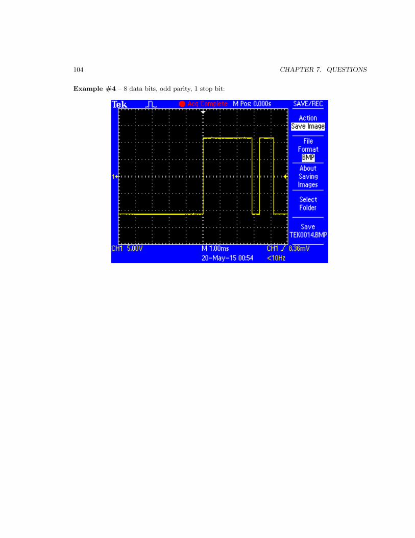
104 CHAPTER 7. QUESTIONS
Example #4 – 8 data bits, odd parity, 1 stop bit:

7.1. CONCEPTUAL REASONING 105
Example #5 – 7 data bits, even parity, 2 stop bits:
Challenges
• Identify the bit rate at which all these ASCII characters were transmitted.

106 CHAPTER 7. QUESTIONS
7.2 Quantitative reasoning
These questions are designed to stimulate your computational thinking. In a Socratic discussion withyour instructor, the goal is for these questions to reveal your mathematical approach(es) to problem-solving so that good technique and sound reasoning may be reinforced. Your instructor may also poseadditional questions based on those assigned, in order to observe your problem-solving firsthand.
Mental arithmetic and estimations are strongly encouraged for all calculations, because withoutthese abilities you will be unable to readily detect errors caused by calculator misuse (e.g. keystrokeerrors).
You will note a conspicuous lack of answers given for these quantitative questions. Unlikestandard textbooks where answers to every other question are given somewhere toward the backof the book, here in these learning modules students must rely on other means to check their work.My advice is to use circuit simulation software such as SPICE to check the correctness of quantitativeanswers. Refer to those learning modules within this collection focusing on SPICE to see workedexamples which you may use directly as practice problems for your own study, and/or as templatesyou may modify to run your own analyses and generate your own practice problems.
Completely worked example problems found in the Tutorial may also serve as “test cases4” forgaining proficiency in the use of circuit simulation software, and then once that proficiency is gainedyou will never need to rely5 on an answer key!
4In other words, set up the circuit simulation software to analyze the same circuit examples found in the Tutorial.If the simulated results match the answers shown in the Tutorial, it confirms the simulation has properly run. Ifthe simulated results disagree with the Tutorial’s answers, something has been set up incorrectly in the simulationsoftware. Using every Tutorial as practice in this way will quickly develop proficiency in the use of circuit simulationsoftware.
5This approach is perfectly in keeping with the instructional philosophy of these learning modules: teaching students
to be self-sufficient thinkers. Answer keys can be useful, but it is even more useful to your long-term success to havea set of tools on hand for checking your own work, because once you have left school and are on your own, there willno longer be “answer keys” available for the problems you will have to solve.

7.2. QUANTITATIVE REASONING 107
7.2.1 Miscellaneous physical constants
Note: constants shown in bold type are exact, not approximations. Values inside of parentheses showone standard deviation (σ) of uncertainty in the final digits: for example, Avogadro’s number givenas 6.02214179(30) × 1023 means the center value (6.02214179×10²³) plus or minus 0.00000030×10²³.
Avogadro’s number (NA) = 6.02214179(30) × 1023 per mole (mol−1)
Boltzmann’s constant (k) = 1.3806504(24) × 10−23 Joules per Kelvin (J/K)
Electronic charge (e) = 1.602176487(40) × 10−19 Coulomb (C)
Faraday constant (F ) = 9.64853399(24) × 104 Coulombs per mole (C/mol)
Magnetic permeability of free space (µ0) = 1.25663706212(19) × 10−6 Henrys per meter (H/m)
Electric permittivity of free space (ǫ0) = 8.8541878128(13) × 10−12 Farads per meter (F/m)
Characteristic impedance of free space (Z0) = 376.730313668(57) Ohms (Ω)
Gravitational constant (G) = 6.67428(67) × 10−11 cubic meters per kilogram-seconds squared(m3/kg-s2)
Molar gas constant (R) = 8.314472(15) Joules per mole-Kelvin (J/mol-K) = 0.08205746(14) liters-atmospheres per mole-Kelvin
Planck constant (h) = 6.62606896(33) × 10−34 joule-seconds (J-s)
Stefan-Boltzmann constant (σ) = 5.670400(40) × 10−8 Watts per square meter-Kelvin4 (W/m2·K4)
Speed of light in a vacuum (c) = 299792458 meters per second (m/s) = 186282.4 miles persecond (mi/s)
Note: All constants taken from NIST data “Fundamental Physical Constants – Extensive Listing”,from http://physics.nist.gov/constants, National Institute of Standards and Technology(NIST), 2006; with the exception of the permeability of free space which was taken from NIST’s2018 CODATA recommended values database.

108 CHAPTER 7. QUESTIONS
7.2.2 Introduction to spreadsheets
A powerful computational tool you are encouraged to use in your work is a spreadsheet. Availableon most personal computers (e.g. Microsoft Excel), spreadsheet software performs numericalcalculations based on number values and formulae entered into cells of a grid. This grid istypically arranged as lettered columns and numbered rows, with each cell of the grid identifiedby its column/row coordinates (e.g. cell B3, cell A8). Each cell may contain a string of text, anumber value, or a mathematical formula. The spreadsheet automatically updates the results of allmathematical formulae whenever the entered number values are changed. This means it is possibleto set up a spreadsheet to perform a series of calculations on entered data, and those calculationswill be re-done by the computer any time the data points are edited in any way.
For example, the following spreadsheet calculates average speed based on entered values ofdistance traveled and time elapsed:
1
2
3
4
5
A B C
Distance traveled
Time elapsed
Kilometers
Hours
Average speed km/h
D
46.9
1.18
= B1 / B2
Text labels contained in cells A1 through A3 and cells C1 through C3 exist solely for readabilityand are not involved in any calculations. Cell B1 contains a sample distance value while cell B2contains a sample time value. The formula for computing speed is contained in cell B3. Note howthis formula begins with an “equals” symbol (=), references the values for distance and speed bylettered column and numbered row coordinates (B1 and B2), and uses a forward slash symbol fordivision (/). The coordinates B1 and B2 function as variables6 would in an algebraic formula.
When this spreadsheet is executed, the numerical value 39.74576 will appear in cell B3 ratherthan the formula = B1 / B2, because 39.74576 is the computed speed value given 46.9 kilometerstraveled over a period of 1.18 hours. If a different numerical value for distance is entered into cellB1 or a different value for time is entered into cell B2, cell B3’s value will automatically update. Allyou need to do is set up the given values and any formulae into the spreadsheet, and the computerwill do all the calculations for you.
Cell B3 may be referenced by other formulae in the spreadsheet if desired, since it is a variablejust like the given values contained in B1 and B2. This means it is possible to set up an entire chainof calculations, one dependent on the result of another, in order to arrive at a final value. Thearrangement of the given data and formulae need not follow any pattern on the grid, which meansyou may place them anywhere.
6Spreadsheets may also provide means to attach text labels to cells for use as variable names (Microsoft Excelsimply calls these labels “names”), but for simple spreadsheets such as those shown here it’s usually easier just to usethe standard coordinate naming for each cell.

7.2. QUANTITATIVE REASONING 109
Common7 arithmetic operations available for your use in a spreadsheet include the following:
• Addition (+)
• Subtraction (-)
• Multiplication (*)
• Division (/)
• Powers (^)
• Square roots (sqrt())
• Logarithms (ln() , log10())
Parentheses may be used to ensure8 proper order of operations within a complex formula.Consider this example of a spreadsheet implementing the quadratic formula, used to solve for rootsof a polynomial expression in the form of ax2 + bx + c:
x =−b ±
√b2 − 4ac
2a
1
2
3
4
5
A B
5
-2
x_1
x_2
a =
b =
c =
9
= (-B4 - sqrt((B4^2) - (4*B3*B5))) / (2*B3)
= (-B4 + sqrt((B4^2) - (4*B3*B5))) / (2*B3)
This example is configured to compute roots9 of the polynomial 9x2 + 5x− 2 because the valuesof 9, 5, and −2 have been inserted into cells B3, B4, and B5, respectively. Once this spreadsheet hasbeen built, though, it may be used to calculate the roots of any second-degree polynomial expressionsimply by entering the new a, b, and c coefficients into cells B3 through B5. The numerical valuesappearing in cells B1 and B2 will be automatically updated by the computer immediately followingany changes made to the coefficients.
7Modern spreadsheet software offers a bewildering array of mathematical functions you may use in yourcomputations. I recommend you consult the documentation for your particular spreadsheet for information onoperations other than those listed here.
8Spreadsheet programs, like text-based programming languages, are designed to follow standard order of operationsby default. However, my personal preference is to use parentheses even where strictly unnecessary just to make itclear to any other person viewing the formula what the intended order of operations is.
9Reviewing some algebra here, a root is a value for x that yields an overall value of zero for the polynomial. Forthis polynomial (9x
2 +5x−2) the two roots happen to be x = 0.269381 and x = −0.82494, with these values displayedin cells B1 and B2, respectively upon execution of the spreadsheet.

110 CHAPTER 7. QUESTIONS
Alternatively, one could break up the long quadratic formula into smaller pieces like this:
y =√
b2 − 4ac z = 2a
x =−b ± y
z
1
2
3
4
5
A B
5
-2
x_1
x_2
a =
b =
c =
9
C
= sqrt((B4^2) - (4*B3*B5))
= 2*B3
= (-B4 + C1) / C2
= (-B4 - C1) / C2
Note how the square-root term (y) is calculated in cell C1, and the denominator term (z) in cellC2. This makes the two final formulae (in cells B1 and B2) simpler to interpret. The positioning ofall these cells on the grid is completely arbitrary10 – all that matters is that they properly referenceeach other in the formulae.
Spreadsheets are particularly useful for situations where the same set of calculations representinga circuit or other system must be repeated for different initial conditions. The power of a spreadsheetis that it automates what would otherwise be a tedious set of calculations. One specific applicationof this is to simulate the effects of various components within a circuit failing with abnormal values(e.g. a shorted resistor simulated by making its value nearly zero; an open resistor simulated bymaking its value extremely large). Another application is analyzing the behavior of a circuit designgiven new components that are out of specification, and/or aging components experiencing driftover time.
10My personal preference is to locate all the “given” data in the upper-left cells of the spreadsheet grid (each datapoint flanked by a sensible name in the cell to the left and units of measurement in the cell to the right as illustratedin the first distance/time spreadsheet example), sometimes coloring them in order to clearly distinguish which cellscontain entered data versus which cells contain computed results from formulae. I like to place all formulae in cellsbelow the given data, and try to arrange them in logical order so that anyone examining my spreadsheet will be ableto figure out how I constructed a solution. This is a general principle I believe all computer programmers shouldfollow: document and arrange your code to make it easy for other people to learn from it.

7.2. QUANTITATIVE REASONING 111
7.2.3 Manchester data frame with a specified bit rate
Sketch an oscillograph for a Manchester-encoded data stream 1011101 at a data rate of 14400 bitsper second:
Be sure to specify the oscilloscope’s timebase setting (i.e. the number of milliseconds per division).
Challenges
• Of what practical importance is bit rate to serial data communication?

112 CHAPTER 7. QUESTIONS
7.3 Diagnostic reasoning
These questions are designed to stimulate your deductive and inductive thinking, where you mustapply general principles to specific scenarios (deductive) and also derive conclusions about the failedcircuit from specific details (inductive). In a Socratic discussion with your instructor, the goal is forthese questions to reinforce your recall and use of general circuit principles and also challenge yourability to integrate multiple symptoms into a sensible explanation of what’s wrong in a circuit. Yourinstructor may also pose additional questions based on those assigned, in order to further challengeand sharpen your diagnostic abilities.
As always, your goal is to fully explain your analysis of each problem. Simply obtaining acorrect answer is not good enough – you must also demonstrate sound reasoning in order tosuccessfully complete the assignment. Your instructor’s responsibility is to probe and challengeyour understanding of the relevant principles and analytical processes in order to ensure you have astrong foundation upon which to build further understanding.
You will note a conspicuous lack of answers given for these diagnostic questions. Unlike standardtextbooks where answers to every other question are given somewhere toward the back of the book,here in these learning modules students must rely on other means to check their work. The best wayby far is to debate the answers with fellow students and also with the instructor during the Socraticdialogue sessions intended to be used with these learning modules. Reasoning through challengingquestions with other people is an excellent tool for developing strong reasoning skills.
Another means of checking your diagnostic answers, where applicable, is to use circuit simulationsoftware to explore the effects of faults placed in circuits. For example, if one of these diagnosticquestions requires that you predict the effect of an open or a short in a circuit, you may check thevalidity of your work by simulating that same fault (substituting a very high resistance in place ofthat component for an open, and substituting a very low resistance for a short) within software andseeing if the results agree.
7.3.1 Testing determinism
Devise a diagnostic test you could apply to assess the determinism of any given serial data network.
Challenges
• Explain the significance of determinism in a serial communication network.

Appendix A
Problem-Solving Strategies
The ability to solve complex problems is arguably one of the most valuable skills one can possess,and this skill is particularly important in any science-based discipline.
• Study principles, not procedures. Don’t be satisfied with merely knowing how to computesolutions – learn why those solutions work.
• Identify what it is you need to solve, identify all relevant data, identify all units of measurement,identify any general principles or formulae linking the given information to the solution, andthen identify any “missing pieces” to a solution. Annotate all diagrams with this data.
• Sketch a diagram to help visualize the problem. When building a real system, always devisea plan for that system and analyze its function before constructing it.
• Follow the units of measurement and meaning of every calculation. If you are ever performingmathematical calculations as part of a problem-solving procedure, and you find yourself unableto apply each and every intermediate result to some aspect of the problem, it means youdon’t understand what you are doing. Properly done, every mathematical result should havepractical meaning for the problem, and not just be an abstract number. You should be able toidentify the proper units of measurement for each and every calculated result, and show wherethat result fits into the problem.
• Perform “thought experiments” to explore the effects of different conditions for theoreticalproblems. When troubleshooting real systems, perform diagnostic tests rather than visuallyinspecting for faults, the best diagnostic test being the one giving you the most informationabout the nature and/or location of the fault with the fewest steps.
• Simplify the problem until the solution becomes obvious, and then use that obvious case as amodel to follow in solving the more complex version of the problem.
• Check for exceptions to see if your solution is incorrect or incomplete. A good solution willwork for all known conditions and criteria. A good example of this is the process of testingscientific hypotheses: the task of a scientist is not to find support for a new idea, but ratherto challenge that new idea to see if it holds up under a battery of tests. The philosophical
113

114 APPENDIX A. PROBLEM-SOLVING STRATEGIES
principle of reductio ad absurdum (i.e. disproving a general idea by finding a specific casewhere it fails) is useful here.
• Work “backward” from a hypothetical solution to a new set of given conditions.
• Add quantities to problems that are qualitative in nature, because sometimes a little mathhelps illuminate the scenario.
• Sketch graphs illustrating how variables relate to each other. These may be quantitative (i.e.with realistic number values) or qualitative (i.e. simply showing increases and decreases).
• Treat quantitative problems as qualitative in order to discern the relative magnitudes and/ordirections of change of the relevant variables. For example, try determining what happens if acertain variable were to increase or decrease before attempting to precisely calculate quantities:how will each of the dependent variables respond, by increasing, decreasing, or remaining thesame as before?
• Consider limiting cases. This works especially well for qualitative problems where you need todetermine which direction a variable will change. Take the given condition and magnify thatcondition to an extreme degree as a way of simplifying the direction of the system’s response.
• Check your work. This means regularly testing your conclusions to see if they make sense.This does not mean repeating the same steps originally used to obtain the conclusion(s), butrather to use some other means to check validity. Simply repeating procedures often leads torepeating the same errors if any were made, which is why alternative paths are better.

Appendix B
Instructional philosophy
“The unexamined circuit is not worth energizing” – Socrates (if he had taught electricity)
These learning modules, although useful for self-study, were designed to be used in a formallearning environment where a subject-matter expert challenges students to digest the content andexercise their critical thinking abilities in the answering of questions and in the construction andtesting of working circuits.
The following principles inform the instructional and assessment philosophies embodied in theselearning modules:
• The first goal of education is to enhance clear and independent thought, in order thatevery student reach their fullest potential in a highly complex and inter-dependent world.Robust reasoning is always more important than particulars of any subject matter, becauseits application is universal.
• Literacy is fundamental to independent learning and thought because text continues to be themost efficient way to communicate complex ideas over space and time. Those who cannot readwith ease are limited in their ability to acquire knowledge and perspective.
• Articulate communication is fundamental to work that is complex and interdisciplinary.
• Faulty assumptions and poor reasoning are best corrected through challenge, not presentation.The rhetorical technique of reductio ad absurdum (disproving an assertion by exposing anabsurdity) works well to discipline student’s minds, not only to correct the problem at handbut also to learn how to detect and correct future errors.
• Important principles should be repeatedly explored and widely applied throughout a courseof study, not only to reinforce their importance and help ensure their mastery, but also toshowcase the interconnectedness and utility of knowledge.
115

116 APPENDIX B. INSTRUCTIONAL PHILOSOPHY
These learning modules were expressly designed to be used in an “inverted” teachingenvironment1 where students first read the introductory and tutorial chapters on their own, thenindividually attempt to answer the questions and construct working circuits according to theexperiment and project guidelines. The instructor never lectures, but instead meets regularlywith each individual student to review their progress, answer questions, identify misconceptions,and challenge the student to new depths of understanding through further questioning. Regularmeetings between instructor and student should resemble a Socratic2 dialogue, where questionsserve as scalpels to dissect topics and expose assumptions. The student passes each module onlyafter consistently demonstrating their ability to logically analyze and correctly apply all majorconcepts in each question or project/experiment. The instructor must be vigilant in probing eachstudent’s understanding to ensure they are truly reasoning and not just memorizing. This is why“Challenge” points appear throughout, as prompts for students to think deeper about topics and asstarting points for instructor queries. Sometimes these challenge points require additional knowledgethat hasn’t been covered in the series to answer in full. This is okay, as the major purpose of theChallenges is to stimulate analysis and synthesis on the part of each student.
The instructor must possess enough mastery of the subject matter and awareness of students’reasoning to generate their own follow-up questions to practically any student response. Evencompletely correct answers given by the student should be challenged by the instructor for thepurpose of having students practice articulating their thoughts and defending their reasoning.Conceptual errors committed by the student should be exposed and corrected not by directinstruction, but rather by reducing the errors to an absurdity3 through well-chosen questions andthought experiments posed by the instructor. Becoming proficient at this style of instruction requirestime and dedication, but the positive effects on critical thinking for both student and instructor arespectacular.
An inspection of these learning modules reveals certain unique characteristics. One of these isa bias toward thorough explanations in the tutorial chapters. Without a live instructor to explainconcepts and applications to students, the text itself must fulfill this role. This philosophy results inlengthier explanations than what you might typically find in a textbook, each step of the reasoningprocess fully explained, including footnotes addressing common questions and concerns studentsraise while learning these concepts. Each tutorial seeks to not only explain each major conceptin sufficient detail, but also to explain the logic of each concept and how each may be developed
1In a traditional teaching environment, students first encounter new information via lecture from an expert, andthen independently apply that information via homework. In an “inverted” course of study, students first encounternew information via homework, and then independently apply that information under the scrutiny of an expert. Theexpert’s role in lecture is to simply explain, but the expert’s role in an inverted session is to challenge, critique, andif necessary explain where gaps in understanding still exist.
2Socrates is a figure in ancient Greek philosophy famous for his unflinching style of questioning. Although heauthored no texts, he appears as a character in Plato’s many writings. The essence of Socratic philosophy is toleave no question unexamined and no point of view unchallenged. While purists may argue a topic such as electriccircuits is too narrow for a true Socratic-style dialogue, I would argue that the essential thought processes involvedwith scientific reasoning on any topic are not far removed from the Socratic ideal, and that students of electricity andelectronics would do very well to challenge assumptions, pose thought experiments, identify fallacies, and otherwiseemploy the arsenal of critical thinking skills modeled by Socrates.
3This rhetorical technique is known by the Latin phrase reductio ad absurdum. The concept is to expose errors bycounter-example, since only one solid counter-example is necessary to disprove a universal claim. As an example ofthis, consider the common misconception among beginning students of electricity that voltage cannot exist withoutcurrent. One way to apply reductio ad absurdum to this statement is to ask how much current passes through afully-charged battery connected to nothing (i.e. a clear example of voltage existing without current).

117
from “first principles”. Again, this reflects the goal of developing clear and independent thought instudents’ minds, by showing how clear and logical thought was used to forge each concept. Studentsbenefit from witnessing a model of clear thinking in action, and these tutorials strive to be just that.
Another characteristic of these learning modules is a lack of step-by-step instructions in theProject and Experiment chapters. Unlike many modern workbooks and laboratory guides wherestep-by-step instructions are prescribed for each experiment, these modules take the approach thatstudents must learn to closely read the tutorials and apply their own reasoning to identify theappropriate experimental steps. Sometimes these steps are plainly declared in the text, just not asa set of enumerated points. At other times certain steps are implied, an example being assumedcompetence in test equipment use where the student should not need to be told again how to usetheir multimeter because that was thoroughly explained in previous lessons. In some circumstancesno steps are given at all, leaving the entire procedure up to the student.
This lack of prescription is not a flaw, but rather a feature. Close reading and clear thinking arefoundational principles of this learning series, and in keeping with this philosophy all activities aredesigned to require those behaviors. Some students may find the lack of prescription frustrating,because it demands more from them than what their previous educational experiences required. Thisfrustration should be interpreted as an unfamiliarity with autonomous thinking, a problem whichmust be corrected if the student is ever to become a self-directed learner and effective problem-solver.Ultimately, the need for students to read closely and think clearly is more important both in thenear-term and far-term than any specific facet of the subject matter at hand. If a student takeslonger than expected to complete a module because they are forced to outline, digest, and reasonon their own, so be it. The future gains enjoyed by developing this mental discipline will be wellworth the additional effort and delay.
Another feature of these learning modules is that they do not treat topics in isolation. Rather,important concepts are introduced early in the series, and appear repeatedly as stepping-stonestoward other concepts in subsequent modules. This helps to avoid the “compartmentalization”of knowledge, demonstrating the inter-connectedness of concepts and simultaneously reinforcingthem. Each module is fairly complete in itself, reserving the beginning of its tutorial to a review offoundational concepts.
This methodology of assigning text-based modules to students for digestion and then usingSocratic dialogue to assess progress and hone students’ thinking was developed over a period ofseveral years by the author with his Electronics and Instrumentation students at the two-year collegelevel. While decidedly unconventional and sometimes even unsettling for students accustomed toa more passive lecture environment, this instructional philosophy has proven its ability to conveyconceptual mastery, foster careful analysis, and enhance employability so much better than lecturethat the author refuses to ever teach by lecture again.
Problems which often go undiagnosed in a lecture environment are laid bare in this “inverted”format where students must articulate and logically defend their reasoning. This, too, may beunsettling for students accustomed to lecture sessions where the instructor cannot tell for sure whocomprehends and who does not, and this vulnerability necessitates sensitivity on the part of the“inverted” session instructor in order that students never feel discouraged by having their errorsexposed. Everyone makes mistakes from time to time, and learning is a lifelong process! Part ofthe instructor’s job is to build a culture of learning among the students where errors are not seen asshameful, but rather as opportunities for progress.

118 APPENDIX B. INSTRUCTIONAL PHILOSOPHY
To this end, instructors managing courses based on these modules should adhere to the followingprinciples:
• Student questions are always welcome and demand thorough, honest answers. The only typeof question an instructor should refuse to answer is one the student should be able to easilyanswer on their own. Remember, the fundamental goal of education is for each student to learnto think clearly and independently. This requires hard work on the part of the student, whichno instructor should ever circumvent. Anything done to bypass the student’s responsibility todo that hard work ultimately limits that student’s potential and thereby does real harm.
• It is not only permissible, but encouraged, to answer a student’s question by asking questionsin return, these follow-up questions designed to guide the student to reach a correct answerthrough their own reasoning.
• All student answers demand to be challenged by the instructor and/or by other students.This includes both correct and incorrect answers – the goal is to practice the articulation anddefense of one’s own reasoning.
• No reading assignment is deemed complete unless and until the student demonstrates theirability to accurately summarize the major points in their own terms. Recitation of the originaltext is unacceptable. This is why every module contains an “Outline and reflections” questionas well as a “Foundational concepts” question in the Conceptual reasoning section, to promptreflective reading.
• No assigned question is deemed answered unless and until the student demonstrates theirability to consistently and correctly apply the concepts to variations of that question. This iswhy module questions typically contain multiple “Challenges” suggesting different applicationsof the concept(s) as well as variations on the same theme(s). Instructors are encouraged todevise as many of their own “Challenges” as they are able, in order to have a multitude ofways ready to probe students’ understanding.
• No assigned experiment or project is deemed complete unless and until the studentdemonstrates the task in action. If this cannot be done “live” before the instructor, video-recordings showing the demonstration are acceptable. All relevant safety precautions must befollowed, all test equipment must be used correctly, and the student must be able to properlyexplain all results. The student must also successfully answer all Challenges presented by theinstructor for that experiment or project.

119
Students learning from these modules would do well to abide by the following principles:
• No text should be considered fully and adequately read unless and until you can express everyidea in your own words, using your own examples.
• You should always articulate your thoughts as you read the text, noting points of agreement,confusion, and epiphanies. Feel free to print the text on paper and then write your notes inthe margins. Alternatively, keep a journal for your own reflections as you read. This is trulya helpful tool when digesting complicated concepts.
• Never take the easy path of highlighting or underlining important text. Instead, summarizeand/or comment on the text using your own words. This actively engages your mind, allowingyou to more clearly perceive points of confusion or misunderstanding on your own.
• A very helpful strategy when learning new concepts is to place yourself in the role of a teacher,if only as a mental exercise. Either explain what you have recently learned to someone else,or at least imagine yourself explaining what you have learned to someone else. The simple actof having to articulate new knowledge and skill forces you to take on a different perspective,and will help reveal weaknesses in your understanding.
• Perform each and every mathematical calculation and thought experiment shown in the texton your own, referring back to the text to see that your results agree. This may seem trivialand unnecessary, but it is critically important to ensuring you actually understand what ispresented, especially when the concepts at hand are complicated and easy to misunderstand.Apply this same strategy to become proficient in the use of circuit simulation software, checkingto see if your simulated results agree with the results shown in the text.
• Above all, recognize that learning is hard work, and that a certain level of frustration isunavoidable. There are times when you will struggle to grasp some of these concepts, and thatstruggle is a natural thing. Take heart that it will yield with persistent and varied4 effort, andnever give up!
Students interested in using these modules for self-study will also find them beneficial, althoughthe onus of responsibility for thoroughly reading and answering questions will of course lie withthat individual alone. If a qualified instructor is not available to challenge students, a workablealternative is for students to form study groups where they challenge5 one another.
To high standards of education,
Tony R. Kuphaldt
4As the old saying goes, “Insanity is trying the same thing over and over again, expecting different results.” Ifyou find yourself stumped by something in the text, you should attempt a different approach. Alter the thoughtexperiment, change the mathematical parameters, do whatever you can to see the problem in a slightly different light,and then the solution will often present itself more readily.
5Avoid the temptation to simply share answers with study partners, as this is really counter-productive to learning.Always bear in mind that the answer to any question is far less important in the long run than the method(s) used toobtain that answer. The goal of education is to empower one’s life through the improvement of clear and independentthought, literacy, expression, and various practical skills.

120 APPENDIX B. INSTRUCTIONAL PHILOSOPHY

Appendix C
Tools used
I am indebted to the developers of many open-source software applications in the creation of theselearning modules. The following is a list of these applications with some commentary on each.
You will notice a theme common to many of these applications: a bias toward code. AlthoughI am by no means an expert programmer in any computer language, I understand and appreciatethe flexibility offered by code-based applications where the user (you) enters commands into a plainASCII text file, which the software then reads and processes to create the final output. Code-basedcomputer applications are by their very nature extensible, while WYSIWYG (What You See Is WhatYou Get) applications are generally limited to whatever user interface the developer makes for you.
The GNU/Linux computer operating system
There is so much to be said about Linus Torvalds’ Linux and Richard Stallman’s GNU
project. First, to credit just these two individuals is to fail to do justice to the mob ofpassionate volunteers who contributed to make this amazing software a reality. I firstlearned of Linux back in 1996, and have been using this operating system on my personalcomputers almost exclusively since then. It is free, it is completely configurable, and itpermits the continued use of highly efficient Unix applications and scripting languages(e.g. shell scripts, Makefiles, sed, awk) developed over many decades. Linux not onlyprovided me with a powerful computing platform, but its open design served to inspiremy life’s work of creating open-source educational resources.
Bram Moolenaar’s Vim text editor
Writing code for any code-based computer application requires a text editor, which maybe thought of as a word processor strictly limited to outputting plain-ASCII text files.Many good text editors exist, and one’s choice of text editor seems to be a deeply personalmatter within the programming world. I prefer Vim because it operates very similarly tovi which is ubiquitous on Unix/Linux operating systems, and because it may be entirelyoperated via keyboard (i.e. no mouse required) which makes it fast to use.
121

122 APPENDIX C. TOOLS USED
Donald Knuth’s TEX typesetting system
Developed in the late 1970’s and early 1980’s by computer scientist extraordinaire DonaldKnuth to typeset his multi-volume magnum opus The Art of Computer Programming,this software allows the production of formatted text for screen-viewing or paper printing,all by writing plain-text code to describe how the formatted text is supposed to appear.TEX is not just a markup language for documents, but it is also a Turing-completeprogramming language in and of itself, allowing useful algorithms to be created to controlthe production of documents. Simply put, TEX is a programmer’s approach to wordprocessing. Since TEX is controlled by code written in a plain-text file, this meansanyone may read that plain-text file to see exactly how the document was created. Thisopenness afforded by the code-based nature of TEX makes it relatively easy to learn howother people have created their own TEX documents. By contrast, examining a beautifuldocument created in a conventional WYSIWYG word processor such as Microsoft Wordsuggests nothing to the reader about how that document was created, or what the usermight do to create something similar. As Mr. Knuth himself once quipped, conventionalword processing applications should be called WYSIAYG (What You See Is All YouGet).
Leslie Lamport’s LATEX extensions to TEX
Like all true programming languages, TEX is inherently extensible. So, years after therelease of TEX to the public, Leslie Lamport decided to create a massive extensionallowing easier compilation of book-length documents. The result was LATEX, whichis the markup language used to create all ModEL module documents. You could saythat TEX is to LATEX as C is to C++. This means it is permissible to use any and all TEXcommands within LATEX source code, and it all still works. Some of the features offeredby LATEX that would be challenging to implement in TEX include automatic index andtable-of-content creation.
Tim Edwards’ Xcircuit drafting program
This wonderful program is what I use to create all the schematic diagrams andillustrations (but not photographic images or mathematical plots) throughout the ModELproject. It natively outputs PostScript format which is a true vector graphic format (thisis why the images do not pixellate when you zoom in for a closer view), and it is so simpleto use that I have never had to read the manual! Object libraries are easy to create forXcircuit, being plain-text files using PostScript programming conventions. Over theyears I have collected a large set of object libraries useful for drawing electrical andelectronic schematics, pictorial diagrams, and other technical illustrations.

123
Gimp graphic image manipulation program
Essentially an open-source clone of Adobe’s PhotoShop, I use Gimp to resize, crop, andconvert file formats for all of the photographic images appearing in the ModEL modules.Although Gimp does offer its own scripting language (called Script-Fu), I have neverhad occasion to use it. Thus, my utilization of Gimp to merely crop, resize, and convertgraphic images is akin to using a sword to slice bread.
SPICE circuit simulation program
SPICE is to circuit analysis as TEX is to document creation: it is a form of markuplanguage designed to describe a certain object to be processed in plain-ASCII text.When the plain-text “source file” is compiled by the software, it outputs the final result.More modern circuit analysis tools certainly exist, but I prefer SPICE for the followingreasons: it is free, it is fast, it is reliable, and it is a fantastic tool for teaching students ofelectricity and electronics how to write simple code. I happen to use rather old versions ofSPICE, version 2g6 being my “go to” application when I only require text-based output.NGSPICE (version 26), which is based on Berkeley SPICE version 3f5, is used when Irequire graphical output for such things as time-domain waveforms and Bode plots. Inall SPICE example netlists I strive to use coding conventions compatible with all SPICEversions.
Andrew D. Hwang’s ePiX mathematical visualization programming library
This amazing project is a C++ library you may link to any C/C++ code for the purposeof generating PostScript graphic images of mathematical functions. As a completelyfree and open-source project, it does all the plotting I would otherwise use a ComputerAlgebra System (CAS) such as Mathematica or Maple to do. It should be said thatePiX is not a Computer Algebra System like Mathematica or Maple, but merely amathematical visualization tool. In other words, it won’t determine integrals for you(you’ll have to implement that in your own C/C++ code!), but it can graph the results, andit does so beautifully. What I really admire about ePiX is that it is a C++ programminglibrary, which means it builds on the existing power and toolset available with thatprogramming language. Mr. Hwang could have probably developed his own stand-aloneapplication for mathematical plotting, but by creating a C++ library to do the same thinghe accomplished something much greater.

124 APPENDIX C. TOOLS USED
gnuplot mathematical visualization software
Another open-source tool for mathematical visualization is gnuplot. Interestingly, thistool is not part of Richard Stallman’s GNU project, its name being a coincidence. Forthis reason the authors prefer “gnu” not be capitalized at all to avoid confusion. This isa much “lighter-weight” alternative to a spreadsheet for plotting tabular data, and thefact that it easily outputs directly to an X11 console or a file in a number of differentgraphical formats (including PostScript) is very helpful. I typically set my gnuplot
output format to default (X11 on my Linux PC) for quick viewing while I’m developinga visualization, then switch to PostScript file export once the visual is ready to include inthe document(s) I’m writing. As with my use of Gimp to do rudimentary image editing,my use of gnuplot only scratches the surface of its capabilities, but the important pointsare that it’s free and that it works well.
Python programming language
Both Python and C++ find extensive use in these modules as instructional aids andexercises, but I’m listing Python here as a tool for myself because I use it almost dailyas a calculator. If you open a Python interpreter console and type from math import
* you can type mathematical expressions and have it return results just as you wouldon a hand calculator. Complex-number (i.e. phasor) arithmetic is similarly supportedif you include the complex-math library (from cmath import *). Examples of this areshown in the Programming References chapter (if included) in each module. Of course,being a fully-featured programming language, Python also supports conditionals, loops,and other structures useful for calculation of quantities. Also, running in a consoleenvironment where all entries and returned values show as text in a chronologically-ordered list makes it easy to copy-and-paste those calculations to document exactly howthey were performed.

Appendix D
Creative Commons License
Creative Commons Attribution 4.0 International Public License
By exercising the Licensed Rights (defined below), You accept and agree to be bound by the termsand conditions of this Creative Commons Attribution 4.0 International Public License (“PublicLicense”). To the extent this Public License may be interpreted as a contract, You are granted theLicensed Rights in consideration of Your acceptance of these terms and conditions, and the Licensorgrants You such rights in consideration of benefits the Licensor receives from making the LicensedMaterial available under these terms and conditions.
Section 1 – Definitions.
a. Adapted Material means material subject to Copyright and Similar Rights that is derivedfrom or based upon the Licensed Material and in which the Licensed Material is translated, altered,arranged, transformed, or otherwise modified in a manner requiring permission under the Copyrightand Similar Rights held by the Licensor. For purposes of this Public License, where the LicensedMaterial is a musical work, performance, or sound recording, Adapted Material is always producedwhere the Licensed Material is synched in timed relation with a moving image.
b. Adapter’s License means the license You apply to Your Copyright and Similar Rights inYour contributions to Adapted Material in accordance with the terms and conditions of this PublicLicense.
c. Copyright and Similar Rights means copyright and/or similar rights closely related tocopyright including, without limitation, performance, broadcast, sound recording, and Sui GenerisDatabase Rights, without regard to how the rights are labeled or categorized. For purposes of thisPublic License, the rights specified in Section 2(b)(1)-(2) are not Copyright and Similar Rights.
d. Effective Technological Measures means those measures that, in the absence of properauthority, may not be circumvented under laws fulfilling obligations under Article 11 of the WIPOCopyright Treaty adopted on December 20, 1996, and/or similar international agreements.
e. Exceptions and Limitations means fair use, fair dealing, and/or any other exception or
125

126 APPENDIX D. CREATIVE COMMONS LICENSE
limitation to Copyright and Similar Rights that applies to Your use of the Licensed Material.
f. Licensed Material means the artistic or literary work, database, or other material to whichthe Licensor applied this Public License.
g. Licensed Rights means the rights granted to You subject to the terms and conditions ofthis Public License, which are limited to all Copyright and Similar Rights that apply to Your use ofthe Licensed Material and that the Licensor has authority to license.
h. Licensor means the individual(s) or entity(ies) granting rights under this Public License.
i. Share means to provide material to the public by any means or process that requirespermission under the Licensed Rights, such as reproduction, public display, public performance,distribution, dissemination, communication, or importation, and to make material available to thepublic including in ways that members of the public may access the material from a place and at atime individually chosen by them.
j. Sui Generis Database Rights means rights other than copyright resulting from Directive96/9/EC of the European Parliament and of the Council of 11 March 1996 on the legal protectionof databases, as amended and/or succeeded, as well as other essentially equivalent rights anywherein the world.
k. You means the individual or entity exercising the Licensed Rights under this Public License.Your has a corresponding meaning.
Section 2 – Scope.
a. License grant.
1. Subject to the terms and conditions of this Public License, the Licensor hereby grants You aworldwide, royalty-free, non-sublicensable, non-exclusive, irrevocable license to exercise the LicensedRights in the Licensed Material to:
A. reproduce and Share the Licensed Material, in whole or in part; and
B. produce, reproduce, and Share Adapted Material.
2. Exceptions and Limitations. For the avoidance of doubt, where Exceptions and Limitationsapply to Your use, this Public License does not apply, and You do not need to comply with its termsand conditions.
3. Term. The term of this Public License is specified in Section 6(a).
4. Media and formats; technical modifications allowed. The Licensor authorizes You to exercisethe Licensed Rights in all media and formats whether now known or hereafter created, and to maketechnical modifications necessary to do so. The Licensor waives and/or agrees not to assert any rightor authority to forbid You from making technical modifications necessary to exercise the LicensedRights, including technical modifications necessary to circumvent Effective Technological Measures.

127
For purposes of this Public License, simply making modifications authorized by this Section 2(a)(4)never produces Adapted Material.
5. Downstream recipients.
A. Offer from the Licensor – Licensed Material. Every recipient of the Licensed Materialautomatically receives an offer from the Licensor to exercise the Licensed Rights under the termsand conditions of this Public License.
B. No downstream restrictions. You may not offer or impose any additional or different termsor conditions on, or apply any Effective Technological Measures to, the Licensed Material if doingso restricts exercise of the Licensed Rights by any recipient of the Licensed Material.
6. No endorsement. Nothing in this Public License constitutes or may be construed as permissionto assert or imply that You are, or that Your use of the Licensed Material is, connected with,or sponsored, endorsed, or granted official status by, the Licensor or others designated to receiveattribution as provided in Section 3(a)(1)(A)(i).
b. Other rights.
1. Moral rights, such as the right of integrity, are not licensed under this Public License, norare publicity, privacy, and/or other similar personality rights; however, to the extent possible, theLicensor waives and/or agrees not to assert any such rights held by the Licensor to the limited extentnecessary to allow You to exercise the Licensed Rights, but not otherwise.
2. Patent and trademark rights are not licensed under this Public License.
3. To the extent possible, the Licensor waives any right to collect royalties from You for theexercise of the Licensed Rights, whether directly or through a collecting society under any voluntaryor waivable statutory or compulsory licensing scheme. In all other cases the Licensor expresslyreserves any right to collect such royalties.
Section 3 – License Conditions.
Your exercise of the Licensed Rights is expressly made subject to the following conditions.
a. Attribution.
1. If You Share the Licensed Material (including in modified form), You must:
A. retain the following if it is supplied by the Licensor with the Licensed Material:
i. identification of the creator(s) of the Licensed Material and any others designated to receiveattribution, in any reasonable manner requested by the Licensor (including by pseudonym ifdesignated);
ii. a copyright notice;

128 APPENDIX D. CREATIVE COMMONS LICENSE
iii. a notice that refers to this Public License;
iv. a notice that refers to the disclaimer of warranties;
v. a URI or hyperlink to the Licensed Material to the extent reasonably practicable;
B. indicate if You modified the Licensed Material and retain an indication of any previousmodifications; and
C. indicate the Licensed Material is licensed under this Public License, and include the text of,or the URI or hyperlink to, this Public License.
2. You may satisfy the conditions in Section 3(a)(1) in any reasonable manner based on themedium, means, and context in which You Share the Licensed Material. For example, it may bereasonable to satisfy the conditions by providing a URI or hyperlink to a resource that includes therequired information.
3. If requested by the Licensor, You must remove any of the information required by Section3(a)(1)(A) to the extent reasonably practicable.
4. If You Share Adapted Material You produce, the Adapter’s License You apply must notprevent recipients of the Adapted Material from complying with this Public License.
Section 4 – Sui Generis Database Rights.
Where the Licensed Rights include Sui Generis Database Rights that apply to Your use of theLicensed Material:
a. for the avoidance of doubt, Section 2(a)(1) grants You the right to extract, reuse, reproduce,and Share all or a substantial portion of the contents of the database;
b. if You include all or a substantial portion of the database contents in a database in whichYou have Sui Generis Database Rights, then the database in which You have Sui Generis DatabaseRights (but not its individual contents) is Adapted Material; and
c. You must comply with the conditions in Section 3(a) if You Share all or a substantial portionof the contents of the database.
For the avoidance of doubt, this Section 4 supplements and does not replace Your obligationsunder this Public License where the Licensed Rights include other Copyright and Similar Rights.
Section 5 – Disclaimer of Warranties and Limitation of Liability.
a. Unless otherwise separately undertaken by the Licensor, to the extent possible, the Licensoroffers the Licensed Material as-is and as-available, and makes no representations or warranties ofany kind concerning the Licensed Material, whether express, implied, statutory, or other. Thisincludes, without limitation, warranties of title, merchantability, fitness for a particular purpose,non-infringement, absence of latent or other defects, accuracy, or the presence or absence of errors,

129
whether or not known or discoverable. Where disclaimers of warranties are not allowed in full or inpart, this disclaimer may not apply to You.
b. To the extent possible, in no event will the Licensor be liable to You on any legal theory(including, without limitation, negligence) or otherwise for any direct, special, indirect, incidental,consequential, punitive, exemplary, or other losses, costs, expenses, or damages arising out of thisPublic License or use of the Licensed Material, even if the Licensor has been advised of the possibilityof such losses, costs, expenses, or damages. Where a limitation of liability is not allowed in full orin part, this limitation may not apply to You.
c. The disclaimer of warranties and limitation of liability provided above shall be interpreted ina manner that, to the extent possible, most closely approximates an absolute disclaimer and waiverof all liability.
Section 6 – Term and Termination.
a. This Public License applies for the term of the Copyright and Similar Rights licensed here.However, if You fail to comply with this Public License, then Your rights under this Public Licenseterminate automatically.
b. Where Your right to use the Licensed Material has terminated under Section 6(a), it reinstates:
1. automatically as of the date the violation is cured, provided it is cured within 30 days of Yourdiscovery of the violation; or
2. upon express reinstatement by the Licensor.
For the avoidance of doubt, this Section 6(b) does not affect any right the Licensor may have toseek remedies for Your violations of this Public License.
c. For the avoidance of doubt, the Licensor may also offer the Licensed Material under separateterms or conditions or stop distributing the Licensed Material at any time; however, doing so willnot terminate this Public License.
d. Sections 1, 5, 6, 7, and 8 survive termination of this Public License.
Section 7 – Other Terms and Conditions.
a. The Licensor shall not be bound by any additional or different terms or conditionscommunicated by You unless expressly agreed.
b. Any arrangements, understandings, or agreements regarding the Licensed Material not statedherein are separate from and independent of the terms and conditions of this Public License.
Section 8 – Interpretation.
a. For the avoidance of doubt, this Public License does not, and shall not be interpreted to,reduce, limit, restrict, or impose conditions on any use of the Licensed Material that could lawfully

130 APPENDIX D. CREATIVE COMMONS LICENSE
be made without permission under this Public License.
b. To the extent possible, if any provision of this Public License is deemed unenforceable, it shallbe automatically reformed to the minimum extent necessary to make it enforceable. If the provisioncannot be reformed, it shall be severed from this Public License without affecting the enforceabilityof the remaining terms and conditions.
c. No term or condition of this Public License will be waived and no failure to comply consentedto unless expressly agreed to by the Licensor.
d. Nothing in this Public License constitutes or may be interpreted as a limitation upon, orwaiver of, any privileges and immunities that apply to the Licensor or You, including from the legalprocesses of any jurisdiction or authority.

131
Creative Commons is not a party to its public licenses. Notwithstanding, Creative Commonsmay elect to apply one of its public licenses to material it publishes and in those instances willbe considered the “Licensor.” Except for the limited purpose of indicating that material is sharedunder a Creative Commons public license or as otherwise permitted by the Creative Commonspolicies published at creativecommons.org/policies, Creative Commons does not authorize theuse of the trademark “Creative Commons” or any other trademark or logo of Creative Commonswithout its prior written consent including, without limitation, in connection with any unauthorizedmodifications to any of its public licenses or any other arrangements, understandings, or agreementsconcerning use of licensed material. For the avoidance of doubt, this paragraph does not form partof the public licenses.
Creative Commons may be contacted at creativecommons.org.

132 APPENDIX D. CREATIVE COMMONS LICENSE

Appendix E
References
“422 and 485 Standards Overview and System Configurations” Application Report SLLA070C,Texas Instruments Incorporated, Dallas, TX, 2002.
Floyd, Thomas L., Digital Fundamentals, 6th edition, Prentice-Hall, Inc., Upper Saddle River, NJ,1997.
“FOUNDATION Fieldbus System Engineering Guidelines” (AG 181) Revision 2.0, The FieldbusFoundation, 2004.
“FOUNDATION Specification System Architecture” (FF 581) Revision FS 1.1, The FieldbusFoundation, 2000.
“Fundamentals of RS-232 Serial Communications” Application Note 83 (AN83), Maxim IntegratedProducts, 2001.
Graham, Frank D., Audels New Electric Library, Volume IX, Theo. Audel & Co., New York, NY,1942.
HART Communications, Technical Information L452 EN; SAMSON AG, 1999.
Horak, Ray, Telecommunications and Data Communications Handbook, John Wiley & Sons, Inc.,New York, NY, 2007.
Horak, Ray, Webster’s New World Telecom Dictionary, Wiley Publishing, Inc., Indianapolis, IN,2008.
“Modbus Application Protocol Specification”, version 1.1b, Modbus-IDA, Modbus Organization,Inc., 2006.
“Modbus Messaging on TCP/IP Implementation Guide”, version 1.0b, Modbus-IDA, ModbusOrganization, Inc., 2006.
“Modicon Modbus Protocol Reference Guide”, (PI-MBUS-300) revision J, Modicon, Inc. Industrial
133

134 APPENDIX E. REFERENCES
Automation Systems, North Andover, MA, 1996.
Newton, Harry, Newton’s Telecom Dictionary, CMP Books, San Francisco, CA, 2005.
Park, John; Mackay, Steve; Wright, Edwin; Practical Data Communications for Instrumentationand Control, IDC Technologies, published by Newnes (an imprint of Elsevier), Oxford, England,2003.
Polybius, Histories, cited from pages 49-50 of Lapham’s Quarterly Volume IX, Number 1, Winter2016, American Agora Foundation, New York, NY, 2016.
“Recommendation ITU-R M.1677 International Morse Code”, ITU Radiocommunication Assembly,2004.
Rector, B.E. et al.,Industrial Electronics Reference Book, Westinghouse Electric Corporation, JohnWiley & Sons Inc., New York, NY, 1948.
“Selecting and Using RS-232, RS-422, and RS-485 Serial Data Standards” Application Note 723(AN723), Maxim Integrated Products, 2000.
Spurgeon, Charles E., Ethernet: The Definitive Guide, O’Reilly Media, Inc., Sebastopol, CA, 2000.
Svacina, Bob, Understanding Device Level Buses: A Tutorial, InterlinkBT, LLC, Minneapolis, MN,1998.
Thoreau, Henry David, Walden, or Life In The Woods, Ticknor and Fields, Boston, MA, 1854.

Appendix F
Version history
This is a list showing all significant additions, corrections, and other edits made to this learningmodule. Each entry is referenced by calendar date in reverse chronological order (newest versionfirst), which appears on the front cover of every learning module for easy reference. Any contributorsto this open-source document are listed here as well.
16 September 2021 – minor additions to some instructor notes.
9 July 2021 – replaced some TeX-style italicizing markup with LaTeX-style.
10 May 2021 – commented out or deleted empty chapters.
18 March 2021 – corrected multiple instances of “volts” that should have been capitalized “Volts”.
9-10 February 2021 – minor additions to the Introduction chapter, and added a Case Tutorialsection showing an ASCII character communicated via EIA/TIA-232. Also, elaborated on theconcept of determinism in the Tutorial chapter.
15-16 September 2020 – minor additions to the Introduction chapter, as well as minortypographical error correction thanks to Ty Weich. Also made minor additions to the Tutorialon how OSI Reference Model layers apply (or don’t apply) to certain communication standards.
30 August 2020 – significantly edited the Introduction chapter to make it more suitable as apre-study guide and to provide cues useful to instructors leading “inverted” teaching sessions.
9 August 2020 – uncommented graphic images which had been left commented out duringdevelopment (to speed the LATEX compilation process).
21 June 2020 – moved example of hash algorithms out of the Tutorial and into the TechnicalReferences chapter.
17 June 2020 – added discussion of UARTs to the Tutorial, as well as some Foundational Concepts.
19 May 2020 – completed Introduction section, added questions.
135

136 APPENDIX F. VERSION HISTORY
17 May 2020 – document first created.

Index
2G cellular network, 28802.11, 30802.3, 15, 22802.4, 27802.5, 27
Adding quantities to a qualitative problem, 114Annotating diagrams, 113Arbitration, channel, 25Asynchronous data transfer, 9, 15
Baud rate, 14Baudot code, 9, 10Bell 202 standard, 12Bit rate, 13bps, 13
CAN Bus network, 29Carrier Sense Multiple Access (CSMA), 29Channel arbitration, 25Checking for exceptions, 114Checking your work, 114Code, computer, 121Collision, 29Continental Code, 7CRC, 22CRC32 hash algorithm, 41CSMA, 29CSMA/BA channel arbitration, 29CSMA/CA, 30CSMA/CD channel arbitration, 29Cyclic redundancy check, 22
Determinism, network communication, 30Digest, 22Dimensional analysis, 113Duplex, 25
Edwards, Tim, 122Ethernet, 11, 22
Fire signals, 36Flow control (serial data communication), 23FOUNDATION Fieldbus H1, 11Frame check sequence, 22Frequency Shift Keying, 12FSK, 12Full-duplex, 25
Graph values to solve a problem, 114Greenleaf, Cynthia, 83GSM cellular network, 28
Half-duplex, 25Handshaking (serial data communication), 23Hash algorithm, 22Hash collision, 22How to teach with these modules, 116Hwang, Andrew D., 123Hyperterminal, 16
Identify given data, 113Identify relevant principles, 113Instructions for projects and experiments, 117Intermediate results, 113Inverted instruction, 116
Jabber, 30Jabber latch, 30
Kermit, 16Knuth, Donald, 122
Lamport, Leslie, 122Limiting cases, 114
Manchester encoding, 11
137

138 INDEX
Mark, 10, 12Master-slave channel arbitration, 26Maxwell, James Clerk, 35Metacognition, 88Minicom, 16Modbus, 37Moolenaar, Bram, 121Morse code, 7Murphy, Lynn, 83
Non-Return-to-Zero, 10NRZ, 10
Open-source, 121OSI Reference Model, 33
Parity, 6, 16, 17Parity bit, 18PLC, 26Polling, 26Polybius, Greek historian, 36Problem-solving: annotate diagrams, 113Problem-solving: check for exceptions, 114Problem-solving: checking work, 114Problem-solving: dimensional analysis, 113Problem-solving: graph values, 114Problem-solving: identify given data, 113Problem-solving: identify relevant principles, 113Problem-solving: interpret intermediate results,
113Problem-solving: limiting cases, 114Problem-solving: qualitative to quantitative, 114Problem-solving: quantitative to qualitative, 114Problem-solving: reductio ad absurdum, 114Problem-solving: simplify the system, 113Problem-solving: thought experiment, 4, 113Problem-solving: track units of measurement,
113Problem-solving: visually represent the system,
113Problem-solving: work in reverse, 114Profibus PA, 11Programmable logic controller, 26
Qualitatively approaching a quantitativeproblem, 114
Radiotelegraph, 7Reading Apprenticeship, 83Reductio ad absurdum, 114–116
Schoenbach, Ruth, 83Scientific method, 88SHA1 hash algorithm, 42Simplex, 25Simplifying a system, 113Socrates, 115Socratic dialogue, 116Space, 10, 12SPICE, 83Stallman, Richard, 121Store and forward, 30Synchronous data transfer, 9, 15
TDMA, 28Telegraph, 7Thought experiment, 4, 113Time Division Multiple Access (TDMA), 28Token Bus, 27Token Ring, 27Token-passing channel arbitration, 27Torvalds, Linus, 121
UART, 16Units of measurement, 113
Variable-frequency drive, 26VFD, 26Visualizing a system, 113
WLAN, 30Work in reverse to solve a problem, 114WYSIWYG, 121, 122


![The Rhododendron [serial] - Internet Archive](https://static.fdokumen.com/doc/165x107/63237b81117b4414ec0c57ee/the-rhododendron-serial-internet-archive.jpg)


![Yackety yack [serial]](https://static.fdokumen.com/doc/165x107/6328fdedcedd78c2b50e548e/yackety-yack-serial.jpg)

![The Chanticleer [serial]](https://static.fdokumen.com/doc/165x107/632863a3051fac18490eb46f/the-chanticleer-serial.jpg)


