Modular Test Sequencer MTS - PI Electronics AG
44
Modular Test Sequencer MTS Operating Manual Rev. 2.0 PI Electronics AG Segelhof 1 CH-5405 Baden
-
Upload
khangminh22 -
Category
Documents
-
view
1 -
download
0
Transcript of Modular Test Sequencer MTS - PI Electronics AG
Modular Test Sequencer MTS
Operating Manual Rev. 2.0
PI Electronics AG Segelhof 1 CH-5405 Baden

Modular Test Sequencer - MTS
PI506-MTS_Operating-Manual_EN.docx Operating Manual Rev. 2.0 page 2
We reserve all rights in this document and in the information contained therein. Reproduction, use or disclosure to third parties without express authority is
strictly forbidden. © PI Electronics AG 2019.
Trademarks LabVIEW is registered trademark of National Instruments.
Notice The information in this document is subject to change without notice and should not be construed as a commitment by PI Electronics AG. PI Electronics AG assumes no responsibility for any errors that may appear in this document. In no event shall PI Electronics AG be liable for direct, indirect, special, incidental or consequential damages of any nature or kind arising from the use of this document, nor shall PI Electronics AG be liable for incidental or consequential damages arising from use of any software or hardware described in this document. This document and parts thereof must not be reproduced or copied without PI Electronics AG’s written permission, and the contents thereof must not be imparted to a third party nor be used for any unauthorized purpose. Copyright © PI Electronics AG 2019.
Modular Test Sequencer - MTS
PI506-MTS_Operating-Manual_EN.docx Operating Manual Rev. 2.0 page 3
We reserve all rights in this document and in the information contained therein. Reproduction, use or disclosure to third parties without express authority is
strictly forbidden. © PI Electronics AG 2019.
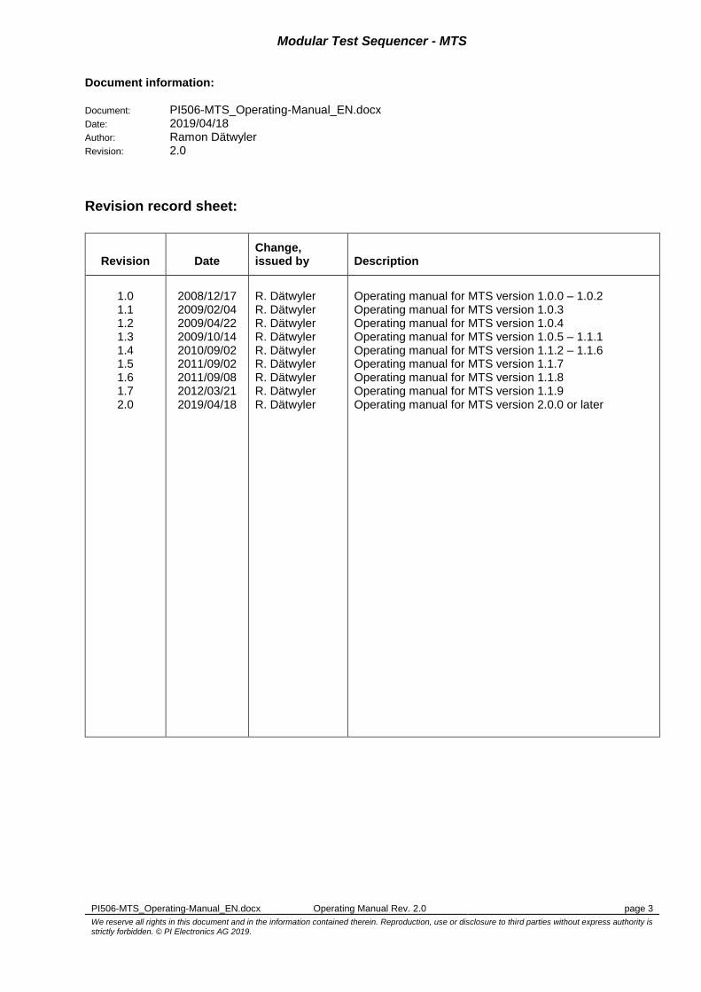
Document information: Document: PI506-MTS_Operating-Manual_EN.docx Date: 2019/04/18 Author: Ramon Dätwyler Revision: 2.0
Revision record sheet:
Revision Date Change, issued by Description
1.0 1.1 1.2 1.3 1.4 1.5 1.6 1.7 2.0
2008/12/17 2009/02/04 2009/04/22 2009/10/14 2010/09/02 2011/09/02 2011/09/08 2012/03/21 2019/04/18
R. Dätwyler R. Dätwyler R. Dätwyler R. Dätwyler R. Dätwyler R. Dätwyler R. Dätwyler R. Dätwyler R. Dätwyler
Operating manual for MTS version 1.0.0 – 1.0.2 Operating manual for MTS version 1.0.3 Operating manual for MTS version 1.0.4 Operating manual for MTS version 1.0.5 – 1.1.1 Operating manual for MTS version 1.1.2 – 1.1.6 Operating manual for MTS version 1.1.7 Operating manual for MTS version 1.1.8 Operating manual for MTS version 1.1.9 Operating manual for MTS version 2.0.0 or later

Modular Test Sequencer - MTS
PI506-MTS_Operating-Manual_EN.docx Operating Manual Rev. 2.0 page 4
We reserve all rights in this document and in the information contained therein. Reproduction, use or disclosure to third parties without express authority is
strictly forbidden. © PI Electronics AG 2019.
Contents: 1 Terms ................................................................................................................................................ 6 2 Introduction ....................................................................................................................................... 7 3 Software operation ............................................................................................................................ 8
3.1 Installation ................................................................................................................................ 8 3.2 Program Start ........................................................................................................................... 8 3.3 License Manager ...................................................................................................................... 8
3.3.1 License types...................................................................................................................... 8 3.3.2 Development License ......................................................................................................... 8 3.3.3 Runtime License ................................................................................................................. 8
3.4 Login ......................................................................................................................................... 9 3.5 User Management .................................................................................................................. 10
3.5.1 Privilege levels.................................................................................................................. 10 3.5.2 Start User Manager .......................................................................................................... 10 3.5.3 User Groups ..................................................................................................................... 10 3.5.4 User Accounts .................................................................................................................. 11
3.6 Main Panel ............................................................................................................................. 12 3.7 Preconditions.......................................................................................................................... 13 3.8 New project/sequence ............................................................................................................ 13 3.9 Save/Save as… sequence ..................................................................................................... 13 3.10 Open project/sequence .......................................................................................................... 13 3.11 Sequence File Revisions ........................................................................................................ 13 3.12 Project structure ..................................................................................................................... 14 3.13 Modules .................................................................................................................................. 15 3.14 Miscellaneous......................................................................................................................... 15 3.15 Variables ................................................................................................................................ 15
3.15.1 Variable data types ........................................................................................................... 15 3.15.2 System variables .............................................................................................................. 16 3.15.3 User variables................................................................................................................... 16 3.15.4 Set variable value ............................................................................................................. 17
3.16 Sequence Table ..................................................................................................................... 17 3.16.1 Table Columns ................................................................................................................. 17 3.16.2 Main Sections ................................................................................................................... 18
3.17 Sequence Compilation ........................................................................................................... 18 3.18 Step Configuration ................................................................................................................. 18
3.18.1 Common items ................................................................................................................. 18 3.18.2 Module .............................................................................................................................. 19 3.18.3 Section .............................................................................................................................. 21 3.18.4 Variable ............................................................................................................................ 22 3.18.5 Loop .................................................................................................................................. 24
3.19 Test Operation........................................................................................................................ 24 3.19.1 Start .................................................................................................................................. 24 3.19.2 Step .................................................................................................................................. 24 3.19.3 Stop .................................................................................................................................. 24 3.19.4 Results Table.................................................................................................................... 24
3.20 Commissioning and debugging options ................................................................................. 25 3.20.1 Breakpoints ....................................................................................................................... 25 3.20.2 Debugging steps............................................................................................................... 26 3.20.3 Slow down execution speed ............................................................................................. 26 3.20.4 Force sequence to continue in any case .......................................................................... 26
3.21 Result Files ............................................................................................................................. 27 3.21.1 File storage ....................................................................................................................... 27 3.21.2 Format .............................................................................................................................. 27 3.21.3 Edit header / footer ........................................................................................................... 27
3.22 Program options ..................................................................................................................... 28 3.23 Program exit ........................................................................................................................... 28 3.24 Program shortcuts .................................................................................................................. 29
4 Appendix ......................................................................................................................................... 30 4.1 Guidelines for LabVIEW modules .......................................................................................... 30

Modular Test Sequencer - MTS
PI506-MTS_Operating-Manual_EN.docx Operating Manual Rev. 2.0 page 5
We reserve all rights in this document and in the information contained therein. Reproduction, use or disclosure to third parties without express authority is
strictly forbidden. © PI Electronics AG 2019.
4.1.1 Using the variable Step.Attachment ................................................................................. 30 4.2 Supported interface data types for LabVIEW modules .......................................................... 30
4.2.1 Boolean (BOOL) ............................................................................................................... 30 4.2.2 Signed Integer 64 Bit (I64) ............................................................................................... 30 4.2.3 Double Precision Floating-Point Number (DBL) ............................................................... 30 4.2.4 String (STR) ...................................................................................................................... 31
4.3 LabVIEW Format Specifiers ................................................................................................... 32 4.3.1 Format Specifiers Syntax Elements ................................................................................. 32
4.3.1.1 Format Codes for the Time Format String ................................................................. 33 4.3.2 Format Specifier Examples .............................................................................................. 34
4.4 How to create a Source Distribution or a Packed Library? .................................................... 35 4.4.1 Source Distribution ........................................................................................................... 35 4.4.2 Packed Library.................................................................................................................. 37
4.5 MTS application files .............................................................................................................. 42 4.6 Report Example ..................................................................................................................... 43
List of figures: Figure 1: System overview ...................................................................................................................... 7 Figure 2: License Manager Window ........................................................................................................ 8 Figure 3: Login ......................................................................................................................................... 9 Figure 4: Change Password .................................................................................................................... 9 Figure 5: User Manager main panel ...................................................................................................... 10 Figure 6: Group overview & Create new group ..................................................................................... 11 Figure 7: Create new user ..................................................................................................................... 11 Figure 8: Front Panel ............................................................................................................................. 12 Figure 9: New Test Sequence ............................................................................................................... 13 Figure 10: Project structure ................................................................................................................. 14 Figure 11: Add Variable ....................................................................................................................... 16 Figure 12: Overwrite a variable value .................................................................................................. 17 Figure 13: Sequence table .................................................................................................................. 17 Figure 14: Common configuration items ............................................................................................. 18 Figure 15: Module configuration: General ........................................................................................... 19 Figure 16: Module configuration: Pre Action ....................................................................................... 19 Figure 17: Module configuration: Module controls .............................................................................. 20 Figure 18: Module configuration: Post Action...................................................................................... 20 Figure 19: Module configuration: Evaluation ....................................................................................... 21 Figure 20: Variable configuration ........................................................................................................ 22 Figure 21: Formula expression ............................................................................................................ 22 Figure 22: Loop configuration .............................................................................................................. 24 Figure 23: Results Table ..................................................................................................................... 25 Figure 24: Set/clear breakpoint ........................................................................................................... 25 Figure 25: Select steps to run in debugging mode .............................................................................. 26 Figure 26: Flag to temporary ignore errors or failed status ................................................................. 26 Figure 27: Header/Footer definition ..................................................................................................... 28 Figure 28: Options dialog .................................................................................................................... 28 Figure 29: New Source Distribution ..................................................................................................... 35 Figure 30: Distribution Settings ........................................................................................................... 35 Figure 31: Additional Exclusions ......................................................................................................... 36 Figure 32: Test modules arranged as a project library ........................................................................ 37 Figure 33: Create a new Packed Library ............................................................................................. 37 Figure 34: Packed Library naming and destination paths ................................................................... 38 Figure 35: Packed Library source files selection ................................................................................. 38 Figure 36: Packed Library build destination path ................................................................................ 39 Figure 37: Packed Library source file settings .................................................................................... 39 Figure 38: Packed Library advanced build options ............................................................................. 40 Figure 39: Packed Library file exclusions ............................................................................................ 40 Figure 40: Packed Library pane compatibility ..................................................................................... 41 Figure 41: Packed Library version definition ....................................................................................... 41 Figure 42: Packed Library Pre/Post build actions ............................................................................... 42

Modular Test Sequencer - MTS
PI506-MTS_Operating-Manual_EN.docx Operating Manual Rev. 2.0 page 6
We reserve all rights in this document and in the information contained therein. Reproduction, use or disclosure to third parties without express authority is
strictly forbidden. © PI Electronics AG 2019.
1 Terms
Term Description
MTS Modular Test Sequencer
UUT Unit Under Test
VI Virtual Instrument (LabVIEW function)
LVLIB Labview library file
LVLIBP Packed LabVIEW library containing all member VI’s of the library
EOL End-of-line
OS Operating System

Modular Test Sequencer - MTS
PI506-MTS_Operating-Manual_EN.docx Operating Manual Rev. 2.0 page 7
We reserve all rights in this document and in the information contained therein. Reproduction, use or disclosure to third parties without express authority is
strictly forbidden. © PI Electronics AG 2019.
2 Introduction
The Modular Test Sequencer is a framework to create and run test sequences as well as to protocol the test results in a given, table-oriented format. The test sequence can be compiled by drag-and-dropping items from the selection boxes. Each test step within the sequence consists of either a LabVIEW VI (module) or another functional item. The step can be individually configured according to its type. A variable engine allows creating user defined variables in order to pass data from one step to another.
Figure 1: System overview

Modular Test Sequencer - MTS
PI506-MTS_Operating-Manual_EN.docx Operating Manual Rev. 2.0 page 8
We reserve all rights in this document and in the information contained therein. Reproduction, use or disclosure to third parties without express authority is
strictly forbidden. © PI Electronics AG 2019.
3 Software operation
3.1 Installation
To install the Modular Test Sequencer software run the executable “setup.exe” from the MTS Installation media and follow the instructions on the screen.
3.2 Program Start
Start the program by using the link PI Electronics AG -> Modular Test Sequencer -> Modular Test Sequencer in the Windows Start Menu. If you start the software for the first time it’s necessary to activate the program by entering a valid license code.
3.3 License Manager
To protect the software for illegal copies a license check is active. If the program is not activated yet the License Manager pops up:
Figure 2: License Manager Window
The ‘Hardware ID’: shows a unique ID of your computer system. To obtain a valid license key please send this 8-digit hex number to PI Electronics AG (E-mail: [email protected]). If you are an authorized user, PI Electronics AG will return you a valid license key for this computer. Optionally and to avoid typing errors you can save the ‘Hardware ID’ to an ASCII file by using the button ‘Export to File…’ and send the generated file to PI Electronics AG. After you received a valid license key enter the numbers into the mask or import it from a file by pressing ‘Import from File…’. Then press ‘Activate’ to license the product.
3.3.1 License types
MTS software includes two license types with different functional scope: Development License and Runtime License. The type of license which is activated and the license expiration date is shown in the header bar of the main window.
3.3.2 Development License
Development License includes the full range of functionality, i.e. create, run, edit and debug of a MTS project.
3.3.3 Runtime License
Runtime License only allows the user to run a sequence of given MTS project.

Modular Test Sequencer - MTS
PI506-MTS_Operating-Manual_EN.docx Operating Manual Rev. 2.0 page 9
We reserve all rights in this document and in the information contained therein. Reproduction, use or disclosure to third parties without express authority is
strictly forbidden. © PI Electronics AG 2019.
3.4 Login
After the program start the operator is prompted to enter the user name and password. After the installation, the two system user accounts ‘Administrator’ (full access) and ‘Guest’ (minimal access) are available (Default passwords: “”). Additional user accounts and passwords can be set up in the User Manager (chapter 3.5) by a user with administrator privileges.
Figure 3: Login
To change a password press button ‘More…’ and enter your old and new passwords:
Figure 4: Change Password

Modular Test Sequencer - MTS
PI506-MTS_Operating-Manual_EN.docx Operating Manual Rev. 2.0 page 10
We reserve all rights in this document and in the information contained therein. Reproduction, use or disclosure to third parties without express authority is
strictly forbidden. © PI Electronics AG 2019.
3.5 User Management
3.5.1 Privilege levels
The user management distinguishes between different levels of privileges. Each user belongs to a group with a privilege level in the range of 1...10. Members of groups of level 1 have the least privileges, those of level 10 the most. The privilege level controls the user access to certain parts of the program:
Remark: If a user cancels the login procedure then level 0 is applied and all parts of the program are inaccessible.
3.5.2 Start User Manager
To open the user manager press button ‘UserMgr…’ on the front panel. Since this part of the program requires administrator privileges (Level 10) you are prompted to login as user of a group of this level, unless you already logged in.
Figure 5: User Manager main panel
3.5.3 User Groups
Before setting up new user profiles the user groups must be defined. Press the button ‘Groups’ to open the group editor.
Level 10 9 8 7 6 5 4 3 2 1
Change user accounts X
Create new sequence/project X X X X X
Open sequence X X X X X X X X X X
Save sequence X X X X X
Edit sequence X X X X X
Configure steps X X X X X
Add/Remove modules X X X X X
Add/Remove variables X X X X X
Edit Header/Footer X X X X X
Start sequence X X X X X X X X X X
Stop sequence X X X X X X X X X X
Step sequence X X X X X
View Results X X X X X X X X X X
Open Help X X X X X X X X X X
Change options X X X X X
Breakpoint/Debugging options X X X X X

Modular Test Sequencer - MTS
PI506-MTS_Operating-Manual_EN.docx Operating Manual Rev. 2.0 page 11
We reserve all rights in this document and in the information contained therein. Reproduction, use or disclosure to third parties without express authority is
strictly forbidden. © PI Electronics AG 2019.
Figure 6: Group overview & Create new group
Press button ‘Add…’ to create a new group and assign a privilege level to the group. To delete a group, press ‘Remove’. Remark: Group Administrators & Guests are system groups cannot be deleted. Press ‘Ok’ to return to the User Manager Main Panel.
3.5.4 User Accounts
After all groups are set up, new users can be created by pressing ‘Add…’. Enter a new user name and assign it to a group. Then enter and confirm a password for this user. After creating all users press ‘Ok’ to return to the User Manager main panel.
Figure 7: Create new user
To edit the group or password of an existing user press button ‘Password’ in the User Manager main panel and change the settings for that user.

Modular Test Sequencer - MTS
PI506-MTS_Operating-Manual_EN.docx Operating Manual Rev. 2.0 page 12
We reserve all rights in this document and in the information contained therein. Reproduction, use or disclosure to third parties without express authority is
strictly forbidden. © PI Electronics AG 2019.
3.6 Main Panel
Both test sequence configuration and execution can be done from the following user interface:
Figure 8: Front Panel
1 Test Info: Shows the current user name, project name and sequence name
2 Status Info: Shows the current state of the sequencer
3 File Handling: Buttons to open/save sequences and to create new sequences
4 User Management: Buttons to log in or user management
5 Run Controls: Buttons to run, step or stop the test sequence
6 Checkboxes for debugging during commissioning
7 Program options and help
8 Modules: Shows the available LabVIEW modules
9 Miscellaneous: Shows the available non-module step types
10 Sequence: Table to compile the test sequence
11 Variables: Shows the available system and user variables
12 Configuration/Results: Panel to configure a single test step or to show test results
1 2
3 4 5
8
9
10
11
12
6 7

Modular Test Sequencer - MTS
PI506-MTS_Operating-Manual_EN.docx Operating Manual Rev. 2.0 page 13
We reserve all rights in this document and in the information contained therein. Reproduction, use or disclosure to third parties without express authority is
strictly forbidden. © PI Electronics AG 2019.
3.7 Preconditions
Before creating or executing a test sequence, the following preparations must have been made: The modules are created and distributed (see chapter 4.4) All necessary drivers for the above modules are installed (e.g. DAQmx, VISA, …)
3.8 New project/sequence
To create a new project or sequence press button ‘New…’ (Shortcut: Ctrl+N). The following window will pop up:
Figure 9: New Test Sequence
Use the Browse-Button to select or create a project folder and define a name for the test sequence. This will create a new project structure (if not existing) and an empty test sequence within the project.
3.9 Save/Save as… sequence
To save the current test sequence, press ‘Save’ (Shortcut: Ctrl+S). To save a copy of the sequence in the project press ‘Save as…’ and enter a new name.
3.10 Open project/sequence
To open an existing sequence, press ‘Open…’ (Shortcut: Ctrl+O) and navigate to the desired sequence. The MTS framework will automatically switch to the navigated project and load its modules into memory.
3.11 Sequence File Revisions
Each sequence file is provided with an internal revision number in order to exactly identify the version of the file. This is necessary since changes to the sequence might be made even after series of units have already been tested, while the file name of the test sequence remains the same. When you create a new sequence the revision will be 1 and increases by 1 each time modifications are saved. The revision of the file is visible in the title bar following the file name. The revision information is also available as a predefined variable called ‘TestSequence.Rev’, which should be included in the header/footer of each Test Report (see 3.21.3).

Modular Test Sequencer - MTS
PI506-MTS_Operating-Manual_EN.docx Operating Manual Rev. 2.0 page 14
We reserve all rights in this document and in the information contained therein. Reproduction, use or disclosure to third parties without express authority is
strictly forbidden. © PI Electronics AG 2019.
3.12 Project structure
When a new project is initiated, a project folder (project name) and the two subfolders ‘Modules’ and ‘Results’ are created. The test sequences are stored in the project directory. The folder ‘Modules’ is used to store the test modules from a LabVIEW distribution. The test results (e.g. TAB separated ASCII file) are stored in the subfolder which is named after the sequence name in the ‘Results’ directory. Alongside a copy of the current sequence file is saved, in order to retain the dedicated version which produced the result files. Thus the file name of the copy is supplemented with the revision of the sequence file <sequence name>_Rev<revision>.mtsq. If the test was running with unsaved sequence changes (which should be avoided) the name gets an additional ‘m’ following the revision number <sequence name>_Rev<revision>m.mtsq.
Figure 10: Project structure
Projects
PSCB
<Project X>
Modules
Results
DAQ_AO.vi
DAQ_AI.vi
<X>.vi
NA571A.txt
NA571B.txt
<X>.txt
PSCB.mtsq
<X>.mtsq
PSCB
<Seq. X>
PSCB_Rev015.mtsq
PSCB_Rev018.mtsq
Revision Sequence files
Sequence files
Result files
LabVIEW module files (distribution)
Modular Test Sequencer - MTS
PI506-MTS_Operating-Manual_EN.docx Operating Manual Rev. 2.0 page 15
We reserve all rights in this document and in the information contained therein. Reproduction, use or disclosure to third parties without express authority is
strictly forbidden. © PI Electronics AG 2019.
3.13 Modules
There are two possibilities to add LabVIEW functions from the distribution to the ‘Modules’ selection box (see chapter 4.4 for more information about creation of a source distribution or packed library):
a) Copy the VI’s and packed libraries (*.lvlibp) from the distribution manually to the project’s ‘Modules’ folder. Then reopen the sequence file to load the copied modules into the memory by using ‘Open…’.
b) Press (+) to browse to the distribution and select all the VI’s in the folder or select a packed library (*.lvlibp). The modules are automatically copied to the project and loaded into memory.
To remove a module from the ‘Modules’ selection box press (-). The file will be deleted in the project’s ‘Modules’ folder (not possible with modules inside packed libraries).
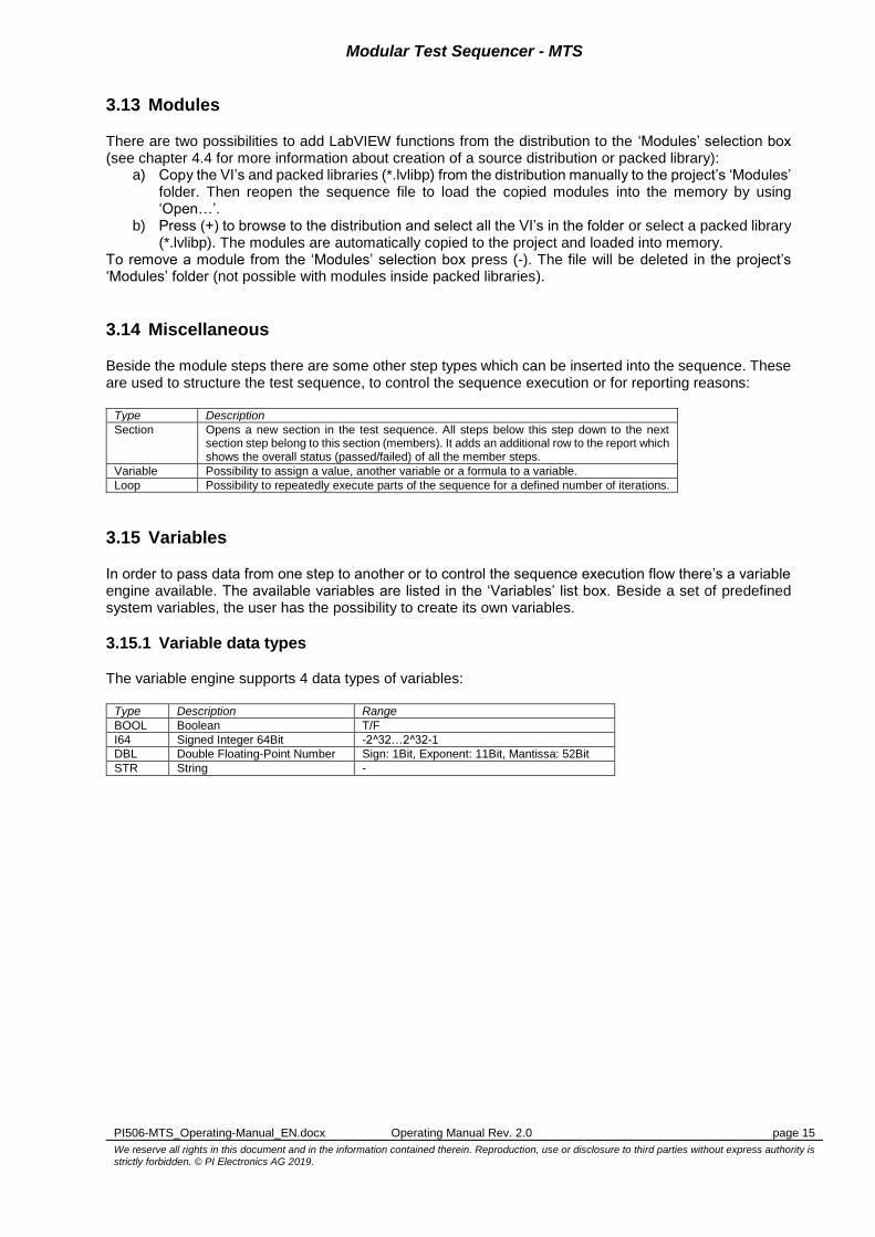
3.14 Miscellaneous
Beside the module steps there are some other step types which can be inserted into the sequence. These are used to structure the test sequence, to control the sequence execution or for reporting reasons:
Type Description
Section Opens a new section in the test sequence. All steps below this step down to the next section step belong to this section (members). It adds an additional row to the report which shows the overall status (passed/failed) of all the member steps.
Variable Possibility to assign a value, another variable or a formula to a variable.
Loop Possibility to repeatedly execute parts of the sequence for a defined number of iterations.
3.15 Variables
In order to pass data from one step to another or to control the sequence execution flow there’s a variable engine available. The available variables are listed in the ‘Variables’ list box. Beside a set of predefined system variables, the user has the possibility to create its own variables.
3.15.1 Variable data types
The variable engine supports 4 data types of variables:
Type Description Range
BOOL Boolean T/F
I64 Signed Integer 64Bit -2^32…2^32-1
DBL Double Floating-Point Number Sign: 1Bit, Exponent: 11Bit, Mantissa: 52Bit
STR String -

Modular Test Sequencer - MTS
PI506-MTS_Operating-Manual_EN.docx Operating Manual Rev. 2.0 page 16
We reserve all rights in this document and in the information contained therein. Reproduction, use or disclosure to third parties without express authority is
strictly forbidden. © PI Electronics AG 2019.
3.15.2 System variables
The variable engine provides a set of predefined system variables which can be accessed in each step:
Name Type Description
Step.Name STR Name of the current step
Step.Value DBL Value of the current step
Step.HighLimit DBL High Limit parameter which can be used for result evaluation
Step.LowLimit DBL Low Limit parameter which can be used for result evaluation
Step.Status BOOL Status of the current step (TRUE=passed, FALSE=failed)
Step.Attachment STR Report attachment of the current step
Section.Status BOOL Status of the current section (TRUE=passed, FALSE=failed)
UUT.Status BOOL Status of the current UUT (TRUE=passed, FALSE=failed)
UUT.StatusString STR UUT.Status as passed/failed-String
UUT.Stop BOOL Stop-Flag for the current UUT
UUT.Counter I64 Number of currently tested UUT’s
UUT.S/N STR Serial number of the current UUT
UUT.StartDate STR Date of the Test-Begin for the current UUT
UUT.StartTime STR Time of the Test-Begin for the current UUT
UUT.StopDate STR Date of the Test-End for the current UUT
UUT.StopTime STR Time of the Test-End for the current UUT
UUT.ExeTime STR Test execution time in seconds for the current UUT
UUT.ResultFileName STR Name of the result file
Operator STR Name of the logged-in user
StationID STR Name of the current computer
Project.Dir STR Directory path of the sequence
TestResults.Dir STR Directory path where results are stored
TestSequence STR Name of the current test sequence
TestSequence.Rev I64 Revision of the current test sequence
TestModules.Dir STR Directory path of the modules
TestModules.Libraries STR List of loaded libraries with versions (comma separated)
Loop.Count I64 Number of total iterations for the current loop
Loop.Iteration I64 Iteration index of the current loop
PostStepDelay I64 Global wait time in milliseconds after a module has been executed
3.15.3 User variables
The variable engine allows the user to create its own variables which can be accessed in each step. A new variable can be created using the button (+) or double-click on an empty row:
Figure 11: Add Variable
Enter name for the variable and select its type, then press ‘OK’. To remove a variable from the list, select the variable and press (-) or hit ‘Delete’. To change a variable, select the variable and press the ‘Edit’ button or hit ‘Space’. Note: System variables cannot be deleted nor changed.

Modular Test Sequencer - MTS
PI506-MTS_Operating-Manual_EN.docx Operating Manual Rev. 2.0 page 17
We reserve all rights in this document and in the information contained therein. Reproduction, use or disclosure to third parties without express authority is
strictly forbidden. © PI Electronics AG 2019.
3.15.4 Set variable value
The value of the variable are updated during sequence execution. However, for sequence commissioning and debugging it might necessary to manually set a variable to a certain value. This can be done by pressing button ‘Overwrite value’:
Figure 12: Overwrite a variable value
Enter the new value for the variable, then press ‘OK’.
3.16 Sequence Table
The sequence table is the place where the different test steps are compiled to a sequence. The color of a step indicates its type: Module steps are black, Section steps italic blue, Variable steps magenta and Loop structures brown. Skipped steps appear in grey color.
Figure 13: Sequence table
3.16.1 Table Columns
The table is divided into the four columns Step name, Step flags, Conditions and Module: Step name: Shows the name of the step, which can be modified in the step configuration.
Exception: Loop and main section step types. Step flags: Shows the settings of the result logging and error handling flags for module step type.
Shortcut Flag
CK Check limits
LD Log data
LS Log result status
SF Stop if test failed
SE Stop upon module error
HD Add column header
Conditions: Shows the ‘Conditions’ user text for module step types, the ‘Loop Count’ for loop step
types or the variable value assignments for variable step types. Module: Shows the module file name for module step types.

Modular Test Sequencer - MTS
PI506-MTS_Operating-Manual_EN.docx Operating Manual Rev. 2.0 page 18
We reserve all rights in this document and in the information contained therein. Reproduction, use or disclosure to third parties without express authority is
strictly forbidden. © PI Electronics AG 2019.
3.16.2 Main Sections
Every test sequence is structured in 3 main sections: Pre-UUT’s: Steps in this section are executed once only at the beginning of the test. UUT: This is the core part of the sequence. Steps in this section are repeatedly executed for each
UUT. After the last step in the UUT section has been executed it will automatically jump back to the first step in this section. So, ensure that the first step in this section is a dialog step, which allows the user to install the next UUT.
Post-UUT’s: Steps in this section are executed once only at the end of the test (after all UUT’s have been tested). The end of the test can be induced by a user stop command (variable UUT.Stop=TRUE), a module error or a failed test step.
3.17 Sequence Compilation
To insert a new step to the sequence simply drag an items from the ‘Modules’ or the ‘Miscellaneous’ selection box and drop it in the sequence table. Then drag the inserted step to the correct position within the test sequence and configure it.
3.18 Step Configuration
Depending on the step type, there are different editors to configure the step. However, some configuration items are common for all step types. Select the ‘Configuration’ tab of the Configuration/Results control.
3.18.1 Common items
The following configuration items are common for all step types:
Configuration item Description Default value
Step name Name of the current step. It will be added as test name in the report. You can use %d to include the iteration index into the name, if the step is placed in a loop structure. Put the text into quotation characters with optional format specifier (‘<Variable> [, <format specifier>]’) if you want to include a value from a variable.
“”
Skip If Skip is TRUE the step will not be executed. OFF
Conditions Allows the user to compose additional information for the test, which will also appear in the report (not available for Variable or Loop step types). Put the text into quotation characters with optional format specifier (‘<Variable> [, <format specifier>]’) if you want to include a value from a variable.
“”
Figure 14: Common configuration items

Modular Test Sequencer - MTS
PI506-MTS_Operating-Manual_EN.docx Operating Manual Rev. 2.0 page 19
We reserve all rights in this document and in the information contained therein. Reproduction, use or disclosure to third parties without express authority is
strictly forbidden. © PI Electronics AG 2019.
3.18.2 Module
General: Shows the full path, icon and description of the module. If you want to substitute the module for this step press ‘Replace…’ and select the new module. The framework tries to reassign configuration values from the former module by cross-checking label names and types. However, always check the control values of the module as described below when exchanging a module.
Figure 15: Module configuration: General
Pre Action: Value assignment from variables to module controls before the module is executed. Use the corresponding button to add (‘Insert’), remove (‘Delete’) or edit (‘Space’) assignments.
Figure 16: Module configuration: Pre Action
Note: Depending on the type of the selected variable only type-compatible controls are listed in the control selection box.

Modular Test Sequencer - MTS
PI506-MTS_Operating-Manual_EN.docx Operating Manual Rev. 2.0 page 20
We reserve all rights in this document and in the information contained therein. Reproduction, use or disclosure to third parties without express authority is
strictly forbidden. © PI Electronics AG 2019.
Module: Change the controls directly on the module’s front panel. The module is executed with these control settings, unless a certain control is changed by a Pre-Action.
Figure 17: Module configuration: Module controls
Post Action: Value assignment from module indicators to variables after the module has been executed. Use the corresponding button to add (‘Insert’ key), remove (‘Delete’ key) or edit (‘Space’ key) assignments. Consider: Depending on the type of the selected indicator only type-compatible variables are listed in the variable selection box.
Figure 18: Module configuration: Post Action
Note: Depending on the type of the selected indicator only type-compatible variables are listed in the variable selection box.

Modular Test Sequencer - MTS
PI506-MTS_Operating-Manual_EN.docx Operating Manual Rev. 2.0 page 21
We reserve all rights in this document and in the information contained therein. Reproduction, use or disclosure to third parties without express authority is
strictly forbidden. © PI Electronics AG 2019.
Evaluation: In this page the settings for the evaluation of the measured value and the report entry are made.
Configuration item Description Default value
Unit Unit of the measured value “”
Check limits Checks the measured value (Step.Value) against a range OFF
Limit Mode Limit range can be fix using Minimum/Maximum parameter or dynamically by using the System variable Step.HighLimit/Step.LowLimit
Fix Limits
Minimum Lower limit of the range when using Fix Limits mode -Inf
Maximum Upper limit of the range when using Fix Limits mode +Inf
Stop if test failed Aborts the execution if the limit check failed OFF
Stop upon module error Aborts the execution if a module error occurred (error out) ON
Log data Adds the measured value to the report OFF
Format Sets the display format for the reported value and limits %.2f
Log result status Adds the result status to the report OFF
Add column header Adds a column header row to the report (before the result row of the current step)
OFF
Figure 19: Module configuration: Evaluation
3.18.3 Section
Beside the common configuration no other settings have to be made. Sections are always added to the report (incl. section status).

Modular Test Sequencer - MTS
PI506-MTS_Operating-Manual_EN.docx Operating Manual Rev. 2.0 page 22
We reserve all rights in this document and in the information contained therein. Reproduction, use or disclosure to third parties without express authority is
strictly forbidden. © PI Electronics AG 2019.
3.18.4 Variable
This step type is used to assign constant values, variables or formula to variables. Use the corresponding button to add (‘Insert’ key), remove (‘Delete’ key) or edit (‘Space’ key) assignments.
Figure 20: Variable configuration
Value: To assign a constant value, simply enter it as normal text. The value will be interpreted according to the assigned variable. Variable: To assign a value containing from another variable use quotation characters (‘<Variable>’) to reference the variable. For strings (STR) it’s possible to concatenate constant text parts with variable values. Formula: To assign a value resulting from a formula the expression must start with the prefix “f=” to distinct it from normal text. The result value will be interpreted according to the assigned variable.
Figure 21: Formula expression

Modular Test Sequencer - MTS
PI506-MTS_Operating-Manual_EN.docx Operating Manual Rev. 2.0 page 23
We reserve all rights in this document and in the information contained therein. Reproduction, use or disclosure to third parties without express authority is
strictly forbidden. © PI Electronics AG 2019.
Variables can be referenced within a formula by using quotation characters (‘<Variable>’). Below a table for all available operators and functions.
Operator Description
+, - unary plus, unary negation ++ and -- are NOT available.
^ exponentiation ** is NOT available
*, / multiplication, division + and – addition and subtraction
Function Description
abs(x) Returns the absolute value of x.
acos(x) Computes the inverse cosine of x in radians.
acosh(x) Computes the inverse hyperbolic cosine of x.
asin(x) Computes the inverse sine of x in radians.
asinh(x) Computes the inverse hyperbolic sine of x.
atan(x) Computes the inverse tangent of x in radians.
atan2(y,x) Computes the arctangent of y/x in radians.
atanh(x) Computes the inverse hyperbolic tangent of x.
ceil(x) Rounds x to the next higher integer (smallest integer >= x).
cos(x) Computes the cosine of x, where x is in radians.
cosh(x) Computes the hyperbolic cosine of x.
cot(x) Computes the cotangent of x (1/tan(x)), where x is in radians.
csc(x) Computes the cosecant of x (1/sin(x)), where x is in radians.
exp(x) Computes the value of e raised to the x power.
expm1(x) Computes one less than the value of e raised to the x power ((e^x) – 1).
floor(x) Truncates x to the next lower integer (largest integer <= x).
getexp(x) Returns the exponent of x.
getman(x) Returns the mantissa of x.
int(x) Rounds x to the nearest integer.
Intrz(x) Rounds x to the nearest integer between x and zero.
ln(x) Computes the natural logarithm of x (to the base of e).
lnp1(x) Computes the natural logarithm of (x + 1).
log(x) Computes the logarithm of x (to the base of 10).
log2(x) Computes the logarithm of x (to the base of 2).
pi(1) Returns the value of constant π, pi(2) = 2π. 2pi or 2(pi) will return an error
pow(x,y) Computes x raised to the y power.
rand( ) Produces a floating-point number between 0 and 1 exclusively.
sec(x) Computes the secant of x, where x is in radians (1/cos(x)).
sign(x) Returns 1 if x is greater than 0, returns 0 if x is equal to 0, and returns –1 if x is less than 0.
sin(x) Computes the sine of x, where x is in radians.
sinc(x) Computes the sine of x divided by x (sin(x)/x), where x is in radians.
sinh(x) Computes the hyperbolic sine of x.
sqrt(x) Computes the square root of x.
tan(x) Computes the tangent of x, where x is in radians.
tanh(x) Computes the hyperbolic tangent of x.

Modular Test Sequencer - MTS
PI506-MTS_Operating-Manual_EN.docx Operating Manual Rev. 2.0 page 24
We reserve all rights in this document and in the information contained therein. Reproduction, use or disclosure to third parties without express authority is
strictly forbidden. © PI Electronics AG 2019.
3.18.5 Loop
If you drag a loop step from the ‘Miscellaneous’ selection box into the sequence table two steps, a ‘Loop-Begin’ and a ‘Loop-End’ step is inserted. The steps inside the ‘Loop-Begin’ and ‘Loop-End’ steps are repeated for the configured number of iterations (‘Loop Count’), which is set in the ‘Loop-Begin’ step.
Figure 22: Loop configuration
3.19 Test Operation
In order to run a test sequence, always ensure that the correct sequence file is loaded and the hardware test setup is properly installed.
3.19.1 Start
Generally, the sequencer always starts the test sequence from the first step in Pre-UUT’s by pressing the button ‘Start [F6]’. However, if the user has a privilege level above 5 the test execution starts at the currently selected row! Keep in mind that some variables might not be initialized or a device might be still under voltage by previous step executions! This feature allows advanced users to start the sequence at a certain point. If no row is selected it starts regularly at the first step in Pre-UUT’s. Before starting to test series of UUT’s always ensure that the last sequence changes are saved in order to be able to associate the generated test results to a certain test sequence revision!
3.19.2 Step
This is feature is for users with privilege level above 5. It allows running the test sequence or parts of it step by step by pressing the button ‘Step [F7]’. Keep in mind that some variables might not be initialized or a device might be still under voltage by previous step executions!
3.19.3 Stop
If you press the button ‘Stop [F8]’ the sequencer always jumps to the Post-UUT’s section and executes the steps inside this section. The test sequence is then stopped.
3.19.4 Results Table
During the execution of steps the current results are displayed in the Results page of the Configuration / Results control according to the step’s report configuration. A result line is always displayed as 7 columns:
Column Description
Name Name of the test step
Conditions Conditions text of the module configuration as explained in chapter 0
Unit Unit of the measured value
Min. Value Lower limit for the test
Max. Value Upper limit for the test
Act. Value Actual measured value
Status Test status (passed/failed)

Modular Test Sequencer - MTS
PI506-MTS_Operating-Manual_EN.docx Operating Manual Rev. 2.0 page 25
We reserve all rights in this document and in the information contained therein. Reproduction, use or disclosure to third parties without express authority is
strictly forbidden. © PI Electronics AG 2019.
The current UUT status is displayed within the ‘Overall UUT Status’ field. The test and error status of the last executed test step are displayed within the ‘Last Step Status’ field. If flag ‘Show result popup after each UUT’ is set, the sequencer shows the result status of the UUT at the end of the test sequence. After one UUT has been completely tested, the sequencer will immediately loop back to the first step in the UUT section, without giving the user the possibility to have a look at the test results. Therefore, by setting the flag ‘Pause execution after each UUT’ the run process can be halted at this point. To continue with the next UUT simply press ‘Start [F6]’ again.
Figure 23: Results Table
3.20 Commissioning and debugging options
The following options are for users with privileges above 5. All commissioning/debugging settings are temporary and are not stored to the sequence file.
3.20.1 Breakpoints
In order to pause test execution at a certain step, one can set/clear a breakpoint by clicking the corresponding row left to the step name.
Figure 24: Set/clear breakpoint

Modular Test Sequencer - MTS
PI506-MTS_Operating-Manual_EN.docx Operating Manual Rev. 2.0 page 26
We reserve all rights in this document and in the information contained therein. Reproduction, use or disclosure to third parties without express authority is
strictly forbidden. © PI Electronics AG 2019.
3.20.2 Debugging steps
In order to execute only a certain set of steps, one has the option to change debugging mode by activating ‘Debug’, check-marking the corresponding steps and pressing ‘Start’. To continuously repeat the sequence of steps additionally activate ‘Loop’. Note: The sequencer always starts at the currently selected row (not the first check-marked row)
Figure 25: Select steps to run in debugging mode
3.20.3 Slow down execution speed
To slow down execution process for a closer investigation of a matter, there is the possibility by manually setting the system variable ‘PostStepDelay’ (see 3.15.2 and 3.15.4)
3.20.4 Force sequence to continue in any case
To avoid abortion of the sequence due to an always failing step or a module error one has the option to set flag ‘Force sequence to continue in any case’
Figure 26: Flag to temporary ignore errors or failed status

Modular Test Sequencer - MTS
PI506-MTS_Operating-Manual_EN.docx Operating Manual Rev. 2.0 page 27
We reserve all rights in this document and in the information contained therein. Reproduction, use or disclosure to third parties without express authority is
strictly forbidden. © PI Electronics AG 2019.
3.21 Result Files
3.21.1 File storage
The result file of each UUT is stored in a subfolder in the ‘Results’ directory of the current project. The subfolder is named after the sequence file. The result file name is built by using the value of the ‘UUT.S/N’ variable (i.e. <UUT.S/N>.<ext>). If this variable is empty, the 9-digit value of the ‘UUT.Counter’ variable is taken for the file name which is increasing with each UUT (<UUT.Counter>.<ext>). Generally, if a file already exists, an increasing 3-digit index is appended to the file name to avoid overwriting (<ExistingName>_<iii>.<ext>). The file extension (<ext>) is depending on the result file type, which can be defined in application INI file (see 12)). Note: A result file will be generated if there are any entries are available in the Results Table (incl. column header or section rows). If the table remains empty, no file is written.
3.21.2 Format
The default format of the result file is based on a table-oriented ASCII file; its columns are separated by a TAB character. The settings can be changed in the program options (see 12). Lines are terminated by the OS-depending end-of-line character(s) a CR character (carriage return). The file is structured into the 3 sections header, test and footer. Header and footer section are user definable and always have 2 columns, where the test section contains all the results of the test. Optionally, the results can be stored as an Excel sheet (see 3.22).
Header
Test Conditions Unit Min. Value Max. Value Act. Value Status
Footer
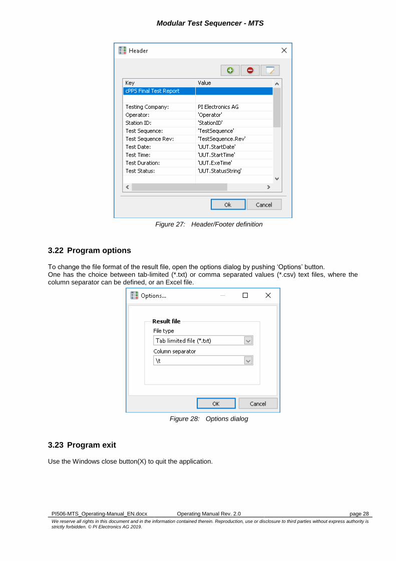
3.21.3 Edit header / footer
To include a customized header/footer in the report press button ‘Edit Header…’/‘Edit Footer…’. The header/footer section has a fixed 2-column format. It allows the user to include values of program variables or simple texts in the form key -> value. Use the corresponding button to add (‘Insert’ key), remove (‘Delete’ key) or edit (‘Space’ key) assignments. Put the text into quotation characters with optional format specifier (‘<Variable> [, <format specifier>]’) if you want to reference to a variable. It’s also possible to leave both fields empty in order to add some space lines. It’s strongly recommended to include the sequence revision variable (‘TestSequence.Rev’) in the result file header or footer (see example 4.6).
Modular Test Sequencer - MTS
PI506-MTS_Operating-Manual_EN.docx Operating Manual Rev. 2.0 page 28
We reserve all rights in this document and in the information contained therein. Reproduction, use or disclosure to third parties without express authority is
strictly forbidden. © PI Electronics AG 2019.
Figure 27: Header/Footer definition
3.22 Program options
To change the file format of the result file, open the options dialog by pushing ‘Options’ button. One has the choice between tab-limited (*.txt) or comma separated values (*.csv) text files, where the column separator can be defined, or an Excel file.
Figure 28: Options dialog
3.23 Program exit
Use the Windows close button(X) to quit the application.

Modular Test Sequencer - MTS
PI506-MTS_Operating-Manual_EN.docx Operating Manual Rev. 2.0 page 29
We reserve all rights in this document and in the information contained therein. Reproduction, use or disclosure to third parties without express authority is
strictly forbidden. © PI Electronics AG 2019.
3.24 Program shortcuts
For easier operation of the most important program functions some keyboard shortcuts are provided:
Function Shortcut
New project/sequence Ctrl+N
Open sequence Ctrl+O
Save sequence Ctrl+S
Login Ctrl+L
User manager Ctrl+U
Options dialog Ctrl+M
Open Help File F1
Start sequence F6
Step sequence F7
Stop sequence F8
Add item Insert
Remove item Delete
Edit item Space

Modular Test Sequencer - MTS
PI506-MTS_Operating-Manual_EN.docx Operating Manual Rev. 2.0 page 30
We reserve all rights in this document and in the information contained therein. Reproduction, use or disclosure to third parties without express authority is
strictly forbidden. © PI Electronics AG 2019.
4 Appendix
4.1 Guidelines for LabVIEW modules
Generally, no special conventions must be followed to integrate LabVIEW into the sequencer. However, the following guidelines will improve the compatibility with the MTS framework:
Do NOT use arrays for front panel controls/indicators, so the module can interface with the MTS framework (see chapter 4.2).
Controls/indicators with cluster structures are allowed. Atomic data elements inside structures are referenced as <cluster label name>.<…>.<atomic element label name> by the framework.
To pass errors from the module to the framework (module error), the standard error output cluster must be named to ‘error out’ (label name).
Do not use ‘Open Front Panel when called’ in the window properties, since it has no effect for dynamically called VI’s. Use property nodes instead, if you wish a front panel to open.
4.1.1 Using the variable Step.Attachment
Since the result evaluation of the MTS framework is based on a fixed data type (Step.Result), it’s sometimes necessary to process the evaluation inside the module step (e.g. if the measured value is an array). In this case it’s possible to format the result table as TAB separated text inside the module and pass it to the ‘Step.Attachment’ variable in a post action variable assignment. In this way the module’s implicit result values are added to the result file. It’s advantageous to stick to the MTS result format for the internally created result table in order to get a proper report (7 columns).
4.2 Supported interface data types for LabVIEW modules
In order to pass data from MTS framework variables to the LabVIEW module’s atomic control elements or vice-versa numerous data types are allowed which are compatible with the four variable data types (chapter 3.15.1):
4.2.1 Boolean (BOOL)
Name Shortcut LabVIEW type code (decimal)
Boolean BOOL 33
4.2.2 Signed Integer 64 Bit (I64)
Name Shortcut LabVIEW type code (decimal)
Signed Integer 8Bit I8 1
Signed Integer 16Bit I16 2
Signed Integer 32Bit I32 3
Signed Integer 64Bit I64 4
Unsigned Integer 8Bit U8 5
Unsigned Integer 16Bit U16 6
Unsigned Integer 32Bit U32 7
Enumerated Integer 8Bit Enum8 21
Enumerated Integer 16Bit Enum16 22
Enumerated Integer 32Bit Enum32 23
4.2.3 Double Precision Floating-Point Number (DBL)
Name Shortcut LabVIEW type code (decimal)
Single Precision Floating-Point Number SGL 9
Double Precision Floating-Point Number DBL 10
Modular Test Sequencer - MTS
PI506-MTS_Operating-Manual_EN.docx Operating Manual Rev. 2.0 page 31
We reserve all rights in this document and in the information contained therein. Reproduction, use or disclosure to third parties without express authority is
strictly forbidden. © PI Electronics AG 2019.
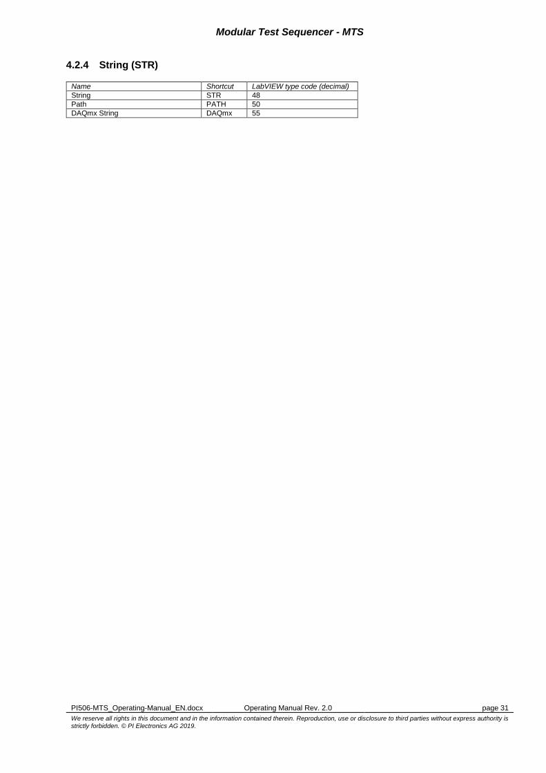
4.2.4 String (STR)
Name Shortcut LabVIEW type code (decimal)
String STR 48
Path PATH 50
DAQmx String DAQmx 55

Modular Test Sequencer - MTS
PI506-MTS_Operating-Manual_EN.docx Operating Manual Rev. 2.0 page 32
We reserve all rights in this document and in the information contained therein. Reproduction, use or disclosure to third parties without express authority is
strictly forbidden. © PI Electronics AG 2019.
4.3 LabVIEW Format Specifiers
For conversion of any variable into reported text you can use LabVIEW format specifiers in the form ‘<Variable>, <format specifier>). For functions that produce a string as an output, a format specifier uses the following syntax elements. Double brackets ( [] ) enclose optional elements. %[$][-][+][#][^][0][<Width>][.<Precision> | _<SignificantDigits>]Conversion Code where <Width> must be a number greater than zero and .Precision and <SignificantDigits> must be a number greater than or equal to zero.
4.3.1 Format Specifiers Syntax Elements
The following table displays the syntax elements for format specifiers. Refer to the examples in chapter 4.3.2 for more information.
Syntax Element Description
% Begins the format specifier.
$ (optional) When you use a formatting function, this modifier specifies the order in which to display variables. Include the digit that represents the order of the variable immediately before this modifier.
- (optional) When you use a formatting function, this modifier left justifies the parameter rather than right justifies it within its width.
+ (optional) When you use a formatting function, this modifier includes sign even when the number is positive.
^ (optional) When you use a formatting function and the e or g conversion codes, this element formats the number in engineering notation, where the exponent is always a multiple of three.
# (optional) When you use a formatting function, this modifier removes trailing zeros. If the number has no fractional part, this modifier also removes the description part.
0 (optional) When you use a formatting function, use this modifier without the - modifier to pad any excess space to the left of a numeric parameter with zeros rather than with spaces to reach minimum width.
Width (optional) When you use a formatting function, the Width element specifies the minimum character field width of the output. This width is not a maximum width. LabVIEW uses as many characters as necessary to format the parameter without truncating it. LabVIEW pads the field to the left or right of the parameter with spaces, depending on justification. If Width is missing or 0, the output is only as long as necessary to contain the converted input parameter.
.Precision or _Significant Digits (optional)
When you use a formatting function, . or _ controls the number of digits displayed. If you use ., LabVIEW uses the number that follows as a precision specifier for digits to the right of the decimal point. If you use _, LabVIEW uses the number that follows as the specified number of significant digits to use in the display format. .Precision—When you use it with floating-point notation, this element specifies the number of digits to the right of the decimal point. If . is not present, LabVIEW uses a precision of six digits. If . is 0, LabVIEW does not insert a precision. When you use it with string parameters, .Precision specifies the maximum width of the scanned field. LabVIEW truncates strings longer than this length. _Significant Digits—Displays the data by rounding to the number of digits you specify. LabVIEW rounds the data only for display purposes, which does not affect the original data. .Precision affects only the digits to the right of the decimal point, and _Significant Digits includes all non-spacing digits. For example,
3.457 has 4 significant digits
0.0012 has 2 significant digits
123000 has 3 significant digits
Note: You cannot use precision and significant digits together in a single format specifier.
For single-precision, floating-point numbers, National Instruments recommends that you use values from 1 to 6 for _Significant Digits. For double-precision and extended-precision, floating-point numbers, National Instruments recommends that you use values from 1 through 13 for _Significant Digits.
<Embedded Format Information>
Contains a time-specific format string. Refer to the chapter 4.3.1.1 for valid format strings. Only %W, %D, %H, %M, %S and %u apply to relative time.
Conversion Codes
Characters that specify how to scan or format a parameter.
Use the following conversion codes for integers and fixed-point numbers:
x—Hexadecimal integer (for example, B8).
o—Octal integer (for example, 701).
b—Binary integer (for example, 1011).
d—Signed decimal integer.
u—Unsigned decimal integer.

Modular Test Sequencer - MTS
PI506-MTS_Operating-Manual_EN.docx Operating Manual Rev. 2.0 page 33
We reserve all rights in this document and in the information contained therein. Reproduction, use or disclosure to third parties without express authority is
strictly forbidden. © PI Electronics AG 2019.
Use the following conversion codes for floating-point and fixed-point numbers:
f—Floating-point number with fractional format (for example, 12.345).
e—Floating-point number in scientific notation (for example, 1.234E1).
g—LabVIEW uses f or e depending on the exponent of the number. LabVIEW uses f if the exponent is greater than –4 or less than the precision specified. LabVIEW uses e if the exponent is less than –4 or greater than the precision specified.
p—Floating-point number in SI notation.
Use the following conversion codes for a string:
s—String (for example, abc). When scanning, s matches only up to the next white-space character. A space matches one or more consecutive white-space characters. To scan a string that may contain white space, use the characters in set conversion code. Specify all the characters which the string may contain within the brackets, including space or other white-space characters.
[ ]—Characters in set. [ ] matches a string that contains only the characters specified between the brackets. Character matches are case sensitive. The [ ] conversion code is useful only when you are scanning strings. To match the caret symbol (^) in a set, make sure it is not the first character after the bracket. The following examples demonstrate the use of the characters in set conversion code:
o %[aeiou]—Matches any string that contains only lowercase vowels.
o %[0-9a-zA-Z ]—Matches a string that contains numbers, letters, or spaces. You can use a hyphen to specify ranges of characters in the set.
o %[^,;]—Matches any string of characters up to but not including the first comma or semicolon.
To match a hyphen, specify it as the first or last character in the set.
Use the following conversion codes for time:
T—Absolute time. Refer to chapter 4.3.2 for examples of using absolute time.
t—Relative time. Refer to chapter 4.3.2 for examples of using relative time.
4.3.1.1 Format Codes for the Time Format String
The Format Date/Time String function calculates the date and time and formats the output string according to the following format codes.
Format Code Value
<%<>T> absolute time container
<%^<>T> universal time container
<%a> abbreviated weekday name (for example Wed)
<%A> full weekday name (for example Wednesday)
<%b> abbreviated month name (for example Jun)
<%B> full month name (for example June)
<%c> locale-specific default date and time
<%d> day of month (01–31)
<%H> hour (24-hour clock) (00–23)
<%I> hour (12-hour clock) (01–12)
<%j> day number of the year (001–366)
<%m> month number (01–12)
<%M> minute (00–59)
<%p> AM or PM flag
<%S> second (00–59)
<%<digit>u> fractional seconds with <digit> precision
<%U> week number of the year (00–53), with the first Sunday as the first day of week one; 00 represents the first week
<%w> weekday as a decimal number (0–6), with 0 representing Sunday
<%W> week number of the year (00–53), with the first Monday as the first day of week one; 00 represents the first week
<%x> locale-specific date
<%1x> long date format
<%2x> locale-specific date
<%X> abbreviated long date format
<%y> year within century (00–99)
<%Y> year, including the century (for example, 1997)
<%z> difference between locale time and universal time (HH:MM:SS)
<%Z> time zone name or abbreviation, depending on the operating system locale settings
Note:
LabVIEW returns abbreviated weekday and month names as numeric values for systems that do not support abbreviated names, such as Chinese and Korean.
You cannot use <%H> (24-hour clock) and <%p> (AM/PM flag) together in the same time format string. If you use <%I> (12-hour clock) instead of <%H>, <%p> operates properly.
Modular Test Sequencer - MTS
PI506-MTS_Operating-Manual_EN.docx Operating Manual Rev. 2.0 page 34
We reserve all rights in this document and in the information contained therein. Reproduction, use or disclosure to third parties without express authority is
strictly forbidden. © PI Electronics AG 2019.
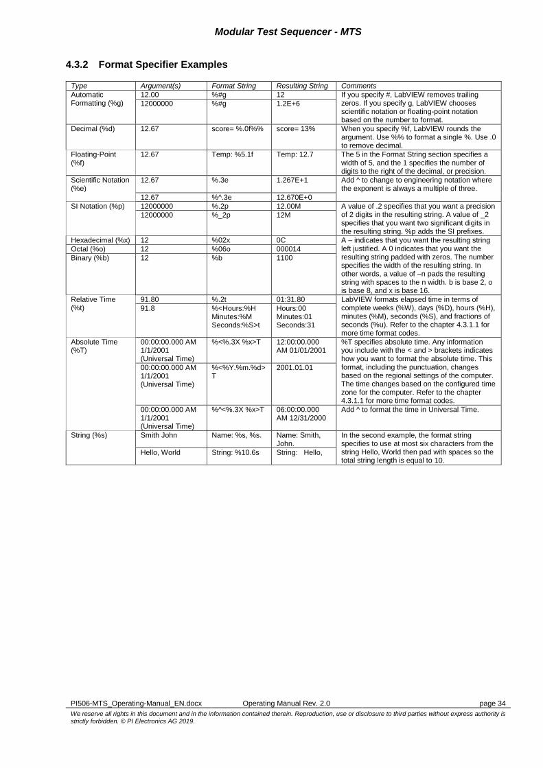
4.3.2 Format Specifier Examples
Type Argument(s) Format String Resulting String Comments
Automatic Formatting (%g)
12.00 %#g 12 If you specify #, LabVIEW removes trailing zeros. If you specify g, LabVIEW chooses scientific notation or floating-point notation based on the number to format.
12000000 %#g 1.2E+6
Decimal (%d) 12.67 score= %.0f%% score= 13% When you specify %f, LabVIEW rounds the argument. Use %% to format a single %. Use .0 to remove decimal.
Floating-Point (%f)
12.67 Temp: %5.1f Temp: 12.7 The 5 in the Format String section specifies a width of 5, and the 1 specifies the number of digits to the right of the decimal, or precision.
Scientific Notation (%e)
12.67 %.3e 1.267E+1 Add ^ to change to engineering notation where the exponent is always a multiple of three.
12.67 %^.3e 12.670E+0
SI Notation (%p) 12000000 %.2p 12.00M A value of .2 specifies that you want a precision of 2 digits in the resulting string. A value of _2 specifies that you want two significant digits in the resulting string. %p adds the SI prefixes.
12000000 %_2p 12M
Hexadecimal (%x) 12 %02x 0C A – indicates that you want the resulting string left justified. A 0 indicates that you want the resulting string padded with zeros. The number specifies the width of the resulting string. In other words, a value of –n pads the resulting string with spaces to the n width. b is base 2, o is base 8, and x is base 16.
Octal (%o) 12 %06o 000014
Binary (%b) 12 %b 1100
Relative Time (%t)
91.80 %.2t 01:31.80 LabVIEW formats elapsed time in terms of complete weeks (%W), days (%D), hours (%H), minutes (%M), seconds (%S), and fractions of seconds (%u). Refer to the chapter 4.3.1.1 for more time format codes.
91.8 %<Hours:%H Minutes:%M Seconds:%S>t
Hours:00 Minutes:01 Seconds:31
Absolute Time (%T)
00:00:00.000 AM 1/1/2001 (Universal Time)
%<%.3X %x>T 12:00:00.000 AM 01/01/2001
%T specifies absolute time. Any information you include with the < and > brackets indicates how you want to format the absolute time. This format, including the punctuation, changes based on the regional settings of the computer. The time changes based on the configured time zone for the computer. Refer to the chapter 4.3.1.1 for more time format codes.
00:00:00.000 AM 1/1/2001 (Universal Time)
%<%Y.%m.%d>T
2001.01.01
00:00:00.000 AM 1/1/2001 (Universal Time)
%^<%.3X %x>T 06:00:00.000 AM 12/31/2000
Add ^ to format the time in Universal Time.
String (%s) Smith John Name: %s, %s. Name: Smith, John.
In the second example, the format string specifies to use at most six characters from the string Hello, World then pad with spaces so the total string length is equal to 10.
Hello, World String: %10.6s String: Hello,

Modular Test Sequencer - MTS
PI506-MTS_Operating-Manual_EN.docx Operating Manual Rev. 2.0 page 35
We reserve all rights in this document and in the information contained therein. Reproduction, use or disclosure to third parties without express authority is
strictly forbidden. © PI Electronics AG 2019.
4.4 How to create a Source Distribution or a Packed Library?
To use LabVIEW functions in the test sequencer it’s necessary to create either a source distribution of the top-level VI’s or a Packed Library (*.lvlibp), so all needed Sub-VI’s from the vi.lib, instr.lib or user.lib are included in the module set.
4.4.1 Source Distribution
1) In the Project Explorer navigate to ‘Build Specification’ and open the context menu ‘New’ -> ‘Source
Distribution’:
Figure 29: New Source Distribution
2) Distribution Settings: Enter a name for the distribution definition, choose ‘Single Destination’ as
‘Packaging Option’ and define the directory where the distribution should be stored:
Figure 30: Distribution Settings

Modular Test Sequencer - MTS
PI506-MTS_Operating-Manual_EN.docx Operating Manual Rev. 2.0 page 36
We reserve all rights in this document and in the information contained therein. Reproduction, use or disclosure to third parties without express authority is
strictly forbidden. © PI Electronics AG 2019.
3) Additional Exclusions: Select option ‘Remove as much as possible’ and uncheck all exclusion boxes, so all library VI’s are included in the distribution.
Figure 31: Additional Exclusions
4) Push ‘Build’ to create the distribution and ‘OK’ to save the build definition in the project.

Modular Test Sequencer - MTS
PI506-MTS_Operating-Manual_EN.docx Operating Manual Rev. 2.0 page 37
We reserve all rights in this document and in the information contained therein. Reproduction, use or disclosure to third parties without express authority is
strictly forbidden. © PI Electronics AG 2019.
4.4.2 Packed Library
LabVIEW packed project libraries are project libraries that package multiple files into a single file with a .lvlibp file extension. The top-level file of a packed library is a project library. By default, the packed library has the same name as the top-level project library.
1) Precondition: All your needed test modules have to be inside a project library, which is part of the project:
Figure 32: Test modules arranged as a project library
2) From the Project Explorer window, right-click ‘Build Specifications’ and select New->Packed
Library from the shortcut menu to display the Packed Library Properties dialog box and configure settings to build a packed library:
Figure 33: Create a new Packed Library

Modular Test Sequencer - MTS
PI506-MTS_Operating-Manual_EN.docx Operating Manual Rev. 2.0 page 38
We reserve all rights in this document and in the information contained therein. Reproduction, use or disclosure to third parties without express authority is
strictly forbidden. © PI Electronics AG 2019.
3) Information: Enter build parameters such as target folder and file name.
Figure 34: Packed Library naming and destination paths
4) Source Files: Select source project library (*.lvlib) as Top-Level Library:
Figure 35: Packed Library source files selection

Modular Test Sequencer - MTS
PI506-MTS_Operating-Manual_EN.docx Operating Manual Rev. 2.0 page 39
We reserve all rights in this document and in the information contained therein. Reproduction, use or disclosure to third parties without express authority is
strictly forbidden. © PI Electronics AG 2019.
5) Destinations: Define target directories and if needed any subdirectory for support files. A packed library contains only LabVIEW files. By default, LabVIEW saves non-LabVIEW files to the same destination directory as the packed library. Select Support Directory in the Destinations list and change the path in the Destination path text box to change where LabVIEW saves non-LabVIEW files.
Figure 36: Packed Library build destination path
6) Source File Settings: Customize any VI properties if needed, otherwise use the default settings:
Figure 37: Packed Library source file settings

Modular Test Sequencer - MTS
PI506-MTS_Operating-Manual_EN.docx Operating Manual Rev. 2.0 page 40
We reserve all rights in this document and in the information contained therein. Reproduction, use or disclosure to third parties without express authority is
strictly forbidden. © PI Electronics AG 2019.
7) Advanced: Checkmark ‘Allow future versions of LabVIEW to load the packed library’ in order to allow future versions of LabVIEW Runtime Engines to load the library without recompilation:
Figure 38: Packed Library advanced build options
8) Additional Exclusions: Define any files which should be excluded from the build, otherwise use
default settings:
Figure 39: Packed Library file exclusions

Modular Test Sequencer - MTS
PI506-MTS_Operating-Manual_EN.docx Operating Manual Rev. 2.0 page 41
We reserve all rights in this document and in the information contained therein. Reproduction, use or disclosure to third parties without express authority is
strictly forbidden. © PI Electronics AG 2019.
9) Connector Pane Settings: Enable ‘Callers adapt at run time to Exported VI connector pane state’ in order to avoid recompilation of any caller VI’s in case the connector pane of a library member changes.
Figure 40: Packed Library pane compatibility
10) Version Information: Use consistent version numbers when building a library. The library name
and version number will be included in the system variable ‘TestModules.Libraries’ (see 3.15.2) and can be used for test documentation (e.g. for report header):
Figure 41: Packed Library version definition

Modular Test Sequencer - MTS
PI506-MTS_Operating-Manual_EN.docx Operating Manual Rev. 2.0 page 42
We reserve all rights in this document and in the information contained therein. Reproduction, use or disclosure to third parties without express authority is
strictly forbidden. © PI Electronics AG 2019.
11) Pre/Post Build Actions: Specify any VI’s to execute before or/and after build process, otherwise leave unchecked:
Figure 42: Packed Library Pre/Post build actions
12) Push ‘Build’ to create the packed project library and ‘OK’ to save the build definition in the project.
4.5 MTS application files
Following a list of files necessary to run the MTS application. Some of them need write access by the MTS application, some read-only access.
File name Folder location Access Description
MTS.exe <ProgramFilesFolder>\PI Electronics AG\MTS
R Application executable
MTS.ini <ProgramFilesFolder>\PI Electronics AG\MTS
R Application base settings
MTS_Releases.txt <ProgramFilesFolder>\PI Electronics AG\MTS
R Application release history
MTS_OperatingManual.pdf <ProgramFilesFolder>\PI Electronics AG\MTS
R Application help document
lvanlys.dll <ProgramFilesFolder>\PI Electronics AG\MTS
R Library for mathematical functions
MTS_Settings.ini <ProgramDataFolder>\PI Electronics AG\MTS
R/W Application configuration settings
<HW-ID>_License.ini <ProgramDataFolder>\PI Electronics AG\MTS
R/W License key file
groups.def <ProgramDataFolder>\PI Electronics AG\MTS\Users
R/W User group definition
*.psw <ProgramDataFolder>\PI Electronics AG\MTS\Users
R/W User password files

Modular Test Sequencer - MTS
PI506-MTS_Operating-Manual_EN.docx Operating Manual Rev. 2.0 page 43
We reserve all rights in this document and in the information contained therein. Reproduction, use or disclosure to third parties without express authority is
strictly forbidden. © PI Electronics AG 2019.
4.6 Report Example
Test Report Part name: PSCB Part number: 3BUS208796-001 Revision: REV. A PO: D106018 Manufacturer: PI Electronics AG Serial number: CH07390015 Test date: 17.12.2008 Test time: 19:30:09 Test duration: 237.3 s Ambient temperature: 22 °C Relative humidity: 40 % Test station: PI-T500-1 Test file: C:\Projects\PSCB\PSCB-Test.mtsq Test file revision: 38 Test status: failed Test Conditions Unit Min. Value Max. Value Act. Value Status Supply Voltages failed +15V: Voltage Nominal V 14.80 15.20 14.95 passed +15V: Current Nominal A 0.010 0.040 0.093 failed -15V: Voltage Nominal V -15.20 -14.80 -14.98 passed -15V: Current Nominal A -0.030 -0.010 -0.023 passed +12V: Voltage Nominal V 11.50 12.50 12.02 passed -12V: Voltage Nominal V -12.50 -11.50 -12.05 passed +15V: Voltage -10% V 13.20 13.80 13.47 passed +15V: Current -10% A 0.010 0.040 0.089 failed -15V: Voltage -10% V -13.80 -13.20 -13.44 passed -15V: Current -10% A -0.040 -0.010 -0.023 passed Digital Outputs Open Drain passed DH-CH1: Current A 0.230 0.242 0.239 passed DH-CH1: LED Check Visual Check passed DH-CH2: Current A 0.230 0.242 0.236 passed DH-CH2: LED Check Visual Check passed DH-CH3: Current A 0.230 0.242 0.236 passed DH-CH3: LED Check Visual Check passed DH-CH4: Current A 0.230 0.242 0.238 passed DH-CH4: LED Check Visual Check passed Digital Outputs PWM passed PWM-CH1: Current @ 100% PWM A 1.22 1.32 1.28 passed PWM-CH1: Current @ 50% PWM A 0.65 0.71 0.71 passed PWM-CH1: LED Check Visual Check passed PWM-CH2: Current @ 100% PWM A 1.22 1.32 1.29 passed PWM-CH2: Current @ 50% PWM A 0.65 0.71 0.71 passed PWM-CH2: LED Check Visual Check passed AC-Trip Switch passed AC-Trip: Line Voltage Vrms 110.00 130.00 124.81 passed AC-Trip: Ref. Current Arms 1.265 1.317 1.290 passed Operator: J. Sample

Modular Test Sequencer - MTS
PI506-MTS_Operating-Manual_EN.docx Operating Manual Rev. 2.0 page 44
We reserve all rights in this document and in the information contained therein. Reproduction, use or disclosure to third parties without express authority is
strictly forbidden. © PI Electronics AG 2019.
Notes:
PI Electronics AG Segelhofstrasse 1 CH-5405 Baden
Switzerland
Phone: +41 56 486 7011 Fax: +41 56 486 7313
www.pie.ch