CJ2 FAMILY - Omron Europe
78
» Faster machine development » Flexibility in communication » Innovation through evolution CJ2 FAMILY New PLCs with a proven track record Programmable Controllers
-
Upload
khangminh22 -
Category
Documents
-
view
0 -
download
0
Transcript of CJ2 FAMILY - Omron Europe

» F a s t e r m a c h i n e d e v e l o p m e n t» F l e x i b i l i t y i n c o m m u n i c a t i o n
» I n n o v a t i o n t h r o u g h e v o l u t i o n
CJ2 FAMILYN e w P L C s w i t h a p r o v e n t r a c k r e c o r d
Programmable Controllers

F-2
Innovation without growing pains
As a modern machine manufacturer you need to
continuously increase the intelligence and flexibility
of your product to remain competitive. But you also
need to be absolutely certain that it all works
perfectly, first time, every time.
The CJ2 is the result of years of experience as
market leader in the field of modular controllers
and represents a logical next step in controller
design. It offers greater performance and faster I/O
response as well as extreme scalability - so you will
only need one family. In addition, programming,
debugging and networking are faster and easier.
Welcome to the new CJ2 Family: built to give you
innovation without growing pains.
Although CJ2 is a can directly replace any CJ1 CPU, it offers the following additional significant advantages:
Open to the world
Data communication is via standard Ethernet port with EtherNet/IP Data Link function.
Advanced motion control
CJ2 units offer multi-axes synchronous control, and can replace expensive motion controllers.
High-speed
Faster program execution and immediate I/O refreshing enables flexible machine control.
Learn one, know them all
Thanks to the wide variety of CPUs with consistent architecture across all PLC families, you only need to learn one, and you will know them all.
Highly flexible
Adapt the PLC to your needs with the wide variety of compatible CJ1 Family I/O units (nearly 100).
9
8
7
6
5
4
3
2
1
F-3
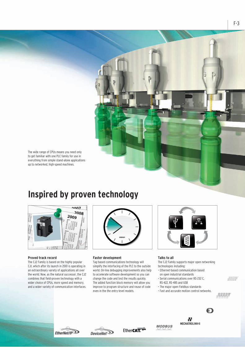
Proved track recordThe CJ2 Family is based on the highly popular CJ1, which after its launch in 2001 is operating in an extraordinary variety of applications all over the world. Now, as the natural successor, the CJ2 combines that field-proven technology with a wider choice of CPUs, more speed and memory, and a wider variety of communication interfaces.
Faster developmentTag-based communications technology will simplify the interfacing of the PLC to the outside world. On-line debugging improvements also help to accelerate software development so you can change the code and test the results quickly. The added function block memory will allow you improve to program structure and reuse of code even in the the entry-level models.
Talks to allThe CJ2 Family supports major open networking technologies including: • Ethernet-based communication based
on open industrial standards • Serial communications over RS-232 C,
RS-422, RS-485 and USB • The major open Fieldbus standards • Fast and accurate motion control networks.
The wide range of CPUs means you need only to get familiar with one PLC family for use in everything from simple stand-alone applications up to networked, high-speed machines.
Inspired by proven technology
F-4
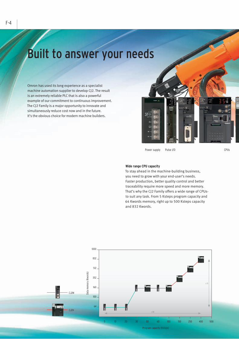
Wide range CPU capacity To stay ahead in the machine-building business, you need to grow with your end-user’s needs. Faster production, better quality control and better traceability require more speed and more memory. That’s why the CJ2 Family offers a wide range of CPUs- to suit any task. From 5 Ksteps program capacity and 64 Kwords memory, right up to 500 Ksteps capacity and 832 Kwords.
Omron has used its long experience as a specialist machine automation supplier to develop CJ2. The result is an extremely reliable PLC that is also a powerful example of our commitment to continuous improvement. The CJ2 Family is a major opportunity to innovate and simultaneously reduce cost now and in the future.It’s the obvious choice for modern machine builders.
Built to answer your needs
Power supply Pulse I/O CPUs
5 10 20 30 50 60 100 150 250 400 500
x 80
x 13
Program capacity (Ksteps)
Data
mem
ory
(Kw
ords
)
64
100
160
352
512
832
1000
CJ2M
CJ2H

F-5
Higher precision In addition to the greater CPU processing performance, Omron has also added new high-speed I/O units, such as analog input units with 20 µs conversion time, while new PLC instructions provide immediate access to fast I/O data. The result is even more real-time reliability.
Easy connection by USB
Simply connect the cable, with no settings required
A CJ2 CPU Unit on an EtherNet/IP network can be accessed via USB, with no need for routing tables
EtherNet/IP
USB port (standard equipment)
Commercially available USB cable
CX-One (e.g., CX-Programmer)
CPUs Communication Analog I/OMotion Digital I/O
Select what you need With CJ2 you can also still connect to the existing CJ1 I/O units. You can benefit from CJ2’s improvements without redesigning the entire system.
USB

F-6
One family - two performance classes
CJ2M for basic machine automation
The CJ2M Series is ideal for packaging and general
machine automation needs. Connectivity is assured
thanks to the built-in USB port and the choice of
Ethernet and RS-232C/422/485 interfaces on the CPU.
Pulse I/O modulesBy mounting optional pulse I/O modules, you can extend the functionality of any CJ2M CPU with:- interrupt inputs- quick-response inputs- high-speed counters- incremental encoder inputs- pulse frequency control outputs- pulse width control outputs
Up to two modules can be mounted per CPU, allowing direct control of four motion axes. Using dedicated instructions, these axes can be controlled directly by the PLC program, without communication delays.
Always accessible through standard USB port
Standard Ethernet port with EtherNet/IP Data Link function
Wide range of program capacities, from 5 Ksteps to 60 Ksteps
Pulse I/O add-on modules have a special connection to theCPU and are controlled by convenient positioning instructions
Dedicated function block memory ensures efficientexecution of function block software modules
Serial option board for CJ2M-CPU3*
* Supported by the CJ2M CPU Unit with version 2.0 or later.

Inputs
Outputs
F-7
CJ2H for high speed, high capacity
The CJ2H Series is ideal for advanced machine automation needs such as those required in image processing inspection of electrical components and high speed sorting on conveyors.
Always accessible through standard USB port
Standard Ethernet port with EtherNet/IP Data Link function
High program capacity of up to 400K Steps
Higher precision for machine operation and processing quality
Immediate refreshing of basic I/O ensures real-time processing Faster response means higher precision and better quality
High data memory capacity of up to 832 Kwords
Advanced motion control – made simple
The CJ2H’s advanced motion control avoids the use of expensive motion controllers. Synchronized control is possible on up to 20 axes by using just five Position Control units (High-speed type). And, programming is easy – simply paste an electronic cam function block into a synchronized interrupt task.
Improve realtime control
Improved Interrupt Response - Scheduled interrupt processing- Input interrupt processing.
Improved Realtime Performance for Immediate Refreshing - Realtime analog I/O values.
Faster Unit Input Response and Output Response - ON/OFF response time for Basic I/O Units- Conversion time (A/D and D/A) for Analog I/O Units- Positioning start time for Position Control Units

F-8 Lineup
Units CJ2M CJ2H
Type Simple Types Standard Types High - end Types Flagship Types
Models CJ2M-CPU1☐ CJ2M-CPU3☐ CJ2H-CPU6☐ CJ2H-CPU6☐-EIP
Appearance
Program Capacity Up to 60 Ksteps Up to 400 Ksteps
Data Memory Capacity Up to 160 Kwords Up to 832 Kwords
I/O Bits 2,560
Basic Instructions(LD) 40ns 16ns
Special instruction (MOV) 120ns 48ns
Floating-point decimal instructions (SIN) 0.86μs 0.59μs
System overhead time 160μs 270μs 100μs 200μs
FB Program AreaYES
(Equivalent to 20K steps.) -
USB Port YES
Serial PortYES
(RS-232C)
One Serial Option Board can be mounted
(RS-232C or RS-422A/485)
YES(RS-232C)
EtherNet/IP Port - YES - YES
Serial PLC Links YES YES(A Serial Option Board is required)
-
High-speed Interrupt Function - YES
Synchronous Unit Operation - YES(In combination with a CJ1W-NC☐☐4 Position Control Unit)
Pulse I/O Modules*YES
(Up to two Pulse I/O Modules can be mounted)-
The CJ2 Provides a Complete LineupThe complete lineup provides high-performance features from machine control to information processing.
Comm
unications Port
*A Pulse I/O Module must be mounted for CJ2M CPU Units with unit version 2.0 or later.

F-9Improve Basic Perfomance
[ Immediate Execution at a Sensor Input ]
Faster Interrupt Response Time for Input Interrupts[ Ideal for Processing at a Fixed Interval ]
Faster Immediate I/O Refreshing
Realtime I/O during Instruction Execution
Ample Instruction Execution Performance for Machine Control. The CJ2 Series fully responds to customer requests for improved tact time and increased information.
Improved Interrupt ResponseFor Finer Control
Immediate refreshing(!LD) 1 μs20TimesFaster
System Overhead
Common processing 100μs*
Interrupt response 30μs
Floating-point decimal instructions
SIN calculation 0.59μsFloating-point decimal addition and subtraction 0.24μs
Basic instructions
LD instruction execution 16nsOUT instruction execution 16ns
*CJ2H-CPU6☐-EIP:200μs
Common Processing
CJ2H8.09ms 1.43ms
* With the High-speed Interrupt Function
CJ2 CPU
Instruction Execution
I/O Refresh
Peripheral Services
Cycle TimeGreatly shortened
Common Processing
Instruction Execution
I/O RefreshPeripheral Services
Shorter Minimum Interval for Scheduled Interrupts
Interrupt Response Timefor Input Interrupts 17 μs*
*1 Supported only for one scheduled interrupt task.
The peripheral (USB) port or serial port of the CPU Unit
can not be used at the same time.
Minimum Interval forScheduled Interrupts 100 μs*1
The Pursuit of High-speed Performance as a ControllerAll processes that affect the cycle time have been made faster.
Air cylinderSensor status is read just prior to instruction execution.
Output immediately after instruct ion is executed
Fiber SensorE3NX-FA
1.8TimesFaster
2TimesFaster
Fastestin the
Industry
CJ2H CPU Unit with unit version 1.1 or later is used.
CJ2H CPU Unit with unit version 1.1 or later is used.
CJ1-H
*2
*2 According to February 2010 OMRON survey in Japan.
-Common Processing
-Instruction Execution
-RefreshBasic I/O Unit:
Immediate refreshing
-Interrupt ResponseMinimum Interval forScheduled Interrupts
Interrupt Response Timefor Input Interrupts
300μs 100μs
LD 20ns 16ns
SIN 42μs 0.59μs
3μs 1.4μs
20μs 1μs
200μs 100μs
30μs 17μs
3 times faster
1.2 times faster
71 times faster
2 times faster
20 times faster
2 times faster
1.8 times faster●Conditions: 30 ksteps, basic-to-special-to-floating-point decimal instruction ratio = 6:3:1, 128 inputs 128 outputs, 2 Analog Input Units, 2 Position Control Units (4-axis Units)

F-10
Pulse I/O Modules expand the applicable positioning applicationsEasily execute the position control of up to four axes
Either one or two Pulse I/O Modules can be connected
to a CJ2M CPU Unit. The programming is as easy as
pasting OMRON Function Blocks for positioning, or
special instructions.
Pulse I/O Functions (for Two Pulse I/O Modules)
Input interrupts 8 points
High-speed
counter inputs: Single-phase, 100 kHz, 4 CHs
or Phase-diff erent input, 50 kHz, 4 CHs
Pulse outputs: 100 kHz, 4 axes or four PWM outputs
Input InterruptsUp to eight interrupt inputs or quick-response inputs can be used.
High-speed CountersUp to four high-speed counter inputs can be used by connecting rotary encoders to Pulse inputs.
CJ2MCPU Unit
Pulse I/O Module
Pulse I/O Module
Pulse I/O Module
CJ2MBuilt-in EtherNet/IPCPU Unit
• Pulse width as short as 30μs can be input with quick-response inputs.
• High-speed processing and interrupt response time of 33μs (in Direct Mode).
• Interrupts can be created for both of rising and falling edges.
•High-speed counting at 100 kHz for single-phase and 50 kHz for phase-diff erent input.
•The ring counter maximum value of a high-speed counter can be changed temporarily during operation.
•Start Interrupt Tasks using Target Value Comparison or Range Comparison for high-speed processing.
•The frequency (speed) can be easily measured by executing HIGH-SPEED COUNTER PV READ (PRV(881)) instruction.
Ideal for applications such as measuring the speed of rotating bodies for inspections or detecting conveyer speeds.
Can also be used for monitoring accumulated motor rotations.
High-speed Counter in Linear ModeFor applications such as conveyors.
High-speed Counter in Ring ModeFor applications such as electronic component index tables.
Incremental encoder
Incremental encoder
MotorI/O
High-speed counter input
High-speed counter input
Inverter(e.g.,3G3MX2)
CJ2M
CJ2M
Pulse I/O Module
Pulse I/O Module
Pulse I/O Modules
Note. A Pulse I/O Module must be mounted for CJ2M CPU Units with unit version 2.0 or later.

F-11
Pulse OutputsFrom stepping motors to servos, positioning control can be easily achieved using pulse outputs for up to four axes.
Faster and easier•Pulse control cycle of 1 ms (1/4 of OMRON's CJ1M). Achieve smoother acceleration and deceleration. •Faster starting of position control (twice as fast as OMRON's CJ1M). Helps reduce machine takt time. •INTERRUPT FEED instruction (IFEED(892)). Execute high-precision feeding from interrupt inputs with just one instruction. •Close integration with the data trace function of the CX-Programmer for easy monitoring of positioning operations.
Complete positioning functions
Positioning controlvariations
Special instructions,OMRON Function BlocksOperation patterns Application examples
TrapezoidalAcceleration/DecelerationPositioningAcceleration/deceleration time can be shortened with Trapezoidal Acceleration/Deceleration Positioning function and Triangular control. Detailed functionsare provided for reducingout-of-step operation forstepping motors andeliminating errordowntime.
Changing theTarget Positionduring PositioningThe target position can bechanged duringpositioning. It is alsopossible to reversedirection when changingthe target position.
Interrupt FeedingIt is possible to change topositioning control duringspeed control. Interruptfeeding can be executedafter the interrupt for aspecified number of pulses.Setting and starting interrupt feeding is possible with one instruction without using an interrupt task.
SequentialPositioningTravel to multiple presetpoints can be executed.This is effective forapplications such aspositioning loaders andunloaders at multiplepoints.
•Basic Form
•Setting Accelerationand DecelerationSeparately
•S-curve Acceleration/Deceleration Setting
•Triangular Control
Acceleration
Acceleration
S-curveacceleration
Target position(frequency,
acceleration/deceleration) changed
Speed control(IFEED instruction)
A specified number of pulses are output and
then positioning stops.
Trapezoidal control(PLS2 instruction)
S-curvedeceleration
Startfrequency
Specified numberof travel pulses
Deceleration
Deceleration
Travel start
Travel start
Controller
Sheet feedingdirection
Constant sheet length from detection of mark until heat welding.
RS-232C
Servo Driver(e.g., SMARTSTEP 2)
Camera
Servomotor
Target speed control
PT
PCB Conveyor Rail Width Positioning
Position Control Using Data Measured after Startup
High-precision Interrupt for Positioning
PCB RackPositioning
Achieved with a single OMRONFunction Block for specifyingsequential positioning.
Achieved with a single OMRONFunction Blocks for specifying absolute(or relative) travel.
While position control is being executed by a PLS2 instruction, another PLS2 instruction can be used to override the first PLS2 instruction.
•Starting Trapezoidal Control
Achieved with a single OMRONFunction Block for interrupt feeding.
• Changing the Target Position with Another Instruction

F-12
Flexible Machine Control with Refined I/O PerformImprove realtime control.
Improved Realtime Performance for Immediate Refreshing
Direct Processing with analog I/O
InputOutput
Basic I/O Units:High-speed typeCJ1W- ID212 ID233
Consistency is achieved from input to processing and output with direct
conversion functions for High-speed Units.*
Direct Processing with Enhanced Immediate Refreshing Analog Input and Output with no jitter
■I/O processing times Max
■I/O processing times Min
Faster Unit I/O Response Lineup of High-speed Units
In addition to the greater processing performance
of the CPU Unit, OMRON has also improved
the response performance of each Unit. Faster
throughput from inputs and processing to outputs
helps to improve equipment tact time and work
processing quality.
Improved System Throughput
Faster Unit Input Response and Output Response
Basic I/O Units, Position Control Units, Analog I/O Units, Serial Communication Units
[ Improved Basic Response ]
Faster ON/OFF response time
ON response time 15 μs
OFF response time 90 μs
[ High-speed All the Way to Pulse Output ]
High-speed Positioning
Positioning start time 0.1 ms*
* Starting time for first axis when all axes are stopped.
[ Improved Basic Response ]
High-speed Analog I/O
A/D, D/A conversion period 20 μs / 1 point
~ to 35 μs / 4 point
[ Data Reception in Microseconds ]
High-speed Serial Communications (No-protocol)
Consistent high speed is achievedfrom data reception to storagein CPU Unit memory.
210 μs*
Continuous reception is possibleon a high-speed cycle. 800 μs*
Baud rate 230 kbps* CJ2H CPU Unit with unit version 1.1 or later is used.
230kbps,10bytes,The DRXDU instruction is used in an interrupt task.
Consistent I/O
processing times
InputInput
OutputOutput
DIRECT CONVERSION
A/D CONVERSION
A/D CONVERSION
D/A CONVERSION
D/A CONVERSION
processing
processing
DIRECT CONVERSION
DIRECT CONVERSION DIRECT CONVERSION
A/D, D/A conversion period( 20 μs)
20 μs 20 μs
20 μs 20 μs
1.3TimesFaster
Fastestin the
Industry
4TimesFaster
20TimesFaster
12TimesFaster
162TimesFaster
42TimesFaster
Position Control Units:High-speed typeCJ1W-NC☐☐4
Analog Input/Output Unit:High-speed typeCJ1W-AD042CJ1W-DA042V
Serial Communication Unit:High-speed typeCJ1W-SCU☐2
* According to February 2010 OMRON survey in Japan.
* The analog-digital or digital-analog conversion and refreshing of converted values and set
values are performed when the Direct Conversion Instruction (AIDC/APDC) is executed.
Supported only by the CJ2H CPU Units with unit version 1.1 or later and CJ2M CPU Units.
*

F-13
EtherNet/IP
Controller Link
FL-net(OMRON)
EtherNet/IP
Controller Link
The port connection does not need to be changed, which makes it easier to build the system.
Using the CJ2H built-in EtherNet/IP port (Functionality differs when using
the CJ2M built-in EtherNet/IP port)
CJ2M-CPU3 ☐ CJ2H-CPU6 ☐-EIP
Built-inEtherNet/IP port
on CPU Units
Built-in EtherNet/IP Port
EtherNet/IP Is User Friendly in Three WaysAn open industrial network that implements a control protocol on general-purpose Ethernet technology.
CJ2 CPU Units are available with multifunctional Ethernet ports that are compatible with EtherNet/IP.Peripheral Devices for universal Ethernet Technology (such as Cables, Hubs, and Wireless Devices) can be used with CJ2 CPU Units. Reduces network installation and wiring costs.
Multiple functions can be executed simultaneously on one port. Support Software, Data Links, Message communications between PLCs, FTP Communications
From manufacturing recipes and information on interlocks between processes to production data, any type of data can be exchanged at high speed and at the optimal timing.Communications performance is vastly improved over OMRON’s Controller Link and FL-net networks.
Extremely Fast and High-capacity Data Links Large Data Transfers with High Reliability
Efficient Programming with Tag Symbols There Is Little Effect on Address Changes.
Previously, when data was exchanged by specifying address and addresses were changed, the program had to be changed at other Controllers and various operations, such as memory checks, had to be performed. Now, tag names reduce the dependence on a memory map and the need for checking items affected by changes. This allows equipment to be easily added or upgraded.
CJ2H-CPU6 ☐ -EIP: 20,000 max., CJ2M-CPU3 ☐ : 2,000 max.
EtherNet/IP
CJ2 CPU
Programmable Terminal
Host application
Data linksMessage communications
FTP
CX-One
HUB
CJ2 CPU CJ1-EtherNet/IP Unit
Messa
ge
commun
icatio
ns
Data links
Data Link Capacity (Total) 20,000 words
8,704 words
Data Link Performance (See note.)
Note: Communications cycle time to exchange 20,000CH data in data links.
180,000 words. . . .
10ms. . . . . . . . . . . . . . . . . . . . . . . . . . . . . . . .
300ms
30TimesFaster
9TimesLarger
CJ2 CPU
Programmable Terminal
Accessed by tag name EtherNet/IP
Host application
No change required.
Even after the change, the number of items produced is acquired correctly from H200.
With the CX-Programmer, the address for the tag named “Number produced” is changed from D100 to H200.
Change
D100
H200
tag name adress
Change
No change required.
Number_produced
Number_produced
Number_produced
Number_produced

F-14
Position Control Units:High-speed typeCJ1W-NC**4
CJ2H CPU Unit
pulse outputs
pulse outputs
synchronized
synchronized
CPU Unit
Versatile Position Control
Synchronous unit operation between Special I/O Units and the CPU Unit ensures concurrency from input to processing and output.A consistent, high-speed synchronous control cycle of 1 ms makes it easy to ensure application performance.
Achieve High-speed, Low-cost Synchronized Multi-axis Control with Pulse Outputs (CJ1W-NC☐☐4)
Building Synchronized Systems Using Only Ladder Programming and No Special Controllers
Cyclictasks
Synchronousinterrupttasks CPU Bus Unit or
Special I/O UnitCPU Bus Unit orSpecial I/O Unit
CPU Bus Unit orSpecial I/O Unit
Up to ten Units
Internalprocessing
Internalprocessing
Internalprocessing
Perfect inputtiming!
Perfect outputtiming!
Fully synchronized operation between CPU Unit and CPU Bus Units/Special I/O Units.
Electronic cam operation for eight axes is supported using two Position Control Units.
Supported only by the CJ2H CPU Units with unit version 1.1 or later.
Servomotor/ Servo Drive
You Get Both the Easy Startup of Networks and the High-speed StartingSuperior Performance and Easy Operation
Share the Same ProgrammingCommon programming enables easy introduction into existing systems
CJ2HCJ2M
CJ2HCJ2M
Programming ToolCX-Programmer
Support ToolCX-Drive
Tool
Two-axisPosition Control Unitwith EtherCAT interface
Two-axisPulse-trainPosition Control Unit(CJ1W-NC 4)
Network Solutions for Control Automation TechnologySimplified system on the integration of network
Expanding applications, not limited for motion
control.
Flexible communication specification allows a
wide variety of devices to join the same network.
The connectable devices involve drive devices
such as Servo Drives and Inverters, I/O devices,
and other intelligent devices, including Vision
Sensors.
Position Control Unit with EtherCAT interfaceCJ1W-NC☐81/NC☐82
Servo Drives
Vision SensorInverter
Analog I/ODigital I/O
Encoder Input
[ High-speed communications ]
[ High-speed starting ]
100Mbps
0.4ms (when starting 4 axes)
With EtherCAT, you can improve the performance of overall system from PLCs to servo system, as well as stand-alone Servo performance.
The Position Control Units with EtherCAT interface use the same positioning functions* as High-speed Pulse-train Position Control Units, and the programming interface is also the same. You can easily switch the unit type between the Position Control Units depending on the application.
* Except Synchronized control function.
High-speed starting and control performance equivalent to those of pulse-train systems are achieved through network connections.
Starting time 0.4 ms Control cycle 0.5 ms
* A CJ2H CPU Unit with unit version 1.3 or higher or a CJ2M CPU Unit is required.
4TimesFaster
5TimesFaster
[ Simple wiring ]
[ Simple startup ]
1 connection
1 port
EtherCAT devices can be easily connected with Ethernet cables, which reduces wiring works.
Without reconnecting the computer, you can configure both the Position Control Units and EtherCAT communications setting via CPU unit. You can also directly connect the CX-Drive to set the Servo Drives.
Up to
20axes
Note: EtherCAT® is a registered trademark and patented technology, licensed by Beckhoff Automation GmbH, Germany.

F-15
Width
Height
Depth
Box1
Width
Height
Depth
Box2Example: “Box2.Height” is specified.
From data structure
Structure data to make it easier to understand and manage.
Previous PLCs With the CJ2M
User program area
Function block definitions
User program area is used.
A dedicated area is used instead of the user program area.
Data Trace
Suggested instructions displayed
Programing and Debugging
More Flexible Programming, Easier DebuggingChanges to specifications can be handled easily and total lead time is reduced for system startup and troubleshooting.
A complete range of intuitive programming functions is
provided, including instruction and address input assistance,
address incrementing, and address incremental copy.
These functions enable waste-free programming with minimal
eff ort. * In comparison to CX-Programmer version 8.
A Smart Input Function greatly reduces the work required to input programs *
Easy, Intuitive Programming Software
Highly Readable Programming The Greatest Program Diversity in the Industry.
-Bit Addresses can be used in the DM Area and EM Area.
-BCD and Binary Timer instructions can be used Together.
-Function blocks make units of processing easy to understand.
-Function block defi nitions do not take up user program memory
capacity.*
-Address off sets can be specifi ed
-Array variables are supported, A symbol can be used for an
array variable subscript.
-Structure symbols* make it easier to create data structures and
data bases.
Stress-free Online Debugging Effects on Machinery Operation Are Reduced.
Greatly Improved Debugging Efficiency Through Superior Data TracingHigh-speed, High-capacity Data Tracing Is Now Possible.
-The additional cycle time due to online editing has been reduced to approx. 1 ms
-Unlimited ST and SFC online editing
Ample Trigger Conditions
One, two, or four words of data and comparison conditions can be specifi ed. For example,
a trigger can be set for when double-precision data is larger than a specifi ed value.
CX-One Data Trace Is Also Upgraded.
The improved CJ2 trace function is fully utilized.
-A function has been added for superimposing trace waveforms
-Trace results can be printed or saved as bit maps.
-The measurement times for two selected points can be
checked.
High-capacity Data Tracing
Maximum 32 Kwords (CJ2H) of data can be traced,
and the EM Area can also be used as trace memory.
Continuous Data Tracing
Sampled data in the trace memory of the CPU Unit
can be regularly collected at the personal computer
to enable sampling for long periods or time. Data
can be saved in the CSV fi les in personal computer.
* Only CJ2M CPU Units
* Data structures allow you to structure various
types of data and define them as a new data type.
50%Reduced
User program area
Function block definitions
* CJ2M: 2,000 data structures max., CJ2H: 4,000 data structures max.

F-16
Inconsistencies in I/O processing times are eliminated to reduce takt times. Analog quantities are input in ultra-high speed (20μs) to improve the accuracy of NG product detection.
Tension Control Inline Measurement
Use High-speed Analog I/O Units Use High-speed Analog I/O Units
Achieve high-speed data input from high-speed measurement sensors, such as laser distance meters and displacement sensors. High-speed Sorting Control Using a Barcode Reader
RS-232C
High-speed Serial Input from Laser Distance Meters High-speed Serial Input from Barcode Readers
Transfer position data to the CPU Unit from laser distance meters with short measurement cycles without missing data to achieve precise control of inverters for conveyors and elevators.
Position control of conveyors and elevators
Laser distance meters, displacement sensors, etc.
Barcode reader
To dispenser
Synchronized Control Multi-axis Position Control through EtherCAT
Use CJ2H CPU Unit and Position Control Unit
An electronic cam enables high-precision synchronized control.
Servomotor
Z axis
Use High-speed Serial Communications Units Use High-speed Serial Communications Units
Direct conversion enables faster input of analog values into the CJ2 CPU Unit.
Use CJ2 CPU Unit and Position Control Unit with EtherCAT interface
Reduce Production Takt Time with High-speed Startup at 0.4 ms.
Applications
Ideal for Applications Requiring High Speed, Synchronization, and Multiple AxesHelps Improve Machine I/O Throughput
Data from the barcode reader is transferred quickly to the CPU Unit to recognize the code and output pulses at high speed.
Palletizing: A starting time of 0.4 ms helps reduce the takt time of applications that perform repeated positioning.
Analog Output Unit:High-speed typeCJ1W-DA042V
Analog Input Unit:High-speed typeCJ1W-AD042
Analog Input Unit:High-speed typeCJ1W-AD042
Position Control Unit with EtherCAT interfaceCJ1W-NC ☐81/NC ☐82Position Control
Units:High-speed typeCJ1W-NC ☐☐4
Servomotor/ Servo Drive
Serial Communication Unit:High-speed typeCJ1W-SCU☐2
Inverters and Servos
Serial Communication Unit:High-speed typeCJ1W-SCU ☐2
Crimping Equipment
Encoder
AC Servomotor R88M-K
AC ServodriverR88D-KTR7D-BP
RS-232C
Y axis
X axis
1
System Design Guide
System Configuration ........................................................................................2
Checking Current Consumption and Power Consumption ...............................10
Dimensions ......................................................................................................11
General Specifications .....................................................................................14
Performance Specifications .............................................................................15
Function Specifications ....................................................................................19
Specifications for Pulse I/O Functions .............................................................24

2 Programmable Controllers CJ2
System Configuration
■ Basic System
OUTOUT ININII101II101
Years
POWERCJ1W-PA205C
TEST
NC
NC
AC100-240VINPUT
L2/N
L1
L+
ALARMOUTPUTDC30V,50mA
NORMAL:ONALARM :OFF
OUTOUT ININII101II101
Years
POWERCJ1W-PA205C
TEST
NC
NC
AC100-240VINPUT
L2/N
L1
L+
ALARMOUTPUTDC30V,50mA
NORMAL:ONALARM :OFF
OUTOUT ININII101II101
Years
POWERCJ1W-PA205C
TEST
NC
NC
AC100-240VINPUT
L2/N
L1
L+
ALARMOUTPUTDC30V,50mA
NORMAL:ONALARM :OFF
LANMODEPOWER WIRELESS
WE70-APFA WIRELESS LAN ACCESS POINT
LANMODEPOWER WIRELESS
WE70-APFA WIRELESS LAN ACCESS POINT
POWER
PA205R
DC24VAC240V
OUTPUTRUN
INPUTAC100-240V
L2/N
L1
CONTROLLER
CJ1G-CPU44SYSMAC
PROGRAMMABLEERR/ALM
RUN
COMM
INHPRPHL
OPEN
PERIPHERAL
BUSY
MCPWR
PORT
OUTOUTIC101IC101
Years
POWERCJ1W-PA205C
TEST
NC
NC
AC100-240VINPUT
L2/N
L1
L+
ALARMOUTPUTDC30V,50mA
NORMAL:ONALARM :OFF
CJ1 Power Supply Units
CJ1W-PA205CCJ1W-PA205RCJ1W-PA202CJ1W-PD025CJ1W-PD022
CJ1 I/O Control Unit
CJ1W-IC101
CJ1 End Cover
CJ1W-TER01
CPU Rack (Backplane-free Structure)
CJ1 Basic I/O UnitsCJ1 Special I/O UnitsCJ1 CPU Bus UnitsNote: A maximum of 10 Units can be mounted.
Programmable Terminal (PT)
NS Series
RS-232C Cable for PT
XW2Z-200T/500T
RS-232C Cable forPersonal Computer
XW2Z-200S/500S-CV
RS-422A Adapter
CJ1W-CIF11
Expansion Rack (Backplane-free Structure)
Expansion Cables
CS1W-CN@@3(30 cm, 70 cm, 2 m, 3 m, 5 m, 10 m, 12 m)
(Same cable as CS series)
CJ1 I/O Interface Unit
CJ1W-II101
Memory Card
HMC-EF@@@(128 MB, 256 MB, 512 MB)
Programmable Terminal (PT)
NS SeriesNote: Product no longer available to order.
Note: Product no longer available to order.
Ethernet Cable
Commercially available100Base-TX twisted-pair cable
CJ2 CPU Units
CJ1 Battery
CJ1W-BAT01
USB Cable
Commercially available USB cable
Programming Devices
CX-One (e.g., CX-Programmer)
FA Wireless Lan Units
WE70
Industrial Switching Hubs
FA Communication Software
SYSMAC Gateway CX-Compolet
W4S1
CJ2H-CPU6@-EIPCJ2H-CPU6@CJ2M-CPU3@CJ2M-CPU1@
PLC
Serial Option Board
RS-232C
CP1W-CIF01
RS-422A/485
CP1W-CIF11CP1W-CIF12-V1
Note: Only CJ2M-CPU3@ can be mounted.Pulse I/O Modules
CJ2M-MD211CJ2M-MD212
Note: Only CJ2M-CPU Units can be mounted.

Programmable Controllers CJ2 3
■ Configuration Units
Note 1. Microsoft, Visual Basic, Visual C#, Visual Studio and Windows are either registered trademarks or trademarks of Microsoft Corporation in the United States and/or other countries.Microsoft product screen shot(s) reprinted with permission from Microsoft Corporarion.EtherCAT® is registered trademark and patented technology, licensed by Beckhoff Automation GmbH, Germany.EtherNet/IPTM, DeviceNetTM and CompoNetTM are trademarks of the ODVA.Other company names and product names in this document are the trademarks or registered trademarks of their respective companies.
2. Including models whose production are discontinued.
CJ1 Basic I/O Units
8-point Units 16-point Units 32-point Units 64-point Units
Input Units● DC Input UnitCJ1W-ID201● AC Input UnitCJ1W-IA201
● DC Input UnitCJ1W-ID211CJ1W-ID212 ● AC Input UnitCJ1W-IA111
● DC Input UnitCJ1W-ID231CJ1W-ID232CJ1W-ID233
● DC Input UnitCJ1W-ID261CJ1W-ID262
Output Units● Relay Contact Output Unit
(independent commons) CJ1W-OC201● Triac Output UnitCJ1W-OA201● Transistor Output UnitsCJ1W-OD201CJ1W-OD203CJ1W-OD202CJ1W-OD204
● Relay Contact Output UnitCJ1W-OC211● Transistor Output UnitsCJ1W-OD211CJ1W-OD213 CJ1W-OD212
● Transistor Output UnitsCJ1W-OD231CJ1W-OD233CJ1W-OD234 CJ1W-OD232
● Transistor Output UnitsCJ1W-OD261CJ1W-OD263CJ1W-OD262
I/O Units
--- ---
(16 inputs, 16 outputs)● DC Input/Transistor Output UnitsCJ1W-MD231CJ1W-MD233CJ1W-MD232
32 inputs, 32 outputs● DC Input/Transistor Output UnitsCJ1W-MD261CJ1W-MD26332 inputs, 32 outputs● TTL I/O UnitCJ1W-MD563
Other Units
---
● Interrupt Input UnitCJ1W-INT01
---
● B7A Interface Units(64 inputs)CJ1W-B7A14(64 outputs)CJ1W-B7A04(32 inputs, 32 outputs)CJ1W-B7A22
● Quick-response Input UnitCJ1W-IDP01
CJ1 Special I/O Units and CPU Bus Units■ Process I/O Units● Isolated-type Units with Universal InputsCJ1W-PH41UCJ1W-AD04U
● Isolated-type Thermocouple Input UnitsCJ1W-PTS15CJ1W-PTS51
● Isolated-type Resistance Thermometer Input Units
CJ1W-PTS16CJ1W-PTS52
● Isolated-type DC Input UnitCJ1W-PDC15
■ Analog I/O Units● Analog Input UnitsCJ1W-AD042 CJ1W-AD081-V1CJ1W-AD041-V1
● Analog Output UnitsCJ1W-DA042V CJ1W-DA08VCJ1W-DA08CCJ1W-DA041CJ1W-DA021
● Analog I/O UnitsCJ1W-MAD42
■ Temperature Control UnitsCJ1W-TC001, CJ1W-TC002CJ1W-TC003, CJ1W-TC004CJ1W-TC101, CJ1W-TC102CJ1W-TC103, CJ1W-TC104
■ High-speed Counter UnitsCJ1W-CT021
■ Position Control Units
CJ1W-NC214 CJ1W-NC414 CJ1W-NC234 CJ1W-NC434 CJ1W-NC113CJ1W-NC213CJ1W-NC413CJ1W-NC133CJ1W-NC233CJ1W-NC433
■ Position Control Unit with EtherCAT interface
CJ1W-NC281CJ1W-NC481CJ1W-NC881CJ1W-NCF81 CJ1W-NC482 CJ1W-NC882 CJ1W-NCF82
■ Position Control Unit with MECHATROLINK-II interface
CJ1W-NC271 CJ1W-NC471 CJ1W-NCF71CJ1W-NCF71-MA
■ Motion Control Unit with MECHATROLINK-II interface
CJ1W-MCH71
■ Serial Communications UnitsCJ1W-SCU22 CJ1W-SCU32 CJ1W-SCU42 CJ1W-SCU21-V1CJ1W-SCU31-V1CJ1W-SCU41-V1
■ EtherNet/IP UnitCJ1W-EIP21
■ Ethernet UnitCJ1W-ETN21
■ Controller Link UnitsCJ1W-CLK23
■ FL-net UnitCJ1W-FLN22
■ DeviceNet UnitCJ1W-DRM21
■ CompoNet Master UnitCJ1W-CRM21
■ CompoBus/S Master UnitCJ1W-SRM21
■ EtherCAT Slave UnitCJ1W-ECT21
■ ID Sensor UnitsCJ1W-V680C11
CJ1W-V680C12
CJ1W-V600C11
CJ1W-V600C12
■ High-speed Data Storage UnitCJ1W-SPU01-V2
High-speed type
High-speed type
High-speed type
High-speed type
High-speed type
High-speed type
High-speed type
High-speed type
High-speed type
High-speed type
High-speed type
High-speed type
High-speed type

4 Programmable Controllers CJ2
■ CJ-series CPU RacksA CJ-series CPU Rack consists of a CPU Unit, Power Supply Unit, Configuration Units (Basic I/O Units, Special I/O Units, and CPU Bus
Units), and an End Cover.
● Required Units
● Types of Units In the CJ Series, Units are classified into the following three types. The number of Racks differs depending on the type.
Rack Unit name Required number of Units
CPU Rack
Power Supply Unit 1
CPU Unit 1
Pulse I/O ModulesRequired only for using Pulse I/O. Up to two Pulse I/O Modules can be connected to a CJ2M CPU Unit. They must be connected immediately to the left of the CPU Unit.
Serial Option Board One Serial Option Board can be mounted in the CJ2M-CPU3@.
I/O Control Unit Required only for mounting to an Expansion Rack. Mount the I/O Control Unit immediately to the right of the CPU Unit.
Number of Configuration Units
10 max. (Same for all models of CPU Unit.)(The number of Basic I/O Units, Special I/O Units, and CPU Bus Units can be varied. The number does not include the I/O Control Unit.)
End Cover 1 (Included with CPU Unit.)
Type Appearance (example) Description Unit recognition methodMax. Units mountable
per CPU Unit
Basic I/O Units Units with contact inputs and contact outputs. Recognized by the CPU Unit accord-ing to the position of the Rack and slot.
A maximum of 40 Units can be mounted.
Special I/O Units
Special I/O Units provide more advanced functionsthan do Basic I/O Units, including I/O other thancontact inputs and contact outputs.Examples of Special I/O Units are Analog I/OUnits and High-speed Counter Units. They differfrom CPU Bus Units (including Network Communi-cations Units) in having a smaller area forexchanging data with the CPU Unit.
Recognized by the CPU Unit accord-ing to the unit number (0 to 95) set with the rotary switches on the front panel.
A maximum of 40 Units can be connected. (Multi-ple unit numbers are allo-cated per Unit, depending on the model and settings.)
CPU Bus Units CPU Bus Units exchange data with the CPU Unit via the CPU Bus.Examples of CPU Bus Units are Network Commu-nications Units and Serial Communications Units. They differ from Special I/O Units in having a larger area for exchanging data with the CPU Unit.
Recognized by the CPU Unit accord-ing to the unit number (0 to F) set with the rotary switch on the front panel.
A maximum of 16 Units can be mounted.
OUTOUTIC101IC101
Years
POWERCJ1W-PA205C
TEST
NC
NC
AC100-240VINPUT
L2/N
L1
L+
ALARMOUTPUTDC30V,50mA
NORMAL:ONALARM :OFF
CONTROLLER
CJ2HCPU64-EIP
SYSMAC
PROGRAMMABLE
BATTERYSW SETTING
ERR/ALMRUN
COMMBKUP
INHPRPHL
NSMS
10M
UNITNo.
NODENo.
x16x1601
COMM100M
OPEN
PERIPHERAL
BUSY
MCPWR
PORT
100BASE-TX10BASE-T
CPU Rack
End CoverCJ1W-TER01(One End Cover is provided as a standard accessory with the CPU Unit.)
Power Supply UnitCJ1W-P@@@ (@)
CPU UnitCJ2H-CPU6@-EIPCJ2H-CPU6@
I/O Control UnitCJ1W-IC101(Required only when connecting to an Expansion Rack.)
CJ-series Basic I/O UnitsCJ-series Special I/O UnitsCJ-series CPU Bus Units
Total: 10 Units max
OUTOUTIC101IC101
Years
POWERCJ1W-PA205C
TEST
NC
NC
AC100-240VINPUT
L2/N
L1
L+
ALARMOUTPUTDC30V,50mA
NORMAL:ONALARM :OFF
CPU Rack
End CoverCJ1W-TER01(One End Cover is provided as a standard accessory with the CPU Unit.)
Power Supply UnitCJ1W-P@@@ (@)
CPU UnitCJ2M-CPU3@CJ2M-CPU1@
I/O Control UnitCJ1W-IC101(Required only when connecting to an Expansion Rack.)
CP1W-CIF01 CP1W-CIF11CP1W-CIF12-V1(CJ2M-CPU3@ Only.)
Pulse I/O ModulesCJ2M-MD211CJ2MMD212(Only connected to the left of the CPU unit.)
CJ-series Basic I/O UnitsCJ-series Special I/O UnitsCJ-series CPU Bus Units
Total: 10 Units max
RS-232C RS-422A/485
Serial Option Board
CJ2M CPU UnitsCJ2H CPU Units

Programmable Controllers CJ2 5
■ CJ-series Expansion RacksA CJ-series Expansion Rack consists of a Power Supply Unit, an I/O Interface Unit, Configuration Units (Basic I/O Units, Special I/O
Units, and CPU Bus Units), and an End Cover.
● Required Units
Note 1. Mounting the I/O Control Unit in any other location may cause faulty operation.2. Mounting the I/O Interface Unit in any other location may cause faulty operation.
● Maximum Number of Configuration Units That Can Be Mounted
Note: It may not be possible to mount the maximum number of configuration Units depending on the specific Units that are mounted. Refer to the next page for details.
Rack Unit name Required number of Units
CPU Rack I/O Control Unit One Unit. Required only when an Expansion Rack is used. Mount the I/O Control Unit immediately to the right of the CPU Unit. (See note 1.)
Expansion Rack
Power Supply Unit One Unit
I/O Interface Unit One Unit. Mount the I/O Interface Unit immediately to the right of the Power Supply Unit. (See note 2.)
Number of Configuration Units Ten Units max. (The number of Basic I/O Units, Special I/O Units, and CPU Bus Units can be varied.This number does not include the I/O Interface Unit.)
End Cover One (Included with the I/O Interface Unit.)
CPU Unit Model Total Units No. of Units on CPU Rack No. of Expansion Racks
CJ2H CJ2H-CPU68 (-EIP) 40 10 per Rack 3 Racks x 10 Units
CJ2H-CPU67 (-EIP)
CJ2H-CPU66 (-EIP)
CJ2H-CPU65 (-EIP)
CJ2H-CPU64 (-EIP)
CJ2M CJ2M-CPU35
CJ2M-CPU34
CJ2M-CPU33
CJ2M-CPU32
CJ2M-CPU31
CJ2M-CPU15
CJ2M-CPU14
CJ2M-CPU13
CJ2M-CPU12
CJ2M-CPU11
Configuration Units: 10 max.
Power Supply UnitCJ1W-P@@@@(@)
CPU UnitCJ2H-CPU@@-EIP
I/O Control UnitCJ1W-IC101
I/O Interface UnitCJ1W-II101
Power Supply UnitCJ1W-P@@@@(@)
Power Supply UnitCJ1W-P@@@@(@)
Power Supply UnitCJ1W-P@@@@(@)
CPU Rack
Expansion Rack
Expansion Rack
Number of Expansion Racks: Up to 3 Expansion Racks can be connected.
I/O Connecting CableCS1W-CN@@3
Configuration Units: 10 max.
I/O Interface UnitCJ1W-II101
I/O Interface UnitCJ1W-II101
I/O Connecting CableCS1W-CN@@3
I/O Connecting Cable CS1W-CN@@3
Expansion Rack
Totalcablelength≤ 12 m
Configuration Units: 10 max.
Configuration Units: 10 max.

6 Programmable Controllers CJ2
● Configuration UnitsCJ-series Special I/O Units
Note: Including models whose production are discontinued.
Type Name Specifications Model
Number of words allocated
(CIO 2000 to CIO 2959)
Number of words allocated
(D20000 to D29599)
Unit No.Number of mountable
Units
Current consumption
(A) Weight
5 VDC 24 VDC
Special I/O Units
General-purpose Universal Analog Input Unit
4 inputs, fully universal
CJ1W-AD04U
10 words 100 words 0 to 95 40 Units 0.32 --- 150 g max.
Analog Input Units
8 inputs (4 to 20 mA, 1 to 5 V, etc.)
CJ1W-AD081-V110 words 100 words 0 to 95 40 Units 0.42 --- 140 g max.
4 inputs (4 to 20 mA, 1 to 5 V, etc.)
CJ1W-AD041-V110 words 100 words 0 to 95 40 Units 0.42 --- 140 g max.
4 inputs (4 to 20 mA, 1 to 5 V, etc.)
CJ1W-AD04210 words 100 words 0 to 95 40 Units 0.52 --- 150 g max.
Analog Output Units
4 outputs (1 to 5 V, 4 to 20 mA, etc.)
CJ1W-DA04110 words 100 words 0 to 95 40 Units 0.12 --- 150 g max.
2 outputs (1 to 5 V, 4 to 20 mA, etc.)
CJ1W-DA02110 words 100 words 0 to 95 40 Units 0.12 --- 150 g max.
8 outputs (1 to 5 V, 0 to 10 V, etc.)
CJ1W-DA08V10 words 100 words 0 to 95 40 Units 0.14 --- 150 g max.
8 outputs (4 to 20 mA) CJ1W-DA08C 10 words 100 words 0 to 95 40 Units 0.14 --- 150 g max.
4 outputs (1 to 5 V, 0 to 10 V, etc.)
CJ1W-DA042V10 words 100 words 0 to 95 40 Units 0.40 --- 150 g max.
Analog I/O Unit
4 inputs (1 to 5 V, 4 to 20 mA, etc.)2 outputs (1 to 5 V, 4 to 20 mA, etc.)
CJ1W-MAD42
10 words 100 words 0 to 95 40 Units 0.58 --- 150 g max.
Isolated-type High-resolution Universal Input Unit
4 inputs, fully universal Resolution: 1/256,000, 1/64,000, 1/16,000
CJ1W-PH41U
10 words 100 words 0 to 95 40 Units 0.30 --- 150 g max.
Isolated-type Thermocouple Input Units
4 thermocouple inputs CJ1W-PTS51 10 words 100 words 0 to 95 40 Units 0.25 --- 150 g max.
2 thermocouple inputs CJ1W-PTS15 10 words 100 words 0 to 95 40 Units 0.18 --- 150 g max.
Isolated-type Resistance Thermometer Input Units
4 resistance thermometer inputs
CJ1W-PTS5210 words 100 words 0 to 95 40 Units 0.25 --- 150 g max.
2 resistance thermometer inputs
CJ1W-PTS1610 words 100 words 0 to 95 40 Units 0.18 --- 150 g max.
Direct Current Input Unit
DC voltage or DC current, 2 inputs
CJ1W-PDC1510 words 100 words 0 to 95 40 Units 0.18 --- 150 g max.
Temperature Control Units
4 control loops, thermocouple inputs, NPN outputs
CJ1W-TC001
20 words 200 words 0 to 94 (uses words for 2 unit numbers)
40 Units 0.25 --- 150 g max.
4 control loops, thermocouple inputs, PNP outputs
CJ1W-TC002
20 words 200 words 0 to 94 (uses words for 2 unit numbers)
40 Units 0.25 --- 150 g max.
2 control loops, thermocouple inputs, NPN outputs, heater burnout detection
CJ1W-TC003
20 words 200 words 0 to 94 (uses words for 2 unit numbers)
40 Units 0.25 --- 150 g max.
2 control loops, thermocouple inputs, PNP outputs, heater burnout detection
CJ1W-TC004
20 words 200 words 0 to 94 (uses words for 2 unit numbers)
40 Units 0.25 --- 150 g max.
4 control loops, temperature- resistance thermometer inputs, NPN outputs
CJ1W-TC101
20 words 200 words 0 to 94 (uses words for 2 unit numbers)
40 Units 0.25 --- 150 g max.
4 control loops, temperature- resistance thermometer inputs, PNP outputs
CJ1W-TC102
20 words 200 words 0 to 94 (uses words for 2 unit numbers)
40 Units 0.25 --- 150 g max.
2 control loops, temperature-resistance thermometer inputs, NPN outputs, heater burnout detection
CJ1W-TC103
20 words 200 words 0 to 94 (uses words for 2 unit numbers)
40 Units 0.25 --- 150 g max.
2 control loops, temperature-resistance thermometer inputs, PNP outputs, heater burnout detection
CJ1W-TC104
20 words 200 words 0 to 94 (uses words for 2 unit numbers)
40 Units 0.25 --- 150 g max.

Programmable Controllers CJ2 7
*1. With a CJ2 CPU Unit, up to 10 Configuration Units can be connected in the CPU Rack and in each Expansion Rack. The CJ1W-NC@@4, however, must becounted as two Units. Configure the Units to satisfy the following formula. Number of CJ1W-NC@@4 Units × 2 + Number of other Units ≤ 10For example, if five CJ1W-NC@@4 Units are connected to one Rack, no other Units can be connected.
*2. The Units must be mounted on the CPU Rack to use synchronous unit operation. *3. In addition to the words allocated in the Special I/O Unit Area, up to 144 words are allocated according to the number of axes and functions uses. Word allocations
are set using the CX-Programmer. *4. The Space Unit is for Position Control Units.*5. If interrupts to the CPU Unit are used, mount the Interrupt Input Unit in one of the following slots on the CPU Rack.
• CJ2H-CPU6@-EIP: Slots 0 to 3 • CJ2H-CPU6@ or CJ2M-CPU@@: Slots 0 to 4
*6. Includes the weight of accessory connectors.*7. Use Lot No. 030121 or later (Unit Version 1.06) of CJ1W-CT021 when using with CJ2 CPU Units.
Type Name Specifications Model
Number of words allocated
(CIO 2000 to CIO 2959)
Number of words allocated
(D20000 to D29599)
Unit No.Number of mountable
Units
Current consumption
(A) Weight
5 VDC 24 VDC
Special I/O Units
Position Control Units
1 axis, pulse output; open collector output
CJ1W-NC11310 words 100 words 0 to 95 40 Units 0.25 --- 100 g max.
2 axes, pulse outputs; open collector outputs
CJ1W-NC213 10 words 100 words 0 to 95 40 Units 0.25 --- 100 g max.
CJ1W-NC214 *1, *2
18 words *3 None 0 to 94 (uses words for 2 unit numbers)
5 Units/Rack
0.27 --- 170 g max.
4 axes, pulse outputs; open collector outputs
CJ1W-NC413
20 words 200 words 0 to 94 (uses words for 2 unit numbers)
40 Units 0.36 --- 150 g max.
CJ1W-NC414 *1, *2
18 words *3
None 0 to 94 (uses words for 2 unit numbers)
5 Units/Rack
0.31 --- 220 g max.
1 axis, pulse output; line driver output
CJ1W-NC13310 words 100 words 0 to 95 40 Units 0.25 --- 100 g max.
2 axes, pulse outputs; line driver outputs
CJ1W-NC233 10 words 100 words 0 to 95 40 Units 0.25 --- 100 g max.
CJ1W-NC234 *1, *2
18 words *3 None 0 to 94 (uses words for 2 unit numbers)
5 Units/Rack
0.27 --- 170 g max.
4 axes, pulse outputs; line driver outputs
CJ1W-NC433
20 words 200 words 0 to 94 (uses words for 2 unit numbers)
40 Units 0.36 --- 150 g max.
CJ1W-NC434 *1, *2
18 words *3 None 0 to 94 (uses words for 2 unit numbers)
5 Units/Rack
0.31 --- 220 g max.
Space Unit *4 CJ1W-SP001 None None --- --- --- --- 50 g max.
ID Sensor Units
V600-series single-head type
CJ1W-V600C1110 words 100 words 0 to 95 40 Units 0.26 0.12 120 g max.
V600-series two-head type
CJ1W-V600C12
20 words 200 words 0 to 94 (uses words for 2 unit numbers)
40 Units 0.32 0.24 130 g max.
V680-series single-head type
CJ1W-V680C1110 words 100 words 0 to 95 40 Units 0.26 0.13 120 g max.
V680-series two-head type
CJ1W-V680C12
20 words 200 words 0 to 94 (uses words for 2 unit numbers)
40 Units 0.32 0.26 130 g max.
High-speed Counter Unit
Number of counter channels: 2, Maximum input frequency: 500 kHz, line driver compatible *5
CJ1W-CT021*7
40 words 400 words 0 to 92 (uses words for 4 unit numbers)
24 Units 0.28 --- 100 g max.
CompoBus/S Master Units
CompoBus/S remote I/O, 256 bits max.
CJ1W-SRM2110 words or 20 words
None 0 to 95 or 0 to 94
40 Units 0.15 --- 66 g max.*6

8 Programmable Controllers CJ2
Type Name Specifications Model
Number of words allocated
(CIO 2000 to CIO 2959)
Number of words allocated
(D20000 to D29599)
Unit No.Number of mountable
Units
Current consumption
(A) Weight
5 VDC 24 VDC
Special I/O Units
CompoNet Master Unit
CompoNet remote I/O
CJ1W-CRM21
20 words None 0 to 94 (uses words for 2 unit numbers)
40 Units 0.40 --- 130 g max.
Communications mode No. 0: 128 inputs/128 outputs for Word Slaves
Communications mode No. 1: 256 inputs/256 outputs for Word Slaves
40 words None 0 to 92 (uses words for 4 unit numbers)
24 Units 0.40 ---
Communications mode No. 2: 512 inputs/512 outputs for Word Slaves
80 words None 0 to 88 (uses words for 8 unit numbers)
12 Units 0.40 ---
Communications mode No. 3: 256 inputs/256 outputs for Word Slaves and 128 inputs/128 outputs for Bit Slaves
80 words None 0 to 88 (uses words for 8 unit numbers)
12 Units 0.40 ---
Communications mode No. 8: 1,024 inputs/ 1,024 outputs for Word Slaves and 256 inputs/256 outputs for Bit Slaves maximum
10 words Depends on setting
0 to 95 uses words for 1 unit number)
40 Units 0.40 ---

Programmable Controllers CJ2 9
CJ-series CPU Bus Units
Note: Including models whose production are discontinued.*1. Some CJ-series CPU Bus Units are allocated words in the CPU Bus Unit Setup Area. The system must be designed so that the number of words allocated in the
CPU Bus Unit Setup Area does not exceed its capacity. Refer to 4-6-2 CPU Bus Unit Setup Area in CJ2 CPU Unit Software User’s Manual (Cat. No. W473). There may also be limits due to the capacity of the Power Supply Unit that you are using or the maximum number of Units to which memory can be allocated inthe CPU But Unit Setup Area.
*2. If interrupts to the CPU Unit are used, mount the Interrupt Input Unit in one of the following slots on the CPU Rack. • CJ2H-CPU6@-EIP: Slots 0 to 3 • CJ2H-CPU6@ or CJ2M-CPU@@: Slots 0 to 4
*3. Up to 15 Units can be connected for a CJ2H-CPU6@-EIP or CJ2M-CPU3@ CPU Unit.*4. Increases by 0.15 A/Unit when an NT-AL001 RS-232C/RS-422A Link Adapter is used. Increases by 0.04 A/Unit when a CJ1W-CIF11 RS-422A Converter is used.
Increases by 0.20 A/Unit when an NV3W-M@20L(-V1) Programmable Terminal is used.*5. Up to seven Units can be connected for a CJ2H-CPU6@-EIP CPU Unit, up to eight Units can be connected for a CJ2H-CPU6@ CPU Unit, and up to two Units
can be connected for a CJ2M CPU Unit.*6. Slave I/O are allocated in DeviceNet Area (CIO 3200 to CIO 3799).*7. Includes the weight of accessory connectors.*8. Only G5-series Servo Drives with Built-in EtherCAT can be connected.*9. When mounting to a CJ-series CPU Rack or a CJ-series Expansion Rack, one of these Units uses the space of three Units.*10. Use version 2 or higher of the SPU Unit with a CJ2 CPU Unit.
Type Name Specifications ModelNumber of words
allocated (CIO 1500 to CIO 1899)
Unit No.Maximum number of Units *1
Current consumption (A) Weight5 VDC 24 VDC
CPU Bus Units *1
High-speed Analog Input Unit
4 inputs: 80 μs/2 inputs, 160 μs/4 inputs
CJ1W-ADG41 *225 words 0 to F 16 Units
*30.65 --- 150 g max.
Controller Link Units
Wired data links CJ1W-CLK23
25 words 0 to F 8 Units 0.35 --- 110 g max.
Serial Communications Units
One RS-232C port and one RS-422A/485 port
CJ1W-SCU41-V125 words 0 to F 16 Units
*30.38 *4 --- 110 g max.
Two RS-232C ports CJ1W-SCU21-V1 0.28 *4
Two RS-422A/485 ports CJ1W-SCU31-V1 0.38
Two RS-232C ports High-speed models
CJ1W-SCU2216 Units *3
0.28 *4 160 g max.
Two RS-422A/485 ports High-speed models
CJ1W-SCU320.4 120 g max.
One RS-232C port and one RS-422A/485 port High-speed models
CJ1W-SCU420.36 *4 140 g max.
Ethernet Units 100Base-TX, FINS communications, socket service, FTP server, and mail communications
CJ1W-ETN21
25 words 0 to F 4 Units 0.37 --- 100 g max.
EtherNet/IP Unit Tag data links, FINS communications, CIP message communications, FTP server, etc.
CJ1W-EIP21
25 words 0 to F *5 0.41 --- 94 g max.
FL-net Unit 100Base-TX cyclic transmissions and message transmissions
CJ1W-FLN2225 words 0 to F 4 Units 0.37 --- 100 g max.
DeviceNet Unit DeviceNet remote I/O, 2,048 points; Both Master and Slave functions, Automatic allocation possible without Configurator
CJ1W-DRM21
25 words *6 0 to F 16 Units *3
0.29 --- 118 g max. *7
Position Control Units with EtherCAT interface *8
2 servo axes CJ1W-NC281 25 words 0 to F 16 Units *3
0.46 --- 110 g max.
4 servo axes CJ1W-NC481
8 servo axes CJ1W-NC881
16 servo axes CJ1W-NCF81
4 servo axes and 64 I/O slaves CJ1W-NC482
8 servo axes and 64 I/O slaves CJ1W-NC882
16 servo axes and 64 I/O slaves
CJ1W-NCF82
EtherCAT Slave Unit
EtherCAT REMORT I/O DATAInput: 400 bytesOutput: 400 bytes
CJ1W-ECT2125 words 0 to F 16 Units 0.34 --- 97g max.
Position Control Units supporting MECHATROLINK-II communications
MECHATROLINK-II, 16 axes max.
CJ1W-NCF71(-MA)
25 words 0 to F 16 Units *3
0.36 --- 95 g max.
Motion Control Units supporting MECHATROLINK-II communications
MECHATROLINK-II, Real axes: 30 max., Virtual axes: 2 max., Special motion control language
CJ1W-MCH71
25 words 0 to F 3 Units/Rack *9
0.60 --- 210 g max.
SPU Unit (High-speed Storage and Processing Unit)
One CF card type I/II slot (used with OMRON HMC-EF@@@ Memory Card), one Ethernet port
CJ1W-SPU01-V2*10
Not used. 0 to F 16 Units *3
0.56 --- 180 g max.
10 Programmable Controllers CJ2
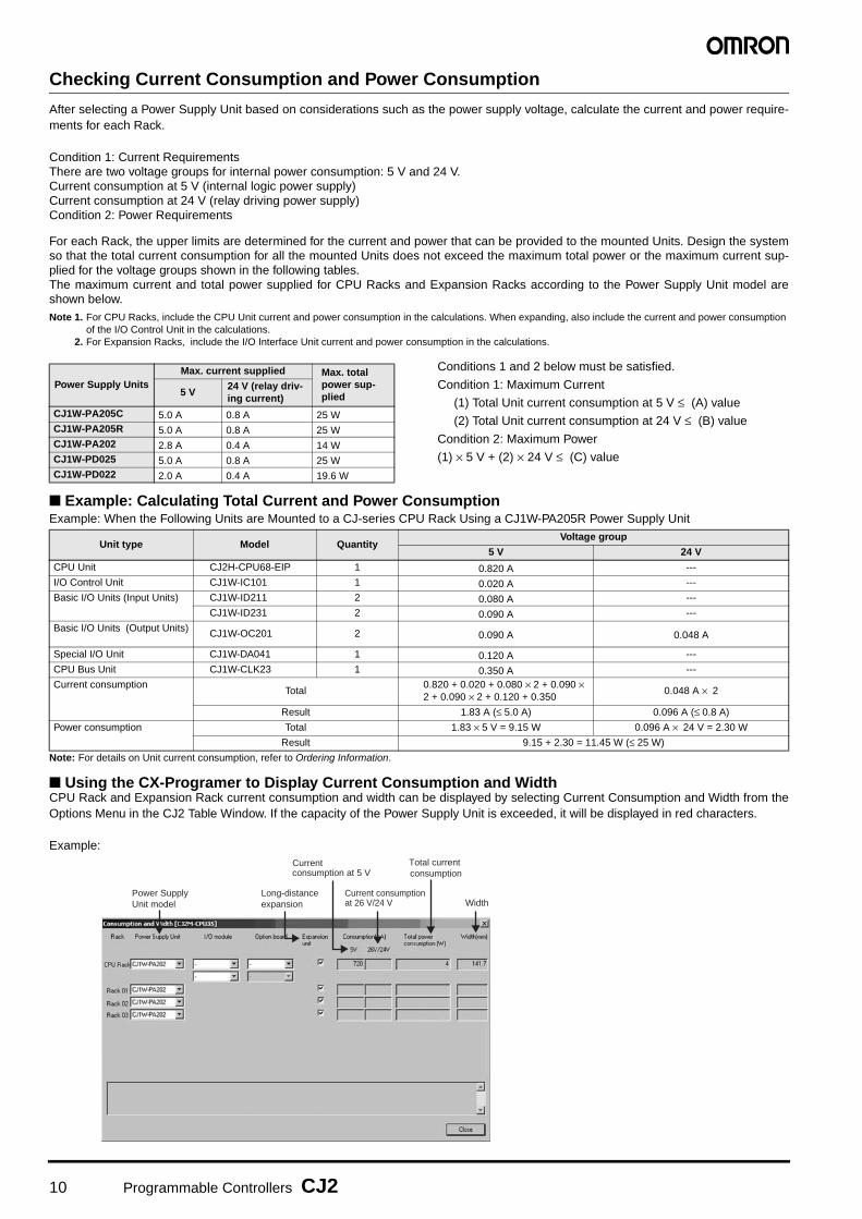
Checking Current Consumption and Power Consumption
After selecting a Power Supply Unit based on considerations such as the power supply voltage, calculate the current and power require-ments for each Rack.
Condition 1: Current RequirementsThere are two voltage groups for internal power consumption: 5 V and 24 V.Current consumption at 5 V (internal logic power supply) Current consumption at 24 V (relay driving power supply)Condition 2: Power Requirements
For each Rack, the upper limits are determined for the current and power that can be provided to the mounted Units. Design the systemso that the total current consumption for all the mounted Units does not exceed the maximum total power or the maximum current sup-plied for the voltage groups shown in the following tables. The maximum current and total power supplied for CPU Racks and Expansion Racks according to the Power Supply Unit model areshown below.Note 1. For CPU Racks, include the CPU Unit current and power consumption in the calculations. When expanding, also include the current and power consumption
of the I/O Control Unit in the calculations.2. For Expansion Racks, include the I/O Interface Unit current and power consumption in the calculations.
Conditions 1 and 2 below must be satisfied.
Condition 1: Maximum Current
(1) Total Unit current consumption at 5 V ≤ (A) value
(2) Total Unit current consumption at 24 V ≤ (B) value
Condition 2: Maximum Power
(1) × 5 V + (2) × 24 V ≤ (C) value
■ Example: Calculating Total Current and Power ConsumptionExample: When the Following Units are Mounted to a CJ-series CPU Rack Using a CJ1W-PA205R Power Supply Unit
Note: For details on Unit current consumption, refer to Ordering Information.
■ Using the CX-Programer to Display Current Consumption and WidthCPU Rack and Expansion Rack current consumption and width can be displayed by selecting Current Consumption and Width from theOptions Menu in the CJ2 Table Window. If the capacity of the Power Supply Unit is exceeded, it will be displayed in red characters.
Example:
Power Supply UnitsMax. current supplied Max. total
power sup-plied5 V
24 V (relay driv-ing current)
CJ1W-PA205C 5.0 A 0.8 A 25 WCJ1W-PA205R 5.0 A 0.8 A 25 WCJ1W-PA202 2.8 A 0.4 A 14 WCJ1W-PD025 5.0 A 0.8 A 25 WCJ1W-PD022 2.0 A 0.4 A 19.6 W
Unit type Model QuantityVoltage group
5 V 24 V
CPU Unit CJ2H-CPU68-EIP 1 0.820 A ---
I/O Control Unit CJ1W-IC101 1 0.020 A ---
Basic I/O Units (Input Units) CJ1W-ID211 2 0.080 A ---
CJ1W-ID231 2 0.090 A ---
Basic I/O Units (Output Units) CJ1W-OC201 2 0.090 A 0.048 A
Special I/O Unit CJ1W-DA041 1 0.120 A ---
CPU Bus Unit CJ1W-CLK23 1 0.350 A ---
Current consumptionTotal
0.820 + 0.020 + 0.080 × 2 + 0.090 × 2 + 0.090 × 2 + 0.120 + 0.350
0.048 A × 2
Result 1.83 A (≤ 5.0 A) 0.096 A (≤ 0.8 A)
Power consumption Total 1.83 × 5 V = 9.15 W 0.096 A × 24 V = 2.30 W
Result 9.15 + 2.30 = 11.45 W (≤ 25 W)
Power Supply Unit model
Current consumption at 5 V
Current consumption at 26 V/24 V
Total current consumption
Long-distance expansion Width

Programmable Controllers CJ2 11
Dimensions
Note: Units are in mm unless specified otherwise.
■ Product Dimensions
● Power Supply Units, CPU Units, and End Covers
● Option Boards (CJ2M-CPU3@ only)● Serial Option Boards
CONTROLLER
CJ2HCPU64-EIP
SYSMAC
PROGRAMMABLE
BATTERYSW SETTING
ERR/ALMRUN
COMMBKUP
INHPRPHL
NSMS
10M
UNITNo.
NODENo.
x16x1601
COMM100M
OPEN
PERIPHERAL
BUSY
MCPWR
PORT
100BASE-TX10BASE-T
35.4
27
27.6
65
90
W
Example Rack Widths using CJ1WPA202 Power Supply Unit (AC, 14 W)No. of Units mounted with 31-mm width
Rack width (mm)With
CJ2H-CPU6@-EIPWith
CJ2H-CPU6@With
CJ2M-CPU3@With
CJ2M-CPU1@1 170.5 139.5 152.7 121.7
2 201.5 170.5 183.7 152.7
3 232.5 201.5 214.7 183.7
4 263.5 232.5 245.7 214.7
5 294.5 263.5 276.7 245.7
6 325.5 294.5 307.7 276.7
7 356.5 325.5 338.7 307.7
8 387.5 356.5 369.7 338.7
9 418.5 387.5 400.7 369.7
10 449.5 418.5 431.7 400.7
Unit/product Model Width
Power Supply Unit
CJ1W-PA205C 80
CJ1W-PA205R 80
CJ1W-PA202 45
CJ1W-PD025 60
CJ1W-PD022 27
CPU Unit
CJ2H-CPU6@-EIP 79.8
CJ2H-CPU6@ 48.8
CJ2M-CPU3@ 62
CJ2M-CPU1@ 31
End Cover CJ1W-TER01 14.7
6581.6
W
90
W=27: CJ1W-PD022W=45: CJ1W-PA202W=80: CJ1W-PA205R CJ1W-PA205CW=60: CJ1W-PD025
�Power Supply Units
14.7
90
�End Cover (included with CPU Units)
34
38.8
�RS-422A Adapter CJ1W-CIF11
CONTROLLER
CJ2HCPU64-EIP
SYSMAC
PROGRAMMABLE
BATTERYSW SETTING
ERR/ALMRUN
COMMBKUP
INHPRPHL
NSMS
10M
UNITNo.
NODENo.
x16x1601
COMM100M
OPEN
PERIPHERAL
BUSY
MCPWR
PORT
100BASE-TX10BASE-T
90
2.7
2.7
79.874.5
65
66.2
�CPU UnitsCJ2H-CPU6@-EIP
90
2.7
2.7
48.874.5
65
66.2
CJ2H-CPU6@
90
2.7 6284.5
75
76.22.7
CJ2M-CPU3@
90
2.7
2.7
3184.5
75
76.2
CJ2M-CPU1@
37.3
35.9
35.9
5.1
16.5
13.5
16.5
19.7
37.3
35.9
35.9
8.9
16.513.5
15.7
16.5
CP1W-CIF01 CP1W-CIF11/CP1W-CIF12-V1

12 Programmable Controllers CJ2
● Units of Width 20 mm
● Units of Width 31 mm
● 64-point Basic I/O Units and 32-point Basic I/O Units (CJ1W-MD23@)
● Special I/O Units and CPU Bus Units
Unit/product Model Width
I/O Control Unit CJ1W-IC101
20
Pulse I/O Modules CJ2M-MD211/212
32-point Basic I/O UnitsCJ1W-ID231/232/233
CJ1W-OD231/232/233/234
B7A Interface UnitCJ1W-B7A22CJ1W-B7A14CJ1W-B7A04
CompoBus/S Master Unit CJ1W-SRM21
Space Unit CJ1W-SP001
● 32-Point I/O Units (CJ1W-ID223@/OD23@)
65
90
2.7
2.7
2066.5
6583.6
Fujitsu connector MIL connector
(112.5)
● I/O Control Unit
90
2.7
2.7(140)
6569.3
68
20
● Pulse I/O Modules (Only CJ2M CPU Unit)
90
2.7
2.7
2065
83.8
66.2
Unit Model Width
I/O Interface Unit CJ1W-II101
31
8/16-point Basic I/O Units
CJ1W-ID201CJ1W-ID211/212CJ1W-IA111/201CJ1W-OD20@CJ1W-OD211/212/213CJ1W-OC201/211CJ1W-OA201
32-point Basic I/O Units CJ1W-MD231CJ1W-MD232/233
64-point Basic I/O Units
CJ1W-ID261CJ1W-OD261CJ1W-MD261
CJ1W-ID262CJ1W-OD262/263CJ1W-MD263CJ1W-MD563
Interrupt Input Unit CJ1W-INT01
Quick-response Input Unit CJ1W-IDP01
Analog I/O UnitsCJ1W-AD@@@ (-V1)CJ1W-DA@@@ (@)CJ1W-MAD42
Process Input Units
CJ1W-PH41UCJ1W-AD04UCJ1W-PTS51/52/15/16CJ1W-PDC15
Temperature Control Units CJ1W-TC@@@
Position Control UnitsCJ1W-NC113/133CJ1W-NC213/233CJ1W-NC413/433
Position Control Unit with EtherCAT interface
CJ1W-NC281CJ1W-NC481CJ1W-NC881CJ1W-NCF81CJ1W-NC482CJ1W-NC882CJ1W-NCF82
EtherCAT Slave Unit CJ1W-ECT21
Position Control Unit withMECHATROLINK-II interface
CJ1W-NCF71
High-speed Counter Unit CJ1W-CT021
ID Sensor Units
CJ1W-V680C11CJ1W-V680C12CJ1W-V600C11CJ1W-V600C12
Unit Model Width
Controller Link Units CJ1W-CLK23
Serial Communications Units
CJ1W-SCU22CJ1W-SCU32CJ1W-SCU42CJ1W-SCU41-V1CJ1W-SCU21-V1CJ1W-SCU31-V1
EtherNet/IP Unit CJ1W-EIP21
31
Ethernet Unit CJ1W-ETN21
DeviceNet Unit CJ1W-DRM21
CompoNet Master Unit CJ1W-CRM21
FL-net Unit CJ1W-FLN22
(140)68
90
2.7
2.7
653169.3
90
2.7
2.7
31 6589
● I/O Interface Unit ● 8/6-point Basic I/O Units,Interrupt Input Unit, and High-speed Input Unit
(112.5)
MIL connector
6566.5
90
2.7
2.7
31
Fujitsu connector
6583.6
90
2.7
2.7
31

Programmable Controllers CJ2 13
● Units of Width 51 mm
● SPU Unit (High-speed Data Storage Unit)CJ1W-SPU01-V2
● Unit of Width 62 mm
● Position Contorol Unit (High-speed model)CJ1W-NC414/434
■ Mounting Dimensions ■ Mounting HeightThe mounting height of CJ-series CPU Racks and ExpansionRacks is from 81.6 to 89.0 mm depending on the Units that aremounted.Additional height is required to connect Programming Devices(e.g., CX-Programmer) and Cables. Be sure to allow sufficientmounting height.
Note: Consider the following points when expanding the configuration:The total length of I/O Connecting Cable must not exceed 12 m.I/O Connecting Cables require the bending radius indicated below.
● Expansion Cable
Note: Outer diameter of cable: 8.6 mm.
Unit Model Width
SPU Unit(High-speed Data Storage Unit)
CJ1W-SPU01-V251
Position Control Units(High-speed type)
CJ1W-NC214/234
6551 9
2.7
90
2.7
Unit Model Width
Position Control Units(High-speed type)
CJ1W-NC414/434 62
62
6584
2.7
90
2.7
CONTROLLER
CJ2HCPU64-EIP
SYSMAC
PROGRAMMABLE
BATTERYSW SETTING
ERR/ALMRUN
COMMBKUP
INHPRPHL
NSMS
10M
UNITNo.
NODENo.
x16x1601
COMM100M
OPEN
PERIPHERAL
BUSY
MCPWR
PORT
100BASE-TX10BASE-T
90
A65
35
27.5
27.5
DIN Track model number A
PFP-100N2 16 mm
PFP-100N 7.3 mm
FPP-50N 7.3 mm
81.6 to 89.0 mm
Approx. 100 to 150 mm
R R ≥ 69 mm

14 Programmable Controllers CJ2
General Specifications
*1. Includes the weight of end covers and battery.*2. Without a Serial Option Board.
ItemCJ2H- CJ2M-
CPU64 (-EIP) CPU65 (-EIP) CPU66 (-EIP) CPU67 (-EIP) CPU68 (-EIP) CPU1@ CPU3@Enclosure Mounted in a panelGrounding Less than 100 ΩCPU Unit Dimensions (H × D × W)
CJ2H-CPU6@-EIP : 90 mm × 65 mm × 80 mmCJ2H-CPU6@ : 90 mm × 65 mm × 49 mm
90 mm × 75 mm × 31 mm
90 mm × 75 mm × 62 mm
Weight *1 CJ2H-CPU6@-EIP : 280 g or lessCJ2H-CPU6@ : 190 g or less
130 g or less 190 g or less *2
Current Consumption CJ2H-CPU6@-EIP : 5 VDC, 0.82 ACJ2H-CPU6@ : 5 VDC, 0.42 A
5 VDC, 0.5 A 5 VDC, 0.7 A
Operation Environment
Ambient Operating Temperature
0 to 55°C
Ambient Operating Humidity
10% to 90% (with no condensation)
Atmosphere Must be free from corrosive gases.Ambient Storage Temperature
−20 to 70°C (excluding battery)
Altitude 2,000 m or lessPollution Degree 2 or less: Meets IEC 61010-2-201.Noise Immunity 2 kV on power supply line (Conforms to IEC 61000-4-4.)Overvoltage Category
Category II: Meets IEC 61010-2-201.
EMC Immunity Level
Zone B
Vibration Resistance
Conforms to IEC60068-2-6.5 to 8.4 Hz with 3.5-mm amplitude, 8.4 to 150 HzAcceleration of 9.8 m/s2 for 100 min in X, Y, and Z directions (10 sweeps of 10 min each = 100 min total)
Shock Resistance
Conforms to IEC60068-2-27.147 m/s2, 3 times in X, Y, and Z directions (100 m/s2 for Relay Output Units)
Battery Life 5 years at 25°CWeight Approx. 10 gModel CJ1W-BAT01
Applicable Standards Conforms to cULus, NK, LR and EC Directives.

Programmable Controllers CJ2 15
Performance Specifications
*1. The following times are added if EtherNet/IP data tag links are used for the CJ2H-CPU6@-EIP. Normal operation: 100 μs + Number of transfer words x 0.33 μsHigh-speed interrupt enabled: 100 μs + Number of transfer words x 0.87 μsThe following time must be added when using EtherNet/IP tag data links for the CJ2M-CPU3@.
100 μs + (No. of words transferred x 1.8 μs)The following time must be added when using Pulse I/O Modules with a CJ2M CPU Unit: 10 μs x Number of Pulse I/O Modules.
*2. This applies when High-speed interrupt function is used.*3. Supported only by CJ2M CPU Units with unit version 2.0 or later. A Pulse I/O Module must be mounted.*4. A960 to A1471 and A10000 to A11535 cannot be accessed by CPU Bus Units, Special I/O Units, PTs, and Support Software that do not specifically support the
CJ2 CPU Units.*5. Bits in the EM Area can be addressed either by bit or by word. These bits cannot be addressed by CPU Bus Units, Special I/O Units, PTs, and Support Software
that do not specifically support the CJ2 CPU Units.*6. EM banks D to 18 cannot be accessed by CPU Bus Units, Special I/O Units, PTs, and Support Software that do not specifically support the CJ2 CPU Units.
ItemCJ2H- CJ2M-
CPU64 (-EIP)
CPU65 (-EIP)
CPU66 (-EIP)
CPU67 (-EIP)
CPU68 (-EIP)
CPU11/31
CPU12/32
CPU13/33
CPU14/34
CPU15/35
User Memory 50K steps
100K steps
150K steps
250K steps
400K steps
5K steps
10K steps
20K steps
30K steps
60K steps
I/O Bits 2,560 bits
Processing Speed
Overhead Processing Time *1 Normal Mode: CJ2H-CPU6@-EIP : 200 μsCJ2H-CPU6@ : 100 μs
Normal Mode: CJ2M-CPU3@: 270 μsCJ2M-CPU1@: 160 μs
Execution Time Basic Instructions: 0.016 μs min.;Special Instructions: 0.048 μs min.
Basic Instructions: 0.04 μs min.;Special Instructions: 0.06 μs min.
Interrupts I/O Interrupts and External Interrupts
Interrupt task startup time: 17 μs *2 or 26 μs(30 μs for unit version 1.0)
Return times to cyclic tasks: 8 μs *2 or 11 μs (15 μs for unit version 1.0)
Interrupt task startup time: 31 μs
Return times to cyclic tasks: 10 μs
Scheduled Interrupts Minimum time interval: 0.2 ms *2 (set in 0.1-ms increments)
Minimum time interval: 0.4 ms (set in 0.1-ms increments)
Interrupt task startup time: 13 μs *2 or 22 μs (27 μs for unit version 1.0)Return times to cyclic tasks: 8 μs *2 or 11 μs (15 μs for unit version 1.0)
Interrupt task startup time: 30 μs
Return time to cyclic task: 11 μs
Maximum Number of Connectable Units Total per CPU Rack or Expansion Rack: 10 Units max.;Total per PLC: 40 Units max.
Basic I/O Units No limitHowever, a maximum of two CJ1W-INT01 Interrupt Input Units can be mounted.
Special I/O Units Units for up to 96 unit numbers can be mounted. (Unit numbers run from 0 to 95. Units are allocated between 1 and 8 unit numbers.)
CPU Bus Units CJ2M-CPU3@: 15 Units max. CJ2M-CPU1@: 16 Units max.
Pulse I/O Modules 2 Units max. *3
Slots for which interrupts can be used Slots 0 to 4 on CPU Rack
Maximum Number of Expansion Racks 3 max.
CIO Area I/O Area 2,560 bits (160 words): Words CIO 0000 to CIO 0159
Link Area 3,200 bits (200 words): Words CIO 1000 to CIO 1199
Synchronous Data Refresh Area 1,536 bits (96 words): Words CIO 1200 to CIO 1295 ---
CPU Bus Unit Area 6,400 bits (400 words): Words CIO 1500 to CIO 1899
Special I/O Unit Area 15,360 bits (960 words): Words CIO 2000 to CIO 2959
Pulse I/O Area --- 20 inputs, 12 outputs (CIO 2960 to CIO 2963) *3
Serial PLC Link Words --- 1,440 bits (90 words): Words CIO 3100 to CIO 3189
DeviceNet Area 9,600 bits (600 words): Words CIO 3200 to CIO 3799
Internal I/O Area 3,200 bits (200 words): Words CIO 1300 to CIO 1499 (Cannot be used for external I/O.)37,504 bits (2,344 words): Words CIO 3800 to CIO 6143 (Cannot be used for external I/O.)
Work Area 8,192 bits (512 words): Words W000 to W511 (Cannot be used for external I/O.)
Holding Area 8,192 bits (512 words): Words H000 to H511Bits in this area maintain their ON/OFF status when PLC is turned OFF or operating mode is changed.Words H512 to H1535: These words can be used only for function blocks. They can be used only for function block instances (i.e., they are allocated only for internal variables in function blocks).
Auxiliary Area Read-only: 31,744 bits (1,984 words)• 7,168 bits (448 words): Words A0 to A447• 24,576 bits (1,536 words): Words A10000 to A11535 *4
Read/write: 16,384 bits (1,024 words) in words A448 to A1471 *4
Temporary Area 16 bits: TR0 to TR15
Timer Area 4,096 timer numbers (T0000 to T4095 (separate from counters))
Counter Area 4,096 counter numbers (C0000 to C4095 (separate from timers))
DM Area 32k words *5DM Area words for Special I/O Units: D20000 to D29599 (100 words × 96 Units)DM Area words for CPU Bus Units: D30000 to D31599 (100 words × 16 Units)
EM Area 32k words/bank × 25 banks max.: E00_00000 to E18_32767 max. *5, *6
32k words/bank × 4 banks max.: E00_00000 to E3_32767 max. *5
32K words × 4 banks
32K words × 4 banks
32K words × 10 banks
32K words × 15 banks
32K words × 25 banks
32K words × 1 bank 32K words × 4 banks

16 Programmable Controllers CJ2
*7. With CJ2H CPU Units with unit version 1.2 or later, force-setting/resetting bits in the EM Area is possible either for banks that have been specified for automaticaddress assignment or for banks specified for the EM Area force-set/reset function. With CJ2M CPU Units, force-setting/resetting bits in the EM Area is possibleonly for banks specified for the EM Area force-set/reset function.
*8. Supported only by the CJ2H-CPU6@-EIP and CJ2M-CPU3@.*9. This data type cannot be used in Function blocks.*10. This data type can be used only in Function blocks.*11. Supported only when CX-Programmer version 9.0 or later is used.
ItemCJ2H- CJ2M-
CPU64 (-EIP)
CPU65 (-EIP)
CPU66 (-EIP)
CPU67 (-EIP)
CPU68 (-EIP)
CPU11/31
CPU12/32
CPU13/33
CPU14/34
CPU15/35
Banks for which bits can be force-set/reset *7
Using EM Area force-setting/resetting Banks 0 to 3 hex
Banks 0 to 3 hex
Banks 0 to 9 hex
Banks 0 to E hex
Banks 0 to 18 hex
Bank 0 hex Banks 0 to 3 hex
Using automatic address allocation specifications
Bank 3 hex
Bank 3 hex
Banks 6 to 9 hex
Banks 7 to E hex
Banks 11 to 18 hex ---
Index Registers IR0 to IR15These are special registers for storing PLC memory addresses for indirect addressing. (Index Registers can be set so that they are unique in each task or so that they are shared by all tasks.)
Cyclic Task Flag Area 128 flags
Memory Card 128 MB, 256 MB, or 512 MB
Operating Modes PROGRAM Mode: Programs are not executed. Preparations can be executed prior to program execution in this mode.
MONITOR Mode: Programs are executed, and some operations, such as online editing, and changes to present values in I/O memory, are enabled in this mode.
RUN Mode: Programs are executed. This is the normal operating mode.
Execution Mode Normal Mode
Programming Languages Ladder Logic (LD),Sequential Function Charts (SFC),Structured Text (ST), andInstruction Lists (IL)
Function Blocks
Maximum number of definitions 2,048 256 2,048
Maximum number of instances 2,048 256 2,048
FB Program Area --- 20K steps
Tasks Type of Tasks Cyclic tasksInterrupt tasks (Power OFF interrupt tasks, scheduled interrupt tasks, I/O interrupt tasks, and external interrupt tasks, and input interrupt tasks *3)
Number of Tasks Cyclic tasks: 128Interrupt tasks: 256(Interrupt tasks can be defined as cyclic tasks to create extra cyclic tasks. Therefore, the total number of cyclic tasks is actually 384 max.)
Symbols (Variables)
Type of Symbols • Local symbols: Can be used only within a single task in the PLC.• Global symbols: Can be used in all tasks in the PLC.• Network symbols (tags) *8: I/O memory in the CPU Unit can be externally accessed using symbols,
depending on parameter settings.
Data Type of Symbols • BOOL (bit)• UINT (one-word unsigned binary)• UDINT (two-word unsigned binary)• ULINT (four-word unsigned binary)• INT (one-word signed binary)• DINT (two-word signed binary)• LINT (four-word signed binary)• UINT BCD (one-word unsigned BCD) *9• UDINT BCD (two-word unsigned BCD) *9• ULINT BCD (four-word unsigned BCD) *9• REAL (two-word floating-point)• LREAL (four-word floating-point)• CHANNEL (word) *9• NUMBER (constant or number) *9• WORD (one-word hexadecimal)• DWORD (two-word hexadecimal)• LWORD (four-word hexadecimal)• STRING (1 to 255 ASCII characters)• TIMER *10• COUNTER *10• user-defined data types (delta structures) *11
Maximum Size of Symbol 32k words
Array Symbols (Array Variables) One-dimensional arrays
Number of Array Elements 32,000 elements max.
Number of Registrable Network Symbols (Tags) *8
20,000 max. 2,000 max.
Length of Network Symbol (Tag) Name *8
255 bytes max.
Encoding of Network Symbols (Tags) *8
UTF-8

Programmable Controllers CJ2 17
ItemCJ2H- CJ2M-
CPU64 (-EIP)
CPU65 (-EIP)
CPU66 (-EIP)
CPU67 (-EIP)
CPU68 (-EIP)
CPU11/31
CPU12/32
CPU13/33
CPU14/34
CPU15/35
Data Tracing Memory Capacity 8,000 words 16,000 words
32,000 words 8,000 words
The EM Area can be specified from the CX-Programmer to use up to 32K words multiplied by the number of banks supported by the CPU Unit model.
Number of Samplings Bits = 31, one-word data =16, two-word data = 8, four-word data = 4
Sampling Cycle 1 to 2,550 ms (Unit: 1 ms)
Trigger Conditions ON/OFF of specified bitData comparison of specified wordData size: 1 word, 2 words, 4 wordsComparison Method: Equals (=), Greater Than (>), Greater Than or Equals (≥), Less Than (<), Less Than or Equals (≤), Not Equal (≠)
Delay Value −32,768 to +32,767 ms
File Memory Memory Card (128, 256, or 512 Mbytes) (Use the Memory Cards provided by OMRON.) EM file memory (Part of the EM Area can be converted for use as file memory.)
Source/Comment Memory
Function block program memory, comment file, program index file, symbol tables
Capacity: 3.5 Mbytes Capacity: 1 Mbytes
Communications
Logical Ports for Communications
Logical Ports 8 ports (Used for SEND, RECV, CMND, PMCR, TXDU, and RXDU instructions.)
Extended Logical Ports 64 ports (Used for SEND2, RECV2, CMND2, and PMCR2 instructions.)
CIP Communications Specification
Class 3 (Connection Type)
Number of connections: 128
UCMM (Non-connection Type)
Maximum number of clients that can communicate at the same time: 32Maximum number of servers that can communicate at the same time: 32
Maximum number of clients that can communicate at the same time: 16Maximum number of servers that can communicate at the same time: 16
Peripheral (USB) Port USB 2.0-compliant B-type connector
Baud Rate 12 Mbps max.
Transmission Distance 5 m max.
Serial Port Interface: Conforms to EIA RS-232C. • CJ2M-CPU1@ interface: Conforms to EIA RS-232C.• CJ2M-CPU3@: No serial ports with default systemOne of the following Serial Option Boards can be mounted. • CP1W-CIF01 RS-232C Option Board• CP1W-CIF11 RS-422A/485 Option Board
(not isolated, max. transmission distance: 50 m)• CP1W-CIF12-V1 RS-422A/485 Option Board
(isolated, max. transmission distance: 500 m)
Communications Method Half-duplex
Synchronization Method Start-stop
Baud Rate 0.3, 0.6, 1.2, 2.4, 4.8, 9.6, 19.2, 38.4, 57.6, or 115.2 (kbps)
Transmission Distance 15 m max.

18 Programmable Controllers CJ2
*12. The EtherNet/IP port is built into the CJ2H-CPU6@-EIP and CJ2M-CPU3@ only.*13. “Packets per second” is the number of communications packets that can be processed per second.*14. When using the EtherNet/IP Unit with version 3.0 or later. When using the EtherNet/IP Unit with version 2.1 or earlier, the maximum allowed communications
bandwidth per Unit is 6,000 pps. When using the EtherNet/IP Unit with version 3.0 or later, the Network Configurator with version 3.57 or higher is required.*15. Large Forward Open (CIP optional specification) must be supported in order for 505 to 1,444 bytes to be used as the data size. Application is supported between
CS/CJ-series PLCs. When connecting to devices from other manufacturers, make sure that the devices support the Large Forward Open specification. *16. Unit version 2.0 of built-in EtherNet/IP section: 20 words.*17. If the maximum number is exceeded, refreshing will require more than one CPU Unit cycle.*18. When changing parameters, however, the EtherNet/IP port where the change is made will be restarted. In addition, a timeout will temporarily occur at the other
node that was communicating with that port, and it will then recover automatically.*19. The EtherNet/IP port supports an IGMP client, so unnecessary multicast packets are filtered by using an ethernet switch that supports IGMP snooping.
ItemCJ2H- CJ2M-
CPU64 (-EIP)
CPU65 (-EIP)
CPU66 (-EIP)
CPU67 (-EIP)
CPU68 (-EIP)
CPU11/31
CPU12/32
CPU13/33
CPU14/34
CPU15/35
Communications
EtherNet/IP Port *12 ---
Tran
smis
sion
Spe
cific
atio
ns Media Access Method CSMA/CD
Modulation Baseband
Transmission Paths Star
Baud Rate 100 Mbps (100Base-TX)
Transmission Media Shielded twisted-pair (STP) cable; Categories: 5, 5e
Transmission Distance 100 m (between ethernet switch and node)
Number of Cascade Connections No restrictions if ethernet switch is used.
Com
mun
icat
ions
Spe
cific
atio
ns
CIP Communications: Tag Data Links ---
Number of Connections 256 32
Packet Interval (Refresh period)
0.5 to 10,000 ms (Unit: 0.5 ms)Can be set for each connection. (Data will be refreshed at the set interval, regardless of the number of nodes.)
1 to 10,000 ms (in 0.5-ms increments) Can be set for each connection. (Data will be refreshed at the set interval, regardless of the number of nodes.)
Maximum allowed communications bandwidth per Unit
6,000 to 12,000 packets per second *13 *14 3,000 packets per second *13
Number of Tag Sets 256 32
Type of Tags CIO, DM, EM, HR, WR, and network symbols
Number of Tags per Connection 8 (Seven tags if PLC status is included in the segment.)
Maximum Link Data Size per Node (total size of all tags)
184,832 words 640 words
Maximum Data Size per Connection
252 or 722 words *15(Data is synchronized within each connection.)
640 words *16 (Data is synchronized within each connection.)
Number of Registrable Tag Set 256 (1 connection = 1 segment) 32 (1 connection = 1 segment)
Maximum Tag Set Size 722 words (One word is used when PLC status is included in the segment.)
640 words *16 (One word is used when PLC status is included in the segment.)
Maximum Number of Tags Refreshable in a Single Cycle of CPU Unit *17
Output/send (CPU Unit to EtherNet/IP): 256Input/receive (EtherNet/IP to CPU Unit): 256
Output/send (CPU Unit to EtherNet/IP): 32Input/receive (EtherNet/IP to CPU Unit): 32
Data Size Refreshable in a Single Cycle of CPU Unit *17
Output/send (CPU to EtherNet/IP): 6,432 wordsInput/receive (EtherNet/IP to CPU): 6,432 words
Output/send (CPU Unit to EtherNet/IP): 640 wordsInput/receive (EtherNet/IP to CPU Unit): 640 words
Change of Tag Data Link Parameter Settings during Operation
OK *18
Multi-cast Packet Filter *19 OK
CIP Communications: Explicit Messages
---
Class 3 (Connection Type)
Number of connections: 128
UCMM (Non-connection Type) Maximum number of clients that can communicate at the same time: 32Maximum number of servers that can communicate at the same time: 32
Maximum number of clients that can communicate at the same time: 16Maximum number of servers that can communicate at the same time: 16
CIP Routing OK (CIP routing is enabled for the following remote Units: CJ1W-EIP21, CJ2H-CPU6@-EIP, CJ2M-CPU3@ and
CS1W-EIP21.)
FINS Communications ---
FINS/UDP OK
FINS/TCP 16 connections max.
EtherNet/IP Conformance Test Conforms to A5.
EtherNet/IP Interface 10Base-T/100Base-TXAuto Negotiation/Fixed Setting

Programmable Controllers CJ2 19
Function Specifications
*1. Supported only by the CJ2H CPU Units with unit version 1.1 or later and CJ2M CPU Units.*2. Position Control Units (High-speed type) CJ1W-NC@@4 supported by the CJ2H CPU Units with unit version 1.1 or later.
Position Control Units with EtherCAT interface CJ1W-NC@82 are supported by the CJ2H CPU Units with unit version 1.4 or later.
Functions Description
Cycle Time Management
Minimum Cycle Time A minimum cycle time can be set. (0.2 to 32,000 ms; Unit: 0.1 ms)The minimum cycle time setting can be changed in MONITOR mode. *1
Cycle Time Monitoring The cycle time is monitored. (0.01 to 40,000 ms; Unit: 0.01 ms)
Background Processing Instructions with long execution times can be executed over multiple cycles to prevent fluctuations in the cycle time.
Unit (I/O) Management
Basic I/O Units, Special I/O Units, and CPU Bus Units
I/O Refreshing Cyclic Refreshing Cyclic refreshing of Basic I/O Units, Special I/O Units, and CPU Bus Units
Immediate Refreshing I/O refreshing by immediate refreshing instructions
Refreshing by IORF I/O refreshing by IORF instruction
Unit Recognition at Startup The number of units recognized when the power is turned ON is displayed.
Basic I/O Units Input Response Time Setting The input response times can be set for Basic I/O Units. The response time can be increased to reduce the effects of chattering and noise at input contacts. The response time can be decreased to enable detecting shorter input pulses.
Load OFF Function All of the outputs on Basic I/O Units can be turned OFF when an error occurs in RUN or MONITOR mode.
Basic I/O Unit Status Monitoring Alarm information can be read from Basic I/O Units and the number of Units recognized can be read.
Reading/writing data using instructions for specific Units *1
Special instructions can be used to read/write required data for specific Units at high speed.
Special I/O Units and CPU Bus Units
Unit Restart Bits to Restart Units A Special I/O Unit or CPU Bus Unit can be restarted.
Synchronous Unit Operation *2 The start of processing for all the specified Units can be synchronized at a fixed interval.Maximum number of Units: 10 Units(Only Units that support Synchronous Operation Mode can be used.)Synchronous operation cycle: 0.5 to 10 ms (default: 2 ms)Maximum number of words for synchronous data refreshing: 96 words (total of all Units)
Configuration Management
Automatic I/O Allocation at Startup I/O words can be automatically allocated to the Basic I/O Units that are connected in the PLC to start operation automatically without registering Units into I/O tables.
I/O Table Creation The current unit configuration can be registered in I/O tables to prevent it from being changed, to reserve words, and to set words.
Rack/Slot First Word Settings The first words allocated to a Units on the Racks can be set.
Memory Management
Holding I/O Memory when Changing Operating Modes The status of I/O memory can be held when the operating mode is changed or power is turned ON. The forced-set/reset status can be held when the operating mode is changed or power is turned ON.
File Memory Files (such as program files, data files, and symbol table files) can be stored in Memory Card, EM File Memory, or Comment Memory.
Built-in Flash Memory The user program and Parameter Area can be backed up to an internal flash memory when they are transferred to the CPU Unit.
EM File Function Parts of the EM Area can be treated as file memory.
Storing Comments I/O comments can be stored as symbol table files in a Memory Card, EM file memory, or comment memory.
EM Configuration EM Area can be set as trace memory or EM file memory.
Memory Cards Automatic File Transfer at Startup A program file and parameter files can be read from a Memory Card when the power is turned ON.
Program Replacement during PLC Operation User programs can be transferred from a Memory Card to CPU Unit during operation.
Function for Reading and Writing Data from a Memory Card Data in I/O memory in the CPU Unit can be written to a Memory Card in CSV/TXT format. Data in CSV/TXT format in the Memory Card can be read to I/O memory in the CPU Unit.

20 Programmable Controllers CJ2
*3. A Serial Option Board is required to use a serial port for the CJ2M-CPU3@ CJ2M CPU Unit. *4. A Serial Option Board is required to use the CJ2M-CPU3@ CJ2M CPU Unit in Serial PLC Links. *5. Supported only by the CJ2H-CPU6@-EIP and CJ2M-CPU3@.*6. Supported only by the CJ2M CPU Units.*7. Supported only by the CJ2H CPU Units with unit version 1.1 or later.
Functions Description
Communications ---
Peripheral (USB) Port
Peripheral Bus Bus for communications with various kinds of Support Software running on a personal computer. High-speed communications are supported.
Serial Port *3 ---
Host Link (SYSWAY) Communications Host Link commands or FINS commands placed between Host Link headers and terminators can be sent from a host computer or PT to read/write I/O memory, read/control the operating mode, and perform other operations for PLC.
No-protocol Communications I/O instructions for communications ports (such as TXD/RXD instructions) can be used for data transfer with peripheral devices such as bar code readers and printers.
NT Link Communications I/O memory in the PLC can be allocated and directly linked to various PT functions, including status control areas, status notification areas, touch switches, lamps, memory tables, and other objects.
Peripheral Bus Bus for communications with various kinds of Support Software running on a personal computer. High-speed communications are supported.
Serial Gateway This gateway enables receiving and automatically converting FINS to the CompoWay/F.
Serial PLC Links *4 Data is exchanged between CPU Units using serial ports without communications programming. PTs set to the 1:N NT Link protocol can be included in the network.
EtherNet/IP Port *5 100Base-TX/10Base-TProtocols: TCP/IP, UDP, ARP, ICMP (ping only), BOOTPApplications: FINS, CIP, SNTP, DNS (Client), FTP (Server)
CIP Communications Service
Tag Data Links Programless cyclic data exchanges with the devices on the EtherNet/IP network.
Message Communications Any CIP commands can be received from the devices on the EtherNet/IP network.
FINS Communications Service
Message Communications Any FINS commands can be transferred with the devices on the EtherNet/IP network.
Interrupt Scheduled Interrupts Tasks can be executed at a specified interval
Resetting and restarting with MSKS(690) *6 When MSKS(690) is executed, the internal timer is restarted and the time to first interrupt is set to a fixed value.
Reading present value of internal timer with MSKS(690) *6
MSKS(690) can be used to read the time that has elapsed until the schedule interrupt is started or since the previous scheduled interrupt.
Power OFF Interrupts A task can be executed when CPU Unit's power turns OFF.
I/O Interrupt Tasks A task can be executed when an input signal is input to an Interrupt Input Unit.
External Interrupt Tasks A task can be executed when interrupts are requested from a Special I/O Unit or a CPU Bus Unit.
High-speed Interrupt Function *7 Improves performance for executing interrupt tasks with certain restrictions.
Clock Clock Function Clock data is stored in memory. Accuracy (Accuracy depends on the temperature.)Ambient temperature of 55°C: −3.5 to +0.5 min error per monthAmbient temperature of 25°C: −1.5 to +1.5 min error per monthAmbient temperature of 0°C: −3 to +1 min error per month
Operation Start Time Storage The time when operating mode was last changed to RUN mode or MONITOR mode is stored.
Operation Stop Time Storage The last time a fatal error occurred or the last time the operating mode was changed to PROGRAM mode is stored.
Startup Time Storage The time when the power was turned ON is stored.
Power Interruption Time Storage The time when the power is turned OFF is stored.
Total Power ON Time Calculation The total time that the PLC has been ON is stored in increments of 10 hours.
Power ON Clock Data Storage A history of the times when the power was turned ON is stored.
User Program Overwritten Time Storage The time that the user program was last overwritten is stored.
Parameter Date Storage The time when the Parameter Area was overwritten is stored.

Programmable Controllers CJ2 21
*8. Supported only by CJ2H CPU Units with unit version 1.2 or later and CJ2M CPU Units.*9. Supported only by CJ2H-CPU6@-EIP and CJ2H-CPU3@.*10. Supported only by CJ2M-CPU3@.
Functions Description
Power Supply Management
Memory Protection Holding Area data, DM Area data, EM Area data, Counter Completion Flags, and counter present values are held even when power is turned OFF. CIO Area, Work Area, some Auxiliary Area data, and Timer Completion Flags, timer present values, index registers, and data registers can be protected by turning ON the IOM Hold Bit in the Auxiliary Area, and by also setting the IOM Hold Bit to “Hold” in the PLC Setup.
Power OFF Detection Time Setting The detection time for power interruptions can be set. AC power supply: 10 to 25 ms (variable)DC power supply: 2 to 5 ms (CJ1W-PD022) or 2 to 20 ms (CJ1W-PD025)
Power OFF Detection Delay Time The detection of power interruptions can be delayed: 0 to 10 ms(Not supported by the CJ1W-PD022.)
Number of Power Interruptions Counter The number of times power has been interrupted is counted.
Function Blocks Standard programming can be encapsulated as function blocks.
Languages in Function Block Definitions Ladder programming or structured text
Debugging Online Editing The program can be changed during operation (in MONITOR or PROGRAM mode), except for block programming areas.
Force-Set/Reset Specified bits can be set or reset.
A parameter can be set to enable force-setting/resetting bits in EM Area banks. Force-setting/resetting is enabled for the specified bank and all the banks after it. *8
Differentiate Monitoring ON/OFF changes in specified bits can be monitored.
Data Tracing The specified I/O memory data can be stored in the trace memory in the CPU Unit. The triggers can be set.
Continuous Tracing The trace data can be uploaded during data tracing using CX-Programmer, which enables continuously logging the data by constantly uploading the trace data (trace data uploading during tracing).
Automatically starting tracing when operation starts Data tracing can be automatically started when operation is started (i.e., when the operating mode is changed from PROGRAM mode to MONITOR or RUN mode).
Storing Location of Error when an Error Occurs The location and task number where execution stopped for a program error is recorded.
Program Check The programs can be checked for items such as no END instruction and FALS/FAL errors at startup.
Self-diagnosis and Restoration
Error Log A function is provided to store predefined error codes in CPU Unit, error information, and time at which the error occurred.
CPU Error Detection CPU Unit WDT errors are detected.
User-defined Failure Diagnosis Errors can be generated for user-specified conditions: Non-fatal errors (FAL) and fatal errors (FALS). Program section time diagnosis and program section logic diagnosis are supported (FPD instruction).
Load OFF Function This function turns OFF all outputs from Output Units when an error occurs.
RUN Output The RUN output from the CJ1W-PA205R turns ON while CPU Unit is in RUN mode or MONITOR mode.
Basic I/O Load Short-circuit Detection This function provides alarm information from Basic I/O Units that have load short-circuit protection.
Failure Point Detection The time and logic of an instruction block can be analyzes using the FPD instruction.
CPU Standby Detection This function indicates when the CPU Unit is on standby because all Special I/O Units and CPU Bus Units have not been recognized at the startup in RUN or MONITOR mode.
Non-fatal Error Detection System FAL Error Detection (User-defined non-fatal error)
This function generates a non-fatal (FAL) error when the user-defined conditions are met in program.
Duplicated Refreshing Error Detection
This function detects an error when an immediate refreshing Instruction in an interrupt task is competing with I/O refreshing of a cyclic task.
Basic I/O Unit Error Detection This function detects the errors in Basic I/O Units.
Backup Memory Error Detection This function detects errors in the memory backup of the user programs and parameter area (backup memory).
PLC Setup Error Detection This function detects setting errors in the PLC Setup.
CPU Bus Unit Error Detection This function detects an error when there is an error in data exchange between the CPU Unit and a CPU Bus Unit.
Special I/O Unit Error Detection This function detects an error when there is an error in data exchange between the CPU Unit and a Special I/O Unit.
Tag Memory Error Detection *9 This function detects errors in tag memory.
Battery Error Detection This function detects an error when a battery is not connected to the CPU Unit or when the battery voltage drops.
CPU Bus Unit Setting Error Detection
This function detects an error when the model of a CPU Bus Unit in the registered I/O tables does not agree with the model that is actually mounted in the PLC.
Special I/O Unit Setting Error Detection
This function detects an error when the model of a Special I/O Unit in the registered I/O tables does not agree with the model of Unit that is actually mounted.
Option Board Error Detection *10 This function detects the errors in Serial Option Board mounting status.

22 Programmable Controllers CJ2
*11. Supported only by CJ2H CPU Units.
Functions Description
Self-diagnosis and Restoration (Continued from previous page)
Fatal Error Detection Memory Error Detection This function detects errors that occur in memory of the CPU Unit.
I/O Bus Error Detection This function detects when an error occurs in data transfers between the Units mounted in Rack slots and the CPU Unit and detects when the End Cover is not connected to the CPU Rack or an Expansion Rack.
Unit/Rack Number Duplication Error
This function detects an error when the same unit number is set for two or more Units, the same word is allocated to two or more Basic I/O Units, or the same rack number is set for two or more Racks.
Too Many I/O Points Error Detection
This function detects an error when the total number of I/O points set in the I/O tables or the number of Units per Rack exceeds the specified range.
I/O Setting Error Detection The registered I/O tables are used to detect errors if the number of Units in the registered I/O tables does not agree with the actual number of Units that are connected or an Interrupt Unit has been connected in the wrong position, i.e., not in the following slots.• CJ2H-CPU6@-EIP: Slots 0 to 3• CJ2H-CPU6@: Slots 0 to 4• CJ2M-CPU3@: Slots 0 to 4• CJ2M-CPU1@: Slots 0 to 4
Program Error Detection This function detects errors in programs.
Instruction Processing Error Detection
This function detects an error when the given data value is invalid when executing an instruction, or execution of instruction between tasks was attempted.
Indirect DM/EM BCD Error Detection
This function detects an error when an indirect DM/EM address in BCD mode is not BCD.
Illegal Area Access Error Detection
This function detects an error when an attempt is made to access an illegal area with an instruction operand.
No END Error Detection
This function detects an error when there is no END instruction at the end of the program.
Task Error Detection This function detects an error when there are no tasks that can be executed in a cycle, there is no program for a task, or the execution condition for an interrupt task was met but there is no interrupt task with the specified number.
Differentiation Overflow Error Detection
This function detects an error when too many differentiated instructions are entered or deleted during online editing (131,072 times or more).
Invalid Instruction Error Detection
This function detects an error when an attempt is made to execute an instruction that is not defined in the system.
User Program Area Overflow Error Detection
This function detects an error when instruction data is stored after the last address in user program area.
Cycle Time Exceeded Error Detection
This function monitors the cycle time (10 to 40,000 ms) and stops the operation when the set value is exceeded.
System FALS Error Detection(User-defined Fatal Error)
This function generates a fatal (FALS) error when the user-defined conditions are met in program.
Version Error Detection This function detects an error when a user program includes a function that is not supported by the current unit version.
Memory Card Transfer Error Detection
This function detects an error when the automatic file transfer from Memory Card fails at startup.
Memory Self-restoration Function This function performs a parity check on the user program area and self-restoration data. *11
Maintenance Simple Backup Function This function collectively backs up the data in CPU Unit (user programs, parameters, and I/O memory) and internal backup data in the I/O Units.
Unsolicited Communications A function that allows the PLC to use Network Communications Instruction to send required FINS commands to a computer connected via a Host Link
Remote Programming and Monitoring Host Link communications can be used for remote programming and remote monitoring through a Controller Link, Ethernet, DeviceNet, or SYSMAC LINK Network. Communications across network layers can be performed.
Controller Link or Ethernet: 8 layersDeviceNet or SYSMAC LINK: 3 layers
Automatic Online Connection via Network
Direct Serial Connection
This function enables automatically connecting to the PLC online when the CX-Programmer is directly connected by a serial connection (peripheral (USB) port or serial port).
Via Networks This function enables connecting the CX-Programmer online to a PLC that is connected via an EtherNet/IP network.
Security Read Protection using Password This function protects reading and displaying programs and tasks using passwords.
Write protection: Set using the DIP switch.Read protection: Set a password using the CX-Programmer.
FINS Write Protection This function prohibits writing by using FINS commands sent over the network.
Unit Name Function This function allows the users to give any names to the Units. Names are verified at online connection to prevent wrong connection
Hardware ID Using Lot Numbers This function sets operation protection by identifying hardware using the user programs according to lot numbers stored in the Auxiliary Area.

Programmable Controllers CJ2 23
■ Unit Versions
■ Unit Versions and Programming DevicesThe following tables show the relationship between unit versions and CX-Programmer versions.
*1. It is not necessary to upgrade the version of the CX-Programmer if functionality that was enhanced for the upgrade of the CPU Unit will not be used. *2. CX-Programmer version 8.2 or higher is required to use the functions added for unit version 1.1. The high-speed interrupt function and changing the minimum
cycle time setting in MONITOR mode, however, are also supported by CX-Programmer version 8.02.*3. A Programming Console cannot be used with a CJ2 CPU Unit.
Units Models Unit Version
CJ2H CPU Unit CJ2H-CPU6@-EIP Unit version 1.0 (Built-in EtherNet/IP section: Unit version 2.0)
Unit version 1.1 (Built-in EtherNet/IP section: Unit version 2.0)
Unit version 1.2 (Built-in EtherNet/IP section: Unit version 2.0)
Unit version 1.3 (Built-in EtherNet/IP section: Unit version 2.0)
Unit version 1.4 (Built-in EtherNet/IP section: Unit version 2.@/Unit version 3.0)
CJ2H-CPU6@ Unit version 1.1
Unit version 1.2
Unit version 1.3
Unit version 1.4
CJ2M CPU Unit CJ2M-CPU3@ Unit version 1.0 (Built-in EtherNet/IP section: Unit version 2.0) Unit version 2.0 (Built-in EtherNet/IP section: Unit version 2.0)Unit version 2.0 (Built-in EtherNet/IP section: Unit version 2.1)
CJ2M-CPU1@ Unit version 1.0Unit version 2.0
CPU Unit Functions
Required Programming Device
CX-ProgrammerProgramming
ConsoleVer.7.1 or lower
Ver.8.0 Ver.8.2 Ver.9.0 Ver.9.1 Ver.9.12Ver.9.3 or
higher
CJ2H CJ2H-CPU6@-EIPUnit version 1.0
Functions for unit version 1.0 --- OK OK OK OK OK OK --- *3
CJ2H-CPU6@-EIPUnit version 1.1
Functions added for unit version 1.1
Using new functions --- --- OK *2 OK OK OK OK
Not using new functions
--- OK *1 OK OK OK OK OK
CJ2H-CPU6@Unit version 1.1
Functions added for unit version 1.1
Using new functions --- --- OK *2 OK OK OK OK
Not using new functions
--- --- OK OK OK OK OK
CJ2H-CPU6@-EIPUnit version 1.2
Functions added for unit version 1.2
Using new functions --- --- --- OK OK OK OK
Not using new functions
--- OK *1 OK *1 OK OK OK OK
CJ2H-CPU6@Unit version 1.2
Functions added for unit version 1.2
Using new functions --- --- --- OK OK OK OK
Not using new functions
--- OK *1 OK *1 OK OK OK OK
CJ2H-CPU6@-EIPUnit version 1.3
Functions added for unit version 1.3
Using new functions --- --- --- --- OK OK OK
Not using new functions
--- OK *1 OK *1 OK OK OK OK
CJ2H-CPU6@Unit version 1.3
Functions added for unit version 1.3
Using new functions --- --- --- --- OK OK OK
Not using new functions
--- OK *1 OK *1 OK OK OK OK
CJ2H-CPU6@-EIPUnit version 1.4
Functions added for unit version 1.4
Using new functions --- --- --- --- --- --- OK
Not using new functions
--- OK *1 OK *1 OK OK OK OK
CJ2H-CPU6@Unit version 1.4
Functions added for unit version 1.4
Using new functions --- --- --- --- --- --- OK
Not using new functions
--- OK *1 OK *1 OK OK OK OK
CJ2M CJ2M-CPU@@ Unit version 1.0
Functions for unit version 1.0 --- --- --- --- OK OK OK
CJ2M-CPU@@Unit version 2.0
Functions added for unit version 2.0
Using new functions --- --- --- --- --- OK OK
Not using new functions
--- --- --- --- OK *1 OK OK

24 Programmable Controllers CJ2
Specifications for Pulse I/O Functions
The following functions of CJ2M can be used by installing one or two Pulse I/O Module. Each module has 10 high-speed inputs and 6high-speed outputs. Pulse I/O Modules can be installed on CJ2M CPU Units with Unit Version 2.0 or Later.• The inputs can be used as general-purpose inputs, interrupt inputs, quick-response inputs, high-speed counters, or origin search
inputs.• The outputs can be used as general-purpose outputs, pulse outputs, origin search outputs, or PWM outputs.
■Performance Specifications
■Function Specifications
Item Description
Pulse I/O
Model of Pulse I/O ModulesCJ2M-MD211 (Sinking-type)CJ2M-MD212 (Sourcing-type )
External interface 40-pin MIL connector
Pulse InputsCan be used as normal inputs, interrupt inputs, quick-response inputs, or high-speed counter inputs. (Function of each input must be selected in the PLC Setup.) Input method: Line-driver input or 24-VDC input (selected by via wiring)
Normal Inputs20 max. (10 per Pulse I/O Module)Input constants: Set in the PLC Setup (0, 0.5, 1, 2, 4, 8, 16, or 32 ms). Default: 8 ms
Interrupt inputs and quick-response inputs
8 max. (4 per Pulse I/O Module)Input signal minimum ON pulse width: 30 μs
High-speed counter inputs
4 max. (2 per Pulse I/O Module)Input method: Differential-phase (×4) pulses, pulse + direction, up/down pulses, or increment pulseMaximum response frequency: 50 kHz for differential phases or 100 kHz for single phaseCounting mode: Linear mode or circular (ring) modeCount value: 32 bitsCounter reset: Phase Z + software reset or software resetControl method: Target-value comparison or range comparisonGate function: Supported
Pulse OutputsCan be used as normal outputs, pulse outputs, or PWM outputs. (Function of each output must be selected in the PLC Setup.) Output method: Sinking or sourcing transistor outputs (The method is determined by Pulse I/O Module model.)
Normal Outputs 12 max. (6 per Pulse I/O Module)
Pulse Outputs
4 max. (2 per Pulse I/O Module)Output method: CW/CCW or pulse + direction (The method is determined by the I/O wiring and the instructions used in the ladder program.) Output frequency: 1 pps to 100 kpps (in increments of 1 pps)Output Mode: Continuous mode (for speed control) or independent mode (for position control)Output pulses: Relative coordinates: 0000 0000 to 7FFF FFFF hex (0 to 2,147,483,647 pulses)Absolute coordinates: 8000 0000 to 7FFF FFFF hex (−2,147,483,648 to 2,147,483,647) Acceleration/deceleration curves: Linear or S-curveOrigin search function: Supported
PWM Outputs4 max. (2 per Pulse I/O Module)Output frequency: 0.1 to 6,553.5 Hz (in 0.1-Hz increments) or 1 to 32,800 Hz (in 1-Hz increments) Duty ratio: 0.0% to 100.0% (in 0.1% increments)
Functions Description
Pulse I/O Functions
Pulse Input Functions
Normal Inputs Input signals are read during I/O refreshing and stored in I/O memory.
Interrupt Inputs An interrupt task can be started when an input signal turns ON or turns OFF.
Quick-response Inputs Input signals that are shorter than the cycle time are read and stored in I/O memory.
High-speed Counter Inputs High-speed pulse signals are counted. Interrupt tasks can also be started.
Pulse Output Functions
Normal Outputs The status of I/O memory is output during I/O refreshing.
Pulse Outputs A pulse signal is output with the specified frequency and number of pulses at a fixed duty ratio (50%).
PWM Outputs A pulse signal is output at the specified duty ratio.
Origin SearchesThe origin point of the machine is determined according to the specified origin search parameters while actually outputting pulses and using the origin and origin proximity input signals as conditions. (Pulse inputs and outputs are also used for this function.)
Interrupt
Input Interrupt Function A task is started for an interrupt input from a Pulse I/O Module or for a high-speed counter input.
Input Interrupts
Interrupt tasks are executed when the interrupt input turns ON or turns OFF. Direct Mode: An interrupt task is executed each time an input signal changes.Counter Mode: Changes in the input signal are counted up or down and the interrupt task is executed when the counter counts out. (The maximum response frequency is 3 kHz.)
High-speed Counter InterruptsAn interrupt task is executed when preset comparison conditions for a high-speed counter are met. Target-value comparison: The interrupt task is executed when the count matches a specified value. Range comparison: The interrupt task is executed when the count enters or leaves a specified range of values.
Connected
Pulse I/O Module 0
Pulse I/O ModuleCJ2M CPU Unit
(Standard or Simple Model)
One Pulse I/O Module can be mounted
Pulse I/O Module 1
ConnectedConnected
Pulse I/O Module 0
Pulse I/O ModuleCJ2M CPU Unit
(Standard or Simple Model)
Note: The Pulse I/O Module closest to the CPU Unit is Pulse I/O Module 0 and the other one is Pulse I/O Module 1.
Two Pulse I/O Modules can be mounted
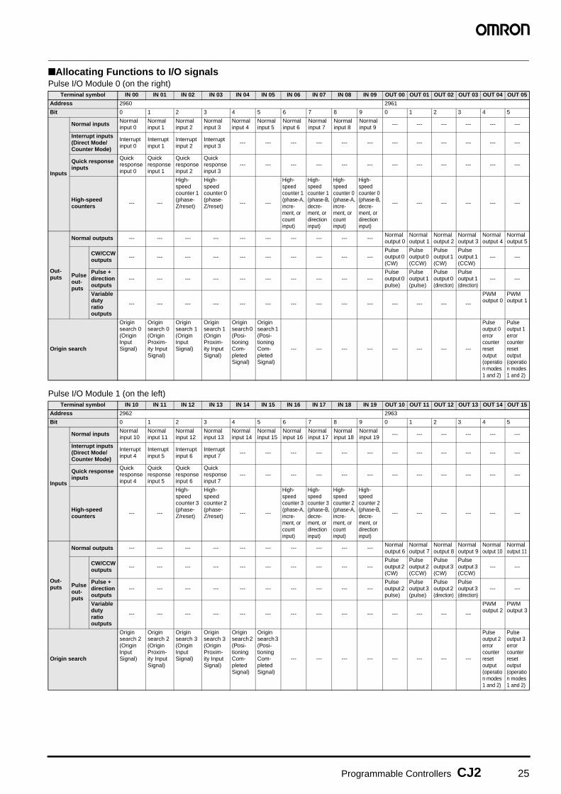
Programmable Controllers CJ2 25
■Allocating Functions to I/O signalsPulse I/O Module 0 (on the right)
Pulse I/O Module 1 (on the left)
Terminal symbol IN 00 IN 01 IN 02 IN 03 IN 04 IN 05 IN 06 IN 07 IN 08 IN 09 OUT 00 OUT 01 OUT 02 OUT 03 OUT 04 OUT 05
Address 2960 2961
Bit 0 1 2 3 4 5 6 7 8 9 0 1 2 3 4 5
Inputs
Normal inputs Normal input 0
Normal input 1
Normal input 2
Normal input 3
Normal input 4
Normal input 5
Normal input 6
Normal input 7
Normal input 8
Normal input 9
--- --- --- --- --- ---
Interrupt inputs (Direct Mode/Counter Mode)
Interrupt input 0
Interrupt input 1
Interrupt input 2
Interrupt input 3
--- --- --- --- --- --- --- --- --- --- --- ---
Quick response inputs
Quick response input 0
Quick response input 1
Quick response input 2
Quick response input 3
--- --- --- --- --- --- --- --- --- --- --- ---
High-speed counters --- ---
High-speed counter 1 (phase- Z/reset)
High-speed counter 0 (phase- Z/reset)
--- ---
High-speed counter 1 (phase-A, incre-ment, or count input)
High-speed counter 1 (phase-B, decre-ment, or direction input)
High-speed counter 0 (phase-A, incre-ment, or count input)
High-speed counter 0 (phase-B, decre-ment, or direction input)
--- --- --- --- --- ---
Out-puts
Normal outputs --- --- --- --- --- --- --- --- --- ---Normal output 0
Normal output 1
Normal output 2
Normal output 3
Normal output 4
Normal output 5
Pulse out-puts
CW/CCW outputs --- --- --- --- --- --- --- --- --- ---
Pulse output 0 (CW)
Pulse output 0 (CCW)
Pulse output 1 (CW)
Pulse output 1 (CCW)
--- ---
Pulse + direction outputs
--- --- --- --- --- --- --- --- --- ---Pulse output 0 pulse)
Pulse output 1 (pulse)
Pulse output 0 (direction)
Pulse output 1 (direction)
--- ---
Variable duty ratio outputs
--- --- --- --- --- --- --- --- --- --- --- --- --- ---
PWMoutput 0
PWMoutput 1
Origin search
Origin search 0 (Origin Input Signal)
Origin search 0 (Origin Proxim-ity Input Signal)
Origin search 1 (Origin Input Signal)
Origin search 1 (Origin Proxim-ity Input Signal)
Origin search 0 (Posi-tioning Com-pleted Signal)
Origin search 1 (Posi-tioning Com-pleted Signal)
--- --- --- --- --- --- --- ---
Pulse output 0 error counter reset output (operation modes 1 and 2)
Pulse output 1 error counter reset output (operation modes 1 and 2)
Terminal symbol IN 10 IN 11 IN 12 IN 13 IN 14 IN 15 IN 16 IN 17 IN 18 IN 19 OUT 10 OUT 11 OUT 12 OUT 13 OUT 14 OUT 15
Address 2962 2963
Bit 0 1 2 3 4 5 6 7 8 9 0 1 2 3 4 5
Inputs
Normal inputs Normal input 10
Normal input 11
Normal input 12
Normal input 13
Normal input 14
Normal input 15
Normal input 16
Normal input 17
Normal input 18
Normal input 19
--- --- --- --- --- ---
Interrupt inputs (Direct Mode/Counter Mode)
Interrupt input 4
Interrupt input 5
Interrupt input 6
Interrupt input 7
--- --- --- --- --- --- --- --- --- --- --- ---
Quick response inputs
Quick response input 4
Quick response input 5
Quick response input 6
Quick response input 7
--- --- --- --- --- --- --- --- --- --- --- ---
High-speed counters --- ---
High-speed counter 3 (phase- Z/reset)
High-speed counter 2 (phase- Z/reset)
--- ---
High-speed counter 3 (phase-A, incre-ment, or count input)
High-speed counter 3 (phase-B, decre-ment, or direction input)
High-speed counter 2 (phase-A, incre-ment, or count input)
High-speed counter 2 (phase-B, decre-ment, or direction input)
--- --- --- --- --- ---
Out-puts
Normal outputs --- --- --- --- --- --- --- --- --- ---Normal output 6
Normal output 7
Normal output 8
Normal output 9
Normal output 10
Normal output 11
Pulse out-puts
CW/CCW outputs --- --- --- --- --- --- --- --- --- ---
Pulse output 2 (CW)
Pulse output 2 (CCW)
Pulse output 3 (CW)
Pulse output 3 (CCW)
--- ---
Pulse + direction outputs
--- --- --- --- --- --- --- --- --- ---Pulse output 2 pulse)
Pulse output 3 (pulse)
Pulse output 2 (direction)
Pulse output 3 (direction)
--- ---
Variable duty ratio outputs
--- --- --- --- --- --- --- --- --- --- --- --- --- ---
PWMoutput 2
PWMoutput 3
Origin search
Origin search 2 (Origin Input Signal)
Origin search 2 (Origin Proxim-ity Input Signal)
Origin search 3 (Origin Input Signal)
Origin search 3 (Origin Proxim-ity Input Signal)
Origin search 2 (Posi-tioning Com-pleted Signal)
Origin search 3 (Posi-tioning Com-pleted Signal)
--- --- --- --- --- --- --- ---
Pulse output 2 error counter reset output (operation modes 1 and 2)
Pulse output 3 error counter reset output (operation modes 1 and 2)
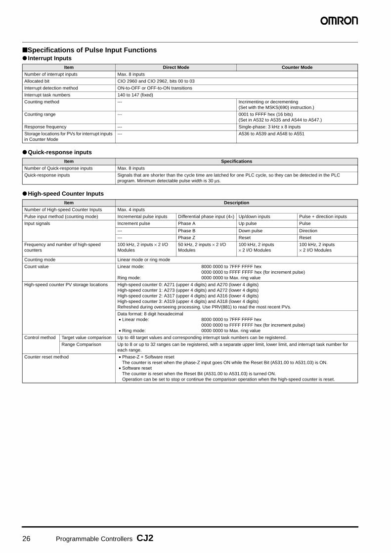
26 Programmable Controllers CJ2
■Specifications of Pulse Input Functions● Interrupt Inputs
● Quick-response inputs
● High-speed Counter Inputs
Item Direct Mode Counter Mode
Number of interrupt inputs Max. 8 inputs
Allocated bit CIO 2960 and CIO 2962, bits 00 to 03
Interrupt detection method ON-to-OFF or OFF-to-ON transitions
Interrupt task numbers 140 to 147 (fixed)
Counting method --- Incrimenting or decrementing (Set with the MSKS(690) instruction.)
Counting range --- 0001 to FFFF hex (16 bits) (Set in A532 to A535 and A544 to A547.)
Response frequency --- Single-phase: 3 kHz x 8 inputs
Storage locations for PVs for interrupt inputs in Counter Mode
--- A536 to A539 and A548 to A551
Item Specifications
Number of Quick-response inputs Max. 8 inputs
Quick-response inputs Signals that are shorter than the cycle time are latched for one PLC cycle, so they can be detected in the PLC program. Minimum detectable pulse width is 30 μs.
Item Description
Number of High-speed Counter Inputs Max. 4 inputs
Pulse input method (counting mode) Incremental pulse inputs Differential phase input (4×) Up/down inputs Pulse + direction inputs
Input signals Increment pulse Phase A Up pulse Pulse
--- Phase B Down pulse Direction
--- Phase Z Reset Reset
Frequency and number of high-speed counters
100 kHz, 2 inputs × 2 I/O Modules
50 kHz, 2 inputs × 2 I/O Modules
100 kHz, 2 inputs × 2 I/O Modules
100 kHz, 2 inputs × 2 I/O Modules
Counting mode Linear mode or ring mode
Count value Linear mode: 8000 0000 to 7FFF FFFF hex0000 0000 to FFFF FFFF hex (for increment pulse)
Ring mode: 0000 0000 to Max. ring value
High-speed counter PV storage locations High-speed counter 0: A271 (upper 4 digits) and A270 (lower 4 digits)High-speed counter 1: A273 (upper 4 digits) and A272 (lower 4 digits)High-speed counter 2: A317 (upper 4 digits) and A316 (lower 4 digits)High-speed counter 3: A319 (upper 4 digits) and A318 (lower 4 digits)Refreshed during overseeing processing. Use PRV(881) to read the most recent PVs.
Data format: 8 digit hexadecimal• Linear mode: 8000 0000 to 7FFF FFFF hex
0000 0000 to FFFF FFFF hex (for increment pulse)• Ring mode: 0000 0000 to Max. ring value
Control method Target value comparison Up to 48 target values and corresponding interrupt task numbers can be registered.
Range Comparison Up to 8 or up to 32 ranges can be registered, with a separate upper limit, lower limit, and interrupt task number for each range.
Counter reset method • Phase-Z + Software resetThe counter is reset when the phase-Z input goes ON while the Reset Bit (A531.00 to A531.03) is ON.
• Software resetThe counter is reset when the Reset Bit (A531.00 to A531.03) is turned ON.Operation can be set to stop or continue the comparison operation when the high-speed counter is reset.
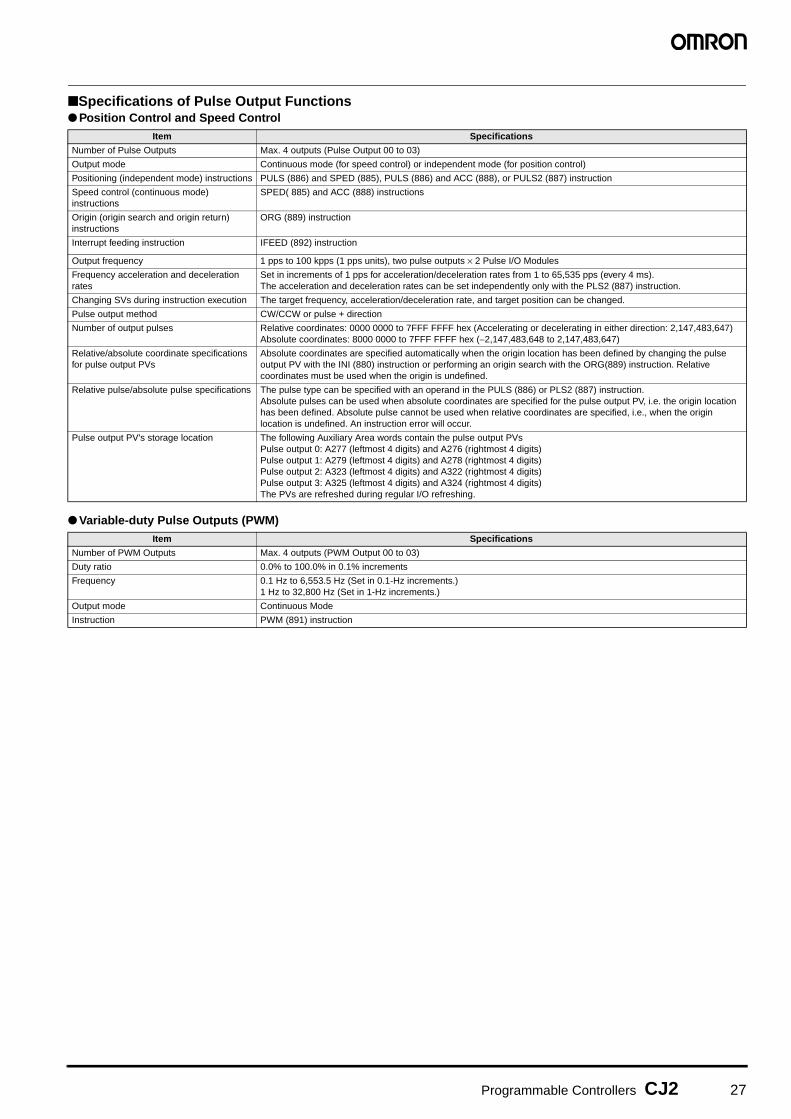
Programmable Controllers CJ2 27
■Specifications of Pulse Output Functions● Position Control and Speed Control
● Variable-duty Pulse Outputs (PWM)
Item Specifications
Number of Pulse Outputs Max. 4 outputs (Pulse Output 00 to 03)
Output mode Continuous mode (for speed control) or independent mode (for position control)
Positioning (independent mode) instructions PULS (886) and SPED (885), PULS (886) and ACC (888), or PULS2 (887) instruction
Speed control (continuous mode) instructions
SPED( 885) and ACC (888) instructions
Origin (origin search and origin return) instructions
ORG (889) instruction
Interrupt feeding instruction IFEED (892) instruction
Output frequency 1 pps to 100 kpps (1 pps units), two pulse outputs × 2 Pulse I/O Modules
Frequency acceleration and deceleration rates
Set in increments of 1 pps for acceleration/deceleration rates from 1 to 65,535 pps (every 4 ms).The acceleration and deceleration rates can be set independently only with the PLS2 (887) instruction.
Changing SVs during instruction execution The target frequency, acceleration/deceleration rate, and target position can be changed.
Pulse output method CW/CCW or pulse + direction
Number of output pulses Relative coordinates: 0000 0000 to 7FFF FFFF hex (Accelerating or decelerating in either direction: 2,147,483,647) Absolute coordinates: 8000 0000 to 7FFF FFFF hex (−2,147,483,648 to 2,147,483,647)
Relative/absolute coordinate specifications for pulse output PVs
Absolute coordinates are specified automatically when the origin location has been defined by changing the pulse output PV with the INI (880) instruction or performing an origin search with the ORG(889) instruction. Relative coordinates must be used when the origin is undefined.
Relative pulse/absolute pulse specifications The pulse type can be specified with an operand in the PULS (886) or PLS2 (887) instruction.Absolute pulses can be used when absolute coordinates are specified for the pulse output PV, i.e. the origin location has been defined. Absolute pulse cannot be used when relative coordinates are specified, i.e., when the origin location is undefined. An instruction error will occur.
Pulse output PV's storage location The following Auxiliary Area words contain the pulse output PVsPulse output 0: A277 (leftmost 4 digits) and A276 (rightmost 4 digits)Pulse output 1: A279 (leftmost 4 digits) and A278 (rightmost 4 digits)Pulse output 2: A323 (leftmost 4 digits) and A322 (rightmost 4 digits)Pulse output 3: A325 (leftmost 4 digits) and A324 (rightmost 4 digits)The PVs are refreshed during regular I/O refreshing.
Item Specifications
Number of PWM Outputs Max. 4 outputs (PWM Output 00 to 03)
Duty ratio 0.0% to 100.0% in 0.1% increments
Frequency 0.1 Hz to 6,553.5 Hz (Set in 0.1-Hz increments.) 1 Hz to 32,800 Hz (Set in 1-Hz increments.)
Output mode Continuous Mode
Instruction PWM (891) instruction

28 Programmable Controllers CJ2
■Specifications of Pulse I/O Modules● Input Specifications (IN00 to IN09/IN10 to IN19)Normal Inputs
Input Circuit Configuration
Interrupt Input and Quick-response Input Specifications (IN00 to IN03 and IN10 to IN13)
InputsIN00 to IN05 and
IN10 to IN15IN06 to IN09 and
IN16 to IN19IN00 to IN05 and
IN10 to IN15IN06 to IN09 and
IN16 to IN19
Input form 24-VDC inputs Line driver inputs
Input current 6.0 mA typical 5.5 mA typical 13 mA typical 10 mA typical
Input voltage range 24 VDC +10%/−15% RS-422A or RS-422 line driver (conforming to AM26LS31), Power supply voltage of 5 V ± 5%
Input impedance 3.6 kΩ 4.0 kΩ ---
Number of circuits 1 common, 1 circuit
ON voltage/current 17.4 VDC min., 3 mA min. ---
OFF voltage/current 1 mA max. at 5 VDC max. ---
ON response time 8 ms max. (The input time constant can be set to 0, 0.5, 1, 2, 4, 8, 16, or 32 ms in the PLC Setup.)
OFF response time 8 ms max. (The input time constant can be set to 0, 0.5, 1, 2, 4, 8, 16, or 32 ms in the PLC Setup.)
Item Specifications
Input IN00 to IN05/IN10 to IN15 IN06 to IN09/IN16 to IN19
Circuit configuration
Item Specifications
ON response time 30 μs max.
OFF response time 150 μs max.
Response pulse
24 V
LD+
Inte
rnal
circ
uits
24 V
LD+
Inte
rnal
circ
uits
30 μs min. 150 μs min.
ON
OFF

Programmable Controllers CJ2 29
High-speed Counter Input Specifications (IN06 to IN09 and IN16 to IN19)24-VDC input Line driver input
Set to 60 kHz
Set to 100 kHz
Phase Z/reset input
50%
OFF
ON
T1 T2
50%
OFF
ON
50%
OFF
ON
T3 T4
Phase-A/Phase-B encoder input, Single-phase 60-kHz pulse input with 50% duty ratio
Phase-A/Phase-B encoder inputs, Differential phases, 30 kHz
Changes in phases A and B must be separated by at least 4.0 μs.
Rise time and fall time: 3.0 μs max.
50%
OFF
ON
T1 T2
50%
OFF
ON
50%
OFF
ON
T3 T4
Encoder input phase A or B, single-phase 60-kHz pulse input with 50% duty ratio
Phase-A/Phase-B encoder inputs, Differential phases, 30 kHz
Changes in phases A and B must be separated by at least 4.0 μs.
8.3 μs min.
16.6 μs min.
33.3 μs min.
T1, T2, T3, T4: 4.0 μs min.
8.3 μs min.
50%
OFF
ON
T1 T2
50%
OFF
ON
50%
OFF
ON
T3 T4
Phase-A/Phase-B encoder input, Single-phase 100-kHz pulse input with 50% duty ratio
Phase-A/Phase-B encoder inputs, Differential phases, 50 kHz
Changes in phases A and B must be separated by at least 2.5 μs.
Rise time and fall time: 2.5 μs max.
2.5 μs max. 2.5 μs max.
10.0 μs min.
5.0 μs min. 5.0 μs min.
50%
OFF
ON
T1 T2
50%
OFF
ON
50%
OFF
ON
T3 T4
Single-phase 100-kHz pulse input with 50% duty ratio
Differential-phase 50-kHz pulse inputChanges in phases A and B must be separated by at least 2.5 μs.
50%
OFF
ON
30 μs min.
150 μs min.
Encoder input phase Z (IN02/IN03 or IN12/IN13)
Maintain an ON time of 30 μs min. and an OFF time of 150 μs min.
50%
OFF
ON
30 μs min. 150 μs min.
Encoder input phase Z (IN02/IN03 or IN12/IN13) Maintain an ON time of 30 μs min. and an OFF time of 150 μs min.

30 Programmable Controllers CJ2
Output Specifications (OUT00 to OUT05 and OUT10 to OUT15)
Pulse Outputs (OUT00 to OUT03 and OUT10 to OUT13)
PWM Outputs (OUT04, OUT05, OUT14, and OUT15)
Item Specifications
Output Specifications Sinking-type (CJ2M-MD211) Sourcing-type (CJ2M-MD212)
Rated voltage 5 to 24 VDC
Allowable voltage range 4.75 to 26.4 VDC
Maximum switching current
0.3 A/output, 1.8 A/Unit
Number of circuits 6 outputs (6 outputs/common)
Maximum inrush current 3.0 A/output, 10 ms max. 2.0 A/output, 10 ms max.
Leakage current 0.1 mA max.
Residual voltage 0.6 V max.
ON response time 0.1 ms max.
OFF response time 0.1 ms max.
Fuse None
External supply power (power supply input for outputs)
10.2 to 26.4 VDC, 20 mA min.
Circuit configuration
Item Specifications
Output Specifications Sinking-type (CJ2M-MD211) Sourcing-type (CJ2M-MD212)
Rated voltage 5 to 24 VDC
Allowable voltage range 4.75 to 26.4 VDC
Maximum switching capacity
30 mA
Minimum switching capacity
7 mA
Maximum output frequency
100 kHz
Output waveform
Item Specifications
Output Specifications Sinking-type (CJ2M-MD211) Sourcing-type (CJ2M-MD212)
Rated voltage 5 to 24 VDC
Allowable voltage range 4.75 to 26.4 VDC
Maximum switching capacity
6.5535 kHz or less: 300 mA, 6.5535 to 32.8 kHz: 100 mA
Maximum output frequency
32,800 Hz
PWM output accuracy(for ON pulse width of 2 μs or longer)
ON duty at 6.5535 kHz or less: -0.2% to +1%, ON duty at 32.8 kHz: -1% to +5% (at switching current of 30 mA)
ON duty at 6.5535 kHz or less: ±0.5%, ON duty at 32.8 kHz: ±2.5% (at switching current of 30 mA)
Output waveform
OUT
COM
+V
Inte
rnal
circ
uits
Isolation circuit
Rated voltage circuit
COM
−V
OUT
Inte
rnal
circ
uits
Isolation circuit
Rated voltage circuit
90%
10%ON
OFF90%
10%OFF
ON
ON
OFF
TtON
50%
ON duty =tON
TX 100%
OFF
ON
TtON
50%
ON duty =tON
TX 100%

31
Ordering Information
Basic Configuration Units .................................................................................32
Programming Devices...................................................................................... 37
Programming Device Connecting Cable.......................................................... 38
FA Communications Software.......................................................................... 39
Optional Products and Maintenance Products ................................................40
DIN Track Accessories .....................................................................................40
Basic I/O Units ..................................................................................................41
Special I/O Units and CPU Bus Units ...............................................................47
International Standards
• The standards are abbreviated as follows: U: UL, U1:UL (Class I Division 2 Products for Hazardous Locations),C: CSA, UC: cULus, UC1: cULus (Class I Division 2 Products for Hazardous Locations), CU: cUL, N: NK, L: Lloyd, CE: EC Directives, and KC: KC Registration.
• Contact your OMRON representative for further detailsand applicable conditions for these standards.
• Refer to the OMRON website (www.ia.omron.com) orask your OMRON representative for the most recentapplicable standards for each model.
● EC DirectivesThe EC Directives applicable to PLCs include the EMC Di-rectives and the Low Voltage Directive. OMRON complieswith these directives as described below.● EMC Directives
Applicable StandardsEMI: EN61000-6-4, EN61131-2EMS: EN61000-6-2, EN61131-2PLCs are electrical devices that are incorporated in ma-chines and manufacturing installations. OMRON PLCsconform to the related EMC standards so that the devic-es and machines into which they are built can more eas-ily conform to EMC standards. The actual PLCs havebeen checked for conformity to EMC standards. Wheth-er thesestandards are satisfied for the actual system, however,must be checked by the customer.EMC-related performance will vary depending on theconfiguration, wiring, and other conditions of the equip-ment or control panel in which the PLC is installed. Thecustomer must, therefore, perform final checks to con-firm that the overall machine or device conforms to EMCstandards.
● Low Voltage DirectiveApplicable Standard:EN61131-2VDC must satisfy the appropriate safety requirements.With PLCs, this applies to Power Supply Units and I/OUnits that operate in these voltage ranges.These Units have been designed to conform toEN61131-2, which is the applicable standard for PLCs.
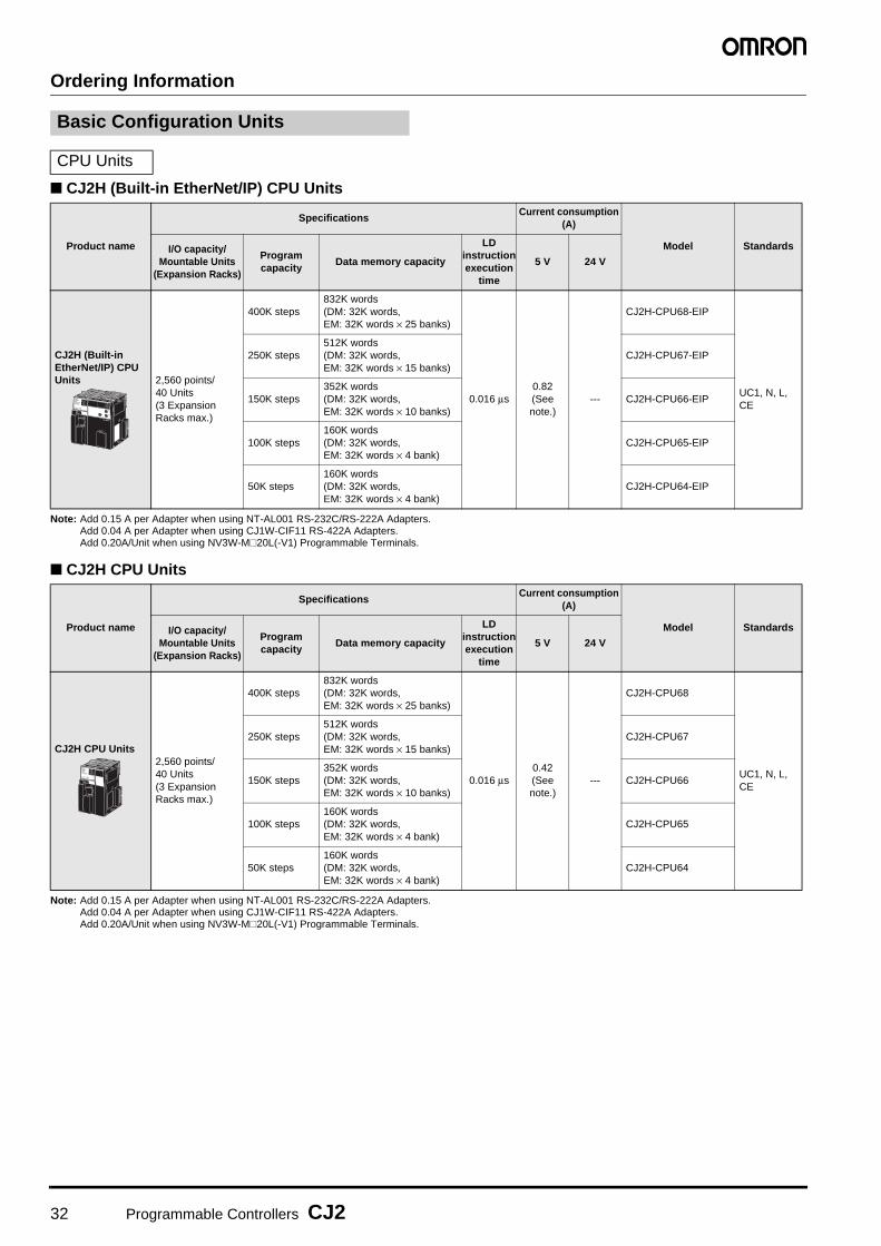
32 Programmable Controllers CJ2
Ordering Information
■ CJ2H (Built-in EtherNet/IP) CPU Units
Note: Add 0.15 A per Adapter when using NT-AL001 RS-232C/RS-222A Adapters.Add 0.04 A per Adapter when using CJ1W-CIF11 RS-422A Adapters.Add 0.20A/Unit when using NV3W-M@20L(-V1) Programmable Terminals.
■ CJ2H CPU Units
Note: Add 0.15 A per Adapter when using NT-AL001 RS-232C/RS-222A Adapters.Add 0.04 A per Adapter when using CJ1W-CIF11 RS-422A Adapters.Add 0.20A/Unit when using NV3W-M@20L(-V1) Programmable Terminals.
Basic Configuration Units
CPU Units
Product name
SpecificationsCurrent consumption
(A)
Model StandardsI/O capacity/Mountable Units
(Expansion Racks)
Program capacity
Data memory capacity
LD instruction execution
time
5 V 24 V
CJ2H (Built-in EtherNet/IP) CPU Units 2,560 points/
40 Units(3 Expansion Racks max.)
400K steps832K words(DM: 32K words, EM: 32K words × 25 banks)
0.016 μs0.82 (See note.)
---
CJ2H-CPU68-EIP
UC1, N, L, CE
250K steps512K words(DM: 32K words,EM: 32K words × 15 banks)
CJ2H-CPU67-EIP
150K steps352K words(DM: 32K words, EM: 32K words × 10 banks)
CJ2H-CPU66-EIP
100K steps160K words(DM: 32K words, EM: 32K words × 4 bank)
CJ2H-CPU65-EIP
50K steps160K words(DM: 32K words, EM: 32K words × 4 bank)
CJ2H-CPU64-EIP
Product name
SpecificationsCurrent consumption
(A)
Model StandardsI/O capacity/Mountable Units
(Expansion Racks)
Program capacity
Data memory capacity
LD instruction execution
time
5 V 24 V
CJ2H CPU Units2,560 points/40 Units(3 Expansion Racks max.)
400K steps832K words(DM: 32K words, EM: 32K words × 25 banks)
0.016 μs0.42 (See note.)
---
CJ2H-CPU68
UC1, N, L, CE
250K steps512K words(DM: 32K words,EM: 32K words × 15 banks)
CJ2H-CPU67
150K steps352K words(DM: 32K words, EM: 32K words × 10 banks)
CJ2H-CPU66
100K steps160K words(DM: 32K words, EM: 32K words × 4 bank)
CJ2H-CPU65
50K steps160K words(DM: 32K words, EM: 32K words × 4 bank)
CJ2H-CPU64

Programmable Controllers CJ2 33
■ CJ2M CPU Units (Built-in EtherNet/IP)
Note: Add 0.005A, 0.030A, and 0.075A when using Serial Communications Option Boards (CP1W-CIF01/CIF11/CIF12-V1), respectively.Add 0.15A/Unit when using NT-AL001 RS-232C/RS-422A Adapters.Add 0.04A/Unit when using CJ1W-CIF11 RS-422A Adapters.Add 0.20A/Unit when using NV3W-M@20L(-V1) Programmable Terminals.
■ CJ2M CPU Units
Note: Add 0.15A/Unit when using NT-AL001 RS-232C/RS-422A Adapters.Add 0.04A/Unit when using CJ1W-CIF11 RS-422A Adapters.Add 0.20A/Unit when using NV3W-M@20L(-V1) Programmable Terminals.
The following accessories are included with the CPU Unit.
Note: A serial port (RS-232C) connector is not provided. Purchase a connector separately for serial port connection.Plug : XM3A-0921 (manufactured by OMRON) or equivalentHood : XM2S-0911-E (manufactured by OMRON) or equivalent
■ Serial Communications Option Boards (Only CJ2M-CPU3@)The serial communications port can be equipped by installing the serial communications option board to the option board slot in front of CPU unit.
Note: It is not possible to use a CP-series Ethernet Option Board (CP1W-CIF41), LCD Option Board (CP1W-DAM01) with a CJ2M CPU Unit.* The following modes cannot be used: 1:1 NT Link, Serial Gateway converted to Host Link FINS, 1:1 Link Master, and 1:1 Link Slave.
Product name
SpecificationsCurrent
consumption (A)
Model StandardsI/O capacity/Mountable Units
(Expansion Racks)
Program capacity
Data memory capacity
LD instruction execution
time
EtherNet/IP function
Option board slot
5 V 24 V
CJ2M (Built-in EtherNet/IP) CPU Units 2,560 points/
40 Units(3 Expansion Racks max.)
60K steps 160K words(DM: 32K words, EM: 32K words ×
4 banks)
0.04 μs YES YES0.7
(See note.)
---
CJ2M-CPU35
UC1, N, L, CE
30K steps CJ2M-CPU34
20K steps64K words(DM: 32K words, EM: 32K words ×
1 bank)
CJ2M-CPU33
10K steps CJ2M-CPU32
5K steps CJ2M-CPU31
Product name
SpecificationsCurrent
consumption (A)
Model StandardsI/O capacity/Mountable Units
(Expansion Racks)
Program capacity
Data memory capacity
LD instruction execution
time
EtherNet/IP function
Option board slot
5 V 24 V
CJ2M CPU Units2,560 points/40 Units(3 Expansion Racks max.)
60K steps 160K words(DM: 32K words, EM: 32K words ×
4 banks)
0.04 μs --- ---0.5
(See note.)
---
CJ2M-CPU15
UC1, N, L, CE
30K steps CJ2M-CPU14
20K steps64K words(DM: 32K words, EM: 32K words ×
1 bank)
CJ2M-CPU13
10K steps CJ2M-CPU12
5K steps CJ2M-CPU11
Item Specifications
Battery CJ1W-BAT01
End Cover CJ1W-TER01 (The End Cover must be connected to the right end of the CPU Rack.)
End Plate PFP-M (2 stoppers)
Product name Specifications Serial communications mode
Current consumption (A) Model Standards
5 V 24 V
RS-232C Option Board One RS-232C port
Connector: D-Sub, 9 pin, femaleMaximum transmission distance: 15m
Host Link, 1:N NT Link, Noprotocol, Serial PLC Link Slave, Serial PLC Link Master, Serial Gateway converted to CompoWay/F, and Tool Bus *
0.005 --- CP1W-CIF01
UC1, N, L, CE
RS-422A/485 Option Board One RS-422A/485 port
Terminal block: using ferrulesMaximum transmission distance: 50m
0.030 --- CP1W-CIF11
RS-422A/485 Isolated-type Option Board
One RS-422A/485 port (Isolated)Terminal block: using ferrulesMaximum transmission distance: 500m
0.075 --- CP1W-CIF12-V1

34 Programmable Controllers CJ2
■Pulse I/O Modules (Only CJ2M CPU Unit with Unit Version 2.0 or Later) Optional Pulse I/O Modules can be mounted to enable pulse I/O. Up to two Pulse I/O Modules can be mounted to the left side of a CJ2M
CPU Unit.
Note: Connectors are not provided with Pulse I/O Modules. Purchase the following Connector, an OMRON Cable with Connectors for Connector Terminal Block Conversion Units, or an OMRON Cable with Connectors for Servo Relay Units.
■Connecting to Pulse I/O ModulesOn wiring, refer to Pulse I/O Modules Connector Wiring Methods.
Note: Minimum ordering quantity for loose contacts is 100 pieces and for reel contacts is 1 reel (10,000 pieces).*1. Socket and Strain Relief set*2. Crimp Contacts (XG5W-0232) are sold separately.*3. Applicable wire size is 28 to 24 AWG.
For applicable conductor construction and more information, visit the OMRON website at www.ia.omron.com.*4. Crimp Contacts are also required.
Product name SpecificationsCurrent
consumption (A) Model Standards5 V 24 V
Pulse I/O ModuleSinking outputs, MIL connector10 inputs (including four interrupt/quickresponse inputs and two high-speed counter inputs)6 outputs (including two pulse outputs and two PWM outputs)
0.08 --- CJ2M-MD211
UC1, N, L, CESourcing outputs, MIL connector
10 inputs (including four interrupt/quickresponse inputs and two high-speed counter inputs)6 outputs (including two pulse outputs and two PWM outputs)
0.08 --- CJ2M-MD212
Product name Specifications Model Standards
Applicable Connector
MIL Flat Cable Connectors *1 40-pin Pressure-welded
Connectors XG4M-4030-T
---
MIL Loose Wire Connectors *2 40-pin Crimped
Connectors XG5N-401 *4
Crimp Contacts for XG5N *3 Loose contacts XG5W-0232
Reel contacts XG5W-0232-R
Manual Crimping Tool for XG5N
XY2B-7007
Connector-Terminal Block Conversion Units
Push-In Plus (Clamp 40-terminals)
XW2K-40G-T
---
Phillips screw (M3 screw terminals, 40-terminals)
XW2D-40G6
Slotted screw (M3 European type, 40-terminals)
XW2R-E40GD-T
Cable for Connector-Terminal Block Conversion Unit
Cable length: 0.25 m XW2Z-C25K
Cable length: 0.5 m XW2Z-C50K
Cable length: 1 m XW2Z-100K
Cable length: 1.5 m XW2Z-150K
Cable length: 2 m XW2Z-200K
Cable length: 3 m XW2Z-300K
Cable length: 5 m XW2Z-500K

Programmable Controllers CJ2 35
Product name Specifications Model Standards
Servo Relay Units
Servo Relay Unit for 1 axis
XW2B-20J6-8A
---Servo Relay Unit for 2 axes
XW2B-40J6-9A
Cables for Servo Relay Units
G5/G Series
Cable for Pulse I/O Modules Cable length: 0.5 m XW2Z-050J-A33
---
Cable length: 1 m XW2Z-100J-A33
Servo Driver Connecting Cables Cable length: 1 m XW2Z-100J-B31
Cable length: 2 m XW2Z-200J-B31
SMARTSTEP2
Cable for Pulse I/O Modules Cable length: 0.5 m XW2Z-050J-A33
Cable length: 1 m XW2Z-100J-A33
Servo Driver Connecting Cables Cable length: 1 m XW2Z-100J-B32
Cable length: 2 m XW2Z-200J-B32

36 Programmable Controllers CJ2
■ Power Supply UnitsOne Power Supply Unit is required for each Rack.
Select the I/O Control Unit, I/O Interface Unit, Expansion Connecting Cable, and Power Supply Unit.
■ CJ-series I/O Control Unit (Mounted on CPU Rack when Connecting Expansion Racks)
Note: Mounting the I/O Control Unit in any other location may cause faulty operation.
■ CJ-series I/O Interface Unit (Mounted on Expansion Rack)
Note: Mounting the I/O Interface Unit in any other location may cause faulty operation.
■ I/O Connecting Cables
Product namePower supply
voltage
Output capacity Options
Model Standards5-VDC output
capacity
24-VDC output
capacity
Total power consump-
tion
24-VDC service
power supply
RUN output
Maintenance forecast monitor
AC Power Supply Unit
100 to 240 VAC
5 A 0.8 A 25 W
No
No Yes CJ1W-PA205C
UC1, N, L, CE
Yes No CJ1W-PA205R
2.8 A 0.4 A 14 W No No CJ1W-PA202
DC Power Supply Unit
24 VDC
5A 0.8 A 25 W No No CJ1W-PD025
2 A 0.4 A 19.6 W No No CJ1W-PD022 UC1, CE
Expansion Racks
Product name Specifications
Current consumption (A) Model Standards
5 V 24 V
CJ-series I/O Control Unit Mount one I/O Control Unit on the CJ-series CPU Rack when connecting one
or more CJ-series Expansion Racks.Connecting Cable: CS1W-CN@@3 Expansion Connecting CableConnected Unit: CJ1W-II101 I/O Interface UnitMount to the right of the CPU Unit.
0.02 --- CJ1W-IC101UC1, N, L, CE
Product Name Specifications
Current consumption (A) Model Standards
5 V 24 V
CJ-series I/O Interface Unit
One I/O Interface Unit is required on each Expansion Rack.Connecting Cable: CS1W-CN@@3 Expansion Connecting CableMount to the right of the Power Supply Unit.
0.13 --- CJ1W-II101UC1, N, L, CE
Product name Specifications Model Standards
I/O Connecting Cable
• Connects an I/O Control Unit on CJ-series CPU Rack to an I/O Interface Unit on a CJ-series Expansion Rack.or
• Connects an I/O Interface Unit on CJ-series Expansion Rack to an I/O Interface Unit on another CJ-series Expansion Rack.
Cable length: 0.3 m CS1W-CN313
N, L, CE
Cable length: 0.7 m CS1W-CN713
Cable length: 2 m CS1W-CN223
Cable length: 3 m CS1W-CN323
Cable length: 5 m CS1W-CN523
Cable length: 10 m CS1W-CN133
Cable length: 12 m CS1W-CN133-B2

Programmable Controllers CJ2 37
■ Support Software
Note: Site licenses are available for users who will run CX-One on multiple computers. Ask your OMRON sales representative for details.* The CXONE-AL00D-V4 contains only the DVD installation media for users who have purchased the CX-One Version 4.@ and does not include the license number.
Enter the license number of the CX-One Version 4.@ when installing. (The license number of the CX-One Version 3.@ or lower cannot be used for installation.)
Support Software in CX-One Ver.4.@The following tables lists the Support Software that can be installed from CX-One.
Note: If the complete CX-One package is installed, approximately 4.0 GB of Hard disk space will be required.
Programming Devices
Product name Specifications Model StandardsNumber of licenses Media
FA Integrated Tool Package CX-One Ver. 4.@
The CX-One is a comprehensive software package that integrates Support Software for OMRON PLCs and components.CX-One runs on the following OS.Windows 7 (32-bit/64-bit version) / Windows 8(32-bit/64-bit version)/Windows 8.1(32-bit/64-bit version) / Windows 10(32-bit/64-bit version)
CX-One Version 4.@ includes CX-Programmer and CX-Simulator.For details, refer to the CX-One catalog (Cat. No. R134).
- (Media only) *
DVD
CXONE-AL00D-V4
---
1 license CXONE-AL01D-V4
3 licenses CXONE-AL03D-V4
10 licenses CXONE-AL10D-V4
30 licenses CXONE-AL30D-V4
50 licenses CXONE-AL50D-V4
Support Software in CX-One Outline
CX-ProgrammerApplication software to create and debug programs for CS/CJ/CP/NSJ-series, C-series, and CVM1/C-series CPU Units. Data can be created and monitored for high-speed-type Position Control Units and Position Control Units with EtherCAT interface.
CX-IntegratorApplication software to build and set up FA networks, such as Controller Link, DeviceNet, CompoNet, CompoWay, and Ethernet networks. The Routing Table Component and Data Link Component can be started from here. DeviceNet Configuration functionality is also included.
Switch Box UtilityUtility software that helps you to debug PLCs. It helps you to monitor the I/O status and to monitor/change present values within the PLC you specify.
CX-ProtocolApplication software to create protocols (communications sequences) between CS/CJ/CP/NSJ-series or C200HX/HG/HE Serial Communications Boards/Units and general-purpose external devices.
CX-SimulatorApplication software to simulate CS/CJ/CP/NSJ-series CPU Unit operation on the computer to debug PLC programs without a CPU Unit.
CX-Position Application software to create and monitor data for CS/CJ-series Position Control Units. (except for High-speed type)
CX-Motion-NCFApplication software to create and monitor data for CS/CJ-series Position Control Units with MECHATROLINK-II interface (NC@71).
CX-Motion-MCHApplication software to create data and monitor program and monitor data CS/CJ-series Motion Control Units with MECHATROLINK-II interface (MCH71).
CX-MotionApplication software to create data for CS/CJ-series, C200HX/HG/HE, and CVM1/CV-series Motion Control Units, and to create and monitor motion control programs.
CX-Drive Application software to set and control data for Inverters and Servos.
CX-Process ToolApplication software to create and debug function block programs for CS/CJ-series Loop Controllers (Loop Control Units/Boards, Process Control CPU Units, and Loop Control CPU Units).
Faceplate Auto-Builder for NSApplication software that automatically outputs screen data as project files for NS-series PTs from tag information in function block programs created with the CX-Process Tool.
CX-Designer Application software to create screen data for NS-series PTs.
NV-Designer Application software to create screen data for NV-series small PTs.
CX-Configurator FDT Application software for setting various units by installing its DTM module.
CX-Thermo Application software to set and control parameters in components such as Temperature Control Units.
CX-FLnet Application software for system setting and monitoring of CS/CJ-series FL-net Units
Network ConfiguratorApplication software for set up and monitor tag datalink for CJ2 (Built-in EtherNet/IP) CPU Units and EtherNet/IP Units.
CX-ServerMiddleware necessary for CX-One applications to communicate with OMRON components, such as PLCs, Display Devices, and Temperature Control Units.
Communications Middleware Middleware necessary to communicate with CP1L CPU Units with built-in Ethernet port.
PLC ToolsA group of components used with CX-One applications, such as the CX-Programmer and CX-Integrator. Includes the following: I/O tables, PLC memory, PLC Setup, Data Tracing/Time Chart Monitoring, PLC Error Logs, File Memory, PLC clock, Routing Tables, and Data Link Tables.

38 Programmable Controllers CJ2
■Peripheral (USB) PortUse commercially available USB cable.
Specifications: USB 1.1 or 2.0 cable (A connector - B connector), 5.0 m max.
■EtherNet/IP PortSupport Software can also be connected via the built-in EtherNet/IP port. Use commercially available 100Base-TX twisted-pair cable with
the same specifications as for an EtherNet/IP Unit.
Specifications: Twisted-pair cable with RJ45 modular connectors at both ends. Connect between EtherNet/IP Unit or built-in EtherNet/IP
port and switching hub. Use STP (shielded twisted-pair) cable of category 5 or 5e.
■ Serial Port
Programming Device Connecting Cable
Product Name
Specifications
Model StandardsApplicable computers
Connection configurationCable length
Remarks
Programming Device Connecting Cables for RS-232C Port
Connects IBM PC/AT or compatible computers, D-Sub 9-pin
IBM PC/AT or compatible computer + XW2Z-200S-CV/V or XW2Z-500S-CV/V + RS-232C port of CPU Unit or Serial Communications Board or Unit
2 m Used for Peripheral Bus or Host Link.Anti-static connectors
XW2Z-200S-CV
---
5 m XW2Z-500S-CV
2 m Used for Host Link only. Peripheral Bus not supported.
XW2Z-200S-V
5 m XW2Z-500S-V
USB-Serial Conver-sion Cable and PC driver (on a CD-ROM disk)
Complies with USB Specification 2.0
IBM PC/AT or compatible computer (USB port)
IBM PC/AT or compatible computer + CS1W-CIF31 + XW2Z-200S-CV/500S-CV + RS-232C port of CPU Unit or Serial Communications Unit
Connect USB Serial Conversion Cable to Serial Connecting Cable, and connect to the PLC RS-232C port.
0.5 m
Used for Peripheral Bus or Host Link.
CS1W-CIF31 NIBM PC/AT or compatible computer + CS1W-CIF31 + XW2Z-200S-V/500S-V + RS-232C port of CPU Unit or Serial Communications Unit
Used for Host Link only. Peripheral Bus not supported.
IBM PC/AT or compatible computer (RS-232C, 9-pin)
CPU Unit built-in RS-232C port
XW2Z-200S-CV/V (2m)XW2Z-500S-CV/V (5m)RS-232C Cables
POWER
PA205R
DC24VAC240V
OUTPUTRUN
INPUTAC100-240V
L2/N
L1
CONTROLLER
CJ1G-CPU44SYSMAC
PROGRAMMABLEERR/ALM
RUN
COMM
INHPRPHL
OPEN
PERIPHERAL
BUSY
MCPWR
PORT

Programmable Controllers CJ2 39
■SYSMAC Gateway (Communications Middleware)
*1 One license is required per computer (execution environment).*2 SYSMAC Gateway SDK doesn't include the license of SYSMAC Gateway.
Purchase the WS02-SGWC1 separately if an execution environment is required.
■CX-Compolet
* One license is required per computer (execution environment). Refer to the CJ2 CPU Unit Catalog (Cat. No. V302) for details.
FA Communications Software
Product
Specifications
ModelNumber of licenses
Media
SYSMAC Gateway *1
Communications middleware for personal computers running Windows.Supports CIP communications and tag data links (EtherNet/IP) in addition to FinsGateway functions.(Fins Gateway functions are included.)Supported communications: RS-232C, USB, Controller Link, Ethernet, EtherNet/IP
1 CD-ROM WS02-SGWC1
Additional licenses(This product provides only additional licenses for WS02-SGWC1. Purchase of WS02-SGWC1 is required.)
10 --- WS02-SGWC1-L10
SYSMAC Gateway SDK Software development kit for creating communications programs using SYSMAC Gateway.Development languages: C, C++
1 *2 CD-ROM WS02-SGWC1S
Product
Specifications
ModelNumber of licenses
Media
CX-Compolet *
Software components that can make it easy to create programs for communications between a computer and controllers.
Supported execution environment: .NET Framework (2.0, 3.0, 3.5, 4.0, 4.5.1, 4.6, 4.7 or 4.8)
Development environment: Visual Studio 2010/2012/2013/2015/2017/2019
Development languages: Visual Basic, C#
Supported communications: Equal to SYSMAC Gateway.
Product includes CX-Compolet and SYSMAC Gateway functions.
1 DVD WS02-CPLC1
Additional licenses(This product provides only additional licenses for WS02-CPLC1. Purchase of WS02-CPLC1 is required.)
3 --- WS02-CPLC1-L3
5 --- WS02-CPLC1-L5
10 --- WS02-CPLC1-L10
CX-Compolet (standalone)(SYSMAC Gateway functions are not included.)
1 CD-ROM WS02-CPLC2
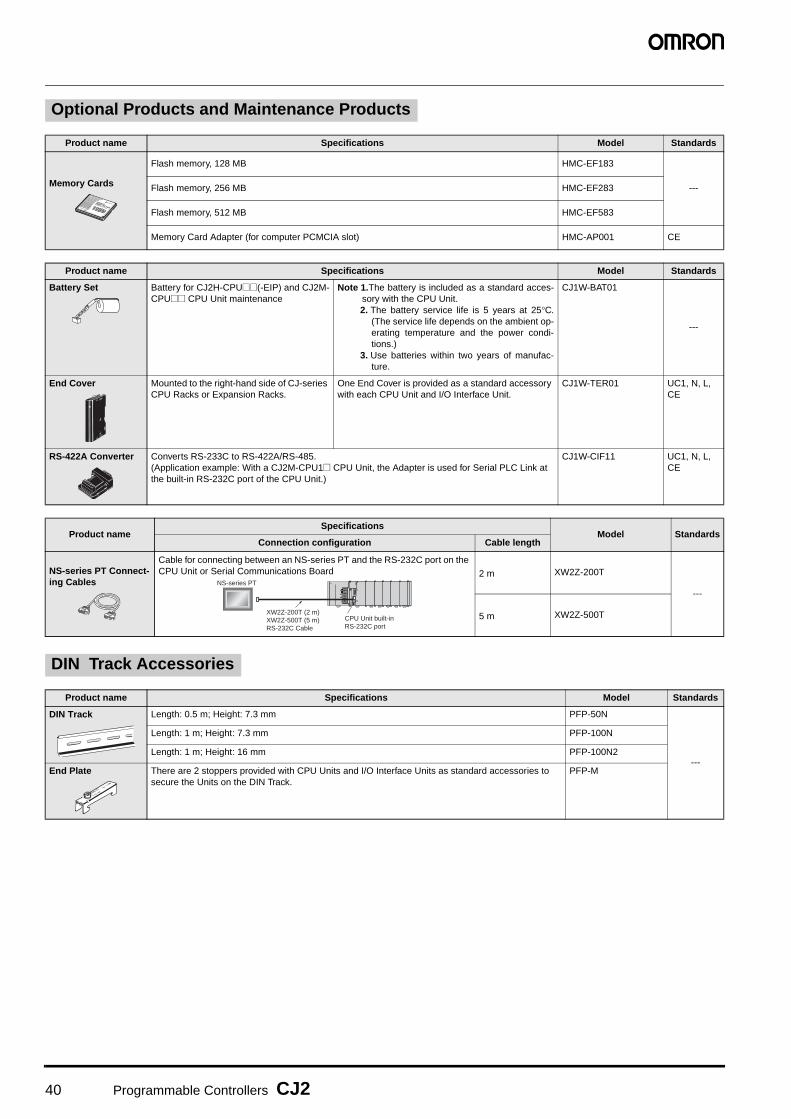
40 Programmable Controllers CJ2
Optional Products and Maintenance Products
Product name Specifications Model Standards
Memory Cards
Flash memory, 128 MB HMC-EF183
---Flash memory, 256 MB HMC-EF283
Flash memory, 512 MB HMC-EF583
Memory Card Adapter (for computer PCMCIA slot) HMC-AP001 CE
Product name Specifications Model Standards
Battery Set Battery for CJ2H-CPU@@(-EIP) and CJ2M-CPU@@ CPU Unit maintenance
Note 1.The battery is included as a standard acces-sory with the CPU Unit.2. The battery service life is 5 years at 25°C.
(The service life depends on the ambient op-erating temperature and the power condi-tions.)
3. Use batteries within two years of manufac-ture.
CJ1W-BAT01
---
End Cover Mounted to the right-hand side of CJ-series CPU Racks or Expansion Racks.
One End Cover is provided as a standard accessory with each CPU Unit and I/O Interface Unit.
CJ1W-TER01 UC1, N, L, CE
RS-422A Converter Converts RS-233C to RS-422A/RS-485.(Application example: With a CJ2M-CPU1@ CPU Unit, the Adapter is used for Serial PLC Link at the built-in RS-232C port of the CPU Unit.)
CJ1W-CIF11 UC1, N, L, CE
Product nameSpecifications
Model StandardsConnection configuration Cable length
NS-series PT Connect-ing Cables
Cable for connecting between an NS-series PT and the RS-232C port on the CPU Unit or Serial Communications Board 2 m XW2Z-200T
---
5 m XW2Z-500T
DIN Track Accessories
Product name Specifications Model Standards
DIN Track Length: 0.5 m; Height: 7.3 mm PFP-50N
---
Length: 1 m; Height: 7.3 mm PFP-100N
Length: 1 m; Height: 16 mm PFP-100N2
End Plate There are 2 stoppers provided with CPU Units and I/O Interface Units as standard accessories to secure the Units on the DIN Track.
PFP-M
NS-series PT
CPU Unit built-in RS-232C port
XW2Z-200T (2 m)XW2Z-500T (5 m)RS-232C Cable

Programmable Controllers CJ2 41
■ Input Units
Note: Connectors are not provided with these connector models. Either purchase one of the following 40-pin Connectors, or use an OMRON XW2K Series Datasheet(Cat. No. G152), XW2R Series Catalog (Cat. No. G077) and XW2D Series Datasheet or a G7@ I/O Relay Terminal.
Basic I/O Units
Unit classification
Product name
SpecificationsCurrent con-sumption (A)
Model Standards
I/O points Input voltage and
currentCommons
External connection
No. of words
allocated5 V 24 V
CJ1 Basic I/O Units
DC Input Units
8 inputs 12 to 24 VDC, 10 mAIndependentcontacts
Removable terminal block 1 word 0.08 --- CJ1W-ID201
UC1, N, L, CE
16 inputs 24 VDC, 7 mA16 points, 1 common
Removable terminal block 1 word 0.08 --- CJ1W-ID211
16 inputs24 VDC, 7 mA
16 points, 1 common
Removable terminal block 1 word 0.13 --- CJ1W-ID212
32 inputs 24 VDC, 4.1 mA16 points, 1 common
Fujitsu connector 2 words 0.09 ---
CJ1W-ID231(See note.)
32 inputs 24 VDC, 4.1 mA16 points, 1 common
MIL connector 2 words 0.09 ---CJ1W-ID232(See note.)
32 inputs24 VDC, 4.1 mA
16 points, 1 common
MIL connector 2 words 0.20 ---CJ1W-ID233(See note.)
64 inputs 24 VDC, 4.1 mA16 points, 1 common
Fujitsu connector 4 words 0.09 ---
CJ1W-ID261(See note.)
64 inputs 24 VDC, 4.1 mA16 points,1 common
MIL connector 4 words 0.09 ---CJ1W-ID262(See note.)
AC Input Units 8 inputs
200 to 24 VAC, 10 mA (200 V, 50 Hz)
8 points, 1 common
Removable Terminal Block 1 word 0.08 --- CJ1W-IA201
16 inputs100 to 120 VAC, 7 mA (100 V, 50 Hz)
16 points, 1 common
Removable Terminal Block 1 word 0.09 --- CJ1W-IA111
High-speed type
High-speed type

42 Programmable Controllers CJ2
■ Output Units
Note: Connectors are not provided with these connector models. Either purchase one of the following 40-pin Connectors, or use an OMRON XW2K Series Datasheet(Cat. No. G152), XW2R Series Catalog (Cat. No. G077) and XW2D Series Datasheet or a G7@ I/O Relay Terminal.
Unit classification
Product name
Specifications No. of words
allocated
Current consumption
(A) Model Standards
Output type
I/O pointsMaximum switching
capacity Commons
External connection
5 V 24 V
CJ1 Basic I/O Units
Relay Con-tact Output Units
− 8 outputs
250 VAC/24 VDC, 2 AIndependentcontacts
Removable terminal block
1 word 0.090.048 max.
CJ1W-OC201
UC1, N, L, CE
− 16 outputs
250 VAC/24 VDC, 2 A16 points, 1 common
Removable terminal block
1 word 0.110.096 max.
CJ1W-OC211
Triac Output Unit
− 8 outputs
250 VAC, 0.6 A 8 points, 1 common
Removable terminal block
1 word 0.22 − CJ1W-OA201
Transistor Output Units
Sinking8
outputs12 to 24 VDC, 2 A
4 points, 1 common
Removable terminal block
1 word 0.09 − CJ1W-OD201
Sinking8
outputs12 to 24 VDC, 0.5 A
8 points, 1 common
Removable terminal block
1 word 0.10 − CJ1W-OD203
Sinking16
outputs12 to 24 VDC, 0.5 A
16 points, 1 common
Removable terminal block
1 word 0.10 − CJ1W-OD211
Sinking
16outputs 24 VDC, 0.5 A
16 points, 1 common
Removable terminal block
1 word 0.15 − CJ1W-OD213
Sinking32
outputs12 to 24 VDC, 0.5 A
16 points, 1 common
Fujitsu connector
2 words 0.14 − CJ1W-OD231(See note.)
Sinking32
outputs12 to 24 VDC, 0.5 A
16 points, 1 common
MIL connector
2 words 0.14 − CJ1W-OD233(See note.)
Sinking
32 outputs 24 VDC, 0.5 A
16 points, 1 common
MIL connector
2 words 0.22 − CJ1W-OD234(See note.)
Sinking64
outputs12 to 24 VDC, 0.3 A
16 points, 1 common
Fujitsu connector
4 words 0.17 − CJ1W-OD261(See note.)
Sinking64
outputs12 to 24 VDC, 0.3 A
16 points, 1 common
MIL connector
4 words 0.17 − CJ1W-OD263(See note.)
Sourcing8
outputs24 VDC, 2 AShort-circuit protection
4 points, 1 common
Removable terminal block
1 word 0.11 − CJ1W-OD202
Sourcing8
outputs24 VDC, 0.5 AShort-circuit protection
8 points, 1 common
Removable terminal block
1 word 0.10 − CJ1W-OD204
Sourcing16
outputs24 VDC, 0.5 AShort-circuit protection
16 points, 1 common
Removable terminal block
1 word 0.10 − CJ1W-OD212
Sourcing32
outputs24 VDC, 0.5 AShort-circuit protection
16 points, 1 common
MIL connector
2 words 0.15 − CJ1W-OD232(See note.)
Sourcing64
outputs12 to 24 VDC, 0.3 A
16 points, 1 common
MIL connector
4 words 0.17 − CJ1W-OD262(See note.)
High-speed type
High-speed type

Programmable Controllers CJ2 43
■ I/O Units
Note 1 .Connectors are not provided with these connector models. Either purchase one of the following 40-pin Connectors, or use an OMRON XW2K Series Datasheet (Cat. No. G152), XW2R Series Catalog (Cat. No. G077) and XW2D Series Datasheet or a G7@ I/O Relay Terminal.
2. Connectors are not provided with these connector models. Either purchase one of the following 20-pin or 24-pin Connectors, or use an OMRON XW2K Series Datasheet (Cat. No. G152), XW2R Series Catalog (Cat. No. G077) and XW2D Series Datasheet or a G7@ I/O Relay Terminal.
● Applicable ConnectorsFujitsu Connectors for 32-input, 32-output, 64-input, 64-output, 32-input/32-output, and 16-input/16-output Units
MIL Connectors for 32-input, 32-output, 64-input, 64-output, 32-input/32-output, and 16-input/16-output Units
Unit classification
Product name
SpecificationsCurrent
consumption (A)
Model StandardsOutput
typeI/O points
Input voltage, Input current
CommonsExternal
connection
No. of words
allocated 5 V 24 V
Maximum switching capacity
CJ1 BasicI/O Units
DC Input/Transis-tor Out-put Units
Sinking
16 inputs 24 VDC, 7 mA16 points,1 common Fujitsu
connector2 words 0.13 ---
CJ1W-MD231(See note 2.)
UC1, N, CE
16 outputs250 VAC/24 VDC, 0.5 A
16 points, 1 common
Sinking
16 inputs 24 VDC, 7 mA16 points, 1 common MIL
connector2 words 0.13 ---
CJ1W-MD233(See note 2.)
UC1, N, CE
16 outputs 12 to 24 VDC, 0.5 A16 points, 1 common
Sinking
32 inputs 24 VDC, 4.1 mA16 points, 1 common Fujitsu
connector4 words 0.14 ---
CJ1W-MD261(See note 1.)
32 outputs 12 to 24 VDC, 0.3 A16 points, 1 common
Sinking
32 inputs 24 VDC, 4.1 mA16 points, 1 common MIL
connector4 words 0.14 ---
CJ1W-MD263(See note 1.)
32 outputs 12 to 24 VDC, 0.3 A16 points, 1 common
Sourcing
16 inputs 24 VDC, 7 mA16 points,1 common MIL
connector2 words 0.13 ---
CJ1W-MD232(See note 2.)
UC1, N, L, CE
16 outputs24 VDC, 0.5 AShort-circuit protection
16 points, 1 common
TTL I/O Units
---
32 inputs 5 VDC, 35 mA16 points, 1 common
MIL connector
4 words 0.19 ---CJ1W-MD563(See note 1.)
UC1, N, CE
32 outputs 5 VDC, 35 mA16 points, 1 common
Name Connection Remarks Applicable Units Model Standards
40-pin Connectors
Soldered FCN-361J040-AU ConnectorFCN-360C040-J2 Connector Cover
Fujitsu Connectors: CJ1W-ID231(32 inputs): 1 per UnitCJ1W-ID261 (64 inputs) 2 per UnitCJ1W-OD231 (32 outputs):1 per UnitCJ1W-OD261 (64 outputs): 2 per UnitCJ1W-MD261 (32 inputs, 32 outputs): 2 per Unit
C500-CE404
---
Crimped FCN-363J040 SocketFCN-363J-AU ContactorFCN-360C040-J2 Connector Cover
C500-CE405
Pressure welded FCN-367J040-AU/F C500-CE403
24-pin Connectors
Soldered FCN-361J024-AU ConnectorFCN-360C024-J2 Connector Cover
Fujitsu Connectors:CJ1W-MD231 (16 inputs, 16 outputs): 2 per Unit
C500-CE241
Crimped FCN-363J024 SocketFCN-363J-AU ContactorFCN-360C024-J2 Connector Cover
C500-CE242
Pressure welded FCN-367J024-AU/F C500-CE243
Name Connection Remarks Applicable Units Model Standards
40-pin Connectors
Pressure welded FRC5-AO40-3TOS MIL Connectors:CJ1W-ID232/233 (32 inputs): 1 per UnitCJ1W-OD232/233/234 (32 outputs):1 per UnitCJ1W-ID262 (64 inputs): 2 per UnitCJ1W-OD262/263 (64 outputs): 2 per UnitCJ1W-MD263/563 (32 inputs, 32 outputs): 2 per Unit
XG4M-4030-T
---
20-pin Connectors
Pressure welded FRC5-AO20-3TOS MIL Connectors:CJ1W-MD232/233 (16 inputs, 16 outputs): 2 per Unit
XG4M-2030-T
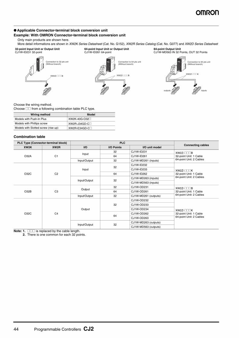
44 Programmable Controllers CJ2
● Applicable Connector-terminal block conversion unitExample: With OMRON Connector-terminal block conversion unit
Only main products are shown here. More detail informations are shown in XW2K Series Datasheet (Cat. No. G152), XW2R Series Catalog (Cat. No. G077) and XW2D Series Datasheet
Choose the wiring method.Choose @@ from a following combination table PLC type.
Combination table
Note: 1. @@@ is replaced by the cable length.2. There is one common for each 32 points.
Wiring method Model
Models with Push-In Plus XW2K-40G-O32@Models with Phillips screw XW2R-J34GD-C@Models with Slotted screw (rise up) XW2R-E34GD-C@
PLC Type (Connector-terminal block) PLCConnecting cables
XW2K XW2R I/O I/O Points I/O unit model
O32A C1Input
32 CJ1W-ID231 XW2Z-@@@B32-point Unit: 1 Cable64-point Unit: 2 Cables
64 CJ1W-ID261
Input/Output 32 CJ1W-MD261 (inputs)
O32C C2
Input32
CJ1W-ID232
XW2Z-@@@K32-point Unit: 1 Cable64-point Unit: 2 Cables
CJ1W-ID233
64 CJ1W-ID262
Input/Output 32CJ1W-MD263 (inputs)
CJ1W-MD563 (inputs)
O32B C3Output
32 CJ1W-OD231 XW2Z-@@@B32-point Unit: 1 Cable64-point Unit: 2 Cables
64 CJ1W-OD261
Input/Output 32 CJ1W-MD261 (outputs)
O32C C4
Output
32
CJ1W-OD232
XW2Z-@@@K32-point Unit: 1 Cable64-point Unit: 2 Cables
CJ1W-OD233
CJ1W-OD234
64CJ1W-OD262
CJ1W-OD263
Input/Output 32CJ1W-MD263 (outputs)
CJ1W-MD563 (outputs)
32-point Input Unit or Output UnitCJ1W-ID231 32-point
64-point Input Unit or Output UnitCJ1W-ID261 64-point
64-point Output UnitCJ1W-MD563 IN 32 Points, OUT 32 Points
Connection to 32 pts unit(Without branch)
XW2Z-@@@B
Connection to 64 pts unit(Without branch)
XW2Z-@@@B
Connection to 64 pts unit(Without branch)
XW2Z-@@@K
outputs inputs

Programmable Controllers CJ2 45
Connector-terminal block conversion unit
Connecting cables
Product name Specifications I/O Points (number of poles) Model
Connector-Terminal Block Conversion Unit
Push-In Plus32 (36) XW2K-40G-O32A
32 (36) XW2K-40G-O32B
32 (36) XW2K-40G-O32C
Phillips screw 32 (34) XW2R-J34GD-C1
32 (34) XW2R-J34GD-C2
32 (34) XW2R-J34GD-C3
32 (34) XW2R-J34GD-C4
Slotted screw (rise up) 32 (34) XW2R-E34GD-C1
32 (34) XW2R-E34GD-C2
32 (34) XW2R-E34GD-C3
32 (34) XW2R-E34GD-C4
Product name Appearance Connectors Model Cable length (m)
For I/O Unit Connecting Cable
XW2Z-@@@B
One 40-pin MIL Connector to One 40-pin Connector Made by Fujitsu Component, Ltd.
XW2Z-050B 0.5
XW2Z-100B 1
XW2Z-150B 1.5
XW2Z-200B 2
XW2Z-300B 3
XW2Z-500B 5
XW2Z-@@@K
One 40-pin MIL Connector to One 40-pin MIL Connector
XW2Z-C50K 0.5
XW2Z-100K 1
XW2Z-150K 1.5
XW2Z-200K 2
XW2Z-300K 3
XW2Z-500K 5

46 Programmable Controllers CJ2
■ Interrupt Input Units
Note 1. Can be used only on CPU Racks, and not on Expansion Racks.2. The locations where the Units can be mounted depend on the CPU Rack and the CPU Unit model.
CJ2H-CPU6@-EIP: From the slot next to the CPU Unit until the forth slot.CJ2H-CPU6@, CJ2M: From the slot next to the CPU Unit until the fifth slot.
■ Quick-response Input Units
Note: There are no restrictions on the mounting position or number of Units.
■ B7A Interface Units
Unit clas-sification
Product name
SpecificationsNo. of words
allocated
Current con-sumption (A)
Model StandardsI/O
points
Input voltage current
Commons Input pulse width
conditions
Max. Units mountable
per Unit
External connec-
tion5 V 24 V
CJ1 BasicI/O Units
Interrupt Input Unit
16 inputs
24 VDC, 7 mA
16 points, 1 common
ON time: 0.05 ms max.OFF time: 0.5 ms max.
2
Remov-able termi-nal block
1 word 0.08 --- CJ1W-INT01UC1, N, L, CE
Unit clas-sification
Product name
Specifications
No. of words
allocated
Current con-sumption (A)
Model Standards I/O
points
Input voltage,
Input current
Commons Input pulse width
conditionsExternal
connection5 V 24 V
CJ1 BasicI/O Units
Quick-response Input Unit
16 inputs
24 VDC, 7 mA
16 points, 1 common
ON time: 0.05 ms max.OFF time: 0.5 ms max.
Removable terminal block
1 word 0.08 --- CJ1W-IDP01UC1, N, L, CE
Unit clas-sification
Product name
Specifications No. of words allocated
Current con-sumption (A) Model Standards
I/O points External connection 5 V 24 V
CJ1 Basic I/O Units
B7A Inter-face Units
64 inputs
Removable terminal block 4 words
0.07 --- CJ1W-B7A14
UC1, CE64 outputs 0.07 --- CJ1W-B7A04
32 inputs/outputs 0.07 --- CJ1W-B7A22
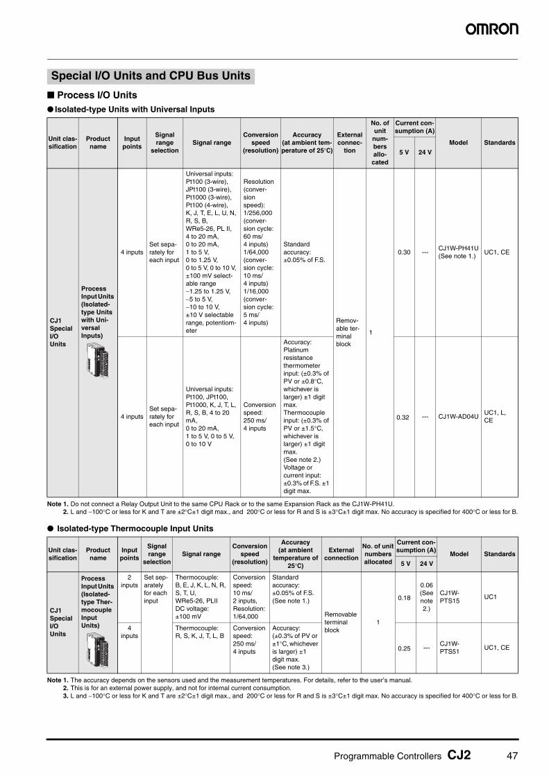
Programmable Controllers CJ2 47
■ Process I/O Units● Isolated-type Units with Universal Inputs
Note 1. Do not connect a Relay Output Unit to the same CPU Rack or to the same Expansion Rack as the CJ1W-PH41U.2. L and −100°C or less for K and T are ±2°C±1 digit max., and 200°C or less for R and S is ±3°C±1 digit max. No accuracy is specified for 400°C or less for B.
● Isolated-type Thermocouple Input Units
Note 1. The accuracy depends on the sensors used and the measurement temperatures. For details, refer to the user’s manual.2. This is for an external power supply, and not for internal current consumption.3. L and −100°C or less for K and T are ±2°C±1 digit max., and 200°C or less for R and S is ±3°C±1 digit max. No accuracy is specified for 400°C or less for B.
Special I/O Units and CPU Bus Units
Unit clas-sification
Product name
Input points
Signal range
selectionSignal range
Conversion speed
(resolution)
Accuracy (at ambient tem-perature of 25°C)
External connec-
tion
No. of unit
num-bers allo-cated
Current con-sumption (A)
Model Standards
5 V 24 V
CJ1 Special I/O Units
ProcessInput Units (Isolated-type Units with Uni-versal Inputs)
4 inputsSet sepa-rately for each input
Universal inputs:Pt100 (3-wire), JPt100 (3-wire), Pt1000 (3-wire), Pt100 (4-wire),K, J, T, E, L, U, N, R, S, B,WRe5-26, PL II,4 to 20 mA, 0 to 20 mA, 1 to 5 V, 0 to 1.25 V, 0 to 5 V, 0 to 10 V, ±100 mV select-able range−1.25 to 1.25 V, −5 to 5 V, −10 to 10 V, ±10 V selectable range, potentiom-eter
Resolution (conver-sion speed):1/256,000 (conver-sion cycle: 60 ms/4 inputs)1/64,000 (conver-sion cycle: 10 ms/4 inputs)1/16,000 (conver-sion cycle: 5 ms/4 inputs)
Standard accuracy: ±0.05% of F.S.
Remov-able ter-minal block
1
0.30 ---CJ1W-PH41U(See note 1.)
UC1, CE
4 inputsSet sepa-rately for each input
Universal inputs: Pt100, JPt100, Pt1000, K, J, T, L, R, S, B, 4 to 20 mA, 0 to 20 mA, 1 to 5 V, 0 to 5 V, 0 to 10 V
Conversion speed: 250 ms/4 inputs
Accuracy:Platinum resistance thermometer input: (±0.3% of PV or ±0.8°C, whichever is larger) ±1 digit max.Thermocouple input: (±0.3% of PV or ±1.5°C, whichever is larger) ±1 digit max. (See note 2.)Voltage or current input: ±0.3% of F.S. ±1 digit max.
0.32 --- CJ1W-AD04UUC1, L, CE
Unit clas-sification
Product name
Input points
Signal range
selectionSignal range
Conversion speed
(resolution)
Accuracy(at ambient
temperature of 25°C)
External connection
No. of unit numbers allocated
Current con-sumption (A)
Model Standards
5 V 24 V
CJ1 Special I/O Units
Process Input Units (Isolated-type Ther-mocouple Input Units)
2 inputs
Set sep-arately for each input
Thermocouple:B, E, J, K, L, N, R, S, T, U, WRe5-26, PLIIDC voltage:±100 mV
Conversion speed: 10 ms/2 inputs, Resolution: 1/64,000
Standard accuracy: ±0.05% of F.S.(See note 1.)
Removable terminal block
1
0.18
0.06 (See note 2.)
CJ1W-PTS15
UC1
4 inputs
Thermocouple:R, S, K, J, T, L, B
Conversion speed: 250 ms/4 inputs
Accuracy: (±0.3% of PV or ±1°C, whichever is larger) ±1 digit max. (See note 3.)
0.25 ---CJ1W-PTS51
UC1, CE

48 Programmable Controllers CJ2
● Isolated-type Resistance Thermometer Input Units
Note: This is for an external power supply, and not for internal current consumption.
● Isolated-type DC Input Units
Note: This is for an external power supply, and not for internal current consumption.
■ Analog I/O Units● Analog Input Units
Note 1. The resolution and conversion speed cannot be set independently. If the resolution is set to 1/4,000, then the conversion speed will be 1 ms/point.2. At 23 ±2°C
Unit clas-sification
Product name
Input points
Signal range
selectionSignal range
Conversion speed
(resolution)
Accuracy (at ambient
temperature of 25°C)
External connec-
tion
No. of unit
num-bers allo-cated
Current con-sumption (A)
Model Standards
5 V 24 V
CJ1 Special I/O Units
Process Analog Input Units (Isolated-type Resis-tance Thermom-eter Input Units)
4 inputs
Com-mon inputs
Resistance ther-mometer: Pt100, JPt100
Conver-sion speed: 250 ms/4 inputs
Accuracy: ±0.3°C of PV or ±0.8°C, which-ever is larger, ±1 digit max.
Remov-able termi-nal block
1 0.25 --- CJ1W-PTS52 UC1, CE
Unit clas-sification
Product name
Input points
Signal range selectionConversion
speed (resolution)
Accuracy (at ambient temperature
of 25°C)
External connec-
tion
No. of unit
numbers allocated
Current con-sumption (A)
Model Standards
5 V 24 V
CJ1 Special I/O Units
Isolated-type DC Input Units
2 inputs
DC voltage:0 to 1.25 V, −1.25 to 1.25 V, 0 to 5 V, 1 to 5 V, −5 to 5 V, 0 to 10 V, −10 to 10 V, ±10 V selectable range
DC current:0 to 20 mA, 4 to 20 mA
Conversion speed: 10 ms/2 inputs
Resolution: 1/64,000
Standard accuracy: ±0.05% of F.S.
Remov-able terminal block
1 0.180.09 (See note.)
CJ1W-PDC15 UC1, CE
Unit clas-sification
Product name
Input points
Signal range selec-tion
Signal range
ResolutionConversion
speed
Accuracy (at ambient
temperature of 25°C)
External connec-
tion
No. of unit
numbers allocated
Current consump-
tion (A) Model Standards
5 V 24 V
CJ1 Special I/O Units
Analog Input Units
4 inputs
Set sepa-rately for each input
1 to 5 V (1/10,000), 0 to 10 V (1/20,000), −5 to 5 V (1/20,000), −10 to 10 V (1/40,000), and 4 to 20 mA (1/10,000)
20 μs/1 point, 25 μs/2 points, 30 μs/3 points, 35 μs/4 pointsThe Direct conversion is provided.
Voltage:±0.2% of F.S.
Current:±0.4% of F.S. Remov-
able termi-nal block
1
0.52 --- CJ1W-AD042 UC1, CE
Analog Input Units
8 inputs
1 to 5 V, 0 to 5 V, 0 to 10 V, −10 to 10 V, 4 to 20 mA
1/4000, (Settable to 1/8000) (See note 1.)
1 ms/point max. (Settable to 250 μs/point)(See note 1.)
Voltage:±0.2% of F.S.
Current:±0.4% of F.S.(See note 2.)
0.42 --- CJ1W-AD081-V1
UC1, N, L, CE
4 inputs 0.42 --- CJ1W-AD041-V1
High-speed type

Programmable Controllers CJ2 49
● Analog Output Units
Note: This is for an external power supply, and not for internal current consumption
● Analog I/O Units
Note: The resolution and conversion speed cannot be set independently. If the resolution is set to 1/4,000, then the conversion speed will be 1 ms/point.
Unit clas-sification
Product name
Output points
Signal range selec-tion
Signal range
Resolu-tion
Conver-sion
speed
Accuracy (at ambient temperature
of 25°C)
External connec-
tion
External power supply
No. of unit
num-bers allo-cated
Current con-sumption (A)
Model Standards
5 V 24 V
CJ1 Special I/O Units
Analog Output Units
4 outputs
Set sepa-rately for each input
1 to 5 V (1/10,000), 0 to 10 V (1/20,000), and −10 to 10 V (1/40,000)
20 μs/1 point, 25 μs/2 points, 30 μs/3 points, 35 μs/4 pointsThe Direct conver-sion is provided.
±0.3% of F.S.
Remov-able termi-nal block
---
1
0.40 --- CJ1W-DA042V UC1, CE
Analog Output Units
8 outputs
1 to 5 V, 0 5 to 5 V, 0 to 10 V, −10 to 10 V 1/4,000
(Settable to 1/8,000)
1 ms/point max. (Settable to 250 μs/point)
24 VDC
, 140 mA max.
0.140.14 (See note.)
CJ1W-DA08VUC1, N, L, CE
8 outputs
4 to 20 mA
24 VDC
, 170 mA max.
0.140.17 (See note.)
CJ1W-DA08CUC1, N, CE
4 outputs 1 to 5 V,
0 to 5 V, 0 to 10 V, −10 to 10 V, 4 to 20 mA
1/40001 ms/point max.
Voltage output: ±0.3% of F.S.Current output: ±0.5% of F.S.
24 VDC
, 200 mA max.
0.120.2 (See note.)
CJ1W-DA041
UC1, N, L, CE
2 outputs
24 VDC
, 140 mA max.
0.120.14 (See note.)
CJ1W-DA021
Unit clas-sification
Product name
No. of points
Signal range selec-tion
Signal range
Resolu-tion (See
note.)
Conversion speed
(See note.)
Accuracy (at ambient temperature
of 25°C)
External connec-
tion
No. of unit numbers allocated
Current consump-
tion (A) Model Standards
5 V 24 V
CJ1 Special I/O Units
Analog I/O Units
4 inputs
Set sepa-rately for each input
1 to 5 V, 0 to 5 V, 0 to 10 V, −10 to 10 V, 4 to 20 mA
1/4,000 (Settable to 1/8,000)
1 ms/point (Settable to 500 μs/point max.)
Voltage input: ±0.2% of F.S.
Current input: ±0.2% of F.S. Remov-
able termi-nal block
1 0.58 --- CJ1W-MAD42UC1, N, L, CE
2 outputs
Voltage output: ±0.3% of F.S.
Current output: ±0.3% of F.S.
High-speed type
+10%−15%
+10%−15%
+10%−15%
+10%−15%

50 Programmable Controllers CJ2
■ Temperature Control Units
■ High-speed Counter Unit
* Use Lot No.030121 or later (Unit Version 1.06) of CJ1W-CT021 when using with CJ2 CPU Units.
Unit clas-sification
Product name
Specifications No. of unit numbers allocated
Current con-sumption (A)
Model Standards
No. of loopsTemperature sensor inputs
Control outputs 5 V 24 V
CJ1 Spe-cial I/O Units
Temper-ature Control Units
4 loops
Thermocouple input (R, S, K, J, T, B, L)
Open collector NPN outputs (pulses)
2
0.25 --- CJ1W-TC001
UC1, N, L, CE
4 loopsOpen collector PNP outputs (pulses) 0.25 --- CJ1W-TC002
2 loops, heater burnout detection function
Open collector NPN outputs (pulses) 0.25 --- CJ1W-TC003
2 loops, heater burnout detection function
Open collector PNP outputs (pulses) 0.25 --- CJ1W-TC004
4 loops
Platinum resistance thermometer input (JPt100, Pt100)
Open collector NPN outputs (pulses) 0.25 --- CJ1W-TC101
4 loopsOpen collector PNP outputs (pulses) 0.25 --- CJ1W-TC102
2 loops, heater burnout detection function
Open collector NPN outputs (pulses) 0.25 --- CJ1W-TC103
2 loops, heater burnout detection function
Open collector PNP outputs (pulses) 0.25 --- CJ1W-TC104
Unit classifi-cation
Product name
Specifications No. of unit numbers allo-
cated
Current con-sumption (A)
Model StandardsCountable channels
Encoder A and B inputs, pulse input Z signals
Max. counting rate
5 V 24 V
CJ1 Spe-cial I/O Units
High-speed Counter Unit
2
Open collectorInput voltage: 5 VDC, 12 V, or 24 V (5 V and 12 V are each for one axis only.)
50 kHz
4 0.28 --- CJ1W-CT021 * UC1, N, L, CE
RS-422 line driver 500 kHz

Programmable Controllers CJ2 51
■ Position Control Units● Position Control Units (High-speed type)
Unit classifi-cation
Product nameSpecifications No. of unit
numbers allocated
Current consump-
tion (A) Model Standards
Control output interfaceNo. of axes
5 V 24 V
CJ1SpecialI/O Units
Position ControlUnits
Pulse-train open-collector output withPulse Counter Function
2 axes2
0.27 --- CJ1W-NC214
UL1, CE4 axes 0.31 --- CJ1W-NC414
Pulse-train line-driver output withPulse Counter Function
2 axes2
0.27 --- CJ1W-NC234
4 axes 0.31 --- CJ1W-NC434
Position Control Unit Cables
Open-collectoroutput
ForCJ1W-NC214/NC414
Connecting Servo Drives:G Series R88D-GTG5 Series R88D-KT
1 axis
Cable length: 1 m XW2Z-100J-G13
---
Connecting Servo Drives:SMARTSTEP2 R7D-BP
Cable length: 3 m XW2Z-300J-G13
Connecting Servo Drives:G Series R88D-GTG5 Series R88D-KT
Cable length: 1 m XW2Z-100J-G14
Connecting Servo Drives:SMARTSTEP2 R7D-BP
Cable length: 3 m XW2Z-300J-G14
Connecting Servo Drives:G Series R88D-GTG5 Series R88D-KT
2 axes
Cable length: 1 m XW2Z-100J-G5
Connecting Servo Drives:SMARTSTEP2 R7D-BP
Cable length: 3 m XW2Z-300J-G5
Connecting Servo Drives:G Series R88D-GTG5 Series R88D-KT
Cable length: 1 m XW2Z-100J-G6
Connecting Servo Drives:SMARTSTEP2 R7D-BP
Cable length: 3 m XW2Z-300J-G6
Line-driver output
ForCJ1W-NC234/NC434
Connecting Servo Drives:G Series R88D-GTG5 Series R88D-KT
1 axis
Cable length: 1 m XW2Z-100J-G9
Cable length: 5 m XW2Z-500J-G9
Cable length: 10 m XW2Z-10MJ-G9
Connecting Servo Drives:SMARTSTEP2 R7D-BP
Cable length: 1 m XW2Z-100J-G12
Cable length: 5 m XW2Z-500J-G12
Cable length: 10 m XW2Z-10MJ-G12
Applicable Servo Drive:G Series R88D-GTG5 Series R88D-KT
2 axes
Cable length: 1 m XW2Z-100J-G1
Cable length: 5 m XW2Z-500J-G1
Cable length: 10 m XW2Z-10MJ-G1
Applicable Servo Drive:SMARTSTEP2 R7D-BP
Cable length: 1 m XW2Z-100J-G4
Cable length: 5 m XW2Z-500J-G4
Cable length: 10 m XW2Z-10MJ-G4
High-speed type

52 Programmable Controllers CJ2
● Position Control Units
Note: The ambient operating temperature for 4-Axes Position Control Units is 0 to 50°C; the allowable voltage fluctuation on the external 24-VDC power supply is 22.8to 25.2 VDC (24 V ±5%).
Unit classifi-cation
Product nameSpecifications No. of unit
numbers allocated
Current consump-
tion (A) Model Standards
Control output interfaceNo. of axes
5 V 24 V
CJ1 Special I/O Units
Position Control Units
Pulse train, open collector output 1 axis1
0.25 --- CJ1W-NC113
UC1, CE
Pulse train, open collector output 2 axes 0.25 --- CJ1W-NC213
Pulse train, open collector output (See note.) 4 axes 2 0.36 --- CJ1W-NC413
Pulse train, line driver output 1 axis1
0.25 --- CJ1W-NC133
Pulse train, line driver output 2 axes 0.25 --- CJ1W-NC233
Pulse train, line driver output (See note.) 4 axes 2 0.36 --- CJ1W-NC433
Space Unit Use a CJ1W-SP001 Space Unit if the operating temperature is 0 to 55°C. CJ1W-SP001 UC1, CE
Servo Relay Units
For 1-Axis Position Control Unit (without communications support) (CJ1W-CN113/133) XW2B-20J6-1B
---For 2- or 4-Axes Position Control Unit (without communications support) (CJ1W-NC213/233/413/433) XW2B-40J6-2B
For 2- or 4-Axes Position Control Unit (with communications support) (CJ1W-NC213/233/413/433) XW2B-40J6-4A
Position Control Unit Cables
Open-collectoroutput
For CJ1W-NC113
Connecting Servo Drives: G5/G Series, SMARTSTEP2
1 axisCable length: 0.5 m XW2Z-050J-A14
---
Cable length: 1 m XW2Z-100J-A14
For CJ1W-NC213/413
Connecting Servo Drives: G5/G Series, SMARTSTEP2
2 axesCable length: 0.5 m XW2Z-050J-A15
Cable length: 1 m XW2Z-100J-A15
Line-driver output
For CJ1W-NC133
Connecting Servo Drives: G5/G Series, SMARTSTEP2
1 axisCable length: 0.5 m XW2Z-050J-A18
Cable length: 1 m XW2Z-100J-A18
For CJ1W-NC233/433
Connecting Servo Drives: G5/G Series, SMARTSTEP2
2 axesCable length: 0.5 m XW2Z-050J-A19
Cable length: 1 m XW2Z-100J-A19

Programmable Controllers CJ2 53
■ Position Control Unit with EtherCAT interface
Note: Use Category 5 or higher cables with double shield of aluminium tape and braid shield for connection with EtherCAT Slaves.We also recommend you to use Category 5 or higher modular connectors.
■EtherCAT Slave Unit
● Recommended EtherCAT Communications CablesCategory 5 or higher (100BASE-TX) straight cable with double shielding (aluminum tape and braided shielding) is recommended.
Cabel with ConnectorsWire Gauge and Number of Pairs: AWG22, 2-pair Cable
Note: The cable length 0.3, 0.5, 1, 2, 3, 5, 10 and 15m are available. For details, refer to Cat.No.G019.
Cables / ConnectorsWire Gauge and Number of Pairs: AWG24, 4-pair Cable
Wire Gauge and Number of Pairs: AWG22, 2-pair Cable
* We recommend you to use above cable and connector together.
Unit classi-fication
Product name
Specifications No. of unit numbers allocated
Current con-sumption (A)
Model Standards
Control output interfaceNo. of axes
5 V 24 V
CJ1 CPU Bus Units
Position Control Unitwith EtherCAT interface
Control commands executed by EtherCAT communications.Positioning functions: Memory operation, Direct operation by ladder programming
2 axes
1 0.46 ---
CJ1W-NC281
UC1, CE
4 axes CJ1W-NC481
8 axes CJ1W-NC881
16 axes CJ1W-NCF81
Control commands executed by EtherCATcommunications.• Positioning functions: Memory operation,
Direct operation by ladder programming• I/O communication : 64 nodes
4 axes
1 0.46 ---
CJ1W-NC482
8 axes CJ1W-NC882
16 axes CJ1W-NCF82
Unit type Product name
Specifications No. of unit numbers allocated
Current con-sumption (A)
Model Standards
Communications cableCommunications
functions5 V 24 V
CJ1 CPUBus Unit
EtherCAT Slave Unit
STP (shielded twisted-pair) cable of category 5 or higher with double shielding
Refreshing methods:Free-Run ModePDO data sizes: TxPDO 400byte max./RxPDO: 400byte max.
1 0.34 --- CJ1W-ECT21 UC1,CE,KC
Item Appearance Recommended manufacturer Cable length(m) Model
Cable with Connectors on Both Ends (RJ45/RJ45) OMRON 0.3 XS5W-T421-AMD-K
0.5 XS5W-T421-BMD-K
1 XS5W-T421-CMD-K
2 XS5W-T421-DMD-K
5 XS5W-T421-GMD-K
10 XS5W-T421-JMD-K
Cable with Connectors on Both Ends (M12/RJ45) OMRON 0.3 XS5W-T421-AMC-K
0.5 XS5W-T421-BMC-K
1 XS5W-T421-CMC-K
2 XS5W-T421-DMC-K
5 XS5W-T421-GMC-K
10 XS5W-T421-JMC-K
Item Appearance Recommended manufacturer Model
Cables --- Tonichi Kyosan Cable, Ltd. NETSTAR-C5E SAB 0.5 × 4P CP
--- Kuramo Electric Co. KETH-SB
RJ45 Connectors --- Panduit Corporation MPS588
Item Appearance Recommended manufacturer Model
Cables --- Kuramo Electric Co. KETH-PSB-OMR *
RJ45 Assembly Connector OMRON XS6G-T421-1 *

54 Programmable Controllers CJ2
■Position Control Unit with MECHATROLINK-II interface
Unit classi-fication Product name
Specifications No. of unit numbers allocated
Current con-sumption (A)
Model StandardsControl output interface
No. of axes
5 V 24 V
CJ1 CPU Bus Units
Position Control Unit with MECHATROLINK-II interface
Control commands executed by MECHATROLINK-II synchronous communications.Direct operation by ladder programming.Control mode: Position control, speed control, or torque control
2 axes
1 0.36 ---
CJ1W-NC271
UC1, CE4 axes CJ1W-NC471
16 axes CJ1W-NCF71
16 axes CJ1W-NCF71-MA
MECHATROLINK-II Cables
MECHATROLINK-II Cables(without ring core and USB connector on both ends)Note: Can be connected to R88D-GN and
R88D-KN only.
Cable length: 0.5 m FNY-W6002-A5
---Cable length: 1 m FNY-W6002-01
Cable length: 3 m FNY-W6002-03
Cable length: 5 m FNY-W6002-05
MECHATROLINK-II Cables(with ring core and USB connector on both ends) (Yaskawa Electric Corporation)Use the model numbers provided in this catalog when ordering from OMRON.
Cable length: 0.5 m FNY-W6003-A5
---
Cable length: 1 m FNY-W6003-01
Cable length: 3 m FNY-W6003-03
Cable length: 5 m FNY-W6003-05
Cable length: 10 m FNY-W6003-10
Cable length: 20 m FNY-W6003-20
Cable length: 30 m FNY-W6003-30
MECHATROLINK-II Terminating Resistors
Terminating Resistor for MECHATROLINK-II (Yaskawa Electric Corporation)Use the model numbers provided in this catalog when ordering from OMRON.
FNY-W6022 ---
MECHATROLINK- II Repeater
Repeater(Yaskawa Electric Corporation)
JEPMC-REP2000-E ---

Programmable Controllers CJ2 55
■ Serial Communications Units
Note 1. When an NT-AL001 RS-232C/RS-422A Conversion Unit is used, this value increases by 0.15 A/Unit. Add 0.20A/Unit when using NV3W-M@20L(-V1) Program-mable Terminals. Add 0.04A/Unit when using CJ1W-CIF11 RS-422A Adapters.
2. The Serial Gateway function is enabled only for Serial Communications Units of unit version 1.2 and later.3. The no-protocol function is enabled only for Serial Communications Units of unit version 1.2 and later (and a CPU Unit of unit version 3.0 or later is also required).4. The Modbus-RTU Slave function is enabled only for Serial Communications Units of unit version 1.3 and later.
■ EtherNet/IP Unit
Note: Up to seven EtherNet/IP Units can be connected to a CJ2H-CPU@@-EIP. Up to two EtherNet/IP Units can be connected to a CJ2M CPU Unit.
■ Ethernet Unit
Unit clas-sification
Product nameSpecifications No. of unit
numbers allocated
Current con-sumption (A)
Model StandardsCommunications
InterfaceCommunications functions 5 V 24 V
CJ1 CPU Bus Units
Serial Com-munications Units 2 RS-232C ports
The following functions can be selected for each port:Protocol macroHost LinkNT Links (1:N mode)Serial GatewayNo-protocol Modbus-RTU Slave
1
0.29 (See
note 1.)--- CJ1W-SCU22
UC1, N, L, CE
2 RS-422A/485 ports 0.46 --- CJ1W-SCU32
1 RS-232C port and 1 RS-422A/485 port
0.38 (See
note 1.)--- CJ1W-SCU42
Serial Com-munications Units
2 RS-232C portsThe following functions can be selected for each port:Protocol macroHost LinkNT Links (1:N mode)Serial Gateway (See note 2.)No-protocol (See note 3.)Modbus-RTU Slave (See note 4.)
1
0.28 (See
note 1.)--- CJ1W-SCU21-V1
2 RS-422A/485 ports 0.38 --- CJ1W-SCU31-V1
1 RS-232C port and 1 RS-422A/485 port
0.38 (See
note 1.)--- CJ1W-SCU41-V1
Unit clas-sification
Product name
Specifications
No. of unit numbers allocated
Current con-sumption (A)
Model StandardsCommunica-tions cable
Communications functions
Max.Units mountable per CPU
Unit
5 V 24 V
CJ1 CPU Bus Unit
EtherNet/IP Unit STP (shielded
twisted-pair) cable of category 5, 5e, or higher.
Tag data linkmessage service
8(See note)
1 0.41 --- CJ1W-EIP21UC1, N, L, CE
Unit clas-sification
Product name
Specifications
No. of unit numbers allocated
Current con-sumption (A)
Model StandardsCommunica-tions cable
Communications functions
Max.Units mountable per CPU
Unit
5 V 24 V
CJ1 CPU Bus Unit
Ethernet Unit
100Base-TX
FINS communications service (TCP/IP, UDP/IP), FTP server functions, socket services, mail transmission service, mail reception (remote command receive), automatic adjustment of PLC’s built-in clock, server/host name specifications
4 1 0.37 --- CJ1W-ETN21UC1, N, L, CE
High-speed type

56 Programmable Controllers CJ2
● Industrial Switching Hubs
● WE70 FA WIRELESS LAN UNITS
Note 1. A Pencil Antenna, mounting magnet, and screw mounting bracket are included as accessories. 2. Always use a model that is applicable in your region. Refer to the WE70 Catalog (Cat. No. N154). 3. Final order entry date:The end of June, 2020.
* From January 2016, the WE70-AP-CA and WE70-CL-CA can be used in Singapore.
■ Controller Link Units● Controller Link Units
Note: Use the following special cable for shielded, twisted-pair cable.• ESVC0.5 × 2C-13262 (Bando Electric Wire: Japanese Company)• ESNC0.5 × 2C-99-087B (JMACS Japan Co., Ltd.: Japanese Company)• ESPC 1P × 0.5 mm2 (Nagaoka Electric Wire Co., Ltd.: Japanese Company)• Li2Y-FCY2 × 0.56qmm (Kromberg & Schubert, Komtec Department: German Company)• 1 × 2 × AWG-20PE+Tr.CUSN+PVC (Draka Cables Industrial: Spanish Company)• #9207 (Belden: US Company)
● Controller Link Support Boards
Note: The CD-ROM contains FinsGateway Version 2003 (PCI-CLK Edition) and FinsGateway Version 3 (PCI-CLK Edition).Install the software from CD Ver 3.10 or higher if the operating system is Windows 7 (32bit) or Windows Vista.Install FinsGateway version 3 if the operating system is Windows NT 4.0 (Service pack 3 or higher), Windows ME, or Windows 98SE.
Product name Appearance Functions No. of ports AccessoriesCurrent
consumption (A)Model
Industrial Switching Hubs
Quality of Service (QoS): EtherNet/IP control data priority 10/100BASE-TX, Auto-Negotiation
5Power supply connector
0.07 W4S1-05D
Product name Applicable region Type Model Standards
WE70 FA WIRELESS LAN UNITS
JapanAccess Point (Master) WE70-AP
---Client (Slave) WE70-CL
EuropeAccess Point (Master) WE70-AP-EU
CEClient (Slave) WE70-CL-EU
CanadaAccess Point (Master) WE70-AP-CA *
UCClient (Slave) WE70-CL-CA *
ChinaAccess Point (Master) WE70-AP-CN
---Client (Slave) WE70-CL-CN
Unit clas-sification
Product name
SpecificationsNo. of unit numbers allocated
Current consumption (A)
Model StandardsCommunications
cableCommunica-
tions typeDuplex support
Max. Units mountable per
CPU Unit5 V 24 V
CJ1 CPU Bus Unit
Controller Link Unit
Wired shielded twisted-pair cable (See note.)
Data links and message service
No 8 1 0.35 --- CJ1W-CLK23 UC1, N, L, CE
Unit classification
SpecificationAccessories Model Standards
Communications cable Communications type
Controller Link Support Board for PCI Bus Wired shielded twisted-pair
cableData link and message service
• CD-ROM × 1 (See note.)• INSTALLATION GUIDE (W467) × 1• Communications connector × 1
3G8F7-CLK23-E CE, KC

Programmable Controllers CJ2 57
● Repeater Units
Note 1. Using Repeater Units enables T-branches and long-distance wiring for Wired Controller Link networks. 62-node configurations, and converting part of the net-work to optical cable.
2. When using wire-to-optical (H-PCF) cable, use a H-PCF cable (for both Controller Link and SYSMAC LINK) or a H-PCF optical fiber cable with connector.3. When using wire-to-optical (GI) cable, use a GI optical cable (for Controller Link).
● Relay Terminal Block
Note: Controller Link Units can be replaced without stopping the communications of the entire network if a Relay Terminal Block is installed in advance on the Unit ina Wired Controller Link network. Relay Blocks cannot be used on Controller Link Support Boards.
● H-PCF Cables and Optical Connectors
* Orange specifications are Discontinuation.
Unit classification Specifications Model Standards
Controller Link Repeater Unit
Wire-to-wire Model CS1W-RPT01
UC1, CEWire-to-Optical (H-PCF) Model (See note 2.) CS1W-RPT02
Wire-to-Optical (GI) Model (See note 3.) CS1W-RPT03
Unit classification Specifications Model Standards
Relay Terminal Block for Wired Controller Link Unit
Use for Wired Controller Link Units (set of 5). CJ1W-TB101 ---
Name Application/construction Specifications Model Standards
Optical Fiber CablesControllerLink, SYSMACLINK, SYSBUS
(1) Optical fiber single-core cord(2) Tension member (plastic-
sheathed wire)(3) Filler (plastic)(4) Filler surrounding signal wires
(plastic, yarn, or fiber)(5) Holding tape (plastic)(6) Heat-resistant PV sheath
Two-core optical cable with tension member
Black * 10 m S3200-HCCB101
---
Black * 50 m S3200-HCCB501
Black * 100 m S3200-HCCB102
Black * 500 m S3200-HCCB502
Black * 1,000 m S3200-HCCB103
Optical Connec-tors (Crimp-cut)
CS1W-RPT02
Half lock S3200-COCF2571
Full lock S3200-COCF2071
CS1W-RPT01PWRT/R1T/R2
SL1
TER SW
TER SW
ON
SL2
DC24VINPUT
1 BAUD2 RATE
SW1
(1)(2)
(4)(3)
(5)(6)

58 Programmable Controllers CJ2
● H-PCF Optical Fiber Cables with Connectors (Black Composite Cables with Two-Optical Lines and Two Power Supply Lines)
• Cable LengthThe following cable lengths are available: 2 m, 5 m, 15 m, 20 m.For lengths of 21 m or more, contact your OMRON sales repre-sentative.
• Model Numbers
• Optical Connector Assembly Tool
Note: There is a risk of quality problems when using cables assembled by typ-ical users, so we recommend purchasing cables with preattached con-nectors or having a qualified technician assemble the cables.Optical connectors for H-PCF Optical Cables with Connectors are adhe-sive polished.
● GI Optical CablesA qualified technician must select, assemble, and install GIOptical Fiber Cable, so always let an optical cable specialisthandle the GI cable.
Usable Optical Cables and Optical Connectors
• Optical fiber types: Graded, indexed, multi-mode, all quartzglass, fiber (GI-type AGF cable)
• Optical fiber construction (core diameter/clad diameter): 62.5/125 μm or 50/125 μm
• Optical fiber optical characteristics of optical fiber: Refer to the tables.• Optical connector: ST connector (IEC-874-10)
• 50/125 μm AGF Cable
Lf is fiber length in km, Ta is ambient temperature, and λ: is the peak wave-length of the test light source.
• 62.5/125 μm AGF Cable
Lf is fiber length in km, Ta is ambient temperature, and λ is the peak wavelength of the test light source.
Application Appearance ModelStan-dards
Controller Link, SYSMAC Link
S3200-CN@@@-20-20
---S3200-CN@@@-20-25
S3200-CN@@@-25-25
Name Applicable Unit Model ManufacturerStan-dards
Optical Fiber Assem-bly Tool (See note.)
This tool is used on site for mounting crimp-cut connectors and hard plastic-clad silica opti-cal fiber for optical transmission systems of C-series SYSBUS, SYSMAC LINK, and Controller Link.
CAK-0057
Sumitomo Electric Industries, Ltd.
---
@@@201
501
102
152
202
Length2 m
5 m
10 m
15 m
20 m
20
25
Number Connector appearance
Full lock
Half lock
Lengths of 2 m, 5 m, 10 m, 15 m, and 20 m
Example: S3200-CN@@@@@@-20-25(1) (2) (3)
Length of 21 m or more
Example: S3200-CN-20-20(1) (3) Specify the
cable length in meters.
(2)Cable Length
Cable length
(1)H-PCF optical fiber cable
(1) Connectors at Both Ends
Item Minimum Standard Maximum Remarks
Numerical Aperture (N.A)
--- 0.21 --- ---
Transmis-sion loss (dB)
--- ---
3.0 Lf0.5 km ≤ Lf
λ = 0.8 μmTa = 25°C
3.0 Lf + 0.2
0.2 km ≤ Lf ≤ 0.5 km
3.0 Lf + 0.4
Lf ≤ 0.2 km
Connection loss (dB)
--- --- 1.0λ = 0.8 μm, one location
Transmission bandwidth (MHz-km)
500 --- --- λ = 0.85μm (LD)
Item Minimum Standard Maximum Remarks
Numerical Aperture (N.A)
--- 0.28 --- ---
Transmis-sion loss (dB)
--- ---
3.5 Lf0.5 km ≤
Lf
λ = 0.8 μmTa = 25°C
3.5 Lf + 0.2
0.2 km ≤ Lf ≤ 0.5
km
3.5 Lf + 0.4
Lf ≤ 0.2 km
Connection loss (dB)
--- --- 1.0λ = 0.8 μm, one location
Transmission bandwidth (MHz-km)
200 --- --- λ = 0.85 μm (LD)

Programmable Controllers CJ2 59
■ FL-net Unit
■ DeviceNet Unit
■ CompoNet Master Unit
■ CompoBus/S Master Unit
■ ID Sensor Units
Note: To use a V680-H01 Antenna, refer to the V680 Series RFID System Catalog (Cat. No. Q151).
Unit classifi-cation
Product name
SpecificationsNo. of unit numbers allocated
Current con-sumption (A)
Model StandardsCommunica-
tions interfaceCommunications
functions
Max. Units mountable
per CPU Units5 V 24 V
CJ1 CPU Bus Units
FL-net Unit
100Base-TX
With FL-net Ver. 2.0 specifications (OPCN-2)Data links and message service
4 1 0.37 --- CJ1W-FLN22 UC1, CE
Unit classifi-cation
Product name Specifications Communications typeNo. of unit numbers allocated
Current con-sumption (A) Model Standards
5 V 24 V
CJ1 CPU Bus Units
DeviceNet Unit
Functions as master and/or slave; allows control of 32,000 points max. per master.
• Remote I/O communications master (fixed or user-set allocations)
• Remote I/O communications slave (fixed or user-set allocations)
• Message communications
1 0.29 --- CJ1W-DRM21UC1, N, L, CE
Unit classifi-cation
Product name
Specifications No. of unit numbers allocated
Current con-sumption (A)
Model StandardsCommunications
functionsNo. of I/O points per Master Unit 5 V 24 V
CJ1 Special I/O Units
CompoNet Master Unit • Remote I/O
communications• Message
communications
Word Slaves: 2,048 max. (1.024 inputs and 1,024 outputs)Bit Slaves: 512 max. (256 inputs and 256 outputs)
1, 2, 4, or 8 0.4 ---
CJ1W-CRM21U, U1, N, L, CE
Unit classifi-cation
Product name
SpecificationsNo. of unit numbers allocated
Current con-sumption (A)
Model StandardsCommunications
functionsNo. of I/O points
Max. Units mountable per
CPU Unit5 V 24 V
CJ1 Special I/O Units
CompoBus/S Master Unit
Remote I/O communications
256 max.(128 inputs and 128 outputs)
401 or 2
(variable) 0.15 --- CJ1W-SRM21UC1, N, L, CE128 max.
(64 inputs and 64 outputs)
Unit clas-sification
Product name
SpecificationsNo. of unit numbers allocated
Current consumption (A)
Model Standards
Connected ID SystemsNo. of con-nected R/W
heads
External power supply
5 V 24 V
CJ1 CPU Bus Units
ID Sensor Units
V680 Series RFID System
1
Not required.
1 0.26 0.13 (See note.)
CJ1W-V680C11
UC, CE2 2 0.32 0.26 CJ1W-V680C12
V600 Series RFID System
1
Not required.
1 0.26 0.12 CJ1W-V600C11
2 2 0.32 0.24 CJ1W-V600C12
FL-net UNITCJ1W-FLN22

60 Programmable Controllers CJ2
■SPU Unit (High-speed Data Storage Unit)
Unit classification Product name
Specifications No. of unit numbers allocated
Current consumption
(A) Model Standards
PC Card slot Ethernet (LAN) port 5 V 24 V
CJ1 CPU Bus Units
SPU Unit (High-speed Data Storage Unit) CF Card Type I/II × 1 slot
Use an OMRON HMC-EF@@@ Memory Card.
1 port (10/100Base-TX) 1 0.56 --- CJ1W-SPU01-V2 UC1, CE
SPU-Console
Functions: Unit settings, sampling settings, etc., for High-speed Data Collection Units (required for making settings for this Unit)
OS: Microsoft Windows 10 (32 bit/64 bit) Microsoft Windows 8.1 (32 bit/64 bit)Microsoft Windows 8 (32 bit/64 bit)Microsoft Windows 7 (32 bit/64 bit)
WS02-SPTC1-V2
---
SPU Unit Data Man-agement Middleware
Function: Data files collected by SPU Unit Data Management Middleware are automatically acquired at the personal computer, and can be registered in a database.
OS: Microsoft Windows 10 (32 bit/64 bit)Microsoft Windows 8.1 (32 bit/64 bit)Microsoft Windows 8 (32 bit/64 bit)Microsoft Windows 7 (32 bit/64 bit)Microsoft Windows Server 2012Microsoft Windows Server 2008
1 license WS02-EDMC1-V2
5 licenses WS02-EDMC1-V2L05
Memory Cards
Flash memory, 128 MB Note:Memory Card is required for data collection.
HMC-EF183
---Flash memory, 256 MB HMC-EF283
Flash memory, 512 MB HMC-EF583

Terms and Conditions AgreementRead and understand this catalog.
Please read and understand this catalog before purchasing the products. Please consult your OMRON representative if you have any questions or comments.
Warranties.(a) Exclusive Warranty. Omron’s exclusive warranty is that the Products will be free from defects in materials and workmanship
for a period of twelve months from the date of sale by Omron (or such other period expressed in writing by Omron). Omron disclaims all other warranties, express or implied.
(b) Limitations. OMRON MAKES NO WARRANTY OR REPRESENTATION, EXPRESS OR IMPLIED, ABOUT NON-INFRINGEMENT, MERCHANTABILITY OR FITNESS FOR A PARTICULAR PURPOSE OF THE PRODUCTS. BUYER ACKNOWLEDGES THAT IT ALONE HAS DETERMINED THAT THE PRODUCTS WILL SUITABLY MEET THE REQUIREMENTS OF THEIR INTENDED USE.
Omron further disclaims all warranties and responsibility of any type for claims or expenses based on infringement by the Products or otherwise of any intellectual property right. (c) Buyer Remedy. Omron’s sole obligation hereunder shall be, at Omron’s election, to (i) replace (in the form originally shipped with Buyer responsible for labor charges for removal or replacement thereof) the non-complying Product, (ii) repair the non-complying Product, or (iii) repay or credit Buyer an amount equal to the purchase price of the non-complying Product; provided that in no event shall Omron be responsible for warranty, repair, indemnity or any other claims or expenses regarding the Products unless Omron’s analysis confirms that the Products were properly handled, stored, installed and maintained and not subject to contamination, abuse, misuse or inappropriate modification. Return of any Products by Buyer must be approved in writing by Omron before shipment. Omron Companies shall not be liable for the suitability or unsuitability or the results from the use of Products in combination with any electrical or electronic components, circuits, system assemblies or any other materials or substances or environments. Any advice, recommendations or information given orally or in writing, are not to be construed as an amendment or addition to the above warranty.
See http://www.omron.com/global/ or contact your Omron representative for published information.
Limitation on Liability; Etc.OMRON COMPANIES SHALL NOT BE LIABLE FOR SPECIAL, INDIRECT, INCIDENTAL, OR CONSEQUENTIAL DAMAGES, LOSS OF PROFITS OR PRODUCTION OR COMMERCIAL LOSS IN ANY WAY CONNECTED WITH THE PRODUCTS, WHETHER SUCH CLAIM IS BASED IN CONTRACT, WARRANTY, NEGLIGENCE OR STRICT LIABILITY.
Further, in no event shall liability of Omron Companies exceed the individual price of the Product on which liability is asserted.
Suitability of Use.Omron Companies shall not be responsible for conformity with any standards, codes or regulations which apply to the combination of the Product in the Buyer’s application or use of the Product. At Buyer’s request, Omron will provide applicable third party certification documents identifying ratings and limitations of use which apply to the Product. This information by itself is not sufficient for a complete determination of the suitability of the Product in combination with the end product, machine, system, or other application or use. Buyer shall be solely responsible for determining appropriateness of the particular Product with respect to Buyer’s application, product or system. Buyer shall take application responsibility in all cases.
NEVER USE THE PRODUCT FOR AN APPLICATION INVOLVING SERIOUS RISK TO LIFE OR PROPERTY OR IN LARGE QUANTITIES WITHOUT ENSURING THAT THE SYSTEM AS A WHOLE HAS BEEN DESIGNED TO ADDRESS THE RISKS, AND THAT THE OMRON PRODUCT(S) IS PROPERLY RATED AND INSTALLED FOR THE INTENDED USE WITHIN THE OVERALL EQUIPMENT OR SYSTEM.
Programmable Products.Omron Companies shall not be responsible for the user’s programming of a programmable Product, or any consequence thereof.
Performance Data.Data presented in Omron Company websites, catalogs and other materials is provided as a guide for the user in determining suitability and does not constitute a warranty. It may represent the result of Omron’s test conditions, and the user must correlate it to actual application requirements. Actual performance is subject to the Omron’s Warranty and Limitations of Liability.
Change in Specifications.Product specifications and accessories may be changed at any time based on improvements and other reasons. It is our practice to change part numbers when published ratings or features are changed, or when significant construction changes are made. However, some specifications of the Product may be changed without any notice. When in doubt, special part numbers may be assigned to fix or establish key specifications for your application. Please consult with your Omron’s representative at any time to confirm actual specifications of purchased Product.
Errors and Omissions.Information presented by Omron Companies has been checked and is believed to be accurate; however, no responsibility is assumed for clerical, typographical or proofreading errors or omissions.

Authorized Distributor:
In the interest of product improvement, specifications are subject to change without notice.
Cat. No. P059-E1-19 0422 (0908)
© OMRON Corporation 2008-2022 All Rights Reserved.
OMRON Corporation Industrial Automation Company
OMRON ELECTRONICS LLC2895 Greenspoint Parkway, Suite 200 Hoffman Estates, IL 60169 U.S.A.Tel: (1) 847-843-7900/Fax: (1) 847-843-7787
Regional HeadquartersOMRON EUROPE B.V.Wegalaan 67-69, 2132 JD HoofddorpThe NetherlandsTel: (31)2356-81-300/Fax: (31)2356-81-388
Contact: www.ia.omron.comKyoto, JAPAN
OMRON ASIA PACIFIC PTE. LTD.438B Alexandra Road, #08-01/02 Alexandra Technopark, Singapore 119968Tel: (65) 6835-3011/Fax: (65) 6835-2711
OMRON (CHINA) CO., LTD.Room 2211, Bank of China Tower, 200 Yin Cheng Zhong Road, PuDong New Area, Shanghai, 200120, ChinaTel: (86) 21-5037-2222/Fax: (86) 21-5037-2200
Note: Do not use this document to operate the Unit.
CSM_17_17