Installation, operation, and maintenance of Type MVS-c load ...
16
Effective December 2010 Supersedes April 2006 Instruction Booklet IB02102007E Installation, operation, and maintenance of Type MVS-c load interrupter switches 4.76 kV, 15 kV, 27 kV, and 38 kV Contents Description Page Introduction 2 Receiving, handling, and storage 3 Installation 3 Operation 5 Maintenance 6 Low voltage control device and wiring 11 Motor operation 12 Electromechanical stored energy release (shunt trip) 13 Bolt tightness for bus connections to terminal pads 16 Common renewal parts 16 This instruction booklet is published solely for information purposes and should not be considered all-inclusive If further information is required, you should consult an authorized Eaton sales representative The sale of the product shown in this literature is subject to the terms and conditions outlined in appropriate Eaton selling policies or other contractual agreement between the parties This literature is not intended to and does not enlarge or add to any such contract The sole source governing the rights and remedies of any purchaser of this equipment is the contract between the purchaser and Eaton NO WARRANTIES, EXPRESSED OR IMPLIED, INCLUDING WARRANTIES OF FITNESS FOR A PARTICULAR PURPOSE OR MERCHANTABILITY, OR WARRANTIES ARISING FROM COURSE OF DEALING OR USAGE OF TRADE, ARE MADE REGARDING THE INFORMATION, RECOMMENDATIONS, AND DESCRIPTIONS CONTAINED HEREIN In no event will Eaton be responsible to the purchaser or user in contract, in tort (including negligence), strict liability or otherwise for any special, indirect, incidental or consequential damage or loss whatsoever, including but not limited to damage or loss of use of equipment, plant or power system, cost of capital, loss of power, additional expenses in the use of existing power facilities, or claims against the purchaser or user by its customers resulting from the use of the information, recommendations and description contained herein
-
Upload
khangminh22 -
Category
Documents
-
view
2 -
download
0
Transcript of Installation, operation, and maintenance of Type MVS-c load ...

Effective December 2010Supersedes April 2006Instruction Booklet IB02102007E
Installation, operation, and maintenance of Type MVS-c load interrupter switches 4.76 kV, 15 kV, 27 kV, and 38 kV
ContentsDescription Page
Introduction . . . . . . . . . . . . . . . . . . . . . . . . . . . . . . 2Receiving, handling, and storage . . . . . . . . . . . . . 3Installation . . . . . . . . . . . . . . . . . . . . . . . . . . . . . . . 3Operation . . . . . . . . . . . . . . . . . . . . . . . . . . . . . . . . 5Maintenance . . . . . . . . . . . . . . . . . . . . . . . . . . . . . 6Low voltage control device and wiring . . . . . . . . 11Motor operation . . . . . . . . . . . . . . . . . . . . . . . . . . 12Electromechanical stored energy release (shunt trip) . . . . . . . . . . . . . . . . . 13Bolt tightness for bus connections to terminal pads . . . . . . . . . . . . . . . 16Common renewal parts . . . . . . . . . . . . . . . . . . . . 16
This instruction booklet is published solely for information purposes and should not be considered all-inclusive . If further information is required, you should consult an authorized Eaton sales representative .
The sale of the product shown in this literature is subject to the terms and conditions outlined in appropriate Eaton selling policies or other contractual agreement between the parties . This literature is not intended to and does not enlarge or add to any such contract . The sole source governing the rights and remedies of any purchaser of this equipment is the contract between the purchaser and Eaton .
NO WARRANTIES, EXPRESSED OR IMPLIED, INCLUDING WARRANTIES OF FITNESS FOR A PARTICULAR PURPOSE OR MERCHANTABILITY, OR WARRANTIES ARISING FROM COURSE OF DEALING OR USAGE OF TRADE, ARE MADE REGARDING THE INFORMATION, RECOMMENDATIONS, AND DESCRIPTIONS CONTAINED HEREIN . In no event will Eaton be responsible to the purchaser or user in contract, in tort (including negligence), strict liability or otherwise for any special, indirect, incidental or consequential damage or loss whatsoever, including but not limited to damage or loss of use of equipment, plant or power system, cost of capital, loss of power, additional expenses in the use of existing power facilities, or claims against the purchaser or user by its customers resulting from the use of the information, recommendations and description contained herein .

2
Instruction Booklet IB02102007EEffective December 2010
Installation, operation, and maintenance of Type MVS-c load interrupter switches
4.76 kV, 15 kV, 27 kV, and 38 kV
eaton Corporation www.eaton.com
Section 1: introductionRead and understand these instructions before attempting any installation, operation, or maintenance of an MVS-c switch .
1.1 Purpose
This instruction booklet is expressly intended to cover the installation, operation, and maintenance of medium voltage switch (MVS-c) load interrupter switches . It does not purport to cover all possible contingencies, variations, and details that may arise during operation or maintenance of this equipment .
If further information is desired regarding this particular application information, contact your local Eaton sales office, see Eaton Price List 31-931 for MVS-c switches, and read the appropriate industry standards .
1.2 Basic description and application
A Type MVS-c load interrupter switch consists of an air insulated, three-pole, gang-operated, quick-make, quick-break, load interrupter switch . The MVS-c switch must be installed in a suitable enclosure before operation, and can be applied in combination with power fuses or other protective devices to provide safe, low-cost, infrequent switching, and circuit protection .
Figure 1. Drawing of a Typical Type MVS-c Load Interrupter Switch
warningFailure to install a type MVs-c switch in a suitable enclosure with proper interlocking May result in property daMage, seVere injury, or death. an MVs-c switch Must be installed in a suitable enclosure beFore being used to switch and control high Voltage power circuits.
1.3 Switch identification
A rating nameplate is located on the mechanism cover of each Type MVS-c switch . Contained on this nameplate are the switch catalog number or style number, and all the switch ratings required by industry standards . This information should be given to the Eaton sales office if a question should arise concerning the switch or if renewal parts are required .
Figure 2. Typical Nameplate
dangerexceeding the naMeplate ratings oF an MVs-c switch May cause property daMage, seVere injury, or death. do not apply an MVs-c switch beyond its naMeplate ratings.
1.4 Safety features
The Type MVS-c load interrupter switch is manufactured with several built-in interlock provisions and safety features to reduce hazards and to provide proper operating sequences .
1. A mechanical interlock provision prevents opening the front enclosure door when the switch is in the “Closed” position when the mating interlocking part is on the enclosure door . A key interlock system may be used in lieu of this device to perform the same function .
2. A switch interlock prevents inadvertent closing of the switch when the front enclosure door is open when the mating interlocking part is on the enclosure door . A key interlock system may be used in lieu of this device to perform the same function .
3. The switch design includes provisions for padlocking the switch in the “Open” or “Closed” position .
4. Mechanical indicators show whether the switch is “Open” or “Closed .”
5. The switch design includes key interlock provisions for the enclosure manufacturer or customer addition of key interlocks to force a sequence of operation such as that in 1 and 2 above, or other unique systems .

3
Instruction Booklet IB02102007EEffective December 2010
Installation, operation, and maintenance of Type MVS-c load interrupter switches 4.76 kV, 15 kV, 27 kV, and 38 kV
eaton Corporation www.eaton.com
1.5 Safe practices
Only qualified electrical workers with training and experience on high voltage circuits should be permitted to work on this equipment . They should be familiar with the work to be performed, the safety equipment required, and hazards involved .
warningdeFeating or disengaging saFety interlocks on an MVs-c switch that is properly installed in an appropriate enclosure and connected to a power source May result in property daMage, bodily injury, or death. do not deFeat or disengage any saFety interlocks when the switchgear is in serVice.
1. Read and understand these instructions before attempting any assembly, operation, or maintenance of an MVS-c switch .
2. Disconnect all power sources before making any adjustments or performing maintenance .
3. After opening an MVS-c switch and before opening the enclosure door, look through the enclosure viewing window to ensure that all three switch main and auxiliary blades are open . If necessary, use a suitable light source to verify all three blades are open .
4. Never energize an MVS-c switch without the arc chutes and barriers installed .
5. Always be sure that all hardware is in place and bolted tightly before putting an MVS-c switch into operation after any mainte-nance operations, but note that the contact hardware must be properly tightened as described in Section 5 to provide the correct contact pressure .
1.6 Eaton contact information
For the location of the nearest Eaton sales office or distributor, call toll free 1-800-525-2000 or log onto www .eaton .com .
1.7 Revision level
Effective December 2010, IB02102007E supersedes IB02102007E dated April 2006 .
Section 2: receiving, handling, and storage2.0 Receiving
When receiving an MVS-c switch, a visual inspection should be performed immediately upon receipt of the switch and before removing it from the truck . Shipping papers should be checked to be sure that all boxes or other accompanying pieces have been received . If any damage or shortages are evident, a claim should be filed at once with the carrier and the nearest Eaton sales office should be notified .
The rating nameplate for each MVS-c switch assembly is located on the switch’s mechanism cover . The information on this nameplate and the applicable Eaton general order number should be given to the Eaton representative whenever identification of the switch assembly is required .
2.1 Handling
An MVS-c switch is insulated for high voltages and it must be protected at all times against damage during handling . Switch and/ or fuse mountings will be packed separately in an individual carton or crate . These packages must be handled with care to avoid damage to the equipment inside .
2.2 Storage
If it is necessary to store an MVS-c switch before installation, keep it in a clean, dry location with ample air circulation and heat to prevent condensation . Like all electrical apparatus, an MVS-c switch contains insulation that must be protected against dirt and moisture .
Section 3: installation3.1 Switch mounting, MVS-c switch
Standard MVS-c switch mounting dimensions and details can be found on Eaton’s Web site, www .eaton .com . Match the MVS-c switch ratings to the appropriate drawing that will permit design and fabrication of the enclosure .
3.2 Fuse mountings
Standard MVS-c fuse mountings and live parts may be found on Eaton’s Web site, www .eaton .com . Match the MVS-c fuse mounting type to the appropriate drawing that will permit design and fabrication of the enclosure .
3.3 Enclosure requirements, MVS-c switch
An enclosure must incorporate the following items on the door to provide for standard National Electrical Manufacturers Association (NEMAT), American National Standards Institute/Institute of Electrical and Electronic Engineers (ANSI/IEEET), and Canadian Standards Association (CSAT) safety requirements .
1. A viewing window for an operator to verify that all three switch blades are open when the switch is opened prior to opening the enclosure door .
2. A door/switch shaft interlocking bracket or a key interlocking system to perform the same function .
3. Door/switch mechanism interlock assembly bracket or a key interlocking system to perform the same function .
Key interlocks may also be added for other key systems . The necessary construction details of these features are included in Eaton Technical Certification Sheets (TCS) 31-970 .
3.4 Control power (low voltage) connections, MVS-c switch
Terminal blocks are supplied for motor operated and shunt trip switches . For an auxiliary switch, the wiring is to be connected to the switch’s terminals . Drawings for these items can be found on Eaton’s Web site, www .eaton .com .
3.5 Inspection before initial energizing of an MVS-c switch
cautioneach switch is properly adjusted at the Factory beFore ship-Ment. howeVer, Vibration and Mechanical stresses iMposed by transit and installation can adVersely aFFect switch adjustMent. thereFore, a Final inspection is essential beFore energizing. iF this inspection reVeals the switch has coMe out oF adjustMent, the switch should be corrected according to alignMent procedures in section 5.2. inspection procedures require closing and opening the switch with the Main door open. this requires oVerride oF the switch saFety interlock as described in section 5.2.1 and Must be accoMplished beFore energizing.
3.5.1 Inspection procedure
Step 1: With switch in the “Open” position (see Figure 3), the distance between the edge of the main blade and the closest point of the break jaw should be:• 6 .625 ± 0 .125 inch (168 .28 ± 3 .18 mm) for 4 .76 kV switches• 6 .875 ± 0 .125 inch (174 .63 ± 3 .18 mm) for 15 kV switches• 11 .50 ± 0 .125 inch (292 .10 ± 3 .18 mm) for 27 and 38 kV switches

4
Instruction Booklet IB02102007EEffective December 2010
Installation, operation, and maintenance of Type MVS-c load interrupter switches
4.76 kV, 15 kV, 27 kV, and 38 kV
eaton Corporation www.eaton.com
The tolerance for inverted switches should be:• 6 .625–0 .125, + 0 .25 inch (168 .28–3 .18, + 6 .35 mm) for
4 .76 kV switches• 6 .875–0 .125, + 0 .25 inch (174 .63–3 .18, + 6 .35 mm) for
15 kV switches
Step 2: The main and flicker blades must be in proper alignment with break jaws and arc chute openings respectively . This can be checked by closing the switch and then partially opening it using the maintenance hub as described in Section 5 .1 .3 .
Step 3: In the closed position, the drive rod links and shaft ears must be 0 .063 to 0 .125 inch (1 .60 to 3 .18 mm) over toggle when checked with a straight edge (see Figure 4) . If the drive rod link is 1 .75 inch (44 .45 mm) wide, be aware a 0 .125 inch (3 .18 mm) spacer must be placed on the shaft to obtain the correct over toggle indication .
Step 4: With the switch closed, the upper spacers of the main blades should rest 0 .188 ± 0 .063 inches (4 .78 ± 1 .60 mm) above the bottom of the depression of the stationary break jaw (see Figure 9) .
Step 5: With the switch closed, each main blade assembly should engage the break jaw such that the back of the blades is between the dimensions in Figure 9 .
Figure 3. Main Blade Open Gap Measurement
Figure 4. Drive Rod Links and Shaft Ears Over Toggle Verification
Step 6: When MVS-c fuse mountings are supplied, check to ensure that the fuse mountings are securely fastened and that the fuses are securely clamped in place . Ensure all threaded fasteners are tightened to the appropriate value (see torque specifications in Section 9 .0) .
Step 7: When Eaton Type RBA fuses are provided, check to ensure that the discharge filters or condensers on the fuses have been securely hand tightened .
Step 8: Wipe away any dust or dirt that may have accumulated in compartment(s), paying particular attention to insulators and insulating material .
Step 9: A final, thorough inspection should be made to ensure that no tools or other objects are accidentally left inside the enclosure .
0 .06–0 .125 Inch
Straight Edge
Drive Rod
Open Gap Distance

5
Instruction Booklet IB02102007EEffective December 2010
Installation, operation, and maintenance of Type MVS-c load interrupter switches 4.76 kV, 15 kV, 27 kV, and 38 kV
eaton Corporation www.eaton.com
Section 4: operation4.1 Mechanical safety interlocks
warningoperation oF an MVs-c switch not installed in a suitable enclosure with proper interlocking May result in property daMage, seVere injury, or death. an MVs-c switch Must be installed in a suitable enclosure beFore being used to switch and control high Voltage power circuits.
warningdeFeating or disengaging saFety interlocks on an MVs-c switch that is connected to a power source May result in property daMage, bodily injury, or death. do not deFeat or disengage any saFety interlocks.
The MVS-c switch in an enclosure should be equipped with switch interlocks and door interlocks as described in Section 3 .3 . A manually operated MVS-c switch also comes with provisions for padlocking it in either the “Open” or “Closed” position .
Figure 5. Typical Door/Switch Mechanism Interlock and Shaft Interlock Locations
4.1.1 Door/switch mechanism interlock
This mechanical interlock prevents inadvertent closure of the switch if the enclosure door is open . When the door is closed, a pointed latch lug fastened to the inside of the enclosure door causes the interlock latch to move out of the blocking position (see Figure 5) . For motor operated switches, see Section 7 .3 .
4.1.2 Door/switch shaft interlock
This interlock prevents the door of the enclosure from being opened when the switch is “Closed” . When the switch is “Closed,” a hook welded to the operating shaft engages a bracket fastened to the inside of the switch enclosure door, thus preventing the door from being opened (see Figure 5) .
4.1.3 Key interlocking, MVS-c switch
Key interlock provisions for one or two key, Kirk brand type “F” lock (or other manufacturers’ equal), with 1 .00 inch (25 .4 mm) bolt projection are standard on a manually operated MVS-c switch . Mounting locations and associated functions of these key interlocks are shown on Eaton Technical Certification Sheets (TCS) 31-970 .
4.2 Switch operation
cautionoperating an MVs-c switch with a key interlock bolt extended will result in equipMent daMage and May also expose a person to bodily injury or death. the key Must be inserted into the interlock and rotated to retract the locking bolt beFore operating an MVs-c switch.
To manually close or open a manually operated MVS-c switch, the operating handle is inserted into the handle casting and rotated up or down as appropriate . This charges the compression spring, and as the spring lever goes over toggle, the stored energy of the spring is transferred to the shaft that snaps the switch “Open” or “Closed .” The blades thus move at a predetermined speed that is independent of the operator .
Figure 6. Flicker Blade Operation
The quick-make mechanism provides power to overcome blowout forces that occur if the switch is closed into a fault . However, these forces are not transmitted to the operating handle because it is not rigidly connected to the blades . Therefore, the switch can be safely closed under short-circuit conditions within its fault-close rating .
Load interruption is accomplished by flicker blades and contact fingers located inside a DE-IONT arc chute . On opening the switch, the main blades open first and all current is shunted through the spring-loaded flicker blades . Further travel of the main blades causes the flicker blades to snap out of their contact fingers . Arcing takes place within the arc chutes between the contact fingers and flicker blades . See Figure 6 for the sequence of operation .
Left Hand Pole: Flicker and Main Blades Engaged .
Center Pole: Main Blade Disengaged, Flicker Blade Engaged .
Right Hand Pole: Flicker and Main Blades Disengaged .

6
Instruction Booklet IB02102007EEffective December 2010
Installation, operation, and maintenance of Type MVS-c load interrupter switches
4.76 kV, 15 kV, 27 kV, and 38 kV
eaton Corporation www.eaton.com
Section 5: Maintenance5.1 Inspection schedule
An MVS-c switch should be thoroughly inspected prior to initial energizing . Every year thereafter a cursory inspection to clean, to lubricate, and to check for signs of wear and tear, damage, and so on, is recommended as described in Section 5 .2 . If any problems are discovered, they should be corrected by following procedures in Sections 5 .3 and 5 .4 .
After the number of rated interruptions at the rated current in Industry Standard ANSI C37 .22 or after the switch has been exposed to fault currents, the switch should be thoroughly inspected at the first opportunity . If the switch has been moved or otherwise subjected to mechanical strain, inspection procedures described in Section 3 .5 should be performed .
5.2 Inspection procedure
warningFailure to coMpletely disconnect the switch FroM all power sources prior to inspection May result in seVere injury or death. an MVs-c switch Must be coMpletely disconnected FroM all power sources beFore perForMing inspection.
5.2.1 Main blade and flicker blade contact inspection
Step 1: Check main blades and flicker blades for arc erosion . Severely damaged blade assemblies should be replaced as described in Section 5 .4 .1 .
Step 2: If flicker blades are pitted from arc erosion, they may be smoothed with a few light strokes of a fine file .
otee:N No attempt should be made to file out pit marks . Do not use abrasive material for cleaning, as small bits of abrasive material may cause the contacts to overheat during the interruption process . The main blade current carrying contact surfaces should not be filed . Opening and closing the switch will keep them clean .
Step 3: If the main blade current-carrying contact surfaces are burned, they must be replaced .
5.2.2 Arc chute inspection
Step 1: Inspect the arc chute sides for cracks or erosion and replace if damaged .
Step 2: Use a flashlight to examine the arcing contacts inside the arc chute . If contacts are burned or pitted over half their surfaces, or if the contacts are out of alignment, the arc chute should be replaced .
cautionslow closing or slow opening the switch against the spring May result in bodily injury iF a person is not careFul to hold the operating handle FirMly. be sure to hold the handle FirMly while perForMing slow closing or slow opening operations.
5.2.3 Flicker blade engagement check
Step 1: Close the switch .
Step 2: Insert the removable handle in the pipe-like maintenance hub welded to the switch shaft (see Figure 6) and slowly “Open” the switch . The flicker blades should remain engaged in the contact fingers while the main blades open .
Step 3: When the main blades clear the break jaws, they will hit a stop on the flicker blade brackets and start the flicker blades out of their contact fingers . The flicker blades will then snap open from the forces in their charged torsion springs .
5.2.4 Interphase barrier inspection
Step 1: Check the interphase barriers for carbon or metallic deposits . Replace if deposits are present .
5.2.5 Electrical parts and insulation check
Step 1: De-energize the primary circuits before removing any enclosure parts .
Step 2: Before cleaning, take “MEGGER” readings between live parts and to ground .
Step 3: Inspect for signs of overheating or weakened insulation .
Step 4: Remove dust from live parts, insulators, drive rod links, and enclosure surfaces . Wipe clean with isopropyl alcohol or distilled water, then wipe dry .
cautionisopropyl alcohol is FlaMMable. proVide adequate Ventila-tion and keep away FroM FlaMes and other ignition sources. consult your saFety departMent beFore using.
Step 5: After the live parts, insulators, and drive rod links have been dusted and wiped clean, take “MEGGER” readings again between the live parts and between phases . Keep a record of these readings for future reference in determining when trends occur that would indicate a lowering of the insulation resistance .
otee:N Periodic high potential tests are not required and are recommended only after repair of high voltage live parts or insulation, or when the trend of “MEGGER” readings indicates it to be advisable . This field test should be made before the main cables are connected and should not exceed the values in Table 1 .
Table 1. Field Dielectric Test Values
kV Class test Voltage, 60 Hz aC applied for 1 Minute
4.76 14.2515 2727 4538 60

7
Instruction Booklet IB02102007EEffective December 2010
Installation, operation, and maintenance of Type MVS-c load interrupter switches 4.76 kV, 15 kV, 27 kV, and 38 kV
eaton Corporation www.eaton.com
5.2.6 Mechanical operation check
Close and open the de-energized switch at least three times to check the performance of the operating mechanism .
5.3 Alignment procedures
Check each of the following items for adjustment and/or alignment . If out of adjustment and/or alignment, follow the instructions given .
warningFailure to coMpletely disconnect the switch FroM all power sources prior to inspection May result in seVere injury or death. the switch Must be coMpletely disconnected FroM all power sources and grounded beFore perForMing inspection and Maintenance.
5.3.1 Override of door/switch mechanism interlock
To operate the switch with the door open, the interlock (Figure 7) must be disengaged . To “Close” the switch, insert the handle into the handle casting and push upward, at the same time push the latch on the left side of the safety barrier downward until the handle casting clears the interlocking pin . Reverse this procedure to open the switch .
Figure 7. Override of the Switch Interlock Safety Latch
5.3.2 Closed-open-stop adjustment
Step 1: Remove the switch mechanism cover (see Figure 6) by removing the bolts . Viewing the switch mechanism from the top, the bottom stop bolt and nut adjusts the closed position (see Figure 8) . In the closed position, the shaft rod ends should be slightly over toggle . This can be easily checked by laying a straight edge on top of the drive rod so that its end extends over the shaft (see Figure 4) . If a 0 .063 to 0 .125 inch (1 .60 to 3 .18 mm) gap appears between straight edge and drive rod, adjustment is correct .
Figure 8. Closed-Open-Stop Adjustment Bolts
Step 2: Check to see that the blades are fully closing . To do this, first push the blade onto the break jaw until all of the slack is removed between the blade and the drive rod link . Then measure the distance from the front of the top of the break jaw to the outer edge of the main blade . This dimension should be between 0 .125 to 0 .281 inch (3 .18 to 7 .14 mm) (see Figure 9) .
Step 3: Should adjustment be required, loosen the bolt holding the drive rod to the shaft and adjust the blade travel . Re-tighten the bolt to 23 ft-lb (31 .18 Nm) . Open and close the switch twice, then recheck the dimension as described above .

8
Instruction Booklet IB02102007EEffective December 2010
Installation, operation, and maintenance of Type MVS-c load interrupter switches
4.76 kV, 15 kV, 27 kV, and 38 kV
eaton Corporation www.eaton.com
Figure 9. Important Clearances
Step 4: In the open position, clearance between the edge of the main blade and the break jaw should be as tabulated in Section 3 .5 .1, Step 1 (see Figure 3) . The top stop bolt adjusts this dimension (see Figure 8) .
Step 5: If the switch is equipped with key interlocking, care must be taken when replacing the switch mechanism cover to ensure that it is properly repositioned . Elongated holes allow for vertical adjust-ment . The key interlock bolt must clear the “Open-Closed” indicating cam handle casting when retracted .
5.3.3 Main blade alignment (Figure 10)
Refer to Figure 10 when performing this procedure .
Figure 10. Blade Assembly and Break Jaw Alignment
Step 1: Loosen the four hinge bolts (shown in the bottom of the drawing) and the two break jaw bolts (shown in the top of the drawing) .
Step 2: Insert the removable handle in the maintenance hub on the shaft and “Close” the switch .
otee:N For safety purposes, the switch will not fully “Close” and will revert to the “Open” position if pressure on the handle is released .
Step 3: Hold the switch in the “Closed” position with the handle and tighten the bolts on both the hinge and jaw to 25 ft-lb (33 .90 Nm) . Hold handle firmly throughout alignment process .
5.3.4 Arc chute alignment
Refer to Figure 10 when performing this procedure .
Step 1: Loosen the two arc chute mounting bolts (shown in the top of the drawing) .
Step 2: Adjust the arc chute so that its opening is parallel to the main blade . Tighten the mounting bolts enough to prevent movement .
Step 3: Using the maintenance hub, located on the switch shaft (see Figure 5), slowly close the switch and check that the flicker blade is in line with the arc chute opening . If necessary, move the arc chute left or right until it lines up with the flicker blade .
Step 4: Completely tighten the arc chute mounting bolts and recheck the alignment .
5.3.5 Vertical position of break jaw
Refer to Figure 9 and Figure 10 when performing this procedure .
Step 1: Close the switch .
Step 2: Check that the upper spacers of the main blades are between 0 .125 and 0 .219 inches (3 .18 and 5 .56 mm) above the tops of the break jaws . If they are not, loosen the bolts holding the break jaw . Adjust as necessary .
Step 3: When setting is correct, tighten bolts to 25 ft-lb (33 .90 Nm) .
5.3.6 Break jaw bolt and hinge contact bolt tightness
The disk springs on the main blade assembly must provide the necessary contact pressure between the main blades and stationary mating parts when the switch is closed (see Figure 10) .
Step 1: Remove the elastic stop nut at the end of the break jaw .
Step 2: Use a sensitive torque wrench to set the proper contact pressure found in Table 2 .

9
Instruction Booklet IB02102007EEffective December 2010
Installation, operation, and maintenance of Type MVS-c load interrupter switches 4.76 kV, 15 kV, 27 kV, and 38 kV
eaton Corporation www.eaton.com
Table 2. Proper Contact Pressure
Fault-Close rating ka asymmetrical torque in lbs (nm)
40 20 (2.26)61 25 (2.83)
Step 3: For the hinge end, there are two configurations:• If there is only an elastic stop nut installed, tighten it to 25 ft-lb
(33 .90 Nm), and then back off the nut one full turn .• If there is an elastic stop nut that jambs a standard hex nut,
remove the elastic stop nut, tighten the standard hex nut to 20 ft-lb (27 .12 Nm), then back off one full turn . Reinstall the locking nut and jamb it against the standard hex nut, being careful not to turn either the bolt or the standard nut .
Standard ohm readings between the top terminal pad and the bottom terminal pad on each pole are not to exceed 60 micro ohms .
5.4 Replacement procedures
warningFailure to coMpletely disconnect the switch FroM all power sources prior to inspection May result in seVere injury or death. the switch Must be coMpletely disconnected FroM all power sources beFore perForMing inspection.
5.4.1 Main blade and hinge subassembly and break jaw replacement
The switch should be in the “Closed” position . Disconnect the drive rod link from the main blade assembly by removing the clevis pins .
5.4.1.1 Method A
For the following procedure, refer to Figure 11 .
Figure 11. Main and Flicker Blade Replacement. Notice the Hinge Bolt Is Pulled Out to Indicate the Method of Replacement
Step 1: Remove the bolt and elastic stop nut holding the switch blades to the stationary hinge parts . The main blade and flicker blade assembly are now freed and may be removed . The terminal pad will remain in place .
Step 2: Remove the two bolts holding the break jaw to the upper terminal . The jaw is now free .
Step 3: Replace the jaw, but only finger tighten its two mounting bolts at this time .
Step 4: Remove the contact pressure bolt on the hinge end of the blade assembly, then separate the blade assembly from the stationary hinge parts .
Step 5: Replace the main blade assembly on the stationary hinge parts and tighten the elastic stop nut to 20 ft-lbs (27 .12 Nm) on the hinge end of the blade, then back off one full turn .
Hinge Bolt

10
Instruction Booklet IB02102007EEffective December 2010
Installation, operation, and maintenance of Type MVS-c load interrupter switches
4.76 kV, 15 kV, 27 kV, and 38 kV
eaton Corporation www.eaton.com
5.4.1.2. Method B
For the following procedure, refer to Figure 11 .
Step 1: Remove components fastened to the hinge end terminal pad and retain for later re-installation .
Step 2: Remove the four bolts holding the stationary hinge parts and the terminal pad to the insulator . Retain the terminal pad for later re-installation with the new blade and hinge assembly .
Step 3: Remove the two bolts holding the break jaw to the upper terminal . The jaw is now free .
Step 4: Replace the jaw but only finger tighten its two mounting bolts at this time .
Step 5: Install the new main blade assembly and terminal pad to the insulator by installing the four bolts but only finger tightening them at this time .
5.4.1.3 Completing method A or B
Step 6: Align flicker blade and arc chute per Paragraph 5 .3 .4 .
Step 7: Check flicker blade function per Paragraph 5 .2 .3 . If satisfactory, connect the drive rod to main blade .
Step 8: Check the switch for adjustments per Paragraph 5 .3 .2 and Paragraph 5 .3 .5 .
Step 9: Perform the pre-operation check detailed in Section 3 .4 .
5.4.2 Spring replacement
The main spring is a large compression spring along the inside of the switch frame on the operating handle side (see Figure 12) . For several higher fault-close ratings, there is also an auxiliary spring connected to the other end of the main shaft . If possible, “Close” the switch before removal of either spring .
Figure 12. Main Spring Replacement Showing the Pipe Spacer
5.4.2.1 Main spring replacement
Step 1: To disengage the main spring, remove the switch mechanism cover (see Figure 5) .
Step 2: Take a 5/16-inch 18 threaded rod 4 .00 inches (101 .6 mm) long and screw it into the rear end of the spring rod .
Step 3: Make a spacer 1 .50 inches (38 .1 mm) long from a pipe or tube with a 1 .00 inch (25 .4 mm) I .D . Put this spacer over the 5/16-inch rod and the main spring rod .
Step 4: Take a washer with an outside diameter larger than the spacer and place it on the threaded rod .
Step 5: Turn a 5/16-inch 18 nut onto the rod until it is hand-tight and then center the spacer .
Step 6: Use an appropriate tool to tighten the nut until the tension on the pin at the front of the spring rod is released .
Step 7: Remove one or both of the retaining E-rings holding the pin in place and remove the pin . The spring assembly is now free from the shaft .
Step 8: Loosen the 5/16-18 nut on the piece of all-thread rod to relieve the tension .
Step 9: Remove the piece of all thread from the spring rod . The rod and spring now may be removed .
Step 10 . To install the main spring assembly, reverse this procedure .
5.4.2.2 Auxiliary spring replacement
To remove the auxiliary spring, put switch in “Closed” position . While the compression spring is in its longest condition, remove the elastic stop nut and bolt holding the spring retaining rod to the small arm of the main shaft .
Pull the spring rod away from its rear support . The spring is now free of the rod .
To install the auxiliary spring, reverse this procedure with the switch in the “Closed” position .
11
Instruction Booklet IB02102007EEffective December 2010
Installation, operation, and maintenance of Type MVS-c load interrupter switches 4.76 kV, 15 kV, 27 kV, and 38 kV
eaton Corporation www.eaton.com
5.4.3 Shaft or bearing replacement
To replace the shaft bearings, remove the switch from the enclosure and place it on a secure work surface .
Disengage the springs as instructed in Section 5 .4 .2 .1 .
Unbolt and remove the drive rods from the switch’s main shaft ears .
Remove the two bolts holding the bearing support on the left end of the shaft .
Remove hardware from the barrier support angle on one side, and do the same for any other left to right structural members .
Pull the side sheets carefully apart to release the main shaft from the bearings . The bearings can now be removed and replaced .
To install the shaft or bearings, follow this procedure in the reverse order .
5.4.4 Pre-use check
After completing any maintenance, the alignment should be checked (see Section 5 .2) . After completing any alignment, the switch should be operated at least three “Close-Open” operations to check for proper performance .
5.5 Lubrication
In general, the switch requires only moderate lubrication . All excess lubrication must be removed with a clean cloth to prevent any accumulation of dust or dirt . Avoid any lubrication on insulation .
Conductive contact grease (Eaton part number 7274A48H02) should be applied sparingly to contact surfaces on the break jaw and between blade and hinge .
Mechanism grease (Eaton part number 53701AI02E) should be applied to the spring rod(s) at the stationary end pivots .
If the handle casting and/or the spring lever is dragging the switch contacts “Open” or “Closed” when the switch is opened or closed, one of the following methods must be used to correct this problem .
5.5.1 Preferred lubrication method
Step 1: Remove the shaft (see Section 5 .4 .3) .
Step 2: Disassemble the rotating components on the shaft . This may require wetting with a spray lubricant or mineral spirits to soften it before the parts can be removed .
Step 3: Clean the machined ends of the shaft and the rotating parts that fit on the shaft .
Step 4: Re-lubricate all rotating parts .
Step 5: Reassemble the shaft .
Step 6: Reinstall the shaft (see Section 5 .4 .3) .
5.5.2 Alternate lubrication method
Step 1: Wet the rotating parts on the shaft and the ends of the shaft with a spray lubricant and let it set for 15 minutes .
Step 2: Begin to work the rotating parts on the shaft back and forth about 45 degrees of travel while holding the shaft in position with a handle in the maintenance hub . If the parts are very stiff or “frozen,” it may be necessary to repeat this several times before the spray lubricant softens the hardened lubricant to allow the parts to rotate freely .
Step 3: Once the parts are free, add a few drops of synthetic lubricating oil and let it wick into the mating surfaces .
Step 4: Wipe off any the excess oil .
otee:N Using this alternative lubrication method will require more attention to periodic maintenance to ensure the mechanism works correctly . The mechanism should be re-oiled with synthetic lubricating oil at regular intervals, making sure any excess oil is wiped off .
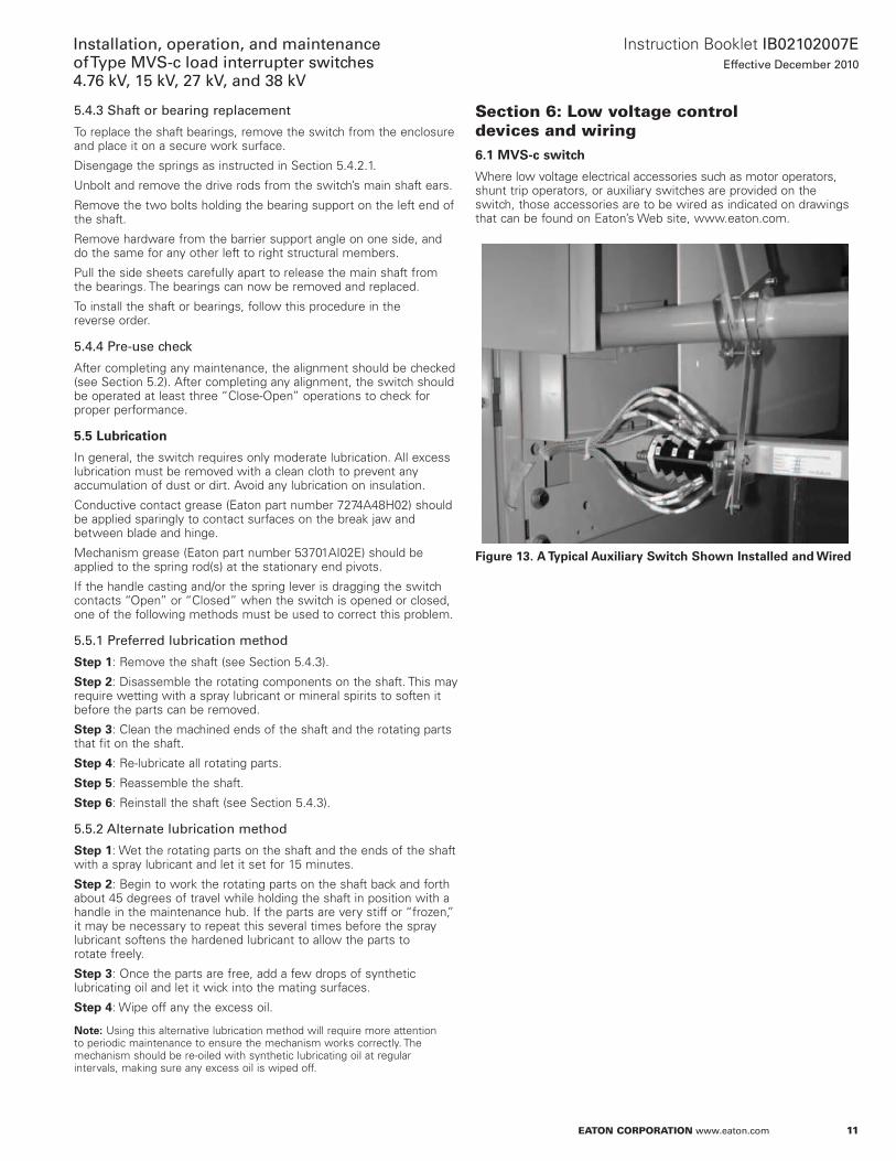
Section 6: Low voltage control devices and wiring6.1 MVS-c switch
Where low voltage electrical accessories such as motor operators, shunt trip operators, or auxiliary switches are provided on the switch, those accessories are to be wired as indicated on drawings that can be found on Eaton’s Web site, www .eaton .com .
Figure 13. A Typical Auxiliary Switch Shown Installed and Wired

12
Instruction Booklet IB02102007EEffective December 2010
Installation, operation, and maintenance of Type MVS-c load interrupter switches
4.76 kV, 15 kV, 27 kV, and 38 kV
eaton Corporation www.eaton.com
Section 7: Motor operation7.1 Motor operated MVS-c switch
The motor operated MVS-c switch is essentially a standard, manually operated switch with a motor driven linear actuator connected to the switch mechanism . Because all basic switch parts are identical to those of the standard manually operated switch, sections of this instruction booklet pertaining to installation, inspection before start-up, maintenance, and parts replacement also apply to the motor operated switch .
Table 3. MVS-c Switch Motor Operator Current Requirements
nominal Voltage e/r amperes
120 Vac 3.024 Vdc 7.048 Vdc 3.5125 Vdc 1.5
Time to “Open” or “Close” an MVS-c switch with an integral motor operator is about 5 seconds for the AC versions and about 10 seconds for the DC versions .
7.1 Receiving and startup
For MVS-c switches, each switch assembly is shipped with the linear actuator installed .
7.2 Electrical operation
The preferred voltage for the linear actuator to operate is 120 Vac . The control power is normally supplied by the customer . (See the job drawings for an electrical schematic diagram and wiring diagram of the motor operator circuitry to determine the actual operating voltage and power source .)
7.3 Safety interlocking
With the MVS-c motor operated switch, safety interlocking is based upon a key interlock system . The switch mechanism key interlock must have an integral electrical switch .
Extending the interlock bolt will mechanically lock the MVS-c switch in the “Open” position, will open the electrical control power circuit for the motor operator, and will release the key . With the key, a person can then unlock the key interlock on the switch enclosure door . This scheme prevents closing the switch with the door open as well as preventing opening of the enclosure door with the switch “Closed .”
warningoperating an MVs-c switch with a key interlock bolt extended will result in equipMent daMage and May also expose a person to bodily injury or death. the key Must be inserted into the interlock and rotated to retract the locking bolt beFore operating an MVs-c switch.
7.4 Hand operation of a motor operated switch
A special pin connects the linear actuator to the switch operator . Loosen the screw holding the pin in place and remove this pin . Remove the bottom support pin holding the linear actuator, pull it out sufficiently to permit unplugging the linear actuator and removing it . The switch may now be manually operated with the removable handle .
Figure 14. Special Pin and Screw at the Top of the Motor Actuator Piston
Figure 15. Bottom Support Pin
warningdeFeating or disengaging saFety interlocks on an MVs-c switch that is connected to a power source May result in property daMage, bodily injury, or death. do not deFeat or disengage any saFety interlocks.
7.5 Maintenance
The linear actuator itself is completely weather-sealed . The linear actuator and its associated bearings are lubricated for their normal life many times in excess of the main switch and require no maintenance .

13
Instruction Booklet IB02102007EEffective December 2010
Installation, operation, and maintenance of Type MVS-c load interrupter switches 4.76 kV, 15 kV, 27 kV, and 38 kV
eaton Corporation www.eaton.com
Section 8: electromechanical stored energy release (shunt trip)8.1 Description
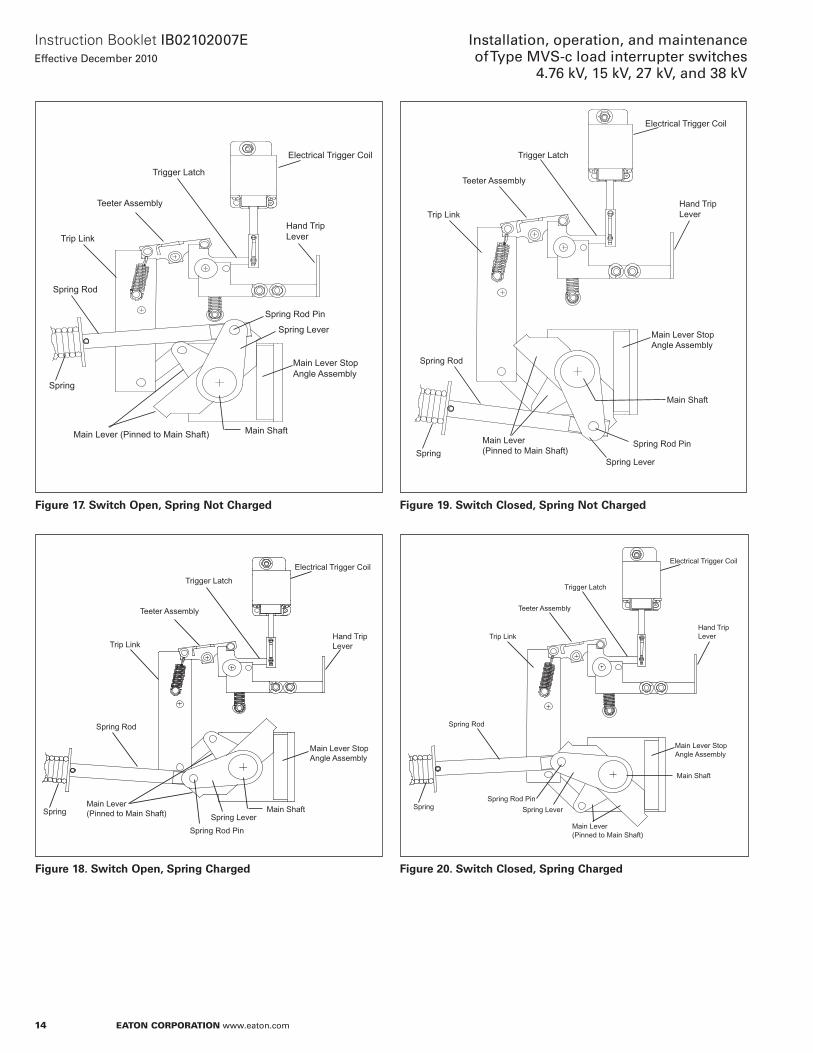
The stored energy release feature of the MVS-c load interrupter switch allows the operator to manually compress the main operating spring, storing the spring energy to “Open” or “Close” the switch upon lifting the trigger latch . When the latch is released, the stored energy in the main operating spring is released to rotate the main shaft to close or to open the switch (see Figure 16) .
Table 4. MVS-c Switch Electromechanical Stored Energy Release Coil Data. Tolerancee: ±15% Vac or Vdc
nominal Voltage e/r amperes
120 Vac 11.2240 Vac 7.450 Vdc 7.4125 Vdc 5.0250 Vdc 2.5240 Vac Capacitor Trip 2.5
Figure 16. Stored Energy Mechanism
8.2 Operation
warningdeViating FroM the warning label on switchgear will result in equipMent daMage and May also expose a person to bodily injury or death. exactly Follow the operating instructions on the label.
cautionchanging the switch position with the switch operating handle will result in daMage to the switch. iF the switch status naMeplate indicates the spring is charged, the trigger latch Must be released to change the position oF the switch.
8.2.1 Charging the spring to “close” or “open” the switch
To initiate the opening or closing action, the handle is inserted into the handle casting and is rotated upward for the closing action or downward for the opening action through an angle of 120 degrees . The switch main operating spring is now charged and the trigger latch ready to be released to “Open” or “Close” the switch .
8.2.2 Closing the switch
Starting condition: The switch is “Open” and the spring has been charged by the action described in Section 8 .2 .1 (see Figure 18) .
When the trigger latch is lifted upward, either manually or by the action of the trigger coil, the blocking mechanism is released permitting the switch to “Close” . The final result is a “Closed” switch with the operating spring in an uncharged condition (see Figure 19) .
8.2.3 Opening the switch
Starting condition: The switch is “Closed” and spring has been charged by action in Section 8 .2 .1 (see Figure 20) .
When the trigger latch is lifted upward, either manually or by the action of the trigger coil, the blocking mechanism is released permitting the switch to “Open” . The final result is an “Open” switch with the operating spring in an uncharged condition (see Figure 17) .
14
Instruction Booklet IB02102007EEffective December 2010
Installation, operation, and maintenance of Type MVS-c load interrupter switches
4.76 kV, 15 kV, 27 kV, and 38 kV
eaton Corporation www.eaton.com
Figure 17. Switch Open, Spring Not Charged
Figure 18. Switch Open, Spring Charged
Figure 19. Switch Closed, Spring Not Charged
Figure 20. Switch Closed, Spring Charged
Electrical Trigger Coil
Hand TripLever
Spring Rod Pin
Spring Lever
Main Lever Stop Angle Assembly
Main ShaftMain Lever (Pinned to Main Shaft)
Spring
Spring Rod
Trip Link
Teeter Assembly
Trigger Latch
Switch Open, Spring Charged
Electrical Trigger Coil
Hand Trip Lever
Spring Rod Pin
Spring Lever
Main Lever Stop Angle Assembly
Main ShaftMain Lever (Pinned to Main Shaft)Spring
Spring Rod
Trip Link
Teeter Assembly
Trigger Latch
Switch Closed, Spring not Charged
Electrical Trigger Coil
Hand Trip Lever
Spring Rod Pin
Spring Lever
Main Lever Stop Angle Assembly
Main Shaft
Main Lever (Pinned to Main Shaft)Spring
Spring Rod
Trip Link
Teeter Assembly
Trigger Latch
Switch Closed, Spring Charged
Electrical Trigger Coil
Hand Trip Lever
Spring Rod Pin
Spring Lever
Main Lever Stop Angle Assembly
Main Shaft
Main Lever (Pinned to Main Shaft)
Spring
Spring Rod
Trip Link
Teeter Assembly
Trigger Latch

15
Instruction Booklet IB02102007EEffective December 2010
Installation, operation, and maintenance of Type MVS-c load interrupter switches 4.76 kV, 15 kV, 27 kV, and 38 kV
eaton Corporation www.eaton.com
8.3 Main shaft position with door interlock (shaft blocking cam)
warningdeFeating the shaFt blocking caM-door interlock when the switch is energized May result in seVere injury or death. de-energize the switch and ground all liVe parts beFore deFeating this interlock to perForM Maintenance, adjustMent, and inspection procedures.
When the enclosure door is opened, a spring-based cam assembly located at the opposite end of the operating shaft from main spring moves into position to block inadvertent switch closing .
The shaft rotation is prevented by the blocking action between the blocking cam on the shaft and the ramping cam of the spring-based assembly . If the door is open and a trip-to-close action is initiated, a jamming action takes place between the blocking cam and the ramping cam to stop shaft rotation; thus, the switch cannot close (see Figure 21) .
Figure 21. Operating Mechanism Showing Door Interlock, Shaft Blocking Cam, and Ramping Cam
The blocking action must be released by inserting the operating handle into the maintenance hub and slightly rotating to reset the charged main spring again over toggle .
8.4 Inspection and maintenance
warningFailure to disconnect and to ground all sources beFore per-ForMing any inspection and Maintenance procedures May result in seVere injury or death. disconnect and ground all sources beFore coMMencing procedures.
warningFailure to replace shaFt blocking asseMbly beFore returning switch to serVice May result in seVere injury or death. replace the shaFt blocking asseMbly beFore energizing.
8.4.1 Blade and arc chute alignmentThe blade and arc chute alignment procedures are the same as for the standard MVS-c switch described in Section 5 . However, before the maintenance hub may be used, the following steps must be taken .
Step 1: Remove the door interlock-shaft blocking cam assembly by removing its two 0 .375 inch bolts .
Step 2: “Close” the switch and leave the spring in its discharged position . The maintenance hub may now be used for alignment procedures, provided the trigger latch is raised during initial rotation of the operating shaft . Failure to release the trigger latch will damage components in the linkage assembly .
8.4.2 Over toggle adjustment
This adjustment is identical to that in Section 5 .
8.4.3 Open gap adjustment
This adjustment is to be made the same as that in Section 5 .
8.4.4 Spring release mechanism adjustment
This mechanism is bolted to the side sheet with four bolts . It is adjusted by loosening these bolts, then sliding the mechanism up or down slightly as appropriate, tightening the bolts, then operating the switch to both the “Open” and “Closed” positions . The mechanism should:• Be latched prior to charging the operating spring• Stay latched when the main spring is charged• Release the linkage and the charged operating spring to “Close”
or “Open” the switch (depending on the position the switch is to change to)
• Latch after the switch has “Closed” or “Opened”
If the spring release mechanism is not latching and releasing correctly, make sure the spring is either discharged or the spring rod restrained (see Section 5 .4 .2, Spring Replacement), then loosen the four mounting bolts and again sliding the mechanism up or down as necessary to obtain the proper action . Be sure to operate the switch “Opened” and “Closed” to ensure the mechanism is latching and releasing correctly .

Eaton CorporationElectrical Sector1111 Superior Ave .Cleveland, OH 44114United States877-ETN-CARE (877-386-2273)Eaton .com
© 2011 Eaton CorporationAll Rights ReservedPrinted in USAPublication No . IB02102007E / Z10583January 2011
PowerChain Management is a registered trademark of Eaton Corporation .
All other trademarks are property of their respective owners .
Instruction Booklet IB02102007EEffective December 2010
Installation, operation, and maintenance of Type MVS-c load interrupter switches
4.76 kV, 15 kV, 27 kV, and 38 kV
Section 9: Bolt tightness for connections to terminal padsUse the following torque values for tightening hardware where conductors are connected to terminal pads .
Table 5. Hardware Torque Values
Bolt Diameter Decimal Size inches (mm)
Bolt Diameter Standard
nominal torque ft-lb (nm)
0.250 (6.35) 1/4-20 4 (5.42)0.312 (7.93) 5/16-18 8 (10.85)0.375 (9.53) 3/8-16 25 (33.90)0.500 (12.70) 1/2-13 50 (67.80)0.625 915.88) 5/8-11 65 (88.13)
Section 10: Common renewal parts
Table 6. Common Renewal Parts
part DescriptionQuantity per Switch Style number
Three-pole, blade and break jaw assembly kit, 600A, 4.76/15 kV
1 7278a27g01
Three-pole, blade and break jaw assembly kit, 1200A, 4.76/15 kV
1 7278a27g02
Three-pole, blade and break jaw assembly kit, 27/38 kV
1 7278a27g05
Barrier assembly kit, interphase 4.76/15 kV 1 7278a27g24Barrier assembly kit, interphase 27/38 kV 1 7278a27g25Insulator, glass polyester, 4.76 kV 6 4892a97h01Insulator, glass polyester, 15 kV 6 4892a97h02Insulator, epoxy, 4.76 kV 6 4892a97h07Insulator, epoxy, 15 kV 6 4892a97h08Insulator, epoxy, 27/38 kV 6 4892a97h18Drive rod link kit, glass polyester, 4.76 kV 1 7278a27g09Drive rod link kit, glass polyester, 15 kV 1 7278a27g10Drive rod link kit, glass polyester, 27/38 kV 1 7278a27g12Contact grease, 2 oz jar AR 7274a48h02Mechanism grease, 1 lb container AR 53701ai02eAuxiliary switch assembly kit 1 221c395g01
otee:N AR = As required .