
OS/390 MVS Parallel Sysplex Configuration Cookbook December ...
550
SG24-4706-00 OS/390 MVS Parallel Sysplex Configuration Cookbook December 1996
-
Upload
khangminh22 -
Category
Documents
-
view
3 -
download
0
Transcript of OS/390 MVS Parallel Sysplex Configuration Cookbook December ...

SG24-4706-00
OS/390 MVS Parallel Sysplex Configuration Cookbook
December 1996


International Technical Support Organization
OS/390 MVS Parallel Sysplex Configuration Cookbook
December 1996
SG24-4706-00
IBML

Take Note!
Before using this information and the product it supports, be sure to read the general information inAppendix I, “Special Notices” on page 447.
First Edition (December 1996)
This edition applies to
Program Name, Program Number Version, Release NumberACF/VTAM, 5695-117 4.3CICS/ESA, 5655-018 4.1CICSPlex SM, 5695-081 1.1DB2, 5695-DB2 4.2DFSMS/MVS, 5695-DF1 1.3EPDM/MVS, 5695-101 1.1IMS/ESA, 5695-176 5.1IMS/ESA Workload Router, 5697-B87 2.1JES2, 5655-068 5.2JES3, 5655-069 5.2RMF, 5655-084 5.1RACF, 5695-039 2.2SDSF/MVS, 5665-488 1.5SMP/E, 5668-949 1.8System Automation for OS/390, 5645-045 1.1TSO/E, 5685-025 2.4NetView for MVS/ESA, 5685-111 2.4OPC/ESA, 5695-007 1.3TCP/IP for MVS, 5655-HAL 3.2
for use with the
Program Name Version, Release NumberMVS/ESA SP 5.2OS/390 1.1OS/390 1.2
Comments may be addressed to:IBM Corporation, International Technical Support OrganizationDept. HYJ Mail Station P099522 South RoadPoughkeepsie, New York 12601-5400
When you send information to IBM, you grant IBM a non-exclusive right to use or distribute the information in anyway it believes appropriate without incurring any obligation to you.
Copyright International Business Machines Corporation 1996. All rights reserved.Note to U.S. Government Users — Documentation related to restricted rights — Use, duplication or disclosure issubject to restrictions set forth in GSA ADP Schedule Contract with IBM Corp.

Contents
Figures . . . . . . . . . . . . . . . . . . . . . . . . . . . . . . . . . . . . . . . . . . . xi
Tables . . . . . . . . . . . . . . . . . . . . . . . . . . . . . . . . . . . . . . . . . . xii i
Preface . . . . . . . . . . . . . . . . . . . . . . . . . . . . . . . . . . . . . . . . . . xvHow This Redbook Is Organized . . . . . . . . . . . . . . . . . . . . . . . . . . . xvThe Team That Wrote This Redbook . . . . . . . . . . . . . . . . . . . . . . . . xviiComments Welcome . . . . . . . . . . . . . . . . . . . . . . . . . . . . . . . . . xix
Chapter 1. Introduction to Configuration of the Parallel Sysplex . . . . . . . . 11.1 How to Use This Redbook - Read This First! . . . . . . . . . . . . . . . . . . 11.2 The Purpose of This Book . . . . . . . . . . . . . . . . . . . . . . . . . . . . . 41.3 What Is Parallel Sysplex? . . . . . . . . . . . . . . . . . . . . . . . . . . . . . 5
1.3.1 Basic Sysplex . . . . . . . . . . . . . . . . . . . . . . . . . . . . . . . . . 51.3.2 Parallel Sysplex . . . . . . . . . . . . . . . . . . . . . . . . . . . . . . . . 5
1.4 Main Reasons for Parallel Sysplex . . . . . . . . . . . . . . . . . . . . . . . 61.4.1 Workload Balancing . . . . . . . . . . . . . . . . . . . . . . . . . . . . . . 61.4.2 Workload Needs Large Capacity . . . . . . . . . . . . . . . . . . . . . . 71.4.3 Granularity . . . . . . . . . . . . . . . . . . . . . . . . . . . . . . . . . . . 71.4.4 Scalability . . . . . . . . . . . . . . . . . . . . . . . . . . . . . . . . . . . . 71.4.5 Nondisruptive Growth . . . . . . . . . . . . . . . . . . . . . . . . . . . . 81.4.6 Continuous Application Availability . . . . . . . . . . . . . . . . . . . . 91.4.7 Cheapest Cost-of-Computing Configuration or Upgrade Path . . . . . 91.4.8 SW Pricing in Parallel Sysplex . . . . . . . . . . . . . . . . . . . . . . . 91.4.9 Upgrade Possibilities . . . . . . . . . . . . . . . . . . . . . . . . . . . . . 10
Chapter 2. High Level Design Concepts for the Parallel Sysplex . . . . . . . . 112.1.1 Important Rules of Thumb Information . . . . . . . . . . . . . . . . . . 12
2.2 Deciding If Parallel Sysplex Is Right for You . . . . . . . . . . . . . . . . . . 122.2.1 Solution Developers Software . . . . . . . . . . . . . . . . . . . . . . . . 142.2.2 Customer References for S/390 Parallel . . . . . . . . . . . . . . . . . 14
2.3 High-Level Design . . . . . . . . . . . . . . . . . . . . . . . . . . . . . . . . . 142.3.1 How Many Parallel Sysplexes Do I Need? . . . . . . . . . . . . . . . . 142.3.2 Systems Symmetry When Configuring a Parallel Sysplex . . . . . . . 212.3.3 What Different ′Plexes Are There? . . . . . . . . . . . . . . . . . . . . . 222.3.4 Non-Parallel Sysplex Configurations . . . . . . . . . . . . . . . . . . . . 41
2.4 CF Architecture . . . . . . . . . . . . . . . . . . . . . . . . . . . . . . . . . . . 432.4.1 MVS/ESA Software to Access the CF . . . . . . . . . . . . . . . . . . . 45
2.5 Data Integrity and Buffer Pool Coherency Considerations . . . . . . . . . 452.5.1 Data Integrity before the Parallel Sysplex . . . . . . . . . . . . . . . . 462.5.2 Data Integrity in a Parallel Sysplex . . . . . . . . . . . . . . . . . . . . 472.5.3 Locking in Parallel Sysplex . . . . . . . . . . . . . . . . . . . . . . . . . 49
2.6 Dynamic Workload Balancing in a Parallel Sysplex . . . . . . . . . . . . . 512.6.1 Dynamic Workload Balancing Exploiters . . . . . . . . . . . . . . . . . 51
Chapter 3. Continuous Availability in a Parallel Sysplex . . . . . . . . . . . . . 533.1 Why Availability Is Important . . . . . . . . . . . . . . . . . . . . . . . . . . . 55
3.1.1 Parallel Sysplex Is Designed to Allow Management of Redundancy . 553.1.2 Planned Outages . . . . . . . . . . . . . . . . . . . . . . . . . . . . . . . 573.1.3 Unplanned Outages . . . . . . . . . . . . . . . . . . . . . . . . . . . . . . 583.1.4 Scope of an Outage . . . . . . . . . . . . . . . . . . . . . . . . . . . . . . 58
Copyright IBM Corp. 1996 iii

3.2 Software Considerations for Availability . . . . . . . . . . . . . . . . . . . . 603.2.1 Data Set Redundancy . . . . . . . . . . . . . . . . . . . . . . . . . . . . . 603.2.2 JES3 and Continuous Availability . . . . . . . . . . . . . . . . . . . . . . 613.2.3 Subsystem Considerations . . . . . . . . . . . . . . . . . . . . . . . . . 62
3.3 Network Considerations for Availability . . . . . . . . . . . . . . . . . . . . 633.3.1 VTAM Generic Resources Function . . . . . . . . . . . . . . . . . . . . 633.3.2 Persistent Sessions . . . . . . . . . . . . . . . . . . . . . . . . . . . . . . 633.3.3 Multi-Node Persistent Sessions . . . . . . . . . . . . . . . . . . . . . . . 643.3.4 High Performance Routing . . . . . . . . . . . . . . . . . . . . . . . . . . 663.3.5 VTAM Systems Management . . . . . . . . . . . . . . . . . . . . . . . . 663.3.6 TCP/IP Virtual IP Addressing . . . . . . . . . . . . . . . . . . . . . . . . 67
3.4 Hardware Considerations for Availability . . . . . . . . . . . . . . . . . . . . 683.4.1 Number of CPCs in Parallel Sysplex . . . . . . . . . . . . . . . . . . . . 683.4.2 Redundant Power . . . . . . . . . . . . . . . . . . . . . . . . . . . . . . . 693.4.3 Isolate the CF . . . . . . . . . . . . . . . . . . . . . . . . . . . . . . . . . 693.4.4 Additional CF in a Parallel Sysplex . . . . . . . . . . . . . . . . . . . . 693.4.5 Additional CF Links . . . . . . . . . . . . . . . . . . . . . . . . . . . . . . 703.4.6 I/O Configuration Redundancy . . . . . . . . . . . . . . . . . . . . . . . 703.4.7 Sysplex Timer Redundancy . . . . . . . . . . . . . . . . . . . . . . . . . 703.4.8 RAS Features on IBM CPCs . . . . . . . . . . . . . . . . . . . . . . . . . 70
3.5 Limitations to Continuous Availability . . . . . . . . . . . . . . . . . . . . . . 713.6 Recovery Considerations for Availability . . . . . . . . . . . . . . . . . . . . 71
3.6.1 Sysplex Failure Management (SFM) . . . . . . . . . . . . . . . . . . . . 713.6.2 Automatic Restart Management (ARM) . . . . . . . . . . . . . . . . . . 73
3.7 Disaster Recovery Considerations in Parallel Sysplex . . . . . . . . . . . . 753.7.1 Geographically Dispersed Sysplexes . . . . . . . . . . . . . . . . . . . 753.7.2 Disaster Recovery Data . . . . . . . . . . . . . . . . . . . . . . . . . . . 773.7.3 CICS Disaster Recovery Considerations . . . . . . . . . . . . . . . . . 793.7.4 DB2 Disaster Recovery Considerations . . . . . . . . . . . . . . . . . . 803.7.5 IMS Disaster Recovery Considerations . . . . . . . . . . . . . . . . . . 813.7.6 Recommended Sources of Disaster Recovery Information . . . . . . 82
Chapter 4. Workloads in Parallel Sysplex . . . . . . . . . . . . . . . . . . . . . . 834.1 Transaction Management in a Parallel Sysplex . . . . . . . . . . . . . . . . 84
4.1.1 Dynamic Transaction Routing . . . . . . . . . . . . . . . . . . . . . . . . 854.1.2 CICS Transaction Manager in a Parallel Sysplex . . . . . . . . . . . . 854.1.3 CICSPlex Systems Manager (CICSPlex SM) . . . . . . . . . . . . . . . 974.1.4 CICS Transaction Affinity Utility . . . . . . . . . . . . . . . . . . . . . . . 984.1.5 IMS Transaction Manager in a Parallel Sysplex . . . . . . . . . . . . . 99
4.2 Database Management in Parallel Sysplex . . . . . . . . . . . . . . . . . 1024.2.1 DB2 Data Sharing Considerations . . . . . . . . . . . . . . . . . . . . 1024.2.2 IMS/DB V5 Data Sharing Considerations . . . . . . . . . . . . . . . . 1094.2.3 CICS/VSAM Record Level Sharing Considerations . . . . . . . . . . 1134.2.4 Solution Developers Databases . . . . . . . . . . . . . . . . . . . . . . 119
4.3 Batch Workload Considerations . . . . . . . . . . . . . . . . . . . . . . . . 1204.3.1 JES2 Considerations in a Parallel Sysplex . . . . . . . . . . . . . . . 1204.3.2 JES3 Considerations in a Parallel Sysplex . . . . . . . . . . . . . . . 1214.3.3 Can I Have JES2 and JES3 in the Same Sysplex? . . . . . . . . . . . 1224.3.4 Batch Workload Balancing and Parallel Sysplex . . . . . . . . . . . 1234.3.5 Will My Batch Workload Fit? . . . . . . . . . . . . . . . . . . . . . . . . 123
4.4 Network Workload Considerations . . . . . . . . . . . . . . . . . . . . . . . 1254.4.1 VTAM Generic Resources Function . . . . . . . . . . . . . . . . . . . 1254.4.2 TCP Applications . . . . . . . . . . . . . . . . . . . . . . . . . . . . . . 131
4.5 TSO/E and Parallel Sysplex . . . . . . . . . . . . . . . . . . . . . . . . . . . 1314.5.1 Query Management Facility Workload Considerations . . . . . . . . 132
iv Parallel Sysplex Configuration Cookbook

4.6 VM/ESA and Parallel Sysplex . . . . . . . . . . . . . . . . . . . . . . . . . 1324.7 Test Considerations in a Parallel Sysplex . . . . . . . . . . . . . . . . . . 132
4.7.1 Testing Implications in a Parallel Sysplex . . . . . . . . . . . . . . . 1324.8 OpenEdition/MVS Parallel Sysplex Exploitation . . . . . . . . . . . . . . . 1354.9 How to Select Applications to Exploit the Parallel Sysplex . . . . . . . . 135
Chapter 5. CPC and CF Configuration in Parallel Sysplex . . . . . . . . . . . 1375.1 An Overview of CPC and CF Configuration Tasks . . . . . . . . . . . . . 1385.2 Select CPC and CF Technology . . . . . . . . . . . . . . . . . . . . . . . . 141
5.2.1 Initial Choice of CPC and CF Technology . . . . . . . . . . . . . . . . 1415.2.2 CPCs Participating in Parallel Sysplex . . . . . . . . . . . . . . . . . 1425.2.3 Deciding between the CPC Options . . . . . . . . . . . . . . . . . . . 1425.2.4 Evaluating Alternate CF Options . . . . . . . . . . . . . . . . . . . . . 146
5.3 Calculate Total CPC Capacity Required . . . . . . . . . . . . . . . . . . . 1535.3.1 Sizing and Modelling Options for CPC . . . . . . . . . . . . . . . . . . 1535.3.2 Calculate Additional Capacity for Data Sharing . . . . . . . . . . . . 1545.3.3 Logical Partitioning (LPAR) Impact on Sizing . . . . . . . . . . . . . 1575.3.4 Sizing the CPC Storage for Parallel Sysplex . . . . . . . . . . . . . . 1585.3.5 Impact of Parallel Sysplex on Number of I/Os . . . . . . . . . . . . . 160
5.4 Calculate Required 9674 Capacity . . . . . . . . . . . . . . . . . . . . . . . 1615.4.1 CF Exploiters . . . . . . . . . . . . . . . . . . . . . . . . . . . . . . . . . 1615.4.2 CF Capacity Planning Activities . . . . . . . . . . . . . . . . . . . . . . 1635.4.3 CF Type and CP Utilization . . . . . . . . . . . . . . . . . . . . . . . . 1635.4.4 CF Links . . . . . . . . . . . . . . . . . . . . . . . . . . . . . . . . . . . . 1665.4.5 CF Storage . . . . . . . . . . . . . . . . . . . . . . . . . . . . . . . . . . 1695.4.6 Sample CF Storage Map . . . . . . . . . . . . . . . . . . . . . . . . . . 1705.4.7 CF Structure Size Summary . . . . . . . . . . . . . . . . . . . . . . . . 1715.4.8 Summary Table for CF Storage Sizing . . . . . . . . . . . . . . . . . . 173
5.5 Review Final Configuration . . . . . . . . . . . . . . . . . . . . . . . . . . . 174
Chapter 6. CF Structures . . . . . . . . . . . . . . . . . . . . . . . . . . . . . . 1756.1 CF Structures Overview . . . . . . . . . . . . . . . . . . . . . . . . . . . . . 177
6.1.1 CF Structure Exploiters . . . . . . . . . . . . . . . . . . . . . . . . . . . 1786.1.2 Structure and Connection Disposition . . . . . . . . . . . . . . . . . . 1826.1.3 CF Volatility/Nonvolatility . . . . . . . . . . . . . . . . . . . . . . . . . 183
6.2 CF Storage for Structures . . . . . . . . . . . . . . . . . . . . . . . . . . . . 1846.2.1 Initial Structure Sizes . . . . . . . . . . . . . . . . . . . . . . . . . . . . 1846.2.2 Using Central and Expanded Storage for the CF . . . . . . . . . . . . 1866.2.3 Structure Placement . . . . . . . . . . . . . . . . . . . . . . . . . . . . 1886.2.4 CF Exploiter Specifics . . . . . . . . . . . . . . . . . . . . . . . . . . . 189
6.3 XCF Structure . . . . . . . . . . . . . . . . . . . . . . . . . . . . . . . . . . . 1906.3.1 XCF Structure Usage . . . . . . . . . . . . . . . . . . . . . . . . . . . . 1906.3.2 XCF Structure Sizing . . . . . . . . . . . . . . . . . . . . . . . . . . . . 1906.3.3 XCF Structure Placement . . . . . . . . . . . . . . . . . . . . . . . . . 1926.3.4 XCF Structure Rebuild Considerations . . . . . . . . . . . . . . . . . 1926.3.5 XCF Structure and Volatility . . . . . . . . . . . . . . . . . . . . . . . . 192
6.4 VTAM Structure . . . . . . . . . . . . . . . . . . . . . . . . . . . . . . . . . . 1936.4.1 VTAM Structure Usage . . . . . . . . . . . . . . . . . . . . . . . . . . . 1936.4.2 VTAM Structure Sizing . . . . . . . . . . . . . . . . . . . . . . . . . . . 1936.4.3 VTAM Structure Placement . . . . . . . . . . . . . . . . . . . . . . . . 1946.4.4 VTAM Structure Rebuild Considerations . . . . . . . . . . . . . . . . 1946.4.5 VTAM Structure and Volatility . . . . . . . . . . . . . . . . . . . . . . . 195
6.5 RACF Structure . . . . . . . . . . . . . . . . . . . . . . . . . . . . . . . . . . 1966.5.1 RACF Structure Usage . . . . . . . . . . . . . . . . . . . . . . . . . . . 1966.5.2 RACF Structure Sizing . . . . . . . . . . . . . . . . . . . . . . . . . . . 196
Contents v

6.5.3 RACF Structure Placement . . . . . . . . . . . . . . . . . . . . . . . . 1986.5.4 RACF Structure Rebuild Considerations . . . . . . . . . . . . . . . . 1986.5.5 RACF Structure and Volatility . . . . . . . . . . . . . . . . . . . . . . . 200
6.6 JES2 Structure . . . . . . . . . . . . . . . . . . . . . . . . . . . . . . . . . . 2016.6.1 JES2 Structure Usage . . . . . . . . . . . . . . . . . . . . . . . . . . . 2016.6.2 JES2 Structure Sizing . . . . . . . . . . . . . . . . . . . . . . . . . . . . 2016.6.3 JES2 Structure Placement . . . . . . . . . . . . . . . . . . . . . . . . . 2026.6.4 JES2 Structure Rebuild Considerations . . . . . . . . . . . . . . . . . 2036.6.5 JES2 Structure and Volatility . . . . . . . . . . . . . . . . . . . . . . . 203
6.7 IMS Structures . . . . . . . . . . . . . . . . . . . . . . . . . . . . . . . . . . 2046.7.1 IMS Structure Usage . . . . . . . . . . . . . . . . . . . . . . . . . . . . 2046.7.2 IMS Structure Sizing . . . . . . . . . . . . . . . . . . . . . . . . . . . . 2046.7.3 IMS Structure Placement . . . . . . . . . . . . . . . . . . . . . . . . . 2086.7.4 IMS Structure Rebuild Considerations . . . . . . . . . . . . . . . . . . 2086.7.5 IMS Structures and Volatility . . . . . . . . . . . . . . . . . . . . . . . 209
6.8 DB2 Structure . . . . . . . . . . . . . . . . . . . . . . . . . . . . . . . . . . . 2106.8.1 DB2 Structure Usage . . . . . . . . . . . . . . . . . . . . . . . . . . . . 2106.8.2 DB2 Structure Sizing . . . . . . . . . . . . . . . . . . . . . . . . . . . . 2116.8.3 DB2 Structure Placement . . . . . . . . . . . . . . . . . . . . . . . . . 2146.8.4 DB2 Structure Rebuild Considerations . . . . . . . . . . . . . . . . . 2156.8.5 DB2 Structures and Volatility . . . . . . . . . . . . . . . . . . . . . . . 216
6.9 Tape Allocation Structure . . . . . . . . . . . . . . . . . . . . . . . . . . . . 2176.9.1 Tape Allocation Structure Usage . . . . . . . . . . . . . . . . . . . . . 2176.9.2 Tape Allocation Structure Sizing . . . . . . . . . . . . . . . . . . . . . 2176.9.3 Tape Allocation Structure Placement . . . . . . . . . . . . . . . . . . 2186.9.4 Tape Allocation Structure Rebuild Considerations . . . . . . . . . . 2186.9.5 Tape Allocation Structure and Volatility . . . . . . . . . . . . . . . . . 218
6.10 System Logger Structure . . . . . . . . . . . . . . . . . . . . . . . . . . . 2196.10.1 System Logger Structure Usage . . . . . . . . . . . . . . . . . . . . 2196.10.2 System Logger Structure Sizing . . . . . . . . . . . . . . . . . . . . . 2196.10.3 System Logger Structure Placement . . . . . . . . . . . . . . . . . . 2236.10.4 System Logger Structure Rebuild Considerations . . . . . . . . . . 2246.10.5 System Logger Structure and Volatility . . . . . . . . . . . . . . . . 224
6.11 CICS/VSAM RLS Structure . . . . . . . . . . . . . . . . . . . . . . . . . . 2266.11.1 CICS/VSAM RLS Structure Usage . . . . . . . . . . . . . . . . . . . . 2266.11.2 CICS/VSAM RLS Structure Sizing . . . . . . . . . . . . . . . . . . . . 2276.11.3 CICS/VSAM RLS Structure Placement . . . . . . . . . . . . . . . . . 2306.11.4 CICS/VSAM RLS Structure Rebuild Considerations . . . . . . . . . 2306.11.5 CICS/VSAM RLS Structures and Volatility . . . . . . . . . . . . . . . 231
6.12 CICS Shared Temporary Storage Structure . . . . . . . . . . . . . . . . 2326.12.1 CICS Shared Temporary Storage Structure Usage . . . . . . . . . . 2326.12.2 CICS Shared Temporary Storage Structure Sizing . . . . . . . . . . 2326.12.3 CICS Shared Temporary Storage Structure Placement . . . . . . . 2336.12.4 CICS Shared Temporary Storage Structure Rebuild Considerations 2336.12.5 CICS Shared Temporary Storage Structure and Volatility . . . . . 233
6.13 GRS Star Structure . . . . . . . . . . . . . . . . . . . . . . . . . . . . . . . 2346.13.1 GRS Star Structure Usage . . . . . . . . . . . . . . . . . . . . . . . . 2346.13.2 GRS Star Structure Sizing . . . . . . . . . . . . . . . . . . . . . . . . 2346.13.3 GRS Star Structure Placement . . . . . . . . . . . . . . . . . . . . . 2366.13.4 GRS Star Structure Rebuild Considerations . . . . . . . . . . . . . . 2366.13.5 GRS Star Structure and Volatility . . . . . . . . . . . . . . . . . . . . 236
6.14 SmartBatch Structure . . . . . . . . . . . . . . . . . . . . . . . . . . . . . . 2376.14.1 SmartBatch Structure Usage . . . . . . . . . . . . . . . . . . . . . . . 2376.14.2 SmartBatch Structure Sizing . . . . . . . . . . . . . . . . . . . . . . . 2376.14.3 SmartBatch Structure Placement . . . . . . . . . . . . . . . . . . . . 238
vi Parallel Sysplex Configuration Cookbook

6.14.4 SmartBatch Structure Rebuild Considerations . . . . . . . . . . . . 2386.14.5 SmartBatch Structure and Volatility . . . . . . . . . . . . . . . . . . 239
Chapter 7. Connectivity in Parallel Sysplex . . . . . . . . . . . . . . . . . . . . 2417.1 Enterprise Systems Connection (ESCON) . . . . . . . . . . . . . . . . . . 242
7.1.1 ESCON Multiple Image Facility (EMIF) . . . . . . . . . . . . . . . . . . 2437.1.2 System Automation for OS/390 . . . . . . . . . . . . . . . . . . . . . . 2437.1.3 ESCON Extended Distance Feature (XDF) . . . . . . . . . . . . . . . . 2447.1.4 ESCON Director (ESCD) Configuration Guidelines . . . . . . . . . . . 2447.1.5 IBM 9036 ESCON Converter Configuration Guidelines . . . . . . . . 2467.1.6 IBM 9729 Optical Wavelength Division Multiplexer . . . . . . . . . . 2467.1.7 FTS Direct Attach . . . . . . . . . . . . . . . . . . . . . . . . . . . . . . 246
7.2 Channel Configuration . . . . . . . . . . . . . . . . . . . . . . . . . . . . . . 2477.2.1 ESCON Logical Paths . . . . . . . . . . . . . . . . . . . . . . . . . . . . 2477.2.2 DASD Control Unit Considerations . . . . . . . . . . . . . . . . . . . . 2487.2.3 ESCON Channel-to-Channel (CTC) Considerations . . . . . . . . . . 2487.2.4 Tape Control Unit Considerations . . . . . . . . . . . . . . . . . . . . 2497.2.5 OEM Hardware Connectivity . . . . . . . . . . . . . . . . . . . . . . . . 2507.2.6 3745/6, 3172 and 3174 Considerations . . . . . . . . . . . . . . . . . . 250
Chapter 8. Network Connectivity for the Parallel Sysplex . . . . . . . . . . . 2518.1 Network Access to the Parallel Sysplex . . . . . . . . . . . . . . . . . . . 252
8.1.1 APPN Overview . . . . . . . . . . . . . . . . . . . . . . . . . . . . . . . 2528.1.2 Use of APPN in the Parallel Sysplex . . . . . . . . . . . . . . . . . . . 2558.1.3 High Performance Routing (HPR) . . . . . . . . . . . . . . . . . . . . . 2568.1.4 High Performance Data Transfer (HPDT) . . . . . . . . . . . . . . . . 2598.1.5 Session Manager Implications in a Parallel Sysplex . . . . . . . . . 2608.1.6 Communications Management Configuration . . . . . . . . . . . . . 2628.1.7 SNI Considerations . . . . . . . . . . . . . . . . . . . . . . . . . . . . . 2668.1.8 IP Access to SNA Applications . . . . . . . . . . . . . . . . . . . . . . 267
8.2 Connecting to the Network . . . . . . . . . . . . . . . . . . . . . . . . . . . 2708.2.1 IBM 3745/6 Communications Controller Family . . . . . . . . . . . . 2708.2.2 IBM 3172 Interconnect Controller . . . . . . . . . . . . . . . . . . . . . 2748.2.3 IBM 3174 Establishment Controller . . . . . . . . . . . . . . . . . . . . 2788.2.4 Open Systems Adapter 2 . . . . . . . . . . . . . . . . . . . . . . . . . 280
Chapter 9. Sysplex Timer Considerations . . . . . . . . . . . . . . . . . . . . . 2839.1 Overview . . . . . . . . . . . . . . . . . . . . . . . . . . . . . . . . . . . . . . 285
9.1.1 TOD Clock . . . . . . . . . . . . . . . . . . . . . . . . . . . . . . . . . . 2859.1.2 ESA/390 Time-Coordination Requirements . . . . . . . . . . . . . . . 2859.1.3 External Time Reference (ETR) Time . . . . . . . . . . . . . . . . . . 2869.1.4 ETR Network . . . . . . . . . . . . . . . . . . . . . . . . . . . . . . . . . 2869.1.5 MVS Support for the Sysplex Timer . . . . . . . . . . . . . . . . . . . 2879.1.6 PR/SM LPAR . . . . . . . . . . . . . . . . . . . . . . . . . . . . . . . . . 2879.1.7 Multiple Clocks and Their Uses . . . . . . . . . . . . . . . . . . . . . . 287
9.2 Configuration Considerations for an ETR Network . . . . . . . . . . . . . 2889.2.1 CPC Support . . . . . . . . . . . . . . . . . . . . . . . . . . . . . . . . . 2889.2.2 Planning for Availability . . . . . . . . . . . . . . . . . . . . . . . . . . 2899.2.3 CMOS CPC Sysplex Timer Attachment Features . . . . . . . . . . . 2919.2.4 ES/9000 Multiprocessor Configurations . . . . . . . . . . . . . . . . . 2959.2.5 9037 Ports . . . . . . . . . . . . . . . . . . . . . . . . . . . . . . . . . . 2989.2.6 9037-2 Console Selection and Considerations . . . . . . . . . . . . . 2999.2.7 Planning for Time Accuracy . . . . . . . . . . . . . . . . . . . . . . . . 3019.2.8 9037 Distance Limitations . . . . . . . . . . . . . . . . . . . . . . . . . 3029.2.9 Planning for Cabling Requirements . . . . . . . . . . . . . . . . . . . 303
Contents vii

9.3 Available 9037 RPQs . . . . . . . . . . . . . . . . . . . . . . . . . . . . . . . 3049.4 Migration from a 9037-1 to a 9037-2 Sysplex Timer Configuration . . . . 305
9.4.1 Requirements during Migration . . . . . . . . . . . . . . . . . . . . . . 3059.4.2 Migration Procedures Not Supported . . . . . . . . . . . . . . . . . . 3059.4.3 Supported Migration Procedures . . . . . . . . . . . . . . . . . . . . . 307
9.5 Recommendations for Continuous Availability . . . . . . . . . . . . . . . 3089.5.1 Location of 9037-2s, Consoles, External Time Sources . . . . . . . . 3089.5.2 Power Considerations . . . . . . . . . . . . . . . . . . . . . . . . . . . 3099.5.3 Cable Routing Considerations . . . . . . . . . . . . . . . . . . . . . . 309
9.6 Concurrent Maintenance and Upgrade Considerations . . . . . . . . . . 3099.6.1 Concurrent Maintenance . . . . . . . . . . . . . . . . . . . . . . . . . . 3109.6.2 Upgrade Options . . . . . . . . . . . . . . . . . . . . . . . . . . . . . . 310
Chapter 10. Consoles and Parallel Sysplex . . . . . . . . . . . . . . . . . . . . 31110.1 Multisystem Consoles in a Parallel Sysplex . . . . . . . . . . . . . . . . 312
10.1.1 MVS Consoles in a Parallel Sysplex . . . . . . . . . . . . . . . . . . 31310.1.2 How Many Consoles Do You Need? . . . . . . . . . . . . . . . . . . 31710.1.3 Automation Implications . . . . . . . . . . . . . . . . . . . . . . . . . 318
10.2 Hardware Management Consoles in a Parallel Sysplex . . . . . . . . . 31910.2.1 Hardware Management Console (HMC) . . . . . . . . . . . . . . . . 31910.2.2 Configuring the LAN . . . . . . . . . . . . . . . . . . . . . . . . . . . . 32010.2.3 Operating the HMC Remotely . . . . . . . . . . . . . . . . . . . . . . 32110.2.4 Automating Operation of the IBM 967x . . . . . . . . . . . . . . . . . 32110.2.5 Can I Use Console Integration Instead of MVS Consoles? . . . . . 32410.2.6 How Many HMCs Should I Order? . . . . . . . . . . . . . . . . . . . 32410.2.7 Installing a New CPC on an Existing HMC LAN . . . . . . . . . . . . 32510.2.8 Battery Backup of the HMC . . . . . . . . . . . . . . . . . . . . . . . 32510.2.9 Updating LIC on the HMC/SE . . . . . . . . . . . . . . . . . . . . . . 32510.2.10 Security Considerations . . . . . . . . . . . . . . . . . . . . . . . . . 326
Chapter 11. Systems Management Products and Parallel Sysplex . . . . . . 32711.1 Systems Management Software in the Parallel Sysplex . . . . . . . . . 32911.2 RACF Sysplex Exploitation . . . . . . . . . . . . . . . . . . . . . . . . . . . 329
11.2.1 Restructured RACF Data Set in RACF V1.9 . . . . . . . . . . . . . . 33011.2.2 RACF V2.1 Sysplex Exploitation . . . . . . . . . . . . . . . . . . . . . 33011.2.3 RACF V2.2 Remote Sharing Facility . . . . . . . . . . . . . . . . . . . 33211.2.4 RACF Packaging . . . . . . . . . . . . . . . . . . . . . . . . . . . . . . 333
11.3 Performance Management Products and Parallel Sysplex . . . . . . . . 33311.3.1 Workload Manager (WLM) in the Parallel Sysplex Environment . . 33411.3.2 Resource Measurement Facility (RMF) in Parallel Sysplex . . . . . 33511.3.3 Performance Reporter for MVS and Parallel Sysplex . . . . . . . . 33611.3.4 System Measurement Facility (SMF) . . . . . . . . . . . . . . . . . . 338
11.4 Operations Management Products and Parallel Sysplex . . . . . . . . . 33811.4.1 Data and Storage Backup and Recovery . . . . . . . . . . . . . . . 33811.4.2 Data Management . . . . . . . . . . . . . . . . . . . . . . . . . . . . . 33911.4.3 System Automation for OS/390 . . . . . . . . . . . . . . . . . . . . . 34111.4.4 Job Scheduling in Parallel Sysplex . . . . . . . . . . . . . . . . . . . 343
11.5 Change Control and Configuration Management Products and ParallelSysplex . . . . . . . . . . . . . . . . . . . . . . . . . . . . . . . . . . . . . . . . . 343
11.5.1 SMP/E Configuration Guidelines . . . . . . . . . . . . . . . . . . . . 34411.5.2 System Logger Considerations . . . . . . . . . . . . . . . . . . . . . 34611.5.3 Hardware Configuration Definition (HCD) Considerations . . . . . 34811.5.4 Naming Conventions . . . . . . . . . . . . . . . . . . . . . . . . . . . 34911.5.5 Shared Master Catalog . . . . . . . . . . . . . . . . . . . . . . . . . . 35211.5.6 Shared System Residence (SYSRES) Volume . . . . . . . . . . . . 352
viii Parallel Sysplex Configuration Cookbook

11.5.7 Sysplex Coupling Services . . . . . . . . . . . . . . . . . . . . . . . . 35311.6 Software Packaging . . . . . . . . . . . . . . . . . . . . . . . . . . . . . . . 359
11.6.1 OS/390 Elements and Features . . . . . . . . . . . . . . . . . . . . . 35911.6.2 Exclusive and Non-Exclusive Elements and Features . . . . . . . . 36011.6.3 OS/390 Software Delivery Options . . . . . . . . . . . . . . . . . . . 360
Appendix A. Tools and Services Catalogue . . . . . . . . . . . . . . . . . . . . 363A.1.1 BWATOOL (Batch Workload Analysis Tool) . . . . . . . . . . . . . . 368A.1.2 BWA2OPC (Batch Workload Analysis Input to OPC/ESA) . . . . . . 368A.1.3 CAU (CICS Affinity Tool) . . . . . . . . . . . . . . . . . . . . . . . . . . 369A.1.4 CBAT (CMOS Batch Analysis Tool) . . . . . . . . . . . . . . . . . . . 369A.1.5 CD13 (MVS/ESA CMOS Processor Utilization Tool) . . . . . . . . . . 370A.1.6 CP90 (Capacity Planning 90) . . . . . . . . . . . . . . . . . . . . . . . 371A.1.7 CP90 PCR (Processor Capacity Reference) . . . . . . . . . . . . . . 372A.1.8 CP90 Quicksizer . . . . . . . . . . . . . . . . . . . . . . . . . . . . . . . 372A.1.9 CVRCAP (CICS/VSAM RLS Capacity Planning) . . . . . . . . . . . . 373A.1.10 DB2PARA (DB2 Parallel Sysplex Inputs for CP90) . . . . . . . . . . 373A.1.11 GRSRNL (GRS RNL Tool) . . . . . . . . . . . . . . . . . . . . . . . . 374A.1.12 HONE/IBMLink ASKQ/Question . . . . . . . . . . . . . . . . . . . . . 375A.1.13 HONE/IBMLink CFPROGS . . . . . . . . . . . . . . . . . . . . . . . . 375A.1.14 HONE/IBMLink CFSYSTEM . . . . . . . . . . . . . . . . . . . . . . . . 375A.1.15 HSMCTUT (HMC Tutorial) . . . . . . . . . . . . . . . . . . . . . . . . 376A.1.16 IMSAFAID (IMS Affinity Aid) . . . . . . . . . . . . . . . . . . . . . . . 376A.1.17 IOCPCONV (IOCP Converter) . . . . . . . . . . . . . . . . . . . . . . 377A.1.18 LPAR/CE (LPAR Capacity Estimator) . . . . . . . . . . . . . . . . . . 377A.1.19 LSPR/PC (Large Systems Performance Reference/PC) . . . . . . . 378A.1.20 PMOS (Performance Management Offerings and Services) . . . . 378A.1.21 PTSHELP (Directory of Parallel Resources) . . . . . . . . . . . . . . 379A.1.22 PTSSERV (Parallel Transaction Server Services) . . . . . . . . . . 379A.1.23 QCBTRACE (QCB Trace) . . . . . . . . . . . . . . . . . . . . . . . . . 379A.1.24 RLSLKSZ (RLS Lock Sizer) . . . . . . . . . . . . . . . . . . . . . . . 380A.1.25 RMFTREND (RMF Trend Monitor) . . . . . . . . . . . . . . . . . . . . 380A.1.26 RMF2SC (RMF-To-Spreadsheet Converter) . . . . . . . . . . . . . . 380A.1.27 SAMPLEX (Sample Plex) . . . . . . . . . . . . . . . . . . . . . . . . . 381A.1.28 SNAP/SHOT . . . . . . . . . . . . . . . . . . . . . . . . . . . . . . . . 381A.1.29 SOFTCAP (Capacity Effects of Software Migration) . . . . . . . . . 381A.1.30 SVS (Solutions Validation Services) . . . . . . . . . . . . . . . . . . 382A.1.31 SWPRICER . . . . . . . . . . . . . . . . . . . . . . . . . . . . . . . . . 382A.1.32 WLMCDSSZ . . . . . . . . . . . . . . . . . . . . . . . . . . . . . . . . 383
Appendix B. RMF Reporting in Parallel Sysplex . . . . . . . . . . . . . . . . . 385B.1 RMF Reports (APAR OW13536) . . . . . . . . . . . . . . . . . . . . . . . . 386
B.1.1 RMF CF Activity Report - Usage Summary . . . . . . . . . . . . . . . 386B.1.2 RMF CF Activity Report - Structure Activity . . . . . . . . . . . . . . 387B.1.3 RMF CF Activity Report - Subchannel Activity . . . . . . . . . . . . . 388
B.2 IMS Data Sharing - RMF Reports . . . . . . . . . . . . . . . . . . . . . . . 389B.3 DB2 Data Sharing - RMF Reports . . . . . . . . . . . . . . . . . . . . . . . 396B.4 RMF V5 Reporting Techniques in the Parallel Sysplex . . . . . . . . . . 401
B.4.1 Parallel Sysplex Reports . . . . . . . . . . . . . . . . . . . . . . . . . 401B.4.2 Local System Reports . . . . . . . . . . . . . . . . . . . . . . . . . . . 404B.4.3 RMF Performance Data Related to Parallel Sysplex . . . . . . . . . 404B.4.4 Coupling Facility Reports . . . . . . . . . . . . . . . . . . . . . . . . . 405B.4.5 General Hints and Tips . . . . . . . . . . . . . . . . . . . . . . . . . . 409
Appendix C. Tuning DB2 Structures . . . . . . . . . . . . . . . . . . . . . . . . 411
Contents ix

C.1 Shared Communications Area . . . . . . . . . . . . . . . . . . . . . . . . . 411C.2 Group Buffer Pools . . . . . . . . . . . . . . . . . . . . . . . . . . . . . . . 411C.3 IRLM Lock Structure Used for DB2 Data Sharing . . . . . . . . . . . . . . 415
C.3.1 Tuning the Lock Usage . . . . . . . . . . . . . . . . . . . . . . . . . . 415C.3.2 Changing the Size of the Lock Structure . . . . . . . . . . . . . . . . 416
Appendix D. Functional Differences between IBM 9672, 9021, and9121-Based CPCs . . . . . . . . . . . . . . . . . . . . . . . . . . . . . . . . . . . 419
D.1.1 Brief Description of Capabilities in Alphabetical Order . . . . . . . 423D.2 Battery Backup on IBM 9672 or IBM 9674 . . . . . . . . . . . . . . . . . . 432
D.2.1 Power Save State Support . . . . . . . . . . . . . . . . . . . . . . . . 432D.2.2 Local Uninterruptible Power Supply . . . . . . . . . . . . . . . . . . . 433
Appendix E. Hardware System Area (HSA) Considerations in a ParallelSysplex . . . . . . . . . . . . . . . . . . . . . . . . . . . . . . . . . . . . . . . . . 435
Appendix F. CF Service Time Analysis . . . . . . . . . . . . . . . . . . . . . . 437F.1 Synchronous and Asynchronous CF Requests . . . . . . . . . . . . . . . 437F.2 RMF Reporting of Link Delays . . . . . . . . . . . . . . . . . . . . . . . . . 437F.3 Total Locking Time . . . . . . . . . . . . . . . . . . . . . . . . . . . . . . . . 440
Appendix G. MSU Values for Selected IBM CPCs . . . . . . . . . . . . . . . . 443
Appendix H. IBM 9674 CFs . . . . . . . . . . . . . . . . . . . . . . . . . . . . . 445
Appendix I. Special Notices . . . . . . . . . . . . . . . . . . . . . . . . . . . . . 447
Appendix J. Related Publications . . . . . . . . . . . . . . . . . . . . . . . . . 451J.1 International Technical Support Organization Publications . . . . . . . . 451J.2 Redbooks on CD-ROMs . . . . . . . . . . . . . . . . . . . . . . . . . . . . . 452J.3 Other Publications . . . . . . . . . . . . . . . . . . . . . . . . . . . . . . . . 452J.4 Parallel Sysplex Customer Testimonials . . . . . . . . . . . . . . . . . . . 454J.5 Packages . . . . . . . . . . . . . . . . . . . . . . . . . . . . . . . . . . . . . . 454J.6 Other References . . . . . . . . . . . . . . . . . . . . . . . . . . . . . . . . . 457
How To Get ITSO Redbooks . . . . . . . . . . . . . . . . . . . . . . . . . . . . . 459How IBM Employees Can Get ITSO Redbooks . . . . . . . . . . . . . . . . . . 459How Customers Can Get ITSO Redbooks . . . . . . . . . . . . . . . . . . . . . 460IBM Redbook Order Form . . . . . . . . . . . . . . . . . . . . . . . . . . . . . . 461
Glossary . . . . . . . . . . . . . . . . . . . . . . . . . . . . . . . . . . . . . . . . . 463
List of Abbreviations . . . . . . . . . . . . . . . . . . . . . . . . . . . . . . . . . 481
Index . . . . . . . . . . . . . . . . . . . . . . . . . . . . . . . . . . . . . . . . . . . 487
x Parallel Sysplex Configuration Cookbook

Figures
1. Scalability in the Parallel Sysplex . . . . . . . . . . . . . . . . . . . . . . . 8 2. Possible Configuration for Parallel Sysplex . . . . . . . . . . . . . . . . . 17 3. Examples of Test Parallel Sysplex Configurations with Real CFs . . . . 18 4. Sharing DASD between Multiple Sysplexes/GRS Rings . . . . . . . . . . 20 5. Parallel Sysplex Configuration . . . . . . . . . . . . . . . . . . . . . . . . . 23 6. JESplex Configurations . . . . . . . . . . . . . . . . . . . . . . . . . . . . . 25 7. GRS Configurations . . . . . . . . . . . . . . . . . . . . . . . . . . . . . . . . 27 8. RACF Configurations . . . . . . . . . . . . . . . . . . . . . . . . . . . . . . . 29 9. SMSplex Configurations . . . . . . . . . . . . . . . . . . . . . . . . . . . . . 3110. WLMplex Configurations . . . . . . . . . . . . . . . . . . . . . . . . . . . . . 3311. RMFplex Configurations . . . . . . . . . . . . . . . . . . . . . . . . . . . . . 3512. OPCplex Configurations . . . . . . . . . . . . . . . . . . . . . . . . . . . . . 3713. CICSplex Configurations . . . . . . . . . . . . . . . . . . . . . . . . . . . . . 3914. Examples of Test Sysplex Configurations (without CFs) . . . . . . . . . . 4215. Multisystem Data Sharing . . . . . . . . . . . . . . . . . . . . . . . . . . . . 4616. Multisystem Data Sharing in Parallel Sysplex . . . . . . . . . . . . . . . . 4817. Failure Domain Example . . . . . . . . . . . . . . . . . . . . . . . . . . . . . 5918. Isolating a Failing MVS . . . . . . . . . . . . . . . . . . . . . . . . . . . . . 7219. Example of Geographically Dispersed Parallel Sysplex . . . . . . . . . . 7720. 3990-6 Peer-to-Peer Remote Copy Configuration . . . . . . . . . . . . . . 7921. 3990-6 Extended Remote Copy Configuration . . . . . . . . . . . . . . . . 8022. Example of Local and Disaster Recovery Site Configurations for DB2
Data Sharing Groups . . . . . . . . . . . . . . . . . . . . . . . . . . . . . . . 8123. Evolution of Multiregion Operation in CICS . . . . . . . . . . . . . . . . . . 8724. Sample CICS Data Sharing Subsystem Configuration in a Parallel
Sysplex . . . . . . . . . . . . . . . . . . . . . . . . . . . . . . . . . . . . . . . 9025. DB2 Data Sharing Group in a Parallel Sysplex . . . . . . . . . . . . . . 10526. DB2 Data Sharing in a Parallel Sysplex . . . . . . . . . . . . . . . . . . . 10727. Sample Data Sharing Group in an IMS Environment . . . . . . . . . . . 11128. VSAM Record Level Sharing in a Parallel Sysplex . . . . . . . . . . . . 11329. Using VTAM Generic Resources in a Parallel Sysplex . . . . . . . . . . 12730. Activity Sequence When Configuring a CPC and CF . . . . . . . . . . . 13931. Bipolar and CMOS Technology Trends . . . . . . . . . . . . . . . . . . . 14432. Parallel Sysplex with CFs in both 9674 and CFCC LP . . . . . . . . . . . 14933. Sample CF Storage Map . . . . . . . . . . . . . . . . . . . . . . . . . . . . 17134. Relationship between Logical Paths, ESDCs, and Links . . . . . . . . . 24535. ESCON Logical Paths Configuration . . . . . . . . . . . . . . . . . . . . . 24836. HPR Connections . . . . . . . . . . . . . . . . . . . . . . . . . . . . . . . . 25737. Session Managers in a Parallel Sysplex . . . . . . . . . . . . . . . . . . 26138. CMC Is Part of Parallel Sysplex . . . . . . . . . . . . . . . . . . . . . . . 26239. CMC Is Outside Parallel Sysplex and Local . . . . . . . . . . . . . . . . 26340. CMC Is Outside Parallel Sysplex and Remote . . . . . . . . . . . . . . . 26441. Using Telnet to Access SNA Applications in a Parallel Sysplex . . . . 26842. Using 3745/6 As a Network Gateway . . . . . . . . . . . . . . . . . . . . 27343. Using 3172 Running ICP As Network Gateway . . . . . . . . . . . . . . . 27644. Using 3172 Running OS/2 As Network Gateway . . . . . . . . . . . . . . 27745. Using 3174 As Network Gateway . . . . . . . . . . . . . . . . . . . . . . . 27946. Using the OSA As Network Gateway . . . . . . . . . . . . . . . . . . . . 28047. 9037 Expanded Availability Configuration . . . . . . . . . . . . . . . . . . 28948. Basic (one 9037) Configuration . . . . . . . . . . . . . . . . . . . . . . . . 29049. Expanded Basic (one 9037) Configuration . . . . . . . . . . . . . . . . . 291
Copyright IBM Corp. 1996 xi

50. Dual Fiber Port Attachment to 9037 Sysplex Timers . . . . . . . . . . . 29151. Two 9672-Rx2/Rx3 CPCs with Master Cards and External Cables . . . 29252. Four 9672-Rx2/Rx3 CPCs with Master Cards and External Cables . . . 29353. 9672-E04 to 9037 Sysplex Timer Attachment Diagram . . . . . . . . . . 29454. Expanded Availability SI-Mode Recommended Configuration . . . . . . 29655. Expanded Availability SI-Mode When Only Two Links Are Available . 29756. Expanded Availability PP-Mode . . . . . . . . . . . . . . . . . . . . . . . 29857. Sysplex Timer Network in a Bridged LAN Environment . . . . . . . . . 30058. Non-configurable Expanded Availability Configuration . . . . . . . . . . 30659. Non Supported Migration - All CPCs Continuously Available . . . . . . 30760. Console Environment . . . . . . . . . . . . . . . . . . . . . . . . . . . . . . 31461. Example Console Configuration . . . . . . . . . . . . . . . . . . . . . . . 31862. The HMC and the Support Elements (9672 E/P/R1) . . . . . . . . . . . . 31963. RACF Data Sharing Modes Introduced with RACF V2.1 . . . . . . . . . 33164. MVS, NetView, and AOC/MVS Association in a Parallel Sysplex . . . . 34365. Example Shared SYSRES Parallel Sysplex Environment . . . . . . . . . 34466. Introducing a New Software Level into the Parallel Sysplex . . . . . . 34567. Systems, Groups, and Members in an XCF Sysplex . . . . . . . . . . . 35468. RMF CF Activity Report - Usage Summary (APAR OW13536) . . . . . . 38669. RMF CF Activity Report - Structure Activity (APAR OW13536) . . . . . . 38770. RMF CF Activity Report - Subchannel Activity (APAR OW13536) . . . . 38871. RMF CF Activity Report - Usage Summary . . . . . . . . . . . . . . . . . 38972. RMF CF Activity Report - Usage Summary . . . . . . . . . . . . . . . . . 39073. RMF CF Activity Report - Structure Activity . . . . . . . . . . . . . . . . 39174. RMF CF Activity Report - Structure Activity . . . . . . . . . . . . . . . . 39275. RMF XCF Activity Report - Usage by System . . . . . . . . . . . . . . . 39376. RMF XCF Activity Report - Usage by Member . . . . . . . . . . . . . . . 39377. RMF XCF Activity Report - Usage by Member . . . . . . . . . . . . . . . 39478. RMF XCF Activity Report - Usage by Member . . . . . . . . . . . . . . . 39479. RMF XCF Activity Report - Path Statistics . . . . . . . . . . . . . . . . . 39580. RMF CF Activity Report - Usage Summary Report . . . . . . . . . . . . 39681. RMF CF Activity Report - Usage Summary . . . . . . . . . . . . . . . . . 39782. RMF CF Activity Report - Structure Activity . . . . . . . . . . . . . . . . 39883. RMF CF Activity Report - Structure Activity . . . . . . . . . . . . . . . . 39984. RMF CF Activity Report - Subchannel Activity . . . . . . . . . . . . . . . 39985. RMF XCF Activity Report-Usage by System . . . . . . . . . . . . . . . . 39986. RMF XCF Activity Report - Usage by Member . . . . . . . . . . . . . . . 40087. RMF XCF Activity Report - Usage by Member . . . . . . . . . . . . . . . 40088. RMF XCF Activity Report - XCF Path Statistics . . . . . . . . . . . . . . 40189. SYSSUM Report - GO Mode . . . . . . . . . . . . . . . . . . . . . . . . . 40290. SYSRTD Report with Response Time Data . . . . . . . . . . . . . . . . . 40391. SYSWKM Report for Subsystem CICS . . . . . . . . . . . . . . . . . . . . 40492. Sample Output of DB2 Group Detail Statistics . . . . . . . . . . . . . . . 41393. Example of RMF CF Subchannel Activity Report . . . . . . . . . . . . . 43894. Flow of a Synchronous CF Request . . . . . . . . . . . . . . . . . . . . . 43995. Synchronous CF Requests (Shared CF Links) . . . . . . . . . . . . . . . 440
xii Parallel Sysplex Configuration Cookbook

Tables
1. Parallel Sysplex Configuration Roadmap . . . . . . . . . . . . . . . . . . . 3 2. Parallel Sysplex Configuration Roadmap . . . . . . . . . . . . . . . . . . . 11 3. IBM Transaction and Database Managers Supporting Parallel Sysplex . 13 4. ′plex Summary . . . . . . . . . . . . . . . . . . . . . . . . . . . . . . . . . . 41 5. Continuous Availability in Parallel Sysplex Roadmap . . . . . . . . . . . 54 6. Workloads in the Parallel Sysplex Roadmap . . . . . . . . . . . . . . . . . 84 7. CPC and CF Sizing and Configuration in Parallel Sysplex Roadmap . 138 8. IBM CPCs Participating in Parallel Sysplex . . . . . . . . . . . . . . . . 142 9. Coefficient (E) for Enablement Cost of IMS/DB and DB2 Data Sharing 15610. CF Structure Exploitation by IBM Products . . . . . . . . . . . . . . . . . 16211. Multimode CF Link Effect on ITR . . . . . . . . . . . . . . . . . . . . . . . 16812. Reduction in Sender ITR/km CF Link (due to Synchronous CF Access) 16913. CF Storage Allocation Estimate Summary . . . . . . . . . . . . . . . . . 17314. CF Structures Roadmap . . . . . . . . . . . . . . . . . . . . . . . . . . . . 17615. CF Structure Characteristics . . . . . . . . . . . . . . . . . . . . . . . . . 17916. Structure Rebuild Characteristics . . . . . . . . . . . . . . . . . . . . . . 18117. XCF Signalling Structure Sizes: MAXMSG(500) . . . . . . . . . . . . . . 19118. XCF Signalling Structures Sizes: MAXMSG(1000) . . . . . . . . . . . . . 19119. VTAM Structure Size . . . . . . . . . . . . . . . . . . . . . . . . . . . . . . 19420. Primary RACF Structure Size - Database 4096 4 KB Elements . . . . . 19721. Primary RACF Structure Size - Database 8192 4 KB Elements . . . . . 19822. JES2 Structure Size . . . . . . . . . . . . . . . . . . . . . . . . . . . . . . . 20223. JES2 Checkpoint Placement Recommendations . . . . . . . . . . . . . . 20224. IMS OSAM/VSAM Structure Size . . . . . . . . . . . . . . . . . . . . . . . 20525. Effect of MAXUSRS on Lock Table Entry Size . . . . . . . . . . . . . . . 20526. IRLM Structure Size for 1-7 IRLMs (1 KB Increments) . . . . . . . . . . 20727. IRLM Structure Size for 8-23 IRLMs (1 KB Increments) . . . . . . . . . 20728. IRLM Structure Size for 24-32 IRLMs (1 KB Increments) . . . . . . . . . 20729. Storage Estimate for the DB2 SCA Structure . . . . . . . . . . . . . . . . 21130. DB2 Buffer Pool Sizing Factors (GBPCACHE CHANGED) . . . . . . . . 21331. DB2 Buffer Pool Sizing Factors (GBPCACHE ALL) . . . . . . . . . . . . 21332. Tape Allocation Structure Size . . . . . . . . . . . . . . . . . . . . . . . . 21833. OPERLOG Structure Size . . . . . . . . . . . . . . . . . . . . . . . . . . . 22034. Logrec Structure Size Specifications . . . . . . . . . . . . . . . . . . . . 22235. VSAM LSR Buffer Pool Sizing Example . . . . . . . . . . . . . . . . . . . 22736. Effect of MAXSYSTEM on Lock Table Entry Size . . . . . . . . . . . . . 22837. Sample Lock Structure Allocation Estimates . . . . . . . . . . . . . . . . 22938. Global Requests and GRS Lock Structure Size . . . . . . . . . . . . . . 23539. SmartBatch Structure Sizing Guide (2- and 4-System Sysplex) . . . . . 23840. SmartBatch Structure Sizing Guide (8- and 16-System Sysplex) . . . . 23841. Connectivity in the Parallel Sysplex Roadmap . . . . . . . . . . . . . . . 24242. Network Connectivity for the Parallel Sysplex Roadmap . . . . . . . . . 25243. HPR Support in IBM Products . . . . . . . . . . . . . . . . . . . . . . . . 25944. Sysplex Timer Considerations Roadmap . . . . . . . . . . . . . . . . . . 28445. Consoles and Parallel Sysplex Roadmap . . . . . . . . . . . . . . . . . . 31246. Systems Management Products in a Parallel Sysplex Roadmap . . . . 32847. IBM Systems Management SW Supporting the Parallel Sysplex . . . . 32948. References Containing Information on the Use of System Symbols . . 35149. Tools Overview . . . . . . . . . . . . . . . . . . . . . . . . . . . . . . . . . 36350. Functional Differences between IBM 9672-, 9021-, and 9121-Based
CPCs . . . . . . . . . . . . . . . . . . . . . . . . . . . . . . . . . . . . . . . 419
Copyright IBM Corp. 1996 xiii

51. HSA Size Estimates . . . . . . . . . . . . . . . . . . . . . . . . . . . . . . . 43552. CF Access Service Times for Lock Requests . . . . . . . . . . . . . . . 44053. 9674 MSU Values . . . . . . . . . . . . . . . . . . . . . . . . . . . . . . . . 445
xiv Parallel Sysplex Configuration Cookbook

Preface
This redbook guides IBM large systems customers and personnel involved in thebasic design and configuration of a Parallel Sysplex. It assists with the keydecisions necessary to meet requirements for performance, capacity andavailability. It also provides information about the hardware and software thatmust be ordered. It does not cover justification or implementation in any detail.
Besides many topics not documented elsewhere, the book is also a collection ofinformation from many sources that has been edited from the perspective of theIBM large systems customer into a single coherent reference source. It is builtaround the concept of a roadmap for ease of use.
Rules of thumb that are valuable for configuring a Parallel Sysplex aredocumented. Topics covered include central processing complex sizing(including S/390 Parallel Enterprise Server 9672 G3, R3-, R2- and R1-basedmodels), CF sizing, the Sysplex Timer, connectivity guidelines, the implications ofParallel Sysplex for IBM software and subsystem configuration, and useful toolsand services.
There is also some consideration of the implications for networks, systemsmanagement, and availability. This redbook is intended to be a starting point forthe configuration of Parallel Sysplex, and it points to other publications in whichareas are covered in more depth.
How This Redbook Is OrganizedThis redbook contains 527 pages. It is organized as follows:
• Chapter 1, “Introduction to Configuration of the Parallel Sysplex”
This chapter provides an introduction to the book and a brief overview ofwhat Parallel Sysplex is. This chapter also contains a guide about how touse this book, and introduces the concept of a “roadmap.”
• Chapter 2, “High Level Design Concepts for the Parallel Sysplex”
This chapter discusses whether Parallel Sysplex is right for you, and beginsthe high-level design of the Parallel Sysplex, including deciding the numberof sysplexes you will need.
• Chapter 3, “Continuous Availability in a Parallel Sysplex”
This chapter describes how Parallel Sysplex can improve continuousavailability, and how that affects the Parallel Sysplex configuration.
• Chapter 4, “Workloads in Parallel Sysplex”
This chapter describes how various workloads can exploit the ParallelSysplex environment and how that influences the configuration of the ParallelSysplex.
• Chapter 5, “CPC and CF Configuration in Parallel Sysplex”
This chapter describes how to size the CPC and the CF, including processor,storage, LPAR overheads, and ICMF in the Parallel Sysplex.
• Chapter 6, “CF Structures”
Copyright IBM Corp. 1996 xv

This chapter contains information about the usage, sizing, placement,volatility, and rebuild characteristics of CF structures.
• Chapter 7, “Connectivity in Parallel Sysplex”
This chapter describes connectivity considerations when configuring ParallelSysplex systems. From a hardware perspective, connectivity is the primaryfocus area, besides providing the basic hardware components for the CF,Sysplex Timer, and CF links.
• Chapter 8, “Network Connectivity for the Parallel Sysplex”
This chapter discusses various network configuration options. Theimplications of the choice of hardware providing the gateway between thenetwork and the Parallel Sysplex are also described.
• Chapter 9, “Sysplex Timer Considerations”
This chapter describes the various factors that have to be considered whenattaching an IBM 9037 Sysplex Timer to CPCs in a Parallel Sysplex.
• Chapter 10, “Consoles and Parallel Sysplex”
This appendix provides considerations for configuring and operating softwareand hardware consoles in Parallel Sysplex as well as non-sysplexenvironments.
• Chapter 11, “Systems Management Products and Parallel Sysplex”
This chapter describes the requirements to configure systems managementconcepts and products in a Parallel Sysplex.
• Appendix A, “Tools and Services Catalogue”
This appendix provides an overview and a short description of some tools,services and techniques that are particularly useful when you configure aParallel Sysplex.
• Appendix B, “RMF Reporting in Parallel Sysplex”
This appendix contains sample RMF Postprocessor reports for DB2 and IMSdata sharing environments. Some of the fields related to Parallel Sysplexare discussed.
• Appendix C, “Tuning DB2 Structures”
This appendix provides some guidance on tuning DB2 SCA, GBP, and IRLMCF structures.
• Appendix D, “Functional Differences between IBM 9672, 9021, and9121-Based CPCs”
This appendix provides a tabular overview of hardware features for selectedIBM CPCs. Included is a short description of each hardware feature.
• Appendix E, “Hardware System Area (HSA) Considerations in a ParallelSysplex”
This appendix provides HSA sizing information for 9121-511, 9021-711,9672-Rxx, as well as 9674 Cxx. The information applies to both non-sysplexand Parallel Sysplex environments.
• Appendix F, “CF Service Time Analysis”
This appendix contains a discussion of CF service times. It describes whatinfluences the CF service time, what is reported by RMF, and what are
xvi Parallel Sysplex Configuration Cookbook

typical CF access response times for lock requests for various CPC/CFcombinations.
• Appendix G, “MSU Values for Selected IBM CPCs”
This appendix lists MSU values for IBM CPCs. These values are used forsoftware pricing but, are also used in this book to estimate relative CPCcapacity.
• Appendix H, “IBM 9674 CFs”
This appendix discusses 9674 technology and capacity.
The Team That Wrote This RedbookThis project was designed, managed and partly documented by:
Henrik Thorsen International Technical Support Organization,Poughkeepsie Center
The authors of this document are:
Erik Bach IBM DenmarkChris Barwise IBM UKDave Clitherow IBM UKNoshir Dhondy IBM USALuiz Fadel IBM BrazilLinda Ferdinand IBM USAPer Fremstad IBM NorwayKeith George IBM UKDick Jorna IBM NetherlandsKazumasa Kawaguchi IBM JapanKuno Kern IBM GermanyJock Marcks IBM AustraliaDennis Moore IBM USARachel Pickering IBM UKAlvaro Salla IBM BrazilKeld Teglgaard IBM DenmarkIan Waite IBM UK
This publication is the result of a series of residencies conducted at theInternational Technical Support Organization, Poughkeepsie Center. However, itwould not have been possible to have assimilated all the information presentedin this publication, had it not been for a joint team effort from variousorganizations across IBM. The organizations that participated include:
• Washington System Center, US M&S• S/390 Parallel Center, S/390 Division• S/390 Development, S/390 Division
Preface xvii

In addition, thanks to the following people for reviewing the publication and offering invaluable adviceand guidance. Their contribution has made the book eminently more accurate and more readable thanit otherwise might have been.Robert M. Abrams IBM USABenno Aladjem IBM SpainSteve Anania IBM USAJaime Anaya IBM USAAlan Ashcroft IBM UKLynn Baker IBM USAJudi Bank IBM USAPaola Bari IBM USASusan Berbec IBM USAEd Berkel IBM USAEvanne Bernardo IBM USAConnie Beuselinck IBM USAPage Borchetta IBM USAMark Brooks IBM USAJane Brockbank IBM UKCharlie Burger IBM USAChuck Calio IBM USAJohn Campbell IBM USAWalt Caprice IBM USAJose Castano IBM USAAlfred Christensen IBM USATony Coscarella IBM USAMike Cox IBM USABrian Curran IBM UKRichard Cwiakala IBM USAVijay Dalal IBM USAJerry Dearing IBM USAGeorge Dillard IBM USAKristin Donceel IBM BelgiumTerry Draper IBM UKJames Doyle IBM USAGregory Dunlap IBM USAMary Duval IBM USAGreg Dyck IBM USASteve Elford IBM SwedenMartin Ferrier IBM UKJohn Fitch IBM USAJim Fyffe IBM USAAttila Fogarasi IBM USADavid Fox IBM USAPeter Garvin IBM USATony Giaccone IBM USARusty Goodwin IBM USADionne Graff IBM USAJennifer Green IBM USAJim Hall IBM USAJohnathan Harter IBM USASteve Heinbuch IBM CanadaGary Henricks IBM USAJuergen Holtz IBM GermanyJanice Hui IBM AustraliaGregory Hutchison IBM USA
Patricia Jakubik IBM USAKim Johnson IBM USAGary King IBM USACarl Klitscher IBM New ZealandJeff Kubala IBM USARavi Kumar IBM USAPaul Lekkas IBM GermanyAndre Laverdure IBM USARich Z. Lewis IBM USAAlan Little IBM USASherman Lockard IBM USAJohn Matush IBM USAGeoff Miller IBM USARoy Moebus IBM USADennis Moore IBM USAStephen Nichols IBM USAJeff Nick IBM USAMadeline Nick IBM USAMarianne Orman IBM UKRon Parrish IBM USAAnthony Pearson IBM USAKris Perry IBM USAJames Perlik IBM USADavid B. Petersen IBM USACharles Poland IBM USAPaul Powell IBM USARichard Prewitt IBM USADavid Raften IBM USAPatrick Rausch IBM USASeppo Rinne IBM USATom Russell IBM CanadaHany Salem IBM USAJonathan Scott IBM UKMartin Schulman IBM USATom Shaw IBM USAJoseph Shelak IBM USASim Schindel IBM FranceHugh G. Smith IBM USAJohn Snowden IBM USADavid Surman IBM USAJohn Swift IBM UKClarisse Taaffe-Hedglin IBM USAMichael Teuffel IBM GermanyYves Tognali IBM FranceJohn Tuccio IBM USASøren Understrup IBM DenmarkKathy Walsh IBM USAJames Warnes IBM USAVern Watts IBM USADavid Whitney IBM USAJoseph Winkelbauer IBM USADouglas Zobre IBM USA
xviii Parallel Sysplex Configuration Cookbook

Further thanks to the staff and the editorial team of the International TechnicalSupport Organization, Poughkeepsie.
Comments WelcomeWe want our redbooks to be as helpful as possible. Should you have anycomments about this or other redbooks, please send us a note at the followingaddress:
Your comments are important to us!
Preface xix

xx Parallel Sysplex Configuration Cookbook

Chapter 1. Introduction to Configuration of the Parallel Sysplex
This redbook is designed as a cookbook. It contains a series of “recipes” youmay use to design the Parallel Sysplex. Which “recipes” you use and in whatorder you use them depends on what you want to achieve: the book is notintended to be read sequentially. This cookbook is not your only source ofinformation. It is intended to consolidate other sources of information at asuitable level of detail.
For a list of the sources used, refer to:
• “Recommended Sources of Further Information” at the beginning of eachchapter
• The packages and books listed in the preface
Recommended Sources of Further Information
The following sources provide support for the information in this chapter:
• A Comparison of S/390 Configurations - Parallel and Traditional,SG24-4514
• OS/390 MVS Setting Up a Sysplex, GC28-1779• OS/390 Parallel Sysplex Overview: Introducing Data Sharing and
Parallelism in a Sysplex, GC28-1860
1.1 How to Use This Redbook - Read This First!This section contains a series of roadmaps to guide you through the book in afast and efficient way. The overall roadmap is like a long-distance route plannerto determine your overall path through the book. Each chapter then contains amore detailed “local roadmap” to guide you through the chapter efficiently.
Each chapter also contains a list of sources of relevant informationrecommended for further reading.
Copyright IBM Corp. 1996 1

A Few Words on the Terminology Used in This Book
To avoid confusion, note that this book uses the following terms:
CF rather than coupling facility.CF link rather than coupling link, ISC link, or coupling facility channel.CP rather than CPU, engine, or processor.CPC rather than CEC, processor, model, computer or machine.DASD rather than disk.LP for PR/SM LPAR partitionSolution developers rather than business partners or independentsoftware vendors (ISVs).MVS and OS/390 are used in the same context.RACF and OS/390 Security Server are used in the same context.VTAM and OS/390 Communications Server are used in the same context.
Note: Where specific functions are only available in one or the other ofthese environments, it is specifically mentioned.
Other books or references might use different terms.
For more information on the terms and acronyms used in this book, refer tothe sections “Glossary” on page 463 and “List of Abbreviations” onpage 481.
2 Parallel Sysplex Configuration Cookbook

Table 1 is the “roadmap” that will help to guide your route through the book.The roadmap can help you read the right information in the right order.
Table 1. Parallel Sysplex Configuration Roadmap
You wanttoconfigure:
Especially concerned about: Then refer to:
Parallel Sysplex
An introduction to this book and to thetask of configuring a Parallel Sysplex:
How to use this book?What is a Parallel Sysplex?What are the advantages of ParallelSysplex?
Chapter 1, “Introduction to Configuration of theParallel Sysplex” on page 1
High level design concepts for theParallel Sysplex
What are other “plexes”?
Chapter 2, “High Level Design Concepts for theParallel Sysplex” on page 11
Availability in the Parallel Sysplex Chapter 3, “Continuous Availability in a ParallelSysplex” on page 53
Workloads and the Parallel Sysplex Chapter 4, “Workloads in Parallel Sysplex” onpage 83
CPC and CF configuration Chapter 5, “CPC and CF Configuration in ParallelSysplex” on page 137
Details of CF structures:What size should I define?Where should I place my structures?What about CF volatility?What about structure rebuild?
Chapter 6, “CF Structures” on page 175
Parallel Sysplex connectivity Chapter 7, “Connectivity in Parallel Sysplex” onpage 241
Network connectivity Chapter 8, “Network Connectivity for the ParallelSysplex” on page 251
Sysplex Timer considerations Chapter 9, “Sysplex Timer Considerations” onpage 283
How do I configure consoles in aParallel Sysplex?HMC considerations
Chapter 10, “Consoles and Parallel Sysplex” onpage 311
Systems management in the ParallelSysplex
Chapter 11, “Systems Management Products andParallel Sysplex” on page 327
Tools to assist in the process ofdesigning Parallel Sysplexconfigurations
Appendix A, “Tools and Services Catalogue” onpage 363
RMF reports related to Parallel Sysplex Appendix B, “RMF Reporting in Parallel Sysplex”on page 385
Tuning DB2 GBP, SCA and IRLMstructures
Appendix C, “Tuning DB2 Structures” on page 411
What HW features are available onwhich IBM CPCs.
Appendix D, “Functional Differences between IBM9672, 9021, and 9121-Based CPCs” on page 419
HSA considerations Appendix E, “Hardware System Area (HSA)Considerations in a Parallel Sysplex” on page 435
Chapter 1. Introduction to Configuration of the Parallel Sysplex 3

1.2 The Purpose of This BookThis cookbook has been written to help you configure a Parallel Sysplex. Theemphasis in this book is on configuration rather than design. By this we meanthat you:
• Order the right hardware and software• Decide how it will work. For example:
− Will all subsystems run on every MVS image?− How will my subsystems work in normal operation?− How will I operate and manage the subsystems/sysplex?− What happens if a component fails?− How will systems management functions work across the sysplex?
The book is not designed to help you justify a Parallel Sysplex, nor to implementit (install it and make it work). It is designed to help you make the initial designdecisions so that implementation does not uncover additional hardware orsoftware that is needed, or fundamental misconceptions about how it shouldwork.
Initially you may only be interested in an approximate sizing. Later you want tobe sure that the hardware and software ordered is correct and complete. If youhave not thought through some of the operational issues above when you placethe order, you may have to add to or subtract from your order when you do workout the details. You will probably have several iterations through the book atdifferent levels of detail, as your Parallel Sysplex evolves from an idea to a firmdecision to install.
This book brings together new information and information that is alreadyavailable, but is scattered between many different sources. It contains the latestinformation based on the experience at the time of writing, but Parallel Sysplex isevolving rapidly, and you should always check the latest information. This bookcontains information about the environments that are capable of beingconfigured now. These are primarily the DB2 and DL/1 data sharingenvironments. There is also some information about CICS/VSAM RLS in thebook.
Recommendation to Check Background Information
The content of this book is based on many sources. These sources includeinformation from relevant FORUMS, whitepapers, other redbooks, productdocumentation and so forth.
For a deeper understanding of the background information, always check thedetailed information.
Parallel Sysplex and the IBM 9672 are separate entities. It is possible to haveParallel Sysplex without the IBM 9672 and vice versa. We will cover some of theIBM 9672 issues in this book because often a Parallel Sysplex and IBM 9672 areimplemented together.
4 Parallel Sysplex Configuration Cookbook

1.3 What Is Parallel Sysplex?Parallel Sysplex is an MVS evolution that started in September of 1990.
1.3.1 Basic SysplexTo help solve the difficulties of managing several MVS systems, IBM introducedthe MVS SYStems comPLEX, or sysplex. The base sysplex lays the groundworkfor simplified multisystem management through the cross-system couplingfacility (XCF) component of MVS/ESA. XCF services allow authorizedapplications on one system to communicate with applications on the samesystem or on other systems. In a base sysplex, CPCs connect bychannel-to-channel communications and a shared data set to support thecommunication. When more than one CPC is involved, a Sysplex Timersynchronizes the time on all systems.
1.3.2 Parallel SysplexSince the introduction of the sysplex, IBM has developed technologies thatenhance sysplex capabilities. High performance communication and datasharing among many MVS systems could be technically difficult. But with theParallel Sysplex, high performance data sharing through a new couplingtechnology (CF) gives high performance multisystem data sharing capability toauthorized applications, such as MVS subsystems. Use of the CF bysubsystems, such as IMS and DB2, ensures the integrity and consistency of datathroughout the sysplex. The capability of linking many systems and providingmultisystem data sharing makes the sysplex platform ideal for parallelprocessing, particularly for online transaction processing (OLTP) and decisionsupport.
A Parallel Sysplex, XES Services, and XCF Component
A Parallel Sysplex is a set of OS/390 or MVS images running as a sysplexwith access to one or more CFs.
Cross-system extended services (XES) is a set of services that allowauthorized applications or subsystems running in a sysplex to share datausing a CF.
Cross-system coupling facility (XCF) is a component of OS/390 or MVS thatprovides functions to support cooperation between authorized programsrunning within a sysplex.
In short, a Parallel Sysplex builds on the base sysplex capability, and allows youto increase the number of CPCs and MVS images that can directly share work.The CF allows high performance, multisystem data sharing across all thesystems. In addition, workloads can be dynamically balanced across systemswith the help of new workload management functions. CICSPlex SM and VTAMgeneric resources are some examples of workload balancing.
Note: When this book refers to Parallel Sysplex, it is a sysplex with access toCFs.
Chapter 1. Introduction to Configuration of the Parallel Sysplex 5

1.4 Main Reasons for Parallel SysplexThe main reasons for moving to a Parallel Sysplex are briefly discussed here.They are covered more fully in S/390 MVS Sysplex Overview: An Introduction toData Sharing and Parallelism, GC28-1208 and the ITSO redbook A Comparison ofS/390 Configurations - Parallel and Traditional, SG24-4514. Note that applicationsdo not usually need to be changed to run in a Parallel Sysplex.
1.4.1 Workload BalancingWithout workload balancing, installations with multiple systems have often had toupgrade one CPC to provide more capacity, while another CPC may have hadspare capacity. The alternative was to redistribute work manually, which istime-consuming, and can only handle short-term imbalances. It could not beused to dynamically and constantly balance workload across the installed CPCs.For example, if you have two CPCs, one of which is busy, in the morning, whileanother peaks in the afternoon, you might upgrade both CPCs, although there isalways more overall capacity than the overall workload demands.
With a Parallel Sysplex, the basic framework exists for workload balancing.There is a small cost for doing workload balancing in a Parallel Sysplex, but thecost is by and large not related to the number of systems, and the workloadbalancing advantages are significant. Some subsystems exploit this frameworkto redistribute work across systems, thus allowing the systems to be run athigher utilizations, and allowing spare capacity anywhere in the Parallel Sysplexto be used to satisfy the demands of the workload. Workload balancing isachieved through static or dynamic transaction routing driven by the transactionsmanagers. This is further discussed in 2.6, “Dynamic Workload Balancing in aParallel Sysplex” on page 51.
CICS/ESA (with CICSPlex SM or a customer-written equivalent) and VTAMgeneric resources provide workload balancing. Workload balancing works forCICS/ESA V4.1 and upwards TORs and for CICS V2.1.2 and upwards AORs.
DB2 can distribute work two ways:
• By distributing DDF (Distributed Data Facilities) requests received from agateway across servers on different MVS images, using information from theMVS workload manager on CPC capacity available to those servers.
• By balancing workstations using VTAM generic resources.
Batch workload balancing is done today using JES services. There is currentlyno interaction between JES and MVS Workload Manager (WLM). OS/390Release 3 enables TSO to be able to balance logons across the sysplex usingOS/390 Communications Server generic resources. Currently, the USERVARgives you the ability to balance TSO. More discussion on USERVAR is found in4.5, “TSO/E and Parallel Sysplex” on page 131.
More discussion on workload balancing is found in Chapter 4, “Workloads inParallel Sysplex” on page 83.
6 Parallel Sysplex Configuration Cookbook

1.4.2 Workload Needs Large CapacityIf a part of your workload cannot be split between multiple MVS images or hasgrown larger than the largest available single-image MVS system, ParallelSysplex may offer a solution to allow you to add additional capacity withoutrewriting the applications. For example, it may allow multiple instances of theapplication to share the data across multiple images.
More discussion on how to share data in a Parallel Sysplex is found in 4.2,“Database Management in Parallel Sysplex” on page 102.
1.4.3 GranularityOnce a Parallel Sysplex has been set up, the increments in which capacity canbe added are often small, and therefore the cost is low. You can match yourinvestment in hardware more closely to the business needs, rather than beingforced to take large capacity (and cost) increments at arbitrary points in yourworkload growth.
For more information on CPCs participating in Parallel Sysplex, refer toChapter 5, “CPC and CF Configuration in Parallel Sysplex” on page 137.
1.4.4 ScalabilityWith Parallel Sysplex, it is possible to have an application that can run withoutmodification on the smallest IBM 9672 machine or a Parallel Sysplex of multipleIBM 9021 711-based CPCs. The difference in capacity is three orders ofmagnitude. This will not be of immediate value to everybody, but could allowserious sizing errors at the application design stage to be overcome without anapplication rewrite (which would probably be much more costly than anyadditional hardware required).
Another consideration for scalability in a Parallel Sysplex is that it is not subjectto the same “drop off” in benefit from adding more images as a tightly coupledmultiprocessing (MP) CPC is when more CPs are added. As more MVS imagesare added to the Parallel Sysplex, you achieve almost linear growth. This isshown graphically in Figure 1 on page 8.
Some information on performance in a Parallel Sysplex is found in Chapter 5,“CPC and CF Configuration in Parallel Sysplex” on page 137.
Chapter 1. Introduction to Configuration of the Parallel Sysplex 7

Figure 1. Scalability in the Parallel Sysplex
1.4.5 Nondisruptive GrowthA Parallel Sysplex may allow Central Processing Complexes (CPCs) to be addedor removed nondisruptively. Upgrades might be accommodated by taking a CPCout of the Parallel Sysplex and upgrading it, while continuing to run the workloadisolated on the remaining CPCs in the Parallel Sysplex. The upgraded CPC canthen be reintroduced to the Parallel Sysplex when testing is complete. Anexample of nondisruptive growth is the possibility of leasing additionalprocessing capacity from IBM to meet short-term requirements for capacity,adding it to the Parallel Sysplex when required, and removing it when thetemporary capacity requirement is over.
Removing or adding a system requires certain steps to be executed so that theremoval or addition happens nondisruptively to the other work within thesysplex. There are sysplex and multisystem application considerations whichneed to be taken into account.
Adding additional capacity by horizontal growth in a Parallel Sysplex will notimmediately benefit a single-threaded application if it is unable to share databetween multiple instances. However, other work in the system can be movedor directed away from the MVS system running the single-threaded application.
Refer to OS/390 Setting up a Sysplex, GC28-1779 for additional detail on theconsiderations in removing or adding a system to a sysplex.
More discussion on upgrade possibilities is found in 1.4.9, “UpgradePossibilit ies” on page 10.
8 Parallel Sysplex Configuration Cookbook

1.4.6 Continuous Application AvailabilityWhen you have a single copy of any system component, hardware or software,you are inevitably exposed to system outages because of either failure of thecomponent or simply planned changes to the component that require it to betaken offline. One of the goals of Parallel Sysplex is to eliminate scheduledoutages, and minimize the effects of an unscheduled outage by allowing work tocontinue to execute on the remaining sysplex resources. This requires, amongother things, that the system be designed for redundancy within the ParallelSysplex. Applications must now be capable of running across multiple systems,with access to the data being possible from at least two systems. If at least twoinstances of a resource exist, then a failure to one allows applications tocontinue.
More discussion on continuous application availability is found in Chapter 3,“Continuous Availability in a Parallel Sysplex” on page 53.
1.4.7 Cheapest Cost-of-Computing Configuration or Upgrade PathParticularly with the CMOS-based IBM 9672, Parallel Sysplex may offer you acheaper way to add processing capacity. Alternatively, if you have multipleCPCs today, and more capacity is needed on one, but there is spare capacity onanother, it may be cheaper to implement a Parallel Sysplex than to upgrade thesystem.
Even if it is not immediately cheaper, the benefits of Parallel Sysplex and theflexibility to balance workload between the CPCs may make implementing aParallel Sysplex attractive at this stage. The reduced cost-of-computing on theIBM 9672 may even make replacing a single bipolar CPC with a Parallel Sysplexa good option. IBM 9672 enables significant savings with respect to energy,facilities requirements, and maintenance costs.
1.4.8 SW Pricing in Parallel SysplexOften you can save money on your SW licenses when going to a ParallelSysplex. Options, such as Parallel Sysplex Licence Charges (PSLC), andMeasured Usage License Charge (MULC) need to be investigated to calculatethe benefit. Solution developers (ISV) SW licences also needs to be investigatedto get the complete picture of SW licences in the Parallel Sysplex. SW licensingis not covered further in this book. For information about IBM SW licenses in theParallel Sysplex, refer to:
• Announcement letters:
− ZA94-0144 IBM S/390 Parallel Sysplex Software Pricing− ZA94-0154 Measured Usage License Charges
• PRICE application in DIALIBM/IBMLINK.
• IBM representatives may request the SWPRICER package from theMKTTOOLS. SWPRICER S/390 PSLC Software Pricer (US Version) is an OS/2tool designed to assist in pricing S/390 software using Parallel SysplexLicense Charges.
• Further information is available in:
− PSLCE package (EMEA version)− PSLCU package (US version)− 390SW1 package
Chapter 1. Introduction to Configuration of the Parallel Sysplex 9

1.4.9 Upgrade PossibilitiesWith a Parallel Sysplex, new options exist for providing more capacity. Theprevious options were to upgrade or replace existing CPCs (vertical growth).The Parallel Sysplex allows new CPCs to be added alongside existing CPCs(horizontal growth). There is also the hybrid option of both vertical andhorizontal growth.
Which option you choose will depend on several factors, including:
• Availability requirements• Is there an upgrade path?• Is there a larger CPC available?• CP speed considerations• Restrictions imposed by existing configuration• Cost
1.4.9.1 Vertical GrowthThis is the traditional option, and requires little discussion. It will almostcertainly be disruptive, unless you are upgrading within a Parallel Sysplex, inwhich case you can keep the Parallel Sysplex workload running on other CPCswhile the upgrade takes place.
1.4.9.2 Horizontal GrowthAdding CPCs to an existing Parallel Sysplex is often1 a much easier task. Theadditional CPC can probably be installed during normal operation, without timepressure or risk to the existing service. Connection to the existing ParallelSysplex can often be achieved nondisruptively, though there are some situationsin which nondisruptive connection is not possible. Testing can then beperformed as required. When the new CPC has been proven to everyone′ssatisfaction, work can then be gradually migrated onto it, with less critical workmigrated first to allow further validation.
1 If for instance there are CF links on the CF, or empty daughter card slots on the hardware.
10 Parallel Sysplex Configuration Cookbook

Chapter 2. High Level Design Concepts for the Parallel Sysplex
In this chapter, we look into some of the considerations that have to be takeninto account when designing your Parallel Sysplex configuration.
Recommended Sources of Further Information
The following sources provide support for the information in this chapter:
• MVS/ESA SP V5 Planning: Security, GC28-1439• MVS/ESA SP V5 Sysplex Migration Guide, SG24-4581• OS/390 Parallel Sysplex Application Migration, GC28-1863• OS/390 Parallel Sysplex Hardware and Software Migration, GC28-1862• OS/390 Parallel Sysplex Overview: Introducing Data Sharing and
Parallelism, GC28-1860• OS/390 MVS Initialization and Tuning Reference, SC28-1752• OS/390 MVS Planning: Global Resource Serialization, GC28-1759• OS/390 Setting Up a Sysplex, GC28-1779• OS/390 Parallel Sysplex Test Report, GC28-1963
Refer to the roadmap for this chapter to locate the section for which you needrecommendations.
Table 2. Parallel Sysplex Configuration Roadmap
You wanttoconfigure:
Especially concerned about: Review
Parallel Sysplex from a high level perspective
Is Parallel Sysplex right for me?Which major IBM subsystems exploit the ParallelSysplex?What about solution developers (ISV) software?Where can I find other customer references?
2.2, “Deciding If Parallel Sysplex IsRight for You” on page 12
How many Parallel Sysplexes do I need?What test configurations should I configure?Does everything have to be symmetrical?What other ′plexes are there, and how dothey map to the Parallel Sysplex?Can I share DASD among sysplexes?
2.3, “High-Level Design” onpage 14
CF architectureWhat are list, lock, and cache structures?How are they used and by what functions andproducts?
2.4, “CF Architecture” on page 43
Data integrity in the Parallel SysplexProvide an example - step by step - on how itworks!What is false, real and total lock contention?
2.5, “Data Integrity and Buffer PoolCoherency Considerations” onpage 45
Dynamic workload balancingWhat is it?Who are the exploiters of dynamic workloadbalancing?
2.6, “Dynamic Workload Balancingin a Parallel Sysplex” on page 51
Copyright IBM Corp. 1996 11

2.1.1 Important Rules of Thumb InformationThis book contains several rules of thumb for configuring a Parallel Sysplex.
Rules of Thumb Limitations
Parallel Sysplex is a fundamentally new architecture, complementing anarchitecture that has matured over thirty years. In the early stages ofParallel Sysplex evolution and exploitation, we may see changes in ParallelSysplex design and subsystem exploitation. This could result in changes inresource requirement. Rules of thumb are often expected to cover everysituation and may be misleading if they are not fully understood. Theyusually work when the assumptions under which they are arrived at originallyare correct and maintained, but these assumptions are not alwaysunderstood or passed on with the rule of thumb, and it is easy not to noticewhen they are violated. One reason not to get too preoccupied with rules ofthumb is that many people grab the numbers and neglect to read the fineprint that tells them whether they apply. Also, as these are currently “earlydays” in the Parallel Sysplex evolution, rules of thumb given today maychange slightly tomorrow. Always check the latest information available (askyour IBM representative) to see if any changes have recently been made.
IBM ′s current intentions and plans stated in this book are subject to review.Announcement of any product is based on IBM′s business and technicaljudgement.
2.2 Deciding If Parallel Sysplex Is Right for YouThere are several reasons for implementing a Parallel Sysplex, including thepotential software savings. You should be clear, however, which applicationsare going to run across a Parallel Sysplex and what benefits you are aiming forbefore you commit to implementation.
The Why Implement an S/390 Single Operational Image? OPSYSPLX package onMKTTOOLS provides a discussion of the advantages to be gained fromimplementing a Parallel Sysplex without data sharing.
Non-data sharing applications can continue to run on individual MVS images inthe Parallel Sysplex. The announced IBM transaction managers and databasemanagers and their respective general availability (GA) dates (when they will beable to exploit a Parallel Sysplex) are shown in Table 3 on page 13.
12 Parallel Sysplex Configuration Cookbook

Table 3. IBM Transaction and Database Managers Supporting Parallel Sysplex
Product Number Support GeneralAvailability
More Information
CICS/ESA V4.1 5655-018 CICS MRO usage of XCFCICS WLM Goal modeoperationCICS exploitation ofVTAM generic resources
4Q. 1994 4.1.2, “CICS TransactionManager in a ParallelSysplex” on page 85
IMS/ESA V5.1 5695-176 IMS/ESA DB n-way datasharingIMS/ESA exploitation ofARM
See Note 1
2Q. 1995 4.1.5, “IMS TransactionManager in a ParallelSysplex” on page 99.4.2.2, “IMS/DB V5 DataSharing Considerations”on page 109
See Note 1
DB2 V4.1 5695-DB2 n-way data sharing 4Q. 1995 4.2.1, “DB2 Data SharingConsiderations” onpage 102
DFSMS/MVS V1.3 5695-DF1 CICS/VSAM RLS 4Q. 1996 4.2.3, “CICS/VSAMRecord Level SharingConsiderations” onpage 113
CICS TransactionServer for OS/390
5655-147 Shared CICS temporarystorageCICS exploitation ofsystem logger
See Note 2
4Q. 1996 4.1.2, “CICS TransactionManager in a ParallelSysplex” on page 85
See Note 2
DB2 for OS/390V5.1
N/A GBP rebuild supportOther enhancements
See Note 3
N/A N/A
See Note 3
IMS/ESA V6.1 5695-176 IMS Shared message QEnhanced Parallel Sysplexworkload balancingEnhanced Parallel Sysplexdatabase sharingOther enhancements
See Note 4
N/A N/A
See Note 4
Note 1: IBM intends to further enhance IMS/ESA V5 in the Parallel Sysplex. See announcement letterZP95-0230 (295-126)
Note 2: IBM intends to further enhance CICS TS in the Parallel Sysplex. See announcement letter ZP96-0549(296-349)
Note 3: IBM intends to further enhance DB2 in the Parallel Sysplex. See announcement letter ZP96-0156(296-107)
Note 4: IBM intends to further enhance IMS/ESA V6 in the Parallel Sysplex. See announcement letterZP96-0466 (296-330)
IBM ′s current intentions and plans stated in this book are subject to review.Announcement of any product is based on IBM′s business and technicaljudgement. Refer to Chapter 4, “Workloads in Parallel Sysplex” on page 83 formore information on the subsystem exploitation of the Parallel Sysplex. Thismay help you to decide what benefits you derive from Parallel Sysplex.
Chapter 2. High Level Design Concepts for the Parallel Sysplex 13

If you currently have one or more of the following environments: CICS/IMS DB,CICS/DB2 and CICS/VSAM RLS - then you are potentially in a good position toderive the most benefit from the Parallel Sysplex environment. CICS is able,using CICSPlex SM, to provide dynamic workload balancing across multiple MVSimages. IMS DB, DB2 and CICS/VSAM RLS can provide the data sharingsupport.
2.2.1 Solution Developers SoftwareSeveral products from solution developers also support and exploit the ParallelSysplex. The list of Database Managers having announced exploitation of theParallel Sysplex includes:
ADAPLEX+ from Software AGDatacom from Computer AssociatesIDMS from Computer AssociatesModel 204 from PraxixOracle7 from Oracle
If you are using a third party Database Manager or Transaction Manager, checkwith your solution developers for Parallel Sysplex support and exploitation.Check the list of solution developers products that tolerate and exploit ParallelSysplex in MVS V5, Parallel Sysplex and OE Product Support (MVSSUP packageon MKTTOOLS, available through your IBM representative). This document isupdated quarterly. Also look at IBM/ISV Product Cross Reference (ISVXNDXpackage on MKTTOOLS, available through your IBM representative). Thisdocument contains a cross reference of IBM and solution developers products inParallel Sysplex.
Solution developers SW licences in Parallel Sysplex should be investigated. Ifsolution developers SW licence information is needed, contact the solutiondevelopers to get the information.
2.2.2 Customer References for S/390 ParallelTo learn about other users′ experiences, refer to J.4, “Parallel Sysplex CustomerTestimonials” on page 454.
2.3 High-Level DesignDo not skip this step and dive straight into sizing the hardware. There areimportant considerations here that will affect the configuration. It will not takelong to review this section!
2.3.1 How Many Parallel Sysplexes Do I Need?The number of Parallel Sysplexes in installations will vary. For mostinstallations however, two Parallel Sysplexes is likely to be the norm. This willcover the current users′ production environments and systems programmers′testing environments. For some installations, a need will exist for additionalParallel Sysplexes because of either technical or business reasons. Applicationdevelopment will normally be part of the production sysplex. As in the past,when new releases of software are brought in, these new releases will be put onthe development images first. The coexistence of n,n+1 levels of software willenable this to happen within the sysplex. For companies offering Facility
14 Parallel Sysplex Configuration Cookbook

Management services, there might be specific business reasons why they wouldnot want to include all their production in the same Parallel Sysplex.
The Year 2000 test environment is a special case. In any environment, sysplexor not, any image running with different time to the actual time must be carefullycontrolled. The Year 2000 Test Environment must be a separate environment tothe Production Sysplex and to the system programmer′s test environment. SeeYear 2000 and 2-Digit Dates: A Guide for Planning, GC28-1251 for IBMrecommendations.
2.3.1.1 Which Environments Should Be Parallel Sysplexes?Normally, a logical basis for the sysplex boundary is the JES2 MAS or the JES3complex. In some instances, the CPCs that share DASD and tape devicesbecome the logical basis for the sysplex. Some number of the CPCs within thesysplex (preferably all) are coupling capable and form the core of the ParallelSysplex. If you have complexes with different naming conventions, different jobschedulers, or different security systems, there might be a need to map theseinto separate Parallel Sysplexes. In all cases, evaluate the test environment andthe software test/migration philosophy that is currently used.
To aid the introduction of new levels of software into the Parallel Sysplex, thefollowing statements were made in the April 1994 and February 1996 S/390announcement material.
n and n + 1 Support
April 1994
“Software maintenance/upgrade needs to be applied nondisruptively byensuring that any software changes will not prevent the upgraded componentfrom being able to be brought back into the Parallel Sysplex. To support thisrequirement, IBM software components within the Parallel Sysplex areexpected to be able to support the concept of ‘n’ and ‘n + 1’ coexistence. Itis the intention that the installations which adopt this approach to softwaremaintenance are able to upgrade their application code and have confidencethat the upgraded software works effectively alongside the executing softwarelevel in the Parallel Sysplex.”
February 1996
“In a multisystem complex or sysplex configuration, three consecutivereleases of OS/390 can coexist, providing compatibility and flexibility inmigration. OS/390 can also coexist with supported MVS systems in amultisystem complex or sysplex. Two consecutive releases of keysubsystems running on OS/390, such as DB2, CICS, and IMS, can coexistwithin a multisystem complex or sysplex. Within a sysplex, the followingJES2 release levels can all coexist in the same multi-access spool (MAS):JES2 5.1, 5.2, OS/390 R1, OS/390 R2 (when available). Within a sysplex, thefollowing JES3 release levels can all coexist in the same complex: JES3 5.2.1,OS/390 R1, OS/390 R2 (when available). Specific functions may only beavailable on the up-level systems, or it may be necessary to up-level allsystems to enable some functions.”
Chapter 2. High Level Design Concepts for the Parallel Sysplex 15

Implementing this coexistence support may require the installation of“compatibility PTFs” on some or all systems in the sysplex prior to upgradingany system in the sysplex to the “n + 1” level.
Note: The concept of “n” and “n + 1” is also applied to items other thansoftware. An example is different levels of coupling facility control code (CFlevels). However, all partitions in a single 9674 must run the same level ofcoupling facility control code. This means that a testing a new CF level requireseither a dedicated test CF for the test or an ICMF partition.
Recommendation for Test Environment in Parallel Sysplex
The environment where changes are tested before going into full productionmust be a Parallel Sysplex environment, whether using the integratedcoupling migration facility (ICMF), or “real” CF links.
The current recommendation is that a test Parallel Sysplex should beseparate and distinct from the production sysplex to ensure any failures donot propagate to the production environment. This environment should alsobe as close in configuration (have same number of CFs, at least) to theproduction environment as is possible; however, the same capacity is notnecessarily required. Remember that the more the test environmentmatches production workload, including stress testing, the higher theprobability that no problems will be encountered in the productionenvironment.
The systems programmers must have the capability of testing new versions ofsoftware in a Parallel Sysplex environment. For more discussion on testing,refer to 4.7, “Test Considerations in a Parallel Sysplex” on page 132.
Each separate Parallel Sysplex needs its own CFs. CFs cannot be sharedbetween multiple sysplexes. An in-use CF is “owned” by one and only onesysplex, and no other sysplex is allowed to access it while it remains “owned.”CFs in a multi-CPC production sysplex are usually provided by logical partitions(LPs) on two or more 9674s.
CFs may also be provided by:
• A logical partition (LP) on IBM 9672 or 9021-711 based CPCs running thecoupling facility control code (CFCC).
• ICMF on IBM 9672-, 9021-711-, or 511-based CPCs
Figure 2 shows a possible configuration which includes two Parallel Sysplexes,one aimed for production (non-shaded) and one aimed for test (shaded). Theproduction Parallel Sysplex is using stand-alone CFs, while the test ParallelSysplex is using ICMF. In using ICMF this way, you do not need real CF links fortesting purposes, and you have the flexibility to reconfigure the central storageused for testing. However, you are not able to test CF link failures, and theprocessing capacity used for testing will have to be included in your capacityplanning process. This configuration is also unable to test running with mixedCF levels, since the ICMF partitions must be at the same CF level.
16 Parallel Sysplex Configuration Cookbook

Figure 2. Possible Configuration for Parallel Sysplex. (Production and Test)
Be aware that two LPs in the same CPC, but in different sysplexes, requireseparate physical CF links to attach to their respective CFs. (This is not shownin Figure 2). However, if two LPs in the same sysplex and in the same CPCattach to the same CF, then they can share physical CF links to make thatattachment.
In your calculations, you would need to include the cost of the extra centralstorage, CP resources, and CF link attachments being used by the testingenvironment shown in Figure 2.
2.3.1.2 Pre-Production Environmental Cost OptionsSysplex and Parallel Sysplex impose restrictions on test environments asfollows:
• A CF cannot be shared across Parallel Sysplexes. Two LPs in a single 9674can belong to two separate Parallel Sysplexes.
• In general, DASD data sets should not be shared between sysplexes (this isdiscussed further in 2.3.1.3, “DASD Sharing between Parallel Sysplexes” onpage 19).
• VM guests cannot currently participate in a Parallel Sysplex.
A VM guest can, however, participate in a sysplex. VM does not currentlysupport the Sysplex Timer; therefore the sysplex is confined to a CPC.
Therefore it is imperative that you have a test sysplex that is separate anddistinct from the production sysplex available for certain types of testing. Thereare basically two alternatives:
1. CF using ICMF. This alternative does not require CF links and specialhardware for the CF function, but it does require central storage on the CPChousing the logical partitions using ICMF. An example is shown in Figure 2.
2. CF with links. This alternative requires some hardware in the form of CFlinks and storage on the CF, as well as CF links on the CPCs housing the
Chapter 2. High Level Design Concepts for the Parallel Sysplex 17

MVS systems. Examples of three test sysplexes are shown in Figure 3 onpage 18 page=no..
Prior to making the hardware acquisition for a production Parallel Sysplex, a testenvironment we recommend is one where ICMF provides the CFs, and severalMVS systems are coupled through emulated CF links.
The three Parallel Sysplex configurations using “real” CFs as shown in Figure 3can be mapped to the corresponding ICMF environments. Let us discuss thedifferent Parallel Sysplex configurations using real CFs and see what level oftesting can be accomplished in each.
Figure 3. Examples of Test Parallel Sysplex Configurations with Real CFs
�1� Two or more MVS systems with two or more CFs. This is the “full”baseline configuration that is similar to the production environment. Withthis configuration, there are no issues since all recovery scenarios andParallel Sysplex options can be tested. A similar environment can beestablished based on CFCC running in LPs on one or more of the CPCs. Thecorresponding ICMF environment could also be established.
�2� Two or more MVS systems with only one CF. This allows full testing innormal operation, but does not allow testing of recovery procedures (forexample, structure rebuild because of CF or connectivity failures from anMVS image). A similar environment can be established based on CFCCrunning in an LP on one of the CPCs. The corresponding ICMF environmentcan also be established.
18 Parallel Sysplex Configuration Cookbook

�3� One MVS system and one CF. This can exercise the CF and CF links, butit does not allow multisystem data sharing and therefore does not test keydata sharing functions. It may allow familiarity to be gained with CFoperation, but full testing would still be required in another environment. Asimilar environment can be established based on CFCC running in an LP onthe CPC. The corresponding ICMF environment can also be established.
For a look at some sysplex configurations that are not Parallel Sysplexconfigurations, refer to 2.3.4, “Non-Parallel Sysplex Configurations” on page 41.
2.3.1.3 DASD Sharing between Parallel SysplexesA Parallel Sysplex can share DASD with a non-sysplex MVS using either GlobalResource Serialization (GRS) or “reserve/release.” Two GRS rings orstand-alone systems cannot share DASD with integrity without using“reserve/release.” In Figure 4 on page 20, two GRS rings are depicted.
In summary:
• “Reserve/release” must be used to serialize data with any system not in theGRS ring, regardless of whether those systems are part of a differentsysplex.
• The GRS ring may extend to include systems not in the sysplex, but thosesystems cannot be part of any other sysplex.
Note that this option is no longer valid in a GRS star configuration, which isan option introduced with OS/390 R2. For more information on GRS starimplementation, refer to the ITSO Redbooks OS/390 Release 2Implementation, SG24-4834 and S/390 Parallel Sysplex Performance,SG24-4356.
Also be aware of some operational aspects related to GRS, documented in 2.3.3,“What Different ′Plexes Are There?” on page 22.
Note: Sharing DASD data sets among two sysplexes requires strict namingconventions for the shared data. It is possible to share data sets acrosssysplexes, as long as the accessors of the data set use “reserve” to serializethe access, and the QNAME/RNAME are known and excluded from theconversion list. When a DASD volume is defined as being SHARED, it does notalways mean that a “reserve” is issued whenever the volume is written to. It isincumbent upon the function or application that is writing to the volume to issuethe “reserve”; it is not done automatically, and you have no control over it.There are some data set functions that use only an ENQueue with a scope of“SYSTEMS,” and no “reserve” to provide the serialization; two examplesSYSVSAM and SYSZDSCB.
Shared DASD among Sysplexes
Only share DASD data sets among sysplexes using “RESERVE” as a lastresort. This applies to catalogs. If catalogs are shared between sysplexes,the reserve on QNAME SYSIGG2 and RNAME of the catalog must not beconverted.
Because the multisystem data set serialization component of Multi ImageManager (MIM) from Computer Associates (CA) does not maintain a knowledgeof sysplex, nor does it function as a ring, it does not have the same restrictionsas GRS. Using this product, you are able to share DASD across multiple
Chapter 2. High Level Design Concepts for the Parallel Sysplex 19

sysplexes without any integrity exposure and without having to depend onprograms/functions issuing a “reserve.”
If you already have MIM installed, it should be possible to run MIM alongsideGRS. You would use GRS for all global serialization except for those data setsyou want to share between sysplexes. These data sets you would include in theGRS exclusion list, and define them in the MIM inclusion list. You would benefitfrom having strict naming conventions for these types of data sets.
There are, however, a number of ENQueues that are issued with a scope ofSYSTEMS that are meant to provide serialization within a sysplex. Using aproduct such as MIM can cause false enqueue contention when a resource thatis being serialized on a system in one sysplex is passed to a system that resideswithin another sysplex. The following are examples of this type of ENQueue:
• SYSZRACF (data sharing mode)• SYSZRAC2• SYSZLOGR• SYSZAPPC• SYSZDAE• SYSZMCS
For more information on these topics, refer to MVS/ESA SP V5 Planning:Security, GC28-1439, OS/390 Setting up a Sysplex, GC28-1779, and OS/390 MVSPlanning: Global Resource Serialization, GC28-1759. See also Appendix A,“Tools and Services Catalogue” on page 363.
Figure 4. Sharing DASD between Mult iple Sysplexes/GRS Rings
20 Parallel Sysplex Configuration Cookbook

2.3.2 Systems Symmetry When Configuring a Parallel SysplexIt is recommended that systems in a Parallel Sysplex are configuredsymmetrically. For more information on this, refer to the ITSO redbook MVS/ESASP V5 Sysplex Migration Guide, SG24-4581.
Symmetry, in the context of a Parallel Sysplex discussion, refers to replicating orcloning the hardware and software configurations across the different physicalCPCs in the Parallel Sysplex. That is, an application that is going to takeadvantage of parallel processing might have identical instances running on allimages in the Parallel Sysplex. The hardware and software supporting theseapplications should also be configured identically (or as close to identical aspossible) on most or all of the systems in the Parallel Sysplex to reduce theamount of work required to define and support the environment.
This does not mean that every CPC must have the same amount of storage andthe same number or type of CPs; rather, the connectivity should be symmetrical(for example, connections to devices, CFs, and so on). A device should alsohave the same device number on every MVS system. Processor asymmetry inParallel Sysplexes that include both bipolar and CMOS CPCs does notcompromise the concept of symmetry. The concept of symmetry allows newsystems to be easily introduced, and permits automatic workload distribution inthe event of failure or when an individual system is scheduled for maintenance.Symmetry also significantly reduces the amount of work required by the systemsprogrammer in setting up the environment. Systems programmers andoperations personnel using the following will find it easier to operate a ParallelSysplex where the concept of symmetry has been implemented to a largedegree:
• Consistent device numbering• Hardware Configuration Definition (HCD)• Good naming conventions• System symbolics• Single Point Of Control (SPOC)/Single System Image (SSI) support in MVS
and subsystems (for example the enhanced ROUTE command)
These make planning, systems management, recovery, and many other aspectsmuch simpler. A move toward Parallel Sysplex is a move toward anenvironment where any workload should be able to run anywhere, for availabilityand workload balancing. Asymmetry can often complicate planning,implementation, operation, and recovery.
There will, however, be some instances where asymmetric configurations willhave to exist. At times this may even be desirable. For example, if you have aParallel Sysplex environment that includes an application requiring a specifichardware resource, you may consider having that resource only on one or asubset of the CPCs in the Parallel Sysplex. A real example is advanced functionprinting (AFP) printers connecting to certain systems.
Chapter 2. High Level Design Concepts for the Parallel Sysplex 21

Discussion of Symmetry in a Parallel Sysplex
OS/390 Parallel Sysplex Test Report, GC28-1963 describes how variouselements contribute to the aspect of symmetry, including:
• Hardware (such as CPs, CPCs, and DASD)
• Software (such as JES2 MAS, JES initialization deck, serialization, andapplications)
• Other aspects (such as I/O, data sharing, data sets, dynamic workloadbalancing, and security)
2.3.3 What Different ′Plexes Are There?Within the Parallel Sysplex environment, there are many different ′plexesreferred to. In this section, we give recommendations on how each of themrelate to one another. Further, there is a brief overview of what constitutes each′plex. In almost all cases, things work best if all the ′plexes line up on theParallel Sysplex boundary. This is mainly because the Parallel Sysplex is theboundary for information acquisition and sharing.
2.3.3.1 How Do All the ′plexes Relate?The following lists many of the ′plexes commonly referred to today. This list isstill growing, so if your favorite is not mentioned here, please do not feeloffended.
• Sysplex• JESplex• GRSplex• RACFplex• SMSplex• HSMplex• WLMplex• RMFplex• OPCplex• CICSplex• HMCplex• CECplex
Note: These terms are not always used in standard IBM documentation.
Now we will define what is meant by each of these, and provide a relationship tothe Parallel Sysplex.
Sysplex describes the set of one or more MVS systems that is given an XCFsysplex name, and in which the authorized programs in the systemscan use XCF services. All systems in a sysplex must be connected toa shared sysplex couple data set. 2 None, one, some or all of theMVS systems can have CF connectivity.
This is the basis for our relationships. A Parallel Sysplex is a Sysplexwith connectivity to a CF. Normally, but not always, a ParallelSysplex and the sysplex have the same boundary. It is, however,possible and sometimes desirable to have only a subset of your
2 An XCFLOCAL sysplex does not allow a sysplex couple data set.
22 Parallel Sysplex Configuration Cookbook

sysplex MVS systems connected to a CF. There is no particular namefor this configuration.
You will also see the following terms used in IBM literature todescribe different Parallel Sysplexes:
Standard Parallel Sysplex which describes the non-data sharing implementation.
Extended Parallel Sysplex which describes the extension into data sharing, andcovers enhancements that are made over time into areas such ashigh availability and disaster recovery.
A Parallel Sysplex example is shown in Figure 5. This example is used as thebase for the additional figures in the ′plex discussion.
Figure 5. Parallel Sysplex Configuration
Before you read the discussion about how the sysplex, Parallel Sysplex, and allthe other ′plexes match, please note that we recommend you to match as manyof your ′plexes as possible. However, you may have valid business or technicalreasons for not being able to follow the recommendation initially. An examplemay be that, in a migration phase, you have non-Parallel Sysplex capable-CPCsin your installation. OS/390 or MVS images on these CPCs may be in thesysplex with the systems in the Parallel Sysplex. In the following section we willlook at some pros and cons of certain configurations.
Chapter 2. High Level Design Concepts for the Parallel Sysplex 23

JESplex This describes the job entry subsystem configuration within a sysplex.For JES2 installations, this is the multi-access spool (MAS)environment. It is recommended that there be only one MAS in asysplex, and that the MAS matches the sysplex boundary. The sameis true for a JES3 global and local configuration. There are a numberof installations that run more than one JES2 MAS in a sysplex, ormore than one JES3 complex in a sysplex, for any number of reasons.
Beginning with V5 releases of both JES2 and JES3, the JES MAS orcomplex must be within a sysplex; they cannot span sysplexes. If youwant to run both JES2 and JES3 in the same sysplex, this can bedone. Here it is unlikely that either the JES2 or JES3 ′plex will matchthe sysplex. Figure 6 on page 25 shows recommended, valid, andnot valid configurations for the JESplex.
The top configuration in Figure 6 on page 25 shows therecommended configuration where the JESplex matches the ParallelSysplex. The JESplex should also match the GRSplex, SMSplex,RACFplex and possibly some of the other ′plexes discussed in thefollowing sections.
The center configuration in Figure 6 on page 25 shows that severalJESplexes can coexist in the same Parallel Sysplex. SeveralJES2plexes, JES3plexes, and a combination of these can coexist in aParallel Sysplex. JES2plexes may even overlap (have systems incommon with) JES3plexes. Note that Figure 6 on page 25 is notmeant to imply that a JESplex must use the CF. However it isrecommended that the JES2plex uses the CF for checkpointing.
The bottom configuration illustrates that systems outside the sysplexcannot belong to a JESplex. This is true for both JES2 and JES3starting from V5.1 of both of these JES releases, due to theintroduction of JESXCF. In case the sysplex includes systems outsidethe Parallel Sysplex, then the JESplex can be larger than the ParallelSysplex. If the sysplex is larger than the Parallel Sysplex, then thesysplex matches the GRSplex, SMSplex, RACFplex and possibly someof the other ′plexes discussed in the following sections.
For more information, refer to 4.3.1, “JES2 Considerations in aParallel Sysplex” on page 120, and 4.3.2, “JES3 Considerations in aParallel Sysplex” on page 121.
24 Parallel Sysplex Configuration Cookbook

Figure 6. JESplex Configurations
Chapter 2. High Level Design Concepts for the Parallel Sysplex 25

GRSplex GRSplex describes one or more MVS systems that use globalresource serialization to serialize access to shared resources (suchas data sets on shared DASD volumes). A GRSplex describes allsystems that are part of a GRS ring or GRS star configuration.
In a GRS ring configuration, systems outside a Parallel Sysplex mayshare DASD with those systems in the Parallel Sysplex. It is possiblefor the GRSplex (based on GRS ring topology) to be larger than theParallel Sysplex, but additional systems cannot belong to anothersysplex. With the GRS star topology, the GRSplex must match theParallel Sysplex. Also, every system in a Parallel Sysplex must be amember of the same GRSplex. Device serialization between multipleParallel Sysplexes must be achieved by the “reserve/release”mechanism.
Figure 7 on page 27 shows recommended, valid, and not validconfigurations for the GRSplex.
The top configuration in Figure 7 on page 27 shows therecommended configuration where the GRSplex matches the ParallelSysplex. The GRSplex should also match the JESplex, SMSplex,RACFplex and possibly some of the other ′plexes discussed in thefollowing sections.
The center configuration in Figure 7 on page 27 shows that theGRSplex (based on GRS ring topology) may include systems outsidethe Parallel Sysplex. If your GRSplex is larger than the ParallelSysplex, there are some operational aspects to be considered:
• Lack of automatic GRS ring rebuild in a recovery situation• No automatic adjustment of the residency time value (RESMIL)• No dynamic changes to the Resource Name Lists (RNLs)
Note that the figure is not meant to imply that a GRSplex must usethe CF. However, a GRSplex based on the star topology uses the CFand thus may not include systems outside the Parallel Sysplex.
The bottom configuration illustrates that several GRSplexes cannotcoexist in the same Parallel Sysplex. For more information related tothe GRSplex configuration in the Parallel Sysplex environment, referto OS/390 MVS Planning: Global Resource Serialization, GC28-1759.Also refer to 2.3.1.3, “DASD Sharing between Parallel Sysplexes” onpage 19 for a discussion on MIM and GRS considerations.
26 Parallel Sysplex Configuration Cookbook

Figure 7. GRS Configurations
Chapter 2. High Level Design Concepts for the Parallel Sysplex 27
RACFplex This describes the systems in a sysplex that are sharing the sameRACF database. If the systems sharing the RACF database are allmembers of the same Parallel Sysplex, RACF can be enabled for datasharing. This implies RACF will use GLOBAL ENQ instead of“reserve/release” for serialization, and RACF will also exploit the CF.In addition, commands are propagated to all systems, and updatesmade on one system are available to all. There can be only oneRACF data sharing group within a sysplex. It is recommended thatyou make the RACFplex match the sysplex and enable it for datasharing.
When the RACFplex matches the sysplex, RACF can be configuredwith all systems sharing the same RACF database and one of thefollowing:
• All systems not enabled for RACF sysplex communication• All systems enabled for RACF sysplex communication• All systems enabled for RACF sysplex communication and RACF
data sharing
Note: RACF sysplex communication and RACF data sharing modeare enabled by turning on associated bits in the data set name table(DSNT). Once RACF sysplex communication is enabled, RACF datasharing mode can be enabled or disabled. The DSNT “sysplexenablement bit” is the gate for RACF data sharing mode.
When sysplex communication is enabled, the second and subsequentsystem IPLed into the sysplex enters the RACF mode that currentlyexists, regardless of the data sharing bit setting in the DSNT.
After IPL, the RVARY command can be used to switch from datasharing to non-data sharing mode and vice versa.
You can share the RACF database with systems outside the sysplexboundary. However, there are operational aspects to be considered:
• RACF data sharing cannot be enabled (RACF non-Data Sharing)
• Commands will not be propagated to systems outside the sysplexboundary
• “Reserve/Release” is used for serialization
You may have reasons to have more than one RACFplex in theParallel Sysplex. This can be accomplished, but only one of theRACFplexes can be enabled for RACF data sharing. The otherRACFplexes will not be able to use the CF for buffering the RACFdatabase, and will instead use DASD.
If you want to exploit RACF data sharing, the participating systems allhave to be within the Parallel Sysplex boundary. Figure 8 on page 29shows recommended, valid, and not valid RACF configurations. Formore information about RACF in the Parallel Sysplex environment,refer to OS/390 Security Server System Programmer′s Guide,SC28-1913.
Also refer to 11.2, “RACF Sysplex Exploitation” on page 329.
28 Parallel Sysplex Configuration Cookbook

Figure 8. RACF Configurations
Chapter 2. High Level Design Concepts for the Parallel Sysplex 29

SMSplex This describes those systems within the sysplex that are using thesame SMS base configuration stored in the active control data set(ACDS), and the same communications data set (COMMDS). Some ofthe SMS systems in the SMSplex do not have to be in a sysplex. It isrecommended that, if possible, the SMS complex, or SMSplex, matchthe sysplex.
Figure 9 on page 31 shows recommended and valid configurationsfor the SMSplex.
The top configuration in Figure 9 on page 31 shows therecommended configuration where the SMSplex matches the ParallelSysplex. The SMSplex should also match the JESplex, GRSplex,RACFplex and possibly some of the other ′plexes discussed.
The center configuration in Figure 9 on page 31 shows that theSMSplex may include systems outside the Parallel Sysplex. If yourSMSplex is larger than the Parallel Sysplex, then it is likely that yourSMSplex matches the sysplex and the GRSplex. The SMSplex mayspan several sysplexes and Parallel Sysplexes, in which case it is notpossible to match the GRSplex. In this configuration, care should betaken with respect to the performance of the catalogs, ACDS andCOMMDS data sets. For a related discussion, refer to 2.3.1.3, “DASDSharing between Parallel Sysplexes” on page 19. Note that thefigure is not meant to imply that a SMSplex may use the CF.
The bottom configuration illustrates that the SMSplexes may besmaller than the Parallel Sysplex. Several SMSplexes may coexist inthe Parallel Sysplex. For more information about SMS in a ParallelSysplex environment, refer to DFSMS/MVS V1.3 Planning forInstallation, SC26-4919.
Also refer to 11.4.2.2, “SMSplex” on page 340.
HSMplex Closely related to the SMSplex is the HSMplex which is the number ofDFSMShsm systems sharing the same HSM control data set such asthe offline control data set (OCDS), backup control data set backupcontrol data set (BCDS), and migration control data set (MCDS).
The configuration issues with the HSMplex are very similar to those ofthe SMSplex.
Note that DFSMS/MVS V1.4 may use CICS/VSAM RLS for some of thecontrol data sets. In this configuration, the HSMplex may not includesystems outside the Parallel Sysplex.
30 Parallel Sysplex Configuration Cookbook

Figure 9. SMSplex Configurations
Chapter 2. High Level Design Concepts for the Parallel Sysplex 31

WLMplex This describes those systems within the sysplex that are in WLM goalmode. If all systems in a sysplex operate in goal mode, then theWLMplex matches the sysplex.
Figure 10 on page 33 shows recommended, valid, and not validconfigurations for the WLMplex. The top configuration in Figure 10 onpage 33 shows the recommended configuration where the WLMplexmatches the Parallel Sysplex.
The center configuration in Figure 10 on page 33 shows that somesystems can operate in WLM goal mode, whereas others operate incompatibility mode. Only one WLMplex can be active at a time.
The bottom configuration illustrates that systems outside the sysplexcannot belong to a WLMplex. If systems outside a Parallel Sysplexbelong to the WLMplex, then these systems have XCF connectivity inform of CTC links.
The configurations shown are not meant to suggest that CF structuresare used for anything other than XCF signalling in the WLMplex.
For more information related to WLM in the Parallel Sysplexenvironment, refer to OS/390 MVS Planning: Workload Management,GC28-1761. See also 11.3.1, “Workload Manager (WLM) in theParallel Sysplex Environment” on page 334.
32 Parallel Sysplex Configuration Cookbook

Figure 10. WLMplex Configurations
Chapter 2. High Level Design Concepts for the Parallel Sysplex 33

RMFplex This describes those systems that are “connected” by their use of theRMF Sysplex data server. The data server uses an in-storagewrap-around buffer (data space) to hold SMF and RMF data. SinceRMF uses XCF for communication, the RMFplex can be smaller butnot larger than the sysplex. Note however, if the in-storage buffer isnot defined, data from this particular system is not availableinteractively to other systems for interrogation using RMF Monitor IIand Monitor III.
Figure 11 on page 35 shows recommended, valid, and not validconfigurations for the RMFplex. The configurations shown are notmeant to suggest that CF structures are used for anything other thanXCF signalling in the RMFplex.
For more information about RMF in the Parallel Sysplex environment,refer to the RMF User′s Guide, GC33-6483. See also Appendix B,“RMF Reporting in Parallel Sysplex” on page 385.
34 Parallel Sysplex Configuration Cookbook

Figure 11. RMFplex Configurations
Chapter 2. High Level Design Concepts for the Parallel Sysplex 35

OPCplex This describes all the systems on which the OPC/ESA controller has“trackers” running. This can be a greater or lesser number of systemsthan that in the sysplex, and may include other non-MVS platformswhere OPC tracker agents are available.
Figure 12 on page 37 shows recommended and valid configurationsfor the OPCplex. The configurations shown are not meant to suggestthat CF structures are used for anything other than XCF signalling inthe OPCplex.
For more information about OPC, refer to OPC/ESA V1.3 InstallationGuide, SH19-4010.
36 Parallel Sysplex Configuration Cookbook

Figure 12. OPCplex Configurations
Chapter 2. High Level Design Concepts for the Parallel Sysplex 37

CICSplex This describes a CICS complex. The complex consists of a set ofCICS regions to be monitored and controlled as a logical entity. Thiscan be a greater or lesser number of systems than the sysplex, andmay include CICS systems outside the sysplex. Some of the CICSsystems in CICSplex may actually be non-S/390 CICS systems.
In a CICSPlex SM environment, a CICSplex is the user-defined name,description, and configuration information for a CICSplex. It isrecommended that the scope of the CICSplex be less than or equal tothe scope of the Parallel Sysplex. Figure 13 on page 39 showsrecommended and valid configurations for the CICSplex.
With the introduction of CICS TS for OS/390 R1, a CF is required forlogging and journaling purposes. The CICSplex may include CICSsystems of different versions and releases.
Refer to CICS/ESA V4 Installation Guide, SC33-1163 for additionalinformation related to the CICSplex environment.
38 Parallel Sysplex Configuration Cookbook

Figure 13. CICSplex Configurations
Chapter 2. High Level Design Concepts for the Parallel Sysplex 39

HMCplex This describes the largest set of CPCs that is monitored by one ormore HMCs. Each HMC can manage up to 32 CPCs. To achievemaximum availability, the recommendation is to have at least twoHMCs. The HMCplex can span from part of, to more than one sysplex.However, it is recommended that it match the sysplex, if possible. AnHMC can manage IBM 9672 and 9674 systems in multiple sysplexes,provided they are all in the same HMC management domain. Up to 4HMCs can participate in the same management domain.
CECplex A name sometimes used for the hardware construct of puttingmultiple CPCs in a single 9672-Exx/Pxx machine.
Table 4 on page 41 summarizes the information about the various ′plexes. Thetable shows that the recommendation is almost always to match the ′plex withthe Parallel Sysplex.
The columns in the table indicate:
• ′plex=Paral lel SysplexThe ′plex matches the Parallel Sysplex.
• < Paral lel SysplexThe scope of the ′plex is smaller than the Parallel Sysplex.
• > Paral lel SysplexThe scope of the ′plex is greater than the Parallel Sysplex.
• > 1 per Parallel SysplexSeveral ′plexes can coexist in the Parallel Sysplex.
• > 1 Parallel Sysplex per ′plexSeveral Parallel Sysplexes can coexist in the ′plex.
• Non-S/390 ExtensionS/390 can provide a single point of control for non-S/390 instances of theapplication.
40 Parallel Sysplex Configuration Cookbook

Table 4. ′plex Summary
′plex′plex =ParallelSysplex
<ParallelSysplex
>ParallelSysplex
> 1 perParallelSysplex
> 1ParallelSysplexper ′plex
Non-S/390Extension
Moreinfo onpage
Sysplex √ √ √ 22
JESplex √ √ √ √ 24
GRSplex(Ring)
√ √ √ 26
GRSplex(Star)
Mandatory 26
RACFplex √ √ √ √ √ √ 28
SMSplex √ √ √ √ √ √ 30
WLMplex √ √ √ √ 32
RMFplex √ √ √ √ 34
OPCplex √ √ √ √ √ √ 36
CICSplex √ √ √ √ √ √ 38
CECplex √ √ √ √ √ 40
HMCplex √ √ √ √ √ 40
Note: Entries with double checkmarks are recommendations.
2.3.4 Non-Parallel Sysplex ConfigurationsExamples of sysplex configurations that are not Parallel Sysplex configurationsare depicted in Figure 14 on page 42.
Chapter 2. High Level Design Concepts for the Parallel Sysplex 41

Figure 14. Examples of Test Sysplex Configurations (without CFs)
�1� One or more MVS systems with no CF but with CTCs defined for XCFusage . (Sysplex Timer, GRS, and so on are not shown on the picture). Withmore than one MVS system and with PLEXCFG=MULTISYSTEM set in theIEASYSxx member of SYS1.PARMLIB, you have a sysplex that anothersystem could join. This configuration must use a sysplex couple data set.Additional couple data sets, such as those specifying policy information (forexample, for WLM), can also be used. XCF coupling services are availableon the system, and multisystem applications can create XCF groups andmembers. Messages can flow between members on any of the one or moresystems in this sysplex. Thus, applications that rely on signalling can berealistically tested. Functions that require a couple data set (such as WLM)can also be tested.
�2� One MVS system with no CF and no CTCs defined for XCF . With no CFand no CTCs, GRS=NONE should be specified; therefore another systemcannot join the sysplex, and PLEXCFG=MONOPLEX could be specified3 inthe IEASYSxx member of SYS1.PARMLIB.
With PLEXCFG=MONOPLEX, the system is a single-system sysplex thatmust use a sysplex couple data set. Again, additional couple data sets, suchas those specifying policy information (for example, for WLM), can also beused. XCF services are available on the system, and multisystemapplications can create XCF groups and members. Messages can flowbetween members on this system through XCF services. Functions thatrequire a couple data set (such as WLM) can be tested.
3 If CTCs are present, they can form a basic ring.
42 Parallel Sysplex Configuration Cookbook

With only one system, functions such as GRS will not use XCF services.
�3� One MVS system, no CF, no CTCs, and no couple data set. This isincluded for completeness; it is not generally considered a sysplex, althoughXCF services are still available to multisystem applications within this oneMVS image.
PLEXCFG=XCFLOCAL specifies that the system is to be a single,stand-alone MVS system that is not a member of a sysplex and cannot usecouple data sets. The COUPLExx parmlib member cannot specify a sysplexcouple data set; therefore, other couple data sets cannot be used. Thus,functions that require a couple data set, such as WLM are not available.
In XCF-local mode, XCF does not provide signalling services between MVSsystems. However, multi-system applications can create groups andmembers, and messages can flow between group members on this system.If signalling paths are specified, they are tested for their operational ability,but they are not used.
Use XCF-local mode for a system that is independent of other systems. InXCF-local mode, XCF services (except permanent status recording) areavailable on the system and you can do maintenance, such as formatting acouple data set or changing the COUPLExx parmlib member.
OS/390 MVS Initialization and Tuning Reference, SC28-1752 and MVS/ESA SP V5Sysplex Migration Guide, SG24-4581 have discussions on various sysplexconfigurations. Refer to these documents for further information.
2.4 CF ArchitectureThe Parallel Sysplex exploits coupling technology. The CF architecture usesspecialized hardware, licensed internal code (LIC), and enhanced MVS andsubsystem code. All these elements are part of the Parallel Sysplexconfiguration. This section will outline the CF architecture.
The CF is a specialized CPC which provides services for the systems in asysplex. These services include common memory and messaging in support ofdata integrity and systems management by high speed processing of signals onfiber optic links to and from the systems the sysplex. The CF executes LICcalled coupling facility control code (CFCC) in an LP. Areas of the CF storageare allocated for the specific use of CF exploiters. These areas are calledstructures. There are three types of structures:
1. Lock, for serialization of data with high granularity. Locks are, for example,used by IRLM for IMS/DB and DB2 databases, by CICS for VSAM RLS, andby GRS star for its global RSA information.
2. Cache, for storing data and maintaining local buffer pool coherencyinformation. Caches are, for example, used by RACF database, DB2databases, VSAM and OSAM databases for IMS, and by CICS/VSAM RLS.Caches contain both directory entries and data entries.
3. List, for shared queues and shared status information. Lists are, forexample, used by VTAM/GR, JES2, MVS system logger, JES2 checkpoint dataset, tape data sharing, CICS temporary storage, and XCF group members forsignalling.
For more information on structures, refer to Chapter 6, “CF Structures” onpage 175.
Chapter 2. High Level Design Concepts for the Parallel Sysplex 43

There is also an area in the storage of the CF called dump space. This is usedby an SVC dump routine to quickly capture serialized structure controlinformation. After a dump, the dump space is copied into MVS processorstorage and then to the SVC dump data set. The dump space can contain datafor several structures.
The CF has CF links but no I/O channels. The CF link normally refers to theconnectivity medium, while CFS and CFR channels refer to sender and receiver(as defined through the IOCP). The CF has only CFR channels.
CF links provide high bandwidth (low latency) communication with fiber optic(short or long wave length) between the CF and MVS images.
The CFCC has the following characteristics:
• CFCC runs only under LPAR. LPAR is mandatory because of the need ofsome LPAR functions, such as recovery and access to the hardwaremanagement console (HMC).4 CFCC does not have these functions itself.The CPs serving the CF logical partition can be shared or dedicated.
• CFCC is loaded from the support element (SE) hard disk (for IBM 967x CPCs)or from the processor controller element (PCE) (for IBM 9021 CPCs) at logicalpartition activation. LPs are specified in the IOCDS, using either HCD orIOCP directly.
• The major CFCC functions are:
− Storage management− Dispatcher (with MP support)− Support for CF links− Console services (HMC)
Some console functions are provided by LPAR.− Trace, logout, and recovery functions− “Model” code that provides the list, cache, and lock structure support
• CFCC is in a “continuous loop” searching for work; this is also called “activewait . ”
• CFCC is not “interrupt driven.” For example:
− There are no inbound CF interrupts (the CF receiver link does notgenerate interrupts to CF logical CPs).
− There are no outbound interrupts. The completion of asynchronous CFoperations is detected by MVS using a polling technique.
The CF is accessed through a privileged instruction issued by an MVScomponent called cross system extended services (XES). The instruction refersto a subchannel. The instruction is executed in synchronous or asynchronousmode. These modes are described as follows:
• Synchronous. The CP in the MVS image waits for the completion of therequest. MVS will transform a synchronous request to executeasynchronously if:
− A necessary resource, such as a subchannel, is not available at the timeof the request. (However, this does not apply to locks.)
4 in the case of 967X CPCs
44 Parallel Sysplex Configuration Cookbook

− A multiple-buffer transfer of data was requested, regardless of theamount of data transferred.
− It is expected that the operation will take a long time to execute.
− It was detected that the operation took a certain time and did notcomplete.
− The requests originate from an MVS logical partition that is using sharedCPs, where there is also an activated CF logical partition using sharedCPs on the same CPC. In this case, the change is done “under thecovers” and MVS maintains a synchronous view of the CF access.
When a synchronous request is executed asynchronously, it is called a“changed” request. Locks are always executed synchronously.
• Asynchronous. The CP in the MVS image issues the request, but the CPUdoes not wait for completion of the request. XES will either return a returncode to the requestor, who may continue processing other work in parallelwith the execution of the operation at the CF, or XES will suspend therequestor. Currently XES recognizes the completion of the asynchronousrequest through a dispatcher polling mechanism and notifies the requestor ofthe completion through the requested mechanism. The completion of therequest can be communicated through vector bits in the hardware systemarea (HSA) of the CPC where the MVS is running. Lists are always executedasynchronously.
RMF has a CF report that presents information on both modes, including thechanged requests. Refer to Figure 82 on page 398, where this report isdiscussed.
2.4.1 MVS/ESA Software to Access the CFAll the accesses to the CF are handled by the MVS/ESA XES component. XESapplication programming interfaces (APIs)5 are the only means by whichprograms and subsystems can access structures in the CF. An example of howstructures are accessed is discussed in 2.5.2, “Data Integrity in a ParallelSysplex” on page 47.
For a comprehensive discussion of the XES application interface, refer to OS/390MVS Programming: Sysplex Services Guide, GC28-1495.
2.5 Data Integrity and Buffer Pool Coherency ConsiderationsData integrity is an important issue when moving to Parallel Sysplex. First wewill discuss data integrity prior to the Parallel Sysplex (both in one system and ina multisystem environment). Then we will discuss data integrity in a ParallelSysplex.
5 Using the macros IXLxxxxx.
Chapter 2. High Level Design Concepts for the Parallel Sysplex 45

2.5.1 Data Integrity before the Parallel SysplexWhen only one MVS system has access to database records, current S/390 datamanagement products are able to address data integrity for thousands of activeusers. They apply a database manager locking technique to ensure data is validfor multiple tasks that may be accessing the same data. They use in-storagebuffering to improve transaction performance, holding frequently used data andrecently used data in buffer pools to avoid the overhead of reading data fromDASD whenever possible.
You may have different reasons to grow from one MVS to multiple MVS systems,for example:
• A demand for continuous availability.• The workload has grown too large for one MVS system.• A lower overall cost of computing.
In a multisystem environment, it is more complex for the systems to do lockingand buffering than in a single system environment. When two or more systemsneed to share data, communication between those systems is essential toensure that the data is consistent and that each has access to the data. Oneway that this communication can occur is through message passing.
Let us assume two MVS images (S1 and S2) share the same database, aspictured in Figure 15. When we start, the same record ABC is stored in eachbuffer pool in each MVS image.
Figure 15. Multisystem Data Sharing
S1 needs to update the “ABC” record. S1 sends a message to obtain a lockacross a channel-to-channel (CTC) link to S2, requesting access to the record. IfS2 is not using the record, it sends a message back to confirm that S1 can havethe access it requires. Consider two things about what was just described:
1. Both S1 and S2 applications had to stop what they were doing tocommunicate with each other.
46 Parallel Sysplex Configuration Cookbook

2. If there are three or more systems, this scheme becomes even morecomplex. The cost of managing the sharing in this method is directlyproportional to the number of systems involved.
This problem is even more complicated than just described. Suppose that S2wants to read the ABC data and that the most recent copy of the record ABC isnot yet written on the DASD file that both systems are sharing. It might be in aninternal buffer of S1 (record ABC′ ). In this case, S2 must first be informed thatthe copy on the disk is not the good one. S1 must then write it out before S2 canhave access to it.
Any mechanism that tells S2 that the copy of the data in its buffer pool is themost recent one is called maintaining buffer pool coherency.
Some database managers offered specific mechanisms before the ParallelSysplex became available. For example, IMS DB provided 2-way data sharingthrough IRLM (using VTAM CTCs for communication), before the implementationof Parallel Sysplex.
2.5.2 Data Integrity in a Parallel SysplexParallel Sysplex provides, among other functions, the ability to manage databaseintegrity (locking and buffering) for up to 32 MVS images in a much simpler waythan in a non-Parallel Sysplex multisystem configuration. We need to allow thesharing of data among many systems without causing the problems described inthe prior example. Data must be shared in such a way that adding systemsdoes not increase the complexity or overhead, but it does preserve data integrityacross updates. To solve this complicated problem, a new sharing technique isneeded. This is implemented through the CF technology that manages thecommunication and serialization necessary for sharing of data. The CF functionworks with structures in the CF that help manage the serialization of access todata and coherency of the data.
MVS has been enhanced to provide a set of services, the XES services, thatenable subsystems and authorized applications to use the CF structures. Theseservices provide buffer pool coherency, and locking serialization that allow datasharing to occur between many MVS systems. As an example of how thisworks, look at Figure 16 on page 48, which shows an example of how cachestructures are used when two systems are sharing data.
Chapter 2. High Level Design Concepts for the Parallel Sysplex 47

Figure 16. Multisystem Data Sharing in Parallel Sysplex
Two systems are sharing database records. Looking at the local buffer pool foreach system, you can see some records (including the ABC record). Assumeboth systems have read record ABC in the past, and a valid current copy existsin each buffer pool.
�1� Both systems have registered their interest in record ABC with the CF. Nowan application in S1 (on the left), needs to update this ABC record to ABC’.
�2� The DBM in S1 invokes an MVS service that calls the CF to obtain anexclusive lock for the update. Depending on the subsystem implementation, thelock may be obtained for one or more records. Assume that the lock wasgranted.
�3� Now S1 “looks” in its HSA vector bit table (associated with the buffer) to seeif the record in the buffer is a valid copy. Assume it is valid, so S1 does nothave to go further (to DASD or CF).
�4� S1 changes the record to ABC′ . It is changed in S1′s local buffer, anddepending on the subsystem protocol, it is written to:
• A cache structure of the CF. (An example is DB2 using a “store-in”technique.)
• A cache structure in the CF and to DASD. An example is VSAM/RLS using a“store-through” technique.
• DASD only. (An example is IMS/DB using a “directory-only” technique.)
�5� A signal is sent by the database manager to the CF to show that this recordhas been updated. The CF has a registration in a cache structure directory ofevery system in the Parallel Sysplex that had a copy of the record ABC, whichhas now been changed to ABC′ . A directory entry is used by the CF to
48 Parallel Sysplex Configuration Cookbook

determine where to send cross-invalidation signals when a page of data ischanged or when that directory entry must be reused.
�6� Without interrupting any of the other systems in the Parallel Sysplex, the CFinvalidates all the local buffers by changing the bit setting in the HSA vectorassociated with the record, and shows that record ABC in the local buffer isdown level. This operation is called cross-invalidation.
Note: Buffer invalidation may also occur under other circumstances, such aswhen a contention situation is resolved through directory reclaim.
�7� At this step, the serialization on the data block is released when the updateoperation is complete. This is done with the use of global buffer directories,placed in the CF, that keep the names of the systems that have an interest in thedata that reside in the CF. (This is sometimes referred as the unlock operation.)
In a store-in operation, the database manager occasionally initiates a cast-outprocess that off-loads the data from the CF to the DASD.
The next time the images involved in data sharing need record ABC, they knowto get a fresh copy (apart from S1, which still has a valid copy in its local buffer).The MVS images are not interrupted during the buffer invalidation. When thelock is freed, all the images correctly reflect the status of the buffer contents.
If S1 did not have a valid copy in the local buffer (as was assumed in step �3�), itwould have read the record from either the cache structure in the CF or fromDASD. The CF only sends messages to systems that have a registered interestin the data, and does not generate an interrupt to tell each image that the bufferis now invalid.
The example above details the steps the image goes through every time arecord is referenced. Note that the shared “locking” also takes place if a systemreads a record without ever doing an update. This guarantees that no otherimages update the record at the same time. This example can be expanded tomore than two systems.
To summarize, the following is the sequence of events for accessing a databasewith integrity in a Parallel Sysplex:
1. An element is locked before it is updated. 2. An element is written to DASD no later than sync point or commit time. 3. Buffer invalidation occurs after the record is written. 4. Locks are released during sync point or commit processing, and after all
writes and buffer invalidations have occurred. The locks may be released in“batches.”
2.5.3 Locking in Parallel SysplexAn important concept when designing a locking structure is the granularity of thedatabase element to be serialized. Making this element very small (such as arecord or a row) reduces lock contention, but increases the number of locksneeded. Making the element bigger (such as a set of tables) causes theopposite effect. There are options in IMS/DB, CICS/VSAM RLS, and DB2 wherethe installation can define this granularity. Refer to the following for moreinformation:
• 4.2.2, “IMS/DB V5 Data Sharing Considerations” on page 109• 4.2.3, “CICS/VSAM Record Level Sharing Considerations” on page 113
Chapter 2. High Level Design Concepts for the Parallel Sysplex 49

• 4.2.1, “DB2 Data Sharing Considerations” on page 102
To avoid massive database lock structures in the CF, a hashing technique isused. Every element in the database to be locked has an identifier (ID). This IDis hashed, and the hash result is an index in the lock structure. Because thereare more database elements than lock entries, there is a probability ofsynonyms. A synonym refers to two or more distinct elements pointing to thesame lock entry. When this situation happens, all the subsystems from differentimages that are using this lock structure need to perform lock resourcenegotiation. During this operation, they can decide if the contention was false(just a synonym) or real (two subsystems trying to get access to the same lock).
Note that the lock requester may or may not be suspended until it is determinedthat there is no real lock contention on the resource. For example, the requestermay be processing other work in parallel while the MVS services (XES) makesthe determination. Contention can be a performance problem for workloads thathave a high level of sharing (locking) activity.
Total contention is the sum of false and real contention and should be kept low.Recommendations show that the total locking contention should be kept to lessthan 2.0% of the total number of requests. If possible, try to keep falsecontention to less than 50 percent of total global lock contention. If total globallock contention is a very low value, it might not be as important to reduce falsecontention.
Real Contention: Real contention is a characteristic of the workload (which isthe set of locks which are obtained, lock hold time, and the nature of workloadconcurrency), and is not easy to tune by tuning the Parallel Sysplexconfiguration. It is tuned by tuning the workload itself. For example, you can tryto avoid long running batch jobs concurrent with online, avoid runningconcurrent batch jobs that access the same data, increase the frequency ofcheckpoints, and so forth.
Real contention is also reduced by reducing the degree of data sharing. CP/SMmay, for example, help to make sure that transactions needing certain data arerun on the same system.
False Contention: False contention has to do with the hashing algorithm that thesubsystem is using, and the size of the lock table in the lock structure.Assuming a reasonably efficient and “even” hashing algorithm, it is true thatincreasing the size of the lock table in the lock structure will reduce falsecontention. Carrying this to extremes, by making the lock table arbitrarily large,one can make the false contention become as small as one wants. This haspractical limits, since, for IRLM, the only way to increase the size of the locktable is to increase the size of the lock structure as a whole. False contentionshould be kept low. Several sources indicate that false contention should notexceed 0.1% of the total lock requests. To minimize the effect of falsecontention, there are three options:
• Increase the lock structure size in the CF.
• Decrease the granularity of locking; or in other words, cut the number oflocks. However, by decreasing the granularity of locking, you increase theprobability of real contention at expense of the false contention. Therefore,this option might not always be considered a solution.
50 Parallel Sysplex Configuration Cookbook

• In the IRLM case, decrease the number of users connecting to the lockstructure, thus allowing more lock entries within a given structure size.
For more information on lock contention and false lock contention, refer toChapter 6, “CF Structures” on page 175.
2.6 Dynamic Workload Balancing in a Parallel SysplexWith parallel processing, the workload can be distributed and balanced across asubset, or across all the CPCs in the Parallel Sysplex. Dynamic workloadbalancing aims to run each arriving transaction in the “best” system. IBM ′s twomajor transaction management systems (IMS and CICS) will, due to theirdifferent structure, implement workload balancing in different fashions, as thefollowing describes:
• IMS V6 will implement workload balancing by implementing algorithms thatmake it possible to pull messages from a sysplex-wide message queue. Ifyou are interested in distributing your IMS V5 workload with currentlyavailable options and solutions, refer to 4.1.5.3, “IMS Workload Routing in anMSC Environment” on page 100.
• CICS implements workload balancing by pushing transactions to differentAORs. These AORs are in the same or on different MVS images. In CICS TSfor OS/390 R1 it is possible to share CICS non-recoverable temporarystorage sysplex-wide. When the temporary storage queues are shared by allMVS images in the Parallel Sysplex, then the transaction can execute on anysystem.
• OS/390 Release 3 will implement workload balancing for TSO/E usinggeneric resources. However, interim solutions exist; for further descriptionsrefer to 4.5, “TSO/E and Parallel Sysplex” on page 131.
Another helpful aspect of workload balancing is availability. If an MVS failureoccurs, the remaining transactions can be routed to another MVS system that isunaffected by the failure.
Among the aspects of dynamic workload management is an increase in the rateof cross-invalidation records in the local buffer pools. Total flexibility increasesthe probability that the same record is referenced and updated in more than onesystem, raising the number of cross-invalidations in the local buffer pools.
2.6.1 Dynamic Workload Balancing ExploitersCurrently (3Q/96), the exploiters of dynamic workload balancing in a ParallelSysplex are CICS/ESA V4.1, DB2 V4.1, VTAM V4.2, and their later releases.These are described as follows:
CICS/ESA V4.1 In CICS, the terminal owning region (TOR) can route the arrivingtransaction to an application owning region (AOR) in the sameMVS, in another MVS in the Parallel Sysplex, or to any MVS inthe network. This routing can be done through CICSPlex SM, orthrough installation-written exit routines. From CICS/ESA V4.1,CICS may now obtain the goal from MVS workload manager (if ingoal mode). If your system is in goal mode and you haveCICSPlex Systems Manager (CICSPlex SM) installed, the bestsystem is the one that historically presented a response time asclose as possible to the goal of the transaction. For more
Chapter 2. High Level Design Concepts for the Parallel Sysplex 51

information, refer to 4.1.2, “CICS Transaction Manager in aParallel Sysplex” on page 85.
DB2 V4.1 DB2 can distribute DDF (Distributed Data Facilities) requestsreceived from a gateway across servers on different MVSimages, using information from the MVS workload manager onCPC capacity available to those servers. For more information,refer to 4.2.1, “DB2 Data Sharing Considerations” on page 102.
VTAM V4.2 VTAM V4.2 provides a generic resource function. This function isexploited by CICS/ESA V4.1 to distribute CICS logons acrossdifferent TORs in MVS systems in the Parallel Sysplex. DB2 V4.1exploits the VTAM generic resource function to balanceworkstations across DB2 regions. For more information, refer to4.4.1.2, “VTAM Workload Balancing for Generic Resources” onpage 127.
VTAM V4.3 VTAM V4.3 allows you to dynamically add applications. In asysplex environment, model application program definitions canbe contained in a single VTAMLST accessible to all VTAMs in thesysplex. An application program can open its ACB on any VTAMin the sysplex. In addition, an application program can be movedto any VTAM in the sysplex by closing its ACB on one VTAM andopening it on another.
IBM intends to further enhance IMS/ESA for the sysplex. Refer to 4.1.5, “IMSTransaction Manager in a Parallel Sysplex” on page 99 for more information.Until the introduction of an IMS/ESA implementation for dynamic workloadbalancing, the solution mentioned in 4.1.5.3, “IMS Workload Routing in an MSCEnvironment” on page 100 might be adequate.
52 Parallel Sysplex Configuration Cookbook

Chapter 3. Continuous Availability in a Parallel Sysplex
Continuous availability is one of the major advantages of migrating to a ParallelSysplex. This chapter discusses how some of the configuration choices affectsystem availability in a Parallel Sysplex.
Recommended Sources of Further Information
The following sources provide support for the information in this chapter:
• CICS/ESA V4 Release Guide, GC33-1161• DB2 for MVS/ESA V4 Data Sharing: Planning and Administration,
SC26-3269• HCD and Dynamic I/O Reconfiguration Primer, SG24-4037• IMS/ESA V5 Administration Guide: Transaction Manager, SC26-8014• IMS/ESA V5 Administration Guide: Database Manager, SC26-8012• IMS/ESA V5 Administration Guide: System, SC26-8013• JES3 in a Parallel Sysplex, SG24-4776• MVS/ESA SP-JES3 Implementation Guide, SG24-4582• MVS/ESA SP V5 Sysplex Migration Guide, SG24-4581• OS/390 Release 2 Implementation, SG24-4834• OS/390 MVS Setting Up a Sysplex, GC28-1779• OS/390 Parallel Sysplex Hardware and Software Migration, GC28-1862• OS/390 Parallel Sysplex Test Report, GC28-1963• Planning for CICS Continuous Availability in an MVS/ESA Environment,
SG24-4593• Remote Copy Guide and Reference, SC35-0169• S/390 G3 Enterprise Server: Complex Systems Availability and Recovery
Configuration Guidelines Student Handout, SG24-4943• S/390 G3 Enterprise Server: Complex Systems Availability and Recovery
Configuration Guidelines, SG24-4927• S/390 G3 Enterprise Server: Complex Systems Availability and Recovery
Exercise Guide, SG24-4913• S/390 G3 Enterprise Server: Complex Systems Availability and Recovery
Exercise Installation and Run-Time Procs, SG24-4912• S/390 G3 Enterprise Server: Complex Systems Availability and Recovery
Presentation Guide, SG24-4911• S/390 G3 Enterprise Server: Complex Systems Availability and Recovery
Reconfiguration and Recovery Procedures, SG24-4914• S/390 G3 Enterprise Server: Complex Systems Availability and Recovery
Student Handout, SG24-4942-00• S/390 MVS Parallel Sysplex Continuous Availability Presentation Guide,
SG24-4502• S/390 MVS Parallel Sysplex Continuous Availability SE Guide, SG24-4503• TCP/IP V3.1 Customization and Administration Guide, SC31-7134• TCP/IP V3.2 for MVS Implementation Guide, SG24-3687• VTAM for MVS/ESA V4.3 Network Implementation Guide, SC31-6548
The following roadmap is intended to guide you through the chapter, providing aquick reference to help you find the appropriate section.
Copyright IBM Corp. 1996 53

Table 5. Continuous Availabil i ty in Parallel Sysplex Roadmap
You wanttoconfigure:
Especially concerned about: Review
Continuous Availability in Parallel Sysplex
Is availabil ity important?How can Parallel Sysplex help me minimize theeffect of planned and unplanned outages?How do I limit the scope of an outage?
3.1, “Why Availabil ity Is Important”on page 55
What availability considerations are related to HW?How is HW redundancy helping availability?What are some of the HW elements that areredundant in Parallel Sysplex?How redundancy permits CPC and CF upgrades.
3.4, “Hardware Considerations forAvailabil i ty” on page 68
What availability considerations are related to SW?What is the concept of “cloning”?What SW resources are key?What about JES3?What about subsystems?
3.2, “Software Considerations forAvailabil i ty” on page 60
How can networking functions contribute to continuousavailability in Parallel Sysplex?
3.3, “Network Considerations forAvailabil i ty” on page 63
Are there limitations to achieving continuousavailability in Parallel Sysplex?
3.5, “Limitations to ContinuousAvailabil i ty” on page 71
Recovery in Parallel Sysplex:What can SFM and ARM do for me?
3.6, “Recovery Considerations forAvailabil i ty” on page 71
Disaster recovery in Parallel Sysplex:Is a geographically dispersed Parallel Sysplexviable?What remote copy techniques are available?I need information about CICS disaster recovery inParallel Sysplex.I need information about DB2 disaster recovery inParallel Sysplex.I need information about IMS disaster recovery inParallel Sysplex.Where can I find more information?
3.7, “Disaster RecoveryConsiderations in Parallel Sysplex”on page 75
54 Parallel Sysplex Configuration Cookbook

3.1 Why Availability Is ImportantThere are real costs associated with system outages. In business terms, anoutage costs real dollars and can seriously impact the ability to respond tochanging business needs.
A planned outage is inconvenient at best. Some companies simply cannottolerate any unplanned down time, and so will schedule a planned outage for atime (for example, 3 a.m. Sunday morning) when the fewest users are affected.This means that necessary work is postponed until a time when the applicationsare not available. It also means that system programmers must workinconvenient hours when they are probably not at their best, and no help isavailable if something goes wrong.
An unplanned outage of course, can happen during the busiest time of the dayand therefore have a serious impact. Also, because of the panic nature of suchan outage, great potential exists for additional harm to be caused by errors thatare introduced when people rush to get the system restored.
Availability Definitions
Levels of availability are defined as follows:
High availability A system that delivers an acceptable or agreed levelof service during scheduled periods
Continuous operation A system that operates 7 days a week, 24 hours aday, with no scheduled outages
Continuous availability A system that delivers an acceptable or agreed levelof service 7 days a week, 24 hours a day
Continuous availability is the combination of high availability and continuousoperation.
Source: S/390 MVS Parallel Sysplex Continuous Availability PresentationGuide, SG24-4502.
For many reasons, a continuously available system is becoming a requirementtoday. In the past, you most likely concentrated on making each part of acomputer system as fail-safe as possible and as fault-tolerant as the technologywould allow. Now it is recognized that it is impossible to achieve truecontinuous availability without the careful management of redundancy.
3.1.1 Parallel Sysplex Is Designed to Allow Management of RedundancyOne of the advantages of Parallel Sysplex is that it allows a configuration ofmultiple redundant parts, each of which is doing real work. In the past, we hadthe concept of one system acting as backup for another, doing low priority workor essentially very little work if the primary system failed. This is costly anddifficult to manage.
With Parallel Sysplex, many systems are actively doing work and are peers toeach other. The implementation of this capability requires multiple access pathsthrough the network, multiple application processing regions and multipledatabase managers sharing common data, with mechanisms for workloadbalancing.
Chapter 3. Continuous Availabil ity in a Parallel Sysplex 55

In case of a failure, or a need to do preventive maintenance on one of thesystems, the remaining systems can assume the extra work without interruption,though users connected through the network to a failed or removed system (forexample, a system containing a CICS TOR) will see a need to reconnect. Nointervention is required by the remaining systems.
Several levels of redundancy are provided in Parallel Sysplex. In addition to“system redundancy,” there can also be redundancy at, for example, thesubsystem level, such as having several AORs per MVS image.
The old adage says that you should not put all your eggs in one basket. Withone very large single system, that is just what you are doing. This is binaryavailability, either all of it runs, or none of it runs.
If, instead, the processing power is broken up into many smaller pieces, much ofthe total capacity remains if any of these pieces break. For this reason, manyinstallations today run multiple stand-alone systems. The workload is partitionedso that a single system outage, will not affect the entire installation, althoughone of the workloads will not run. To manage installations in this manner, thesystems programmer must manage several systems, SYSRES packs, mastercatalogs, parmlib members, all of which are different.
Parallel Sysplex allows the system programmer to manage several copies of onesingle system image. Each of the systems in Parallel Sysplex can be a clone ofthe others, sharing master catalogs, SYSRES packs and parmlib members. Inaddition, because of the fact that each individual system can access the dataequally, if one system is lost, the work is shifted to another system in thecomplex and continues to run.
Parallel Sysplex - the Instant Solution?
You should not be under the illusion that implementing Parallel Sysplexalone will immediately produce continuous availability. The configuration ofParallel Sysplex has to conform to the same requirements for addressingcontinuous availability as in a non-sysplex environment. For example, youmust have:
• Adequate redundancy of critical hardware and software• No single points of failure• Well-defined procedures/practices for
− Change management− Problem management− Operations management
Thus the design concept of Parallel Sysplex provides a platform that enablescontinuous availability to be achieved in a way that is not possible in anon-sysplex environment, but not without consideration of the basic rules ofconfiguring for continuous availability.
Also, the full exploitation of data sharing and workload balancing availablethrough the Parallel Sysplex, and the level of software that will support thesefunctions, will ultimately help provide continuous availability.
When continuous availability is discussed it is often centered on hardwarereliability and redundancy. Much emphasis is put on ensuring that single pointsof failure are eliminated in channel configurations, DASD configurations,
56 Parallel Sysplex Configuration Cookbook

environmental support and so on. These are important, but far short of thewhole picture.
A survey was done to determine what activities were being carried out ininstallations during planned outages. The numbers quoted are not necessarilydefinitive, but do serve to highlight a point:
• Software maintenance 25%• Database backups 25%• Database Reorganizations 25%• Hardware maintenance 15%• Other 10% (for example, environmental maintenance)
The key message from this survey is that during the time allocated for plannedoutages, 75% of the activity is directed at software-related issues. Therefore,while the hardware element is important when planning for continuousavailability, equal if not more consideration must be given to the softwareelement.
Recommendation on Availability Analysis
We recommend that an analysis of all outages that occurred over theprevious 12-24 months be carried out and compared with an estimate of whatwould have happened in Parallel Sysplex. In many cases the analysis mayneed to be qualified by statements such as: “for systems which haveimplemented data sharing,” or “provided transaction affinities have beenresolved.” In addition, we recommend that a formal availability review bedone for hardware, software, and the environment, for both failures andchanges. Parallel Sysplex with data sharing and load balancing is aprerequisite for continuously available MVS systems, but so is a welldesigned environment.
3.1.2 Planned OutagesPlanned outages constitute the largest amount of system down time. Restartingan image to add new software or maintenance, to make configuration changes,and so on, is costly. Much progress has already been made in this area to avoidIPLs. For example, MVS has many parameters that can be changeddynamically, I/O configurations can be changed dynamically, and, by usingESCON, new peripheral devices can be added dynamically.
Dynamic I/O reconfiguration allows a channel path definition to be changed fromconverter (CVC) to ESCON (CNC). However, changing a channel from parallel toESCON, even on a 9672, will require a POR. Note that dynamic I/Oreconfiguration requires specification of HSA expansion factors, which in turnrequire a POR to be set initially.
In Parallel Sysplex, HCD supports cross-system activation of the new I/Oconfiguration. This is discussed in detail in HCD and Dynamic I/OReconfiguration Primer, SG24-4037.
Many parts of the hardware allow concurrent repair or maintenance, resulting infewer outages due to this work.
Parallel Sysplex can make planned outages less disruptive.
Chapter 3. Continuous Availabil ity in a Parallel Sysplex 57

A system can be removed from the sysplex and work will continue to be routedto the remaining systems. For the end user, the application is still running, (endusers may have to log on again to reestablish the session), even if one of thesystems is down.
While a system is removed from the sysplex, maintenance or new softwarelevels can be applied. When the system is reintroduced to the sysplex, it cancoexist at the new software level with the other systems. New function may notbe available until the software is upgraded on all systems, but existing functionsare not affected.
In order for this strategy to work, new levels of software must be written to allowcompatibility with previous levels. No software maintenance should require asysplex-wide IPL. See 2.3.1.1, “Which Environments Should Be ParallelSysplexes?” on page 15 for more information on the IBM strategy for thiscoexistence.
3.1.3 Unplanned OutagesFor many years IBM has continued to improve the fault-tolerance of thehardware. For example, in the 9672 G3 Enterprise Server CPCs, the systemassist processor (SAP) reassignment hardware feature dynamically replaces afailed SAP with a spare processing unit (PU) on all models where this ispossible, otherwise it dynamically reassigns an MVS CP as a SAP. Themachines also have dual primary power feeds. For an overview of these andother CPC hardware features related to availability, refer to the RAS section ofTable 50 on page 421.
Parallel Sysplex has superior availability characteristics in unplanned, as well asin planned, outages, because work continues to be routed to existing systemswhen one system is removed. In addition, when a system fails or losesconnectivity to the rest of the sysplex, the remaining systems immediately takesteps to make sure that the system in question cannot contaminate any existingwork by cutting it off from the running sysplex. The sysplex components,working together, also begin to recover the failing system and any transactionsthat were in progress when the failure occurred.
The installation-established recovery policies to determine what happens whenfailures occur, including how much is done automatically and how much requiresoperator intervention.
3.1.4 Scope of an OutageAn additional consideration for planning for availability is to limit the scope ofthe effects outages will have. For example, two smaller physically, separateCPCs have better availability characteristics than one CPC twice as powerful,because a catastrophic hardware failure causes only half the available capacityto be lost. In a CICS environment, splitting an application region (AOR) into twoAORs in Parallel Sysplex allows work to flow through one region if another hasfailed. Putting the two AORs on separate physical hardware devices gives evenmore availability. Figure 17 on page 59 shows how separating elements canhelp limit the scope of failure.
58 Parallel Sysplex Configuration Cookbook

Figure 17. Failure Domain Example
The more separate pieces, or domains, there are, the less total capacity there isto lose when a domain fails. CICS is an example of how this concept applies.Other examples that show the effect of “small” failure domains include:
• Separate power connections to hardware where possible.
• Physically separate channels and CF links that attach the same pieces ofhardware. Care should also be taken to “spread” the channels and CF linksover as many 967x “cards” as possible.
• Define backup NCPs to allow minimal or fast recovery.
• Put backup or spare copies of critical data sets on volumes belonging todifferent DASD subsystems. An example of this is primary and alternatecouple data sets.
• Use RAMAC (with its RAID-5 protection) or dual copy for all important datasets such as shared SYSRES, master catalog and so on.
• Have multiple CTCs for XCF signalling and also for VTAM.
• Spread CF structures across multiple CFs according to the currentguidelines, and do rebuild on separate CFs.
• Choose Sysplex Timer redundancy features.
• Distribute ESCON channels CPCs and control units across several ESCONdirectors.
The following sections will briefly touch on some of these examples. For a morecomplete discussion, refer to S/390 MVS Parallel Sysplex Continuous AvailabilityPresentation Guide, SG24-4502.
Chapter 3. Continuous Availabil ity in a Parallel Sysplex 59

Various methods exist to assist in determining failure domains or “single pointsof failure.” One such method is Component Failure Impact Analysis (CFIA). ACFIA study can be performed by your IBM Services specialists.
3.2 Software Considerations for AvailabilityWhen managing multiple systems, it is much easier to manage multiple copies ofa single image than to manage many different images. For that reason, it ispossible to create MVS systems that are clones of each other. They can sharethe same master catalog and SYSRES pack. They can IPL from the sameparmlib member. There is additional information in Chapter 11, “SystemsManagement Products and Parallel Sysplex” on page 327, on cloned MVSsystems.
This ability to create multiple copies of the same system makes it possible tocreate multiple candidates where work can run. If a transaction can run on anyof n systems, it can also run on “n - 1” systems if one system fails. However,the sharing of some critical resources can be an availability problem. Refer to11.5.5, “Shared Master Catalog” on page 352 for availability considerationsusing shared master catalogs.
3.2.1 Data Set RedundancySome data sets need to be redundant in Parallel Sysplex in order to achievecontinuous availability.
3.2.1.1 System Data SetsIn a non-sysplex environment certain system data sets are key to highavailability. These data sets become even more crucial in Parallel Sysplexbecause they are now shared by all the systems in the sysplex and as suchbecome potential single points of failure. Consideration should be given to theuse of 3990 dual copy techniques and/or RAID 5 technology to ensure a livebackup at all times. Examples of such resources are:
• Master Catalog
Refer to 11.5.5, “Shared Master Catalog” on page 352 to get moreinformation on the redundancy required for the master catalog.
• Couple Data Sets
Refer to 11.5.7.4, “Considerations for Couple Data Sets” on page 356 to getmore information on the redundancy required for the couple data sets.
• SYSRES
Refer to 11.5.6, “Shared System Residence (SYSRES) Volume” on page 352to get more information on the redundancy required for SYSRES.
3.2.1.2 Subsystem Data SetsIn a non-sysplex environment certain subsystem data sets are key to highavailability. These data sets become even more crucial in Parallel Sysplex sincethey are now shared by several instances of the subsystems. An example ofsuch data sets would be:
• DB2 catalog• DB2 directory• IMS RECON data set
60 Parallel Sysplex Configuration Cookbook

Placing such data sets behind a 3990 control unit with dual copy capability or ona RAMAC Array Subsystem can provide improved data availability.
Chapter 4, “Workloads in Parallel Sysplex” on page 83 provides further detail,on subsystems within a Parallel Sysplex.
3.2.2 JES3 and Continuous AvailabilityThere are some specific considerations for JES3 in a Parallel Sysplex.
3.2.2.1 Migration to JES3 V5 RecommendedIt is possible to run a Parallel Sysplex with JES3 V3 or JES3 V4.
However, prior to JES3 V5, changing JES3 releases required a JES3 cold startand therefore a sysplex-wide IPL. Also, in these earlier releases of JES3, thespecification, in the initialization deck, of CPUID=, MODEL=, and CTC devicenumbers, made complex-wide IPLs necessary for routine CPU changes.
JES3 V5 uses XCF for JES3-JES3 communication and therefore simplifies sysplexconfiguration and operation. Thus, it is strongly recommended that you migrateto the latest levels of JES3, as well as the latest levels of the BCP. This isdiscussed in more detail in Chapter 4 of the ITSO redbook MVS/ESA SP-JES3 V5Implementation Guide, SG24-4582.
Some changes have been introduced for OS/390 R1. If you are migrating fromJES3 SP5.2.1, an IPL, hot start of the global processor is required. But since thisdoes not require an IPL of the locals as well, this is not a sysplex-wide IPL. Thelocal processors can each be migrated separately, requiring each to be IPLedwith a “local start.” However, if you are migrating to OS/390 R1 from a release ofJES3 that is lower than JES3 SP5.2.1, a complex-wide IPL with a warm start isrequired.
3.2.2.2 JES3 Continuous Availability ConsiderationsJES3, even in OS/390 R1, requires a concurrent restart of all systems in the JES3complex for the following changes:
• Any additions of MAINs to the initialization deck.• Any addition of Remote Job Processors (RJP) to the initialization deck.• Any change in the JES3 managed device configuration.• Any change in JES3 user exits.
Therefore, in a JES3 environment it is very important to plan ahead.
There are a number of areas which require consideration for high availability:
• Initialization deck changes.
− To a limited extent it is possible to plan around this by, for example,including additional MAINPROC statements to allow for nondisruptiveinclusion of new MVS images. It is possible to change the name ofmains in the initialization deck without the requirement of a warm start.
− Similar considerations apply to RJP workstation definitions. Any additionof RJPWS definitions to the deck requires a complex-wide IPL. As withMAINs, plan ahead and code additional RJPs in advance.
• JES3 managed devices are ineligible for dynamic I/O reconfiguration. This isparticularly important for DASD devices, for which we recommend SMSmanagement. Operationally this will lead to some new situations. For
Chapter 3. Continuous Availabil ity in a Parallel Sysplex 61

example, operators will not be able to use commands such as *ID,D=devno, or *I S,V=volser commands.
JES3 provides support for tape sharing. This could be replaced by MVS 5.2tape sharing. However, in general DASD is more likely to beinstalled/de-installed than tape, so lack of dynamic reconfiguration is lessimportant in this case. The operational impact of moving to MVS tapemanagement would be greater. For example, jobs requiring tape drivescould go into execution with no available drives and then go into allocationrecovery. We expect JES3 users will retain JES3 management of tape.
Further discussion of JES3 in Parallel Sysplex can be found in 4.3.2, “JES3Considerations in a Parallel Sysplex” on page 121, and from a continuousavailability point of view in S/390 MVS Parallel Sysplex Continuous Availability SEGuide, SG24-4503. For more general information on JES3 in a Parallel Sysplex,refer to the ITSO redbook, JES3 in a Parallel Sysplex, SG24-4776.
3.2.3 Subsystem ConsiderationsThe following provides pointers to information about subsystems and availabilityissues.
3.2.3.1 CICSPlanning for CICS Continuous Availability in an MVS/ESA Environment,SG24-4593 has a full discussion of the issues. See the Unavailability Cause andSolution Checklist in chapter 1 of the publication for an analysis of causes ofunavailability and strategies for circumventing them.
3.2.3.2 DB2Particular consideration needs to be given to shared DB2 resources such as DB2catalog and directory data sets. Details are discussed in DB2 for MVS/ESA V4Data Sharing: Planning and Administration, SC26-3269.
3.2.3.3 IMSIt should be noted that IMS V5.1 does not support data sharing for the followingtypes of databases:
• MSDBs• DEBDs with SDEPs• DEBDs using virtual storage option (VSO)
A solution for these databases is to place them in only one system and havetransactions routed to them using MSC, which can be partly automated usingWorkload Router (WLR). This would of course create a potential single point offailure.
Refer to IMS/ESA V5 Administration Guide: Database Manager, SC26-8012,IMS/ESA V5 Administration Guide: System, SC26-8013, and IMS/ESA V5Administration Guide: Transaction Manager, SC26-8014 for information on IMS ina data sharing environment.
IMS V6 solves a problem with time changes such as daylight savings time. IMSuses local times for log time stamps. Therefore there is a requirement, at leasttwice a year, to shut all IMS systems down. For one instance, when changingfrom daylight saving time to standard time, the IMS systems have to be broughtdown for one hour to avoid duplicate time stamps. S/390 MVS Parallel Sysplex
62 Parallel Sysplex Configuration Cookbook

Continuous Availability SE Guide, SG24-4503 contains a discussion on timechanges in a Parallel Sysplex and procedures required for IMS.
3.3 Network Considerations for AvailabilityVTAM provides several facilities which can increase the availability of SNAapplications in a Parallel Sysplex. There is also an enhancement to the APPNarchitecture called High Performance Routing (HPR) which can increase networkavailability for SNA applications. TCP/IP has a function that can enhanceavailability of TCP applications in a Parallel Sysplex. Each of these functions isdiscussed below.
3.3.1 VTAM Generic Resources FunctionThe ability to view the Parallel Sysplex as one unit or many interchangeableparts is useful from a network perspective. For workload balancing, it is nice tobe able to have users simply log on to a generic name, and then route thatlogon to a system with available capacity, keeping the routing transparent to theuser. The user therefore views the system as one unit, while the workloadbalancing under the covers knows that it really consists of multiple parts. Thiscapability is available beginning with VTAM V4.2. The function is called genericresources. It allows the installation to specify a single generic name torepresent a collection of applications in the Parallel Sysplex. You may defineseveral generic names to represent different workload collections.
The generic resources function also provides a level of availability in the ParallelSysplex. If a system fails while a user is logged on, he must log on again, butsimply to the same generic name as before. The new session is thenestablished with another subsystem in the Parallel Sysplex. So the end user nolonger has to know the name of a backup system and can get back into sessionfaster.
For more information about the VTAM generic resources function and how itworks, refer to 4.4.1, “VTAM Generic Resources Function” on page 125. Formore information about subsystems exploiting the VTAM generic resourcesfunction, refer to 4.4.1.3, “Generic Resource Subsystem Support” on page 129.
3.3.2 Persistent SessionsAn availability enhancement introduced in VTAM V3.4.1 and exploited by severalsubsystems is persistent session support. This function provides the ability forsessions to be maintained when a subsystem fails. The subsystem can berestarted on the same VTAM and the end user sessions are still active when thenew subsystem is available. VTAM keeps the session state information requiredto support this function in a private data space.
The subsystems that support persistent sessions specify how long they arewilling to wait from the time of the failure to the re-opening of the access methodcontrol blocks (ACBs). This tells VTAM how long the session state information isto be kept in VTAM storage. This timeout value is specified in the PSTIMERvalue on the SETLOGON macro, which the subsystems use after opening theirACBs.
Chapter 3. Continuous Availabil ity in a Parallel Sysplex 63

The IBM subsystems that support persistent sessions today are:
• CICS V4.1 and higher• APPC/MVS for MVS SP V4.2.2 and higher
In the future, it is expected that others, such as IMS, will provide this support.
3.3.2.1 CICS Persistent Session SupportPersistent session support improves the ability of CICS in the following manner.If CICS fails, the user perception is that CICS is “hanging.” What is on thescreen at the time of the failure remains until persistent session recovery iscomplete. After a successful CICS emergency restart, the recovery optionsdefined for the terminals or sessions take effect. Depending on the CICS setup,all you may have to do is clear the screen, signon again, and continue to enterCICS transactions.
For more information on CICS exploitation of persistent session support, refer toCICS/ESA V4 Release Guide, GC33-1161.
3.3.2.2 APPC/MVS Persistent Session SupportA number of applications make use of the services of APPC/MVS for certainfunctions. These applications may or may not support end users. Examplesinclude:
• IMS V4.1 and higher• OPC/ESA• RACF V4R2• MERVA/ESA
In the future, it is expected that more applications will use APPC/MVS. Forexample, OS/390 Rel 3 provides distributed synch point services, which will useAPPC/MVS.
3.3.3 Multi-Node Persistent SessionsIn a Parallel Sysplex environment, the availability benefits of persistent sessionsare enhanced if the failed subsystem is restarted on a different VTAM system.This allows recovery from hardware failures or failures in system software suchas MVS or VTAM. This capability is called multi-node persistent session support.
At the time of writing, the multi-node persistent session support is expected tobe provided as an extension to the existing persistent session support. It willrequire additional support in VTAM and persistent session support in thesubsystem concerned.
3.3.3.1 High Performance RoutingThe multi-node persistent session function uses High Performance Routing(HPR), which is an extension to the APPN architecture. HPR connections areestablished to carry either some, part of, or all of, the session from theapplication in the Parallel Sysplex to the remote end user. For more informationon how HPR connections operate, refer to 8.1.3, “High Performance Routing(HPR)” on page 256.
If there is a failure of a system in the Parallel Sysplex, the endpoint of the HPRconnection is moved to a different system. Although VTAM V4.3 provides HPRsupport today, it can only provide support for routing around failures onintermediate nodes or links (as opposed to failures on the HPR endpoints). The
64 Parallel Sysplex Configuration Cookbook

ability to reroute the endpoint of an HPR connection in a Parallel Sysplex is aspecial case, and this function will be provided in VTAM V4.4 as the multi-nodepersistent session support.
It is possible to support multi-node persistent sessions even if HPR is used onlyinside the Parallel Sysplex. In this case, an HPR connection is establishedbetween the end node where the application is running and one of the networknodes in the Parallel Sysplex. For more information on APPN node types, referto 8.1.1, “APPN Overview” on page 252.
Figure 36 on page 257 shows the effects of placing HPR functionality at differentplaces in the network. Using end-to-end HPR will give the maximum benefit tothe end user, in terms of availability. If any component in the network fails, suchas an intermediate routing node or a telecommunications line, HPR will routearound that failure. If there is a failure in the hardware or system software onthe Parallel Sysplex system where the end user′s application is running, HPRand the multi-node persistent session function will move the endpoint to anothersystem. For a list of hardware and software that provide HPR support, see8.1.3.1, “HPR Implementations” on page 259.
Where Do You Use HPR?
To achieve maximum availability, you should consider moving the HPRfunction as far out into the network as possible.
3.3.3.2 APPN ConfigurationWhen using the multi-node persistent session function, sessions are moved froma subsystem on one VTAM to a restarted subsystem on another VTAM. It isexpected that this support will require both VTAM systems to be configured asAPPN end nodes.
VTAM Configuration for Multi-Node Persistent Session
VTAM systems which may wish to use multi-node persistent sessions in thefuture should be configured as APPN end nodes (or migration data hosts).
For more information on APPN node types, refer to 8.1.1, “APPN Overview” onpage 252.
3.3.3.3 Subsystem Support of Multi-Node Persistent SessionAt the time of writing, it is expected that subsystems that support persistentsessions will be able to use multi-node persistent session when VTAM providesthis function. The implications of this are the same as in the single node case.For example, in the case of a CICS recovery with multi-node persistent session,the end user will have to sign on again if he was signed on at the time of thefailure.
Refer to 3.3.2, “Persistent Sessions” on page 63 for a list of supportedsubsystems.
Chapter 3. Continuous Availabil ity in a Parallel Sysplex 65

3.3.4 High Performance RoutingHPR was mentioned above as being a prerequisite for the multi-node persistentsession support. However, even for subsystems that will not support multi-nodepersistent sessions, there are availability benefits for the end user inimplementing HPR on the network. This is because HPR provides the ability toreroute sessions around failures in the network, through the feature known asnondisruptive path switching. The ability to reroute sessions implies that analternate route is available for the automatic rerouting to work. Note that HPRalso can hold sessions until the failing link/node recovers (assuming the failingcomponent recovers in time), which means that an alternate route is notrequired.
Using HPR nondisruptive path switching in the network does not require anyspecific Parallel Sysplex features. However, to get the maximum availabilitybenefits, you should try to use HPR for as much of the end user′s session aspossible. For example, by providing the HPR endpoint function in VTAM insidethe Parallel Sysplex, and also at the end user′s workstation, with all intermediatenodes providing HPR routing function, the end user will get the best availabilityfrom the network and the Parallel Sysplex.
Figure 36 on page 257 shows the effects of placing the HPR functionality atdifferent places in the network. For a list of hardware and software that provideHPR support, see 8.1.3.1, “HPR Implementations” on page 259.
3.3.5 VTAM Systems ManagementA number of systems management facilities supported by VTAM can increaseoverall availability.
3.3.5.1 MVS Automatic Restart Manager SupportVTAM V4.3 provides support for the MVS Automatic Restart Manager (ARM).ARM exploitation reduces the impact on end users when a VTAM failure occurs.VTAM will register with ARM at startup time. ARM can then automaticallyrestart VTAM after a failure, so long as the ARM function is still active. OtherARM participants are automatically notified after the VTAM recovery. For moreinformation on ARM, refer to 3.6.2, “Automatic Restart Management (ARM)” onpage 73.
3.3.5.2 CloningVTAM V4.3 also provides support for the cloning facilities introduced in MVS SPV5.2. VTAM allows you to dynamically add applications in the Parallel Sysplexenvironment. Model application definitions can be used, so that a single set ofVTAMLST members can be used for all VTAM application major nodes.
VTAM can also be an MVS cloned application itself, using MVS symbolics in allVTAMLST members. It is possible to use a single set of VTAMLST members forall the VTAM systems. It is also possible to use MVS symbolics for VTAMcommands.
If the VTAM systems are defined as APPN nodes (either end nodes or networknodes), it is much easier to make full use of the MVS cloning facilities. VTAMAPPN systems require fewer system definitions than VTAM subarea systems.The definitions that are required are simpler and lend themselves readily to theuse of the MVS symbolics.
66 Parallel Sysplex Configuration Cookbook

VTAM ′s Use of Cloning
VTAM systems that use APPN rather than subarea protocols can makeoptimum use of the MVS cloning facilities.
The cloning of applications and the cloning of VTAM itself make it much easier toreplicate systems in a Parallel Sysplex environment.
3.3.5.3 APPN DynamicsAPPN dynamics offer many advantages that may enhance availability. APPNfeatures greater distributed network control that avoids critical hierarchicaldependencies, thereby isolating the effects of single points of failure; dynamicexchange of network topology information to foster ease of connection,reconfiguration, and adaptive route selection; dynamic definition of networkresources; and automated resource registration and directory lookup. APPNextends the LU 6.2 peer orientation for end-user services to network control andsupports multiple LU types, including LU0, LU1, LU2, LU3, and LU6.2.
VTAM V4.4 will provide the ability to use XCF services to create “logical” APPNS/390 server-to-S/390 server connections, thus eliminating VTAM CTCs.
3.3.6 TCP/IP Virtual IP AddressingThere is an enhancement to TCP/IP called Virtual IP Addressing (VIPA) whichcan improve availability in a sysplex environment. The VIPA enhancement wasfirst delivered as PTF UN91028 to TCP/IP V3.1, and is available in TCP/IP V3.2.The VIPA function is used with the RouteD daemon to provide fault-tolerantnetwork connections to a TCP/IP for MVS system. The RouteD daemon is asocket application program that enables TCP/IP for MVS to participate indynamic route updates, using the Routing Information Protocol Version 1 (RIP-1).
A TCP/IP for MVS system may have many physical interfaces. Each physicalinterface is assigned an IP address. The availability of an IP address that isassigned to a physical interface depends on the availability of the hardwarecomponents that constitute the physical interface, such as:
• An adapter on a 3172• An adapter in a 3745 or 3746• An OSA adapter
For example, if the adapter in a 3172 or the 3172 in itself become unavailable,the IP addresses of the interfaces that are associated with the failing hardwarecomponents become unavailable.
The VIPA functions allow the installation to define a virtual interface that is notassociated with any hardware components and thus cannot fail. The IP addressthat is defined for a virtual interface is therefore always available.
Remote IP S/390 servers connect to the VIPA address through one of thephysical interfaces of the TCP/IP for MVS system. Name servers must beconfigured to return the VIPA address of the TCP/IP for MVS system and not theIP addresses of the physical interfaces. If a physical interface fails, dynamicroute updates will be sent out over the other physical interfaces, anddownstream IP routers or S/390 servers will update their IP routing tables to usean alternate path towards the VIPA address. The effect is, that TCP connections
Chapter 3. Continuous Availabil ity in a Parallel Sysplex 67

will not be broken, but will recover nondisruptively through the remainingphysical interfaces of a TCP/IP for MVS system.
If a complete TCP/IP for MVS system becomes unavailable, connections withclients will be broken. A stand-by TCP/IP for MVS system can in that situationbe dynamically modified to take over the VIPA identity of the failing TCP/IP forMVS system. After such a take-over action, remote clients can re-connect to theVIPA address of the failing system, now ending up being connected to a back-upsystem. If the back-up system supports the same set of server functions as thefailing system supported (such as FTP services, Telnet services, etc.), clients willbe able to manually recover by re-establishing their FTP session or telnetsession.
The take-over action can be initiated through normal NetView/390 messageautomation functions.
VIPA may be used with static route definitions, but in case of an interface failure,a manual update of routing tables in both TCP/IP for MVS and down-streamrouters is required. This is impractical in any but the smallest network.
For more information, refer to the ITSO redbook TCP/IP V3R2 for MVSImplementation Guide, SG24-3687.
3.4 Hardware Considerations for AvailabilityThe amount of redundancy to configure is a very important consideration. To alarge extent, this will depend on the amount of availability required. In mostcases, the redundancy is not extra, but is part of the system.
For example, it is strongly suggested that an installation configure at least twoCF links between each image and the CF. Ths system uses all CF links whenthey are available. If one fails, the others automatically carry the full load.
The usual configuration principles apply to these CF links: configure one linkfrom each side of an MP to a CF, and at the CF attach the links to different CFadapter cards in different IBB domains in different cages of the 9674 CF ifpossible.
The same is true for CFs. Configuring two CFs means that each can haveworking structures in residence, but if one is lost, the other can contain the totalnumber of structures.
3.4.1 Number of CPCs in Parallel SysplexWhen planning for continuous availability and a guaranteed service level, youmight want to configure one more CPC than the number you estimated forperformance. In the event of a hardware outage, the redistribution of the load tothe running CPCs will not cause a performance degradation. Another option youcan choose is to provide extra capacity in the CPCs without providing anadditional CPC.
68 Parallel Sysplex Configuration Cookbook

3.4.2 Redundant PowerBoth 9672 and 9674 CPCs have dual power cords that should be connected toseparate power sources. In addition, a local UPS is available that provides agreater level of protection against power outages.
The local UPS (machine type 9910) can keep a 9672/9674 fully operational for 6 to12 minutes, depending on configuration. If it is providing support to a 9674 CF ora CF LP in a 9672 in power save state, then the CF memory is preserved for 8 to16 hours, maintaining the structures as they were just before the power drop.
This can significantly decrease recovery time for the CF exploiters, because theywill not have to allocate and build the structures again. For a further discussionof UPS and power save mode/state, refer to S/390 MVS Parallel SysplexContinuous Availability SE Guide, SG24-4503.
3.4.2.1 CF Volatility/NonvolatilityThe existence of a battery backup feature 9672 R1/9674 C01, Internal BatteryFeature (9672 G3 Enterprise Servers and 9674-C04), or UPS determines thevolatil ity of the CF; that is, it determines whether the contents of storage aremaintained across an external power outage. Certain CF exploiters “react” tothe volatility, or change of volatility of the CF. Details of the volatility attributeand the reaction of exploiters to it are provided in Chapter 6, “CF Structures” onpage 175. It is important to consider the volatility of the CF when configuring forcontinuous availability.
3.4.3 Isolate the CFA CF can be allocated in a 9672, in a 9674, or in a 9021/711. The CF componentshould be physically isolated from the related MVS images; that is, in anotherCPC in another LP. (This is an example of single failure domains in stand-aloneunits.)
Therefore, a failure in the CPC or in the LP does not cause simultaneous failuresin the MVS systems and in the CF.
Also, you should not provide two CFs to a Parallel Sysplex by configuring themas two LPs within one CPC.
Continuous Availability CF Configuration
Having MVS images and a CF in LPs on the same CPC, while being a validParallel Sysplex configuration, is not a continuous availability configuration.Using 9674s is highly recommended for continuous availability configurations.
3.4.4 Additional CF in a Parallel SysplexIf a CF fails, the structures must be rebuilt on another CF. The rebuild is aprocess that uses coupling recovery services in MVS to recover data on analternate CF. This assumes that an alternate CF with sufficient free storage isavailable.
For more details on the rebuild support provided for each CF exploiter refer toChapter 6, “CF Structures” on page 175.
Chapter 3. Continuous Availabil ity in a Parallel Sysplex 69

Recommendation for n + 1 CFs
Given the considerations mentioned above, it is recommended that inParallel Sysplex you should have “n + 1” CFs, where “n” is the number ofCFs needed for a given workload, from a performance perspective, and onemore is available in case of any CF failure.
Note that an additional CF does not act simply as a spare. It can also beused for hosting structures during normal work. However, enough capacitymust be reserved in this CF to absorb the structures of the other CF.
3.4.5 Additional CF LinksFor high availability, redundant CF links are configured between processors andCFs. This capability removes a single point of failure for the processor′s datasharing capability in the parallel processing environment.
However, in a configuration with more than 16 CPCs, redundant CF links to asingle CF cannot be maintained since the maximum number of links to a CF is32.
Recommendation for CF Links
It is recommended that you have multiple CF links between MVS images andCFs. Where multiple CF links connect an MVS image to a CF, they should berouted physically separate from each other. This procedure prevents havingelements damaged by an external physical occurrence.
It is also desirable to avoid the intensive use of a few physical CF linksserving many MVS logical partitions in the same CPC, because if onephysical CF is down, many logical partitions could be affected. Therecommendation is therefore to avoid or minimize the sharing of CF links.
See 5.4.4, “CF Links” on page 166 for further information on configuring CF links.
3.4.6 I/O Configuration RedundancyNormal channel configuration techniques should be applied for both ESCON andany parallel channels in a Parallel Sysplex. Channels should be spread acrosschannel cards/IBB domains to maintain channel path availability.
Refer to Chapter 7, “Connectivity in Parallel Sysplex” on page 241 forinformation on I/O redundancy.
3.4.7 Sysplex Timer RedundancyRefer to 9.2.2, “Planning for Availability” on page 289 to get information onSysplex Timer redundancy.
3.4.8 RAS Features on IBM CPCsFor an overview of reliability, availability and serviceability (RAS) features onIBM CPCs, refer to Table 50 on page 419.
70 Parallel Sysplex Configuration Cookbook

3.5 Limitations to Continuous AvailabilityToday there are situations in non-sysplex and Parallel Sysplex environments thatlimit the achievement of continuous availability. It is anticipated that many ofthese limitations will be fixed over time in further releases of LIC and software.Some existing limitations are highlighted below. With careful planning, it ispossible to minimize the disruption caused by these limitations:
• Some database reorganizations are disruptive. Where databases arepartitioned, the disruption can be reduced to that part of the database that isbeing reorganized.
• Current lack of rebuild support for the DB2 GBP structure. Loss of thestructure or CF can cause a major disruption to the DB2 data sharing group.Similarly, if nonconcurrent maintenance is required on the CF, the GBP hasto be “moved” by a disruptive process.
• Some upgrade/maintenance activities on the CF are nonconcurrent. With norebuild support for certain CF structures, this necessitates an outage on theaffected subsystem.
• Coexistence support for n, n+1 is not fully implemented for all software.
• Daylight saving time issues up to and including IMS V5. (This issue isplanned to be resolved in IMS V6).
DB2 V5 is planned to provide concurrent database reorganization and alsorebuild support for group buffer pools.
3.6 Recovery Considerations for AvailabilityWhen failures occur in a Parallel Sysplex, work can continue on the remainingelements of the system. Also, many features have been added that will makerecovery of the failed system easier.
When a failure occurs in a CF, structures may be automatically recovered on analternate CF (if one exists) if the preference list for the structure contains thealternate CF name. This structure rebuild is initiated by each subsystem thathave structures on the CF when the subsystem is informed that a failure hasoccurred. At present, not all subsystems support dynamic structure rebuild.See Chapter 6, “CF Structures” on page 175 for more detail.
3.6.1 Sysplex Failure Management (SFM)To enhance the continuous availability of a sysplex, XES provides sysplex failuremanagement (SFM). An SFM couple data set contains one or more SFMpolicies, with only one policy being active at any one time, that allow aninstallation to predefine the actions MVS is to take when certain types of failuresoccur in the sysplex.
For example, if one system loses signalling connectivity to the sysplex, SFMprovides the method for reconfiguring the sysplex so that operations cancontinue. The “isolation” of a failed system can be automatic if SFM is enabled.Figure 18 on page 72 shows the process followed if a system fails to update itsstatus. One possible example, shown in Figure 18 on page 72 is where SYS Afails to update its status (�1�). This is detected by SYS B, (�2�), which in turnrequests, through the CF (�3�), to isolate SYS A. Having received the request
Chapter 3. Continuous Availabil ity in a Parallel Sysplex 71

Figure 18. Isolating a Failing MVS
from SYS B, the CF sends the isolate signal to SYS A, (�4�), which informs SYS Ato isolate itself from the Parallel Sysplex.
Note: This does require SYS A to still be in communication with the CF.
The timings related to the isolate function are dependent on a number ofparameters coded in the SFM policy and the COUPLExx member of parmlib. Foran explanation of the interaction between these parameters, refer to the ITSOredbook Parallel Sysplex Continuous Availability Guide, SG24-4503.
Only one SFM policy is active in the sysplex at any one time, but installationsmay require different recovery actions at different times, for example during theonline day and during the batch window. Different SFM policies can be definedin the SFM couple data set and activated using the SETXCF operator command.This function can be automated using an appropriate automation tool.
SFM allows you to assign a relative value (WEIGHT) to each system in theParallel Sysplex. In this way, the most important systems in the Parallel Sysplexcan continue without operator intervention in the event of a failure.
As a simple example, assume there are three systems in a sysplex. MVS A hasWEIGHT(10), MVS B has WEIGHT(10), and MVS C has WEIGHT(30). There is anXCF connectivity failure between MVS B and MVS C. The alternative is tocontinue with MVS A and MVS B (total WEIGHT=20) or MVS A and MVS C (totalWEIGHT=40). The latter configuration is used, that is, MVS B is isolated fromthe sysplex.
Weights are attributed to systems based on a number of factors determined bythe installation. Examples might be:
• ITRs of the systems in the sysplex
72 Parallel Sysplex Configuration Cookbook

• Configuration dependencies, such as unique features or I/O connected to aparticular system in the sysplex
Weight is any value from 1 to 9999. Specifying no weight is equivalent tospecifying WEIGHT(1). If you do not specify a WEIGHT parameter in the SFMpolicy, every system is given the same importance when it comes to partitioning.
The SFM policy, in conjunction with the CFRM policy, is also used to determinethe rebuild activity for those CF structures that support it. Refer to Chapter 6,“CF Structures” on page 175 for details of rebuild characteristics of the variousCF exploiters.
Recommendation for SFM
If the key impetus for moving to Parallel Sysplex is a business need forcontinuous availability, then minimizing operator intervention and ensuring aconsistent and predefined approach to recovery from failure of elementswithin the sysplex is paramount. Having SFM enabled is highlyrecommended.
SFM is discussed in detail in the ITSO redbook Parallel Sysplex ContinuousAvailability Guide, SG24-4503, Chapter 2 and in OS/390 Setting Up a Sysplex,GC28-1779.
Another term you may see being used is that of coupling facility failure policy(CFFP). This relates to some code changes made to OS/390 R2 (and someretro-fitted to MVS V5 and OS/390 R1) which reduce the chance for you to “shootyourself in the foot.” For example, code has been added to the SETXCF STARTREBUILD command process to check to ensure the CF we are rebuilding thestructure in does not have worse connectivity than the CF the structure currentlyresides in. For more information on CFFP, refer to OS/390 Release 2Implementation, SG24-4834.
3.6.2 Automatic Restart Management (ARM)The purpose of automatic restart management (ARM) is to provide fast, efficientrestarts for critical applications. These can be in the form of a batch job orstarted task (STC). ARM is used to restart them automatically whether theoutage is the result of an abend, system failure, or the removal of a system fromthe sysplex.
When a system, subsystem or application fails, it may hold database locks thatcannot be recovered until the task is restarted. Therefore, a certain portion ofthe shared data is unavailable to the rest of the systems until recovery has takenplace.
ARM is a function in support of integrated sysplex recovery and interacts with:
• Sysplex Failure Management (SFM)• Workload Manager (WLM)
ARM also integrates with existing functions in both automation (AOC/MVS) andproduction control (OPC/ESA) products. However, care needs to be taken whenplanning and implementing ARM to ensure that multiple products (OPC/ESA andAOC/ESA, for example) are not trying to restart the same elements. AOC/MVSV1.4 introduced support to enable proper tracking of ARM-enabled elements to
Chapter 3. Continuous Availabil ity in a Parallel Sysplex 73

ensure that multiple restarts are avoided. For further information see 11.4.3.1,“Considerations for System Automation in Parallel Sysplex” on page 341.
For more information on WLM see 11.3.1, “Workload Manager (WLM) in theParallel Sysplex Environment” on page 334.
3.6.2.1 ARM CharacteristicsARM was introduced in MVS V5.2.0. ARM requires a couple data set to containpolicy information, as well as status information, for registered elements. BothJES2 and JES3 environments are supported.
The following describe the main functional characteristics:
• ARM provides only job and STC recovery. Transaction or database recoveryare the responsibility of the restarted applications.
• ARM does not provide initial starting of applications (first or subsequentIPLs). Automation or production control products provide this function.Interface points are provided through exits, event notifications (ENFs), andmacros.
• The system or sysplex should have sufficient spare capacity to guarantee asuccessful restart.
• To be eligible for ARM processing, elements (Jobs/STCs) must be registeredwith ARM. This is achieved through the IXCARM macro and requiressubsystem support.
• A registered element that terminates unexpectedly is restarted on the samesystem.
• Registered elements on a system that fails are restarted on another system.Related elements are restarted on the same system (for example, DB2 andits corresponding IRLM address space).
• The intended exploiters of the ARM function are the jobs and STCs of certainstrategic transaction and resource managers, such as the following:
− CICS/ESA− CP/SM− DB2− IMS/TM− IMS/DBCTL− ACF/VTAM
These products, at the correct level, already have the capability to exploitARM. When they detect that ARM has been enabled they register anelement with ARM to request a restart if a failure occurs.
3.6.2.2 ARM and SubsystemsWhen a subsystem such as CICS, IMS or DB2 fails in a Parallel Sysplex, itimpacts other instances of the subsystem in the sysplex due to such things asretained locks and so on. It is therefore necessary to restart these subsystemsas soon as possible after failure to enable recovery actions to be started, andthus keep disruption across the sysplex to a minimum.
Using ARM to provide the restart mechanism ensures that the subsystem isrestarted in a pre-planned manner without waiting for human intervention. Thusdisruption due to retained locks or partly completed transactions is kept to aminimum.
74 Parallel Sysplex Configuration Cookbook

It is recommended therefore that ARM be implemented to restart majorsubsystems in the event of failure of the subsystem or the system on which itwas executing within the Parallel Sysplex.
A discussion on how ARM supports the various subsystems is provided in S/390MVS Parallel Sysplex Continuous Availability SE Guide, SG24-4503.
Recommendation for Recovery in the Sysplex
OS/390 Parallel Sysplex Test Report, GC28-1963 contains information about:
• Hardware recovery• CF recovery• Subsystem recovery
It is recommended that you take a look at this document when planning forthe recovery aspects of the Parallel Sysplex.
3.7 Disaster Recovery Considerations in Parallel SysplexAt a SHARE session in Anaheim, California, the Automated Remote SiteRecovery Task Force presented a scheme consisting of six tiers of recoverability.These are outlined in the ITSO redbook, Planning for CICS ContinuousAvailability in an MVS/ESA Environment, SG24-4593.
Many installations are currently Tier 2; that is, backups are kept off-site withhardware installed for recovery in the event of a disaster.
Some installations are now looking at Tier 6; that is, a backup site is maintainedand there is minimal-to-zero data loss. This approach requires the use offacilities such as IBM 3990 Remote Copy.
Finally, there are investigations in process for what might be called Tier 6+; thatis, a Tier 6 approach using Parallel Sysplex facilities across geographicallydispersed sites.
3.7.1 Geographically Dispersed SysplexesMany installations maintain two or more separate sites, with each site providingdisaster recovery capability to the others.
ESCON distances to DASD can extend to 43km. CF links can be up to 10km withsingle-mode fibers (and an RPQ). Distances beyond 10km are possible. Theperformance impact beyond 20km makes active use of a Parallel Sysplex lesspractical. For a related Sysplex Timer discussion, refer to 9.2.8, “9037 DistanceLimitations” on page 302.
The IBM 9729 Optical Wavelength Division Multiplexer (usually called theMuxMaster), enables up to 10 200Mb/sec (mega bits per second) full-duplexchannels to be transmitted over a single fiber at distances up to 50km. You canuse the 9729 to extend ESCON channels FDDI links and in the future we expect tobe able to extend CF links and sysplex timer links as well. The use ofMuxMaster may enable significant cost reduction in establishing ageographically dispersed sysplex.
Chapter 3. Continuous Availabil ity in a Parallel Sysplex 75

Extended distances will degrade both ESCON channel and CF link response time;see 5.4.4, “CF Links” on page 166 for details of CF link degradation.
Some installations may use two sites within these distances for disasterrecovery purposes. Are there benefits from having a Parallel Sysplex that spansthe sites? Clearly, having a cross-site Parallel Sysplex would make the totalprocessing capacity across sites eligible for PSLC pricing as a single sysplex.
It may be technically advantageous to run the two sites as a Parallel Sysplex.Sysplex capability can provide benefit in other (non-disaster) recovery situations.At the present time, a geographically dispersed sysplex cannot providecontinuous application availability in the event of a disaster affecting one site.
Figure 19 on page 77 represents a geographically dispersed Parallel Sysplexthat could facilitate a number of recovery scenarios.
Site 1 and Site 2 can operate as a single Parallel Sysplex. However, thedistance between the sites may dictate that spreading production workloadacross the complete Parallel Sysplex is not viable. Assume then that Site 1performs high priority work in its own subplex, and Site 2, performs low prioritywork in its subplex.
In the event of a loss of a CPC in Site 1, it would be possible for the workloadassociated with it to be taken over by LP X, for example, until the failed CPC isrestored.
As Site 2 performs low priority work, it has no backup CF. In the event of afailure, therefore, spare CF capacity could be used in Site 1.
Site 2 can also act as a disaster recovery site for Site 1. By using remote copytechniques, copies of key system data and databases can be maintained at Site2 for fast recovery of productive systems in the event of a complete loss ofproduction at Site 1. As Site 1 is a data sharing environment, the recovery siteis required to provide a similar environment.
Each site can also provide additional capacity for the other for scheduledoutages. For example, provided all structures support rebuild the 9674 in Site 2can be upgraded without interrupting the applications. If remote copy is used,whole applications can be moved between sites with minimal interruption toapplications using techniques such as peer-to-peer dynamic address switching(P/DAS). This might be useful if a complete power down is scheduled in eithersite.
Note: Figure 19 on page 77 only depicts a Model 1 Sysplex Timer. With the9037 Model 2, the timers can also be located one in each site.
See 3.7.2, “Disaster Recovery Data” on page 77 for a discussion on remote copytechniques, and the remaining sections of this chapter for specific subsystemdisaster recovery considerations.
76 Parallel Sysplex Configuration Cookbook

Figure 19. Example of Geographically Dispersed Parallel Sysplex
3.7.2 Disaster Recovery DataA key element of any disaster recovery solution is having critical data availableat the recovery site as soon as possible and as up-to-date as possible. Thesimplest method of achieving this is with offsite backups of such data. However,the currency of this data is dependent on when the outage happened relative tothe last backup.
A number of options are available allow for the electronic transfer of data to aremote site. Two techniques, electronic remote journaling and remote DASDmirroring, are discussed further.
3.7.2.1 Electronic Remote JournalingElectronic remote journaling requires an active CPC at the remote site, withappropriate DASD and tape subsystems. The transaction manager and databasemanager updates are transmitted to the remote site and journaled. Imagecopies of databases and copies of the subsystem infrastructure are required atthe recovery site. In the event of an outage at the primary site, the subsysteminfrastructure is restored, the journaled data is reformatted to the subsystem logformat, and recovery of the subsystem (TM/DB) is initiated. The only data lost isthat in the remote journal buffers which was not hardened to DASD, and thatwhich was being transmitted at the time of the outage. This is likely to amountto seconds worth of data. The quantity of data lost is proportional to thedistance between sites.
Electronic remote journaling can be implemented using the Remote RecoveryData Facility (RRDF). RRDF is supplied by E-Net Corporation and is availablefrom IBM as part of the IBM Cooperative Software Program.
Chapter 3. Continuous Availabil ity in a Parallel Sysplex 77

3.7.2.2 Remote DASD MirroringThe 3990 Model 6 system provides two options for maintaining remote copies ofdata. Both address the problem of data made out-of-date by the time intervalbetween the last safe backup and the time of failure. These options are:
• Peer-to-peer remote copy (PPRC)• Extended remote copy (XRC)
Peer-to-Peer Remote Copy: PPRC provides a mechanism for synchronouscopying of data to the remote site, which means that no data is lost in the timebetween the last backup at the application system and the recovery at theremote site. The impact on performance must be evaluated, since an applicationwrite to the primary subsystem is not considered complete until the data hasbeen transferred to the remote subsystem.
Figure 20 on page 79 shows a sample peer-to-peer remote copy configuration.
The peer-to-peer remote copy implementation requires ESCON links between theprimary site 3990 and the remote (recovery) site 3990. These links are providedvia:
• Direct ESCON connection between 3990-6 controllers• Multimode ESCON director connection, as shown in Figure 20 on page 79• XDF ESCON director connection• 9036 ESCON extender connection
The mode of connection determines the distance limit of the secondary 3990controller.
Peer-to-peer dynamic address switching (P/DAS) provides the mechanism toallow switching from the primary to the secondary 3990 controller.
Extended Remote Copy: XRC provides a mechanism for asynchronous copyingof data to the remote site. Only data that is in transit between the failedapplication system and the recovery site is lost in the event of a failure at theprimary site. Note that the delay in transmitting the data from the primarysubsystem to the recovery subsystem is usually measured in seconds.
Figure 21 on page 80 shows a sample extended remote copy configuration.
The extended remote copy implementation involves the transfer of data betweenthe primary subsystem and the recovery subsystem under the control of aDFSMS/MVS S/390 server system, which can exist at the primary site, at therecovery site, or anywhere in between. Figure 21 on page 80 shows anindependently sited data mover at ESCON distance limits. However, XRC sitescan be separated by distances greater than those supported by ESCON, with theuse of channel extenders and high speed data links.
Each remote copy solution uniquely addresses data sequence consistency forthe secondary volumes. Combining the techniques may lead to unpredictableresults, exposing you to data integrity problems. This situation applies to PPRC,XRC and specific database solutions such as IMS RSR. See 3.7.5, “IMS DisasterRecovery Considerations” on page 81 for an overview of IMS RSR.
The 3990 Remote Copy solutions are data-independent; that is, beyond theperformance considerations, there is no restriction on the data that is mirroredat a remote site using these solutions.
78 Parallel Sysplex Configuration Cookbook

Figure 20. 3990-6 Peer-to-Peer Remote Copy Configuration
A complete description of PPRC and XRC functions, configuration andimplementation can be found in the ITSO redbook Planning for IBM RemoteCopy, SG24-2595.
3.7.3 CICS Disaster Recovery ConsiderationsWith CICS TS for OS/390 R1 and later releases, a key consideration is that therecovery site requires a Parallel Sysplex capability. CICS TS for OS/390 R1exploitation of the system logger for CICS journaling necessitates this. Thiscapability could be provided by either full implementation of a Parallel Sysplex,with CPCs, CF and sysplex timer, or within a single CPC using ICMF.
The way in which recovery data is provided to the secondary site determineswhat is required in terms of CICS infrastructure copies. For example, if recoverydata is provided from off-site backup data, backup copies of VSAM files and acopy of the CICS infrastructure are required. If full remote DASD mirroring is inplace, CICS journaling must be duplexed to the CF and LOGR staging data sets;the CICS/VSAM RLS data sharing group must be identical to that of theproduction site. VSAM files, LOGR infrastructure, CICS/VSAM RLSinfrastructure, CICS infrastructure must also be copied to the secondary site.
For a full discussion on the options available for CICS disaster recovery, refer tothe ITSO redbook, Planning for CICS Continuous Availability in an MVS/ESAEnvironment, SG24-4593.
Chapter 3. Continuous Availabil ity in a Parallel Sysplex 79

Figure 21. 3990-6 Extended Remote Copy Configuration
3.7.4 DB2 Disaster Recovery ConsiderationsBe aware that if you implement a DB2 data sharing group, your disasterrecovery site must be able to support the same DB2 data sharing groupconfiguration as your main site. It must have the same group name, the samenumber of members, and the names of the members must be the same.Additionally, the structure names in the CFRM policy must be the same(although the sizes can be different).
The hardware configuration, however, can be different. For example, your mainsite could be a multisystem data sharing group spread among several CPCs,with CFs and sysplex timers. Your disaster recovery site could be a large singleMVS image, which could run all of the DB2 subsystems in the data sharing groupand use ICMF, or a CF in an LP as the CF.
Since some of the benefits of the Parallel Sysplex are lost by bringing thesubsystems under one MVS, all but one of the members could be stopped oncethe data sharing group has been started on the recovery site. Figure 22 onpage 81 shows this configuration.
80 Parallel Sysplex Configuration Cookbook

Figure 22. Example of Local and Disaster Recovery Site Configurations for DB2 Data Sharing Groups
Additional details are found in DB2 for MVS/ESA V4 Data Sharing: Planning andAdministration, SC26-3269.
3.7.5 IMS Disaster Recovery ConsiderationsIMS was the first IBM S/390 program product to exploit hot standby. Using theextended recovery facility (XRF), one IMS system shadows another and takesover within seconds if the active system fails. With XRF, a number of IMS TMinstallations worldwide have achieved continuous service availability for morethan 1000 days.
With the introduction of IMS 5.1, the concept of a standby system was extendedfrom a local perspective to remote site recovery (RSR), which providessystem-managed transfer and application of log data to shadow databases at theremote site. A key feature of RSR is that the remote databases are assured ofconsistency and integrity. In the event of a site failure, the remote system canbe restarted as the production system within minutes.
RSR offers two levels of support, selected on an individual database basis:
• Database Level Tracking
With this level of support, the database is shadowed at the remote site, thuseliminating database recovery in the event of a primary site outage.
• Recovery Level Tracking
No database shadowing is provided with this option. The logs aretransmitted electronically to the remote site and are used to recover the
Chapter 3. Continuous Availabil ity in a Parallel Sysplex 81

databases by applying forward recovery to image copies in the event of anoutage at the primary site.
RSR supports the recovery of IMS full-function databases, Fast Path DEDBs, IMSmessage queues, and the telecommunications network. Additional details arefound in IMS/ESA V5 Administration Guide: Transaction Manager, SC26-8014.
As with DB2, if you have implemented data sharing at the primary site, then theremote recovery site must also be a Parallel Sysplex environment, and the IMSdata sharing group must be identical.
3.7.6 Recommended Sources of Disaster Recovery InformationThe following is a list of books that provide valuable information for manyaspects of disaster recovery.
• S/390 G3 Enterprise Server: Complex Systems Availability and RecoveryConfiguration Guidelines Student Handout, SG24-4943
• S/390 G3 Enterprise Server: Complex Systems Availability and RecoveryConfiguration Guidelines, SG24-4927
• S/390 G3 Enterprise Server: Complex Systems Availability and RecoveryExercise Guide, SG24-4913
• S/390 G3 Enterprise Server: Complex Systems Availability and RecoveryExercise Installation and Run-Time Procs, SG24-4912
• S/390 G3 Enterprise Server: Complex Systems Availability and RecoveryPresentation Guide, SG24-4911
• S/390 G3 Enterprise Server: Complex Systems Availability and RecoveryReconfiguration and Recovery Procedures, SG24-4914
• S/390 G3 Enterprise Server: Complex Systems Availability and RecoveryStudent Handout, SG24-4942
82 Parallel Sysplex Configuration Cookbook

Chapter 4. Workloads in Parallel Sysplex
In this chapter, we review the important workload considerations for the ParallelSysplex environment. We examine the most common workload types and lookat the characteristics of their exploitation of the Parallel Sysplex. Also, wherepossible, any changes to your configuration caused or recommended by theimplementation of a Parallel Sysplex are highlighted.
If you are running a Parallel Sysplex environment consisting of differing CPCtypes (for example IBM ES/9021 and IBM 9672), consideration must also be givento workloads that require specific hardware features. See Table 50 on page 419for a complete list of functional differences. Care must be taken to ensure thatworkloads dependent on these features are executed only on hardwareplatforms that support them.
Recommended Sources of Further Information
The following sources provide support for the information in this chapter:
• CICS TS for OS/390 R1 Migration Guide, GC33-1571• CICS TS for OS/390 R1 Release Guide, GC33-1570• CICS Workload Management Using CICSPlex SM and the MVS/ESA
Workload Manager, GG24-4286• CICSPlex Systems Manager V1 Concepts and Planning, GC33-0786• DB2 for MVS/ESA V4 Data Sharing: Performance Topics, SG24-4611• DB2 for MVS/ESA V4 Data Sharing: Planning and Administration,
SC26-3269• DFSMS/MVS V1.3 Planning for Installation, SC26-4919• DFSMS/MVS V1.3 DFSMSdfp Storage Administration Reference,
SC26-4920• IMS/ESA V5 Administration Guide: System, SC26-8013• JES2 Multi-Access Spool in a Sysplex Environment, GG66-3263• JES3 in a Parallel Sysplex, SG24-4776• Moving Work from Large Engines to the IBM 9672, 9672WORK package• OS/390 MVS Multisystem Consoles Implementing Sysplex Operations,
SG24-4626• OS/390 Parallel Sysplex Application Migration, GC28-1863• OS/390 Parallel Sysplex Test Report, GC28-1963• S/390 MVS Parallel Sysplex Migration Paths, SG24-2502• S/390 MVS Parallel Sysplex Batch Performance, SG24-2557• Subarea Network to APPN Network Migration Experiences, SG24-4656• Technical Overview: VTAM V4.2, NCP V6.3, V7.1 and V7.2, GG66-3256• VTAM for MVS/ESA V4.3 Customization, LY43-0068 (available to
IBM-licensed customers only)• VTAM for MVS/ESA V4.3 Network Implementation Guide, SC31-6548• VTAM for MVS/ESA V4.3 Programming, SC31-6550
Copyright IBM Corp. 1996 83

Table 6. Workloads in the Parallel Sysplex Roadmap
You wanttoconfigure:
Especiallyconcernedabout:
Subtopic ofconcern:
Then refer to:
Workloads in a Parallel Sysplex
Transaction management 4.1, “Transaction Management in a Parallel Sysplex” onpage 84
CICS 4.1.2, “CICS Transaction Manager in a Parallel Sysplex” onpage 85
IMS TM 4.1.5, “IMS Transaction Manager in a Parallel Sysplex” onpage 99
Database management 4.2, “Database Management in Parallel Sysplex” on page 102
DB2 4.2.1, “DB2 Data Sharing Considerations” on page 102.
IMS/DB 4.2.2, “IMS/DB V5 Data Sharing Considerations” on page 109
VSAM RLS 4.2.3, “CICS/VSAM Record Level Sharing Considerations” onpage 113
Solutiondevelopers(ISV) databases
4.2.4, “Solution Developers Databases” on page 119
Batch processing 4.3, “Batch Workload Considerations” on page 120
JES2 4.3.1, “JES2 Considerations in a Parallel Sysplex” on page 120
JES3 4.3.2, “JES3 Considerations in a Parallel Sysplex” on page 121
Workloadbalancing
4.3.4, “Batch Workload Balancing and Parallel Sysplex” onpage 123
Will my batchfit?
4.3.5, “Will My Batch Workload Fit?” on page 123
Network access 4.4, “Network Workload Considerations” on page 125
SNAapplications
4.4.1.2, “VTAM Workload Balancing for Generic Resources” onpage 127
TCPapplications
4.4.2, “TCP Applications” on page 131
Other workloads
TSO 4.5, “TSO/E and Parallel Sysplex” on page 131
Testing 4.7, “Test Considerations in a Parallel Sysplex” on page 132
OpenEdition/MVS 4.8, “OpenEdition/MVS Parallel Sysplex Exploitation” onpage 135
Applications 4.9, “How to Select Applications to Exploit the ParallelSysplex” on page 135
4.1 Transaction Management in a Parallel SysplexIn a Parallel Sysplex environment it is possible to achieve data sharing withoutany transaction manager support, since data sharing is provided by the databasemanager. However, transaction manager support is required for dynamictransaction routing. It is therefore recommended that you upgrade thetransaction manager to the correct level to support Parallel Sysplex and the datasharing level of the database manager. This upgrade can be classified as a“business as usual” activity.
84 Parallel Sysplex Configuration Cookbook

4.1.1 Dynamic Transaction RoutingDynamic transaction routing is the ability to route the execution of an instance ofa transaction to any system, based on operational requirements at the time ofexecution. Operational requirements are such things as required performanceor transaction affinity. Affinities are further discussed in 4.1.2.4, “Affinities andCICS” on page 92, and in 4.1.5.2, “Affinities and IMS Transaction Manager” onpage 100. Dynamic transaction routing in a Parallel Sysplex delivers dynamicworkload balancing. For further discussion, refer to 2.6, “Dynamic WorkloadBalancing in a Parallel Sysplex” on page 51.
To establish a dynamic transaction routing environment, the following steps arerequired:
1. Establish multiple application regions 2. Understand any transaction affinities 3. Remove or tolerate these affinities 4. Clone the application
For a CICS application to be suitable for cloning, it must be able to run in morethan one CICS region. The first application that is chosen to use the ParallelSysplex data sharing environment is likely to be one that can be cloned withoutchange. Cloning can occur on a single MVS image. Cloning across MVSimages provides additional availability. The transaction manager definitionsmust be modified to route the transactions accordingly. Be aware that if you areusing distributed program link (DPL), the application can be considered ashaving affinities and might not be suitable for dynamic transaction routing.
Now we will take a look at two IBM transaction managers, CICS and IMS TM.
4.1.2 CICS Transaction Manager in a Parallel SysplexIn this section, we look at the topology for CICS in a Parallel Sysplex, and also athow affinities may affect the Parallel Sysplex configuration.
4.1.2.1 Multiple Region OperationCICS has, for many years had, the ability to route transactions from one CICSaddress space to another. CICS provides two mechanisms to do this:
• Multiple region operation (MRO)• Inter-system communication (ISC)
Prior to CICS/ESA V4, CICS MRO could only be used to route transactionsbetween CICS regions within one MVS image. CICS ISC could provide routingbetween CICS regions on multiple MVS images.
In CICS/ESA V3, a dynamic transaction routing exit was added. This exit allowsrouting decisions to be made based on programmable criteria rather than onstatic table-based definitions. Also, IBM has introduced a product, CICSPlex SM,which provides sophisticated routing algorithms that can provide workloadbalancing and failure avoidance.
Note: CICSPlex SM is not required to run CICS in a Parallel Sysplex, but it isstrongly recommended (without it you will need to provide your own dynamictransaction routing program). CICSPlex SM can also provide a single point ofcontrol or management for all CICS regions in the Parallel Sysplex environment.CICSPlex SM can provide a single system image for CICS operations, and realtime analysis, and monitoring. CICSPlex SM supports CICS/MVS V2.1.2,
Chapter 4. Workloads in Parallel Sysplex 85

CICS/ESA V.3.3 and above, in addition to CICS/VSE V2.2. Examples of thefacilities provided are:
• Single system image. CICSPlex SM keeps track of the location and status ofevery CICS resource, allowing CICS regions to be managed as a singlesystem. Actions affecting multiple resources can be achieved with a singlecommand, even where the resources are spread among multiple CICSsystems on different machines.
• Single point of control. CICSPlex SM allows all the CICS systems in anenterprise to be managed from a single point of control. This supportscustomers who have business reasons for organizing their systems intomore than one CICSplex (for example, one for test and another forproduction).
• Real Time Analysis (RTA). RTA provides management by exception, drawingattention to potential deviations from service level agreements. CICS userswill see improved reliability and higher availability of their systems, becausepotential problems are detected and corrected before they become critical.
For more detail on CICSPlex SM, refer to IBM CICSPlex Systems Manager forMVS/ESA Concepts and Planning, GC33-0786 or 4.1.3, “CICSPlex SystemsManager (CICSPlex SM)” on page 97.
As mentioned earlier in this section, one limitation of MRO, before CICS V4, wasthat all the regions had to be within the same MVS image. There were twomethods of communication: cross memory, and inter-region communication(IRC). For communication between CICS systems on different MVS images, ISChad to be used. ISC uses VTAM connections between the CICS regions indifferent MVS images. With CICS V4, however, MRO is able to connect CICSregions in different MVS images within a sysplex using XCF. The communicationis achieved using XCF as the service provider, which has a lower overhead thanthe VTAM connection in an ISC setup. The increase in throughput achieved bythe use of XCF instead of ISC is significant. More information is found inCICS/ESA V4 Performance Comparison with CICS/ESA V3. This is available toIBM representatives on MKTTOOLS in the CICSE41P package. Also, detailedinformation about the different options, including the possible throughputincrease when using XCF/MRO compared to VTAM CTCs for the connectionsbetween CICS systems, is found in CICS/ESA V4 Intercommunication Guide,SC33-1181.
Note: The amount of CF resource that you will need depends on how you areusing the CF. Using the CF for XCF may require substantial resources if there isa high rate of XCF traffic from CICS function shipping and MRO transactionrouting, for example.
Also be aware that there is a cost in transaction routing due to the path length ofthe routing code, plus the actual time to move the execution from one place toanother. Therefore, CICSPlex SM has a check in its balancing algorithm to see ifthe local region is suitable for execution of the transaction. If it is, it will favorthis system, as MRO will use cross memory services to route the transaction,not XCF/MRO or ISC.
Today, a CICS system with only a single CICS address space is rare. Forcapacity and availability reasons, many CICS users have already implementedMRO. Availability was enhanced by separating workloads of different types fromeach other. It is not unusual to have a CICS region dedicated to a singleapplication suite. Capacity was improved within the CICS application owning
86 Parallel Sysplex Configuration Cookbook

regions (AORs) by splitting off the terminal functions into a separate terminalowning region (TOR).
Figure 23 shows the evolution of CICS from a single system to multiple regionsrunning on multiple MVS images, all communicating through XCF.
Note: CICS installations that are not using MRO, whether they have few ormany CICS regions, may want to implement MRO as one of the first plan itemsfor migrating to a Parallel Sysplex.
Figure 23. Evolution of Mult i region Operation in CICS
Another exploitation of MRO is called function shipping. This has been used toallow data sharing between CICS regions. Function shipping works by passingall requests for a particular resource (usually files or a database) to a specificCICS region. With this capability came a new type of CICS region, thefile-owning region (FOR).
Also, you can substitute DB2 or IMS DBCTL substituted for the FOR. For adiscussion on database managers, refer to 4.2, “Database Management inParallel Sysplex” on page 102.
Note: Local DL/1 support in IMS has been withdrawn at IMS/ESA V5.
Chapter 4. Workloads in Parallel Sysplex 87

CICS and Parallel Sysplex
CICS/ESA and the Parallel Sysplex have a very complementary structure,especially when using MRO.
It is recommended that you use XCF MRO services when connecting CICSregions within a Parallel Sysplex.
CICS systems being part of a Parallel Sysplex can be at different releaselevels. This provides a means of supporting “old” macro-level CICS code inthe Parallel Sysplex, running in, for example, CICS V2 regions.
The CICSPlex SM product is highly recommended when running CICS in theParallel Sysplex environment.
4.1.2.2 What Will My Data Sharing Configuration Look Like?This section describes an example of a target data sharing configuration that isrecommended for a Parallel Sysplex. The main subsystem components of thistarget configuration are described in 4.1.2.3, “The Target Subsystems in aParallel Sysplex” on page 89. For a complete discussion on this topic, refer toOS/390 Sysplex Application Migration, GC28-1863.
The target configuration is designed with considerations for:
• Availability: to provide maximum availability of online applications by cloningas many of the sysplex components as possible. Currently, these include:
− The MVS images− The VTAM nodes− The transaction processing subsystems (CICS and IMS TM)− The DBCTL and DB2 subsystems, providing DL/1 and DB2 multisystem
data sharing
• Capacity: to provide a growth capability for adding additional capacitywithout disrupting production work. The sysplex provides this kind ofnondisruptive growth capability, enabling you to easily add a new CPC.
• Systems management: to provide better systems management of multipleMVS images with MVS clones offering easier installation and administrationof additional MVS images.
In a sysplex, you should aim for as much symmetry as possible, especially in aParallel Sysplex, which is based entirely on multiple IBM 9672 CPCs. Forexample, there is no reason why you should not install a CICS terminal-owningregion on each MVS image.
Two instances where symmetry is not always possible are: a file owning regionon only one MVS image, and a queue-owning region (QOR) on another. Theconcept of CICS queue-owning regions is discussed in “The CICSTerminal-Owning Regions” on page 90.
In CICS TS for OS/390 R1, both these restrictions are lifted. However, you shouldbe aware that the CICS temporary storage queues in data sharing mode arenon-recoverable.
88 Parallel Sysplex Configuration Cookbook

4.1.2.3 The Target Subsystems in a Parallel SysplexThe target configuration shown in Figure 24 on page 90 includes the followingelements:
• One terminal-owning region (TOR1 through TOR4) in each of the MVSimages.
• Twelve application-owning regions allocated across the four MVS images.
Although the transaction processing workload that runs in this ParallelSysplex configuration is assumed to be a mixture of DBCTL and DB2-basedapplications, all the application-owning regions are capable of running alltransactions. That is, they are clones of each other, and any workloadseparation is controlled by workload management policies and the CICSdynamic routing mechanism. Therefore, all the application-owning regionsrequire a connection to both DBCTL and DB2 subsystems in their respectiveMVS images.
• At least one file-owning region in the sysplex (on MVSA).
• At least one queue-owning region in the sysplex (on MVSC).
• Four DBCTL environments allocated across the four MVS images to supportthe CICS-DL/1 workload processed by the application-owning regions. EachDBCTL consists of a database control (DBCTL) address space, a databaserecovery control (DBRC) address space, and a DL/1 separate address space(DLISAS).
• Four DB2 subsystems allocated across the MVS images to support theCICS-DB2 workload processed by the application-owning regions.
• Eight IMS resource lock managers (IRLMs), two for each MVS image (aseparate IRLM is required for DBCTL and DB2 on each MVS).
Chapter 4. Workloads in Parallel Sysplex 89

Figure 24. Sample CICS Data Sharing Subsystem Configuration in a Parallel Sysplex. As a result of CICS 5.1implementation, the FORs and QORs are potentially replaced by CICS/VSAM RLS and CICS TS services.
The CICS Terminal-Owning Regions: With the VTAM generic resources function,all the terminal-owning regions in the CICSPlex can be represented by onegeneric application (APPL) name, and appear as one to terminal users. Thismeans that regardless of which application the users want, they log on to only asingle CICS application ID. VTAM generic resources resolves the generic nameto the specific APPLID of one of the terminal-owning regions. Thus, theCICSPlex appears as a single system to the end user.
Fast TOR restart can be implemented by using persistent sessions. This wasintroduced in CICS/ESA V4.1.
These terminal-owning regions are identical in every respect except for theirexternal identifiers. This means that:
• They have different specific APPLIDs to identify them to VTAM and theirpartner MRO regions.
• They each have a unique local name specified on the SYSIDNT systeminitialization parameter.
• They each have a unique CICS monitoring subsystem identifier for RMFperformance reporting, specified on the MNSUBSYS system initializationparameter.
90 Parallel Sysplex Configuration Cookbook

Generally, apart from the identifiers listed above, you should try to make yourterminal-owning regions identical clones, defined with identical resources (suchas having the same system initialization parameters).
Exact cloning may not be possible if you have some resources that are definedto only one region. For example, if your network needs to support predefinedauto connected CICS terminals, you have to decide which region such resourcesshould be allocated to and specify them accordingly. In this situation you cannotuse the same group list (GRPLIST) system initialization parameter to initialize allyour terminal-owning regions.
However, the GRPLIST system initialization parameter is extended in CICS/ESAV4.1, allowing you to specify up to four group list names, which makes it easierto handle variations in CICS startup group lists.
The reasons for having multiple terminal-owning regions are as follows:
• For continuous availability. You need to ensure that you have enoughterminal-owning regions to provide continuous availability of the CICSplex.
Fewer users are impacted by the failure of one terminal-owning region. If aterminal-owning region fails, the users connected to other terminal-owningregions are unaffected, while the users of the failed region can logon againimmediately, using the VTAM generic resource name, without waiting for thefailed terminal-owning region to restart.
• For performance. To service several application-owning regions requiresmany MRO send and receive sessions. It is better to allocate the requiredsessions across several terminal-owning regions than to try to load them allin to just one or two.
In the sample configuration, we balanced the number of subsystems andCICS regions to fully exploit MVS images running on multiprocessor CPCs.
• For faster restart. If a terminal-owning region fails restarting is fasterbecause of the smaller number of sessions to be recovered.
The CICS Application-Owning Regions: The application-owning regions aredefined as sets, with each set containing identical regions (AOR clones). Eachset of clones should be capable of handling one or more different applications.The terminal-owning regions achieve workload balancing and availability bydynamically routing the incoming transactions to the best candidateapplication-owning region within a cloned set.
If you have split your CICS regions into separate regions based on applications,the data sharing, workload balancing environment of the Parallel Sysplex allowsyou to collapse regions together again. If your reason for splitting applicationsinto separate regions is to provide some form of storage protection betweenapplications, the introduction of transaction isolation in CICS/ESA 4.1 may makesplitting no longer necessary.
Note: CICS AORs in the Parallel Sysplex can be a mixture of V2, V3, V4, and V5.
The CICS File-Owning Regions: You need a file-owning region within theCICSPlex (which currently does not support data sharing through the CF), toprovide access to other data, such as BDAM files, which are managed by theCICS file control component. The application-owning regions function ship file
Chapter 4. Workloads in Parallel Sysplex 91

requests to the file-owning region.) We have shown only one file-owning regionin your configuration, but you might want to consider having more than one.
The CICS Queue-Owning Regions: Including a queue-owning region in theCICSPlex is important today. This avoids any inter-transaction affinities thatmight occur with temporary storage or transient data queues. Defining queuesto the application-owning regions as “remote” queues, accessed through aqueue-owning region, ensures that they are accessible by anyapplication-owning region through function shipping requests. An alternative toa queue-owning region is to make the file-owning region a combined FOR/QOR.
Note: With CICS TS for OS/390 R1, the need for the QOR may go away. CICSTS for OS/390 R1 introduces shared temporary storage queues between differentCICS systems using the CF. The temporary storage that is shared isnon-recoverable.
The IMS DBCTL Environment: To exploit IMS data sharing, our targetconfiguration includes one IMS DBCTL environment in each MVS that has CICSapplication-owning regions, with each such region connected to the DBCTL in itsMVS image.
The DB2 Subsystems: To exploit DB2 data sharing, our target configurationincludes one DB2 subsystem in each MVS that has CICS application-owningregions, with each such region connected to the DB2 in its MVS image.
The CICSPlex SM Address Space: Our configuration shows a CICSPlex SMaddress space (CMAS) in each MVS image that runs CICS regions. Togetherthey provide a single system image of the CICSPlex, shown in Figure 24 onpage 90.
A CMAS is the hub of any CICSPlex SM configuration, being responsible formanaging and reporting on CICS regions and their resources. A CICSPlex ismanaged by one or more CMASes. In our case, we have installed one CMAS ineach MVS image. The CMAS does the monitoring, real time analysis, workloadmanagement, and operational functions of CICSPlex SM, and maintainsconfiguration information about the CICS regions for which it is responsible. SeeCICSPlex Systems Manager V1 Concepts and Planning, GC33-0786 for moreinformation about a CMAS.
4.1.2.4 Affinities and CICSCICS transactions use many different techniques to pass data from one toanother. Some of these techniques require that the transactions exchangingdata must execute in the same CICS AOR, and therefore impose restrictions onthe dynamic routing of transactions. If transactions exchange data in ways thatimpose such restrictions, there is said to be an affinity between them.
There are two categories of affinity, “inter-transaction” and “transaction-system”affinity.
The restrictions on dynamic transaction routing caused by transaction affinitiesdepend on the duration and scope of the affinities. Clearly, the ideal situation fora dynamic transaction routing program is to have no transaction affinities at all.However, even when transaction affinities do exist, there are limits to the scopeof these affinities. The scope of an affinity is determined by:
92 Parallel Sysplex Configuration Cookbook

• Affinity relation. This determines how the dynamic transaction routingprogram is to select a target AOR for a transaction instance associated withthe affinity.
• Affinity lifetime. This indicates how long the affinity exists.
Inter-transaction affinity is an affinity between two or more CICS transactions. Itis caused when transactions pass information between one another, orsynchronize activity between one another, by using techniques that force them toexecute in the same CICS AOR. Inter-transaction affinity, which imposesrestrictions on the dynamic routing of transactions, can occur in the followingcircumstances:
• One transaction terminates, leaving “state data” in a place that a secondtransaction can access only by running in the same CICS AOR.
• One transaction creates data that a second transaction accesses while thefirst transaction is still running. For this to work safely, the first transactionusually waits on some event, that the second transaction posts when it hasread the data created by the first transaction. This synchronizationtechnique requires that both transactions are routed to the same CICSregion.
Transaction-system affinity is an affinity between a transaction and a particularCICS AOR (that is, it is not an affinity between transactions themselves). It iscaused by the transaction interrogating or changing the properties of that CICSregion.
Transactions with affinity to a particular system, rather than another transaction,are not eligible for dynamic transaction routing. Usually, they are transactionsthat use INQUIRE and SET commands or have some dependency on global userexit programs.
An affinity lifetime is classified as one of the following types:
System The affinity lasts while the target AOR exists, and ends whenever theAOR terminates (at a normal, immediate, or abnormal termination).(The resource shared by transactions that take part in the affinity isnot recoverable across CICS restarts.)
Permanent The affinity extends across all CICS restarts. (The resource sharedby transactions that take part in the affinity is recoverable acrossCICS restarts.) This is the most restrictive of all the inter-transactionaffinities.
Pseudo-conversation The (LUname or user ID) affinity lasts for the entirepseudo-conversation, and ends when the pseudo-conversation endsat the terminal.
Logon The (LUname) affinity lasts for as long as the terminal remains loggedon to CICS, and ends when the terminal logs off.
Signon The (user ID) affinity lasts for as long as the user is signed on, andends when the user signs off.
Note: For user ID affinities, the pseudo-conversation and signon lifetime areonly possible in situations where only one user per user ID is permitted. Suchlifetimes are meaningless if multiple users are permitted to be signed on at thesame time with the same user (at different terminals).
An affinity relation is classified as one of the following:
Chapter 4. Workloads in Parallel Sysplex 93

Global A group of transactions in which all instances of transactions initiatedfrom any terminal must execute in the same AOR for the lifetime ofthe affinity. The affinity lifetime for global relations is system orpermanent.
LUname A group of transactions whose affinity relation is defined as LUnameis one in which all instances of transactions initiated from the sameterminal must execute in the same AOR for the lifetime of the affinity.The affinity lifetime for LUname relations is pseudo-conversation,logon, system, or permanent.
User ID A group of transactions whose affinity relation is defined as user ID isone in which all instances of transactions initiated from a terminaland executed on behalf of the same user ID, must execute in thesame AOR for the lifetime of the affinity. The affinity lifetime for userID relations is pseudo-conversation, signon, system, or permanent.
In a dynamic transaction routing environment, your dynamic transaction routingprogram must consider transaction affinities to route transactions effectively.Ideally, you should avoid creating application programs that cause affinities, inwhich case the problem does not exist. However, where existing applicationsare concerned, it is important that you determine whether they are affected bytransaction affinities before using them in a dynamic transaction routingenvironment. This is the task the CICS Transaction Affinities Utility is designedto do. It can build a list of affinities, which you can then review. Once this hasbeen done, you decide whether the affinity can be removed (usually through asmall application modification or CICS table definition change), or whether it is tobe tolerated. When many affinities are tolerated, the ability to perform workloadbalancing is reduced. The utility can build a list of the affinities that are to betolerated, and it is possible to put this information into CICSPlex SM. TheCICSPlex SM balancing algorithms will then ensure that the affinity is respected.
Recommendation to Use CAU
It is strongly recommended you use the CICS Transaction Affinities Utility toidentify possible affinities in your CICS systems.
CAU is a part of CICS Transaction Server for OS/390.
More details are found in the ITSO redbook OS/390 MVS Parallel SysplexApplication Considerations, SG24-4743, CICS/ESA V4 Transaction Affinities UtilityUser′s Guide, SC33-1159 or 4.1.4, “CICS Transaction Affinity Utility” on page 98.
4.1.2.5 Additional Functions in CICS TS for OS/390 R1In this section we look at CICS TS for OS/390 R1. This release includes manynew and changed functions. Those of specific interest to the Parallel Sysplexinclude:
• CICS/VSAM record-level sharing (RLS)• Temporary storage data sharing• The CICS log manager• Enhancements to VTAM generic resources
For a complete overview of the new and changed functions in CICS TS forOS/390 R1 refer to the CICS Transaction Server for OS/390 Release Guide,GC33-1570.
94 Parallel Sysplex Configuration Cookbook

CICS/VSAM RLS: RLS is a VSAM function, provided by DFSMS/MVS V1.3, andexploited by CICS TS for OS/390 R1. RLS enables VSAM data to be shared, withfull update capability, between many applications running in many CICS regions.For a description of CICS/VSAM RLS, refer to 4.2.3, “CICS/VSAM Record LevelSharing Considerations” on page 113.
RLS provides many benefits to CICS applications, improving the way CICSregions can share VSAM data. Using RLS you may:
Improve performance. Multiple CICS application-owning regions can directlyaccess the same VSAM data sets, avoiding the need to function ship tofile-owning regions. The constraint imposed by the capacity of an FOR to handleall the accesses for a particular data set, on behalf of many CICS regions, doesnot apply.
Reduce lock contention. For files opened in RLS mode, VSAM locking is at therecord level, not at the control interval level, which can improve throughput andreduce response times.
Improve availability. Availability is improved in a number of ways:
• The FOR is eliminated as a single point of failure. With an SMSVSAM ineach MVS image in the Parallel Sysplex, work can be dynamically routed toanother MVS image in the event of a system failure.
• Data sets are not taken offline in the event of a backout failure. If a backoutfailure occurs, only the records affected within the unit of work remainlocked; the data set remains online.
Improve sharing between CICS and Batch. Batch jobs can read and update,concurrently with CICS, non-recoverable data sets that are opened by CICS inRLS mode. Conversely, batch jobs can read (but not update), concurrently withCICS, recoverable data sets that are opened by CICS in RLS mode.
Improve integrity. Integrity is improved in RLS mode for both reading andwriting of data. RLS uses the shared lock capability to implement new readintegrity options. CICS supports these options through extensions to theapplication programming interface (API). For CICS/VSAM RLS usage and sizingrelated to the CF, also refer to 6.11, “CICS/VSAM RLS Structure” on page 226.
Temporary Storage Data Sharing: The CICS TS for OS/390 R1 temporarystorage data sharing facility supports the Parallel Sysplex environment byproviding shared access to CICS non-recoverable temporary storage queues.
Temporary storage data sharing enables you to share non-recoverabletemporary storage queues between many applications running in different CICSregions across the Parallel Sysplex. CICS uses temporary storage data sharingto store shared queues in a structure in a CF, access to which is provided by aCICS temporary storage server address space.
CICS stores a set of temporary storage queues that you want to share in atemporary storage pool. Each temporary storage pool corresponds to a CF liststructure defined in the CFRM policy. You can create single or multipletemporary storage pools within the Parallel Sysplex, to suit your requirements,as the following examples show:
• You could create separate temporary storage pools for specific purposessuch as, for production, or for test and development.
Chapter 4. Workloads in Parallel Sysplex 95

• You could create more than one production pool, particularly if you havemore than one CF and you want to allocate temporary storage pool liststructures to each CF.
The benefits of temporary storage data sharing include:
Improved performance compared with the use of remote queue-owning regions.Access to queues stored in the CF is quicker than function shipping to a QOR.
Improved availability compared with a QOR. The availability of a temporarystorage server is better than that with a QOR because you can have more thanone temporary storage server for each pool (typically one server in each MVSimage in the Parallel Sysplex). If one temporary storage server or MVS imagefails, transactions can be dynamically routed to another AOR on a different MVSimage, and the transaction can then use the temporary storage server in thatMVS image.
Elimination of inter-transaction affinities. Temporary storage data sharing avoidsinter-transaction affinity.
For CICS temporary storage usage and sizing related to the CF, refer to 6.12,“CICS Shared Temporary Storage Structure” on page 232.
The CICS Log Manager: The CICS log manager replaces the journal controlmanagement function of earlier releases. Using services provided by the MVSsystem logger, the CICS log manager supports:
• The CICS system log, which is also used for dynamic transaction backout.(The CICS internal dynamic log of earlier releases does not exist in CICS TSfor OS/390 R1.)
• Forward recovery logs, auto journals, and user logs (general logs).
The MVS system logger is a component of MVS/ESA SP 5.2, which provides aprogramming interface to access records on a log stream. Refer to 11.5.2,“System Logger Considerations” on page 346, for further information. Be awarethat the MVS system logger requires a CF (either using ICMF or CFCC).
The CICS log manager uses the services of the MVS logger to enhance CICSlogging in line with the demand of the Parallel Sysplex environment. Inparticular it provides online merging of general log streams from different CICSregions which may be on different MVS images in the Parallel Sysplex. TheCICS log manager, with the MVS system logger, improves management ofsystem log and dynamic log data (all of which are written to the system logstream) by:
• Avoiding log wraparound• Automatically deleting obsolete log data of completed units-of-work
All CICS logs (except for user journals defined as type SMF or DUMMY) arewritten to MVS system logger log streams. User journals of type SMF arewritten to the MVS SMF log data set.
There are a number of tasks that you must complete in order to set up the CICSTS for OS/390 R1 log manager environment. Refer to CICS Transaction Serverfor OS/390 Migration Guide, GC33-1571 and to 6.10, “System Logger Structure”on page 219. Specifically, we recommend that you:
96 Parallel Sysplex Configuration Cookbook

• Carefully plan your CF configuration. The MVS system logger requires atleast one CF. However, the ability to rebuild CF structures becomes vital ifyou want to avoid disruptions to your processing environment in case of aCF failure. Therefore, it is recommended that you have two CFs.
• When planning structure sizes, ensure that you allow enough storage toavoid having the log stream associated with the CICS system log spilling toDASD.
• Use the CICS logger CF sizing utility (DFHLSCU) to calculate the amount ofCF space you need and the average buffer size of your log streams.
• Make sure that your specifications for the log streams are such that the MVSsystem logger copies to staging data sets if the CF is (or becomes) volatile.
• Specify each staging data set to be at least the same size as the log streamshare of the CF, but round the average block size up to a multiple of 4096.
• Make sure you define a naming convention that is sysplex-wide consistentfor CF structures, DASD log data sets, and DASD staging data sets. This willhelp you in identifying these resources.
The CICS log manager provides several benefits for all users. Refer to the CICSTransaction Server for OS/390 Release Guide, GC33-1570 for further explanation.
Enhancements to VTAM Generic Resources: Support for VTAM genericresources is enhanced in CICS TS for OS/390 R1, with the aim of improving theusability of generic resources with LU6.2 (APPC) connections. The main benefitof these changes is to inter-sysplex communication, in which both sysplexes usegeneric resources. The changes mean the following:
• There is more flexibility in communicating by APPC links between genericresources in partner sysplexes, because routing of connections betweensysplexes is controlled by CICS.
• You can inquire of an APPC connection between generic resource sysplexesto see which member of the remote generic resource is in session with amember of the local generic resource.
• Generic resource members can now use APPC, as well as MRO, connectionswithin the CICSplex.
Refer to CICS Transaction Server for OS/390 Release Guide, GC33-1570 forfurther explanation.
4.1.3 CICSPlex Systems Manager (CICSPlex SM)CICSPlex Systems Manager (CICSPlex SM) is a systems management productfor monitoring CICS regions and managing a CICS multiregion option (MRO)environment. CICSPlex SM provides a single image in a CICS/MRO environmentthrough:
• Single point of control for all CICS regions• Dynamic workload balancing• Single system image (operations, monitoring, real time analysis)
Two cases of dynamic workload balancing are to be considered:
• When all candidate AORs are running on MVS images in goal mode• When at least one of the candidate AORs is running on an MVS image in
compatibil ity mode
Chapter 4. Workloads in Parallel Sysplex 97

Further discussion of CICSPlex SM is found in 4.1.2.1, “Multiple RegionOperation” on page 85.
4.1.3.1 All MVS Images Operating in Goal ModeIf MVS is being operated in goal mode, you still have the choice of running theCICS transactions with the “join shortest queue” algorithm. This is sometimesreferred to as “queue mode,” and is currently the recommended choice. If CICSis operated in goal mode, then the following events occur:
1. A transaction arrives to a CICS terminal-owning region (TOR).
2. The TOR passes the transaction externals properties, such as LU name, userID, and so on, to workload manager (WLM).
3. WLM consults the classification rules stored in the current service policy anddetermines the transaction service class.
4. The TOR passes control to CICSPlex SM for dynamic workload balancing,(that is, the selection of the CICS application-owning region (AOR) where thetransaction is going to be executed).
5. CICSPlex SM consults WLM about the goal of the arrived transaction. Thegoal is associated with a service class.
6. Having the goal of the transaction, CICSPlex SM selects the “bes t ” AOR.The selection process is the following: route all transactions belonging to aservice class that are failing to meet their goals to a specific AOR, those thatare meeting their goals to another AOR, and those that are exceeding theirgoal to another AOR. These AORs could be in the same MVS, or in anotherMVS in the Parallel Sysplex, or in a remote MVS. However, the algorithmtends to favor local AOR regions. AORs that are prone to abend will not befavored, although they may appear to have a very short transaction responsetime. Refer to the ITSO redbook CICS Workload Management UsingCICSPlex SM and the MVS/ESA Workload Manager, GG24-4286 for moreinformation.
4.1.3.2 At Least One MVS Image Operating in Compatibility ModeHere, we have the following events:
1. A transaction arrives in a CICS terminal owning region (TOR).
2. TOR passes control to CICSPlex SM for dynamic workload balancing.
3. CICSPlex SM selects the least used AOR, which is the one that has thesmallest queue (also called queue mode) of waiting transactions. This AORcould be in the same MVS, or in another MVS in the Parallel Sysplex, or in aremote MVS. However, the algorithm tends to favor local AOR regions.
Note: If you have CICS and you do not install CICSPlex SM, it is possible tohave dynamic workload distribution through exit routines in the TOR.
4.1.4 CICS Transaction Affinity UtilityA transaction affinity is a relationship, between transactions of a specifiedduration, that require them to be processed by the same AOR. Detecting anddocumenting the affinities in your applications is a daunting task. It is probablyalmost impossible to perform it manually for most CICS installations. You shoulduse the IBM CICS Transaction Affinities Utility for this task. Turn to 4.1.2.4,“Affinities and CICS” on page 92 for more discussion on CICS and affinities.You can also refer to the ITSO redbook CICS Workload Management Using
98 Parallel Sysplex Configuration Cookbook

CICSPlex SM and the MVS/ESA Workload Manager, GG24-4286 and CICS/ESA V4Dynamic Transaction Routing in a CICSPlex, SC33-1012.
The Transaction Affinities Utility is available as part of the base CICS productstarting with CICS TS for OS/390 R1, and can be used to detect transactionaffinities in application programs for CICS TS for OS/390 R1 regions only. If youwant to detect transaction affinities in releases of CICS earlier than CICS TS forOS/390 R1, the CICS Transaction Server for OS/390 Transaction Affinities Utility(CAU) is available from IBM. The product number is 5696-582. This productincludes both data gathering, and data analysis functions. You can also get thedata gathering part from the Internet at the following universal resource locator(URL):
http://www.hursley.ibm.com/cics/txppacs/cs1a.html.
You would then have to contact the IBM Services organization to have them dothe analysis of the data you gathered.
4.1.5 IMS Transaction Manager in a Parallel SysplexHere we look at the facilities provided by IMS Transaction Manager (TM) forexploitation of the Parallel Sysplex. Currently, in IMS V5, there is no dynamicworkload balancing capability similar to that provided by CICSPlex SM in a CICSenvironment. IMS TM does have a facility to route transactions between oneIMS TM control region and another. This facility is called Multiple SystemsCoupling (MSC).
Statement of General Direction
IBM intends to further enhance IMS/ESA for the sysplex. Theseenhancements will enable IMS to further participate in a S/390 paralleltransaction environment, with its intrinsic benefits of workload balancing,availability, and growth.
For more information, refer to the IBM announcement letter ZG96-0466(296-330) IMS/ESA V6 Transaction and Database Servers.
Included in the planned IMS shared message queue release is an option to placeIMS DB OSAM data in the cache structure. IMS TM will support a sharedmessage queue for workload balancing. Rather than using the CICS transactionrouting method, IMS is likely to use a single message queue from which IMSmessage processing regions in multiple MVS images can pull messages (fromthe CF) as resources allow.
If workload distribution in an IMS TM environment is your primary interest, referto 4.1.5.3, “IMS Workload Routing in an MSC Environment” on page 100.
4.1.5.1 Multiple Systems Coupling (MSC)MSC can provide communication between multiple IMS systems. It does not useany XCF services. The communication path is one of the following:
• VTAM• CTC• Binary synchronous line, using BTAM• Main storage-to-main storage
Chapter 4. Workloads in Parallel Sysplex 99

Note: The main storage-to-main storage connection is a software emulatedconnection and cannot exist between IMS systems on different MVS images.
4.1.5.2 Affinities and IMS Transaction ManagerIn general, IMS does not have facilities (such as temporary storage and transientdata) that leave data in an address space for later retrieval, because IMS alwaysused a multiple region architecture.
However, there are certain IMS TM considerations for elements that cannot becloned or have a different meaning. Examples of such elements are as follows:
• Transaction scheduling parameters, such as SERIAL, do not apply acrossclones. That is, if SERIAL is specified in each clone, the ProgramSpecification Block (PSB) may be scheduled in each clone at the same time.
• If MSC is used before any cloning takes place, each of the clones willprobably need to have MSC, and a unique MSC SYSID. Similarly, the systemwith which the clones are communicating will have to have definitions foreach clone. It will also have to define each remote transaction in only one ofthe clones.
• There may be terminals, such as printers, which each of the clones will wantto use. They cannot be in session with each clone simultaneously.
Although the problem of “affinities” in IMS is almost non existent, you mightwant to take a look at the following.
IMS Affinities Analysis
There is guidance on identifying affinities in an IMS environment in theIMSAFAID package on MKTTOOLS available to IBM representatives. For ashort description of IMSAFAID, refer to Appendix A, “Tools and ServicesCatalogue” on page 363.
4.1.5.3 IMS Workload Routing in an MSC EnvironmentIn IMS TM there are user exits to effect workload distribution within connectedIMS systems. The Input Message Routing exit routine (DFSNPRT0) provides theability to change the destination system identification (SID) of the input messageimmediately after it is received by IMS from the input device or program. Bychanging the destination name, you can reroute the message to a differentdestination or IMS system than was originally defined (SYSGEN), or is currentlydefined (/ASSIGN or /MSASSIGN).
In a Parallel Sysplex environment or other environments where transactionmacros are cloned as local transactions across IMS systems, this exit routinecan control the routing of transaction messages to the various IMS systems.This is done by returning a MSNAME or SID to IMS causing the message toreroute (over the MSC link) to another IMS system for processing. Byimplementing this exit routine you are able to implement transaction loadbalancing within the context of this exit routine. This might be of interest to youas an interim solution prior to the availability of the planned release of IMS thatwill offer dynamic workload balancing.
For a more detailed discussion of the IMS TM exit routines refer to the IMS/ESAV5 Customization Guide, SC26-8020.
100 Parallel Sysplex Configuration Cookbook

IBM has a product that uses these exits to provide workload routing. It is calledthe IMS/ESA Workload Router, (5697-B87). The IMS/ESA Workload Router isdesigned to enable IMS/ESA V5 (and above) customers to exploit the increasedavailability, expanded capacity, and cost benefits of the Parallel Sysplex. Theproduct enables IMS transaction routing and workload shifting among CPCswithin the Parallel Sysplex, and is offered as an interim solution. The softwareimplementation is generalized and potentially useful to all IMS customerswishing to exploit transaction routing across a Parallel Sysplex.
IMS/ESA Workload Router functions as IMS Transaction Manager user exits todistribute an IMS transaction work load among two or more IMS online systemsinterconnected through Multiple Systems Coupling (MSC) communications links.Users may view this configuration as a single system image by accessing onlyone of the IMS systems directly. The IMS/ESA Workload Router architecturedoes not preclude direct access to any of the IMS systems by end users.IMS/ESA Workload Router distributes the IMS transaction work load amongpre-defined “paths.” The paths are equivalent to MSC MSNAMEs defined to theIMS system. Multiple paths may be defined between IMS systems. Each pathhas an associated goal that represents the percentage of the total number ofIMS transactions to be distributed to the path, as the following example shows:
Path A GOAL = 20Path B GOAL = 20Path C GOAL = 60
In this example, 20% of the transactions would be routed to Path A, 20% to PathB, and 60% to Path C. Local processing of the transactions can take place on,for example, Path C. In addition to balancing the work load between IMSsystems, the architecture provides for balancing the flow over the MSC linkswithin the configuration.
IMS/ESA Workload Router is sensitive to the availability of MSC link components.If it finds that an MSC link is not available, it will automatically route arrivingtransactions to another MSC link. When the link becomes available, IMS/ESAWorkload Router will automatically reinstate work to it.
IMS/ESA Workload Router provides for the notion of affinity. Transactions maybe specifically or generically included or excluded from routing. Certaintransactions may be directed toward certain paths, processed locally only, orremote-preferred with affinity definitions. The affinity definitions provide for thedesignation of specific transaction names, generic transaction names, or affinityby IMS transaction scheduler class. IMS/ESA Workload Router includes anonline administration interface. The interface executes as an unauthorized IMSMessage Processing Program in a standard IMS Message Processing Region. Itprovides for monitoring and dynamically changing the IMS/ESA Workload Routerconfiguration.
IMS/ESA Workload Router routes transactions based on rules established byyou. Should a CPC or system fail, you are notified of this. Through automation,you can adjust the flow of transactions away from the failure. IMS/ESA WorkloadRouter is not dynamic. It does not interface with Workload Manager andtherefore transactions are truly routed instead of dynamically balanced acrossthe Parallel Sysplex. For more information on WLR V2, refer to IBMannouncement letter ZG96-0664 (296-478), IMS/ESA Workload Router V2 offersgreater routing flexibility.
Chapter 4. Workloads in Parallel Sysplex 101

4.2 Database Management in Parallel SysplexIn this section we look at database management software. The main focus is onhow to set up the software for optimal exploitation of the Parallel Sysplexenvironment. The following database management software is covered:
• DB2 V4.1• DB2 V5.1 (preview information)• IMS/DB V5• CICS/VSAM RLS
4.2.1 DB2 Data Sharing ConsiderationsDB2 has supported remote “data sharing” since V2.3. However, the data sharingwas through DRDA (Distributed Relational Database Architecture). This designwas based on the client/server model, where workstations running databasecode that adhered to the DRDA standard could access host DB2 data throughDRDA. DB2 supports connection of its distributed partners using the VTAMgeneric resources function with DB2s Distributed Data Facilities (DDF) support.DB2 also allows read access to common DB2 databases from several DB2subsystems using shared read-only data. A database is a logical construct thatcontains the physical data in the form of index spaces and table spaces. OneDB2 owns data in a given shared database and has exclusive control overupdating the data in that shared database. We use the term owner or owningDB2 to refer to the DB2 subsystem that can update the data in a given database.Other DB2s can read, but not update, data in the owner′s database. These otherDB2s are read-only DB2s, or readers. You do not create any physical dataobjects on the reader, but you do perform data definition on the reader. This isso that the reader′s catalog can contain the data definitions that mimic datadefinitions on the owning DB2. This allows applications running on the reader toaccess the physical data belonging to the owner. With shared read-only data,the owning DB2 cannot update at the same time other DB2 are reading. Accesshas to be stopped before any updates can be done.
With V4, DB2 introduces an optional function that provides applications with fullread and write concurrent access to shared databases. DB2 data sharing allowsusers on multiple DB2 subsystems to share a single copy of the DB2 catalog,directory, and user data sets. The DB2 subsystems sharing the data belong to aDB2 data sharing group. The advantages of DB2 data sharing are as follows:
• Improved price for performance• Incremental growth and capacity• Availability• Flexible configurations• Integration of existing applications
For a more detailed description of the advantages gained by implementing aParallel Sysplex refer to 1.4, “Main Reasons for Parallel Sysplex” on page 6.
Be aware that if you want to exploit DB2 data sharing, your migration path isfrom your current version to DB2 V4.1 or a later release. Having enabled datasharing in DB2 V4.1, you will then be able to migrate to future releases of DB2.If you do not intend to exploit data sharing, this migration path does not apply.
102 Parallel Sysplex Configuration Cookbook

4.2.1.1 DB2 for OS/390 V5.1 EnhancementsDB2 for OS/390 V5.1 incorporates a number of enhancements for ParallelSysplex:
• Improvements in query processing . Now the full power of a Parallel Sysplexcan be used not only to split a read-only query into a number of smallertasks but also to run these tasks in parallel across multiple DB2 subsystemson multiple CPCs in a data sharing group. Sysplex Query Parallelism issupported by combining the data from all parallel tasks, regardless of thedata sharing member on which they were executed. You still get anapplication view of the thread, just as for CP Query Parallelism in DB2 V4.1.TCB times of parallel tasks running on machines with different processorspeed are adjusted so that they can be analyzed in a meaningful way.
• Support for very large tables . The support for very large tables provide theperformance needed for complex data analysis used by data miningapplications. DB2 V5.1 raises the limit for table space size from 64 GB to 1TB, which increases availability for mission-critical applications. In addition,the limit for partitions is raised from 64 to up to 254.
• Availability enhancement . The LOAD and REORG DB2 utilities are enhanced.LOAD and REORG can have a COPY produced at the same time, avoidingthe need for a separate COPY step. Also, online REORG allows both readand write operations during the reorganization of indexes and table spaces.
• Enhanced data sharing support . To simplify the monitoring of applications ina data sharing environment, group-scope reports can now be generated foraccounting. This is especially helpful if you use MVS Workload Managementto dynamically schedule your applications on different data sharingmembers. Accounting group-scope reports help you get a complete pictureof the resources an application has used, no matter on which member it ran.
DB2 for OS/390 V5.1 Enhancement for GBP Rebuild
DB2 V5.1 provides rebuild support for Group Buffer Pools (GBPs) as wellas automatic support for recovery when they are damaged.
• Improved connectivity . Now an application can connect directly to DB2 forMVS/ESA using the TCP/IP protocol. Open application access is alsoimproved through support for Call Level Interface (CLI) extensions such asODBC and X/Open′s CLI, plus new support for native ASCII encoded tables.
• DB2 WWW connectivity, capacity planning and performance monitoring . DB2V5.1 delivers OS/390 database server support with tools such as DB2 WorldWide Web (WWW) Connection, DB2 Estimator, and DB2 Performance Monitor(DB2PM). On both new OS/390 server operating systems as well as on theMVS/ESA platform, the tools provide the capability to make DB2 for MVSdata available to Internet web browser clients, to estimate capacity, modelSQL performance, and tune DB2 subsystems.
For more information refer to IBM announcement letter ZA96-0156 (296-107)Preview: DB2 for OS/390 V5.1 Diverse Data Server Addressing the Demands ofClient/Server and Data Warehouse Applications.
Chapter 4. Workloads in Parallel Sysplex 103

4.2.1.2 Data Sharing GroupA data sharing group is a collection of one or more DB2 subsystems accessingshared DB2 data. Each DB2 subsystem belonging to a particular data sharinggroup is a member of that group. All members of the group use the sameshared catalog and directory. Currently, the maximum number of members in agroup is 32. A data sharing environment means that a group has been definedwith at least one member. A non-data sharing environment means that no grouphas been defined. A DB2 subsystem can only be a member of one DB2 datasharing group.
It is possible to have more than one DB2 data sharing group in a ParallelSysplex. You might, for example, want one group for testing and another groupfor production data. Each group′s shared data is unique to that group. DB2assumes that all data is capable of being shared across the data sharing group.
Actual sharing is controlled by CPC connectivity and by authorizations.However, DB2 does not incur unnecessary overhead if data is not activelyshared. Controls to maintain data integrity go into effect only when DB2 detectsinter-subsystem read/write interest on a page set.
The following DASD resources must be shared by a data sharing group:
• Single shared MVS catalog; user catalogs for DB2 must be shared to avoidambiguities.
• Single shared DB2 catalog; any resource dedicated to one system (forexample, any DB2 TABLESPACE), must be unique in the DB2 sharing group.
• Single shared DB2 directory.
• Shared databases.
• ICF user catalog for shared databases
• The LOG data sets are unique to each DB2 member; however, they are readby all members of the data sharing group.
• The boot strap data sets (BSDSs) are unique to each DB2 member; however,they are read by all members of the data sharing group.
It is recommended that DB2 work files are also shared between data sharingmembers. This enables you to restart DB2 on other systems when needed.
As we see in Figure 25 on page 105, each DB2 system in the data sharing grouphas its own set of log data sets and its own bootstrap data set (BSDS).However, these data sets must reside on DASD that is shared between allmembers of the data sharing group. This is to allow all systems access to all ofthe available log data in the event of a DB2 subsystem failure.
104 Parallel Sysplex Configuration Cookbook

Figure 25. DB2 Data Sharing Group in a Parallel Sysplex
4.2.1.3 Single System ImageA data sharing group presents a single system image using one DB2 catalog andconceptually sharing all user databases. Up to 32 DB2 subsystems can read andwrite to the same databases. DB2 V3 used shared read only databases(SRODs). SRODs allowed no change to the data while shared. The CF allowstables to be treated like local tables from any DB2 in the data sharing group ondifferent MVSs.
A transaction executed in one MVS system is dependent on its log files.Therefore, for a non-distributed transaction, only the DB2 that began thetransaction keeps all of the information needed to successfully complete it. Thesame is true for the transaction manager.
All data across a DB2 data sharing group is capable of being shared. Any tableor tablespace is assumed to be shared across the DB2 data sharing group,including the DB2 catalog and directory. The physical connections required fordata sharing are assumed to be available. DB2 dynamically optimizes dataaccess when only one DB2 is accessing it. Authorization changes across theDB2 data sharing group -- actual sharing is controlled by DASD/CPC connectivityand by authorization. GRANT and REVOKE need to be issued only once and arevalid across the data sharing group.
Data access concurrency is supported at every level -- data sharing istransparent to the DB2 user. For example, row level locking appears to be thesame whether done in a data sharing environment or not. Locking is done onlyby the IRLM, which in turn uses MVS′s XES services to communicate with theCF.
Chapter 4. Workloads in Parallel Sysplex 105

4.2.1.4 How DB2 Data Sharing WorksThis section provides background information about how shared data is updatedand how DB2 protects the consistency of that data. For data sharing, you musthave a Parallel Sysplex. You define the data sharing group and its members byusing the installation and migration process.
Data is accessed by any DB2 in the group. Potentially, there can be manysubsystems reading and writing the same data. DB2 uses special data sharinglocking and caching mechanisms to ensure data consistency.
When one or more members of a data sharing group has opened the same tablespace, index space, or partition, and at least one of them has been opened forwriting, then the data is said to be of “inter-DB2 R/W interest” to the members(sometimes we shorten this to “inter-DB2 interest”). To control access to datathat is of inter-DB2 interest, DB2 caches it in a storage area in the CF called agroup buffer pool (GBP), whenever the data is changed.
When there is inter-DB2 interest in a particular table space, index, or partition, itis dependent on the group buffer pool, or GBP-dependent. You define groupbuffer pools using CFRM policies. For more information about these policies,see OS/390 MVS Setting Up a Sysplex, GC28-1779.
There is mapping between a group buffer pool and the local buffer pools of thegroup members. For example, each DB2 has a buffer pool named BP0. For datasharing, you must define a group buffer pool (GBP0) in the CF that maps tobuffer pool BP0. GBP0 is used for caching the DB2 catalog, directory tablespaces and index along with any other table spaces, indexes, or partitions thatuse buffer pool 0.
There is one group buffer pool for all buffer pools of the same name. You canput group buffer pools in different CFs. Group buffer pools are used for cachingdata of interest to more than one DB2, and can also be used to cache pagesread in from DASD. This option should be used judiciously and evaluatedcarefully for your environment. Both options can be combined in a GBP.
When a particular page of data is changed by one DB2, DB2 caches that page inthe group buffer pool. The CF invalidates any image of the page in the localbuffer pools of all the members. Then, when a request for that same data issubsequently made by another DB2, it looks for the data in the group buffer pool.
Figure 26 on page 107 shows the process of DB2 data sharing in more detail. InFigure 26 on page 107, both System A and System B have registered with theCF �1� their interest in record ABC, a current copy of which exists in eachsystems buffer.
An application in System A needs to update the record to ABC′ �2�. DB2 inSystem A calls the CF to obtain an exclusive lock for the update �3�. System Achecks its HSA vector table �4�, to ensure that the record in its buffer is a validcopy.
System A changes the record to ABC′ �5�, which is subsequently changed in itslocal buffer �6�, and written to the GBP in the CF �7�. The CF now invalidatesSystem B′s local buffer �8� by changing the bit setting in the HSA vectorassociated with the record ABC. Finally, the lock held by System A on therecord is released �9�.
106 Parallel Sysplex Configuration Cookbook

Figure 26. DB2 Data Sharing in a Parallel Sysplex
For a further description of this process, refer to DB2 for MVS/ESA V4 DataSharing: Planning and Administration, SC26-3269. For a discussion on bufferpool sizing for DB2 see 6.8, “DB2 Structure” on page 210 and refer to OS/390MVS Parallel Sysplex Capacity Planning, SG24-4680.
4.2.1.5 Writing Changed Data to DASDDB2 uses a castout process to write changed data to DASD from a group bufferpool. When data is cast out from a group buffer pool to DASD, that data mustfirst pass through a DB2′s address space because there is no direct connectionfrom a CF to DASD. This data passes through a private buffer, not DB2′s virtualbuffer pools. You can control the frequency of castouts with thresholds andcheckpoints for each GBP.
4.2.1.6 DB2 Usage of CF StructuresDuring startup, DB2 members join one XCF group, and the associated internalresource lock managers (IRLMs) join another XCF group. To join, they use thenames you specify during DB2 installation.
The Sysplex Timer keeps the CPC time-stamps synchronized for all DB2s in thedata sharing group. DB2 uses a value derived from the time-stamp to replacethe RBA when datasharing.
At least one CF must be installed and defined to MVS before you can run DB2with data sharing capability. Before starting DB2 for data sharing, you musthave defined one lock structure, one list structure, and at least one cachestructure (group buffer pool 0). DB2 uses the three types of CF structures asfollows:
• Cache structures
Cache structures are used as group buffer pools for the DB2 data sharinggroup. DB2 uses a group buffer pool to cache data that is of interest to morethan one DB2 in the data sharing group. Group buffer pools are also used tomaintain the consistency of data across the buffer pools of members of thegroup by using a cross-invalidating mechanism. Cross-invalidation is used
Chapter 4. Workloads in Parallel Sysplex 107

when a particular member ′s buffer pool does not contain the latest version ofthe data.
If data is not to be shared (that is, it will be used only by one member), thenchoose a buffer pool for those non-shared page sets. Assume you chooseBP6. Every other member must define its virtual buffer pool 6 with a size of0; then there is no need to define the CF structure for group buffer pool 6.
Group buffer pools cache shared data pages, which are registered in theGBP directory. This registration allows XES cache structure support to crossinvalidate the data pages when necessary. Changes to a registeredresource invalidate all other registered copies of that resource in the localbuffer pools.
Reuse of an invalidated resource results in a reread of that resource. TheXES cross invalidation advises DB2 to reread (from either CF or DASD) thepage when needed. The CF invalidates a given data buffer in all of the localbuffer pools when the data is changed by another subsystem. For moreinformation, refer to 6.8.2.2, “DB2 Group Buffer Pools (GBP)” on page 211.
Cache structure services, accessed by DB2, provides the following functions:
− Automatic notification to affected DB2s when shared data has beenchanged (cross-system invalidation). The CF keeps track of which DB2sare using a particular piece of data and, using CF links, the CF signals tothe DB2 system when its copy of the data becomes obsolete.
− Maintenance of cache structure free space. The CF maintains lists ofwhich entries in a cache structure have been changed and which havenot. These lists are kept in the order of most recently used. When theCF needs to reclaim space in a structure, it does so from the list ofunchanged entries, using the oldest (or least recently used). Entries onthe changed list are not eligible for reclaim.
− Data may be read and written between a group buffer pool and a localbuffer pool owned by a single DB2.
The group buffer pool in DB2 V4 and later releases is implemented as a CFcache structure. Each group buffer pool contains:
− Directory entry
The directory entry contains references for each page represented in thegroup buffer pool. It has slots for all users of that particular page, and isused, for example, to notify all users of cross invalidation for that page.The entry indicates the position of the data. Shared data can be locatedin the related local buffer pool of more than one member of a datasharing group at the same time.
− Data entry
The group buffer pool pages are implemented as data entries in thecache structure of the CF. The group buffer pool is maintained by theparticipating DB2s. It contains the GBP-dependent pages. Data entriesare either 4 KB or 32 KB.
108 Parallel Sysplex Configuration Cookbook

• List structure
There is one list structure per data sharing group used as the sharedcommunications area (SCA) for the members of the group. The SCA keepsDB2 data sharing group member information; it contains recoveryinformation for each data sharing group member. The first connector to thestructure is responsible for building the structure if it does not exist. Formore information, refer to 6.8.2.1, “DB2 Shared Communications Area (SCA)”on page 211.
List services allow DB2s running in the same data sharing group to use a CFto share data organized in SCA. The CF list structure consists of an array oflists and an optional lock table. Lists are shared by multiple subsystems orsimply used by one subsystem. Lists hold information about the state ofactivities in a subsystem that might be used by that subsystem in a recoverysituation.
The SCA is used in DB2 V4 and later releases to track database exceptionstatus.
• Lock structure
One lock structure per data sharing group is used by IRLM to control locking.The lock structure contains global locking information for resources onbehalf of the requesting IRLM and DB2. It protects shared resources andallows concurrency. The system lock manager (SLM), a component of XES,presents the global lock information to the lock structure. For moreinformation refer to C.3, “IRLM Lock Structure Used for DB2 Data Sharing”on page 415.
A lock structure is used to serialize on resources such as records, pages, ortable spaces. It consists of two parts:
− A CF lock list table, which consists of a series of lock entries thatassociate the systems with a resource name that has been modified,including a lock status (LS) of that resource.
A resource is any logical entity such as a record, a page, or an entiretablespace. DB2 defines the resources for which serialization isrequired. A CF lock list table has information about the resource usedby a member DB2 and is used for recovery if a DB2 fails. One commonset of list elements is used for all members of the data sharing group.
− CF lock hash table. Each hash entry is made up of one SHARE bit foreach member of the data sharing group and one EXCLUSIVE byte.
For more information about DB2 and IRLM structures, refer to 6.8, “DB2Structure” on page 210. For more information about DB2 disaster recovery inParallel Sysplex, refer to 3.7.4, “DB2 Disaster Recovery Considerations” onpage 80.
4.2.2 IMS/DB V5 Data Sharing ConsiderationsLike CICS, which has long supported multiple region operation (MRO), IMS hassupported data sharing for a similar period. IMS/DB supports two levels ofsharing:
• Database level data sharing• Block level data sharing
For the purposes of this book, we shall only consider block level data sharing,since that is the level of sharing that now exploits the Parallel Sysplex.
Chapter 4. Workloads in Parallel Sysplex 109

Before IMS/ESA V5 DB (IMS/DB), the maximum number of MVS images thatcould share data was two. This limit has been increased within the ParallelSysplex to 32 connections to a structure within the CF.6 The term “connection”can refer to the following subsystems: either an IMS TM/DB subsystem(including IMS batch), or a DBCTL subsystem for use by, for example, CICS.
A single IMS batch job constitutes one connection to the cache structure. So, itis worthwhile to determine if any of the IMS batch jobs can be converted toBMPs (batch message processing program). The BMPs will run using the singleconnection of the IMS control region.
Note: There may be some additional overhead associated in converting toBMPs caused by the sharing of the database buffer pools with other dependentregions. Ensure that applications issue CHKP calls periodically to release locksheld when executed as a BMP. The same consideration applies to batch.
4.2.2.1 IMS Database Types Eligible for Data SharingThe following database organizations are supported by IMS/ESA V5.1 for datasharing:
• HIDAM• HDAM• HISAM• SHISAM• Secondary indices• DEDBs with some exceptions (see 4.2.2.2, “IMS/DB V5 Database Types Not
Eligible for Data Sharing”)
IMS Fast Path (DEDB) sharing in a Parallel Sysplex environment does notdirectly make use of the CF; there is no buffer coherency control for DEDBssince each DEDB CI can exist only in one buffer at a time (controlled byIRLM locking).
Programs using these types of databases usually do not require any changes tofunction in a data sharing environment.
4.2.2.2 IMS/DB V5 Database Types Not Eligible for Data SharingThe following database organizations are not supported by IMS/ESA V5.1 fordata sharing:
• DEDBs:− With sequential dependents (SDEPs)− Using the virtual storage only (VSO) option
• MSDBs
4.2.2.3 IMS/DB V5 Sysplex Data SharingWhen multiple IMS systems share data across multiple MVS images, it is knownas sysplex data sharing. Each MVS image involved in sysplex data sharing musthave at least one IRLM (V2.1). IRLM communicates using the CF. In IMSnon-sysplex data sharing, IRLM used VTAM CTC connections for communication.The CF is used to maintain data integrity across IMS systems that share data.Unlike DB2, IMS/DB (V5.1) does not store any data in a cache structure in theCF. This is called “directory only” caching. IMS/DB V6.1 is scheduled to use theCF cache structure in a fashion similar to DB2 for certain database types
6 The number of connections to a cache structure is 64 with CFLEVEL 2 and will increase to 255 with APAR OW15447.
110 Parallel Sysplex Configuration Cookbook

Although IMS/DB uses the directory part of the cache structure for “data,” it isnot database-type data.
4.2.2.4 Buffer InvalidationWhen a database block or control interval (CI) is updated by one IMS, then IMSmust make sure all copies of this block or CI in other IMS buffer pools aremarked invalid. To do this, the updating IMS issues a so-called invalidate call.This call notifies the CF that the content of a buffer has been updated and that allother copies of the buffer need to be invalidated. The CF then invalidates thebuffer for each IMS that registered an interest in the buffer. Whenever IMS triesto access a buffer, it checks whether the buffer is still valid. If the buffer isinvalid, IMS rereads the data from DASD. Thus data integrity is maintained.Buffer invalidation works in all IMS sysplex database environments: DB/DC,DBCTL, and DB batch. In the sysplex environment, IMS supports buffer pools forVSAM, VSAM hiperspace, OSAM, and OSAM sequential buffering buffers.
Note: Before a record is updated, the IMS system performing the update mustobtain the lock for that record. The lock is only released once thecross-invalidate has been processed, or at commit time.
4.2.2.5 IMS V5 Data Sharing GroupsAs with DB2, there is the concept of a data sharing group. Figure 27 shows asample IMS data sharing group.
Figure 27. Sample Data Sharing Group in an IMS Environment
The members (IMS subsystems) of this group share:
• Databases.
• A RECON dual copy data set.
Chapter 4. Workloads in Parallel Sysplex 111

• One or more CFs.
• A single IRLM lock table structure in the CF (hereafter called an IRLMstructure). The IRLM structure name matches the XCF group name.
• OSAM and VSAM buffer invalidate structures in the CF (hereafter called anOSAM or VSAM structure).
Communication in the data sharing group is through the IRLMs connected to theCF. Without a CF, no valid sysplex data sharing environment exists; the IRLMwill not grant global locks, even for non-sysplex data sharing. IRLM 2.1 requiresa CF for interprocessor data sharing. If a CF is not available, IRLM 2.1 onlyallows intra-processor data sharing. IMS connects to the structures in the CF.Sysplex data sharing uses the OSAM and VSAM structures for bufferinvalidation. This differs from non-sysplex data sharing, which does bufferinvalidation using broadcasts (notifies) to each IMS. Sysplex data sharing usesthe IRLM structure in the CF to establish and control the data sharingenvironment.
Figure 27 on page 111 shows the CFs and the three structures in them that areused for IMS sysplex data sharing. To increase throughput, structures might besplit across CFs; the IRLM structure, for example, could be put on one CF, andOSAM and VSAM structures on another.
The OSAM and VSAM structures, as mentioned earlier, are used only for bufferinvalidation in IMS/ESA V5.1. For each block of shared data read by any IMSconnected to the CF, an entry is made in the OSAM or VSAM structure. Eachentry consists of a field for the buffer ID (known to MVS as the resource name)and 64 slots. The slots are for IMS subsystems to register their interest in anentry ′s buffer. This makes it possible for as many as 64 IMS subsystems toshare data. Note that the sysplex data sharing limit of 64 IMSs is the number ofIMSs (for example IMS subsystems such as IMS/DB, DBCTL and IMS/batch) thatcan connect to a structure; it is not the number of IMSs that are running.
Note: prior to CFLEVEL 2 the limit was 32. APAR OW15447 will raise this limitto 255.
The IRLM structure is used to establish and control the data sharingenvironment. For a data sharing group, the first IMS to connect to an IRLMstructure determines the data sharing environment for any IMS that laterconnects to the same IRLM structure. When identifying to IRLM, IMS passes thenames of the CF structures specified on the CFNAMES control statement (in theIMS PROCLIB data set member DFSVSMxx), plus the DBRC RECON initializationtimestamp (RIT) from the RECON header. The identify operation fails for any IMSnot specifying the identical structure names and RIT as the first IMS.
4.2.2.6 XRF and Sysplex Data SharingXRF can be used in a sysplex data sharing environment if the CF is availableand connected when the alternate system is brought up. For more informationabout IMS disaster recovery in Parallel Sysplex, refer to 3.7.5, “IMS DisasterRecovery Considerations” on page 81.
Note: XRF and VTAM generic resources are mutually exclusive.
112 Parallel Sysplex Configuration Cookbook

4.2.3 CICS/VSAM Record Level Sharing ConsiderationsCICS/VSAM record-level sharing (RLS) is a data set access mode that allowsmultiple address spaces, CICS application owning regions (AORs) on multipleMVS systems, and jobs to access data at the same time. With CICS/VSAM RLS,multiple CICS systems can directly access a shared VSAM data set, eliminatingthe need for function shipping between AORs and file owning regions (FORs).CICS provides the logging commit and rollback functions for VSAM recoverablefiles. VSAM provides record-level serialization and cross-system caching. CICS,not VSAM, provides the recoverable files function. Figure 28 is an illustration ofCICS/VSAM RLS implementation in MVS Parallel Sysplex.
Figure 28. VSAM Record Level Sharing in a Parallel Sysplex
As a new data access mode, CICS/VSAM RLS allows multisystem access to aVSAM data set while ensuring cross-system locking and buffer invalidation.CICS/VSAM RLS uses MVS CF services to perform “data set level locking,”“record locking,” and “data caching.” CICS/VSAM RLS maintains datacoherency at the control interval level. It uses CF caches as store-throughcaches. When a control interval of data is written, it is written to both the CFcache and to DASD. This ensures that a failure in the CF cache does not resultin the loss of VSAM data.
The SMSVSAM server is a new system address space used for CICS/VSAM RLS.The data space associated with the server contains most of the VSAM controlblocks and the system-wide buffer pool used for data sets opened for
Chapter 4. Workloads in Parallel Sysplex 113

record-level sharing. SMSVSAM assumes responsibility for synchronizing thiscontrol block structure across the sysplex.
A new attribute, LOG, defines a data set as recoverable or non-recoverable.Because CICS maintains the log of changed records for a data set (thus allowingtransactional changes to be undone), only VSAM data sets under CICS arerecoverable. Whether a data set is recoverable or not determines the level ofsharing allowed between applications:
• Both CICS and non-CICS jobs can have concurrent read/write access tonon-recoverable data sets;
• Non-CICS jobs can have read-only access to recoverable data sets,concurrent with read/write access by CICS transactions. Full read integrityis ensured.
4.2.3.1 Implementing CICS/VSAM RLSTo enable the CF for CICS/VSAM RLS, you must define one or more CF cachestructures to MVS and add these to your SMS base configuration. Cache setnames are used to group CF cache structures in the SMS base configuration. Insetting up for CICS/VSAM RLS processing, you also need to define the CF lockstructure to MVS.
A data set is assigned to a CF cache structure based on the SMS policies youset up. If the storage class for a VSAM data set contains a non-blank cache setname, the data set is eligible for record-level sharing. When the data set isopened for RLS-processing, the cache set name is used to derive an eligible CFcache structure to use for data set access.
To configure for CICS/VSAM RLS, you need to consider the elements outlinedbelow:
• Determine hardware, software, and availability requirements for the CFs.
• Evaluate applications to determine which can take advantage of VSAMrecord-level sharing for their data.
• Map out the CF cache structures; include number, sizes, and connectivity.Refer to 6.11, “CICS/VSAM RLS Structure” on page 226 for furtherinformation.
• Determine the size of the CF lock structure. Refer to 6.11, “CICS/VSAM RLSStructure” on page 226 for assistance.
• Plan the changes to MVS to define the CF cache and lock structures.
• Plan the changes to the SMS configuration. Include base configurationdefinitions for CF cache structures, new storage classes, storage groupconnectivity, and modifications to the ACS routines.
• Determine the size, number, and placement of sharing control data sets(SHCDS).
• Analyze the potential use of reserves on volumes where sharing control datasets will reside. Consider a conversion to enqueues.
• Plan new procedures to ensure data integrity with the CF cache structureadded to the storage hierarchy.
• Set up new operational procedures for CF management.
• Add new parameters to SYS1.PARMLIB member IGDSMSxx.
114 Parallel Sysplex Configuration Cookbook

• Establish new authorization levels required for VSAM record-level sharingaccess and support.
• Determine which VSAM data sets are eligible for record-level sharing. UseIDCAMS DEFINE or ALTER to specify the LOG attribute for each eligible dataset, declaring whether the data set is recoverable or non-recoverable.
• Establish application procedures for VSAM record-level sharing. UseIDCAMS DEFINE or ALTER to specify LOG and LOGSTREAMID attributes forVSAM cluster definitions. Define procedures for batch jobs that updaterecoverable spheres.
For more information refer to DFSMS/MVS V1.3 Planning for Installation,SC26-4919.
For more information on the tool CICS/VSAM RLS Capacity Planning Tool(CVRCAP), refer to Appendix A, “Tools and Services Catalogue” on page 363.
4.2.3.2 Software DependenciesCICS/VSAM RLS support has a prerequisite of MVS/ESA SP 5.2 or higher. Itrequires global resource serialization (GRS) or an equivalent function formultisystem serialization.
There are additional dependencies on the following program products, orequivalent products, for full-function support:
• CICS V5• CICSVR V2.3• RACF V2.1• EPDM V1.1.1• Appropriate levels of COBOL, PL/I, FORTRAN, and Language Environment
runtime libraries, for batch applications that will use VSAM RLS data access
4.2.3.3 Hardware DependenciesTo exploit this support, you must have at least one CF connected to all systemscapable of VSAM record-level sharing. For multiple CFs, you need to select onefacility with global connectivity to contain the master lock structure. You canattach additional CFs to a subset of the systems, but it is the responsibility ofsystem administrators and users to ensure their jobs run on a CPC with therequired connectivity.
Chapter 4. Workloads in Parallel Sysplex 115

Maximum Availability Recommendation
For maximum availability, it is recommended that you set up at least two CFswith global connectivity. If a CF is not operational, this allows the storagemanagement locking services to repopulate its in-storage duplexed copy oflocks to the secondary CF. A CF must be large enough to contain either alock structure or a cache structure (or both), and have enough “white space”to allow the structures to be modified. This may also include other structuresbesides the RLS structure.
You define a single, nonvolatile CF lock structure, IGWLOCK00, to enforceCICS/VSAM RLS protocols and to perform record-level locking. The CF lockstructure must have global connectivity to all systems capable of VSAMrecord-level sharing. A nonvolatile CF for the lock structure is not required,but it is recommended for high availability environments. For example, if youmaintain a volatile CF lock structure, then when a power outage causes aParallel Sysplex failure and loss of information in the CF lock structure, alloutstanding recovery (CICS restart and backout) must be completed beforenew sharing work is allowed.
To enable the CF for VSAM record-level sharing, you must define the CF cachestructures to SMS. Use cache set names to group CF cache structures in theSMS base configuration. CF cache structures associated with a given storageclass must have, at a minimum, the same device connectivity as the storagegroups mapped to that storage class.
In summary, we recommend you set up multiple CFs for maximum availabilityand workload balancing, and ensure that these CFs have global connectivity toall systems that will use CICS/VSAM RLS.
4.2.3.4 Coexistence IssuesWithin a Parallel Sysplex, an SMS configuration can be shared between systemsrunning DFSMS/MVS V1.3 and other DFSMS/MVS systems; however, tolerationPTFs must be applied to all pre-DFSMS/MVS V1.3 systems so that they do notconflict with RLS access. An SMS configuration used on a DFSMS/MVS V1.3system must be activated on the same level system.
For fallback from DFSMS/MVS V1.3, a DFSMS/MVS V1.3-defined SMS controldata set is compatible with down-level DFSMS/MVS systems, if all tolerationPTFs are applied to those systems.
GRS is required to ensure cross-system serialization of VSAM resources andother DFSMS/MVS control structures altered by CICS/VSAM RLS. Non-RLS openrequests are not allowed when RLS access to a data set is active, or if RLStransaction recovery for the data set is pending.
In a JES3 environment, you must be careful to define cache set names only inthe SMS storage classes that are used by data sets opened for RLS processing.A non-blank cache set name causes a job to be scheduled on an RLS-capablesystem. If all storage classes have non-blank cache set names, then all jobsaccessing SMS-managed data sets are scheduled to DFSMS/MVS V1.3 systems,causing an imbalance in workload between the DFSMS/MVS V1.3 systems anddown-level systems.
116 Parallel Sysplex Configuration Cookbook

4.2.3.5 SMS ChangesTo implement CICS/VSAM RLS, you need to modify your SMS configuration inthe following ways:
• Add the CF cache structures to your SMS base configuration.
You can have up to 255 CF cache set definitions in your base configuration.Each cache set can have one to eight cache structures (or buffer pools)defined to it, allowing data sets to be assigned to different cache structuresin an effort to balance the workload. CF cache structures associated with agiven storage class must have, at a minimum, the same connectivity as thestorage groups mapped to that storage class.
Having multiple CF cache structures defined in a cache set could provideimproved availability. If a CF cache structure fails and a rebuild of thestructure is not successful, SMS dynamically switches all data sets using thefailed CF structure to other CF structures within the same cache set.
• Update storage class definitions to associate storage classes with CF cacheset names. You also need to define the direct and sequential CF weightvalues in the storage classes.
• Change the ACS routines to recognize data sets that are eligible for VSAMrecord-level sharing so that they can be assigned to storage classes thatmap to CF cache structures.
Storage requirements for SMS control data sets have also changed toaccommodate new CICS/VSAM RLS information.
4.2.3.6 RestrictionsUse of VSAM record-level sharing introduces the following processingrestrictions:
• CICS/VSAM RLS access cannot be used for VSAM linear data sets,key-range data sets, extended format key-sequenced data sets larger than 4GB, temporary data sets, VSAM volume data sets (VVDS), or catalogs. Italso cannot be specified when using the ISAM compatibility interface.
• A VSAM KSDS defined for record-level sharing cannot have the index setimbedded (with IMBED option). REPLICATE is allowed.
• CICS/VSAM RLS does not allow addressed access (RPL OPTCD=ADR) to aVSAM KSDS, or control interval access (RPL OPTCD=CNV) to any data setorganization.
• Individual components of a VSAM cluster cannot be opened for record-levelsharing. A direct open of an alternate index is not supported.
• Data sets opened specifically for system use cannot take advantage ofCICS/VSAM RLS.
• A checkpoint on a VSAM data set cannot be taken while a data set is openfor RLS access in the address space.
• Opening a data set for record-level sharing does not establish implicitpositioning. An explicit POINT or GET NSP is required.
• The GETIX and PUTIX macros are not supported.
• CICS/VSAM RLS does not support Hiperbatch.
Chapter 4. Workloads in Parallel Sysplex 117

• Some parameters specified on the ACB are either ignored or not supported.Buffer-related parameters BSTRNO, BUFND BUFNI, BUFSP, and SHRPOOLare ignored. Data identifiers DDN and DSN are also ignored.DFR is ignored, and NDF is assumed, for direct requests that do not specifyNSP.CFX is ignored, while NFX is assumed. Control blocks in common (CBIC)and user buffering (UBF) are not supported. RMODE31 is assumed.
VSAM record-level sharing does not apply to IMS databases that are stored inVSAM data sets. IMS provides data sharing based on local shared resources(LSR) with the CF cross-invalidate capability.
4.2.3.7 CICS ConsiderationsThe migration considerations for CICS are as follows:
• Changes in file sharing between CICS regions: prior to VSAM RLS, shareddata set access across CICS Application-Owning Regions (AORs) wasprovided by CICS function-shipping file access requests to a CICSFile-Owning Region (FOR). CICS/VSAM RLS can now provide direct sharedaccess to a VSAM data set from multiple CICS regions. The highestperformance is achieved by a configuration where the CICS AORs accessCICS/VSAM RLS directly.
However, a configuration that places a CICS FOR between CICS AORs andCICS/VSAM RLS is supported as well. FORs can continue to exist to providedistributed access to the files from outside the sysplex.
• LOG and LOGSTREAMID parameters for DEFINE CLUSTER: these parametersreplace the corresponding definitions in the CICS File Control Table (FCT).LOG specifies whether the VSAM sphere is recoverable (where CICSensures backout) or non-recoverable. LOGSTREAMID specifies the name ofa forward recovery log stream to use for the VSAM sphere.
• BWO parameter for DEFINE CLUSTER: if CICS/VSAM RLS is used, this is themechanism for specifying backup-while-open in a CICS environment.
• Sharing control: sharing control is a key element of this support. Carefulconsideration must be given to managing the sharing control data sets whichcontain information related to transaction recovery.
• Recovery: new error conditions affect subsystem recovery. These includeloss of the lock structures, loss of a CF Cache Structure, SMSVSAM serverfailure, or errors during backout processing.
• Batch job updates of a recoverable VSAM sphere: CICS/VSAM RLS does notpermit a batch job to update a recoverable sphere in RLS access mode. Thesphere must be RLS-quiesced first, using a CICS command, and then thebatch job can open the VSAM sphere for output using non-RLS protocols. Ifit is necessary to run critical batch window work while transaction recoveryis outstanding, there are protocols that allow non-RLS update access to theVSAM sphere. Backouts done later must be given special handling. If youintend to use this capability, you need to plan for the use of IDCAMS SHCDSPERMITNONRLSUPDATE and DENYNONRLSUPDATE commands and for thespecial handling of these transaction backouts.
Refer to CICS Transaction Server for OS/390 Release Guide, GC33-1570, andCICS Transaction Server for OS/390 Migration Guide, GC33-1571, for moreinformation.
118 Parallel Sysplex Configuration Cookbook

4.2.3.8 Enabling CICS/VSAM RLS ProcessingThe SMSVSAM address space is automatically started when this release ofDFSMS/MVS is installed. The capability for CICS/VSAM RLS processing,however, is also dependent on the following:
• All systems are running in sysplex mode. (Local mode is not allowed.)
• At least two sharing control data sets, and one spare sharing control dataset, are activated.
• At least one CF cache structure is defined to MVS and the SMSconfiguration.
• The CF lock structure IGWLOCK00 is defined to MVS and is available.
Until VSAM RLS processing is enabled, all attempts to open a data set, whereVSAM RLS is specified through the ACB or JCL, will fail. Once enabled, VSAMRLS processing continues unless one of the following conditions exist:
• No sharing control data sets are available.
• The CF lock structure IGWLOCK00 is unavailable.
• The SMSVSAM address space fails and cannot be restarted.
• The SMS address space has a null configuration active. (In this case, onlyexisting data sets already assigned to a CF cache structure can beprocessed.)
• No CF cache structures are defined in the SMS configuration or currentlyassociated with data sets.
In addition to VSAM RLS processing being available, the following requirementsmust be met for a data set to be opened for record-level sharing:
• If a data set is currently assigned to a CF cache structure, that CF cachestructure must be available.
• If a data set is not currently assigned to a CF cache structure, a cache setmust be specified on the storage class and at least one of the associated CFcache structures must be available.
4.2.4 Solution Developers DatabasesImportant Notice about Solution Developers
Take a look at the package called MVSSUP on MKTTOOLS. This package isavailable to IBM representatives. MVSSUP contains the current positionabout IBM and solution developers products which support or exploit theParallel Sysplex.
Also have a look at IBM/ISV Product Cross Reference (ISVXNDX package onMKTTOOLS).
Oracle has announced and made available a product exploiting the ParallelSysplex. The product is called Oracle7 for MVS Release 7.2 Parallel ServerOption.
Chapter 4. Workloads in Parallel Sysplex 119

Software AG has announced and made available a product exploiting theParallel Sysplex. The product is called ADAPLEX+. 7
Computer Associates (CA) has announced that their currently available productsDatacom and IDMS will support the Parallel Sysplex. However, CA has notannounced general availability at the time of writing.
Praxix has announced that their product Model 204 will support the ParallelSysplex. They have also announced general availability for first quarter 1997.
4.3 Batch Workload ConsiderationsIn this section, we will review how the job entry subsystem exploits the ParallelSysplex environment. Further, we will take a look at any techniques availablefor workload balancing in a batch environment today. Since MVS SP V5.1, therehas been a new component called JESXCF. This component provides the crosssystems communication vehicle (through XCF services) for the use of the jobentry subsystem. Both JES2 and JES3 V5 levels exploit this new component. Atsubsystem initialization time, each JES member will automatically join a JES XCFgroup. All the members attached to the group then use XCF services tocommunicate with each other.
4.3.1 JES2 Considerations in a Parallel SysplexIt is recommended that all JES2 members in the sysplex be part of the sameJES2 MAS. For discussions and illustrations about how JESplexes map toParallel Sysplexes refer to 2.3.3, “What Different ′Plexes Are There?” onpage 22.
Note: Be aware that for systems operating at JES2 V5.1 and above in a MASconfiguration, a sysplex (not necessarily Parallel Sysplex) is mandatory. This isto allow the JESXCF component to provide communication to all members in theMAS through XCF services. However, a Parallel Sysplex does not require JES2V5.
JES2 can exploit the CF. In addition to its use of XCF, which may be using theCF for communication (see 11.5.7.2, “XCF Signalling Path Considerations” onpage 354 for more detail), JES2 can also place its checkpoint information into astructure in the CF. For further detail on structures, refer to 6.6, “JES2Structure” on page 201.
7 For further information, refer to HONE: announcement letter ZA94-0330 (394-291).
120 Parallel Sysplex Configuration Cookbook

n and n + 1 Considerations for JES2
Within a Parallel Sysplex, the following JES2 release levels can all coexist inthe same MAS:
• JES2 V 5.1• JES2 V 5.2• OS/390 R1• OS/390 R2
Specific functions may only be available on the up-level systems, or it maybe necessary to up-level all systems to enable some functions.
4.3.2 JES3 Considerations in a Parallel SysplexWith JES3 V5.1 and DFSMS/MVS V1.2, it is only possible to have eight membersin a JES3 complex. This limitation has been removed with JES3 V5.2 andDFSMS/MVS V1.3 (a corequisite PTF is required for JES3 V5.2.1 to enable morethan eight systems). Currently, other than use of XCF for communicationpurposes, JES3 does not exploit the CF.
There is additional information on JES3 considerations, with emphasis onavailability in 3.2.2, “JES3 and Continuous Availability” on page 61.
n and n + 1 Considerations for JES3
Within a Parallel Sysplex, the following JES3 release levels can all coexist inthe same Parallel Sysplex:
• JES3 V 5.2.1• OS/390 R1• OS/390 R2
Specific functions may only be available on the up-level systems, or it maybe necessary to up-level all systems to enable some functions.
4.3.2.1 JES3 and ConsolesBe aware that with the introduction of JES3 V5.2, JES3 no longer manages itsown consoles, but exploits MVS/ESA MCS console support. This may have animpact in your operational procedures. Read the ITSO redbook MVS/ESASP-JES3 V5 Implementation Guide, SG24-4582 for a full discussion on the impactof JES3 and the Parallel Sysplex. Also read the ITSO redbook OS/390 MVSMultisystem Consoles Implementing MVS Sysplex Operations, SG24-4626 to gainan understanding of console handling in a Parallel Sysplex. See alsoChapter 10, “Consoles and Parallel Sysplex” on page 311.
4.3.2.2 Considerations for JES3 Global on an IBM 9672Although this subject is not specifically related to Parallel Sysplex, it may needto be considered when planning a configuration for a Parallel Sysplex. An IBM9672 is a full function S/390 CPC, based on microprocessor technology. ThisCPC is fully capable of running JES3 and other S/390 based applications, but thefollowing items must be considered when running JES3 on an IBM 9672:
• JES3 global initialization is a very CP-intensive operation, focused on asingle task in the JES3 global address space. Since a single CP in the CPC
Chapter 4. Workloads in Parallel Sysplex 121

is providing the processing power for this task, the speed of this CP has aneffect on JES′s startup time. Starting JES3 on an 9672-R1 model versus a711-based CPC can elongate startup time by 3 to 5 times.
• The amount of batch work that can be scheduled into a single JES3 complexis based on the amount of processing capability the primary task in the JES3global address space is capable of using. Once the JES3 main task is at orclose to 100% used, the batch on the local processors will begin to wait onthe global to provide service, thus causing performance bottlenecks. In thisenvironment there are two alternatives; the first is to place the globalprocessor on a machine with a faster CP, and the second is to split the JES3complex into two complexes.
• In order to size whether an existing workload can fit onto a global processorrunning on an IBM 9672, JES3 provides a facility called JMF (JES MonitoringFacility) that is used to determine how busy the JES3 main task is. JMFprovides an indication of how busy the IATNUC task is. This is multiplied bythe relative difference in internal throughput ratio (ITR) between the IBM 9672and the CPC on which the measurements were taken. For example:
Will the JES3 Global Fit on an IBM 9672?
x * Current single CP ITR / Single 9672 CP ITR = y
where x = % busy given by JMFand y = % busy projected for IATNUC on IBM 9672
Where values for y are less than 100%, the workload would fit into JES3 withan IBM 9672 as the global processor.
The relative speeds of the CPCs can be determined by looking at LargeSystem Performance Reference Document, LSPR/PC or CP90 ProcessorCapacity Reference (PCR).
For additional information on JES3 V5, refer to the MVS/ESA SP-JES3 V5Implementation Guide, SG24-4582, and the JES3 V5 product library.
4.3.3 Can I Have JES2 and JES3 in the Same Sysplex?The simple answer to this is yes. You can even have JES3 and JES2 on thesame MVS image if you want. With the introduction of JES3 V5.2.1, consolemanagement is now provided by MCS. Because MCS is now providing theconsole support, previous console limitations for mixed JES2 and JES3 sysplexeshave been removed. If you are considering a mixed JES2 and JES3 sysplex, it isrecommended to have JES3 at least at the V5.2.1 level and JES2 at thecorresponding level for this reason.
Be aware, however, that the JES service organization does not consider this asupported configuration and will not accept APARs caused by interactionsbetween the JES components.
For discussions and illustrations about how JESplexes map to Parallel Sysplexesrefer to 2.3.3, “What Different ′Plexes Are There?” on page 22.
122 Parallel Sysplex Configuration Cookbook

4.3.4 Batch Workload Balancing and Parallel SysplexNeither JES2, JES3 nor WLM have the code to support batch workloaddistribution across MVS images based upon resources (physical or logical).Batch scheduling and balancing has not changed with Parallel Sysplex.
There are techniques available in JES2 to control where a job will run within aJES2 MAS environment, which can provide a form of balancing based onJOBCLASS, SYSAFF and initiator setup. This can be achieved by operatorcommand, initialization options, JCL/JECL 8 changes or by coding JES2 exits.See MVS/ESA SP-JES2 V5 Implementation Guide, SG24-4583 for additionalinformation.
Note: Be aware, however, that even if system affinity is used, JCL conversioncan take place on any member of the MAS, so procedure libraries must beshared to prevent JCL errors during the conversion process.
JES3 balances the workload among CPCs by considering the resourcerequirements of the workload. JES3 can route work to specific systems byenabling initiator groups/classes and JECL (//*MAIN statement). JES3 is awareof tape and DASD connectivity and thus will schedule work to the CPC that hasthe correct devices attached. As such, the introduction of a Parallel Sysplexdoes not affect the way JES3 manages its workload.
4.3.5 Will My Batch Workload Fit?Often commercial batch work is I/O bound to the extent that an increase in CPtime will not significantly increase elapsed time. However, some individualbatch jobs may be so CP intensive that a slower CP could unacceptably increaseelapsed time. In particular, installations are often constrained by batch windows,that is, intervals of time during which a set of batch jobs must complete. Theimpact on the batch window of an increase in CP time should be understood,especially since some batch jobs are related to each other so one job can startexecution only after others complete. A document intended for professionalswho want to perform a batch window reduction study is found in the ITSOredbook S/390 MVS Parallel Sysplex Batch Performance, SG24-2557.
The elapsed time or response time for completing a unit of work consists of timeusing, or waiting to use, various resources. At a high level these are mainly CP,I/O (including paging), and network. As a simplistic example, an increase in CPexecution and queueing time affects only one component of elapsed time. Othercomponents remain unchanged.9 Therefore, a percentage increase only in CPexecution/queueing time results in a smaller percentage increase in totalelapsed time.
Systems with additional CPs, even if less powerful, may have improvedperformance compared to systems with fewer but more powerful CPs. This istrue, for example, if work is frequently delayed from being dispatched on thecurrent machine because there is more ready work than CPs on which toexecute. A simple illustration of this is a system with a single CP with two jobsready to execute, but only one job is active because it is using the CP and notdoing I/O for extended periods of time. Going to more CPs gives MVS a chanceto dispatch more work in parallel, thus potentially reducing wait time. Reduced
8 JECL - JES2 control language. See MVS/ESA SP V5 JCL Reference, GC28-1479 for more information.
9 There are occasions where this is not true. It is not simple to predict the exact effect of a variation in the CP execution time.
Chapter 4. Workloads in Parallel Sysplex 123

wait time may compensate somewhat for slower CP speed. The benefit here ismost likely for lower priority work, because the higher priority ready work isalways the first to be given a CP to execute on.
More information is available in Moving Work from Large Engines to the IBM9672, which is available for IBM representatives from MKTTOOLS as the9672WORK package.
Note: Moving batch jobs (for example, parts of your critical batch flow) betweenCPCs with very different CP sizes needs to be planned. Care should be takennot to get 322 “CPU Time exceeded” or 522 “Wait Time exceeded” ABENDS oneither Jobs or Steps. An execution time of 5 seconds on a 9021 711-basedprocessor is not the same as 5 seconds on a 9672 R1 based processor. Somesuggestions to avoid problems follow:
• Code exits to handle the situation:
− SMF exit IEFUTL
− Extend the time, or adjust real time to processor speed
− JES2 exits
• Adjust the TIME parameter on the JCL.
This suggestion works best if jobs are moved “permanently” from onesystem to any other.
• Allow jobs to run indefinitely (TIME=1440).
This way, timeout control is given up.
• Have OPC/ESA, or a similar product issue an alert to NetView for automationpurposes when a certain time threshold is reached.
• Use unique job classes to default the CPU time limits, and only startinitiators for certain classes on specific MVS images.
For example: class E only on 9672, class F only on 711-based CPCs, and soforth.
4.3.5.1 Tools for Investigating Workload Considerations in aParallel SysplexTools available to assist you in determining the effect of a smaller CP in yourenvironment are BWATOOL and BWA2OPC, available on MKTTOOLS. They useSMF records as input to create a report estimating the changes in elapsed timefor batch workloads. This report can later be imported to OPC/ESA to show theeffect of the changes. Also available is the CD13 tool which addressesprocessor utilization. More information is available in Table 49 on page 363.
Additionally, CP90 has been enhanced to include a new function called “analyzeprocessor speed.” This function will quickly determine how well workloadsmoving from one CPC model to another can perform. Throughput and CPresponse time are projected analytically. Examples of questions that areanswered are:
• Will my migrated workload fit on the new CPC?• If my workload is a single task, multi-thread workload using one CP, how will
CP response time be affected?
124 Parallel Sysplex Configuration Cookbook

4.3.5.2 Available Service OfferingsSeveral IBM service offerings will help you investigate workload considerationsin a Parallel Sysplex. The following is not a complete list of available services.
Performance Management I/O (PMIO - Part of PMOS): If you require a muchdeeper examination into the elements making up the batch window, you mayconsider performing a Performance Management of the I/O Subsystem (PMIO)study. This study will take a detailed look into all aspects of the batch windowand see what solutions there may be to help reduce the overall batch window.Also, a judgment is made whether there are sufficient system resourcesavailable (CP, storage and I/O capacity) to support your solutions.
CMOS Batch Analysis Tool (CBAT): A WSC service offering, CMOS BatchAnalysis Tool (CBAT) will help analyze the effects of migrating batch workloadsto 9672 CPCs.
Solutions Validation Services (SVS): SVS can be used to run your application atproduction volumes in a sysplex or non-sysplex environment. You can validatecapacity, as well as find and fix problems prior to production.
For further information about PMIO, CBAT and SVS, refer to Table 49 onpage 363.
4.4 Network Workload ConsiderationsThere are various ways to connect the network of end users to applications inthe sysplex. The two main application types considered in this book are SNAapplications and TCP applications. VTAM provides network access to thesysplex for SNA applications and TCP/IP provides network access to the sysplexfor TCP applications. Today, only VTAM provides specific functions to exploit theParallel Sysplex, although it is expected that TCP/IP will provide exploitation infuture releases.
4.4.1 VTAM Generic Resources FunctionTo allow an end user to easily connect to an application that may be availableon multiple systems, VTAM provides a function known as generic resources. Theuse of generic resources provides the end user with a single system image ofthe application.
4.4.1.1 Using Generic ResourcesThe generic resources function is an extension to the existing USERVAR support.It was introduced in VTAM V4.2, to support applications in a Parallel Sysplex.
The end user accesses the desired application by using a generic resource nameof the application. VTAM determines the actual application instance10 for thissession based on workload and other performance criteria. The genericresources function will allow you to add CPCs and applications, and to moveapplications to different MVS images on the same or different CPCs withoutimpacting the end user.
10 Meaning which application on which MVS image
Chapter 4. Workloads in Parallel Sysplex 125

APPN Requirement: The generic resources function requires the use ofAdvanced Peer-to-Peer Networking (APPN) in the Parallel Sysplex. This meansthat the VTAM systems which are running generic resources must be configuredeither as APPN end nodes or as APPN network nodes. The VTAM end nodesmust have a direct connection to at least one VTAM network node inside theParallel Sysplex. A VTAM end node will select one of the VTAM network nodesto be its network node server, and a direct connection is required for this. Formore information on APPN and APPN node types, refer to 8.1.1, “APPNOverview” on page 252.
Sessions with generic resource applications can be established from eithersubarea nodes or APPN nodes. The generic resource function can supportsessions from all LU types, including LU0, LU1, LU2, LU3, LU6, LU6.1 and LU6.2.
Do You Have to Migrate the Network to APPN?
Generic resources require the use of APPN protocols inside the ParallelSysplex. This does not mean that the entire network must be running APPNto access these applications.
If the network contains subarea nodes which require access to generic resourceapplications, one (or more) of the VTAM network nodes in the Parallel Sysplexwill provide a boundary between the subarea network and APPN. A VTAMimage which provides this function is called an Interchange Node and isdiscussed in more detail in 8.1.1, “APPN Overview” on page 252.
Generic Resource Definition: There are no new VTAM definitions to definegeneric resources. Subsystems which want to use the VTAM generic resourcesfunction will inform VTAM using the SETLOGON macro. The SETLOGON macrois issued after an application opens its ACB with VTAM. The SETLOGON ADDoption (with the generic resource name specified in the NIB of the GNAMEoperand) will indicate to VTAM that this application is to be added into a genericresource. VTAM takes this information, and then updates the CF structure withthe new application instance. See “VTAM Use of the CF” on page 127 for moreinformation.
A subsystem can remove itself from a generic resource at any time, withouthaving to close its ACB. It does this with the SETLOGON macro and the DELETEoption. If this happens, and the ACB is still open, end users can still logon usingthe application name, but not using the generic name.
For more information on how subsystems communicate with VTAM, refer toVTAM Programming, SC31-6550.
126 Parallel Sysplex Configuration Cookbook

Figure 29. Using VTAM Generic Resources in a Parallel Sysplex
Figure 29 shows a Parallel Sysplex where an end user has logged onto ageneric resource name called APPL. There are a number of actual applicationinstances of this generic resource, called APPL1, APPL2 and APPL3. Theseactual application instances reside on systems VTAMC, VTAMD and VTAME.One of the network nodes VTAMA or VTAMB is responsible for doing theworkload balancing, which results in actual application instance APPL2 beingselected for this session request.
4.4.1.2 VTAM Workload Balancing for Generic ResourcesVTAM does workload balancing for generic resources using information stored inthe CF. For VTAM to use the CF, there must be an active coupling facilityresource management (CFRM) policy defined for the Parallel Sysplex. All theVTAMs in the Parallel Sysplex that are part of the same generic resourceconfiguration must be connected to the same CF.
VTAM Use of the CF: When VTAM on an MVS in a Parallel Sysplex is started, itautomatically connects to the CF structure, after first checking that the CFRMpolicy is active. The first VTAM to become active in the Parallel Sysplex willallocate the storage for the structure.
VTAM uses a list structure in the CF to keep the information about the genericresources in the Parallel Sysplex. The default name for this list structure isISTGENERIC. VTAM V4.3 allows you to override the default name by specifying adifferent structure name on the VTAM STRGR start option. This enhancementallows you to have multiple CF structures for generic resources within yournetwork, which might be useful if you wish to separate test and production
Chapter 4. Workloads in Parallel Sysplex 127

structures. For more information on CF usage, sizing, placement and rebuildconfigurations, refer to 6.4, “VTAM Structure” on page 193.
Inside the VTAM structure, the CF keeps information on the session counts foreach application instance in a generic resource. These session counts areupdated automatically each time a session is established or terminated.
When a session setup request for a generic resource name is sent into thenetwork from an end user, the request will eventually reach one of the VTAMnetwork nodes in the Parallel Sysplex. The VTAM network node which receivesthe request will then query the CF structure. The CF will return to the VTAMnetwork node a list of actual application instances, and a session count for eachone. The VTAM network node will then choose the appropriate actualapplication instance. There are a number of ways this is done:
• VTAM Session Balancing
VTAM will use the session counts provided by the CF to balance the numberof active sessions on each actual application instance. As a request for anew session is being resolved, the network node VTAM will select theapplication instance that is running the lowest number of sessions.
This support was provided in VTAM V4.2.
• VTAM Call to MVS Workload Manager
After making the selection based on the session counts, the VTAM networknode calls the MVS workload manager, which can override the instancechosen using VTAM′s own logic. The MVS workload manager will look atthe available capacity of the systems running the application instances of thegeneric resource. The system which has the highest available capacity isselected and the name of the application instance on this system is returnedto VTAM.
This support was provided in VTAM V4.3.
• VTAM Generic Resource Exit
Finally, VTAM will call the user-written VTAM Generic Resource exit (if itexists), which will override the first two choices. IBM provides a default exitcalled ISTEXCGR, which can be modified to select the application instancebased on user criteria. For more information, refer to VTAM CustomizationLY43-0068 (available to IBM-licensed customers only).
This support was provided in VTAM V4.2.
The reason for providing options to override VTAM′s session balancing logic isto take into account the different relative processing capabilities of the MVSsystems. In Figure 29 on page 127, MVSC may have three times the capacity ofMVSD and MVSE. In this case, using VTAM′s session balancing logic alone mayresult in the under-utilization of the MVSC system.
Session Affinity: Some sessions have special requirements, such as adependence on a specific application instance of a generic resource. Examplesof sessions with affinities are:
• Parallel LU6.2 sessions• Parallel LU6.1 sessions
In addition to the application information described earlier, the CF also keepsinformation about individual LUs in the generic resources structure. If affinities
128 Parallel Sysplex Configuration Cookbook

exist, then the VTAM network node uses this information from the CF when itselects the application instance.
In Figure 29 on page 127, if the end user wishes to establish a parallel sessionafter the first session is established with generic resource APPL, the networknode doing the instance selection will ensure that APPL2 is selected. In thisway, both sessions are between the end user and APPL2 and hence are parallel.
APPN Directory Services: After the actual application instance has beendecided, the VTAM network node must then locate the application. It usesAPPN′s directory services to do this.
When applications on VTAM end nodes first open their ACBs, information isdynamically sent to the VTAM network node server for that end node, using theAPPN control point session. There is no longer any need to predefine VTAMapplications as cross-domain resources (CDRSCs) on other VTAMs. Thisprocess is known as APPN registration. If an application closes its ACB, thenthe VTAM end node will dynamically de-register itself from the network nodeserver.
In the Parallel Sysplex environment, the VTAM network nodes will use the APPNcentral directory server (CDS) database. The CDS is used on every networknode in a Parallel Sysplex. Starting with VTAM V4.4 there is no longer arequirement for every network node in the sysplex to be a CDS. In VTAM V4.4none, some or all the network nodes may be a CDS.
The CDS will return the name of the VTAM end node where the applicationinstance resides, and also the name of the VTAM network node server for thatend node. These two names are used by APPN to verify the application and alsoto calculate the route to be used for the end user session.
Once the actual application instance has been located and verified, the sessionrequest is sent to the VTAM where the instance is located. The session is thenestablished using the selected route.
Local Access to Generic Resources: Special logic is used for VTAM workloadbalancing. If there are local LUs attached to a VTAM system that runs an actualapplication instance of a generic resource, the resource selection logic isdifferent. Local LUs can be applications or end user LUs. If a local LU requestsa session with a generic resource name, VTAM will attempt to select the localinstance on the same node.
This can result in unbalanced numbers of sessions among the instances of thegeneric resource. For example, in Figure 29 on page 127, assume there are alarge number of local channel-attached devices connected to VTAME. When theend users on these devices request sessions with the generic resource name ofAPPL, they will always be connected to actual application instance APPL3.
4.4.1.3 Generic Resource Subsystem SupportThe following IBM subsystems support the VTAM generic resources functiontoday:
• CICS/ESA V4.1• DB2 V4.1• IMS/ESA V6
Chapter 4. Workloads in Parallel Sysplex 129

In addition, there is an solution developer session manager product calledTeleview that also supports generic resources.
IBM is planning to extend generic resources support to:
• APPC/MVS (provided by OS/390 R3)• TSO (provided by VTAM V4.4)
CICS Generic Resources Support: CICS/ESA V4.1 exploits the VTAM genericresources function to distribute CICS logons across different TORs in MVSimages in the Parallel Sysplex.
It is quite usual to have more than one CICS TOR on the same VTAM system,and the generic resources function can support this.
DB2 Generic Resources Support: DB2 V4.1 and follow-on releases uses theVTAM generic resources function to balance sessions from remote DRDArequesters.
DB2 uses the DRDA architecture to communicate with remote requesters, usingLU6.2 sessions. The component of DB2 at the DRDA server called theDistributed Data Facility (DDF) is the part that connects to the network. It alsoopens the VTAM ACB, and can be part of a generic resource. DB2 has anotherway of doing workload balancing, because DDF can call the MVS workloadmanager.
DB2 Workload Balancing
• For remote gateways with many parallel LU6.2 sessions from clients, useDB2′s workload balancing.
• For remote clients which are single DRDA users, use VTAM′s genericresources.
IMS Generic Resources Support: IMS/ESA V6 uses the VTAM generic resourcesfunction to balance sessions across IMS Transaction Managers.
4.4.1.4 Generic Resource Planning ConsiderationsThe following points summarize the planning considerations for genericresources. For some more general comments on APPN migration, refer to8.1.2.1, “APPN Planning Considerations” on page 256.
• VTAM systems which will support generic resources must be configured touse APPN (as APPN network nodes or APPN end nodes).
• There must be at least one VTAM network node in the same Parallel Sysplexas the VTAM end nodes.
• Each VTAM end node must have a control point session with one of theVTAM network nodes.
• All instances of a generic resource must be in the same Parallel Sysplex.
• All VTAM systems that will run generic resources must be in the samenetwork (have the same netid).
• An application can only be known by one generic resource name.
• The generic resource name must be unique in the network. It cannot be thesame as another LU or application name.
130 Parallel Sysplex Configuration Cookbook

• A generic resource name cannot be the same as a USERVAR name. Thismeans that any applications that are using generic resources cannot alsouse XRF.
• It is possible to have more than one actual application instance of a genericresource on a VTAM system.
4.4.2 TCP ApplicationsTCP/IP V3.2, does not yet exploit the Parallel Sysplex. TCP users in the networkcan continue to access TCP applications on the S/390 server in the same waythey do today. So, TCP/IP can exist on MVS system that are part of a ParallelSysplex, without migration implications.
At the time of writing, it is expected that a future release of TCP/IP for MVS willprovide functions which will exploit the Parallel Sysplex, to enable workloadbalancing across multiple IP addresses.
4.5 TSO/E and Parallel SysplexCurrently TSO/E is not multisystems11 aware. As such, it does not exploit VTAMgeneric resource support or any other use of the CF. It is a recognizedrequirement for TSO to become more aware of the Parallel Sysplex environment.Whenever you do not implement a fully shared catalog environment, users maynot be able to access all of their data from any single member in the sysplex.
TSO/E and Generic Resources
In OS/390 R3, there will be new functions in both the Workload Manager andthe Communications Server. Between the two, users will logon to TSO asbefore, but their session will be directed, using a combination of genericresources and dynamic workload balancing, to the system which has thelightest load. More information will be available in the OS/390 R3publications when they are available.
However, if you find that for workload reasons you do need to split your TSOusers across members of the Parallel Sysplex, then you will have to consider the“affinities” that exist within the workload. You will also have to considerwhether the JES2 MAS will cause you a problem with users not being able to logon to more than one system. The section on affinities in a CICS environment(4.1.2.4, “Affinities and CICS” on page 92) may be useful in guiding you throughthe process of determining the affinities that may exist.
If dynamic workload balancing in a TSO environment is of importance to youprior to OS/390 R3, there is currently a function in VTAM called USERVAR thatyou may explore as an interim solution. Through the USERVAR function you canprovide a pseudonym for multiple TSO systems. The USERVAR exit routine canthen be implemented to distribute TSO users to these systems. This will giveyou the possibility of balancing your workload, but it would not be possible tohave functions such as reconnect work in a predictable way. However, as aninterim solution, the USERVAR function might satisfy your needs. For further
11 TSO (and batch) can however connect to DB2 group names.
Chapter 4. Workloads in Parallel Sysplex 131

information on the USERVAR exit routine, refer to VTAM Network ImplementationGuide, SC31-6548 .
An alternative to workload balancing is to use a session manager such asNetView Access Services or TPX during the interim period.
4.5.1 Query Management Facility Workload ConsiderationsOne of the typical workloads for TSO users in a DB2 environment is the use ofthe query management facility (QMF) for “online,” often read only, data analysis.Sometimes QMF is using the uncommitted read bind option (ISOLATION(UR)).
Since the access is often read only, it may be acceptable to use data that iscurrent. If this is true, you may be able to offload the QMF workload to anotherMVS image and not worry about that DB2 being part of the data sharing group.The QMF queries could then run against the database without having to worryabout data sharing overheads. If, however, there is any update of the datarequired, then the DB2 subsystem wil l have to be part of the data sharing group.Note, however, that TSO attach cannot span across several MVSs.
4.6 VM/ESA and Parallel SysplexWhere MVS is running under VM/ESA as a guest, it cannot participate in aParallel Sysplex. This is because VM does not support the CF. Also, for a basicsysplex, all members must be running under the same VM in a single CPC, asVM does not support an external Sysplex Timer, but does support a simulatedSysplex Timer resident on the single CPC. It is possible, however, for the MVSimages under VM to be part of a GRS ring with other “native” MVS images forthe sharing of DASD. These “native” images may or may not be in a ParallelSysplex.
4.7 Test Considerations in a Parallel SysplexIn this section we look at implications for testing in a Parallel Sysplex. Generaltesting considerations will not be covered. Depending on the environmentimplemented for test purposes in Parallel Sysplex, your configuration may varyconsiderably. For some examples of various test Parallel Sysplex environments,refer to 2.3.1.2, “Pre-Production Environmental Cost Options” on page 17.
4.7.1 Testing Implications in a Parallel SysplexTesting in the Parallel Sysplex environment, which could have up to 32 systems,provides an opportunity for “creativity” because applications should be tested inan environment that mimics the production environment. The challenge is toprovide for a thorough, effective test without using excessive resources, andensuring errors are not introduced when moving or cloning systems. Specificareas for consideration are:
• CF• Dynamic transaction routing• Failure and recovery scenarios• Variations or unique functions in systems• Stress testing• Shared data validation• Network
132 Parallel Sysplex Configuration Cookbook

• Maintaining an adequate test environment
Below is a discussion of each of these areas.
CF: Since the CF is vital to the integrity of the system, verifying that it isworking correctly with new releases of software is critical.
Considerations include how to test all the various “links” to each of the systems,verifying that recovery works, validating the data sharing capabilities, andinsuring that each user of the CF is working correctly.
The same CF cannot be used for both production and test, because somesubsystems have hard coded the names of the CF structures into their code.
Note: This does not mean that multiple CFs cannot be run, for example, inseparate logical partitions on an IBM 9674.
Dynamic Transaction Routing: The implementation of transaction routingintroduces the necessity to verify that routing is occurring as expected. Whennew applications are introduced, routing may be impacted. Test cases will needto be run to verify the routing. The best test would be to have all the systemsparticipate. Realistically, only a subset of the number of systems is validatedduring a test. An availability or risk analysis is needed to determine theoptimum test environment.
During the application testing, tests should be developed to validate or detecttransaction affinities. It is far better to learn of the affinity during testing thanafter the application has gone into production and been propagated acrossseveral systems. If affinities are detected, appropriate changes can be made tothe dynamic routing tables.
Failure and Recovery Scenarios: Test cases will need to be developed to seewhether the new environment will recover appropriately when the followingfailures occur:
• Connectivity failure including:VTAMCTCs3745s
• Couple data sets failure• CF link failure• CF failure• CF structure failure12
• CPC failure• MVS system failure• Subsystem failure including:
Individual CICS AOR failureIndividual CICS TOR failureDatabase managers (for example DB2 and IMS/DB)
• Sysplex Timer connectivity failure• Application failure
Failure tests should be used to get a clear understanding of what all the differentstructure owners do during CF failures (for example, VTAM rebuilds its structure,
12 An event that is unlikely to occur, and difficult to provoke.
Chapter 4. Workloads in Parallel Sysplex 133

JES2 goes into CKPT RECONFIG dialog, IRLM rebuilds depending onREBUILDPERCENT, and so on).
Recommended Reference Test Document
OS/390 Parallel Sysplex Test Report, GC28-1963 is an experience-baseddocument. We anticipate that it will be updated quarterly and grow with newexperiences. It is a valuable reference for determining recovery proceduresfor a Parallel Sysplex.
Variations or Unique Functions: To successfully test a new system that ispropagated to each of the different hardware platforms in the Parallel Sysplex,any variations must be known. Test cases are needed to validate everyvariation prior to propagation so that errors do not occur upon implementationbecause the system has some unique feature or application.
Note: Thus, it is recommended to keep all the images in a Parallel Sysplex as“identical” as possible.
Stress or Performance Testing: In some environments, there are a large CPCand an IBM 9672 (smaller) CPC. Considerations for stress testing the differentplatforms may need to be done if your workload is sensitive to CP size, since thecapacities can vary. The same tests might be used with the expectation ofdifferent results, or different tests might be needed.
Note: The workload must be an accurate representation of the productionworkload to ensure no “surprises” when the tested environment is moved toproduction.
Shared Data Validation: With the introduction of enabling shared data, testingneeds to insure that the integrity of the data is being maintained. Testing needsto verify that the expected data is updated correctly and that applications do notbreak any “rules.”
Network: Note that VTAM has been changed to allow the specification of its CFstructure name. The name is specified as a VTAM start parameter. Before thischange, VTAM was one of the subsystems that “hard-codes” the name of itsstructure in the CF. Therefore, when testing VTAM, ensure that a separate testCF is being used.
The second consideration is to ensure that there is adequate connectivity to thetest systems to have a thorough test of the various terminals, connections, andprinters within the network. This consideration also applies to non-ParallelSysplex systems.
Maintaining an Adequate Test Environment: Determining what is needed for avalid test environment is a function of your configuration and availabilityrequirements. The trade-off of equipment and resources (costs) versus reductionin errors (availability) needs to be made. The greater the availabilityrequirement, the more robust the test environment and test plan need to be.
For example, to functionally test dynamic transaction routing, the following isneeded: at least two systems with the software, CF, CF links (or use ICMF) andtransactions that are to be routed, and shared data. For a generalrecommendation for a testing environment in Parallel Sysplex, refer to the labelbox on page 16.
134 Parallel Sysplex Configuration Cookbook

4.8 OpenEdition/MVS Parallel Sysplex ExploitationTwo statements of general direction with respect to OpenEdition/MVSexploitation of the Parallel Sysplex exist:
• Shared File Support in a sysplex environment
Improvements are made to the hierarchical file system (HFS) to allow files tobe shared across systems in a Parallel Sysplex. This will improve fileavailability when using a Parallel Sysplex environment.
• Improved socket support in a Parallel Sysplex environment
Socket support will be extended to allow UNIX applications to communicatewith each other within a Parallel Sysplex environment. This is intended toenable load balancing and improved RAS when using sockets as well as toprovide support for typical UNIX sockets in a Parallel Sysplex environment.
The above statements present IBM′s currently intended plans. IBM will continueto monitor business conditions and requirements and may make changes tothese plans as required.
4.9 How to Select Applications to Exploit the Parallel SysplexParallel Sysplex provides enhanced application functions that can improveapplication value, and thus benefit your business. Some applicationrequirements that exist in most installations include:
• Improved application performance• Continuous application availability• Application growth
Refer to the ITSO redbook S/390 MVS Parallel Sysplex Migration Paths,SG24-2502 for a method to use when actually selecting the workloads to exploit aParallel Sysplex.
Chapter 4. Workloads in Parallel Sysplex 135

136 Parallel Sysplex Configuration Cookbook

Chapter 5. CPC and CF Configuration in Parallel Sysplex
This chapter explains how to configure the CPC and the CF in Parallel Sysplex.For information on how to configure HMC for the 9672 CPC, refer to Chapter 10,“Consoles and Parallel Sysplex” on page 311.
Recommended Sources of Further Information
The following sources provide support for the information in this chapter:
• CF Reporting Enhancements to RMF V5.1, HONE document OZSG023606(WSC Flash 9609.1)
• CICS TS for OS/390 R1 System Definition Guide, SC33-1682• DB2 for MVS/ESA V4 Data Sharing Performance Topics, SG24-4611• DFSORT Release 13 Benchmark Guide, GG24-4476• ES/9000 and ES/3090 PR/SM Planning Guide, GA22-7123• Hints and Tips Checklist for Parallel Sysplex, CHKLIST package• IMS/ESA V5 Administration Guide: System, SC26-8013• LPAR Performance Considerations for Parallel Sysplex Environment,
HONE document OZSG023608 (WSC Flash 9609.3)• OS/390 MVS Parallel Sysplex Capacity Planning, SG24-4680• Parallel Sysplex System Performance Considerations, MFTS package• S/390 9672/9674 PR/SM Planning Guide, GA22-7236• S/390 Microprocessor Models R2 and R3 Overview, SG24-4575• S/390 MVS Parallel Sysplex Performance, SG24-4356• S/390 Parallel Enterprise Server G3 Presentation Guide, SG24-4866
The following roadmap is intended to guide you through these topics byproviding a quick reference to help you find the appropriate section.
Copyright IBM Corp. 1996 137

Table 7. CPC and CF Sizing and Configuration in Parallel Sysplex Roadmap
You wanttoconfigure:
Especially concerned about: Review
CPCs and CPs in Parallel Sysplex
How do I choose CPC and CFtechnology?
5.2.1, “Initial Choice of CPC and CF Technology”on page 141.
Which CPCs participate in ParallelSysplex?
5.2.2, “CPCs Participating in Parallel Sysplex” onpage 142.
Deciding between the CPC optionsWhat do I have today?Are the CPs too small?What about the functionaldifferences between CPC options?What are the growth options?
5.2.3, “Deciding between the CPC Options” onpage 142.
What types of CFs exist? 5.2.4, “Evaluating Alternate CF Options” onpage 146.
Do I need one or more CFs? 5.2.4.1, “Multiple CFs versus Single CF” onpage 147.
Should I use shared or dedicated CPsfor the CF?
5.2.4.4, “Shared or Dedicated CPs for CF on CPC?”on page 149.5.4.3.2, “Shared or Dedicated CPs for CF LPs on a9674” on page 165.
How do I calculate the total CPCcapacity required?
5.3, “Calculate Total CPC Capacity Required” onpage 153.
How do I calculate the additionalcapacity required?
5.3.2, “Calculate Additional Capacity for DataSharing” on page 154.
What is the impact of logicalpartit ioning on total capacity required
5.3.3, “Logical Partitioning (LPAR) Impact onSizing” on page 157.
How much CPC storage is required inParallel Sysplex?
5.3.4, “Sizing the CPC Storage for Parallel Sysplex”on page 158.
Are the number of I/Os influenced byParallel Sysplex?
5.3.5, “Impact of Parallel Sysplex on Number ofI/Os” on page 160.
How much 9674 resource is needed? 5.4, “Calculate Required 9674 Capacity” onpage 161.
Which products exploit the CF? 5.4.1, “CF Exploiters” on page 161.
How much CP utilization is expected ina CF?
5.4.3, “CF Type and CP Utilization” on page 163.
How much storage util ization isexpected in a CF?
5.4.5, “CF Storage” on page 169.
5.1 An Overview of CPC and CF Configuration TasksThe following diagram outlines a possible sequence of activities for sizing a CPCand CF. You might not do all of these activities. If you do, then you might notnecessarily carry them out strictly in this order. However it is a reasonablesequence to follow. Sizing the CPC and CFs are interrelated tasks. They dodepend on each other to some extent.
138 Parallel Sysplex Configuration Cookbook

Figure 30. Activity Sequence When Configuring a CPC and CF
The individual activities are described in the following list. At any point in thesequence, it may become obvious that the initial assumptions made are nolonger applicable. The loops back to the “initial choice of CPC/CF technology”activity are showing that the process might be an iterative one.
1. Initial environment design
How many sysplexes do you need to configure? For example, productionand test should be separate. See 2.3.1, “How Many Parallel Sysplexes Do INeed?” on page 14 for guidance on this activity.
2. Initial choice of CPC/CF technology
This is necessary to help work out the additional Parallel Sysplex capacityrequired. The capacity needed is different for different combinations of CPCand CF technology. See 5.2.1, “Initial Choice of CPC and CF Technology” onpage 141 for guidance on this activity. Existing CPC and I/O devicetechnology may impose restrictions on the connectivity options. Forexample, 9672 E/P/R1 models are limited to 48 channels. Guidance on these
Chapter 5. CPC and CF Configuration in Parallel Sysplex 139

areas are provided in and Chapter 7, “Connectivity in Parallel Sysplex” onpage 241.
3. Derive total CPC capacity required
At this step you calculate the MVS capacity required on each CPC. See5.3.2, “Calculate Additional Capacity for Data Sharing” on page 154 forguidance on this activity.
4. Is initial technology choice still valid?
Having calculated this, the MVS capacity requirement might be too large tofit on the technology initially selected. In that case, you would selectdifferent CPC technology and recalculate.
5. Calculate CF capacity required
Here you start sizing the CF. See 5.4.3, “CF Type and CP Utilization” onpage 163 for guidance on this activity.
6. Is initial technology choice still valid?
At this stage, just as in the CPC sizing phase, it is possible, although notprobable, that you will exceed the processing power of the CF technologyyou initially selected. Here you reselect and recalculate.
7. How many CFs do I need?
At this stage you need to decide how many CFs you need, both forperformance and availability. See 5.2.4.1, “Multiple CFs versus Single CF”on page 147 for guidance on this activity.
8. Which machine do I run them on?
Are you going to configure IBM 9674 CFs (which is the recommendation), runCFCC LPs on IBM 9021 711 or IBM 9672-based CPCs, or use ICMF? See5.2.4, “Evaluating Alternate CF Options” on page 146 for guidance on thisactivity.
9. Size CF storage
Tables are given to help you size the storage. IBM 9674 and 9672 providestorage for a fraction of the price compared to that on the 9021 711-basedmachines. See 5.4.5, “CF Storage” on page 169 for guidance on this activity.
10. Design CF link configuration
The number of CF links required for performance and availability should beconsidered. See 5.4.4, “CF Links” on page 166 for guidance on this activity.
11. Is initial technology choice still valid?
Limitations of particular technologies may prompt a reselection. Forexample, IBM 9021 711-based CPCs and IBM 9121 511-based CPCs can onlysupport four CF links per side.
12. Resize CPC if CF on CPC
If the CF is going to run on the CPC, then the CPC needs to be sized to allowfor the additional CF capacity and the LPAR overheads. See 5.3, “CalculateTotal CPC Capacity Required” on page 153 for guidance on this activity.
13. Is initial technology choice still valid?
Limitations of particular technologies may prompt a reselection oftechnology.
140 Parallel Sysplex Configuration Cookbook

14. Size CPC storage
This needs to be done for MVS partitions and possibly also for ICMF or CFCCpartitions (whether on IBM 9021 711 or 9672). See 5.3.4, “Sizing the CPCStorage for Parallel Sysplex” on page 158 and 6.2, “CF Storage forStructures” on page 184 for guidance on these activities.
15. Is price acceptable?
At any stage, the costs of particular features or decisions on a particularplatform may cause rethinking. You may have to go round this loop severaltimes to determine the optimal configuration.
5.2 Select CPC and CF TechnologyRefer to Appendix A, “Tools and Services Catalogue” on page 363, for a list oftools applicable to the Parallel Sysplex environment. Some of these tools canassist in the process of sizing the CPC and the CF. You will find severalreferences in this book concerning a capacity planning tool called CP90. It is acapacity planning tool where you can use softcopy RMF Reports as a direct inputor provide the input manually or use a input from a specialized SMF extractprogram. Besides the current/actual data, you can specify your plannedworkload or hardware configuration and CP90 includes this into its calculationand output processing. A subset of this tool is called the Quicksizer. As thename suggests, Quicksizer allows you to do quick capacity planning in a parallelconfiguration. You can subscribe to CP90 on IBMLink on a annual fee basis.You can also have capacity planning services performed for you by an IBMrepresentative on a fee basis, as market support or as a subcontract. Talk withyour IBM representative for more information about CP90 and Quicksizer.
Recommendation to Use CP90
Use CP90 for a high level estimate of Parallel Sysplex configurations. TheOS/2 based version of Quicksizer (subset of CP90) can also be used. Makesure you use the latest version.
Refer to the ITSO Redbook OS/390 MVS Parallel Sysplex Capacity Planning,SG24-4680 for more information.
Also ask your IBM representative for further information about CP90 andQuicksizer.
5.2.1 Initial Choice of CPC and CF TechnologyRecommendation to Use Fast CMOS Technology for CF
To reduce data sharing overhead in a Parallel Sysplex productionenvironment, use fast CMOS technology for the CF but see 5.4.3, “CF Typeand CP Utilization” on page 163 where this is discussed further.
For a more detailed discussion on how many and what type of CFs should beused, refer to 5.2.4, “Evaluating Alternate CF Options” on page 146.
Chapter 5. CPC and CF Configuration in Parallel Sysplex 141

Since the data sharing overheads depend on the technologies of both the CPCand the CF, you need to make an initial decision on what these technologies arebefore you can work out the details of capacity required.
5.2.2 CPCs Participating in Parallel SysplexTable 8 explains how certain IBM CPCs participate in a Parallel Sysplexenvironment.
Table 8. IBM CPCs Participating in Parallel Sysplex
CPC Support Remark
IBM 9021 (340-based) N/A Upgradable to (520-based), see note 1
IBM 9021 (520-based) N/A Upgradable to (711-based), see note 1
IBM 9021 (711-based) Can couple and be coupledto
ICMF, CFCC and CF links
IBM 9121 (320-based) N/A Upgradable to (511-based), see note 1
IBM 9121 (511-based) Can couple Cannot run CFCC using real CF links, butcan use ICMF Can have CF links to anexternal CF.
IBM 9672 (Rxx) Can couple and be coupledto
ICMF, CFCC and CF links
IBM 4381/3090/9221 N/A See note 1.
Note:
1. Can share data with Sysplex systems (loosely coupled). Loosely coupled in the above table means usingGRS or “reserve/release.”
Some non-IBM CPC vendors have announced the ability to participate in aParallel Sysplex environment. Contact these vendors directly if you have anyquestions on their products.
5.2.2.1 Examples of Alternate ConfigurationsThere are three main possible production Parallel Sysplex configurations:
1. CPCs are all IBM 9672 with all IBM 9674 CFs. 2. CPCs are all IBM 511- and 711-based with all IBM 9674 CFs. 3. CPCs are a mixture of the above two with IBM 9674 CFs.
A fourth variation to any of the above is where one or more CF is provided byrunning CFCC in an LP of one or more of the CPCs. This variation is primarilyvalid during the early phases of Parallel Sysplex and is discussed further in5.2.4.2, “The Idea of Hot Standby CFs” on page 147 and 5.2.4.3, “When Is a CFLP on a Production CPC Recommended?” on page 149.
5.2.3 Deciding between the CPC OptionsThe guiding principle should be that the newest technology should be selectedunless there are good reasons for selecting older technology. This is becausenewer technology could be expected to have a longer life, more function, betterenvironmentals, better growth paths and less restrictions. For example, the 9672G3 servers can have up to 16 coupling links. compared with 8 on a 9021 or 12on a 9672 R3 model. A G3 server with 4 coupling links can have up to 244ESCON channels, or up to 116 ESCON channels and 96 parallel channels. Thefollowing list is intended to cover some of the main factors that may dictate, orhelp you decide, which path to select.
142 Parallel Sysplex Configuration Cookbook

• Your existing configuration . Use this to determine whether to upgrade orreplace existing hardware and software. Elements to consider are:
− The ability of the existing CPCs to participate in Parallel Sysplex. SeeTable 8 on page 142.
− The connectivity of existing peripherals to participate in Parallel Sysplex.See Chapter 7, “Connectivity in Parallel Sysplex” on page 241.
− Existing software levels and the ability of existing applications toparticipate in Parallel Sysplex. See Chapter 4, “Workloads in ParallelSysplex” on page 83.
• Function - If any applications need, for example, the Integrated CryptographicFeature (ICRF) or Vector Facility (VF), they should be run on CPCs thatsupport these features. See Appendix D, “Functional Differences betweenIBM 9672, 9021, and 9121-Based CPCs” on page 419.
• Capacity
− Is there enough capacity in one CPC? See 5.3.2, “Calculate AdditionalCapacity for Data Sharing” on page 154.
− Do some of your workloads require large CPs? See 5.2.3.1, “Do Any ofMy Workloads Require Large CPs?” on page 144 for more information onhow to determine this.
• Connectivity
− The number of CF links on IBM 9021 and 9121 is limited to four per side(though it is possible to use ESCON Multiple Image Facility (EMIF) toshare CF sender links in the same Parallel Sysplex).
− The number of ESCON/parallel channels on 9672 E/P/R1 -based CPCs islimited to at most 48 channels. With 4 CF links these models could haveat most 48 parallel and ESCON channels in total.
• Availability
− Parallel Sysplex provides the framework for continuous availability. Formore information, refer to Chapter 3, “Continuous Availability in aParallel Sysplex” on page 53.
• Future
− Upgradability.
− Growth paths - the technology trend shows that bipolar uniprocessortechnology had been doubling in capacity approximately every five years,while CMOS doubles in capacity approximately every 18 to 24 months.See Figure 31 on page 144, which shows uniprocessor relativeperformance for selected IBM CPCs. Refer to Processor CapacityReference (PCR)13 or LSPR/PC for information about 9672 G3 CP speedand capacity.
− The capability to perform new functions such as hardware assistedcryptography on IBM 9672 G3 Enterprise servers.
13 Consult Appendix A, “Tools and Services Catalogue” on page 363 for more information.
Chapter 5. CPC and CF Configuration in Parallel Sysplex 143

• Ease of implementation
− Once Parallel Sysplex is established, it may be easier to add or upgradea CPC in Parallel Sysplex than to upgrade a CPC in a non-sysplexenvironment, as it does not necessarily require an outage.
• Price
− You may need to configure various options and price them in total beforeselecting an option. The cost of capacity may not be the only factor.Some features, such as central storage, may be significantly cheaper onthe IBM 9672 than on the IBM 9021, for example.
− Operating costs are much lower on the IBM 9672 than on bipolar CPCs.
Figure 31. Bipolar and CMOS Technology Trends
5.2.3.1 Do Any of My Workloads Require Large CPs?This is less of a concern than it is often thought to be. If you are moving to anIBM 9672 from a CPC with larger CPs this might be a concern. The problemcould arise with batch, and workloads with a single address space which arelimited to running on one CP at a time and consume a significant proportion ofone CP. The address spaces of primary concern are CICS regions and the IMScontrol region (among IBM subsystems). Solution developer′s subsystems mayalso be constrained in a similar fashion. See 4.3.5, “Will My Batch WorkloadFit?” on page 123 for more details on batch and other single task orientedworkloads. For a related discussion in the JES3 environment, refer to 4.3.2.2,“Considerations for JES3 Global on an IBM 9672” on page 121.
Consult Moving Work from Large Engines to the IBM 9672 (available as9672WORK package on MKTTOOLS) for more details. The batch workloadanalysis tool (BWATOOL) can also provide useful information when moving batch
144 Parallel Sysplex Configuration Cookbook

workload between systems. For CICS and other workload analysis you can useCD13. These tools are briefly described in Appendix A, “Tools and ServicesCatalogue” on page 363.
A function in CP90 called “Analyze Processor Speed” quickly determines theperformance of workloads that move from one CPC to another. Throughput andCP response time are projected analytically. This can help you answer thefollowing questions:
• Will the migrated workload fit in the new CPC?
• If the workload is a single task multi-thread workload using one single CP,how will CP response time be affected?
Generally for online transactions, the I/O and networking components of theend-user response time are significantly larger than the CP component. Thismeans that the increase in the CP component because of the slower CP maynot have much effect on the user′s response time. CP90, Quicksizer, CD13and SNAP/SHOT can model this.
5.2.3.2 Functional Differences between IBM CPCsTable 50 on page 419 outlines the functional differences between IBM CPCtypes. All IBM 9672 models support most of IBM 9021 functions. The keyexceptions are Vector Facility (VF) and ICRF (Integrated Cryptographic Facility)for certain 9672 models. The G3 Enterprise Servers are scheduled to havecryptographic capability in 1997.
5.2.3.3 Determine Workload Split across CPCsIdeally it would be possible to split the workload across CPCs without limitation.But even for CICS/DB2 or CICS-IMS, this requires a detailed workload analysis inadvance to avoid affinity problems with dynamic transaction routing. For CICSapplications you can use the CICS Affinity tool.
If the requirement is to overcome limitations of image size, for example it maybe possible to split the workload in some “natural” way and still obtain benefitfrom Parallel Sysplex without getting the benefit of dynamic workload balancing.
There are two major points which should be considered for workload splitting:
• Database dependencies• Application dependencies
For database dependencies you must determine if a database manager thatallows database sharing is already available.
Application dependencies are often difficult to discover because of the limitedinternal knowledge of those applications, and may also be much more difficult tosolve because of the kind of implementation used. The ITSO redbook OS/390MVS Parallel Sysplex Application Considerations, SG24-4743 helps you to identifyand solve these kinds of problems.
5.2.3.4 Different Types of CFsThe coupling services are accomplished by having CF links and a CF orequivalent on one or more of the following:
• Logical partition on IBM 9674 C0x CF (recommended for production)
Chapter 5. CPC and CF Configuration in Parallel Sysplex 145

• Logical partition on 9672-Rxx with Licensed Internal Code (LIC that allowsoperation as a CF)
• Logical partition on IBM 9021 711-based CPCs with SEC 228270, or higher
The different CPCs are coupled by having CF links to one or more CFs. The CFis used to enable data sharing across combinations of S/390 Parallel TransactionServers, S/390 Parallel Enterprise Servers, and the 711- and 511-based ES/9000CPCs. Up to 32 MVS systems may be coupled to appear as a single image tothe user.
5.2.4 Evaluating Alternate CF OptionsAdvantages of an IBM 9674 CF over an LP running CFCC in a CPC include:
• The recommendation to keep a CF separate from a production MVS system,using the 9674 to avoid losing both a CF and an MVS image at the sametime.
• Software license charges can be higher if not using an IBM 9674 as a CF,since no software is licensed to an IBM 9674. However, there is no reductionin software charge on a CPC for running a CF LP.
• IBM 9674 has greater connectivity: 32 CF links versus 12 or less on 9672R2/R3 CPCs, and four per side on 511- or 711-based CPCs.
• Processor storage, especially central, available on a CPC running MVSimages for defining structures could be constrained.
Recommendation about Type and Number of CFs
• Dedicated IBM 9674 CFs matched to the Parallel Sysplex configurationrequirements are recommended. Matching means:
− All IBM 9672-R1 in Parallel Sysplex, minimal or no data sharing: IBM9674-C01 is adequate.
− All IBM 711-based CPCs in Parallel Sysplex, some data sharing: IBM9674-C02, C03, or C04 should be used.
− For a mixture of IBM 511- and 711-based CPCs, and 9672 CPCs, IBM9674-C02, C03, or C04 should be used. See 5.4.3, “CF Type and CPUtilization” on page 163 for more details.
• For availability, configure one more IBM 9674 than the minimum numberrequired for capacity reasons.
• The CF configuration must contain sufficient “white space” (processorstorage set aside for rebuilding of structures from other CFs) to allow forstructure rebuild in the event of the failure of any CF in the configuration.
The CFRM policy preference lists for the structures must be set up in away to allow this rebuild to occur. The preference list for each structureshould contain more than one CF name. If it contains only one CF nameand that CF fails, it will not be possible to rebuild the structure into anyother CF.
• If the processor storage required for structures is expected to exceed2048 MB, then an IBM 9674-C03 or C04 must be configured.
See 5.2.4.2, “The Idea of Hot Standby CFs” on page 147 for a discussion onhot standby CF on the CPC.
146 Parallel Sysplex Configuration Cookbook

5.2.4.1 Multiple CFs versus Single CFWe recommend at least two 9674 CFs for a production sysplex, especially whendata-sharing. There are two major reasons for having multiple CFs:
• Availability• Performance
It is important to have multiple CFs to allow structures to be rebuilt in the eventof a CF being taken out for service or in case of failure. If structures cannot berebuilt (for example, due to no second CF or insufficient space in the CF), thensome subsystems are unable to continue. Some subsystems may also stopusing the structures if the rebuild takes too long. For example, this couldhappen if insufficient resources have been configured for the recovery.
A few subsystems can continue operation if the structures cannot be rebuilt (forexample JES2 will use the DASD checkpoint instead - providing a duplexcheckpoint on DASD. See 4.3.1, “JES2 Considerations in a Parallel Sysplex” onpage 120 for further details). Another example is that RACF can continueoperation if the structures cannot be rebuilt. See 11.2, “RACF SysplexExploitation” on page 329.
For a more detailed discussion of the rebuild characteristics of differentstructures refer to Chapter 6, “CF Structures” on page 175.
If you only configure a single CF, then the subsystems that are unable to handlethe unrecoverable loss of structures will stop and await recovery action from theoperators. This is clearly undesirable, and you should obtain an additional CF todeal with a failure of any CF, unless your usage is restricted to subsystems thatcan continue without the CF.
After you have properly considered the availability issues, you have to lookcarefully at performance or, in other words, to the CF access rate you expect. Ifyou are running a data sharing workload, it is a good idea to distribute CFaccesses across multiple CFs. For example, typical distribution would be to putthe lock structure in one CF, and all the cache and other structures in a secondCF. To determine the optimal distribution, you may have go through actualmeasurement and tuning. See also the ITSO redbook OS/390 MVS ParallelSysplex Capacity Planning, SG24-4680 for more information
5.2.4.2 The Idea of Hot Standby CFsThe idea of a “hot standby” CF running on one of the CPCs in a productionsysplex to avoid buying a second 9674 has been a subject of discussion and anexample of the sort of configuration being considered is shown in Figure 32 onpage 149. It is also usually assumed in this discussion that the CF LP on CPC2would be defined with shared CPs and have a low weight. In the event of 9674failure, the CF partition weights would be increased. If you are considering thisoption, it is important to understand its limitations.
The problem with having a second CF defined on a CPC also running MVS in thesame Parallel Sysplex is that, if any problem causes the CPC containing the CFto fail, both MVS and the CF (and any structures it contains) are lost. For somestructures, automatic recovery is not possible. This would then cause disruptionto the workloads using those structures. So the hot standby CF should containfew if any structures used by any application on that CPC. See Table 16 onpage 181 for a summary of structures which could be considered, because
Chapter 5. CPC and CF Configuration in Parallel Sysplex 147

rebuild is supported in this case. Note that rebuild may take longer than wouldbe the case for loss of a CF only.
The advantage of a hot standby CF with few or no structures are defined in it, isthat if the stand-alone CF fails, structure rebuild can take place in the hotstandby CF.
It is worth clarifying what this hot standby CF would have to do:
• It would have to be an active LP running CFCC.
• It would have to have sufficient storage defined to allow all the structuresnecessary for normal operation to be rebuilt (there is no facility for storageto be dynamically reallocated to CFCC from another partition).
• It would have to have dedicated CPs or shared CPs with sufficient LPARweight to perform structure rebuild and take on the normal workload.
• It would have to have sufficient CF links to and from the CPC in which itoperates.
• It would probably have battery back up, enabling CF structures to survivepower drops.
This means that the hot standby LP is using all the storage allocated to it, andall the processor cycles allocated to it, even when there are no structuresallocated in the CF that the LP contains. If it has a shared CP, it would thenhave reduced performance compared to the stand-alone CF, and shouldtherefore never be used as production backup configuration, but as anacceptable availability configuration.
An optimal implementation of a hot standby CF requires processor storage, linksand CP resources to be assigned very rapidly at the time of a CF failure. This isnot possible today unless the resources are already dedicated.
The reason the partition needs to be up and running CFCC with the right weightis that in the event of failure of the stand-alone CF, it would take too long todetect the failure and activate CFCC or change the partition weights. Whathappens when the hot standby CF is not active during failure of the first CF isapplication dependent. Some applications will attempt a rebuild, find nowhere torebuild, and immediately end. Others may not end immediately, but most likelywill before the partition is activated. If the rebuild takes too long because of lowpartition weight for CFCC, some subsystems may time out. Figure 32 onpage 149 shows a Parallel Sysplex configuration where a “hot standby” isimplemented on one of the CPCs. All CPCs may contain production MVS imagescoupled to both the CFCC LP and the 9674.
148 Parallel Sysplex Configuration Cookbook

Figure 32. Parallel Sysplex with CFs in both 9674 and CFCC LP. (This is notrecommended for production).
In summary, because you must allocate all resources to a hot standby CF inadvance to be prepared for a takeover, the better choice is usually to have two9674s instead of a 9674 and a hot stand-by.
5.2.4.3 When Is a CF LP on a Production CPC Recommended?The main use we see for this type of configuration is for a CF belonging to adifferent sysplex from that of any OS/390 image on that CPC. The obvious casesare of a CF for a test sysplex on a CPC with production OS/390 images, or a CFfor the production sysplex on a CPC with test OS/390 images.
Another situation which we would consider normal is the use of ICMF for singleCPC installations to enable tape sharing between OS/390 LPs or for CICS TS forOS/390 R1 logging (and possibly CICS/VSAM RLS). See 5.2.4.5, “IntegratedCoupling Migration Facility (ICMF)” on page 152 for more information.
5.2.4.4 Shared or Dedicated CPs for CF on CPC?The recommendation is to use dedicated CPs for CF LPs (except for ICMF on aCPC). If a CF request arrives and the CF is not dispatched, the requesting MVSsystem sees a longer service time with shared CPs than it would see withdedicated CPs and application performance becomes harder to manage. A CFusing shared CPs never goes into a wait state: it runs in what is called an activewait. This means that when there is no contention for physical CPs, the CFpartition keeps the physical CPs. When contention begins to increase for the CPresources, the LPAR dispatcher will “throttle back” the CF partition. When allpartitions are requesting their share, the CF partition is limited to the share youspecify.
Chapter 5. CPC and CF Configuration in Parallel Sysplex 149

The problem with a shared CP for CFCC code is that CFCC may not bedispatched when a request is sent. If the request is a synchronous one, therequesting MVS will wait until it receives a response, which means it could bewaiting for the CFCC to be dispatched. MVS does not perform other work whilewaiting for this response, so those cycles are lost. This may increase the datasharing overhead noticeably if the CFCC weights are low. One side effect couldbe more lock contention, as locks are held longer. Another side effect could behigher subchannel busy counters. For these reasons, a shared CP for CFCCcode is not recommended for production or for performance validation. It couldbe an adequate configuration for functional testing purposes.
150 Parallel Sysplex Configuration Cookbook

Recommendations If a CF LP in a CPC Is Used
• The recommendation is to use dedicated CPs for CFCC for production.
• Think carefully before defining a shared CF LP with more than one logicalprocessor. A CF LP with one dedicated CP may well give betterperformance than a CF LP with two or more shared CPs using moreresource.
• If CPs are shared for CFCC (although this is not generally recommended);set the weight of the CF LP between 50% and 90%. If you have less thana full physical CP allocated to the CF LP, this will result in someelongation of response time.
Generally, functions involved in data sharing are more CF-operationintensive and have higher responsiveness requirements, and so theydemand a higher CF LP weight. Structures used in a data sharingenvironment include:
− IRLM lock structure for IMS− IRLM lock structure for DB2− IMS OSAM cache− IMS VSAM cache− DB2 group buffer pool cache(s)− VSAM/RLS cache− System Logger (if used by CICS)− RACF cache(s)− XCF signalling
Generally, functions not directly involved in data sharing, for example thesysplex management and single-system image functions, require lessresponsiveness and thus less weight for the CFs that contain them.Structures that fit into this category are:
− System Logger (Operations Log, Logrec)− JES2 checkpoint− DB2 SCA− VTAM generic resources− Shared tape
The categories of structures listed above are generalizations. Actualresponsiveness requirements will vary depending on your environment.
• Never cap a CF LP.
Capping worsens the problem of CF responsiveness and is likely tocause severe problems to any application with structures in the cappedCF.
S/390 9672/9674 PR/SM Planning Guide, GA22-7236 lists guidelines forsetting up a CF logical partition to use shared CPs. Refer to theseguidelines.
For more considerations about CFs that operate in shared LPs seeinformation-APAR II09294.
Chapter 5. CPC and CF Configuration in Parallel Sysplex 151

5.2.4.5 Integrated Coupling Migration Facility (ICMF)You can run ICMF on all CPCs that are Parallel Sysplex capable, except the IBM9674 CF. ICMF provides capability that can assist with the testing or migration toa Parallel Sysplex environment. For ICMF, PR/SM emulates the function of CFlinks to connect to MVS images in the CPC to CF images in that CPC. Allparticipating images, both MVS and CF, must be running in LPAR mode in thesame CPC to use ICMF.
Figure 2 on page 17 shows a configuration using ICMF for testing purposes and9674s for production.
Note: One MVS image cannot couple to ICMF and CFCC at the same time.
ICMF Recommendation
ICMF provides a cost-effective alternative for the testing and migration ofworkloads to Parallel Sysplex. ICMF provides an environment for migrationactivities. Using this facility, the installation, development, and testing ofsoftware needed for Parallel Sysplex using the CF can be completed beforethe installation of the CF links and a CF.
Careful consideration is needed if you intend to use ICMF in a productionenvironment. ICMF is not intended to run in a configuration with high CFactivities.
ICMF may be used in single CPC production Parallel Sysplex environmentsas a low cost solution. You may choose this option if you understand andaccept the availability and performance oriented issues involved.
An enhancement to ICMF is available for all Parallel Sysplex capable IBM CPCs.This support, termed ICMF assist, improves performance for ICMF.
152 Parallel Sysplex Configuration Cookbook

ICMF Dispatching Enhancement (ICMF Assist)
The coupling facility control code running in the CF partition uses an “activewait” process. “Active wait” means that the logical CPs of the CF partitionnever voluntarily relinquish control of the physical CP resource (that is, nevervoluntarily enter the wait state). As a result, a CF partition will use CPresources up to the limit of its logical CP capacity during periods of nocontention for the CP resource, and will be limited to its relative share of CPresources during periods of contention for the CP resource. At no time willthe CF partition be given less than its relative share of CP resources, eventhough other partitions have a demand for the CP resource and there is nocoupling work pending for the CF partition.
A change has been implemented for CF partitions using ICMF. The changeimplements a “non-active wait” process. The logical CP for a CF partitionusing ICMF will now voluntarily relinquish control (enter the wait state) whenthere is no coupling work pending. This change is possible for CF partitionsusing ICMF because LPAR, in emulating the CF links, is aware of all CF linktraffic, and can therefore re-dispatch the logical CP for the CF partition whencoupling work is encountered.
The text above is an excerpt from WSC flash 9528. For more information,refer to HONE: Integrated Coupling Migration Facility (ICMF) DispatchingEnhancement (9021 711-Based, 9121 511-Based, 9672 CPCs).
The ICMF dispatching enhancement applies only to CF logical partitionsrunning ICMF and sharing CPs. It does not apply to CF LPs that are notusing ICMF.
5.3 Calculate Total CPC Capacity RequiredSizing the overhead of running Parallel Sysplex is not necessarily the end of theCPC sizing. Depending on your configuration, you may need to execute severalother steps, which are outlined in the following sections. If you are planning torun the CF on one or more of the CPCs rather than on the IBM 9674s, then youwill need to size the CF before you can complete this section. See 5.4,“Calculate Required 9674 Capacity” on page 161 to size the CF.
5.3.1 Sizing and Modelling Options for CPCWhen you are sizing Parallel Sysplex for the first time, it is easy to forget thatsizing the hardware must fit in with the normal capacity planning activities. Forexample, it would be easy to get caught up in the details of the differences insizing Parallel Sysplex, and model how the current workload will run rather thanhow the future workload will run! To put this in perspective, and as a reminder,capacity planning involves several activities:
1. Measuring your current workload 2. Checking for a balanced system 3. Predicting the future 4. Modelling and interpretation of data:
• Guidelines (for example ROTs)• Projections (for example the CP90 S/390 Parallel Sysplex Quicksizer)• Analytic method (for example CP90)• Simulation (for example SNAP/SHOT)
Chapter 5. CPC and CF Configuration in Parallel Sysplex 153

• Benchmark - Large System Performance Reference (LSPR) is anexample of benchmarks conducted by IBM. (Note that there is currentlyno published data for LSPR in Parallel Sysplex, though LSPR data doesexist for the IBM 9672-R models).
5. Collecting and documenting the results
This chapter covers activities involved with item four in this list: Modelling andinterpretation of data. Refer to the ITSO redbook OS/390 MVS Parallel SysplexCapacity Planning, SG24-4680 for more information on other topics.
Recommendation to Use CP90
Use CP90 where possible, as this tool uses formulas incorporating the latestavailable performance information. CP90 supports IMS/DB, DB2 andCICS/VSAM RLS data sharing. DB2 results vary greatly depending on theinput (locking and cache access rate).
5.3.2 Calculate Additional Capacity for Data SharingBefore you calculate the additional capacity for data sharing, you shouldconsider that you probably will migrate to other (newer) SW releases, whichusually means that additional capacity is required. Use Software MigrationCapacity Planning Aid (SOFTCAP) to estimate the amount of additional capacityrequired. For more information refer to A.1.29, “SOFTCAP (Capacity Effects ofSoftware Migration)” on page 381.
The capacity plan should determine the non-sysplex capacity requirements forworkloads that are going to share data. The next step is to calculate thecapacity required in a Parallel Sysplex environment.
There are several references on performance in Parallel Sysplex, including theITSO Redbooks:
• S/390 MVS Parallel Sysplex Performance, SG24-4356• OS/390 MVS Parallel Sysplex Capacity Planning, SG24-4680• DB2 for MVS/ESA V4 Data Sharing: Performance Topics, SG24-4611
Caution When Using the Numbers Given
There is no single number for data sharing overheads, even for a given CPC,CF, CF link technology and workload type (for example, CICS-DB2). Thenumbers you experience will depend on several factors, including the amountof data sharing, and the characteristics of your unique workload. A fewnumbers from different sources are outlined in the following sections. Thesenumbers are based on experience and may change. The numbers are oftentaken from situations that have 100% data sharing, or are designed to stresssome element of the system. They may therefore give higher overheads thanyou would see with your workload.
The first section outlines the formula described more fully in S/390 ParallelSysplex System Performance Considerations Presentation Guide (available asMFTS package on MKTTOOLS). This formula gives the average cost of datasharing using data seen to date. This information may change over time.Different environments may see different costs.
154 Parallel Sysplex Configuration Cookbook

Additional Capacity Required in Parallel Sysplex
The overheads below apply only to that portion of the workload that issharing data in an IMS/DB or DB2 environment. Typically this is less than100% of the workload, and therefore, the overheads seen are usually lessthan 10% of the total capacity.
To put this in perspective, several software upgrades in the past, for examplewhen migrating from one version of MVS to the next, had an overhead ofaround 5%. This means that over several upgrades, an overhead of morethan 10% was accepted for the value of the additional function that thesoftware provided.
Once the initial cost of adding the second MVS image has been absorbed,the costs of adding subsequent images are typically less than 0.5%.
Formula for Additional Capacity
In the following examples we need to use a measure of capacity. Severalsuch measures exist such as MIPs (in several varieties) and RPPs (seeGlossary). We use MSU (Millions of Service Units) as used in PSLC (ParallelSysplex License Charge) pricing because these are published numbers andthey do give a reasonable approximation to relative processor capacity. Forexample, a 9021-831 and a 9672-RX3 are both rated at 30 MSUs and they areof approximately equivalent capacity. An application using 50% of a9672-RX3 would be described as using 15 MSUs. See Appendix G, “MSUValues for Selected IBM CPCs” on page 443 for MSUs of IBM CPCs.
Additional Parallel Sysplex MSU A = M% * T + (E% +((N - 2) * I%)) * D
where Additional Parallel Sysplex MSU = the MSU required to supportmultisystems management and data sharing in a Parallel Sysplexenvironment.
T = Total MSU of the MVS system you are sizingD = MSU of the application that is sharing dataN = Number of MVS images participating in Parallel SysplexM = Multisystems management cost associated with Parallel Sysplex (3%)E = Enablement cost for data sharing in Parallel SysplexI = Incremental growth cost for data sharing in Parallel Sysplex
The parameter D includes the capacity used for the database and transactionmanager, and the apportioned part of the MVS and VTAM services related to thisdata sharing workload. Table 9 on page 156 shows the coefficient E (from thepreceding formula) for various configurations. Note that the numbers apply toIMS/DB, DB2, and VSAM/RLS data sharing environments.
Enablement cost, which is sometimes called data sharing overhead, is highlydependent on your specific locking rate and cache access rate. The followingtable shows the figures obtained from IBM benchmarks. Customer experience isoften less than half these figures, so the table represents a worst case. Allvalues are rounded to the nearest whole number.
Chapter 5. CPC and CF Configuration in Parallel Sysplex 155

Table 9. Coefficient (E) for Enablement Cost of IMS/DB and DB2 Data Sharing
CF
Sender CPC
9672-E/P/R19674-C01
9672-R2/R39674-C02/C03
9672-G39674-C04
9021 711
9672-E/P/R1 14 13 12 12
9672-R2/R3 17 15 14 14
9672 G3 21 18 16 15
9021 711 23 20 19 17
Note: 100% data sharing environment at CFLEVEL 2; all values are percentages.
The Incremental Growth Coefficient (I) is 0.5% for all CPU models. In otherwords, the scalability in Parallel Sysplex is nearly linear.
The Multisystems Management cost (M) is the initial cost to run in a base sysplexor Parallel Sysplex and is approximately 3% of the total workload. M includessuch functions as GRS ring processing, JES2 shared checkpoint processing, andworkload management.
5.3.2.1 Examples of Use of the FormulaThe following examples illustrate how the formula works. Let us calculate theadditional Parallel Sysplex MSU (A) using the formula on page 155, the E valuesfrom Table 9, and MSUs from Appendix G, “MSU Values for Selected IBMCPCs” on page 443.
Example 1: An IMS DL/1 application currently uses 50% of a 9021-831. The MVSsystem is running in a non-sysplex environment. Half of the application ismigrated to Parallel Sysplex and will share IMS DL/1 data. The CFs used are9674 C02s. The workload will be spread across three MVS images running on9672-R2 based CPCs.
M• = 3%, T• = 30 MSU, E• = 15%N• = 3, I• = 0.5%, D• = 15/2 MSU.
A• = 3% * 30 MSU + (15% + ((3 - 2) * 0.5%)) * 7.5 MSU =>A• = 0.9 MSU + (15.5% * 7.5) MSU =>A• = 0.9 + 1.2 MSU = 2.1 MSU (approximately)
========
We see that the cost of data sharing is about 7% of total capacity.
Example 2: An MVS image operating as a base sysplex uses 66% of an9021-821. (9021-821 is a 21 MSU machine). Ten percent of the MVS system is aDB2 application that is migrated to Parallel Sysplex composed of two G3Enterprise Server CPCs coupled to a 9674-C04.
M• = 0%, T• = 0.66 * 21 MSU, E• = 16%N• = 2, I• = 0.5%, D• = 0.1 * 0.66 * 21 = 1.4 MSU (approximately)
A• = 0% * 0.66*21 MSU + (16% + ((2 - 2) * 0.5%)) * 1.4 MSU =>A• = 0 MSU + (16% + 0%) * 1.4 MSU =>A• = 0 + 0.22 MSU = 0.22 MSU
=======
156 Parallel Sysplex Configuration Cookbook

We see that the cost of data sharing is about 1% of total original capacity.
CP90 uses a different approach. It calculates access rates to the CF from thesize of the workload and what subsystem it uses, such as CICS, DB2, IMS andeventually VSAM, and the activities to the CF, such as lock, cache and list. Seethe ITSO redbook OS/390 MVS Parallel Sysplex Capacity Planning, SG24-4680 formore detailed information. Each product, such as RACF, JES2, XCF and so forth,is listed, and CP90 models how much it would access the CF. Path lengths ofeach type of access are based on measurements. The path lengths includeprocessor cycles, while MVS waits for the CF and while the CF and the CF linksare busy. The timing is adjusted based on single CP speed from CPC to CPC.From this, CP90 can determine the overhead when moving to a specific ParallelSysplex, the utilization of a CF, and utilization of the CF links. CP90 candetermine when additional CF links are needed. The effect of link speed andlength can also be analyzed.
Important Note on CP90 and Quicksizer
CP90 and Quicksizer are updated as new information becomes available.You should therefore use these tools rather than relying only on rules ofthumb and formulas.
5.3.3 Logical Partitioning (LPAR) Impact on SizingA Parallel Sysplex environment may have more LPs than a non-sysplexenvironment, as there may be ICMF and CFCC LPs and more copies of MVS ona single CPC (including more test LPs for test Parallel Sysplexes). The LPARoverhead may increase when running more LPs. The performance of logicalpartitions will vary depending on the workload, the operating system, the LPARconfiguration and the CPC and its physical configuration. Thus, no singleinternal throughput rate ratio (ITRR) number can accurately representperformance in LPAR mode.
There are differences in LPAR efficiencies on different CPC models so thatrelative capacity of two CPCs may be different between base mode and LPARmode, even with similar LPAR configurations.
The IBM tool LPAR/CE, (LPAR Capacity Estimator), can be used to model yourproposed LPAR environment. For more information refer to:
• LPAR Performance Considerations for Parallel Sysplex Environment, HONEdocument OZSG023608 (WSC Flash 9609.3)
• A.1.18, “LPAR/CE (LPAR Capacity Estimator)” on page 377.
• OS/390 Parallel Sysplex Capacity Planning, SG24-4680
With LPAR/CE, you can define multiple configurations and workloads, and modelthe impact of migration to logical partitions under LPAR. It can also be used tomodel changes in LPAR configurations or migrations to different CPC models.
You should also refer to S/390 9672/9674 PR/SM Planning Guide, GA22-7236 ifyou need additional information.
Your test sysplex may use ICMF. The calculations for understanding the impactto a single system running ICMF code to emulate the CF are as follows:
Chapter 5. CPC and CF Configuration in Parallel Sysplex 157

Formula for Total System Impact of ICMF in an LP
Total System Impact = LPAR cost + ICMF cost + CFCC cost
Where: LPAR cost is the cost of enabling the LPAR environment. This costcan be obtained from LPAR/CE for each specific model.
ICMF cost includes the cost of using emulated links for a CF LP. This cost isexpected to be less than 1% of a single CP. Note: If running amultiprocessor, 1% is amortized across the number of CPs in theconfiguration.
CFCC cost is the cost of running CFCC in a normal CF partition for the sameworkload.
5.3.4 Sizing the CPC Storage for Parallel SysplexIf you are upgrading software to move to Parallel Sysplex, you should check theadditional storage requirements for that software migration. Use SoftwareMigration Capacity Planning Aid (SOFTCAP) to size this additional storagerequirement. This tool will model storage and internal throughput ratio (ITR)changes when migrating to OS/390 R2 and later with associated subsystems.For more information on SOFTCAP, refer to Appendix A, “Tools and ServicesCatalogue” on page 363.
Sizing storage for the MVS system and subsystems should be done by usingexisting techniques as far as possible, keeping in mind that more copies ofsubsystems and MVS may exist in Parallel Sysplex.
For a discussion on some tools that can assist in this area, refer to the ITSOredbook Introduction to Storage Performance Management Tools & Techniquesfor MVS/ESA, GG24-4045.
5.3.4.1 MVS-Related Storage in Parallel SysplexIf you are not already running in a sysplex, the MVS system storage for eachsystem will be approximately the same as it would have been for one large MVSsystem, but you should allow for the following additional central storage:14
• XCF storage - around 6 MB• Console storage - around 3 MB• RMF SMF data buffer - around 32 MB15
• GRS depending on the number of systems in the RSA ring prior to GRS star• JESXCF storage depending on the number of JESXCF members (0-6 MB)
These numbers are approximate. If you are already running in a sysplex, you donot need to allow for this additional storage. The total is expected to be in therange 25-100 MB per image.
14 Some of the following storage is “virtual,” thus not necessarily adding to the total working set.
15 User specified in the interval 1 MB - 2 GB. Not all of the buffer is available for SMF records. 64 bytes per SMF record areused for a directory entry.
158 Parallel Sysplex Configuration Cookbook

5.3.4.2 Subsystem Related Storage in Parallel SysplexSome storage is related to CPC capacity and some is data-related. A simpleguideline for planning storage for subsystems is:
Guidelines for Planning Subsystem Storage for Parallel Sysplex
• Storage used by batch/TSO: estimate same amount of storage used bythe original system.
• Storage used by online: same number of buffers on each system as usedby the original system for DB2, IMS and CICS/VSAM RLS.
For a more complete discussion on how to size local and global bufferpools in Parallel Sysplex refer to the ITSO redbook OS/390 ParallelSysplex Capacity Planning, SG24-4680.
• IRLM needs additional storage for P-locks
For DB2 data sharing, you should plan for additional storage because ofadditional data sharing locks called P-locks. Unlike transaction locks,storage for P-locks is held even when there is no transaction activity. Formore information, see information-APAR II09146. Plan on using 5-15MB.
Storage sizing for Parallel Sysplex differs somewhat from a non-sysplexenvironment. If you have a system using a certain amount of buffer pools today,what size of buffer pool will you require in Parallel Sysplex if the system is splitacross two or more images? The answer very much depends on the degree ofdata sharing. Our recommendation is to use the same number of buffers in eachof the daughter systems as in the original system and then you can tune thisnumber down.
It may be possible to reduce the size of the total buffer pool from therecommendation given above if you can minimize data sharing between systemsby directing transactions that use the same data to separate systems. If youknow that a set of transactions largely or exclusively uses a subset of data, andanother set of transactions largely or exclusively uses another subset of data,then you may be able to set the systems up so that actual data sharing isminimal. In that case, you could split up the original buffer pool between thesystems. This depends on application knowledge and you must implement thetransaction routing. For example, this may be possible using CICSplex/SM forCICS environments. However, it is impossible to estimate this in general.
Obviously the sort of routing mentioned above limits workload balancing.
5.3.4.3 Central or Expanded StorageIBM 9672 processor storage can be divided into central storage and expandedstorage by customer choice. IBM 9672 R3-based models can have up to 4 GB ofstorage and G3 models can have up to 8 GB of storage. IBM 9672 G3 CPC canhave all storage as central storage and use up to 2 GB central storage per LP.In the case of a 9672 R3-based CPC with 4 GB, you must always define expandedstorage, even though all the partitions are smaller than 2 GB.
Generally, functions that can use central storage will outperform the samefunctions in expanded storage (and since the cost of the storage is the same,there is no great advantage to using expanded storage on these machines).
Chapter 5. CPC and CF Configuration in Parallel Sysplex 159

If you are defining a CF partition within a CPC, it is easiest to calculate thestorage needs of the CF if only central storage is used. However, the use ofexpanded storage on 9672-R2/R3 and G3 models for CF LPs is not a performanceconcern.
Expanded storage is used for hiperspaces and paging/swapping. There arefunctions that use expanded storage hiperspaces and you will have to determinefor each of them whether you can operate as effectively using only centralstorage or whether to continue to use expanded storage. For example, withoutexpanded storage you will be unable to use Hiperbatch. On the other hand,VSAM Hiperspace Buffers could be replaced by increasing normal VSAMbuffering.
Recommendation to Define Central Storage
You should define as much central storage as you can.
5.3.4.4 Hardware System Area (HSA) Considerations in a ParallelSysplexHSA size differs on different CPCs and is a function of:
• EC level• I/O definition (including OSA and CF links)• Whether dynamic I/O configuration is enabled• Whether ICMF is enabled• Number of logical partitions defined
For more information about HSA, refer to Appendix E, “Hardware System Area(HSA) Considerations in a Parallel Sysplex” on page 435.
5.3.5 Impact of Parallel Sysplex on Number of I/OsThe number of I/Os per transaction in a single image is a function of local bufferpool hits: the higher the hit ratio, the lower the I/O rate. When moving toParallel Sysplex, I/Os per transaction becomes a function of the local buffer poolhit ratio and the global buffer pool hit ratio. There are different effects on I/O indifferent data sharing environments with this recommendation depending on thedatabase manager
IMS DB V5: Read I/O activity may increase as a result of cross-invalidation.Updates by other systems cause invalidation in the local buffer of a givensystem. The misses to a local buffer pool are expected to increase by 1% to 5%per system added to Parallel Sysplex. It averages about 3% per system. WithIMS as the database manager, this means an increase in I/Os per transaction of1% to 5% per system added to Parallel Sysplex.
You may be able to reduce the I/O rate by increasing the buffer pool sizes, butthere is a limit to how far this can be taken.
DB2, IMS DB V6 or VSAM/RLS Data Sharing Since DB2, certain IMS V6databases and CICS/VSAM RLS will place changed data in the global bufferpool, most of the increase in local buffer pool cross-invalidation misses issatisfied by retrieving the data from the global buffer pool in the CF. Thus thereshould be little increase in I/Os per transaction for these subsystems.
160 Parallel Sysplex Configuration Cookbook

5.4 Calculate Required 9674 CapacitySizing a 9674 is an important task and involves estimating the 3 major resourceswell known from traditional capacity planning. For a CF these resources are:
• CP capacity• CF storage• CF links
CPC capacity planning includes both the number of CPs and the speed of theCPs. A bad selection can significantly affect total sharing overhead. CF storageis driven by the type and amount of workload that is selected to run in ParallelSysplex. After this, CF links can be selected based on items such as availability,utilization, and EMIF sharing.
A 9674 may contain more than one CF LP though normally this would only occurif the two CFs were in separate sysplexes. In the discussions which follow weusually assume the 9674 will actually only have one LP.
Several tools are available (CP90, Quicksizer, SNAP/SHOT) to help you do theinitial CF sizing.
5.4.1 CF ExploitersTable 10 on page 162 lists IBM products and functions that currently exploit theCF. It is expected that this table will expand over time, not only for IBM productsbut also for solution developers products.
Chapter 5. CPC and CF Configuration in Parallel Sysplex 161

Table 10. CF Structure Exploitation by IBM Products
Component Function StructureType
More Information Documented in Publication
XCF Signalling List 6.3, “XCFStructure” onpage 190
OS/390 MVS Setting up a Sysplex, GC28-1779
VTAM Genericresourcesnames
List 6.4, “VTAMStructure” onpage 193
VTAM V4.3 for MVS/ESA NetworkImplementation Guide, SC31-6548
RACF RACFdatabase
Cache 6.5, “RACFStructure” onpage 196
OS/390 Security Server SystemProgrammer ′s Guide, SC28-1913
JES2 Checkpointdata set
List 6.6, “JES2Structure” onpage 201
OS/390 MVS Initialization and Tuning Guide,SC28-1751
IMS OSAMVSAM
Cache 6.7, “ IMSStructures” onpage 204
OS/390 Sysplex Application Migration,GC28-1863
IRLM Locking Lock 6.7, “ IMSStructures” onpage 204 and 6.8,“DB2 Structure”on page 210
OS/390 Sysplex Application Migration,GC28-1863IMS/ESA V5 Administration Guide: System,SC26-8013CICS/ESA V4 Recovery and Restart Guide,SC33-1182DB2 for MVS/ESA V4 Data Sharing: Planningand Administration SC26-3269
DB2 SCAGBP
ListCache
6.8, “DB2Structure” onpage 210
DB2 for MVS/ESA V4 Data Sharing: Planningand Administration, SC26-3269
Allocation Tapesharing
List 6.9, “TapeAllocationStructure” onpage 217
OS/390 MVS Initialization and Tuning Guide,SC28-1751OS/390 MVS System Commands, GC28-1781
SystemLogger
Logging
• Syslog• Logrec• CICS
List 6.10, “SystemLogger Structure”on page 219
OS/390 MVS Programming: AssemblerServices Guide, GC28-1762.OS/390 MVS Programming: AssemblerServices Reference, GC28-1910
CICS SharedTemporaryStorage
List 6.10, “SystemLogger Structure”on page 219
CICS Transaction Server for OS/390 SystemDefinition Guide SC33-1682
DFSMSVSAM/RLS
CICS/VSAMsharing
CacheLock
6.11, “CICS/VSAMRLS Structure”on page 226
DFSMS/MVS V1.3 Presentation Guide,GG24-4391
GRS Star ResourceSerialization
Lock 6.13, “GRS StarStructure” onpage 234
OS/390 Release 2 Implementation,SG24-4834
162 Parallel Sysplex Configuration Cookbook

5.4.2 CF Capacity Planning ActivitiesCapacity planning for the 9674 continues to use some of the traditionalapproaches. The requirement for high availability in a sysplex leads to multiple9674s even though one might suffice for performance and capacity. Therequirement for good performance and for structure rebuild leads to rather lowerutilization of a 9674 than OS/390 or MVS CPCs typically attain.
Factors affecting sizing of the 9674 are:
• Availability considerations
• CP utilization and link utilization as determined by CF access rates (and typeof access)
• CF storage size is determined primarily by the structures it contains innormal mode and those that are rebuilt in it after the failure of another 9674,which is known as “white space.”
This section is at overview level and does not consider access rates to the CF.How to estimate these is covered in the ITSO redbook S/390 MVS ParallelSysplex Performance, SG24-4356. The primary tool for estimating CF CP and linkutilization is CP90 (or the Quicksizer).
We do, however, give ROTs based on experience that can be used for basicplanning.
5.4.3 CF Type and CP UtilizationThe primary method of sizing CF CP utilization is by use of CP90 or theQuicksizer, which estimate CF access type and rate for your workload by usingdefault values or values obtained from RMF, DB2PM, or other tools. Theserates, together with the type of CF links (multimode or single-mode), the lengthof the CF links and the 9674 model, determine 9674 utilization. CP90 usesmeasured values for the cost of each access to a CF for each of the above.
Often you will start exploiting functions on the CF not related to data sharing,thus reducing the need to have much CF processing power at early stages of themigration. However, an easy way to start out is to get two IBM 9674 CFs. Therecommendation is to spread the structures across two or more, (say n), 9674s,to balance the structure workload, and to make sure that there is enoughstorage capacity and processing power available so that if one CF fails, all of thestructures can be rebuilt into the surviving ones. Since one CF is forredundancy, utilization should be calculated as if only n-1 are in use.
Choice of 9674 Model
In general it is true that the faster the CF CP, the lower the overhead of usingit. However Table 9 on page 156 shows that the difference in overhead on a711-based CPC is only 1% between using a 9674-C02/3 and using a 9674-C04in IBM benchmark data sharing environments. As we have mentioned, theoverheads in practice are often much lower and so the difference may be0.5% or lower. The Quicksizer tool can be used to estimate particular cases.
Remember that 9674-C02/C03 upgrades are more granular than on 9674-C04,and so the incremental cost of upgrading a 9674-C02/C03 is lower than thaton a 9674-C04. Upgrading an installed 9674 to 9674-C04 to reduce datasharing overheads will often be unnecessary.
Chapter 5. CPC and CF Configuration in Parallel Sysplex 163

9674 CP Sizing Rules of Thumb
A simple conservative rule of thumb for calculating usage of the CF is to usethe 1:10 ratio, meaning the CF needs processing resources equivalent toone-tenth of the processing power used by the data sharing workload to bemigrated. This estimate estimates the amount of capacity to be providedincluding unused capacity available for recovery situations. This rule ofthumb applies to the IMS, DB2 and CICS/VSAM RLS data sharingenvironment.
For information on this rule of thumb, refer to the ITSO redbook S/390 MVSParallel Sysplex Performance, SG24-4356. Also refer to the ITSO redbookOS/390 MVS Parallel Sysplex Capacity Planning, SG24-4680.
A much more accurate estimate can be obtained fairly easily by using theCP90 Quicksizer tool.
Target 9674 Utilization
Note that the CF is a shared resource to the coupled MVS images. Thesender CP spins until completion of synchronous requests. If the requestwaits for service in the CF, the originating CP still spins. In other words, ahighly utilized CF will cause sender CPU time to increase for synchronousrequests. Therefore a reasonable target utilization is 40% CPU busy for theCF.
We assume that we have two 9674s. In the event of one 9674 failing andneeding to run over 40% CF utilization, we recommend that the total loaddoes not exceed 80% of the CF. If the CFs, load cannot be dynamicallybalanced. Provided each 9674 runs under 50% utilized normally,performance should still be satisfactory. As more experience is gained, andas hardware and software evolves, this recommendation may change.
From a performance standpoint, it is reasonable to split the CF work acrossseveral CFs. Two or more CFs are always recommended in a productionenvironment, especially for availability reasons.
The unit of capacity that we use in this book is MSU (as in our estimates for CPCdata sharing costs). This is not a very accurate measure. CP90 or theQuicksizer should be used to obtain a better estimate for more accurateplanning. Information on the MSU values for 9674s can be found in Appendix G,“MSU Values for Selected IBM CPCs” on page 443.
Example 1 . The workload on a 3090-600J is planned to be migrated to a datasharing sysplex. We estimate the CFs required.
A 3090-600J is of similar capacity to a 9021-821 which is rated at 21 MSU (seeAppendix G, “MSU Values for Selected IBM CPCs” on page 443). Expectedrequired CF MSUs are therefore about 2.1 MSU. Assuming we configure two9674s, we find 1-way 9074-C01 CFs will suffice though the sub-uniprocessor9672-C02 of about the same capacity would be a better choice.
Example 2 . In a sysplex with two 9674-C02 1-way CFs running at 10% utilization,a 9021-9X2 runs a DB2 system which fully utilizes the whole CPC. There is a
164 Parallel Sysplex Configuration Cookbook

plan to move the workload onto two 9672 G3 Enterprise Servers and to use DB2data sharing. We give an estimate for 9674 CF upgrades required.
From Appendix G, “MSU Values for Selected IBM CPCs” on page 443, we seethat a 9X2 has 76 MSU. Our ROT estimates 9674 additional required capacity is7.6 MSU. The current load on the 9674s is about 0.8 MSU in total, and so weneed to allow 1.6 MSU extra for the existing load on the CFs, (allowing 50%utilization). We need to configure two 9674s of at least (1.6 + 7.6) / 2 = 4.6 MSUeach. From Table 53 on page 445, we find a 1-way 9674-C02 provides 4 MSU, a2-way 9674-C02 provides 7 MSU, and 1-way 9674-C04 provides 6 MSU. Anupgrade to a 9674-C04 1-way or a 2-way 9674-C02 is sufficient and allows forsome growth.
5.4.3.1 Alternative Form of the Rule of ThumbThe ITSO redbook S/390 MVS Parallel Sysplex Performance, SG24-4356, gives asimilar rule but suggests using a factor of 1/12 for CICS IMS DB systems. Therule estimates the number of CF CPs of a given technology which are required.Use of the rule requires access to IBM LSPR information.
MinimumCPs = 112
× ∑n
LSPRn
LSPRCF× CPn
LSPRn
LSPRCF≡ the LSPR ratio of a single CP for the sending CEC
of CPC family nto the single CP of the CF CPC family
CPn ≡ the number of CPs for all the sending CECs of type n
This number should be rounded to the next largest whole number.
The LSPR ratios are found in Large Systems Performance Reference.
This is a general guideline that can be adjusted up or down depending on thenumber of functions that are using structures on the CF. It can also be adjustedfor the percentage of the CPC that is using the coupling technology.
5.4.3.2 Shared or Dedicated CPs for CF LPs on a 9674The recommendation is to use dedicated CPs for the same reasons that werecommend dedicated CPs for a CF in a CPC as discussed in 5.2.4.3, “When Is aCF LP on a Production CPC Recommended?” on page 149. Many 9674s willhave a single CF LP and few will have more than two CF LPs, so that there ismuch less reason to consider shared engines than in a CPC. The major reasonto have two CF LPs on a 9674 is when the two CFs are in different sysplexes,such as Test and Production. In this case, since the Production CF will havededicated engines, so will the Test CF. The only obvious valid reason to havetwo CFs in the same sysplex in the same 9674 is for testing purposes.
Chapter 5. CPC and CF Configuration in Parallel Sysplex 165

Choosing between 9674 Models with 2 CFs in a 9674
If you plan to have two active CFs in a 9674 where a 9674-C02 with two, threeor four CPs would provide sufficient CF capacity, then choosing a 9674-C02will provide more CPs than a 9674-C04 of the same capacity and so providemore flexibility in the number of CPs dedicated in each partition. Using twoCFs with shared CPs on a 9674-C04 will give worse performance than using a9674-C02 of similar overall capacity with two CFs each with dedicated CPs.
5.4.4 CF LinksThe primary method of sizing CF link utilization is by use of CP90 or theQuicksizer using the same factors as are needed to estimate CP utilization.CP90 will estimate the number of links needed from each CPC to each 9674.
CF links connect a CPC to a CF, which supports data sharing and other functionsin Parallel Sysplex. These CF links use fiber optic cables, but run faster thanESCON channel speeds,
CF sender links can be shared between PR/SM partitions in the same sysplexconnected to a CF. Receiver links cannot be shared between CF LPs.
CF links are high-bandwidth fiber optic channels that provide high-speed accessto a CF from images running in both basic and LP mode. Multiple CF links canbe used to connect an MVS/ESA system running on a coupling-capable CPC to asingle CF, as well as to multiple CFs. This provides considerable flexibility todesign shared data systems that are fault-tolerant, resulting in high availability.
Currently there are two types of channels available:
• Multimode fiber optics, 50 MB/sec, maximum distance up to 1km• Single-mode fiber optics, 100 MB/sec, maximum distance up to 3km
Notes:
1. RPQ 8P1786 is available to extend the single-mode fiber to 10km orlonger.
2. There is a performance degradation for increased distances because ofpropagation delay. For each 1km of distance, an access to the CF takes10 microseconds longer. This has a varying effect on performancedependent on the frequency and type of access, and is discussed furtherin 5.4.4.3, “Effect of Distance on CF Links” on page 169.
All new and additional links should be ordered as single-mode. There is nolimitation on mixing single and multimode links.
Remember that non-MP 711-based CPCs are limited to 4 CF links and MP711-based based CPCs are limited to eight CF links, so constraints on CFconnectivity must be taken into consideration. Note also that an MP 711-basedCPC with only two CF links has them both on Side A. If your contingency plansfor such a CPC involve running physically partitioned, then you should order (atleast) four CF links, two on each side.
Each CF link is made up of two subchannels. Each CF link can therefore havetwo active commands. For a reality check, the number of CF CPs should be less
166 Parallel Sysplex Configuration Cookbook

than or equal to two times the number of CF links attached. From an MVSimage, the load will balance over the number of CF links connected to a CF.
If you intend to use shared links, you should read LPAR PerformanceConsiderations for Parallel Sysplex Environments, WSC Flash 9609.03, whichexplains in some detail the effect of sharing CF links, though the effect isexpected to be small.
It is recommended that no more than 10 percent of the total requests be delayedfor “subchannel busy.” This figure can be found in the RMF Subchannel ActivityReport (see Figure 70 on page 388.). This recommendation will usually allowquite high subchannel utilization when two links are configured to the CF fromeach image as recommended.
CF Link Recommendation
• Use single-mode links.
• Use dedicated CF links if possible.
• Configure additional links for availability.
5.4.4.1 How Many CF Links Do I Need?The number of CF links on a 9674 is determined by the CPCs it attaches to.
The ITSO Redbook S/390 MVS Parallel Sysplex Performance, SG24-4356,describes how to estimate the number of CF links based on the types of systemsyou have configured using the following factors:
• Number of Parallel Sysplexes you want to run
Remember that you cannot share CF links on a CPC that belong to differentSysplexes, and CF receiver links cannot be shared at all.
• Number of coupled physical systems
• Number of coupled images
• Number of 9674s required for availability or performance reasons
• Number of CF links required for availability or performance reasons
If two 9674s are configured for availability, and if two links from each CPC toeach 9674 are configured for availability, then in most cases these four CF linksper CPC will also provide suitable capacity for good performance in theproduction sysplex. Unless the test sysplex uses only ICMF, then more links willbe required on any CPC with both test and production LPs.
The following simple ROT should also be used to check the number of CF linksconfigured per sending CPC.
Remember MSUs (Millions of Service Units) are a measure of CPC power usedby IBM for PSLC (Parallel Sysplex License Charge) pricing. See Appendix G,“MSU Values for Selected IBM CPCs” on page 443 for MSU values of IBM CPCs.
Chapter 5. CPC and CF Configuration in Parallel Sysplex 167

ROT Formula for Estimating Number of CF Links
A rough number for CF sizing is 1 CF link per 15 data sharing MSUs on anIBM CPC, or use the ROTs included in the ITSO redbook S/390 MVS ParallelSysplex Performance, SG24-4356.
As an example, a 9021-9X2 is rated at 78 MSU. The preceding ROT wouldsuggest 5 CF links might suffice on this machine (from a performance viewpoint)for a datasharing workload fully utilizing the CPC. Given that two 9674s will beconfigured, it would be better to configure 3 links to each.
Similarly, this rule estimates that 4 CF links should suffice on a 9672-RX4 G3Enterprise Server. These would normally be configured two to each of two9674s.
5.4.4.2 Converting Multimode to Single-Mode CFC LinksWe expect this to be worthwhile only in exceptional circumstances. It is nottrivial to change from single-mode to multimode and it requires outages onaffected CPCs. As recommended in 5.4.4, “CF Links” on page 166, all new linksshould be ordered as single-mode.
Single-mode CF links have performance benefits over multimode CF links inconfigurations that meet both of the following:
1. The “sender ” machine is either a 9021 711-based system or a 9672 R2/R3 ornewer system and the CF must be a 9674-C02 or newer.
2. The workload does a significant amount of data transfer such as DB2,CICS/VSAM RLS or IMS/DB V6 data sharing.
Thus single-mode will not have significant performance benefit for:
1. A sysplex with 9672-R1 CPCs and 9674-C01 CFs
2. IMS DB V5 data sharing.
Refer to Table 11 for the impact of using multimode fibers versus single-modefibers. The expectation is that there is no noticeable effect in IMS data sharingenvironments. The table applies to DB2 and CICS/VSAM RLS environments.
The 9672-E/P/R1 CPCs and 9674-C01 CF are unable to obtain benefit from thefaster links because their internal buses are not fast enough to do so.
Table 11. Multimode CF Link Effect on ITR
CF
Sending CPC ITR Degredation/Km CF link
9672-E/P/R19674-C01
9672-R2/R39674-C02/C03
9672 G39674-C04
9021 711
9672-E/P/R1 0 % 0 % 0 % 0 %
9672-R2/R3 0 % 0-1% 0-2% 0-3%
9672 G3 0 % 0-1% 0-2% 0-3%
9021 711 0 % 0-1% 0-2% 0-3%
Note: Applies to 100% DB2 or CICS/VSAM RLS data sharing environment.
168 Parallel Sysplex Configuration Cookbook

5.4.4.3 Effect of Distance on CF LinksSynchronous accesses take longer as the CF link increases in length. Thistranslates to a reduction in ITR in the sending CPC.
OS/390 tries to optimize the use of synchronous and asynchronous requests andtheir usage is software level dependent. APAR OW15588 describes an SPEwhich makes changes in this area. The information below is our best currentinformation.
Thus we see that, for example, a 10km CF link causes a 7-9% overhead on a9021-711 based CPC connected to a 9674-C02 for the standard IBM benchmarkworkloads. These are heavier than most real-life systems and many systemswould incur less than half that cost.
Link utilization will also increase with distance by 1-2% per kilometer,(depending on load).
Table 12. Reduction in Sender ITR/km CF Link (due to Synchronous CF Access)
Sending CPC
9672-E/P/R1 .2%
9672-R2/R3 .2-.3%
9672 G3 .2-.4%
9021 711 .7-.9%
Note: IBM Benchmark figures
5.4.5 CF Storage9674 storage contains:
1. Storage for structures including white space 2. HSA 3. CFCC 4. Dump space
Because increments are large, storage needs to be adequate, but precision maynot be of great importance.
We recommend that central storage is used wherever possible (rather thanexpanded storage), for simplicity and convenience. On 9674-C02/C03/C04 thereis little performance difference between central and expanded storage. If morethan 2GB is required for a CF then expanded storage should be used. Even on a9674-C04, (where each partition can have up to 2GB storage), we recommendexpanded storage usage if requirements exceed 2GB rather than defining asecond CF on the same 9674 in the same sysplex.
Remember that not all structures allow the use of expanded storage (sometimescalled data storage or non-control storage). For example, the lock structure orIMS OSAM/VSAM cache structure does not allow the use of non-control storageand therefore cannot be allocated in expanded storage.
CF storage for structures is calculated by adding together storage required byeach structure allocated. It is important to have adequate storage, especially forlock structures and cache structures (to prevent contention and reclaim orientedproblems), or transactions will slow down or even fail. Therefore, it is better to
Chapter 5. CPC and CF Configuration in Parallel Sysplex 169

initially over-allocate structures, and tune down over time. Details are given onsizing structures in Chapter 6, “CF Structures” on page 175.
On a dedicated 9674 CF, 32 MB is adequate for the use of the CFCC, includingHSA. For more information about HSA sizes for Parallel Sysplex capable CPCs,refer to Appendix E, “Hardware System Area (HSA) Considerations in a ParallelSysplex” on page 435. Allow 5% of 9674 processor storage for dump space.
CF Storage Rule of Thumb
Use central storage if possible.
Reserve enough “white space” to accommodate CF rebuilds.
Sample first cut estimates:
• Two 9674s with 256 MB each should suffice for a standard sysplex
• Two 9674s with 256-512 MB each should suffice for IMS DB V5 datasharing
• Two 9674s with 512-1024 MB each should suffice for DB2 or CICS/VSAMRLS data sharing.
DB2 data sharing production environments could need more storage. More“aggressive” exploitation, such as DB2 use of the CF for buffer pool data(GBPCACHE ALL), may initially require more than 1024MB of storage per CF.
5.4.6 Sample CF Storage MapFigure 33 on page 171 shows an example of a storage allocation in two IBM9674 CFs, based on the recommended dual CF configuration, and based onrecommended initial starting values in the CF for Parallel Sysplex with up to fourMVS images.
Note: Not all CF storage is required by structures. HSA, CFCC, and DUMP areexamples of non-structure storage requirements. Chapter 6, “CF Structures” onpage 175 explains how the numbers in Figure 33 on page 171 were calculated,or which sources they were derived. You might experience different scenarios inyour installation. Figure 33 on page 171 is provided to give you an overall ideaof the layout of the CF storage map. The map is included to show a method forsizing storage on a CF.
170 Parallel Sysplex Configuration Cookbook

Figure 33. Sample CF Storage Map
Examination of the results in Table 13 on page 173 shows, based on initialassumptions, that 256 MB may be adequate for up to four systems participatingin Parallel Sysplex, without IMS or DB2 data sharing. A 9674 in a sysplex withmore than four sending systems (up to eight), or the sharing of data by definingcache structures for IMS or DB2, could require 1024 MB, or even more, of CFstorage.
5.4.7 CF Structure Size SummaryWhen designing Parallel Sysplex, it is important not only to consider the initialimplementation, but also to document a “design point” in which Parallel Sysplexcan expand either through capacity increases or additional data sharingexploitation.
Chapter 5. CPC and CF Configuration in Parallel Sysplex 171

Recommendation about Structure Sizing
Storage requirements must be estimated separately for each CF exploiterand each specific structure. You may find that different methods yield slightlydifferent results. Try to understand what is behind each methodology, and tryto verify the different results against your specific workload and configuration.If you are in doubt about which one you should select, always select the onewith the “largest” storage size and then tune it later to your CF storageconfiguration.
Refer to Chapter 6, “CF Structures” on page 175 to get an approximatestorage estimate.
• If estimates vary significantly between alternate methods, seek advicefrom your local IBM marketing specialist.
• Round up the sum of all storage estimates for structures to the nextincrement of storage available on the IBM 9674. Do not forget to includethe storage required for HSA, CFCC, dumpspace, and “white space.”
• Because of the granularity of storage available on the 9674, recalculatestorage estimates if a storage increment is exceeded by a smallpercentage: for example, if you calculated 1100 MB, you may not be ableto justify using 2048 MB. If an additional CF is installed for availability,and structures are distributed across available CFs, then, in a recoverysituation, a minor reduction in CF storage may be acceptable.
Table 13 on page 173 summarizes CF structure storage estimates for an initialimplementation of four images, and a “design point” of eight images. Thevalues in the table are based on the information and references in Chapter 6,“CF Structures” on page 175.
172 Parallel Sysplex Configuration Cookbook

5.4.8 Summary Table for CF Storage Sizing
Table 13. CF Storage Allocation Estimate Summary
CF StorageContent
Initial Assumptions EstimatedStorageRequirementMB
Design Assumptions EstimatedStorageRequirementMB
HSA IBM 9674, one LP, eight CFlinks
12 IBM 9674, one LP, sixteenCF links
12
CFCC Required for each CF 8 Required for each CF 8
DUMP 5% of total storage 13 5% of total storage 26
XCF Four Parallel Sysplexsystems. One structure in
each CF
9 Eight Parallel Sysplexsystems. One structure in
each CF
36
RACF 255 local buffers, 4096 4 KBbuffers
5 255 local buffers, 8192 4 KBbuffers
9
VTAM 25,000 sessions 5 50,000 sessions 10
JES2 10 3390-3 cylinders forcheckpoint file
8 10 3390-3 cylinders forcheckpoint file
8
IMS 80,000 local buffers, 90%common
16 120,000 local buffers, 90%common
24
IRLM-IMS 223 lock table entries 32 223 lock table entries 64
DB2 SCA 100 plans, 50 databases, 500tables
8 200 plans, 200 databases,2000 tables
16
DB2 GBP 50,000 4 KB buffers, 10%factor
31 100,000 4KB buffers, 20%factor
104
DB2 GBP 5000 32 KB buffers, 10%factor
18 10000 32 KB buffers, 20%factor
68
IRLM-DB2 223 lock table entries 32 223 lock table entries 64
CICS-LOGGER Journals, Primary andSecondary Logs
40 Journals, Primary andSecondary Logs
100
VSAM/RLSCache
Total LSR buffer pools inc.hiper pools
80 Total LSR buffer pools inHiperpools
120
VSAM/RLSLock
4 systems, MAXSYSTEM=4 32 8 systems, MAXSYSTEM=8 128
CICS TS Application dependent 20 Application dependent 50
“TEST-SET” Cache/Lock/List 30 Cache/Lock/List 60
Allocation Unlikely to exceed 256 KB,40 tape devices
1 Unlikely to exceed 512 KB,90 tape devices
1
Operlog Retain 40,000 messages 55 Retain 50,000 messages 65
Note: For detailed information on CF structure sizing, refer sections 6.3, “XCF Structure” on page 190through 6.10, “System Logger Structure” on page 219.
Note:
• This table is used to show a methodology; actual ″mileage″ may vary.• This table does not represent a storage map. Refer to Figure 33 on page 171 for an example of how
structures might map to a CF configuration.
Chapter 5. CPC and CF Configuration in Parallel Sysplex 173

5.5 Review Final ConfigurationAt the end of the configuration task, you should have at least two configurationalternatives that give you a good idea in which “range,” expressed in numberand speed of the CPs, MB of storage and number of CF links and channels, youwill fall. As in all configuration and capacity planning studies, you then calibrateyour final configuration by ranking and weighing your key items considering cost,performance, flexibility, risk, availability, and future use. As mentioned earlier,in addition to this configuration task, you should set up a project in parallel tomeasure and verify whether your configuration assumptions are valid. Youidentify which items have been changed, and evaluate how new functions andnew experiences can be considered in further configuration upgrades.
174 Parallel Sysplex Configuration Cookbook

Chapter 6. CF Structures
This chapter provides an overview of CF structures and some “rules of thumb”(ROTs) to guide you in initial CF structure storage sizing. Guidance onplacement of structures, structure rebuild considerations, and the influence of CFvolatility is also provided.
Note
The majority of the structure size tables provided in this chapter are takenfrom ASKQ item RTA000043828. Reference should be made to this documentthrough your IBM representative to check for any revised or additionalinformation.
Some HONE systems have the information in SETI item OZSQ662530.
Recommended Sources Of Further Information
The following sources provide support for the information in this chapter:
• CICS for OS/390 R1 Installation Guide, GC33-1681• CICS for OS/390 R1 Migration Guide, GC33-1571• CICS TS for OS/390 R1 Operations and Utilities Guide, SC33-1685• CICS TS for OS/390 R1 System Definition Guide, SC33-1682• DB2 for MVS/ESA V4 Data Sharing: Planning and Administration, SC26-3269• DB2 for MVS/ESA V4 Data Sharing: Performance Topics, SG24-4611• DFSMS/MVS V1.3 DFSMSdfp Storage Administration Reference, SC26-4920• ES/9000 and ES/3090 PR/SM Planning Guide, GA22-7123• IMS Guide for Locking Calculations, PTSLOCK package on MKTTOOLS• IMS/ESA V5 Operations Guide, SC26-8029• JES2 Multi-Access Spool in a Sysplex Environment, GG66-3263• OS/390 JES2 Initialization and Tuning Guide, SC28-1791• OS/390 JES2 Initialization and Tuning Reference, SC28-1792• OS/390 MVS Programming: Assembler Services Guide, GC28-1762• OS/390 MVS Setting Up a Sysplex, GC28-1779• OS/390 MVS Parallel Sysplex Capacity Planning, SG24-4680• OS/390 Release 2 Implementation, SG24-4834• S/390 MVS Parallel Sysplex Continuous Availability SE Guide, SG24-4503• S/390 MVS Parallel Sysplex Performance, SG24-4356• MVS/ESA SP V5 Sysplex Migration Guide, SG24-4581• VTAM for MVS/ESA V4.3 Installation and Migration Guide, GC31-6547• VTAM for MVS/ESA V4.3 Resource Definition Reference, SC31-6552
Copyright IBM Corp. 1996 175

The following roadmap will guide you through the chapter, providing a quickreference to help you find the appropriate section.
Table 14. CF Structures Roadmap
You wanttoconfigure:
Especially concerned about: Then refer to:
CF Structures
What are the general characteristics ofCF structures?
6.1, “CF Structures Overview” on page 177
What are the general points ofconfiguring CF structures?
6.2, “CF Storage for Structures” on page 184
How do I configure XCF structures? 6.3, “XCF Structure” on page 190
How do I configure VTAM• GenericResource structures?
6.4, “VTAM Structure” on page 193
How do I configure RACF• structures? 6.5, “RACF Structure” on page 196
How do I configure JES2 checkpointstructures?
6.6, “JES2 Structure” on page 201
How do I configure IMS structures? 6.7, “IMS Structures” on page 204
How do I configure DB2 structures? 6.8, “DB2 Structure” on page 210
How do I configure OS/390 SharedTape structures?
6.9, “Tape Allocation Structure” on page 217
How do I configure OS/390 Loggerstructures?
6.10, “System Logger Structure” on page 219
How do I configure CICS/VSAM RLSstructures?
6.11, “CICS/VSAM RLS Structure” on page 226
How do I configure CICS TemporaryStorage structures?
6.12, “CICS Shared Temporary Storage Structure”on page 232
How do I configure GRS Starstructures?
6.13, “GRS Star Structure” on page 234
How do I configure SmartBatchstructures?
6.14, “SmartBatch Structure” on page 237
Note:
• (1) - Includes OS/390 Communications Server• (2) - Includes OS/390 Security Server
176 Parallel Sysplex Configuration Cookbook

6.1 CF Structures OverviewWithin the CF, storage is dynamically partitioned into structures. OS/390services can then manipulate data within the structures. Each of the followingstructures has unique functions:
• Cache structures. Sharing CPCs can use the CF to cache shared data.Three types of caching are done: cache store-through, cache store-in, anddirectory-only. For cache store-through, the data is written back to DASDimmediately. For cache store-in, DASD is not updated immediately. Forshared data caches using the CF, cross-invalidation of local buffers is doneautomatically. Examples of the use of caching are as follows:
− DB2 uses a cache structure to store buffer pool data. This is an exampleof cache “store-in.”
− RACF uses a cache structure to quickly access frequently usedinformation located in the database. “Store-through” cache is used forthe RACF primary and backup databases. This is also applicable to theOS/390 Security Server.
− For members in the data sharing group, IMS uses cache structures forOSAM and VSAM buffers. Here, the cache structures are used tomanage the integrity of data in the local buffer pools; they are currentlynot used to store shared data. This is an example of “directory-only”usage of the cache.
− CICS/VSAM RLS uses cache structures to maintain buffer and datacoherency at the control interval (CI) level of all MVS systems in aParallel Sysplex. CICS/VSAM RLS uses the cache structure for“store-through” caching; that is, data is written to DASD as well as to thecache structure. Status is returned to the subsystem when both the CFwrite and DASD write have completed.
• Lock structures. Centralized lock tables are used in the CF to providesynchronous serialization and contention detection. Examples of the use oflocking are as follows:
− The CF is used as a high-speed locking facility by the IMS Resource LockManager (IRLM), which in turn supports DL/1 and DB2 data sharing.
− CICS/VSAM RLS uses the locking function of the CF to provide recordlevel locking.
− GRS Star support uses the contention detection and managementcapability of the lock structure to determine and assign ownership of aparticular global resource.
• List Structures. List structures provide shared queues and shared statusinformation. Messages can be exchanged using CF list structures toimplement high-performance data sharing. Some examples of list structureusage follow:
− JES2 uses the list structure for shared work queues. JES2 can place thecheckpoint data set in the CF to exchange job information betweensystems. When a system accesses the checkpoint, it can review allchanges from other systems and add its own updates, without having toserialize on a DASD volume.
− OS/390 Communications Server or VTAM, uses a list structure for sharedstatus generic resource information.
Chapter 6. CF Structures 177

− The system logger component of OS/390 is used by, for example,OPERLOG to create a single logstream in a list structure.
− XCF uses the list structure for message passing. Prior to the CF,channel-to-channel (CTC) links were required between eachcommunicating processing unit.
XCF message passing is exploited by the following:
- GRS ring processing (not applicable to GRS Star configurations)
- Workload manager, to pass performance management data amongsystems
- CICS, for MRO requests between MVS images
- JES2, to send messages for checkpoint error or reconfiguration
- Console, for multisystem message passing
- VLF, to send messages
- XES, in the resolution of contention once contention has beendetected by the CF
This list of XCF exploiters is a sample and not meant to be exhaustive.The number of XCF exploiters is likely to increase over time.
An example is VTAM V4.4 that will use XCF services.
Table 10 on page 162 also provides a list of CF structure exploiters, togetherwith a list of reference publications.
6.1.1 CF Structure ExploitersThe following tables provide an overview of the current CF exploiters. Table 15on page 179 provides an overview of the structure characteristics for eachexploiter. In Table 16 on page 181 some guidance is given to the rebuildcharacteristics for each of the structures. Further information on each can befound by following the page reference in the last column of each entry.
In cases where there is no automatic recovery of the structure following a CF orconnectivity failure, there is generally a “manual” operation which can beperformed to rebuild/recover from the failure.
Source of Information
A good source for further discussion on the recovery aspects from variousfailures is found in the ITSO redbook S/390 MVS Parallel Sysplex ContinuousAvailability SE Guide, SG24-4503.
178 Parallel Sysplex Configuration Cookbook

Table 15. CF Structure Characteristics
ExploiterStructureType
Structure NameConnectionDisposit ion
StructureDisposit ion
Reacts toCF
volati l i ty
For MoreInformation
Turn toPage
XCF List IXC... Delete Delete 190
IMS OSAM Cache User defined Delete Delete 204
IMS VSAM Cache User defined Delete Delete 204
IRLM (IMS) Lock User defined Keep Keep √ 204
IRLM (DB2) Lock grpname_LOCK1 Keep Keep √ 210
DB2 SCA List grpname_SCA Delete Keep √ 210
DB2 GBP Cache grpname_GBP... Keep Delete √ 210
VTAM GR V4.2 List ISTGENERIC Keep Delete 193
VTAM GR V4.3• List User defined Keep Delete 193
OS/390 Logger List User defined Keep Delete √ 219
OS/390 Shared Tape List IEFAUTOS Delete Delete 217
RACF• Cache IRRXCF00_... Delete Delete 196
JES2 Checkpoint List User defined Delete Keep √ 201
CICS/VSAM RLS Lock Lock IGWLOCK00 Keep Keep 226
CICS/VSAM RLS Cache Cache User defined Delete Delete 226
CICS Temp Store List DFHXQLS_... Delete Delete 232
GRS Star Lock ISGLOCK Delete Delete 234
SmartBatch List SYSASFPssnm• Delete Delete 237
Note:
• Not all implementations of these functions are exactly the same in every case. Refer to the descriptions for each of the CF exploiters,
provided in this chapter.• (1) - also includes OS/390 Communications Server• (2) - also includes OS/390 Security Server• (3) - ssnm is the BatchPipes (pipeplex) subsystem name
In Table 15, the following descriptions apply:
Structure Name Some structures have defined names or parts ofnames. These parts listed in uppercase in the tableare mandatory for the structure name.
Connection Disposition The connection disposition of a structure is one of thefollowing:
• DELETE The connection is placed in an undefinedstate if it terminates abnormally.
• KEEP The connection is placed in afailed-persistent state if it terminates abnormally.
See 6.1.2.2, “Connection State and Disposition” onpage 182 for a full description of connectiondisposition.
Structure Disposition The structure disposition of a structure is one of thefollowing:
• DELETE When the last connected exploiterdisconnects from the structure, the structure isdeallocated from the CF storage.
• KEEP When the last connected exploiterdisconnects from the structure, the structureremains allocated in the CF storage.
Chapter 6. CF Structures 179

See 6.1.2.1, “Structure Disposition” on page 182 for afull description of structure disposition.
Reacts to CF Volatility In some cases the volatility, or change in volatility, ofthe CF has an effect on the structure. See therelevant section for these structures marked √ for adescription.
180 Parallel Sysplex Configuration Cookbook

Sm
art
Ba
tch
√ 23
7
GR
SS
tar
√ √ √ √ √ √ 23
4
CIC
ST
em
pS
tora
ge
√ 23
2
CIC
S/
VS
AM
RL
SC
ach
e
√ √ √ √ √ 22
6
CIC
S/
VS
AM
RL
SL
ock √ √ √ √ 22
6
JES
2
20
1
RA
CF
•
à å à à à 19
6
OS
/39
0T
ap
eS
ha
re
√ √ √ √ √ √ 21
7
OS
/39
0L
og
ge
r
√ √ √ √ √ √ √ 21
9
VT
AM
GR
•
√ √ √ √ √ √ 19
3
DB
2G
rou
pB
uff
er
Po
ol
√ 21
0
DB
2S
CA
√ √ √ √ √ √ 21
0
IRL
M(D
B2
)
√ √ √ √ √ 21
0
IRL
M(I
MS
)
√ √ √ √ √ 20
4
IMS
VS
AM
√ √ √ √ √ 20
4
IMS
OS
AM
√ √ √ √ √ 20
4
XC
F
√ √ √ √ √ √ √ 19
0
Ta
ble
1
6.
Str
uct
ure
Re
bu
ild
Ch
ara
cte
rist
ics
Fu
nct
ion
Au
tom
ati
c r
eb
uil
d f
or
str
uc
ture
da
ma
ge
Au
tom
ati
c r
eb
uil
d f
or
los
t
CF
co
nn
ec
tiv
ity
wit
h n
o
ac
tiv
e S
FM
po
lic
y o
r
CO
NN
FA
IL(N
O)
Au
tom
ati
c r
eb
uil
d f
or
los
t
CF
co
nn
ec
tiv
ity
wit
h
ac
tiv
e S
FM
po
lic
y a
nd
CO
NN
FA
IL(Y
ES
);
RE
BU
ILD
PE
RC
EN
T i
s
us
ed
to
de
term
ine
re
bu
ild
Au
tom
ati
c r
eb
uil
d i
f C
F
fail
s
Au
tom
ati
c r
eb
uil
d i
f b
oth
a C
F a
nd
MV
S/S
ub
sy
ste
m
fail
, b
ut
oth
er
MV
S/S
ub
sy
ste
ms
in
th
e
Pa
rall
el
Sy
sp
lex
su
rviv
e
SE
TX
CF
ST
AR
T R
EB
UIL
D
su
pp
ort
SE
TX
CF
ST
AR
T A
LT
ER
SIZ
E s
up
po
rt
Fo
r m
ore
in
form
ati
on
tu
rn
to p
ag
e
No
te:
•N
ot
all
im
ple
me
nta
tio
ns
of
the
se f
un
ctio
ns
are
exa
ctly
th
e s
am
e i
n e
very
ca
se.
Re
fer
to t
he
de
scri
pti
on
s fo
r e
ach
of
the
CF
exp
loit
ers
pro
vid
ed
in
th
is c
ha
pte
r.•
(1)
- a
lso
in
clu
de
s O
S/3
90
Co
mm
un
ica
tio
ns
Se
rve
r•
(2)
- a
lso
in
clu
de
s O
S/3
90
Se
curi
ty S
erv
er
•(3
) -
wit
h A
PA
R O
W1
94
07
in
sta
lle
d o
n A
LL
sys
tem
s in
th
e R
AC
F d
ata
sh
ari
ng
gro
up
Chapter 6. CF Structures 181

6.1.2 Structure and Connection DispositionThe following section describes how a CF structure reacts, depending on thetype of connection established with the exploiter.
6.1.2.1 Structure DispositionWhen issuing the connection request through the IXLCONN macro, the requestermust specify several keywords. These define the type of structure, (list, cache,or lock), the structure disposition, (KEEP or DELETE), and the requirement for anonvolatile CF.
A structure disposition of KEEP indicates that even though there are not anymore exploiters connected to the structure, because of normal or abnormaldisconnection, the structure is to remain allocated in the CF processor storage.
A structure disposition of DELETE implies that as soon as the last connectedexploiter disconnects from the structure, the structure is deallocated from the CFprocessor storage.
To manually deallocate a structure with a disposition of DELETE, one has to haveall exploiters disconnected from the structure. An example of such a process isdeallocating the XCF signalling structure. This can be achieved by stopping thePATHINs and PATHOUTs in every member of the sysplex; you can do this usingthe following MVS operator commands.
RO *ALL,SETXCF STOP,PI,STRNM=xcf_strnameRO *ALL,SETXCF STOP,PO,STRNM=xcf_strname
To deallocate a structure with a disposition of KEEP, one has to force thestructure out of the CF by the SETXCF FORCE command.
Notes:
1. A structure with active or failed-persistent connections cannot bedeallocated. The connections must be put in the undefined state first. See6.1.2.2, “Connection State and Disposition.”
2. A structure with a related dump still in the CF dump space cannot bedeallocated. The dump has to be deleted first.
3. Because of the risk of data loss, care must be taken when using the SETXCFFORCE command. All consequences must be well understood before issuingthe command.
6.1.2.2 Connection State and DispositionA connection is the materialization of a structure exploiter′s access to thestructure. The connection is in one of three states:
• Undefined means that the connection is not established.
• Active means that the connection is being currently used.
• Failed-persistent means that the connection has abnormally terminated but islogically remembered, although it is not physically active.
At connection time, another parameter in the IXLCONN macro indicates thedisposition of the connection. A connection can have a disposition of KEEP orDELETE.
182 Parallel Sysplex Configuration Cookbook

A connection with a disposition of KEEP is placed in what is called afailed-persistent state if it terminates abnormally, that is, without a propercompletion of the exploiter task. When in the failed persistent state, aconnection becomes active again as soon as the connectivity to the structure isrecovered. The failed-persistent state can be thought of as a place holder forthe connection to be recovered. Note that in some special cases a connectionwith a disposition of KEEP may be left in an undefined state even after anabnormal termination.
A connection with a disposition of DELETE is placed in an undefined state if itterminates abnormally. When the connectivity to the structure is recovered, theexploiter must reestablish a new connection.
6.1.3 CF Vola tility/NonvolatilityPlanning a CF configuration requires particular attention to the storage volatilityof the CF where the structures reside. The advantage of a nonvolatile CF is thatif you lose power to a CF that is configured to be nonvolatile, the CF enterspower save mode, saving the data contained in the structures.
Continuous availability of structures is provided by making the CF storagecontents nonvolatile.
This is done in different ways, depending on how long a power loss we want toallow for:
• With a UPS• With an optional battery backup feature• With a UPS plus a battery backup feature
The volatility or nonvolatility of the CF is reflected by the volatility attribute, andis monitored by the system and subsystems to decide on recovery actions in thecase of power failure.
There are some subsystems such as the system logger that are very sensitive tothe status of this CF attribute. They behave in different ways depending on thevolatility status. To set the volatility attribute you should use the CFCC MODEcommand:
• Mode Powersave
This is the default setup and automatically determines the volatility status ofthe CF based on the presence of the battery backup feature. If the batterybackup is installed and working, the CFCC sets its status to nonvolatile. Thebattery backup feature will preserve CF storage contents across a certaintime interval (default is 10 seconds).
• Mode Nonvolatile
This command is used to inform the CFCC to set nonvolatile status for itsstorage because a UPS is installed.
• Mode Volatile
This command informs the CFCC to put its storage in volatile statusregardless whether or not there is a battery.
Further discussion of the CFCC MODE command is available in the ES/9000 andES/3090 PR/SM Planning Guide, GA22-7123.
Chapter 6. CF Structures 183

Different structures react to the volatility attribute, or change of volatility, of theCF in various ways. This is described for each structure in the following sectionsof this chapter.
A factor closely associated with volatility/nonvolatility is failure isolation. Forexample, it is recommended that CFs be failure isolated with respect to all MVSimages in a Parallel Sysplex. Failure to do so can result in a single failureaffecting both the CF and one or more OS/390 image. This can greatly affect therecovery scenarios for lock structures, for example.
Certain structures are made aware of the failure isolation of any particularconfiguration. One such structure is the OS/390 system logger. For furtherinformation, refer to 6.10, “System Logger Structure” on page 219.
6.2 CF Storage for StructuresFrom the initial CF storage estimates summarized in Table 13 on page 173, itwas concluded that 256 MB may be adequate before exploitation by DB2, with upto four images in the Parallel Sysplex. If, however, the Parallel Sysplexconfiguration expands to support up to eight systems with DB2 exploitation, theCF storage requirement would most likely exceed 512 MB, assuming exploitationby all eligible components.
Recommendation about CF Storage
When you estimate CF storage requirements, note the following:
• Always configure central storage if possible. If there is not sufficientcentral storage, some structures might be assigned to expanded storage.
• Configure “spare” storage (“white space”) to ensure that structures fromone failing CF are rebuilt in the remaining CFs. If storage on a singleIBM 9674 CF is adequate to contain all structures, then a second IBM9674 CF with equivalent storage will enable structures to be distributedover both CFs to optimize performance and availability.
• In the absence of detailed installation dependent data, you may use twoIBM 9674 CFs with 256 MB of storage each. If DB2 structures are definedimmediately, consideration should be given to a starting configurationwhere each of the 9674s has 512 MB or more of storage.
• If all essential structures fit into one of the two IBM 9674 CFs, theninstallation of the second IBM 9674 can be deferred until the ParallelSysplex is in a production environment.
• The spare storage capacity in each of the CFs can be used for testingParallel Sysplex, as long as sufficient CF links are available. The test CFcapacity should be isolated and run as a separate CF LP.
6.2.1 Initial Structure SizesThere are many products that use the CF to support improved sharing of data,message passing and locking. For each CF exploiter, starting points forstructure sizes are given along with some rationale for the size. In everyinstance, the size of the structure will depend on some installation-specific entitythat will have to be estimated. It is important to understand that these structuresize estimates are based on installation-provided parameters and the exploiters′
184 Parallel Sysplex Configuration Cookbook

assumptions of “normal behavior.” These estimates are as valid as thecity/highway miles per gallon fuel usage estimates on a new car sticker; actualmileage may vary.
Some of the values are easier to estimate than others. Some of the estimatedvalues are precise, and others potentially have large variances. After you havemade your estimate, adjust that number down or up based upon knowledge ofthe application, installation mode of operation, consequence of a low or badestimate, and so on. Whenever you are comfortable with the estimatedinstallation value, you need only examine the product specific table to determinean initial estimate of structure size. The structure size is given in 1 KBincrements as required for the XCF administrative data definition utility.
MVS SP V5.2 Enhancement
MVS SP V5.2 provided additional capability for continuous availability andmore efficient management of resources within the CF.
Enhancements allow dynamic changes to the size of a CF structure while it isin use. Structures, without disrupting their ongoing use by structureconnectors, can be:
• Expanded up to the “maximum” size determined at allocation time
• Contracted down to the size of “in use” structure objects, or to a“minimum toleration” threshold
• Modified to have a different entry-to-element ratio (reapportioning the useof storage in the structure)
The size alterations can be achieved using the SETXCF operator command.
The reapportionment of entry-to-element ratio is limited to a programminginterface; for example, it is used by DB2 and CICS shared temporary storage.
Because of dynamic structure sizes, extra care should be used whencalculating the storage size to set aside for “white-space” in the CF.
An example of a CF storage map can be seen in Figure 33 on page 171.
It is important to understand the following facts when dealing with thespecification and allocation of structures:
• The installation defined structure size can be read by the creator of thestructure using the IXCQUERY service (after Parallel Syspleximplementation). Further, the program may make some decision on how thestructure space should be apportioned based on this information and otherprogram input from outside the policy definition.
• The allocated (versus specified) structure attributes are returned to theallocator of the structure, at which time the structure user must decidewhether the structure is usable, and respond accordingly.
• Structure space is allocated in 256 KB increments. This means that if youspecify 1000 KB for a structure size, the allocated structure size is 1024 KB.However, IXCQUERY will return 1000 KB, not 1024 KB.
• Plan for peak processing periods. Use system activity for peak processingperiods, which is either at high transaction rates or high batch volumes. (For
Chapter 6. CF Structures 185

example, a few IMS BMPs can easily hold more locks than many onlinetransactions). Using peak activity rates should ensure you do not have toincrease structure sizes. Overestimating sizes causes few problems, whileunderestimating sizes may cause abends.
• Remember the rules that XES follows in attempting to choose a CF wheneverthe structure is initially allocated. The structure is placed in the firstavailable CF in the CFRM preference list that:
1. Has connectivity to the system on which the request is being made.
2. Has a CFLEVEL greater than or equal to the requested CFLEVEL.
3. Has available space greater than or equal to the requested structuresize.
4. Meets the volatil ity requirement. This is specified by theconnector/allocator of the structure and is not in the policy definition.
5. Meets the failure independent requirement requested. For example,placing the CF in an LP in a CPC with one or more additional LPs thatare running MVS to access the CF would not provide afailure-independent environment.
6. Does not contain structures in the exclusion list.
If there is no CF that meets all the above criteria, XES services will removethe constraints in the following order until a CF is selected:
− Ignore the exclusion list.− Ignore the volatility requirement.− Return a structure in a CF with the most storage.
Thus it is important to plan where the structures will reside to have theperformance and availability that is desired. Certain CF exploiters will livewith a structure that does not meet its most desirable requirements, andothers will not.
Structure Allocation and the Preference List
A structure is never allocated in a CF that is not in the preference list for thatstructure. Thus, the rules stated are applied only to the CFs specified in thepreference list, not to all CFs.
The preference list has an impact on procedures required for various CFreconfiguration activities. Sample procedures for these activities can be found inASKQ item RTA000096483 (in some countries SETI item OZSQ683411) on HONE.This item is available from your IBM representative.
6.2.2 Using Central and Expanded Storage for the CFThe storage supporting CFCC can consist of both central storage (CSTOR) andexpanded storage (ESTOR). However, using both types of storage complicatesstructure space planning and CSTOR/ESTOR configuration.
In a 9674 C02/C03 little overhead results from using expanded rather than centralstorage. In a 9674 C04, the overhead is even smaller. However, you are onlylikely to want to use ESTOR if you require a CF partition with more than 2GB ofstorage.
186 Parallel Sysplex Configuration Cookbook

Recommendation about CSTOR/ESTOR
Always use CSTOR for the CF before using ESTOR.
• In 9674-C01/C02 (and 9672-R1/R2 CPCs), there is no reason to useESTOR, since processor storage cannot exceed 2GB. Therefore allstorage can be defined as CSTOR.
• For 9674-C02/C03/C04, define all storage up to 2 GB as CSTOR. DefineESTOR only if your CF partition requires more than 2GB of storage.
Installations using an LP on 711-based CPCs may need to specify both ESTORand CSTOR for CFCC or ICMF use due to constraints on the amount of availableCSTOR.
Certain entire structure types or structure components can only reside in whatCFCC refers to as control storage (which is composed only of CSTOR). Certainstructure components can reside in non-control storage (which is composed ofESTOR). Only the “data elements” for cache structures and the “list elements”for list structures can reside in ESTOR. All other structure components mustreside in CSTOR. For example, the following items must reside in CSTOR:
• All lock structures
• List structure headers, list entries, list lock table, and internal control blocksrelated to the list structure
• Cache structure directory entries and internal control blocks related to thecache structure
When a structure is allocated that has components that can reside in non-controlstorage, then non-control storage is preferred over control storage for thosecomponents. If there is insufficient non-control storage for these components,the entire structure is allocated from control storage.
When a structure is allocated from control storage and non-control storage, each“portion” is rounded up to 256K. As an illustration, suppose that you want acache structure of 128 KB that has 40 KB data elements. Assuming non-controlstore exists, CFCC would use 256 KB of the non-control store for the 40 KB dataelements and 256 KB of control store for the remaining structure space. In thisexample, there is 512 KB of storage supporting a 128 KB structure. Had therebeen only control storage or insufficient non-control storage, then the entirestructure would have been supported by 256 KB of storage.
You can see that this “flexibility” can lead to “complexity.” This situation isfurther compounded by some CF exploiters, such as DB2, that dynamicallydetermine the portion of the structure that should be list elements or cache dataelements.
For each structure that follows, there is an indication of the approximatepercentage that is eligible for non-control storage residency. Refer toAppendix B, “RMF Reporting in Parallel Sysplex” on page 385 for sample RMF(Postprocessor) reports that report on CF usage and can assist in the tuning ofthe CF storage.
Chapter 6. CF Structures 187

Overhead of Using ESTOR for the CF
In a 9674 C02/C03/C04, there is only little overhead in using expanded ratherthan central storage.
Some structures must be allocated in control storage (central storage), andstructures cannot be split across central and expanded storage.
When possible, always use central storage for simplicity.
6.2.3 Structure PlacementStructure placement is essentially the process of satisfying the demands of theCF users with the resources available. There are few absolutes.
• The sum of the structure space must be less than the memory available on aCF.
• Do not configure any CF so that a single CF failure can cause a catastrophicoutage. It is far better to run degraded than not to run at all. Make certainthat there is sufficient “white space” and processing capacity in theremaining CFs to allow the exploiters to rebuild their structures somewhereelse and continue running.
• Define the preference list for each structure in the CFRM policies in such away as to allow it to be rebuilt into another CF. That is, each structure′spreference list should contain multiple CFs. This is still valid for thosestructures that do not support rebuild. Define multiple CFs in the preferencelist in case one of the CFs is not available at initial allocation time.
• Multiple CFRM policies are needed with preference list variations to enablecertain structures to be moved to accommodate CF service activities.
• Structures cannot be split across CFs. A structure exists in one and onlyone CF at any point in time.
• There are some architectural limitations:
− A CF can only contain 63 structures at CFLEVEL 0 and 1. A CF cancontain up to 1023 structures at CFLEVEL 2.
− The CFRM policy supports 64 structure definitions. This is increased to255 with APAR OW15447.
− CF list and lock structures support 32 connectors.
− CF cache structures support 32 connectors at CFLEVEL 0 and 1. CFcache structures support 64 connectors at CFLEVEL 2. This is alsoincreased to 255 with APAR OW15447.
Note: Number of structures and connectors to structures are constrained bywhatever is defined in CFRM policy. Where CFLEVELs support larger limitsthan 255, they will still be constrained to 255 or less by the CFRM definition.
Few installations will go from an uncoupled environment to a coupledenvironment, with all application data being fully shared among all applications,in one step. It takes time to implement the environment. Perhaps the users ofthe CF will be in this order: XCF first, then OS/390 Security Server (RACF), thenJES2, then OS/390 Communications Server (VTAM), and so on, until all the usershave structures. Then applications and their databases will be migrated.Perhaps even additional CPCs and additional CFs are added to the sysplex
188 Parallel Sysplex Configuration Cookbook

before the migration is completed. Note that if there is a substantial amount ofXCF activity, from CICS function shipping for example, then there may be aheavy load on the CF.
We want to place, allocate, or reserve space for structures to allow recoveryfollowing a bad estimate or a hardware failure, without a major applicationoutage. From a structure space point of view, we will make certain that one CFfailure is accommodated by rebuilding the structures to the remaining CFs.While this may not be optimal for performance, it is better than having thecomplete system in a wait state.
Many installations will initially have two IBM 9674 CFs, with 256 MB of memory.From previous discussions, all storage is configured as CSTOR. Allowing forHSA (approximately 12 MB) and the CFCC code (approximately 8 MB), we canreasonably conclude there is up to 223 MB of storage useable for structures,assuming a default dump space of 5 percent (or 13 MB).
Furthermore, it is unreasonable to assume that there is one CF that has noactive structures and is merely a standby. This is particularly implausible whenonly two CFs are present. It is preferable to have all CFs in use as designatedtargets for various structures should any one fail. Because having two CFs isthe most restrictive scenario, we shall assume only two are present.
6.2.4 CF Exploiter SpecificsThe following sections of this chapter look at each CF exploiter in detail. Theyprovide:
• An overview of the structure usage• Guidance on structure sizing• Guidance on structure placement• The structure rebuild characteristics• The relevance of CF volatil ity to the structure
for each of the various structures:
• 6.3, “XCF Structure” on page 190• 6.4, “VTAM Structure” on page 193• 6.5, “RACF Structure” on page 196• 6.6, “JES2 Structure” on page 201• 6.7, “IMS Structures” on page 204• 6.8, “DB2 Structure” on page 210• 6.9, “Tape Allocation Structure” on page 217• 6.10, “System Logger Structure” on page 219• 6.11, “CICS/VSAM RLS Structure” on page 226• 6.12, “CICS Shared Temporary Storage Structure” on page 232• 6.13, “GRS Star Structure” on page 234• 6.14, “SmartBatch Structure” on page 237
Chapter 6. CF Structures 189

6.3 XCF StructureThis section contains the following:
• Usage of XCF structures• Sizing of XCF structures• Placement of XCF structures• XCF structure rebuild characteristics• XCF structure and volatility
6.3.1 XCF Structure UsageThe XCF uses a list structure for passing messages between XCF groupmembers. Approximately 75% of the structure can reside in non-control storage,although this is not generally recommended.
6.3.2 XCF Structure SizingXCF Structure Size Summary
XCF structure size is a function of the number of systems defined in the CDS,and the buffer transmission size. Recommended starting values range from2.5 MB (two systems) to 580 MB (32 systems), with 3.8 MB (four systems)considered a practical starting value.
The required XCF structure size is dependent on the number of systems in theParallel Sysplex. Table 17 on page 191 and Table 18 on page 191 both have anindex to the number of systems in the sysplex. XCF attempts to allocate thestructure sub-components in such a way as to support the number of systemsdefined in the couple data set. So if the couple data set is formatted for 12systems, XCF sets up the structure with the expectation that 12 systems will useit for XCF communication. However, the index into the tables in Table 17 onpage 191 and Table 18 on page 191 should be the number of systems that willbe connected to the structure. Usually this is the maximum number of systemsthat you plan to run in your sysplex.
Table 17 on page 191 and Table 18 on page 191 provide two starting points forstructure sizes. The value under the Minimum column will support a testconfiguration with minimal activity. For a production or heavy test environment,use the values under the Recommended Starting Value column. The Maximumcolumn represents the maximum amount of space that XCF could use in thestructure. This is dependent on the total amount of message data that XCF couldaccept for delivery throughout the sysplex, which depends on the limits youimpose on XCF outbound message buffer space (MAXMSG values). Refer toOS/390 MVS Setting up a Sysplex, GC28-1779 for more information on messagebuffer space.
Remember that structure space is allocated in 256 KB increments.
190 Parallel Sysplex Configuration Cookbook

Table 17. XCF Signall ing Structure Sizes: MAXMSG(500).
Use the number of systems in the sysplex to determine the number of 1 KB increments in the XCF structure.
Number of Systems Minimum Recommended StartingValue
Maximum
2 512 1024 4864
4 1280 3840 26624
8 4352 16128 122368
12 9728 37376 288000
16 17408 67584 523008
24 39424 154880 1202432
32 70400 278016 2160384*
Note: “*” indicates the structure is larger than 231, which exceeds the maximum storage available on some967x models, and is thus unattainable.
Table 18. XCF Signall ing Structures Sizes: MAXMSG(1000).
Use the number of systems in the sysplex to determine the number of 1 KB increments in the XCF structure.
Number of Systems Minimum Recommended StartingValue
Maximum
2 512 1024 9216
4 1280 3840 52736
8 4352 16128 244224
12 9728 37376 575232
16 17408 67584 1045248
24 39424 154880 2403328*
32 70400 278016 4318720*
Note: “*” indicates the structure is larger than 231, which exceeds the maximum storage available on some967x models, and is thus unattainable.
Note: Structure size is dependent on local buffer space (MAXMSG). In Table 17and Table 18, the column labeled Maximum will only apply if every XCF requestto the CF is a message filling the buffer. The Recommended column assumesthat the average of all messages is less than the maximum, and the same forboth tables.
While it is possible for XCF to use a structure smaller than the one prescribed, itis not recommended that this be done initially. This structure supports themaximum possible range in XCF buffer transmission sizes (4 KB - 61 KB), andsince you cannot predict XCF transmission sizes, generous estimates are thebest bet. Over-specification of this number is not disadvantageous and only hasthe effect of reserving more space than required. However, under-specificationof this number can cause problems since it can impede XCF communication,which in turn can have a negative impact on multisystem applications that areusing the XCF signalling service.
After you have gained experience with your particular workload, you are able todetermine the typical utilization of the structure, and may then elect to adjust thestructure size accordingly. Using the XCF Activity Reports available from RMFwill assist in tuning the XCF structure. Examples of using RMF reports are
Chapter 6. CF Structures 191

provided in OS/390 MVS Setting up a Sysplex, GC28-1779. Sample RMF reportsare also provided in Appendix B, “RMF Reporting in Parallel Sysplex” onpage 385. One should always allow some additional capacity to allow XCF toaccommodate temporary spikes. Usually, the space you provide must be able tosupport the peak XCF communication load.
6.3.3 XCF Structure PlacementThe most important thing about XCF is that there must be multiple/alternatepaths at all times to prevent the disruption of the sysplex should one path fail.You cannot be in the position of manually reconfiguring XCF paths after thefailure and expect availability. MVS SP V5, and later OS/390 releases, providethe installation with the option of using CTCs and/or CF structures for XCFcommunication paths. There are three options:
1. Use CTCs and CF structures (recommended) 2. Use only CF structures 3. Use only CTCs
In the second case, define two CF structures for XCF use. Each structure shouldreside in a different CF. Both structures are available to XCF for use at all timesduring normal operation. Consequently, should a structure or a CF fail, there isalways an XCF signalling path available through the second structure while thefailed structure rebuilds. So the sysplex remains intact and functioning. It isessential to define two structures if you do not have CTC signalling paths inaddition to signalling structures.
For a discussion on XCF signalling path considerations refer to 11.5.7.2, “XCFSignalling Path Considerations” on page 354.
6.3.4 XCF Structure Rebuild ConsiderationsXCF fully supports rebuild of its list structure both automatically and manually.XCF will always rebuild the structure for any connection failure irrespective ofwhether an active SFM policy is in place or not. XCF will always rebuild thestructure for any structure failure.
6.3.5 XCF Structure and VolatilityThe volatility of the CF has no bearing on the XCF structure. The structure canbe placed in either a nonvolatile or volatile CF, and no action is taken by XCFshould the volatility of the CF change.
192 Parallel Sysplex Configuration Cookbook

6.4 VTAM StructureNote: For OS/390, the term OS/390 Communications Server is used to describethe functions previously delivered by VTAM. This chapter still uses the termVTAM to avoid confusion. However, the information presented is also valid forthe OS/390 Communications Server.
This section contains the following:
• Usage of VTAM structures• Sizing of VTAM structures• Placement of VTAM structures• VTAM structure rebuild characteristics• VTAM structure and volatility
6.4.1 VTAM Structure UsageVTAM uses a list structure to maintain information about the sessions associatedwith applications exploiting VTAM generic resources. Normally, less than 5% ofthe VTAM structure can reside in non-control storage, although this is notgenerally recommended.
The structure name was fixed as ISTGENERIC in VTAM V4.2. In VTAM V4.3, thisrestriction has been removed and the structure name is user-defined. A startoption has been added that allows you to specify the name of the CF structureused for generic resources. This function allows you to have multiple CFstructures existing for generic resources within your network. For furtherinformation, refer to VTAM for MVS/ESA V4.3 Installation and Migration Guide,GC31-6547, or VTAM for MVS/ESA V4.3 Resource Definition Reference,SC31-6552.
6.4.2 VTAM Structure SizingVTAM Structure Size Summary
VTAM structure size is a function of the total number of sessions exploitingVTAM generic resources. Recommended starting values range from 1.3 MB(5,000 sessions) to 48 MB (250,000 sessions) with 5 MB (25,000 sessions)considered a practical starting value.
The structure space for VTAM generic resources is a function of the maximumnumber of unique session-partner LU pairs involved with generic resourceapplications.
In the case of a terminal network consisting only of LU2s, this is roughly thenumber of users who log on to generic resources (GR) applications.
In the case of LU6.2, this is roughly the number of unique LU6.2 connections toGR applications, because each network LU may have sessions with multipleParallel Sysplex applications. All parallel sessions between the same pair ofLUs count as one connection. For example, if LUX has ten parallel sessions toCICS generic resource (GR) name MYTORS, this would count as one connection.If LUY has three parallel sessions to MYTORS and four parallel sessions toURTORS, this would count as two connections. At this point, you will want toadd your own contingency factor, say 20-25 percent, and consult Table 19 onpage 194 for an initial estimate of structure size.
Chapter 6. CF Structures 193

The required structure space becomes very linear as the number of LUs (orsessions) increase. So if you need space for 400,000 sessions, just double thevalue for 200,000 sessions. Remember the structure space is allocated in 256KB increments.
Upon the initial allocation of a structure, VTAM makes some assumptionsregarding the mix of list entries to list elements. If, over time, VTAM exhaustseither the list entries or list elements, VTAM will rebuild the structure using thecurrent usage ratio of entries/elements.
If the allocated structure space is too small to handle the required number ofsessions, even when the ratio of list entry to list elements is optimal, the systemprogrammer will have to define a policy with a larger VTAM structure size andinitiate a rebuild. So it pays to have the system programmer to make asomewhat generous estimate.
Table 19. VTAM Structure Size
Number ofSessions
RecommendedStructure Size
Number ofSessions
RecommendedStructure Size
5000 1280 125000 24064
25000 5120 150000 28928
50000 9728 175000 33792
75000 14592 200000 38400
100000 19456 225000 43264
Note: Use the number of LUs/sessions associated with generic resources todetermine the number of 1 KB increments required for the VTAM structure.
6.4.3 VTAM Structure PlacementThe VTAM structure can reside in any CF that has the space and processingpower. Activity against the VTAM structure occurs at session setup andbreakdown. So this structure will exhibit the fluctuating activity pattern thatonline workloads cause. There needs to be “white space” in another CF torebuild the structure if required.
VTAM Structure and Multi-Node Persistent Session
Currently this section does not discuss the VTAM structure and MNPS, whichis a possibility introduced in VTAM V4.4.
Note that the CF structure is used for caching data sent during an MNPSsession until receipt is acknowledged by the other end of the RTP.
6.4.4 VTAM Structure Rebuild ConsiderationsThe VTAM list structure can easily be rebuilt into an alternative CF, through anoperator command or automatically when a connector (VTAM node) detects aproblem either with connectivity to the structure, or the structure itself. Thereare no specific rebuild considerations.
One point to note is that when there is an SFM policy active with CONNFAIL(YES)specified, VTAM V4.2 ignores the REBUILDPERCENT parameter of the CFRMpolicy and initiates a rebuild of the structure as soon as one member loses
194 Parallel Sysplex Configuration Cookbook

connectivity. VTAM V4.3 only starts to rebuild the structure as soon as theREBUILDPERCENT threshold is reached.
6.4.5 VTAM Structure and VolatilityThe VTAM Generic Resources structure is allocated in either a nonvolatile or avolatile CF. VTAM has no special processing for handling a CF volatility change.
Chapter 6. CF Structures 195

6.5 RACF StructureNote: For OS/390, the term OS/390 Security Server is used to describe thefunctions previously delivered by RACF. This chapter still uses the term RACF toavoid confusion. However, the information presented is also valid for the OS/390Security Server. This section contains the following:
• Usage of RACF structures• Sizing of RACF structures• Placement of RACF structures• RACF structure rebuild characteristics• RACF structure and volatility
6.5.1 RACF Structure UsageRACF uses the CF to improve performance by using a cache structure to keepfrequently used information, located in the RACF database, quickly accessible. Iffor some reason there is a CF failure, RACF can function using its DASD-residentdatabase.
Note
It is possible, through a RACF command, to switch between DASD usage anda CF structure in-flight.
Approximately 85% of the structure can reside in non-control storage, althoughthis is not generally recommended.
The namess of the RACF structures are in the form of IRRXCF00_ayyy, where:
• a is either P for primary structure or B for backup structure.• yyy is the sequence number.
6.5.2 RACF Structure SizingRACF Structure Size Summary
RACF structure size is a function of the number of systems defined in theRACF data sharing group, the size of the RACF data set, and the maximumnumber of local buffers among members of the data sharing group.
Recommended starting values based on a database size of 4096 4 KBelements and 255 local buffers, range from 2 MB (two systems) to 17 MB (32systems), with 5 MB (4 systems) considered a practical starting value.
The amount of structure storage and the number of structures are dependent onthe number of data sets that comprise the RACF database (RACF supports up to99), and the number of local ECSA resident buffers that the installation definesfor each data set that comprises the data base.
For example, you may have split the RACF database into three separate datasets. Each portion of the database has a primary and backup. Each of the datasets is allowed 255 data/index buffers. This is done to alleviate I/O to a singlevolume and to allow a large number of local RACF buffers for performancereasons. In this case, there are three primary RACF structures and three backupRACF structures allocated in the CFs.
196 Parallel Sysplex Configuration Cookbook

The minimum size of the backup structures is 20 percent of the size of thecorresponding primary structure. Determination of the size of the primarystructure is dependent on three things:
1. The number of systems in the RACF data sharing group
2. The maximum number of local buffers shared among the members of thedata sharing group
3. The size of the RACF data set
To simplify matters, the tables used assume that the number of local buffers foreach system is the same, and arbitrarily assume that the installation has 255(the maximum) local buffers.
In all cases, there is a minimum amount of space that RACF must have in aprimary structure (or secondary structure) for the structure to be consideredusable. This minimum structure size is based on the number of local buffersdefined for RACF usage. For a local buffer value of 255, this number is 1280.Assuming that the total size of the RACF database is large, there is value tomaking the size of the cache structure greater than the sum of the local buffersizes for all participating RACFs. This is because the cache structure maycontain a cached copy of data in the RACF database even if it is not currently inany of the RACF local caches, and if in the future some RACF references thatdata, it is possible to read it from the cache as opposed to DASD, yielding I/Oavoidance. The most desirable configuration would be a structure that iscapable of containing the entire RACF database.
Table 20 and Table 21 on page 198 use as an index the number of systems inthe RACF data sharing group to determine the size of the primary structurebased on the size of the RACF database. Once the size of the structure is largeenough to hold the entire database, an increase in the number of systems hasno effect on the structure size.
Remember the structure space is allocated in 256 KB increments.
Table 20. Primary RACF Structure Size - Database 4096 4 KB Elements
Number of Systems RACF Structure Size
2 2304
4 4608
8 8960
16 17408
32 17408
Note: Use the number of systems as an index to determine the minimum, maximum,and recommended structure size in 1 KB increments. This table is based on 255local buffers for each member of the RACF data sharing group.
Chapter 6. CF Structures 197

Make the backup structures at least 20% the size of the primary structures.
Table 21. Primary RACF Structure Size - Database 8192 4 KB Elements
Number of Systems RACF Structure Size
2 2304
4 4608
8 8960
16 17408
32 34816
Note: Use the number of systems as an index to determine the minimum, maximum,and recommended structure size in 1 KB increments. This table is based on 255local buffers for each member of the RACF data sharing group.
6.5.3 RACF Structure PlacementThe RACF primary data set structures will see greater activity than the alternatedata set structure. For strictly performance purposes, place the primary andalternate structures in separate CFs. Spread the primary structures across theavailable CFs as their space requirements and access requirements allow, tryingto keep the backup RACF structures separated from the corresponding primaryRACF structures.
If the installation has the RACF database split into three data sets, you might tryplacing the structures in CFs based upon the amount of I/O to each of the datasets. Be aware that RACF uses different local buffer management schemeswhen a CF structure is being used than when there is no structure. Currentwisdom is that the change in buffer management will require less physical I/O tothe data sets. So the correlation between CF accesses to a structure and thephysical I/O to a data set may not be very good. However, it is better than noestimate at all.
6.5.4 RACF Structure Rebuild ConsiderationsRACF rebuild support is dependent on service level. The following sectionsdescribe the impact of two APARS designed to provide RACF structure rebuildsupport.
6.5.4.1 Prior to APAR OW02202There was no rebuild support for RACF structures prior to APAR OW02202.
6.5.4.2 APAR OW02202 (September 1994)APAR OW02202 introduced rebuild support for RACF structures in the followingmanner.
OW02202 affects RACF structure rebuild by deallocating the structure(automatically issuing RVARY NODATASHARE command) and then reallocatingthe structure (RVARY DATASHARE) as dictated by the preference list in theCFRM policy. Unless all participating RACFs experience the connectivityproblem to the same structure, there is no attempt to move or rebuild thestructure. For example, if only one system loses connectivity to a RACFstructure, this RACF instance will switch to READ-ONLY mode, while the rest ofthe sysplex will continue in RACF data sharing mode. To recover this situation,
198 Parallel Sysplex Configuration Cookbook

the structure has to be manually rebuilt into a location that the disconnectedRACF instance has connectivity to.
OW02202 RACF Manual Rebuild Restriction: OW02202 does not support theLOCATION=OTHER keyword of the SETXCF START, REBUILD command.Additionally, as stated earlier, the REBUILD is accomplished by the automaticissuing of the RVARY commands. RVARY has sysplex-wide scope. This meansthat RACF has the following restrictions:
• The rebuild always occurs as if LOCATION=NORMAL.• For any one rebuild request, all the RACF structures currently allocated are
rebuilt.
This means that as the rebuild process always scans the CFRM preference list, itis highly likely that the structures are rebuilt in the same place.
In order to have the RACF structures rebuilt into a different CF, one of thefollowing conditions must be met:
• A permanent failure has occurred in the original CF, and there is another CFavailable in the preference list.
• The CFRM active policy is changed with a preference list designatinganother CF as the prime candidate for allocation of the structure.
For a description and examples of how to change an active CFRM policy, refer tothe ITSO redbook S/390 MVS Parallel Sysplex Continuous Availability SE Guide,SG24-4503.
6.5.4.3 APAR OW19407 (September 1996)APAR OW19407 introduces RACF structure rebuild support that conforms fullywith XES architected protocols.
This means that the rebuild is no longer achieved by effectively issuing theRVARY command.
This means that RACF structures will:
• Automatically rebuild in the event of a structure failure. Only the affectedstructure will be rebuilt.
• Automatically rebuild in the event of a connectivity failure based on theREBUILDPERCENT value when an SFM policy with CONNFAIL(YES) is active.
• Automatically rebuild in the event of a connectivity failure when no SFMpolicy is active or when an SFM policy with CONNFAIL(NO) is active.
• Support the LOCATION=OTHER keyword of the SETXCF START,REBUILDoperator command.
6.5.4.4 Implications of What APAR Is AppliedWhich APAR is applied, and on how many systems in the Parallel Sysplex it isapplied, both effect the level of RACF structure rebuild support available, asfollows:
• If any one connected system does not have APAR OW02202 installed, noRACF structure rebuild is supported in the Parallel Sysplex.
• If all connected systems have APAR OW02202 installed, then RACF rebuildsupport is provided, as described in 6.5.4.2, “APAR OW02202 (September
Chapter 6. CF Structures 199

1994)” on page 198. This is also the case for any subset of connectedsystems that may have APAR OW19407 installed as well.
• When all connected systems in the RACF data sharing group have APAROW19407 installed, then full rebuild support is available, as described in6.5.4.3, “APAR OW19407 (September 1996)” on page 199.
Recommended Service
All systems in the data sharing group should be upgraded with APAROW19407.
6.5.5 RACF Structure and VolatilityThe RACF is allocated in either a nonvolatile or a volatile CF. RACF has nospecial processing for handling a CF volatility change.
200 Parallel Sysplex Configuration Cookbook

6.6 JES2 StructureThis section contains the following:
• Usage of JES2 structures• Sizing of JES2 structures• Placement of JES2 structures• JES2 structure rebuild characteristics• JES2 structure and volatility
6.6.1 JES2 Structure UsageJES2 uses a list structure for its checkpoint data set structure. Approximately85% of the structure can reside in non-control storage, although this is notgenerally recommended.
The name of the JES2 checkpoint structure is user-defined.
6.6.2 JES2 Structure SizingJES2 Structure Size Summary
JES2 structure size is a function of the size of the checkpoint data set.Recommended starting values range from 0.5 MB (100 4 KB blocks) to 15 MB(3,500 4 KB blocks), with 8 MB (1,500 4 KB blocks) considered a practicalstarting value.
The structure must be sufficient in size or JES2 will not initialize. Fortunatelythere are a number of ways of determining the appropriate structure size.
• During the initialization of JES2, a message is issued that states JES2′srequirement for checkpoint space in 4 KB blocks in the $HASP537 message.This is the easiest method.
• You can use the formula in JES2 Initialization and Tuning Guide, SC28-1791to determine the size of the checkpoint data set based upon the number ofjob output elements (JOEs), and so on. This is one of the more complicatedmethods.
• Determine the number of cylinders occupied by the checkpoint data set, andmultiply by 150 (3380) or 180 (3390) to determine the number of 4 KB blocks.If this is a higher number than the other two, it suggests you may haveover-allocated the data set. However, it does have the advantage of beingeasily derived.
Use the number of 4 KB blocks as an index into Table 22 on page 202 to get theminimum recommended structure size. There is no penalty, other than cost ofstorage, for overestimating the number. Remember allocation is in 256 KBincrements.
Chapter 6. CF Structures 201

Table 22. JES2 Structure Size
Number of 4 KBBlocks
MinimumStructure Size
Number of 4 KBBlocks
MinimumStructure Size
100 512 1900 8448
500 2304 2300 9984
900 4096 2700 11776
1300 5888 3100 13568
1700 7424 3500 15360
Note: Use the number of 4 KB increments in the JES2 checkpoint data set todetermine the number of 1 KB increments in the JES2 structure.
6.6.3 JES2 Structure PlacementJES2 can use a CF list structure for the primary checkpoint data set. Thealternate checkpoint data set can reside in a CF structure or on DASD. Thecurrent recommendation is to start with the primary checkpoint in a CF structureand the alternate on DASD. Depending on the “nonvolatile” characteristics ofthe installation′s CF, having both primary and alternate checkpoint data sets in aCF is possible. See 6.6.5, “JES2 Structure and Volatility” on page 203 for furtherdiscussion of volatility issues. The potential for a cold start must be evaluated incase both CFs containing checkpoint structures fail. Should you decide to useCFs for both the primary and alternate checkpoint, be certain to place thestructures in a separate CF.
The JES2 checkpoint structure can reside in any CF that has sufficient space.There are no special considerations regarding the structures from which itshould be isolated. Place the structure in a CF that has the processing power tosupport the access rate.
The current recommendation for JES2 checkpoint structure placement issummarized in Table 23. For more information, refer to JES2 V5 Initializationand Tuning Reference, SC28-1792.
More information on setting up a multi-access spool (MAS) in a Parallel Sysplexenvironment is found in JES2 Multi-Access Spool in a Sysplex Environment,GG66-3263 and the ITSO redbook MVS/ESA SP-JES2 V5 Implementation Guide,GG24-4355.
For a performance comparison between JES2 checkpoints on DASD and a CF,refer to the ITSO redbook S/390 MVS Parallel Sysplex Performance, SG24-4356.
Table 23. JES2 Checkpoint Placement Recommendations. The checkpoint definitionsused here are the same as those used in the JES2 initialization deck.
Checkpoint Definition Checkpoint Placement
CKPT1 CF1
CKPT2 DASD
NEWCKPT1 CF2
NEWCKPT2 DASD
Note: NEWCKPT1 should not be in the same CF as CKPT1 for availability reasons.
202 Parallel Sysplex Configuration Cookbook

6.6.4 JES2 Structure Rebuild ConsiderationsJES2 does not support rebuild. All structure and connectivity failures are treatedas I/O errors by JES2, and as such invoke the JES2 Checkpoint ReconfigurationDialog. However, if you have, for example, the CKPT1 definition pointing to astructure in one CF, then consider having NEWCKPT1 pointing to a structure inanother CF. Then if you are “forced” into the JES2 Checkpoint ReconfigurationDialog, you are in a position to switch with minimum fuss to the NEWCKPT1structure. Additionally, if the parameter OPVERIFY=NO is coded in thecheckpoint definition, then the JES2 Checkpoint Reconfiguration Dialog willproceed without any operator intervention.
You should remember to reset the NEWCKPT1 value after a CheckpointReconfiguration Dialog has taken place. Doing so will ensure you are notexposed by having no valid NEWCKPT1 defined in the event of another failure. Itwill also get rid of future forwarding of “CKPT1 Suspended” messages.
6.6.5 JES2 Structure and VolatilityJES2 can use a CF structure for primary checkpoint data set, and its alternatecheckpoint data set can either be in a CF or on DASD. Depending on thevolatility of the CF, JES2 will or will not allow you to have both primary andsecondary checkpoint data sets on the CF. There must be at least onenonvolatile CF available. It is recommended that if you are running with theJES2 primary checkpoint in a CF, even if that CF is “nonvolatile,” you should runwith a duplex checkpoint on DASD as specified in the CKPT2 keyword or thecheckpoint definition. This may require a modification to the checkpointdefinition in the JES2 initialization parameters.
Should a CF become volatile, then the VOLATILE keyword specified in theCKPTDEF parameter of the JES2 initialization deck determines the action taken.The action specified is one of the following:
• JES2 issues a message to the operator to suspend or continue the use of thestructure as a checkpoint data set.
• JES2 automatically enters the Checkpoint Reconfiguration Dialog.
• JES2 just ignores the volatility state of the structure.
Refer to OS/390 JES2 Initialization and Tuning Guide, SC28-1791 for furtherinformation regarding coding of the JES2 initialization parameters.
Chapter 6. CF Structures 203

6.7 IMS StructuresThis section contains the following:
• Usage of IMS structures• Sizing of IMS structures• Placement of IMS structures• IMS structure rebuild characteristics• IMS structures and volatility
6.7.1 IMS Structure UsageIMS uses two separate cache structures, one for OSAM buffers and one forVSAM buffers. These cache structures contains no data and are used tomaintain local buffer coherency. Buffer pool coherency guarantees that eachdata hit in the local buffer pool accesses a “valid” copy of this particular data.These entire structures must reside in control storage.
IRLM uses a lock structure to provide locking capability among IMS systemssharing data. The entire structure must reside in control storage. The name ofthe IRLM lock structure and the XCF group name must match for every memberin the data sharing group.
The names for the OSAM, VSAM, and IRLM structures are user-defined.
6.7.2 IMS Structure SizingIMS Structure Size Summary
IMS OSAM and VSAM structure sizes are a function of the sum of the local(OSAM and/or VSAM) buffers, and the level of repetition of data betweensystems. Recommended starting values range from 2.0 MB (10,000 buffers)to 203 MB (1,000,000 buffers), with 16 MB (80,000 local buffers, 90% commonamong four systems) considered a practical starting value.
The IRLM lock structure size is a function of the number of systems in theIMS data sharing group and the number of lock table entries required (to thepower of 2). Recommended starting values range from 1.2 MB (1-7 IRLMs,219 lock table entries) to 3,835 MB (24-32 IRLMs), with 32 MB (1-7 IRLMs, 223
lock table entries) considered a practical starting value.
6.7.2.1 OSAM and VSAM StructuresAs the structures are identical in format, you can determine the size of eachstructure using identical methodology. Table 24 on page 205 gives a maximumamount of space to be allocated to the structure. The amount of space is basedon the assumption that there is no common data in any two IMS buffer pools,which is the worst case scenario. To use the following table, compute the totalnumber of OSAM (or VSAM) buffers in use on all IMS systems, and use thatvalue as an index to determine the maximum recommended size of the requiredstructure.
The estimate given here is an overly generous estimate. You can reduce thesize of the structure based upon your understanding of the local buffer poolusage among the various IMSs in the data sharing group.
204 Parallel Sysplex Configuration Cookbook

For example, four systems, each with 80,000 local buffers, and 90% appearing inevery local buffer pool, could index into Table 24 on page 205 with a value of320,000 for the total number of buffers, giving a 65 MB structure size. Indexinginto the table with a value of 104,000 (that is, 72,000 + (8,000 * 4)), gives astructure size of 20 MB, which is far more realistic.
Table 24. IMS OSAM/VSAM Structure Size
TotalBuffers
MaximumStructure
Size
TotalBuffers
MaximumStructure
Size
TotalBuffers
MaximumStructure
Size
TotalBuffers
MaximumStructure
Size
10000 2048 260000 52992 510000 103680 760000 154624
50000 10240 300000 61184 550000 113920 800000 162560
100000 20480 350000 71168 600000 122112 850000 172800
150000 30720 400000 81408 650000 132096 900000 183040
200000 40704 450000 91648 700000 142336 950000 193024
250000 50944 500000 101632 750000 152576 1000000 203264
Note: Use the total number of OSAM/VSAM buffers in all members of the data sharing group to determinethe size of the OSAM/VSAM structure in 1 KB increments.
The Maximum Structure Size column can be interpreted as a recommendedstructure size. This assumes that the index into the table is not based on thesum of all local buffers, but on a number significantly lower, based on the levelof repetition of data in all buffer pools.
6.7.2.2 IRLM Lock StructureThe space in the structure is divided into a lock table and record data areas.The record data is used for IRLM to handle modify locks. Unfortunately, onedoes not directly tell IRLM the size of the lock table desired. IRLM infers thisfrom other parameters in the IRLM procedure. The size of the lock table portionof the lock structure depends on the lock table entry width and the number ofentries. The width of the lock table entry depends on the number of IRLMs inthe data sharing group. The number of bytes used in each entry is determinedby the IRLM MAXUSRS parameter. Use Table 25 to determine the width of thelock table entry.
The main difficulty in sizing the IRLM lock structure is to estimate the number oflock entries, especially if you are not exploiting block level data sharing already.
There is a formula that can assist in estimating the number of lock entries. Theformula is:
Number of Lock Entries = 500 × Lock Rate
This will provide a reasonable starting point for calculating the number of lockentries and thus the structure size. Depending on your current IMS
Table 25. Effect of MAXUSRS on Lock Table Entry Size
MAXUSRS Lock Entry Size
1-7 2 bytes
8-23 4 bytes
24-55 8 bytes
Chapter 6. CF Structures 205

configuration, there are different procedures available to obtain the locking rates.The IMS Guide for Locking Calculations available on MKTTOOLS as PTSLOCKpackage contains information on how to assess the number of locks held andlock rates in the IMS environment. Contact your IBM representative for accessto this document.
The number of lock entries is required to be a power of 2. Sometimes thiscauses some unexpected results, as explained in this section. The total lockcontention should not be higher than 0.5 to 2%. It is desirable, for performancereasons, to have a lock table that is a size to keep false lock contention to asmall number (the recommendation is 50% of real contention). Refer to 2.5.3,“Locking in Parallel Sysplex” on page 49 for a discussion about real and falsecontention. This information is shown in RMF reports. Refer to Figure 74 onpage 392 for an example of the report. In this figure, �A� shows the fields ofinterest. There must be sufficient record space to hold the modify locks ortransactions can be abended.
IRLM is quite forgiving regarding the specification of the number of IRLMs. Ifmore IRLMs connect to the structure than originally specified in the IRLMprocedure, IRLM will rebuild the lock structure as required. This will effectivelyincrease the width of a lock table entry thus reducing the number of lock tableentries.
This is one structure that, when erring slightly on the high side, may haveundesirable effects. It is advisable to specify the correct number of IRLMs in thegroup. XES performs certain setup and cleanup functions which require it to, forexample, scan all of the locks in the lock table, or scan all of the record dataentries in the structure. The time these processes take will tend to scale linearlywith the size of the structure, so overdefining the structure adversely impactsstartup, cleanup, and recovery times for lock structures.
However, the size of the structure should never be compromised at the expenseof increased false contention.
Recommended Service
Corequisite APARs OW17228 and OW19542 improve the performance ofcertain cleanup procedures. This should lessen the impact of overdefiningthe lock structure.
Table 26 on page 207, Table 27 on page 207, and Table 28 on page 207 arebased upon the number of lock table entries, which influences the width of thelock entries in the table and the number of IRLMs specified on the IRLMprocedure (which may be less than actually active).
Use the number of lock table entries desired to get a lower and upper boundaryon the structure space to be specified from the Specified Structure Size column.The Allocated Structure Size column is the lower and upper boundary on theamount of storage allocated in 256 KB increments. The Record Data Entriescolumn is a lower and upper boundary on the number of record data entriesassociated with a structure of size specified in the Specified Structure Sizecolumn.
206 Parallel Sysplex Configuration Cookbook

After setting the initial value, monitor the use of the IRLM structure (contention)using RMF, which can suggest that you increase the size of the structure. Youwill get IRLM messages when 75% of the current IRLM structure is used.
In addition, the structure must be large enough to ensure that false contention inthe lock structure is kept to a minimum. A general guideline is to keep the totalcontention to less than 2% of all lock requests and false contention to 50% orless than total contention.
Table 26. IRLM Structure Size for 1-7 IRLMs (1 KB Increments)
Number ofLock Entries
Specified Structure Size Allocated Structure Size Record Data Entries
Minimum Maximum Minimum Maximum Minimum Maximum
219 1025 2048 1280 2048 1672 7289
221 4097 8192 4352 8192 1672 29759
223 16385 32768 16640 32768 1672 119637
225 65537 131072 65792 131072 1672 479148
227 262145 524288 262400 524288 1672 1917195
Note: Use the size of the lock table as an index to determine the minimum and maximum specifiablestructure space.
Table 27. IRLM Structure Size for 8-23 IRLMs (1 KB Increments)
Number ofLock Entries
Specified Structure Size Allocated Structure Size Record Data Entries
Minimum Maximum Minimum Maximum Minimum Maximum
218 1025 2048 1280 2048 1622 7240
220 4097 8192 4352 8192 1622 29709
222 16385 32768 16640 32768 1622 119587
224 65537 131072 65792 131072 1622 479099
226 262145 524288 262400 524288 1622 1917146
Note: Use the size of the lock table as an index to determine the minimum and maximum specifiablestructure space.
Table 28. IRLM Structure Size for 24-32 IRLMs (1 KB Increments)
Number ofLock Entries
Specified Structure Size Allocated Structure Size Record Data Entries
Minimum Maximum Minimum Maximum Minimum Maximum
217 1025 2048 1280 2048 1595 7212
219 4097 8192 4352 8192 1595 29681
221 16385 32768 16640 32768 1595 119559
223 65537 131072 65792 131072 1595 479071
225 262145 524288 262400 524288 1595 1917118
Note: Use the size of the lock table as an index to determine the minimum and maximum specifiablestructure space.
Chapter 6. CF Structures 207

6.7.3 IMS Structure PlacementThe OSAM structure and the VSAM structure can exist in the same or differentCFs. There is no inherent reason to keep them separate or together, althoughtheir sizes may require separation.
The IRLM structure should be kept in a different CF than the IMS structures. Themain reason for separation is recovery. Additionally, the activity against theIRLM structure is greater than that against the IMS structures, and you canbalance the access activity across CFs.
There needs to be sufficient unallocated space in another CF to move thestructure if required.
6.7.4 IMS Structure Rebuild ConsiderationsWith an active SFM policy with CONNFAIL(YES) coded, both lock and cachestructures will rebuild in the event of a connectivity failure, in accordance withthe SFM policy WEIGHTs and CFRM policy REBUILDPERCENT.
With no active SFM policy or an active policy with CONNFAIL(NO), IMS will notinitiate the rebuild of the affected structure. The data sharing member which lostconnectivity goes into non-data sharing mode. This has the following effects:
• For connectivity failure to a lock structure:
− The affected IRLMs remain active in failure status.
− The batch jobs using the affected IRLMs abend.
− The IMS/TMs or DBCTLs using the affected IRLMs are quiesced.
− Dynamic backout is invoked for in-flight transactions.
IMS monitors the resource and when connectivity is restored, IMS identifiesto IRLM, which causes IRLM to connect to the lock structure and operationsto resume.
• For connectivity failure to a cache structure:
− The local buffers are invalidated.− IMS stops all databases with SHARELVL=2 or 3, that is, stops data
sharing.− If IMS/TM is used, affected transactions are put in the suspend queue.
If connectivity is restored, IMS automatically reconnects to the cachestructure and starts the affected databases. The transactions are releasedfrom the suspended queue.
If a CF should fail and there is no active SFM policy or an active policy withCONNFAIL(NO), the failure is considered by all members of the data sharinggroup to be a connectivity failure. Therefore, all members will react asdescribed for a single connectivity failure. It is recommended therefore toalways have an active SFM policy with CONNFAIL(YES). In this situation, a CFfailure will result in structure rebuild activity.
For information on handling the recovery from these situations, refer to IMS/ESAV5 Operations Guide, SC26-8029 or the ITSO redbook S/390 MVS Parallel SysplexContinuous Availability SE Guide, SG24-4503.
208 Parallel Sysplex Configuration Cookbook

For structure failures, there is always a request for a dynamic rebuild either byIMS or IRLM. Transactions are held during the rebuild and are automaticallyresumed upon successful completion of the rebuild.
6.7.5 IMS Structures and VolatilityThe IRLM lock structure for IMS locks should be allocated in a nonvolatile CF.Recovery after a power failure is faster if the locks are still available.
IMS issues a warning message if the lock structure is allocated in a volatile CF.The message is also issued if the volatility of the CF changes. No attempt ismade to move the structure should the volatility change.
The cache directory structure for VSAM or OSAM databases is allocated in anonvolatile or volatile CF. IMS does not attempt to move the structures shouldthe CF become volatile.
Chapter 6. CF Structures 209

6.8 DB2 StructureThis section contains the following:
• Usage of DB2 structures• Sizing of DB2 structures• Placement of DB2 structures• DB2 structure rebuild characteristics• DB2 structures and volatility
6.8.1 DB2 Structure UsageDB2 V4 exploits the CF for the following structures:
• Shared communications area (SCA)
This is a list structure. There is one structure per data sharing group. Thisstructure contains exception condition information about databases andsome other information.
• Group buffer pools (GBP)
These are cache structures. DB2 uses a group buffer pool (GBP) to cachedata that is of interest to more than one DB2 in the data sharing group. Thegroup buffer pools are also used to maintain the consistency of data acrossthe buffer pools of members of the group by using a cross-invalidatemechanism. This is used when a particular member′s buffer pool does notcontain the latest version of data.
One group buffer pool is used for all buffer pools of the same name in theDB2 group. For example, a buffer pool 0 (BP0) must exist on each memberto contain the catalog and directory table spaces. Thus, there must be agroup buffer pool 0 (GBP0) structure in a CF.
• IRLM for lock management
The CF lock structure contains information used to determine cross-systemcontention on a particular resource, and it also contains information aboutlocks that are currently used to control changes to shared resources. Thesize of the lock structure must reflect the total number of concurrent locksheld by all members in the DB2 data sharing group.
IRLM reserves space for “must complete” functions (such as rollback orcommit processing) so that a shortage of storage will not cause a DB2subsystem failure. However, if storage runs short in the lock structure, therecan be an impact on availability (transactions are terminated), responsetime, and throughput.
For a more complete description of DB2 data sharing, refer to DB2 for MVS/ESAV4 Data Sharing: Planning and Administration, SC26-3269 and the ITSO redbookDB2 for MVS/ESA V4 Data Sharing: Performance Topics, SG24-4611.
210 Parallel Sysplex Configuration Cookbook

6.8.2 DB2 Structure SizingDB2 Structure Size Summary
DB2 SCA structure size is a function of the number of plans, databases,tables, and exception conditions. Recommended starting values range from8 MB (100,50,500) to 49 MB (600,600,6000), with 16 MB (200,200,2000)considered a practical starting value.
DB2 GBP structure size is a function of the number of local buffers, and thelevel of write activity. For recommended starting values, refer to 6.8.2.2,“DB2 Group Buffer Pools (GBP).”
6.8.2.1 DB2 Shared Communications Area (SCA)DB2 SCA structure size is a function of the number of plans, databases, tables,and exception conditions. Use the following table to determine an appropriatesize for your installation.
SCA Is a Critical Resource
Running out of space in this structure can cause DB2 to crash. Becausemuch of the space in the SCA is taken up with exception information, spaceis reclaimed by correcting the database exception conditions. Use of the DB2command DISPLAY GROUP will show the size of the SCA structure and howmuch of it is in use.
However, care should be taken when interpreting the results.
A low percentage used may only mean that there are few exceptionconditions, not that the SCA is overallocated.
Reducing the size of the SCA based purely on the percentage used may alsocause DB2 to crash.
For an example of the output of the DISPLAY GROUP command see Appendix C,“Tuning DB2 Structures” on page 411.
Table 29. Storage Estimate for the DB2 SCA Structure
Installation Size Number ofDatabases
Number of Tables Structure Size
Small 50 500 8 MB
Medium 200 2000 16 MB
Large 400 4000 32 MB
Very Large 600 8000 48 MB
6.8.2.2 DB2 Group Buffer Pools (GBP)A group buffer pool consists of two parts:
• Data pages• Directory entries
The size of a data page is either 4 KB or 32 KB, depending on the page sizesupported by the corresponding DB2 buffer pools.
Chapter 6. CF Structures 211

The approximate size of a directory entry is 256 bytes. The actual size isdependent on a number of factors, such as:
• CF level• Whether 4 KB or 32 KB are used in the buffer pool
Refer to ES/9000 and ES/3090 PR/SM Planning Guide, GA22-7123 for furtherinformation.
A directory entry specifies the location and status of an image of a pagesomewhere in the data sharing group, whether the image appears in the groupbuffer pool or in one of the member buffer pools. It is therefore used for thecross-invalidation function. The CF uses it to determine where to sendcross-invalidation signals when a page of data is changed or when that directoryentry must be reused.
The space allocated for a group buffer pool is divided into two parts according tothe ratio of the number of directory entries to the number of data pages. Thisratio is called the directory entry-to-data element ratio, or just entry-to-elementratio. When you originally define a structure in the CFRM policy for a groupbuffer pool, you specify its total size. You can change the default DB2entry-to-element ratio (5:1) with the DB2 command ALTER GROUPBUFFERPOOL.
Note: Be aware that the default values might not always be optimal forperformance in your environment.
For recommended values of the ratio for directory entries to data pages, andhow to verify you have the right values, refer to C.2, “Group Buffer Pools” onpage 411.
The size of a group buffer pool is related to the amount of sharing and theamount of updating. An estimate must be based on the total amount of memberbuffer pool storage multiplied by a percentage based on the amount of updateactivity. The more sharing and updating there is, the more pages must becached in the group buffer pool.
DB2 supports two specifications for the buffer pools:
• GBPCACHE CHANGED
If this is specified on the tablespace or index definition, updated pages areonly written to the group buffer pool when there is inter-DB2 read/writeinterest. When there is no inter-DB2 interest, the group buffer pool is notused.
• GBPCACHE ALL
If this is specified on the tablespace of index definition, pages are cached inthe group buffer pool as they are read in from DASD.
Note: At the time of publication, this option is not recommended, forperformance reasons.
Rule of Thumb : For installation planning purposes, the following rule of thumb isoffered as an initial estimate for the size of a DB2 group buffer pool for aninstallation where only changed data is to be cached (GBPCACHE CHANGED):
Sum the local buffer pool storage for this buffer pool number (both virtual andhiperpool) across all the DB2s of the group. Then, multiply this amount by oneof the factors in Table 30 on page 213.
212 Parallel Sysplex Configuration Cookbook

Bear in mind that the type of workload you run influences the amount of storageused. For example, if you have “hot spots” in which a single page gets updatedfrequently rather than having updates spread throughout the table space, thenyou might need less storage for caching.
Example: The total virtual buffer pool storage (including hiperpool storage) forall the DB2s in the group is 400 MB. A high amount of read/write sharing isexpected in the environment. The calculation is now:
400 MB x 50% = 200 MB
Rule of Thumb : For installation planning purposes, the following rule of thumb isoffered as an initial estimate for the size of a DB2 group buffer pool when theinstallation is caching read only pages along with changed pages (GBPCACHEALL):
Sum the local buffer pool storage for this buffer pool number (virtual only) acrossall the DB2s of the group. Then, multiply this amount by one of the factors inTable 31.
Example: The local virtual buffer pool storage (do not count hiperpool storage)on all the DB2s of the group adds up to 200 MB. Half of the page sets cominginto the pool are defined as GBPCACHE ALL. The calculation is now:
200 MB x 75% = 150 MB
For more information on the implications of DB2 GBP sizing, see Appendix C,“Tuning DB2 Structures” on page 411.
Table 30. DB2 Buffer Pool Sizing Factors (GBPCACHE CHANGED)
Factor Condition
5 % For light sharing with a low amount of updating
50% For a high amount of sharing with much update activity
Table 31. DB2 Buffer Pool Sizing Factors (GBPCACHE ALL)
Factor Condition
50% Few table spaces, indexes, or partitions specify GBPCACHE ALL
75% Half the table spaces, indexes, or partitions specify GBPCACHE ALL
100% Almost all the table spaces, indexes, or partitions specify GBPCACHEALL for a heavy sharing environment
6.8.2.3 IRLM Lock StructureThe sizing formula for calculating the size of the IRLM lock structure for DB2usage is relatively easy to use:
1. Add up the ECSA storage used for IRLM control block for all members of thedata sharing group.
2. Divide this total by 2.
3. Multiply the result by 1.1 to allow space for IRLM “must complete” functions,and round to the nearest power of 2.
Example: On the DB2 installation panel DSNTIPJ, MAXIMUM ECSA
Chapter 6. CF Structures 213

= 6MB. There are 10 DB2 and IRLM pairs in the group. Therefore, the sizeestimate is:
((6 MB x 10) / 2) x 1.1 = 33 MB (round down to 32 MB)
Alternative Rule of Thumb: It is possible that your installation currently has“ECSA=NO” coded for your IRLM parameters. In this case, the following ROTcould be used to determine an estimate for the number of lock entries.
Use this number as an index to either Table 26 on page 207, Table 27 onpage 207, or Table 28 on page 207 provided under 6.7.2.2, “IRLM LockStructure” on page 205.
Number of Lock Entries = 750 × Lock Rate
The lock rate for DB2 can be determined by using DB2 Performance Managerreports.
For further discussion on DB2 locking rate calculations, refer to the ITSOredbook OS/390 MVS Parallel Sysplex Capacity Planning, SG24-4680.
For more information on tuning the DB2 IRLM lock structure, see Appendix C,“Tuning DB2 Structures” on page 411.
Recommended APARs
There are a number of APARs available that will improve the performance ofDB2 data sharing.
• OW15587 and OW15590 provide support for CFLEVEL 2 for the CF, alongwith the appropriate level of LIC.
• PN72413 enables DB2 to benefit from functions provided in CFLEVEL 2 byusing the Register-Name-List to enable a set of up to 32 pages to beregistered with a single CF interaction.
• PN83549 enables IRLM to benefit from functions provided in CFLEVEL 2by using the batch unlock interface that allows batching the release ofresources into a single request that gives performance improvement.
• PN82871 is a fix to IRLM and stops from IRLM propagating “duplicate”(parent/child) locks across the group. You should see a drop in CFaccesses, especially when accessing tables with many partitions.
6.8.3 DB2 Structure PlacementThere is a simple recommendation for the placement of the DB2 structures.
Assuming you have at least two CFs, which is the recommendation, place theDB2 SCA structure with the IRLM lock structure in one CF, and the DB2 GroupBuffer Pool structures in the other. If you use this recommendation, you willminimize your risk of increased outage following a CF failure. For more details,refer to DB2 for MVS/ESA V4 Data Sharing: Planning and Administration,SC26-3269.
214 Parallel Sysplex Configuration Cookbook

6.8.4 DB2 Structure Rebuild ConsiderationsRebuild support is provided for SCA and lock structures, but not for GBP.
6.8.4.1 SCA and Lock StructuresRebuild support is provided, but the process is dependent on the type of failure.
Connectivity Failures: Rebuild for these structures in the event of a connectivityfailure is dependent on there being an active SFM policy with CONNFAIL(YES)coded. With such a policy, connectivity failure results in the automatic rebuildingof the affected structure in an alternate CF, provided that:
• The alternate CF is on the preference list in the CFRM policy, and hasenough free processor storage to accommodate the new structure.
• All participating DB2 members have connectivity to the alternate CF.
• The REBUILDPERCENT threshold for the structure has been reached.
If there is no active SFM policy, or if CONNFAIL(NO) is coded, then the datasharing group members losing connectivity to either the SCA or lock structuresare brought down. They are recovered by restarting their DB2 instances oncethe connectivity problem has been resolved. Alternatively, they can be restartedfrom another MVS system that still has connectivity to the structure.
Structure Failures: An active SFM policy is not required to ensure the rebuildingof SCA and lock structures in the event of a structure failure. In such an event,DB2 will always attempt to rebuild the structure in an alternate CF.
Manual Rebuild: The SCA and lock structures support manual rebuild using theSETXCF START,REBUILD command, without stopping the data sharing groupmembers.
6.8.4.2 Group Buffer PoolThere is currently no rebuild support of DB2 Group buffer pool structures.
Connectivity Failures: Whether you have an active SFM policy or not has nobearing on the way the GBP reacts to a connectivity failure.
The data sharing group members losing connectivity to a GBP attempt to carryon operations without the affected GBP:
• Transactions which were using the GBP at the time of loss of connectivityadd their pages to the Logical Page List (LPL), making these pagesunavailable for other transactions.
• New transactions which try to access the affected GBP receive an SQLreturn code of -904, indicating that the pages are not available.
To recover from this situation:
• Repair the connectivity failure. As soon as connectivity to the GBP isrestored, the affected data sharing group members will automaticallyreconnect to the GBP.
You could also stop the affected DB2 members and restart them from aS/390 server that still has connectivity to the GBP structure.
• If the connectivity failure cannot be repaired, or if the GBP contents havebeen damaged, then do the following:
Chapter 6. CF Structures 215

Delete all the connections left to the GBP (these are failed-persistentconnections and SETXCF FORCE will have to be used). This deallocates theGBP and one of the DB2 members will then perform a damage assessmentand will mark the affected DB2 objects as “GBP recovery pending” (GRECP)with proper messages to indicate which databases have been affected. Thenext step is then to restart the affected database with the START DBcommand. This will reallocate the GBP, and the objects will be recovered.This can be done from any DB2 member.
Structure Failures: GBP structures react to structure failures in exactly thesame manner as for connectivity failures. Recovery is as described forconnectivity failures.
Manual Rebuild: Manual rebuild is not supported for GBP. To manually move aGBP structure to another CF requires that you deallocate the GBP structure fromthe first CF and reallocate it to the alternate CF. This means that the GBP has tobe temporarily stopped or disconnected.
For guidance on the process of deallocating and reallocating a GBP structure,refer to DB2 for MVS/ESA V4 Data Sharing: Planning and Administration Guide,SC26-3269 or the ITSO redbook, S/390 MVS Parallel Sysplex ContinuousAvailability SE Guide, SG24-4503.
6.8.5 DB2 Structures and VolatilityDB2 requests of MVS that structures be allocated in a nonvolatile CF; however, itdoes not prevent allocation in a volatile CF. DB2 does issue a warning messageif allocation occurs into a volatile CF. A change in volatility after allocation doesnot have an effect on your existing structures, but DB2 will again issue a warningmessage.
The advantage of a nonvolatile CF is that if you lose power to a CF that isconfigured to be nonvolatile, the CF enters power save mode, saving the datacontained in the structures. When power is returned, there is no need to do agroup restart, and there is no need to recover the data from the group bufferpools. For DB2 systems requiring high availability, nonvolatile CFs arerecommended. If your CF does not have a battery backup but has some otherform of UPS, then the state can be set to nonvolatile through an operatorcommand to the CF. See 6.1.3, “CF Volatility/Nonvolatility” on page 183.
216 Parallel Sysplex Configuration Cookbook

6.9 Tape Allocation StructureThis section contains the following:
• Usage of tape allocation structures• Sizing of tape allocation structures• Placement of tape allocation structures• Tape allocation structure rebuild characteristics• Tape allocation structure and volatility
6.9.1 Tape Allocation Structure UsageIn MVS SP V5.2 and subsequent OS/390 releases, tape allocation uses a liststructure (IEFAUTOS) to provide multisystems management of tape deviceswithout operator intervention.
The entire structure must reside in central storage.
6.9.2 Tape Allocation Structure SizingTape Allocation Structure Size Summary
Tape allocation structure size is a function of the number of systems in thesysplex and the number of tape devices to be shared. Recommendedstarting values range from the minimum structure size of 256 KB (twosystems, 66 shared tapes) to 2 MB (32 systems, 127 shared tapes), with 0.5MB (four systems, 88 shared tapes) considered a practical starting value.
The tape allocation structure size is calculated with the following formula:
Z = (N + 1) × T
Where:Z = index valueN = the number of systems in the sysplexT = the number of shared tape devices
Applying this formula for 32 tape drives shared in a four-system Parallel Sysplexyields the following value for Z:
Z = (4 + 1) × 32 = 160
Referring to Table 32 on page 218, we find that the minimum structure size of256 KB is adequate.
Chapter 6. CF Structures 217

Table 32. Tape Allocation Structure Size.
Find your Z-value in the table to arrive at the required structure size (1 KBincrements).
Z-value Structure Size Z-value Structure Size
200 256 2700 1280
500 512 3000 1536
800 512 3300 1536
1100 768 3600 1792
1400 768 3900 1792
1700 1024 4200 2048
2000 1024 4500 2048
2300 1280 4800 2304
2500 1280 5000 2304
6.9.3 Tape Allocation Structure PlacementThere is no specific recommendation for tape allocation structure placement.However, the structure cannot be split.
6.9.4 Tape Allocation Structure Rebuild ConsiderationsRebuild will occur for the IEFAUTOS structure for one of the following reasons:
• Structure failure• Operator-initiated command• Lost connectivity to the structure; the current SFM policy decides rebuild
should be initiated
Be aware that during rebuild, no devices defined as automatically switchable canbe varied online or offline, nor can they be allocated or unallocated. For thisreason, operators should not issue a SETXCF START, REBUILD command for theIEFAUTOS structure during normal operations.
If a rebuild fails:
• The tape devices which are not allocated are taken offline. The operator canvary them back online, but they are dedicated to the single system they areonline to.
• The tape devices that are allocated are kept online, but become dedicated tothe systems that had them allocated.
If the structure is eventually successfully rebuilt, reconnection to the structure isautomatic, and tape devices will again be sharable.
6.9.5 Tape Allocation Structure and VolatilityThe MVS tape structure is allocated in either a nonvolatile or a volatile CF.There is no special processing for handling a CF volatility change.
218 Parallel Sysplex Configuration Cookbook

6.10 System Logger StructureThis section contains the following:
• Usage of system logger structures• Sizing of system logger structures• Placement of system logger structures• System logger structure rebuild characteristics• System logger structure and volatility
6.10.1 System Logger Structure UsageThe system logger is implemented as a subsystem with its own address spaceand uses list structures to hold the logstream data from the exploiter. Currentexploiters of the system logger are OPERLOG, LOGREC, and CICS TS for OS/390R1. The amount of non-control storage that the structure can use varies greatly,from less than 50 percent to as much as 85 percent, although it is not generallyrecommended to use non-control storage.
CICS TS for OS/390 R1 Usage of the System Logger: CICS TS for OS/390 R1uses the system logger for all its logging and journaling requirements. Usingservices provided by the system logger, the CICS log manager supports:
• The CICS system log, which is used for dynamic transaction backout,emergency restart, and preserving information for resynchronizing in-doubtunits of work
• Forward recovery logs, auto-journals, and user journals
For further information on CICS TS for OS/390 R1 use of the system logger referto CICS TS for OS/390 R1 Migration Guide, SC33-1571.
There is an extensive write-up on the system logger function in the ITSO redbookMVS/ESA SP V5 Sysplex Migration Guide, SG24-4581. You should also reference11.5.2, “System Logger Considerations” on page 346, for additional information.
6.10.2 System Logger Structure SizingLogger Structure Size Summary
The logger structure size is dependent upon a number of factors:
• The maximum and average size of the message blocks being written tothe logstream
• The number of logstreams per structure• The number of messages that need to be kept in the structure at any
point in time
6.10.2.1 Sizing the OPERLOG StructureOPERLOG uses the system logger component, IXGLOGR, to create a singlelogstream for messages generated in the sysplex. In reality, you are actuallycalculating the IXGLOGR structure that supports the OPERLOG logstream. Sinceyou will dedicate a structure to OPERLOG logstream, it is treated as a uniqueentity.
The amount of storage needed to support the OPERLOG logstream is dependenton the desired residency time and on the rate at which messages are generated
Chapter 6. CF Structures 219

in the sysplex. Essentially, this boils down to how many messages you want tokeep in the structure at any point in time.
This in turn is related to how far back in time people look at Syslog on average.It is faster to retrieve messages from the structure than from the spill data sets.
If you have plenty of CF storage, then the general recommendation is to use thelogger structure content to “fill” it up.
Table 33. OPERLOG Structure Size.
Number of Messages Structure Size
10000 13568
50000 66304
100000 132608
150000 198656
200000 264704
300000 397056
400000 529408
500000 661760
600000 793856
700000 926208
800000 1058560
Note: Use the total number of messages you wish to retain in the CF to determinethe number of 1 KB increments of structure storage.
6.10.2.2 Sizing the LOGREC StructureThe general recommendation is to make the LOGREC structure no larger thanthat of the OPERLOG structure. LOGREC data does not benefit from maintainingthe data in the structure to the same degree as OPERLOG. Therefore, data canbe offloaded from the structure to DASD more frequently, but no more than oneoffload every five seconds.
Use the following information as a guide to sizing the structure (and staging dataset) that is used for the Logrec logstream.
The following terms stem from the values specified on LOGR logstream andstructure definitions, as well as CFRM structure definitions.
Given that:
• AVGBUFSIZE = 4068• MAXBUFSIZE = 4068
and making the following assumptions:
• LOGSNUM = 1• Residency time of 10 seconds.• Defaults for thresholds:
− HIGHOFFLOAD(80)− LOWOFFLOAD(0)
• Staging data sets are used for the logstream.
220 Parallel Sysplex Configuration Cookbook

In the following table, the column heading meanings are:
• Write Per Second: The number of log blocks written to the log stream persecond from a single system.
This value is estimated by calculating the projected writes per second usingthe current logrec data sets. For each system that will write to the logreclogstream, do the following calculation:
− Request or obtain an EREP report for a particular time span. It must bea report that includes all records. For example, take an EREP dailyreport that processed all records.
− Near the top of the report, message IFC120I tells how many records werewritten in the time span chosen for the report. Divide this number by thenumber of seconds in the time span for the average writes per secondfor this logrec data set.
− You can also look at timestamps in the output to analyze how manyrecords were written in a particular second. You can do this to check forpeak usage.
− Add the results for each logrec data set that will write to the logstream toget the total writes per second for a logrec logstream.
• Number of Systems: The number of systems in the sysplex.
• MXSS-to-TSS: The ratio of the maximum structure size to the target structuresize. For example, if you want your maximum structure size to be twice asbig as your target structure size, then MXSS-to-TSS would be two. If youwant your maximum structure size to be the same as your target structuresize, then MXSS-to-TSS would be one.
• INITSIZE: Value to specify in the CFRM policy as the initial amount of space,in 1K blocks, to be allocated for the structure in the CF.
• SIZE: Value to specify in the CFRM policy as the maximum amount of space,in 1K blocks, to be allocated for the structure in the CF.
• STG_SIZE: Value used in the definition of the log stream to specify the size,in 4K blocks, of the DASD staging data set for the logstream being defined.
Chapter 6. CF Structures 221

Table 34. Logrec Structure Size Specifications
Case # Writes perSecond
Number ofSystems
MXSS toTSS
INITSIZE SIZE STG_SIZE
1 1 1 1 256 256 42
2 10 1 1 768 768 153
3 10 2 1 1280 1280 266
4 10 3 1 2048 2048 378
5 10 4 1 2560 2560 545
6 10 8 1 4864 4864 1047
7 1 1 1.5 256 512 98
8 10 1 1.5 768 1280 266
9 10 2 1.5 1280 2048 433
10 10 3 1.5 2048 2816 601
11 10 4 1.5 2560 4096 880
12 10 8 1.5 4864 7680 1662
13 1 1 2 256 768 153
14 10 1 2 768 1792 378
15 10 2 2 1536 2816 601
16 10 3 2 2048 4352 936
17 10 4 2 2560 5376 1159
18 10 8 2 5120 0240 2222
For further information on OPERLOG and LOGREC sizing, refer to OS/390 MVSProgramming: Assembler Services Guide, GC28-1762, ES/9000 and ES/3090PR/SM Planning Guide, GA22-7123, and OS/390 Setting Up a Sysplex, GC28-1779.
6.10.2.3 Sizing the CICS TS for OS/390 R1 StructureIt is recommended that you use the CICS-supplied utility, DFHLSCU, to help youcalculate the amount of CF space required and the average buffer size of thelogstreams.
The utility is run against existing CICS V3 or V4 journal records and establishesvalues for:
• AVGBUFSIZE - The average buffer size of your logstream. It is importantthat this value accurately reflects the real size of most log blocks written tothe structure. This value controls the efficient use of space in the structureand thus minimizes DASD offload.
• INITSIZE - The initial amount of space to be allocated for the structure, asdefined in the CFRM policy.
• SIZE - The maximum size of the structure, as defined in the CFRM policy.
• STG_SIZE - The size of the staging data sets required by the log stream, asdefined in the LOGR policy.
For details on how to use the DFHLSCU utility, refer to CICS TS for OS/390 R1Operations and Utilities Guide, SC33-1685.
222 Parallel Sysplex Configuration Cookbook

If you have no previous CICS data as input to the utility, refer to CICS TS forOS/390 R1 Installation Guide, SC33-1681 for details on how to calculate CICSMVS logger structure sizes.
CICS uses at least four distinct structures for various logstreams. Each structurecould have more than one logstream and there could be more than one structurefor each type of logstream. The structure names are user-defined, but youshould use a naming convention that helps identify what the structure is usedfor, such as LOG_purpose_nnn, where purpose identifies the type of usage andnnn is a sequence number to allow for more than one structure for eachpurpose.
Some examples might be:
LOG_DFHLOG_001
For the CICS system log. The structure should be large to avoid the need towrite data to DASD. The average buffer size would be small.
LOG_DFHSHUNT_001
For the CICS secondary system log. The structure should be small, but itrequires a large buffer size.
LOG_USERJRNL_001
For user journals where block writes are not forced. The average andmaximum sizes of these structures would be the same.
LOG_GENERAL_001
For forward recovery logs and user journals where block writes are forcedperiodically.
For more information regarding usage and sizing for CICS TS for OS/390 V1exploitation of the system logger, refer to CICS TS for OS/390 R1 MigrationGuide, SC33-1571 and CICS TS for OS/390 R1 Installation Guide, SC33-1681.
6.10.3 System Logger Structure PlacementThere are recommendations about the placement of system logger structureswith regard to:
• The volatility of the CF
• Whether the CF is failure isolated
That is, the CF is not in a configuration in which an MVS image and CFwould fail in the same instance. An MVS image and a CF in different LPs onthe same CPC would be considered non-failure isolated.
The recommendation is to place the system logger structures in nonvolatile CFsthat are failure-isolated to avoid the need for staging data sets.
There are no specific recommendations about the placement of system loggerstructures with regard to whether certain exploitations of the logger should bekept apart. You should treat the placement of the various logger structures in amanner similar to that for DASD data sets, that is, spread the structure acrossthe available CFs to ensure that access to the structures is balanced.
However, if you are using CICS TS for OS/390 R1 and have implementedCICS/VSAM RLS, there are a number of options you could consider.
Chapter 6. CF Structures 223

You could consider placing the CICS system log structure in a different CF fromthe CICS/VSAM RLS structure. Should the CF containing the CICS/VSAM RLSlock structure fail, CICS will recover the logs from the CICS system log. If theCICS system log structure is in the same CF, CICS will have to wait for thelogger to recover its structure first, before any CICS recovery can take place.Put the structures in separate CFs to speed the recovery of CICS/VSAM RLSlocks.
On the other hand, if you have multiple CICS system log structures, you mightwant to spread these across the available CFs, as the failure of one CF couldrender all your CICS regions unusable. For any single CICS region, the DFHLOGand DFHSHUNT structures should reside on the same CF, as a loss of eitherstructure will make the region unusable.
When deciding on the best structure placement option for your installation, youhave to weigh the likelihood of losing any particular structure or CF and theimpact that will have on your CICS regions.
6.10.4 System Logger Structure Rebuild ConsiderationsThe system logger initiates a rebuild of the affected structure for any instance ofthe logger that loses connectivity to the structure. This will occur whether or notthere is an active SFM policy. However, if an SFM policy and CONNFAIL(YES)are coded, then the rebuild will take place according to the SFM policy WEIGHTsand CFRM policy REBUILDPERCENT.
The system logger always initiates a structure rebuild when a structure fails.
The system logger will also initiate a structure rebuild when it detects that theCF has become volatile. However, if the only CF available for rebuild is itselfvolatile, the logger will carry on the rebuild operation.
6.10.5 System Logger Structure and VolatilityThe system logger duplexes log data in data spaces on the OS/390 image thatwrote the data. However, the system logger is sensitive to thevolatile/nonvolatile status of the CF where the logstream structures areallocated. Depending on the CF status, the system logger is able to protect itsdata against a double failure (of MVS and the CF), by use of DASD staging datasets.
When you define a logstream, you can specify the following parameters:
• STG_DUPLEX(NO/YES)
Specifies whether the CF logstream data should be duplexed on DASDstaging data sets. You can use this specification together with theDUPLEXMODE parameter to be configuration-independent.
• DUPLEXMODE(COND/UNCOND)
Specifies the conditions under which the CF log data are duplexed in DASDstaging data sets. COND means that duplexing is done only if the logstreamcontains a single point of failure and is therefore vulnerable to permanentlog data loss. For example, the logstream is allocated to a volatile CF, or aCF residing on the same CPC as the MVS system.
The use of staging data sets is logstream-dependent when COND isspecified. For example, with one CPC containing a nonvolatile CF LP and an
224 Parallel Sysplex Configuration Cookbook

MVS image, MVS1, and a second CPC with one MVS image, MVS2, thelogstream for MVS1 will use staging data sets and MVS2 will not.
Chapter 6. CF Structures 225

6.11 CICS/VSAM RLS StructureThis section contains the following:
• Usage of CICS/VSAM RLS structures• Sizing of CICS/VSAM RLS structures• Placement of CICS/VSAM RLS structures• CICS/VSAM RLS structure rebuild characteristics• CICS/VSAM RLS structures and volatility
6.11.1 CICS/VSAM RLS Structure UsageCICS/VSAM RLS uses both cache structures and a lock structure.
6.11.1.1 Cache StructureCF cache structures provide a level of storage hierarchy between local memoryand DASD cache. They are also used as a system buffer pool for VSAM RLSdata when that data is modified on other systems.
You can assign one or more CF cache structures to each cache set associatedwith a storage class. Having multiple cache sets allows you to provide differentperformance attributes for data sets with differing performance requirements.When more than one CF cache structure is assigned to a cache set, data setswithin that storage class are cached in each CF structure in turn, in an effort tobalance the load. CF cache structures associated with a given storage classmust have, at a minimum, the same connectivity as the storage groups mappedto that storage class.
In order for DFSMSdfp to use the CF for CICS/VSAM RLS, after you define the CFcache structures to MVS, you must also add them to the SMS base configuration.
To add CF cache structures to the base configuration, you associate them with acache set name. This cache set name is also specified in one or more storageclass definitions. When a storage class associated with a data set contains acache set name, the data set becomes eligible for CICS/VSAM record-levelsharing and can be placed in one of the CF cache structures associated with thecache set. The system selects the best cache structure in which to place thedata set.
6.11.1.2 Lock StructureThe CF lock structure is used to enforce the protocol restrictions for CICS/VSAMRLS data sets, and to maintain the record-level locks and other DFSMSdfpserializations. You should ensure that the CF lock structure has universalconnectivity, so that it is accessible from all systems in the sysplex that supportCICS/VSAM RLS.
The CF lock structure name is fixed as IGWLOCK00.
For a further discussion of what CICS/VSAM RLS is, see 4.2.3, “CICS/VSAMRecord Level Sharing Considerations” on page 113.
226 Parallel Sysplex Configuration Cookbook

6.11.2 CICS/VSAM RLS Structure SizingCICS/VSAM RLS Structure Size Summary
CICS/VSAM RLS cache structure size is the sum of all the LSR pools andcorresponding hiperspace pool size for existing file owning regions (FORs).
CICS/VSAM RLS lock structure size is determined by the number of systemsand the lock entry size.
6.11.2.1 Cache Structure SizingSeveral factors determine the number and size of your CF cache structures:
• Number of available CFs• Amount of space available in each CF• Amount of data to be accessed through each CF• Continuous availability requirements for CF reconfiguration• Performance requirements for various applications
To help you achieve the best possible performance with VSAM RLS buffering,the sum total of all the CF cache structure sizes you define should ideally be thesum total of the local VSAM LSR buffer pool sizes. This total is known as the CFcache.
Local VSAM LSR buffer pool size is the sum of LSR pool size and, if used, thecorresponding hiperspace pool size. You can run VSAM RLS with less CF cachestorage than this, but the CF cache must be large enough for the CF cachedirectories to contain an entry for each of the VSAM RLS local buffers across allinstances of the RLS server. Otherwise the VSAM RLS local buffers becomefalsely invalid and must be refreshed. To minimize this, the minimum CF cachestructure size should be 1/10 the size of the local buffer pool.
For example, the following CICS FOR configuration shows the sum total of thelocal VSAM RLS buffer pool size prior to migrating to VSAM RLS.
When migrating this configuration to VSAM RLS, the CF cache you define shouldbe at least 180 MB. In this way, cross-invalidated local RLS buffers can berefreshed from the CF cache structures.
There is likely to be little benefit in defining a CF cache greater than the sum ofthe local VSAM LSR buffer pool sizes. When the CF cache is smaller,performance depends upon the dynamics of the data references among thesystems involved. In some cases, you might want to consider increasing thesize of very small CF caches (for example, increase 2 MB to 10 MB).
Table 35. VSAM LSR Buffer Pool Sizing Example
File OwningRegion
LSR pool size Hiperspace poolsize
Sum Total
FOR_1 20 MB 30 MB 50 MB
FOR_2 50 MB no pool 50 MB
FOR_3 30 MB 50 MB 80 MB
Total 100 MB 80 MB 180 MB
Chapter 6. CF Structures 227

See CICS TS for OS/390 R1 Installation Guide, GC33-1681 or DFSMS/MVS V1.3DFSMSdfp Storage Administration Reference, SC26-4920 for more information oncalculating cache structure size.
Once you have determined the total CF cache required, you may need to breakthis down into individual cache structures. The number is dependent on thestorage class of those data sets eligible for RLS. The first step is to determinehow many storage classes you require. This maps to the number of cache setsdefined to DFSMS. Within each cache set, you may then define up to eightcache structures for availability.
6.11.2.2 Lock Structure SizingThe following formula may be used as a starting point to estimate the sizerequirements of the CF lock structure:
10M × number of systems × lock entry size
where:
Number of systems is the number of systems in the sysplex
Lock entry size is the size of each lock entry. This value depends upon theMAXSYSTEM value that is specified to the IXCMIAPU Couple Data Set formatutility. Refer to the following table to determine the actual lock entry size forthe different MAXSYSTEM setting values:
The CF lock structure has two parts to it:
• A lock table, used to determine whether there is inter-CPC read/writeinterest on a particular resource
• A record table space, used to keep track of the status of record locks
The lock size estimates in Table 37 on page 229 include the memoryrequirements necessary both for the lock table itself, as well as for therecord-lock memory requirements. These estimates should be considered onlyas rough initial values to assist in the attainment of a locking structure with adesired false contention target of less than 1%.
Table 36. Effect of MAXSYSTEM on Lock Table Entry Size
MAXSYSTEM Lock Entry Size
1-7 2 bytes
8-23 4 bytes
24-55 8 bytes
228 Parallel Sysplex Configuration Cookbook

In considering false contention, it is the size of the lock table that you must beconcerned with. The total size of the lock structure is what determines the sizeof the lock table. It is best to define a total lock structure size that is a power oftwo in order to maximize the lock table size. In such a case, the lock tablecomprises 50% of the total space and the record table space comprises theother 50%. Any memory in excess of a power if two is allocated exclusively tothe record table space. For example, a total structure size of 63MB would resultin a lock table of 16MB and a record table space of 47MB. A total size of 64MBwould result in an allocation of 32MB each.
For a further discussion of false contention, see Appendix C, “Tuning DB2Structures” on page 411 .
Table 37. Sample Lock Structure Allocation Estimates
MAXSYSTEM valuespecified
Number of Systems Total Lock Structure Size
4
2 40 MB
4 80 MB
8 160 MB
8 (default)
2 80 MB
4 160 MB
8 320 MB
32
2 160 MB
4 320 MB
8 640 MB
6.11.2.3 Specifying a Better Size for the Lock StructureOnce an initial lock structure size has been selected, and the sysplex has beenrunning with that size for some time, the system false contention percentageshould then be monitored. Using the monitored false contention percentage canassist in the task of selecting an even more appropriate structure size than theinitial guess generated from using the formula given above. The followingexpression shows how to determine a minimum lock structure size:
Min Lock Structure Size = F × M
where:
F = The false contention percentage, expressed as a percentage
M = The current lock structure allocation size
Lock Structure Sizing Example: Suppose your sysplex has a MAXSYSTEMsetting of three, and there are currently two CPCs connected to the CF. Applythe following equation:
Initial Lock Structure Size = 10M × number of systems × lock entry size
In this case:
Number of systems = 2
Lock entry size = 2 bytes
Chapter 6. CF Structures 229

Therefore the initial size to specify is:
Initial Lock Structure Size = 10M × 2 × 2 bytes = 40MB
However, to maximize the lock table space itself, you should size the lockstructure with a number that is a power of two. Therefore you could set the totallock size at either 32MB or 64MB for this case. Suppose you had selected 32MB as the initial lock size.
After you specify an initial lock structure size of 32 MB and the sysplex runs for awhile, you may determine that the false contention rate is 2%.
If you apply the formula for modifying the lock structure size, you come up withthe following:
Min Lock Structure Size = 2 × 32MB = 64MB
In this example, the Parallel Sysplex really would benefit from a lock structuresize that is at least twice as big.
On the other hand, if the monitored false contention rate came in at 0.5%(F=0.5), then you could still expect good performance with a lock structure sizehalf as big. However, this does not mean that half of the lock structure size ispresently going to waste. A lower false contention rate is more desirable than ahigher one, and if you halve the lock structure allocation, you can expect todouble the false contention rate.
In summary, you should aim for a real contention rate of 2% or less, with a falsecontention rate of 50% or less of the real contention rate.
6.11.3 CICS/VSAM RLS Structure PlacementHaving multiple CF cache structures defined in a cache set will provide improvedavailability. If a CF cache structure fails and a rebuild of the structure is notsuccessful, SMS dynamically switches all data sets using the failed CF structureto other CF structures within the same cache set.
The lock structure should be placed in a nonvolatile CF that has globalconnectivity to all systems capable of CICS/VSAM record-level sharing. See6.11.5, “CICS/VSAM RLS Structures and Volatility” on page 231 for morediscussion on volatility.
6.11.4 CICS/VSAM RLS Structure Rebuild ConsiderationsIn the event of a connectivity failure, SMSVSAM will rebuild both cache and lockstructures when there is an SFM policy active with CONNFAIL(YES) coded. Inthis case rebuild is performed according to the SFM WEIGHT and CFRM policyREBUILDPERCENT parameters.
In the event of a cache structure failure, SMSVSAM attempts to rebuild thestructure. If the rebuild fails, SMSVSAM will switch all the files that were usingthe failed structure to another cache structure in the cache set. If SMSVSAM issuccessful in switching to another cache structure, processing continuesnormally and the failure is transparent to the CICS regions.
In the event of a lock structure failure, SMSVSAM attempts to rebuild the locks ina new lock structure. CICS is only made aware of the failure if the lock structure
230 Parallel Sysplex Configuration Cookbook

rebuild itself fails. In this case, the locks have been lost and the CICS recoverymanager must recover using data from the system log. In such an event, RLSdata sets cannot be used until all CICS regions that were accessing them haverecovered the data to a consistent state. The SMSVSAM servers will recycleand CICS will be forced to close and open all data sets before CICS will beallowed to access the data sets. In-flight transactions that attempt to accessRLS data sets are abnormally terminated.
6.11.5 CICS/VSAM RLS Structures and VolatilityThe lock structure for CICS/VSAM RLS should be allocated in a nonvolatile CF.Recovery after a power failure is faster if the locks are still available. If your CFdoes not have a battery backup, but has some other form of UPS, then the statecan be set to nonvolatile through an operator command to the CF. See 6.1.3,“CF Volatility/Nonvolatility” on page 183.
CICS/VSAM RLS does not attempt to move either the cache or lock structuresshould the CF become volatile.
Chapter 6. CF Structures 231

6.12 CICS Shared Temporary Storage StructureThis section contains the following:
• Usage of CICS shared temporary storage structures• Sizing of CICS shared temporary storage structures• Placement of CICS shared temporary storage structures• CICS shared temporary storage structure rebuild characteristics• CICS shared temporary storage structure and volatility
6.12.1 CICS Shared Temporary Storage Structure UsageCICS shared temporary storage uses list structures to provide access tonon-recoverable temporary storage queues from multiple CICS regions runningon any OS/390 image in a Parallel Sysplex. CICS stores a set of temporarystorage (TS) queues that you want to share in a TS pool. Each TS poolcorresponds to a CF list structure.
You can create a single TS pool or multiple TS pools within a sysplex, to suityour requirements. For example:
• You could create separate pools for specific purposes, such as a TS pool forproduction, or a TS pool for test and development.
• You could create more than one production pool, particularly if you havemore than one CF and you want to allocate TS pool structures in each CF.
The name of the TS list structures have to conform to DFHXQLS_ poolname,where poolname is user-defined.
6.12.2 CICS Shared Temporary Storage Structure SizingCICS Shared Temporary Storage Structure Size Summary
The size of a TS pool list structure is a function of the number of list entriesand the number of data elements associated with each entry. The dataelement size for the TS pool is usually 256 bytes.
A TS queue pool is stored as a keyed list structure in the CF. A keyed liststructure consists of a predefined number of lists, each of which can containzero or more list entries.
In a TS queue pool, one of the lists is used to hold queue index entries, keyed byqueue name. The data is stored as the data portion of the queue index entry ifthe total amount of data does not exceed 32KB or 9999 items. These are knownas small queues.
If the data exceeds either of these limits, a separate list is allocated for thequeue data, known as big queues. Each item is stored as a separate item in thatlist, keyed by item number.
Two other lists are used to keep track of which of the data lists are in use andwhich are free.
The CICS TS for OS/390 R1 System Definition Guide, SC33-1682 provides adetailed description of the list structure content.
232 Parallel Sysplex Configuration Cookbook

A formula for determining the size of a TS queue pool CF structure for a givennumber of entries is provided here.
Total size = 200K + (number of large queues × 1K)
+ number of entries in all queues ×
(170 + average entry size rounded up to 256) × 1.05
If the structure is allocated at 1/n of its maximum size, then the final part of theformula changes from 1.05 to:
(1 + 0.05n)
The CICS TS for OS/390 R1 System Definition Guide, SC33-1682 provides a fulldescription of the elements that make up the formula.
6.12.3 CICS Shared Temporary Storage Structure PlacementThe are no specific recommendations for CICS shared TS structure placement.
6.12.4 CICS Shared Temporary Storage Structure Rebuild ConsiderationsThe TS pool structure supports the operator command SETXCF START ALTERSIZE to dynamically alter the size of the structure to the maximum specified inthe CFRM policy. The TS pool element to entry ratio is also altered dynamicallywhen the TS server detects that the this ratio is causing inefficient utilization ofspace in the structure.
TS data sharing queues are not recoverable, but they are normally preservedacross a CICS region restart or an MVS IPL.
However, a scheduled outage is required to move a TS pool from one CF toanother. The TS server program DFHXQMN can be run as batch utility to dothis. This utility provides UNLOAD and RELOAD options to effectively take acopy of the TS pool structure and reload it into another CF or back into the sameCF to allow for CF maintenance.
Note
The CICS TS structure does not support structure rebuild, eitherautomatically or manually through the SETXCF START REBUILD operatorcommand.
If there is a CF failure, you lose the TS pool data.
6.12.5 CICS Shared Temporary Storage Structure and VolatilityThere are no specific recommendations with regard to the volatility of the CF andthe TS pool structure.
Chapter 6. CF Structures 233

6.13 GRS Star StructureThis section contains the following:
• Usage of GRS Star structures• Sizing of GRS Star structures• Placement of GRS Star structures• GRS Star structure rebuild characteristics• GRS Star structure and volatility
6.13.1 GRS Star Structure UsageGRS uses the contention detection and management capability of a lockstructure to determine and assign ownership of a particular global resource.Each system only maintains a local copy of its own global resources. The GRSlock structure in the CF has the overall image of all system global resources inuse.
As such, the GRS lock structure is vital to the operation of the sysplex once youhave migrated to a GRS Star configuration.
For a more complete description of how the GRS lock structure is used, refer toOS/390 Release 2 Implementation.
6.13.2 GRS Star Structure SizingGRS Star Structure Sizing Summary
The size of the lock structure required by GRS is a function of
• Size and types of systems in the sysplex• Workload characteristics
In general, a recommended starting value for the size of the structure is10MB. Then use RMF CF Activity Reports to see if there is any noticeablefalse contention. If there is, increase the size of the structure.
GRS uses the lock structure to reflect a composite system level of interest foreach global resource. The interest is recorded in the user data associated withthe lock request.
The name of the lock structure must be ISGLOCK, and the size depends on thefollowing factors:
• The size and type of systems in the sysplex• The type of workload
GRS requires a lock structure large enough for at least 32K entries. The numberof lock entries used depends on the number of outstanding global requests. In atypical environment, the major contributors for active global requests are relatedto the number of data sets and databases allocated (qname SYSDSN), VSAMdata sets opened (qname SYSVSAM), and ISPF-used data sets (qname SPFEDIT).It is assumed that the major name SYSDSN is in the RNL inclusion list.
A small sysplex, made up of smaller CPCs, running a transaction processingworkload will need a smaller structure than a sysplex, composed of large CPCs,and running a batch and TSO workload combination.
234 Parallel Sysplex Configuration Cookbook

It is recommended to use the following formula to determine the size forISGLOCK:
Structure size (in KB) = INT((((Peak # Global Resources * 6)/1024) + 1) * 10 )
where peak number of global resources equals the number of unique globallymanaged resources (SYSTEMS ENQs and converted RESERVEs) outstanding,measured at a time of peak load. INT stands for the integer part of thecalculated expression
If the calculated structure size is less than 10MB, it is suggested to start using asize of 10M that, according to the formula, corresponds to 170,000 globaloutstanding requests. GRS uses ten bytes for each lock entry. Therefore, givena number of outstanding global requests, the formula gives a structure size forthe number of locks times six times the number of global requests. This is tokeep false contention low.
The utility program ISGSCGRS, available in SYS1.LINKLIB of OS/390 Release 2,can be used to obtain the number of outstanding global requests. The programissues a WTO every 10 seconds indicating the number of outstanding requests,and runs for two minutes. To execute the program, use the following JCL, whichcan be found in SYS1.SAMPLIB member ISGCGRS of OS/390 Release 2.Samples of WTOs are also included.
//ANYNAME JOB (999,POK),CLASS=A,MSGCLASS=X,TIME=1440//STEP001 EXEC PGM=ISGSCGRS
12:11.49.06 ANYNAME 00000090 IEF403I ANYNAME - STARTED - TIME=12.11.4912:11:49.14 ANYNAME 00000090 +Number of global resources outstanding: 0000225312:11:59.20 ANYMANE 00000090 +Number of global resources outstanding: 0000225312:12:09.26 ANYNAME 00000090 +Number of global resources outstanding: 0000225312:12:19.32 ANYNAME 00000090 +Number of global resources outstanding: 0000225312:12:29.37 ANYNAME 00000090 +Number of global resources outstanding: 0000225312:12:39.43 ANYNAME 00000090 +Number of global resources outstanding: 0000225312:12:49.49 ANYNAME 00000090 +Number of global resources outstanding: 0000225312:12:59.55 ANYNAME 00000090 +Number of global resources outstanding: 0000225312:13:09.60 ANYNAME 00000090 +Number of global resources outstanding: 00002252
// // //12:13:49 ANYNAME 00000090 IEF404I ANYNAME - ENDED - TIME=12.13.49 00002257
Table 38 provides a relationship between the number of global active requestsand the size of the lock structure.
Because GRS does not support changing the ISGLOCK structure size via theSETXCF START,ALTER command, it is recommended that the CFRM policy eitherspecify the size for the structure or size equal to INITSIZE. The structure sizecan be changed dynamically using the SETXCF START,REBUILD command.
Table 38. Global Requests and GRS Lock Structure Size
Number of global outstanding requests Structure size in bytes
32K 1885K
50K 2940K
100K 5970K
150K 8800K
170K 10000K
500K 29307K
1000K 58604K
Chapter 6. CF Structures 235

6.13.3 GRS Star Structure PlacementThere is no specific recommendation for the placement of the GRS lockstructure. Be aware, however, that if a system loses connectivity to thestructure, and the structure is not rebuilt to a CF where the system does haveconnectivity, the system affected is put into a wait state.
For this reason, if you are planning to migrate to a GRS star configuration, whichis strongly recommended for performance reasons, you must have at least twoCFs, and your CFRM/SFM policies must be set to allow rebuild of the GRSstructure in case of lost connectivity.
6.13.4 GRS Star Structure Rebuild ConsiderationsIn general, GRS will always attempt to rebuild the structure in the case of aconnectivity failure, a CF failure, or a structure failure. This can be overriddenby use of the REBUILDPERCENT parameter in the CFRM policy and the SFMpolicy.
The REBUILDPERCENT parameter determines, along with the system weights inthe SFM policy, whether a structure should be rebuilt in case of a connectivityfailure. If a system in a GRS star configuration loses connectivity and thestructure is not rebuilt, the system will be lost (wait x0A3).
For this reason, the best GRS availability can be achieved by specifyingREBUILDPERCENT(1) for the ISGLOCK structure. This, requires an alternate CFwith the necessary spare capacity.
6.13.5 GRS Star Structure and VolatilityThe GRS Star structure does not react in any way to the volatility of the CF.
236 Parallel Sysplex Configuration Cookbook

6.14 SmartBatch StructureThis section contains the following:
• Usage of SmartBatch structures• Sizing of SmartBatch structures• Placement of SmartBatch structures• SmartBatch structure rebuild characteristics• SmartBatch structure and volatility
6.14.1 SmartBatch Structure UsageSmartBatch uses a list structure in a CF to enable cross-system BatchPipes.Cross-system BatchPipes is also known as pipeplex. In order to establish apipeplex, the BatchPipes subsystems on each of the OS/390 or MVS images inthe Parallel Sysplex have to have the same name and connectivity to a commonCF list structure. It is possible to have multiple pipeplexes within a singleParallel Sysplex by using different subsystem names, but each pipeplex musthave its own list structure.
Be aware that BatchPipes can run in two modes: local and cross-system. WhenBatchPipes operates in local mode, no CF structure is used and data is pipedusing a data space in processor storage.
BatchPipes determines the mode, local or cross-system, by querying the CF tosee if a structure has been defined in the active CFRM policy with the nameassociated with this subsystem. The structure is fixed in name for each pipeplexand follows the form SYSASFPssnm, where ssnm is the BatchPipes subsystemname for this pipeplex. If such a structure is found, then the mode is set tocross-system.
If a batch job on one MVS image opens a pipe, and another job on the sameMVS reads data from that pipe then, because the two jobs are on the same MVSimage, data does not flow through the CF but via processor storage, as in localmode. There is, however, one difference: control information identifying jobsconnected to the pipe is passed to the CF. This action is performed in caseanother batch job, on a different MVS, tries to use the same pipe, in which casethe data flow has to be via the CF.
6.14.2 SmartBatch Structure SizingThe SmartBatch product provides a small tool in the form of a REXX EXEC, whichshould be used to size the SmartBatch list structure. The size of the structuredepends on three variables:
• The maximum number of concurrent pipes• The average number of buffers per pipe• The number of systems in the sysplex
These values are passed to the EXEC, which then provides the number of 1Kblocks to use as both the INITSIZE and MAXSIZE parameters in the CFRM policywhen defining the structure. Refer to Table 39 on page 238 and Table 40 onpage 238 for some examples of the output from the EXEC, given specific inputs.You will see that the number of systems in the sysplex is the least significantvariable. Therefore, it makes sense to equate this parameter to the maximumnumber of systems in your sysplex.
Chapter 6. CF Structures 237

Table 39. SmartBatch Structure Sizing Guide (2- and 4-System Sysplex)
Maximum Number ofConcurrent Pipes
2-System Sysplex 4-System Sysplex
DefaultBuffers •
20Buffers
255Buffers
DefaultBuffers •
20Buffers
255Buffers
20 8196 16556 167672 9224 17584 168700
50 15964 36864 414652 16992 37892 415684
100 28912 70708 826288 29940 71740 827320
Note:
• (1) is default number of buffers (7), unless user-specified in JCL BUFNO parameter or ASFPBPxx memberof SYS1.PARMLIB.
• The values in the table are the number of 1KB blocks required for the structure.
Table 40. SmartBatch Structure Sizing Guide (8- and 16-System Sysplex)
Maximum Number ofConcurrent Pipes
8-System Sysplex 16-System Sysplex
DefaultBuffers •
20Buffers
255Buffers
DefaultBuffers •
20Buffers
255Buffers
20 11284 19644 170760 15400 23760 174876
50 19052 39952 417740 23168 44064 421856
100 32000 73796 829376 36112 77912 833492
Note:
• (1) is default number of buffers (7), unless user specified in JCL BUFNO parameter or ASFPBPxx memberof SYS1.PARMLIB.
• The values in the table are the number of 1KB blocks required for the structure.
Use these structure sizes for planning purposes only. If you want to implementSmartBatch, then use the EXEC provided to calculate the exact size for thestructure based upon your values for the variables.
6.14.3 SmartBatch Structure PlacementThe placement of the SmartBatch structure has to be given some carefulthought. Since the structure is used as a “data pipeline,” it can be accessedvery frequently. As such, its placement should be considered along with theperformance requirements for other CF exploiters, so as to minimize anypossible impact.
6.14.4 SmartBatch Structure Rebuild ConsiderationsThe rebuild supported by the SmartBatch structure, is an operator-initiatedrebuild. This is used for one of two main reasons:
• To increase the size of the structure
SETXCF START ALTER is not supported. If you need to increase the size ofthe structure for any of the following reasons:
− It is found to be too small− An increase in the number of concurrent pipes needs to take place− An increase in the number of buffers per needs to take place
you adjust the CFRM policy. Then, activate the new policy and issue theSETXCF START REBUILD command.
238 Parallel Sysplex Configuration Cookbook

• To move the structure to a different CF
In order to perform disruptive maintenance on the CF, or to start to utilize anew CF, you may wish to move the SmartBatch structure to a different CF.To achieve this, you must issue SETXCF START REBUILD with theLOCATION=OTHER parameter, assuming the other CFNAME is defined inthe preference list in the CFRM policy definition for the structure.
If either the CF or the structure fails, then the pipeplex cannot service the jobsusing cross-system pipes. A message is issued and the BatchPipes subsystemis cancelled. Any job trying to read or write to a pipe will be terminated.
When a system loses connectivity to the CF with the SmartBatch structure, andthere are currently no pipes open to/from that system, the other systems in thepipeplex are unaffected. If there were jobs using pipes on the system losingconnectivity, jobs on other systems connected to these pipes will receive anerror propogation message and fail (abend BC6).
6.14.5 SmartBatch Structure and VolatilityThe SmartBatch structure takes no notice of the volatility of the CF.
Chapter 6. CF Structures 239

240 Parallel Sysplex Configuration Cookbook

Chapter 7. Connectivity in Parallel Sysplex
When configuring a Parallel Sysplex system from a hardware perspective,connectivity is a primary area of focus, as opposed to other basic hardwarecomponents, such as the CF, Sysplex Timer, and CF links. In a Parallel Sysplex,the direction for connectivity is “any-to-any,” and changes are to be madenondisruptively. Although with fewer than four images there may be sufficientconnectivity provided with parallel channels, it is considered essential thatESCON directors (ESCDs) and channels be included in the Parallel Sysplexdesign in most cases. The primary reasons for this are to ensurecross-connectivity to all devices in the Parallel Sysplex, and to potentially effectchanges nondisruptively.
Recommended Sources of Further Information
The following sources provide support for the information in this chapter:
• ES/9000 9021 711-based Models Functional Characteristics, GA22-7144• ES/9000 9121 511-based Models Functional Characteristics, GA24-4358• IBM 3990 Storage Control Reference For Model 6, GA32-0274• Open Blueprint and Network Centric Computing, OPENBLUD package• S/390 Microprocessor Models R2 and R3 Overview, SG24-4575• S/390 Parallel Enterprise Server G3 Presentation Guide, SG24-4866• 3495 Partitioning Support Across Sysplexes, PART9495 package
Use the roadmap in Table 41 on page 242 to guide you through this chapterefficiently.
Copyright IBM Corp. 1996 241

Table 41. Connectivity in the Parallel Sysplex Roadmap
You wanttoconfigure:
Especiallyinterestedin:
Subtopic ofinterest:
Refer to:
A Parallel Sysplex
Adequate connectivity of I/Odevices
Chapter 7, “Connectivity in Parallel Sysplex” onpage 241
ESCON and EMIFbenefits in aParallel Sysplex
7.1, “Enterprise Systems Connection (ESCON)”
Logical pathrequirements, andESCDs
7.2.1, “ESCON Logical Paths” on page 247
DASD control unitlogical pathrequirements
7.2.2, “DASD Control Unit Considerations” on page 248
CTCconsiderations
7.2.3, “ESCON Channel-to-Channel (CTC)Considerations” on page 248
Tapeconsiderations
7.2.4, “Tape Control Unit Considerations” on page 249
OEM control unitconsiderations
7.2.5, “OEM Hardware Connectivity” on page 250
3745/6 8.2.1.2, “3745/6 ESCON Channel Considerations” onpage 271
7.1 Enterprise Systems Connection (ESCON)Recommendation to Use ESCON Channels
ESCON channels should always be configured as an alternative to parallelchannels, if available as an option. In smaller configurations, it may not beessential, but should be considered a strategic decision.
ESCON channels enable the use of ESCOM Multiple Image Facility (EMIF) on theCPC. This allows for improved channel utilization by consolidating channels forimproved channel resource management, improved I/O flexibility, and enhancedconnectivity.
ESCON channels and ESCDs improve connectivity and I/O switching.Additionally, the ESCON Manager16 helps to manage ESCON and non-ESCONproducts in the configuration and provides a single point of control for managingI/O resources.
ESCON architecture provides significant benefits beyond parallel (OEMI)channels, including:
• Increased channel-to-control unit distances• Smaller and lighter cables
16 Included in System Automation for OS/390
242 Parallel Sysplex Configuration Cookbook

• Built-in channel-to-channel adapter (CTC) capability• Enhanced switching through the ESCD and ESCON Manager17
• Enhanced availability through “hot plugging” of cables• Ability to reduce the number of control unit channel adapters and processor
channel ports in some environments• Ability to share ESCON channels across PR/SM logical partitions• Enhanced performance for some device types, such as the IBM 3490E and
3590 tape subsystem• Connectivity of any CPC to any data
7.1.1 ESCON Multiple Image Facility (EMIF)Single image CPCs can be configured to support up to 10 PR/SM logicalpartitions, and physically partitioned MPs can be configured to support up to 20PR/SM logical partitions (10 per side). This is useful in consolidating workloadsonto fewer machines, and in providing additional hot standby or test partitions.
EMIF allows sharing of ESCON-attached control units across the PR/SMpartitions within a CPC. This can reduce the number of channels, control unitchannel adapters, and ESCD ports otherwise required to share control unitsacross LPs. Support is provided by all ESCON-capable operating systems.
The ESCON Multiple Image Facility (EMIF) supports sharing of:
• ESCON channels• CF links• OSA channels
Note: In a Parallel Sysplex configuration, CF links can be shared across LPswithin a CPC by MVS images for “sender” CF links. In a Parallel Sysplexconfiguration, CF links cannot be shared across LPs when defined as “receiver”channels for a CF.
7.1.2 System Automation for OS/390Recommendation to Use ESCM
The ESCON Manager (ESCM) function of System Automation for OS/390(5645-045) is highly recommended in the Parallel Sysplex environment. It is apart of Sysplex Operations Manager for MVS. It does not use CF structuresfor communication, but can use ESCON CTCs.
The System Automation for OS/390 (5688-008) is a systems management tooldesigned to enhance user control and manageability in the ESCON architectureenvironment when changing ESCD configurations. The changes are entered at aCPC rather than at the local ESCD console. This allows installations to takeadvantage of the coordination facilities offered by the ESCM. The ESCMcoordinates the necessary operating system commands on each system imagewith ESCM installed and connected to the ESCD to avoid disruptive configurationchanges.
The ESCM can perform simultaneous configuration changes on multiple ESCDs,an action that is not feasible with local control of each ESCD. ESCM is
17 Included in System Automation for OS/390
Chapter 7. Connectivity in Parallel Sysplex 243

recommended on each CPC with ESCON connections to installed ESCDs. IfESCON Manager is implemented for the first time, considerable planning andeducation may be required.
7.1.3 ESCON Extended Distance Feature (XDF)ESCON XDF allows extended distances using laser-driven fiber. Althoughoriginally announced as available on some IBM CPCs, this feature waswithdrawn from CPCs and can no longer be ordered on a CPC. It is nowavailable on ESCDs (ESCON Directors). Distances are device-dependent. Forexample, an IBM 3174 can be up to 43km from the channel, and an IBM 3490 canbe up to 23km from the channel; the maximum distance for IBM 3990 Model 3 is15km, while the maximum distance for IBM 3990 Model 6 is 43km.
7.1.4 ESCON Director (ESCD) Configuration GuidelinesESCD models provide dynamic switch function:
• ESCON director 9033 Model 4 (8 - 16 ports)• ESCON director 9032 Model 3 (28 - 124 ports)
Recommendation about ESCD Models in a Parallel Sysplex
The 9032 Model 3 and the 9033 Model 4 are the preferred choice in a ParallelSysplex for availability and switching.
Earlier designs (such as the 9033 Model 1 and the 9032 Model 2 which bothhave been withdrawn from marketing) did not have the nonstop designfeatures, which are considered essential in a Parallel Sysplex.
The ESCD, with its dynamic switching capability, is the “hub” of the ESCONtopology, as shown in Figure 34 on page 245.
244 Parallel Sysplex Configuration Cookbook

Figure 34. Relationship between Logical Paths, ESDCs, and Links
A link connects to an ESCD through a port.
The ESCD, under user control, routes transmissions from one port to any otherport in the same ESCD and provides data and command exchange for multiplechannels and control units.
ESCDs implement less than the architected maximum number of ports. ESCDsare non-blocking, in the sense that there are enough internal paths for up to 62pairs of ports to communicate simultaneously. Signals travel from one port toanother, converting from optical signals to electrical, and back to optical. Thisallows for some “elasticity” in the bit stream (source and destination ports donot have to be locked at exactly the same time) and for repowering the opticalsignal, balancing for any losses at interfaces or on the fiber cables themselves.
The ESCD also provides a control unit function that can control port connectivity.Ports can be dedicated, prohibited from communicating to other ports, orblocked from communicating.
The control unit function is model-dependent, and can be invoked either by theESCD console, or by the control unit port, which is a reserved port internal to theESCD. The ESCM function of System Automation for OS/390 can be used tointerface with the control unit port and provide the user with a high-level,not-implementation-specific, easy-to-use interface.
Chapter 7. Connectivity in Parallel Sysplex 245

7.1.5 IBM 9036 ESCON Converter Configuration GuidelinesThe IBM 9036 ESCON Converter/Repeater comes in two models:
• Model 1 supports multimode to single-mode fiber conversion and signalrepeat.
• Model 2 supports single-mode to single-mode fiber signal repeat.
There may be a maximum of three IBM 9036 ESCON Converter/Repeaters andtwo ESCDs within a channel to control unit/CPC path. Each IBM 9036 adds 200nanoseconds of latency (equivalent to approximately 40 meters of fiber) to thelink. Link timeouts and data rates are unaffected, other than by the latencyadded by the IBM 9036s in the link.
There are also RPQs for 9036 Model 4 (RPQ 8P1841, 8P1842, 8P1843).A corresponding RPQ for 9036 Model 3 exists (RPQ 8K1919).
A pair of these can be used to extend the distance between the Sysplex Timerand a CPC to 26km.
7.1.6 IBM 9729 Optical Wavelength Division MultiplexerThe IBM 9729-001 Optical Wavelength Division Multiplexer (also known asMuxMaster) is a fiberoptic multiplexer capable of transmitting 20 bit streams of200 Mb/sec on a single fiber over a distance of 50 kilometers. Besides FDDI, the9729 also supports ESCON and the Sysplex Timer, offering ten full duplexchannels on a single fiber, thereby enabling economical bidirectionaltransmission of multiple bitstreams over a single fiber.
Two 9729 units are connected to a single-mode fiber link. This type ofconnection opens possibilities for support of devices (DASD, Tape, SysplexTimers, CF links and so on) at a greater distance from the CPC than before.
7.1.7 FTS Direct AttachThe Fiber Transport Services (FTS) Direct Attach feature enables quickconnect/disconnect of fiber trunk cables at both the CF and the sender CPCends. If the CF has to be moved, the trunk cables can be quickly disconnectedfrom the direct attach harnesses, which remain installed and plugged into the CFports. Once the machine and trunk cables are relocated, the trunk cables areeasily reconnected to the “Direct Attach” harnesses. One trunk connector isequivalent to plugging six duplex jumper cables. Fiber Transport Services (FTS)Direct Attach Physical and Configuration Planning, GA22-7234 explain in how toplan an FTS direct attach installation for the following:
• 9674• 9672• 9021• 9032 ESCON Director models 002 and 003
Installation Instructions for Fiber Transport Services (FTS) Direct Attach TrunkingSystem in 9672 Processors and 9674 Coupling Facilities, SA22-7229 providesinstructions and a pictorial description of how to install the direct attachharnesses and trunks in all the 9672 CPCs and 9674 CFs.
246 Parallel Sysplex Configuration Cookbook

7.2 Channel ConfigurationWhenever new channels are acquired or hardware is changed, the opportunityshould be taken to move toward ESCON. See Chapter 7, “Connectivity inParallel Sysplex” on page 241 for the reasons behind this strategy.
Use EMIF to share physical channels between LPs on the same CPC. This canreduce the number of channels required. EMIF is restricted to ESCON paths(parallel channels cannot be shared between LPs in this way), and does notallow channels to be shared between CPCs.
7.2.1 ESCON Logical PathsCheck That Logical Path Support Is Not Exceeded
Remember to check that the control unit supports the number of logical pathsthat you have defined: it would be easy to exceed the number of logical pathson older control units using ESCON.
As well as understanding the physical configuration requirements of the I/Osubsystem, it is also necessary to have an awareness of the ESCON logicalpartition configuration, which can impact both performance and availability.Under some circumstances, providing a physical path from a processor to adevice does not guarantee a working (logical) path.
Each ESCON-capable control unit supports a specific number of ESCON logicalpartitions, regardless of the number of physical channels connected and thenumber of IOCP paths defined. This is not only a connectivity problem, but canalso become an availability issue if the mapping and manipulation of the logicalpartition are not understood. For example, as shown in Figure 35 on page 248,each of the ten systems in the Parallel Sysplex has a physical path defined andconfigured to the ESCON 3174 supporting the device used as the MVS masterconsole. However, in order for the device to be used as a console, the 3174control unit is customized in non-SNA mode and supports only one ESCONlogical partition. The Allow/Prohibit attributes of the associated ESCON directorports must be correctly manipulated in order to manage the MVS paths to thedevice as required.
Note that the configuration shown in the figure is not necessarily optimumbecause the connected CPCs support EMIF, and there is no need for a differentphysical channel to support the path from each system in the sysplex to theconsole device. The configuration is drawn this way to simplify the logicalpartition explanation.
The ESCON logical partition considerations for each specific control unit type arediscussed in detail in the following sections.
Part of the design criteria for the ESCON I/O interface was an absence (or atleast minimization) of required modifications to control programs andapplications. Logical paths are usually established at initialization, but if EMIF isused in LPAR mode, logical paths are established at partition activation or later.Requests to establish logical paths are based on information contained in theIOCDS.
Chapter 7. Connectivity in Parallel Sysplex 247

Figure 35. ESCON Logical Paths Configuration
7.2.2 DASD Control Unit ConsiderationsDASD Logical Paths
Ensure that DASD devices are connected through control units that provide asufficient number of logical paths.
The IBM 3990-6 has up to 128 logical paths, 16 per ESCON port. Similarnumbers apply to the 9390 control unit.
The IBM RAMAC Virtual Array Model 2 subsystem currently has up to 32logical paths. Parallel channels reduce this on a one-for-one basis. IBMplans to increase this to 128 paths.
The IBM RAMAC Scalable Array (RSA) and RAMAC Electronic Array (REA)have up to 512 logical paths, 32 logical paths per ESCON port.
3990-3 is limited to 16 logical paths. Installed parallel channels reduce thistotal on a one-for-one basis.
7.2.3 ESCON Channel-to-Channel (CTC) ConsiderationsAlthough 3088s, which provide CTC connections between parallel channels, canbe used in a Parallel Sysplex, they will often be unable to provide sufficientconnectivity and are not recommended. The ESCON Channel-to-ChannelConnection (CTC) is an IOCP option on current IBM CPCs. The CTC option isspecified in HCD, and the CTC microcode is loaded into the ESCON channelinterface at POR.
248 Parallel Sysplex Configuration Cookbook

The ESCON CTC performs at the channel speed of the ESCON channels of thecommunicating CPC pair. The ESCON CTC is superior to the 3088 in providinglonger connections, a more flexible configuration, and improved performance.
Note: The IBM 3088 has been withdrawn from marketing.
ESCON CTC Configuration Recommendation
To configure a fully redundant CTC configuration use 2 pairs of ESCON CTCchannels per CPC in the sysplex and route the two pairs through 2 ESCDs.Sysplex Migration Guide, SG24-4581 describes a simple numberingconvention for CTC devices which encodes the sending and receiving CPCsin the device number.
7.2.4 Tape Control Unit ConsiderationsUnlike DASD control units that support dynamic channel switching, a tape controlunit can only be online to one system at a time. This means that you can, eithermanually (with VARY commands) or with tape switching software, switch tapeunits between systems.
JES3 installations have had an automatic tape switching capability for years.
Tape Sharing in a Parallel Sysplex
MVS SP V5.2 provides automatic tape sharing within a Parallel Sysplex.JES2 installations can share tapes (3480, 3490, 3490E, and 3590) betweensystems in a Parallel Sysplex. Tape switching across Parallel Sysplexes isnot provided. Tape pools can be either dedicated or autoswitched.
If all your tapes are accessed from systems in one Parallel Sysplex, then youmay no longer need special tape switching software.
For more information on the tape sharing structure in the CF, refer to 6.9, “TapeAllocation Structure” on page 217.
Logical Paths in Tape Subsystems
• The 3590 tape subsystem has two ESCON adapters standard, each with64 logical paths.
• Existing IBM 3490/3490E tape drives can be upgraded with ESCONchannel interfaces (if not already installed) to provide 16 logical paths perESCON port.
Older tape subsystems, such as the IBM 3803, IBM 3420, IBM 3422, and IBM 3480and the IBM 3490/3490E with parallel adapters, are accommodated through useof the 9034 ESCON Converter, or through parallel channel interfaces.
Chapter 7. Connectivity in Parallel Sysplex 249

IBM 3494 and 3495 Considerations
There are no unique or additional considerations, relating to connectivity, forthe IBM 3494 and IBM 3495 tape library data servers. The control units withinthe IBM349x are the standard IBM 3490 and IBM 3590 control units discussedabove.
3495 Partitioning Support Across Sysplexes (available as PART3495 packageon MKTTOOLS) provides a discussion about procedures and actions youmust take to enable partitioned access of a tape library from multipleSMSplexes. It also contains guidelines on sharing volumes between anSMSplex and non-MVS platforms, and using tape libraries for disasterrecovery. The disaster recovery scenarios have not been formally tested.
7.2.5 OEM Hardware ConnectivityConnectivity is the primary area that should be looked at. Considerations arelimited to ensuring there are enough physical and logical paths to support theParallel Sysplex environment. It is business as usual to ensure that all controlunits (OEM and IBM) are at appropriate microcode level if a new CPC is installedas part of a Parallel Sysplex migration.
7.2.6 3745/6, 3172 and 3174 ConsiderationsSee 8.2.1.2, “3745/6 ESCON Channel Considerations” on page 271, 8.2.2, “IBM3172 Interconnect Controller” on page 274 and 8.2.3, “IBM 3174 EstablishmentController” on page 278.
250 Parallel Sysplex Configuration Cookbook

Chapter 8. Network Connectivity for the Parallel Sysplex
This chapter describes the options for connecting your network to a ParallelSysplex. It looks at the general networking aspects related to the configurationof the VTAM systems inside and outside the Parallel Sysplex. In particular, itdiscusses the requirement for APPN and High Performance Routing (HPR) andshows how these requirements are integrated with existing non-APPN networks.
We also discuss the various options for connecting the network to the ParallelSysplex. The choice of the hardware gateway between the network and theParallel Sysplex can affect availability in some configurations, and so it isimportant to realize the importance of this choice.
Recommended Sources of Further Information
The following sources provide support for the information in this chapter:
• 3172 SNA Communications User′s Guide, GC30-3675• 3172 HPR Channel Connectivity Program V1 User′s Guide, GC30-3766• 3172 3172 ICP V3.4 Supplemental Guide, GC30-3771• 3172 Model 3 Multiprotocol Networking, GG24-4252• 3172 3172 Model 3 Summary, GX28-8005• 3174 3174 Establishment Controller Planning Guide, GA27-3918• 3174 3174 Network Server Installation Guide, GG24-3061• 3174 3174 Network Server in Frame Relay and Multiprotocol Networks,
GG24-4376• 3745/6 Overview, GA33-0180• 3746 M900 Migration and Planning Guide, GA33-0183• 3746 M900/M950 Network Node Migration and Planning Guide, GA33-0349• 3746 Nways Controller M950 and M900, SG24-2536• 3746 M900 and NCP V7.2, GG24-4464• APPN Architecture and Product Implementation Tutorial, GG24-3669• NCP V7.4 Resource Definition Guide, SC31-6223• Networking Considerations of Parallel Sysplex, SYSPNET package• Open Blueprint and Network Centric Computing, OPENBLUD package• Open Systems Adapter 2 Implementation Guide, SG24-4770• OS/390 Parallel Sysplex Test Report, GC28-1236• Performance for S/390 Open Systems Adapter, OSAPERF package• Planning for S/390 Open Systems Adapter Feature, GC23-3870• S/390 Microprocessor Models R2 and R3 Overview, SG24-4575• S/390 Open Systems Adapter P-Guide, OSAG package• Subarea Network to APPN Network Migration Experiences, SG24-4656• VTAM for MVS/ESA V4.3 Network Implementation Guide, SC31-6548
Use the roadmap in Table 42 on page 252 to guide you through this chapterefficiently.
Copyright IBM Corp. 1996 251

Table 42. Network Connectivity for the Parallel Sysplex Roadmap
You wanttoconfigure:
Especiallyinterestedin:
Subtopic ofinterest:
Refer to:
Network connections to a Parallel Sysplex
General networking issuesWhen do I need to use APPN?When do I need to use HPR?What about HPDT?
8.1, “Network Access to the Parallel Sysplex”
What difference dosession managersmake?
8.1.5, “Session Manager Implications in a ParallelSysplex” on page 260
How do I use aCMC?
8.1.6, “Communications Management Configuration” onpage 262
Can I use SNI? 8.1.7, “SNI Considerations” on page 266
What happens if Iwant to use TCP/IPprotocols in thenetwork?
8.1.8, “IP Access to SNA Applications” on page 267
Network Gateway to the ParallelSysplex
What difference does thechoice of gateway make?
8.2, “Connecting to the Network” on page 270
IBM 3745/6considerations
8.2.1, “IBM 3745/6 Communications Controller Family”on page 270
IBM 3172considerations
8.2.2, “IBM 3172 Interconnect Controller” on page 274
IBM 3174considerations
8.2.3, “IBM 3174 Establishment Controller” on page 278
Open SystemsAdapterconsiderations
8.2.4, “Open Systems Adapter 2” on page 280
8.1 Network Access to the Parallel SysplexThere are some networking issues that relate to functions discussed in otherparts of this book. This section addresses some of the more general issues.
For details on availability, refer to 3.3, “Network Considerations for Availability”on page 63. For details on workload balancing, refer to 4.4, “Network WorkloadConsiderations” on page 125.
8.1.1 APPN OverviewThe Advanced Peer-to-Peer Networking (APPN) architecture is an extension toSNA that enables systems to communicate and operate in a peer-orientedmanner. VTAM V4.1 and higher provide APPN for the S/390 server platform.
The APPN architecture defines two node types:
• Network node• End node
252 Parallel Sysplex Configuration Cookbook

The APPN network node is responsible for network services and performsfunctions such as topology and directory services on behalf of the end nodes.
The APPN end node is where applications are run, and it has a subset of thenetworking services of a network node.
The end node uses one particular network node for its network services, and thisnetwork node is known as the network node server for that end node. Thenetwork node server must be in the same Parallel Sysplex as the end nodes itserves.
An end node has a control session with its network node server, known as itscontrol point session. This control point session is used for many functions,including dynamic application registration and session setup requests. If theselected network node server fails, its end nodes must connect to an alternativenetwork node in the Parallel Sysplex and establish control point sessions. Ifthere is no alternative network node for an end node to select as its networknode server, then the end users in the network will not be able to establish newsessions with generic resource applications on that end node.
VTAM′s implementation of APPN is different from other APPN nodes, becauseVTAM can operate as a subarea SNA system while acting as an APPN node.Consequently, there are various types of configurations which VTAM can use:
Network node An APPN network node with no subarea appearance
Interchange node An APPN network node with a subarea appearance
End node An APPN end node with no subarea appearance
Migration data host An APPN end node with a subarea appearance
Subarea node A subarea node with no APPN appearanceAll VTAMs prior to VTAM V4.1 are defined this way. AllVTAMs from V4.1 onwards can optionally be configured assubarea nodes, which is the default option.
APPN is enabled in VTAM by specifying the NODETYPE start option. In thesimplest configurations, this is all that must be done. Refer to the ParallelSysplex Test Report, GC28-1236, for a description of the VTAM definitions used ina sample Parallel Sysplex.
The APPN architecture supports all LU types, including LU0, LU1, LU2, LU3, LU6,LU6.1 and LU6.2.
BSC3270 connections are not supported over APPN links.
8.1.1.1 Virtual-Route-Based Transmission GroupIn most configurations, especially where the network is large and complex, thereare some other VTAM parameters which must be considered in addition toNODETYPE. One very important consideration when planning a migration is theintegration of subarea and APPN routing.
VTAM V4.2 introduced a routing function called the virtual-route-basedtransmission group (VR-TG) to assist in subarea-to-APPN migrations. Thisfunction allows VTAMs that operate in subarea mode using SSCP sessions toalso bring up APPN control point sessions over subarea routes. This enablesAPPN connectivity over a subarea network without having to define separate
Chapter 8. Network Connectivity for the Parallel Sysplex 253

APPN connections. All of the subarea routes between the two VTAMs can nowbe described as a single APPN transmission group, providing optimum routingover the subarea network in a mixed APPN/subarea environment.
Using VR-TGs is very simple. They are defined by specifying VRTG=YES on thecross-domain resource manager (CDRM) statements used to define otherVTAMs. You do not have to code VRTG=YES on CDRM definitions if you wantVRTGs with every other adjacent CDRM in your network. Instead, you cansimply code VRTG=YES as a start option.
For more information on VR-TGs and mixed APPN/subarea environments, referto VTAM Network Implementation Guide, SC31-6548.
8.1.1.2 Dependent LU Requester/ServerDependent LUs, such as 3270 terminals and printers, continue to be supportedby all releases of VTAM. This is true even if VTAM is configured as an APPNnode. However, these types of LUs are dependent on VTAM for their sessionestablishment, and they are supported by a function known as the boundaryfunction. The boundary function is provided by VTAM or the NCP, anddependent LUs must be logically adjacent to the VTAM or NCP to get thisfunction.
If you are migrating from an existing subarea network to APPN, but you do notwish to make any changes to the network that supports dependent LUs, then noadditional functions are required. However, if the migration to APPN ishappening to enable additional APPN routing nodes to be used in the network,then additional function may be required. You add additional network nodes, forexample, when 3745s are replaced with 3746-950 network nodes. If the newAPPN network causes additional APPN routing nodes to be placed in thenetwork, then the dependent LUs may no longer be adjacent to the boundaryfunction.
The feature known as Dependent LU Requester/Server (DLUR) allows remotedependent LUs to be placed in an APPN network, thus removing the requirementto be adjacent to the boundary function in VTAM or NCP and allowing moreflexible APPN network design. It also brings APPN routing benefits to thedependent LUs because routes through the network can now be optimized.
The function is provided in two parts. The dependent LU server component wasfirst introduced in VTAM V4.2. The dependent LU requester is provided by thefollowing platforms:
• Communication Manager/2 V1.11 for OS/2• Communications Server for OS/2 WARP V4• Personal Communications 3270 V4.1 for Windows 95• 2210 MRS V1.1• 2216 M400• 2217 R2• 3172 HPR Channel Connectivity Program• 3174 C6• 3746 M900/M950• 6611 V1.4• Non-IBM products
254 Parallel Sysplex Configuration Cookbook

8.1.2 Use of APPN in the Parallel SysplexIt is possible to implement a Parallel Sysplex without using APPN. However, thefollowing functions will require the use of APPN protocols inside the ParallelSysplex:
• Generic resources• Multi-node persistent sessions (VTAM V4.4)
There is another reason for using APPN, which is to get the benefits of the MVScloning enhancements, which are supported by VTAM V4.3. This is discussed in3.3.5, “VTAM Systems Management” on page 66. Although APPN is notrequired to support cloning, it is much easier to exploit it if the VTAM systemsare defined as APPN nodes rather than subarea SNA nodes.
If APPN is being used for any of these reasons, then some of the VTAM systemswill be defined as APPN end nodes and some will be defined as APPN networknodes. It is possible to have just one APPN network node and configure the restof the systems as APPN end nodes. However, in a Parallel Sysplex, therecommendation is to have a minimum of two VTAM network nodes foravailability reasons. The rest of the VTAM systems can be configured as endnodes.
The network nodes can be “pure” network nodes or interchange nodes. The endnodes can be “pure” end nodes or migration data S/390 servers. If it is possibleto add any new VTAM systems to the Parallel Sysplex as “pure” APPN nodeswith no subarea appearance, then this will provide the simplest solution toconfigure. There are very few additional definitions to be made in APPN,compared to what was done for subarea systems.
How Do I Configure My VTAM Systems?
1. Define existing subarea nodes as interchange nodes or migration dataS/390 servers, and make use of VR-TGs. This will enable APPNconnectivity, without having to change any of your subarea routing.
2. Use APPN for new images. APPN allows the new systems to be addedwith very few definitions, without having to change any of your subarearouting.
If you define VTAM systems as APPN nodes, it is still possible to accessapplications on the systems from workstations that are not using the APPNprotocols. This requires the use of an interchange node somewhere in thenetwork. The interchange node can be inside or outside the Parallel Sysplex.
It is possible to run user applications on the VTAM network nodes in a ParallelSysplex. Both end nodes and network nodes can support subsystems such asCICS, IMS, DB2, and TSO. If the VTAM generic resource function is being used,the actual application instances can also run on VTAM end nodes or VTAMnetwork nodes. However, for availability reasons, it may be desirable to use theVTAM network nodes purely for networking services, and run applications onlyon the VTAM end nodes.
While instances of GR applications can reside on either sysplex end nodes ornetwork nodes, MNPS applications must reside on end nodes.
Chapter 8. Network Connectivity for the Parallel Sysplex 255

8.1.2.1 APPN Planning ConsiderationsIt is not possible to make a recommendation about how to design the APPNconfigurations for the VTAM systems in a Parallel Sysplex. This choice isdependent on the particular environment and on the way the network isconfigured and used. However, there are a number of general points that shouldbe considered and these are listed below. There are also some more specificconsiderations for generic resources listed in 4.4.1.4, “Generic ResourcePlanning Considerations” on page 130.
• Ensure that every VTAM end node has logical links to all potential VTAMnetwork node servers to carry the control point sessions. This can be over adirect channel path between the VTAM end node and the VTAM networknode, or it could be a path from the VTAM end node to an NCP that is ownedby the VTAM network node.
• The generic resources function requires the use of APPN on the VTAMsystems that are supporting the application instances. These VTAM systemscan be configured as “pure” APPN nodes (end nodes and network nodes) oras APPN nodes with subarea support (migration data S/390 servers andinterchange nodes).
• It is possible to configure VTAM systems so that there are a mixture of nodetypes in the Parallel Sysplex. As long as all the VTAMs that are supportinggeneric resources are configured as APPN nodes, the remaining systemscan still be subarea only.
• If a VTAM system owns NCPs (running in 37xx controllers), then the VTAMmust be configured as an Interchange Node.
• If you are migrating from an environment where VTAM systems are alreadyset up as subarea nodes, then redefine the nodes to be interchange nodesand migration data S/390 servers. Use VR-TGs to carry the control pointsessions. This allows APPN communications, but with no changes toexisting routing, and enables the simplest migration.
• If you are planning to add a number of new VTAM systems to your ParallelSysplex, then try to make these “pure” end nodes. This allows you to makeuse of the APPN dynamics to add the new systems with the minimumamount of definitions. It also enables you to make optimum use of the MVScloning facilities.
• If there are any BSC3270 terminals in the network that require access toapplications on VTAM systems in a Parallel Sysplex, the VTAMs must bedefined as subarea nodes or APPN nodes with a subarea appearance. Inaddition, there must be a subarea path from the network to each appropriateVTAM system.
For more details on all of these points, and general advice on migration, refer tothe VTAM Network Implementation Guide, SC31-6548, and the ITSO redbookSubarea Network to APPN Network Migration Experiences, SG24-4656.
8.1.3 High Performance Routing (HPR)High Performance Routing is an extension to APPN that provides a number ofbenefits:
• Nondisruptive path switching• Improved performance• Improved throughput in intermediate routing nodes
256 Parallel Sysplex Configuration Cookbook

HPR support is provided in two parts:
HPR routing function A node that provides HPR routing can act as anintermediate node for an HPR connection. Any nodethat provides HPR support will provide this level offunction.
In the HPR architecture, HPR routing is known asAutomatic Networking Routing (ANR).
HPR endpoint function The HPR endpoint function is required at each end ofan HPR connection. It is provided by some, but notall, HPR implementations. All nodes that support theHPR endpoint function must also support the HPRrouting function.
In the HPR architecture, the HPR endpoint function isknown as Rapid Transport Protocol (RTP).
Figure 36. HPR Connections
Figure 36 shows a number of different HPR configurations. It can be seen thatHPR connections can carry the whole of an end user session, or just a part of it.
• Enduser1 Considerations
Enduser1′s session cannot be supported over an end-to-end HPR connection.This could be because the workstation itself does not support the HPRendpoint function, or because the intermediate nodes GW1 and GW4 do notsupport the HPR routing function.
Chapter 8. Network Connectivity for the Parallel Sysplex 257

Without HPR, this session may be established using a direct channel pathfrom GW1 to VTAMC (not shown in Figure 36). The figure shows what willhappen in the future if we want to use multi-node persistent sessions.Multi-node persistent session support requires an HPR connection from theVTAM end node. The assumption is that the selected route will use GW1and GW2 and that this route does not support HPR in the network. In thiscase, to use a multi-node persistent session, VTAM itself must provide theHPR connection inside the Parallel Sysplex. So, the HPR connection will bemade between VTAMC and one of the VTAM network nodes VTAMA orVTAMB.
• Enduser2 Considerations
Enduser2 is using a workstation that supports the HPR endpoint function.When the session was established with APPL2 on VTAMD, it was determinedthat all the nodes along the path supported the HPR routing function. So thewhole session is carried over an HPR connection. This offers the bestpossible availability, because if any intermediate node or line fails, HPR willdynamically move the HPR connection to a different path without disruptingthe end user session. Note that the recovery can take place on the existingpath, if the failing component (link or node) recovers in time.
This connectivity will also support multi-node persistent sessions in thefuture. This support will allow the HPR endpoint itself to be moved to adifferent end node, if MVSD (or VTAMD or the hardware on the image) fails.
• Enduser3 Considerations
Enduser3′s session cannot be supported over an end-to-end HPR connection.This could be because the workstation itself does not support the HPRendpoint function, or because the intermediate node GW6 does not supportthe HPR routing function. However, the front end node GW3 does providethe HPR endpoint function, and so an HPR connection can be set up betweenVTAME and GW3 to carry that part of the end user′s session. This allowsnondisruptive path switching around failures inside the Parallel Sysplex (forexample, if a channel fails). However, Enduser3 will lose the session if GW3or GW6 fail.
This connectivity will also support multi-node persistent sessions in thefuture.
If the configuration in Figure 36 on page 257 really existed, with GW2 and GW3supporting HPR and GW1 having no HPR support, then you should try to ensurethat the as many HPR-capable links as possible are chosen for multi-nodepersistent sessions. You can affect how much of the session is running overHPR by connecting users who need to access multi-node persistent sessionapplications to the GW2 and GW3 gateways.
In a migration phase, of course, this may not always be possible, and so therewill be users connected via gateways like GW1 which does not yet support HPR.VTAM always does its best to ensure that an HPR-capable link is chosen for atleast the first hop of a multi-node persistent session. So, the solution, inmigration cases, is the route via a VTAM network node.
258 Parallel Sysplex Configuration Cookbook

8.1.3.1 HPR ImplementationsThe HPR function is usually delivered as a software update and is available onmost APPN platforms. The IBM products listed in Table 43 support HPR today,or have indicated their intent to support it:
Table 43. HPR Support in IBM Products
Product HPR Routing Function(ANR)
HPR Endpoint Function(RTP)
VTAM V4.3 Yes Yes (1)
NCP V7.3 Yes No
Communications Serverfor OS/2 WARP V4
Yes Yes
Personal Communications3270 V4.1 for Windows 95
Yes (2) Yes
2210 MRS V1.1 Announced Announced
2216 M400 Announced Announced
2217 (R2) Yes Yes
3172 HPR ChannelConnectivity Program
Yes Yes
3174 C6 Yes (RPQ 8Q1594) No
3746 M900/M950 Yes Announced
6611 Mult iprotocolNetwork Program (MPNP)
V1.4
Yes Yes
AS/400 (OS/400) R3.1 Yes No
Note: (1) Currently on an end node or network node. In addition, it is possible touse HPR to get to an interchange node or a migration data host, but only if using aformat identification 2 (FID2) link. It is not possible to access an interchange node ora migration data host using a FID4 VR-TG.
Endpoint function to interchange nodes and migration data hosts, using FID4 links, isexpected in VTAM V4.4.
Note: (2) PCOMM for Windows can only run on an APPN end node. So it can do HPRrouting, but it cannot act as an intermediate routing node.
8.1.4 High Performance Data Transfer (HPDT)The Communications Server for OS/390 R3 provides High Performance DataTransfer (HPDT) facilities offering improved throughput for APPC applications.
8.1.4.1 High Performance Data Transfer (HPDT) for APPCApplicationsTo better capitalize on high-speed networking, the communications serverintroduces HPDT services and an HPDT interface to optimize performance forcommunications server APPC applications - particularly those that transferlarger blocks of data.
HPDT services are available to applications written to the communicationsserver ′s APPCCMD interface and whose sessions connect two intraCPCapplications or traverse one of the following high-bandwidth networkattachments:
• S/390 OSA-2 connected to a native ATM network
Chapter 8. Network Connectivity for the Parallel Sysplex 259

• APPN CPC-to-CPC channel connections• XCF links between CPCs in a sysplex
No application change is required to receive performance benefits.
For more information, refer to announcement letter OS/390 Release 2 Availabilityand Release 3, ZP96-0455 (296-339).
8.1.5 Session Manager Implications in a Parallel SysplexSession managers are used to provide a customized front end to SNAapplications, and they often also allow multiple active sessions. They are run asVTAM programs, and can act in two different ways:
• Pass mode• Relay mode
In pass mode, the end user session is connected directly between the end userand the application. The session manager is only involved when the session isestablished, and then again when the session is taken down. There are nospecial implications for session managers using pass mode in a Parallel Sysplexenvironment.
In relay mode, there are actually two sessions for each end user. There is asession from the end user to the session manager, and a second session fromthe session manager to the application. Most session managers operate thisway, as this is the method used when they implement multiple sessions. In aParallel Sysplex environment, there can be problems with session managers thatuse relay mode, if you are also using generic resources.
The placing of the session manager is of concern. In an environment with alarge number of VTAM systems, it is usual to run one or two copies of thesession manager. You would normally place a session manager on a VTAMnetwork node, although it is technically possible to put it on an end node.
260 Parallel Sysplex Configuration Cookbook

Figure 37. Session Managers in a Parallel Sysplex. Implications of Using Relay Mode
Figure 37 shows a configuration where the session manager in relay mode isrunning on MVSA. The end users have a session (or multiple sessions) with thesession manager LUSM. Then, for each remote end user LU, the sessionmanager will create a local LU on VTAMA, which then has a session with theapplication. In the diagram, these local LUs are shown as LUxx.
In this configuration, it is important that no actual application instances ofgeneric resources are located on VTAMA. This is because all the end user LUs(LUxx) appear to VTAMA as local LUs. If a generic resource is defined that doesuse an actual application instance on VTAMA, then VTAMA would always usethis local application instance. Consequently, the other application instances(APPL1, APPL2, APPL3 and so on) will never be chosen, and session balancingwill not work. Refer to “Local Access to Generic Resources” on page 129 formore details.
In this environment, the session manager node is always a single point offailure. If the session manager fails, or if the VTAM network node fails, then allthe end sessions are lost. In addition, if there are two session managers, foravailability, the end user will have to know the name of the alternate one to useafter a failure.
The solution to this single point of failure is for the session manager to supportgeneric resources itself. In this case, when sessions are lost after a failure, theuser can log on again to the same generic name, and the sessions will be withan alternate session manager in the same generic resource.
Chapter 8. Network Connectivity for the Parallel Sysplex 261

8.1.6 Communications Management ConfigurationThe communications management configuration (CMC) is a description for aconfiguration that is often used in networks with large numbers of NCPs runningin 37xx controllers. The CMC concept is based on the following principles:
CMC One VTAM system is responsible for the ownership of all NCPsin the network, both local and remote.
Backup CMC It is usual to have another VTAM system, in a different part ofthe network, that can take over ownership of the NCPs in casethe primary CMC fails.
Data host The rest of the VTAM systems will be defined as data hosts.This means they can run applications, but they do not haveresponsibility for ownership of NCPs.
This configuration can increase availability for the end users. If a system whereapplications are running goes down, the rest of the network will be unaffected.Only sessions to applications on that system will be lost. This configuration hasbeen used for many years, especially for large networks.
The CMC configuration can still be used if a Parallel Sysplex is implemented.The CMC itself can be placed inside or outside the Parallel Sysplex.
Figure 38. CMC Is Part of Parallel Sysplex
Figure 38 shows a configuration where the CMC is one of the VTAM networknodes in the Parallel Sysplex. This configuration will be applicable if there are asmall number of VTAM systems, or it is not acceptable to add extra imagespurely for the network node function. The CMC is reconfigured to become anetwork node, and acts as network node server for the served VTAM end nodes.
262 Parallel Sysplex Configuration Cookbook

This means that the CMC will operate as an interchange node, because it is anAPPN network node, and it owns NCPs.
The main planning activity in this configuration is to decide how the local NCPsshould be configured to attach to the channel-attached VTAM nodes. This isdiscussed in detail in 8.1.6.1, “APPN Connectivity for NCP-Owning VTAMs” onpage 264.
Figure 39. CMC Is Outside Parallel Sysplex and Local
Figure 39 shows a configuration where the CMC is outside the Parallel Sysplex.The CMC is local to the Parallel Sysplex and there is channel connectivity to theParallel Sysplex systems.
This is a valid configuration, but there may be some connectivity implications ifthe CMC VTAMX is non-APPN and the Parallel Sysplex systems are using APPN.If VTAMX is APPN, then you must decide how the local NCPs should beconfigured to attach to the channel-attached VTAM nodes. Refer to 8.1.6.1,“APPN Connectivity for NCP-Owning VTAMs” on page 264 for more details.
Chapter 8. Network Connectivity for the Parallel Sysplex 263

Figure 40. CMC Is Outside Parallel Sysplex and Remote
Figure 40 shows a configuration where the CMC is outside the Parallel Sysplex,and remote from it. Therefore, there is no channel connectivity to the ParallelSysplex systems.
This is also a valid configuration, but there may be some connectivityimplications if the CMC VTAMX is non-APPN and the Parallel Sysplex systemsare using APPN. If VTAMX is APPN, then you must decide how the local NCPsshould be configured to attach to the channel-attached VTAM nodes. Refer to8.1.6.1, “APPN Connectivity for NCP-Owning VTAMs” for more details.
8.1.6.1 APPN Connectivity for NCP-Owning VTAMsThis discussion applies to the CMC configuration where a single VTAM system(possibly with a backup system) is responsible for all NCP ownership. However,the discussion also applies to any VTAM system that has NCP ownership and sois relevant for customers who share NCP ownership among a number of VTAMsystems. For convenience, the term CMC is used to mean any VTAM systemwhich owns NCPs.
CMC Is Inside Parallel Sysplex: When the CMC is also one of the ParallelSysplex network nodes, it must be configured as an interchange node. It willhave control point sessions to the VTAM end nodes that can run over eitherVR-TGs or APPN links. These control point sessions will run over channelconnections.
The local channel-attached NCPs do not necessarily have to be APPN capable.The channel links from the local NCPs can be configured to support APPNconnections to the VTAM end nodes, or they can remain as subareaconnections. This is discussed in “Connectivity for Channel-Attached NCPs” onpage 265.
264 Parallel Sysplex Configuration Cookbook

CMC Is Outside Parallel Sysplex: There are a number of configurationpossibilities:
1. The CMC is configured as an interchange node, and it has control pointsessions with the VTAM network nodes inside the Parallel Sysplex overAPPN connections.
The local channel-attached NCPs must be APPN capable, and are configuredto support APPN T2.1 connections over the channel. The implications of thisare discussed in “Connectivity for Channel-Attached NCPs.”
This configuration provides the simplest solution, because APPN dynamicscan be used to replace the definitions used in the subarea configuration.However, the growth in NCP storage may be unacceptable.
2. The CMC is configured as an interchange node It has control point sessionswith the VTAM network nodes inside the Parallel Sysplex over subareaconnections, using VR-TG.
The local channel-attached NCPs do not have to be APPN capable. They canbe down-level on hardware or software, and the channel connections to theVTAM end nodes use subarea protocols. This is discussed in “Connectivityfor Channel-Attached NCPs.”
This configuration provides a good solution where there is a large existingnetwork. It is not always possible or desirable to change existing devices,and the VR-TG allows the use of APPN without changing the subareanetwork.
3. The CMC is configured as a subarea node.
It has no APPN appearance, and therefore can only have subarea connectionto other VTAMs.
This configuration may result in less than optimum routing for certainsessions. This can happen when there are both APPN and subarea routes tothe VTAM end nodes (which are actually configured as migration data hosts).In the ideal case, the end user session will be routed across the network,through the local 3745/6 and then across the ESCON channel to theappropriate VTAM system. However, in some cases, the session will berouted across the network, through the local 3745/6, through the VTAMnetwork node, and then to the appropriate VTAM system. This hasimplications for availability, because each session passes through anadditional node. It is possible that in this configuration, some sessions usethe optimum route across the channel, while others route through the VTAMnetwork node. The reason for this difference has to do with whether thesearch for the application is done using APPN or subarea logic.
All of these CMC configurations are valid. However, the third configuration cancause less than optimum routes to be selected, so it is always recommended toupgrade the CMC to be APPN capable.
Recommendation for Planning Purposes
If you are using a CMC configuration, always upgrade the CMC itself to be anAPPN interchange node.
Connectivity for Channel-Attached NCPs: If the CMC or network-owning systemhas been upgraded to be APPN capable, then you have the option of migratingthe channel connections from the local NCPs to the VTAM end nodes to be APPN
Chapter 8. Network Connectivity for the Parallel Sysplex 265

links, or leaving them using subarea protocols. If the CMC is not APPN capable,then the channel connections from the local NCPs must continue to use subareaprotocols.
These options are discussed below:
• Local channel connections use APPN
The NCPs that the CMC owns may be configured to support APPN. In thiscase, NCP V6.2 and upwards is required, which implies the use of a 3745communications controller. There will also be implications for 3745resources, such as storage and engine utilizations. This is also discussed in8.2.1.3, “3745/6 Software” on page 272.
The definitions for the channel connections between the NCPs and the VTAMend nodes are now for APPN T2.1 links, rather than subarea links.Consequently, they are much simpler to define, since APPN links have veryfew parameters and do not require predefined routing. In the future, it willbe easier to add new nodes into the Parallel Sysplex without having to do asubarea routing exercise. This configuration also provides the opportunity todo HPR routing to support multi-node persistent sessions in the future.
In the future, VTAM will support HPR over VR-TGs therefore, using VR-TGs tothe sysplex end nodes will support MNPS sessions.
One restriction in this configuration is that BSC3270 connections are notsupported over APPN links. So, if you still use BSC3270, you should notmigrate your channel connections to be APPN links.
• Local channel connections use subarea protocols
The NCPs that the CMC owns may continue to use subarea protocols. TheNCP subarea definitions for the connections to the VTAM systems areunchanged. The CMC will use VR-TGs to communicate with the VTAMsystems. In this case, there is no requirement for a specific version of NCP,and no growth in 37xx resources.
However, this does mean that new subarea routes have to be defined, asnew images are added into the Parallel Sysplex, and this has implications forall VTAMs and NCPs in the network.
Recommendation for Planning Purposes
To avoid increased storage and CCU usage in NCP, it is recommended touse VR-TGs between the CMC and the Parallel Sysplex VTAM systems.
8.1.7 SNI ConsiderationsSNA Network Interconnection (SNI) is widely used in subarea networking toconnect networks with different network identifiers (netids). SNI gateways areprovided by a combination of functions in VTAM and NCP.
There are a number of configurations to be considered in a Parallel Sysplexenvironment:
• SNI Gateway Outside Parallel Sysplex
If an SNI gateway is outside the Parallel Sysplex, it is possible for remoteend users from a different network to establish sessions with applicationsinside the Parallel Sysplex. The GWSSCP function will be provided by aVTAM outside the Parallel Sysplex, for example by an external CMC.
266 Parallel Sysplex Configuration Cookbook

• SNI Gateway at Parallel Sysplex Boundary
It is also possible for an SNI gateway to be provided at the Parallel Sysplexboundary. For example, the VTAM network nodes and end nodes can bepart of one netid, with the rest of the network outside the Parallel Sysplex ina different network. The GWSSCP function will be provided by one of theParallel Sysplex network nodes, which will be configured as an interchangenode.
• Different Networks Inside the Parallel Sysplex
It is also possible to configure different netids within the Parallel Sysplex.The VTAM end nodes can have different netids from the VTAM networknodes. This is a standard APPN feature, and does not require SNI at all.However, this configuration cannot be used for generic resources.
Generic Resources and MNPS Requirements for Netids
The generic resources function requires that all the VTAM systems in thesysplex are part of the same network (use the same netid).
The MNPS function requires that all the end nodes in the sysplex havethe same netid. However, contrary to the generic resources case, MNPSallows the sysplex NNs to have a different netid from the sysplex networknodes, if desired. This configuration does not support generic resources.
To avoid any potential conflicts, it is recommended that you configure allthe VTAM systems inside a Parallel Sysplex with the same netid.
8.1.8 IP Access to SNA ApplicationsIn some configurations, it may be required to access SNA applications fromnetworks that are running the IP protocol. There are a number of techniques fordoing this, which include:
• Using Telnet (TN3270)• Using encapsulation• Using AnyNet
The choice of method affects system availability, and some of the issues arediscussed briefly below.
8.1.8.1 Telnet TN3270The Telnet TN3270 function allows an end user to access SNA applications froma workstation that runs only TCP/IP. Telnet works by using two components:
• The TN3270 client function operates on the end user′s workstation. Itprovides a 3270 session appearance to the end user, but carries the trafficover a TCP connection.
• The TN3270 server function operates somewhere between the TN3270 clientand the SNA application on the S/390 server. It provides an LU for each TCPconnection from a remote TN3270 client.
The placement of the TN3270 server function has implications on the workloadbalancing in a Parallel Sysplex.
Chapter 8. Network Connectivity for the Parallel Sysplex 267

Figure 41. Using Telnet to Access SNA Applications in a Parallel Sysplex
Figure 41 shows an environment where the TN3270 server function is performedby TCP/IP on MVSB. In this case, it is important that no actual applicationinstances of generic resources are located on VTAMB. If you defined a genericresource that does use an actual application instance on VTAMB, then it appearsto VTAMB as though all the LUs are local on MVSB. Therefore, the local actualapplication instance will always be chosen, and session balancing will not workacross the other actual application instances in the Parallel Sysplex. Refer to“Local Access to Generic Resources” on page 129 for more details.
Typically, you would use a small number of TN3270 servers for network access,rather than configuring one on every S/390 server system. Therefore, it isrecommended that the TN3270 servers be configured on the same MVS systemsas the VTAM network nodes, and the generic resource application instancesshould be run only on the VTAM end nodes. In this way, workload balancing canbe achieved for TN3270 clients.
Where Do You Put the TN3270 Server?
Define it on the VTAM network node system and do not run any genericresources there.
An alternative to using the TN3270 server function in TCP/IP for MVS is to use aseparate gateway, such as an RS/6000. Putting the TN3270 server in a gatewayoutside the Parallel Sysplex will ensure that the workload balancing done by thegeneric resources function is not affected in any way.
268 Parallel Sysplex Configuration Cookbook

8.1.8.2 EncapsulationAnother technique that supports the transport of SNA sessions over IP networksis using IP packets to encapsulate the SNA frames. The industry standard forthis is known as RFC1434 Data Link Switching. This technique is used bymultiprotocol routers, which tend to use IP as their backbone protocol.The IBM routers that implement data link switching are:
• 2210 Nways Multiprotocol Router• 6611 Network Processor
A remote router will use data link switching to carry the SNA sessions over theIP network from the end user site to the central site. At the central site, anotherrouter with data link switching is used to convert the packets back to SNA.Usually, the central site router connects into a device, such as a 3745, using aToken-Ring LAN connection.
Frame Relay: frame relay is an industry standard protocol that is often used toconnect multiprotocol traffic. In particular, it can be used to carry both SNA andIP traffic. It is implemented in a number of IBM products.
In the context of this chapter, frame relay is not actually carrying SNA traffic overIP. However, it does enable SNA and IP traffic to flow over the network, which isthe objective of the routers. So, frame relay is often discussed as amultiprotocol solution.
There is an extension to the frame relay protocol that allows remote devices,such as the 2210, to connect directly to the 3745 without needing aLAN-connected router at the central site. The common names for this functionare boundary network node (BNN) or boundary access node (BAN). This functionis provided by most of the IBM products that support frame relay and not justrouters. The levels of router software and NCP to support the BNN or BANfunction are:
• 3745 running NCP V7.3 or later• 6611 running MPNP V1.4 or later• 2210 running Multiprotocol Routing Network Services (MRNS) V1.2 or later
8.1.8.3 AnyNetAnyNet is the name of a family of products that implement the MultiProtocolTransport Networking (MPTN) architecture. The AnyNet products provide atechnique for doing protocol compensation in software or microcode. AnyNetsupports a number of protocols, but SNA and TCP/IP are the ones consideredhere.
To access SNA applications in a Parallel Sysplex across an IP network, AnyNetwould be used in the following manner:
• On the end user′s workstation, you would use AnyNet SNA over TCP/IPaccess agent code. This support is provided in products likeCommunications Server for OS/2 WARP. The access agent node allows anSNA session to be sent out of the workstation over a TCP/IP connection.Therefore, the workstations must run both Communications Server andTCP/IP.
• An alternative to putting the AnyNet access agent on every workstation is touse an AnyNet SNA over TCP/IP gateway. This would be used between theend user and the sysplex, and is also supported by Communications Server
Chapter 8. Network Connectivity for the Parallel Sysplex 269

for OS/2 WARP. The difference here is that the workstations only run theirSNA emulation software, and the AnyNet gateway runs SNA and TCP/IP.
• In either of the above cases, the S/390 server configuration is the same. Youwould run the AnyNet SNA over TCP/IP gateway code, which is provided asa feature on VTAM V4.2 or higher. In addition, you would need TCP/IP V2.2.1or higher.
The considerations for the AnyNet gateway are similar to those described in8.1.8.1, “Telnet TN3270” on page 267 for the placing of the TN3270 server. TheAnyNet gateway is configured on one of the VTAM network node systems. It isimportant that no actual application instances of generic resources are locatedon the AnyNet gateway system. If you defined a generic resource that does usean actual application instance on the network node, then it appears to thenetwork node as though all the LUs are local on the node. Therefore, the localactual application instance will always be chosen, and session balancing will notwork across the other actual application instances in the Parallel Sysplex. Referto “Local Access to Generic Resources” on page 129 for more details.
Where Do You Put the AnyNet Gateway?
Define it on the VTAM network node system and do not run any genericresources there.
8.2 Connecting to the NetworkDirect channel connection from each MVS image in the Parallel Sysplex to thenetwork gateway is recommended to provide the most efficient path for end usersessions. Similarly, ESCON channels are recommended to connect each MVSimage to the network gateway.
In a large Parallel Sysplex, the only practical solution is to use ESCON channelsbecause of the restrictions on the number of parallel channel adapters on thenetwork gateway hardware. In smaller configurations, it may not be essential,but ESCON should always be considered a strategic option.
This section does not provide a comparison of all the feeds and speeds of thenetwork gateways. For a full set of positioning information, refer to the GWPOSpackage.
However, this section does discuss the APPN and HPR support of each of thegateways, because that may affect the benefits of functions such as multi-nodepersistent sessions in the future.
8.2.1 IBM 3745/6 Communications Controller FamilyThe 3745/6 communications controller family of products provides the largestand most flexible channel-attached gateway from the network to the ParallelSysplex. Traditionally it acts as a front end processor for SNA traffic. It alsoprovides support for TCP/IP, both as a network gateway for access to TCP on theS/390 server and as an independent IP router.
270 Parallel Sysplex Configuration Cookbook

8.2.1.1 3745/6 HardwareThe 3745/6 combination provides the following connectivity options:
• Parallel or ESCON channels
• Token-Ring or Ethernet LAN connections
• Low/medium line connections over V.24/V.35/X.21
• High speed connections (up to 2Mbps) over V.35/X.21
• Supported protocols, including SDLC, frame relay, IP, X.25, PPP, BSC3270and ISDN
• APPN network node (with 3746 M900/M950 NNP, or as part of a VTAMcomposite network node with NCP)
• IP routing support (using RIP, OSPF or BGP)
The 3745 will often be configured with one or more connected 3746 expansionframes. In most cases, a 3746 M900 will be configured, as this adds increasedconnectivity and processing capacity to the 3745. In particular, the 3746 M900 isused to provide ESCON channel connectivity.
The 3746 M950 Nways Controller can also be used as a network gateway. The3746 M950 provides all the functions of the 3746 M900, but it acts as astand-alone routing node, without being attached to a 3745 and without therequirement for the NCP.
The adapters in a 3746 M900 can be controlled by the NCP running in the 3745,or by a Network Node Processor (NNP), which runs in the M900 itself. Theadapters in a 3746 M950 are always controlled by the NNP. The NNP providesan APPN network node for the 3746.
A 3745 with 3746 M900 or a stand-alone 3746 M950 is a prerequisite to usingESCON channels. Also, if you require the channel connections to be defined asAPPN links, then a 3745 or 3745/6 or 3746 M950 is required. However, if neitherESCON nor APPN links are required, then older communications controllers suchas the 3725 or 3720 can be used.
8.2.1.2 3745/6 ESCON Channel ConsiderationsESCON adapters are physically installed in a 3746 M900 or a stand-alone 3746M950. Each ESCON adapter is connected to an ESCON channel processor on the3746. If you are using a 3745 and you wish to configure ESCON adapters, youneed to add a 3746 M900 to the existing 3745. At the same time, the 3745 has tobe upgraded to a Model 17A, 21A, 31A, 41A, or 61A.
At the time of writing, the maximum number of ESCON adapters that can beinstalled in a 3746 M900 or a stand-alone 3746 M950 is 10. There is a microcodeupdate in plan, which will increase this maximum number of ESCON adapters to16. The ESCON adapters can be controlled by the NCP in the 3745, or the NNPin the M900/M950.
The theoretical limit of a maximum of 16 ESCON adapters is imposed becausethe 3746 M900/M950 has slots for 16 processors, which can be any of thefollowing:
• ESCON Channel Processor• Communications Line Processor (for serial lines)• Token-Ring Processor (for Token-Ring or Ethernet LAN connections)
Chapter 8. Network Connectivity for the Parallel Sysplex 271

So, when planning the installation of ESCON adapters, you need to be aware ofthe other processors that may be installed on the 3746. The maximum numberof 16 processors per 3746 M900 applies to the 3745 M17A, 21A, and 31A. If youare using a 3745 M41A or 61A, the maximum number of processors supported inthe attached 3746 M900 is 15.
The base 3745 may optionally have an additional 3746 Model A11 or A12, andadditional IBM 3746 Model L13, L14, or L15 expansion frames attached to it. The3746 M900 must be bolted to the IBM 3745 or, if present, to the 3746 Model A11or A12.
Each ESCON adapter can connect to a maximum of 16 S/390 servers. Theseconnections may be attached to physically separate S/390 servers, to differentchannels on the same S/390 server, to shared channels, or to different VTAMson the same channel. The ESCON adapters support the EMIF capability ofESCON S/390 servers.
If ESCON adapters are not used, parallel channel adapters are configured on the3745. The maximum number supported is 16, depending on the model. It ispossible to install both parallel channel adapters and ESCON channel adapterson a 3745/6, without restrictions.
EP/PEP Guidelines: A number of configurations use the Emulation Program (EP)in a 37xx controller to support BSC and Asynch connections to BTAMapplications. If you do have an EP or PEP in your 37xx controller, then it is stillpossible to access these applications in a Parallel Sysplex. Parallel channeladapters must be used, as the EP does not support ESCON.
EP/PEP Still Has a Requirement for Parallel Channels
If you use EP/PEP in your Parallel Sysplex, reserve parallel channels for it.
For availability, configure two ESCON adapters and two paths to each S/390server image. If more than one SSCP uses a path, the configuration should bechecked for performance using the CF3745 tool.
ESCON Byte-Multiplexer (CBY) Channel Support: Support for the CBY channelpath allows ESCON channels attached to an IBM 9034 ESCON Converter Model 1to connect to control units that require byte-multiplexer channels. CBY channelpaths operate as byte-multiplexer channel paths. However, you cannot defineCBY channel paths for logical partitions running in S/370 mode. CBY channelpaths support the following control units:
• IBM 3745• IBM 3725• IBM 3720
8.2.1.3 3745/6 Software3745: The software used in the 3745 is the Network Control Program (NCP). Ifyou have decided to keep the connections to the Parallel Sysplex as subarealinks, and use VR-TGs between the VTAMs to support APPN control pointsessions, then there is no pre requisite NCP level. For more information onVR-TGs, refer to 8.1.1.1, “Virtual-Route-Based Transmission Group” on page 253.
272 Parallel Sysplex Configuration Cookbook

However, if you want to add new nodes into the Parallel Sysplex as APPN endnodes or network nodes, then you will need to define APPN transmission groupsbetween the VTAM APPN nodes and the NCP in the 3745/6. This means that youneed to provide APPN support in the NCP. NCP V6.2 and higher provide thesupport for APPN.
Storage Requirement for APPN
If you migrate existing subarea links to become APPN links, additionalstorage may be required on the 3745/6 communications controller. Youshould use CF3745 to check the NCP storage requirements.
3746 M900 and M950: The 3746 M950 does not use the NCP, so there are noNCP software prerequisites. If the adapters of the 3746 M900 are controlled bythe NNP, there are also no NCP prerequisites. There are a number of levels ofmicrocode in the 3746 that provide different levels of function. You should useCF3745 to check these EC levels. The important ones for ESCON and APPNattachment are:
EC D22560A ECA144 First APPN support. Up to four S/390 server connectionsper ESCON channel adapter. Up to ten processors inthe M900/M950.
EC D22560D ECA146 Up to 16 S/390 server connections per ESCON channeladapter. Up to ten CPs in the M900/M950.
EC D46100 ECA159 Up to 16 CPs in the M900/M950.
8.2.1.4 3745/6 Networking Considerations
Figure 42. Using 3745/6 As a Network Gateway
Chapter 8. Network Connectivity for the Parallel Sysplex 273

Figure 42 shows a typical environment where a network-attached end user has asession with an application on Parallel Sysplex system VTAMD. The 3745/6provides the SNA boundary function to support sessions from dependent LUs.This function allows sessions from end users to be routed through the NCP anddirectly up a channel path to the VTAMD system. The boundary function is anSNA component used for all dependent LUs, and is provided here by the NCP.
If the ESCON channel adapter is controlled by the Network Node Processor(NNP) of the 3746 M900 or M950, then the end user session will still take the pathshown in Figure 42 on page 273. In this case, the boundary function will beprovided by the DLUR function, which is provided by the NNP. Refer to 8.1.1.2,“Dependent LU Requester/Server” on page 254, for an explanation of theDependent LU Requester/Server.
Looking into the future, if you want to plan to make use of multi-node persistentsessions, the 3745/6 is positioned to support HPR. Both the NCP and the 3746M900/M950 support HPR routing. The 3746 M900/M950 can provide HPRendpoint function, which may be useful if the network has not been migrated toAPPN/HPR.
Using 3745/6 for multi-node persistent sessions will provide optimum availabilitybenefits, because the end user session can be routed directly through the 3745/6without having to route through an intermediate VTAM network node. If yourefer to Figure 36 on page 257, the 3745/6 provide a gateway with the samefunctions as GW2. They can also both act as remote intermediate nodes, suchas GW5 in Figure 36 on page 257.
8.2.2 IBM 3172 Interconnect ControllerThe 3172 Interconnect Controller provides a S/390 server gateway formedium-sized networks. It originally provided support for LAN connections tothe S/390 server, but now supports serial line and ATM connections as well. Itprovides access to SNA applications and TCP applications on the S/390 server.In addition, it can provide access to LAN File Services/ESA for MVS andLANRES/MVS.
The 3172 does not act as a front end processor the way a 3745/6 can. It cannotroute from LAN adapter to LAN adapter, but always routes from the network tothe S/390 server (and vice versa). The one exception to this is that when usingframe relay, it is possible to route from adapter to adapter.
8.2.2.1 3172 HardwareThe 3172 provides the following connectivity options:
• Parallel or ESCON channels• Token-Ring, Ethernet or FDDI LAN connections• ATM 100Mbps and 155Mbps• Low/medium line connections over V.24/V.35/X.21• Supported protocols, including SDLC, frame relay and X.25• APPN network node (HPR Channel Connectivity Program platform).
The current model of the IBM 3172 Interconnect Controller is Model 3.
274 Parallel Sysplex Configuration Cookbook

8.2.2.2 ESCON Channel ConsiderationsThe 3172 can support up to two ESCON channel connections, using two of thelatest ESCON single slot adapters. The first ESCON adapter for the 3172 was atwo-slot adapter, and only one could be installed. Each ESCON adapter on the3172 can support up to a maximum of 16 S/390 servers, when used inconjunction with an IBM ESCON Director. When used without an ESCONDirector, each ESCON adapter on the 3172 can connect to a maximum of 15LPAR S/390 servers in an EMIF-capable CPC.
The maximum number of parallel channel adapters that can be installed in the3172 is two. The ESCON channel adapters are mutually exclusive with theparallel channel adapters.
8.2.2.3 3172 SoftwareThe 3172 Model 3 has two software platforms, which have different networkingimplications:
• Interconnect Control Program (ICP)
This was the first software platform for the 3172, and is used by most SNAcustomers. The ICP software supports only LAN connections.
• OS/2 (using SNA Communications Program/HPR Channel ConnectivityProgram)
The OS/2 platform for the 3172 allows the support of the serial lineattachments (SDLC and frame relay). The latest software that runs on thisplatform to provide SNA support is the HPR Channel Connectivity Program,which provides the APPN network node and HPR support.
8.2.2.4 3172 Networking ConsiderationsThe two operating system platforms for the 3172 are discussed separately in thissection, because they have different networking implications.
Chapter 8. Network Connectivity for the Parallel Sysplex 275

3172 Running ICP
Figure 43. Using 3172 Running ICP As Network Gateway
Figure 43 shows an environment where a network-attached end user has asession with an application on Parallel Sysplex system VTAMD. The 3172running ICP does not provide the SNA boundary function itself, but makes use ofthe boundary function in VTAM. This means that sessions from dependent LUshave to be routed through VTAM, which provides the boundary function. This isthe normal way the 3172 operates, and is not a special case for Parallel Sysplex.
In this environment, it is most likely that the boundary function will be providedby one of the VTAM network nodes. This means that every session from a 3172connected end user will be routed through one of the network nodes. Thesessions will pass from the end user across the network and into the VTAMnetwork node via the 3172, and will typically then be routed from the VTAMnetwork node to the selected VTAM end node using another connection, such asan ESCON CTC.
One factor that changes the routing of the end user session is the use of APPNin the network. If APPN is used in the network and on the end user′sworkstation, then it is possible to use a facility of APPN called connectionnetwork support. This supports media such as LANs where all the nodes arelogically adjacent. In this case, the end user session can be routed directlyacross the 3172 and up the channel to the VTAM end node, without having toroute through an intermediate VTAM network node.
Looking into the future, if you want to plan to make use of multi-node persistentsessions, you should be aware of the limitations of the 3172 running the ICP. ICPdoes not provide HPR routing or HPR endpoint functions, and so it is not
276 Parallel Sysplex Configuration Cookbook

possible to route a multi-node persistent session directly through the 3172 andup the channel to the VTAM end node. The end user session will have to useone of the VTAM network nodes as an intermediate node.
In Figure 36 on page 257, the 3172 running ICP provides a gateway withfunctions similar to that of node GW1, where the assumption was that it did notprovide HPR function, at all. In this case, to support multi-node persistentsessions, one of the VTAM network nodes will be used to provide the endpoint ofthe HPR connection.
3172 Running OS/2
Figure 44. Using 3172 Running OS/2 As Network Gateway
Figure 44 shows the effects of using the OS/2 platform with the HPR ChannelConnectivity Program. Using this software, the end user session can be routeddirectly through the 3172, without having to use boundary function in VTAM. Thisis because the 3172 with the HPR Channel Connectivity Program is an APPNnetwork node with the DLUR function. See 8.1.1.2, “Dependent LURequester/Server” on page 254 for more details. This will improve availabilitybecause the sessions are no longer forced to route through an intermediateVTAM system.
In addition, when you look at the future use of multi-node persistent sessions,the 3172 running the HPR Channel Connectivity Program will provide HPRrouting and endpoint functions. This means that the 3172 will be able to pass theend user′s multi-node persistent session directly to the VTAM S/390 server,without having to route through an intermediate VTAM network node.
Chapter 8. Network Connectivity for the Parallel Sysplex 277

In Figure 36 on page 257, the 3172 running the HPR Channel ConnectivityProgram provides a gateway with functions similar to those of node GW2, andHPR endpoint functions similar to those provided by GW3.
8.2.3 IBM 3174 Establishment ControllerThe 3174 provides support for small numbers of users to connect to a S/390server or network. There are models for local channel and remote connections.
8.2.3.1 3174 HardwareThe 3174 provides the following connectivity options:
• Parallel or ESCON channels• Token-Ring or Ethernet connections• Co-ax connections for 3270• Async ports for ASCII terminals/S/390 servers• Serial line interfaces over V.24, V.35, and X.21• Supported protocols, including SDLC, frame relay, X.25, and ISDN• APPN network node (config Support C.1 and higher)• Telnet TN3270 support.
8.2.3.2 ESCON Channel ConsiderationsThe 3174 Models 12L and 22L provide a single ESCON channel adapter toconnect to the S/390 server. Each ESCON adapter can connect up to eight VTAMS/390 servers, when connected to an ESCON Director. Alternatively, eachESCON adapter can connect up to eight S/390 servers using EMIF. It is notpossible to have more than one channel adapter on the 3174.
The 3174 can be defined as a local SNA controller (in which case it has a singleaddress), or defined as a local non-SNA controller, where multiple addresses aredefined with an address range of either 16 or 32.
The IBM 3174 Models 12L and 22L can be used as MVS/ESA Multiple ConsoleSupport (MCS) console control units if they are defined as local non-SNA controlunits. In that case, single-link multi-S/390 server (SLMH) attachment is notsupported.
The 3174 Models 11L and 21L provide a single parallel channel adapter toconnect to the S/390 server. These models use the S/370 parallelchannel-attachment. They can communicate with an ESCON S/390 serverthrough the ESCON Converter Model 1 (IBM 9034).
8.2.3.3 3174 SoftwareThe 3174 runs Licensed Internal Code, which is supported as microcode. Thefirst release to support ESCON was Config Support B.3. The first release tosupport APPN was Config Support C.1.
278 Parallel Sysplex Configuration Cookbook

8.2.3.4 3174 Networking Considerations
Figure 45. Using 3174 As Network Gateway
Figure 45 shows the effects of using the 3174 as a network gateway. The 3174uses the boundary function in VTAM, and so the end user sessions are routedthrough a VTAM node. In the Parallel Sysplex environment, thechannel-attached 3174s would be put on the VTAM network nodes. The sessionswill pass from the end user across the network and into the VTAM network nodevia the 3174, and will typically then be routed from the VTAM network node tothe selected VTAM end node using another connection, such as an ESCON CTC.
If the 3174s are attached to the VTAM end nodes, there will be implications whenusing generic resources, and workload balancing may be affected. Refer to“Local Access to Generic Resources” on page 129 for more details.
Looking into the future, if you plan to make use of multi-node persistentsessions, you should be aware of the limitations of the 3174. The 3174 does notprovide HPR routing across the ESCON channel, and it does not provide HPRendpoint functions, at all. Therefore, it is not possible to route a multi-nodepersistent session directly through the 3174 and up the channel to the VTAM endnode. The end user session will have to use one of the VTAM network nodes asan intermediate node.
In Figure 36 on page 257, the 3174 running ICP provides a gateway withfunctions similar to that of node GW1. In this case, to support multi-nodepersistent sessions, one of the VTAM network nodes will be used to provide theendpoint of the HPR connection.
Chapter 8. Network Connectivity for the Parallel Sysplex 279

8.2.4 Open Systems Adapter 2The S/390 Open Systems Adapter 2 (OSA-2) feature provides direct attachmentof LANs to one or more CPCs in the Parallel Sysplex. OSA-2 providesconnectivity for SNA/APPN and TCP/IP S/390 server applications.
OSA-2 is plugged into any I/O slot in a CPC or I/O expansion frame. It isavailable on the following CPCs:
• 9672 G3• 9672 R2/R3• Multiprise 2000
OSA-2 appears to the application software as a channel-attached control unit. Itis defined in VTAM in the same way as a 3172 running the ICP.
OSA-2 provides the following connectivity options:
• Token-Ring, Ethernet, or FDDI LAN connections• ATM connections
OSA-2 adapters may be shared across PR/SM logical partitions on CPCs.
For more information, refer to Planning for S/390 Open Systems Adapter Feature,GC23-3870.
8.2.4.1 OSA Networking Considerations
Figure 46. Using the OSA As Network Gateway
Figure 46 shows an environment where a network attached end user has asession with an application on Parallel Sysplex system VTAMD. OSA does not
280 Parallel Sysplex Configuration Cookbook

provide the SNA boundary function itself, but makes use of the boundary functionin VTAM. This means that sessions from dependent LUs have to be routedthrough the VTAM that provides the boundary function. This is the normal wayOSA operates, and is not a special case for the Parallel Sysplex.
In this environment, it is most likely that the boundary function will be providedby one of the VTAM network nodes. The sessions will pass from the end useracross the network and into the VTAM network node via the OSA, and willtypically then be routed from the VTAM network node to the selected VTAM endnode using another connection, such as an ESCON CTC.
One factor which changes the routing of the end user session is the use of APPNin the network. If APPN is used in the network and on the end user′sworkstation, then it is possible to use a facility of APPN called connectionnetwork support. This supports media such as LANs where all the nodes arelogically adjacent. In this case, the end user session can be routed directlyacross the network and into the OSA on the VTAM end node, without having toroute through an intermediate VTAM network node.
In the future, if you want to plan to make use of multi-node persistent sessions,you should be aware of the limitations of OSA. OSA does not provide HPRrouting or HPR endpoint functions, and so it is not possible to route a multi-nodepersistent session directly through OSA and up the channel to the VTAM endnode. The end user session will have to use one of the VTAM network nodes asan intermediate node.
In Figure 36 on page 257, OSA provides a gateway with functions similar to thatof node GW1, where the assumption was that it did not provide HPR functions atall. GW1 is shown as external, while OSA is internal to the S/390 server, butfrom the routing point of view, it can be considered as an externalchannel-attached control unit. In this case, to support multi-node persistentsessions, one of the VTAM network nodes will be used to provide the endpoint ofthe HPR connection.
Chapter 8. Network Connectivity for the Parallel Sysplex 281

282 Parallel Sysplex Configuration Cookbook

Chapter 9. Sysplex Timer Considerations
This chapter addresses the various factors that have to be considered whenattaching an IBM 9037 Sysplex Timer to CPCs in a Parallel Sysplex.
Mandatory Hardware Requirement
The 9037 Sysplex Timer is a mandatory hardware requirement for a ParallelSysplex consisting of more than one CPC. In this case, XCF requires that theCPCs be connected to the same External Time Reference (ETR) network.
The 9037 synchronizes the Time-of-Day (TOD) clocks of multiple CPCs, andthereby allows events started by different CPCs to be properly sequenced. Whenmultiple CPCs update the same database and database reconstruction isnecessary, all updates have to be time-stamped in proper sequence.
In a sysplex environment, the allowable differences between TOD clocks indifferent CPCs is limited by inter-CPC signalling time, which is very small (and isexpected to become even smaller in the future). Some environments requirethat TOD clocks be accurately set to an international time standard. The SysplexTimer satisfies these requirements by providing an accurate clock-settingprocess, a common clock-stepping signal, and an optional capability forattaching to an external time source.
A primary goal when designing the Sysplex Timer was to provide a time facilitywhose availability exceeded the availability of any of the individual sysplexelements. It was also essential that the integrity of the timing information beensured. This is accomplished by extensive error detection and correction andby high-priority interruptions for situations where there is a loss (or possibleloss) of Sysplex Timer synchronization. These interruptions alert the systemcontrol programs in all participating systems that they must initiate eitherimmediate recovery or an orderly shutdown, to maintain data integrity.
Recommended Sources of Further Information
The following sources provide support for the information in this chapter:
• Coordination of Time-Of-Day Clocks among Multiple Systems, IBM Journalof Research and Development -36-4
• IBM 9037 Sysplex Timer and S/390 Time Management, GG66-3264• Sysplex Timer Planning, GA23-0365• IBM 9037 Model 2 Planning Guide, SA22-7233• Using the 9037 Model 2 Sysplex Timer, SA22-7230• Migration Planning for the 9037 Model 2 Sysplex Timer, 9037MIGR
package
Copyright IBM Corp. 1996 283

The following roadmap is intended to guide you through the chapter, providing aquick reference to help you find the appropriate section.
Table 44. Sysplex Timer Considerations Roadmap
You want toconfigure:
Especiallyconcernedabout:
Subtopic ofconcern:
Refer to:
Sysplex Timer
Overview 9.1, “Overview” on page 285
Configuration Considerations 9.2, “Configuration Considerations for an ETRNetwork” on page 288
How many SysplexTimers?
9.2.2, “Planning for Availability” on page 289
Which attachmentfeature to use forCMOS CPCs?
9.2.3, “CMOS CPC Sysplex Timer AttachmentFeatures” on page 291
How many 9037attachments arerequired forES/9000 MPs?
9.2.4, “ES/9000 Multiprocessor Configurations”on page 295
9037 Portgranulari ty
9.2.5, “9037 Ports” on page 298
9037-2 consoleother functions?
9.2.6, “9037-2 Console Selection andConsiderations” on page 299
How to improvetime accuracy
9.2.7, “Planning for Time Accuracy” on page 301
What are thedistancelimitationsbetweencomponents of anETR network?
9.2.8, “9037 Distance Limitations” on page 302
Who supplies thecables?
9.2.9, “Planning for Cabling Requirements” onpage 303
Available 9037RPQs
9.3, “Available 9037 RPQs” on page 304
Supportedmigrat ionprocedures
9.4.3, “Supported Migration Procedures” onpage 307
How to configurefor continuousavailabi l i ty
9.5, “Recommendations for ContinuousAvailabil i ty” on page 308
Options fornondisruptivemaintenance andfuture upgrade
9.6, “Concurrent Maintenance and UpgradeConsiderations” on page 309
284 Parallel Sysplex Configuration Cookbook

9.1 OverviewThere is a long-standing requirement for accurate time and date information indata processing. As single systems have been replaced by multiple, coupledsystems, this need has evolved into a requirement for both accurate andconsistent clocks among the systems. Clocks are said to be consistent when thedifference or offset between them is sufficiently small. An accurate clock isconsistent with a standard time source.
Refer to IBM 9037 Sysplex Timer and S/390 Time Management, GG66-3264 for amore detailed overview.
9.1.1 TOD ClockThe TOD clock was introduced as part of the System/370 architecture to providea high-resolution measure of real time, suitable for the indication of date andtime of day. It is a 64-bit unsigned binary counter with a period of approximately143 years. The value of the TOD clock is directly available to applicationprograms by use of the STCK instruction, which stores the value of the clock intoa storage location specified by the instruction. The TOD clock is incremented, sothat 1 is added into bit position 51 every microsecond. The architecture requiresthat the TOD clock resolution be sufficient to ensure that every value stored by aSTCK instruction is unique, and that consecutive STCK instructions alwaysproduce increasing values.
In System/370 architecture, when more than one TOD clock exists within ashared-storage MP, the stepping rates are synchronized so that all TOD clocksare incremented at exactly the same rate, and the architectural requirement forunique and increasing TOD clock values still applies. In the case wheresimultaneous STCK instructions are issued on different CPs, uniqueness may beensured by inserting CP-specific values in bit positions to the right of theincremented position.
A carry out of bit 32 of the TOD clock occurs every 2•• microseconds (1.048576seconds). This interval is sometimes called a “mega-microsecond” (Mµs). Thiscarry signal is used to start one clock in synchronization with another, as part ofthe process of setting the clocks. The carry signals from two or more clocksmay be checked to ensure that all clocks agree to within a specified tolerance.
The use of a binary counter for the time of day, such as the TOD clock, requiresthe specification of a time origin, or epoch; that is, the time at which the TODclock value would have been all zeros. The System/370 architecture establishedthe epoch for the TOD clock as January 1, 1900, 0 a.m. Greenwich Mean Time(GMT).
9.1.2 ESA/390 Time-Coordination RequirementsThe justification for consistency between TOD clocks in coupled CPCs isillustrated by the following scenario:
1. CPC A executes a STCK instruction (time stamp x), which places the clockcontents in storage.
2. CPC A then signals CPC B.
3. On receipt of the signal, CPC B executes STCK (time stamp y).
Chapter 9. Sysplex Timer Considerations 285

For time stamps x and y to reflect the fact that y is later than x, the two TODclocks must agree within the time required to send the signal. The consistencyrequired is limited by the time required for signalling between the coupled CPCsand the time required by the STCK instruction itself.
Consider a transaction-processing system in which the recovery processreconstructs the transaction data from log files. If time stamps are used fortransaction data logging, and the time stamps of two related transactions aretransposed from the actual sequence, the reconstruction of the transactiondatabase might not match the state that existed before the recovery process.
Other time-coordination requirements are outlined in IBM 9037 Sysplex Timerand S/390 Time Management, GG66-3264.
9.1.3 External Time Reference (ETR) TimeIn defining an architecture to meet ESA/390 time-coordination requirements, itwas necessary to introduce a new kind of time, sometimes called ETR time, thatreflects the evolution of international time standards, yet remains consistent withthe original TOD definition. Until the advent of the ETR architecture, the TODclock value had been entered manually, and the occurrence of leap seconds hadbeen essentially ignored. Introduction of the ETR architecture has provided ameans whereby TOD clocks can be set and stepped very accurately, on thebasis of an external Coordinated Universal Time (UTC) time source, so theexistence of leap seconds cannot be ignored.
ETR time can be computed from UTC by adding the number of accumulated leapseconds between 1972 and the time that is to be converted:
ETR time = UTC + Leap Seconds
Leap seconds, and whether they should be specified or not, are discussed indetail in IBM 9037 Model 2 Planning Guide, SA22-7233.
9.1.4 ETR NetworkAn ETR network consists of the following three types of elements configured in anetwork with star topology:
1. ETR sending unit 2. ETR link 3. ETR receiving unit
The sending unit is the centralized external time reference, which transmits ETRsignals over dedicated ETR links. The IBM 9037 Sysplex Timer is animplementation of the ETR sending unit. The receiving unit in each CPC includesthe means by which the TOD clocks are set and by which consistency with ETRtime is maintained. The receiving unit implementation is model-dependent, andis also called the Sysplex Timer attachment feature. The ETR network maycomprise one or more sysplexes and CPCs not belonging to a sysplex.
It is likely that a large installation may have more than one ETR network, inwhich case it is important that all CPCs within a sysplex be attached to the samenetwork. The ETR data includes network ID information, which is verified by thesystem control programs running in the attached CPCs, to ensure trueconsistency of all TOD clocks within a sysplex.
286 Parallel Sysplex Configuration Cookbook

9.1.5 MVS Support for the Sysplex TimerStarting with MVS V4.1, the Sysplex Timer provides a source for time informationthat allows the operating system to set and maintain synchronization of the TODclock in each CP of a CPC and across multiple CPCs. MVS also includesservices to applications, subsystems, and operators for determining whether theclocks are synchronized.
Two modes of time synchronization are available:
• Local synchronization mode where MVS is using the services of the CPsTOD clock
• ETR synchronization mode where MVS uses the services of the SysplexTimer
The default in MVS V4, V5, and OS/390 is to synchronize to a Sysplex Timer.
The Sysplex Timer is not “defined” to MVS like a device; however, there areparameters in the SYS1.PARMLIB data set that control its use. The parametersin the CLOCKxx member of SYS1.PARMLIB that are important fortime-coordination are:
TIMEZONE d.hh.mm.ssETRMODE YES|NOETRZONE YES|NOOPERATOR PROMPT|NOPROMPTSIMETRID nnETRDELTA nn
These parameters are discussed in detail in IBM 9037 Sysplex Timer and S/390Time Management, GG66-3264.
9.1.6 PR/SM LPARLPAR microcode can communicate with the Sysplex Timer. Therefore, MVS V4and V5 logical partitions can use the 9037 through SYS1.PARMLIB(CLOCKxx)specifications.
LPAR microcode will set the CPCs hardware TOD clock to be in synchronizationwith the 9037. Each LP is given its own logical TOD clock by a TOD-clock-offsetcontrol block for each logical partition. With this control block, the clock in apartition and the physical TOD clock can have different values.
At every LPAR activation, each LP′s logical TOD clock is initially set to the samevalue as the physical TOD (and 9037) value.
9.1.7 Multiple Clocks and Their UsesTwo types of clocks are available on ES/9000 CPCs:
• Processor Controller Element (PCE) Battery-Operated Clock (BOC)• Time of Day Clock (TOD)
Three clocks are available on the 9672 Parallel Transaction Servers and the 9672Parallel Enterprise Servers:
• Hardware Management Console (HMC) Battery-Operated Clock• Support Element (SE) Battery-Operated Clock• Time of Day Clock (TOD)
Chapter 9. Sysplex Timer Considerations 287

Besides the real hardware clocks, PR/SM allows a machine to be logicallydivided into multiple logical partitions. Each LP has its own logical TOD clock.
9.2 Configuration Considerations for an ETR NetworkThere are many factors that must be considered when configuring an ETRnetwork. Availability, time accuracy, cabling, console requirements, andattachment feature options are some examples. This section discusses thefactors that play an important role in configuring an ETR network.
9.2.1 CPC SupportThis section provides hardware and software requirements for the 9037-2. Formore detailed information, refer to the sales manual.
9.2.1.1 CPC Support - HardwareThe 9037-2 can attach to the following CPCs:
• 9021 CPC Models 520, 640, 660, 740, 820, 860, 900
• 9021 711-based CPCs
• 9121 511-based CPCs
• Parallel Enterprise Server 9672, all Models
• Multiprise 2000
Note: For a discussion of CMOS CPC Sysplex Timer attachment features, referto 9.2.3, “CMOS CPC Sysplex Timer Attachment Features” on page 291. Contactyour IBM representative for the appropriate feature codes.
9.2.1.2 CPC Support - SoftwareThe following operating systems are supported:
• OS/390 R1 or higher
• MVS V4.3 or higher
• Transaction Processing Facility (TPF) V4.1
The following software provides enhanced support for the 9037-2:
• SystemView System Automation for OS/390 (SA/MVS) R2. SA/MVS runs onOS/390 and MVS. It provides exception and status monitoring for the 9037-2and its associated fiber optic cable connections.
288 Parallel Sysplex Configuration Cookbook

9.2.2 Planning for AvailabilityParallel Sysplex Availability Recommendation
The recommended configuration in a Parallel Sysplex environment is the9037 expanded availability configuration, shown in Figure 47. Thisconfiguration is fault-tolerant to single points of failure and minimizes thepossibility that a failure can cause a loss of time synchronization informationto the attached CPCs or CPC sides.
APAR OW19728 documents how Sysplex Timer failures affect MVS images ina sysplex. It also explains the effect on MVS IPL, if ETR signals are notpresent. In a multisystem sysplex, any MVS image that loses ETR signals isplaced into a non-restartable wait state.
┌─────────┐ ┌─────────┐│ 9037 ├────────────────────────────────┤ 9037 ││ ├────────────────────────────────┤ │└─┬─────┬─┘ └─┬─────┬─┘│ │ │ ││ │ ┌────────────────────────────────┘ ││ └───┼────────────────────────────────┐ │
┌─┬────┴────┬────┴───┬─┐ ┌──┬───────┴──┬──┴───────┬───┐│ │ Port 0 │ Port 1 │ │ │ │ Port 0 │ Port 1 │ ││ ├─────────┴────────┤ │ │ ├──────────┴──────────┤ ││ │attachment feature│ │ │ │ attachment feature │ ││ └──────────────────┘ │ │ └─────────────────────┘ ││ │ │ ││ 9672 RX4 │ │ ES/9000 9021 ││ │ │ │└──────────────────────┘ └────────────────────────────┘
Figure 47. 9037 Expanded Availabil i ty Configuration. Note this configuration isapplicable to both the 9037-1 and 9037-2 units, even though the physical interfacesbetween 9037s are different for the two models. The console is intentionally not shown,because the console interface is significantly different for the two models.
9.2.2.1 Expanded Availability configurationThe Expanded Availability configuration consists of two 9037s. The two 9037s arecoupled and synchronized with each other, and transmit the same timesynchronization information to all attached CPCs. Redundant fiber optic cablesare used to connect each 9037 to the same Sysplex Timer attachment feature foreach CPC or CPC side. Each feature consists of two ports. If a failure occurs,the active port is automatically switched to the alternate port, without disruptingCPC operation. The connections between 9037 units are duplicated to provideredundancy, and critical information is exchanged between the two 9037s everyMµs, so that if one of the 9037 units fail, the other 9037 unit will continuetransmitting to the attached CPCs.
Note: For an effective Expanded Availability configuration, Port 0 and Port 1 ofthe attachment feature in each CPC must be connected to different 9037s.
Chapter 9. Sysplex Timer Considerations 289

9.2.2.2 Basic configurationThe 9037 Basic configuration, shown in Figure 48, can be used for applicationsthat require a source of dependable time signals, such as when setting andmaintaining the time of multiple CPCs to the same external time reference isdesirable. When the 9037 provides this source, the user does not need to set theCPC TOD clock at IPL.
┌─────────┐│ 9037 ││ │└─┬─┬─┬─┬─┘
┌──────────────────┘ │ │ └─────────────────────┐│ ┌─────────┘ └───────────┐ │
┌──┬────┴─────┬────┴─────┬──┐ ┌──┬─────┴────┬──────┴───┬──┐│ │ Port 0 │ Port 1 │ │ │ │ Port 0 │ Port 1 │ ││ ├──────────┴──────────┤ │ │ ├──────────┴──────────┤ ││ │ attachment feature │ │ │ │ attachment feature │ ││ └─────────────────────┘ │ │ └─────────────────────┘ ││ ES/9000 9121 │ │ ES/9000 9021 │
└───────────────────────────┘ └───────────────────────────┘
Figure 48. Basic (one 9037) Configuration. Note this configuration is applicable to boththe 9037-1 and 9037-2 units, even though the physical interfaces between 9037s aredifferent for the two models. The console is intentionally not shown, because the consoleinterface is significantly different for the two models.
This configuration consists of one 9037, and can provide synchronization to allattached CPCs. The impact of a fiber optic cable or port failure can beminimized by connecting each port of the Sysplex Timer attachment feature to a9037 port. For a 9037-2, there is an added availability benefit, if the two ports ofthe attachment feature are connected to 9037-2 ports on separate cards, sincethe 9037-2 port cards are hot pluggable.
9.2.2.3 Expanded Basic configurationThe Expanded Basic configuration is similar to the Basic configuration in thatonly one 9037 is connected to the CPCs. In the Expanded Basic configuration, aControl Link Oscillator card is installed in the Timer. With this card installed, the9037 can “steer” to an external time source. This configuration can also beenhanced to the fully redundant Expanded Availability configuration, without anyoutage of your operations.
290 Parallel Sysplex Configuration Cookbook

┌─────────────┐ ┌─────────┐│External Time├────┤ 9037 ││ Source │ │ │└─────────────┘ └─┬─┬─┬─┬─┘┌──────────────────┘ │ │ └─────────────────────┐│ ┌─────────┘ └───────────┐ │
┌──┬────┴─────┬────┴─────┬──┐ ┌──┬─────┴────┬──────┴───┬──┐│ │ Port 0 │ Port 1 │ │ │ │ Port 0 │ Port 1 │ ││ ├──────────┴──────────┤ │ │ ├──────────┴──────────┤ ││ │ attachment feature │ │ │ │ attachment feature │ ││ └─────────────────────┘ │ │ └─────────────────────┘ ││ ES/9000 9121 │ │ ES/9000 9021 │
└───────────────────────────┘ └───────────────────────────┘
Figure 49. Expanded Basic (one 9037) Configuration. Note this configuration is onlyapplicable to the 9037-2 unit.
9.2.3 CMOS CPC Sysplex Timer Attachment FeaturesThis section describes the attachment feature considerations required to connectCMOS CPC to a Sysplex Timer (either 9037-1 or 9037-2).
9.2.3.1 Attachment Features for 9672 Parallel Enterprise ServerTwo different types of Sysplex Timer attachment features can be used for the9672 G3, R3, R2, R1, and 2003 (all models). They are:
• Dual fiber port or stand-alone card• Master card (not available on 9672 R1 models)
Dual Fiber Port or Stand-alone Card: This card should be used as long as thereis no potential risk of exceeding the maximum port capability of the 9037-2Sysplex Timer (24 ports). It has two fiber optic ports, each of which is attachedto a Sysplex Timer using a fiber optic cable. In an Expanded Availabilityconfiguration, each fiber optic port should be attached to a different SysplexTimer. This card does not have any output ports to redistribute the 9037 signals.Refer to Figure 50.
┌─────────────────┐┌────┐ │ ┌──┐ ││9037├────┼─�┌┐│ │└─┬┬─┘ │ │└┘│ │││ │ │ │ 9672 │
┌─┴┴─┐ │ │ │ ││9037├────┼─�┌┐│ │└────┘ │ │└┘│ │
│ └──┘ │└─────────────────┘
Figure 50. Dual Fiber Port Attachment to 9037 Sysplex Timers
Master Card: Each master card has two input ports and one output port. Themaster input port is a fiber optic port that is attached to a Sysplex Timer using afiber optic cable. The slave input port is an electrical port, which receivesre-driven timer signals from the other master card′s output port. In an Expanded
Chapter 9. Sysplex Timer Considerations 291

Availability configuration, each master card should be attached to a differentSysplex Timer.
The master card′s output port distributes timer signals to the other master cardthrough a 25-foot external cable. Refer to Figure 51, and Figure 52 on page 293.Therefore, redundant Sysplex Timer paths are made available to a pair of CPCs,with only one fiber optic connection to a 9037. This allows you to extend thephysical 24-port limitation of the 9037-2 or the 16-port limitation of the 9037-1 to32 OS/390 or MVS images.
MasterCard
│�
┌───────────────────────────┐┌────┐ Fiber │ ┌───┐ 9672-Rx2/Rx3/Rx4 ││9037�────────┼──� │ │└─┬┬─┘ Optic │ │ │ │││ │ │ │elec. input │││ │ │ ��──┐ │││ │ │ │ │ │││ │ │ │elec. output │││ │ │ ─��──┼─┐ │││ │ └───┘ │ │ │││ └────────┼─┼────────────────┘││ │ │ �───── External 25′ cables││ ┌────────┼─┼────────────────┐
┌─┴┴─┐ Fiber │ ┌───┐ │ │ ││9037�────────┼──� │ │ │ │└────┘ Optic │ │ │ │ │ │
│ │ │ │ │elec. ││ │ ��──┼─┘input ││ │ │ │ ││ │ │ │ ││ │ ─��──┘elec. output ││ └───┘ ││ 9672-Rx2/Rx3/Rx4 │└───────────────────────────┘
Figure 51. Two 9672-Rx2/Rx3 CPCs with Master Cards and External Cables
292 Parallel Sysplex Configuration Cookbook

┌────┐ ┌────┐│9037├──────────────────┤9037│└┬──┬┘ └┬──┬┘│ │ ┌─────────┘ └─────────────┐│ │ │ │
┌─────────────┘ └──────────┼─────────┐ ││ ┌──────────┘ │ ││ │ │ │
┌─────┴─────┐ ┌─────┴─────┐ ┌─────┴─────┐ ┌─────┴─────┐│ ├────� │ │ ├────� ││ 9672-Rx3 │ │ 9672-Rx4 │ │ 9672-Rx4 │ │ 9672-Rx4 ││ �────┤ │ │ �────┤ │└───────────┘ └───────────┘ └───────────┘ └───────────┘
│ ││ │
two cables used two cables usedto redrive ETR to redrive ETRsignals signals
Figure 52. Four 9672-Rx2/Rx3 CPCs with Master Cards and External Cables. Note youcan have any combination of Rx4, Rx3, and Rx2 CPCs for the pair of CPCs withinter-connecting cables.
Figure 52 shows how, with only two fiber optic connections from each 9037, four9672 CPCs can continue to receive ETR signals in an expanded availabilityconfiguration.
9.2.3.2 Attachment Features for 9672 Parallel Transaction ServerNote: This section is applicable to 9672-Exx/Pxx models.
Three different types of Sysplex Timer attachment features can be used,depending on the number of CPCs installed. They are:
• Dual fiber port or stand-alone card• Master card• Slave card
Dual Fiber Port or Stand-alone Card: This card is the same as the onedescribed in “Dual Fiber Port or Stand-alone Card” on page 291. It does nothave any output ports to redistribute the timer signals, and is recommended for9672 models E01 and P01. For models E01 and P01, either a dual fiber port cardor master card, described in “Master Card” on page 291, can be ordered. Onlythe dual fiber port card allows models E01 or P01 to have two attachment portsto the Sysplex Timer and provide the fault-tolerance of an expanded availabilityconfiguration.
Master Card: This card is the same as the one described in “Master Card” onpage 291. The master card′s output port distributes the 9037 signals to theother master card and all the slave cards in the string through wire cables.Refer to Figure 53 on page 294.
Slave Card: This card is always used for 9672 models that have more than twoCPCs and is installed in the third through eighth CPC in each string. Each slavecard has two electrical input ports, each receiving signals from a differentmaster card ′s output port. The slave card does not have any output ports to
Chapter 9. Sysplex Timer Considerations 293

redistribute the 9037 signals. Figure 53 on page 294 is a diagram of a 9672-E04.CPC-0 and CPC-1 contain master cards plus a breakout distribution box. Slavecards are installed in CPC-2 and CPC-3.
Master Breakout Slavecard Dist Box card
│ │ │� � �
┌─────────────────┐┌──────────────────┐┌────┐ │ ┌──┐ ┌───┐ ││ ┌──┐││9037├────┼─�┌┐│ │ ├─┼┼──────────────�┌┐││└─┬┬─┘ │ │└┘│ │ │ ││ │└┘││││ │ │ │ ┌──┤ ├─┼┼──────┐ │ ││││ │ │┌┐�──┐│ │ │ ││ ┌─┼───────�┌┐││││ │ │└┘│ ││ │ │ ││ │ │ │└┘││││ │ │ │ ││ └──┘ ││ │ │ │ ││││ │ │┌┬┼──┼┼────┘ ││ │ │ │ ││││ │ │└┘│ ││ ││ │ │ │ ││││ │ └──┘ ││ CPC 0││ │ │ CPC 2 └──┘│││ └───────┼┼────────┘└────┼─┼───────────┘││ ┌───────┼┼────────┐┌────┼─┼───────────┐
┌─┴┴─┐ │ ┌──┐ ││ ┌───┐ ││ │ │ ┌──┐││9037├────┼─�┌┐│ ││ │ ├─┼┼────┘ └───────�┌┐││└────┘ │ │└┘│ ││ │ │ ││ │└┘││
│ │ │ └┼──┤ │ ││ │ │││ │┌┐�───┘ │ ├─┼┼──────────────�┌┐│││ │└┘│ │ │ ││ │└┘│││ │ │ └──┘ ││ │ │││ │┌┬┼────────┘ ││ │ │││ │└┘│ ││ │ │││ └──┘ CPC 1││ CPC 3 └──┘│└─────────────────┘└──────────────────┘
Figure 53. 9672-E04 to 9037 Sysplex Timer Attachment Diagram
Attention
If both CPC-0 and CPC-1 are deactivated, there are no Sysplex Timer paths toCPC-2, CPC-3, or, in the case of a model larger than a 9672-E04, to anysubsequent CPCs in the string.
9.2.3.3 Attachment Features for 9674 CFThe 9674 CF does not require a connection to the Sysplex Timer; therefore, noSysplex Timer card is available.
294 Parallel Sysplex Configuration Cookbook

9.2.4 ES/9000 Multiprocessor ConfigurationsMP Availability Recommendation
MP systems should:
• Use the 9037 expanded availability configuration.• Install a Sysplex Timer attachment feature on each CPC side.• Attach redundant fiber optic cables from each 9037 to the same Sysplex
Timer attachment feature.
9.2.4.1 Single-Image ConfigurationWhen an MP is in a single-image configuration, the cabling should be as shownin Figure 54 on page 296. Even though each 9037 is transmitting to both sides,only one Sysplex Timer attachment feature is stepping the TOD. The feature thatsteps the TOD is the one associated with the Processor Controller Element (PCE)side that was active during power-on-reset (POR). For example, if PCE A-sidewas active during POR, then the attachment feature in Side 0 will step the TOD,and is referred to as the active attachment feature. The attachment featureassociated with the PCE side that was inactive at POR is referred to as thestandby attachment feature. Subsequent PCE side switchovers will have noeffect on the available CPC ETR side (the one stepping the TOD).
On the 9121 511-based and the 9021 711-based multiprocessors, the standbyattachment feature can become the active attachment feature, if there is acomplete failure of the CPC′s active attachment feature, or when the lastavailable port of the active attachment feature is no longer available.
Also, if a single-image multiprocessor is being dynamically reconfigured intophysically-partitioned mode, the 511-based and 711-based CPCs will switch theactive Sysplex Timer attachment feature to the on-going side, if it was on theoff-going side originally.
Other multiprocessor models must perform a POR before the actively receivingside can be switched. For further information, refer to IBM 9037 Sysplex Timerand S/390 Time Management, GG66-3264.
Chapter 9. Sysplex Timer Considerations 295

┌─────────┐ ┌─────────┐ │ 9037 ├───────────────────┤ 9037 │
│ ├───────────────────┤ │ └─┬─────┬─┘ └─┬─────┬─┘
│ │ ┌────────────────────┘ ││ └──┼────────────────────┐ ││ │ │ │
┌──┬───────┴──┬─────┴────┬───────┬───────┴──┬──┴───────┬───┐│ │ Port 0 │ Port 1 │ │ Port 0 │ Port 1 │ ││ ├──────────┴──────────┤ ├──────────┴──────────┤ ││ │ attachment feature │ │ attachment feature │ ││ └─────────────────────┘ └─────────────────────┘ │
│ Side 0 Side 1 │ └──────────────────────────────────────────────────────────┘
Multiprocessor Single-Image
┌─────────────────────┐│ A-Side | B-Side │└─────────────────────┘
Processor Controller Element (PCE)
Figure 54. Expanded Availabil i ty SI-Mode Recommended Configuration
Even though the recommended configuration is to cable both sides of asingle-image multiprocessor, installations may want to use only two links insteadof four to attach the 9037 to the multiprocessor. In this case, the preferred optionis to cable both links to the same side of the multiprocessor as shown inFigure 55 on page 297.
The advantage of the configuration shown in Figure 55 on page 297, comparedto attaching the two cables one on each side of the multiprocessor, is primarilythat the status of the alternate port of the active attachment feature will alwaysbe detected and reported. If the CPC hardware detects a not operationalcondition on the alternate port of the active attachment feature, an MVSmessage is generated. Also, the MVS command Display ETR is able to displaythe status of both ports of the active attachment feature.
However, MVS does not have access to reading the status of the ports on thestandby attachment feature. If there is only one link per side, and the first failureoccurs on the port cabled to the backup side, MVS, and potentially you, wouldnot be aware of the failure. If the first failure was not repaired, and subsequentlythe active stepping port fails, there is no backup available. MVS images on thismultiprocessor will enter into a non-restartable wait state. Remember that a linkfailure could be caused by an inadvertent disconnect of the fiber link at a patchpanel, or a power outage affecting one of the 9037s.
There are two minor disadvantages to the configuration shown in Figure 55 onpage 297. If you want to reconfigure from SI to PP mode, then one of the sideswill have no 9037 connection and therefore cannot participate in a sysplex.However, it is not recommended to operate in a sysplex environment with onlyone Sysplex Timer link. Therefore, the lack of this capability should not beviewed as a major problem. Also, there is a very small, but finite possibility thata single fault on the Sysplex Timer attachment feature in the active side couldaffect both ports on that side. Since the backup side has no 9037 connections,
296 Parallel Sysplex Configuration Cookbook

the side switchover will not be successful and MVS images on thismultiprocessor will enter into a non-restartable wait state.
┌─────────┐ ┌─────────┐ │ 9037 ├───────────────────┤ 9037 │
│ ├───────────────────┤ │ └─┬───────┘ └─┬───────┘
│ ┌────────────────────┘│ ││ │
┌──┬───────┴──┬─────┴────┬───────┬──────────┬──────────┬───┐│ │ Port 0 │ Port 1 │ │ Port 0 │ Port 1 │ ││ ├──────────┴──────────┤ ├──────────┴──────────┤ ││ │ attachment feature │ │ attachment feature │ ││ └─────────────────────┘ └─────────────────────┘ │
│ Side 0 Side 1 │ └──────────────────────────────────────────────────────────┘
Multiprocessor Single-Image
┌─────────────────────┐│ A-Side | B-Side │└─────────────────────┘
Processor Controller Element (PCE)
Figure 55. Expanded Availabil i ty SI-Mode When Only Two Links Are Available
9.2.4.2 Physically Partitioned ConfigurationWhen an MP is physically partitioned (Figure 56 on page 298), it is similar tohaving two separate CPCs. When operating in this configuration, each side ofthe multiprocessor receives time-synchronization information from the SysplexTimer Attachment feature attached to that side.
Chapter 9. Sysplex Timer Considerations 297

┌─────────┐ ┌─────────┐│ 9037 ├───────────────────┤ 9037 ││ ├───────────────────┤ │└─┬─────┬─┘ └─┬─────┬─┘│ │ ┌────────────────────┘ ││ └──┼────────────────────┐ ││ │ │ │
┌──┬───────┴──┬─────┴────┬──┐ ┌──┬───────┴──┬──┴───────┬───┐│ │ Port 0 │ Port 1 │ │ │ │ Port 0 │ Port 1 │ ││ ├──────────┴──────────┤ │ │ ├──────────┴──────────┤ ││ │ attachment feature │ │ │ │ attachment feature │ ││ └─────────────────────┘ │ │ └─────────────────────┘ ││ Side 0 │ │ Side 1 │└───────────────────────────┘ └────────────────────────────┘
Physically Partitioned Physically Partitioned
┌─────────────────────┐│ A-Side │ B-Side │└─────────────────────┘
Processor Controller Element (PCE)
Figure 56. Expanded Availabil i ty PP-Mode
9.2.5 9037 PortsThe 9037-2 can have a minimum of four ports and a maximum of 24 ports. Portscan be added with a granularity of four ports per additional 9037-2 port card.9037-2 port cards are hot pluggable, which means that they can be plugged inwithout requiring the 9037-2 unit power to be turned off. 9037-2 port cards cantherefore be concurrently maintained, added or removed.
The 9037-1 can have a minimum of four ports and a maximum of 16 ports. Portscan be added with a granularity of four ports per additional 9037-1 port card.Note that the 9037-1 port cards are not hot pluggable.
The number of ports needed is equal to the total number of CPC connections, upto 24 ports. More than 24 CPC connections are possible in a configuration withCMOS CPCs. Refer to “Master Card” on page 291. Although there is norequirement to install spare ports, having them enables a quick transfer ofconnections, since the 9037-1 or 9037-2 units do not have to be powered off toconnect a fiber optic link to a port.
If a Basic configuration or Expanded Basic configuration is used, it isrecommended that a redundant port connection is provided to each CPC. For a9037-2, these connections should be made from different port cards. Thisreduces the probability of a single point of failure, as well as allowing a defectiveport to be replaced without disrupting transmission of timer signals.
Note: The Sysplex Timer is not channel-attached and, therefore, is not definedto the Input/Output Configuration Program (IOCP), MVS Configuration Program(MVSCP), or Hardware Configuration Definition (HCD). Also, the Sysplex Timerlinks cannot be routed through an ESCON Director, because the twoarchitectures are different.
298 Parallel Sysplex Configuration Cookbook

9.2.6 9037-2 Console Selection and ConsiderationsNote: This section describes the console application and selectionconsiderations for a 9037-2 console. If you have a 9037-1 unit, refer to SysplexTimer Planning, GA23-0365.
A console, dedicated to each 9037-2 configuration, is used to:
• Enter and display initialization data, such as time and offsets
• Adjust the Time
• Enable and disable ports
• Define or modify connection definitions from the 9037-2 Console to the 9037-2unit
• Select ETS type and its operational parameters
• Manage and monitor the Sysplex Timer network
• Collect error information from the 9037s and generate an error log
• Maintain a change log for data entered by the user
The console connects to the 9037-2 over a 4/16 Mbps Token-Ring Local AreaNetwork (LAN). The LAN can be dedicated to the console or be a public LAN. Adedicated LAN is recommended, since the Sysplex Timer is a critical componentof the Parallel Sysplex and access on a public LAN could jeopardize LANsecurity. Also, a LAN with heavy traffic should be avoided, otherwise the9037-2′s capability to report errors to the console may be impaired.
A 9037-2 may have sessions with up to two consoles at a time. One of these canbe configured as the active console and the other as an optional standbyconsole. A Sysplex Timer network can be controlled by only one active consoleat a time. Operators at either console may view configuration and statusinformation, but only the operator at the active console can make changes to theoperating state of the 9037-2 units. All event reports are sent to both consoles ifthey are present. When changes are made at either console, the other consoleis notified of the changes and its configuration and status information is updated.If the active console fails, the standby console can be reconfigured as the activeconsole. When a 9037-2 is placed in Maintenance Mode, a subset of functions isavailable on the standby console for changing configuration information, whilemaintenance actions are being performed. For a detailed listing of whichfunctions are available in Maintenance Mode on the standby console, refer toUsing the 9037 Model 2 Sysplex Timer, SA22-7230.
In an Expanded Availability configuration only one 9037-2 is attached to an activeconsole over the Token-Ring. The console communicates with the second 9037-2over the fiber optic links (CLO links) between the 9037-2 units. A standbyconsole can attach to the second 9037-2 through the same Token-Ring or aseparate dedicated LAN, if distances exceed the limits of a Token-Ring LAN.Figure 57 on page 300 shows an Expanded Availability configuration with activeand standby consoles in a bridged LAN environment. For other examples ofpossible console configurations, refer to IBM 9037 Model 2 Planning Guide,SA22-7233.
Chapter 9. Sysplex Timer Considerations 299

┌───────┐ ┌───────┐│Active │ │Standby││Console│ │Console│└───┬───┘ └───┬───┘
│ ││ │
┌─────┴────────┐ ┌──────┐ ┌─────┴────────┐│Token-Ring LAN├───────────┤Bridge├─────────────┤Token-Ring LAN│└─────┬────────┘ └──────┘ └─────┬────────┘
│ ││ │
┌─────┴────────┐ ┌────────┐ ┌────────┐ ┌─────┴────────┐│ ├───┤Repeater├──────┤Repeater├───┤ ││ 9037-2 │ └────────┘ └────────┘ │ 9037-2 ││ │ ┌────────┐ ┌────────┐ │ ││ ├───┤Repeater├──────┤Repeater├───┤ │└─────┬────┬───┘ └────────┘ └────────┘ └──────────┬───┘
│ │ ┌────────┐ ┌────────┐ ││ └───────┤Repeater├──────┤Repeater├─────────┐ ││ └────────┘ └────────┘ │ ││ ┌────────┐ ┌────────┐ │ ││ ┌───────┤Repeater├──────┤Repeater├─────────┼────┘│ │ └────────┘ └────────┘ │
┌─────┴────┴───┐ ┌─────┴────────┐│ │ │ │
│ CPC 1 │ │ CPC n │ │ │ │ │ │ │ │ │ └──────────────┘ └──────────────┘
Figure 57. Sysplex Timer Network in a Bridged LAN Environment. Note the repeater canbe either the IBM 9729-001 (also known as MuxMaster) or RPQ 8K1919.
9.2.6.1 9037-2 Console PlatformsThe WIN-OS/2-based console application can exist on three different platforms:
1. The recommended platform: a dedicated IBM PC with appropriate hardwareand software. The console is not automatically included as part of a 9037-2order. You can select to order the console with the 9037-2 from IBM, or youcan order it separately - either from IBM or from a non-IBM source. If youorder it separately, make sure you meet the minimum hardware andsoftware requirements specified in IBM 9037 Model 2 Planning Guide,SA22-7233.
2. The IBM PC console used with a 9032 Model 3 or 9033 Model 4 ESCONDirector.
3. The S/390 Parallel Enterprise Server′s Hardware ManagementConsole(HMC).
300 Parallel Sysplex Configuration Cookbook

9.2.6.2 Console AvailabilityThe 9037-2 console should always be attached to the 9037-2 units. If a 9037-2console failure occurs, the console should be repaired as soon as possible. The9037-2 continues to transmit data to all attached CPCs while the console is beingrepaired. However, console functions listed in 9.2.6, “9037-2 Console Selectionand Considerations” on page 299 cannot be performed. Also, informationnecessary to service the 9037-2 could be lost, if the console is not available.
9.2.6.3 Console Remote OperationsUsing Distributed Console Access Facility (DCAF) software, it is possible toinitiate a remote session to either 9037-2 console, active or standby. The remotesession has all the command privileges of the target console.
Note: It is not possible to operate the 9037-1 console from a remote location.The distance between the 9037-1 console and the 9037-1 unit should not exceed2.2m.
9.2.7 Planning for Time AccuracyIf you have specific requirements to provide accurate time relative to someexternal time standard for your data processing applications, you need toconsider attaching an external time source (ETS) to the Timer and using the leapsecond offset.
Note: For details of supported RS-232C protocols and considerations to be usedin selecting an external time source, refer to IBM 9037 Model 2 Planning Guide,SA22-7233.
Accuracy without an External Time Source
When either the 9037-1 or 9037-2 is not attached to an external time source,the accuracy of the 9037 is typically ± 32 seconds per year from the initialtime setting. Actual accuracy could vary with the effects of component agingand machine environment.
This accuracy can be enhanced by attaching the 9037 to an external time source,such as a low-frequency time-code receiver. This allows the 9037 time to be setfrom an external time source, and the capability is provided to adjust the time,so that 9037 time can track to the time provided by the external time source.
In the case of the 9037-2, the capability to track to an external time source isavailable in both the Expanded Basic configuration and Expanded Availabilityconfiguration. The external time source attaches directly to the 9037-2 unit.
In the case of the 9037-1, the capability to track to an external time source isnormally available only in the Expanded Availability configuration configuration.Refer to 9.3, “Available 9037 RPQs” on page 304 for information on how thiscapability can be obtained in the 9037-1 Basic configuration. The external timesource attaches to the 9037-1 console.
Chapter 9. Sysplex Timer Considerations 301

Accuracy with an External Time Source
9037-2
The external time source function can be used to maintain accuracy to within± 0.001 second of a stable external time source. Using the onepulse-per-second (PPS) high precision option of the external time sourcefunction, the accuracy can be increased to within 0.0001 second of a stableexternal time source.
9037-1
The external time source function can be used to maintain accuracy to within± 0.005 second of a stable external time source.
A variety of external time sources can be used. The four supportedconfigurations for a 9037-2 are listed below. For a list of supportedconfigurations for a 9037-1, refer to Sysplex Timer Planning, GA23-0365.
1. An external modem that attaches to the ETS port of the 9037-2. This allowsthe 9037-2 to dial-up an available time service, such as the AutomatedComputer Time Service (ACTS) or international equivalent.
2. A time-code receiver that attaches to the ETS port of the 9037-2 and to anantenna
3. A time-code generator that attaches to the ETS port of the 9037-2 and to anexternal time code input
4. A one pulse-per-second (PPS) signal from either a time-code receiver ortime-code generator. This signal is used to increase the accuracy to whichthe 9037-2 can track an ETS source and is used in conjunction with thereceiver or generator RS232 output.
Note: For a complete listing of available time services, refer to IBM 9037 Model2 Planning Guide, SA22-7233.
9.2.7.1 Preferred External Time SourceThe 9037-2 allows you to attach an ETS to both units in an Expanded Availabilityconfiguration. The ETS source attached to one of the 9037-2s has to bedesignated as the preferred ETS at the console. The ETS source attached to theother 9037-2 automatically gets assigned as the backup. The preferred ETS isthe time source toward which the Timer network will steer. If the preferred ETSfails, the backup ETS automatically becomes the active ETS to which the Timernetwork is steered. When the preferred ETS is restored, it becomes the activeETS automatically.
Note: The two ETSs can be of different types. For example, the preferred ETScould receive signals from a radio receiver and the backup could be a dial-upservice.
9.2.8 9037 Distance LimitationsThere are distance limitations on:
• How far the 9037s can be located from the attached CPCs
• How far two 9037s in an expanded availability configuration can be separatedfrom each other
302 Parallel Sysplex Configuration Cookbook

• How far the console can be located from the 9037s
9.2.8.1 9037-2 or 9037-1 to CPC Distance LimitationsNote: Both 9037-1 and 9037-2 have the same Timer to CPC distance limitation.
The total cable distance between the 9037 and the CPC attachment port, whichincludes jumper cables, trunk cables, and any distribution panels required,cannot exceed 3km for 62.5/125-micrometer fiber and 2km for 50/125-micrometerfiber. When installing these cables, an additional 2m of slack must be providedto allow for the positioning of the 9037 and the cable routing within the 9037.
The distance of 3km can be extended to 26km and the distance of 2km can beextended to 24km by using either the IBM 9729-001 (also known as MuxMaster)or RPQ 8K1919. Refer to Figure 57 on page 300.
See 9.3, “Available 9037 RPQs” on page 304 for more details of the RPQ.
9.2.8.2 9037-2 to 9037-2 Distance LimitationsThe total cable distance between 9037-2 units, which includes jumper cables,trunk cables, and any distribution panels required, cannot exceed 3km for62.5/125-micrometer fiber and 2km for 50/125-micrometer fiber. When installingthese cables, an additional 2m of slack must be provided to allow for thepositioning of the 9037 and the cable routing within the 9037.
The distance of 3km can be extended to 26km and the distance of 2km can beextended to 24km by using either the IBM 9729-001 (also known as MuxMaster)or RPQ 8K1919. Refer to Figure 57 on page 300.
See 9.3, “Available 9037 RPQs” on page 304 for more details of the RPQ.
9.2.8.3 9037-1 to 9037-1 Distance LimitationsThe distance between the two 9037-1 units in an Expanded Availabilityconfiguration should not exceed 2.2m. This includes any allowance for internalrouting and slack.
9.2.8.4 9037-2 to 9037-2 Console Distance LimitationsThe console can be located anywhere up to the limit of the installed Token Ring.It can also connect to the local LAN containing the 9037-2 through a bridgedLAN. The console cannot connect through a router, unless the router is used forbridging only. See Figure 57 on page 300.
9.2.8.5 9037-1 to 9037-1 Console Distance LimitationsThe distance between the 9037-1 console and the 9037-1 should not exceed 2.2m.This includes any allowance for internal routing and slack.
9.2.9 Planning for Cabling RequirementsIt is important to note which cables are supplied with the 9037 and which cablesyou the customer is expected to supply.
Chapter 9. Sysplex Timer Considerations 303

9.2.9.1 Cables Included with the 9037-2The following cables are supplied with each 9037-2:
• A 6.1m cable to connect the 9037-2 to the Token Ring.• An AC power cord which is site-dependent and varies in length and outlet
plug type.
9.2.9.2 Cables Included with the 9037-1The console adapter cables used to attach the console to the 9037-1s, and thecontrol link cables used to attach the two 9037-1s to each other (expandedavailability configuration), are provided with the 9037-1.
9.2.9.3 Customer Supplied CablesThe customer must supply:
• The fiber optic cabling used to attach the 9037s to the sysplex attachmentfeature of each CPC
• Two fiber optic cables used to attach the 9037-2 units to each other.
• Any cables required to attach the external time source, if the external timesource function is used. Note: a null-modem cable or adapter is required ifthe ETS device is wired as Data Terminal Equipment (DTE).
A fiber optic cabling environment could use jumper cables, trunk cables,distribution panels, and various connector types. Either 62.5/125-micrometer or50/125-micrometer multimode fiber can be used. The distance limitations areoutlined in 9.2.8, “9037 Distance Limitations” on page 302. Refer to 9.3,“Available 9037 RPQs” if single-mode fiber support or extended distance supportis required.
The 9037 automatically compensates for propagation delay through the fiberoptic cables. Therefore, the effects of different fiber cable lengths are nearlytransparent to processor TOD clock synchronization. It is important to note thatthe difference in length between the individual fibers that make up a pair mustbe less than 10m for the 9037 to effectively perform the compensation. Thisspecification applies to both the fiber links between the 9037 and the CPCs and,in the case of the 9037-2, to the fiber links between 9037-2 units in an ExpandedAvailability configuration. Maintaining a difference of less than 10m is not aproblem with duplex-to-duplex jumper cables, where the fibers are the samelength. However, this is an important consideration when laying trunk cablesand using distribution panels.
Make sure you have reviewed important considerations for routing cables in anExpanded Availability configuration, outlined in 9.5, “Recommendations forContinuous Availability” on page 308.
9.3 Available 9037 RPQsThe following 9037 RPQs are available to you when required:
• 8K1903 (9037 RPQ Pointer to RPQ 8K1919)
RPQ 8K1903 is a 9037 RPQ, which refers the reader to RPQ 8K1919 for thespecial purpose 9036-3 Extender.
• 8K1919 (single-mode fiber and extended distance support)
304 Parallel Sysplex Configuration Cookbook

RPQ 8K1919 allows the use of single-mode fiber optic (laser) links eitherbetween the CPC and the 9037, or between 9037-2 units in an ExpandedAvailability configuration. It also extends the distance between the 9037 andthe CPC, or the distance between 9037-2 units, to 26km.
RPQ 8K1919 is a special LED/laser converter called the 9036 Model 3, and ithas been designed specifically to handle timer signals. Two 9036-3extenders (two RPQs) are required for each link that needs extendeddistance or conversion to single mode before crossing a right of way. Referto Figure 57 on page 300.
Notes:
1. RPQ 8K1919 provides a single 9036-003 Extender. Two extenders allowone 9037 link to reach distances similar to the ESCON Extended DistanceFacility (XDF).
2. ESCON Directors do not provide any additional 9037 cabling distancecapabilities and they cannot be used. Directors do not support theExternal Time Reference (9037) architecture.
• 8K1787 (Basic configuration ETS Tracking)
A 9037 Basic configuration requires RPQ 8K1787 before the 9037 can performan automatic adjustment to make the 9037 slowly match the time provided bythe external time source. The 9037 is then capable of gradually “steering”the physical TOD clock time stamps without discontinuity to MVS.
9.4 Migration from a 9037-1 to a 9037-2 Sysplex Timer ConfigurationIf you have a Parallel Sysplex and are using the 9037-1, you may want to install a9037-2 because of the new features it provides. This section discusses thesupported and non supported migration procedures and the requirements thatneed to be met during this migration.
9.4.1 Requirements during MigrationWhen migrating from a 9037-1 to a 9037-2, the fundamental requirement is tomaintain data integrity. Also, since one of the key attributes of the ParallelSysplex is continuous availability, the expectation is to perform the migrationwithout any outage, or at worst a limited outage (not all systems), of the ParallelSysplex.
9.4.2 Migration Procedures Not SupportedIt is important to understand that any migration considerations involve thecomplete replacement of an existing 9037-1 with a 9037-2.
9.4.2.1 9037-1/9037-2 Coexistence Not SupportedYou cannot connect a 9037-1 to a 9037-2 in an Expanded Availabilityconfiguration as shown in Figure 58 on page 306.
Chapter 9. Sysplex Timer Considerations 305

CONNECTION┌────────────┐ NOT ALLOWED ┌────────────┐│ │────────────────│ ││ 9037-1 │ │ 9037-2 ││ │────────────────│ │└────────────┘ CONNECTION └────────────┘
NOT ALLOWED
Figure 58. Non-configurable Expanded Availabil i ty Configuration
9.4.2.2 MES Upgrade of 9037-1 Not SupportedThe 9037-2 is a completely redesigned box with a different chassis, powersupply, card form factors, interfaces to the console, and so on. Therefore, youcannot upgrade (MES) from a 9037-1 to a 9037-2 by replacing cards or upgradingcode.
9.4.2.3 Migration with Continuous Availability of Parallel SysplexNot SupportedSince a 9037-1 and a 9037-2 cannot be synchronized, there is no procedure thatwill allow all the CPCs in a Parallel Sysplex to continue participating in datasharing during the migration window. A potential risk of compromising dataintegrity exists, if such a migration is attempted. However, a migration withlimited outage of Parallel Sysplex is supported, as outlined in 9.4.3, “SupportedMigration Procedures” on page 307.
To illustrate the potential data integrity exposure, consider the following:
Assume that in Figure 59 on page 307, all the CPCs are participating in datasharing. At one stage of the migration procedure, the Time-of-Day clocks of allthe CPCs will be stepping to signals received from the 9037-1 (Port 0 of eachCPC in this example), and the alternate ports of all CPCs will be connected toenabled ports from the 9037-2.
If a failure were to occur at this stage, in the connection between the 9037-1 andCPC 1, such that Port 0 of CPC 1 is non operational, the hardware in CPC 1 willautomatically switch ports and start stepping to signals received on Port 1 fromthe 9037-2. A data integrity exposure now exists, since time stamps for MVSimages in CPC 1 are obtained from the 9037-2, while time stamps for MVSimages in CPCs 2 and 3 are obtained from a non-synchronized 9037-1.
306 Parallel Sysplex Configuration Cookbook

┌──────────┐ ┌──────────┐│ 9037-1 │ │ 9037-2 ││ │ │ │
└─┬──┬───┬─┘ └─┬──┬───┬─┘│ │ │ │ │ │
┌────────┘ │ └──────────────────┼──┼───┼─────┐│ └───────────┐ │ │ └─────┼──────┐│ ┌────────────────┼──────────┘ │ │ ││ │ │ ┌──────┘ │ ││ │ │ │ │ ││ │ │ │ │ ││ │ │ │ │ │
┌──┬──┴───┬──┴──┬──┐ ┌──┬──┴───┬──┴──┬──┐ ┌──┬──┴───┬──┴──┬──┐│ │ 0 │ 1 │ │ │ │ 0 │ 1 │ │ │ │ 0 │ 1 │ ││ └──────┴─────┘ │ │ └──────┴─────┘ │ │ └──────┴─────┘ ││ │ │ │ │ │ │ CPC 1 (9021/9X2) │ │ CPC 2 (9672/Rxx) │ │ CPC 3 (9672/Rxx) │└──────────────────┘ └──────────────────┘ └──────────────────┘
Figure 59. Non Supported Migration - A l l CPCs Continuously Available
Observe the following in Figure 59.
• All CPCs are participating in data sharing during the migration• 9037-1 and 9037-2 are not synchronized
9.4.3 Supported Migration ProceduresTwo procedures have been developed that meet the fundamental requirement ofmaintaining data integrity during the migration, even though they result in eithera limited outage or a planned outage of the Parallel Sysplex. They are:
1. Migration with limited outage of sysplex
This procedure meets the fundamental requirement of maintaining dataintegrity during the migration. It allows one of the CPCs in a multisystemsysplex to continue processing workloads during the migration. All the MVSimages on this CPC can continue processing during the migration. On eachof the remaining CPCs in the Parallel Sysplex, subsystems such as CICS,IMS, and DB2 that participate in data sharing will be shut down. By shuttingdown these subsystems, new requests for work cannot be processed bythese CPCs during the migration window. MVS does not need to be shutdown on any of the CPCs during the migration. By not having to re-IPL MVSon any of the CPCs, the time required for the outage can be minimized.
2. Migration with planned outage of sysplex
As the name implies, the you must plan an outage and shut down all MVSimages running with ETRMODE=Y.
9037MIGR package on MKTTOOLS (available via your IBM servicerepresentative) provides the planning information required to determine which ofthese supported procedures is best suited for your configuration. The migrationplanning also minimizes the time required for a limited or planned outage.
Chapter 9. Sysplex Timer Considerations 307

9.5 Recommendations for Continuous AvailabilityEven though the 9037-2 Expanded Availability configuration is fault-tolerant tosingle points of failure, careful planning is required to maximize the probabilitythat at least one 9037-2 will continue to transmit signals to the attached CPCs inthe event of failures. The recommendations discussed here are to maximizeavailability of all components of a 9037-2 Expanded Availability configuration.This includes the 9037-2 units, consoles, external time sources, and anyrepeaters that may be needed for extended distance connectivity. Some of theserecommendations may not apply to your configuration.
9.5.1 Location of 9037-2s, Consoles, External Time Sources• The two 9037-2 units should be physically separated. The greater the
separation, the greater the probability that a single point of environmentalfailure will not affect both units.
• Select one of the sites as the primary. The other site will be considered asthe secondary or remote site.
To ensure data integrity among the different MVS images participating in aParallel Sysplex, the 9037-2 design ensures that if, at any time, the two9037-2s lose the capability to synchronize with each other, at least one of the9037-2 units disables transmission of signals to the CPCs. To implement thisrule, the 9037-2s in an Expanded Availability configuration arbitrate, at IPLtime, which unit is primary and which is secondary. The key significance ofthe primary assignment is that the primary 9037-2 will continue to transmit tothe attached CPCs in the event of loss of synchronism. For example, if bothlinks are accidentally severed, the primary 9037-2 will continue to transmitand the secondary 9037-2 will disable transmission. When both timers aresynchronized, both transmit the same time synchronization information to allattached CPCs. There is no concept of Timer switchover.
• Place one of the 9037-2 units in the primary data center and the other in thesecondary or remote data center.
• To ensure that the 9037-2 located in the primary data center is assigned asprimary during the IPL arbitration, you must implement the following:
− If your configuration is using ETS, the preferred ETS must be attached tothe 9037-2 in the primary data center.
For continuous availability of ETS, a backup ETS should be attached tothe 9037-2 in the secondary data center. See 9.2.7, “Planning for TimeAccuracy” on page 301 for more details.
− If you are not using ETS, the active console must be attached to the9037-2 in the primary data center.
For continuous availability of consoles, a standby console should also beconfigured. The standby console can be manually configured to take therole of the active console, in the event of an active console failure.Manual intervention assures a single point of control.
308 Parallel Sysplex Configuration Cookbook

9.5.2 Power ConsiderationsNote: The recommendations for repeaters in this section pertain only to therepeaters between the 9037-2 units.
1. The two 9037-2 units should be connected to separate ac power sources. Ata minimum, they should be connected to separate power circuits.
2. If you have repeaters, each repeater should be connected to a separate acpower source. It is especially important to keep the power source of at leastone of the repeaters separate from the source for the 9037-2 unit in theprimary data center. See notes below for an explanation.
3. Protect the power connections by adding a dedicated Uninterruptable PowerSupply (UPS) for each 9037-2 and repeater. See notes below for anexplanation.
Notes:
1. During a power outage, the 9037-2 unit has sufficient internal capacitance totransmit a special Off Line Sequence (OLS) on the CLO links between9037-2s to signal the other 9037-2 unit that its transmissions to the CPCs willsoon be disabled. If the 9037-2 unit in the primary data center has a poweroutage, receipt of the OLS signal by the 9037-2 unit in the secondary datacenter is critical to allow it to become the primary and continue transmissionto the CPCs. If the OLS signal is not received, the 9037-2 unit in thesecondary data center will also disable transmission of signals. This willplace all MVS images in a non-restartable wait state.
2. If repeaters are used to extend the CLO links, you must implement therecommendations listed above to ensure that the OLS signal transmission isnot impaired. The repeater does not have sufficient capacitance to staypowered on after a power outage.
9.5.3 Cable Routing Considerations• Each CLO link fiber optic cable should be routed across separate paths. The
greater the separation, the greater the probability that a single point offailure (accidental or otherwise) will not affect both links. In addition, theCLO links should be routed across separate paths from the fiber optic cablesthat attach the 9037-2 to the CPCs. If the CLO links are accidentally severed,the 9037-2 in the primary data center will still be able to transmit to the CPCslocated in the secondary or remote data center.
• Separately route the redundant fiber optic cables from each 9037-2 unit tothe CPC across separate paths.
9.6 Concurrent Maintenance and Upgrade ConsiderationsThe effects of concurrent maintenance and upgrade are different for a Basicconfiguration and Expanded Basic configuration, compared to an ExpandedAvailability configuration. The Expanded Availability configuration offers the bestcapability for both concurrent maintenance and nondisruptive upgrade.
Note: Only the 9037-2 offers the Expanded Basic configuration.
Chapter 9. Sysplex Timer Considerations 309

9.6.1 Concurrent MaintenanceConcurrent maintenance of all 9037 Field Replaceable Unit (FRUs) is possible ina 9037 Expanded Availability configuration. The 9037 requiring repair can bepowered off to replace the FRU, since the other 9037 continues to transmit timeinformation to the attached CPC.
Note: Verify that the 9037 ports are configured as described in 9.2.2, “Planningfor Availability” on page 289, before powering off either 9037.
The 9037-2 Expanded Availability configuration also allows concurrent downloadof Licensed Internal Code (LIC).
In a 9037 Basic configuration or Expanded Basic configuration, limited concurrentmaintenance can be performed. If the failure is associated with a specific fiberoptic port or associated link and there are spare ports available, the repair canbe done concurrently by moving the transmission of ETR signals to the spareport.
The 9037-2′s port cards are hot pluggable. This means that they can be removedor replaced concurrently even in a Basic configuration or Expanded Basicconfiguration.
If the 9037 console or console cables need to be repaired, concurrentmaintenance can also be performed in the Basic or Expanded Basicconfiguration, since the 9037 console can be powered off without impacting thetransmission of ETR signals.
9.6.2 Upgrade OptionsThe following upgrade options are available:
1. Upgrade from a basic to an expanded basic or Expanded Availabilityconfiguration
2. Upgrade from an expanded basic to an Expanded Availability configuration
3. Increase the number of port attachments (in groups of four)
Upgrading from a basic to an expanded Basic or Expanded Availabilityconfiguration is always a disruptive process. The single 9037 running in theBasic configuration has to be powered off to add the card required tosynchronize the two 9037s.
Upgrading from an expanded basic to an Expanded Availability configuration canbe done concurrently and is therefore recommended if any future planningincludes adding a second 9037-2.
The 9037-2′s port cards are hot pluggable. This means that increasing thenumber of port cards can be done concurrently in all three 9037-2 configurations.
In the case of the 9037-1, adding port cards to a Basic configuration requires thatthe 9037-1 be powered off. In a 9037-1 Expanded Availability configuration, it ispossible to add port cards without the attached CPCs losing time information.This is essentially accomplished by removing and upgrading one 9037-1 at atime while the other continues to transmit to the attached CPCs.
Note: Verify that the 9037-1 ports are configured as described in 9.2.2, “Planningfor Availability” on page 289, before powering off either 9037-1.
310 Parallel Sysplex Configuration Cookbook

Chapter 10. Consoles and Parallel Sysplex
This chapter discusses the configuration aspects of consoles in a ParallelSysplex. The Hardware Management Console (HMC) associated with the S/3909672 family of CPCs is also discussed.
Recommended Sources of Further Information
The following sources provide support for the information in this chapter:
• DCAF V1.3 Installation and Configuration Guide, SH19-4068• DCAF V1.3 User′s Guide, SH19-4069• MVS/ESA SP V5 Planning: Operations, GC28-1441• MVS/ESA SP JES3 V5 Implementation Guide, SG24-4582• OS/390 MVS Initialization and Tuning Guide, SC28-1751• OS/390 MVS Multisystem Consoles Implementing Sysplex Operations,
SG24-4626• TCP/IP Tutorial and Technical Overview, GG24-3376• Token-Ring Network Introduction and Planning Guide, GA27-3677• 9672/9674 Hardware Management Console Guide, GC38-0453• 9672/9674 Hardware Management Console Tutorial, SK2T-1196• 9672/9674 Managing Your Processors, GC38-0452• 9672/9674 Programming Interfaces: Hardware Management Console
Application, SC28-8141• 9672/9674 System Overview, GA22-7148
The following roadmap is intended to guide you through the chapter, providing aquick reference to help you find the appropriate section.
Copyright IBM Corp. 1996 311

Table 45. Consoles and Parallel Sysplex Roadmap
You want toconfigure:
Especiallyconcernedabout:
Subtopic ofconcern:
Refer to:
Consoles
Mult isystem consoles 10.1, “Multisystem Consoles in a ParallelSysplex” on page 312
MVS consoleconsiderations
10.1.1, “MVS Consoles in a Parallel Sysplex” onpage 313
How manyconsoles?
10.1.2, “How Many Consoles Do You Need?” onpage 317
Dealing withautomation
10.1.3, “Automation Implications” on page 318
Hardware Management Console 10.2, “Hardware Management Consoles in aParallel Sysplex” on page 319
What is the HMC? 10.2.1, “Hardware Management Console (HMC)”on page 319
What can I do withthe HMC LAN?
10.2.2, “Configuring the LAN” on page 320
Can I have aremote HMC?
10.2.3, “Operating the HMC Remotely” onpage 321
Can I automateHMC operation?
10.2.4, “Automating Operation of the IBM 967x”on page 321
Can I use HMC asMVS console?
10.2.5, “Can I Use Console Integration Instead ofMVS Consoles?” on page 324
How many HMCs? 10.2.6, “How Many HMCs Should I Order?” onpage 324
What securityshould I consider?
10.2.10, “Security Considerations” on page 326
10.1 Multisystem Consoles in a Parallel SysplexThe introduction of a Parallel Sysplex into the MVS environment provides asimpler and more flexible way to operate consoles in a multisystemenvironment. Many changes were introduced into multiple console support(MCS) to support the Parallel Sysplex environment. These changes began withMVS/ESA V4 and have continued with each new MVS release.
In a Parallel Sysplex, MCS consoles can:
• Be attached to any system.• Receive messages from any system in the Parallel Sysplex.• Route commands to any system in the Parallel Sysplex.
Therefore, new factors need to be considered when defining MCS consoles inthis environment, such as:
• There is no requirement that each system have consoles attached.• The 99 console limit for the Parallel Sysplex can be extended with the use of
extended MCS consoles.• A Parallel Sysplex, which can be up to 32 systems, can be operated from a
single console.
312 Parallel Sysplex Configuration Cookbook

• Multiple consoles can have master command authority.
For detailed information on all aspects of Multisystem Consoles in a ParallelSysplex, refer to the ITSO redbook, OS/390 MVS Multisystem ConsolesImplementing MVS Sysplex Operations, SG24-4626.
10.1.1 MVS Consoles in a Parallel SysplexCross-coupling services (XCF) enables MCS messages and commands to betransported between systems in the sysplex. This means that both MCS andextended MCS consoles can issue commands to, and receive replies from, anysystem in the sysplex. Because consoles on all systems are known across anentire sysplex, when planning the console configuration, it is necessary that youunderstand the new roles played by master and alternate consoles. Additionaldocumentation is available in MVS/ESA SP V5 Planning: Operations, GC28-1441and OS/390 MVS Initialization and Tuning Reference, SC28-1752.
In the MVS world, there are the following different types of consoles, as shown inFigure 60 on page 314:
• MCS consoles• Extended MCS consoles• Integrated (System) Consoles• Subsystem consoles
It is mainly MCS and EMCS Consoles that are affected by changes in a ParallelSysplex configuration and require some planning consideration.
MCS Consoles: MCS consoles are display devices that are attached to anMVS/ESA system and provide the basic communication between operators andMVS. MCS consoles must be locally channel-attached to non-SNA 3x74 controlunits; there is no MCS console support for any SNA-attached devices.
Note: An ESCON-attached 3174 can be used; however, it must be configured innon-SNA mode. This also means that it will only support a single S/390 server;multi-S/390 server ESCON support requires SNA mode on the 3174.
You can define MCS consoles in a console configuration according to differentfunctions. For example, one MCS console can function as a master console forthe sysplex, while another MCS console can be used as a monitor to displaymessages to an operator working in a functional area, such as a tape poollibrary, or to display printer related messages.
Note to JES3 Users
Beginning with JES3 V5.2.1, JES3 will no longer support JES3-managedconsoles. In fact, no locally-attached consoles will be definable to JES3. Thismeans that any MCS console in the sysplex can be used to operate thecomplex, rather than the subset of consoles defined to the JES3 global. Alsonote that the JES3 *SEND command has been replaced by the MVS ROUTEcommand for routing commands in the complex.
For more information, refer to the ITSO redbook MVS/ESA SP JES3 V5Implementation Guide, SG24-4582.
Chapter 10. Consoles and Parallel Sysplex 313

Figure 60. Console Environment
Extended MCS Consoles: An extended MCS console is actually a program thatacts as a console. It is used to issue MVS commands and to receive commandresponses, unsolicited message traffic, and the hardcopy message set. Thereare two ways to use extended MCS consoles:
• Interactively, through IBM products such as TSO/E, SDSF, and NetView• Through user-written application programs
Generally speaking, an extended MCS console is used for almost any of thefunctions that are performed from an MCS console. It can also be controlled in amanner that is similar to an MCS console. For example, you can controlcommand authorization and message routing, provide alternate consoles, and soon, as from an MCS console. In addition, because extended MCS consoles arenothing more than the exploitation of a programming interface, there is norestriction that the consoles must be locally channel-attached to a non-SNA 3x74control unit. TSO/E′s console implementation allows you to establish anextended MCS console session using a terminal that is SNA attached.
Note: The major drawback to using a TSO/E console session in place of an MCSconsole is that it is not a full-screen application. When you enter a command,you must continue to press Enter until the command response is displayed.There is an IBM-supplied sample application that makes a TSO/E consolesession more usable in that it more or less simulates full-screen mode. Thedocumentation on the application is found in member IEATOPSD inSYS1.SAMPLIB.
314 Parallel Sysplex Configuration Cookbook

Integrated System Console: On an IBM ES/9000 CPC, there is a console that isintegrated into the processor controller; it is referred to as SYSCONS, and it isused as though it were a standard MCS console. It is referred to by the nameSYSCONS. Because the interface to the processor controller element (PCE) isslow, it is not recommended that this console be used except where there is avery low message volume and it is an emergency situation. This facility is alsoavailable on the hardware management console (HMC) for the IBM 9672 CPC.
If necessary, this console could be used to IPL a system. However, once thesystem has joined the Parallel Sysplex, messages from this system will berouted to other consoles in the Parallel Sysplex. It could also be used as a“console of last resort.” If there are no other consoles available to MVS/ESA,the SYSCONS console could be used.
Subsystem Console: Subsystem allocatable consoles are console definitionsthat are available to authorized applications, such as JES3 or NetView, forexample. These consoles are allocated and used by the individual applicationsthrough the subsystem interface (SSI).
10.1.1.1 Master ConsoleWhen not running as a member of a Parallel Sysplex, every MVS/ESA systemhas a master console. When running in a Parallel Sysplex, however, there isonly one master console for the entire Parallel Sysplex, regardless of thenumber of systems. There are other consoles, though, that can be defined tohave the same authority as the master console.
Initially, the master console will be determined by the system that initializes theParallel Sysplex and will be the first available MCS console that has an authorityof master in its definition in CONSOLxx.18 Subsequent consoles defined with anauthority of master are simply consoles with master authority. So, what is sounique about the master console? Actually, there is little distinction between themaster console and a console with master authority. Here are the differences:
• The master console is the “candidate of last resort” for a console switch. Ifa console cannot be switched anywhere else, it will be switched to themaster console.
• The master console receives undeliverable (UD) messages when there is noother console that is eligible. These are messages for which there is noconsole available that is eligible to receive the message. For example, if awrite to operator (WTO) was issued with a route code of 27 and there was noconsole online that was eligible to receive that route code, the messagewould be considered a UD message.
• The master console receives messages issued to CONSID=0. These aresuch things as command responses to IEACMD00/COMMNDxx,19 issuedcommands, and a variety of system-initiated messages.
18 A member in SYS1.PARMLIB.
19 More members of SYS1.PARMLIB.
Chapter 10. Consoles and Parallel Sysplex 315

Notice about Master Consoles in Parallel Sysplex
There is only one active master console in the entire Parallel Sysplex.Therefore, when planning the console configuration, you must ensue that nomatter which console is the master, there is always an alternate consoleavailable somewhere in the Parallel Sysplex. This is necessary so that theconsole can be switched should the master console fail or the system towhich it is attached be taken out of the sysplex. This is true for bothscheduled and unscheduled outages.
10.1.1.2 Other Consoles in a SysplexYou can define a maximum of 99 MCS consoles, including any subsystemallocatable consoles for an MVS system. In a Parallel Sysplex, the limit is also99 consoles for the entire Parallel Sysplex, which means that you may have toconsider this in your configuration planning. One possible way to alleviate thisrestriction is through the use of extended MCS consoles.
Note: Consoles that contribute to the maximum of 99 are those that are definedin CONSOLxx members through CONSOLE statements, MCS consoles, andsubsystem consoles. It does not include extended MCS consoles.
Use NetView 2.3 and Upwards in Parallel Sysplex
NetView, since Release 2.3, supports both subsystem and extended MCSconsoles.
Because of the limit of 99 consoles in a sysplex, IBM recommends thatNetView be implemented to use extended MCS consoles, if possible.
In non-sysplex implementations, it has long been a recommendation to have apair of dedicated 3x74 control units on each system to avoid a single point offailure.
In a Parallel Sysplex implementation, there is no requirement that you have anMCS console on every system in the Parallel Sysplex. Using command andmessage routing capabilities, from one MCS console or extended MCS console,it is possible to control multiple systems in the Parallel Sysplex. Although MCSconsoles are not required on all systems, you should plan the configurationcarefully to ensure that there is an adequate number to handle the messagetraffic and to provide a valid configuration, regardless of the number of systemsin the Parallel Sysplex at a time.
If there is neither an MCS console nor an integrated system console on asystem, that system probably can not be the first to be IPLed into a sysplex; inaddition, synchronous messages would go to the hardware system console(SCPMSG frame), or a wait state would result. Alternate consoles must also beconsidered across the entire sysplex, especially for the sysplex master console.You should plan the console configuration so that there is always an alternate tothe sysplex master console available at all times. If you do not do so,unnecessary operator action will be required, and messages may be lost or sentto the hardcopy log. Many of the console-related parameters are sysplex inscope, which can mean a couple of things:
• They are defined once and are in effect for the life of the sysplex; some maybe changed through operator command.
• They are known to all systems in the sysplex.
316 Parallel Sysplex Configuration Cookbook

For example, the first system in the sysplex will establish the following:
• Master console - first console available with master authority• CNGRP - which member is to be used, if any• RMAX - maximum number for writes to operator with reply (WTORs)• RLIM - maximum number of outstanding WTORs allowed• AMRF - whether the action message retention facility will be active
Note: For information on these parameters, refer to OS/390 MVS Initializationand Tuning Reference, SC28-1752.
Consoles can and should be named, especially subsystem consoles. Subsystemconsoles are treated as part of a sysplex-wide pool of subsystem-allocatableconsoles available to any system in the sysplex.
Attention: Maximum Number of Consoles in Parallel Sysplex
Because there is no system affinity to a subsystem console definition, eventhe subsystem consoles that were defined in a system′s CONSOLxx memberdo not get deleted when that system leaves the Parallel Sysplex. When thissystem IPLs and rejoins the Parallel Sysplex, unless you have named thesubsystem consoles, MVS/ESA has no way of knowing that the subsystemconsoles had been defined previously; therefore, it will add them again. Asyou can see, because subsystem consoles count against the maximum of 99consoles, after a few IPLs you will have exceeded the limit. APAR OW05419has been created to address this problem. To be effective, the APARrequires that consoles are named.
The APAR abstract is: A new service that will clean up the “slot” left by theremoval of a console from a sysplex.
10.1.2 How Many Consoles Do You Need?Although it will not be possible to eliminate all of the non-SNA 3x74s or MCSconsoles, it may be possible to reduce the number from what was required whenrunning the same number of individual single systems outside a ParallelSysplex. Because of the multisystem console support in Parallel Sysplex, thereis no longer a requirement that every system have MCS consoles physicallyattached. There is no longer a restriction that an MCS console have an alternateon the same system, or even that this alternate be an MCS console, for thatmatter; it could be an extended MCS console.
For better control during the startup and shutdown procedure for the sysplex,you should ensure that the first system coming up, and the last system leavingthe sysplex, have a physically attached console. This will make it easier tocontrol the flow of the systems joining or leaving the sysplex, and facilitate a fastrecovery in case of problems. It is also recommended that to manage theParallel Sysplex, the configuration should include at least two screens capable ofacting as MVS consoles. These screens should be attached through dedicatednon-SNA control units, on different channels, on different CPCs. Figure 61 onpage 318 shows an example configuration.
When planning a Parallel Sysplex, the issue of console configuration should bethoroughly reviewed and understood.
Chapter 10. Consoles and Parallel Sysplex 317

Figure 61. Example Console Configuration
10.1.3 Automation ImplicationsThe greatest impact of this change to command and message processing is tothe automation code residing in the message processing facility (MPF) exits andlistening on the subsystem interface. Automation processing must take thesechanges into consideration:
• Automation can now use MVS-provided services to have a command issuedon a CPC other than the one on which it is operating. Furthermore, thecommand responses will be returned to the issuing system. Automation nolonger has to provide its own vehicle for issuing “off processor” commandsand retrieving the responses.
• Messages that automation gathers from the subsystem interface (SSI) can nolonger be considered as always originating on the system where it resides.The automation product must determine which system issued the message,and act accordingly.
• Automation products can determine if the message originated “off system”by bit WQERISS being set in the write-to-operator queue element (WQE).The originating system can be determined by examining the WMJMSNM fieldof the WQE.
• Automation code residing in an MPF message exit will see only messagesoriginating on the system on which it resides.
• Solicited messages that automation sees through the SSI or MPF exits maynot be destined for display on the system where the automation coderesides.
318 Parallel Sysplex Configuration Cookbook

10.2 Hardware Management Consoles in a Parallel SysplexThis section covers the Hardware Management Console, or HMC, for 9672 and9674. Recommendations for the IBM 9021, 9121, and 9221 remain unchangedfrom previous guidance. See 10.1.1, “MVS Consoles in a Parallel Sysplex” onpage 313 for information on MVS consoles. Much of the information in thissection also applies to a non-sysplex environment.
10.2.1 Hardware Management Console (HMC)The HMC was introduced with IBM 9672 E/P systems. In these, multiple CPCseach with an associated support element (SE) were put into a single9672-Exx/Pxx machine in one or more frames. The SEs were all interconnectedon a token-ring LAN and with one or more HMCs from which the CECplex couldbe managed. The concept was extended with 9672 R1/R2/R3 and 9672 G3Enterprise Servers. For example, if you have multiple 9672s and 9674s with anymixture of CPCs (say four) there will be four CPCs and four SEs, but only oneHMC is required. With previous S/390 systems, each CPC needed its ownconsole to perform power-on-resets (PORs), problem analysis, and other tasksnecessary for system operation.
The HMC provides a means of operating multiple CPCs, or processors, from thesame console. It does this by communicating with each CPC through its SE.When tasks are performed at the HMC, the commands are sent to one or moreSEs through the token-ring LAN. The SEs then issue commands to their CPCs.CPCs can be grouped at the HMC, so that a single command can be passedalong to all of the CPCs in the S/390 microprocessor cluster, if desired.Figure 62 shows an HMC and SE configuration of a 9672-E04 CECplex.
Figure 62. The HMC and the Support Elements (9672 E/P/R1)
Chapter 10. Consoles and Parallel Sysplex 319

The HMC can be connected to the IBM 9672, 9674, and 9221-211-based systems20
but not to previous systems such as the IBM 9021 or 9121. The HMC is aspecialized PS/2 running OS/2, Communications Manager/2, the distributedconsole access facility (DCAF), and the Hardware Management Consoleapplication. It also contains configuration information about its ownconfiguration and about SEs defined to it.
When you order the HMC, you get the PS/2 with the HMC LIC running on it. Youcannot use an alternative PS/2, as the LIC is only licensed to an HMC. You canrun other OS/2 or WIN/OS2 applications on the HMC, although this is generallynot recommended.
The HMC is attached via local area network (LAN) to the SE in a 9672 or 9674CPC through the 8228 Multi-station Access Unit. By using the SE connection, theHMC controls and monitors status for multiple CPCs, providing a single point ofcontrol and a single system image. Multiple HMCs and 9672 or 9674s can be onthe same LAN.
The HMC user interface is designed to provide the functions you need throughan object-oriented design. Through this design, you can directly manipulate theobjects that make up your S/390 microprocessor cluster, and be aware ofchanges to S/390 microprocessor cluster status as they are detected. It isrecommended to order the HMCs with the larger 21 inch screen for betterusability.
A good overview of the HMC and its setup is contained in the ITSO redbookMVS/ESA SP V5 Sysplex Migration Guide, SG24-4581.
The HMC is ideally suited as a single point of control from a hardware point ofview. As such, the HMC can serve as the console for the ESCON director byinstalling the ESCON director application onto the HMC. The Sysplex Timermodel 2 will also support the HMC as its console, and this is discussed in moredetail in Chapter 9, “Sysplex Timer Considerations” on page 283.
Note: Currently, if an EC upgrade is performed that changes all the HMC code,then any other additional applications besides the ones mentioned will also needto be reinstalled.
An HMC can manage IBM 9672 and 9674 systems in multiple sysplexes, providedthey are all in the same HMC management domain. Up to 16 HMCs canparticipate in the same management domain. The HMC management domain isset on the HMC Settings panel.
10.2.2 Configuring the LANIt is recommended that you have a dedicated 16 Mbps token-ring LAN foroperation of the IBM 9672 or 9674 systems. The reason for this is that it isundesirable to have other LAN problems interfering with operation of the S/390processor complex. See also 10.2.10, “Security Considerations” on page 326.
Using 8230s when connecting other hardware to the SE will improve systemavailability by preventing the other hardware from taking down the LAN forproblems such as beaconing.
20 Provided the 9221-211 based system have the 09/95 system EC and the optional IBM token-ring adapter feature installed.
320 Parallel Sysplex Configuration Cookbook

A 75 foot cable is supplied with each HMC ordered. Distances up to the limitsupported by token-ring LANs are supported if you supply cables. If you areunfamiliar with token-ring LANs, or you want to know more about token-ring limitand cable information, refer to Token-Ring Network Introduction and PlanningGuide, GA27-3677.
It is possible to use a Wide Area Network (WAN) between the HMC and the SE,provided certain criteria are met. See 10.2.3, “Operating the HMC Remotely” forthe alternative solutions.
A gateway can be configured into the LAN (and in fact may be required), if youwant to operate the HMC through NetView.
10.2.3 Operating the HMC RemotelyIf you wish to operate the HMC from a remote location, using Distributed ControlAccess Facility (DCAF) is the easiest, cheapest, and recommended solution. Theremote user only needs to install a PS/2, OS/2, CM/2, and DCAF. DCAF providessupport for a variety of connection types including SDLC switched connections,SNA token-ring connections, and TCP/IP connections. This allows full graphical,mouse-driven operation of the HMC from a remote location. The targetworkstation user may regain control by using a hot-key combination.
For more information on remote consoles, see Hardware Management ConsoleGuide, GC38-0453. The DCAF requirements can be found in the DCAF V1.3Installation and Configuration Guide, SH19-4068.
Note that performance of the HMC using DCAF will depend on the networkperformance between the HMC and the remote PS/2. It could be very slow if thenetwork performance is not good. Using a dial-up facility, any line speed lessthan 14,400 Mb/sec is unusable. 14,400 Mb/sec is probably only acceptable foremergency use. For regular use, using DCAF across a low to medium loaded 16Mb Token-Ring provides an acceptable response.
A second option for a remote HMC requires a fully configured HMC in theremote site. This remote HMC must be kept at the same level of LIC, or higher,than the SEs it controls. The LAN bridge used must allow for either SNA LU 6.2or TCP/IP, in support of communication between the HMC and the ServiceElement(s). Again, while response is network dependent, it has proved to beadequate across 9600 SDLC and over ISDN links. Currently the LAN bridge usedmust allow for SNA LU 6.2, TCP/IP, and NetBIOS in support of communicationbetween the HMC and the Service Element(s).
10.2.4 Automating Operation of the IBM 967xThere are at least four different methods of automating the operation of 967xsystems:
• Using the Operations Management Facility through NetView/390 in an SNAenvironment.
• Using an SNMP-based systems management product, such as NetView/6000,in a TCP/IP environment.
• Using customer-developed applications (written in C, C++, or REXX)running on the HMC or on any system with TCP/IP connectivity to the HMC.
• Using systems management products from other vendors.
Chapter 10. Consoles and Parallel Sysplex 321

10.2.4.1 Using the Operations Management Facility throughNetView in an SNA EnvironmentA central site processor may be designated as the focal point or S/390 serverfrom which other systems will be operated. Other networked systems managedfrom the focal point are often referred to as the target systems, entry points, orremote nodes. Since the S/390 server and networked systems are connectedthrough channels or telecommunications lines, they could be located across theroom from each other or across the country. The communication link thatconnects the central site to the target processor is known as the operationalpath. This high-speed line supports the day-to-day operations and processing ofthe enterprise′s line-of-business applications. The operational path is also usedfor NetView-to-NetView communications when the NetView licensed program isused for software and SNA-resource network management support.
For S/390 CPCs, there is an additional communication link used for hardwarenetwork management. This link connects the central site to the supportelements using a token-ring LAN. It is called the initialization/recovery path.Using this path, the S/390 server system carries out administrative tasks for itsdistributed nodes. Administrative tasks include such activities as activating anddeactivating systems, and reacting to system problems. The main advantage ofusing the initialization/recovery path to transport network management requestsis that the operational path may not always be available. Unavailability of theoperational path may be due simply to the fact that the system has not yet beenactivated. A more serious reason may be that the system had a hardware orsoftware failure. In any event, the initialization/recovery path provides aconnection that makes communication possible for system activation or problemreporting.
Clearly, with the HMC being icon-driven by the user, it would not be easy toautomate without another interface.
The operations management facilities offer a unique way to carry out routinetasks on an unattended S/390 processor system. Examples of such tasks are:
• Powering on distributed processors in a network• Performing power-on reset (IML) of these processors• Performing initial program load (IPL) of these processors• Powering off the processors
It eliminates the need for local operators and optimizes the use of networkoperators at the central site. With the introduction of the distributed controlaccess facility (DCAF), a network operator at the central site could do thesetasks from a remote console. For more information on remote consoles, seeHardware Management Console Guide, GC38-0453.
Operations management commands may be issued through NetView commandlists, which automate, and often eliminate, certain operator tasks. They ensureconsistency in the handling and processing of tasks, thus decreasing the chancefor errors. See 9672/9674 Managing Your Processors, GC38-0452 for details ofthe commands and responses that may be issued, and other information onautomation and HMC operation.
NetView provides facilities that enable automation support for SNA networks.You can exploit NetView′s automation capabilities by using automation products,such as TSCF and AOC/MVS, that provide automation routines that can managethe IBM 9672 or 9674, or you can write your own automation routines using
322 Parallel Sysplex Configuration Cookbook

NetView command lists (CLISTs) or REXX. Problem reports are generated andsent to NetView using SNA generic alerts.
TSCF Release 2 supports the coupled systems environment, including the IBM9674, the 9672, and ES/9000 CPCs with the integrated CFs (ICMF or couplingfacility control code, IBM licensed internal code) as target systems.
TSCF interfaces directly with the operations command facility (OCF) implementedin the support element, using the same LAN that interconnects the supportelement and the HMCs. The TSCF pass-through function, which enables systemor operator console frames of screen-oriented processors to be displayed on theNetView console at the focal-point system, is supported on S/390microprocessors only for operator consoles attached to a TSCF PS/2. Functionequivalent to the S/390 microprocessor′s system console is provided by theHMCs use of the Distributed Console Access Facility (DCAF).
To use the S/390 processor hardware facilities, the following supporting softwareis needed at your central site processor.
• NetView Release 2.3 (or higher)• VTAM Release 3.4 (or higher)
10.2.4.2 Using an SNMP-Based Systems Management ProductThe HMC contains an SNMP agent that can report status changes, hardwaremessages, and console integration messages through SNMP traps. It alsoallows full remote operation through SNMP attributes. These are published inthe IBM Management Information Base (MIB). This allows any SNMP-basedsystems management product, such as IBM′s NetView/6000, to manage theCPCs attached to a HMC. This is a very important capability when 967x systemsare installed in an environment that is primarily TCP/IP-based and managed bySNMP-based systems management products. Additional information on SNMPcan be found in the ITSO redbook TCP/IP Tutorial and Technical Overview,GG24-3376.
10.2.4.3 Using the HMC APIs to Automate OperationsThe HMC provides two sets of application program interfaces (APIs) that in turnuse SNMP to communicate with the HMC SNMP agent. The first API provides alibrary of functions which can be called from OS/2 based C or C++ programs.The second API provides a set of functions that can be called from OS/2-basedREXX programs. These programs can run on an HMC, or on any OS/2 systemwith TCP/IP connectivity to an HMC. These APIs provide complete monitoringand operation of all CPCs attached to the HMC. The APIs are shipped with theHMC. Sample programs written in C and REXX are also shipped with the HMC.For more information, refer to 9672/9674 Programming Interfaces: HardwareManagement Console Application, SC28-8141.
10.2.4.4 Using Non-IBM Systems Management Products toAutomate OperationsSeveral companies have developed systems management products that arebased on the HMC APIs described in the previous section. These programsprovide remote and automated operation of all of the CPCs attached to the HMC.This allows 967x systems to be managed consistently with other systems inenvironments where one of these system management programs is being used.
Chapter 10. Consoles and Parallel Sysplex 323

10.2.5 Can I Use Console Integration Instead of MVS Consoles?The practical answer is no. The 9672 does support console integration, so theHMC can be an MVS NIP console. This support is similar to using the hardwareconsole on a 9021, but is significantly more “user friendly.” Even so, having theHMC as the only MVS console is a poor choice in the vast majority of cases.The exception is a sysplex environment with most messages suppressed at IPLand handled by automation and/or routed to a sysplex console attached to a3174 on another system during production operations.
The recommended approach is to use the 3270 emulation sessions built into theHMC for MVS consoles. This requires attachment of the HMC 3270 connectionadapter (a standard adapter) through a 3270 coax cable to a channel-attachedterminal control unit such as a 3174, or token-ring LAN connectivity to achannel-attached SNA control unit.
10.2.6 How Many HMCs Should I Order?It is very easy to configure one HMC with each IBM 9672 and 9674 ordered, andto end up with too many HMCs.
Each HMC can manage up to 32 CPCs. Each SE can be managed by up to 16Hardware Management Consoles. To achieve maximum availability, IBMrecommends that you have at least two Hardware Management Consoles. SinceHMCs operate as peers, this provides full redundancy. It is also important toremember that any failure in an SE or HMC will not bring down the operatingsystem or systems running on the CPC or CPCs.
Many customers will have two (or more) computer sites, and they operate thesesites remotely. In this situation, one HMC needs to be in each computer site formaintenance service. This local HMC can also have ESCON director andSysplex Timer console support installed for the local timer and directors. Inaddition, each remote operations area needs to have an HMC for awareness andmanagement of the remote 9672s and 9674s. In most cases, any 9672 (or 9674)will be defined on all HMCs.
Operations can use DCAF to access the timer and director console on theremote HMC for management of this equipment. Service personnel can use thelocal HMC console for 9032 and 9037 at the computer site when necessary. Atthe time of writing it is expected that much more detail on this method ofoperation will be given in a future ITSO redbook.
Another way to increase the availability of operation functions is to put a3174L-type control unit on the S/390 token-ring LAN to allow NetView/390 tointeract with the support elements. You can use NetView/390 with or withoutTSCF. To use it without TSCF, you need to write your own automation routinesusing NetView/390 CLISTs or REXX.
10.2.6.1 Ordering Considerations for the HMCsThere are several items you need to consider when ordering the HMCs. Sincethe physical setup is rather complicated, it is worth involving both you and anIBM specialist early to ensure everything ordered is right first time. Thefollowing list outlines a few items to consider:
• How many should I order?
See 10.2.6, “How Many HMCs Should I Order?” for details.
324 Parallel Sysplex Configuration Cookbook

• Cables for the LAN.
One 75 foot cable is shipped with each HMC. If this is not what you want,you will need to order (and pay for) additional cables.
• Optical diskettes
You require a number of 3.5in 128 MB formatted optical rewritable disks.They are used to back up the LIC and customer data on the HMC/SE.
• Console printer
The HMC console application has no explicit printer support, but anOS/2-supported printer can be used to do “print screens,” for example. TheHMC PS/2 system units IBM has been shipping have an available parallelport and an available serial port. Over time, these system units couldchange; you should use the parallel port if possible.
10.2.7 Installing a New CPC on an Existing HMC LANAn HMC can control any CPC with an SE with LIC at or below the level of theHMC LIC. Before an HMC can control a new CPC with a higher level SE LIC, theHMC LIC must be upgraded. Ensure that action is taken to confirm the requiredHMC LIC EC level and upgrade it if necessary.
Installing a G3 Enterprise Server or a 9674-C04
Take care if ordering a new CPC or 9674-C04 without a console. In manycases existing HMCs will need to be replaced if they are going to control aG3 Enterprise Server or a 9674-C04, and this requires an MES upgrade to theCPC to which the existing HMC is attached.
We recommend you upgrade all installed HMCs to support the new level oftechnology as soon as any 9672 G3 Server or 9674-C04 is installed.
10.2.8 Battery Backup of the HMCThe Exide battery backup module cannot provide power for the HMCs throughthe rack. There are many inexpensive PS/2 UPSs on the market that would workfor HMCs.
10.2.9 Updating LIC on the HMC/SELicensed Internal Code (LIC) is contained on the fixed disks of the HMCs andSEs. The HMC manages all the LIC for an HMC and each support element. In adistributed network, the central site focal point can supervise the LIC changeprocess. Changes to LIC are provided in sets sometimes referred to asmaintenance change levels (MCLs). Each LIC change may have definedprerequisites that must be in place before it can be used. The prerequisites areautomatically checked at the time the LIC change is prepared for systemactivation. IBM controls the level of LIC for S/390 processor systems andreleases changes as necessary. Such changes are all mandatory and must beapplied sequentially by level, as defined by IBM. This sequencing is handledautomatically when you apply the changes. The internal code changes areprovided to you by the IBM Support System or optical disk and are applied to theHMC and each SE.
Chapter 10. Consoles and Parallel Sysplex 325

10.2.10 Security ConsiderationsSecurity is covered in more detail in 9672/9674 System Overview, GA22-7148.
To ensure total security, connect all HMCs, all CPCs, and all attaching controlunits to a private LAN. Using a private LAN for your configuration offers severalsecurity, availability, and performance advantages, as follows:
• Direct access to the LAN is limited to those HMCs and CPCs attached to it.Outsiders cannot connect to it.
• Traffic disruption due to temporary outages on the LAN is reduced, includingminor disruptions caused by plugging in and powering on new devices onthe LAN, and such catastrophic disruptions as LAN adapters being run at thewrong speed.
• LAN traffic is minimized, reducing the possibility of delays at the HMC userinterface. Additionally, HMC and SE activity, if included on a non-privateLAN, could potentially disrupt other LAN activity.
• If using a private LAN is not practical, isolate the LAN used by the HMCs,SEs, and control units by providing a LAN bridge between the isolated LANand the backbone LAN to provide an intermediate level of security.
• Assign a unique domain name that includes all the CPCs controlled from oneor more HMCs.
• Install one or more HMCs that have defined to them all the CPCs you want tocontrol. Place at least one of these HMCs in the machine room near theCPCs that form its domain.
• Create user IDs and passwords for the HMC, or change the passwords of thedefault user IDs.
• Control DCAF access to the HMC by setting the appropriate enablementoption on the HMC.
• Change the DCAF passwords on the HMC as appropriate.
• Do not publicize the SNA names or TCP/IP addresses of the HMCs or theSEs. configuration to make it a network node
• Do not modify the HMC communications configuration to make it a NetworkNode.
Normal PS/2 security issues should also be satisfied, such as ensuring the PS/2is in a secure area, and that the keyboards are locked when not in use. It isclearly possible to cause significant service disruption from the HMC console ifunauthorized access is possible.
326 Parallel Sysplex Configuration Cookbook

Chapter 11. Systems Management Products and Parallel Sysplex
This chapter describes some systems management aspects and modificationsthat an installation needs to be aware of in order to configure systemsmanagement products in a Parallel Sysplex.
Recommended Sources of Further Information (Part 1 of 2)
The following sources provide support for the information in this chapter:
• ACF/VTAM V4.3 Release Guide, GC31-6555• Automating CICS/ESA Operations with CICSPlex SM and NetView,
SG24-4424• Automation for S/390 Parallel Sysplex, SG24-4549• DFSMS/MVS V1.3 General Information, GC26-4900• Effective Use of MVS Workload Manager Controls, MVSWLM94 on
MKTTOOLS• Hints and Tips Checklist for Parallel Sysplex, CHKLIST on MKTTOOLS• Integrated Centralized Automated/Advanced Operation, SG24-2599• MVS/ESA RMF V5 User′s Guide, GC33-6483• MVS/ESA SP V5 Sysplex Migration Guide, SG24-4581• MVS/ESA V5 WLM Performance Studies, SG24-4532• OPC/ESA V1.3 Installation Guide, SH19-4010• OS/390 An Introduction to OS/390, GC28-1725• OS/390 Hardware Configuration Manager Primer, SG24-4898• OS/390 HCD: User′s Guide, SC28-1848• OS/390 JES2 Commands, GC28-1790• OS/390 JES2 Initialization and Tuning Reference, SC28-1792• OS/390 JES3 Commands, GC28-1798• OS/390 MVS Initialization and Tuning Reference, SC28-1752• OS/390 MVS JCL Reference, GC28-1757• OS/390 MVS Planning: Global Resource Serialization, GC28-1759• OS/390 MVS Planning: Workload Management, GC28-1761• OS/390 MVS Programming: Assembler Services Guide, GC28-1762• OS/390 MVS Programming: Authorized Assembler Services Guide,
GC28-1763• OS/390 MVS System Commands, GC28-1781• OS/390 MVS System Management Facilities (SMF), GC28-1783• OS/390 Parallel Sysplex Application Migration, GC28-1863• OS/390 Parallel Sysplex Test Report, GC28-1963• OS/390 Setting Up a Sysplex, GC28-1779• OS/390 Software Management Cookbook, SG24-4775
Copyright IBM Corp. 1996 327

Recommended Sources of Further Information (Part 2 of 2)
• Parallel Sysplex Test Report, GC28-1236• RACF V2.2 Installation and Implementation Guide, SG24-4580• RACF V2.2 Technical Presentation Guide, GG24-2539• S/390 MVS Parallel Sysplex Performance, SG24-4356• SMP/E Reference, SC28-1107• Systemview AOC/MVS R4 General Information, GC28-1080• TSO/E V2 CLISTs, SC28-1876• TSO/E V2 Customization, SC28-1872• TSO/E V2 User′s Guide, SC28-1880• MVS/ESA RMF V5 Getting Started on Performance Management,
LY33-9176(available to IBM-licensed customers only)
The following roadmap is intended to guide you through the chapter, providing aquick reference to help you find the appropriate section.
Table 46. Systems Management Products in a Paral lel Sysplex Roadmap
You wanttoconfigure:
Especially concerned about: Review
Systems Management Products in a Parallel Sysplex
Having a quick view of the major IBMsystems management products
11.1, “Systems Management Software in theParallel Sysplex” on page 329
Investigating security aspects 11.2, “RACF Sysplex Exploitation” on page 329
Making your Parallel Sysplex performwell
11.3, “Performance Management Products andParallel Sysplex” on page 333
Operating a Parallel Sysplex 11.4, “Operations Management Products andParallel Sysplex” on page 338
Managing your Parallel Sysplex 11.5, “Change Control and ConfigurationManagement Products and Parallel Sysplex” onpage 343
Software Packaging 11.6, “Software Packaging” on page 359
328 Parallel Sysplex Configuration Cookbook

11.1 Systems Management Software in the Parallel SysplexThe following table provides an overview of IBM products covering systemsmanagement disciplines.
Table 47. IBM Systems Management SW Supporting the Parallel Sysplex
Name Systems Man agementDiscipline
Remark
Resource MeasurementFacility (RMF), 5655-084
PerformanceManagement
RMF V5.1 and upwards enhanced to support theParallel Sysplex.
Target System ControlFacility (TSCF), 5688-139
Operations Management TSCF V1.2 is being integrated into SystemAutomation for OS/390.
NetView, 5685-111 Systems Management NetView V2.4 or later recommended for ParallelSysplex.
Resource AccessControl Facility (RACF),5695-039
Security Management RACF V2.1 and upwards enhanced to support theParallel Sysplex.
Performance Reporterfor MVS, formallySystemview EnterprisePerformance DataManager/MVS (EPDM),5695-101
PerformanceManagement andCapacity Planning
EPDM V1.1 enhanced to support the Parallel Sysplex.
System Automation forOS/390, 5645-005
Operations Management An integrated set of operations managementproducts including AOC/MVS, ESCON manager, TSCFand the Parallel Sysplex Hardware ManagementConsole.
Systems ModificationProgram Extended(SMP/E), 5668-949
Change Management SMP/E R8 or later recommended for ParallelSysplex.
SystemView AutomatedOperations Control/MVS(AOC/MVS), 5685-151
Operations Management AOC/MVS R3 or later recommended for ParallelSysplex. AOC/MVS R4 is integrated into SystemAutomation for OS/390.
ESCON Manager(ESCM), 5688-151
Operations Management ESCM integrated into System Automation forOS/390.
System Display andSearch Facility (SDSF),5665-488
Operations Management SDSF V1.5 and upwards enhanced to support theParallel Sysplex.
Hardware ConfigurationDialogue (HCD), part ofMVS/ESA.
Operations andConfigurationsManagement
MVS SP V5.1 HCD and upwards supports the ParallelSysplex.
Data Facility SystemStorage Manager(DFSMS/MVS), 5695-DF1
Operations Management DFSMS/MVS V1.2 and upwards recommended forthe Parallel Sysplex. DFSMS/MVS V1.3 supportsVSAM RLS.
11.2 RACF Sysplex ExploitationRACF has been enhanced to support the Parallel Sysplex.
Chapter 11. Systems Management Products and Parallel Sysplex 329

11.2.1 Restructured RACF Data Set in RACF V1.9Although not a strict requirement for a Parallel Sysplex, RACF V2.1 and upwardsis the recommended level. The major reason is that RACF V2.1 can gain inperformance when caching the RACF data sets on the CF. Since a restructuredRACF data set is mandatory in RACF V2.1, a short discussion is included.
RACF V1.9 introduced a restructured RACF data set (RDS) that makes better useof storage. There is a data set conversion utility running in RACF V1.9. Toconvert to the restructured data set, the installation must first install RACF V1.9on all the systems that share the RACF data set. Once the conversion takesplace, there are no external changes except that it can define longer profilenames.
11.2.2 RACF V2.1 Sysplex ExploitationRACF V2.1 introduces the concept of sysplex communications, which can be setin three different “modes” through the RVARY command or by an install option.These three modes are non-data sharing mode, data sharing mode and read-onlymode. Figure 63 on page 331 shows the three modes.
11.2.2.1 Non-Data Sharing ModeNon-data sharing mode provides RACF command communications through XCFamong the RACF members without using the CF (for caching RACF databaserecords). In terms of commands, this mode is going to offer a single image viewbecause any RACF command can be entered in any system and propagated toall systems. RACF databases are DASD shared among all the RACF systems,and “reserve/release” protocol is used to maintain the database integrity. For anon-data sharing option, the database must be on a device configured asshared, and each system must be:
• Running MVS 4.2 or later and RACF V2.1• In a sysplex and joined a RACF XCF data sharing group• Not in XCF-local mode
11.2.2.2 Data Sharing ModeData sharing mode provides performance, systems management, and availabilityenhancements designed for RACF installations that run MVS V5 and above onsystems in a Parallel Sysplex. Data sharing mode uses CF cache structures asa store through cache for the RACF primary and backup databases. Thestructures act like a buffer for the RACF read activity. Any time you makechanges to RACF, the DASD version is always updated before the structure. Ifyou lose the RACF structure, you go to “read-only mode” for RACF, where nochanges are allowed. One cache structure is created for each data set thatmakes up the primary and backup RACF databases. These cache structures areshared with all systems in the CF and will allow buffering of a much larger partof the RACF database than can be accomplished with single system in-storagebuffers.
RACF Can Gain Performance through Use of the CF
One major reason for data sharing is to reduce the I/O rate to the RACFdatabases.
330 Parallel Sysplex Configuration Cookbook

Figure 63. RACF Data Sharing Modes Introduced with RACF V2.1
End users of RACF and programs using RACF interfaces will be unaware thatRACF data sharing is taking place within the Parallel Sysplex. The databasesmust be on a device configured as shared, and each system must be:
• Running with MVS/ESA 5.1 and above, and RACF V2.1 and above• In the same sysplex and joined by a RACF XCF data sharing group• Accessing the same CF• Not in XCF-local mode
A RACF data sharing address space is used to support CF data sharing. Thedata sharing option also allows command propagation through XCF and the useof GRS for ENQ/DEQ serialization.
Important Note about SYSZRACF
You should check the values currently set in the GRS PARMLIB member,(GRSRNLxx), to verify that SYSZRACF is not in the SYSTEMS exclusion list. IfSYSZRACF is in the SYSTEMS exclusion list, command propagation will notwork; and if you enter data sharing mode, your database will be corrupted.
Once in RACF V2.1 data sharing mode, the database cannot be shared withother systems that do not participate in the data sharing group. Systems notparticipating in the RACF data sharing group can, of course, access anotherRACF database. For information about sizing the RACF structures in the CF,refer to 6.5, “RACF Structure” on page 196.
For information about having several RACF systems in the same ParallelSysplex, refer to 2.3.3, “What Different ′Plexes Are There?” on page 22.Consider the following when defining multiple RACFplexes in a Parallel Sysplex:
• Only one RACFplex can be enabled for sysplex communications. Thesysplex enabled RACFplex:
− Can operate in data sharing or non-data sharing mode
Chapter 11. Systems Management Products and Parallel Sysplex 331

− Must have all systems in the RACFplex enabled for sysplexcommunication
− Cannot include any systems outside the sysplex
• One or more RACFplexes that are not enabled for sysplex communicationmay exist within a sysplex. These RACFplexes:
− Cannot be enabled for sysplex communications.
− Do not support RACF command propagation.
− Cannot operate in data sharing mode.
− Can coexist with each other and with a sysplex enabled RACFplex.
− Can include systems inside and outside of the sysplex.
− Uses “reserve/release” for serialization.
− Must not share the same RACF database as the sysplex enabledRACFplex, otherwise, the RACF database will be destroyed.
11.2.2.3 Read-Only ModeThe system enters read-only mode, which is an emergency mode, when use ofthe CF is specified, but an error has occurred, making the CF either inaccessibleto or unusable by RACF. In this mode, no updates to the databases are allowed.Immediately after a structure failure has been detected, RACF V2.1 starts therebuilding of the RACF structure in another available CF. This function can bedone automatically or be installation controlled. After the successful rebuild, themode is converted from read only to data sharing mode again. Following a CFconnection failure, RACF will switch to read-only mode and stay there untilsomeone initiates a rebuild for the structure. In RACF read-only mode, you caneither:
• Issue an RVARY command, which:
− Disconnects from the structure
− Connects to a new structure and creates a new one by using thepreference list
• Issue an XCF rebuild, which triggers the RVARY to initiate “under thecovers.”
Enhanced RACF Structure Rebuild Support
RACF structure rebuild has been enhanced with APAR OW19407. RACFparticipates fully with XES architected protocols, supportsLOCATION=OTHER and supports REBUILDPERCENT for connectivity loss.For full details see 6.5, “RACF Structure” on page 196.
11.2.3 RACF V2.2 Remote Sharing FacilityRACF remote sharing facility (RRSF) is a RACF V2.2 facility that allows you to:
• Manage remote RACF databases. For example, a security administrator canmaintain the remote RACF database of the disaster recovery center, withoutthe need to log on to that remote system. Each RACF command can bequalified by the keyword AT (also called command direction).
• Keep RACF databases synchronized. This might be helpful for recovery andworkload balancing purposes. RACF TSO commands that update the RACF
332 Parallel Sysplex Configuration Cookbook

database are automatically directed to execute on a remote node, afterbeing executed on the local node.
• Keep passwords synchronized. For example, a user who owns more thanone user ID on the same system, or different user IDs on different systems,can keep passwords synchronized between all his user IDs.
• Issue RACF TSO commands from the MVS operator console when thesubsystem RACF address space is active.
The main consideration for RRSF in a Parallel Sysplex is that all RACF databaseupdates that are propagated through RRSF to one member of the ParallelSysplex are available for all other members of the Parallel Sysplex, regardlessof which data sharing mode the sysplex is running.
This implies that if the members in a sysplex share the RACF database, youshould configure the RRSF network in such a way that database updates areonly propagated to a single member of the sysplex. Refer to the ITSO redbookRACF V2.2 Installation and Implementation Guide, SG24-4580 to investigate howthis can be achieved in your environment.
11.2.4 RACF PackagingWith the availability of OS/390 R1, RACF V2.2 becomes an optional feature. It ispackaged with DCE security support products, and together they are known asthe OS/390 Security Server. Although this is an optional feature, it is highlyrecommended. If the OS/390 Security Server is not selected then security willneed to be provided by other vendor products. Details of what makes up OS/390and the delivery options are available in 11.6, “Software Packaging” onpage 359.
11.3 Performance Management Products and Parallel SysplexPerformance management is the activity in an installation that monitors andallocates data processing resources to applications according to a service levelagreement (SLA) or equivalent.
• There are three ways to solve performance problems:
− Buy more resources.
− Create the illusion you bought more resources. This is known as tuning.The capability to tune successfully implies you have been previouslywasting resources.
− Steal it from a less important application. Again there is a cost. Herethe cost is reduced service to the application from which the resourceswere stolen.
• There is usually a conflict between throughput and response objectives. Thefirst one aims to heavily use the system (high utilization) and the second oneto serve better the key transactions (high availability of resources).
• Performance management is an heuristic task, implying an ongoing set ofmeasurements and related modifications (based on the measured values).
The most important performance element in Parallel Sysplex is the workloadmanager MVS SP V5, or OS/390 component. The next topic discusses theworkload manager together with products for doing performance measurementsin Parallel Sysplex.
Chapter 11. Systems Management Products and Parallel Sysplex 333

11.3.1 Workload Manager (WLM) in the Parallel Sysplex EnvironmentThe workload manager is a component of the MVS SP V5 basic control program(BCP) and follow-on OS/390 releases. WLM is active whether systems arerunning in goal mode or compatibility mode. It has the following objectives:
• More effective use of a single system• Improve productivity:
− Reduction of complexity− Hands-off systems management− Effective service management− Effective performance management
• More effective use of Parallel Sysplex
You tell WLM about its goals through a service policy. In this policy, theworkload is associated with service classes that are WLM constructs describinggoals.
Note: WLM operates no matter what type of sysplex you run, including ParallelSysplex.
Migration from Compatibility Mode to Goal Mode
It is not a difficult task to migrate from compatibility mode to goal mode. Itshould take several weeks, if normal planning has taken place.
The following recommendations apply when configuring Parallel Sysplex forrunning in goal mode:
• It is not mandatory to operate your OS/390 or MVS systems in ParallelSysplex in goal mode. It is, however, strongly recommended.
• You can run your Parallel Sysplex systems with some of them in goal modeand some of them in compatibility mode. The ones in goal mode make aWLMplex. In the WLMplex, the goals described in the service policy have aWLMplex scope; that is, they refer to the transactions running in thosesystems. The ones in compatibility mode are excluded from the WLMplexand have a single system scope.
This is illustrated in Figure 6 on page 25.
• It is strongly recommended to switch off the generation of SMF type 99records to avoid a high CP and I/O cost. SMF type 99 contains very detailedinformation on what actions SRM took to address service class goals. Thisinformation is not used in ordinary situations and can be compared to othertype of traces.
• The WLM couple data set is very lightly used and does not need any specificrecommendation for placement. However, you should not place the WLMcouple data sets on any devices that will experience “reserves.” See 11.4,“Operations Management Products and Parallel Sysplex” on page 338 for adiscussion on couple data sets and reserves.
• CICSPlex SM may use WLM interfaces to get the goal of the arrivingtransaction. Based on the goal, the transaction can be routed to AORslocated in the Parallel Sysplex.
• CICS, IMS/DC, and DB2 DDF use the WLM interface to pass the externalproperties of arriving transactions, to allow WLM to derive the service class.
334 Parallel Sysplex Configuration Cookbook

For more information about WLM, see Effective Use of MVS Workload ManagerControls (available as MVSWLM94 package on MKTTOOLS).
For more information about performance of WLM when running in goal mode,refer to the ITSO redbook S/390 MVS/ESA V5 WLM Performance Studies,SG24-4532.
11.3.2 Resource Measurement Facility (RMF) in Parallel SysplexThis topic requires that the reader understands RMF concepts and terminology.For more basic information about RMF, look at RMF V5 User′s Guide, GC33-6483.
The objectives for RMF V5 are to support the:
• Workload manager in goal mode• Concept of single system image for performance management in Parallel
Sysplex• CF by providing reports that cover CFs, CF structures, and CF link usage
RMF consists of three Monitors and one Postprocessor.
11.3.2.1 RMF Sysplex Data ServerThe RMF Sysplex data server is a distributed RMF function. It is started as anidentical copy on each system of the sysplex. Each copy of the data servercommunicates with all other copies in the sysplex using XES services.
RMF Sysplex data server introduces a new component in RMF. The RMFSysplex data server provides performance data, collected locally by the distinctRMF data gatherers, to any RMF reporter instance in the Parallel Sysplex.(Performance data includes VSAM records produced by the Monitor III datagatherer, and any type of SMF records, including the ones not produced byRMF.)
The RMF Sysplex data server is active when RMF has been started. Its maintask is to manage the requests from other systems for SMF records or Monitor IIor III data. Besides this, it also manages RMF′s SMF data buffer. The SMF databuffer can be managed on start or modify of the RMF address space. It is awrap around buffer residing in a data space whose size may vary from 1 MB to 2GB. (The default is 32 MB.) It can hold any type of SMF record as long as thisrecord is defined in the SMFPRMxx parmlib member. By default, it holds therecords written by Monitor I (70 to 78).
11.3.2.2 RMF Postprocessor Reports in Parallel SysplexThe RMF Postprocessor produces local system reports and sysplex-wide reports.The data comes from Monitor I, Monitor II, and Monitor III. Examples of RMFPostprocessor sysplex reports, including the Coupling Facility Activity Report,are listed in Appendix B, “RMF Reporting in Parallel Sysplex” on page 385.
11.3.2.3 RMF Monitor II Reports in Parallel SysplexRMF Monitor II reporting is enhanced in OS/390 R2 to be shown on any systemin the Parallel Sysplex. The reports may contain data from any system in theParallel Sysplex.
Chapter 11. Systems Management Products and Parallel Sysplex 335

11.3.2.4 RMF Monitor III Reports in Parallel SysplexWith Monitor III, it is not only possible to create sysplex reports or reports basedon the local system, but also to create remote reports from any other system inthe sysplex. The reporter can run on any of the systems in the sysplex. Thisreduces the impact in case of a system failure. The Sysplex Data Index reportshows the time range covered in the Monitor III data gatherer buffers for everyRMF instance. It reports the active policy name, together with the activationdate and time. For more information about RMF Monitor III reports in ParallelSysplex, refer to Appendix B, “RMF Reporting in Parallel Sysplex” on page 385.
11.3.2.5 RMF Sysplex Performance Data Accessible through RMFAPIRMF V5.1 and upwards provides four APIs for general purpose use.21 These APIscan be used by any application to retrieve RMF data from anywhere in thesysplex. Besides RMF, SDSF uses ERB2XDGS to retrieve Monitor II data fromthe systems in the sysplex. For more information on RMF callable servicesrelated to Parallel Sysplex, refer to RMF V5 User′s Guide, GC33-6483.
11.3.2.6 RMF Synchronization in Parallel SysplexTo create sysplex reports, RMF requires that all gatherers are running in sync oneach of the systems. The best choice is to use the default (SYNC(SMF)) thatsynchronizes the interval RMF writes records with SMF. This makes it possibleto compare RMF records with SMF records of other sources. Furthermore, it isrecommended that the same interval length be used on each system. Thismakes reporting more consistent.
Requirement to Synchronize RMF in Parallel Sysplex
To produce Parallel Sysplex reports, all the RMF Monitor I instances inParallel Sysplex must have the same interval and synchronization values.
Some sample reports are provided in Appendix B, “RMF Reporting in ParallelSysplex” on page 385. Some of the fields in the RMF reports related to theParallel Sysplex are described in B.4, “RMF V5 Reporting Techniques in theParallel Sysplex” on page 401.
11.3.2.7 RMF and SpreadsheetIt is possible to get RMF data into a spreadsheet. Refer to RMFTREND on page380 and RMF2SC on page 380 for more information.
11.3.3 Performance Reporter for MVS and Parallel SysplexPerformance Reporter for MVS, formally known as Enterprise Performance DataManager/MVS (EPDM), collects detailed systems management data recorded bymany parts of the Parallel Sysplex, stores it in a standard DB2 database, andpresents it as either tabular or graphical reports.
There are many questions that need to be answered when doing performanceanalysis in Parallel Sysplex. Examples include:
• What are the expected data volumes for SMF? On the IMS log?• What data should be recorded or avoided?
21 They are: ERBDSQRY, ERBDSREC, ERB2XDGS, and ERB3XDRS.
336 Parallel Sysplex Configuration Cookbook

• How do you track IMS and CICS response times and performance?• What are the typical run times for data reduction?• How do you manage all the log data sets produced?
Performance Reporter for MVS can provide meaningful information from theprocessed logs in Parallel Sysplex.
11.3.3.1 Processing the Log DataThe volumes of log data produced in Parallel Sysplex depend on the number ofMVS images and the load and the type of applications executing. In a ParallelSysplex environment, SMF still records individually on each system. This meansthat the number of SMF log data sets increases in proportion to the number ofMVS images. Managing many data sets is time consuming and error-prone.Therefore automated procedures are beneficial in such circumstances. It isimportant to be aware of the expected run times for post processing log data inbatch.
Performance Reporter for MVS has tailoring functions that provide the user witha flexible tool for achieving the trade-off between the cost of processing largeamounts of data, and the value of detailed information. The more granular theinformation, the longer the run times.
11.3.3.2 Reports from the Data ProcessedPerformance Reporter for MVS can derive, from the vast amounts of collecteddata, management information for tracking the performance of:
• Application response times• System throughput, measured as volumes of work (transactions, jobs) per
unit of time• Availability of the subsystem or application used by the end user
The list of supplied reports with EPDM is long, and there are a number of reportsthat are relevant both to a sysplex and a Parallel Sysplex environment. Thefollowing list is a sample from the supplied reports:
• MVS Workload by Workload Type, Monthly Trend. This report showsconsumed CP time (TCB and SRB) per workload type, in millions of serviceunits. The report also shows the total processor capacity, which is thenumber of service units that would be consumed if processor usage is 100%.
• MVS Sysplex Overview, Monthly Trend. This report gives you an overview ofthe activity for all MVS systems in a sysplex.
• MVS Workload by Resource Group, Daily/Monthly Overview. These reportsshow unweighted TCB and SRB service units used for resource groups andthe minimum/maximum capacity specified for the resource groups.
• MVS Availability for a Sysplex, Daily/Monthly Trend.
• MVS Response Time (Goal in %), Daily/Monthly Trend.
• MVSPM Average Coupling Facility Busy Profile, Hourly Trend.
• MVS Execution Velocity (Goal in %), Daily/Monthly Trend.
Chapter 11. Systems Management Products and Parallel Sysplex 337

11.3.4 System Measurement Facility (SMF)The function of SMF is not in itself affected by Parallel Sysplex configuration.Note however:
• The generation of type 99 SMF records should be avoided during theproduction shift when operating in goal mode. It consumes CP resourcesand requires significant DASD space in the SMF data sets. It can beswitched on in specific cases where you need more information about notmeeting your performance goals.
• XCF stores CF data in certain subtypes of the type 74 SMF record.
• RMF V5 introduced a distributed server for SMF records. Through theParallel Sysplex data server, any application can get SMF records producedin other systems in a Parallel Sysplex. Refer to 11.3.2.1, “RMF Sysplex DataServer” on page 335 to get more information about the Parallel Sysplex dataserver.
• Automatic restart management (ARM) introduces some changes in SMFrecords, as follows:
The type 30 (common address space work) and type 90 (system status) SMFrecords have been enhanced to provide information relating to ARM activity,elements, and policy management.
The details can be found by referencing OS/390 MVS System ManagementFacilities (SMF), GC28-1783.
11.4 Operations Management Products and Parallel SysplexOperations management activities that are affected by the introduction ofParallel Sysplex are data and storage backup and recovery, data management,automation, consoles, and scheduling.
11.4.1 Data and Storage Backup and RecoveryThis area does not differ very much from the considerations in a multi-MVSenvironment.
Couple Data Sets and Reserve/Release
Couple data sets, particularly the sysplex couple data sets but also othertypes of couple data sets as well, must not be placed on a volume that issubject to any “reserve/release” activity. Many sysplex functions rely uponunimpeded access to the couple data sets (CDSs), and the sysplex (or asubset of systems or subsystems operating in the sysplex) may be adverselyimpacted by such “reserve/release” activity. Be careful when makingbackups of data sets that are placed on volumes having CDSs or other vitalsysplex data set.
11.4.1.1 DFSMSdss Considerations for Parallel SysplexWhen DFSMSdss is doing a full volume backup, it issues a reserve against thevolume. If the volume contains data sets such as a couple data set, the volumebackup activity could cause a status update missing condition, as the coupledata set could not be accessed during the backup activity.
338 Parallel Sysplex Configuration Cookbook

Planning to switch from primary to alternate couple data set in time forscheduled backups could be difficult to manage and may lead to disruptionwithin the sysplex. A possible solution to this issue is to change the reserveactivities, for the volumes concerned, into global ENQs. This can be done byensuring the following statement is included in the active GRSRNLxx member ofparmlib, for each appropriate volume.
RNLDEF RNL(CON) TYPE(SPECIFIC) QNAME(SYSVTOC) RNAME(cdsvol) /* CONVERT VTOC of CDS VOLUME */
Before implementing the solution, installations should check that convertingreserve activity to global ENQ does not impose performance problems.
Review OS/390 MVS Planning: Global Resource Serialization, GC28-1759, beforeimplementing reserve conversion for other possible implications in yourenvironment.
11.4.2 Data ManagementThis section describes some important aspects and products related to datamanagement in Parallel Sysplex.
11.4.2.1 DFSMS/MVS in Parallel SysplexParallel Sysplex support is provided by DFSMS/MVS V1.2 and upwards throughthe VSAM local shared resource (LSR) cross-invalidate function and through thesupport for more than eight systems in a SMSplex environment. DFSMS/SMSV1.3 furthers the support for Parallel Sysplex data sharing by providing VSAMRecord Level Sharing (RLS) as exploited by CICS V5.1 and additional systemname support (which is discussed later in this section).
VSAM LSR Cross-Invalidate: VSAM local shared resources cross invalidate(VSAM LSR XI) is an enhancement to VSAM LSR. This enhancement uses theMVS XES services, in conjunction with the CF, to achieve local buffer coherencyin a DL/1 VSAM data sharing environment.
DL/1 also continues to provide the locking required in the data sharingenvironment. This support includes obtaining an exclusive lock on a VSAMcontrol interval before changing the contents of the control interval.
Note: DL/1 still provides the local buffer coherency function for OSAM by usingthe IMS/VS Resource Lock Manager (IRLM) to broadcast buffer invalidationrequests.
VSAM LSR XI works for both central storage and hiperspace buffers.
For further information regarding VSAM LSR XI use of CF structures, refer to 6.7,“IMS Structures” on page 204.
CICS/VSAM RLS: CICS/VSAM RLS is discussed in detail in 4.2.3, “CICS/VSAMRecord Level Sharing Considerations” on page 113. Information regarding theCF structures used to implement CICS/VSAM RLS is provided in Chapter 6, “CFStructures” on page 175.
Chapter 11. Systems Management Products and Parallel Sysplex 339

11.4.2.2 SMSplexAn SMSplex is a system (an MVS image) or a collection of systems that shares acommon SMS configuration. The systems in an SMSplex share a common ACDSand COMMDS pair.
It is recommended that the SMSplex matches the Parallel Sysplex for bettermanageability of your data. This is illustrated in Figure 9 on page 31.
DFSMS/MVS V1.2 introduced the concept of SMS system group names that allowthe specification of a system group as a member of a SMSplex. A system groupconsists of all systems that are part of the same Parallel Sysplex and arerunning the SMS with the same configuration, minus any systems in the ParallelSysplex that are explicitly defined in the SMS configuration.
The SMS system group name must match the Parallel Sysplex name defined inthe COUPLExx parmlib member, and the individual system names must matchsystem names in IEASYSxx parmlib member. Note that JES3 does not supportthe SMS system group names. When a system group name is defined in theSMS configuration, all systems in the named Parallel Sysplex are represented bythe same name in the SMSplex. The SMSplex does not have to mirror a ParallelSysplex; you can choose to configure individual systems and Parallel Sysplexesinto an SMSplex configuration.
DFSMS/MVS V1.3 and Group Name Support
DFSMS/MVS V1.3 introduces support for up to 32 system names or groupnames, or a combination of both. This support now enables you to supportmore than eight systems in a JES3 SMS complex, where system groupnames cannot be used. For more information, refer to DFSMS/MVS V1.3General Information, GC26-4900.
11.4.2.3 DFSMShsm ConsiderationsDFSMShsm support for migration, backup, and dump processing supportssystem group names.
The enhanced DFSMShsm processes storage groups for automatic spacemanagement, data availability management, and automatic dump processing inthe following way:
• A storage group may be processed by any system if the system name in thestorage group is blank.
• A storage group may be processed by a subset of systems if the systemname in the storage group is a system group name.
• A storage group may be processed by a specific system if the system namein the storage group is a system name.
DFHSMhsm can optionally use CICS/VSAM RLS as a means to share its controldata sets in DFSMS/MVS 1.4.
340 Parallel Sysplex Configuration Cookbook

11.4.2.4 SMSplex and CoexistenceDFSMS/MVS V1.2 may coexist with previous DFSMS/MVS or MVS/DFP releasesthat support SMS, with the following restrictions:
• System group names are not used. If system names only are defined in theconfiguration, DFSMS/MVS V1.2 is SMS-compatible with previous releases.
• All pre-DFSMS/MVS V1.2 systems are explicitly defined in the configuration,and only DFSMS/MVS V1.2 systems are represented by system groupnames. The system group names are treated as system names bypre-DFSMS/MVS V1.2 systems.
• For DFSMS/MVS V1.3, you can run SMS in either 32-name mode or incompatibility mode. When your system runs in 32-name mode, the SMSconfiguration can only be shared with other DFSMS/MVS 1.3 systems runningin 32-name mode. When your system runs in compatibility mode, only eightsystem names, system group name, or a combination of system and systemgroup names are supported in the SMS configuration. In compatibility mode,the configuration can be shared with systems running down-level releases ofDFSMS/MVS or DFP, and with systems also running in compatibility mode.
11.4.3 System Automation for OS/390System Automation for OS/390 is an integrated package of operationsmanagement program products and services. It includes a workstation-basedgraphical user interface that provides a “single point of control” for monitoringand controlling hardware and software resources of Parallel Sysplex. This userinterface is implemented through the cooperative interaction of the products thatmake up System Automation for OS/390. This level of integration permitstransitions across product boundaries, as well as exception-based design thatenables monitoring the status of all important systems resources through colorcoded icons. System Automation for OS/390 integrates three systemsmanagement products:
• AOC/MVS• TSCF• ESCON Manager
System Automation for OS/390 provides I/O exception monitoring, additional“point-and-click” sysplex command support, and integrated automation featuresfor CICS, IMS, and OPC.
The Tivoli “merger” will have a bearing on the naming and availability of thesystems management products as we know them. Phase one of theSystemview/TME product line unification has been completed. This addressesproducts in the UNIX, AIX, and OS/2 arena.
11.4.3.1 Considerations for System Automation in Parallel SysplexThis section describes aspects of system automation that may need to change ina Parallel Sysplex environment. The focus of the section is solely onNetView-based automation.
Also refer to the ITSO redbook Automation for S/390 Parallel Sysplex, SG24-4549for more information.
Automation in Parallel Sysplex is very similar to automation in a multisystemMVS environment. The principal tool for system automation is IBM SystemViewAutomated Operations Control/MVS (AOC/MVS). AOC/MVS extends NetView to
Chapter 11. Systems Management Products and Parallel Sysplex 341

provide automated operations facilities that improve system control and enhanceoperator productivity.
In multisystem environments today, the recommendation is to have one of thesystems act as a focal point system to provide a single point of control where theoperator is notified of exception conditions only. This is still the case in aParallel Sysplex.
Another recommendation is to automate as close to the source as possible.This means having both NetView and AOC/MVS installed on all systems in theParallel Sysplex to enable automation to take place on the system where thecondition or message occurs.
With R4 of AOC/MVS which is part of System Automation for OS/390, support isprovided for the Automatic Restart Management (ARM) function. Both AOC/MVSand ARM provide facilities to restart applications. AOC/MVS now provides forcoordination of these facilities, allowing you to develop a restart strategy thattakes advantage of both. AOC/MVS R4 coordinates with MVS to:
• Determine which facility is responsible for restarting a specific application.
• Avoid possible conflicts and duplicate application recovery attempts.
• Allow you to take full advantage of the ARM recovery capabilities forapplications running on sysplexes. AOC/MVS will continue to automate anapplication after ARM has moved it to a secondary system, providedAOC/MVS is installed and customized on that system. If it is not installed onthe secondary system, AOC/MVS is still aware that the application is activewithin the sysplex and will not attempt to restart it on its primary system, ifthat system is restarted within the sysplex.
Additional enhancements include:
• Improved status coordination between focal point and target systems. Thestatus monitored resources can be accurately reflected on the AOC/MVSgraphical interface.
• Fast query capability is available, providing a quick means of accessingautomation control file information.
• Additional icons for tracking outstanding WTORs on a system or sysplex.
• Policy dialogs now have support for the use of numeric system names.
Refer to Systemview AOC/MVS R4 General Information, GC28-1080 for moreinformation.
In Figure 64 on page 343, the association between MVS, NetView, and AOC/MVSis shown.
342 Parallel Sysplex Configuration Cookbook

MVS SYSTEM 1┌────────────────┐│ NetView ││ (Focal Point) ││ AOC/MVS │└───────┬────────┘
┌──────────────────────────┼──────────────────────────┐MVS SYSTEM 2 MVS SYSTEM 3 MVS SYSTEM 4
┌───────────────┐ ┌────────────────┐ ┌────────────────┐│ NetView │ │ NetView │ │ NetView ││(Bkp. foc. Pt.)│ │ │ │ ││ AOC/MVS │ │ AOC/MVS │ │ AOC/MVS │└───────────────┘ └────────────────┘ └────────────────┘
Figure 64. MVS, NetView, and AOC/MVS Association in a Parallel Sysplex
To allow for contingency, thus supporting the goal of continuous availability, abackup focal point NetView should also be planned for in your configuration.This will allow the current focal point system to be taken out of the ParallelSysplex for planned outages. In addition, unplanned outages on the focal pointwill not render the Parallel Sysplex inoperable.
11.4.4 Job Scheduling in Parallel SysplexThis topic describes a typical configuration for Operations Planning andControl/ESA (OPC/ESA) in Parallel Sysplex. As with MVS automation in ParallelSysplex, the OPC/ESA setup is not very different from today′s multi-MVSenvironment. OPC/ESA is designed to have a single controller in a complex anda tracker on each MVS image where OPC/ESA is to schedule work to be run.For continuous operations, at least one standby controller should also be definedin your OPC/ESA configuration.
Note: OPC/ESA is capable of having a tracker agent on OS/2, OS/400, andAIX/6000 platforms. In a Parallel Sysplex, OPC/ESA can use cross couplingfacility (XCF) services for communication between the controller and thetrackers. OPC/ESA does not interface with the MVS workload manager (WLM)for performance information or to facilitate dynamic workload balancing.Through OPC/ESA customization, static workload distribution or balancing isachieved.
Note: OPC/ESA does support workload restart and workload reroute. Refer toOPC/ESA V1.3 Installation Guide, SH19-4010 for a description of these functions.
11.5 Change Control and Configuration Management Products and ParallelSysplex
This section looks at some issues that arise when configuring and changing yourinstallation in a Parallel Sysplex environment. Some of the topics covered are:
• SMP/E configuration guidelines• System logger considerations• Hardware Configuration Definition (HCD) considerations• Naming conventions and the use of cloning to replicate systems in the
Parallel Sysplex• Sharing the SYSRES volume• Sharing the master catalog volume
Chapter 11. Systems Management Products and Parallel Sysplex 343

• Sysplex coupling services
Available IBM Services
Note note that in your country, there is likely to be a range of ParallelSysplex implementation and migration services. Check with your countryservice providers to find out what is available. It is strongly recommendedthat a Parallel Sysplex implementation has a service contract to support theinstallation and setup of the Parallel Sysplex environment.
11.5.1 SMP/E Configuration GuidelinesIn this topic, we take a look at current recommendations for SMP/E usage in aParallel Sysplex environment. As with systems today, for maximum flexibility,each set of target data sets you have should be managed by SMP/E. This maynot increase the number of SMP/E environments you have to maintain. Themain reason for this is that with MVS/ESA SP V5 and above, you can share theSYSRES volume, so each system is unlikely to have its own SYSRES. Thisapproach will give you the ability to apply updates (either product ormaintenance) to each of your target environments independently of each other.
With Parallel Sysplex, you also have the opportunity to update each image in theParallel Sysplex independently. This will require an additional set of targetlibraries, which you can introduce into the Parallel Sysplex one system at a time.Consider the Parallel Sysplex environment in Figure 65.
Figure 65. Example Shared SYSRES Parallel Sysplex Environment
344 Parallel Sysplex Configuration Cookbook

In this Parallel Sysplex, there are eight MVS images, with two SYSRES volumes.To introduce a new level of the system, we must introduce a third SYSRES (seeFigure 66 on page 345).
In Figure 66, we see that one of the MVS images (MVS A) is now IPLed from thenew SYSRES M, where this new SYSRES is the new level of system to beintroduced into the Parallel Sysplex. Once this new level has been “proven” inParallel Sysplex, MVS B, MVS C, and MVS D can have IPLs scheduled to bringthem up to the n + 1 level. Once this is done, SYSRES 1 can then be cloned tobe at n + 1 also. Using this new SYSRES 1, you can then IPL systems MVS E,MVS F, MVS G and MVSH, one by one, onto this new n + 1 level.
Figure 66. Introducing a New Software Level into the Parallel Sysplex
Note: Be aware, each of the two SYSRES volumes should have a backup. Onceall of the systems have been brought up to the n + 1 level, the old backupSYSRES data sets should then be cloned to the n + 1 level also. Finally, the oldSYSRES 2 can then be returned to the maintenance system to become the “new”SYSRES M.
Chapter 11. Systems Management Products and Parallel Sysplex 345

OS/390 n, n+1 Coexistence
In a multisystem complex or sysplex configuration, three consecutivereleases of OS/390 can coexist, providing compatibility and flexibility inmigration. OS/390 can also coexist with supported MVS systems in amultisystem complex or sysplex.
Two consecutive releases of key subsystems running on OS/390, such asDB2, CICS, and IMS, can coexist within a multisystem complex or sysplex.
Within a sysplex, the following JES2 release levels can all coexist in thesame multi-access spool (MAS): JES2 5.1, 5.2, OS/390 R1, OS/390 R2.
Within a sysplex, the following JES3 release levels can all coexist in thesame sysplex: JES3 5.2.1, OS/390 R1, OS/390 R2.
11.5.1.1 SMP/E Data Set PlacementIf you have every target environment SMP/E-maintained, as recommendedearlier in 11.5.1, “SMP/E Configuration Guidelines” on page 344, the mostsensible place for the target consolidated software inventory (CSI) is the SYSRESvolume itself. In addition to the CSI, the other target environment-dependantdata sets should be on the SYSRES also. These are:
• SMPLTS, SMP/E load module temporary store• SMPMTS, SMP/E macro temporary store• SMPSCDS, SMP/E save control data set• SMPSTS, SMP/E source temporary store• SMPLOG, SMP/E log data set• SMPLOGA, second SMP/E log data set
The SMP/E global CSI data set should be on a separate volume with, forexample, the SMPPTS data set. For more information on these SMP/E data sets,refer to SMP/E Reference, SH19-4010.
Note: If you are not sharing the SYSRES (see 11.5.6, “Shared System Residence(SYSRES) Volume” on page 352 for more discussion on this topic), then theconfiguration shown here does not change much. The only effect will be thatthere will be more SYSRES data sets and therefore more SMP/E environments.
11.5.2 System Logger ConsiderationsThe system logger is a set of services that allows an application to write,browse, and delete log data. System logger addresses the problem of logmanagement in a multisystem MVS environment, creating a single image look.System logger provides the merging of log data generated in several systems inParallel Sysplex.
System Logger Exploitation
Two OS/390 components use the system logger functions OPERLOG andLOGREC. CICS TS for OS/390 R1 exploits the system logger for CICS systemlogs and journals.
System logger is implemented as a subsystem with its own address space and,through XES services, uses the list structures of a CF in Parallel Sysplex. Each
346 Parallel Sysplex Configuration Cookbook

address space is a member of an XCF system logger group. For informationabout the the structures associated with the exploiters of the system logger, see6.10, “System Logger Structure” on page 219.
11.5.2.1 System Logger Stream ConceptAll the instances of a system logger exploiter (such as OPERLOG or Logrec)must connect to a log stream through the IXGCONN macro. The exploiterinstances own the log stream. Every time that a time-stamped log block iscreated, it is sent to the associated log stream. All the log blocks of the logstream (coming from different instances) are written to a CF structure. Multipledifferent log streams can map to the same CF list structure. In this case, a set oflist headers is allocated to each log stream that maps to the structure. The logdata is written to a list header. The system logger keeps log blocks in GMT timestamp order.
11.5.2.2 Stream Offload from the CFWhen a high threshold is reached in the log stream located in the structure, themember that added the last log block broadcasts that an offload is required. Allinstances of the logger connected to the log stream “race” to become the ownerof the offload process. Only one instance will win the race. The winner does theoffload until a low threshold is attained. (Offload means to de-stage the logstream in the CF to a Log VSAM linear data set. There may be one or more logDASD data sets associated with a log stream.)
There is no facility within the system logger to provide dual logging, that is,offloading to two data sets, thus providing duplicate data for disaster recoveryfor instance. This can be achieved using the dual copy or PPRC/XRC functionsfor 3990 DASD control units.
11.5.2.3 Log Stream Subsystem Data Set InterfaceThe log stream subsystem data set interface enables application programs tocontinue to read log data that is contained in a log stream. In order to use thisfacility, the programmer must make minor changes to the JCL that invokes theapplication programs that read from the log data sets. In addition, theapplication program must use BSAM or QSAM services in order to employ theuse of the SUBSYS= JCL access to the log stream. For example, the EREPservice aid program, IFCEREP1, can still be used to read Logrec records evenwhen they are in a log stream. Minor JCL modifications make it possible tohave EREP read requests sent to the system logger through a standard API.Each Logrec record in the log stream is returned to the EREP program in amanner similar to when the EREP program reads Logrec records from a Logrecdata set.
11.5.2.4 System Logger and the Volatility State of the CFIf the CF containing the structure that contains the log stream is volatile, astaging VSAM linear data set may optionally be allocated. For safety reasons,every log block moved to the CF is copied to this data set by the local instance.The local stage data set also has a high threshold, that if reached, forces anoffload of the log stream in the CF to the Log data set. Depending on the size ofthe local stage data set, they may never reach the high threshold. The offload ofthe stream from the CF causes the liberation of space in the local stage data setby reclaiming the appropriate CIs.
Chapter 11. Systems Management Products and Parallel Sysplex 347

CF and Volatility
Installations with UPS facilities may set the CF mode to “Nonvolatile” througha CFCC operator command. Refer to 6.1.3, “CF Volatility/Nonvolatility” onpage 183 for more information on this command.
For further discussion about the impact of CF volatility on the the system loggersee 6.10, “System Logger Structure” on page 219.
Another consideration that determines the use of staging data sets is the failureisolation of the logger structure. For a discussion of failure isolation see 6.10,“System Logger Structure” on page 219.
11.5.3 Hardware Configuration Definition (HCD) ConsiderationsThis section is not intended to give detailed information on installing or tailoringof HCD. The aim is to focus on HCD in a Parallel Sysplex environment. WithMVS/ESA V5 and above, HCD is required to build an I/O definition file (IODF).MVSCP is not supported to define the I/O configuration to MVS.
11.5.3.1 Parallel Sysplex Considerations for HCDThere is one key message for the use of HCD in a Parallel Sysplex environment.That message is: Keep your configuration symmetrical. There are two mainreasons for this:
• Operational simplicity
Symmetry provides operational simplicity. For example, if a printer can beonline to multiple systems and the operators need to move it to anothersystem, they only need to issue one simple command to determine whichsystem has the printer online. If that same printer has a different address oneach member of the Parallel Sysplex, the operator must issue the commandas many times as there are systems, assuming he knows which devicenumber it is on each system.
• Ease of cloning
Symmetry provides ease of cloning. If all devices are symmetrical, thencloning an MVS image may not require any modification to the IODF. Youmay want to change some image specific information, such as the eligibledevice table (EDT).
Migration to HCD from MVS V2 or V3: If you are in a situation of running aversion of MVS that does not support HCD, careful thought has to be given tohow to migrate from MVSCP and IOCP to HCD. Due to the great benefit of usingthe HCD dialog under ISPF rather than the batch migration interface, it isstrongly recommended that you create the smallest usable MVSCP/IOCP deckfor your test image and migrate that using the batch programming interface. Dothis to build your initial IODF to IPL your MVS V5 system for the first time. Then,once you have an MVS V5 system up, use the HCD ISPF dialog to migrate yourfull configuration to an IODF.
Note: If you have separate data sets for MVSCP and IOCP, you will only have tomigrate the MVSCP data set into the IODF to IPL MVS. For detailed informationon how to perform the migration, refer to OS/390 Hardware ConfigurationDefinition: User′s Guide, SC28-1848.
348 Parallel Sysplex Configuration Cookbook

11.5.4 Naming ConventionsAs systems work together in a Parallel Sysplex to process work, multiple copiesof a software product in the Parallel Sysplex need to appear as a single systemimage. This single system image is important for managing MVS, the JES2 MASconfiguration or JES3 complex, transaction managers, database managers, andACF/VTAM. However, the notion of sysplex scope is important to any softwareproduct that you replicate to run on MVS systems in the Parallel Sysplex. Tomanage these separate parts as a single image, it is necessary to establish anaming convention for systems and subsystems that run in the Parallel Sysplex.
11.5.4.1 Developing Naming ConventionsYou need to develop a flexible, consistent set of names for MVS systems andsubsystems in the sysplex.
• Develop consistent names for CICS, IMS TM, IMS DB, IRLM, DB2, and VTAMfor use in data sharing:
− Naming conventions for applications:- For detailed information and recommendations on application
subsystem naming conventions, refer to OS/390 Parallel SysplexApplication Migration, GC28-1863.
• Specify the same names for the following on each system:
− MVS system name− SMF system identifier (SID)− JES2 member name
• Keep MVS system names short (for example, 3-4 characters). Short systemnames are easy for operators to use and reduce the chance of operatorerror.
Consider the following examples of system names for a sysplex:
System 1 : S01 or SY01System 2 : S02 or SY02System 3 : S03 or SY03... ... ....
System 32: S32 or SY32
• Develop consistent and usable naming conventions for the following systemdata sets that systems in the sysplex cannot share:
− Logrec data sets− STGINDEX data sets− Page/Swap data sets− SMF data sets
Allow the names to be defined in one place, namely IEASYSxx. MVS/ESA SP5.1 and above allow these non-shareable data sets to be defined withsubstitution variables so that the sysplex can substitute the system name foreach MVS image. As a result, you only need to define these data sets oncein IEASYSxx of SYS1.PARMLIB.
The following is an example of how the MVS system name SY01 issubstituted when a variable is used for the SYS1.LOGREC data set:
− Variable name substitution- SYS1.&SYSNAME..LOGREC becomes SYS1.SY01.LOGREC
Examples of working naming conventions can be found in the S/390 MVS,GC28-1236 and OS/390 Parallel Sysplex Test Reports, GC28-1963. A further
Chapter 11. Systems Management Products and Parallel Sysplex 349

example is contained in the Hints and Tips Checklist for Parallel Sysplexavailable from your IBM representative through the CHKLIST package onMKTTOOLS.
11.5.4.2 MVS/ESA SP V5.2 EnhancementsMVS/ESA SP 5.2 enhanced the ability of two or more systems to share systemdefinitions in a multisystem environment. Systems can use the samecommands, dynamic allocations, parmlib members, and job control language(JCL) for started tasks while retaining unique values where required. A systemsymbol acts like a variable in a program; it can take on different values, basedon the input to the program. Picture a situation where several systems requirethe same definition, but one value within that definition must be unique. You canhave all the systems share the definition, and use a system symbol as a “placeholder” for the unique value. When each system processes the shareddefinition, it replaces the system symbol with the unique value it has defined tothe system symbol. If all systems in a multisystem environment can sharedefinitions, you can view the environment as a single system image with onepoint of control.
Sharing resource definitions has the following benefits:
• It provides a single place to change installation definitions for all systems ina multisystem environment. For example, you can specify a singleSYS1.PARMLIB data set that all systems share.
• It reduces the number of installation definitions by allowing systems to sharedefinitions that require unique values.
• It allows one to ensure that systems specify unique values for commands orjobs that can flow through several systems.
• It helps maintain meaningful and consistent naming conventions for systemresources.
When system symbols are specified in a definition that is shared by two or moresystems, each system substitutes its own unique defined values for those systemsymbols. There are two types of system symbols:
• Static system symbols have substitution texts that remain fixed for the life ofan IPL.
• Dynamic system symbols have substitution texts that can change during anIPL.
MVS/ESA SP 5.1 introduced support for system symbols in a limited number ofparmlib members and system commands. MVS/ESA SP 5.2 enhanced thatsupport by allowing system symbols in:
• Dynamic allocations• JES2 initialization statements and commands• JES3 commands• JCL for started tasks and TSO/E logon procedures• Most MVS parmlib members• Most MVS system commands
If your installation wants to substitute text for system symbols in other interfaces,such as application or vendor programs, it can call a service to performsymbolic substitution.
350 Parallel Sysplex Configuration Cookbook

MVS/ESA SP 5.1 introduced support for the &SYSNAME and &SYSPLEX staticsystem symbols, which represent the system name and the sysplex name,respectively. MVS/ESA SP 5.2 enhanced that support by adding the following:
• &SYSCLONE - A one or two character abbreviation for the system name• Up to 100 system symbols that your installation defines
You can also define the &SYSPLEX system symbol earlier in system initializationthan in MVS/ESA SP 5.1. The early processing of &SYSPLEX allows you to useits defined substitution text in other parmlib members.
PARMLIB Symbolic Preprocessor Tool Enhancements: PARMLIB SymbolicPreprocessor Tool support for MVS/ESA SP 5.2 and OS/390 R1 is being providedas a migration aid for Parallel Sysplex migration. This support provides you withthe ability to interactively determine what symbol substitutions will take place inPARMLIB before use, potentially saving system IPLs. Error detection andcorrection can now be done from an ISPF session.
Enhancements introduced in OS/390 R2 allow you to preprocess symbolicsdefined in a concatenated PARMLIB.
See OS/390 MVS Initialization and Tuning Reference, SC28-1752 for informationabout how to set up support for system symbols. For information about how touse system symbols, see the following books:
Table 48. References Containing Information on the Use of System Symbols
Use in: Reference
Applicationprograms
Using the system symbol substitution service inOS/390 MVS Programming: Assembler Services Guide, GC28-1762
Dynamicallocations
Providing input to the DYNALLOC macro inOS/390 MVS Programming: Authorized Assembler Services Guide, GC28-1763
JCL for startedtasks
Using system symbols in JCL inOS/390 MVS JCL Reference, GC28-1757
JES2 commands Using system symbols in JES2 commands inOS/390 JES2 Commands, GC28-1790
JES2 init ializationstatements
Using system symbols in JES2 initialization statements inOS/390 JES2 Initialization and Tuning Reference, SC28-1792
JES3 commands Using system symbols in JES3 commands inOS/390 JES3 Commands, GC28-1798
Parmlib members Using system symbols in parmlib members inOS/390 MVS Initialization and Tuning Reference, SC28-1752
SYS1.VTAMLSTdata set
Using MVS system symbols in VTAM definitions inACF/VTAM V4.3 Release Guide, GC31-6555
System commands Managing messages and commands inOS/390 MVS System Commands, GC28-1781
TSO/E REXX andCLIST variables
Accessing system symbols through REXX and CLIST variables inTSO/E V2 User′s Guide, SC28-1880 and TSO/E V2 CLISTs, SC28-1876
TSO/E logonprocedures
Setting up logon processing inTSO/E V2 Customization, SC28-1872
Chapter 11. Systems Management Products and Parallel Sysplex 351

11.5.5 Shared Master CatalogThe master catalog is a critical data set, and you are likely to share this in thesysplex. OS/390 and MVS provide functions that make sharing the mastercatalog easy, either across all systems in the sysplex, or across a subset ofsystems in the sysplex.
MVS SP V5.2 and above offer a full range of symbols to be used. With theintroduction of MVS SP V5.1, an installation that has multiple MVS images canshare a master catalog and an IPL volume among multiple MVS images. To aidin the sharing, the previously fixed named, non-shareable system data setsSYS1.LOGREC and SYS1.STGINDEX can now be specified by the installation. Inaddition, a system symbolic, &SYSNAME, was introduced and may be used aspart of data set name specifications for some parameters in PARMLIB. Whenyou use &SYSNAME, the data set name specification becomes flexible, and youdo not need a separate parameter specification for each system in the sysplex.
11.5.6 Shared System Residence (SYSRES) VolumeToday′s DASD is typified by high performance and high reliability. This, coupledwith the ability to use more than one I/O definition (with HCD) with any particularsystem residence (SYSRES) volume, has made sharing SYSRES volumes avaluable software management tool.
11.5.6.1 What Is a Shared SYSRES?A shared SYSRES is one from which more than one system image has an IPL ata time. It contains the target libraries for MVS and its related products.Although it will be discussed here as though it is a single volume, more than onevolume might be needed to contain your target libraries.
The number of images that can share a SYSRES is limited predominately by thenumber of paths to the DASD device on which it resides. Since MVS/XA V2,SYSRES I/O traffic has been significantly reduced, making it easy to shareSYSRES among systems without performance issues.
Experience with 4-way, large system complexes suggests that a SYSRES wouldhave to be shared by a much larger number of systems for the SYSRES deviceresponse time to become a significant factor in system performance. However,depending on data set placement and whether the SYSRES resides behind acache controller, you might experience some contention during a simultaneousIPL of the complex.
Note: If your automation tools automatically reply to the message:
IEA120A DEVICE devn VOLID NOT READ, REPLY ′ CONT′ OR ′ WAIT′
with “CONT,” you may be unable to complete an IPL if critical devices are busy.The probability of a critical device being busy may be increased, depending ondata set placement, when you share a SYSRES.
11.5.6.2 Availability Considerations for Shared SYSRESBefore choosing to implement a shared SYSRES in your environment, you shouldconsider the implications for availability. The difference in availability betweenshared SYSRES environments and dedicated SYSRES environments isinsignificant in most cases, but questions arise frequently enough that it bearsexamination. You could also consider using dual copy for making a “live” copyof the SYSRES volume. Statistically, the availability of a system complex is
352 Parallel Sysplex Configuration Cookbook

improved with a shared system residence volume. The availability of individualsystems within the complex is unaffected.
There are times when the availability of the entire complex is less importantthan the availability of some combination of systems in the complex. When youimplement a shared SYSRES, it becomes a single critical resource for all thesystems that share it. In this way, it becomes a resource analogous to othersingle critical resources in your installation, such as the RACF database. Thereare times when you will want to avoid sharing the SYSRES. For instance, youmight need to limit the number of single critical resources for two or moresystems. (For example, a shared SYSRES environment is not appropriate for acomplex in which IMS and its XRF backup systems both reside. Either theprimary IMS system or its backup should have a dedicated system residencevolume.) In this and similar cases, the more important consideration is theprobability of both systems failing at the same time. This probability isincreased in a shared SYSRES environment. You might also want to avoid ashared SYSRES environment between images that require frequent maintenanceand those that do not.
11.5.7 Sysplex Coupling ServicesNow we take a look at XCF and XES and what considerations have to be madewhen configuring a Parallel Sysplex.
11.5.7.1 XCF and XES ConsiderationsXCF allows three methods for passing messages between members of XCFgroups:
• Memory-to-memory: between members of the same XCF group in a singleMVS image
• Channel-to-channel (CTC) connections: between members of the same groupon different MVS images
• CF list structure: between members of the same group on different MVSimages
The method chosen is an internal decision made by XCF based upon the targetof the message and the available signalling paths. In this discussion, we shallonly examine CTC and CF structure options. This is because they are themethods most relevant for consideration when configuring the Parallel Sysplex.
For XES, the external controls are set using the coupling facility resourcemanagement (CFRM) policy definitions. One of the major considerations is thestructure size. For a discussion on this topic, refer to 6.2.1, “Initial StructureSizes” on page 184. For details on other aspects of the CFRM policy, refer toOS/390 Setting up a Sysplex, GC28-1779.
In this section, we also take a look at couple data sets. There are several typesof couple data sets utilized in Parallel Sysplex. Their availability is critical forthe continued operation of Parallel Sysplex.
Chapter 11. Systems Management Products and Parallel Sysplex 353

11.5.7.2 XCF Signalling Path ConsiderationsBefore we look at the advantages and disadvantages of CTCs versus CFstructures for signalling, we shall define a few terms often used in XCF-relatedterminology.
XCF Group: A group is the set of related members defined to XCF by amultisystem application in which members of the group can communicate (sendand receive data) between MVS systems with other members of the same group.A group can span one or more of the systems in a sysplex and represents acomplete logical entity to XCF.
Multisystem Application: A multisystem application is a program that hasvarious functions distributed across MVS systems in a multisystem environment.Examples of multisystem applications are:
• CICS• Global resource serialization (GRS)• Resource Measurement Facility (RMF)• Workload manager (WLM)
You can set up a multisystem application as more than one group, but thelogical entity for XCF is the group.
Member: A member is a specific function (one or more routines) of amultisystem application that is defined to XCF and assigned to a group by themultisystem application. A member resides on one system in the sysplex andcan use XCF services to communicate (send and receive data) with othermembers of the same group. However, a member is not a particular task and isnot a particular routine. The member concept applies to all authorized routinesrunning in the address space in which the member was defined. The entireaddress space could act as that member. All tasks and SRBs in that addressspace can request services on behalf of the member. Members of XCF groupsare unique within the sysplex. In Figure 67, the association between groups andmembers is portrayed.
Sysplex┌──────────────────────────┼──────────────────────────┐
OS/390 System 1 OS/390 System 2 OS/390 System 3┌─────────────┐ ┌─────────────┐ ┌─────────────┐ │ Group A │ │ Group A │ │ Group A │ │ Member 1 │ │ Member 3 │ │ Member 5 │ │ Member 2 │ │ Member 4 │ │ Member 6 │└─────────────┘ └─────────────┘ └─────────────┘
Figure 67. Systems, Groups, and Members in an XCF Sysplex
The two types of signalling paths of interest are:
• CTC connections• CF list structures
The main point to remember when planning the signalling paths for XCF to use,is to ensure that there is redundancy in whatever you configure.
For example, if you use CTCs for signalling, then you should define at least twopaths into each system in the Parallel Sysplex and two paths out. This ensuresthat, if one path should fail, there will always be an alternative path available.
354 Parallel Sysplex Configuration Cookbook

When using CF list structures exclusively for XCF signalling (partial or no CTCconnectivity between systems exist), at least two signalling structures should bedefined and they should be allocated in at least two CFs. XCF supports thestructure rebuild function of XES, but it will take some time if there is noalternative signalling connectivity (CTC or CF structure) available. XCF will use,as a last resort, the sysplex couple data set to accomplish the rebuild processsynchronization. The signalling during rebuild that goes through the couple dataset are XCF-internal signals used to coordinate the rebuild process. Normaluser-specified signals (for example, an instance of CICS sending a signal toanother instance of CICS) may be delayed during rebuild of the last or onlysignalling structure in the sysplex.
Another good reason for having multiple signalling paths, either CTC orstructure, is for throughput considerations. If XCF has multiple paths, it will nottry to put a request onto an already busy path. Alternatively, you can decide toroute messages for specific XCF groups along specific paths. This can be veryuseful if one particular group is known to have specific signalling requirements,such as it always uses long messages. The systems programmer could assignXCF groups to transport classes and then associate the transport class with aspecific signalling path or paths.
For detailed information, refer to OS/390 Setting up a Sysplex, GC28-1779.
Recommendation about XCF Message Sizes and Signalling Paths
When using XCF for the first time, assign all signalling paths to the defaulttransport class. Then examine RMF XCF Activity reports to determine if alarger message buffer than that of the default transport class is needed,based on the percentage of messages that are too big for the default classlength. This is indicated in the %BIG column. For further discussion abouthow to tune XCF signalling, refer to Parallel Sysplex Test Report, GC28-1236.
If a message buffer is too small for a particular message request, the requestincurs additional overhead because XCF must format a larger message buffer. Ifa message buffer is too large for a particular message request, central storageis wasted. XCF adjusts the size of the buffers in a particular transport class on asystem-by-system basis based on the actual message traffic. Overhead isindicated in the %OVR column. For example, in a given RMF interval, if 50Kmessages are sent from one system to another and the %SML=0, %FIT=90,%BIG=10 and %OVR=95, this means that 5K messages were too big to fit inthe existing message buffer and that 95% of the 5K (big) messages incurredoverhead from XCF buffer tuning functions. See Appendix B, “RMF Reporting inParallel Sysplex” on page 385 for a sample of the RMF XCF ACTIVITY report.
If the amount of overhead from XCF buffer tuning is unacceptable, considerdefining another transport class for the larger messages and assign a signallingpath or paths to that transport class to handle the larger message traffic. Wehave found the following two transport classes to work well in many cases:
CLASSDEF CLASS(DEFAULT) CLASSLEN(956) GROUP(UNDESIG)CLASSDEF CLASS(DEF16K) CLASSLEN(16316) GROUP(UNDESIG)
Note: When you specify the value for CLASSLEN, subtract 68 bytes for XCFcontrol information. Otherwise, XCF will round to the next 4K increment.
Chapter 11. Systems Management Products and Parallel Sysplex 355

Defining XCF transport classes with GROUP(UNDESIG) allows XCF to selectwhich transport class (and their assigned signalling paths) messages should betransferred over based on message size.
Note: See OW16903 for an enhancement to XCF buffer adjustment algorithm.
The right number of signalling paths is indicated by the column BUSY in the RMFXCF Activity Report. If the busy count rises, the number of paths or the messagebuffer space for the inbound path should be increased. Experience shows thatmaking all paths available to any transport class that needs them, the workloadis spread evenly. Workload spikes are handled well.
Assigning groups such as GRS or RMF to a specific transport class is notrecommended unless there is a proven need to do so.
11.5.7.3 What Type of Signalling Path Should I Use?There are three possible options for the signalling between systems in a ParallelSysplex:
• CTCs only• CF structures only• A combination of CTCs and CF structures
For low XCF rates of activity, there is little performance difference between CTCand CF signalling paths. At high rates, performance is improved by using CTCs.XCF will always use the fastest path for signalling, when there is a choice. Therecommendation therefore is to configure both CF structures and CTCs and allowXCF to determine the best path.
For a more detailed discussion of this, refer to OS/390 Setting up a Sysplex,GC28-1779.
CTC Configuration Guidelines
Full CTC connectivity, redundancy, and extensibility requires four ESCONchannels per CPC.
Refer to MVS/ESA SP V5 Sysplex Migration Guide, SG24-4581 for astep-by-step explanation and suggestion on how to configure CTCs in asysplex given requirements for connectivity, redundancy, and extensibility.The outlined methodology makes it easy to add systems to the sysplex overtime.
11.5.7.4 Considerations for Couple Data SetsWhen implementing a Parallel Sysplex, it is necessary for a number of coupledata sets to be shared by some or every system in the Parallel Sysplex. Thosecouple data sets are:
• Sysplex couple data sets (also known as XCF couple data sets)• CF resource manager (CFRM) couple data sets• Sysplex failure management (SFM) couple data sets• Workload manager (WLM) couple data sets• Automatic restart manager (ARM) couple data sets• System logger (LOGR) couple data sets
The sysplex CDS must be shared by all systems in the Parallel Sysplex. Theother couple data sets must be shared by the systems using this function.
356 Parallel Sysplex Configuration Cookbook

When planning for the couple data sets, the following considerations should betaken into account. These considerations are applicable to not only the sysplex(or XCF) couple data sets, but to the couple data sets for CFRM, SFM, WLM,ARM and LOGR policy data, as well.
• An alternate couple data set.
To avoid a single point of failure in the sysplex, all couple data sets shouldalso have an alternate couple data set on a different device, control unit, andchannel from the primary.
• A spare couple data set.
When the alternate couple data set replaces the primary, the originalprimary data set is deallocated, and there is no longer an alternate coupledata set. Because it is recommended to have an alternate couple data setalways available to be switched, consider formatting three data sets beforeIPL. For example:− SYS1.XCF.CDS01 - Specified as primary couple data set− SYS1.XCF.CDS02 - Specified as alternate couple data set− SYS1.XCF.CDS03 - Spare
Then, if the alternate (CDS02) becomes the primary, you can issue theSETXCF COUPLE,ACOUPLE command to make the spare data set (CDS03)the alternate. Details of the command are found in OS/390 MVS SystemCommands, GC28-1781.
A couple data set can be switched by the operator through use of theSETXCF command, and by the system because of error conditions.
The SETXCF command can be used to switch from the primary couple dataset to the alternate couple data set. When the alternate couple data setbecomes the primary, MVS uses the new primary couple data set for allsystems and stops using the old primary couple data set.
• A couple data set cannot span volumes.
XCF does not support multi-volume data sets.
• A multiple extent couple data set is not supported.
For the sysplex couple data set, the format utility determines the size of thedata set based on the number of groups, members, and systems specified,and allocates space on the specified volume for the data set. There must beenough contiguous space available on the volume for the couple data set.
For the couple data sets that support administrative data, (for example CFRMand SFM), the format utility determines the size of the data sets based on thenumber of parameters within the policy type that is specified.
• A couple data set is used by only one sysplex.
The name of the sysplex for which a data set is intended must be specifiedwhen the couple data set is formatted. The data set can be used only bysystems running in the sysplex whose name matches that in the couple dataset.
Each sysplex must have a unique name, and each system in the sysplexmust have a unique name. Each couple data set for a sysplex, therefore,must be formatted using the sysplex name for which the couple data set isintended.
• The couple data set must not exist prior to formatting.
Chapter 11. Systems Management Products and Parallel Sysplex 357

The format utility cannot use an existing data set. This prevents theaccidental reformatting of an active couple data set. You must delete anexisting couple data set before reformatting it.
• Couple data set placement.
Couple data sets should be placed on volumes that do not have high I/Oactivity. The I/O activity to the volume by XCF is not great; however, it isessential that XCF be able to get to the volume whenever it has to. For thesame reason, you should not place the couple data set on a volume that issubject to “reserves,” has page data sets, or may have an SVC dummy dataset allocated and written on that volume.
Attention
If SFM is active for status update missing conditions, and such acondition occurs because of the I/O being disrupted, it is possible thatsystems could be partitioned from the sysplex.
If the volume that the couple data set resides on is one for which DFDSSdoes a full volume backup, you will have to take this into consideration andpossibly plan to switch the primary to the alternate during the backup toavoid a status update missing condition due to the “reserve” against thevolume by DFDSS.
See 11.4.1.1, “DFSMSdss Considerations for Parallel Sysplex” on page 338for a discussion of a possible solution to this issue.
When selecting a volume for an alternate couple data set, use the sameconsiderations as described for the primary. When XCF writes to the coupledata set, it first writes to the primary, waits for a successful completion, andthen writes to the alternate. Not until the write to the alternate is successfulis the operation complete.
• Performance and availability considerations.
The placement of couple data sets can improve performance, as well asavailability. For maximum performance and availability, each couple dataset should be on its own volume. However, this may be an expensiveapproach. The following examples provide the lowest cost approach that isworkable:
− Do not place the primary sysplex couple data set on the same volume asthe primary CFRM couple data set. All other primary couple data setscan reside on the same volume, and all other alternate couple data setscan reside on a different volume. In the following table, (P) representsthe primary and (A) represents the alternate couple data sets:
Volume X Couple Data Sets Volume Y Couple Data Sets------------------------- -------------------------
Sysplex (P) Sysplex (A)CFRM (A) CFRM (P)SFM (P) SFM (A)WLM (P) WLM (A)ARM (P) ARM (A)LOGR (P) LOGR (A)
Note: In this example, if access to volume X fails for any reason and aswitch is made to the alternate CDSs, then it will be noted that thesysplex and CFRM CDSs are now on the same volume. It may beadvantageous to put the CFRM (or sysplex) pair on two completely
358 Parallel Sysplex Configuration Cookbook

different volumes to ensure this situation does not arise under anycircumstances.
− Place couple data sets on volumes that are attached to cached controlunits with the DASD fast write (DFW) feature. This recommendationapplies to all couple data sets in any size sysplex. Those couple datasets most affected by this are the sysplex couple data set and the CFRMcouple data set. The recommendation becomes more critical the moresystems you have in the sysplex.
− Place couple data sets on volumes that are not subject to“reserve/release” contention or significant I/O contention from sourcesnot related to couple data sets. This is true even if the I/O contention issporadic.
• MIH considerations for couple data set.
The interval for missing interrupts is specified on the DASD parameter of theMIH statement in the IECIOSxx parmlib member. The default time is 15seconds. If there is little or no I/O contention on the DASD where the coupledata sets reside, consider specifying a lower interval (such as 7 seconds) tobe used by MIH in scanning for missing interrupts. A lower value alerts MVSor OS/390 to a problem with a couple data set earlier.
• Security considerations for couple data sets.
Consider RACF-protecting the couple data sets with the appropriate level ofsecurity. If you are using RACF, you want to ensure that XCF hasauthorization to access RACF-protected sysplex resources. The XCF STCmust have an associated RACF user ID defined in the RACF started taskprocedure table. The started procedure name is XCFAS.
11.6 Software PackagingThis section introduces the shipment package for OS/390 and references thevarious delivery offerings.
11.6.1 OS/390 Elements and FeaturesOS/390 consists of base elements that deliver essential operating systemfunctions. Most of the elements are products that have been available for sometime. To distinguish the element from its prior or preceding product, the termroot product can be used. The OS/390 level of an element can be either:
• A repackaging of the root product• The root product with some added function• The root product unchanged
In addition to the base elements, OS/390 has optional features that have anaffinity to the base. There are two types of optional feature:
• One type is shipped with OS/390 regardless of whether you order the featureor not. If you do order any of these features, then they are shipped enabled.If you do not order any of these features, then they are shipped disabled.Dynamic enablement is supported through a new parmlib member if thefeature is required to be used at a later date.
• The second type of feature does not support dynamic enablement and is notshipped with OS/390 unless you specifically order it.
Chapter 11. Systems Management Products and Parallel Sysplex 359

OS/390 Dynamic Enablement of Optional Features
IBM ′s direction is to have all optional features capable of being dynamicallyenabled/disabled and hence shipped with the base.
11.6.2 Exclusive and Non-Exclusive Elements and FeaturesSome elements and features contain new functions that are only available inOS/390.
Other elements exist within OS/390 and as separately orderable products. Thenew functions are available in either and as such are termed non-exclusiveelements.
OS/390 Exclusive Elements and Features
IBM ′s direction is to make functional enhancements only to OS/390. Hencethe number of exclusive elements and features will increase.
For further details on what specific elements and features are available inOS/390, refer to OS/390 An Introduction to OS/390, GC28-1725.
11.6.3 OS/390 Software Delivery OptionsIBM offers the following methods for the delivery and installation of OS/390:
• ServerPac for OS/390• Custom Built Product Delivery Offering (CBPDO)• IBM fee based customized packages (CustomPacs)
11.6.3.1 ServerPac for OS/390The ServerPac is the recommended system replacement vehicle and comes freewith your OS/390 license. ServerPac for OS/390 provides a selection of OS/390base elements and optional features packaged with other products and featuresnot contained OS/390. It is delivered in a dump-by-data set format and providesa system that is IPL and ISV tested prior to shipment. Serverpac can be used toinstall an OS/390 system for the first time or to replace an existing system.ServerPac can be ordered separately for subsystems such as CICS, IMS DB2, orNCP.
11.6.3.2 CBPDOThe CBPDO updates an existing system instead of replacing it. CBPDO is a freeoption with your OS/390 license. It consists of a logically stacked SMP/ERELFILE tape that contains the base elements of OS/390, the optional featuresordered and the optional features that can be dynamically enabled.
11.6.3.3 IBM Fee Based Customized PackagesDepending on the implementation in your country, you can purchase one ormore of the following customized packages in addition to or instead of thestandard OS/390 options. All deliverables are individually tailored to somedegree, using your data, and delivered at the IBM recommended service level.
• IBM SystemPac/MVS• IBM Express/MVS• IBM FunctionPac/MVS
360 Parallel Sysplex Configuration Cookbook

• ProductPac/MVS• ProductPac/E• ServicePac/MVS• Selective Follow-on service
For a complete description of these customized packages and recommendationson their use, refer to the ITSO redbook OS/390 Software Management Cookbook,SG24-4775.
Also be aware that through your services organizations, there may well be otheralternatives. For example, in the US there is the SoftwareXcel InstallationExpress (SIE) service, and in the UK, there is an offering called Select/MVS.
Chapter 11. Systems Management Products and Parallel Sysplex 361

362 Parallel Sysplex Configuration Cookbook

Appendix A. Tools and Services Catalogue
This appendix provides an overview of some of the many different tools, servicesand techniques available to help make configuration of the Parallel Sysplexeasier.
Note: All tools and services might not be available in all locations.
Table 49 provides a tabular overview of the services and tools followed by ashort description of each. This table is incomplete in the sense that not allavailable tools are covered. Some tools, which have perhaps been around foryears, might also be applicable in the Parallel Sysplex environment.
Always check the latest information.
Tools and Resources - A Roadmap to CMOS and Parallel Sysplex, PSROADMPpackage on MKTTOOLS describes capacity planning tools and resources forsizing CMOS CPCs and Parallel Sysplex.
Note
Some of the tools and programs shown are fee-based service offerings.Ask your local IBM representative for further information.
Table 49 (Page 1 of 5). Tools Overview
Name Description Input/output Refer to:
BWATOOL
Batch Workload AnalysisTool
This takes into account CP time andCP queue time when moving jobs fromone CPC to another. It does this on anindividual job basis, not on a workloadbasis. In this package is a user′sguide and the load module to run it.
BWATOOL reads SMFType 30 Records andproduces a writtenreport.
page 368
BWA2OPC
Batch Workload Analysisto OPC
Reads BWATOOL reports intoOPC/ESA to show the effects on thebatch window.
BWA2OPC readsBWATOOL job analysisreports into OPC/ESA
page 368
CAU
CICS TransactionAffinities Util ity
CAU analyzes CICS transactionrouting in a CICSPlex. It is designedto detect potential causes ofinter-transaction affinity andtransaction-system affinity.
Input is provided bytracing EXEC CICScommands. CAU Buildsa file of affinitytransaction groupdefinitions for CICSPlexSM.
page 369
CBAT
CMOS Batch AnalysisTool
CBAT is a service that helps youanalyze your batch workloads as youprepare to migrate these workloads to9672-based CPCs. This service willprovide capabil ity to review yourbatch workloads.
Input is informationfrom any of a number ofscheduling systems aswell as actual jobperformanceinformation. Output is awritten report includingrecommendations,possible “what i f”scenarios, and graphics.
page 369
Copyright IBM Corp. 1996 363

Table 49 (Page 2 of 5). Tools Overview
Name Description Input/output Refer to:
CD13
MVS/ESA CMOSProcessor Utilization
Tool
CD13 addresses the issues whenmoving workloads to a new CPC thathas a CP size less than the originalCP. It may also be used to justify ordisprove the benefits of moving to aCPC with a much larger CP size.
Input: SMF recordsOutput: Workload reportwith engine util ization tobe used for evaluation
page 370
CP90
Capacity Planning 90
Comprehensive S/390 server basedcapacity planning tool for singlesystem, multisystem and ParallelSysplex environments.
Input: From theCP90EXTR tool, or theCPAIP tool or manually.Output is graphical ortabular and textual.
page 371
CP90 PCR
CP90 ProcessorCapacity Reference
A Capacity Planning Services CP90offering. PCR is a PC-based useful forassessing the relative capacity ofvarious CPCs within an architecture(such as 390/370).
Input can be workloadprofiles, CPC types, andoperating environments.Output graphicallyshows relative capacity,internal response time,and mixed workloadcharts.
page 372
CP90 Quicksizer
CP90 S/390 ParallelSysplex Quicksizer
(SPSSZR)
PS/2- or HONE-based subset of CP90.The Quicksizer produces a high levelestimate of S/390 Parallel Sysplexconfigurations.
Manual input/writ tenreports providing ahigh-level estimate fornumber of CPCs, CPs,CFs, storage on CPCs,storage on CFs andnumber of CF channels.
page 372
CVRCAP
CICS/VSAM RLSCapacity Planning Tool
CVRCAP is a tool that helps withcapacity planning for CICS/VSAM RLSapplications.
Input: SMF type 70, 72and 110 records (CICS)Output: CP90 Quicksizerinput
page 373
DB2PARA
DB2 Parallel SysplexInputs for CP90
Tool to assist the input process toCP90 Quicksizer, for a detailed DB2data sharing analysis.
Input: SMF type 101(DB2) records.Output: Reports showingDB2 plan UPDATE andDELETE activity.
page 373
GRSRNL
ENQ/DEQ/RESERVEAnalysis Aid Reports
Tool to assist in planning the RNL′s forGRS implementation.
Input: Monitorssupervisor calls 56 and48Output:ENQ/DEQ/RESERVE“ repor t ”
page 374
HONE/IBMLinkASKQ/Question
Technical Questions
Source of technical assistance forS/390 and sysplex with parallelproducts.
You provide the input inthe form of a question,and a parallel specialistprovides an answer.
page 375
HONE/IBMLinkCFPROgs
Software Configurator
CFPROGS can be used to configuremost of the SW needed in a ParallelSysplex. Extensive cross-checking iscarried out. SW configurations can bemigrated to new HW configurations.
Input is in the form ofmanual or previouslystored configurations.Output is in the form ofreports that can bebrowsed, printed, ortransferred to IBM forfurther orderprocessing.
page 375
364 Parallel Sysplex Configuration Cookbook

Table 49 (Page 3 of 5). Tools Overview
Name Description Input/output Refer to:
HONE/IBMLinkCFSYSTEM
System Configurator
CFSYSTEM is used to configure new orMES S/390 HW configurations. TheHW supported includes ParallelSysplex capable CPCs like ES/9000,ES/9672 and CFs like ES/9674. Al lfeatures can be selected, andextensive cross-checking is applied toensure a “valid” configuration.
Input is either manualor restored from savefiles. Output is in theform of reports that areeither printed ortransferred to IBM forfurther orderprocessing.
page 375
HSMCTUT
HMC Tutorial
This tutorial will give you experienceinteracting with the graphical interfaceused by the Hardware ManagementConsole.
Interactive tutorial onPC simulating the HMC
page 376
IMSAFAID
IMS Affinity Aid
IMS affinity aid is a procedure to helpif you are considering a migration toan IMS data sharing environment.IMSAFAID describes how to identifyaffinities.
Input is in the form ofmanually entered IMScommands and datafrom IMS reports.
page 376
IOCPCONV
IOCP CHPID NumberConversion Tool
Utility tool that converts CHPIDnumbers on a 9672 E/P/Rx1 CPC toCHPID numbers on a 9672 Rx4, Rx3 orRx2 CPC.
Input: Old IOCPOutput: Changed IOCP
page 377
LPAR/CE
LPAR Capacity Estimator
PC-based tool used to assess capacityfor a CPC processing multipleworkload elements under LPAR.
Input: Number and typeof CPC, workload, CPbusy percentage, LPARconfiguration.Output: LPAR usageexpressed aspercentage of CPC.
page 377
LSPR/PC
Large SystemsPerformance Reference
/ PC
PC-based tool used to asses relativeCPC capacity, using IBM′s LSPR ITRdata.
Input: Current workload.Output: Relativecapacity for targetCPCs.
page 378
PMOS
PerformanceManagement Offerings
and Services
Performance Management Offeringand Services for the MVS, CICS, DB2,SNA, and I/O area.
Input: Subsystems dataOutput: Analysis andreports page 378
PTSHELP
A Directory of ParallelResources
A directory of parallel resourcesavailable to assist in the 9672 ParallelServer market and associatedsoftware and services. Resourcesinclude people, tools, and deliverables.
N/A
page 378
PTSSERV
Parallel TransactionServer Services
Marketing materials about services forthe Parallel Transaction Server (PTS).These services are delivered throughIBM ′s Availability Centers and nationaltechnical support groups.
N/A
page 379
QCBTRACE
Queue Control BlockTrace
QCBTRACE provides detailedsnapshots of data from selected MVScontrol blocks. Information about XCFand CFs is part of the comprehensivereporting.
Input is gathered fromMVS control blocksbased on input usersselected through menus.Output producesgraphical, textual, andtabular reports.
page 379
Appendix A. Tools and Services Catalogue 365

Table 49 (Page 4 of 5). Tools Overview
Name Description Input/output Refer to:
RLSLKSZ
RLS Lock StructureSizing Tool
Estimating the size of the VSAM RLSIGWLOCK00 LOCK structure.
Input: The VSAM type ofaccessOutput: The estimatedIGWLOCK00 structuresize
page 380
RMFTREND
RMF Trend Monitor
An OS/2 Client Server application toextract RMF Monitor III performancedata from S/390 server and store it inLOTUS 1-2-3 (*.WK1) format forgraphical or statistical analysis byLOTUS compatible spreadsheetapplications.
Input: RMF III dataOutput: Spreadsheet
page 380
RMF2SC
RMF SpreadsheetConverter function
RMF2SC converts RMF reports tospreadsheet format, allowing detailedanalysis on a PC.RMF2SC is part of the RMF product.
Input: RMF PP reportOutput: Spreadsheet
page 380
SAMPLEX
Sample Parallel SysplexLibrary
SAMPLEX is a set of library membersfrom a Parallel Sysplex installation.This package provides jobs,procedures, and PARMLIB members,to be used as templates when movingto Parallel Sysplex.
N/A
page 380
SNAP/SHOT
System NetworkAnalysis Program/
Simulated HostOverview Technique
SNAP/SHOT services provideend-to-end capacity planning servicesfor new or changing applications. Youmay simulate various “what i f”scenarios to identify the best options.
Very detailed input inthe form of for exampletraces required andconsequently detailedoutput may be the resultin the form of reports.
page 381
SOFTCAP
Software Capacity
This tool estimates the capacityeffects when migrating to differentversions of MVS, CICS, IMS,DFP/DFSMS, and VTAM. This tool isbased on the work as documentedinitially in WSC Flash 9441. Itoperates under OS/2.
Input is manual. Itconsists of current andfuture levels of softwareand processor util izationby that software.Output panels describethe anticipated capacityeffects for selectedmigration scenarios.
page 381
SVS
Solutions ValidationServices
SVS can aid in the planning,development, execution, and analysisof complex applications and systemtests. The service can include:
• Stress tests• Benchmarks of existing systems
and applications on newtechnology
Input is the actualworkload.Output is running theactual workload onspecific configurations. page 382
SWPRICER
S/390 PSLC SoftwarePricer (US Version)
An OS/2-based tool designed to assistin the sizing of S/390 software usingParallel Sysplex license charges. Thetool supports both single-system andmulti-system PSLC and allows pricingcomparisons with GMLC, MULC, flat,and user-based pricing.
Input: CPCs and SWproductsOutput: Pricingcalculations, reports,and Lotus spreadsheets.
page 382
366 Parallel Sysplex Configuration Cookbook

Table 49 (Page 5 of 5). Tools Overview
Name Description Input/output Refer to:
WLMCDSSZ
WLM Couple Data SetSizer Utility
This utility determines the size of anallocated WLM Couple Data set. It ishelpful in determining the size of anexisting WLM couple data set whenadding a new alternate WLM coupledata set.
Input: DFDSS “printdata set”Output: WLM externalkeywords that wereused at the originalformat t ime.
page 383
Appendix A. Tools and Services Catalogue 367

A.1.1 BWATOOL (Batch Workload Analysis Tool)This tool addresses the questions related to “small” engine sizes for batch jobs.It identifies batch workload candidates to move to 9672 or faster CPCs. The toolis S/390 server-based, reads SMF data as input, and does simple batch CP timeand CP queue time comparisons. BWATOOL does not directly address I/O,response time, and batch window issues.
To obtain the BWATOOL package, IBM representatives may execute any of thefollowing commands:
OMNIDISK MKTTOOLS GET BWATOOL PACKAGE
TOOLS SENDTO USDIST MKTTOOLS MKTTOOLS GET BWATOOL PACKAGE
or:
TOOLS SENDTO KGNVMC CUSTOOLS PARATOOL GET BWATOOL PACKAGE
A.1.2 BWA2OPC (Batch Workload Analysis Input to OPC/ESA)This tool helps to answer the question: “Will your batch work finish in time ifexecuted on a 9672 CPC?” BWATOOL helps to identify jobs that could becandidates for running on 9672 CPCs. Dependencies between different jobs, andperhaps other constraints needs to assessed as well. This is verytime-consuming if there are many jobs, or complex dependencies between jobs.
If you use OPC/ESA to plan and control your batch work today, then you can useBWA2OPC. BWA2OPC is a complementary tool that takes the output ofBWATOOL and uses it to modify the OPC/ESA database, so that the OPC/ESAplanning system can be used to produce a plan showing what the totalturnaround time for the batch workload would be on a CMOS CPCs. It can alsobe used as a base for simulations to study alternative ways of running the work.
To obtain the BWA2OPC package, IBM representatives may execute any of thefollowing commands:
OMNIDISK MKTTOOLS GET BWA2OPC PACKAGE
TOOLS SENDTO USDIST MKTTOOLS MKTTOOLS GET BWA2OPC PACKAGE
368 Parallel Sysplex Configuration Cookbook

A.1.3 CAU (CICS Affinity Tool)The IBM CICS Transaction Affinities Utility MVS/ESA works by detecting the CICSapplication programs issuing EXEC CICS commands that may cause transactionaffinity. It consists of four main components:
1. Detector (REAL-TIME) 2. Reporter (BATCH) 3. Builder (BATCH) 4. Scanner (BATCH)
This program is useful not only to run against production CICS regions, but alsoin test environments to detect possible affinities introduced by new or changedapplication suites or packages. To detect as many potential affinities aspossible, CAU should be used against all parts of the workload, includingrarely-used transactions and out-of-normal situations. IBM CICS TransactionAffinities Utility MVS/ESA is an integral part of CICS TS for OS/390; it can also beobtained as an IBM program product (5696-582).
A.1.4 CBAT (CMOS Batch Analysis Tool)The CMOS Batch Analysis Tool (CBAT) is a service that helps you analyze yourbatch workloads as you prepare to migrate these workloads to 9672-based CPCs.This service provides the capability to review your batch workloads by using:
• Information from many scheduler systems, including OPC/ESA, CA, ZEKE,and JES3. This information will be used to provide job interrelationships forthe development of the schedule′s critical path and overall time line.
• Actual performance information of the scheduled batch jobs to allowestimations of how the jobs and job networks will run on the CMOS CPCs.
The output of this service offering will be:
• A Gantt chart of measured and estimated job net executions, including thecritical path
• Resource histograms showing impacts on CP, tape drive allocations, andinitiators
• A report with recommendations and “what if” scenarios that is used toadjust the job nets if either resources or time constraints are exceeded
• Consulting services to review and discuss the outputs of the CBAT serviceoffering
For further information, contact
Walt Caprice301-240-9917t/l 372-9917DALVM41B(CAPRICE)[email protected] at IBMMAIL
Appendix A. Tools and Services Catalogue 369

A.1.5 CD13 (MVS/ESA CMOS Processor Utilization Tool)This tool uses standard SMF data. Interval recording must be active and may beall the data needed. If suitable interval recording is in place, you will be able touse previously collected data. The report should be reviewed to understand theworkloads reported and to evaluate the likely impact. It should not be assumedthat because a workload has a high engine utilization, there is a problem. Theworkload may use multitasking implicitly (exploit several TCBs), or you may beable to split the workload (for example, splitting a large CICS system), or theworkload may be of little importance and the increased run time may beacceptable. Each workload should be discussed and evaluated before movingthe workload to the new CPC.
To obtain the CD13 package, IBM representatives may execute the followingcommand:
EXEC TOOLS SENDTO WINVMB TOOLS TXPPACS GET CD13 PACKAGE
370 Parallel Sysplex Configuration Cookbook

A.1.6 CP90 (Capacity Planning 90)CP90 covers most aspects of S/390 Parallel Sysplex capacity planning:
• It can be used to generate a sysplex configuration for designated workloads.
• You may define a sysplex configuration and move current workloads to it.
• With specified growth rates, a sysplex configuration can be viewed over time,so you can determine when additional 9672s need to be added, or the CFneeds to be upgraded.
• CP90 will also size the CF both on 9674s and other eligible CPC. Sizingincludes redundancy, user-specified saturation design point, utilization overtime based on workload growth rate, storage requirement, CF link number,CF link type and CF link utilization.
• CP90 can also size eligible non-9672 CPCs sharing in a sysplex.
• Overhead can be adjusted based on the amount of coupling activities.
• CF storage calculations can be adjusted based on user input, such as thenumber of buffers, terminals, RACF, JES2 data set size, and so forth.
• Input to the CP90 tool:
− From the CP90EXTR tool - recommended− From the CPAIP tool - normally not recommended− Typed in manually - normally not recommended
• Output is graphs and “smart text,” which may be customized.
• IBM representatives may contact CP90ID at DALVM41B for consultation,problem resolution, suggestions, and other needs.
Additional information can be found in the CP90STUF package on MKTTOOLS oron CPSTOOLS.
To obtain the CP90STUF package, IBM representatives may execute any of thefollowing commands:
OMNIDISK MKTTOOLS GET CP90STUF PACKAGE
TOOLS SENDTO USDIST MKTTOOLS MKTTOOLS GET CP90STUF PACKAGE
OMNIDISK CPSTOOLS GET CP90STUF PACKAGE
EXEC TOOLS SENDTO WSCVM TOOLS CPSTOOLS GET CP90STUF PACKAGE
Appendix A. Tools and Services Catalogue 371

A.1.7 CP90 PCR (Processor Capacity Reference)CP90 “Processor Capacity Reference” (PCR) is a PC-based capacity planningtool. This tool is based on capacity data provided by the respective productdivisions. PCR makes CPC capacity comparisons within specific architectures.The current implementation includes System 390/370 CPCs, which arecharacterized with IBM′s official LSPR data.
Note: Registration is required (see PCR RULES, which is part of the PCRpackage, for information). The capabilities include:
• Complete access to all IBM LSPR data.• Designate the base-CPC and assign a scaling factor.• Select comparison CPCs for graphing.• Use filters to refine/limit CPC lists.• Define the mixed workload′s composition.• Add new CPCs, based on known relationships.• Generate graphic output:
− Relative capacity bar charts− Internal response time line charts− Mixed workload composition pie charts
• Graph customize capability.• Create PM metafiles for use under FreeLance for OS/2.• Generate CPC capacity table output for printing.• Save study scenarios.
PCR can be obtained from CPSTOOLS at WSCVM using either of the followingcommands from your PROFS ID:
OMNIDISK CPSTOOLS GET PCR PACKAGE
EXEC TOOLS SENDTO WSCVM TOOLS CPSTOOLS GET PCR PACKAGE
A.1.8 CP90 QuicksizerA “CP90 S/390 Parallel Sysplex Quicksizer tool” is available, both in the S/390server-based CP90, and as a PC-based OS/2 application. It requires minimalinput that describes the current workload and the portion of the workloadtargeted for Parallel Sysplex implementation. Results provide a high-levelestimate for the Parallel Sysplex configuration that would be required to supportthe designated workload, including the number of CPCs, CPs, and storage. Ahigh-level estimate for the number of CFs, including the number of CPs and CFlinks, and storage size, is given. The workload is analyzed for:
• Service time impact• CP response time• Transaction response time
Note: This tool is also available as a S/390 server-based application on HONE.The HONE fastpath command to get access to the Quicksizer tool is:
CPST
To obtain Quicksizer, IBM representatives may execute the following command:
TOOLS SENDTO WSCVM TOOLS CPSTOOLS GET SPSSZR PACKAGE
372 Parallel Sysplex Configuration Cookbook

A.1.9 CVRCAP (CICS/VSAM RLS Capacity Planning)CVRCAP executes under MVS and is a tool that helps with capacity planning forCICS/VSAM RLS applications. It simplifies the process of calculating theparameters that are needed as input to CP90 Quicksizer. The data used by thetool is RMF type 70 & 72 records and CICS 110 records.
This tool is available in some countries as an IBM service.
To obtain the CVRCAP description/package, authorized IBM representatives mayexecute any of the following commands:
OMNIDISK MKTTOOLS GET CVRCAP PACKAGE
TOOLS SENDTO USDIST MKTTOOLS MKTTOOLS GET CVRCAP PACKAGE
A.1.10 DB2PARA (DB2 Parallel Sysplex Inputs for CP90)DB2PARA executes under MVS and is a tool that helps with capacity planning forDB2 data sharing applications. It simplifies the process of calculating theparameters that are needed as input to CP90 Quicksizer. The data used by thetool is DB2 type 110 records.
The tool reports DB2 plan activity such as delete and update activity. Filteringand output tailoring is possible. Three scenarios are presented:
• Customized lock reduction based upon characteristics of the DB2 plans.Lock reduction of eighty percent obtained by plans with no update or deleteactivity.
• Generic, fifty percent lock reduction across all plans
• No lock reduction, applicable if the input data represents a DB2 V4.1 systemalready employing type 2 indices.
DB2PARA has no requirement for DB2PM.
This tool is available in some countries as an IBM service.
To obtain the DB2PARA description/package, authorized IBM representativesmay execute any of the following commands:
OMNIDISK MKTTOOLS GET DB2PARA PACKAGE
TOOLS SENDTO USDIST MKTTOOLS MKTTOOLS GET DB2PARA PACKAGE
Appendix A. Tools and Services Catalogue 373

A.1.11 GRSRNL (GRS RNL Tool)The main objective of this tool is to assist with planning the RNLs for GRSimplementation. The tool monitors supervisor calls 56 and 48(enqueue/reserve/dequeue) and collects data about the resources serialized,and the requesters.The objectives of the tool are to:
• Assist in planning the RNLs for GRS implementation by:− Finding the name and scope of enqueues− Measuring the rate and time of the RESERVEs
• Lower the contention and interlock exposures of shared DASD volumes by:− Measuring the total and maximum reserve time of the DASD volumes
with RESERVE activities− Listing the resources that contributed to the volumes′ reserve time− Verifying the results when RNLs are implemented
• Tune GRS RING by:− Measuring the ring delay for global enqueues, and the actual RESMIL
value− The tool supports both GRS star and ring topology
The reports produced by the tool help the systems programmer set up the RNLsin a GRS environment.
This tool is available in some countries as an IBM service.
To obtain the GRSRNL (BOCA-AUD) description/package, authorized IBMrepresentatives may execute the following command:
TOOLS SENDTO ROMEPPC CETOROMA OFFERING GET BOCA-AUD PACKAGE
374 Parallel Sysplex Configuration Cookbook

A.1.12 HONE/IBMLink ASKQ/QuestionDo you need technical advice regarding the parallel product line? Do you knowhow to obtain that help from a parallel specialist? The Washington SystemsCenter (WSC) in Gaithersburg, Maryland and the Parallel Center inPoughkeepsie, New York are available to support your needs regarding parallelproducts.
An easy and efficient way for IBM representatives to obtain expert technicalassistance on parallel or any S/390 product is to use the HONE-based tool, ASKQ(Ask Technical Questions). You will normally receive a response no later thanthe end of the next business day.
For more information on ASKQ/Question, refer to HONE/IBMLink.
A.1.13 HONE/IBMLink CFPROGSThe CFPROGS software configurator assists you in creating softwareconfigurations either for a single program or for a complex set of softwareproducts.
Using the configurator, a software configuration is created interactively bymaking selections, specifying details and answering questions. During thisprocess, the information you provide is stored in the configuration together withinformation added by CFPROGS as a result of its own internal processing, suchas program component specification codes and license feature codes.Whenever you like, this information is saved in a file on your own disk, and thework is suspended and can be continued later.
The configuration that is processed by CFPROGS is generally called the“current” configuration, as opposed to previously saved configurations; there isonly one current configuration at a time.
For more information on CFPROGS, refer to HONE/IBMLink.
A.1.14 HONE/IBMLink CFSYSTEMCFSYSTEM is the S/390 system hardware configurator. It helps you determinethe system components and features of a specific hardware configuration. Whenyou execute CFSYSTEM, you need to identify all devices to be included in theconfiguration first. CFSYSTEM determines system prerequisites.
For more information on CFPSYSTEM, refer to HONE/IBMLink.
Appendix A. Tools and Services Catalogue 375

A.1.15 HSMCTUT (HMC Tutorial)This tutorial, Learning About the Hardware Management Console, gives youexperience in interacting with the graphical interface used by the HardwareManagement Console.
This tutorial is a simulation of the Hardware Management Console. Althoughthere may be more than one way to perform a task on the real HardwareManagement Console (mouse, keyboard, mnemonics, and so forth), the tutorialprovides directed education and will only accept the method described in theinstructions.
To obtain the HSCMTUT diskette-kit, order Hardware Management ConsoleTutorial, SK2T-1196.
To obtain the HSMCTUT package, IBM representatives may execute any of thefollowing commands:
OMNIDISK MKTTOOLS GET HSMCTUT PACKAGE
TOOLS SENDTO USDIST MKTTOOLS MKTTOOLS GET HSMCTUT PACKAGE
A.1.16 IMSAFAID (IMS Affinity Aid)IMSAFAID is a procedure that helps you to identify IMS affinities using existingIMS commands and reports. It discusses:
• How to use standard IMS commands to identify the DL/1 databases that areaccessed by IMS transactions and BMPs to assist in IMS migration planning.
• PSB and transaction scheduling parameters whose settings need to bechecked to understand if the intent of these settings will be preserved in aparallel environment.
• How to identify IMS transactions that have an affinity to DB2.
To obtain the IMSAFAID package, IBM representatives may execute any of thefollowing commands:
OMNIDISK MKTTOOLS GET IMSAFAID PACKAGE
TOOLS SENDTO USDIST MKTTOOLS MKTTOOLS GET IMSAFAID PACKAGE
376 Parallel Sysplex Configuration Cookbook

A.1.17 IOCPCONV (IOCP Converter)IOCPCONV is used prior to upgrading from a 9672 R1 model to a 9672 G3, R3 orR2 model. The CHPID numbers in the 9672 E/P/R CPC cage and feature code1000 I/O expansion cage will change when the CPC is upgraded to a 9672 G3, R3or R2 model. This tool converts the 9672 E/P/Rx1 CHPID numbers to the valuesfor the designated target 9672 G3 R3 or R2 model. The converted output file canthen be used as a base for other configuration changes.
MVS users of HCD 5.1 or above do not need to use this tool. HCD will convertCHPID numbers when you perform the “Change Processor” function to changean Rx1 to an Rx2, Rx3, or Rx4 CPC.
To obtain the IOCPCONV package, IBM representatives may execute any of thefollowing commands:
OMNIDISK MKTTOOLS GET IOCPCONV PACKAGE
TOOLS SENDTO USDIST MKTTOOLS MKTTOOLS GET IOCPCONV PACKAGE
A.1.18 LPAR/CE (LPAR Capacity Estimator)The “LPAR Capacity Estimator” (LPAR/CE) is a PC-based tool that assesses CPCcapacity when running various workloads in independent logical partitions underLPAR. This tool is based on IBM′s LSPR data and LPAR benchmark tests.
The input data required includes the planned PR/SM CPC model, and thefollowing items defining each workload:
• Current CPC model• SCP version• Workload type• Utilization• New partition configuration under LPAR
Basic output represents the percent of the S/390 server LPAR CPC required tosupport the total workload, and a comparison of the CPC′s capacity running inLPAR mode to the same CPC′s capacity running in basic mode.
To obtain the LPAR/CE package, IBM representatives may execute any of thefollowing commands:
OMNIDISK CPSTOOLS GET LPARCE PACKAGE
EXEC TOOLS SENDTO WSCVM TOOLS CPSTOOLS GET LPARCE PACKAGE
For questions or additional information on LPAR/CE, IBM representatives maysend a note to IBM′s Capacity Planning Services - CP90ID at DALVM41B.
Appendix A. Tools and Services Catalogue 377

A.1.19 LSPR/PC (Large Systems Performance Reference/PC)LSPR/PC is a PC-based productivity tool that provides relative capacityassessments for CPCs. The tool is based on IBM′s LSPR Internal ThroughputRate (ITR) data, and on the processor comparison method described in LargeSystems Performance Reference (LSPR) (available as LSPRPC package). Thedata includes:
• OS/390, MVS/ESA, MVS/XA, and MVS/370 - E/S batch, commercial batch,TSO, CICS, DB2, and IMS workloads
• VM/ESA, and VM/370 (SP and HPO) - VM/CMS workloads
• VSE/ESA - CICS workload, run in basic-mode and as a V = R guest underVM/ESA
After choosing the specific CPCs and workload of interest, LSPR/PC results arepresented graphically, with supporting tables available. Graphs may becaptured for use in presentations. Additional capabilities include the ability toscale the relative capacity data, project the life of a CPC with workload growth,estimate the number of users supported, and estimate the effects of a workloadconsolidation.
LSPR/PC is available for IBM representatives from PCTOOLS, or fromMKTTOOLS. It can also be found on CPSTOOLS at WSCVM.
To obtain the LSPR/PC package, execute any of the following commands:
OMNIDISK MKTTOOLS GET LSPRPC PACKAGE
TOOLS SENDTO USDIST MKTTOOLS MKTTOOLS GET LSPRPC PACKAGE
A.1.20 PMOS (Performance Management Offerings and Services)PMOS is provided for the MVS, CICS, DB2, SNA and I/O environments.It provides comprehensive analyses of subsystem workload activities, utilization,and responsiveness.
PMOS uses various subsystems data as input and provides reports that describeareas of bottlenecks. Areas where latent demand exists will be focused on tobetter understand how you can manage the particular environment moreeffectively.PMOS is described in the following specification sheets:
• G5446240 PMMVS brochure• G5446256 PMCICS brochure• G5446255 PMDB2 brochure• G5446241 PMNET (PMSNA) brochure
To obtain the PMOS package, IBM representatives may execute any of thefollowing commands:
OMNIDISK MKTTOOLS GET PMOS PACKAGE
TOOLS SENDTO USDIST MKTTOOLS MKTTOOLS GET PMOS PACKAGE
If further information is needed, IBM representatives may send a note to:
DALVM41B(PMOS).
378 Parallel Sysplex Configuration Cookbook

A.1.21 PTSHELP (Directory of Parallel Resources)PTSHELP is divided into:
• PTSHELP, which is the US version• EMEAHELP, which is the EMEA version
To obtain the EMEAHELP package, IBM representatives may execute any of thefollowing commands:
OMNIDISK MKTTOOLS GET EMEAHELP PACKAGE
TOOLS SENDTO USDIST MKTTOOLS MKTTOOLS GET EMEAHELP PACKAGE
A.1.22 PTSSERV (Parallel Transaction Server Services)This package includes the latest PTSSERV document, information on otherservices or tools for marketing PTS services, and a PTSSERV EXEC that is usefulin sizing PTS services.
To obtain the PTSSERV package, IBM representatives may execute any of thefollowing commands:
OMNIDISK MKTTOOLS GET PTSSERV PACKAGE
TOOLS SENDTO USDIST MKTTOOLS MKTTOOLS GET PTSSERV PACKAGE
A.1.23 QCBTRACE (QCB Trace)QCBTRACE is a collection of user-written routines that allow the inspection anddisplay of internal MVS control blocks meaningful to operations, systemprogrammers, and measurements personnel. This program is an evolutionarytool and is subject to change as necessary. QCBTRACE executes as a program,and if run from an authorized library, can display XCF and CF information assome of the “storage options.”
To obtain the QCBTRACE package, IBM representatives may execute thefollowing command:
TOOLS SENDTO KGNVMC TOOLSMVS MVSTOOLS GET QCBTRACE PACKAGE
Appendix A. Tools and Services Catalogue 379

A.1.24 RLSLKSZ (RLS Lock Sizer)RLSLKSZ estimates the CF storage requirements for the locking structureincurred in an CICS/VSAM RLS environment.Input:
• Number of CPCs• Capacity used on each CPC• Read request fraction• Sequential request fraction• Recoverable transaction fraction• Desired “false contention” fraction
Output:
• Estimated LOCK structure size
This tools includes versions of this program for execution in OS2/DOS, VM/CMS,or AIX environments.
To obtain the RLSLKSZ package, IBM representatives may execute any of thefollowing commands:
OMNIDISK MKTTOOLS GET RLSLKSZ PACKAGE
TOOLS SENDTO USDIST MKTTOOLS MKTTOOLS GET RLSLKSZ PACKAGE
A.1.25 RMFTREND (RMF Trend Monitor)The RMF Trend-Monitor function provides access to various RMF Monitor III dataitems. These can be retrieved for a number of time ranges. The data isavailable in the Monitor III wrap-around buffer and the connected VSAM datasets.The data is downloaded to the PC and subsequently converted to LOTUS 1-2-3file format, so that it can be postprocessed by any Lotus-compatible spreadsheetapplication.
The PC client application is an OS/2 PM dialog, which allows the menu-drivenselection of the requested data item.
To obtain the RMFTREND descriptions, IBM representatives may execute thefollowing command:
TOOLS SENDTO BOEVM3 IIVTOOLS RMFINFO GET RMFTREND PACKAGE
A.1.26 RMF2SC (RMF-To-Spreadsheet Converter)RMF2SC is part of the RMF product (RMF V4.3 and up). Instructions ofinstallation and usage of the PC part can be found in the following publications:
• RMF V5 Usability Enhancements, GC33-6474for RMF V5.
• MVS/ESA RMF User′s Guide, GC28-1058for RMF V4.
380 Parallel Sysplex Configuration Cookbook

A.1.27 SAMPLEX (Sample Plex)These sample members are provided to be used as skeletons for the building ofa customized Parallel Sysplex.
Note: Never use the sample members without proper customization.
SAMPLEX contains:
• A set of PARMLIB members modified or newly created for theimplementation of a Parallel Sysplex
• Procedures used to start the subsystems
• Some jobs used to define Sysplex resources (couple data sets, policies, andso forth)
To obtain the SAMPLEX package, IBM representatives may execute any of thefollowing commands:
OMNIDISK MKTTOOLS GET SAMPLEX PACKAGE
TOOLS SENDTO USDIST MKTTOOLS MKTTOOLS GET SAMPLEX PACKAGE
A.1.28 SNAP/SHOTSNAP/SHOT is a detailed analysis tool used to simulate the operation of a realsystem. SNAP/SHOT reports response time, capacities, bottlenecks, and so on.This tool could be essential in explaining the behavior of workloads, and isusable for both batch and interactive workloads.
SNAP/SHOT models Parallel Sysplex, including CFs, and MRO/XCF transactionrouting. This yields end-to-end response time in a CICSPlex.
For an overview of SNAP/SHOT services and information about who to contact,have your IBM representative send a note to:
DALVM41B(SNAPSHOT)
A.1.29 SOFTCAP (Capacity Effects of Software Migration)This is an OS/2 REXX program that will show the effects on capacity whenmigrating to different software versions. Currently, CICS, DFP/DFSMS, IMS,MVS, and VTAM are supported for a non-data sharing environment.
This tool is based on the work documented in WSC Flash 9441.
To obtain the SOFTCAP package, IBM representatives may execute any of thefollowing commands:
OMNIDISK MKTTOOLS GET SOFTCAP PACKAGE
TOOLS SENDTO USDIST MKTTOOLS MKTTOOLS GET SOFTCAP PACKAGE
Appendix A. Tools and Services Catalogue 381

A.1.30 SVS (Solutions Validation Services)SVS can be used to help you validate S/390 parallel solutions as follows:
• Use SVS to “test drive” Parallel Sysplex prior to a purchase decision.
• Use SVS to run your applications at production volumes (scale) in a sysplexor non-sysplex environment. You can validate capacity, and find and fixproblems prior to production.
SVS provides expertise, equipment, and tools to assist you in stress andperformance testing of S/390 server and client/server applications.
For further information, have your IBM representative send a note to:
DALVM41B(SVS).
To obtain the SVS descriptions, IBM representatives may execute the followingcommand:
TOOLS SENDTO BOEVM3 IIVTOOLS RMFINFO GET SSVS PACKAGE
A.1.31 SWPRICERSWPRICER is an OS/2-based tool designed to assist in generating pricingestimates for coupled (PSLC) and uncoupled software configurations. SWPRICERprovides the capability to generate “What if” pricing based across PSLC, GMLC,IMLC, MULC, Flat, and User pricing value metrics. The current functions includethe following:
• Generating a new coupled or uncoupled pricing estimate• Opening an existing coupled or uncoupled pricing estimate• Creating a printed software price report• Exporting output into a Lotus 123.WK1 file• Generating a price matrix report• Generating an OS/390 Price comparison report• Importing a CFREPORT
To obtain the SWPRICER package, IBM representatives may execute any of thefollowing commands:
OMNIDISK MKTTOOLS GET SWPRICER PACKAGE
TOOLS SENDTO USDIST MKTTOOLS MKTTOOLS GET SWPRICER PACKAGE
382 Parallel Sysplex Configuration Cookbook

A.1.32 WLMCDSSZWLMCDSSZ is a REXX tool that is used to determine the size of an existing WLMcouple data set. As a user of XCF services, WLM reads and writes to a Functioncouple data set using record format. For integrity reasons, XCF disallows theaddition of a new Function couple data set if the record sizes are too small.
WLM determines the record sizes at format time by passing the WLM externalkeywords to an exit. A conversion occurs to change the WLM externals into therecords that XCF understands. XCF will fail a SETXCF command if the WLMFunction couple data set was not formatted with enough space.
The WLMCDSSZ can determine the service classes, workloads, and policies thatwere used when the WLM primary function couple data set was formatted. Thenew values are required to be at least as large as the starting values, to ensurethe format of the new couple data set. WLMCDSSZ uses a DFDSS print as inputand converts it into the WLM external keywords.
To obtain the WLMCDSSZ package, IBM representatives may execute any of thefollowing commands:
OMNIDISK MKTTOOLS GET WLMCDSSZ PACKAGE
TOOLS SENDTO USDIST MKTTOOLS MKTTOOLS GET WLMCDSSZ PACKAGE
Appendix A. Tools and Services Catalogue 383

384 Parallel Sysplex Configuration Cookbook

Appendix B. RMF Reporting in Parallel Sysplex
This appendix provides several sample RMF reports that are for illustrationpurposes only. Sample reports are provided for both DB2 and IMS data sharingenvironments, showing:
• Coupling facility activity• XCF activity
Following the sample reports is a discussion of the reports related to ParallelSysplex, highlighting the key fields.
In addition two different sets of RMF coupling facility reports are compared; preand post APAR OW13536. This APAR includes the following enhancements:
• Data about cache structure usage will be provided on the Usage Summaryreport and the Structure Activity report. Additional data about cachestructure usage will be stored in the SMF 74.4 record.
• Data about reclaims within the cache structure.
• Data relating to subchannel delays on both the Structure Activity andSubchannel Activity reports will be reformatted so SYNC and ASYNC delaysare presented in the same units. Additional data about SYNC requests willbe provided.
• Additional information about CF CP utilization in the PR/SM environment willbe provided on the Usage Summary report.
• Additional information about contention for serialized list structures will beprovided on the Structure Activity report.
Note: The APAR OW13536 applies to RMF V5.1 as well as to RMF V5.2.
Important Information about APAR OW13536
Detailed Information concerning this RMF reporting enhancement can befound in CF Reporting Enhancements to RMF V5.1, WSC FLASH 9609.1,available from your IBM representative. In some countries this can be foundas HONE document OZSG023606.
This book does not contain the latest versions of all the shown RMF reports.
Copyright IBM Corp. 1996 385

B.1 RMF Reports (APAR OW13536)The following section shows you the layout of the enhanced RMF reports. Theyare:
• CF Activity Report - Usage Summary• CF Activity Report - Structure Activity• CF Activity Report - Subchannel Activity
B.1.1 RMF CF Activity Report - Usage Summary
C O U P L I N G F A C I L I T Y A C T I V I T YPAGE 1
OS/390 SYSPLEX PLEXPERF DATE 04/11/1996 INTERVAL 030.00.000REL. 01.02.00 RPT VERSION 1.2.0 TIME 13.39.00 CYCLE 01.000 SECONDS
------------------------------------------------------------------------------------------------------------------------------ COUPLING FACILITY NAME = CF5 TOTAL SAMPLES(AVG) = 1787 (MAX) = 1797 (MIN) = 1777------------------------------------------------------------------------------------------------------------------------------
COUPLING FACILITY USAGE SUMMARY------------------------------------------------------------------------------------------------------------------------------ STRUCTURE SUMMARY �M� �N�------------------------------------------------------------------------------------------------------------------------------
% OF % OF AVG LST/DIR DATA LOCK DIRSTRUCTURE ALLOC CF # ALL REQ/ ENTRIES ELEMENTS ENTRIES RECLAIMS
TYPE NAME STATUS CHG SIZE STORAGE REQ REQ SEC TOT/CUR TOT/CUR TOT/CUR
LIST IXCPLEX_PATH1 ACTIVE 59M 2.9% 39461 100% 21.92 14K 14K N/A N/A1 33 N/A
LIST IEFAUTOS ACTIVE 256K 0.0% 0 0.0% 0.00 285 286 16 N/A0 0 0
ISTGENERIC ACTIVE 10M 0.5% 0 0.0% 0.00 56K 1111 4 N/A8 0 0
LOCK CRTWDB2_LOCK1 ACTIVE 125M 6.2% 0 0.0% 0.00 432K 0 17M N/A0 0 0
CACHE IRRXCF00_P001 ACTIVE 2M 0.1% 9239 18.8% 5.13 420 409 N/A 088 88 N/A
------- ----- ------- ------ -------STRUCTURE TOTALS 195M 9.6% 48700 100% 27.05
STORAGE SUMMARY------------------------------------------------------------------------------------------------------------------------------
ALLOC % OF CF ------- DUMP SPACE -------SIZE STORAGE % IN USE MAX % REQUESTED
TOTAL CF STORAGE USED BY STRUCTURES 195M 9.6% TOTAL CF DUMP STORAGE 6M 0.3% 0.0% 0.0% TOTAL CF STORAGE AVAILABLE 2G 90.1%
------- TOTAL CF STORAGE SIZE 2G
ALLOC % ALLOCATEDSIZE
TOTAL CONTROL STORAGE DEFINED 2G 9.9% TOTAL DATA STORAGE DEFINED 0K 0.0%
PROCESSOR SUMMARY------------------------------------------------------------------------------------------------------------------------------
AVERAGE CF UTILIZATION (% BUSY) 0.6 �O� LOGICAL PROCESSORS: DEFINED 6 EFFECTIVE 6.0
Figure 68. RMF CF Activity Report - Usage Summary (APAR OW13536)
386 Parallel Sysplex Configuration Cookbook

B.1.2 RMF CF Activity Report - Structure Activity
C O U P L I N G F A C I L I T Y A C T I V I T YPAGE 3
OS/390 SYSPLEX PLEXPERF DATE 04/11/1996 INTERVAL 030.00.000REL. 01.02.00 RPT VERSION 1.2.0 TIME 13.39.00 CYCLE 01.000 SECONDS
------------------------------------------------------------------------------------------------------------------------------ COUPLING FACILITY NAME = CF5------------------------------------------------------------------------------------------------------------------------------
COUPLING FACILITY STRUCTURE ACTIVITY------------------------------------------------------------------------------------------------------------------------------
STRUCTURE NAME = IXCPLEX_PATH1 TYPE = LIST# REQ -------------- REQUESTS ------------- -------------- DELAYED REQUESTS -------------
SYSTEM TOTAL # % OF -SERV TIME(MIC)- REASON # % OF ---- AVG TIME(MIC) -----NAME AVG/SEC REQ ALL AVG STD_DEV REQ REQ /DEL STD_DEV /ALL
J40 9240 SYNC 0 0.0% 0.0 0.05.13 ASYNC 9240 23.4% 5084.9 17158 NO SCH 177 1.9% 4609 28024 88.3
CHNGD 0 0.0% INCLUDED IN ASYNCDUMP 0 0.0% 0.0 0.0
------------------------------------------------------------------------------------------------------------------------------ TOTAL 39461 SYNC 0 0.0% 0.0 0.0
21.92 ASYNC 39K 100% 4516.7 13891 NO SCH 1346 3.4% 3061 10566 104.4CHNGD 0 0.0%
DUMP 0 0.0% 0.0 0.0 0.0...
�Q� STRUCTURE NAME = IEFAUTOS TYPE = LIST
# REQ -------------- REQUESTS ------------- -------------- DELAYED REQUESTS -------------SYSTEM TOTAL # % OF -SERV TIME(MIC)- REASON # % OF ---- AVG TIME(MIC) ----- EXTERNAL REQUESTNAME AVG/SEC REQ ALL AVG STD_DEV REQ REQ /DEL STD_DEV /ALL CONTENTIONS
J40 0 SYNC 0 0.0% 0.0 0.0 REQ TOTAL 00.00 ASYNC 0 0.0% 0.0 0.0 NO SCH 0 0.0% 0.0 0.0 0.0 REQ DEFERRED 0
CHNGD 0 0.0% INCLUDED IN ASYNCDUMP 0 0.0% 0.0 0.0
...�R�
STRUCTURE NAME = CRTWDB2_LOCK1 TYPE = LOCK# REQ -------------- REQUESTS ------------- -------------- DELAYED REQUESTS -------------
SYSTEM TOTAL # % OF -SERV TIME(MIC)- REASON # % OF ---- AVG TIME(MIC) ----- EXTERNAL REQUESTNAME AVG/SEC REQ ALL AVG STD_DEV REQ REQ /DEL STD_DEV /ALL CONTENTIONS
J40 0 SYNC 0 0.0% 0.0 0.0 REQ TOTAL 00.00 ASYNC 0 0.0% 0.0 0.0 NO SCH 0 0.0% 0.0 0.0 0.0 REQ DEFERRED 0
CHNGD 0 0.0% INCLUDED IN ASYNC -CONT 0-FALSE CONT 0
...
STRUCTURE NAME = IRRXCF00_P001 TYPE = CACHE# REQ -------------- REQUESTS ------------- -------------- DELAYED REQUESTS -------------
SYSTEM TOTAL # % OF -SERV TIME(MIC)- REASON # % OF ---- AVG TIME(MIC) -----NAME AVG/SEC REQ ALL AVG STD_DEV REQ REQ /DEL STD_DEV /ALL
J40 2396 SYNC 2396 25.9% 317.6 90.31.33 ASYNC 0 0.0% 0.0 0.0 NO SCH 0 0.0% 0.0 0.0 0.0
CHNGD 0 0.0% INCLUDED IN ASYNCDUMP 0 0.0% 0.0 0.0
... �S�
------------------------------------------------------------------------------------------------------------------------------ TOTAL 9239 SYNC 9239 100% 311.6 78.6 -- DATA ACCESS ---
5.13 ASYNC 0 0.0% 0.0 0.0 NO SCH 0 0.0% 0.0 0.0 0.0 READS 2553CHNGD 0 0.0% WRITES 3288
DUMP 0 0.0% 0.0 0.0 0.0 CASTOUTS 0XI′ S 2528
Figure 69. RMF CF Activity Report - Structure Activity (APAR OW13536)
Appendix B. RMF Reporting in Parallel Sysplex 387

B.1.3 RMF CF Activity Report - Subchannel Activity
C O U P L I N G F A C I L I T Y A C T I V I T YPAGE 6
OS/390 SYSPLEX PLEXPERF DATE 04/11/1996 INTERVAL 030.00.000REL. 01.02.00 RPT VERSION 1.2.0 TIME 13.39.00 CYCLE 01.000 SECONDS
------------------------------------------------------------------------------------------------------------------------------ COUPLING FACILITY NAME = CF5------------------------------------------------------------------------------------------------------------------------------
SUBCHANNEL ACTIVITY �T�------------------------------------------------------------------------------------------------------------------------------
# REQ ----------- REQUESTS ----------- -------------- DELAYED REQUESTS -------------- SYSTEM TOTAL --BUSY-- # -SERVICE TIME(MIC)- # % OF ------ AVG TIME(MIC) ------ NAME AVG/SEC -- CONFIG -- -COUNTS- REQ AVG STD_DEV REQ REQ /DEL STD_DEV /ALL
J40 11229 SCH GEN 4 PTH 0 SYNC 0 0.0 0.0 SYNC 2 0.0% 20883 28788 0.06.2 SCH USE 4 SCH 2 ASYNC 9240 5084.9 17158 ASYNC 177 1.9% 4609 28024 88.3
SCH MAX 4 CHANGED 0 INCLUDED IN ASYNC TOTAL 179 1.9%PTH 2 UNSUCC 0 0.0 0.0
J50 11812 SCH GEN 4 PTH 0 SYNC 0 0.0 0.0 SYNC 3 0.0% 13976 23367 0.06.6 SCH USE 4 SCH 3 ASYNC 9792 4460.5 16572 ASYNC 422 4.3% 3319 3117 143.0
SCH MAX 4 CHANGED 0 INCLUDED IN ASYNC TOTAL 425 4.3%PTH 2 UNSUCC 0 0.0 0.0
J60 11864 SCH GEN 4 PTH 0 SYNC 0 0.0 0.0 SYNC 1 0.0% 442.0 0.0 0.06.6 SCH USE 4 SCH 1 ASYNC 9848 4565.7 13711 ASYNC 344 3.5% 2441 3101 85.3
SCH MAX 4 CHANGED 0 INCLUDED IN ASYNC TOTAL 345 3.5%PTH 2 UNSUCC 0 0.0 0.0
J70 12577 SCH GEN 4 PTH 0 SYNC 0 0.0 0.0 SYNC 3 0.0% 853.7 522.0 0.07.0 SCH USE 4 SCH 3 ASYNC 10581 4026.7 5741 ASYNC 403 3.8% 2641 3111 100.6
SCH MAX 4 CHANGED 0 INCLUDED IN ASYNC TOTAL 406 3.8%PTH 2 UNSUCC 0 0.0 0.0
Figure 70. RMF CF Activity Report - Subchannel Activity (APAR OW13536)
388 Parallel Sysplex Configuration Cookbook

B.2 IMS Data Sharing - RMF Reports
C O U P L I N G F A C I L I T Y A C T I V I T YPAGE 1
MVS/ESA SYSPLEX PLEXPERF DATE 11/19/1994 INTERVAL 014.36.000SP5.1.0 RPT VERSION 5.1.0 TIME 20.25.00 CYCLE 01.000 SECONDS
------------------------------------------------------------------------------------------------------------------------------COUPLING FACILITY NAME = CF03TOTAL SAMPLES(AVG) = 876 (MAX) = 876 (MIN) = 876
------------------------------------------------------------------------------------------------------------------------------COUPLING FACILITY USAGE SUMMARY
------------------------------------------------------------------------------------------------------------------------------ STRUCTURE SUMMARY------------------------------------------------------------------------------------------------------------------------------
% OF % OF AVG LIST LIST LOCK CACHE TOTSTRUCTURE ALLOC CF # ALL REQ/ ENTRIES ELEMENTS ENTRIES DIR ENTRY/
TYPE NAME STATUS CHG SIZE STORAGE REQ REQ SEC TOT/CUR TOT/CUR TOT/CUR DATA ELEM
LIST IXCSIG1 ACTIVE 69M 3.4% 36252 4.4% 41.38 16K 16K N/A N/A1 16 N/A N/A
IXCSIG2 ACTIVE 69M 3.4% 47899 5.8% 54.68 16K 16K N/A N/A1 17 N/A N/A
LIST JESCKPT ACTIVE 13M 0.7% 339 0.0% 0.39 3210 3191 2 N/A251 251 1 N/A
LOCK IRLMLOCKTBL2 ACTIVE 64M 3.2% 449832 54.8% 513.51 381K 0 2097K N/A61 0 42K N/A
CACHE OSAMSESXI2 ACTIVE 64M 3.2% 69655 8.5% 79.51 N/A N/A N/A 342KN/A N/A N/A 0
VSAMSESXI2 ACTIVE 64M 3.2% 217154 26.4% 247.89 N/A N/A N/A 342KN/A N/A N/A 0
------- ----- ------- ------ -------STRUCTURE TOTALS 342M 17.2% 821131 100% 937.36
STORAGE SUMMARY------------------------------------------------------------------------------------------------------------------------------
ALLOC % OF CF ------- DUMP SPACE -------SIZE STORAGE % IN USE MAX % REQUESTED
TOTAL CF STORAGE USED BY STRUCTURES 342M 17.2%TOTAL CF DUMP STORAGE 0K 0.0% 0.0% 0.0%TOTAL CF STORAGE AVAILABLE 2G 82.8%
-------TOTAL CF STORAGE SIZE 2G
ALLOC % ALLOCATEDSIZE
TOTAL CONTROL STORAGE DEFINED 2G 17.2%TOTAL DATA STORAGE DEFINED 0K 0.0%
Figure 71. RMF CF Activity Report - Usage Summary
Appendix B. RMF Reporting in Parallel Sysplex 389

C O U P L I N G F A C I L I T Y A C T I V I T YPAGE 2
MVS/ESA SYSPLEX PLEXPERF DATE 11/19/1994 INTERVAL 014.36.000SP5.1.0 RPT VERSION 5.1.0 TIME 20.25.00 CYCLE 01.000 SECONDS
------------------------------------------------------------------------------------------------------------------------------COUPLING FACILITY NAME = CF03TOTAL SAMPLES(AVG) = 876 (MAX) = 876 (MIN) = 876
------------------------------------------------------------------------------------------------------------------------------COUPLING FACILITY USAGE SUMMARY
------------------------------------------------------------------------------------------------------------------------------ PROCESSOR SUMMARY------------------------------------------------------------------------------------------------------------------------------
% BUSYAVG. CF UTILIZATION 7.7%
DATA FROM SEVERAL SYSTEMS IS MISSING OR INCOMPLETE! REPORTED DATA MAY BE INEXACT!
Figure 72. RMF CF Activity Report - Usage Summary
390 Parallel Sysplex Configuration Cookbook

C O U P L I N G F A C I L I T Y A C T I V I T YPAGE 3
MVS/ESA SYSPLEX PLEXPERF DATE 11/19/1994 INTERVAL 014.36.000SP5.1.0 RPT VERSION 5.1.0 TIME 20.25.00 CYCLE 01.000 SECONDS
------------------------------------------------------------------------------------------------------------------------------COUPLING FACILITY NAME = CF03
------------------------------------------------------------------------------------------------------------------------------COUPLING FACILITY STRUCTURE ACTIVITY
------------------------------------------------------------------------------------------------------------------------------
STRUCTURE NAME = IXCSIG1 TYPE = LIST# REQ -------------- REQUESTS ------------- -------------- QUEUED REQUESTS --------------
SYSTEM TOTAL # % OF -SERV TIME(MIC)- (ARRIVAL RATE) --- QUEUE TIME(MIC)--NAME AVG/SEC REQ ALL AVG STD_DEV MIN AVG MAX AVG STD_DEV
SY#A 36252 SYNC 0 0.0% 0.0 0.0 HPRIO 0 3.0 32 NO SCH 3200 488641.38 ASYNC 36K 100% 1646.6 2659.8 LPRIO 0 3.9 49
CHNGD 0 0.0% INCLUDED IN ASYNC DUMP 0 0.0 0 DUMP 0.0 0.0
------------------------------------------------------------------------------------------------------------------------------TOTAL 36252 SYNC 0 0.0% 0.0 0.0 NO SCH 3200 4886
41.38 ASYNC 36K 100% 1646.6 2659.8 DUMP 0.0 0.0CHNGD 0 0.0%
STRUCTURE NAME = IXCSIG2 TYPE = LIST# REQ -------------- REQUESTS ------------- -------------- QUEUED REQUESTS --------------
SYSTEM TOTAL # % OF -SERV TIME(MIC)- (ARRIVAL RATE) --- QUEUE TIME(MIC)--NAME AVG/SEC REQ ALL AVG STD_DEV MIN AVG MAX AVG STD_DEV
SY#A 47899 SYNC 0 0.0% 0.0 0.0 HPRIO 0 3.5 40 NO SCH 3332 499354.68 ASYNC 48K 100% 1673.7 2857.4 LPRIO 0 5.4 57
CHNGD 0 0.0% INCLUDED IN ASYNC DUMP 0 0.0 0 DUMP 0.0 0.0
------------------------------------------------------------------------------------------------------------------------------TOTAL 47899 SYNC 0 0.0% 0.0 0.0 NO SCH 3332 4993
54.68 ASYNC 48K 100% 1673.7 2857.4 DUMP 0.0 0.0CHNGD 0 0.0%
STRUCTURE NAME = JESCKPT TYPE = LIST# REQ -------------- REQUESTS ------------- -------------- QUEUED REQUESTS --------------
SYSTEM TOTAL # % OF -SERV TIME(MIC)- (ARRIVAL RATE) --- QUEUE TIME(MIC)--NAME AVG/SEC REQ ALL AVG STD_DEV MIN AVG MAX AVG STD_DEV
SY#A 339 SYNC 164 48.4% 329.7 95.8 HPRIO 0 0.0 2 NO SCH 1152 807.60.39 ASYNC 161 47.5% 1888.3 911.2 LPRIO 0 0.1 5
CHNGD 14 4.1% INCLUDED IN ASYNC DUMP 0 0.0 0 DUMP 0.0 0.0
------------------------------------------------------------------------------------------------------------------------------ TOTAL 339 SYNC 164 48.4% 329.7 95.8 NO SCH 1152 807.6
0.39 ASYNC 161 47.5% 1888.3 911.2 DUMP 0.0 0.0CHNGD 14 4.1%
Figure 73. RMF CF Activity Report - Structure Activity
Appendix B. RMF Reporting in Parallel Sysplex 391

C O U P L I N G F A C I L I T Y A C T I V I T YPAGE 4
MVS/ESA SYSPLEX PLEXPERF DATE 11/19/1994 INTERVAL 014.36.000SP5.1.0 RPT VERSION 5.1.0 TIME 20.25.00 CYCLE 01.000 SECONDS
------------------------------------------------------------------------------------------------------------------------------COUPLING FACILITY NAME = CF03
------------------------------------------------------------------------------------------------------------------------------COUPLING FACILITY STRUCTURE ACTIVITY
------------------------------------------------------------------------------------------------------------------------------
STRUCTURE NAME = IRLMLOCKTBL2 TYPE = LOCK# REQ -------------- REQUESTS ------------- -------------- QUEUED REQUESTS --------------
SYSTEM TOTAL # % OF -SERV TIME(MIC)- (ARRIVAL RATE) --- QUEUE TIME(MIC)-- REQUESTNAME AVG/SEC REQ ALL AVG STD_DEV MIN AVG MAX AVG STD_DEV CONTENTIONS
SY#A 450K SYNC 450K 100% 278.3 730.7 HPRIO 0 0.0 0 NO SCH 0.0 0.0 # REQ 449K513.5 ASYNC 0 0.0% 0.0 0.0 LPRIO 0 0.0 0 # REQ DELAYED 310
CHNGD 0 0.0% INCLUDED IN ASYNC -CONT 310-FALSE CONT 167
------------------------------------------------------------------------------------------------------------------------------TOTAL 450K SYNC 450K 100% 278.3 730.7 NO SCH 0.0 0.0 # REQ 449K
513.5 ASYNC 0 0.0% 0.0 0.0 # REQ DELAYED 310CHNGD 0 0.0% -CONT 310
-FALSE CONT 167
STRUCTURE NAME = OSAMSESXI2 TYPE = CACHE# REQ -------------- REQUESTS ------------- -------------- QUEUED REQUESTS --------------
SYSTEM TOTAL # % OF -SERV TIME(MIC)- (ARRIVAL RATE) --- QUEUE TIME(MIC)--NAME AVG/SEC REQ ALL AVG STD_DEV MIN AVG MAX AVG STD_DEV
SY#A 69655 SYNC 66K 95.2% 247.1 58.2 HPRIO 0 3.3 24 NO SCH 986.6 321579.51 ASYNC 0 0.0% 1247.0 2046.1 LPRIO 0 0.0 0
CHNGD 3328 4.8% INCLUDED IN ASYNC DUMP 0 0.0 0 DUMP 0.0 0.0
------------------------------------------------------------------------------------------------------------------------------TOTAL 69655 SYNC 66K 95.2% 247.1 58.2 NO SCH 986.6 3215
79.51 ASYNC 0 0.0% 1247.0 2046.1 DUMP 0.0 0.0CHNGD 3328 4.8%
STRUCTURE NAME = VSAMSESXI2 TYPE = CACHE# REQ -------------- REQUESTS ------------- -------------- QUEUED REQUESTS --------------
SYSTEM TOTAL # % OF -SERV TIME(MIC)- (ARRIVAL RATE) --- QUEUE TIME(MIC)--NAME AVG/SEC REQ ALL AVG STD_DEV MIN AVG MAX AVG STD_DEV
SY#A 217K SYNC 206K 94.8% 255.4 60.9 HPRIO 0 11.3 64 NO SCH 1192 3731247.9 ASYNC 0 0.0% 1282.8 2300.2 LPRIO 0 0.0 0
CHNGD 11K 5.2% INCLUDED IN ASYNC DUMP 0 0.0 0 DUMP 0.0 0.0
------------------------------------------------------------------------------------------------------------------------------TOTAL 217K SYNC 206K 94.8% 255.4 60.9 NO SCH 1192 3731
247.9 ASYNC 0 0.0% 1282.8 2300.2 DUMP 0.0 0.0CHNGD 11K 5.2%
DATA FROM SEVERAL SYSTEMS IS MISSING OR INCOMPLETE! REPORTED DATA MAY BE INEXACT!
Figure 74. RMF CF Activity Report - Structure Activity
392 Parallel Sysplex Configuration Cookbook

X C F A C T I V I T YPAGE 1
MVS/ESA SYSTEM ID SY#A DATE 11/19/94 INTERVAL 14.36.000SP5.1.0 RPT VERSION 5.1.0 TIME 20.25.00 CYCLE 1.000 SECONDS
XCF USAGE BY SYSTEM----------------------------------------------------------------------------------------------------------------------------------
REMOTE SYSTEMS LOCAL--------------------------------------------------------------------------------------------------------- -----------------
OUTBOUND FROM SY#A INBOUND TO SY#A SY#A--------------------------------------------------------------------------- --------------------------- -----------------
----- BUFFER ----- ALLTO TRANSPORT BUFFER REQ % % % % PATHS REQ FROM REQ REQ TRANSPORT REQSYSTEM CLASS LENGTH OUT SML FIT BIG OVR UNAVAIL REJECT SYSTEM IN REJECT CLASS REJECTSY#B DEFAULT 956 9,662 0 100 0 0 0 0 SY#B 26,310 0 DEFAULT 0SY#I DEFAULT 956 23,287 0 100 0 0 0 0 SY#I 7,442 0
---------- ----------TOTAL 32,949 TOTAL 33,752
Figure 75. RMF XCF Activity Report - Usage by System
X C F A C T I V I T YPAGE 2
MVS/ESA SYSTEM ID SY#A DATE 11/19/94 INTERVAL 14.36.000SP5.1.0 RPT VERSION 5.1.0 TIME 20.25.00 CYCLE 1.000 SECONDS
XCF USAGE BY MEMBER----------------------------------------------------------------------------------------------------------------------------------
MEMBERS COMMUNICATING WITH SY#A MEMBERS ON SY#A----------------------------------------------------------------- -----------------------------------------------------
REQ REQFROM TO REQ REQ
GROUP MEMBER SYSTEM SY#A SY#A GROUP MEMBER OUT INCOFVLFNO SY#B SY#B 0 0 COFVLFNO SY#A 0 0 SY#I SY#I 0 0 ---------- ----------
---------- ---------- TOTAL 0 0TOTAL 0 0CTTXGRP CTTX####SY#B SY#B 0 0 CTTXGRP CTTX####SY#A 0 0 CTTX####SY#I SY#I 0 0 ---------- ----------
---------- ---------- TOTAL 0 0TOTAL 0 0DFHIR000 CICSDAB1 SY#B 594 595 DFHIR000 CICSDAA1 931 931 CICSDAB2 SY#B 1,044 1,044 CICSDAA2 847 847 CICSDAB3 SY#B 983 983 CICSDAA3 842 842 CICSDAB4 SY#B 982 983 CICSDAA4 713 713 CICSDAI1 SY#I 1,631 1,631 CICSDTA1 8,175 8,177 CICSDAI2 SY#I 1,397 1,397 CPSMDCA1 442 442 CICSDAI3 SY#I 784 784 ---------- ---------- CICSDAI4 SY#I 760 760 TOTAL 11,950 11,952 CICSDTB1 SY#B 3,333 3,333 CICSDTI1 SY#I 0 0 CPSMDCB1 SY#B 221 221 CPSMDCI1 SY#I 221 221
---------- ----------TOTAL 11,950 11,952IRLMGRPE IRLMGRPE$IRLB002 SY#B 2,334 2,334 IRLMGRPE IRLMGRPE$IRLA001 4,615 4,615
IRLMGRPE$IRLI009 SY#I 2,281 2,281 ---------- -------------------- ---------- TOTAL 4,615 4,615
TOTAL 4,615 4,615IXCLO000 M2 SY#B 555 559 IXCLO000 M1 1,900 1,893
M3 SY#I 365 354 ---------- -------------------- ---------- TOTAL 1,900 1,893
TOTAL 920 913IXCLO005 M2 SY#I 0 0 IXCLO005 M1 62 62 M3 SY#B 0 0 ---------- ----------
---------- ---------- TOTAL 62 62TOTAL 0 0
Figure 76. RMF XCF Activity Report - Usage by Member
Appendix B. RMF Reporting in Parallel Sysplex 393

X C F A C T I V I T YPAGE 3
MVS/ESA SYSTEM ID SY#A DATE 11/19/94 INTERVAL 14.36.000SP5.1.0 RPT VERSION 5.1.0 TIME 20.25.00 CYCLE 1.000 SECONDS
XCF USAGE BY MEMBER----------------------------------------------------------------------------------------------------------------------------------
MEMBERS COMMUNICATING WITH SY#A MEMBERS ON SY#A----------------------------------------------------------------- -----------------------------------------------------
REQ REQFROM TO REQ REQ
GROUP MEMBER SYSTEM SY#A SY#A GROUP MEMBER OUT INN1 N1$SY#B SY#B 0 0 N1 N1$SY#A 0 0 N1$SY#I SY#I 0 0 ---------- ----------
---------- ---------- TOTAL 0 0TOTAL 0 0SYSGRS SY#B SY#B 0 16,207 SYSGRS SY#A 16,206 16,207 SY#I SY#I 16,206 0 ---------- ----------
---------- ---------- TOTAL 16,206 16,207TOTAL 16,206 16,207SYSIGW00 IGWCLM01SY#B SY#B 0 0 SYSIGW00 IGWCLM01SY#A 0 0 IGWCLM01SY#I SY#I 0 0 ---------- ----------
---------- ---------- TOTAL 0 0TOTAL 0 0SYSIGW01 IGWCLM01SY#B SY#B 0 0 SYSIGW01 IGWCLM01SY#A 0 0 IGWCLM01SY#I SY#I 0 0 ---------- ----------
---------- ---------- TOTAL 0 0TOTAL 0 0SYSIKJBC SY#B SY#B 0 0 SYSIKJBC SY#A 0 0 SY#I SY#I 0 0 ---------- ----------
---------- ---------- TOTAL 0 0TOTAL 0 0SYSMCS SY#B SY#B 0 37 SYSMCS SY#A 0 37 SY#I SY#I 0 0 ---------- ----------
---------- ---------- TOTAL 0 37TOTAL 0 37SYSMCS2 SY#B SY#B 0 0 SYSMCS2 SY#A 0 0 SY#I SY#I 0 0 ---------- ----------
---------- ---------- TOTAL 0 0TOTAL 0 0SYSRMF SYSRMF@@SY#B SY#B 0 0 SYSRMF SYSRMF@@SY#A 0 0 SYSRMF@@SY#I SY#I 0 0 ---------- ----------
---------- ---------- TOTAL 0 0TOTAL 0 0
Figure 77. RMF XCF Activity Report - Usage by Member
X C F A C T I V I T YPAGE 4
MVS/ESA SYSTEM ID SY#A DATE 11/19/94 INTERVAL 14.36.000SP5.1.0 RPT VERSION 5.1.0 TIME 20.25.00 CYCLE 1.000 SECONDS
XCF USAGE BY MEMBER----------------------------------------------------------------------------------------------------------------------------------
MEMBERS COMMUNICATING WITH SY#A MEMBERS ON SY#A----------------------------------------------------------------- -----------------------------------------------------
REQ REQFROM TO REQ REQ
GROUP MEMBER SYSTEM SY#A SY#A GROUP MEMBER OUT INSYSWLM SY#B SY#B 14 14 SYSWLM SY#A 28 28
SY#I SY#I 14 14 ---------- -------------------- ---------- TOTAL 28 28
TOTAL 28 28
Figure 78. RMF XCF Activity Report - Usage by Member
394 Parallel Sysplex Configuration Cookbook

X C F A C T I V I T YPAGE 5
MVS/ESA SYSTEM ID SY#A DATE 11/19/94 INTERVAL 14.36.000SP5.1.0 RPT VERSION 5.1.0 TIME 20.25.00 CYCLE 1.000 SECONDS
TOTAL SAMPLES = 876 XCF PATH STATISTICS----------------------------------------------------------------------------------------------------------------------------------
OUTBOUND FROM SY#A INBOUND TO SY#A--------------------------------------------------------------------------------- ----------------------------------------
T FROM/TO T FROM/TO TO Y DEVICE, OR TRANSPORT REQ AVG Q FROM Y DEVICE, OR REQ BUFFERSSYSTEM P STRUCTURE CLASS OUT LNGTH AVAIL BUSY RETRY SYSTEM P STRUCTURE IN UNAVAILSY#B S IXCSIG1 DEFAULT 4,234 0.09 4,218 16 0 SY#B S IXCSIG1 14,705 0
S IXCSIG2 DEFAULT 6,266 0.09 6,234 32 0 S IXCSIG2 15,900 0C UNK* TO 0.09
SY#I S IXCSIG1 DEFAULT 9,074 0.10 9,073 1 0 SY#I S IXCSIG1 5,165 0S IXCSIG2 DEFAULT 15,047 0.10 15,033 14 0 S IXCSIG2 6,250 0C UNK* TO 0.10
---------- ---------- TOTAL 34,621 TOTAL 42,020
Figure 79. RMF XCF Activity Report - Path Statistics
Appendix B. RMF Reporting in Parallel Sysplex 395

B.3 DB2 Data Sharing - RMF Reports
C O U P L I N G F A C I L I T Y A C T I V I T YPAGE 1
MVS/ESA SYSPLEX PLEX90A DATE 03/14/1995 INTERVAL 010.00.000SP5.1.0 RPT VERSION 5.1.0 TIME 15.55.00 CYCLE 01.000 SECONDS
------------------------------------------------------------------------------------------------------------------------------COUPLING FACILITY NAME = LF01TOTAL SAMPLES(AVG) = 595 (MAX) = 595 (MIN) = 595
------------------------------------------------------------------------------------------------------------------------------COUPLING FACILITY USAGE SUMMARY
------------------------------------------------------------------------------------------------------------------------------STRUCTURE SUMMARY �L�
------------------------------------------------------------------------------------------------------------------------------
% OF % OF AVG LIST LIST LOCK CACHE TOTSTRUCTURE ALLOC CF # ALL REQ/ ENTRIES ELEMENTS ENTRIES DIR ENTRY/
TYPE NAME �A� STATUS CHG SIZE STORAGE REQ REQ �B� SEC TOT/CUR TOT/CUR TOT/CUR DATA ELEM
LIST DSNDB0G_SCA ACTIVE 49M 2.4% 31 0.3% 0.05 70K 140K N/A N/A151 300 N/A N/A
LOCK DSNDB0G_LOCK1 ACTIVE 196M 9.6% 10038 100% 16.73 536K 0 34M N/A799 0 671K N/A
CACHE DSNDB0G_GBP1 ACTIVE 22M 1.1% 0 0.0% 0.00 N/A N/A N/A 22KN/A N/A N/A 4392
DSNDB0G_GBP8 ACTIVE 196M 9.6% 0 0.0% 0.00 N/A N/A N/A 200KN/A N/A N/A 40K
------- ----- ------- ------ -------STRUCTURE TOTALS 462M 22.8% 10069 100% 16.78
STORAGE SUMMARY ------------------------------------------------------------------------------------------------------------------------------
ALLOC % OF CF ------- DUMP SPACE -------SIZE STORAGE % IN USE MAX % REQUESTED
�C�TOTAL CF STORAGE USED BY STRUCTURES 462M 22.8%TOTAL CF DUMP STORAGE 1M 0.1% 0.0% 0.0%TOTAL CF STORAGE AVAILABLE 2G 77.2%
-------TOTAL CF STORAGE SIZE 2G
ALLOC % ALLOCATEDSIZE
TOTAL CONTROL STORAGE DEFINED 2G 22.8%TOTAL DATA STORAGE DEFINED 0K 0.0%
Figure 80. RMF CF Activity Report - Usage Summary Report
396 Parallel Sysplex Configuration Cookbook

C O U P L I N G F A C I L I T Y A C T I V I T YPAGE 2
MVS/ESA SYSPLEX PLEX90A DATE 03/14/1995 INTERVAL 010.00.000SP5.1.0 RPT VERSION 5.1.0 TIME 15.55.00 CYCLE 01.000 SECONDS
------------------------------------------------------------------------------------------------------------------------------COUPLING FACILITY NAME = LF01TOTAL SAMPLES(AVG) = 595 (MAX) = 595 (MIN) = 595
------------------------------------------------------------------------------------------------------------------------------COUPLING FACILITY USAGE SUMMARY
------------------------------------------------------------------------------------------------------------------------------PROCESSOR SUMMARY
------------------------------------------------------------------------------------------------------------------------------
% BUSYAVG. CF UTILIZATION �D� 0.1%
DATA FROM SEVERAL SYSTEMS IS MISSING OR INCOMPLETE! REPORTED DATA MAY BE INEXACT!
Figure 81. RMF CF Activity Report - Usage Summary
Appendix B. RMF Reporting in Parallel Sysplex 397

C O U P L I N G F A C I L I T Y A C T I V I T YPAGE 3
MVS/ESA SYSPLEX PLEX90A DATE 01/14/1995 INTERVAL 010.00.000SP5.1.0 RPT VERSION 5.1.0 TIME 15.55.00 CYCLE 01.000 SECONDS
------------------------------------------------------------------------------------------------------------------------------COUPLING FACILITY NAME = LF01
------------------------------------------------------------------------------------------------------------------------------COUPLING FACILITY STRUCTURE ACTIVITY
------------------------------------------------------------------------------------------------------------------------------
STRUCTURE NAME = DSNDB0G_SCA TYPE = LIST# REQ -------------- REQUESTS ------------- -------------- QUEUED REQUESTS --------------
SYSTEM TOTAL # % OF -SERV TIME(MIC)- (ARRIVAL RATE) --- QUEUE TIME(MIC)--NAME AVG/SEC REQ ALL AVG STD_DEV MIN AVG MAX AVG STD_DEV
�E� �F� �G� SY#A 31 SYNC 31 100% 663.4 113.1 HPRIO 0 0.0 0 NO SCH 0.0 0.0
0.05 ASYNC 0 0.0% 0.0 0.0 LPRIO 0 0.0 0CHNGD 0 0.0% INCLUDED IN ASYNC DUMP 0 0.0 0 DUMP 0.0 0.0
------------------------------------------------------------------------------------------------------------------------------TOTAL 31 SYNC 31 100% 663.4 113.1 NO SCH 0.0 0.0
0.05 ASYNC 0 0.0% 0.0 0.0 DUMP 0.0 0.0CHNGD 0 0.0%
STRUCTURE NAME = DSNDB0G_LOCK1 TYPE = LOCK# REQ -------------- REQUESTS ------------- -------------- QUEUED REQUESTS --------------
SYSTEM TOTAL # % OF -SERV TIME(MIC)- (ARRIVAL RATE) --- QUEUE TIME(MIC)-- REQUESTNAME AVG/SEC REQ ALL AVG STD_DEV MIN AVG MAX AVG STD_DEV CONTENTIONS
�H�SY#A 10038 SYNC 10K 100% 346.9 49.7 HPRIO 0 0.0 0 NO SCH 0.0 0.0 # REQ 11K
16.73 ASYNC 0 0.0% 0.0 0.0 LPRIO 0 0.0 0 # REQ DELAYED 0CHNGD 0 0.0% INCLUDED IN ASYNC -CONT 0
-FALSE CONT 0
------------------------------------------------------------------------------------------------------------------------------TOTAL 10038 SYNC 10K 100% 346.9 49.7 NO SCH 0.0 0.0 # REQ 11K
16.73 ASYNC 0 0.0% 0.0 0.0 # REQ DELAYED 0CHNGD 0 0.0% -CONT 0
-FALSE CONT 0
STRUCTURE NAME = DSNDB0G_GBP1 TYPE = CACHE# REQ -------------- REQUESTS ------------- -------------- QUEUED REQUESTS --------------
SYSTEM TOTAL # % OF -SERV TIME(MIC)- (ARRIVAL RATE) --- QUEUE TIME(MIC)--NAME AVG/SEC REQ ALL AVG STD_DEV MIN AVG MAX AVG STD_DEV
SY#A 0 SYNC 0 0.0% 0.0 0.0 HPRIO 0 0.0 0 NO SCH 0.0 0.00.00 ASYNC 0 0.0% 0.0 0.0 LPRIO 0 0.0 0
CHNGD 0 0.0% INCLUDED IN ASYNC DUMP 0 0.0 0 DUMP 0.0 0.0
------------------------------------------------------------------------------------------------------------------------------TOTAL 0 SYNC 0 0.0% 0.0 0.0 NO SCH 0.0 0.0
0.00 ASYNC 0 0.0% 0.0 0.0 DUMP 0.0 0.0CHNGD 0 0.0%
Figure 82. RMF CF Activity Report - Structure Activity
398 Parallel Sysplex Configuration Cookbook

C O U P L I N G F A C I L I T Y A C T I V I T YPAGE 4
MVS/ESA SYSPLEX PLEX90A DATE 01/14/1995 INTERVAL 010.00.000SP5.1.0 RPT VERSION 5.1.0 TIME 15.55.00 CYCLE 01.000 SECONDS
------------------------------------------------------------------------------------------------------------------------------COUPLING FACILITY NAME = LF01
------------------------------------------------------------------------------------------------------------------------------COUPLING FACILITY STRUCTURE ACTIVITY
------------------------------------------------------------------------------------------------------------------------------STRUCTURE NAME = DSNDB0G_GBP8 TYPE = CACHE
# REQ -------------- REQUESTS ------------- -------------- QUEUED REQUESTS -------------- SYSTEM TOTAL # % OF -SERV TIME(MIC)- (ARRIVAL RATE) --- QUEUE TIME(MIC)--
NAME AVG/SEC REQ ALL AVG STD_DEV MIN AVG MAX AVG STD_DEV
SY#A 0 SYNC 0 0.0% 0.0 0.0 HPRIO 0 0.0 0 NO SCH 0.0 0.00.00 ASYNC 0 0.0% 0.0 0.0 LPRIO 0 0.0 0
CHNGD 0 0.0% INCLUDED IN ASYNC DUMP 0 0.0 0 DUMP 0.0 0.0
------------------------------------------------------------------------------------------------------------------------------TOTAL 0 SYNC 0 0.0% 0.0 0.0 NO SCH 0.0 0.0
0.00 ASYNC 0 0.0% 0.0 0.0 DUMP 0.0 0.0CHNGD 0 0.0%
DATA FROM SEVERAL SYSTEMS IS MISSING OR INCOMPLETE! REPORTED DATA MAY BE INEXACT!
Figure 83. RMF CF Activity Report - Structure Activity
C O U P L I N G F A C I L I T Y A C T I V I T YPAGE 5
MVS/ESA SYSPLEX PLEX90A DATE 03/14/1995 INTERVAL 010.00.000SP5.1.0 RPT VERSION 5.1.0 TIME 15.55.00 CYCLE 01.000 SECONDS
-----------------------------------------------------------------------------------------------------------------------------COUPLING FACILITY NAME = CF03
-----------------------------------------------------------------------------------------------------------------------------SUBCHANNEL ACTIVITY
-----------------------------------------------------------------------------------------------------------------------------# REQ ----------- REQUESTS ----------- -------------- QUEUED REQUESTS --------------
SYSTEM TOTAL --BUSY-- # -SERVICE TIME(MIC)- (ARRIVAL RATE) -- QUEUE TIME(MIC) --NAME AVG/SEC -- CONFIG -- -COUNTS- REQ AVG STD_DEV MIN AVG MAX AVG STD_DEV
�I� �J� �K�SY#A 10939 SCH GEN 4 PTH 0 SYNC 10069 347.9 53.0 HPRIO 0 0.0 0 NO SCH 0.0 0.0
18.2 SCH USE 4 SCH 0 ASYNC 0 0.0 0.0 LPRIO 0 0.0 0SCH MAX 4 CHANGED 0 INCLUDED IN ASYNC DUMP 0 0.0 0 DUMP 0.0 0.0PTH 2 UNSUCC 0 0.0 0.0
DATA FROM SEVERAL SYSTEMS IS MISSING OR INCOMPLETE! REPORTED DATA MAY BE INEXACT!
Figure 84. RMF CF Activity Report - Subchannel Activity
X C F A C T I V I T YPAGE 1
MVS/ESA SYSTEM ID SY#A DATE 03/14/95 INTERVAL 01.19.000SP5.1.0 RPT VERSION 5.1.0 TIME 15.55.00 CYCLE 1.000 SECONDS
XCF USAGE BY SYSTEM----------------------------------------------------------------------------------------------------------------------------------
REMOTE SYSTEMS LOCAL--------------------------------------------------------------------------------------------------------- -----------------
OUTBOUND FROM SY#A INBOUND TO SY#A SY#A--------------------------------------------------------------------------- --------------------------- -----------------
----- BUFFER ----- ALLTO TRANSPORT BUFFER REQ % % % % PATHS REQ FROM REQ REQ TRANSPORT REQSYSTEM CLASS LENGTH OUT SML FIT BIG OVR UNAVAIL REJECT SYSTEM IN REJECT CLASS REJECTSY#B DEFAULT 956 5,367 0 100 0 0 0 0 SY#B 5,164 0 DEFAULT 0
---------- ----------TOTAL 5,367 TOTAL 5,164
Figure 85. RMF XCF Activity Report-Usage by System
Appendix B. RMF Reporting in Parallel Sysplex 399

X C F A C T I V I T YPAGE 2
MVS/ESA SYSTEM ID SY#A DATE 03/14/95 INTERVAL 01.19.000SP5.1.0 RPT VERSION 5.1.0 TIME 15.55.00 CYCLE 1.000 SECONDS
XCF USAGE BY MEMBER----------------------------------------------------------------------------------------------------------------------------------
MEMBERS COMMUNICATING WITH SY#A MEMBERS ON SY#A----------------------------------------------------------------- -----------------------------------------------------
REQ REQFROM TO REQ REQ
GROUP MEMBER SYSTEM SY#A SY#A GROUP MEMBER OUT INDSNDB0G DB2INMVSDB1G 0 0
---------- ----------TOTAL 0 0
DXRDB0G DXRDB0G$$DJ1G01 0 0---------- ----------
TOTAL 0 0
IXCLO000 M57 0 0---------- ----------
TOTAL 0 0
N1 N1$SY#B SY#B 0 0 N1 N1$SY#A 0 0---------- ---------- ---------- ----------
TOTAL 0 0 TOTAL 0 0
SYSGRS SY#B SY#B 5,163 5,163 SYSGRS SY#A 5,163 5,163---------- ---------- ---------- ----------
TOTAL 5,163 5,163 TOTAL 5,163 5,163
SYSIGW00 IGWCLM01SY#B SY#B 0 0 SYSIGW00 IGWCLM01SY#A 0 0---------- ---------- ---------- ----------
TOTAL 0 0 TOTAL 0 0
SYSIGW01 IGWCLM01SY#B SY#B 0 0 SYSIGW01 IGWCLM01SY#A 0 0---------- ---------- ---------- ----------
TOTAL 0 0 TOTAL 0 0
SYSIKJBC SY#B SY#B 0 0 SYSIKJBC SY#A 0 0---------- ---------- ---------- ----------
TOTAL 0 0 TOTAL 0 0
SYSMCS SY#B SY#B 210 0 SYSMCS SY#A 210 0---------- ---------- ---------- ----------
TOTAL 0 0 TOTAL 210 0
SYSMCS2 SY#B SY#B 0 0 SYSMCS2 SY#A 0 0---------- ---------- ---------- ----------
TOTAL 0 0 TOTAL 0 0
Figure 86. RMF XCF Activity Report - Usage by Member
X C F A C T I V I T YPAGE 3
MVS/ESA SYSTEM ID SY#A DATE 03/14/95 INTERVAL 01.19.000SP5.1.0 RPT VERSION 5.1.0 TIME 15.55.00 CYCLE 1.000 SECONDS
XCF USAGE BY MEMBER----------------------------------------------------------------------------------------------------------------------------------
MEMBERS COMMUNICATING WITH SY#A MEMBERS ON SY#A----------------------------------------------------------------- -----------------------------------------------------
REQ REQFROM TO REQ REQ
GROUP MEMBER SYSTEM SY#A SY#A GROUP MEMBER OUT INSYSRMF SYSRMF@@SY#A 0 0
---------- ----------TOTAL 0 0
SYSWLM SY#B SY#B 1 1 SYSWLM SY#A 1 1---------- ---------- ---------- ----------
TOTAL 1 1 TOTAL 1 1
Figure 87. RMF XCF Activity Report - Usage by Member
400 Parallel Sysplex Configuration Cookbook

X C F A C T I V I T YPAGE 4
MVS/ESA SYSTEM ID SY#A DATE 03/14/95 INTERVAL 01.19.000SP5.1.0 RPT VERSION 5.1.0 TIME 15.55.00 CYCLE 1.000 SECONDS
TOTAL SAMPLES = 76 XCF PATH STATISTICS----------------------------------------------------------------------------------------------------------------------------------
OUTBOUND FROM SY#A INBOUND TO SY#A--------------------------------------------------------------------------------- ----------------------------------------
T FROM/TO T FROM/TO TO Y DEVICE, OR TRANSPORT REQ AVG Q FROM Y DEVICE, OR REQ BUFFERSSYSTEM P STRUCTURE CLASS OUT LNGTH AVAIL BUSY RETRY SYSTEM P STRUCTURE IN UNAVAIL
SY#B C 02E5 to 02E5 DEFAULT 5,381 0.04 5,353 28 0 SY#B C 02E4 to 02E4 5,167 0---------- --------
TOTAL 5,381 TOTAL 5,167
Figure 88. RMF XCF Activity Report - XCF Path Statistics
B.4 RMF V5 Reporting Techniques in the Parallel SysplexRMF V5 provides two types of reports related to Parallel Sysplex. They areParallel Sysplex reports and local reports.
B.4.1 Parallel Sysplex ReportsThese reports give a Parallel Sysplex view. The reports are created usingdifferent techniques such as:
• A Monitor III data gatherer instance collects its own performance datalocally. This data is combined with data from other images by a reporterrunning in any other image, as determined by the user. This design avoids asingle point of failure because any system can host the reporter. Examplesof RMF reports produced using this technique are:
− Sysplex summary report− Response time distribution report− Work manager delay report
• An RMF postprocessor running in one image can process Parallel Sysplexglobal data from Parallel Sysplex exploiters such as workload manager (ingoal mode) or XCF. The exploiters communicate to each other to provideParallel Sysplex global data. The Postprocessor formats the data andreports a global view. Examples of Postprocessor reports created using thistechnique are the XCF and workload manager activity reports.
B.4.1.1 Parallel Sysplex RMF Postprocessor ReportsThe following is a list of Parallel Sysplex reports produced by the RMFPostprocessor and the RMF Monitor III.
• CF activity report
Examples of RMF CF activity reports are provided in:
− Figure 68 on page 386− Figure 69 on page 387− Figure 70 on page 388
• Shared DASD activity report
• XCF Activity Report
Appendix B. RMF Reporting in Parallel Sysplex 401

Examples of RMF XCF activity reports are provided in:
− Figure 75 on page 393− Figure 76 on page 393− Figure 77 on page 394− Figure 78 on page 394− Figure 79 on page 395
• Workload activity report for goal mode and compatibility mode
B.4.1.2 Parallel Sysplex RMF Monitor III ReportsShort descriptions, with examples, of three Monitor III reports related to ParallelSysplex follow.
Sysplex Summary Report: This report tells you how well performance policygoals are being met by comparing actual data with goal data.
The performance status line provides you with an overview of the sysplex statusfor the previous two hours and indicates when problems are beginning.
The performance index shows you at a glance how well all performance goalsare being attained.
� �RMF 1.2.0 Sysplex Summary - RMFPLEX1 Line 1 of 35
Command ===> Scroll ===> HALF
WLM Samples: 100 Systems: 8 Date: 07/02/96 Time: 10:31:40 Range: 100 SecRefresh: 100 Sec
�----|||||--|----X--XX-XXXX-XX-XX--||---XXXXX---|--||||||||--XXXX--X--XX----XX�
Service Definition: SLA_1994 Installed at: 01/01/96, 06.02.00Active Policy: WORKDAYS Activated at: 07/01/96, 23.17.54
------- Goals versus Actuals -------- Trans --Avg. Resp. Time-Exec Vel --- Response Time --- Perf Ended Queue Activ Total
Name T I Goal Act ---Goal--- --Actual-- Indx Rate Time Time Time
ATM&POS W N/A 168.5 0.152 0.459 0.611 ATMLABOR S 1 N/A 0.80 90% 88% 1.1 44.4 0.000 0.700 0.700 POSMULTI S 1 N/A 0.50 90% 85% 1.2 124.7 0.208 0.379 0.587 BATCH W 75 18.3 3.11H 24.8M 3.52H BATCHP1 S 61 11.2 4.08M 9.26M 13.3M
1 3 65 10.0M AVG 24.5M AVG 2.5 8.5 5.93M 18.6M 24.5M2 D 40 2.7 12.3M 9.83M 22.1M
BATCHP2 S D 89 7.1 7.41H 48.2M 8.21H CICSSTC W 68 0.0 0.000 0.000 0.000CICSTOR S 1 90 12 7.5 0.0 0.000 0.000 0.000CICSAOR S 1 90 57 1.6 0.0 0.000 0.000 0.000CICSDOR S 1 90 99 0.9 0.0 0.000 0.000 0.000 SYSTEM W 84 0.0 0.000 0.000 0.000 SYSSTC S N/A 84 N/A 0.0 0.000 0.000 0.000 TSO W 63 6.4 0.608 1.933 2.541 DEVELOP S 63 6.4 0.073 1.360 1.433
1 1 65 1.00 AVG 0.80 AVG 0.8 3.9 0.000 0.797 0.7972 3 60 3.00 90% 92% 1.0 2.3 0.000 2.991 2.9913 5 40 43 1.1 0.2 3.201 4.234 7.235
OFFICE R N/A 95 N/A 0.8 0.038 0.284 0.322� �Figure 89. SYSSUM Report - GO Mode
402 Parallel Sysplex Configuration Cookbook

Response Time Distribution Report: This report has all of the data aboutresponse times for specific service groups. A character-graphic representationshows how the response time is distributed. The report offers a zoomingcapability from the sysplex to the single-system view.
� �RMF 1.2.0 Response Time - RMFPLEX1 Line 1 of 5
Command ===> Scroll ===> HALF
WLM Samples: 100 Systems: 8 Date: 07/02/96 Time: 10.31.40 Range: 100 sec
Class : POSMULTI % 40| �||||�Period: 1 of | �||||�
TRX | �||||�Goal: | �||||�0.500 sec for 90% 20| �||||||||||||�
| �||||||||||||�| �||||||||||||||||XXXX�|�||||��||||||||||||||||XXXX� �------------� .... Resp.0|-----//---+---+---+---+---+---+---+---+---+//---- Time<0.30 0.350 0.500 0.700 >0.75(sec)
--Avg. Resp. Time-- Trx --Subsystem Data-- --Exec Data--System Data Queued Active Total Rate Actv Ready Delay Ex Vel Delay
*ALL 0.208 0.379 0.587 124.7 9 4 54MVS1 all 0.061 0.311 0.372 84.3 7 8 74MVS2 all 0.149 0.984 1.134 40.4 2 0 42MVS3 part 0.0 0.0 0.0 0.0 0 0 0MVS5 none� �
Figure 90. SYSRTD Report with Response Time Data
Work Manager Delay Report: Here you find performance information about thetransactions of the CICS and IMS subsystem. You can see what the sysplexresponse times are and if there are delays that might cause performanceproblems.
Appendix B. RMF Reporting in Parallel Sysplex 403

� �RMF 1.2.0 Work Manager Delays - RMFPLEX1 Line 1 of 3
Command ===> Scroll ===> HALF
WLM Samples: 100 Systems: 2 Date: 03/25/96 Time: 16.03.00 Range: 100 Sec
Class: POSMULTI Period: 1 Avg. Resp. time: 0.587 sec for 12473 TRX. Goal: 0.500 sec average Avg. Exec. time: 0.379 sec for 12389 TRX. Actual: 0.587 sec average Abnormally ended: 0 TRX.
Sub P -----------------Response time breakdown (in %)------------ -Switched--Type Tot Act Rdy Idle -----------------Delayed by------------ Time (%)
LOCK I/O CONV DIST SESS TIME PROD MISC LOC SYS REM
CICS B 84 9 0 0 5 0 65 0 0 0 0 5 40 25 0 CICS X 43 4 8 0 6 18 0 0 0 0 1 6 0 0 0IMS X 16 5 0 0 0 11 0 0 0 0 0 0 0 0 0
------------ Address Spaces Serving this Service Class POSMULTI ---------------Jobname ASID System Serv-Class Service Proc-Usg Veloc Capp Quies
CICSTOR1 0102 MVS1 CICSTOR 36 6 36 0 0CICSTOR2 0129 MVS2 CICSTOR 64 11 54 0 0CICSAOR1 0258 MVS2 CICSAOR 21 8 5 18 0CICSAOR2 0033 MVS2 CICSAOR 53 2 33 18 0IMSDBCTL 0091 MVS2 SYSSTC 48 7 73 0 0� �
Figure 91. SYSWKM Report for Subsystem CICS
B.4.2 Local System ReportsThese reports do not present a Parallel Sysplex view, but rather a local viewbased on local performance data. This data can be reported locally, that is, inthe same system where data was gathered or remotely in any other system inthe Parallel Sysplex. For example, in Monitor III, the FREF/BREF command has anew field, the SYSTEM keyword, allowing you to see any Monitor III report fromany other system.
B.4.3 RMF Performance Data Related to Parallel SysplexThe following is a description of the data passed between data gatherers.Reporters are also identified for each type of monitor.
B.4.3.1 Monitor IThis data gatherer produces SMF records from 70 to 78 (with the exception of72.2, 74.2, 74.3, and 74.4 all produced by the Monitor III gatherer).
These records are formatted and reported by:
• Monitor I data reporter for local reports• Postprocessor for creating:
− Local reports− Parallel Sysplex reports, such as workload activity report in goal mode
404 Parallel Sysplex Configuration Cookbook

B.4.3.2 Monitor IIThis data gatherer produces22 SMF records 79. These records are formatted andreported by the Monitor II data reporter producing local reports only.
B.4.3.3 Monitor IIIThis data gatherer produces:
• VSAM records in a virtual storage wraparound table or in a VSAM file.These VSAM records are formatted and reported by the Monitor III datareporter in order to create Monitor III local reports or the sysplex-wideMonitor III reports.
• The following SMF records are placed in wraparound storage (data space) orin SMF data sets on DASD:
− 74.2 XCF transit data− 74.4 CF performance data
The SMF records 74.2 and 74.4 are processed by the Postprocessor to createXCF activity and coupling facility activity reports.
B.4.4 Coupling Facility ReportsThe data for this report is gathered individually by each instance of the monitorIII data gatherer in the Parallel Sysplex and stored in just one SMF record (74.4)per CF per interval. A Postprocessor running in one image accesses this datathrough Parallel Sysplex data server services. The report is produced for eachCF in the Parallel Sysplex and has three sections:
• Coupling Facility Activity - Usage Summary• Coupling Facility Activity - Structure Activity• Coupling Facility Activity - Subchannel Activity
This set of reports assists the installation in managing the CFs. They are helpfulfor:
• Optimizing each structure placement across multiple CFs• Tuning the structure allocation policy in the couple data set• Doing capacity planning globally and by workload type
The following topics present some of the important fields of the CF reports.Reference is made to the sample reports, for example, the notation �A� in thefollowing text corresponds to the notation �A� in the coupling facility reportspresented in B.3, “DB2 Data Sharing - RMF Reports” on page 396.
B.4.4.1 Coupling Facility Usage SummaryThis section of the report is a snapshot taken at the end of the interval. Thissummary lists all the structures occupying space in the CF, ordered by type suchas list, lock, and cache. For every type, the structures are shown in collatingsequence.
The following are some remarks about some of the important fields in the report.
In Figure 80 on page 396:
• STATUS: �A� Beside the active and inactive structures (which means theyhave storage but no application is connected) the report may show the status
22 if started as a background session.
Appendix B. RMF Reporting in Parallel Sysplex 405

as unallocated. Unallocated signifies that sometime during the interval, thestructure was active, but at the end of the interval storage is no longerallocated.
• AVG REQ/SEC: �B� Shows the number of requests per second against thisstructure. It includes synchronous and asynchronous requests. Theserequests are reads or writes.
• TOTAL CF STORAGE USED BY STRUCTURES (% OF CF STORAGE): �C�Reports the percentage of the CF processor storage that is occupied withstructures. You need to take note of this field to avoid waste of CF storage(if you overestimate it).
• AVG. CF UTILIZATION (% BUSY): �D� Indicates the real processor utilization(discarding the external loop cycles) in the logical partition that hosts the CF.It can be used to decide the number of logical CPs and the overall CPcapacity that is needed by this CF.
Next, let us have a look at Figure 68 on page 386:
• LOGICAL PROCESSORS: DEFINED / EFFECTIVE: �O� These are additionalfields in the enhanced version of the RMF CF USAGE report. Logicalprocessors DEFINED show you how many logical processors are defined tothis CF. The effective number tells you how many of those defined enginesthe CF used including the time spent looking for work. That′s why theexample shown in Figure 68 on page 386 gets 6 for uncapped runs with nocontention. The CF uses all 6 of its defined engines. The number only goesbelow the defined number when there is contention for the engines (ignoringcapping) and the weights start kicking in.
• DIR RECLAIMS: �N� This is again a new field in the enhanced RMF reportwhich shows how often a shortage of directory entries occurred, therefore,how often CFCC had to reclaim in-use directory entries associated withunchanged data. If this number is not zero, it could signify a bad situationfrom a performance point of view. This situation can be rectified byincreasing the size of the structure or by changing the proportion of thestructure space used for directory entries and data elements (sometimescalled cache data/element ratio). Detailed information about this subject canbe found in CF Reporting Enhancements to RMF V5.1, WSC FLASH 9609.1mentioned at the beginning of this appendix.
The content of the field �L� CACHE TOT DIR ENTRY/DATA ELEM has beenmoved to the field previously called LIST ENTRIES LIST ELEM. Look at �M�to see the new location of these counters and the updated field names. Youshould note that field �M� now contains the information that was previouslycontained in field �L� CACHE TOT DIR ENTRY/DATA ELEM in Figure 80 onpage 396.
B.4.4.2 Coupling Facility Structure ActivityThis section of the report section shows details (per connected MVS image) foreach active structure in the CF. Following is some information about the mostimportant fields in the report
In Figure 82 on page 398:
• REQUESTS - SERV TIME(MIC): �E� Contains information about the averageservice time in microseconds and the standard deviation of the requestsagainst the structure. The activity is divided into synchronous, asynchronousand changed, that is the ones that were synchronous but became
406 Parallel Sysplex Configuration Cookbook

asynchronous. For each synchronous request, the MVS CP waits while theoperations complete. This service time depends on the:
− Type of the structure− Amount of data being transferred− Speed of the CF channel− Speed of the CP in the CF− Speed of sender CP in CPC
• QUEUED REQUESTS (ARRIVAL RATE): �F� Show the number of requests(minimum, maximum, and average) that were queued per second due tosubchannel busy condition. This condition is caused by a previous requeststill in process.
• QUEUED REQUESTS (QUEUE TIME): �G� Contains information about theaverage queue time in microseconds and the standard deviation of therequests against the structure. This time increases with an increase in therequest arrival rate and the average service time.
Next, let us have a look at Figure 69 on page 387:
• DELAYED REQUESTS: �P� This is the new term in the enhanced RMF reportversion which replaces the name QUEUED. This term was selected due tothe fact that SYNC requests, especially lock requests, are delayed (spinning)rather than queued. ASYNC requests, previously named “queued” when nosubchannel was available, are now also reported under the headingDELAYED REQUESTS.
Let us go back to Figure 82 on page 398:
• REQUEST CONTENTIONS: �H� Reports lock contention counts; however it isnot possible to report the specific resource names causing the contention.
Compare this with Figure 69 on page 387:
With the enhanced RMF report, this field �R� has been renamed to EXTERNALREQUEST CONTENTIONS. Not only lock structure contention is reported, buteven contention to serialized list structures (like JES2CKPT or IEFAUTOS) isreported �Q�. More detailed information about this subject can be found in CFReporting Enhancements to RMF V5.1, WSC FLASH 9609.1, mentioned at thebeginning of this appendix.
This column (�H� or �R�) has four fields:
• # REQ• # REQ DELAYED• -CONT• -FALSE CONT
Each one is a subset counter of the previous. For lock structures all four fieldsare used, but for serialized list structures, only the first 2 fields are reported �Q�.
• # REQ: Total requests issued for the lock structure.
• # REQ DELAYED: A subset of # REQ. # REQ DELAYED includes requestsdelayed for three reasons: true lock contention, false lock contention, and“other . ” The “other” category includes such things as internal XES latchesbeing unavailable to process the request, recovery actions against thestructure being in progress, and so forth.
Appendix B. RMF Reporting in Parallel Sysplex 407

Note that in the enhanced reports, # REQ DELAYED is renamed to # REQDEFERRED �R�.
• -CONT: A subset of the REQ DELAYED field. It is the total number ofrequests that experienced contention (sum of real and false).
• -FALSE CONT: A subset of the CONT field showing the number of falsecontentions. This occurs because a hashing algorithm is used to map a lockto a lock table entry. There are more locks than lock entries. When morethan one lock request maps the same entry, there is the potential forcontention delay. However, the members of the group using the lock cancommunicate among themselves to negotiate lock ownership. Thesubsystem itself does not perform this lock negotiation; it is performedinternally by XCF.
Possible solutions might be to increase the storage allocated to the lockstructure or to decrease the number of locks by lowering the granularity ofthe database elements being shared. Refer to 2.5.3, “Locking in ParallelSysplex” on page 49 for a discussion about real and false contention.
Next, let us have a look at Figure 68 on page 386
• DATA ACCESS: �S� In the enhanced RMF version, total data access countshave been added to the RMF report. This information is acquired fromcounters in the CF and therefore is “global” in nature and cannot be brokendown into individual connection contribution. Only the owner (databasemanager) of the cache structure itself knows how efficiently the local bufferand cache structure are being used. But here you can get the first “feeling”for the different (READS, WRITES, CASTOUT and XI) access activities againstthis cache structure.
For more detailed information about this item, read CF ReportingEnhancements to RMF V5.1, WSC FLASH 9609.1, mentioned at the beginningof this appendix.
B.4.4.3 Coupling Facility Subchannel ActivityThis report section shows, per system, all the activity toward a CF. There is noindividual report per subchannel or CF channel. The reason is that XES treatsthe set of available subchannels and the associated CF links as a pool ofresources for any request for that facility. XES load balances across thesubchannels automatically.
There is no channel measurement block facility to measure CF channels activityas there is for I/O channels. All this data is captured by XES. The followingprovides some information about some important fields in the report:
Next, let us have a look at Figure 84 on page 399
• REQ AVG/SEC: �I� The total number of requests per second from onesystem to this CF. This number usually is greater than the sum of theindividual structure values in the coupling facility structure activity reportbecause it includes global CF commands that are not attributable to anystructure.
• CONFIG: �J� This column has four fields: SCH GEN, SCH USE, SCH MAX, andPTH. This column reports numbers about subchannels and CF linkspresented in the configuration.
Note: The word subchannel has the same meaning as UCW and they can beused interchangeably.
408 Parallel Sysplex Configuration Cookbook

− SCH_GEN: Number of subchannels defined in this MVS to access this CF.
− SCH_USE: Number of subchannels currently used by an MVS in this CF
− SCH_MAX: Maximum number of CF subchannels that MVS can optimallyuse for CF requests. It is calculated by multiplying the number of CFschannels by the number of command buffer sets per CF channel(currently two). You should compare SCH-MAX with SCH-GEN, if:
- SCH-MAX is greater than SCH-GEN, you may able to improve CFperformance by increasing the number of subchannels.
- If it is less, you may be able to save storage by decreasing thenumber of subchannels.
− PTH: Number of CF links available to transfer CF requests between thisMVS image and the CF.
• BUSY COUNTS: �K�
− PTH: Number of times a CF request was rejected because all CF pathsfrom this MVS image to the CF were busy, but at least one UCW wasfree.
Busy can be caused by an LP shared sender CF link, or by asynchronousactivities triggered by the CF receiver. In the first case, it means thecontention is due to activity from a remote logical partition.
− SCH: Number of times MVS had to delay a CF request because it foundall CF subchannels busy.
If there is contention, there are some actions you can take:
− Change the sender CF links from shared to dedicated.− Allocate more CF links and more subchannels.− Offload structures to other CFs.− Use Single-mode instead of multimode links.
• Service and queue times are shown as in the Coupling Facility StructureActivity report, with the addition of the UNSUCC count that indicates thenumber of requests that could not complete due to hardware problems.
Next, let us have a look at Figure 70 on page 388:
• DELAYED REQUESTS: �T� This part has been changed and renamed fromQUEUED REQUESTS to DELAYED REQUEST in the enhanced RMF reportversion.
B.4.5 General Hints and TipsThere are several documents related to Parallel Sysplex capacity planning,measurement and tuning; we want to avoid repeating all this information againin this book. If you need detailed information, have a look at the followingpublications:
• S/390 Parallel Sysplex Performance, SG24-4356• OS/390 Parallel Sysplex Capacity Planning, SG24-4860• DB2 for MVS/ESA V4 Data Sharing Performance Topics, SG24-4611• MVS/ESA Parallel Sysplex Performance, WSC FLASH 9609.3• CF Reporting Enhancements to RMF V5.1, WSC FLASH 9609.1
Appendix B. RMF Reporting in Parallel Sysplex 409

410 Parallel Sysplex Configuration Cookbook

Appendix C. Tuning DB2 Structures
This appendix provides some guidance on tuning DB2 GBP, SCA, and IRLMstructures.
C.1 Shared Communications AreaRunning out of space in this structure can cause DB2 to crash. Because much ofthe space in the SCA is taken up with exception information, space is reclaimedby correcting the database exception conditions.
Use of the DB2 command DISPLAY GROUP will show the size of the SCAstructure and how much of it is in use. For example, the following commandwill, in a data sharing environment, display the status of the DB2 data sharinggroup of which DB1G is a member:
-DB1G DISPLAY GROUP
The following output is generated:
12.54.39 STC00054 DSN7100I -DB1G DSN7GCMD*** BEGIN DISPLAY OF GROUP(DSNDB0G )--------------------------------------------------------------------DB2 SYSTEM IRLMMEMBER ID SUBSYS CMDPREF STATUS NAME SUBSYS IRLMPROC
-------- --- ---- -------- -------- -------- ---- -------- DB1G 1 DB1G -DB1G ACTIVE MVS1 DJ1G DB1GIRLM DB2G 2 DB2G -DB2G ACTIVE MVS2 DJ2G DB2GIRLM DB3G 3 DB3G -DB3G QUIESCED MVS3 DJ3G DB3GIRLM DB4G 4 DB4G -DB4G FAILED MVS4 DJ4G DB4GIRLM --------------------------------------------------------------------SCA STRUCTURE SIZE: 16384 KB, STATUS= AC, SCA IN USE: 2 %LOCK1 STRUCTURE SIZE: 20480 KB, NUMBER HASH ENTRIES: 131072
NUMBER LOCK ENTRIES: 3315, LOCK ENTRIES IN USE: 50 %*** END DISPLAY OF GROUP(DSNDB0G )12.54.39 STC00054 DSN9022I -DB1G DSN7GCMD ′ DISPLAY GROUP ′ NORMAL COMPLETION
C.2 Group Buffer PoolsThis section further details GBP structure sizing with the emphasis on: whathappens if you get it wrong?
One of the critical tuning factors in a DB2 data sharing configuration is the sizeof the group buffer pools. There are three aspects of group buffer pool (cachestructure) size that need to be considered:
• Total structure size
As described in 6.8, “DB2 Structure” on page 210, the total structure size ofa group buffer pool is specified in the CF policy definition for the cachestructure.
• Number of directory entries
A directory entry contains control information for one database page. Eachdirectory entry is 256 bytes long. A directory entry is used by the CF todetermine where to send cross-invalidation signals when a page of data ischanged or when that directory entry must be reused. Suppose there are
Copyright IBM Corp. 1996 411

fewer directory entries in the GBP than the total number of buffers in thecorresponding local buffer pools. If you imagine fixing the local buffer poolsat a point in time where no two buffers contain the same database page,consider what happens if a process were to update all the pages in all thelocal buffer pools. Even with a perfect hashing algorithm for databasepages, at least one directory entry must be used for two pages from thedifferent local buffer pools. When the first of two such pages is updated, theother buffer in one of the local buffer pools must be invalidated, even thoughit contains a different database page which has not been updated. This iscalled false invalidation. Clearly, as the number of directory entries furtherdecreases, the probability of false invalidation increases. Our ROTs try toavoid this problem.
• Number of data entries
Data entries are the actual places where the data page resides. These are 4KB or 32 KB in size (the same size as the data page).
The number of directory entries and data entries in the CF structure isdetermined by the size specified in the CF policy and the ratio of directoryentries to data pages. The ratio is automatically defined for each group bufferpool at the time the first member of the DB2 group is installed. The default valueused is five directory entries per data page, which should be adequate forworkloads that contain both read and update operations.
Recommended Ratios for GBP Structure
From experience, we have seen that the default ratio of 5:1 is not always theideal value. The desired value depends on the amount of data sharing andthe update activity.
For systems where there is little data sharing with a low update activity(where you have used a factor of 5% for calculating the GBP size), then theratio should be changed to 20:1. This will reduce the number of buffers in theGBP quite significantly (for a given structure size), but since the 5% factorhas been used, update activity is low.
For systems where there is some data sharing with a medium update activity,(where you have used a factor of 20% for calculating the GBP size) then theratio can be left as 5:1.
However, where there is heavy data sharing with a high update activity(where you have used a factor of 50% for calculating the GBP size), then youshould use the ratio of 2:1 for the number of directory entries to data pages.This will increase the number of buffers in the GBP by about 10% (for a givenstructure size).
In order to see if your ratios are set correctly, use the DISPLAYGROUPBUFFERPOOL(GBPn) GDETAIL(*) command for each GBP and checkthe values in �E� and �F� and the number of castouts, as shown in Figure 92on page 413 and the description following the figure.
After installation, you can change the ratio with the DB2 command ALTERGROUPBUFFERPOOL.
Note: However, the change does not take effect until the next time the groupbuffer pool is allocated.
412 Parallel Sysplex Configuration Cookbook

The following sections describe the symptoms of values that are not ideal forbest performance and how you can fix the problems.
DB2 Group Buffer Pool Size Too Small: When the group buffer pool is too small,the following problems can occur:
• The thresholds for changed pages is reached more frequently, causing datato be cast out to DASD more often.
• There may be many cross-invalidations caused by reusing existing directoryentries, which requires refreshing a page from DASD.
In any event, pages in the group buffer pool have to be refreshed from DASDmore often because they are not in the group buffer pool. You can use theGDETAIL option of the DISPLAY GROUPBUFFERPOOL command to gatherdetailed statistical information about how often data is returned on a readrequest to the group buffer pool:
-DB1G DISPLAY GROUPBUFFERPOOL(GBP0) GDETAIL(*)
Here is what the detail portion of the report output looks like:
DSNB783I -DB1G CUMULATIVE GROUP DETAIL STATISTICS SINCE 15:35:23 Mar 17, 1994DSNB784I -DB1G GROUP DETAIL STATISTICS
READSDATA RETURNED �A� = 11382
DSNB785I -DB1G DATA NOT RETURNEDDIRECTORY ENTRY EXISTED �B� = 6789DIRECTORY ENTRY CREATED �C� = 2209DIRECTORY ENTRY NOT CREATED �D� = 47
DSNB786I -DB1G WRITESCHANGED PAGES = 1576CLEAN PAGES = 0FAILED DUE TO LACK OF STORAGE �E� = 0
CHANGED PAGES SNAPSHOT VALUE = 311DSNB787I -DB1G RECLAIMS
FOR DIRECTORY ENTRIES = 12FOR DATA ENTRIES = 234
CASTOUTS = 1265DSNB788I -DB1G CROSS INVALIDATIONS
DUE TO DIRECTORY RECLAIMS �F� = 298DUE TO WRITES = 12
DSNB790I -DB1G DISPLAY FOR GROUP BUFFER POOL GBP0 IS COMPLETEDSN9022I -DB1G DSNB1CMD ′ DISPLAY GROUPBUFFERPOOL′ NORMAL COMPLETION
Figure 92. Sample Output of DB2 Group Detail Statistics
What you need to determine is the read hit ratio. The read hit ratio is:
read hit ratio = reads where data is returned / total number of reads
The value for the number of reads where data is returned is in the field markedby �A�. The total number of read requests is the total of all “READS” counterson the display (�A� + �B� + �C� + �D�).
If there is a low ratio of “read hits,” it can indicate that the average residencytime for a cached page in group buffer pool is too short. Figure 91 above showsa “read hit” ratio of approximately 0.56. You might benefit from altering thegroup buffer pool to increase the total size. Information on how to do this is
Appendix C. Tuning DB2 Structures 413

found in DB2 for MVS/ESA V4 Data Sharing: Planning and Administration,SC26-3269.
The following sections describe how to determine if the problem is caused by asub-optimal ratio of directory entries to data entries.
Too Few Directory Entries in the DB2 Group Buffer Pool: When existingdirectory entries are being reclaimed to handle new work, cross-invalidationmust occur for all the DB2 subsystems that have the particular data pages intheir buffer pools, even when the data has not actually changed. The pages inthose members ′ buffer pools need to be refreshed, which can degradeperformance of the system.
The DISPLAY GROUPBUFFERPOOL with the GDETAIL option includes a fieldcalled “CROSS-INVALIDATIONS DUE TO DIRECTORY RECLAIMS” (denoted by�F� in Figure 92 on page 413). A high number might indicate a problem; checkthe group buffer pool hit ratio to see if the lack of directory entries might becausing excessive reads from the group buffer pool.
To increase the number of directory entries in the group buffer pool, you can doone of the following:
• Increase the total size of the group buffer pool; however, this only has theneeded effect if the number of DB2 members is less than four.
• Use the ALTER GROUPBUFFERPOOL command to adjust the ratio in favor ofdirectory entries.
Information on how to do this is found in DB2 for MVS/ESA V4 Data Sharing:Planning and Administration, SC26-3269.
Too Few Data Entries: If a group buffer pool does not have enough data entries,then castout to DASD occurs more frequently. You can see the number of pagescast out by using the GDETAIL option of the DISPLAY GROUPBUFFERPOOLcommand.
A more serious data entry shortage is indicated by the field denoted by �E� inthe DISPLAY GROUPBUFFERPOOL GDETAIL report, shown in Figure 92 onpage 413. A value in this field indicates that the data page resources of the CFare being consumed faster than the DB2 castout processes can free them.
To increase the number of data entries in the group buffer pool, you can do oneof the following:
• Increase the total size of the group buffer pool.
• Use the ALTER GROUPBUFFERPOOL command to adjust the ratio in favor ofdata entries.
Again, information on how to do this is found in DB2 for MVS/ESA V4 DataSharing: Planning and Administration, SC26-3269.
414 Parallel Sysplex Configuration Cookbook

C.3 IRLM Lock Structure Used for DB2 Data SharingThis section provides some tuning guidance for the IRLM structure as used byDB2. It also discusses details on how to change the IRLM structure size.
C.3.1 Tuning the Lock UsageMost recommendations for reducing lock contention and locking costs in a singlesystem hold true when sharing data as well. This section reiterates somegeneral recommendations and emphasizes:
• Use of type 2 indexes• Avoiding false contention
There is also information about:
• Monitoring the lock structure• Changing the size of the lock structure
C.3.1.1 General RecommendationsTo reduce locking contention, use the same tuning actions that are in place forsingle-DB2 processing today, including the following:
• Reduce the scope of BIND operations by using packages. This reduces DB2catalog and directory contention.
• Use an ISOLATION level of cursor stability (CS) instead of repeatable read(RR).
• Bind your plans with CURRENTDATA(NO).
This allows block fetching for ambiguous cursors, because ambiguouscursors do not require data currency.
• For batch access, ensure frequent checkpoints and commits.
• Use partitioned table spaces.
• If your applications can tolerate reading uncommitted data, you can also usethe ISOLATION level of uncommitted read (UR), (also known as dirty read),as described in DB2 for MVS/ESA V4 Release Guide, SC26-3394.
C.3.1.2 Use Type 2 IndexesData sharing allows you to use either type 1 or type 2 indexes. However, thereare limitations to using type 1 indexes. In any event, type 2 indexes are a betterchoice because they are required if you want to use many other enhancementsin V4, such as improved partition independence and the ability to run complexqueries as parallel tasks. Type 2 indexes also help avoid locks on the index.Again, the fewer locks that are needed, the fewer locks need to be propagatedbeyond the local IRLM and, therefore, the lower the overhead of data sharing.For more information about type 2 indexes, see DB2 for MVS/ESA V4 ReleaseGuide, SC26-3394.
C.3.1.3 Avoid False ContentionThe CF lock structure has a hash table used to determine whether there iscross-system interest on a particular locked resource. If the hash table is toosmall, many locks are represented by a single hash value. Thus, it is possible tohave “false” lock contention. This is where two different locks hash to the samehash entry in the CF lock table in the locking structure. The second lock
Appendix C. Tuning DB2 Structures 415

requester is suspended until it is determined that there is no real lock contentionon the resource.
False contention can be a problem with workloads that are read/write-intensiveand have heavy inter-DB2 interest. You can determine the amount of falsecontention by using statistics trace class 1. You can reduce false lockcontentions by specifying a larger size for the lock structure and manuallyrebuilding it, as described in C.3.2, “Changing the Size of the Lock Structure.”
C.3.1.4 Monitoring the Lock StructureMonitor the use of the lock structure using the following:
• DB2 statistic trace class 1 that records CF statistics, especially incidents offalse contention, which can indicate the structure is not large enough.
• RMF coupling facility reports. Take a look at Figure 82 on page 398 for asample of this report. The area marked with �H� shows the lock contention,both real and false.
Monitoring DB2 Locking: The existing ways of monitoring the use of locks havebeen extended for data sharing. These are:
• Use of the DISPLAY DATABASE command• Use of traces• Use of the EXPLAIN statement
Full descriptions of these options are found in the DB2 for MVS/ESA V4 DataSharing: Planning and Administration, SC26-3269 and the DB2 for MVS/ESA V4Administration Guide, SC26-3265.
Recommended APARs
There are a number of recommended APARs available that will improveperformance in a DB2 data sharing environment. Refer to 6.8, “DB2Structure” on page 210 for more information.
C.3.2 Changing the Size of the Lock StructureThis section describes two possible ways of changing the size of the lockstructure: one way is dynamic and changes the storage of only the lock tableportion of the lock structure. The other way requires a CFRM policy change anda rebuild, but it can change the storage of both the lock table and hash table inthe lock structure.
C.3.2.1 Altering the Lock Structure Size DynamicallyIf all members of the group are running with MVS V5.2 and with a couplingfacility control code level greater than 0, enter the following command (thisexample assumes the group name is DSNDB0G):
SETXCF START,ALTER,STRNAME=DSNDB0G_LOCK1,SIZE=newsize
This example assumes that “newsize” is less than or equal to the maximum sizedefined in the CFRM policy for the lock structure.
If the maximum size (SIZE in the CFRM policy) is still not big enough, you mustincrease the lock storage in the CFRM policy and rebuild the lock structure.
416 Parallel Sysplex Configuration Cookbook

C.3.2.2 Changing the Size and Rebuilding the Lock StructureIf any or all members of the group are running with MVS V5.1 or with a couplingfacility control code level of 0, or if your purpose for changing the lock structuresize is to reduce false contention, you must:
1. Increase the storage for the lock structure in the CFRM policy.
2. Issue the following MVS command to rebuild the structure (this exampleassumes the group name is DSNDB0G):
SETXCF START,REBUILD,STRNAME=DSNDB0G_LOCK1
Appendix C. Tuning DB2 Structures 417

418 Parallel Sysplex Configuration Cookbook

Appendix D. Functional Differences between IBM 9672, 9021, and9121-Based CPCs
Table 50 (Page 1 of 3). Functional Differences between IBM 9672-, 9021-, and 9121-Based CPCs
Function
ES/9000 ES/9000 ES/9672
I B M9021
711-based
I B M9121
511-basedE/P/R1 R2/R3 G3
I /O:
ESCON Basic Mode CTC S S S S S
8 Path Dynamic Reconnect S S*B S S S
ESCON LED Channels S O S S S
17 MB/sec S - S S S
10 MB/sec (-) S (-) (-) (-)
ESCON XDF O*M O*M O*M - -
Dynamic Reconfigurat ion Management S S S S S
Paral le l Channels O O O O O
Cancel Subchannel S S S S S
ESCON Byte Channel (CBY) Support w/9034 Converter O*3 O*C O*J O O
Open Systems Adapter 1 (OSA 1) O*4 O*D O*K O -
Open Systems Adapter 2 (OSA 2) - - - O S
PR/SM: S S S S S
Multiple LPAR 2GB Central Storage - - - - S
EMIF S S*B S S S
10 Part i t ions S - S S S
Dynamic Storage Reconfiguration (1) S S S S S
Enhanced DSR Expanded S - - - S
Enhanced DSR Central S - - - S
Preferred Path S S S S S
Saved LPCTL settings S S S S S
Integrated Crypto. Facil ity (ICRF) O - - - F
LPAR Management Time Report S S S S S
Automatic Reconfiguration Facil i ty (ARF) S S S S S
VARY CP ON/OFF S S S S S
Resource Capping S S S S S
Dispatcher Enhancements S S S S S
CAP/Weight Enhancements S S S S S
LPAR Recovery (PAF) S S - - -
7 Part i t ions S S S S S
Paral le l Sysplex:
ICMF S*2/3 S*C S*J S S
CF l inks O*2/3 O*C S*J O O
CF Mode O*2/3 - S*J S S
CF Shared CP O*3 - S*J S S
Concurrent CF link LIC Patch O*3 - S*J S S
Concurrent CF l ink Card Maintenance S - S*J S S
CF Level 0 S*2 - S*J - -
CF Level 1 S*3 S*C S*J S -
CF Level 2 S
Copyright IBM Corp. 1996 419
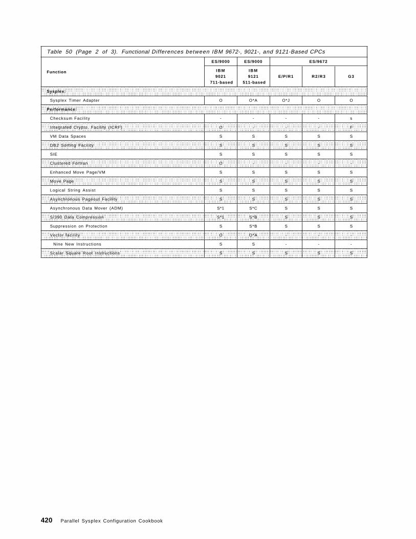
Table 50 (Page 2 of 3). Functional Differences between IBM 9672-, 9021-, and 9121-Based CPCs
Function
ES/9000 ES/9000 ES/9672
I B M9021
711-based
I B M9121
511-basedE/P/R1 R2/R3 G3
Sysplex:
Sysplex Timer Adapter O O*A O*J O O
Performance:
Checksum Faci l i ty - - - - s
Integrated Crypto. Facil ity (ICRF) O - - - F
VM Data Spaces S S S S S
DB2 Sorting Facil i ty S S S S S
SIE S S S S S
Clustered Fortran O - - - -
Enhanced Move Page/VM S S S S S
Move Page S S S S S
Logical Str ing Assist S S S S S
Asynchronous Pageout Faci l i ty S S S S S
Asynchronous Data Mover (ADM) S*1 S*C S S S
S/390 Data Compression S*1 S*B S S S
Suppression on Protection S S*B S S S
Vector faci l i ty O O*A - - -
Nine New Instructions S S - - -
Scalar Square Root Instructions S S S S S
420 Parallel Sysplex Configuration Cookbook

Table 50 (Page 3 of 3). Functional Differences between IBM 9672-, 9021-, and 9121-Based CPCs
Function
ES/9000 ES/9000 ES/9672
I B M9021
711-based
I B M9121
511-basedE/P/R1 R2/R3 G3
RAS:
Partial Memory Restart (POR) - - - - S
CP/SAP Sparing - - - - S
Dynamic Memory Array (DMA) S - - - S
Spare Memory Chips (POR) S - S S*L S
Fault-Tolerant Memory Path S - - - -
Memory ECC 4-bit - - - S*L S
Concurrent Channel Upgrade - - - S*L S
Concurrent Channel Maintenance S - S S S
Subsystems Storage Protection S S S S S
Subspace Group Facil i ty S*2 S*C S S S
AMD Concurrent Replacement S - S S S
Processor Availabil i ty Feature (PAF) S S - - -
SAP Reassignment - - - S*L S
Two-level HSB S - S S S
Dual Instruction Complete S - - - -
Concurrent LIC Maintenance S*1 - S*O S*P S*P
Concurrent Power Maintenance S - S S S
Dual Power Feeds - - - S*L S
Battery Backup - - O - O
Local UPS - - - O*L O
50/60 Hz Power S S S S S
n + 1 Power Suppl ies S - S S*L S
Console Integrat ion S S S S S
Concurrent CP TCM Maintenance S - - - -
I/O Interface Reset S S S S S
Set Recovery Time Option S S S S S
MVS Dynamic Physical Part i t ioning Performance S S - - -
Duplexed PCE-Single Image S - - - -
IOSP Concurrent Maintenance - S - - -
PCE Limited Function Mode - S - - -
SE/HMC Concurrent Maintenance - - S S S
The 9672 E, P and R1 CPCs all use the same S/390 microprocessor. The E and Pmodels were announced first and were shipped with a Sysplex Timer attachmentand (at least) one coupling link as standard. The R1 models were initiallyannounced as not being sysplex capable but this facility was later added by ECD57262 which also changed the version code returned by the STIDP instruction.On R1 models the timer attachment and coupling links are optional (as in later9672 models).
Keys to Table:S = standard O = optional - = not supported F = FutureS - SEC 228215 (711-based original SEC)*1 - SEC 228250 (711-based)*2 - SEC 228270 (711-based)*3 - SEC 236420 (711-based - CF links for Model 9X2)*4 - SEC 236422 (711-based)
Appendix D. Functional Differences between IBM 9672, 9021, and 9121-Based CPCs 421

S - SEC C35932 (511-based original SEC)*A - SEC C35936 (511-based)*B - SEC C35945 (511-based)*C - SEC C35954 (511-based, CF sender links only)*D - SEC C35956 (511-based)*F - to be available in the future as standard*J - see paragraph above on E/P/R1 processors*K - EC D79541 (9672)*L - EC E12923 (9672 R3) and EC E45548 (9672 R2 and R3)*M - XDF Withdrawn from marketing*N - Less then H5*O - For HMC and SE*P - For HMC, channels (ESCON, parallel, CF), Service Element,
power control, and some OSA-1 and OSA-2 components
Note
A similar table is located in SETI item OZSQ677922 on HONE (ASKQ itemRTA000054184). For updated information, refer to this table. Additionalinformation can also be found in LSDIFFC and S390PROC on MKTTOOLS.For updated information, refer to this table.
We have not included a column for the S/390 Multiprise servers because theycannot attach to an external CF though they can run ICMF.
422 Parallel Sysplex Configuration Cookbook

D.1.1 Brief Description of Capabilities in Alphabetical OrderAMD Concurrent Replacement: Provides the ability to replace failed Air MovingDevices (for example, fans and blowers) concurrently with machine operation.The CPC contains extra (“n+1”) AMDs in most places. AMDs are used to coolcomponents such as processor storage array cards, channel cards, and somelow-current power supplies.
Asynchronous Data Mover Facility (ADMF): Improves the process of movingdata between central and expanded storage. ADMF is used by DB2 V 3 toimplement hiperpools; hiperpools use expanded storage to provide much largerDB2 buffer pools than available in the past. IBM testing has shown DB2hiperpools can provide up to a 30% response time reduction and 13% ITRimprovement for OLTP, and up to a 50% reduction in elapsed time for queryprocessing. These benefits are mainly due to ADMF′s ability to support largerbuffer pools than possible without ADMF.
The “asynchronous” part of ADMF is that processing is off-loaded from the CPs,freeing them for other work. In ES/9000 CPCs supporting ADMF, the movementis performed by the Integrated Offload Processor (IOP); in the 9672 themovement is performed by the System Assist Processor (SAP).
Asynchronous Pageout Facility: In MVS, movement of a page from central toexpanded storage is normally synchronous. This means that the task waits untilthe move completes before continuing execution. The Asynchronous PageoutFacility allows instruction execution to continue while the move occurs. Thisfacility, while active in all environments, is expected to show a significant benefit(for example significant reduction in processor time) only in environments thatgenerate a high volume of in-storage paging, such as numerically intensivecomputing using large data structures.
Battery Backup: A battery that provides power to the CPC only (not I/Operipherals), allowing the CPC to withstand short term power outages. Thebattery powers the CPC only, and may not be needed if the CPC is protected bya UPS system.
9221: The Battery Backup feature provides power to the 9221 CP for up toapproximately five minutes after the external power source is interrupted. VSEwill use this capability beginning in VSE/ESA Release 2 to attempt to reducerestart time after power is restored.
9672: The Battery Backup feature provides power to the 9672 for up toapproximately 3.5 minutes. In addition, the 9672 Battery Backup featureprovides an external connection allowing attachment to an auxiliary powermodule that can extend battery protection up to 48 hours. For detailedinformation on backup power sources, see D.2, “Battery Backup on IBM 9672 orIBM 9674” on page 432.
Cancel Subchannel: This instruction allows a system control program towithdraw a pending start function from a designated subchannel withoutsignalling the device. The MVS Missing Interrupt Handler uses this facility toimprove its recovery process. VM/ESA uses this function to improve guest I/Orecovery in its Missing Interrupt Handler.
Appendix D. Functional Differences between IBM 9672, 9021, and 9121-Based CPCs 423

Checksum Facility: This facility consists of the CHECKSUM instruction whichcan be used to compute a 16-bit or 32-bit checksum. This instruction will beused by in a future release of OS/390 to improve TCP/IP performance.
Concurrent Channel Installation: Parallel or ESCON Channels can be added toan installed CPC nondisruptively.
Concurrent Channel Maintenance: Allows replacement of a channel card whilenormal system operations continue. Applies to parallel channels and ESCONchannels. Access to attached devices can continue without disruption if thedevices are also connected to channels on other cards.
Concurrent CP/TCM Maintenance: In an n-way (multi-engine) system, one CPcan be varied offline and the TCM replaced while the rest of the systemcontinues running, should a CP encounter a problem. After replacement, the CPcan be varied online.
Concurrent LIC Updates: Most Licensed Internal Code updates can be appliedconcurrently with normal operations.
On 9672-R2/3 models, LIC updates to the Hardware Master Console, paralleland ESCON channels, service elements, CF links, power control, and to someextent in OSA 1 and OSA 2, can be applied concurrently.
On 9021 711-based models, most patches that previously required a scheduledoutage can be applied concurrently with operations; in April 1994, this capabilitywas extended with the announcement of support for concurrent PR/SM LicensedInternal Code patches. (For concurrent LIC updates a backup PCE is required;this is standard on single-sided systems and on two-sided systems operating insingle-image mode, not in physically partitioned mode).
On 9021 520-based models, up to 70% of LIC updates have been appliedconcurrently; other updates required a scheduled outage.
Console integration: The system console (called the Hardware ManagementConsole in 9672 CPCs) can also be used as an operator console. If operationsare sufficiently automated (for example through NetView), this may allowinstallations to eliminate the need for non-SNA consoles and supporting clustercontrollers.
Coupling Facility Control Code: Coupling facility control code (CFCC) is IBMLicensed Internal Code (LIC) that runs as an extension to PR/SM LPAR LIC.CFCC provides the CF function in a Parallel Sysplex. The CF function, inconjunction with CF links for connectivity, can be used by other LPs in the sameCPC and by MVS images in other CPCs. In addition to indicated CPCs, CFCCalso runs in the 9674 CF.
CF Links: CF links connect a CPC to a CF that supports data sharing and otherfunctions in a Parallel Sysplex. These links use fiber optic cables, but run fasterthan ESCON channel speeds and use a different protocol.
CP/SAP Sparing: In the event of a S/390 G3 CP failure, a spare Processing Unit(PU) on the Multi-Chip Module (MCM) can be activated to take the place of thefailed CP via a POR. In the event of a SAP failure, the spare PU will bedynamically activated to replace the failed SAP. This feature is not available onthe 10-way G3 models nor on other models with optional SAPs where the
424 Parallel Sysplex Configuration Cookbook

number of SAPs plus the number of CPs is 12, because these CPCs have nospare PU in the MCM.
Data Compression: A hardware facility to reduce the processor time required tocompress data. For DASD storage, average space savings are in the range of40%-50% for supported data types. For communication lines, this facility canimprove the response time for transmitting bulk data. Other benefits can includereduced channel utilization, reduced CPC storage for DASD data buffers, andmore. Hardware-assisted compression provides about a five times reduction inprocessor time compared to software-based compression. In MVS/ESA, thisfacility is supported by IMS/DB and DB2; by system-managed QSAM, BSAM, andVSAM data; by LANRES/MVS; and by VTAM. VSE/ESA supports this facility forVSAM and VTAM.
DB2 Sort Facility: A combination of enhancements to hardware and softwarethat can provide up to a 37% reduction in elapsed time and up to a 62%reduction in CPU time for DB2 queries using sort, when used with DB2 V2.3 andlater releases
Dual Power Feeds: There are two input power lines. An installation canenhance availability by connecting these feeds to independent power sources.
Dynamic Reconfiguration Management: Provides for dynamic changes to aCPC′s I/O configuration definition. The interactive Hardware ConfigurationDefinition (HCD) function in MVS/ESA SP V4.2 invokes this hardware facility, andalso dynamically updates MVS′s definition of the I/O configuration. Dynamicreconfiguration management eliminates the need for system outages to changeCPC “understanding” of I/O configurations.
Dynamic Reconfiguration Management is synergistic with other dynamic(continuous availability) I/O-related facilities such as HCD updating MVS′“understanding” of the I/O configuration, ESCON cable “hot plugging,” and theability of DFSMS to dynamically assign newly initialized volumes as targets fornew data sets.
N+1 Power Supplies: Provides continuous power to the CPC in the case ofmost power supply malfunctions. In addition, failed power supplies can bereplaced while the system continues to run (that is, concurrent maintenance).
ESCON Byte Channel Support: ESCON channels can attach selectedbyte-interleaved based devices through a 9034 ESCON Converter. This isrepresented as channel type CBY in the IOCP.
ESCON Channels: Enterprise Systems Connection architecture. ESCONprovides significant benefits beyond parallel (OEMI) channels, such as:
• Increased channel-to-control unit distances• Smaller and lighter cables• Built-in channel-to-channel adapter (CTC) capability• Enhanced switching through the ESCON Director and ESCON Manager• Enhanced availability through the “hot plugging” of cables and through the
elimination of daisy chaining• The ability to reduce the number of control unit channel adapters and CPC
channel ports in some environments, the ability to share channels acrossPR/SM logical partitions
Appendix D. Functional Differences between IBM 9672, 9021, and 9121-Based CPCs 425

• Enhanced performance for some device types such as the 3490E tapesubsystem
ESCON Max Speed - 10 MB/sec: This item identifies CPC models that supportESCON channels at speeds up to 10 MB/sec. For example, the 3490E tapesubsystem can transfer data at 9 MB/sec when attached to ESCON channels.
ESCON Max Speed - 17 MB/sec: This item identifies CPC models that supportESCON channels at speeds up to 17 MB/sec. Support for the 17 MB/sec speedis provided by: 3990 cache hits, the RAMAC Array Subsystem, the 9340 DASDsubsystem, and ESCON channel-to-channel (CTC) operations.
ESCON CTC Basic Mode: Channel-to-channel (CTC) communications usespecialized protocols. Generally, CTC communications over parallel channelsrequire an IBM 3088 device, which supports protocols (commands) called “basicmode” and “extended mode.” ESCON CTCs originally only supported a variationof extended mode. VTAM/ESA and MVS/sysplex are examples of systemcomponents that support the original ESCON CTC protocol. However, somesystem components, such as JES2 and JES3 non-VTAM CTC support, GRSoutside of a sysplex, and others, required basic mode and could not use theoriginal ESCON CTC protocol. CPC models with ESCON CTC basic modecapability support basic mode as well as extended mode, eliminating the needfor parallel channels and 3088s for programs that use basic mode protocols.
ESCON Extended Distance Feature (XDF): (NOTE: XDF was withdrawn frommarketing as of May 30, 1995. Extended ESCON distances are supported throughESCON Directors and ESCON Channel Extenders.)
XDF is an optional form of ESCON channel. ESCON XDF allows extendedchannel-to-control unit distances, and extended channel-to-channel distancesusing laser-driven fiber. Distances are device-dependent. For example, a 3174can be up to 43km from the channel, and a 3490 or 3490E tape subsystem can beup to 23km from the channel; the maximum distance for the 3990-6 StorageControl is 20km, the maximum distance for the 3990-3 is 15km, the maximumdistance for the RAMAC Array Subsystem is 43km, and the maximum distancefor Channel-to-Channel connections is 60km.
ESCON Multiple Image Facility (EMIF): This facility allows sharing of ESCONattached control units across the PR/SM partitions within a CPC. This canreduce the number of channels, control unit channel adapters, and ESCONDirector ports otherwise required to share control units across LPARs. Supportis provided by all ESCON-capable operating systems.
Fault-Tolerant Dynamic Memory Arrays: (See “Spare Memory Chips (POR)” inthis section for a related facility on other CPC models.)
Two benefits apply to both central and expanded storage. First, “backgroundscrubbing” monitors central and expanded storage during idle periods,correcting soft errors on the fly before data is fetched by the CPC (in the 3090,background scrubbing was performed for expanded storage only). Second,“array chip sparing” dynamically moves data to a spare memory chip if anotherchip (on the same card) has incurred a number of hard errors that exceed athreshold.
426 Parallel Sysplex Configuration Cookbook

(Background: “Soft” errors are bit errors that can be corrected by rewriting thedata, while “hard” errors cannot be corrected by rewriting the data, although thedata may be corrected by error correction procedures.
An additional benefit applies to central storage in 711-based systems andprotects against data path failures in addition to chip failures. (Background: Inboth 520- and 711-based systems, central storage consists of cards that containmodules that house storage chips. Modules are grouped into pairs and eachpair shares a data path for reading and writing data off the memory card.) In711-based systems, each central storage card has a pair of spare modules withits own data path, meaning that if a standard data path fails, data from both ofthe modules sharing that data path can be moved to the spare modules (the datais recovered through error correction techniques). In contrast, in 520-basedsystems, there is a single spare module (with its own data path) per card, sothat a data path failure does not permit the data in the two modules sharing thatdata path to be moved to the single spare.
ICRF - Integrated Cryptographic Feature: Provides a high speedencryption/decryption capability, improving throughput compared to outboardcryptographic solutions.
Note: ICRF-smart card is an enhancement to the ICRF feature, allowing keys tobe entered into the ICRF Key Storage Unit through IBM Personal Security Cardsrather than manually. Parts of the key can be on different cards in thepossession of different individuals.
Integrated Coupling Migration Facility: The Integrated Coupling MigrationFacility (ICMF) provides a CF capability that can assist with the migration to aParallel Sysplex environment. ICMF also can support the MVS system logger(introduced in MVS/ESA V5.2) in an environment with a single MVS image. ForICMF, PR/SM emulates the function of CF links to connect MVS images in thatCPC to CF images in that CPC. All participating images, both MVS and CF, mustbe running in LPAR mode in the same CPC to use ICMF.
I/O Interface Reset A reset that quickly and automatically removes outstandingRESERVEs for DASD volumes in a shared DASD environment. This reset can beinitiated by 1) the CPC hardware when it enters a checkstop state, or 2) byMVS/ESA, VM/XA, or VM/ESA SCPs as their last action prior to loading adisabled wait state PSW. Timing is important because, until a reset is issuedthat releases outstanding RESERVEs to DASD (for example, such a reset isissued implicitly when an operator IPLs a system), other systems sharing thatDASD could be locked out. This facility is also known as System Initiated Reset.
Logical String Assist: This assist consists of three instructions used by the IBMSAA AD/Cycle C/370 compiler to improve the performance of string operations:Compare Logical String, Move Logical String, and Search Logical String.
Move Page: This instruction improves the performance of data movementbetween central and expanded storage. It is required for Hiperbatch, and, ifavailable, is used by VSAM for improved performance for buffers in hiperspace.
Move Page Enhanced for VM: This facility is supported by VM/ESA and used bySQL/DS with the VM Data Spaces Support Feature. It eliminates unnecessarydata movement between system paging DASD devices or expanded storage, andcentral storage, providing increased throughput.
Appendix D. Functional Differences between IBM 9672, 9021, and 9121-Based CPCs 427

Multiple LPAR 2GB Central Storage on G3 Enterprise Servers: On G3 EnterpriseServers with more than 2GB processor storage installed, each logical partition islimited to at most 2GB central storage. The total central storage can exceed2GB and could be the whole of installed processor storage.
MVS Dynamic Physical Partitioning Performance: Reduces the time tophysically partition a multiprocessor running in single image mode by reducingthe time to reconfigure central storage. Lab measures for a 256 MB centralstorage configuration showed times reduced from 16 minutes down to oneminute.
Open Systems Adapter 1: This feature provides a direct attachment of LANs tothe CPC. LAN protocols supported include FDDI, Token-Ring, and Ethernet. Inaddition, the adapter will offload some TCP/IP and Network File System (NFS)processing. Application support is provided by LANRES/MVS, LFS/ESA, TCP/IPfor MVS, and ACF/VTAM for MVS. VM supports some functions; VSE issupported as a VM guest.
Open Systems Adapter 2: This feature provides a direct attachment of LANs tothe CPC. LAN protocols supported include FDDI, Token-Ring, and Ethernet. OSA2 is smaller and less expensive than OSA 1 but does not provide the offloadsupport provided in OSA 1. OSA 2 supports TCP/IP passthru for MVS and VM,and SNA/APPN (VTAM) passthru for MVS. Support for Asynchronous TransferMode (ATM) is a Statement of Direction. OSA 2 cards can be installed andmaintained concurrent with CPC operations.
Partial Memory Restart: This enhancement minimizes the length of an outagecaused by a memory card failure. If a memory card fails, the system can berestarted with half of the original memory. Processing can be resumed until areplacement memory card is installed.
Processor Availability Facility: This facility enhances application availability onn-way CPC models. If an engine fails, this facility allows the application that wasrunning on that engine to continue execution on another engine. In many cases,that would result in application termination on systems without this facility. TheProcessor Availability Facility is available on ES/9000 9021 and 9121 n-way(multi-engine) CPCs, and on n-way ES/3090-J CPCs except for the 250J. Onsupported 3090 CPC models, the facility is included in SEC 227576. TheProcessor Availability Facility is supported natively by MVS/ESA and VM/ESA,and by PR/SM LPAR in shared partitions regardless of the operating system.The PR/SM LPAR support is enhanced to support this facility when the LPARdispatcher is in control in 520-, 511-, and 711-based models.
PR/SM: PR/SM stands for Processor Resource/Systems Manager. PR/SM hastwo modes. In LPAR (logical partition) mode, a CPC is configured into multiplelogical images, each capable of running a separate operating system. In MPG(multiple preferred guests) mode, the VM/XA or VM/ESA operating systemsupports multiple preferred guests for improved performance.
PR/SM Automatic Reconfiguration: The Automatic Reconfiguration Facility (ARF)automates PR/SM dynamic storage reconfiguration, improving performanceduring an XRF (Extended Recovery Facility) “takeover.” MVS/ESA SP V4 sysplexsupport invokes this facility according to installation policy. CICS support isavailable in CICS/ESA V3.2.1.
428 Parallel Sysplex Configuration Cookbook

PR/SM Dispatcher Improvements: An enhancement to PR/SM LPAR that, inconjunction with the dispatcher enhancements in MVS/ESA V4.3, offersreductions in LPAR management time.
PR/SM Dynamic Storage Reconfiguration: The ability for an active logicalpartition to acquire CPC storage from another, adjacent logical partition. Thisfacility can be invoked through an operator command entered at the systemconsole, or it can be invoked automatically through the PR/SM automaticreconfiguration facility available on selected CPC models.
PR/SM Dynamic Storage Reconfiguration Enhanced for Central Storage: Centralstorage can be reconfigured from one logical partition to another, even if thepartitions are not contiguous. Granularity on 9021-based CPC is in multiples of 4MB if CS < 2 GB, or multiples of 16 MB if CS = 2 GB.
On the 9672 G3 CPCs, granularity varies with the size of the total installedstorage, as follows:
Total installed storage (Size) Granularity------------------------------ -----------
0 MB < Size <= 512 MB 1 MB512 MB < Size <= 1 GB 2 MB1 GB < Size <= 2 GB 4 MB2 GB < Size <= 4 GB 8 MB4 GB < Size <= 8 GB 16 MB
PR/SM Dynamic Storage Reconfiguration Enhanced for Expanded Storage:Expanded storage can be reconfigured from one logical partition to another,even if the partitions are not contiguous. Granularity is in multiples of 4 MB.
On the 9672 G3 CPCs, granularity varies with the size of total installed storageas follows:
Total installed storage (Size) Granularity------------------------------ -----------
0 MB < Size <= 512 MB 1 MB512 MB < Size <= 1 GB 2 MB1 GB < Size <= 2 GB 4 MB2 GB < Size <= 4 GB 8 MB4 GB < Size <= 8 GB 16 MB
PR/SM Logical Vary CP: Within a logical partition, a logical CP can be variedonline or offline using operating system commands. This allows physicalengines to be reassigned across shared and dedicated partitions while thepartitions remain activated. For example, If a physical engine that wasdedicated to an LPAR fails, another physical engine currently in the shared poolcan be varied offline from that pool and online to the dedicated partition. Or, adedicated engine (in an LPAR assigned multiple dedicated engines) may bereassigned to the shared pool while the dedicated LPAR remains active, forimproved CPC utilization as workloads vary across shifts.
PR/SM LPAR definitions retained: Retains logical partition definitions (forexample, partition weights, dedicated/shared status, capping) across power-onresets even when a new I/O configuration data set (IOCDS) is used. Thisreduces the manual time and effort otherwise required to redefine theseparameters.
Appendix D. Functional Differences between IBM 9672, 9021, and 9121-Based CPCs 429

PR/SM LPAR Management Time Reporting: This CPC facility, along with RMFsupport, provides improved LPAR processor utilization reporting The RMFPartition Data Report provides total and effective partition dispatch times. Thisdata enables you to quantify the low utilization effect and do more accuratecapacity planning.
PR/SM LPAR Preferred Path: Supports the ability to designate (in the IOCP) apreferred channel path for I/O operations, when in PR/SM LPAR mode (thisfunction existed previously only in basic mode). Always attempting new I/Orequests to the same path first can improve throughput for IBM 3480/3490 tapesubsystems. Most installed tape subsystems have two control unit functions,each with its own buffer storage and channel attachments, and each with accessto all tape drives. The subsystem employs an algorithm that attempts to keepbuffers for a given drive in the control unit to which most I/O requests for thatdrive are directed, avoiding internal overhead that otherwise occurs.
PR/SM Multiple LPAR 2GB Central Storage: 9672 G3 Parallel Enterprise Serverscan have up to 8GB of processor storage. Each LP can be defined with up to 2GB of central storage. Thus all processor storage can be defined as centralstorage.
PR/SM Physical VARY CP ON/OFF: Physical processors can be varied on/offline to a logical partition by operator command. This facility complements theconcurrent CP/TCM maintenance capability.
PR/SM Resource Capping: The ability to limit the maximum amount of centralprocessor resource available to a given logical partition.
PR/SM Security: Control over the degree of isolation of logical partitions. Forexample, a system console screen specifies which LPAR(s) can update thephysical processor′s IOCDS data sets, and which LPAR(s) can accessperformance information about other LPARs.
PR/SM 10 LPARs/Side: Single image CPCs can be configured to support up toten PR/SM logical partitions, and physically partitioned multiprocessors can beconfigured to support up to 20 PR/SM logical partitions (10 per side). This canbe useful in consolidating workloads onto fewer machines, and in providingadditional hot standby or test partitions. The ESCON Multiple Image Facility(EMIF) allows the sharing of ESCON channels across multiple partitions, thuscontrolling that aspect of cost.
SAP Reassignment: 9672 CPCs include a System Assist Processor (SAP) thathandles I/O processing for the system. A SAP failure on a G3 Enterprise Serveris usually managed by CP/SAP Sparing as described in “CP/SAP Sparing” onpage 424. When this cannot take place, as on an 10-way G3 Enterprise Server,then SAP Reassignment takes place as described below. In a system with morethan one CP, except for G3 Enterprise Servers excluded above, if a SAP fails, afunctioning CP is assigned to take over the SAP function. SAP reassignmentallows repair to optionally be postponed to a more convenient time; however,CPC capacity is reduced until the failed SAP is repaired. In R1 models, the SAPfailure requires a re-IML for recovery, and the assignment of a new SAPhappens automatically at re-IML time. In 9672 R2/R3 models, SAP reassignmenthappens dynamically, eliminating an unplanned outage.
Scalar Square Root: Two instructions for short and long precision square root.
430 Parallel Sysplex Configuration Cookbook

SIE Assist: In VM environments, the provides most I/O without control programintervention for dedicated devices of preferred guests, offering improvedperformance.
Spare Memory Chips (POR): Processor storage (memory) cards contain sparememory chips. During a planned power-on reset (POR), the system invokes aspare memory chip in place of one with accumulated failing bits. Note that in9672 CPCs (and others as well) a processor storage scrubbing process runs inthe background during normal machine operation to correct soft bit errors,preventing them from accumulating into uncorrectable errors.
(Background: “Soft” errors are bit errors that can be corrected by rewriting thedata, while “hard” errors cannot be corrected by rewriting the data, though thedata may be corrected by error correction procedures.)
Subspace Group Facility: Protects CICS application programs within the sameaddress space from accidentally or intentionally overlaying each others′ code ordata. This facility is also known as “transaction isolation,” and augments theSubsystem Storage Protection feature that is used by CICS to prevent applicationprograms from overlaying CICS system code and data. The Subspace GroupFacility is supported by CICS/ESA V4 when running under MVS/ESA V5.
Subsystem Storage Protection: Enhances subsystem availability by preventingapplication code from overlaying subsystem code and data. This facility issupported by CICS/ESA in MVS/ESA; a statement of direction in announcementletter 294-160 describes plans for CICS/VSE to support this facility.
Suppression on Protection: This hardware facility can improve performance inthe MVS/ESA OpenEdition and AIX/ESA environments (MVS/ESA support is inV5.2). The benefit applies to UNIX fork processing. The fork operation creates acopy of the issuing program which will execute independently. The Suppressionon Protection facility allows the new child process to share the parent′s pageson a read-only basis; new copies of pages are made only when the systemdetects that the child is attempting to modify one of the shared pages. (Note thatAIX/ESA is not supported on the 9672 CPC.)
Sysplex Timer: A table-top unit that synchronizes the time-of-day clocks in up to16 CPCs or CPC sides, providing consistent time stamping. This unit eliminatesthe need for an operator to manually set the time-of-day clock at IPL time (aprocess that is imprecise as well as error prone). The Sysplex Timer is requiredin a sysplex environment unless all images are in the same physical CPC (orsame side if the CPC is physically partitioned).
Vector Facility: Instructions and hardware (for example registers) offeringimproved performance in numerically intensive environments.
Vector - New Instructions: Nine instructions announced September, 1991, whichcan improve performance when using the Vector Facility. The instructionsinclude four for square root calculation, two for multiply-then-add, two formultiply-then-subtract, and one for load vector interrupt index (this can improvethe efficiency of handling variable vector sizes).
VM Data Spaces: A facility similar to MVS/ESA data spaces, but requiringunique microcode. VM/ESA uses VM data spaces to provide improvedperformance.
Appendix D. Functional Differences between IBM 9672, 9021, and 9121-Based CPCs 431

4.5 MB Parallel Channels: These channels support the copper bus and tagcables that were required prior to ESCON. Many existing devices support themaximum 4.5 megabyte/second speed when attached to parallel channels, suchas 3480, 3490(E), 3088, 3990-6, and 3990-3 for cache access, and the RAMACArray Subsystem. (Some of these devices attach to 3.0 MB/sec channels aswell.)
60 Hz Power: The CPC power requirement. Prior to the ES/9000 CPC family,IBM water-cooled CPCs required a 415Hz power source, provided through a unitsuch as a 3089 or other “motor generator.” The water-cooled ES/9000 50/60Hzpower requirement eliminates the motor generator as a single point of failure.
8 Path Dynamic Reconnect: Up to eight channel paths can be defined to adevice from a single operating system image. (IBM CPCs without this featureare limited to four paths to a device per image.)
D.2 Battery Backup on IBM 9672 or IBM 9674For IBM 9672 G3 Enterprise Servers and 9674-C04 CFs, the Internal BatteryFeature (IBF) provides the function of a local Uninterruptible Power source. Ithas continuous self-testing capability for battery backup which has been fullyintegrated into the diagnostics, including Remote Service Facility (RSF) support.IBF enables between 3.5 to 20 minutes of full power hold-up for the 9672 G3Parallel Enterprise Server and up to one hour for the 9674-C04 CF in power savemode.
An optional battery backup (BBU) feature exists on 9672-R1 and 9674-C01. Abackup battery provides power to the CPC, allowing it to withstand short termpower outages. The battery powers the CPC only, and may not be needed if theCPC is protected by an Uninterruptible Power Supply (UPS) system.
On the IBM 9672-R1 and IBM 9674-C01, the battery backup feature providespower for up to approximately 3.5 minutes. Also, the battery backup featureprovides an external connection allowing attachment to an auxiliary powermodule that can extend battery protection up to 48 hours. There is no BatteryBackup feature to IBM 9672 R2/R3 based models.23 Consult announcement letterZG94-0210 (194-281) for more details and to see what restrictions apply.
D.2.1 Power Save State SupportFor 9672 and 9674 models, power save state is available to preserve CF storageacross a utility power failure. Power save state allows CF structures to be savedintact. This simplifies the subsystem recovery and restart activity that wouldhave been required had the structures been lost. Enabling power save state forthe CPC (the default setting) functions as follows:
• CF logical partition (LPAR) operation shuts down and storage contents for CFLPs are preserved across a utility power failure regardless of the volatilityMODE setting of the CF LP. When utility power is restored, CF LPs return tooperation with their structures intact. A CPC draws less power in powersave state, allowing CF LPAR storage contents to be preserved for a longerperiod of time than if the CPC continued operation.
23 Including IBM 9674 C02 and C03.
432 Parallel Sysplex Configuration Cookbook

• Any non-CF LP running on the same CPC as the CF LP is automaticallysystem reset when the CPC loses utility power. When utility power isrestored, you must re-IPL the non-CF LPs.
Power save state requires:
• An installed and charged battery backup feature on the CPC or anoperational uninterruptible power source (UPS). See, for example, D.2.2,“Local Uninterruptible Power Supply.”
• Enabling prior to power-on reset of the CPC (enabled is the default powersave state setting).
Power Save State applies to:
• 9672-R1 models at EC level D57262• 9674-C01 at EC level D57264• 9672-R2/R3 base• 9674-C02/C03 base
D.2.2 Local Uninterruptible Power SupplyThe Local Uninterruptible Power Supply, Machine Type 9910, is available fromIBM for use with all 9672 models.
Appendix D. Functional Differences between IBM 9672, 9021, and 9121-Based CPCs 433

434 Parallel Sysplex Configuration Cookbook

Appendix E. Hardware System Area (HSA) Considerations in aParallel Sysplex
This appendix contains HSA storage information for input into storage planningin a Parallel Sysplex. The HSA contains the CPC Licensed Internal Code (LIC)and configuration information used by the CPC during the current power-on resetof the machine. HSA is not available for program use.
The HSA size varies according to:
• The Power-on Reset (POR) mode of the CPC• The EC/SEC level of the CPC• The size of the I/O configuration• Whether or not dynamic I/O configuration is enabled
The purpose of this section is to give information suitable for capacity planning.As such, our figures intentionally overestimate HSA size for 9672 and 9674 CPCswhere increases can be expected in the future. Note that HSA does not includeCFCC code requirements, either for an ICMF partition or a normal CF partition.For planning purposes, we suggest you allow 16MB for CFCC per partition inwhich it runs, in addition to storage for structures in the CF.
HSA changes may be important because they change the storage available toyour systems, and may, for example, prevent you from bringing up an LP unlessthe storage definitions are changed. This is time-consuming if it is onlydiscovered when you are bringing your systems back after an EC change.
Accurate 9672/9674 HSA sizing is complex and depends on many variables 9674sizing given is sufficient for two CF LPARs with 32 links. A small 9672configuration has up to 4 logical partitions and 24 channels. A large 9672 is amaximum configuration.
HSA Sizes Are EC Level-Dependent - Check the Latest Information
Precise HSA information is EC level-dependent, so you should check currentEC levels to find the latest HSA sizes if you need precise information. Thiscan be checked on SETI (ASKQ) on HONE.
Table 51. HSA Size Estimates
Base Mode LPAR Mode
9674 n/a 20MB
Small 9672 16MB 24MB
Large 9672 20MB 48MB
9021 711 48MB 48MB
Note: For capacity planning purposes only
Copyright IBM Corp. 1996 435

436 Parallel Sysplex Configuration Cookbook

Appendix F. CF Service Time Analysis
This appendix contains a discussion of CF service times excluding:
• ICMF
• Shared CF LPs since these are not in general recommended. Forinformation, if a CPC has partitions running CFCC and MVS which both useshared CPs, then synchronous MVS requests are changed to asynchronous“under the covers” from MVS. This is done in case the MVS LP and CF LPare in the same sysplex, which is even less recommended.
F.1 Synchronous and Asynchronous CF RequestsSynchronous CF requests are important because:
1. A synchronous request requires a variable amount of CPU time dependingon CF and CF link utilization.
2. Synchronous requests directly contribute to application response times andare used for high priority requests, such as lock requests. (Though note thata CF does not implement any priority service).
Typical CF service times for certain CPC/CF combinations are discussedtogether with a pictorial overview of a CF access request and a discussion oninterpreting RMF reports. Note that although only one link is shown, werecommend at least 2 CF links from each CPC to each 9674 CF.
F.2 RMF Reporting of Link DelaysThe following report and most of the discussion is taken from S/390 ParallelSysplex Performance, SG24-4356.
For every CF link, there are two CF subchannels where data is placed to be sentacross CF links. When you define a CF link in the IOCDS, HCD automaticallydefines the two subchannels.
Copyright IBM Corp. 1996 437

C O U P L I N G F A C I L I T Y A C T I V I T YPAGE 18
MVS/ESA SYSPLEX UTCPLXJ8 DATE 11/15/1995 INTERVAL 030.00.000******* RPT VERSION 5.2.0 CONVERTED TIME 11.30.00 CYCLE 01.000 SECONDS
------------------------------------------------------------------------------------------------------------------------------COUPLING FACILITY NAME = CF1
------------------------------------------------------------------------------------------------------------------------------SUBCHANNEL ACTIVITY
------------------------------------------------------------------------------------------------------------------------------# REQ ----------- REQUESTS ----------- -------------- DELAYED REQUESTS --------------
SYSTEM TOTAL --BUSY-- # -SERVICE TIME(MIC)- # % OF -------AVG TIME(MIC) ------NAME AVG/SEC -- CONFIG -- -COUNTS- REQ AVG STD_DEV REQ REQ /DEL STD_DEV /ALL
J80 639197 SCH GEN 4 PTH 525 SYNC 602326 190.5 34.7 SYNC 271 0.0% 0.0 0.0 0.0355.1 SCH USE 4 SCH 271 ASYNC 36166 1940.7 1528 ASYNC 2723 7.5% 1106 1258 82.9
SCH MAX 4 CHANGED 167 INCLUDED IN ASYNC TOTAL 2994 0.5%PTH 2 UNSUCC 0 0.0 0.0
...JC0 322520 SCH GEN 4 PTH 0 SYNC 286916 232.7 53.4 SYNC 453 0.2% 952.8 1170 1.5
179.2 SCH USE 4 SCH 453 ASYNC 33288 3291.7 2057 ASYNC 2993 8.9% 2511 2591 224.2SCH MAX 4 CHANGED 234 INCLUDED IN ASYNC TOTAL 3446 1.1%PTH 2 UNSUCC 0 0.0 0.0
...
Figure 93. Example of RMF CF Subchannel Activity Report
• The number of subchannels configured (CONFIG) tells you how manysubchannels were defined in the IOCDS (SCH GEN), how many are currentlybeing used (SCH USE), how many could be used if they were available giventhe current pathing configuration (SCH MAX), and how many CF links arecurrently connected (PTH). You should check this information and verify that:
− The correct number of subchannels are connected.
If the number of subchannels currently being used are fewer than thenumber of subchannels defined; verify that you have not lost connectivityon some CF links.
− The correct number of subchannels have been defined.
If more subchannels have been defined than you intend to use, you couldreduce the number generated and save a small amount of storage.
• Subchannel busy
For each CF link, there are two subchannels for each MVS image. The datato be sent to the CF is loaded into these subchannels. If no subchannels areavailable, ASYNC requests are queued. Non-immediate SYNC requests arechanged to ASYNC requests (which are then also queued). Immediate SYNCrequests (like locks) “spin” waiting for the next available subchannel.
438 Parallel Sysplex Configuration Cookbook

Figure 94. Flow of a Synchronous CF Request
This is illustrated above in Figure 94. Data about the delayed requests isreported under the SYNC and ASYNC DELAYED REQUESTS and summarizedon the TOTAL line.
For those requests that experience a delay, the duration of the delay isreported separately (/DEL). You can assess the impact of the subchanneldelay for each class of requests as amortized over all the requests (/ALL) ofthat type by adding this to the service time.
In Figure 93 on page 438, synchronous requests had zero measurable delaydue to subchannel busy, and asynchronous requests were delayed onaverage 1106 microseconds.
As a guideline, we recommend that sum of the SYNC and ASYNC requestsdelayed (TOTAL − % OF REQ) be less than 10% of all requests. If thepercentage of requests queued is greater than 10%, you should consideradding another CF link on the related sending CEC.
In Figure 93 on page 438, only 2994 requests out of 639197 were delayedwhich is less than 0.5% delayed
• Path busy
When a CF request obtains a subchannel, in most cases, it will proceeddown the path to the CF and complete the processing with no further delays.However, if this is a PR/SM environment with multiple MVS images sharingCF links, the request could encounter a busy path. If this is a SYNC request,the request is immediately retried until it obtains a path. The time spentspinning for the path is accumulated in the SYNC service time. If this is anASYNC request, the request is returned and goes back through the processof obtaining another subchannel, which may include requeuing for asubchannel.
The number of times a “Path Busy” condition is encountered is reported inthe BUSY COUNTS — PTH.
Appendix F. CF Service Time Analysis 439

Figure 95. Synchronous CF Requests (Shared CF Links)
Figure 95 above illustrates this. To limit the additional overhead incurred inprocessing requests deferred for Path Busy, we recommend that thepercentage of requests encountering this delay be limited to 10%. If itexceeds this amount, you may want to consider dedicating the CF links toeach MVS image or adding additional CF links.
In Figure 93 on page 438, we can deduce that system J80 must have beenusing a shared CF link since the path busy count, 525, is non-zero. Lessthan 0.1% of requests were delayed for this cause.
F.3 Total Locking TimeMeasurements of CF lock requests are shown in Table 52 for variouscombinations of sender CPCs and CFs. This is the average service time perrequest as shown in RMF coupling facility activity reports. Note that there 9674shad a reasonable load on them, so that lower service times could be seen onlightly loaded 9674s. This time includes data transfer time on the CF links butnot the time setting up the request.
Table 52. CF Access Service Times for Lock Requests
CPC CF Service Time
9672 R1-based 9674-C01 0.25 ms
9672 R2/R3-based 9674-C02/3 0.18 ms
9672 G3 9674-C04 0.14 ms
9021 711-based 9674-C01 0.16 ms
9021 711-based 9674-C02/3 0.13 ms
9021 711-based 9674-C04 0.10 ms (expected)
9021 711-based 9021 711-based 0.08 ms
Note: Multimode CF links are used to connect CPC and CF
440 Parallel Sysplex Configuration Cookbook

The ITSO redbook S/390 MVS Parallel Sysplex Performance, SG24-4356 describesmeasured numbers from a series of 100% DB2 and IMS/DB data sharingbenchmarks. The benchmark information in Appendix A shows that the totalCPU time for a synchronous access for a 9672 R1-based CPC coupled to a 9674C01 CF is in the range 0.60 to 0.70 ms compared to an IMS lock request usingprogram isolation in non-data sharing mode. A lock request is alwayssynchronous and since it transfers very little data, will tend to be in the lowerpart of the range. The total CPU time includes time spent in the subsystemssoftware (IRLM or DBMS), time spent in MVS, and time spent while waiting forthe response from the CF.
The redbook concludes that the hardware component (as shown in the RMF CFactivity report) of the CF service time is usually a little less than half the totallock service time for this combination of sender/receiver technology (R1/C01).Table 52 on page 440 shows that the expected CF service for 9672-R1 to9674-C01 for lock requests is .25 ms which is 35-45% of .6-.7 ms of total time perlock. The .35-.45 ms not spent accessing the CF is split roughly 50/50 betweenthe subsystem and MVS.
Scaling Considerations for CF Access Service Times
Part of the CF service time as reported by RMF is link dependent and partscales with sender speed and part scales with the receiver speed.
For more information, refer to the ITSO redbook S/390 MVS Parallel SysplexPerformance, SG24-4356.
Appendix F. CF Service Time Analysis 441

442 Parallel Sysplex Configuration Cookbook

Appendix G. MSU Values for Selected IBM CPCs
MSUs are used for IBM PSLC pricing of CPCs. They are used in this book in firstcut sizing of data sharing overheads and CFs.
9674s are not given MSU values. Above each range of 9672 CPCs we indicatethe corresponding 9674 family. CPCs in that family for which a 9674 CF existsare indicated by an asterisk.
See Table 53 on page 445 for details of 1-way to 5-way 9674-C04.
9674-C04
9672-RA4 6 9021-711 119672-R14 8 9021-821 219672-RB4 11 9021-822 219672-R24 15 9021-831 309672-RC4 20 9021-832 309672-R34 22 9021-941 389672-R44 28 9021-942 389672-R54 35 9021-952 469672-R64 * 41 9021-962 539672-R74 * 46 9021-972 609672-R84 * 51 9021-982 679672-R94 * 55 9021-9X2 789672-RX4 * 599672-RY4 64
9121-311 49674-C02 9121-411 4
9121-511 69672-RA2 * 3 9121-521 89672-R12 * 4 9121-522 89672-R22 * 7 9121-621 119672-R32 * 10 9121-622 119672-R42 * 13 9121-732 159672-R52 * 15 9121-742 199672-R72 * 19
9674-C03
9672-R53 * 189672-R63 * 209672-R73 * 239672-R83 * 269672-RX3 * 30
9674-C01
9672-R11 * 39672-R21 * 59672-R31 * 69672-R41 * 89672-R51 * 99672-R61 * 10
Copyright IBM Corp. 1996 443

444 Parallel Sysplex Configuration Cookbook

Appendix H. IBM 9674 CFs
The information is included for completeness. CP90 or the Quicksizer should beused to estimate 9674 capacity requirements.
9674-C01 models are 1- to 6-way models based on corresponding 9672-R1models on an CP for CP basis.
9674-C02 models are 1- to 7-way models based on corresponding 9672-R2models on an CP for CP basis including a sub-uniprocessor model.
9674-C03 models are 5- to 10-way models based on corresponding 9672-R3models on an CP for CP basis. Note there is an overlap in processing capacitybetween the 9674-C02 and 9674-C03 models. (See Appendix G, “MSU Values forSelected IBM CPCs” on page 443 for MSU values for the corresponding 9672models.)
The 9674-C04 1- to 5-way models are based on technology similar to theMultiprise 2003 servers 1- to 5-way CPCs models 116, 126, 136, 146, 156. Thereis no sub-uniprocessor model.
The 9674-C04 6- to 10-way models are based on similar technology to the 9672G3 Enterprise servers 6- to 10-way CPCs.
For planning purposes only, we include a table of 9674-C04 MSU values. MSUvalues for 9674-C01/C02/C03 can be found by using the tables in Appendix G,“MSU Values for Selected IBM CPCs” on page 443 and the information above.
Table 53. 9674 MSU Values
Model MSU
9674-C04 1-way 6
9674-C04 2-way 12
9674-C04 3-way 17
9674-C04 4-way 21
9674-C04 5-way 25
9674-C04 6-way 41
9674-C04 7-way 46
9674-C04 8-way 51
9674-C04 9-way 55
9674-C04 10-way 59
Note: For capacity planning purposes only
Copyright IBM Corp. 1996 445

446 Parallel Sysplex Configuration Cookbook

Appendix I. Special Notices
This publication is intended to help large systems customers configure a S/390Parallel Sysplex.
References in this publication to IBM products, programs or services do notimply that IBM intends to make these available in all countries in which IBMoperates. Any reference to an IBM product, program, or service is not intendedto state or imply that only IBM′s product, program, or service may be used. Anyfunctionally equivalent program that does not infringe any of IBM′s intellectualproperty rights may be used instead of the IBM product, program or service.
Information in this book was developed in conjunction with use of the equipmentspecified, and is limited in application to those specific hardware and softwareproducts and levels.
IBM may have patents or pending patent applications covering subject matter inthis document. The furnishing of this document does not give you any license tothese patents. You can send license inquiries, in writing, to the IBM Director ofLicensing, IBM Corporation, 500 Columbus Avenue, Thornwood, NY 10594 USA.
Licensees of this program who wish to have information about it for the purposeof enabling: (i) the exchange of information between independently createdprograms and other programs (including this one) and (ii) the mutual use of theinformation which has been exchanged, should contact IBM Corporation, Dept.600A, Mail Drop 1329, Somers, NY 10589 USA.
Such information may be available, subject to appropriate terms and conditions,including in some cases, payment of a fee.
The information contained in this document has not been submitted to anyformal IBM test and is distributed AS IS. The information about non-IBM(″vendor″) products in this manual has been supplied by the vendor and IBMassumes no responsibility for its accuracy or completeness. The use of thisinformation or the implementation of any of these techniques is a customerresponsibility and depends on the customer′s ability to evaluate and integratethem into the customer′s operational environment. While each item may havebeen reviewed by IBM for accuracy in a specific situation, there is no guaranteethat the same or similar results will be obtained elsewhere. Customersattempting to adapt these techniques to their own environments do so at theirown risk.
Any performance data contained in this document was determined in acontrolled environment, and therefore, the results that may be obtained in otheroperating environments may vary significantly. Users of this document shouldverify the applicable data for their specific environment.
The following document contains examples of data and reports used in dailybusiness operations. To illustrate them as completely as possible, the examplescontain the names of individuals, companies, brands, and products. All of thesenames are fictitious and any similarity to the names and addresses used by anactual business enterprise is entirely coincidental.
Copyright IBM Corp. 1996 447

Reference to PTF numbers that have not been released through the normaldistribution process does not imply general availability. The purpose ofincluding these reference numbers is to alert IBM customers to specificinformation relative to the implementation of the PTF when it becomes availableto each customer according to the normal IBM PTF distribution process.
The following terms are trademarks of the International Business MachinesCorporation in the United States and/or other countries:
The following terms are trademarks of other companies:
C-bus is a trademark of Corollary, Inc.
PC Direct is a trademark of Ziff Communications Company and isused by IBM Corporation under license.
ACF/VTAM Advanced Function PrintingAdvanced Peer-to-Peer Networking AFPAIX AIX/6000AnyNet AOEXPERT/MVSAPPN C/370CBIPO CBPDOCICS CICS/ESACICS/MVS CICS/VSECUA DATABASE 2DB2 DB2/2DFSMS DFSMS/MVSDFSMShsm DFSORTDistributed Relational DatabaseArchitecture
DRDA
Enterprise System/3090 Enterprise Systems Architecture/390Enterprise Systems ConnectionArchitecture
ES/9000
ESA/390 ESCON XDFESCON GDDMHardware Configuration Definition HiperbatchHipersorting HiperspaceIBM IMSIMS/ESA LSPRLSPR/PC MVS/DFPMVS/ESA MVS/SPMVS/XA NetViewOpenEdition Operating System/2OS/2 OS/390OS/400 Parallel SysplexPersonal System/2 PR/SMPrint Services Facility Processor Resource/Systems ManagerPROFS PS/2PSF QMFRACF RAMACResource Measurement Facil ity RETAINRISC System/6000 RMFRS/6000 S/370S/390 SAASNAP/SHOT SQL/DSSysplex Timer System/370System/390 SystemViewVM/ESA VSE/ESAVTAM 3090400
448 Parallel Sysplex Configuration Cookbook

UNIX is a registered trademark in the United States and othercountries licensed exclusively through X/Open Company Limited.
Microsoft, Windows, and the Windows 95 logoare trademarks or registered trademarks of Microsoft Corporation.
Java and HotJava are trademarks of Sun Microsystems, Inc.
Other trademarks are trademarks of their respective companies.
C + + American Telephone and TelegraphCompany, Incorporated
DCE The Open Software FoundationIPX Novell, IncorporatedMS-DOS Microsoft CorporationNetWare Novell, IncorporatedNetwork File System Sun Microsystems, IncorporatedNFS Sun Microsystems IncorporatedORACLE Oracle Corporation
Appendix I. Special Notices 449

450 Parallel Sysplex Configuration Cookbook

Appendix J. Rel ated Publications
The publications listed in this section are considered particularly suitable for amore detailed discussion of the topics covered in this redbook.
J.1 International Technical Support Organization PublicationsAt the time of writing, a few of these books are not available, but should bepublished in the near future.
For information on ordering these ITSO publications see “How To Get ITSORedbooks” on page 459.
The publications listed are sorted in alphabetical order.
• A Comparison of S/390 Configurations - Parallel and Traditional, SG24-4514• APPN Architecture and Product Implementations Tutorial, GG24-3669
(available in softcopy only)• Automating CICS/ESA Operations with CICSPlex SM and NetView, SG24-4424• CICS Workload Management Using CICSPlex SM And the MVS/ESA Workload
Manager, GG24-4286• DFSMS/MVS V1.3 Presentation Guide, GG24-4391• DFSORT Release 13 Benchmark Guide, GG24-4476• Disaster Recovery Library: Data Recovery, GG24-3994• Disaster Recovery Library: Database Recovery, GG24-3993• Disaster Recovery Library: Design Concepts, GG24-4211• Disaster Recovery Library: Planning Guide, GG24-4210• HCD and Dynamic I/O Reconfiguration Primer, SG24-4037• Introduction to Storage Performance Management Tools & Techniques for
MVS/ESA, GG24-4045 (available in softcopy only)• JES3 in a Parallel Sysplex, SG24-4776• MVS/ESA Software Management Cookbook, GG24-3481 (available in softcopy
only)• MVS/ESA SP-JES2 V5 Implementation Guide, SG24-4583• MVS/ESA SP-JES3 V5 Implementation Guide, SG24-4582• MVS/ESA SP V5 Sysplex Migration Guide, SG24-4581• OS/390 Hardware Configuration Manager Primer, SG24-4898• OS/390 MVS Multisystem Consoles Implementing MVS Sysplex Operations,
SG24-4626• OS/390 Release 2 Implementation, SG24-4834• Automation for S/390 Parallel Sysplex, SG24-4549• RACF V2.1 Installation and Implementation Guide, GG24-4405• RACF V2.2 Technical Presentation Guide, GG24-2539• Subarea Network to APPN Network Migration Experiences, SG24-4656• S/390 G3 Enterprise Server: Complex Systems Availability and Recovery
Configuration Guidelines Student Handout, SG24-4943• S/390 G3 Enterprise Server: Complex Systems Availability and Recovery
Configuration Guidelines, SG24-4927• S/390 G3 Enterprise Server: Complex Systems Availability and Recovery
Exercise Guide, SG24-4913• S/390 G3 Enterprise Server: Complex Systems Availability and Recovery
Exercise Installation and Run-Time Procs, SG24-4912• S/390 G3 Enterprise Server: Complex Systems Availability and Recovery
Presentation Guide, SG24-4911
Copyright IBM Corp. 1996 451

• S/390 G3 Enterprise Server: Complex Systems Availability and RecoveryReconfiguration and Recovery Procedures, SG24-4914
• S/390 G3 Enterprise Server: Complex Systems Availability and RecoveryStudent Handout, SG24-4942-00
• S/390 Microprocessor Models R2 and R3 Overview, SG24-4575• S/390 MVS Parallel Sysplex Batch Performance, SG24-2557• S/390 MVS Parallel Sysplex Continuous Availability Presentation Guide,
SG24-4502• S/390 MVS Parallel Sysplex Migration Paths, SG24-2502• S/390 MVS Parallel Sysplex Performance, SG24-4356• S/390 MVS/ESA V5 WLM Performance Studies, SG24-4352• S/390 Parallel Enterprise Server G3 Presentation Guide, SG24-4866• Technical Overview: VTAM V4.2, NCP V6.3, V7.1 and V7.2, GG66-3256• TCP/IP Tutorial and Technical Overview, GG24-3376• TCP/IP V3.1 for MVS Customization and Administration Guide, SC31-7134• TCP/IP V3.2 for MVS Implementation Guide, SG24-3687• VTAM V4.2 Early User Experiences, GG24-4250• 3172 Model 3 Multiprotocol Networking, GG24-4252• 3174 Network Server Installation Guide, GG24-3061• 3174 Network Server in Frame Relay and Multiprotocol Networks, GG24-4376• 3746 Nways Controller M950 and M900, SG24-2536• 3746-900 and NCP V7.2, GG24-4464
J.2 Redbooks on CD-ROMsRedbooks are also available on CD-ROMs. Order a subscription and receiveupdates 2-4 times a year at significant savings.
CD-ROM Title SubscriptionNumber
Collection KitNumber
System/390 Redbooks Collection SBOF-7201 SK2T-2177Networking and Systems Management Redbooks Collection SBOF-7370 SK2T-6022Transaction Processing and Data Management Redbook SBOF-7240 SK2T-8038AS/400 Redbooks Collection SBOF-7270 SK2T-2849RISC System/6000 Redbooks Collection (HTML, BkMgr) SBOF-7230 SK2T-8040RISC System/6000 Redbooks Collection (PostScript) SBOF-7205 SK2T-8041Application Development Redbooks Collection SBOF-7290 SK2T-8037Personal Systems Redbooks Collection SBOF-7250 SK2T-8042
J.3 Other PublicationsThese publications are also relevant as further information sources. Thepublications listed are sorted in alphabetical order.
• CICS/ESA V4 Dynamic Transaction Routing in a CICSplex, SC33-1012• CICS/ESA V4 CICS-IMS Database Control Guide, SC33-1184• CICS/ESA V4 Intercommunication Guide, SC33-1181• CICS/ESA V4 Recovery and Restart Guide, SC33-1182• CICS/ESA V4 Transaction Affinities Utility User′s Guide, SC33-1159• CICS TS for OS/390 R1 Installation Guide, GC33-1681• CICS TS for OS/390 R1 Migration Guide, GC33-1571• CICS TS for OS/390 R1 Operations and Utilities Guide, SC33-1685• CICS TS for OS/390 R1 Release Guide, GC33-1570• CICS TS for OS/390 R1 System Definition Guide, SC33-1682• DB2 for MVS/ESA V4 Data Sharing: Planning and Administration, SC26-3269
452 Parallel Sysplex Configuration Cookbook

• DB2 for MVS/ESA V4 Data Sharing: Quick Reference Card, SX26-3839• DCAF V1.3 Installation and Configuration Guide, SH19-4068• DCAF V1.3 Users Guide, SH19-4069• DFSMS/MVS V1.3 DFSMSdfp Storage Administration Reference, SC26-4920• DFSMS/MVS V1.3 General Information, GC26-4900• DFSMS/MVS V1.3 Planning for Installation, SC26-4919• ES/9000 and ES/3090 PR/SM Planning Guide, GA22-7123• ES/9000 9021 711-Based Models Functional Characteristics, GA22-7144• ES/9000 9121 511-Based Models Functional Characteristics, GA24-4358• CICSPlex Systems Manager V1 Concepts and Planning, GC33-0786• IBM Token-Ring Network Introduction and Planning Guide, GA27-3677• IBM 3990 Storage Control Reference for Model 6, GA32-0274• IBM 9037 Model 2 Sysplex Timer, SA22-7233• IBM 9037 Sysplex Timer and S/390 Time Management, GG66-3264• IMS/ESA V5 Administration Guide: System, SC26-8013• IMS/ESA V5 Administration Guide: Transaction Manager, SC26-8014• IMS/ESA V5 Customization Guide, SC26-8020• JES2 Multi-Access Spool in a Sysplex Environment, GG66-3263• Large System Performance Reference, SC28-1187• MVS/ESA RMF User′s Guide, GC33-6483• MVS/ESA RMF V5 Getting Started on Performance Management, LY33-9176
(available to IBM-licensed customers only)• MVS/ESA SP V5 Conversion Notebook, GC28-1436• MVS/ESA SP V5 Hardware Configuration Definition: User′s Guide, SC33-6468• MVS/ESA SP V5 JCL Reference, GC28-1479• MVS/ESA SP V5 JES2 Initialization and Tuning Reference, SC28-1454• MVS/ESA SP V5 Planning: Global Resource Serialization, GC28-1450• MVS/ESA SP V5 Planning: Operations, GC28-1441• MVS/ESA SP V5 Planning: Security, GC28-1439• MVS/ESA SP V5 Planning: Workload Management, GC28-1493• MVS/ESA SP V5 Programming: Sysplex Services Reference, GC28-1496• MVS/ESA SP V5 Programming: Sysplex Services Guide, GC28-1495• NCP V7.4 Resource Definition Guide, SC31-6223• OS/390 MVS Initialization and Tuning Guide, SC28-1751• OS/390 MVS Initialization and Tuning Reference, SC28-1752• OS/390 MVS Programming: Assembler Services Guide, GC28-1762• OS/390 MVS Programming: Assembler Services Reference, GC28-1910• OS/390 MVS Programming: Authorized Assembler Services Guide, GC28-1763• OS/390 MVS Recovery and Reconfiguration Guide, GC28-1777• OS/390 MVS System Management Facilities (SMF), GC28-1783• OS/390 Parallel Sysplex Hardware and Software Migration, GC28-1862• OS/390 Parallel Sysplex Overview: Introducing Data Sharing and Parallelism
in a Sysplex, GC28-1860• OS/390 Parallel Sysplex Test Report, GC28-1963 (available in softcopy only)• OS/390 Security Server System Programmer′s Guide, SC28-1913• OS/390 Setting Up a Sysplex, GC28-1779• OS/390 Sysplex Application Migration, GC28-1863• Planning for Fiber Optic Links, GA23-0367• Planning for S/390 Open Systems Adapter Feature, GC23-3870• S/390 G3 and 9674 Model C04 System Overview, GA22-7150• S/390 MVS Sysplex Systems Management, GC28-1209• S/390 9672/9674 Managing Your Processors, GC38-0452• S/390 9672/9674 PR/SM Planning Guide, GA22-7236• S/390 9672/9674 Programming Interfaces: Hardware Management Console
Application, SC28-8141
Appendix J. Related Publications 453

• S/390 9672/9674 System Overview, GA22-7148• SMP/E R8 Reference, SC28-1107• Sysplex Timer Planning, GA23-0365• IBM 9037 Model 2 Planning Guide, SA22-7233• Using the 9037 Model 2 Sysplex Timer, SA22-7230• TCP/IP for MVS V3.1 Customization and Administration Guide, SC31-7134• Year 2000 and 2-Digit Dates: A Guide for Planning, GC28-1251• VTAM for MVS/ESA V4.3 Customization, LY43-0068 (available to IBM-licensed
customers only)• VTAM for MVS/ESA V4.3 Installation and Migration Guide, GC31-6547• VTAM for MVS/ESA V4.3 Network Implementation Guide, SC31-6548• VTAM for MVS/ESA V4.3 Planning for Integrated Networks, SC31-8062• VTAM for MVS/ESA V4.3 Programming, SC31-6550• VTAM for MVS/ESA V4.3 Resource Definition Samples, SC31-6554• 3172 HPR Channel Connectivity Program V1 User′s Guide, GC30-3766• 3172 SNA Communications User′s Guide, GC30-3675• 3172 HPR Channel Connectivity Program V1 User′s Guide, GC30-3766• 3172 ICP V3.4 Supplemental Guide, GC30-3771• 3172 Model 3 Summary, GX28-8005• 3174 Establishment Controller Planning Guide, GA27-3918• 3745/3746 Overview, GA33-0180• 3746 Model 900 Migration and Planning Guide, GA33-0183• 3746 Model 900/950 Network Node Migration and Planning Guide, GA33-0349• 9672/9674 Hardware Management Console Guide, GC38-0453• 9672/9674 Hardware Management Console Tutorial, SK2T-1196• 9672/9674 Managing Your Processors, GC38-0452• 9672/9674 Programming Interfaces: Hardware Management Console
Application, SC28-8141• 9672/9674 System Overview, GA22-7148
J.4 Parallel Sysplex Customer TestimonialsThe list below refers to customer testimonials. These are also known as S/390Application Briefs:
• Alamo Rent-a-Car, GK20-2765• Allstate, GK20-2842• Ed Tel, Inc., GK20-2767• First Bank Systems, GK20-2841• Fred Meyer, GK20-2751• Health Insurance Commission, GK20-2843• IBM manufacturing, GK20-2759• Mellon Bank, GK20-2753• Standard Bank of South Africa, GK20-2801• Toronto Dominion Bank, GK20-2803• Zeiss, GK20-2769
J.5 PackagesMost of the following packages are available on MKTTOOLS. Some packagescome from other tools disks as noted. Many of these packages are available forcustomer usage; ask your IBM representative for more information. MKTTOOLSis accessed in multiple ways:
454 Parallel Sysplex Configuration Cookbook

• OMNIDISK: A VM facility that provides an easy access to IBM TOOLS andconference disks
• TOOLCAT: A VM EXEC that provides a catalog of TOOLS disks and easyaccess to the packages that reside on the disks
• Direct CMS commands (useful if you already know the package name andwhere it resides)
• BOCA-AUD package: ENQ/DEQ/Reserve Analysis Aid24
• BWATOOL package: Batch Workload Analysis Tool• BWA2OPC package: Batch Workload Analysis input to OPC/ESA• CD13 package: MVS/ESA CMOS Processor Utilization Tool25
• CHKLIST package: Hints and Tips Checklist for Parallel Sysplex• CICSE41P package: CICS/ESA V4 Performance Comparison with CICS/ESA V3• CP90STUF package: Performance Analysis and Capacity Planning Tools• CVRCAP package: CICS/VSAM RLS Capacity Planning Tool• DB2PMV41 package: DB2 for MVS/ESA V4.1 Performance Monitor Online
Demo and Information• DB2PMV42 package: DB2 for MVS/ESA V4.2 Performance Monitor Online
Demo and Information26
• DB2PSDS package: DB2 Data Sharing - Parallel Sysplex• DB2V4DSP package: DB2 for MVS/ESA V4 Data Sharing Performance
Presentation• DB2V4OVP package: DB2 for MVS/ESA V4 General Performance Presentation• DB2V4PGD package: DB2 for MVS/ESA V4 Presentation Guide• DB2V4PKG package: DB2 for MVS/ESA V4 Announcement Portfolio• E390EPSO package: EMEA S/390 Enhanced Parallel Sysplex Offering• ERLANG package: PC Tool to size 3090/9021 workload• GWPOS package: Gateway to the Host Positioning• G2214101 package: S/390 Parallel Sysplex Spec Sheet• G2214178 package: IBM Sysplex Operations Manager for MVS/ESA Spec
Sheet• G2214221 package: S/390 Parallel Enterprise Server Spec Sheet• G2214461 package: SAP R/2 and S/390 Parallel Sysplex• G3260416 package: S/390 Parallel Reference Guide• G3260594 package: S/390 Software Pricing Reference Guide• HTPG package: S/390 Parallel Sysplex Presentation Guide• IBMREF package: IBM Worldwide Customer References• IMSAFAID package: IMS Affinity Aid - Process• IMSPARAL package: IMS Data Sharing in a Parallel World• IMSPP package: IMS in a Parallel Processing Environment Presentation
Guide• IMSWLR package: IMS/ESA Workload Router Unlocks Power of Sysplex• IMS5NWAY package: Overview - A Technical Introduction to N-Way Data
Sharing• ISVXNDX package: IBM/ISV Product Cross Reference• ISVXNDX package: ISV Products That Support Parallel Environment• LPARCE package: LPAR Capacity Estimator (LPAR/CE)• LSDIFC package: Large Systems Functional Evolution Customer Guide• LSPRPC package: Large Systems Performance Reference (LSPR)• MARKET51 package: CICS/ESA 5.1 Performance Report
24 TOOLS SENDTO ROMEPPC CETOROMA OFFERING SUB BOCA-AUD PACKAGE
25 TOOLS SENDTO WINVMB TOOLS TXPPACS GET CD13 PACKAGE
26 DB2 V5.1
Appendix J. Related Publications 455

• MFTS package: S/390 Parallel Sysplex System Performance ConsiderationsPresentation Guide
• MFTSPERF package: Performance for S/390 Parallel Transaction Server• MIGRWKSP package: S/390 Parallel Sysplex Migration Planning Work• MVSSUP package: MVS V5, Parallel Sysplex and OE Product Support• MVSWLM94 package: Effective Use of MVS Workload Manager Controls• NCSM package: S/390 Parallel Sysplex Business Value Presentation Guide• OPENBLUD package: Open Blueprint and Network Centric Computing• OPSYSPLX package: Why Implement a S/390 Operational Single Image
(Sysplex)?• OSAG package: S/390 Open Systems Adapter Presentation Guide• OSAPERF package: Performance for S/390 Open Systems Adapter• OS390TST package: S/390 Parallel Sysplex Test Report• PARA package: IBM Parallel Leadership Presentation Guide• PARG package: S/390 Parallel Sysplex Presentation Guide• PARSYSOV package: Introduction to MVS Parallel Sysplex• PART3495 package: 3495 Partitioning Support Across Sysplexes• PCR package: CP90 Processor Capacity Reference (PCR)27
• PHPS package: S/390 Parallel Enterprise Server Generation 3 PresentationGuide
• PSLCE package: S/390 Parallel Sysplex Software Pricing (EMEA Version)• PSLCU package: Parallel Sysplex License Charge (US Version)• PSNOW package: S/390 MVS Parallel Sysplex - Start the Migration Now• PSROADMP package: Tools and Resources - A Roadmap to CMOS and
Parallel Sysplex• PTSHELP package: S/390 Parallel Transaction Server Resource Directory• PTSLOCK package: Calculating Locking Rates in an IMS Environment• PTSMIG package: PTS Migration Guide• PTSMIGR package: Parallel Sysplex Migration: Start to Finish• PTSSERV package: Parallel Transaction Server Services• PTSVALUE package: Customer Value while Migrating to Parallel Sysplex• QCBTRACE package: Queue Control Block Trace28
• RLSLKSZ package: RLS Lock Structure Sizing Tool• RMFTREND package: RMF Trend Monitor29
• ROADMAP package: Tools and Resources - A Roadmap to CMOS andParallel
• SMBA package: IBM SmartBatch for OS/390• SMS13OVR package: DFSMS/MVS V1.3 Overview• SOFTCAP package: Software Migration Capacity Planning Aid• SPSSZR package: CP90 S/390 Parallel Sysplex Quicksizer30
• SWPRICER package: S/390 PSLC Software Pricer (US Version)• SYSPLEX package: Proposal for MVS/ESA SYSPLEX 9672 and ES/9000• SYSPNET package: Networking Considerations of Parallel Sysplex• S390INDX package: S/390 Marketing Materials Index• S390TEST package: Parallel Sysplex Test Report• 390SW1 package: S/390 Software Pricing Strategy Methodology
Implementation• 390HOGAN package: Hogan Systems to Support IBM′s Parallel Sysplex
Architecture
27 EXEC TOOLS SENDTO WSCVM TOOLS CPSTOOLS GET PCR PACKAGE
28 TOOLS SENDTO KGNVMC TOOLSMVS MVSTOOLS GET QCBTRACE PACKAGE
29 TOOLS SENDTO BOEVM3 IIVTOOLS RMFINFO GET RMFTREND PACKAGE
30 TOOLS SENDTO WSCVM TOOLS CPSTOOLS GET SPSSZR PACKAGE
456 Parallel Sysplex Configuration Cookbook

• 9037MIGR package: Migration Planning for the 9037 Mod 2 Sysplex Timer• 9279MUX Package: IBM 9729 Optical Wavelength Division Multiplex Timer• 9672WORK package: Moving Work from Large Engines to the IBM 9672
J.6 Other ReferencesAnnouncement letters:
• Preannouncement: IBM CICS TS for OS/390 R1 Provides Server/ClientManagement Function in a Single Solution Package, ZP96-0549 (296-349)
• IMS/ESA Workload Router Version 2 offers greater routing flexibility,ZG96-0664 (296-478)
• IMS/ESA Version 5 Release 1 General Availability with enhancements,ZP95-0230 (295-126)
• IMS/ESA Version 6 Transaction and Database Servers, ZG96-0466 (296-330)• OS/390 Release 2 Availability and Release 3, ZP96-0455 (296-339)• Preview: DB2 for MVS/ESA V4.2 Diverse Data Server Addressing the
Demands of Client/Server and Data Warehouse Applications, ZA96-0156(296-107)31
Articles:
• Coordination of Time-Of-Day Clocks among Multiple Systems, IBM Journal ofResearch and Development - 36-4, G322-0181
Diskette-kit:
• Hardware Management Console Tutorial, SK2T-1198 (SK2T-1198 is notorderable on its own, but is part of SK2T-5843).
31 DB2 V5.1
Appendix J. Related Publications 457

Washington System Center Flashes (IBMlink/Hone)
• CF Reporting Enhancements to RMF V5.1, WSC FLASH 9609.1• MVS/ESA Parallel Sysplex Performance, WSC FLASH 9609.3
458 Parallel Sysplex Configuration Cookbook

How To Get ITSO Redbooks
This section explains how both customers and IBM employees can find out about ITSO redbooks, CD-ROMs,workshops, and residencies. A form for ordering books and CD-ROMs is also provided.
This information was current at the time of publication, but is continually subject to change. The latestinformation may be found at URL http://www.redbooks.ibm.com.
How IBM Employees Can Get ITSO Redbooks
Employees may request ITSO deliverables (redbooks, BookManager BOOKs, and CD-ROMs) and information aboutredbooks, workshops, and residencies in the following ways:
• PUBORDER — to order hardcopies in United States
• GOPHER link to the Internet - type GOPHER.WTSCPOK.ITSO.IBM.COM
• Tools disks
To get LIST3820s of redbooks, type one of the following commands:
TOOLS SENDTO EHONE4 TOOLS2 REDPRINT GET SG24xxxx PACKAGETOOLS SENDTO CANVM2 TOOLS REDPRINT GET SG24xxxx PACKAGE (Canadian users only)
To get lists of redbooks:
TOOLS SENDTO USDIST MKTTOOLS MKTTOOLS GET ITSOCAT TXTTOOLS SENDTO USDIST MKTTOOLS MKTTOOLS GET LISTSERV PACKAGE
To register for information on workshops, residencies, and redbooks:
TOOLS SENDTO WTSCPOK TOOLS ZDISK GET ITSOREGI 1996
For a list of product area specialists in the ITSO:
TOOLS SENDTO WTSCPOK TOOLS ZDISK GET ORGCARD PACKAGE
• Redbooks Home Page on the World Wide Web
http://w3.itso.ibm.com/redbooks
• IBM Direct Publications Catalog on the World Wide Web
http://www.elink.ibmlink.ibm.com/pbl/pbl
IBM employees may obtain LIST3820s of redbooks from this page.
• REDBOOKS category on INEWS
• Online — send orders to: USIB6FPL at IBMMAIL or DKIBMBSH at IBMMAIL
• Internet Listserver
With an Internet E-mail address, anyone can subscribe to an IBM Announcement Listserver. To initiate theservice, send an E-mail note to [email protected] with the keyword subscribe in the body ofthe note (leave the subject line blank). A category form and detailed instructions will be sent to you.
Copyright IBM Corp. 1996 459

How Customers Can Get ITSO Redbooks
Customers may request ITSO deliverables (redbooks, BookManager BOOKs, and CD-ROMs) and information aboutredbooks, workshops, and residencies in the following ways:
• Online Orders (Do not send credit card information over the Internet) — send orders to:
• Telephone orders
• Mail Orders — send orders to:
• Fax — send orders to:
• 1-800-IBM-4FAX (United States) or (+1) 415 855 43 29 (Outside USA) — ask for:
Index # 4421 Abstracts of new redbooksIndex # 4422 IBM redbooksIndex # 4420 Redbooks for last six months
• Direct Services - send note to [email protected]
• On the World Wide Web
Redbooks Home Page http://www.redbooks.ibm.comIBM Direct Publications Catalog http://www.elink.ibmlink.ibm.com/pbl/pbl
• Internet Listserver
With an Internet E-mail address, anyone can subscribe to an IBM Announcement Listserver. To initiate theservice, send an E-mail note to [email protected] with the keyword subscribe in the body ofthe note (leave the subject line blank).
IBMMAIL InternetIn United States: usib6fpl at ibmmail [email protected] Canada: caibmbkz at ibmmail [email protected] North America: dkibmbsh at ibmmail [email protected]
United States (toll free) 1-800-879-2755Canada (toll free) 1-800-IBM-4YOU
Outside North America (long distance charges apply)(+45) 4810-1320 - Danish(+45) 4810-1420 - Dutch(+45) 4810-1540 - English(+45) 4810-1670 - Finnish(+45) 4810-1220 - French
(+45) 4810-1020 - German(+45) 4810-1620 - Italian(+45) 4810-1270 - Norwegian(+45) 4810-1120 - Spanish(+45) 4810-1170 - Swedish
IBM PublicationsPublications Customer SupportP.O. Box 29570Raleigh, NC 27626-0570USA
IBM Publications144-4th Avenue, S.W.Calgary, Alberta T2P 3N5Canada
IBM Direct ServicesSortemosevej 21DK-3450 AllerødDenmark
United States (toll free) 1-800-445-9269Canada 1-403-267-4455Outside North America (+45) 48 14 2207 (long distance charge)
460 Parallel Sysplex Configuration Cookbook

IBM Redbook Order Form
Please send me the following:
Title Order Number Quantity
First name Last name
Company
Address
City Postal code Country
Telephone number Telefax number VAT number
• Invoice to customer number
• Credit card number
Credit card expiration date Card issued to Signature
We accept American Express, Diners, Eurocard, Master Card, and Visa. Payment by credit card notavailable in all countries. Signature mandatory for credit card payment.
DO NOT SEND CREDIT CARD INFORMATION OVER THE INTERNET.
How To Get ITSO Redbooks 461

462 Parallel Sysplex Configuration Cookbook

Glossary
Explanations of Cross-References: The followingcross-references are used in this glossary:
Contrast with. This refers to a term that has anopposed or substantively differentmeaning.
See. This refers the reader to multiple-wordterms in which this term appears.
See also. This refers the reader to terms that have arelated, but not synonymous meaning.
Aabend . Abnormal end of task.
abnormal end of task (abend) . Ending a task beforeits completion because of an error condition thatcannot be resolved by recovery facilit ies while thetask is being executed.
access method . A technique for moving databetween main storage and input/output devices.
ACF/NCP . Advanced Communications Function forthe Network Control Program. Synonym for NCP.
ACF/SSP . Advanced Communications Function forthe System Support Programs. Synonym for SSP.
ACF/VTAM . Advanced Communications Function forthe Virtual Telecommunications Access Method.Synonym for VTAM.
active IRLM . The IRLM supporting the active IMSsubsystem in an XRF complex.
active service policy . The service policy thatdetermines workload management processing if thesysplex is running in goal mode. See goal mode.
activity . A logical unit of work into which peerapplication entities can separate the data that theyexchange.
adapter . Hardware card that allows a device, such asa PC, to communicate with another device, such as amonitor, a printer, or other I/O device. In a LAN,within a communicating device, a circuit card that,with its associated software and/or microcode,enables the device to communicate over the network.
Advanced Function Printing (AFP) . A set of licensedprograms that use the all-points-addressable conceptto print text and graphics on a printer.
affinity . A connection or association between twoobjects.
all points addressable (APA) . In computer graphics,pertaining to the ability to address and display or notdisplay each picture element (pel) on a displaysurface.
alternate IRLM . The IRLM supporting the alternateIMS subsystem in an XRF complex.
ambiguous cursor . A database cursor that is notdeclared with either the clauses FOR FETCH ONLY orFOR UPDATE OF, and is not used as the target of aWHERE CURRENT OF clause on an SQL UPDATE orDELETE statement. The package processes dynamicSQL statements.
analog . Pertaining to data consisting of continuouslyvariable physical quantities.
application . A collection of software componentsused to perform specific types of work on a computer;for example, a payroll application or an airlinereservation application.
architecture . A logical structure that encompassesoperating principles including services, functions, andprotocols. See computer architecture, networkarchitecture, Systems Network Architecture (SNA).
asynchronous . Without regular time relationship.Unexpected or unpredictable with respect to theprogram ′s instructions, or to time. Contrast withsynchronous.
attributes . Characteristics or properties that can becontrolled, usually to obtain a required appearance;for example, the color of a line.
automated tape library . A device consisting ofrobotic components, cartridge storage areas, tapesubsystems, and controlling hardware and software,together with the set of tape volumes that reside inthe library and can be mounted on the library tapedrives.
Bback up . The process of copying data and storing itfor use in case the original data is somehow damagedor destroyed.
base or basic sysplex . A base or basic sysplex is theset of one or more MVS systems that is given a crosssystem coupling facility (XCF) name and in which theauthorized programs can then use XCF couplingservices. A base sysplex does not include a CF. Seealso Parallel Sysplex and sysplex.
Copyright IBM Corp. 1996 463

basic mode . A central processor mode that does notuse logical partitioning. Contrast with logical lypartitioned (LPAR) mode.
batch . Pertaining to a program or operation that isperformed with litt le or no interaction between theuser and the system.
batch checkpoint/restart . The facility that enablesbatch processing programs to synchronizecheckpoints and to be restarted at a user-specifiedcheckpoint.
batch environment . The environment in which noninteractive programs are executed. The environmentschedules their execution independently of theirsubmitter.
batch message processing (BMP) program . An IMSbatch processing program that has access to onlinedatabases and message queues. BMPs run online,but like programs in a batch environment, they arestarted with job control language (JCL).
batch-oriented BMP program . A BMP program thathas access to online databases and message queueswhile performing batch-type processing. Abatch-oriented BMP does not access the IMS messagequeues for input or output. It can access onlinedatabases, GSAM databases, and MVS files for bothinput and output.
batch processing program . An application programthat has access to databases and MVS datamanagement facilities but does not have access tothe IMS control region or its message queues. Seealso batch message processing program and messageprocessing program.
block level sharing . A kind of data sharing thatenables application programs in different IMSsystems to update data concurrently.
block multiplexer channel . A channel that transmitsblocks of data to and from more than one device byinterleaving the record blocks. Contrast with selectorchannel.
BMP program . See batch message processingprogram.
buffer . (1) A portion of storage used to hold input oroutput data temporarily. (2) A routine or storageused to compensate for a difference in data rate ortime of occurrence of events, when transferring datafrom one device to another.
buffer invalidation . A technique for preventing theuse of invalid data in a Parallel Sysplex data sharingenvironment. The technique involves marking allcopies of data in DB2 or IMS buffers invalid once asharing DBMS subsystem has updated that data.
buffer pool . A set of buffers that contains buffers ofthe same length. See also buffer, buffer invalidation,and group buffer pool.
byte multiplexer channel . A multiplexer channel thatinterleaves bytes of data. See also block multiplexerchannel. Contrast with selector channel.
Ccache structure . A CF structure that enableshigh-performance sharing of cached data bymultisystem applications in a sysplex. Applicationscan use a cache structure to implement severaldifferent types of caching systems, including astore-through or a store-in cache. As an example,DB2 uses data sharing group cache structures asgroup buffer pools. See also group buffer pool,castout, and cache structure services.
castout . The DB2 process of writing changed pagesfrom a group buffer pool to DASD.
cache structure services . MVS services that enableapplications in a sysplex to perform operations suchas the following on a CF cache structure:
• Manage cache structure resources.• Store data into and retrieve data from a cache
structure.• Manage accesses to shared data.• Determine when shared data has been changed.• Determine whether a local copy of shared data is
valid.
card-on-board (COB) logic . The type of technologythat uses pluggable, air-cooled cards.
CAS . Coordinating address space.
catalog . A data set that contains extensiveinformation required to locate other data sets, toallocate and deallocate storage space, to verify theaccess authority of a program or operator, and toaccumulate data set usage statistics.
central processing unit (CPU) . The part of acomputer that includes the circuits that control theinterpretation and execution of instructions.
central processor (CP) . The part of the computer thatcontains the sequencing and processing facilities forinstruction execution, initial program load, and othermachine operations. See also central processorcomplex and central electronic complex.
central processor complex (CPC) . A physicalcollection of hardware that includes central storage,one or more CPs, timers, and channels.
central storage . Storage that is an integral part ofthe processor unit. Central storage includes bothmain storage and the hardware system area.
464 Parallel Sysplex Configuration Cookbook

CF. Coupling facility. See also Coupling Facility.
CFRM policy . A declaration regarding the allocationrules for a CF structure. See also structure.
channel . (1) A functional unit, controlled by a S/390server that handles the transfer of data betweenprocessor storage and local peripheral equipment.(2) A path along which signals can be sent. (3) Theportion of a storage medium that is accessible to agiven reading or writing station. (4) In broadbandtransmission, a designation of a frequency band 6MHz wide.
channel-to-channel (CTC) . Refers to thecommunication (transfer of data) between programson opposite sides of a channel-to-channel adapter(CTCA).
channel-to-channel adapter (CTCA) . A hardwaredevice that can be used to connect two channels onthe same computing system or on different systems.
CICSPlex . (1) The largest set of CICS systems to bemonitored and controlled as a single entity. (2) In aCICSPlex SM environment, the user-defined name,description, and configuration information for aCICSPlex. A CICSPlex can be made up of CICSsystems or CICS system groups. See also CICSsystem and CICS system group.
CICSPlex SM . CICSPlex System Manager.
CICSPlex SM address space (CMAS) . A CICSPlex SMcomponent that is responsible for managing aCICSPlex. A CMAS provides the single system imagefor a CICSPlex by serving as the interface to otherCICSPlexes and external programs. There must be atleast one CMAS for each MVS image on which youare running CICSPlex SM. A single CMAS canmanage CICS systems within one or moreCICSPlexes. See also coordinating address space(CAS) and managed address space (MAS).
CICSPlex System Manager (CICSPlex SM) . An IBMCICS systems management product that providessingle system image and single point of control forone or more CICSPlexes, including CICSPlexes onheterogeneous operating systems.
classification . The process of assigning a serviceclass and, optionally, a report class to a work request.Subsystems, together with workload managementservices, use classification rules to assign work to aservice class when it enters a sysplex.
classification rules . The rules workload managementand subsystems use to assign a service class and,optionally, a report class to a work request. Aclassification rule consists of one or more of thefollowing work qualifiers: subsystem type, subsysteminstance, user ID, accounting information, transaction
name, transaction class, source LU, NETID, and LUname.
CMAS . CICSPlex SM address space. See alsoCICSPlex SM address space (CMAS).
CMAS link . A communications link between oneCICSPlex SM address space (CMAS) and anotherCMAS or a remote managed address space (MAS).CMAS links are defined when CICSPlex SM isconfigured.
complementary metal-oxide semiconductor (CMOS) .A technology that combines the electrical propertiesof positive and negative voltage requirements to useconsiderably less power than other types ofsemiconductors.
CNC. Mnemonic for an ESCON channel-attached toan ESCON-capable device.
command . An instruction that directs a control unitor device to perform an operation or a set ofoperations.
compatibility mode . A mode of processing in whichthe SRM parmlib members IEAIPSxx and IEAICSxxdetermine system resource management. See alsogoal mode.
component . (1) Hardware or software that is part ofa functional unit. (2) A functional part of an operatingsystem; for example, the scheduler or supervisor.
computer architecture . The organizational structureof a computer system, including hardware andsoftware.
configuration . The arrangement of a computersystem or network as defined by the nature, number,and chief characteristics of its functional units. Morespecifically, the term configuration may refer to ahardware configuration or a software configuration.See also system configuration.
connectivity . A term used to describe the physicalinterconnections of multipledevices/computers/networks employing similar ordifferent technology and/or architecture together toaccomplish effective communication between andamong connected members. It involves dataexchange and/or resource sharing.
console . A logical device that is used forcommunication between the user and the system.See also service console.
construct . A collective name for data class, storageclass, management class, and storage group.
control interval (CI) . A fixed-length area of directaccess storage in which VSAM creates distributedfree space and stores records. Also, in a
Glossary 465

key-sequenced data set or file, the set of recordspointed to by an entry in the sequence-set indexrecord. The control interval is the unit of informationthat VSAM transmits to or from direct access storage.A control interval always comprises an integralnumber of physical records.
control program . A computer program designed toschedule and supervise the execution of programs ofa computer system.
control region . The MVS main storage region thatcontains the IMS control program.
control unit . A general term for any device thatprovides common functions for other devices ormechanisms. Synonym for control ler .
Coordinated Universal Time (UTC) . UTC is the officialreplacement for (and is generally equivalent to) thebetter known “Greenwich Mean Time.”
coordinating address space (CAS) . An MVSsubsystem that provides ISPF end-user access to theCICSPlex. There must be at least one CAS for eachMVS image on which you are running CICSPlex SM.See also CICSPlex SM address space (CMAS) andmanaged address space (MAS).
couple data set . A data set that is created throughthe XCF couple data set format utility and, dependingon its designated type, is shared by some or all of theMVS systems in a sysplex. See also Sysplex coupledata set and XCF couple data set.
coupling facility (CF) . A special logical partition (LP)that provides high-speed caching, list processing, andlocking functions in Parallel Sysplex. See alsocoupling facil ity channel, coupling facility white space,and coupling services.
coupling facility channel (CF link) . A high bandwidthfiber optic channel that provides the high-speedconnectivity required for data sharing between a CFand the CPCs directly attached to it.
coupling facility white space . CF storage set asidefor rebuilding of structures from other CFs, in case offailure.
coupling services . In a sysplex, the functions of XCFthat transfer data and status between members of agroup residing on one or more MVS systems in thesysplex.
CPU service units . A measure of the task controlblock (TCB) execution time multiplied by an SRMconstant that is CPU model-dependent. See alsoservice unit.
cross-system coupling facility (XCF) . XCF is acomponent of MVS that provides functions to support
cooperation between authorized programs runningwithin a sysplex.
cross-system extended services (XES) . Providesservices for MVS systems in a sysplex to share dataon a CF.
cryptographic . Pertaining to the transformation ofdata to conceal its meaning.
customer application . An application that doescustomer-specific processing. See application.
Customer Information Control System (CICS) . AnIBM-licensed program that enables transactionsentered at remote terminals to be processedconcurrently by user-written application programs. Itincludes facilities for building, using, and maintainingdatabases.
CVC. Mnemonic for an ESCON channel-attached to aIBM 9034 (ESCON Converter).
Ddaemon . A task, process, or thread thatintermittently awakens to perform some chores andthen goes back to sleep (software).
database . (1) A set of data, or a part or the whole ofanother set of data, that consists of at least one fileand is sufficient for a given purpose or for a givendata-processing system. (2) A collection of datafundamental to a system. See also Database Control(DBCTL), data entry database (DEDB), data sharing,and data sharing group.
Database Control (DBCTL) . An environment allowingfull-function databases and DEDBs to be accessedfrom one or more transaction managementsubsystems.
data entry database (DEDB) . A direct-accessdatabase that consists of one or more areas, witheach area containing both root segments anddependent segments. The database is accessedusing VSAM media manager.
Data Facility Hierarchical Storage Manager (DFHSM) .An IBM-licensed program used to back up, recover,and manage space on volumes.
data link . (1) Any physical link, such as a wire or atelephone circuit, that connects one or more remoteterminals to a communication control unit, orconnects one communication control unit withanother. (2) The assembly of parts of two dataterminal equipment (DTE) devices that are controlledby a link protocol and the interconnecting data circuit,that enable data to be transferred from a data sourceto a data link. (3) In SNA, see also l ink.
466 Parallel Sysplex Configuration Cookbook

Note: A telecommunication line is only the physicalmedium of transmission. A data link includes thephysical medium of transmission, the protocol, andassociated devices and programs; it is both physicaland logical.
data set . The major unit of data storage andretrieval, consisting of a collection of data in one ofseveral prescribed arrangements and described bycontrol information to which the system has access.
data sharing . In Parallel Sysplex, the ability ofconcurrent subsystems (such as DB2 or IMS databasemanagers) or application programs to directly accessand change the same data while maintaining dataintegrity. See also Sysplex data sharing and datasharing group.
data sharing group . A collection of one or moresubsystems that directly access and change the samedata while maintaining data integrity. See also DB2data sharing group and IMS/DB data sharing group.
DB2 data sharing group . A collection of one or moreconcurrent DB2 subsystems that directly access andchange the same data while maintaining dataintegrity.
DDF. Distributed Data Facility (DB2). DB2 subsystemrunning in an address space that supports VTAMcommunications with other DB2 subsystems andsupports the execution of distributed database accessrequests on behalf of remote users. This providesisolation of remote function execution from localfunction execution.
decipher . To convert enciphered data into clear data.
decrypt . To convert encrypted data into clear data.
DEDB . See data entry database.
default . Pertaining to an attribute, value, or optionthat is assumed when none is explicitly specified.
delay monitoring services . The workloadmanagement services that monitor the delaysencountered by a work request.
device . (1) A mechanical, electrical, or electroniccontrivance with a specific purpose. (2) Aninput/output unit such as a terminal, display, orprinter.
direct access storage device (DASD) . A physicaldevice like IBM′s 3390 in which data can bepermanently stored and subsequently retrieved usinglicensed products like IMS and DB2, or usingIBM-supported access methods like VSAM inoperating system environments like MVS.
directory . A list of files that are stored on a disk ordiskette. A directory also contains information aboutthe file, such as size and date of last change.
Disk Operating System (DOS) . A program thatcontrols the operation of an IBM Personal Computeror IBM Personal System/2 computer and theexecution of application programs.
Data Language/I (DL/I) . The IMS data manipulationlanguage, a common high-level interface between auser application and IMS. DL/I calls are invoked fromapplication programs written in languages such asPL/I, COBOL, VS Pascal, C, and Ada. It can also beinvoked from assembler language applicationprograms by subroutine calls. IMS lets the userdefine data structures, relate structures to theapplication, load structures, and reorganizestructures.
DOS. See Disk Operating System.
duration . The length of a service class performanceperiod in service units.
dynamic . Pertaining to an operation that occurs atthe time it is needed rather than at a predeterminedor fixed time. See also dynamic connection, dynamicconnectivity, dynamic reconfiguration, dynamicreconfiguration management, and dynamic storageconnectivity.
dynamic connection . In an ESCON Director, aconnection between two ports, established orremoved by the ESCD and that, when active, appearsas one continuous link. The duration of theconnection depends on the protocol defined for theframes transmitted through the ports and on the stateof the ports.
dynamic connectivity . In an ESCON Director, thecapability that allows connections to be establishedand removed at any time.
dynamic reconfiguration . Pertaining to a processorreconfiguration between a single-image (SI)configuration and a physically partitioned (PP)configuration when the system control program isactive.
dynamic reconfiguration management . In MVS, theability to modify the I/O configuration definitionwithout needing to perform a power-on reset (POR) ofthe hardware or an initial program load (IPL).
dynamic storage reconfiguration . A PR/SM LPARfunction that allows central or expanded storage to beadded or removed from a logical partit ion withoutdisrupting the system control program operating inthe logical partition.
Glossary 467

Eelement . A major part of a component (for example,the buffer control element) or a major part of thesystem (for example, the system control element).
EMIF. ESCON multiple image facility.
emitter . In fiber optics, the source of optical power.
enhanced sysplex . An enhanced sysplex is a sysplexwith one or more CFs. See also base sysplex andsysplex.
end node . A type 2.1 node that does not provide anyintermediate routing or session services to any othernode. For example, APPC/PC is an end node.
enterprise . A business or organization that consistsof two or more sites separated by a publicright-of-way or a geographical distance.
Enterprise Systems Connection (ESCON) . A set ofproducts and services that provides a dynamicallyconnected environment using optical cables as atransmission medium. See also ESCD, ESCM, andESCON channel.
environmental error record editing and printingprogram (EREP) . The program that makes the datacontained in the system recorder fi le available forfurther analysis.
Environmental Services Subsystem (ESSS) . Acomponent of CICSPlex SM that owns all the dataspaces used by the product in an MVS image. TheESSS executes at initialization and remains in theMVS image for the life of the IPL to ensure that thedata spaces can survive the loss of a CICSPlex SMaddress space (CMAS).
EREP. Environmental error record editing andprinting program.
ESA/390 . Enterprise Systems Architecture/390.
ESCD. Enterprise Systems Connection (ESCON)Director. See also ESCD console, ESCD consoleadapter, and ESCM.
ESCD console . The ESCON Director input/outputdevice used to perform operator and service tasks atthe ESCD.
ESCD console adapter . Hardware in the ESCONDirector console that provides the attachmentcapability between the ESCD and the ESCD console.
ESCM. See ESCON Manager.
ESCON channel . A channel having an EnterpriseSystems Connection channel-to-control-unit I/O
interface that uses optical cables as a transmissionmedium. Contrast with parallel channel.
ESCON Director (ESCD) . A device that providesconnectivity capability and control for attaching anytwo links to each other.
ESCON Extended Distance Feature (ESCON XDF) . AnESCON feature that uses laser/single-mode fiber optictechnology to extend unrepeated link distances up to20km. PR/SM logical partitions in an ESCONenvironment.
ESCON Manager (ESCM) . A licensed program thatprovides S/390 server control and intersystemcommunication capability for ESCON Directorconnectivity operations.
ESCON multiple image facility (EMIF) . A facility thatallows channels to be shared among PR/SM logicalpartitions in an ESCON environment.
ESCON XDF. ESCON Extended Distance Feature.
ETR. See External Time Reference.
exclusive lock . A lock that prevents concurrentlyexecuting application processes from reading orchanging data. Contrast with shared lock.
execute . To perform the actions specified by aprogram or a portion of a program.
execution . The process by which a computer carriesout the instruction or instructions of a computerprogram.
expanded storage . (1) Optional integratedhigh-speed storage that transfers 4KB pages to andfrom central storage. (2) Additional (optional)storage that is addressable by the system controlprogram.
Extended Recovery Facility (XRF) . Software designedto minimize the effect of failures in MVS, VTAM, theS/390 server processor, or IMS/VS on sessionsbetween IMS/VS and designated terminals. Itprovides an alternate subsystem to take over fail ingsessions.
Extended Parallel Sysplex . is a name sometimesused to refer to Parallel Sysplexes that exploit datasharing and future enhancements for ultra highavailabil ity and disaster recovery.
External Time Reference (ETR) . This is how MVSdocumentation refers to the 9037 Sysplex Timer. AnETR consists of one or two 9037s and their associatedconsoles.
External Time Source (ETS) . An accurate time sourceused to set the time in the Sysplex Timer. Theaccurate time can be obtained by dialing time
468 Parallel Sysplex Configuration Cookbook

services or attaching to radio receivers or time codegenerators.
Ffalse lock contention . A contention indication fromthe CF when multiple lock names are hashed to thesame indicator and when there is no real contention.
Fast Path . IMS functions for applications that requiregood response characteristics and that may havelarge transaction volumes. Programs have rapidaccess to main-storage databases (to the field level),and to direct-access data entry databases. Messageprocessing is grouped for load balancing andsynchronized for database integrity and recovery.See also MSDB and DEDB.
Fast Path databases . Two types of databasesdesigned to provide high data availability and fastprocessing for IMS applications. They can beprocessed by the following types of programs: MPPs,BMPs, and IFPs. See also main storage database anddata entry database.
feature . A part of an IBM product that can beordered separately by the customer.
file system . The collection of files and filemanagement structures on a physical or logical massstorage device such as a disk.
format . (1) A specified arrangement of things, suchas characters, fields, and lines, usually used fordisplays, printouts, or files. (2) To arrange thingssuch as characters, fields, and lines.
frame . For an S/390 microprocessor cluster, a framecontains one or two CPCs, support elements, and ACpower distribution.
frequency . The rate of signal oscillation, expressedin hertz (cycles per second).
full function databases . Hierarchic databases that areaccessed through Data Language I (DL/1) calllanguage and can be processed by all four types ofapplication programs: IFP, MPPs, BMPs, and batch.Full function databases include HDAM, HIDAM, HSAM,HISAM, SHSAM, and SHISAM.
Ggeneric resource name . A name used by VTAM thatrepresents several application programs that providethe same function in order to handle sessiondistribution and balancing in a sysplex.
gigabytes . One billion (10•) bytes.
global resource serialization (GRS) . A component ofMVS/ESA SP used for sharing system resources and
for converting DASD “reserve” volumes to data setENQueues.
global resource serialization complex (GRSplex) .One or more MVS systems that use global resourceserialization to serialize access to shared resources(such as data sets on shared DASD volumes.
GMT. See Greenwich Mean Time.
goal mode . A mode of processing where the activeservice policy determines system resourcemanagement. See also compatibil i ty mode.
Greenwich Mean Time (GMT) . Time at the time zonecentered around Greenwich, England.
group buffer pool . A CF cache structure used by aDB2 data sharing group to cache data and to ensurethat the data is consistent for all members. See alsobuffer pool.
group services . Services for establishingconnectivity among the multiple instances of aprogram, application, or subsystem (members of agroup running on MVS) in a sysplex. Group servicesallow members of the group to coordinate andmonitor their status across the systems of a sysplex.
Hhardware . (1) Physical equipment as opposed toprograms, procedures, rules, and associateddocumentation. (2) Contrast with software.
Hardware Management Console . A console used tomonitor and control hardware such as the S/390microprocessors.
hardware system area (HSA) . A logical area ofcentral storage, not addressable by applicationprograms, used to store Licensed Internal Code andcontrol information.
highly parallel . Refers to multiple systems operatingin parallel, each of which can have multipleprocessors. See also n-way.
high-speed buffer . A cache or a set of logicallypartitioned blocks that provides significantly fasteraccess to instructions and data than provided bycentral storage.
host (computer) . (1) In a computer network, acomputer that provides end users with services suchas computation and databases and that usuallyperforms network control functions. (2) The primaryor controll ing computer in a multiple-computerinstallation.
HSA . See hardware system area.
Glossary 469

IIBM Personal Computer Disk Operating System(DOS). A disk operating system based on MS-DOS.
importance level . An attribute of a service class goalthat indicates the importance of meeting the goalrelative to other service class goals, in five levels:lowest, low, medium, high, and highest.
IMS/DB data sharing group . A collection of one ormore concurrent IMS/DB subsystems that directlyaccess and change the same data while maintainingdata integrity. The components in an IMS/DB datasharing group include the sharing IMS subsystems,the IRLMs they use, the IRLM, OSAM, and VSAMstructures in the CF, and a single set of DBRCRECONs.
IMS system log . A single log made up of online datasets (OLDSs) and write-ahead data sets (WADSs).
in-doubt period . The period during which a unit ofwork is pending during commit processing thatinvolves two or more subsystems. See also in-doubtwork unit .
in-doubt work unit . In CICS/ESA and IMS/ESA, apiece of work that is pending during commitprocessing; if commit processing fails between thepolling of subsystems and the decision to execute thecommit, recovery processing must resolve the statusof any work unit that is in doubt.
indirect CMAS . A CICSPlex SM address space(CMAS) that the local CMAS can communicate withthrough an adjacent CMAS. There is no directCMAS-to-CMAS link between the local CMAS and anindirect CMAS. Contrast with adjacent CMAS. Seealso local CMAS.
Information Management System (IMS) . A generalpurpose system whose full name is InformationManagement System/Virtual Storage (IMS/VS).
initialization . Preparation of a system, device, orprogram for operation.
initial microcode load (IML) . The action of loading theoperational microcode.
initial program load (IPL) . The initialization procedurethat causes an operating system to start operation.
input/output (I/O) . (1) Pertaining to a device whoseparts can perform an input process and an outputprocess at the same time. (2) Pertaining to afunctional unit or channel involved in an inputprocess, output process, or both, concurrently or not,and to the data involved in such a process.
input/output channel . In a data processing system, afunctional unit, controlled by the processing unit, that
handles the transfer of data between main storageand peripheral equipment.
input/output support processor (IOSP) . The hardwareunit that provides I/O support functions for theprimary support processor (PSP). It also providesmaintenance support function for the processorcontroller element (PCE).
installed service definition . The service definitionresiding in the couple data set for WLM. The installedservice definition contains the active service policyinformation.
interactive . Pertaining to a program or system thatalternately accepts input and then responds. Aninteractive system is conversational; that is, acontinuous dialog exists between user and system.Contrast with batch.
interface . A shared boundary. An interface might bea hardware component to link two devices or it mightbe a portion of storage or registers accessed by twoor more computer programs.
interrupt . (1) A suspension of a process, such asexecution of a computer program caused by anexternal event, and performed in such a way that theprocess can be resumed. (2) To stop a process insuch a way that it can be resumed. (3) In datacommunication, to take an action at a receivingstation that causes the sending station to end atransmission. (4) To temporarily stop a process.
invalidation . The process of removing records fromcache because of a change in status of a subsystemfacility or function, or because of an error whileprocessing the cache image of the set of records.When such a cache image is invalidated, thecorresponding records cannot be accessed in cacheand the assigned cache space is available forallocation.
IOCDS. I/O configuration data set.
IOCP. I/O configuration program.
I/O. See input/output.
I/O service units . A measure of individual data setI/O activity and JES spool reads and writes for alldata sets associated with an address space.
JJES (Job Entry Subsystem) . A system facility forspooling, job queuing, and managing I/O.
jumper cable . In an ESCON environment, an opticalcable, having two conductors, that provides physicalattachment between two devices or between a deviceand a distribution panel. Contrast with trunk cable.
470 Parallel Sysplex Configuration Cookbook

LLAN device . In the subsystem, the configurationinformation that is associated with a LAN adapter.
latency . The time interval between the instant atwhich an instruction control unit initiates a call fordata and the instant at which the actual transfer ofdata starts.
leap second . Corrections of exactly one secondinserted into the UTC time scale since January 1,1972. This adjustment occurs at the end of a UTCmonth, normally on June 30 or December 31. Seealso Coordinated Universal Time (UTC).
LIC . See Licensed Internal Code.
Licensed Internal Code (LIC) . Software provided foruse on specific IBM machines and licensed tocustomers under the terms of IBM ′s CustomerAgreement. Microcode can be Licensed Internal Codeand licensed as such.
link . The combination of physical media, protocols,and programming that connects devices.
list structure . A CF structure that enablesmultisystem applications in a sysplex to shareinformation organized as a set of lists or queues. Alist structure consists of a set of lists and an optionallock table, which can be used for serializing resourcesin the list structure. Each list consists of a queue oflist entries.
list structure services . MVS services that enablemultisystem applications in a sysplex to performoperations such as the following on a CF liststructure:
• Read, update, create, delete, and move listentries in a list structure.
• Perform serialized updates on multiple list entriesin a list structure.
• Monitor lists in a list structure for transitions fromempty to non-empty.
load module . A computer program in a form suitablefor loading into memory for execution.
local area network (LAN) . A data network located onthe user ′s premises in which serial transmission isused for direct data communication among datastations. It services a facility without the use ofcommon carrier facil it ies.
local cache . A buffer in local system storage thatmight contain copies of data entries in a CF cachestructure.
local CMAS . The CICSPlex SM address space(CMAS) that a user identifies as the current context
when performing CMAS configuration andmanagement tasks.
local MAS . A managed address space (MAS) thatresides in the same MVS image as the CICSPlex SMaddress space (CMAS) that controls it and that usesthe Environmental Services Subsystem (ESSS) tocommunicate with the CMAS.
lock resource . Data accessed through a CF structure.
lock structure . A CF structure that enablesapplications in a sysplex to implement customizedlocking protocols for serialization ofapplication-defined resources. The lock structuresupports shared, exclusive, and application-definedlock states, as well as generalized contentionmanagement and recovery protocols. See alsoexclusive lock, shared lock, and false lock contention.
lock structure services . MVS services that enableapplications in a sysplex to perform operations suchas the following on a CF lock structure:
• Request ownership of a lock.• Change the type of ownership for a lock.• Release ownership of a lock.• Manage contention for a lock.• Recover a lock held by a failed application.
logical connection . In a network, devices that cancommunicate or work with one another because theyshare the same protocol.
logically partitioned (LPAR) mode . A CPC power-onreset mode that enables use of the PR/SM featureand allows an operator to allocate CPC hardwareresources (including CPs, central storage, expandedstorage, and channel paths) among logical partitions.Contrast with basic mode.
logical partition (LP) . In LPAR mode, a subset of theprocessor unit resources that is defined to supportthe operation of a system control program (SCP). Seealso logically partitioned (LPAR) mode.
logical unit (LU) . In VTAM, the source and recipientof data transmissions. Data is transmitted from onelogical unit (LU) to another LU. For example, aterminal can be an LU, or a CICS or IMS system canbe an LU.
loosely coupled . A multisystem structure thatrequires a low degree of interaction and cooperationbetween multiple MVS images to process a workload.See also tightly coupled.
LP. See logical partit ion.
LPAR . See logically partitioned (LPAR) mode.
LU . See logical unit.
Glossary 471

Mm-image . The number (m) of MVS images in asysplex. See also n-way.
mainframe (S/390 server) . A large computer, inparticular one to which other computers can beconnected so that they can share facilities the S/390server provides; for example, an S/390 computingsystem to which personal computers are attached sothat they can upload and download programs anddata.
main storage . A logical entity that represents theprogram addressable portion of central storage. Al luser programs are executed in main storage. Seealso central storage.
main storage database (MSDB) . A root-segmentdatabase, residing in main storage, which can beaccessed to a field level.
maintenance point . A CICSPlex SM address space(CMAS) that is responsible for maintaining CICSPlexSM definitions in its data repository and distributingthem to other CMASs involved in the management ofa CICSPlex.
managed address space (MAS) . A CICS system thatis being managed by CICSPlex SM. See also localMAS and remote MAS.
MAS . Managed address space.
MAS agent . A CICSPlex SM component that actswithin a CICS system to provide monitoring and datacollection for the CICSPlex SM address space (CMAS).The level of service provided by a MAS agentdepends on the level of CICS the system is runningunder and whether it is a local or remote MAS. Seealso CICSPlex SM address space (CMAS), localMAS,save and remote MAS.
massively parallel . Refers to thousands ofprocessors in a parallel arrangement.
mega-microsecond . A carry out of bit 32 of the TODclock occurs every 2•• microseconds (1.048576seconds). This interval is sometimes called a“mega-microsecond” (Mµs). This carry signal is usedto start one clock in synchronism with another, aspart of the process of setting the clocks. See alsotime-of-day clock.
member . A specific function (one or more modulesor routines) of a multisystem application that isdefined to XCF and assigned to a group by themultisystem application. A member resides on onesystem in the sysplex and can use XCF services tocommunicate (send and receive data) with othermembers of the same group.
memory . Program-addressable storage from whichinstructions and other data can be loaded directly intoregisters for subsequent execution or processing.Synonymous with main storage.
microcode . (1) One or more microinstructions. (2) Acode, representing the instructions of an instructionset, that is implemented in a part of storage that isnot program-addressable. (3) To design, write, andtest one or more microinstructions.
microprocessor . A processor implemented on one ora small number of chips.
migration . Installing a new version or release of aprogram when an earlier version or release is alreadyin place.
mixed complex . A global resource serializationcomplex in which one or more of the systems in theglobal resource serialization complex are not part of amultisystem sysplex.
module . A program unit that is discrete andidentifiable with respect to compiling, combining withother units, and loading; for example, the input to oroutput from an assembler, compiler, l inkage editor, orexecutive routine.
monitoring environment . A record of execution delayinformation about work requests kept by the workloadmanagement services. A monitoring environment ismade up of one or more performance blocks. Seealso performance block.
MP . Multiprocessor.
MSDB . See main storage database.
MSU . The unit used in IBM PSLC pricing as anestimate of CPC capacity. It is used in this book asan estimate of CPC capacity for CPC and 9674capacity planning purposes.
multifiber cable . An optical cable that contains twoor more fibers. See also jumper cable, optical cableassembly, and trunk cable.
multimode optical fiber . A graded-index or step-indexoptical fiber that allows more than one bound mode topropagate. Contrast with single-mode optical fiber.
multi-MVS environment . An environment thatsupports more than one MVS image. See also MVSimage and sysplex.
multi-node persistent sesssions (MNPS) . MNPSextends persistent sessions capability across multipleCPCs connected through the CF. MNPS provides forthe recovery of VTAM, MVS, hardware or applicationfailures by restarting the application on another hostin the Parallel Sysplex without requiring users tore-logon.
472 Parallel Sysplex Configuration Cookbook

Multiple Systems Coupling (MSC) . An IMS facilitythat permits geographically dispersed IMS systems tocommunicate with each other.
multiprocessing . The simultaneous execution of twoor more computer programs or sequences ofinstructions. See also parallel processing.
multiprocessor (MP) . A CPC that can be physicallypartit ioned to form two operating processorcomplexes.
multisystem application . An application program thathas various functions distributed across MVS imagesin a multisystem environment.
multisystem environment . An environment in whichtwo or more MVS images reside in one or moreprocessors, and programs on one image cancommunicate with programs on the other images.
multisystem sysplex . A sysplex in which two or moreMVS images are allowed to be initialized as part ofthe sysplex. See also single-system sysplex.
M µs. See mega-microsecond.
MVS image . A single occurrence of the MVS/ESAoperating system that has the ability to process work.
MVS system . An MVS image together with itsassociated hardware, which collectively are oftenreferred to simply as a system, or MVS system.
Nn-way . The number (n) of CPs in a CPC. Forexample, a 6-way CPC contains six CPs.
NCP. (1) Network Control Program (IBM-licensedprogram). Its full name is Advanced CommunicationsFunction for the Network Control Program.Synonymous with ACF/NCP. (2) Network controlprogram (general term).
NetView . A System/390-based IBM-licensed programused to monitor a network, manage it, and diagnoseits problems.
network . A configuration of data processing devicesand software connected for information interchange.See also network architecture and network controlprogram (NCP).
network architecture . The logical structure andoperating principles of a computer network.
network control program (NCP) . A program residingin a communication controller (for example, the IBM3745 Communication Controller) that controls theoperation of the communication controller. The termNCP refers to ACF/NCP.
node . (1) In SNA, an endpoint of a link or junctioncommon to two or more links in a network. Nodescan be distributed to S/390 server processors,communication controllers, cluster controllers, orterminals. Nodes can vary in routing and otherfunctional capabilities.
Ooffline . Not controlled directly by, or notcommunicating, with a computer. Contrast withonline.
OLDS . See online log data set.
online . Pertaining to equipment, devices, or dataunder the direct control of the processor. Contrastwith offl ine.
online log data set (OLDS) . A data set on directaccess storage that contains the log records writtenby an online IMS system.
open system . 1. A system with specified standardsand that therefore can be readily connected to othersystems that comply with the same standards. 2. Adata communications system that conforms to thestandards and protocols defined by open systemsinterconnection (OSI). Synonym for node.
operating system (OS) . Software that controls theexecution of programs and that may provide servicessuch as resource allocation, scheduling, input/outputcontrol, and data management. Although operatingsystems are predominantly software, partial hardwareimplementations are possible. Examples are IBMPC DOS, IBM OS/2, and MVS/ESA.
Operating System/2 (OS/2) . A set of programs thatcontrol the operation of high-speed large-memory IBMpersonal computers (such as the IBM PersonalSystem/2 computer, Model 50 and above), providingmultitasking and the ability to address up to 16 MB ofmemory. Contrast with Disk Operating System (DOS).
Operational Single Image . Multiple operating systemimages being managed as a single entity. This maybe a basic sysplex, Standard Parallel Sysplex orExtended Parallel Sysplex.
optical cable . A fiber, multiple fibers, or a fiberbundle in a structure built to meet optical,mechanical, and environmental specifications. Seealso jumper cable and trunk cable.
optical receiver . Hardware that converts an opticalsignal to an electrical logic signal. Contrast withoptical transmitter.
optical repeater . In an optical fiber communicationsystem, an opto-electronic device or module thatreceives a signal, amplifies it (or, for a digital signal,
Glossary 473

reshapes, retimes, or otherwise reconstructs it) andretransmits it.
optical transmitter . Hardware that converts anelectrical logic signal to an optical signal. Contrastwith optical receiver.
PP-lock . There are times when a P-lock must beobtained on a page to preserve physical consistencyof the data between members. These locks areknown as page P-locks. Page P-locks, are used, forexample, when two subsystems attempt to update thesame page of data and row locking is in effect. Theyare also used for GBP-dependent space map pagesand GBP-dependent leaf pages for type 2 indexes,regardless of locking level. IRLM P-locks apply toboth DB2 and IMS/DB data sharing.
parallel . (1) Pertaining to a process in which allevents occur within the same interval of time, eachhandled by a separate but similar functional unit; forexample, the parallel transmission of the bits of acomputer word along the lines of an internal bus.(2) Pertaining to the concurrent or simultaneousoperation of two or more devices or to concurrentperformance of two or more activities in a singledevice. (3) Pertaining to the concurrent orsimultaneous occurrence of two or more relatedactivities in multiple devices or channels.(4) Pertaining to the simultaneity of two or moreprocesses. (5) Pertaining to the simultaneousprocessing of the individual parts of a whole, such asthe bits of a character and the characters of a word,using separate facilities for the various parts.(6) Contrast with serial.
parallel processing . The simultaneous processing ofunits of work by many servers. The units of work canbe either transactions or subdivisions of large units ofwork (batch).
Parallel Sysplex . A Parallel Sysplex is a sysplex withone or more CFs. See also base sysplex and sysplex.
partition . An area of storage on a fixed disk thatcontains a particular operating system or logicaldrives where data and programs can be stored.
partitionable CPC . A CPC can be divided into twoindependent CPCs. See also physical partition,single-image mode, MP, and side.
partitioned data set (PDS) . A data set in DASDstorage that is divided into partitions, calledmembers, each of which can contain a program, partof a program, or data.
performance . For a storage subsystem, ameasurement of effective data processing speedagainst the amount of resource that is consumed by a
complex. Performance is largely determined bythroughput, response time, and system availability.See also performance administration, performanceblock, performance management, and performanceperiod.
performance administration . The process of definingand adjusting workload management goals andresource groups based on installation businessobjectives.
performance block . A piece of storage containingworkload management ′s record of execution delayinformation about work requests.
performance management . The process workloadmanagement uses to decide how to match resourcesto work according to performance goals andprocessing capacity.
performance period . A service goal and importancelevel assigned to a service class for a specificduration. You define performance periods for workthat has variable resource requirements.
persistent connection . A connection to a CF structurewith a connection disposition of KEEP. MVS maintainsinformation about the connection so that when theconnection terminates abnormally from a CFstructure, MVS places the connection in afailed-persistent state, and the connection canattempt to reconnect to the structure.
persistent session . (1) In the NetView program, anetwork management session that remains activeeven though there is no activity on the session for aspecified period of time. (2) An LU-LU session thatVTAM retains after the failure of a VTAM applicationprogram. Following the application program′srecovery, the application program either restores orterminates the session.
persistent structure . A structure allocated in the CFwith a structure disposition of KEEP. A persistentstructure keeps its data intact across system orsysplex outages, regardless of whether any users areconnected to the structure.
personal computer (PC) . A desk-top, free-standing,or portable microcomputer that usually consists of asystem unit, a display, a monitor, a keyboard, one ormore diskette drives, internal fixed-disk storage, andan optional printer. PCs are designed primarily togive independent computing power to a single userand are inexpensively priced for purchase byindividuals or small businesses. Examples include thevarious models of the IBM Personal Computers andthe IBM Personal System/2 computer.
physical partition . Part of a CPC that operates as aCPC in its own right, with its own copy of theoperating system.
474 Parallel Sysplex Configuration Cookbook

physical resource . Any resource of a computeravailable to do work, such as the processor, mainstorage, or a line. Contrast with logical resource.
physically partitioned (PP) configuration . A systemconfiguration that allows the processor controller touse both CPC sides as individual CPCs. The A-side ofthe processor controls side 0, the B-side controls side1. Contrast with single-image (SI) mode.
policy . A set of installation-defined rules formanaging sysplex resources. The XCF PR/SM policyand sysplex failure management policy are examplesof policies.
power-on reset . The state of the machine after alogical power-on before the control program is IPLed.
preference list . An installation list of CFs, in priorityorder, that indicates where MVS is to allocate astructure.
Print Services Facility (PSF) . An IBM-licensedprogram that produces printer commands from thedata sent to it.
processing unit . The part of the system that does theprocessing, and contains processor storage.
processor . A processing unit, capable of executinginstructions when combined with main storage andchannels. See also processor complex, processorcontrol ler, and processor controller element (PCE andCPC).
processor complex . A physical collection ofhardware that includes main storage, one or moreprocessors, and channels.
processor controller . Hardware that provides supportand diagnostic functions for the CPs.
processor controller element (PCE) . Hardware thatprovides support and diagnostic functions for theprocessor unit. The processor controllercommunicates with the processor unit through thelogic service adapter and the logic support stations,and with the power supplies through the powerthermal controller. It includes primary supportprocessor (PSP), initial power controller (IPC),input/output support processor (IOSP), and the controlpanel assembly.
Processor Resource/Systems Manager (PR/SM) . Afunction that allows the processor unit to operateseveral system control programs simultaneously inLPAR mode. It provides for logical partitioning of thereal machine and support of multiple preferredguests. See also LPAR.
program temporary fix (PTF) . A temporary solutionor bypass of a problem diagnosed by IBM in a currentunaltered release of the program.
protocol . A specification of the format and relativetiming of information exchanged between peerentities within a layer.
program specification block (PSB) . The control blockin IMS that describes databases and logical messagedestinations used by an application program.
public network . A communication common carriernetwork that provides data communication servicesover switched, non-switched, or packet-switchinglines.
RRAS . Reliability, availability, serviceability.
receiver . In fiber optics, see optical receiver.
reconfiguration . (1) A change made to a givenconfiguration in a computer system; for example,isolating and bypassing a defective functional unit orconnecting two functional units by an alternative path.Reconfiguration is effected automatically or manuallyand can be used to maintain system integrity.(2) The process of placing a processor unit, mainstorage, and channels offline for maintenance, andadding or removing components.
record . A set of data treated as a unit.
recovery . To maintain or regain system operationafter a failure occurs. Generally, to recover from afailure is to identify the failed hardware, tode-configure the failed hardware, and to continue orrestart processing.
report class . A group of work for which reportinginformation is collected separately. For example, youcan have a WLM report class for informationcombining two different service classes, or a reportclass for information on a single transaction.
recovery control (RECON) data sets . Data sets inwhich Database Recovery Control stores informationabout logging activity and events that might affect therecovery of databases.
remote MAS . A managed address space (MAS) thatuses MRO or LU6.2 to communicate with the CICSPlexSM address space (CMAS) that controls it. A remoteMAS may or may not reside in the same MVS imageas the CMAS that controls it.
request . A service primitive issued by a service userto call a function supported by the service provider.
request for price quotation (RPQ) . A custom featurefor a product.
Resource Access Control Facility (RACF) . An IBMprogram product that provides access control byidentifying and verifying users to the system. RACF
Glossary 475

authorizes access to resources, logs unauthorizedaccess attempts, and logs accesses to protected datasets.
resource group . An amount of processing capacityacross one or more MVS images, assigned to one ormore WLM service classes.
response time . The amount of time it takes after auser presses the enter key at the terminal until thereply appears at the terminal.
routing . The assignment of the path by which amessage will reach its destination.
relative processor power (RPP) . A unit used toexpress processor capacity. RPP is a measuredaverage of well defined workload profiles ITR-ratios.ITR (Internal Throughput Rate) is measured intransactions/CPU second. LSPR (Large SystemsPerformance Reference) measurements predict RPPvalues for processors running certain releases ofoperating systems.
Sselector channel . An I/O channel that operates withonly one I/O device at a time. Once the I/O device isselected, a complete record is transferred one byte ata time. Contrast with block multiplexer channel.
serial . (1) Pertaining to a process in which all eventsoccur one after the other; for example, serialtransmission of the bits of a character according toV24 CCITT protocol. (2) Pertaining to the sequentialor consecutive occurrence of two or more relatedactivities in a single device or channel. (3) Pertainingto the sequential processing of the individual parts ofa whole, such as the bits of a character or thecharacters of a word, using the same facilities forsuccessive parts. (4) Contrast with paral lel .
serialized list structure . A CF list structure with alock table containing an array of exclusive lockswhose purpose and scope are application-defined.Applications can use the lock table to serialize onparts of the list structure, or resources outside the liststructure.
server . A device, program, or code module on forexample a network dedicated to a specific function.
server address space . Any address space that helpsprocess work requests.
service administration application . The online ISPFapplication used by the service administrator tospecify the workload management service definition.
service class . A subset of a workload having thesame service goals or performance objectives,
resource requirements, or availabil i ty requirements.For workload management, you assign a service goaland optionally a resource group to a service class.
service console . A logical device used by servicerepresentatives to maintain the processor unit and toisolate failing field replaceable units. The serviceconsole can be assigned to any of the physicaldisplays attached to the input/output supportprocessor.
service definition . An explicit definition of theworkloads and processing capacity in an installation.A service definition includes workloads, serviceclasses, systems, resource groups, service policies,and classification rules.
service definition coefficient . A value that specifieswhich type of resource consumption should beemphasized in the calculation of service rate. Thetypes of resource consumption are CPU, IOC, MSO,and SRB.
service policy . A named set of performance goalsand, optionally, processing capacity boundaries thatworkload management uses as a guideline to matchresources to work. See also active service policy.
service request block (SRB) service units . Ameasure of the SRB execution time for both local andglobal SRBs, multiplied by an SRM constant that isCPU model dependent.
service unit . The amount of service consumed by awork request as calculated by service definitioncoefficients and CPU, SRB, I/O, and storage serviceunits.
session . (1) A connection between two applicationprograms that allows them to communicate. (2) InSNA, a logical connection between two networkaddressable units that can be activated, tailored toprovide various protocols, and deactivated asrequested. (3) The data transport connectionresulting from a call or link between two devices.(4) The period of time during which a user of a nodecan communicate with an interactive system; usuallyit is the elapsed time between log on and log off.(5) In network architecture, an association of facilitiesnecessary for establishing, maintaining, and releasingconnections for communication between stations.
shared . Pertaining to the availability of a resource tomore than one use at the same time.
shared lock . A lock that prevents concurrentlyexecuting application processes from changing, butnot from reading, data. Contrast with exclusive lock.
side . A part of a partitionable PC that can run as aphysical partition and is typically referred to as theA-side or the B-side.
476 Parallel Sysplex Configuration Cookbook

single-image (SI) mode . A mode of operation for amultiprocessor (MP) system that allows it to functionas one CPC. By definition, a uniprocessor (UP)operates in single-image mode. Contrast withphysically partitioned (PP) configuration.
single-mode optical fiber . An optical fiber in whichonly the lowest-order bound mode (which can consistof a pair of orthogonally polarized fields) canpropagate at the wavelength of interest. Contrastwith multimode optical f iber.
single-MVS environment . An environment thatsupports one MVS-image. See also MVS image.
single point of control . The characteristic a sysplexdisplays when you can accomplish a given set oftasks from a single workstation, even if you needmultiple IBM and vendor products to accomplish thatparticular set of tasks.
single system image . The characteristic a productdisplays when multiple images of the product can beviewed and managed as one image.
single-system sysplex . A sysplex in which only oneMVS system is allowed to be initialized as part of thesysplex. In a single-system sysplex, XCF providesXCF services on the system but does not providesignalling services between MVS systems. See alsomultisystem complex and XCF-local mode.
SMS communication data set (COMMDS) . Theprimary means of communication among systemsgoverned by a single SMS configuration. The SMScommunication data set (COMMDS) is a VSAM lineardata set that contains the current util ization statisticsfor each system-managed volume. SMS uses thesestatistics to help balance space usage amongsystems.
SMS configuration . The SMS definitions and routinesthat the SMS subsystem uses to manage storage.
SMS system group . All systems in a sysplex thatshare the same SMS configuration andcommunications data sets, minus any systems in thesysplex that are defined individually in the SMSconfiguration.
SNA . See Systems Network Architecture.
SNA network . The part of a user-application networkthat conforms to the formats and protocols ofSystems Network Architecture. It enables the reliabletransfer of data among end users and providesprotocols for controlling the resources of variousnetwork configurations. The SNA network consists ofnetwork addressable units (NAUs), boundary functioncomponents, and the path control network.
software . (1) Programs, procedures, rules, and anyassociated documentation pertaining to the operationof a system. (2) Contrast with hardware.
standard . Something established by authority,custom, or general consent as a model or example.
Standard Parallel Sysplex . A non-data sharingParallel Sysplex.
storage . A unit into which recorded data can beentered, in which it can be retained and processed,and from which it can be retrieved.
storage management subsystem (SMS) . An operatingenvironment that helps automate and centralize themanagement of storage. To manage storage, SMSprovides the storage administrator with control overdata class, storage class, management class, storagegroup, and ACS routine definitions.
structure . A construct used by MVS to map andmanage storage on a CF. See cache structure, liststructure, and lock structure.
subarea . A portion of the SNA network consisting ofa subarea node, any attached peripheral nodes, andtheir associated resources. Within a subarea node,all network addressable units, links, and adjacent linkstations (in attached peripheral or subarea nodes)that are addressable within the subarea share acommon subarea address and have distinct elementaddresses.
subarea node . In SNA, a node that uses networkaddresses for routing and whose routing tables aretherefore affected by changes in the configuration ofthe network. Subarea nodes can provide gatewayfunction, and boundary function support for peripheralnodes. Type 4 and type 5 nodes are subarea nodes.
subsystem . A secondary or subordinate system, orprogramming support, usually capable of operatingindependently of or asynchronously with a controllingsystem.
support element . A hardware unit that providescommunications, monitoring, and diagnostic functionsto a central processor complex (CPC).
switch . On an adapter, a mechanism used to enable,disable or select a value for a configurable option orfeature.
symmetry . The characteristic of a sysplex where allsystems, or certain subsets of the systems, have thesame hardware and software configurations andshare the same resources.
synchronous . (1) Pertaining to two or moreprocesses that depend on the occurrences of aspecific event such as common timing signal.
Glossary 477

(2) Occurring with a regular or predictable timingrelationship.
sysplex . A set of MVS systems communicating andcooperating with each other through certainmultisystem hardware components and softwareservices to process customer workloads. There is adistinction between a base sysplex and a ParallelSysplex. See also MVS system, base sysplex,enhanced sysplex, and Parallel Sysplex.
sysplex couple data set . A couple data set thatcontains sysplex-wide data about systems, groups,and members that use XCF services. All MVSsystems in a sysplex must have connectivity to thesysplex couple data set. See also couple data set.
sysplex data sharing . The ability of multiple IMSsubsystems to share data across multiple MVSimages. Sysplex data sharing differs from two-waydata sharing in that the latter allows sharing acrossonly two MVS images.
sysplex failure management . The MVS function thatminimizes operator intervention after a failure occursin the sysplex. The function uses installation-definedpolicies to ensure continued operations of workdefined as most important to the installation.
sysplex management . The functions of XCF thatcontrol the initialization, customization, operation, andtuning of MVS systems in a sysplex.
sysplex partitioning . The act of removing one ormore systems from a sysplex.
Sysplex Timer . An IBM unit that synchronizes thetime-of-day (TOD) clocks in multiple processors orprocessor sides. External Time Reference (ETR) isthe MVS generic name for the IBM Sysplex Timer(9037).
system . In data processing, a collection of people,machines, and methods organized to accomplish a setof specific functions.
system configuration . A process that specifies thedevices and programs that form a particular dataprocessing system.
system control element (SCE) . The hardware thathandles the transfer of data and control informationassociated with storage requests between theelements of the processor unit.
system control program (SCP) . Programming that isfundamental to the operation of the system. SCPsinclude MVS, VM, and VSE operating systems and anyother programming that is used to operate andmaintain the system. Synonymous with operatingsystem.
System Modification Program Extended (SMP/E) . AnIBM-licensed program that facilitates the process ofinstalling and servicing an MVS system.
S/390 microprocessor cluster . A configuration thatconsists of CPCs and may have one or more CFs.
systems management . The process of monitoring,coordinating, and controlling resources withinsystems.
Systems Network Architecture (SNA) . Thedescription of the logical structure, formats, protocols,and operational sequences for transmittinginformation units through networks and controll ing theconfiguration and operation of networks.
System Support Programs (SSP) . An IBM-licensedprogram, made up of a collection of utilities and smallprograms, that supports the operation of the NCP.
Ttakeover . The process by which the failing activesubsystem is released from its extended recoveryfacility (XRF) sessions with terminal users andreplaced by an alternate subsystem.
TCP/IP. Transmission control protocol/internetprotocol. A public domain networking protocol withstandards maintained by the U.S. Department ofDefense to allow unlike vendor systems tocommunicate.
Telnet . U.S. Deptartment of Defense′s virtualterminal protocol, based on TCP/IP
terminal . A device that is capable of sending andreceiving information over a link; it is usuallyequipped with a keyboard and some kind of display,such as a screen or a printer.
throughput . (1) A measure of the amount of workperformed by a computer system over a given periodof time, for example, number of jobs per day. (2) Ameasure of the amount of information transmittedover a network in a given period of time.
tightly coupled . Multiple CPs that share storage andare controlled by a single copy of MVS. See alsoloosely coupled and tightly coupled multiprocessor.
tightly coupled multiprocessor . Any CPC withmultiple CPs.
time-of-day (TOD) clock . A 64-bit unsigned binarycounter with a period of approximately 143 years. Itis incremented so that 1 is added into bit position 51every microsecond. The TOD clock runs regardless ofwhether the processing unit is in a running, wait, orstopped state.
TOD. See time-of-day (TOD) clock.
478 Parallel Sysplex Configuration Cookbook

Token-Ring . A network with a ring topology thatpasses tokens from one attaching device (node) toanother. A node that is ready to send can capture atoken and insert data for transmission.
transaction . In an SNA network, an exchangebetween two programs that usually involves a specificset of initial input data that causes the execution of aspecific task or job. Examples of transactions includethe entry of a customer’s deposit that results in theupdating of the customer’s balance, and the transferof a message to one or more destination points.
transmission control protocol/internet protocol(TCP/IP). A public domain networking protocol withstandards maintained by the U.S. Department ofDefense to allow unlike vendor systems tocommunicate.
transmitter . In fiber optics, see optical transmitter.
trunk cable . In an ESCON environment, a cableconsisting of multiple fiber pairs that do not directlyattach to an active device. This cable usually existsbetween distribution panels and can be located within,or external to, a building. Contrast with jumper cable.
TSO. See TSO/E.
TSO/E. In MVS, a time-sharing system accessed froma terminal that allows user access to MVS systemservices and interactive facilit ies.
tutorial . Online information presented in a teachingformat.
type 2.1 node (T2.1 node) . A node that can attach toan SNA network as a peripheral node using the sameprotocols as type 2.0 nodes. Type 2.1 nodes can bedirectly attached to one another using peer-to-peerprotocols. See end node, node, and subarea node.
Uuniprocessor (UP) . A CPC that contains one CP andis not partitionable.
UP. See uniprocessor (UP).
UTC. See Coordinated Universal Time.
Vvalidity vector . On a CPC, a bit string that ismanipulated by Cross-Invalidate to present a userconnected to a structure with the validity state ofpages in its local cache.
velocity . A service goal naming the rate at which youexpect work to be processed for a given service class
or a measure of the acceptable processor and storagedelays while work is running.
version . A separate IBM-licensed program, based onan existing IBM-licensed program, that usually hassignificant new code or a new function.
virtual storage (VS) . (1) The storage space that canbe regarded as addressable main storage by the userof a computer system in which virtual addresses aremapped into real addresses. The size of virtualstorage is limited by the addressing scheme of thecomputer system and by the amount of auxiliarystorage available, not by the actual number of mainstorage locations. (2) Addressable space that isapparent to the user as the processor storage space,from which the instructions and the data are mappedinto the processor storage locations.
Virtual Storage Access Method (VSAM) . An accessmethod for direct or sequential processing of fixedand variable-length records on direct access devices.The records in a VSAM data set or file can beorganized in logical sequence by a key field (keysequence), in the physical sequence in which they arewritten on the data set or file (entry-sequence), or byrelative-record number.
Virtual Telecommunication Access Method (VTAM) .This program provides for workstation and networkcontrol. It is the basis of a System NetworkArchitecture (SNA) network. It supports SNA andcertain non-SNA terminals. VTAM supports theconcurrent execution of multiple telecommunicationsapplications and controls communication amongdevices in both single-processors and multipleprocessors networks.
Wwarm start . Synonymous with normal restart.
white space . CF storage set aside for rebuilding ofstructures from other CFs, in case of failure.
wide area network . A network that providescommunication services to a geographic area largerthan that served by a local area network.
workload . A group of work to be tracked, managedand reported as a unit. Also, a group of serviceclasses.
workload management mode . The mode in whichworkload management manages system resources onan MVS image. Mode can be either compatibil i tymode or goal mode.
work qualifier . An attribute of incoming work. Workqualifiers include: subsystem type, subsysteminstance, user ID, accounting information, transactionname, transaction class, source LU, NETID, and LUname.
Glossary 479

workstation . (1) An I/O device that allows eithertransmission of data or the reception of data (or both)from a S/390 server system, as needed to perform ajob, for example, a display station or printer. (2) Aconfiguration of I/O equipment at which an operatorworks. (3) A terminal or microcomputer, usually oneconnected to a S/390 server or network, at which auser can perform tasks.
write-ahead data set (WADS) . A data set containinglog records that reflect completed operations and arenot yet written to an online log data set.
XXCF. See Cross-system coupling facility.
XCF couple data set . The name for the sysplexcouple data set prior to MVS/ESA System ProductV5.1. See sysplex couple data set.
XCF-local mode . The state of a system in which XCFprovides limited services on one system and does notprovide signalling services between MVS systems.See also single-system sysplex.
XCF PR/SM policy . In a multisystem sysplex onPR/SM, the actions that XCF takes when one MVSsystem in the sysplex fails. This policy provides highavailabil ity for multisystem applications in thesysplex.
XES. See cross-system extended services.
XRF. See Extended recovery facility.
480 Parallel Sysplex Configuration Cookbook

List of Abbreviations
ac alternating currentACB Access Control BlockACDS Alternate Control Data SetACDS Active Control Data Set (SMS)ACS Automatic Class Selection (SMS)ACTS Automated Computer Time ServiceADM Asynchronous Data MoverADMF Asynchronous Data Mover FunctionADMOD Auxiliary DC Power ModuleADSM ADSTAR Distributed Storage ManagerALA Link Address (ESCON)AMD Air Moving DeviceAMRF Action Message Retention FacilityANR Automatic Networking RoutingAOR Application Owning Region (CICS)APA All Points AddressableAPI Application Program InterfaceAPPC Advanced Program-to-Program
CommunicationAPPLID Application Identif ierAPPN Advanced Peer-to-Peer NetworkingARF Automatic Reconfiguration Facil ityARM Automatic Restart ManagerASKQ Ask Questions (HONE)ASYNC AsynchronousATL Automated Tape LibraryAVG AverageAWM Alternate Wait Management (OS/390)BAN Boundary Access NodeBBU Battery BackupBCDS Backup Control Data Set (DFSMShsm)BCP Basic Control ProgramBCU Basic Configurable UnitBDAM Basic Direct Access MethodBMP Batch Message Process (IMS)BNN Boundary Network Node (SNA)BOC Battery Operated ClockBOF Bill Of FormsBP Buffer PoolBSC Binary Synchronous CommunicationBSDS Bootstrap Data SetBWAT Batch Workload Analysis ToolBWO Backup While OpenCA Computer AssociatesCA Continuous Availabil i tyCAA Cache Analysis AidCADS Channel Adapter Data StreamingCAS Coordinating Address Space.CAU CICS Affinity UtilityCBAT CMOS Batch Analysis ToolCBIC Control Blocks In CommonCBIPO Custom Built Installation Process OfferingCBPDO Custom Built Product Delivery OfferingCBY ESCON Byte Multiplexer ChannelCCU Communications Control UnitCCU Central Control UnitCDRM Cross-Domain Resource ManagerCDS Central Directory Server
CDS Couple Data SetCEC Central Electronics ComplexCF Coupling FacilityCFCC Coupling Facility Control CodeCFCC LP Coupling Facility Logical PartitionCFFP Coupling Facility Failure Policy (OS/390)CFIA Component Failure Impact AnalysisCFR Coupling Facility ReceiverCFRM Coupling Facility Resources ManagementCFS Coupling Facility SenderCHG ChangedCHKP Check pointCHPID Channel Path IdentifierCI Control Interval (VSAM)CICS Customer Information Control SystemCKPT CheckpointCLI Call Level InterfaceCMAS CICSPlex SM Address SpaceCMC Communications Management
ConfigurationCMF CICS Monitoring FacilityCMOS Complementary Metal Oxide
SemiconductorCNC ESCON channel-attached to an
ESCON-capable deviceCOB Card-On-BoardCP Control ProgramCP Central ProcessorCP/SM CICSPlex Systems Manager (CICSPlex
SM)CPC Central Processing ComplexCPF Command Prefix FacilityCPU Central Processing UnitCR Control Region (CICS)CR Capture RatioCDRSC Cross-Domain ResourcesCS Cursor Stability (DB2)CS Central StorageCSA Common Systems AreaCSI Consolidated Software Inventory (SMP/E)CSTOR Control Storage (Central Storage for CF)CSU Customer SetupCTC Channel To ChannelCTCA Channel To Channel AdapterCU Control UnitCUA Common User Access (SAA)CWA Common Work AreaDAE Dump Analysis EliminationDASD Direct Access Storage DeviceDB DatabaseDBD Database DescriptionDBRC Database Recovery Control (IMS)DCAF Distributed Control Access FacilityDD Data DefinitionDDF Distributed Data Facilities (DB2)DEDB Data Entry Database (IMS)DEQ Dequeue
Copyright IBM Corp. 1996 481

DFHMS Data Facility Hierarchical StorageManager
DFSMS Data Facility Storage ManagementSubsystem
DFW DASD Fast WriteDIB Data In BlockDIM Data In MemoryDL/1 Data Language 1DLISAS DL/1, Separate Address SpaceDLUR Dependent LU Requester/ServerDMA Direct Memory AccessDNS Domain Name ServicesDP Dispatching PriorityDPL Distributed Program Link (CICS)DRDA Distributed Remote Database AccessDRDA Distributed Relational Database
ArchitectureDSG Data Sharing GroupDSM Distributed Security ManagerDSNT Data Set Name Table (OS/390)DSR Dynamic Storage ReconfigurationDTE Data Terminal EquipmentEC Engineering ChangeECB Event Control BlockECC Error Correction CodeECL Emitter Coupled LogicEDR Enqueue Residency ValueEDT Eligible Device TableEMCS Extended Multiple Console SupportEMIF ESCON Multiple Image FacilityEN End NodeENF Event Notification FacilityENQ EnqueueENTR Ethernet/Token-RingEP Emulation Program (3745)EPDM Enterprise Data ManagerERS Enqueue Residency Value (GRS)ES Expanded StorageES Enterprise SystemsESCA ESCON AdapterESCD ESCON DirectorESCON Enterprise Systems ConnectionESTOR non-Control Storage (Expanded Storage
for CF)ETR External Throughput RateETR External Time ReferenceETS External Time SourceEV Execution Velocity (WLM)FAX FacsimileFF Fast ForwardFF Fox Fox (hexadecimal)FOR File Owning Region (CICS)FRU Field Replaceable UnitFTP File Transfer ProgramFTP File Transfer ProtocolFTS Fiber Transport ServicesGA General Availabil i tyGB GigabyteGBP Group Buffer PoolGMLC Graduated Monthly License ChargeGMT Greenwich Mean TimeGR Generic Resource
GRECP Group Bufferpool Recovery Pending (DB2)GRS Global Resource SerializationGTF Generalized Trace FacilityGUI Graphical User InterfaceHCD Hardware Configuration DefinitionHDAM Hierarchic Direct Access MethodHFS Hierarchical File System (UNIX)HIDAM Hierarchic Indexed Direct Access MethodHIPPI High-Performance Parallel InterfaceHISAM Hierarchic Indexed Sequential Access
MethodHMC Hardware Management ConsoleHONE Hands On Network EnvironmentHPDT High Performance Data Transfer (APPC)HPR High Performance Routing (APPN)HSA Hardware Service AreaHSB High Speed BufferHSC Hardware System ConsoleHW HardwareHWMCA Hardware Management Console
ApplicationHz Symbol for HertzI/O Input/OutputIBB Internal Bus BufferIBF Internal Battery Facility on 9672 G3
Enterprise ServersIBM International Business Machines
CorporationICE I/O Controller ElementICMF Integrated Coupling Migration FacilityICP Interconnect Controller Program (IBM
program product)ICRF Integrated Cryptographic FeatureICS Installation Control SpecificationsIFP IMS Fast PathIML Initial Microcode LoadIMS Information Management SystemIMS DB Information Management System
Database ManagerIMS TM Information Management System
Transaction ManagerIOC I/O Count (SRM)IOCP Input Output Configuration DefinitionIODF I/O Definition FileIOP I/O ProcessorIOQ I/O QueueIOSP Input/Output Support ProcessorIPC Initial Power ControllerIPCS Interactive Problem Control SystemIPL Initial Program LoadIPS Installation Performance SpecificationIPX Internet Packet ExchangeIRC Inter-region CommunicationsIRLM Integrated Resource Lock ManagerISC Inter-System CommunicationsISMF Integrated Storage Management Facil ityISPF Interactive System Productivity FacilityISV Independent Software VendorITR Internal Throughput RateITRR Internal Throughput Rate RatioITSC International Technical Support Center
482 Parallel Sysplex Configuration Cookbook

ITSO International Technical SupportOrganization
JCL Job Control LanguageJECL JES Control LanguageJES Job Entry SubsystemJMF JES3 Monitoring FacilityJOE Job Output Element (JES)KB KilobyteKM KilometerLAN Local Area NetworkLASER Light Amplif ication by Stimulated
Emission of RadiationLCU Logical Control UnitLED Light Emitting DiodeLFS LAN File ServerLIC Licensed Internal CodeLP Logical PartitionLPAR Logically Partitioned ModeLPCTL Logical Partition Controls (frame)LPL Logical Page ListLSCD Large Scale Computing DivisionLSPR Large Systems Performance ReferenceLSR Local Shared ResourcesLST Load Module Temporary Store (SMP/E)LU Logical Unit (SNA)MAS Multi-Access SpoolMAU Multi-Station Access UnitMAX MaximumMB MegabyteMbps Megabits per SecondMBps Megabytes per SecondMCCU Mult isystem Channel Communications
UnitMCDS Migration Control Data Set (DFSMShsm)MCL Maintenance Change LevelMCS Multiple Console SupportMDB Message Data BlockMDH Migration Data HostMES Miscellaneous Equipment SpecificationMIB Management Information Base (OSI)MICR Magnetic Ink Character
Recognition/ReaderMIH Missing Interrupt HandlerM I M Multi Image ManagerMIPS Millions of Instructions Per SecondM M Mult imodeMP MultiprocessorMPF Message Suppressing FacilityMPG Multiple Preferred GuestsMPL Mult iprogramming LevelMPNP Multiprotocol Network ProgramMPR Message Processing Region (IMS)MPTN Multiprotocol Transport NetworkingMRNS Multiprotocol Routing Network ServicesMRO Multiregion OperationMSC Multisystems Communication (IMS)MSDB Main Storage Database (IMS)MSO Main Storage Occupancy (SRM)MSU Millions of Service UnitsMTS Macro Temporary Store (SMP/E)MTW Mean Time to WaitMULC Measured Usage License Charge
MVS Multiple Virtual StorageMVS Man Versus SystemN/A Not ApplicableNAU Network Addressable UnitNFS Network File SystemNIB Node Initialization BlockNIP Nucleus Initialization ProcessNN Network Node (SNA)NNP Network Node ProcessorNSS National System SupportNSSS Networking and System Services and
SupportNVS Nonvolati le StorageOCDS Offline Control Data Set (DFSMShsm)OCF Operations Command FacilityOCR Optical Character Recognition/ReaderOEMI Original Equipment Manufacturer
Information/InterfaceOMF Operations Management Facil ityOO Object-OrientedOPC Operations Planning and ControlOS Operating SystemOSA Open Systems ArchitectureOSAM Overflow Sequential Access MethodOSI Open Systems InterconnectionPAF Processor Availability FacilityPCE Processor Controller ElementPCM Plug Compatible ManufacturersP/DAS PPRC Dynamic Address SwitchingPDS Partitioned Data SetPDSE Partitioned Data Set EnhancedPEL Picture ElementPEP Partitioned Emulation Program (3745)PES Parallel Enterprise ServerPET Platform Evaluation TestPI Performance IndexPLET Product Announcement LetterPM Presentation Manager (OS/2)PMIO Performance Management Input/OutputPMOS Performance Management Offerings and
ServicesPOR Power On ResetPP Physical Partitioned (mode of operation)PPP Point-to-Point ProtocolPPRC Peer-to-Peer Remote CopyPPS Pulse-Per-SecondPR/SM Processor Resource/System ManagerPROFS Professional Office SystemPSB Program Specification BlockPSLC Parallel Sysplex License ChargePSP Preventive Service PlanningPTF Program Temporary FixPTH PathPTS Parallel Transaction ServerPU Physical Unit (SNA)QOR Queue Owning Region (CICS)RACF Resource Access Control FacilityRAMAC Random Access Method of Accounting
and ControlRAS Reliabil i ty Availabil i ty Serviceabil i tyRCD Read Configuration DataRDS Restructured Database (RACF)
List of Abbreviations 483

REA RAMAC Electronic ArrayREQ RequiredRG Resource GroupRIOC Relative I/O ContentRIP Routing Information ProtocolRIT RECON Initialization Timestamp (IMS)RJP Remote Job ProcessorRLL Row Level LockingRLS Record Level Sharing (VSAM)RMF Resource Measurement Facil ityRNL Resource Name List (GRS)ROT Rules Of ThumbRPP Relative Processor PerformanceRPQ Request for Price QuotationRR Repeatable Read (DB2)RRDF Remote Recovery Data FacilityRRSF RACF Remote Sharing FacilityRSA RAMAC Scalable ArrayRSA Ring System Authority (GRS)RSM Real Storage ManagerRSR Remote Site RecoveryRSU Recommended Service UpgradeRTA Real Time AnalysisRTM Recovery Termination ManagerSA/MVS System Automation/MVSSAA Systems Application ArchitectureSAE Single Application EnvironmentSAF System Authorization Facil itySAP System Assist ProcessorSAPR Systems Assurance Product ReviewSCA Shared Communication Area (DB2)SCDS Save Control Data Set (SMP/E)SCDS Source Control Data Set (SMS)SCE System Control ElementSCH SubchannelSCP System Control ProgramSCSI Small Computer System InterfaceSCTC ESCON CTC control unitSCV Software Compatible VendorSDEP Sequential Dependant (IMS)SE Support ElementSEC System Engineering ChangeSETI SE Technical Information (HONE)SFM Sysplex Failure ManagementSHISAM Simple Hierarchic Indexed Sequential
Access MethodSI Single Image (mode of operation)SID System Identif ierSIE Start Interpretive ExecutionSIGP Signal Processor (instruction)SLA Service Level AgreementSLIP Serviceability Level Indicator ProcessingSLM System Lock Manager (XCF)SLMH Single-Link Multiple Host (IBM 3174 with
ESCON interface)SLSS System Library Subscription ServiceSM Single-ModeSMF Systems Management Facil itySMOL Sales Manual Online (HONE)SMP/E System Modification Program/ExtendedSMPLOG SMP/E LogSMPLTS SMP/E Load Module Temporary Store
SMPMTS SMP/E Macro Temporary StoreSMPSCDS SMP/E Save Control Data SetSMPSTS SMP/E Source Temporary StoreSMS System Managed StorageSMSVSAM System Managed Storage VSAMSNA Systems Network ArchitectureSNAP/SHOT System Network Analysis Program/
Simulation Host Overview TechniqueSNI SNA Network InterconnectSNMP Simple Network Management ProtocolSP System ProductSPOC Single Point Of ControlSPOF Single Point Of FailureSPOOL Simultaneous Peripheral Operation OnlineSQL Structured Query LanguageSQL/DS Structured Query Language/Data SystemSRB Service Request Block (MVS control
block)SRM System Resources ManagerS/S Start/StopSSCH Start SubchannelSSI Single System ImageSSI Subsystem InterfaceSSP Subsystem Storage ProtectSTC Started Task ControlSTCK Store Clock (instruction)STS Source Temporary StoreSUBSYS SubsystemSVC Supervisor Call (instruction)SVS Solutions Validation ServicesSW SoftwareSYNC SynchronousSYSID System Identif ierSYSPLEX Systems ComplexSYSRES System Residence Volume (or IPL
volume)TCB Task Control Block (OS/390)TCM Thermal Conduction ModuleTCP/IP Transmission Control Protocol/Internet
ProtocolTCU Terminal Control UnitTG Transmission GroupTM Transaction ManagerTMM Tape Mount ManagementTOD Time Of DayTOR Terminal Owning RegionTPF Transaction Processing FacilityTPNS Teleprocessing Network SimulatorTS Temporary Storage (CICS)TS Transaction Server (CICS)TSC TOD Synchronization CompatibilityTSCF Target System Control FacilityTSO Time Sharing OptionTSOR Temporary Storage Owning Region (CICS)TSQ Temporary Storage Queue (CICS)UBF User BufferingUCW Unit Control WordUD Undeliverable (message)UP UniprocessorUPS Uninterruptible Power Supply/SystemUR Universal Read (DB2)URL Universal Resource Locator
484 Parallel Sysplex Configuration Cookbook

UTC Universal Time, CoordinatedVF Vector FacilityVGA Video Graphics Array/AdapterVIO Virtual I/OVIPA Virtual IP Addressing (TCP/IP)VLF Virtual Lookaside FacilityVM Virtual MachineVPD Vital Product DataVR Virtual Route (SNA)VSAM Virtual Storage Access MethodVSO Virtual Storage Option (IMS)VTAM Virtual Telecommunications Access
MethodVTOC Volume Table Of ContentWAN Wide Area NetworksWLM Workload ManagerWLR IMS/ESA Workload RouterWQE Write to operator queue element (MVS
control block)WSC Washington System CenterWTAS World Trade Account SystemWTO Write To OperatorWTOR Write To Operator with ReplyWWW World Wide WebXCA External Communications AdapterXCF Cross-system Coupling FacilityXDF Extended Distance FeatureXES Cross-system Extended ServicesXI Cross-InvalidateXRC Extended Remote CopyXRF Extended Recovery Facility
List of Abbreviations 485

486 Parallel Sysplex Configuration Cookbook

Index
Numerics2-digit dates 152000 15228215 SEC 421228250 SEC 421228270 SEC 146, 421236420 SEC 421236422 SEC 4213172
channel-attachments 275considerations 252interconnect control ler 274Model 3 274
3174channel to 3174 distance 244considerations 252ESCON interface 278ESCON non-SNA for MCS 313Model 11L 278Model 12L 278Model 21L 278Model 22L 278SNA mode 313sysplex console attachment 324to allow NetView interaction with SEs 324
321-based processorsSee ES/9000
322 abend 124340-based processors
See ES/90003420 2493422 2493490
channel to 3490 distance 244ESCON 249JES2 sharing 249logical path combinations 250parallel adapters 249
3490Econsiderations 243ESCON 249JES2 sharing 249parallel adapters 249performance 243
3494considerations 250
3495considerations 250PART3495 package 241, 250, 457partitioning across sysplexes 241, 250
3720considerations 272
3725considerations 272
3745considerations 252ESCON 271SYSPNET package 457test 133
3746M900 272M950 272Model 900 271Model 950 271Model A11 271Model A12 271Model L13 271Model L14 271Model L15 271
3803 2493990
channel to 3990 Model 3 distance 244channel to 3990 Model 6 distance 244extended remote copy 78Model 3 244Model 6 244, 248peer-to-peer remote copy 78publications 241, 454remote copy 78
4381 142511-based processors
See ES/9000520-based processors
See ES/9000522 abend 1245655-018 ii, 125655-068 ii5655-069 ii5655-084 ii, 3295655-095 3295655-HAL ii5665-488 ii, 3295668-949 ii, 3295685-025 ii5685-111 ii, 3295685-151 3295688-008 2435688-139 3295688-151 3295695-007 ii5695-039 ii, 3295695-081 ii5695-095 ii5695-101 ii, 3295695-117 ii5695-176 ii, 125695-DB2 ii, 12
Copyright IBM Corp. 1996 487

5695-DF1 ii, 12, 3295696-582 369711-based processors
See ES/90008230 3208K1787 RPQ 3058K1903 RPQ 3048K1919 RPQ 303, 3058P1786 RPQ 1669021 1429032
Model 2 244Model 3 244
9034 4199036
9037 extended distances 305latency 246Model 1 246Model 2 246Model 3 305RPQ 8K1919 305
9037See also Sysplex Timer9037 to 9037 console distance limitations 3039037 to 9037 distance limitation 3039037 to CPC distance limitation 3039037 to CPC extended distance RPQ 303, 3049672 attachment features 2939674 attachment features 294and ES/9000 MP configurations 295, 297basic configuration 290console considerations 299—301console functions 299ETS connection 301ETS tracking 305expanded availabil ity configuration 289extended distances using 9036-3 305PR/SM 287propagation delay 304RPQ to extend distance to CPC 303RPQs 284, 303, 304single-mode fiber and extended distance
support 304slave card 293STCK 285
9340channel to 9340 distance 244
96729672WORK package 124, 457and Parallel Sysplex 4automating operation 321battery backup 421, 432BBU 432—433CECplex 22, 40central storage 159CFCC 16channel limitations on R1/R2/R3 -based CPCs 143CMOS batch analysis tool 363, 369
9672 (continued)connectivity 146cost-of-computing 9CP90 and R1-based CPCs 155dual fiber port 291, 293dual power cords 69E-based models 419expanded storage 159Exx-based CPCs 155formula for calculating if JES3 global will fit 122functional differences 83, 419G3 models 419hardware features 419HMC management domain 40, 320ICMF assist 152JES3 global considerations 121JES3 startup time 122local UPS 421LPAR 16LSPR benchmark 154master card 291, 293memory ECC 4-bit 421moving from large CPs to IBM 9672 124moving workload from CPCs with large CPs 144n + 1 power supplies 421no ICRF support 145no VF support 145operating cost 144OSA 1 280OSA 2 280P-based models 419PAF9672 package 53, 457performance 137, 457power save state 432publications 137, 454, 457R1-based CPCs 155R1-based models 143, 155, 419R2-based models 419, 432R3-based models 419, 432real storage options 159SAP reassignment 421SE 44, 320support element 44Sysplex Timer attachment features 293system assist processor reassignment 58system overview 454up to 4 GB storage for R3-based models 159up to 8 GB storage for G3 models 159UPS 69, 432will batch workload fit? 123
9672WORK package 124, 144, 4579674
BBU 432—433connectivity 146dual power cords 69HMC management domain 40, 320LPAR 16number needed for availabil ity 146
488 Parallel Sysplex Configuration Cookbook

9674 (continued)power save state 432publications 454receiver l ink 17recommended init ial number of 184recommended initial storage size 184recommended models 146SE 44, 320sender link 17support element 44Sysplex Timer attachment features 294system overview 454UPS 69, 432
9729 75, 2469910 433
Aabbreviations 463, 481abend
322 124522 124BC6 239caused by underestimated structure size 186causing ARM to restart systems 73of transactions due to excessive false lock
contention 206WLM not routing work to AORs prone to abend 98
ACB 63ACDS 30acronyms 463, 481active
port (9037) 289active wait 149ADAPLEX 120ADM 420advantages
CTCs versus CF structure 354of coordination facilities in ESCM 243of parallel processing 21of Parallel Sysplex 53of using central storage on 9672 160of using initialization/recovery path 322of using private LAN for HMC 326PTSVALUE package 11, 457
affinityand dynamic transaction routing 85CAU 94, 98, 363, 369CICS 92definit ion 98detecting in test environments 369for subsystem consoles 317global 94IMS affinity aid 457IMS TM 100IMSAFAID package 100, 365, 376INQUIRE 93inter-transaction 92lifet ime 92
affinity (continued)logon 93LUname 94permanent 93pseudo-conversation 93relation 92removing 85scope 92SERIAL 100session 128SET 93signon 93system 93toleration 85transaction-system 92TSO 131user ID 94
AFP 21AIX 135alternate
port (9037) 289AMRF 317ANR 257AnyNet 269AOC/MVS 341
9672 automation 322ARM interaction 73ARM restart 73, 342graphical interface 342MVS, NetView, and AOC/MVS association in a
Parallel Sysplex 343NetView 342part of System Automation for OS/390 329publications 328recommended release for Parallel Sysplex 329tracking outstanding WTORs 342
AORSee application-owning region
APAROW05419 317OW13536 385
APISee application program interface (API)
APPCSYSZAPPC QNAME 20
applicationaccessing extended MCSs 314authorized to share data 5availability in Parallel Sysplex 58benefit of Parallel Sysplex 12client/server stress and performance tests 382cloning 85cloning VTAM 351complex testing 366, 382connected to CF structures 405customer benchmarks 366, 382customer developed for automation of HMC 321DB2-based 89
Index 489

application (continued)detecting CICS affinities 369dynamically adding to Parallel Sysplex 66failure recovery 73failure testing 133generic CICS name 90generic resources 193HWMCA 320ID 90in need of certain functions 143issuing CHKPs 110knowledge if splitting buffer pools 159mult isystem 42, 191, 354naming conventions 349OSA support 280Parallel Sysplex migration 83, 162, 349program interface for HMC 323reading TOD 285reading uncommitted data 415removing aff inity 94requiring specific HW features 21response time tracking by EPDM 337restart by ARM 342retrieval of RMF data 336running across Parallel Sysplex 12running unchanged in Parallel Sysplex 6service level agreement 333session connectivity 125simulation of ″what if″ scenarios 366, 381single-threaded 8storage protection 91symmetry in Parallel Sysplex 22sysplex migration 454system symbol substitution 351test 133UNIX and Parallel Sysplex 135
application program interface (API)HMC 323log stream subsystem data set interface 347RMF 336SMF 336XES 45
application-owning regionand WLM 98cloning 91redundancy 56
APPLID 90APPN 252
BSC3270 253High Performance Routing 256HPR 257network node server 126, 253RTP 257storage requirement on communications
control ler 273VTAM session connectivity in Parallel Sysplex 125XCF support 67
architectureAPPN 252CF 11, 43—45DRDA 102ESA/390 468ESCON 242ETR 286glossary definit ion 463modelled by PCR 364MRO 100network 473Parallel Sysplex 12SNA 463, 478Sysplex Timer 283
ARF 419ARM
See Automatic Restart Management (ARM)ASKQ 364, 375
check latest information regarding HSA 435RTA000043828 175RTA000054184 422
assemblerpublications 162, 351, 454
ASYNC DELAYED REQUESTS 439asynchronous CF access 44asynchronous data mover 420asynchronous pageout facility 420Automatic Restart Management (ARM)
and AOC/MVS 342AOC/MVS 342characteristics 74couple data sets 356, 357, 358description 73exploiters 73highlights 73IMS exploitation 12purpose 73SMF type 30 338SMF type 90 338structure rebuild considerations 54subsystem interaction 74VTAM exploitation 66which subsystems are restarted? 73
automationAOC/MVS 322, 329ARM 66, 338, 342CICS/ESA operations with CICSPlex SM and
Netview 328considerations in the Parallel Sysplex 341—343console integration 324exchange of sysplex SMF data 335HMC customer written application 321HMC NetView command lists 322MPF 318NetView/6000 321OMF 321OPC/ESA 343operation of IBM 967x 321
490 Parallel Sysplex Configuration Cookbook

automation (continued)operations management 338operations using HMC APIs 323products in Parallel Sysplex 318RACF structure rebuild 332SNMP-based systems management 321SSI 318sysplex 341sysplex automation and consoles 452to avoid JOB timeouts 124TSCF 322using EPDM 337using solution developers products 323using symbolic parameters 352VTAM restart 66
availabi l i ty967x power save state 432AMD concurrent replacement 421battery backup 421binary 56concurrent channel maintenance 421concurrent channel upgrade 421concurrent CP TCM maintenance 421concurrent power maintenance 421concurrent SE maintenance 421continuous 55continuous application 9CP restart 53CP/SAP sparing 421CPC HW features 58dates for IBM SW Parallel Sysplex support 12definitions 55disaster recovery considerations 75—82dual power feeds 421duplexed PCE-single image 421dynamic memory array 421EPDM reports 337failure domain 59fault-tolerant memory path 421glossary 475hardware considerations 68—70, 71high 55impact on number of CF links 140, 166—168impact on number of CFs 140IOSP concurrent maintenance 421local UPS 421memory ECC 4-bit 421n + 1 power supplies 421network considerations 63PAF9672 package 53, 457part ial memory restart 421PCE limited function mode 421processor availabil ity feature 421reason to implement MRO 86recovery considerations 71—73redundancy 54SAP reassignment 421SE/HMC concurrent maintenance 421
availabi l i ty (continued)software considerations 60spare memory chips 421subspace group facility 421subsystems storage protection 421Sysplex Timer 295Sysplex Timer expanded availability
configuration 289why is it important? 55
Bbackup
battery 325, 421, 432CDS 338CF 112critical data sets 59data 338DFSMShsm 340focal point NetView 343full volume 358NCP 59RACF CF structures 196, 197RACF database 177, 196, 330status update missing 358storage 338SYSRES volume 345XRF 353
basic mode 419batch
See also BMP322 CPU time exceeded abends 124522 wait time exceeded abends 1249672WORK package 124and speed of CP 123benefit from multiple smaller CPs 124BWA2OPC package 457BWATOOL package 457CBAT 125, 363, 369checkpoint/restart 464CMOS analysis tool 125, 363, 369CMOS batch analysis tool 363, 369connecting to DB2 group names 131critical path 369dependencies 368IMS BMP 110job interrelationships 369performance 83, 452PMIO 125publications 452SmartBatch 237storage in Parallel Sysplex guidelines 159tool 368will workload fit on IBM 9672? 123window problems in Parallel Sysplex 123workload analysis to OPC 363, 368workload analysis tool 363, 368workload balancing 123workload considerations in Parallel Sysplex 120
Index 491

Batch Workload Analysis Tool 368battery backup 183
9672 148, 421, 432—4339674 421, 432—433Exide 325HMC 325HMC battery-operated clock 287PCE battery-operated clock 287SE battery-operated clock 287
BBUSee battery backupSee UPS
BCDS 30BDAM file access 91bibliography 451block level data sharing 109BMP
See also batchbatch-oriented 464glossary description 464holding locks 186identifying reference to certain DL/1
databases 376single connection 110
boundary for Parallel Sysplex 15BSC 272BSDS 104BTAM 99buffer
IMS 204invalidation 49, 111OSAM 204sizing in Parallel Sysplex guideline 159VSAM 204
buffer pool 46ALTER GROUPBUFFERPOOL (DB2) 212, 412castout 414coherency 47, 204coherency by using cache structures 43cross-invalidation 51data pages 211DB2 162DB2 GBP too small 413directory entries 211DISPLAY GROUPBUFFERPOOL (DB2) 414GBP naming in DB2 210GBPCACHE ALL (DB2) 212GBPCACHE CHANGED (DB2) 212hit ratio 160local and global hit ratios 160local IMS usage 204miss 160OSAM sequential 111sizing in Parallel Sysplex guideline 159
business partners 2See also solution developers
BWA2OPC package 124, 363, 368, 457
BWATOOL package 124, 144, 363, 368, 457
CC35932 SEC 422C35936 SEC 422C35945 SEC 422C35954 SEC 422C35956 SEC 422CA 369cables
9037 289, 292, 2959037 console 310CF links 166customer supplied to the 9037 304ESCON 242, 245HMC token-ring LAN 321, 325included with the 9037-1 304included with the 9037-2 304jumper (9037) 303, 304slack (9037) 303supplied by IBM or you? 284, 303Sysplex Timer 289, 292, 295trunk (9037) 303, 304
cache structurean example 47CICS 162CICS/VSAM 43CP90 CF access rate calculation 157data store 43data stored in SMF 74.4 385DB2 43, 162DB2 GBP 177different types 177directory entries 187enhanced RMF reporting 385glossary 464IMS 43, 99, 110, 177, 204OS/390 Security Server 177, 196, 197OSAM 43, 177, 204OSAM databases 43RACF 43, 162, 177, 196, 197, 330RMF report showing structure activity 389RMF reporting 385services 464store-in 177store-through 177to maintain local buffer pool coherency 43VSAM 43, 177, 204VSAM databases 43VSAM RLS 177what is it? 11
cancel subchannel 419capacity
See also capacity planningadding horizontally 8adding nondisruptively 88additional needed in Parallel Sysplex 139additional to allow XCF to accommodate
peaks 192
492 Parallel Sysplex Configuration Cookbook

capacity (continued)calculate capacity required for CF 140constraints 7CPC considerations 143derive for CPC needed in Parallel Sysplex 140,
154how to size CP 163how to size the CP 140improving CICS by splitting functions into separate
TOR 87in testing environment 16increments 7LPAR 457LPAR estimation 365, 377, 457meeting short-term requirements 8MVS workload manager information available to
servers 6Parallel Sysplex range 7parti t ioned 56processor reference 122, 364, 372, 457reason to implement MRO 86related TSO storage in Parallel Sysplex 159reports shown by EPDM 337required in a Parallel Sysplex 154sizing total CPC required in Parallel Sysplex 153small increments 7software migration 158, 366, 381test considerations 125trend for CPCs 143using spare 6validated using SVS 382workload balancing to handle imbalances 6
capacity planningactivit ies involved 153analytic method 153and the Parallel Sysplex 153ARIAS 364, 371benchmark 154CF activities 163checking for a balanced system 153CICS/VSAM RLS 373CP90 153, 364, 371, 372CPAIP 364, 371CVRCAP package 115, 373DB2 plan activity analysis 373DB2PARA package 373difference between Parallel Sysplex and
non-Parallel Sysplex 153effects of software migration 158, 366, 381, 457end-to-end 366, 381EPDM/MVS 329guidelines 153LSPR 154measuring current workload 153modelling and interpretation of data 153mult isystem 364, 371non-sysplex requirements 154Parallel Sysplex 364, 371
capacity planning (continued)PCR 364, 372predicting the future 153projections 153PSROADMP package 363, 457publications 154Quicksizer 153, 364roadmap 137simulation 153single system 364, 371SNAP/SHOT 153, 366, 381SOFTCAP package 158, 381, 457tools overview 363
capping 419castout 413, 414catalog
DB2 contention 415DB2 reader 102glossary 464master redundancy 60of TOOLS disks 455Parallel Sysplex tools and services 363RNAME 19shared master 56, 60, 343, 352sharing across multiple sysplexes 19SYSIGGV2 19table space (DB2) 210when not fully shared in sysplex 131
CAU 98See also CICS Transaction Affinity Utility
CBAT 125, 363, 369CBY 419CD13 package 364, 370, 457CDRM 254CDS
See couple data setCEC
See CPCCECplex 22, 40central processor (CP)
analyze processor speed (CP90) 124capacity considerations 143, 144concurrent TCM maintenance 421cost of running a hot standby CF 148CPU time exceeded abends 124intense operation: JES3 global initialization 121LSPR/PC 365, 378maximum recommended usage of CF 164PAF9672 package 53, 457processor availabil ity feature 421resources to create SMF type 99 338response time 124response time projections 124rule of thumb for CF resources 164shared CF CP 419shared or dedicated for CF? 149shared or dedicated for CFCC 44sizing 137
Index 493

central processor (CP) (continued)speed and batch window 123symmetry in Parallel Sysplex 22system assist processor reassignment 58terminology 2VARY CP ON/OFF hardware feature 419wait time exceeded abends 124weight for CF partition 153
CFSee also CF linkSee also CFCCaccess service times 440and VM/ESA 132architecture 11, 43asynchronous access 44capacity planning activities 163central storage preference 184CFCC 183changed request 44choice of technology 140choosing between 9674 and LP on non-9674
CPC 146configuration methodology 138connections 110CP90 access rate calculations 157CP90 sizing 371description of configuration activities 139dump space 44enhanced RMF CF CP reporting 385enhanced RMF reporting 385EPDM reports 337exploiters 161failure testing 17false contention 50, 207, 408hot standby 147how many channels do I need? 168how many do I need? 140how many links do I need? 140, 166how much storage do I need? 140, 224how to size the CP capacity 140, 163—173IMS CFNAMES 112IMS fast path 110in test environments 17initial choice of CPC/CF technology 139, 141initial structure sizes 184invalidates 49JES2 exploitation 120level 0 419level 1 419level 2 419levels 16lock requests 44maximum connections 110mode hardware support 419number in test environments 16outline flow diagram for sizing 138OW13536 APAR 385PAF9672 package 53, 457
CF (continued)poll ing 44preserving storage across power failures 432QCBTRACE package 457QCBTRACE reporting 365, 379real contention 50, 207, 408receiver l ink 17recommendation to use fast CMOS
technology 141recommended number 147recovery 75recovery scenarios 17required CFs for IMS data sharing 112RMF reports 405sample storage map 170, 171sender link 17shared CP 419sizing 433sizing influenced by choice of CPC 137SMF type 74 338SMF type 74.4 405spare storage 184stand-alone versus hot standby 147storage 169storage for structures 184structure size summary 171structures 165subchannel 437subchannel activity 408subchannel busy 438summary table for CF storage sizing 173symmetrical configured 21synchronous access 44Sysplex Timer attachment features 294terminology 2testing 133total contention 50, 207, 408VM guest 17volat i l i ty 183white space 146, 184XCF/MRO performance 86XES allocation methodology 186
CF linkconcurrent card maintenance 419concurrent LIC patch 419CP90 determining number 157data transfer t ime 440EMIF sharing 143emulated by ICMF 152hardware support 419how many do I need? 140, 166—168IBM 9021 and 9121 limitations 143mult imode 168on IBM 9121 511-based CPCs 142planning 437propagation delay 166, 441receiver 17, 44redundancy 70
494 Parallel Sysplex Configuration Cookbook

CF link (continued)RPQ 8P1786 166sender 17, 44single-mode 168single-mode fiber extended distances 166symmetrical configured 21terminology 2
CF structureSee cache structureSee CFSee list structureSee lock structure
CFCSee CF
CFCCactive wait 150, 153CF levels 16CF link support 44characteristics 44console services 44dispatcher 44HMC 44LP on IBM 9021 140LP on IBM 9672 140LP on IBM 9674 140LPAR 43, 44major functions 44MP support 44MVS connectivity 152overview 43shared or dedicated CPs 44storage management 44weights and lock contention 149
CFFP 73CFNAMES 112CFPROGS 364, 375CFRM 80CFRM couple data sets 357CFSYSTEM 365, 375channels
cancel subchannel 419CBY 272, 419CF receiver 17CF sender 17dynamic reconnect 419EP/PEP parallel requirement 272ESCON 419ESCON byte channel 419ESCON byte-multiplexer 272LED 419number in Parallel Sysplex compared to single
system 246parallel 419subchannel 419XDF 419
checkpointalternate JES2 data set 202batch 464
checkpoint (continued)BMP 110CF structure 202data set 43formula to determine size of JES2 checkpoint data
set 201frequency 50, 415JES2 43, 120, 201JES2 checkpoint data set 120JES2 performance 202JES2 placement recommendation 202JES2 space requirement 201JES2 structure 120, 177JES2 structure size 201list structure 43primary JES2 data set 202shared processing part of multisystems
management cost 156checksum facility 420CHKLIST package 137, 457CICS
affinity types 92and WLM 98APPLID 90ARM restart 73automated operations with CICSPlex SM and
Netview 328cache structure 43, 162CAU 94, 98, 363, 369CD13 package 364, 370, 457CICS/VSAM 4CICS/VSE 86CICSE41P package 86, 457CICSplex 22, 38, 465CICSPlex SM 363, 369cloning 88CMAS 92, 465CMOS processor util ization tool 364, 370connectivity 86continuous availabil ity 91CP90 CF access rate calculation 157data sharing configuration 88DB2 87DBCTL 452DFHLSCU 222different release levels in Parallel Sysplex 88DL/1 89dynamic transaction routing 85dynamic workload balancing 97EPDM response time reports 337evolution 87EXEC CICS command trace 363, 369exploitation of VTAM/GR 12failure 74fast restart 91fast TOR restart 90FOR 87function shipping 87
Index 495

CICS (continued)generic resources 13, 193goal 98goal mode 98IMS DBCTL 87INQUIRE 93ISC 85journal management 96list structure 43lock structure 43logon distribution 52macro level 88, 91MRO 85MRO single image 97MRO usage of XCF 12, 86multiple AORs 85multiregion operation 87online storage in Parallel Sysplex guidelines 159performance 86, 91persistent session 90pseudo-conversation 93publications 162, 328, 452QOR 88, 92QOR/FOR combination 92queue mode 98RLS 95RMF transaction response time reporting 403routing algorithms 98SET 93shared temporary storage 12, 43, 88, 95single point of control 97single system image 97SOFTCAP package 381steps required to establish dynamic transaction
routing 85storage protection 91sysplex automation 341sysplex-wide log 96TORs in Parallel Sysplex 90transaction affinities 85transaction isolation 91VSAM RLS 12, 113VTAM generic resources 130WLM compatibil i ty mode operation 98WLM goal mode operation 98WLM queue mode operation 98XCF communication 178
CICS Transaction Affinity Utilitydescription 363, 369input 94, 363, 369output 363, 369publications 454recommended to use 94
CICS/VSE 86CICSE41P package 86, 457CICSplex 22, 38CICSPlex Systems Manager
See also CICS
CICSPlex Systems Manager (continued)and the Parallel Sysplex 97—98and WLM 98balancing algorithm 86CICS single image 97CICS/VSE 86CICSplex 22, 38CMAS 92, 465description 38dynamic workload balancing 97glossary 465input from CAU 94publications 328, 452real time analysis 86RTA 86single point of control 86, 97single system image 86, 97WLM 334workload balancing 51
classification rules 98clock
See also Sysplex TimerSee also time-of-day (TOD) clockCLOCKxx 287HMC battery-operated 287mega-microsecond 472PCE battery-operated 287SE battery-operated 287TOD 283, 285, 287
CLOCKxx 287cloning 21, 66CMAS 92CMC 262CMOS
batch analysis tool 125, 363, 369CD13 package 457CICS processor utilization tool 370cost-of-computing 9IOCPCONV package 365, 377meaning of term 465processor util ization tool 364recommendation to use for coupling
technology 141systems symmetry 21technology trend 143
CNGRP 317commands
*SEND (JES3) 313ALTER GROUPBUFFERPOOL 412ALTER GROUPBUFFERPOOL (DB2) 212automation in sysplex 341CPST (HONE) 372DISPLAY DATABASE (DB2) 416DISPLAY GROUP (DB2) 211, 411DISPLAY GROUPBUFFERPOOL (DB2) 414EXEC CICS (CICS) 363, 369EXPLAIN (DB2) 416FREF/BREF (RMF) 404
496 Parallel Sysplex Configuration Cookbook

commands (continued)IMS 365, 376INQUIRE (CICS) 93OMNIDISK (VM) 368ROUTE (MVS) 21, 313RVARY (RACF) 196, 330, 332SET (CICS) 93SETXCF (MVS) 185, 357, 416, 417TOOLS (VM) 368VARY (MVS) 249
COMMDS 30COMMNDxx 315compatibi l i ty
mode 97, 334, 402, 465PTFs 15strategy for levels of software in Parallel
Sysplex 58SW examples (n and n + 1) 15
configurationautomatic reconfiguration facility (ARF) 419availabil i ty considerations 53—82CF link 140CF storage 184Change Control and Configuration Management
Products and Parallel Sysplex 343—359CICS data sharing 88consoles 319CTC guidelines 356DB2 data sharing 92, 411DB2 example local and disaster recovery site 81description of activities for sizing CFs 139description of activities for sizing CPCs 139dynamic storage reconfiguration 158ESCC guidelines 246ESCD 243ESCON 241ETR 288expanded availability for 9037 289glossary 465HMC 319—326HONE SW 364HSA 435introduction to 1LAN 320least expensive 9logical path guidelines 247LPAR 365LPAR modelling 157management 329methodology 138MONOPLEX 41MULTISYSTEM 41non-Parallel Sysplex 41non-Parallel Sysplex examples 41of the Parallel Sysplex 1OSA 280Parallel Sysplex activities 139Parallel Sysplex examples 17
configuration (continued)Parallel Sysplex high level estimate 364Parallel Sysplex roadmap 3PLEXCFP= parmlib options 41redundancy 70sample data sharing subsystem 89sample Parallel Sysplex 142SMSplex 340starting CF 184symmetry 21Sysplex Timer 283Sysplex Timer considerations 288systems management software 329test 11test with minimum XCF activity 190tools and services for Parallel Sysplex 363XCFLOCAL 41
connectivity8230 3209674 versus 9672 146any-to-any in Parallel Sysplex 241CF 110CICS 86CICS terminals 91communications 270CPC symmetrical 21CTC 133DASD 123DASD considerations 143DB2 102DCAF 321director port 245failure test 133HMC TCP/IP 321, 323HMC token-ring LAN 319, 324ICMF 152improved by ESCON 242IMS 112in the Parallel Sysplex 241—250, 251JES3 DASD 123MAU 320number of CF links 143OEM 250OEM hardware 250restrictions on certain CPCs 139roadmap 241, 251SE 320Sysplex Timer 133systems symmetry 21tape control unit 249TCP/IP 321test systems 134to CFs 22to power sources 69TSO 131very important in large Parallel Sysplex 241VTAM 125what happens if lost? 58
Index 497

consoleSee also Distributed Console Access Facility
(DCAF)See also Hardware Management Console (HMC)See also Multiple Console Support (MCS)9037 2849037 availability 3019037 external modem 3029037 remote operations 3019037 to 9037 console distance limitations 303alternate 316alternate in Parallel Sysplex 316configuring 319console integration or MVS consoles? 324CONSOLxx 315, 316, 317DCAF 320definition of 465ESCON director 243, 468extended MCS 313, 314for the ESCON director using HMC 320functions for Sysplex Timer 299hardware 316, 319HMC battery-operated clock 287HMC graphical interface 365, 376HMC Parallel Sysplex considerations 319—326HMC part of System Automation for OS/390 329HMCplex 22, 40how many? 317HWMCA 320integrated system 313, 315integration 421JES3 313JESx limitation 122learning about HMC 376master 315—317maximum number in Parallel Sysplex 316maximum number in sysplex 317MCS 122, 313MCS control units 278MVS 319MVS consoles in a Parallel Sysplex 313—344naming 317NetView 316, 323NIP 324operator 323OW05419 APAR 317performance 317printer 313RACF TSO commands 333related parameters 316remote using DCAF 322removing from Parallel Sysplex 317route codes 315service 476software 319SSI 315storage 158subsystem 313, 315
console (continued)switch 315SYSCONS 315sysplex automation 452Sysplex Timer considerations 299—301Sysplex Timer requirements 288system 323SYSZMCS QNAME 20tape 313TSCF 323TSO/E 314undeliverable messages 315XCF communication 178XCF group services 178
CONSOLxx 315, 316, 317contention
CFCC weights and lock contention 149DB2 416DB2 catalog 415DB2 directory 415false 50false CF contention 50, 207, 408false contention causing abends 206false enqueue 20false lock 407for physical CPs (active wait) 149from remote LP 409how to avoid false contention 415how to decrease for locks 49I/O 359list structures (RMF reports) 385real 50real CF contention 50, 207, 408recommendation for 50reducing false 416RMF reporting 207, 407, 408simultaneous IPL in Parallel Sysplex 352total 50total CF contention 50, 207, 408true lock 407tuning workload to avoid CF contention 50what is false, real and total 11XCF latches 407
continuous availabil ity967x power save state 432CICS 91CICSplex 91couple data sets 60CP restart 53customer demand for 46data set redundancy 60definit ion 55dynamic change of structure sizing 185focal point NetView 343for applications 9for more than 1000 days? 81framework provided by Parallel Sysplex 143impossible without redundancy 55
498 Parallel Sysplex Configuration Cookbook

continuous availabil ity (continued)in a Parallel Sysplex 53—82master catalog 60MRO 91n + 1 CPCs 68network considerations 63PAF9672 package 53, 457publications 53roadmap 54standby controller in OPC/ESA 343SYSRES 60XRF 81
continuous operationsSee also operationsin the Parallel Sysplex 55standby controller in OPC/ESA 343when having multiple CFs 147
conversion list 19converter
9034 272, 278, 4199036 246, 3059037 305ESCON 249, 272, 278, 419LED/laser for Sysplex Timer 305multimode to single-mode 246single-mode to single-mode fiber repeat 246
costCFCC 157enablement for data sharing 155ICMF 157incremental for data sharing 155LPAR 157MULC 9mult isystems management 156of computing 9of increased number of LPs 157of managing n-way data sharing in non-sysplex
environment 47of operating a 9672 144of system outages 55Parallel Sysplex enablement for DL/1 155Parallel Sysplex incremental for DL/1 155PSLC 9SW 9transaction routing 86
couple data setalternate 357ARM 74, 356, 357, 358availabil i ty considerations 60CFRM 357, 358determining the size 357LOGR 356, 357, 358MONOPLEX sysplex 41MULTISYSTEM sysplex 41SFM 356, 357, 358spare 357Sysplex 358WLM 357, 358
COUPLExx 340Coupling Facility Control Code (CFCC) 183coupling facility link
See CF linkCP90
analytic method 153analyze processor speed 124, 145CF access rate calculation 157CF sizing 371coefficients 155CP response time projection 145CP90STUF package 457CVRCAP package 115, 373DB2 data sharing modelling 154DB2PARA package 373DB2PARA tool 364determining number of CF links 157determining relative speed of CPCs 122free consultation 371LPAR overhead 157output 371PCR 364, 372PCR description 372PCR package 457publications 137, 164Quicksizer 141, 364, 457recommended to use 141, 154short description 364, 371SPSSZR package 457
CP90STUF package 371, 457CPC
See also ECSee also SEC9021 711-based data sharing 1579037 to CPC distance limitation 3039037 to CPC extended distance RPQ 303, 3049672WORK package 457asymmetry 21availability HW features 58bipolar versus CMOS 9capacity considerations 143CECplex 22, 40CF shared CP 419clocks 287concurrent CP TCM maintenance 421configuration methodology 138deciding between the options 142description of configuration activities 139determining relative speed of CPCs 122factors determining type of upgrade 10functional differences 145how to derive the total capacity needed in Parallel
Sysplex 140, 154HSA layout 435initial choice of CPC/CF technology 139, 141LPAR impact 157LSPR/PC 122, 365, 378major decision factors 142
Index 499

CPC (continued)modell ing options 153moving batch jobs between 124nondisruptive adding and removing 8nondisruptive install 10number in Parallel Sysplex 68number that can be managed by one HMC 40,
324outline flow diagram for sizing 138PAF9672 package 53, 457participating in Parallel Sysplex 142, 143PCE 44processor availabil ity feature 421Processor Capacity Reference 122processor controller element 44recommendation to distribute across several
ESCDs 59relative speed 122RPQ to extend distance to Sysplex Timer 303sample Parallel Sysplex configurations 142SAP reassignment 421SE 44, 320sizing 137sizing influenced by choice of CF 137sizing options 153speed and batch window 123STCK instruction 285storage 137support element 44symmetrical configured 21symmetry in Parallel Sysplex 22system assist processor reassignment 58terminology 1, 2
CPST 372cross-invalidate 49, 51, 111, 160, 210, 339, 413, 479Cross-system Coupling Facility (XCF)
allowing additional capacity to accommodatepeaks 192
basic services 5CICS MRO 12CP90 CF access rate calculation 157CTC communication 192group name 112group services console 178groups 41JES3 121JESXCF 120list structure 43, 162, 190members 41MRO 86only activity on CF 86OPC/ESA usage 343part of sysplex 5QCBTRACE package 457QCBTRACE reporting 365, 379RMF communication 34SMF type 74 338SMF type 74.2 405
Cross-system Coupling Facility (XCF) (continued)SMF type 74.4 405storage 158structure 190—193structure failure 133, 146, 147, 148, 188, 192structure size summary 190structure sizing 190subchannel 44users of message passing 178VTAM support 67XCF component of MVS 5XCFLOCAL 41XES 44XES services 5
cross-system extended servicesAPI 45CF allocation methodology 186services 5SFM 71
CSI 346CTC
basic mode HW support 419configuration guidelines 356ESCON 243ESCON built-in 243ESCON configuration guidelines 250failure test 133for 2-way IMS/DB data sharing 47for XCF communication 192glossary description 465GRS considerations 242IMS MSC 99IRLM 47microcode 248MONOPLEX 42MRO using VTAM versus XCF 86multiple CTC recommendation 59non-Parallel Sysplex configurations 41recommendation to use for XCF signalling 356recommended number of paths 354versus CF structure 178, 354VTAM 47VTAM IRLM 110
customer references 454, 457CVRCAP 364, 373CVRCAP package 115, 373
DD57262 EC 433D57264 EC 433DASD
a method to size the JES2 checkpoint dataset 201
cache store-through 177cast out 413connectivity considerations 143control unit logical paths requirements 242, 247cross-invalidate I/O 160
500 Parallel Sysplex Configuration Cookbook

DASD (continued)data compression 420defined as SHARED 19device numbering 21DFW 359failure domains 59HCD 352I/O rate change in Parallel Sysplex 160JES2 checkpoint performance 202log data sets 347naming convention 19PMIO 125RACF databases 330RACF I/O avoidance 197resources to create SMF type 99 338shared activity report (RMF) 401shared in DB2 environment 104sharing 142sharing between Parallel Sysplexes 19SMF records in Parallel Sysplex 405symmetrical connections 21symmetry in Parallel Sysplex 22terminology 2
data integritybuffer invalidation 111GRS rings 19IMS using the CF 110in a single MVS image 45in multiple MVS images with Parallel Sysplex 47in multiple MVS images without Parallel
Sysplex 46in the Parallel Sysplex 11, 45Parallel Sysplex 11RACF database 330reserve/release 19
data link switching 269data sharing
9021 711-based 157an introduction 1an introduction to 1, 11and influence on buffer sizing 159BDAM considerations 91between CICS regions 87block level 205CICS data sharing configuration 88CICS shared temporary storage 95cost of data sharing formula 155cost of managing 47CP90 DB2 modelling 154DB2 4, 48, 102DB2 data sharing group 104DB2 data sharing RMF report 396—401DB2 group 210DB2 n-way data sharing 12DB2 read only 102DEDBs 110DL/1 4, 155DRDA 102
data sharing (continued)effect on RIOC 163eligible IMS databases 110enablement cost 155HDAM 110HIDAM 110HISAM 110ICMF 146IMS 92IMS block level data sharing 109IMS data sharing group 111IMS data sharing RMF report 389—395IMS database level data sharing 109IMS DB2 sample reports 385IMS secondary indices 110IMS sysplex data sharing 110IMS/DB 48, 109IMS/ESA DB n-way data sharing 12IMS5NWAY package 457incremental cost 155OS/390 Security Server 197overhead depending on technology 142publications 11, 81, 83, 162RACF 197RACF remote sharing facility 332remote DB2 102RLS 95RMF DB2 sample reports 385SHISAM 110symmetry in Parallel Sysplex 22tape 43test 19using the CF 146VSAM considerations 91VSAM record level sharing 113VSAM RLS (CICS) 12XRF 112
database level data sharing 109Database management 102—120database manager
See also DB2See also IMSADAPLEX 120failure testing 133Oracle7 Parallel Server for MVS 119overview table 13support in Parallel Sysplex 12, 84
DB2See also database managera data sharing example 48acting as CICS FOR 87ALTER GROUPBUFFERPOOL 212ALTER GROUPBUFFERPOOL (DB2) 412ARM restart 73batch and TSO connect 131BSDS 104, 105buffer pools in Parallel Sysplex guidelines 159cache store-in 177
Index 501

DB2 (continued)cache structure 43, 162, 177catalog contention 415cloning 88connectivity 102CP90 CF access rate calculation 157CP90 modelling data sharing 154data sharing 4, 102data sharing group 104, 105, 210data sharing RMF report 396—401DB2PARA tool 364DDF 51, 102directory contention 415disaster recovery 54, 80DISPLAY DATABASE 416DISPLAY GROUP 211, 411DISPLAY GROUPBUFFERPOOL 414DRDA 102EPDM database 336example local and disaster recovery site
configuration 81EXPLAIN 416failure 74GBP rule of thumb 212GBP specifications 211GBP structure 177GBP too small 413GBPCACHE ALL 212GBPCACHE CHANGED 212generic resources 6hiperpool 213I/O increase in Parallel Sysplex 160input to Quicksizer 373IRLM 89IRLM structure 210list structure 162lock granularity 49lock structure 43, 162, 177log 104LOGs 105n-way data sharing 12naming standard 349owners 102partit ion independence 415partitioned table spaces 415plan activity analysis 373publications 53, 81, 83, 162, 414, 454QMF 132read only data sharing 102readers 102recommended start values for structures 184remote data sharing 102sample RMF data sharing reports 385shared DASD 104sorting facil ity 420structure 177, 210, 216structure failure 133, 146, 147, 148, 188, 210structure size summary 210
DB2 (continued)structure sizing 210subsystem failure 104sysplex data sharing 48target Parallel Sysplex configuration 92test experiences 134VTAM generic resources 52, 102, 130work files 105workstation balancing 52
DB2PARA 364, 373DB2PARA package 373DBCTL 87DBRC 89DBRC RECON 112DCAF
See Distributed Console Access Facility (DCAF)DDF 51, 102DEDB 110DELAYED REQUESTS 439Dependent LU requester/server 277DEQ 20DFHLSCU 222DFSMS/MVS
ACDS 30COMMDS 30defining SMSplex configuration 340DFSMS Support 339DFSMShsm 340publications 452record level sharing 12SMS13OVR package 113, 457SMSplex 22, 30, 340SOFTCAP package 381VSAM RLS 113VSAM RLS (CICS) 12
DFSMSdss 338DFSORT
See also sortpublications 137, 452
DFSVSMxx 112DFW 359directory
contention 415entries in group buffer pool 211entry size (DB2) 212hit rate 414number of entries 411of parallel resources 379ratio of entries to the number of data pages 212reclaims 414statistics 414table space (DB2) 210too few in the DB2 global buffer pool 414
disclaimer 12disk
See DASDdistance
9037 extended distances using 9036-3 305
502 Parallel Sysplex Configuration Cookbook

distance (continued)9037 limitations 302—3039037 to 9037 3039037 to 9037 console 3039037 to CPC 3039037 to CPC extended distance RPQ 303, 3049037-1 to 9037-1 console 301CF link propagation delay 166, 441channel to 3174 244channel to 3490 244channel to 3990 Model 3 244channel to 3990 Model 6 244channel to 9340 244device-dependent 244ESCON extended distance feature (XDF) 244, 468ESCON increased channel-to-control unit 242HMC token-ring LAN 321limitations between components of an ETR
network 284multimode fiber optics 166single-mode fiber optics 166single-mode fiber optics extended distance 166
Distributed Console Access Facility (DCAF)connectivity 321HMC 320, 323, 326publications 321, 454remote consoles 322
DL/1See also IMSa data sharing example 48CICS 89, 154cost of data sharing 155data sharing 4DBCTL 88DLISAS 89information overview 4IRLM 177local DL/1 support in IMS 87lock structure 177Parallel Sysplex enablement cost 155Parallel Sysplex incremental cost 155sysplex data sharing 48tool to identify databases that are accessed by IMS
transactions 376DLISAS 89DLUR 254DMA 421DRDA 102DSM 333DSR 158, 419dual fiber port or stand-alone card 291, 293dump
automatic processing 340CF example 173DFSMShsm 340space 44SVC 44SYSZDAE QNAME 20
dump space 44DUPLEXMODE 224dynamic memory array 421dynamic reconnect 419Dynamic Transaction Routing (DTR)
affinities 85, 94in a CICSPlex 99in Parallel Sysplex 85publications 99, 454testing 133transaction manager support 84workload balancing 6
dynamic workload balancing 11
EEC
See also CPCSee also SECD57262 433D57264 433D79541 422E12923 422influence on HSA 160level supporting active wait 149levels causing HSA requirements to change 435
EMEAHELP package 379EMIF
CF sender link 17EMIF 143, 243hardware support 419OSA 243suited for Parallel Sysplex 242, 247
enhanced sysplexSee Parallel Sysplex
ENQ 20, 339environment
batch and Parallel Sysplex 123initial design 139
EP 272EPDM 336ERB2XDGS 336ERB3XDRS 336ERBDSQRY 336ERBDSREC 336EREP 347ES/3090
9672WORK package 457publications 454
ES/9000711-based CPC data sharing 1579021 511-based ICMF 169021 711-based LP 169672WORK package 457CF connectivity 146functional differences to 9672 83ICMF assist 152JES3 startup time 122PCE 44
Index 503

ES/9000 (continued)processor controller element 44publications 454
ESCON 24210 MB/sec 41917 MB/sec 4193172 2753174 2783490 2493490E 2499034 272, 278, 4199036 2469729 246and Parallel Sysplex 242any-to-any connectivity 242basic mode CTC support 419benefits compared to OEMI channels 242built-in CTC 243byte channel 419byte-mult iplexer 272CBY 272, 419converter 246, 249, 272, 278, 419CTC 243CTC configuration guidelines 250director console 243director console using HMC 320EMIF 243EMIF CF sender link 17ESCD 244ESCDs essential for Parallel Sysplex 241LED channels 419logical paths 247manager (ESCM) 242, 243, 329, 341nondisruptive adding of new devices 57not connecting Sysplex Timer links 298not the same as CF links 166publications 241, 251recommendation to distribute CPCs across several
ESCDs 59recommendation to use ESCON channels in Parallel
Sysplex 242sharing CF sender links 143XDF 244, 419
ESCON Basic Mode CTC 419Ethernet 280ETR 286ETS tracking 305extended remote copy 78external t ime reference 286
Ffailure domain 59false contention 50, 207, 408
See also contentionfast path 110FDDI 280fiber
See cables
fiber (continued)See CF linkSee channelsSee connectivitySee converterSee ESCON
formulaSee also rules of thumbcost of data sharing (CP90) 155CP90 data sharing environments 154for average cost of data sharing 154for calculating if JES3 global will fit on an
9672 122for total system impact of ICMF in an LP 158to calculate tape allocation structure size 217to determine size of JES2 checkpoint data set 201
FORUMs 4
GGBP
See buffer poolSee DB2
generic resourcesand TSO/E 131availabi l i ty 63CF structure 127CICS 193CICS exploitation 13, 130CICS TORs 90connectivity recommendation 270DB2 6DB2 exploitation 102, 130IMS exploitation 130list of exploiters 52list structure 43, 162, 177, 193name 90structure size 193TSO 6VTAM 6, 12, 125
glossary 463GMT 285goal 98granularity of Parallel Sysplex 7group list 91GRPLIST 91GRS 142
and VM/ESA 132conversion list 19DASD sharing between Parallel Sysplex 19enqueue 19GRSplex 22, 26GRSRNLxx 331ISGSCGRS utility 235lock structure 43, 162, 177Lock structure rebuild 236Lock structure REBUILDPERCENT 236MONOPLEX 41naming convention 19
504 Parallel Sysplex Configuration Cookbook

GRS (continued)publications 11QNAME 19reserve/release 19ring processing part of multisystems management
cost 156rings and Parallel Sysplex 19RNAME 19structure sizing 234structure use 234symmetry in Parallel Sysplex 22SYSIGGV2 19SYSTEMS 19SYSVSAM 19SYSZAPPC 20SYSZDAE 20SYSZDSCB 19SYSZLOGR 20SYSZMCS 20SYSZRAC2 20SYSZRACF 20SYSZRACF recommendation 331XCF communication 178
GRSplex 22, 26GRSRNL 364, 374GRSRNLxx 331, 339guest operating systems 17
Hhardware
availabil i ty considerations 68—70, 71cloning 21OEM connectivity 250recovery 75system assist processor reassignment 58systems symmetry 21
Hardware Configuration Definition (HCD)and the concept of symmetry 21cannot be used to define the Sysplex Timer 298considerations 343, 348IOCP 44migrat ion 348Parallel Sysplex support 329part of System Automation for OS/390 329publications 454
hardware featuresESCON extended distance (XDF) 244ICRF 143OSA 280RAS 70required by applications 21specific requirements 83Sysplex Timer redundancy 59system assist processor reassignment 58VF 143
Hardware Management Console (HMC)APIs 323battery backup 325
Hardware Management Console (HMC) (continued)battery-operated clock 287CFCC 44concurrent maintenance 421console for the ESCON director 320DCAF 323description 319glossary definition 469HMCplex 22, 40how many to order? 324HWMCA 320LAN attachments 326learning about 376LIC 320management domain 40, 320NIP 324operating remotely 321ordering considerations 324Parallel Sysplex considerations 319—326part of System Automation for OS/390 329print support 325publications 322, 454, 457security considerations 326SNMP agent 323TSCF 323tutorial 365, 376
hardware redundancySee also redundancyCF 163CF link 70CPC 371CTC 354, 356ESCON 356helping availabil i ty 54HMC 324I/O configuration 70Parallel Sysplex advantage 55power 69Sysplex Timer 59, 70Sysplex Timer cables 289, 292within Parallel Sysplex 9
hashing 50HCD 298
See also Hardware Configuration Definition (HCD)HDAM 110HFS 135HIDAM 110High Performance Routing (HPR)
HPR Channel Connectivity Program 275Multi-node persistent session 64nondisruptive path switching 66, 256
high-level design 14HISAM 110HMC
See consoleSee Hardware Management Console (HMC)
HMCplex 22, 40
Index 505

HONEASKQ 364, 375ASKQ item RTA000043828 175ASKQ item RTA000054184 422CFPROGS 364, 375CFSYSTEM 365, 375check latest information regarding HSA 435CP90 372CPST 372Quicksizer 364, 372SETI item OZSQ662530 175, 196, 227SETI item OZSQ677922 422
horizontal growth 8, 10how to use this redbook 1HPDT 259HPR 256, 257
See also High Performance Routing (HPR)HSA
check information on Hone 435considerations in a Parallel Sysplex 435glossary 469influenced by EC levels 160influenced by Parallel Sysplex configuration
options 160vector bits 44, 48
HSMCTUT 365, 376HSMplex 22HW
See hardware
IIATNUC 122IBF 432ICMF
See Integrated Coupling Migration FacilityICP 275ICRF 143, 145ICRF hardware support 419, 420IEACMD00 315IEASYSxx 41, 340, 349IECIOSxx 359IEFUTL 124IMS
See also database manager2-way data sharing 47affinity aid 457ARM exploitation 12ARM restart 73block level data sharing 109BMP 110BTAM MSC 99cache structure 43, 99, 177, 204CFNAMES 112cloning 100cloning IMS TM 88CP90 CF access rate calculation 157CTC MSC 99data sharing 109
IMS (continued)data sharing group 111data sharing RMF report 389—395database level data sharing 109databases eligible for data sharing 110DBCTL 87, 452DEDB 110DEDBs 110DFSVSMxx 112disaster recovery 54, 81EPDM response time reports 337failure 74fast path 110HDAM 110HIDAM 110HISAM 110I/O increase in Parallel Sysplex 160IMS affinities aid 376IMS TM and affinities 100IMS TM Parallel Sysplex exploitation 99IMS5NWAY package 457IMSAFAID package 100, 365, 376, 457IMSPP package 457IRLM 47local DL/1 support 87lock granularity 49lock structure 43, 177MSC 99MSDB 110n-way data sharing 12online storage in Parallel Sysplex guidelines 159PROCLIB 112PSB 100PTSLOCK package 457publications 53, 83, 454RECON 111RMF transaction response time reporting 403rules of thumb for CF Resources 164SDEP 110secondary indices 110separating structures for recovery purposes 208SERIAL 100shared message queue 12, 99SHISAM 110statement of general direction 99structure 204—210structure failure 133, 146, 147, 148, 188structure size summary 204structure sizing 204SYSID 100sysplex automation 341sysplex data sharing 110VSO 110VTAM CTCs 47VTAM generic resources 130VTAM MSC 99workload balancing 99workload distribution 100
506 Parallel Sysplex Configuration Cookbook

IMS (continued)XRF 112
IMS/DBSee DL/1
IMS5NWAY package 457IMSAFAID package 100, 365, 376, 457IMSPP package 457Independent Software Vendors
cross reference of IBM and ISV Parallel Sysplexproducts 14, 119, 457
ISVXNDX package 14, 119, 457MVSSUP package 14Parallel Sysplex exploitation 14Parallel Sysplex toleration 14terminology 2
INQUIRE 93inside the sysplex 263Integrated Coupling Migration Facility
active wait 153assist 152cost 157DB2 disaster recovery site 80for testing environment 16formula for total system impact in an LP 158hardware support 419HSA 160HSA considerations 435LP 152—153MVS connectivity 152non-active wait 153recommended environment 152system logger 152test capability 152when to use? 140
introductionroadmap 1to configuration of the Parallel Sysplex 1to configuring a Parallel Sysplex 1to data sharing 1, 11token-ring 321
IOCDS 44IOCP 44, 298IOCPCONV package 365, 377IODF 348IOSP 421IPL
contention 352contention during simultaneous IPLs 352from level n or level n + 1 SYSRES 345from processor controller console 315from same parmlib member 60initial IODF 348message suppression 324MVS parameters to avoid 57no need to set the TOD clock 290non-CF LPs, after power drop 433power save state 433shared SYSRES 352
IPL (continued)shared volume 352sysplex-wide 58
IRC 86IRLM
2-way data sharing 47broadcasting buffer invalidation requests 339DB2 89DBCTL 89lock structure 43, 162, 177, 204required CFs for IMS data sharing 112RMF report showing lock structure activity 389separating structures for recovery purposes 208structure 207structure failure 133, 134, 146, 147, 148, 188, 210structure name 112structure placement 204structure sizing 207VTAM CTC 47, 110
ISC 85ISC link
See also CF linkterminology 2
ISGCGRS 235ISV
See solution developersISVXNDX package 14, 119, 457ITR 158IXCARM 74IXCQUERY 185IXGLOGR 219
JJCL
adjust TIME parameter to avoid 322/522abends 124
for started tasks 351publications 351, 454system symbols in 351TIME=1440 124
JECL 123JES2
3490 sharing 2493490E sharing 2493590 sharing 249and JES3 in same Parallel Sysplex 122and WLM 6CF exploitation 120checkpoint CF structure 203checkpoint data set 43, 120coding exits for workload balancing 123console l imitation 122CP90 CF access rate calculation 157exit coding to avoid 322/522 abends 124formula to determine size of JES2 checkpoint data
set 201initialization deck 22JCL 123
Index 507

JES2 (continued)JECL 123JESplex 22, 24JESXCF 120JOBCLASS 123list structure 43, 162, 177, 201MAS recommendations 24, 120publications 83, 454RMF report showing list structure activity 389shared checkpoint processing part of multisystems
management cost 156structure 201—204structure failure 133, 134, 146, 147, 148, 188structure size summary 201structure sizing 201symmetry in Parallel Sysplex 22SYSAFF 123workload balancing techniques 123XCF communication 178
JES3and JES2 in same Parallel Sysplex 122and WLM 6console l imitation 122consoles 313formula for calculating if JES3 global will fit on an
9672 122global and local configuration 24global considerations 121IATNUC task 122JESplex 22, 24JESXCF 120JMF 122reasons to split JES3 complex 122workload balancing 123XCF 121
JESplex 22, 24JESXCF 120JMF 122JOBCLASS 123
LLANRES/MVS 280LANSERVER/MVS 280Large Systems Performance Reference (LSPR)
9672 154and 9672 R-based CPCs 154LPAR/CE 377LSPR/PC 122, 365, 378LSPRPC package 457PCR 122, 372publications 122, 454
leap seconds 286LED channels 419levels of CFCC 16LIC 43
9672 CF 146CFCC 142concurrent CF link LIC patch 419
LIC (continued)glossary 471HMC 320in HSA 435overview 43structures 43updating on the HMC/SE 325
Light Emitting Diode 419link
See CF linklist structure
allocation 217checkpoint data set 43CICS shared temporary storage 43CICS temporary storage 162CP90 CF access rate calculation 157DB2 162DB2 SCA 210examples of 177generic resource 177, 193generic resources 43glossary 471, 476glossary services 471IEFAUTOS 217JES2 43, 162, 177, 201JES2 checkpoint data set 120LOGGER 162, 347OS/390 Communication Server 177RMF report showing structure activity 389shared queues 43shared status information 43single logstream 178SmartBatch 237system logger 43, 162, 178tape sharing 43, 162VTAM 43, 177, 193VTAM generic resources 162XCF 162, 178, 190XCF group members 43
load moduleSMP/E temporary store 346
lock structureactivity reported by RMF 407changing the size 416CICS 43CP90 CF access rate calculation 157data serialization 43DB2 43, 162, 177DL/1 177examples of 177false contention 50, 207, 407glossary 471granulari ty 49GRS 43, 162, 177GRS Star 234hashing 50IMS 43, 177IMS/DB 43
508 Parallel Sysplex Configuration Cookbook

lock structure (continued)IRLM 43, 112, 162, 177, 204IRLM DB2 415IRLM DB2 monitoring 416IRLM rebuild 206recovery t imes 206RMF report showing structure activity 389services 471synchronous 44synonyms 50timing elements 441true contention 407VSAM 43VSAM RLS 162, 177
logSee also system loggerCF sensitivity 183CICS sysplex-wide 96DB2 104EPDM processing 337journal management 96Logrec 347merging of data 346offload 347reconstruction of transaction data 286SMF 337SMP/E 346SMP/E log data sets 346stream 219stream subsystem data set interface 347structure IXGLOGR 219Sysplex Timer change log 299transfer to remote site 81
loggerSee system logger
logical string assist 420LOGR couple data sets 357LOGSTREAM 224LP
See LPARLPAR
10 partition support 4197 partit ion support 419active wait 153automatic reconfiguration facility (ARF) 419CFCC 43, 44HSA 160impact on CPC sizing 157LPAR/CE 365, 377, 457LPARCE package 377management t ime report 419microcode setting TOD clock 287non-active wait 153number likely to grow in Parallel Sysplex 157preferred path 419recovery under PAF 419resource capping 419saved LPCTL settings 419
LPAR (continued)terminology 2weight to hot standby CF 148
LPAR/CE 365, 377LPARCE package 377, 457LS/MVS 280LSPR 165
See also Large Systems Performance Reference(LSPR)
LSPR/PC 365, 378LSPRPC package 378, 457
MMacro level CICS 88maintenance
concurrent SE 421Parallel Sysplex software 15scheduled 21software not requiring a sysplex-wide IPL 58
MASSee Multi-Access Spool
master card 291, 293master catalog 60MAU 320MCDS 30MCS
See Multiple Console Support (MCS)mega-microsecond 472message passing 46MFTS package 137, 154, 457MFTSPERF package 457MIB 323migrat ion
See also Integrated Coupling Migration Facilityapplication 454basic mode to LPAR mode 157capacity effects of software upgrades 381CF power needed at early stages 163communications software 273DBCTL 452from compatibil ity to goal mode 334hardware and software 454ICMF 152IMSAFAID package 365, 376IOCPCONV package 365, 377migration paths 1MVS Sysplex application 83Parallel Sysplex paths 11philosophy in Parallel Sysplex 15PSNOW package 457PTSMIGR 457publications 53, 83, 162, 349start now 1SW migration tool 366, 381to HCD from MVS V2 or 3 348will my workload fit on a new CPC? 124
MIH 359
Index 509

MIM 19MKTTOOLS
See packageM M
See CF linkSee ESCON
MNSUBSYS 90modem 302Monitor III 336MONOPLEX 41, 42move page 420MPTN 269MRO 85
See also Multiple Region OperationSee also operations
MRO usage of XCF 12MSC 99MSDB 110MSU 155, 156MULC 9Multi-Access Spool
in a sysplex environment 202publications 83, 202, 454recommendation for Parallel Sysplex 24recommendations 120symmetry in Parallel Sysplex 22
Multi-node persistent sessionconnectivity recommendations 270
Multi-node persistent sessions 64mult imode
See CF linkSee ESCON
Multiple Console Support (MCS)activity (RMF XCF Activity Report) 394control units 278extended MCS 313, 314extended MCS consoles for NetView 316maximum number in Parallel Sysplex 316MCS 313MVS support 122SYSZMCS 20
Multiple Region OperationCICS single image 97CICS XCF usage 12, 86continuous availabil ity 91fast restart 91function shipping 87limitat ion 86performance 91reasons for multiple MROs 91XCF 86XCF communication 178
mult iprocessorcharacteristics 7ICMF cost 158sample CICS Parallel Sysplex configuration 91Sysplex Timer configurations 295
MULTISYSTEM 41, 42MuxMaster
9729 Model 1 246Model 1 246
MVScloning 88connecting to ICMF and CFCC 152console integration or MVS consoles? 324consoles in a Parallel Sysplex 313—344data integrity 45extended MCS consoles 313, 314HCD 298LANRES/MVS 280LANSERVER/MVS 280LS/MVS 280maximum number of MVS systems that may be
coupled 146MCS 122MCS consoles 313modelling of storage and ITR changes when
migrat ing 158MVS, NetView, and AOC/MVS association in a
Parallel Sysplex 343MVSCP 298NIP console 324Oracle7 Parallel Server for MVS 119parameters to avoid IPL 57PMCICS 365, 378PMDB2 365, 378PMIO 365, 378PMMVS 365, 378PMSNA 365, 378QCBTRACE 365, 379QCBTRACE package 457RLS 96SAMPLEX package 381SOFTCAP package 381storage performance and techniques 158storage sizing 158system logger 96TCP/IP 280WLM compatibil i ty mode 98WLM goal mode 98
MVSSUP package 14, 119, 457MVSWLM94 package 335, 457
Nn and n + 1 15NCP 59, 272NetView
alert to avoid 322/522 abends 124automated CICS/ESA operations with CICSPlex
SM 328console 323consoles 316extended MCS consoles 316focal point backup 343HMC 322
510 Parallel Sysplex Configuration Cookbook

NetView (continued)MVS, NetView, and AOC/MVS association in a
Parallel Sysplex 343NetView/6000 321, 323OMF 322publications 328recommended release in Parallel Sysplex 329
NFS 280NIP 324nondisruptive
adding and removing CPCs 8adding of new ESCON devices 57adding Parallel Sysplex capacity 88changes in the I/O configuration 241growth 8install 10SW maintenance/upgrade 15upgrade considerations for Sysplex Timer 309
OOCDS 30OCF 323OE/MVS 135OEM 250OEMI 242OMNIDISK 455OPC/ESA 343
batch workload analysis input to OPC/ESA 363,368
input to CBAT 369OPCplex 22, 36OPENBLUD package 457operations
9037 limitation 301and access to XCF structures 192and configurations management 329AOC/MVS 342automated facil it ies 342automated using HMC APIs 323automating the 9672 321CICS WLM compatibility mode 98CICS WLM goal mode 13confusing if too much asymmetry in Parallel
Sysplex 21consoles 313continuous 55enhanced productivity 342ESCM 243full testing 18functions in HMC 319general considerations 4HMC 322HMC remote via SNMP attributes 323IMS identify 112lights out 322management 329management activities affected by Parallel
Sysplex 338
operations (continued)management products and Parallel Sysplex 318,
338mouse-driven on HMC 321OCF 323OMF 321OPC/ESA 343operational path 322parameters for Sysplex Timer 299planning documentation 313, 454queue mode 98shutting down the spare CF 149simulating real 381subsystems continuing when CF fails 147Sysplex Operations Manager 243System Automation for OS/390 329, 341training 19TSCF 323update 49using solution developers products 323
optical diskettes 325ORACLE 119OS/390 Communications Server
See also VTAMlist structure 177structure 193structure failure 188structure size summary 193structure sizing 193
OS/390 Security ServerSee also RACFcache store-through 177cache structure 177, 196I/O avoidance 197structure 201structure failure 188structure size summary 196structure sizing 196
OSAEMIF 243, 280Ethernet 280FDDI 280HSA 160LAN 280LANRES/MVS 280LANSERVER/MVS 280OSA 1 280OSA 2 280, 419OSAG package 457OSAOVER package 457OSAPERF package 457TCP/IP 280Token-Ring 280
OSAG package 457OSAOVER package 457OSAPERF package 457outage
avoiding by reserving CF storage 189
Index 511

outage (continued)can be avoided in Parallel Sysplex when adding or
upgrading CPCs 144can be catastrophic if there is only one CF 188consoles 316cost of 55planned 55, 57, 58planned for focal point NetView 343scheduled 9scope 58short term power 432temporary LAN 326unplanned 54, 55, 58unscheduled 9
outside the sysplex 263, 264overview
9672 4549674 454capacity planning tools 363CFCC 43DFSMS/MVS V1.3 457publications 11services 363SMS13OVR package 113sysplex 1, 454TCP/IP 452tools 363
OW05419 APAR 317OW13536 APAR 385owners (DB2) 102
Ppackage 455
9672WORK 124, 144, 457BWA2OPC 124, 363, 368, 457BWATOOL 124, 144, 363, 368, 457CD13 364, 370, 457CHKLIST 137, 457CICSE41P 86, 457CP90STUF 371, 457CVRCAP 115, 373DB2PARA 373EMEAHELP 379IMS5NWAY 457IMSAFAID 100, 365, 376, 457IOCPCONV 365, 377ISVXNDX 14, 119, 457LPARCE 377, 457LSPRPC 378, 457MFTS 137, 154, 457MFTSPERF 457MVSSUP 14, 119, 457MVSWLM94 335, 457OPENBLUD 457OSAG 457OSAOVER 457OSAPERF 457PAF9672 53, 457
package (continued)PART3495 241, 250, 457PCR 122, 364, 372, 457PSLCE 9, 457PSLCTOOL 9PSLCU 9, 457PSNOW 457PSROADMP 363, 457PTSHELP 365, 457PTSLOCK 206, 457PTSMIGR 457PTSSERV 365, 457PTSVALUE 11, 457QCBTRACE 365, 379QCBTRACE package 457related to Parallel Sysplex 455RFMTREND 380RLSLKSZ 366, 380RMFTREND 366S390TEST 53, 134, 328, 355, 457SAMPLEX 366, 381SMS13OVR 113, 457SOFTCAP 158, 366, 381, 457SPSSZR 372, 457SYSPNET 457
PAF 53, 421, 457PAF9672 package 457parallel channels 419Parallel Sysplex
2-digit dates 15advantages 3and 9672 4and AFP 21and batch 123and GRS rings 19and JES3 global and local 24and MAS 24and TSO/E 131and VM guests 17and VM/ESA 132and VTAM 125background information 4boundary 15capacity planning 153, 364CECplex 22, 40characteristics 7CICS support 12CICSplex 22, 38compatibility PTFs 15configuration examples 17console l imitation 316consoles in a Parallel Sysplex 313—344CPC hardware features 419CPC sizing 137cross reference of IBM and ISV Parallel Sysplex
products 14, 119, 457customer references 454, 457DASD sharing 19
512 Parallel Sysplex Configuration Cookbook

Parallel Sysplex (continued)data integrity 45, 47database management 102DB2 support 12definit ion 5DFSMS/MVS support 12disaster recovery 54disclaimer 4failure domain 59granulari ty 7growth 7GRS 19GRSplex 22, 26Hierarchical File Support (HFS) 135high level design concepts 11high-level design 14hints and tips 137HMCplex 22, 40how many are needed? 139how many do I need? 11, 14HSMplex 22IMS data sharing 110IMS TM exploitation 99IMS/ESA support 12introduction to configuration of 1ISV software 14JES2 and JES3 together 122JES2 considerations 120JESplex 22, 24linear growth 7migrat ion 1migration paths 1MONOPLEX 42MULTISYSTEM 42naming convention 19non-Parallel Sysplex configurations 41number of CPCs 68number of LPs 157OE/MVS exploitation 135one master console 315OPCplex 22, 36performance 137, 154, 457PSROADMP package 363, 457publications 452Quicksizer 457RACFplex 22, 28recovery 54redundancy 9RMF performance data related to Parallel
Sysplex 404RMF reports 401RMFplex 22, 34roadmap 11sample configuration 89scalabil ity 7separation of test and production environment 17services catalogue 363Shared File Support (SFS) 135
Parallel Sysplex (continued)sizing batch storage in Parallel Sysplex 159sizing online storage in Parallel Sysplex 159SMSplex 22, 30software maintenance 15software pricing 9, 457support of database managers 12support of transaction managers 12SW compatibil ity examples 15sysplex 22systems asymmetry 21systems management products 327systems symmetry 21terminology 1test configurations 11tools catalogue 363—383transaction management 84upgrade possibil it ies 10upgrades 8value 457VM and Sysplex Timer 17what is it all about? 5WLMplex 22, 32workload considerations 83—135XCFLOCAL 43year 2000 15
Parallel Sysplex boundary 15Parallel Transaction Server
See also 9672CECplex 22, 40CP90STUF package 371, 457list of services 365, 457PTSHELP package 457PTSLOCK package 457PTSMIGR package 457PTSVALUE package 11, 457publications 137, 154, 457services 379
parallel isman introduction to 1, 11publications 1, 11
parmlib membersCLOCKxx 287COMMNDxx 315CONSOLxx 315, 316COUPLExx 340GRSRNLxx 331IEACMD00 315IEASYSxx 41, 340, 349IECIOSxx 359MONOPLEX 41MULTISYSTEM 41PLEXCFP= options 41SMFPRMxx 335XCFLOCAL 41
PART3495 package 241, 250, 457part ial memory restart 421
Index 513

part i t ionSee also LPARSee also Workload Manager3495 2503495 across sysplexes 241, 250access to a tape library 250CFCC 141CPCs allowing definition of up to 10 419CPCs allowing definition of up to 7 419ICMF 141independence (DB2) 415input to LPAR/CE 377logical modelled by LPAR/CE 377MVS 141MVS dynamic performance feature 421physical 243physical and Sysplex Timer 297table spaces (DB2) 415weight and CFCC 147workload 56
passwordSee also securityDSM synchronization 333HMC change and create 326HMC DCAF 326
path dynamic reconnect 419PCE 44, 421PCR package 122, 364, 372, 457peer-to-peer remote copy 78PEP 272performance
3490E 2433590 2439036 latency 2469672 137, 457APPN High Performance Routing 256asynchronous data mover 420asynchronous pageout facility 420batch 83, 452CF access service times 440CF link propagation delay 441checksum facility 420CICS 86CICSE41P package 86console 317CVRCAP 115, 373data compression 420DB2 sorting facility 420DB2PARA 373DFSORT 137dual instruction complete 421fast CICS restart 91ICRF hardware support 420impact on number of CF links 140, 166—168impact on number of CFs 140JES2 checkpoint 202keeping CF contention low 50logical string assist 420
performance (continued)LPAR 157LPAR estimates for various CPCs 157LPAR/CE 365, 377LSPR ITR data 365LSPR/PC 365, 378LSPRPC package 457management products and Parallel
Sysplex 333—338MFTS package 137, 154move page 420multiple AORs 91OSAPERF package 457Parallel Sysplex 154, 457Parallel Sysplex I/O impact 160parallel transaction server 137, 154, 457PMCICS 365, 378PMDB2 365, 378PMIO 125, 365, 378PMMVS 365, 378PMSNA 365, 378publications 154, 452RMF data related to Parallel Sysplex 404SIE 420single-mode CF links 168suppression on protection 420testing 134two-level HSB 421uniprocessor relative 144vector facil i ty 420XCF MRP 86XCF versus VTAM 86XCF/MRO performance 86
persistent session 63CICS 90VTAM 90
persistent structure 474physically partit ioned configuration 297pipeplex 237planning
CicsPlex SM 83data sharing 414DB2 data sharing 83DFSORT 137GRS 11operations 454PR/SM 137security 11software migration 158Sysplex Timer 283, 454token-ring 321workload management 328
PMCICS 365, 378PMDB2 365, 378PMIO 125, 365, 378PMMVS 365, 378PMOS 365, 378
514 Parallel Sysplex Configuration Cookbook

PMSNA 365, 378polling the CF 44POR 435postprocessor 335power cords 69power save state 432PR/SM 243
and Sysplex Timer 287CF CP utilization reported by RMF 385emulated CF links 152hardware support 419LPAR/CE 377number of logical partit ions 243OSA 280
PR/SM hardware support 419preferred path 419prerequisite publications 451price
factor when configuring the Parallel Sysplex 139PSLCE package 9, 457PSLCU package 9, 457
printAFP considerations 100AFP considerations in Parallel Sysplex 21cloning printers 100consoles 313HMC print 325operational considerations in Parallel Sysplex 348output from Parallel Sysplex tools 364test 134
processorSee also 9672See also central processor (CP)See also CFSee also CMOSSee also CPCSee also ES/9000availabil i ty feature 421CMOS CICS utilization tool 370CMOS utilization tool 364CP90 analyze speed 145functional differences 145LSPR/PC 122Performance Reference (PCR) 122sizing 137system assist processor reassignment 58
processor controller element 44PROCLIB 112production
capacity validated using SVS 382CICSplex 86ICMF not recommended 152isolation of test and production CFs 184MVS images 148nondisruptive growth 88Parallel Sysplex 16performance recommendation 141recommendations for XCF messaging 356
production (continued)recommended CF 69, 145recommended start XCF values 190separate from test 146tested in environment that mimics the
production 132use CAU to detect affinities 369VTAM structure name 127
propagation delay 166, 304, 441PS/2
HMC tutorial 365, 376LSPR/PC 365, 378Quicksizer 364SOFTCAP package 381UPS 325
PSB 100pseudo-conversation 93PSLC 9PSLCE package 9, 457PSLCTOOL package 9PSLCU package 9, 457PSNOW package 457PSROADMP package 363, 457PTF
compatibi l i ty 15PTS
See Parallel Transaction ServerPTSHELP package 365, 379, 457PTSLOCK package 206, 457PTSMIGR package 457PTSSERV package 365, 457PTSVALUE package 11, 457publications
9672 137, 322, 323, 326, 4579674 322, 323, 326AOC 328assembler 162, 351, 454batch 83, 452capacity planning 137, 154, 158, 164CAU 94CICS 86, 99, 162, 328, 452CICS affinity utility 454CICSPlex SM 328CICSPlex Systems Manager 83, 452consoles 313continuous availabil ity 53CP90 137, 154, 164data sharing 81, 162, 214, 414, 416DB2 53, 81, 83, 162, 214, 414, 415, 416, 454DBCTL 452DCAF 321, 454DFSMS/MVS 113DFSMS/SMS 162DFSORT 137, 452dynamic transaction routing 99, 454ES/3090 137ES/9000 137, 454ESCON 241, 251
Index 515

publications (continued)GRS 11HCD 348, 454HMC 321, 322, 323, 454, 457IBM 3495 250IBM 3990 241, 454IBM 9672 454IBM 9674 454IMS 53, 83, 99, 454JCL 351, 454JES2 83, 123, 202, 351, 454JES3 122, 313, 351LSPR 122, 378, 454MAS 83migrat ion 53, 162, 349Multi-Access Spool 454MVS 1, 11, 83, 158, 162, 202, 313, 317, 328, 348,
349, 351, 353, 355, 356, 357Netview 328OE product support 14OPC/ESA 343Parallel Sysplex 1, 11, 53, 83, 137, 154, 162, 164,
190, 202, 313, 328, 349, 353, 355, 356performance 83, 137, 144, 154, 157, 162, 164, 202,
313, 317, 334, 335, 336, 338, 351, 378, 452, 457PR/SM 137, 157prerequisite 451RACF 162, 328recovery 162related 451RMF 328, 335, 336, 454security 11SMF 338, 454SMP/E 346, 454SMS 452solution developers 14sysplex automation and consoles 452Sysplex Timer 283, 285, 286, 287, 295, 302, 454systems management 328, 454TCP/IP 323, 452test 53, 83token-ring 321, 454TSO/E 351VTAM 83, 162, 351, 452, 454WLM 98, 328, 334, 335Workload Manager 452XCF 162XES 162
QQCBTRACE package 365, 379, 457QMF 132QNAME 19
SYSIGGV2 19SYSVSAM 19SYSZAPPC 20SYSZDAE 20SYSZDSCB 19
QNAME (continued)SYSZLOGR 20SYSZMCS 20SYSZRAC2 20SYSZRACF 20
QOR 88, 92queue mode operation 98Quicksizer 153, 364
capacity planning 153description 364, 372HONE access 372how to obtain 372modelling response time 145SPSSZR package 457when to use 157
RRACF
See also OS/390 Security Servercache store-through 177cache structure 43, 162, 177, 196, 330CP90 CF access rate calculation 157data sharing mode 330emergency mode 332I/O avoidance 197non-data sharing mode 330performance 330publications 328RACF minimum release in Parallel Sysplex 330RACFplex 22, 28RDS 330read-only mode 330, 332RRSF 332structure 196—201structure failure 133, 146, 147, 148, 188, 332structure size summary 196structure sizing 196SYSZRAC2 QNAME 20SYSZRACF QNAME 20SYSZRACF recommendation 331
RACFplex 22, 28RAS hardware features 421RDS 330readers (DB2) 102real contention 50, 207, 408
See also contentionreal time analysis 86rebuilding structures 17receiver l ink 17recommendation
9674 C0x for production CF 69, 145avoid generation of SMF type 99 338connectivity for VTAM multi-node persistent
session 270do not modify the HMC communications 326do not publicize the SNA names or TCP/IP
addresses of the HMCs or the SEs 326for alternate master console in Parallel
Sysplex 316
516 Parallel Sysplex Configuration Cookbook

recommendation (continued)for CF links 70for CF storage 184for CSTOR/ESTOR usage 187for JES2 MAS 120for JES3 global and local 24for MAS and Parallel Sysplex 24for maximum CP utilization of CFs 164for maximum Sysplex Timer availabil ity 295for number of MCS consoles in Parallel
Sysplex 316for number of SMP/E environments in Parallel
Sysplex 344for scope of CICSplex 40for scope of HMCplex 40for structure sizing methods 172for testing environment 16for total contention 207for total locking contention 50for type and number of CFs 146further reading 1, 11, 53, 137JES3 SW level in Parallel Sysplex 122NetView minimum release in Parallel Sysplex 329not to use ICMF in production environment 152number of CTC paths in Parallel Sysplex 354provide a private LAN for HMC 326RACF minimum release in Parallel Sysplex 330save parallel channels for EP/PEP 272source to read about concept of symmetry 21start values for DB2 structures 184starting values for CF structures 190test reference document 134to always use CSTOR 187to assign a second transport class for XCF
production 356to check background information 4to check latest information on HONE 12to configure symmetrical 21to currently operate the CICSplex in queue
mode 98to define as much central storage as possible on
9672 160to distribute CPCs across several ESCDs 59to have a dedicated 16 Mbps token-ring LAN for
HMCs 320to have at least two CF links 68to have multiple CTCs 59to have n + 1 CFs 70to have n + 1 CPCs 68to not configure a single CF 188to not have SYSZRACF in the SYSTEMS exclusion
list 331to order HMCs with the larger 21 inch screen 320to physically route channels separately 70to separate test and production CFs 146to separate testing environment from production in
Parallel Sysplex 16to spread structures across CFs 163
recommendation (continued)to synchronize RMF and SMF 336to upgrade transaction manager to correct SW
level 84to use CAU 94to use CICSPlex SM 85to use CP90 141, 154to use CTCs for XCF signalling 356to use dedicated CPs for CFCC 149, 151to use DFW for couple data sets 359to use ESCON channels in Parallel Sysplex 242to use extended MCS consoles for NetView 316to use fast CMOS coupling technology 141to use Sysplex Timer redundancy features 59to use the current edition of CP90 141to use the current edition of Quicksizer 141when to use single-mode CF links 168
RECON 111, 112reconnect 419record level sharing
cache structure 177capacity planning 373CICS VSAM 12CVRCAP package 115, 373I/O increase in Parallel Sysplex 160lock structure 162, 177single-mode CF links 168test experiences 134VSAM data sharing 95
recoveryactions from operators 147and the concept of symmetry 21application failure 133ARM 73automatically recovery of structures 71availabil i ty considerations 71—73causing certain data to be unavailable 73CF 75CF failure 133CF link failure 133CF scenarios 17CF structure failure 133CFCC 44CICS/ESA 162considerations for availabil ity 71couple data set failure 133coupling MVS services 69CPC failure 133data and storage backup 338DB2 disaster 54, 80, 109DBRC 89, 112developing test cases 133disaster availabil ity considerations 75—82disaster considerations in Parallel Sysplex 75disaster in Parallel Sysplex 54disaster tape library 250distribution of CF resources 172establishing policies 58
Index 517

recovery (continued)failing CICS TOR 91hardware 75IMS disaster 54, 81, 112in Parallel Sysplex 54LPAR 44LPAR recovery under PAF 419MVS system 133non-recoverable CICS affinities 93path (token-ring) 322performance versus availabil i ty 189planning the connectivity 241planning the network connectivity 251RECON 111, 112remote RACF database 332RMF showing recovery action against
structures 407RSR 81separating IMS structures 208set time option 421subsystem 75subsystem failure 133Sysplex Timer role 283testing scenarios 18, 132, 133, 134time stamps 286times for lock structures 206VTAM 66when losing a CF 147with insufficient resources 147XRF 81, 353XRF and sysplex data sharing 112
redundancySee also hardware redundancyAOR 56CF 163CF link 70couple data set 60CPC 371CTC 354, 356data set 60ESCON 356helping availabil i ty 54HMC 324I/O configuration 70levels of 56management of 55master catalog 60Parallel Sysplex advantage 55power 69subsystem 56Sysplex Timer 59, 70Sysplex Timer cables 289, 292SYSRES 60system 56within Parallel Sysplex 9
related publications 451relative processing power (RPP)
remote site recovery (IMS)reserve 338reserve/release 19, 142restart CICS 91RIT 112RLIM 317RLS
See record level sharingRLSLKSZ package 366, 380RMAX 317RMF
API 336CF CP utilization 385CF reports 405CF subchannel activity reporting 408CICS transaction response time reporting 403data related to Parallel Sysplex 404—409DB2 data sharing report 396—401distributed server for SMF records 338enhanced CF CP reporting 385enhanced CF reporting 385ERB2XDGS 336ERB3XDRS 336ERBDSQRY 336ERBDSREC 336IMS data sharing report 389—395IMS transaction response time reporting 403local reports 401Monitor II 405Monitor III 336, 401, 405OW13536 APAR 385Parallel Sysplex reports 401PMCICS 365, 378PMDB2 365, 378PMIO 365, 378PMMVS 365, 378PMSNA 365, 378postprocessor 335, 405providing data to SDSF 336publications 328, 335, 336, 454RMF2SC 366RMFplex 22, 34showing recovery action against structures 407SMF data buffer 34SMF data buffer storage 158SMF synchronization 336SMF type 70 to 78 404SMF type 72.2 404SMF type 74 338SMF type 74.2 404, 405SMF type 74.3 404SMF type 74.4 404, 405SMF type 79 405structure activity reporting 406sysplex data server 34, 335typical CF access service times 440XCF communication 34
518 Parallel Sysplex Configuration Cookbook

RMF reportsSee sample RMF reports
RMF2SC 380RMF2SC package 366RMFplex 22, 34RMFTREND package 366, 380RNAME 19roadmaps 1
Connectivity in the Parallel Sysplex 241, 251Consoles and Parallel Sysplex 176, 311continuous availability in a Parallel Sysplex 53CPC sizing in Parallel Sysplex 137for an introduction to Parallel Sysplex 1for the entire book 1global 3local 1Parallel Sysplex from a high level perspective 11PSROADMP package 363, 457Sysplex Timer Considerations 284systems management products in a Parallel
Sysplex 328workloads in the Parallel Sysplex 84
ROTSee formula
RPPSee relative processing power (RPP)
RPQ8K1787 3058K1903 3048K1919 303, 3058P1786 1669037 to CPC extended distance 303, 304ETS tracking (9037) 305single-mode fiber and extended distance support
(9037) 304to extend distances between CPC and 9037 303
RRSF 332RSR
See remote site recovery (IMS)RTA 86RTP 257rules of thumb
attention 12capacity planning 153caveat 12for CF processing resources 164for sizing batch storage in Parallel Sysplex 159for sizing buffer pools in Parallel Sysplex 159for sizing online storage in Parallel Sysplex 159for sizing TSO storage in Parallel Sysplex 159I/O increase in Parallel Sysplex (DB2) 160I/O increase in Parallel Sysplex (IMS) 160I/O increase in Parallel Sysplex (RLS) 160initial size of DB2 GBP 212limitations 12understand the assumptions 12
SS/S 272S390TEST package 53, 134, 328, 355, 457sample RMF reports
Coupling Facility Activity Report 389, 390, 391,392, 396, 397, 398, 399
XCF activity report 393, 394, 395, 399, 400, 401SAMPLEX package 366, 381SAP 58scalability of Parallel Sysplex 7scheduled maintenance 21scheduled outages 9SCPMSG frame 316SDEP 110SDSF 336SE 421
See also support elementSEC
See also CPCSee also EC228215 421228250 421228270 146, 421236420 421236422 421C35932 422C35936 422C35945 422C35954 422C35956 422
secondary indices 110security
See also password9672 3269674 326considerations for HMC 326different systems in customer systems 15DSM 333for HMC PS/2 326ICRF 145ICRF hardware support 419, 420private LAN for HMC 326publications 11recommended RACF release in Parallel
Sysplex 329symmetry in Parallel Sysplex 22
sender link 17SERIAL 100service class 98service policy 98session
Multi-node persistent sessions 64persistent session 63
session managers 260SET 93SETI
check latest information regarding HSA 435OZSQ662530 175, 196, 227
Index 519

SETI (continued)OZSQ677922 422
shared message queue 12shared temporary storage 12sharing
CF CP 419DASD in DB2 environment 104DASD volumes 19data integrity 45data validation 134ESCON attached control units 243IMS message queue 99master catalog 56, 60, 343, 352parmlib 60queues 43status information 43SYSRES 60, 352tape 43VSAM record level sharing 113
SHISAM 110SID 349SIE 420single point of control 86single system image 86
from network 63, 125single-image configuration 295single-mode
See CF linkSee ESCON
SLA 333slave card 293SM
See CF linkSee ESCON
SmartBatch 237structure sizing 237structure use 237
SMFBWATOOL package 457data related to Parallel Sysplex 404—405DB2PARA tool 364distributed server for records 338IEFUTL exit 124in RMF data buffer 335input to BWATOOL 124, 368input to CD13 370log 337Parallel Sysplex considerations 338PMCICS 365, 378PMDB2 365, 378PMIO 365, 378PMMVS 365, 378PMSNA 365, 378publications 338, 454recording in Parallel Sysplex 337RMF data buffer 158, 335RMF synchronization 336RMF Sysplex data server 34
SMF (continued)SMFPRMxx 335system identif ier 349transferred across sysplex 335type 101 364type 30 338, 363, 368type 70 to 78 335, 404type 72.2 404type 74 338type 74.2 404, 405type 74.3 404type 74.4 404, 405type 79 405type 90 338type 99 334, 338
SMFPRMxx 335SMP/E
configuration guidelines 344—346data set placement 346log data set 346macro temporary store 346number of environments in Parallel Sysplex 344publications 454recommended level for Parallel Sysplex 329save control data set 346source temporary store 346temporary store 346
SMPLOG 346SMPLOGA 346SMPLTS 346SMPMTS 346SMPSCDS 346SMPSTS 346SMS13OVR package 113, 457SMSplex 22, 30, 340SNAP/SHOT 153, 366, 381SNI 266SNMP 323SOFTCAP package 158, 366, 381, 457software
availabil i ty considerations 60cloning 21cost 9CSI 346ISV 14maintenance 15maintenance not requiring a sysplex-wide IPL 58migration tool 366, 381MULC 9Parallel Sysplex compatibility examples 15pricing 9, 457PSLC 9PSLCTOOL package 9S390TEST 53SOFTCAP package 158software levels needed in Parallel Sysplex 143systems symmetry 21to access the CF 45
520 Parallel Sysplex Configuration Cookbook

software (continued)upgrade 15
Software AG 120solution developers
databases 84, 119exploiting the CF 161MVSSUP package 119software single address space constrained 144SW licensing in Parallel Sysplex 9systems management products using HMC
APIs 323terminology 2
sortSee also DFSORTDB2 sorting facility 420publications 137, 452
sourcefurther reading 83recommended reading 1, 11, 137, 175, 241, 251,
283, 311SPOC 21SPSSZR 364SPSSZR package 372, 457SRM
compatibi l i ty mode 465CPU service units 466SMF type 99 334, 338
SSI 21, 315SSP 421STC 74STCK 285storage
APPN requirement on communicationscontrol ler 273
central 159CF 169CF storage for structures 184CICS shared temporary 43CICS shared temporary storage 95console 158cost of running a hot standby CF 148CPC 137CSTOR 186data compression 420DSR 1 419dynamic reconfiguration 158dynamic storage reconfiguration 419enhanced DSR central 419ESTOR 186fault-tolerant memory path 421how much do I need for CFs? 140, 224HSA 160memory ECC 4-bit 421modelling for SW changes 158online storage in Parallel Sysplex guidelines 159protection 91publications 158sample CF map 170, 171
storage (continued)sizing for MVS 158SMF data buffer 158spare memory chips 421subspace group facility 421subsystems storage protection 421summary table for CF storage sizing 173TSO storage in Parallel Sysplex guidelines 159XCF 158
storage protection 91structure
See also cache structureSee also l ist structureSee also lock structurecache 177CF storage 184CP90 CF access rate calculation 157DB2 210—216DB2 failure 133, 146, 147, 148, 188, 210dump space 44dynamic change of size 185dynamic modification of entry-to-element
rat io 185exclusion list 186failure 133, 148, 192, 196, 210
DB2 133, 146, 147, 148, 188, 210IMS 133, 146, 147, 148, 188IRLM 133, 134, 146, 147, 148, 188, 210JES2 133, 134, 146, 147, 148, 188OS/390 Communications Server 188OS/390 Security Server 188, 196OSAM 133, 146, 147, 148, 188RACF 133, 146, 147, 148, 188, 196system logger 133, 146, 147, 148, 188tape allocation 133, 146, 147, 148, 188testing 133VSAM 133, 146, 147, 148, 188VTAM 133, 134, 146, 147, 148, 188XCF 133, 146, 147, 148, 188, 192
glossary 477granulari ty 49IMS 204—210IMS failure 133, 146, 147, 148, 188initial sizes 184IRLM failure 133, 134, 146, 147, 148, 188, 210IXCQUERY 185JES2 201—204JES2 checkpoint 202JES2 checkpoint data set 120JES2 failure 133, 134, 146, 147, 148, 188list 177lock 177OS/390 Communications Server 188, 193OS/390 Security Server 201OS/390 Security Server failure 188OS/390 system logger 219—224OSAM 112OSAM failure 133, 146, 147, 148, 188
Index 521

structure (continued)persistent 474placement 175—239, 411
DB2 188, 214GRS Star 188IMS 188, 208IRLM 188JES2 188, 202OS/390 Communications Server 188OS/390 Security Server 188, 198OSAM 188, 208RACF 188, 198SmartBatch 188system logger 188, 223tape allocation 188, 218VSAM 188, 208VTAM 188, 193XCF 188, 192
placement considerations 188RACF 196—201RACF failure 133, 146, 147, 148, 188, 332rebuild 17, 146, 147recommended CF configuration to allow
recovery 148requirement for CSTOR 187RMF report showing structure activity 389RMF reporting 406RMF showing recovery action against 407separating IMS structures for recovery
purposes 208size summary 171sizing 175—239, 411
DB2 210, 211GRS Star 234IMS 204IRLM 204, 207JES2 201OS/390 Communications Server 193OS/390 Security Server 196OSAM 204RACF 196SmartBatch 237system logger 219tape allocation 217VSAM 204VTAM 193XCF 190
sizing methods 172splitt ing 112spreading across multiple CFs 59summary table for CF storage sizing 173system logger failure 133, 146, 147, 148, 188tape allocation 217—219tape allocation failure 133, 146, 147, 148, 188tape allocation structure 217test failure 133usage 175—239, 411
DB2 210GRS Star 234
structure (continued)usage (continued)
IMS 204IRLM 204, 210JES2 201OS/390 Communications Server 193OS/390 Security Server 196OSAM 204RACF 196SmartBatch 237system logger 219tape allocation 217VSAM 204VTAM 193XCF 190
versus CTCs 354volat i l i ty 175—239VSAM 112VSAM failure 133, 146, 147, 148, 188VTAM 127, 193—196VTAM failure 133, 134, 146, 147, 148, 188VTAM name 127XCF 190—193XCF failure 133, 146, 147, 148, 188, 192
subchannel 44, 408, 419support element 44
9672 3209674 320battery-operated clock 287concurrent maintenance 421connection 320CPC hardware support 421LIC 325
SVC dump 44SVS 366, 382SW
See softwareSWPRICER 366, 382symmetry 21synchronous CF access 44synonyms 50SYS1.PARMLIB
See parmlib membersSYSAFF 123SYSCONS 315SYSID 100SYSIDNT 90SYSIGGV2 19, 20sysplex 22
automation 341automation and consoles 452couple data sets 358definit ion 5failure management 71hardware and software migration 454how many are needed? 139IMS data sharing 110MONOPLEX 41, 42
522 Parallel Sysplex Configuration Cookbook

sysplex (continued)MULTISYSTEM 41, 42non-Parallel Sysplex configurations 41overview 1, 454overview reports (EPDM) 337RMF Sysplex data server 34Services guide 454Services reference 454setting up 454systems complex 5systems management 454XCFLOCAL 41, 43
sysplex failure management (SFM)ARM considerations 73continuous availability in Parallel Sysplex 71couple data sets 356, 357, 358relative value 71status update missing 358
Sysplex Timer9037 to 9037 console distance limitations 3039672 attachment features 2939674 attachment features 294adapter hardware feature 420and physical partit ioned configuration 297and single-image configuration 295and VM 17and VM/ESA 132basic configuration 290considerations 283console configurations 299—301console functions 299ETS tracking 305expanded availabil ity configuration 289planning 454PR/SM 287propagation delay 304publications 454recommendation to use redundancy features 59redundancy 70RPQ to extend distance to CPC 303single-mode fiber and extended distance
support 304slave card 293STCK 285
Sysplex Timer attachment features 293, 294SYSPNET package 457SYSRES 60System Automation for OS/390 341system logger
considerations 346—348couple data sets 356, 357high threshold 347ICMF support 152list structure 162, 178, 347structure 96, 189, 219—224structure failure 133, 146, 147, 148, 188structure size summary 219structure sizing 219
system logger (continued)SYSZLOGR QNAME 20
systems managementSee also CICSPlex Systems ManagerSee also DFSMS/MVSSee also SMFSee also sysplex failure management (SFM)and the concept of symmetry 21disciplines 329mult isystems management 155products and Parallel Sysplex 327—361publications 328, 454roadmap systems management products in a
Parallel Sysplex 328SNMP-based 321software in the Parallel Sysplex 329Sysplex 454System Automation for OS/390 341
systems symmetry 21SYSVSAM 19SYSZAPPC 20SYSZDAE 20SYSZDSB 19SYSZLOGR 20SYSZMCS 20SYSZRAC2 20SYSZRACF 20, 331
Ttape
3495 partitioning support across sysplexes 241,250
3590 tape subsystem suited for ParallelSysplex 249
access of tape libraries from multipleSMSplexes 250
allocation structure failure 133, 146, 147, 148, 188allocation structure size summary 217allocation structure sizing 217allocations (CBAT) 369autoswitched tape pools 249connecting older devices to Parallel Sysplex 249connectivity considerations 242console considerations 313control unit connectivity 249data sharing 43in JES3 complex 15JES3 awareness 123library data servers 250list structure 162logical path combinations 250mult isystems management 217OS/390 tape allocation structure 217packaged software 359PART3495 package 241, 250, 457sharing 162structure 217—219switching across Parallel Sysplexes 249
Index 523

tape (continued)typical structure size 173
TCP/IP 280AnyNet 269glossary 478OS/2 323OSA 280overview 452publications 323, 452remote operation of HMC 321SNMP 321TCP applications 131Telnet TN3270 267VIPA 67
Teleview 130temporary storage data sharing 95terminal-owning region
and Parallel Sysplex 90and WLM 98
terminology 1test
2-digit dates 15adding and removing CPCs nondisruptively 8allowing full testing in normal operation 18and shared CPs 150causing additional LPs 157CF 43, 132, 133CF failure 17CICSplex 86client/server applications 382configuration with minimum XCF activity 190configurations 11connections 134considerations in a Parallel Sysplex 132—135detecting affinities in test environments 369distinction between production and test 17dynamic transaction routing 132, 133evaluating environments 15failure and recovery scenarios 132, 133, 134general recommendation for environments in
Parallel Sysplex 16GRS 43how many environments needed? 139IBM benchmarks 377ICMF 16isolation of test and production CFs 184JES2 systems 120LPAR partitions 243n and n + 1 15network 132, 134new CPCs in Parallel Sysplex 10Parallel Sysplex imposed restrictions 17partial testing of Parallel Sysplex functions 19performance 382philosophy in Parallel Sysplex 15printers 134publications 53, 83recommendation for small MVSCP/IOCP deck 348
test (continued)recommended XCF start value in heavy test
environment 190recovery scenarios 17S390TEST package 53, 134, 328, 355, 457shared data validation 132, 134stress 132, 134, 382structure failure 133structure rebuild 17SVS 366, 382terminals 134testing in non-Parallel Sysplex systems 42two CF alternatives 17using spare storage capacity in CFs 184variations or unique functions 132VTAM structure name 127what configurations to configure? 11what Parallel Sysplex options can be tested in what
test environment? 18WLM functions 42year 2000 15
time-of-day (TOD) clock9037 2839037 synchronization 283accuracy 283allowable sysplex differences 283clock 285clock-offset control block 287CLOCKxx 287entering values manually 286init ial ization 287international t ime standard 283LPAR microcode 287mega-microsecond 472microcode setting clock 287multiple systems coordination 283STCK 285value 285value of clock 285
TimerSee Sysplex Timer
Tivoli 341TME 341TOD 287
See also time-of-day (TOD) clockToken-Ring
cables 325distance considerations 321glossary 478interconnecting HMCs 319introduction 454optional feature on 9221-211 based CPCs 320OSA 280planning 454publications 321, 454
TOOLCAT 455tools
See also package
524 Parallel Sysplex Configuration Cookbook

tools (continued)9672WORK 124, 144, 457ASKQ 364, 375batch analysis tool 363, 369batch workload analysis 145, 363, 368BWA2OPC 363, 368, 457BWATOOL 144, 363, 368, 457capacity planning 364, 371catalogue 363—383CAU 363CBAT 125, 363, 369CD13 364, 370, 457CFPROGS 364, 375CFSYSTEM 365, 375CICS affinity tool 363CICS CMOS processor utilization tool 370CMOS batch analysis 125, 363, 369CMOS processor util ization tool 364CP90STUF 371, 457CVRCAP 115, 364, 373DB2PARA 364, 373effects of SW migrations 366, 381EMEAHELP package 379GRSRNL 364HSMCTUT 365, 376IMS affinities aid 100IMSAFAID 100, 376, 457LPAR/CE 365, 377LPARCE 377, 457LSDIFFC 422LSPR/PC 365, 378LSPRPC 378, 457OPC/ESA 363, 368overview 363Parallel Sysplex Quicksizer 372PCR 122, 364, 372, 457principal for system automation in Parallel
Sysplex 342PSLCTOOL 9PSROADMP package 363, 457PTSHELP package 379PTSLOCK 206, 457QCBTRACE 379QCBTRACE package 457S390PROC 422SNAP/SHOT 381SOFTCAP package 158, 366, 381, 457SPSSZR 372, 457storage performance and techniques 158SW migrations 366, 381tabular overview 363to assess number of locks held in the IMS
environment 206to help CPC sizing in Parallel Sysplex 141to model storage and ITR changes when migrating
SW 158TOR
See terminal-owning region
total contention 50, 207, 408See also contention
trademarks 448transaction isolation 91transaction management in Parallel Sysplex 84transaction manager
See also CICSSee also IMSSee also TSOParallel Sysplex support 12, 84—100single system image 349support for dynamic transaction routing 84support in Parallel Sysplex 12
transaction routing 85transaction server
See 9672TSCF 323, 324, 341TSO
affinities 131and S/390 Parallel Sysplex 131connecting to DB2 group names 131console 314generic resources 6generic resources support 131QCBTRACE 365storage in Parallel Sysplex guidelines 159VTAM generic resources 130workload balancing 131
tuningCF storage 187DB2 data sharing 411JES2 201, 202lock usage 415MVS 162, 317, 351Parallel Sysplex configuration to keep false CF
contention low 50Parallel Sysplex tools and services 363publications 162structure allocation policy 405workload to avoid CF contention 50
Uuninterruptible power supply (UPS) 183UNIX 135unscheduled outages 9UPS 421
See also battery backup9672 69, 421, 4329674 4329910 433local 69, 421using PS/2 UPS for HMC 325
USERVAR 125, 131UTC 286
Index 525

Vvector facil ity 420vert ical growth 10VF 143, 145, 420Virtual-route-based transmission group 253, 256,
265, 272VLF 178VM guests 17VM/ESA 132VR-TG 254, 265VSAM
buffer invalidation 111buffer pool 111cache structure 43, 162, 204CICS RLS 12CICS/VSAM 4CP90 CF access rate calculation 157data sharing 91hiperspace buffer pool 111lock structure 43LSR 339RLS 88, 95, 113RLS I/O increase in Parallel Sysplex 160RLS test experiences 134RLSLKSZ 380RMF report showing cache structure activity 389SMS13OVR package 113structure 112structure failure 133, 146, 147, 148, 188SYSVSAM 19
VSO 110VTAM
See also OS/390 Communications Serverand Parallel Sysplex 125APPN 67ARM exploitation 66ARM restart 73CDRM 254CF structure 127cloning nodes 88Communications Server for OS/390 R3 259CTCs for 2-way IMS/DB data sharing 47DB2 DDF 102DLUR 254generic resources 12, 125generic resources and DB2 102generic resources exploiters 52HPDT 259IMS MSC 99IRLM CTC 110list structure 43, 177OPENBLUD package 457persistent session 90, 474publications 83, 452, 454session connectivity in Parallel Sysplex 125SOFTCAP package 381structure 193—196structure failure 133, 134, 146, 147, 148, 188
VTAM (continued)structure size summary 193structure sizing 193SYSPNET package 457VR-TG 254XCF support 67
Wwhite space (CF) 146, 184WLM 334
See also Workload ManagerWLMCDSSZ 367, 383WLMplex 22, 32workload
balancing in batch environments 123batch workload analysis to OPC 363, 368batch workload analysis tool 363, 368BWA2OPC package 457BWATOOL package 457CP90 determining CF access rates 157EPDM reports 337measuring current 153moving from large CPs to IBM 9672 124parti t ioned 56PMCICS 365, 378PMDB2 365, 378PMIO 365, 378PMMVS 365, 378PMSNA 365, 378QMF considerations 132requiring large CPs 143, 144, 145single task multi-thread 124, 145
workload balancingall MVS images in goal mode 97and affinities 94and availabil i ty 51and the concept of symmetry 21at least one MVS system in compatibility
mode 97batch 6, 120, 123CICS 6CICS AOR 91, 97CICS TOR and CICSPlex SM 98CICSPlex SM 14, 51, 85, 97DB2 51distributed CICS logons 130dynamic 11IMS 99IMS shared message queue 99IMS transaction managers 130JES 6JES2 techniques 123JES3 123OPC/ESA 343Parallel Sysplex exploiters 51RACF 332structure workload 163symmetry in Parallel Sysplex 22
526 Parallel Sysplex Configuration Cookbook

workload balancing (continued)to handle capacity imbalances 6TOR 6TSO 6TSO generic resources 130VTAM 63VTAM generic resources 6, 125WLM 6workstations across DB2 regions 130
Workload Managerand JES 6and Parallel Sysplex 334—335CICS goal mode operation 97CICS queue mode operation 98classification rules 98compatibi l i ty mode 98couple data sets 357, 358current service policy 98goal 98goal mode 98MVSWLM94 package 335, 457policy 32publications 328, 452service class 98sysplex recovery 73WLMplex 22, 32workload balancing 6workload management part of multisystems
management cost 156XCF communication 178
XXCF
See Cross-system Coupling Facility (XCF)See cross-system extended services
XCFLOCAL 41, 43XDF 244, 419, 422XES
See Cross-system Coupling Facility (XCF)See cross-system extended services
XI 111XRF 81, 112
Yyear 2000 15
ZZEKE 369
Index 527

IBML
Printed in U.S.A.
SG24-4706-00