Installation and Operation Manual
12
Installation and Operation Manual Please read this manual completely before attempting to install, operate or service this equipment This manual is Copyright © 2018 Duke Manufacturing Co. All rights reserved. Reproduction without written permission is prohibited. Duke is a registered trademark of the Duke Manufacturing Co. Duke Manufacturing Co. 2305 N. Broadway St. Louis, MO 63102 Phone: 314-231-1130 Toll Free: 1-800-735-3853 Fax: 314-231-5074 www.dukemfg.com P/N 219565 REV K 1/15/2018 “ADI” TYPE ICE PANS MECHANICALLY ASSISTED ICE PANS STANDARD 7 COLD PANS
-
Upload
khangminh22 -
Category
Documents
-
view
2 -
download
0
Transcript of Installation and Operation Manual

Installation andOperation Manual
Please read this manual completely before attempting to install, operate or service this equipment
This manual is Copyright © 2018 Duke Manufacturing Co. All rights reserved. Reproduction without written permission is prohibited. Duke is a registered
trademark of the Duke Manufacturing Co.
Duke Manufacturing Co.2305 N. Broadway
St. Louis, MO 63102Phone: 314-231-1130
Toll Free: 1-800-735-3853Fax: 314-231-5074
www.dukemfg.com P/N 219565 REV K 1/15/2018
“ADI” TYPE ICE PANSMECHANICALLY ASSISTED ICE PANS
STANDARD 7 COLD PANS

2
Installation and Operation of: Thurmaduke Ice Pans
TABLE OF CONTENTS
Manufacturer’s Introduction ................................................................................................................... 2
Important Safety Instructions .............................................................................................................. 2-3
Installation ............................................................................................................................................. 4
Installation -Drop In Refrigerated........................................................................................................... 5
Installation - Cold Pan ........................................................................................................................... 6
Mechanically Assisted Ice Pan - Adjusting Thermostatic Controls ........................................................ 7
Standard 7 Cold Pans - Adjusting Thermostatic Controls ..................................................................... 8
Wire Diagrams ......................................................................................................................................11
MANUFACTURER’S INTRODUCTION
THE DUKE COLD PAN IS A SERVING UNIT SPECIALLY DESIGNED FOR HOLDING AND SERVING FOODS AND CONDIMENTS. IT SHOULD NOT BE USED FOR CHILLING PRODUCTS; IT IS ONLY FOR HOLDING AND SERVING FOODS AND CONDIMENTS.
IMPORTANT SAFETY INSTRUCTIONSThroughout this manual, you will find the following safety words and symbols that signify important safety issues with regards to operating or maintaining the equipment.
WARNING Indicates a hazardous situation which, if not avoided, could result in death or serious injury.
CAUTION Indicates a hazardous situation which, if not avoided, could result in minor or moderate injury.
CAUTION Indicates Important Information
Indicates electrical shock hazard which, if not avoided, could result in death or serious injury and/or equipment damage.

3
Installation and Operation of: Thurmaduke Ice Pans
In addition to the warnings and cautions in this manual, use the following guidelines for safe operation of the unit.
• Read all instructions before using equipment.
• For your safety, the equipment is furnished with a properly grounded cord connector.
• Do not attempt to remove or disconnect the grounded connector.
• Install or locate the equipment only for its intended use as described in this manual.
• Do not use corrosive chemicals in this equipment.
• Do not operate this equipment if it has a damaged cord or plug, if it is not working properly, or if it has been damaged or dropped.
• Do not store explosive substances such as aerosol cans with a flammable propellant inside the appliance.
• This equipment should be serviced by qualified personnel only. Contact the nearest Duke authorized service facility for adjustment or repair.
• Do not block or cover any openings on the unit.
• Do not immerse cord or plug in water.
• Keep cord away from heated surfaces.
• Do not allow cord to hang over edge of table or counter.
The following warnings and cautions appear throughout this manual and should be carefully observed.
• Turn the unit off, disconnect the power source before performing any service or maintenance on the unit.
• The procedures in this manual may include the use of chemical products. You must read the Material Safety Data Sheets before using any of these products.
• The unit should be grounded according to local electrical codes to prevent the possibility of electrical shock.
• It requires a grounded receptacle with dedicated electrical lines, protected by fuses or circuit breaker of the proper rating, in accordance with all applicable regulations.
• Disposal of the unit must be in accordance with local environmental codes and/or any other applicable codes.
• This appliance is not intended for use by persons (including children) with reduced physical, sensory or mental capabilities, or lack of experience and knowledge, unless they have been given supervision or instruction concerning use of the appliance by a person responsible for their safety.
• Children should be supervised to ensure that they do not play with the appliance
4
Installation and Operation of: Thurmaduke Ice Pans
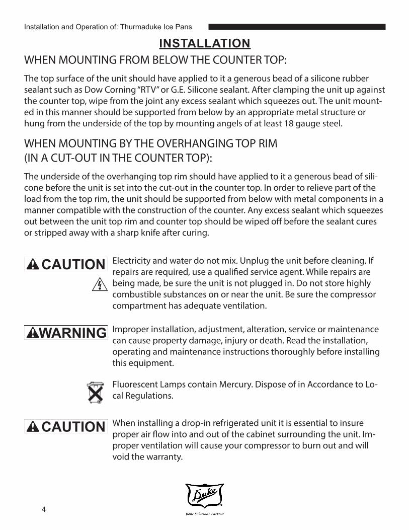
INSTALLATIONWHEN MOUNTING FROM BELOW THE COUNTER TOP:The top surface of the unit should have applied to it a generous bead of a silicone rubber sealant such as Dow Corning “RTV” or G.E. Silicone sealant. After clamping the unit up against the counter top, wipe from the joint any excess sealant which squeezes out. The unit mount-ed in this manner should be supported from below by an appropriate metal structure or hung from the underside of the top by mounting angels of at least 18 gauge steel.
WHEN MOUNTING BY THE OVERHANGING TOP RIM(IN A CUT-OUT IN THE COUNTER TOP):The underside of the overhanging top rim should have applied to it a generous bead of sili-cone before the unit is set into the cut-out in the counter top. In order to relieve part of the load from the top rim, the unit should be supported from below with metal components in a manner compatible with the construction of the counter. Any excess sealant which squeezes out between the unit top rim and counter top should be wiped off before the sealant cures or stripped away with a sharp knife after curing.
Electricity and water do not mix. Unplug the unit before cleaning. If repairs are required, use a qualified service agent. While repairs are being made, be sure the unit is not plugged in. Do not store highly combustible substances on or near the unit. Be sure the compressor compartment has adequate ventilation.
CAUTION
Improper installation, adjustment, alteration, service or maintenance can cause property damage, injury or death. Read the installation, operating and maintenance instructions thoroughly before installing this equipment.
WARNING
Fluorescent Lamps contain Mercury. Dispose of in Accordance to Lo-cal Regulations.
When installing a drop-in refrigerated unit it is essential to insure proper air flow into and out of the cabinet surrounding the unit. Im-proper ventilation will cause your compressor to burn out and will void the warranty.
CAUTION

5
Installation and Operation of: Thurmaduke Ice Pans
INSTALLATION - DROP IN REFRIGERATED
The method shown below will provide proper circulation. Both openings should be 20” x 20”, or 400 sq. in., (100 sq. in min. for 230V), and there should be no wall within 6” (within 2” for 230V) of the compressor housing. A lowered grill, allowing free air flow, may be placed over the intake and/or exhaust opening.
To assure long life of your unit, please insure that the above instructions are followed.
Units are shipped from the factory assembled and require only the necessary electrical and drain connections.
120 Volt Units
Minimum Opening 400Sq. In.
Air IntakeAir Exhaust to
Rear or Bottom
220/230Volt Units
Minimum Opening 100 Sq. In.
Counter Top Cut Out Dimensions
Model Width Length Remote Controlin. cm in. cm in cm
ADI-2MSL-N7 16-3/4 42.3 47-3/4 121.9 H 4-1/8 10.478
ADI-3MSL-N7 16-3/4 42.3 67-1/8 177.8 W 2-3/16 5.56

6
Installation and Operation of: Thurmaduke Ice Pans
INSTALLATION - DROP IN REFRIGERATED - CONT.ELECTRICAL CONNECTIONS:The unit is designed to be operated on one (1) 15 amp dedicated circuit. The unit must be grounded. The receptacle, wired circuit, and protection should meet the required local codes for proper operation. If the supply cord is damaged, it must be replaced by the manufacturer, it’s service agent or an authorized service com-pany in order to avoid a hazard.
DRAIN CONNECTION:The unit is designed to be used with or without a drain hook-up. The drain is sup-plied with a hose attached for use with a drain pan, or may be hooked up to a floor or sink drain. Consult local codes as to the type of drain hook-up required in your area.
CAUTION This equipment is to be installed to comply with applicable Federal, State or Local Plumbing Code.
INSTALLATION - COLD PAN
The cold pan is designed to hold pre-chilled products at suitable serving temperature. It is not designed to chill products or store them for long periods of time. Due to the variety of food products served from the cold pan, they should be stirred periodically to maintain consistent temperature. Foods that are not stirred periodically can become too warm on the top surface and freeze at the bottom.
Prior to use, the unit should be turned on to lower the pan temperature before the chilled product is set in place. The unit should shut down daily for defrosting and cleaning.
CLEANING INSTRUCTIONS - COLD PANCleaning should be done by wiping the cold pan using a mild soap and water solution. Abrasive cleaners should not be used.

7
Installation and Operation of: Thurmaduke Ice Pans
MECHANICALLY ASSISTED ICE PAN - ADJUSTING THERMOSTATIC CONTROLS
(Duke Part# 216528, 226840, 216412 or 216837)
Your mechanical cold pan or salad bar has been preset in the factory to satisfy most appli-cations. Due to conditions which may exist in your operation, you may need to adjust the thermostat on your unit for colder or warmer temperature. The thermostat is located behind the louvered grill in the compressor compartment. Normally, the temperature setting would be about 28°F for mechanical control knob (216528) and about 11°F for digital thermostat (226840) models .
216528 thermostat: the temperature of your unit may be adjusted by turning the gray knob on top of the control. This will, in turn, move the needle on the thermostat dial marked “Cut-in”, which is the temperature indicated on the right hand scale of the control. The “Cut-in” temperature indicates the temperature at which the condensing unit will begin to run and cool the liner.
224840, 216412 or 216837 thermostat: the temperature of your unit may be adjusted by pushing the “up” or “down” arrow keys on the Elreha control. The condensing unit will stop cooling at this temperature.
CAUTION Field adjustment of the “differential” setting must not be made by other than qualified refrigeration service personnel. Unauthorized tampering with the “differential” setting may void the warranty on this equipment.
MECHANICALLY ASSISTED ICE PAN PARTS LIST
PART# DESCRIPTION to be used w.. DUKE EQUIPMENT MODEL212170 Cord 15A, 125V All Units216528 Thermostat
(for condensing unit 216401)All Units, except, 2FT, 3FT, 4FT, 5FT, 6FT
226840 Thermostat (for condensing unit 216824)
All Units, except, 2FT, 3FT, 4FT, 5FT, 6FT
216824 Condensing Unit, M2FL-H023-IAA-140
1M, 2M, 3M, 2MD, 3MD, 315,2MDSL, 3MDSL, 2MSL, 3MSL
216401 Condensing Unit, M2FL-0024-IAA-140
4M, 5M, 6M, 4MD, 5MD, 6MD, 2FT, 3FT, 4FT, 5FT, 6FT, 316,327

8
Installation and Operation of: Thurmaduke Ice Pans
Your mechanical cold pan or salad bar has been preset in the factory to satisfy most applica-tions. Due to conditions which may exist in your operation, you may need to adjust the ther-mostat on your unit for colder or warmer temperature. The thermostat is located behind the louvered grill in the compressor compartment. Normally, the temperature setting would be about 20°F.
The temperature of your unit may be adjusted by turning the gray knob on top of the con-trol. This will, in turn, move the needle on the thermostat dial marked “Cut-in”, which is the temperature indicated on the right hand scale of the control. The “Cut-in” temperature indi-cates the temperature at which the condensing unit will begin to run and cool the liner.
CAUTION Field adjustment of the “differential” setting must not be made by other than qualified refrigeration service personnel. Unauthorized tampering with the “differential” setting may void the warranty on this equipment.
MECHANICALLY ASSISTED ICE PAN ADJUSTING THERMOSTATIC CONTROLS - CONT.
(Duke Part# 216528, 226840, 216412 or 216837)CAP TUBE SIZE BY MODEL
MODEL # CAP TUBE SIZE MODEL # CAP TUBE SIZE MODEL# CAP TUBE SIZE1M .042” x 66” 3MD .042” x 72” 2FT .031” x 60”2M .042” x 66” 4MD .031” x 60” 3FT .031” x 84”3M .042” x 72” 5MD .031” x 69” 4FT .031” x 60”4M .031” x 60” 6MD .042” x 60” 5FT .042” x 60”5M .031” x 69” 2MDSL .042” x 66” 3FT .042” x 60”6M .031” x 69” 3MSL .042” x 72”
2MD .042” x 72” 3MDSL .042” x 72”
STANDARD 7 COLD PANS - ADJUSTING THERMOSTATIC CONTROLS (Duke Part# 216498)

9
Installation and Operation of: Thurmaduke Ice Pans
STANDARD 7 COLD PANS ADJUSTING THERMOSTATIC CONTROLS - CONT
(Duke Part# 216498)
STANDARD 7 COLD PAN PARTS LIST
PART# DESCRIPTION to be used w.. DUKE EQUIPMENT MODEL212170 Cord 15A,125V All Units216498 Thermostat All Units (*Except units ending with –H suffix)216837 Thermostat
(for condensing unit 216879)ADI-4MD-N7-H
216588 Thermostat (for condensing unit 216443)
All 230V Units
216824 Condensing Unit, M2FL-H023-IAA-140
1M-N7, 1MD-N7, 2M-N7, 2MD-N7, 2MSL-N7, 2MDSL-N7
216443 Condensing Unit (230 V UNIT) M2FL-0024-IAZ-340
ADI-1MSL-N7, ADI-1MDSL-N7, ADI-2MSL-N7, ADI-2MDSL-N7, ADI-3MSL-N7, ADI-3MDSL-N7
216401 Condensing Unit, M2FL-0024-IAA-140
3M-N7, 3MD-N7, 3MSL-N7, 3MDSL-N7, 4M-N7, 4MD-N7
216402 Condensing Unit, M2FL-B033-IAA-140
5M-N7, 5MD-N7, 6M-N7, 6MD-N7, 7M-N7, 7MD-N7
216419 Condensing Unit, FTEL-0050-IAA-201
8M-N7, 8MD-N7
216879 Condensing Unit, M4FL-0033-IAA-122
ADI-4MD-N7-H

10
Installation and Operation of: Thurmaduke Ice Pans
If your cold pan model number ends with “-H” it may be supplied with an additional light on the front control panel. This light is an additional safety feature and is used to alert staff that there may be an issue with the performance of the cold pan. If this light ever illu-minates, discontinue use and contact the Duke Service Department right away at 1-800-435-3853
MODELS WITH -H
CAP TUBE SIZE BY MODEL
MODEL # CAP TUBE SIZE MODEL # CAP TUBE SIZE MODEL# CAP TUBE SIZE1M – N7 .050” x 120” 1MD – N7 .050” x 120” 2MSL – N7 .042” x 108”2M – N7 .042” x 108” 2MD – N7 .042” x 108” 2MDSL – N7 .042” x 108”3M – N7 .042” x 120” 3MD – N7 .050” x 120” 3MSL – N7 .050” x 120”4M – N7 .042” x 108” 4MD – N7 .042” x 108” 3MDSL – N7 .050” x 120”5M – N7 .042” x 108” 5MD – N7 .042” x 108” ADI-4MD-N7-H TXV – Sporlan /
Y1001FBS6M – N7 .042” x 108” 6MD – N7 .042” x 108” ADI-1MSL-N7,
ADI-1MDSL-N7, ADI-2MSL-N7,
ADI-2MDSL-N7, ADI-3MSL-N7,
ADI-3MDSL-N7
TXV – EFJ-1/8-C7M – N7 .050” x120” 7MD - N7 .050” x 120”8M – N7 TXV – Sporlan /
EFJ-1/4-Z8MD - N7 TXV – Sporlan /
EFJ-1/4-Z
CAUTION

11
Installation and Operation of: Thurmaduke Ice Pans
*For all models EXCEPT those end-ing with –H suffix
WIRE DIAGRAMS
*Only For models ending with –H suffix
*Wiring Schematic B:

12
Installation and Operation of: Thurmaduke Ice Pans
Notes
Wiring Diagram: Thurmaduke ADI Type Ice Pan 230VAC, 50hz
BRN
BLU
Line Cord
WHT
BLK BLK
WHT
BLK WHT
BLKBLK
RED
WHT
WHT
RED
Switch
Control Panel
Temp Sensor
Compressor
Con
desn
or
Cold Pan
ControlPressure Switch
ELC0158 Rev. B 12/21/2017