User's Guide - MechatroMotive
89
User’s Guide Racing Car Diagnostic Display for Racing Engine Management Systems Technical support MechatroMotive Ltd. Web: www.MechatroMotive.com E-mail: [email protected] Balázs Varga +36 30 476 24 31 Released 28/05/2015
-
Upload
khangminh22 -
Category
Documents
-
view
1 -
download
0
Transcript of User's Guide - MechatroMotive
User’s Guide Racing Car Diagnostic Display for Racing Engine Management Systems
Technical support
MechatroMotive Ltd. Web: www.MechatroMotive.com E-mail: [email protected] Balázs Varga +36 30 476 24 31 Released 28/05/2015

User’s Guide - RCD Display
www.mechatromotive.com 2/89
Table of contents 1. Introduction ................................................................................................................. 4
2. Overview .................................................................................................................... 4
2.1. Main functions ...................................................................................................... 4
2.2. Inputs ................................................................................................................... 4
2.3. Technological parameters .................................................................................... 5
3. Installation and wiring ................................................................................................. 6
3.1. Connectors ........................................................................................................... 8
3.1.1. Main Connector 1 ........................................................................................ 8
3.1.2. Main Connector 2 ........................................................................................ 9
3.1.3. Keyboard Connector ................................................................................. 11
4. Standard features ..................................................................................................... 12
5. Connecting engine management system .................................................................. 16
5.1. DTA .................................................................................................................... 16
5.2. Link .................................................................................................................... 17
5.3. MoTeC ............................................................................................................... 23
5.3.1. MoTeC M800 and other MoTeC ECUs with CRC32 protocol .................... 23
5.3.2. MoTeC M4 ................................................................................................ 33
5.4. Syvecs ............................................................................................................... 40
5.5. Vi-PEC ............................................................................................................... 51
5.5.1. VTS ........................................................................................................... 51
5.5.2. iVTS .......................................................................................................... 58
5.6. VEMS ................................................................................................................. 62
5.7. None .................................................................................................................. 64
6. Connecting sensors .................................................................................................. 65
6.1. Connecting analog sensors ................................................................................ 65
6.1.1. Passive sensors ........................................................................................ 66
6.1.2. NTC .......................................................................................................... 67
6.1.3. PT100-PT1000 .......................................................................................... 67
6.2. Connecting switch sensors ................................................................................. 68
6.3. Connecting impulse type sensors ....................................................................... 68
6.4. Connecting the thermocouples ........................................................................... 68
7. Configuration Options ............................................................................................... 69
7.1. Entering data ...................................................................................................... 69
7.2. Setting the alerts ................................................................................................ 70
7.3. RPM LED bar setting ......................................................................................... 73

User’s Guide - RCD Display
www.mechatromotive.com 3/89
7.4. Brightness setting ............................................................................................... 74
7.5. Analog parameters ............................................................................................. 75
7.6. Defining a calibration equation for analog sensors ............................................. 76
7.7. Others ................................................................................................................ 79
7.7.1. Setting the impulses .................................................................................. 79
7.7.2. Fullscreen warning .................................................................................... 80
7.7.3. ECU type ................................................................................................... 80
7.7.4. Start screen ............................................................................................... 80
7.7.5. DTA gear by shaft ..................................................................................... 80
7.7.6. Load defaults ............................................................................................ 80
8. Firmware update ....................................................................................................... 81
9. Safety regulations ..................................................................................................... 85
10. Figures list ................................................................................................................ 86
11. Tables list ................................................................................................................. 89

User’s Guide - RCD Display
www.mechatromotive.com 4/89
1. Introduction RCD Display is a universal display panel, which can visualize data from sensors attached, and can communicate with the engine controller unit. The RCD Display can communicate with ECUs via CAN buses. Supported types:
DTA o S40 PRO o S60 PRO o S80 PRO o S100 PRO
Link o G4 storm
MoTeC o all ECUs with CRC32 protocol o M4
VEMS
Syvecs
Vi-PEC Vi-PEC o VTS (v10000 or later) o iVTs
2. Overview
2.1. Main functions
Display 5,7" 320 x 240 pixel
Different screens
Programmable RPM LED bar
External control panel
Communicating: CAN, RS232
User defined limits
Flexible sensor calibration
2.2. Inputs
2 pcs “K” typ. thermocouple
6 pcs Analogs 0-15V
5 pcs Digital input (buttons)
4 pcs General digital input

User’s Guide - RCD Display
www.mechatromotive.com 5/89
1 pcs Phototransistor
1 pcs CAN
1 pcs RS232
2.3. Technological parameters
Dimensions: 198 x 130 x 36 mm
Voltage: 10 V - 15 V
Power consumption: 1 A
Size of display: 5,7 ”
Resolution: 320 x 240 pixel
Frequency of freshening: 60 Hz
Color depth of display: 256 bit
Maximal brightness: 800 cd/m2
Contrast Ratio: 800 : 1
Operating temperature range: -20 °C – °60 C

User’s Guide - RCD Display
www.mechatromotive.com 6/89
3. Installation and wiring
Be careful when you install the panel, use vibration resistant self-locking nuts!
When routing the cables, ensure of their integrity, avoid contact with moving parts of the vehicle!
With the supplied pins you can carry out the necessary wiring.
Be sure to connect the connectors at the back of the panel and the wiring harness to the appropriate place!
1. Figure - Main connectors
User’s Guide - RCD Display
www.mechatromotive.com 7/89
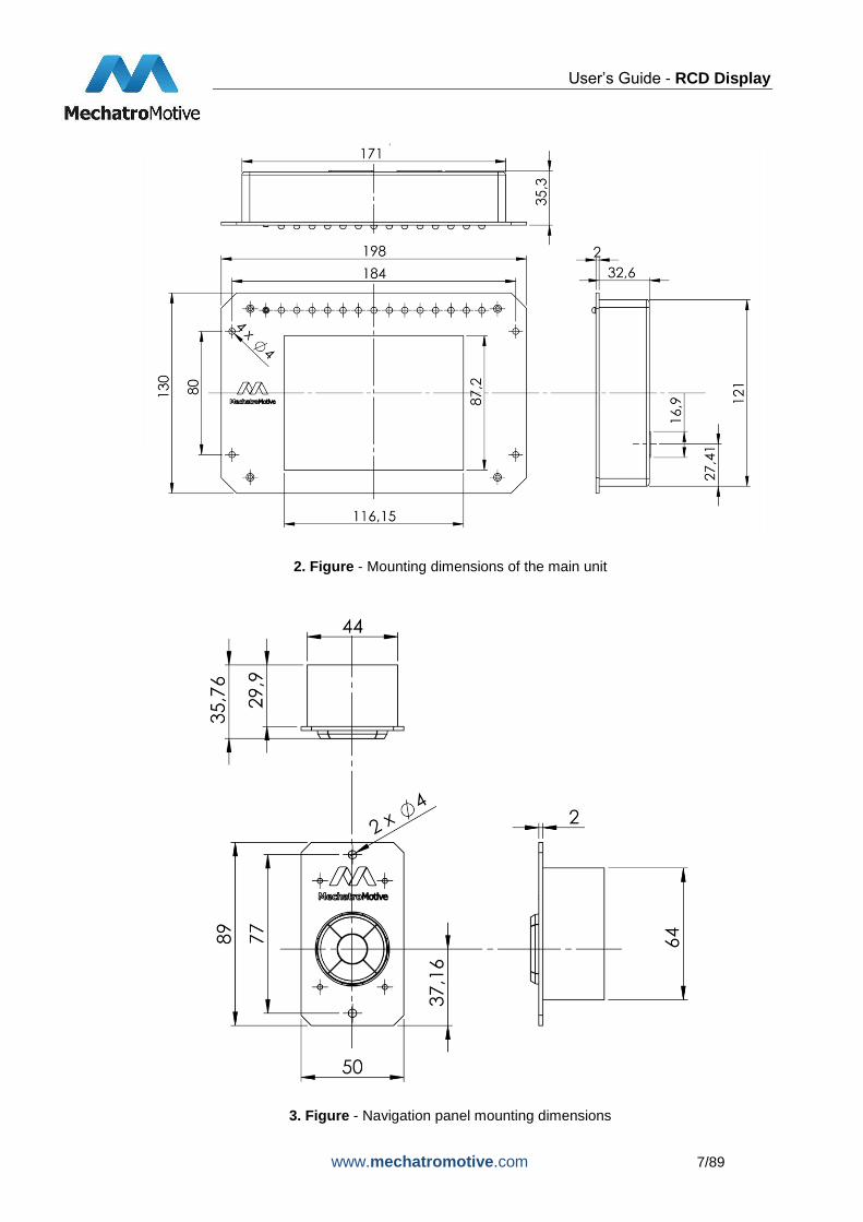
2. Figure - Mounting dimensions of the main unit
3. Figure - Navigation panel mounting dimensions
User’s Guide - RCD Display
www.mechatromotive.com 8/89
3.1. Connectors
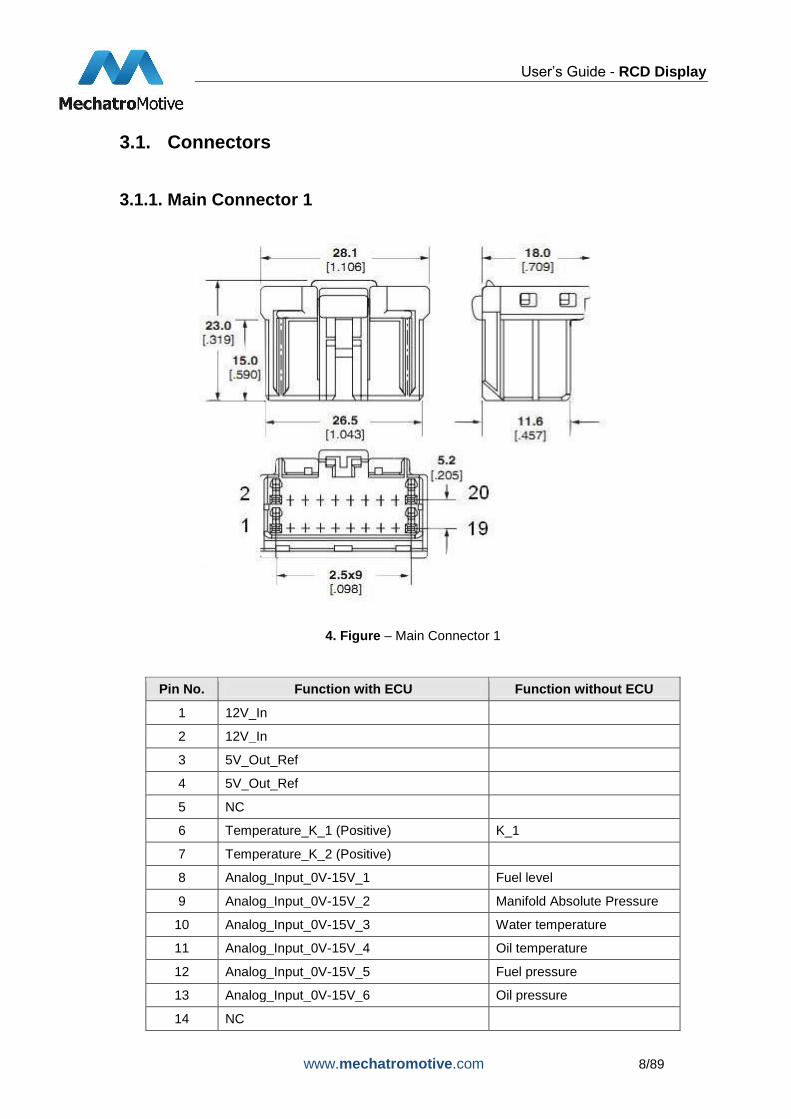
3.1.1. Main Connector 1
4. Figure – Main Connector 1
Pin No. Function with ECU Function without ECU
1 12V_In
2 12V_In
3 5V_Out_Ref
4 5V_Out_Ref
5 NC
6 Temperature_K_1 (Positive) K_1
7 Temperature_K_2 (Positive)
8 Analog_Input_0V-15V_1 Fuel level
9 Analog_Input_0V-15V_2 Manifold Absolute Pressure
10 Analog_Input_0V-15V_3 Water temperature
11 Analog_Input_0V-15V_4 Oil temperature
12 Analog_Input_0V-15V_5 Fuel pressure
13 Analog_Input_0V-15V_6 Oil pressure
14 NC

User’s Guide - RCD Display
www.mechatromotive.com 9/89
15 Analog_GND
16 Analog_GND
17 GND
18 GND
19 CAN_H
20 CAN_L
1. Table - Main Connector 1 pinout
3.1.2. Main Connector 2
5. Figure - Main Connector 2
Pin No. Function Function without ECU
1 12V_In
2 Keyboard_Sw_5
3 Keyboard_Sw_4
4 Keyboard_Sw_3
5 Keyboard_Sw_2
6 Keyboard_Sw_1
7 Impulse_1 Engine rpm
8 Impulse_2 Vehicle speed

User’s Guide - RCD Display
www.mechatromotive.com 10/89
9 Impulse_3
10 RS232_RX
11 RS232_TX
12 Digital_Input_1
13 Digital_Input_2
14 Digital_Input_3
15 Digital_Input_4
16 NC
17 NC
18 NC
19 NC
20 GND
2. Table - Main Connector 2 pinout
The input cables of Pin 2-6 are the cables of the Keyboard Connector. These cables can be colored or numbered, as you can see in the 3.Table- Keyboard Connector pinout.

User’s Guide - RCD Display
www.mechatromotive.com 11/89
3.1.3. Keyboard Connector
Male connector to navigation panel (Micro-Fit Jr.)
6. Figure – Keyboard Connector (Male)
Female connector to the wiring harness side (Micro-Fit Jr.)
7. Figure - Keyboard Connector (Female)
8-wire gray double-insulated round cable. The cables can be colored or numbered.
Pin No. Function Color of the cable Number of the
cable
1 12V+ Red 6
2 GND Gray yellow-green
3 NC White -
4 SW_1 Blue 5
5 SW_2 Yellow 4
6 SW_3 Brown 3
7 SW_4 Green 2
8 SW_5 Pink 1
3. Table - Keyboard Connector pinout

User’s Guide - RCD Display
www.mechatromotive.com 12/89
4. Standard features For handling the display use the external control panel. Using the buttons you can switch between screens, enter data and perform settings.
Menu Structure
MAIN MENU
o RUN
RACE WINDOW
STREET WINDOW
WARM UP WINDOW
DIAG 1 WINDOW
DIAG 2 WINDOW
DIAG 3 WINDOW
o DEMO
RACE WINDOW
STREET WINDOW
WARM UP WINDOW
DIAG 1 WINDOW
DIAG 2 WINDOW
DIAG 3 WINDOW
o SETUP
LOWER LIMITS
UPPER LIMITS
LED RANGES
BRIGHTNESS
ANALOGS
OTHERS

User’s Guide - RCD Display
www.mechatromotive.com 13/89
8. Figure – Main menu
9. Figure – Street window

User’s Guide - RCD Display
www.mechatromotive.com 14/89
10. Figure - Warmup window
11. Figure – Diag 1 window

User’s Guide - RCD Display
www.mechatromotive.com 15/89
12. Figure – Diag window 2 / 3
Displayed parameters depending on the type of the engine management will be shown on 1 or 2 screens.
13. Figure – Race window

User’s Guide - RCD Display
www.mechatromotive.com 16/89
5. Connecting engine management system
5.1. DTA Data from DTA Engine Management System:
Parameter Description Unit
RPM Motor rpm 1/ford
TPS Throttle position sensor %
Water Temp Coolant temperature C
Air Temp Air Temperature C
MAP Intake manifold pressure Kpa
Lambda Lambda x 1000
KPH Vehicle speed x 10 km/h
Oil P Oil pressure Kpa
Fuel P Fuel pressure Kpa
Oil Temp Oil temperature C
Volts Battery voltage x 10 V
Fuel Con. Fuel Consumption (h) L/Hr x 10
Gear Gear -
Advance Deg x 10
Injection Injection time ms x 100
Fuel Con. Fuel Consumption (km) L/100Km x 10
Ana1 Analog Input 1 mV
Ana2 Analog Input 2 mV
Ana3 Analog Input 3 mV
Cam Advance x 10
Cam Targ x 10
Cam PWM x 10
Crank Errors
Cam Errors
4. Table - DTA parameters
The frequency of data, which arrive from motor controlling unit, is the sending frequency.

User’s Guide - RCD Display
www.mechatromotive.com 17/89
5.2. Link In order to operate your motor controller properly with the RDC display, you have to make the following settings in the PCLink G4 software.
14. Figure – PCLink PrintScreen_1
Open ECU Controls menu CAN Configuration. You will see the following screen:

User’s Guide - RCD Display
www.mechatromotive.com 18/89
15. Figure – PCLink PrintScreen_2
Click on Load button. The following screen will open:

User’s Guide - RCD Display
www.mechatromotive.com 19/89
16. Figure – PCLink PrintScreen_3
Choose in your PCLink G4 / CAN library: Generic Dash.lcc and click Open.

User’s Guide - RCD Display
www.mechatromotive.com 20/89
17. Figure – PCLink PrintScreen_4
Here you should set the Data Rate, Transmit Rate. Recommended setting: Data Rate: 1 MBPS Click OK. Data from Link Engine Management System:
Parameter Description Unit Range
Engine Speed Motor rpm RPM 0 - 15000 RPM
MAP Manifold Absolute
Pressure kPa
0 - 650 kPa
MGP Manifold Gauge
Pressure kPa
-100 - 550 kPa
BAP Barometric Pressure kPa 0 - 200 kPa
TP (Main) Throttle Position % 0-100%
Inj Duty Cycle Injection Duty Cycle % 0-100 %

User’s Guide - RCD Display
www.mechatromotive.com 21/89
Inj Duty Cycle (Sec) Injection Duty Cycle % 0 - 100%
Inj Actual PW Injector Pulse Width ms 0 - 65 ms
ECT Engine Temp
Correction °C
-50 - 205 °C
IAT Intake Air
Temperature °C
-20 - 205 °C
Batt Voltage ECU Volts V 0 - 65 V
Mass Air Flow Mass Air Flow L/Hr x 10 0 - 6500 g/s
Gear Gear Position - 0 - 6
Inj Timing Injector Timing deg 0 - 719 deg
Ign Angle Ignition Timing deg -100 - 100 deg
Inlet / LH Posn Cam Inlet Position L deg 0 - 60 deg
Inlet RH Posn Cam Inlet Position R deg 0 - 60 deg
Exh RH Posn Cam Exhaust Position
R deg
-60 - 0 deg
WideBand 1 Lambda Sensor AFR 0 - 65 AFR
WideBand 2 Lambda Sensor AFR 0 - 65 AFR
Trig 1 Err Counter Trig 1 Error Counter - 0 - 255
Fault Codes Fault Codes - 0 - 255
Fuel Pressure Fuel Pressure kPa 0 - 6550 kPa
Oil Temp Oil Temperature °C -50 - 205 °C
Oil Pressure Oil Pressure kPa 0 - 6550 kPa
Speed (DI #1) Speed 1 kph 0 - 1000 kph
Speed (DI #2) Speed 2 kph 0 - 1000 kph
Speed (DI #3) Speed 3 kph 0 - 1000 kph
Speed (DI #4) Speed 4 kph 0 - 1000 kph
Knk Level Cyl 1 Knock Sensor 1 units 0 - 1000 units
Knk Level Cyl 2 Knock Sensor 2 units 0 - 1000 units
Knk Level Cyl 3 Knock Sensor 3 units 0 - 1000 units
Knk Level Cyl 4 Knock Sensor 4 units 0 - 1000 units
Knk Level Cyl 5 Knock Sensor 5 units 0 - 1000 units
Knk Level Cyl 6 Knock Sensor 6 units 0 - 1000 units
Knk Level Cyl 7 Knock Sensor 7 units 0 - 1000 units
Knk Level Cyl 8 Knock Sensor 8 units 0 - 1000 units
Limits Flags Words Limits Flags Words* - 0 - 65536
*See 6. Table 5. Table - Link parameters

User’s Guide - RCD Display
www.mechatromotive.com 22/89
Bit Description
0 RPM Limit
1 MAP Limit
2 Speed Limit
3 Maximum Ignition Flag
4 Anti-lag Ignition Cut
5 High Supply Voltage Limit
6 Overrun Flag
7 Traction Limit
8 Low Supply Voltage Flag
9 Launch RPM Limit
10 Wakeup Flag
11 GP RPM Limit 1
12 CL Stepper Limit
13 GP RPM Limit 2
14 EThrottle Limit
15 Cyclic Idle Active
6. Table - Limits Flags Definition

User’s Guide - RCD Display
www.mechatromotive.com 23/89
5.3. MoTeC
5.3.1. MoTeC M800 and other MoTeC ECUs with CRC32 protocol
In order to operate your motor controller properly with the RDC display, you have to make the following settings in the MoTeC ECU Manager software.
18. Figure – MoTeC ECU Manager PrintScreen_1
Open Adjust General Setup Communications CAN Setup. The following screen will appear:

User’s Guide - RCD Display
www.mechatromotive.com 24/89
19. Figure - MoTeC ECU Manager PrintScreen_2
There you must set three parameters: CAN 0 Data, CAN 0 Address and CAN 0 Transfer Rate.

User’s Guide - RCD Display
www.mechatromotive.com 25/89
20. Figure - MoTeC ECU Manager PrintScreen_3
Set CAN 0 Data to 3, and press OK.

User’s Guide - RCD Display
www.mechatromotive.com 26/89
21. Figure - MoTeC ECU Manager PrintScreen_4
Set CAN 0 Adress to 1520, and press OK.

User’s Guide - RCD Display
www.mechatromotive.com 27/89
22. Figure - MoTeC ECU Manager PrintScreen_5
Set CAN 0 Transfer Rate to 50, and press OK.

User’s Guide - RCD Display
www.mechatromotive.com 28/89
23. Figure - MoTeC ECU Manager PrintScreen_6
After the configuration, select File Send File to Ecu....
Name Value / Scaling
Header 0 $82
Header 1 $81
Header 2 $80
Data Length 1 – 255 Channels (currently 84)
RPM 1RPM
Throttle Position 0.1%
Manifold Pressure 0.1kPa
Air Temperature 0.1C
Engine Temperature 0.1C
Lambda 1 0.001La
Lambda 2 0.001La
Exhaust Manifold Pressure 0.1kPa
Mass Air Flow 0.1*
Fuel Temperature 0.1C
Fuel Pressure 0.1kPa
Oil Temperature 0.1C
Oil Pressure 0.1kPa
Gear Voltage 0.01V

User’s Guide - RCD Display
www.mechatromotive.com 29/89
Knock Voltage 0.01V
Gear Shift Force 0.1kg
Exhaust Temperature 1 1C
Exhaust Temperature 2 1C
User Channel 1 0.1*
User Channel 2 0.1*
User Channel 3 0.1*
User Channel 4 0.1*
Battery Voltage 0.01V
ECU Temperature 0.1C
Digital Input 1 Speed 0.1km/h
Digital Input 2 Speed 0.1km/h
Digital Input 3 Speed 0.1km/h
Digital Input 4 Speed 0.1km/h
Drive Speed 0.1km/h
Ground Speed 0.1km/h
Slip 0.1km/h
Aim Slip 0.1km/h
Launch RPM 1RPM
Lambda 1 short term trim 0.1%
Lambda 2 short term trim 0.1%
Lambda 1 long term trim 0.1%
Lambda 2 long term trim 0.1%
Aim Lambda 1 0.001La
Aim Lambda 2 0.001La
Fuel Cut Level *100/255 = 0.1%
Ignition Cut Level *100/255 = 0.1%
Ignition Advance 0.1dBTDC
Load Point 0.1
Efficiency Point 0.1
Fuel Used 1*
Auxiliary O/P 1 Duty Cycle 1%
Auxiliary O/P 2 Duty Cycle 1%
Auxiliary O/P 3 Duty Cycle 1%
Auxiliary O/P 4 Duty Cycle 1%
Auxiliary O/P 5 Duty Cycle 1%
Auxiliary O/P 6 Duty Cycle 1%
Auxiliary O/P 7 Duty Cycle 1%
Auxiliary O/P 8 Duty Cycle 1%
Fuel Actual Pulse Width 0.5 µs
Fuel Effective Pulse Width 0.5 µs
Fuel Injector Duty Cycle 0.1%
Gear /10 = gear
Sync Position 0.1%

User’s Guide - RCD Display
www.mechatromotive.com 30/89
Fuel Comp 1 0.1%
Fuel Comp 2 0.1%
Diagnostic Error Group 1 TP_ERR 1
MAP_ERR 2
AT_ERR 4
ET_ERR 8
LA1_ERR 16
LA2_ERR 32
EMAP_ERR 64
MAF_ERR 128
Diagnostic Error Group 2 BARO_ERR 1
FT_ERR 2
FP_ERR 4
OT_ERR 8
OP_ERR 16
LAT_G_ERR 32
LONG_G_ERR 64
SLIP_V_ERR 128
Diagnostic Error Group 3 GEAR_V_ERR 1
KNOCK_ERR 2
EGT1_ERR 4
EGT2_ERR 8
USER1_ERR 16
USER2_ERR 32
USER3_ERR 64
USER4_ERR 128
Diagnostic Error Group 4 BATV_ERR 1
ECUT_ERR 2
VERT_G_ERR 4
GEAR_FORCE_ERR 8
DBW_CONT 16
DBW_ERR 32
DBW_AIM 64
DBW_FB 128
Diagnostic Error Group 5 -
Diagnostic Error Group 6 LOW_BAT_ERR 1
OVER_BOOST_ERR 2
NO_SYNC_ERR 4
SYNC_ERR 8
NO_REF_ERR 16
REF_ERR 32
RPM_OVER_ERR 64

User’s Guide - RCD Display
www.mechatromotive.com 31/89
F_MAX_DTY_ERR 128
Diagnostic Error Group 7 MEM_ERR 1
DELTA_BAT 2
LA1_HEATER_ERR 4
LA2_HEATER_ERR 8
LA1_OT 16
LA2_OT 32
LA1_SENS_ERR 64
LA2_SENS_ERR 128
Diagnostic Error Group 8 -
Diagnostic Error Group 9 RESET_TESTMOD 1
RESET_SYS 2
RESET_NOXTAL 4
- 8
RESET_HALTMON 16
- 32
- 64
RESET_EXT 128
Diagnostic Error Group 10 INJ1_ERR 1
INJ2_ERR 2
INJ3_ERR 4
INJ4_ERR 8
INJ5_ERR 16
INJ6_ERR 32
INJ7_ERR 64
INJ8_ERR 128
Diagnostic Error Group 11 INJ1_SHORT 1
INJ2_SHORT 2
INJ3_SHORT 4
INJ4_SHORT 8
INJ5_SHORT 16
INJ6_SHORT 32
INJ7_SHORT 64
INJ8_SHORT 128
Diagnostic Error Group 12 INJ1_OPEN 1
INJ2_OPEN 2
INJ3_OPEN 4
INJ4_OPEN 8
INJ5_OPEN 16
INJ6_OPEN 32
INJ7_OPEN 64
INJ8_OPEN 128
Diagnostic Error Group 13 INJ1_PEAK 1
User’s Guide - RCD Display
www.mechatromotive.com 32/89
INJ2_PEAK 2
INJ3_PEAK 4
INJ4_PEAK 8
INJ5_PEAK 16
INJ6_PEAK 32
INJ7_PEAK 64
INJ8_PEAK 128
Diagnostic Error Group 14 SYNC_LOW 1
SYNC_RNT 2
SYNC_TRIG 4
SYNC_ARM 8
REF_LOW 16
REF_RNT 32
REF_TRIG 64
REF_ARM 128
Diagnostic Error Group 15 -
Diagnostic Error Group 16 -
Status Flags Group 1 RPM Limit Exceeded 1
Launch Control 2
Gear Change Ign Cut 4
REF/SYNC Synched 8
Closed Loop La 2 16
Closed Loop La 1 32
Lambda 2 Cold 64
Lambda 1 Cold 128
Status Flags Group 2 Overrun Boost 1
Alternator Off 2
Overrun Fuel Cut 4
- 8
- 16
- 32
- 64
- 128
Status Flags Group 3 Digital Input 1 1
Digital Input 2 2
Digital Input 3 4
Digital Input 4 8
- 16
Nitrous 32
User’s Guide - RCD Display
www.mechatromotive.com 33/89
Air Con Request 64
Dual RPM Limit 128
Status Flags Group 4 Traction Ctrl Disable 1
Clutch 2
Logging Enable 4
Beacon Mark 8
Overrun Boost
Enable 16
Gear Chg Cut
Request 32
Ignition Switch 64
Brake 128
Status Flags Group 5 - 1
- 2
Spray Bar 4
- 8
- 16
Telemetry Control 32
Power Steer OvLd 64
Ground Speed Limit 128
Status Flags Group 6 -
Status Flags Group 7 Digital Input 5 1
Digital Input 6 2
Digital Input 7 4
Digital Input 8 8
Digital Input 9 16
Digital Input 10 32
- 64
- 128
Status Flags Group 8 -
CRC byte 1 (HI Byte)
CRC byte 2
CRC byte 3
CRC byte 4 (LO Byte)
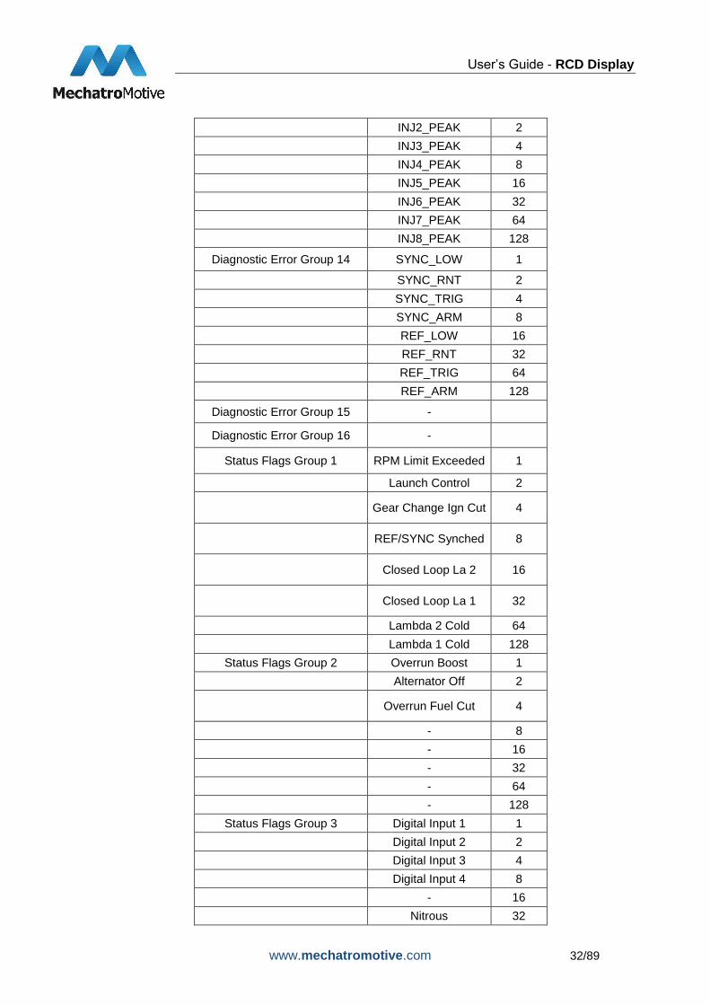
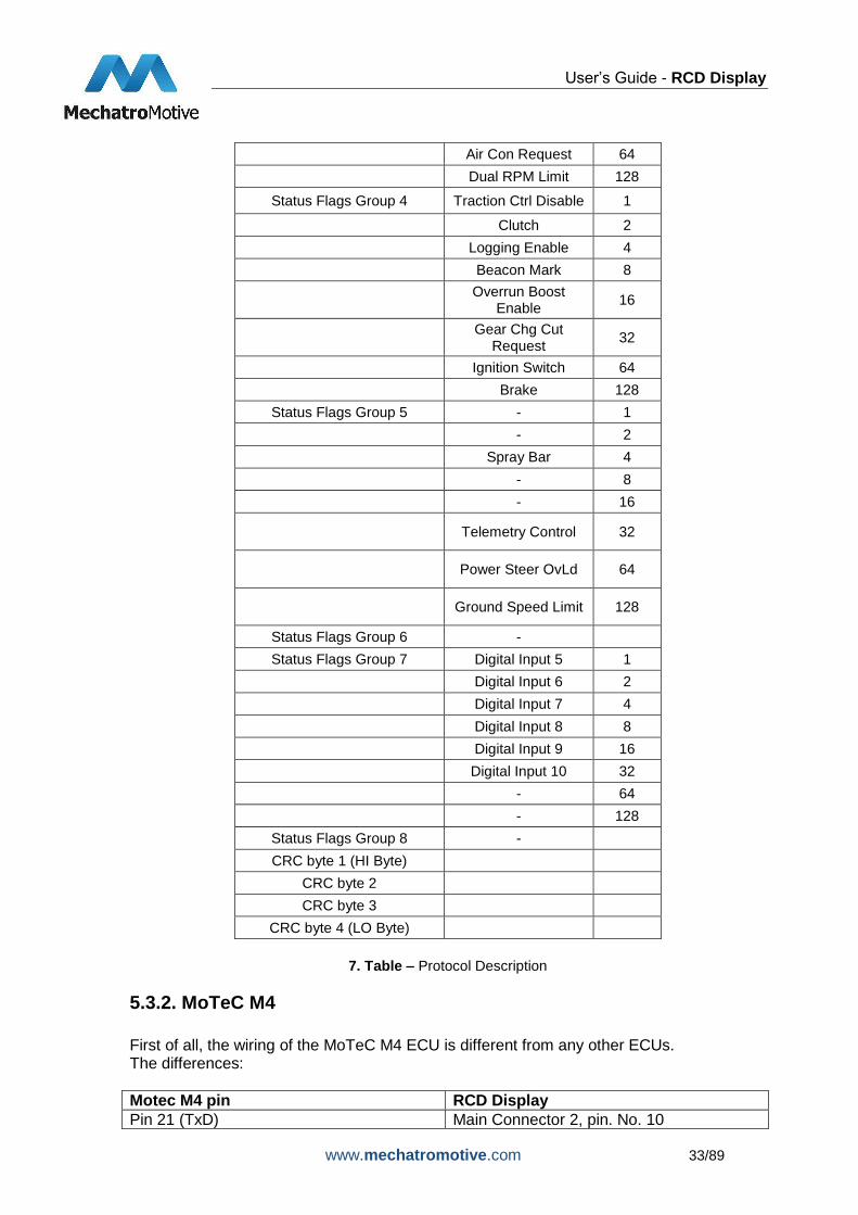
7. Table – Protocol Description
5.3.2. MoTeC M4
First of all, the wiring of the MoTeC M4 ECU is different from any other ECUs. The differences:
Motec M4 pin RCD Display
Pin 21 (TxD) Main Connector 2, pin. No. 10

User’s Guide - RCD Display
www.mechatromotive.com 34/89
Pin 22 (RxD) Main Connector 2, pin. No. 11
Pin 23 (DTR) Main Connector 2, pin. No. 12
Connection of the other wires are the same as they are listed in the 4.1. Connectors chapter. In order to operate your motor controller properly with the RDC display, you have to make the following settings in the MoTeC ECU Manager software:
24. Figure – MoTeC M4 PrintScreen_1
As a first step, you shoul choose your MoTeC M4 version.
25. Figure - MoTeC M4 PrintScreen_2
Now select the program EMP.

User’s Guide - RCD Display
www.mechatromotive.com 35/89
26. Figure - MoTeC M4 PrintScreen_3
Click on Adjust.
27. Figure - MoTeC M4 PrintScreen_4
If you connect the ECU to the computer for the first type, select the Create New File option. Next time when you connect your ECU, it will find this file on your computer.
User’s Guide - RCD Display
www.mechatromotive.com 36/89
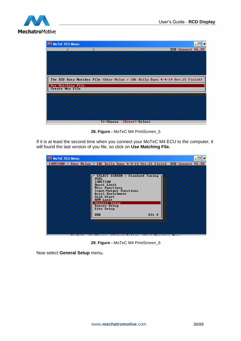
28. Figure - MoTeC M4 PrintScreen_5
If it is at least the second time when you connect your MoTeC M4 ECU to the computer, it will found the last version of you file, so click on Use Matching File.
29. Figure - MoTeC M4 PrintScreen_6
Now select General Setup menu.

User’s Guide - RCD Display
www.mechatromotive.com 37/89
30. Figure - MoTeC M4 PrintScreen_7
In the General Setup menu, select Miscellaneous Setup 2.
31. Figure - MoTeC M4 PrintScreen_8
In Miscellaneous Setup 2, you should only change the value of Telemetry Data Set. Set it to 5. You should also set the Telemetry Baud Rate in this menu. The value of the baud rate should be 19200.
Name Value / Scaling
RPM 1RPM
Throttle Position 1%
Manifold Pressure 1kPa
Air Temperature 1C
Engine Temperature 1C
Lambda 1 0.01La

User’s Guide - RCD Display
www.mechatromotive.com 38/89
Aux Temperature 0,1*
Aux Voltage 0,1*
Battery Voltage 0.1V
ECU Temperature 0.1C
Barometric Pressure 0,1kPa
Digital Input 1 Speed 0.1km/h
Digital Input 2 Speed 0.1km/h
Ground Speed 0.1km/h
Drive Speed 0.1km/h
Slip 0.1km/h
Gear /10 = gear
Load Point 0.1
Efficiency Point 0.1
Efficiency 2 Point 0.1
Fuel Used 0.01L
Auxiliary O/P 1 Duty Cycle 0,1%
Auxiliary O/P 2 Duty Cycle 0,1%
Auxiliary O/P 3 Duty Cycle 0,1%
Auxiliary O/P 4 Duty Cycle 0,1%
Lambda short term trim 0.1%
Lambda long term trim 0.1%
Fuel Actual Pulse Width 1 µs
Fuel Effective Pulse Width 1 µs
Fuel Injector Duty Cycle 0.1%
Fuel Acceleration Enrichment 1 µs
Ignition Cut Level 0.1%
Fuel Cut Level 0.1%
Diagnostic Error Group 1 TP_ERR 1
MAP_ERR 2
AT_ERR 4
ET_ERR 8
BAT_ERR 16
LA_ERR 32
AUXV_ERR 64
AUXT_ERR 128
Ignition Advance 0,1 dBTDC
Sync position 1%
Fuel Aux Temp Comp 0,1%
Fuel Aux Volt Comp 0,1%
8. Table - Protocol Description of MoTeC M4 ECU
Diagnostic Error Group2 ECUT_ERR 1
DELTA_BAT 2

User’s Guide - RCD Display
www.mechatromotive.com 39/89
- 4
- 8
- 16
- 32
AUXV_DP 64
AUXT_DP 128
Diagnostic Error Group 3 INJ1_ERR 1
INJ2_ERR 2
INJ3_ERR 4
INJ4_ERR 8
- 16
- 32
- 64
- 128
Diagnostic Error Group 4 LOW_BAT_ERR 1
OVER_BOOST_ERR 2
NO_SYNC_ERR 4
SYNC_ERR 8
NO_REF_ERR 16
REF_ERR 32
RPM_OVER_ERR 64
F_MAX_DTY_ERR 128
Diagnostic Error Group 5 MEMORY_ERR 1
IN_GEAR_ERR 2
INJ_SPRAY_ERR 4
SPD1_DEC_ERR 8
SPD2_DEC_ERR 16
BRAKE 32
DIG_IN1 64
DIG_IN2 128
9. Table - Protocol Description of MoTeC M4 ECU – Diagnostic Error Groups
User’s Guide - RCD Display
www.mechatromotive.com 40/89
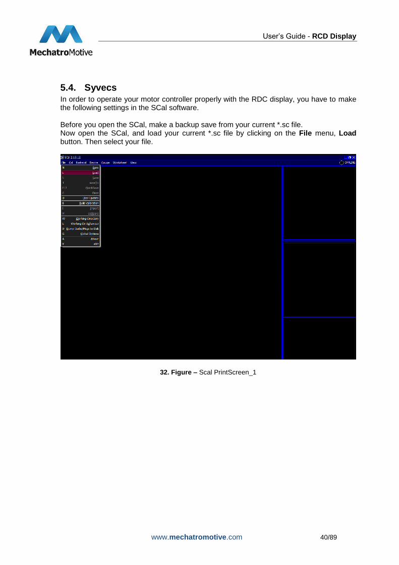
5.4. Syvecs In order to operate your motor controller properly with the RDC display, you have to make the following settings in the SCal software. Before you open the SCal, make a backup save from your current *.sc file. Now open the SCal, and load your current *.sc file by clicking on the File menu, Load button. Then select your file.
32. Figure – Scal PrintScreen_1

User’s Guide - RCD Display
www.mechatromotive.com 41/89
33. Figure - Scal PrintScreen_2
Download the Mechatromotive_RCD.sc file from our webpage. You can find it by clicking on the following buttons: Products -> RCD Display -> Downloads. Now open the file in a new window with the Scal and in the pop-up window, choose GENERIC option. Don’t close the other *.sc file!
34. Figure - Scal PrintScreen_3
Some of the pictures will contain two windows. The left one is your current *.sc file, the right one is the Mechatromotive_RCD.sc file. In the Calibration menu of your current *.sc file, click on Datastreams and inside this on Datastream Select.

User’s Guide - RCD Display
www.mechatromotive.com 42/89
35. Figure - Scal PrintScreen_4
In the Datasream Select window, push the 0 button, then the following window will come up:
36. Figure - Scal PrintScreen_5

User’s Guide - RCD Display
www.mechatromotive.com 43/89
37. Figure - Scal PrintScreen_6
Select the Custom CAN, and click on the OK button. Now you have to copy the values of Frame Identifier, Frame Frequency and Frame Content from the Mechatromotive_RCD.sc file to your current *.sc file. For this, select Datastreams Custom CAN Frame Content – f(Slot,Frame) in both window.
38. Figure - Scal PrintScreen_7

User’s Guide - RCD Display
www.mechatromotive.com 44/89
39. Figure - Scal PrintScreen_8
Now in the Mechatromotive_RCD.sc window click on Select All.
40. Figure - Scal PrintScreen_9
41. Figure - Scal PrintScreen_10
Now select Edit Copy, still in the the Mechatromotive_RCD.sc window.

User’s Guide - RCD Display
www.mechatromotive.com 45/89
42. Figure - Scal PrintScreen_11
43. Figure - Scal PrintScreen_12
Now go to your current *.sc file. Click on Select All.
44. Figure - Scal PrintScreen_13

User’s Guide - RCD Display
www.mechatromotive.com 46/89
45. Figure - Scal PrintScreen_14
Click on Edit Paste, still in your current *.sc file’s window.
46. Figure - Scal PrintScreen_15
47. Figure - Scal PrintScreen_16
Now repeat the movements with the other parameters. Select Calibration Datastreams Custom CAN Frame Frequency f(Frame).
48. Figure - Scal PrintScreen_17
Now in the Mechatromotive_RCD.sc window click on Select All.

User’s Guide - RCD Display
www.mechatromotive.com 47/89
49. Figure - Scal PrintScreen_18
Now select Edit Copy, still in the the Mechatromotive_RCD.sc window.
50. Figure - Scal PrintScreen_19
Now go to your current *.sc file. Click on Select All.
51. Figure - Scal PrintScreen_20
Click on Edit Paste, still in your current *.sc file’s window.

User’s Guide - RCD Display
www.mechatromotive.com 48/89
52. Figure - Scal PrintScreen_21
Select Calibration Datastreams Custom CAN Frame Identifier f(Frame).
53. Figure - Scal PrintScreen_22
Now in the Mechatromotive_RCD.sc window click on Select All.
54. Figure - Scal PrintScreen_23
Now select Edit Copy, still in the the Mechatromotive_RCD.sc window.

User’s Guide - RCD Display
www.mechatromotive.com 49/89
55. Figure - Scal PrintScreen_24
Now go to your current *.sc file. Click on Select All.
56. Figure - Scal PrintScreen_25
Click on Edit Paste, still in your current *.sc file’s window.
57. Figure - Scal PrintScreen_26
Now you can close the Mechatromotive_RCD.sc, and save your current *.sc file.

User’s Guide - RCD Display
www.mechatromotive.com 50/89
Parameter Description Unit Range
Engine Speed Motor rpm RPM 0 - 10000
RPM
TPS1 Throttle Position 1 % 0-100%
VBAT Battery Voltage V 5 - 15 V
MAP1 Manifold Absolute Pressure 1 kPa 0 -300 kPa
ECT1 Engine Coolant Temp 1 °C -25 - 125 °C
AIT1 Air Intake Temperature 1 °C -25 - 100 °C
EGT1 Exhaust Gas Temperature 1 °C 0 - 1250 °C
EGT2 Exhaust Gas Temperature 2 °C 0 - 1250 °C
LAM1 Lambda Sensor 1 La 0,5 - 1,5 La
LAM2 Lambda Sensor 2 La 0,5 - 1,5 La
FP1 Fuel Pressure 1 kPa 0 - 1000 kPa
FT1 Fuel Temperature 1 °C -25- 125 °C
EOP1 Engine Oil Pressure 1 kPa 0 - 1000 kPa
EOT Engine Oil Temperature °C -25 - 150 °C
Gear Gear Position - 0 - 10
fuelDutyPri1 Injection Duty Cycle % 0-100 %
fuelComp Fuel Comp % 0-100 %
Driven wheel speed
Driven wheel speed kph 0 - 300 kph
Vehicle speed Vehicle speed kph 0 - 300 kph
CCP1 Crank Case Pressure 1 kPa 0 - 110 kPa
ACT1 Air Charge Temperature 1 °C -25 - 100 °C
BaP Barometric Pressure kPa 70 - 110 kPa
IgnFinalPri1 Final Ignition Timing after corrections deg -10 - 50 deg
wheelSpin Ammount of Wheelspin detected by Traction
control % 0 - 100%
10. Table - Protocol Description
User’s Guide - RCD Display
www.mechatromotive.com 51/89
5.5. Vi-PEC
5.5.1. VTS
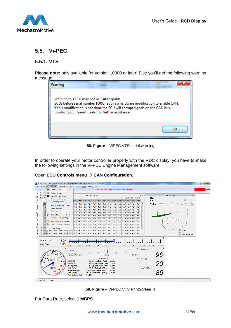
Please note: only available for version 10000 or later! Else you’ll get the following warning message:
58. Figure – ViPEC VTS serial warning
In order to operate your motor controller properly with the RDC display, you have to make the following settings in the Vi-PEC Engine Management software.
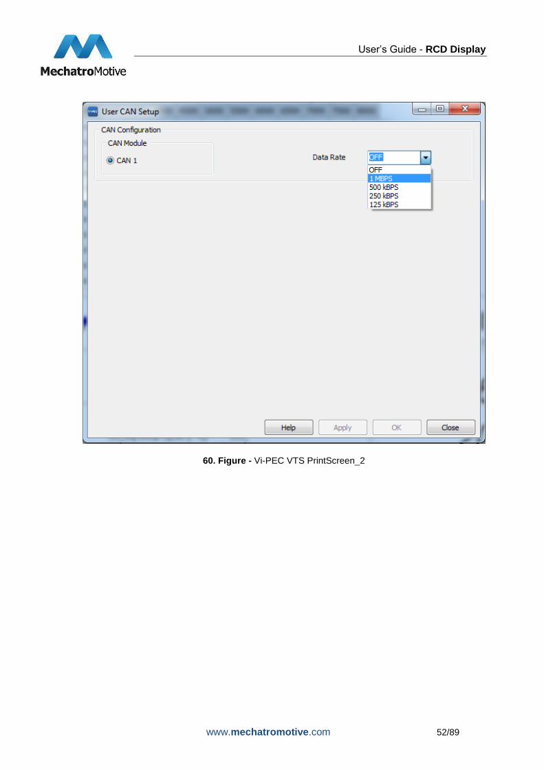
Open ECU Controls menu CAN Configuration.
59. Figure – Vi-PEC VTS PrintScreen_1
For Dara Rate, select 1 MBPS.
User’s Guide - RCD Display
www.mechatromotive.com 52/89
60. Figure - Vi-PEC VTS PrintScreen_2

User’s Guide - RCD Display
www.mechatromotive.com 53/89
61. Figure - Vi-PEC VTS PrintScreen_3
Click on Load button. The following screen will come up:
User’s Guide - RCD Display
www.mechatromotive.com 54/89
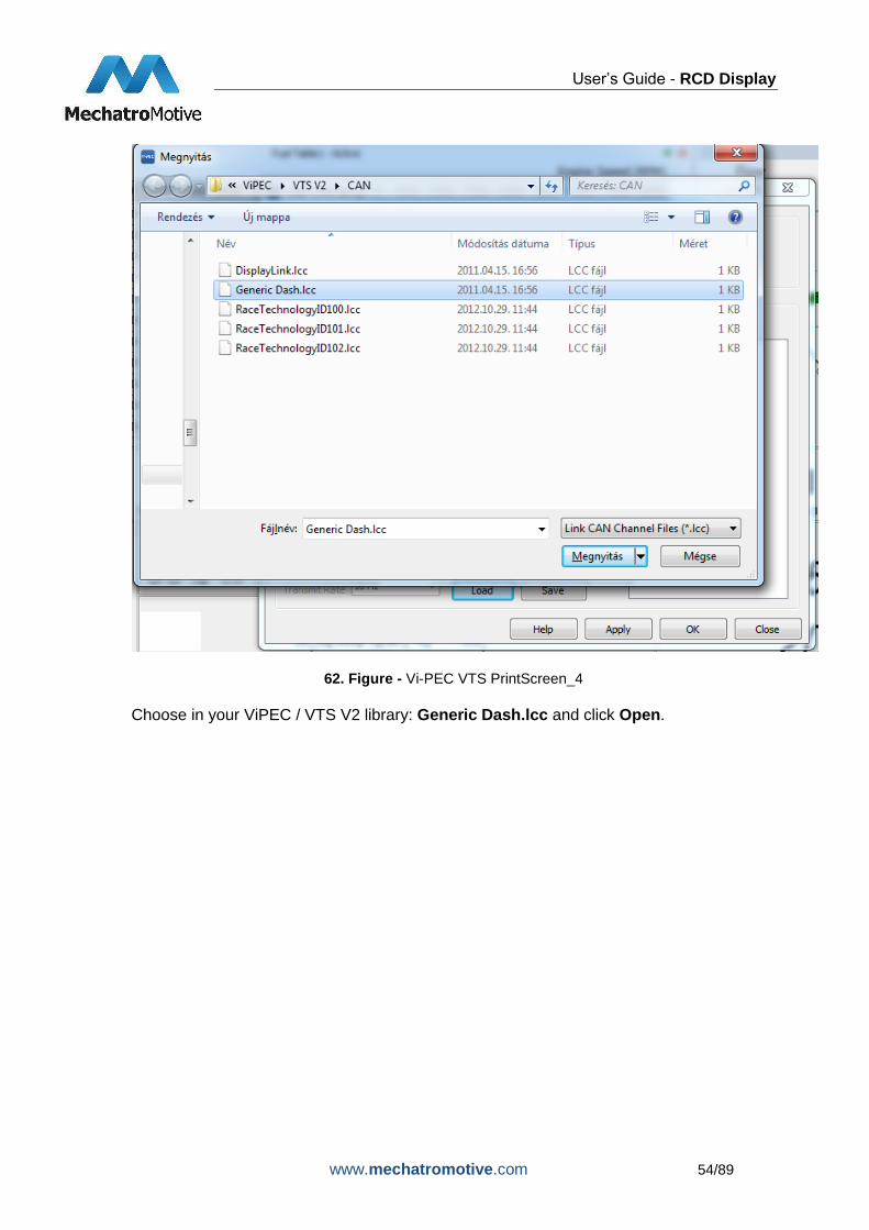
62. Figure - Vi-PEC VTS PrintScreen_4
Choose in your ViPEC / VTS V2 library: Generic Dash.lcc and click Open.

User’s Guide - RCD Display
www.mechatromotive.com 55/89
63. Figure - Vi-PEC VTS PrintScreen_5
Here you should set/check the CAN ID, Data Direction, Transmit Format and Transmit Rate. Recommended settings: CAN ID: 1000 Data Direction: ECU Transmit Transmit Format: Compound Transmit Rate: 10Hz. Click OK. Data from Vi-PEC VTS Engine Management System:
Parameter Description Unit Range
Engine Speed Motor rpm RPM 0 - 15000 RPM
MAP Manifold Absolute
Pressure kPa
0 - 650 kPa
MGP Manifold Gauge
Pressure kPa
-100 - 550 kPa
BAP Barometric Pressure kPa 0 - 200 kPa

User’s Guide - RCD Display
www.mechatromotive.com 56/89
TP (Main) Throttle Position % 0-100%
Inj Duty Cycle Injection Duty Cycle % 0-100 %
Inj Duty Cycle (Sec) Injection Duty Cycle % 0 - 100%
Inj Actual PW Injector Pulse Width ms 0 - 65 ms
ECT Engine Temp
Correction °C
-50 - 205 °C
IAT Intake Air
Temperature °C
-20 - 205 °C
Batt Voltage ECU Volts V 0 - 65 V
Mass Air Flow Mass Air Flow L/Hr x 10 0 - 6500 g/s
Gear Gear Position - 0 - 6
Inj Timing Injector Timing deg 0 - 719 deg
Ign Angle Ignition Timing deg -100 - 100 deg
Inlet / LH Posn Cam Inlet Position L deg 0 - 60 deg
Inlet RH Posn Cam Inlet Position R deg 0 - 60 deg
Exh RH Posn Cam Exhaust Position
R deg
-60 - 0 deg
WideBand 1 Lambda Sensor AFR 0 - 65 AFR
WideBand 2 Lambda Sensor AFR 0 - 65 AFR
Trig 1 Err Counter Trig 1 Error Counter - 0 - 255
Fault Codes Fault Codes - 0 - 255
Fuel Pressure Fuel Pressure kPa 0 - 6550 kPa
Oil Temp Oil Temperature °C -50 - 205 °C
Oil Pressure Oil Pressure kPa 0 - 6550 kPa
Speed (DI #1) Speed 1 kph 0 - 1000 kph
Speed (DI #2) Speed 2 kph 0 - 1000 kph
Speed (DI #3) Speed 3 kph 0 - 1000 kph
Speed (DI #4) Speed 4 kph 0 - 1000 kph
Knk Level Cyl 1 Knock Sensor 1 units 0 - 1000 units
Knk Level Cyl 2 Knock Sensor 2 units 0 - 1000 units
Knk Level Cyl 3 Knock Sensor 3 units 0 - 1000 units
Knk Level Cyl 4 Knock Sensor 4 units 0 - 1000 units
Knk Level Cyl 5 Knock Sensor 5 units 0 - 1000 units
Knk Level Cyl 6 Knock Sensor 6 units 0 - 1000 units
Knk Level Cyl 7 Knock Sensor 7 units 0 - 1000 units
Knk Level Cyl 8 Knock Sensor 8 units 0 - 1000 units
Limits Flags Words Limits Flags Words* - 0 - 65536

User’s Guide - RCD Display
www.mechatromotive.com 57/89
*See 10. Table 11. Table – Protocol description
Bit Description
0 RPM Limit
1 MAP Limit
2 Speed Limit
3 Maximum Ignition Flag
4 Anti-lag Ignition Cut
5 High Supply Voltage Limit
6 Overrun Flag
7 Traction Limit
8 Low Supply Voltage Flag
9 Launch RPM Limit
10 Wakeup Flag
11 GP RPM Limit 1
12 CL Stepper Limit
13 GP RPM Limit 2
14 EThrottle Limit
15 Cyclic Idle Active
12. Table- Limits Flag Definition

User’s Guide - RCD Display
www.mechatromotive.com 58/89
5.5.2. iVTS
In order to operate your motor controller properly with the RDC display, you have to make the following settings in the Vi-PEC Engine Management System software.
64. Figure – Vi-PEC iVTS PrintScreen_1
Open ECU Controls menu CAN Setup. You will see the following screen:

User’s Guide - RCD Display
www.mechatromotive.com 59/89
65. Figure - Vi-PEC iVTS PrintScreen_2
In the Mode menu, select User Defined. Now click on Channel 1.
66. Figure - Vi-PEC iVTS PrintScreen_3

User’s Guide - RCD Display
www.mechatromotive.com 60/89
In the Mode menu, select Transmit Generic Dash.
67. Figure - Vi-PEC iVTS PrintScreen_4
Data from Link Engine Management System:
Parameter Description Unit Range
Engine Speed Motor rpm RPM 0 - 15000 RPM
MAP Manifold Absolute
Pressure kPa
0 - 650 kPa
MGP Manifold Gauge
Pressure kPa
-100 - 550 kPa
BAP Barometric Pressure kPa 0 - 200 kPa
TP (Main) Throttle Position % 0-100%
Inj Duty Cycle Injection Duty Cycle % 0-100 %
Inj Duty Cycle (Sec) Injection Duty Cycle % 0 - 100%
Inj Actual PW Injector Pulse Width ms 0 - 65 ms
ECT Engine Temp
Correction °C
-50 - 205 °C
IAT Intake Air
Temperature °C
-20 - 205 °C
Batt Voltage ECU Volts V 0 - 65 V
Mass Air Flow Mass Air Flow L/Hr x 10 0 - 6500 g/s
Gear Gear Position - 0 - 6

User’s Guide - RCD Display
www.mechatromotive.com 61/89
Inj Timing Injector Timing deg 0 - 719 deg
Ign Angle Ignition Timing deg -100 - 100 deg
Inlet / LH Posn Cam Inlet Position L deg 0 - 60 deg
Inlet RH Posn Cam Inlet Position R deg 0 - 60 deg
Exh RH Posn Cam Exhaust Position
R deg
-60 - 0 deg
WideBand 1 Lambda Sensor AFR 0 - 65 AFR
WideBand 2 Lambda Sensor AFR 0 - 65 AFR
Trig 1 Err Counter Trig 1 Error Counter - 0 - 255
Fault Codes Fault Codes - 0 - 255
Fuel Pressure Fuel Pressure kPa 0 - 6550 kPa
Oil Temp Oil Temperature °C -50 - 205 °C
Oil Pressure Oil Pressure kPa 0 - 6550 kPa
Speed (DI #1) Speed 1 kph 0 - 1000 kph
Speed (DI #2) Speed 2 kph 0 - 1000 kph
Speed (DI #3) Speed 3 kph 0 - 1000 kph
Speed (DI #4) Speed 4 kph 0 - 1000 kph
Knk Level Cyl 1 Knock Sensor 1 units 0 - 1000 units
Knk Level Cyl 2 Knock Sensor 2 units 0 - 1000 units
Knk Level Cyl 3 Knock Sensor 3 units 0 - 1000 units
Knk Level Cyl 4 Knock Sensor 4 units 0 - 1000 units
Knk Level Cyl 5 Knock Sensor 5 units 0 - 1000 units
Knk Level Cyl 6 Knock Sensor 6 units 0 - 1000 units
Knk Level Cyl 7 Knock Sensor 7 units 0 - 1000 units
Knk Level Cyl 8 Knock Sensor 8 units 0 - 1000 units
Limits Flags Words Limits Flags Words* - 0 - 65536
*See 12. Table 13. Table – Protocol Description
Bit Description
0 RPM Limit
1 MAP Limit
2 Speed Limit
3 Maximum Ignition Flag
4 Anti-lag Ignition Cut
5 High Supply Voltage Limit
6 Overrun Flag

User’s Guide - RCD Display
www.mechatromotive.com 62/89
7 Traction Limit
8 Low Supply Voltage Flag
9 Launch RPM Limit
10 Wakeup Flag
11 GP RPM Limit 1
12 CL Stepper Limit
13 GP RPM Limit 2
14 EThrottle Limit
15 Cyclic Idle Active
14. Table – Limits Flag Definition
5.6. VEMS In order to operate your motor controller properly with the RDC display, you have to make the following settings in the VemsTune software:
68. Figure - VEMS PrintScreen_1
Select Outputs Display Settings menu.

User’s Guide - RCD Display
www.mechatromotive.com 63/89
69. Figure - VEMS PrintScreen_2
In this menu, set AIM Enable to Enabled.
Signal Channel # Frequency [Hz] Transfor
m Units
RPM 1 10 y=x RPM
Wheel speed 5 10 y=x/10 km/h
Oil pressure 9 5 y=x/1000 bar
Oil temperature 13 2 y=x/10-
100 °C
Water temperature
17 2 y=x/10-
100 °C
Fuel pressure 21 5 y=x/1000 bar
Battery voltage 33 5 y=x/100 Volts
Throttle angle 45 10 y=x/10 °
Manifold press 69 10 y=x mbar
Air charge temperature
97 2 y=x/10-
100 °C
Exhaust temperature
101 2 y=x/10-
100 °C
Lambda sensor 105 10 y=x/1000 Lambda
Fuel temp 109 2 y=x/10-
100 °C
Gear 113 5 y=x 0=rev, 1=neutral, 2=first,
3=second, etc.
Errors 125 2 - ECU-specific error flags

User’s Guide - RCD Display
www.mechatromotive.com 64/89
15. Table - Protocol Description of VEMS ECU
5.7. None If you choose this option, the RCD Display shows the value of the connected sensors on the screens, and it’s not searching for a connected ECU. You can find the connection points in “Function without ECU” column of the tables in the following sections: 4.1.1 Main Connector 1 and 4.1.2 Main Connector 2.

User’s Guide - RCD Display
www.mechatromotive.com 65/89
6. Connecting sensors
6.1. Connecting analog sensors The active sensor’s output voltage are proportional to the measured physical parameter, typically 0 – 5 V or 0 - 10 V.
Connect the GDN pin of the sensor to the „Analog_GND“ , named „Main Connector 1“ connector.
Connect the VDD pin of the sensor to the „5V_Out_Ref“ or „12V_In“ pin of the „Main Connector 1“ connector.
Connect the OUT pin of the sensor to „Main Connector 1“ „Analog_Input_0V-15V_X“ pin.
Do the sensor calibration! If you need help, go to the following page: http://www.mechatromotive.com/pullup.php, where you can write your values into the white boxes, and the computer does the calculations. (50. Figure)
70. Figure – The online calibration page

User’s Guide - RCD Display
www.mechatromotive.com 66/89
6.1.1. Passive sensors
The passive sensors usually modulate their resistance depending on the physical parameter’s change. For a such sensor a pull-up resistor need to be placed into the circuit, so the analog input can detect the changes.
71. Figure – How to connect the pullup resistor
The sensor’s output voltage depends on the value of the connected pull-up resistor. To complete the calibration the sensor’s output voltage must be determined at two points. If possible, measure the voltages. If not, perform the following calculation with two known resistance values.
PULLUPMINSENSOR
MINSENSOR
MINRR
RvoltageOutput
_
_5_

User’s Guide - RCD Display
www.mechatromotive.com 67/89
PULLUPMAXSENSOR
MAXSENSOR
MAXRR
RvoltageOutput
_
_5_
72. Figure – Resitor based sensor output with pullup
After connecting the sensor perform the sensor calibration!
6.1.2. NTC
If you connect NTC temperature sensor, the following relation may work best:
SENSORPULLUP RR4
1
6.1.3. PT100-PT1000
If you connect PT100 or PT1000 temperature sensor, the following relation may work best:
SENSORPULLUP RR

User’s Guide - RCD Display
www.mechatromotive.com 68/89
6.2. Connecting switch sensors
Connect one of the switch sensor‘s pins to the „Digital_Input_x“ named pin of the „Main Connector 2“ connector.
Connect the sensor’s other pin to a positive supply voltage, for example to the „12V_In“ pin of the „Main Connector 1“ connector.
If the recieved voltage lies between (5V-18V), the inputs show binary value 1.
6.3. Connecting impulse type sensors
Connect the sensor’s impulse output to the „Impulse_x“ named pin of the „Main Connector 2“ connector.
At the input 5V-18V level square wave signal can be detected by the device.
The input signal is between 1,5 Hz – 10.916 Hz, so it can be measured between 90 rpm – 655.000 rpm.
Many sensors give more impulse during one rev. In this case there is a possibility to set a multipliar value, with which the device can show a real rpm. You can find this value in the OTHERS window of the SETUP menu, reaching from the main menu.
Example If the sensor gives 10 impulse per 1 rev, set the value of the Imp_x_multiplier to 1/(impulse numbers per rev), thus 0,1.
6.4. Connecting the thermocouples
The RCD can handle 2 „K“ type thermocouple. Connect the thermocouple‘s positive terminal (usually green) to the „Temperature_K_x (Pozitive)“ in „Main Connector 1“.
Connect the thermocouple‘s negative terminal (usually white) to the „Analog_GND“ in „Main Connector 1“.
If you connected the terminals the wrong way, the system will not suffer any damage. In that case, if the temperature increases, the displayed value will decrease.

User’s Guide - RCD Display
www.mechatromotive.com 69/89
7. Configuration Options
At first enter to the main menu for settings.
In the basic screen push the „OK” button and choose the SETUP menu from the possible menu points.
Now you can scroll with the right „►” and left „◄” arrows to choose the required setting.
The data is saved in non-forgettable memory, therefore do not need to be redefined when you restart the display.
7.1. Entering data In the cases you need to type in numbers or text to perform a setting, there is a keyboard screen available. If you should type numbers, there are only numbers on the keyboard, otherwise there are other characters, as well. The type window appears when you move the cursor to that parameter you want to modify, and push the „OK“ button on the control panel.
73. Figure – Type window
If necessary you can use the modifier keys (SHIFT, CAPSLOCK, SPACE, BACKSPACE) for typing in the new data. If you have successfully completed the data entry, navigate to the „OK” button on the keyboard, then push the „OK” button of the navigator. Then you can see the entered number as the alerting threshold limit of the selected parameter.

User’s Guide - RCD Display
www.mechatromotive.com 70/89
If you would like to keep the original data, navigate to the „esc“ button on the keyboard screen then push „OK” button on the navigation panel. After that, you can change other parameters as well. The changes will be activated immediately, but will only be saved if you switch screen. You can switch the screen if you overstep the first or the last parameter using the up „▲” or the down „▼” arrows. At this time the cursor jumps to the name of the screen and you can choose from other screens using the right „►” or left „◄” arrows.
7.2. Setting the alerts Starting from the basic screen enter to the ALARM SETUP screen as it is written at 6. point. There are two ALARM SETUP screens, where you can change the lower (Lower Limits) and the upper (Higher Limits) alerting limits. It is not necessary to choose an alert limit for every parameter. You can activate the parameter if you choose the „√” sign, next to the parameter. You can deactivate the parameter if you choose the „--” sign.
74. Figure – Set alarm

User’s Guide - RCD Display
www.mechatromotive.com 71/89
Definable alarm limits for the parameters:
Parameter Description
Water temperature Water temperature (DTA)
Oil temperature Oil temperature (DTA)
Oil pressure Oil pressure (DTA)
Fuel pressure Fuel pressure (DTA)
Battery voltage Battery voltage (DTA)
MAP pressure MAP pressure (DTA)
Fuel level Fuel level (RCD)
16. Table - Definable alarm limits for the parameters
If you navigate the cursor to the numerical value and push „OK” on the navigation panel, the keyboard screen appears. Now you can type in a new value, as it is written in the 6.1. point. Working The defined alerts start to work immediately after setting. If any measured alerting parameters are out of the defined range, a full-screen alert box appears, showing the name and value of the critical parameter. If you would like to return to the other parameters and screens, push the „OK” button. The side of the screen remains red until the alarm is active. If the engine speed is below 600 rpm, the oil pressure and fuel pressure alarming parameters are not active.

User’s Guide - RCD Display
www.mechatromotive.com 72/89
75. Figure – Alarm_1
76. Figure – Alarm_2

User’s Guide - RCD Display
www.mechatromotive.com 73/89
7.3. RPM LED bar setting At the top of the display you can see a LED line, for which segments you can define the RPM, when they flash. You can define starter and final RPM for every color (8 green leds, 3 yellow leds, 3 blue leds). The machine automatically calculates when it is necessary to light up the middle LEDs. If you setup the “Flashing“ mode, the hole LED bar starts flashing when the rpm reaches the value.
77. Figure – LED ranges
Parameters, that can be ordered to the LED bar:
Parameter Description
Green start The RPM at which the first green LED lights up
Yellow start The RPM at which the first yellow LED lights up
Blue start The RPM at which the first blue LED lights up
Blue end The RPM at which the last blue LED lights up
Flashing
The engine speed at which the LED bar start flashing.
17. Table - LED bar parameters
You can reach the settings as described in the 7.1 point.

User’s Guide - RCD Display
www.mechatromotive.com 74/89
7.4. Brightness setting Ambient light intensity sensor With the help of an ambient light sensor, the device continually adjust both the backlight and the speed indicator LED's brightness, depending on the external light intensity. If the outside brightness is high, the LED’s and the display light are intense. In dark environment the LED’s and the display are lighter. You can enter to the BRIGHTNESS screen from the basic screen, as described in the 7. point.
78. Figure – Brightness setup window
Adjustable parameters:
Parameter Description
Green min Minimum brightness of green LED‘s
Green max Maximum brightness of green LED‘s
Yellow min Minimum brightness of yellow LED‘s
Yellow max Maximum brightness of yellow LED‘s
Blue min Minimum brightness of blue LED‘s
Blue max Maximum brightness of blue LED‘s
LCD min Minimum brightness of display backlight
LCD max Maximum brightness of display backlight
18. Table - LED bar parameters
User’s Guide - RCD Display
www.mechatromotive.com 75/89
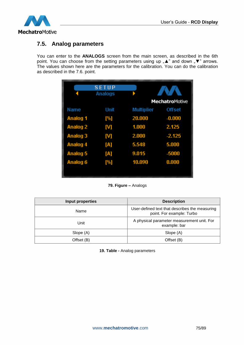
7.5. Analog parameters You can enter to the ANALOGS screen from the main screen, as described in the 6th point. You can choose from the setting parameters using up „▲” and down „▼” arrows. The values shown here are the parameters for the calibration. You can do the calibration as described in the 7.6. point.
79. Figure – Analogs
Input properties Description
Name User-defined text that describes the measuring
point. For example: Turbo
Unit A physical parameter measurement unit. For
example: bar
Slope (A) Slope (A)
Offset (B) Offset (B)
19. Table - Analog parameters

User’s Guide - RCD Display
www.mechatromotive.com 76/89
7.6. Defining a calibration equation for analog sensors
80. Figure – Output of an analog sensor
For the definition of sizing equation, you have to have two points of the equations. One value (A) belongs to the 0 V voltage, the other value (B) belongs to the maximum voltage. These two points define the function of the equation, and with them, you can define the Offset and Multiplier of the chosen analogs. The Offset is equal to the value A. The Multiplier is the gradient of the function. You can get the Multiplier with the following steps: subtract the value A from the value B and then divide the difference with the value of the maximum voltage. This quotient is the value of the Multiplier. Do not worry if the Multiplier or the Offset is negative, they can be correct values. If the Multiplier is negative, that means the function is decreasing. (28. Figure) The values of the analog and the voltage give the following equations:
Where A is equal to b that shows the value of the Offset, and a is the value of the Multiplier.

User’s Guide - RCD Display
www.mechatromotive.com 77/89
81. Figure - Decreasing function
82. Figure – Calculate the minimum and maximum outputs
For example, you have the following values: 0.5 V 1 bar 4.5 V 10 bar

User’s Guide - RCD Display
www.mechatromotive.com 78/89
That means you have the following equations:
(II)
We are searching the equation , because we need the values of a and b. To
get them, you have to do the followings:
From the equation (I), we can get the value of a.
Now you know the value of the Multiplier (2.25) and the Offset (-0.125).
User’s Guide - RCD Display
www.mechatromotive.com 79/89
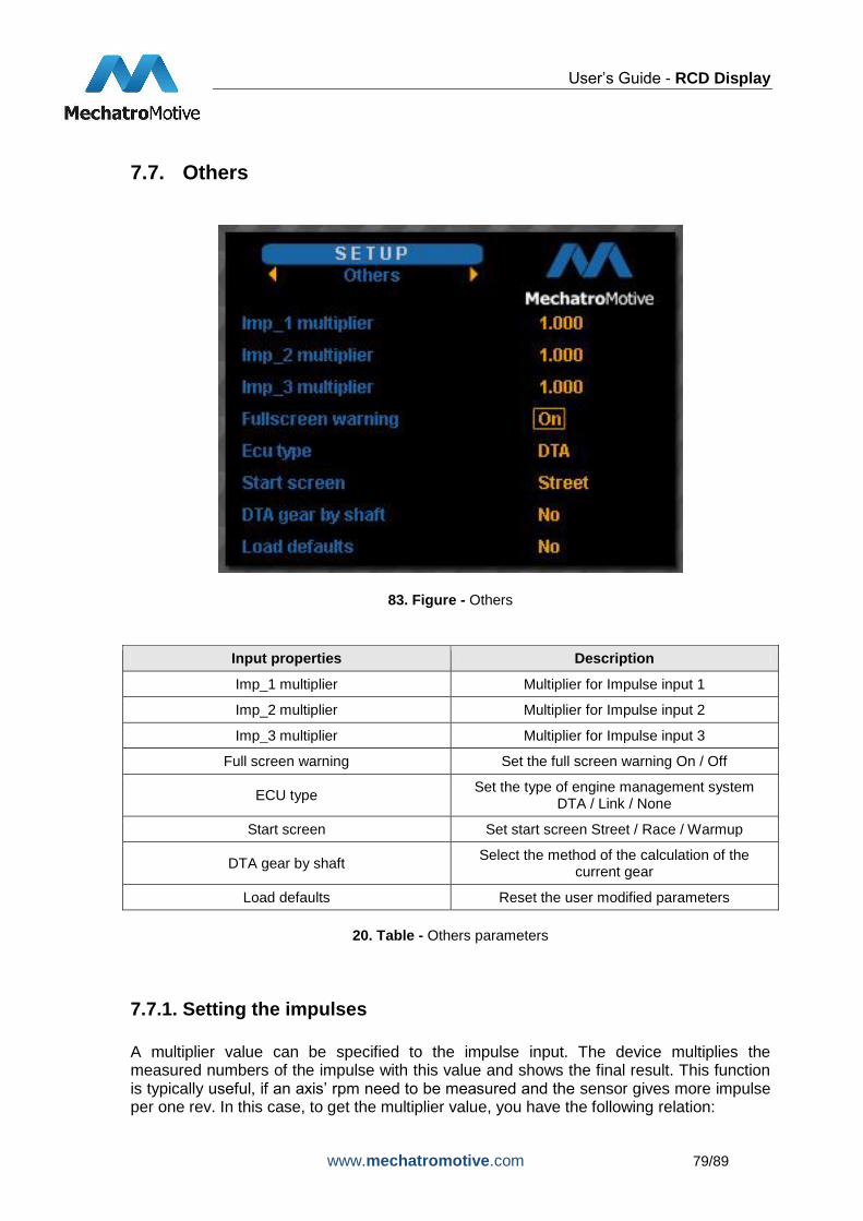
7.7. Others
83. Figure - Others
Input properties Description
Imp_1 multiplier Multiplier for Impulse input 1
Imp_2 multiplier Multiplier for Impulse input 2
Imp_3 multiplier Multiplier for Impulse input 3
Full screen warning Set the full screen warning On / Off
ECU type Set the type of engine management system
DTA / Link / None
Start screen Set start screen Street / Race / Warmup
DTA gear by shaft Select the method of the calculation of the
current gear
Load defaults Reset the user modified parameters
20. Table - Others parameters
7.7.1. Setting the impulses
A multiplier value can be specified to the impulse input. The device multiplies the measured numbers of the impulse with this value and shows the final result. This function is typically useful, if an axis’ rpm need to be measured and the sensor gives more impulse per one rev. In this case, to get the multiplier value, you have the following relation:

User’s Guide - RCD Display
www.mechatromotive.com 80/89
rearperimpulseofNumberMultiplier
____
1
7.7.2. Fullscreen warning
In case of an alarm, the value of the parameter beyond the limit will appear on in a red frame. If the Fullscreen warning is On, the alarm window will be visible until the driver push the „OK” button on the navigation panel. If the Fullscreen warning is Off, the alarm window appears on the screen at the beginning of the alarm, and after 3 seconds automaticly disappears. Thus the driver do not have to deal with the alarm’s switch off.
7.7.3. ECU type
You can set your engine management system’s type, choose between:
DTA
Link
MoTeC M4 and ECUs compatible with CRC32 serial protocol
Syvecs
VEMS
all ECUs with AIM serial protocol
Vi-PEC VTS (v10000 or later), iVTs
None
7.7.4. Start screen
You can choose which screen will load when you turn on the device. Choose between Street, Race and Warmup.
7.7.5. DTA gear by shaft
If you use DTA Engine Management System, there are two ways to calculate the current gear: with a position potentiometer or with gear ratio (shaft). If you use the gear ratio, select „Yes“.
7.7.6. Load defaults
All of the parameters reset to factory defaults.

User’s Guide - RCD Display
www.mechatromotive.com 81/89
8. Firmware update Only the 140804MM, and later softwares can be updated. To update a firmware, first you have to connect the Main Connector 2’s pins to a D-Sub 9 connector’s pins:
Main Connector 2 D-Sub 9
Pin No. Function Pin No. Function
10 RS232_RX 3 TXD
11 RS232_TX 2 RXD
20 GND 5 GND
21. Table - How to connect the Main Connector 2 to a D-Sub 9
84. Figure - How to connect the Main Connector 2 to a D-Sub 9
Now you can connect the RCD Display to your computer. If you don’ have any RS232 serial port on your PC, use an RS232 to USB adapter. If the adapter doesn’t work, try to reconnect it! Then you have to download two files from our webpage: http://mechatromotive.com/index.php?folder=termekek/rcd&page=index_rcd&lang=eng . On the webpage, click on the Downloads button, and there you will find the files. (A *.hex and a *.exe file). Then start the MM-Bootloader.exe file, and follow these steps: Click on the “…” button, and select the latest “*.hex” file that you downloaded from our webpage.

User’s Guide - RCD Display
www.mechatromotive.com 82/89
85. Figure – MM-BootLoader printscreen_1
Then click on the Open button. Now you have to find out to which serial port is your device connected. You can find it with the help of the computer’s Device Manager.
86. Figure - MM-BootLoader printscreen_2
Type the number of the serial port, then click on the Connect button.

User’s Guide - RCD Display
www.mechatromotive.com 83/89
87. Figure - MM-BootLoader printscreen_3
Reset the RCD Display, then click on the OK button.
88. Figure - MM-BootLoader printscreen_4
Now wait until your device is updated, and then click on the OK button.

User’s Guide - RCD Display
www.mechatromotive.com 84/89
89. Figure - MM-BootLoader printscreen_5
90. Figure - MM-BootLoader printscreen_6

User’s Guide - RCD Display
www.mechatromotive.com 85/89
9. Safety regulations
While driving do not pay more attention than necessary to the screen, ensure the safe transport!
The panel operates from extra low voltage, high-voltage parts are not included, therefore electrical accidents cannot occur.
Do not connect instruments with incorrect outputs or damaged device or sensor.
Do not connect directly the RCD Display to the battery! Insert a 2 A fuse into the circuit!
Disrupting any component of the product results the immediate termination of the guarantee. If the panel is failed or does not work, contact your distributor.

User’s Guide - RCD Display
www.mechatromotive.com 86/89
10. Figures list 1. FIGURE - MAIN CONNECTORS .................................................................................................... 6
2. FIGURE - MOUNTING DIMENSIONS OF THE MAIN UNIT .......................................................... 7
3. FIGURE - NAVIGATION PANEL MOUNTING DIMENSIONS ........................................................ 7
4. FIGURE – MAIN CONNECTOR 1 ................................................................................................... 8
5. FIGURE - MAIN CONNECTOR 2 .................................................................................................... 9
6. FIGURE – KEYBOARD CONNECTOR (MALE) ........................................................................... 11
7. FIGURE - KEYBOARD CONNECTOR (FEMALE) ........................................................................ 11
8. FIGURE – MAIN MENU ................................................................................................................ 13
9. FIGURE – STREET WINDOW ...................................................................................................... 13
10. FIGURE - WARMUP WINDOW ................................................................................................... 14
11. FIGURE – DIAG 1 WINDOW ...................................................................................................... 14
12. FIGURE – DIAG WINDOW 2 / 3 ................................................................................................ 15
13. FIGURE – RACE WINDOW ........................................................................................................ 15
14. FIGURE – PCLINK PRINTSCREEN_1 ....................................................................................... 17
15. FIGURE – PCLINK PRINTSCREEN_2 ....................................................................................... 18
16. FIGURE – PCLINK PRINTSCREEN_3 ....................................................................................... 19
17. FIGURE – PCLINK PRINTSCREEN_4 ....................................................................................... 20
18. FIGURE – MOTEC ECU MANAGER PRINTSCREEN_1 ........................................................... 23
19. FIGURE - MOTEC ECU MANAGER PRINTSCREEN_2 ............................................................ 24
20. FIGURE - MOTEC ECU MANAGER PRINTSCREEN_3 ............................................................ 25
21. FIGURE - MOTEC ECU MANAGER PRINTSCREEN_4 ............................................................ 26
22. FIGURE - MOTEC ECU MANAGER PRINTSCREEN_5 ............................................................ 27
23. FIGURE - MOTEC ECU MANAGER PRINTSCREEN_6 ............................................................ 28
24. FIGURE – MOTEC M4 PRINTSCREEN_1 ................................................................................. 34
25. FIGURE - MOTEC M4 PRINTSCREEN_2 .................................................................................. 34
26. FIGURE - MOTEC M4 PRINTSCREEN_3 .................................................................................. 35
27. FIGURE - MOTEC M4 PRINTSCREEN_4 .................................................................................. 35
28. FIGURE - MOTEC M4 PRINTSCREEN_5 .................................................................................. 36
29. FIGURE - MOTEC M4 PRINTSCREEN_6 .................................................................................. 36
30. FIGURE - MOTEC M4 PRINTSCREEN_7 ................................................................................. 37
31. FIGURE - MOTEC M4 PRINTSCREEN_8 .................................................................................. 37
32. FIGURE – SCAL PRINTSCREEN_1 ........................................................................................... 40
33. FIGURE - SCAL PRINTSCREEN_2............................................................................................ 41
34. FIGURE - SCAL PRINTSCREEN_3............................................................................................ 41
35. FIGURE - SCAL PRINTSCREEN_4............................................................................................ 42
36. FIGURE - SCAL PRINTSCREEN_5............................................................................................ 42
37. FIGURE - SCAL PRINTSCREEN_6............................................................................................ 43

User’s Guide - RCD Display
www.mechatromotive.com 87/89
38. FIGURE - SCAL PRINTSCREEN_7............................................................................................ 43
39. FIGURE - SCAL PRINTSCREEN_8............................................................................................ 44
40. FIGURE - SCAL PRINTSCREEN_9............................................................................................ 44
41. FIGURE - SCAL PRINTSCREEN_10.......................................................................................... 44
42. FIGURE - SCAL PRINTSCREEN_11.......................................................................................... 45
43. FIGURE - SCAL PRINTSCREEN_12.......................................................................................... 45
44. FIGURE - SCAL PRINTSCREEN_13.......................................................................................... 45
45. FIGURE - SCAL PRINTSCREEN_14.......................................................................................... 46
46. FIGURE - SCAL PRINTSCREEN_15.......................................................................................... 46
47. FIGURE - SCAL PRINTSCREEN_16.......................................................................................... 46
48. FIGURE - SCAL PRINTSCREEN_17.......................................................................................... 46
49. FIGURE - SCAL PRINTSCREEN_18.......................................................................................... 47
50. FIGURE - SCAL PRINTSCREEN_19.......................................................................................... 47
51. FIGURE - SCAL PRINTSCREEN_20.......................................................................................... 47
52. FIGURE - SCAL PRINTSCREEN_21.......................................................................................... 48
53. FIGURE - SCAL PRINTSCREEN_22.......................................................................................... 48
54. FIGURE - SCAL PRINTSCREEN_23.......................................................................................... 48
55. FIGURE - SCAL PRINTSCREEN_24.......................................................................................... 49
56. FIGURE - SCAL PRINTSCREEN_25.......................................................................................... 49
57. FIGURE - SCAL PRINTSCREEN_26.......................................................................................... 49
58. FIGURE – VIPEC VTS SERIAL WARNING ................................................................................ 51
59. FIGURE – VI-PEC VTS PRINTSCREEN_1 ................................................................................ 51
60. FIGURE - VI-PEC VTS PRINTSCREEN_2 ................................................................................. 52
61. FIGURE - VI-PEC VTS PRINTSCREEN_3 ................................................................................. 53
62. FIGURE - VI-PEC VTS PRINTSCREEN_4 ................................................................................. 54
63. FIGURE - VI-PEC VTS PRINTSCREEN_5 ................................................................................. 55
64. FIGURE – VI-PEC IVTS PRINTSCREEN_1 ............................................................................... 58
65. FIGURE - VI-PEC IVTS PRINTSCREEN_2 ................................................................................ 59
66. FIGURE - VI-PEC IVTS PRINTSCREEN_3 ................................................................................ 59
67. FIGURE - VI-PEC IVTS PRINTSCREEN_4 ................................................................................ 60
68. FIGURE - VEMS PRINTSCREEN_1 ........................................................................................... 62
69. FIGURE - VEMS PRINTSCREEN_2 ........................................................................................... 63
70. FIGURE – THE ONLINE CALIBRATION PAGE ........................................................................ 65
71. FIGURE – HOW TO CONNECT THE PULLUP RESISTOR....................................................... 66
72. FIGURE – RESITOR BASED SENSOR OUTPUT WITH PULLUP ............................................ 67
73. FIGURE – TYPE WINDOW ......................................................................................................... 69
74. FIGURE – SET ALARM ............................................................................................................... 70
75. FIGURE – ALARM_1 ................................................................................................................... 72
76. FIGURE – ALARM_2 ................................................................................................................... 72
77. FIGURE – LED RANGES ............................................................................................................ 73

User’s Guide - RCD Display
www.mechatromotive.com 88/89
78. FIGURE – BRIGHTNESS SETUP WINDOW .............................................................................. 74
79. FIGURE – ANALOGS .................................................................................................................. 75
80. FIGURE – OUTPUT OF AN ANALOG SENSOR ........................................................................ 76
81. FIGURE - DECREASING FUNCTION ........................................................................................ 77
82. FIGURE – CALCULATE THE MINIMUM AND MAXIMUM OUTPUTS ....................................... 77
83. FIGURE - OTHERS ..................................................................................................................... 79
84. FIGURE - HOW TO CONNECT THE MAIN CONNECTOR 2 TO A D-SUB 9 ........................... 81
85. FIGURE – MM-BOOTLOADER PRINTSCREEN_1 .................................................................... 82
86. FIGURE - MM-BOOTLOADER PRINTSCREEN_2 ..................................................................... 82
87. FIGURE - MM-BOOTLOADER PRINTSCREEN_3 ..................................................................... 83
88. FIGURE - MM-BOOTLOADER PRINTSCREEN_4 ..................................................................... 83
89. FIGURE - MM-BOOTLOADER PRINTSCREEN_5 ..................................................................... 84
90. FIGURE - MM-BOOTLOADER PRINTSCREEN_6 ..................................................................... 84

User’s Guide - RCD Display
www.mechatromotive.com 89/89
11. Tables list 1. TABLE - MAIN CONNECTOR 1 PINOUT ....................................................................................... 9
2. TABLE - MAIN CONNECTOR 2 PINOUT ..................................................................................... 10
3. TABLE - KEYBOARD CONNECTOR PINOUT ............................................................................. 11
4. TABLE - DTA PARAMETERS ....................................................................................................... 16
5. TABLE - LINK PARAMETERS ...................................................................................................... 21
6. TABLE - LIMITS FLAGS DEFINITION .......................................................................................... 22
7. TABLE – PROTOCOL DESCRIPTION ......................................................................................... 33
8. TABLE - PROTOCOL DESCRIPTION OF MOTEC M4 ECU ....................................................... 38
9. TABLE - PROTOCOL DESCRIPTION OF MOTEC M4 ECU – DIAGNOSTIC ERROR GROUPS
................................................................................................................................................... 39
10. TABLE - PROTOCOL DESCRIPTION ........................................................................................ 50
11. TABLE – PROTOCOL DESCRIPTION ....................................................................................... 57
12. TABLE- LIMITS FLAG DEFINITION........................................................................................... 57
13. TABLE – PROTOCOL DESCRIPTION ....................................................................................... 61
14. TABLE – LIMITS FLAG DEFINITION .......................................................................................... 62
15. TABLE - PROTOCOL DESCRIPTION OF VEMS ECU .............................................................. 64
16. TABLE - DEFINABLE ALARM LIMITS FOR THE PARAMETERS ............................................. 71
17. TABLE - LED BAR PARAMETERS ............................................................................................. 73
18. TABLE - LED BAR PARAMETERS ............................................................................................. 74
19. TABLE - ANALOG PARAMETERS ............................................................................................. 75
20. TABLE - OTHERS PARAMETERS ............................................................................................. 79
21. TABLE - HOW TO CONNECT THE MAIN CONNECTOR 2 TO A D-SUB 9 .............................. 81