
THE AUTOMATION BOOK
156
Global service & support Innovative solutions Standards driven Improving financial performance THE AUTOMATION BOOK A world of solutions FACTORY AUTOMATION
-
Upload
khangminh22 -
Category
Documents
-
view
2 -
download
0
Transcript of THE AUTOMATION BOOK

Global service & support
Innovative solutions
Standards driven
Improving financial performance
THE AUTOMATION BOOKA world of solutions
FACTORY AUTOMATION

2
Global Player
Through Mitsubishi Electric’s vision, “Changes for the Better“ are possible for a brighter future.
We bring together the best minds to cre-ate the best technologies. At Mitsubishi Electric, we understand that technology is the driving force of change in our lives. By bringing greater comfort to daily life, maximising the efficiency of businesses and keeping things running across so-ciety, we integrate technology and in-novation to bring changes for the better.
Mitsubishi Electric is involved in many areas including the following
Energy and electric systems
A wide range of power and electrical products from generators to large-scale displays.
Electronic devices
A wide portfolio of cutting-edge semiconductor devices for systems and products.
Home appliance
Dependable consumer products like air conditioners and home entertainment systems.
Information and communication systems
Commercial and consumer-centric equipment, products and systems.
Industrial automation systems
Maximising productivity and efficiency with cutting-edge automation technology.
Global impact of Mitsubishi Electric

Introduction to Mitsubishi Electric 4
Applications in action 6
Tomorrow’s quality, today’s goals 12
European service 14
Automation solutions 16
Logic controller/Compact PLC/Modular PLC 20
HMIs/GOTs/Software 22
Inverters 24
Motion control 26
Robots 28
Low voltage/Energy monitoring 30
Application solutions 32
Section 2: Technical information
IntegratedEngineering
IntegratedNetwork
AutomationController
MES
ERP
3
Contents
Contents

4
Global partner. Local friend.
Present right through EuropeFrom the development of products to the management of entire plants, our experience in the industrial market spans more than 80 years. The knowledge we have built up over the decades and our complete product portfolio allow us to work together with customers to create complete turnkey solutions that meet all specific needs. With a globe-spanning service network, we not only provide after-sales service, but also training and technical consultation.
Global partner, local friend
Mitsubishi Electric Factory Automation is synonymous with innovative, high-quality products. Our programmable logic controllers, drive solutions and industrial robots are among the most powerful on the market and have been contributing to the success of European manufacturing for over 35 years.
Sales and support, never far away
The Factory Automation division has its own sales organisations in Germany, Great Britain, France, Ireland, Italy, Spain, Russia, Poland and the Czech Republic. In addition, we have developed an ex-tensive network of partner companies across the whole of Europe and neigh-bouring countries.
We coordinate and organise our local support throughout Europe to ensure the highest possible standards. Addi-tional support services are available from our European Development Cen-tre (EDC) and EMC Competence Centre.
An open working relationship between supplier and customer gets results faster and more efficiently.

5
Trust and loyalty
Trust and loyalty is as important as productsCollaboration with capable partners in the automation industry is one of the key elements in Mitsubishi Electric’s suc-cess. Today more than ever, customers expect automation solutions tailored to the specific requirements of their appli-cations. Our partners’ expertise in spe-cific industries, coupled with Mitsubishi Electric’s innovative automation tech-nology, are the two main ingredients of a successful recipe for made-to-order solutions and perfect customer service.
A focus on service
The customer is always the focus of all our service activities. Our customers get the best possible support from expe-rienced staff, who provide competent advice and help with planning, projects, installation and configuration, training and all automation questions and tasks. Optimized stocks and a central logistics center ensure fast, efficient deliveries of replacement and spare parts. For fast technical information and support, we handle questions from customers all over Europe via our telephone hotline.
Setting the standards
Mitsubishi Electric has a reputation for producing high-quality products. This comes, in part, from our commitment to understanding and meeting the require-ments of international standards and directives. In addition to European CE compliance, many products also have additional approvals such as:
Shipping approvals like ABS, DNV, GL, RINA, BV, Lloyd’s register
International approvals like UL (USA), cUL (Canada) and EAC mark.
Market leaders
In the world of manufacturing, change is omnipresent. To ensure our products reflect the current needs of customers, we base every aspect of product devel-opment and production on the voice of the market. To keep our high levels of product reliability, we incorporate a quality control program that leaves nothing to chance, resulting in the high level of quality synonymous with the Mitsubishi Electric name.
Mitsubishi Electric products are widely regarded as being among the most innovative in the industry. In terms of volume, one in three PLCs in the world today is a Mitsubishi Electric.
Indeed, some of our competitors use Mitsubishi Electric’s innovative power management technology in their own frequency inverters.
When all these factors are taken to-gether, it is no wonder our customers think of Mitsubishi Electric’s automation products as leading the market.
Attention to detail leaves little to chance.

6
Water
Water is a critical element of life. With-out a constant, clean supply for drinking and washing and effective handling of grey waste, society quickly breaks down. Automation solutions need to be reli-able and flexible to meet the changing
demands of the public but also the pres-sures to deliver shareholder value. That is why so many utility companies use Mitsubishi Electric.
Application in action
COMPANYKlinting Vandvaerk
LOCATIONDenmark
AUTOMATION SPECIALISTPRO/AUTOMATIC
APPLICATIONWater pumping station
PRODUCTSMitsubishi Electric modular PLCs, frequency inverter drives, Wago remote I/Os
NETWORKCC-Link
NOTE Bore holes were up to 1.2 km away from the main water station.
COMMENT “It was easy to create the network systems and it has some very pow-erful unique features.” Jean Petersen PRO/AUTOMATIC
Automation solutions

7
Food
The range of food available to the con-sumer today is vast, from ready prepared salads to pre-cooked pies and frozen meats. Much of it comes from far off places but must be processed and deliv-ered on time, every time. Because food is so important to our daily lives there
are strict rules and guidelines regard-ing traceability, labeling, packaging and quality control. Mitsubishi Electric has expertise in all of these areas.
Application in action
COMPANYVirgin Trading (Virgin Cola)
LOCATIONIreland
AUTOMATION SPECIALISTCharles Wait
APPLICATIONManufacture of cola concentrate
PRODUCTSMitsubishi Electric software and modular PLCs
NOTE Production facility built to be one of the most efficient in the world with an on-site staff of 6 producing up to 2 billion liters of Cola per year
COMMENT “We chose Mitsubishi Electric … because of their reputation for reliability and worldwide support particularly in the food and bever-age industry.” Rod Golightly, Charles Wait
Automation solutions

8
Automation solutions
Manufacturing
Manufacturing, like all engineering fields, is constantly under pressure to deliver innovative products in the most cost-effective way. Generally, manufac-turers are looking for suppliers who offer automation solutions that support the wide variety of standards they need, as well as offering flexibility, availability and reliability.
This is one reason why the world’s manu-facturers have bought more than twelve million Mitsubishi Electric FX family PLCs and 23 million inverters since their in-troduction over 30 years ago.
Application in action
COMPANYKaba Group
LOCATIONAustria
APPLICATIONManufacture of keys
PRODUCTSMitsubishi Electric robots
NOTE Two robots are used, one ‘s to place the brass workpiece in to the milling machine while a second robot picks up machined keys and applies the final finish from a rotat-ing brush.
COMMENT “Thanks to the use of the robot we were able to reduce costs and sig-nificantly improve the transit time.” Robert Weninghofer Production Manager at Kaba

9
Automation solutions
Automotive
Shorter production cycles, adaptive manufacturing and integration of all areas in the manufacturing process are what make the automotive industry one of the most high power, high pressure, manufacturing sectors in the world.
This is also why these global brands turn to Mitsubishi Electric for the highest level of automation expertise.
Application in action
COMPANYGlobal Engine Manufacturing Alliance (GEMA)
LOCATIONUSA
APPLICATIONManufacture of automotive engines
PRODUCTSMitsubishi Electric modular PLCs, HMI, servo amplifiers, CNC control-lers and software
NOTE GEMA is an alliance of the Chrysler Group, Mitsubishi Motors and Hyundai Motor Co. There are two facilities which will, together, produce up to 840,000 engines per year.
COMMENT The Chrysler Group estimates that they will save annual costs of around 100 million dollars per year with the new automation concept.

10
Automation solutions
Chemical
The chemical and pharmaceutical in-dustries are among the world’s most competitive, facing tough “speed to market” issues. New products developed in the laboratory have to be rushed into production. To do this safely, quickly and reliably, manufacturers need flexible
automation solutions that support a wide range of standards. Mitsubishi Electric automation products answer these needs.
Application in action
COMPANYFollmann & Co.
LOCATIONGermany
APPLICATIONAdhesive manufacture
PRODUCTSMitsubishi Electric compact PLCs, HMI, frequency inverter drives
NETWORKEthernet + Fieldbus
NOTE The system has control over the manufacturing process for 17 differ-ent adhesives
COMMENT “It was easy to create the network systems and it has some very pow-erful unique features.” Jean Petersen PRO/AUTOMATIC
11
Automation solutions
Process
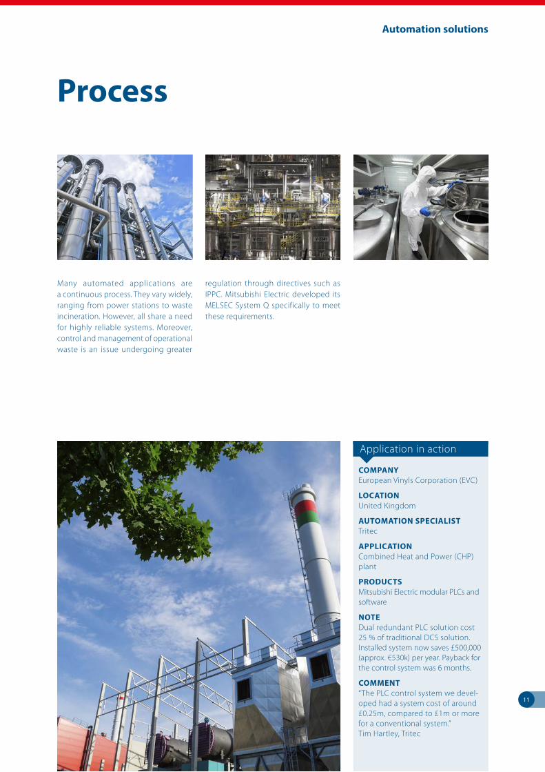
Many automated applications are a continuous process. They vary widely, ranging from power stations to waste incineration. However, all share a need for highly reliable systems. Moreover, control and management of operational waste is an issue undergoing greater
regulation through directives such as IPPC. Mitsubishi Electric developed its MELSEC System Q specifically to meet these requirements.
Application in action
COMPANYEuropean Vinyls Corporation (EVC)
LOCATIONUnited Kingdom
AUTOMATION SPECIALISTTritec
APPLICATIONCombined Heat and Power (CHP) plant
PRODUCTSMitsubishi Electric modular PLCs and software
NOTE Dual redundant PLC solution cost 25 % of traditional DCS solution. Installed system now saves £500,000 (approx. €530k) per year. Payback for the control system was 6 months.
COMMENT “The PLC control system we devel-oped had a system cost of around £0.25m, compared to £1m or more for a conventional system.” Tim Hartley, Tritec

12
Tomorrow’s quality
Eco Changes – for a greener future
Eco Changes is an expression of Mitsubishi Electric’s commitment to environmental management. The pro-gramme is directed towards a greener future, achieved with innovative envi-ronmental technologies and manufac-turing expertise.
Mitsubishi Electric’s goal is to help cre-ate an ecological society by means of a broad spectrum of technologies and solutions for private households, offic-es, businesses, infrastructure and even space exploration. As a global company, we intend to make a key contribution to achieving the goal of a world with low carbon dioxide emissions and high recycling rates.
Tomorrow’s quality ...
Tomorrow’s technology requires investment today

13
Today’s goals
... today’s goals
No matter what the application, the in-dustry or a company’s size, Mitsubishi Electric offers its customers the best service possible. This involves getting to know and understand the customer’s needs and being responsive to chang-ing legal and social attitudes in order to develop products required tomorrow, in one year, or in five years.
R&D – lifeblood of the future
Research and development is the life-blood of Mitsubishi Electric. Our re-search and development centers in Japan, the United States and in Europe are working on innovative technologies today for the breakthrough products of tomorrow. Mitsubishi Electric invests ap-proximately 4 % of sales in developing tomorrow’s technologies.
In a variety of ways, putting programmes and systems into place that help us get closer to our goal of actualizing a sus-
tainable planet. From procurement to product design and manufacturing to logistics these activities demonstrate how environmentally conscious think-ing and action are steadily becoming ingrained in our corporate culture.
Helping the environment
It’s all about balance: the balance be-tween effective use of resources, ef-ficient use of energy, and safeguards against potentially harmful substances.
This insight into the balance between ef-ficient automated manufacture and care for our environment helps us to better
understand the needs of our customers. For example, the need to monitor and control waste in accordance with the European Integrated Pollution Preven-tion Control (IPPC) directive.
This is an immense challenge, but one that Mitsubishi Electric is actively pursu-ing on a daily basis, while keeping fo-cused on one goal. That goal is a global society where life can continually im-prove in harmonious coexistence with the natural environment.
And so Mitsubishi Electric factories work to ensure full ISO 14000 compliance, and to produce products with fewer harmful substances.
Working for a sustainable future.
Tomorrow’s technology requires investment today

14
European service
When choosing an automation part-ner our customers look at many differ-ent factors, from company stability to market-leading products. Yet one thing they are all interested in is service and support.
Service in Europe
Networks, technology centers and part-ners spanning Europe ensure outstand-ing local support services.
Product and service
Technical support is about getting the right answers first time.

15
European service
Our customer hotline supports both current and older product lines. Local engineers then provide telephone sup-port in native languages.
This local service can also provide in-depth technical support when neces-sary. Thanks to this mix of local and cen-tralized support customers can always be sure they can get the support they need, when they need it.
Complementing our local support, the website https://eu3a.mitsubishielectric.com offers MyMitsubishi users access to manuals, CAD drawings, HMI drivers, GSD files and EPlan files for easy design etc. for free.
Minimizing downtime
Downtime caused by an operational fail-ure is never good news. In today’s tough business environment returning to full production as soon as possible is critical.
Our comprehensive services will help you to get your plant up and running again fast, keeping expensive downtime to a minimum.
Training for performance
Dealing with complex automation equipment in a fast-paced manufactur-ing environment requires well-trained personnel. Mitsubishi Electric offers the latest automation training in the use and maintenance of automation sys-tems. This ensures optimum operating performance.
The human element
All repairs are carried out by qualified and experi-
enced engineers.
Comprehensive training programsReliable technical support is only a call away

Automation solutions
IntegratedEngineering
IntegratedNetwork
AutomationController
MES
ERP
Transparent connectivity
ERP (Enterprise resource planning) MES (Manufacturing execution system)
Integration of automation controller and HMI
Seamless connectivity within all levels of manufacturingy
Centralized engineering environment
PAC & HMI
Network
Engineering
16
Automation solutions whatever the applicatione-F@ctory is the Mitsubishi Electric solu-tion for improving the performance of any manufacturing enterprise, providing three key benefits: Reduced total cost of ownership (TCO), Maximized productiv-ity, and Seamless integration.
Companies often mull over and discuss factory or plant-wide management so-lutions for many years – but without ever actually implanting them. After all, they are understandably reluctant to halt production for an extended period while the new system is being fitted, and find the prospect of organizing and planning the whole activity daunting, especially since they often want to im-plement a new solution all at once.
e-F@ctory
The e-F@ctory solution from Mitsubishi Electric answers a lot of these issues. It is based on the MELSEC System Q and MELSEC iQ-R series automation platform
concept. Thanks to the modular design of these automation controllers, it is now much easier to implement plant-wide control based on segmented or manufacturing cell solutions.
Communication
Plant-wide operations rely on good communication strategies. The MELSEC automation platform can support over 50 different forms of communication, including standard RS232, fieldbuses, Ethernet, web servers and redundant networks.
Making life easy
Traditionally, the interface between MES and the production environment has been separated by a layer of man-agement PCs and master PLCs used for concentrating data and cell information. With the MELSEC automation platform, this structure can be simplified by em-
bedding the PC directly on the same backplane. This removes a layer of man-agement structure as well as simplifies implementation.
Each customer’s requirements are dif-ferent and the automation solutions from Mitsubishi Electric are designed to offer a wide range of solutions that can be easily adapted. The MELSEC au-tomation platform enables the use of local embedded web server technology, meaning that Ethernet and web-based browsing can be used for capturing da-ta. Moreover, a dedicated MES interface allows MELSEC System Q and the iQ-R series to “talk” directly to the MES soft-ware without any intermediary devices, reducing implementation and on-going maintenance costs.

17
Automation solutions
CNC control
Maximise your production and control with the utmost reliability.
EDM machines
Mitsubishi Electric EDM – voted as the “Global Market Leader 2005” by Frost and Sullivan.
Compact PLCs
The world’s favorite compact PLC brings together power and simplicity in equal measure.
Inverters
Mitsubishi Electric offers reliable fre-quency inverters for any application. Our FR family stands for consistent en-gineering, highest energy efficiency and easy startup.
HMIs, GOTs and IPC
Mitsubishi Electric offers what is prob-ably the biggest range of control termi-nals and industrial PCs (IPCs) available from any single manufacturer.
Modular PLCs
The MELSEC L series, iQ-R series and MELSEC System Q are high-performance modular controllers. With a wealth of integrated functions, they enable con-figuration of optimum solutions for all automation tasks.
MELSOFT
Productivity tools and software solu-tions to help you get the best out of your automation investment.
Motion control
Mitsubishi Electric Servo and Motion systems offer scalable solutions from 1 to 192 synchronized axes.
Robots
MELFA robots offer class-leading tech-nology for both SCARA and articulated arm systems.
LV switchgear and energy management
Advanced low voltage technology cov-ering switchgear and circuit breakers.

18
Automation solutions
Our solutions for your benefite-F@ctory was born out of the expertise Mitsubishi Electric has developed as a global manufacturing enterprise, fac-ing essentially the same challenges our customers face. Our solution has been implemented in our factories with dra-matic results. We are now sharing this expertise with those who are looking for the same benefits from their own manufacturing operations.
An e-F@ctory plant solves various issues through the direct collection of a wide variety of production site data, such as production and operation performance results and quality information, in real-time from equipment and devices, and then utilizes this data in an enterprise IT system.
This real-time integration of production data and enterprise IT solidly aids in im-proving quality, reducing lead time and increasing productivity. The e-F@ctory solution has several key parts as follows.
CC-Link network architectureCC-Link provides a completely open network architecture that links all fac-tory devices. The top layer is CC-Link IE, which provides the first gigabit industri-al Ethernet backbone to meet the ever-increasing data communication needs of modern factories.
This extends down the hierarchy with CC-Link IE Field, bringing gigabit band-width to all devices.
iQ PlatformThe iQ Platform is the enabling control-ler hardware for the e-F@ctory solution. An iQ system unites PLC, motion, CNC, robot and process control in a single unified controller architecture, linked seamlessly by a high-speed backplane.
MES InterfaceThe MES Interface IT products provide the vital link between the shop floor controllers such as the iQ Platform, and the enterprise IT systems. The con-nection is direct, with no intermediate PC hardware introducing maintenance or security issues.
For more information about Mitsubishi Electric MES interface products please refer to the technical part, chapter 11 in this catalog.
The e-F@ctory AllianceA key part of the e-F@ctory solution is the “e-F@ctory Alliance”. We have teamed with other best-in-class suppliers to create partnerships that allow our customers to truly benefit from the most comprehensive solutions available. The e-F@ctory Alliance currently has over 31 partners and their number is growing.
The e-F@ctory solution
Get maximum system efficiency and performance with e-F@ctory
FA integrated solutionsReduce total cost
Quality SafetyProductivity SecuritySustainability
MES interfaceC Controller
ProgrammableController
Sensor Energy-savingDrive Mechatronics
FA-ITInformation
Interface
since2003
Sales and distribution
Operation andmaintenance
Productdesign
Processdesign
ProcurementProduction
Supply chain
Engineeringchain
MES
SCADA
SCM
Simulator
ERP
CAD/CAMIT system
Edge-computing
Shop floor
Data handlingData primary processing/analysis

19
Automation solutions
Comprehensive safety solutions
The European Machinery Directive or in-ternational standards such as ISO12100 impose strict regulations for the safety of plant and machinery. Just like the machines themselves, the automation systems that control them must also comply with the directives and stand-
ards to ensure the safety of personnel in all phases of the machines’ service life.
At the same time, the safety concept has shifted from human intervention based “zero accidents” to risk assessment based “zero risk”. As a solution for this, Mitsubishi Electric provides a total safety solution by incorporating safety control devices, safety drive devices, and safety
components required for safety systems. This allows optimal safety control to be realized, boosting productivity.
Many companies can offer you a choice of safety devices, or perhaps a safety system of some kind. However, few can provide a complete safety solution that fully integrates with the conventional automation of your systems. The result is not only worker, machine and process safety, but industry-leading productivity and performance.
Please refer to the technical information section of this catalog for more informa-tion and ask for our separately available safety brochure.
Safety solutions
Safety in every phase of your production
Safety control is fully integrated into the Mitsubishi Electric automation solution
0.8
0.2
0.40.6
1
2
46810
20
21NC
22NC
AC-1Ith32A
0.8
0.2
0.40.6
1
2
46810
20
21NC
22NC
AC-1Ith32A
0.8
0.2
0.40.6
1
2
46810
20
21NC
22NC
AC-1Ith32A
GOT
QS-Safety
iQ PlatformGOT
Sicherheits-Servover-stärker
Safe Torque Off Signal
Motor
Safety Devices
QS Safety I/O Blocks
Safety Devices
Motor
Safety VFD
Robot
Safety Devices
Safety Devices
WS-Safety
Safety Relays
iQ Platform
QS Safety I/O Blocks

20
Logic controller/Compact PLC/Modular PLC
Simple
Mitsubishi Electric PLCs are simple to use. We have reduced many complex actions to a single instruction, making our PLCs much easier to program.
Easy
Moreover, we have designed program-ming and system configuration to be as flexible as possible. For example, our GX Works programming tools allow us-ers to quickly create PLC programs and configure new modules.
Furthermore, customers who wish to use more structured programming methods can choose from an array of languages supported by the IEC61131-3 standards.
All software packages are designed to reduce programming overheads through the use of intuitive layouts and functionality that guides the develop-ment of efficient code.
In addition, we offer innovative support tools such as GX Simulator. This package permits users to run PLC programs in a simulation mode without any additional hardware, helping to reduce expensive on-site commissioning time.
Reliable
We design and build our PLCs to the highest international standards gaining many marine and other special approvals in the process. We do this as part of our drive to supply the best quality products possible. A prime example of Mitsubishi Electric quality is the widespread use of our components in the global auto in-dustry, where zero tolerance of product failure is fast becoming the norm.
A unified tool – iQ Works
The iQ Automation Platform is a lead-ing solution for simplified manage-ment of complex and heterogeneous industrial production systems. The concept unites PLC, motion, robot and CNC technologies in a single compact hardware platform, enabling seamless interaction between the different con-trol systems. One of the key benefits is the ability to use a single unified tool for development and maintenance of the component systems. iQ Works is that tool: A unified development envi-ronment that encompasses all aspects of development and maintenance and can be controlled entirely from a single central location.
Simple, easy, reliable
Proven reliability from standalone to complete installations
One system, one tool
PLC Programming
Package GX Works3 GX Works2 GX Works2 FX AL-PCS/WIN
MELSEC iQ-F/iQ-R series
MELSEC Q/L series
FX3 SPS FX3 SPS ALPHA series
Ladder l l l l
Function Block Diagram l l l l l
Structured Text l l l l
SFC l l l l
IEC61131 Compliant l l l l

21
Logic controller/Compact PLC/Modular PLC
A wide range of solutions
Mitsubishi Electric PLC and controller solutions are divided into three simple groups.
Logic controllers
These Mitsubishi Electric products are called ALPHA controllers. They are small compact units with input/output (I/O), CPU, memory, power supply and HMI built into a single unit. The units are pro-grammed with a very intuitive Function Block-style programming tool (AL-PCS/WIN).
Compact PLCs
Compact PLCs are widely used in appli-cations ranging from machine control to networked systems. Mitsubishi Electric’s famous FX3 and FX5 range of PLCs are some of the most popular compact PLCs on the market, as demonstrated by sales of over 17 million controllers worldwide. Compact PLCs contain I/O, CPU, mem-ory and power supply in a single unit.
Moreover, it can extend its capabilities by selecting different options such as I/O, analog, temperature control, posi-tioning and simple motion. One of the most popular additions is a network-ing connection. Network options can include Ethernet, Profibus DP, CC-Link, DeviceNetTM as well as CANopen and SAE J1939.
Modular PLCs
Modular controllers like Mitsubishi Elec-tric’s MELSEC L series, iQ-R series and MELSEC System Q are high-performance PLC systems with broad functionality. The range, power and function of these high-end PLCs is impressive, with opera-tion times measured in nanoseconds. They are equipped with a separate pow-er supply, CPU, I/O and special options mounted on a backplane.
Additional backplanes can be added as the system expands. Their modular architecture makes it easy to configure these controllers for any task. Modular PLCs comprise a power supply, one or more CPU modules and I/O and/or special function modules. These special function modules include analog, com-munications and network modules and a special MES interface. A Web server module is also available for Internet ac-cess.
The CPU comes with an integrated Ethernet port for easy access to this standard network.
Mitsubishi Electric’s MELSEC System Q demonstrates one of the greatest ben-efits of an automation platform. It makes it possible to integrate PLC CPUs, mo-tion controllers, robot controllers and process CPUs all in a single system. In addition, there are options for systems built around industrial PCs, redundant PLCs, as well as a recent innovation, the C controller.
iQ Platform
Mitsubishi Electric’s iQ is the world’s first automation platform combining all key automation types in one system. No longer are valuable engineering re-sources spent trying to make different systems from separate vendors work to-gether. With iQ, Mitsubishi Electric takes care of system integration. We provide an extensive array of controller types that seamlessly operate together on the same backplane. Now your engineering staff can concentrate on the demands of the application itself right from the beginning.
Control to fit
There is a solution to match your needs
MELSEC System Q 32–8192
MELSEC L series 24–4096
FX3/FX5 10–512
10–28 ALPHA
MELSEC iQ-R series 4096
LogiC ControLLer
ComPaCt PLC
moduLar PLC
ALPHA2 FX3/FX5 series MELSEC L seriesMELSEC iQ-R series
MELSEC System Q
I/O 10–28 10–512 24–4096 4096 4096
Memory200 function blocks
20–260 k steps
40–1200 k steps
40–1200 k steps
10–1000 k steps
Cycle period/log. instruction
20 µs0.065–0.55 µs (65–550 ns)
0.0095–0.040 µs (9.5–40 ns)
0.98–1.96 ns 0.0095–0.2 µs (9.5–200 ns)

22
HMIs/GOTs/IPCs/SCADA
Mitsubishi Electric’s visualization con-cept brings together a wide range of human machine interfaces, industrial PCs and software solutions that let you see what is really happening in the pro-duction process.
This combination of three visualization technologies from a single supplier, al-lows users to choose the best solution to fit their requirements.
Dedicated HMI solutions
The GOT1000, GOT Simple and GOT2000 series of graphic operator terminals provide the very latest in touch-screen display technology. This gives users a bright clear display of information with the flexibility of touch screen input.
The GOT units are designed for fun-damental integration with Mitsubishi Electric automation technology. This means easier, faster project develop-ment as well as increased system per-formance and additional access to core functions in Mitsubishi’s automation hardware.
Industrial PC (IPC) solutions
Mitsubishi Electric’s range of IPC solu-tions offer customers a robust platform for developing their own solutions. They are designed to provide the flexibility of high- performance PC power but with a sturdy industrial design to protect them during operation. This means users can install an IPC in their manufacturing en-vironment with complete confidence.
A range of Mitsubishi Electric auto-mation software called MELSOFT sup-ports the IPCs. This provides users with a choice of software components that they can embed in their own solution to complete visualization packages, such as GT SoftGOT.
Seeing is believing
Production line or remote plant intelligence – Mitsubishi Electric makes data accessible.

23
HMIs/GOTs/IPCs/SCADA
Hardware with flexibility
When selecting the right visualization application, a number of basic factors have to be taken into account.
Water protection
HMI products from Mitsubishi Electric provide a wide range of solutions cater-ing to virtually every application need. All units have an IP65 ingress protec-tion rating or higher – they can be safely hosed down for cleaning, for example. This is often the case in the food indus-try where high levels of hygiene have to be maintained at all times.
Communication
An important part of automation is communication. Mitsubishi Electric’s HMI solutions can connect to leading networks like Ethernet, CC-Link (IE) and Modbus®. With access to hundreds of drivers, Mitsubishi Electric’s HMI and SCADA solutions can also be used with automation products from other manu-facturers.
Ease of use
Programming and using Mitsubishi Electric HMIs is easy. All of the packages come with pre-defined graphic libraries to help users get started quickly. More than one hundred drivers are available, making it possible to use Mitsubishi’s HMI solutions with automation products from third-party manufacturers.
MELSOFT
The MELSOFT automation software suite offers users a range of solutions includ-ing PLC and HMI programming software components such as OPC servers and Active X containers for embedding di-rectly into a user’s solution.
MAPS (Mitsubishi Adroit Process Suite)
MAPS is an engineering tool that en-compasses the entire product life cycle of automation solutions. The benefits of MAPS are already available in the devel-opment and integration phases. MAPS also makes it easier to integrate your data and enables customers to install extensions and perform maintenance themselves. The program uses prede-fined, user-configurable PLC function blocks and SCADA graphics based on the international S88 and S95 standards. This standardization means that in addi-tion to saving time, MAPS also reduces the development, testing and commis-sioning overheads of your automation projects. A range of import functions facilitates fast and easy configuration of the user interfaces for both SCADA and PLC projects. MAPS uses a central data-base for exchanging global variables, making accidental duplication of data records impossible.
Perfect vision
There is a solution to match your needs
IPC with MAPS
GOT1000 series
GOT2000 series
Hmi Programming/SimuLation
PackageFeature
GT Works3
Functions: Programming Simulation
l
l
Graphics Library l
HMI HardwareGOT1000 series/ GOT2000 series
Soft HMI CapabilityGT SoftGOT1000/ GT SoftGOT2000
PC baSed viSuaLiSation
Package
Feature
Soft HMI
PC Control
GT Soft-GOT
MX Sheet
MX Com-
ponent
MX OPC
Server
OPC l l
Active X l
VB/VBA l l l l
Web Deploy-able
l l
ODBC
Operation: Information Open Plant Factory Floor
l
l
l
l
l
l
l
l
l
GOT Simple series

24
Inverters/Drives
Frequency inverters offer a good exam-ple of a widely accepted, widely used automation technology. Inverters allow engineers greater control over a motor’s speed and torque performance. Increas-ingly, inverters are also seen as a simple but important way to reduce energy costs. Today, over 23 million Mitsubishi Electric frequency inverters are in opera-tion around the world in a wide range of applications.
High standards
Our commitment to meeting interna-tional standards guides the design of Mitsubishi Electric inverters. Current certifications include the European CE, America’s UL and cUL, the Russian EAC, as well as shipping approvals. These certifications help exporters who sell machines and systems with embedded inverters.
Mitsubishi Electric inverters mean reli-ability and performance. This is why two consecutive IMS Customer Satisfaction Surveys gave Mitsubishi Electric invert-ers top marks for reliability and tech-nology.
The FR-D700 SC and FR-E700 SC inverter drive series come with the two-channel STO (Safe Torque Off ) safety system in-tegrated as standard equipment. This makes it possible to operate multiple inverter drives inexpensively with a sin-gle safety relay.
Cut costs
A standard industrial motor in a typi-cal fan or pump application may only cost a few hundred euros to purchase. However, that same motor will consume hundreds of thousands of euros in elec-tricity costs over its operational lifetime. Using an inverter can significantly re-duce this outlay.
Intelligent solutions for every task
Mitsubishi Electric offers four types of inverter: Simple, Economy, Flexible and Advanced. Each has been optimized to offer the very best in control and per-formance.
In addition, depending upon the type selected, Mitsubishi Electric inverters can support the following networks: EtherNet / IP, CC Link, CC-Link IE Field, Profibus DP/DPV1, Profinet, DeviceNetTM, EtherCat, CanOpen, SSCNET III/H, LonWorks, RS485, Modbus®/RTU and Modbus®/TCP/BacNet. This extensive communication ability makes it easier to integrate in-verter control into larger automation systems.
Driving performance
Intelligent solutions for every task
Inverters help to reduce power consumption and
machine wear.

FR-F800 0.75–630 kW, 3ph
FR-A800 0.4–630 kW, 3ph
FR-E700 SC0.4–15 kW, 3ph
0.1–2.2 kW, 1ph
FR-D700 SC0.4–7.5 kW, 3ph
0.1–2.2 kW, 1ph
25
Inverters/Drives
FR-D700 SC
Micro
Mitsubishi Electric’s entry-level series combines ultra-compact dimensions with a wealth of new functions, includ-ing an emergency stop input for reliable stopping. Current vector control ensures that this frequency inverter can always deliver high torque, even at low speeds. An integrated brake transistor enables direct connection of a brake resistor for better braking performance. The FR-D700 SC is the ideal choice for driving fans, agitators and conveyor belt systems.
FR-E700 SC
Compact
Improved functions and capabilities make the FR-E700 SC inverters an eco-nomical and universal choice for a huge range of applications such as conveyor belts, hoists, stage systems, pumps, fans and extruders. Features include an in-tegrated USB port, safe stop inputs for safety stop function, improved power delivery in the low-speed range, options for controlled shutdown and a slot in which you can install one of the many available option cards for the 700 series.
Powering the future
Comprehensive range from ultra compact to
ultra-powerful
inverter range
FR-D700 SC FR-E700 SC FR-F800 FR-A800
D720S SC D740 SC E720S SC E740 SC F820F840/ F842
F846 A820A840/ A842
A860 1 A870 A862 FR-CC2
Input voltage1-phase
200–240 V AC
3-phase 380–
480 V AC
1-phase 200–
240 V AC
3-phase 380–
480 V AC
3-phase 200–
240 V AC
3-phase 380–
500 V AC
3-phase 380–
500 V AC
3-phase 200–
240 V AC
3-phase 380–
500 V AC
3-phase 525–
600 V AC
3-phase 525–
690 V AC
3-phase 525–
600 V AC
3-phase 380–
600 V AC
Output [kW] 0.1–2.2 0.4–7.5 0.1–2.2 0.4–15 0.75–132 0.75–630 0.4–132 0.2–132 0.2–1300 0.4–250 160–200 2 220–630 220–630
Overload 200 % 200 %250 %/ 120 %
250 %/ 120 %
250 %/ 120 %
250 %/ 120 %
250 %/ 120 %
250 %/ 120 %
250 %/ 120 %
250 %/ 120 %
250 %/ 120 %
Rating IP20 IP20 IP20 IP00/IP20 IP55 IP20 IP00 IP00 IP00 IP00 IP00
1 not for the european market 2 to be launched soon 37 to 630 kW
FR-F800*
Flexible
Many frequency inverter drives save power but the FR-F800 saves more. Its innovative AOEC technology (Advanced Optimum Excitation Control) ensures that exactly the right magnetic flux is al-ways applied to the motor for maximum motor efficiency and minimum power consumption. FR-F800 inverters are par-ticularly well suited for pump and fan, HVAC and building services applications.
FR-A800*
Powerful
The frequency inverters of the FR-A800 series deliver high-end performance and power. Their RSV (Real Sensorless Vector control) technology ensures maximum torque and optimum smooth
running. For greater flexibility, these inverters have four overload ranges, options for controlled shutdown and integrated PLC functions. With their dynamic performance, the FR-A800 in-verters are ideal for cranes and hoisting gear, high-shelf storage systems, extrud-ers, centrifuges, winding systems and positioning applications for IM and PM Motors.
* with built-in Ethernet connection (Modbus® TCP/IP & CCLIEFB)

26
Servo/Motion
As the demands on manufacturing increase, there is a growing need to produce higher quantities of finished goods with lower wastage. To achieve this, all areas of automation are evolving to meet these new demands.
One area undergoing rapid growth is servo and motion control. The develop-ment of high-performance servomotors combined with intuitive motion control is replacing traditional movement solu-tions.
Speed and performance
Servomotors allow users to create au-tomation solutions that are faster, more precise and more compact.
Mitsubishi Electric has been pushing forward the boundaries of servomotor design, creating ultra compact brushless motors. All motors of the MR-JE series have an encoder with a resolution of 131,072 pulses per revolution. All mo-tors of the MR-J4 series have an encoder with a resolution of 4,194,304 pulses per revolution. This permits greater machine speed and accuracy.
Plug and Play
Mitsubishi Electric servo and motion so-lutions offer easy system building and configuration based on PC “plug and play” concepts.
Simple connections
The availability of pre-made cables of different lengths means that connecting a servomotor to an amplifier or any oth-er combination is quick and error free.
Automatic motor recognition
When a Mitsubishi Electric servomotor is connected to an amplifier it is automati-cally recognized. The correct parameters are then automatically loaded, ready for operation. This reduces the set-up time and the chance of errors.
Simple networking
High-speed servo and motion applica-tions need special high-speed network-ing. Mitsubishi Electric’s Servo System Controller Network (SSCNET III/H) pro-vides the system capability, connecting and fully synchronizing up to 192 axes us-ing a simple plug and cable construction.
*) The MR-JE-BF and MR-J4-B series products use SSCNET III/H, a fiber-based version of the network giving complete noise immunity.
Poetry in motion
Speed, accuracy and control when you need it
27
Servo/Motion
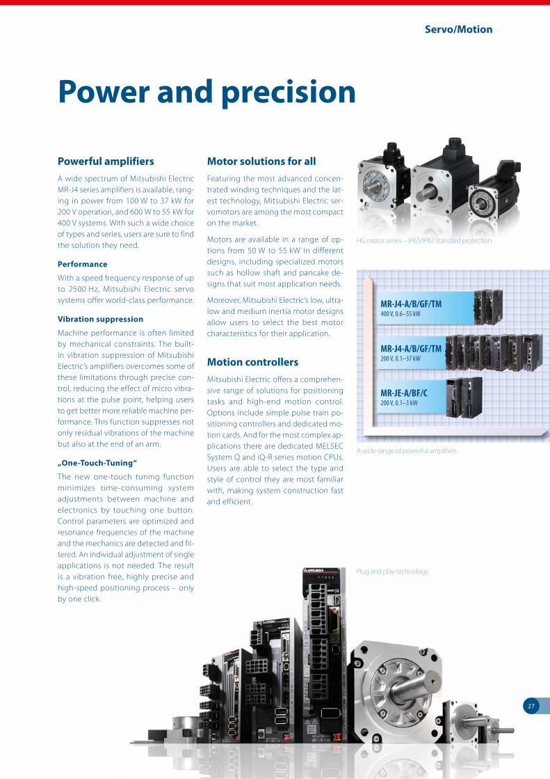
Powerful amplifiers
A wide spectrum of Mitsubishi Electric MR-J4 series amplifiers is available, rang-ing in power from 100 W to 37 kW for 200 V operation, and 600 W to 55 kW for 400 V systems. With such a wide choice of types and series, users are sure to find the solution they need.
Performance
With a speed frequency response of up to 2500 Hz, Mitsubishi Electric servo systems offer world-class performance.
Vibration suppression
Machine performance is often limited by mechanical constraints. The built-in vibration suppression of Mitsubishi Electric’s amplifiers overcomes some of these limitations through precise con-trol, reducing the effect of micro vibra-tions at the pulse point, helping users to get better more reliable machine per-formance. This function suppresses not only residual vibrations of the machine but also at the end of an arm.
„One-Touch-Tuning“
The new one-touch tuning function minimizes time-consuming system adjustments between machine and electronics by touching one button. Control parameters are optimized and resonance frequencies of the machine and the mechanics are detected and fil-tered. An individual adjustment of single applications is not needed. The result is a vibration free, highly precise and high-speed positioning process – only by one click.
Motor solutions for all
Featuring the most advanced concen-trated winding techniques and the lat-est technology, Mitsubishi Electric ser-vomotors are among the most compact on the market.
Motors are available in a range of op-tions from 50 W to 55 kW in different designs, including specialized motors such as hollow shaft and pancake de-signs that suit most application needs.
Moreover, Mitsubishi Electric’s low, ultra-low and medium inertia motor designs allow users to select the best motor characteristics for their application.
Motion controllers
Mitsubishi Electric offers a comprehen-sive range of solutions for positioning tasks and high-end motion control. Options include simple pulse train po-sitioning controllers and dedicated mo-tion cards. And for the most complex ap-plications there are dedicated MELSEC System Q and iQ-R series motion CPUs. Users are able to select the type and style of control they are most familiar with, making system construction fast and efficient.
Power and precision
Plug and play technology
A wide range of powerful amplifiers
MR-J4- A/B/GF/TM200 V, 0.1–37 kW
MR-J4-A/B/GF/TM400 V, 0.6–55 kW
MR-JE-A/BF/C200 V, 0.1–3 kW
HG motor series – IP65/IP67 standard protection

28
Robots/Articulated arm/SCARA
Robots are already widely accepted as a cost-effective solution for high-speed, high-accuracy pick-and-place applica-tions as well as some basic assembly tasks.
€ 1.65/hr
Robot usage can vary widely but an av-erage application over a typical 7-year life cycle can cost as little as € 1.65 per hour to purchase and operate.
BASIC talk
Programming a Mitsubishi Electric robot arm is easier than most people think. The programming language is a BASIC-like structure with commands reflect-ing the requested action. For example, the command MOV means “move”, HCLOSE means “hand close”. Further-more, all Mitsubishi Electric robots are programmed using the same language, reducing the user’s learning curve.
Making life easy
With the software RT ToolBox3 all robot models are programmable in a quick and easy way. Imported 3D CAD data, program variables and robot simulations can easily be displayed on the graphical surface of the programming software RT Toolbox3.
This leading edge software allows a ro-bot application to be programmed and its operation simulated before the hard-ware is purchased. This makes system design and building quicker and easier. Moreover, it can identify potential haz-ards before robot integration begins.
Advanced control as standard
All Mitsubishi Electric robot controllers are shipped with the full control soft-ware as standard. This means users do not need to buy additional task- driven software modules at a later date.
Innovation in movement
High speed, high accuracy pick and place applications
Powerful software helps you get the most out of
your robot application.
29
Robots/Articulated arm/SCARA
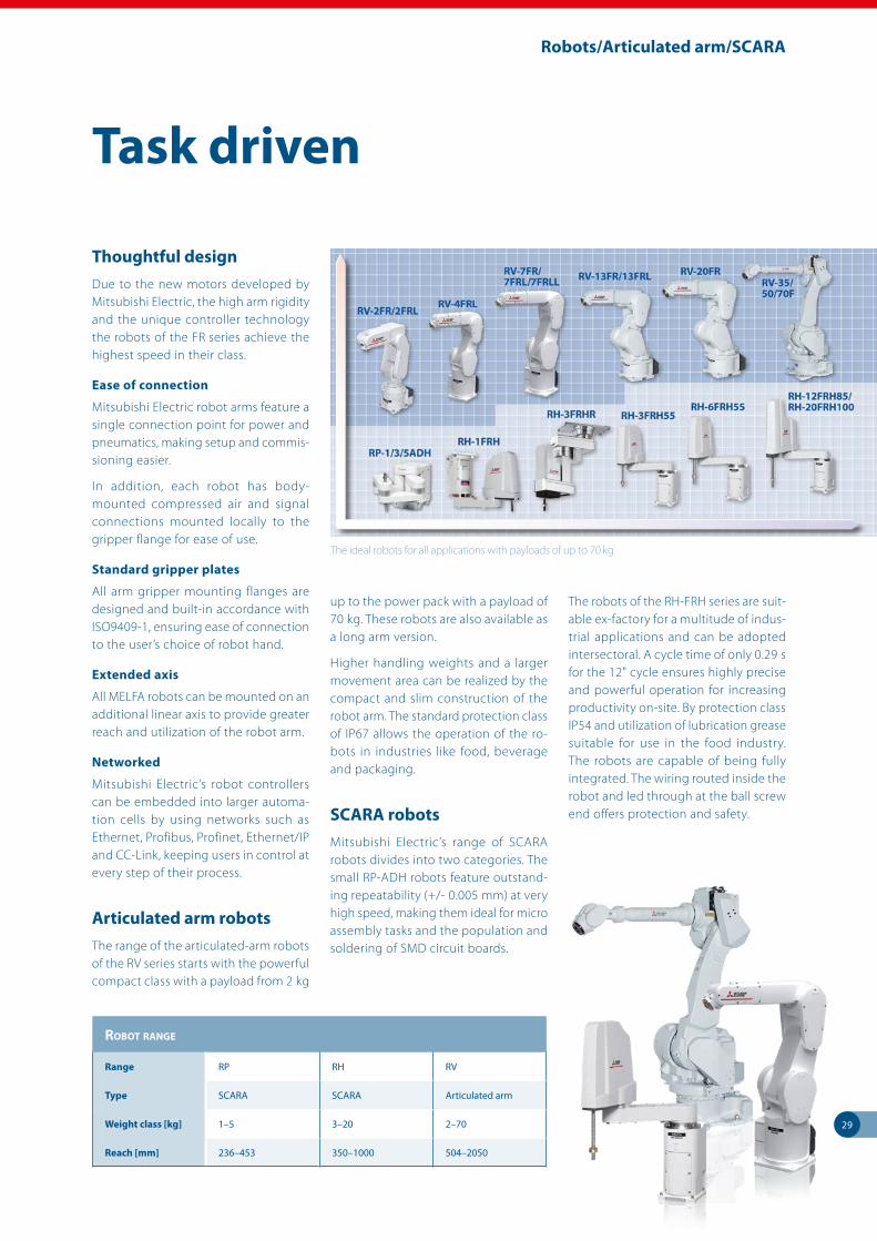
Thoughtful design
Due to the new motors developed by Mitsubishi Electric, the high arm rigidity and the unique controller technology the robots of the FR series achieve the highest speed in their class.
Ease of connection
Mitsubishi Electric robot arms feature a single connection point for power and pneumatics, making setup and commis-sioning easier.
In addition, each robot has body- mounted compressed air and signal connections mounted locally to the gripper flange for ease of use.
Standard gripper plates
All arm gripper mounting flanges are designed and built-in accordance with ISO9409-1, ensuring ease of connection to the user’s choice of robot hand.
Extended axis
All MELFA robots can be mounted on an additional linear axis to provide greater reach and utilization of the robot arm.
Networked
Mitsubishi Electric’s robot controllers can be embedded into larger automa-tion cells by using networks such as Ethernet, Profibus, Profinet, Ethernet/IP and CC-Link, keeping users in control at every step of their process.
Articulated arm robots
The range of the articulated-arm robots of the RV series starts with the powerful compact class with a payload from 2 kg
up to the power pack with a payload of 70 kg. These robots are also available as a long arm version.
Higher handling weights and a larger movement area can be realized by the compact and slim construction of the robot arm. The standard protection class of IP67 allows the operation of the ro-bots in industries like food, beverage and packaging.
SCARA robots
Mitsubishi Electric’s range of SCARA robots divides into two categories. The small RP-ADH robots feature outstand-ing repeatability (+/- 0.005 mm) at very high speed, making them ideal for micro assembly tasks and the population and soldering of SMD circuit boards.
The robots of the RH-FRH series are suit-able ex-factory for a multitude of indus-trial applications and can be adopted intersectoral. A cycle time of only 0.29 s for the 12" cycle ensures highly precise and powerful operation for increasing productivity on-site. By protection class IP54 and utilization of lubrication grease suitable for use in the food industry. The robots are capable of being fully integrated. The wiring routed inside the robot and led through at the ball screw end offers protection and safety.
Task driven
The ideal robots for all applications with payloads of up to 70 kg
robot range
Range RP RH RV
Type SCARA SCARA Articulated arm
Weight class [kg] 1–5 3–20 2–70
Reach [mm] 236–453 350–1000 504–2050

30
Low voltage/Energy monitoring
Mitsubishi Electric has been active in the low voltage (LV) switchgear market since 1933. Ever since Mitsubishi Electric developed and manufactured the first molded case circuit breakers, the com-pany has been committed to research and development in this field, making it one of the world’s leading manufactur-ers of circuit breakers.
Innovation
Groundbreaking research and design has resulted in innovative LV switch-gear, providing users with greater quality, safety and reliability. Today’s LV products feature meticulously designed technology: even the casing material used in the PA (Polymer Ablation type Auto-Puffer) provides greater safety and high voltage breaking performance.
Leading edge
Jet Pressure Trip (JPT ) is an extension of the PA concept, allowing switchgear to trip even faster than a traditional magnetic solution. This means that the switchgear can improve its current- lim-iting performance and circuit breaking reliability. Any connected devices are then better protected, a major benefit to users.
Other technologies such as ISTAC (Im-pulsive Slot-Type Accelerator, used as a high-speed arc-controlling technol-ogy) and developments in digital ETR (Electronic Trip Relay) and VJC (Vapour Jet Control) all contribute to making Mitsubishi Electric’s LV products lead-ing edge.
Global products
All LV products are designed to comply with international standards such as JIS, IEC, EN, GB, UL/CSA.
Breakthrough technology
Groundbreaking research and design
Standards are at the center of our product de-
velopment.

31
Low voltage/Energy monitoring
Mitsubishi Electric offers a complete solution for line and load side distribu-tion, ranging from air circuit breakers to molded case breakers and magnetic contactors.
Air circuit breakers (ACBs)
These compact Super AE units come in a broad spectrum of performance catego-ries from 1,000 to 6,300 Amps. The basic unit is available as a fixed or “draw out” design, which can be augmented with options for enhanced overload control, network and energy consumption.
Thanks to these features Mitsubishi Electric’s ACBs provide users with the flexibility to meet most applications.
Moulded case circuit breakers (MCCBs)
Mitsubishi Electric’s MCCBs of the World Super Series (WS) provide protection across the current range from 32 to 1,600 Amps. Each unit is available in a fixed or slot–in design and has a range of additional options such as electronic trips
Magnetic contactors, thermal over-load relays, contactor relays
The MS range of LV switchgear is a re-liable and customizable solution for load side connection. The MS-N range is made up of magnetic contactors, ther-mal overload relays and contactor relays.
These space-efficient products are up to 25 % smaller than similar units. In addi-tion, the MS range has enhanced per-formance. For example, the magnetic contactors withstand voltage drops of up to 35 % while still ensuring reliable operation.
The MS-N units can be customized with a wide range of options, including ther-mal overload relays, time delay modules, auxiliary contacts and trip indicators to suit the user’s specific needs.
Miniature circuit breakers (MCB)
Trip-free mechanism
During fault MCB trips even if handle is held in ON position.
Low watt loss
Power loss values are much lesser than IEC specified values; making it one of the most energy efficient MCB.
Energy limiting class: 3
High current limiting performance un-der fault conditions achieved due to ultrafast contact opening and rapid quenching of arc.
Circuit identification
Legend plates for circuit identifications and hence enhanced safety.
Motor circuit breaker (MMP)
Self-protected manual motor controller
Reliable protection and superior performance
Compact design
Smart wiring
Safety & quality
Global standards
Energy monitoring (ME96 and EMU4)
Multi-measuring instrument Super-S series (ME96)
Mitsubishi Electric multi-measuring instrument SS series features high per-formance and crystal clear display. With simple operating functions, SS series is the best support to your measuring and monitoring systems.
Energy measuring unit EcoMonitorLight (EMU4)
Simple & easier providing energy visu-alization. Introducing the EcoMonitor-Light, an energy measuring unit with an integrated display that provides easy energy visualization in order to provide ways to save energy and to comply with the Energy Saving Act in response to the need for a simple manner to figure out energy consumption.
A complete solution
Advanced low voltage technology
WS 32–1600 A
SAE 1000–6300 A
MS 20–1000 A
MCB0.5–63 A

32
Application solutions
Customer applications with Mitsubishi Electric products have been widespread from critical applications in pharmaceu-tical industries to sublime applications in the leisure industry.
Here are just a few examples of applica-tions that customers have completed in the past:
Agriculture – Plant watering systems – Plant handling systems – Sawmill (wood)
Building management – Smoke detection monitoring – Ventilation and temperature control – Lift (elevator) control – Automated revolving doors – Telephone management – Energy management – Swimming pool management
Construction – Steel bridge manufacturing – Tunnel boring systems
Food and drink – Bread manufacturing (mixing/baking) – Food processing
(washing/sorting/slicing/packag-ing)
Leisure – Multiplex cinema projection – Animated mechatronics
(museums/theme parks)
Medical – Respiration machine testing – Sterilization
Pharmaceutical/chemical – Dosing control – Pollution measurement systems – Cryogenic freezing – Gas chromatography – Packaging
Plastics – Plastic welding systems – Energy management systems for injection molding machines – Loading/unloading machines – Blow molding test machines – Injection molding machines
Automotive
Printing
Textiles
Transportation – Sanitation on passenger ships – Sanitation on rail rolling stock – Fire tender pump management – Waste disposal truck management
Utilities – Wastewater disposal – Freshwater pumping – Clarification plants
Where have Mitsubishi Electric products been used?
Automotive control solutions
Remote management solutions include SCADA,
Networking, Telemetry and Industrial Modems.

Technical Information Section
All Product Ranges

2
More information?
The catalogue at hand is designed to give an overview of the extensive product range of Mitsubishi Electric Europe B.V., Factory Automation. If you cannot find the information you require in this catalogue, there are a number of ways you can get further details on configuration and technical issues, pricing and availability.
For technical issues visit the https://eu3a.mitsubishielectric.com website. Our website provides a simple and fast way of accessing further technical data and up to the minute details on our products and services. Manuals and catalogues are available in several different languages and can be downloaded for free.
For technical, configuration, pricing and availability issues contact our distributors and partners. Mitsubishi Electric partners and distributors are only too happy to help answer your technical questions or help with configuration building. For a list of Mitsubishi Electric partners please see the back of this catalogue or alternatively take a look at the “contact us” section of our website.
About this technical information section
This section is a guide to the range of products available. For detailed configuration rules, system building, installation and configuration the associated product manuals must be read. You must satisfy yourself that any system you design with the products in this catalogue is fit for purpose, meets your requires and conforms to the product configuration rules as defined in the product manuals.
© Mitsubishi Electric Europe B.V., Factory Automation - European Business Group
The products of Mitsubishi Electric Europe B.V., that are listed and described in this document, are neither subject to approval for export nor subject to the Dual-Use List.

3
Contents
Overview
1 SOFTWARE 4
2 NETWORKS 8
3 REMOTE I/O MODULES 13
4 MODULAR PLCs 21
MELSEC iQ-R series 23
MELSEC System Q 30
MELSEC L series 40
5 COMPACT PLCs 45
6 HMIs 61
7 FREQUENCY INVERTERS 68
8 SERVO AND MOTION SYSTEMS 88
9 ROBOTS 105
10 LOW VOLTAGE AND ENERGY MONITORING 110
11 MES SOLUTIONS 118
12 POWER SUPPLIES 120
Index 121
1
2
3
4
5
6
7
8
9
10
11
12

4
1
Softw
are
Software
Our MELSOFT suite embodies a wide range of software to optimise your plant productivity: from visualisation and control systems to historic and downtime monitoring capabilities. A core design feature of our software is that it is scala-ble. It is a well accepted truism that one solution rarely fits all, so within each application category there are a range of products offering different levels of functionality and connectivity designed to meet your individual needs. All products are based on Microsoft standards (OPC etc), giving you a broad range of connectivity options and a familiar interface. The MELSOFT suite consists of three main areas:
z Visualisation. This type of software is aimed at monitoring and controlling your automa-tion processes.
z Programming. Our extensive range of programming software enables users to write their own PLC code for their application. We have software solutions for each of the follow-ing products groups; servos, inverters, logic blocks, PLCs, HMIs and networking.
z Communication. Our communication software is designed to integrate our products with common third party software packages. This provides you with the reliability and qual-ity of Mitsubishi Electric hardware, combined with the familiarity of software packages/tools such as Microsoft Excel, ActiveX and OPC.
Unified engineering environment: iQ Works
iQ Works integrates the functions necessary to manage every part of the system cycle.
System design
The intuitive system configuration diagram allows for the graphic assembly of systems, centralized management of disparate projects and batch configuration of the entire control system.
Programming
Use system labels to seamlessly share device data between GOTs, PLCs and motion controllers. Save the time and hassle of changing device values in each program by using the update system labels feature.
Test and startup
Debug and optimize programs using the simulation functions. Use the included diagnostics and monitoring functions to quickly identify the source of errors.
Operation and maintenance
Speed up the process of commis-sioning, configuring and updating the system by using the batch read feature. Virtually eliminate the confusion associated with system management.
MELSOFT Navigator
– is the heart of iQ Works. It enables the effortless design of entire upper-level systems and seam-lessly integrates the other MELSOFT programs included with iQ Works. Functions such as system configuration design, batch parameter setting, system labels and batch read all help to reduce TCO.
MELSOFT GX Works
– represents the next generation in MELSOFT PLC maintenance and programming software, with improvements made throughout to increase productivity and drive down engineering costs.
MELSOFT MT Works
– is a comprehensive motion CPU maintenance and program design tool. Its many useful functions, such as intuitive settings, graphical programming and digital oscilloscope, simulator, different Motion OS support, assistance help, to reduce the MT Works2 associated with motion systems.
MELSOFT GT Works
– is a complete HMI programming, screen creation and maintenance program. In order to reduce the labor required to create detailed and impressive applications, the software’s functionality has been built around the concepts of ease of use, simplifications (without sacrificing functionality) and elegance (in design and screen graphics).

5
Software
1
Softw
are
PLC programming
GX Works2 supports all MELSEC PLCs (except MELSEC iQ-R/iQ-F), while GX Works3 supports the MELSEC iQ-R and iQ-F series and offers numerous functions to faciliate programming
work and support the user. GX Works2 FX has the same functionality as GX Works2 but just for FX3 PLC´s.
GX Works2/GX Works3
GX Configurator DP is a setup and configuration software for Profibus DP networks. It can be used to configure Mitsubishi Electric Profibus DP
master and all slave modules including inverters and HMI’s as well as other manufacturers products.
GX Configurator DP
The original visual based function block pro-gramming software for logic controllers. Easy to use Windows based software that requires no prior experience or training by the user.
Program elements are placed on screen, with inputs on the left and outputs on the right and the function blocks in the middle.
ALPHA – ALVLS (AL-PCS/WIN)
GX Configurator PN
GX Configurator PN is the configuration tool for Profinet I/O modules. This software offers func-tions for the configuration of the Profinet I/O
network, testing the configuration and transfer of the settings to the Profinet module.
Programming MELSEC series
FX iQ-F iQ-R Q L
GX Works2 P P PGX Works3 P PGX Works2 FX P
Drag & Drop
Simply drag & drop when adding a module

6
Software
1
Softw
are
Programming of drive systems
MT Works2 is an integral start-up software used to structure and configure a system for MELSEC System Q motion and iQ-R series controller applications.
MT Works2
MR Configurator2 is a user-friendly software for easy setup, tuning and operation of the MELSERVO servo systems. Tuning, monitor display, diagnosis, reading/writing parameters,
and test operations are easily performed on a personal computer. This start-up support tool achieves a stable machine system, optimum control, and short setup time.
MR Configurator2
FX Configurator FP is a special configurator tool for the FX3U PLC SSCNET III positioning module. This software reduces programming and setup time for any level of positioning application.
FX Configurator FP
FR Configurator and FR Configurator 2 are powerful frequency inverter configuration and management tools. It runs in Windows making it possible to manage your inverters
with a standard PC. It allows the inverters to be monitored and the parameters to be configured, providing a user friendly environment to control single or multiple inverters.
FR Configurator/FR Configurator2

7
Software
1
Softw
are
Robots programming
RT Toolbox3 is a software for program creation and total engineering support.
This PC software supports everything from system startup to debugging, simulation, maintenance and operation. This includes programming and editing, operational checking before robots are installed, measureing process
tact time, debugging during robot startup, monitoring robot operation after startup, and trouble shooting.
RT Toolbox3 Pro offers an add-in tool 1 for Solid-Works 2 used for robot simulation in production systems on PC’s converting processing paths of workpieces into robot position data.
RT Toolbox3
MX Sheet enables users to gather data from their PLC and analyse it using the familiar tools and functions of Excel. MX Sheet can analyse and display real-time data in tables, graphs and charts as it happens.
MX Sheet
PC data management
The MX OPC Server is a Mitsubishi Electric I/O driver OPC Data Access (DA) and Alarm/Events (AE) server that provides the interface and communications protocol between a wide range of Mitsubishi Electric hardware and your process control software. Mitsubishi Electric drivers incorporate OLE Automation technology and OPC compliance to provide flexibility and ease-of-use.
MX OPC Server
MX Component provides users with powerful ActiveX controls that simplify the communica-tion between a PC and PLC. Users to not have to design complex communication protocols and is ideal for implementing specific software applications requiring PLC connectivity.
MX Component supports a wide variety of pow-erful and standardised programming languages such as Visual C++ .NET, VBA and VB Script.
MX Component
MAPS visualisation solutions
The Mitsubishi Electric Adroit Process Suite (MAPS) creates advanced, secure and integrated solutions that deliver value to your business. The MAPS SCADA/MAPS HMI and related software products provide the latest automation software for general industrial users including water utilities, telecommunications, food and bever-age, manufacturing, life sciences, processing or building and facilities management industries. MAPS is also built to deliver solutions around IIoT applications.
MAPS takes raw data from the front end device like a Programmable Logic Controller (PLC) or
Remote Telemetry Unit (RTU) in the process field and transforms it into an easy to understand graphic representation, whilst adding the ability to log history, do alarming and process values.
MAPS SCADA helps identify and manage key factors such as quality, production and energy efficiency, which ultimately lead to greater business profits.
The MAPS SCADA is at the forefront of the SCADA/HMI market, making it one of the most open, advanced and scalable SCADA platforms available.
Life-cycle engineering, SCADA, HMI, reports and operational excellence for industrial applications
With GT Works3 you will get a comprehen-sive tool for programming, maintenance and screen creation. It is composed of the software GT Designer3, GT SoftGOT1000 and
GT SoftGOT2000 as well as the simulation tool GT Simulator and a converter for already exist-ing projects.
Visualisation software – HMI programming
GT Works3

8
2
Netw
orks
Networks
From simple stand alone systems and basic AS-Interface networks to Ethernet based networks and even Global networks based on Remote Telemetry Technology, Mitsubishi Electric has the answers. Here is an overview of some of the networks Mitsubishi Electric provides:
Ethernet
If you are looking for the widest possible set of connectable technologies, Ethernet is unrivalled. The Ethernet interface allows communication via CC-Link IE Field, Profinet, Modbus®/TCP, EtherNet/IP and EtherCat.
EtherNet/IP
EtherNet/IP is an open Ethernet standard for industrial networks using TCP/IP technology. It incorporates the Common Industrial Protocol (CIP) as application protocol.
CC-Link, CC-Link IE Control, CC-Link IE Field, CC-Link IE Field Basic and CC-Link Safety
If you need unparalleled ease of connection between Mitsubishi Electric products or you are looking for a single supplier for your control net-work needs, then CC-Link is the natural choice.
AnyWireASLINK
AnyWireASLINK is a sensor-level network that realizes a smaller installation space and reduces wiring due to its easy wiring topology. The ability to monitor the network system from a centralized location reduces commissioning time and improves productivity.
Profibus DP
Profibus is one of the most widely used auto-mation networks in Europe. It provides a wide possible range of compatible devices while delivering fast and robust communication.
Profinet
Open industrial Ethernet standard for automa-tion. Profinet uses TCP/IP and IT standards, is capable of real-time Ethernet and allows the integration of field bus systems.
Modbus®/TCP, Modbus®/RTU
The Modbus® protocol is a messaging structure which is used to establish master-slave/client-server communication between intelligent devices. It is a de facto standard, truly open and a widely used network protocol in the industrial manufacturing environment.
DeviceNet™
DeviceNet™ is another widely accepted open network type with a large variety of third party products. This network type is particularly popu-lar in North America.
AS-Interface (Actuator Sensor Interface)
The Actuator Sensor Interface (AS-Interface) is the international standard for the lowest field bus level. The network suits versatile demands, as it’s very flexible and easy to install. It is usually used to control sensors, actuators, I/O units and gateways.
MELSECNET/H
For the systems that demand uncompromising reliability and high speed performance, only a dedicated network can deliver. MELSECNET/H and it’s predecessor MELSECNET/10 use high speed, redundant functionality to give deter-ministic delivery of large data volumes.
SSCNET III/H
Mitsubishi Electric’s SSCNET III (Servo System Controller Network) is a dedicated motion controller network ensuring maximum control and flexibility for motion systems under all conditions.
The motion controllers and servo amplifiers can be linked via the SSCNET network.
CANopen
CANopen is an “open” implementation of the Controller Area Network (CAN), which is defined in the EN50325-4 standard. It was developed by members of the CAN in Automation interna-tional users and manufacturers group.
BACnet
BACnet is a communications protocol for Building Automation and Control (BAC) networks that leverage the ASHRAE, ANSI and ISO 16484-5 protocol.
EtherCAT
EtherCAT is the abbreviation of Ethernet for Control Automation Technology. It is an open network communication between a master and slaves that uses real-time Ethernet.
NetworkPLC
HMI Inverter Servo Breaker Robot Energy metersModular Compact ALPHA
Ethernet
TCP/IP V V — V V — — V —CC-Link IE Field V V — V V V — V —CC-Link IE Control V — — V — — — — —CC-Link IE Field Basic V V — V V V — V —Modbus®/TCP V V — V V V — — V
Profinet V — — — V V — V —EtherNet/IP — — — — V V — V —EtherCat — — — — V V — — —
CC-Link V V — V V V V V V
Profibus DP V V — — V — V V —Modbus®/RTU V V — V V V V — —DeviceNet™ V V — — V — — V —AS-Interface V — V — — — — — —MELSECNET/H V — — V — — — — —SSCNET III/H V V — — V V — V —CANopen V V — — V — — — —BACnet V (iQ-R) — — — — — — — —

9
Networks
2
Netw
orks
Typical distributed control structure
P R O F I
U SBPROCESS FIELD BUS
C L P AC L P A 1
1
1
PROFIBUS/DPPROFIBUS DP
M
DeviceNetDeviceNet
AS-InterfaceAS-Interface
CC-LINKCC-LINK
CC-LINKCC-LINK
System Q
MELSECNET/10/HMELSECNET/10/H
System Q
System Q
System Q
System Q
MELSECNET/10MELSECNET/10MELSECNET/10/HMELSECNET/10/H
GOT
TCP/IP ETHERNETTCP/IP ETHERNET
MODBUSMODBUS
FX
System Q
System Q
System QSystem Q
1
1
System Q
System Q
System Q
CANopenCANopen
CC-Link IECC-Link IE
CC-Link IECC-Link IE Field Network
CC-Link IE Motion Network
M
M
M
SSCNET IIISSCNET III
1
1
1
1
FX
FX
System Q
System Q
1
FR-E700 ENE
FR-A800FR-F800-E
Safety PLC
I/O module
CC-Link, CC-Link IE Control, CC-Link IE Field, CC-Link IE Field Basic and CC-Link Safety
Standard CC-Link modulesSeries Master/slave modules Description Art. no.
MELSEC iQ-R series RJ61BT11 CC-Link master/local module 279572
MELSEC System QQJ61BT11N CC-Link master/local module 154748QS0J61BT12 CC-Link Safety master module 203209
MELSEC L series
L26CPU-BT CPU with integrated CC-Link master/local module 238056L26CPU-PBT CPU with integrated CC-Link master/local module 244977LJ61BT11 CC-Link master/local module 238099LJ61CL12 CC-Link/LT master module 284432
MELSEC iQ-F series FX5-CCL-MS CC-Link master module/intelligent device station 312299
MELSEC FX seriesFX3U-16CCL-M CC-Link master module 248224FX3U-64CCL CC-Link local module on FX3 217915FX2N-32CCL CC-Link local module 102961
PCI Express Q81BD-J61BT11 Master/local module for PCI Express bus 221859PCI Q80BD-J61BT11N Master/local module for PCI/F PC master 200758
Frequency invertersFR-A7NC CC-Link interface for FR-A700/FR-F700 156778FR-A7NC-Ekit-SC-E CC-Link interface for FR-E700 SC 239644FR-A8NC CC-Link interface for FR-A800/FR-F800 269431
HMI GT15-J61BT13 CC-Link interface for GOT1000 203494Breakers BIF-CC-W CC-Link interface for SUPER AE air circuit breakers 168571MELFA robots 2D-TZ576 CC-Link interface for robot controller CR750-D 219063
Energy metersME0040C-SS96 CC-Link interface for ME96SSA 273874EMU4CM-C CC-Link interface for ME96SSA 292655
CC-Link IE Field Basic modulesSeries Master/slave modules Description Art. no.
MELSEC iQ-R seriesRmCPU
CC-Link IE Field Basic master
various
RmENCPU
MELSEC System QQmUDVCPUQmUDPVCPU
MELSEC L series LmCPU
MELSEC iQ-F seriesFX5UFX5UC
HMI
GT27
CC-Link IE Field Basic slaveGT25GT23GT21GS21

10
Networks
2
Netw
orks
Ethernet interface modules for various network protocols
Series Modules Description Art. no.MELSEC iQ-R series RJ71EN71 Ethernet interface module, 1 Gbps, 100 Mbps, 10 Mbps, two interfaces, multi-network connectivity (Ethernet/CC-Link iE) 279570
MELSEC System Q
QJ71E71-100 Ethernet interface module,100 Mbps,100BASE-TX/10BASE-T 138327QJ71E71-B2 Ethernet interface module, 10BASE2 129614QJ71E71-B5 Ethernet interface module, 10BASE5 147287QJ71MT91 Modbus®/TCP master and client 10BASE-T/100BASE-TX 155603NZ2EHG-T8 Compact-sized industrial switching HUB equipped with 8 ports capable of 1000BASE-T 259221NZ2EHF-T8 Compact-sized industrial switching HUB equipped with 8 ports capable of 100BASE-T 259222
MELSEC L series LJ71E71-100 Ethernet interface module, 100 Mbps, 10 Mbps, 10BASE-T/100BASE-TX 263072
MELSEC FX seriesFX3U-ENET-ADP Ethernet interface module, 10BASE-T 157447FX3U-ENET Ethernet interface module, 100BASE-TX/10BASE-T 166086FX3U-ENET-P502 Ethernet interface module, 100BASE-TX/10BASE-T, Modbus®/TCP ready 225142
HMI GT15-J71E71-100 Ethernet interface module, 100BASE-TX/10BASE-T 166309
Frequency invertersFR-A7N-WiE WiFi Ethernet multi-protocol (Modbus®/TCP, EtherNet/IP, BACnet, MELSEC ABCSP according Modbus®/RTU) for FR-A700/FR-F700 264932A7NETH-2P Ethernet protocol (EtherNet/IP ProfiNet I/O, BacNet/IP, EtherCat, Modbus®/TCP&MC) for FR-A700/FR-F700/FR-E700 283759A8NEIP_2P EtherNet/IP 2port interface for FR-A800/FR-F800 262950
EtherCat
Series Modules Description Art. no.
Frequency invertersA8NECT_2P EtherCat/IP 2port interface for FR-A800/FR-F800 284809 A7NETH-2P EtherCat/IP 2port interface for FR-A700/FR-E700 283759
Servo MR-J4-mTM-ECT MR-J4 servo amplifiers with integrated EtherCAT interface from 50 W to 22 kW various
Modbus®/TCP, Modbus®/RTU
Series Master/slave modules Description Art. no.
MELSEC System QQJ71MB91 Serial Modbus® interface master/slave module 167757QJ71MT91 Modbus®/TCP interface master/slave module for Ethernet 155603
MELSEC L seriesCPU-Module Built-in Modbus®/TCP functionality (master/slave) —LJ71C24 Serial Modbus®/RTU master module 238093LJ71C24-R2 Serial Modbus®/RTU master module 238094
MELSEC iQ-F seriesFX5-232ADP Serial Modbus® RS232C interface master/slave module 280513FX5-485ADP Serial Modbus® RS485 interface master/slave module 280514
MELSEC FX seriesFX3U-232ADP-MB Serial Modbus® RS232C interface master/slave module 165276FX3U-485ADP-MB Serial Modbus® RS485 interface master/slave module 165277FX3U-ENET-P502 Ethernet modul, 100BASE-TX/10BASE-T, Modbus®/TCP ready 225142
Breaker BIF-MD-W Modbus® interface for SUPER AE air circuit breakers 168573
Energy metersME0000MT-SS96 Modbus® interface for ME96SSA 297420EMU4-CM-MT Modbus® interface for ME96SSA 304060
Servo MR-JE-mC MR-JE servo amplifiers with Modbus®/TCP interface from 100 W to 3 kW various
CC-Link IE modulesSeries Master/slave modules Description Art. no.
MELSEC iQ-R series
RJ71GP21-SX Control/normal station for CC-Link IE Control, 1 Gbps, fiber-optic cable 279571RJ71GF11-T2 CC-Link IE Field master/local station, 1 Gbps 279569RJ72GF15-T2 CC-Link IE Field remote head module, 1 Gbps, Cat5e 297947R04ENCPU
CC-Link IE Control master/slave or CC-Link IE Field master/slave
290226R08ENCPU 290227R16ENCPU 290228R32ENCPU 290232R120ENCPU 290234
MELSEC System Q
QJ71GF11-T2 CC-Link IE Field master/slave modul, 1 Gbps, Cat5e 236484QS0J71GF11-T2 CC-Link IE Field master/local module 245177QJ71GP21-SX 1 Gbps, master/slave module for FO GI 208815QJ71GP21S-SX 1 Gbps, master/slave module for FO GI with external voltage supply 208816Q80BD-J71GP21-SX 1 Gbps, PCI PC card, master/slave for FO GI 208817Q80BD-J71GP21S-SX 1 Gbps, PCI PC card, master/slave for FO GI with external voltage supply 208818Q81BD-J71GF11-T2 PCI PC card, master/local module 253008NZ2GF-ETB CC-Link IE Field network Ethernet adapter 253007
MELSEC L seriesLJ71GF11-T2 CC-Link IE Field master/local module 246346 LJ72GF15-T2 CC-Link IE Field head module 238100
MELSEC iQ-F series FX5-CCLIEF CC-Link IE Field intelligent device station 297444
Frequency invertersFR-A7NCE Option card for integration of a FR-A700/FR-F700 into a CC-Link IE Field network 244993FR-A8NCE Option card for integration of a FR-A800/FR-F800 into a CC-Link IE Field network 273102
HMIGT15-J71GP23-SX GOT CC-Link IE interface for GT15/16 HMIs, 1 Gbps, fibre optic ring network 218576GT15-J71GF13-T2 GT16/15 CC Link IE Field network module 247574
MELFA robots 2F-DQ535-CCIEF-SET CC-Link IE Field interface card for CR800-D robot controller 324560Servo MR-J4-mGF MR-J4 servo amplifiers with integrated CC-Link IE Field interface from 50 W to 22 kW various

11
Networks
2
Netw
orks
Profibus DP(V1)
Master/slave moduleSeries Modules Description Art. no.
MELSEC iQ-R series RJ71PB91V Profibus master/slave module 308714Master modules
Series Modules Description Art. no.
MELSEC System Q QJ71PB92V Profibus DP interface master module (DP V1/V2) 165374MELSEC L series ME1PB1-L Profibus DP interface master module 268527MELSEC FX series FX3U-64DP-M Profibus DP interface master module for FX3U PLCs 166085
Slave modulesSeries Modules Description Art. no.
MELSEC System Q QJ71PB93D Profibus DP slave module 143545MELSEC L series ME2PB1-L Profibus DP slave module 278167MELSEC FX series FX3U-32DP Profibus DP slave module for FX3U PLCs 194214
Frequency inverters
A8NDPV1 Profibus DPV1 interface for FR-A800, compliant to Profidrive, with D-sub connector 262948FR-A8NP Profibus interface for FR-A800, only PPO support, compatible to FR-A7NP 274514FR-A7NP Profibus interface for FR-A700/FR-F700 158524FR-A7NP-Ekit-SC-E Profibus interface for FR-E700 SC 239646FR-A7NP-Ekit-SC-E-01 Profibus interface with D-sub connector for FR-E700/FR-E700 SC 273138
Breaker BIF-PR-W Profibus interface for SUPER AE air circuit breakers 168572Slave I/O
Series Module Description Art. no.
All PLC types ST series/STlite series Modular input/output system for connection to Profibus DP refer to page 16 and following
I/O bridge modulesSeries Modules Description Art. no.
MELSEC FX series FX2N-32DP-IF-D Profibus remote I/O using FX2N I/O and special function modules; 24 V DC power supply 142763MELFA robots 2D-TZ577 Profibus DP interface for robot controller CR750-D 218861
AS-Interface
Series Master/slave modules Description Art. no.
MELSEC System Q QJ71AS92 AS-Interface module, version 2.11, dual network master 143531ALPHA AL2-ASI-BD AS-Interface board for use with AL2-14MR or AL2-24MR 142525
AnyWireASLINK
Series Modules Description Art. no.
MELSEC iQ-R series RJ51AW12AL AnyWireASLINK system master module 301856MELSEC iQ-F series FX5-ASL-M AnyWireASLINK system master module 312300
MELSEC L series LJ51AW12AL AnyWireASLINK system master module 290898
DeviceNetTM
Series Master/slave modules Description Art. no.
MELSEC System Q QJ71DN91 DeviceNet™ interface master/slave module 136390MELSEC FX series FX2N-64DNET DeviceNet™ interface slave module 131708
Frequency invertersFR-A7ND DeviceNet™ interface for FR-A700/FR-F700 158525FR-A7ND-Ekit-SC-E DeviceNet™ interface for FR-E700 SC 239648FR-A8ND DeviceNet™ interface for FR-A800 269432
Series Modules Description Art. no.
MELSEC iQ-R series RJ71PN92 Profinet master module 308713
MELSEC System Q ME1PN1FW-CCPU Profinet master module 252935
Frequency invertersA8NPRT_2P Profinet interface for FR-A800/FR-F800, compliant to Profidrive 262949
A7NETH-2P Profinet interface for FR-A700/FR-E700 283759
MELFA robots 2D-TZ535-PN-SET Profinet I/O interface for robot controller CR750-D/CR800-D 269546
Servo MR-J4-mTM-PNT MR-J4 Servo amplifiers with integrated Profinet interface from 50 W to 22 kW various
Profinet

12
Networks
2
Netw
orks
CANopen
Series Modules Description Art. no.
MELSEC iQ-R series RJ71CN91* CANopen communication module 308735MELSEC System Q ME3CAN1-Q CANopen communication module 278799MELSEC L series ME3CAN1-L CANopen communication module 283159MELSEC FX series FX3U-CAN CANopen communication module 252845
Frequency invertersFR-A7NCA CANopen communication module for FR-A700 191424FR-A7NCA E kit CANopen communication module for FR-E700 210705FR-A8NCA CANopen communication module for FR-A800/FR-F800 298153
* Please consult local Mitsubishi Electric representative to determine availability of these modules.
SSCNET III/H
Series Modules Description Art. no.
MELSEC FX series FX3U-20SSC-H FX3U positioning module, 2 axes (SSCNET III) 206189
MELSEC iQ-F seriesFX5-40SSC-S Simple motion module, 4 axes 281405FX5-80SSC-S Simple motion module, 8 axes 304187
MELSEC L series
LD77MS2 Simple motion module, 2 axes 268199LD77MS4 Simple motion module, 4 axes 268200LD77MS16 Simple motion module, 16 axes 268201LJ72MS15 Remote station (head module with END cover) 271040
MELSEC System Q
QD77MS2 Simple motion module, 2 axes 248702QD77MS4 Simple motion module, 4 axes 248703QD77MS16 Simple motion module, 16 axes 248704Q172DSCPU Motion controller, 16 axes 248700Q173DSCPU Motion controller, 32 axes 248701
Motion controllerQ170MSCPU(-S1) Stand alone motion controller, 16 axes 266524
(266535)MR-MQ100 Singe axis motion controller, 1 axis (SSCNET III) 217705
Frequency invertersFR-A7NS SSCNET III interface for FR-A700 191403FR-A8NCE SSCNET III/H interface for FR-A800 273102
ServoMR-JE-mBF MR-JE servo amplifiers with SSCNET III/H interface from 100 W to 3 kW variousMR-J4-mB MR-J4 servo amplifiers with SSCNET III/H interface from 50 W to 55 kW various
LonWorks
Series Modules Description Art. no.
Frequency invertersFR-A7NL Option card for integration of a FR-A700 into a LonWorks network 156779FR-A7NL-Ekit-SC-E Option card for integration of a FR-E700 SC into a LonWorks network 239645FR-A8NL LonWorks Interface for FR-A800/FR-F800 318109
SAE J1939
Series Module Description Art. no.
MELSEC FX series FX3U-J1939 Communication module for SAE J1939 network 254276
MELSECNET/H
Master, local station
Series Modules Description Art. no.
MELSEC System Q
QJ71BR11 MELSECNET/H master/local, coaxial cable 127592
QJ71LP21GE MELSECNET/H master/local, GI 62.5/125 fibre optic cable 138959
QJ71LP21-25 MELSECNET/H master/local, SI fibre optic cable 136391
QJ71NT11B MELSECNET/H master/local, twisted pair 221861
Slave (remote I/O)Series Modules Description Art. no.
MELSEC System QQJ72LP25-25 MELSECNET/H remote I/O controller, SI fibre optic cable 136392
QJ72BR15 MELSECNET/H remote I/O controller, coaxial cable 136393
Normal stationSeries Modules Description Art. no.
HMIGT15-J71LP23-25 MELSECNET/H communication unit, fiber-optic cable 229842
GT15-J71BR13 MELSECNET/H communication unit, coaxial cable 229843

13
1
2
3
Rem
ote I/O
mo
du
les
CC-Link/CC-Link IE Field remote modules
These remote modules are intended to be installed near the control target. The advantages are reduced cabling and the capability of acquir-ing data and operation results of individual machine modules autonomously.
For wet environments six types of low profile waterproof remote I/O modules with IP67 pro-tection are available featuring Input, Output and Combination modules.
z Up to 64 I/O modules with a maximum of 32 inputs or 32 outputs each can be con-nected.
z All modules have a very compact design which is tough and highly shock-resistant.
z Status indicator LEDs for the inputs
z Standard electrical isolation between process and control via optocouplers
z Mounting with DIN rail adapters or screws
z Modules can be mounted in horizontal arrangement or in one of 4 orientations on a flat surface.
z Ready for use with all CC-Link master modules.
Product Range Module Type No. of input No. of output Description Art. no.
Digital in
AJ65BTB1-16DRemote module
16 — DC input (+COM/-COM) 75447AJ65BTB2-16D 16 — DC input with 8 potential terminals (+COM/-COM) 75450AJ65SBTB1-8D
Compact remote module
8 — DC input (+COM/-COM) 104422AJ65SBTB1-16D 16 — DC input (+COM/-COM) 136026AJ65SBTB3-16D 16 — DC input (+COM/-COM), 3-wire sensors 151186AJ65SBTB1-16D1 16 — Fast DC input (+COM/-COM) 140144AJ65SBTB1-32D1 32 — Fast DC input (+COM/-COM) 140145AJ65SBTB1-32D 32 — DC input (+COM/-COM) 136025AJ65FBTA4-16D
Waterproof remote module16 — Protection IP67, DC input (sink type) 137587
AJ65FBTA4-16DE 16 — Protection IP67, DC input (source type) 137588
Digital out
AJ65BTB1-16TRemote module
— 16 Transistor output, (sink type), 0.5 A 75449AJ65BTB2-16R — 16 Relay output, 2 A 75453AJ65SBTB1-8TE
Compact remote module
— 8 Transistor output (source type), short circuit proof, 0.1 A 129574AJ65SBTB2-8T1 — 8 Transistor output (sink type), 0.5 A 144062AJ65SBTB1-16TE — 16 Transistor output (source type), 0.5 A 129575AJ65SBTB1-32T — 32 Transistor output (sink type), 0.5 A 138957AJ65SBTB2N-8R — 8 Relay output, 2 A 140148AJ65SBTB2N-16R — 16 Relay output, 2 A 140149AJ65SBTB1-16T1 — 16 Transistor output (sink type), 0.5 A 163966AJ65SBTB1B-16TE1 — 16 Transistor output (source type), 0.1 A 204679AJ65SBTB1-32TE1 — 32 Transistor output (source type), 0.1 A 204680AJ65SBTB2N-16S — 16 Triac output, 0.6 A 159954AJ65FBTA2-16T
Waterproof remote module— 16 Protection IP67, DC output (sink type), 0.5 A 150380
AJ65FBTA2-16TE — 16 Protection IP67, DC output (source type), 1 A 150381
Combine
AJ65BTB1-16DTRemote module
8 8 DC input (sink type), transistor output (sink type) 75448AJ65BTB2-16DT 8 8 DC input with 16 potential terminals (sink type), transistor output (sink type) 75452AJ65BTB2-16DR 8 8 DC input (source type), relay output 75451AJ65FBTA42-16DT
Waterproof remote module8 8 Protection IP67, DC output (sink type), DC input (sink type) 137589
AJ65FBTA42-16DTE 8 8 Protection IP67, DC output (source type), DC input (source type) 137590AJ65SBTB1-32DT1
Compact combined modules16 16 DC input (sink type), DC output (sink type), short circuit proof 166822
AJ65SBTB1-32DTE1 16 16 DC input (source type), DC output (source type) 204681
Analog in
AJ65BT-64AD
Remote module
4 — 4-channel input, -10–10 V, -20–20 mA 75444AJ65BT-64RD3 4 — 4-channel input, for 3-wire-type Pt100 temperature sensors 88026AJ65BT-64RD4 4 — 4-channel input, for 4-wire-type Pt100 temperature sensors 88027AJ65BT-68TD 8 — 8-channel thermocouple input 88025AJ65SBT-64AD
Compact remote module4 — 4-channel input, -10–10 V, 0 A–20 mA 140146
AJ65SBT2B-64RD3 4 — 4-channel input, for Pt100 with three-wire technology 221862
Analog out
AJ65BT-64DAVRemote module
— 4 4-channel voltage output, -10–10 V 75446AJ65BT-64DAI — 4 4-channel current output, 4–20 mA 75445AJ65SBT-62DA
Compact remote module— 2 2-channel voltage output, -10–10 V, 0 A–20 mA 140147
AJ65SBT2B-64DA — 4 4-channel voltage output, -10–10 V, 0 A–20 mA 221863Repeater AJ65SBT-RPT Compact repeater — — Repeater allowing 'T' branching and network extension 130353

14
Remote I/O modules
1
2
3
Rem
ote I/O
mo
du
les
High-speed counter
The high-speed counter modules acquire signals at frequencies beyond the range of normal digital input modules. Positioning tasks or frequency measurements for example can be performed.
Data exchange with peripherals
These modules allow communication with peripheral devices through a standard RS232C interface. The peripherals are connected point to point (1:1).
Open control loop positioning
Locating the positioning unit near the servo/mechanical system not only reduces cable costs but also eliminates problems arising from noise and cable losses.
Product range Module Type Description Art. no.
CounterAJ65BT-D62
Remote module2 high-speed counter inputs, 5–24 V DC, up to 200 kHz 88028
AJ65BT-D62D 2 high-speed counter inputs, EIA standard RS422 connection, up to 400 kHz (low current consumption) 88029AJ65BT-D62D-S1 2 high-speed counter inputs, EIA standard RS422 connection, up to 400 kHz 88030
Interface AJ65BT-R2N Remote module Serial interface, RS232C (D-Sub, 9 pole), 1 channel 216545Positioning AJ65BT-D75P2-S3 Remote module 2 axes positioning module, pulse output, linear and circular interpolation 88002
Bridge Module
NZ2GF-CCB CC-Link IE Field to CC-Link Allows the connection of a CC-Link network to a CC-Link IE network. 266160NZ2AW1C1BY CC-Link to AnyWire Bitty Used for the connection between AnyWire Bitty having the DC transmission line system and CC-Link. 291717NZ2AW1C2AL CC-Link to AnyWireASLINK Bridge module used for the connection between AnyWireASLINK and CC-Link. 294278NZ2AW1C2D2 CC-Link to AnyWire DB A20 Used for the connection between AnyWire DB A20 having the full-duplex transmission mode and CC-Link Ver 2.00. 290899NZ2AW1GFAL CC-Link IE Field to AnyWireASLINK Seamlessly connects AnyWireASLINK products to CC-Link IE Field Network 297161
I/O modules
NZ2GF2B1-16D
CC-Link IE Field network remote I/O module
16 points input, 24 V DC (positive/negative common shared) 1-wire, terminal block type, response time 0–70 ms 260472NZ2GF2B1-32D 32 points input, 24 V DC (positive/negative common) 1-wire, terminal block type 312890NZ2GF2B1-32DT 32 points I/O, 24 V DC (16 inputs: positive common, 16 outputs: sink type, 0.5 A/point), 1-wire, screw terminal block 312893NZ2GF2B1-32DTE 32 points I/O, 24 V DC (16 inputs: negative common, 16 outputs: source type, 0.5 A/point), 1-wire, screw terminal block 312894NZ2GF2B1-16T 16 points output, 12 to 24 V DC, 0.5 A/point, 4 A/common, transistor output (sink type) 1-wire, terminal block type 260473NZ2GF2B1-32T 32 points output, 12/24 V DC (0.5 A), sink type, screw terminal block, 1-wire 312891NZ2GF2B1-16TE 16 points output, 12 to 24 V DC, 0.5 A/point, 4 A/common, transistor output (source type) 1-wire, terminal block type 260474NZ2GF2B1-32TE 32 points output, 12/24 V DC (0.5 A), source type, screw terminal block, 1-wire 312892NZ2GF2B2-16A 16 points input, 100–120 V AC, 50/60 Hz, screw terminal block, 2-wire 312905NZ2GF2B2-16R 16 points output, relay output, 24 V DC/240 V AC (2 A), screw terminal block, 2-wire 312906NZ2GF2B2-16S 16 point output, triac output, 100–240 V AC/0.6 A, screw terminal block, 2-wire 312907NZ2GF2S2-16A 16 point input, 100–120 V AC, 50/60 Hz, spring clamp terminal block, 2-wire 312908NZ2GF2S2-16R 16 points, relay output, 24 V DC/240 V AC (2 A), spring clamp terminal block, 2-wire 312909NZ2GF2S2-16S 16 points, triac output, 100–240 V AC/0.6 A, spring clamp terminal block, 2-wire 312910NZ2GFCF-D62PD2 2 high-speed counter inputs, 5/24 V DC/Differential inputs, up to 8 MHz 266159NZ2EX2B1-16D
CC-Link IE Field network extension I/O module
16 points input, 24 V DC (positive/negative common shared) 1-wire, terminal block type, response time 0–70ms 260507NZ2EX2B1-16T 16 points output, 12 to 24 V DC, 0.5 A/point, 4 A/common, transistor output (sink type) 1-wire, terminal block type 260508NZ2EX2B1-16TE 16 points output, 12 to 24 V DC, 0.5 A/point, 4 A/common, transistor output (source type) 1-wire, terminal block type 260509
NZ2EXSS2-8TE CC-Link IE Field Safety extension output module 8 points with single wiring/4 points with double wiring, 24 V DC (0.5 A), sink + source type, spring clamp terminal block, 2-wire 289991
NZ2EX2B1N-16D
CC-Link IE Field extension module for block type remote module
16 input points, 24 V DC, response time 0–70 ms, positive/negative common shared, screw terminal block, 1-wire 304894NZ2EX2B1N-16T 16 points output, 12/24 V DC (0.5 A), transistor output (sink type), screw terminal block, 1-wire 305035NZ2EX2B1N-16TE 16 points output,24 V DC, 12/24 V DC (0.5 A), transistor output (source type), screw terminal block, 1-wire 305036NZ2EX2S1-16D 6 points input, 24 V DC, response time 0–70 ms, positive/negative common shared, spring clamp terminal block, 1-wire 297155NZ2EX2S1-16T 16 points output, 12/24 V DC (0.5 A), transistor output (sink type), spring clamp terminal block, 1-wire 297156NZ2EX2S1-16TE 16 points output, 12/24 V DC (0.5 A), transistor output (source type), spring clamp terminal block, 1-wire 297157
NZ2GFSS2-32D CC-Link IE Field Safety remote I/O module
Main safety input, 32 points with single wiring/16 points with double wiring, 24 V DC, response time 0.4 ms, negative common, spring clamp terminal block, 2-wire 289990
NZ2GF2B1N-16D
CC-Link IE Field block type remote module
16 points input , 24 V DC, response time 0–70 ms, positive/negative common shared, screw terminal block, 1-wire 291254NZ2GF2B1N-16T 16 points output, 12/24 V DC (0.5 A), transistor output (sink type), screw terminal block,1-wire 291275NZ2GF2B1N-16TE 16 points output, 12/24 V DC (0.5 A), transistor output (source type), screw terminal block,1-wire 291276NZ2GFCE3-32D 32 points input, 24 V DC, response time 0–70 ms, positive common, sensor connector (e-CON), 3-wire 296462
NZ2GFCE3-32T 32 points transistor (sink type), e-CON32 points output, 12/24 V DC (0.5 A), transistor output (sink type), sensor connector (e-CON), 3-wire 296463
NZ2GFCE3-32DT 32 point I/O combined, 16 points input, 24 V DC, response time 0–70 ms, positive common, 16 points output, 12/24 V DC (0.5 A), transistor output (sink type), sensor connector (e-CON), 3-wire 296464
NZ2GFCF1-32D 32 points input, 24 V DC, response time 0–70 ms, positive/negative common shared, 40-pin connector, 1-wire 296515NZ2GFCF1-32T 32 points output, 12/24 V DC (0.1 A), transistor output (sink type), 40-pin connector, 1-wire 296516
NZ2GFCF1-32DT 32 point I/O combined, 16 points input, 24 V DC, response time 0–70 ms, positive/negative common shared, 16 points output, 12/24 V DC (0.1 A), transistor output (sink type), 40-pin connector, 1-wire 296517
NZ2GF2S1-16D 16 points input, 24 V DC, response time 0–70 ms, positive/negative common shared, spring clamp terminal block, 1-wire 297158NZ2GF2S1-16T 16 points output, 12/24 V DC (0.5 A), transistor output (sink type), spring clamp terminal block, 1-wire 297159NZ2GF2S1-16TE 16 points output, 12/24 V DC (0.5 A), transistor output (source type), spring clamp terminal block, 1-wire 297160NZ2GFCE3-16D 16 points input, 24 V DC, response time 0–70 ms, positive common, sensor connector (e-CON), 3-wire 306593NZ2GFCE3-16DE 16 points input, 24 V DC, response time 0–70 ms, negative common, sensor connector (e-CON), 3-wire 306594NZ2GFCE3-16T 16 points output, 12/24 V DC (0.5 A), transistor output (sink type), sensor connector (e-CON), 3-wire 306625
NZ2GFCE3-16TE CC-Link IE Field block type remote module 16 points output, 12/24 V DC (0.5 A), transistor output (source type), sensor connector (e-CON), 3-wire 306626

15
Remote I/O modules
1
2
3
Rem
ote I/O
mo
du
les
Product range Module Type Description Art. no.
I/O modules
NZ2GF12A4-16DE
CC-Link IE Field Waterproof/dustproof type (IP67) remote module
16 points input, 24 V DC, response time 0–70 ms, negative common, waterproof connector, 2–4-wire 307261NZ2GF12A2-16TE 16 points output, 12/24 V DC (2 A), transistor output (source type), waterproof connector, 2-wire 307262NZ2GF12A2-16T 16 points output, 12/24 V DC (2 A), transistor output (sink type), waterproof connector, 2-wire 307420
NZ2GF12A42-16DT 16 point I/O combined , 8 points input, 24 V DC, response time 0–70 ms, positive common, 2–4-wire, 8 points output, 12/24V DC (2 A), transistor output (sink type), 2-wire waterproof connector 307421
NZ2GF12A42-16DTE 16 point I/O combined , 8 points input, 24 V DC, response time 0–70 ms, negative common, 2–4-wire, 8 points output, 12/24V DC (2 A), transistor output (source type), 2-wire waterproof connector 307422
NZ2GF12A4-16D 16 points input, 24 V DC, response time 0–70 ms, positive common, waterproof connector, 2–4-wire 307423NZ2GF2B1N1-16D CC-Link IE Field block type
remote module16 points input, 24 V DC, response time 0–70 ms, positive/negative common shared, screw terminal block, 1-wire 311383
NZ2GF2B1N1-16TE 16 points output, 12/24 V DC (0.5 A), transistor output (sink type), screw terminal block, 1-wire 311859
Temperature control units
NZ2GF2B-60TCTT4CC-Link IE Field
4 channels, thermocouple input, transistor output, screw terminal block 306627NZ2GF2B-60TCRT4 4 channels, RTD input, transistor output, screw terminal block 306628
Analog modules
NZ2GF2B-60AD4
CC-Link IE Field network analog-digital converter module
4 channels voltage/current analog-digital converter module (analog input type) 260505
NZ2GF2S-60MD4 4 channel voltage/current/temperature analog-digital converter module (multi analog input type); conversion speed 40 ms/4 ch, spring clamp terminal block 312911
NZ2GFCE-60ADV8 8 channel voltage analog-digital converter module (analog input type), -10–10 V DC; conversion speed 1 ms/ch; sensor connector (e-CON) 312912
NZ2GFCE-60ADI8 8 channel current analog-digital converter module (analog input type), 0–20 mA DC; conversion speed 1 ms/ch; sensor connector (e-CON) 312913
NZ2GF2B-60DA4
CC-Link IE Field network digital-analog converter module
4 channels voltage/current digital-analog converter module (analog output type) 260506
NZ2GFCE-60DAV8 8 channel voltage digital-analog converter module (analog output type), -10–10 V DC; conversion speed 1 ms/ch; sensor connector (e-CON) 312914
NZ2GFCE-60DAI8 8 channel voltage digital-analog converter module (analog output type), 0–20 mA DC; conversion speed 1 ms/ch; sensor connector (e-CON) 312915
See also CC-Link Safety remote I/O modules, page 38See also CC-Link Safety relays, page 39
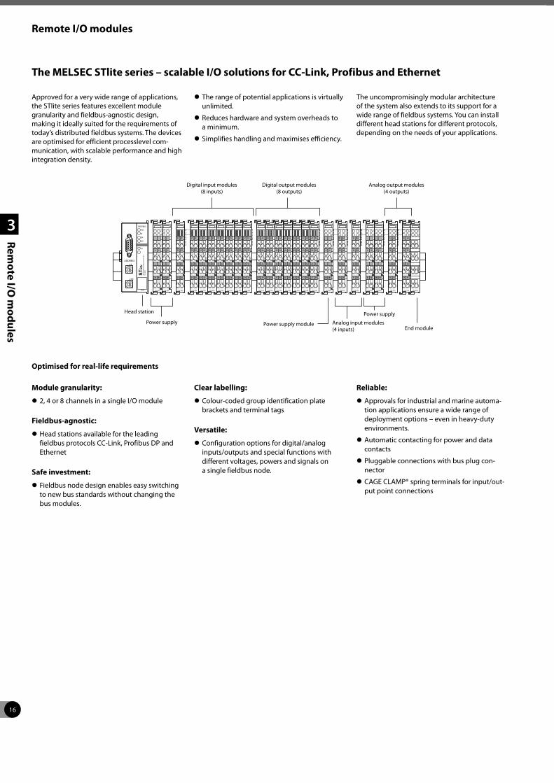
16
Remote I/O modules
1
2
3
Rem
ote I/O
mo
du
les
The MELSEC STlite series – scalable I/O solutions for CC-Link, Profibus and Ethernet
Approved for a very wide range of applications, the STlite series features excellent module granularity and fieldbus-agnostic design, making it ideally suited for the requirements of today’s distributed fieldbus systems. The devices are optimised for efficient processlevel com-munication, with scalable performance and high integration density.
z The range of potential applications is virtually unlimited.
z Reduces hardware and system overheads to a minimum.
z Simplifies handling and maximises efficiency.
The uncompromisingly modular architecture of the system also extends to its support for a wide range of fieldbus systems. You can install different head stations for different protocols, depending on the needs of your applications.
Digital input modules (8 inputs)
Digital output modules (8 outputs)
Analog output modules (4 outputs)
Head station
Power supply Power supply module
Power supply
Analog input modules (4 inputs) End module
Optimised for real-life requirements
Module granularity:
z 2, 4 or 8 channels in a single I/O module
Fieldbus-agnostic:
z Head stations available for the leading fieldbus protocols CC-Link, Profibus DP and Ethernet
Safe investment:
z Fieldbus node design enables easy switching to new bus standards without changing the bus modules.
Clear labelling:
z Colour-coded group identification plate brackets and terminal tags
Versatile:
z Configuration options for digital/analog inputs/outputs and special functions with different voltages, powers and signals on a single fieldbus node.
Reliable:
z Approvals for industrial and marine automa-tion applications ensure a wide range of deployment options – even in heavy-duty environments.
z Automatic contacting for power and data contacts
z Pluggable connections with bus plug con-nector
z CAGE CLAMP® spring terminals for input/out-put point connections

17
Remote I/O modules
1
2
3
Rem
ote I/O
mo
du
les
The head stations connect the STlite I/O systems with the Profibus DP, CC-Link or Ethernet fieldbus systems. Each head station recognises all inserted I/O and special function modules and generates a local process image from the configuration.
STlite series head stations
The power supply modules deliver power to the bus terminals at the required voltages.
Power supply modules
One of these end modules must be installed at the end of each fieldbus node. The end module terminates the internal terminals bus and ensures reliable data communications.
Bus end module
The analog temperature input module enables direct connection of Pt100 resistance tempera-ture sensors, with either a 2-wire or 3-wire cable.
Temperature input module
This module provides an interface for incremen-tal encoders with an RS422 port. A counter with a quadrature decoder and a null point signal latch can be read and activated by the controller.
Incremental encoder input module
Specifications STL-BT1 STL-PB1 STL-ETH1
Number of I/O modules 64 64 64
Communication protocol CC-Link standard Profibus DP Ethernet TCP/IP ECO, Modbus®/TCP
Fieldbus
input process image 256 bytes 244 bytes 14 bytes digital, 2 bytes
system, 32 bytes analog
output process image 256 bytes 244 bytes 14 bytes digital, 2 bytes
system, 32 bytes analog
Number of addressable modules 64 96 with repeater Limited by Ethernet specification
Order information Art. no. 242280 242279 242281
Accessories STL-CCLink con: Art. no. 242314 The fieldbus connector connects a CC-Link device to a CC-Link line.
Specifications STL-PS STL-BPS
Voltage supply 24 V DC (-25–30 %) 24 V DC (-25–30 %)Input current max. — 500Total current for I/O modules mA — 2000
Order information Art. no. 242311 242312
Specifications STL-ET
Order information Art. no. 242313
Specifications STL-TI2
Module type Analog temperature input moduleNumber of input channels 2Sensor types Pt100 and resistance measurementTemperature measuring range -200–850 °C (Pt100)Resolution 0.1 °C
Order information Art. no. 242307
Specifications STL-ENC
Module type Incremental Encoder InterfaceEncoder connection 3 input channelsCounting range 32 bits binaryMax. counting frequency 250 kHz
Order information Art. no. 242308

18
Remote I/O modules
1
2
3
Rem
ote I/O
mo
du
les
Specifications STL-DI8-V1 STL-DI8-V2
Module type Digital input module Digital input moduleIntegrated inputs 8, source type, 1-conductor connection 8, source type, 1-conductor connection
Order information Art. no. 242282 242283
Specifications STL-DO4 STL-DO8 STL-RO2
Module type Digital output module Digital output module Digital relay output moduleIntegrated outputs 4, source type 8, source type 2 contacts (normally open)
Order information Art. no. 242284 242295 242296
Digital input modules
The digital input modules have 8 channels. They are used for inputting control signals from the field, for example from sensors.
Digital output modules
Digital output modules are available with 4 or 8 outputs. They are used to send control signals from the automation controller to the con-nected actuators.
Digital relay output module
The relay output modules have two make con-tacts. The relays have floating contacts and are actuated with the internal system voltage.
Digital I/O modules
Analog input modules
The analog input modules with current input process standard 4–20 mA signals. The modules with voltage inputs can handle standard ±10 V or 0–10 V signals.
Analog output modules
The analog output modules with current outputs generate standard 4–20 mA signals. The modules with voltage outputs generate standard ±10 V or 0–10 V signals.
Analog I/O modules
Specifications STL-AD2-V STL-AD2-I STL-AD4-V1 STL-AD4-V2 STL-AD4-I
Module type Analog input moduleNumber of input channels 2 2 4 4 4Signal input 0–10 V 4–20 mA ±10 V 0–10 V 4–20 mA
Order information Art. no. 242297 242298 242299 242300 242301
Specifications STL-DA2-I STL-DA2-V STL-DA4-V1 STL-DA4-V2 STL-DA4-I
Module type Analog output moduleNumber of output channels 2 2 4 4 4Signal output 4–20 mA 0–10 V 0–10 V ±10 V 4–20 mA
Order information Art. no. 242302 242303 242304 242305 242306
This counter inputs binary 24 V signals and transmits the counter value to the installed bus system. An input is used to switch between Up and Down counting.
Up/Down counter module
The SSI transmitter interface module enables direct connection of an SSI transmitter. To read out the transmitter the module emits a clock signal and represents the data flow as a data word in the process image.
Interface module
Specifications STL-C100
Module type Up/Down counterSwitching outputs 2Counter inputs 1Max. counting frequency 100 kHz
Order information Art. no. 242309
Specifications STL-SSI
Module type Transmitter interfaceInterface SSISensor connection 1 input/1 output channel
Order information Art. no. 242310

19
Remote I/O modules
1
2
3
Rem
ote I/O
mo
du
les
The MELSEC ST series – premium product for process industry
System description
The ST series is designed as a modular input/output system for connection to CC-Link and Profibus DP. It comprises of:
z basic module (head station and bus node for CC-Link and Profibus DP)
z power supply modules
z digital and analog I/O modules
They can be combined freely to provide an efficient system configuration depending on your demands.
The name „ST“ means „Slice-type Terminal“ and comes from the physical appearance of the very slim modules (12.6 mm). As well as slice type modules, cost saving block modules with 16 inputs or outputs are also available.
The extension modules are designed as a 2-component system, that means they consist of electronic modules for the function and base modules as modular backplane bus (available with two types of terminals: spring clamp or screw clamp terminals).
The electronic modules can be clipped easily in the base modules without any tool. The combined unit can then be mounted on a DIN rail. Exchange of the electronic modules can be made on-line, so the system keeps running. Re-wiring is not needed.
Every electronic module provides LEDs for quick and easy diagnostics and also additional information. Error and status messages are also shown on the basic module.
16pt digital input module
16pt digital output module
Head station
Power supply module
Power feeding module
Power supply module
1ch analog output module
2ch analog output module
2pt digital input module
2pt digital input module
4pt digital input module
2pt digital output module
2ch analog input modules
Special features:
z ST = Slice terminals, only 12.6 mm wide
z Modular structure with no restriction on installation position
z Easy and complete handling via 3 push buttons
z Connection diagram on every module
z Applicable wire size for all base modules 0.5–2.5 mm², flexible wire with ferrule or solid core wire without ferrule
z Expandable in two-point increments
z Replaceable electronic modules
z Hot swap function without re-wiring
z Quick diagnostics via LED´s
z Distributed 24 V DC for actuators/sensors
z Gold contacts for all bus and signal connections
z Electronic modules are coded to prevent an incorrect unit being inserted
z Easy parameter setting with GX Configurator DP
The basic module ST1H-PB connects the remote I/O modules of the ST series to CC-Link and Profibus DP.
Basic modules (head stations) of the MELSEC ST series
You need one ST1PSD beside the basic module to operate the ST station, a second or more are only needed depending on the power con-sumption of the connected items.
The power feeding module ST1PDD distributes 24 V DC only for the I/Os of the actuators and sensors.
Bus power for head station and power feeding module
Specifications ST1H-BT ST1H-PBOccupied I/O points 4 inputs/4 outputs 4/4
Communicationsprotocol CC-Link standard Profibus DPmedium CC-Link cable Shielded 2-wire
Interface type CC-Link RS485Supported operation modes Remote station (1–4) Sync mode, freeze mode
Order information Art. no. 214496 152951
Specifications ST1PSD ST1PDD
Module typePower supply for head station, internal 5 V DC backplane bus and 24 V DC for I/Os (double function)
Power feeding module
Nominal voltage V DC 24.0 24.0Max. output current (5 V DC) A 2.0 —Max. output current (24 V DC) A 8 (10 with fuse) 8 (10 with fuse)
Order information Art. no. 152952 152953
Applicable base module for basic module supply
spring clamp type ST1B-S4P2-H-SET, art. no. 152908 ST1B-S4P2-D, art. no. 152910screw clamp type ST1B-E4P2-H-SET, art. no. 152918 ST1B-E4P2-D, art. no. 152920
Applicable base module for bus refreshing within the station
spring clamp type ST1B-S4P2-R-SET, art. no. 152909 —screw clamp type ST1B-E4P2-R-SET, art. no. 152919 —

20
Remote I/O modules
1
2
3
Rem
ote I/O
mo
du
les
Specifications ST1X2-DE1 ST1X4-DE1 ST1X16-DE1 ST1X1616-DE1-S1Number of input points 2 4 16 32
Applicable base module
spring clamp type ST1B-S4X2, art. no. 152911
ST1B-S6X4, art. no. 152912
ST1B-S4X16, art. no. 152913
ST1B-S6X32, art. no. 169313
screw clamp type ST1B-E4X2, art. no. 152921
ST1B-E6X4, art. no. 152922
ST1B-E4X16, art. no. 152923
ST1B-E6X32, art. no. 169314
Connection cable type 3-wire 24 V DC (with shield) 3-wire 24 V DC 3-wire 24 V DC
(with shield)3-wire 24 V DC (with shield)
Order information Art. no. 152964 152965 152966 169309
Specifications ST1Y2-TE2 ST1Y16-TE2 ST1Y2-TE8 ST1Y2-TPE3 ST1Y16-TPE3 ST1Y2-R2Number of output points 2 16 2 2 16 2 Output type Transistor Transistor Transistor Transistor Transistor Relay
Applicable base module
spring clamp typeST1B-S3Y2, art. no. 152914
ST1B-S3Y16, art. no. 152915
ST1B-S3Y2, art. no. 152914
ST1B-S3Y2, art. no. 152914
ST1B-S3Y16, art. no. 152915
ST1B-S4IR2, art. no. 152916
screw clamp typeST1B-E3Y2, art. no. 152924
ST1B-E3Y16, art. no. 152925
ST1B-E3Y2, art. no. 152924
ST1B-E3Y2, art. no. 152924
ST1B-E3Y16, art. no. 152925
ST1B-E4IR2, art. no. 152927
Connection cable type 2-wire 24 V DC with shield
2-wire 24 V DC with shield
2-wire 24 V DC with shield
2-wire 24 V DC with shield
2-wire 24 V DC with shield
2 wires (inter-nal connected)
Order information Art. no. 152967 152968 169408 152969 152970 152971
Digital input modules
The digital input modules of the ST series directly connect field devices (contacts, limit switches, sensors, etc.).
Digital output modules
The digital output modules of the ST series connect directly to field devices (e.g. contactors, valves, lights).
The TPE3 models provide advanced protec-tion functions e.g. for thermal and short circuit failures.
Digital I/O modules
Analog input modules
The analog input modules of the ST series convert analog process data like pressure, tem-perature, etc. into digital values that are sent to the Profibus DP/CC-Link master.
Analog output modules
The analog output modules of the ST series con-vert the digital values sent from the Profibus DP/CC-Link master into an analog voltage signal.
Analog temperature input modules
The analog temperature input modules of the ST series convert analog temperature data into digital values that are sent to the Profibus DP/CC-Link master.
Analog I/O modules
Specifications ST1AD2-V ST1AD2-I ST1TD2 ST1RD2
Module type Analog input module Analog input module Analog temperature input module
Analog temperature input module
Occupied I/O points 4/4 4/4 4/4 4/4
Signal input -10–10 V, 0–10 V, 0–5 V, 1–5 V 0–20 mA, 4–20 mA Thermocouple input:
K, T, E, J, B, R, S or N Pt100, Pt1000
Resolution 12 bit + sign 12 bit + sign 0.1–0.8 °C 1 0.1 °CConversion speed 0.1 ms per channel 0.1 ms per channel 30/60 ms per channel 80 ms per channel
Applicable base module
spring clamp type ST1B-S4IR2, art. no. 152916
ST1B-S4IR2, art. no. 152916
ST1B-S4TD2, art. no. 161736
ST1B-S4TD2, art. no. 161736
screw clamp type ST1B-E4IR2, art. no. 152927
ST1B-E4IR2, art. no. 152927
ST1B-E4TD2, art. no. 161737
ST1B-E4TD2, art. no. 161737
Order information Art. no. 152972 152973 161734 169406
1 Depends on the thermocouple used
Specifications ST1DA2-V/-F01 ST1DA1-I/-F01 ST1SS1
Module type Analog output module Analog output moduleAbsolute encoder interface with SSI (synchronal serial interface)
Occupied I/O points 4/4 4/4 4/4
Signal output range -10–10 V, 0–10 V, 0–5 V, 1–5 V 0–20 mA, 4–20 mA 31 bit binary
(0–2147483647)Resolution 12 bit + sign 12 bit + sign 2 to 31 bitsApplicable base module
spring clamp type ST1B-S4IR2, art. no. 152916 ST1B-S4IR2, art. no. 152916 ST1B-S4IR2, art. no. 152916screw clamp type ST1B-E4IR2, art. no. 152927 ST1B-E4IR2, art. no. 152927 ST1B-E4IR2, art. no. 152927
Order information Art. no. 152975/217631 152976/217632 193660

21
1
2
3
4
Mo
du
lar PLC
s
Modular PLCs – MELSEC iQ-R series, System Q and L series
Modular controllers like Mitsubishi Electric’s MELSEC iQ-R series, System Q and the L series are high-performance PLC systems with broad functionality. The range, power and function of these high-end PLCs is impressive, with opera-tion times measured in nanoseconds.
The modular design allows flexible usage in a broad range of applications. Additional backpla-nes can be added as the system expands.
Modular PLCs comprise a power supply, one or more CPU modules and I/O and/or special function modules.
Use of digital and special function modules
The use of digital and analog modules and most special function modules is dependent only on the maximum available number of addresses and thus on the CPU used in each case.
The following modules are available for assemb-ling the system:
Pulse catch and interrupt modules
Digital input modules for pulse storage and for processing subroutines.
Digital input/output modules
For various signal levels with transistor, relay or triac switches.
Analog input/output modules
For processing current/voltage signals and for temperature value acquisition as well as temperature control with direct connection of Pt100 resistance thermometers or thermocouples. A HART enabled module for current input is also available for the MELSEC System Q.
Positioning modules
High-speed counter modules with possi-bility for connection of incremental shaft encoder or multiaxial positioning modules for servo and step drives with up to 8 axes per module.
Communications modules
Interface modules with RS232/RS422/ RS485 interface for connection of peripherals or for PLC-PLC communi cation.
Network modules
For interfacing with Ethernet, CC-Link, CC-Link IE, Profibus DP/Profinet, Modbus®/ TCP/RTU, DeviceNet™, AS-Interface and MELSEC networks.
iQ Platform
Mitsubishi Electric’s integrated control architec-ture is the world’s first automation platform combining all key automation types on one controller.
For detailed information, please refer to the family catalogues.
No longer are valuable engineering resources spent trying to make different systems from separate vendors work together.
With the iQ Platform, which includes the MELSEC iQ-R series and System Q, we provide an extensive array of controller types.
The I/O range of the iQ Platform is 0 to 12,228.
BASE UNITMODEL Q38BSERIAL 0205020E0100017-A
POWER CPU I / 00 Q38B(N)I / 07I / 06 I / 05I / 04I / 03
E.S.DI / 02I / 01
P1L ER
LINK
P1L ER
LINK
0
1
2
3
4
5
6
7
8
9
A
B
C
D
E
F
0
1
2
3
4
5
6
7
8
9
A
B
C
D
E
F
0
1
2
3
4
5
6
7
8
9
A
B
C
D
E
F
POWER
R61P
R120SFCPU
PLC control
Motion control
Process control
C Controller
High speed motion
Monitor and control
Common engineering platform
Automotive
Material handling
Semiconductor
Plant
CC-Link
Safety control

22
Modular PLCs
1
2
3
4
Mo
du
lar PLC
s
MELSEC iQ-R series
MELSEC System Q
MELSEC System Q has been designed to be at the heart of your manufacturing process, as it is at the heart of Mitsubishi Electric‘s compo-nent automation concept. It offers you total integration of your control and communication needs from a single platform – connecting your automation with your business needs.
z Communication – is a communication hub connecting to fieldbus or data networks including 100 Mbps Ethernet
z Scalability – offers Multi CPU solutions on a single backplane
z Flexibility – solutions can combine various CPU types as a seamless solution; PLC, Motion, Robots, NC, PC and Process CPUs
z MES and web server module for quick and simple connectivity to the IT world
z Redundancy options ranging from full red-undant PLC hardware to redundant network options improve uptime and productivity
MELSEC L series
The MELSEC L series is a powerful but compact modular controller with many features built-in to the CPU itself. The rack-free design promo-tes high system flexibility with minimum form factor. Built-in Mini-B USB and Ethernet allow for easy communication, along with a built-in SD/SDHC memory slot for data logging and memory storage, and built-in digital I/O for simple high-speed counting and positioning functions.
The high-performance version CPU also includes a built-in CC-Link interface for Master/Local Sta-tion networking. This highly flexible architecture makes the MELSEC L series ideal for both stand-alone and networked machines.
z Rack-free design
z CPUs packed with comprehensive built-in features/functions
z Integrated data logging
z Built-in I/O features
z Communication and networking capabilities
z High-end 16-axis motion expansion possible using SSCNET III/H
MELSEC Sytem Q
P1L ER
LINK
P1L ER
LINK
0
1
2
3
4
5
6
7
8
9
A
B
C
D
E
F
0
1
2
3
4
5
6
7
8
9
A
B
C
D
E
F
0
1
2
3
4
5
6
7
8
9
A
B
C
D
E
F
POWER
R61P
MELSEC iQ-R series MELSEC L series
The iQ Platform builds on the power of Mitsubishi Electric’s high performance program-mable automation controllers (PAC), comple-menting this with a broad range of control modules and network interfaces.
The iQ-R series CPU offers dramatic improve-ments in performance, setting new bench-mark standards for processing speed. At the same time, the iQ-R series offers reductions in development cost, maintenance cost and risk of system failure, while providing an innovative upgrade path that will enable users to take advantage of ongoing developments through software upgrades rather than hardware upgrades.
Mounting of multiple CPUs on an iQ-R series backplane is supported, enabling users to develop vastly more complex and sophistica-ted automation applications from a single PAC backplane.
z Productivity – Improve productivity through advanced performance/functionality
z Scalability – offers Multi CPU solutions on a single backplane
z Connectivity – Seamless connectivity within all levels of manufacturing
z Flexibility – solutions can combine various CPU types as a seamless solution; PLC, Motion, Robots, NC, PC and Process CPUs
z Engineering – Reducing development costs through intuitive engineering
z Compatibility – Compatible with most exis-ting MELSEC System Q I/O
z Security – Unauthorized access protection across distributed control network
z Maintenance – Reduce maintenance costs and downtime utilizing easier maintenance features

23
MELSEC iQ-R series
1
2
3
4
Mo
du
lar PLC
s
POWER
R61P
0
1
2
3
4
5
6
7
8
9
A
B
C
D
E
F
P1L ER
LINK
P1L ER
LINK
System structure
The CPU and modules are connected to a base unit which has an internal bus connection for high-speed communication between the indi-vidual modules and the CPUs. A power supply module which supplies the voltage for the entire modules is also installed on this base unit.
The base units are available in different versions with 5 to 12 module slots.
Each base unit can be supplemented by means of an extension unit providing additional slots. Up to seven extension base units can be connected and a maximum of 64 modules installed at any one time. An RQ extension base unit is also available, ensuring compatibility with existing MELSEC System Q modules.
For cabling larger systems and machines – e. g. in a modular design – the use of remote I/O modules offers additional communications facilities
What you need
Main base units (Standard, Extended temperature range)
The main base unit is used for mounting and connecting up to four CPUs, power supply unit, input modules, output modules and special function modules.
Base units
Extension base units (Standard, Extended temperature range), RQ extension base unit
The extension base units are connected to the main base unit by means of preassembled bus cables. The RQ extension base units are for MELSEC System Q modules.
MELSEC iQ-R series – What a system looks like
Power supply module
CPU module Digital I/O moduleSpecial function
module Network module
Base unit
Terminal block also available with spring clamps
Interface for extension base unit (under the transparent cover)
SD memory card
Backup battery (slot on the lower side)
Ethernet interface
USB interface
Specifications R35B R38B R310RB R312B R310B-HT R38RB-HT
Slots for I/O modules 5 8 10 12 10 8Slots for power supply modules 1 1 2 1 1 2
Order information Art. no. 279583 279584 301652 279585 308780 301650
Specifications R65B R68B R610RB R612B RQ65B RQ68B RQ612B R610B-HT R68RB-HT
Slots for I/O modules 5 8 10 12 5 8 12 10 8Slots for power supply modules 1 1 2 1 1 1 1 1 2
Order information Art. no. 279590 279589 301653 279588 279591 279586 279587 308782 301651

24
MELSEC iQ-R series
1
2
3
4
Mo
du
lar PLC
s
These units power all the modules mounted to a base unit. The choice is dependent on the power consumption of the individual modules (this is especially important when using multiple CPUs) and the available input power supply voltage.
Standard and redundant power supply modules
The MELSEC iQ-R series includes a wide range of programmable automation controllers capable of catering to diversified automation control needs.
CPU modules
PLC CPU modules
At the core of the MELSEC iQ-R series is a programmable controller CPU. This CPU is the heart of the control system and includes various features for different applications. The most common CPU is the programmable controller CPU, into which various features are embedded, enabling it to perform a wide range of control tasks.
Specifications R04CPUR04ENCPU
R08CPUR08ENCPU
R16CPUR16ENCPU
R32CPUR32ENCPU
R120CPUR120ENCPU
I/O points 4096 4096 4096 4096 4096
Memory capacity for PLC program 40 k steps (160 kByte)
80 k steps (320 kByte)
160 k steps (640 kByte)
320 k steps (1280 kByte)
1200 k steps (4800 kByte)
Order information Art. no. 279576290226
279577290227
279578290228
279579290232
279580290234
Accessories
NZ1MEM-2GBSD; 2 GB SD memory card; NZ1MEM-4GBSD; 4 GB SDHC memory card; NZ1MEM-8GBSD; 8 GB SDHC memory card; NZ1MEM-16GBSD; 16 GB SDHC memory card; NZ2MC-1MBS; 1 MB extended SRAM cassette; NZ2MC-2MBS; 2 MB extended SRAM cassette; NZ2MC-4MBS; 4 MB extended SRAM cassette; NZ2MC-8MBS(E); 8 MB extended SRAM cassette; only supported by safety and process CPU;NZ2MC-16MBS; 16 MB extended SRAM cassette; safety CPU is not supported
POWER
R61P
Specifications R08PCPU R16PCPU R32PCPU R120PCPUI/O points 4096 4096 4096 4096
Memory capacitydata memory 5 MByte 10 MByte 20 MByte 40 MByte
for PLC program 80 k steps (320 kByte)
160 k steps (640 kByte)
320 k steps (1280 kByte)
1200 k steps (4800 kByte)
Order information Art. no. 285496 285499 285500 285497
Process CPU modules and redundant function module
The MELSEC iQ-R process CPUs are designed specifically for medium- to large-scale process control systems requiring high-speed perfor-mance coupled with the handling of large PID loops.
When paired with a redundant function module, a highly reliable (redundant) control system can be realized with a tracking data capacity of up to 1 M words between the control and standby systems supported.
R61P Power supply
R120PCPU/R6RFM Process CPU and redundant function module
Specifications R61P R62P R63P R63RP R64P * R64RP
Input voltage 100–240 (85–264) V AC
100–240 (85–264) V AC
24 (15.6–31.2) V DC
24 (19.2–31.2) V DC
100–240 (85–264) V AC
100–240 (85–264) V AC
Rated output current
5 V DC A 6.5 3.5 6.5 6.5 9 924 V DC ±10 % A — 0.6 — — — —
Order information Art. no. 279581 285507 279582 308710 285508 301649
* Redundant power supply
Specifications R6RFM
Type Redundant process CPUOccupied I/O points 32Tracking cable data capacity (word) 1 M
Order information Art. no. 301648
R120CPU PLC CPU module
Specifications R08PSFCPU-SET R16PSFCPU-SET R32PSFCPU-SET R120PSFCPU-SET
Type SIL2 Process CPUs
Memory capacity
overall 5 MByte 10 MByte 20 MByte 40 MByte
for PLC program80 k steps (40 k steps for safety programs)
160 k steps (40 k steps for safety programs)
320 k steps (40 k steps for safety programs)
1200 k steps (40 k steps for safety programs)
Order information Art. no. 317842 317843 317844 317895

25
MELSEC iQ-R series
1
2
3
4
Mo
du
lar PLC
s
C Controller CPU
The C Controller module is part of the applica-tion-specific range in the MELSEC iQ-R series. The multi-core ARM®-based controller pre-in-stalled with VxWorks® version 6.9, realizes the simultaneous execution of programs, thereby providing a robust and deterministic alternative to computer based systems.
Specifications R12CCPU-VNumber of I/Os 4096Memory Work RAM: 256 MB; ROM: 12 MB; battery-backed-up RAM: 4 MBCommunication interfaces Ethernet 100BASE-T/100BASE-TX (2 ch.), RS232 (1 ch.)SD memory card slot 1 slot
Order information Art. no. 285498
Safety function module and safety CPU
The safety function module must be mounted next to the iQ-R safety CPU module. It is included with the purchase of an iQ-R safety CPU set, and cannot be purchased independent from the set.
SPEED
CH1
SD/RD
SPEED
CH2
SD/RDR12CCPU-V C Controller CPU
Specifications R6SFM
I/O points 16Control method Stored program cyclic operation
Memory capacity Safety program
program capacity 40 k steps (160 kByte)program memory 160 kBytedevice/label memory 80 kByte
Note: This product ships as part of the RmSFCPU-SET.
R120SFCPU/R6SFM Safety CPU and safety function module
Specifications R08SFCPU-SET 1 R16SFCPU-SET 1 R32SFCPU-SET 1 R120SFCPU-SET 1
Safety integrity level (SIL) SIL 3 (IEC 61508)Performance level (PL) PL e (EN/ISO 13849-1)
Memory capacity
program capacity 80 k steps (40 k steps for safety programs)
160 k steps (40 k steps for safety programs)
320 k steps (40 k steps for safety programs)
1200 k steps (40 k steps for safety programs)
program memory 320 kByte 640 kByte 1280 kByte 4800 kBytedevice/label memory 1178 kByte 1710 kByte 2306 kByte 3370 kBytedata memory 5 MByte 10 MByte 20 MByte 40 MByte
Order information Art. no. 289989 290199 290200 290201
1 Product package includes a safety CPU(RmSFCPU) and safety function module (R6SFM).
Motion CPUs for advanced applications
The motion CPU module is a dedicated high-precision control CPU module, designed solely for applications that require advanced motion control such as positioning control, syn-chronous control, and speed-torque control at a very high accuracy. A motion system requires a motion controller CPU and a PLC CPU. Only after combining a highly dynamic positioning control CPU and a PLC, an innovative Motion Control system is created.
Specifications R16MTCPU R32MTCPU R64MTCPUNumber of control axes 16 32 64Interpolation functions Linear interpolation for up to 4 axes, circular interpolation for 2 axes, helical interpolation for 3 axesProgramming language Motion SFC, dedicated instructionInterfaces Ethernet 100/10 Mbps, SSCNET III/H (USB, RS232C via PLC CPU), PERIPHERAL I/F, SD memory card
Order information Art. no. 280227 280288 295076
SPEED
CN1
CN2
SD/RDR32MTCPU Motion CPU
R120SFCPU

26
MELSEC iQ-R series
1
2
3
4
Mo
du
lar PLC
s
Digital (high-speed) input and output modules
Digital I/O modules are the senses of the automation system and provide an interface of various processes to the controller.
I/O modules are available in a wide range of densities (16, 32 and 64-points) depending on the I/O requirements and minimum use of space in the control cabinet.
Terminal blocks are interchangeable with MELSEC System Q I/O terminals and can save on the cost of upgrading from existing control systems.
Digital input modules
Specifications RX10 RX28 RX40C7 RX40PC6H*/RX40NC6H* RX40NC6B RX41C4 RX41C6HS* RX42C4 RX61C6HS*
Number of input channels 16 8 16 16 16 32 32 64 32
Rated input voltage100– 120 V AC (50/60 Hz)
100– 120 V AC (50/60 Hz)
24 V DC 24 V DC 24 V DC 24 V DC 24 V DC 24 V DC 5 V DC
Order inform. Art. no. 279546 308711 279533 290235/290236 301646 279534 307424 279545 304546
* High-speed module
Digital output modulesSpecifications RY10R2 RY18R2 RY20S6 RY40NT5P RY40PT5P RY40PT5BNumber of output channels 16 8 16 16 16 16
Output type Relay Relay Triac Transistor (sink) Transistor (source)
Transistor with diagnostic func-tions (source)
Rated output voltage 24 V DC/ 240 V AC
24 V DC/ 240 V AC 100–240 V AC 12–24 V DC 12–24 V DC 24 V DC
Order inform. Art. no. 279550 308712 308676 279547 279551 301647
Combined I/O moduleSpecifications RH42C4NT2PNumber of input channels 32Rated input voltage 24 V DCNumber of output channels 32
Rated output voltage 12–24 V DC
Order inform. Art. no. 279554
Specifications RY41PT1P RY41NT2H* RY41NT2P RY41PT2H* RY42NT2P RY42PT1PNumber of output channels 32 32 32 32 64 64
Output type Transistor (source) Transistor (sink) Transistor (sink) Transistor
(source) Transistor (sink) Transistor (source)
Rated output voltage 12–24 V DC 5–24 V DC 12–24 V DC 5–24 V DC 12–24 V DC 12–24 V DC
Order inform. Art. no. 279552 308707 279548 304547 279549 279553
* High-speed module
RY40NT5P Digital output module
0
1
2
3
4
5
6
7
8
9
A
B
C
D
E
FRH42C4NT2P Combined I/O module
RX42C4 Digital input module
Flexible high-speed I/O control moduleSpecifications RD40PD01Number of input channels 12Rated input voltage 5/24 V DCNumber of output channels 8
Rated output voltage 5–24 V DC
Order inform. Art. no. 307562

27
MELSEC iQ-R series
1
2
3
4
Mo
du
lar PLC
s
Temperature sensors are connected directly to these modules. They convert measured analog values into16-bit signed binary temperature measurement values.
Analog modules for temperature measurement
Specifications R60RD8-G R60TD8-GNumber of input channels 8 8Connectable thermocouple type Pt100, JPt100, Ni100, Pt50 B, R, S, K, E, J, T, NTemperature measuring range Depends on the thermocouple used
Order information Art. no. 285505 285506
12345678910
1112
13
14
15
16
1718
IV
SLD
IV
SLD
IV
SLD
(FG)
IV
SLD V
+
CH3
CH4
CH1
V+
I+
CH2I+V+
I+V+
I+
AG
R60AD4/R60DA4 Analog I/O modules
12345678910
1112
13
14
15
16
1718
(FG)
COMNC
CH1
V+
I+
COMNC
CH2
V+
I+
COMNC
CH3
V+
I+
COM
NC
CH4
V+
I+
24V
24G
+
Specifications R60AD4 R60ADV8 R60ADI8 R60AD8-G R60AD16-G R60ADH4*Number of input channels 4 8 8 8 16 4
Analog inputvoltage V -10–10 -10–10 — -10–10 -10–10 -10–10current mA 0–20 — 0–20 0–20 0–20 0–20
Overall accuracy ±0.3 %, ±0.1 %
±0.3 %, ±0.1 %
±0.3 %, ±0.1 % ±0.1 % ±0.1 % ±0.2%,
±0.1 %
Order information Art. no. 279556 279558 279561 285502 285501 308708
*High-speed analog input module
MELSEC iQ-R series analog modules are the interface between external analog signals and the control system. Various modules are availa-ble to cover a wide range of requirements.
Analog (high-speed) input modules
MELSEC iQ-R series analog output modules reliably deliver accurate analog values. A variety of modules (voltage, current, or mixed) are available to cover a wide range of application requirements, such as frequency inverters, valves or slide valves.
Faster, smoother predefined wave signal output
The analog output module enables pre-reg-istration of waveforms easily using MELSOFT GX Works3, realizing a smoother continuous output that closely matches the precision required for the application, such as torque con-trol for a press or injection molding machine.
Analog output modules
Specifications R60DA4 R60DAH4 R60DAV8 R60DAI8 R60DA8-G R60DA16-GNumber of output channels 4 4 8 8 8 16
Analog outputvoltage V -10–10 -10–10 -10–10 — -10–10 -10–10current mA 0–20 0–20 — 0–20 0–20 0–20
Overall accuracy ±0.3 %, ±0.1 %
±0.3 %, ±0.1 %
±0.3 %, ±0.1 %
±0.3 %, ±0.1 % ±0.1 % ±0.1 %
Order information Art. no. 279557 307260 279560 279559 285504 285503
Temperature control modules
MELSEC iQ-R series temperature control mod-ules are ideal for applications requiring highly stable and responsive temperature control. The series comes with thermocouple and RTD input module types and are available with or without heater disconnection detection.
Specifications R60TCTRT2TT2 R60TCRT4 R60TCTRT2TT2BW R60TCRT4BW
Control output type Transistor Transistor Transistor Transistor
Supported temperature sensorsR, K, J, T, S, B, E, N, U, L, PLII, W5Re/W26Re
Pt100, JPt100R, K, J, T, S, B, E, N, U, L, PLII, W5Re/W26Re
Pt100, JPt100
Sampling cycle Switchable between 250 ms and 500 ms/4 channelsControl output cycle s 0.5–100 0.5–100 0.5–100 0.5–100Temperature control method PID ON/OFF impulse or 2-position control
Order information Art. no. 290202 290203 290204 290225
R60TCTRT2TT2 Temperature control module
R60TD8-G Analog module for temperature measurement
12345678910
11
12
13
14
15
16
1718

28
MELSEC iQ-R series
1
2
3
4
Mo
du
lar PLC
s
RD62P2 High-speed counter module
The MELSEC iQ-R series counter modules are capable of 200k pulse/s for the DC input type, and 8M pulse/s for differential input. When used with a high-accuracy incremental encoder, positional tracking can also be realized.
The pulse measurement feature enables measuring of the pulse cycle.
High-speed counter modules
Specifications RD62P2 RD62P2E RD62D2
Number of counter input channels 2 2 2
Count input signalphase 1-phase-input (multiple of 1 or 2), CW/CCW input,
2-phase input (multiple of 1, 2 or 4)
signal levels 5/12/24 V DC (2–5 mA) 5/12/24 V DC (2–5 mA) EIA Standard RS422-ADifferential line driver level
Max. counting speed 200 kHz 200 kHz 8 MHz
Order information Art. no. 279566 279568 279567
The MELSEC iQ-R series offers a choice of two positioning modules, transistor output or differential drive output, depending on the connected amplifier. The modules are capable of transmission speeds up to 5 M pulses/s, and the differential driver output module supports wiring up to a distance of 10 m.
Positioning modules
Specifications RD75P2 RD75P4 RD75D2 RD75D4
Number of control axes 2 4 2 4Acceleration/deceleration processing Trapezoidal acceleration/deceleration, S-curve acceleration/decelerationMax. output pulse kpps 200 5000 200 5000Internal power consumption (5 V DC) A 0.38 0.54 0.42 0.78
Order information Art. no. 279562 279563 279564 279565
The serial communication modules enable serial devices with up to 230.4 kbps transmission speeds to be connected per channel. Com-munications protocols such as Modbus® are supported via the pre-defined protocol feature.
Interface modules
Specifications RJ71C24 RJ71C24-R2 RJ71C24-R4
Interface typechannel 1 RS232-compliance
(D-sub 9P female)RS232-compliance (D-sub 9P female)
RS422/485-compliance (2-piece terminal block)
channel 2 RS422/485-compliance (2-piece terminal block)
RS232-compliance (D-sub 9P female)
RS422/485-compliance (2-piece terminal block)
Order information Art. no. 279573 279574 279575
CH1
CH2
RJ71C24 Interface module
The network and interface modules of the MELSEC iQ-R series ensure a vast selection of interconnectivity possibilities with various protocols and network topologies providing the best-fit solution for various applications.
Network modules
Specifications RJ71GF11-T2 RJ71EN71 RJ71GP21-SX RJ61BT11 RJ72GF15-T2
Network type CC-Link IE Field Ethernet CC-Link IE control CC-Link CC-Link IE Field remote head
Order information Art. no. 279569 279570 279571 279572 297947
Specifications RJ71PN92 RJ71PB91V RJ71CN91 RJ71BAC96 RJ71DN91
Network type Profinet Profibus DP CANopen BACnet DeviceNet
Order information Art. no. 308713 308714 308735 311945 317838
RD75D4 Positioning modules
MES Interface module
A MES Interface module provides direct data-base connectivity for IT systems and facilitates automatic SQL* text generation using intuitive configuration setup software. This module allows production data from the shop floor to be inserted into database records directly.* Structured Query Language is a programming language designed for
managing data in a relational database.
Specifications RD81MES96
Module type MES Interface moduleTransmission method Ethernet
Database connection
supported database Oracle® Database, Microsoft® SQL Server, Microsoft® AccessSQL text transmission SELECT, INSERT, UPDATE, DELETE, Multi-SELECT, STORED PROCEDUREaccessible CPU module iQ-R series (direct, remote), Q series (remote), L series (remote)
Order information Art. no. 295423
RD81MES96 MES Interface module

29
MELSEC iQ-R series
1
2
3
4
Mo
du
lar PLC
s
iQ-R C-Application server
The C-Application server is based on mod-ern web services and supports all kind of IoT requests. Its strength is to collect information in real time, provide analysis and forwards the results to a variety of cloud systems.
Specifications C-Application server for R12CCPU-V
Transmission type Ethernet, SerialDatabase SQLite3, MySQL, Redis
FunctionCCPU and MD library function support, CAS specific functions, HTML5, Websocket, Lua API, Lua server pages, XML parser, Event handler, REST, AJAX, SOAP, JSON, XML-RPC Web-Services, WebDAV, SMTP, SMTPS, STARTTLS, SSL, Shark SSL, SMQ, PikeHTTP
Order information Art. no. 308736
High-speed data logger module
C intelligent function module
This module enables logging of various data such as Unicode, CSV, and BIN text formats, which can be utilized for spreadsheet reporting owing to the automatic report generation fea-ture: BIN text format data can be ported directly to Microsoft® Windows® Excel®. Logging files can also be automatically sent to a FTP server or directly into a Microsoft® Windows® share folder.
Specifications RD81DL96
Accessible CPU modules iQ-R series (direct, remote), System Q series (remote), L series (remote)
Function
data logging Logs CPU module device values at specified data sampling intervals.event logging Monitors sampled device values from the CPU module, and logs events that occur.report Outputs the data sampled by the high speed data logger module as an Excel® file.
recipeExecutes the following operations using recipe files stored in the SD memory card:
z Transfer device values written on the recipe files to devices in the CPU module. z Transfer device values in the CPU module to the recipe files.
Order information Art. no. 308709
C/C++ program execution
The C Intelligent function module is available with a multi-core ARM®-based controller pre-in-stalled with VxWorks® Version 6.9, which realizes simultaneous execution of programs, thereby providing a robust and deterministic alternative to computer-based systems. This module can be used for applications such as in-line production quality testing or as a gateway for various indus-try-specific communications protocols.
RD55UP06-V C intelligent function module
OPC UA server module
Specifications RD81OPC96
Card slot SD memory card/SDHC memory card (2–16 GB)
Ethernet port
number of channels 2 data transmission speed 1 Gbps, 100 Mbps, 10 Mbpsmax. number of cascaded stages 1 2 (100 Mbps), 4 (10 Mbps)
max. segment length 2 m 100 (between hup and node)interface RJ45
Setup software MX OPC UA Module Configurator-R (SW1DND-ROPCUA-E)
Order information Art. no. 312973
1 Based on use with a repeater hup. For switching hup, refer to the manufacturers documentation.2 for maximum segment length between hups, refer to switching hup manufacturer documentation.
RD81DL96 High-speed data logger module
RD81OPC96 OPC UA module
The MELSEC iQ-R series OPC UA server module integrates the OPC UA server directly into the equipment control system as a robust alterna-tive to a computer-based configuration.
Specifications RD55UP06-V
Hardwareendian format Little endianMPU ARM® Cortex-A9 Dual Core
Software
operating system VxWorks Version 6.9programming language C language (C/C++)programming development environment CW Workbench/Wind River Workbench3.3
setting/monitoring tool GX Works3 (SW1DND-GXW3-E) a
Communication interface Ethernet (1000BASE-T/100BASE-TX/10BASE-T) (1 ch.)
Order information Art. no. 303298
1 Setting and monitoring of the module is integrated within the GX Works3 engineering software.

30
MELSEC System Q
1
2
3
4
Mo
du
lar PLC
s
MELSEC System Q – What a system looks like
System structure
The CPU and modules are connected to a base unit which has an internal bus connection for communication between the individual mod-ules and the CPUs. The power supply module which supplies the voltage for the entire system is also installed on this base unit.
The base units are available in 4 different ver-sions with 3 to 12 module slots.
Each base unit can be supplemented by means of an extension unit providing additional slots.
If you wish to keep open the option of subse-quent extension of your PLC or if you have free slots on your base unit, you can insert dummy modules in vacant module positions.
They serve to protect the free slots from soiling or from mechanical effects and can also be used for reserving I/O points.
For cabling larger systems and machines – e. g. in a modular design – the use of remote I/O modules offers additional communications facilities.
Power supply module
CPU-module Digital I/O moduleSpecial function
moduleNetwork module
Base unit
Protective cover for removable terminal block
Interface for extension unit (under the transparent cover)
Memory cardBackup battery (slot on the lower side)
Ethernet/RS232 interfaces
USB interface
What you need
Base units
Main base units
The main base unit is used for mounting and connecting CPUs, power supply unit, input modules, output modules and special function modules.
Specifications Q32SB Q33B Q33SB Q35B Q35SB Q35DB Q38B Q38DB* Q38RB Q312B Q312DB*
Slots for I/O modules 2 3 3 5 5 5 8 8 8 12 12Slots for power supply modules 1 1 1 1 1 1 1 1 2 1 1
Order inf. Art. no. 147273 136369 147284 127586 147285 249091 127624 207608 157067 129566 207609
* These base units are required for the new iQ Platform motion, NC and robot CPUs.
Safety main base unit
The safety main base unit holds and connects the safety CPU and up to two CC-Link safety master modules as well as network modules (CC-Link IE Field, CC-Link IE Controller Network, Ethernet and MELSECNET/H, one module each).
Specifications QS034B
Slots for I/O modules 4Slots for power supply modules 1
Order inf. Art. no. 203206

31
MELSEC System Q
1
2
3
4
Mo
du
lar PLC
s
Specifications Q52B Q55B Q63B Q65B Q68B Q68RB Q612B Q65WRB QA1S51B
Slots for I/O modules 2 5 3 5 8 8 12 5 1Slots for power supply modules — — 1 1 1 2 1 1 —
Order inf. Art. no. 140376 140377 136370 129572 129578 157066 129579 210163 249092
Extension base units
The extension base units are connected to the main base unit by means of pre-assembled bus cables.
Specifications Q61P Q61P-D Q61SP Q62P Q63P Q63RP Q64PN Q64RPN QS061P-A1 QS061P-A2
Input voltage 85– 264 V AC
100– 240 V AC
85– 264 V AC
100– 240 V AC 24 V DC 24 V DC 100–
240 V AC100– 240 V AC
100– 120 V AC
200– 240 V AC
Rated output current
5 V DC A 6 6 2 3 6 8.5 8.5 8.5 6 624 V DC ±10 % A — — — 0.6 — — — — — —
Order information Art. no. 190235 221860 147286 140379 136371 166091 217627 283021 203207 203208
These units power all the modules on the back-plane. The choice is dependent on the power consumption of the individual modules (this is especially important when using multiple CPUs).
Power supply modules
The CPU modules of the MELSEC System Q are available as single and multi processor CPUs through which they achieve a wide application range.
PLC CPU modules
Universal PLC CPUs
These universal PLC CPUs are the latest genera-tion of modular CPUs for the MELSEC System Q controller platform and they are the foundation of the iQ Platform system. They can be com-bined with the motion, robot and NC CPUs to configure scalable and highly flexible modular automation systems.
Specifications Q00UJCPU Q00UCPU Q01UCPU Q02UCPU Q03UDCPU, Q03UDECPU
I/O points 256/8192 1024/8192 1024/8192 2048/8192 4096/8192
Memory capacity for PLC program 10 k steps (40 kByte)
10 k steps (40 kByte)
15 k steps (60 kByte)
20 k steps (80 kByte)
30 k steps (120 kByte)
Order information Art. no. 221575 221576 221577 207604 207605, 217899
Specifications Q04UDHCPU, Q04UDEHCPU
Q06UDHCPU, Q06UDEHCPU
Q10UDHCPU, Q10UDEHCPU
Q13UDHCPU, Q13UDEHCPU
I/O points 4096/8192 4096/8192 4096/8192 4096/8192
Memory capacity for PLC program 40 k steps (160 kByte)
60 k steps (240 kByte)
100 k steps (400 kByte)
130 k steps (520 kByte)
Order information Art. no. 207606, 217900 207607, 215808 221578, 221579 217619, 217901
Specifications Q03UDVCPU Q04UDVCPU Q06UDVCPU Q13UDVCPU Q26UDVCPUI/O points 4096/8192
Memory capacity for PLC program 30 k steps (120 kByte)
40 k steps (160 kByte)
60 k steps (240 kByte)
130 k steps (520 kByte)
260 k steps (1040 kByte)
Order information Art. no. 266161 266162 266163 266164 266165
Accessories
Q4MCA-1MBS; 1 MB memory cassette for QmUDVCPU Art. no. 266134; Q4MCA-2MBS; 2 MB memory cassette for QmUDVCPU Art. no. 266155; Q4MCA-4MBS; 3 MB memory cassette for QmUDVCPU Art. no. 266156; Q4MCA-8MBS; 4 MB memory cassette for QmUDVCPU Art. no. 266157
Specifications Q20UDHCPU, Q20UDEHCPU
Q26UDHCPU, Q26UDEHCPU Q50UDEHCPU * Q100UDEHCPU *
I/O points 4096/8192 4096/8192 4096/8192 4096/8192
Memory capacity for PLC program 200 k steps (800 kByte)
260 k steps (1040 kByte)
500 k steps (2000 kByte)
1000 k steps (4000 kByte)
Order information Art. no. 221580, 221581 217620, 217902 242368 242369* is supported by GX Works2 only
Q26UDEHCPU Universal PLC CPU
Q61P-A2 Power supply module

32
MELSEC System Q
1
2
3
4
Mo
du
lar PLC
s
Specifications Q02PHCPU Q06PHCPU Q12PHCPU Q25PHCPU
I/O points 4096/8192 4096/8192 4096/8192 4096/8192
Memory capacityoverall ≤32 MByte ≤32 MByte ≤32 MByte ≤32 MBytemax. for PLC program
28 k steps (112 kByte)
60 k steps (240 kByte)
124 k steps (496 kByte)
252 k steps (1008 kByte)
Order information Art. no. 218138 218139 143529 143530
Specifications Q12PRHCPU Q25PRHCPU
I/O points 4096/8192 4096/8192
Memory capacityoverall ≤32 MByte ≤32 MBytemax. for PLC program 124 k steps (496 kByte) 252 k steps (1008 kByte)
Order information Art. no. 157070 157071
Process CPU modules
The MELSEC System Q process CPU allows flexible system design based on off-the-shelf components, which reduces both initial and implementation costs.
The MELSEC Process Control system is best suited for food manufacturing and chemical plant applications.
Redundant PLC CPU modules
Two PLC systems with the same configuration can provide a hot standby system through auto-matic synchronisation of data. This is the key to a redundant system and high availability. Down time and costs for re-starting are also dramat-ically reduced. If the control system fails, the standby system takes over without interruption of the process.
C Controller CPUs
The C Controller allow the integration and programming of the MELSEC System Q automa-tion platform with C++. Using the worldwide established real time operating system VxWorks, the realisation of complex tasks, communication and protocols becomes very easy.
PC CPU modules
The Q10WCPU uses the Microsoft Windows® operating system and can be combined with the power supplies, racks, I/O and special modules from the MELSEC System Q. The CPU module can be used in stand-alone mode or in multi-CPU mode, in conjunction with PLC CPU modules for example. This enables a seamless connection between the process and the data processing system.
Specifications Q10WCPU-WI-E Q10WCPU-WI-CFE
CPU Intel® Atom™ Processor N450 1.66 GHzChip set Intel® ICH8MProcessing frequency GHz 1.66
Memory
L1 cache Instruction 32 kB + data 24 kB
L2 cache 512 kB
Main 1 GBVideo Analog-RGB, resolution 1400x1050 at 60 Hz (16 million colors)Interfaces Serial (RS232C), USB, keyboard/mouse, LAN, monitorPC card slots 1 slot for CF memory card (type I)
Order information Art. no. 252826 252827
Q12PRHCPU Redundant PLC CPU
Q24DHCCPU-V Q12DCCPU-V C Controller CPU
Q10WCPU-WI-E PC CPU
Specifications Q12DCCPU-V Q24DHCCPU-V Q24DHCCPU-LS
Programming language C or CC++ C or CC++ —
MemoryStandard RAM: 3 MB; Work RAM: 128 MB; Battery-backed-up RAM: 128 kB
Standard RAM: 0–4 MB; Standard ROM: 382 MB; Work RAM: 512 MB;Battery-backed-up RAM: 1–5 MB
Work RAM: 512 MB; Battery-backed-up RAM: 5 MB
Communication interfacesRS232 (1 ch.), 10BASE-T/100BASE-TX (2 ch.), USB (1 ch.)
Ethernet (3 ch.), USB (2x), PCI Express, RS232
Ethernet (3 ch.), USB (2x), PCI Express, RS232
CF card I/F 1 slot for a TYPE I card (Max. 8 GB CF card is supported) 1 slot for SD memory card 1 slot for SD memory card
Order information Art. no. 221925 260296 273605

33
MELSEC System Q
1
2
3
4
Mo
du
lar PLC
s
Digital I/O modules
Various input modules are available for convert-ing digital process signals with different voltage levels into the levels required by the PLC.
The MELSEC System Q output modules have different switching elements for adaptation to many control tasks.
QX10 Digital input module
1
NC
L
L
3L
2L
5L
4L
7L
6L
9L
8L
BL
AL
DL
CL
FL
EL
COM
0
1
2
3
4
5
6
7
8
9
A
B
C
D
E
F
QY10
QY10 Digital output module
iQ Platform CPUs
Robot CPU (see Robots chapter) NC CPU (please contact your nearest Mitsubishi Electric distributor for more details)
Safety CPU module
The CC-Link safety network eliminates the complex wiring needed in conventional safety controller systems. The remote safety I/O sta-tions are connected to the CC-Link safety master module in the safety PLC using standard CC-Link cables.
The safety CPU module conforms to the safety requirements of EN 954-1 Category 4, ISO 13849-1 PL e, and IEC 61508 (JIS C 0508) SIL 3 and is certified by TÜV Rheinland.
Digital input modulesSpecifications QX10 QX10-TS QX28 QX40 QX40-TS QX40-S1 QX41 QX41-S1 QX41-S2 QX42 QX42-S1
Input points 16 16 8 16 16 16 32 32 32 64 64
Rated input voltage
100– 120 V AC (50/60 Hz)
100– 120 V AC (50/60 Hz)
100– 240 V AC (50/60 Hz)
24 V DC 24 V DC 24 V DC 24 V DC 24 V DC 24 V DC 24 V DC 24 V DC
Order inf. Art. no. 129581 221838 136396 132572 221839 136574 132573 146921 229239 132574 146922
Specifications QX50 QX70 QX71 QX72 QX80 QX80-TS QX81 QX81-S2 QX82 QX82-S1
Input points 16 16 32 64 16 16 32 32 64 64Rated input voltage 48 V DC 5 V DC/
12 V DC5 V DC/ 12 V DC
5 V DC/ 12 V DC 24 V DC 24 V DC 24 V DC 24 V DC 24 V DC 24 V DC
Order inf. Art. no. 204678 136397 136398 136399 127587 221840 129594 229240 150836 150837
Digital output modulesSpecifications QY10 QY10-TS QY18A QY22 QY40P QY40P-TS QY41H QY41P
Output points 16 16 8 16 16 16 32 32
Output type Relay Relay Relay Triac Transistor (sink type)
Transistor (sink type)
Transistor high-speed (sink type)
Transistor (sink type)
Rated output voltage 24 V DC/240 V AC 24 V DC/240 V AC 24 V DC/240 V AC 100–240 V AC 12/24 V DC 12/24 V DC 5–24 V DC 12/24 V DC
Order inf. Art. no. 129605 221841 136401 136402 132575 221842 308738 132576
Specifications QY42P QY50 QY68A QY70 QY71 QY80 QY80-TS QY81P QY82P
Outputs 64 16 8 16 32 16 16 32 64
Output type Transistor (sink type)
Transistor (sink type)
Transistor (sink/source type)
Transistor (sink type)
Transistor (sink type)
Transistor (source type)
Transistor (source type)
Transistor (source type)
Transistor (source type)
Rated output voltage 12/24 V DC 12/24 V DC 5–24 V DC 5/12 V DC 5/12 V DC 12/24 V DC 12/24 V DC 12/24 V DC 12/24 V DC
Order inf. Art. no. 132577 132578 136403 136404 136405 127588 221843 129607 242366
QS001CPU Safety CPU module
Specifications QS001CPU
I/O points 4096/8192Programming language (Sequence Control) Relay symbol language, function blockMemory capacity 128 kB
Order information Art. no. 203205

34
MELSEC System Q
1
2
3
4
Mo
du
lar PLC
s
Up to eight current transformers can be con-nected directly to the analog CT input module Q68CT. External signal converters are not required anymore.
Analog CT input module
Specifications Q68CTInput points 8 Analog input (via CT sensor) 5/50/100/200/400/600 A ACOverall accuracy ±0.5 %
Order inform. Art. no. 257758
Specifications Q62AD-DGH Q64AD Q64ADH Q64AD-GH Q66AD-DG Q68AD-G Q68ADV Q68ADI ME1AD8HAI-QInput points 2 4 4 4 6 8 8 8 8
Analog input 4 mA/20 mA -10 V/10 V (0/20 mA)
-10 V/10 V (0/20 mA)
-10 V/10 V (0/20 mA) 0/4/20 mA -10 V/10 V
(0/20 mA) -10 V/10 V 0/20 mA 0/4/20 mA
Overall accuracy ±0.05 % ±0.4 %, ±0.1 %
±0.2 %, ±0.1 % ±0.05 % ±0.1 % ±0.1 % ±0.4 %,
±0.1 %±0.4 %, ±0.1 % ±0.15 %
Order inform. Art. no. 145036 129615 251331 143542 204676 204675 129616 129617 229931
The analog input modules convert analog process signals, for example pressure, flow or fill level, linearly into digital values, which are further processed by the Q CPU.
The analog input modules Q62AD-DGH, Q64ADGH, Q66AD-DG and Q68AD-G are designed for applications requiring high accuracy.
The functionality of a HART master station is integrated in the ME1AD8HAI-Q.
Analog input modules
The analog output modules convert digi-tal values predetermined by the CPU into analog current or voltage signal. For example, frequency inverters, valves or slide valves are controlled by means of these signals.
The analog output module Q66DA-G is espe-cially designed for applications requiring high accuracy.
The analog output modules Q62DAN, Q64DAN, Q68DAVN and Q68DAIN isolate the analog out-put channel from the external power supply.
The functionality of a HART master station is integrated in the ME1DA6HAI-Q.
Analog output modules
Specifications Q62DAN Q62DA-FG Q64DAN Q64DAH Q66DA-G Q68DAVN Q68DAIN ME1DA6HAI-QOutput points 2 2 4 4 6 8 8 6
Analog output-10–10 V DC (0 mA– 20 mA DC)
-10–10 V DC (0 mA– 20 mA DC)
-10–10 V DC (0 mA– 20 mA DC)
-10–10 V DC(0 mA–20 mA DC)
-12–12 V DC (0 mA– 22 mA DC)
-10–10 V DC 0 mA– 20 mA DC
0/4 mA– 20 mA DC
Overall accuracy ±0.1 % ±0.1 % ±0.1 % ±0.1 % ±0.1 % ±0.1 % ±0.1 % 0.15 %
Order inform. Art. no. 200689 145037 200690 266158 204677 200691 200692 236649
Q62DA/Q66DA-G Analog output modules
Q64AD/Q68AD-G Analog input modules
321
456789101112131415161718
Q68CT
Q68CT
CH1
CH3
CH2
CH4
CH5
CH7
CH8
CH6
k
k
k
k
k
k
k
l
l
l
l
l
l
l
l
N C
NC
k
ALMRUN
ERR.
Q68CT Analog CT input module
With the analog input/output module Q64AD2DA the user has a module that has both, four analog inputs and two analog outputs.
Combined analog I/O module
Specifications Q64AD2DA
Input points 4
Analog input
voltage V -10–10current mA 0–20
Accuracy ±0.4 % (0–55 °C), ±0.1 % (20–30 °C)Output points 2
Analog output
voltage V -10–10current mA 0–20
Accuracy ±0.3 % (0–55 °C), ±0.1 % (20–30 °C)
Order inform. Art. no. 229238
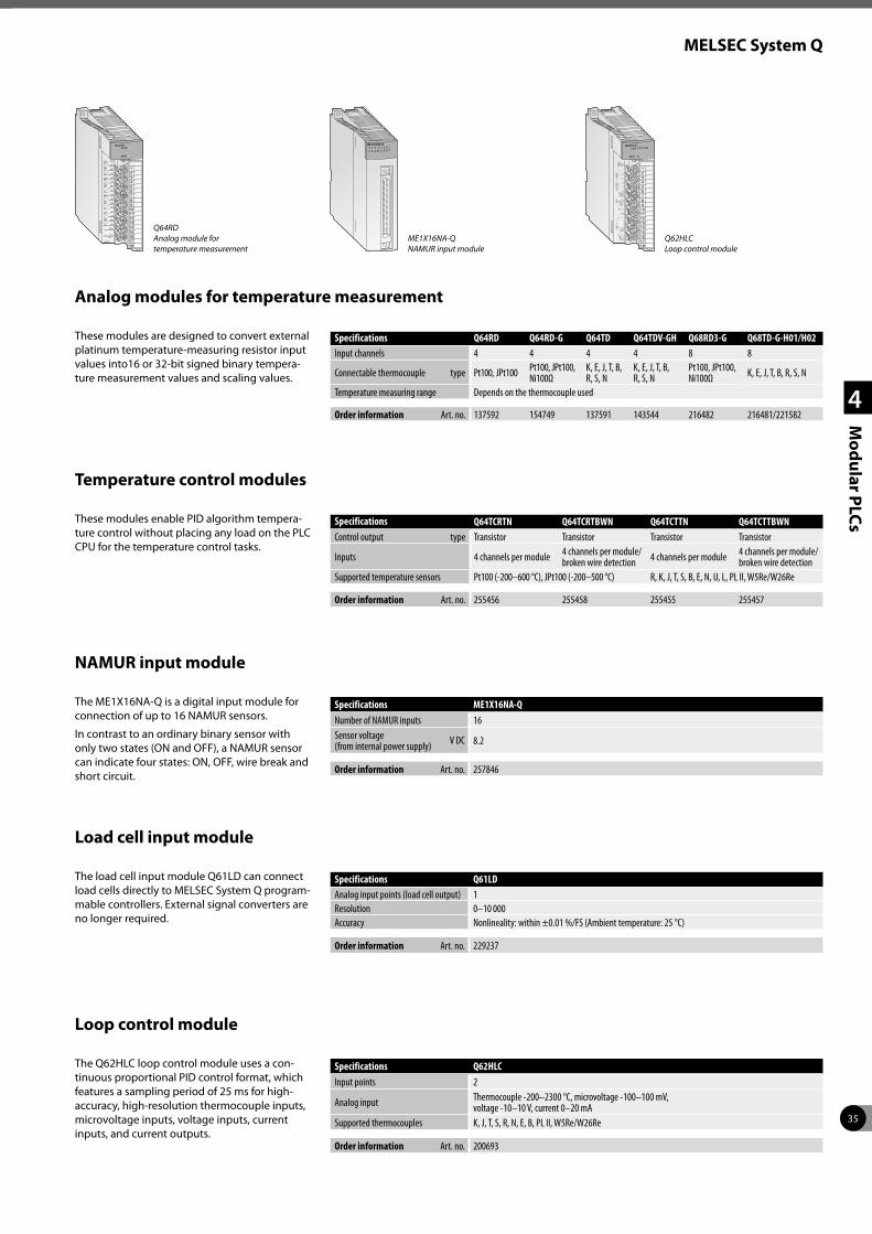
35
MELSEC System Q
1
2
3
4
Mo
du
lar PLC
sThese modules enable PID algorithm tempera-ture control without placing any load on the PLC CPU for the temperature control tasks.
Temperature control modules
Specifications Q64TCRTN Q64TCRTBWN Q64TCTTN Q64TCTTBWNControl output type Transistor Transistor Transistor Transistor
Inputs 4 channels per module 4 channels per module/broken wire detection 4 channels per module 4 channels per module/
broken wire detectionSupported temperature sensors Pt100 (-200–600 °C), JPt100 (-200–500 °C) R, K, J, T, S, B, E, N, U, L, PL II, W5Re/W26Re
Order information Art. no. 255456 255458 255455 255457
These modules are designed to convert external platinum temperature-measuring resistor input values into16 or 32-bit signed binary tempera-ture measurement values and scaling values.
Analog modules for temperature measurement
Specifications Q64RD Q64RD-G Q64TD Q64TDV-GH Q68RD3-G Q68TD-G-H01/H02Input channels 4 4 4 4 8 8
Connectable thermocouple type Pt100, JPt100 Pt100, JPt100, Ni100Ω
K, E, J, T, B, R, S, N
K, E, J, T, B, R, S, N
Pt100, JPt100, Ni100Ω K, E, J, T, B, R, S, N
Temperature measuring range Depends on the thermocouple used
Order information Art. no. 137592 154749 137591 143544 216482 216481/221582
Q64RD Analog module for temperature measurement
The Q62HLC loop control module uses a con-tinuous proportional PID control format, which features a sampling period of 25 ms for high-accuracy, high-resolution thermocouple inputs, microvoltage inputs, voltage inputs, current inputs, and current outputs.
Loop control module
Specifications Q62HLC
Input points 2
Analog input Thermocouple -200–2300 °C, microvoltage -100–100 mV, voltage -10–10 V, current 0–20 mA
Supported thermocouples K, J, T, S, R, N, E, B, PL II, W5Re/W26Re
Order information Art. no. 200693
Q62HLC Loop control module
The load cell input module Q61LD can connect load cells directly to MELSEC System Q program-mable controllers. External signal converters are no longer required.
Load cell input module
Specifications Q61LDAnalog input points (load cell output) 1Resolution 0–10 000Accuracy Nonlineality: within ±0.01 %/FS (Ambient temperature: 25 °C)
Order information Art. no. 229237
NAMUR input module
The ME1X16NA-Q is a digital input module for connection of up to 16 NAMUR sensors.
In contrast to an ordinary binary sensor with only two states (ON and OFF), a NAMUR sensor can indicate four states: ON, OFF, wire break and short circuit.
Specifications ME1X16NA-Q
Number of NAMUR inputs 16Sensor voltage (from internal power supply) V DC 8.2
Order information Art. no. 257846
ME1X16NA-Q NAMUR input module

36
MELSEC System Q
1
2
3
4
Mo
du
lar PLC
s
The voltage converter QE8WH4VT is required for voltage input to a power measurement module Q81WH4W or QE83WH4W.
Voltage converter
Specifications QE8WH4VT
Phase wire system 3-phase (4-wire)Input voltage range 63.5/110 V to 277/480 V AC (cannot operate at less than 55/95 V AC)Frequency 50/60 Hz
Order information Art. no. 259458
The MELSEC System Q MES module allows users to interface their production control systems directly to an MES database.
MES interface module
Specifications QJ71MES96N
Module type MES interface moduleCommunications method EthernetInterface type 10BASE-T/100BASE-TX
Order information Art. no. 407188
P1
P2
P3
P0
FG QE8WH4VT Voltage converter
The web server module QJ71WS96 enables the remote control monitoring of MELSEC System Q.
Web server module
Specifications QJ71WS96Module type Web server, FTP server/clientCommunications method Ethernet: CSMA/CDInterface type 10BASE-T/100BASE-TX
Order information Art. no. 147115
The power measurement modules QE81WH4W and QE83WH4W detect the voltage and current consumption of loads and calculate the power of the absorbed and emitted energy.
Power measurement modules
Specifications QE81WH4W QE83WH4W
No. of measuring circuits 1 3
Measured itemsCurrent, voltage, frequency, current demand*, active power, active power demand*, power factor, active energy (consumption, regenerative), reactive energy, energy consumption over a specified time period
Order information Art. no. 259456 259457
* “Demand” is the average movement within the specified time period.
These counter modules detect high frequency signals which cannot be handled by normal input modules. For example, simple position-ing tasks or frequency measurements can be realised.
High-speed counter modules
Specifications QD62 QD62E QD62D QD60P8-G QD63P6 QD64D2Counter inputs 2 2 2 8 6 2Max. counting frequency kHz 200 200 500 30 200 4000I/O type Sink Source Differential — — Differential
Order information Art. no. 132579 128949 132580 145038 213229 278855
QE81WH4W Power measurement module
QJ71WS96 Web server module

37
MELSEC System Q
1
2
3
4
Mo
du
lar PLC
s
Due to its high-speed counter inputs, PWM outputs for control DC drives and the integrated cam switching function with 8 outputs, the QD65PD2 is well suited for high precision posi-tioning tasks.
Multi-function counter/timer module
Specifications QD65PD2
Counter inputs 2Max. counting frequency DC input 200 kHz, differential input 8 MHzCounting range 32 bits + sign (binary), -2147483648–2147483647External digital input points 6External digital output points 8
Order information Art. no. 245113
The interrupt module QI60 is suitable for appli-cations demanding quick responses.
Interrupt module and high-speed inputs
This module enables communication with peripheral devices via a standard RS232 interface.
The peripherals are connected point-to-point on a 1:1 basis.
Interface modules
Specifications QI60 QX40H QX70H QX80H QX90H
Input points 16 16 16 16 16Rated input voltage V DC 24 (sink type) 24 5 24 5
Order information Art. no. 136395 221844 221855 221856 221857
Specifications QJ71C24N QJ71C24N-R2 QJ71C24N-R4 QJ71MB91 QJ71MT91
Interface typechannel 1 RS232
(9-pin D-sub)RS232 (9-pin D-sub)
RS422/RS485 (screw terminals)
RS232 (9-pin D-sub) Ethernet (RJ45)
channel 2 RS422/RS485 (screw terminals)
RS232 (9-pin D-sub)
RS422/RS485 (screw terminals)
RS422/RS485 (screw terminals) —
Order information Art. no. 149500 149501 149502 167757 155603
The high speed data logger module can log programmable controller devices without using a personal computer.
High speed data logger module
Specifications QD81DL96
Ethernetinterface 10BASE-T/100BASE-TXdata transmission rate 10BASE-T: 10 Mbps; 100BASE-TX: 100 Mbps
Number of mountable CompactFlash cards 1
Order information Art. no. 221934
QD81DL96 High speed data logger module
QD65PD2 Multi-function counter/timer module
QI60 Interrupt module
The C-Application server is based on mod-ern web services and supports all kind of IoT requests. Its strength is to collect information in real time, provide analysis and forwards the results to a variety of cloud systems.
Q series C-Application server
Specifications C-Application server for Q12DCCPU-V
Transmission type Ethernet, SerialDatabase SQLite3
FunctionQBF and MD library function support, CAS specific functions, HTML5, Websocket, Lua API, Lua server pages, XML parser, Event handler, REST, AJAX, SOAP, JSON, XML-RPC Web-Services, WebDAV, SMTP, SSL, Shark SSL, PikeHTTP
Order information Art. no. 289014

38
MELSEC System Q
1
2
3
4
Mo
du
lar PLC
s
MELSEC Safety PLC
Even with increasing productivity, the safety of humans operating machinery and manufactur-ing facilities must still always have top priority. The MELSEC System QS PLC is specially designed for managing safety systems.
It is connected to safety devices like Emer-gency Stop switches and light curtains and has extensive diagnostics functions that enable it to reliably switch safety-critical outputs at the right time to turn machines off in the event of danger.
The actual machinery (conveyor belts, robots etc.) is still controlled by a conventional PLC.
The CC-Link Safety network eliminates the com-plex wiring needed in conventional safety con-troller systems. The remote Safety I/O stations are connected to the CC-Link master module in the Safety PLC using standard CC-Link cables. In the event of communications errors powerful and effective error identification routines automatically switch off the outputs of both the Safety PLC and the remote Safety I/O stations.
CC-Link Safety is also compatible with CC-Link. This means you can also use standard CC-Link I/O modules in a CC-Link Safety network for those inputs and outputs that are not critical for safety.
E-STOP switch
Safety controller systems
Safety PLC
Remote Safety I/O station
Machine controller systems
Standard PLC
Robot
Power shut-off for hazards (robot etc.)
Type Safety Controller Components Art. no.
QS001CPU Safety PLC, 14 K steps program capacity 203205QS034B-E Safety base unit, accommodates power supply unit, CPU and up to 4 modules 203206QS061P-A1 Safety power supply unit, 100–120 V AC 203207QS061P-A2 Safety power supply unit, 200–240 V AC 203208
QS0J61BT12 CC-Link Safety master module 203209
QS0J65BTB2-12DT Safety remote I/O module, 8 dual safety inputs + 4 dual safety outputs 203210QS0J65BTS2-8D CC-Link Safety remote I/O module, 8 dual safety inputs 217625QS0J65BTS2-4T CC-Link Safety remote I/O module, 4 dual safety outputs 217626QS0J71GF11-T2 CC-Link Safety master module (local module) 245177
Engineering environment Safety power supply module CC-Link Safety system master module
Safety main base unit
Safety CPU module MELSECNET/H module
CC-Link Safety system remote I/O modules CC-Link remote I/O module
CC-Link Safety
CC-Link Safety

39
MELSEC System Q
1
2
3
4
Mo
du
lar PLC
s
Safety relays
Safety relay modules are the ideal solution for applications where you don’t need a separate Safety PLC. These modules are installed together with the standard MELSEC System Q compo-nents on the same base unit, or in a CC-Link network. This enables a normal PLC used as a controller to also perform safety functions, without the added cost of a separate safety controller and without additional programming and configuration.
MELSEC WS Safety Controller
The MELSEC WS Safety Controller provides a cost effective way to add a safety controller capabil-ity to individual machines, or smaller scale sys-tems. Mitsubishi Electric is proud to announce that the WS is a joint development with SICK AG of Germany, an acknowledged leader in the global machine safety industry. Its compact size insures easy placement in most control cabinets, without adding extra cost. Configuration saves engineering time by using a graphical icon based method, and program development and certification is simplified by the use of safety function blocks. For more complex needs, the WS is also scalable by simply adding additional I/O modules. Finally, integration with conven-tional control systems is easily achieved with the CC-Link open network connection or Ethernet.
Specifications Module Type Art. no.
Safety relay modulesFor installation in a CC-Link station
QS90SR2SP-CC P-Type, 1 safety input, 1 safety output 215801QS90SR2SN-CC N-Type, 1 safety input, 1 safety output 215803
For installation on a MELSEC System Q base unitQS90SR2SP-Q P-Type, 1 safety input, 1 safety output 215799QS90SR2SN-Q N-Type, 1 safety input, 1 safety output 215800
Extension modules Can be connected to safety relay modulesQS90SR2SP-EX P-Type, 1 safety input, 1 safety output 215804QS90SR2SN-EX N-Type, 1 safety input, 1 safety output 215805
Function Module Description Art. no.
CPUWS0-CPU000200 Program memory: 255 function blocks 230057WS0-CPU130202 Program memory: 255 function blocks; EFI (direct communication with SICK safety devices) 230058
Input module WS0-XTDI80202 8 safety inputs 230059Input/output modul WS0-XTIO84202 8 safety inputs; 4 safety outputs 230060Output module WS0-4RO4002 4 safety relay outputs 230064
Communication moduleWS0-GETH00200 Module for Ethernet communication 230063WS0-GCC100202 Module for CC-Link communication 235441
Memory WS0-MPL000201 Memory plug 230061Programming cable WS0-C20R2 Serial programming cable 230062
Erweiterungskabel
CC-Link Connection
Q-bus Backplane Connection
MELSEC System Q
MELSEC System Q
E-STOP switch
CC-Link
Light curtain, E-STOP switch, safety door switch etc.
Motor, contactor, drive
Extended safety relay module
Safety relay module for CC-Link
Safety relay module for Q-bus
Safety relay module for Q-bus
Safety relay module for Q-bus
MELSEC System Q
Extension modules can be connected
Dedicated extension cable
E-STOP switch
Engineering environment
Safety door switch
Safety Light curtain
Safety controller
GOT
orRS232
Main power

40
MELSEC L series
1
2
3
4
Mo
du
lar PLC
s
MELSEC L series – What a system looks like
System structure
The MELSEC L series is a powerful but compact modular controller with many features built-in to the CPU itself. The rack-free design promotes high system flexibility with minimum form factor. By connecting various types of modules, the system can be enhanced according to the application. Up to 10 expansion modules can be added per system configuration. As a baseless structure is employed, the space of the control panel can be used effectively without being limited by the size of the base.
MELSEC L series controllers are all-in-one pro-grammable controllers that have the following functions built into the CPU module:
z 2 channels of high-speed counters up to 200 kHz
z Positioning possibilities for two axes, also up to 200 k pulses per second
z Built-in Ethernet communication
z Built-in I/Os which are available via a 40-pin high density connector supporting several I/O options
z High-speed data logging to the SD memory card
z CC-Link Ver. 2 Master/Slave interface (in the high-performance CPU)
z Full support in iQ Works and GX Works2
z Modbus®/TCP functionality (Master/Slave)
Power supply moduleCPU
Display module (optional) Integrated I/Os
Integrated CC-Link network station*
I/O module (optional)
End cover
Detachable screw terminal block
CC-Link interfaceUSB interface (under the cover)
Ethernet interfaceSD/SDH card
Memory card slot
Power input terminals
* High-performance CPU only
What you need
The CPU modules are the heart of a MELSEC L series system and contain a diverse range of control functions. Every CPU comes with 24 points of built-in I/Os.
Specifications L02SCPU/L02SCPU-P
L02CPU/L02CPU-P
L06CPU/L06CPU-P
L26CPU/L26CPU-P
L26CPU-BT/L26CPU-PBT
Number of I/O points 1024/8192* 1024/8192* 4096/8192* 4096/8192* 4096/8192*Program size (no. of steps) 20 k 20 k 60 k 260 k 260 k
Order information Art. no. 263070/269668 238057/244976 263068/** 263069/** 238056/244977
* number of points available on a program ** on request Model name with “P”: source type digital output, model name without “P”: sink type digital output.
CPU modules

41
MELSEC L series
1
2
3
4
Mo
du
lar PLC
s
This provides 5 V DC power for all modules on the back plane. There are three types of power supplies available, the selection is dependent on the available supply voltage.
Power supply modules
Specifications L61P L63P L63SP
Input voltage 100–240 V AC 24 V DC 24 V DCRated output current (5 V DC) A 5 5 5
Order information Art. no. 238063 238064 279592
Digital I/O modules
There is a wide selection of digital input and output modules depending on the signal level, sink or source designation and density of points required. Modules are available in 16 point input or output with screw terminals mounted on the module, higher densities of 32 and 64 point require a connector, cable and terminal block.
Digital input modulesSpecifications LX40C6 LX10 LX41C4 LX28 LX42C4
Number of input points 16 16 32 8 64
Rated input voltage 24 V DC 100–120 V AC, 50/60 Hz 24 V DC 100–240 V AC,
50/60 Hz 24 V DC
Order information Art. no. 238085 255566 238086 255567 238087
Digital output modulesSpecifications LY10R2 LY18R2A LY28S1A LY20S6
Number of output points 16 8 8 16Output type Relay Relay Triac Triac
Order information Art. no. 238088 279074 279075 255568
The analog input module converts analog process signals, for example pressure, flow or fill level, linearly into digital values, which are further processed by the MELSEC L series CPU.
The analog output module converts digital values predetermined by the CPU into analog current or voltage signal.
Analog I/O modules
Analog input modulesSpecifications L60AD4 L60AD4-2GH L60ADVL8 L60ADIL8
Input points 4 4 8 8
Digital output -20480–20479 (-32768–32767)*
-32000–32000 (-32768–32767)*
-16384–16383 (-32768–32767)*
-8192–8191 (-32768–32767)*
Max. resolutionvoltage input 200 µV 125 µV 500 µV —current input 800 nA 500 nA — 2000 nA
Overall accuracy ±0.1 % ±0.05 % ±0.2 % ±0.2 %Conversion speed 20 µs/channel 40 µs/2 channels 1 ms/channel 1 ms/channel
Order information Art. no. 238091 263071 279071 279065
Analog output modulesSpecifications L60DA4 L60DAVL8 L60DAIL8
Output points 4 8 8
Digital input -20480–20479 (-32768–32767)*
-16384–16383 (-32768–32767)*
-8192–8191 (-32768–32767)*
Max. resolutionvoltage input 200 µV 320 —current input 700 nA — 707
Overall accuracy ±0.3 % (0–55 °C), ±0.1 % (20–30 °C)
±0.5 % (0–55 °C), ±0.3 % (20–30 °C)
±1.0 % (0–55 °C), ±0.3 % (20–30 °C)
Conversion speed 20 µs/channel 200 µs/channel 200 µs/channel
Order information Art. no. 238092 304494 304545
* Value in brackets when using the scaling function
L61P Power supply module
LX40C6/LY10R2 Digital I/O modules
Specifications LY40NT5P LY41NT1P LY42NT1P LY40PT5P LY41PT1P LY42PT1P
Number of output points 16 32 64 16 32 64
Output type Transistor (sink type)
Transistor (sink type)
Transistor (sink type)
Transistor (source type)
Transistor (source type)
Transistor (source type)
Order information Art. no. 242167 238089 238090 242168 242169 242170
L60AD4/L60DA4 Analog I/O modules

42
MELSEC L series
1
2
3
4
Mo
du
lar PLC
s
Temperature control modules
These modules apply the independent control of temperatures. This relieves the CPU of the PLC.
Specifications L60TCTT4 L60TCRT4 L60TCTT4BW * L60TCRT4BW *
Inputs 4 channels per module 4 channels per module 4 channels per module 4 channels per module
Supported temperature sensors Thermocouple Pt100 resistance thermometer Thermocouple Pt100 resistance
thermometer
Order information Art. no. 246347 246348 246349 246350
* Heating current monitoring to detect a defective or disconnected heater.
L60MD4-G Multiple input module
Multiple input module
The multiple input module L60MD4-G can measure voltages, currents and temperatures. An input type can be selected for each channel independently.
Specifications L60MD4-G
Input points 4
Input range
voltage -10–10 V DCcurrent 0–20 mA DCmicrovoltage -100–100 mV DCthermocouple K, J, T, E, N, R, S, B, U, L, PLII, W5Re/W26Reresistance thermometer Pt1000, Pt100, JPt100, Pt50
Conversion time 50 ms/channel
Order information Art. no. 279072
L60TCTT4 Temperature control module
Combined analog input/output module
An analog I/O module has two sets of A/D con-version channels and D/A conversion channels.
Specifications L60AD2DA2
Input channels 2
Analog input
voltage V -10–10current mA 0–20
Accuracy ±0.3 % (0–55 °C), ±0.2 % (20–30 °C)Output channels 2
Analog output
voltage V -10–10current mA DC 0–20
Accuracy ±0.4 % (0–55 °C), ±0.2 % (20–30 °C)
Order information Art. no. 269673
Temperature input module
The RTD input module converts temperature data input by a corresponding RTD (nine types: Pt100, JPt100, Pt1000, Pt50, Ni100, Ni120, Ni500, Cu100, or Cu50) to a temperature measured value and digital operation value.
Specifications L60RD8
Input channels 8Applicable RTD Pt100, JPt100, Pt1000, Pt50, Ni100, Ni120, Ni500, Cu100 or Cu50Conversion speed 40 ms/channel
Order information Art. no. 289962
L60AD2DA2 Combined analog input/output module
123456789101112131415161718

43
MELSEC L series
1
2
3
4
Mo
du
lar PLC
s
The counter modules detect high-frequency signals, which cannot be handled by normal input modules.
High-speed counter modules
Specifications LD62 LD62D
Counter inputs (channels) 2 2
Count input signalphase 1-phase input (multiple of 1/2), CW/CCW, 2-phase input (multiple of 1/2/4)signal level 5/12/24 V DC (2–5 mA) EIA standard RS422A differential type line driver
Max. counting frequency kHz 200 500
Order information Art. no. 238097 238098
LD62 High-speed counter module
LJ71C24 Interface module
These modules enable communication with peripheral devices via a standard serial interface.
Interface modules
Specifications LJ71C24 LJ71C24-R2
Interface typechannel 1 RS232-compliance (D-sub 9P female) RS232-compliance (D-sub 9P female)channel 2 RS422/485-compliance (2-piece terminal block) RS232-compliance (D-sub 9P female)
Order information Art. no. 238093 238094
IO-Link module
IO-Link is an extension of conventional digital inputs and outputs and allows the connection of intelligent sensors and actuators to a PLC.
Specifications ME1IOL6-L
No. of channels 6Channel configuration IO-Link, digital output, digital input, disabled
Order information Art. no. 245825
Flexible high-speed I/O control module
Equipped with FPGA for high-speed I/O control
For the flexible high-speed I/O control module, users can easily create a high-speed, compli-cated hardware logic independent from the CPU module by graphically combining input/outputs, logical operation circuits, and counters with the configuration tool.
LD40PD01 Flexible high-speed I/O control module
SpecificationsLD40PD01DC Differential
Number of input points 12 points (5/24 V DC/differential)Number of output points 8 points (5–24 V DC, 0.1 A/point) 6 pointsNumber of interrupts 8 interrupts
Order information Art. no. 296588

44
MELSEC L series
1
2
3
4
Mo
du
lar PLC
s
Branch/extension modules
Extension for MELSEC L series PLC
With a L6EXB branch module, which is con-nected to the CPU, and with up to two (L02CPU, L02CP-P) or up to three extension modules ( L26CPU-BT, L26CPUPBT), a PLC can be extended to max. 30/40 modules.
Specifications L6EXB (branch module) L6EXE (extension module)
Internal power consumption (5 V DC) A 0.08 0.08
Order information Art. no. 247227 247226
L6EXB Branch module
This end cover can be used instead of the stand-ard end cover which comes with the CPU in the basic equipment.
The L6EC-ET end cover has a single relay output for error notification.
End cover
Specifications L6EC-ET L6EC
Application Error notification via relay output Standard end coverOutput Screw terminal —
Order information Art. no. 238062 249151
Note: L series CPU modules are supplied with a standard end cover L6EC.
L6EC-ET End cover
The L6ADP-R2 provides a RS232 and the L6ADP-R4 a RS422/485 interface for serial com-munication with the L series PLC.
Serial communications adapters
Specifications L6ADP-R2 L6ADP-R4
Application Serial connection, e.g. GT10 terminals Serial connection, e.g. GOT terminals
Order information Art. no. 238059 273657
L6ADP-R2 Serial communications adapter

45
1
2
3
4
5
Co
mp
act PLC
s
Compact PLCs
FX family
Micro PLCs have opened up the world of oppor-tunities in Industrial Automation due to their small size and low cost. Now many applications that were never previously considered can benefit – from barriers to security systems and a host of others. The FX family is the world’s best selling cost-effective ‘brick’ type PLCs, consisting of eight independent but compatible product ranges.
Depending on your application and control needs, you can choose from the small, attrac-tively priced, “stand-alone” FX3S series or the more powerful FX3G, FX3GC, FX3GE, FX3U, FX3UC, FX5U and FX5UC series.
The MELSEC iQ-F includes the FX5U and the FX5UC series. Designed on the concepts of outstanding performance, superior drive control and user centric programming, the iQ-F reaches to new areas of application with a high-speed system bus (approx. 150-times faster than
FX3U), extensive built-in functions and network support (built-in Ethernet and RS485 interface, build in analog inputs/output).
All FX series PLCs can be expanded to adapt them to the changing needs of your installations and applications.
Network integration is also supported, making it possible for your FX controllers to communicate with other PLCs, controllers and HMIs.
Micro controllers ALPHA series
ALPHA fills the gap between traditional relays and timers and a PLC. Offering functionality, reliability and flexibility but without the worry of cost of overheads. ALPHA is the perfect mainte-nance product, and yet can adequately control a new process from the start.
The ALPHA can be expanded to provide a small increase in I/O, analogue output, temperature input or networking capability.
The ALPHA2 can process up to 200 function blocks in a single program, and every single function (timers, counters, analog signal processing, calendar, clock etc.) can be used as many times as you need in all your programs.
Communications modules
Interface modules with RS232/ RS422/RS485 or USB for the con-nection of peripherals and PLC–PLC links.
Network modules for Ethernet, Profibus DP, CC-Link, DeviceNet™, CANopen, Ethernet, Modbus®/RTU/ ASCII and for the configuration of proprietary Mitsubishi Electric networks.
Digital input/output modules
For a variety of signal levels with relay or transistor switches.
Analog input/output modules
For processing current/voltage signals and temperature registration with a direct connection option for Pt100, Pt1000 and Ni1000 resistance thermometers and thermocouplers.
Positioning modules
High-speed counter modules with support for the connection of incremental rotary transducers and positioning modules for servo and stepping motor drives.
Equipment features
Expandability and power
The MELSEC FX family is highly flexible, enabling fast and efficient configuration and program-ming for the application at hand.
It is the ideal choice, no matter whether you need to install a simple control application requiring up to 30 I/Os (FX3S) or a demanding, complex system with up to 384 I/O points for FX3U/FX3UC and up to 512 I/O points for FX5U/FX5UC.
The capacity of the CPUs of the FX family can be expanded with memory cassettes.
The diagram highlights the capabilities of each FX PLC type.
FX3G/FX3GC/FX3GEFX3SFX3U/FX3UC FX5U/FX5UC
FX3G/FX3GC/FX3GEFX3SFX3U/FX3UC FX5U/FX5UC
No. of inputs/outputs
Program steps
Cycle time (µs)
For detailed information, please refer to the family catalogues.

46
Compact PLCs
1
2
3
4
5
Co
mp
act PLC
s
What components are required for an FX PLC system?
Expansion adapter
I/O extension module
Special function module
CPU module
Expansion board
A basic FX PLC system can consist of a stand-alone base unit, with the functionality and I/O range increased by adding extension I/O and special function modules. The following section provides an overview of options available.
Base units
The FX3S, FX3G, FX3U and FX5U can be AC or DC powered, the FX3GC, FX3UC and the FX5UC are only DC powered, both with a mix of input and output styles. The PLCs can be programmed with the user friendly GX Works2 and GX Works3 (FX5 PLCs) programming software, allowing programs to be transferred between different FX PLCs. All PLC base units include an integrated real time clock.
Base units are available with different I/O configu-rations from 10 to 128 points but can be expanded to 512 points depending upon the FX range selected.
Extension boards
Except for the FX3GC, FX3UC and FX5UC series, extension adapter boards can be installed directly into the base unit and therefore do not require any additional installation space.
Programming is done directly via special com-mands and dedicated data register in the PLC.
For a small number of digital I/O (2 to 4) an extension adapter board can be installed directly into the FX3S, FX3G, FX3GE, FX3U or FX5U controller. Interface adapter boards can also provide the FX PLC with additional RS232, RS422, RS485 or USB interfaces.
Expansion adapters
The special Adapters, also called ADPs, add standard high-speed functions to a FX PLC. Mounted on the left side of a base unit, these units are extremely compact and easy to use.
The programming is similar to the expansion boards via special instructions and dedicated data registers in the PLC.
Available are various serial communication, analog, temperature input, positioning, high-speed counting and data logging ADPs. Com-pared to the BDs the ADPs offer more flexibility and performance. For the connection of ADP modules, a converter adapter is required for some base units.
Extension I/O modules
Unpowered and powered extension digital I/O modules can be added to the FX3G, FX3GC, FX3GE, FX3U, FX3UC, FX5U and FX5UC PLCs.
A wide range from 8 to 48 I/O points with dif-ferent inputs and outputs are available. There is no limitation on the number of extension units or blocks, you can design the system to match application requirements, just make sure to check the system power supply and number of available I/O points.
Dedicated I/O blocks for the FX3GC and FX3UC are available as well.
Special function modules
A wide variety of special function modules are available for the FX3G, FX3GC, FX3GE, FX3U FX3UC, FX5U and FX5UC PLCs. They cover networking functionality, analog control, high speed input, pulse train outputs, data logging function, temperature inputs and Simple Motion modules.
Thanks to the standardized communication via memory integrated into the special function modules, programming is straightforward.
The integrated CPU performs PLC scan time independent operation perfectly fitted for net-working or positioning tasks, thus reducing the load on the PLC base unit. Up to 8 different units can be connected to the base unit.
Memory extension and operator terminals
Each FX family base unit (except FX3GC/FX5U/FX5UC) can be equipped with a memory cas-sette. The programming unit interface enables the connection of programming tools like PC and hand held programming units as well as graphical operator terminals.

47
Compact PLCs
1
2
3
4
5
Co
mp
act PLC
s
Expansion possibilities ALPHA2 FX3S FX3G FX3GC FX3GE FX3U FX3UC FX5U FX5UC
Extensions for inside PLC installation
Digital P — — — — — — — —Analog P — — — — — — — —
Extension modules (installation outside the PLC)
Digital — — P P P P P P PAnalog — P P P P P P P PTemperature P P P P P P P P P
Network modules
Ethernet — P P P — 1 P P P PCC-Link — — P P P P P P PCANopen — — P P P P P — —Profibus DP — — P P P P P — —DeviceNet — — P P P P P — —Modbus® RTU/ASCII — — P P P P P P PSSCNET III — — — — — P P P PSAE J1939 — — P P P P P — —
Expansion boards
RS232 P P P — P P — P —RS422 — P P — P P — P —RS485 — P P — P P — P —USB — — — — — P — — —
Communications modulesRS232 — P P P P P P P P
RS485 — P P P P P P P P
Dedicated function modules
High speed counter — — — — — P P — —Positioning — — — — — P P — —
Memory cassettes P P P — P P P — 2 — 2
External display — — P — P P — — —
1 Base unit has built-in Ethernet interface2 No memory cassettes are used for FX5. SD card is available.

48
Compact PLCs
1
2
3
4
5
Co
mp
act PLC
s
The FX5U/FX5UC series CPU modules feature outstanding performance and superior drive control.
z High-speed system bus
z Built-in Ethernet port
z Built-in analog inputs/output (FX5U only)
z Built-in positioning (200 kpps, 4-axis)
z Built-in RS485 port (with Modbus® function)
z Built-in SD card slot
z Advanced security functions
z Battery-less and maintenance free
z Connection of FX5 and various FX3 expansion modules possible
z Connection of connector type FX5 I/O mod-ules possible
FX5U/FX5UC series
FX5U base units with 32–80 I/Os
FX5UC base units with 32–96 I/Os
Specifications FX5U-32MR/DS FX5U-32MT/DSS FX5U-32MR/ES FX5U-32MT/ESSIntegrated inputs/outputs 32 32 32 32Power supply 24 V DC 24 V DC 100–240 V AC 100–240 V ACIntegrated inputs 16 16 16 16Integrated outputs 16 16 16 16Output type Relay Transistor (source type)* Relay Transistor (source type)*
Order information Art. no. 297436 297438 280489 280491
Specifications FX5U-64MR/DS FX5U-64MT/DSS FX5U-64MR/ES FX5U-64MT/ESSIntegrated inputs/outputs 64 64 64 64Power supply 24 V DC 24 V DC 100–240 V AC 100–240 V ACIntegrated inputs 32 32 32 32Integrated outputs 32 32 32 32Output type Relay Transistor (source type)* Relay Transistor (source type)*
Order information Art. no. 301923 301945 280492 280494
Specifications FX5U-80MR/DS FX5U-80MT/DSS FX5U-80MR/ES FX5U-80MT/ESSIntegrated inputs/outputs 80 80 80 80Power supply 24 V DC 24 V DC 100–240 V AC 100–240 V ACIntegrated inputs 40 40 40 40Integrated outputs 40 40 40 40Output type Relay Transistor (source type)* Relay Transistor (source type)*
Order information Art. no. 301946 301948 280495 280497
* Sink type transistor output units on request.
Specifications FX5UC-32MT/DSS FX5UC-32MT/DSS-TS FX5UC-64MT/DSS FX5UC-96MT/DSSIntegrated inputs/outputs 32 32 64 96Power supply 24 V DC 24 V DC 24 V DC 24 V DCIntegrated inputs 16 16 32 48Integrated outputs 16 16 32 48Output type Transistor (source type)* Transistor (source type)* Transistor (source type)* Transistor (source type)*
Order information Art. no. 283530 315551 294579 294581
* Sink type transistor output units on request.
MELSEC iQ-F

49
Compact PLCs
1
2
3
4
5
Co
mp
act PLC
s
FX3S series
The FX3S series base units are available with 10 to 30 input/output points.
It is possible to choose between relay and tran-sistor output type.
z Integrated power supply (AC or DC powered)
z Maintenance-free EEPROM memory
z Ample memory capacity (4000 steps) and device ranges
z High-speed operations
z Incorporated positioning control
z Integrated real-time clock
z FX3S-30MT/ESS-2AD and FX3S-30MR/ES-2AD with two integrated analog inputs (0–10 V DC)
z System upgrades by exchangeable interface and I/O adapter boards for direct fitting into the base unit
z LEDs for indicating the input and output status
z Standard programming unit interface
z User-friendly programming systems, includ-ing IEC 61131-3 (EN 61131-3)-compatible programming software, HMIs and hand-held programming units
Base units with 10–14 I/Os
Base units with 20–30 I/Os
Specifications FX3S-10 MR/ES
FX3S-10 MR/DS
FX3S-10 MT/ESS
FX3S-10 MT/DSS
FX3S-14 MR/ES
FX3S-14 MR/DS
FX3S-14 MT/ESS
FX3S-14 MT/DSS
Integrated inputs/outputs 10 10 10 10 14 14 14 14Power supply 100–240 V AC 24 V DC 100–240 V AC 24 V DC 100–240 V AC 24 V DC 100–240 V AC 24 V DCIntegrated inputs 6 6 6 6 8 8 8 8Integrated outputs 4 4 4 4 6 6 6 6
Output type Relay Relay Transistor (source)*
Transistor (source)* Relay Relay Transistor
(source)*Transistor (source)*
Order information Art. no. 267110 271687 267112 271695 267113 271688 267125 271696
Specifications FX3S-20 MR/ES
FX3S-20 MR/DS
FX3S-20 MT/ESS
FX3S-20 MT/DSS
FX3S-30 MR/ES
FX3S-30 MR/DS
FX3S-30 MR/ES-2AD
FX3S-30 MT/ESS
FX3S-30 MT/ESS-2AD
FX3S-30 MT/DSS
Integrated inputs/outputs 20 20 20 20 30 30 30 30 30 30Power supply 100–240 V AC 24 V DC 100–240 V AC 24 V DC 100–240 V AC 24 V DC 100–240 V AC 100–240 V AC 100–240 V AC 24 V DCIntegrated inputs 12 12 12 12 16 16 16 16 16 16Integrated outputs 8 8 8 8 14 14 14 14 14 14
Output type Relay Relay Transistor (source)*
Transistor (source)* Relay Relay Relay Transistor
(source)*Transistor (source)*
Transistor (source)*
Order information Art. no. 267126 271689 267128 271697 267129 271690 271654 267131 271686 271698
* Sink type transistor output units on request.
MELSEC-F

50
Compact PLCs
1
2
3
4
5
Co
mp
act PLC
s
The FX3G/FX3GE/FX3GC series base units are available in different versions and feature the following functions:
z Integrated USB interface for communication between PLCs and PC
z Integrated serial interface for communication between PCs and HMI
z LEDs for indicating the input and output status
z Detachable terminal blocks for all units z Slot for memory cassettes*
z Integrated real-time clock z Integrated positioning control z Exchangeable interface and extension adapt-ers for direct mounting into a base unit*
z Expandable with digital I/O modules, special function modules and ADP modules
z User-friendly programming systems, includ-ing IEC 61131-3 (EN 61131-3) compatible programming software, HMIs and hand-held programming units
* (only FX3G and FX3GE)
Special features of the FX3GE series:
z Integrated analog input (2ch) z Integrated analog output (1ch) z Integrated Ethernet interface
Special features of the FX3GC series:
z Connection of inputs and outputs via connectors.
FX3G/FX3GE/FX3GC series
FX3G base units with 14–60 I/Os
Specifications FX3G-14 MR/ES
FX3G-14 MT/ESS
FX3G-14 MR/DS
FX3G-14 MT/DSS
FX3G-24 MR/ES
FX3G-24 MT/ESS
FX3G-24 MR/DS
FX3G-24 MT/DSS
Integrated inputs/outputs 14 14 14 14 24 24 24 24Power supply 100–240 V AC 100–240 V AC 24 V DC 24 V DC 100–240 V AC 100–240 V AC 24 V DC 24 V DCIntegrated inputs 8 8 8 8 14 14 14 14Integrated outputs 6 6 6 6 10 10 10 10
Output type Relay Transistor (source type)* Relay Transistor
(source type)* Relay Transistor (source type)* Relay Transistor
(source type)*
Order information Art. no. 231466 231470 231474 231478 231467 231471 231475 231479
Specifications FX3G-40 MR/ES
FX3G-40 MT/ESS
FX3G-40 MR/DS
FX3G-40 MT/DSS
FX3G-60 MR/ES
FX3G-60 MT/ESS
FX3G-60 MR/DS
FX3G-60 MT/DSS
Integrated inputs/outputs 40 40 40 40 60 60 60 60Power supply 100–240 V AC 100–240 V AC 24 V DC 24 V DC 100–240 V AC 100–240 V AC 24 V DC 24 V DCIntegrated inputs 24 24 24 24 36 36 36 36Integrated outputs 16 16 16 16 24 24 24 24
Output type Relay Transistor (source type)* Relay Transistor
(source type)* Relay Transistor (source type)* Relay Transistor
(source type)*
Order information Art. no. 231468 231472 231476 231480 231469 231473 231477 231481
FX3GE base units with 24/40 I/Os
FX3GC base units with 32 I/Os
Specifications FX3GC-32 MT/D FX3GC-32 MT/DSSIntegrated inputs/outputs 32 32Power supply 24 V DC 24 V DCIntegrated inputs 16 16Integrated outputs 16 16Output type Transistor (sink type) Transistor (source type)
Order information Art. no. 251545 251546
Specifications FX3GE-24 MR/ES
FX3GE-24 MT/ESS
FX3GE-24 MR/DS
FX3GE-24 MT/DSS
FX3GE-40 MR/ES
FX3GE-40 MT/ESS
FX3GE-40 MR/DS
FX3GE-40 MT/DSS
Integrated inputs/outputs 24 24 24 24 40 40 40 40Power supply 100–240 V AC 100–240 V AC 24 V DC 24 V DC 100–240 V AC 100–240 V AC 24 V DC 24 V DCIntegrated inputs 14 14 14 14 24 24 24 24Integrated outputs 10 10 10 10 16 16 16 16
Output type Relay Transistor (source type)* Relay Transistor
(source type)* Relay Transistor (source type)* Relay Transistor
(source type)*
Order information Art. no. 264869 269884 269917 269919 264870 269916 269920 269922
* Units with sink type transistor outputs on request.

51
Compact PLCs
1
2
3
4
5
Co
mp
act PLC
s
The FX3U/FX3UC series base units are available in different versions and feature the following functions:
z Integrated serial interface for communication between PCs and HMI
z Integrated positioning control
z Exchangeable interface modules for direct mounting into a base unit
z LEDs for indicating the input and output status
z Slot for memory cassettes (only FX3U)
z Integrated real-time clock
z Expandable with digital I/O modules, special function modules and ADP modules
z User-friendly programming systems, includ-ing IEC 61131-3 (EN 61131-3) compatible programming software, HMIs and hand-held programming units
Special features of the FX3UC series:
z Very compact dimensions
z Adapter modules and system cabling sets available for units with ribbon cable connectors
FX3U/FX3UC series
FX3U base units with 16–128 I/Os
Specifications FX3U-16 MR/ES
FX3U-32 MR/ES
FX3U-48 MR/ES
FX3U-64 MR/ES
FX3U-80 MR/ES
FX3U-128 MR/ES
Integrated inputs/outputs 16 32 48 64 80 128Power supply 100–240 V AC 100–240 V AC 100–240 V AC 100–240 V AC 100–240 V AC 100–240 V ACIntegrated inputs 8 16 24 32 40 64Integrated outputs 8 16 24 32 40 64Output type Relay Relay Relay Relay Relay Relay
Order information Art. no. 231486 231487 231488 231489 231490 231491
Specifications FX3U-16 MT/ESS
FX3U-32 MT/ESS
FX3U-48 MT/ESS
FX3U-64 MT/ESS
FX3U-80 MT/ESS
FX3U-128 MT/ESS
Integrated inputs/outputs 16 32 48 64 80 128Power supply 100–240 V AC 100–240 V AC 100–240 V AC 100–240 V AC 100–240 V AC 100–240 V ACIntegrated inputs 8 16 24 32 40 64Integrated outputs 8 16 24 32 40 64Output type Transistor (source type)* Transistor (source type)* Transistor (source type)* Transistor (source type)* Transistor (source type)* Transistor (source type)*
Order information Art. no. 231492 231493 231494 231495 231496 231497
Specifications FX3U-16 MR/DS
FX3U-32 MR/DS
FX3U-48 MR/DS
FX3U-64 MR/DS
FX3U-80 MR/DS
Integrated inputs/outputs 16 32 48 64 80Power supply 24 V DC 24 V DC 24 V DC 24 V DC 24 V DCIntegrated inputs 8 16 24 32 40Integrated outputs 8 16 24 32 40Output type Relay Relay Relay Relay Relay
Order information Art. no. 231498 231499 231500 231501 231502
Specifications FX3U-16 MT/DSS
FX3U-32 MT/DSS
FX3U-48 MT/DSS
FX3U-64 MT/DSS
FX3U-80 MT/DSS
Integrated inputs/outputs 16 32 48 64 80Power supply 24 V DC 24 V DC 24 V DC 24 V DC 24 V DCIntegrated inputs 8 16 24 32 40Integrated outputs 8 16 24 32 40Output type Transistor (source type)* Transistor (source type)* Transistor (source type)* Transistor (source type)* Transistor (source type)*
Order information Art. no. 231503 231504 231505 231506 231507
* Units with sink type transistor outputs on request.
FX3UC base units with 16–96 I/Os
Specifications FX3UC-16 MT/DSS
FX3UC-32 MT/DSS
FX3UC-64 MT/DSS
FX3UC-96 MT/DSS
Integrated inputs/outputs 16 32 64 96
Power supply 24 V DC (+20 %, -15 %) 24 V DC (+20 %, -15 %) 24 V DC (+20 %, -15 %) 24 V DC (+20 %, -15 %)Integrated inputs 8 16 32 48Integrated outputs 8 16 32 48Output type Transistor (source type)* Transistor (source type)* Transistor (source type)* Transistor (source type)*
Order information Art. no. 231508 231509 231510 231511
* Units with sink type transistor outputs on request.

52
Compact PLCs
1
2
3
4
5
Co
mp
act PLC
s
Additional special function and expansion mod-ules are available that make it possible to extend the capacity of the PLC system. There are three basic categories of modules:
z Modules that occupy digital I/Os (connected on the right hand side of the base unit). These are the digital unpowered and powered extension units, as well as the special function modules.
z Communication and adapter modules that are connected to the left hand side of the base unit, for example FX3U-4AD-ADP and FX2NC-485ADP.
z Internal adapter boards for the FX3S, FX3G, FX3GE, FX3U and the FX5U series. These expansion units are installed directly in the base unit and do not occupy any digital I/O.
Note: To connect special function modules or extension units of the FX0N/FX2N/FX3U series to an FX3UC series base unit, an adapter FX2NC-CNV-IF or the power supply FX3UC-1PS-5V is required. When connecting a special function module of the FX3U series to a FX5U/FX5UC base unit the communications adapter FX5U-CNV-BUS resp. FX5U-CNV-BUSC is required.
Expandability and functionality
Various unpowered and powered extension units (FX3UC/FX5UC unpowered only) are avail-able for extending the base units.
The unpowered units contain 16 or 32 digital inputs/outputs max. and do not need a separate power supply, since they are powered via the system bus.
The powered extension units contain a larger number of inputs/outputs and an integrated power supply unit, to power the system bus and the digital inputs.
Expansion modules for the FX3/FX5 series
Unpowered expansion I/O
Powered expansion I/O
Unpowered expansion I/O
Powered expansion I/O

53
Compact PLCs
1
2
3
4
5
Co
mp
act PLC
s
SpecificationsPOWERED
FX5-16 ER/ES
FX5-16 ET/ESS
FX5-32 ER/DS
FX5-32 ET/DSS
FX5-32 ER/ES
FX5-32 ET/ESS
Integrated inputs/outputs 16 16 32 32 32 32Application FX5U/FX5UC CPU modulesPower supply AC range (+10 %, -15 %) — — — — 100–240 V 100–240 VIntegrated inputs 8 8 16 16 16 16Integrated outputs 8 8 16 16 16 16
Output type Relay Transistor(source) 1 Relay Transistor
(source) 1 Relay Transistor(source) 1
Order information Art. no. 304652 304654 297439 297441 280506 280508
SpecificationsPOWERED
FX2N-32 ER-ES/UL
FX2N-32 ET-ESS/UL
FX2N-48 ER-DS
FX2N-48 ER-ES/UL
FX2N-48 ET-DSS
FX2N-48 ET-ESS/UL
Integrated inputs/outputs 32 32 48 48 48 48Application FX3G and FX3U/FX3UC series base unitsPower supply AC range (+10 %, -15 %) 100–240 V 100–240 V — 100–240 V — 100–240 VIntegrated inputs 16 16 24 24 24 24Integrated outputs 16 16 24 24 24 24
Output type Relay Transistor(source) 1 Relay Relay Transistor
(source) 1Transistor(source) 1
Order information Art. no. 65568 65569 66633 65571 66634 65572
SpecificationsUNPOWERED
FX2N-8 ER-ES/UL
FX2N-8 EX-ES/UL
FX2N-8 EYR-ES/UL
FX2N-8 EYT-ESS/UL
FX2N-16 EX-ES/UL
FX2N-16 EYR-ES/UL
FX2N-16 EYT-ESS/UL
FX2NC-16 EX-T-DS
FX2NC-16 EYR-T-DS
FX2NC-16 EX-DS
FX2NC-16 EYT-DSS
FX2NC-32 EX-DS
FX2NC-32 EYT-DSS
Integrated inputs/outputs 8 8 8 8 16 16 16 16 16 16 16 32 32Application FX3G/FX3GC/FX3GE and FX3U/FX3UC series base units FX3GC/FX3UC series base unitsPower supply All modular extension blocks are supplied by the base unit.Integrated inputs 4 8 — — 16 — — 16 — 16 — 32 —Integrated outputs 4 — 8 8 — 16 16 — 16 — 16 — 32
Output type Relay — Relay Transistor(source) 1 — Relay Transistor
(source) 1 — Relay — Transistor(source) 1 — Transistor
(source) 1
Order information Art. no. 166285 166284 166286 166287 65776 65580 65581 128152 128153 104503 104504 104505 104506
1 Sink type transistor output units on request.
Expansion modules for the FX3 series
Expansion modules for the FX5 series
SpecificationsUNPOWERED
FX5-8 EX/ES
FX5-8 EYR/ES
FX5-8 EYT/ESS
FX5-16 EX/ES
FX5-16 EYR/ES
FX5-16 EYT/ESS
FX5-16 ET/ESS-H
Integrated inputs/outputs 8 8 8 16 16 16 16Application FX5U/FX5UC CPU modulesPower supply AC range (+10 %, -15 %) All unpowered I/O modules are supplied by the CPU module.Integrated inputs 8 — — 16 — — 8Integrated outputs — 8 8 — 16 16 8
Output type — Relay Transistor(source) 1 — Relay Transistor
(source) 1Transistor(source) 1
Order information Art. no. 280498 280499 280501 280505 280502 280504 297443
1 Sink type transistor output units on request.
SpecificationsUNPOWERED
FX5-C16 EX/DS
FX5-C16 EYT/DSS
FX5-C32 EX/DS
FX5-C32 EX/DS-TS
FX5-C32 EYT/DSS
FX5-C32 EYT/DSS-TS
FX5-C32 ET/DSS
FX5-C32 ET/DSS-TS
Integrated inputs/outputs 16 16 32 32 32 32 32 32Application FX5U/FX5UC CPU modulesPower supply AC range (+10 %, -15 %) All unpowered I/O modules are supplied by the CPU module.Integrated inputs 16 — 32 32 — — 16 16Integrated outputs — 16 — — 32 32 16 16
Output type — Transistor(source) 1 — — Transistor
(source) 1Transistor(source) 1
Transistor(source) 1
Transistor(source) 1
Order information Art. no. 294583 294585 283532 315552 283556 315554 283534 315636
1 Sink type transistor output units on request.

54
Compact PLCs
1
2
3
4
5
Co
mp
act PLC
s
The analog output modules provide the user with two to four analog outputs. The modules convert digital values from a controller of the FX series to the analog signals required by the process.
Specifications FX2N-2DA FX3U-4DA FX5-4DA
Applicable for Base units FX3G/FX3GC/FX3GE/FX3U/FX3UC
Base units FX3G/FX3GC/FX3GE/FX3U/FX3UC/FX5U/FX5UC
Base units FX5U/FX5UC
Analog outputs 2 4 4Analog output range 0–10 V DC/0–5 V DC/4–20 mA -10–10 V DC/0–20 mA/4–20 mA -10–10 V DC/0–20 mA
Resolutionvoltage 2.5 mV (12 bit) 0.32 mV (16 bit + sign) 0.3125 mV (16 bit + sign)current 4 µA (12 bit) 0.63 µA (15 bit) 0.625 µA (16 bit + sign)
Fullscale overall accuracy ±1 % ±0.3–0.5 % * ±0.1–0.3 % *
Order information Art. no. 102868 169509 325715
* Dependent on the ambient temperatureNotes: To connect these modules to a FX3UC or FX3GC base unit, an adapter FX2N-CNV-IF or a power supply FX3UC-1PS-5V is required. For the connection of a FX3U-4DA to a FX5U/FX5UC base unit, a bus conversion module FX5-CNV-BUSC resp. FX5-CNV-BUS is required.
The analog input modules provide the user with two to eight analog inputs. The module converts analog process signals into digital values which are further processed by the base unit.
Specifications FX2N-2AD FX3U-4AD FX3UC-4AD FX2N-8AD FX5-4AD FX5-8AD
Applicable for
Base units FX3G/FX3GC/FX3GE/FX3U/FX3UC
Base units FX3G/FX3GC/FX3GE/ FX3U/FX3UC/ FX5U/FX5UC
Base units FX3GC/FX3UC
Base units FX3G/FX3GC/FX3GE/FX3U/FX3UC
Base units FX5U/FX5UC
Base units FX5U/FX5UC
Analog inputs 2 4 4 8 4 8
Analog input range0–10 V DC/0–5 V DC/ 0/4–20 mA
-10–10 V DC/ -20–20 mA/4–20 mA
-10–10 V DC/ -20–20 mA/4–20 mA
-10–10 V DC/-20–20 mA/4–20 mA
-10–10 V DC/ -20–20 mA/
-10–10 V DC/ -20–20 mA/ Temperature detector (K, J, T, B, R, S, Pt100, Ni100) 2
Resolutionvoltage 2.5 mV,
1.25 mV, 4 µA (12 bit)
0.32 mV (15 bit + sign)
0.32 mV (15 bit + sign)
0.63 mV (14 bit + sign)
0.3125 mV (16 bit + sign)
0.3125 mV (16 bit + sign)
current 1.25 µA (14 bit + sign)
1.25 µA (14 bit + sign)
2.5 µA (13 bit + sign)
0.625 µA (16 bit + sign)
0.625 µA (16 bit + sign)
Fullscale overall accuracy ±1 % ±0.3–1 % 1 ±0.3–1 % 1 ±0.3–0.5 % 1 ±0.1–0.3 % 1 ±0.3–±0.5 %
Order information Art. no. 102869 169508 210090 129195 334430 312297
1 Dependent on the ambient temperature2 Please refer to manuals for further details of specification of temperature detectors.Notes: The FX2N-8AD can be configured to accept standard analog inputs as well as selected temperature inputs such as K, T or J type thermocouples. To connect these modules to a FX3UC or FX3GC base unit, an adapter FX2N-CNV-IF or a power supply FX3UC-1PS-5V is required.For the connection of a FX3U-4AD to a FX5U/FX5UC base unit, a bus conversion module FX5-CNV-BUSC resp. FX5-CNV-BUS is required.
The analog input/output module provides provide the user with four analog inputs and one analog output. It serves for conversion of analog process signals into digital values, and vice versa.
Specifications FX2N-5A
Applicable for Base units FX3G/FX3GC/FX3GE/FX3U/FX3UC
Analog channelsinputs 4outputs 1
Resolution (input)
voltage -10–10 V (15 bit + sign), -100–100 mV (11 bit + sign)
current -20–20 mA (14 bit + sign), 0/4–20 mA (14 bit)
Resolution (output)
voltage -10–10 V (12 bit)current 0/4–20 mA (10 bit)
Order information Art. no. 153740
Note: To connect the module to a FX3UC or FX3GC base unit, an adapter FX2N-CNV-IF or a power supply FX3UC-1PS-5V is required.
FX3U-4AD Analog input module
FX2N-5A Combined analog I/O module
Analog output modules
Analog input modules
Combined analog I/O module
3UFX -4AD
A / DFX3U-4DA Analog output module
FX -4DA3U
24 V
D/A

55
Compact PLCs
1
2
3
4
5
Co
mp
act PLC
s
The analog input adapters for thermocouples are used for processing temperatures. They have four independent inputs for detecting signals from thermocouples of various types.
The FX3U/FX5U-4AD-PT-ADP, FX3U-4AD-PTW-ADP and FX3U-4AD-PNK-ADP analog input adapters enable the connection of up to four resistance thermometers to the PLC system.
The temperature control module FX3U-4LC is equipped with four temperature input points and four transistor (open collector) output points. It is used to read temperature signals from thermocouples and Pt100 sensors, and performs PID output control.
The temperature control module FX5U-4LC sup-ports parameter transfer/automatic refreshing. The spring clamp terminal enables compact size and enhances vibration resistance.
Temperature control modules
Analog temperature input adapters
FX3U-4AD-TC-ADP/ FX3U-4AD-PT-ADP Analog temperature input adapter
Specifications FX3U-4AD- TC-ADP
FX3U-4AD- PT-ADP
FX3U-4AD- PTW-ADP
FX3U-4AD- PNK-ADP
FX5-4AD- PT-ADP
FX5-4AD- TC-ADP
Applicable for Base units FX3S, FX3G, FX3GC, FX3GE, FX3U, FX3UC Base units FX5U, FX5UC
Analog inputs 4 (thermocouples, J or K type) 4 (Pt100) 4 (Pt100) 4 (Pt1000 or
Ni1000) 4 4
Compensated temperature range °C -100–600 (J)/
-100–1000 (K) -50–250 -100–600
-50–250 (Pt1000)/ -40–110 (Ni1000)
-200–850 (Pt100)/ -60–250(Ni100)
-40–750 (J)/ -200–1200 (K)/ 0–1600 (R, S)
Digital outputs -1000–6000 (J)/ -1000–10000 (K) -500–2500 -1000–6000
-500–2500 (Pt1000)/ -400–1100 (Ni1000)
-2000–8500 (Pt100)/ -600–2500 (Ni100)
-400–7500 (J)/ -2000–12000 (K)/ 0–16000 (R, S)
Resolution °C 0.3 (J)/0.4 (K) 0.1 0.2–0.3 0.1 0.1 0.1 (K,J,T), 0.1–0.3 (B,R,S)
Total accuracy ±0.5 % (fullscale) ±0.5–1.0 % (fullscale)* ±0.4–2.4 °C (fullscale)*
±2.8–7.2 °C (fullscale)*
Order information Art. no. 165273 165272 214173 214172 304298 304299
*Dependent on the ambient temperatureNotes: When connecting the FX3 analog adapters to a FX3G, FX3S or FX3U base unit, a communications adapter is required. A direct connection without adapter is possible if these modules are connected to a FX3GC, FX3GE or FX3UC base unit.
Specifications FX3U-4LC FX5-4LC
Applicable for Base units FX3G, FX3GC, FX3GE, FX3U, FX3UC, FX5U, FX5UC Base units FX5U, FX5UC
Analog inputs 4 (thermocouple and Pt100 sensors) 4 (thermocouple, Pt100 and Pt1000 sensors )Compensated temperature range °C -200–2300 -200–2300
Digital outputs 4 NPN transistor open collector output points 4 NPN transistor open collector output points
Resolution °C 0.1 or 1 0.1 °C , 1.0 °C , 0.5 μV or 5.0 μVVaries depending on input range of used sensors
Fullscale overall accuracy ±0.3–0.7 % (fullscale, dependent on the ambient temperature)
Order information Art. no. 232806 312298
Notes: To connect these modules to a FX3UC or FX3GC base unit, an adapter FX2N-CNV-IF or a power supply FX3UC-1PS-5V is required. For the connection of a FX5U-4LC to a FX5U/FX5UC base unit, a bus conversion module FX5-CNV-BUSC resp. FX5-CNV-BUS is required.
FX -4LC3U
OUT1OUT2
OUT3
OUT4
24 V
FX3U-4LC Temperature control module
The analog input adapter FX3U-4AD-ADP is mounted on the left side of the base unit and extends a controller of the FX3 series with four analog inputs.
The FX3U-4DA-ADP adapter module provides four analog outputs, the FX3U-3A-ADP two analog inputs and one analog output.
By adding a FX5U-4AD-ADP or FX5U-4DA-AD, a PLC of the FX5U or FX5UC series can be expanded with four analog inputs or four analog outputs respectively.
Specifications FX3U-3A-ADP FX3U-4AD-ADP FX5U-4AD-ADP FX3U-4DA-ADP FX5U-4DA-ADP
Applicable for Base units FX3S, FX3G, FX3GC, FX3GE, FX3U, FX3UC
Base units FX5U, FX5UC
Base units FX3S, FX3G, FX3GC, FX3GE, FX3U, FX3UC
Base units FX5U, FX5UC
Analog channelsinputs 2 4 4 — —outputs 1 — — 4 4
Analog range 0–10 V DC, 4–20 mA
0–10 V DC, 4–20 mA
-10–10 V DC, -20–20 mA
0–10 V DC, 4–20 mA
-10–10 V DC, -20–20 mA
Resolution 2.5 mV/4 μA (12 bit)
2.5 mV/10 µA (12 bit/11 bit)
312.5 µV/1.25 µA (14 bit)
2.5 mV/4 µA (12 bit)
312.5 µV/1 µA (14 bit)
Overall accuracy ±0.5–1 %* ±0.5 %*/±1 % ±0.1 %*/±1 % ±0.5 %*/±1 % ±0.1 %*/±1 %
Order information Art. no. 221549 165241 283559 165271 283560
*Dependent on the ambient temperature and signal qualityNotes: When connecting the analog adapters to a FX3G, FX3S or FX3U base unit, a communications adapter is required. A direct connection without adapter is possible if these modules are connected to a FX3GC, FX3GE or FX3UC base unit.
Analog I/O adapters
FX5U-4AD-ADP FX5U-4DA-ADP Analog I/O adapter

56
Compact PLCs
1
2
3
4
5
Co
mp
act PLC
s
These high speed modules provide additional counting and pulse train output features to the FX3U/FX3UC PLC.
FX2N-1HC High speed counter and pulse train module
The FX3U-CF-ADP is a general purpose data log-ging adapter. The difference to other available logging units is that the PLC main unit controls the data logging based on user requirements.
Data logger module
FX3U-CF-ADP Data logger module
High speed counter and pulse train modules
Specifications FX3U-CF-ADP
Data access method Controlled by the main unit, no polling from the logging unit possible.Connectable units A maximum of one FX3U-CF-ADP can be connected per PLC.Time stamp function The real time clock data of the base unit is used.Recommended storage media CompactFlash memory card (GT05-MEM-256MC, -512MC,-1GC, -2GC)Max. file size 512 MBFile format CSVMax. number of files 63 (plus one FIFO file.)FIFO function One pattern (the file name gets automatically generated.)
Order information Art. no. 230104
Specifications FX2N-1HC FX2NC-1HC FX3U-4HSX-ADP FX3U-2HSY-ADP FX3U-2HC
Applicable for Base units FX3U/FX3UC
Base units FX3UC
Base units FX3U
Base units FX3U
Base units FX3U/FX3UC/FX5U/FX5UC
Signal level 5, 12, 24 V DC/7 mA 5, 12, 24 V DC/7 mA 5 V DC Differential line driver 5, 12, 24 V DC
Counterinputs 2 (1 phase) or
1 (2 phase)2 (1 phase) or 1 (2 phase) 4 — 2
outputs — — — 2 2
Max. frequencyinputs kHz 50 50 100/200 — 100/200outputs kHz — — — 200 —
Counting range (Up/down & ring counter)
16 bit 0–65535 0–65535 — — 0–65535
32 bit -2147483648–2147483647
-2147483648–2147483647 — — -2147483648–
2147483647
Order information Art. no. 65584 217916 165274 165275 232805
Note: For the connection of a FX3U-2HC to a FX5U/FX5UC base unit, a bus conversion module FX5-CNV-BUSC resp. FX5-CNV-BUS is required.
The addition of communication expansion adapters permit active communication between the PLC and surrounding devices.
An expansion adapter is mounted to the left side of an PLC base unit.
Specifications FX3U-232ADP-MB FX5-232ADP FX3U-485ADP-MB FX5-485ADP
Applicable forBase units FX3G, FX3GC, FX3GE, FX3U, FX3UC
Base units FX5U, FX5UCBase units FX3G, FX3GC, FX3GE, FX3U, FX3UC
Base units FX5U, FX5UC
Interface RS232 with 9-pin D-sub connector; Modbus® RS232C RS485; Modbus® RS485Communication speed* kbps 0.3–19.2 0.3–19.2 0.3–19.2 0.3–19.2Max. communication distance m 15 15 500 500
Order information Art. no. 206190 280513 206191 280514
* Speed depends on communication method (Parallel link, N:N network, no protocol, dedicated protocol etc.)Note: When connecting a FX3U adapter to a FX3U, a communications adapter FX3U-mmm-BD is required. When connecting a FX3U adapter to a FX3G PLC the communications adapter FX3G-CNV-ADP is required.
Communication expansion adapters (RS485 and RS232)
FX5-485ADP Communication expansion adapter

57
Compact PLCs
1
2
3
4
5
Co
mp
act PLC
s
The communication adapter boards provide an additional communication interface for a MELSEC FX PLC.
They are installed directly in a PLC base unit and therefore do not require any additional installa-tion space.
Specifications FX3G-232-BD FX3U-232-BD FX5-232-BD
Applicable for Base units FX3S/FX3G/FX3GE Base units FX3U Base units FX5UInterface RS232C with 9 pole D-sub connector
Order information Art. no. 221254 165281 280511
Specifications FX3G-422-BD FX3U-422-BD FX5-422-BD-GOT
Applicable for Base units FX3S/FX3G/FX3GE Base units FX3U Base units FX5UInterface RS422 with 8 pole Mini-DIN connector
Order information Art. no. 221252 165282 280515
Specifications FX3G-485-BD FX3G-485-BD-RJ FX3U-485-BD FX5-485-BD
Applicable for Base units FX3S/FX3G/FX3GE
Base units FX3S/FX3G/FX3GE Base units FX3U Base units FX5U
Interface RS485 (terminal block)
Order information Art. no. 221253 271699 165283 280512
Communication adapter boards
FX5-485-BD Communication adapter board
The communication adapter board FX3U-USB-BD is an additional USB 2.0 interface for a FX3U base unit.
Specifications FX3U-USB-BD
Applicable for Base units FX3UFunction USB interface (USB MINI B connector, female)
Order information Art. no. 165284
FX3G-8AV-BD Extension adapter
For the FX3G series PLCs a analog-digital converter with two analog inputs and a digi-tal-analog converter with one analog output is available.
The FX3G-/FX3U-8AV-BD analog setpoint adapter enable the user to set 8 analog setpoint values.
Specifications FX3G-2AD-BD FX3G-1DA-BD FX3G-8AV-BD FX3U-8AV-BD
Applicable for Base units FX3G Base units FX3G Base units FX3S/FX3G/FX3GE Base units FX3U
Function AD converter DA converter Analog setpoint Analog setpoint
Order information Art. no. 221265 221266 221267 237307
Extension adapters
The interface module FX2N-232IF provides an RS232C interface for serial data communications with the MELSEC FX3U and FX3UC.
Communication with PCs, printers, modems, barcode readers etc. is handled by the PLC program.
Specifications FX2N-232IF
Applicable for Base units: FX3U, FX3UCInterface RS232C with 9 pole D-SUB connector (photocoupler isolation)Communication speed* kbps 0.3–19.2Max. communication distance m 15
Order information Art. no. 66640
Note: To connect this module to a FX3UC base unit, an adapter FX2NC-CNV-IF or a power supply FX3UC-1PS-5V is required.
Interface module

58
Compact PLCs
1
2
3
4
5
Co
mp
act PLC
s
Communications adapters
The communications adapters enable the connection of the adapter modules FXmm-mmmADP on the left hand side of the FX3S, FX3G and FX3U base units.
Specifications FX3S-CNV-ADP FX3G-CNV-ADP FX3U-CNV-BD
Applicable for Base units FX3S Base units FX3G Base units FX3U
Order information Art. no. 267132 221268 165285
FX5-CNV-BUS Bus conversion module
Communications adapters, connection conversion modules/adapters
FX5-CNV-BC Connector conversion adapter
Specifications FX5-CNV-BUS FX5-CNV-BUSC
Applicable for Base units FX5U Base units FX5UC
Order information Art. no. 280510 283558
Bus conversion modules
The FX5-CNV-BUS and the FX5-CNV-BUSC are connection conversion modules for connect-ing intelligent function modules of the FX3U series or an extension power supply unit FX3U-1PSU-5V to a FX5 series PLC.
Specifications FX5-CNV-IF FX5-CNV-IFC
Conversion type FX5 (extension cable type) ->FX5 (extension connector type)
FX5 (extension connector type) ->FX5 (extension cable type)
Applicable for Base units FX5U Base units FX5UC
Order information Art. no. 297455 283557
Connector conversion modules
The FX5-CNV-IF is used to connect extension connector type modules of the MELSEC FX5UC series to FX5U CPU module systems.
The FX5-CNV-IFC is used to connect I/O modules (extension cable type) or intelligent modules of the MELSEC FX5U series to FX5UC CPU module systems.
Specifications FX5-CNV-BC
Conversion type Extended extension cable -> FX5 module (extension cable type)Applicable for Base units FX5U/FX5UC
Order information Art. no. 297456
Connector conversion adapter
The FX5-CNV-BC is an adapter to convert the connector of an extended extension cable (FX5-30EC or FX5-65EC) used between modules of extension cable type.

59
Compact PLCs
1
2
3
4
5
Co
mp
act PLC
s
The display modules FX3S-5DM and FX3G-5DM are inserted directly with space-saving into the controller and enable monitoring and editing of the data stored in the PLC.
The control and display panel FX-10-DM-E pro-vides a key-oriented user-interface and enables you to monitor and edit process data in the PLC.
The FX3U-7DM display module can be incor-porated in the main unit, or can be installed in the enclosure using the FX3U-7DM-HLD display module holder.
Specifications FX3S-5DM FX3G-5DM FX-10DM-E
Applicable for Base units FX3S Base units FX3G All base units FX3UDisplay LCD (with backlight) LCD (with backlight) LCD (with backlight)
Order information Art. no. 282202 221270 132600
All FX base units are equipped with a slot for the memory cassettes. By connection of these mem-ory cassettes, the internal memory of the control-ler is switched off and only the program specified in the respective memory cassette is run.
Specifications FX3G-EEPROM-32L
Applicable for Base units FX3GSize 32000 steps
Order information Art. no. 221269
Specifications FX3U-FLROM-16 FX3U-FLROM-64 FX3U-FLROM-64L FX3U-FLROM-1M
Applicable for Base units FX3U Base units FX3U Base units FX3U Base units FX3U
Size 16000 64000 64000 64000 + 1.3 MB for source data
Order information Art. no. 165278 165279 165280 245565
Control and display panels, display panel holder
Memory cassettes
FX3G-5DM Display module
Specifications FX3U-7DM FX3U-7DM-HLD
Applicable for Base units FX3U Base units FX3UDisplay 16 letters x 4 lines —
Order information Art. no. 165268 165287
FX3U-FLROM-64L Memory cassette

60
Compact PLCs
1
2
3
4
5
Co
mp
act PLC
s
ALPHA2 base units
The ALPHA2 brings the benefits of the ALPHA closer to the functionality of a Micro PLC. A pro-gram capacity of 200 functions and 38 function blocks including mathematical operations,
PWM,1 KHz high speed counter and SMS text messaging, open up new possibilities in all areas of building and industrial automation.
The ALPHA2 series
Base units with 10–24 I/Os
Specifications AL2-10MR-A AL2-10MR-D AL2-14MR-A AL2-14MR-D AL2-24MR-A AL2-24MR-D
Integrated inputs/outputs 6/4 6/4 8/6 8/6 15/9 15/9Power supply 100–240 V AC 24 V DC 100–240 V AC 24 V DC 100–240 V AC 24 V DC
Order information Art. no. 215070 215071 215072 215073 215074 215075
Digital extension modules
There are 4 different extension modules availa-ble for the ALPHA2, which allow the controller to be extended through additional inputs or outputs. The modules are inserted directly into the ALPHA2 and therefore do not take up any additional space.
The AL2-4EX has the additional feature that 2 inputs may be used as high-speed counters with a counting frequency of 1 kHz.
Specifications AL2-4EX-A2 AL2-4EX AL2-4EYR AL2-4EYT
Inputs 4 4 — —Input voltage 220–240 V AC 24 V DC (+20 %, -15 %) — —Outputs — — 4 (relay) 4 (transistor)
Order information Art. no. 142522 142521 142523 142524
Analog extension modules
The analog extension modules significantly increase the range of applications for the ALPHA2. With these modules it is possible to output voltage or current signals or to measure temperatures.
Three different analog extension modules are available:
z The AL2-2DA offers two additional analog outputs for the ALPHA2 and converts a digital input value into a voltage or a current. This module is inserted directly onto the ALPHA2.
z The AL2-2PT-ADP connects an external Pt100 sensor to convert temperature readings into analog signals (0–10 V).
z The AL2-2TC-ADP connects thermocouple sensors (K type) to convert temperature read-ings into analog signals (0–10 V).
Specifications AL2-2DA AL2-2PT-ADP AL2-2TC-ADP
Analog inputs — 2 2
Connectable temperature sensors —Pt100 sensor Temp. coefficient 3.850 ppm/°C (IEC 751)
Thermocouple (K type), isolated type (IEC 584-1 1977, IEC 584-2 1982)
Compensated range — -50–200 °C -50–450 °CAnalog outputs 2 — —
Analog output range
voltage 0–10 V DC (5 kΩ–1 MΩ) — —current 4–20 mA (max. 500 Ω) — —
Order information Art. no. 151235 151238 151239

61
1
2
3
4
6
HMI
Human Machine Interfaces
HMI control units for interaction between operator and machine
The interface between operator and technics
In automatisation technologie the HMI repre-sents the face of the machine and should show all important process and status information to the operator. The control units of the HMI series provide an optimal dialog between operator and machine and they are completely integrated into the philosophy of Mitsubishi FA. Therefore they are the ideal extension for MELSEC PLC systems and other components of Factory Automation.
GOT control units provide a maximum trans-parency for all system processes and the deep integration into FA products offers a very fast troubleshooting and many other advantages. This reduces down time and raises the added value of the production.
GOTs can be installed directly to the machine while the connection to other FA products is simple and cost-efficient. Without big efforts it is possible to show all relevant information in graphical form to the operator.
Even under heavy duty conditions the HMIs remain operational due to the protective structure IP65 (and higher).
Special features
z Integration with Mitsubishi Electric FA components
z Diagnostic functions
z Alarm handling
z Data logging
z Data base connectivity
z User management
z Recipe mamagement
z Remote access
z WLAN
Mitsubishi Electric offers three GOT series: GOT2000, GOT Simple and GOT1000. These series cover the whole range of individual appli-cations from basic model to high end model.
The graphs on this and the following page are showing the full range of the main ranges of HMIs.
GOT2000
For detailed information, please refer to the family catalogues.
Functionality
Dis
pla
y si
ze
GOT2000 series GT21 (13 models) GT23 (4 models) GT25 (32 models) GT27 (34 models)
Display
type TFT, LCD TFT, LCD TFT, LCD TFT, LCDdimensions 3.8–7" 8.4–10.4" 5.7–12.1" 5.7–15"text User definable User definable User definable User definablegraphical resolution (pixels) 320x128 to 800x480 640x480 640x480 to 800x600 640x480 to 1024x768
Power supply 24 V DC 24 V DC/100–240 V AC 24 V DC/100–240 V AC 24 V DC/100–240 V AC
Internal memory capacity Internal memory (ROM): 15 MBWorking memory (RAM): 3 MB
Internal memory (ROM): 9 MBWorking memory (RAM): 9 MB
Internal memory (ROM): 32 MBWorking memory (RAM): 80 MB
Internal memory (ROM) 57 MBWorking memory (RAM): 128 MB
External memory card 1 (SD memory card) 1 (SD memory card) 1 (SD memory card) 1 (SD memory card)Keyboard Touch panel Touch panel Touch panel Touch panelFunction keys Touch keys Touch keys Touch keys Touch keys
Interfacesserial RS232, RS422/485 RS232, RS422/RS485 RS232, RS422/RS485 RS232, RS422/RS485
others Ethernet (TCP/IP), USB, SD memory card Ethernet (TCP/IP), USB (front), SD memory card
Ethernet (TCP/IP), USB (front), SD memory card
Ethernet (TCP/IP), USB (front), SD memory card
Network possibilitiesEthernet (TCP/IP), RS232, RS422/485, Modbus®/RTU, CC-Link/ID via G4, CC-Link IE Field Basic
Ethernet (TCP/IP), RS232, RS422/485, CC-Link IE Field Basic
Ethernet (TCP/IP), CC-Link (IE), CC-Link IE Field Basic, Modbus®, RS232, RS422/485, A bus, Q bus, MELSECNET/10/H
Ethernet (TCP/IP), CC-Link (IE), CC-Link IE Field Basic, Modbus®, RS232, RS422/485, A bus, Q bus, MELSECNET/10/H
IP rating (front panel) IP67 IP67 IP67 IP67

62
HMI
1
2
3
4
6
HMI
GOT1000
GOT Simple
GOT Simple series GS21 (2 models)
Display
type TFT, LCDdimensions 7–10"text User definablegraphical resolution (pixels) 800x480
Power supply 24 V DCInternal memory capacity Internal memory (ROM): 9 MB, working memory (RAM): 9 MBExternal memory card 1 (SD memory card)Keyboard Touch panelFunction keys Touch keys
Interfacesserial RS232, RS422others Ethernet (TCP/IP), SD memory card
Network possibilities Ethernet (TCP/IP), RS232, RS422IP rating (front panel) IP65
Functionality
Dis
pla
y si
ze
GOT1000 series GT10 (2 models) GT14 (4 models) GT16 (20 models)
Display
type STN TFT TFTdimensions 5.7" 5.7" 5.7–15"text User definable User definable User definablegraphical resolution (pixels) 320x240 320x240 640x480 to 1024x768
Power supply 24 V DC 24 V DC 24 V DC/100–240 V ACInternal memory capacity 3.0 MB 9 MB 15 MB (expandable up to 57 MB)External memory card — 1 (CompactFlash, 2 GB max.) 1 (CompactFlash, 2 GB max.)Keyboard Touch panel Touch panel Touch panelFunction keys Touch keys Touch keys Touch keys
Interfacesserial RS422/RS232 (depending on model) RS232, RS422, RS485 RS232others GT104m/GT105m: USB (back side) USB (Mini-B, front side), USB (Type A, back side) USB (front), USB host for memory stick (2 GB max.)
Network possibilities Serial Ethernet, RS422, RS485, RS232 Ethernet (TCP/IP), CC-Link (IE), RS232, RS422, RS485, A bus, Q bus, MELSECNET/10/H, Modbus®/TCP
IP rating (front panel) IP67 IP67 IP67
Functionality
Dis
pla
y si
ze

63
HMI
1
2
3
4
6
HMI
GOT2000 series
ModelDisplay unit Interfaces
Art. no.Type Colour Dimensions (mm) RS232 RS232C RS422 RS485 USB Ethernet CF slot SD memory
cardGT2103-PMBD TFT monochrome, 32 grey scales 89x35.6 (3.8") V V V V V optional 279809 GT2103-PMBDS TFT monochrome, 32 grey scales 89x35.6 (3.8") V V V V V optional 279810 GT2103-PMBDS2 TFT monochrome, 32 grey scales 89x35.6 (3,8") V V V optional 288038GT2103-PMBLS TFT monochrome, 32 grey scales 89x35.6 (3.8") V V V 288039GT2104-PMBD TFT monochrome, 32 grey scales 109.4x36.5 (4.5") V V V V V 290600GT2104-PMBDS TFT monochrome, 32 grey scales 109.4x36.5 (4.5") V V V V V 290601GT2104-PMBDS2 TFT monochrome, 32 grey scales 109.4x36.5 (4.5") V V V 312446GT2104-PMBLS TFT monochrome, 32 grey scales 109.4x36.5 (4.5") V V 298333GT2104-RTBD TFT LCD, 65536 colours 95x53.8 (4.3") V V V V V V 283924GT2105-QMBDS TFT monochrome, 32 grey scales 115x86 (5,7") V V V V V 297852GT2105-QTBDS TFT LCD, 65536 colours 115x86 (5,7") V V V V V 297851GT2107-WTBD TFT LCD, 65536 colours 180.5x133.5 (7") V V V V V V 313329GT2107-WTSD TFT LCD, 65536 colours 180.5x133.5 (7") V V V V V V 311489GT2308-VTBA TFT LCD, 65536 colours 170.9x128.2 (8.4") V V V V V V 270570GT2308-VTBD TFT LCD, 65536 colours 170.9x128.2 (8.4") V V V V V V 270571GT2310-VTBA TFT LCD, 65536 colours 211.2x158.4 (10.4") V V V V V V 270568GT2310-VTBD TFT LCD, 65536 colours 211.2x158.4 (10.4") V V V V V V 270569GT2505-VTBD TFT LCD, 65536 colours 153x121 (5.7") V V V V V V 323265GT2507-WTBD TFT LCD, 65536 colours 180.5x133.5 (7") V V V V V V 313826GT2507-WTSD TFT LCD, 65536 colours 180.5x133.5 (7") V V V V V V 313825GT2508-VTBA-GF TFT LCD, 65536 colours 170.9x128.2 (8.4") V V V V V V 293288GT2508-VTBD-GF TFT LCD, 65536 colours 170.9x128.2 (8.4") V V V V V V 293289GT2508-VTBA TFT LCD, 65536 colours 170.9x128.2 (8.4") V V V V V V 276819GT2508-VTBD TFT LCD, 65536 colours 170.9x128.2 (8.4") V V V V V V 276820GT2508-VTWA-GF TFT LCD, 65536 colours 170.9x128.2 (8.4") V V V V V V 293290GT2508-VTWD-GF TFT LCD, 65536 colours 170.9x128.2 (8.4") V V V V V V 293291GT2508-VTWA TFT LCD, 65536 colours 170.9x128.2 (8.4") V V V V V V 276821GT2508-VTWD TFT LCD, 65536 colours 170.9x128.2 (8.4") V V V V V V 276822GT2510-WXTSD TFT LCD, 65536 colours 243.5x185.5(10.1") V V V V V V 313793GT2510-VTBA-GF TFT LCD, 65536 colours 211.2x158.4 (10.4") V V V V V V 293284GT2510-VTBD-GF TFT LCD, 65536 colours 211.2x158.4 (10.4") V V V V V V 293285GT2510-VTBA TFT LCD, 65536 colours 211.2x158.4 (10.4") V V V V V V 276815GT2510-VTBD TFT LCD, 65536 colours 211.2x158.4 (10.4") V V V V V V 276816GT2510-VTWA-GF TFT LCD, 65536 colours 211.2x158.4 (10.4") V V V V V V 293286GT2510-VTWD-GF TFT LCD, 65536 colours 211.2x158.4 (10.4") V V V V V V 293287GT2510-VTWA TFT LCD, 65536 colours 211.2x158.4 (10.4") V V V V V V 276817GT2510-VTWD TFT LCD, 65536 colours 211.2x158.4 (10.4") V V V V V V 276818GT2512-STBA-GF TFT LCD, 65536 colours 246x184.5 (12.1") V V V V V V 293282GT2512-STBD-GF TFT LCD, 65536 colours 246x184.5 (12.1") V V V V V V 293283GT2512-STBA TFT LCD, 65536 colours 246x184.5 (12.1") V V V V V V 281858GT2512-STBD TFT LCD, 65536 colours 246x184.5 (12.1") V V V V V V 281859GT2508F-VTND TFT LCD, 65536 colours 170.9x128.2 (8.4") V V V V V V 296314GT2508F-VTNA TFT LCD, 65536 colours 170.9x128.2 (8.4") V V V V V V 296313GT2510F-VTND TFT LCD, 65536 colours 211.2x158.4 (10.4") V V V V V V 296312GT2510F-VTNA TFT LCD, 65536 colours 211.2x158.4 (10.4") V V V V V V 296311GT2512F-STND TFT LCD, 65536 colours 246x184.5 (12.1") V V V V V V 296310GT2512F-STNA TFT LCD, 65536 colours 246x184.5 (12.1") V V V V V V 296309GT2705-VTBD-GF TFT LCD, 65536 colours 115x86 (5.7") V V V V V V 293281GT2705-VTBD TFT LCD, 65536 colours 115x86 (5.7") V V V V V V 288037GT2708-STBA-GF TFT LCD, 65536 colours 170.9x128.2 (8.4") V V V V V V 293277GT2708-STBD-GF TFT LCD, 65536 colours 170.9x128.2 (8.4") V V V V V V 293278GT2708-STBA TFT LCD, 65536 colours 170.9x128.2 (8.4") V V V V V V 270564GT2708-STBD TFT LCD, 65536 colours 170.9x128.2 (8.4") V V V V V V 270565GT2708-VTBA-GF TFT LCD, 65536 colours 170.9x128.2 (8.4") V V V V V V 293279GT2708-VTBD-GF TFT LCD, 65536 colours 170.9x128.2 (8.4") V V V V V V 293280GT2708-VTBA TFT LCD, 65536 colours 170.9x128.2 (8.4") V V V V V V 270566GT2708-VTBD TFT LCD, 65536 colours 170.9x128.2 (8.4") V V V V V V 270567GT2710-STBA-GF TFT LCD, 65536 colours 211.2x158.4 (10.4") V V V V V V 293271GT2710-STBD-GF TFT LCD, 65536 colours 211.2x158.4 (10.4") V V V V V V 293272GT2710-STBA TFT LCD, 65536 colours 211.2x158.4 (10.4") V V V V V V 270558GT2710-STBD TFT LCD, 65536 colours 211.2x158.4 (10.4") V V V V V V 270559GT2710-VTBA-GF TFT LCD, 65536 colours 211.2x158.4 (10.4") V V V V V V 293273GT2710-VTBD-GF TFT LCD, 65536 colours 211.2x158.4 (10.4") V V V V V V 293274GT2710-VTWA-GF TFT LCD, 65536 colours 211.2x158.4 (10.4") V V V V V V 293275GT2710-VTWD-GF TFT LCD, 65536 colours 211.2x158.4 (10.4") V V V V V V 293276GT2710-VTBA TFT LCD, 65536 colours 211.2x158.4 (10.4") V V V V V V 270560GT2710-VTBD TFT LCD, 65536 colours 211.2x158.4 (10.4") V V V V V V 270561GT2710-VTWA TFT LCD, 65536 colours 211.2x158.4 (10.4") V V V V V V 270562GT2710-VTWD TFT LCD, 65536 colours 211.2x158.4 (10.4") V V V V V V 270563GT2712-STBA-GF TFT LCD, 65536 colours 246x184.5 (12.1") V V V V V V 293267
Overview

64
HMI
1
2
3
4
6
HMI
GOT1000 series
ModelDisplay unit Interfaces
Art. no.Type Colour Dimensions (mm) RS232 RS232C RS422 RS485 USB Ethernet CF slot Human sensor
GT1050-QBBD STN blue/white, 16 scales 115x86 (5.7") V V V 218492GT1055-QSBD STN 256 colours 115x86 (5.7") V V V 218491GT1450-QMBDE TFT 16 grey scales 115x86 (5.7") V V (2x) 281252GT1455-QTBDE TFT colour LCD 115x86 (5.7") V V V (2x) 248881GT1455HS-QTBDE TFT colour LCD 115x86 (5.7") V V V (2x) 271384GT1450HS-QMBDE TFT monochrome, 16 grey scales 115x86 (5.7") V V V (2x) 271455GT1655-VTBD TFT 65536 colours 115x86 (5.7") V V V V V V 244210GT1662-VNBA TFT 16 colours 171x128 (8.4") V V V V V V 237194GT1662-VNBD TFT 16 colours 171x128 (8.4") V V V V V V 237194GT1665HS-VTBD TFT 65536 colours 132.5x99.4 (6.5") V V V V V V 237248GT1672-VNBA TFT 16 colours 211x158 (10.4") V V V V V V 237192GT1672-VNBD TFT 16 colours 211x158 (10.4") V V V V V V 237193GT1675-VNBA TFT 4096 colours 211x158 (10.4") V V V V V V 237190GT1675-VNBD TFT 4096 colours 211x158 (10.4") V V V V V V 237191GT1665M-STBA TFT 16 colours 171x128 (8.4") V V V V V V V 221949GT1665M-STBD TFT 16 colours 171x128 (8.4") V V V V V V V 221950GT1665M-VTBA TFT 16 colours 171x128 (8.4") V V V V V V V 221951GT1665M-VTBD TFT 16 colours 171x128 (8.4") V V V V V V V 221952GT1675M-STBA TFT 65536 colours 211x158 (10.4") V V V V V V V 221945GT1675M-STBD TFT 65536 colours 211x158 (10.4") V V V V V V V 221946GT1675M-VTBA TFT 65536 colours 211x158 (10.4") V V V V V V V 221947GT1675M-VTBD TFT 65536 colours 211x158 (10.4") V V V V V V V 221948GT1685M-STBA TFT 65536 colours 249x184.5 (12.1") V V V V V V V 221360GT1685M-STBD TFT 65536 colours 249x184.5 (12.1") V V V V V V V 221361GT1695M-XTBA TFT 65536 colours 304.1x228.1 (15") V V V V V V V 221358GT1695M-XTBD TFT 65536 colours 304.1x228.1 (15") V V V V V V V 221359
Overview
GOT Simple series
ModelDisplay unit Interfaces
Art. no.Type Colour Dimensions (mm) RS232 RS232C RS422 RS485 USB Ethernet CF slot SD memory
cardGS2107-WTBD TFT LCD, 65536 colours 154x85.9 (7") V V V V 273362GS2110-WTBD TFT LCD, 65536 colours 222x132.5 (10") V V V V 273361
Overview
ModelDisplay unit Interfaces
Art. no.Type Colour Dimensions (mm) RS232 RS232C RS422 RS485 USB Ethernet CF slot SD memory
cardGT2712-STWA-GF TFT LCD, 65536 colours 246x184.5 (12.1") V V V V V V 293269GT2712-STBD-GF TFT LCD, 65536 colours 246x184.5 (12.1") V V V V V V 293268GT2712-STWD-GF TFT LCD, 65536 colours 246x184.5 (12.1") V V V V V V 293270GT2712-STBA TFT LCD, 65536 colours 246x184.5 (12.1") V V V V V V 270504GT2712-STWA TFT LCD, 65536 colours 246x184.5 (12.1") V V V V V V 270556GT2712-STBD TFT LCD, 65536 colours 246x184.5 (12.1") V V V V V V 270555GT2712-STWD TFT LCD, 65536 colours 246x184.5 (12.1") V V V V V V 270557GT2715-XTBA-GF TFT LCD, 65536 colours 304.1x228.1 (15") V V V V V V 293265GT2715-XTBD-GF TFT LCD, 65536 colours 304.1x228.1 (15") V V V V V V 293266GT2715-XTBA TFT LCD, 65536 colours 304.1x228.1 (15") V V V V V V 275975GT2715-XTBD TFT LCD, 65536 colours 304.1x228.1 (15") V V V V V V 275976

65
HMI
1
2
3
4
6
HMI
Functionality
Dis
pla
y si
ze
Nowadays industrial PCs are a inherent part of automation and process control. The series of APPC/IPPC panel PCs provides outstanding computer performance based on energy-saving Intel® processors. Designed for use in deman-ding applications in industrial environments,
these IPCs feature high quality, fast perfor-mance, attractive design and brilliantly legible displays. A wide operating and storage tem-perature range, tough vibration resistance and high IP ratings mean these IPCs can be used in locations users could never consider before.
All IPCs are equipped with a fanless high perfor-mance CPU (Intel® Celeron™/Core™ i3) and SSD drives. This reduces the risk of a production stop with all the consequences and cost due to the failure of a moving part.
APPC/IPPC panel PC series
Industrial panel PCs
APPC/IPPC series APPC 1245T-J1900-WL APPC 1540T-J1900-WL APPC 1740T-J1900-WL IPPCA 1570T-DC IPPCA 1970TPE2-DC IPPC 2170P-DC
Display 12.1" TFT 15" TFT 17" TFT 15" TFT 19" TFT 21.5" TFTResolution pixel 1024x768 1024x768 1280x1024 1024x768 1280x1024 1920x1080Format 4:3 4:3 4:3 4:3 4:3 16:9Brightness cd/m2 500 400 350 400 350 300Touchscreen Resistive, 5 wire Resistive, 5 wire Resistive, 5 wire Resistive, 5 wire Resistive, 5 wire Projective capacitiveBacklight LED LED LED LED LED LED
Colour
Pantone black/ RAL 15 00 front bezel w/Pantone 400C/RAL 090 80 10 metal style membrane
Pantone black/ RAL 15 00 front bezel w/Pantone 400C/RAL 090 80 10 metal style membrane
Pantone black/ RAL 15 00 front bezel w/Pantone 400C/RAL 090 80 10 metal style membrane
Pantone 432C/ RAL 70 24 front bezel Aluminum front bezel with SPPC nickel plated housing
Pantone 432C/ RAL 70 24 front bezel Aluminum front bezel with SPPC nickel plated housing
Pantone 432C/ RAL 70 24 front bezel Aluminum front bezel with SPPC nickel plated housing
Mounting Panel/wall/stand/VESA Panel/wall/stand/VESA Panel/wall/stand/VESA Panel/wall/stand/VESA 100x100 mm
Panel/wall/stand/VESA 100x100 mm
Panel/wall/stand/VESA 100x100 mm
Processor Celeron J1900 2.42 GHz Celeron J1900 2.42 GHz Celeron J1900 2.42 GHz Intel® Core™ i3-4350T, 3.1 GHz Intel® Core™ i5-3610ME, 2.7 GHz
Intel® Core™i3-4350T 3.1 GHz
RAM 4 GB 4 GB 4 GB 4 GB 4 GB 4 GB
Interfaces2x RS232/422/485, 2x LAN, 1x VGA, 1x Mic, 3x USB, PS2, 4x DIG/IN, 4x DIG/OUT
2x RS232/422/485, 2x LAN, 1x VGA, 1x Mic, 3x USB, PS2
2x RS232/422/485, 2x LAN, 1x VGA, 1x Mic, 3x USB, PS2
1x RS232/422/485, 2xRJ45, 1x DVI-I, 1x DisplayPort, 1x Line-out, 1x Line-in, 1x Mic, 1x Front USB 2.0, 4x Rear USB 3.0, 1x PS2
1x RS232/422/485, 2x RJ45, 1x DVI-I, 1x DisplayPort, 1x Line-out, 1x Line-in, 1x Mic, 1x Front USB 2.0, 4x Rear USB 3.0, 1x PS2
2xRSJ45, 1xDVI-I (DVI-D + DVI-A), 1xDisplayPort, 1xLine-out; 1xLine-in; 1xMic-in, 4xUSB3.0, 1xPS2
Field bus options — — — Profinet, Profibus, DeviceNet™, EtherNet/IP and EtherCAT
Profinet, Profibus, DeviceNet™, EtherNet/IP and EtherCAT
Profinet, Profibus, DeviceNet™, EtherNet/IP and EtherCAT
Drives 64 GB SSD MLC 64 GB SSD MLC 64 GB SSD MLC 64 GB SSD MLC 64 GB SSD MLC 64 GB SSD MLC
Power supply 12 V–30 V DC 12 V–30 V DC 12 V–30 V DC 9 V–30 V DC 9 V–30 V DC 12 V–30 V DC
Cooling Fanless Fanless Fanless Fanless Fanless FanlessProtection class IP65 (front) IP65 (front) IP65 (front) IP66 (front) IP66 (front) IP66 (front)OS Windows®7 Pro Windows®7 Pro Windows®7 Pro Windows®7 Pro Windows®7 Pro Windows®7 ProWeight kg 4 5 6.7 9 10.6 11.7Dimensions (WxHxD) mm 317x243x65.89 384.37x309.95x63.2 410.4x340.4x65.9 477.64x310x95.72 477.64x399.24x99.38 562.4x382.4x105.05
Order information Art. no. 314713 317456 317457 317458 325820 338701
Functionality
Dis
pla
y si
ze

66
HMI
1
2
3
4
6
HMI
Specifications NISE 2410 NISE 3600E
Processor Intel® Atom™ E3827, 1.75 GHz Intel® Core™ i5-3610ME, 2.7 GHzRAM 4 GB 4 GBDisplay option Dual independent display Three*/dual independent display (*only 3rd generation processor)
I/O interface
front
ATX power on/off switch, 1x power status, 1x HDD access, 1x battery low, 4x programming, LEDs, 4x Tx/Rx LEDs, 2x LAN LEDs, 2x DB9 RS232 for COM1/COM21x external CFast socket, 1x SIM card holder, 1x USB 3.0 (900 mA per each), 1x mic-in and 1x line-out, 2x antenna holes for optional Wi-Fi/3.5 G antenna
ATX power on/off switch, HDD access/power status LEDs, 2x USB3.0 ports, 2x display port (can be converted to DVI-D or HDMI via cables), 2x antenna holes, 1x external CFast (optional), 1x SIM card socket
rear
4x USB 2.0, 1x DVI-I display output, 1x HDMI display output, 1x remote power on/off switch, 2x Intel® I210IT GbE LAN ports; support WoL, Teaming and PXE, 2x DB9 for COM3/COM4, both support RS232/422/485 with auto flow control, 1x 3-pin DC input, support 9–30 V DC input
2x DB9 for COM5/COM6 (RS232), 1x DB44 serial port, 4x COM port (COM1/COM3/COM4: RS232; COM2: RS232/422/485), 2x Intel® GbE LAN ports (Intel® 82574L and 82579LM); support WoL, Teaming and PXE, 2x USB2.0 ports, 2x USB3.0 ports, 1x DB15 VGA port, 1x DVI-D port, 1x line-out and 1x mic-in, 2-pin remote power on/off switch, 9–30 V DC input
internal 4x GPI and 4 GPO (5V, TTL Type) —Drives 64 GB SSD MLC 64 GB SSD MLC
Expansion slot2x mini-PCIe socket for optional Wi-Fi/4G LTE/3.5 GNISE 2410: one PCI expansion, NISE 2410E: 1x PCIe x4 expansion (only support PCIex1 speed and signal)
1x PCIex4 expansion slot, 1x mini-PCIe socket
Power supply 9–30 V DC 9–30 V DCCooling Fanless FanlessOS Windows®7 Pro Windows®7 ProDimensions (WxHxD) mm 195x90x200 215x93x272
Order information Art. no. 296393 296394
NISE box PC series
Functionality
Perf
orm
ance
The industrial box PC and display offering is a flexible way to deploy an industrial PC system as it offers the possibility to combine the display and the PC part independently from each other to match the needs of an application perfectly.
All NISE series PCs offer the same technical features as the panel PCs like a fanless high performance CPU (Intel® Atom™/Core™ i5) and SSD drives.
The high resolution APPD/IPPD series displays ranging from 12.1" to 21.5" are built for use in industrial environments. They are available as 4:3 resistive and 16:9 capacitive touchscreens.
Industrial box PCs and displays
Functionality

67
HMI
1
2
3
4
6
HMI
APPD/IPPD display series
Functionality
Dis
pla
y si
ze
APPD/IPPD series APPD 1205T APPD 1500T APPD 1700T IPPD 1600P IPPD 1800P IPPD 2100P
Display 12.1" LCD 15" LCD 17" LCD 15.6" LCD 18.5" LCD 21.5" LCDResolution pixel 1024x768 1024x768 1280x1024 1366x768 1366x768 1920x1080Format 4:3 4:3 4:3 16:9 16:9 16:9Brightness cd/m2 500 400 380 300 400 300
Touchscreen Resistive, 5 wire Resistive, 5 wire Resistive, 5 wire 10 points P-Cap (projected capacitive)
10 points P-Cap (projected capacitive)
10 points P-Cap (projected capacitive)
Backlight LED LED CCFL LED LED LED
Colour Pantone black/ plastic front bezel
Pantone black/ plastic front bezel
Pantone black/ plastic front bezel
Pantone 425C/ RAL 70 24 front bezel Aluminum front bezel with metal housing
Pantone 425C/ RAL 70 24 front bezel Aluminum front bezel with metal housing
Pantone 425C/ RAL 70 24 front bezel Aluminum front bezel with metal housing
Mounting Panel/wall/stand/ VESA 100x100 mm
Panel/wall/stand/ VESA 100x100 mm
Panel/wall/stand/ VESA 100x100 mm
Panel/wall/stand/ VESA 100x100 mm
Panel/wall/stand/ VESA 100x100 mm
Panel/wall/stand/ VESA 100x100 mm
Power supply 12 V–24 V DC 12 V–24 V DC 12 V–24 V DC 12–24 V DC 12–24 V DC 12–24 V DCCooling Fanless Fanless Fanless Fanless Fanless FanlessProtection class IP65 (front) IP65 (front) IP65 (front) IP66 (front) IP66 (front) IP66 (front)Weight kg 2.9 3.98 5.3 5.48 6.24 7.87Dimensions (WxHxD) mm 317x243x53.5 384.37x309.95x51.2 410.4x340.4x43.7 417.4x312.4x51.75 490.8x320.6x50.65 562.4x382.4x50.85
Order information Art. no. 296428 296429 296430 296425 296426 296427
Accessory DVI-D cable, art. no. 296431

68
1
2
3
4
7
Frequ
ency inverters
Frequency inverters
Mitsubishi Electric’s comprehensive range of frequency inverters offers a wealth of benefits for the user, making it easy to choose the perfect solution for every drive application.
The Mitsubishi Electric frequency inverters sup-port an overload capacity up to 250 % (depend on type) is standard. This means they deliver double the performance of the competing inverters with the same kw rating.
Mitsubishi Electric inverters also have active current limiting. This provides the perfect response characteristics of the current vector
system and gives you the confidence you need for demanding drive applications. The system instantly identifies overcurrents and limits them automatically with its fast response, allowing the motor to continue operating normally at the current threshold.
Mitsubishi Electric inverters are also able to communicate with industry stand-ard bus systems, like CC-Link, CC-Link IE Field, Profibus DP/V1, PROFINET, DeviceNet™, EtherNet/IP, EtherCat, CanOpen, LonWorks, RS485/Modbus®/RTU, SSCNET III making it
possible to integrate frequency inverters as part of a complete automation system.
Mitsubishi Electric inverters are real energy savers achieving maximum drive capacity utilisation with minimum power consumption. Flux optimisation ensures that the connected motor only gets exactly the amount of magnetic flux required for optimum efficiency. This is particularly important at low speeds as motors are normally using a voltage/frequency control system.
Feature FR-D700 SC FR-E700-SC FR-F800 FR-A741/FR-A770 FR-A800
Rated motor output range 0.1–7.5 kW 0.1–15 kW 0.75–630 kW FR-A741: 5.5–55 kWFR-A770: 355–560 kW
0.2–630 kW (FR-A842 up to 1300 kW in parallel operation)
Frequency range 0.2–400 Hz 0.2–400 Hz 0.2–590 Hz 0.2–400 Hz 0.2–590 Hz
Power supply
Single-phase, FR-D720S: 200–240 V (-15 %/+10 %)Three-phase, FR-D720: 200–240 V (-15 %/+10 %) FR-D740: 380–480 V (-15 %/+10 %)
Single-phase, 200–240 V (-15 %/+10 %) Three-phase, 380–480 V (-15 %/+10 %)
Three-phase, FR-F820: 200–240 V FR-F840: 380–500 V (-15 %/+10 %)
Three-phase, FR-A741: 380–480 V (-15 %/+10 %)FR-A770: 600–690 V (±10 %)
Three-phase, FR-A820: 200–240 V FR-A840: 380–500 V FR-A860: 525–600 V FR-A870: 525–759 V (available soon) (-15 %/+10 %)
Protection IP20 IP20FR-F820: IP20FR-F840: IP00/IP20FR-F842: IP00
IP00
FR-A820: IP20FR-A840: IP00/IP20FR-A842: IP00FR-A846: IP55FR-A860: IP00 FR-A870: IP00/20
Special functions
z V/f control z Sensorless vector control z Brake transistor z Safe Torque Off (STO)
according EN 61800-5-2 z Energy saving control
(Optimum excitation control) z Life time diagnostics z Dancer control
z V/f control z Modbus®/TCP, CC-Link IE Field z Sensorless vector control z Brake transistor z Safe Torque Off (STO)
according EN 61800-5-2 z Torque limit z Ext. brake control z Flying start z Remote I/O z Life time diagnostics
z Energy saving control z Advanced magnetic flux vector
control z Modbus®/TCP, CC-Link IE Field
Basic, BACnet z Traverse function z Switch motor to direct mains
operation z Special function for the water
and HVAC application z Regeneration avoidance
function z Flying start z Life time diagnostics z Integrated PLC function z Integrated BACNet z Pre-charge function
z Torque control z Positon control z Real sensorless vector control z Closed loop vector control z Integrated PLC function z Easy gain tuning z Life time diagnostics z 4 Quadrant operation with
100 % regeneration of brake energy to grid (only A741)
z Torque control z Positon control z Real sensorless vector control z PM sensorless vector control z Closed loop vector control z Safe Torque Off (STO)
according EN 61800-5-2 z Trace function z Integrated PLC function z AC & PM motor autotuning z Anti sway function z Easy gain tuning z Life time diagnostics z Integrated EMC filter
Specifications Refer to page 69 Refer to page 70 Refer to page 71 Refer to page 76 Refer to page 78
For detailed information, please refer to the family catalogues.
0 kW 55 kW 600 kW
A820 0.2–132 kW
Thre
e-ph
ase
100 kW 200 kW 300 kW 400 kW 500 kW
A840/A842 280–630 kW
A860/A862
F820 0.75–132 kW
F840/F842 0.75–355 kW 355–630 kW
220–630 kW
0.2–355 kW
0.4–250 kW
A870 200–355 kW
F846 0.75–160 kW
Thre
e-p
hase
D740 SC 0.4–7.5 kW
0.1–2.2 kWD720S SC
E740 SC 0.4–15 kW
A741 5.5–55 kW
A770 355–630 kW
Sing
le-
pha
se

69
Frequency inverters
1
2
3
4
7
Frequ
ency inverters
FR-D700 SC series
The FR-D700 SC is a pace-setter in the miniature drive system class with integrated safe torque off function according EN61800-5-2. It features simple and secure operation and a wide range of technology functions.
The small dimensions render the FR-D700 SC series frequency inverters ideal for use in restricted spaces. New functions such as inter-mediate circuit control of the output frequency, the dancer roll control or the traverse function, facilitate universal use in numerous applications such as
z Pumps
z Fans
z Presses
z Conveyor belts
z Industrial washing machines
z Automatic shelf systemsD700-SC
Product lineFR-D720S-mSC-EC/-E6 FR-D740-mSC-EC/-E6008 014 025 042 070 100 012 022 036 050 080 120 160
Output
Rated motor capacity a kW 0.1 0.2 0.4 0.75 1.5 2.2 0.4 (0.55)
0.75 (1.1)
1.5 (2.2)
2.2 (3)
3.7 (4)
5.5 (7.5)
7.5 (11)
Rated output capacity b kVA 0.3 0.5 1.0 1.6 2.8 3.8 1.2 2.0 3.0 4.6 7.2 9.1 13.0
Rated current c A 0.8 1.4 2.5 4.2 7.0 10.0 1.2 (1.4)
2.2 (2.6)
3.6 (4.3)
5.0 (6.0)
8.0 (9.6)
12.0 (14.4)
16.0 (19.2)
Overload capacity 4 150 % of rated motor capacity for 60 s; 200 % for 0.5 sVoltage 5 3-phase AC, 0 V to power supply voltageBrake transistor — Built-in
Maximum brake torqueregenerative f 150 % 100 % 50 % 20 % 100 % 50 % 20 %with FR-ABR(H) option 100 % torque/10 % ED
Input
Power supply voltage 1-phase, 200–240 V AC, -15 %/+10 % 3-phase, 380–480 V AC, -15 %/+10 %Voltage range 170–264 V AC at 50/60 Hz 325–528 V AC at 50/60 HzPower supply frequency 50/60 Hz ±5 %Rated input capacity 7 kVA 0.5 0.9 1.5 2.3 4.0 5.2 1.5 2.5 4.5 5.5 9.5 12 17
ControlAcceleration/deceleration time 0.1 to 3600 s (may be set individually for acceleration and deceleration)Acceleration/deceleration characteristics Linear or S-pattern acceleration/deceleration mode selectableBraking torque DC braking Operating frequency: 0–120 Hz, operating time: 0–10 s, voltage: 0–30 % (externally adjustable)
Order in- formation
Single painted PCB(EC) Art. no. 247595 247596 247597 247598 247599 247600 247601 247602 247603 247604 247605 247606 247607Double painted PCB (E6) Art. no. 266097 266098 266099 266100 266101 266102 266103 266104 266135 266136 266137 266138 266139
Remarks:1 The applied motor capacity indicated is the maximum capacity applicable for use of the Mitsubishi Electric 4-pole standard motor. The motor capacity ratings in brackets are for ambient temperatures up to 40 °C.2 The specifications of the rated output capacity are related to a motor voltage of 440 V.3 The rated output current in brackets are for ambient temperatures up to 40 °C. 4 The % value of the overload capacity indicated is the ratio of the overload current to the inverter’s rated output current. For repeated duty, allow time for the inverter and motor to return to or below the temperatures under 100 % load.5 The maximum output voltage does not exceed the power supply voltage. The maximum output voltage can be changed within the setting range. However, the pulse voltage value of the inverter output side voltage remains unchanged
at about √2 that of the power supply.6 The braking torque indicated is a short-duration average torque (which varies with motor loss) when the motor alone is decelerated from 60 Hz in the shortest time and is not a continuous regenerative torque. When the motor is decel-
erated from the frequency higher than the base frequency, the average deceleration torque will reduce. Since the inverter does not contain a brake resistor, use the optional brake resistor FR-ABR-(H) when regenerative energy is large. A brake unit FR-BU2 or BU2 may also be used. (Option brake resisitor cannot be used for FR-D720S-008 SC and 014 SC.)
7 The power supply capacity varies with the value of the power supply side inverter impedance (including those of the input choke and cables).

70
Frequency inverters
1
2
3
4
7
Frequ
ency inverters
FR-E700 SC series
This frequency inverter has enhanced func-tions and performance, like an integrated USB interface, an digital dial with display and higher power output at low speed. For communica-tion a wide range of network connections are avalible like BACnet, EtherNet/IP, Modbus®/TCP etc., which can be realized with optioncards. The FR-E700 ENE version is equipped with built in CC-Link IE-Field Basic and Modbus®/TCP. Additional removable optioncards, like 16 bit digital input card (FR-A7AX E kit) or CC-Link card FR-A7NC E kit makes the inverter suitable for versatile applications like:
z Textile machines
z Door and gate actuators
z Elevators
z Cranes
z Material handling systems
Product lineFR-E720S-mSC-EC/-E6/-ENE FR-E740-mSC-EC/-E6/-ENE008 015 030 050 080 110 016 026 040 060 095 120 170 230 300
Output
Rated motor capacity a kW 0.1 0.2 0.4 0.75 1.5 2.2 0.4 0.75 1.5 2.2 3.7 5.5 7.5 11 15Rated output capacity b kVA 0.3 0.6 1.2 2 3.2 4.4 1.2 2 3 4.6 7.2 9.1 13 17.5 23
Rated current 3 A 0.8 (0.8)
1.5 (1.4)
3(2.5)
5 (4.1)
8(7)
11 (10)
1.6 (1.4)
2.6 (2.2)
4 (3.8)
6 (5.4)
9.5 (8.7) 12 17 23 30
Overload capacity d 150 % of rated motor capacity for 60 s; 200 % for 3 s
Voltage e 3-phase AC, 0 V to power supply voltage 3-phase, 0 V up to power supply voltage
Brake transistor — Built-in
Maximum brake torqueregenerative f 150 % 100 % 50 % 20 % 100 % 50 % 20 %
with FR-ABR(H) option 100 % torque/10 % ED 100 % torque/
6 % ED
Input
Power supply voltage 1-phase, 200–240 V AC, -15 %/+10 % 3-phase, 380–480 V AC, -15 %/+10 %Voltage range 170–264 V AC at 50/60 Hz 325–528 V AC at 50/60 HzPower supply frequency 50/60 Hz ±5 %Rated input capacity g kVA 0.5 0.9 1.5 2.5 4 5.2 1.5 2.5 4.5 5.5 9.5 12 17 20 28
ControlAcceleration/deceleration time 0.01–360 s, 0.1–3600 s (may be set individually for acceleration and deceleration)Acceleration/deceleration characteristics Linear or S-pattern acceleration/deceleration mode selectableBraking torque DC braking Operating frequency: 0–120 Hz, operating time: 0–10 s, voltage: 0–30 % (externally adjustable)
Order in- formation
Single painted PCB (EC) Art. no. 234795 234796 234797 234798 234799 234800 234801 234802 234803 234804 234805 234806 234807 234808 234809Single painted PCB (ENE) 316591 316592 316593 316594 316595 316596 316572 316573 316574 316585 316586 316587 316588 316589 316590Double painted PCB (E6) Art. no. 240974 240975 240976 240977 240978 240979 240980 240981 240982 240983 240984 240985 240986 240987 240988
Remarks:1 The applied motor capacity indicated is the maximum capacity applicable for use of the Mitsubishi Electric 4-pole standard motor.2 The specifications of the rated output capacity are related to a motor voltage of 440 V.3 Setting 2 kHz or more in Pr. 72 PWM frequency selection to perform low acoustic noise operation with the ambient temperature exceeding 40 °C, the rated output current is the value in parenthesis.4 The % value of the overload capacity indicated is the ratio of the overload current to the inverter’s rated output current. For repeated duty, allow time for the inverter and motor to return to or below the temperatures under 100 % load.5 The maximum output voltage does not exceed the power supply voltage. The maximum output voltage can be changed within the setting range. However, the pulse voltage value of the inverter output side voltage remains unchanged
at about√2 that of the power supply.6 The braking torque indicated is a short-duration average torque (which varies with motor loss) when the motor alone is decelerated from 60 Hz in the shortest time and is not a continuous regenerative torque. When the motor is decel-
erated from the frequency higher than the base frequency, the average deceleration torque will reduce. Since the inverter does not contain a brake resistor, use the optional brake resistor FR-ABR-(H) when regenerative energy is large. A brake unit FR-BU2 or BU2 may also be used. (Option brake resisitor cannot be used for FR-E720S-008SC and 015SC.)
7 The power supply capacity varies with the value of the power supply side inverter impedance (including those of the input choke and cables).

71
Frequency inverters
1
2
3
4
7
Frequ
ency inverters
FR-F800 series
Mitsubishi Electric’s FR-F800 series is designed for unparalleled energy saving, optimised speed control, simple start-up, and versatility.
Main applications are to be used with pumps, fans and compressors and HVAC applications. It features many innovative functions that allow for the best compromise between efficiency and accurate control.
Additional features are the integrated standard protocols for CC-Link IE Field Basic (CCLIEFB), SLMP, Modbus®/TCP, BACnet/IP and the Drive to Drive communication.
z Air conditioning systems, e.g. in building management (integrated BACnet/IP)
z Air extraction systems
z Fans and blowers
z Compressors
z Ground water pumps
z Heat pumps
z Drive systems with high idling rates
Product lineFR-F840-m-E2-6000023 00038 00052 00083 00126 00170 00250 00310 00380 00470 00620 00770 00930 01160
Output
Rated motor capacity 1 kW
120 % overload capacity (SLD) 5 0.75 1.5 2.2 3.7 5.5 7.5 11 15 18.5 22 30 37 45 55150 % overload capacity (LD) 0.75 1.5 2.2 3.7 5.5 7.5 11 15 18.5 22 30 37 45 55
Rated current 6 A
120 % overload capacity (SLD) 5
I rated 6 2.3 3.8 5.2 8.3 12.6 17 25 31 38 47 62 77 93 116I max. 60 s 2.5 4.2 5.7 9.1 13.9 18.7 27.5 34.1 41.8 51.7 68.2 84.7 102.3 127.5
I max. 3 s 2.8 4.6 6.2 10 15.1 20.4 30 37.2 45.6 56.4 74.4 92.4 111.6 139.2
150 % overload capacity (LD)
I rated 6 2.1 3.5 4.8 7.6 11.5 16 23 29 35 43 57 70 85 106I max. 60 s 2.5 4.2 5.8 9.1 13.8 19.2 27.6 34.8 42 51.6 68.4 84 102 127.2
I max. 3 s 3.1 5.2 7.2 11.4 17.2 24 34.5 43.5 52.5 64.5 85.5 105 127.5 159
Rated output capacity kVA
SLD 5 1.8 2.9 4.0 6.3 9.6 13 19.1 23.6 29.0 35.8 47.3 58.7 70.9 88.4LD 1.6 2.7 3.7 5.8 8.8 12.2 17.5 22.1 26.7 32.8 43.4 53.3 64.8 80.8
Overload capacity 2
SLD 120 % of rated motor capacity for 3 s; 110 % for 1 min. (max. ambient temperature 40 °C) – inverse time characteristicsLD 150 % of rated motor capacity for 3 s; 120 % for 1 min. (max. ambient temperature 50 °C) – inverse time characteristics
Voltage 3 3-phase AC, 0 V to power supply voltageFrequency range 0.2–590 HzCarrier frequency 0.7–14.5 kHz (user adjustable)
Input
Power supply voltage 3-phase, 380–500 V AC, -15 %/+10 %Voltage range 323–550 V AC at 50/60 HzPower supply frequency 50/60 Hz ±5 %
Rated input capacity 4 kVA
SLD 5 2.5 4.1 5.9 8.3 12 17 24 31 37 44 59 74 88 107LD 2.3 3.7 5.5 7.7 12 17 24 29 34 41 57 68 81 99
Control
External power supply 24 V 23–25.5 V DC, max. 1.4 AAcceleration/deceleration time 0 to 3600 s (can be set individually)Acceleration/deceleration characteristics Linear or S-form course, user selectable
DC injection brake Operating frequency (0–120 Hz), operating time (0–10 s) and operating voltage (0–30 %) can be set individually. The DC brake can also be activated via the digital input.
Order in-for-mation 7
Ethernet versionArt. no.
307171 307172 307173 307174 307215 307216 307217 307218 307219 307220 307221 — — —Input power frame — — — — — — — — — — — 307162 307163 307164Control card (Ethernet) — — — — — — — — — — — 307205 307205 307205
Remarks:1 The performance figures at the rated motor capacity are based on a motor voltage of 440 V AC.2 The overload capacity in % is the ratio of the overload current to the inverter’s rated current in the respective operating mode. For repeated duty cycles allow sufficient time for the inverter and the motor to cool below the temperature
reached at 100 % load. The waiting periods can be calculated using the r.m.s. current method (I²xt), which requires knowledge of the duty.3 The maximum output voltage cannot exceed the power supply voltage. The output voltage can be varied over the entire power supply voltage range. 4 The rated input capacity varies depending on the impedance values on the power supply side of the inverter (including the cables and input choke).5 When the load curve with 120 % overload capacity is selected the maximum permitted ambient temperature is 40 °C.6 When operating with carrier frequencies ≥2.5 kHz this value is reduced automatically as soon as the frequency inverter exceeds 85 % of the rated output current.7 All inverters with circuit board coating (IEC60721-3-3 3C2/3S2)

72
Frequency inverters
1
2
3
4
7
Frequ
ency inverters
Product lineFR-F840-m-E2-6001800 02160 02600 03250 03610 04320 04810 05470 06100 06830
Output
Rated motor capacity 1 kW
120 % overload capacity (SLD) 5 90 110 132 160 185 220 250 280 315 355150 % overload capacity (LD) 75 90 110 132 160 185 220 250 280 315
Rated current 6 A
120 % overload capacity (SLD) 5
I rated 6 180 216 260 325 361 432 481 547 610 683I max. 60 s 198 238 286 357 397 475 529 602 671 751I max. 3 s 216 259 312 390 433 518 577 656 732 820
150 % overload capacity (LD)
I rated 6 144 180 216 260 325 361 432 481 547 610I max. 60 s 173 216 259 312 390 433 518 577 656 732I max. 3 s 216 270 324 390 487 541 648 721 820 915
Rated output capacity kVA
SLD 5 137 165 198 248 275 329 367 417 465 521LD 110 137 165 198 248 275 329 367 417 465
Overload capacity 2
SLD 120 % of rated motor capacity for 3 s; 110 % for 1 min. (max. ambient temperature 40 °C) – inverse time characteristicsLD 150 % of rated motor capacity for 3 s; 120 % for 1 min. (max. ambient temperature 50 °C) – inverse time characteristics
Voltage 3 3-phase AC, 380–500 V to power supply voltageFrequency range 0.2–590 HzCarrier frequency 0.7–6 kHz (user adjustable)
Input
Power supply voltage 3-phase, 380–500 V AC, -15 %/+10 %Voltage range 323–550 V AC at 50/60 HzPower supply frequency 50/60 Hz ±5 %
Rated input capacity 4 kVA
SLD 5 137 165 198 248 275 329 367 417 465 520LD 110 137 165 198 248 275 329 367 417 465
Control
External power supply 24 V 23–25.5 V DC, max. 1.4 AAcceleration/deceleration time 0 to 3600 s (can be set individually)Acceleration/deceleration characteristics Linear or S-form course, user selectable
DC injection brake Operating frequency (0–120 Hz), operating time (0–10 s) and operating voltage (0–30 %) can be set individually. The DC brake can also be activated via the digital input.
Order in-forma-tion 7
Ethernet versionArt. no.
— — — — — — — — — —Input power frame 307185 307186 307187 307188 307189 307190 307191 307192 307193 307194Control card (Ethernet) 307205 307205 307205 307205 307205 307205 307205 307205 307205 307205
Remarks:1 The performance figures at the rated motor capacity are based on a motor voltage of 440 V AC.2 The overload capacity in % is the ratio of the overload current to the inverter’s rated current in the respective operating mode. For repeated duty cycles allow sufficient time for the inverter and the motor to cool below the temperature
reached at 100 % load. The waiting periods can be calculated using the r.m.s. current method (I²xt), which requires knowledge of the duty. When using the FR-F820-01250(30K) or lower and FR-F840-00620(30K) or lower at the surrounding air temperature of 40 °C or less (30 °C or less for the SLD rated inverter), side-by-side installation (0 cm clearance) is available.
3 The maximum output voltage cannot exceed the power supply voltage. The output voltage can be varied over the entire power supply voltage range. 4 The rated input capacity varies depending on the impedance values on the power supply side of the inverter (including the cables and input choke).5 When the load curve with 120 % overload capacity is selected the maximum permitted ambient temperature is 40 °C.6 When operating with carrier frequencies ≥2.5 kHz this value is reduced automatically as soon as the frequency inverter exceeds 85 % of the rated output current.7 All inverters with circuit board coating (IEC60721-3-3 3C2/3S2)

73
Frequency inverters
1
2
3
4
7
Frequ
ency inverters
Product lineFR-F842-m-E2-6007700 08660 09620 10940 12120
Output
Rated motor capacity 1 kW
120 % overload capacity (SLD) 4 400 450 500 560 630150 % overload capacity (LD) 355 400 450 500 560
Rated current 5 A
120 % overload capacity (SLD) 4
I rated 5 770 866 962 1094 1212I max. 60 s 847 953 1058 1203 1333I max. 3 s 924 1039 1154 1313 1454
150 % overload capacity (LD)
I rated 5 683 770 866 962 1094I max. 60 s 820 924 1039 1154 1313I max. 3 s 1024 1155 1299 1443 1641
Rated output capacity kVA
SLD 4 587 660 733 834 924LD 521 587 660 733 834
Overload capacity 2
SLD 120 % of rated motor capacity for 3 s; 110 % for 1 min. (max. ambient temperature 40 °C) – inverse time characteristicsLD 150 % of rated motor capacity for 3 s; 120 % for 1 min. (max. ambient temperature 50 °C) – inverse time characteristics
Voltage 3 3-phase AC, 380–500 V to power supply voltageFrequency range 0.2–590 HzCarrier frequency 0.7–6 kHz (user adjustable)
InputDC power supply voltage 430–780 V DCControl power supply voltage 1-phase, 380–500 V AC, 50/60 HzControl power supply range Frequency ±5 %, voltage ±10 %
Control
External power supply 24 V 23–25.5 V DC, max. 1.4 AAcceleration/deceleration time 0 to 3600 s (can be set individually)Acceleration/deceleration characteristics Linear or S-form course, user selectable
DC injection brake Operating frequency (0–120 Hz), operating time (0–10 s) and operating voltage (0–30 %) can be set individually. The DC brake can also be activated via the digital input.
Order informa-tion 6
Ethernet versionArt. no.
— — — — —Input power frame 307195 307196 307197 307198 307199Control card (Ethernet) 307205 307205 307205 307205 307205
Remarks:1 The performance figures at the rated motor capacity are based on a motor voltage of 440 V AC.2 The overload capacity in % is the ratio of the overload current to the inverter’s rated current in the respective operating mode. For repeated duty cycles allow sufficient time for the inverter and the motor to cool below the temperature
reached at 100 % load. The waiting periods can be calculated using the r.m.s. current method (I²xt), which requires knowledge of the duty.3 The maximum output voltage cannot exceed the power supply voltage. The output voltage can be varied over the entire power supply voltage range. 4 When the load curve with 120 % overload capacity is selected the maximum permitted ambient temperature is 30 °C.5 When operating with carrier frequencies ≥2.5 kHz this value is reduced automatically as soon as the frequency inverter exceeds 85 % of the rated output current.6 All inverters with circuit board coating (IEC60721-3-3 3C2/3S2)

74
Frequency inverters
1
2
3
4
7
Frequ
ency inverters
Product lineFR-F846-m-E2-60L200023 00038 00052 00083 000126 00170 00250 00310 00380 00470
Output
Rated motor capacity 1 kW 150 % overload capacity (LD) 0.75 1.5 2.2 3.7 5.5 7.5 11 15 18.5 22Rated current A 150 % overload capacity (LD) 2.1 3.5 4.8 7.6 11.5 16 23 29 35 43Overload capacity 2 LD 120 % of rated motor capacity for 60 s; 150 % for 3 s (max. ambient temperature 50 °C)Voltage 3 3-phase, 380–500 V to power supply voltageFrequency range Hz 0.2–590Control method V/f; advanced magnetic flux vector, real sensorless vector (RSV), closed loop vector, PM sensorless vector controlMaximum brake torque regenerative 10 % torque/continuous
Input
Power supply voltage 3-phase, 380–500 V AC, -15 %/+10 %Voltage range 323–550 V AC at 50/60 Hz (low voltage level adjustable by parameter)
Power supply frequency 50/60 Hz ±5 %
Rated input current 4 A LD 2.1 3.5 4.8 7.6 11.5 16 23 29 35 43
Power supply capacity 5 kVA LD 1.6 2.7 3.7 5.8 9 12 18 22 27 33
Control
External power supply 24 V 23–25.5 V DC, max. 1.4 AAcceleration/deceleration time 0–3600 s (can be set individually), linear or S-pattern acceleration/deceleration mode, backlash measures acceleration/deceleration can be selected.Acceleration/deceleration characteristics Linear or S-form course, user selectable
DC injection brake Operating frequency (0–120 Hz), operating time ( 0–10 s) and operating voltage (0–30 %) can be set individually. The DC brake can also be activated via the digital input.
Order information 6 Art. no. 318057 318058 318059 318060 318061 318062 318063 318064 318065 318066
Product lineFR-F846-m-E2-60L200620 00770 00930 01160 01800 02160 02600 03250 03610
Output
Rated motor capacity 1 kW 150 % overload capacity (LD) 30 37 45 55 75 90 110 132 160Rated current A 150 % overload capacity (LD) 57 70 85 106 144 180 216 260 325Overload capacity 2 LD 120 % of rated motor capacity for 60 s; 150 % for 3 s (max. ambient temperature 50 °C)Voltage 3 3-phase, 380–500 V to power supply voltageFrequency range Hz 0,2–590Control method V/f; advanced magnetic flux vector, real sensorless vector (RSV), closed loop vector, PM sensorless vector controlMaximum brake torque regenerative 10 % torque/continuous
Input
Power supply voltage 3-phase, 380–500 V AC, -15 %/+10 %Voltage range 323–550 V AC at 50/60 Hz (low voltage level adjustable by parameter)
Power supply frequency 50/60 Hz ±5 %
Rated input current 4 A LD 57 70 85 106 144 180 216 260 325
Power supply capacity 5 kVA LD 43 53 65 81 110 137 165 198 248
Control
External power supply 24 V 23–25.5 V DC, max. 1.4 AAcceleration/deceleration time 0–3600 s (can be set individually), linear or S-pattern acceleration/deceleration mode, backlash measures acceleration/deceleration can be selected.Acceleration/deceleration characteristics Linear or S-form course, user selectable
DC injection brake Operating frequency (0–120 Hz), operating time ( 0–10 s) and operating voltage (0–30 %) can be set individually. The DC brake can also be activated via the digital input.
Order information 6 Art. no. 318067 318068 318069 318070 318071 318072 318073 318074 318075
Remarks:1 The applied motor capacity indicated is the maximum capacity applicable for use of the Mitsubishi Electric 4-pole standard motor. The 200 % overload capacity (ND) is the factory default setting. 2 The % value of the overload capacity indicates the ratio of the overload current to the inverter’s rated output current. For repeated duty, allow time for the inverter and motor to return to or below the temperatures under 100 % load.
The waiting periods can be calculated using the r.m.s. current method (I²xt), which requires knowledge of the duty.3 The maximum output voltage does not exceed the power supply voltage. The maximum output voltage can be changed within the setting range.
However, the pulse voltage value of the inverter output side voltage remains unchanged at about √2 that of the power supply.4 The rated input capacity varies depending on the impedance values on the power supply side of the inverter (including the cables and input choke).5 The power supply capacity is the value at the rated output current. It varies by the impedance at the power supply side (including those of the input choke and cables).6 All inverters with circuit board coating (IEC60721-3-3 3C2/3S2)

75
Frequency inverters
1
2
3
4
7
Frequ
ency inverters
Product lineFR-F820-m-3-N6 00046 00077 00105 00167 00250 00340 00490 00630 00770
Output
Rated motor capacity 1 kW
120 % overload capacity (SLD) 5 0.75 1.5 2.2 3.7 5.5 7.5 11 15 18.5 150 % overload capacity (LD) 0.75 1.5 2.2 3.7 5.5 7.5 11 15 18.5
Rated current 6 A
120 % overload capacity (SLD) 5
I rated 6 4.6 7.7 10.5 16.7 25.0 34.0 49.0 63.0 77.0I max. 60 s 5.1 8.5 11.5 18.4 27.5 37.4 53.9 69.3 84.7I max. 3 s 5.5 9.3 12.6 20.0 30.0 40.8 58.8 75.6 92.4
150 % overload capacity (LD)
I rated 6 4.2 7.0 9.6 15.2 23.0 31.0 45.0 58.0 70.5I max. 60 s 5.0 8.4 11.5 18.2 27.6 37.2 54.0 69.6 84.6I max. 3 s 6.3 10.5 14.4 22.8 34.5 46.5 67.5 87.0 105.8
Rated output capacity kVA
SLD 5 1.8 2.9 4.0 6.4 10.0 13.0 19.0 24.0 29.0LD 1.6 2.7 3.7 5.8 8.8 12.0 17.0 22.0 27.0
Overload capacity 2
SLD 120 % of rated motor capacity for 3 s; 110 % for 1 min. (max. ambient temperature 40 °C) – inverse time characteristicsLD 150 % of rated motor capacity for 3 s; 120 % for 1 min. (max. ambient temperature 50 °C) – inverse time characteristics
Voltage 3 3-phase AC, 0 V to power supply voltageFrequency range 0.2–590 HzCarrier frequency 0.7–14.5 kHz (user adjustable)
Input
Power supply voltage 3-phase, 200–240 V AC, -15 %/+10 %Voltage range 170–264 V AC at 50/60 HzPower supply frequency 50/60 Hz ±5 %
Rated input capacity 4 kVA
SLD 5 2.0 3.4 5.0 7.5 12.0 17.0 24.0 31.0 37.0LD 1.9 3.2 4.7 7.0 11.0 16.0 22.0 29.0 35.0
Control
External power supply 24 V 23–25.5 V DC, max. 1.4 AAcceleration/deceleration time 0 to 3600 s (can be set individually)Acceleration/deceleration characteristics Linear or S-form course, user selectable
DC injection brake Operating frequency (0–120 Hz), operating time (0–10 s) and operating voltage (0–30 %) can be set individually. The DC brake can also be activated via the digital input.
Order information 7 Art. no. 289229 289230 289231 289232 289233 289234 289235 289236 289237
Product lineFR-F820-m-3-N6 FR-F820-m-3-60 FR-F820-m-3-U600930 01250 01540 01870 02330 03160 03800 04750
Output
Rated motor capacity 1 kW
120 % overload capacity (SLD) 5 22 30 37 45 55 75 90/110 132150 % overload capacity (LD) 22 30 37 45 55 75 90 110
Rated current 6 A
120 % overload capacity (SLD) 5
I rated 6 93 125 154 187 233 316 380 475I max. 60 s 102.3 137.5 169.4 205.7 256.3 347.6 418 522.5I max. 3 s 111.6 150 184.8 246.8 279.6 379.2 456 570
150 % overload capacity (LD)
I rated 6 85 114 140 170 212 288 346 432I max. 60 s 102 136.8 168 204 257.4 345.6 415.2 518.4I max. 3 s 127.5 171 210 255 318 432 519 648
Rated output capacity kVA
SLD 5 35 48 59 71 89 120 145 181LD 32 43 53 65 81 110 132 165
Overload capacity 2
SLD 120 % of rated motor capacity for 3 s; 110 % for 1 min. (max. ambient temperature 40 °C) – inverse time characteristicsLD 150 % of rated motor capacity for 3 s; 120 % for 1 min. (max. ambient temperature 50 °C) – inverse time characteristics
Voltage 3 3-phase AC, 0 V to power supply voltageFrequency range 0.2–590 HzCarrier frequency 0.7–14.5 kHz (user adjustable)
Input
Power supply voltage 3-phase, 200–240 V AC, -15 %/+10 %Voltage range 170–264 V AC at 50/60 HzPower supply frequency 50/60 Hz ±5 %
Rated input capacity 4 kVA
SLD 5 44 58 70 84 103 120 145 181LD 41 53 68 79 97 110 132 165
Control
External power supply 24 V 23–25.5 V DC, max. 1.4 AAcceleration/deceleration time 0 to 3600 s (can be set individually)Acceleration/deceleration characteristics Linear or S-form course, user selectable
DC injection brake Operating frequency (0–120 Hz), operating time (0–10 s) and operating voltage (0–30 %) can be set individually. The DC brake can also be activated via the digital input.
Order information 7 Art. no. 289238 289239 289240 289241 289242 289243 289255 289256
Remarks:1 The performance figures at the rated motor capacity are based on a motor voltage of 440 V AC.2 The overload capacity in % is the ratio of the overload current to the inverter’s rated current in the respective operating mode. For repeated duty cycles allow sufficient time for the inverter and the motor to cool below the temperature
reached at 100 % load. The waiting periods can be calculated using the r.m.s. current method (I²xt), which requires knowledge of the duty.3 The maximum output voltage cannot exceed the power supply voltage. The output voltage can be varied over the entire power supply voltage range. 4 The rated input capacity varies depending on the impedance values on the power supply side of the inverter (including the cables and input choke).5 When the load curve with 120 % overload capacity is selected the maximum permitted ambient temperature is 30 °C.6 When operating with carrier frequencies ≥2.5 kHz this value is reduced automatically as soon as the frequency inverter exceeds 85 % of the rated output current.7 All inverters with circuit board coating (IEC60721-3-3 3C2/3S2)

76
Frequency inverters
1
2
3
4
7
Frequ
ency inverters
FR-A770 series
The frequency inverter FR-A770 is the first choice for operation under rough environmental conditions like waste water treatment, min-ing, oil industry or shipping. It was especially designed for industrial networks with 690 V power supply.
z The functionality of the FR-A770 is based on the series FR-A740-EC.
z Power supply voltage 690 V
z Rated motor capacity of 355 kW and 630 kW
z Overload capacity of 150 % for 60 sec
z Integrated PLC function
z Standard interfaces USB, RS485 and Modbus®/RTU
z Compatible to standard networks like CC-Link, CC-Link IE Field, Profibus DP, Profinet, EtherNet/IP, DeviceNet™ and LonWorks
z Plug and play integration into motion systems
Product lineFR-A770-m-K-79
355/400K 560/630K
Output
Rated motor capacity 1 150 % overload capacity 355/400 560/630
Rated current A 150 % over-load capacity
I rated 401 (344) 2 611 (545) 2
I max. 60 s 602 (516) 917 (818)Rated output capacity kVA 479 (411) 730 (651)Overload capacity 150 % of rated motor capacity for 60 sFrequency range 0.2–400 HzModulation control PPM control with 2 kHz carrier frequency
Input
Power supply voltage 3-phase, 600–690 V AC, ±10 %Voltage range 540–759 V AC at 50/60 HzPower supply frequency 50/60 Hz ±5 %Rated input capacity kVA 463 730
Control
Acceleration/deceleration time 0; 0.1–3600 s (can be set individually)Acceleration/deceleration characteristics Linear or S-form course, user selectable
DC injection brake Operating frequency (0–120 Hz), operating time ( 0–10 s) and operating voltage (0–30 %) can be set individually. The DC brake can also be activated via the digital input.
Order information Art. no. 268859 268860
Remarks:1 Motor capacity derating is required when input voltage is below 660 V.2 When operating the vector control using a motor with encoder and a plug-in option FR-A7AP/FR-A7AL, the related output current is the value in parentheses and maximum surrounding air temperature reduces to 40 °C.The following functions are not available: power failure-time deceleration-to-stop function, DC feeding, regenerative function, soft PWM operation selection.

77
Frequency inverters
1
2
3
4
7
Frequ
ency inverters
FR-A741 high-end inverters with integrated power regeneration function
The FR-A741 is the latest addition to the high-performance FR-A700 series and sets new standards with an integrated power regen-eration function that also improves braking performance.
Featuring a large number of innovative technol-ogies, this compact frequency inverter delivers exceptional performance and is ideal for hoist drives and high-powered machines with torque that can be used for regenerative braking.
Compared to a frequency inverter with standard braking technology it offers decisive advan-tages:
z 100 % braking energy infeed
z No braking resistor required
z No external braking chopper required
z Up to 40 % less installation space, depending on the output capacity
z Integrated AC reactor
z Integrated PLC function
z PM auto tuning
Product lineFR-A741-m5.5K 7.5K 11K 15K 18.5K 22K 30K 37K 45K 55K
Output
Rated motor capacity 1 kW 200 % overload capacity (ND) 5.5 7.5 11 15 18.5 22 30 37 45 55
Rated current 3 A 200 % overload capacity (ND) 12 17 23 31 38 44 57 71 86 110
Rated output capacity 2 kVA 9.1 13 17.5 23.6 29 32.8 43.4 54 65 84Overload capacity 3 150 % of rated motor capacity for 60 s; 200 % for 3 s (max. ambient temperature 50 °C)Voltage d 3-phase AC, 0 V to power supply voltageFrequency range Hz 0.2–400Regenerative braking torque 100 % continuous/150 % for 60 s
Input
Power supply voltage 3-phase, 380–480 V AC, -15 %/+10 %Voltage range 323–528 V AC at 50/60 HzPower supply frequency 50/60 Hz ±5 %Rated input capacity e kVA 12 17 20 28 34 41 52 66 80 100
Control
Acceleration/deceleration time 0; 0.1–3600 s (can be set individually)Acceleration/deceleration characteristics Linear or S-form course, user selectable
DC injection brake Operating frequency (0–120 Hz), operating time ( 0–10 s) and operating voltage (0–30 %) can be set individually. The DC brake can also be activated via the digital input.
Order information Art. no. 216905 216906 216907 216908 216909 217397 216910 216911 216912 216913
Remarks:1 The rated motor capacity indicated is the maximum capacity applicable for use of the Mitsubishi Electric 4-pole standard motor.2 The rated output capacity indicated assumes that the output voltage is 440 V.3 The % value of the overload capacity indicates the ratio of the overload current to the inverter's rated output current.
For repeated duty, allow time for the inverter and motor to return to or below the temperatures under 100 % load.4 The maximum output voltage does not exceed the power supply voltage. The maximum output voltage can be changed within the setting range.
However, the pulse voltage value of the inverter output side voltage remains unchanged at about √2 that of the power supply.5 The power supply capacity varies with the value of the power supply side inverter impedance (including those of the input choke and cables).

78
Frequency inverters
1
2
3
4
7
Frequ
ency inverters
FR-A800 series
The FR-A800 frequency inverters combine inno-vative functions and reliable technology with maximum power, economy and flexibility.
The FR-A800 is the appropriate inverter for demanding drive tasks with requirements for high torque and excellent frequency precision and for positioning applications.
For applications under special environmental conditions, there is also a dust- and water-proof type available with protective structure IP55.
The wide range of functionality, like program-mable PLC function, the outstanding drive features and the possibility of controlling IM and PM motors makes the inverter suitable for versatile applications like:
z Conveyor technology
z Chemical machines
z Winding machines
z Printing machines
z Cranes and lifting gear
z High-bay warehousing systems
z Extruders
z Centrifuges
z Machine tools
Product lineFR-A840-m-E2-6000023 00038 00052 00083 00126 00170 00250 00310 00380 00470 00620 00770 00930 01160
Output
Rated motor capacity 1 kW
120 % overload capacity (SLD) 0.75 1.5 2.2 3.7 5.5 7.5 11 15 18.5 22 30 37 45 55150 % overload capacity (LD) 0.75 1.5 2.2 3.7 5.5 7.5 11 15 18.5 22 30 37 45 55200 % overload capacity (ND) 0.4 0.75 1.5 2.2 3.7 5.5 7.5 11 15 18.5 22 30 37 45250 % overload capacity (HD) 0.2 0.4 0.75 1.5 2.2 3.7 5.5 7.5 11 15 18.5 22 30 37
Rated current A
120 % overload capacity (SLD)
I rated 2.3 3.8 5.2 8.3 12.6 17 25 31 38 47 62 77 93 116I max. 60 s 2.1 4.2 5.7 9.1 13.9 18.7 27.5 34.1 41.8 51.7 68.2 84.7 102.3 127.6I max. 3 s 2.8 4.6 6.2 10.0 15.1 20.4 30.0 37.2 45.6 56.4 74.4 92.4 111.6 139.2
150 % overload capacity (LD)
I rated 2.1 3.5 4.8 7.6 11.5 16 23 29 35 43 57 70 85 106I max. 60 s 2.5 4.2 5.8 9.1 13.8 19.2 27.6 34.8 42.0 51.6 68.4 84.0 102.0 127.2I max. 3 s 3.2 5.3 7.2 11.4 17.3 24.0 34.5 43.5 52.5 64.5 85.5 105.0 127.5 159.0
200 % overload capacity (ND)
I rated 1.5 2.5 4 6 9 12 17 23 31 38 44 57 71 86I max. 60 s 2.3 3.8 6.0 9.0 13.5 18.0 25.5 34.5 46.5 57.0 66.0 85.5 106.5 129.0I max. 3 s 3.0 5.0 8.0 12.0 18.0 24.0 34.0 46.0 62.0 76.0 88.0 114.0 142.0 172.0
250 % overload capacity (HD)
I rated 0.8 1.5 2.5 4 6 9 12 17 23 31 38 44 57 71I max. 60 s 1.6 3.0 5.0 8.0 12.0 18.0 24.0 34.0 46.0 62.0 76.0 88.0 114.0 142.0I max. 3 s 2.0 3.8 6.3 10.0 15.0 22.5 30.0 42.5 57.5 77.5 95.0 110.0 142.5 177.5
Overload capacity 2
SLD 110 % of rated motor capacity for 60 s; 120 % for 3 s (max. ambient temperature 40 °C) – inverse time characteristicsLD 120 % of rated motor capacity for 60 s; 150 % for 3 s (max. ambient temperature 50 °C) – inverse time characteristicsND 150 % of rated motor capacity for 60 s; 200 % for 3 s (max. ambient temperature 50 °C) – inverse time characteristicsHD 200 % of rated motor capacity for 60 s; 250 % for 3 s (max. ambient temperature 50 °C) – inverse time characteristics
Voltage 3 3-phase AC, 380–500 V to power supply voltageFrequency range 0.2–590 HzControl method V/f; advanced magnetic flux vector, real sensorless vector (RSV), closed loop vector, PM sensorless vector controlBrake transistor 100 % ED Built-in
Maximum brake torque
regenerative 100 % torque/2 % ED with built-in brake resistor 20 % torque/continuous with FR-ABR option 6 100 % torque/10 %ED 100 % torque/6 %ED —
Minimum brake resistance values 5 Ω 371 236 190 130 83 66 45 34 34 21 21 13.5 13.5 13.5
Input
Power supply voltage 3-phase, 380–500 V AC, -15 %/+10 %Voltage range 323–550 V AC at 50/60 Hz (Undervoltage level is selectable by parameter.)Power supply frequency 50/60 Hz ±5 %
Rated input current g A
SLD 3.2 5.4 7.8 10.9 16.4 22.5 31.7 40.3 48.2 58.4 76.8 97.6 115 141LD 3 4.9 7.3 10.1 15.1 22.3 31 38.2 44.9 53.9 75.1 89.7 106 130ND 2.3 3.7 6.2 8.3 12.3 17.4 22.5 31 40.3 48.2 56.5 75.1 91 108HD 1.4 2.3 3.7 6.2 8.3 12.3 17.4 22.5 31 40.3 48.2 56.5 75.1 91
Power supply capacity 4 kVA
SLD 2.5 4.1 5.9 8.3 12 17 24 31 37 44 59 74 88 107
LD 2.3 3.7 5.5 7.7 12 17 24 29 34 41 57 68 81 99
ND 1.7 2.8 4.7 6.3 9.4 13 17 24 31 37 43 57 69 83HD 1.1 1.7 2.8 4.7 6.3 9.4 13 17 24 31 37 43 57 69
Control
External power supply 24 V 23–25.5 V DC, max. 1.4 AAcceleration/deceleration time 0–3600 s (can be set individually), linear or S-pattern acceleration/deceleration mode, backlash measures acceleration/deceleration can be selected.Acceleration/deceleration characteristics Linear or S-form course, user selectable
DC injection brake Operating frequency (0–120 Hz), operating time ( 0–10 s) and operating voltage (0–30 %) can be set individually. The DC brake can also be activated via the digital input.
Order informationEthernet version
Art. no.297566 297567 297568 297569 297570 297571 297572 297573 297574 297575 297576 — — —
Input power frame — — — — — — — — — — — 307162 307163 307164Control card (Ethernet) — — — — — — — — — — — 307202 307202 307202
Remarks:Explanation for 1 to 7 see next page.

79
Frequency inverters
1
2
3
4
7
Frequ
ency inverters
Product lineFR-A840-m-E2-6001800 02160 02600 03250 03610 04320 04810 05470 06100 06830
Output
Rated motor capacity 1 kW
120 % overload capacity (SLD) 75/90 110 132 160 185 220 250 280 315 355150 % overload capacity (LD) 75 90 110 132 160 185 220 250 280 315200 % overload capacity (ND) 55 75 90 110 132 160 185 220 250 280250 % overload capacity (HD) 45 55 75 90 110 132 160 185 220 250
Rated current A
120 % overload capacity (SLD)
I rated 180 216 260 325 361 432 481 547 610 683I max. 60 s 198 238 286 358 397 475 529 602 671 751I max. 3 s 216 259 312 390 433 518 577 656 732 820
150 % overload capacity (LD)
I rated 144 180 216 260 325 361 432 481 547 610I max. 60 s 173 216 259 312 390 433 518 577 656 732I max. 3 s 216 270 324 390 488 542 648 722 821 915
200 % overload capacity (ND)
I rated 110 144 180 216 260 325 361 432 481 547I max. 60 s 165 216 270 324 390 488 542 648 722 821I max. 3 s 220 288 360 432 520 650 722 864 962 1094
250 % overload capacity (HD)
I rated 86 110 144 180 216 260 325 361 432 481I max. 60 s 172 220 288 360 432 520 650 722 864 962I max. 3 s 215 275 360 450 540 650 813 903 1080 1203
Overload capacity 2
SLD 110 % of rated motor capacity for 60 s; 120 % for 3 s (max. ambient temperature 40 °C) – inverse time characteristicsLD 120 % of rated motor capacity for 60 s; 150 % for 3 s (max. ambient temperature 50 °C) – inverse time characteristicsND 150 % of rated motor capacity for 60 s; 200 % for 3 s (max. ambient temperature 50 °C) – inverse time characteristicsHD 200 % of rated motor capacity for 60 s; 250 % for 3 s (max. ambient temperature 50 °C) – inverse time characteristics
Voltage 3 3-phase AC, 380–500 V to power supply voltageFrequency range 0.2–590 HzControl method V/f; advanced magnetic flux vector, real sensorless vector (RSV), closed loop vector, PM sensorless vector controlBrake transistor 100 % ED Built-in FR-BU2/BU-UFS (option)
Maximum brake torque 5
regenerative20 % torque/ continuous
10 % torque/continuous
with FR-ABR option f — —Minimum brake resistance values 5 Ω 13.5 —
Input
Power supply voltage 3-phase, 380–500 V AC, -15 %/+10 %Voltage range 323–550 V AC at 50/60 Hz (Undervoltage level is selectable by parameter.)
Power supply frequency 50/60 Hz ±5 %
Rated input current g kVA
SLD 180 216 260 325 361 432 481 547 610 683LD 144 180 216 260 325 361 432 481 547 610ND 134 144 180 216 260 325 361 432 481 547HD 108 110 144 180 216 260 325 361 432 481
Power supply capacity 4 kVA
SLD 137 165 198 248 275 329 367 417 465 521LD 110 137 165 198 248 275 329 367 417 465ND 102 110 137 165 198 248 275 329 367 417HD 83 84 110 137 165 198 248 275 329 367
Control
External power supply 24 V 23–25.5 V DC, max. 1.4 AAcceleration/deceleration time 0–3600 s (can be set individually), linear or S-pattern acceleration/deceleration mode, backlash measures acceleration/deceleration can be selectedAcceleration/deceleration characteristics Linear or S-form course, user selectable
DC injection brake Operating frequency (0–120 Hz), operating time ( 0–10 s) and operating voltage (0–30 %) can be set individually. The DC brake can also be activated via the digital input.
Order information h Ethernet version
Art. no.— — — — — — — — — —
Input power frame 307185 307186 307187 307188 307189 307190 307191 307192 307193 307194Control card (Ethernet) 307202 307203 307203 307203 307203 307203 307203 307203 307203 307203
Remarks:1 The applied motor capacity indicated is the maximum capacity applicable for use of the Mitsubishi Electric 4-pole standard motor. The 200 % overload capacity (ND) is the factory default setting. 2 The % value of the overload capacity indicates the ratio of the overload current to the inverter's rated output current. For repeated duty, allow time for the inverter and motor to return to or below the temperatures under 100 % load.
The waiting periods can be calculated using the r.m.s. current method (I²xt), which requires knowledge of the duty.3 The maximum output voltage does not exceed the power supply voltage. The maximum output voltage can be changed within the setting range.
However, the pulse voltage value of the inverter output side voltage remains unchanged at about √2 that of the power supply.4 The rated input capacity varies depending on the impedance values on the power supply side of the inverter (including the cables and input choke).5 Value for the ND rating6 The braking capability of the inverter can be improved with a optional brake resistor. Please do not use resistor values below the given minimum values.7 The rated input current indicates a value at a rated output voltage. The impedance at the power supply side (including those of the input choke and cables) affects the rated input current.8 All inverters with circuit board coating (IEC60721-3-3 3C2/3S2)

80
Frequency inverters
1
2
3
4
7
Frequ
ency inverters
Product lineFR-A842-m-E2-6007700 08660 09620 10940 12120
Output
Rated motor capacity 1 kW
120 % overload capacity (SLD) 400 450 500 560 630150 % overload capacity (LD) 355 400 450 500 560200 % overload capacity (ND) 315 355 400 450 500250 % overload capacity (HD) 280 315 355 400 450
Rated current A
120 % overload capacity (SLD)
I rated 770 866 962 1094 1212I max. 60 s 847 952 1058 1203 1333I max. 3 s 924 1039 1154 1314 1454
150 % overload capacity (LD)
I rated 683 770 866 962 1094I max. 60 s 820 924 1039 1154 1314I max. 3 s 1024 1155 1299 1443 1641
200 % overload capacity (ND)
I rated 610 683 770 866 962I max. 60 s 915 1024 1155 1299 1443I max. 3 s 1220 1366 1540 1732 1924
250 % overload capacity (HD)
I rated 547 610 683 770 866I max. 60 s 1094 1220 1366 1540 1732I max. 3 s 1367 1525 1707 1925 2165
Rated output capacity 2 kVA
SLD 587 660 733 834 924LD 521 587 660 733 834ND 465 521 587 660 733HD 417 465 521 587 660
Overload capacity 3
SLD 110 % of rated motor capacity for 60 s; 120 % for 3 s (max. ambient temperature 40 °C) – inverse time characteristicsLD 120 % of rated motor capacity for 60 s; 150 % for 3 s (max. ambient temperature 50 °C) – inverse time characteristicsND 150 % of rated motor capacity for 60 s; 200 % for 3 s (max. ambient temperature 50 °C) – inverse time characteristicsHD 200 % of rated motor capacity for 60 s; 250 % for 3 s (max. ambient temperature 50 °C) – inverse time characteristics
Voltage 4 3-phase AC, 380–500 V to power supply voltageFrequency range 0.2–590 HzControl method V/f; advanced magnetic flux vector, real sensorless vector (RSV), closed loop vector, PM sensorless vector controlMaximum brake torque regenerative 10 % torque/continuous
InputDC Power supply voltage 430–780 V DC Control power supply voltage 2-phase AC, 380–500 V, 50/60 Hz
Control power supply range Frequency ±5 %, voltage ±10 %
Control
External power supply 24 V 23–25.5 V DC, max. 1.4 AAcceleration/deceleration time 0–3600 s (can be set individually), linear or S-pattern acceleration/deceleration mode, backlash measures acceleration/deceleration can be selected.Acceleration/deceleration characteristics Linear or S-form course, user selectable
DC injection brake Operating frequency (0–120 Hz), operating time ( 0–10 s) and operating voltage (0–30 %) can be set individually. The DC brake can also be activated via the digital input.
Order information 5 Art. no.Ethernet version — — — — —Input power frame 307195 307196 307197 307198 307199Control card (Ethernet) 307203 307203 307203 307203 307203
Remarks:1 The applied motor capacity indicated is the maximum capacity applicable for use of the Mitsubishi Electric 4-pole standard motor. The 200 % overload capacity (ND) is the factory default setting. 2 The rated output capacity indicated assumes that the output voltage is 440 V.3 The % value of the overload capacity indicates the ratio of the overload current to the inverter's rated output current. For repeated duty, allow time for the inverter and motor to return to or below the temperatures under 100 % load.
The waiting periods can be calculated using the r.m.s. current method (I²xt), which requires knowledge of the duty.4 The maximum output voltage does not exceed the power supply voltage. The maximum output voltage can be changed within the setting range.
However, the pulse voltage value of the inverter output side voltage remains unchanged at about √2 that of the power supply.5 All inverters with circuit board coating (IEC60721-3-3 3C2/3S2)

81
Frequency inverters
1
2
3
4
7
Frequ
ency inverters
Product lineFR-A820-m-E1-N600046 00077 00105 00167 00250 00340 00490 00630 00770
Output
Rated motor capacity 1 kW
120 % overload capacity (SLD) 0.75 1.5 2.2 3.7 5.5 7.5 11 15 18.5150 % overload capacity (LD) 0.75 1.5 2.2 3.7 5.5 7.5 11 15 18.0200 % overload capacity (ND) 0.4 0.75 1.5 2.2 3.7 5.5 7.5 11 15.0250 % overload capacity (HD) 0.2 0.4 0.75 1.5 2.2 3.7 5.5 7.5 11.0
Rated current A
120 % overload capacity (SLD)
I rated 4.6 7.7 10.5 16.7 25.0 34.0 49.0 63.0 77.0I max. 60 s 5.1 8.5 11.5 18.4 27.5 37.4 53.9 69.3 84.7I max. 3 s 5.5 9.3 12.6 20.0 30.0 40.8 58.8 75.6 92.4
150 % overload capacity (LD)
I rated 4.2 7.0 9.6 15.2 23.0 31.0 45.0 58.0 70.5I max. 60 s 5.0 8.4 11.5 18.2 27.6 37.2 54.0 69.6 84.6I max. 3 s 6.3 10.5 14.4 22.8 34.5 46.5 67.5 87.0 105.8
200 % overload capacity (ND)
I rated 3.0 5.0 8.0 11.0 17.5 24.0 33.0 46.0 61.0I max. 60 s 4.5 7.5 12.0 16.5 26.3 36.0 49.5 69.0 91.5I max. 3 s 6.0 10.0 16.0 22.0 35.0 48.0 66.0 92.0 122.0
250 % overload capacity (HD)
I rated 1.5 3.0 5.0 8.0 11.0 17.5 24.0 33.0 46.0
I max. 60 s 3 6.0 10.0 16.0 22.0 35.0 48.0 66.0 92.0
I max. 3 s 3.8 7.5 12.5 20.0 27.5 43.8 60.0 82.5 115.0
Rated output capacity 2 kVA
SLD 1.8 2.9 4.0 6.4 10.0 13.0 19.0 24.0 29.0LD 1.6 2.7 3.7 5.8 8.8 12.0 17.0 22.0 27.0ND 1.1 1.9 3.0 4.2 6.7 9.1 13.0 18.0 23.0HD 0.6 1.1 1.9 3.0 4.2 6.7 9.1 13.0 18.0
Overload capacity 3
SLD 110 % of rated motor capacity for 60 s; 120 % for 3 s (max. ambient temperature 40 °C) – inverse time characteristicsLD 120 % of rated motor capacity for 60 s; 150 % for 3 s (max. ambient temperature 50 °C) – inverse time characteristicsND 150 % of rated motor capacity for 60 s; 200 % for 3 s (max. ambient temperature 50 °C) – inverse time characteristicsHD 200 % of rated motor capacity for 60 s; 250 % for 3 s (max. ambient temperature 50 °C) – inverse time characteristics
Voltage 4 3-phase AC, 200–240 V to power supply voltageFrequency range 0.2–590 HzControl method V/f; advanced magnetic flux vector, real sensorless vector (RSV), closed loop vector, PM sensorless vector controlBrake transistor 100 % ED Built-in
Maximum brake torque 9
regenerative 150 % torque/3 % ED 5 100 % torque/3 % ED 5 100 % torque/2 % ED 5 20 % torque/continuouswith FR-ABR option 6 100 % ED
Input
Power supply voltage 3-phase, 200–240 V AC, -15 %/+10 %Voltage range 170–264 V AC at 50/60 Hz
Power supply frequency 50/60 Hz ±5 %
Rated input capacity 7 kVA
SLD 2.0 3.4 5.0 7.5 12.0 17.0 24.0 31.0 37.0LD 1.9 3.2 4.7 7.0 11.0 16.0 22.0 29.0 35.0ND 1.5 2.4 4.0 5.4 8.6 13.0 17.0 23.0 30.0HD 0.9 1.5 2.4 4.0 5.4 8.6 13.0 17.0 23.0
Control
External power supply 24 V 23–25.5 V DC, max. 1.4 AAcceleration/deceleration time 0–3600 s (can be set individually), linear or S-pattern acceleration/deceleration mode, backlash measures acceleration/deceleration can be selected.Acceleration/deceleration characteristics Linear or S-form course, user selectable
DC injection brake Operating frequency (0–120 Hz), operating time (0–10 s) and operating voltage (0–30 %) can be set individually. The DC brake can also be activated via the digital input.
Order information 8 Art. no. 297613 297614 297615 297616 297617 297618 297619 297620 297621
Remarks:1 The applied motor capacity indicated is the maximum capacity applicable for use of the Mitsubishi Electric 4-pole standard motor. The 200 % overload capacity (ND) is the factory default setting. 2 The rated output capacity indicated assumes that the output voltage is 220 V.3 The % value of the overload capacity indicates the ratio of the overload current to the inverter's rated output current. For repeated duty, allow time for the inverter and motor to return to or below the temperatures under 100 % load.
The waiting periods can be calculated using the r.m.s. current method (I²xt), which requires knowledge of the duty.4 The maximum output voltage does not exceed the power supply voltage. The maximum output voltage can be changed within the setting range.
However, the pulse voltage value of the inverter output side voltage remains unchanged at about √2 that of the power supply.5 Value by the built-in brake resistor.6 The braking capability of the inverter can be improved with a optional brake resistor. Please do not use resistor values below the given minimum values.7 The rated input capacity varies depending on the impedance values on the power supply side of the inverter (including the cables and input choke).8 All inverters with circuit board coating (IEC60721-3-3 3C2/3S2)9 Value for the ND rating.

82
Frequency inverters
1
2
3
4
7
Frequ
ency inverters
Product lineFR-A820-m-E1-N6 FR-A820-m-E1-60 FR-A820-m-E1-U600930 01250 01540 01870 02330 03160 03800 04750
Output
Rated motor capacity 1 kW
120 % overload capacity (SLD) 22 30 37 45 55 75 90/110 132150 % overload capacity (LD) 22 30 37 45 55 75 90 110200 % overload capacity (ND) 18.5 22 30 37 45 55 75 90250 % overload capacity (HD) 15 18.5 22 30 37 45 55 75
Rated current A
120 % overload capacity (SLD)
I rated 93 125 154 187 233 316 380 475I max. 60 s 102.3 137.5 169.4 205.7 256.3 347.6 418 522.5I max. 3 s 111.6 150 184.8 246.8 279.6 379.2 456 570
150 % overload capacity (LD)
I rated 85 114 140 170 212 288 346 432I max. 60 s 102 136.8 168 204 257.4 345.6 415.2 518.4I max. 3 s 127.5 171 210 255 318 432 519 648
200 % overload capacity (ND)
I rated 76 90 115 145 175 215 288 346I max. 60 s 114 135 172.5 217.5 262.5 322.5 432 519I max. 3 s 152 180 230 290 350 430 576 692
250 % overload capacity (HD)
I rated 61 76 90 115 145 175 215 288I max. 60 s 122 152 180 230 290 350 430 576I max. 3 s 152.5 190 225 287.5 362.5 437.5 537.5 720
Rated output capacity 2 kVA
SLD 35 48 59 71 89 120 145 181LD 32 43 53 65 81 110 132 165ND 29 34 44 55 67 82 110 132HD 23 29 34 44 55 67 82 110
Overload capacity 3
SLD 110 % of rated motor capacity for 60 s; 120 % for 3 s (max. ambient temperature 40 °C) – inverse time characteristicsLD 120 % of rated motor capacity for 60 s; 150 % for 3 s (max. ambient temperature 50 °C) – inverse time characteristicsND 150 % of rated motor capacity for 60 s; 200 % for 3 s (max. ambient temperature 50 °C) – inverse time characteristicsHD 200 % of rated motor capacity for 60 s; 250 % for 3 s (max. ambient temperature 50 °C) – inverse time characteristics
Voltage 4 3-phase AC, 200–240 V to power supply voltageFrequency range 0.2–590 HzControl method V/f; advanced magnetic flux vector, real sensorless vector (RSV), closed loop vector, PM sensorless vector controlBrake transistor 100 % ED Built-in —
Maximum brake torque 8
regenerative 20 % torque/continuous 10 % torque/continuous with FR-ABR option 5 100 % ED —
Input
Power supply voltage 3-phase, 200–240 V AC, -15 %/+10 %Voltage range 170–264 V AC at 50/60 Hz Power supply frequency 50/60 Hz ±5 %
Rated input capacity 6 kVA
SLD 44 58 70 84 103 120 145 181LD 41 53 68 79 97 110 132 165ND 37 43 57 69 82 101 110 132HD 30 37 43 57 69 82 82 110
Control
External power supply 24 V 23–25.5 V DC, max. 1.4 AAcceleration/deceleration time 0–3600 s (can be set individually), linear or S-pattern acceleration/deceleration mode, backlash measures acceleration/deceleration can be selected.Acceleration/deceleration characteristics Linear or S-form course, user selectable
DC injection brake Operating frequency (0–120 Hz), operating time (0–10 s) and operating voltage (0–30 %) can be set individually. The DC brake can also be activated via the digital input.
Order information 7 Art. no. 284532 284533 284760 284761 284762 284763 284764 284775
Remarks:1 The applied motor capacity indicated is the maximum capacity applicable for use of the Mitsubishi Electric 4-pole standard motor. The 200 % overload capacity (ND) is the factory default setting. 2 The rated output capacity indicated assumes that the output voltage is 220 V.3 The % value of the overload capacity indicates the ratio of the overload current to the inverter's rated output current. For repeated duty, allow time for the inverter and motor to return to or below the temperatures under 100 % load.
The waiting periods can be calculated using the r.m.s. current method (I²xt), which requires knowledge of the duty.4 The maximum output voltage does not exceed the power supply voltage. The maximum output voltage can be changed within the setting range.
However, the pulse voltage value of the inverter output side voltage remains unchanged at about √2 that of the power supply.5 The braking capability of the inverter can be improved with a optional brake resistor. Please do not use resistor values below the given minimum values.6 The rated input capacity varies depending on the impedance values on the power supply side of the inverter (including the cables and input choke).7 All inverters with circuit board coating (IEC60721-3-3 3C2/3S2)8 Value for the ND rating.

83
Frequency inverters
1
2
3
4
7
Frequ
ency inverters
Product lineFR-A860-m-1-N600027 00061 00090 00170 00320 00450
Output
Rated motor capacity 1 kW
120 % overload capacity (SLD) 1.5 3.7 5.5 11 18.5 30150 % overload capacity (LD) 1.5 3.7 5.5 11 18.5 30200 % overload capacity (ND) 0.75 2.2 3.7 7.5 15 22250 % overload capacity (HD) 0.4 1.5 2.2 5.5 11 18.5
Rated current 2 A
120 % overload capacity (SLD)
I rated 2.7 6.1 9 14.4 27.2 45I max. 60 s 2.97 6.71 9.9 15.84 29.92 49.5I max. 3 s 3.24 7.32 10.8 17.28 32.64 54
150 % overload capacity (LD)
I rated 2.5 5.6 8.2 16 27 41I max. 60 s 3 6.72 9.84 19.2 32.4 49.2I max. 3 s 3.75 8.4 12.3 24 40.5 61.5
200 % overload capacity (ND)
I rated 1.7 4 6.1 12 22 33I max. 60 s 2.55 6 9.15 18 33 49.5I max. 3 s 3.4 8 12.2 24 44 66
250 % overload capacity (HD)
I rated 1 2.7 4 9 16 24
I max. 60 s 2 5.4 8 18 32 48
I max. 3 s 2,5 6.75 10 22.5 40 60
Rated output capacity 3 kVA
SLD 2.7 6.1 9 17 32 45LD 2.5 5.6 8.2 16 27 41ND 1.7 4 6.1 12 22 33HD 1 2.7 4 9 16 24
Overload capacity 4
SLD 110 % of rated motor capacity for 60 s; 120 % for 3 s (max. ambient temperature 40 °C) – inverse time characteristics
110 % of rated motor capacity for 60 s; 120 % for 3 s (max. ambient temperature 30 °C) – inverse time characteristics
LD 120 % of rated motor capacity for 60 s; 150 % for 3 s (max. ambient temperature 50 °C) – inverse time characteristicsND 150 % of rated motor capacity for 60 s; 200 % for 3 s (max. ambient temperature 50 °C) – inverse time characteristicsHD 200 % of rated motor capacity for 60 s; 250 % for 3 s; 280 % for 0.5 s (max. ambient temperature 50 °C) – inverse time characteristics
Voltage 5 3-phase AC, 525–600 V to power supply voltageFrequency range 0.2–590 HzControl method V/f; advanced magnetic flux vector, real sensorless vector (RSV), closed loop vector, PM sensorless vector controlBrake transistor 100 % ED Built-inMaximum brake torque 6 regenerative 20 % torque/continuous
Input
Power supply voltage 3-phase, 525–600 V AC at 60 HzVoltage range 472–660 V AC at 60 Hz
Power supply frequency 60 Hz ±5 %
Rated input capacity 7 kVA
SLD 4.7 10.6 15 26.7 42,4 60.6LD 4.4 9.8 13.8 25.2 35.8 54.4ND 3 7 10.3 18.9 29.2 43.8HD 1.8 4.7 6.7 14.2 21.2 31.9
Control
External power supply 24 V 23–25.5 V DC, max. 1.4 AAcceleration/deceleration time 0–3600 s (can be set individually), linear or S-pattern acceleration/deceleration mode, backlash measures acceleration/deceleration can be selected.Acceleration/deceleration characteristics Linear or S-form course, user selectable
DC injection brake Operating frequency (0–120 Hz), operating time ( 0–10 s) and operating voltage (0–30 %) can be set individually. The DC brake can also be activated via the digital input.
Order information Art. no. 286057 286058 286059 286060 286061 286062
Remarks:Explanation for 1 to g see next page.
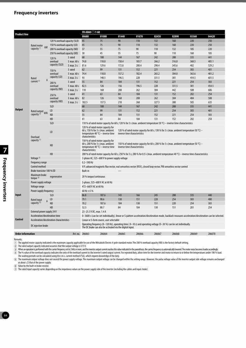
84
Frequency inverters
1
2
3
4
7
Frequ
ency inverters
Product lineFR-A860-m-1-6000680 01080 01440 01670 02430 02890 03360 04420
Output
Rated motor capacity 1 kW
120 % overload capacity (SLD) 45 75 90 110 132 160 220 250150 % overload capacity (LD) 45 75 90 110 132 160 220 250200 % overload capacity (ND) 37 55 75 90 110 132 185 220250 % overload capacity (HD) 30 45 55 75 90 110 160 185
Rated current 2 A
120 % overload capacity (SLD)
I rated 68 108 144 167 242 288 335 441I max. 60 s 74.8 118.8 158.4 183.7 266.2 316.8 368.5 485.1I max. 3 s 81.6 129.6 172.8 200.4 290.4 345.6 402 529.2
150 % overload capacity (LD)
I rated 62 99 131 152 221 254 303 401I max. 60 s 74.4 118.8 157.2 182.4 265.2 304.8 363.6 481.2I max. 3 s 93 148.5 196.5 228 331.5 381 454.5 601.5
200 % overload capacity (ND)
I rated 55 84 104 131 152 221 254 303I max. 60 s 82.5 126 156 196.5 228 331.5 381 454.5I max. 3 s 110 168 208 262 304 442 508 606
250 % overload capacity (HD)
I rated 41 63 84 104 131 152 202 254I max. 60 s 82 126 168 208 262 304 404 508I max. 3 s 102.5 157.5 210 260 327.5 380 505 635
Rated output capacity 3 kVA
SLD 68 108 144 167 242 288 335 441LD 62 99 131 152 221 254 303 401ND 55 84 104 131 152 221 254 303HD 41 63 84 104 131 152 202 254
Overload capacity 4
SLD 110 % of rated motor capacity for 60 s; 120 % for 3 s (max. ambient temperature 50 °C) – inverse time characteristics
LD
120 % of rated motor capacity for 60 s; 150 % for 3 s (max. ambient temperature 40 °C) – inverse time characteristics
120 % of rated motor capacity for 60 s; 150 % for 3 s (max. ambient temperature 50 °C) – inverse time characteristics
ND
150 % of rated motor capacity for 60 s; 200 % for 3 s (max. ambient temperature 40 °C) – inverse time characteristics
150 % of rated motor capacity for 60 s; 200 % for 3 s (max. ambient temperature 50 °C) – inverse time characteristics
HD 200 % of rated motor capacity for 60 s; 250 % for 3 s; 280 % for 0.5 s (max. ambient temperature 40 °C) – inverse time characteristicsVoltage 5 3-phase AC, 525–600 V to power supply voltageFrequency range 0.2–590 HzControl method V/f; advanced magnetic flux vector, real sensorless vector (RSV), closed loop vector, PM sensorless vector controlBrake transistor 100 % ED Built-in —Maximum brake torque 6 regenerative 20 % torque/continuous
Input
Power supply voltage 3-phase, 525–600 V AC at 60 HzVoltage range 472–660 V AC at 60 Hz Power supply frequency 60 Hz ±5 %
Rated input capacity g A
SLD 86.8 107.6 143 166 245 288 335 440LD 79.1 98.6 130 151 220 254 303 400ND 70.2 107.6 104 130 151 220 254 303HD 52.3 80.7 84 104 130 151 201 254
Control
External power supply 24 V 23–25.5 V DC, max. 1.4 AAcceleration/deceleration time 0–3600 s (can be set individually), linear or S-pattern acceleration/deceleration mode, backlash measures acceleration/deceleration can be selected.Acceleration/deceleration characteristics Linear or S-form course, user selectable
DC injection brake Operating frequency (0–120 Hz), operating time ( 0–10 s) and operating voltage (0–30 %) can be set individually. The DC brake can also be activated via the digital input.
Order information Art. no. 286063 286064 286065 286066 286067 286068 286069 286070
Remarks:1 The applied motor capacity indicated is the maximum capacity applicable for use of the Mitsubishi Electric 4-pole standard motor. The 200 % overload capacity (ND) is the factory default setting. 2 The rated output capacity indicated assumes that the output voltage is 575 V.3 When an operation is performed with the carrier frequency set to 3 kHz or more, and the inverter output current reaches the value indicated in the parenthesis, the carries frequency is automatically lowered. The motor noise becomes louder accordingly.4 The % value of the overload capacity indicates the ratio of the overload current to the inverter’s rated output current. For repeated duty, allow time for the inverter and motor to return to or below the temperatures under 100 % load.
The waiting periods can be calculated using the r.m.s. current method (I²xt), which requires knowledge of the duty.5 The maximum output voltage does not exceed the power supply voltage. The maximum output voltage can be changed within the setting range. However, the pulse voltage value of the inverter output side voltage remains unchanged
at about √2 that of the power supply.6 Value by the built-in brake resistor.7 The rated input capacity varies depending on the impedance values on the power supply side of the inverter (including the cables and input choke).

85
Frequency inverters
1
2
3
4
7
Frequ
ency inverters
Product lineFR-A862-m-1-6005450 06470 08500
Output
Rated motor capacity 1 kW
120 % overload capacity (SLD) 400 450 630150 % overload capacity (LD) 355 400 560200 % overload capacity (ND) 280 355 450250 % overload capacity (HD) 220 280 400
Rated current 2 A
120 % overload capacity (SLD)
I rated 545 647 850I max. 60 s 599.5 711.7 935I max. 3 s 654 776.4 1020
150 % overload capacity (LD)
I rated 496 589 773I max. 60 s 595.2 706.8 927.6I max. 3 s 744 883.5 1159.5
200 % overload capacity (ND)
I rated 402 496 663I max. 60 s 603 744 994.5I max. 3 s 804 992 1326
250 % overload capacity (HD)
I rated 304 402 589
I max. 60 s 608 804 1178
I max. 3 s 760 1005 1472.5
Rated output capacity 3 kVA
SLD 543 645 847LD 494 587 770ND 401 494 661HD 302 401 578
Overload capacity 4
SLD 110 % of rated motor capacity for 60 s; 120 % for 3 s (max. ambient temperature 40 °C) – inverse time characteristicsLD 120 % of rated motor capacity for 60 s; 150 % for 3 s (max. ambient temperature 50 °C) – inverse time characteristicsND 150 % of rated motor capacity for 60 s; 200 % for 3 s (max. ambient temperature 50 °C) – inverse time characteristicsHD 200 % of rated motor capacity for 60 s; 250 % for 3 s; 280 % for 0.5 s (max. ambient temperature 50 °C) – inverse time characteristics
Voltage 5 3-phase AC, 525–600 V to power supply voltageFrequency range 0.2–590 HzControl method V/f; advanced magnetic flux vector, real sensorless vector (RSV), closed loop vector, PM sensorless vector controlMaximum brake torque 6 regenerative 10 % torque/continuous
InputDC power supply voltage 618–933 V DCControl power supply voltage 1-phase, 525–600 V AC, 50/60 Hz
Control power supply range Frequency ±5 %, voltage ±10 %
Control
External power supply 24 V 23–25.5 V DC, max. 1.4 AAcceleration/deceleration time 0–3600 s (can be set individually), linear or S-pattern acceleration/deceleration mode, backlash measures acceleration/deceleration can be selected.Acceleration/deceleration characteristics Linear or S-form course, user selectable
DC injection brake Operating frequency (0–120 Hz), operating time ( 0–10 s) and operating voltage (0–30 %) can be set individually. The DC brake can also be activated via the digital input.
Order information Art. no. 286240 286241 286242
Remarks:Explanation for 1 to f see a page before.

86
Frequency inverters
1
2
3
4
7
Frequ
ency inverters
Converter module FR-CC2
The converter module FR-CC2 is a diode converter unit. The FR-CC2-H has to be used together with the FR-A842, the FR-CC2-C together with the FR-A862 inverter unit. The separation of the inverter and the converter module allows flexible design of different systems such as parallel drive and common bus line to reduce cost and to minimize installation space.
At a rated motor capacity of 220 kW and higher the frequency inverter is divided in a converter unit (FR-CC2) and an inverter unit (FR-A842/FR-A862). Both units are connected via DC bus.
The FR-CC2 supports a 12 pulse connection with additional phase-shifting transformers for reducing low-degree harmonic currents.
Motorcapacity [kW] 1
ConverterunitFR-CC2-Hm
Inverter
SLD (superlight duty) LD (light duty) ND (normal duty, initial value) HD (heavy duty)Model
FR-A842- mRated
current [A]Model
FR-A842- mRated
current [A]Model
FR-A842- mRated
current [A]Model
FR-A842- mRated
current [A]
280 315K — — — — — — — — — 315K 07700 547315 315K — — — — — — 315K 07700 610 355K 08660 610355 355K — — — 315K 07700 683 355K 08660 683 400K 09620 683400 400K 315K 07700 770 355K 08660 770 400K 09620 770 450K 10940 770450 450K 355K 08660 866 400K 09620 866 450K 10940 866 500K 12120 866500 500K 400K 09620 962 450K 10940 962 500K 12120 962 — — —
1 The applicable motor capacity indicated is the maximum capacity applicable for use of the Mitsubishi Electric 4-pole standard motor.
Compatible inverters
The table below shows the inverter models compatible with the FR-CC2 converter units.
Product lineFR-CC2-HmK-60315K 355K 400K 450K 500K 560K 630K
Output
Rated motor capacity kW 315 355 400 450 500 560 630
Overload current rating 1 200 % 60 s, 250 % 3 s 150 % 60 s,200 % 3 s
120 % 60 s,150 % 3 s
110 % 60 s,120 % 3 s
Voltage 2 430–780 V 4
Input
Power supply voltage 3-phase, 380–500 V AC, -15 %/+10 %Voltage range 323–550 V AC at 50/60 Hz
Power supply frequency 50/60 Hz ±5 %
Rated input capacity 3 kVA 465 521 587 660 733 833 924
Order information Art. no. 274507 274508 274509 274510 274511 279637 279638
Product lineFR-CC2-CmK-60355 400 560
Output
Rated motor capacity kW 355 400 560
Overload current rating 1
SLD 110 % of rated motor capacity for 60 s; 120 % for 3 s (max. ambient temperature 40 °C) – inverse time characteristicsLD 120 % of rated motor capacity for 60 s; 150 % for 3 s (max. ambient temperature 50 °C) – inverse time characteristicsND 150 % of rated motor capacity for 60 s; 200 % for 3 s (max. ambient temperature 50 °C) – inverse time characteristicsHD 200 % of rated motor capacity for 60 s; 250 % for 3 s; 280 % for 0.5 s (max. ambient temperature 40 °C) – inverse time characteristics
Voltage 2 618–933 V DC 4
Input
Power supply voltage 3-phase, 525–600 V AC, -15 %/+10 %Voltage range 472–660 V AC at 60 HzPower supply frequency 60 Hz ±5 %
Rated input capacity 3 kVA
SLD 543 644 847LD 494 587 770ND 400 494 660
HD 303 400 587
Order information Art. no. 286237 286238 286239
1 The % value of the overload current rating indicated is the ratio of the overload current to the inverter’s rated output current. For repeated duty, allow time for the converter unit and the inverter to return to or below the temperatures under 100 % load.2 The converter unit output voltage varies according to the input power supply voltage and the load. The maximum point of the voltage waveform at the converter unit output side is approximately the power supply voltage multiplied by √2.3 The power supply capacity is the value at the rated output current. It varies by the impedance at the power supply side (including those of the input choke and cables).4 The permissible voltage imbalance ratio is 3 % or less. (Imbalance ratio = (highest voltage between lines – average voltage between three lines)/average voltage between three lines x100)

87
Frequency inverters
1
2
3
4
7
Frequ
ency inverters
Internal and external options
A large number of options allows an individual adoption of the inverter to the according task. The options can be installed quickly and easily. Detailed information on installation and func-tions is included in the manual of the options.
The options can be divided into two major categories:
z Internal options
z External options
Internal options
The internal options comprise input and output extensions as well as communications options supporting the operation of the inverter within a network or connected to a personal computer or PLC.
External options
In addition to the parameter unit that enables interactive operation of the frequency inverter the available external options also include addi-tional EMC noise filters, chokes for improving efficiency and brake units with brake resistors.
Option Description FR-D700 SC FR-E700 SC FR-F800 FR-A700 FR-A800 FR-HC2
Internal options
Digital input Input of the frequency setting via BCD or binary code — U U U U —
Digital output Selectable standard output signals of the inverter can be output at the open collector. — U U U U —
Expansion analog output Selectable additional signals can be output and indicated at the analog output. — U U U U —
Relay output Selectable standard output signals of the inverter can be output through relay terminals. — U U U U —
Orientation control, encoder feedback (PLG), vector and master slave control
These options are used for position control, precise speed control and master/slave control. — — — U U —
Communications
CC-Link Integration of a frequency inverter into a CC-Link. — U U U U U
CC-Link IE Field Integration of a frequency inverter into a CC-Link IE Field network. — — — U U —
CC-Link IE Field Basic Integration of a frequency inverter into a CC-Link IE Field Basic network. — — U — U —
Modbus®/TCP Integration of a frequency inverter into a Modbus®/TCP network. — U U U U U
EtherNet/IP Integration of a frequency inverter into a EtherNet/IP network. — U U U U U
EtherCat Integration of a frequency inverter into a EtherCat network. — U U U U —
LonWorks Integration of a frequency inverter into a LonWorks network. — U U U U —
Profibus DPV1 Integration of a frequency inverter into a Profibus DPV1 network. — — U — U —
Profibus DP PPO Integration of a frequency inverter into a Profibus DP PPO network. — U U U U —
Profinet Integration of a frequency inverter into a Profinet network. — U U U U U
DeviceNet™ Integration of a frequency inverter into a DeviceNet™. — U U U U —
SSCNET III/H Integration of a frequency inverter into a SSCNET III/H. — — — U U —
CAN Bus Integration of a frequency inverter into a CAN Bus network — — U — U —
RS485 multi-protocol RS485 multi-protocol interface card — — U U — U
Option Description FR-D700 SC FR-E700 SC FR-F800 FR-A700 FR-A800
External options
Parameter unit (8 languages) Interactive parameter unit with LC display. U U U U U
FR-Configurator software Parameterization and setup software for the Mitsubishi Electric inverter series. U U U U U
EMC noise filter Noise filter for compliance with EMC directives. U U U U U
Brake unit For an improvement of the brake capacity. For high inertia loads and active loads. Used in combination with a resistor unit. U U U U U
External high-duty brake resistor To improve the brake capacity; used in combination with the internal brake transistor. U U — U U
DC chokeAC chokes
For increased efficiency, reduction of mains feedback and compensation of voltage fluctuations. U U U U U
Floor standing unit FSU IP20 physical contact protection in a freely-locatable floor-standing unit. Detailed information on request. — — U U U
Harmonic filter module Passive harmonic filter to reduce mains pollution U U U U U
Regenerative unit Regeneration of electrical energy in short-term operation (ED <50 %) U U U U U
Regenerative unit Regeneration of electrical energy in short-term operation (ED =100 %) U U U U U
Harmonic converter For power supply and regeneration of electrical energy (ED = 100 %) U U U U U
Communications Profibus DP High speed converter for Profibus DP to RS485 inverter protocol U U U U U

88
1
2
3
4
8
Servo an
d m
otio
n system
s
Servo and motion systems
Mitsubishi Electric offers a variety of servo and motion system products providing solutions for applications covering point-to-point and syn-chronised systems. Systems can be built using a single axis or multi-axes, for example when using a MELSEC iQ-R motion CPU solution up to 192 axes can be controlled.
Therefore operation is possible by standard pulse train outputs as well as by different networks like SSCNET III/H, CC-Link IE Field, CC-Link IE Field Basic, EtherCAT, PROFINET und EtherNet/IP™.
The servo motors and amplifiers take Mitsubishi Electric Motion Control to new levels of precision with a wide range of motors and a wide range of amplifiers (up to 220 kW).
All MR-JE series motors are fitted with 131,072 pulse-per-revolution encoders, all MR-J4 series motors with 4,194,304 pulse-per-revolu-tion encoders.
All Mitsubishi Electric servo and motion system hardware is complimented by a range of soft-ware packages allowing easy programming and set-up of the units.
What are the components of a MR-J4 servo system?
Servo motors
Utilising the most advanced concentrated winding techniques and latest technology, these brushless servo motors are among the most compact on the market.
Mitsubishi Electric servo motors are made to high standards and offer a wide range of power, speed and inertia ratings providing a motor for all applications. With a range from 50 W to 55 kW
and with a considerable number of motor types like rotary, linear and direct drive servo motors a complete line-up of products can be offered by Mitsubishi Electric.
Also, all motors in the MR-J4 series are fitted with absolute encoders as standard. Therefore, an absolute position system can be created by simply providing power to servo amplifier via
a battery. Once this has been done the super capacitor inside the motor and back-up battery allow the servo motor position to be constantly monitored.
Improving machine performance with high-performance motors
To raise your machine on a high productive level, you need not only powerful servo ampli-fiers but also high performance servo motors. These motors have to support the high encoder resolution of 22 bits with the MR-J4 series for improved accuracy and speed. Fully closed loop control is supported as standard. A variety of models is available to match various applica-tions.
Rotary servo motors achieve high-accuracy, high-torque output during high speed position-ing and smooth rotation with a high resolution encoder and improved processing speed. Linear servo motors support highly accurate tandem synchronous control. Direct drive motors are used for compact and rigid machine and high-torque operations.
For rough environment conditions some motor series are also available with higher protection class like IP65 or IP67.
The MR-J4 series servo amplifiers are able to operate rotary servo motors, linear servo motors, and direct drive motors as standard.
[Resolution comparison]
MR-JE series 17 bits = 131,072 pulses/rev
MR-J4 series 22 bits = 4,194,304 pulses/rev
16 times
16 times 4000000-pulse encoder
Rotary servo motor
Linear servo motor
Direct drive motor
For detailed information, please refer to the family catalogues.
0 1 kW 5 kW2 kW 100 kW40 kW30 kW20 kW10 kW
HG-KN 100–750 W
HG-KR/HG-MR 50–750 W
HG-SR 0.5–7 kW200
V
7 kW
HG-RR 1–5 kW
HG-JR 0.5–22 kW
400
V
HG-SR 0.5–7 kW
HG-JR 0.5–55 kW *
55 kW
HG-SN 0.5–3 kW
* For order information about servo motors higher than 22 kW, please contact your Mitsubishi Electric representative

89
Servo and motion systems
1
2
3
4
8
Servo an
d m
otio
n system
s
Servo amplifiers
Mitsubishi Electric offers a wide range of servo amplifiers to meet the demands of all types of applications. From standard digital pulse and analogue controlled amplifiers through to dedicated network bus type amplifiers, there is a product for all circumstances.
Real Time Adaptive Tuning (RTAT) is a unique Mitsubishi Electric technology, enabling the servo to deliver maximum dynamic perfor-mance, even if the load keeps changing, by automatically tuning online (during operation) to the application.
The digital pulse-train and analogue units of the MR-JE and the MR-J4 series from 100 W to 55 kW ab. The SSCNET III/H bus type amplifiers (type MR-J4-B/MR-JE-BF series) offer the user ease of connectivity, via SSCNET III/H.
Whereby the MR-J4-TM supports Ethernet based open network communication and MR-J4-GF comunicates via CC Link IE Field.
Positioning controllers
For the compact, cost effective, FX range of PLCs, the FX2N-10PG unit provides single-axis control with built-in positioning tables, fast external start and an output pulse rate of up to 1 MHz. The module FX3U-20SSC-H is a positioning module for the MR-J4-B series. This module pro-vides a quick and easy, but efficient positoning control system for simpler applications.
For larger and more complex applications the MELSEC iQ F series, MELSEC iQ-R series, MELSEC L series and MELSEC System Q provide numerous positioning and Simple Motion mod-ules (1, 2, 4 and 16 axes).
These are: open-collector output type (LD75P/QD75P/RD77P series), differential output type (LD75D/QD75DN/RD77D series) and SSCNET III bus type (FX3U-20SSC-H), SSCNET III/H bus type (LD77MS/QD77MS).
Using the SSCNET III/H system can provide much improved, easier to use positioning systems, with reduced wiring and better noise immunity. All positioning modules provide functions such as interpolation, speed control and positioning operations, etc. For advanced motion applica-tions like axes synchronisation and CAM control the Simple Motion modules (FX5-mSSC-S/LD77/QD77/RD77) are available.
Additionally the simple motion modules of the MELSEC iQ-R series and MELSEC System Q provide a CC-Link IE Field interface.
Motion Controllers
For specialist applications requiring the highest level of control and precision, the dynamic servo technology provided by the iQ-R motion CPU is combined with the powerful processing power of the MELSEC iQ-R PLC CPU, creating a completely new generation of Motion Controller products.
This fully integrated and flexible system has the capability to control up to 192 axes using SSCNET III/H, which is more than capable for hand ling any motion application.
Advanced one-touch tuning function
Servo gain adjustment for precise vibration sup-pression control can be done only by one touch. Machine resonance suppression filter, advanced vibration suppression control II (adjustment for one frequency), and robust filter are adjusted just by turning on this function. The advanced vibration suppression control function enables the machine to operate with high speed at the highest performance.
Advanced vibration suppression control II
The vibration suppression algorithm supports a three-inertia system so that two types of low frequency vibrations are suppressed at the same time. For adjustment the setup software MR Configurator2 is used. This function is effective in suppressing vibration at the end of an arm and in reducing residual vibration in a machine. Droop pulses are reduced to a minimum.
Machine diagnosis function
This function is a powerful monitoring and maintenance support tool. It detects changes of machine parts (ball screw, guide, bearing, belt, etc.) by analyzing machine friction, load moment of inertia, unbalanced torque, and changes in vibration component from the data inside the servo amplifier. Monitoring is done with the setup software MR Configurator2. Timely maintenance of wear parts will be indi-cated before breakdown.
200
V40
0 V
MR-J4-A/B/GF/TM 0.6–55 kW *
MR-JE-A/BF/C 0.1 kW–3 kW
MR-J4-A/B/GF/TM 0.1–22 kW
MR-J4W2-B 0.2–1 kW
MR-J4W3-B 0.2–0.4 kW
* For order information about servo amplifiers higher than 22 kW, please contact your Mitsubishi Electric representative
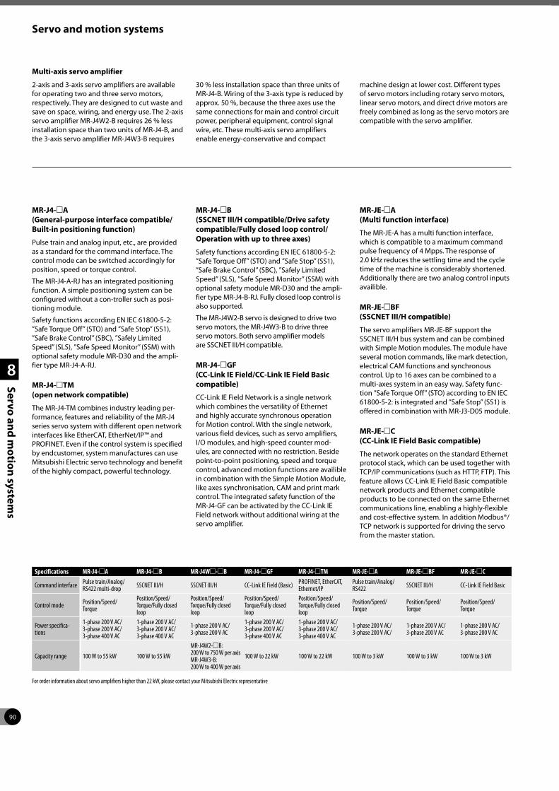
90
Servo and motion systems
1
2
3
4
8
Servo an
d m
otio
n system
s
MR-J4-mA (General-purpose interface compatible/ Built-in positioning function)
Pulse train and analog input, etc., are provided as a standard for the command interface. The control mode can be switched accordingly for position, speed or torque control.
The MR-J4-A-RJ has an integrated positioning function. A simple positioning system can be configured without a con-troller such as posi-tioning module.
Safety functions according EN IEC 61800-5-2: ”Safe Torque Off” (STO) and ”Safe Stop” (SS1), ”Safe Brake Control” (SBC), ”Safely Limited Speed” (SLS), ”Safe Speed Monitor” (SSM) with optional safety module MR-D30 and the ampli-fier type MR-J4-A-RJ.
MR-J4-mTM (open network compatible)
The MR-J4-TM combines industry leading per-formance, features and reliability of the MR-J4 series servo system with different open network interfaces like EtherCAT, EtherNet/IP™ and PROFINET. Even if the control system is specified by endcustomer, system manufactures can use Mitsubishi Electric servo technology and benefit of the highly compact, powerful technology.
MR-J4-mB (SSCNET III/H compatible/Drive safety compatible/Fully closed loop control/Operation with up to three axes)
Safety functions according EN IEC 61800-5-2: ”Safe Torque Off” (STO) and ”Safe Stop” (SS1), ”Safe Brake Control” (SBC), ”Safely Limited Speed” (SLS), ”Safe Speed Monitor” (SSM) with optional safety module MR-D30 and the ampli-fier type MR-J4-B-RJ. Fully closed loop control is also supported.
The MR-J4W2-B servo is designed to drive two servo motors, the MR-J4W3-B to drive three servo motors. Both servo amplifier models are SSCNET III/H compatible.
MR-J4-mGF (CC-Link IE Field/CC-Link IE Field Basic compatible)
CC-Link IE Field Network is a single network which combines the versatility of Ethernet and highly accurate synchronous operation for Motion control. With the single network, various field devices, such as servo amplifiers, I/O modules, and high-speed counter mod-ules, are connected with no restriction. Beside point-to-point positioning, speed and torque control, advanced motion functions are availible in combination with the Simple Motion Module, like axes synchronisation, CAM and print mark control. The integrated safety function of the MR-J4-GF can be activated by the CC-Link IE Field network without additional wiring at the servo amplifier.
MR-JE-mA (Multi function interface)
The MR-JE-A has a multi function interface, which is compatible to a maximum command pulse frequency of 4 Mpps. The response of 2.0 kHz reduces the settling time and the cycle time of the machine is considerably shortened. Additionally there are two analog control inputs availible.
MR-JE-mBF (SSCNET III/H compatible)
The servo amplifiers MR-JE-BF support the SSCNET III/H bus system and can be combined with Simple Motion modules. The module have several motion commands, like mark detection, electrical CAM functions and synchronous control. Up to 16 axes can be combined to a multi-axes system in an easy way. Safety func-tion ”Safe Torque Off” (STO) according to EN IEC 61800-5-2: is integrated and ”Safe Stop” (SS1) is offered in combination with MR-J3-D05 module.
MR-JE-mC (CC-Link IE Field Basic compatible)
The network operates on the standard Ethernet protocol stack, which can be used together with TCP/IP communications (such as HTTP, FTP). This feature allows CC-Link IE Field Basic compatible network products and Ethernet compatible products to be connected on the same Ethernet communications line, enabling a highly-flexible and cost-effective system. In addition Modbus®/TCP network is supported for driving the servo from the master station.
Specifications MR-J4-mA MR-J4-mB MR-J4Wm-mB MR-J4-mGF MR-J4-mTM MR-JE-mA MR-JE-mBF MR-JE-mC
Command interface Pulse train/Analog/RS422 multi-drop SSCNET III/H SSCNET III/H CC-Link IE Field (Basic) PROFINET, EtherCAT,
Ethernet/IPPulse train/Analog/RS422 SSCNET III/H CC-Link IE Field Basic
Control mode Position/Speed/Torque
Position/Speed/Torque/Fully closed loop
Position/Speed/ Torque/Fully closed loop
Position/Speed/Torque/Fully closed loop
Position/Speed/Torque/Fully closed loop
Position/Speed/Torque
Position/Speed/Torque
Position/Speed/Torque
Power specifica-tions
1-phase 200 V AC/ 3-phase 200 V AC/ 3-phase 400 V AC
1-phase 200 V AC/ 3-phase 200 V AC/ 3-phase 400 V AC
1-phase 200 V AC/ 3-phase 200 V AC
1-phase 200 V AC/ 3-phase 200 V AC/ 3-phase 400 V AC
1-phase 200 V AC/ 3-phase 200 V AC/ 3-phase 400 V AC
1-phase 200 V AC/ 3-phase 200 V AC/
1-phase 200 V AC/ 3-phase 200 V AC
1-phase 200 V AC/ 3-phase 200 V AC
Capacity range 100 W to 55 kW 100 W to 55 kW
MR-J4W2-mB: 200 W to 750 W per axis MR-J4W3-B: 200 W to 400 W per axis
100 W to 22 kW 100 W to 22 kW 100 W to 3 kW 100 W to 3 kW 100 W to 3 kW
For order information about servo amplifiers higher than 22 kW, please contact your Mitsubishi Electric representative
Multi-axis servo amplifier
2-axis and 3-axis servo amplifiers are available for operating two and three servo motors, respectively. They are designed to cut waste and save on space, wiring, and energy use. The 2-axis servo amplifier MR-J4W2-B requires 26 % less installation space than two units of MR-J4-B, and the 3-axis servo amplifier MR-J4W3-B requires
30 % less installation space than three units of MR-J4-B. Wiring of the 3-axis type is reduced by approx. 50 %, because the three axes use the same connections for main and control circuit power, peripheral equipment, control signal wire, etc. These multi-axis servo amplifiers enable energy-conservative and compact
machine design at lower cost. Different types of servo motors including rotary servo motors, linear servo motors, and direct drive motors are freely combined as long as the servo motors are compatible with the servo amplifier.

91
Servo and motion systems
1
2
3
4
8
Servo an
d m
otio
n system
s
Servo motor features and typical applications
Absolute high-resolution encoder as standard equipment
Inclusion of an absolute position detection sys-tem eliminates the need for a homing sequence, approximate DOG and other sensors, helping to reduce time and enhance reliability. With these motors high performance and safety at low speed is ensured.
With Mitsubishi Electric original absolute mode, an absolute system can be configured using conventional I/O even with pulse-train control.
Model designation Features Application example
K
Low inertiaLarger motor inertia moment makes this unit well suited for machines with fluctuating load inertia moment or machines with low rigidity such as conveyors.
z Conveyors z Food preparation machinery z Printers z Small loaders and unloaders z Small robots and component assembly devices z Small X-Y tables z Small press feeders
Handling systems
M
Ultra low inertiaSmall motor inertia moment makes this unit well suited for high-dynamic positioning operations with extra small cycle times.
z Inserters, mounters, bonders z Printed board hole openers z In-circuit testers z Label printers z Knitting and embroidery machinery z Ultra-small robots and robot tips
Inserters, mounters, bonders
S
Medium inertiaStable control is performed from low to high-speeds, enabling this unit to handle a wide range of applications (e.g. direct connection to ball screw components).
z Conveyor machinery z Specialised machinery z Robots z Loaders and unloaders z Winders and tension devices z Turrets z X-Y tables z Test devices
Winders and tension devices
RLow inertiaA compact sized low inertia moment model with medium capacity. Well suited for high-frequency operation.
z Roll feeders z Loaders and unloaders z high-frequency conveyor machinery
JLow inertia (400 V)A 400 V servo motor for the MELSERVO-J4 series for a power range up to 55 kW with low inertia and high speed. It has a compact size, is equipped with high resolution encoder and is compatible to global standards.
z Food and packaging z Printing machine z Pick up robot for injection molding machine z Palletizing machine z General machine which require
high-speed and high-frequency
Wrapping machinery
Note: Other types of motors are available on request.

92
Servo and motion systems
1
2
3
4
8
Servo an
d m
otio
n system
s
Servo motor specifications and matching amplifiers
Motors for MR-J4 (200 V) series servo amplifiers
Motor series 200 V
Rated speed [r/min]
Maximum rotation speed [r/min]
Rated torque [Nm]
Peak running range [Nm]
Moment of inertia J [x10-4 kg m2]
Rated output capacity [kW]
Servo motor model
Servo motor type Amplifier pairing MR-J4
Art. no.Voltage Protective
structure 10 20 40 60 70 100 200 350 500 700 11K 15K 22K
HG-MR
M 3000 6000
0.16 0.48 0.0162 0.05 HG-MR053
200 V AC IP65
Q 2486610.32 0.95 0.0300 0.10 HG-MR13 Q 2486620.64 1.9 0.0865 0.20 HG-MR23 Q 2486631.3 3.8 0.142 0.40 HG-MR43 Q 2486642.4 7.2 0.586 0.75 HG-MR73 Q 248665
HG-KR
K 3000 6000
0.16 0.56 0.0450 0.05 HG-KR053
200 V AC IP65
Q 2486510.32 1.1 0.0777 0.10 HG-KR13 Q 2486520.64 2.2 0.221 0.20 HG-KR23 Q 2486531.3 4.5 0.371 0.40 HG-KR43 Q 2486542.4 8.4 1.26 0.75 HG-KR73 Q 248655
HG-SR
S 2000 3000
2.4 7.2 7.26 0.50 HG-SR52
200 V AC IP67
Q 2486714.8 14.3 11.6 1.00 HG-SR102 Q 2486727.2 21.5 16.0 1.50 HG-SR152 Q 2486739.5 28.6 46.8 2.00 HG-SR202 Q 24867416.7 50.1 78.6 3.50 HG-SR352 Q 24867523.9 71,6 99.7 5.00 HG-SR502 Q 24867633.4 100 151 7.00 HG-SR702 Q 248677
HG-JR
J3000
6000
1,6 4.8 <6.4> 1 1.52 0.5 HG-JR53
200 V AC IP67d
Q Q2 261539
2.4 7.2 <9.6> 1 2.09 0.75 HG-JR73 Q Q2 261540
3.2 9.6 <12.7> 1 2.65 1.0 HG-JR103 Q Q2 261541
4.8 14.3 <19.1> 1 3.79 1.5 HG-JR153 Q Q2 261542
6.4 19.1 <25.5> 1 4.92 2.0 HG-JR203 Q Q2 261543
10.5 <11.1> 3
32.0 <44.6> 1 13.2 3.3
<3,5> 3 HG-JR353 Q Q23 261544
15.9 47.7 <63.7> 1 19.0 5.0 HG-JR503 Q Q2 261545
500022.3 66.8 43.3 7.0 HG-JR703 Q 26154628.6 85.8 55.8 9.0 HG-JR903 Q 261547
15003000
70.0 210 220 11 HG-JR11K1M Q 26155795.5 286 315 15 HG-JR15K1M Q 261558
2500 140 420 489 22 HG-JR22K1M Q 261559
HG-RR
R 3000 4500
3.2 8.0 1.50 1.0 HG-RR103
200 V AC IP65
Q 2628964.8 11.9 1.90 1.5 HG-RR153 Q 2628976.4 15.9 2.30 2.0 HG-RR203 Q 26289811.1 27.9 8.30 3.5 HG-RR353 Q 26289915.9 39.8 12.0 5.0 HG-RR503 Q 262900
1 The value in angle brackets is applicable when the maximum torque is increased. The maximum torque will be increased by changing the servo amplifier to be combined (see 2).
2 This combination of the HG-JR servo motor and the servo amplifier increases the maximum torque from 300 % to 400 % of the rated torque.
3 The value in angle brackets is applicable when the servo motor is used with MR-J4-500B or MR-J4-500A.
4 22 kW of HG-JR series is rated IP44

93
Servo and motion systems
1
2
3
4
8
Servo an
d m
otio
n system
s
Motors for MR-J4 (400 V) series servo amplifiers
Motors for MR-JE-A/BF/C series servo amplifiers
Motor series 200 V
Rated speed [r/min]
Maximum rotation speed [r/min]
Rated torque [Nm]
Peak running range [Nm]
Moment of inertia J [x10-4 kg m2]
Rated output capacity [kW]
Servo motor model
Servo motor type Amplifier pairing MR-JE
Art. no.Voltage Protective
structure 10 20 40 70 100 200 300
HG-KN
K 3000 4500
0,32 0,95 0,088 0,1 HG-KN13
200 V AC IP65
Q 2826310,64 1,9 0,24 0,2 HG-KN23K Q 2826331,3 3,8 0,42 0,4 HG-KN43K Q 2826352,4 7,2 1,43 0,75 HG-KN73JK Q 282637
HG-SN
S 2000 3000
2,39 7,16 6,1 0,5 HG-SN52JK
200 V AC IP67
Q 2826394,77 14,3 11,9 1,0 HG-SN102JK Q 2826417,16 21,5 17,8 1,5 HG-SN152JK Q 2826439,55 28,6 38,3 2,0 HG-SN202JK Q 28264514,3 42,9 58,5 3,0 HG-SN302JK Q 282647
Motor series 400 V
Rated speed [r/min]
Maximum rotation speed [r/min]
Rated torque [Nm]
Peak running range [Nm]
Moment of inertia J [x10-4 kg m2]
Rated output capacity [kW]
Servo motor model
Servo motor type Amplifier pairing MR-J4
Art. no.Voltage Protective
structure 60 100 200 350 500 700 11K 15K 22K
HG-SR
S 2000 3000
2.4 7.2 7.26 0.5 HG-SR524
400 V AC IP67
Q 2614314.8 14.3 11.6 1.0 HG-SR1024 Q 2614327.2 21.5 16.0 1.5 HG-SR1524 Q 2614339.5 28.6 46.8 2.0 HG-SR2024 Q 26143416.7 50.1 78.6 3.5 HG-SR3524 Q 26143523.9 71.6 99.7 5.0 HG-SR5024 Q 26143633.4 100 151 7.0 HG-SR7024 Q 261437
HG-JR
J3000
6000
1.6 4.8 <6.4> 1 1.52 0.5 HG-JR534
400 V AC IP67 4
Q Q2 261445
2.4 7.2 <9.6> 1 2.09 0.75 HG-JR734 Q Q2 261446
3.2 9.6 <12.7> 1 2.65 1.0 HG-JR1034 Q Q2 261447
4.8 14.3 <19.1> 1 3.79 1.5 HG-JR1534 Q Q2 261448
6.4 19.1 <25.5> 1 4.92 2.0 HG-JR2034 Q Q2 261449
10.5 <11.1> 3
32.0 <44.6> 1 13.2 3.3
<3.5> 3 HG-JR3534 Q Q2 3 261450
15.9 47.7 <63.7> 1 19.0 5.0 HG-JR5034 Q Q2 261451
500022.3 66.8 43.3 7.0 HG-JR7034 Q 26145228.6 85.8 55.8 9.0 HG-JR9034 Q 261453
15003000
70.0 210 220 11 HG-JR11K1M4 Q 26138495.5 286 315 15 HG-JR15K1M4 Q 261535
2500 140 420 489 22 HG-JR22K1M4 Q 261536
1 The value in angle brackets is applicable when the maximum torque is increased. The maximum torque will be increased by changing the servo amplifier to be combined (see 2).
2 This combination of the HG-JR servo motor and the servo amplifier increases the maximum torque from 300 % to 400 % of the rated torque.
3 The value in angle brackets is applicable when the servo motor is used with MR-J4-500B or MR-J4-500A.
4 22 kW of HG-JR series is rated IP44

94
Servo and motion systems
1
2
3
4
8
Servo an
d m
otio
n system
s
MR-JE servo amplifier specifications
The MR-JE was designed to reach high perfor-mance and to get an easy-to-use servo system for all kind of machines. Proven reliability with a 2.0 kHz high-frequency response, an energy-sav-ing design and the easy setup with Advanced One-Touch Tuning can be offered by MR-JE.
The servo motors are equipped with 131,072 pulses/ rev (17-bit) incremental encoder for achieving high-accuracy positioning and smooth rotation for applications from 100 W to 3 kW. In combination with the MR Configurator2 software package the servo system is easy to start-up, to adjust and to analyze.
Specifications MR-JE-mBF 10BF 20BF 40BF 70BF 100BF 200BF 300BF
Power supply 3-phase or 1-phase 200–240 V AC, 50/60 Hz 3-phase or 1-phase 200–240 V AC, 50/60 Hz *
3-phase 200– 240 V AC, 50/60 Hz
Control system Sinusoidal PWM control/current control systemDynamic brake Built-in
Protective functions Overcurrent shutdown, regeneration overvoltage shutdown, overload shutdown (electronic thermal), encoder fault protection, regeneration fault protection, undervoltage/sudden power outage protection, overspeed protection, excess error protection
Safety function STO (IEC/EN 61800-5-2); (SS1 function is available by using the safety option card MR-J3-D05)Structure/protection Self-cooling, open (IP20) Fan-cooling, open (IP20)
Environmentambient temperature Operation: 0–55 °C (no freezing); storage: -20–65 °C (no freezing)ambient humidity Operation: 90 % RH max. (no condensation); storage: 90 % RH max. (no condensation)others Elevation: 1000 m or less above sea level; oscillation: 5.9 m/s2 (0.6 G) max.
Position/speed/torque control mode Control via SSCNET III/H Communication speed 150 MbpsWeight kg 0.8 0.8 0.8 1.5 1.5 2.1 2.1Dimensions (WxHxD) mm 50x168x135 50x168x135 50x168x135 70x168x185 70x168x185 90x168x195 90x168x195
Order information Art. no. 312937 312938 312939 312940 312941 312942 312943
* When 1-phase 200 V AC to 240 V AC power supply is used, use them with 75 % or less of the effective load ratio.
MITSUBISHI
MODE
AUTO
MR-JE-10A
SET
CNP1
CN3
CN1
L2L3P+C
L1
UVW
CN2
Specifications MR-JE-mA 10A 20A 40A 70A 100A 200A 300A
Power supply 3-phase or 1-phase 200–240 V AC, 50/60 Hz 3-phase or 1-phase 200–240 V AC, 50/60 Hz *
3-phase 200– 240 V AC, 50/60 Hz
Control system Sinusoidal PWM control/current control systemDynamic brake Built-in
Protective functions Overcurrent shutdown, regeneration overvoltage shutdown, overload shutdown (electronic thermal), encoder fault protection, regeneration fault protection, undervoltage/sudden power outage protection, overspeed protection, excess error protection
Structure/protection Self-cooling, open (IP20) Fan-cooling, open (IP20)
Environmentambient temperature Operation: 0–55 °C (no freezing); storage: -20–65 °C (no freezing)ambient humidity Operation: 90 % RH max. (no condensation); storage: 90 % RH max. (no condensation)others Elevation: 1000 m or less above sea level; oscillation: 5.9 m/s2 (0.6 G) max.
Position control mode
max. input pulse frequency 4 Mpps (differential receiver), 200 kpps (open collector)positioning feedback pulse 131072 pulses per servo motor rotationtorque limit Set by parameters or external analog input (0–+ 10 V DC/maximum torque)
Speed control mode
control range Analog speed command 1:2000, internal speed command 1:5000fluctuation rate ±0.01 % max. (load fluctuation 0–100 %)torque limit Set by parameters or external analog input (0–+10 V DC/maximum torque)
Torque control mode
command input 0–±8 V DC/maximum torquespeed limit Set by parameters or external analog input (0–±10 V DC, rated speed)
Weight kg 0.8 0.8 0.8 1.5 1.5 2.1 2.1Dimensions (WxHxD) mm 50x168x135 50x168x135 50x168x135 70x168x185 70x168x185 90x168x195 90x168x195
Order information Art. no. 268792 268793 268794 268795 268796 268797 268798
Specifications MR-JE-mC 10C 20C 40C 70C 100C 200C 300C
Power supply 3-phase or 1-phase 200–240 V AC, 50/60 Hz 3-phase or 1-phase 200–240 V AC, 50/60 Hz *
3-phase 200– 240 V AC, 50/60 Hz
Control system Sinusoidal PWM control/current control systemDynamic brake Built-in
Protective functions Overcurrent shutdown, regeneration overvoltage shutdown, overload shutdown (electronic thermal), encoder fault protection, regeneration fault protection, undervoltage/sudden power outage protection, overspeed protection, excess error protection
Environmentambient temperature Operation: 0–55 °C (no freezing); storage: -20–65 °C (no freezing)ambient humidity Operation: 90 % RH max. (no condensation); storage: 90 % RH max. (no condensation)others Elevation: 1000 m or less above sea level; oscillation: 5.9 m/s2 (0.6 G) max.
Position/speed/torque control mode Control via CC-Link IE Field BasicWeight kg 0.8 0.8 0.8 1.5 1.5 2.1 2.1Dimensions (WxHxD) mm 50x168x135 50x168x135 50x168x135 70x168x185 70x168x185 90x168x195 90x168x195
Order information Art. no. 312314 312335 312336 312337 312338 316778 316779
* When 1-phase 200 V AC to 240 V AC power supply is used, use them with 75 % or less of the effective load ratio.

95
Servo and motion systems
1
2
3
4
8
Servo an
d m
otio
n system
s
MR-J4 servo amplifier specifications
The MELSERVO MR-J4 series is designed for ease of use and setup, safety, energy-efficiency and user friendly handling. With additional functions like “One-touch Tuning” and “Advanced Vibration Suppression Control” the servo performance achieves industry-leading level.The range covers 200 V amplifiers from 0.1 to 37 kW and 400 V amplifiers from 0.6 to 55 kW.
z Processing of encoder signals with 22 bit resolution (4,194,304 pulses/rev.)
z Speed frequency response is increased to 2.5 kHz
z Operating of rotary, linear and direct drive motors as standard
z Compatible with safety functions STO (Safe Torque Off) and SS1 (Safe Stop 1) correspond-ing EN 61800-5-2 as standard.
The MR-J4-B servo amplifier receives a com-mand signal from a control system via high speed motion network SSCNET III/H with a com-munication speed of 150 Mbps and a cycle time of 0.22 ms. This optical network is very reliable in operation because it is not affected by EMC.
For control, the MR-J4-A servo amplifier has a pulse train input and two analog inputs for cur-rent or voltage. Possible modes of the MR-J4-A are torque, speed or position control.
Specifications MR-J4-mA/B(-RJ) 10A 10B
20A 20B
40A 40B
60A 60B
70A 70B
100A 100B
200A 200B
350A 350B
500A 500B
700A 700B
11KA 11KB
15KA 15KB
22KA 22KB
Power supply 3-phase or 1-phase 200–240 V AC, 50/60 Hz1-phase or 3-phase 200–240 V AC, 50/60 Hz *
3-phase 200–240 V AC, 50/60 Hz
Control system Sinusoidal PWM control/current control systemDynamic brake Built-in External optionSpeed frequency response 2500 Hz
Protective functions Overcurrent shutdown, regeneration overvoltage shutdown, overload shutdown (electronic thermal), servomotor overheat protection, encoder fault protection, regeneration fault protection, undervoltage/sudden power outage protection, overspeed protection, excess error protection.
Safety function STO (IEC/EN 61800-5-2); (The functions SS1, SS2, SOS, SBC, SLS and SSM are available in combination with the optional functional safety unit MR-D30.)Structure Self-cooling, open (IP20) Fan cooling, open (IP20)Order information A-RJ type Art. no. 269247 269248 269249 269250 269251 269252 269253 269254 269265 269266 269267 269268 269269B-RJ type Art. no. 269279 269280 269281 269282 269283 269284 269285 269286 269287 269288 269289 269290 269291
* When 1-phase 200 V AC to 240 V AC power supply is used, use them with 75 % or less of the effective load ratio.
Specifications MR-J4-mA4/B4(-RJ) 60A4 60B4
100A4 100B4
200A4 200B4
350A4 350B4
500A4 500B4
700A4 700B4
11KA4 11KB4
15KA4 15KB4
22KA4 22KB4
Power supply 3-phase 380–480 V AC, 50/60 HzControl system Sinusoidal PWM control/current control systemDynamic brake Built-in External optionSpeed frequency response 2500 Hz
Protective functions Overcurrent shutdown, regeneration overvoltage shutdown, overload shutdown (electronic thermal), servomotor overheat protection, encoder fault protection, regeneration fault protection, undervoltage/sudden power outage protection, overspeed protection, excess error protection.
Safety function STO (IEC/EN 61800-5-2); (The functions SS1, SS2, SOS, SBC, SLS and SSM are available in combination with the optional functional safety unit MR-D30.)Structure Self-cooling, open (IP20) Fan cooling, open (IP20)Order information A-RJ type Art. no. 269270 269271 269272 269273 269274 269275 269276 269277 269278B-RJ type Art. no. 269292 269293 269294 269295 269296 269297 269298 269299 269300
Common specifications MR-J4-mA/A4(-RJ) 10A 20A 40A 60A(4) 70A 100A(4) 200A(4) 350A(4) 500A(4) 700A(4) 11KA(4) 15KA(4) 22KA(4)
Position control mode
maximum input pulse frequency 4 Mpps (when using differential receiver), 200 kpps (when using open collector)positioning feedback pulse Resolution per encoder/servo motor rotation: 4194304 pulses/revolution (22 Bit)command pulse multiple A/B multiple; A: 1–16777215, B: 1–16777215, 1/10 <A/B <4000
torque limit input Set by parameters or external analog input (0–± 10 V DC/maximum torque)
Speed control mode
speed control range Analog speed command 1:2000, internal speed command 1:5000analog speed command input 0–± 10 V DC/rated speed (The speed at 10 V can be changed by parameter.)
speed fluctuation rate ±0.01 % max. (load fluctuation 0–100 %); 0 % (power fluctuation ±10 %) ±0.2 % max. (ambient temperature 25 °C ±10 °C ), when using external analog speed command
torque limit Set by parameters or external analog input (0–± 10 V DC/maximum torque)
Torque control specifications
torque command input 0–±8 V DC/maximum torque (input impedance 10–12 kΩ)speed limit Set by parameters or external analog input (0–± 10 V DC, rated speed)
Integrated positioning
position tables 255 table entries for target position, set speed value, acceleration/deceleration time, braking
programming style 256 programs, 640 program steps, 25 commandsindexing function 255 stations, rotational direction tightly adjustable or automatically shortest path
Common specifications MR-J4-mB/B4(-RJ) (SSCNET III/H) 10B 20B 40B 60B(4) 70B-RJ 100B(4) 200B(4) 350B(4) 500B(4) 700B(4) 11KB(4) 15KB(4) 22KB(4)
Position/speed control mode, torque control specifications Control via SSCNET III/H
Communication speed 150 Mbps

96
Servo and motion systems
1
2
3
4
8
Servo an
d m
otio
n system
s
MR-J4W2-B/MR-J4W3-B servo amplifier specifications
Additional to the standard version of the MR-J4 amplifiers (SSCNET III/H Motion Network) for one servo motor Mitsubishi Electric now offers also servo amplifiers for two or three servo motors. The amplifiers for two (MR-J4W2-B) and three axes (MR-J4W3-B) are space and wiring saving and more efficient than two or three single amplifiers. Therefore the engineer saves
not only space inside the cabinet and costs due to less wires, but also valuable energy what reduces the pollution of CO2 at the same time. The range of output power for the amplifier for two axes is from 0.2 to 1 kW, for three axes from 0.2 to 0.4 kW per axis. All other specification items are identical with the standard version of the MR-J4-B for one axis.
In combination with the optional MR-D30 func-tional safety unit, additional safety functions according to EN IEC 61800-5-2 can be realized. By combining the MR-D30 functional safety unit with a MR-J4 servo amplifier, safety functions “Safe Stop 1” (SS1), “Safe Brake Control” (SBC), “Safely Limited Speed” (SLS) and “Safe Speed Monitor” (SSM) according to EN IEC 61800-5-2 are available.
If additionally a servo motor with functional saftey encoder is used, “Safe Stop 2” (SS2) and “Safe Operating Stop” (SOS) are supported.
The activation is possible by wiring the signals directly to the MR-D30 or in combination with the Motion Controller via a safe SSCNET III/H communication. Additionally the wiring will be reduced by activating via network.
MR-D30 functional safety unit
Specifications MR-J4W2-mB/MR-J4W3-mB W2-22B W2-44B W2-77B W2-1010B W3-222B W3-444B
Power supply 1-phase or 3-phase 200–240 V AC, 50/60 Hz 3-phase 200–240 V AC, 50/60 Hz 1-phase or 3-phase 200–240 V AC, 50/60 Hz
Control system Sinusoidal PWM control/current control systemDynamic brake Built-in Built-in Built-in Built-in Built-in Built-inSpeed frequency response 2500 Hz 2500 Hz 2500 Hz 2500 Hz 2500 Hz 2500 Hz
Protective functions Overcurrent shutdown, regeneration overvoltage shutdown, overload shutdown (electronic thermal), servomotor overheat protection, encoder fault protection, regeneration fault protection, undervoltage/sudden power outage protection, overspeed protection, excess error protection.
Safety function STO (IEC/EN 61800-5-2); (SS1 function is available by using the safety option card MR-J3-D05)
Order information Art. no. 248645 248646 248647 248648 248649 248650
Specifications MR-D30
Control power supplyvoltage /frequency 24 V DCpermissible voltage fluctuation 24 V DC ±10 %power supply capacity 800 mA
Supported amplifiers MR-J4-mA-RJ/B-RJ/GF-RJ/TMShut-off input (Safety devices) 6 redundant input points, source or sink logicShut-off release input (restart devices) 3 redundant output points, source logicResponse time 15 ms or less for Safe Torque Off (STO)
Environment
ambient temperature Operation: 0–55 °C (no freezing), storage: -20–65 °C (no freezing)ambient humidity Operation: 90 % RH or less (no condensation), storage: 90 % RH or less (no condensation)
atmosphere Inside control panel; no corrossive gas, no flammable gas, no oil mist, no dust
elevation 1000 m or less above sea leveloscillation 5.9 m/s2 or less at 10 to 57 Hz (directions of X, Y and Z axes)
Order information Art. no. 275670

97
Servo and motion systems
1
2
3
4
8
Servo an
d m
otio
n system
s
MR-J4-GF servo amplifier specifications
PULL
Compatible with CC-Link IE Field and CC-Link IE Field Basic Network
CC-Link IE Field Network compatible servo amplifier MR-J4-GF executes positioning of one or multiple axes, synchronous control, and speed-torque control by being connected to the various master modules compatible with CC-Link IE Field Network, including the Simple Motion module, and CC-Link IE embedded CPU module, etc.
The CC-Link IE Field Basic offers a cost effective network integration by direct control from the integrated Ethernet Port of MELSEC iQ-F, MELSEC iQ-R, MELSEC System Q and the MELSEC L series
In combination with the Simple Motion Module RD77GF, that can be used in the CC-Link IE Field network, the system offers extraordinary speed and performance, excellent flexibility, reduced wiring and simple programming.
Specifications MR-J4-m(-RJ) (200 V-Type) 10GF 20GF 40GF 60GF 70GF 100GF 200GF 350GF 500GF 700GF 11KGF 15KGF 22KGF
Power supply
voltage /frequency 1AC input 1-phase or 3-phase 200–240 V AC, 50/60 Hz 1-phase or 3-phase
200–240 V AC, 50/60 Hz 3 3-phase 200–240 V AC, 50/60 Hz
DC input 2 283–340 V DC
permissible voltage fluctuation
AC input 1-phase or 3-phase 170–264 V AC 1-phase or 3-phase 170–264 V AC 3 3-phase 170–264 V AC
DC input 2 241–374 V DCDynamic brake Built-in External optionWeight kg 1.0 1.0 1.0 1.0 1.4 1.4 2.1 2.3 4.0 6.2 13.4 13.4 18.2
Dimensions (WxHxD) mm 50x168x 155
50x168x 155
50x168x 155
50x168x 155
60x168x 185
60x168x 185
90x168x 195
90x168x 195
105x250x 200
172x300x 200
220x400x 260
220x400x 260
260x400x 260
Order information Art. no. 295435 295436 295437 295438 295439 295440 295441 295442 295443 295444 306875 306876 306877
Specifications MR-J4-m(-RJ) (400 V-Type) 60GF4 100GF4 200GF4 350GF4 500GF4 700GF4 11KGF4 15KGF4 22KGF4
Power supply
voltage /frequency 1 3-phase 380–480 V AC, 50/60 Hzpermissible voltage fluctuation 3-phase 323–528 V AC
Dynamic brake Built-in External optionWeight kg 1.7 1.7 2.1 3.6 4.3 6.5 13.4 13.4 18.2Dimensions (WxHxD) mm 60x168x195 60x168x195 90x168x195 105x250x200 130x250x200 172x300x200 220x400x260 220x400x260 260x400x260
Order information Art. no. 295445 295446 295447 295448 295449 295450 306878 305879 306880
Common specifications
Control system Sinusoidal PWM control/current control system
Protective functions Overcurrent shutdown, regeneration overvoltage shutdown, overload shutdown (electronic thermal), servomotor overheat protection, encoder fault protection, regeneration fault protection, undervoltage/sudden power outage protection, overspeed protection, excess error protection.
Safety function STO (IEC/EN 61800-5-2); (The functions SS1, SS2, SOS, SBC, SLS and SSM are available in combination with the optional functional safety unit MR-D30.)
1 Rated output capacity and rated rotation speed of the servo motor used in combination with the servo amplifier are as indicated when using the power voltage and frequency listed. Output and speed cannot be guaranteed when the power supply voltage is less than specified.
2 The DC power supply iput is available only with MR-J4-mGF-RJ servo amplifiers.
3 When 1-phase 200–240 V AC power supply is used, use them with 75 % or less effective load ratio.
4 The communication cycle depends on the controller specifications and the number of axes connected.

98
Servo and motion systems
1
2
3
4
8
Servo an
d m
otio
n system
s
MR-J4-TM-ECT/MR-J4-TM-PNT/MR-J4-TM-EIP servo amplifier specifications
With the MR-J4-TM servo amplifier the industry leading performance, features and reliability of the MR-J4 series servo system is combined with Ethernet based open network interface.
Dedicated Servo amplifier control loops by Mitsubishi Electric developed components like One-Touch-Tuning, Vibration suppression con-trol, Adaptive Real-Time Autotuning.
High resolution 4,194,304 pulse/rev absolute encoders for high-accuracy positioning and smooth rotation
Specifications MR-J4-mTM (200 V Type) 10TM 20TM 40TM 60TM 70TM 100TM 200TM 350TM 500TM 700TM
Power supply voltage /frequency 1-phase or 3-phase 200–240 V AC, 50/60 Hz 1-phase or 3-phase 200–240 V AC, 50/60 Hz 1 3-phase 200–240 V AC, 50/60 Hz
Weight kg 1.0 1.0 1.0 1.0 1.4 1.4 2.1 2.3 4.0 6.2Dimensions (WxHxD) mm 50x168x161 50x168x161 50x168x161 50x168x161 60x168x191 60x168x191 90x168x201 90x168x201 105x250x206 172x300x206
Order information MR-J4-mTM-ECT
Art. no.290156 290157 290158 290159 290160 290161 290162 290163 290164 290205
MR-J4-mTM-PNT 298566 298567 298568 298569 298570 298571 298572 298573 298574 298695MR-J4-mTM-EIP 298708 298709 298710 298711 298712 298713 298714 298715 298716 298717
Common specifications MR-J4-TM-ECT MR-J4-TM-PNT MR-J4-TM-EIP
Safety function STO (IEC/EN 61800-5-2)
Ethernet Interfaces 2 ports RJ45 100 BASE-TX
Communication protocol IEC61158 Type12 CAN application protocol over EtherCAT (CoE), IEC61800-7 CiA402 Drive Profile
PROFINET IO, Real Time (RT) communication, PROFIdrive v4.1
THE CIP NETWORKS LIBRARY Volume 2, EtherNet/IP Adaptation of CIP
Specifications MR-J4-mTM4 (400 V Type) 60TM4 100TM4 200TM4 350TM4 500TM4 700TM4 11KTM4 15KTM4 22KTM4
Power supply voltage /frequency 1 3-phase 380–480 V AC, 50 Hz/60 HzWeight kg 1.7 1.7 2.1 3.6 4.3 6.5 13.4 13.4 18.2Dimensions (WxHxD) mm 60x168x201 60x168x201 90x168x201 105x250x206 130x250x206 172x300x206 220x400x266 220x400x266 260x400x266
Order information MR-J4-mTM4-ECT
Art. no.290206 290207 290208 290209 290210 290211 294050 294051 294052
MR-J4-mTM4-PNT 298696 298697 298698 298699 298700 298701 298705 298706 298707MR-J4-mTM4-EIP 298718 298719 298720 298721 298722 298723 298727 298728 298729
1 When 1-phase 200–240 V AC power supply is used, use them with 75 % or less effective load ratio.

99
Servo and motion systems
1
2
3
4
8
Servo an
d m
otio
n system
s
Positioning modules MELSEC System Q
The MELSEC iQ-R series offers a choice of two positioning modules, transistor output or differential drive output, depending on the connected amplifier. The modules are capable of transmission speeds up to 5M pulses/s, and the differential driver output module supports wiring up to a distance of 10 m.
It can be used in positional control or speed control, and features include linear, circular, and helical interpolation, which is a complex control required for deep-thread milling applications.
Positioning modules MELSEC iQ-R
Specifications RD75D2 RD75D4 RD75P2 RD75P4
Number of control axes 2 4 2 4
Interpolation pulse/s 2-axis linear interpolation,2-axis circular interpolation
2-/3-/4-axis linear interpolation, 2-axis circular interpolation, 3-axis helical interpolation
2-axis linear interpolation,2-axis circular interpolation
2-/3-/4-axis linear interpolation, 2-axis circular interpolation, 3-axis helical interpolation
Positioning data items 600 600 600 600Output type Differential driver Differential driver Open collector Open collectorOutput signal Pulse chain Pulse chain Pulse chain Pulse chain
Order information Art. no. 279564 279565 279562 279563
Specifications QD70P4 QD70P8
Number of control axes 4 8 Interpolation —Points per axis 10 (by PLC program or with the positioning software GX Configurator PT)Output signal Pulse chainOutput frequency kHz 1–200 000Positioning method PTP positioning; speed/locus positioning; path controlPulse output type Open collector output
Order information Art. no. 138328 138329
Multi-axis positioning
The modules are especially designed for systems including multiple axes that do not require any extensive control. The QD70P4 controls up to 4 axes and the QD70P8 up to 8 axes.
Since any number of positioning modules can be used the number of axes to be controlled as well is unlimited.
QD70P4RUN AX1
AX2AX3AX4ERR.
CON1
QD70P4RUN AX1
AX2AX3AX4ERR.
CON1

100
Servo and motion systems
1
2
3
4
8
Servo an
d m
otio
n system
s
Specifications QD72P3C3 QD73A1
Number of control axes 3 1Interpolation — —
Positioning
data items 1 per axis 1start time Positioning control, speed control: 1 ms 1.2 mspulse output method Open collector output Analog output (0–±10 V DC, adjustable to ±5–±10 V DC)max. output pulse kpps 100 —
Counter functioncount input signal 1-phase input, 2-phase input; 5–24 V DC 2-phase inputcounting speed kpps 100 1000
External connection 40-pin connector 15-pin and 9-pin connector
Order information Art. no. 213230 257759
Space efficient positioning
The QD72P3C3 and QD73A1 realize positioning applications with less space requirements.
Positioning with an open control loop
The modules generate the travel command via a pulse chain.
The speed is proportional to the pulse frequency and the distance travelled is proportional to the pulse length.
Specifications QD75P1N QD75P2N QD75P4N
Number of control axes 1 2 4
Interpolation — 2 axis linear and circular interpolation 2, 3, or 4 axis linear and 2 axis circular interpolation
Points per axis 600 pieces of data with PLC program, 100 pieces of data with GX Configurator QPOutput type Open collector Open collector Open collectorOutput signal Pulse chain Pulse chain Pulse chainOutput frequency kHz max. 4000 max. 4000 max. 4000
Order information Art. no. 248389 248390 248391
Long distance positioning
The modules of the QD75 series are suitable for bridging long distances between module and drive system.
The modules QD75D provide differential outputs.
Specifications QD75D1N QD75D2N QD75D4N
Number of control axes 1 2 4
Interpolation — 2 axis linear and circular interpolation 2, 3, or 4 axis linear and2 axis circular interpolation
Points per axis 600 pieces of data with PLC program, 100 pieces of data with GX Configurator QPOutput type Differential driver Differential driver Differential driverOutput signal Pulse chain Pulse chain Pulse chainOutput frequency kHz max. 4000 max. 4000 max. 4000
Order information Art. no. 248392 248393 248394
QD72P3C3
CON1CON2
CH3 CH2 CH1AX
AB
RUN
ERR.
QD72P3C3
QD75P2NAX1RUNAX2
ERR.
AX1AX2
QD75D1NAX1RUN
ERR.
AX1

101
Servo and motion systems
1
2
3
4
8
Servo an
d m
otio
n system
s
The MELSEC L series offers six different position-ing modules for control of up to four axes.
z Differential output type (LD75Dm )
z Open-collector output type (LD75Pm)
These positioning modules can be used with standard type servo amplifiers (Mitsubishi Electric MR-JE-A, MR-J4-A).
All MELSEC L series positioning modules can provide functionality such as interpolation, speed positioning operation etc.
The open-collector output type module pro-vides positioning with open loop control. The module generates the travel command via the pulse chain. The speed is proportional to the pulse frequency and the distance travelled is proportional to the pulse length.
The differential output type module is suitable for bridging long distances between the module and the drive system due to the fact that the output allows large cable lengths.
Positioning modules MELSEC L series
Specifications LD75D1 LD75D2 LD75D4 LD75P1 LD75P2 LD75P4
Accessible axes 1 2 4 1 2 4
Output frequency pulse/s — 2-axis linear interpolation, 2-axis circular interpolation
2-/3-/4-axis linear inter-polation, 2-axis circular interpolation
— 2-axis linear interpolation, 2-axis circular interpolation
2-/3-/4-axis linear inter-polation, 2-axis circular interpolation
Positioning data items per axis 600 600 600 600 600 600Output type Differential driver Differential driver Differential driver Open collector Open collector Open collectorOutput signal Pulse chain Pulse chain Pulse chain Pulse chain Pulse chain Pulse chain
Order information Art. no. 251448 251449 238095 251446 251447 238096
Positioning module MELSEC FX series
The SSCNET III module FX3U-20SSC-H can be used in combination with a FX3U or FX3UC programmable controller to achieve a cost effective solution for high precision, high speed positioning. The plug-and-play fiber optic SSCNET III cabling reduces setup time and increases control distance for positioning opera-tions in a wide range of applications.
Servo parameters and positioning information for the FX3U-20SSC-H are easily set up with an FX3U/FX3UC base unit and a personal computer. For parameter setting, monitoring and testing the easy programming software FX Configura-tor-FP is available.
Specifications FX3U-20SSC-H
Accessible axes 2 (independent or interpolation)Output frequency 1 Hz to 50 MHzServo amplifier network SSCNET IIICommunications speed 50 MbpsStarting time ms 1.6 (+1.7 SSCNET III cycle time)Max. to PLC connectable modules Up to 8 can be connected to the FX3U PLCStatus displays Power, module status, axis status, error
Power supply 5 V DC 100 mA24 V DC —
Related I/O points 8Weight kg 0.3Dimensions (WxHxD) mm 55x90x87
Order information Art. no. 231512
Notes: The FX3U-20SSC-H can be used in combination with a FX3U or FX3UC base unit only. Please refer to the Mitsubishi Electric MELSERVO catalog for suitable servo motors and amplifiers.

102
Servo and motion systems
1
2
3
4
8
Servo an
d m
otio
n system
s
Single axis Motion Controller MR-MQ100
The MR-MQ100 allows a single axis to be com-pletely controlled and synchronised to a sepa-rate encoder or virtual axis with no additional controller hardware like a PLC. Applications such as rotary cutters, flying saws and labelling can be realized cost-effectively.
A complete range of essential functions are available, including encoder and virtual axis synchronization, registration, point to point positioning and user defined cam profiles.
Specifications MR-MQ100
Power supply 24 V DC ±10 % (required current capacity: 400 mA)Digital inputs (mark sensors) 4 inputs (24 V DC)Digital outputs 2 outputs (24 V DC)
Synchronous encoder
signal type A/B phase pulse train inputvoltage input/open-collector type (5 V DC) Up to 800 kpps (after magnification by 4), up to 10 m
differential input type Up to 4 Mpps (after magnification by 4), up to 30 mPeripheral interface 100 Mbps/10 Mbps Ethernet (for programming and additional options)
Positioningmethod (PTP (Point To Point) control, speed control/speed-position control, fixed-pitch feed, constant speed control, position follow-up control,
speed control with fixed position stop, speed switching control, high-speed oscillation control, synchronous control (SV22))acceleration/deceleration control Automatic trapezoidal acceleration/deceleration, S-curve acceleration/decelerationcompensation Backlash compensation, Electronic gear, Phase compensation
Order information Art. no. 217705
Single-axis positioning modules FX, iQ-F
The positioning modules FX3U-1PG, FX2N-10PG and FX5-20PG-P are extremely efficient position-ing modules for controlling either step drives or servo drives (by external regulator) with a pulse chain. They are very suitable for achieving accurate positioning in combination with the MELSEC FX series.
The configuration and allocation of the posi-tion data are carried out directly via the PLC program. A very wide range of manual and automatic functions are available to the user.
Specifications FX3U-1PG FX2N-10PG FX5-20PG-P
Applicable for Base units FX3U/FX3UC/FX5U/FX5UC Base units FX3U/FX3UC Base units FX5U/FX5UCAccessible axes 1 1 2Output frequency pulses/s 10–200 000 1–1 000 000 1–200 000
Signal level for digital inputs 24 V DC/40 mA 5 V DC/100 mA; 24 V DC/70 mA 24 V DC/5 mA
Power supply 5 V DC 150 mA (from base unit) 120 mA (from base unit) —24 V DC — — 120 mA (from base unit)
Related I/O points 8 8 8Weight kg 0.3 0.2 0.2Dimensions (WxHxD) mm 43x90x87 43x90x87 50x90x83
Order information Art. no. 259298 140113 312301
Note: For the connection of a FX3U-1PG to a FX5U/FX5UC base unit, a bus conversion module FX5-CNV-BUSC resp. FX5-CNV-BUS is required.

103
Servo and motion systems
1
2
3
4
8
Servo an
d m
otio
n system
s
MELSEC Simple Motion modules
The MELSEC iQ-F, the iQ-R, System Q and the MELSEC L series lineup includes Simple Motion modules in addition to the regular positioning modules. Various control functions previously only possible with Motion Controllers, such as speed control, torque control, synchronous control and cam control, are now available with the Simple Motion modules.
These functions can be realized with simple parameter adjustments and via the PLC pro-gram.
Specifications FX5-40SSC-S FX5-80SSC-S
Number of controllable axes 4 8Interpolation functions Linear interpolation for up to 4 axes, circular interpolation for 2 axesServo amplifier network SSCNET III/H SSCNET III/HServo amplifier MR-JE-BF/MR-J4-B/MR-J4W2-B/MR-J4W3-B
Positioningmethod PTP (Point To Point) control, path control (linear and arc), speed control, speed-position switching control, position-speed switching control, torque controlacceleration/deceleration control Trapezoidal acceleration/deceleration, S-curve acceleration/decelerationcompensation Backlash compensation, electronic gear, near pass function
Number of positioning points 600 per axis (can be set with GX Works2/GX Works3 or PLC program)External input signals 1 encoder, A/B phase; 4 digital inputs [DI1–DI4]Cam function 256 kBytes, max. 256 (depends on resolution)
Order information Art. no. 281405 304187
S
Specifications RD77GF4 RD77GF8 RD77GF16 RD77GF32 RD77MS2 RD77MS4 RD77MS8 RD77MS16
Number of controllable axes 4 8 16 32 2 4 8 16
Interpolation functions Linear interpolation for up to 4 axes, circular interpolation for 2 axes, helical interpolation for 3 axes
2 axes linear and circular interpolation
Linear interpolation for up to 4 axes, circular interpolation for 2 axes
Servo amplifier network CC-Link IE Field CC-Link IE Field CC-Link IE Field CC-Link IE Field SSCNET III/H SSCNET III/H SSCNET III/H SSCNET III/HServo amplifier MR-J4-GF(-RJ) MR-JE-BF/MR-J4(W2/W3)-B
Positioningmethod PTP (Point To Point) control, path control (linear and arc), speed control, speed-position switching control, position-speed switching control, speed-torque control,
advanced synchronous controlacceleration/deceleration control Trapezoidal acceleration/deceleration, S-curve acceleration/decelerationcompensation Backlash compensation, electronic gear, near pass function
Number of positioning points 600 data/axis (All the data points can be set with the buffer memory.) 600 per axis (can be set with GX Works3 or PLC program)External input signals External devices, like encoder or remote I/O are connected via CC-Link IE Field 1 encoder, A/B phase; 4 digital inputs [DI1–DI4]Cam function 3 MBytes, max. 1024 (depends on resolution) 256 kBytes, max. 256 (depends on resolution)
Order information Art. no. 295077 295078 295079 304200 280229 280230 280231 280232
Specifications QD77GF4 QD77GF8 QD77GF16 QD77MS2 QD77MS4 QD77MS16
Number of controllable axes 4 8 16 2 4 16
Interpolation functions Linear interpolation for up to 4 axes, circular interpolation for 2 axes
2 axes linear and circular interpolation
Linear interpolation for up to 4 axes, circular interpolation for 2 axes
Servo amplifier network CC-Link IE Field CC-Link IE Field CC-Link IE Field SSCNET III/H SSCNET III/H SSCNET III/HServo amplifier MR-J4-GF(-RJ) MR-JE-BF/MR-J4(W2/W3)-B
Positioningmethod PTP (Point To Point) control, path control (linear and arc), speed control, speed-position switching control, position-speed switching control,
synchronous control, cam controlacceleration/deceleration control Trapezoidal acceleration/deceleration, S-curve acceleration/decelerationcompensation Backlash compensation, electronic gear, near pass function
Number of positioning points 600 data/axis (All the data points can be set with the buffer memory.) 600 per axis (can be set with GX Works3 or PLC program)External input signals External devices, like encoder or remote I/O are connected via CC-Link IE Field 1 encoder, A/B phase; 4 digital inputs [DI1–DI4]Cam function storage area cam data 256 kBytes, max. 256 (depends on resolution)
Order information Art. no. 297645 297646 269032 248702 248703 248704
Specifications LD77MS2 LD77MS4 LD77MS16
Number of controllable axes 2 4 16
Interpolation functions 2 axes linear and circular interpolation Linear interpolation for up to 4 axes, circular interpolation for 2 axes
Linear interpolation for up to 4 axes, 2 axes linear and circular interpolation
Servo amplifier network SSCNET III/H SSCNET III/H SSCNET III/HServo amplifier MR-JE-BF/MR-J4(W2/W3)-B
Positioningmethod PTP (Point To Point) control, path control (linear and arc), speed control, speed-position switching control, position-speed switching control, torque controlacceleration/deceleration control Trapezoidal acceleration/deceleration, S-curve acceleration/decelerationcompensation Backlash compensation, electronic gear, near pass function
Number of positioning points 600 per axis (can be set with GX Works2/GX Works3 or PLC program)External input signals 1 encoder, A/B phase; 4 digital inputs [DI1–DI4]Cam function 256 kBytes, max. 256 (depends on resolution)
Order information Art. no. 268199 268200 268201

104
Servo and motion systems
1
2
3
4
8
Servo an
d m
otio
n system
s
Stand-alone Motion Controller Q170MSCPU/Q170MSCPU-S1
The Q170MSCPU/Q170MSCPU-S1 combines a PLC CPU, a Motion CPU and a power supply module into one compact unit. No base unit is required, although an extension base unit with standard PLC modules can be connected if required.
An encoder interface is included as standard, enabling multiple axes synchronization with an external encoder.
Specifications Q170MSCPU Q170MSCPU-S1
Motion-CPU
number of controllable axes 16operation cycle 0.22 ms, 0.44 ms, 0.88 ms, 1.77 ms, 3.55 ms, 7.11 msprogramming languages Motion SFC, dedicated instruction, mechanical support language (SV22)servo program capacity 16 k stepsservo amplifier MR-J4-B over SSCNET III/H
Interpolation functions Linear interpolation for up to 4 axes, circular interpolation for 2 axes, helical interpolation for 3 axes
PLC CPU
number of I/O points 4096 pointsprogramming languages Ladder, instruction list, SFC, structured textprogram capacity 30 k steps (120 k bytes) 60 k steps (240 k bytes)processing speed 20 ns (LD instruction); 40 ns (MOV instruction) 9.5 ns (LD instruction); 19 ns (MOV instruction)total number of instructions 858 (including real number operation instruction)
Positioningmethod (PTP (Point To Point) control, speed control/speed-position control, fixed-pitch feed, constant speed control, position follow-up control,
speed control with fixed position stop, speed switching control, high-speed oscillation control, synchronous control (SV22))acceleration/deceleration control Automatic trapezoidal acceleration/deceleration, S-curve acceleration/decelerationcompensation Backlash compensation, electronic gear, phase compensation
Order information Art. no. 266524 266535
Motion Controller CPUs of MELSEC System Q and iQ-R series
The Q-Motion Controller CPU controls and synchronises the connected servo amplifiers and servo motors. A motion system besides the controller CPU, also includes a PLC CPU. Only after combining a highly dynamic positioning control CPU and a PLC, an innovative Motion Control system is created.
MELSEC System Q-Motion system modules
Specifications Q172DSCPU Q173DSCPU R16MTCPU R32MTCPUType Motion CPU Motion CPU Motion CPU Motion CPUI/O points 8192 8192 8192 8192No. of control axes 16 32 16 32Interpolation functions Linear interpolation for up to 4 axes, circular interpolation for 2 axes, helical interpolation for 3 axes
Positioningmethod PTP (point to point), speed control/speed-position control, fixed pitch feed, constant speed control, position follow-up control, speed switching control,
high-speed oscillation control, synchronous control (SV22)acceleration/deceleration control Automatic trapezoidal acceleration/deceleration, S-curve acceleration/decelerationcompensation Backlash compensation, electronic gear
Servo program capacity 16 k steps, 3200 positioning points 32 k steps, 6400 positioning pointsInterfaces SSCNET III/H (USB, RS232C via PLC CPU)Servo amplifier MR-J4-B over SSCNET III/H
Order information Art. no. 248700 248701 280227 280228
Type Description Art. no.Q172DLX Servo external signals interface module 213894Q172DEX Serial absolute synchronous encoder interface module 213895Q173DPX Manual pulse generator interface module 213896Q173DSXY Safety signal module 251051

105
1
2
3
4
9
MELFA
rob
ot system
s
Example of a robot system configuration
P1L ER
LINK
P1L ER
LINK
POWER
R61P
Ethernet
SSCNET III/HCNC
Servo amplifier Additional axes
Tracking
PLCPC RT Toolbox3
Robot controller
Ethernet
Vision sensor
Remote I/Os
USB or Ethernet
GOT
CC-Link, CC-Link IE Field, CC-Link IE Field Basic, DeviceNet™, Profibus, PROFINET, EtherNet/IP
D type controller R type controller
MELFA robot systems
Large range of robot models makes selection easy
Mitsubishi Electric produces a comprehensive range of robot models to cater to the full spec-trum of modern needs.
All Mitsubishi Electric robots are powerful, fast and compact – that goes almost without saying.
The product range includes the almost universal articulated-arm robots with 6 degrees of freedom and payloads of 2 kg to 70 kg and SCARA robots with 4 degrees of freedom and payloads of 3 kg to 20 kg for assembly and palletising tasks.
Two special models are the unique high-preci-sion robots with their parallel arm structure for very fast micro handling tasks with payloads of 1 kg to 5 kg as well as the flexible high-speed SCARA robot for ceiling mounting.
Advanced intelligence, safety and integration
The concept of FR robots offers a simple approach to advanced and flexible production to handle all automation needs. This concept is based on 3 key features
z Intelligence: “MELFA Smart Plus” offers greater accuracy and shorter startup times, making installation simpler and more advanced tasks possible.
z Safety: A comprehensive range of safety functions, including position and speed monitoring, allow work to be conducted in cooperation with people
z Integration: MELSEC iQ-R compatible robot controller and the e-F@ctory integrated FA solution offers seamless integration of robots and IT systems.
D type and R type controller
Mitsubishi Electric offers two basic robot fami-lies that meet all requirements - no matter how complex or demanding an application is. Advan-tages of the FR series are high performance and maximum productivity. Additional feature of the FR series with R type controller is the high integration potential, which is unique compared with other robot systems.
Full production line integration can easily be realised with R type controller robot systems. This is an iQ Platform based robot controller which directly communicates with the iQ-R PLC CPU and the complete range of iQ system mod-ules (I/O, networking, special function, etc.).
Powerful features like fully integrated HMI terminal application monitoring, communica-tion on most of the widely used networks and high performance MES functionality for 100 % data logging are just some of the features of this system.
For detailed information, please refer to the family catalogues.
P1L ER
LINK
P1L ER
LINK
POWER
R61P
Robot CPURobot CPU
MELSEC iQ-R series
Robot controller
Robot controller
Robot controller
Robot controller

106
MELFA robot systems
1
2
3
4
9
MELFA
rob
ot system
s
Articulated robot for 7 kg to 20 kg payload
The RV-7FR with a nominal and maximum payload of 7 kg sets new benchmark standards for speed, flexibility, ease of integration and sim-plicity of programming. For an optimum work radius the robot is available in three versions with ranges from 713 mm to 1503 mm. Ethernet, USB, tracking, camera connection and additional axis connections are standard in all MELFA Robot Series.
The high-performance robots RV-13FR and RV-20FR are specially suited for handling heavy loads. Due to the compact body and slim arm design, the robots can operate in a large work area. The anti-collision function of the iQ Platform models prevents collisions between robots which are working close together.
There’s also a clean room model available that conforms to ISO Level III.
Modell RV-7FRM-D/ RV-7FRM-R
RV-7FRLM-D/ RV-7FRLM-R
RV-7FRLLM-D/RV-7FRLLM-R
RV-13FRM-D/RV-13FRM-R
RV-13FRLM-D/RV-13FRLM-R
RV-20FRM-D/RV-20FRM-R
Degrees of freedom 6 6 6 (super long arm) 6 6 6Maximum payloadt kg 7 7 7 13 13 20Gripper flange reach mm 713 908 1503 1094 1388 1094Repeatability mm ±0.02 ±0.02 ±0.06 ±0.05 ±0,05 ±0,05Max. speed mm/s 11064 10977 15300 10450 9700 4200
Controller type CR800-D/ CR800-R + R16RTCPU
CR800-D/ CR800-R + R16RTCPU
CR800-D/ CR800-R + R16RTCPU
CR800-D/ CR800-R + R16RTCPU
CR800-D/ CR800-R + R16RTCPU
CR800-D/ CR800-R + R16RTCPU
Operating range (deg.)
J1 480 (±240) 480 (±240) 380 (±190) 380 (±190) 380 (±190) 380 (±190)J2 240 (-115–125) 240 (-110–130) 240 (-90–150) 240 (-90–150) 240 (-90–150) 240 (-90–150)
J3 156 (-0–156) 162 (-0–162) 167.5 (-10–157.5) 167.5 (-10–157.5) 167.5 (-10–157.5) 167.5 (-10–157.5)
J4 400 (±200) 400 (±200) 400 (±200) 400 (±200) 400 (±200) 400 (±200)J5 240 (-120–120) 240 (-120–120) 240 (-120–120) 240 (-120–120) 240 (-120–120) 240 (-120–120)J6 720 (±360) 720 (±360) 720 (±360) 720 (±360) 720 (±360) 720 (±360)
Robot weight kg 65 67 130 120 130 120Protection IP67 IP67 IP67 IP67 IP67 IP67
Order information Art. no. 313091/ 314058
313093/ 314060
313095/314062
313097/ 314064
313099/ 314066
312663/ 314068
Articulated robot for 2 kg and 4 kg payload
The compact and light RV-2FR(B)/RV-2FRL(B) can be seamless integrated into different automa-tion systems. Flexibility and the wide range of motion permits acting in applications with limited space.
The RV-4FR series of robots have been designed to be very simple to integrate into an existing automation cell. Features such as the direct con-trol over local I/Os allows the robot to interact directly with sensors and actuators.
The RV-4FR series has been optimised with a choice of major networking technologies: Ethernet, EtherNet/IP, DeviceNet™, Profibus DP, PROFINET and CC-Link, CC-Link IE Field, CC-Link IE Field Basic.
For complex automation cells where movement is restricted, or there is a large distance between working points, the RV-4FR robots can control up to 8 additional axes to its standard robot arm configuration.
In addition, a clean room model is available that conforms to ISO Level III.
Modell RV-2FR-D/ RV-2FR-R
RV-2FRB-D-S25/RV-2FRB-R-S25
RV-2FRL-D-S25/RV-2FRL-R-S25
RV-2FRLB-D-S25/RV-2FRLB-R-S25 RV-4FRLM-D RV-4FRLM-R
Degrees of freedom 6 6 6 6 6 6Maximum payload kg 2 2 2 2 4 4Gripper flange reach mm 504 504 649 649 649 649Repeatability mm ±0.02 ±0.02 ±0.02 ±0.02 ±0.02 ±0.02Max. speed mm/s 4955 4955 4955 4955 9048 9048Controller type CR800-D/CR800-R + R16RTCPU CR800-D CR800-R + R16RTCPU
Operating range (deg.)
J1 480 (-240–240) 480 (-240–240) 480 (-240–240) 480 (-240–240) 480 (±240) 480 (±240)J2 240 (-120–120) 240 (-120–120) 237 (-117–120) 237 (-117–120) 240 (-120–120) 240 (-120–120)J3 160 (0–160) 160 (0–160) 160 (0–160) 160 (0–160) 164 (0–164) 164 (0–164)J4 400 (-200–200) 400 (-200–200) 400 (-200–200) 400 (-200–200) 400 (±200) 400 (±200)J5 240 (-120–120) 240 (-120–120) 240 (-120–120) 240 (-120–120) 240 (-120–120) 240 (-120–120)J6 720 (-360–360) 720 (-360–360) 720 (-360–360) 720 (-360–360) 720 (±360) 720 (±360)
Robot weight kg 19 19 21 21 41 41Protection IP30 IP30 IP30 IP30 IP67 IP67
Order information Art. no. 313052/314029
313053/314030
313054/314031
313085/314032 313089 314056
RV-4FRL
RV-7FRL

107
MELFA robot systems
1
2
3
4
9
MELFA
rob
ot system
s
Articulated robot for 35 kg to 70 kg payload
High capacity robots RV-35F/RV-50F/RV-70F
These robots with payload from 35 kg up to 70 kg are addressing applications that require higher payloads and longer reaches, including CNC machine tending, large material handling, palletizing and end of line packaging.
Highlights:
z Long reach arm up to 2050 mm for tasks can be spread farther apart and can accommo-date larger parts and processes
z Multiple environmental protection ratings – available in IP40 and IP67 protection ratings for various application requirements
z Seamless integration in the Mitsubishi Electric Automation world
Modell RV-35F 1 RV-50F 1 RV-70F 1
Degrees of freedom 6 6 6Maximum payload kg 35 50 70Gripper flange reach mm 2050 2050 2050Repeatability mm ±0.07 ±0.07 ±0.07Max. speed mm/s 13450 13000 11500Controller type CR760 1
Operating range (deg.)
J1 330 (±165) 330 (±165) 330 (±165)J2 215 (-80–135) 215 (-80–135) 215 (-80–135)J3 261 (-90–171) 261 (-90–171) 261 (-90–171)J4 720 (±360) 720 (±360) 720 (±360)J5 250 (±125) 250 (±125) 250 (±125)J6 900 (±450) 900 (±450) 900 (±450)
Robot weight kg 640 640 640Protection IP67 IP67 IP67
Order information Art. no. On request On request On request
1 Please contact your Mitsubishi Electric representative for more details.
RV-35F/RV-50F/RV-70F
J4
J5
J3
J1
J2

108
MELFA robot systems
1
2
3
4
9
MELFA
rob
ot system
s
SCARA robot for 1 kg to 20 kg payload
Modell RP-1ADH-S15 RP-3ADH-S15 RP-5ADH-S15
Degrees of freedom 4 4 4Maximum payload kg 1 3 5Controller type CR1DA CR1DA CR1DA
Operating range
WxD (mm) 150x105 (A6 size) 210x148 (A5 size) 297x210 (A4 size)J3 vertikal
motion (mm) 30 50 50
J4 (deg.) ±200 ±200 ±200
Repeat position accuracy
X-Y surface (mm) ±0.005 ±0.008 ±0.01J3 vertikal
motion (mm) ±0.01 ±0.01 ±0.01
J4 (deg.) ±0.02 ±0.03 ±0.03Robot weight kg 12 24 25
Order information Art. no. 252843 252844 252885
SCARA robot for overhead installation
SCARA robots are ideal for sorting, palletizing and component installation.
This combination of compact dimensions and great precision predestine the RP robots for micro-handling tasks.
With a resulting reduced cycle time of only 0.29 seconds for a 12" cycle the robots of the RH-FRH series achieve the highest speeds in their class thanks to the new motors developed by Mitsubishi Electric, high arm rigidity and unique control technology.
Straight from the factory, the RH-FRH series offers many features, such as connections for pneumatic grippers, Ethernet, USB, tracking functions, camera interface, hand I/O, additional axis controller and an interface for GOT HMIs with freely programmable user interfaces. For pharmaceutical and micro electronic applica-tions there is a clean room model available that conforms to ISO Level III.
Modell RH-1FRHR5515-D RH-1FRHR5515-R RH-3FRHR3515-D-S25 RH-3FRHR3515-R-S25
Degrees of freedom 4 4Maximum payload kg 3 3Controller type CR800-D CR800-R + R16RTCPU CR800-D CR800-R + R16RTCPUGripper flange reach mm 550 350
Operating range
J1 (deg.) 354 (±177) 450 (±225)J2 (deg.) 290 (±145) 450 (±225)
J3 (Z) (mm) 150 150J4 (Θ axis) (deg.) 720 (±360) 1440 (±720)
Repeatability X-Y direction mm ±0.012 ±0.01Max. speed mm/s 6000 6267 (J1, J2)Robot weight kg 49 24Protection IP20 (IP65 optional) IP20 (IP65 optional)
Order information Art. no. 312997 313661 312998 314028
RWith its special compact design and support for overhead installation above the application, the robot RH-3FRHR3515 doesn’t take up any valuable space in the work area next to the installation location, enabling even smaller work cell dimensions.
The RH-1FRHR5515 is a high-speed robot dedicated for handling of small parts up to 1 kg. Up to 150 picks/min with conveyer tracking including hand open/close are possible.
Modell RH-3FRH3515-D/RH-3FRH5515-R
RH-6FRH5520N-D/RH-6FRH5520N-R
RH-12FRH8535N-D/RH-12FRH8535N-R
RH-20FRH10035N-D/RH-20FRH10035N-R
Degrees of freedom 4 4 4 4Maximum payload kg 3 6 12 20
Controller type CR800-D/ CR800-R + R16RTCPU
CR800-D/ CR800-R + R16RTCPU
CR800-D/ CR800-R + R16RTCPU
CR800-D/ CR800-R + R16RTCPU
Gripper flange reach mm 550 550 850 1000
Operating range
J1 (deg.) 340 (±170) 340 (±170) 340 (±170) 340 (±170)J2 (deg.) 290 (±145) 290 (±145) 306 (±153) 306 (±153)
J3 (Z) (mm) 150 200 350 350
J4 (Θ axis) (deg.) 720 (±360) 720 (±360) 720 (±360) 720 (±360)Repeatability X-Y direction mm ±0.012 ±0.012 ±0.015 ±0.015Max. speed mm/s 8300 8300 11350 13283Robot weight kg 32 37 69 77Protection IP20 IP54 (IP65 optional) IP54 (IP65 optional) IP54 (IP65 optional)
Order information Art. no. 312930/ 313651
312985/ 313666
312991/ 313672
312995/ 313676
RH-3FRHR
RH-12FRH

109
MELFA robot systems
1
2
3
4
9
MELFA
rob
ot system
s
Powerful controller
Every robot system has its own compact, modu-lar robot controller, which contains the CPU and the power electronics for controlling the robot.
No matter which Mitsubishi robot you use the programming language and options are always the same. You can add special application func-tions by inserting expansion option cards in the slots in the controllers. Therefore it is possible, to integrate the controller into different types of networks.
The CR800 Controller has already implemented functions like Ethernet- and USB-Connection, Additional Axes Control over SSCNET III/H and Tracking Encoder interface as a standard.
Characteristics/Functions CR1DA
Shipped with robot RP-1ADH/3ADH/5ADH
Number of controllable axes 6 robot axes + 2 interpolation axes + 6 independent axesInterfaces USB, Ethernet, RS232 (all integrated)
Memory capacity
no. of teaching points Max. 13000 no. program steps Max. 26000 no. of programs 256
External inputs/outputs
general purpose I/Os Optionalhand open/close 8emergency stop I/Os 1door switch input 1
Characteristics/Functions CR800-D CR800-R
Shipped with robot RV-2FR/2FRL/4FR/4FRL/7FR/7FRL/7FRLL/13FR/13FRL/20FRRH-1FRHR/3FRHR/3FRH/6FRH/12FRH/20FRH
Number of controllable axes 6 robot axes + 2 interpolation axes + 6 independent axesInterfaces Ethernet, USB, SSCNET III/H
Memory capacity
no. of teaching points 39000no. program steps 78000no. of programs 512
External inputs/outputs
general purpose I/Os Up to 256 optional Up to 8192 shared with PLC CPUhand open/close 8 inputs/8 outputsemergency stop I/Os 1 (redundant)door switch input 1 (redundant)
Robots teach panel
The R56TB teach panel is a multifunctional con-trol and programming terminal for all Mitsubishi Electric FR series and F series, SD/SQ series and ADH series robots. Its intuitive user interface makes it easy to control robot movements and perform extensive diagnostics and monitoring functions for users of all levels. All safety-crit-ical functions such as robot movements are assigned to keys.
Programming and monitoring functions are accessed and adjusted quickly and easily via the bright 6.5" touchscreen display.
R32TB R56TB
Specifications R56TB R32TB
Compatibility All Mitsubishi Electric FR series and F series, SD/SQ series and ADH series robotsFunctions Operation, programming and monitoring of all robot functions
Programming and monitoring
Read out information, also during operation; program editing with virtual keyboard; display up to 14 lines of program code; I/O monitoring for up to 256 inputs and 256 outputs; service display with information on maintenance intervals; error display with details of the last 128 alarms
Read out information, also during operation, program editing with T9-Key standard, supervising of I/Os, display of error alarms, Right-/Left-Hand usage, 36 keys for operation selection
Software Integrated operating system software with menu-based user interfaceMenu navigation (language) German, English, French, Italian English, Japanese
Displaytype/dimensions 6.5" TFT display (640x480 pixels) Monochrome LCD graphic display
(24 characters x 8 linestechnology Touchscreen with backlight LCD with backlight
Interfaces USB, Ethernet for connection to the robot controller RS422 for connection to the robot controllerConnection Direct connection to the robot controller, cable length 7mProtection rating IP65 IP65Weight kg 1.25 0.9
Order information Art. no. 218854 214968

110
1
2
3
4
10
Low vo
ltage &
energ
y mo
nito
ring
The complete solution for line and load side
Mitsubishi Electric offers the whole line from Air Circuit Breakers over Low Voltage Switchgear to Magnetic Contactors and Thermal Overload Relays.
A complete breaker program for complete, all-round protection.
SUPER AE series air circuit breakers
The SUPER AE air circuit breaker family consists of models from 1000 to 6300 A with a broad range of adjustable breaking capacities.
At the lower end of the scale the smallest cur-rent setting Ir is 125 A, with the AE1000 model. With the AE6300, the maximum possible setting is a full 6300 A.
Features include:
z Complete breaker program
z Frame size from 1000 A to 6300 A
z Wide performance range
z Breaking capacity up to 130 kA
z Growing power demands
z Optimum overload tripping system
z Additional disconnectors available
WSS series moulded case circuit breakers
The MCCBs of the Mitsubishi Electric breaker series are amongst the smallest compact circuit breakers in the world with electronic overload indication. The system is based, among other things, on the well-known and proven micropro-cessor technology. The WSS breaker series meets national and international protection ratings according to VDE, EN, and IEC standards for industrial applications as well as for extended shipping demands. The innovative tripping technology guarantees a high reliability and highest protection.
The highlights are
z 3 A to 1600 A rated capacity (3- and 4-pole)
z Interchangeable relay unit (thermal type or electronic type)
z Available in fixed and slot-in versions
z Breaking capacity up to 200 kA
z Additional disconnectors available
Miniature circuit breakers (MCB)
z Trip free mechanism During fault MCB trips even if handle is held in ON position.
z Low watt loss Power loss values are much lesser than IEC specified values; making it one of the most energy efficient MCB.
z Energy limiting class: 3 High current limiting performance under fault conditions achieved due to ultra fast contact opening and rapid quenching of arc.
z Circuit identification Legend plates for circuit identifications and hence enhanced safety.
MS series magnetic contactors and thermal overload relays
Compact, modular extensions and an ener-gy-saving design – these are the main require-ments set by users of contactors and auxiliary contactors.
MS meets these requirement plus:
z Easy mounting and wiring
z Easy inspection
z Built-in surge absorber (from S-T65)
z Safety terminal functions
z Improvement of electromagnet
z International standard models
Motor circuit breaker (MMP)
z Self-protected manual motor controller
z Reliable protection and superior performance
z Compact design
z Smart wiring
z Safety & quality
z Global standards
Energy monitoring (ME96 and EMU4)
z Multi-measuring instrument Super-S series (ME96) Mitsubishi Electric multi-measuring instru-ment SS series features high performance and crystal clear display. With simple operating functions, SS series is the best support to your measuring and monitoring systems.
z Energy measuring unit EcoMonitorLight (EMU4) Simple & easier providing energy visualiza-tion. Introducing the EcoMonitorLight, an energy measuring unit with an integrated display that provides easy energy visualiza-tion in order to provide ways to save energy and to comply with the Energy Saving Act in response to the need for a simple manner to figure out energy consumption.
Low voltage switch gears and energy monitoring
For detailed information, please refer to the family catalogues.

111
Low voltage & energy monitoring
1
2
3
4
10
Low vo
ltage &
energ
y mo
nito
ring
SUPER AE series air circuit breakers (AE-SW series)
Built for the global demands of the 21st century
Mitsubishi Electric offers a really complete range of circuit breakers.
The World Super AE-SW air circuit family consist of models from 1000 to 6300 A and are avail-able in both 3 and 4 pole versions with fixed or drawout configurations to suit your individual requirements. There are only 3 standard sizes, making planning much easier.
The development target was based on the features:
z Simple operation for maximum user-friend-liness
z Flexible installation and customised protec-tion for your systems
z Class leading performance range and extended service life
z Enhanced network support for comprehen-sive monitoring and control
Type AE1000-SW AE1250-SW AE1600-SW AE2000-SWA AE2000-SW AE2500-SW AE3200-SW AE4000-SWA AE4000-SW AE5000-SW AE6300-SW
Frame type 1 2 3Rated current In (A) 40 °C 1000 1250 1600 2000 2000 2500 3200 4000 4000 5000 6000Max. rated operational voltage Ue (V) 690 690 690Rated insulation voltage Ui (V) 1000 1000 1000Rated impulse withstand voltage Uimp (kV) 12 12 12Suitable for isolation V V V
Category B B BPollution degree 3 3 3Number of poles 3 4 3 4 3 4 3 4 3 4 3 4 3 4 3 4 3 4 3 4 3 4Rated current Ir (A) adjustment range at 40 °C 500–1000 625–1250 800–1600 1000–2000 625–2000 1250–2500 1600–3200 2000–4000 2000–4000 2500–5000 3150–6300Rated current of neutral pole (A) 1000 1250 1600 2000 2000 2500 3200 4000 2000 2500 3150Rated service short-circuit breaking capacity 1 Icu (kA, rms) Ics = Icu = 100 %
690 V AC 65 75 85
400 V AC 65 85 130
Rated short-time withstand current (kA rms) Icw
1 s 65 75 100
Operating cycles 2 (ON/OFF) without rated current 25000 20000 10000 (3P)/5000 (4P)
Connecting terminalhorizontal V — V — —vertical V 3 V V 3 V V
frontal V 3 — V 3 — —
Outline dimensions (mm) WxHxD
fixed type 3-pole: 410x340x290 4-pole: 410x425x290
3-pole: 410x475x290 4-pole: 410x605x290
3-pole: 414x873x290 4-pole: 414x1003x290
draw-out type 3-pole: 430x300x368 4-pole: 430x385x368
3-pole: 430x435x368 4-pole: 430x565x368
3-pole: 430x439x368 4-pole: 430x569x368
3-pole: 480x875x368 4-pole: 480x1005x368
Weight (kg)fixed type 41 51 41 51 42 52 47 57 60 72 61 73 63 75 81 99 160 180 160 180 160 180draw-out type 64 78 64 78 65 79 70 84 92 113 93 114 95 116 108 136 233 256 233 256 240 263cradle only 26 30 26 30 26 30 31 35 35 43 35 43 36 44 49 61 118 133 118 133 125 140
1 Conforms to IEC60947-2, EN60947-22 Number of mechanical operating cycles (on/off).3 Optional
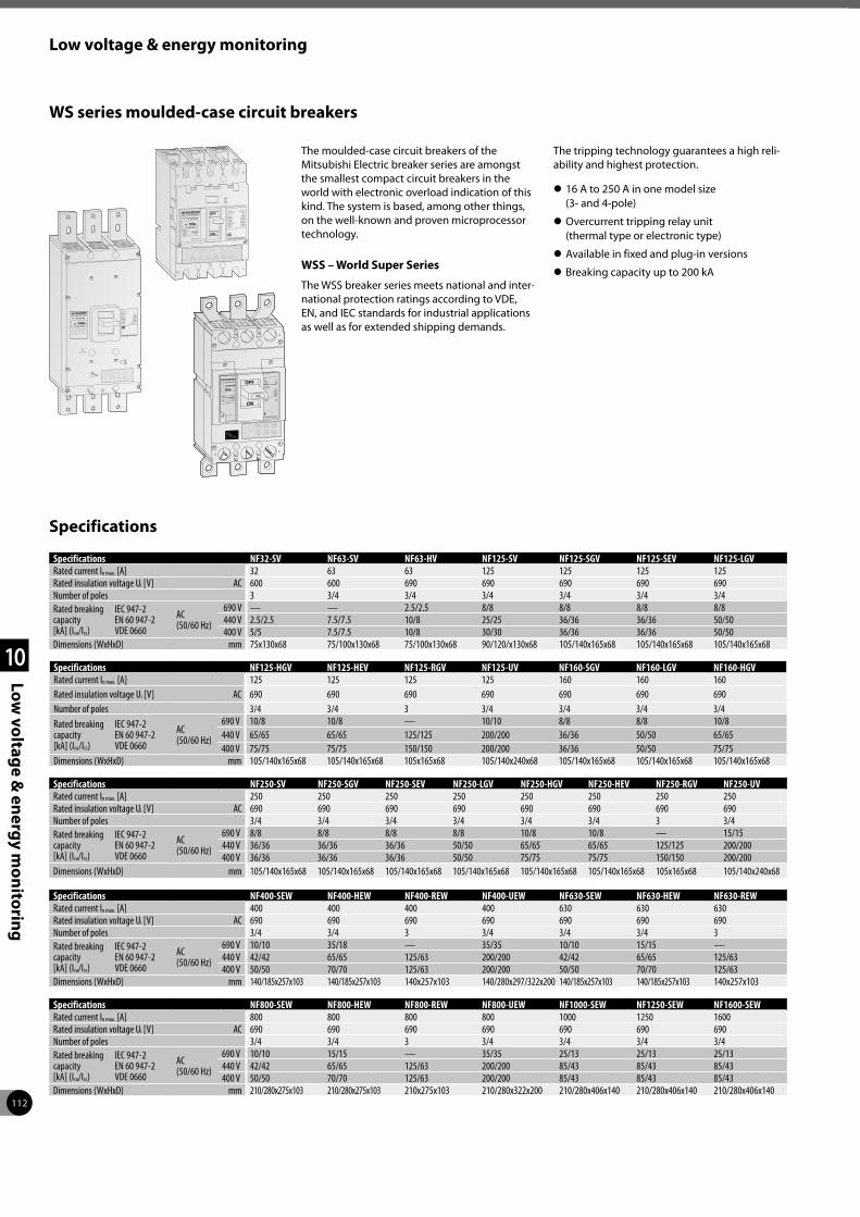
112
Low voltage & energy monitoring
1
2
3
4
10
Low vo
ltage &
energ
y mo
nito
ring
WS series moulded-case circuit breakers
The moulded-case circuit breakers of the Mitsubishi Electric breaker series are amongst the smallest compact circuit breakers in the world with electronic overload indication of this kind. The system is based, among other things, on the well-known and proven microprocessor technology.
WSS – World Super Series
The WSS breaker series meets national and inter-national protection ratings according to VDE, EN, and IEC standards for industrial applications as well as for extended shipping demands.
The tripping technology guarantees a high reli-ability and highest protection.
z 16 A to 250 A in one model size (3- and 4-pole)
z Overcurrent tripping relay unit (thermal type or electronic type)
z Available in fixed and plug-in versions
z Breaking capacity up to 200 kA
Specifications
Specifications NF32-SV NF63-SV NF63-HV NF125-SV NF125-SGV NF125-SEV NF125-LGVRated current In max. [A] 32 63 63 125 125 125 125Rated insulation voltage Ui [V] AC 600 600 690 690 690 690 690Number of poles 3 3/4 3/4 3/4 3/4 3/4 3/4Rated breaking capacity [kA] (Icu/Ics)
IEC 947-2 EN 60 947-2 VDE 0660
AC (50/60 Hz)
690 V — — 2.5/2.5 8/8 8/8 8/8 8/8440 V 2.5/2.5 7.5/7.5 10/8 25/25 36/36 36/36 50/50400 V 5/5 7.5/7.5 10/8 30/30 36/36 36/36 50/50
Dimensions (WxHxD) mm 75x130x68 75/100x130x68 75/100x130x68 90/120/x130x68 105/140x165x68 105/140x165x68 105/140x165x68
Specifications NF125-HGV NF125-HEV NF125-RGV NF125-UV NF160-SGV NF160-LGV NF160-HGVRated current In max. [A] 125 125 125 125 160 160 160Rated insulation voltage Ui [V] AC 690 690 690 690 690 690 690Number of poles 3/4 3/4 3 3/4 3/4 3/4 3/4Rated breaking capacity [kA] (Icu/Ics)
IEC 947-2 EN 60 947-2 VDE 0660
AC (50/60 Hz)
690 V 10/8 10/8 — 10/10 8/8 8/8 10/8440 V 65/65 65/65 125/125 200/200 36/36 50/50 65/65400 V 75/75 75/75 150/150 200/200 36/36 50/50 75/75
Dimensions (WxHxD) mm 105/140x165x68 105/140x165x68 105x165x68 105/140x240x68 105/140x165x68 105/140x165x68 105/140x165x68
Specifications NF250-SV NF250-SGV NF250-SEV NF250-LGV NF250-HGV NF250-HEV NF250-RGV NF250-UVRated current In max. [A] 250 250 250 250 250 250 250 250Rated insulation voltage Ui [V] AC 690 690 690 690 690 690 690 690Number of poles 3/4 3/4 3/4 3/4 3/4 3/4 3 3/4Rated breaking capacity [kA] (Icu/Ics)
IEC 947-2 EN 60 947-2 VDE 0660
AC (50/60 Hz)
690 V 8/8 8/8 8/8 8/8 10/8 10/8 — 15/15440 V 36/36 36/36 36/36 50/50 65/65 65/65 125/125 200/200400 V 36/36 36/36 36/36 50/50 75/75 75/75 150/150 200/200
Dimensions (WxHxD) mm 105/140x165x68 105/140x165x68 105/140x165x68 105/140x165x68 105/140x165x68 105/140x165x68 105x165x68 105/140x240x68
Specifications NF400-SEW NF400-HEW NF400-REW NF400-UEW NF630-SEW NF630-HEW NF630-REWRated current In max. [A] 400 400 400 400 630 630 630Rated insulation voltage Ui [V] AC 690 690 690 690 690 690 690Number of poles 3/4 3/4 3 3/4 3/4 3/4 3Rated breaking capacity [kA] (Icu/Ics)
IEC 947-2 EN 60 947-2 VDE 0660
AC (50/60 Hz)
690 V 10/10 35/18 — 35/35 10/10 15/15 —440 V 42/42 65/65 125/63 200/200 42/42 65/65 125/63400 V 50/50 70/70 125/63 200/200 50/50 70/70 125/63
Dimensions (WxHxD) mm 140/185x257x103 140/185x257x103 140x257x103 140/280x297/322x200 140/185x257x103 140/185x257x103 140x257x103
Specifications NF800-SEW NF800-HEW NF800-REW NF800-UEW NF1000-SEW NF1250-SEW NF1600-SEWRated current In max. [A] 800 800 800 800 1000 1250 1600Rated insulation voltage Ui [V] AC 690 690 690 690 690 690 690Number of poles 3/4 3/4 3 3/4 3/4 3/4 3/4Rated breaking capacity [kA] (Icu/Ics)
IEC 947-2 EN 60 947-2 VDE 0660
AC (50/60 Hz)
690 V 10/10 15/15 — 35/35 25/13 25/13 25/13440 V 42/42 65/65 125/63 200/200 85/43 85/43 85/43400 V 50/50 70/70 125/63 200/200 85/43 85/43 85/43
Dimensions (WxHxD) mm 210/280x275x103 210/280x275x103 210x275x103 210/280x322x200 210/280x406x140 210/280x406x140 210/280x406x140

113
Low voltage & energy monitoring
1
2
3
4
10
Low vo
ltage &
energ
y mo
nito
ring
Type BV-DN NV125-CV NV250-CV
Rated current In [A] 10, 16, 20, 25, 32, 40 80, 100, 125 150, 175, 200, 225, 250Number of poles 2 (1+N) 3 3Rated voltage [V AC] 230 100–440 100–440Rated current sensitivity [mA] 30 100/200/500 selectable 100/200/500 selectableMax. operating time [s] 0.04 0.45/1.0/2.0 selectable 0.45/1.0/2.0 selectablePulsating current sensitivity AC A (Harmonic Surge Ready) A (Harmonic Surge Ready)
Rated breaking capacity [kA]230 V AC 4.5 30 36440 V AC — 10 15
Number of operating cycles
without current 20000 10000 8000
with current20000 (In 10, 16,20 A) 15000 (In 25 A) 10000 (In 32, 40 A)
6000 4000
Dimensions [mm]
a
b
cca a 36 90 105
b 88 130 165c 44 68 68
ca 70 90 92Mass [kg] 0.19 1 1.7Automatic tripping device Thermal-magnetic Thermal-magnetic Thermal-magneticBased on standard IEC61009-1 IEC60947-2 IEC60947-2Breaker type MCB MCCB MCCBCE marking Self-declaration Self-declaration TÜV approval
* All the accessories and dimensions of the NF125-SV are compatible with the NV125-CV. All the accessories and dimensions of the NF250-SGV are compatible with the NV250-CV. For internal accessories only is possible to fit it on the left side.
Magnetothermic and earth leakage protection
DIN series
Earth leakage circuit breakers ELCB and residual current circuit breakers with overcurrent protec-tion RCBO
Miniature circuit breakers and residual current circuit breakers
Model type No. of poles [P] Rating Instantaneous tripping Voltage [V] Short-circuit capacity [kA] Compliance standard
MCB BHW-T10 1, 2, 3, 4 6 to 63 A 0.5 to 63 A
Type B Type C, D 240/415 AC 10 IEC 60898-1
RCCB BVW-T 2 (1+N), 4 (3+N) 16 to 63A — 240/415 AC — IEC 61008-1
Explanation of markings (example model type: BHW-T10)
Wiring diagram
Model type
Instantaneous tripping model type and rated current
Short-circuit capacity

114
Low voltage & energy monitoring
1
2
3
4
10
Low vo
ltage &
energ
y mo
nito
ring
General purpose contactors
Compact, modular extensions and an energy-saving design – these are the main require-ments set by users of contactors and auxiliary contactors.
Requirements that the MS-N/T series from Mitsubishi Electric fulfill.
Special features:
z Easy mounting and wiring
z Easy inspection
z Built-in surge absorber (from S-N50)
z Safety and speedy terminal functions
z Thermo-plastic improves the barrier strength
z Coil boasts lower coil consumption
z Improvement of Electromagnet (DC electromagnet with AC operation)
z Less noise nor surge from coil
z Conform to IEC947-4-1, EN-Standards
z Wide range for rated continuous current Ith from 20 A to 1000 A
Handling of the contactors
S-T10 to S-N65 units can all be mounted on DIN rail (35 mm wide).
A variety of auxiliary blocks and optional fea-tures are available including:
z Standard front clip-on auxiliary contact blocks (4-pole-type and 2-pole-type)
z Low-level signal front-clip-on auxiliary con-tact blocks
z Side clip-on auxiliary contact blocks
z Surge absorbers (varistor and CR models)
z Surge absorbers with LED operating indicators
z Mechanical interlocks
Compact arc quenching and magnet layout greatly reduces installation space.
The coil rating is displayed in a location readily visible even after the unit is installed onto the panel.
Contacts are visible when the cover is removed, allowing them to be checked easily.
ST-20
S-N400
Three-phase motor ratings IEC category AC3 for contactors
ContactorAC-operated S-T10 S-T12 S-T20 S-T21 S-T25 S-T32 S-T35 S-T50 S-T65DC-operated — SD-T12 SD-T20 SD-T21 SD-T25 SD-T32 SD-T35 SD-T50 SD-T65
AC 380–440 V kW 4 5.5 7.5 11 15 15 18.5 22 30Rated continuous current Ith A 20 20 20 32 32 32 60 80 100
Auxiliary contacts (standard) 1 NO or 1 NC 1 NO + 1 NC or 2 NO or 2 NC
1 NO + 1 NC or 2 NO 2 NO + 2 NC 2 NO + 2 NC — 2 NO + 2 NC 2 NO + 2 NC 2 NO + 2 NC
Thermal overload relays
Type TH-T18KP TH-T25KP TH-T25KP/TH-T50KP TH-T65KPSetting range A 0.1–18 0.24–26 0.24–34 A 0.24–50 12–65
Three-phase motor ratings IEC category AC3 for contactors
ContactorAC-operated S-T80 S-T100 S-N125 S-N150 S-N180 S-N220 S-N300 S-N400 S-N600 S-N800DC-operated SD-T80 SD-T100 SD-N125 SD-N150 — SD-N220 SD-N300 SD-N400 SD-N600 SD-N800
AC 380–440 V kW 45 55 60 75 90 132 160 220 330 440Rated continuous current Ith A 120 150 150 200 260 260 350 450 800 1000
Auxiliary contacts (standard) 2 NO + 2 NC 2 NO + 2 NC 2 NO + 2 NC 2 NO + 2 NC 2 NO + 2 NC 2 NO + 2 NC 2 NO + 2 NC 2 NO + 2 NC 2 NO + 2 NC 2 NO + 2 NC
Thermal overload relays
Type TH-T65KP/TH-T100KP TH-N120KP TH-N120TAKP TH-N220RHKP TH-N400RHKP TH-N600KPSetting range A 12–80 12–100 34–100 85–150 65–250 85–400 200–800

115
Low voltage & energy monitoring
1
2
3
4
10
Low vo
ltage &
energ
y mo
nito
ring
Thermal overload relays
A selection of relays for optimum motor protection characteristics
The thermal relay line-up includes the phase failure protection type models (three-element relays).
This array of protection characteristics allows you to choose the units suited to your motor protection needs.
z An operation indicator makes maintenance and inspection easy.
z 1 NO and 1 NC contact
z Rated current can be set easily
z Finger protection up to TH-N60KPCX
z Trip-free reset bar
z Convenient reset release (optional)TH-T18KP
Contactor relays
Contactor relays are designed for use in low volt-age control circuit applications.
Our standard contactor relay version is with 5 auxiliary contacts.
With side clip-on and front clip-on configura-tions available, a maximum of 4 auxiliary con-tacts are possible.
z High reliability: By adopting bifurcated mov-ing contacts and by improving the shape of the contacts, contact performance has been made more reliable than ever.
z Different types: Standard, large capacity, overlap contact
z Various contact arrangement and long life
z Mountable on 35 mm DIN rails
z Dust-proof construction
z Easily visible coil ratings
z Easy wiring (self-rising terminal screws)
z Various accessories common with the series S-N contactors (front and side clip-on type additional auxiliary contact blocks, surge absorbers)
z Finger protected types are available (DIN 57106/VDE 0106 Part 100) (Suffix “CX”)
SR-T5 Contactor relays
DC-operated type SRD-N4CX 4A SRD-N4CX 3A1B SRD-N4CX 2A2BAuxiliary contacts 4 NO 3 NO, 1 NC 2 NO, 2 NC
Contactor relays RS-T series
ContactorAC-operated SR-T5 5A SR-T5 4A1B SR-T5 3A2BDC-operated SRD-T5 5A SRD-T5 4A1B SRD-T5 3A2B
Auxiliary contacts (standard) 5 NO 4 NO + 1 NC 3 NO + 2 NC

116
Low voltage & energy monitoring
1
2
3
4
10
Low vo
ltage &
energ
y mo
nito
ring
Motor circuit breaker
MMP-T32 integrates low voltage circuit breakers and thermal overload relay functions. This device is capable of protecting the motor branch circuits from overload, phase-loss and short-circuit occurrences. The MMP-T32 enables more secure wiring and motor protection than standard open type starters.
In addition to motor protection, integrating the Mitsubishi MS-T series contactor provides a smaller footprint, and the combination motor controller will help
z Self-protected manual motor controller
z Reliable protection and superior performance
z Compact design
z Smart wiring
z Safety & quality
z Global standards
Frame A 32 32Type name MMP-T32 MMP-T32LF
Standard JIS C8201-2-1 Ann.1, JIS 8201-4-1, EN60947-2, EN60947-4-1, IEC60947-2, IEC60947-4-1, GB14048.2, UL60947-4-1A, CSAC22.2NO.60947-4-1 EN60947-2, EN60947-4-1, IEC60947-2, IEC60947-4-1, GB14048.2
Number of poles 3Handle shape Tumbler handleRated current In [A] 0.1 to 32Rated operational voltage Ue [V] 200 to 690Rated frequency [Hz] 50/60Rated insulation voltage Ui [V] 690Rated impulse withstand voltage Uimp [kV] 6
Rated short-circuit breaking capacity [kA] JIS C8201-2-1 Ann.1 IEC60947-2
rated current Ie [A] 200/240 V 400/415 V 440/460 V 200/240 V 400/415 V 440/460 Vheater designation current setting range Icu Ics Icu Ics Icu Ics Icu Ics Icu Ics Icu Ics
0.16 0.1–0.16 100 100 100 100 100 1000.25 0.16–0.25 100 100 100 100 100 1000.4 0.25–0.4 100 100 100 100 100 1000.63 0.4–0.63 100 100 100 100 100 1001 0.63–1 100 100 100 100 100 1001.6 1–1.6 100 100 100 100 100 1002.5 1.6–2.5 100 100 100 100 100 1004 2.5–4 100 100 100 100 100 1006.3 4–6.3 100 100 100 100 100 50 508 5.5–8 100 100 50 38 100 100 15 1510 7–10 100 100 50 38 100 100 15 1513 9–13 100 100 50 38 100 15 7.5 8 418 12–18 100 50 38 35 27 100 15 7.5 8 425 18–25 100 50 38 35 27 50 15 6 6 332 24–32 100 50 38 35 27 50 10 5 6 3
Selectivity category
JIS C8201-2-1 Ann.1 IEC60947-2 Cat.A
Utilization category
JIS C8201-4-1 IEC60947-4-1 AC-3
Trip class (JIS C8201-4-1, IEC60947-4-1) 10Instantaneous release current 13 x Maximum Ie
Durabilitymechanical [times] 100,000electrical [times] 100,000
Phase loss sensitive YesTrip display YesTest trip function YesAuxiliary contact unit UT-MAX (1a or 1b) AC-12: 125 V/5 A, 250 V/3 AAlarm contact unit UT-MAL (1a or 1b) DC-12: 125 V/0.4 A, 250 V/0.2 AShort-circuit indicator unit UT-TUWeight [g] 330

117
Low voltage & energy monitoring
1
2
3
4
10
Low vo
ltage &
energ
y mo
nito
ring
Electronic multi-measuring instruments
The ME96SS measures and displays all impor-tant values of a low voltage/medium voltage power distribution system. By optional plug-in modules, remote I/O’s and open network com-munication can be added. The remote I/O will be used for monitoring the MCCB or ACB status or can be used for energy counters.
The ME96SS provides full integration in a CC-Link or Modbus® network and allows
therefore energy reduction and optimization controlled by our well-known PLC series.
Compact sizes according to DIN
z Easy to read display and simple to learn operation
z Flexible to use and modular expandable
z Conforms to CE standard
Specifications ME96SSHA-MB ME96SSRA-MB ME96SSEA-MB
Display LCD, monochrome LCD, monochrome LCD, monochromeFunction keys 7 7 7Memory for Measurements and settingsNetwork connection Modbus®/RTU communicationExpandability CC-Link, digital or analogue I/Os via plug-in moduleExternal power supply AC 100–240 V (±15 %), DC 100–240 V (-30 % +15 %)Operating conditions -5 to +55 °C (average temperature: 35 °C or less per day), 0 to 85 % RH, non-condensingStorage conditions -25 to +75 °C (average temperature: 35 °C or less per day), 0 to 85 % RH, non-condensingStandards EMC: EN61326-1:2006 safety standard: EN61010-1:2001
Order information Art. no. 297417 297418 297419
Type EMU4-FD1-MB
Phase wire system 3-phase 4-wire, 3-phase 3-wire (3 CT, 2 CT), 1-phase 3-wire, 1-phase 2-wire
Rating
current AC 5 A, AC 1 A
voltage
3-phase 4-wire: max. AC 277/480 V; 3-phase 3-wire: (DELTA) max. AC 220 V, (STAR) max. AC 440 V1-phase 3-wire: max. AC 220/440 V; 1-phase 2-wire: (DELTA) max. AC 220 V, (STAR) max. AC 440 V
frequency 50–60 Hz (common)Communication specification Modbus®/RTU communication
External input
input signal Non-voltage form A contact, 1 input (choose the function from below)
function
Setting to “pulse input”: Pulse count (0–999,999 counts)Setting to “contact input”: Contact monitoring only
Contact monitoring and energy measuring at work (when contact is on)
Externaloutput
output signal Non-voltage Form A contact, 1 output (choose the function from below)
function
Upper limit monitoring of current demand, Lower limit monitoring of current demand, Upper/lower limit monitoring of voltage, Upper limit monitoring of power demand, Lower limit monitoring of power demand, Upper/lower limit monitoring of power factor, Upper limit monitoring of pulse count, Lower limit monitoring of pulse countPulse output, Output item: Energy use
Accessible optional plug-in module
EMU4-CM-C CC-Link communicationEMU4-LM Logging module (SD CARD)EMU4-CM-MT Modbus®/TCP communication
Auxiliary power AC 100–240 V (+10 %,-15 %) 50/60 HzAttachment method IEC rail mounting
Operating temperature/humidity -5 to +55 °C (average temperature: 35 °C or less per day), 0 to 85 % RH, non-condensing
Storage temperature/humidity -10 to +60 °C (average temperature: 35 °C or less per day), 0 to 85 % RH, non-condensing
Optional part (For EMU4-LM) SD memory card (EMU4-SD2GB) a
1 Make sure to use the SD memory card manufactured by Mitsubishi Electric Corporation (Model EMU4-SD2GB). Using other types of the SD memory cards may cause trouble such as data destruction of the memory card or system failure.
Energy measuring unit EcoMonitorLight
Introducing the EcoMonitorLight, an energy measuring unit with an integrated display that provides easy energy visualization in order to provide ways to save energy and to comply
with the Energy Saving Act in response to the need for a simple manner to figure out energy consumption.

118
1
2
3
4
11
MES so
lutio
ns
Effectively optimizing production by directly connecting enterprise systems with the shop floor.
MES Solutions The MES interface product group enables direct connection between the MES (Manufacturing Execution System) database and shop floor equipment, without a communica-tion gateway such as a PC.
The MES benefits are:
z accurate information in real-time through direct utilization of internal device information
z simple system implementation by direct con-necting to database(s)
z no need for PCs and programs, which greatly reduces costs
z improved reliability by changing the gateway PC to a PLC
z no specialists and expensive interfacing soft-ware needed
z reduced installation costs
z reduced network load because of trigger executed database communication and not polling data
MELSEC System Q MES interface IT module
The MES Interface IT module provides a direct link from the iQ Platform to enterprise IT systems. Hence any shop floor system using the iQ Platform can communicate directly with high level IT systems.
This allows the removal of the usual intermedi-ate layer of PC infrastructure required to process shop floor data. This saves cost, increases secu-rity and reduces maintenance requirements.
MES solutions
Quality management, Scheduling
Production planning, cost management, inventory management, task management, etc.
ERP
MES
MES interface
Shop floorEthernet
e-F@ctory
CC-LinkHMI Motion controller CNC
EDMLaser processing Industrial
robots
Inverter Eco MasterMELSERVO
Specifications MESiT
Module type MES interface IT modulCommunications method EthernetInterface type 10BASE-T/100BASE-TX
DB interface function
general Interacts with databases via user-defined jobs (Windows, Linux, Unix ect)databases Oracle®/SAP, Microsoft® SQL, DB2, DB2/400
SQL commands Insert, batch insert, update, select, select with delete, select with update, stored procedure and count rows delete
messaging Http, E-mail, TCP, IBM WebSphere MQ, MQTT, JBOSStrigger buffering function The MES module buffers the data and trigger time to internal memory.arithmetic processing Formulas can be applied to data before sending from the MES interface module.program execution function Executes programs in the application server computer
Memory capacity 1 CompactFlash card can be installedInternal power consumption (5 V DC) mA 0.93Dimensions (WxHxD) mm 27.4x98x115
Order information Art. no.
MES-IT module Hardware: 134930Core software incl. Mitsubishi Electric driver and 5 connections to PLC 227387Database connection for SQL 227390Database connection for Oracle 227391Database connection for DB2 227392Additional 5 PLC connections 227388Siemens driver for S7-200, 300, 400, 12000 229481Mitsubishi Electric MC protocol driver 231543Modbus driver 231544Rockwell driver 227395Omron driver 227397

119
MES solutions
1
2
3
4
11
MES so
lutio
ns
MELSEC System Q MES interface module
QJ71MES96
The MELSEC System Q MES module allows users to interface their production control systems directly to a MES database based on Windows technology.
GT15-MESB-48M and GT16M-MESB
By using an MES option card the GT15 and GT16 are able to communicate directly with Windows databases without needing a Gateway-PC.
The information collected on the MELSEC System Q PLC is linked by the PLC MES interface module, and the information from existing equipment and 3rd party controllers is linked by the GOT1000 MES interface function.
The MES interface product series links shop floor equipment and MES information simply, with minimum cost.
MES option board for GOT (GT15 and GT16 series)
GT25-MESIFKEY-1
The MES interface function allows SQL text transmission from a GOT to a database in the server computer connected via the Ethernet, enabling writing GOT’s device values to the database and reading database values to set them to GOT’s devices. This direct communica-tion with the server computer eliminates the need for gateway equipment.
MES interface function for GOT (GT27 and GT25 series)
Specifications GT25-MESIFKEY-1
MES interface function 1 license
DB interface function
general Interacts with databases via user-defined jobstag function Collects device data of the PLCs CPU on the network in units of tags.trigger monitor function Monitors the status of conditions (time, tag values, etc.)trigger buffering function The SD memory card in the GOT stores the data and trigger time.SQL text transmission Automatically generates the correct SQL message according to requirements.arithmetic processing Formulas can be applied to data before sending via the MES function.program execution function Executes programs in the application server computer
Order information Art. no. 274946
Specifications QJ71MES96
Module type MES interface moduleCommunications method EthernetInterface type 10BASE-T/100BASE-TX
DB interface function
general Interacts with databases via user-defined jobstag function Collects device data of the PLCs CPU on the network in units of tags.trigger monitor function Monitors the status of conditions (time, tag values, etc.)trigger buffering function The MES module buffers the data and trigger time to internal memory.SQL text transmission Automatically generates the correct SQL message according to requirements.arithmetic processing Formulas can be applied to data before sending from the MES interface module.program execution function Executes programs in the application server computer
Memory capacity 1 CompactFlash card can be installedI/O points 32Internal power consumption (5 V DC) mA 650Dimensions (WxHxD) mm 27.5x98x90
Order information Art. no. 200698
Specifications GT15-MESB48M GT16M-MESB
Module typeGT15 option card with 48 MB expansion memory and MES functionality (for direct database connection)
GT16 option card with MES functionality (for direct database connection)
DB interface function
general Interacts with databases via user-defined jobstag function Collects device data of the PLCs CPU on the network in units of tags.trigger monitor function Monitors the status of conditions (time, tag values, etc.)trigger buffering function The MES module buffers the data and trigger time to internal memory.SQL text transmission Automatically generates the correct SQL message according to requirements.arithmetic processing Formulas can be applied to data before sending from the MES interface module.program execution function Executes programs in the application server computer
Order information Art. no. 203473 221369
For GT15 the additional Ethernet communication module GT15-J71E71-100 is required.For GT15 and GT16 a standard CF card up to 2 GB is required

120
1
2
3
4
12
Power su
pp
lies
Power supplies
Specifications FX3U-1PSU-5V 1 FX3UC-1PS-5V FX5-1PSU-5V FX5-C1PS-5V
Application Power supply for the FX3U system bus
Power supply for the FX3UC system bus
Power supply for FX5U (AC power supply type)
Power supply for FX5U (DC power supply type) and FX5UC
Nominal input voltage 100–240 V AC (50/60 Hz) 24 V DC (+20 %/-15 %) 100–240 V AC (50/60 Hz) 24 V DCOutput voltage 5 V DC/24 V DC 5 V DC 5 V DC/24 V DC 5 V DC/24 V DC
Max. output current5 V DC 1 A at 40 °C;
0.8 A at 55 °C 1 A 1.2 A at 40 °C; 0.8 A at 55 °C
1.2 A at 40 °C; 0.8 A at 55 °C
24 V DC 0.3 A at 40 °C; 0.2 A at 55 °C — 0.3 A at 40 °C;
0.2 A at 55 °C0.625 A at 40 °C; 0.4 A at 55 °C
Dimensions (WxHxD) mm 55x90x87 24x90x74 50x90x83 20.1x90x74
Order information Art. no. 169507 210091 280509 294586
1 The FX3U-1PSU-5V can’t be used with a 24 V base unit! When connecting an input extension module (e.g. FX2N-8ER-ES/UL, FX2N-8ER) to the FX3U-1PSU-5V, supply the power for it from the 24 V DC service power supply of the connected main unit or powered extension unit on the upstream side.
The ALPHA POWERs are convenient power supplies for the 24 V units and other external devices. They are applicable for wall or DIN rail mounting and their dimensions are matched to those of the ALPHA family.
Up to 5 ALPHA power units can be installed together for redundant mode operation or connected in parallel for more power.
The units have an integrated thermal overload protection circuit and a POWER LED. The output voltage is adjustable.
Specifications ALPHA POWER 24-0.75 ALPHA POWER 24-1.75 ALPHA POWER 24-2.5
Application Power supply for the 24 V ALPHA base units and external devicesNominal input voltage 100–240 V AC (45–65 Hz)Output voltage 24 V DC (+/-1 %)Max. output current 0.75 A 1.75 A 2.5 AProtection IP20Dimensions (WxHxD) mm 36x90x61 54x90x61 72x90x61
Order information Art. no. 209029 209030 209031
The primary switched-mode power supply units PSU are especially applicable for universal usage in batch mechanical engineering. The wide range input and the UL, cUL certifications allow a worldwide application. The 3-phase units supply the full permanent output power at breakdown of one phase.
The power supply units can be installed in parallel for more power or for redundant mode operation.
The units dispose of an adjustable output volt-age, a thermal overload protection circuit and a POWER LED.
Specifications PSU 25 PSU 50 PSU 100 PSU 200 PSU 200-3
Application Power supply for all peripheral devicesNominal input voltage 100–240 V AC (45–65 Hz) 380–400 V ACOutput voltage 24 V DCMax. output current 2.5 A 5 A 10 A 20 A 20 AProtection IP20Dimensions (WxHxD) mm 32x130x115 40x130x115 60x130x152.5 115x130x152.5 115x130x152.5
Order information Art. no. 206147 206148 206149 208850 208851
Accessories (PSU 100 or larger) Wall mounting adapter PSU-UWA, art. no.: 208853
The power supply modules FX3U-1PSU-5V, FX3UC-1PS-5V, FX5-1PSU-5V and FX5-C1PS-5V are required when the built-in power supply of a PLC base unit is insufficient.
They reinforce the build-in 5 V DC and 24 V DC power supply of a FX3 resp. FX5 base unit. They do not occupy any I/O points and deliver up to 1.2 A for the 5 V system bus (for special function modules).

121
Index
Compact PLCsAnalog input modules . . . . . . . . . . . . . . . . . . . . . . . . . . . . . . . . . . . . . . . . . 54Analog I/O adapters . . . . . . . . . . . . . . . . . . . . . . . . . . . . . . . . . . . . . . . . . . . 55Analog output modules. . . . . . . . . . . . . . . . . . . . . . . . . . . . . . . . . . . . . . . . 54Analog temperature input adapters . . . . . . . . . . . . . . . . . . . . . . . . . . . . . 55Combined analog I/O module. . . . . . . . . . . . . . . . . . . . . . . . . . . . . . . . . . . 54Communication adapter boards. . . . . . . . . . . . . . . . . . . . . . . . . . . . . . . . . 57Communications adapters . . . . . . . . . . . . . . . . . . . . . . . . . . . . . . . . . . . . . 58Communications adapters, connection conversion modules/adapters. 58Components for an FX PLC system . . . . . . . . . . . . . . . . . . . . . . . . . . . . . . . 46Control and display panels, display panel holder. . . . . . . . . . . . . . . . . . . 59Data logger module . . . . . . . . . . . . . . . . . . . . . . . . . . . . . . . . . . . . . . . . . . . 56Equipment features . . . . . . . . . . . . . . . . . . . . . . . . . . . . . . . . . . . . . . . . . . . 45Expandability and functionality. . . . . . . . . . . . . . . . . . . . . . . . . . . . . . . . . 52Expandability and power . . . . . . . . . . . . . . . . . . . . . . . . . . . . . . . . . . . . . . 45Expansion modules for the FX3 series . . . . . . . . . . . . . . . . . . . . . . . . . . . . 53Expansion modules for the FX5 series . . . . . . . . . . . . . . . . . . . . . . . . . . . . 53Expansion possibilities. . . . . . . . . . . . . . . . . . . . . . . . . . . . . . . . . . . . . . . . . 47Extension adapters. . . . . . . . . . . . . . . . . . . . . . . . . . . . . . . . . . . . . . . . . . . . 57High speed counter and pulse train modules . . . . . . . . . . . . . . . . . . . . . . 56Interface module . . . . . . . . . . . . . . . . . . . . . . . . . . . . . . . . . . . . . . . . . . . . . 57MELSEC-F. . . . . . . . . . . . . . . . . . . . . . . . . . . . . . . . . . . . . . . . . . . . . . . . . . . . 49
FX3G/FX3GE/FX3GC series . . . . . . . . . . . . . . . . . . . . . . . . . . . . . . . . . . . 50FX3S series. . . . . . . . . . . . . . . . . . . . . . . . . . . . . . . . . . . . . . . . . . . . . . . . 49FX3U/FX3UC series . . . . . . . . . . . . . . . . . . . . . . . . . . . . . . . . . . . . . . . . . 51
MELSEC iQ-F . . . . . . . . . . . . . . . . . . . . . . . . . . . . . . . . . . . . . . . . . . . . . . . . . 48FX5U/FX5UC series . . . . . . . . . . . . . . . . . . . . . . . . . . . . . . . . . . . . . . . . . 48
Memory cassettes . . . . . . . . . . . . . . . . . . . . . . . . . . . . . . . . . . . . . . . . . . . . 59Micro controllers Alpha series. . . . . . . . . . . . . . . . . . . . . . . . . . . . . . . . . . . 45Temperature control modules. . . . . . . . . . . . . . . . . . . . . . . . . . . . . . . . . . . 55The ALPHA2 series . . . . . . . . . . . . . . . . . . . . . . . . . . . . . . . . . . . . . . . . . . . . 60
Frequency invertersComprehensive range . . . . . . . . . . . . . . . . . . . . . . . . . . . . . . . . . . . . . . . . . 68FR-A741. . . . . . . . . . . . . . . . . . . . . . . . . . . . . . . . . . . . . . . . . . . . . . . . . . . . . 77FR-A770. . . . . . . . . . . . . . . . . . . . . . . . . . . . . . . . . . . . . . . . . . . . . . . . . . . . . 76FR-A800. . . . . . . . . . . . . . . . . . . . . . . . . . . . . . . . . . . . . . . . . . . . . . . . . . . . . 78FR-CC2 . . . . . . . . . . . . . . . . . . . . . . . . . . . . . . . . . . . . . . . . . . . . . . . . . . . . . . 86FR-D700 SC . . . . . . . . . . . . . . . . . . . . . . . . . . . . . . . . . . . . . . . . . . . . . . . . . . 69FR-E700 SC . . . . . . . . . . . . . . . . . . . . . . . . . . . . . . . . . . . . . . . . . . . . . . . . . . 70FR-F800 . . . . . . . . . . . . . . . . . . . . . . . . . . . . . . . . . . . . . . . . . . . . . . . . . . . . . 71Internal and external options . . . . . . . . . . . . . . . . . . . . . . . . . . . . . . . . . . . 87
HMIGOT1000 . . . . . . . . . . . . . . . . . . . . . . . . . . . . . . . . . . . . . . . . . . . . . . . . . . . . 62
Models overview . . . . . . . . . . . . . . . . . . . . . . . . . . . . . . . . . . . . . . . . . . 64Series overview. . . . . . . . . . . . . . . . . . . . . . . . . . . . . . . . . . . . . . . . . . . . 62
GOT2000 . . . . . . . . . . . . . . . . . . . . . . . . . . . . . . . . . . . . . . . . . . . . . . . . . . . . 61Models overview . . . . . . . . . . . . . . . . . . . . . . . . . . . . . . . . . . . . . . . . . . 63Series overview. . . . . . . . . . . . . . . . . . . . . . . . . . . . . . . . . . . . . . . . . . . . 61
GOT Simple . . . . . . . . . . . . . . . . . . . . . . . . . . . . . . . . . . . . . . . . . . . . . . . . . . 62Models overview . . . . . . . . . . . . . . . . . . . . . . . . . . . . . . . . . . . . . . . . . . 64Series overview. . . . . . . . . . . . . . . . . . . . . . . . . . . . . . . . . . . . . . . . . . . . 62
HMI control units . . . . . . . . . . . . . . . . . . . . . . . . . . . . . . . . . . . . . . . . . . . . . 61Industrial panel PCs . . . . . . . . . . . . . . . . . . . . . . . . . . . . . . . . . . . . . . . . . . . 65
APPC/IPPC panel PC series. . . . . . . . . . . . . . . . . . . . . . . . . . . . . . . . . . . 65Industrial box PCs and displays. . . . . . . . . . . . . . . . . . . . . . . . . . . . . . . 66
Low voltage switch gears and energy monitoringDIN series. . . . . . . . . . . . . . . . . . . . . . . . . . . . . . . . . . . . . . . . . . . . . . . . . . . 113Electronic multi-measuring instruments . . . . . . . . . . . . . . . . . . . . . . . . 117General purpose contactors . . . . . . . . . . . . . . . . . . . . . . . . . . . . . . . . . . . 114Magnetothermic and earth leakage protection. . . . . . . . . . . . . . . . . . . 113Motor circuit breaker . . . . . . . . . . . . . . . . . . . . . . . . . . . . . . . . . . . . . . . . . 116Relays. . . . . . . . . . . . . . . . . . . . . . . . . . . . . . . . . . . . . . . . . . . . . . . . . . . . . . 115SUPER AE series . . . . . . . . . . . . . . . . . . . . . . . . . . . . . . . . . . . . . . . . . . . . . 111The complete solution . . . . . . . . . . . . . . . . . . . . . . . . . . . . . . . . . . . . . . . . 110WS series . . . . . . . . . . . . . . . . . . . . . . . . . . . . . . . . . . . . . . . . . . . . . . . . . . . 112
MELFA robot systemsArticulated robot
2 kg and 4 kg payload . . . . . . . . . . . . . . . . . . . . . . . . . . . . . . . . . . . . . 1067 kg to 20 kg payload. . . . . . . . . . . . . . . . . . . . . . . . . . . . . . . . . . . . . . 10635 kg to 70 kg payload. . . . . . . . . . . . . . . . . . . . . . . . . . . . . . . . . . . . . 107
D type and R type controller . . . . . . . . . . . . . . . . . . . . . . . . . . . . . . . . . . . 105Example of a robot system configuration . . . . . . . . . . . . . . . . . . . . . . . . 105Large range. . . . . . . . . . . . . . . . . . . . . . . . . . . . . . . . . . . . . . . . . . . . . . . . . 105Powerful controller . . . . . . . . . . . . . . . . . . . . . . . . . . . . . . . . . . . . . . . . . . 109Robots teach panel . . . . . . . . . . . . . . . . . . . . . . . . . . . . . . . . . . . . . . . . . . 109SCARA robot . . . . . . . . . . . . . . . . . . . . . . . . . . . . . . . . . . . . . . . . . . . . . . . . 108
MES solutionsMES interface function . . . . . . . . . . . . . . . . . . . . . . . . . . . . . . . . . . . . . . . 119MES interface IT module . . . . . . . . . . . . . . . . . . . . . . . . . . . . . . . . . . . . . . 118MES interface module . . . . . . . . . . . . . . . . . . . . . . . . . . . . . . . . . . . . . . . . 119MES option board. . . . . . . . . . . . . . . . . . . . . . . . . . . . . . . . . . . . . . . . . . . . 119Optimizing production . . . . . . . . . . . . . . . . . . . . . . . . . . . . . . . . . . . . . . . 118
Modular PLCsiQ Platform . . . . . . . . . . . . . . . . . . . . . . . . . . . . . . . . . . . . . . . . . . . . . . . . . . 21MELSEC iQ-R series. . . . . . . . . . . . . . . . . . . . . . . . . . . . . . . . . . . . . . . . . . . . 23
Analog (high-speed) input modules . . . . . . . . . . . . . . . . . . . . . . . . . . 27Analog modules for temperature measurement . . . . . . . . . . . . . . . . 27Analog output modules. . . . . . . . . . . . . . . . . . . . . . . . . . . . . . . . . . . . . 27Base units . . . . . . . . . . . . . . . . . . . . . . . . . . . . . . . . . . . . . . . . . . . . . . . . 23C intelligent function module. . . . . . . . . . . . . . . . . . . . . . . . . . . . . . . . 29CPU modules. . . . . . . . . . . . . . . . . . . . . . . . . . . . . . . . . . . . . . . . . . . . . . 24Digital (high-speed) input and output modules . . . . . . . . . . . . . . . . 26High-speed counter modules . . . . . . . . . . . . . . . . . . . . . . . . . . . . . . . . 28High-speed data logger module. . . . . . . . . . . . . . . . . . . . . . . . . . . . . . 29Interface modules . . . . . . . . . . . . . . . . . . . . . . . . . . . . . . . . . . . . . . . . . 28iQ-R C-Application server . . . . . . . . . . . . . . . . . . . . . . . . . . . . . . . . . . . 29MES Interface module . . . . . . . . . . . . . . . . . . . . . . . . . . . . . . . . . . . . . . 28Network modules . . . . . . . . . . . . . . . . . . . . . . . . . . . . . . . . . . . . . . . . . . 28OPC UA server module . . . . . . . . . . . . . . . . . . . . . . . . . . . . . . . . . . . . . . 29Positioning modules . . . . . . . . . . . . . . . . . . . . . . . . . . . . . . . . . . . . . . . 28Standard and redundant power supply modules . . . . . . . . . . . . . . . . 24System structure. . . . . . . . . . . . . . . . . . . . . . . . . . . . . . . . . . . . . . . . . . . 23Temperature control modules. . . . . . . . . . . . . . . . . . . . . . . . . . . . . . . . 27What a system looks like . . . . . . . . . . . . . . . . . . . . . . . . . . . . . . . . . . . . 23What you need . . . . . . . . . . . . . . . . . . . . . . . . . . . . . . . . . . . . . . . . . . . . 23
MELSEC L series . . . . . . . . . . . . . . . . . . . . . . . . . . . . . . . . . . . . . . . . . . . . . . 40Analog I/O modules . . . . . . . . . . . . . . . . . . . . . . . . . . . . . . . . . . . . . . . . 41Branch/extension module. . . . . . . . . . . . . . . . . . . . . . . . . . . . . . . . . . . 44Combined analog input/output module . . . . . . . . . . . . . . . . . . . . . . . 42CPU modules. . . . . . . . . . . . . . . . . . . . . . . . . . . . . . . . . . . . . . . . . . . . . . 40Digital I/O modules . . . . . . . . . . . . . . . . . . . . . . . . . . . . . . . . . . . . . . . . 41Flexible high-speed I/O control module . . . . . . . . . . . . . . . . . . . . . . . 43High-speed counter modules . . . . . . . . . . . . . . . . . . . . . . . . . . . . . . . . 43Interface modules . . . . . . . . . . . . . . . . . . . . . . . . . . . . . . . . . . . . . . . . . 43IO-Link module. . . . . . . . . . . . . . . . . . . . . . . . . . . . . . . . . . . . . . . . . . . . 43Multiple input module. . . . . . . . . . . . . . . . . . . . . . . . . . . . . . . . . . . . . . 42Power supply modules. . . . . . . . . . . . . . . . . . . . . . . . . . . . . . . . . . . . . . 41Serial communications adapters . . . . . . . . . . . . . . . . . . . . . . . . . . . . . 44System structure. . . . . . . . . . . . . . . . . . . . . . . . . . . . . . . . . . . . . . . . . . . 40Temperature control modules. . . . . . . . . . . . . . . . . . . . . . . . . . . . . . . . 42Temperature input module . . . . . . . . . . . . . . . . . . . . . . . . . . . . . . . . . . 42What a system looks like . . . . . . . . . . . . . . . . . . . . . . . . . . . . . . . . . . . . 40What you need . . . . . . . . . . . . . . . . . . . . . . . . . . . . . . . . . . . . . . . . . . . . 40
MELSEC System Q . . . . . . . . . . . . . . . . . . . . . . . . . . . . . . . . . . . . . . . . . . . . . 30Analog CT input module . . . . . . . . . . . . . . . . . . . . . . . . . . . . . . . . . . . . 34Analog input modules . . . . . . . . . . . . . . . . . . . . . . . . . . . . . . . . . . . . . . 34Analog modules for temperature measurement . . . . . . . . . . . . . . . . 35Analog output modules. . . . . . . . . . . . . . . . . . . . . . . . . . . . . . . . . . . . . 34Base units . . . . . . . . . . . . . . . . . . . . . . . . . . . . . . . . . . . . . . . . . . . . . . . . 30CC-Link Safety. . . . . . . . . . . . . . . . . . . . . . . . . . . . . . . . . . . . . . . . . . . . . 38Combined analog I/O module. . . . . . . . . . . . . . . . . . . . . . . . . . . . . . . . 34Digital I/O modules . . . . . . . . . . . . . . . . . . . . . . . . . . . . . . . . . . . . . . . . 33High-speed counter modules . . . . . . . . . . . . . . . . . . . . . . . . . . . . . . . . 36High speed data logger module . . . . . . . . . . . . . . . . . . . . . . . . . . . . . . 37Interface modules . . . . . . . . . . . . . . . . . . . . . . . . . . . . . . . . . . . . . . . . . 37Interrupt module and high-speed inputs . . . . . . . . . . . . . . . . . . . . . . 37Load cell input module . . . . . . . . . . . . . . . . . . . . . . . . . . . . . . . . . . . . . 35Loop control module . . . . . . . . . . . . . . . . . . . . . . . . . . . . . . . . . . . . . . . 35MELSEC Safety PLC . . . . . . . . . . . . . . . . . . . . . . . . . . . . . . . . . . . . . . . . . 38MELSEC WS Safety Controller . . . . . . . . . . . . . . . . . . . . . . . . . . . . . . . . 39MES interface module . . . . . . . . . . . . . . . . . . . . . . . . . . . . . . . . . . . . . . 36Multi-function counter/timer module. . . . . . . . . . . . . . . . . . . . . . . . . 37NAMUR input module . . . . . . . . . . . . . . . . . . . . . . . . . . . . . . . . . . . . . . 35PLC CPU modules . . . . . . . . . . . . . . . . . . . . . . . . . . . . . . . . . . . . . . . . . . 31Power measurement modules . . . . . . . . . . . . . . . . . . . . . . . . . . . . . . . 36Power supply modules. . . . . . . . . . . . . . . . . . . . . . . . . . . . . . . . . . . . . . 31Q series C-Application server. . . . . . . . . . . . . . . . . . . . . . . . . . . . . . . . . 37Safety relays . . . . . . . . . . . . . . . . . . . . . . . . . . . . . . . . . . . . . . . . . . . . . . 39System structure. . . . . . . . . . . . . . . . . . . . . . . . . . . . . . . . . . . . . . . . . . . 30Temperature control modules. . . . . . . . . . . . . . . . . . . . . . . . . . . . . . . . 35Voltage converter . . . . . . . . . . . . . . . . . . . . . . . . . . . . . . . . . . . . . . . . . . 36Web server module . . . . . . . . . . . . . . . . . . . . . . . . . . . . . . . . . . . . . . . . 36What a system looks like . . . . . . . . . . . . . . . . . . . . . . . . . . . . . . . . . . . . 30What you need . . . . . . . . . . . . . . . . . . . . . . . . . . . . . . . . . . . . . . . . . . . . 30
Overview MELSEC iQ-R series, System Q and L series . . . . . . . . . . . . . . . 21
NetworksAnyWireASLINK . . . . . . . . . . . . . . . . . . . . . . . . . . . . . . . . . . . . . . . . . . . . . . 11AS-Interface . . . . . . . . . . . . . . . . . . . . . . . . . . . . . . . . . . . . . . . . . . . . . . . . . 11CANopen . . . . . . . . . . . . . . . . . . . . . . . . . . . . . . . . . . . . . . . . . . . . . . . . . . . . 12CC-Link, CC-Link IE Control, CC-Link IE Field, CC-Link IE Field Basic and CC-Link Safety . . . . . . . . . . . . . . . . . . . . . . . . . . . . . . . . . . . . . . . . . . . . . 9DeviceNetTM. . . . . . . . . . . . . . . . . . . . . . . . . . . . . . . . . . . . . . . . . . . . . . . . . 11EtherCat. . . . . . . . . . . . . . . . . . . . . . . . . . . . . . . . . . . . . . . . . . . . . . . . . . . . . 10Ethernet interface modules for various network protocols. . . . . . . . . . . 10LonWorks. . . . . . . . . . . . . . . . . . . . . . . . . . . . . . . . . . . . . . . . . . . . . . . . . . . . 12MELSECNET/H . . . . . . . . . . . . . . . . . . . . . . . . . . . . . . . . . . . . . . . . . . . . . . . . 12Modbus®/TCP, Modbus®/RTU . . . . . . . . . . . . . . . . . . . . . . . . . . . . . . . . . . . 10
Overview . . . . . . . . . . . . . . . . . . . . . . . . . . . . . . . . . . . . . . . . . . . . . . . . . . . . . 8Profibus DP(V1) . . . . . . . . . . . . . . . . . . . . . . . . . . . . . . . . . . . . . . . . . . . . . . 11Profinet . . . . . . . . . . . . . . . . . . . . . . . . . . . . . . . . . . . . . . . . . . . . . . . . . . . . . 11SAE J1939 . . . . . . . . . . . . . . . . . . . . . . . . . . . . . . . . . . . . . . . . . . . . . . . . . . . 12SSCNE TIII/H . . . . . . . . . . . . . . . . . . . . . . . . . . . . . . . . . . . . . . . . . . . . . . . . . 12Typical distributed control structure . . . . . . . . . . . . . . . . . . . . . . . . . . . . . . 9
Power supplies . . . . . . . . . . . . . . . . . . . . . . . . . . . . . . . . . . . . . . . . . . 120
Remote I/O modulesCC-Link/CC-Link IE Field remote modules . . . . . . . . . . . . . . . . . . . . . . . . . 13
Data exchange with peripherals. . . . . . . . . . . . . . . . . . . . . . . . . . . . . . 14High-speed counter . . . . . . . . . . . . . . . . . . . . . . . . . . . . . . . . . . . . . . . . 14Open control loop positioning . . . . . . . . . . . . . . . . . . . . . . . . . . . . . . . 14
The MELSEC STlite series – scalable I/O solutions for CC-Link, Profibus and Ethernet . . . . . . . . . . . . . . . . . . . . . . . . . . . . . . . . . . . . . . . . . 16
Analog I/O modules . . . . . . . . . . . . . . . . . . . . . . . . . . . . . . . . . . . . . . . . 18Bus end module . . . . . . . . . . . . . . . . . . . . . . . . . . . . . . . . . . . . . . . . . . . 17Digital I/O modules . . . . . . . . . . . . . . . . . . . . . . . . . . . . . . . . . . . . . . . . 18Head stations . . . . . . . . . . . . . . . . . . . . . . . . . . . . . . . . . . . . . . . . . . . . . 17Incremental encoder input module . . . . . . . . . . . . . . . . . . . . . . . . . . . 17Interface module . . . . . . . . . . . . . . . . . . . . . . . . . . . . . . . . . . . . . . . . . . 18Power supply modules. . . . . . . . . . . . . . . . . . . . . . . . . . . . . . . . . . . . . . 17Temperature input module . . . . . . . . . . . . . . . . . . . . . . . . . . . . . . . . . . 17Up/Down counter module. . . . . . . . . . . . . . . . . . . . . . . . . . . . . . . . . . . 18
The MELSEC ST series – premium product for process industry . . . . . . . 19Analog I/O modules . . . . . . . . . . . . . . . . . . . . . . . . . . . . . . . . . . . . . . . . 20Bus power for head station and power feeding module . . . . . . . . . . 19Digital I/O modules . . . . . . . . . . . . . . . . . . . . . . . . . . . . . . . . . . . . . . . . 20Head stations . . . . . . . . . . . . . . . . . . . . . . . . . . . . . . . . . . . . . . . . . . . . . 19
Servo and motion systemsComponents of a MR-J4 servo system . . . . . . . . . . . . . . . . . . . . . . . . . . . . 88General overview . . . . . . . . . . . . . . . . . . . . . . . . . . . . . . . . . . . . . . . . . . . . . 88MELSEC Simple Motion modules . . . . . . . . . . . . . . . . . . . . . . . . . . . . . . . 103MELSEC System Q-Motion system modules . . . . . . . . . . . . . . . . . . . . . . 104Motion controller CPUs of MELSEC System QDS and iQ-R . . . . . . . . . . . 104MR-D30 functional safety unit . . . . . . . . . . . . . . . . . . . . . . . . . . . . . . . . . . 96MR-J4-GF servo amplifier . . . . . . . . . . . . . . . . . . . . . . . . . . . . . . . . . . . . . . 97MR-J4 servo amplifier . . . . . . . . . . . . . . . . . . . . . . . . . . . . . . . . . . . . . . . . . 95MR-J4-TM-ECT/MR-J4-TM-PNT/MR-J4-TM-EIP servo amplifier . . . . . . . 98MR-J4W2-B/MR-J4W3-B servo amplifier . . . . . . . . . . . . . . . . . . . . . . . . . 96MR-JE servo amplifier . . . . . . . . . . . . . . . . . . . . . . . . . . . . . . . . . . . . . . . . . 94Positioning modules
MELSEC FX series . . . . . . . . . . . . . . . . . . . . . . . . . . . . . . . . . . . . . . . . . 101MELSEC iQ-R . . . . . . . . . . . . . . . . . . . . . . . . . . . . . . . . . . . . . . . . . . . . . . 99MELSEC L series. . . . . . . . . . . . . . . . . . . . . . . . . . . . . . . . . . . . . . . . . . . 101MELSEC System Q . . . . . . . . . . . . . . . . . . . . . . . . . . . . . . . . . . . . . . . . . . 99Single-axis FX, iQ-F . . . . . . . . . . . . . . . . . . . . . . . . . . . . . . . . . . . . . . . 102
Servo motor features and typical applications . . . . . . . . . . . . . . . . . . . . . 91Servo motor specifications and matching amplifiers . . . . . . . . . . . . . . . 92Single axis motion controller . . . . . . . . . . . . . . . . . . . . . . . . . . . . . . . . . . 102Stand-alone motion controller . . . . . . . . . . . . . . . . . . . . . . . . . . . . . . . . . 104
SoftwareiQ Works. . . . . . . . . . . . . . . . . . . . . . . . . . . . . . . . . . . . . . . . . . . . . . . . . . . . . . 4MAPS visualisation solutions . . . . . . . . . . . . . . . . . . . . . . . . . . . . . . . . . . . . 7
Life-cycle engineering, SCADA, HMI, reports and operational excellence for industrial applications. . . . . . . . . . . . . . . . . . . . . . . . . . . 7
PC data management . . . . . . . . . . . . . . . . . . . . . . . . . . . . . . . . . . . . . . . . . . 7MX Component . . . . . . . . . . . . . . . . . . . . . . . . . . . . . . . . . . . . . . . . . . . . . 7MX OPC Server . . . . . . . . . . . . . . . . . . . . . . . . . . . . . . . . . . . . . . . . . . . . . 7MX Sheet . . . . . . . . . . . . . . . . . . . . . . . . . . . . . . . . . . . . . . . . . . . . . . . . . . 7
PLC programming . . . . . . . . . . . . . . . . . . . . . . . . . . . . . . . . . . . . . . . . . . . . . 5ALPHA - ALVLS (AL-PCS/WIN) . . . . . . . . . . . . . . . . . . . . . . . . . . . . . . . . . 5GX Configurator DP. . . . . . . . . . . . . . . . . . . . . . . . . . . . . . . . . . . . . . . . . . 5GX Configurator PN. . . . . . . . . . . . . . . . . . . . . . . . . . . . . . . . . . . . . . . . . . 5GX Works2/GX Works3 . . . . . . . . . . . . . . . . . . . . . . . . . . . . . . . . . . . . . . . 5
Programming of drive systems. . . . . . . . . . . . . . . . . . . . . . . . . . . . . . . . . . . 6FR Configurator/FR Configurator2 . . . . . . . . . . . . . . . . . . . . . . . . . . . . . 6FX Configurator FP . . . . . . . . . . . . . . . . . . . . . . . . . . . . . . . . . . . . . . . . . . 6MR Configurator2 . . . . . . . . . . . . . . . . . . . . . . . . . . . . . . . . . . . . . . . . . . . 6MT Works2. . . . . . . . . . . . . . . . . . . . . . . . . . . . . . . . . . . . . . . . . . . . . . . . . 6
Robots programming. . . . . . . . . . . . . . . . . . . . . . . . . . . . . . . . . . . . . . . . . . . 7RT Toolbox3 . . . . . . . . . . . . . . . . . . . . . . . . . . . . . . . . . . . . . . . . . . . . . . . . 7
Visualisation software – HMI programming . . . . . . . . . . . . . . . . . . . . . . . 7GT Works3 . . . . . . . . . . . . . . . . . . . . . . . . . . . . . . . . . . . . . . . . . . . . . . . . . 7

122
Notes

33
Your solution partner
Your solution partner
Mitsubishi Electric offers a wide range of automation equipment from PLCs and HMIs to CNC and
EDM machines
A name to trust
Since its beginnings in 1870, some 45 companies use the Mitsubishi name, covering a spectrum of finance, com-merce and industry.
The Mitsubishi brand name is recog-nized around the world as a symbol of premium quality.
Mitsubishi Electric Corporation is active in space development, transportation, semiconductors, energy systems, com-munications and information process-ing, audiovisual equipment and home electronics, building and energy man-agement and automation systems, and has 237 factories and laboratories world-wide in over 121 countries.
This is why you can rely on Mitsubishi Electric automation solution - because we know first hand about the need for reliable, efficient, easy-to-use automa-tion and control in our own factories.
As one of the world’s leading companies with a global turnover of over 4 trillion Yen (over $40 billion), employing over 130,000 people, Mitsubishi Electric has the resource and the commitment to deliver the ultimate in service and sup-port as well as the best products.
Low voltage: MCCB, MCB, ACB
Medium voltage: VCB, VCC
Power monitoring, energy management
Compact and Modular Controllers
Inverters, Servos and Motors
Visualization: HMIs, Software, MES connectivity
Numerical Control (NC)
Robots: SCARA, Articulated arm
Processing machines: EDM, Lasers, IDS
Air-conditioning, Photovoltaic, EDS

Global Partner. Local Friend.
European Offices
GermanyMitsubishi Electric Europe B.V.Mitsubishi-Electric-Platz 1D-40882 RatingenPhone: +49 (0)2102 / 486-2048
Czech Rep.Mitsubishi Electric Europe B.V.Pekařská 621/7CZ-155 00 Praha 5Phone: +420 734 402 587
FranceMitsubishi Electric Europe B.V.2, Rue de l’UnionF-92565 Rueil Malmaison CedexPhone: +33 1 41 02 83 00
HungaryMitsubishi Electric Europe B.V.Madarász Irodapark,Madarász Viktor u. 47-49.HU-1138 BudapestPhone: +36 70 3322 372
IrelandMitsubishi Electric Europe B.V.Westgate Business Park, BallymountIRL-Dublin 24Phone: +353 (0)1 4198800
ItalyMitsubishi Electric Europe B.V.Viale Colleoni 7 Palazzo SirioI-20864 Agrate Brianza (MB)Phone: +39 039 / 60 53 1
NetherlandsMitsubishi Electric Europe B.V.Nijverheidsweg 23CNL-3641RP MijdrechtPhone: +31 297 250 350
PolandMitsubishi Electric Europe B.V.ul. Krakowska 48PL-32-083 BalicePhone: +48 (0) 12 347 65 00
RussiaMitsubishi Electric (Russia) LLC2 bld. 1, Letnikovskaya st.RU-115114 MoscowPhone: +7 495 / 721 2070
SlovakiaMitsubishi Electric Europe B.V.Levická 7SK-949 01 NitraPhone: +421 917 624036
SpainMitsubishi Electric Europe B.V.Carretera de Rubí 76-80 Apdo. 420E-08190 Sant Cugat del Vallés (Barcelona)Phone: +34 (0) 93 / 5653131
SwedenMitsubishi Electric Europe B.V. (Scandinavia) Hedvig Möllers gata 6SE-223 55 LundPhone: +46 (0) 8 625 10 00
TurkeyMitsubishi Electric Turkey Elektrik Ürünleri A.Ş.Şerifali Mahallesi Kale Sokak No:41 TR-34775 Ümraniye-İSTANBUL Phone: +90 (216) 969 25 00
UKMitsubishi Electric Europe B.V.Travellers LaneUK-Hatfield, Herts. AL10 8XBPhone: +44 (0)1707 / 28 87 80
Representatives
AustriaGEVAWiener Straße 89A-2500 BadenPhone: +43 (0)2252 / 85 55 20
BelarusOOO TECHNIKONProspect Nezavisimosti 177-9BY-220125 MinskPhone: +375 (0)17 / 393 1177
Bosnia and HerzegovinaINEA RBT d.o.o.Stegne 11SI-1000 LjubljanaPhone: +386 (0)1/ 513 8116
BulgariaAKHNATON4, Andrei Ljapchev Blvd., PO Box 21BG-1756 SofiaPhone: +359 (0)2 / 817 6000
CroatiaINEA CRLosinjska 4 aHR-10000 ZagrebPhone: +385 (0)1 / 36 940 - 01/ -02/ -03
Czech RepublicSIMAP CZ s.r.o.Nové sady 988/2CZ-602 00 BrnoPhone: +420 777 731 900
DenmarkHANS FØLSGAARD A/STheilgaards Torv 1DK-4600 KøgePhone: +45 4320 8600
EstoniaElectrobit OÜPärnu mnt. 160iEST-11317, TallinnPhone: +372 6518 140
FinlandUTU Automation OyPeltotie 37FIN-28400 UlvilaPhone: +358 (0)207 / 463 500
GreeceUTECO A.B.E.E.5, Mavrogenous Str.GR-18542 PiraeusPhone: +30 (0)211 / 1206-900
HungaryMELTRADE Kft.Fertő utca 14.HU-1107 BudapestPhone: +36 (0)1 / 431-9726
KazakhstanTOO Kazpromavtomatika Ul. Zhambyla 28KAZ-100017 KaragandaPhone: +7 7212 / 50 10 00
LatviaOAK Integrator Products SIA Ritausmas iela 23LV-1058 RigaPhone: +371 67842280
LithuaniaAutomatikos Centras, UAB Pramonės pr. 17HLT-51327 KaunasPhone: +370 37 262707
MaltaALFATRADE Ltd.99, Paola HillMalta-Paola PLA 1702Phone: +356 (0)21 / 697 816
MoldovaINTEHSIS SRLbld. Traian 23/1MD-2060 KishinevPhone: +373 (0)22 / 66 4242
PortugalFonseca S.A.R. João Francisco do Casal 87/89PT-3801-997 Aveiro, Esgueira Phone: +351 (0)234 / 303 900
RomaniaSirius Trading & ServicesAleea Lacul Morii Nr. 3RO-060841 Bucuresti, Sector 6Phone: +40 (0)21 / 430 40 06
SerbiaINEA SR d.o.o.Ul. Karadjordjeva 12/217SER-11300 SmederevoPhone: +381 69 172 27 25
SlovakiaSIMAP SKDolné Pažite 603/97SK-911 06 TrenčínPhone: +421 (0)32 743 04 72
SloveniaINEA RBT d.o.o.Stegne 11SI-1000 LjubljanaPhone: +386 (0)1 / 513 8116
SwitzerlandOMNI RAY AGIm Schörli 5CH-8600 DübendorfPhone: +41 (0)44 / 802 28 80
UkraineCSC- AUTOMATION Ltd.4 B, Yevhenа Sverstyuka Str.UA-02002 KievPhone: +380 (0)44 / 494 33 44
EgyptEIM Energy3 Roxy SquareET-11341 Heliopolis, CairoPhone: +202 24552559
IsraelGIRIT CELADON Ltd.12 H’aomanut StreetIL-42505 NetanyaPhone: +972 (0)9 / 863 39 80
IsraelILAN & GAVISH Ltd.24 Shenkar St., Kiryat ArieIL-49001 Petah-TikvaPhone: +972 (0)3 / 922 18 24
LebanonCEG LIBANCebaco Center/Block A Autostrade DORALebanon-BeirutPhone: +961 (0)1 / 240 445
South AfricaADROIT TECHNOLOGIES20 Waterford Office Park 189 Witkoppen RoadZA-FourwaysPhone: + 27 (0)11 / 658 8100
Specifications subject to change. All trademarks and copyrights acknowledged.
Mitsubishi Electric Europe B.V.FA - European Business Group Mitsubishi-Electric-Platz 1 D-40882 Ratingen Germany Tel.: +49(0)2102-4860 Fax: +49(0)2102-4861120 [email protected] https://eu3a.mitsubishielectric.com
Art. no. 170021-J Printed December 2021
Version check