VS50/60 - CNC-Multiservice
123
MACHINING CENTER VS50/60 INSTRUCTION MANUAL MAINTENANCE SEIKI-SEICOS Σ16M/18M Version 1.01 BM-2782-1-0221-E-1-01
-
Upload
khangminh22 -
Category
Documents
-
view
5 -
download
0
Transcript of VS50/60 - CNC-Multiservice

1
MACHINING CENTER
VS50/60INSTRUCTION MANUAL
MAINTENANCESEIKI-SEICOS Σ16M/18M
Version 1.01
BM-2782-1-0221-E-1-01

1
Introduction
Thank you for your having purchased the machine, favoring our product lines for your use.
This manual contains fundamental information on the maintenace. Please read and fully understand
the contents for your safe machine operation.
In particular, the contents of the items concerning safety in this manual and the descriptions on the
“caution plates” attached to the machine are important. Please follow the instructions contained
and keep them always in mind to ensure safe operation.
The reference record papers on adjusting setting values such as a parameter list are attached to
the machine unit and enclosed in the packing. These are necessary for maintenance and
adjustment of the machine later on. Please keep them safely not to be mislaid.
The design and specifications of this machine may be changed to meet any future improvement.
As the result, there may arise some cases where explanations in this manual could become partly
inconsistent with the actual machine. Please note this point in advance.
In this manual, items on the standard and optional specifications are handled indiscriminately.
Please refer to the “delivery note” for the detailed specification of your machine confirmation.

i
CONTENTS
1. INSTALLATION.................................................................................... 1 - 1
1-1 Machine Installation ........................................................................................................... 1 - 1
1-1-1 Environment of the Machine ...................................................................................... 1 - 1
1-2 Foundation and Layout Drawing ........................................................................................ 1 - 3
1-3 Transportation of Machine ................................................................................................. 1 - 5
1-3-1 Precautions for Lifting Work ...................................................................................... 1 - 5
1-3-2 Precautions When Using the Forklift ......................................................................... 1 - 5
1-4 Electric Wiring ................................................................................................................... 1 - 8
1-5 Air Supply ......................................................................................................................... 1 - 10
1-6 Oil Supply ........................................................................................................................ 1 - 11
1-7 Mounting Procedure ........................................................................................................ 1 - 12
2. INSPECTION AND MAINTENANCE ................................................... 2 - 1
2-1 Daily Check and Periodic Check Items ............................................................................. 2 - 1
2-1-1 Daily Checking Items ................................................................................................. 2 - 1
2-1-2 Periodic Check Items ................................................................................................ 2 - 5
2-2 Lubrication, Oil Supply and Coolant ................................................................................. 2 - 10
2-2-1 List of Lubrication and Oil Supply ............................................................................ 2 - 11
2-2-2 Handling of Coolant Unit .......................................................................................... 2 - 12
2-3 When the Call Light (Yellow Warning Lamp) is Lit Up...................................................... 2 - 17
2-3-1 Kinds of Alarms and Study and Measure of Causes of Obstacles .......................... 2 - 17
2-3-2 Replacing Method of Battery .................................................................................... 2 - 18
2-3-3 Alarm List ................................................................................................................. 2 - 21
2-4 Parameters ..................................................................................................................... 2 - 32
2-4-1 Kinds and Main Contents of Parameter ................................................................... 2 - 32
2-4-2 About a Management of Parameter ......................................................................... 2 - 32
2-4-3 Altering the PC Parameter Setting ........................................................................... 2 - 33
2-5 List of SOL/LS Functions and Uses
(See the SOL/LS Layout for the Location of Equipment.) ............................................... 2 - 34
2-6 ATC Maintenance and Adjustment ................................................................................... 2 - 37
2-6-1 Drive Mechanism General ....................................................................................... 2 - 37
2-6-2 Explanation of Actions ATC ...................................................................................... 2 - 39
2-6-3 ATC (Automatic Tool Changer) Maintenance, Adjustment and Operation ................ 2 - 42
2-6-4 Method of Manual Tool Unclamping ......................................................................... 2 - 45
2-6-5 Procedure for Bleeding Air in the Tool Locking System ........................................... 2 - 46
2-6-6 Adjusting a Tool Push Allowance .............................................................................. 2 - 48
2-7 Each Axis Stroke and Zero Point Adjustment ................................................................... 2 - 50
2-8 Countermeasures against shift of follow-up coordinate
(shift of memory software OT) ........................................................................................ 2 - 54

ii
2-9 Adjustment of Synchro Belt Tension for Z-axis Feed ....................................................... 2 - 55
2-10 Instructions for Motor/Inverter for ATC Twin Arm Rotation ............................................. 2 - 56
2-10-1 Setting and Changing the Parameters................................................................... 2 - 56
2-10-2 Initializing the Parameters ..................................................................................... 2 - 57
2-10-3 Monitoring .............................................................................................................. 2 - 59
2-10-4 Errors .................................................................................................................... 2 - 60
2-10-5 Resetting the Inverter ............................................................................................. 2 - 63
2-10-6 Inspection and Maintenance .................................................................................. 2 - 64
2-10-7 Troubleshooting ..................................................................................................... 2 - 67
2-11 Handling and Maintenance of Spindle Oil Air Lubricating Unit (Option) .......................... 2 - 70
2-11-1 Oil Air Lubrication Circuit ........................................................................................ 2 - 70
2-11-2 Pump Unit .............................................................................................................. 2 - 71
2-11-3 Mixing Valve ............................................................................................................ 2 - 73
2-11-4 Daily maintenance ................................................................................................. 2 - 74
2-12 Related to Coolant ......................................................................................................... 2 - 76
2-13 Related to Air Pressure.................................................................................................. 2 - 80
2-14 Chip Conveyor (For the Inside of Standard Machine) .................................................... 2 - 84
2-15 Spindle Cooling Circuit Diagram .................................................................................... 2 - 85
2-16 Servo Unit ...................................................................................................................... 2 - 86
2-16-1 Alarm Concerning Power Supply Unit
(Source Power of Spindle/Servo Amplifier) ............................................................. 2 - 86
2-16-2 Spindle Amplifier Status Display ............................................................................. 2 - 89
2-16-3 Spindle Amplifier Alarm .......................................................................................... 2 - 90
2-16-4 Detail of Spindle Amplifier Alarm Contents ............................................................. 2 - 95
2-17 List of Supply Items ..................................................................................................... 2 - 102

1 - 1
1. INSTALLATION
1-1 Machine InstallationWhen installing NC machine, solid foundation is essential. It is also most important for maintainingthe best condition of cutting accuracy of the machine. The nature of the ground condition of thefactory site, for example, rock base or reclaimed land, makes a big difference. It is, therefore,difficult to give any definite rules generally applicable to the installation of this machine. (Refer tothe foundation and arrangement drawings.)
The followings are the concrete items to be carefully attended when installing this machine.
1) The bearing capacity of soil should be 5 ton/m2 or larger and thickness of the foundation shouldbe 300mm or thicker.
2) The area of the foundation should be extend to at least 300mm outer circumference of themachine bed.
3) When digging vibration proof drains, they should be dug along the circumference of thefoundation.
4) Placing separate concrete blocks underneath each machine leg instead of a real foundation isoften seen, which is just not adequate. Such is no value as proper foundation,
As this machine yields large volumes of chip during machining, carts are often used for chipdisposal. The traffic of carts and detaching covers in maintenance work need free space so thatthe operators can move around without touching other machines. This factor should beconsidered when selecting the installing position of the machine.
1-1-1 Environment of the MachinePay full attention to a room temperature, dust, vibrations, etc. in order to make use of theprimary performance of the machine. High accuracy cannot be obtained in the environmentwhere the room temperature greatly changes. Just a slight change of the room temperaturepartly affects the machine. Be fully careful of effects heat transfer from the direct sunshine,vent, heating unit, and so on.
Under the environment where the air is polluted so much by dust, etc., the sliding sections andelectric devices of the machine are greatly effected in their service lives.
Particularly, electronic devices related to controls are susceptible to dust and humidity. Installthe machine in the environment as clean as possible.
1. Installation Environment of NC Machine
In case that electric machines and appliances generating high frequency noise areinstalled or newly erected near by NC machines, keep to the following precautions.
1) Example of the electric machines and appliances generating high frequency noise.
[1] Arc welding machine
[2] Resistance welding machine

1 - 2
[3] High frequency drying machine
[4] Electric discharge machine
[5] Others
2) Installation form of NC machine
[1] Power supply line
The power supply line (AC200V) of NC machine must be separated line with that forelectric machines and appliances.
If impossible, connect the line at the point more than 20m apart from the point wherethe power supply for electric machines and appliances is connected.
[2] Installation place of NC machine
NC machine must be installed more than 20m apart from electric machines andappliances.
[3] Earth of NC machine
The earth of NC machine must be grounded within 5m from NC machine separatingfrom the ground of electric machines and appliances, and make a ground work with
not more than 100Ω or comply with the laws and regulations of the country.Or the earth wire size must be not less than 8mm2.
3) Example of earth of NC machine
The earth state of NC machine and electric machines and appliances illustrated asunder.
Power receiving equipment

1 - 3
1-2 Foundation and Layout Drawing
Note) 1. Ground bearing force should be 5ton/m2 (1000 lbs/ft2) or more. And foundationthickness should be at least 300mm. (12”)
2. The area of foundations is to be 300mm (12”) or more of the circumference of themachine bed.
3. Install the tremor insulating groove along the outer periphery of the foundation.

1 - 4
Foundation and Layout Drawing
VS60
Note) 1. Ground bearing force should be 5ton/m2 (1000 lbs/ft2) or more. And foundationthickness should be at least 300mm. (12”)
2. The area of foundations is to be 300mm (12”) or more of the circumference of themachine bed.
3. Install the tremor insulating groove along the outer periphery of the foundation.

1 - 5
1-3 Transportation of MachineSince this machine has an integrated structure mechanically and electrically, it can be
transported only by detaching its power cord. To fix its moving parts and pass wire ropes
around the machine, refer to Fig.1-1.
1-3-1 Precautions for Lifting WorkPay proper attention to lifting work, because it is one of important steps when transporting
the machine.
! WARNINGSince the lifting work for machine transportation is carried out with a crane or chainblock, its precautions are listed below:
(1) Use a wire rope whose diameter is 14 mm (0.55 inch) or more.
(2) Apply a pad to an acute-angle part to protect the wire rope and machine.
(3) Pass the rope so that the center of gravity of a load will come over the center line of a
lifting angle.
(4) Do not use a rusted wire rope, one which has been untwisted, or one whose core wire
is broken.
(5) Lift the machine gradually. Stop it once when the wire rope become strained, and
check a lifting conditions. When the machine is lifted up from the floor, check again
that there are no abnormalities with the lifting rope, and proceed with the lifting rope.
When lowering the machine, it is necessary to be careful that it is lowered down slowly.
Stop lowering the machine immediately before it reaches the floor to check.
Then, lower it down completely.
1-3-2 Precautions When Using the Forklift
! WARNINGSince the lifting work for machine transportation is carried out with a forklift, itsprecautions are listed below:

1 - 6
(1) Select a fork lift which has a sufficient capability to handle and endure a machine
weight.
(2) In order not to damage the outer projected parts of the machine, it is necessary to
carry out this work in cooperation with a watchman.
(3) When inserting the fork under the machine, use the right and left cast grooves
provided for fork insertion under the base of the machine proper.
(4) When lifting the machine, be sure to carry out temporary lifting so that you can lift it
with the center of gravity of the machine set at the stablest positions in both
longitudinal and crosswise directions.

1 - 7

1 - 8
1-4 Electric WiringWires between the machine proper and accessories will be connected by Hitachi Seiki. Wiring
from the power supply source to the electric cabinet should be prepared in advance by the
customer.
For this purpose, use wires of thickness specified in the following table, depending on the
distance from the power supply to the electric cabinet.
Power supply : 200/220V (50/60 Hz) ±10%
Source Power Capacity
The electric capacity required for the machine varies depending on the specification of the
spindle and the type of option attachments. To calculate the capacity of the machine being
installed, add the capacity of option specification on to that of the standard machine.
Machine Electric Capacity = Standard Machine Electric Capacity
+ Total Electric Capacity of Option Attachments
Power Capacity of Standard Machine
Spindle Specification Power Capacity
4500 min-1 25 kVA
10000 min-1 40 kVA
12000 min-1 Standard 18 kVA
12000 min-1 High output 36 kVA
20000 min-1 31 kVA
Option Attachment requiring Additional Power Capacity
Option Attachment Additional Power Capacity
Oilhole Coolant 0.5MPA 1.3 kVA
Oilhole Coolant 1.5MPA 1.4 kVA
Oilhole Coolant 7.0MPA 3.7 kVA
Through Coolant 0.5MPA 1.3 kVA
Through Coolant 1.5MPA 1.4 kVA
Through Coolant 7.0MPA 3.7 kVA
Jet Coolant 1.0 kVA
Gun Coolant 0.4 kVA
Mist Collector 1.1 kVA
Hydraulic Power Source 1.3 kVA

1 - 9
Thickness of Wire
The source power wire thickness varies depending on the specification ofthe spindle. Use the
wire of the following thickness to meet the specification.
Spindle Specification Source Power Wire Minimum Grounding Wire Minimum
Thickness Thickness
4500 min-1 38 mm2 8 mm2
10000 min-1 60 mm2 8 mm2
12000 min-1 Standard 22 mm2 8 mm2
12000 min-1 High output 50 mm2 8 mm2
20000 min-1 50 mm2 8 mm2
* The thicknesses of the source power wire in the above table are calculated on the assumption
that three 600V vinyl coated wires are set in a conduit pipe at the ambient temperature is
30°C.

1 - 10
1-5 Air SupplyThis machine uses clean air to clean the spindle hole and the tool, for Z axis sliding face and
automatic door, or for oil mist unit. The air supply should be prepared by the customer.
Its joint of the machine is of PT1/4, female.
Air pressure : 0.5MPa 5 kgf/cm2 (72 PSI) or more
Flow : 100 • /min. (ANR) (Standard Specification)
*It is recommended to install an air tank having a capacity of 40• or larger, as there are cases
when supply of a large volume of air is needed instantaneously.
The machine proper is provided with an air filter and regulator to remove dust and
supersaturated moisture from air. When the temperature of the air from the air supply is
higher than that of the machine proper, air gets cooled at the machine proper and tends to
form water drops.
Jetting air containing water is prone to cause rust on the spindle hole and tool shank, which
may affect machining accuracy and cutting surfaces. Therefore, the temperature of the air
from the air supply should below. (Water and dust accumulating in the air filter is automatically
drained. To manually drain them, see the descriptions on mechanical drain operation.) In
case there is a large difference in temperature, install an air drier between the air supply and
the machine.
Flow rete
The flow rate to be set varies depending on the option specification. Therefore, the flow rate
applicable to the actual machine should be determined by the flow rate for the standard
specification machine added by the total required flow rate for the option specification.
Flow rate for the machine = Standard flow rate + flow rate for option specification
Standard specification
Machine specification
#40-12000min-1
Flow rate
100 /min (ANR)

1 - 11
Optional specification
Tool nose air blow
Center-through air blow
Pulscale X, Y
Oil mist/Needle 1 shot
Semi-dry processing unit
Flow rate
300 /min (ANR)
300 /min (ANR)
60 /min (ANR)
60 /min (ANR)
300 /min (ANR)
Additional flow rate required by optional specifications
In case with APC (essential)
Air pressure: 0.5MPa (5kg/cm2) or higher
Flow rate: 100 /min (ANR)
Air tank capacity: 40 or larger
1-6 Oil SupplyWhen adding lubricating oil, take care of the following:
1. Add the specified amount of the designated oil. Do not use different oils, and do not add to
much of oil.
2. Clean the oil supply port in advance. See that dust, etc. do not enter.
3. When adding oil, set a filter on the oil supply port, so that dust and other foreign substance
will not enter. In case a filter is not available, use a wire netting of 150 mesh or more.
4. Always use new oil. Do not use a mixture of new and old oil.
5. Even when using new oil, do not use all the oil from the can. Always leave some oil in the
can. This is necessary to avoid sediments in the can being used.
For the oil supply positions, intervals, oil amount and quality, see “5-2 Lubrication and Oil

1 - 12
Supply”.
1-7 Mounting Procedure(1) Dismounting fixtures for shipment and transportation
Upon installing the machine at a fixed place, be sure to dismount the fixtures for
shipment/transportations .
• Remove the fixed plate for the table, column and head.
(2) Installation
A leveling method is one of the factors which determine machine accuracy. Proper
leveling of the machine is most fundamental.
Carry it out carefully, because it affects not only machining accuracy, but also machine’s
service life.
First, put leveling pads at installation points on the floor.
Install the machine so that the leveling adjust bolts attached to the machine legs will be
placed on them.
Use precision levels whose sensitivity per graduation is’ about 0.02 mm/m (0.00025 in./
ft.) and length is about 200 mm (8 in.).
Levels used for woodworking/engineering are not recommendable.
Place the levels with the same end in the same direction.
Keep level-placing surfaces clean at any time lest dust, etc. should be caught under the
levels.
Outline of Installation Work
[1] Confirming a foam in a level
Adjust so that a foam does not get too long and set it at the center on the table. By
turning it by 180°, while holding the position, and observing a foam in memory of the
same direction, level has been obtained.
[2] Adjusting the absolute level
As shown in Fig.5-5, place levels on the table in parallel with the X and Y directions,
and measure the level of the machine at 3 places in the X and Y directions,
respectively.

1 - 13
Adjust the level of the machine with the leveling bolts so that each difference in
reading of the levels may be settled within 0.04 mm/m (0.0005 in./ft.) in both X and Y
directions.
[3] Adjusting the table operating level
Place the levels at the center of the table and move the X axis almost over its full
stroke. Make adjustment in such a way that each difference in reading of the levels
at this time will meet within the following target values:
• For the level put in the X-axis direction: 0.02 mm/m (0.00025 in./ft.)
• For the level put in the Y-axis direction: 0.04 mm/m (0.0005 in./ft.)
[4] Reconfirm the above-mentioned steps [1] through [3] and make fine adjustment, if
necessary.
[5] When the stable operating levels in [3] cannot be obtained, it is likely that the
condition of the floor, where the machine is installed, is improper. Check and improve
it, referring to the foundation drawing.

1 - 14
VS50
Fig.1-2
Fig.1-3

1 - 15
VS60

2 - 1
2. INSPECTION AND MAINTENANCE
2-1 Daily Check and Periodic Check Items
2-1-1 Daily Checking ItemsThe following are maintenance items to be checked by operators. These maintenanceitems are important to prevent machine trouble and to perform efficient operation.Perform maintenance according to the following daily check list.

2 - 2
Daily check list
Checking part Check item Details of checks1. Main cooling unit a)Check main cooling unit for ⇒ Check for sound of fan running
operation.b)Check cooling unit for sufficient ⇒ Oil level check
quantity of oil. (Checks beforestarting work)
c) Check that air filter is thoroughly ⇒ Checks for clogging andcleaned. cleaning
d)Check for oil leakage. ⇒ Check for oil leakage2. Pneumatic unit a)Check for normal set pressure. ⇒ Normal value: 5 kgf/cm2
b)Check pneumatic unit for faults ⇒ Check for air leakagesuch as air leakage.
3. Coolant unit a)Check coolant unit and piping for ⇒ Checks for coolant leakage andfaults. abnormal noise
b)Check coolant unit for sufficient ⇒ Oil level checkquantity of coolant.
c) Check that air filter is thoroughly ⇒ Checks for clogging andcleaned. cleaning
d)Check for discharge. ⇒ Visual checke)Check for oil leakage. ⇒ Check for oil leakage
4. Operation panel a)Check that alarm is not displayed ⇒ Visually check it to determineand control panel on the screen. (Battery alarm, the cause for corrective action.
etc.)b)Check that cooling fan is running. ⇒ Visually check it to determine
the cause for corrective action.5. Spindle head a)Check that running-in performed. ⇒ Run in the spindle according to
“Spindle warm-up” section ofthe operation manual.
b)Check for abnormal noise. ⇒ Check for abnormal noise(M/C, NCL) during spindle running
c) Check spindle gear lubricating ⇒ Check that spindle headfloat. (TG) (Checks before ascends when spindle runs and tstarting work) hat it descends when spindle
comes to a stop.d)Check that spindle tapered ⇒ Check for removal of dust,
portion is cleaned. (M/C) fouling and foreign matter suchas chips
e)Check spindle for start, stop and ⇒ Check that spindle start andfaults. (NCL, spindle) stop do not spend time too
much.6. ATC magazine a)Check that tool pots and tapered ⇒ Check for removal of dust,
portion are cleaned. fouling and foreign matter suchas chips
b)Check that ATC grip portion is ⇒ Check for removal of dust,cleaned. fouling and foreign matter such
as chipsc) Check pull stud for tool for ⇒ Check pull stud for tightness
looseness. when changing tools.

2 - 3
Checking part Check item Details of checks7. Table unit a)Check that telescopic cover is ⇒ Check for removal of foreign
cleaned. matter including chips and chipson wiper portion
b)Check the quantity of table ⇒ Oil level check indexing gear lubricating oil.
8. Feed unit a)Check for abnormal noise. ⇒ Check for abnormal noise whenoperating feed unit
9. Covers a)Check that covers are not ⇒ Check that covers are notdetached. detached. If any cover is
detached, attach it.b)Check that window is cleaned. ⇒ Check for cleaningc) Check that nameplate and ⇒ Check for cleaning
caution plate are cleaned.10. Interlocking a)Check door interlocking function. ⇒ Check that spindle does not run
device when opening door.11. Hydraulic unit a) Check for normal set pressure. ⇒ Normal value: 35 kgf/cm2, 45
(Option) kgf/cm2 and 70 kgf/cm2 (Itdepends on the model.)
b)Check hydraulic unit for faults. ⇒ Checks for abnormal noise andoil leakage.
c) Check hydraulic unit for sufficient ⇒ Oil level checkquantity of oil.
d)Check that oil temperature is ⇒ Oil temperature check: Proper60°C or less. temperature is 60°C or less.
e)Check for oil leakage. ⇒ Check for oil leakage12. Lubricating unit a) Check for proper consumption. ⇒ 1 liter/10 hours as a guide
(When equipped b) Check lubricating unit for ⇒ Oil level checkwith a high- sufficient quantity of oil.speed spindle.) c) Check that air filter is cleaned. ⇒ Checks for clogging and
cleaning.d)Check for oil leakage. ⇒ Check for oil leakage (Shorten
checking intervals depending onworking environment.)
13. High-pressure a) Check high-pressure unit and ⇒ Checks for coolant leakage,coolant piping for faults. abnormal noise and abnormal(Option) vibration.
b)Check for discharge. ⇒ Visual checkc) Check pump for discharge ⇒ Normal value: 35 kgf/cm2 or 70
pressure. (Pressure gage) kgf/cm2 (It depends on thespecifications.)
d)Check that air filter is thoroughly ⇒ Checks for clogging andcleaned. cleaning
e)Check high-pressure pump for ⇒ Oil level (cap oil filling) checksufficient quantity of oil. and replenishment
f) Check for high-pressure pump oil ⇒ Checks for oil degradation andfouling. oil color
g)Check for sufficient quantity of ⇒ Check through main tankcoolant.

2 - 4
Checking part Check item Details of checks14. APC a) Check that pallet seating surface ⇒ Check for removal of foreign
(Option) is cleaned. matter including chipsb)Check that pallets and cover ⇒ Check for removal of foreign
portion are cleaned. matter including chips15. Chip conveyor a) Check for obstructions on the ⇒ Check for removal of
(Option) conveyor. obstructions such as workpiece,tool and square bar
b)Check the quantity of chips in the ⇒ Check the quantity of chips andchip box and that of coolant. that of coolant, and dispose of
them as necessary.c) Check that a large quantity of ⇒ Prevent a large quantity of chips
chips collect on the chip from collecting on the conveyor.conveyor. (Inclusive of screw Check that conveyor operatesconveyor) to discharge chips.
d)Check for abnormal noise. ⇒ Check for abnormal noise whenoperating chip conveyor
16. Mist collector a) Check that mist does not remain ⇒ Visual check Provide angular(Option) in the hose. hose route.
b)Check that filter is thoroughly ⇒ Checks for clogging andcleaned. cleaning
c) Check that oil is properly drained. ⇒ Visual check for proper oildrainage
d)Check mist for leakage. ⇒ Visual check

2 - 5
2-1-2 Periodic Check Items
Periodic checks by maintenance personnel are essential for assuring continued machineaccuracy. Perform maintenance at regular intervals according to the following periodiccheck list.

2 - 6
Periodic check list
Checking part Check item Checking interval Details of checks1 3 6 12
1.
2.
3.
4.
5.
6.
Main coolingunit
Pneumatic unit
Coolant unit
Operationpanel andcontrol panel
Table unit
Feed unit
a) Check piping forfaults.
b) Change hydraulicfluid.
a) Check piping forfaults.
b) Check that filter isthoroughly cleaned.
a) Check forconspicuously dirtycoolant unit.
b) Check for foul smell.c) Check piping for
faults.
a) Check forconspicuously dirtyoperation panel andcontrol panel.(Cleaning)
b) Check for foreignmatter in the controlpanel.
c) Check that air filter isthoroughly cleaned.
d) Check that cooling fanis cleaned.
e) Check power supplyand voltage.
a) Check bolts on thetelescopic cover forlooseness.
a) Check ball screw andguide for lubrication(oil and grease).
O
O
O
O
O
OO
O
O
O
O
O
O
O
⇒ Check for oil leakage,and tighten connectorsecurely if necessary.
⇒ Clean the inside of tankand strainer, andchange hydraulic fluidas necessary.
⇒ Check for oil leakage,and tighten connectorsecurely if necessary.
⇒ Checks for clogging andcleaning (Shortenchecking intervalsdepending on workingenvironment.)
⇒ Refer to Coolant sectionin the instructionmanual. (NCL)
⇒ Check for oil leakage,and tighten connectorsecurely if necessary.
⇒ Visual check andcleaning
⇒ Removal of foreignmatter
⇒ Checks for clogging andcleaning (Shortenchecking intervalsdepending on workingenvironment.)
⇒ Check for dirty coolingfan
⇒ Check that secondaryvoltage of main breakeris set within + - 10% ofthe specified value.
⇒ Check bolts fortightness, and tightenthem if necessary.
⇒ Visually check oil film.

2 - 7
Checking part Check item Checking interval Details of checks1 3 6 12
7.
8.
9.
10.
11.
12.
13.
14.
15.
Belt, Timingbelt (Z axes,)
Level
LS and SOL
Cover
Wiper andbrush
Interlockingdevice
Cable
OT (Over-travel)Earth leakagebreaker
a) Check belt fordeflection.
b) Check surface fordamage and heightsfor deterioration.
a) Check the level of bedand table with levelvial.
a) Check that LS andSOL are notmoistened with oil.
b) Check for oil fouling.a) Check mounting bolts
for looseness.
a) Check wiper andbrush for deteriorationand damage.
b) Check for jamming ofchips and foreignmatter.
a) Check spindle speedlimiting interlockingfunction.
a) Check for damagedappearance (tears,crushes, strippedconductor, etc.).
b) Check connector forlooseness.
c) Check for caughtcable.
d) Check that cable is notmoistened.
a) Check LS foractuation.
a) Check breaker foroperation.
O
O
O
O
OO
O
O
O
O
O
O
O
O
O
⇒ Check deflectionamount with tensionmeter. (Normal value:8mm 5.7/kg)
⇒ Visual checks anddegreasing
⇒ Level check andadjustment with levelvial
⇒ Determine the cause totake corrective action.
⇒ Cleaning⇒ Check cover clamping
bolts for tightness, andtighten securely ifnecessary.
⇒ Visual checks
⇒ Visual checks
⇒ Check spindle speedlimiting interlocking setvalue (parameter) whenusing special chuck andjig.
⇒ Visual checks Replaceif there is somethingwrong.
⇒ Visual check Tightensecurely if necessary.
⇒ Visual check. Return tonormal. Appearancecheck. Replace if thereis something wrong.
⇒ Visual check andcleaning. Determinethe cause.
⇒ Operate the machine tocheck function.
⇒ Press test button tocheck breaker foroperation.

2 - 8
Checking part Check item Checking interval Details of checks1 3 6 12
16.
17.
18.
19.
ATC cam unit
Hydraulic unit(Option)
Lubricatingunit(Whenequipped with ahigh-speedspindle.)
High-pressurecoolant(Option)
a) Check for properquantity of oil.
a) Check piping forfaults.
b) Change hydraulicfluid.
c) Check that strainer isthoroughly cleaned.
d) Check oil fordiscoloration (fouling).
a) Check piping forfaults.
b) Change hydraulicfluid.
c) Check that strainer isthoroughly cleaned.
a) Check piping forfaults.
b) Check that filter isthoroughly cleaned.
c) Check high-pressurepump for sufficientquantity of oil.
d) Check for high-pressure pump oilfouling.
e) Check high-pressurepump suction anddischarge valves fordamage or wear.
f) Check for damagedor dirty high-pressurepump diaphragm.
O
O
O
O
O
O
O
O
O
O
O
O
O
O
⇒ Check oil level gage ofcam unit. Supply oilwhen insufficient.
⇒ Check for oil leakage,and tighten connectorsecurely if necessary.
⇒ Clean the inside of tankand strainer, andchange hydraulic fluidas necessary.
⇒ Checks for cloggingand cleaning (Shortenchecking intervalsdepending on workingenvironment.)
⇒ Check oil color with oilgage. When color isgetting brown, changeoil.
⇒ Check for oil leakage,and tighten connectorsecurely if necessary.
⇒ Clean the inside of tankand strainer, andchange hydraulic fluidas necessary.
⇒ Checks for cloggingand cleaning
⇒ Check for oil leakage,and tighten connectorsecurely if necessary.
⇒ Checks for cloggingand cleaning
⇒ Oil level (cap oil filling)check andreplenishment
⇒ Checks for oildegradation and oilcolor
⇒ Replace if damage orwear is found.
⇒ Replace or clean ifnecessary.

2 - 9
Checking part Check item Checking interval Details of checks1 3 6 12
19.
20.
High-pressurecoolant(Option)
Chip conveyor(Option)
g) Check gas chargingpressure ofaccumulator.
a) Check that chipconveyor is oiled.
O
O
⇒ Recharge if chargingpressure is dropped.(Charging pressure: 50K)
⇒ Apply grease tosprocket area asnecessary.

2 - 10
2-2 Lubrication, Oil Supply and Coolant
When supplying oil, be fully aware of the following:
1. Supply specified oil by specified amount. Do not supply a different type of oil or over thespecified amount.
Otherwise, the machine may malfunction.
2. Clean an oil inlet port in advance lest dust, etc. should enter inside.
3. When supplying the oil, use a filter to prevent foreign substances from entering inside thetank.
When the filter is not available, use a wire net of 150 mesh or more.
4. Whenever you supply the oil, use new one. Do not mix with reproduced or old oil.
5. Even when opening a new oil can, do not use all oil in it, but leave some unused. This isnecessary to eliminate moisture and deposits.
See the lubrication chart for lubricating points, lubrication frequency, oil quantity and oil types.

2 - 11
2-2-1 List o
f Lu
bricatio
n an
d O
il Su
pp
ly
Sopt to be Lubricating Lubricating Oil Nisseki Idemitsu Kosan Shell Mobile Mitsubishi Oil ESSO ISO
lubricated method period quantity symbol
Replace every 6 Super Daphne Super Tetra Oil Mobile Velocity Diamond Lub Unipower
1 Spindle cooling Trochoid pump months; add 17• Mulpus 10 Multi Oil 10 10SP Oil No.3 RO10 (N) MP10 FC10
when necessary
Lub. oil tank Super Daphne Super Mobile DTE Oil Diamond Unipower
2 (Spindle oil air) Gear pump As necessary 2• Mulpus 32 Multi Oil 32 Tetra Oil 32 Light Tetrad 32 MP32 FC32
#50 - 10,000
Lub. oil tank Super Daphne Super Mobile Velocity Diamond Unipower
3 (Spindle oil air) Gear pump As necessary 2• Mulpus 22 Multi Oil 22 Tetra Oil 22 Oil No.10 Tetrad 22 MP22 FC22
#40 - 20,000
ATC cam Every Bonnock
4 unit exchange the M68
cam unit

2 - 12
2-2-2 Handling of Coolant Unit
1) Maintenance of coolant tank with flat and scraper conveyor
Checking, cleaning and maintenance of coolant tank and accessories are as follows.
a) About cleaning of filters and replacement of elements
Refer to the section 2-10 “Related to Coolant”.
In case of the trochoid pump or high pressure pump for oil hole or through coolant are
provided optionally, replacement of element is required when a division of indicator or suction
filter changes from blue to yellow or red.
b) About cleaning inside of coolant tank
Cleaning of coolant tank once every six months as standard is required since chips
accumulate at the bottom of coolant tank.

2 - 13
Coolant
1) How to control coolant fluid
The consistency of coolant fluid is changed depending upon the quality of water used,mixture of chips or foreign substances and evaporation of moisture. And unless themaintenance of the coolant fluid is made for a long time, germs may be generated, thatcauses to break the filters, the piping and the pump. Check the density of the fluid, andpH timely, replace the coolant fluid, and also clean the inside of the coolant tank inconsideration of using conditions.
Since contaminated muddy clods may be generated when a different kind of coolant fluidis mixed up, remove completely the previous fluid through flushing the piping, the tankand the equipment sufficiently, when changing the coolant fluid.
•Items to be checked periodicallyIt is advised to check the following items periodically.
1. Liquid color check
Observe the color eyes.
When the color is changed to blown, it is presumed that rust may generate. In case of FCand FCD, chips happen to become blown. When the coolant fluid becomes block, it ispresumed that it has been corroded. When the fluid becomes block and gives out a putridsmell on Monday morning or after a long period of holidays, the color of the fluid mayhappen to return to the original color in the afternoon. It is phenomena that the fluidchanged through extinction of bacteria (anaerobic germs) by touching the fluid with air.
When it is not returned, it is required to replace the fluid, since the fluid is too putrid. Inthis case, replace all the coolant fluid and make flushing sufficiently. The remainingbacteria will cause to repeat the putrid consequently.
2. Check of the putrid smell
Special care must be taken to smell.
When the fluid is filled with putrid smell, theingredient of the cutting fluid be destroyed bybreeding of bacteria or eaten by bacteria asnutritive substance, that causes the change ofits density, lowering of pH and outbreak ofrust.
When the putrid smell is not faded away evenafter half a day in the status of operation, it isrequired to replace the coolant fluid.
3. Check of the filthiness of the fluid
Observe the filthiness of the fluid by eyes.
The filthiness of the fluid has influence on the machining accuracy, the dirt of themachined work and the dirt of the machine.

2 - 14
And the dirt of the machine makes hard to observe the state of machining from the outside.
4. Check of the quantity
Check the level of the rank periodically.
Shortage of the fluid quantity causes to form bubbles or to disable the fluid to supplysufficiently to the machining point.
And also it will hasten the progress of the putrefaction.
5. Control of the density
It is the most important procedure to control the density of the fluid when soluble cuttingoil is used.
It is the best way to measure the density by a refractometer.
If not available, it is possible to control to some extent the density of the fluid bycalculating precisely the magnification at the time of dilution and also by calculating themagnification without fail when pouring some more fluid.
It is the most desirable method to checkperiodically the density by a density-meter,since there are various factors such aschange of the ingredients by bacteria,decrease by taking out with the workpiecesor vaporization of the fluid. When the densityof the cutting fluid is low, serious problemssuch as bad smell by putrefaction, loweringon the pH and rust promotion will occur.Generally the density of the cutting fluid iswithin the extent of 20 times through 30times, but it will be different depending on the kind of cutting fluid. Comply with themaker’s recommending value. Since it becomes impossible to measure the fluid whenlots of rust preventive oil or lubrication oil is mixed.
6. Control of the pH
Measure the pH by using either a litmus test paper or a simple pH measuring instrument.
When the pH value of the fluid is 7,the fluid is neutral. When the valueis larger than 7, the fluid is alkalineand when it is smaller than 7, thefluid is acidic.
Generally pH8.5 through 9.5 is anideal value. When the valuebecomes lager than this, alkalinebecomes stronger, that causes the chapping of the skin of the hands.
When it becomes smaller, the fluid is acidulate, that causes hastening of rust. Especiallywhen the pH value of the fluid becomes less than 8, care must be taken since rust ishastened rapidly. In this case, replace the fluid.

2 - 15
7. Check of the stagnant sludge
Check whether chips and/or sludge stagnate in the tank and the piping.
Remove chips and/or sludge from the tank and thepiping by flushing as occasion calls.
And mixture of rust preventive oil and lubrication oilmay become the nutritive elements, and the surfaceof the tank is covered with them, that causes thebreeding of anaerobic germs. Remove theadulterated oil periodically.
It is recommendable to employ an eliminator such asskimmer.
2) Control of the waste oil
“Water Pollution Control Law” and “Sewage Water Law” are adapted to the waste oil ofcutting fluid.
The substances more than 10 items of ingredients contained in the cutting fluid aredesignated as organic substance, and they become the object of regulation items.Therefore, appropriate disposition such as disposal by the waste oil disposing system inthe factory or taking-over by the waste oil treating trader is required.
The cost for waste oil disposal at the time of replacement of the fluid is directly related tothe life of fluid, and 50% of cost-down can be attained by replacing the fluid once a yearinstead of twice a year.
Accordingly, conclusive control of the using fluid will mean development as a whole.
3) Types and selection of water-soluble cutting agents
Though there are various purposes of cutting agents, the following two points are themost important basically.
Lubrication: The cutting agents reduces friction, prevents generation of heat, andsmoothens .............. (Deposition-resistant property).
Cooling: The cutting agent cools generated heat.
In addition to the above-mentioned matters, enviroment- and safety-related metters suchas washing property and swarf disposal must be taken into enough consideration. Water-soluble cutting agents are divided into an emulsion type, soluble type, and chemicalsolution type. Their characteristics are shown in the following table. Do not use thechemical solution type in particular, because it causes detachment of coating and affectsseal materials and resin materials adversely.

2 - 16
Do not use this type.
Type Emulsion Type Soluble Type Chemical Solution Type
Characteristics * This type has beenused widely in thecutting field, becauseit is relatively large inparticle diameter ( 4to 7 µm) and high inlubricating property.
* It is the solublecutting agent that wasmade first.
* It decomposes easilydue to lack of stability.
Form
* This type is excellentin permeabilitybecause it is small inparticle diameter( 0.1 to 0.03 µm ).
* It has been usedmainly for grindingpurposes, but it isused also for cuttingpurposes due to thedevelopment of theextreme pressureagent.
* Since it uses muchsurface-active agent,it is likely to affectcoating adversely.
* Dissolving this inwater, it becomesmilky. This isbecause particlesdissolved in water arelarge, reflecting light.
* Dissolving this inwater, it becomessemi-transparent.This is becauseparticles dissolver inwater are very fine,passing light.

2 - 17
2-3 When the Call Light (Yellow Warning Lamp) is Lit Up
1. When the machine is stopped (suspended) by a program stop code (M00, M01, M02, M03,etc.) while executing the program.
2. When the ALARM lamp (red) on the operation panel is lit up: When the ALARM lamp is litup, the machine comes “standstill” indicating that a trouble occurred.
2-3-1 Kinds of Alarms and Study and Measure of Causes ofObstacles
(1) Alarms related to the NC cabinet (NC alarm)
“ALARM No.” and “ALARM MESSAGE” are displayed on the CRT. Determine the cause ofthe alarm according to the alarm list, and troubleshoot.
(2) Alarm related to the equipment of the machine side and the PC control (machine alarm).
Alarm message of No.1000 downward is displayed.
Search for the cause of the troubles outputting the alarm relay number, using the ladder
diagram display, and remove the obstacles for restoration.

2 - 18
CautionSince the life of battery is about one year, replace it once a year periodically even ifabove alarm is not occurred.
2-3-2 Replacing Method of BatteryThere are two separate battery settings with the machine, namely (1) battery for NC unitand (2) battery for magazine servomotor encoder.
(1) Battery for NC Memory Back Up
NC unit has a battery mounted for keeping the memories regarding programs, offsetamounts, parameters and so forth. When the level of thebattery voltage gets lowdown, a warning message “794 Battery Low” is displayed on the screen. In case ofthe warning, replace the battery without delay.
Battery Replacing Procedures
Prepare a lithium battery A02B-0200-K102.
[1] Turn ON the source power of the machine (CNC), keep it for about 30 seconds thenturn it OFF.
[2] Remove the battery mounted on the upper part of the CNC unit.
Disconnect the connector first, then remove the battery from the battery case.
[3] Replace a new battery and connect the connector.
Note) The battery case is located in the middle section on the upper part of the unit asshown in the diagram below.
! WARNING
If battery replacing procedures are wrong, there are risks of an explosiveaccident. Do not replace batteris other than the specified one(A02B-0200-K102).

2 - 19
Caution
! WARNING
The procedures [1] through [3] should be completed within 30 minutes.
If a condition of the power OFF and battery had removed is continued 30 min or more,the memory contents of the CNC may be lost.
The memories are lost, if the battery is taken off and left as it is for a longer time.
(2) Battery for Magazine Servomotor Encoder
When replacing the battery, turn ON the source power of the machine (CNC) and bringit into the status of Emergency Stop.
The replacing procedures are undertaken while the control panel door is open with thesource power ON, which involve certain risks. Thus the handling of this operationshould be restricted to those who are well trained in maintenance and safety matters.Be careful not to touch the high tension circuit during the operation, as there is adanger of an electrical shock.
For those machines equipped with an absolute encoder, a battery is installedseparately for the encoder.
When Alarm No.F307 or No.F308 is generated, replace a new battery as soon aspossible. Delay of battery replacement may cause to a loss of memory on absoluteposition, necessitating extra work of new original point setting.
Battery Replacing Procedures
[1] Turn ON the source power of the NC unit.
[2] Remove the battery case located bottom side of the magazine servo amplifier module(SVMG).
To remove the case, hold both sides of the front part of the case and pull it downward.
[3] Take off the connector attached on the battery.
[4] Replace the battery then connect the connector.
[5] Put the battery case on.

2 - 20
Servo Amplifier for Magazine Indexing “SVMG”.
The servo amplifier for magazine indexing is located at the place shown by the following
diagram in the control panel.
Battery case and battery
A06B-6093-K001
(A98L-0031-0011/L)

2 - 21
2-3-3 Alarm
List
Alarm No. Address Message Reset CauseŸMethod of Return
2000 D400.0 DOOR LOCK RELEASE CONDITION ERROR * Can not open the door during operation of the spindle, feed axes and
programs.
2001 D400.1 ATC DOOR LOCK RELEASE CONDITION ERROR * Can not open the door during the ATC operation.
2002 D400.2 NO SHUTTER MODE
2003 D400.3 HYDRAULIC OIL LOW LEVEL Oil of the hydraulic unit is in short.
2004 D400.4 HYDRAULIC OIL PRESSURE LOW Insufficient pressure in the hydraulic system is detected. Oil leakage or
defect of the hydraulic unit may be the cause.
2005 D400.5 NC ALARM
2006 D400.6 BREAKER TRIP Excess current of AC100V is detected by defect of the solenoid, the
electromagnetic switch, the relay, etc. or by shortage of the wire.
2007 D400.7 DISTRIBUTOR FUSE BLOWN OUT Excess current of AC100V is detected by defect of the solenoid, the
electromagnetic switch, the relay, etc. or by shortage of the wire.
2010 D401.0 SPINDLE SPEED ARRIVE ALARM Action of the spindle start is not completed. Confirm the content when
alarm of the spindle amplifier is displayed.
2011 D401.1 SPINDLE START CONDITION ERROR (TOOL *
CLAMP)
2012 D401.2 SPINDLE ROTATING COMMAND ERROR (TOOL Can not confirm fastening of tools while the spindle is rotating. Confirm
CLAMP) the tool lock unit and twin arm original position.
2013 D401.3 CHIP CONVEYOR ISN’T AUTO MODE *
2014 D401.4 ATC HAND ISN’T CLOSE * Return by the original position return button or by the maintenance mode.
2015 D401.5 ATC HAND ISN’T OPEN * Return by the original position return button or by the maintenance mode.
2016 D401.6 HAND ISN’T MAGAZINE OR TWIN ARM SIDE * Return by the original position return button or by the maintenance mode.

2 - 22
Alarm No. Address Message Reset CauseŸMethod of Return
2017 D401.7 ATC ORIGIN RETURN CYCLE TIME OVER
2020 D402.0 MŸSŸT FUNCTION CYCLE TIME OVER Action of MSTB function is not completed. Alarms that occur
simultaneously may be the cause.
2021 D402.1 HYDRAULIC PUMP MOTOR OVER LOAD Hydraulic motor start confirmation signal turned OFF. If the thermal
switch is tripping, the hydraulic system or the hydraulic unit may be
defective.
2022 D402.2 FLOOD COOLANT MOTOR OVER LOAD Coolant motor start confirmation signal turned OFF. If the thermal switch
is tripping, the coolant may be choked or the coolant pump may be
defective.
2023 D402.3 COIL CONVEYOR MOTOR OVER LOAD Coil conveyor start confirmation signal turned OFF. If the thermal switch
is tripping, jamming of cutting chips or the motor may be defective.
2024 D402.4 OIL HOLE COOLANT MOTOR OVER LOAD Coolant motor start confirmation signal turned OFF. If the thermal switch
is tripping, the coolant may be choked or the coolant pump may be
defective.
2025 D402.5 GUN COOLANT MOTOR OVER LOAD Coolant motor start confirmation signal turned OFF. If the thermal switch
is tripping, the coolant may be choked or the coolant pump may be
defective.
2026 D402.6 JET COOLANT MOTOR OVER LOAD Coolant motor start confirmation signal turned OFF. If the thermal switch
is tripping, the coolant may be choked or the coolant pump may be
defective.
2027 D402.7 CHIP CONVEYOR MOTOR OVER LOAD Alarm signal of the flat conveyor is turned ON. The torque limiter or the
thermal relay is tripping by jamming of cutting chips, etc.
2030 D403.0 SPINDLE SPEED CHANGE TIME OVER
2031 D403.1 SHOWER COOLANT MOTOR OVER LOAD Coolant motor start confirmation signal turned OFF. If the thermal switch
is tripping, the coolant may be choked or the coolant pump may be defective.

2 - 23
Alarm No. Address Message Reset CauseŸMethod of Return
2032 D403.2 PUSH ATC ORIGIN BUTTON
2033 D403.3 SPINDLE ORIENTATION COMMAND ERROR * Can not confirm tool fastening. Confirm status of the tool lock unit.
(TOOL CLAMP)
2034 D403.4 SPINDLE ORIENTATION COMMAND ERROR (X Can not command the other areas than operating area.
AXIS)
2035 D403.5 SPINDLE ORIENTATION TIME OVER The spindle built-in censor, the spindle amplifier may be defective. When
alarm occurs in the spindle amplifier, confirm the alarm.
2036 D403.6 SPINDLE DRIVE UNIT ALARM
2037 D403.7 SPINDLE ZERO SPEED DETECT ALARM The status that the spindle isn’t rotating is detected. Confirm display
(alarm) on the spindle amplifier.
2040 D404.0 SPINDLE SPEED AGREE ALARM The spindle speed reach signal can not be detected for 10 seconds.
Confirm the cutting status and the alarm of the spindle amplifier.
2042 D404.2 M-CODE ERROR (DIRECT TAP CYCLE) * Can not command M code related to the spindle during direct tapping.
2043 D404.3 SPINDLE COOLING UNIT ALARM Operation signal of the main cooling unit can not be detected. Confirm
operation status of the unit.
2044 D404.4 SPINDLE COOLING UNIT PRESSURE LOW Pressure of the main cooling unit is lowered. Confirm oil volume and oil
leakage.
2045 D404.5 SPINDLE STOPPED * The spindle was stopped by by manual mode during the spindle starting
up. Reset or continue the program after making the spindle rotate.
2046 D404.6 TOOL CLAMP UNFINISH * Command again after fastening the tool.
2047 D404.7 LS TOOL UNCLAMP ALARM @
2050 D405.0 LS TOOL CLAMP ALARM @
2051 D405.1 SOL TOOL UNCLAMP ALARM @
2052 D405.2 DOOR INS’T CLOSED * The door is left open.
2053 D405.3 SPINDLE TOOL IS BROKEN The tool is broken. Replace it.
2054 D405.4 SPINDLE TOOL IS USED UP The tool is used up. Replace it.

2 - 24
Alarm No. Address Message Reset CauseŸMethod of Return
2055 D405.5 BUCK UP CYCLE ALARM
2056 D405.6 AUTO-MEASUREMENT AMPLIFIRE ALARM Alarm signal is emitted from renishaw measuring unit. Confirm the
content by display of light receiving section and renishaw manual.
2057 D405.7 TOOL LENGTH MEASUREMENT ALARM The tool breakage through tool length measuring is detected. Replace it.
2060 D406.0 SPINDLE ISN’T STOPPED * Can not command M16 while the spindle is rotating.
2061 D406.1 BE M74 ON * Command after canceling auto measuring mode.
2062 D406.2 LUBRICATING OIL PRESSURE LOW Pressure of lubricating oil is lowered. Check on oil leakage or choking.
2063 D406.3 OL LUBRICATOR AIR PRESSURE LOW Air pressure of the spindle oil air lubrication is lowered. Check on air
leakage or choking.
2064 D406.4 OL LUBRICATOR OIL PRESSURE LOW Lubricating oil pressure of the spindle oil air lubrication is lowered.
Check on oil leakage or choking.
2065 D406.5 LUBRICATING OIL EMPTY Lubricating oil is running short. Supply lubricating oil.
2066 D406.6 AIR PRESSURE LOW Pressure of air supplied to the machine is lowered. Check on air leakage
and confirm the air supply source.
2067 D406.7 INSPECT LUBRICATING OIL Date for lubricating oil recovery set by regular maintenance now has
come. After recovering lubricating oil, set again date of next recovery on
the regular maintenance screen.
2070 D407.0 INSPECT HYDRAULIC OIL Date for replacing the hydraulic unit set by regular maintenance now has
come. After replacing oil, set again date of next replacement on the
regular maintenance screen
2071 D407.1 TOOL NUMBER ERROR Can not use the tool number commanded.
2072 D407.2 NO OPTION Can not use because of option.
2073 D407.3 MAINTENANCE MODE ON Maintenance operation (Maintenance) mode is set.
2074 D407.4 MAINTENANCE M CODE ERROR Can not command in the maintenance mode.
2075 D407.5 M06 ERROR (MEASUREMENT CYCLE) * Command after canceling measurement mode.

2 - 25
Alarm No. Address Message Reset CauseŸMethod of Return
2076 D407.6 BUCK UP CYCLE ON
2077 D407.7
2080 D408.0 X-AXIS ISN’T IN 3RD REFERENCE POSITION * Can not command because X-axis is not at the third original point.
2081 D408.1 Z-AXIS ISN’T IN 2ND REFERENCE POSITION * Can not command because Z-axis is not at the second original point.
2082 D408.2 ATC TWIN ARM ORIGIN ERROR * Return by the original point return button or by maintenance mode.
2083 D408.3 INTERLOCKED BY ATC AREA * Command after returning X-axis to operation area.
2084 D408.4 CALLING TOOL IN SPINDLE * Command again after confirming the tool number.
2085 D408.5 SPINDLE ORIENTATION UNFINISH * Command after executing spindle orientation.
2086 D408.6 ESCAPE X AXIS FROM ATC AREA *
2087 D408.7 MAGAZINE POT HAS TOOL * Pull out the tool at the tool change position of the magazine.
2090 D409.0 DOOR IS OPEN *
2091 D409.1 ATC MAGAZINE DOOR IS OPEN
2092 D409.2 MAGAZINE POSITION ISN’T COLLECT * Move the magazine by the button on the operation panel, and the
magazine returns to the right position.
2093 D409.3 ATC MANUAL INTERRUPT MODE * ATC operation panel selects manual indexing.
2094 D409.4 ATC MAGAZINE DOOR IS OPEN *
2095 D409.5 LS ATC SHUTTER OPEN ALARM Confirm status of ATC shutter (shutter opening cylinderŸLS).
2096 D409.6 LS ATC SHUTTER CLOSE ALARM Confirm status of ATC shutter (shutter opening cylinderŸLS).
2097 D409.7 SOL ATC SHUTTER OPEN ALARM Confirm status of ATC shutter (shutter opening cylinderŸSOL).
2100 D410.0 SOL ATC SHUTTER CLOSE ALARM Confirm status of ATC shutter (shutter opening cylinderŸSOL).
2101 D410.1 SOL TOOL CARRIER TWIN ARM SIDE ALARM Confirm status of feed band (twin arms side cylinderŸSOL).
2102 D410.2 SOL TOOL CARRIER MAGAZINE SIDE ALARM Confirm status of feed band (magazine side cylinderŸSOL).
2103 D410.3 SOL TOOL CARRIER CLOSE ALARM Confirm status of feed band (hand closing cylinderŸSOL).
2104 D410.4 SOL TOOL CARRIER OPEN ALARM Confirm status of feed band (hand opening cylinderŸSOL).

2 - 26
Alarm No. Address Message Reset CauseŸMethod of Return
2105 D410.5 LS TOOL CARRIER TWIN ARM ALARM Confirm status of feed band (twin arms side cylinderŸLS).
2106 D410.6 LS TOOL CARRIER MAGAZINE ALARM Confirm status of feed band (magazine side cylinderŸLS).
2107 D410.7 LS TOOL CARRIER CLOSE ALARM Confirm status of feed band (hand closing cylinderŸLS).
2110 D411.0 LS TOOL CARRIER OPEN ALARM Confirm status of feed band (hand opening cylinderŸLS).
2111 D411.1 ATC CAM INDEX INVERTER ALARM Confirm alarm of inverter in the control box, and refer to the twin arms
control unit stated in items 2-9.
2112 D411.2 X-AXIS ISN’T IN ATC POSITION *
2113 D411.3 TOOL CARRIER HAND ISN’T ORIGIN * Return by the original point return button or by maintenance mode.
2114 D411.4 ATC CAM STOP COMMAND LS DETECT ERROR LS of [motor stop command] can not be detected when the twin arm is in
action (tool change).
2115 D411.5 ATC CAM ORIGIN DETECT ERROR
2116 D411.6 ATC CAM INDEX ALARM Refer to item 2-6-3 of ATC trouble shooting.
2117 D411.7 ATC MAGAZINE INDEX TIME OVER
2120 D412.0 NOT AUTO MODE The key switch of mode selection does not select AUTO.
2121 D412.1 THROUGH COOLANT FILTER STOPPED UP Filter choking of the coolant tank (pressure switch) is detected. Remove
out cutting chips, etc.
2122 D412.2 MP10 POWER ON ALARM Alarm signal is on when supplying power to the measuring amplifier
(MP10). Confirm status of the measuring amplifier.
2123 D412.3 MP10 POWER OFF ALARM Alarm signal is not changed when cutting off power to the measuring
amplifier (MP10). Confirm status of the measuring amplifier.
2124 D412.4 INTERLOKED BY Z-CANCEL
2125 D412.5 APC INVERTER ALARM
2126 D412.6 NEED APC ORIGIN

2 - 27
Alarm No. Address Message Reset CauseŸMethod of Return
2127 D412.7 APC CARRYING NOT READY
2130 D413.0 APC PALLET LOCATING PIN ISN’T PUT IN
2131 D413.1 PUSH APC ORIGIN BUTTON AFTER
“G30 P3 Y0” COMMAND
2132 D413.2 PUSH APC ORIGIN BUTTON AFTER
“G30 P4 Y0” COMMAND
2133 D413.3
2134 D413.4
2135 D413.5 APC PALLET LOCATING PIN ISN’T COME OUT
2136 D413.6 LS APC DOOR OPEN ALARM
2137 D413.7 LS APC DOOR CLOSE ALARM
2140 D414.0 APC DOOR MOTOR OVER LOAD
2141 D414.1 APC ARM TURN BY PUSH BUTTON
LEFT PIN=CCW RIGHT PIN=CW
2142 D414.2 LS APC PALLET LOCATING PIN 1 ALARM
2143 D414.3 LS APC PALLET LOCATING PIN 1 ALARM
2144 D414.4 LS APC PALLET LOCATING PIN 2 ALARM
2145 D414.5 LS APC PALLET LOCATING PIN 2 ALARM
2146 D414.6 PALLET FIT ALARM
2147 D414.7 SOL APC PALLET LOCATING PIN 1 ALARM
2150 D415.0 SOL APC PALLET LOCATING PIN 2 ALARM
2151 D415.1 APC ARM MOTION ALARM
2152 D415.2 LS APC ARM ORIGIN ALARM
2153 D415.3 LS APC MIDDLE POSITION OF LEFT
PALLET ALARM

2 - 28
Alarm No. Address Message Reset CauseŸMethod of Return
2154 D415.4 LS APC MIDDLE POSITION OF RIGHT
PALLET ALARM
2155 D415.5 LS APC ORIGIN OF RIGHT PALLET ALARM
2156 D415.6 LS APC ORIGIN OF LEFT PALLET ALARM
2157 D415.7 PALLET CLAMP OIL SHORTAGE
2160 D416.0 NO APC DOOR MODE
2161 D416.1 APC PALLET POSITION ERROR
2162 D416.2 PALLET CLAMP / UNCLAMP ERROR
2163 D416.3 APC PREPARATIONS DOOR CLOSE ALARM
2164 D416.4 APC RIGHT PALLET CHECK ALARM
2165 D416.5 APC LEFT PALLET CHECK ALARM
2166 D416.6 PALLET CLAMP ISN’T FINISHED
2170 D417.0 WORK COUNTER COUNT UP Used up the number of works set on the screen. Reset the number of
workpieces.
2171 D417.1 CUTTING CYCLE COMPLETION Used up the operation time set on the screen. Reset the number of
operation time
2172 D417.2 LS AUTO DOOR OPEN ALARM Confirm status of the door (cylinderŸLS).
2173 D417.3 LS AUTO DOOR CLOSE ALARM Confirm status of the door (cylinderŸLS).
2174 D417.4 SOL AUTO DOOR OPEN ALARM Confirm status of the door (cylinderŸSOL).
2175 D417.5 SOL AUTO DOOR CLOSE ALARM Confirm status of the door (cylinderŸSOL).
2176 D417.6 APC DOOR LOCK RELEASE CONDITION ERROR
2177 D417.7 APC PREPARTIONS DOOR CLOSE ALARM

2 - 29
Alarm No. Address Message Reset CauseŸMethod of Return
2181 D418.1 CONFIRMATION OF THE TOOL LOCK
RETURN COME OFF
2184 D418.4 DOOR OPEN ALARM
2185 D418.5 NEED ATC ORIGIN (MAINTENANCE MODE)
2190 D419.0 CH1 SENSOR BREAK ALARM
2191 D419.1 CH2 SENSOR BREAK ALARM
2192 D419.2 CH3 SENSOR BREAK ALARM
2193 D419.3 CH4 SENSOR BREAK ALARM
2194 D419.4 CH5 SENSOR BREAK ALARM
2195 D419.5 X OFF SET BIG DATA ALARM
2196 D419.6 Y OFF SET BIG DATA ALARM
2197 D419.7 Z OFF SET BIG DATA ALARM
2200 D420.0 TAPE FORMAT ERROR
2201 D420.1 SELECT TOOL IS USED UP
2202 D420.2 SELECT TOOL IS BROKEN
2203 D420.3 PRE-CUTTING TOOL CHECK ERROR
2204 D420.4 DISCORD CALL TOOL = WAITING TOOL ERROR
2206 D420.6 MESURMENT TOOL R.P.M. OVER

2 - 30
Alarm No. Address Message Reset CauseŸMethod of Return
2207 D420.7 ATC CYCLE ON JOG FEED INTERLOKED
NC RESET OR PROGRAM START
2230 D423.0 MICRO SEPARATOR ON ALARM
2231 D423.1 SUPPLY PUMP ON ALARM
2232 D423.2 FILTER PUMP ON ALARM
2233 D423.3 FILTER PUMP FILTER STOPPED UP
2234 D423.4 MICRO SEPARATOR ON
2235 D423.5 SUPPLY PUMP ON
2236 D423.6 FILTER PUMP ON
2237 D423.7 COOLANT OVER FLOW
2240 D424.0 SUPPLY PUMP IS STOP
2241 D424.1 INSPECT COOLANT OIL LEVEL
2242 D424.2 COOLANT COOLING UNIT ALARM

2 - 31
Alarm No. Address Message Reset CauseŸMethod of Return
2243 D424.3 HIGH PRESSURE COOLANT SUPPLY PUMP ON Draw pump start confirmation signal is turned OFF. When the thermal
ALARM switch is tripping, choking of the coolant or the draw pump may be
defective.
2244 D424.4 HIGH PRESSURE COOLANT UNIT FILTER
STOPPED UP
2245 D424.5 BE M83/M84 ON
2246 D424.6 HIGH PRESSURE COOLANT ON ALARM Coolant motor start confirmation signal turned OFF. If the thermal switch
is tripping, the coolant may be choked or the coolant pump may be
defective.
2247 D424.7 COOLANT OFF
Regarding the Cause of Alarms
Alarms resulting from not filling some of requirements during a command are marked with an asterisk (*) in the reset column.
Press the NC reset key then, after adjusting the required conditions, direct the command again.
Regarding the Release of Alarms
To release the alarm, remove the cause of the alarm, then press the NC RESET key or the PROGRAM START key keeping the machine in operation standby status.

2 - 32
2-4 Parameters
A parameter is an important factor to decide a characteristic and function of the machine.
Contents of parameter are characterize a specification of standard and optional, to select acontent of specification and a function in detail and to arrange a capability of the function andprocedure of the process etc.
2-4-1 Kinds and Main Contents of Parameter
(1) NC parameter
Refer to the table of NC parameter.
Details of content describe in the maintenance section of instruction manual of the SEIKI-
SEICOS.
(2) PC parameter
Refer to the table of PC parameter attached to the machine.
2-4-2 About a Management of Parameter
Since a setting value (data) of each parameter has been set at the manufacturer of themachine, it is not necessary to modify or set at an user except special condition.
(However, except areas of custom macro and backlash pitch error compensation. )
Also, a record table of actual value (setting data) of parameters of NC and PC is attachedto the machine, therefore, keep it carefully out provide it for maintenance if needed.

2 - 33
2-4-3 Altering the PC Parameter Setting
(Procedures)
1. Set an emergency stop with the machine.
2. Display NC setting screen by OPER/MAINTE → F4/SYSTEM → [30]: F menu → [2]:F_SETTING, and change PWE from 0 to 1.
3. Display keep relay screen by RETURN → [1]: F_PMC→ F3/PMCPRM → F3/ KEEPRL.
4. Keep relay addresses K17~K39 become PC parameters. Using Page Key and cursor key,select the bits to be changed into.
5. Return PWE changed by procedure 2: From 1 to 0.
Changing is completed as above.

2 - 34
2-5 List of SOL/LS Functions and Uses(See the SOL/LS Layout for the Location of Equipment.)
(Machine proper)
Item No. Function and useStandard specification
RemarksSOL LS
1 Air source pressure insertion 61A PS-1
2 Splash cover door locking ON (Opening) 400A 400A
3 Splash cover door locking (Opening) — 400B
4 ATC magazine door interlocking ON (Opening) 412A 412A CE mark
5 ATC magazine door interlocking (Closing) — 412B CE mark
6 ATC magazine door interlocking (Closing) — 250B
7 Spindle air blow 28A —
8 -X axis over-travel — 1A
9 X axis zero return deceleration — 2A
10 -Y axis over-travel — 6A
11 +Y axis over-travel — 6B
12 Y axis zero return deceleration — 7A
13 -Z axis over-travel — 10A
14 +Z axis over-travel — 11A
15 Y axis zero return deceleration — 11B
16 Tool contact check — 145A
17 Spindle drawbar return — 436A
18 T/L cylinder fall detection — 495A
19 T/L cylinder stroke failure detection — 496A

2 - 35
(Related to ATC)
Item No. Function and useStandard specification
RemarksSOL LS
1 ATC shutter opening 431A
2 ATC shutter closing 431B 431B
3 Tool carriage magazine side 92A 92A
4 Tool carriage arm side 92B 92B
5 Tool carriage hand opening 603A 603A
6 Tool carriage hand closing 603B 603B
7 Cam unit backup pump ON 636A 636A
8 Twin arm torque limiter release — 638A
9Cam indexing check Origin
— 637Acheck
10Cam indexing check
— 637BIntermediate position sensing
11 Cam indexing check Motor stop — 637C
Action of Tool Lock Device and relevant LS Status
LS Status Tool Lock Device ATC Cam
Action LS436A LS496A LS637A LS637B LS637C
Tool clamp (No tool on spindle) ON OFF ON OFF ON
Tool clamp (A tool on spindle) OFF OFF ON OFF ON
Tool unclamp ON ON OFF ON —

2 - 36
Layout of SOL/LS

2 - 37
2-6 ATC Maintenance and Adjustment
2-6-1 Drive Mechanism General

2 - 38
Use hoses specified by Hitachi Seiki as 3/4” and 1/4” pressure oil feed hoses betweenthe cam unit and the tool locking cylinder. Use of hoses other than specified maycause serious trouble with the ATC (automatic tool changer).
Caution

2 - 39
2-6-2 Explanation of Actions ATCACT operates continuously according to command contents.
1. Change Spindle and Waiting Tool……M06 Operation
Note) (M1**) in the figures operates only at the maintenance mode.
1) Open the shutter, and move to thespindle orientation Z-axis secondoriginal point.
2) Move to X-axis third original point
(tool change position).
3) Tool change action (M117)
4) Move to X-axis second original point,and index magazine of waiting toolnumber.
5) Shutter is closed.

2 - 40
2. Call Tool to Waiting Position………….T01~T20 (T30 Option)
Note) (M1**) in the figures operates only at the maintenance mode.
1) Index magazine of waiting toolnumber.
2) Feed hand is closed (M102).
3) Move feed hand to magazine side.
4) Feed hand is open (M103).
5) Index magazine of T code number.
6) Feed hand is closed (M102).
7) Move feed hand to twin arms side(M105).
8) Feed hand is open (M103).
9) Index magazine of spindle tool number.

2 - 41
3. Return Waiting Tool to Magazine……….T00 Action
Note) (M1**) in the figures operates only at the maintenance mode.
1) Index magazine of waiting toolnumber.
2) Feed hand is closed (M102).
3) Move feed hand to magazine side.
4) Feed hand is open (M103).
5) Index magazine of spindle toolnumber.
6) Feed hand is closed (M102).
7) Move feed hand to twin arms side(M105).
8) Feed hand is open (M103).

2 - 42
2-6-3 ATC (Automatic Tool Changer) Maintenance, Adjustment andOperation
Operating Procedure and Details of Operation
The ATC performs operation shown in Fig. *-* depending on the nature of commands.When the above operation stops due to reset, power failure, etc., execute origin return.The methods of return are described below.
(1) Method of setting magazine rotation at the origin (indexing orientation)
Pressing the magazine “FORWARD” or “REVERSE” button allows the magazine to berotated.
(2) Method of returning the carriage hand to the origin
Pressing the “ORIGIN RETURN” button allows the carriage hand to be returned to theorigin.
(3) Method of closing the ATC shutter (Origin)
Pressing the “ORIGIN RETURN” button causes the ATC shutter to be closed.
(4) Method of returning the twin arm
Pressing the “ORIGIN RETURN” button, the twin arm returns to the origin point.
Subsequently, put the X-axis back to the machining area and close the ATC shutter.
Origin Return Action
The order of origin return actions is as shown in the table below corresponding to eachATC stop position.
When origin return cannot be effected by pressing the “ORIGIN RETURN” button, use
maintenance M code commanding each action in the order as listed in the above table.
ATC Stop Position Action Order
Magazine rotating for returning standby tool No action
Carriage hand closing on twin arm side Carriage hand open
Carriage hand moving to magazine side Carriage hand 1. Twin arm side → 2. Open
Carriage hand opening on the magazine Carriage hand 1. Close → 2. Twin arm side → 3.
side Open
Magazine rotating for T command tool index [After moving magazine manually to indexing set
position]
Carriage hand 1. Close → 2. Twin arm side → 3.
Open
Carriage hand closing on the magazine side Carriage hand 1. Close → 2. Twin arm side → 3.
Open
Carriage hand moving to twin arm side Carriage hand 1. Twin arm side → 2. Open
Carriage hand opening on the twin arm side Carriage hand open
Magazine swinging for spindle tool indexing No action
Shutter open Shutter close
Twin arm action in progress Twin arm remaining action

2 - 43
Operation in the Maintenance Mode
When an independent individual action (Maintenance M Code) is required formaintenance, adjusting work etc., exercise the following operations.
1. Turn ON the [MAINT] switch for maintenance located in the machine control panel.
Or, command [M998] in the MDI mode.
2. Be sure that the control panel door is closed for safety measures.
3. Put the mode into [MDI].
4. Command the maintenance M code.
5. Turn OFF the [MAINT] switch.
To cancel [M998], use [M999] command.
* Any command in the maintenance mode should be by individual M code in one block.
Maintenance M Code and Action
In the maintenance mode, M codes listed in the following table can be commanded.
Actions can be effected disregarding the conditions asterisked (*) in the above table, if amaintenance M code is commanded by keep pressing the “Spindle Stop” button.
M code Action Conditions enabling Action
M100 Opening shutter
M101 Closing shutter X-axis is in the machining area.
M102 Closing carriage hand * Carriage hand is on the magazine side or on the
twin arm side.
* Twin arm is at the origin point.
* Magazine is at the indexing set position.
M103 Opening carriage hand Same conditions as M102
M104 Carriage hand on * Magazine is at the indexing set position.
magazine side * Carriage hand is closed.
* Twin arm is at the origin point.
* No tool is at magazine standby position.
M105 Carriage hand on twin arm * Magazine is at the indexing set position.
side * Carriage hand is closed.
* Twin arm is at the origin point.
M118 Twin arm forward rotation No tool shall be mounted on spindle.
(One cycle) * Carriage hand shall be positioned at origin.
M119 Twin arm reverse rotation Same conditions as M118
(One cycle)

2 - 44
ATC Troubleshooting
No. Alarm Detail of check Cause Remedy
1
2
3
ATC cam
indexing failureCheck on diagnostic
screen that signal from
LS is entered into
address “X013.6”.
Yes
Yes
Yes
Yes
Yes
No
Leakage
Leakage
No
leakage
Normal
Normal
Abnormal
Inadequate tool push
allowance
Excessive contact of
tool with spindle
Tool failure
Spindle orientation
failure
Malfunction of tool
locking device in
spindle
Malfunction of tool
locking cylinder
Slight oil leakage
from joints (Oozing at
most).
Large quantity of oil
leakage or broken
hose
Cam unit trouble
Air leakage into cam
unit from air system
Trouble with cam unit
may have occurred
without air leakage.
Trouble with solenoid
valve
Readjust seeing Section
2-6-6 “Adjusting a tool
push allowance”.
Tapping the tool from
side with plastic hammer
allows it to be pulled out.
Contact Hitachi Seiki in
the event of frequent
occurrence.
Check tool. Check pull
stud for looseness in
particular.
Contact Hitachi Seiki.
Contact Hitachi Seiki.
Inspect related parts
according to Section 2.
Tighten joints securely
and see Section 2-6-5.
See Section 2-6-5
“Process of bleeding air
in the tool locking
system”.
Contact Hitachi Seiki.
Repair air system and
leave SOL636 for five
minutes with it actuated.
Check alarm goes off.
Contact Hitachi Seiki.
Contact Hitachi Seiki.
Tool loosening
failure
Tool clamping
failure
Visually inspect piping
(hoses and joints) from
ATC cam box to tool
locking cylinder. Check
for oil leakage.
Check SOL636 (solenoid
valve) for normal function.

2 - 45
Caution
2-6-4 Method of Manual Tool UnclampingWhen the tool cannot be pulled out by normal operation due to ATC trouble, etc., it can beforcedly done by hand. Use the following procedure to pull out the tool.
(1) Turn on the [MAINT] switch in the control panel.
(2) Operate M120 to supply air to the cam unit.
(3) Prepare two hexagon socket set screws (JIS B 1177) M12×L60.(4) Put them into two threaded holes in the plate on the upper part of the tool lock. (See
the figure below.)
(5) Turn the set screws with the supplied Allen hex socket wrench (6mm) to push downthe piston. Give the two set screws a turn alternately then.
(6) Lowering the piston to the limit allows the tool to be pulled out.
(7) Pull out the two set screws.
(8) After this, perform the specified reset operation seeing Section 2-6-3 “Maintenance,adjustment and operation”.
To prevent the tool from falling, always place a 150 mm or more piece of lumberbetween the tool and the table before performing this operation.

2 - 46
Caution
2-6-5 Procedure for Bleeding Air in the Tool Locking SystemAir bleeding is performed with a cam unit-contained air bleed pump when air is mixed intothe pressure oil feed hoses between the cam unit and the tool locking cylinder.
Always make sure that a tool is not mounted on the spindle and also that a tool is notmounted on the twin arm before performing the following procedure. Never performthe following procedure without making sure of the above, and contact Hitachi Seiki.
Procedures for air venting of VS50 ATC Cum Unit
When installing, perform air venting after leveling. ATC and tool Clamping/unclamping
must be performed after air venting.
[1] Clear out tools of the spindle and waiting position, and at the original position of Z-axis,
press the emergency stop button.
[2] Pull out ≪B1≫ plug of ATC cum unit. Pay attention in order not to loose the plug.
[3] Pull out tube ≪A2≫ from ≪B2≫ , and connect it to ≪B1≫ .
[4] Connect tube ≪A1≫ of no connection to ≪B2≫ .
[5] Press [OPERATION PREPARATION] button while, pressing [OVERRIDE MEMORY]
button. ( Emergency stop button must be reset.)
[6] Set MDI mode, and command M120.
Cum unit pump is activated, and feed oil in the unit to ≪A3≫ hose.
In three minutes, M120 is completed.
[7] As air venting in the cum unit is completed, press the emergency stop button, and
return the air tube to the original position.
Pull out ≪A1≫ tube from ≪B2≫ .
Pull out ≪A2≫ tube from ≪B1≫ , and connect it to ≪B2≫ .
Connect the plug to ≪B1≫ tube.
Fix ≪A1≫ tube.
[8] Press [OPERATION PREPARATION] button while, pressing [OVERRIDE MEMORY]
button. ( Emergency stop button must be reset.)
[9] Push up the maintenance switch in the high voltage box. ( Maintenance operation
mode is displayed on the upper left of the screen.)
[10] Set MDI mode, and command M100;. (ATC shutter is opened.)
[11] Command M997;. ( Select without ATC shutter mode.)
[WITHOUT SHUTTER MODE] is displayed on alarm screen.
Air venting of the hose of tool clamping/unclamping
[12] Push down the maintenance switch in the high voltage box. ( Maintenance operation
mode is released.)

2 - 47
[13] Confirm that the spindle and ATC arm have no tools, and put X-axis in the center of
the table.
[14] Set MDI mode, and command M121;.
Rotation action of ATC arm, and toll clamping/unclamping are repeated.
In about 15 minutes, M121 is completed.
[15] Turn off the power of the machine after M121 is completed. ( Without shutter mode is
released.
[16] Switch on the power, and perform tool clamping/unclamping operation by manual
mode. Confirm that tools can be attached and detached. If attachment and
detachment can be done smoothly, air venting is completed. If not, repeat the
procedures from [1].
[17] After air venting is completed, set MDI mode, and command M998;. ( returned to
maintenance operation mode.)
[18] Command M101;. (ATC shutter is closed.)
[19] Command M999;. (Maintenance operation mode is released.)

2 - 48
2-6-6 Adjusting a Tool Push AllowanceTo permit pulling the tool out of the spindle smoothly in ATC operation and others, the toolis pushed out after it is unclamped from behind.
Use the following procedure to adjust the tool push-out allowance (tool push allowance).
1. Preparation
(1) Remove the head cover [1].(It weighs 10kg.)
(2) Loosen the nut [2].
(3) Loosen the lock screw [3]on the tool push allowanceadjusting ring. (Onelocation)
(4) Raise the claw [4] acrossthe groove in the tool pushallowance adjusting nut sothat the nut turns.
2. When the push allowance is insufficient
(1) Turn the tool push allowance adjusting ring [5] counterclockwise. The screw pitchon the ring is 2mm.
(2) Turn the tool push allowance adjusting nut [6] clockwise for secure tightening.
(3) Use the dial gage [7] to adjust the push allowance for about 0.5mm.

2 - 49
3. When the push allowance is excessive
(1) Turn the tool push allowance adjustingnut [6] counterclockwise. The screwpitch on the nut is 2mm.
(2) Turn the tool push allowance adjustingring [4] clockwise for secure tightening.
(3) Use the dial gage [7] to adjust the pushallowance for about 0.5mm.
4. After adjustment
(1) Tighten the lock screw [3] on theadjusting ring. When the anglechanges greatly, pull out the lock screwand gun metal piece, and tighten withanother threaded hole easy to tighten.
(2) Bend the claw [5] to be put across theadjusting nut to put it across the groovein the nut.
(3) Tighten the nut [2].
(4) Attach the head cover [1].

2 - 50
2-7 Each Axis Stroke and Zero Point Adjustment
VS50
(1)Each axis stroke and zero point adjustment(20 tool and 30 tool ATC specifications)
X-axis 1000 +ATC stroke 315
Y-axis 510
Z-axis 450
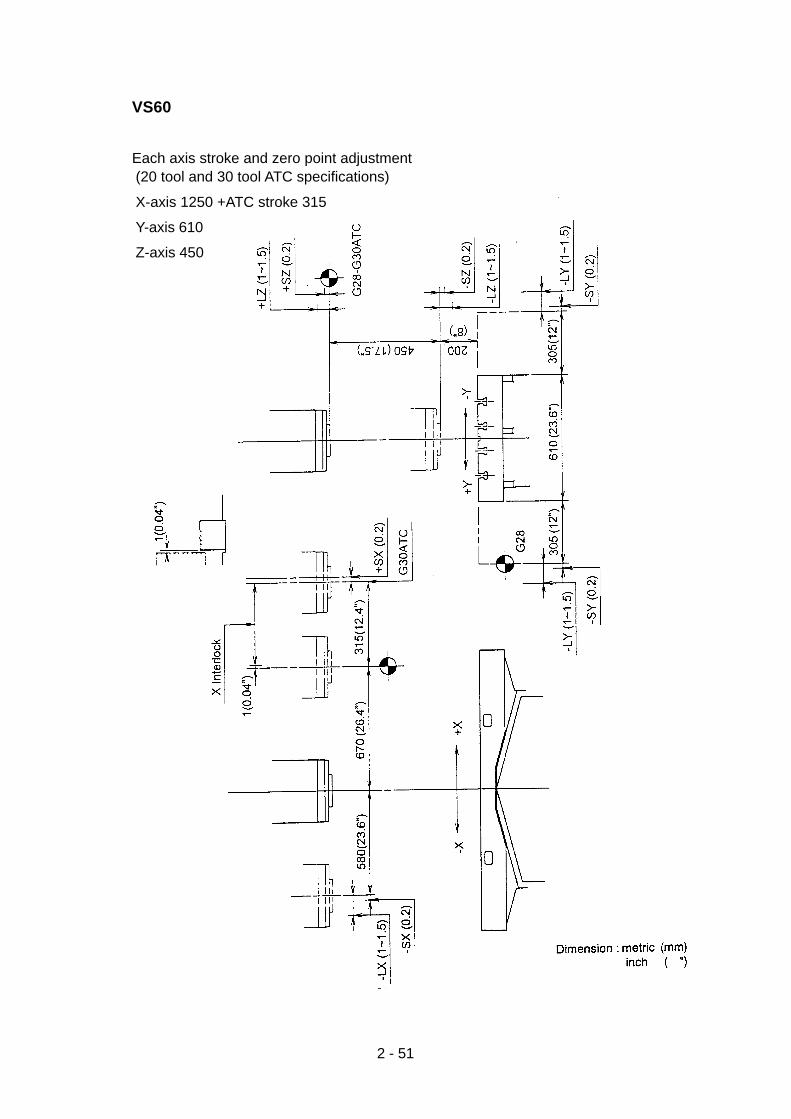
2 - 51
VS60
Each axis stroke and zero point adjustment(20 tool and 30 tool ATC specifications)
X-axis 1250 +ATC stroke 315
Y-axis 610
Z-axis 450

2 - 52
(2)Adjusting parameter No. and contents
Parameter No. Contents
1226 Machine coordinate value of 2nd reference point
1227 Machine coordinate value of 3rd reference point
1850 Gride shift amount of each axis
1326 + direction coordinate value of soft stroke limit for each axis
1327 - direction coordinate value of soft stroke limit for each axis
(3)Adjusting .diagnosis input signal No. and contents
Contents Input signal No. from PC
Over travel + G114.0
X axis Over travel - G116.0
Reference point deceleration G196.0
Over travel + G114.1
Y axis Over travel - G116.1
Reference point deceleration G196.1
Over travel + G114.2
Z axis Over travel - G116.2
Reference point deceleration G196.2
Over travel + G114.3
4 axes Over travel - G116.3
Reference point deceleration G196.3

2 - 53
(4)Procedures of reference point adjustment
[1] Set 1 bit of the parameter No.1002 to 1 and No.1850 (grid shift amount) to 0.
[2] Push the emergency button once and set the standby in order to set parameters to
the servo.
[3] Perform manual reference point return.
[4] Return the lead by half in the reverse direction against the reference point return
direction.
[5] Loosen the dog for reference point deceleration and set the dog to the position where
the deceleration signal is turned ON.
[6] Set the machine reference point and the stop position to the parameter No.1850.
Note) When using the linear scale, turn the one rotation signal sensor ON half this side of
the lead from the position where the deceleration signal is turned OFF.

2 - 54
2-8 Countermeasures against shift of follow-up coordinate
(shift of memory software OT)
When power failure occurs during axis movement, the follow-up coordinate system is shifted and
the software OT may consequently be shifted.
Procedures of recovering follow-up coordinate
1 Once put the NC source power OFF.
2 Press the NC source power ON button, while pressing P and CAN buttons. Keep pressing
the P and CAN buttons until the NC screen displays ∑18M.
3 After making preparation for operation, perform zero return of Z, Y, X-axis in this order.
4 At the time of X-axis zero return, if a message “Move X-axis to zero return valid area.” is
displayed, move X-axis to the -X direction by JOG feed. As X-axis enters the valid area,
the message changes to “X-axis in zero return valid area”.
5 Perform zero return in the zero return mode.
6 On completion of zero return, a message “Have the axis returned to machining area.” is
sometimes displayed. In this case, reset the NC system by pressing NC reset button.
Note 1) During follow-up coordinate releasing operation, S-axis JOG feed is valid in the minus
direction only. (This is for avoiding collision with the ATC shutter.)
Note 2) During follow-up coordinate releasing operation, X-axis zero return is interlocked until the
zero return valid area (-300mm or more from the machine zero point on the minus side) is
confirmed.
Note 3) For the feed by manual pulse generator, the axis is not interlocked. When the tool is in
contact with work, have the tool escaped to a safe position by manual pulse generator.
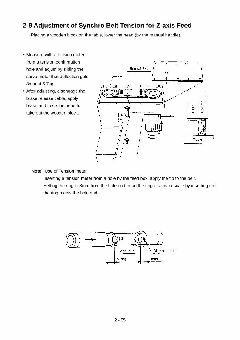
2 - 55
Col
umn
2-9 Adjustment of Synchro Belt Tension for Z-axis FeedPlacing a wooden block on the table, lower the head (by the manual handle).
• Measure with a tension meter
from a tension confirmation
hole and adjust by sliding the
servo motor that deflection gets
8mm at 5.7kg.
• After adjusting, disengage the
brake release cable, apply
brake and raise the head to
take out the wooden block.
Note) Use of Tension meter
Inserting a tension meter from a hole by the feed box, apply the tip to the belt.
Setting the ring to 8mm from the hole end, read the ring of a mark scale by inserting until
the ring meets the hole end.

2 - 56
2-10 Instructions for Motor/Inverter for ATC Twin Arm Rotation
2-10-1 Setting and Changing the ParametersFor the control of an inverter, many parameters are used and it is possible to select thespecific parameters necessary for inverter operation and to set proper values for the selectedparameters using the parameter unit meeting the application requirements (load and operationconditions).
To protect the parameters from accidental alteration, set “1” for Pr.77 (Parameter write disableselection).
• Operating procedure (Reading and writing the value set in Pr.1 (upper limit frequency))
(1) Press the [PU OP] key ..... The PU operation indicating lamp
is lit.PU Operation
Displayedalternately
(2) Press the [SET] key .......... “P.” appears in the display unit.
(3) Input “1” (the parameter .... “P.1” appears in the display unit.
number of the parameter
to be called.)
(4) Press the [READ] key ....... The current set value is displayed
in the display unit.
(5) Input the value to be set ... The new value is displayed in the
(Example:60) display unit.
(6) Press the [WRITE] key ..... The new value is stored to thememory.
(7) When the [READ] key is pressed next, the parameter number advances to “2”
(Pr.2). Press the [READ] key once again, and the current setting for Pr.2 is
displayed. In the same operation, the current setting for other parameters can be
read.
..... If the error message “Err.” appears in
the display unit when the [WRITE]
key is pressed, refer to page 20.
Display unit

2 - 57
2-10-2 Initializing the ParametersThe operation to return the set values for the parameters, excluding the calibration value, tothe factory-set values (initialization) is called “parameter clear”.
The operation to initialize all the parameters including the calibration value is called “parameterall clear”.
1) Parameter Clear
• Operating procedure
(2) Press the [SET] key ........... “P.” appears in the display unit.
(3) Input “999” using the .......... “P.999” appears in the display unit.
numeric keys.
(4) Press the [READ] key ........ “Pr.Cr.” appears in the display unit.
(Note 1)
(5) Press the [WRITE] key ....... “Pr.Cr” in the display unit blinks on and
off. This completes parameter clear
operation. (Note 2)
PU Operation
(blinking)
Display unit
Notes: 1. If the [WRITE] key is pressed before pressing the [READ] key, the operation is notaccepted.
2. If the attempted parameter clear operation is rejected by the inverter, “Err.” and “Pr.Cr.” are displayed alternately.
Note: In the parameter clear operation, the following parameters are not initialized.
• Pr. 900 FM terminal calibration • Pr. 904 Frequency setting current bias
• Pr.902 Frequency setting voltage bias • Pr.905 Frequency setting current gain
• Pr.903 Frequency setting voltage gain • Pr.38 Frequency at 5 V (10 V) input
• Pr.39 Frequency at 20 mA input
Note: While writing of the parameters is disabled, Pr. 77 = 1 or during operation in Pr. 77 = 0,it is not permissible to change the value set for parameters. In this case, however,Pr.900 to Pr.905 can be changed.
(1) Press the [PU OP] key ....... The PU operation indicating lamp is lit.

2 - 58
2) Parameter All Clear
• Operating procedure
(1) Press the [PU OP] key ...... The PU operation indicating lamp is lit. PU Operation
(blinking)
Notes: 1. If the [WRITE] key is pressed before pressing the [READ] key, the operation is notaccepted.
2. If the attempted parameter all clear operation is rejected by the inverter, “Err.” and“ALLC” are displayed alternately.
Note: While writing of the parameters is disabled, Pr. 77 = 1 or during operation in Pr. 77 = 0,it is not permissible to change the value set for parameters. In this case, however,Pr.900 to Pr.905 can be changed.
(2) Press the [SET] key .......... “P.” appears in the display unit.
(3) Input “998” using the ......... “P.998” appears in the display unit.
numeric keys.
(4) Press the [READ] key ....... “ALLC” appears in the display unit.
(Note 1)
(5) Press the [WRITE] key ..... “ALLC” in the display unit blinks on and
off. This completes parameter
all clear operation. (Note 2)
Display unit

2 - 59
2-10-3 MonitoringJust after turning ON the power, or when the monitor key is pressed, the parameter unit entersthe monitor mode. In the monitor mode, load status (output frequency, output current, etc.),protective function activation status in response to the occurrence of an alarm, etc. can bemonitored.
(1) Changing the monitor information (output frequency, output current, error code)The monitor information is changed each time the monitor key is pressed.
• Operating procedure
(2) Press the [MONITOR] key ... Output current is displayed.
(3) Press the [MONITOR] key ... Error code is given for the alarm
which has occurred. (Note 2)
(4) Press the monitor key The monitor mode returns to the
output frequency monitor.
(Output voltage cannot be
monitored.)
Notes: 1: When the [WRITE] key is pressed while the parameter unit is displaying any of theabove indicated monitor data, the priority is given to that monitor mode. After thesetting of the priority, the selected information is displayed first when the parameterunit mode is changed to the monitor mode or just after the power is turned ON.
2: If a fault occurs within the inverter, the error message is given immediately.
Display unit(1) Turn ON the power .............. Output frequency is displayed.
(Note 1)

2 - 60
2-10-4 ErrorsIf a failure occurs within the inverter during operation, the corresponding error code isautomatically displayed in the parameter unit.
1) Error Codes and Contents of Errors
(Note)
Note: The ETHM error occurs if current below 150 % of the current set for the electronic thermal
relay (Pr.9) flowed the motor over an extended period of time. <Example>
• If “5 A” is set for Pr. 9 (electronic thermal relay).
5(A)×150(%)=7.5(A)
The protective function is activated by a current below 7.5 A, due to the inverse time
trip characteristic of the built-in electronic thermal relay circuit.
* This error is also displayed in the emergency stop status established by selecting the
PU STOP key function in external operation is stopped by pressing this stop key during
external operation and pressing the stop key.
•Other display
Display Error Code Contents of Error
EOPT When the retry function is selected, retry is executed if the corresponding inverter alarmoccurs. This message is displayed while retry is executed.The display is given for the period set by Pr.68 (retry execution waiting time).
Display Error Code Contents of ErrorE 0 Normal*Err Setting operation error, reset signal is ON, incorrect connection between the parameter unit
and the inverter, etc. wrong incoming voltage.
EOC1 During acceleration, inverter output current exceeded the overcurrent limit.EOC2 During fixed speed operation, inverter output current exceeded the overcurrent limit.EOC3 During deceleration, inverter output current exceeded the overcurrent limit.
EOV1 During acceleration, regenerative power from the motor exceeded the regenerativeovervoltage limit.
EOV2 During fixed speed operation, regenerative power from the motor exceeded theregenerative overvoltage limit.
EOV3 During deceleration, regenerative power from the motor exceeded the regenerativeovervoltage limit.
ETHT The electronic thermal relay in the inverter was tripped (current over 150 % of the ratedcurrent).
ETHM The electronic thermal relay in the inverter was tripped (current below 150 % of the ratedcurrent, but above 100% current.)
EFAN Fault of the inverter fan (provided for 1.5 K to 3.7 K models)
EOLT During fixed speed operation, the current limit function was continuously activated and themotor stopped.
E BE Fault of the brake transistor in the inverter was detected.EONT An external relay was tripped, which was connect to drive by customer.
E PE Fault of the memory device in the inverter where the parameter data is stored CPUdefective.
EPUE The parameter unit was disconnected from the inverter.ErET Restarting was not possible within the set number of retries.
ECPU Run-away of the CPU.E GF If a ground fault current has flown due to a ground fault occurring in the output (load) side of
the inverter, this function stops the inverter output. A ground fault occurring at low groundresistance may activate the overcurrent protection (OC1 to OC3). Provided for the 400 Vtype only.

2 - 61
2) Digital Display (7-Segment Display) and Actual CharactersThe indication given by the 7-segment display represents the actual characters as shownbelow.
ActualCharacter Display
ActualCharacterDisplay Actual
Character Display
3) Logged Error ContentsThe contents of the errors are stored for the past four events. To check the contents of thesestored errors, follow the procedure indicated below.
• Operating procedure
(1) Press the [MONITOR] key ........ The parameter unit enters the
monitor mode.
(2) Press the [MONITOR] key ........ The information of the latest error
several times unfit the error is displayed in the display unit.
display is given (Note)
(3) Press the [READ] key once ...... The information of the error one
before the previous error is
displayed.
(4) Press the [READ] key once ...... The information of the error two
before the previous error is
displayed.
(5) Press the [READ] key once ...... The information of the error three
before the previous error is
displayed.
(6) Press the [READ] key The display returns to the
once information of the latest error.
Note:For the information of the latest error, a period is displayed following “E” (Example: E. OC1)
Display unit

2 - 62
4) Clearing Error LogThe log of errors (four events) can be cleared by the following operation.
• Operating procedure
(1) Press the [PU OP] key ...... The PU operation indicating lamp is lit.
Notes: 1. If the [WRITE] key is pressed before pressing the [READ] key, the operation is notaccepted.
2. If the attempted error history clear operation is rejected by the inverter, “Err.” and“Er.CL” are displayed alternately.
(2) Press the [SET] key ........... “P.” appears in the display unit.
(3) Input “996” using the .......... “P.996” appears in the display
numeric keys. unit.
(4) Press the [READ] key ........ “Er.CL” appears in the display
(Note 1) unit.
(5) Press the [WRITE] key ...... “Er.CL” in the display unit blinks.
This completes error log clear
operation. (Note 2)
PU Operation
• To check the operation status just before the occurrence of an error:If an error occurs, the contents of the display unit automatically switches to the display of theactuated protective function. If the monitor key is pressed without resetting the inverter, thedisplay unit displays output frequency. The frequency displayed will be that at which themotor was running just before the occurrence of the error. Current value can be checked inthe same manner. However, these values are not stored in the 4 fault memory and arecleared by the reset operation.
(blinking)
Display unit

2 - 63
2-10-5 Resetting the Inverter
(2) Press the [SET] key ........ “P.” appears in the display unit.
(3) Input “997” using the ....... “P.997” appears in the display unit.
numeric keys.
(4) Press the [READ] key ..... “rEST” appears in the display unit.
(Note 1)
(5) Press the [WRITE] key ... “rEST” in the display unit is turned off.
This completes inverter reset operation.
(Note 2) (off)
Notes: 1: If the [WRITE] key is pressed before pressing the [READ] key, it is not accepted.
2: If the attempted inverter reset clear operation is rejected by the inverter, “Err.” and“rEST” are displayed alternately.
Operation 2
Press the [STOP] key while the inverteris in faulty state.
Operation 3
Turn OFF power supply once. Aftermaking sure that the POWER indicatinglamp or the LED has gone out, turn onpower supply again.
Operation 4
Close the circuit across the resetterminal RES and SD for more than 0.1second and then open it.
Display unit
To reset the inverter, follow any of the following four procedures. Remember that theaccumulated internal thermal data of the electronic thermal relay and the retry count arecleared if the inverter is reset.
Operation 1
(1) Press the [PU OP] key ... The PU operation indicating lamp is lit. PU Operation

2 - 64
2-10-6 Inspection and MaintenanceThe general-purpose inverter is static equipment mainly consisting of semi-conductor devices.To prevent problems occurring due to environmental conditions such as high temperature,humidity, dust, and vibration, or aging of the component parts, inspection at regular intervals isnecessary.
1) Precautions on Inspection and MaintenanceAfter the power is turned off, the smoothing capacitor remains charged at high voltage for awhile. Remove the front cover and wait until the POWER indicating lamp (refer to page 3) onthe printed circuit board goes off. Start inspection or maintenance several minutes after theturning off of the POWER indicating lamp.
2) Inspection Items
(3) Testing insulation resisting using a Megger
a) To test the insulation resistance of the external circuit, disconnect all wires from theinverter terminals so that test voltage will not be applied to the inverter circuits.
b) For the continuity test of the control circuit, use a multimeter (high resistance range). Donot use a Megger or buzzer for the test.
c) Conduct the insulation resistance test on the inverter main circuit only. Do not conductthe test on the control circuits.
(2) Regular inspection
Check the following items which may be
checked only after stopping the inverter atregular intervals.
a) Check that the cooling system iscorrect. Clean the air filter, etc.
b) Tighten the screws and bolts. Sincescrews and bolts will loosen due tovibration and thermal expansion, checkthe screws and bolts and tighten them ifloose.
c) Check the conductors and insulators forcorrosion and damage.
d) Measure insulation resistance.
e) Check the cooling fan, smoothingcapacitor, and relay. Replace adefective part.
(1) Daily inspection
Check the following items during operation.
a) The motor operates properly.
b) The environment is normal.
c) The cooling system is normal.
d) There is no unusual vibration or noise.
e) There is no overheat or discoloration.
During operation, check the inverter input/output voltage with a multimeter.

2 - 65
Daily Inspection and Regular Interval Inspection
Location Item Contents
Inspection Interval
Inspection Method Judgment InstrumentDaily Interval
1 2
year year
Overallinspection
Maincircuit
Environment
Equipment
Supplyvoltage
Overallinspection
Conductorsand wires
Terminalblock
InvertermoduleConvertermodule
Smoothingcapacitor
Check ambienttemperature,humidity, dust, etc.
Vibration and noise
Main circuit voltage
(1) Insulationresistance(between the maincircuit terminaland groundingterminal)
(2) Loose connection
(3) Overheat oncomponent part
(4) Cleaning
(1) Distortion inconductors
(2) Damage oncoating of theconductors
Damage
Resistance across theterminals
(1) Leak of fluid
(2) Protrusion of thesafety valve, orbulging.
(3) Measuring thecapacitance
O
O
O
O O
O
O
O
O
O
O
OO
O
Visual inspection,inspection by ear.
Measure voltageacross terminals R, S,and T
(1) After disconnectingall wires at theinverter terminals,close R, S, T, U, Vand W terminals.Measure insulationresistance betweenthe point wherethese terminals areconnected and thegrounding terminalusing a Megger.
(2) Tighten the loosescrews and bolts.
(3) Check visually.
(1) (2) Visualinspection
Visual inspection
After disconnecting allwires at the inverterterminals, measureresistance acrossterminals R, S, T andP, N and U, V, W andP, N with a multimeterin the × 1Ω range.
(1) (2) Visual Inspection
(3) Measure with acapacitancemeasuringinstrument.
Ambient temperature:
-10?C to + 50?C
(without freezing)Humidity:
Loss than 90 % (non-condensation)
Must be free ofabnormal vibrationand noise.
170 to 242 V 50 Hz
170 to 253 V 60 Hz
(1) Must be larger than5 MΩ.
(2) (3) Must be free ofabnormalities.
(1) (2) Must be free ofabnormalities.
Must be free ofabnormalities.
(1) (2) Must be free ofabnormalities.
(3) High than 85 % ofthe rated capacity.
Thermometer,hygrometer,recorder
Multimeter,digitalmultimeter
500 VDCMegger
Analogmultimeter
Capacitymeter

2 - 66
Location Item Contents
Inspection Interval
Inspection Method Judgment InstrumentDaily Interval
1 2
year year
Maincircuit
ControlcircuitProtectioncircuit
Coolingsystem
Display
Motor
Relay
Resistor
Operationcheck
Cooling fan
Display unit
Meter
Overallinspection
Insulationresistance
(1) Chattering noiseduring operation
(2) Smoothness oncontact
(1) Crack on resistorinsulator
(2) Disconnection
(1) Check the balanceof interphaseoutput voltage byoperating theinverterindependently.
(2) Conduct thesequenceprotectionoperation test tocheck theprotection anddisplay circuits.
(1) Abnormal vibrationand noise
(2) Loose connection
(1) LEDs
(2) Cleaning
Indication
(1) Abnormalvibration andnoise
(2) Abnormal smell
O
O
O
O
O
O
O
O
O
O
O
O
O
O
(1) Listeninginspection
(2) Visual inspection
(1) Visual inspection.Cement resistors,wire wound resistor
(2) Disconnect the wireat one side andmeasure resistancewith a multimeter.
(1) Measure voltageacross the inverteroutput terminals U,V, W.
(2) Short the inverterprotection circuitoutputs.
(1) Turn the fan withoutapplying voltage.
(2) Tighten the loosescrews and bolts.
(1) Check the LEDs onthe panel.
(2) Clean with rag.
(1) Check the indicationof the meter on thepanel.
(1) Visual inspection,inspection by bodyfeeling (vibration)and by ear.
(2) Smell due to overheating, damage,etc.
(1) Disconnect wiresfrom the U, V, andW terminals. Motorwires should be included.
(1) Must be free ofabnormalities.
(2) Must be free ofabnormalities.
(1) Must be free ofabnormalities.
(2) Must be within±10 % of theIndicatedresistance.
(1) Imbalance shouldbe within 4V (for200V), 8V (for 400V).
(2) The alarm shouldbe output.
(1) Must be able to turnsmoothly.
(2) Must be free ofabnormalities.
(1) Make sure that theLEDs are lit.
(1) The indicationmust conform tothe specifiedvalue.
(1) (2) Must be free ofabnormalities.
(1) Must be higherthan 5 MΩ.
Multimeter,digitalmultimeter
Digital multi-meter, rectifiervoltmeter
Voltmeter,ammeter
500 VMegger.
Check with Megger(across terminals andground terminal)

2 - 67
2-10-7 TroubleshootingIf a fault occurs and the inverter fails to operate properly, locate the cause of the fault and takeproper corrective action by referring to the troubleshooting below. If the correspondinginformation is not found in the table, the inverter has problem, or the component parts aredamaged, contact the nearest service representative.
1) Inspection by the Display on the Parameter UnitIn response to the occurrence of a fault, the display unit of the inverter automatically displaysthe code of the detected fault.
Display Probable Cause Check Corrective Action
Err: Error
OC1: Overcurrent duringacceleration (*1)
OC2: Overcurrent duringconstant speedoperation (*1)
OC3: Overcurrent duringdeceleration (*1)
OV1: Overvoltage duringacceleration
OV2: Overvoltage duringconstant speedoperation
OV3: Overvoltage duringdeceleration
THT: Overload warning
THM: Overload warning
FAN: Fan alarm
OLT: Stall prevention
BE: Brake transistor alarm(*2)
OHT: External thermalrelay tripped
• Operation setting error
• Reset signal is ON.
• PU is not connected to theinverter correctly.
• High input voltage (approx.260 VAC)
• Faulty internal circuit
• CPU run-away
Overcurrent
DC overvoltage in main circuit
Thermal relay for inverter istripped.
Thermal relay for motor istripped.
Cooling fan of the Inverter hasstopped.
Operation of the stallprevention function or thecurrent limit function for a longperiod
Faulty brake transistor
An external thermal relay hasbeen tripped.
• Review the operationmethod.
• Is wiring at the reset terminalcorrect?
• Is connector securedcorrectly?
• Is input voltage correct?
• Is acceleration too fast?
• Is output short-circuited orgrounded?
• Was load changedsuddenly?
• Is output short-circuited orgrounded?
• Is deceleration too fast?
• Is output short-circuited orgrounded?
• Is mechanical brake appliedtoo early?
• Is acceleration too fast?
• Is load changed suddenly?
• Is deceleration too fast?
• Is motor used in the over-loaded condition?
• Is there foreign matter insidethe fan assembly?
• Is there wiring error?
• Is motor used in the over-loaded condition?
• Is braking frequency correct?
• Is the motor overheated?
• Is an external relay in use?
• Refer to page 43.
• Turn OFF the reset signal.
• Correct the connection.
• Use correct input voltage.
• Change the inverter.
• Reset the inverter (page 42).
• Extend acceleration time.
• Eliminate sudden loadchange.
• Extend deceleration time.
• Check the brake applicationtiming.
• Extend acceleration time.
• Eliminate sudden load change.
• Extend deceleration time.(adjust deceleration timecompensating for load GD2)Reduce braking frequency.
• Reduce theload.Increase thecapacity of motorand inverter.
• Remove foreign matter.
• Check the wiring.
• Reduce the load.Increase the capacity ofmotor and Inverter.
• Reduce load (GD2).Reduce braking frequency.
• Reduce load (GD2).Reduce braking frequency.Eliminate sending.

2 - 68
Display Probable Cause Check Corrective Action
PE: Parameter storingdevice error
PUE: PU disconnectiondetected
rET: Retry count over
CPU: CPU error
Faulty EEPROM
Connector of the parameterunit Is disconnected.
CPU run-away
• Is the number of parameterwriting too many?
• Is EEPROM worn out?
• Check the cause of the error
• Replace the inverter.
• Install and connect theparameter unit securely.
• Replace the inverter.
Notes 1: *1.With the FR-A 024-1.5 K to 3.7 K, if the cooling fan stops, the protection function isactivated due to overheating of the main circuit devices. Therefore, check thecooling fan also. The cooling fan must start when power is turned on.
*2.For the inverter equipped with the optional brake resistor.
2: Error output is not given if input voltage is low or momentary power interruption occurs.In these cases, however, the inverter is protected so that the inverter will not bedamaged. Depending on the operating status (magnitude of load, during acceleration/deceleration, etc.), the overcurrent protection function, etc. may be actuated when theinput power is restored.
If operation cannot beresumed within the number ofretry times set the inverteralarms and stop retryattempts.
• Is the parameter unitconnection loose?

2 - 69
2) Troubles and Check Points
Trouble Check Points
Motor does not start.
Motor rotates in theopposite direction.
Actual motor speed differsfrom the set speedexcessively.
Motor acceleration ordeceleration is not smooth.
Motor speed varies duringrotation.
Motor current is too large.
Motor speed does notincrease.
Motor speed fluctuatesduring motor operation.
(1) Check the main circuit.• Is power supplied? (Is the POWER indicating lamp lit?)• Is the motor connected correctly?
(2) Check the input signals.• Is the start signal input?• Are both the forward and reverse rotation signals input?• Is the frequency set signal zero?• Is the circuit across terminals AU and SD closed (ON) when the frequency setting
signal is in the range from 4 to 20 mA?• Is the output stop signal (across terminals MRS and SD) or the reset signal (across
terminals RES and SD) ON?(3) Check the values set for parameters.
• Is the reverse rotation prevention (Pr.78) function set?• Is the setting for the reverse mode (Pr.79) correct?• Are the setting for the bias and gain (Pr.902 to Pr.905) correct?• Is the setting for the start frequency (Pr.13) larger than the operation frequency?• Is the frequency setting for the operation functions (multiple-speed operation, etc.)
correct?• Is the setting for the upper limit frequency (Pr.1) zero?
(4) Check the load.• Is the load too heavy? Is the motor start constrained?
(5) Others• Has the emergency stop status been established by pressing the parameter unit
stop key? (Is “E 0” displayed?)• Is the alarm indicating lamp (ALARM) lit?
• Is the phase sequence (U, V, W) at the output terminals correct?• Are the start signals (forward, reverse) connected correctly?• Is the frequency setting signal correct? (Measure the input signal level.)• Are the values set for the following parameters correct?
Pr.1 (upper limit frequency), Pr.38 (frequency at 5 VDC input), Pr.39 (frequency at 20mA input), Pr.902 to Pr.905 (bias and gain)
• Are the input signal lines influenced by external noise? (use shielded wires, ifinfluenced.)
• Is acceleration or deceleration time too short?• Is the load too heavy?• Is the stall prevention function activated due to excessively large value set for torque
boost?• Is the load changing?• Is the frequency setting signal stable?• Is the load too heavy?• Is the value set for torque boost (manual) too large?• Is the value set for upper limit frequency correct? Is it too small?• Is the load too heavy?• Is the stall prevention function activated due to excessively large value set for torque
boost?(1) Check the load.
• Is the load changing?(2) Check the input signals.
• Is the frequency setting signal stable?(3) Others
• In the general-purpose magnetic flux vector control mode, is the setting forapplicable motor capacity (Pr.80) correct for the inverter capacity and motorcapacity?
• In the general-purpose magnetic flux vector control mode, is the wiring length longerthan 30 m?
• In the V/F control mode, is the wiring length too long ?
Note: “Pr.” is an abbreviation of “Parameter.”

2 - 70
2-11 Handling and Maintenance of Spindle Oil Air Lubricating Unit(Option)
2-11-1 Oil Air Lubrication Circuit
12 Mixing valve Ryube 3B-1 S joint 04999080740 1
11 Nylon tube CKD F-1508 Black 04999036941 -
10 Filter regulator CKD W3000-8-F-B 04999018439 1
9 Dry filter Maeda Shell Service M-103 04999026186 1
8 Pressure switch CKD PE-2T 04619000420 1
7 Regulator CKD R-1000-8-B 04999054394 1
6 Solenoid valve CKD AB41025-02G-AC100V 04133108210 1
5 Pressure switch CKD PE-2T 04619000420 1
4 Mixing valve Ryube MIX-1A4C w/ S joint 04999120679 1
3 Nylon tube Showa Yuki SHOWA nylon 4 04999003499 -
2 Line filter Showa Yuki LF0101 30 micron (90010041000) 1
1 Lubricating unit Showa Yuki LCB4 7613 (90010040900) 1
No. Item name Maker Type Code No. Qt’y

2 - 71
2-11-2 Pump Unit1. When using the pump unit:
[1] Use clean and dry compressed air
[2] Air containing dust affects the life of the machine.
[3] Do not forget practicing daily check to avoid accidents and troubles.
Periodical inspection should be exercised once in every 6 month to check wear and
secular deterioration of the machine.
2. Specification
Pump Discharge Quantity 100cc/min (50Hz) 120cc/min (60Hz)
MLB01W2 Discharge Pressure 15kgf/cm2 1.5MPa
Motor Voltage 100V 200V
Cycle 50Hz 60Hz 50Hz 60Hz
Amperage 1.5A 1.2A 0.8A 0.6A
Revolution 2500rpm 3000rpm 2500rpm 3000rpm
Output 17W×2P
Insulation Class Class E
Max. operating time 5 minutes
Pausing time Operating time×2 or longer (min. 2 minutes)
Total tank capacity 2• (effective capacity 1.3• )
Float switch (OLV01) Contact point capacity Max. AC0.33A, DC0.5A
Pressure switch (GFB8) Contact point capacity Max. AC250V 5A
Viscosity range of oil used 50 ~ 800 cSt
Press the lubrication button when you wish to operate the pump at an arbitrary time.
The pump will keep running while the button is being pressed.

2 - 72
3. Outside view
Model type LCB47613
Pump Discharge volume 100cc/min
MLB01W2 Discharge pressure 15kgf/cm2 1.5MPa
Tank Total capacity 2•
Effective capacity 1.3•
Control unit None
Pump unit weight 4.1kg

2 - 73
2-11-3 Mixing Valve1. Function
The mechanism of the mixing valve is to supply minimum requirement of lubricating oilintermittently into the flow of compressed air, enabling to efficiently perform twofunctions of lubrication and cooling.
It is especially effective in cooling and lubrication of the bearing part of the highrevolution spindle.
2. Specification
Spindle specification #50 - 10,000 #40 - 20,000
Type MIX-1A4C S joint 3B-1 S joint
Oil to apply High speed spindle oil or turbine oil(Refer to “2-2-1 List of Lubrication and Oil Supply”)
Viscosity to apply 32cSt/40°C 22cST/40°C
Air pressure to apply 0.4Mpa
Oil pressure too apply 1.5Mpa
Oil discharge volume 0.01cc×1, 0.05cc×4 0.03cc×3
3. Outside view and name of each part
Ÿ #50 - 10,000
Ÿ #40 - 20,000

2 - 74
2-11-4 Daily maintenance1. Air removing of mixing valve
1) Bring the system into the maintenance mode and make the setting of lubricantdischarge at one shot per minute.
2) Detach the piping of the nozzle part at the tip.
3) Close the air throttle of the mixing valve completely. (by turning the throttle leverclockwise to the end stopper)
4) Fill up lubricant in the circuit between the lubrication unit and the mixing valve. (3~ 5 shots)
5) Confirm that no air remains in the circuit, including the part of the circuit up to thesliding face.Make necessary measures such as loosening the piping to the switching valve onthe lubrication side of the sliding face.
6) Repeat discharges until lubricant is filled up in the mixing valve and lubricantbegins to flow out to the path on the nozzle side. (several shots)
7) Open the air release plug. (loosening it to such an extent that it is held hangingand not dropping off)
8) Repeat discharges until air is removed. (about 5 shots)
9) Repeat shots until lubricant free of air mixture flows into the circuit on the nozzleside. (If air-free lubricant in the circuit is measured in length of about 10 cm, it isall right.)
10) If the lubricant movement at the tip by one shot comes up to the figures in theTable below, it is all right.)
11) Open the air throttle. (2 counterclockwise turns)
12) Let air-flow go through until lubricant becomes vacant in the circuit after the mixingvalve.
13) Connect the pipe to the nozzle.
Mixing valve discharge volume and move amount of lubricant in the path
Call No. Inscribed markDischarge volume
Move distance (mm)(cm3 /stroke)
A 1 0.01 1.5 ~ 2.5
B 3 0.03 5 ~ 8
C 5 0.05 7 ~ 13
Note:The above values are worked out based on the tube innerdiameter of 2.5mm.

2 - 75
2. Dry filter
To avoid the influence of variable quality of source air, the circuit has two built-in dryfilters. For the maintenance, the first filter is cleaned and the second one is replaced.When a filter is clogged, the pressure switch detects it by dropped air pressure.
1) Replacement
Fill the date of replacement on the label attached on the filter cartridge so that thenext replacement date is scheduled, normally 4 to 5 months later, though it variesdepending on working conditions. Replacement is also necessary when thepressure loss exceeding 0.7kg/cm2 of the air passing through the filter, which is anevidence of the clogged condition of the second filter.
2) Cleaning
The first filter is made of stainless steel. The filter can be reused By washing it oncein every two years with detergent, though such intervals would vary depending onthe working conditions, Use organic detergent such as trichloroethylene, when thecontamination is serious, otherwise ordinary detergent will do.
The second filter is made of cotton woven with stainless steel wire, which is subjectto shrink or deform when washed and dried. Thus it cannot be washed and reused,therefore must be replaced with new one.
3) Method of replacing filter
There is no need of detaching the unit from the airflow line or from the fitting metal.For replacing, proceed with the following steps keeping the position of the filter unitas it is.
1. Loosen all the bolts on the manifold until the cartridge becomes freely movable.
2. Remove one outside corner bolt and draw out the cartridge side way.
3. Set a new cartridge in the same position.
4. Put the corner bolt back to the position and tighten evenly in turn, first the centerbolt then the corner bolt.
3. Lubricant filter
In order to ensure stable performance of the mixing valve, a main pipe filter is installedin the lubricating circuit. For the maintenance of this filter, exercise inspections withintervals of one year. Filter clogging is detected by the pressure switch.

2 - 76
2-12 Related
to C
oo
lant
19 VINYL HOSE S0-9 2.5m
18 VINYL HOSE S0-25 2.5m
17 VINYL HOSE S0-25 2.5m
16 VINYL HOSE S0-25 2.5m
15 VINYL HOSE S0-25 2.5m
14 VINYL HOSE S0-25 2.5m
13 VINYL HOSE S0-25 2.5m
12 HOSE P105-12×100cm FU-FU 2
11 HOSE P105-12×100cm FU-FU 2
10 HOSE P105-9×70cm FU-FU 2
9 CHECK VALVE RF1/2 2
8 NOZZLE SNPT 1/4-40 2
7 COOLANT GUN SP100 1
6 COOLANT PUMP LSW25T0.4 1
5 COOLANT PUMP LSW15T0.18 2
4 COOLANT PUMP VKR122AD 1
3TROCHOID TOP-2MY1500-
2PUMP 216HWNPE-VB15-10
2 COOLANT UNIT RFH25YC3702V-5 1
1 COOLANT UNIT RFH25YC3702V-6 1
NO PART NAME MODEL QTY

2 - 77
1) Specifications of the coolant pump (for flood/gun coolant)
No. Part name Q’ty Materials
1 Casing 1 FC15 JISG5501
3 Discharge casing 1 FC15 JISG5501
21 Impeller 1 FC20 JISG5501
31 Spindle 1 S45C JISG4051
40 Impeller nut 1 SS JISG3101
69 Cutting edge 1 FPM
79 Stopper 1 SK-5 JISG4401
90 Hexagon bolt 2 SS JISG3101
109 Cap 1 FPMI
801 Rotor 1 A1
802 Stator 1 S60 JISC2554
804 Terminal boat 1 SPCE JISG3141
807 Motor frame 1 SPCC JISG3141
809 Upper bracket 1 FC15 JISG5501
830 Wave form washer 1 SK-5 JISG4401
Table of the specificationsPump model LSW15A0.18MR
Pump Diameter (mm) 15
Discharge amount (L/min) 10~60
Total lift of pump (m) 9~5 13~8
Using viscosity limit (cst) 150 75
Using liquid filtering accuracy Middle, class accuracy filtering
(Max. length of chips possible in the pump :2.5mm))
Quality of material Impeller, casing, discharge casing ....FC
Motor Phase 3
Pole 2
Output (kW) 0.18
Voltage (V) 200 200/220
Max. permissible current (A) 1.1 1.2
Frequency (Hz) 50 60
Synchronous rotation speed (rpm) 3000 3600
Class of insulation E
Ambient temperature (°C) -15 ~ 40
Temperature rise (deg) Not more than 75
Rating Continuos
Protection method All closed inner type
Bearing Loading side 6202VV
Opposite loading side 6202VV
Gross weight (kgf) 13
Painting color RAL-6011
Note) 1. Inquire at Hitachi Seiki for other special fluids.
2. It is of the type using 50/60Hz in combination.

2 - 78
2) Coolant pump (For jet coolant)
Parts List1 Frame
2 Shaft
3 Stator
4 Rotor
5 Driving-side bearing
6 Counter-driving-side bearing
7 Wave washer
8 Rotation direction
9 End cover
10 Impeller
11 Bottom plate
12 Adjusting washer
13 Mechanical seal
14 Casing
15 Spiral box
16 Terminal box
17 Terminal cableSpecification
Standard voltage
Spec Model VKN093A
Output (W) 400
Rated voltage (V) 200 200/220
Frequency (Hz) 50 60
Rated current (A) 2.4 2.5/2.4
Discharge (• /min) 140 200
Total lift head (m) 5
Max. suction pipe length (m) 0.7
Applied viscosity limit (R’) 800 300
Standard piping dia. (PS) 1
Painted color Mancel N5
Pump standard JEM 1242

2 - 79
3) Oil hole coolant pump (1.5MPa)
Discharge DischargeRotor width
DischargeWeightPump model 1500rpm 1800rpm
AC dia. D
kgf• /min • /min PF204HWMPVBE 6.0 7.2 10 86 1/2 4.3
Motor provided (made by Yasukawa Electric Co., Ltd.)Motor
K R L I P E F Q H J M N Z Y XWeight
output kgf
200W 114 127.5 241.5 63 127 50 40 125 127 15 135 108 7 15 3.2 7.5

2 - 80
2-13 Related to Air Pressure1) Pneumatic circuit diagram NO HITACHI PART PART MAKER
SEIKI CODE NAME NUMBER
1 04-780301750 COUPLER 30SH+20PM NITTO
KOUKI
2 04-999033438 FILTER W300-8-F CKD
REGULATOR
3 04-133108210 SOLENOID AB41-02-5- CKD
VALVE 02G-AC100V
4 04-619000420 PRESSURE PE-2T CKD
SWITCH
FLOW
5 04-999026702 CONTROL SMW-6A CKD
VALVE
6 04-999020056 SILENCER SLW-8W CKD
7 04-133149210 SOLENOID 4F130-08- CKD
VALVE AC100V
8 04-999034819 SOLENOID 4F230-08- CKD
VALVE AC100V
9 04-999036941 SOLENOID AG31-02-1- CKD
VALVE 02G-AC100V
10 SOLENOID AG31-01-1- CKD
VALVE 02G-AC100V
11 04-999054394 REGULATOR R1000-8-B CKD
12 04-999036941 NYLON F-1508 CKD
TUBE
13 04-999037052 NYLON F-1504 CKD
TUBE
14 04-999037052 NYLON F-1506 CKD
TUBE
15 04-999048762 SOLENOID AG31-01-3- CKD
VALVE 02G-AC100V
FLOW
16 04-999026702 CONTROL SC3G-6-8 CKD
VALVE

2 - 81
2) Air filter/regulator unit
Outline and features
The Selex FR unit (W3000) is an equipment serving both as the filter F3000 which has a
high effect for removing water drop and dust and as the regulator R3000 which is capable
of setting accurate and stable pressure. It is most suitable to utilize it in a narrow space
especially.
Precautions for using
Ÿ Shelter the equipment from direct rays of the sun.
Ÿ Since the material of the bowl is polycarbonet, don’t use
checmicals such as thinner, carbon tatra-chloride, alcohol, chloro-
form, trichlor-ethylene, ecetate ester, sulfuric acid and alkaline
soluble fluid etc. and in such atmosphere.
Ÿ Wash the bowl element in water after washing it in domestic
neutraldetergent.
Ÿ The ID of the discharging parts of the drain is to be not less than
6mm and its length is to be within 5mm and don’t use elevating
pipings.
Ÿ Don’t move the equipment by gripping the pressure control knob
on the regulator section or fling it around.
No. Part name MaterialPart No.
W3000
[1] Plate cover ABS ———
[2] Body ADC ———
[3] O-ring Specification F4-550349
NBR
[4] Element PP F4-550350
[5] Dia-frame ass’y ZDC, NBR F4-550464
[6] Cover PBT ———
[7] Nob POM ———
[8] Valve ass’y C3604, NBR F4-550477
[9] Pressure gauge PBT, NBR G401
ass’y
[10] Gauge plug PA, BR F4-550241
ass’y
[11] Bowl ass’y PC, POM, PUR F4-550478
[12] Bowl guard PA F3-550425

2 - 82
3) Pneumatic solenoid valve (for spindle air-blow)
AB 41025-02G-AC100V
No. Product Name Material
1 Coil Resin, Wound by tape for type H
2 Core assembly sus405, 316L, L, 403
3 Shading coil Cu, In case of Body SUS: Ag
4 Plunger SUS405
5 Spring SUS304
6 O-ring Nitric byron Teflon
7 Seal NBR byron Teflon
8 Body C3771 or SUS303
9 Stuffing C3771

2 - 83
4) Pneumatic solenoid valve (for ATC shutter)
• JIS symbol
3 positions are of all port flock.
4F130
SOL X At conduct
P (S) → A (C1)
B (C2) → R2 (E2)
SOL Y At conducted condition
P (S) → B (C2)
A (C1) → R1 (E1)
At non-conducted codition
P (S), A (C1), B (C2),
R1 (E1), R2 (E2)...Closed
No. Part name Materials Remarks
[1] Name plate Tetoron film
[2] Gasket NBR Nitrile rubber
[3] Cylinder(A) A5058 Aluminum
[4] Spool A6063 Aluminum
[5] Seal ass’y
[6] Body ADC12
[7] Piston(B) ass’y
[8] Gasket NBR Aluminum
[9] Pilot valve body ADC12 Aluminum die custing
[10] Gasket NBR Aluminum
[11] Miclosole SOL valve
[12] Small DIN terminal
box
[13] Cylinder(B) A5056 Aluminum
[14] Piston(B) ass’y
[15] Cap ADC12 Aluminum die custing
[16] Spring seat SS41
[17] Spring SWPB Piano wire
[18] O-ring NBR Nitrile rubber
[19] Body block A5056 Aluminum die custing
[5] [7] [11] [14]
Seal assay Piston (A) assay Coil model No. Piston (B) assay
4F9-112
4F9-110 4F9-Microsole simple 4F9-111
model No. (Basic —
4F9-159 ps132-MOB-Voltage) —

2 - 84
2-14 Chip Conveyor (For the Inside of Standard Machine)
TA 2 - 1974
No. Part name Part No. Q’ty
[1] Deceleration motor G3FM-18-50-T010A 1 0.1KW×4P×φ3
[2] Bearing 6007. DDU 1
[3] Oil seal AC 2365 EO 1
[4] Coil seat φ39 1
[5] Coil spring o 12×16×φ72×P90 L = 2120 1
[6] Housing 157.5×230×30 1
[7] Spring for hole φ65 1
[8] Plain washer 1W-12 4
[9] Spring washer 2W-12 4
[10] Bolt 4B1250 4
[11] O ring G-105 1

2 - 85
2-15 Sp
ind
le Co
olin
g C
ircuit D
iagram
No
te: RU
N and S
TO
P LE
Ds light, blink, and go O
FF
depending on the status of operation.
VS50 Spindle Cooling Circuit Diagram
Spindle head
14 7G3/8 Male and female elbow 1
13 7G1/2 Male and female elbow 1
12 S0-15 Vinyl hose Toyokkusu
11 WHN-20 Male screw joint 2
10 8G1/2×3/8 Bush 1
9 2782-45-330-01 Stay 1
8 2782-45-230-00 Stay 1
7 SGT-W2 25-40/9 Hose band 8 Noruma
6 WHN-29 Male screw joint 7 Niwa Seisakusho
5 SO-19 Vinyl hose Toyokkusu
4 SGT-W2 20-32/9 Hose band 4 Noruma
3 WHN-33 Male screw joint 2 Niwa Seisakusho
2 7G3/4 Male and female elbow 2
1 AKS55K-F52 Oil con 1 Daikin
No. Part No. Part Name Q’ty Maker

2 - 86
2-16 Servo Unit
2-16-1 Alarm Concerning Power Supply Unit(Source Power of Spindle/Servo Amplifier)
When an alarm is generated, the alarm LED (red) lights up on the status display and thealarm code is indicated in two figures on the 7-segment LED.
STATUSPIL
ALM
Alarm code is displayed. (01~)
Alarm LED (red) lights up.
1) Alarm code 01
Ÿ Contents
The main circuit power module (IPM) detected abnormality. (PSM-5.5, -11)
Excessive current flowed at the main circuit power input part. (PSM-15~-30)
Ÿ Cause and trouble-shooting
(a) IGBT (or IPM) is defective.
⇒ Replace the IGBT (or IPM).
(b) Mismatch of AC reactor specification.
⇒ Confirm the PSM and AC reactor.
2) Alarm code 02
Ÿ Contents
The cooling fan of the controlling circuit part stopped.
Ÿ Cause and trouble-shooting
The cooling fan is out of order.
Confirm the condition of the cooling fan rotation.
⇒ Replace the cooling fan.
3) Alarm code 03
Ÿ Contents
The temperature of the main circuit radiator went up abnormally.
Ÿ Cause and trouble-shooting
(a) The cooling fan is out of order.
Confirm the condition of the cooling fan rotation.
⇒ Replace the cooling fan.
2 - 87
(b) Dust contamination
⇒ Clean up the cooling system by factory air blower or by vacuum cleaner.
(c) Overload overation
⇒ Re-examine the operating conditions.
4) Alarm code 04
Ÿ Contents
The voltage at the main circuit DC part (DC link) came down.
Ÿ Cause and trouble-shooting
(a) Instantaneous power down was generated.
Confirm the source power.
⇒ Replace the cooling fan.
(b) Voltage down of input source power.
Confirm the source power specification.
(c) This trouble could occur, when the main circuit source power is cut off while theemergency stop is released.
5) Alarm code 05
Ÿ Contents
Power charge to the main circuit was not made within the specified time.
Ÿ Cause and trouble-shooting
(a) The number of SVM, SPM connecting units is in excess.
⇒ Confirm the PSM specification.
(b) DC link is in short-circuit.
⇒ Confirm the connection.
(c) Charging current restricting resistance is defective.
⇒ Replace the distribution board.
6) Alarm code 06
Ÿ Contents
Input source power is abnormal. (Phase defect)
Ÿ Cause and trouble-shooting
(a) Input source power phase is lacking.
Confirm the connection.
7) Alarm code 07
Ÿ Contents
The voltage at the main circuit DC part (DC link) became abnormally high.

2 - 88
Ÿ Cause and trouble-shooting
(a) Excessive regenerating power.
Regeneration is not possible. PSM capacity is insufficient.
⇒ Confirm the PSM specification.
(b) Impedance on the AC source power side is high.
⇒ Clean up the cooling system by factory air blower or by vacuum cleaner.
(c) Regenerating circuit is abnormal.
Check the terminal and confirm the voltage at IR, IS is normal.
⇒ Replace the distribution board and/or controlling PCB.
(d) IGBT (or IPM) is defective.
⇒ Replace IGBT (or IPM).

2 - 89
2-16-2 Spindle Amplifier Status Display
Item
Status Display
Contents
1.
2.
3.
4.
5.
6.
7.
8.
Light ONLight OFF
LED lit on is indicated
by
PILALMERR
PILALMERR
PILALMERR
PILALMERR
Blinking
PILALMERR
PILALMERR
PILALMERR
Alarm codedisplay 01~
PILALMERR
Error code
display 01~
Source power ON indicating LED “PIL” is OFF.
Controlling source power is not yet thrown in.
Source power circuit is defective. Refer to item 4.3.2.
The last two digits of the ROM series is displayed for about
1.0 second after control source power ON.
Example) “00”: ROM Series 9D00
ROM Version display for about 1.0 second.
01, 02, 03, ŸŸŸ correspond A, B, C, ŸŸŸ.
Example) “04”: ROM Version No. D
CNC source power is not yet thrown in.
Waiting serial communication and completion of parameter
loading.
Parameter loading is completed.
The motor is not excited.
The motor is excited.
Alarm status
SPM is not operable condition.
Refer to item II. 3.3.
Error status
Wrong parameter setting. Sequence is not proper.
Refer to parameter setting manual.

2 - 90
2-16-3 Spindle Amplifier AlarmWhen the “ERR” LED on the indicating window of the spindle amplifier lights up, thenumber indicated next right to the LED reading “ER-**” will tell the alarm contents. Inthe same way, when the “ALM” LED lights on, “AL-**” tells the alarm contents. List ofalarm codes are given in the following.
NOTE
Er-xx is not displayed on CRT.
Message Contents Countermeasure
Er-01
Er-02
Er-03
Er-04
Er-05
Er-06
Er-07
Er-08
Er-09
Er-10
Er-11
Er-12
Er-13
Er-14Er-15
*Although EPS (there are 2 types: connection signal
and PMC→CNC) and MRDY (machine ready signal) arenot input, SFR/SRV is input. However, regarding MRDY,pay attention to the setting of use/not use spindleparameter MRDY.
If spindle motor is not integrated with spindle in systemwith high-resolution magnetic pulse coder, speeddetector of spindle motor is set to 128 p/rev.Attempt to excite motor fails if value other than 128 p/revis set.
Parameter for high-resolution magnetic pulse coder isnot set, but Cs contouring control commands is entered.In this case, motor is not excited.Although parameter setting for using position coder wasnot performed, commands for servo mode andsynchronous control are input.In this case, the motor will not be excited.
Although option parameter for orientation is not set, theorientation command (ORCM) is input.
Although option parameter for output switchover is notset, LOW winding is selected.
Although Cs contouring control command was entered,SFR/SRV is not entered.
Although servo mode control command was input,SFR/SRV is not input.
Although synchronous control command was input,SFR/SRV is not input.
Cs control command was entered, but another mode(servo mode, synchronous control, orientation) isspecified.
Servo mode command was entered, but another mode(Cs contouring control, synchronous control, orientation)is specified.
Synchronous control command was entered, butanother mode (Cs contouring control, servo mode,orientation) is specified.
Orientation command was entered, but another mode(Cs contouring control, servo mode, synchronouscontrol) is specified.
SFR/SRV are simultaneously commanded.Cs contouring control command is entered whendifferential speed control function is enabled byparameter setting (No. 6500#5=1).
*Confirm the sequence of EPS and MRDY.
Set the spindle motor speed detector parameterto 128 p/rev.
Check parameter setting for high-resolutionmagnetic pulse coder.
Confirm the parameter setting of the positioncoder.
Confirm the parameter setting of orientation.
Confirm the parameter setting for outputswitching and power line status signal.
Confirm the sequence.
Confirm the sequence.
Confirm the sequence.
Never set another mode when Cs contouringcontrol command is being processed. Beforechanging to another mode, clear Cs contouringcontrol command.Do not command other modes during servomode command. When moving to othermodes, perform after releasing the servo modecommand.Do not command other mode duringsynchronous control command. When movingto other modes, perform after releasing thesynchronous control command.
Do not command other modes duringorientation command. When moving to othermodes, perform after releasing the orientationcommand.Command one or the other.Check parameter setting and control inputsignal.

2 - 91
Message Contents Countermeasure
Er-16
Er-17
Er-18
Er-19
Er-20
Er-21
Er-22
Er-23
Er-24
Contactsignal of*ESP
Differential mode command (DEFMDA) is entered whendifferential speed function is disabled by parametersetting (No. 6500#5=1).Parameter setting (No. 6511#0, 1, 2) for speed detectoris incorrect. (Specified speed detector is not present.)Spindle orientation command of position coder type isentered when use of position code signal is disabled byparameter setting (No. 6501#2=0).Although the command for orienting the magneticsensor system was entered, another mode was issued.
Both the slave mode and the high-resolution magneticpulse coder were enabled.The slave mode command (SLV=1) was entered underposition control (servo mode, orientation, etc.).The position control command (servo mode, orientation,etc.) was entered in the slave operation mode (SLV=1).A slave mode command was entered when the slavemode is disabled.To perform continuous indexing in the mode fororienting the position coder system, incrementaloperation (INCMD=1) was first performed, then theabsolute position command (INCMD=0) was entered.
Between ESP1 and ESP2 of spindle control printedcircuit board
Check parameter setting and control inputsignal.
Check parameter setting.
Check parameter setting and control inputsignal.
Do not issue another mode while the orientationcommand is executed. Before issuing anothermode, cancel the orientation command.These two settings are incompatible. Check theparameter settings.Enter the salve mode command in the normaloperation mode.Enter the position control command in thenormal operation mode.
Enable the slave mode.
Check the control input signal (INCMD). Toexecute the absolute position commandcontinuously, be sure to perform orientation withthe absolute position command first.Contact is open : emergency stopContact is closed : general operation

2 - 92
Alarm No. Meanings Description RemedyAL-01
AL-02
AL-03
AL-04
AL-05
AL-07
AL-08
AL-09
AL-10
AL-11
AL-12
AL-13
AL-15
AL-16
AL-18
AL-19
AL-20
AL-24
AL-25
AL-26
AL-27
Motor overheat
Excessive speeddeviation
DC link section fuseblown
Input fuse blown. Inputpower open phase.
Control power supplyfuse blown
Excessive speed
High input voltage
Excessive load onmain circuit section
Low input voltage
Overvoltage in DC linksection
Overcurrent in DC linksection
CPU internal datamemory abnormality
Spindle switch/outputswitch alarm
RAM abnormality
Program ROM sumcheck error
Excessive U phasecurrent detection circuitoffset
Excessive V phasecurrent detection circuitoffsetSerial transfer dataerrorSerial data transferstoppedDisconnection ofposition detectionsignal for Cscontouring control
Position coder signaldisconnection
Detects internal motor temperature:exceeding specified temperature.
Detects motor speed exceedingspecified speed excessively.
Detects that fuse F4 in DC link sectionis blown (models 30S and 40S).
Detects blown fuse (F1 to F3), openphase or momentary failure of power(models 30S and 40S).Detects that control power supply fuseAF2 or AF3 is blown (models 30S and40S).Detects that motor rotation hasexceeded 115% of its rated speed.Detects that switch is set to 200 VACwhen input voltage is 230 VAC orhigher (models 30S and 40S).
Detects abnormal temperature rise ofpower transistor radiator.
Detects drop in input power supplyvoltage.
Detects abnormally high direct currentpower supply voltage in power circuitsection.Detects flow of abnormally largecurrent in direct current section ofpower circuit.Detects abnormality in CPU internaldata memory. This check is made onlywhen power is turned on.
Detects incorrect switch sequence inspindle switch/output switch operation.
Detects abnormality in RAM forexternal data. This check is made onlywhen power is turned on.Detects program ROM data error. Thischeck is made only when power isturned on.Detects excessive U phase currentdetection circuit offset. This check ismade only when power is turned on.
Detects excessive V phase currentdetection circuit offset. This check ismade only when power is turned on.Detects serial transfer data error (suchas NC power supply turned off, etc.)Detects that serial data transfer hasstopped.Detects abnormality in speed detectionsignal for Cs contouring control (suchas unconnected cable and adjustmenterror).
Detects abnormality in position codersignal (such as unconnected cable andparameter setting error).
Check load status.Cool motor, then reset alarm.
Check load status.Reset alarm.
Check power transistors, and so forth.Replace fuse.
Replace fuse. Check open phase andpower supply regenerative circuitoperation.Check for control power supply shortcircuit. Replace fuse.
Reset alarm.
Set switch to 230 VAC.
Cool radiator, than reset alarm.
Correct cause, then reset alarm.
Correct cause, then reset alarm.
Correct cause, then rest alarm.
Correct cause, then reset alarm.
Check sequence.
Correct cause, then reset alarm.
Correct cause, then reset alarm.
Correct cause, then reset alarm.
Correct cause, then reset alarm.
Correct cause, then reset alarm.
Correct cause, then reset alarm.
Correct cause, then reset alarm.
Correct cause, then reset alarm.

2 - 93
Alarm No. Meanings Description RemedyAL-28
AL-29
AL-30
AL-31
AL-32
AL-33
AL-34
AL-35
AL-36AL-37
AL-39
AL-40
AL-41
AL-42
AL-43
Disconnection ofposition detectionsignal for Cscontouring controlShort-time overload
Input circuitovercurrent
Speed detection signaldisconnection motorrestraint alarm
Abnormality in RAMinternal to LSI forserial data transferInsufficient DC linksection charging
Parameter data settingbeyond allowablerange or values
Excessive gear ratiodata setting
Error counter over flowSpeed detectorparameter setting errorAlarm for indicatingfailure in detecting 1-rotation signal for Cscontouring controlAlarm for indicating 1-rotation signal for Cscontouring control notdetected
Alarm for indicatingfailure in detectingposition coder 1-rotation signal.Alarm for indicatingposition coder 1-rotation signal notdetectedAlarm for indicatingdisconnection ofposition coder signalfor differential speedmode
Detects abnormality in positiondetection signal for Cs contouringcontrol (such as unconnected cableand adjustment error).Detects that overload has beencontinuously applied for some periodof time (such as restraining motorshaft in positioning).Detects overcurrent flowing in inputcircuit.Detects that motor cannot rotate atspecified speed (but rotates at veryslow speed or has stopped). (Thisincludes checking of speed detectionsignal cable.)Detects abnormality in RAM internal toLSI for serial data transfer. This checkis made only when power is turned on.Detects insufficient charging of directcurrent power supply voltage in powercircuit section when magneticcontactor in amplifier is turned on(such as open phase and defectivecharging resistor).
Detects parameter data set beyondallowable range of values.
Detects gear ratio data set beyondallowable range of values.Detects error counter overflow.
Detects incorrect setting of parameterfor number of speed detection pulses.
Detects 1-rotation signal detectionfailure in Cs contouring control.
Detects that 1-rotation signal has notoccurred in Cs contouring control.
Detects failure in detecting positioncoder 1-rotation signal.
Detects that position coder 1-rotationsignal has not occurred.
Detects that main spindle positioncoder signal used for differentialspeed mode is not connected yet (oris disconnected).
Correct cause, then reset alarm.
Correct cause, then reset alarm.
Correct cause, then reset alarm.
Correct cause, then reset alarm.
Correct cause, then reset alarm.
Correct cause, then reset alarm.
Set correct data.
Set correct data.
Correct cause, then reset alarm.
Set correct data.
Make signal adjustment.Check cable shield status.
Make 1-rotation signal adjustment.
Make signal adjustment for signalconversion circuit.Check cable shield status.
Make 1-rotation signal adjustment forsignal conversion circuit.
Check that main spindle position codersignal is connected to connector CN12.

2 - 94
Alarm No. Meanings Description RemedyAL-46
AL-47
AL-48
AL-49
AL-50
AL-51
AL-52
AL-53
AL-54
AL-55
Alarm for indicatingfailure in detectingposition coder 1-rotation signal inthread cuttingoperation.Position coder signalabnormality
Position coder 1-rotation signalabnormalityThe converteddifferential speed istoo high.
Excessive speedcommand calculationvalue in spindlesynchronizationcontrol
Undervoltage at DClink section
ITP signal abnormalityI
ITP signal abnormalityII
Overload currentalarmPower lineabnormality in spindleswitching/outputswitching
Detects failure in detecting positioncoder 1-rotation signal in thread cuttingoperation.
Detects incorrect position coder signalcount operation.
Detects that occurrence of positioncoder 1-rotation signal has stopped.
Detects that difference between aspindle speed and another spindlespeed has exceeded allowable limit indifferential speed mode.
Detects that speed commandcalculation value exceeded allowablerange in spindle synchronizationcontrol.
Detects that DC power supply voltageof power circuit has dropped (due tomomentary power failure or loosecontact of magnetic contactor).Detects abnormality in synchronizationsignal (ITP signal) with CNC (such asloss of ITP signal).
Detects abnormality in synchronizationsignal (ITP signal) with CNC (such asloss of ITP signal).Detects that excessive current flowedin motor for long time.Detects that switch request signaldoes not match power line statuscheck signal.
Make 1-rotation signal adjustment forsignal conversion circuit.Check cable shield status.
Make signal adjustment for signalconversion circuit.Check cable shield status.
Make 1-rotation signal adjustment forsignal conversion circuit.
Calculate differential speed by multiplyingspeed of other spindle by gear ratio.Check if calculated value is not greaterthan maximum speed of motor.
Calculate motor speed by multiplyingspecified spindle speed by gear ratio.Check if calculated value is not greaterthan maximum speed of motor.
Correct cause, than reset alarm.
Correct cause, than reset alarm.
Correct cause, than reset alarm.
Check if overload operation or frequentacceleration/deceleration is performed.Check operation of magnetic contractorfor power line switching.Check if power line status check signal isprocessed normally.

2 - 95
2-16-4 Detail of Spindle Amplifier Alarm Contents
AL-01 Motor overheatItem Cause of trouble Check procedure Remedy
1 Defective fan motor Check if fan motor is Replace fan motor.of motor rotating.
2 Overload operation Check cutting conditions Review cuttingand how tools are worn. conditions and tools.Check load meter forcutting.
3 Dirty motor cooling Check motor cooling Clean motor coolingsystem system for dirt. system with an air gun
or vacuum cleaner.
4 Disconnection or Check signal line Connect signal lineloose contact of connection status. correctly.motor overheatsignal line
AL-02 Excessive speed
deviationItem Cause of trouble Check procedure Remedy
1 Overload operation Check with load meter. Review cutting(overload) conditions and tools.
2 Defective transistor Check if transistor Replace transistormodule collector-emitter is open. module.
3 Fuse for protecting Check if fuses F3A to Insert fuse4s firmly.drive on PCB F3M (models 1S to 26S) Replace any blown fuse.blown or not or FA to FG (models 30Sinserted correctly and 40S) are blown or(disconnection, removed.loose contact, etc.)
4 Speed feedback Check level of speed Check motor speedsignal abnormality feedback signal. detector and signal
cable connection.5 Wiring failure Check that cables are
(disconnection, connected correctly.loose contact, etc.)
NOTE
How to check the speed feedback signal
Observe the speed feedback signal with an oscilloscope
after turning on power and setting the rotation command off
(motor stopped and drive power set off).
Observe the test points indicated below, while turning the
motor slowly by hand.

2 - 96
AL-03 Blown fuse in DC
link section
Test point Normal wave formPA-0V
PB-0V Same as aboveRA-0V DC2.5V±0.2V
RB-0V Same as abovePAA-0VPBA-0V
(CW rotation)
Check that the ON/OFF duty cycle is 50%.(The PAP and PBP signals are inverted in CCW direction.)
This alarm indicates that the fuse (F4) in the DC link section is
blown.
In this case, the transistor module may have failed.
AL-04 Input fuse blown
Input power open
phaseItem Cause of trouble Check procedure Remedy
1
2
3
4
5
High impedance onAC power supplyside.Example:
Two transformersare connected inseries, or variableautotransformer isconnected.
Defective transistormodule
Defective diodemodule or thyristormodule
Defective surgeabsorber orcapacitorWhen input fuse isnot blown
Alarm No. 04 is on onlyat time of decelerationfrom high speedoperation.Alarm No. 04 can be onwhen F1 to F3 are notblown.
Disconnect diodemodules DM1 to DM3and thyristor modulesSM1 to SM3, then checkA-K connection withmultimeter. (Defectivemodules are usuallyshort-circuited.)Check surge absorbersZ1 to Z3 and capacitorsC4 to C6.Check if Item 1 isapplicable.
Change power supply toone with lowimpedance.There maybe loose connection ofinput power cableExample:
Open phase due toscrews not tightenedfirmly.
Replace transistormodule and fuse.
Replace defectivepart.Replace blown fuse.
Replace defectivepart.Replace blown fuse.
When Item 1 is notapplicable, replace PCB.

2 - 97
AL-05 Control power
supply fuse blown
NOTE
See Chapter 6.
AL-08 High input voltage
This alarm indicates abnormally low AC power voltage (-15% or
less).
This alarm may be generated even during momentary power
failures.
AL-11 Overvoltage of DC
link circuit
(Regenerative
circuit is faulty ...
Regeneration
failure)
AL-09 Heat sink is
overheated
AL-10 Input power
voltage drops
Item Cause of trouble Check procedure Remedy12
Defective PCBAbnormal powersupply voltage
Check AC input voltage.See (5) above.
Replace PCB.
AL-07 Excessive speed
(Detection by
digital value)
Item Cause of trouble Check procedure Remedy1 Incorrect setting of
parameter fornumber of speedfeedback pulses(No. 6511)
Check if number ofspeed feedback pulsesmatches parametersetting.
Set correct value inparameter.
Item Cause of trouble Check procedure Remedy1
2
AC power supplyvoltage 10% higherthan rated voltage.
Incorrect setting oftoggle switch forvoltage switching.
Check power supplyvoltage.
Check power supplyvoltage.
Change setting from
200V to 230V.
Item Cause of trouble Check procedure Remedy1
2
3
Cooling fan isdefective.
Overloadoperation.Dusty and dirty.
Check if fan is rotating.Check load by using aload meter.
Replace fan.
Re-examine the cuttingcondition.Clean using compressedair or vacuum cleaner.
Item Cause of trouble Check procedure Remedy1
2
3
High powerimpedance.PCB is defective.Defective transistormodule (TM1).
Examine AC powerspecification.Replace PCB.
Replace transistormodule.
AL-12 Overcurrent flows
to DC link circuit
Item Cause of trouble Check procedure Remedy1
2
3
Output terminals orinternal circuit ofmotor is shorted.Transistor moduleis defective.PCB is defective.
Check connections.
Check the transistormodule.
Replace transistormodule.
Replace PCB.

2 - 98
AL-16 RAM abnormality
AL-13 CPU internal data
memory alarm
Replace PCB.
Item Cause of trouble Check procedure Remedy1
2
External datamemory (RAM)defectivePCB defective
Replace memory(RAM).
Replace PCB.
AL-18 Program ROM
sum check error
Item Cause of trouble Check procedure Remedy1 Program memory
data (ROM)defective
Compare data displayedwhen power is turnedON with ROM labels.
Replace programmemory (ROM).
AL-19 Excessive U
phase current
detection circuit
offset
Item Cause of trouble Check procedure Remedy1
2
3
A/D converterdefective
U-phase currentdetector circuitdefective.
Loose contact ofconnectorsbetween PCB andpower circuit
After power is turned on,check if offset voltageon check terminal IU isbeyond range of about±100mV.
Check connectorconnection betweenPCB and power circuit.
Replace A/D converter.
Replace PCB.
Ensure that PCB andpower circuit aresecurely connected witheach other.
AL-20 Excessive V
phase current
detection circuit
offset
Item Cause of trouble Check procedure Remedy1
2
v-phase currentdetector circuitdefective.
Loose contact ofconnectorsbetween PCB andpower circuit
After power is turned on,check if offset voltageon check terminal IV isbeyond range of about±100mV.
Check connectorconnection betweenPCB and power circuit.
Replace PCB.
Ensure that PCB andpower circuit aresecurely connected witheach other.
AL-24 Serial transfer
data error
AL-25 Serial data
transfer stopped
Item Cause of trouble Check procedure Remedy1
2
3
CNC power supplyis OFF.
Defective opticalcable for serial datatransmission
Defective datatransmission/reception elementsin LSI used in serialdata transmission
Check that CNC poweris ON.
Check that optical cableis fitted securely to theconnector. Check thatthe cable is notbroken.Check thattransmission/receptionsurfaces of the cable areclean.
Turn CNC power ON.
Connectsecurely.Replace opticalcable.Clean opticalcable transmission/reception surfaces.
Replace LSI.ReplacePCB.

2 - 99
AL-26 Disconnection of
speed detection
signal for Cs
contouring
control
Item Cause of trouble Check procedure Remedy1
2
3
4
Signal level ofspindle motor forCs contouringcontrol is invalid.Signal line ofspindle motor forCs contour controlis defective.
Defective detectorcircuit for Cscontour controlIncorrect parametersetting
Check the signal, and if necessary adjust to thenormal level using the variable resistor for signallevel adjustment in the preamp.
Connect signal cablesecurely.Replacesignal cable.
Replace detectorcircuit.
Parameter CAXIS1=0No.4001#5
AL-27 Position coder
signal
disconnection
Item Cause of trouble Check procedure Remedy1
2
Position codersignal line defective
Incorrect parametersetting
Check that signel cableis connected securely toconnector.Check thatsignal cable is notbroken.Check that the parametersetting does not indicatethat the position codersignal is used whenactually it is not.
Connect signal cablesecurely.Replace signalcable.
Parameter MRDY2=0No. 4001#2
AL-28 Disconnection of
position
detection signal
for Cs
contouring
control
Item Cause of trouble Check procedure Remedy1
2
3
Signal level ofspindle detector forCs axis control isdefectiveSignal line ofspindle detector forCs axis control isdefective
Defective detectorcircuit for Cs axiscontrol
Check the signal level, and if necessary adjust tothe normal level using the variable resistor forsignal level adjustment in the preamp.
Connect signal cablesecurely.Replace signal cable.
Replace detector circuit.
AL-29 Short-time
overload
Item Cause of trouble Check procedure Remedy1 Overload operation
(Overload)Use loadmeter to checkthat a load close to theload resistance limit isnot imposedcontinuously for 30seconds or more.
Re-examine cuttingconditions and tools.
Check that signal cable isconnected securely toconnector.Check thatsignal cable is not broken.
Check that the parametersetting does not indicatethat the Cs contour controldetector is used whenactually it is not.
Check the signal cable isconnected securely toconnector.Check thatsignal cable is notbroken.

2 - 100
AL-30 Input circuit
overcurrent
AL-34 and F-XXX are alternately displayed in the spindle
amplifier indicator section if an AL-34 alarm is raised.
"XXX" indicates the data number internal to the spindle for a
parameter where a value beyond the allowable range is specified.
AL-35 Excessive gear
ratio data setting
Item Cause of trouble Check procedure Remedy1
2
Defective of powertransistor used forpower
Defective of powerregeneration circuit
Check power transistor. Replace powertransistor.
Replace PCB.
AL-31 Speed detection
signal
disconnection
motor restraint
alarm
Item Cause of trouble Check procedure Remedy1
2
3
Motor constrained
Defective motorspeed feedbacksignalDefective motorspeed feedbacksignal cable
Check that nothing ispreventing the motorfrom accelerating.Check signal waveform.(Alarm No.2)
Check that cable isconnected securely toconnector.Check thatcable is not broken.
Remove cause.
Remove cause.
Connect cablesecurely.Replace cable.
AL-32 Abnormality in
RAM internal to
LSI for serial
data transfer
Item Cause of trouble Check procedure Remedy1 Defective LSI used
in serial datatransmission
Replace LSI.Replace PCB.
AL-33 Insufficient DC
link section
charging
Item Cause of trouble Check procedure Remedy1 Defective relay
used in DC linkrecharging.Disconnection ofresistor used inlimiting re-chargecurrent
Check relevant parts. Replace amp.
AL-34 Parameter data
setting beyond
allowable range
of values
Item Cause of trouble Check procedure Remedy1 Incorrect parameter
settingCheck if specifiedparameter value isbeyond allowable rangeof values
Specify value withinallowable range.
Item Cause of trouble Check procedure Remedy1 Parameter data of
gear ratio andposition gain aretoo large.
Check gear ratio andposition gain data.
Change to suitablevalues.

2 - 101
AL-37 Speed detector
parameter
setting error
AL-39 Alarm for
indicating failure
in detecting
1-rotation signal
for Cs contouring
control
AL-40 Alarm for
indicating
1-rotation signal
for Cs contouring
control not
detected
Item Cause of trouble Check procedure Remedy1 Incorrect setting of
parameter fornumber of speedfeedback pulses(No. 6511)
Check if number ofspeed feedback pulsesmatches parametersetting.
Set correct value inparameter.
Item Cause of trouble Check procedure Remedy1
2
Incorrect data ROMtype for Cscontouring controldetector circuit, orincorrect setting
Low level of Cscontouring controlfeedback signal, ornoise on samefeedback signal
Check data ROM type forCs contouring controldetector circuit andsetting.
Check feedback signallevel and also check iffeedback signalwaveform includes noise.
Install correct type ofROM.Perform setting correctly.
Adjust feedback signal.Check shielding status.
Item Cause of trouble Check procedure Remedy
1 No occurrence of1-rotation signalamong Cscontouring controlfeedback signals,or 1-rotation signaloffset adjustmenterror
Check 1-rotation signalamong Cs contouringcontrol feedbacksignals.
Make 1-rotation signaloffset adjustment.Checkcables.
AL-41 Alarm for
indicating failure
in detecting
position coder
1-rotation signal
Item Cause of trouble Check procedure Remedy1
2
Incorrect setting ofparameter fornumber of positioncoder signal pulses(No. 4003#4, 6, 7).Incorrect amplitudeand offset ofposition coderfeedback signal. ornoise on samefeedback signal.
Check number ofposition coder signalpulses and parametersetting.
Check feedback signallevel and also check iffeedback signalwaveform includesnoise.
Set correct value inparameter.
Adjust feedbacksignal.Check shieldingstatus.
AL-47 Position coder
signal
abnormality
Item Cause of trouble Check procedure Remedy1
2
Incorrect setting ofparameter fornumber of positioncoder signal pulses(No. 4003#4, 6, 7).
Incorrect amplitudeand offset ofposition coderfeedback signal. ornoise on samefeedback signal.
Check number ofposition coder signalpulses and parametersetting.
Check feedback signallevel and also check iffeedback signalwaveform includesnoise.
Set correct value inparameter.
Adjust feedbacksignal.Check shieldingstatus.

2 - 102
2-17 List of Supply Items
No. Code No. Product Name Model Q’ty Remarks
Head (#50-4500min-1)
1 02-341201450 Limit switch SL1-A 3 Z-axis VS50/60
2 02-341201470 Limit switch SL1-H 2 Tool locking VS50/60
up/down
3 02-999038529 Proximity switch E2E-X2D1-N-5M 1 Check for tool VS50/60
4 2741-00-301-00 Cylindrical roller NN3020MBKRCCG28 1 Main bearing VS50/60
bearing UPBU21
5 2741-00-574-00 Coil spring TB50*300 special 1 Drawbar spring VS50/60
6 2782-00-303-00 Angular ball 7017CTYP5 1 Support bearing VS50/60
bearing
7 2782-00-308-00 Angular ball 7020ATYDBCP5P4 1 Main angular VS50/60
bearing bearing
8 2782-49-430-01 Hose SHOUNAN 1 For through VS50/60
coolant
9 2782-49-432-03 Hose SHOUNAN 1 One set of tool VS50/60
locking return
10 2772-05-459-00 SKY packing Fluorine rubber board 1 UTS packing VS50/60
11 2782-05-340-10 Cover 1 Delson plate VS50/60
12 2782-05-345-00 SKY packing Oil-resistant rubber 1 Packing under the aVS50/60
bove plate
13 04-999111859 Hose assembly PA1412*670CM 1 Tool locking main VS50/60
UA12F-UA12F hose
Related to body (Head, column, saddle and table)
1 2782-00-503-10 Telescope cover STD Table 1 Enomoto VS50
2 2782-00-504-10 Slide cover STD Table 1 Enomoto VS50
3 2782-10-431-00 Wiper HSW-1 1 Fukuikasei VS50
4 2782-10-432-00 Wiper HSW-1 1 Fukuikasei VS50
5 2782-10-433-00 Wiper HSW-1 1 Fukuikasei VS50
6 2782-10-434-00 Wiper HSW-1 1 Fukuikasei VS50
7 2783-00-500-00 Telescope cover STD Table 1 Enomoto VS60
8 2783-00-501-00 Slide cover STD Table 1 Enomoto VS60
9 2783-10-431-00 Wiper HSW-1 1 Fukuikasei VS60
10 2783-10-432-00 Wiper HSW-1 1 Fukuikasei VS60
11 2783-10-433-00 Wiper HSW-1 1 Fukuikasei VS60
12 2783-10-434-00 Wiper HSW-1 1 Fukuikasei VS60
13 02-341201450 Limit switch SL1-A 5 Yamatake VS50/60
14 05-141000380 Timing belt STS400SMB1248 1 Bando VS50/60
Splash Guard
1 2782-75-349-00 Wiper WP-34 1 Nitta VS50/60
2 2782-75-350-10 Wiper HSW-1 1 Fukuikasei VS50/60
3 2782-75-351-01 Wiper HSW-1 1 Fukuikasei VS50/60
4 2782-75-352-03 Wiper HSW-1 1 Fukuikasei VS50/60
5 2782-75-353-10 Wiper HSW-1 1 Fukuikasei VS50/60
6 2782-75-453-02 Wiper HSW-1 1 Fukuikasei VS50/60

2 - 103
No. Code No. Product Name Model Q’ty Remarks
7 2782-75-430-11 Window 720×330×t3 2 STD spec VS50/60
8 2782-75-431-10 Window 720×330×t5 2 CE mark-capable VS50/60
spec.
9 02-341201450 Limit switch SL1-A 1 Yamatake VS50/60
10 02-999043763 Lock switch TZFS-24VDC 1 SSR VS50/60
11 04-133149210 Solenoid valve 4F130-08-AC100V 1 CKD VS50/60
12 04-999111347 Cylinder SCM-LB-40B-420 1 CKD VS50/60
13 2782-00-512-10 Winder cover K-3-620-7379 2 JABARA VS50/60
ATC
1 02999093467 Proximity switch FL2R-4J6HD-L2 1 Yamatake VS50/60
2 02999096022 Photoelectric EE4-SX473 3 Omron VS50/60
switch
3 04133107210 Solenoid valve AG43-02-4-02G- 1 CKD VS50/60
AC100V
4 04133149210 Solenoid valve 4F130-08-AC100 2 CKD VS50/60
5 05999059576 Belt B250S5M550 1 Mitsuboshi VS50/60
6 06326030000 Dust seal 26L30 2
7 2741-70-536-00 Spring/C Coil (SWP)
8 2782-70-470-00 Spring/C Coil (SWP)
9 2782-70-474-01 Rail (MC Nylon) KSK VS50/60
10 2782-70-475-01 Rail (MC Nylon) KSK VS50/60
Coolant
1 2732-00-212-10 Coolant pump LSW15 T0.18 1 Teraru-Kyokuto VS50/60
2 02-999043123 Coolant pump LSW25T0.4 2 Teraru-Kyokuto VS50/60

104
MACHINING CENTER
VS50/60
INSTRUCTION MANUAL
MAINTENANCE
SEIKI-SEICOS Σ16M/18M
Version 1.01
8-2000
First Edition 1-1988