CNC Machine Design Proposal - CiteSeerX
70
CNC Machine Design Proposal 1 Project 24 Submitted By: Team: F09-24-CNCMACHD CNC Machine Design Proposal Submitted to: Saluki Engineering Company Team Members: James Williams (PM) EE/CompE Shawn Gossett EE Eric Blankenship EE/CompE Eddie Spiller CompE Pat Brokaw ME Brian Hagene ME
-
Upload
khangminh22 -
Category
Documents
-
view
0 -
download
0
Transcript of CNC Machine Design Proposal - CiteSeerX

CNC Machine Design Proposal
1
Project 24
Submitted By:
Team: F09-24-CNCMACHD
CNC Machine Design Proposal
Submitted to: Saluki Engineering Company
Team Members:
James Williams (PM) EE/CompE
Shawn Gossett EE
Eric Blankenship EE/CompE
Eddie Spiller CompE
Pat Brokaw ME
Brian Hagene ME

CNC Machine Design Proposal
2
Abstract
Saluki Engineering Company Team 24 proposes to design and build a multi function CNC
system. The intent of the project is to design the entire system with a minimum cost of $1600,
while providing high precision of 0.001 inch, long life span, and high machining speeds of up to
4 inches per second. It will further utilize a single software front end that can handle multiple
file types. The system will be divided into three mechanical subsystems, three electrical
subsystems, and the software subsystem, each of which has several design options available to
achieve the task.
The three mechanical subsystems will consist of the framing system, the guide system, and the
mechanical drive system. The guide and mechanical drive systems have several choices of
material and structure type, and each of these choices will be evaluated based on cost and
precision. Furthermore, the guide and frame subsystems will be analyzed for deflections and
thermal expansion characteristics in order to select the best fit for cost, precision, and longevity
tradeoffs. The drive subsystem will be analyzed for efficiency and cost tradeoffs.
The electrical subsystems consist of the hand pendent (a device used to manually move the
machine without the need of an attached PC), the communications and main controller board,
and the motor drive electronics subsystems. Further, firmware (device specific software) will be
written for the hand pendent processor, the communications processors, and the main motion
controller processor.
The software subsystem will be evaluated and selected based upon the number and types of file
drawing files with which it can be used, without requiring intermediate programs to translate the
files.
A more in-depth description will be provided for each subsystem later in this proposal.
The cost of this project is estimated to be $1600, which is a significant savings over current
machines currently available on the market with the proposed features (CNC Shark retails at
$2,399). The design, building, and testing of the CNC will occur between January 24 and April
18, 2010.

CNC Machine Design Proposal
3
November 19, 2009
Saluki Engineering Company
Senior Engineering Design Center
College of Engineering – Mailcode 6603
Carbondale IL 62901-6603
618-889-7644
Dear SEC Management:
This is a letter in response to your design proposal for creating a CNC Machine on behalf of an
anonymous client. The purpose of this proposal is to inform and testify to our decision
concerning the design of the CNC Machine.
This design will allow us to create a CNC with many applications with an increased amount of
speed compared to many that only can do one desired task at a slower rate. The focus of the
proposal will be directed to the three main sections of the design: the software with input/output
communications, the structural makeup with internal hardware components, and the drive
mechanism with high power concentration. The design will also be comprised of subsections of
each main topic including software types, drive techniques, linking, embedded control, and
comparing/contrasting of designs. The desired goal is to create a design that will cost a
significantly less amount than designs already on the market that can also accomplish different
tasks at higher rates of speed.
We, as a group, would like to thank you for this opportunity to work on this project. If there are
any questions, feel free to contact the project manager, James Williams, at (618)937-8521 or
email to [email protected] .
Sincerely,
Shawn Gossett (Secretary)
James Williams (Project Manager)
Team 24
Saluki Engineering Company

CNC Machine Design Proposal
4
Confidentiality Statement
RESTRICTION ON DISCLOSURE OF
INFORMATION
The information provided in or for this proposal is the confidential, proprietary
property of the Saluki Engineering Company of Carbondale, Illinois, USA. Such
information may be used solely by the party to whom this proposal has been
submitted by Saluki Engineering Company and solely for the purpose of evaluating
this proposal. The submittal of this proposal confers no right in, or license to use, or
right to disclose to others for any purpose, the subject matter, or such information
and data, nor confers the right to reproduce, or offer such information for sale. All
drawings, specifications, and other writings supplied with this proposal are to be
returned to Saluki Engineering Company promptly upon request. The use of this
information, other than for the purpose of evaluating this proposal, is subject to the
terms of an agreement under which services are to be performed pursuant to this
proposal.
CNC Machine Design Proposal
5
Table of Contents
List of Figures ................................................................................................................................. 7
List of Tables .................................................................................................................................. 8
1 Introduction ............................................................................................................................. 9
2 Literature Review .................................................................................................................. 10
2.1 Introduction .................................................................................................................... 10
2.2 Comparison with Current Designs ................................................................................. 10
2.2.1 Patriot CNC Router System .................................................................................... 10
2.2.2 12 x 24 Desktop CNC Router with Servo Control ................................................. 11
2.2.3 CNC Shark Routing System ................................................................................... 12
2.3 Mechanical Systems Review .......................................................................................... 13
2.3.1 Guide Rail Design ................................................................................................... 13
2.3.2 Drive Designs.......................................................................................................... 15
2.4 Materials Review for Frame ........................................................................................... 18
2.5 Communications............................................................................................................. 19
2.5.1 USB Ports................................................................................................................ 19
2.5.2 Serial Ports .............................................................................................................. 21
2.6.1 Parallel Ports ........................................................................................................... 22
2.6.2 Ethernet ................................................................................................................... 22
2.7 Drive System .................................................................................................................. 23
2.7.1 Stepper Motor and Servo Motor ............................................................................. 23
2.7.2 Stepper Motor Drivers ............................................................................................ 25
2.7.3 Drive Techniques .................................................................................................... 25
2.8 Hand Pendants ................................................................................................................ 30
2.9 Software ......................................................................................................................... 31
2.9.1 Mach 3: ................................................................................................................... 31
2.9.2 Enhanced Machine Controller (EMC) .................................................................... 33
2.9.3 BOBCAD CNC:...................................................................................................... 33
2.9.4 Desk CNC: .............................................................................................................. 35
3 Project Description ................................................................................................................ 37

CNC Machine Design Proposal
6
4 Design basis ........................................................................................................................... 40
4.1 Mechanical ..................................................................................................................... 40
4.1.1 Drive ....................................................................................................................... 40
4.1.2 Guide ....................................................................................................................... 40
4.1.3 Frame ...................................................................................................................... 40
4.1.4 List of deliverables .................................................................................................. 41
4.1.5 List of Activities ..................................................................................................... 41
4.2 Electrical......................................................................................................................... 42
4.2.1 Motion Controller ................................................................................................... 42
4.2.2 Hand Pendant .......................................................................................................... 43
4.2.3 Drive Electronics .................................................................................................... 44
4.2.4 List of Deliverables ................................................................................................. 46
4.2.5 List of Activities ..................................................................................................... 46
4.3 Software ......................................................................................................................... 46
4.4 Test Procedures, Calculations and Analysis .................................................................. 46
5 AIL for First Two Weeks of Semester .................................................................................. 48
6 Team Timeline ....................................................................................................................... 50
7 List of Resources ................................................................................................................... 51
8 Organization Chart ................................................................................................................ 53
9 References ............................................................................................................................. 54
Appendix A – Resumés ................................................................................................................ 57
Appendix B – Miscellaneous Tables and Figures ......................................................................... 70

CNC Machine Design Proposal
7
List of Figures Figure 2-1: Patriot CNC Router ................................................................................................... 11
Figure 2-2: Desktop CNC Router ................................................................................................ 12
Figure 2-3: CNC Shark ................................................................................................................ 12
Figure 2-4: Shaft .......................................................................................................................... 13
Figure 2-5: Shaft and Support Rail .............................................................................................. 14
Figure 2-6: V-notch Rail .............................................................................................................. 14
Figure 2-7: Versa-Mount Guide and Rail .................................................................................... 14
Figure 2-8: Patent 4,789,249 ........................................................................................................ 15
Figure 2-9: Patent 5,829,885 ........................................................................................................ 15
Figure 2-10: ACME Power Screw ............................................................................................... 16
Figure 2-11: Ball Screw ............................................................................................................... 16
Figure 2-12: "A"Connector .......................................................................................................... 20
Figure 2-13: "B" Connector ......................................................................................................... 20
Figure 2-14: Internal Wiring of USB Connection ....................................................................... 20
Figure 2-15: 9-pin Connector....................................................................................................... 21
Figure 2-16: 25-pin Connector..................................................................................................... 21
Figure 2-17: DB-25 ...................................................................................................................... 22
Figure 2-18: Centronics 36 .......................................................................................................... 22
Figure 2-19: Small Ethernet Network .......................................................................................... 23
Figure 2-20: Single Phase Full-Step (25)..................................................................................... 26
Figure 2-21: Two Phase Full-Stepping ........................................................................................ 27
Figure 2-22: Half-stepping ........................................................................................................... 28
Figure 2-23: Currents vs. Steps in Windings of Micro-Stepping ................................................ 29
Figure 2-24: Mill or lathe control pendant ................................................................................... 31
Figure 2-26: MP2 pendant ........................................................................................................... 31
Figure 2-25: MR175 standard pendant ........................................................................................ 31
Figure 3-2: Mechanical Subsystem .............................................................................................. 37
Figure 3-1: CNC Major Subsystems ............................................................................................ 37
Figure 3-3: Electrical Subsystem ................................................................................................. 38
Figure 4-1: Motion Controller Block Diagram ............................................................................ 42
Figure 4-2: Hand Pendant Block Diagram................................................................................... 43
Figure 4-3: Drive System Block Diagram ................................................................................... 45
Figure 6-1: Timeline .................................................................................................................... 50
Figure 8-1: Organization Chart .................................................................................................... 53

CNC Machine Design Proposal
8
List of Tables Table 2-1: Materials Comparisons ............................................................................................... 19
Table 2-2: Servo versus Stepper .................................................................................................. 24
Table 2-3: Stepping Techniques -Advantages/Disadvantages ..................................................... 29
Table 3-1: Specification Summary .............................................................................................. 39
Table 4-1: Tests, Calculations and Analysis ................................................................................. 46
Table 5-1: Action Item List for Spring 2010 ............................................................................... 48
Table 7-1: List of Resources ........................................................................................................ 51
Table 7-2: Resources Needed ...................................................................................................... 52

CNC Machine Design Proposal
9
1 Introduction
A CNC machine is defined as a computer numerically controlled machine that is programmed
and controlled through a computer that offers very short set up times and the flexibility to run
batches from one to several thousand (1). Today, they are widely used in manufacturing in
combination with software programs to efficiently and consistently create different products for
large companies or even single consumers.
Their uses in the manufacturing sector include drilling, milling, reaming, boring, and counter
boring. Parts can be grooved and threaded with CNC turning centers, and they have the ability to
be transformed into CNC lathes, CNC drill and tap area, CNC grinding, and in conjunction with
routers to make CNC wood engravers and letterers (2).
Unfortunately, most CNC machines in use only have the ability to perform a single task due to
their inability to exchange working head parts. They tend to run slowly depending upon how
precise the design is, and they usually run at very high costs making them extremely hard to sell
in small markets with high development rates.
As stated earlier, CNC costs make it difficult for these machines to be sold to smaller,
growing markets. Market research has shown that in China alone the market share of domestic
machine tool has surpassed 50% for the first time, and the proportion of CNC machine tool
production value to the total production value of machine tool has also increased greatly (3). In
addition, the output of CNC machine tools in China was 126,000 units in 2007, up by 47%
compared to 2006 (4). Unfortunately, they are looking at creating their own machines instead of
having them imported. Statistically, China has imported 5,700 metal machine tools during Jan-
Aug 2007, a decrease of 4% compared to the same period in 2006, with an import value of US $
4.35 billion, up by 11.5% . Later during Jan-Jul 2008, China has imported 10,000 CNC machines
tools, a decrease of 17.6% compared to the same period of 2006, with an average import price of
US$164,000 per unit, up by 25.3% (4). If a well-designed machine could be offered domestically
that could offer many different operations with higher speeds and lower cost, the Chinese market
would look again to importing more of these machines which could funnel to smaller,
developing countries surrounding China in the Asian market that have a high need for machines
to perform high precision tasks.

CNC Machine Design Proposal
10
2 Literature Review
2.1 Introduction
The goal of this project is to design and build a high quality CNC which can perform multiple
job functions by attaching different head styles. At the same time, the unit will have a minimum
cost price point compared with other machines of similar functionality. The areas of technology
that will be covered in this review are:
Comparison with current designs
Mechanical Systems Review
Drive Electronic Techniques
Communication/Linking
Software
Embedded Control
2.2 Comparison with Current Designs
2.2.1 Patriot CNC Router System
The Patriot CNC Router (5), shown in Error! Reference source not found., is designed for basic
prototyping applications such as engraving, dental impressions, jewelry, orthopedic models, and
many other applications. It is constructed with precision ball screws on all three axes and
utilizes a closed-loop servo control system.
The Patriot has a working travel of 14.7”x10.8”x6.8” and has a physical footprint of
28”x31”x42.5”. It has a repeatability of four ten-thousandths of an inch and a position accuracy
of two thousandths of an inch.
This CNC will accept any file size and uses a standard Windows application interface that
utilizes industry standard G&M-code. Additional advanced software packages can be purchased
which provides 3-D and 4-D graphics translation to G&M-code.

CNC Machine Design Proposal
11
Figure 2-1: Patriot CNC Router
2.2.2 12 x 24 Desktop CNC Router with Servo Control
This CNC router system, shown in Figure 2-2 from IMService (6), is a compacted desktop unit
that provides a full 12 x 24 x 4 inches of travel. Its uses include woodworking, PCB trace
routing, drilling, engraving, 3D surface milling cutouts, and many other applications. The unit
does not include the spindle, which must be purchased separately. It uses a servo control system
that provides speeds up to 350 inches per minute. DeskCNC control hardware and software are
included. It uses a standard RS-232 serial link; however a parallel port or USB-2 version is
available at an additional cost. The basic system cost is $2999.
The mechanical drive system utilizes precision Thompson rods with linear ball bearings on the Z
axis. The X and Y axes use V-groove bearing wheels and steel track. The framing is black
anodized aluminum. It uses a moving table design approach, so that the X axis gantry remains
fixed.

CNC Machine Design Proposal
12
Figure 2-2: Desktop CNC Router
2.2.3 CNC Shark Routing System
Figure 2-3 shows the most portable CNC router system available from Next Wave Automation
(7). As with most CNC’s, it can be used for woodworking, PCB, engraving, drilling, and 3D
milling applications among other things.
Figure 2-3: CNC Shark
This particular unit utilizes an all plastic (HDPE) frame which is aluminum reinforced where needed for
additional rigidity. The plastic frame makes the machine light weight and induces a cheaper construction
cost. The table top is constructed of wood. The machine uses precision linear bearing guides on all axes.
It has a travel of 13 x 24 x 4.25 inches.

CNC Machine Design Proposal
13
The CNC Shark uses a USB interface that includes memory storage on the controller. It uses stepper
motor drive technology and uses a 24V motor supply system. Mach3 software is provided for machine
control.
This particular system has a cost of $2,399. As with previous machines additional CAM software can be
purchased. The basic software provides on G&M-code file support.
2.3 Mechanical Systems Review
The mechanical subsystem of a CNC provides the means needed to cut and machine various
materials for a given job. The choice of materials has a direct impact on performance, precision,
repeatability, longevity, and mechanical noise transfer into the parts.
The mechanical subsystem is comprised of the guide system, the drive system, and the frame
housing structure. Each of these systems has a direct impact on the aforementioned qualities of a
CNC. The remainder of this section will focus on the types of these systems and look at the
advantages and disadvantages of each.
2.3.1 Guide Rail Design
The first frame subsystem design to consider would be a conventional railing system (8), which
consists of a linear motion bearing and shaft assembly which would simply allow unrestricted
movement along their lengths. The most logical rail design to consider, given the design
specifications and size requirements, would be the sort of railing that could be supported in some
way to handle the loads applied to it without much deflection. In researching railing systems
such as these, information was found which could give some insight into the reasonable values of
a system such as this. For instance, the railing system shown here has a simple steel shaft railing
system and is light weight. For many years there have been vast improvements made in rail
design to help increase the performances of the rail system.
Steel shaft railing, as seen in Figure 2-4 is both a
simple and efficient design for linear motion
applications (9). The shaft provides support to
loading applications along the shaft, along with
forces generated from linear motion, which makes
this a perfect concept for this particular system.
Figure 2-4: Shaft

CNC Machine Design Proposal
14
Figure 2-5: Shaft and Support Rail
Another example of a railing system can be seen in
Figure 2-5 which uses a shaft and support system to
support loading applications along the shaft, along with
forces from linear motion (10). The shaft and support
system in this particular system can come in a ceramic
material which provides enhanced properties of the
system. The enhanced properties include a reduction of
vibration while also reducing deflection of the shaft
during loading cases to help increase the life of the shaft.
As seen in Figure 2-6, the rail design is very diversely
designed, and has been well engineered for loading
applications. It is also worth noting that the companies
cited as (9) and (10) carry several different types of
these railing systems which all have both advantages
and disadvantages as pertaining to the CNC system.
Each system found, even from several different vendors,
have rail systems ranging from ceramic rails to case
hardened steel railing systems. Most rail systems are
case hardened steel, and have some sort of bearing to go
along with them.
The V-notch rail system uses a notch in the rail and V-grooved wheel riding on the railing
surface to carry the load and support linear motion (10). The V-notch rail can be more complex
by notching the top and bottom of the rail which can be used for rails suspended above the
ground, which makes this system a perfect concept for this particular system.
The last railing system to consider that is the simplest and
most applicable railing system is the example shown in
Figure 2-7 which involves a Versa-Mount guide block and
rail (9). This system is capable of higher loading capacities
with stability in handling off-balanced loads, along with
being oriented in any position and still maintaining
approximately the same load capacity due to its rigidity.
These characteristics also make this system a perfect
concept for this particular system.
Figure 2-6: V-notch Rail
Figure 2-7: Versa-Mount Guide and Rail
CNC Machine Design Proposal
15
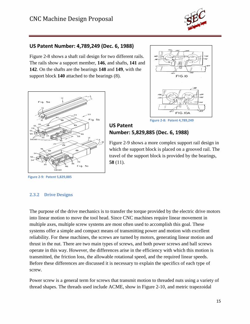
US Patent Number: 4,789,249 (Dec. 6, 1988)
Figure 2-8 shows a shaft rail design for two different rails.
The rails show a support member, 146, and shafts, 141 and
142. On the shafts are the bearings 148 and 149, with the
support block 140 attached to the bearings (8).
US Patent Number: 5,829,885 (Dec. 6, 1988)
Figure 2-9 shows a more complex support rail design in
which the support block is placed on a grooved rail. The
travel of the support block is provided by the bearings,
58 (11).
2.3.2 Drive Designs
The purpose of the drive mechanics is to transfer the torque provided by the electric drive motors
into linear motion to move the tool head. Since CNC machines require linear movement in
multiple axes, multiple screw systems are most often used to accomplish this goal. These
systems offer a simple and compact means of transmitting power and motion with excellent
reliability. For these machines, the screws are turned by motors, generating linear motion and
thrust in the nut. There are two main types of screws, and both power screws and ball screws
operate in this way. However, the differences arise in the efficiency with which this motion is
transmitted, the friction loss, the allowable rotational speed, and the required linear speeds.
Before these differences are discussed it is necessary to explain the specifics of each type of
screw.
Power screw is a general term for screws that transmit motion to threaded nuts using a variety of
thread shapes. The threads used include ACME, show in Figure 2-10, and metric trapezoidal
Figure 2-8: Patent 4,789,249
Figure 2-9: Patent 5,829,885

CNC Machine Design Proposal
16
among others. The trapezoid or squared thread shape allows for smoother rotation without the
clapping force that is present in fastener threads. (12) Most power screws are made from steel
and nuts are made from bronze and plastics to reduce friction (12). As seen in Figure 2-11, ball
screws use ball bearings between the threads of the nut and screw. These ball bearings travel a
continuous path through the nut providing rolling contact and reducing friction. Some ball
screws offer multiple ball circuits distributing the load and improving reliability (13).
Figure 2-10: ACME Power Screw
Figure 2-11: Ball Screw
Both types of screws are available in various leads and with multiple starts. The lead of a screw
gives the linear travel of the nut for every revolution of the screw (14). The speed of the linear
advance is determined by dividing the rpm by the lead (12). When a lead is increased and the
helical threads are lengthened, gaps would be left between individual threads. This is when
multiple start geometry is utilized. A screw with multiple starts indicates that there is more than
one thread running down the length of the screw filling the gaps between threads that would
otherwise be present in high lead screws. The linear speed requirement of the system is used to
determine both the rpm and the lead. A screw with a high lead can be rotated more slowly to
produce a given linear speed while a screw with a lower lead must be rotated faster to create the
same linear velocities. However, each type of screw has limits on the rpm they are capable of
operating at and the leads that they are manufactured in. In this case, other factors must be
analyzed, and together, the system requirements specify the best type screw for the machine.
Most of the screw characteristics are determined by the type of contact between the nut and
screw. A power screw such as ACME uses a screw to nut contact resulting in sliding friction.
While the coefficient of friction depends on the part materials, it is generally higher than that of
ball screws, which have rolling contact provided by the ball bearings. This friction results in a
loss of torque transmitted and lower output efficiency for ACME lead screws. ACME lead
screws have efficiencies that range from 20-30%, while ball screws transmit motion with over
90% efficiency (12). This friction significantly impacts the system, but most important is the
increase in the required drive motor torque. If the system requires high speeds, then motors must

CNC Machine Design Proposal
17
be much larger, increasing cost and adding weight. Also, the low efficiency of ACME screws
converts a majority of that torque into heat. For these reasons, ACME screws are limited to
speeds below 300 rpm with most applications below 100 rpm (12). However, with improved nut
materials, these negatives can be reduced making power screws more attractive.
The sliding contact of ACME threaded screws that reduces its allowable speeds also creates its
many advantages. Most importantly, the larger friction force allows the screw to self-lock and
keep any thrust load from being converted to torque and backdriving the motor. Ball screws will
experience free linear motion of the nut, know as backlash, unless a preloaded nut or double nut
or some type of brake is used (13). This can create complexity in the design and increase cost of
the system, making ACME screws desirable when this is a significant problem. These screws are
available with many different leads. Higher leads provide for quick linear translation, but require
greater rotational torque to move loads. Smaller leads provide for precise positioning and
require less rotational torque. Due to the greater complexity of the ball nut, ACME screws
generally have the advantage for low lead, high precision applications as they can be
manufactured in leads as low as 0.5mm/rev (15).
Another consideration includes screw life and reliability. For this, the advantage belongs to the
ball screws. Due to the extensive testing done with balls for roller bearings there are less
unknowns than for ACME screws in which load, speed, lubrication, heat, and other factors must
be taken into account (12). The life of power screws depend greatly on the system variables
where life for ball screws can be reasonably estimated from wear life calculations.
In the process of selecting the best screw for a particular application, all of the system variables
must be examined to determine what requirements must be met and which compromises can be
allowed. If higher rotational speeds are needed, with the lower friction, less heat generation, and
more efficient conversion of drive torques will require the use of ball screws. However, if
simplicity, lower costs, self-locking, or high precision leads are the more desirable attributes,
then power screws such as ACME are the more likely choice.
CNC machines currently on the market use both power screws and ball screws. Most of the
lower end machines use power screws such as ACME threads for cost savings and design
simplicity. However, as speeds increase and higher reliability requirements are desired, ball
screws become more common. Consumers are the ultimate judge on system practicality, and
besides speed and accuracy requirements, their only concern in regards to the drive system is that
it works now and continues to work for a reasonable length of time. For many hobbyists in this
market, an ACME screw will provide excellent function and life that their usage will require.
The small businesses and more active hobbyists will most likely desire ball screw drives and will
be willing and capable of paying for its advantages. As with all purchases and design

CNC Machine Design Proposal
18
comparisons, all of the options must be weighed with the advantages, disadvantages, and costs of
each in order to determine best drive mechanism for the system.
2.4 Materials Review for Frame
A variety of materials have been used in the building of CNC machines. In comparing the
materials there are five selection factors that need to be reviewed. CNC frame materials need to
have some strength in order to support the weight of the gantry and the cutting head as well as
withstand forces resulting from the milling process. Stiffness is also required to prevent any
deflections due to both static forces and dynamic forces resulting from the acceleration of the
tool head. Weight is also important because the mass of the frame contributes to both the static
and acceleration forces. The best frame material would accomplish all three and offer excellent
machinability and be available at a low cost.
Several materials including some metals, steel and aluminum, and a range of plastics that
include high density polyethylene (HDPE), ultra high molecular weight polyethylene (UHMW
PE), polypropylene, polycarbonate, nylon, and Delrin(acetal) were researched. Their properties
were tabulated in order to compare their characteristics and assess their applicability as a CNC
frame material. The properties that were gathered include the modulus of elasticity, yield
strength, and density. The ratio of the modulus of elasticity to density was calculated to give an
indication of stiffness and the ratio of yield strength to density was found to give a strength value
relative to weight (16). Costs have also been found, from US Plastics Corp, for a sheet of each
plastic measuring ½”x24”x48” (17). For steel and aluminum the thickness is indicated in the
table while the width and length remained the same.
Comparing metals and plastics is not easy as metals have a much higher strength and
modulus of elasticity, but also have a greater weight and are more difficult to machine. It’s
interesting to note that both steel and aluminum have similar stiffness to weight properties
indicated by the ratio E/ρ, while the high grade aluminum has a significant advantage in strength
to weight.
The advantage of building with plastics is the reduction in weight. From the data in Table
2-1: Materials Comparisons, the polyethylene, both HDPE and UHMW PE, and polypropylene
plastics were the lightest with densities of 0.90-0.96g/cm3. Another benefit of plastics is easier
machining as drilling and cutting processes do not significantly wear on the blades and bits.
Good strength and stiffness properties are available in plastics as well. When nylon is reinforced
it has some excellent properties, as does the acetal, Delrin. However, comparing the costs, HDPE
and polypropylene are the most economical choices and due to their low densities they have
strength to weight ratios very near to that of steel.

CNC Machine Design Proposal
19
Table 2-1: Materials Comparisons
Material E
(106psi)
Sy
(ksi)
ρ
(g/cm3)
E/ρ Sy/ρ Hardness Cost of 1/2"x24"x48" sheet
Steel A36 (18) 29 36 7.85 3.69 4.6 3/16” 64.32 (19)
Aluminum 6061-T6 10 37 2.71 3.69 13.7 ¼” 167.98
HDPE (20) 0.12 4.3 0.96 0.13 4.5 D60-70 61.19
UHMW PE 0.06 3 0.94 0.06 3.2 D60-70 150.38
Polypropylene 0.16 5 0.9 0.18 5.6 R80-110 45.09
Polycarbonate 0.32 9 1.2 0.27 7.5 M70-82 151.60
Nylon 6/6 (30% glass reinforced)
1.3 25 1.25 1.04 20.0 R101-119
272.78
Delrin(acetal) 0.46 9.5 1.42 0.32 6.7 M80-90 372.50
2.5 Communications
In order for the CNC to process any design implanted into it, the machine must have a
connection system between itself and the software being used by the computer. Many
connections used today are very common to people from using cable linking to add pictures to
their computer hard drive or using a modem connection to log on to the internet. We will discuss
the four major types of communication systems between computers and other hardware
including:
USB Ports
Serial Ports
Parallel Ports
Ethernet
2.5.1 USB Ports
The USB ports, or universal serial bus ports, are most likely the simplest and one of the most
widely available connection systems between computers and devices. The cable connector
between the device and the computer uses either an “A” connector seen in Figure 2-12 which
travels upstream to the computer or a “B” connector seen in Figure 2-13 which travels
downstream to the device (21).

CNC Machine Design Proposal
20
The computer will act as the host once the connection is made. The computer will then use
enumeration to provide an address to the device depending upon what other types of USB
connections are attached at the same time. The device will respond to the host and describe what
kind of data transfer it wants to perform. There are three types of data transfers: interrupt, bulk,
and isochronous. Interrupt transfer is for devices that will provide very little information. Bulk
transfers will send information in very large packets that must be confirmed as correct by the
device. Isochronous transfers will send information in a streaming pattern to prevent error
connections. The USB device must use available bandwidth provided by the computer. This
must be divided into frames and the computer will control the frames. Isochronous and interrupt
transfers will be provided guaranteed bandwidth by the computer while bulk transfers will be
given only remaining bandwidth not being used. Some of the USB features include: maximum
data rate of 480 megabits per second at the 2.0 level, allowed to be plugged and unplugged at any
time, provide power to lower power devices attached to USB sockets of the computer, and
internally contains two power wires, one for ground and one for +5 volts, and two data transfer
wires as seen in Figure 2-14.
Figure 2-14: Internal Wiring of USB Connection
Red – 5Volts, Brown – GND, Blue/Yellow – Data Transfer
Figure 2-13: "B" Connector Figure 2-12: "A"Connector
CNC Machine Design Proposal
21
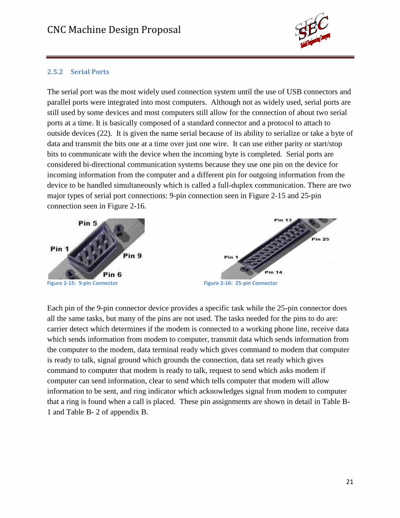
2.5.2 Serial Ports
The serial port was the most widely used connection system until the use of USB connectors and
parallel ports were integrated into most computers. Although not as widely used, serial ports are
still used by some devices and most computers still allow for the connection of about two serial
ports at a time. It is basically composed of a standard connector and a protocol to attach to
outside devices (22). It is given the name serial because of its ability to serialize or take a byte of
data and transmit the bits one at a time over just one wire. It can use either parity or start/stop
bits to communicate with the device when the incoming byte is completed. Serial ports are
considered bi-directional communication systems because they use one pin on the device for
incoming information from the computer and a different pin for outgoing information from the
device to be handled simultaneously which is called a full-duplex communication. There are two
major types of serial port connections: 9-pin connection seen in Figure 2-15 and 25-pin
connection seen in Figure 2-16.
Figure 2-15: 9-pin Connector
Figure 2-16: 25-pin Connector
Each pin of the 9-pin connector device provides a specific task while the 25-pin connector does
all the same tasks, but many of the pins are not used. The tasks needed for the pins to do are:
carrier detect which determines if the modem is connected to a working phone line, receive data
which sends information from modem to computer, transmit data which sends information from
the computer to the modem, data terminal ready which gives command to modem that computer
is ready to talk, signal ground which grounds the connection, data set ready which gives
command to computer that modem is ready to talk, request to send which asks modem if
computer can send information, clear to send which tells computer that modem will allow
information to be sent, and ring indicator which acknowledges signal from modem to computer
that a ring is found when a call is placed. These pin assignments are shown in detail in Table B-
1 and Table B- 2 of appendix B.

CNC Machine Design Proposal
22
2.6.1 Parallel Ports
Parallel ports are the most common way of connecting bulk transfer devices to a computer
although they are slowly being replaced by USB ports. Unlike the serial port, the parallel port is
able to send a byte of information at one time which allows the standard parallel port to send 50
to 100 kilobytes of data per second (23). The most common use for parallel ports is for printing
purposes. There are two major types of parallel ports for printing: the DB-25 shown in Figure
2-17 and the Centronics 36 shown in Figure 2-18.
Figure 2-17: DB-25
Figure 2-18: Centronics 36
Each pin has a specific task to allow the connection between the printer and the computer. These
tasks include: strobe which uses voltage gain and drop to tell the printer that data is being given,
carry data which provides either a positive voltage when a 1 bit is being sent or ground when a 0
bit is being sent, acknowledge which sends a voltage gain and drop to tell the computer data was
received, busy which tells the computer the printer is ready to receive if it falls below a certain
voltage, out of paper which sends a voltage to a certain pin to stop the printer from continuing a
job, online which tells the computer the device is on and available, auto feed which tells the
printer to continue feeding paper as long as a certain holds a high voltage, problem which tells
the computer an error has occurred when the voltage drops on a certain pin, initialize which
drops the voltage on a certain pin to warn the printer when a new job is starting, offline which
turns the printer off as long as a certain holds a consistent voltage, and grounds which serve as
reference signals for the low charges. All of the pins assignments for both types of parallel ports
are given in Error! Reference source not found..
2.6.2 Ethernet
Ethernet is used greatly for networking over either short or long distances to many different
devices and large amounts of information. It has a great advantage over other communication
systems by allowing it to communicate with many devices at one time and many different levels
of distance. There are two major types of Ethernet networks, LAN (local area networks) and
WAN (wide area network) (24) . LAN’s are used to connect many devices over short distances
while WAN’s are used to connect a few devices over large area of up to many kilometers.
Although WAN’s carry information over long distances, they tend to be slower and less reliable
than LAN’s, but improvements in fiber optic cables may lessen this hindrance as the process

CNC Machine Design Proposal
23
improves. Ethernet is able to accommodate new devices once they become attached to the
network by connecting to the single cable which allows any device on the network to
communicate with any other device without modifications to the devices. Unfortunately, for the
devices to communicate effectively with each other, they must have knowledge of the network’s
protocol or language. The messages between the machines are sent over mediums that may meet
at a shared medium or segment. The devices will interact with the segment by attaching at its
nodes with the nodes communicating in chunks of information called frames. The protocol
discussed earlier will govern how the frames will work in the network by showing the source and
destination address of the message as it moves through the network.
Figure 2-19: Small Ethernet Network
2.7 Drive System
The drive system of a CNC controls the motors which are connected to the mechanical system.
There are two electromechanical approaches that can be used to drive the mechanical system.
There is a servo controlled and there is the stepper motor drive approach. Both have strengths
and weaknesses. While servo systems have a basic drive system with feedback, stepper motors
have multiple methods in which they can be driven. These techniques can be simple or
complicated, and it becomes a question of performance versus cost which determines the type
used.
2.7.1 Stepper Motor and Servo Motor
The main difference between stepper motors and servo motors is the type of motor used and the
way it is controlled. Stepper motors use between 50 to 100 pole brushless motors while the

CNC Machine Design Proposal
24
servo motors use only 4 to 12 poles (25).
Stepper motors can accurately move between step positions because of the high number of poles
the motor has. Stepper motors move incrementally using pulses of current and do not require the
use of a closed loop feedback system. Servo motors on the other hand require the use of a
feedback system to calculate the required amount of current to move the motor.
The performance difference between a stepper and a servo is a result of the motor design. The
stepper motor has significantly higher number of poles than the servo motors. One revolution of
a stepper motor requires many current pulses through the motors windings than a servo motor.
Therefore the torque of a stepper motor is greatly reduced at higher speeds compared to the servo
motor. On the other hand, the high number of poles of a stepper motors delivers more torque at
lower speeds then of the same size servo motor. Torque reduction of a stepper motor at higher
speeds can be reduced by increasing the driving voltage to the motor. Table 2-2 outlines both
advantages and disadvantages of both servo and stepper motors.
Table 2-2: Servo versus Stepper
Servo Motors Stepper Motors
Advantages Higher torque at high speeds Reduced heat production
Reduced cost in drive electronics High torque at low speeds Position accuracy and repeatability Position stability High holding torque Easier to maintain and reliable Flexibility, may be used with open or closed loop configurations
Disadvantages Drive electronics are complicated and expensive Lower torque at low speeds
Generates considerable heat if not using feedback Lower torque at high speeds Resonance problems that must be overcome
A stepper motor’s ability to position accurately is one of the main advantages of using them.
Stepper motors have an angle tolerance range of +- 5%, and this angle error is not accumulative
from one step to the next. This means that at stepper motor taking one step and travels 1.8
degrees +-.09 degrees or can travel 1,000,000 degrees +-.09 degrees (26).
Servo systems are best utilized for high speed, high torque applications that have dynamic load
changes. Stepper motors are optimal for applications that will use low to medium acceleration,

CNC Machine Design Proposal
25
require high holding torque and flexibility of using an open loop or closed loop system. The
stepper motor has many advantages over using servo motors. This concludes the discussion of
servo motors altogether. The focus of the remaining discussion of the drive system for stepper
motors.
2.7.2 Stepper Motor Drivers
The function of the driver is to supply the rated amount of current to the motor in the shortest
time possible (27). The driver voltage is very important to the operation and performance of the
stepper motor. The motors’ winding have a certain resistance and inductive reactance thus a
certain time constant. This is the time it takes to supply the rated current to the motor. At high
motor speeds this significantly reduces the torque supplied by the motor. The reduction in torque
can be overcome by increasing the drive voltage to the motor, normally called overdriven the
motor. Two of the most commonly used driver types for stepper motors are constant current and
constant voltage.
2.7.2.1 Constant Current Drivers (Pulse Width Modulation or Chopper Drives)
The chopper driver regulates the current supplied to the motor by applying a square wave with
varying duty cycle to the driver voltage (28). These drivers require a high voltage power supply
to generate a high driver voltage to motor voltage, thus improving the high speed performance of
the motor. This type of driver works well at high speeds.
2.7.2.2 Constant Voltage Drivers (Resistance Limited)
In the RL driver the amount of current the stepper receives is only limited by the impedance of
the motor windings. In this configuration the drive voltage must match the rated voltage of the
motor. This type of driver works best at low speeds.
2.7.3 Drive Techniques
Stepper motors can be driven with several different drive techniques. This section will discuss wave,
full, half and micro stepping techniques and will summarize the advantages and disadvantages.
2.7.3.1 Wave Stepping (Single Phase Full-Step)
Single phase full-stepping, illustrated in Figure 2-20, is the simplest of the driving techniques
(29). In full step operation, the motor steps through the normal step angle i.e. 200 step/revolution
motors take 1.8 degree steps. Single phase full-step excitation is where the motor is operated
with only one phase energized at a time.

CNC Machine Design Proposal
26
Figure 2-20: Single Phase Full-Step (25)
2.7.3.2 Full Stepping (Two Phase)
Two phase full-stepping, illustrated in Figure 2-21, is a drive method where both windings of the
motor are always energized. Instead of making one winding off and another on, in sequence,
only the polarity of one winding are energized at a time.
Advantages:
This mode provides good torque and speed performance with a minimum amount of
resonance problems
Provides approximately 50% more torque than single phase full-stepping
Disadvantages:
Requires twice the power compared to single phase full-stepping.
Has an increase in the amount of noise and vibrations when the step-rate equals
resonance frequency.

CNC Machine Design Proposal
27
Figure 2-21: Two Phase Full-Stepping
2.7.3.3 Half Stepping
Half-stepping, illustrated in Figure 2-22, is a technique by which both phases are energized,
followed by only one phase being energized resulting in steps one half the normal step size. This
increases the amount of steps by double compared to full-stepping.
Advantages:
Has almost no resonance problems
Operated over a wide range of speeds
Can drive almost any load
Disadvantages
Requires more power because of the energizing of the phases
More complicated drive electronics
Precision is reduced due to electrical angle changes

CNC Machine Design Proposal
28
Figure 2-22: Half-stepping
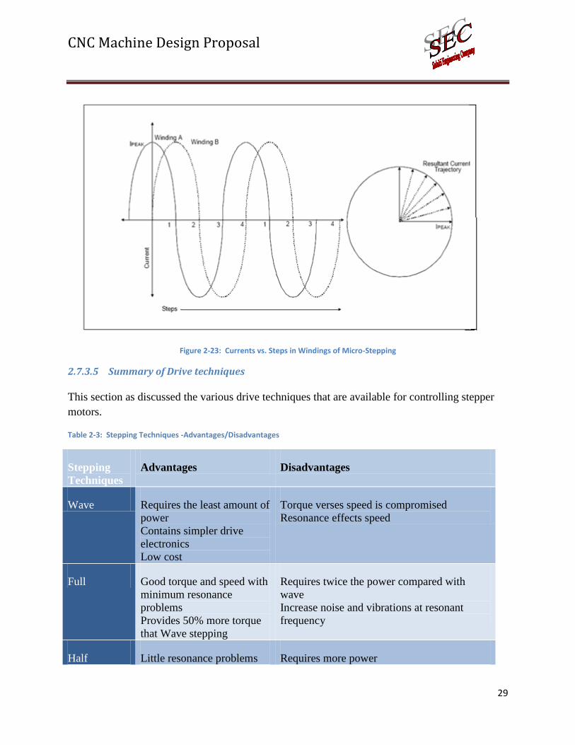
2.7.3.4 Micro-stepping
Micro-stepping, illustrated in Figure 2-23, is produced by proportioning the current in the two
windings according to sine and cosine functions. Micro-stepping is a way of moving the stator
flux of a stepper more smoothly than in full or half step drive modes as stated by Fredrik
Eriksson (30). For practical methods, the current in one winding is kept constant over half of the
complete step and current in the other winding is varied as a function of sin to maximize the
motor torque.
Advantages:
Smooth movement at low speeds
Increased step positioning resolution, as a result of a smaller step angle
Maximum torque at both low and high step-rates
Disadvantages:
Used only where smoother, low speed motion or more resolution is required
Low performance at higher speeds
High cost
Most complex drive electronic system
CNC Machine Design Proposal
29
Figure 2-23: Currents vs. Steps in Windings of Micro-Stepping
2.7.3.5 Summary of Drive techniques
This section as discussed the various drive techniques that are available for controlling stepper
motors.
Table 2-3: Stepping Techniques -Advantages/Disadvantages
Stepping
Techniques
Advantages Disadvantages
Wave Requires the least amount of
power
Contains simpler drive
electronics
Low cost
Torque verses speed is compromised
Resonance effects speed
Full Good torque and speed with
minimum resonance
problems
Provides 50% more torque
that Wave stepping
Requires twice the power compared with
wave
Increase noise and vibrations at resonant
frequency
Half Little resonance problems Requires more power

CNC Machine Design Proposal
30
Larger speed range
Can drive almost any load
Complex drive electronics
Reduced precision at electrical angles
Micro Smooth movement at low
speeds
Increased step position
resolution
Maximum torque at both
low and high speeds
Low performance at higher speeds
Increased cost
Most complex of all stepper drive techniques
2.8 Hand Pendants
A hand pendant is defined as a handheld control for a machine tool (31). This device is usually
used in conjunction with a PC to give the user complete access to the schematic and the work
area. It allows the user to control the axes upon which it wants the machine to move. It gives the
ability to increase and decrease input feed rates and movement of the machine to help prevent
damage to the machine if it is over-performing. All pendants allow the user to immediately stop
the machine from continuing work if a large problem arises. They are either fitted with push
buttons for quick access or with dials to allow quick changes in the work process. If the pendant
is well designed, it may also be embedded with a viewing screen to allow for details surrounding
the work environment including the machine’s parameters, limits, and locations. These screens
also may give the user the ability to access files from offline storage units if wanted. Pendants
have many different functions depending upon what the user wants the CNC pendant to control
simultaneously. Some examples of pendants with prices are the MP2 pendant for $250.00 (32),
illustrated in Figure 2-24: Mill or lathe control pendant, the MR175 standard pendant for $995
(33), illustrated in Figure 2-25: MR175 standard pendant, and mill or lathe control pendants for
$762 (34), illustrated in Figure 2-26: MP2 pendant.

CNC Machine Design Proposal
31
Figure 2-24: Mill or lathe control pendant
Figure 2-26: MP2 pendant
2.9 Software
Low cost, home and small business CNCs require at least one software package to operate. This
is the basic package which allows the user to open a graphics file and command the system to
machine the part. There are several basic interface software available for DIY (Do-It-Yourself)
CNC, which most low cost units are constructed. This section will look at the following:
Mach 3
EMC (Enhanced Machine Controller)
BobCAD CNC
Desk CNC
2.9.1 Mach 3:
Mach 3 is a CNC software system that works with a full PC 6-axis CNC controller. Mach 3 can
import DXF, BMP, JPG, and HPGL files to create an image that can be machined with the CNC.
This program which was created by Art Soft was designed for small businesses and hobbyist. It
has high resolutions for the users who enjoy GUI interfaces. Mach 3 uses three external software
packages: Lazy Cam, Wizards, and VB scribe. Lazy Cam allows the user to import different files
types to the CNC controller and transfers them into G-code files. Wizards are mini programs that
allow the user to write their own G-code easily. It has many capabilities such as gear cutting,
digitizing, holes, slots, text engraving, and more. It also gives you premade designs from the
company so you don't have to create a standard G-code file. Mach 3 requires a desktop PC due to
the power saving control implemented on the laptop.
Figure 2-25: MR175 standard pendant

CNC Machine Design Proposal
32
Features:
Spindle speed control
Multiple relay control
Manual pulse generation
Video display machine
Touch screen ability
Full screen eligibility
Equipment Control:
Lathes
Mills
Routing
Lasers
Plasma
Engraves
Gear Cutting
Internal Software:
Lazy Cam
Wizard
VB Scribe
Computer Requirements:
Windows 2000/XP
1 GHZ Processor
512 MB Ram
Non-integrated Video Card
Desktop PC (no laptop)
Advantages and Disadvantages:
1. Very high GUI interface requires a strong graphics card to run software
2. Several different types of files can be imported to be changed to G-code
3. Needs 2 separate programs to change from other file formats to G-code
4. Has the ability to do numerous cutting techniques
5. Already designed templates to make project creation quicker
Prices: Total - $290
Mach 3 - $175
Lazy Cam - $75
Wizards - $50
CNC Machine Design Proposal
33
2.9.2 Enhanced Machine Controller (EMC)
EMC is open source software for Linux operating systems. It is designed from hobbyist and even
industrial type settings but requires lots of configuring. This program was designed for users who
understand programming and configuration processes to allow them to make the EMC the way the user
wants it. This program does not have a high resolution GUI interface.
Advantages and Disadvantage:
Free government based program (Linux operating system)
Open sourced
Added Add-on
Poor user interface makes it hard to use
Software takes ample amount of time to configure
Very difficult for non-programming users
Very fast running program
Pricing: Total - $0
2.9.3 BOBCAD CNC:
BOBCAD CNC is a powerful CNC software that has a lot of capabilities. It has the ability to do
milling, lathing, art, wire, nesting, and CAD drawings. The 2D and 3D interface that goes with this
program is key for artist and hobbyist who want to create something precise. BOBCAD is a very user
friendly program that does not need any type of configuration. BOBCAD's capabilities include text and
geometry, surfaces and solids from text, geometry and solid editing, geometry verification, part
dimensioning and spline construction and more. This program also allows you to insert directly other
file formats to be changed to G-Code.
Capabilities:
Text and geometry
Surfaces and solids from text
Geometry from solid editing
Geometry verification
Part dimensioning
Spline construction

CNC Machine Design Proposal
34
2D and 3D wire frame construction
Free-form surface creation
Primitive solids for molding
Hole pattern and gear construction
Solid, wireframe and transparent viewing
Layer and users coordinate systems
manager
File Importing:
SLDPRT
DWG
DXF
Rhino CAD 3dm
IGES
STEP
STL
SAT
X_B
X_T
CAD
and more
Features:
Profiling
Plunge roughing
Cross posting
Solid NC verification
User definable drilling job status
Facing operations
Tool library
New offset pocketing operations
Job tree
View and define stock
4th
axis wrapping and indexing
Program by tools or by features
Reorder machining in Job Tree
DNC and communications
Multiple work offset
Customizable cutting conditions for
material
System Requirements:
2.0 GHZ Processor
2 GB RAM
2 GB Hard Disk
Windows XP
512 MB graphics Adapter that supports open GL 1.1
Advantages and Disadvantage:
1. User friendly

CNC Machine Design Proposal
35
2. Precise mapping to see finished product before cutting
3. Very expensive
4. High resolution requires higher computer requirements
Price:
BobCAD – CAM v23 mill:
◦ Pro: $3495.00
◦ Standard: $2495.00
V23 Lathe : $1995.00
V23 Art : $995.00
V23 Wire : $1995.00
CadCAM V21: $1995.00
Bob Wire: $1495.00
Bob Nest: $995.00
Hobby Pro: $995.00
BOBART Pro: $995.00
2.9.4 Desk CNC:
Desk CNC is a simple and constructive software to use. It has the abilities to do contour, pockets, drills,
and more. It has the ability to do 3D images in a less high resolution GUI atmosphere. This program
also has the capabilities to upload different types of file formats that can be converted to G-Code and
run with the CNC. Desk CNC also has the ability to upload gerber files to construct circuit boards.
Capabilities:
Contour
Drill
Automatically detects islands and nested
islands
Multiple Depths- Islands on top of islands
inside boundaries
Wall Profiles – Any region can have any
wall profile
Automatically Chains entities into
optimized regions
Programmable Post Processor
Automatically vectorized DXF Text
Add True Type Font Text around an Arc
Files:
TIF
GIF
JPEG
PCX
BMP
RLE
ICO
CUR
PNG
EMF
WMF
TARAGA
PPM
AVI

CNC Machine Design Proposal
36
Advantages and Disadvantages:
Simple program layout
Very good user interface
Computer system requirements very low
Does not require configuring
Pricing: Total- $350
software
controller board

CNC Machine Design Proposal
37
3 Project Description
The objective of this project is to design and build a CNC router which provides high quality
features at a reduced cost compared with similar machines. It will further extend the traditional
single task machines in such a way that multiple distinguishable tasks may be performed such as
routing, PCB routing, solder paste dispensing, and airbrush operations.
There are three major subsystems to this CNC design as shown in Figure 3-1, they are:
1. Mechanical
2. Electrical
3. Software
The mechanical subsystem, shown in Figure 3-2, is further broken down into the following
subsections:
1. Frame
2. Drive
3. Guide
Figure 3-2: Mechanical Subsystem
Frame
DriveGuide
CNC Router
Mechanical
Electrical
Software
Figure 3-1: CNC Major Subsystems

CNC Machine Design Proposal
38
The electrical subsystem, show in Figure 3-3, is further broken down into three primary electrical
systems as follows:
1. Motion Controller
2. Power Drive
3. Hand Pendant
Figure 3-3: Electrical Subsystem
The software subsystem will provide a simple windows GUI. The software that will be used will
be obtained from Williams Engineering. The software package currently provides the following
file types:
1. HPGL (Hewlett Packard Graphics Language)
2. TIFF (Tagged Image File Format)
3. G-Code
4. DXF (Drawing Exchange Format)
The software will be further modified to support the following additional file formats:
1. RS-274X (Gerber Files)
2. NC (Drill Files)
These formats will provide the ability to route printed circuit boards and to dispense solder paste.
The CNC mechanical structure will have a physical foot print of 34”x30”x20”. It will provide a
motion travel of 28 ½”x26”x8” and have a clearance of 12” above the work area. It will
maintain a precision of 0.001” for a load force of 10lbs. The minimum acceleration that the
machine will provide is 10 in/sec2. The minimum velocity that the machine will provide is 2
Main Controller
Hand Pendant
Power Drive

CNC Machine Design Proposal
39
in/sec. The frame structure will utilize HDPE plastics and will incorporate aluminum
reinforcement where necessary so that the above mentioned precision can be achieved.
The motion controller of the electrical subsystem will provide the following communications
resources:
1. RS232
2. USB
3. Ethernet
It will further provide an interface for a USB jump drive so that files can be loaded without the
need of a computer. A VGA interface will be provided, so that an optional monitor may be
connected.
The power drive electrical system will be provided a high voltage motor drive electronics, which
will utilize stepper motor technology. This board will be optically isolated from the motion
controller board.
The hand pendant electronics will provide a color TFT screen for feedback information. It will
provide a basic interface such that the machine can be moved around manually. A feed override
interface will be provided such that speeds can be manually adjusted by +/- 50%. It will provide
the ability to access the USB jump drive so that job files can be executed without a PC
connection.
The following Table 3-1 summarizes the machine specifications mentioned above. A more
detailed description of each major subsystem is provided in chapter 4 of this document.
Table 3-1: Specification Summary
Machine Specification
Table Dimensions 34”x28”20
Travel Dimensions 28.5”x26”x8”
Minimum Acceleration 10 inch/sec2
Minimum Rapid Speed 2 inch/sec
Minimum Load Force 10 lb
Precision 0.001 inch
Structural Material HDPE with aluminum reinforcement
Motor Type Stepper
Communications RS232, USB, Ethernet
File Formats HPGL, TIFF, DXF, G-Code, RS-274x, NC
External Controls Hand Pendant

CNC Machine Design Proposal
40
4 Design basis The following documents are included with this proposal:
Request for Proposal (RFP)
F09-24-CNCMACHD Proposal
Project Description
4.1 Mechanical The mechanical system is composed of the frame section, the drive section, and the guide
system. This section will provide a detailed description of each of these.
4.1.1 Drive
The drive mechanics of CNC machines convert torque provided by the electric motors into linear
motion of the tool head. Screws with threaded nuts provide a simple and compact way to
transmit this power. A ball screw and a ball nut system will be used because of its low friction
and high efficiency. ACME screws will not be used because neither of their advantages, a larger
weight supporting capacity and the simplicity of self locking, have application for this machine.
Instead, the ability to reduce the required torque needed to produce the specified linear speeds,
due to the fact that ball screws operate with a superior efficiency, make ball screws the obvious
choice for all three axes. In addition, the lack of heat generation caused by friction and an
increased reliability support the decision to implement ball screws and ball nuts as the means of
power transmission.
4.1.2 Guide
The guide rails support the weight of the gantry and tool head, while providing the alignment
during the movement of the gantry. The linear rod guide rails will be case hardened steel shafts
with ball bushings. However, a more complex shaft or support rail may be required if the weight
and loads on the gantry create deflections above the specified tolerances of the machine.
4.1.3 Frame
CNC frame materials need to have some strength in order to support the weight of the gantry and
the cutting head as well as withstand forces resulting from the milling process. Stiffness is also
required to prevent any deflections due to both static forces and dynamic forces resulting from
the acceleration of the tool head. Weight is important because the mass of the frame contributes
to both the static and acceleration forces. The best frame material would accomplish all three,
offer excellent machinability, and be available at a low cost.
From the review of the materials, it was decided that high density polyethylene (HDPE) offered
the best combination of these five selection factors. Among the plastics it was one of the lightest

CNC Machine Design Proposal
41
and least expensive choices. Also as a plastic it will be very easy to machine, while still
providing sufficient strength and rigidity.
The machine frame is divided into the gantry sides and the base table.
4.1.3.1 Gantry Sides
The gantry sides support the weight of the upper gantry and the head while traveling on the
lower guide rails. HDPE will be used to create the gantry sides, because, as mentioned, the
gantry must be light weight to reduce inertia forces during acceleration.
4.1.3.2 Base Table
The base table will support the material to be worked on, and act as the base of the machine.
Constructing the base table will require a large amount of material and involve a great deal of
machining and assembly. Because HDPE is low cost and it can be easily machined, it will be
used for the base. In this application, the strength and stiffness qualities of HDPE will be tested.
The weight supported by the lower guide rails, the rails that allow the machine to move along the
length of the table, might create excessive deflections in the sides of the base table. This could
cause a displacement of the tool head that exceeds the design tolerances. It is believed that
HDPE will be able to withstand these forces and maintain tolerances. If deflections become an
issue, a hybrid system will be considered, in which aluminum will be used to reinforce the HDPE
base sides.
4.1.4 List of deliverables
1. Z-Axis assembly
2. Y-Axis assembly
3. X-Axis assembly
4. Complete table assembly
5. Head attachment for spindle
6. Structural CAD drawings
4.1.5 List of Activities
Design X, Y and Z axis assemblies
Design head attachment for spindle
Perform material deflection analysis
Machine ball screw ends
Tap guide rod ends
Machine carriage blocks for X, Y and Z axis
Assemble table
Test Precision of machine assembly
CNC Machine Design Proposal
42
4.2 Electrical
This section provides a detailed description of the three primary electrical systems; motion
controller, power drive electronics, and hand pendant.
4.2.1 Motion Controller
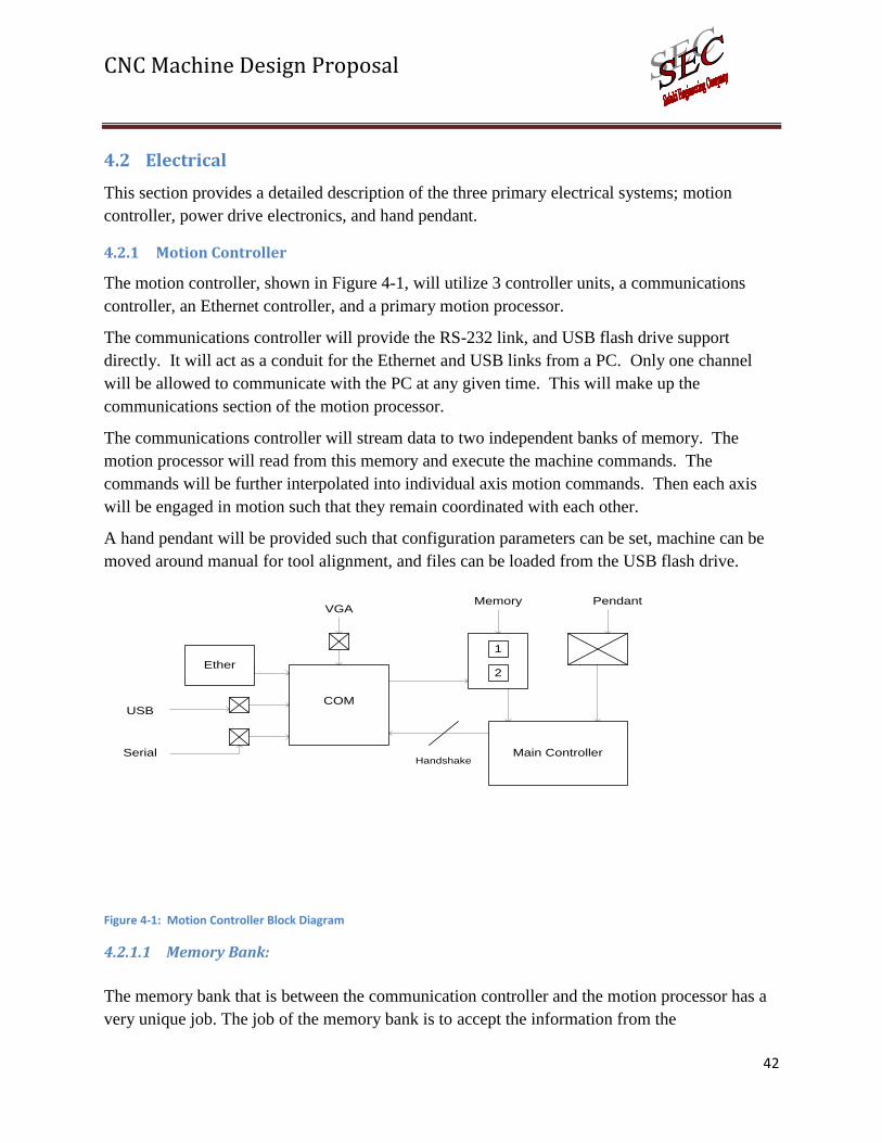
The motion controller, shown in Figure 4-1, will utilize 3 controller units, a communications
controller, an Ethernet controller, and a primary motion processor.
The communications controller will provide the RS-232 link, and USB flash drive support
directly. It will act as a conduit for the Ethernet and USB links from a PC. Only one channel
will be allowed to communicate with the PC at any given time. This will make up the
communications section of the motion processor.
The communications controller will stream data to two independent banks of memory. The
motion processor will read from this memory and execute the machine commands. The
commands will be further interpolated into individual axis motion commands. Then each axis
will be engaged in motion such that they remain coordinated with each other.
A hand pendant will be provided such that configuration parameters can be set, machine can be
moved around manual for tool alignment, and files can be loaded from the USB flash drive.
COM
Main Controller
Ether
USB
Serial
1
2
Memory
Handshake
PendantVGA
Figure 4-1: Motion Controller Block Diagram
4.2.1.1 Memory Bank:
The memory bank that is between the communication controller and the motion processor has a
very unique job. The job of the memory bank is to accept the information from the

CNC Machine Design Proposal
43
communication controller and distribute it to the motion processor. The first step to the memory
bank’s process is receiving the data. Once it receives the data it places the information into one
of the two memory slots. These memory slots switch which receives and which distributes
information to the motion processor. This process allows for the main controller board to have
minimal delay time with the information. While one memory chip is taking information, the
other chip is distributing previous information, given to the memory bank, to the main controller.
4.2.1.2 Communication Controller
This microchip’s design purpose is to receive data from the Ethernet, USB, Serial Port, and the
USB Jump Drive and give it to the memory bank. It also has an output port that will go to a VGA
monitor.
4.2.2 Hand Pendant
In order to control the CNC offline, a hand pendant needs to be incorporated into the system to
allow the ability to load files and other various functions such as jogging, setting work offsets,
and machine parameters. Based upon the different ways files will be uploaded through either
ports or USB connection, the CNC will require a hand pendant that has to be created to allow the
user access to these files whether online or offline from a computer. Also, due to the offline
aspect, the required pendant must give the user access to the parameters of the machine and give
the ability to load stored files from an outside connection. In order for this pendant to work
successfully, the system for the pedant must be created as shown in the block diagram of Figure
4-2.
Color TFT Display
Function Selection
Interface
Feed Override
InterfaceAxis Control
Interface
Figure 4-2: Hand Pendant Block Diagram

CNC Machine Design Proposal
44
4.2.2.1 Display
An LCD display must be incorporated into the design for the hand pendant to give the user the
ability to access information incoming from the stored files. It should give the user access to the
soft limits of the design during operation. It should provide information from the parameters of
the machine including velocity, speeds, feed rates, zero coordinate, park position, and home
position. Because of the machines ability to receive files offline, it must be able to provide a
connection route with a USB jump drive without assistance from a computer.
4.2.2.2 Axis Control Interface
There will be four directions the user will be allowed to go with the pendant, but an axis
selection switch will give the user the ability to change from the y-axis to z-axis off the same set
of buttons. The north and south buttons will be able to work with the y and z axes depending
upon which axis has been toggled before movement occurs. The east and west buttons will work
only with the x-axis.
4.2.2.3 Function Selection Interface
This interface will link with the LCD display to view access of the different parameters of the
machine and uploading previously completed files remaining in the system.
4.2.2.4 Feed Override Interface
This control will be providing the user the ability to override the job program’s feeds and speeds.
The interface will give the user the ability to either increase or decrease the feeds and speeds of
the system by a margin of 50% depending upon the rate given to the machine by the imported
files.
4.2.3 Drive Electronics
The drive electronics system, shown in Figure 4-3, provides the interface from the motion
controller to the physical motors.

CNC Machine Design Proposal
45
High Voltage Power
Supply
Driver
Page 1
DRIVE SYSTEM
MotorController
Figure 4-3: Drive System Block Diagram
4.2.3.1 Motor
The type of motor used in the design of a CNC is important to reducing the overall cost of the
machine. By selecting the stepper motor, over the servo motor, the cost of the motor and drive
electronics will be significantly reduced.
The motor will provide high torque at lower speeds and the reduced torque level at higher speeds
can be overcome by overdriving the motor.
Open loop configuration is proposed because of the position accuracy and repeatability inherent
to all stepper motors. This leads to a reduction in the complexity of the driver electronics.
4.2.3.2 Driver
The driver will provide the required amount of current to the motor. The chopper driver will be
used because it improves the high speed performance of the motor. By overdriving the motor,
the toque at higher speeds will be increased.
The driver will receive two main control signals from the controller: step and direction.
4.2.3.3 High Voltage Power Supply
The use of the chopper driver requires the use of a higher voltage level to the motor. By
overdriving the motor, torque at high speeds is greatly increased.

CNC Machine Design Proposal
46
4.2.4 List of Deliverables
1. Main controller board
2. Drive electronics board
3. High voltage power supply
4. Hand pendant
4.2.5 List of Activities
1. Design main controller board
2. Design drive electronics board
3. Design hand pendant
4. Write firmware for main controller processors
5. Write firmware for hand pendant
6. Test main controller with all communications methods
7. Test hand pendant
8. Test drive electronics
4.3 Software
The software for this project will be acquired from Williams Engineering. With this software,
two additional file formats will be introduced: support for RS-274X (Gerber), which provides
reading of printed circuit board files, and NC (Drill) files. Two DLLs (Dynamic Link Library)
will be written in order to support these additional file formats.
The existing software currently allows the following file formats:
1. HPGL
2. DXF
3. TIFF
4. G-Code
4.4 Test Procedures, Calculations and Analysis
Table 4-1: Tests, Calculations and Analysis
Electrical Perform basic motion tests with hand pendant
Jog North, South, East, West, Up and Down
Read/set parameters
List jump drive files
Set park position
Set work offsets
Set home position
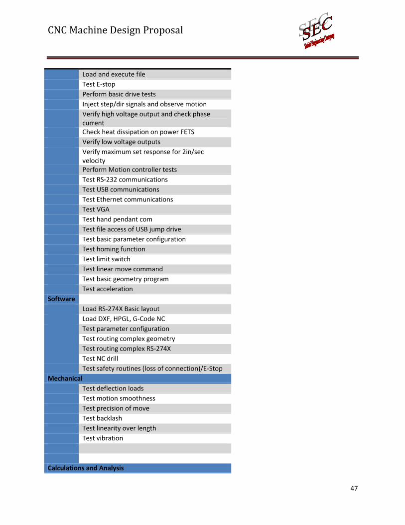
CNC Machine Design Proposal
47
Load and execute file
Test E-stop
Perform basic drive tests
Inject step/dir signals and observe motion
Verify high voltage output and check phase current
Check heat dissipation on power FETS
Verify low voltage outputs
Verify maximum set response for 2in/sec velocity
Perform Motion controller tests
Test RS-232 communications
Test USB communications
Test Ethernet communications
Test VGA
Test hand pendant com
Test file access of USB jump drive
Test basic parameter configuration
Test homing function
Test limit switch
Test linear move command
Test basic geometry program
Test acceleration
Software
Load RS-274X Basic layout
Load DXF, HPGL, G-Code NC
Test parameter configuration
Test routing complex geometry
Test routing complex RS-274X
Test NC drill
Test safety routines (loss of connection)/E-Stop
Mechanical
Test deflection loads
Test motion smoothness
Test precision of move
Test backlash
Test linearity over length
Test vibration
Calculations and Analysis

CNC Machine Design Proposal
48
Perform deflection analysis
Perform Max loading calculations
Calc center of mass for uprights
Calc guide size
Calc power budget and component values
Calc sense resistor sizes
Perform electrical simulation of high power supply
Calc transformer size and storage capacitor
5 AIL for First Two Weeks of Semester
Table 5-1: Action Item List for Spring 2010
2010 Dates
Week Item # Activity Person Assigned Due
1 Structural Design Brian 1/19/10 2/1/10
2 Structural Design Pat 1/19/10 2/1/10
3 Cost Analysis James 1/19/10 2/1/10
4 Pendent Design Shawn 1/19/10 2/10/10
5 Main Controller Design Glenn 1/19/10 2/15/10
1 (Jan 18-Jan 24) 6 Drive Design Eric 1/19/10 2/1/10
7 CAD Drawings Brian 1/19/10 2/1/10
8 CAD Drawings Pat 1/19/10 2/1/10
9 Schematic of Pendent Shawn 1/19/10 2/1/10
10 Board Layout of Pendent Glenn 1/19/10 2/1/10
11 Schematic of Controller James 1/19/10 2/1/10
12 Schematic of Drive Eric 1/19/10 2/1/10
13 Board Routing Shawn 2/1/10 2/15/10
14 Board Routing Eric 2/1/10 2/15/10
15 Board Routing Glenn 2/1/10 2/15/10
16 Design Calculations Brian 2/1/10 2/15/10
17 Design Calculations Pat 2/1/10 2/15/10
2 (Jan 25-Jan 31) 18 Write Test Procedures James 2/1/10 2/15/10
19 Machine Parts Brian 2/1/10 2/15/10
20 Machine Parts Pat 2/1/10 2/15/10
21 Write Firmware Pendent Glenn 2/1/10 2/15/10
22 Write Firmware Main Controller Eric 2/1/10 2/15/10

CNC Machine Design Proposal
49
23 Write Firmware Communications Shawn 2/1/10 2/15/10
24 Modify Windows Software James 2/1/10 2/15/10

CNC Machine Design Proposal
50
6 Team Timeline ID Task Name
1 Mechanical Design2 Mechanical Assembly3 Test and analyse mechanical system4 Order Tooling for Machining operat ions5 Generate AutoCAD Drawings6 Order Mechanical parts7 Perform beam deflection analysis8 Machine Guide Rails to specs9 Machine Ballscrews to specs10 Machine Spindle holder assembly11 Machine airbrush holder12 Machine Past despenser holder13 Machine linear bushing blocks to specs14 Electrical Design15 Design Hand Pendent16 Design High Power and Drive Electronics17 Design Main Controller system18 Generate Bill of Materials 19 Order Electrical parts20 Order Circuit Boards21 Assemble Pendent22 Assemble Drive and High Power23 Assemble Main Controller24 Firmware Programming25 Test full sy stem26 Write Pendent Firmware27 Test Pendent Firmware28 Write Main Controller Firmware29 Test Main Controller Firmware30 Write Communications Controller Firmware31 Test Communications Controller Firmware32 Write Ethernet Controller Firmware33 Test Ethernet Controller Firmware34 Documentation & Presentat ion35 Design Report36 Progress Report
January 1 February 1 March 1 April 1 May 1
Figure 6-1: Timeline

CNC Machine Design Proposal
51
7 List of Resources Table 7-1: List of Resources
QTY Part Number Description Price
DigiKey 15 IRF7341PBFCT-ND HEXFET 4.7A@25C, 55V VDSS, 0.050 OHM ON
20.7
DigiKey 2 768-1011-1-ND IC USB TO PARALLEL FIFO 28-SSOP 9
DigiKey 10 751-1366-1-ND HIGH SPEED OPTO-COUPLER 21.25
DigiKey 3 160-1365-5-ND OptoIsolator 3.06
DigiKey 1 PIC24FJ256GB110-I/PF-ND
USB Host controller. 8.86
DigiKey 1 ENC624J600-I/PT-ND Ethernet 10/100 controller 4.94
DigiKey 1 PIC24HJ256GP610-I/PF-ND
PIC24 micro controller 9.52
DigiKey 1 PIC24HJ32GP302-I/SO-ND
PIC24 micro controller 4.82
DigiKey 1 507-1442-ND 08B0-1G1T-06-F RJ45 MODULAR JACK 4.83
DigiKey 2 74FST3257DTR2GOSCT-ND
Multiplexer 1.6
DigiKey 1 296-13094-1-ND RS-232 Transceiver 1.5
DigiKey 2 706-1035-ND 256Kx16 SRAM 10NS 13.72
DigiKey 2 MCP1825T-3302E/DCCT-ND
3.3V 500mA VOLTAGE REG 1.725
DigiKey 2 MCP1825T-5002E/DCCT-ND
5.0V 500mA VOLTAGE REG 1.725
DigiKey 2 MCP1825T-1802E/DCCT-ND
1.8V 500mA VOLTAGE REG 1.53
DigiKey 2 MCP1825S-2502E/DB-ND
2.5V 500mA VOLTAGE REG 1.41
DigiKey 2 620-1166-1-ND IC Driver Microstepping 38-TSSOP 7.455
DigiKey 1 GBJ2001-FDI-ND Bridge Rectifier, 100VRB 20A 0.88
DigiKey 1 568-3310-1-ND Voltage Regulator 5V@100mA Output 1.11
4DSystems 1 16686 uOLED-96-G1 65
4DSystems 1 16683 4D-Micro-VGA-PICASO-MD1 (Plus MD1-UB board)
84
Roton 3 19193 5/8 X 0.200 Right Hand Recirculating Square Ball Nut
70.65
Roton 1 59321 5/8 x 0.200 right hand screw 24 inches 20.18
VBX 2 KIT7961 NB Linear Systems:SW8 1/2" Ball Bushings 27.9
VBX 8 KIT7963 NB Linear Systems:SW12 3/4" Ball Bushings
143.6
McMaster 2 6061K64 Precision Shafts, 3/4 X 36 57.18
McMaster 4 9403K13 Solid-Profile Polyurethane Shaft Wipers 5.8

CNC Machine Design Proposal
52
1/2 ID
McMaster 12 9403K15 Solid-Profile Polyurethane Shaft Wipers 3/4 ID
18
McMaster 2 6061K33 Precision Shafts,1/2" X 12. 13.32
McMaster 1 91255A247 10-24 Button Socket CAP Screw 1" 12.66
McMaster 1 92949a249 10-24 Button Socket CAP Screw 1-1/4" 8.17
McMaster 1 92949A546 1/4-20 Button Socket Cap Screw 1-1/2 7.59
McMaster 3 5399712 60 Teeth 1.54, 1/4 Belt 0.08 Pitch 4.62
McMaster 3 5399696 60 Teeth 5/16 ID, 0.08 Pitch 4.47
McMaster 1 7887K88 160MXL Timing Belt 4.23
McMaster 1 1679K666 180MXL Timing Belt 4.49
Amazon 1 Y236803 Avel Y236803 500va 86.18
NorvaPlastics 1 HDPE Frame materials customer routed 914
1671.68
Table 7-2: Resources Needed
Machine Shop
MATLAB
AutoCAD
AutoCAD Inventor
EDWinXP
MultiSIM
MPLAB
Microsoft Visio
Microsoft Project

CNC Machine Design Proposal
53
8 Organization Chart
Figure 8-1: Organization Chart
Dr. HaiboFaculty Advisor
James Williams
Project Manager
Complete System
Eric Blankenship
Power/Drive
Shawn Gossett
Pendant
Glenn Spiller
Microcontrollers
Pat Brokaw
Mechanical Frame
Brian Hagene
Mechanical Drive and
Guide

CNC Machine Design Proposal
54
9 References 1. Glossary - Stourbridge Turning and Grinding Ltd. Stourbridge Turning and Grinding Ltd. [Online] 2007.
[Cited: Oct 7, 2010.] http://www.stag-eng.co.uk/services/glossary.htm.
2. Simpson, Stuart. CNC Machines. EzineArticles.com. [Online] Aug 29, 2005. [Cited: Oct 7, 2010.]
http://ezinearticles.com/?cnc-Machines&id=64944.
3. Market Research Report on CNC Machine tool Industry. MindBranch(R). [Online] SunFAITH China Ltd.,
July 2009. [Cited: Oct 7, 2010.] http://www.mindbranch.com/listing/product/r521-217.html.
4. China CNC (Computerized Numerical Controlled) Machine Tool Market Report. ResearchInChina.com.
[Online] 2008. [Cited: Oct 7, 2010.] http://www.researchinchina.com/Htmls/Report/2008/5602.html.
5. Techno CNC Router Systems | The Patriot CNC Router. Techno CNC Router Systems. [Online] [Cited:
Oct 9, 2010.] http://www.techno-isel.com/CNC_Routers/Patriot_CNC_Router.htm.
6. 12 x 24 Desktop CNC Router w/ Servo control system. CadCamCadCam.com. [Online] [Cited: Oct 7,
2010.] http://www.cadcamcadcam.com/12x24desktopcncrouterwservocontrolsystem.aspx.
7. Next Wave Automation - CNC Shark. Next Wave Automation. [Online] [Cited: October 18, 2010.]
http://www.nextwaveautomation.com/CNCShark.aspx.
8. Thompson Industries, Inc. Patent 4789249. freepatentsonline.com. [Online] Dec 6, 1988. [Cited: Oct
14, 2010.] http://www.freepatentsonline.com/4789249.pdf.
9. MacMaster-Carr - Linear Shafts. McMaster-Carr Supply Company. [Online] [Cited: Oct 14, 2010.]
http://www.mcmaster.com/#linear-shafts/=4292k6.
10. Pre-assembled & One Piece Support Rail, Open Bearing Shafting. PBC Linear. [Online] [Cited: Oct 14,
2010.] http://www.pacific-bearing.com/Rail-Shaft-Assemblies-CCR-SRA.aspx.
11. Scheich, Hubert. Patent 5829885. freepatentsonline. [Online] ISCI, Automation Hugo Isert,
November 3, 1998. [Cited: Oct 14, 2010.] http://www.freepatentsonline.com/5829885.pdf.
12. Application Engineering. Roton Products Inc. [Online] 2005. [Cited: October 10, 2010.]
http://www.roton.com/application_engineering.aspx.
13. Degenova, John. What you Ought To Know About Ball Screws. Machine Design.com. [Online] July 22,
1989. [Cited: October 12, 2010.] http://machinedesign.com/article/what-you-ought-to-know-about-ball-
screws-0722.
14. Buffamonte, Steven. Straight talk on linear actuators. Machine Design.com. [Online] August 5, 2004.
[Cited: October 12, 2010.] http://machinedesign.com/article/straight-talk-on-linear-actuators-0805.

CNC Machine Design Proposal
55
15. Budimir, Miles. Leadscrews roll over ball screws. Machine Design.com. [Online] December 11, 2003.
[Cited: October 12, 2010.] http://machinedesign.com/article/leadscrews-roll-over-ball-screws-1211.
16. Ashby, Michael F. Materials Selection in Mechanical Design 3rd ed. Oxford : Elsevier, 2005.
17. United States Plastics Corp. [Online] [Cited: Oct 21, 2009.]
http://www.usplastics.com/catalog/default.asp.
18. Hibbeler, R.C. Statics and Mechanics of Materials 2nd. New Jersey : Pentice Hall, 2004.
19. Metals Depot. [Online] [Cited: Oct 21, 2009.] http://www.metalsdepot.com/index.phtml?aident.
20. Bauccio, Michael, Flint, Veronica and Sunniva, Collins. ASM Engineering Materials Reference Book
2nd. Ohio : ASM International, 1994.
21. Axelson, Jan. USB Complete. Madison : Lakeview Research LLC, 2005.
22. Tyson, Jeff. How Serial Ports Work. HowStuffWorks.com. [Online] February 09, 2001. [Cited: Oct 13,
2010.] http://computer.howstuffworks.com/serial-port.htm#.
23. —. How Parallel Ports Work. HowStuffWorks.com. [Online] October 03, 2000. [Cited: Oct 13, 2010.]
http://computer.howstuffworks.com/parallel-port.htm#.
24. Pidgeon, Nick. How Ethernet Works. HowStuffWorks.com. [Online] April 01, 2000. [Cited: Oct 13,
2009.] http://computer.howstuffworks.com/ethernet19.htm#.
25. AMCI: Tech Tutorials:Stepper vs. Servo. AMCI Advanced Micro Controls Inc. [Online] [Cited: Oct 16,
2009.] http://www.amci.com/tutorials/tutorials-stepper-vs-servo.asp.
26. Hybrid Motors - Basic Introduction of Step Motors. NMB Technologies Corporation. [Online] [Cited:
Oct 16, 2009.] http://www.nmbtc.com/motors/hybrid-step/engineering/basic-introduction-of-step-
motors.html.
27. NMB. Hybrid Motors - Torque and Speed Relationship. NMB Technologies Corporation. [Online]
[Cited: Oct 16, 2009.] http://www.nmbtc.com/motors/hybrid-step/engineering/torque-and-speed-
relationship.html.
28. Hybrid Motors - Drivers and Winding Configuration. NMB Technologies Corporation. [Online] [Cited:
Oct 16, 2009.] http://www.nmbtc.com/motors/hybrid-step/engineering/drivers-and-winding-
configuration.html.
29. Introduction to Step Motor Systems. Anaheim Automation. [Online] [Cited: Oct 16, 2009.]
http://www.anaheimautomation.com/intro.htm#Modes.

CNC Machine Design Proposal
56
30. Ericson. Stepper Motor Basics. Industrial Circuits Application Note. [Online] [Cited: Oct 16, 2009.]
http://www.solarbotics.net/library/pdflib/pdf/motorbas.pdf.
31. Warfield, Robert. CNCDictionary. cnc Cookbook.com. [Online] CNCCookbook, 2009. [Cited:
November 2, 2009.] http://www.cnccookbook.com/CCDictionary.
32. Designs, Bob Campbell. CNC Mini Pendant-MP2. Campbell Designs.com. [Online] 2005. [Cited:
November 2, 2009.] http://campbelldesigns.net/CNC%20mini%20pendant%20MP1.php.
33. Company, Thomas Publishing. Micronor Introduces Handheld Pendant with Live or Dead Man
Enable Switches. News.Thomasnet.com. [Online] 2009. [Cited: November 2, 2009.]
http://news.thomasnet.com/fullstory/490751.
34. AjaxCNC. Operator Controls. ajaxcnc.com. [Online] AjaxCNC, 2009. [Cited: November 2, 2009.]
http://www.ajaxcnc.com/cnccomponenets.htm.
35. Korane, Kenneth J. Actuators tackle the tough jobs. Machine Design.com. [Online] January 26, 2006.
[Cited: October 12, 2010.] http://machinedesign.com/article/actuators-tackle-the-tough-jobs-0126.
36. Brain, Marshall. How USB Ports Work. HowStuffWorks.com. [Online] April 01, 2000. [Cited: Oct 13,
2010.] http://computer.howstuffworks.com/usb1.htm#.
37. Axelson, Jan. Embedded Ethernet and Internet Complete. Madison : Lakeview Research LLC, 2003.
38. —. Parallel Port Complete. Madison : Lakeview Research LLC, 1999.
39. —. Serial Port Complete. Madison : Lakeview Research LLC, 1998.
40. Online Metals. [Online] [Cited: Oct 21, 2009.] http://www.onlinemetals.com/index.cfm.

CNC Machine Design Proposal
57
Appendix A – Resumés 1940 Evergreen Terrace Dr Apt 2 Carbondale, IL 62901
Home: (618) 937-8521 Mobile: (618) 303-2609 [email protected]
James L Williams
Objective To obtain a position in Electrical and Computer Engineering.
Experience July 3, 2008- July 14, 2008 ATS Macomb, IL
Maintenance Senior Technician
Perform electrical troubleshooting and repair of plant equipment
Use computers to trouble shoot PLC controls
Write custom software for various upgrade projects
Write PLC ladder logic for machine rebuilds
Write Touch Screen interface for various machines
Cost analyze machine rebuilds
Jan 4, 2007 - July 3, 2008 ATS Macomb, IL
Maintenance Technician II
Perform electrical troubleshooting and repair of plant equipment
Use computers to trouble shoot PLC controls
Write custom software for various upgrade projects
Write PLC ladder logic for machine rebuilds
Write Touch Screen interface for various machines
Cost analyze machine rebuilds
Aug 18, 2005 - Jan 4, 2007 ATS Macomb, IL
Maintenance Technician I
Perform electrical troubleshooting and repair of plant equipment
Use computers to trouble shoot PLC controls

CNC Machine Design Proposal
58
Sept 2, 2004 - Aug 18, 2005 ATS Macomb, IL
Tech Associate
Perform basic electrical troubleshooting and repair of plant equipment
Perform periodic scheduled maintenance
Dec 11, 2003- Sept 2, 2004 ATS Macomb, IL
Inventory Control Clerk
Order inventory when need, receive and put away inventory
Validate physical inventory which database content
Write inventory control software using MSSQL database engine
Write custom inventory program for PDA handheld computers to validate inventory data and issue orders
2002-2003 Norva Plastics, Inc Norfolk, VA
CNC Program/Operator and Network systems administrator
Given customer specific drawings and artwork, modify and program for CNC laser and CNC router.
Operator both CNC laser, CNC router and CNC mill
Occasional plastics fabrication
Setup and maintain all company computers and Windows 2000 networking environment.
Troubleshoot CNC equipment electronic/mechanical problems along with PC and office networking equipment.
Develop industry specific inventory tracking and job control, using C++ Builder and MSSQL 2000 RDBMS.
Rewire electrical motors for 480 3 phase system.
Pull wire and hookup of new 1200 A 480 Volt power system for new building.
Run CAT 5E networking cable in new building.
2000-2002 Self Employee Contract Work Embedded Systems Engineer
Specify and document motion control software
Specify and document design of motion control hardware
Develop motion control software under Windows
Develop firmware for motion control hardware

CNC Machine Design Proposal
59
Design motion control Hardware
Troubleshoot and analyze hardware design flaws
Create schematic drawing and board layout diagrams using EDWin XP schematic capture software.
Extensive soldering of prototype boards
2000–2002 CreditView USA, Inc Chesapeake, VA 1997-2000 CreditView AS Oslo, Norway
Software Development Engineer
Designed software interfaces with external Debt collection agencies such as D&B, Equifax, Credit Inform etc.
Developed large-scale DB solutions for credit management.
Extensive use of COM in 4GL language (Progress) compiler.
Extensive knowledge of COM specification and fundamentals.
Extensive windows programming experience using C++
Experience with all versions of MS Windows.
Experience with MS SQL and Progress RDBMS.
Developed windows dll libraries for use with main application.
Wrote software specifications and data flow charts.
Worked with customers to tailor application to their needs.
Obtained a high security clearance for Ericsson in Norway for developing hardware driver with encryption boards. Then developed windows application for storages data retrieved from encryption hardware into a RDBMS.
1993-1996 Norva Plastics, Inc Norfolk, VA
Engineer/Fabricator
Maintained shop equipment.
Machined plastics to customer specifications.
Administered Novell 3.1 network server and client machines.
Maintained and repaired computers.
Maintained accounting software.
Aided in fabrication department when required.
1991-1993 US Navy NAS Virginia Beach, VA
Aviation Machinist
Performed period maintenance of F-14 aircraft.
Removed and installed jet engines.
Operated support equipment in conjunction with aircraft.
Education 2009 SIUC Carbondale, IL
Working towards a dual degree BS in Computer and Electrical

CNC Machine Design Proposal
60
Engineering (Senior Status)
2006 - 2008 Spoon River College Canton, IL
Associate in Science (Focus In Pre-engineering)
2005 - 2006 Western Illinois University Macomb, IL
General classes towards BS in Engineering (Transfer)
Machine Tooling class
1993–1995 ITT Technical Institute Norfolk, VA
AOS in Electronics Engineering Technology
Graduated as valedictorian
Knowledge and
Skills
Basic HTML programming
1 year working with Visual C++
Embedded Visual C++ for programming PPC 2003 PDA and windows CE clients
MS Office, Visual Source Safe and MS Project
MS SQL Enterprise RDMS and MS Access Database
Windows 95/98/ME/2000 and XP programming
Windows NT/2000/XP device driver architecture
Windows Terminal Server, Windows NT/2000 server setup, TCP/IP protocol.
Basic Java Programming
Some Delphi in conjunction with major C++ Builder VCL programming
Some MS Visual Basic 6
CNC machine operation and machining skills
Object oriented design approach for application development
8 Bit Microchip controllers
Electrical wiring and motor rewiring.
Electronics design, including microprocessor design, digital logic, CPLD’s, VHDL programming
Allen-Bradley, Mitsubishi, and Hitachi PLC programming
Interests Electronics designing, motion control, embedded software developing, machining, computers. Learning new technologies and programming environments.

CNC Machine Design Proposal
61
Brian M. Hagene [email protected]
9769 County Line Rd.
Coulterville, IL 62237
618-758-2592
Objective: A full-time position in Mechanical Engineering during beginning May 2010.
Summary: Excelled in coursework, achieving a 3.9/4.0, with a passionate work ethic developed from
various work experiences.
Education
Senior at Southern Illinois University, Carbondale, IL 62901
Bachelor of Science in Mechanical Engineering, May 2010
G. P. A.: 3.8/4.0
Relevant Coursework
Thermodynamics II Heat Transfer Speech Communication
Machine Design Senior Design Combustion Engines
Mechanical Analysis Engineering Economics Engineering Controls Experience
Intern, Illinois Environmental Protection Agency June 2009- August 2009
Assisted in P2 project to find way to use food grade alcohol as refrigerant in heaters.
Collected samples from waste water treatment plants throughout Southern Illinois.
Collected creek samples including minerals, water temperature, channel width, pH, and the microhabitat.
Collected mineral samples along with the dissolved oxygen, clarity, and water temperature readings of lakes used by water distribution facilities.
Security, Whelan Security June 2008- June 2009
Prohibited unauthorized persons from entering Power Plant work site.
Logged activity of traffic coming on site such as delivery trucks, workers, and machinery.
Distributed verbally the on-site rules to visitors when they arrived. Carry out, Buchheit, Inc. June 2007- February 2008
Provided service to customers who had trouble lifting purchased merchandise.

CNC Machine Design Proposal
62
Ran floor scrubber, cleaned parking lot, retrieved empty carts, janitorial duties.
Relieved co-workers in other departments for lunch break, stocked shelves. Peer Tutor, Southwestern Illinois College August 2005 – May 2007
Offered help to students needing help in math ranging from Algebra to Calculus.
Demonstrated different techniques on problem solving until student found comfortable method for them.
Skills
Microsoft Office/Excel Self-motivated AutoCad
Work well in groups Good leadership skills Goal oriented
Great Speech Comm Work well hands-on Honors/Awards
Aisin Manufacturing Scholarship 2008-2009
Dean’s List, 2007, 2008, 2009
Vice-President’s High Honors List, 2005, 2006, 2007 Activities
Weight lifter/trainer Peer Tutor Recycle Metals/plastic
Bowler Help the elderly Practice computer skills
Guitar player

CNC Machine Design Proposal
63
Eric Blankenship
112 Prairie Rd
Carterville, IL 62918
(618) 579-9838
Objective: Electrical/Electronic Engineer for the Department of Defense starting in January 2011.
Professional Summary
• Holds Secret Clearance • Employed by the US Navy as electronic technician: 6 years of experience in the operation,
maintenance, and repair of electronic equipment. • Designing a Computer Numeric Controller for the Senior Design Project. • Own and manage rental properties
Education and Training
• Bachelor of Science in Computer Engineering, December 2010
Southern Illinois University, Carbondale, IL 62901
GPA: 4.0/4.0 • Bachelor of Science in Electrical Engineering, May 2010
Southern Illinois University, Carbondale, IL 62901
GPA: 4.0/4.0 • Associate in Science, John A. Logan College, May 2008
John A. Logan College, Carterville, IL 62918
GPA: 3.9/4.0 • AN/SRA-56, 57, 58 Coupler Maintenance, June 2004, US Navy • Naval Modular Automated Communications System, April 2004, US Navy • AN/SRQ-4 Light Airborne multipurpose system (LAMPS) MK 3 Data Link Transceiver
Maintenance, February 2004, US Navy • Data Link Communications System Maintenance Technician, November 2003, US Navy • General Purpose Electronic Test Equipment Repair and Calibration, May 2001, US Navy • Electronic Technician Communications Strand, Class A, January 2001, US Navy • Advanced Electronic Technical Core, September 2000, US Navy
Relevant Coursework
• Circuit design • Power Electronics • Electromechanical Energy Conversion • Systems and Control

CNC Machine Design Proposal
64
Experience
US Navy 2000-2006
Mid-Atlantic Regional Calibration Center, Norfolk, Virginia July 2001- June 2003
• Leading technician in the electronic department • Calibrated and repaired general purpose electronic test equipment including but not limited to: • Panel meters, dielectric/surge test sets, PH/conductivity meters, vibration analyzers, tank level
indicators, multimeters, clamp-on meters, power supplies, function generators, synthesized signal
generators, communication test sets, spectrum analyzers, etc… • Worked more than 1,000 off duty hours to increase knowledge of all areas of the electronic
department and to increase problem solving skills by troubleshooting complex problems. • Wrote calibration procedures for various types of test equipment. • Implemented safe troubleshooting guide lines for various test equipment reducing repair time. • Conducted hands-on repair training for more than 20 personnel, effectively reducing repair time
and cost. • Maintained an 8-day turn-around time well below the cal lab’s standard of 14 days. • Volunteered off duty time to assist in the Special Olympics.
USS Ramage, Norfolk Naval Station, Norfolk, Virginia June 2003 – March 2006
• Calibration Coordinator: Managed the ships test equipment inventory of over 300 items.
Directed the ship in the maintenance, operation, and stowage of electronic test equipment.
Increased the ships calibration readiness from 82% to greater than 98%. • Work Center Supervisor: Supervised maintenance personnel on preventative maintenance and
repair of all shipboard communications equipment. Planned daily, weekly, monthly and yearly
maintenance schedules for 2 work centers. • Maintained, aligned, and repaired communication and radar equipment including: • HF Transmitters, Receivers, Couplers • UHF/VHF Transceivers, Couplers and Antennas. • EHF/SHF Satellite Communications • Common Data Link Management System (CDLMS) • Naval Modular Automated Communications System (NAVMACS) • Light Airborne Multipurpose System (LAMPS MK3) • Air and Surface Radars • Found major error in the calibration procedure for the UPM-151 Radar Test Set used to align the
ships IFF. (Identification Friend or Foe) • Recognized expert on the operation and maintenance of the Common Data Link Management
System. • Relied on by Ramage and other ships in the fleet for training, operation, and repairs of the
CDLMS, at sea and in-port. • Trained personnel to operate and fix common malfunctions during operations, reducing down
time in real world operations. • Rewrote technical manuals to provide a clear understanding to maintenance personnel, effectively
reducing cost and down time. • Wrote a step-by-step troubleshooting procedure down to the lowest replaceable assembly for
maintenance personal to quickly return system to normal operation.
CNC Machine Design Proposal
65
• Repaired major casualty, which allowed Ramage to complete Cruise Missile Tactical
Qualification early. • Supervisor of the phone and distance line for underway refueling. • Responsible for communications between ships, and the safety of eight personnel.
Skills • Microsoft Word, Excel, Powerpoint, and Access • Xilinx, Cadence, VHDL, and Verilog • MATLAB/Simulink • Multisim
Honors/Awards • Awarded Navy Achievement Medal (2) • Awarded Meritorious Unit Commendation • Awarded Navy Battle “E” • Awarded Good Conduct Medal • Awarded Scholastic Honors at Southern Illinois University • Awarded Southern Illinois University Transfer Scholarship • Dean’s List

CNC Machine Design Proposal
66
Pat Brokaw [email protected]
Permanent Address: College Address:
19756 County Highway 11 400 E. College St.
Pittsfield, IL 62363 Carbondale, IL 62901
217-285-2058 217-491-2135
Objective: A full-time Mechanical Engineering position beginning in May 2010.
Summary
Excelled in every course, achieving a 3.98 GPA, with an intense work ethic developed from a
varied work history and a farming background.
Education
Bachelor of Science in Mechanical Engineering, Minor in Mathematics, May 2010
Southern Illinois University, Carbondale, IL 62901
G.P.A.: 3.98/4.00
Relevant Coursework
Manufacturing
Methods
Material Selection
Pneumatic &
Hydraulic Engr
Internal Combustion
Engines
Thermodynamics
Heat Transfer
Machine Design
Mechanical Analysis
& Design
Numerical Methods
Computer-Aided
Engr. Drawings
Experience
Externship, St. Louis MetroLink Spring Break 2009
Explored the many facets of a light rail and mass transit company including LRV maintenance,
track and crossing construction, OCS design and maintenance, track signals, and bus maintenance
Summer Maintenance, Summer 2007 & Summer 2008
Pikeland Community School District, Unit 10
Laid vinyl floor tile and wall base; mowed, trimmed, and sprayed campus; painted; replaced
ceiling tiles; plumbed drinking fountains; trenched and laid drainage tile, coaxial, and telephone
cable.
Road Maintenance, Martinsburg Township Summer 2006
Hauled gravel, graded and dragged gravel roads, patched asphalt roads, mowed roadsides,
cleaned drain ditches.
Landscaping Project, Eric Dawson Summer 2006
Built retaining wall, two freestanding walls, two stairways, patio, and walkway.
Lawn Care, Self-employed Summers 2003 – 2008
Maintained 6 yards: including mowing, trimming, trimming trees and shrubs, leaf and brush
clean-up, spring and fall eave trough cleaning.
Skills
Comprehensive Engineering Lab Reports
Proficient in Microsoft Office
Experience with Autodesk AutoCAD and Inventor, MatLab, and Microsoft Visual C++
Honors/Awards
Dean’s List every semester
Aisin Manufacturing Scholarship 2009-2010

CNC Machine Design Proposal
67
SIUC College of Engineering Dean’s Scholarship, Fall 08 – Spring 09
Provost Scholarship, 2006 – 2008, SIUC Scholarship, 2006 - 2008
Memberships
ASME Fall 08 - Spring 09, Fall 09- Spring 10
ASME Industry Representative, Fall 2009-Spring 2010 ASME Design Competition Team Spring 09

CNC Machine Design Proposal
68
Shawn Gossett [email protected]
11590 Southpoint Lane
West Frankfort, Il 62896
(618) 218-1335
Objective: An internship in Electrical Engineering starting summer (May-Aug) 2010.
Professional Summary
Collaborating on creating high power supply for a Computer Numeric Controller for Senior Design Team
Participated in building a robot for an IEEE Robotics Competition
Achieved Dean’s List status every semester while working 15-25 hours per week
Education
Bachelor of Science in Electrical Engineering, May 2010
Southern Illinois University, Carbondale, IL 62901
GPA: 4.0/4.0
Associate in Science, December 2007
John A. Logan College, Carterville, IL, 62918
GPA: 3.82/4.0
Relevant Coursework
Power Electronics
Networking
Electromechanical Energy Conversion
Systems and Control Experience
Lifeguard/Instructor, West Frankfort Aquatic Center April 2004-present
Instructed children to swim in groups and individual
Trained individuals to become Red Cross Certified lifeguards
Collected and accounted for funds through facility as a keyholder Skills
Microsoft Word, Excel, and Powerpoint
Xilinx- Schematic, VHDL, and Verilog
MATLAB/Simulink
Honors/Awards/Memberships
Omron Electronics Inc. Scholarship, 2008, 2009
Southern Illinois University Transfer Scholarship,2008
Member: Tau Beta Pi, May 2009
Member: IEEE, October 2008

CNC Machine Design Proposal
69

CNC Machine Design Proposal
70
Appendix B – Miscellaneous Tables and Figures Table B- 1: 9-pin serial port assignments
Pins Assignments
1 Carrier Detect
2 Receive Data
3 Transmit Data
4 Data Terminal Ready
5 Signal Ground
6 Data Set Ready
7 Request To Send
8 Clear To Send
9 Ring Indicator
Figure B- 1: Pin assignments for parallel port types
Table B- 2: 25-pin serial port assignments
Pins Assignments
1 Not Used
2 Transmit Data
3 Receive Data
4 Request To Send
5 Clear To Send
6 Data Set Ready
7 Signal Ground
8 Carrier Detect
9 Current Loop Return +
10 Not Used
11 Current Loop Return -
12 Not Used
13 Not Used
14 Not Used
15 Not Used
16 Not Used
17 Not Used
18 Receive Current Loop Return +
19 Not Used
20 Data Terminal Ready
21 Not Used
22 Ring Indicator
23 Not Used
24 Not Used
25 Receive Current Loop Return -