
Cisco ASR 920 Series Aggregation Services Router ...
260
Cisco ASR 920 Series Aggregation Services Router Configuration Guide, Cisco IOS XE 17 First Published: 2019-11-14 Last Modified: 2022-04-11 Americas Headquarters Cisco Systems, Inc. 170 West Tasman Drive San Jose, CA 95134-1706 USA http://www.cisco.com Tel: 408 526-4000 800 553-NETS (6387) Fax: 408 527-0883
-
Upload
khangminh22 -
Category
Documents
-
view
3 -
download
0
Transcript of Cisco ASR 920 Series Aggregation Services Router ...
Cisco ASR 920 Series Aggregation Services Router Configuration Guide,Cisco IOS XE 17First Published: 2019-11-14
Last Modified: 2022-04-11
Americas HeadquartersCisco Systems, Inc.170 West Tasman DriveSan Jose, CA 95134-1706USAhttp://www.cisco.comTel: 408 526-4000
800 553-NETS (6387)Fax: 408 527-0883

THE SPECIFICATIONS AND INFORMATION REGARDING THE PRODUCTS IN THIS MANUAL ARE SUBJECT TO CHANGE WITHOUT NOTICE. ALL STATEMENTS,INFORMATION, AND RECOMMENDATIONS IN THIS MANUAL ARE BELIEVED TO BE ACCURATE BUT ARE PRESENTED WITHOUT WARRANTY OF ANY KIND,EXPRESS OR IMPLIED. USERS MUST TAKE FULL RESPONSIBILITY FOR THEIR APPLICATION OF ANY PRODUCTS.
THE SOFTWARE LICENSE AND LIMITED WARRANTY FOR THE ACCOMPANYING PRODUCT ARE SET FORTH IN THE INFORMATION PACKET THAT SHIPPED WITHTHE PRODUCT AND ARE INCORPORATED HEREIN BY THIS REFERENCE. IF YOU ARE UNABLE TO LOCATE THE SOFTWARE LICENSE OR LIMITED WARRANTY,CONTACT YOUR CISCO REPRESENTATIVE FOR A COPY.
The Cisco implementation of TCP header compression is an adaptation of a program developed by the University of California, Berkeley (UCB) as part of UCB's public domain version ofthe UNIX operating system. All rights reserved. Copyright © 1981, Regents of the University of California.
NOTWITHSTANDING ANY OTHERWARRANTY HEREIN, ALL DOCUMENT FILES AND SOFTWARE OF THESE SUPPLIERS ARE PROVIDED “AS IS" WITH ALL FAULTS.CISCO AND THE ABOVE-NAMED SUPPLIERS DISCLAIM ALL WARRANTIES, EXPRESSED OR IMPLIED, INCLUDING, WITHOUT LIMITATION, THOSE OFMERCHANTABILITY, FITNESS FOR A PARTICULAR PURPOSE AND NONINFRINGEMENT OR ARISING FROM A COURSE OF DEALING, USAGE, OR TRADE PRACTICE.
IN NO EVENT SHALL CISCO OR ITS SUPPLIERS BE LIABLE FOR ANY INDIRECT, SPECIAL, CONSEQUENTIAL, OR INCIDENTAL DAMAGES, INCLUDING, WITHOUTLIMITATION, LOST PROFITS OR LOSS OR DAMAGE TO DATA ARISING OUT OF THE USE OR INABILITY TO USE THIS MANUAL, EVEN IF CISCO OR ITS SUPPLIERSHAVE BEEN ADVISED OF THE POSSIBILITY OF SUCH DAMAGES.
Any Internet Protocol (IP) addresses and phone numbers used in this document are not intended to be actual addresses and phone numbers. Any examples, command display output, networktopology diagrams, and other figures included in the document are shown for illustrative purposes only. Any use of actual IP addresses or phone numbers in illustrative content is unintentionaland coincidental.
All printed copies and duplicate soft copies of this document are considered uncontrolled. See the current online version for the latest version.
Cisco has more than 200 offices worldwide. Addresses and phone numbers are listed on the Cisco website at www.cisco.com/go/offices.
The documentation set for this product strives to use bias-free language. For purposes of this documentation set, bias-free is defined as language that does not imply discrimination based onage, disability, gender, racial identity, ethnic identity, sexual orientation, socioeconomic status, and intersectionality. Exceptions may be present in the documentation due to language thatis hardcoded in the user interfaces of the product software, language used based on standards documentation, or language that is used by a referenced third-party product.
Cisco and the Cisco logo are trademarks or registered trademarks of Cisco and/or its affiliates in the U.S. and other countries. To view a list of Cisco trademarks, go to this URL:https://www.cisco.com/c/en/us/about/legal/trademarks.html. Third-party trademarks mentioned are the property of their respective owners. The use of the word partner does not imply apartnership relationship between Cisco and any other company. (1721R)
© 2022 Cisco Systems, Inc. All rights reserved.
C O N T E N T S
Feature History 1C H A P T E R 1
Getting Started With the Cisco ASR 920 Series Router 3C H A P T E R 2
Overview 3
Restrictions 5
Interface Naming 6
Interface Speed Based on Port Type 8
VCoP Optics Support 9
Using Cisco IOS XE Software 11C H A P T E R 3
Understanding Command Modes 11
Recommended Methods for CLI Configuration on Router 13
Accessing the CLI Using a Router Console 13
Using Keyboard Shortcuts 13
Using the History Buffer to Recall Commands 14
Getting Help 14
Finding Command Options Example 15
Using the no and default Forms of Commands 17
Saving Configuration Changes 18
Managing Configuration Files 18
Filtering Output from the show and more Commands 19
Powering Off the Router 20
Password Recovery 20
Finding Support Information for Platforms and Cisco Software Images 21
Using Cisco Feature Navigator 21
Using Software Advisor 21
Cisco ASR 920 Series Aggregation Services Router Configuration Guide, Cisco IOS XE 17iii

Using Software Release Notes 21
Using Zero Touch Provisioning 23C H A P T E R 4
Prerequisites for Using ZTP 23
Restrictions for Using ZTP 24
Information About Using ZTP 24
Example ZTP Configuration 26
Downloading the Initial Configuration 26
DHCP Server 26
TFTP Server 27
ZTP LED Behavior 27
Verifying the ZTP Configuration 28
Using Dual Rate Ports 29C H A P T E R 5
Restrictions for Dual Port 29
Prerequisites for Dual Port 31
Information About Dual Port 32
Verifying the Interface Mode 33
Console Port and Telnet Handling 35C H A P T E R 6
Console Port Overview 35
Connecting Console Cables 35
Installing USB Device Drivers 35
Console Port Handling Overview 36
Telnet and SSH Overview 36
Persistent Telnet 36
Configuring a Console Port Transport Map 36
Examples 38
Configuring Persistent Telnet 38
Examples 40
Viewing Console Port, SSH, and Telnet Handling Configurations 41
Important Notes and Restrictions 43
Using the Management Ethernet Interface 45C H A P T E R 7
Cisco ASR 920 Series Aggregation Services Router Configuration Guide, Cisco IOS XE 17iv
Contents
Gigabit Ethernet Port Numbering 45
IP Address Handling in ROMmon and the Management Ethernet Port 46
Gigabit Ethernet Management Interface VRF 46
Common Ethernet Management Tasks 46
Viewing the VRF Configuration 46
Viewing Detailed VRF Information for the Management Ethernet VRF 47
Setting a Default Route in the Management Ethernet Interface VRF 47
Setting the Management Ethernet IP Address 47
Telnetting over the Management Ethernet Interface 48
Pinging over the Management Ethernet Interface 48
Copy Using TFTP or FTP 48
NTP Server 48
SYSLOG Server 49
SNMP-related services 49
Domain Name Assignment 49
DNS service 49
RADIUS or TACACS+ Server 49
VTY lines with ACL 50
Out of Band Management Through USB Modem 51C H A P T E R 8
Prerequisites for the OOB Management Through USB Modem 51
Restrictions for the OOB Management Through USB Modem 51
Information About the OOB Management Through USB Modem 52
Configuring the Management Interface on the MAG 53
Configuration Example: MAG Configuration with Dynamic IP Address on Logical MN Interface 54
Configuration Example: MAG Configuration with Static IP Address on Logical MN Interface 55
Configuring the LMA 56
Configuration Example 57
Verifying the Configuration 57
MAG Call Setup 57
MAG Data Path 58
Debug Commands 58
Related Documents 59
Cisco ASR 920 Series Aggregation Services Router Configuration Guide, Cisco IOS XE 17v
Contents
Power Over Ethernet 61C H A P T E R 9
Prerequisites for PoE 61
Restrictions for PoE 61
Information About PoE 61
Installing the PoE License 62
PoE License 62
How to Configure the PoE 62
Verifying the PoE Configuration 63
Debugging the PoE Configuration 65
Additional References 66
Feature Information for Power Over Ethernet 67
Configuring T1/E1 Interfaces 69C H A P T E R 1 0
Configuration Tasks 69
Limitations 70
Required Configuration Tasks 71
Activating the IMs 71
Deactivating the IMs 71
Setting the Card Type 71
Configuring the Controller 72
Verifying Controller Configuration 73
Optional Configurations 74
Configuring Framing 74
Setting an IP Address 75
Configuring Encapsulation 76
Configuring the CRC Size for T1 Interfaces 77
Saving the Configuration 78
Troubleshooting E1 and T1 Controllers 78
Setting a Loopback on the E1 Controller 79
Setting a Loopback on the T1 Controller 79
Running Bit Error Rate Testing 80
Monitoring and Maintaining the T1/E1 Interface Module 81
Verifying the Interface Configuration 82
Cisco ASR 920 Series Aggregation Services Router Configuration Guide, Cisco IOS XE 17vi
Contents
Verifying Per-Port Interface Status 82
Configuration Examples 82
Example: Framing and Encapsulation Configuration 82
Example: CRC Configuration 83
Example: Facility Data Link Configuration 83
Example: Invert Data on the T1/E1 Interface 84
Installing and Upgrading Software 85C H A P T E R 1 1
Upgrading Field Programmable Hardware Devices 85
File Systems on the Cisco ASR 920 Series Router 85
Restrictions 86
System Requirements 86
Memory Recommendations 86
ROMmon Version Requirements 86
Bootflash Space Requirements 87
Determining the Software Version 87
Cisco IOS XE 3S to Cisco IOS Version Number Mapping 87
Autogenerated Files and Directories 87
Upgrading the Router Software 88
Downloading an Image 88
Upgrading the ROMMON on router 90
Verifying the Upgrade 91
Software Upgrade Example 92
Activating or Deactivating Interface Module 95C H A P T E R 1 2
Overview 95
Prerequisites for Activating an IM 96
Restrictions for Activating an IM 96
Activating an IM 97
Prerequisites for Deactivating an IM 97
Restrictions for Deactivating an IM 98
Deactivating an IM 98
Sample Configuration and Verification Examples for Activation or Deactivation of IMs 99
Sample Configuration and Verification of Activating an 8-port 1G Cu IM (A900-IMA8T) 99
Cisco ASR 920 Series Aggregation Services Router Configuration Guide, Cisco IOS XE 17vii
Contents
Sample Configuration and Verification for Deactivating an 8-port 1G Cu IM (A900-IMA8T) 101
Sample Configuration and Verification of Activating 8-port T1/E1 IM (A900-IMA8D) 103
Sample Configuration and Verification of Deactivating 8-port T1/E1 IM (A900-IMA8D) 106
Configuring Ethernet Interfaces 111C H A P T E R 1 3
Configuring an Interface 111
Specifying the Interface Address on an Interface 113
Configuring Hot Standby Router Protocol 113
Verifying HSRP 114
Modifying the Interface MTU Size 115
Interface MTU Configuration Guidelines 116
Interface MTU Configuration Task 116
Verifying the MTU Size 117
Configuring the Encapsulation Type 117
Configuring Autonegotiation on an Interface 117
Enabling Autonegotiation 117
Disabling Autonegotiation 118
Configuring Carrier Ethernet Features 118
Saving the Configuration 118
Shutting Down and Restarting an Interface 119
Verifying the Interface Configuration 119
Verifying Per-Port Interface Status 119
Verifying Interface Status 120
Configuring LAN/WAN-PHY Controllers 122
Configuring the LAN-PHY Mode 122
Configuring WAN-PHY Signal Failure and Signal Degrade Bit Error Rates 124
Configuration Examples 124
Basic Interface Configuration 124
MTU Configuration 125
VLAN Encapsulation 125
Configuring Serial Interfaces 127C H A P T E R 1 4
Information About Serial Interface Module 127
Restrictions 129
Cisco ASR 920 Series Aggregation Services Router Configuration Guide, Cisco IOS XE 17viii
Contents
How to Configure Serial Interface 130
Required Configuration Tasks 130
Configuring the Controller 130
Optional Configurations 131
Configuring Layer 1 on Sync and Async Interface Server 131
Configuring Layer 1 on Sync and Async Interface Client 134
Configuring a Channel Group 135
Configuring Encapsulation 136
Configuring Transparent Pseudowire (PW) Cross-Connect 137
Configuring Invert Clock Signal 138
Configuring NRZI Formats 139
Saving the Configuration 139
Verifying the Serial Interface Configuration 140
Configuration Examples 141
Example: Encapsulation Configuration 141
Configuring Optical Interface Modules 143C H A P T E R 1 5
Limitations and Restrictions 143
Managing Interface Naming 144
Identifying Slots and Subslot 144
Setting the Card Type 145
Configuring the Controller 145
Configuring SDH 146
Configuring SDH Mode 146
SDH T1 Mode 146
SDH T1 Mode 149
Configuring SDH in POS Mode 152
Configuring SONET Mode 153
Configuring SONET Mode 153
Configuring SONET Mode 154
Configuring SONET POS Mode 155
Configuring a CEM group 157
Configuring CEM Group in SONET Mode 157
Configuring CEM Group in SDH Mode 158
Cisco ASR 920 Series Aggregation Services Router Configuration Guide, Cisco IOS XE 17ix
Contents
Configuring DS3 Clear Channel on OC-3 and OC-12 Interface Module 160
Configuring DS3 Clear Channel in SONET Mode 160
Configuring DS3 Clear Channel in SDH Mode 162
Optional Configurations 164
Configuring the National Bit 164
Verifying the National Bit 165
Configuring the CRC Size for T1 165
Optional Packet over SONET Configurations 166
Encapsulation 166
MTU Value 166
CRC Value 166
Keepalive Value 167
Bandwidth 167
Scrambling 167
C2 Flag 167
J1 Flag 167
Configuring Multilink Point-to-Point Protocol 168
MLPPP Configuration Guidelines 168
Creating a Multilink Bundle 168
Assigning an Interface to a Multilink Bundle 169
Configuring Fragmentation Size and Delay on an MLPPP Bundle 170
Changing the Default Endpoint Discriminator 171
Disabling Fragmentation on an MLPPP Bundle 171
Configuring BERT 172
Configuring Automatic Protection Switching 172
Verifying Interface Configuration 172
Verifying Per-Port Interface Status 172
Troubleshooting 172
Framing and Encapsulation Configuration Example 174
National Bit Configuration Example 174
CRC Configuration Example 174
Facility Data Link Configuration Example 175
MLPPP Configuration Example 175
MFR Configuration Example 176
Cisco ASR 920 Series Aggregation Services Router Configuration Guide, Cisco IOS XE 17x
Contents
Configuration Examples 177
Example of Cyclic Redundancy Check Configuration 177
Example of Facility Data Link Configuration 177
Example of Invert Data on T1/E1 Interface 177
Additional Resources 178
Dying Gasp Support for Loss of Power Supply Through SNMP, Syslog and Ethernet OAM 179C H A P T E R 1 6
Prerequisites for Dying Gasp Support 180
Restrictions for Dying Gasp Support 180
Configuring SNMP Dying Gasp 181
Example: Configuring SNMP Dying Gasp on a Router 182
Example: Configuring SNMP Community Strings on a Router 182
Example: Configuring SNMP-Server Host Details on the Router Console 182
Dying Gasp Trap Support for Different SNMP Server Host/Port Configurations 183
Environmental Settings on the Network Management Server 183
Message Displayed on the Peer Router on Receiving Dying Gasp Notification 184
Displaying SNMP Configuration for Receiving Dying Gasp Notification 184
Configuring Pseudowire 185C H A P T E R 1 7
Pseudowire Overview 185
Limitations 185
Transportation of Service Using Ethernet over MPLS 186
CEM Configuration 186
CEM Configuration Guidelines and Restrictions 186
Configuring a CEM Group 187
Using CEM Classes 188
Configuring CEM Parameters 189
Configuring Payload Size (Optional) 189
Setting the Dejitter Buffer Size 190
Setting an Idle Pattern (Optional) 190
Enabling Dummy Mode 190
Setting a Dummy Pattern 190
Shutting Down a CEM Channel 190
Configuring Structure-Agnostic TDM over Packet (SAToP) 190
Cisco ASR 920 Series Aggregation Services Router Configuration Guide, Cisco IOS XE 17xi
Contents
Configuring Circuit Emulation Service over Packet-Switched Network (CESoPSN) 192
Configuring an Ethernet over MPLS Pseudowire 193
Configuring Pseudowire Redundancy 195
Sample Configurations 196
Example: CEM Configuration 197
Example: Ethernet over MPLS 197
Example: BGP PIC with TDM-PW Configuration 199
Adaptive Clock Recovery (ACR) 199
Benefits of ACR for 8 T1/E1 Interface Module 200
Prerequisites for ACR Configuration in 8 T1/E1 Interface Module 200
Restrictions for ACR on 8 T1/E1 Interface Module 200
Configuring ACR for T1 Interfaces for SAToP 201
Verifying the ACR Configuration of T1 Interfaces for SAToP 201
Associated Commands 203
Configuring and Monitoring Alarm 205C H A P T E R 1 8
Monitoring Alarms 205
Network Administrator Checks Console or Syslog for Alarm Messages 206
Enabling the Logging Alarm Command 206
Examples of Alarm Messages 206
ALARMS for Router 206
Reviewing and Analyzing Alarm Messages 210
Configuring External Alarm Trigger 210
Approaches for Monitoring Hardware Alarms 211
Onsite Network Administrator Responds to Audible or Visual Alarms 211
How to Configure External Alarms 211
Example 212
Alarm Filtering Support 213
Information About Alarm Filtering Support 213
Overview of Alarm Filtering Support 213
Prerequisites for Alarm Filtering Support 214
Restrictions for Alarm Filtering Support 214
How to Configure Alarm Filtering for Syslog Messages and SNMP Notifications 214
Configuring Alarm Filtering for Syslog Messages 214
Cisco ASR 920 Series Aggregation Services Router Configuration Guide, Cisco IOS XE 17xii
Contents
Configuring Alarm Filtering for SNMP Notifications 215
Configuration Examples for Alarm Filtering Support 215
Configuring Alarm Filtering for Syslog Messages: Example 215
Configuring Alarm Filtering for SNMP Notifications: Example 215
Facility Protocol Status Support 215
show facility protocol status 216
Restrictions 216
Routing Protocols Outputs 216
show facility-protocol status command 220
Tracing and Trace Management 221C H A P T E R 1 9
Tracing Overview 221
How Tracing Works 221
Tracing Levels 222
Viewing a Tracing Level 223
Setting a Tracing Level 224
Viewing the Content of the Trace Buffer 224
BCP Support on MLPPP 227C H A P T E R 2 0
Finding Feature Information 227
Prerequisites for BCP Support on MLPPP 227
Restrictions for BCP Support on MLPPP 227
Information About BCP Support on MLPPP 228
Supported Profiles and Protocols 229
Quality of Service 229
How to Configure BCP Support on MLPPP 229
Configuring Multiple EFPs Bridged Through the Same Link 229
Configuring an EFP 229
Adding an EFP to a Multilink 230
Configuring Multiple Encapsulated VLANs Bridged Through Different Multilinks 231
Adding an Encapsulated VLAN to Multilinks 231
Configuring QoS for BCP Support on MLPPP 232
Defining a QoS Policy 233
Applying a QoS Policy on an MLPPP Interface 234
Cisco ASR 920 Series Aggregation Services Router Configuration Guide, Cisco IOS XE 17xiii
Contents
Verifying BCP Support on MLPPP 235
Configuration Examples for BCP Support on MLPPP 236
Example: Configuring an EFP 236
Example: Multilink with a Single EFP 237
Example: Multilink with Multiple EFPs 237
Example: Multilink with QoS 238
Example: Multilink Between Cisco ASR 903 Series Routers and Cisco C7600 Series Routers 239
Example: Multilink with Maximum 10 Links 240
Additional References 244
Related Documents 244
MIBs 245
RFCs 245
Technical Assistance 245
Feature Information for BCP Support on MLPPP 245
Cisco ASR 920 Series Aggregation Services Router Configuration Guide, Cisco IOS XE 17xiv
Contents
C H A P T E R 1Feature History
The following table lists the new and modified features supported in the Cisco ASR 920 Series AggregationServices Router Configuration Guide in Cisco IOS XE 17 releases.
DescriptionFeature
Cisco IOS XE Cupertino 17.8.1
Maximum Transmission Unit (MTU) is increased to a maximum of 9670 bytes on theCisco RSP2module. You can configure theMTU bytes using themtu bytes command.
Increase MaximumMTU Size
Cisco IOS XE Bengaluru 17.5.1
This feature enables FPGA based effective space utilization between Ethernet OAMand SNMP.Use theplatform-oam-snmp-dg-enable command onCisco routerto configure this feature.
SNMP Dying GaspEnhancement
Cisco ASR 920 Series Aggregation Services Router Configuration Guide, Cisco IOS XE 171

Cisco ASR 920 Series Aggregation Services Router Configuration Guide, Cisco IOS XE 172
Feature History
C H A P T E R 2Getting Started With the Cisco ASR 920 SeriesRouter
This chapter covers the following topics:
• Overview, on page 3• Restrictions, on page 5• Interface Naming, on page 6• Interface Speed Based on Port Type, on page 8• VCoP Optics Support, on page 9
OverviewCisco ASR 920 families of routers include :
• ASR 920-I (Indoor) [ASR-920-12CZ-A/ASR-920-12CZ-D]—This sub-family has fixed ENET interfaces(12 x 1 GE + 2 x 10GE) and dual power supplies (AC or DC).
• ASR 920-C (Compact) [ASR-920-4SZ-A/ASR-920-4SZ-D]—This sub-family of routers have a compactform factor and configurable ports: 4 x 1 GE or 4 x 10 GE or any combinations of 1 GE and 10 GEamong the four ports available. In addition, there are 2 x 1 GE copper ports available.
• ASR 920-O (Outdoor) [ASR-920-10SZ-PD and ASR-920-8S4Z-PD]—This sub-family is designed fordeployment outdoors in an environment that is protected from rain and direct sunlight and provides costoptimized, and extended temperature range for business, residential, and mobile access services.
• ASR 920-F (Fixed) [ASR-920-24SZ-M/ASR-920-24TZ-M]—This sub-family with 1 RU form factorhas fixed ENET interfaces (four 10GE and twenty-four 1GE Copper or SFP) and redundant modularpower supplies (AC or DC).
• ASR 920-M (Modular) [ASR-920-24SZ-IM]—This sub-family with 1.5 RU form factor has fixed ENETinterfaces (four 10GE and twenty-four 1GE Fiber), one modular interface, and redundant modular powersupplies (AC or DC). The interface modules from ASR 900 family of routers can be leveraged for usewith this model.
• ASR-920-12SZ-IM—Eight 1G copper ports, four SFP ports, and four 1G/10G Dual Rate ports one IMslot Power over Ethernet (PoE), and a global navigation satellite system (GNSS) port, with redundantAC or DC power supplies.
Cisco ASR 920 Series Aggregation Services Router Configuration Guide, Cisco IOS XE 173
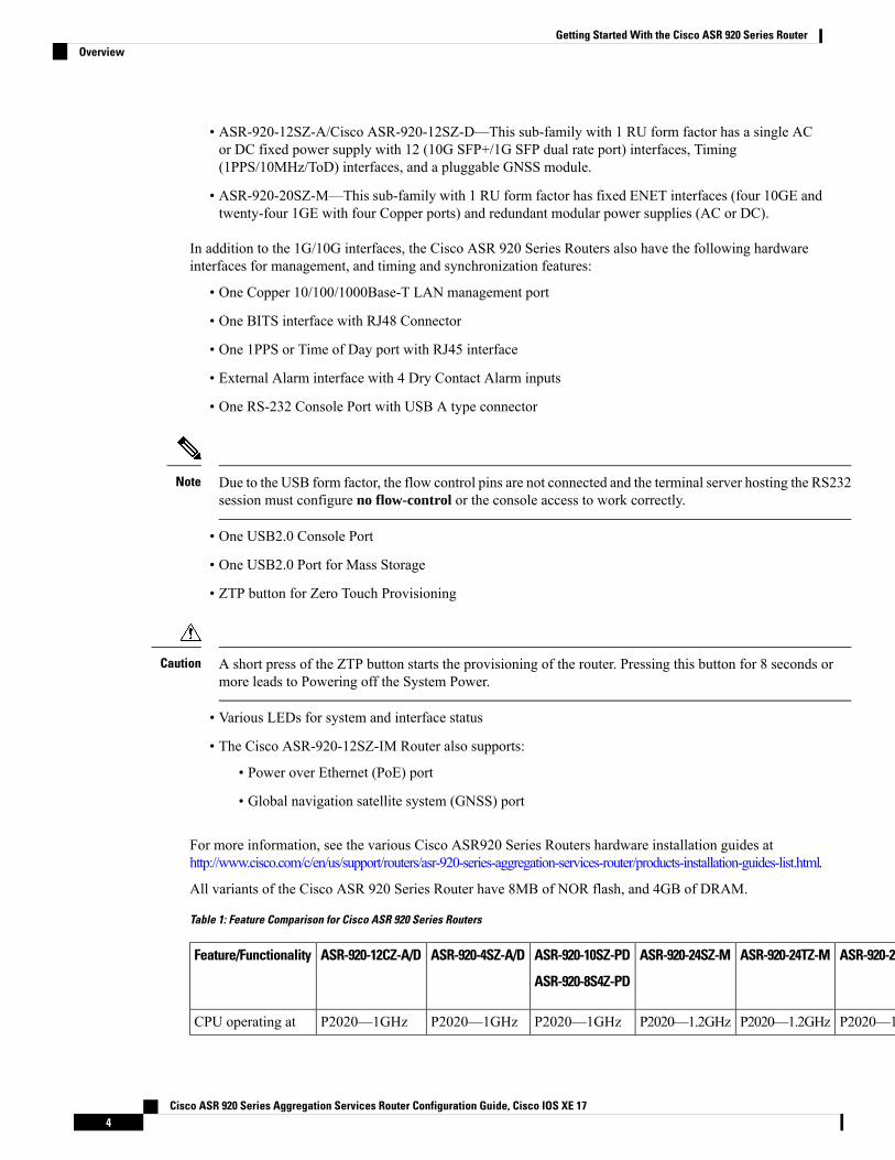
• ASR-920-12SZ-A/Cisco ASR-920-12SZ-D—This sub-family with 1 RU form factor has a single ACor DC fixed power supply with 12 (10G SFP+/1G SFP dual rate port) interfaces, Timing(1PPS/10MHz/ToD) interfaces, and a pluggable GNSS module.
• ASR-920-20SZ-M—This sub-family with 1 RU form factor has fixed ENET interfaces (four 10GE andtwenty-four 1GE with four Copper ports) and redundant modular power supplies (AC or DC).
In addition to the 1G/10G interfaces, the Cisco ASR 920 Series Routers also have the following hardwareinterfaces for management, and timing and synchronization features:
• One Copper 10/100/1000Base-T LAN management port
• One BITS interface with RJ48 Connector
• One 1PPS or Time of Day port with RJ45 interface
• External Alarm interface with 4 Dry Contact Alarm inputs
• One RS-232 Console Port with USB A type connector
Due to the USB form factor, the flow control pins are not connected and the terminal server hosting the RS232session must configure no flow-control or the console access to work correctly.
Note
• One USB2.0 Console Port
• One USB2.0 Port for Mass Storage
• ZTP button for Zero Touch Provisioning
A short press of the ZTP button starts the provisioning of the router. Pressing this button for 8 seconds ormore leads to Powering off the System Power.
Caution
• Various LEDs for system and interface status
• The Cisco ASR-920-12SZ-IM Router also supports:
• Power over Ethernet (PoE) port
• Global navigation satellite system (GNSS) port
For more information, see the various Cisco ASR920 Series Routers hardware installation guides athttp://www.cisco.com/c/en/us/support/routers/asr-920-series-aggregation-services-router/products-installation-guides-list.html.
All variants of the Cisco ASR 920 Series Router have 8MB of NOR flash, and 4GB of DRAM.
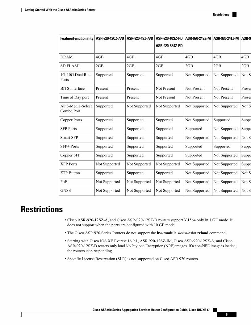
Table 1: Feature Comparison for Cisco ASR 920 Series Routers
CiscoASR-920-20SZ-M
CiscoASR-920-12SZ-A/CiscoASR-920-12SZ-D
ASR-920-12SZ-IMASR-920-24SZ-IMASR-920-24TZ-MASR-920-24SZ-MASR-920-10SZ-PD
ASR-920-8S4Z-PD
ASR-920-4SZ-A/DASR-920-12CZ-A/DFeature/Functionality
P2020—1.2GHzT1042—1.2GHzT1042—1.2GHzP2020—1.2GHzP2020—1.2GHzP2020—1.2GHzP2020—1GHzP2020—1GHzP2020—1GHzCPU operating at
Cisco ASR 920 Series Aggregation Services Router Configuration Guide, Cisco IOS XE 174
Getting Started With the Cisco ASR 920 Series RouterOverview
CiscoASR-920-20SZ-M
CiscoASR-920-12SZ-A/CiscoASR-920-12SZ-D
ASR-920-12SZ-IMASR-920-24SZ-IMASR-920-24TZ-MASR-920-24SZ-MASR-920-10SZ-PD
ASR-920-8S4Z-PD
ASR-920-4SZ-A/DASR-920-12CZ-A/DFeature/Functionality
4GB4GB4GB4GB4GB4GB4GB4GB4GBDRAM
2GB4GB4GB2GB2GB2GB2GB2GB2GBSD FLASH
Not SupportedSupportedSupportedNot SupportedNot SupportedNot SupportedSupportedSupportedSupported1G-10G Dual RatePorts
Not PresentPresentNot PresentPresentNot PresentNot PresentNot PresentPresentPresentBITS interface
Not PresentPresentPresentPresentNot PresentNot PresentNot PresentPresentPresentTime of Day port
Not SupportedNot SupportedNot SupportedNot SupportedNot SupportedNot SupportedNot SupportedNot SupportedSupportedAuto-Media-SelectCombo Port
SupportedNot SupportedSupportedSupportedSupportedNot SupportedSupportedSupportedSupportedCopper Ports
SupportedSupportedSupportedSupportedNot SupportedSupportedSupportedSupportedSupportedSFP Ports
Not SupportedNot SupportedNot SupportedNot SupportedNot SupportedNot SupportedSupportedSupportedSupportedSmart SFP
SupportedSupportedSupportedSupportedSupportedSupportedSupportedSupportedSupportedSFP+ Ports
SupportedNot SupportedSupportedSupportedNot SupportedSupportedSupportedSupportedSupportedCopper SFP
Not SupportedNot SupportedSupportedSupportedNot SupportedNot SupportedNot SupportedNot SupportedNot SupportedXFP Ports
Not SupportedSupportedSupportedNot SupportedNot SupportedNot SupportedSupportedSupportedSupportedZTP Button
Not SupportedNot SupportedSupportedNot SupportedNot SupportedNot SupportedNot SupportedNot SupportedNot SupportedPoE
Not SupportedSupportedSupportedNot SupportedNot SupportedNot SupportedNot SupportedNot SupportedNot SupportedGNSS
Restrictions• Cisco ASR-920-12SZ-A, and Cisco ASR-920-12SZ-D routers support Y.1564 only in 1 GE mode. Itdoes not support when the ports are configured with 10 GE mode.
• The Cisco ASR 920 Series Routers do not support the hw-module slot/subslot reload command.
• Starting with Cisco IOS XE Everest 16.9.1, ASR 920-12SZ-IM, Cisco ASR-920-12SZ-A, and CiscoASR-920-12SZ-D routers only load No Payload Encryption (NPE) images. If a non-NPE image is loaded,the routers stop responding.
• Specific License Reservation (SLR) is not supported on Cisco ASR 920 routers.
Cisco ASR 920 Series Aggregation Services Router Configuration Guide, Cisco IOS XE 175
Getting Started With the Cisco ASR 920 Series RouterRestrictions
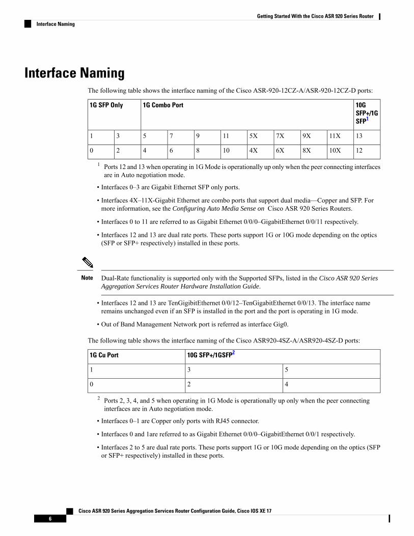
Interface NamingThe following table shows the interface naming of the Cisco ASR-920-12CZ-A/ASR-920-12CZ-D ports:
10GSFP+/1GSFP1
1G Combo Port1G SFP Only
1311X9X7X5X1197531
1210X8X6X4X1086420
1 Ports 12 and 13 when operating in 1GMode is operationally up only when the peer connecting interfacesare in Auto negotiation mode.
• Interfaces 0–3 are Gigabit Ethernet SFP only ports.
• Interfaces 4X–11X-Gigabit Ethernet are combo ports that support dual media—Copper and SFP. Formore information, see the Configuring Auto Media Sense on Cisco ASR 920 Series Routers.
• Interfaces 0 to 11 are referred to as Gigabit Ethernet 0/0/0–GigabitEthernet 0/0/11 respectively.
• Interfaces 12 and 13 are dual rate ports. These ports support 1G or 10G mode depending on the optics(SFP or SFP+ respectively) installed in these ports.
Dual-Rate functionality is supported only with the Supported SFPs, listed in the Cisco ASR 920 SeriesAggregation Services Router Hardware Installation Guide.
Note
• Interfaces 12 and 13 are TenGigibitEthernet 0/0/12–TenGigabitEthernet 0/0/13. The interface nameremains unchanged even if an SFP is installed in the port and the port is operating in 1G mode.
• Out of Band Management Network port is referred as interface Gig0.
The following table shows the interface naming of the Cisco ASR920-4SZ-A/ASR920-4SZ-D ports:
10G SFP+/1GSFP21G Cu Port
531
420
2 Ports 2, 3, 4, and 5 when operating in 1G Mode is operationally up only when the peer connectinginterfaces are in Auto negotiation mode.
• Interfaces 0–1 are Copper only ports with RJ45 connector.
• Interfaces 0 and 1are referred to as Gigabit Ethernet 0/0/0–GigabitEthernet 0/0/1 respectively.
• Interfaces 2 to 5 are dual rate ports. These ports support 1G or 10G mode depending on the optics (SFPor SFP+ respectively) installed in these ports.
Cisco ASR 920 Series Aggregation Services Router Configuration Guide, Cisco IOS XE 176
Getting Started With the Cisco ASR 920 Series RouterInterface Naming
Dual-Rate functionality is supported only with the Supported SFPs, listed in the Cisco ASR 920 SeriesAggregation Services Router Hardware Installation Guide.
Note
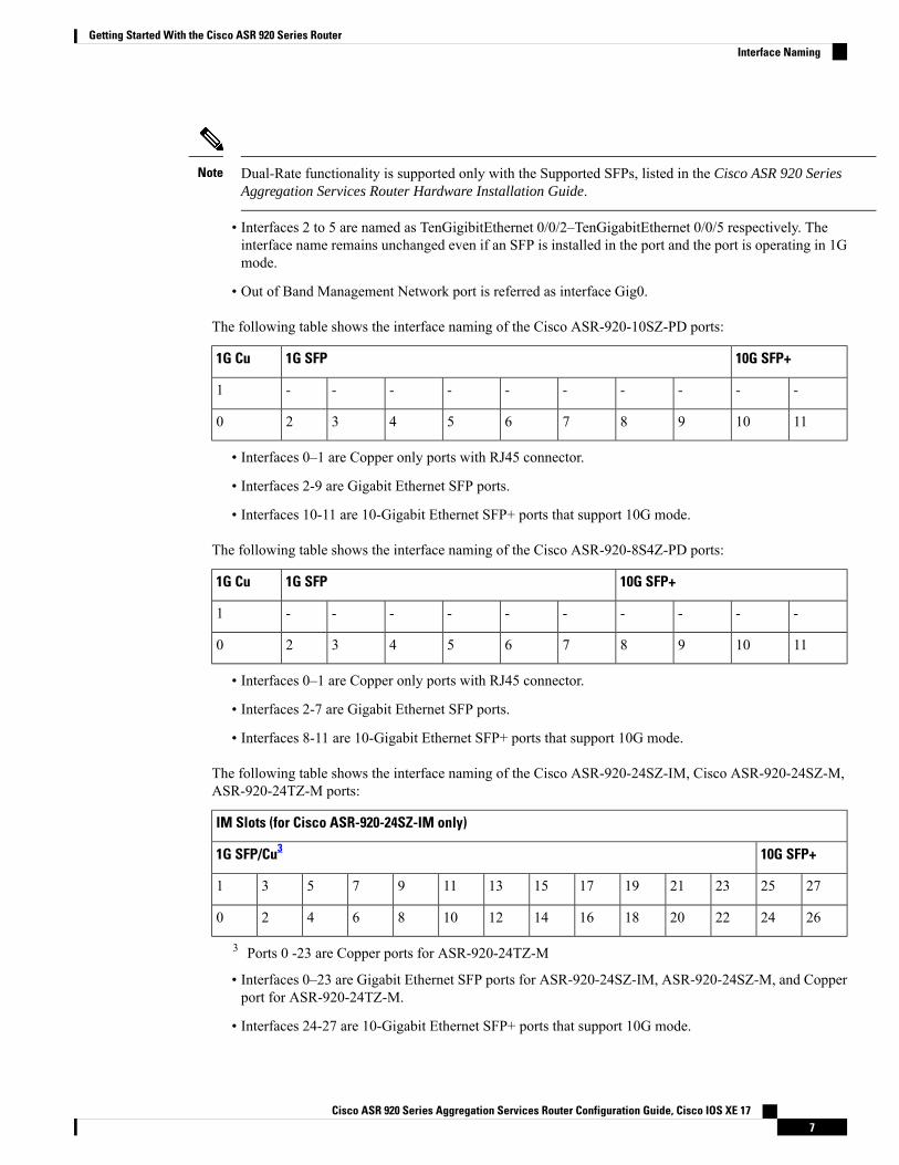
• Interfaces 2 to 5 are named as TenGigibitEthernet 0/0/2–TenGigabitEthernet 0/0/5 respectively. Theinterface name remains unchanged even if an SFP is installed in the port and the port is operating in 1Gmode.
• Out of Band Management Network port is referred as interface Gig0.
The following table shows the interface naming of the Cisco ASR-920-10SZ-PD ports:
10G SFP+1G SFP1G Cu
----------1
1110987654320
• Interfaces 0–1 are Copper only ports with RJ45 connector.
• Interfaces 2-9 are Gigabit Ethernet SFP ports.
• Interfaces 10-11 are 10-Gigabit Ethernet SFP+ ports that support 10G mode.
The following table shows the interface naming of the Cisco ASR-920-8S4Z-PD ports:
10G SFP+1G SFP1G Cu
----------1
1110987654320
• Interfaces 0–1 are Copper only ports with RJ45 connector.
• Interfaces 2-7 are Gigabit Ethernet SFP ports.
• Interfaces 8-11 are 10-Gigabit Ethernet SFP+ ports that support 10G mode.
The following table shows the interface naming of the Cisco ASR-920-24SZ-IM, Cisco ASR-920-24SZ-M,ASR-920-24TZ-M ports:
IM Slots (for Cisco ASR-920-24SZ-IM only)
10G SFP+1G SFP/Cu3
27252321191715131197531
26242220181614121086420
3 Ports 0 -23 are Copper ports for ASR-920-24TZ-M
• Interfaces 0–23 are Gigabit Ethernet SFP ports for ASR-920-24SZ-IM, ASR-920-24SZ-M, and Copperport for ASR-920-24TZ-M.
• Interfaces 24-27 are 10-Gigabit Ethernet SFP+ ports that support 10G mode.
Cisco ASR 920 Series Aggregation Services Router Configuration Guide, Cisco IOS XE 177
Getting Started With the Cisco ASR 920 Series RouterInterface Naming
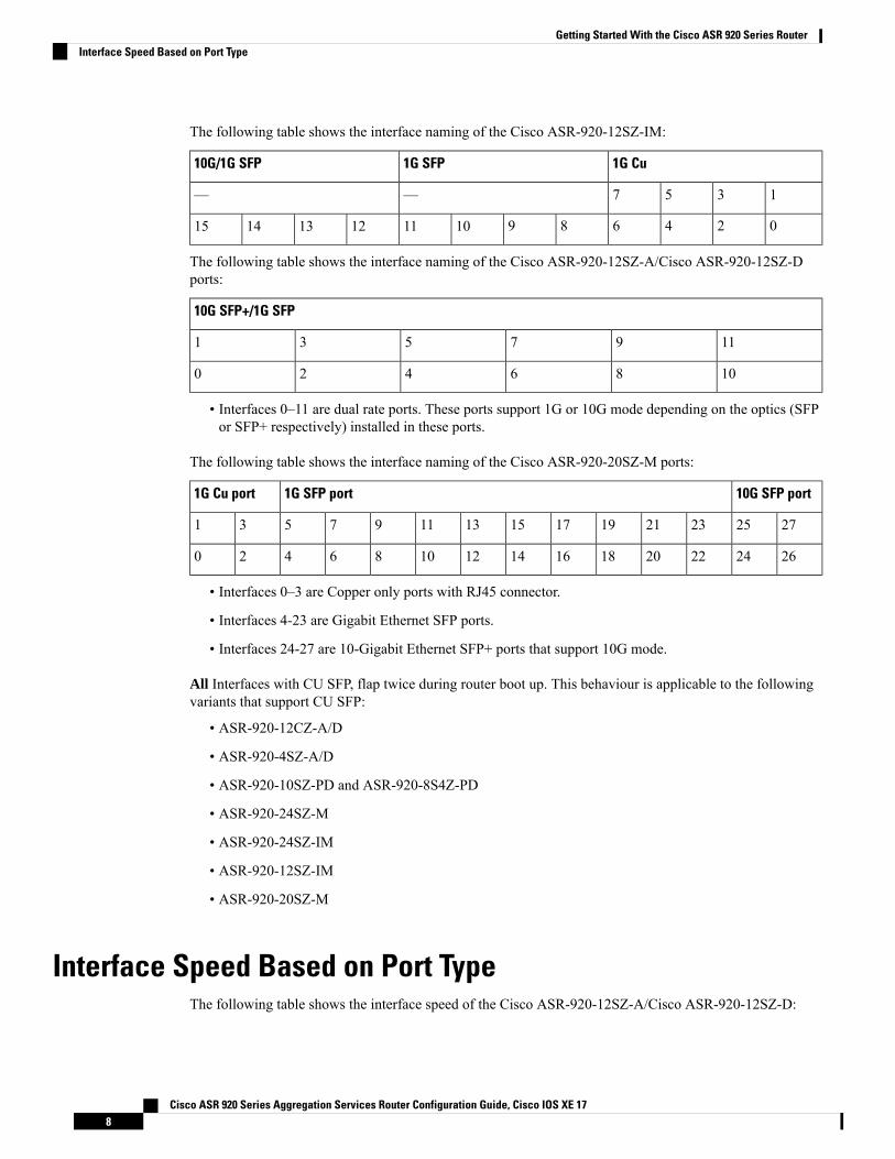
The following table shows the interface naming of the Cisco ASR-920-12SZ-IM:
1G Cu1G SFP10G/1G SFP
1357——
024689101112131415
The following table shows the interface naming of the Cisco ASR-920-12SZ-A/Cisco ASR-920-12SZ-Dports:
10G SFP+/1G SFP
1197531
1086420
• Interfaces 0–11 are dual rate ports. These ports support 1G or 10G mode depending on the optics (SFPor SFP+ respectively) installed in these ports.
The following table shows the interface naming of the Cisco ASR-920-20SZ-M ports:
10G SFP port1G SFP port1G Cu port
27252321191715131197531
26242220181614121086420
• Interfaces 0–3 are Copper only ports with RJ45 connector.
• Interfaces 4-23 are Gigabit Ethernet SFP ports.
• Interfaces 24-27 are 10-Gigabit Ethernet SFP+ ports that support 10G mode.
All Interfaces with CU SFP, flap twice during router boot up. This behaviour is applicable to the followingvariants that support CU SFP:
• ASR-920-12CZ-A/D
• ASR-920-4SZ-A/D
• ASR-920-10SZ-PD and ASR-920-8S4Z-PD
• ASR-920-24SZ-M
• ASR-920-24SZ-IM
• ASR-920-12SZ-IM
• ASR-920-20SZ-M
Interface Speed Based on Port TypeThe following table shows the interface speed of the Cisco ASR-920-12SZ-A/Cisco ASR-920-12SZ-D:
Cisco ASR 920 Series Aggregation Services Router Configuration Guide, Cisco IOS XE 178
Getting Started With the Cisco ASR 920 Series RouterInterface Speed Based on Port Type
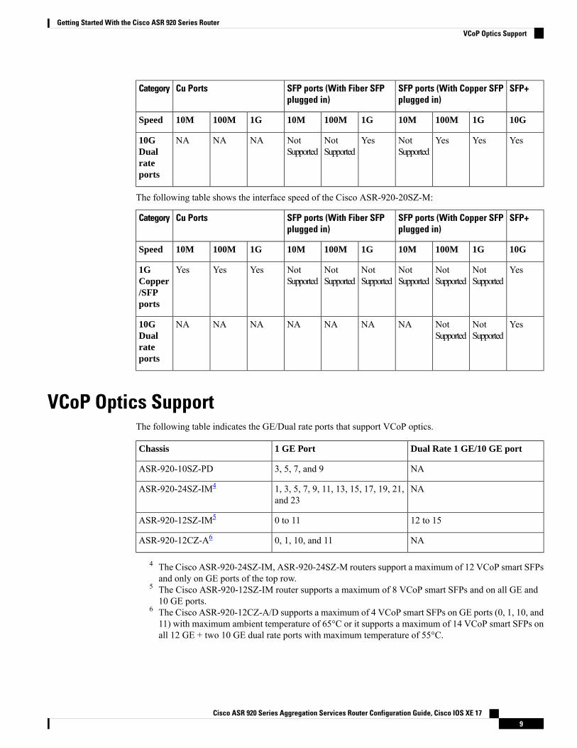
SFP+SFP ports (With Copper SFPplugged in)
SFP ports (With Fiber SFPplugged in)
Cu PortsCategory
10G1G100M10M1G100M10M1G100M10MSpeed
YesYesYesNotSupported
YesNotSupported
NotSupported
NANANA10GDualrateports
The following table shows the interface speed of the Cisco ASR-920-20SZ-M:
SFP+SFP ports (With Copper SFPplugged in)
SFP ports (With Fiber SFPplugged in)
Cu PortsCategory
10G1G100M10M1G100M10M1G100M10MSpeed
YesNotSupported
NotSupported
NotSupported
NotSupported
NotSupported
NotSupported
YesYesYes1GCopper/SFPports
YesNotSupported
NotSupported
NANANANANANANA10GDualrateports
VCoP Optics SupportThe following table indicates the GE/Dual rate ports that support VCoP optics.
Dual Rate 1 GE/10 GE port1 GE PortChassis
NA3, 5, 7, and 9ASR-920-10SZ-PD
NA1, 3, 5, 7, 9, 11, 13, 15, 17, 19, 21,and 23
ASR-920-24SZ-IM4
12 to 150 to 11ASR-920-12SZ-IM5
NA0, 1, 10, and 11ASR-920-12CZ-A6
4 The Cisco ASR-920-24SZ-IM, ASR-920-24SZ-M routers support a maximum of 12 VCoP smart SFPsand only on GE ports of the top row.
5 The Cisco ASR-920-12SZ-IM router supports a maximum of 8 VCoP smart SFPs and on all GE and10 GE ports.
6 The Cisco ASR-920-12CZ-A/D supports a maximum of 4 VCoP smart SFPs on GE ports (0, 1, 10, and11) with maximum ambient temperature of 65°C or it supports a maximum of 14 VCoP smart SFPs onall 12 GE + two 10 GE dual rate ports with maximum temperature of 55°C.
Cisco ASR 920 Series Aggregation Services Router Configuration Guide, Cisco IOS XE 179
Getting Started With the Cisco ASR 920 Series RouterVCoP Optics Support

Cisco ASR 920 Series Aggregation Services Router Configuration Guide, Cisco IOS XE 1710
Getting Started With the Cisco ASR 920 Series RouterVCoP Optics Support
C H A P T E R 3Using Cisco IOS XE Software
This chapter provides information to prepare you to configure the Cisco ASR 920 Series Router:
• Understanding Command Modes, on page 11• Recommended Methods for CLI Configuration on Router, on page 13• Accessing the CLI Using a Router Console, on page 13• Using Keyboard Shortcuts, on page 13• Using the History Buffer to Recall Commands, on page 14• Getting Help, on page 14• Using the no and default Forms of Commands, on page 17• Saving Configuration Changes, on page 18• Managing Configuration Files, on page 18• Filtering Output from the show and more Commands, on page 19• Powering Off the Router, on page 20• Password Recovery, on page 20• Finding Support Information for Platforms and Cisco Software Images, on page 21
Understanding Command ModesThe command modes available in the traditional Cisco IOS CLI are exactly the same as the command modesavailable in Cisco IOS XE.
You use the CLI to access Cisco IOS XE software. Because the CLI is divided into many different modes,the commands available to you at any given time depend on the mode that you are currently in. Entering aquestion mark (?) at the CLI prompt allows you to obtain a list of commands available for each commandmode.
When you log in to the CLI, you are in user EXEC mode. User EXEC mode contains only a limited subsetof commands. To have access to all commands, you must enter privileged EXEC mode, normally by using apassword. From privileged EXEC mode, you can issue any EXEC command—user or privileged mode—oryou can enter global configuration mode.Most EXEC commands are one-time commands. For example, showcommands show important status information, and clear commands clear counters or interfaces. The EXECcommands are not saved when the software reboots.
Configuration modes allow you to make changes to the running configuration. If you later save the runningconfiguration to the startup configuration, these changed commands are stored when the software is rebooted.To enter specific configuration modes, you must start at global configuration mode. From global configuration
Cisco ASR 920 Series Aggregation Services Router Configuration Guide, Cisco IOS XE 1711
mode, you can enter interface configuration mode and a variety of other modes, such as protocol-specificmodes.
ROMmonitor mode is a separate mode used when the Cisco IOS XE software cannot load properly. If a validsoftware image is not found when the software boots or if the configuration file is corrupted at startup, thesoftware might enter ROM monitor mode.
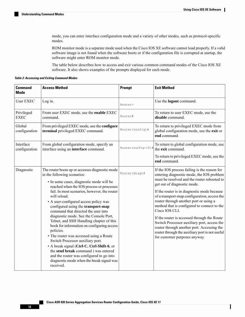
The table below describes how to access and exit various common command modes of the Cisco IOS XEsoftware. It also shows examples of the prompts displayed for each mode.
Table 2: Accessing and Exiting Command Modes
Exit MethodPromptAccess MethodCommandMode
Use the logout command.Router>
Log in.User EXEC
To return to user EXEC mode, use thedisable command.Router#
From user EXEC mode, use the enable EXECcommand.
PrivilegedEXEC
To return to privileged EXEC mode fromglobal configuration mode, use the exit orend command.
Router(config)#From privileged EXECmode, use the configureterminal privileged EXEC command.
Globalconfiguration
To return to global configuration mode, usethe exit command.
To return to privileged EXECmode, use theend command.
Router(config-if)#From global configuration mode, specify aninterface using an interface command.
Interfaceconfiguration
If the IOS process failing is the reason forentering diagnostic mode, the IOS problemmust be resolved and the router rebooted toget out of diagnostic mode.
If the router is in diagnostic mode becauseof a transport-map configuration, access therouter through another port or using amethod that is configured to connect to theCisco IOS CLI.
If the router is accessed through the RouteSwitch Processor auxiliary port, access therouter through another port. Accessing therouter through the auxiliary port is not usefulfor customer purposes anyway.
Router(diag)#The router boots up or accesses diagnostic modein the following scenarios:
• In some cases, diagnostic mode will bereached when the IOS process or processesfail. In most scenarios, however, the routerwill reload.
• A user-configured access policy wasconfigured using the transport-mapcommand that directed the user intodiagnostic mode. See the Console Port,Telnet, and SSH Handling chapter of thisbook for information on configuring accesspolicies.
• The router was accessed using a RouteSwitch Processor auxiliary port.
• A break signal (Ctrl-C, Ctrl-Shift-6, orthe send break command ) was enteredand the router was configured to go intodiagnostic mode when the break signal wasreceived.
Diagnostic
Cisco ASR 920 Series Aggregation Services Router Configuration Guide, Cisco IOS XE 1712
Using Cisco IOS XE SoftwareUnderstanding Command Modes
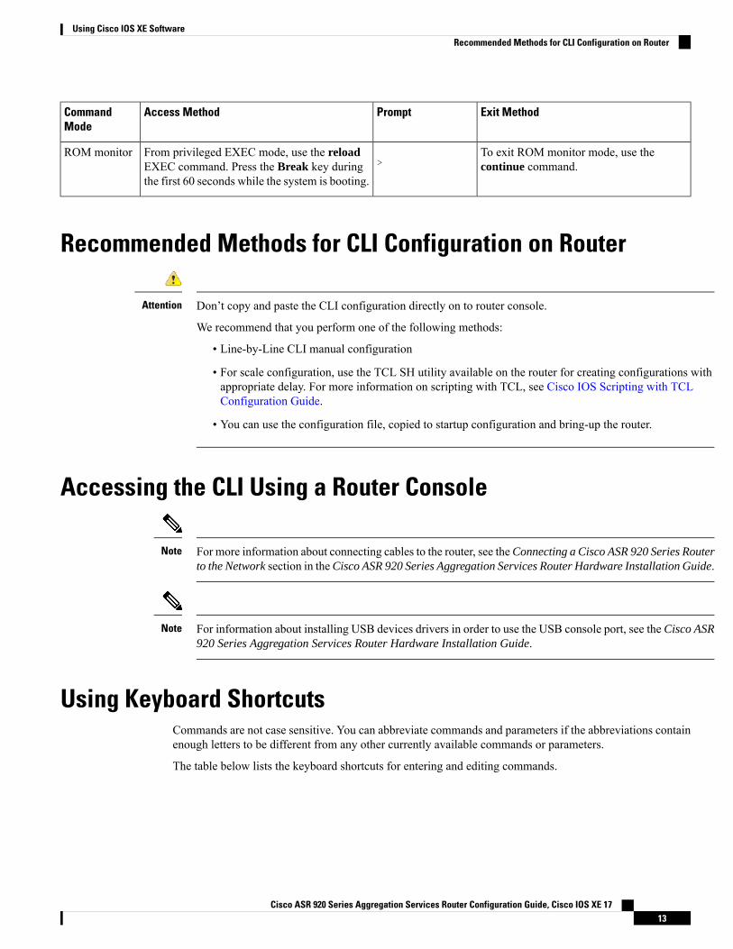
Exit MethodPromptAccess MethodCommandMode
To exit ROM monitor mode, use thecontinue command.>
From privileged EXEC mode, use the reloadEXEC command. Press the Break key duringthe first 60 seconds while the system is booting.
ROM monitor
Recommended Methods for CLI Configuration on Router
Don’t copy and paste the CLI configuration directly on to router console.
We recommend that you perform one of the following methods:
• Line-by-Line CLI manual configuration
• For scale configuration, use the TCL SH utility available on the router for creating configurations withappropriate delay. For more information on scripting with TCL, see Cisco IOS Scripting with TCLConfiguration Guide.
• You can use the configuration file, copied to startup configuration and bring-up the router.
Attention
Accessing the CLI Using a Router Console
For more information about connecting cables to the router, see theConnecting a Cisco ASR 920 Series Routerto the Network section in theCisco ASR 920 Series Aggregation Services Router Hardware Installation Guide.
Note
For information about installing USB devices drivers in order to use the USB console port, see the Cisco ASR920 Series Aggregation Services Router Hardware Installation Guide.
Note
Using Keyboard ShortcutsCommands are not case sensitive. You can abbreviate commands and parameters if the abbreviations containenough letters to be different from any other currently available commands or parameters.
The table below lists the keyboard shortcuts for entering and editing commands.
Cisco ASR 920 Series Aggregation Services Router Configuration Guide, Cisco IOS XE 1713
Using Cisco IOS XE SoftwareRecommended Methods for CLI Configuration on Router
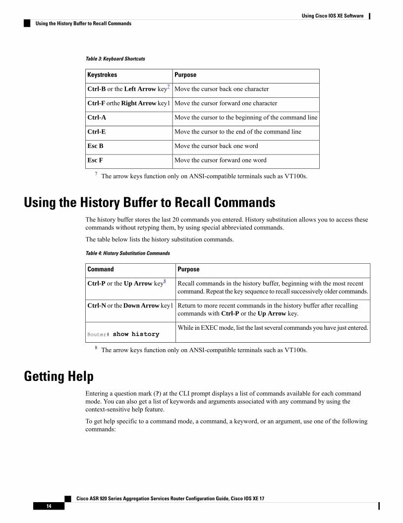
Table 3: Keyboard Shortcuts
PurposeKeystrokes
Move the cursor back one characterCtrl-B or the Left Arrow key7
Move the cursor forward one characterCtrl-F ortheRight Arrow key1
Move the cursor to the beginning of the command lineCtrl-A
Move the cursor to the end of the command lineCtrl-E
Move the cursor back one wordEsc B
Move the cursor forward one wordEsc F
7 The arrow keys function only on ANSI-compatible terminals such as VT100s.
Using the History Buffer to Recall CommandsThe history buffer stores the last 20 commands you entered. History substitution allows you to access thesecommands without retyping them, by using special abbreviated commands.
The table below lists the history substitution commands.
Table 4: History Substitution Commands
PurposeCommand
Recall commands in the history buffer, beginning with the most recentcommand. Repeat the key sequence to recall successively older commands.
Ctrl-P or the Up Arrow key8
Return to more recent commands in the history buffer after recallingcommands with Ctrl-P or the Up Arrow key.
Ctrl-N or theDown Arrow key1
While in EXECmode, list the last several commands you have just entered.Router# show history
8 The arrow keys function only on ANSI-compatible terminals such as VT100s.
Getting HelpEntering a question mark (?) at the CLI prompt displays a list of commands available for each commandmode. You can also get a list of keywords and arguments associated with any command by using thecontext-sensitive help feature.
To get help specific to a command mode, a command, a keyword, or an argument, use one of the followingcommands:
Cisco ASR 920 Series Aggregation Services Router Configuration Guide, Cisco IOS XE 1714
Using Cisco IOS XE SoftwareUsing the History Buffer to Recall Commands
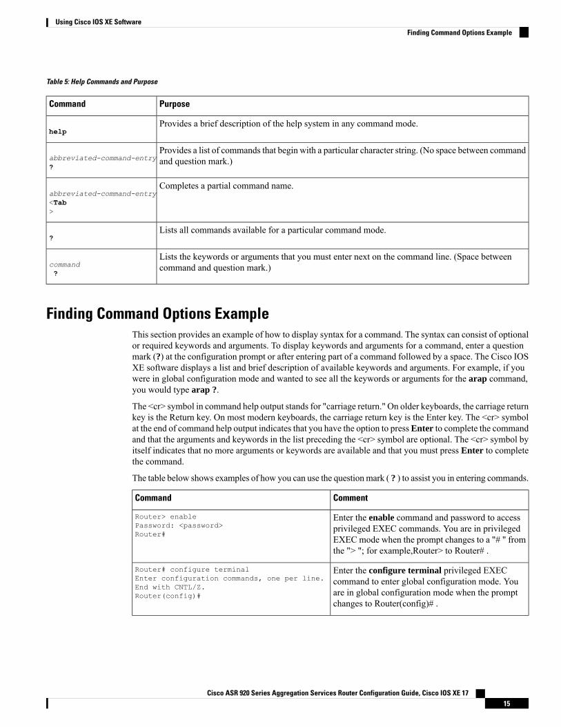
Table 5: Help Commands and Purpose
PurposeCommand
Provides a brief description of the help system in any command mode.help
Provides a list of commands that begin with a particular character string. (No space between commandand question mark.)abbreviated-command-entry
?
Completes a partial command name.abbreviated-command-entry<Tab>
Lists all commands available for a particular command mode.?
Lists the keywords or arguments that you must enter next on the command line. (Space betweencommand and question mark.)command
?
Finding Command Options ExampleThis section provides an example of how to display syntax for a command. The syntax can consist of optionalor required keywords and arguments. To display keywords and arguments for a command, enter a questionmark (?) at the configuration prompt or after entering part of a command followed by a space. The Cisco IOSXE software displays a list and brief description of available keywords and arguments. For example, if youwere in global configuration mode and wanted to see all the keywords or arguments for the arap command,you would type arap ?.
The <cr> symbol in command help output stands for "carriage return." On older keyboards, the carriage returnkey is the Return key. On most modern keyboards, the carriage return key is the Enter key. The <cr> symbolat the end of command help output indicates that you have the option to pressEnter to complete the commandand that the arguments and keywords in the list preceding the <cr> symbol are optional. The <cr> symbol byitself indicates that no more arguments or keywords are available and that you must press Enter to completethe command.
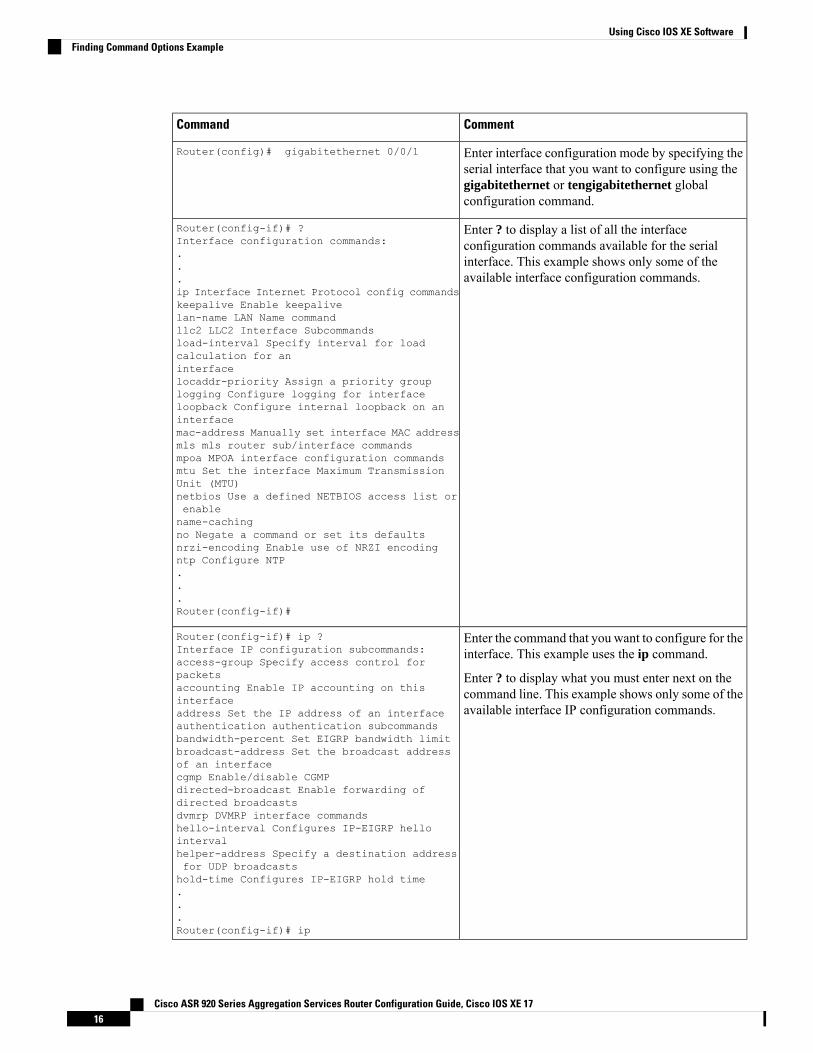
The table below shows examples of how you can use the questionmark ( ? ) to assist you in entering commands.
CommentCommand
Enter the enable command and password to accessprivileged EXEC commands. You are in privilegedEXEC mode when the prompt changes to a "# " fromthe "> "; for example,Router> to Router# .
Router> enablePassword: <password>Router#
Enter the configure terminal privileged EXECcommand to enter global configuration mode. Youare in global configuration mode when the promptchanges to Router(config)# .
Router# configure terminalEnter configuration commands, one per line.End with CNTL/Z.Router(config)#
Cisco ASR 920 Series Aggregation Services Router Configuration Guide, Cisco IOS XE 1715
Using Cisco IOS XE SoftwareFinding Command Options Example
CommentCommand
Enter interface configuration mode by specifying theserial interface that you want to configure using thegigabitethernet or tengigabitethernet globalconfiguration command.
Router(config)# gigabitethernet 0/0/1
Enter ? to display a list of all the interfaceconfiguration commands available for the serialinterface. This example shows only some of theavailable interface configuration commands.
Router(config-if)# ?Interface configuration commands:...ip Interface Internet Protocol config commandskeepalive Enable keepalivelan-name LAN Name commandllc2 LLC2 Interface Subcommandsload-interval Specify interval for loadcalculation for aninterfacelocaddr-priority Assign a priority grouplogging Configure logging for interfaceloopback Configure internal loopback on aninterfacemac-address Manually set interface MAC addressmls mls router sub/interface commandsmpoa MPOA interface configuration commandsmtu Set the interface Maximum TransmissionUnit (MTU)netbios Use a defined NETBIOS access list orenablename-cachingno Negate a command or set its defaultsnrzi-encoding Enable use of NRZI encodingntp Configure NTP...Router(config-if)#
Enter the command that you want to configure for theinterface. This example uses the ip command.
Enter ? to display what you must enter next on thecommand line. This example shows only some of theavailable interface IP configuration commands.
Router(config-if)# ip ?Interface IP configuration subcommands:access-group Specify access control forpacketsaccounting Enable IP accounting on thisinterfaceaddress Set the IP address of an interfaceauthentication authentication subcommandsbandwidth-percent Set EIGRP bandwidth limitbroadcast-address Set the broadcast addressof an interfacecgmp Enable/disable CGMPdirected-broadcast Enable forwarding ofdirected broadcastsdvmrp DVMRP interface commandshello-interval Configures IP-EIGRP hellointervalhelper-address Specify a destination addressfor UDP broadcastshold-time Configures IP-EIGRP hold time...Router(config-if)# ip
Cisco ASR 920 Series Aggregation Services Router Configuration Guide, Cisco IOS XE 1716
Using Cisco IOS XE SoftwareFinding Command Options Example
CommentCommand
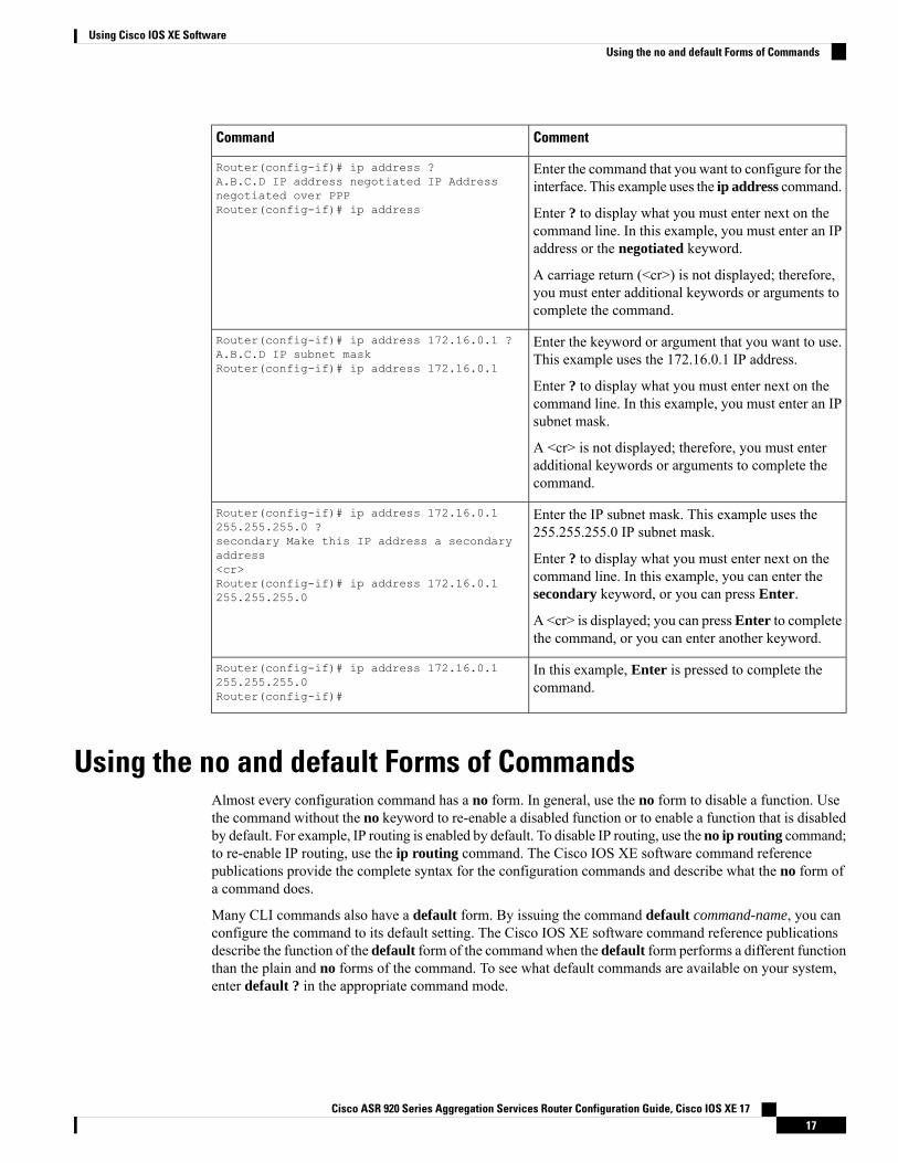
Enter the command that you want to configure for theinterface. This example uses the ip address command.
Enter ? to display what you must enter next on thecommand line. In this example, you must enter an IPaddress or the negotiated keyword.
A carriage return (<cr>) is not displayed; therefore,you must enter additional keywords or arguments tocomplete the command.
Router(config-if)# ip address ?A.B.C.D IP address negotiated IP Addressnegotiated over PPPRouter(config-if)# ip address
Enter the keyword or argument that you want to use.This example uses the 172.16.0.1 IP address.
Enter ? to display what you must enter next on thecommand line. In this example, you must enter an IPsubnet mask.
A <cr> is not displayed; therefore, you must enteradditional keywords or arguments to complete thecommand.
Router(config-if)# ip address 172.16.0.1 ?A.B.C.D IP subnet maskRouter(config-if)# ip address 172.16.0.1
Enter the IP subnet mask. This example uses the255.255.255.0 IP subnet mask.
Enter ? to display what you must enter next on thecommand line. In this example, you can enter thesecondary keyword, or you can press Enter.
A <cr> is displayed; you can pressEnter to completethe command, or you can enter another keyword.
Router(config-if)# ip address 172.16.0.1255.255.255.0 ?secondary Make this IP address a secondaryaddress<cr>Router(config-if)# ip address 172.16.0.1255.255.255.0
In this example, Enter is pressed to complete thecommand.
Router(config-if)# ip address 172.16.0.1255.255.255.0Router(config-if)#
Using the no and default Forms of CommandsAlmost every configuration command has a no form. In general, use the no form to disable a function. Usethe command without the no keyword to re-enable a disabled function or to enable a function that is disabledby default. For example, IP routing is enabled by default. To disable IP routing, use the no ip routing command;to re-enable IP routing, use the ip routing command. The Cisco IOS XE software command referencepublications provide the complete syntax for the configuration commands and describe what the no form ofa command does.
Many CLI commands also have a default form. By issuing the command default command-name, you canconfigure the command to its default setting. The Cisco IOS XE software command reference publicationsdescribe the function of the default form of the commandwhen the default form performs a different functionthan the plain and no forms of the command. To see what default commands are available on your system,enter default ? in the appropriate command mode.
Cisco ASR 920 Series Aggregation Services Router Configuration Guide, Cisco IOS XE 1717
Using Cisco IOS XE SoftwareUsing the no and default Forms of Commands
Saving Configuration ChangesUse the copy running-config startup-config command to save your configuration changes to the startupconfiguration so that the changes will not be lost if the software reloads or a power outage occurs. For example:
Router# copy running-config startup-configBuilding configuration...
It might take a minute or two to save the configuration. After the configuration has been saved, the followingoutput appears:
[OK]Router#
This task saves the configuration to NVRAM.
Managing Configuration FilesOn the router, the startup configuration file is stored in the nvram: file system and the running-configurationfiles are stored in the system: file system. This configuration file storage setup is not unique to the router andis used on several Cisco router platforms.
As a matter of routine maintenance on any Cisco router, users should backup the startup configuration file bycopying the startup configuration file fromNVRAMonto one of the router’s other file systems and, additionally,onto a network server. Backing up the startup configuration file provides an easy method of recovering thestartup configuration file in the event the startup configuration file in NVRAM becomes unusable for anyreason.
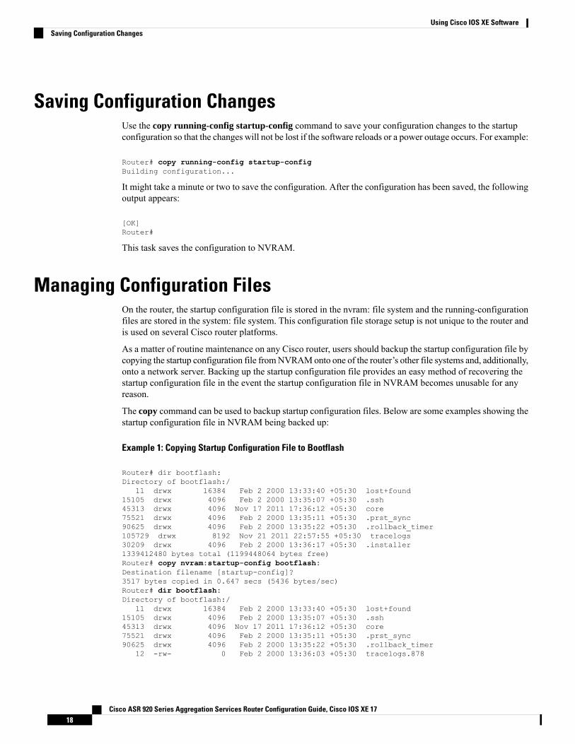
The copy command can be used to backup startup configuration files. Below are some examples showing thestartup configuration file in NVRAM being backed up:
Example 1: Copying Startup Configuration File to Bootflash
Router# dir bootflash:Directory of bootflash:/
11 drwx 16384 Feb 2 2000 13:33:40 +05:30 lost+found15105 drwx 4096 Feb 2 2000 13:35:07 +05:30 .ssh45313 drwx 4096 Nov 17 2011 17:36:12 +05:30 core75521 drwx 4096 Feb 2 2000 13:35:11 +05:30 .prst_sync90625 drwx 4096 Feb 2 2000 13:35:22 +05:30 .rollback_timer105729 drwx 8192 Nov 21 2011 22:57:55 +05:30 tracelogs30209 drwx 4096 Feb 2 2000 13:36:17 +05:30 .installer1339412480 bytes total (1199448064 bytes free)Router# copy nvram:startup-config bootflash:Destination filename [startup-config]?3517 bytes copied in 0.647 secs (5436 bytes/sec)Router# dir bootflash:Directory of bootflash:/
11 drwx 16384 Feb 2 2000 13:33:40 +05:30 lost+found15105 drwx 4096 Feb 2 2000 13:35:07 +05:30 .ssh45313 drwx 4096 Nov 17 2011 17:36:12 +05:30 core75521 drwx 4096 Feb 2 2000 13:35:11 +05:30 .prst_sync90625 drwx 4096 Feb 2 2000 13:35:22 +05:30 .rollback_timer
12 -rw- 0 Feb 2 2000 13:36:03 +05:30 tracelogs.878
Cisco ASR 920 Series Aggregation Services Router Configuration Guide, Cisco IOS XE 1718
Using Cisco IOS XE SoftwareSaving Configuration Changes
105729 drwx 8192 Nov 21 2011 23:02:13 +05:30 tracelogs30209 drwx 4096 Feb 2 2000 13:36:17 +05:30 .installer
13 -rw- 1888 Nov 21 2011 23:03:17 +05:30 startup-config1339412480 bytes total (1199439872 bytes free)
Example 2: Copying Startup Configuration File to USB Flash Disk
Router# dir usb0:Directory of usb0:/43261 -rwx 208904396 May 27 2008 14:10:20 -07:00asr920-adventerprisek9.02.01.00.122-33.XNA.bin2 55497216 bytes total (40190464 bytes free)Router# copy nvram:startup-config usb0:Destination filename [startup-config]?3172 bytes copied in 0.214 secs (14822 bytes/sec)Router# dir usb0:Directory of usb0:/43261 -rwx 208904396 May 27 2008 14:10:20 -07:00asr920-adventerprisek9.02.01.00.122-33.XNA.bin43262 -rwx 3172 Jul 2 2008 15:40:45-07:00 startup-config255497216 bytes total (40186880 bytes free)
Example 3: Copying Startup Configuration File to a TFTP Server
Router# copy bootflash:startup-config tftp:Address or name of remote host []? 172.17.16.81Destination filename [pe24_asr-1002-confg]? /auto/tftp-users/user/startup-config!!3517 bytes copied in 0.122 secs (28828 bytes/sec)
For more detailed information on managing configuration files, see the Configuration FundamentalsConfiguration Guide, Cisco IOS XE Release 3S.
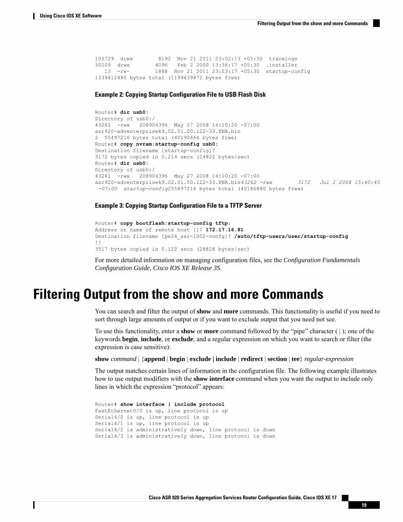
Filtering Output from the show and more CommandsYou can search and filter the output of show and more commands. This functionality is useful if you need tosort through large amounts of output or if you want to exclude output that you need not see.
To use this functionality, enter a show or more command followed by the “pipe” character ( | ); one of thekeywords begin, include, or exclude; and a regular expression on which you want to search or filter (theexpression is case sensitive):
show command | {append | begin | exclude | include | redirect | section | tee} regular-expression
The output matches certain lines of information in the configuration file. The following example illustrateshow to use output modifiers with the show interface command when you want the output to include onlylines in which the expression “protocol” appears:
Router# show interface | include protocolFastEthernet0/0 is up, line protocol is upSerial4/0 is up, line protocol is upSerial4/1 is up, line protocol is upSerial4/2 is administratively down, line protocol is downSerial4/3 is administratively down, line protocol is down
Cisco ASR 920 Series Aggregation Services Router Configuration Guide, Cisco IOS XE 1719
Using Cisco IOS XE SoftwareFiltering Output from the show and more Commands
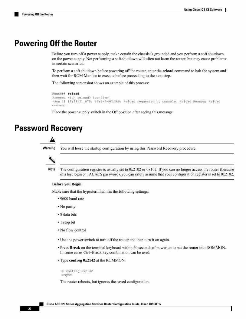
Powering Off the RouterBefore you turn off a power supply, make certain the chassis is grounded and you perform a soft shutdownon the power supply. Not performing a soft shutdown will often not harm the router, but may cause problemsin certain scenarios.
To perform a soft shutdown before powering off the router, enter the reload command to halt the system andthen wait for ROM Monitor to execute before proceeding to the next step.
The following screenshot shows an example of this process:
Router# reloadProceed with reload? [confirm]*Jun 18 19:38:21.870: %SYS-5-RELOAD: Reload requested by console. Reload Reason: Reloadcommand.
Place the power supply switch in the Off position after seeing this message.
Password Recovery
You will loose the startup configuration by using this Password Recovery procedure.Warning
The configuration register is usually set to 0x2102 or 0x102. If you can no longer access the router (becauseof a lost login or TACACS password), you can safely assume that your configuration register is set to 0x2102.
Note
Before you Begin:
Make sure that the hyperterminal has the following settings:
• 9600 baud rate
• No parity
• 8 data bits
• 1 stop bit
• No flow control
• Use the power switch to turn off the router and then turn it on again.
• Press Break on the terminal keyboard within 60 seconds of power up to put the router into ROMMON.In some cases Ctrl+Break key combination can be used.
• Type confreg 0x2142 at the ROMMON.
1> confreg 0x21421>sync
The router reboots, but ignores the saved configuration.
Cisco ASR 920 Series Aggregation Services Router Configuration Guide, Cisco IOS XE 1720
Using Cisco IOS XE SoftwarePowering Off the Router
• The router will reload and prompt for configuration.Type no after each setup question, or press Ctrl-Cto skip the initial setup procedure.
• Type enable at the Router> prompt.
You are now in enable mode and should see the Router# prompt.
• Reset the config-register from 0x2142 to 0x2102. To do so, type the following:
config-register configuration_register_setting
Where, configuration_register_setting is 0x2102. For example,
(config)# config-register 0x2102
Finding Support Information for Platforms and Cisco SoftwareImages
Cisco software is packaged in feature sets consisting of software images that support specific platforms. Thefeature sets available for a specific platform depend on which Cisco software images are included in a release.To identify the set of software images available in a specific release or to find out if a feature is available ina given Cisco IOS XE software image, you can use Cisco Feature Navigator or the software release notes.
Using Cisco Feature NavigatorUse Cisco Feature Navigator to find information about platform support and software image support. CiscoFeature Navigator enables you to determine which Cisco IOS XE software images support a specific softwarerelease, feature set, or platform. To access Cisco Feature Navigator, go to http://www.cisco.com/go/cfn. Anaccount on Cisco.com is not required.
Using Software AdvisorTo see if a feature is supported by a Cisco IOS XE release, to locate the software document for that feature,or to check the minimum software requirements of Cisco IOS XE software with the hardware installed onyour router, Cisco maintains the Software Advisor tool on Cisco.com athttp://www.cisco.com/cgi-bin/Support/CompNav/Index.pl.
You must be a registered user on Cisco.com to access this tool.
Using Software Release NotesCisco IOS XE software releases include release notes that provide the following information:
• Platform support information• Memory recommendations• New feature information• Open and resolved severity 1 and 2 caveats for all platforms
Cisco ASR 920 Series Aggregation Services Router Configuration Guide, Cisco IOS XE 1721
Using Cisco IOS XE SoftwareFinding Support Information for Platforms and Cisco Software Images

Release notes are intended to be release-specific for the most current release, and the information providedin these documents may not be cumulative in providing information about features that first appeared inprevious releases. Refer to Cisco Feature Navigator for cumulative feature information.
Cisco ASR 920 Series Aggregation Services Router Configuration Guide, Cisco IOS XE 1722
Using Cisco IOS XE SoftwareUsing Software Release Notes
C H A P T E R 4Using Zero Touch Provisioning
The Cisco ASR 920 Series Router (ASR-920-20SZ-M, ASR-920-24SZ-IM, ASR-920-24SZ-M, andASR-920-24TZ-M)do not have a ZTP or Reset button.
Note
Routers running ZTP must be able to connect to a DHCP server and TFTP server, download the configurationtemplate, and begin operation, all at the press of a button.
Note
• Prerequisites for Using ZTP, on page 23• Restrictions for Using ZTP, on page 24• Information About Using ZTP, on page 24• Downloading the Initial Configuration, on page 26• ZTP LED Behavior, on page 27• Verifying the ZTP Configuration, on page 28
Prerequisites for Using ZTP• The Cisco ASR 920 Series Router must be running Cisco IOS-XE Release 3.13.0S or later.
• The interface connected to the TFTP server must be turned green.
• DHCP server should be configured to ensure reachability to the TFTP server.
• Ports that are licensed through port licensing are disabled during the ZTP process. It is highly recommendedthat you connect to free ports that do not need a license to be enabled. For information on port licensing,see Licensing 1G and 10G Ports on the Cisco ASR 920 Series Router .
Do not change the ROMMON configuration register to 0x0.Caution
Cisco ASR 920 Series Aggregation Services Router Configuration Guide, Cisco IOS XE 1723
Restrictions for Using ZTP• ZTP is not supported on the LAN Management port—Gig0 on the router. ZTP is supported only on theEthernet interfaces such as 1—Gige, 10—Gige ports, and so on.
• ZTP is not initialized if the ZTP button is pressed for more than eight seconds. In this case, the routergoes through a normal reload process.
• ZTP is also not initialized when the router is already reloading or if the router is in ROMMON prompt.
• When the ZTP process is initialized all previous logs in the buffer are cleared.
• DHCP declines addresses when loading DHCP configuration through TFTP. It is strongly recommendedto have only the CNS configuration present on the configuration file to avoid tampering with the ZTPBDI.
• ZTP is not initialized if bootflash has files named as 'router-confg'.
• Disabling gratuitous ARP is not supported.
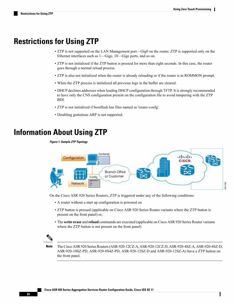
Information About Using ZTPFigure 1: Sample ZTP Topology
On the Cisco ASR 920 Series Routers, ZTP is triggered under any of the following conditions:
• A router without a start up configuration is powered on
• ZTP button is pressed (applicable on Cisco ASR 920 Series Router variants where the ZTP button ispresent on the front panel) or,
• Thewrite erase and reload commands are executed (applicable on Cisco ASR 920 Series Router variantswhere the ZTP button is not present on the front panel)
TheCiscoASR920 Series Routers (ASR-920-12CZ-A,ASR-920-12CZ-D,ASR-920-4SZ-A,ASR-920-4SZ-D,ASR-920-10SZ-PD, ASR-920-8S4Z-PD, ASR-920-12SZ-D and ASR-920-12SZ-A) have a ZTP button onthe front panel.
Note
Cisco ASR 920 Series Aggregation Services Router Configuration Guide, Cisco IOS XE 1724
Using Zero Touch ProvisioningRestrictions for Using ZTP
The Cisco ASR 920 Series Routers (ASR-920-20SZ-M, ASR-920-24SZ-IM, ASR-920-24SZ-M, andASR-920-24TZ-M) do not have a ZTP or Reset button.
Router# write eraseSystem configuration has been modified. Save? [yes/no]: noRouter# reload
If you type yes at the prompt, the system configuration is saved in the nvRAM and the ZTP process terminates.Note
After the ZTP process initializes, the following sequence is initiated:
1. The router detects the management VLAN and waits for any of the following data packets.
• Broadcast (Gratuitous ARP)
• ISIS hello packets
• OSPF hello packets
• IPv6 router advertisement packets
• VRRP
The operations center can initiate any of the above packets over the network to establish a connection to theDHCP server.
Note
2. When the first packet on any VLAN is detected, the router initiates a DHCP session to a DHCP serverover that VLAN.
3. After a DHCP session is established, the router must establish a connection with the TFTP server throughDHCP option 43 or DHCP option 150.
4. When connectivity to the TFTP server is established, the bootup process starts.
When the ZTP process initiates, the Cisco ASR 920 Series Router creates an Ethernet flow point (EFP) andassociates a bridge domain interface (BDI) on the detected management VLAN.
The router creates the following configuration to establish a connection with the DHCP server and the TFTPserver. The BDI created for this purpose has description ZTP_BDI configured under the BDI interface.
Do not delete ZTP_BDI. Deleting this configuration results in loss of connectivity to the router and the ZTPprocess terminates.
Caution
Effective Cisco IOS-XERelease 3.14.0S, to stop the ZTP process when the ZTP button is accidentally pressed,use the ztp disable command in global configuration mode. However, if you long press the ZTP button, (morethan 8 sec) ZTP is still initialized reload even though ZTP is disabled through the ztp disable command.
Note
Cisco ASR 920 Series Aggregation Services Router Configuration Guide, Cisco IOS XE 1725
Using Zero Touch ProvisioningInformation About Using ZTP
Example ZTP ConfigurationLet us assume that GigabitEthernet0/0/1 is connected to the DHCP server and is used to connect to the TFTPserver. VLAN ID 1000 is used as the management VLAN.
Router# show running-config int gi0/0/1Building configuration...Current configuration : 216 bytes!interface GigabitEthernet0/0/1no ip addressmedia-type auto-selectno negotiation autoservice instance 12 ethernetencapsulation dot1q 1000rewrite ingress tag pop 1 symmetricbridge-domain 12!end!interface BDI12description ZTP_BDIip address dhcpend
Downloading the Initial ConfigurationAfter the VLAN discovery process is complete, the configuration download process begins. The followingsequence of events is initiated.
1. The router sends DHCP discover requests on each Ethernet interface. The serial number of the router isused as a client identifier.
2. The DHCP server allocates and sends an IP address, TFTP address (if configured with option 150) anddefault router address to the router.
3. If the TFTP option (150) is present, the router requests a bootstrap configuration that can be stored in anyof the following files: PID-<mac-address>, network-confg, router-confg, ciscortr.cfg, or cisconet.cfg.
Ensure to use hyphenated hexadecimal notation of MAC address (DOM-78-72-5D-00-A5-80) to name thefiles.
Note
DHCP ServerThe following is a sample configuration to set up a Cisco router as a DHCP server:
ip dhcp excluded-address 30.30.1.6ip dhcp excluded-address 30.30.1.20 30.30.1.255!ip dhcp pool mwrdhcpnetwork 30.30.1.0 255.255.255.0
Cisco ASR 920 Series Aggregation Services Router Configuration Guide, Cisco IOS XE 1726
Using Zero Touch ProvisioningExample ZTP Configuration
option 150 ip 30.30.1.6default-router 30.30.1.6
This configuration creates a DHCP pool of 30.30.1.x addresses with 30.30.1.0 as the subnet start. The IPaddress of the DHCP server is 30.30.1.6. Option 150 specifies the TFTP server address. In this case, the DHCPand TFTP server are the same.
The DHCP pool can allocate from 30.30.1.1 to 30.30.1.19 with the exception of 30.30.1.6, which is the DHCPserver itself.
TFTP ServerThe TFTP server stores the bootstrap configuration file.
The following is a sample configuration (network– confg file):
hostname test-router!{ asrrouter-specifc configuration content}!end
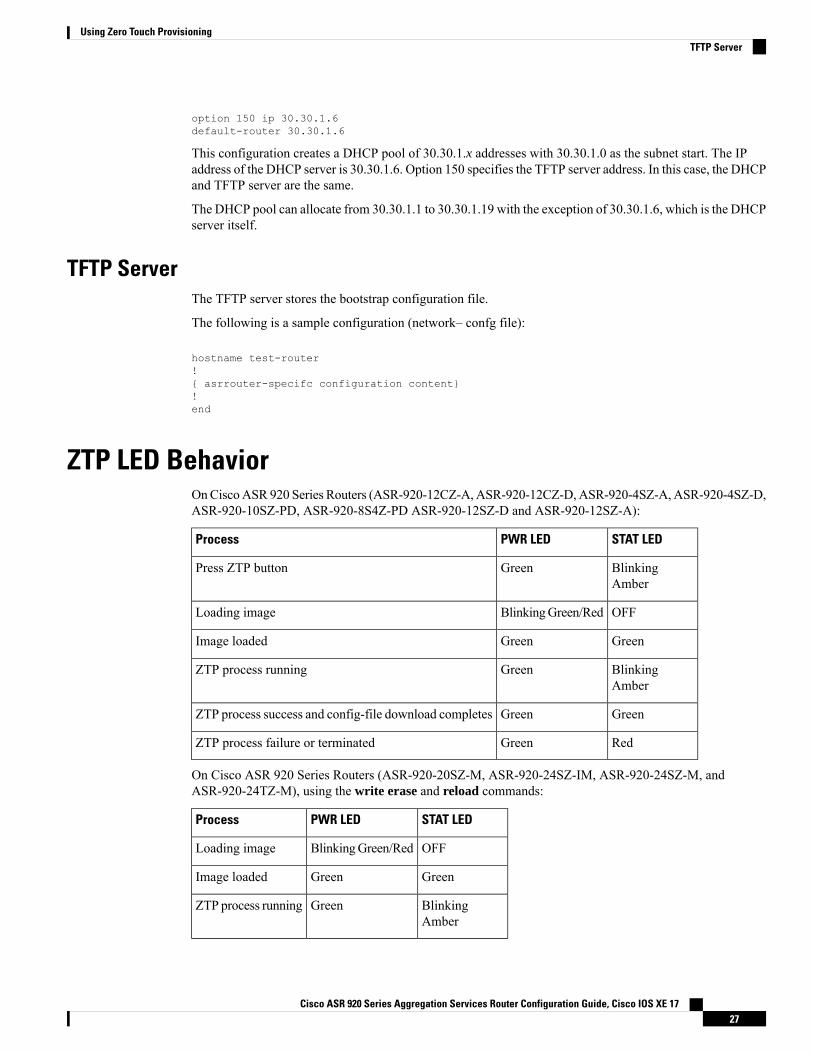
ZTP LED BehaviorOnCiscoASR 920 Series Routers (ASR-920-12CZ-A,ASR-920-12CZ-D,ASR-920-4SZ-A,ASR-920-4SZ-D,ASR-920-10SZ-PD, ASR-920-8S4Z-PD ASR-920-12SZ-D and ASR-920-12SZ-A):
STAT LEDPWR LEDProcess
BlinkingAmber
GreenPress ZTP button
OFFBlinkingGreen/RedLoading image
GreenGreenImage loaded
BlinkingAmber
GreenZTP process running
GreenGreenZTP process success and config-file download completes
RedGreenZTP process failure or terminated
On Cisco ASR 920 Series Routers (ASR-920-20SZ-M, ASR-920-24SZ-IM, ASR-920-24SZ-M, andASR-920-24TZ-M), using the write erase and reload commands:
STAT LEDPWR LEDProcess
OFFBlinkingGreen/RedLoading image
GreenGreenImage loaded
BlinkingAmber
GreenZTP process running
Cisco ASR 920 Series Aggregation Services Router Configuration Guide, Cisco IOS XE 1727
Using Zero Touch ProvisioningTFTP Server

Verifying the ZTP ConfigurationTo verify if the ZTP configuration is successful, use the following command:
• show running-config
Cisco ASR 920 Series Aggregation Services Router Configuration Guide, Cisco IOS XE 1728
Using Zero Touch ProvisioningVerifying the ZTP Configuration
C H A P T E R 5Using Dual Rate Ports
Dual rate ports support both SFP and SFP+ optic modules.
Dual rate ports are not supported on Cisco ASR 920 Series Router (ASR-920-24SZ-IM, ASR-920-24SZ-M,ASR-920-24TZ-M, and ASR-920-12SZ-D).
Note
Effective with Cisco IOS XE Bengaluru 17.4.1 release, on 1G interface or 1G mode on a dual rate port, whennegotiation is configured (for example, if the default is 'negotaiton auto' and 'no negotiation auto' is configured),you can find the interface flap once during bootup. This is an expected behavior.
Note
See the Supported SFP chapter in theCisco ASR 920 Series Aggregation Services Router Hardware InstallationGuide .
• Restrictions for Dual Port, on page 29• Prerequisites for Dual Port, on page 31• Information About Dual Port, on page 32• Verifying the Interface Mode , on page 33
Restrictions for Dual PortFor more information on licensing, see, Activating Port Upgrade and Bulk Port License on Cisco ASR 920Series Router.
• When a dual rate port operates in 1G mode, autonegotiation is forced on the interface. For the link to beoperationally up, ensure that the peer device is also configured with autonegotiation.
• If a 10G license is installed and activated for a dual rate port and an SFP is installed in that port, theinterface comes up in 1G mode.
• If a 10G license is installed and activated for a dual rate port and an SFP+ is installed in that port, theinterface comes up in 10G mode.
• If a 10G license is not installed for particular port but an SFP is installed on that port, the interface comesup in 1G mode.
Cisco ASR 920 Series Aggregation Services Router Configuration Guide, Cisco IOS XE 1729
• If sufficient 10G licenses or bulk port licenses are not available or activated for a port and an SFP+ isinstalled in that port, the 10G mode is not enabled and the interface will be in link down state . Thefollowing system warning message is displayed:Warning: SFP+ inserted at port 5 tengig license not in use
• However, if the 10G license is installed and activated after the insertion of the SFP+ the interfacecomes up in 10G mode automatically.
Do not issue another license command until the previous license command is processed completely. As partof the license command, multiple dual port EEM scripts will be running. These scripts, in turn, copy the portconfiguration. After executing completely, the previous configuration is restored. However, if you changethe port configuration while the command is still executing, changes will not be in effect.
Note
• If an activated 10G license is uninstalled or deactivated for a port with SFP+, the interface is initializedto 1G mode and 10G interfaces is administratively down.
• Dual rate interfaces in 1G mode cannot be bundled with another 1G port under a port channel interface.However, two dual rate interfaces of the same bandwidth can be bundled together. For example,
• Interface Te0/0/11 and Interface Gig0/0/3 cannot be bundled in a port channel interface even ifinterface Te 0/0/11 is operating in 1G mode
• Interface Te0/0/11 and Interface Te0/0/12 can be bundled together under a port channel interfaceprovided they have the same bandwidth (1G or 10G).
• After changing an SFP on a dual rate port, youmust wait for approximately threeminutes before attemptingany other SFP changes in that port.
• In case of ASR-920-10SZ-PD, ASR-920-8S4Z-PD and ASR-920-12CZ-A:
• The maximum default VTY lines supported by Cisco IOS XE is 5, and atleast 2 VTY (VTY 0 and1) lines must be kept free for the dual rate EEM script to work as stated in the general EEMconfiguration guidelines at Embedded Event Manager Configuration Guide.
• In case of ASR-920-4SZ-D, ASR-920-12SZ-A/Cisco ASR-920-12SZ-D, and ASR-920-12SZ-IM:
• The maximum default VTY lines supported by Cisco IOS XE is 5, and atleast 4 VTY lines mustbe kept free for the dual rate EEM script to work as stated in the general EEM configuration guidelinesat Embedded Event Manager Configuration Guide.
Ensure that the VTY used for the dual rate EEM script is not used by any othertransport protocols such as SSH, Telnet.
If AAA is configured on the VTY used by the dual rate EEM script, then it mighttake time to authorize each command, thus causing timeout issues.
If more than 5 VTYs are required, you can increase the number of VTY lines byrunning the vty line 0 n command where range 0 to n represents the total numberof VTY lines permitted on the router.
Note
Cisco ASR 920 Series Aggregation Services Router Configuration Guide, Cisco IOS XE 1730
Using Dual Rate PortsRestrictions for Dual Port
• Copper SFPs are not supported in dual rate ports for ASR920-12SZ-IM.
• Dual rate EEM script triggers DHCP renegotiation. The dualrate_eem_policy.tcl script is triggeredwhen there is a 10G to 1G optics change or vice versa in a dual rate front panel interface.
• We recommend that you wait for 30 seconds between the removal and insertion of an SFP on an interface.
Prerequisites for Dual PortWhen a dual rate port operates in 1G mode, auto negotiation is forced on the interface. For the link to beoperationally up, ensure that the peer device is also configured with auto negotiation.
Whenever there is a physical swap of optics from 1G to 10G or vice-versa on Cisco ASR 920 Series Routers(ASR-920-12CZ-A, ASR-920-4SZ-A, ASR-920-12SZ-IM, ASR-920-10SZ-PD, and ASR-920-8S4Z-PD), asystem internal EEM script is triggered to program the hardware registers. However configuration such asAAA/TACACS can cause the EEM script (dualrate_eem_policy) to timeout with following error.%HA_EM-6-LOG: Mandatory.dualrate_eem_policy.tcl: 1Process Forced Exit- MAXRUN timer expired
Ensure the following procedure for the devices that are configured with AAA authentication for their VTYaccess:
1. AAA or TACACS server must authenticate the devices by ensuring:
a. the reachability
b. the correct username credentials configured for EEM (refer point-3 below)
If the mentioned criteria fails, then the EEM script prompts MAXRUN Timeout Error.Note
2. Avoid MAXRUN timeout error by bypassing the authorization.
a. Unconfigure the current policy using the following command.no event manager policy Mandatory.dualrate_eem_policy.tcl type system
b. Reconfigure the policy with Authorization bypass using the following command.event manager policy Mandatory.dualrate_eem_policy.tcl type system authorizationbypass
3. Ensure correct authorization of EEM with TACACS.
Ensure EEM script can pick the username from the following command.event manager session cli username <Username privilege 15>
Example:event manager session cli username Cisco_user1 privilege 15
The matching username (here, Cisco_user1) should be configured in TACACS.
Cisco ASR 920 Series Aggregation Services Router Configuration Guide, Cisco IOS XE 1731
Using Dual Rate PortsPrerequisites for Dual Port
Information About Dual PortThis feature offers the flexibility of retaining the existing 1G connections, and upgrading to a 10G connectionby installing the SFP+ modules when required. For more information, see Restrictions .
The router can detect the removal of an SFP and an insertion of an SFP+ module, or the removal of an SFP+and an insertion of an SFP module, and trigger mode change events in the system. Depending on the eventtype, the events generate the following messages:
%IOSXE_SPA-6-DUAL_RATE_CHANGE: TenGigabitEthernet0/0/13: MODE_10G%IOSXE_SPA-6-DUAL_RATE_CHANGE: TenGigabitEthernet0/0/13: MODE_1G
The above events in turn, trigger the following actions:
• Current running configuration is saved to a temporary file on the bootflash: on the router.
Ensure that at least 10MB of free space is available on the bootflash:, else the script and dual rate functionalityitself may fail.
Note
• Configurations are changed to default values on the interface.• Interface is shut down.• Running configuration (stored in bootflash:) is re-applied.• If the interface was previously in administratively up state, it is brought up.• If the running configuration was the same as the start up configuration, the configuration is saved afterthe OIR of the SFP/SFP+.
It is highly recommended that you wait for the interfaces to be administratively up before performing asubsequent OIR.
Note
Features such as, QoS that rely on the bandwidth of the interface for service policy configuration may needto be reconfigured as the previously-configured service policy may no longer be applicable. Perform a carefulverification of such features and consider reconfiguring them as required.
Note
Since the configuration are reapplied on detection of change of SFP type, depending on the size of theconfiguration on the router, the reapplication of configuration may take some time. It is recommended thatyou wait for 60 seconds before verifying the configuration.
Note
Use the following command to debug failures and collect EEM debug logs:
debug event manager tcl cli_lib
Cisco ASR 920 Series Aggregation Services Router Configuration Guide, Cisco IOS XE 1732
Using Dual Rate PortsInformation About Dual Port
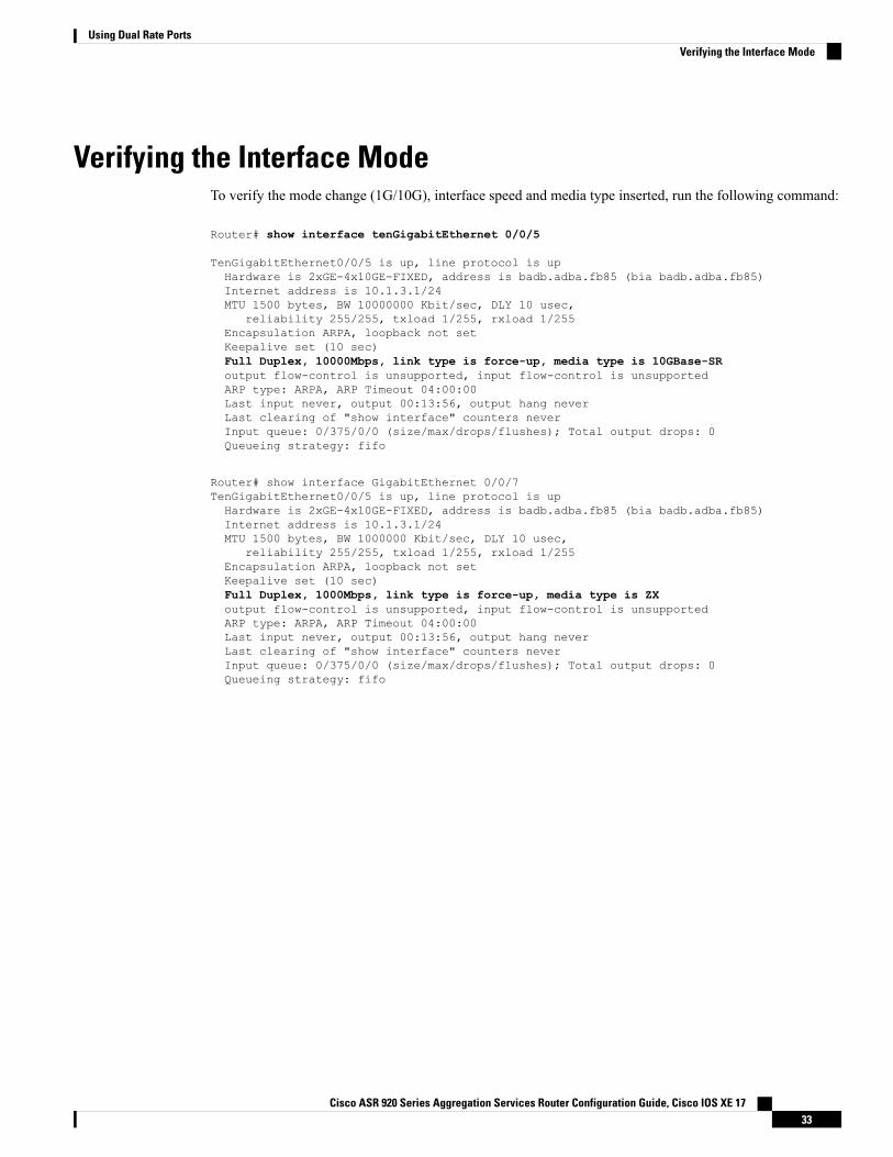
Verifying the Interface ModeTo verify the mode change (1G/10G), interface speed and media type inserted, run the following command:
Router# show interface tenGigabitEthernet 0/0/5
TenGigabitEthernet0/0/5 is up, line protocol is upHardware is 2xGE-4x10GE-FIXED, address is badb.adba.fb85 (bia badb.adba.fb85)Internet address is 10.1.3.1/24MTU 1500 bytes, BW 10000000 Kbit/sec, DLY 10 usec,
reliability 255/255, txload 1/255, rxload 1/255Encapsulation ARPA, loopback not setKeepalive set (10 sec)Full Duplex, 10000Mbps, link type is force-up, media type is 10GBase-SRoutput flow-control is unsupported, input flow-control is unsupportedARP type: ARPA, ARP Timeout 04:00:00Last input never, output 00:13:56, output hang neverLast clearing of "show interface" counters neverInput queue: 0/375/0/0 (size/max/drops/flushes); Total output drops: 0Queueing strategy: fifo
Router# show interface GigabitEthernet 0/0/7TenGigabitEthernet0/0/5 is up, line protocol is upHardware is 2xGE-4x10GE-FIXED, address is badb.adba.fb85 (bia badb.adba.fb85)Internet address is 10.1.3.1/24MTU 1500 bytes, BW 1000000 Kbit/sec, DLY 10 usec,
reliability 255/255, txload 1/255, rxload 1/255Encapsulation ARPA, loopback not setKeepalive set (10 sec)Full Duplex, 1000Mbps, link type is force-up, media type is ZXoutput flow-control is unsupported, input flow-control is unsupportedARP type: ARPA, ARP Timeout 04:00:00Last input never, output 00:13:56, output hang neverLast clearing of "show interface" counters neverInput queue: 0/375/0/0 (size/max/drops/flushes); Total output drops: 0Queueing strategy: fifo
Cisco ASR 920 Series Aggregation Services Router Configuration Guide, Cisco IOS XE 1733
Using Dual Rate PortsVerifying the Interface Mode

Cisco ASR 920 Series Aggregation Services Router Configuration Guide, Cisco IOS XE 1734
Using Dual Rate PortsVerifying the Interface Mode
C H A P T E R 6Console Port and Telnet Handling
• Console Port Overview, on page 35• Connecting Console Cables, on page 35• Installing USB Device Drivers, on page 35• Console Port Handling Overview, on page 36• Telnet and SSH Overview, on page 36• Persistent Telnet, on page 36• Configuring a Console Port Transport Map, on page 36• Configuring Persistent Telnet, on page 38• Viewing Console Port, SSH, and Telnet Handling Configurations, on page 41• Important Notes and Restrictions, on page 43
Console Port OverviewThe console port on the router is an EIA/TIA-232 asynchronous, serial connection with no flow control andan RJ-45 connector. The console port is used to access the router and is located on the front panel of the router.
For information on accessing the router using the console port, see the Cisco ASR 920 Hardware InstallationGuide.
Connecting Console CablesFor information about connecting console cables to the Cisco ASR 920 Series Router, see the Cisco ASR 920Series Aggregartion Services Router Hardware Installation Guide.
Installing USB Device DriversFor instructions on how to install device drivers in order to use the USB console port, see the ASR 920 SeriesAggregartion Services Router Hardware Installation Guide.
Cisco ASR 920 Series Aggregation Services Router Configuration Guide, Cisco IOS XE 1735
Console Port Handling OverviewUsers using the console port to access the router are automatically directed to the IOS XE command-lineinterface, by default.
If a user is trying to access the router through the console port and sends a break signal (a break signal canbe sent by entering Ctrl-C or Ctrl-Shift-6, or by entering the send break command at the Telnet prompt )before connecting to the IOS XE command-line interface, the user is directed into diagnostic mode by defaultif the non-RPIOS sub-packages can be accessed.
These settings can be changed by configuring a transport map for the console port and applying that transportmap to the console interface.
Telnet and SSH OverviewTelnet and Secure Shell (SSH) on the router can be configured and handled like in any other Cisco platforms.For information on traditional Telnet, see the line command in the Cisco IOS Terminal Services CommandReference guide.
For information on configuring traditional SSH, see the Secure Shell Configuration Guide.
The router also supports persistent Telnet. Persistent Telnet allows network administrators to more clearlydefine the treatment of incoming traffic when users access the router through the Management Ethernet portusing Telnet. Notably, persistent Telnet provides more robust network access by allowing the router to beconfigured to be accessible through the EthernetManagement port using Telnet even when the IOSXE processhas failed.
Persistent TelnetIn traditional Cisco routers, accessing the router using Telnet is not possible in the event of an IOS failure.When Cisco IOS fails on a traditional Cisco router, the only method of accessing the router is through theconsole port. Similarly, if all active IOS processes have failed on a router that is not using persistent Telnet,the only method of accessing the router is through the console port.
With persistent Telnet however, users can configure a transport map that defines the treatment of incomingTelnet traffic on the Management Ethernet interface. Among the many configuration options, a transport mapcan be configured to direct all traffic to the IOS command-line interface, diagnostic mode, or to wait for anIOS vty line to become available and then direct users into diagnostic mode when the user sends a break signalwhile waiting for the IOS vty line to become available. If you use Telnet to access diagnostic mode, the Telnetconnection will be usable even in scenarios when no IOS process is active. Therefore, persistent Telnetintroduces the ability to access the router via diagnostic mode when the IOS process is not active.
Configuring a Console Port Transport MapThis task describes how to configure a transport map for a console port interface on the router.
Cisco ASR 920 Series Aggregation Services Router Configuration Guide, Cisco IOS XE 1736
Console Port and Telnet HandlingConsole Port Handling Overview
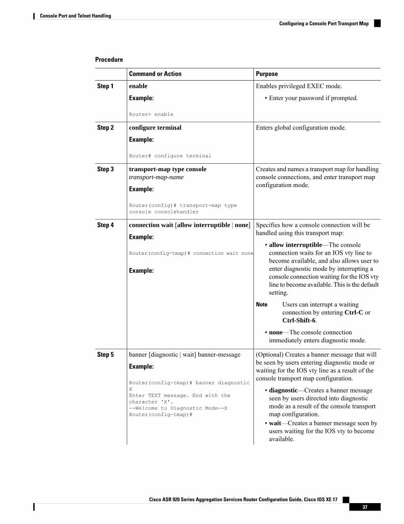
Procedure
PurposeCommand or Action
Enables privileged EXEC mode.enableStep 1
Example: • Enter your password if prompted.
Router> enable
Enters global configuration mode.configure terminal
Example:
Step 2
Router# configure terminal
Creates and names a transport map for handlingconsole connections, and enter transport mapconfiguration mode.
transport-map type consoletransport-map-name
Example:
Step 3
Router(config)# transport-map typeconsole consolehandler
Specifies how a console connection will behandled using this transport map:
connection wait [allow interruptible | none]
Example:
Step 4
• allow interruptible—The consoleconnection waits for an IOS vty line toRouter(config-tmap)# connection wait none
become available, and also allows user toenter diagnostic mode by interrupting aExample:console connection waiting for the IOS vtyline to become available. This is the defaultsetting.
Users can interrupt a waitingconnection by entering Ctrl-C orCtrl-Shift-6.
Note
• none—The console connectionimmediately enters diagnostic mode.
(Optional) Creates a banner message that willbe seen by users entering diagnostic mode or
banner [diagnostic | wait] banner-message
Example:
Step 5
waiting for the IOS vty line as a result of theconsole transport map configuration.
Router(config-tmap)# banner diagnosticX • diagnostic—Creates a banner message
seen by users directed into diagnosticEnter TEXT message. End with thecharacter 'X'.
mode as a result of the console transportmap configuration.
--Welcome to Diagnostic Mode--XRouter(config-tmap)#
• wait—Creates a banner message seen byusers waiting for the IOS vty to becomeavailable.
Cisco ASR 920 Series Aggregation Services Router Configuration Guide, Cisco IOS XE 1737
Console Port and Telnet HandlingConfiguring a Console Port Transport Map
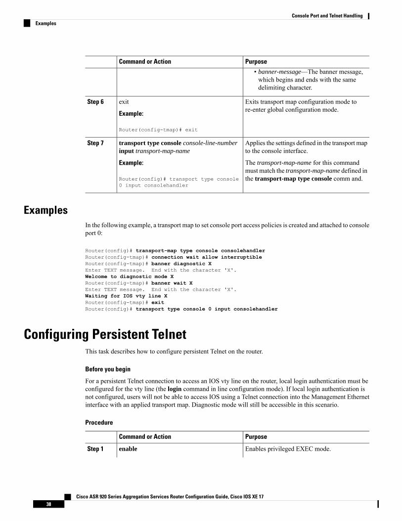
PurposeCommand or Action
• banner-message—The banner message,which begins and ends with the samedelimiting character.
Exits transport map configuration mode tore-enter global configuration mode.
exit
Example:
Step 6
Router(config-tmap)# exit
Applies the settings defined in the transport mapto the console interface.
transport type console console-line-numberinput transport-map-name
Step 7
Example: The transport-map-name for this commandmust match the transport-map-name defined inthe transport-map type console comm and.Router(config)# transport type console
0 input consolehandler
ExamplesIn the following example, a transport map to set console port access policies is created and attached to consoleport 0:
Router(config)# transport-map type console consolehandlerRouter(config-tmap)# connection wait allow interruptibleRouter(config-tmap)# banner diagnostic XEnter TEXT message. End with the character 'X'.Welcome to diagnostic mode XRouter(config-tmap)# banner wait XEnter TEXT message. End with the character 'X'.Waiting for IOS vty line XRouter(config-tmap)# exitRouter(config)# transport type console 0 input consolehandler
Configuring Persistent TelnetThis task describes how to configure persistent Telnet on the router.
Before you begin
For a persistent Telnet connection to access an IOS vty line on the router, local login authentication must beconfigured for the vty line (the login command in line configuration mode). If local login authentication isnot configured, users will not be able to access IOS using a Telnet connection into the Management Ethernetinterface with an applied transport map. Diagnostic mode will still be accessible in this scenario.
Procedure
PurposeCommand or Action
Enables privileged EXEC mode.enableStep 1
Cisco ASR 920 Series Aggregation Services Router Configuration Guide, Cisco IOS XE 1738
Console Port and Telnet HandlingExamples
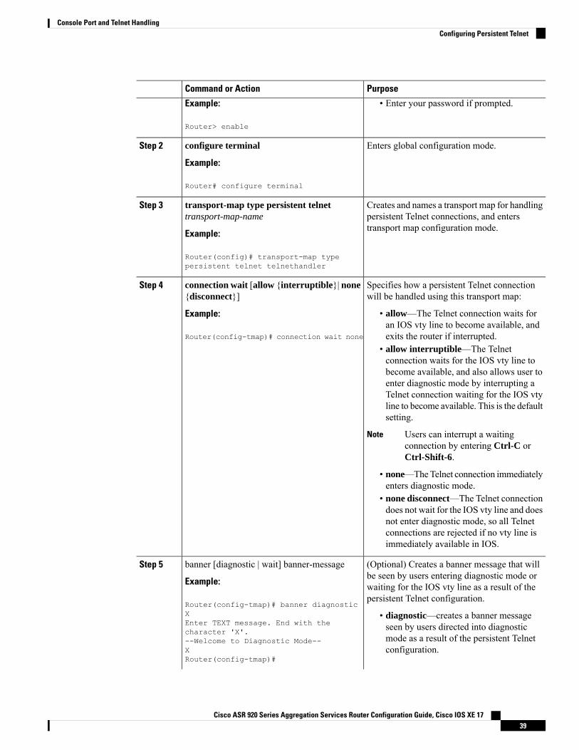
PurposeCommand or Action
Example: • Enter your password if prompted.
Router> enable
Enters global configuration mode.configure terminal
Example:
Step 2
Router# configure terminal
Creates and names a transport map for handlingpersistent Telnet connections, and enterstransport map configuration mode.
transport-map type persistent telnettransport-map-name
Example:
Step 3
Router(config)# transport-map typepersistent telnet telnethandler
Specifies how a persistent Telnet connectionwill be handled using this transport map:
connection wait [allow {interruptible}| none{disconnect}]
Step 4
Example: • allow—The Telnet connection waits foran IOS vty line to become available, andexits the router if interrupted.Router(config-tmap)# connection wait none
• allow interruptible—The Telnetconnection waits for the IOS vty line tobecome available, and also allows user toenter diagnostic mode by interrupting aTelnet connection waiting for the IOS vtyline to become available. This is the defaultsetting.
Users can interrupt a waitingconnection by entering Ctrl-C orCtrl-Shift-6.
Note
• none—TheTelnet connection immediatelyenters diagnostic mode.
• none disconnect—The Telnet connectiondoes not wait for the IOS vty line and doesnot enter diagnostic mode, so all Telnetconnections are rejected if no vty line isimmediately available in IOS.
(Optional) Creates a banner message that willbe seen by users entering diagnostic mode or
banner [diagnostic | wait] banner-message
Example:
Step 5
waiting for the IOS vty line as a result of thepersistent Telnet configuration.
Router(config-tmap)# banner diagnosticX • diagnostic—creates a banner message
seen by users directed into diagnosticEnter TEXT message. End with thecharacter 'X'.
mode as a result of the persistent Telnetconfiguration.
--Welcome to Diagnostic Mode--XRouter(config-tmap)#
Cisco ASR 920 Series Aggregation Services Router Configuration Guide, Cisco IOS XE 1739
Console Port and Telnet HandlingConfiguring Persistent Telnet
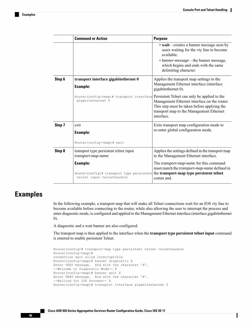
PurposeCommand or Action
• wait—creates a banner message seen byusers waiting for the vty line to becomeavailable.
• banner-message—the banner message,which begins and ends with the samedelimiting character.
Applies the transport map settings to theManagement Ethernet interface (interfacegigabitethernet 0).
transport interface gigabitethernet 0
Example:
Router(config-tmap)# transport interfacegigabitethernet 0
Step 6
Persistent Telnet can only be applied to theManagement Ethernet interface on the router.This step must be taken before applying thetransport map to the Management Ethernetinterface.
Exits transport map configuration mode tore-enter global configuration mode.
exit
Example:
Step 7
Router(config-tmap)# exit
Applies the settings defined in the transport mapto the Management Ethernet interface.
transport type persistent telnet inputtransport-map-name
Step 8
Example: The transport-map-name for this commandmust match the transport-map-name defined in
Router(config)# transport type persistenttelnet input telnethandler
the transport-map type persistent telnetcomm and.
ExamplesIn the following example, a transport map that will make all Telnet connections wait for an IOS vty line tobecome available before connecting to the router, while also allowing the user to interrupt the process andenter diagnostic mode, is configured and applied to theManagement Ethernet interface (interface gigabitethernet0).
A diagnostic and a wait banner are also configured.
The transport map is then applied to the interface when the transport type persistent telnet input commandis entered to enable persistent Telnet.
Router(config)# transport-map type persistent telnet telnethandlerRouter(config-tmap)#connection wait allow interruptibleRouter(config-tmap)# banner diagnostic XEnter TEXT message. End with the character 'X'.--Welcome to Diagnostic Mode-- XRouter(config-tmap)# banner wait XEnter TEXT message. End with the character 'X'.--Waiting for IOS Process-- XRouter(config-tmap)# transport interface gigabitethernet 0
Cisco ASR 920 Series Aggregation Services Router Configuration Guide, Cisco IOS XE 1740
Console Port and Telnet HandlingExamples
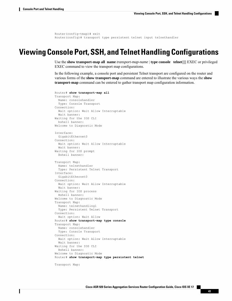
Router(config-tmap)# exitRouter(config)# transport type persistent telnet input telnethandler
Viewing Console Port, SSH, and Telnet Handling ConfigurationsUse the show transport-map all name transport-map-name | type console telnet]]] EXEC or privilegedEXEC command to view the transport map configurations.
In the following example, a console port and persistent Telnet transport are configured on the router andvarious forms of the show transport-map command are entered to illustrate the various ways the showtransport-map command can be entered to gather transport map configuration information.
Router# show transport-map allTransport Map:Name: consolehandlerType: Console Transport
Connection:Wait option: Wait Allow InterruptableWait banner:
Waiting for the IOS CLIbshell banner:
Welcome to Diagnostic Mode
Interface:GigabitEthernet0
Connection:Wait option: Wait Allow InterruptableWait banner:
Waiting for IOS promptBshell banner:
Transport Map:Name: telnethandlerType: Persistent Telnet Transport
Interface:GigabitEthernet0
Connection:Wait option: Wait Allow InterruptableWait banner:
Waiting for IOS processBshell banner:
Welcome to Diagnostic ModeTransport Map:Name: telnethandling1Type: Persistent Telnet Transport
Connection:Wait option: Wait Allow
Router# show transport-map type consoleTransport Map:Name: consolehandlerType: Console Transport
Connection:Wait option: Wait Allow InterruptableWait banner:
Waiting for the IOS CLIBshell banner:
Welcome to Diagnostic ModeRouter# show transport-map type persistent telnet
Transport Map:
Cisco ASR 920 Series Aggregation Services Router Configuration Guide, Cisco IOS XE 1741
Console Port and Telnet HandlingViewing Console Port, SSH, and Telnet Handling Configurations
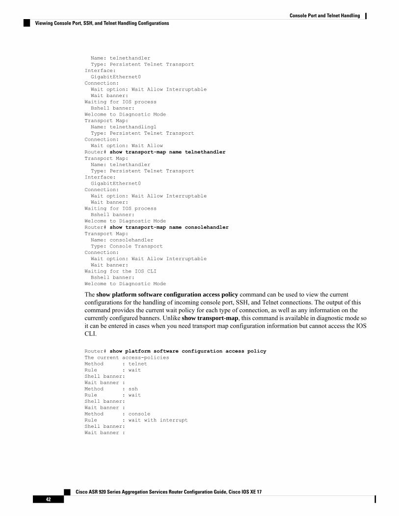
Name: telnethandlerType: Persistent Telnet Transport
Interface:GigabitEthernet0
Connection:Wait option: Wait Allow InterruptableWait banner:
Waiting for IOS processBshell banner:
Welcome to Diagnostic ModeTransport Map:Name: telnethandling1Type: Persistent Telnet Transport
Connection:Wait option: Wait Allow
Router# show transport-map name telnethandlerTransport Map:Name: telnethandlerType: Persistent Telnet Transport
Interface:GigabitEthernet0
Connection:Wait option: Wait Allow InterruptableWait banner:
Waiting for IOS processBshell banner:
Welcome to Diagnostic ModeRouter# show transport-map name consolehandlerTransport Map:Name: consolehandlerType: Console Transport
Connection:Wait option: Wait Allow InterruptableWait banner:
Waiting for the IOS CLIBshell banner:
Welcome to Diagnostic Mode
The show platform software configuration access policy command can be used to view the currentconfigurations for the handling of incoming console port, SSH, and Telnet connections. The output of thiscommand provides the current wait policy for each type of connection, as well as any information on thecurrently configured banners. Unlike show transport-map, this command is available in diagnostic mode soit can be entered in cases when you need transport map configuration information but cannot access the IOSCLI.
Router# show platform software configuration access policyThe current access-policiesMethod : telnetRule : waitShell banner:Wait banner :Method : sshRule : waitShell banner:Wait banner :Method : consoleRule : wait with interruptShell banner:Wait banner :
Cisco ASR 920 Series Aggregation Services Router Configuration Guide, Cisco IOS XE 1742
Console Port and Telnet HandlingViewing Console Port, SSH, and Telnet Handling Configurations
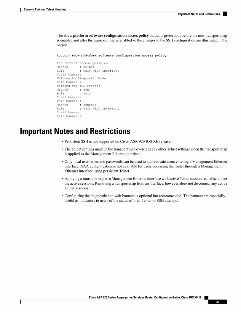
The show platform software configuration access policy output is given both before the new transport mapis enabled and after the transport map is enabled so the changes to the SSH configuration are illustrated in theoutput.
Router# show platform software configuration access policy
The current access-policiesMethod : telnetRule : wait with interruptShell banner:Welcome to Diagnostic ModeWait banner :Waiting for IOS ProcessMethod : sshRule : waitShell banner:Wait banner :Method : consoleRule : wait with interruptShell banner:Wait banner :
Important Notes and Restrictions• Persistent SSH is not supported on Cisco ASR 920 IOS XE release.
• The Telnet settings made in the transport map overrides any other Telnet settings when the transport mapis applied to the Management Ethernet interface.
• Only local usernames and passwords can be used to authenticate users entering a Management Ethernetinterface. AAA authentication is not available for users accessing the router through a ManagementEthernet interface using persistent Telnet.
• Applying a transport map to a Management Ethernet interface with active Telnet sessions can disconnectthe active sessions. Removing a transport map from an interface, however, does not disconnect any activeTelnet sessions.
• Configuring the diagnostic and wait banners is optional but recommended. The banners are especiallyuseful as indicators to users of the status of their Telnet or SSH attempts.
Cisco ASR 920 Series Aggregation Services Router Configuration Guide, Cisco IOS XE 1743
Console Port and Telnet HandlingImportant Notes and Restrictions

Cisco ASR 920 Series Aggregation Services Router Configuration Guide, Cisco IOS XE 1744
Console Port and Telnet HandlingImportant Notes and Restrictions
C H A P T E R 7Using the Management Ethernet Interface
The Cisco ASR 920 Series Router has one Gigabit Ethernet Management Ethernet interface on each RouteSwitch Processor.
The purpose of this interface is to allow users to perform management tasks on the router; it is basically aninterface that should not and often cannot forward network traffic but can otherwise access the router, oftenvia Telnet and SSH, and perform most management tasks on the router. The interface is most useful beforea router has begun routing, or in troubleshooting scenarios when the interfaces are inactive.
The following aspects of the Management Ethernet interface should be noted:
• Each router has a Management Ethernet interface.• IPv4, IPv6, and ARP are the only routed protocols supported for the interface.• The interface provides a method of access to the router even if the interfaces or the IOS processes aredown.
• TheManagement Ethernet interface is part of its own VRF. This is discussed in more detail in the GigabitEthernet Management Interface VRF, on page 46.
• Gigabit Ethernet Port Numbering, on page 45• IP Address Handling in ROMmon and the Management Ethernet Port, on page 46• Gigabit Ethernet Management Interface VRF, on page 46• Common Ethernet Management Tasks, on page 46
Gigabit Ethernet Port NumberingThe Gigabit Ethernet Management port is always GigabitEthernet0.
The port can be accessed in configuration mode like any other port on the router.
Router#config tEnter configuration commands, one per line. End with CNTL/Z.Router(config)#interface gigabitethernet0Router(config-if)#
Cisco ASR 920 Series Aggregation Services Router Configuration Guide, Cisco IOS XE 1745
IP Address Handling in ROMmon and the Management EthernetPort
On the router, IP addresses can be configured in ROMmon (the IP_ADDRESS= and IP_SUBNET_MASK=commands) and through the use of the IOS command-line interface (the ip address command in interfaceconfiguration mode).
Assuming the IOS process has not begun running on the router, the IP address that was set in ROMmon actsas the IP address of the Management Ethernet interface. In cases where the IOS process is running and hastaken control of the Management Ethernet interface, the IP address specified when configuring the GigabitEthernet 0 interface in the IOS CLI becomes the IP address of the Management Ethernet interface. TheROMmon-defined IP address is only used as the interface address when the IOS process is inactive.
For this reason, the IP addresses specified in ROMmon and in the IOSCLI can be identical and theManagementEthernet interface will function properly.
Gigabit Ethernet Management Interface VRFThe Gigabit Ethernet Management interface is automatically part of its own VRF. This VRF, which is named“Mgmt-intf,” is automatically configured on the router and is dedicated to theManagement Ethernet interface;no other interfaces can join this VRF. Therefore, this VRF does not participate in the MPLS VPN VRF orany other network-wide VRF.
Placing the management ethernet interface in its own VRF has the following effects on the ManagementEthernet interface:
• Many features must be configured or used inside the VRF, so the CLI may be different for certainManagement Ethernet functions on the router than on Management Ethernet interfaces on other routers.
• Prevents transit traffic from traversing the router. Because all of the interfaces and the ManagementEthernet interface are automatically in different VRFs, no transit traffic can enter the ManagementEthernet interface and leave an interface, or vice versa.
• Improved security of the interface. Because the Mgmt-intf VRF has its own routing table as a result ofbeing in its own VRF, routes can only be added to the routing table of theManagement Ethernet interfaceif explicitly entered by a user.
The Management Ethernet interface VRF supports both IPv4 and IPv6 address families.
Common Ethernet Management TasksBecause users can perform most tasks on a router through the Management Ethernet interface, many taskscan be done by accessing the router through the Management Ethernet interface.
Viewing the VRF ConfigurationThe VRF configuration for the Management Ethernet interface is viewable using the show running-configvrf command.
This example shows the default VRF configuration:
Cisco ASR 920 Series Aggregation Services Router Configuration Guide, Cisco IOS XE 1746
Using the Management Ethernet InterfaceIP Address Handling in ROMmon and the Management Ethernet Port
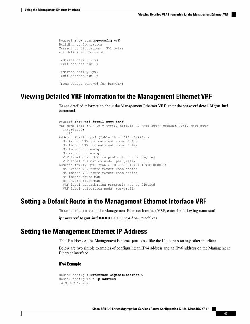
Router# show running-config vrfBuilding configuration...Current configuration : 351 bytesvrf definition Mgmt-intf!address-family ipv4exit-address-family!address-family ipv6exit-address-family!(some output removed for brevity)
Viewing Detailed VRF Information for the Management Ethernet VRFTo see detailed information about the Management Ethernet VRF, enter the show vrf detail Mgmt-intfcommand.
Router# show vrf detail Mgmt-intfVRF Mgmt-intf (VRF Id = 4085); default RD <not set>; default VPNID <not set>Interfaces:Gi0
Address family ipv4 (Table ID = 4085 (0xFF5)):No Export VPN route-target communitiesNo Import VPN route-target communitiesNo import route-mapNo export route-mapVRF label distribution protocol: not configuredVRF label allocation mode: per-prefix
Address family ipv6 (Table ID = 503316481 (0x1E000001)):No Export VPN route-target communitiesNo Import VPN route-target communitiesNo import route-mapNo export route-mapVRF label distribution protocol: not configuredVRF label allocation mode: per-prefix
Setting a Default Route in the Management Ethernet Interface VRFTo set a default route in the Management Ethernet Interface VRF, enter the following command
ip route vrf Mgmt-intf 0.0.0.0 0.0.0.0 next-hop-IP-address
Setting the Management Ethernet IP AddressThe IP address of the Management Ethernet port is set like the IP address on any other interface.
Below are two simple examples of configuring an IPv4 address and an IPv6 address on the ManagementEthernet interface.
IPv4 Example
Router(config)# interface GigabitEthernet 0Router(config-if)# ip addressA.B.C.D A.B.C.D
Cisco ASR 920 Series Aggregation Services Router Configuration Guide, Cisco IOS XE 1747
Using the Management Ethernet InterfaceViewing Detailed VRF Information for the Management Ethernet VRF
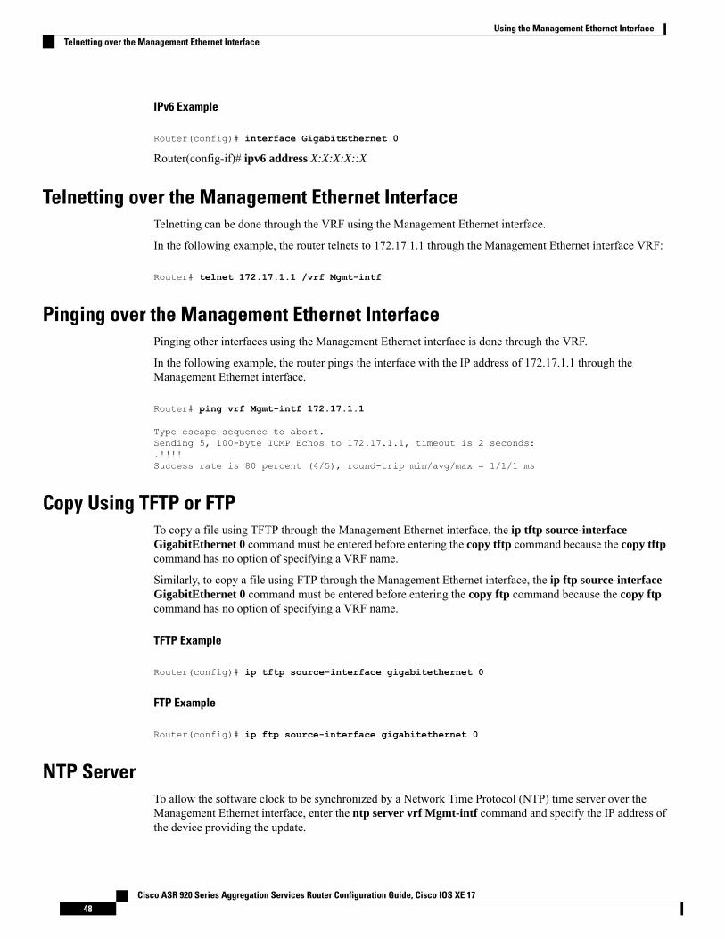
IPv6 Example
Router(config)# interface GigabitEthernet 0
Router(config-if)# ipv6 address X:X:X:X::X
Telnetting over the Management Ethernet InterfaceTelnetting can be done through the VRF using the Management Ethernet interface.
In the following example, the router telnets to 172.17.1.1 through the Management Ethernet interface VRF:
Router# telnet 172.17.1.1 /vrf Mgmt-intf
Pinging over the Management Ethernet InterfacePinging other interfaces using the Management Ethernet interface is done through the VRF.
In the following example, the router pings the interface with the IP address of 172.17.1.1 through theManagement Ethernet interface.
Router# ping vrf Mgmt-intf 172.17.1.1
Type escape sequence to abort.Sending 5, 100-byte ICMP Echos to 172.17.1.1, timeout is 2 seconds:.!!!!Success rate is 80 percent (4/5), round-trip min/avg/max = 1/1/1 ms
Copy Using TFTP or FTPTo copy a file using TFTP through the Management Ethernet interface, the ip tftp source-interfaceGigabitEthernet 0 command must be entered before entering the copy tftp command because the copy tftpcommand has no option of specifying a VRF name.
Similarly, to copy a file using FTP through the Management Ethernet interface, the ip ftp source-interfaceGigabitEthernet 0 command must be entered before entering the copy ftp command because the copy ftpcommand has no option of specifying a VRF name.
TFTP Example
Router(config)# ip tftp source-interface gigabitethernet 0
FTP Example
Router(config)# ip ftp source-interface gigabitethernet 0
NTP ServerTo allow the software clock to be synchronized by a Network Time Protocol (NTP) time server over theManagement Ethernet interface, enter the ntp server vrf Mgmt-intf command and specify the IP address ofthe device providing the update.
Cisco ASR 920 Series Aggregation Services Router Configuration Guide, Cisco IOS XE 1748
Using the Management Ethernet InterfaceTelnetting over the Management Ethernet Interface
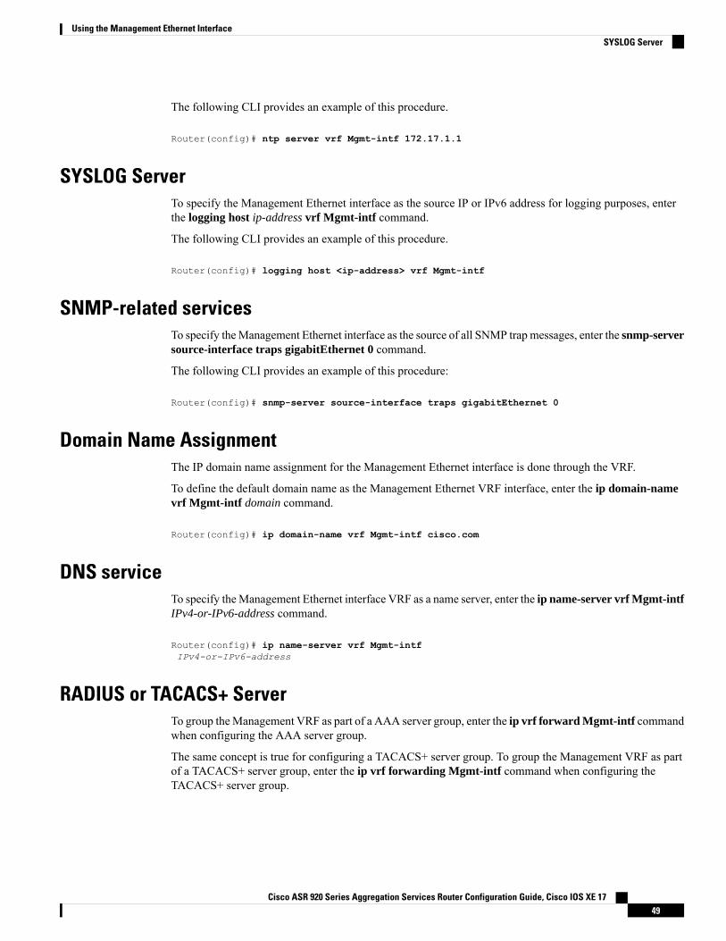
The following CLI provides an example of this procedure.
Router(config)# ntp server vrf Mgmt-intf 172.17.1.1
SYSLOG ServerTo specify the Management Ethernet interface as the source IP or IPv6 address for logging purposes, enterthe logging host ip-address vrf Mgmt-intf command.
The following CLI provides an example of this procedure.
Router(config)# logging host <ip-address> vrf Mgmt-intf
SNMP-related servicesTo specify theManagement Ethernet interface as the source of all SNMP trap messages, enter the snmp-serversource-interface traps gigabitEthernet 0 command.
The following CLI provides an example of this procedure:
Router(config)# snmp-server source-interface traps gigabitEthernet 0
Domain Name AssignmentThe IP domain name assignment for the Management Ethernet interface is done through the VRF.
To define the default domain name as the Management Ethernet VRF interface, enter the ip domain-namevrf Mgmt-intf domain command.
Router(config)# ip domain-name vrf Mgmt-intf cisco.com
DNS serviceTo specify theManagement Ethernet interface VRF as a name server, enter the ip name-server vrf Mgmt-intfIPv4-or-IPv6-address command.
Router(config)# ip name-server vrf Mgmt-intfIPv4-or-IPv6-address
RADIUS or TACACS+ ServerTo group theManagement VRF as part of a AAA server group, enter the ip vrf forward Mgmt-intf commandwhen configuring the AAA server group.
The same concept is true for configuring a TACACS+ server group. To group the Management VRF as partof a TACACS+ server group, enter the ip vrf forwarding Mgmt-intf command when configuring theTACACS+ server group.
Cisco ASR 920 Series Aggregation Services Router Configuration Guide, Cisco IOS XE 1749
Using the Management Ethernet InterfaceSYSLOG Server
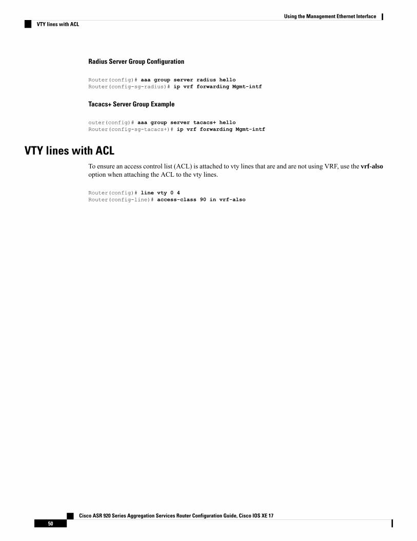
Radius Server Group Configuration
Router(config)# aaa group server radius helloRouter(config-sg-radius)# ip vrf forwarding Mgmt-intf
Tacacs+ Server Group Example
outer(config)# aaa group server tacacs+ helloRouter(config-sg-tacacs+)# ip vrf forwarding Mgmt-intf
VTY lines with ACLTo ensure an access control list (ACL) is attached to vty lines that are and are not using VRF, use the vrf-alsooption when attaching the ACL to the vty lines.
Router(config)# line vty 0 4Router(config-line)# access-class 90 in vrf-also
Cisco ASR 920 Series Aggregation Services Router Configuration Guide, Cisco IOS XE 1750
Using the Management Ethernet InterfaceVTY lines with ACL
C H A P T E R 8Out of Band Management Through USB Modem
Effective Cisco IOS XE Release 3.15.0S, the Cisco ASR 920 Series Router provides out-of-band connectivityto manage remotely-deployed cell site routers using the 3G or 4G cellular network through the USB modem(also called the dongle). This OOB connectivity gives the service providers the ability to securely managetheir remote cell site routers at anytime from anywhere. This feature also eliminates the need for the onsiteor remote IT staff to handle outages.
Out of Band Management feature is not supported in Cisco IOS XE Everest 16.5.1.
• Prerequisites for the OOB Management Through USB Modem, on page 51• Restrictions for the OOB Management Through USB Modem, on page 51• Information About the OOB Management Through USB Modem, on page 52• Configuring the Management Interface on the MAG, on page 53• Configuring the LMA, on page 56• Verifying the Configuration, on page 57
Prerequisites for the OOB Management Through USB Modem• The Local Mobility Anchor (LMA) must be a Cisco ASR 1000 Series Router.
• The Mobile Access Gateway (MAG) must be the Cisco ASR 920 Series Router (ASR-920-12CZ-A/D,ASR-920-4SZ-A/D, ASR 920-10SZ-PD, or ASR-920-8S4Z-PD).
• The dongle can be inserted only in the USB Memory port of the Cisco ASR 920 Series Router.
Restrictions for the OOB Management Through USB ModemFor Cisco IOS-XE Release 3.15.0S:
• Multi-VRF is not supported on the Cisco ASR 1000 Series Router.• Only UDP PMIPv6 tunnels are supported between the LMA and MAG.• Only the following dongle are supported:
• Reliance (ZTE: model- AC2739)• Airtel 4G (Huawei: model-E3272)• TATA DoCoMo (ZTE: model-MF190)
Cisco ASR 920 Series Aggregation Services Router Configuration Guide, Cisco IOS XE 1751
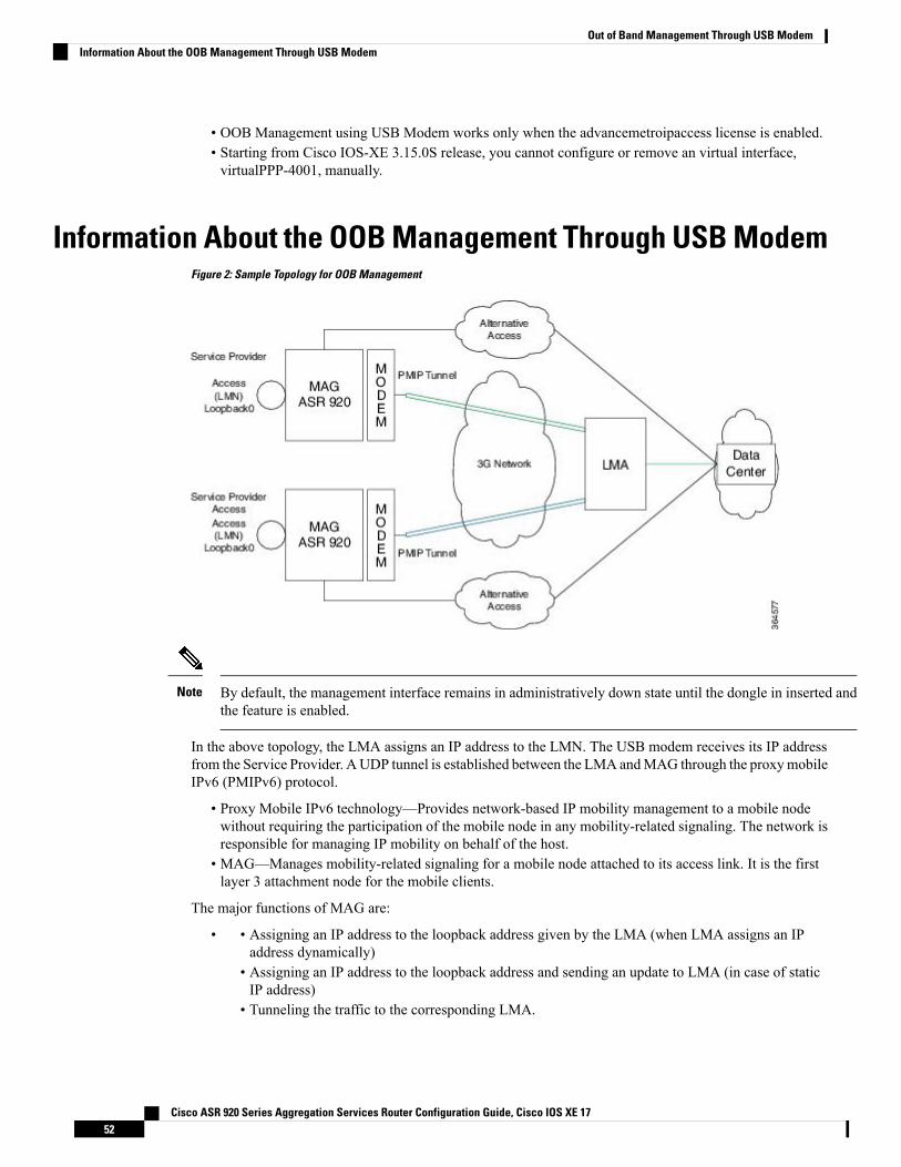
• OOB Management using USB Modem works only when the advancemetroipaccess license is enabled.• Starting from Cisco IOS-XE 3.15.0S release, you cannot configure or remove an virtual interface,virtualPPP-4001, manually.
Information About the OOB Management Through USB ModemFigure 2: Sample Topology for OOB Management
By default, the management interface remains in administratively down state until the dongle in inserted andthe feature is enabled.
Note
In the above topology, the LMA assigns an IP address to the LMN. The USB modem receives its IP addressfrom the Service Provider. AUDP tunnel is established between the LMA andMAG through the proxymobileIPv6 (PMIPv6) protocol.
• Proxy Mobile IPv6 technology—Provides network-based IP mobility management to a mobile nodewithout requiring the participation of the mobile node in any mobility-related signaling. The network isresponsible for managing IP mobility on behalf of the host.
• MAG—Manages mobility-related signaling for a mobile node attached to its access link. It is the firstlayer 3 attachment node for the mobile clients.
The major functions of MAG are:
• Assigning an IP address to the loopback address given by the LMA (when LMA assigns an IPaddress dynamically)
•
• Assigning an IP address to the loopback address and sending an update to LMA (in case of staticIP address)
• Tunneling the traffic to the corresponding LMA.
Cisco ASR 920 Series Aggregation Services Router Configuration Guide, Cisco IOS XE 1752
Out of Band Management Through USB ModemInformation About the OOB Management Through USB Modem
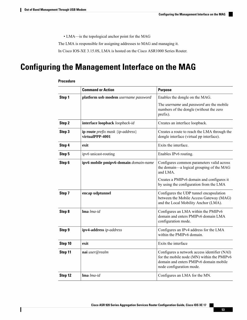
• LMA—is the topological anchor point for the MAG
The LMA is responsible for assigning addresses to MAG and managing it.
In Cisco IOS-XE 3.15.0S, LMA is hosted on the Cisco ASR1000 Series Router.
Configuring the Management Interface on the MAGProcedure
PurposeCommand or Action
Enables the dongle on the MAG.platform usb modem username passwordStep 1
The username and password are the mobilenumbers of the dongle (without the zeroprefix).
Creates an interface loopback.interface loopback loopback-idStep 2
Creates a route to reach the LMA through thedongle interface (virtual pp interface).
ip route prefix mask {ip-address}virtualPPP-4001
Step 3
Exits the interface.exitStep 4
Enables IPv6 routing.ipv6 unicast-routingStep 5
Configures common parameters valid acrossthe domain—a logical grouping of the MAGand LMA.
ipv6 mobile pmipv6-domain domain-nameStep 6
Creates a PMIPv6 domain and configures itby using the configuration from the LMA
Configures the UDP tunnel encapsulationbetween the Mobile Access Gateway (MAG)and the Local Mobility Anchor (LMA).
encap udptunnelStep 7
Configures an LMA within the PMIPv6domain and enters PMIPv6 domain LMAconfiguration mode.
lma lma-idStep 8
Configures an IPv4 address for the LMAwithin the PMIPv6 domain.
ipv4-address ip-addressStep 9
Exits the interfaceexitStep 10
Configures a network access identifier (NAI)for the mobile node (MN) within the PMIPv6
nai user@realmStep 11
domain and enters PMIPv6 domain mobilenode configuration mode.
Configures an LMA for the MN.lma lma-idStep 12
Cisco ASR 920 Series Aggregation Services Router Configuration Guide, Cisco IOS XE 1753
Out of Band Management Through USB ModemConfiguring the Management Interface on the MAG
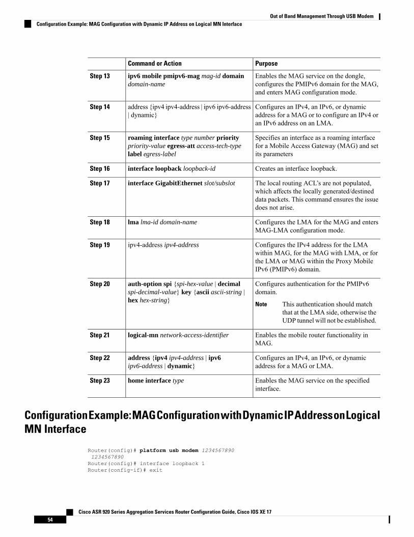
PurposeCommand or Action
Enables the MAG service on the dongle,configures the PMIPv6 domain for the MAG,and enters MAG configuration mode.
ipv6 mobile pmipv6-mag mag-id domaindomain-name
Step 13
Configures an IPv4, an IPv6, or dynamicaddress for a MAG or to configure an IPv4 oran IPv6 address on an LMA.
address {ipv4 ipv4-address | ipv6 ipv6-address| dynamic}
Step 14
Specifies an interface as a roaming interfacefor a Mobile Access Gateway (MAG) and setits parameters
roaming interface type number prioritypriority-value egress-att access-tech-typelabel egress-label
Step 15
Creates an interface loopback.interface loopback loopback-idStep 16
The local routing ACL’s are not populated,which affects the locally generated/destined
interface GigabitEthernet slot/subslotStep 17
data packets. This command ensures the issuedoes not arise.
Configures the LMA for the MAG and entersMAG-LMA configuration mode.
lma lma-id domain-nameStep 18
Configures the IPv4 address for the LMAwithin MAG, for the MAG with LMA, or for
ipv4-address ipv4-addressStep 19
the LMA or MAG within the Proxy MobileIPv6 (PMIPv6) domain.
Configures authentication for the PMIPv6domain.
auth-option spi {spi-hex-value | decimalspi-decimal-value} key {ascii ascii-string |hex hex-string}
Step 20
This authentication should matchthat at the LMA side, otherwise theUDP tunnel will not be established.
Note
Enables the mobile router functionality inMAG.
logical-mn network-access-identifierStep 21
Configures an IPv4, an IPv6, or dynamicaddress for a MAG or LMA.
address {ipv4 ipv4-address | ipv6ipv6-address | dynamic}
Step 22
Enables the MAG service on the specifiedinterface.
home interface typeStep 23
ConfigurationExample:MAGConfigurationwithDynamicIPAddressonLogicalMN Interface
Router(config)# platform usb modem 12345678901234567890Router(config)# interface loopback 1Router(config-if)# exit
Cisco ASR 920 Series Aggregation Services Router Configuration Guide, Cisco IOS XE 1754
Out of Band Management Through USB ModemConfiguration Example: MAG Configuration with Dynamic IP Address on Logical MN Interface
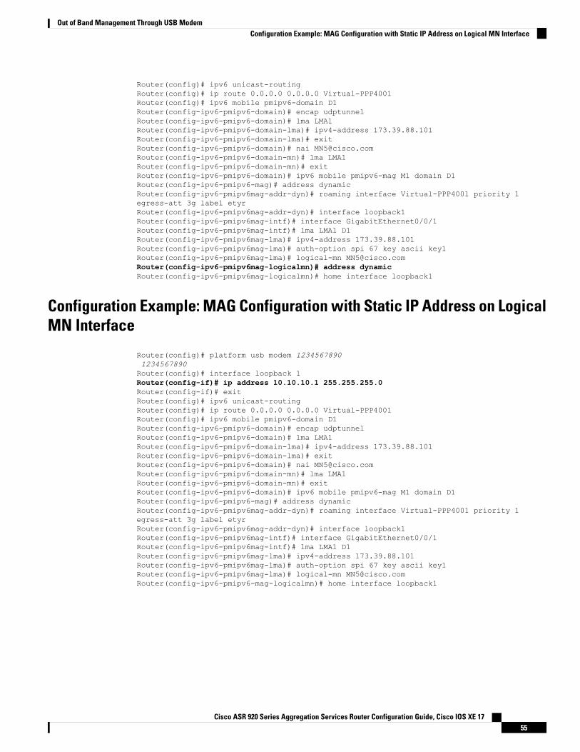
Router(config)# ipv6 unicast-routingRouter(config)# ip route 0.0.0.0 0.0.0.0 Virtual-PPP4001Router(config)# ipv6 mobile pmipv6-domain D1Router(config-ipv6-pmipv6-domain)# encap udptunnelRouter(config-ipv6-pmipv6-domain)# lma LMA1Router(config-ipv6-pmipv6-domain-lma)# ipv4-address 173.39.88.101Router(config-ipv6-pmipv6-domain-lma)# exitRouter(config-ipv6-pmipv6-domain)# nai [email protected](config-ipv6-pmipv6-domain-mn)# lma LMA1Router(config-ipv6-pmipv6-domain-mn)# exitRouter(config-ipv6-pmipv6-domain)# ipv6 mobile pmipv6-mag M1 domain D1Router(config-ipv6-pmipv6-mag)# address dynamicRouter(config-ipv6-pmipv6mag-addr-dyn)# roaming interface Virtual-PPP4001 priority 1egress-att 3g label etyrRouter(config-ipv6-pmipv6mag-addr-dyn)# interface loopback1Router(config-ipv6-pmipv6mag-intf)# interface GigabitEthernet0/0/1Router(config-ipv6-pmipv6mag-intf)# lma LMA1 D1Router(config-ipv6-pmipv6mag-lma)# ipv4-address 173.39.88.101Router(config-ipv6-pmipv6mag-lma)# auth-option spi 67 key ascii key1Router(config-ipv6-pmipv6mag-lma)# logical-mn [email protected](config-ipv6-pmipv6mag-logicalmn)# address dynamicRouter(config-ipv6-pmipv6mag-logicalmn)# home interface loopback1
Configuration Example: MAG Configuration with Static IP Address on LogicalMN Interface
Router(config)# platform usb modem 12345678901234567890Router(config)# interface loopback 1Router(config-if)# ip address 10.10.10.1 255.255.255.0Router(config-if)# exitRouter(config)# ipv6 unicast-routingRouter(config)# ip route 0.0.0.0 0.0.0.0 Virtual-PPP4001Router(config)# ipv6 mobile pmipv6-domain D1Router(config-ipv6-pmipv6-domain)# encap udptunnelRouter(config-ipv6-pmipv6-domain)# lma LMA1Router(config-ipv6-pmipv6-domain-lma)# ipv4-address 173.39.88.101Router(config-ipv6-pmipv6-domain-lma)# exitRouter(config-ipv6-pmipv6-domain)# nai [email protected](config-ipv6-pmipv6-domain-mn)# lma LMA1Router(config-ipv6-pmipv6-domain-mn)# exitRouter(config-ipv6-pmipv6-domain)# ipv6 mobile pmipv6-mag M1 domain D1Router(config-ipv6-pmipv6-mag)# address dynamicRouter(config-ipv6-pmipv6mag-addr-dyn)# roaming interface Virtual-PPP4001 priority 1egress-att 3g label etyrRouter(config-ipv6-pmipv6mag-addr-dyn)# interface loopback1Router(config-ipv6-pmipv6mag-intf)# interface GigabitEthernet0/0/1Router(config-ipv6-pmipv6mag-intf)# lma LMA1 D1Router(config-ipv6-pmipv6mag-lma)# ipv4-address 173.39.88.101Router(config-ipv6-pmipv6mag-lma)# auth-option spi 67 key ascii key1Router(config-ipv6-pmipv6mag-lma)# logical-mn [email protected](config-ipv6-pmipv6-mag-logicalmn)# home interface loopback1
Cisco ASR 920 Series Aggregation Services Router Configuration Guide, Cisco IOS XE 1755
Out of Band Management Through USB ModemConfiguration Example: MAG Configuration with Static IP Address on Logical MN Interface
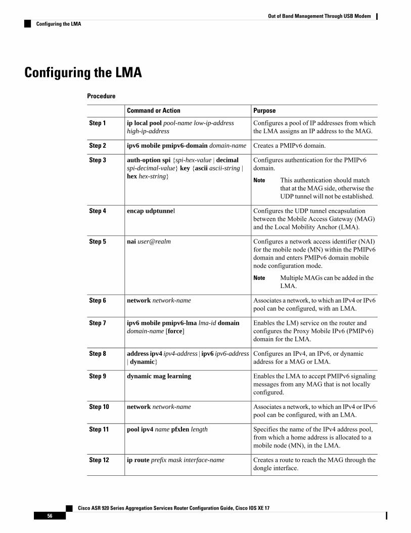
Configuring the LMAProcedure
PurposeCommand or Action
Configures a pool of IP addresses from whichthe LMA assigns an IP address to the MAG.
ip local pool pool-name low-ip-addresshigh-ip-address
Step 1
Creates a PMIPv6 domain.ipv6 mobile pmipv6-domain domain-nameStep 2
Configures authentication for the PMIPv6domain.
auth-option spi {spi-hex-value | decimalspi-decimal-value} key {ascii ascii-string |hex hex-string}
Step 3
This authentication should matchthat at theMAG side, otherwise theUDP tunnel will not be established.
Note
Configures the UDP tunnel encapsulationbetween the Mobile Access Gateway (MAG)and the Local Mobility Anchor (LMA).
encap udptunnelStep 4
Configures a network access identifier (NAI)for the mobile node (MN) within the PMIPv6
nai user@realmStep 5
domain and enters PMIPv6 domain mobilenode configuration mode.
MultipleMAGs can be added in theLMA.
Note
Associates a network, to which an IPv4 or IPv6pool can be configured, with an LMA.
network network-nameStep 6
Enables the LM) service on the router andconfigures the Proxy Mobile IPv6 (PMIPv6)domain for the LMA.
ipv6 mobile pmipv6-lma lma-id domaindomain-name [force]
Step 7
Configures an IPv4, an IPv6, or dynamicaddress for a MAG or LMA.
address ipv4 ipv4-address | ipv6 ipv6-address| dynamic}
Step 8
Enables the LMA to accept PMIPv6 signalingmessages from any MAG that is not locallyconfigured.
dynamic mag learningStep 9
Associates a network, to which an IPv4 or IPv6pool can be configured, with an LMA.
network network-nameStep 10
Specifies the name of the IPv4 address pool,from which a home address is allocated to amobile node (MN), in the LMA.
pool ipv4 name pfxlen lengthStep 11
Creates a route to reach the MAG through thedongle interface.
ip route prefix mask interface-nameStep 12
Cisco ASR 920 Series Aggregation Services Router Configuration Guide, Cisco IOS XE 1756
Out of Band Management Through USB ModemConfiguring the LMA
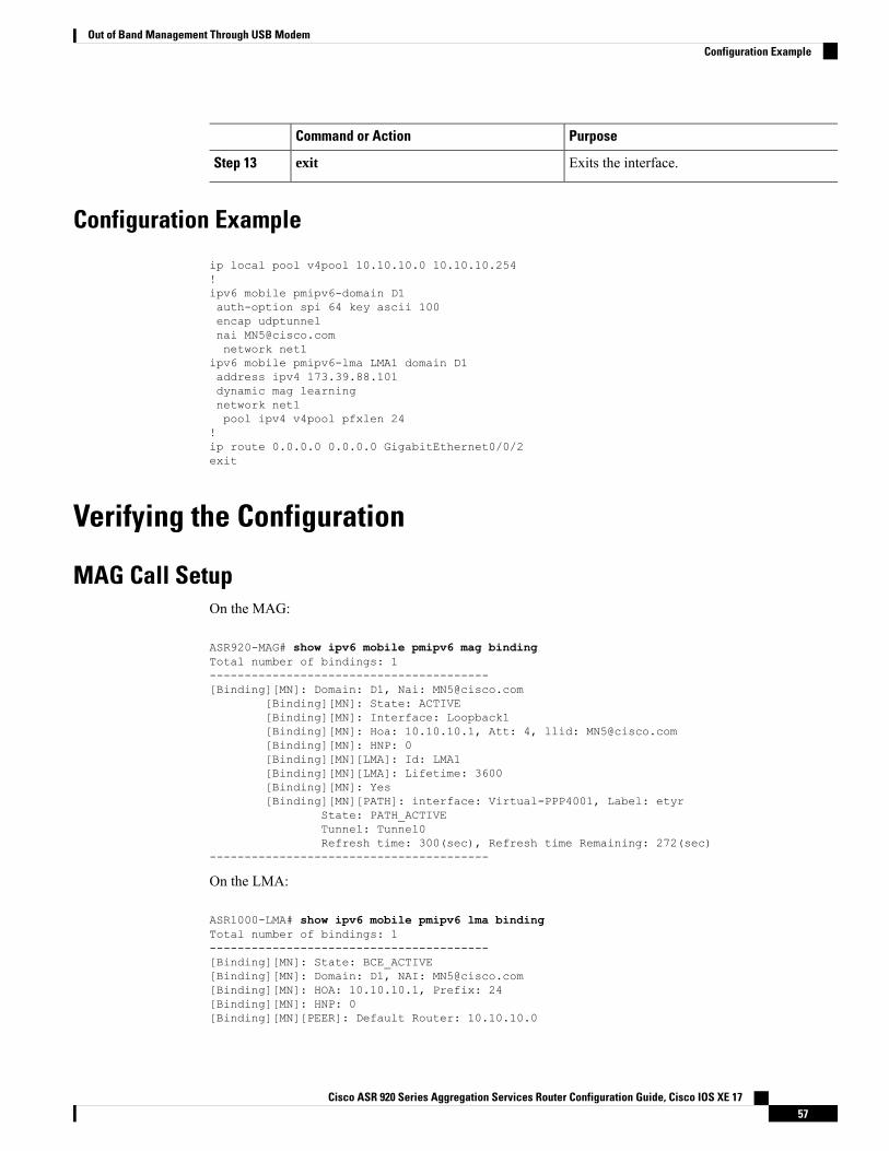
PurposeCommand or Action
Exits the interface.exitStep 13
Configuration Example
ip local pool v4pool 10.10.10.0 10.10.10.254!ipv6 mobile pmipv6-domain D1auth-option spi 64 key ascii 100encap udptunnelnai [email protected] net1
ipv6 mobile pmipv6-lma LMA1 domain D1address ipv4 173.39.88.101dynamic mag learningnetwork net1pool ipv4 v4pool pfxlen 24
!ip route 0.0.0.0 0.0.0.0 GigabitEthernet0/0/2exit
Verifying the Configuration
MAG Call SetupOn the MAG:
ASR920-MAG# show ipv6 mobile pmipv6 mag bindingTotal number of bindings: 1----------------------------------------[Binding][MN]: Domain: D1, Nai: [email protected]
[Binding][MN]: State: ACTIVE[Binding][MN]: Interface: Loopback1[Binding][MN]: Hoa: 10.10.10.1, Att: 4, llid: [email protected][Binding][MN]: HNP: 0[Binding][MN][LMA]: Id: LMA1[Binding][MN][LMA]: Lifetime: 3600[Binding][MN]: Yes[Binding][MN][PATH]: interface: Virtual-PPP4001, Label: etyr
State: PATH_ACTIVETunnel: Tunnel0Refresh time: 300(sec), Refresh time Remaining: 272(sec)
----------------------------------------
On the LMA:
ASR1000-LMA# show ipv6 mobile pmipv6 lma bindingTotal number of bindings: 1----------------------------------------[Binding][MN]: State: BCE_ACTIVE[Binding][MN]: Domain: D1, NAI: [email protected][Binding][MN]: HOA: 10.10.10.1, Prefix: 24[Binding][MN]: HNP: 0[Binding][MN][PEER]: Default Router: 10.10.10.0
Cisco ASR 920 Series Aggregation Services Router Configuration Guide, Cisco IOS XE 1757
Out of Band Management Through USB ModemConfiguration Example
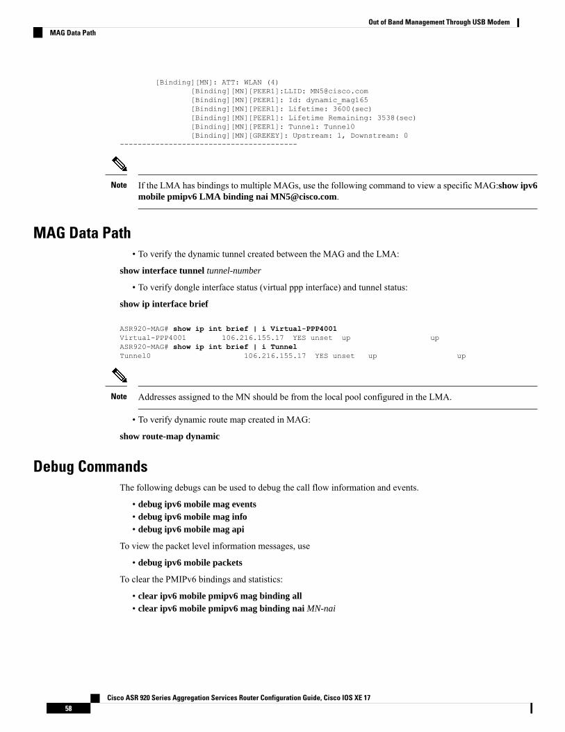
[Binding][MN]: ATT: WLAN (4)[Binding][MN][PEER1]:LLID: [email protected][Binding][MN][PEER1]: Id: dynamic_mag165[Binding][MN][PEER1]: Lifetime: 3600(sec)[Binding][MN][PEER1]: Lifetime Remaining: 3538(sec)[Binding][MN][PEER1]: Tunnel: Tunnel0[Binding][MN][GREKEY]: Upstream: 1, Downstream: 0
----------------------------------------
If the LMA has bindings to multiple MAGs, use the following command to view a specific MAG:show ipv6mobile pmipv6 LMA binding nai [email protected].
Note
MAG Data Path• To verify the dynamic tunnel created between the MAG and the LMA:
show interface tunnel tunnel-number
• To verify dongle interface status (virtual ppp interface) and tunnel status:
show ip interface brief
ASR920-MAG# show ip int brief | i Virtual-PPP4001Virtual-PPP4001 106.216.155.17 YES unset up upASR920-MAG# show ip int brief | i TunnelTunnel0 106.216.155.17 YES unset up up
Addresses assigned to the MN should be from the local pool configured in the LMA.Note
• To verify dynamic route map created in MAG:
show route-map dynamic
Debug CommandsThe following debugs can be used to debug the call flow information and events.
• debug ipv6 mobile mag events• debug ipv6 mobile mag info• debug ipv6 mobile mag api
To view the packet level information messages, use
• debug ipv6 mobile packets
To clear the PMIPv6 bindings and statistics:
• clear ipv6 mobile pmipv6 mag binding all• clear ipv6 mobile pmipv6 mag binding nai MN-nai
Cisco ASR 920 Series Aggregation Services Router Configuration Guide, Cisco IOS XE 1758
Out of Band Management Through USB ModemMAG Data Path

Related DocumentsFor more information on mobility commands, see the Cisco IOS IP Mobility Command Reference.
Cisco ASR 920 Series Aggregation Services Router Configuration Guide, Cisco IOS XE 1759
Out of Band Management Through USB ModemRelated Documents

Cisco ASR 920 Series Aggregation Services Router Configuration Guide, Cisco IOS XE 1760
Out of Band Management Through USB ModemRelated Documents
C H A P T E R 9Power Over Ethernet
Effective Cisco IOS XE Release 3.16S, the Cisco ASR-920-12SZ-IM Aggregation Services Router supportsPower over Ethernet (PoE). PoE is the ability for any LAN switching infrastructure to provide power over acopper Ethernet cable to an endpoint or powered device.
• Prerequisites for PoE, on page 61• Restrictions for PoE, on page 61• Information About PoE, on page 61• How to Configure the PoE, on page 62• Verifying the PoE Configuration, on page 63• Additional References, on page 66• Feature Information for Power Over Ethernet, on page 67
Prerequisites for PoE• Cisco ASR-920-12SZ-IM Aggregation Services Router supports multiple variants of power supplies.When using the AC power supplies, approximately 180 watts is used for PoE functionality, which canbe shared by all eight available copper Ethernet ports.
• PoE is applicable only on the following ports: Gi0/0/0 to Gi 0/0/7• When using DC power supplies, PoE is supported only if the input feed to the power-supply is 48 volts.
Restrictions for PoE• Configuring a port as a static port pre-provisions power for that port. This power is deducted from thecentral power pool. It is, therefore, advisable to configure a port as an auto port.
• PoE does not support interface modules (IMs).• The system allocates 180W of static power. However, if a component or device tries to draw power over180 W, the Cisco ASR-920-12SZ-IM Router silently reloads.
Information About PoEThe Cisco ASR-920-12SZ-IM Router uses the inline power as well as a global pool of power to power themodules, fans and other subsystems in the router. This power is alloted to all the powered devices detectedon a first-come-first-serve basis. However, but if many devices are connected, and a new device is added to
Cisco ASR 920 Series Aggregation Services Router Configuration Guide, Cisco IOS XE 1761
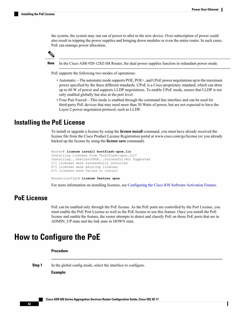
the system, the system may run out of power to allot to the new device. Over-subscription of power couldalso result in tripping the power supplies and bringing down modules or even the entire router. In such cases,PoE can manage power allocation.
In the Cisco ASR-920-12SZ-IM Router, the dual power supplies function in redundant power mode.Note
PoE supports the following two modes of operations:
• Automatic—The automaticmode supports POE, POE+, andUPoE power negotiations up to themaximumpower specified by the these different standards. UPoE is a Cisco proprietary standard, which can drawup to 60 W of power and supports LLDP negotiations. To enable UPoE mode, ensure that LLDP is notonly enabled globally but also at the port level.
• Four-Pair Forced—This mode is enabled through the command line interface and can be used forthird-party PoE devices that may need more than 30 Watts of power, but are not expected to have theLayer-2 power negotiation protocol, such as LLDP.
Installing the PoE LicenseTo install or upgrade a license by using the license install command, you must have already received thelicense file from the Cisco Product License Registration portal at www.cisco.com/go/license (or you alreadybacked up the license by using the license save command).
Router# license install bootflash:upoe.licInstalling licenses from “bootflash:upoe.lic”Installing...Feature:UPOE...Successful:Not Supported1/1 licenses were successfully installed0/1 licenses were existing licenses0/1 licenses were failed to install
Router(config)# license feature upoe
For more information on installing licenses, see Configuring the Cisco IOS Software Activation Feature.
PoE LicensePoE can be enabled only through the PoE license. As the PoE ports are controlled by the Port License, youmust enable the PoE Port License as well as the PoE license to use this feature. Once you install the PoElicense and enable the feature, the router attempts to detect and classify PoE on those PoE ports that are inADMIN_UP state and the link state in DOWN state.
How to Configure the PoEProcedure
Step 1 In the global config mode, select the interface to configure.
Example:
Cisco ASR 920 Series Aggregation Services Router Configuration Guide, Cisco IOS XE 1762
Power Over EthernetInstalling the PoE License
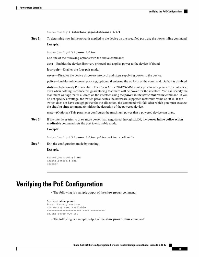
Router(config)# interface gigabitethernet 0/0/1
Step 2 To determine how inline power is applied to the device on the specified port, use the power inline command:
Example:
Router(config-if)# power inline
Use one of the following options with the above command:
auto—Enables the device discovery protocol and applies power to the device, if found.
four-pair—Enables the four-pair mode.
never—Disables the device discovery protocol and stops supplying power to the device.
police—Enables inline power policing; optional if entering the no form of the command. Default is disabled.
static—High priority PoE interface. The Cisco ASR-920-12SZ-IMRouter preallocates power to the interface,even when nothing is connected, guaranteeing that there will be power for the interface. You can specify themaximum wattage that is allowed on the interface using the power inline static max value command. If youdo not specify a wattage, the switch preallocates the hardware-supported maximum value of 60 W. If theswitch does not have enough power for the allocation, the command will fail, after which you must executethe shut/no shut command to initiate the detection of the powered device.
max—(Optional) This parameter configures the maximum power that a powered device can draw.
Step 3 If the interfaces tries to draw more power than negotiated through LLDP, the power inline police actionerrdisable command sets the port to errdisable mode.
Example:
Router(config-if)# power inline police action errdisable
Step 4 Exit the configuration mode by running:
Example:
Router(config-if)# endRouter(config)# endRouter#
Verifying the PoE Configuration• The following is a sample output of the show power command:
Router# show powerPower Summary Maximum(in Watts) Used Available---------------------- ---- ---------Inline Power 0.0 180
• The following is a sample output of the show power inline command:
Cisco ASR 920 Series Aggregation Services Router Configuration Guide, Cisco IOS XE 1763
Power Over EthernetVerifying the PoE Configuration
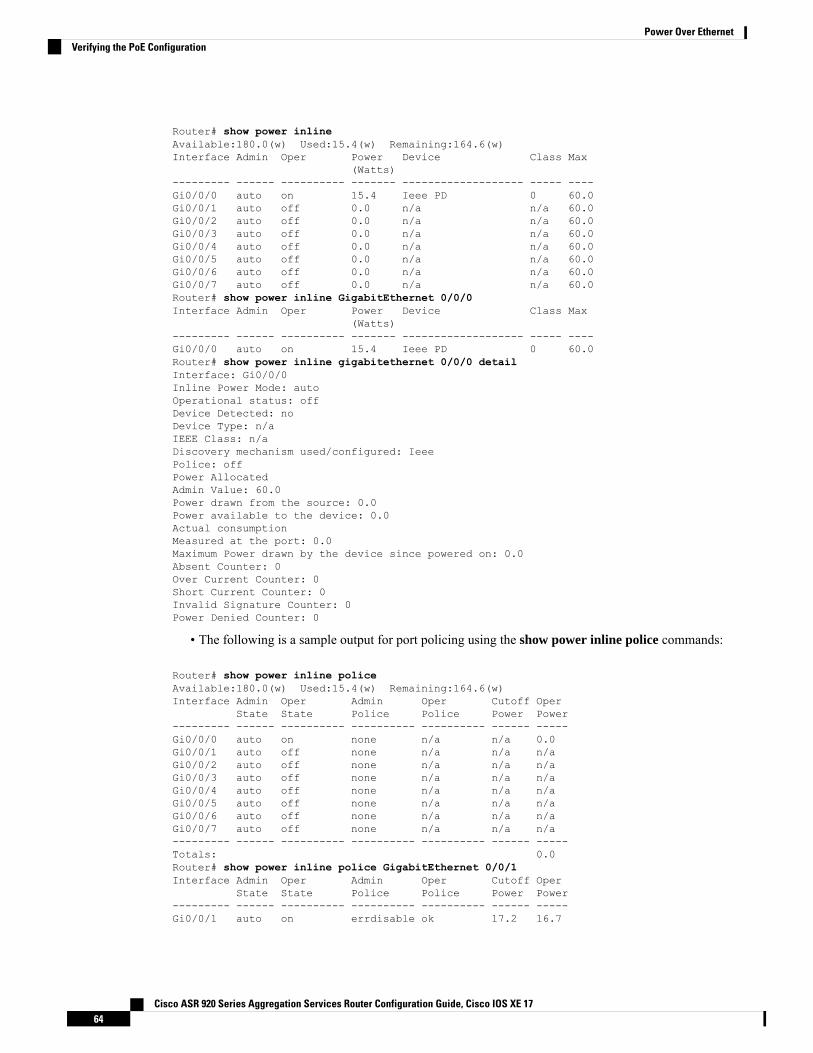
Router# show power inlineAvailable:180.0(w) Used:15.4(w) Remaining:164.6(w)Interface Admin Oper Power Device Class Max
(Watts)--------- ------ ---------- ------- ------------------- ----- ----Gi0/0/0 auto on 15.4 Ieee PD 0 60.0Gi0/0/1 auto off 0.0 n/a n/a 60.0Gi0/0/2 auto off 0.0 n/a n/a 60.0Gi0/0/3 auto off 0.0 n/a n/a 60.0Gi0/0/4 auto off 0.0 n/a n/a 60.0Gi0/0/5 auto off 0.0 n/a n/a 60.0Gi0/0/6 auto off 0.0 n/a n/a 60.0Gi0/0/7 auto off 0.0 n/a n/a 60.0Router# show power inline GigabitEthernet 0/0/0Interface Admin Oper Power Device Class Max
(Watts)--------- ------ ---------- ------- ------------------- ----- ----Gi0/0/0 auto on 15.4 Ieee PD 0 60.0Router# show power inline gigabitethernet 0/0/0 detailInterface: Gi0/0/0Inline Power Mode: autoOperational status: offDevice Detected: noDevice Type: n/aIEEE Class: n/aDiscovery mechanism used/configured: IeeePolice: offPower AllocatedAdmin Value: 60.0Power drawn from the source: 0.0Power available to the device: 0.0Actual consumptionMeasured at the port: 0.0Maximum Power drawn by the device since powered on: 0.0Absent Counter: 0Over Current Counter: 0Short Current Counter: 0Invalid Signature Counter: 0Power Denied Counter: 0
• The following is a sample output for port policing using the show power inline police commands:
Router# show power inline policeAvailable:180.0(w) Used:15.4(w) Remaining:164.6(w)Interface Admin Oper Admin Oper Cutoff Oper
State State Police Police Power Power--------- ------ ---------- ---------- ---------- ------ -----Gi0/0/0 auto on none n/a n/a 0.0Gi0/0/1 auto off none n/a n/a n/aGi0/0/2 auto off none n/a n/a n/aGi0/0/3 auto off none n/a n/a n/aGi0/0/4 auto off none n/a n/a n/aGi0/0/5 auto off none n/a n/a n/aGi0/0/6 auto off none n/a n/a n/aGi0/0/7 auto off none n/a n/a n/a--------- ------ ---------- ---------- ---------- ------ -----Totals: 0.0Router# show power inline police GigabitEthernet 0/0/1Interface Admin Oper Admin Oper Cutoff Oper
State State Police Police Power Power--------- ------ ---------- ---------- ---------- ------ -----Gi0/0/1 auto on errdisable ok 17.2 16.7
Cisco ASR 920 Series Aggregation Services Router Configuration Guide, Cisco IOS XE 1764
Power Over EthernetVerifying the PoE Configuration
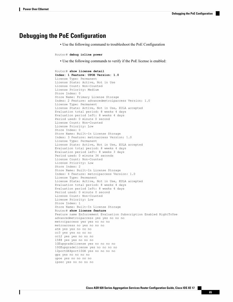
Debugging the PoE Configuration• Use the following command to troubleshoot the PoE Configuration
Router# debug inline power
• Use the following commands to verify if the PoE license is enabled:
Router# show license detailIndex: 1 Feature: UPOE Version: 1.0License Type: PermanentLicense State: Active, Not in UseLicense Count: Non-CountedLicense Priority: MediumStore Index: 0Store Name: Primary License StorageIndex: 2 Feature: advancedmetroipaccess Version: 1.0License Type: PermanentLicense State: Active, Not in Use, EULA acceptedEvaluation total period: 8 weeks 4 daysEvaluation period left: 8 weeks 4 daysPeriod used: 0 minute 0 secondLicense Count: Non-CountedLicense Priority: LowStore Index: 0Store Name: Built-In License StorageIndex: 3 Feature: metroaccess Version: 1.0License Type: PermanentLicense State: Active, Not in Use, EULA acceptedEvaluation total period: 8 weeks 4 daysEvaluation period left: 8 weeks 3 daysPeriod used: 0 minute 36 secondsLicense Count: Non-CountedLicense Priority: LowStore Index: 2Store Name: Built-In License StorageIndex: 4 Feature: metroipaccess Version: 1.0License Type: PermanentLicense State: Active, Not in Use, EULA acceptedEvaluation total period: 8 weeks 4 daysEvaluation period left: 8 weeks 4 daysPeriod used: 0 minute 0 secondLicense Count: Non-CountedLicense Priority: LowStore Index: 1Store Name: Built-In License StorageRouter# show license featureFeature name Enforcement Evaluation Subscription Enabled RightToUseadvancedmetroipaccess yes yes no no nometroipaccess yes yes no no nometroaccess no yes no no noatm yes yes no no nooc3 yes yes no no nooc12 yes yes no no no1588 yes yes no no no1GEupgradelicense yes no no no no10GEupgradelicense yes no no no no12portGE4port10GE yes no no no nogps yes no no no noupoe yes no no no noipsec yes no no no no
Cisco ASR 920 Series Aggregation Services Router Configuration Guide, Cisco IOS XE 1765
Power Over EthernetDebugging the PoE Configuration
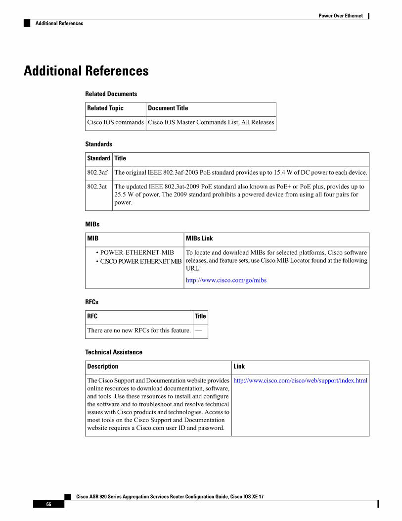
Additional ReferencesRelated Documents
Document TitleRelated Topic
Cisco IOS Master Commands List, All ReleasesCisco IOS commands
Standards
TitleStandard
The original IEEE 802.3af-2003 PoE standard provides up to 15.4W of DC power to each device.802.3af
The updated IEEE 802.3at-2009 PoE standard also known as PoE+ or PoE plus, provides up to25.5 W of power. The 2009 standard prohibits a powered device from using all four pairs forpower.
802.3at
MIBs
MIBs LinkMIB
To locate and download MIBs for selected platforms, Cisco softwarereleases, and feature sets, use CiscoMIBLocator found at the followingURL:
http://www.cisco.com/go/mibs
• POWER-ETHERNET-MIB• CISCO-POWER-ETHERNET-MIB
RFCs
TitleRFC
—There are no new RFCs for this feature.
Technical Assistance
LinkDescription
http://www.cisco.com/cisco/web/support/index.htmlTheCisco Support andDocumentationwebsite providesonline resources to download documentation, software,and tools. Use these resources to install and configurethe software and to troubleshoot and resolve technicalissues with Cisco products and technologies. Access tomost tools on the Cisco Support and Documentationwebsite requires a Cisco.com user ID and password.
Cisco ASR 920 Series Aggregation Services Router Configuration Guide, Cisco IOS XE 1766
Power Over EthernetAdditional References
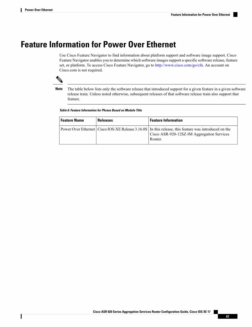
Feature Information for Power Over EthernetUse Cisco Feature Navigator to find information about platform support and software image support. CiscoFeature Navigator enables you to determine which software images support a specific software release, featureset, or platform. To access Cisco Feature Navigator, go to http://www.cisco.com/go/cfn. An account onCisco.com is not required.
The table below lists only the software release that introduced support for a given feature in a given softwarerelease train. Unless noted otherwise, subsequent releases of that software release train also support thatfeature.
Note
Table 6: Feature Information for Phrase Based on Module Title
Feature InformationReleasesFeature Name
In this release, this feature was introduced on theCisco ASR-920-12SZ-IM Aggregation ServicesRouter.
Cisco IOS-XERelease 3.16.0SPower Over Ethernet
Cisco ASR 920 Series Aggregation Services Router Configuration Guide, Cisco IOS XE 1767
Power Over EthernetFeature Information for Power Over Ethernet

Cisco ASR 920 Series Aggregation Services Router Configuration Guide, Cisco IOS XE 1768
Power Over EthernetFeature Information for Power Over Ethernet
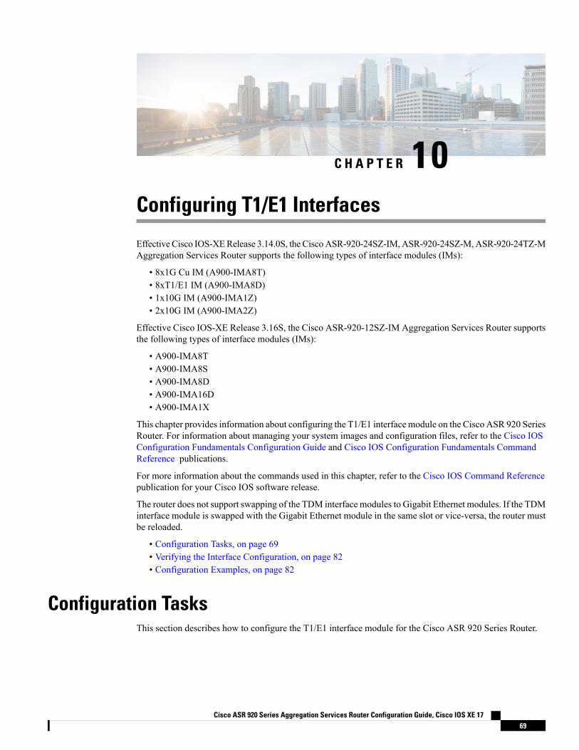
C H A P T E R 10Configuring T1/E1 Interfaces
Effective Cisco IOS-XERelease 3.14.0S, the CiscoASR-920-24SZ-IM,ASR-920-24SZ-M,ASR-920-24TZ-MAggregation Services Router supports the following types of interface modules (IMs):
• 8x1G Cu IM (A900-IMA8T)• 8xT1/E1 IM (A900-IMA8D)• 1x10G IM (A900-IMA1Z)• 2x10G IM (A900-IMA2Z)
Effective Cisco IOS-XE Release 3.16S, the Cisco ASR-920-12SZ-IM Aggregation Services Router supportsthe following types of interface modules (IMs):
• A900-IMA8T• A900-IMA8S• A900-IMA8D• A900-IMA16D• A900-IMA1X
This chapter provides information about configuring the T1/E1 interface module on the Cisco ASR 920 SeriesRouter. For information about managing your system images and configuration files, refer to the Cisco IOSConfiguration Fundamentals Configuration Guide and Cisco IOS Configuration Fundamentals CommandReference publications.
For more information about the commands used in this chapter, refer to the Cisco IOS Command Referencepublication for your Cisco IOS software release.
The router does not support swapping of the TDM interface modules to Gigabit Ethernet modules. If the TDMinterface module is swapped with the Gigabit Ethernet module in the same slot or vice-versa, the router mustbe reloaded.
• Configuration Tasks, on page 69• Verifying the Interface Configuration, on page 82• Configuration Examples, on page 82
Configuration TasksThis section describes how to configure the T1/E1 interface module for the Cisco ASR 920 Series Router.
Cisco ASR 920 Series Aggregation Services Router Configuration Guide, Cisco IOS XE 1769
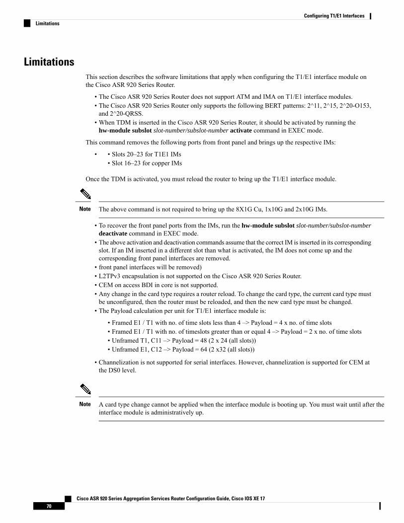
LimitationsThis section describes the software limitations that apply when configuring the T1/E1 interface module onthe Cisco ASR 920 Series Router.
• The Cisco ASR 920 Series Router does not support ATM and IMA on T1/E1 interface modules.• The Cisco ASR 920 Series Router only supports the following BERT patterns: 2^11, 2^15, 2^20-O153,and 2^20-QRSS.
• When TDM is inserted in the Cisco ASR 920 Series Router, it should be activated by running thehw-module subslot slot-number/subslot-number activate command in EXEC mode.
This command removes the following ports from front panel and brings up the respective IMs:
• Slots 20–23 for T1E1 IMs•• Slot 16–23 for copper IMs
Once the TDM is activated, you must reload the router to bring up the T1/E1 interface module.
The above command is not required to bring up the 8X1G Cu, 1x10G and 2x10G IMs.Note
• To recover the front panel ports from the IMs, run the hw-module subslot slot-number/subslot-numberdeactivate command in EXEC mode.
• The above activation and deactivation commands assume that the correct IM is inserted in its correspondingslot. If an IM inserted in a different slot than what is activated, the IM does not come up and thecorresponding front panel interfaces are removed.
• front panel interfaces will be removed)• L2TPv3 encapsulation is not supported on the Cisco ASR 920 Series Router.• CEM on access BDI in core is not supported.• Any change in the card type requires a router reload. To change the card type, the current card type mustbe unconfigured, then the router must be reloaded, and then the new card type must be changed.
• The Payload calculation per unit for T1/E1 interface module is:
• Framed E1 / T1 with no. of time slots less than 4 –> Payload = 4 x no. of time slots• Framed E1 / T1 with no. of timeslots greater than or equal 4 –> Payload = 2 x no. of time slots• Unframed T1, C11 –> Payload = 48 (2 x 24 (all slots))• Unframed E1, C12 –> Payload = 64 (2 x32 (all slots))
• Channelization is not supported for serial interfaces. However, channelization is supported for CEM atthe DS0 level.
A card type change cannot be applied when the interface module is booting up. You must wait until after theinterface module is administratively up.
Note
Cisco ASR 920 Series Aggregation Services Router Configuration Guide, Cisco IOS XE 1770
Configuring T1/E1 InterfacesLimitations
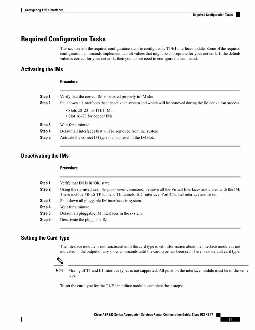
Required Configuration TasksThis section lists the required configuration steps to configure the T1/E1 interfacemodule. Some of the requiredconfiguration commands implement default values that might be appropriate for your network. If the defaultvalue is correct for your network, then you do not need to configure the command.
Activating the IMs
Procedure
Step 1 Verify that the correct IM is inserted properly in IM slotStep 2 Shut down all interfaces that are active in system and which will be removed during the IM activation process.
• Slots 20–23 for T1E1 IMs• Slot 16–23 for copper IMs
Step 3 Wait for a minute.Step 4 Default all interfaces that will be removed from the system.Step 5 Activate the correct IM type that is preset in the IM slot.
Deactivating the IMs
Procedure
Step 1 Verify that IM is in 'OK' state.Step 2 Using the no interface interface-name command, remove all the Virtual Interfaces associated with the IM.
These include MPLS TP tunnels, TE tunnels, BDI interface, Port-Channel interface and so on.Step 3 Shut down all pluggable IM interfaces in system.Step 4 Wait for a minute.Step 5 Default all pluggable IM interfaces in the system.Step 6 Deactivate the pluggable IMs.
Setting the Card TypeThe interface module is not functional until the card type is set. Information about the interface module is notindicated in the output of any show commands until the card type has been set. There is no default card type.
Mixing of T1 and E1 interface types is not supported. All ports on the interface module must be of the sametype.
Note
To set the card type for the T1/E1 interface module, complete these steps:
Cisco ASR 920 Series Aggregation Services Router Configuration Guide, Cisco IOS XE 1771
Configuring T1/E1 InterfacesRequired Configuration Tasks
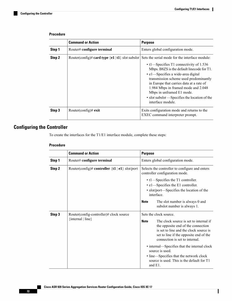
Procedure
PurposeCommand or Action
Enters global configuration mode.Router# configure terminalStep 1
Sets the serial mode for the interface module:Router(config)# card type {e1 | t1} slot subslotStep 2
• t1—Specifies T1 connectivity of 1.536Mbps. B8ZS is the default linecode for T1.
• e1—Specifies a wide-area digitaltransmission scheme used predominantlyin Europe that carries data at a rate of1.984 Mbps in framed mode and 2.048Mbps in unframed E1 mode.
• slot subslot—Specifies the location of theinterface module.
Exits configuration mode and returns to theEXEC command interpreter prompt.
Router(config)# exitStep 3
Configuring the ControllerTo create the interfaces for the T1/E1 interface module, complete these steps:
Procedure
PurposeCommand or Action
Enters global configuration mode.Router# configure terminalStep 1
Selects the controller to configure and enterscontroller configuration mode.
Router(config)# controller {t1 | e1} slot/portStep 2
• t1—Specifies the T1 controller.• e1—Specifies the E1 controller.• slot/port—Specifies the location of theinterface.
The slot number is always 0 andsubslot number is always 1.
Note
Sets the clock source.Router(config-controller)# clock source{internal | line}
Step 3
The clock source is set to internal ifthe opposite end of the connectionis set to line and the clock source isset to line if the opposite end of theconnection is set to internal.
Note
• internal—Specifies that the internal clocksource is used.
• line—Specifies that the network clocksource is used. This is the default for T1and E1.
Cisco ASR 920 Series Aggregation Services Router Configuration Guide, Cisco IOS XE 1772
Configuring T1/E1 InterfacesConfiguring the Controller
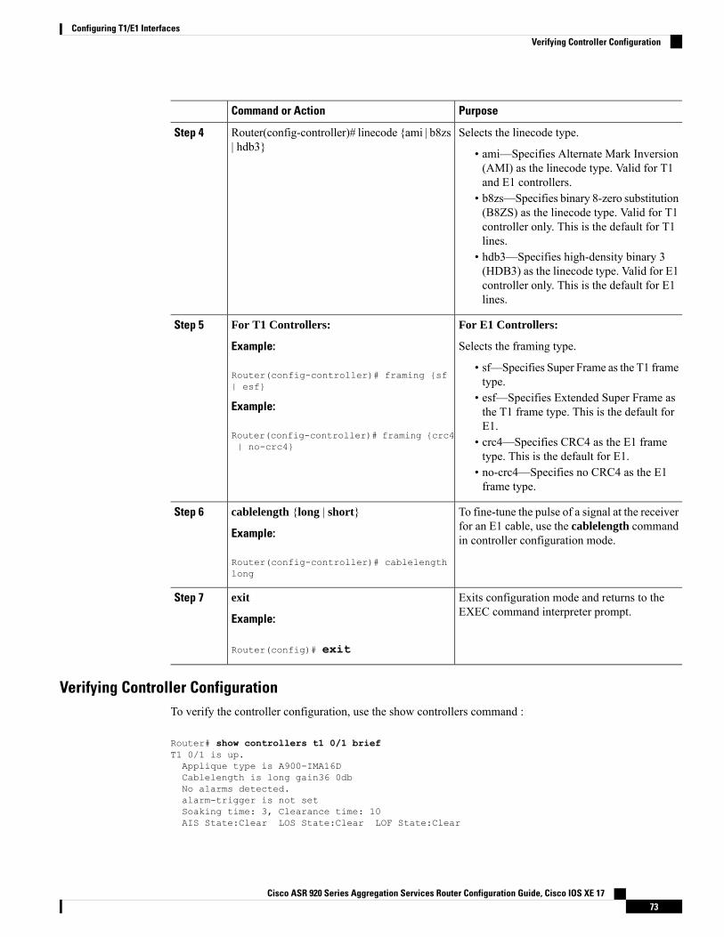
PurposeCommand or Action
Selects the linecode type.Router(config-controller)# linecode {ami | b8zs| hdb3}
Step 4
• ami—Specifies Alternate Mark Inversion(AMI) as the linecode type. Valid for T1and E1 controllers.
• b8zs—Specifies binary 8-zero substitution(B8ZS) as the linecode type. Valid for T1controller only. This is the default for T1lines.
• hdb3—Specifies high-density binary 3(HDB3) as the linecode type. Valid for E1controller only. This is the default for E1lines.
For E1 Controllers:For T1 Controllers:Step 5
Example: Selects the framing type.
Router(config-controller)# framing {sf| esf}
• sf—Specifies Super Frame as the T1 frametype.
• esf—Specifies Extended Super Frame asthe T1 frame type. This is the default forE1.
Example:
Router(config-controller)# framing {crc4| no-crc4} • crc4—Specifies CRC4 as the E1 frame
type. This is the default for E1.• no-crc4—Specifies no CRC4 as the E1frame type.
To fine-tune the pulse of a signal at the receiverfor an E1 cable, use the cablelength commandin controller configuration mode.
cablelength {long | short}
Example:
Router(config-controller)# cablelengthlong
Step 6
Exits configuration mode and returns to theEXEC command interpreter prompt.
exit
Example:
Step 7
Router(config)# exit
Verifying Controller ConfigurationTo verify the controller configuration, use the show controllers command :
Router# show controllers t1 0/1 briefT1 0/1 is up.Applique type is A900-IMA16DCablelength is long gain36 0dbNo alarms detected.alarm-trigger is not setSoaking time: 3, Clearance time: 10AIS State:Clear LOS State:Clear LOF State:Clear
Cisco ASR 920 Series Aggregation Services Router Configuration Guide, Cisco IOS XE 1773
Configuring T1/E1 InterfacesVerifying Controller Configuration
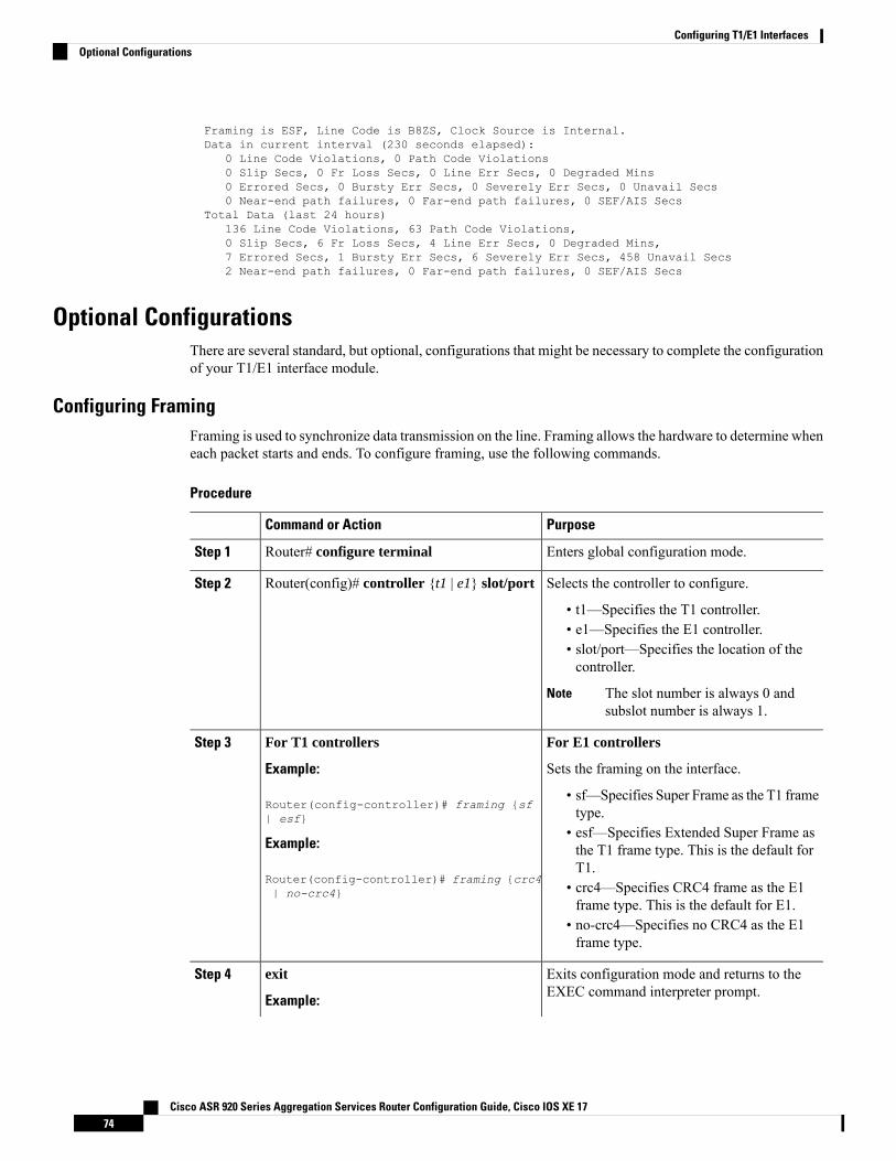
Framing is ESF, Line Code is B8ZS, Clock Source is Internal.Data in current interval (230 seconds elapsed):
0 Line Code Violations, 0 Path Code Violations0 Slip Secs, 0 Fr Loss Secs, 0 Line Err Secs, 0 Degraded Mins0 Errored Secs, 0 Bursty Err Secs, 0 Severely Err Secs, 0 Unavail Secs0 Near-end path failures, 0 Far-end path failures, 0 SEF/AIS Secs
Total Data (last 24 hours)136 Line Code Violations, 63 Path Code Violations,0 Slip Secs, 6 Fr Loss Secs, 4 Line Err Secs, 0 Degraded Mins,7 Errored Secs, 1 Bursty Err Secs, 6 Severely Err Secs, 458 Unavail Secs2 Near-end path failures, 0 Far-end path failures, 0 SEF/AIS Secs
Optional ConfigurationsThere are several standard, but optional, configurations that might be necessary to complete the configurationof your T1/E1 interface module.
Configuring FramingFraming is used to synchronize data transmission on the line. Framing allows the hardware to determine wheneach packet starts and ends. To configure framing, use the following commands.
Procedure
PurposeCommand or Action
Enters global configuration mode.Router# configure terminalStep 1
Selects the controller to configure.Router(config)# controller {t1 | e1} slot/portStep 2
• t1—Specifies the T1 controller.• e1—Specifies the E1 controller.• slot/port—Specifies the location of thecontroller.
The slot number is always 0 andsubslot number is always 1.
Note
For E1 controllersFor T1 controllersStep 3
Example: Sets the framing on the interface.
Router(config-controller)# framing {sf| esf}
• sf—Specifies Super Frame as the T1 frametype.
• esf—Specifies Extended Super Frame asthe T1 frame type. This is the default forT1.
Example:
Router(config-controller)# framing {crc4| no-crc4} • crc4—Specifies CRC4 frame as the E1
frame type. This is the default for E1.• no-crc4—Specifies no CRC4 as the E1frame type.
Exits configuration mode and returns to theEXEC command interpreter prompt.
exit
Example:
Step 4
Cisco ASR 920 Series Aggregation Services Router Configuration Guide, Cisco IOS XE 1774
Configuring T1/E1 InterfacesOptional Configurations
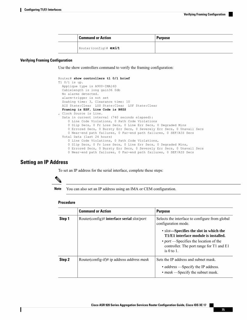
PurposeCommand or Action
Router(config)# exit
Verifying Framing Configuration
Use the show controllers command to verify the framing configuration:
Router# show controllers t1 0/1 briefT1 0/1 is up.Applique type is A900-IMA16DCablelength is long gain36 0dbNo alarms detected.alarm-trigger is not setSoaking time: 3, Clearance time: 10AIS State:Clear LOS State:Clear LOF State:ClearFraming is ESF, Line Code is B8ZS
, Clock Source is Line.Data in current interval (740 seconds elapsed):
0 Line Code Violations, 0 Path Code Violations0 Slip Secs, 0 Fr Loss Secs, 0 Line Err Secs, 0 Degraded Mins0 Errored Secs, 0 Bursty Err Secs, 0 Severely Err Secs, 0 Unavail Secs0 Near-end path failures, 0 Far-end path failures, 0 SEF/AIS Secs
Total Data (last 24 hours)0 Line Code Violations, 0 Path Code Violations,0 Slip Secs, 0 Fr Loss Secs, 0 Line Err Secs, 0 Degraded Mins,0 Errored Secs, 0 Bursty Err Secs, 0 Severely Err Secs, 0 Unavail Secs0 Near-end path failures, 0 Far-end path failures, 0 SEF/AIS Secs
Setting an IP AddressTo set an IP address for the serial interface, complete these steps:
You can also set an IP address using an IMA or CEM configuration.Note
Procedure
PurposeCommand or Action
Selects the interface to configure from globalconfiguration mode.
Router(config)# interface serial slot/portStep 1
• slot—Specifies the slot in which theT1/E1 interface module is installed.
• port —Specifies the location of thecontroller. The port range for T1 and E1is 0 to 1.
Sets the IP address and subnet mask.Router(config-if)# ip address address maskStep 2
• address —Specify the IP address.• mask —Specify the subnet mask.
Cisco ASR 920 Series Aggregation Services Router Configuration Guide, Cisco IOS XE 1775
Configuring T1/E1 InterfacesVerifying Framing Configuration
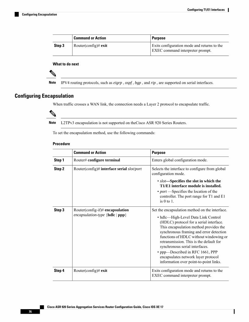
PurposeCommand or Action
Exits configuration mode and returns to theEXEC command interpreter prompt.
Router(config)# exitStep 3
What to do next
IPV4 routing protocols, such as eigrp , ospf , bgp , and rip , are supported on serial interfaces.Note
Configuring EncapsulationWhen traffic crosses a WAN link, the connection needs a Layer 2 protocol to encapsulate traffic.
L2TPv3 encapsulation is not supported on theCisco ASR 920 Series Routers.Note
To set the encapsulation method, use the following commands:
Procedure
PurposeCommand or Action
Enters global configuration mode.Router# configure terminalStep 1
Selects the interface to configure from globalconfiguration mode.
Router(config)# interface serial slot/portStep 2
• slot—Specifies the slot in which theT1/E1 interface module is installed.
• port —Specifies the location of thecontroller. The port range for T1 and E1is 0 to 1.
Set the encapsulation method on the interface.Router(config-if)# encapsulationencapsulation-type {hdlc | ppp}
Step 3
• hdlc—High-Level Data Link Control(HDLC) protocol for a serial interface.This encapsulation method provides thesynchronous framing and error detectionfunctions of HDLCwithout windowing orretransmission. This is the default forsynchronous serial interfaces.
• ppp—Described in RFC 1661, PPPencapsulates network layer protocolinformation over point-to-point links.
Exits configuration mode and returns to theEXEC command interpreter prompt.
Router(config)# exitStep 4
Cisco ASR 920 Series Aggregation Services Router Configuration Guide, Cisco IOS XE 1776
Configuring T1/E1 InterfacesConfiguring Encapsulation
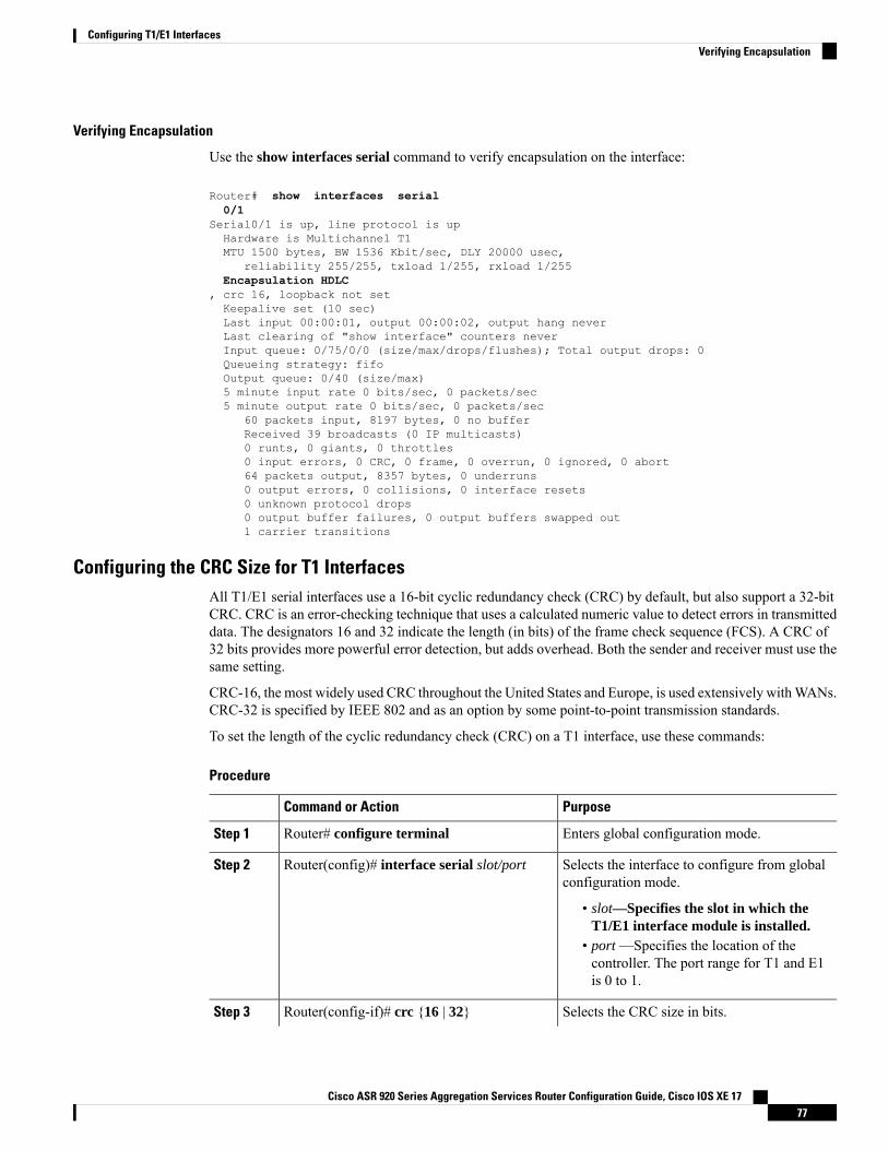
Verifying Encapsulation
Use the show interfaces serial command to verify encapsulation on the interface:
Router# show interfaces serial0/1
Serial0/1 is up, line protocol is upHardware is Multichannel T1MTU 1500 bytes, BW 1536 Kbit/sec, DLY 20000 usec,
reliability 255/255, txload 1/255, rxload 1/255Encapsulation HDLC
, crc 16, loopback not setKeepalive set (10 sec)Last input 00:00:01, output 00:00:02, output hang neverLast clearing of "show interface" counters neverInput queue: 0/75/0/0 (size/max/drops/flushes); Total output drops: 0Queueing strategy: fifoOutput queue: 0/40 (size/max)5 minute input rate 0 bits/sec, 0 packets/sec5 minute output rate 0 bits/sec, 0 packets/sec
60 packets input, 8197 bytes, 0 no bufferReceived 39 broadcasts (0 IP multicasts)0 runts, 0 giants, 0 throttles0 input errors, 0 CRC, 0 frame, 0 overrun, 0 ignored, 0 abort64 packets output, 8357 bytes, 0 underruns0 output errors, 0 collisions, 0 interface resets0 unknown protocol drops0 output buffer failures, 0 output buffers swapped out1 carrier transitions
Configuring the CRC Size for T1 InterfacesAll T1/E1 serial interfaces use a 16-bit cyclic redundancy check (CRC) by default, but also support a 32-bitCRC. CRC is an error-checking technique that uses a calculated numeric value to detect errors in transmitteddata. The designators 16 and 32 indicate the length (in bits) of the frame check sequence (FCS). A CRC of32 bits provides more powerful error detection, but adds overhead. Both the sender and receiver must use thesame setting.
CRC-16, the most widely used CRC throughout the United States and Europe, is used extensively withWANs.CRC-32 is specified by IEEE 802 and as an option by some point-to-point transmission standards.
To set the length of the cyclic redundancy check (CRC) on a T1 interface, use these commands:
Procedure
PurposeCommand or Action
Enters global configuration mode.Router# configure terminalStep 1
Selects the interface to configure from globalconfiguration mode.
Router(config)# interface serial slot/portStep 2
• slot—Specifies the slot in which theT1/E1 interface module is installed.
• port —Specifies the location of thecontroller. The port range for T1 and E1is 0 to 1.
Selects the CRC size in bits.Router(config-if)# crc {16 | 32}Step 3
Cisco ASR 920 Series Aggregation Services Router Configuration Guide, Cisco IOS XE 1777
Configuring T1/E1 InterfacesVerifying Encapsulation
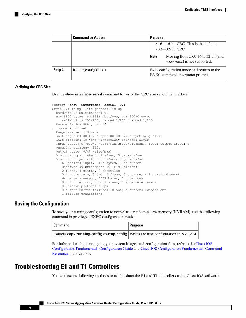
PurposeCommand or Action
• 16—16-bit CRC. This is the default.• 32—32-bit CRC.
Moving from CRC 16 to 32 bit (andvice-versa) is not supported.
Note
Exits configuration mode and returns to theEXEC command interpreter prompt.
Router(config)# exitStep 4
Verifying the CRC Size
Use the show interfaces serial command to verify the CRC size set on the interface:
Router# show interfaces serial 0/1Serial0/1 is up, line protocol is upHardware is Multichannel T1MTU 1500 bytes, BW 1536 Kbit/sec, DLY 20000 usec,
reliability 255/255, txload 1/255, rxload 1/255Encapsulation HDLC, crc 16
, loopback not setKeepalive set (10 sec)Last input 00:00:01, output 00:00:02, output hang neverLast clearing of "show interface" counters neverInput queue: 0/75/0/0 (size/max/drops/flushes); Total output drops: 0Queueing strategy: fifoOutput queue: 0/40 (size/max)5 minute input rate 0 bits/sec, 0 packets/sec5 minute output rate 0 bits/sec, 0 packets/sec
60 packets input, 8197 bytes, 0 no bufferReceived 39 broadcasts (0 IP multicasts)0 runts, 0 giants, 0 throttles0 input errors, 0 CRC, 0 frame, 0 overrun, 0 ignored, 0 abort64 packets output, 8357 bytes, 0 underruns0 output errors, 0 collisions, 0 interface resets0 unknown protocol drops0 output buffer failures, 0 output buffers swapped out1 carrier transitions
Saving the ConfigurationTo save your running configuration to nonvolatile random-access memory (NVRAM), use the followingcommand in privileged EXEC configuration mode:
PurposeCommand
Writes the new configuration to NVRAM.Router# copy running-config startup-config
For information about managing your system images and configuration files, refer to the Cisco IOSConfiguration Fundamentals Configuration Guide and Cisco IOS Configuration Fundamentals CommandReference publications.
Troubleshooting E1 and T1 ControllersYou can use the following methods to troubleshoot the E1 and T1 controllers using Cisco IOS software:
Cisco ASR 920 Series Aggregation Services Router Configuration Guide, Cisco IOS XE 1778
Configuring T1/E1 InterfacesVerifying the CRC Size
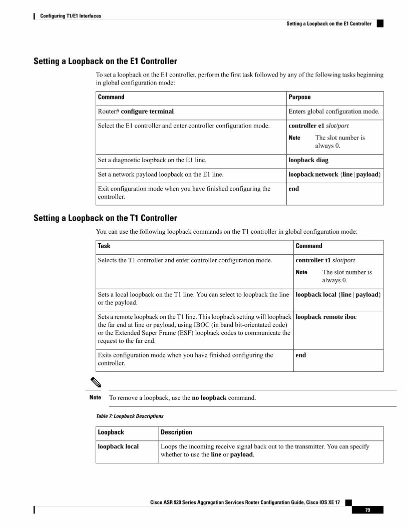
Setting a Loopback on the E1 ControllerTo set a loopback on the E1 controller, perform the first task followed by any of the following tasks beginningin global configuration mode:
PurposeCommand
Enters global configuration mode.Router# configure terminal
controller e1 slot/port
The slot number isalways 0.
Note
Select the E1 controller and enter controller configuration mode.
loopback diagSet a diagnostic loopback on the E1 line.
loopback network {line | payload}Set a network payload loopback on the E1 line.
endExit configuration mode when you have finished configuring thecontroller.
Setting a Loopback on the T1 ControllerYou can use the following loopback commands on the T1 controller in global configuration mode:
CommandTask
controller t1 slot/port
The slot number isalways 0.
Note
Selects the T1 controller and enter controller configuration mode.
loopback local {line | payload}Sets a local loopback on the T1 line. You can select to loopback the lineor the payload.
loopback remote ibocSets a remote loopback on the T1 line. This loopback setting will loopbackthe far end at line or payload, using IBOC (in band bit-orientated code)or the Extended Super Frame (ESF) loopback codes to communicate therequest to the far end.
endExits configuration mode when you have finished configuring thecontroller.
To remove a loopback, use the no loopback command.Note
Table 7: Loopback Descriptions
DescriptionLoopback
Loops the incoming receive signal back out to the transmitter. You can specifywhether to use the line or payload.
loopback local
Cisco ASR 920 Series Aggregation Services Router Configuration Guide, Cisco IOS XE 1779
Configuring T1/E1 InterfacesSetting a Loopback on the E1 Controller
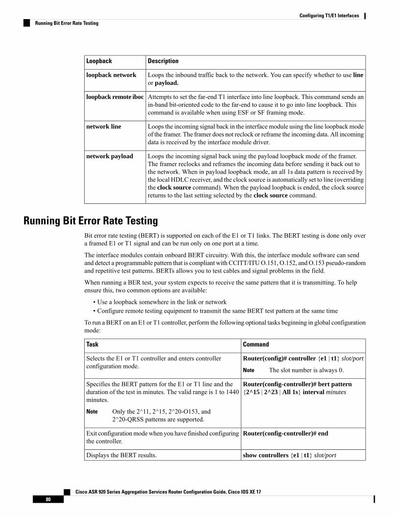
DescriptionLoopback
Loops the inbound traffic back to the network. You can specify whether to use lineor payload.
loopback network
Attempts to set the far-end T1 interface into line loopback. This command sends anin-band bit-oriented code to the far-end to cause it to go into line loopback. Thiscommand is available when using ESF or SF framing mode.
loopback remote iboc
Loops the incoming signal back in the interface module using the line loopbackmodeof the framer. The framer does not reclock or reframe the incoming data. All incomingdata is received by the interface module driver.
network line
Loops the incoming signal back using the payload loopback mode of the framer.The framer reclocks and reframes the incoming data before sending it back out tothe network. When in payload loopback mode, an all 1s data pattern is received bythe local HDLC receiver, and the clock source is automatically set to line (overridingthe clock source command). When the payload loopback is ended, the clock sourcereturns to the last setting selected by the clock source command.
network payload
Running Bit Error Rate TestingBit error rate testing (BERT) is supported on each of the E1 or T1 links. The BERT testing is done only overa framed E1 or T1 signal and can be run only on one port at a time.
The interface modules contain onboard BERT circuitry. With this, the interface module software can sendand detect a programmable pattern that is compliant with CCITT/ITUO.151, O.152, and O.153 pseudo-randomand repetitive test patterns. BERTs allows you to test cables and signal problems in the field.
When running a BER test, your system expects to receive the same pattern that it is transmitting. To helpensure this, two common options are available:
• Use a loopback somewhere in the link or network• Configure remote testing equipment to transmit the same BERT test pattern at the same time
To run a BERT on an E1 or T1 controller, perform the following optional tasks beginning in global configurationmode:
CommandTask
Router(config)# controller {e1 | t1} slot/port
The slot number is always 0.Note
Selects the E1 or T1 controller and enters controllerconfiguration mode.
Router(config-controller)# bert pattern{2^15 | 2^23 | All 1s} interval minutes
Specifies the BERT pattern for the E1 or T1 line and theduration of the test in minutes. The valid range is 1 to 1440minutes.
Only the 2^11, 2^15, 2^20-O153, and2^20-QRSS patterns are supported.
Note
Router(config-controller)# endExit configurationmodewhen you have finished configuringthe controller.
show controllers {e1 | t1} slot/portDisplays the BERT results.
Cisco ASR 920 Series Aggregation Services Router Configuration Guide, Cisco IOS XE 1780
Configuring T1/E1 InterfacesRunning Bit Error Rate Testing
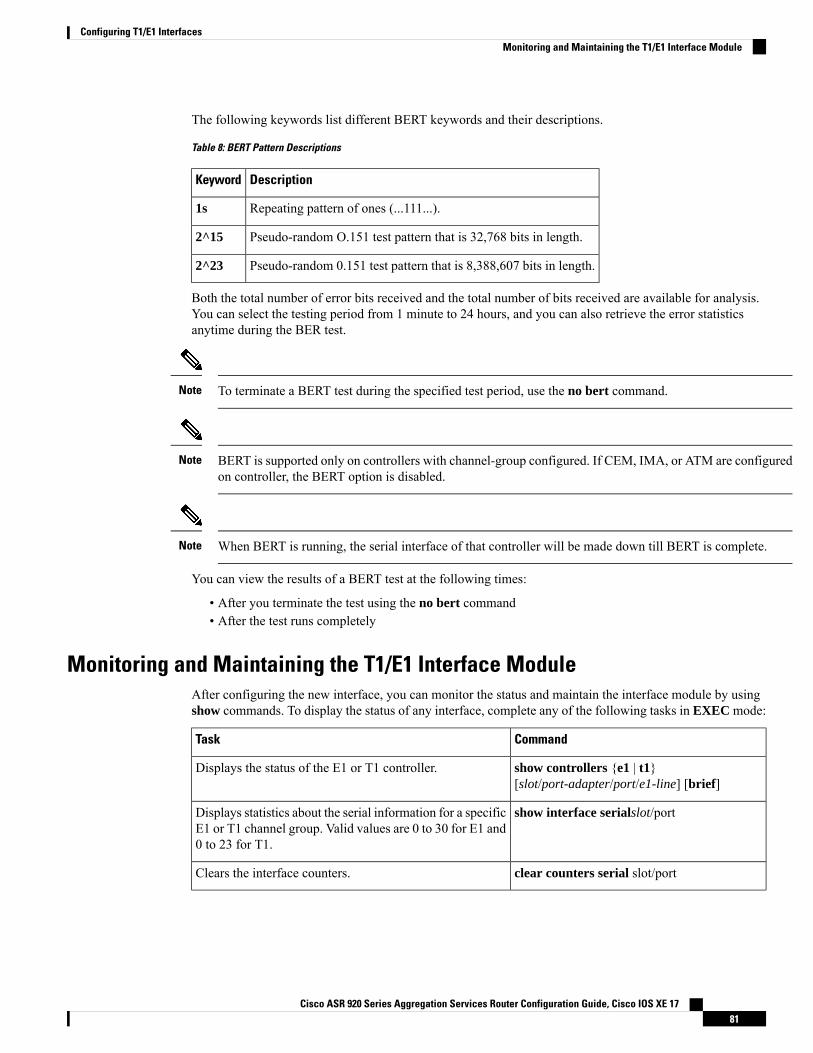
The following keywords list different BERT keywords and their descriptions.
Table 8: BERT Pattern Descriptions
DescriptionKeyword
Repeating pattern of ones (...111...).1s
Pseudo-random O.151 test pattern that is 32,768 bits in length.2^15
Pseudo-random 0.151 test pattern that is 8,388,607 bits in length.2^23
Both the total number of error bits received and the total number of bits received are available for analysis.You can select the testing period from 1 minute to 24 hours, and you can also retrieve the error statisticsanytime during the BER test.
To terminate a BERT test during the specified test period, use the no bert command.Note
BERT is supported only on controllers with channel-group configured. If CEM, IMA, or ATM are configuredon controller, the BERT option is disabled.
Note
When BERT is running, the serial interface of that controller will be made down till BERT is complete.Note
You can view the results of a BERT test at the following times:
• After you terminate the test using the no bert command• After the test runs completely
Monitoring and Maintaining the T1/E1 Interface ModuleAfter configuring the new interface, you can monitor the status and maintain the interface module by usingshow commands. To display the status of any interface, complete any of the following tasks in EXEC mode:
CommandTask
show controllers {e1 | t1}[slot/port-adapter/port/e1-line] [brief]
Displays the status of the E1 or T1 controller.
show interface serialslot/portDisplays statistics about the serial information for a specificE1 or T1 channel group. Valid values are 0 to 30 for E1 and0 to 23 for T1.
clear counters serial slot/portClears the interface counters.
Cisco ASR 920 Series Aggregation Services Router Configuration Guide, Cisco IOS XE 1781
Configuring T1/E1 InterfacesMonitoring and Maintaining the T1/E1 Interface Module
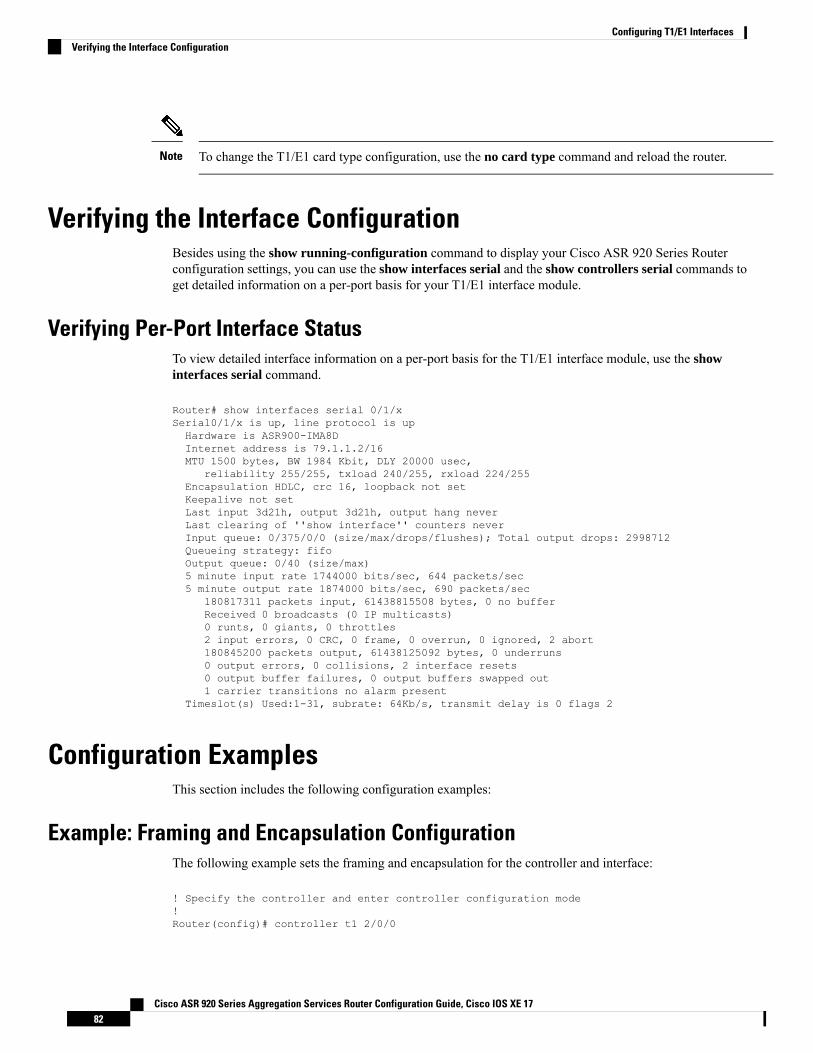
To change the T1/E1 card type configuration, use the no card type command and reload the router.Note
Verifying the Interface ConfigurationBesides using the show running-configuration command to display your Cisco ASR 920 Series Routerconfiguration settings, you can use the show interfaces serial and the show controllers serial commands toget detailed information on a per-port basis for your T1/E1 interface module.
Verifying Per-Port Interface StatusTo view detailed interface information on a per-port basis for the T1/E1 interface module, use the showinterfaces serial command.
Router# show interfaces serial 0/1/xSerial0/1/x is up, line protocol is upHardware is ASR900-IMA8DInternet address is 79.1.1.2/16MTU 1500 bytes, BW 1984 Kbit, DLY 20000 usec,
reliability 255/255, txload 240/255, rxload 224/255Encapsulation HDLC, crc 16, loopback not setKeepalive not setLast input 3d21h, output 3d21h, output hang neverLast clearing of ''show interface'' counters neverInput queue: 0/375/0/0 (size/max/drops/flushes); Total output drops: 2998712Queueing strategy: fifoOutput queue: 0/40 (size/max)5 minute input rate 1744000 bits/sec, 644 packets/sec5 minute output rate 1874000 bits/sec, 690 packets/sec
180817311 packets input, 61438815508 bytes, 0 no bufferReceived 0 broadcasts (0 IP multicasts)0 runts, 0 giants, 0 throttles2 input errors, 0 CRC, 0 frame, 0 overrun, 0 ignored, 2 abort180845200 packets output, 61438125092 bytes, 0 underruns0 output errors, 0 collisions, 2 interface resets0 output buffer failures, 0 output buffers swapped out1 carrier transitions no alarm present
Timeslot(s) Used:1-31, subrate: 64Kb/s, transmit delay is 0 flags 2
Configuration ExamplesThis section includes the following configuration examples:
Example: Framing and Encapsulation ConfigurationThe following example sets the framing and encapsulation for the controller and interface:
! Specify the controller and enter controller configuration mode!Router(config)# controller t1 2/0/0
Cisco ASR 920 Series Aggregation Services Router Configuration Guide, Cisco IOS XE 1782
Configuring T1/E1 InterfacesVerifying the Interface Configuration
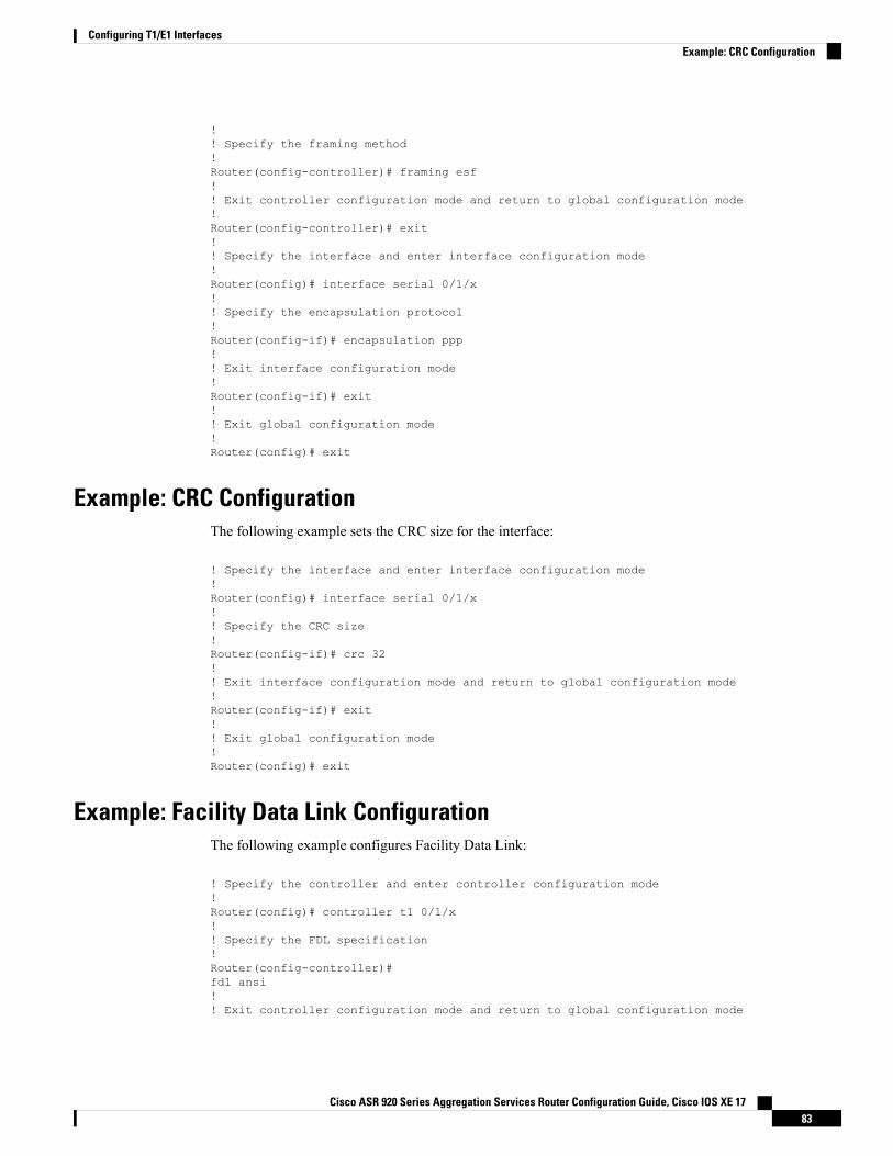
!! Specify the framing method!Router(config-controller)# framing esf!! Exit controller configuration mode and return to global configuration mode!Router(config-controller)# exit!! Specify the interface and enter interface configuration mode!Router(config)# interface serial 0/1/x!! Specify the encapsulation protocol!Router(config-if)# encapsulation ppp!! Exit interface configuration mode!Router(config-if)# exit!! Exit global configuration mode!Router(config)# exit
Example: CRC ConfigurationThe following example sets the CRC size for the interface:
! Specify the interface and enter interface configuration mode!Router(config)# interface serial 0/1/x!! Specify the CRC size!Router(config-if)# crc 32!! Exit interface configuration mode and return to global configuration mode!Router(config-if)# exit!! Exit global configuration mode!Router(config)# exit
Example: Facility Data Link ConfigurationThe following example configures Facility Data Link:
! Specify the controller and enter controller configuration mode!Router(config)# controller t1 0/1/x!! Specify the FDL specification!Router(config-controller)#fdl ansi!! Exit controller configuration mode and return to global configuration mode
Cisco ASR 920 Series Aggregation Services Router Configuration Guide, Cisco IOS XE 1783
Configuring T1/E1 InterfacesExample: CRC Configuration
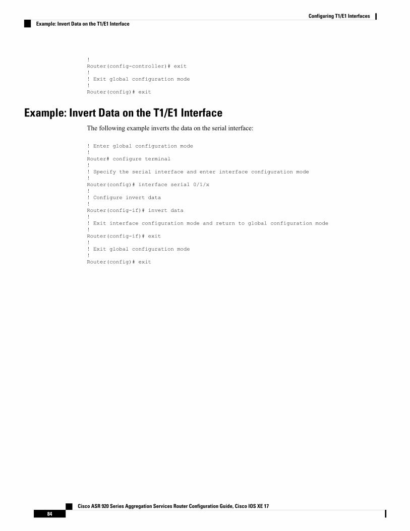
!Router(config-controller)# exit!! Exit global configuration mode!Router(config)# exit
Example: Invert Data on the T1/E1 InterfaceThe following example inverts the data on the serial interface:
! Enter global configuration mode!Router# configure terminal!! Specify the serial interface and enter interface configuration mode!Router(config)# interface serial 0/1/x!! Configure invert data!Router(config-if)# invert data!! Exit interface configuration mode and return to global configuration mode!Router(config-if)# exit!! Exit global configuration mode!Router(config)# exit
Cisco ASR 920 Series Aggregation Services Router Configuration Guide, Cisco IOS XE 1784
Configuring T1/E1 InterfacesExample: Invert Data on the T1/E1 Interface
C H A P T E R 11Installing and Upgrading Software
This chapter describes how to update software on the Cisco ASR 920 Series Router.
• Upgrading Field Programmable Hardware Devices, on page 85• File Systems on the Cisco ASR 920 Series Router, on page 85• Restrictions, on page 86• System Requirements, on page 86• Autogenerated Files and Directories, on page 87• Upgrading the Router Software, on page 88• Verifying the Upgrade, on page 91• Software Upgrade Example, on page 92
Upgrading Field Programmable Hardware DevicesCisco IOS XE on Cisco ASR 920 Series Routers (ASR-920-24SZ-IM and ASR-920-12SZ-IM) supportupgradeable firmware for field programmable hardware devices such as interface modules (IMs) and upgradesIM FPGA when ever there is an upgrade.
Cisco ASR 920 Series Router upgrades the HOFPGAwhen required and is indicated to the user through logs.Generally an upgrade is only necessary in cases where a system message indicates that an upgrade is requiredor a Cisco technical support representative suggests an upgrade.
The procedures in this chapter describe how to upgrade the firmware on Cisco ASR 920 Series Router.
File Systems on the Cisco ASR 920 Series RouterThe table below provides a list of file systems that can be seen on the Cisco ASR 920 Series Router.
Table 9: File Systems
DescriptionFile System
The boot flash memory file system.bootflash:
The Cisco Networking Services file directory.cns:
Router NVRAM. You can copy the startup configuration to NVRAM or from NVRAM.nvram:
Cisco ASR 920 Series Aggregation Services Router Configuration Guide, Cisco IOS XE 1785
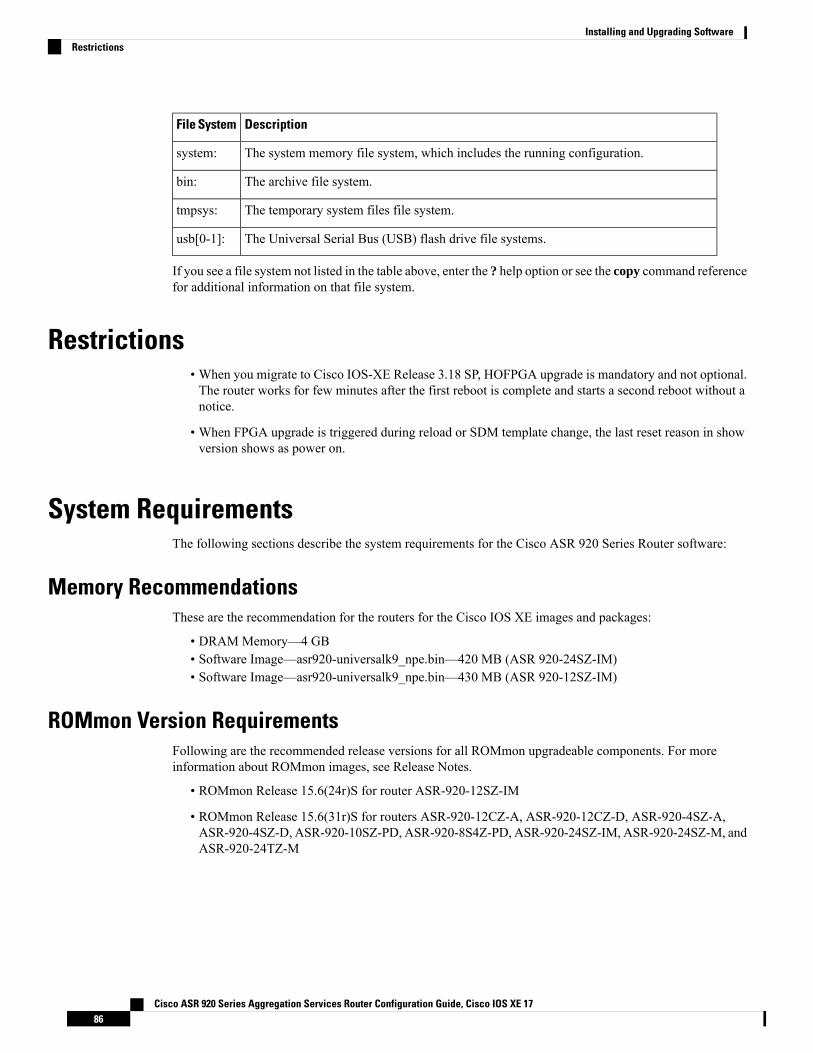
DescriptionFile System
The system memory file system, which includes the running configuration.system:
The archive file system.bin:
The temporary system files file system.tmpsys:
The Universal Serial Bus (USB) flash drive file systems.usb[0-1]:
If you see a file system not listed in the table above, enter the ? help option or see the copy command referencefor additional information on that file system.
Restrictions• When you migrate to Cisco IOS-XE Release 3.18 SP, HOFPGA upgrade is mandatory and not optional.The router works for few minutes after the first reboot is complete and starts a second reboot without anotice.
• When FPGA upgrade is triggered during reload or SDM template change, the last reset reason in showversion shows as power on.
System RequirementsThe following sections describe the system requirements for the Cisco ASR 920 Series Router software:
Memory RecommendationsThese are the recommendation for the routers for the Cisco IOS XE images and packages:
• DRAMMemory—4 GB• Software Image—asr920-universalk9_npe.bin—420 MB (ASR 920-24SZ-IM)• Software Image—asr920-universalk9_npe.bin—430 MB (ASR 920-12SZ-IM)
ROMmon Version RequirementsFollowing are the recommended release versions for all ROMmon upgradeable components. For moreinformation about ROMmon images, see Release Notes.
• ROMmon Release 15.6(24r)S for router ASR-920-12SZ-IM
• ROMmon Release 15.6(31r)S for routers ASR-920-12CZ-A, ASR-920-12CZ-D, ASR-920-4SZ-A,ASR-920-4SZ-D, ASR-920-10SZ-PD, ASR-920-8S4Z-PD, ASR-920-24SZ-IM, ASR-920-24SZ-M, andASR-920-24TZ-M
Cisco ASR 920 Series Aggregation Services Router Configuration Guide, Cisco IOS XE 1786
Installing and Upgrading SoftwareRestrictions
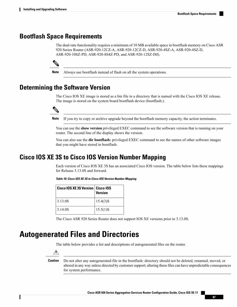
Bootflash Space RequirementsThe dual-rate functionality requires a minimum of 10MB available space in bootflash memory on Cisco ASR920 Series Router (ASR-920-12CZ-A, ASR-920-12CZ-D, ASR-920-4SZ-A, ASR-920-4SZ-D,ASR-920-10SZ-PD, ASR-920-8S4Z-PD, and ASR-920-12SZ-IM).
Always use bootflash instead of flash on all the system operations.Note
Determining the Software VersionThe Cisco IOS XE image is stored as a bin file in a directory that is named with the Cisco IOS XE release.The image is stored on the system board bootflash device (bootflash:).
If you try to copy or archive upgrade beyond the bootflash memory capacity, the action terminates.Note
You can use the show version privileged EXEC command to see the software version that is running on yourrouter. The second line of the display shows the version.
You can also use the dir bootflash: privileged EXEC command to see the names of other software imagesthat you might have stored in bootflash.
Cisco IOS XE 3S to Cisco IOS Version Number MappingEach version of Cisco IOS XE 3S has an associated Cisco IOS version. The table below lists these mappingsfor Release 3.13.0S and forward.
Table 10: Cisco IOS XE 3S to Cisco IOS Version Number Mapping
Cisco IOSVersion
Cisco IOS XE 3S Version
15.4(3)S3.13.0S
15.5(1)S3.14.0S
The Cisco ASR 920 Series Router does not support IOS XE versions prior to 3.13.0S.
Autogenerated Files and DirectoriesThe table below provides a list and descriptions of autogenerated files on the router.
Do not alter any autogenerated file in the bootflash: directory should not be deleted, renamed, moved, oraltered in anyway unless directed by customer support; altering these files can have unpredictable consequencesfor system performance.
Caution
Cisco ASR 920 Series Aggregation Services Router Configuration Guide, Cisco IOS XE 1787
Installing and Upgrading SoftwareBootflash Space Requirements
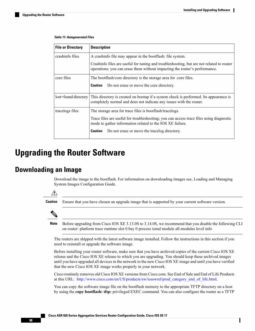
Table 11: Autogenerated Files
DescriptionFile or Directory
A crashinfo file may appear in the bootflash: file system.
Crashinfo files are useful for tuning and troubleshooting, but are not related to routeroperations: you can erase them without impacting the router’s performance.
crashinfo files
The bootflash/core directory is the storage area for .core files.
Do not erase or move the core directory.Caution
core files
This directory is created on bootup if a system check is performed. Its appearance iscompletely normal and does not indicate any issues with the router.
lost+found directory
The storage area for trace files is bootflash/tracelogs.
Trace files are useful for troubleshooting; you can access trace files using diagnosticmode to gather information related to the IOS XE failure.
Do not erase or move the tracelog directory.Caution
tracelogs files
Upgrading the Router Software
Downloading an ImageDownload the image to the bootflash. For information on downloading images see, Loading and ManagingSystem Images Configuration Guide.
Ensure that you have chosen an upgrade image that is supported by your current software version.Caution
Before upgrading from Cisco IOS XE 3.13.0S to 3.14.0S, we recommend that you disable the following CLIon router: platform trace runtime slot 0 bay 0 process iomd module all-modules level info
Note
The routers are shipped with the latest software image installed. Follow the instructions in this section if youneed to reinstall or upgrade the software image.
Before installing your router software, make sure that you have archived copies of the current Cisco IOS XErelease and the Cisco IOS XE release to which you are upgrading. You should keep these archived imagesuntil you have upgraded all devices in the network to the new Cisco IOS XE image and until you have verifiedthat the new Cisco IOS XE image works properly in your network.
Cisco routinely removes old Cisco IOSXE versions fromCisco.com. See End of Sale and End of Life Productsat this URL: http://www.cisco.com/en/US/products/sw/iosswrel/prod_category_end_of_life.html.
You can copy the software image file on the bootflash memory to the appropriate TFTP directory on a hostby using the copy bootflash: tftp: privileged EXEC command. You can also configure the router as a TFTP
Cisco ASR 920 Series Aggregation Services Router Configuration Guide, Cisco IOS XE 1788
Installing and Upgrading SoftwareUpgrading the Router Software
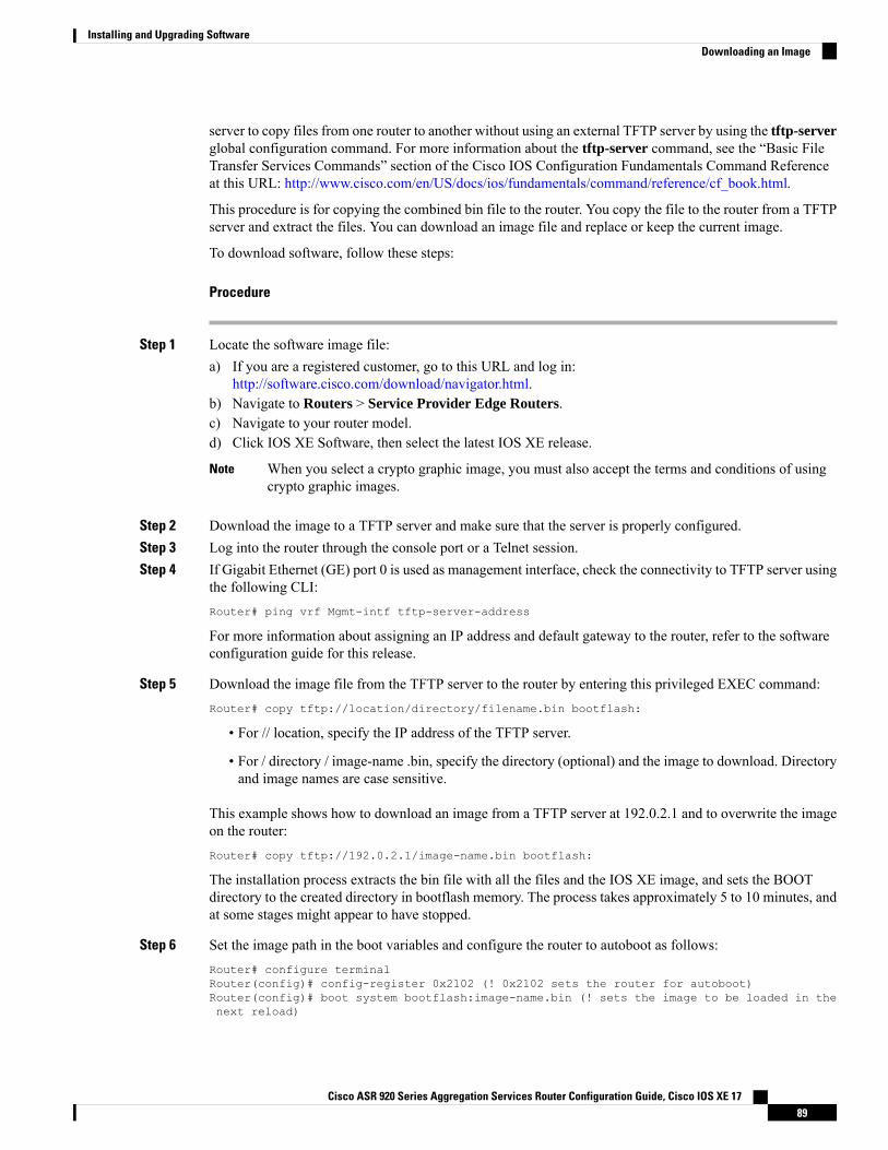
server to copy files from one router to another without using an external TFTP server by using the tftp-serverglobal configuration command. For more information about the tftp-server command, see the “Basic FileTransfer Services Commands” section of the Cisco IOS Configuration Fundamentals Command Referenceat this URL: http://www.cisco.com/en/US/docs/ios/fundamentals/command/reference/cf_book.html.
This procedure is for copying the combined bin file to the router. You copy the file to the router from a TFTPserver and extract the files. You can download an image file and replace or keep the current image.
To download software, follow these steps:
Procedure
Step 1 Locate the software image file:a) If you are a registered customer, go to this URL and log in:
http://software.cisco.com/download/navigator.html.b) Navigate to Routers > Service Provider Edge Routers.c) Navigate to your router model.d) Click IOS XE Software, then select the latest IOS XE release.
When you select a crypto graphic image, you must also accept the terms and conditions of usingcrypto graphic images.
Note
Step 2 Download the image to a TFTP server and make sure that the server is properly configured.Step 3 Log into the router through the console port or a Telnet session.Step 4 If Gigabit Ethernet (GE) port 0 is used as management interface, check the connectivity to TFTP server using
the following CLI:Router# ping vrf Mgmt-intf tftp-server-address
For more information about assigning an IP address and default gateway to the router, refer to the softwareconfiguration guide for this release.
Step 5 Download the image file from the TFTP server to the router by entering this privileged EXEC command:Router# copy tftp://location/directory/filename.bin bootflash:
• For // location, specify the IP address of the TFTP server.
• For / directory / image-name .bin, specify the directory (optional) and the image to download. Directoryand image names are case sensitive.
This example shows how to download an image from a TFTP server at 192.0.2.1 and to overwrite the imageon the router:Router# copy tftp://192.0.2.1/image-name.bin bootflash:
The installation process extracts the bin file with all the files and the IOS XE image, and sets the BOOTdirectory to the created directory in bootflash memory. The process takes approximately 5 to 10 minutes, andat some stages might appear to have stopped.
Step 6 Set the image path in the boot variables and configure the router to autoboot as follows:Router# configure terminalRouter(config)# config-register 0x2102 (! 0x2102 sets the router for autoboot)Router(config)# boot system bootflash:image-name.bin (! sets the image to be loaded in thenext reload)
Cisco ASR 920 Series Aggregation Services Router Configuration Guide, Cisco IOS XE 1789
Installing and Upgrading SoftwareDownloading an Image
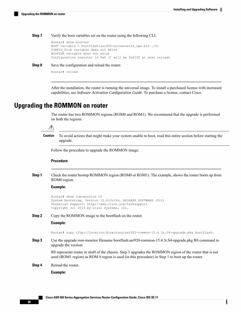
Step 7 Verify the boot variables set on the router using the following CLI:Router# show bootvarBOOT variable = bootflash:asr920-universalk9_npe.bin ,12;CONFIG_FILE variable does not existBOOTLDR variable does not existConfiguration register is 0x0 (! will be 0x2102 at next reload)
Step 8 Save the configuration and reload the router.Router# reload
After the installation, the router is running the universal image. To install a purchased license with increasedcapabilities, see Software Activation Configuration Guide. To purchase a license, contact Cisco.
Upgrading the ROMMON on routerThe router has two ROMMON regions (ROM0 and ROM1). We recommend that the upgrade is performedon both the regions.
To avoid actions that might make your system unable to boot, read this entire section before starting theupgrade.
Caution
Follow the procedure to upgrade the ROMMON image:
Procedure
Step 1 Check the router bootup ROMMON region (ROM0 or ROM1). The example, shows the router boots up fromROM0 region.
Example:
Router# show rom-monitor r0System Bootstrap, Version 15.4(3r)S4, RELEASE SOFTWARE (fc1)Technical Support: http://www.cisco.com/techsupportCopyright (c) 2014 by cisco Systems, Inc.
Step 2 Copy the ROMMON image to the bootflash on the router.
Example:
Router# copy tftp://location/directory/asr920-rommon-15.4.3r.S4-upgrade.pkg bootflash:
Step 3 Use the upgrade rom-monitor filename bootflash:asr920-rommon-15.4.3r.S4-upgrade.pkg R0 command toupgrade the version.
R0 represents router in slot0 of the chassis. Step 3 upgrades the ROMMON region of the router that is notused (ROM1 region) as ROM 0 region is used (in this procedure) in Step 1 to boot up the router.
Step 4 Reload the router.
Example:
Cisco ASR 920 Series Aggregation Services Router Configuration Guide, Cisco IOS XE 1790
Installing and Upgrading SoftwareUpgrading the ROMMON on router
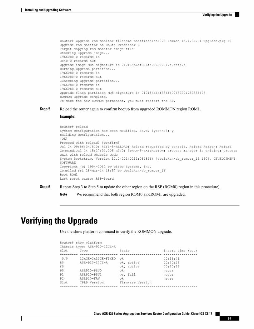
Router# upgrade rom-monitor filename bootflash:asr920-rommon-15.4.3r.S4-upgrade.pkg r0Upgrade rom-monitor on Route-Processor 0Target copying rom-monitor image fileChecking upgrade image...1966080+0 records in3840+0 records outUpgrade image MD5 signature is 712184b6ef336f40263222175255f475Burning upgrade partition...1966080+0 records in1966080+0 records outCChecking upgrade partition...1966080+0 records in1966080+0 records outUpgrade flash partition MD5 signature is 712184b6ef336f40263222175255f475ROMMON upgrade complete.To make the new ROMMON permanent, you must restart the RP.
Step 5 Reload the router again to confirm bootup from upgraded ROMMON region ROM1.
Example:
Router# reloadSystem configuration has been modified. Save? [yes/no]: yBuilding configuration...[OK]Proceed with reload? [confirm]Jul 24 09:56:34.510: %SYS-5-RELOAD: Reload requested by console. Reload Reason: ReloadCommand.Jul 24 15:27:03.205 R0/0: %PMAN-5-EXITACTION: Process manager is exiting: processexit with reload chassis codeSystem Bootstrap, Version 12.2(20140211:085836) [pbalakan-sb_romver_16 130], DEVELOPMENTSOFTWARECopyright (c) 1994-2012 by cisco Systems, Inc.Compiled Fri 28-Mar-14 18:57 by pbalakan-sb_romver_16Boot ROM1Last reset cause: RSP-Board
Step 6 Repeat Step 3 to Step 5 to update the other region on the RSP (ROM0) region in this procedure).
We recommend that both region ROM0 a.ndROM1 are upgraded.Note
Verifying the UpgradeUse the show platform command to verify the ROMMON upgrade.
Router# show platformChassis type: ASR-920-12CZ-ASlot Type State Insert time (ago)--------- ------------------- --------------------- -----------------0/0 12xGE-2x10GE-FIXED ok 00:18:41R0 ASR-920-12CZ-A ok, active 00:20:39F0 ok, active 00:20:39P0 ASR920-PSU0 ok neverP1 ASR920-PSU1 ps, fail neverP2 ASR920-FAN ok neverSlot CPLD Version Firmware Version--------- ------------------- ---------------------------------------
Cisco ASR 920 Series Aggregation Services Router Configuration Guide, Cisco IOS XE 1791
Installing and Upgrading SoftwareVerifying the Upgrade
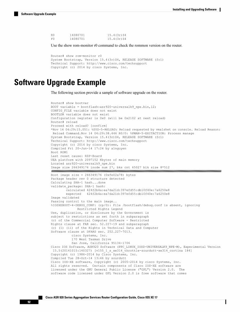
R0 14080701 15.4(3r)S4F0 14080701 15.4(3r)S4
Use the show rom-monitor r0 command to check the rommon version on the router.
Router# show rom-monitor r0System Bootstrap, Version 15.4(3r)S4, RELEASE SOFTWARE (fc1)Technical Support: http://www.cisco.com/techsupportCopyright (c) 2014 by cisco Systems, Inc.
Software Upgrade ExampleThe following section provide a sample of software upgrade on the router.
Router# show bootvarBOOT variable = bootflash:asr920-universalk9_npe.bin,12;CONFIG_FILE variable does not existBOOTLDR variable does not existConfiguration register is 0x0 (will be 0x2102 at next reload)Router# reloadProceed with reload? [confirm]*Nov 14 04:29:15.051: %SYS-5-RELOAD: Reload requested by vmalshet on console. Reload Reason:Reload Command.Nov 14 04:29:38.446 R0/0: %PMAN-5-EXITACTION: Process manageSystem Bootstrap, Version 15.4(3r)S4, RELEASE SOFTWARE (fc1)Technical Support: http://www.cisco.com/techsupportCopyright (c) 2014 by cisco Systems, Inc.Compiled Fri 20-Jun-14 17:24 by alnguyenBoot ROM1Last reset cause: RSP-BoardUEA platform with 2097152 Kbytes of main memoryLocated asr920-universalk9_npe.binImage size 266349176 inode num 27, bks cnt 65027 blk size 8*512##########################################################################################################################################################################################################################################################################################Boot image size = 266349176 (0xfe02a78) bytesPackage header rev 0 structure detectedCalculating SHA-1 hash...donevalidate_package: SHA-1 hash:
calculated 424f2b4a:ea7da21d:397efd55:db10f40e:7a6250e8expected 424f2b4a:ea7da21d:397efd55:db10f40e:7a6250e8
Image validatedPassing control to the main image..%IOSXEBOOT-4-DEBUG_CONF: (rp/0): File /bootflash/debug.conf is absent, ignoring
Restricted Rights LegendUse, duplication, or disclosure by the Government issubject to restrictions as set forth in subparagraph(c) of the Commercial Computer Software - RestrictedRights clause at FAR sec. 52.227-19 and subparagraph(c) (1) (ii) of the Rights in Technical Data and ComputerSoftware clause at DFARS sec. 252.227-7013.
cisco Systems, Inc.170 West Tasman DriveSan Jose, California 95134-1706
Cisco IOS Software, ASR920 Software (PPC_LINUX_IOSD-UNIVERSALK9_NPE-M), Experimental Version15.5(20141015:140327) [v155_1_s_xe314_throttle-sourdutt-xe314_cortina 184]Copyright (c) 1986-2014 by Cisco Systems, Inc.Compiled Tue 28-Oct-14 13:46 by sourduttCisco IOS-XE software, Copyright (c) 2005-2014 by cisco Systems, Inc.All rights reserved. Certain components of Cisco IOS-XE software arelicensed under the GNU General Public License ("GPL") Version 2.0. Thesoftware code licensed under GPL Version 2.0 is free software that comes
Cisco ASR 920 Series Aggregation Services Router Configuration Guide, Cisco IOS XE 1792
Installing and Upgrading SoftwareSoftware Upgrade Example
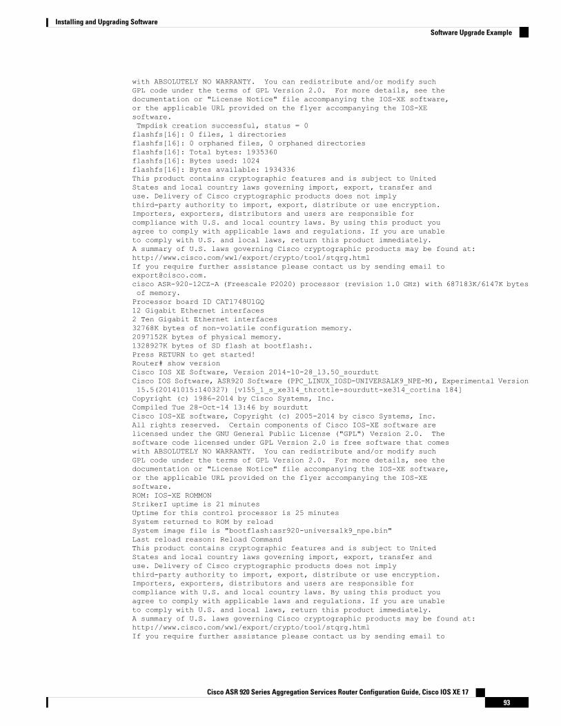
with ABSOLUTELY NO WARRANTY. You can redistribute and/or modify suchGPL code under the terms of GPL Version 2.0. For more details, see thedocumentation or "License Notice" file accompanying the IOS-XE software,or the applicable URL provided on the flyer accompanying the IOS-XEsoftware.Tmpdisk creation successful, status = 0flashfs[16]: 0 files, 1 directoriesflashfs[16]: 0 orphaned files, 0 orphaned directoriesflashfs[16]: Total bytes: 1935360flashfs[16]: Bytes used: 1024flashfs[16]: Bytes available: 1934336This product contains cryptographic features and is subject to UnitedStates and local country laws governing import, export, transfer anduse. Delivery of Cisco cryptographic products does not implythird-party authority to import, export, distribute or use encryption.Importers, exporters, distributors and users are responsible forcompliance with U.S. and local country laws. By using this product youagree to comply with applicable laws and regulations. If you are unableto comply with U.S. and local laws, return this product immediately.A summary of U.S. laws governing Cisco cryptographic products may be found at:http://www.cisco.com/wwl/export/crypto/tool/stqrg.htmlIf you require further assistance please contact us by sending email [email protected] ASR-920-12CZ-A (Freescale P2020) processor (revision 1.0 GHz) with 687183K/6147K bytesof memory.Processor board ID CAT1748U1GQ12 Gigabit Ethernet interfaces2 Ten Gigabit Ethernet interfaces32768K bytes of non-volatile configuration memory.2097152K bytes of physical memory.1328927K bytes of SD flash at bootflash:.Press RETURN to get started!Router# show versionCisco IOS XE Software, Version 2014-10-28_13.50_sourduttCisco IOS Software, ASR920 Software (PPC_LINUX_IOSD-UNIVERSALK9_NPE-M), Experimental Version15.5(20141015:140327) [v155_1_s_xe314_throttle-sourdutt-xe314_cortina 184]Copyright (c) 1986-2014 by Cisco Systems, Inc.Compiled Tue 28-Oct-14 13:46 by sourduttCisco IOS-XE software, Copyright (c) 2005-2014 by cisco Systems, Inc.All rights reserved. Certain components of Cisco IOS-XE software arelicensed under the GNU General Public License ("GPL") Version 2.0. Thesoftware code licensed under GPL Version 2.0 is free software that comeswith ABSOLUTELY NO WARRANTY. You can redistribute and/or modify suchGPL code under the terms of GPL Version 2.0. For more details, see thedocumentation or "License Notice" file accompanying the IOS-XE software,or the applicable URL provided on the flyer accompanying the IOS-XEsoftware.ROM: IOS-XE ROMMONStrikerI uptime is 21 minutesUptime for this control processor is 25 minutesSystem returned to ROM by reloadSystem image file is "bootflash:asr920-universalk9_npe.bin"Last reload reason: Reload CommandThis product contains cryptographic features and is subject to UnitedStates and local country laws governing import, export, transfer anduse. Delivery of Cisco cryptographic products does not implythird-party authority to import, export, distribute or use encryption.Importers, exporters, distributors and users are responsible forcompliance with U.S. and local country laws. By using this product youagree to comply with applicable laws and regulations. If you are unableto comply with U.S. and local laws, return this product immediately.A summary of U.S. laws governing Cisco cryptographic products may be found at:http://www.cisco.com/wwl/export/crypto/tool/stqrg.htmlIf you require further assistance please contact us by sending email to
Cisco ASR 920 Series Aggregation Services Router Configuration Guide, Cisco IOS XE 1793
Installing and Upgrading SoftwareSoftware Upgrade Example
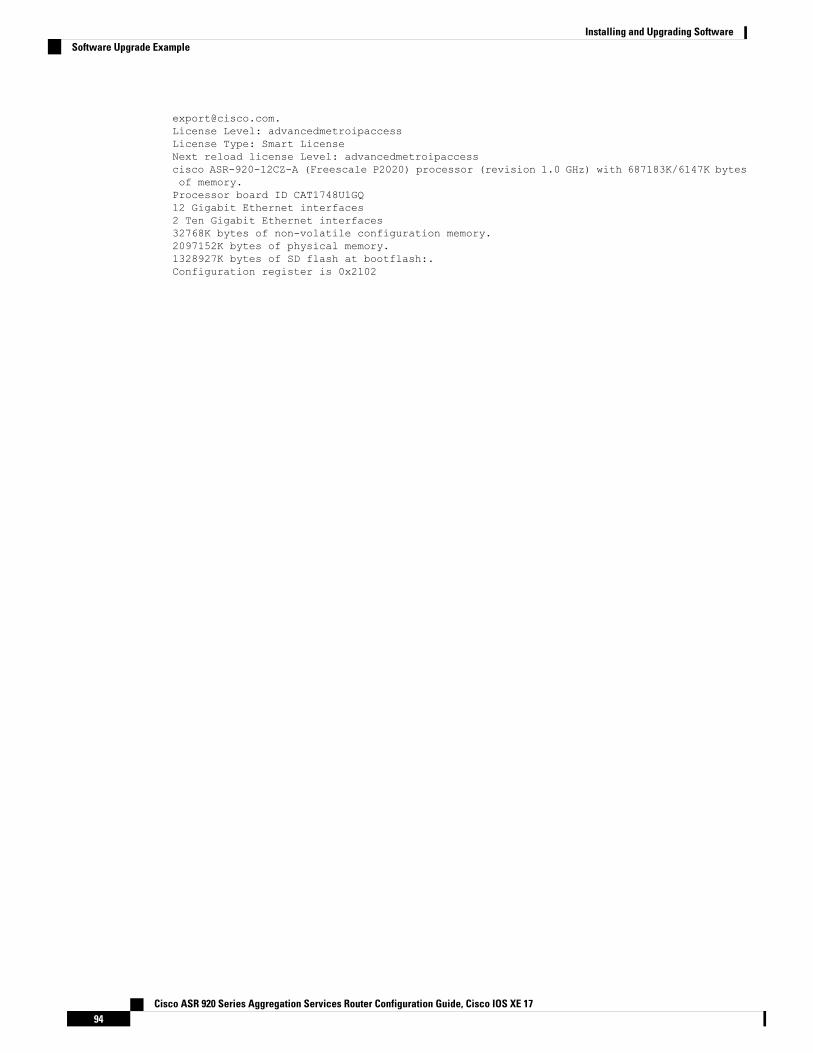
[email protected] Level: advancedmetroipaccessLicense Type: Smart LicenseNext reload license Level: advancedmetroipaccesscisco ASR-920-12CZ-A (Freescale P2020) processor (revision 1.0 GHz) with 687183K/6147K bytesof memory.Processor board ID CAT1748U1GQ12 Gigabit Ethernet interfaces2 Ten Gigabit Ethernet interfaces32768K bytes of non-volatile configuration memory.2097152K bytes of physical memory.1328927K bytes of SD flash at bootflash:.Configuration register is 0x2102
Cisco ASR 920 Series Aggregation Services Router Configuration Guide, Cisco IOS XE 1794
Installing and Upgrading SoftwareSoftware Upgrade Example
C H A P T E R 12Activating or Deactivating Interface Module
This chapter provides information about activating or deactivating interface module (IM) on the CiscoASR-920-24SZ-IM and Cisco ASR-920-12SZ-IM Routers. For more information about the commands usedin this chapter, see the Cisco IOS XE 3S Command References.
The router does not support swapping of the TDM interfacemodules to Gigabit Ethernet modules on the CiscoASR 920 Router and vice-versa. If the TDM interface module is swapped with the Gigabit Ethernet modulein the same slot or vice-versa, the router must be reloaded.
Note
• Overview, on page 95• Prerequisites for Activating an IM, on page 96• Restrictions for Activating an IM, on page 96• Activating an IM, on page 97• Prerequisites for Deactivating an IM, on page 97• Restrictions for Deactivating an IM, on page 98• Deactivating an IM, on page 98• Sample Configuration and Verification Examples for Activation or Deactivation of IMs, on page 99
OverviewCisco ASR-920-24SZ-IM Router supports the following IMs in Cisco IOS XE Release 3.16:
• 8-port 10/100/1000 Ethernet Interface Module (A900-IMA8T)
• 1-port 10GE XFP Interface Module (A900-IMA1X)
• 2-port 10GE SFP+/XFP Interface Module (A900-IMA2Z)
• 8-port RJ48C T1/E1 Interface Module (A900-IMA8D)
• 16-port T1/E1 Interface Module (A900-IMA16D)
• 32-port T1/E1 Interface Module (A900-IMA32D)
• 4-port OC3/STM1 or 1 port OC12/STM4 Interface Module (A900-IMA4OS)
• Combo 8-port 10/100/1000 and 1 port 10GE Interface Module (A900-IMA8T1Z)
Cisco ASR 920 Series Aggregation Services Router Configuration Guide, Cisco IOS XE 1795
Cisco ASR-920-12SZ-IM Router supports the following IMs in Cisco IOS XE Release 3.14S:
• 8-port 10/100/1000 Ethernet Interface Module (A900-IMA8T)
• 8-port SFP Gigabit Ethernet Interface Module (A900-IMA8S)
• 8-port RJ48C T1/E1 Interface Module (A900-IMA8D)
• 16-port T1/E1 Interface Module (A900-IMA16D)
• 32-port T1/E1 Interface Module (A900-IMA32D)
• 1-port 10GE XFP Interface Module (A900-IMA1X)
• 2-port 10GE SFP+/XFP Interface Module (A900-IMA2Z)
• Combo 8-port 10/100/1000 and 1 port 10GE Interface Module (A900-IMA8T1Z)
• Combo 8 SFP GE and 1-port 10GE IM (A900-IMA8S1Z)
• 4-port OC3/STM1 or 1-port OC12/STM4 Interface Module (A900-IMA4OS)
For information on installing and removing the IMs, see the Cisco ASR-920-24SZ-IM, ASR-920-24SZ-M,ASR-920-24TZ-M Aggregation Services Router Hardware Installation Guide.
The router does not support swapping of the TDM interface modules to Gigabit Ethernet modules. If the TDMinterface module is swapped with the Gigabit Ethernet module in the same slot or vice-versa, the router mustbe reloaded.
Prerequisites for Activating an IM• IM must be installed in the router• IM must not be in admin down mode• To activate 8x1G Cu IM or 8xT1/E1 IM, you must give up the following ports on the router front panel:
• 16 to 23 for Cu IM• 20 to 23 for T1/E1 IM
• To activate a TDM IM you must reload the router. Without reloading the router, the IM or associatedfront panel ports can not be used. If reload is aborted, the ports 20 to 23 remain disabled and IM remainsin Out-of-Service (OOS) state until the next reload.
Restrictions for Activating an IM• You cannot activate an IM when activate or deactivate commands are running in the background. Theactivate process usually completes in two minutes.
• Activating an incorrect IM type results in the IM OOS state.• write erase does not disable activated IM. To disable the IM, you must use the hw-module subslotcommand.
Cisco ASR 920 Series Aggregation Services Router Configuration Guide, Cisco IOS XE 1796
Activating or Deactivating Interface ModulePrerequisites for Activating an IM
Activating an IM
This section is not applicable to Cisco ASR-920-12SZ-IM Router for TDM IMs.Note
This section is applicable only to the 8x1G Cu IM or 8xT1/E1 IMs. There is no impact to the front panel portsto bring up or bring down the 1x10G and 2x10G IMs.
Note
Before using the IM, you must activate the IM.
• Verify that the correct IM is inserted in the IM slot.
• Shut down all active interfaces to be removed in IM activation (8x1G Cu IM or 8xT1/E1 IM). SeePrerequisites for Activating an IM, on page 96, for active interfaces to be shut down.
• Wait for a minute.
• Default all interfaces to be removed from the router.
• Execute the following command to activate the IM present in the IM slot.
hw-module subslot slot-number/subslot-number activate
• slot-number—Specifies the chassis slot number where the IM is installed.• subslot-number—Specifies the chassis subslot number where IM is installed.
The activate CLI operations run in the background.Note
The following ports on the router are relinquished when activating 8x1G Cu IMor 8xT1/E1 IM:
• 16 to 23 for Cu IM• 20 to 23 for T1/E1 IM
Note
Prerequisites for Deactivating an IM• IM must be installed in the router• IM must not be in admin down mode
Cisco ASR 920 Series Aggregation Services Router Configuration Guide, Cisco IOS XE 1797
Activating or Deactivating Interface ModuleActivating an IM
Restrictions for Deactivating an IM• You cannot deactivate an IM when activate or deactivate commands are running in the background. Thedeactivation process usually completes in two minutes.
• You cannot use write erase to disable activated IM. To disable the activated IM, you must use CLI.• Deactivating an IM by specifying an incorrect IM type or without an IM installed in the router can causehardware or software resource issues. In this case, you must reload the router to reclaim the front panelports and other ASIC related resources.
• You must reload the router to complete the activate/deactivate process.
Activation or deactivation of 8x1G Cu IM does not require a router reload.Note
• The hw-module subslot default command is not supported on TDM and OC-3 interface module.
Deactivating an IM
This section is applicable only to the 8-port 1G Cu IM or 8-port T1/E1 IMs. There is no impact to the frontpanel ports to bring up or bring down the 1-port 10G and 2-port 10G IMs.
Note
Before removing the IM from the router, you must deactivate the IM.
• Verify that the correct IM is in OK state in the router.
• Remove all virtual interfaces (using the no interface interface-name command) that are associated withthe IM. These interfaces includeMPLS TP tunnels, TE tunnels, BDI interface, and Port-Channel interface.
• Shut down all pluggable IM interfaces in the router.
• Wait for a minute.
• Default all pluggable IM interfaces in the router.
• Execute the following command to deactivate the IM present in the IM slot:
hw-module subslot slot-number/subslot-number deactivate
• slot-number—Specifies the chassis slot number where the IM is installed.• subslot-number—Specifies the chassis subslot number where IM is installed.
The deactivate CLI operations run in the background.Note
Cisco ASR 920 Series Aggregation Services Router Configuration Guide, Cisco IOS XE 1798
Activating or Deactivating Interface ModuleRestrictions for Deactivating an IM
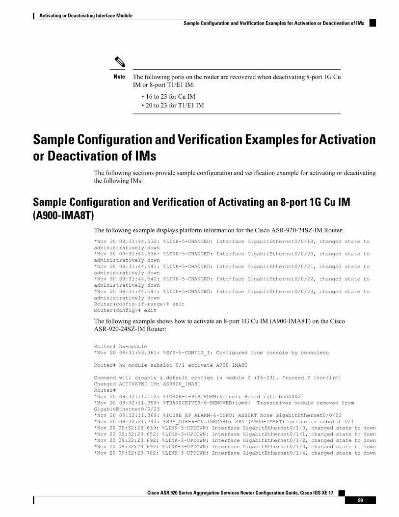
The following ports on the router are recovered when deactivating 8-port 1G CuIM or 8-port T1/E1 IM:
• 16 to 23 for Cu IM• 20 to 23 for T1/E1 IM
Note
Sample Configuration and Verification Examples for Activationor Deactivation of IMs
The following sections provide sample configuration and verification example for activating or deactivatingthe following IMs:
Sample Configuration and Verification of Activating an 8-port 1G Cu IM(A900-IMA8T)
The following example displays platform information for the Cisco ASR-920-24SZ-IM Router:*Nov 20 09:31:44.532: %LINK-5-CHANGED: Interface GigabitEthernet0/0/19, changed state toadministratively down*Nov 20 09:31:44.536: %LINK-5-CHANGED: Interface GigabitEthernet0/0/20, changed state toadministratively down*Nov 20 09:31:44.541: %LINK-5-CHANGED: Interface GigabitEthernet0/0/21, changed state toadministratively down*Nov 20 09:31:44.542: %LINK-5-CHANGED: Interface GigabitEthernet0/0/22, changed state toadministratively down*Nov 20 09:31:44.547: %LINK-5-CHANGED: Interface GigabitEthernet0/0/23, changed state toadministratively downRouter(config-if-range)# exitRouter(config)# exit
The following example shows how to activate an 8-port 1G Cu IM (A900-IMA8T) on the CiscoASR-920-24SZ-IM Router:
Router# hw-module*Nov 20 09:31:53.361: %SYS-5-CONFIG_I: Configured from console by consolesu
Router# hw-module subslot 0/1 activate A900-IMA8T
Command will disable & default configs in module 0 (16-23). Proceed ? [confirm]Changed ACTIVATED IM: ASR900_IMA8TRouter#*Nov 20 09:32:11.112: %IOSXE-1-PLATFORM:kernel: Board info b500002*Nov 20 09:32:11.359: %TRANSCEIVER-6-REMOVED:iomd: Transceiver module removed fromGigabitEthernet0/0/23*Nov 20 09:32:11.369: %IOSXE_RP_ALARM-6-INFO: ASSERT None GigabitEthernet0/0/23*Nov 20 09:32:21.743: %SPA_OIR-6-ONLINECARD: SPA (A900-IMA8T) online in subslot 0/1*Nov 20 09:32:23.639: %LINK-3-UPDOWN: Interface GigabitEthernet0/1/0, changed state to down*Nov 20 09:32:23.652: %LINK-3-UPDOWN: Interface GigabitEthernet0/1/1, changed state to down*Nov 20 09:32:23.692: %LINK-3-UPDOWN: Interface GigabitEthernet0/1/2, changed state to down*Nov 20 09:32:23.697: %LINK-3-UPDOWN: Interface GigabitEthernet0/1/3, changed state to down*Nov 20 09:32:23.702: %LINK-3-UPDOWN: Interface GigabitEthernet0/1/4, changed state to down
Cisco ASR 920 Series Aggregation Services Router Configuration Guide, Cisco IOS XE 1799
Activating or Deactivating Interface ModuleSample Configuration and Verification Examples for Activation or Deactivation of IMs
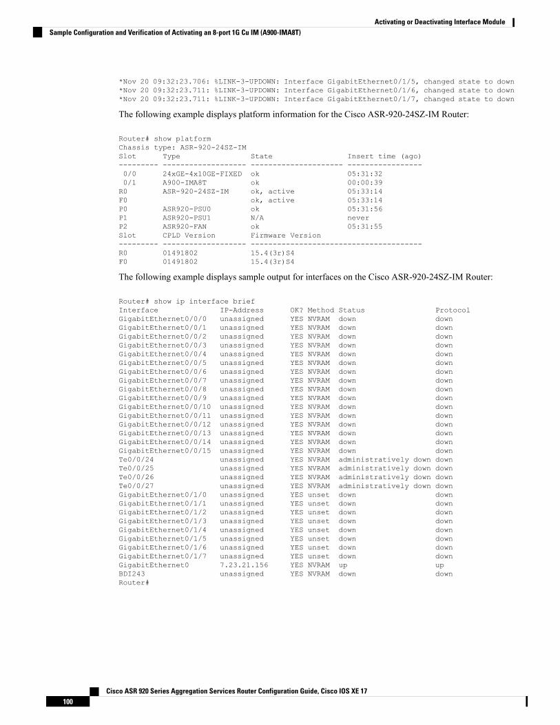
*Nov 20 09:32:23.706: %LINK-3-UPDOWN: Interface GigabitEthernet0/1/5, changed state to down*Nov 20 09:32:23.711: %LINK-3-UPDOWN: Interface GigabitEthernet0/1/6, changed state to down*Nov 20 09:32:23.711: %LINK-3-UPDOWN: Interface GigabitEthernet0/1/7, changed state to down
The following example displays platform information for the Cisco ASR-920-24SZ-IM Router:
Router# show platformChassis type: ASR-920-24SZ-IMSlot Type State Insert time (ago)--------- ------------------- --------------------- -----------------0/0 24xGE-4x10GE-FIXED ok 05:31:320/1 A900-IMA8T ok 00:00:39R0 ASR-920-24SZ-IM ok, active 05:33:14F0 ok, active 05:33:14P0 ASR920-PSU0 ok 05:31:56P1 ASR920-PSU1 N/A neverP2 ASR920-FAN ok 05:31:55Slot CPLD Version Firmware Version--------- ------------------- ---------------------------------------R0 01491802 15.4(3r)S4F0 01491802 15.4(3r)S4
The following example displays sample output for interfaces on the Cisco ASR-920-24SZ-IM Router:
Router# show ip interface briefInterface IP-Address OK? Method Status ProtocolGigabitEthernet0/0/0 unassigned YES NVRAM down downGigabitEthernet0/0/1 unassigned YES NVRAM down downGigabitEthernet0/0/2 unassigned YES NVRAM down downGigabitEthernet0/0/3 unassigned YES NVRAM down downGigabitEthernet0/0/4 unassigned YES NVRAM down downGigabitEthernet0/0/5 unassigned YES NVRAM down downGigabitEthernet0/0/6 unassigned YES NVRAM down downGigabitEthernet0/0/7 unassigned YES NVRAM down downGigabitEthernet0/0/8 unassigned YES NVRAM down downGigabitEthernet0/0/9 unassigned YES NVRAM down downGigabitEthernet0/0/10 unassigned YES NVRAM down downGigabitEthernet0/0/11 unassigned YES NVRAM down downGigabitEthernet0/0/12 unassigned YES NVRAM down downGigabitEthernet0/0/13 unassigned YES NVRAM down downGigabitEthernet0/0/14 unassigned YES NVRAM down downGigabitEthernet0/0/15 unassigned YES NVRAM down downTe0/0/24 unassigned YES NVRAM administratively down downTe0/0/25 unassigned YES NVRAM administratively down downTe0/0/26 unassigned YES NVRAM administratively down downTe0/0/27 unassigned YES NVRAM administratively down downGigabitEthernet0/1/0 unassigned YES unset down downGigabitEthernet0/1/1 unassigned YES unset down downGigabitEthernet0/1/2 unassigned YES unset down downGigabitEthernet0/1/3 unassigned YES unset down downGigabitEthernet0/1/4 unassigned YES unset down downGigabitEthernet0/1/5 unassigned YES unset down downGigabitEthernet0/1/6 unassigned YES unset down downGigabitEthernet0/1/7 unassigned YES unset down downGigabitEthernet0 7.23.21.156 YES NVRAM up upBDI243 unassigned YES NVRAM down downRouter#
Cisco ASR 920 Series Aggregation Services Router Configuration Guide, Cisco IOS XE 17100
Activating or Deactivating Interface ModuleSample Configuration and Verification of Activating an 8-port 1G Cu IM (A900-IMA8T)
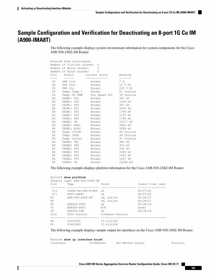
Sample Configuration and Verification for Deactivating an 8-port 1G Cu IM(A900-IMA8T)
The following example displays system environment information for system components for the CiscoASR-920-24SZ-IM Router:
Router# show environmentNumber of Critical alarms: 0Number of Major alarms: 0Number of Minor alarms: 0Slot Sensor Current State Reading---- ------ ------------- -------P0 PEM Iout Normal 7 AP0 PEM Vout Normal 12 V DCP0 PEM Vin Normal 230 V ACP0 Temp: Temp 1 Normal 51 CelsiusP2 Temp: FC PWM Fan Speed 65% 38 CelsiusR0 VADM1: VX1 Normal 997 mVR0 VADM1: VX2 Normal 1046 mVR0 VADM1: VX3 Normal 997 mVR0 VADM1: VP1 Normal 3283 mVR0 VADM1: VP2 Normal 1796 mVR0 VADM1: VP3 Normal 1197 mVR0 VADM1: VP4 Normal 1768 mVR0 VADM1: VH Normal 12317 mVR0 VADM1: AUX1 Normal 3840 mVR0 VADM1: AUX2 Normal 6958 mVR0 Temp: CYLON Normal 60 CelsiusR0 Temp: FPGA Normal 49 CelsiusR0 Temp: Outlet Normal 47 CelsiusR0 VADM2: VX1 Normal 995 mVR0 VADM2: VX2 Normal 973 mVR0 VADM2: VX3 Normal 754 mVR0 VADM2: VP1 Normal 2495 mVR0 VADM2: VP2 Normal 1495 mVR0 VADM2: VP3 Normal 1497 mVR0 VADM2: VH Normal 12296 mV
The following example displays platform information for the Cisco ASR-920-24SZ-IM Router:
Router# show platformChassis type: ASR-920-24SZ-IMSlot Type State Insert time (ago)--------- ------------------- --------------------- -----------------0/0 24xGE-4x10GE-FIXED ok 05:37:550/1 A900-IMA8T ok 00:07:02R0 ASR-920-24SZ-IM ok, active 05:39:37F0 ok, active 05:39:37P0 ASR920-PSU0 ok 05:38:19P1 ASR920-PSU1 N/A neverP2 ASR920-FAN ok 05:38:18Slot CPLD Version Firmware Version--------- ------------------- ---------------------------------------R0 01491802 15.4(3r)S4F0 01491802 15.4(3r)S4
The following example displays sample output for interfaces on the Cisco ASR-920-24SZ-IM Router:
Router# show ip interface briefInterface IP-Address OK? Method Status Protocol
Cisco ASR 920 Series Aggregation Services Router Configuration Guide, Cisco IOS XE 17101
Activating or Deactivating Interface ModuleSample Configuration and Verification for Deactivating an 8-port 1G Cu IM (A900-IMA8T)
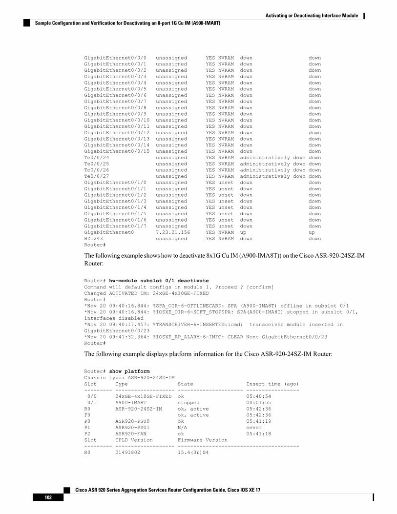
GigabitEthernet0/0/0 unassigned YES NVRAM down downGigabitEthernet0/0/1 unassigned YES NVRAM down downGigabitEthernet0/0/2 unassigned YES NVRAM down downGigabitEthernet0/0/3 unassigned YES NVRAM down downGigabitEthernet0/0/4 unassigned YES NVRAM down downGigabitEthernet0/0/5 unassigned YES NVRAM down downGigabitEthernet0/0/6 unassigned YES NVRAM down downGigabitEthernet0/0/7 unassigned YES NVRAM down downGigabitEthernet0/0/8 unassigned YES NVRAM down downGigabitEthernet0/0/9 unassigned YES NVRAM down downGigabitEthernet0/0/10 unassigned YES NVRAM down downGigabitEthernet0/0/11 unassigned YES NVRAM down downGigabitEthernet0/0/12 unassigned YES NVRAM down downGigabitEthernet0/0/13 unassigned YES NVRAM down downGigabitEthernet0/0/14 unassigned YES NVRAM down downGigabitEthernet0/0/15 unassigned YES NVRAM down downTe0/0/24 unassigned YES NVRAM administratively down downTe0/0/25 unassigned YES NVRAM administratively down downTe0/0/26 unassigned YES NVRAM administratively down downTe0/0/27 unassigned YES NVRAM administratively down downGigabitEthernet0/1/0 unassigned YES unset down downGigabitEthernet0/1/1 unassigned YES unset down downGigabitEthernet0/1/2 unassigned YES unset down downGigabitEthernet0/1/3 unassigned YES unset down downGigabitEthernet0/1/4 unassigned YES unset down downGigabitEthernet0/1/5 unassigned YES unset down downGigabitEthernet0/1/6 unassigned YES unset down downGigabitEthernet0/1/7 unassigned YES unset down downGigabitEthernet0 7.23.21.156 YES NVRAM up upBDI243 unassigned YES NVRAM down downRouter#
The following example shows how to deactivate 8x1GCu IM (A900-IMA8T)) on the CiscoASR-920-24SZ-IMRouter:
Router# hw-module subslot 0/1 deactivateCommand will default configs in module 1. Proceed ? [confirm]Changed ACTIVATED IM: 24xGE-4x10GE-FIXEDRouter#*Nov 20 09:40:16.844: %SPA_OIR-6-OFFLINECARD: SPA (A900-IMA8T) offline in subslot 0/1*Nov 20 09:40:16.844: %IOSXE_OIR-6-SOFT_STOPSPA: SPA(A900-IMA8T) stopped in subslot 0/1,interfaces disabled*Nov 20 09:40:17.457: %TRANSCEIVER-6-INSERTED:iomd: transceiver module inserted inGigabitEthernet0/0/23*Nov 20 09:41:32.364: %IOSXE_RP_ALARM-6-INFO: CLEAR None GigabitEthernet0/0/23Router#
The following example displays platform information for the Cisco ASR-920-24SZ-IM Router:
Router# show platformChassis type: ASR-920-24SZ-IMSlot Type State Insert time (ago)--------- ------------------- --------------------- -----------------0/0 24xGE-4x10GE-FIXED ok 05:40:540/1 A900-IMA8T stopped 00:01:55R0 ASR-920-24SZ-IM ok, active 05:42:36F0 ok, active 05:42:36P0 ASR920-PSU0 ok 05:41:19P1 ASR920-PSU1 N/A neverP2 ASR920-FAN ok 05:41:18Slot CPLD Version Firmware Version--------- ------------------- ---------------------------------------R0 01491802 15.4(3r)S4
Cisco ASR 920 Series Aggregation Services Router Configuration Guide, Cisco IOS XE 17102
Activating or Deactivating Interface ModuleSample Configuration and Verification for Deactivating an 8-port 1G Cu IM (A900-IMA8T)

F0 01491802 15.4(3r)S4Router#
The following example displays sample output for interfaces on the Cisco ASR-920-24SZ-IM Router:Router# show ip interface briefInterface IP-Address OK? Method Status ProtocolGigabitEthernet0/0/0 unassigned YES NVRAM down downGigabitEthernet0/0/1 unassigned YES NVRAM down downGigabitEthernet0/0/2 unassigned YES NVRAM down downGigabitEthernet0/0/3 unassigned YES NVRAM down downGigabitEthernet0/0/4 unassigned YES NVRAM down downGigabitEthernet0/0/5 unassigned YES NVRAM down downGigabitEthernet0/0/6 unassigned YES NVRAM down downGigabitEthernet0/0/7 unassigned YES NVRAM down downGigabitEthernet0/0/8 unassigned YES NVRAM down downGigabitEthernet0/0/9 unassigned YES NVRAM down downGigabitEthernet0/0/10 unassigned YES NVRAM down downGigabitEthernet0/0/11 unassigned YES NVRAM down downGigabitEthernet0/0/12 unassigned YES NVRAM down downGigabitEthernet0/0/13 unassigned YES NVRAM down downGigabitEthernet0/0/14 unassigned YES NVRAM down downGigabitEthernet0/0/15 unassigned YES NVRAM down downGigabitEthernet0/0/16 unassigned YES NVRAM down downGigabitEthernet0/0/17 unassigned YES NVRAM down downGigabitEthernet0/0/18 unassigned YES NVRAM down downGigabitEthernet0/0/19 unassigned YES NVRAM down downGigabitEthernet0/0/20 unassigned YES NVRAM down downGigabitEthernet0/0/21 unassigned YES NVRAM down downGigabitEthernet0/0/22 unassigned YES NVRAM down downGigabitEthernet0/0/23 unassigned YES NVRAM down downTe0/0/24 unassigned YES NVRAM administratively down downTe0/0/25 unassigned YES NVRAM administratively down downTe0/0/26 unassigned YES NVRAM administratively down downTe0/0/27 unassigned YES NVRAM administratively down downGigabitEthernet0 7.23.21.156 YES NVRAM up upBDI243 unassigned YES NVRAM down down
Sample Configuration and Verification of Activating 8-port T1/E1 IM(A900-IMA8D)
The following example shows how to activate 8-port T1/E1 IM (A900-IMA8D) on the CiscoASR-920-24SZ-IMRouter:Router# hw-module subslot 0/1 activate A900-IMA8DCommand will disable & default configs in module 0 (20-23). Proceed ? [confirm]System reload is required for act/deact of TDM IMs. Proceed with reload ?[confirm]
Changed ACTIVATED IM: ASR900_IMA16D
*Nov 20 09:47:08.155: %TRANSCEIVER-6-REMOVED:iomd: Transceiver module removed fromGigabitEthernet0/0/23*Nov 20 09:47:08.875: %IOSXE_RP_ALARM-6-INFO: ASSERT None GigabitEthernet0/0/23 [OK]Proceed with reload? [confirm]
*Nov 20 09:47:22.275: %SYS-5-RELOAD: Reload requested by console. Reload Reason: ReloadCommand.Nov 20 09:47:56.304 R0/0:System Bootstrap, Version 15.4(3r)S4, RELEASE SOFTWARE (fc1)Technical Support: http://www.cisco.com/techsupport
Copyright (c) 2014 by cisco Systems, Inc.
Cisco ASR 920 Series Aggregation Services Router Configuration Guide, Cisco IOS XE 17103
Activating or Deactivating Interface ModuleSample Configuration and Verification of Activating 8-port T1/E1 IM (A900-IMA8D)
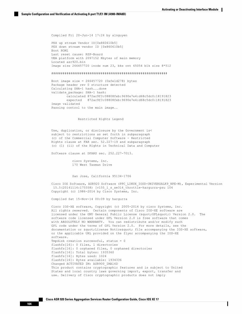
Compiled Fri 20-Jun-14 17:24 by alnguyen
PEX up stream Vendor ID[0x860610b5]PEX down stream vendor ID [0x860610b5]Boot ROM1Last reset cause: RSP-BoardUEA platform with 2097152 Kbytes of main memoryLocated asr920.binImage size 266457720 inode num 23, bks cnt 65054 blk size 8*512
#############################################################
Boot image size = 266457720 (0xfe1d278) bytesPackage header rev 0 structure detectedCalculating SHA-1 hash...donevalidate_package: SHA-1 hash:
calculated 872ac9f3:08808feb:9690e7e4:d68c5dc0:18191823expected 872ac9f3:08808feb:9690e7e4:d68c5dc0:18191823
Image validatedPassing control to the main image..
Restricted Rights Legend
Use, duplication, or disclosure by the Government is<subject to restrictions as set forth in subparagraph(c) of the Commercial Computer Software - RestrictedRights clause at FAR sec. 52.227-19 and subparagraph(c) (1) (ii) of the Rights in Technical Data and Computer
Software clause at DFARS sec. 252.227-7013.
cisco Systems, Inc.170 West Tasman Drive
San Jose, California 95134-1706
Cisco IOS Software, ASR920 Software (PPC_LINUX_IOSD-UNIVERSALK9_NPE-M), Experimental Version15.5(20141114:175558) [v155_1_s_xe314_throttle-hargurra-psu 104Copyright (c) 1986-2014 by Cisco Systems, Inc.
Compiled Sat 15-Nov-14 00:09 by hargurra
Cisco IOS-XE software, Copyright (c) 2005-2014 by cisco Systems, Inc.All rights reserved. Certain components of Cisco IOS-XE software arelicensed under the GNU General Public License ("GPL") Version 2.0. Thesoftware code licensed under GPL Version 2.0 is free software that comeswith ABSOLUTELY NO WARRANTY. You can redistribute and/or modify suchGPL code under the terms of GPL Version 2.0. For more details, see thedocumentation or "License Notice" file accompanying the IOS-XE software,or the applicable URL provided on the flyer accompanying the IOS-XEsoftware.Tmpdisk creation successful, status = 0flashfs[16]: 0 files, 1 directoriesflashfs[16]: 0 orphaned files, 0 orphaned directoriesflashfs[16]: Total bytes: 1935360flashfs[16]: Bytes used: 1024flashfs[16]: Bytes available: 1934336Changed ACTIVATED IM: ASR900_IMA16DThis product contains cryptographic features and is subject to UnitedStates and local country laws governing import, export, transfer anduse. Delivery of Cisco cryptographic products does not imply
Cisco ASR 920 Series Aggregation Services Router Configuration Guide, Cisco IOS XE 17104
Activating or Deactivating Interface ModuleSample Configuration and Verification of Activating 8-port T1/E1 IM (A900-IMA8D)
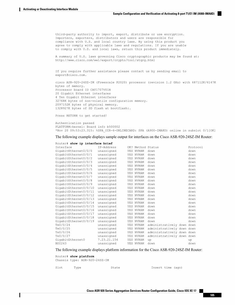
third-party authority to import, export, distribute or use encryption.Importers, exporters, distributors and users are responsible forcompliance with U.S. and local country laws. By using this product youagree to comply with applicable laws and regulations. If you are unableto comply with U.S. and local laws, return this product immediately.
A summary of U.S. laws governing Cisco cryptographic products may be found at:http://www.cisco.com/wwl/export/crypto/tool/stqrg.html
If you require further assistance please contact us by sending email [email protected].
cisco ASR-920-24SZ-IM (Freescale P2020) processor (revision 1.2 GHz) with 687112K/6147Kbytes of memory.Processor board ID CAT1707V01N20 Gigabit Ethernet interfaces4 Ten Gigabit Ethernet interfaces32768K bytes of non-volatile configuration memory.2097152K bytes of physical memory.1328927K bytes of SD flash at bootflash:.
Press RETURN to get started!
Authentication passedPLATFORM:kernel: Board info b500002*Nov 20 09:53:23.315: %SPA_OIR-6-ONLINECARD: SPA (A900-IMA8D) online in subslot 0/1[OK]
The following example displays sample output for interfaces on the Cisco ASR-920-24SZ-IM Router:Router# show ip interface briefInterface IP-Address OK? Method Status ProtocolGigabitEthernet0/0/0 unassigned YES NVRAM down downGigabitEthernet0/0/1 unassigned YES NVRAM down downGigabitEthernet0/0/2 unassigned YES NVRAM down downGigabitEthernet0/0/3 unassigned YES NVRAM down downGigabitEthernet0/0/4 unassigned YES NVRAM down downGigabitEthernet0/0/5 unassigned YES NVRAM down downGigabitEthernet0/0/6 unassigned YES NVRAM down downGigabitEthernet0/0/7 unassigned YES NVRAM down downGigabitEthernet0/0/8 unassigned YES NVRAM down downGigabitEthernet0/0/9 unassigned YES NVRAM down downGigabitEthernet0/0/10 unassigned YES NVRAM down downGigabitEthernet0/0/11 unassigned YES NVRAM down downGigabitEthernet0/0/12 unassigned YES NVRAM down downGigabitEthernet0/0/13 unassigned YES NVRAM down downGigabitEthernet0/0/14 unassigned YES NVRAM down downGigabitEthernet0/0/15 unassigned YES NVRAM down downGigabitEthernet0/0/16 unassigned YES NVRAM down downGigabitEthernet0/0/17 unassigned YES NVRAM down downGigabitEthernet0/0/18 unassigned YES NVRAM down downGigabitEthernet0/0/19 unassigned YES NVRAM down downTe0/0/24 unassigned YES NVRAM administratively down downTe0/0/25 unassigned YES NVRAM administratively down downTe0/0/26 unassigned YES NVRAM administratively down downTe0/0/27 unassigned YES NVRAM administratively down downGigabitEthernet0 7.23.21.156 YES NVRAM up upBDI243 unassigned YES NVRAM down down
The following example displays platform information for the Cisco ASR-920-24SZ-IM Router:Router# show platformChassis type: ASR-920-24SZ-IM
Slot Type State Insert time (ago)
Cisco ASR 920 Series Aggregation Services Router Configuration Guide, Cisco IOS XE 17105
Activating or Deactivating Interface ModuleSample Configuration and Verification of Activating 8-port T1/E1 IM (A900-IMA8D)
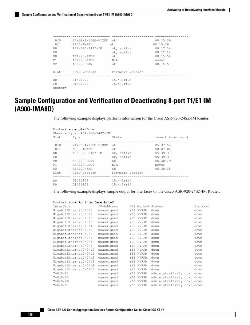
--------- ------------------- --------------------- -----------------0/0 24xGE-4x10GE-FIXED ok 00:15:260/1 A900-IMA8D ok 00:15:26R0 ASR-920-24SZ-IM ok, active 00:17:14F0 ok, active 00:17:14P0 ASR920-PSU0 ok 00:15:52P1 ASR920-PSU1 N/A neverP2 ASR920-FAN ok 00:15:51
Slot CPLD Version Firmware Version--------- ------------------- ---------------------------------------R0 01491802 15.4(3r)S4F0 01491802 15.4(3r)S4Router#
Sample Configuration and Verification of Deactivating 8-port T1/E1 IM(A900-IMA8D)
The following example displays platform information for the Cisco ASR-920-24SZ-IM Router:
Router# show platformChassis type: ASR-920-24SZ-IMSlot Type State Insert time (ago)--------- ------------------- --------------------- -----------------0/0 24xGE-4x10GE-FIXED ok 05:37:550/1 A900-IMA8T ok 00:07:02R0 ASR-920-24SZ-IM ok, active 05:39:37F0 ok, active 05:39:37P0 ASR920-PSU0 ok 05:38:19P1 ASR920-PSU1 N/A neverP2 ASR920-FAN ok 05:38:18Slot CPLD Version Firmware Version--------- ------------------- ---------------------------------------R0 01491802 15.4(3r)S4F0 01491802 15.4(3r)S4
The following example displays sample output for interfaces on the Cisco ASR-920-24SZ-IM Router:
Router# show ip interface briefInterface IP-Address OK? Method Status ProtocolGigabitEthernet0/0/0 unassigned YES NVRAM down downGigabitEthernet0/0/1 unassigned YES NVRAM down downGigabitEthernet0/0/2 unassigned YES NVRAM down downGigabitEthernet0/0/3 unassigned YES NVRAM down downGigabitEthernet0/0/4 unassigned YES NVRAM down downGigabitEthernet0/0/5 unassigned YES NVRAM down downGigabitEthernet0/0/6 unassigned YES NVRAM down downGigabitEthernet0/0/7 unassigned YES NVRAM down downGigabitEthernet0/0/8 unassigned YES NVRAM down downGigabitEthernet0/0/9 unassigned YES NVRAM down downGigabitEthernet0/0/10 unassigned YES NVRAM down downGigabitEthernet0/0/11 unassigned YES NVRAM down downGigabitEthernet0/0/12 unassigned YES NVRAM down downGigabitEthernet0/0/13 unassigned YES NVRAM down downGigabitEthernet0/0/14 unassigned YES NVRAM down downGigabitEthernet0/0/15 unassigned YES NVRAM down downTe0/0/24 unassigned YES NVRAM administratively down downTe0/0/25 unassigned YES NVRAM administratively down downTe0/0/26 unassigned YES NVRAM administratively down downTe0/0/27 unassigned YES NVRAM administratively down down
Cisco ASR 920 Series Aggregation Services Router Configuration Guide, Cisco IOS XE 17106
Activating or Deactivating Interface ModuleSample Configuration and Verification of Deactivating 8-port T1/E1 IM (A900-IMA8D)
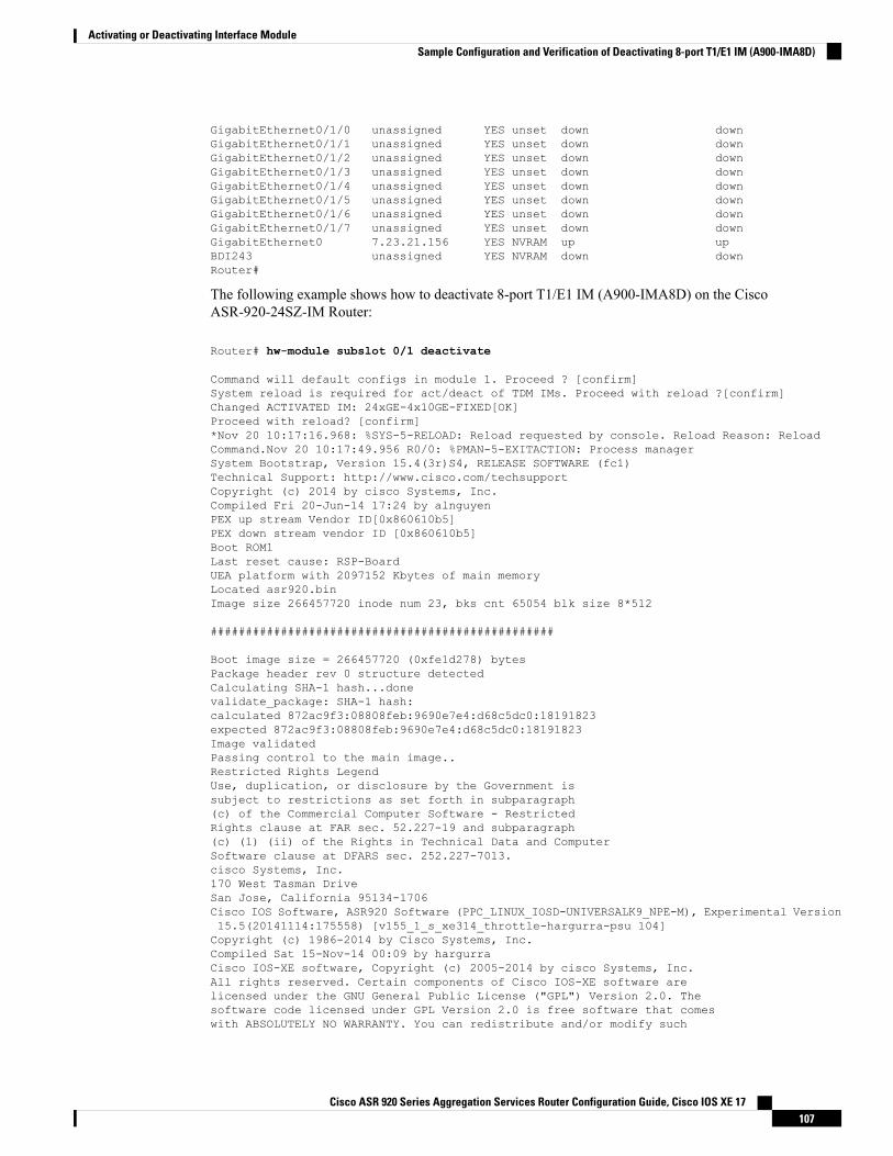
GigabitEthernet0/1/0 unassigned YES unset down downGigabitEthernet0/1/1 unassigned YES unset down downGigabitEthernet0/1/2 unassigned YES unset down downGigabitEthernet0/1/3 unassigned YES unset down downGigabitEthernet0/1/4 unassigned YES unset down downGigabitEthernet0/1/5 unassigned YES unset down downGigabitEthernet0/1/6 unassigned YES unset down downGigabitEthernet0/1/7 unassigned YES unset down downGigabitEthernet0 7.23.21.156 YES NVRAM up upBDI243 unassigned YES NVRAM down downRouter#
The following example shows how to deactivate 8-port T1/E1 IM (A900-IMA8D) on the CiscoASR-920-24SZ-IM Router:
Router# hw-module subslot 0/1 deactivate
Command will default configs in module 1. Proceed ? [confirm]System reload is required for act/deact of TDM IMs. Proceed with reload ?[confirm]Changed ACTIVATED IM: 24xGE-4x10GE-FIXED[OK]Proceed with reload? [confirm]*Nov 20 10:17:16.968: %SYS-5-RELOAD: Reload requested by console. Reload Reason: ReloadCommand.Nov 20 10:17:49.956 R0/0: %PMAN-5-EXITACTION: Process managerSystem Bootstrap, Version 15.4(3r)S4, RELEASE SOFTWARE (fc1)Technical Support: http://www.cisco.com/techsupportCopyright (c) 2014 by cisco Systems, Inc.Compiled Fri 20-Jun-14 17:24 by alnguyenPEX up stream Vendor ID[0x860610b5]PEX down stream vendor ID [0x860610b5]Boot ROM1Last reset cause: RSP-BoardUEA platform with 2097152 Kbytes of main memoryLocated asr920.binImage size 266457720 inode num 23, bks cnt 65054 blk size 8*512
#################################################
Boot image size = 266457720 (0xfe1d278) bytesPackage header rev 0 structure detectedCalculating SHA-1 hash...donevalidate_package: SHA-1 hash:calculated 872ac9f3:08808feb:9690e7e4:d68c5dc0:18191823expected 872ac9f3:08808feb:9690e7e4:d68c5dc0:18191823Image validatedPassing control to the main image..Restricted Rights LegendUse, duplication, or disclosure by the Government issubject to restrictions as set forth in subparagraph(c) of the Commercial Computer Software - RestrictedRights clause at FAR sec. 52.227-19 and subparagraph(c) (1) (ii) of the Rights in Technical Data and ComputerSoftware clause at DFARS sec. 252.227-7013.cisco Systems, Inc.170 West Tasman DriveSan Jose, California 95134-1706Cisco IOS Software, ASR920 Software (PPC_LINUX_IOSD-UNIVERSALK9_NPE-M), Experimental Version15.5(20141114:175558) [v155_1_s_xe314_throttle-hargurra-psu 104]Copyright (c) 1986-2014 by Cisco Systems, Inc.Compiled Sat 15-Nov-14 00:09 by hargurraCisco IOS-XE software, Copyright (c) 2005-2014 by cisco Systems, Inc.All rights reserved. Certain components of Cisco IOS-XE software arelicensed under the GNU General Public License ("GPL") Version 2.0. Thesoftware code licensed under GPL Version 2.0 is free software that comeswith ABSOLUTELY NO WARRANTY. You can redistribute and/or modify such
Cisco ASR 920 Series Aggregation Services Router Configuration Guide, Cisco IOS XE 17107
Activating or Deactivating Interface ModuleSample Configuration and Verification of Deactivating 8-port T1/E1 IM (A900-IMA8D)
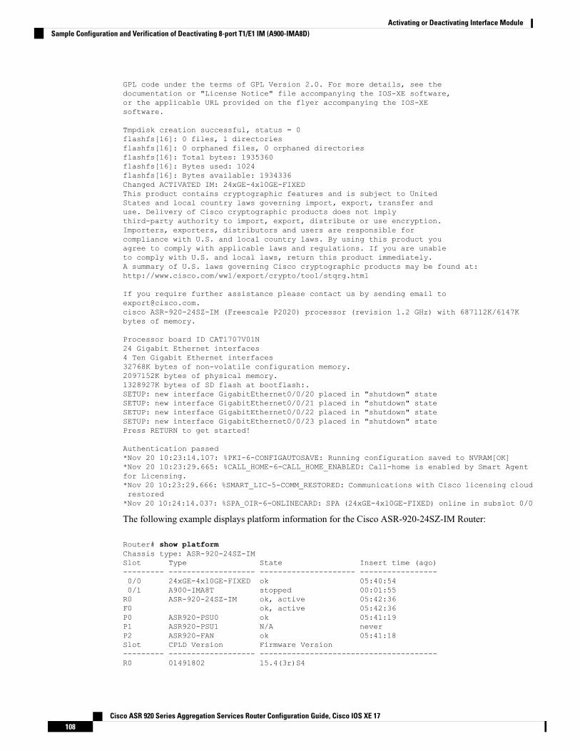
GPL code under the terms of GPL Version 2.0. For more details, see thedocumentation or "License Notice" file accompanying the IOS-XE software,or the applicable URL provided on the flyer accompanying the IOS-XEsoftware.
Tmpdisk creation successful, status = 0flashfs[16]: 0 files, 1 directoriesflashfs[16]: 0 orphaned files, 0 orphaned directoriesflashfs[16]: Total bytes: 1935360flashfs[16]: Bytes used: 1024flashfs[16]: Bytes available: 1934336Changed ACTIVATED IM: 24xGE-4x10GE-FIXEDThis product contains cryptographic features and is subject to UnitedStates and local country laws governing import, export, transfer anduse. Delivery of Cisco cryptographic products does not implythird-party authority to import, export, distribute or use encryption.Importers, exporters, distributors and users are responsible forcompliance with U.S. and local country laws. By using this product youagree to comply with applicable laws and regulations. If you are unableto comply with U.S. and local laws, return this product immediately.A summary of U.S. laws governing Cisco cryptographic products may be found at:http://www.cisco.com/wwl/export/crypto/tool/stqrg.html
If you require further assistance please contact us by sending email [email protected] ASR-920-24SZ-IM (Freescale P2020) processor (revision 1.2 GHz) with 687112K/6147Kbytes of memory.
Processor board ID CAT1707V01N24 Gigabit Ethernet interfaces4 Ten Gigabit Ethernet interfaces32768K bytes of non-volatile configuration memory.2097152K bytes of physical memory.1328927K bytes of SD flash at bootflash:.SETUP: new interface GigabitEthernet0/0/20 placed in "shutdown" stateSETUP: new interface GigabitEthernet0/0/21 placed in "shutdown" stateSETUP: new interface GigabitEthernet0/0/22 placed in "shutdown" stateSETUP: new interface GigabitEthernet0/0/23 placed in "shutdown" statePress RETURN to get started!
Authentication passed*Nov 20 10:23:14.107: %PKI-6-CONFIGAUTOSAVE: Running configuration saved to NVRAM[OK]*Nov 20 10:23:29.665: %CALL_HOME-6-CALL_HOME_ENABLED: Call-home is enabled by Smart Agentfor Licensing.*Nov 20 10:23:29.666: %SMART_LIC-5-COMM_RESTORED: Communications with Cisco licensing cloudrestored*Nov 20 10:24:14.037: %SPA_OIR-6-ONLINECARD: SPA (24xGE-4x10GE-FIXED) online in subslot 0/0
The following example displays platform information for the Cisco ASR-920-24SZ-IM Router:
Router# show platformChassis type: ASR-920-24SZ-IMSlot Type State Insert time (ago)--------- ------------------- --------------------- -----------------0/0 24xGE-4x10GE-FIXED ok 05:40:540/1 A900-IMA8T stopped 00:01:55R0 ASR-920-24SZ-IM ok, active 05:42:36F0 ok, active 05:42:36P0 ASR920-PSU0 ok 05:41:19P1 ASR920-PSU1 N/A neverP2 ASR920-FAN ok 05:41:18Slot CPLD Version Firmware Version--------- ------------------- ---------------------------------------R0 01491802 15.4(3r)S4
Cisco ASR 920 Series Aggregation Services Router Configuration Guide, Cisco IOS XE 17108
Activating or Deactivating Interface ModuleSample Configuration and Verification of Deactivating 8-port T1/E1 IM (A900-IMA8D)

F0 01491802 15.4(3r)S4Router#
The following example displays sample output for interfaces on the Cisco ASR-920-24SZ-IM Router:Router# show ip interface briefInterface IP-Address OK? Method Status ProtocolGigabitEthernet0/0/0 unassigned YES NVRAM down downGigabitEthernet0/0/1 unassigned YES NVRAM down downGigabitEthernet0/0/2 unassigned YES NVRAM down downGigabitEthernet0/0/3 unassigned YES NVRAM down downGigabitEthernet0/0/4 unassigned YES NVRAM down downGigabitEthernet0/0/5 unassigned YES NVRAM down downGigabitEthernet0/0/6 unassigned YES NVRAM down downGigabitEthernet0/0/7 unassigned YES NVRAM down downGigabitEthernet0/0/8 unassigned YES NVRAM down downGigabitEthernet0/0/9 unassigned YES NVRAM down downGigabitEthernet0/0/10 unassigned YES NVRAM down downGigabitEthernet0/0/11 unassigned YES NVRAM down downGigabitEthernet0/0/12 unassigned YES NVRAM down downGigabitEthernet0/0/13 unassigned YES NVRAM down downGigabitEthernet0/0/14 unassigned YES NVRAM down downGigabitEthernet0/0/15 unassigned YES NVRAM down downGigabitEthernet0/0/16 unassigned YES NVRAM down downGigabitEthernet0/0/17 unassigned YES NVRAM down downGigabitEthernet0/0/18 unassigned YES NVRAM down downGigabitEthernet0/0/19 unassigned YES NVRAM down downGigabitEthernet0/0/20 unassigned YES NVRAM down downGigabitEthernet0/0/21 unassigned YES NVRAM down downGigabitEthernet0/0/22 unassigned YES NVRAM down downGigabitEthernet0/0/23 unassigned YES NVRAM down downTe0/0/24 unassigned YES NVRAM administratively down downTe0/0/25 unassigned YES NVRAM administratively down downTe0/0/26 unassigned YES NVRAM administratively down downTe0/0/27 unassigned YES NVRAM administratively down downGigabitEthernet0 7.23.21.156 YES NVRAM up upBDI243 unassigned YES NVRAM down down
Cisco ASR 920 Series Aggregation Services Router Configuration Guide, Cisco IOS XE 17109
Activating or Deactivating Interface ModuleSample Configuration and Verification of Deactivating 8-port T1/E1 IM (A900-IMA8D)

Cisco ASR 920 Series Aggregation Services Router Configuration Guide, Cisco IOS XE 17110
Activating or Deactivating Interface ModuleSample Configuration and Verification of Deactivating 8-port T1/E1 IM (A900-IMA8D)
C H A P T E R 13Configuring Ethernet Interfaces
This chapter provides information about configuring the Gigabit Ethernet interface on the Cisco ASR 920Series Router.
For more information about the commands used in this chapter, see theCisco IOS XE 3S Command References.
Effective Cisco IOS-XERelease 3.16S, the Cisco ASR-920-12SZ-IMAggregation Services Router was addedto the Cisco ASR 920 Series Routers family.
On the Cisco ASR-920-12SZ-IMAggregation Services Router, ports from 12 through 15 can operate at either1G or 10G, and operates in a mutually exclusive way. You cannot insert both 1G and 10G together. If youinsert IG IMs (A900-IMA8T1Z, A900-IMA8S1Z, A900-IMA8T, A900-IMA8S), the dual rate port supportsonly 10G.
Note
• Configuring an Interface, on page 111• Specifying the Interface Address on an Interface, on page 113• Configuring Hot Standby Router Protocol, on page 113• Modifying the Interface MTU Size, on page 115• Configuring the Encapsulation Type, on page 117• Configuring Autonegotiation on an Interface, on page 117• Configuring Carrier Ethernet Features, on page 118• Saving the Configuration, on page 118• Shutting Down and Restarting an Interface, on page 119• Verifying the Interface Configuration, on page 119• Verifying Interface Status, on page 120• Configuring LAN/WAN-PHY Controllers, on page 122• Configuration Examples, on page 124
Configuring an InterfaceThis section lists the required configuration steps to configure Gigabit and Ten Gigabit Ethernet interfaces.Follow these steps to configure your interface:
Cisco ASR 920 Series Aggregation Services Router Configuration Guide, Cisco IOS XE 17111
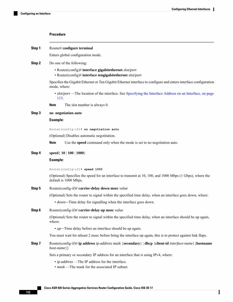
Procedure
Step 1 Router# configure terminal
Enters global configuration mode.
Step 2 Do one of the following:
• Router(config)# interface gigabitethernet slot/port• Router(config)# interface tengigabitethernet slot/port
Specifies the Gigabit Ethernet or Ten Gigabit Ethernet interface to configure and enters interface configurationmode, where:
• slot/port —The location of the interface. See Specifying the Interface Address on an Interface, on page113.
The slot number is always 0.Note
Step 3 no negotiation auto
Example:
Router(config-if)# no negotiation auto
(Optional) Disables automatic negotitation.
Use the speed command only when the mode is set to no negotiation auto.Note
Step 4 speed{ 10 | 100 | 1000}
Example:
Router(config-if)# speed 1000
(Optional) Specifies the speed for an interface to transmit at 10, 100, and 1000 Mbps (1 Gbps), where thedefault is 1000 Mbps.
Step 5 Router(config-if)# carrier-delay down msec value
(Optional) Sets the router to signal within the specified time delay, when an interface goes down, where:
• down—Time delay for signalling when the interface goes down.
Step 6 Router(config-if)# carrier-delay up msec value
(Optional) Sets the router to signal within the specified time delay, when an interface should be up again,where:
• up—Time delay before an interface should be up again.
You must wait for atleast 2 msec before bring the interface up again, this is to protect against link flaps.
Step 7 Router(config-if)# ip address ip-address mask {secondary} | dhcp {client-id interface-name}{hostnamehost-name}]
Sets a primary or secondary IP address for an interface that is using IPv4, where:
• ip-address —The IP address for the interface.• mask —The mask for the associated IP subnet.
Cisco ASR 920 Series Aggregation Services Router Configuration Guide, Cisco IOS XE 17112
Configuring Ethernet InterfacesConfiguring an Interface
• secondary—(Optional) Specifies that the configured address is a secondary IP address. If this keywordis omitted, the configured address is the primary IP address.
• dhcp—Specifies that IP addresses will be assigned dynamically using DHCP.• client-id interface-name—Specifies the client identifier. The interface-name sets the client identifier tothe hexadecimal MAC address of the named interface.
• hostname host-name—Specifies the hostname for the DHCP purposes. The host-name is the name ofthe host to be placed in the DHCP option 12 field.
Step 8 Router(config-if)# mtu bytes
(As Required) Specifies the maximum packet size for an interface, where:
• bytes— The maximum number of bytes for a packet.
The default is 1500 bytes; the range is from 1500 to 9216.
Step 9 Router(config-if)# no shutdown
Enables the interface.
Specifying the Interface Address on an InterfaceTo configure or monitor Ethernet interfaces, you need to specify the physical location of the interface in theCLI. The interface address format is slot/port, where:
• slot—The chassis slot number in the router of the interface.
The interface slot number is always 0.Note
• subslot—The subslot of the interface. Interface subslots are always 0.• port—The number of the individual interface port on an interface.
Router(config)# interface GigabitEthernet 0/0/0no ip addressshutdownnegotiation autono cdp enable
Configuring Hot Standby Router ProtocolHot Standby Router Protocol (HSRP) provides high network availability because it routes IP traffic fromhosts without relying on the availability of any single router. You can deploy HSRP in a group of routers toselect an active router and a standby router. (An active router is the router of choice for routing packets; astandby router is a router that takes over the routing duties when an active router fails, or when preset conditionsare met).
HSRP is enabled on an interface by entering the standby [group-number] ip [ip-address [secondary]]command. The standby command is also used to configure various HSRP elements. This document does not
Cisco ASR 920 Series Aggregation Services Router Configuration Guide, Cisco IOS XE 17113
Configuring Ethernet InterfacesSpecifying the Interface Address on an Interface
discuss more complex HSRP configurations. For additional information on configuring HSRP, see to theHSRP section of the Cisco IP Configuration Guide publication that corresponds to your Cisco IOSXE softwarerelease. In the following HSRP configuration, standby group 2 on Gigabit Ethernet port 0/1/0 is configuredat a priority of 110 and is also configured to have a preemptive delay should a switchover to this port occur:
Router(config)#interface GigabitEthernet 0/1/0Router(config-if)#standby 2 ip 192.168.1.200Router(config-if)#standby 2 priority 110Router(config-if)#standby 2 preempt
Themaximum number of different HSRP groups that can be created on one physical interface is 4. If additionalgroups are required, create 4 groups on the physical interface, and the remaining groups on the BDI or onanother physical interface.
The maximum number of HSRP or VRRP groups allowed are:
• RSP1A—128 HSRP or VRRP groups. 128 HSRP or VRRP groups restriction implies that the maximumnumber of different interfaces that can be configured with VRRP or HSRP is 128. You cannot configureHSRP or VRRP for more than 128 interfaces but you can configure upto 256 HSRP or VRRP groups inthose 128 interfaces.
• RSP1B —256 HSRP or VRRP groups
• RSP2A-64 and RSP2-128—128 HSRP or VRRP groups, prior to Cisco IOS Release XE 3.15S
• RSP2A-64 and RSP2-128 —256 HSRP or VRRP groups, starting Cisco IOS Release XE 3.15S
• RSP3-200 and RSP3-400—255 HSRP or VRRP groups, starting Cisco IOS Release XE 3.18.1SP
TCAM space utilization changes when HSRP groups are configured on the router. If HSRP groups areconfigured the TCAM space is utilized. EachHSRP group takes 1 TCAMentry. The “Out of TCAM”messagemay be displayed if total number of TCAM space used by HSRP groups and prefixes on the router exceedsscale limit.
Note
HSRP state flaps with sub-second “Hello” or “Dead” timers.Note
Restrictions
HSRPv2 is not supported.
Verifying HSRPTo verify the HSRP information, use the show standby command in EXEC mode:
Router# show standbyEthernet0 - Group 0Local state is Active, priority 100, may preemptHellotime 3 holdtime 10Next hello sent in 0:00:00Hot standby IP address is 198.92.72.29 configuredActive router is local
Cisco ASR 920 Series Aggregation Services Router Configuration Guide, Cisco IOS XE 17114
Configuring Ethernet InterfacesVerifying HSRP
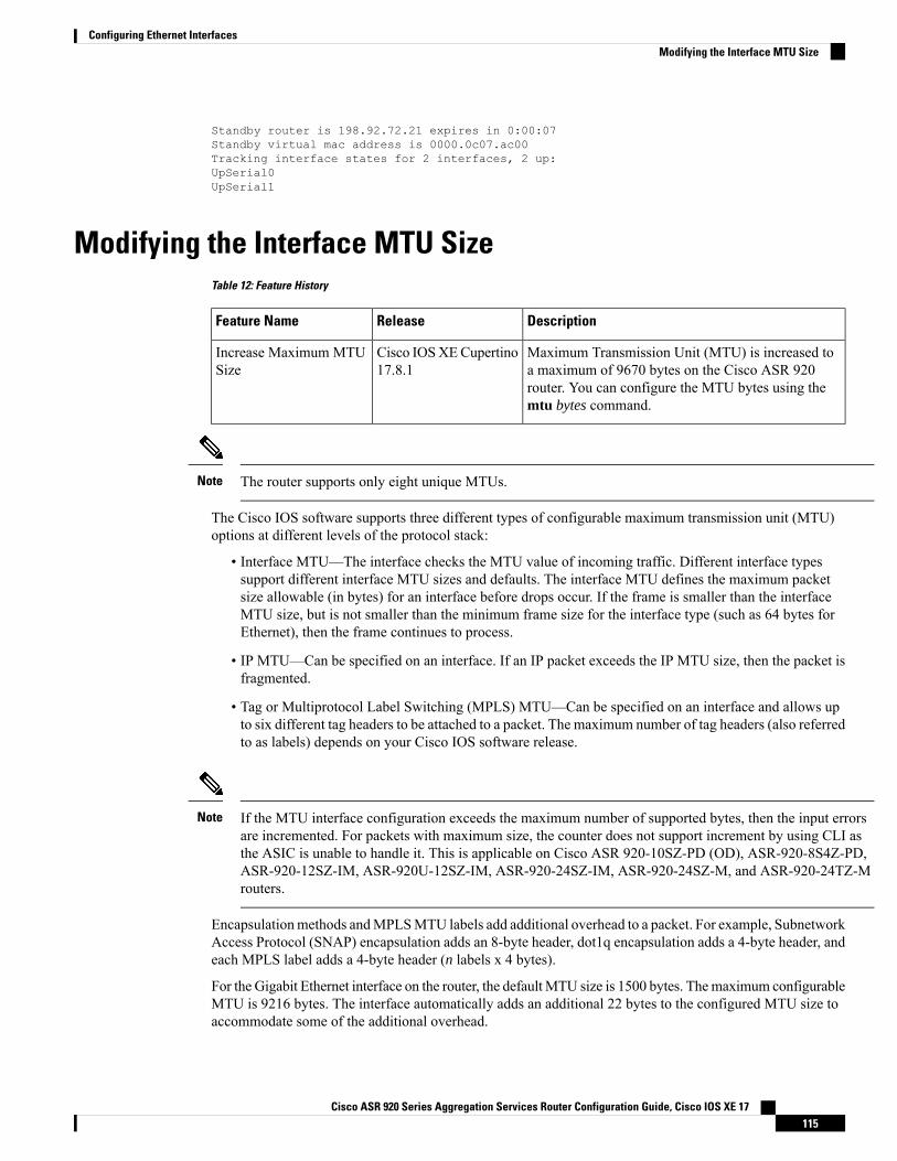
Standby router is 198.92.72.21 expires in 0:00:07Standby virtual mac address is 0000.0c07.ac00Tracking interface states for 2 interfaces, 2 up:UpSerial0UpSerial1
Modifying the Interface MTU SizeTable 12: Feature History
DescriptionReleaseFeature Name
Maximum Transmission Unit (MTU) is increased toa maximum of 9670 bytes on the Cisco ASR 920router. You can configure the MTU bytes using themtu bytes command.
Cisco IOSXECupertino17.8.1
Increase Maximum MTUSize
The router supports only eight unique MTUs.Note
The Cisco IOS software supports three different types of configurable maximum transmission unit (MTU)options at different levels of the protocol stack:
• Interface MTU—The interface checks the MTU value of incoming traffic. Different interface typessupport different interface MTU sizes and defaults. The interface MTU defines the maximum packetsize allowable (in bytes) for an interface before drops occur. If the frame is smaller than the interfaceMTU size, but is not smaller than the minimum frame size for the interface type (such as 64 bytes forEthernet), then the frame continues to process.
• IP MTU—Can be specified on an interface. If an IP packet exceeds the IP MTU size, then the packet isfragmented.
• Tag or Multiprotocol Label Switching (MPLS) MTU—Can be specified on an interface and allows upto six different tag headers to be attached to a packet. The maximum number of tag headers (also referredto as labels) depends on your Cisco IOS software release.
If the MTU interface configuration exceeds the maximum number of supported bytes, then the input errorsare incremented. For packets with maximum size, the counter does not support increment by using CLI asthe ASIC is unable to handle it. This is applicable on Cisco ASR 920-10SZ-PD (OD), ASR-920-8S4Z-PD,ASR-920-12SZ-IM, ASR-920U-12SZ-IM, ASR-920-24SZ-IM, ASR-920-24SZ-M, and ASR-920-24TZ-Mrouters.
Note
Encapsulationmethods andMPLSMTU labels add additional overhead to a packet. For example, SubnetworkAccess Protocol (SNAP) encapsulation adds an 8-byte header, dot1q encapsulation adds a 4-byte header, andeach MPLS label adds a 4-byte header (n labels x 4 bytes).
For the Gigabit Ethernet interface on the router, the defaultMTU size is 1500 bytes. Themaximum configurableMTU is 9216 bytes. The interface automatically adds an additional 22 bytes to the configured MTU size toaccommodate some of the additional overhead.
Cisco ASR 920 Series Aggregation Services Router Configuration Guide, Cisco IOS XE 17115
Configuring Ethernet InterfacesModifying the Interface MTU Size
Increase Maximum MTU Size on ASR 920 Router
Effective Cisco IOS XE Cupertino 17.8.1, a maximum of 9644 MTU bytes are supported on the Cisco ASR920 router.
Prior to this release, you can configure a maximum of 9216 bytes on the router.
Limitations
• The giants and input errors field counts are not incremented for both 1G and 10G ports on Cisco ASR920 platforms.
• In EtherLike-MIB, the dot3StatsFrameTooLongs frames count in SNMP increases when the framepacket size is more than the default MTU.
• If the packet size is more than the configured MTU value and exceeds 1Mbps, packets are dropped.Packets are fragmented when the packet size is more than the configured MTU value and when trafficis lesser than 1Mbps.
• Due to hardware limitation on the Cisco ASR 920 router, ping is not supported with MTU size of greaterthan 9215 bytes.
Interface MTU Configuration GuidelinesWhen configuring the interface MTU size, consider the following guidelines:
• The default interface MTU size accommodates a 1500-byte packet, plus 22 additional bytes to cover thefollowing additional overhead:
• Layer 2 header—14 bytes• Dot1q header—4 bytes• CRC—4 bytes
• If you are using MPLS, be sure that the mpls mtu command is configured for a value less than or equalto the interface MTU.
• If you are using MPLS labels, then you should increase the default interface MTU size to accommodatethe number of MPLS labels. Each MPLS label adds 4 bytes of overhead to a packet.
Interface MTU Configuration TaskTo modify the MTU size on an interface, use the following command in interface configuration mode:
PurposeCommand
Configures the maximum packet size for an interface, where:
• bytes— Specifies the maximum number of bytes for a packet.
The default is 1500 bytes and the maximum configurable MTU is 9216bytes.
Router(config-if)# mtubytes
To return to the default MTU size, use the no form of the command.
Cisco ASR 920 Series Aggregation Services Router Configuration Guide, Cisco IOS XE 17116
Configuring Ethernet InterfacesInterface MTU Configuration Guidelines
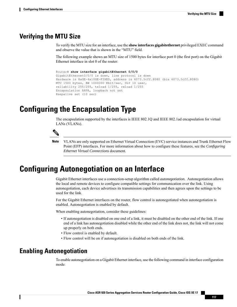
Verifying the MTU SizeTo verify theMTU size for an interface, use the show interfaces gigabitethernet privileged EXEC commandand observe the value that is shown in the “MTU” field.
The following example shows an MTU size of 1500 bytes for interface port 0 (the first port) on the GigabitEthernet interface in slot 0 of the router:
Router# show interface gigabitEthernet 0/0/0GigabitEthernet0/0/0 is down, line protocol is downHardware is 8xGE-4x10GE-FIXED, address is 6073.5cff.8080 (bia 6073.5cff.8080)MTU 1500 bytes, BW 1000000 Kbit/sec, DLY 10 usec,reliability 255/255, txload 1/255, rxload 1/255Encapsulation ARPA, loopback not setKeepalive set (10 sec)
Configuring the Encapsulation TypeThe encapsulation supported by the interfaces is IEEE 802.1Q and IEEE 802.1ad encapsulation for virtualLANs (VLANs).
VLANs are only supported on Ethernet Virtual Connection (EVC) service instances and Trunk Ethernet FlowPoint (EFP) interfaces. For more information about how to configure these features, see the ConfiguringEthernet Virtual Connections document.
Note
Configuring Autonegotiation on an InterfaceGigabit Ethernet interfaces use a connection-setup algorithm called autonegotiation. Autonegotiation allowsthe local and remote devices to configure compatible settings for communication over the link. Usingautonegotiation, each device advertises its transmission capabilities and then agrees upon the settings to beused for the link.
For the Gigabit Ethernet interfaces on the router, flow control is autonegotiated when autonegotiation isenabled. Autonegotiation is enabled by default.
When enabling autonegotiation, consider these guidelines:
• If autonegotiation is disabled on one end of a link, it must be disabled on the other end of the link. If oneend of a link has autonegotiation disabled while the other end of the link does not, the link will not comeup properly on both ends.
• Flow control is enabled by default.• Flow control will be on if autonegotiation is disabled on both ends of the link.
Enabling AutonegotiationTo enable autonegotiation on a Gigabit Ethernet interface, use the following command in interface configurationmode:
Cisco ASR 920 Series Aggregation Services Router Configuration Guide, Cisco IOS XE 17117
Configuring Ethernet InterfacesVerifying the MTU Size
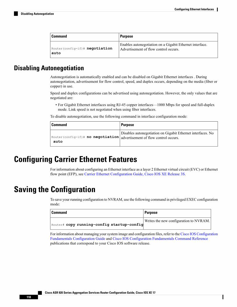
PurposeCommand
Enables autonegotiation on a Gigabit Ethernet interface.Advertisement of flow control occurs.Router(config-if)# negotiation
auto
Disabling AutonegotiationAutonegotiation is automatically enabled and can be disabled on Gigabit Ethernet interfaces . Duringautonegotiation, advertisement for flow control, speed, and duplex occurs, depending on the media (fiber orcopper) in use.
Speed and duplex configurations can be advertised using autonegotiation. However, the only values that arenegotiated are:
• For Gigabit Ethernet interfaces using RJ-45 copper interfaces—1000 Mbps for speed and full-duplexmode. Link speed is not negotiated when using fiber interfaces.
To disable autonegotiation, use the following command in interface configuration mode:
PurposeCommand
Disables autonegotiation on Gigabit Ethernet interfaces. Noadvertisement of flow control occurs.Router(config-if)# no negotiation
auto
Configuring Carrier Ethernet FeaturesFor information about configuring an Ethernet interface as a layer 2 Ethernet virtual circuit (EVC) or Ethernetflow point (EFP), see Carrier Ethernet Configuration Guide, Cisco IOS XE Release 3S.
Saving the ConfigurationTo save your running configuration to NVRAM, use the following command in privileged EXEC configurationmode:
PurposeCommand
Writes the new configuration to NVRAM.Router# copy running-config startup-config
For information about managing your system image and configuration files, refer to the Cisco IOSConfigurationFundamentals Configuration Guide and Cisco IOS Configuration Fundamentals Command Referencepublications that correspond to your Cisco IOS software release.
Cisco ASR 920 Series Aggregation Services Router Configuration Guide, Cisco IOS XE 17118
Configuring Ethernet InterfacesDisabling Autonegotiation
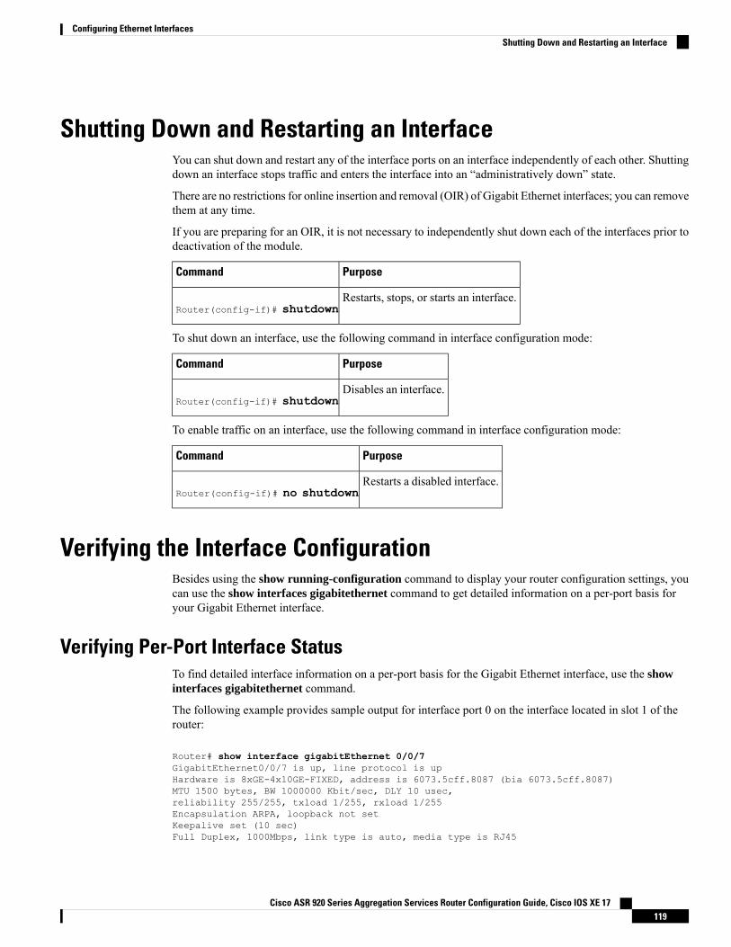
Shutting Down and Restarting an InterfaceYou can shut down and restart any of the interface ports on an interface independently of each other. Shuttingdown an interface stops traffic and enters the interface into an “administratively down” state.
There are no restrictions for online insertion and removal (OIR) of Gigabit Ethernet interfaces; you can removethem at any time.
If you are preparing for an OIR, it is not necessary to independently shut down each of the interfaces prior todeactivation of the module.
PurposeCommand
Restarts, stops, or starts an interface.Router(config-if)# shutdown
To shut down an interface, use the following command in interface configuration mode:
PurposeCommand
Disables an interface.Router(config-if)# shutdown
To enable traffic on an interface, use the following command in interface configuration mode:
PurposeCommand
Restarts a disabled interface.Router(config-if)# no shutdown
Verifying the Interface ConfigurationBesides using the show running-configuration command to display your router configuration settings, youcan use the show interfaces gigabitethernet command to get detailed information on a per-port basis foryour Gigabit Ethernet interface.
Verifying Per-Port Interface StatusTo find detailed interface information on a per-port basis for the Gigabit Ethernet interface, use the showinterfaces gigabitethernet command.
The following example provides sample output for interface port 0 on the interface located in slot 1 of therouter:
Router# show interface gigabitEthernet 0/0/7GigabitEthernet0/0/7 is up, line protocol is upHardware is 8xGE-4x10GE-FIXED, address is 6073.5cff.8087 (bia 6073.5cff.8087)MTU 1500 bytes, BW 1000000 Kbit/sec, DLY 10 usec,reliability 255/255, txload 1/255, rxload 1/255Encapsulation ARPA, loopback not setKeepalive set (10 sec)Full Duplex, 1000Mbps, link type is auto, media type is RJ45
Cisco ASR 920 Series Aggregation Services Router Configuration Guide, Cisco IOS XE 17119
Configuring Ethernet InterfacesShutting Down and Restarting an Interface
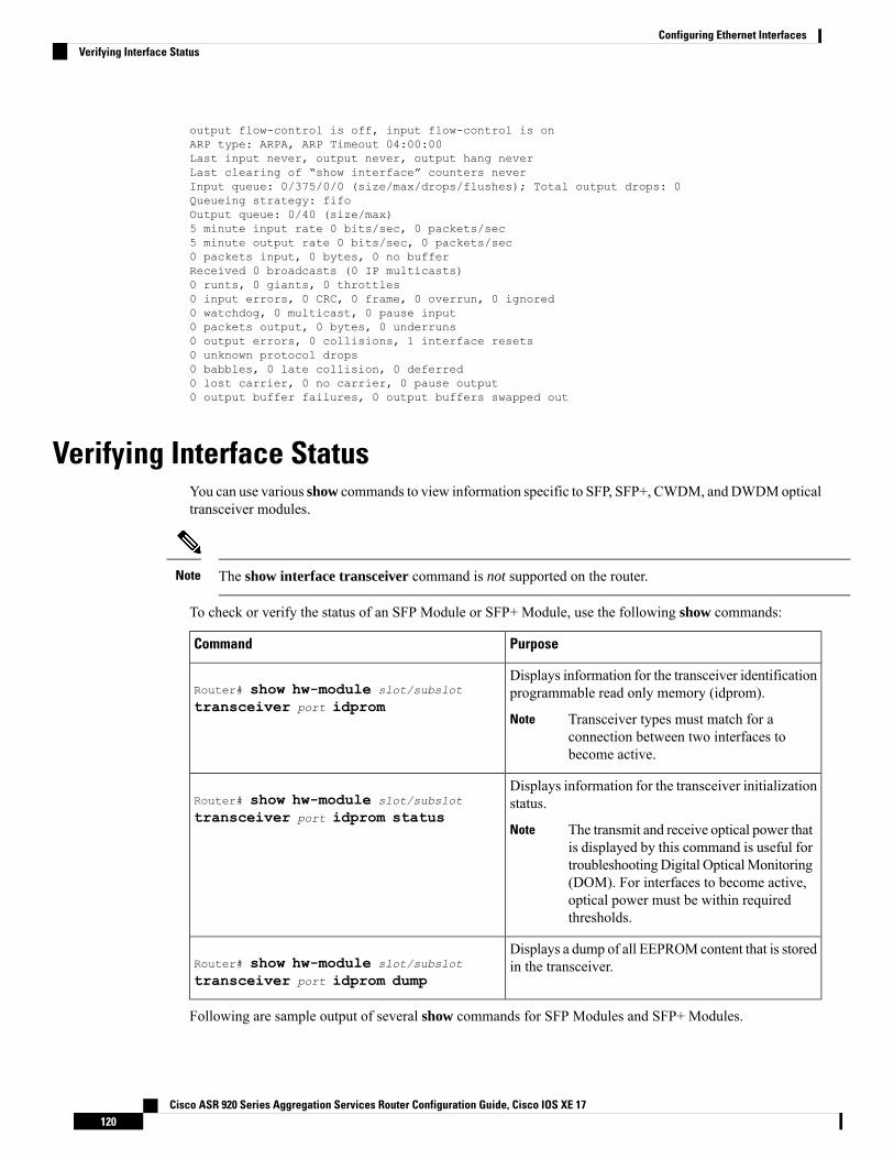
output flow-control is off, input flow-control is onARP type: ARPA, ARP Timeout 04:00:00Last input never, output never, output hang neverLast clearing of “show interface” counters neverInput queue: 0/375/0/0 (size/max/drops/flushes); Total output drops: 0Queueing strategy: fifoOutput queue: 0/40 (size/max)5 minute input rate 0 bits/sec, 0 packets/sec5 minute output rate 0 bits/sec, 0 packets/sec0 packets input, 0 bytes, 0 no bufferReceived 0 broadcasts (0 IP multicasts)0 runts, 0 giants, 0 throttles0 input errors, 0 CRC, 0 frame, 0 overrun, 0 ignored0 watchdog, 0 multicast, 0 pause input0 packets output, 0 bytes, 0 underruns0 output errors, 0 collisions, 1 interface resets0 unknown protocol drops0 babbles, 0 late collision, 0 deferred0 lost carrier, 0 no carrier, 0 pause output0 output buffer failures, 0 output buffers swapped out
Verifying Interface StatusYou can use various show commands to view information specific to SFP, SFP+, CWDM, andDWDMopticaltransceiver modules.
The show interface transceiver command is not supported on the router.Note
To check or verify the status of an SFP Module or SFP+ Module, use the following show commands:
PurposeCommand
Displays information for the transceiver identificationprogrammable read only memory (idprom).
Transceiver types must match for aconnection between two interfaces tobecome active.
Note
Router# show hw-module slot/subslot
transceiver port idprom
Displays information for the transceiver initializationstatus.
The transmit and receive optical power thatis displayed by this command is useful fortroubleshootingDigital OpticalMonitoring(DOM). For interfaces to become active,optical power must be within requiredthresholds.
Note
Router# show hw-module slot/subslot
transceiver port idprom status
Displays a dump of all EEPROMcontent that is storedin the transceiver.Router# show hw-module slot/subslot
transceiver port idprom dump
Following are sample output of several show commands for SFP Modules and SFP+ Modules.
Cisco ASR 920 Series Aggregation Services Router Configuration Guide, Cisco IOS XE 17120
Configuring Ethernet InterfacesVerifying Interface Status
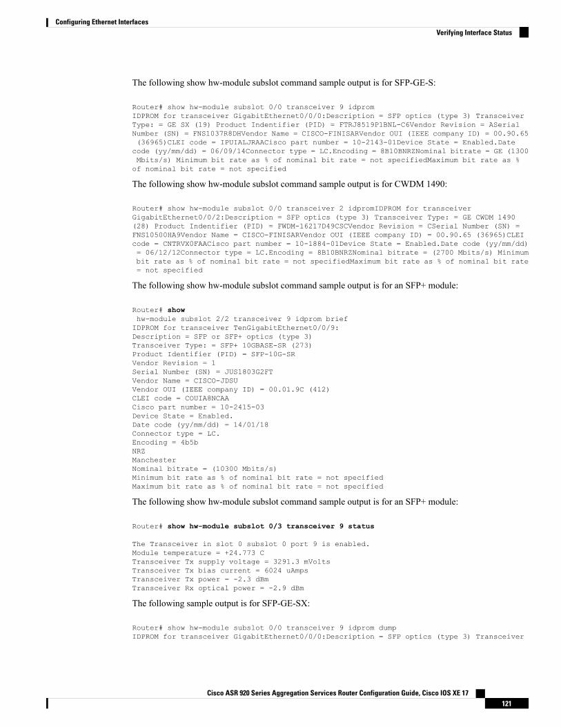
The following show hw-module subslot command sample output is for SFP-GE-S:
Router# show hw-module subslot 0/0 transceiver 9 idpromIDPROM for transceiver GigabitEthernet0/0/0:Description = SFP optics (type 3) TransceiverType: = GE SX (19) Product Indentifier (PID) = FTRJ8519P1BNL-C6Vendor Revision = ASerialNumber (SN) = FNS1037R8DHVendor Name = CISCO-FINISARVendor OUI (IEEE company ID) = 00.90.65(36965)CLEI code = IPUIALJRAACisco part number = 10-2143-01Device State = Enabled.Datecode (yy/mm/dd) = 06/09/14Connector type = LC.Encoding = 8B10BNRZNominal bitrate = GE (1300Mbits/s) Minimum bit rate as % of nominal bit rate = not specifiedMaximum bit rate as %of nominal bit rate = not specified
The following show hw-module subslot command sample output is for CWDM 1490:
Router# show hw-module subslot 0/0 transceiver 2 idpromIDPROM for transceiverGigabitEthernet0/0/2:Description = SFP optics (type 3) Transceiver Type: = GE CWDM 1490(28) Product Indentifier (PID) = FWDM-16217D49CSCVendor Revision = CSerial Number (SN) =FNS10500HA9Vendor Name = CISCO-FINISARVendor OUI (IEEE company ID) = 00.90.65 (36965)CLEIcode = CNTRVX0FAACisco part number = 10-1884-01Device State = Enabled.Date code (yy/mm/dd)= 06/12/12Connector type = LC.Encoding = 8B10BNRZNominal bitrate = (2700 Mbits/s) Minimumbit rate as % of nominal bit rate = not specifiedMaximum bit rate as % of nominal bit rate= not specified
The following show hw-module subslot command sample output is for an SFP+ module:
Router# showhw-module subslot 2/2 transceiver 9 idprom briefIDPROM for transceiver TenGigabitEthernet0/0/9:Description = SFP or SFP+ optics (type 3)Transceiver Type: = SFP+ 10GBASE-SR (273)Product Identifier (PID) = SFP-10G-SRVendor Revision = 1Serial Number (SN) = JUS1803G2FTVendor Name = CISCO-JDSUVendor OUI (IEEE company ID) = 00.01.9C (412)CLEI code = COUIA8NCAACisco part number = 10-2415-03Device State = Enabled.Date code (yy/mm/dd) = 14/01/18Connector type = LC.Encoding = 4b5bNRZManchesterNominal bitrate = (10300 Mbits/s)Minimum bit rate as % of nominal bit rate = not specifiedMaximum bit rate as % of nominal bit rate = not specified
The following show hw-module subslot command sample output is for an SFP+ module:
Router# show hw-module subslot 0/3 transceiver 9 status
The Transceiver in slot 0 subslot 0 port 9 is enabled.Module temperature = +24.773 CTransceiver Tx supply voltage = 3291.3 mVoltsTransceiver Tx bias current = 6024 uAmpsTransceiver Tx power = -2.3 dBmTransceiver Rx optical power = -2.9 dBm
The following sample output is for SFP-GE-SX:
Router# show hw-module subslot 0/0 transceiver 9 idprom dumpIDPROM for transceiver GigabitEthernet0/0/0:Description = SFP optics (type 3) Transceiver
Cisco ASR 920 Series Aggregation Services Router Configuration Guide, Cisco IOS XE 17121
Configuring Ethernet InterfacesVerifying Interface Status
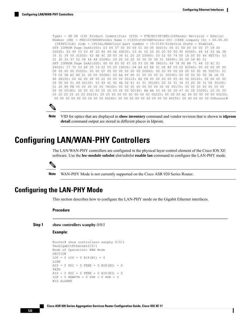
Type: = GE SX (19) Product Indentifier (PID) = FTRJ8519P1BNL-C6Vendor Revision = ASerialNumber (SN) = FNS1037R8DHVendor Name = CISCO-FINISARVendor OUI (IEEE company ID) = 00.90.65(36965)CLEI code = IPUIALJRAACisco part number = 10-2143-01Device State = Enabled.SFP IDPROM Page 0xA0:000: 03 04 07 00 00 00 01 00 00 00010: 00 01 0D 00 00 00 37 1B 0000020: 43 49 53 43 4F 2D 46 49 4E 49030: 53 41 52 20 20 20 00 00 90 65040: 46 54 52 4A 3835 31 39 50 31050: 42 4E 4C 2D 43 36 41 20 20 20060: 03 52 00 74 00 1A 00 00 46 4E070: 5331 30 33 37 52 38 44 48 20080: 20 20 20 20 30 36 30 39 31 34090: 20 20 58 80 01SFP IDPROM Page 0xA2:000: 6D 00 E3 00 67 00 F3 00 98 58010: 69 78 90 88 71 48 1D 4C 01F4020: 17 70 03 E8 25 19 02 F5 25 19030: 04 A9 E3 EE 01 DF 8F C5 02 EC040: 00 00 00 00 0000 00 00 00 00050: 00 00 00 00 00 00 00 00 00 00060: 00 00 00 00 00 00 00 00 3E 5D070: 0179 C0 5B AC 86 01 00 00 00080: 00 AA FF FD 01 00 00 00 01 00090: 00 00 00 00 00 3A 1B 7080 D8100: 00 62 00 28 00 22 00 00 00 00110: 82 F8 05 40 00 00 05 40 00 00120: 00 00 00 0000 00 00 01 49 50130: 55 49 41 4C 4A 52 41 41 31 30140: 2D 32 31 34 33 2D 30 31 56 30150:31 20 89 FB 55 00 00 00 00 78160: 00 00 00 00 00 00 00 00 00 00170: 00 00 00 00 00 00 0000 00 00180: 00 00 00 00 00 00 00 00 00 00190: AA AA 53 46 50 2D 47 45 2D 53200: 20 20 2020 20 20 20 20 20 20210: 20 20 00 00 00 00 00 00 00 00220: 00 00 00 A2 00 00 00 00 00 00230:00 00 00 00 00 00 00 00 00 00240: 00 00 00 00 00 00 00 00 00 40250: 00 40 00 00 00 00Router#
VID for optics that are displayed in show inventory command and vendor revision that is shown in idpromdetail command output are stored in different places in Idprom.
Note
Configuring LAN/WAN-PHY ControllersThe LAN/WAN-PHY controllers are configured in the physical layer control element of the Cisco IOS XEsoftware. Use the hw-module subslot slot/subslot enable lan command to configure the LAN-PHY mode.
WAN-PHY Mode is not currently supported on the Cisco ASR 920 Series Router.Note
Configuring the LAN-PHY ModeThis section describes how to configure the LAN-PHY mode on the Gigabit Ethernet interfaces.
Procedure
Step 1 show controllers wanphy 0/0/1
Example:
Router# show controllers wanphy 0/0/1TenGigabitEthernet0/0/1Mode of Operation: WAN ModeSECTIONLOF = 0 LOS = 0 BIP(B1) = 0LINEAIS = 0 RDI = 0 FEBE = 0 BIP(B2) = 0PATHAIS = 0 RDI = 0 FEBE = 0 BIP(B3) = 0LOP = 0 NEWPTR = 0 PSE = 0 NSE = 0WIS ALARMS
Cisco ASR 920 Series Aggregation Services Router Configuration Guide, Cisco IOS XE 17122
Configuring Ethernet InterfacesConfiguring LAN/WAN-PHY Controllers
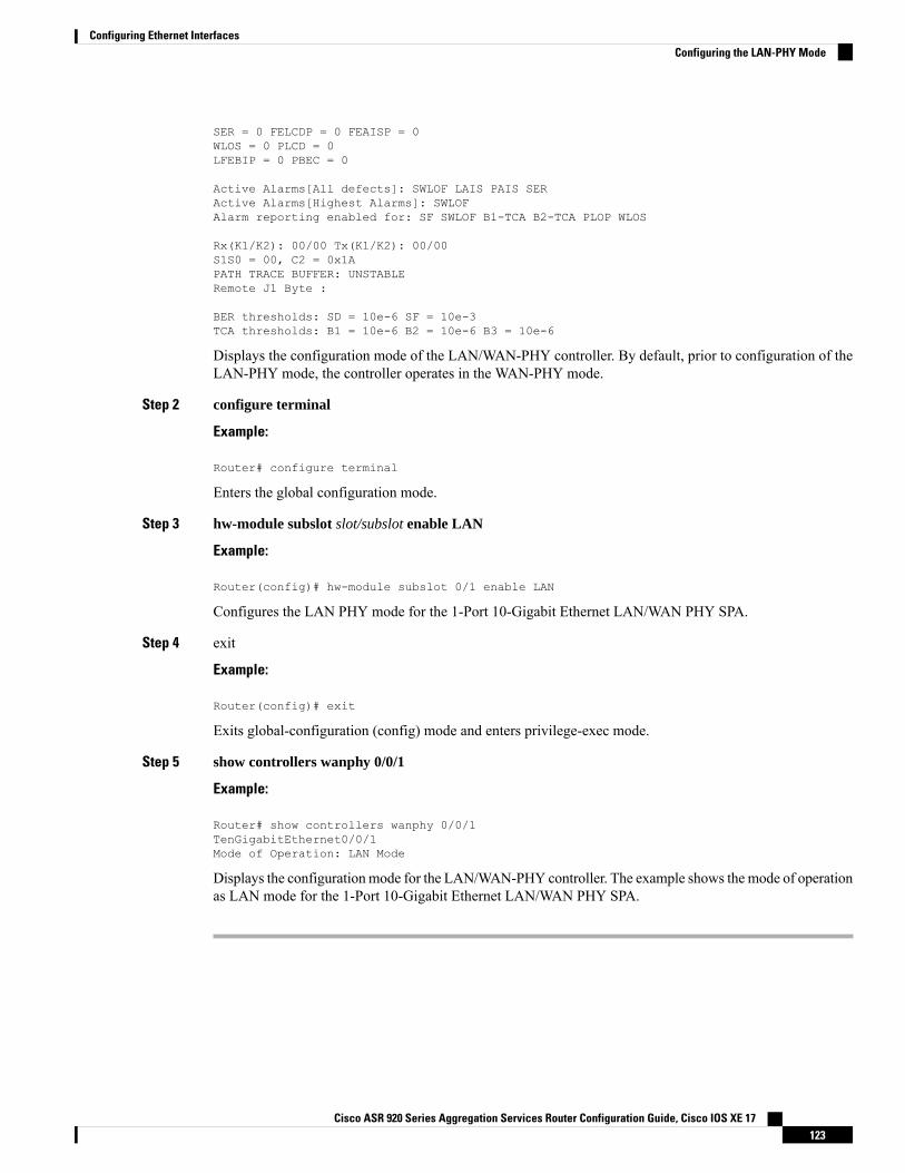
SER = 0 FELCDP = 0 FEAISP = 0WLOS = 0 PLCD = 0LFEBIP = 0 PBEC = 0
Active Alarms[All defects]: SWLOF LAIS PAIS SERActive Alarms[Highest Alarms]: SWLOFAlarm reporting enabled for: SF SWLOF B1-TCA B2-TCA PLOP WLOS
Rx(K1/K2): 00/00 Tx(K1/K2): 00/00S1S0 = 00, C2 = 0x1APATH TRACE BUFFER: UNSTABLERemote J1 Byte :
BER thresholds: SD = 10e-6 SF = 10e-3TCA thresholds: B1 = 10e-6 B2 = 10e-6 B3 = 10e-6
Displays the configuration mode of the LAN/WAN-PHY controller. By default, prior to configuration of theLAN-PHY mode, the controller operates in the WAN-PHY mode.
Step 2 configure terminal
Example:
Router# configure terminal
Enters the global configuration mode.
Step 3 hw-module subslot slot/subslot enable LAN
Example:
Router(config)# hw-module subslot 0/1 enable LAN
Configures the LAN PHY mode for the 1-Port 10-Gigabit Ethernet LAN/WAN PHY SPA.
Step 4 exit
Example:
Router(config)# exit
Exits global-configuration (config) mode and enters privilege-exec mode.
Step 5 show controllers wanphy 0/0/1
Example:
Router# show controllers wanphy 0/0/1TenGigabitEthernet0/0/1Mode of Operation: LAN Mode
Displays the configurationmode for the LAN/WAN-PHY controller. The example shows themode of operationas LAN mode for the 1-Port 10-Gigabit Ethernet LAN/WAN PHY SPA.
Cisco ASR 920 Series Aggregation Services Router Configuration Guide, Cisco IOS XE 17123
Configuring Ethernet InterfacesConfiguring the LAN-PHY Mode
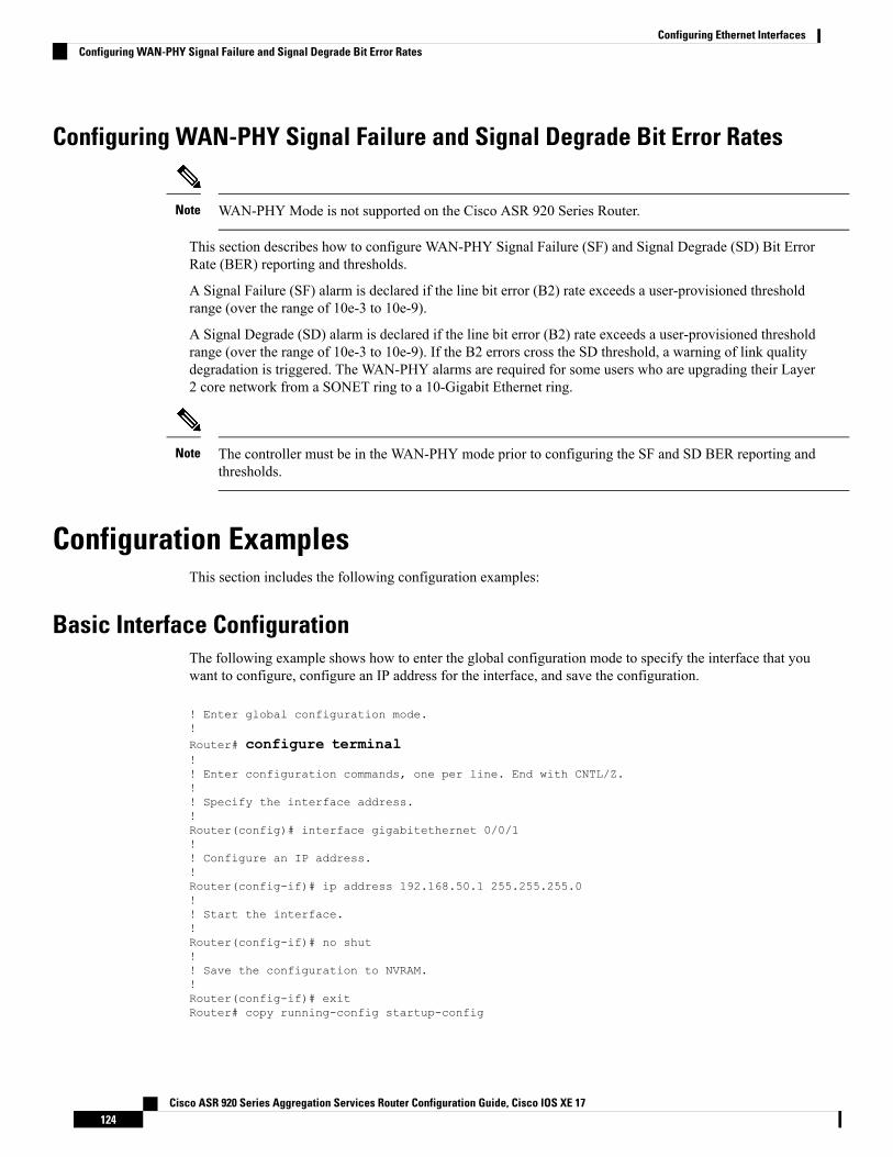
Configuring WAN-PHY Signal Failure and Signal Degrade Bit Error Rates
WAN-PHY Mode is not supported on the Cisco ASR 920 Series Router.Note
This section describes how to configure WAN-PHY Signal Failure (SF) and Signal Degrade (SD) Bit ErrorRate (BER) reporting and thresholds.
A Signal Failure (SF) alarm is declared if the line bit error (B2) rate exceeds a user-provisioned thresholdrange (over the range of 10e-3 to 10e-9).
A Signal Degrade (SD) alarm is declared if the line bit error (B2) rate exceeds a user-provisioned thresholdrange (over the range of 10e-3 to 10e-9). If the B2 errors cross the SD threshold, a warning of link qualitydegradation is triggered. The WAN-PHY alarms are required for some users who are upgrading their Layer2 core network from a SONET ring to a 10-Gigabit Ethernet ring.
The controller must be in the WAN-PHY mode prior to configuring the SF and SD BER reporting andthresholds.
Note
Configuration ExamplesThis section includes the following configuration examples:
Basic Interface ConfigurationThe following example shows how to enter the global configuration mode to specify the interface that youwant to configure, configure an IP address for the interface, and save the configuration.
! Enter global configuration mode.!Router# configure terminal!! Enter configuration commands, one per line. End with CNTL/Z.!! Specify the interface address.!Router(config)# interface gigabitethernet 0/0/1!! Configure an IP address.!Router(config-if)# ip address 192.168.50.1 255.255.255.0!! Start the interface.!Router(config-if)# no shut!! Save the configuration to NVRAM.!Router(config-if)# exitRouter# copy running-config startup-config
Cisco ASR 920 Series Aggregation Services Router Configuration Guide, Cisco IOS XE 17124
Configuring Ethernet InterfacesConfiguring WAN-PHY Signal Failure and Signal Degrade Bit Error Rates
MTU ConfigurationThe following example shows how to set the MTU interface to 9216 bytes.
The interface automatically adds an additional 38 bytes to the configured MTU interface size.Note
! Enter global configuration mode.!Router# configure terminal! Enter configuration commands, one per line. End with CNTL/Z.!! Specify the interface address!Router(config)# interface gigabitethernet 0/0/1!! Configure the interface MTU.!Router(config-if)# mtu 9216
VLAN EncapsulationThe following example shows how to configure the interface port 2 (the third port), and configure the firstinterface on the VLAN with the ID number 268, using IEEE 802.1Q encapsulation:
! Enter global configuration mode.!Router# configure terminal! Enter configuration commands, one per line. End with CNTL/Z.Router(config)# interface gigabitEthernet 0/0/5!! Specify the interface address!Router(config-if)# service instance 10 ethernet!! Configure dot1q encapsulation and specify the VLAN ID.!Router(config-if-srv)# encapsulation dot1q 268
VLANs are only supported on EVC service instances and Trunk EFP interfaces. For more information abouthow to configure these features, see the see the Carrier Ethernet Configuration Guide, Cisco IOS XE Release3S.
Cisco ASR 920 Series Aggregation Services Router Configuration Guide, Cisco IOS XE 17125
Configuring Ethernet InterfacesMTU Configuration

Cisco ASR 920 Series Aggregation Services Router Configuration Guide, Cisco IOS XE 17126
Configuring Ethernet InterfacesVLAN Encapsulation
C H A P T E R 14Configuring Serial Interfaces
This chapter configures the serial interface module (PN: A900-IMASER14A/S) Async/Sync R232 serial datausing Transparent Pseudowire (PW) over MPLS network and raw socket. It includes the following sections:
For information about managing your system images and configuration files, refer to the Cisco IOSConfiguration Fundamentals Configuration Guide and Cisco IOS Configuration Fundamentals CommandReference publications.
For more information about the commands used in this chapter, refer to the Cisco IOS Command Referencepublication for your Cisco IOS software release.
• Information About Serial Interface Module, on page 127• Restrictions, on page 129• How to Configure Serial Interface, on page 130• Verifying the Serial Interface Configuration, on page 140• Configuration Examples, on page 141
Information About Serial Interface ModuleThe serial interface module supports pseudowire transport over MPLS and raw socket for Async and Synctranffic. The Serial IM interfaces monitor and detect cable connections, cable types and also monitors modemcontrol signals periodically.
Cisco ASR 920 Series Aggregation Services Router Configuration Guide, Cisco IOS XE 17127
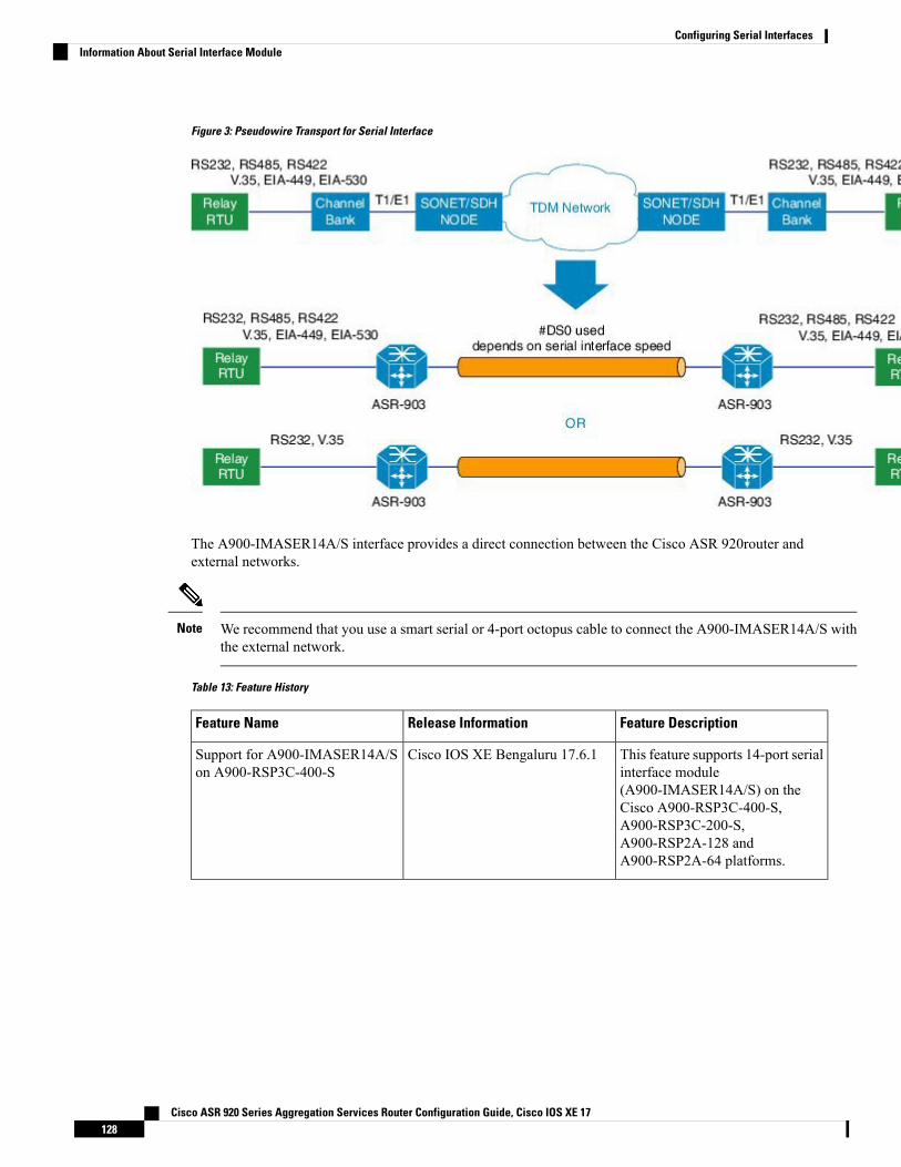
Figure 3: Pseudowire Transport for Serial Interface
The A900-IMASER14A/S interface provides a direct connection between the Cisco ASR 920router andexternal networks.
We recommend that you use a smart serial or 4-port octopus cable to connect the A900-IMASER14A/S withthe external network.
Note
Table 13: Feature History
Feature DescriptionRelease InformationFeature Name
This feature supports 14-port serialinterface module(A900-IMASER14A/S) on theCisco A900-RSP3C-400-S,A900-RSP3C-200-S,A900-RSP2A-128 andA900-RSP2A-64 platforms.
Cisco IOS XE Bengaluru 17.6.1Support for A900-IMASER14A/Son A900-RSP3C-400-S
Cisco ASR 920 Series Aggregation Services Router Configuration Guide, Cisco IOS XE 17128
Configuring Serial InterfacesInformation About Serial Interface Module
Effective fromCisco IOSXEBangalore Release 17.6.1, 14-port serial interfacemodule (A900-IMASER14A/S)is supported on the following:
• Any slots on A900-RSP2A-128 in ASR 903
• Any slots on A900-RSP3C-400-S in ASR 903
• Only on slot 4 on A900-RSP3C-200-S in ASR 903
• Only on slots 3, 4 and 5 on A900-RSP2A-64 in ASR 903
• Only on slots 3, 4, 7, 8, 11 and 12 on A900-RSP3C-400-W in ASR 907. The serial IM will not work onslots 11 and 12, if the IMs A900-IMA8T or A900-IMA8S is inserted on any slot in the router.
Note
Out of 14 ports, 6 ports support sync interfaces and 8 ports support async interfaces. RS232 Async data iscarried over Raw Socket and Transparent byte mode and RS232 Sync data is carried over Raw Socket.
For more information about RS422 and RS485, refer to Table 6 in the Troubleshooting chapter of the CiscoASR 903 and ASR 903U Aggregation Services Router Hardware Installation Guide
RestrictionsThis section describes the port restrictions for Serial interface module:
• Ports 0-7 are Async ports on the 68-pin connector
• Ports 8-13 are Sync or Async on the 12-in-1 connector
Sync is not supported in Cisco IOS XE Release 3.14S. Sync ports cannot be configured in Cisco IOS XERelease 3.14S.
Note
• Maximum speed on all ports is 236Kbps.
This section describes the software limitations that apply when configuring the Serial interface module:
• The router can only be configured as data circuit-terminating equipment (DCE).
• Configuration of pseudowire between local and remote PE with different speed on Sync and Async portsis not supported.
• Sub-rate (below DS0 bandwidth) Async (R232) data over MPLS MPLS using T1/E1 CESoP is notsupported.
• Pseudowire ping is not supported for the pseusdowire configured on the serial interface module.
• Only two serial interface modules can come up on the router in release prior to Cisco IOS XE Release3.14. Starting with Cisco IOS XE Release 3.14, all 6 bays on the router are available for insertion ofinterface modules simultaneously.
• Only Trans encapsulation is supported in Cisco IOS XE Release 3.14S.
Cisco ASR 920 Series Aggregation Services Router Configuration Guide, Cisco IOS XE 17129
Configuring Serial InterfacesRestrictions
• If you installed a new A900-IMASER14A/S or if you want to change the configuration of an existinginterface, you must enter configuration mode to configure the new interfaces. If you replaced anA900-IMASER14A/S that was previously configured, the system recognizes the new interfaces andbrings each of them up in their existing configuration.
• Pseudowire ping is not supported for cross-connect configured on A900-IMA14A/S interface module.
• A maximum speed of 64 kbps between PE and DTE is supported for RS232 Sync ports.
• PE can act only as DCE and provides the clock to DTE.
• Serial IM Sync signaling transport does not interoperate with the third party equipments. HLDC framesused for transport of these signals are Cisco-specific.
• CTS signal goes down, when control signal frequency is configured more than 5000 ms and timeoutsetting is more than 20,000 ms (4x control_frequency), which is greater than the OIR time (~20s) for aselected subordinate to complete an OIR cycle. This results in the primary being unaware that thesubordinate is down and CTS of all subordinates are down too. To avoid this situation, ensure that thetimeout is shorter than the OIR time of the subordinate. Set the control frequency to less than or equalto 5000 ms and the timeout setting to less than or equal to 20,000 ms before you perform OIR.
• If the mode is changed from P2P to P2MP with one primary serving three subordinates (all threesubordinates on the same card on another chassis, different from the primary) or an online insertion andremoval (OIR) of the card is performed with P2MP configuration, CTS signal for all the subordinateswill go down despite that all are still driving their RTS up. This will get corrected when the subordinatestoggle their RTS.
• RS422 and RS485 can be configured only on ports 0-7 of the serial interface.
How to Configure Serial Interface
Required Configuration Tasks
Configuring the ControllerTo create the interfaces for the Serial interface module, complete these steps:
Procedure
Step 1 configure terminal
Example:
Router# configure terminal
Enters global configuration mode.
Step 2 controller serial slot/subslot/port
Example:
Cisco ASR 920 Series Aggregation Services Router Configuration Guide, Cisco IOS XE 17130
Configuring Serial InterfacesHow to Configure Serial Interface
Router(config)# controller serial 0/4/1
Selects the controller to configure and enters controller configuration mode.
• slot/subslot/port—Specifies the location of the interface.
The slot number is always 0.Note
Step 3 physical-layer async | sync
Example:
Router(config-controller)# physical-layer async
Configures the serial interface in async or sync mode.
• async—Specifies async interface.
• sync—Specifies sync interface. This is the default mode.
Step 4 exit
Example:
Router(config)# exit
Exits configuration mode and returns to the EXEC command interpreter prompt.
Example: Controller Configuration
Router# configure terminalRouter(config)# controller0/4/1Router(config-controller)# physical-layer asyncRouter(config)# exit
Optional Configurations
Configuring Layer 1 on Sync and Async Interface ServerThe RS232 which is enabled by default on the async interface, supports RS232 DCE cable with the DB-25connector. The Cisco smart serial cable with the DB-25 connector supports RS232, RS485, and RS422. TheRJ45 cable type supports only RS485.
Procedure
Step 1 configure terminal
Example:
Router# configure terminal
Cisco ASR 920 Series Aggregation Services Router Configuration Guide, Cisco IOS XE 17131
Configuring Serial InterfacesExample: Controller Configuration
Enters global configuration mode.
Step 2 line slot/bay/port
Example:
Router(config)#line 0/4/1
Select the controller to configure and enters serial interface configuration mode.
• slot/subslot/port—Specifies the location of the interface.
Step 3 media-type {rs422 | rs485 }
Example:
Router(config-line)# media-type rs422
Sets the media type to either RS422 or RS485.
Step 4 databits {5 | 6 | 7 | 8}
Example:
Router(config-line)# databits 8
Sets the databit configuration. The default is 8.
Step 5 stopbits {1 | 1.5 | 2}
Example:
Router(config-line)# stopbits 2
Sets the stopbit configuration. The default is 2.
Step 6 speed speed-value
Example:
Router(config-line)# speed 9600
Specifies the serial interface speed. The valid range is form 300 to 230400. The default is 9600.
Step 7 raw-socket tcp server port server ip address
Example:Router(config-line)# raw-socket tcp server 5000 10.0.0.1
Specifies raw-tcp server configuration.
Step 8 raw-socket packet length packet length
Example:Router(config-line)# raw-socket packet-length 32
Specifies raw-tcp packet length configuration options.
Step 9 parity {even | mark | none | odd | space}
Example:
Cisco ASR 920 Series Aggregation Services Router Configuration Guide, Cisco IOS XE 17132
Configuring Serial InterfacesConfiguring Layer 1 on Sync and Async Interface Server
Router(config-line)# parity none
Sets the parity.
Step 10 sig-transport u-frame pattern pattern
Example:Router(config-line)#sig-transport u-frame pattern NR0
This step is specific to Sync mode only. Specifies the u-frame format used for internal signal transport.
Step 11 control-sig-transport [on | off] frequency frequency range
Example:Router(config-line)#control-sig-transport on frequency <50-65535>
Specifies if hardware control signals need to be sent to remote PE or not. Also specifies the frequency (periodbetween successive control frames) in milliseconds. By default, control signal is OFF. Frequency needs to beconfigured only if the control signal is ON.
Step 12 connection-topology [point-to-point | point-to-multipoint]
Example:Router(config-line)#connection-topology point-to-multipoint
This step is specific to Sync mode only. Specifies the type of topology.
Step 13 dtr [used | not-used]
Example:Router(config-line)# dtr not-used
(Optional) DTR is programmable when DTR pin in FPGA is not connected. By default, DTR is set as used.
Step 14 connection-timeout timeout
Example:Router(config-line)# connection-timeout <800-65535>
(Optional) Specifies the connection timeout of the primary and subordinate session. It should be configured4 times higher than the frequency.
Step 15 exit
Example:
Router(config)# exit
Exits configuration mode and returns to the EXEC command interpreter prompt.
Example: Async Layer 1 Parameters
Router# configure terminalRouter(config)# line 0/4/1Router(config-line)# databits 8Router(config-line)# stopbits 2Router(config-line)# speed 9600
Cisco ASR 920 Series Aggregation Services Router Configuration Guide, Cisco IOS XE 17133
Configuring Serial InterfacesExample: Async Layer 1 Parameters
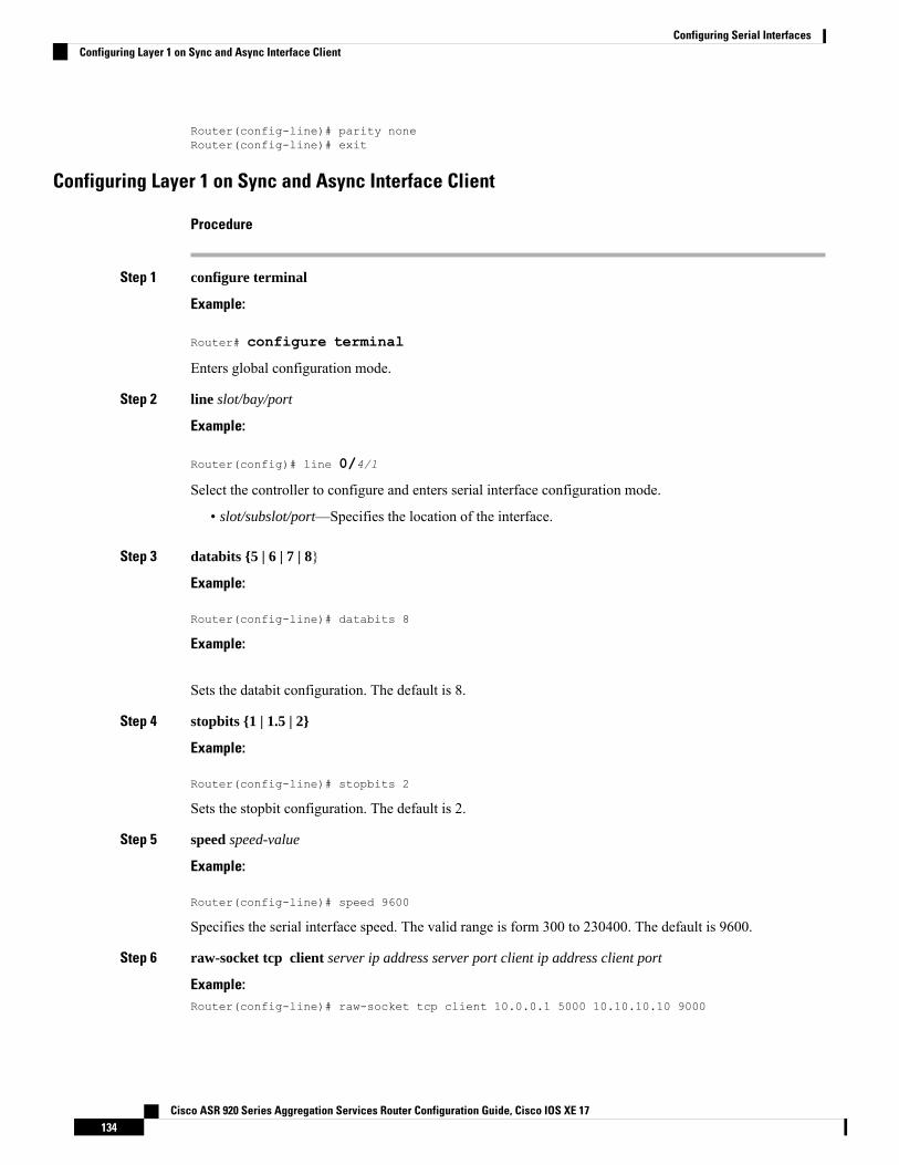
Router(config-line)# parity noneRouter(config-line)# exit
Configuring Layer 1 on Sync and Async Interface Client
Procedure
Step 1 configure terminal
Example:
Router# configure terminal
Enters global configuration mode.
Step 2 line slot/bay/port
Example:
Router(config)# line 0/4/1
Select the controller to configure and enters serial interface configuration mode.
• slot/subslot/port—Specifies the location of the interface.
Step 3 databits {5 | 6 | 7 | 8}
Example:
Router(config-line)# databits 8
Example:
Sets the databit configuration. The default is 8.
Step 4 stopbits {1 | 1.5 | 2}
Example:
Router(config-line)# stopbits 2
Sets the stopbit configuration. The default is 2.
Step 5 speed speed-value
Example:
Router(config-line)# speed 9600
Specifies the serial interface speed. The valid range is form 300 to 230400. The default is 9600.
Step 6 raw-socket tcp client server ip address server port client ip address client port
Example:Router(config-line)# raw-socket tcp client 10.0.0.1 5000 10.10.10.10 9000
Cisco ASR 920 Series Aggregation Services Router Configuration Guide, Cisco IOS XE 17134
Configuring Serial InterfacesConfiguring Layer 1 on Sync and Async Interface Client
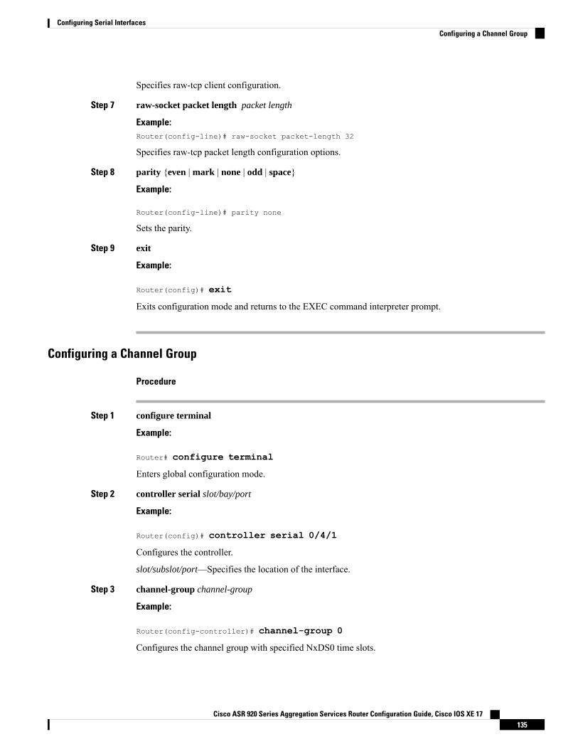
Specifies raw-tcp client configuration.
Step 7 raw-socket packet length packet length
Example:Router(config-line)# raw-socket packet-length 32
Specifies raw-tcp packet length configuration options.
Step 8 parity {even | mark | none | odd | space}
Example:
Router(config-line)# parity none
Sets the parity.
Step 9 exit
Example:
Router(config)# exit
Exits configuration mode and returns to the EXEC command interpreter prompt.
Configuring a Channel Group
Procedure
Step 1 configure terminal
Example:
Router# configure terminal
Enters global configuration mode.
Step 2 controller serial slot/bay/port
Example:
Router(config)# controller serial 0/4/1
Configures the controller.
slot/subslot/port—Specifies the location of the interface.
Step 3 channel-group channel-group
Example:
Router(config-controller)# channel-group 0
Configures the channel group with specified NxDS0 time slots.
Cisco ASR 920 Series Aggregation Services Router Configuration Guide, Cisco IOS XE 17135
Configuring Serial InterfacesConfiguring a Channel Group
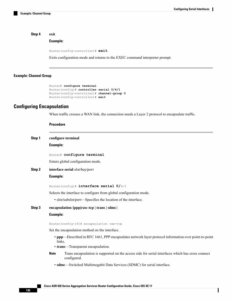
Step 4 exit
Example:
Router(config-controller)# exit
Exits configuration mode and returns to the EXEC command interpreter prompt.
Example: Channel Group
Router# configure terminalRouter(config)# controller serial 0/4/1Router(config-controller)# channel-group 0Router(config-controller)# exit
Configuring EncapsulationWhen traffic crosses a WAN link, the connection needs a Layer 2 protocol to encapsulate traffic.
Procedure
Step 1 configure terminal
Example:
Router# configure terminal
Enters global configuration mode.
Step 2 interface serial slot/bay/port
Example:
Router(config)# interface serial 0/4/1
Selects the interface to configure from global configuration mode.
• slot/subslot/port—Specifies the location of the interface.
Step 3 encapsulation {ppp|raw-tcp | trans | sdmc}
Example:
Router(config-if)# encapsulation raw-tcp
Set the encapsulation method on the interface.
• ppp—Described in RFC 1661, PPP encapsulates network layer protocol information over point-to-pointlinks.
• trans—Transparent encapsulation.
Trans encapsulation is supported on the access side for serial interfaces which has cross connectconfigured.
Note
• sdmc—Switched Multimegabit Data Services (SDMC) for serial interface.
Cisco ASR 920 Series Aggregation Services Router Configuration Guide, Cisco IOS XE 17136
Configuring Serial InterfacesExample: Channel Group
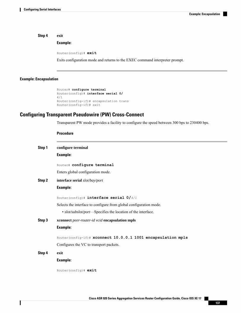
Step 4 exit
Example:
Router(config)# exit
Exits configuration mode and returns to the EXEC command interpreter prompt.
Example: Encapsulation
Router# configure terminalRouter(config)# interface serial 0/4/1Router(config-if)# encapsulation transRouter(config-if)# exit
Configuring Transparent Pseudowire (PW) Cross-ConnectTransparent PW mode provides a facility to configure the speed between 300 bps to 230400 bps.
Procedure
Step 1 configure terminal
Example:
Router# configure terminal
Enters global configuration mode.
Step 2 interface serial slot/bay/port
Example:
Router(config)# interface serial 0/4/1
Selects the interface to configure from global configuration mode.
• slot/subslot/port—Specifies the location of the interface.
Step 3 xconnect peer-router-id vcid encapsulation mpls
Example:
Router(config-if)# xconnect 10.0.0.1 1001 encapsulation mpls
Configures the VC to transport packets.
Step 4 exit
Example:
Router(config)# exit
Cisco ASR 920 Series Aggregation Services Router Configuration Guide, Cisco IOS XE 17137
Configuring Serial InterfacesExample: Encapsulation
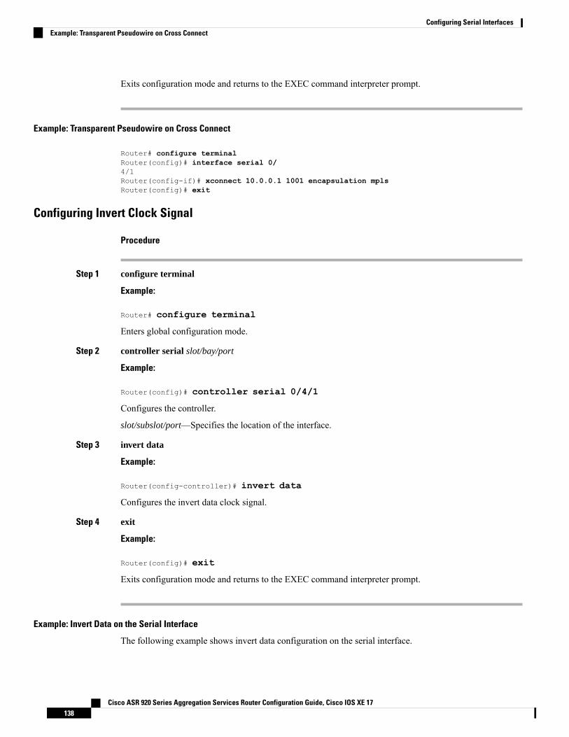
Exits configuration mode and returns to the EXEC command interpreter prompt.
Example: Transparent Pseudowire on Cross Connect
Router# configure terminalRouter(config)# interface serial 0/4/1Router(config-if)# xconnect 10.0.0.1 1001 encapsulation mplsRouter(config)# exit
Configuring Invert Clock Signal
Procedure
Step 1 configure terminal
Example:
Router# configure terminal
Enters global configuration mode.
Step 2 controller serial slot/bay/port
Example:
Router(config)# controller serial 0/4/1
Configures the controller.
slot/subslot/port—Specifies the location of the interface.
Step 3 invert data
Example:
Router(config-controller)# invert data
Configures the invert data clock signal.
Step 4 exit
Example:
Router(config)# exit
Exits configuration mode and returns to the EXEC command interpreter prompt.
Example: Invert Data on the Serial Interface
The following example shows invert data configuration on the serial interface.
Cisco ASR 920 Series Aggregation Services Router Configuration Guide, Cisco IOS XE 17138
Configuring Serial InterfacesExample: Transparent Pseudowire on Cross Connect
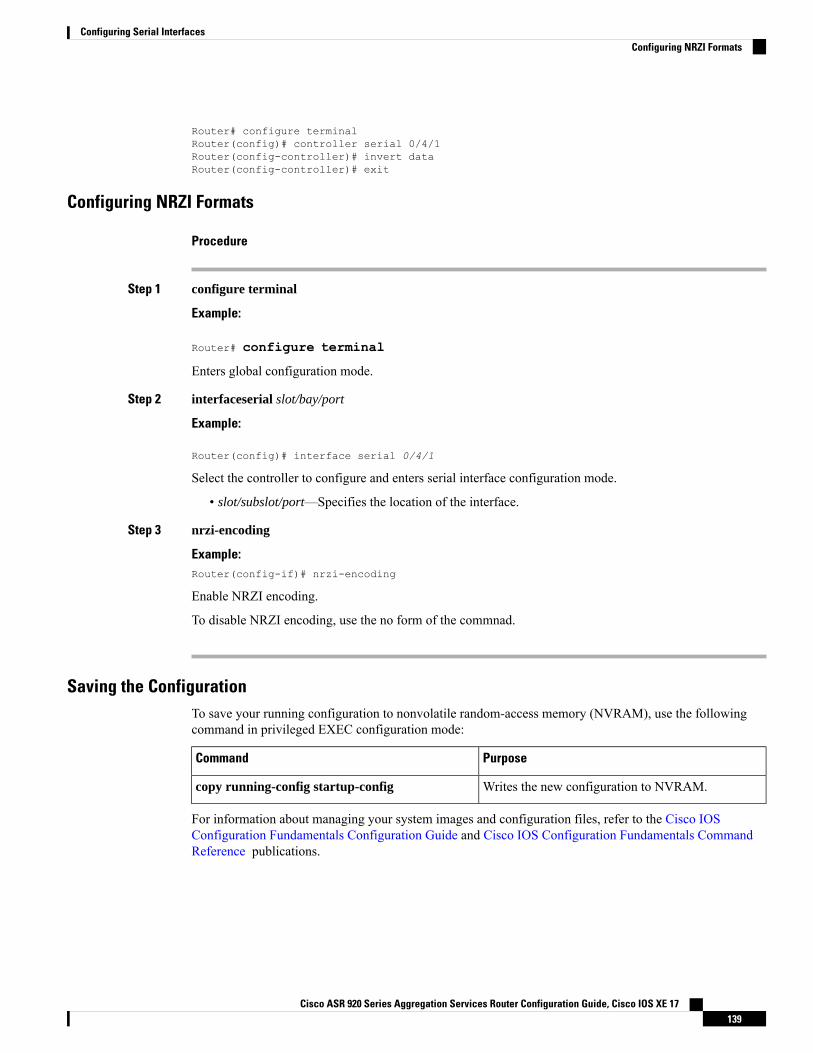
Router# configure terminalRouter(config)# controller serial 0/4/1Router(config-controller)# invert dataRouter(config-controller)# exit
Configuring NRZI Formats
Procedure
Step 1 configure terminal
Example:
Router# configure terminal
Enters global configuration mode.
Step 2 interfaceserial slot/bay/port
Example:
Router(config)# interface serial 0/4/1
Select the controller to configure and enters serial interface configuration mode.
• slot/subslot/port—Specifies the location of the interface.
Step 3 nrzi-encoding
Example:Router(config-if)# nrzi-encoding
Enable NRZI encoding.
To disable NRZI encoding, use the no form of the commnad.
Saving the ConfigurationTo save your running configuration to nonvolatile random-access memory (NVRAM), use the followingcommand in privileged EXEC configuration mode:
PurposeCommand
Writes the new configuration to NVRAM.copy running-config startup-config
For information about managing your system images and configuration files, refer to the Cisco IOSConfiguration Fundamentals Configuration Guide and Cisco IOS Configuration Fundamentals CommandReference publications.
Cisco ASR 920 Series Aggregation Services Router Configuration Guide, Cisco IOS XE 17139
Configuring Serial InterfacesConfiguring NRZI Formats
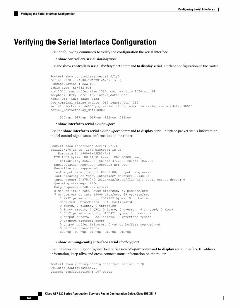
Verifying the Serial Interface ConfigurationUse the following commands to verify the configuration the serial interface
• show controllers serial slot/bay/port
Use the show controllers serial slot/bay/port command to display serial interface configuration on the router.
Router# show controllers serial 0/1/0Serial0/1/0 - (A900-IMASER14A/S) is upEncapsulation : RAW-TCPCable type: RS-232 DCEmtu 1500, max_buffer_size 1524, max_pak_size 1524 enc 84loopback: Off, crc: 16, invert_data: Offnrzi: Off, idle char: Flagdce_terminal_timing_enable: Off ignore_dtr: Offserial_clockrate: 64000bps, serial_clock_index: 14 serial_restartdelay:30000,serial_restartdelay_def:30000
DCD=up DSR=up DTR=up RTS=up CTS=up
• show interfaces serial slot/bay/port
Use the show interfaces serial slot/bay/port command to display serial interface packet status information,model control signal status information on the router.
Router# show interfaces serial 0/1/0Serial0/1/0 is up, line protocol is up
Hardware is A900-IMASER14A/SMTU 1500 bytes, BW 64 Kbit/sec, DLY 20000 usec,
reliability 255/255, txload 47/255, rxload 103/255Encapsulation RAW-TCP, loopback not setKeepalive not supportedLast input never, output 00:00:00, output hang neverLast clearing of "show interface" counters 00:38:06Input queue: 0/375/0/0 (size/max/drops/flushes); Total output drops: 0Queueing strategy: fifoOutput queue: 0/40 (size/max)5 minute input rate 26000 bits/sec, 69 packets/sec5 minute output rate 12000 bits/sec, 69 packets/sec
157782 packets input, 7562229 bytes, 0 no bufferReceived 0 broadcasts (0 IP multicasts)0 runts, 0 giants, 0 throttles0 input errors, 0 CRC, 0 frame, 0 overrun, 0 ignored, 0 abort156862 packets output, 3460471 bytes, 0 underruns0 output errors, 0 collisions, 0 interface resets0 unknown protocol drops0 output buffer failures, 0 output buffers swapped out0 carrier transitionsDCD=up DSR=up DTR=up RTS=up CTS=up
• show running-config interface serial slot/bay/port
Use the show running-config interface serial slot/bay/port command to display serial interface IP addressinformation, keep alive and cross-connect status information on the router.
Router# show running-config interface serial 0/1/0Building configuration...Current configuration : 107 bytes
Cisco ASR 920 Series Aggregation Services Router Configuration Guide, Cisco IOS XE 17140
Configuring Serial InterfacesVerifying the Serial Interface Configuration
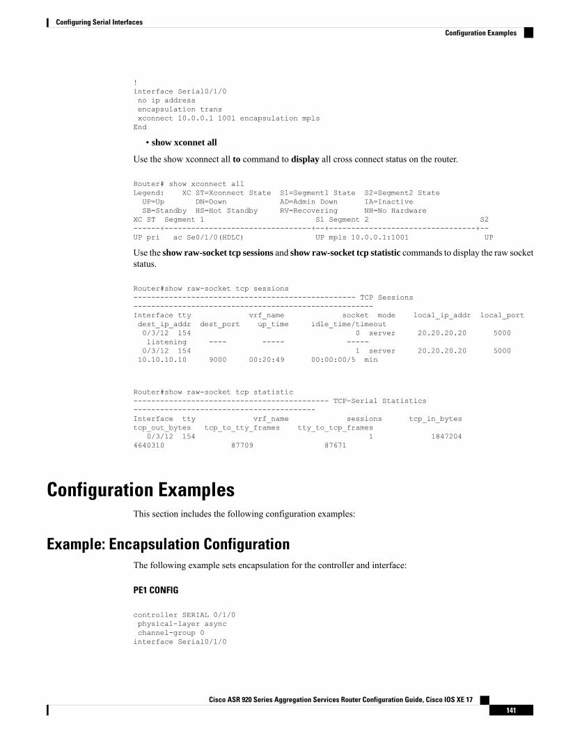
!interface Serial0/1/0no ip addressencapsulation transxconnect 10.0.0.1 1001 encapsulation mplsEnd
• show xconnet all
Use the show xconnect all to command to display all cross connect status on the router.
Router# show xconnect allLegend: XC ST=Xconnect State S1=Segment1 State S2=Segment2 StateUP=Up DN=Down AD=Admin Down IA=InactiveSB=Standby HS=Hot Standby RV=Recovering NH=No Hardware
XC ST Segment 1 S1 Segment 2 S2------+---------------------------------+--+---------------------------------+--UP pri ac Se0/1/0(HDLC) UP mpls 10.0.0.1:1001 UP
Use the show raw-socket tcp sessions and show raw-socket tcp statistic commands to display the raw socketstatus.
Router#show raw-socket tcp sessions-------------------------------------------------- TCP Sessions------------------------------------------------------Interface tty vrf_name socket mode local_ip_addr local_portdest_ip_addr dest_port up_time idle_time/timeout0/3/12 154 0 server 20.20.20.20 5000listening ---- ----- -----0/3/12 154 1 server 20.20.20.20 500010.10.10.10 9000 00:20:49 00:00:00/5 min
Router#show raw-socket tcp statistic-------------------------------------------- TCP-Serial Statistics-----------------------------------------Interface tty vrf_name sessions tcp_in_bytestcp_out_bytes tcp_to_tty_frames tty_to_tcp_frames
0/3/12 154 1 18472044640310 87709 87671
Configuration ExamplesThis section includes the following configuration examples:
Example: Encapsulation ConfigurationThe following example sets encapsulation for the controller and interface:
PE1 CONFIG
controller SERIAL 0/1/0physical-layer asyncchannel-group 0interface Serial0/1/0
Cisco ASR 920 Series Aggregation Services Router Configuration Guide, Cisco IOS XE 17141
Configuring Serial InterfacesConfiguration Examples

no ip addressencapsulation transxconnect 10.0.0.2 1001 encapsulation mpls
PE2 CONFIG
controller SERIAL 0/2/0physical-layer asyncchannel-group 0interface Serial0/2/0no ip addressencapsulation transxconnect 10.0.0.1 1001 encapsulation mpls
Cisco ASR 920 Series Aggregation Services Router Configuration Guide, Cisco IOS XE 17142
Configuring Serial InterfacesExample: Encapsulation Configuration
C H A P T E R 15Configuring Optical Interface Modules
This chapter describes the most common configurations for optical interface modules on the Cisco ASR 920Series Routers.
• Limitations and Restrictions, on page 143• Managing Interface Naming, on page 144• Setting the Card Type, on page 145• Configuring the Controller, on page 145• Configuring SDH, on page 146• Configuring SONET Mode, on page 153• Configuring a CEM group, on page 157• Configuring DS3 Clear Channel on OC-3 and OC-12 Interface Module, on page 160• Optional Configurations, on page 164• Configuring Multilink Point-to-Point Protocol, on page 168• Configuring BERT, on page 172• Configuring Automatic Protection Switching, on page 172• Verifying Interface Configuration, on page 172• Troubleshooting, on page 172• Configuration Examples, on page 177• Additional Resources, on page 178
Limitations and Restrictions• SDH framing mode is supported; SONET framing is supported beginning in Cisco IOS XE Release 3.8.
• On the OC-3 controller, framing mode is applicable on the interface module and per port. When framingmode is set to SONET, all the 4 ports on the interface module are enabled for SONET mode. Similarly,when framing mode is set to SDH mode, all 4 ports on the interface module are enabled for SDH mode.
• The OC-3 controller supports Asynchronous mode at the V5 byte level for Plesiochronous DigitalHierarchy (PDH). This value cannot be modified. If a mismatch occurs between the V5 byte, and thepeer (remote router), loss of frames may be observed at the PDH level.
• HDLC, PPP, and MLPPP encapsulation are supported. In POS mode, HDLC and PPP are supported.
• ATM Layer 2 AAL0 and AAL5 encapsulation types are supported.
• E1 unframed encapsulation is not supported except using SAToP pseudowire interfaces.
Cisco ASR 920 Series Aggregation Services Router Configuration Guide, Cisco IOS XE 17143
• Unframed T1 is supported only for SATOP. E1 unframed is supported.
• MPLS-TP is not supported over Packet Over Sonet (POS) interfaces.
• Multicast is not supported on OC-12 interfaces.
• QoS is supported using MLPPP interfaces and egress POS interfaces.
• MPLS is supported only on PoS interfaces; MPLS on T1/E1 MLP is supported starting with Cisco IOSXE Release 3.9. MPLS over MLP is also supported.
• Channelization is not supported for serial interfaces. However, Channelization is supported for CEM atthe DS0 level.
• DS3 Clear channel is supported only on CEM.
• BERT is not supported on DS0 and DS1 CEM. It is supported only on DS3 CEM mode.
• Configurations on the interfacemodule must be completely removed before moving the interfacemoduleto a different slot on the router.
• Mixed configurations of features are not supported on the same port. For example, one OC-3 port canhave only CEM (CESoP or SAToP) or ATM or IMA or DS3 configurations, but not a combination ofthese features on a single port.
• CEM is not supported across OC12/ STM-4 interface module. CEM is supported on all four ports ofOC-3/STM-1 interface module.
• If two CEM circuits are configured under the same OC-3 interface module, the circuits should not beconfiugred with the same circuit-id. If two CEM cirsuits are configured on different OC-3 intefacemodules, then both circuits can be configured with the same circuit-id.
• By default, AIS-SHUT is enabled on the OC-3 SONET/SDH controller and port level shut down ofSONET/SDH controller results in AIS alarm on peer node. To enable the LOS alarm on controller shutdown, you must configure “no ais-shut” at SONET/SDH controller level.
• Maximum channels per OC-3/ STM interface module for T1 interfaces is 336 for RSP1 and RSP2.
• Maximum channels per OC-3/STM interface module for E1 interfaces is 252 for RSP1 and RSP2.
Managing Interface NamingThe following sections describe how to manage interface naming on the Cisco ASR 920 Series Routers.
Identifying Slots and SubslotTo specify the physical address for controller or interface configuration, use the interface and controller sonetcommands, where:
• slot—Specifies the chassis slot number where the interface module is installed; the slot number is always0 for interface modules on the .Cisco ASR 920 Series Router.
• subslot—Specifies the subslot where the interface module is installed.
• port—Specifies the SONET port number.
Cisco ASR 920 Series Aggregation Services Router Configuration Guide, Cisco IOS XE 17144
Configuring Optical Interface ModulesManaging Interface Naming
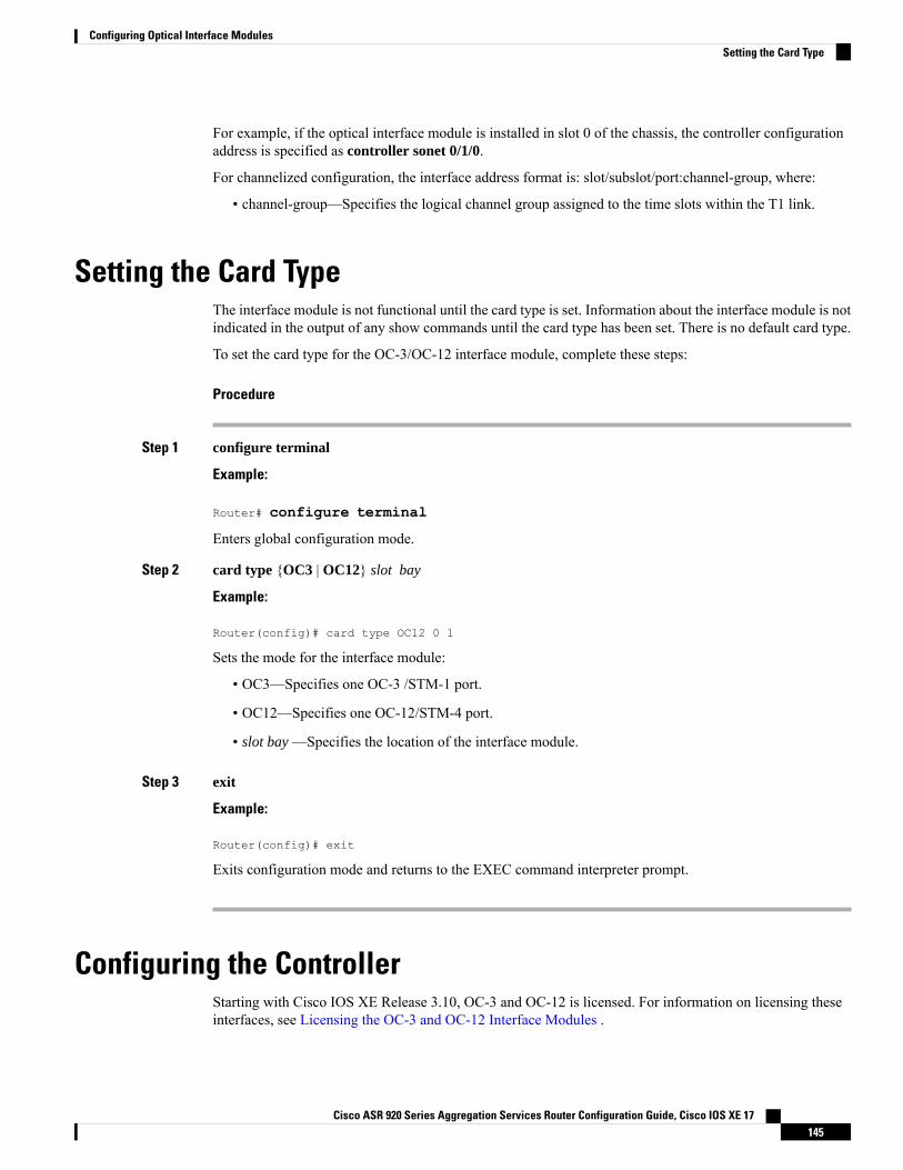
For example, if the optical interface module is installed in slot 0 of the chassis, the controller configurationaddress is specified as controller sonet 0/1/0.
For channelized configuration, the interface address format is: slot/subslot/port:channel-group, where:
• channel-group—Specifies the logical channel group assigned to the time slots within the T1 link.
Setting the Card TypeThe interface module is not functional until the card type is set. Information about the interface module is notindicated in the output of any show commands until the card type has been set. There is no default card type.
To set the card type for the OC-3/OC-12 interface module, complete these steps:
Procedure
Step 1 configure terminal
Example:
Router# configure terminal
Enters global configuration mode.
Step 2 card type {OC3 | OC12} slot bay
Example:
Router(config)# card type OC12 0 1
Sets the mode for the interface module:
• OC3—Specifies one OC-3 /STM-1 port.
• OC12—Specifies one OC-12/STM-4 port.
• slot bay —Specifies the location of the interface module.
Step 3 exit
Example:
Router(config)# exit
Exits configuration mode and returns to the EXEC command interpreter prompt.
Configuring the ControllerStarting with Cisco IOS XE Release 3.10, OC-3 and OC-12 is licensed. For information on licensing theseinterfaces, see Licensing the OC-3 and OC-12 Interface Modules .
Cisco ASR 920 Series Aggregation Services Router Configuration Guide, Cisco IOS XE 17145
Configuring Optical Interface ModulesSetting the Card Type
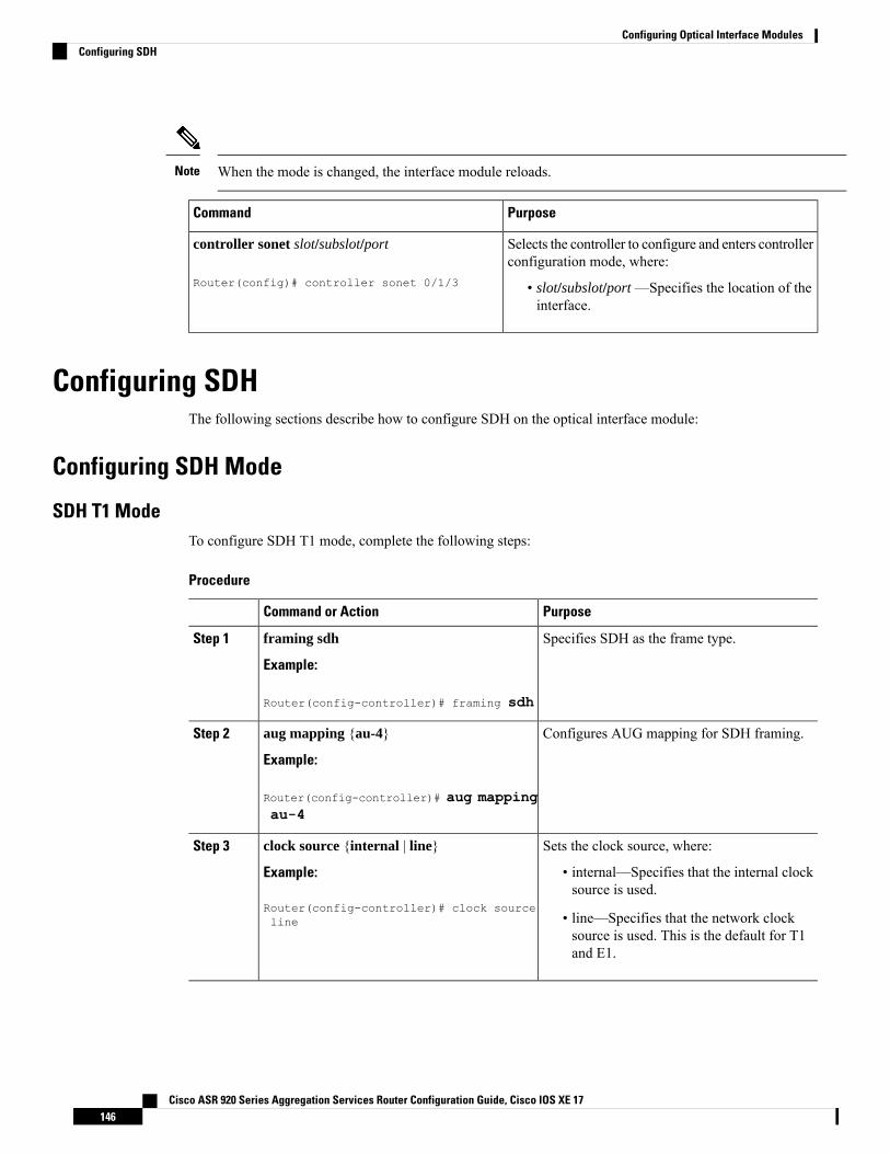
When the mode is changed, the interface module reloads.Note
PurposeCommand
Selects the controller to configure and enters controllerconfiguration mode, where:
• slot/subslot/port —Specifies the location of theinterface.
controller sonet slot/subslot/port
Router(config)# controller sonet 0/1/3
Configuring SDHThe following sections describe how to configure SDH on the optical interface module:
Configuring SDH Mode
SDH T1 ModeTo configure SDH T1 mode, complete the following steps:
Procedure
PurposeCommand or Action
Specifies SDH as the frame type.framing sdh
Example:
Step 1
Router(config-controller)# framing sdh
Configures AUG mapping for SDH framing.aug mapping {au-4}
Example:
Step 2
Router(config-controller)# aug mappingau-4
Sets the clock source, where:clock source {internal | line}Step 3
Example: • internal—Specifies that the internal clocksource is used.
Router(config-controller)# clock sourceline • line—Specifies that the network clock
source is used. This is the default for T1and E1.
Cisco ASR 920 Series Aggregation Services Router Configuration Guide, Cisco IOS XE 17146
Configuring Optical Interface ModulesConfiguring SDH
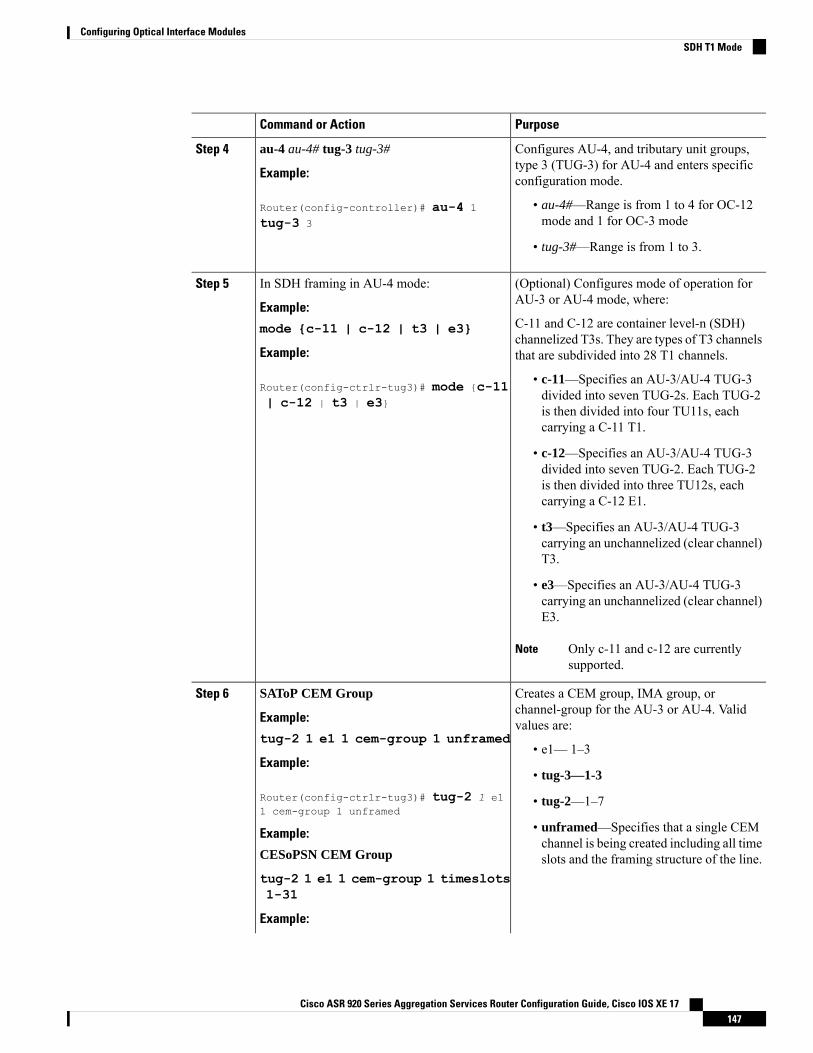
PurposeCommand or Action
Configures AU-4, and tributary unit groups,type 3 (TUG-3) for AU-4 and enters specificconfiguration mode.
au-4 au-4# tug-3 tug-3#
Example:
Router(config-controller)# au-4 1
tug-3 3
Step 4
• au-4#—Range is from 1 to 4 for OC-12mode and 1 for OC-3 mode
• tug-3#—Range is from 1 to 3.
(Optional) Configures mode of operation forAU-3 or AU-4 mode, where:
In SDH framing in AU-4 mode:
Example:
Step 5
C-11 and C-12 are container level-n (SDH)channelized T3s. They are types of T3 channelsthat are subdivided into 28 T1 channels.
mode {c-11 | c-12 | t3 | e3}
Example:
Router(config-ctrlr-tug3)# mode {c-11| c-12 | t3 | e3}
• c-11—Specifies an AU-3/AU-4 TUG-3divided into seven TUG-2s. Each TUG-2is then divided into four TU11s, eachcarrying a C-11 T1.
• c-12—Specifies an AU-3/AU-4 TUG-3divided into seven TUG-2. Each TUG-2is then divided into three TU12s, eachcarrying a C-12 E1.
• t3—Specifies an AU-3/AU-4 TUG-3carrying an unchannelized (clear channel)T3.
• e3—Specifies an AU-3/AU-4 TUG-3carrying an unchannelized (clear channel)E3.
Only c-11 and c-12 are currentlysupported.
Note
Creates a CEM group, IMA group, orchannel-group for the AU-3 or AU-4. Validvalues are:
SAToP CEM Group
Example:
tug-2 1 e1 1 cem-group 1 unframed
Step 6
• e1— 1–3Example:
• tug-3—1-3
Router(config-ctrlr-tug3)# tug-2 1 e11 cem-group 1 unframed
• tug-2—1–7
• unframed—Specifies that a single CEMchannel is being created including all timeslots and the framing structure of the line.
Example:
CESoPSN CEM Group
tug-2 1 e1 1 cem-group 1 timeslots1-31
Example:
Cisco ASR 920 Series Aggregation Services Router Configuration Guide, Cisco IOS XE 17147
Configuring Optical Interface ModulesSDH T1 Mode
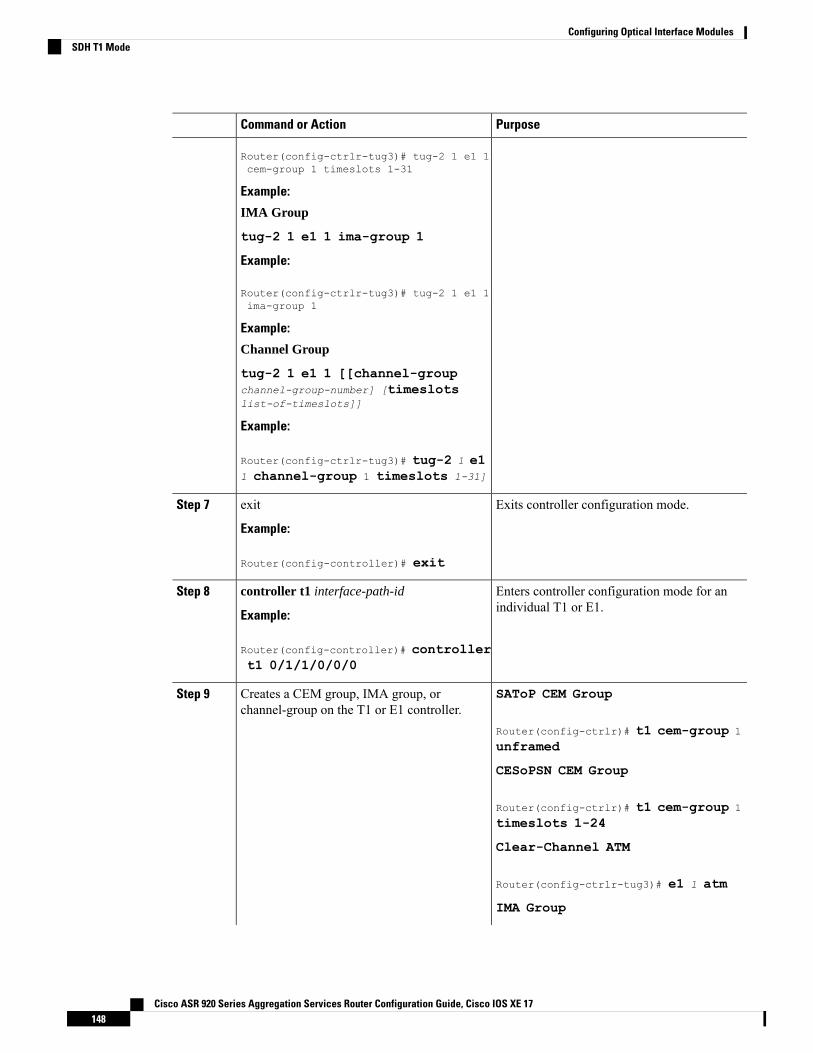
PurposeCommand or Action
Router(config-ctrlr-tug3)# tug-2 1 e1 1cem-group 1 timeslots 1-31
Example:
IMA Group
tug-2 1 e1 1 ima-group 1
Example:
Router(config-ctrlr-tug3)# tug-2 1 e1 1ima-group 1
Example:
Channel Group
tug-2 1 e1 1 [[channel-groupchannel-group-number] [timeslotslist-of-timeslots]]
Example:
Router(config-ctrlr-tug3)# tug-2 1 e11 channel-group 1 timeslots 1-31]
Exits controller configuration mode.exit
Example:
Step 7
Router(config-controller)# exit
Enters controller configuration mode for anindividual T1 or E1.
controller t1 interface-path-id
Example:
Step 8
Router(config-controller)# controllert1 0/1/1/0/0/0
SAToP CEM GroupCreates a CEM group, IMA group, orchannel-group on the T1 or E1 controller.
Step 9
Router(config-ctrlr)# t1 cem-group 1
unframed
CESoPSN CEM Group
Router(config-ctrlr)# t1 cem-group 1
timeslots 1-24
Clear-Channel ATM
Router(config-ctrlr-tug3)# e1 1 atm
IMA Group
Cisco ASR 920 Series Aggregation Services Router Configuration Guide, Cisco IOS XE 17148
Configuring Optical Interface ModulesSDH T1 Mode
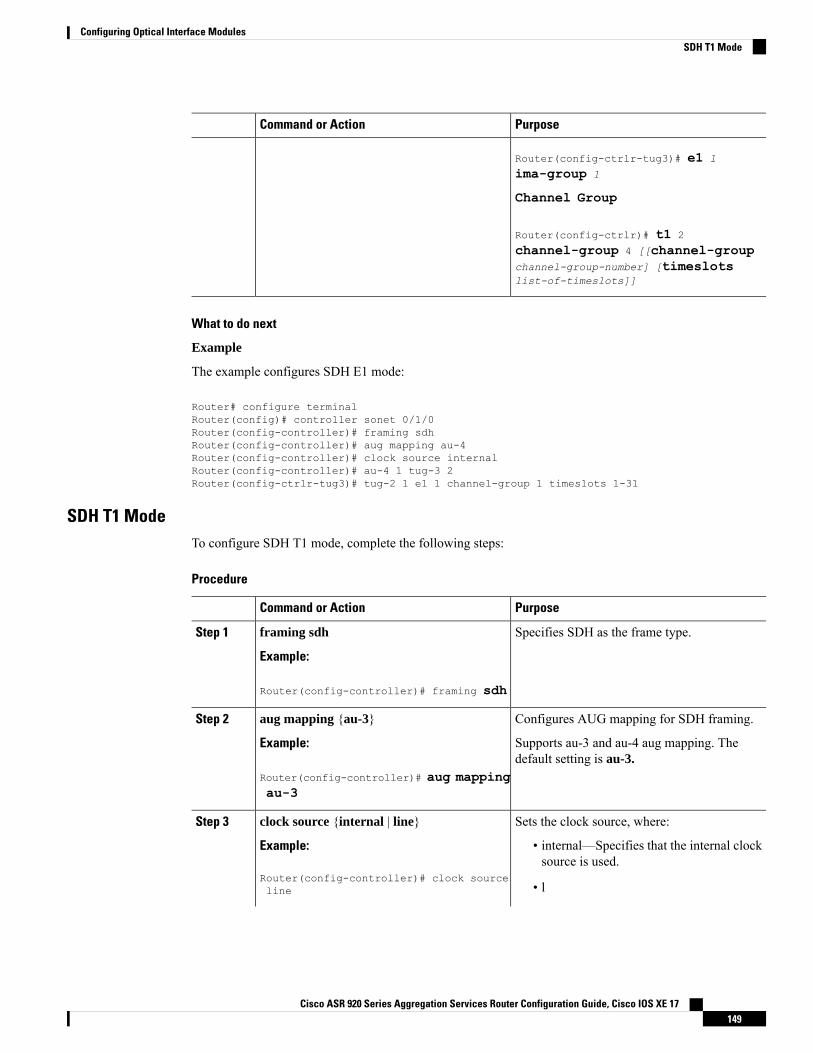
PurposeCommand or Action
Router(config-ctrlr-tug3)# e1 1
ima-group 1
Channel Group
Router(config-ctrlr)# t1 2
channel-group 4 [[channel-groupchannel-group-number] [timeslotslist-of-timeslots]]
What to do next
Example
The example configures SDH E1 mode:
Router# configure terminalRouter(config)# controller sonet 0/1/0Router(config-controller)# framing sdhRouter(config-controller)# aug mapping au-4Router(config-controller)# clock source internalRouter(config-controller)# au-4 1 tug-3 2Router(config-ctrlr-tug3)# tug-2 1 e1 1 channel-group 1 timeslots 1-31
SDH T1 ModeTo configure SDH T1 mode, complete the following steps:
Procedure
PurposeCommand or Action
Specifies SDH as the frame type.framing sdh
Example:
Step 1
Router(config-controller)# framing sdh
Configures AUG mapping for SDH framing.aug mapping {au-3}Step 2
Example: Supports au-3 and au-4 aug mapping. Thedefault setting is au-3.
Router(config-controller)# aug mappingau-3
Sets the clock source, where:clock source {internal | line}Step 3
Example: • internal—Specifies that the internal clocksource is used.
Router(config-controller)# clock sourceline • l
Cisco ASR 920 Series Aggregation Services Router Configuration Guide, Cisco IOS XE 17149
Configuring Optical Interface ModulesSDH T1 Mode
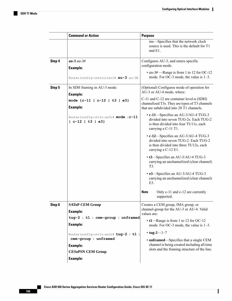
PurposeCommand or Action
ine—Specifies that the network clocksource is used. This is the default for T1and E1.
Configures AU-3, and enters specificconfiguration mode.
au-3 au-3#
Example:
Step 4
• au-3# —Range is from 1 to 12 for OC-12mode. For OC-3 mode, the value is 1–3.Router(config-controller)# au-3 au-3#
(Optional) Configures mode of operation forAU-3 or AU-4 mode, where:
In SDH framing in AU-3 mode:
Example:
Step 5
C-11 and C-12 are container level-n (SDH)channelized T3s. They are types of T3 channelsthat are subdivided into 28 T1 channels.
mode {c-11 | c-12 | t3 | e3}
Example:
Router(config-ctrlr-au3)# mode {c-11| c-12 | t3 | e3}
• c-11—Specifies an AU-3/AU-4 TUG-3divided into seven TUG-2s. Each TUG-2is then divided into four TU11s, eachcarrying a C-11 T1.
• c-12—Specifies an AU-3/AU-4 TUG-3divided into seven TUG-2. Each TUG-2is then divided into three TU12s, eachcarrying a C-12 E1.
• t3—Specifies an AU-3/AU-4 TUG-3carrying an unchannelized (clear channel)T3.
• e3—Specifies an AU-3/AU-4 TUG-3carrying an unchannelized (clear channel)E3.
Only c-11 and c-12 are currentlysupported.
Note
Creates a CEM group, IMA group, orchannel-group for the AU-3 or AU-4. Validvalues are:
SAToP CEM Group
Example:
tug-2 1 t1 1 cem-group 1 unframed
Step 6
• t1—Range is from 1 to 12 for OC-12mode. For OC-3 mode, the value is 1–3.Example:
Router(config-ctrlr-au3)# tug-2 1 t1 1
cem-group 1 unframed
• tug-2—1–7
• unframed—Specifies that a single CEMchannel is being created including all timeslots and the framing structure of the line.
Example:
CESoPSN CEM Group
Example:
Cisco ASR 920 Series Aggregation Services Router Configuration Guide, Cisco IOS XE 17150
Configuring Optical Interface ModulesSDH T1 Mode
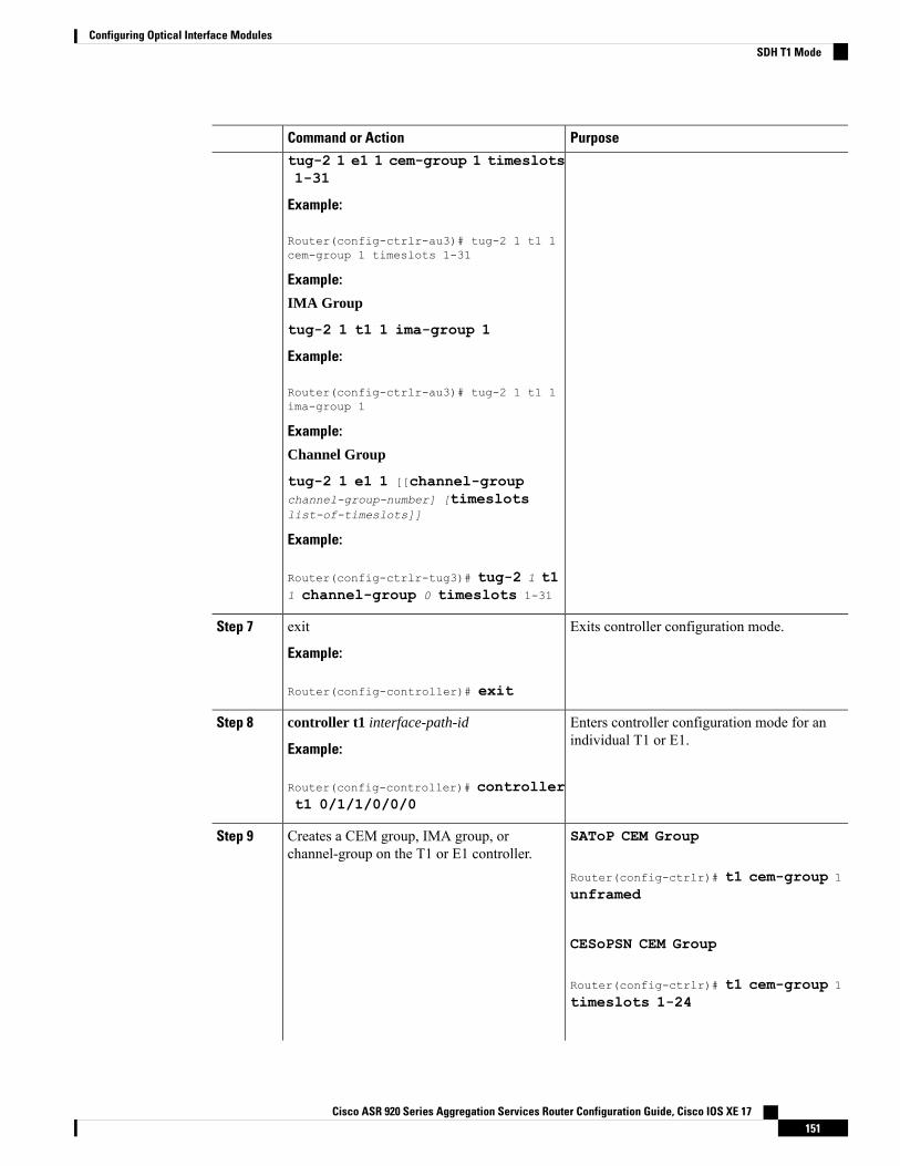
PurposeCommand or Actiontug-2 1 e1 1 cem-group 1 timeslots1-31
Example:
Router(config-ctrlr-au3)# tug-2 1 t1 1cem-group 1 timeslots 1-31
Example:
IMA Group
tug-2 1 t1 1 ima-group 1
Example:
Router(config-ctrlr-au3)# tug-2 1 t1 1ima-group 1
Example:
Channel Group
tug-2 1 e1 1 [[channel-groupchannel-group-number] [timeslotslist-of-timeslots]]
Example:
Router(config-ctrlr-tug3)# tug-2 1 t11 channel-group 0 timeslots 1-31
Exits controller configuration mode.exit
Example:
Step 7
Router(config-controller)# exit
Enters controller configuration mode for anindividual T1 or E1.
controller t1 interface-path-id
Example:
Step 8
Router(config-controller)# controllert1 0/1/1/0/0/0
SAToP CEM GroupCreates a CEM group, IMA group, orchannel-group on the T1 or E1 controller.
Step 9
Router(config-ctrlr)# t1 cem-group 1
unframed
CESoPSN CEM Group
Router(config-ctrlr)# t1 cem-group 1
timeslots 1-24
Cisco ASR 920 Series Aggregation Services Router Configuration Guide, Cisco IOS XE 17151
Configuring Optical Interface ModulesSDH T1 Mode
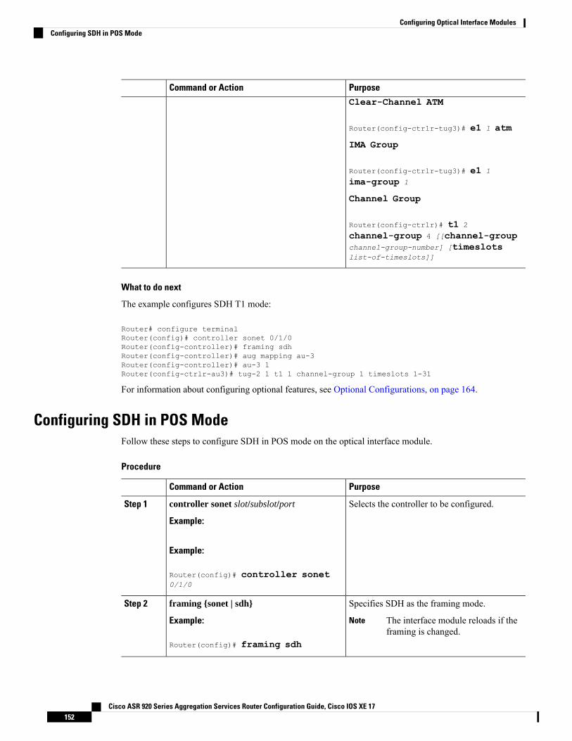
PurposeCommand or ActionClear-Channel ATM
Router(config-ctrlr-tug3)# e1 1 atm
IMA Group
Router(config-ctrlr-tug3)# e1 1
ima-group 1
Channel Group
Router(config-ctrlr)# t1 2
channel-group 4 [[channel-groupchannel-group-number] [timeslotslist-of-timeslots]]
What to do next
The example configures SDH T1 mode:
Router# configure terminalRouter(config)# controller sonet 0/1/0Router(config-controller)# framing sdhRouter(config-controller)# aug mapping au-3Router(config-controller)# au-3 1Router(config-ctrlr-au3)# tug-2 1 t1 1 channel-group 1 timeslots 1-31
For information about configuring optional features, see Optional Configurations, on page 164.
Configuring SDH in POS ModeFollow these steps to configure SDH in POS mode on the optical interface module.
Procedure
PurposeCommand or Action
Selects the controller to be configured.controller sonet slot/subslot/port
Example:
Step 1
Example:
Router(config)# controller sonet0/1/0
Specifies SDH as the framing mode.framing {sonet | sdh}Step 2
Example: The interface module reloads if theframing is changed.
Note
Router(config)# framing sdh
Cisco ASR 920 Series Aggregation Services Router Configuration Guide, Cisco IOS XE 17152
Configuring Optical Interface ModulesConfiguring SDH in POS Mode
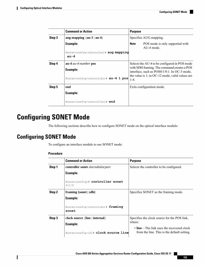
PurposeCommand or Action
Specifies AUG mapping.aug mapping {au-3 | au-4}Step 3
Example: POS mode is only supported withAU-4 mode.
Note
Router(config-controller)# aug mappingau-4
Selects the AU-4 to be configured in POSmodewith SDH framing. The command creates a POS
au-4 au-4-number pos
Example:
Step 4
interface, such as POS0/1/0:1. In OC-3 mode,
Router(config-controller)# au-4 1 posthe value is 1; in OC-12 mode, valid values are1-4.
Exits configuration mode.end
Example:
Step 5
Router(config-controller)# end
Configuring SONET ModeThe following sections describe how to configure SONET mode on the optical interface module:
Configuring SONET ModeTo configure an interface module to use SONET mode:
Procedure
PurposeCommand or Action
Selects the controller to be configured.controller sonet slot/subslot/port
Example:
Step 1
Router(config)# controller sonet0/1/0
Specifies SONET as the framing mode.framing {sonet | sdh}
Example:
Step 2
Router(config-controller)# framingsonet
Specifies the clock source for the POS link,where:
clock source {line | internal}
Example:
Step 3
• line—The link uses the recovered clockfrom the line. This is the default setting.Router(config-if)# clock source line
Cisco ASR 920 Series Aggregation Services Router Configuration Guide, Cisco IOS XE 17153
Configuring Optical Interface ModulesConfiguring SONET Mode
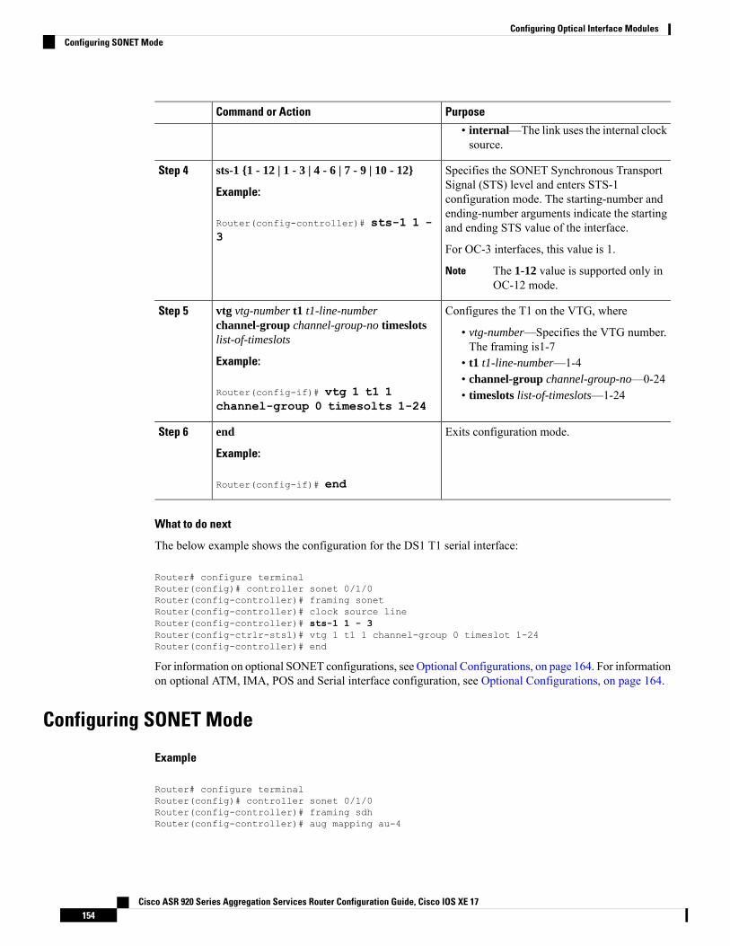
PurposeCommand or Action
• internal—The link uses the internal clocksource.
Specifies the SONET Synchronous TransportSignal (STS) level and enters STS-1
sts-1 {1 - 12 | 1 - 3 | 4 - 6 | 7 - 9 | 10 - 12}
Example:
Step 4
configuration mode. The starting-number and
Router(config-controller)# sts-1 1 -3
ending-number arguments indicate the startingand ending STS value of the interface.
For OC-3 interfaces, this value is 1.
The 1-12 value is supported only inOC-12 mode.
Note
Configures the T1 on the VTG, wherevtg vtg-number t1 t1-line-numberchannel-group channel-group-no timeslotslist-of-timeslots
Step 5
• vtg-number—Specifies the VTG number.The framing is1-7
Example: • t1 t1-line-number—1-4• channel-group channel-group-no—0-24
Router(config-if)# vtg 1 t1 1channel-group 0 timesolts 1-24
• timeslots list-of-timeslots—1-24
Exits configuration mode.end
Example:
Step 6
Router(config-if)# end
What to do next
The below example shows the configuration for the DS1 T1 serial interface:
Router# configure terminalRouter(config)# controller sonet 0/1/0Router(config-controller)# framing sonetRouter(config-controller)# clock source lineRouter(config-controller)# sts-1 1 - 3Router(config-ctrlr-sts1)# vtg 1 t1 1 channel-group 0 timeslot 1-24Router(config-controller)# end
For information on optional SONET configurations, see Optional Configurations, on page 164. For informationon optional ATM, IMA, POS and Serial interface configuration, see Optional Configurations, on page 164.
Configuring SONET Mode
Example
Router# configure terminalRouter(config)# controller sonet 0/1/0Router(config-controller)# framing sdhRouter(config-controller)# aug mapping au-4
Cisco ASR 920 Series Aggregation Services Router Configuration Guide, Cisco IOS XE 17154
Configuring Optical Interface ModulesConfiguring SONET Mode
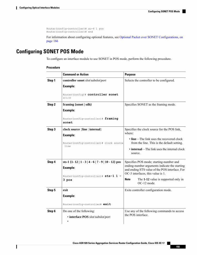
Router(config-controller)# au-4 1 posRouter(config-controller)# end
For information about configuring optional features, see Optional Packet over SONET Configurations, onpage 166
Configuring SONET POS ModeTo configure an interface module to use SONET in POS mode, perform the following procedure.
Procedure
PurposeCommand or Action
Selects the controller to be configured.controller sonet slot/subslot/port
Example:
Step 1
Router(config)# controller sonet0/1/0
Specifies SONET as the framing mode.framing {sonet | sdh}
Example:
Step 2
Router(config-controller)# framingsonet
Specifies the clock source for the POS link,where:
clock source {line | internal}
Example:
Step 3
• line—The link uses the recovered clockfrom the line. This is the default setting.Router(config-controller)# clock source
line• internal—The link uses the internal clocksource.
Specifies POS mode; starting-number andending-number arguments indicate the starting
sts-1 {1- 12 | 1 - 3 | 4 - 6 | 7 - 9 | 10 - 12} pos
Example:
Step 4
and ending STS value of the POS interface. ForOC-3 interfaces, this value is 1.
Router(config-controller)# sts-1 1 -3 pos The 1-12 value is supported only in
OC-12 mode.Note
Exits controller configuration mode.exit
Example:
Step 5
Router(config-controller# exit
Use any of the following commands to accessthe POS interface.
Do one of the following:Step 6
• interface POS slot/subslot/port•
Cisco ASR 920 Series Aggregation Services Router Configuration Guide, Cisco IOS XE 17155
Configuring Optical Interface ModulesConfiguring SONET POS Mode
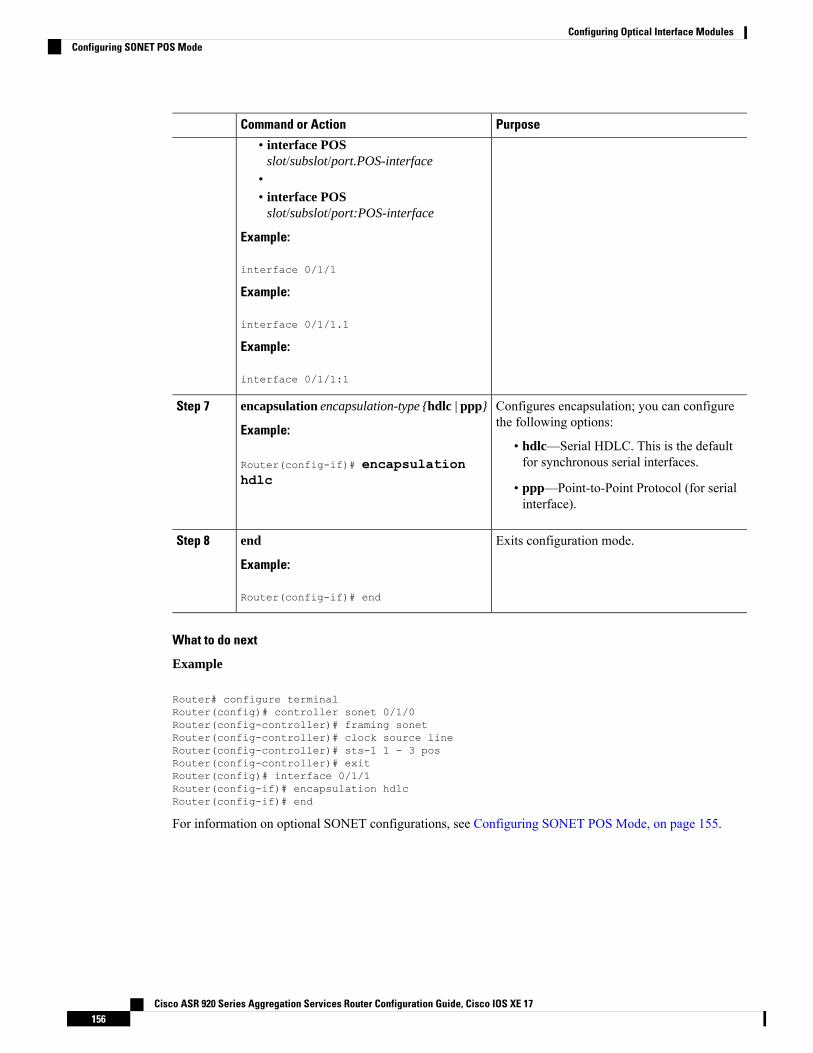
PurposeCommand or Action
• interface POSslot/subslot/port.POS-interface
•• interface POS
slot/subslot/port:POS-interface
Example:
interface 0/1/1
Example:
interface 0/1/1.1
Example:
interface 0/1/1:1
Configures encapsulation; you can configurethe following options:
encapsulation encapsulation-type {hdlc | ppp}
Example:
Step 7
• hdlc—Serial HDLC. This is the defaultfor synchronous serial interfaces.Router(config-if)# encapsulation
hdlc • ppp—Point-to-Point Protocol (for serialinterface).
Exits configuration mode.end
Example:
Step 8
Router(config-if)# end
What to do next
Example
Router# configure terminalRouter(config)# controller sonet 0/1/0Router(config-controller)# framing sonetRouter(config-controller)# clock source lineRouter(config-controller)# sts-1 1 - 3 posRouter(config-controller)# exitRouter(config)# interface 0/1/1Router(config-if)# encapsulation hdlcRouter(config-if)# end
For information on optional SONET configurations, see Configuring SONET POS Mode, on page 155.
Cisco ASR 920 Series Aggregation Services Router Configuration Guide, Cisco IOS XE 17156
Configuring Optical Interface ModulesConfiguring SONET POS Mode
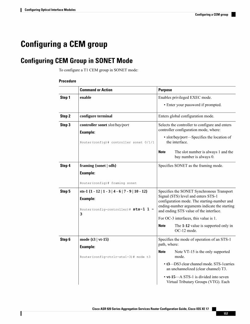
Configuring a CEM group
Configuring CEM Group in SONET ModeTo configure a T1 CEM group in SONET mode:
Procedure
PurposeCommand or Action
Enables privileged EXEC mode.enableStep 1
• Enter your password if prompted.
Enters global configuration mode.configure terminalStep 2
Selects the controller to configure and enterscontroller configuration mode, where:
controller sonet slot/bay/port
Example:
Step 3
• slot/bay/port—Specifies the location ofthe interface.Router(config)# controller sonet 0/1/1
The slot number is always 1 and thebay number is always 0.
Note
Specifies SONET as the framing mode.framing {sonet | sdh}
Example:
Step 4
Router(config)# framing sonet
Specifies the SONET Synchronous TransportSignal (STS) level and enters STS-1
sts-1 {1 - 12 | 1 - 3 | 4 - 6 | 7 - 9 | 10 - 12}
Example:
Step 5
configuration mode. The starting-number and
Router(config-controller)# sts-1 1 -3
ending-number arguments indicate the startingand ending STS value of the interface.
For OC-3 interfaces, this value is 1.
The 1-12 value is supported only inOC-12 mode.
Note
Specifies the mode of operation of an STS-1path, where:
mode {t3 | vt-15}
Example:
Step 6
Note VT-15 is the only supportedmode.
NoteRouter(config-ctrlr-sts1-3)# mode t3
• t3—DS3 clear channelmode. STS-1carriesan unchannelized (clear channel) T3.
• vt-15—A STS-1 is divided into sevenVirtual Tributary Groups (VTG). Each
Cisco ASR 920 Series Aggregation Services Router Configuration Guide, Cisco IOS XE 17157
Configuring Optical Interface ModulesConfiguring a CEM group
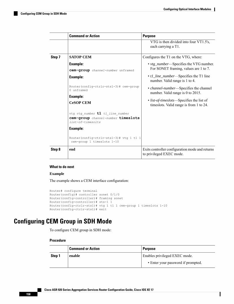
PurposeCommand or Action
VTG is then divided into four VT1.5's,each carrying a T1.
Configures the T1 on the VTG, where:SATOP CEMStep 7
Example: • vtg_number—Specifies the VTG number.For SONET framing, values are 1 to 7.cem-group channel-number unframed
• t1_line_number—Specifies the T1 linenumber. Valid range is 1 to 4.
Example:
Router(config-ctrlr-sts1-3)# cem-group0 unframed • channel-number—Specifies the channel
number. Valid range is 0 to 2015.Example:
• list-of-timeslots—Specifies the list oftimeslots. Valid range is from 1 to 24.CeSOP CEM
vtg vtg_number t1 t1_line_number
cem-group channel-number timeslotslist-of-timesolts
Example:
Router(config-ctrlr-sts1-3)# vtg 1 t1 1cem-group 1 timeslots 1-10
Exits controller configuration mode and returnsto privileged EXEC mode.
endStep 8
What to do next
Example
The example shows a CEM interface configuration:
Router# configure terminalRouter(config)# controller sonet 0/1/0Router(config-controller)# framing sonetRouter(config-controller)# sts-1 1Router(config-ctrlr-sts1)# vtg 1 t1 1 cem-group 1 timeslots 1-10Router(config-ctrlr-sts1)# exit
Configuring CEM Group in SDH ModeTo configure CEM group in SDH mode:
Procedure
PurposeCommand or Action
Enables privileged EXEC mode.enableStep 1
• Enter your password if prompted.
Cisco ASR 920 Series Aggregation Services Router Configuration Guide, Cisco IOS XE 17158
Configuring Optical Interface ModulesConfiguring CEM Group in SDH Mode
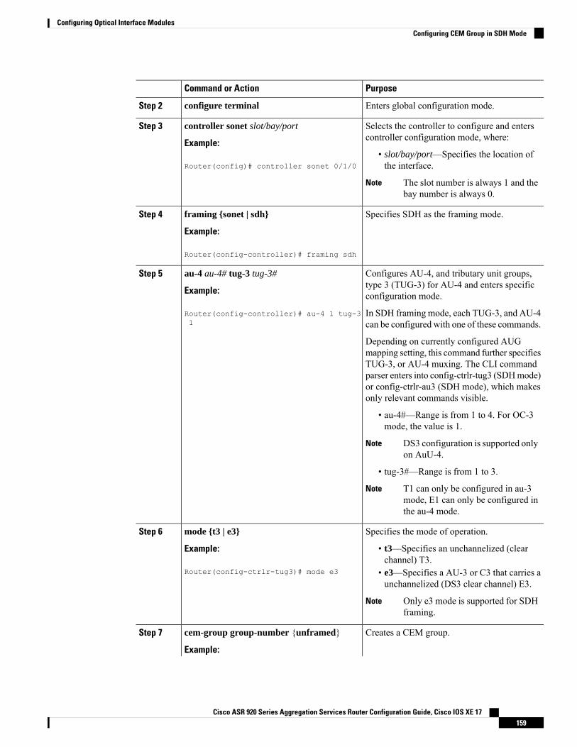
PurposeCommand or Action
Enters global configuration mode.configure terminalStep 2
Selects the controller to configure and enterscontroller configuration mode, where:
controller sonet slot/bay/port
Example:
Step 3
• slot/bay/port—Specifies the location ofthe interface.Router(config)# controller sonet 0/1/0
The slot number is always 1 and thebay number is always 0.
Note
Specifies SDH as the framing mode.framing {sonet | sdh}
Example:
Step 4
Router(config-controller)# framing sdh
Configures AU-4, and tributary unit groups,type 3 (TUG-3) for AU-4 and enters specificconfiguration mode.
au-4 au-4# tug-3 tug-3#
Example:
Router(config-controller)# au-4 1 tug-31
Step 5
In SDH framing mode, each TUG-3, and AU-4can be configured with one of these commands.
Depending on currently configured AUGmapping setting, this command further specifiesTUG-3, or AU-4 muxing. The CLI commandparser enters into config-ctrlr-tug3 (SDHmode)or config-ctrlr-au3 (SDH mode), which makesonly relevant commands visible.
• au-4#—Range is from 1 to 4. For OC-3mode, the value is 1.
DS3 configuration is supported onlyon AuU-4.
Note
• tug-3#—Range is from 1 to 3.
T1 can only be configured in au-3mode, E1 can only be configured inthe au-4 mode.
Note
Specifies the mode of operation.mode {t3 | e3}Step 6
Example: • t3—Specifies an unchannelized (clearchannel) T3.
Router(config-ctrlr-tug3)# mode e3 • e3—Specifies a AU-3 or C3 that carries aunchannelized (DS3 clear channel) E3.
Only e3 mode is supported for SDHframing.
Note
Creates a CEM group.cem-group group-number {unframed}Step 7
Example:
Cisco ASR 920 Series Aggregation Services Router Configuration Guide, Cisco IOS XE 17159
Configuring Optical Interface ModulesConfiguring CEM Group in SDH Mode
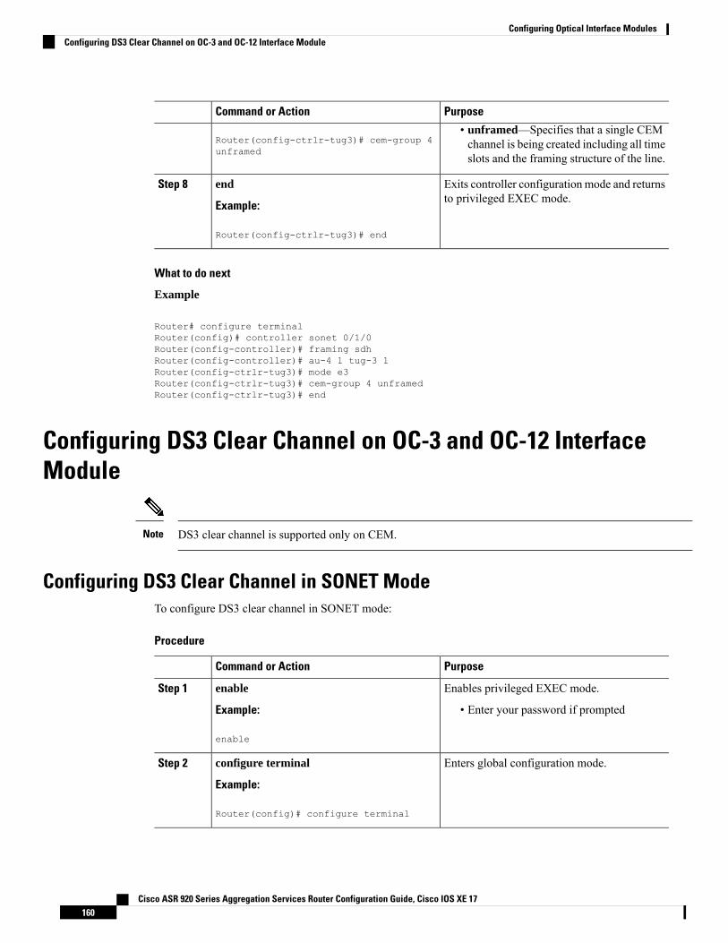
PurposeCommand or Action
Router(config-ctrlr-tug3)# cem-group 4unframed
• unframed—Specifies that a single CEMchannel is being created including all timeslots and the framing structure of the line.
Exits controller configuration mode and returnsto privileged EXEC mode.
end
Example:
Step 8
Router(config-ctrlr-tug3)# end
What to do next
Example
Router# configure terminalRouter(config)# controller sonet 0/1/0Router(config-controller)# framing sdhRouter(config-controller)# au-4 1 tug-3 1Router(config-ctrlr-tug3)# mode e3Router(config-ctrlr-tug3)# cem-group 4 unframedRouter(config-ctrlr-tug3)# end
Configuring DS3 Clear Channel on OC-3 and OC-12 InterfaceModule
DS3 clear channel is supported only on CEM.Note
Configuring DS3 Clear Channel in SONET ModeTo configure DS3 clear channel in SONET mode:
Procedure
PurposeCommand or Action
Enables privileged EXEC mode.enableStep 1
Example: • Enter your password if prompted
enable
Enters global configuration mode.configure terminal
Example:
Step 2
Router(config)# configure terminal
Cisco ASR 920 Series Aggregation Services Router Configuration Guide, Cisco IOS XE 17160
Configuring Optical Interface ModulesConfiguring DS3 Clear Channel on OC-3 and OC-12 Interface Module
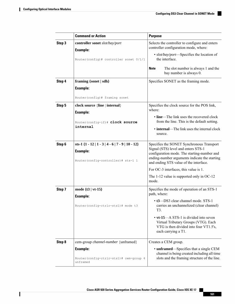
PurposeCommand or Action
Selects the controller to configure and enterscontroller configuration mode, where:
controller sonet slot/bay/port
Example:
Step 3
• slot/bay/port—Specifies the location ofthe interface.Router(config)# controller sonet 0/1/1
The slot number is always 1 and thebay number is always 0.
Note
Specifies SONET as the framing mode.framing {sonet | sdh}
Example:
Step 4
Router(config)# framing sonet
Specifies the clock source for the POS link,where:
clock source {line | internal}
Example:
Step 5
• line—The link uses the recovered clockfrom the line. This is the default setting.Router(config-if)# clock source
internal • internal—The link uses the internal clocksource.
Specifies the SONET Synchronous TransportSignal (STS) level and enters STS-1
sts-1 {1 - 12 | 1 - 3 | 4 - 6 | 7 - 9 | 10 - 12}
Example:
Step 6
configuration mode. The starting-number and
Router(config-controller)# sts-1 1ending-number arguments indicate the startingand ending STS value of the interface.
For OC-3 interfaces, this value is 1.
The 1-12 value is supported only in OC-12mode.
Specifies the mode of operation of an STS-1path, where:
mode {t3 | vt-15}
Example:
Step 7
• t3—DS3 clear channel mode. STS-1carries an unchannelized (clear channel)T3.
Router(config-ctrlr-sts1)# mode t3
• vt-15—A STS-1 is divided into sevenVirtual Tributary Groups (VTG). EachVTG is then divided into four VT1.5's,each carrying a T1.
Creates a CEM group.cem-group channel-number {unframed}Step 8
Example: • unframed—Specifies that a single CEMchannel is being created including all timeslots and the framing structure of the line.Router(config-ctrlr-sts1)# cem-group 4
unframed
Cisco ASR 920 Series Aggregation Services Router Configuration Guide, Cisco IOS XE 17161
Configuring Optical Interface ModulesConfiguring DS3 Clear Channel in SONET Mode
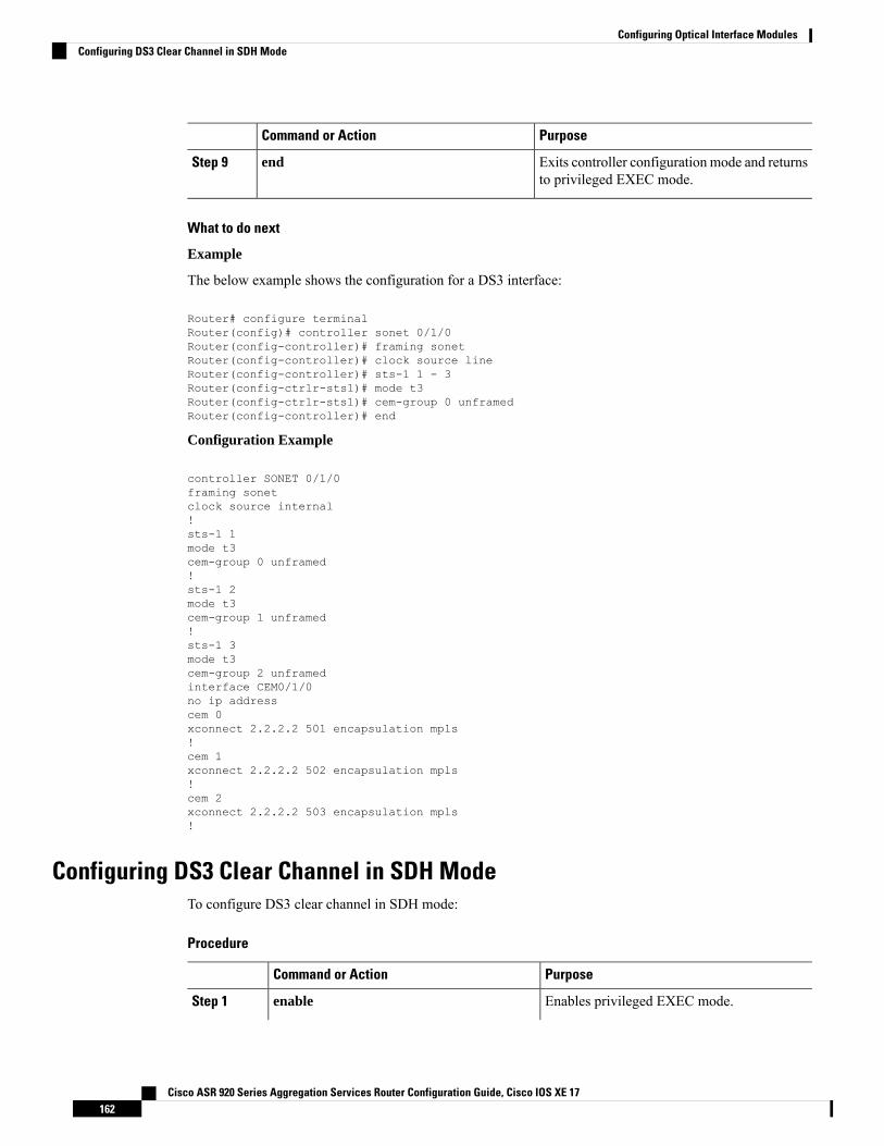
PurposeCommand or Action
Exits controller configuration mode and returnsto privileged EXEC mode.
endStep 9
What to do next
Example
The below example shows the configuration for a DS3 interface:
Router# configure terminalRouter(config)# controller sonet 0/1/0Router(config-controller)# framing sonetRouter(config-controller)# clock source lineRouter(config-controller)# sts-1 1 - 3Router(config-ctrlr-sts1)# mode t3Router(config-ctrlr-sts1)# cem-group 0 unframedRouter(config-controller)# end
Configuration Example
controller SONET 0/1/0framing sonetclock source internal!sts-1 1mode t3cem-group 0 unframed!sts-1 2mode t3cem-group 1 unframed!sts-1 3mode t3cem-group 2 unframedinterface CEM0/1/0no ip addresscem 0xconnect 2.2.2.2 501 encapsulation mpls!cem 1xconnect 2.2.2.2 502 encapsulation mpls!cem 2xconnect 2.2.2.2 503 encapsulation mpls!
Configuring DS3 Clear Channel in SDH ModeTo configure DS3 clear channel in SDH mode:
Procedure
PurposeCommand or Action
Enables privileged EXEC mode.enableStep 1
Cisco ASR 920 Series Aggregation Services Router Configuration Guide, Cisco IOS XE 17162
Configuring Optical Interface ModulesConfiguring DS3 Clear Channel in SDH Mode
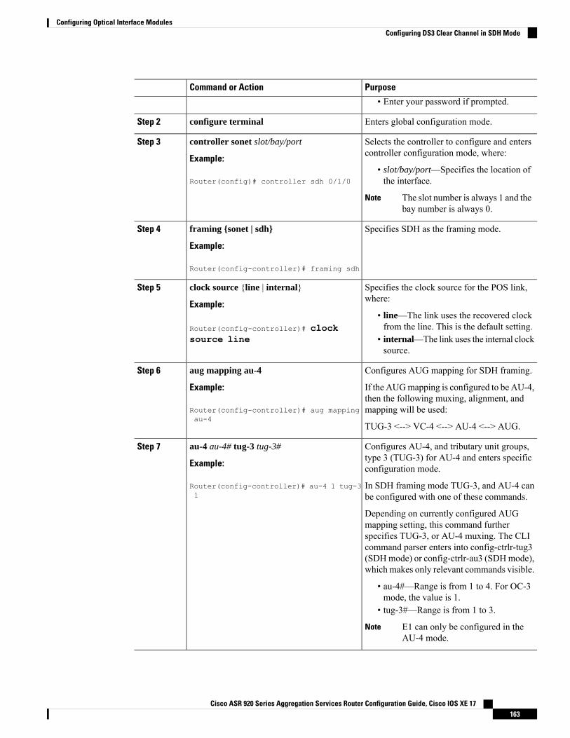
PurposeCommand or Action
• Enter your password if prompted.
Enters global configuration mode.configure terminalStep 2
Selects the controller to configure and enterscontroller configuration mode, where:
controller sonet slot/bay/port
Example:
Step 3
• slot/bay/port—Specifies the location ofthe interface.Router(config)# controller sdh 0/1/0
The slot number is always 1 and thebay number is always 0.
Note
Specifies SDH as the framing mode.framing {sonet | sdh}
Example:
Step 4
Router(config-controller)# framing sdh
Specifies the clock source for the POS link,where:
clock source {line | internal}
Example:
Step 5
• line—The link uses the recovered clockfrom the line. This is the default setting.Router(config-controller)# clock
source line • internal—The link uses the internal clocksource.
Configures AUG mapping for SDH framing.aug mapping au-4Step 6
Example: If the AUGmapping is configured to be AU-4,then the following muxing, alignment, andmapping will be used:Router(config-controller)# aug mapping
au-4TUG-3 <--> VC-4 <--> AU-4 <--> AUG.
Configures AU-4, and tributary unit groups,type 3 (TUG-3) for AU-4 and enters specificconfiguration mode.
au-4 au-4# tug-3 tug-3#
Example:
Router(config-controller)# au-4 1 tug-31
Step 7
In SDH framing mode TUG-3, and AU-4 canbe configured with one of these commands.
Depending on currently configured AUGmapping setting, this command furtherspecifies TUG-3, or AU-4 muxing. The CLIcommand parser enters into config-ctrlr-tug3(SDHmode) or config-ctrlr-au3 (SDHmode),which makes only relevant commands visible.
• au-4#—Range is from 1 to 4. For OC-3mode, the value is 1.
• tug-3#—Range is from 1 to 3.
E1 can only be configured in theAU-4 mode.
Note
Cisco ASR 920 Series Aggregation Services Router Configuration Guide, Cisco IOS XE 17163
Configuring Optical Interface ModulesConfiguring DS3 Clear Channel in SDH Mode
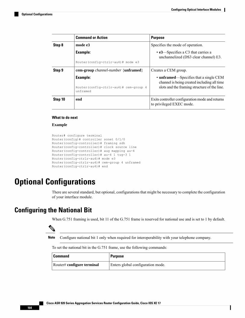
PurposeCommand or Action
Specifies the mode of operation.mode e3Step 8
Example: • e3—Specifies a C3 that carries aunchannelized (DS3 clear channel) E3.
Router(config-ctrlr-au4)# mode e3
Creates a CEM group.cem-group channel-number {unframed}Step 9
Example: • unframed—Specifies that a single CEMchannel is being created including all timeslots and the framing structure of the line.Router(config-ctrlr-au4)# cem-group 4
unframed
Exits controller configurationmode and returnsto privileged EXEC mode.
endStep 10
What to do next
Example
Router# configure terminalRouter(config)# controller sonet 0/1/0Router(config-controller)# framing sdhRouter(config-controller)# clock source lineRouter(config-controller)# aug mapping au-4Router(config-controller)# au-4 1 tug-3 1Router(config-ctrlr-au4)# mode e3Router(config-ctrlr-au4)# cem-group 4 unframedRouter(config-ctrlr-au4)# end
Optional ConfigurationsThere are several standard, but optional, configurations that might be necessary to complete the configurationof your interface module.
Configuring the National BitWhen G.751 framing is used, bit 11 of the G.751 frame is reserved for national use and is set to 1 by default.
Configure national bit 1 only when required for interoperability with your telephone company.Note
To set the national bit in the G.751 frame, use the following commands:
PurposeCommand
Enters global configuration mode.Router# configure terminal
Cisco ASR 920 Series Aggregation Services Router Configuration Guide, Cisco IOS XE 17164
Configuring Optical Interface ModulesOptional Configurations
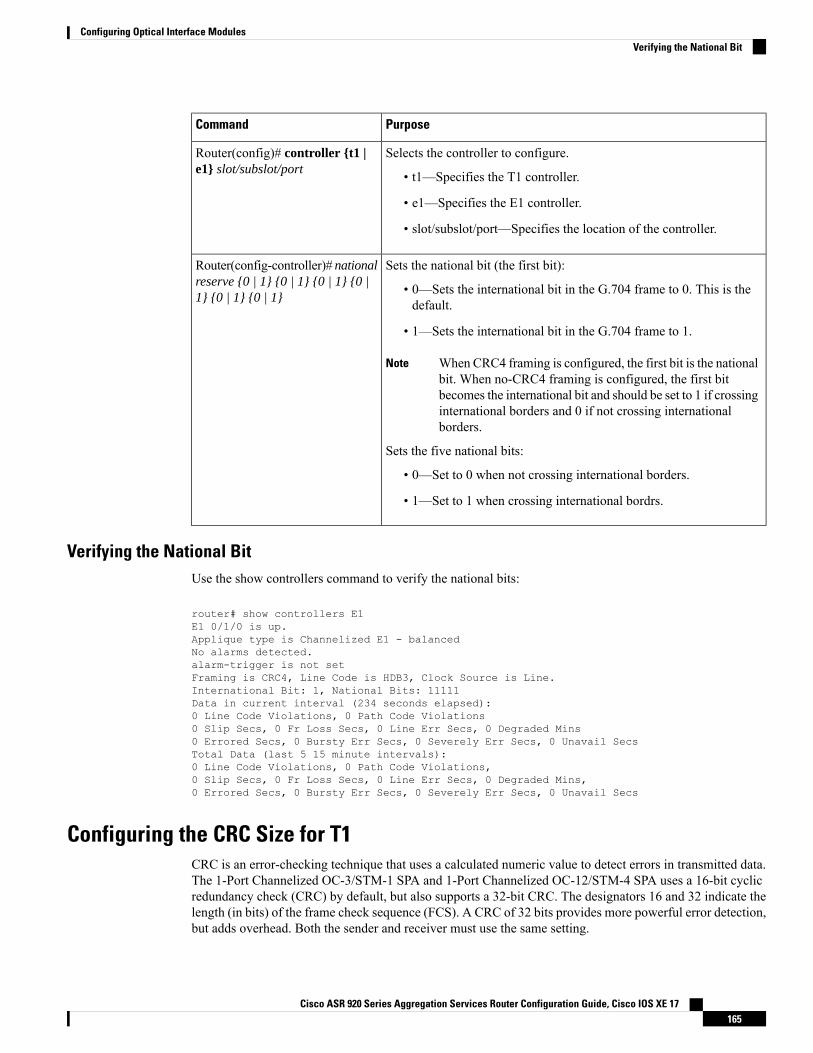
PurposeCommand
Selects the controller to configure.
• t1—Specifies the T1 controller.
• e1—Specifies the E1 controller.
• slot/subslot/port—Specifies the location of the controller.
Router(config)# controller {t1 |e1} slot/subslot/port
Sets the national bit (the first bit):
• 0—Sets the international bit in the G.704 frame to 0. This is thedefault.
• 1—Sets the international bit in the G.704 frame to 1.
When CRC4 framing is configured, the first bit is the nationalbit. When no-CRC4 framing is configured, the first bitbecomes the international bit and should be set to 1 if crossinginternational borders and 0 if not crossing internationalborders.
Note
Sets the five national bits:
• 0—Set to 0 when not crossing international borders.
• 1—Set to 1 when crossing international bordrs.
Router(config-controller)# nationalreserve {0 | 1} {0 | 1} {0 | 1} {0 |1} {0 | 1} {0 | 1}
Verifying the National BitUse the show controllers command to verify the national bits:
router# show controllers E1E1 0/1/0 is up.Applique type is Channelized E1 - balancedNo alarms detected.alarm-trigger is not setFraming is CRC4, Line Code is HDB3, Clock Source is Line.International Bit: 1, National Bits: 11111Data in current interval (234 seconds elapsed):0 Line Code Violations, 0 Path Code Violations0 Slip Secs, 0 Fr Loss Secs, 0 Line Err Secs, 0 Degraded Mins0 Errored Secs, 0 Bursty Err Secs, 0 Severely Err Secs, 0 Unavail SecsTotal Data (last 5 15 minute intervals):0 Line Code Violations, 0 Path Code Violations,0 Slip Secs, 0 Fr Loss Secs, 0 Line Err Secs, 0 Degraded Mins,0 Errored Secs, 0 Bursty Err Secs, 0 Severely Err Secs, 0 Unavail Secs
Configuring the CRC Size for T1CRC is an error-checking technique that uses a calculated numeric value to detect errors in transmitted data.The 1-Port Channelized OC-3/STM-1 SPA and 1-Port Channelized OC-12/STM-4 SPA uses a 16-bit cyclicredundancy check (CRC) by default, but also supports a 32-bit CRC. The designators 16 and 32 indicate thelength (in bits) of the frame check sequence (FCS). A CRC of 32 bits provides more powerful error detection,but adds overhead. Both the sender and receiver must use the same setting.
Cisco ASR 920 Series Aggregation Services Router Configuration Guide, Cisco IOS XE 17165
Configuring Optical Interface ModulesVerifying the National Bit
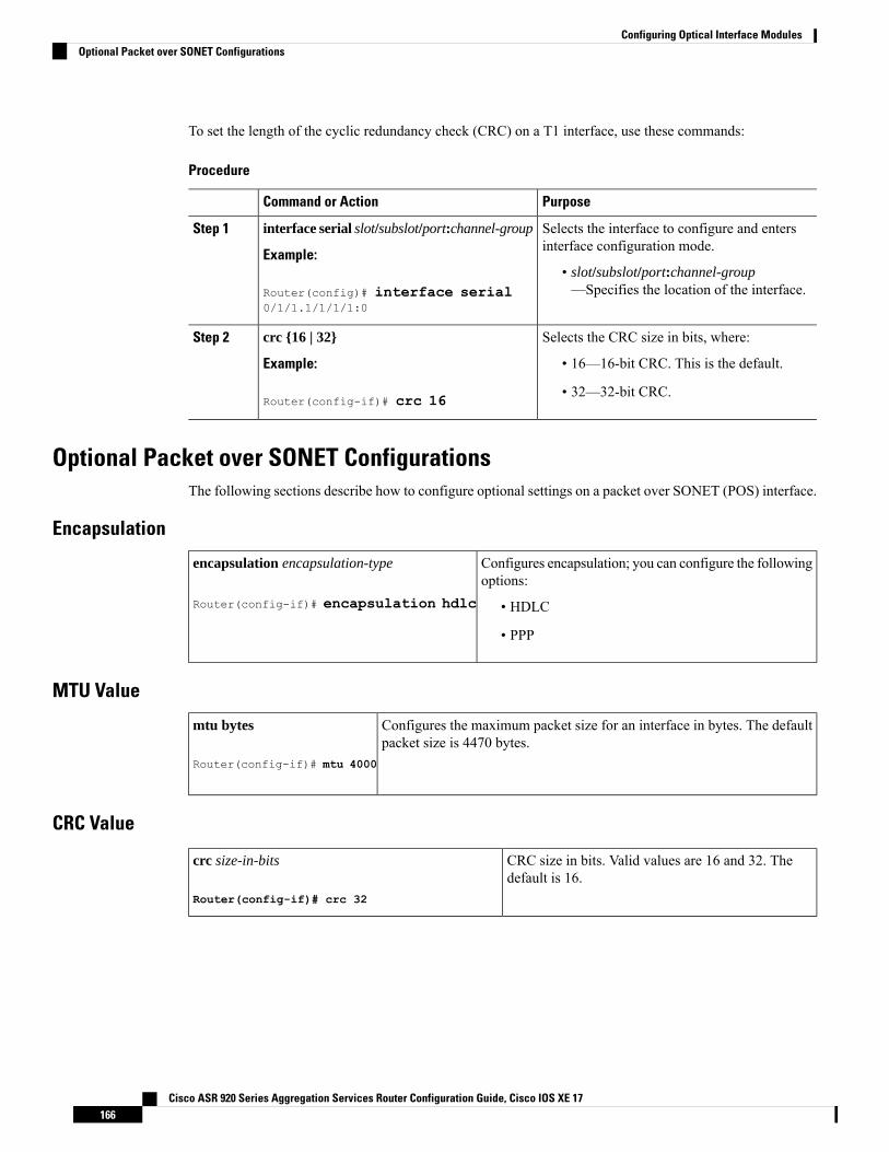
To set the length of the cyclic redundancy check (CRC) on a T1 interface, use these commands:
Procedure
PurposeCommand or Action
Selects the interface to configure and entersinterface configuration mode.
interface serial slot/subslot/port:channel-group
Example:
Step 1
• slot/subslot/port:channel-group—Specifies the location of the interface.Router(config)# interface serial
0/1/1.1/1/1/1:0
Selects the CRC size in bits, where:crc {16 | 32}Step 2
Example: • 16—16-bit CRC. This is the default.
Router(config-if)# crc 16 • 32—32-bit CRC.
Optional Packet over SONET ConfigurationsThe following sections describe how to configure optional settings on a packet over SONET (POS) interface.
Encapsulation
Configures encapsulation; you can configure the followingoptions:
• HDLC
• PPP
encapsulation encapsulation-type
Router(config-if)# encapsulation hdlc
MTU Value
Configures the maximum packet size for an interface in bytes. The defaultpacket size is 4470 bytes.
mtu bytes
Router(config-if)# mtu 4000
CRC Value
CRC size in bits. Valid values are 16 and 32. Thedefault is 16.
crc size-in-bits
Router(config-if)# crc 32
Cisco ASR 920 Series Aggregation Services Router Configuration Guide, Cisco IOS XE 17166
Configuring Optical Interface ModulesOptional Packet over SONET Configurations
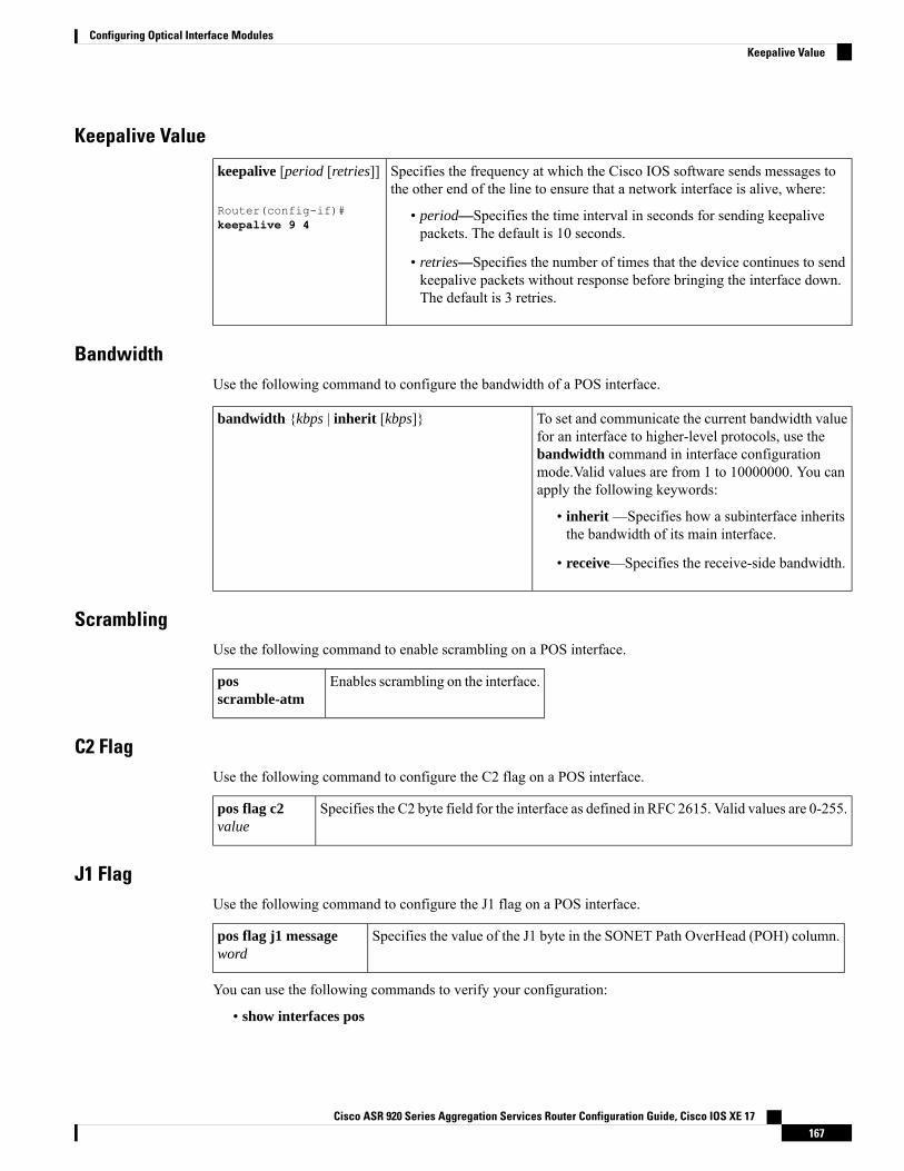
Keepalive Value
Specifies the frequency at which the Cisco IOS software sends messages tothe other end of the line to ensure that a network interface is alive, where:
• period—Specifies the time interval in seconds for sending keepalivepackets. The default is 10 seconds.
• retries—Specifies the number of times that the device continues to sendkeepalive packets without response before bringing the interface down.The default is 3 retries.
keepalive [period [retries]]
Router(config-if)#keepalive 9 4
BandwidthUse the following command to configure the bandwidth of a POS interface.
To set and communicate the current bandwidth valuefor an interface to higher-level protocols, use the
bandwidth {kbps | inherit [kbps]}
bandwidth command in interface configurationmode.Valid values are from 1 to 10000000. You canapply the following keywords:
• inherit —Specifies how a subinterface inheritsthe bandwidth of its main interface.
• receive—Specifies the receive-side bandwidth.
ScramblingUse the following command to enable scrambling on a POS interface.
Enables scrambling on the interface.posscramble-atm
C2 FlagUse the following command to configure the C2 flag on a POS interface.
Specifies the C2 byte field for the interface as defined in RFC 2615. Valid values are 0-255.pos flag c2value
J1 FlagUse the following command to configure the J1 flag on a POS interface.
Specifies the value of the J1 byte in the SONET Path OverHead (POH) column.pos flag j1 messageword
You can use the following commands to verify your configuration:
• show interfaces pos
Cisco ASR 920 Series Aggregation Services Router Configuration Guide, Cisco IOS XE 17167
Configuring Optical Interface ModulesKeepalive Value
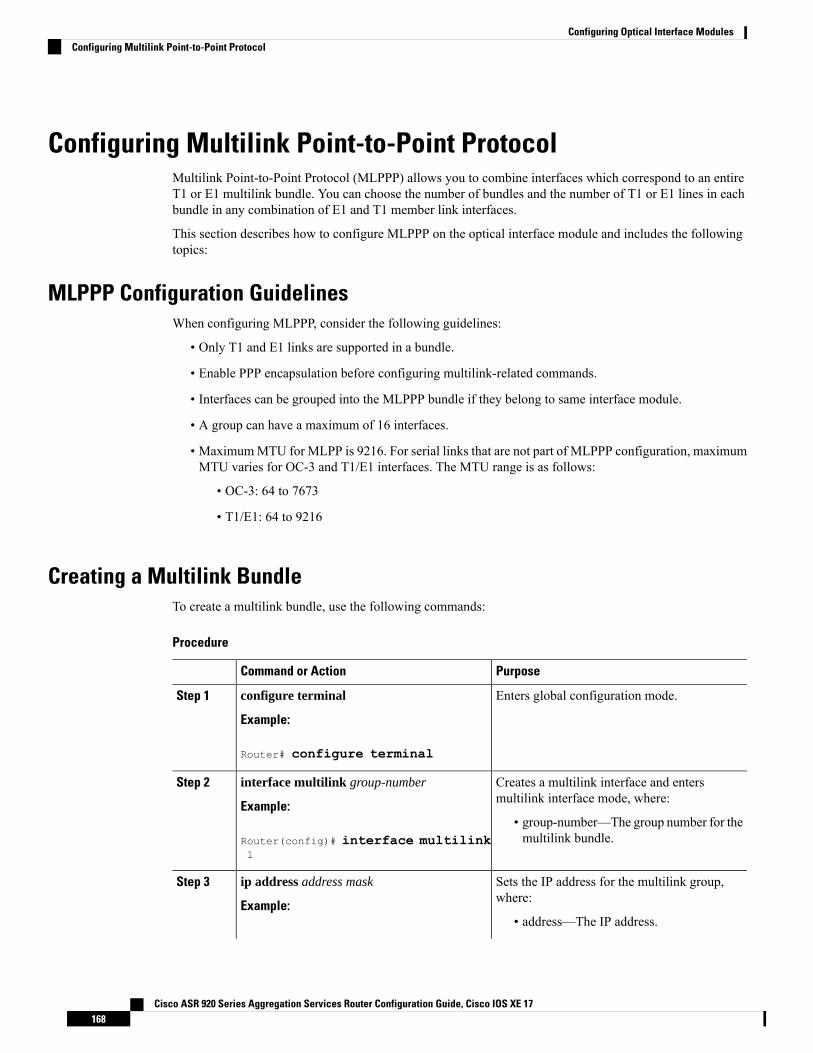
Configuring Multilink Point-to-Point ProtocolMultilink Point-to-Point Protocol (MLPPP) allows you to combine interfaces which correspond to an entireT1 or E1 multilink bundle. You can choose the number of bundles and the number of T1 or E1 lines in eachbundle in any combination of E1 and T1 member link interfaces.
This section describes how to configure MLPPP on the optical interface module and includes the followingtopics:
MLPPP Configuration GuidelinesWhen configuring MLPPP, consider the following guidelines:
• Only T1 and E1 links are supported in a bundle.
• Enable PPP encapsulation before configuring multilink-related commands.
• Interfaces can be grouped into the MLPPP bundle if they belong to same interface module.
• A group can have a maximum of 16 interfaces.
• MaximumMTU for MLPP is 9216. For serial links that are not part of MLPPP configuration, maximumMTU varies for OC-3 and T1/E1 interfaces. The MTU range is as follows:
• OC-3: 64 to 7673
• T1/E1: 64 to 9216
Creating a Multilink BundleTo create a multilink bundle, use the following commands:
Procedure
PurposeCommand or Action
Enters global configuration mode.configure terminal
Example:
Step 1
Router# configure terminal
Creates a multilink interface and entersmultilink interface mode, where:
interface multilink group-number
Example:
Step 2
• group-number—The group number for themultilink bundle.Router(config)# interface multilink
1
Sets the IP address for the multilink group,where:
ip address address mask
Example:
Step 3
• address—The IP address.
Cisco ASR 920 Series Aggregation Services Router Configuration Guide, Cisco IOS XE 17168
Configuring Optical Interface ModulesConfiguring Multilink Point-to-Point Protocol
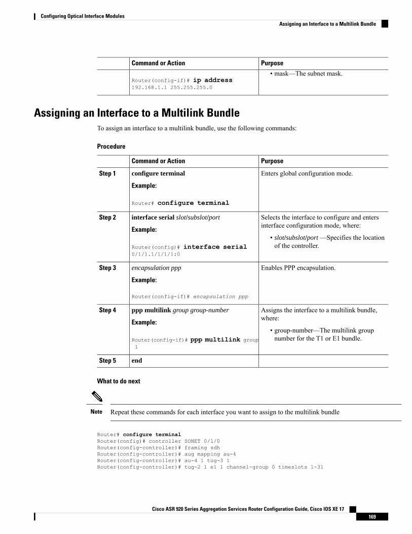
PurposeCommand or Action
Router(config-if)# ip address192.168.1.1 255.255.255.0
• mask—The subnet mask.
Assigning an Interface to a Multilink BundleTo assign an interface to a multilink bundle, use the following commands:
Procedure
PurposeCommand or Action
Enters global configuration mode.configure terminal
Example:
Step 1
Router# configure terminal
Selects the interface to configure and entersinterface configuration mode, where:
interface serial slot/subslot/port
Example:
Step 2
• slot/subslot/port —Specifies the locationof the controller.Router(config)# interface serial
0/1/1.1/1/1/1:0
Enables PPP encapsulation.encapsulation ppp
Example:
Step 3
Router(config-if)# encapsulation ppp
Assigns the interface to a multilink bundle,where:
ppp multilink group group-number
Example:
Step 4
• group-number—The multilink groupnumber for the T1 or E1 bundle.Router(config-if)# ppp multilink group
1
endStep 5
What to do next
Repeat these commands for each interface you want to assign to the multilink bundleNote
Router# configure terminalRouter(config)# controller SONET 0/1/0Router(config-controller)# framing sdhRouter(config-controller)# aug mapping au-4Router(config-controller)# au-4 1 tug-3 1Router(config-controller)# tug-2 1 e1 1 channel-group 0 timeslots 1-31
Cisco ASR 920 Series Aggregation Services Router Configuration Guide, Cisco IOS XE 17169
Configuring Optical Interface ModulesAssigning an Interface to a Multilink Bundle
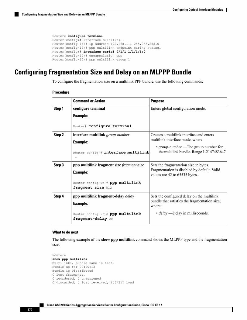
Router# configure terminalRouter(config)# interface multilink 1Router(config-if)# ip address 192.168.1.1 255.255.255.0Router(config-if)# ppp multilink endpoint string string1Router(config)# interface serial 0/1/1.1/1/1/1:0Router(config-if)# encapsulation pppRouter(config-if)# ppp multilink group 1
Configuring Fragmentation Size and Delay on an MLPPP BundleTo configure the fragmentation size on a multilink PPP bundle, use the following commands:
Procedure
PurposeCommand or Action
Enters global configuration mode.configure terminal
Example:
Step 1
Router# configure terminal
Creates a multilink interface and entersmultilink interface mode, where:
interface multilink group-number
Example:
Step 2
• group-number —The group number forthemultilink bundle. Range 1-2147483647Router(config)# interface multilink
1
Sets the fragmentation size in bytes.Fragmentation is disabled by default. Validvalues are 42 to 65535 bytes.
ppp multilink fragment size fragment-size
Example:
Router(config-if)# ppp multilinkfragment size 512
Step 3
Sets the configured delay on the multilinkbundle that satisfies the fragmentation size,where:
ppp multilink fragment-delay delay
Example:
Router(config-if)# ppp multilinkfragment-delay 20
Step 4
• delay —Delay in milliseconds.
What to do next
The following example of the show ppp multilink command shows the MLPPP type and the fragmentationsize:
Router#show ppp multilinkMultilink1, bundle name is test2Bundle up for 00:00:13Bundle is Distributed0 lost fragments,0 reordered, 0 unassigned0 discarded, 0 lost received, 206/255 load
Cisco ASR 920 Series Aggregation Services Router Configuration Guide, Cisco IOS XE 17170
Configuring Optical Interface ModulesConfiguring Fragmentation Size and Delay on an MLPPP Bundle
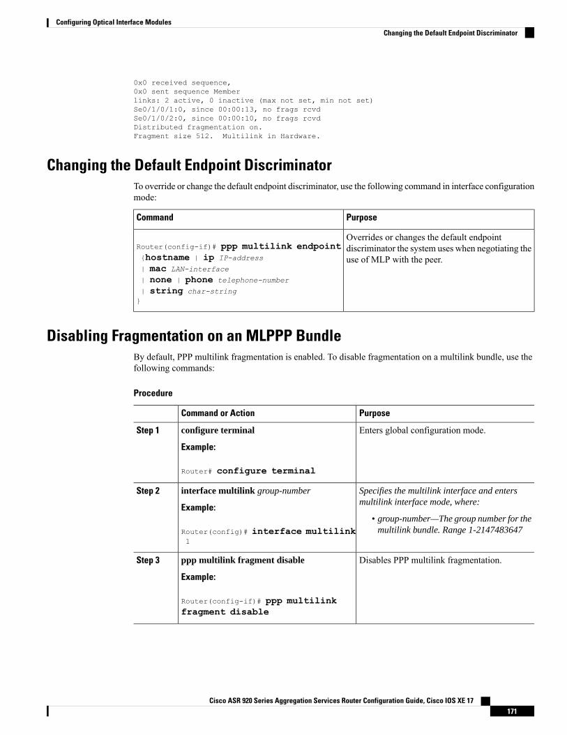
0x0 received sequence,0x0 sent sequence Memberlinks: 2 active, 0 inactive (max not set, min not set)Se0/1/0/1:0, since 00:00:13, no frags rcvdSe0/1/0/2:0, since 00:00:10, no frags rcvdDistributed fragmentation on.Fragment size 512. Multilink in Hardware.
Changing the Default Endpoint DiscriminatorTo override or change the default endpoint discriminator, use the following command in interface configurationmode:
PurposeCommand
Overrides or changes the default endpointdiscriminator the system uses when negotiating theuse of MLP with the peer.
Router(config-if)# ppp multilink endpoint{hostname | ip IP-address
| mac LAN-interface
| none | phone telephone-number
| string char-string}
Disabling Fragmentation on an MLPPP BundleBy default, PPP multilink fragmentation is enabled. To disable fragmentation on a multilink bundle, use thefollowing commands:
Procedure
PurposeCommand or Action
Enters global configuration mode.configure terminal
Example:
Step 1
Router# configure terminal
Specifies the multilink interface and entersmultilink interface mode, where:
interface multilink group-number
Example:
Step 2
• group-number—The group number for themultilink bundle. Range 1-2147483647Router(config)# interface multilink
1
Disables PPP multilink fragmentation.ppp multilink fragment disable
Example:
Step 3
Router(config-if)# ppp multilinkfragment disable
Cisco ASR 920 Series Aggregation Services Router Configuration Guide, Cisco IOS XE 17171
Configuring Optical Interface ModulesChanging the Default Endpoint Discriminator
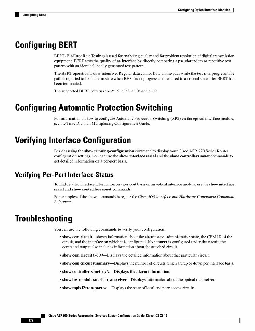
Configuring BERTBERT (Bit-Error Rate Testing) is used for analyzing quality and for problem resolution of digital transmissionequipment. BERT tests the quality of an interface by directly comparing a pseudorandom or repetitive testpattern with an identical locally generated test pattern.
The BERT operation is data-intensive. Regular data cannot flow on the path while the test is in progress. Thepath is reported to be in alarm state when BERT is in progress and restored to a normal state after BERT hasbeen terminated.
The supported BERT patterns are 2^15, 2^23, all 0s and all 1s.
Configuring Automatic Protection SwitchingFor information on how to configure Automatic Protection Switching (APS) on the optical interface module,see the Time Division Multiplexing Configuration Guide.
Verifying Interface ConfigurationBesides using the show running-configuration command to display your Cisco ASR 920 Series Routerconfiguration settings, you can use the show interface serial and the show controllers sonet commands toget detailed information on a per-port basis.
Verifying Per-Port Interface StatusTo find detailed interface information on a per-port basis on an optical interface module, use the show interfaceserial and show controllers sonet commands.
For examples of the show commands here, see the Cisco IOS Interface and Hardware Component CommandReference .
TroubleshootingYou can use the following commands to verify your configuration:
• show cem circuit—shows information about the circuit state, administrative state, the CEM ID of thecircuit, and the interface on which it is configured. If xconnect is configured under the circuit, thecommand output also includes information about the attached circuit.
• show cem circuit 0-504—Displays the detailed information about that particular circuit.
• show cem circuit summary—Displays the number of circuits which are up or down per interface basis.
• show controller sonet x/y/z—Displays the alarm information.
• show hw-module subslot transceiver—Displays information about the optical transceiver.
• show mpls l2transport vc—Displays the state of local and peer access circuits.
Cisco ASR 920 Series Aggregation Services Router Configuration Guide, Cisco IOS XE 17172
Configuring Optical Interface ModulesConfiguring BERT
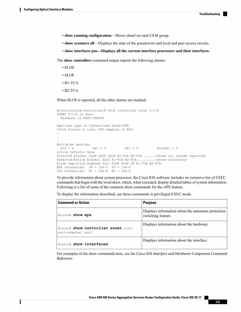
• show running configuration—Shows detail on each CEM group.
• show xconnect all—Displays the state of the pseudowire and local and peer access circuits.
• show interfaces pos—Displays all the current interface processors and their interfaces.
The show controllers command output reports the following alarms:
• SLOS
• SLOF
• B1-TCA
• B2-TCA
When SLOS is reported, all the other alarms are masked.
Router(config-controller)# show controller sonet 0/1/2SONET 0/1/2 is down.Hardware is A900-IMA4OS
Applique type is Channelized Sonet/SDHClock Source is Line, AUG mapping is AU4....Multiplex Section:AIS = 6 RDI = 0 REI = 0 BIP(B2) = 0
Active Defects: NoneDetected Alarms: SLOS SLOF LAIS B1-TCA B2-TCA ......<shows all alarms reported>Asserted/Active Alarms: SLOS B1-TCA B2-TCA..........<shows hierarchy>Alarm reporting enabled for: SLOS SLOF SF B1-TCA B2-TCABER thresholds: SF = 10e-3 SD = 10e-6TCA thresholds: B1 = 10e-6 B2 = 10e-6
To provide information about system processes, the Cisco IOS software includes an extensive list of EXECcommands that begin with the word show, which, when executed, display detailed tables of system information.Following is a list of some of the common show commands for the APS feature.
To display the information described, use these commands in privileged EXEC mode.
PurposeCommand or Action
Displays information about the automatic protectionswitching feature.Router# show aps
Displays information about the hardware.Router# show controller sonet slot/port-adapter/ port
Displays information about the interface.Router# show interfaces
For examples of the show commands here, see the Cisco IOS Interface and Hardware Component CommandReference.
Cisco ASR 920 Series Aggregation Services Router Configuration Guide, Cisco IOS XE 17173
Configuring Optical Interface ModulesTroubleshooting
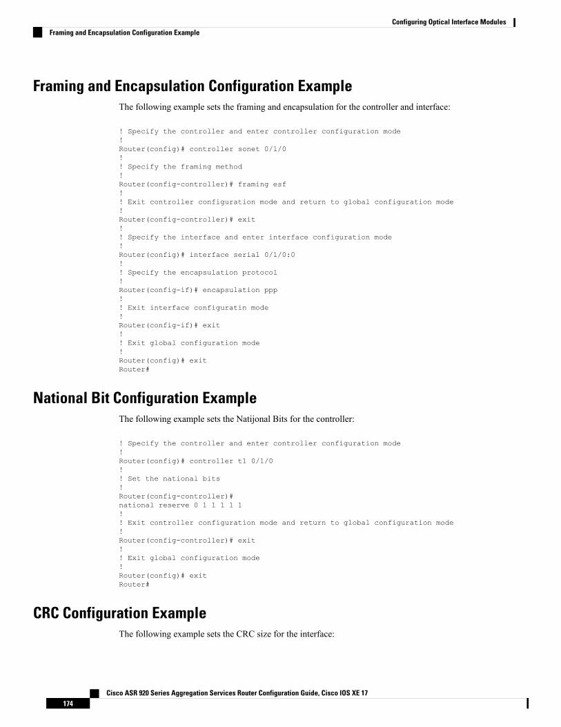
Framing and Encapsulation Configuration ExampleThe following example sets the framing and encapsulation for the controller and interface:
! Specify the controller and enter controller configuration mode!Router(config)# controller sonet 0/1/0!! Specify the framing method!Router(config-controller)# framing esf!! Exit controller configuration mode and return to global configuration mode!Router(config-controller)# exit!! Specify the interface and enter interface configuration mode!Router(config)# interface serial 0/1/0:0!! Specify the encapsulation protocol!Router(config-if)# encapsulation ppp!! Exit interface configuratin mode!Router(config-if)# exit!! Exit global configuration mode!Router(config)# exitRouter#
National Bit Configuration ExampleThe following example sets the Natijonal Bits for the controller:
! Specify the controller and enter controller configuration mode!Router(config)# controller t1 0/1/0!! Set the national bits!Router(config-controller)#national reserve 0 1 1 1 1 1!! Exit controller configuration mode and return to global configuration mode!Router(config-controller)# exit!! Exit global configuration mode!Router(config)# exitRouter#
CRC Configuration ExampleThe following example sets the CRC size for the interface:
Cisco ASR 920 Series Aggregation Services Router Configuration Guide, Cisco IOS XE 17174
Configuring Optical Interface ModulesFraming and Encapsulation Configuration Example
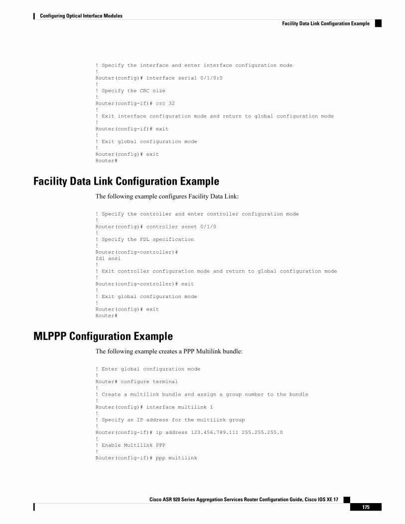
! Specify the interface and enter interface configuration mode!Router(config)# interface serial 0/1/0:0!! Specify the CRC size!Router(config-if)# crc 32!! Exit interface configuration mode and return to global configuration mode!Router(config-if)# exit!! Exit global configuration mode!Router(config)# exitRouter#
Facility Data Link Configuration ExampleThe following example configures Facility Data Link:
! Specify the controller and enter controller configuration mode!Router(config)# controller sonet 0/1/0!! Specify the FDL specification!Router(config-controller)#fdl ansi!! Exit controller configuration mode and return to global configuration mode!Router(config-controller)# exit!! Exit global configuration mode!Router(config)# exitRouter#
MLPPP Configuration ExampleThe following example creates a PPP Multilink bundle:
! Enter global configuration mode!Router# configure terminal!! Create a multilink bundle and assign a group number to the bundle!Router(config)# interface multilink 1!! Specify an IP address for the multilink group!Router(config-if)# ip address 123.456.789.111 255.255.255.0!! Enable Multilink PPP!Router(config-if)# ppp multilink
Cisco ASR 920 Series Aggregation Services Router Configuration Guide, Cisco IOS XE 17175
Configuring Optical Interface ModulesFacility Data Link Configuration Example
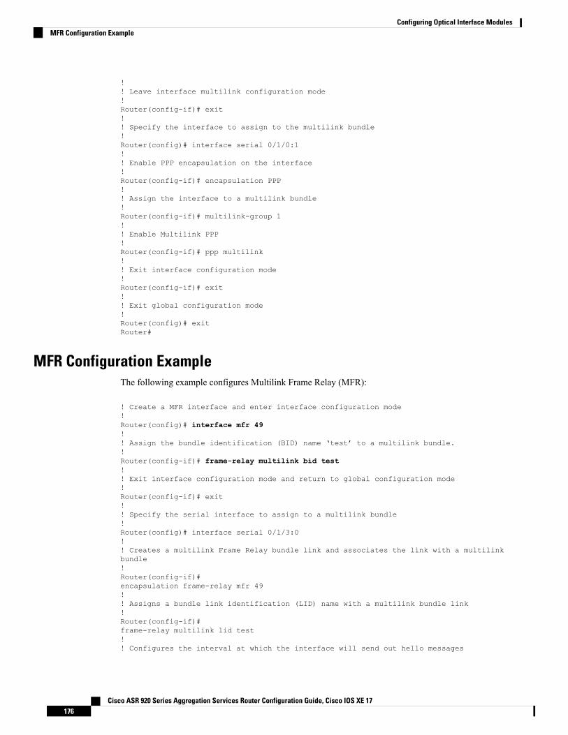
!! Leave interface multilink configuration mode!Router(config-if)# exit!! Specify the interface to assign to the multilink bundle!Router(config)# interface serial 0/1/0:1!! Enable PPP encapsulation on the interface!Router(config-if)# encapsulation PPP!! Assign the interface to a multilink bundle!Router(config-if)# multilink-group 1!! Enable Multilink PPP!Router(config-if)# ppp multilink!! Exit interface configuration mode!Router(config-if)# exit!! Exit global configuration mode!Router(config)# exitRouter#
MFR Configuration ExampleThe following example configures Multilink Frame Relay (MFR):
! Create a MFR interface and enter interface configuration mode!Router(config)# interface mfr 49!! Assign the bundle identification (BID) name ‘test’ to a multilink bundle.!Router(config-if)# frame-relay multilink bid test!! Exit interface configuration mode and return to global configuration mode!Router(config-if)# exit!! Specify the serial interface to assign to a multilink bundle!Router(config)# interface serial 0/1/3:0!! Creates a multilink Frame Relay bundle link and associates the link with a multilinkbundle!Router(config-if)#encapsulation frame-relay mfr 49!! Assigns a bundle link identification (LID) name with a multilink bundle link!Router(config-if)#frame-relay multilink lid test!! Configures the interval at which the interface will send out hello messages
Cisco ASR 920 Series Aggregation Services Router Configuration Guide, Cisco IOS XE 17176
Configuring Optical Interface ModulesMFR Configuration Example
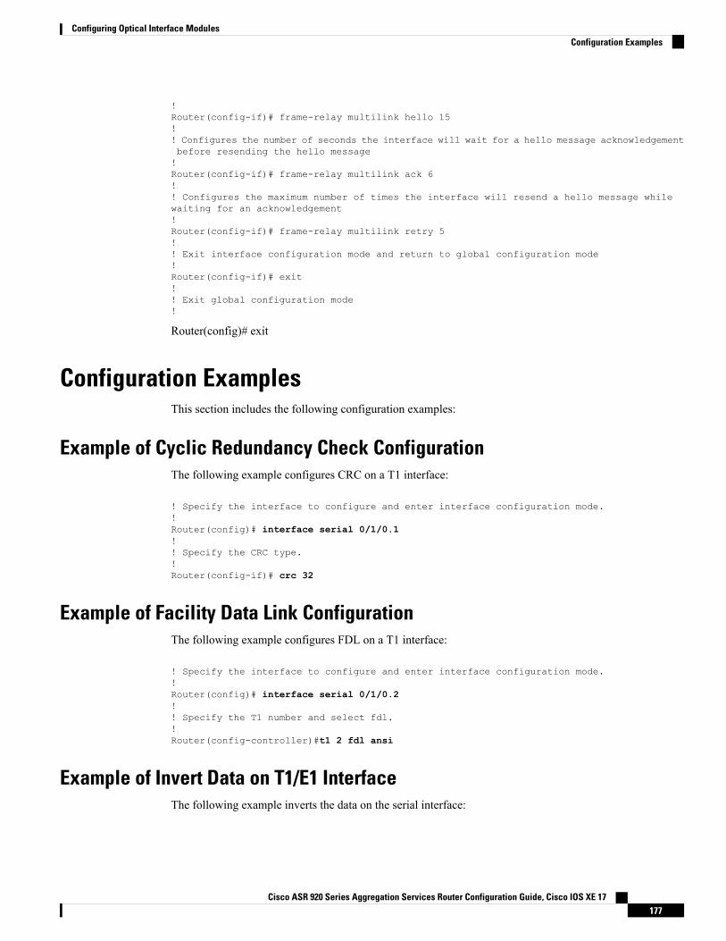
!Router(config-if)# frame-relay multilink hello 15!! Configures the number of seconds the interface will wait for a hello message acknowledgementbefore resending the hello message!Router(config-if)# frame-relay multilink ack 6!! Configures the maximum number of times the interface will resend a hello message whilewaiting for an acknowledgement!Router(config-if)# frame-relay multilink retry 5!! Exit interface configuration mode and return to global configuration mode!Router(config-if)# exit!! Exit global configuration mode!
Router(config)# exit
Configuration ExamplesThis section includes the following configuration examples:
Example of Cyclic Redundancy Check ConfigurationThe following example configures CRC on a T1 interface:
! Specify the interface to configure and enter interface configuration mode.!Router(config)# interface serial 0/1/0.1!! Specify the CRC type.!Router(config-if)# crc 32
Example of Facility Data Link ConfigurationThe following example configures FDL on a T1 interface:
! Specify the interface to configure and enter interface configuration mode.!Router(config)# interface serial 0/1/0.2!! Specify the T1 number and select fdl.!Router(config-controller)#t1 2 fdl ansi
Example of Invert Data on T1/E1 InterfaceThe following example inverts the data on the serial interface:
Cisco ASR 920 Series Aggregation Services Router Configuration Guide, Cisco IOS XE 17177
Configuring Optical Interface ModulesConfiguration Examples
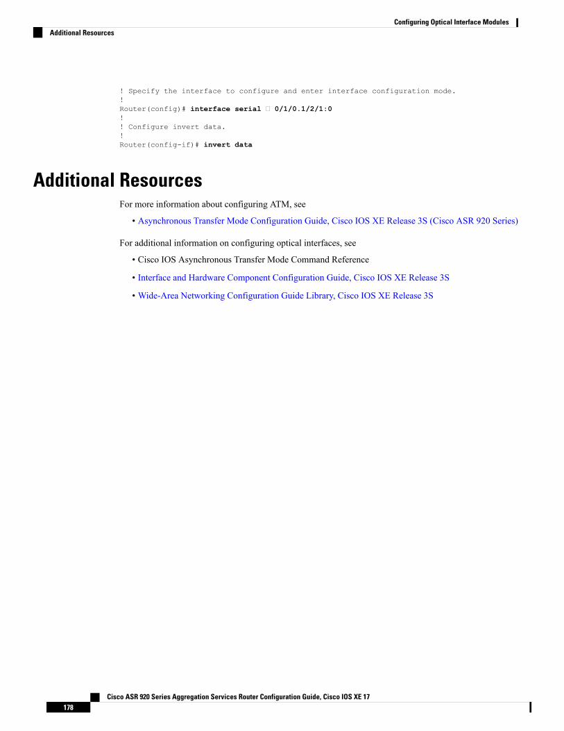
! Specify the interface to configure and enter interface configuration mode.!Router(config)# interface serial 0/1/0.1/2/1:0!! Configure invert data.!Router(config-if)# invert data
Additional ResourcesFor more information about configuring ATM, see
• Asynchronous Transfer Mode Configuration Guide, Cisco IOS XE Release 3S (Cisco ASR 920 Series)
For additional information on configuring optical interfaces, see
• Cisco IOS Asynchronous Transfer Mode Command Reference
• Interface and Hardware Component Configuration Guide, Cisco IOS XE Release 3S
• Wide-Area Networking Configuration Guide Library, Cisco IOS XE Release 3S
Cisco ASR 920 Series Aggregation Services Router Configuration Guide, Cisco IOS XE 17178
Configuring Optical Interface ModulesAdditional Resources

C H A P T E R 16Dying Gasp Support for Loss of Power SupplyThrough SNMP, Syslog and Ethernet OAM
Dying Gasp — One of the following unrecoverable condition has occurred:
• Power failure or removal of power supply cable
This type of condition is vendor specific. An Ethernet Operations, Administration, and Maintenance (OAM)notification about the condition may be sent immediately.
This document describes the Dying Gasp feature which is used to send dying gasp messsages through SNMP,syslog, or Ethernet Operation, Administration, and Maintenance (OAM) to report the abrupt loss of power tothe host platform.
The SNMP server for the SNMPDying-Gaspmessage is specified through the snmp-server host configurationcommand. The Ethernet-OAMDying-Gasp packets are created for interfaces where Ethernet-OAM is enabled.
Table 14: Feature History
Feature DescriptionRelease InformationFeature Name
This feature enables FPGA based effective spaceutilization between Ethernet OAM and SNMP. Usetheplatform-oam-snmp-dg-enable commandon Cisco router to configure this feature.
Cisco IOS XE Bengaluru17.5.1
SNMP Dying GaspEnhancement
• Prerequisites for Dying Gasp Support, on page 180• Restrictions for Dying Gasp Support, on page 180• Configuring SNMP Dying Gasp, on page 181• Example: Configuring SNMP Community Strings on a Router, on page 182• Example: Configuring SNMP-Server Host Details on the Router Console, on page 182• Dying Gasp Trap Support for Different SNMP Server Host/Port Configurations, on page 183• Message Displayed on the Peer Router on Receiving Dying Gasp Notification, on page 184• Displaying SNMP Configuration for Receiving Dying Gasp Notification, on page 184
Cisco ASR 920 Series Aggregation Services Router Configuration Guide, Cisco IOS XE 17179
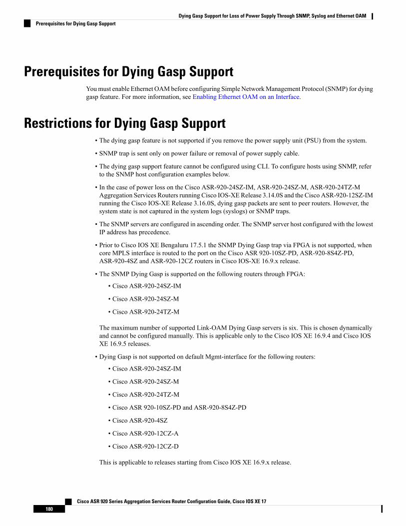
Prerequisites for Dying Gasp SupportYoumust enable Ethernet OAMbefore configuring Simple NetworkManagement Protocol (SNMP) for dyinggasp feature. For more information, see Enabling Ethernet OAM on an Interface.
Restrictions for Dying Gasp Support• The dying gasp feature is not supported if you remove the power supply unit (PSU) from the system.
• SNMP trap is sent only on power failure or removal of power supply cable.
• The dying gasp support feature cannot be configured using CLI. To configure hosts using SNMP, referto the SNMP host configuration examples below.
• In the case of power loss on the Cisco ASR-920-24SZ-IM, ASR-920-24SZ-M, ASR-920-24TZ-MAggregation Services Routers running Cisco IOS-XE Release 3.14.0S and the Cisco ASR-920-12SZ-IMrunning the Cisco IOS-XE Release 3.16.0S, dying gasp packets are sent to peer routers. However, thesystem state is not captured in the system logs (syslogs) or SNMP traps.
• The SNMP servers are configured in ascending order. The SNMP server host configured with the lowestIP address has precedence.
• Prior to Cisco IOS XE Bengaluru 17.5.1 the SNMP Dying Gasp trap via FPGA is not supported, whencore MPLS interface is routed to the port on the Cisco ASR 920-10SZ-PD, ASR-920-8S4Z-PD,ASR-920-4SZ and ASR-920-12CZ routers in Cisco IOS-XE 16.9.x release.
• The SNMP Dying Gasp is supported on the following routers through FPGA:
• Cisco ASR-920-24SZ-IM
• Cisco ASR-920-24SZ-M
• Cisco ASR-920-24TZ-M
The maximum number of supported Link-OAM Dying Gasp servers is six. This is chosen dynamicallyand cannot be configured manually. This is applicable only to the Cisco IOS XE 16.9.4 and Cisco IOSXE 16.9.5 releases.
• Dying Gasp is not supported on default Mgmt-interface for the following routers:
• Cisco ASR-920-24SZ-IM
• Cisco ASR-920-24SZ-M
• Cisco ASR-920-24TZ-M
• Cisco ASR 920-10SZ-PD and ASR-920-8S4Z-PD
• Cisco ASR-920-4SZ
• Cisco ASR-920-12CZ-A
• Cisco ASR-920-12CZ-D
This is applicable to releases starting from Cisco IOS XE 16.9.x release.
Cisco ASR 920 Series Aggregation Services Router Configuration Guide, Cisco IOS XE 17180
Dying Gasp Support for Loss of Power Supply Through SNMP, Syslog and Ethernet OAMPrerequisites for Dying Gasp Support
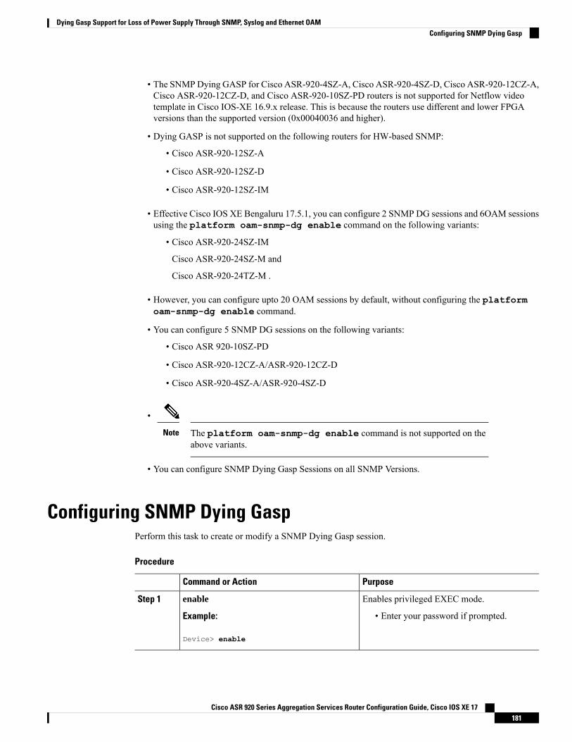
• The SNMPDying GASP for Cisco ASR-920-4SZ-A, Cisco ASR-920-4SZ-D, Cisco ASR-920-12CZ-A,Cisco ASR-920-12CZ-D, and Cisco ASR-920-10SZ-PD routers is not supported for Netflow videotemplate in Cisco IOS-XE 16.9.x release. This is because the routers use different and lower FPGAversions than the supported version (0x00040036 and higher).
• Dying GASP is not supported on the following routers for HW-based SNMP:
• Cisco ASR-920-12SZ-A
• Cisco ASR-920-12SZ-D
• Cisco ASR-920-12SZ-IM
• Effective Cisco IOS XE Bengaluru 17.5.1, you can configure 2 SNMP DG sessions and 6OAM sessionsusing the platform oam-snmp-dg enable command on the following variants:
• Cisco ASR-920-24SZ-IM
Cisco ASR-920-24SZ-M and
Cisco ASR-920-24TZ-M .
• However, you can configure upto 20 OAM sessions by default, without configuring the platformoam-snmp-dg enable command.
• You can configure 5 SNMP DG sessions on the following variants:
• Cisco ASR 920-10SZ-PD
• Cisco ASR-920-12CZ-A/ASR-920-12CZ-D
• Cisco ASR-920-4SZ-A/ASR-920-4SZ-D
•
The platform oam-snmp-dg enable command is not supported on theabove variants.
Note
• You can configure SNMP Dying Gasp Sessions on all SNMP Versions.
Configuring SNMP Dying GaspPerform this task to create or modify a SNMP Dying Gasp session.
Procedure
PurposeCommand or Action
Enables privileged EXEC mode.enableStep 1
Example: • Enter your password if prompted.
Device> enable
Cisco ASR 920 Series Aggregation Services Router Configuration Guide, Cisco IOS XE 17181
Dying Gasp Support for Loss of Power Supply Through SNMP, Syslog and Ethernet OAMConfiguring SNMP Dying Gasp
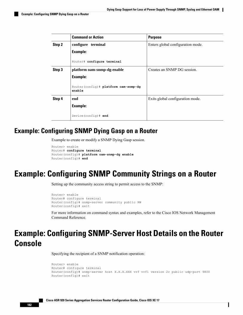
PurposeCommand or Action
Enters global configuration mode.configure terminal
Example:
Step 2
Router# configure terminal
Creates an SNMP DG session.platform oam-snmp-dg-enable
Example:
Step 3
Router(config)# platform oam-snmp-dgenable
Exits global configuration mode.end
Example:
Step 4
Device(config)# end
Example: Configuring SNMP Dying Gasp on a RouterExample to create or modify a SNMP Dying Gasp session.Router> enableRouter# configure terminalRouter(config)# platform oam-snmp-dg enableRouter(config)# end
Example: Configuring SNMP Community Strings on a RouterSetting up the community access string to permit access to the SNMP:
Router> enableRouter# configure terminalRouter(config)# snmp-server community public RWRouter(config)# exit
For more information on command syntax and examples, refer to the Cisco IOS Network ManagementCommand Reference.
Example: Configuring SNMP-Server Host Details on the RouterConsole
Specifying the recipient of a SNMP notification operation:
Router> enableRouter# configure terminalRouter(config)# snmp-server host X.X.X.XXX vrf vrf1 version 2c public udp-port 9800Router(config)# exit
Cisco ASR 920 Series Aggregation Services Router Configuration Guide, Cisco IOS XE 17182
Dying Gasp Support for Loss of Power Supply Through SNMP, Syslog and Ethernet OAMExample: Configuring SNMP Dying Gasp on a Router
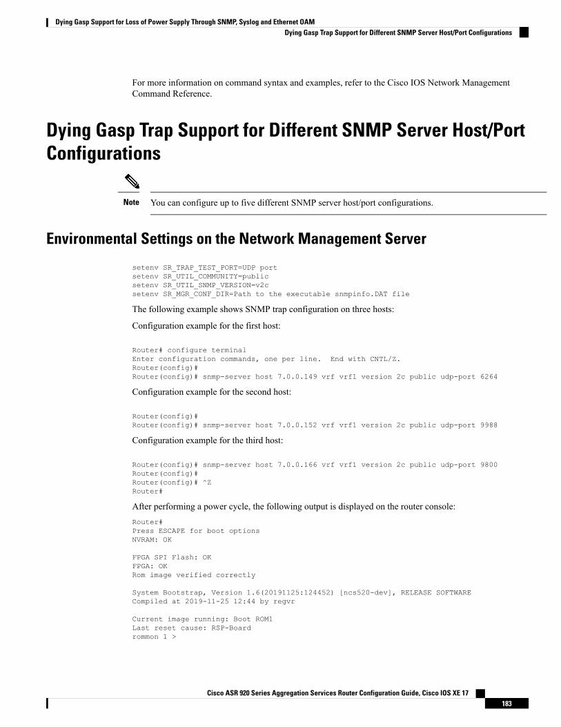
For more information on command syntax and examples, refer to the Cisco IOS Network ManagementCommand Reference.
Dying Gasp Trap Support for Different SNMP Server Host/PortConfigurations
You can configure up to five different SNMP server host/port configurations.Note
Environmental Settings on the Network Management Server
setenv SR_TRAP_TEST_PORT=UDP portsetenv SR_UTIL_COMMUNITY=publicsetenv SR_UTIL_SNMP_VERSION=v2csetenv SR_MGR_CONF_DIR=Path to the executable snmpinfo.DAT file
The following example shows SNMP trap configuration on three hosts:
Configuration example for the first host:
Router# configure terminalEnter configuration commands, one per line. End with CNTL/Z.Router(config)#Router(config)# snmp-server host 7.0.0.149 vrf vrf1 version 2c public udp-port 6264
Configuration example for the second host:
Router(config)#Router(config)# snmp-server host 7.0.0.152 vrf vrf1 version 2c public udp-port 9988
Configuration example for the third host:
Router(config)# snmp-server host 7.0.0.166 vrf vrf1 version 2c public udp-port 9800Router(config)#Router(config)# ^ZRouter#
After performing a power cycle, the following output is displayed on the router console:Router#Press ESCAPE for boot optionsNVRAM: OK
FPGA SPI Flash: OKFPGA: OKRom image verified correctly
System Bootstrap, Version 1.6(20191125:124452) [ncs520-dev], RELEASE SOFTWARECompiled at 2019-11-25 12:44 by regvr
Current image running: Boot ROM1Last reset cause: RSP-Boardrommon 1 >
Cisco ASR 920 Series Aggregation Services Router Configuration Guide, Cisco IOS XE 17183
Dying Gasp Support for Loss of Power Supply Through SNMP, Syslog and Ethernet OAMDying Gasp Trap Support for Different SNMP Server Host/Port Configurations
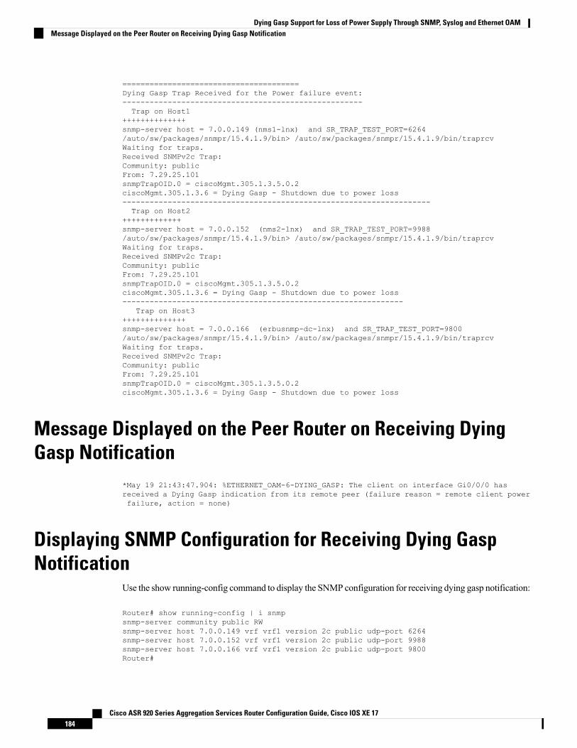
=======================================Dying Gasp Trap Received for the Power failure event:-----------------------------------------------------Trap on Host1
++++++++++++++snmp-server host = 7.0.0.149 (nms1-lnx) and SR_TRAP_TEST_PORT=6264/auto/sw/packages/snmpr/15.4.1.9/bin> /auto/sw/packages/snmpr/15.4.1.9/bin/traprcvWaiting for traps.Received SNMPv2c Trap:Community: publicFrom: 7.29.25.101snmpTrapOID.0 = ciscoMgmt.305.1.3.5.0.2ciscoMgmt.305.1.3.6 = Dying Gasp - Shutdown due to power loss--------------------------------------------------------------------Trap on Host2
+++++++++++++snmp-server host = 7.0.0.152 (nms2-lnx) and SR_TRAP_TEST_PORT=9988/auto/sw/packages/snmpr/15.4.1.9/bin> /auto/sw/packages/snmpr/15.4.1.9/bin/traprcvWaiting for traps.Received SNMPv2c Trap:Community: publicFrom: 7.29.25.101snmpTrapOID.0 = ciscoMgmt.305.1.3.5.0.2ciscoMgmt.305.1.3.6 = Dying Gasp - Shutdown due to power loss--------------------------------------------------------------
Trap on Host3++++++++++++++snmp-server host = 7.0.0.166 (erbusnmp-dc-lnx) and SR_TRAP_TEST_PORT=9800/auto/sw/packages/snmpr/15.4.1.9/bin> /auto/sw/packages/snmpr/15.4.1.9/bin/traprcvWaiting for traps.Received SNMPv2c Trap:Community: publicFrom: 7.29.25.101snmpTrapOID.0 = ciscoMgmt.305.1.3.5.0.2ciscoMgmt.305.1.3.6 = Dying Gasp - Shutdown due to power loss
Message Displayed on the Peer Router on Receiving DyingGasp Notification
*May 19 21:43:47.904: %ETHERNET_OAM-6-DYING_GASP: The client on interface Gi0/0/0 hasreceived a Dying Gasp indication from its remote peer (failure reason = remote client powerfailure, action = none)
Displaying SNMP Configuration for Receiving Dying GaspNotification
Use the show running-config command to display the SNMP configuration for receiving dying gasp notification:
Router# show running-config | i snmpsnmp-server community public RWsnmp-server host 7.0.0.149 vrf vrf1 version 2c public udp-port 6264snmp-server host 7.0.0.152 vrf vrf1 version 2c public udp-port 9988snmp-server host 7.0.0.166 vrf vrf1 version 2c public udp-port 9800Router#
Cisco ASR 920 Series Aggregation Services Router Configuration Guide, Cisco IOS XE 17184
Dying Gasp Support for Loss of Power Supply Through SNMP, Syslog and Ethernet OAMMessage Displayed on the Peer Router on Receiving Dying Gasp Notification
C H A P T E R 17Configuring Pseudowire
This chapter provides information about configuring pseudowire features on the Cisco ASR 920 Series Router.
• Pseudowire Overview, on page 185• CEM Configuration, on page 186• CEM Configuration Guidelines and Restrictions, on page 186• Configuring a CEM Group, on page 187• Using CEM Classes , on page 188• Configuring CEM Parameters, on page 189• Configuring Structure-Agnostic TDM over Packet (SAToP), on page 190• Configuring Circuit Emulation Service over Packet-Switched Network (CESoPSN), on page 192• Configuring an Ethernet over MPLS Pseudowire, on page 193• Configuring Pseudowire Redundancy, on page 195• Sample Configurations, on page 196
Pseudowire OverviewEffective Cisco IOS-XE Release 3.18S:
• BGP PIC with TDM Pseudowire is supported on the ASR 920 routers with RSP2 modules.• BGP PIC for Pseudowires, with MPLS Traffic Engineering is supported on the ASR 920 router withRSP2 modules.
The following sections provide an overview of pseudowire support on the Cisco ASR 920 Series Router.
LimitationsIf you are running Cisco IOS-XE Release 3.17S and later releases, the following limitations apply:
• Channel associated signaling (CAS) is not supported on the T1/E1 and OC-3 interface modules.• BGP PIC is not supported for MPLS/LDP over MLPPP and POS in the core.• BGP PIC is not supported for Multi-segment Pseudowire or Pseudowire switching.• BGP PIC is not supported for VPLS and H-VPLS.• BGP PIC is not supported for IPv6.• If BGP PIC is enabled, Multi-hop BFD should not be configured using the bfd neighbor fall-over bfdcommand.
Cisco ASR 920 Series Aggregation Services Router Configuration Guide, Cisco IOS XE 17185
• If BGP PIC is enabled, neighbor ip-address weight weight command should not be configured.• If BGP PIC is enabled, bgp nexthop trigger delay 6 under the address-family ipv4 command and bgp
nexthop trigger delay 7 under the address-family vpnv4 command should be configured. For informationon the configuration examples for BGP PIC–TDM, see Example: BGP PICwith TDM-PWConfiguration.
• If BGP PIC is enabled and the targeted LDP for VPWS Xconnect services are established over BGP,perform the following tasks:
• Configure Pseudowire-class (pw-class) with encapsulation “mpls”.• Configure no status control-plane route-watch under the pw-class.• Associate the pw-class with the VPWS xconnect configurations.
If you are running Cisco IOS-XE 3.18S, the following restrictions apply for BGP PIC with MPLS TE forTDM Pseudowire:
• MPLS TE over MLPPP and POS in the core is not supported.• Co-existence of BGP PICwithMPLS Traffic Engineering Fast Reroute (MPLS TE FRR) is not supported.
Transportation of Service Using Ethernet over MPLSEthernet over MPLS (EoMPLS) PWs provide a tunneling mechanism for Ethernet traffic through anMPLS-enabled Layer 3 core network. EoMPLS PWs encapsulate Ethernet protocol data units (PDUs) insideMPLS packets and use label switching to forward them across an MPLS network. EoMPLS PWs are anevolutionary technology that allows you to migrate packet networks from legacy networks while providingtransport for legacy applications. EoMPLS PWs also simplify provisioning, since the provider edge equipmentonly requires Layer 2 connectivity to the connected customer edge (CE) equipment. The Cisco ASR 920Series Router implementation of EoMPLS PWs is compliant with the RFC 4447 and 4448 standards.
The Cisco ASR 920 Series Router supports VLAN rewriting on EoMPLS PWs. If the two networks usedifferent VLAN IDs, the router rewrites PW packets using the appropriate VLAN number for the local network.
For instructions on how to create an EoMPLS PW, see Configuring an Ethernet over MPLS Pseudowire.
CEM ConfigurationCEM provides a bridge between a time-division multiplexing (TDM) network and a packet network, such asMultiprotocol Label Switching (MPLS). The router encapsulates the TDM data in the MPLS packets andsends the data over a CEM pseudowire to the remote provider edge (PE) router. Thus, function as a physicalcommunication link across the packet network.
Steps for configuring CEM features are also included in the Configuring Structure-Agnostic TDM over Packet(SAToP) and Configuring Circuit Emulation Service over Packet-Switched Network (CESoPSN), on page192 sections.
Note
CEM Configuration Guidelines and RestrictionsNot all combinations of payload size and dejitter buffer size are supported. If you apply an incompatiblepayload size or dejitter buffer size configuration, the router rejects it and reverts to the previous configuration.
Cisco ASR 920 Series Aggregation Services Router Configuration Guide, Cisco IOS XE 17186
Configuring PseudowireTransportation of Service Using Ethernet over MPLS
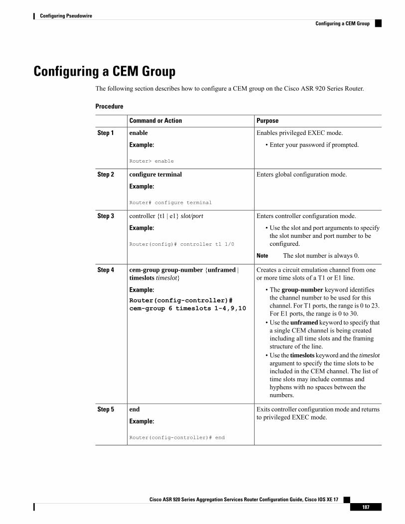
Configuring a CEM GroupThe following section describes how to configure a CEM group on the Cisco ASR 920 Series Router.
Procedure
PurposeCommand or Action
Enables privileged EXEC mode.enableStep 1
Example: • Enter your password if prompted.
Router> enable
Enters global configuration mode.configure terminal
Example:
Step 2
Router# configure terminal
Enters controller configuration mode.controller {t1 | e1} slot/portStep 3
Example: • Use the slot and port arguments to specifythe slot number and port number to beconfigured.Router(config)# controller t1 1/0
The slot number is always 0.Note
Creates a circuit emulation channel from oneor more time slots of a T1 or E1 line.
cem-group group-number {unframed |timeslots timeslot}
Step 4
Example: • The group-number keyword identifiesthe channel number to be used for thisRouter(config-controller)#
cem-group 6 timeslots 1-4,9,10 channel. For T1 ports, the range is 0 to 23.For E1 ports, the range is 0 to 30.
• Use the unframed keyword to specify thata single CEM channel is being createdincluding all time slots and the framingstructure of the line.
• Use the timeslots keyword and the timeslotargument to specify the time slots to beincluded in the CEM channel. The list oftime slots may include commas andhyphens with no spaces between thenumbers.
Exits controller configuration mode and returnsto privileged EXEC mode.
end
Example:
Step 5
Router(config-controller)# end
Cisco ASR 920 Series Aggregation Services Router Configuration Guide, Cisco IOS XE 17187
Configuring PseudowireConfiguring a CEM Group
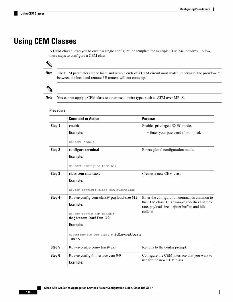
Using CEM ClassesA CEM class allows you to create a single configuration template for multiple CEM pseudowires. Followthese steps to configure a CEM class:
The CEM parameters at the local and remote ends of a CEM circuit must match; otherwise, the pseudowirebetween the local and remote PE routers will not come up.
Note
You cannot apply a CEM class to other pseudowire types such as ATM over MPLS.Note
Procedure
PurposeCommand or Action
Enables privileged EXEC mode.enableStep 1
Example: • Enter your password if prompted.
Router> enable
Enters global configuration mode.configure terminal
Example:
Step 2
Router# configure terminal
Creates a new CEM classclass cem cem-class
Example:
Step 3
Router(config)# class cem mycemclass
Enter the configuration commands common tothe CEM class. This example specifies a sample
Router(config-cem-class)# payload-size 512
Example:
Step 4
rate, payload size, dejitter buffer, and idlepattern.
Router(config-cem-class)#dejitter-buffer 10
Example:
Router(config-cem-class)# idle-pattern0x55
Returns to the config prompt.Router(config-cem-class)# exitStep 5
Configure the CEM interface that you want touse for the new CEM class.
Router(config)# interface cem 0/0
Example:
Step 6
Cisco ASR 920 Series Aggregation Services Router Configuration Guide, Cisco IOS XE 17188
Configuring PseudowireUsing CEM Classes
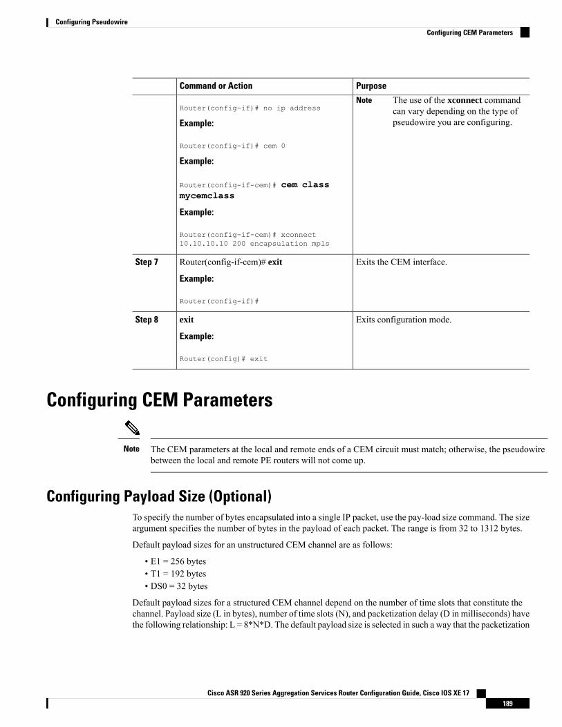
PurposeCommand or Action
Router(config-if)# no ip addressThe use of the xconnect commandcan vary depending on the type ofpseudowire you are configuring.
Note
Example:
Router(config-if)# cem 0
Example:
Router(config-if-cem)# cem classmycemclass
Example:
Router(config-if-cem)# xconnect10.10.10.10 200 encapsulation mpls
Exits the CEM interface.Router(config-if-cem)# exit
Example:
Step 7
Router(config-if)#
Exits configuration mode.exit
Example:
Step 8
Router(config)# exit
Configuring CEM Parameters
The CEM parameters at the local and remote ends of a CEM circuit must match; otherwise, the pseudowirebetween the local and remote PE routers will not come up.
Note
Configuring Payload Size (Optional)To specify the number of bytes encapsulated into a single IP packet, use the pay-load size command. The sizeargument specifies the number of bytes in the payload of each packet. The range is from 32 to 1312 bytes.
Default payload sizes for an unstructured CEM channel are as follows:
• E1 = 256 bytes• T1 = 192 bytes• DS0 = 32 bytes
Default payload sizes for a structured CEM channel depend on the number of time slots that constitute thechannel. Payload size (L in bytes), number of time slots (N), and packetization delay (D in milliseconds) havethe following relationship: L = 8*N*D. The default payload size is selected in such a way that the packetization
Cisco ASR 920 Series Aggregation Services Router Configuration Guide, Cisco IOS XE 17189
Configuring PseudowireConfiguring CEM Parameters
delay is always 1 millisecond. For example, a structured CEM channel of 16xDS0 has a default payload sizeof 128 bytes.
The payload size must be an integer of the multiple of the number of time slots for structured CEM channels.
Setting the Dejitter Buffer SizeTo specify the size of the dejitter buffer used to compensate for the network filter, use the dejitter-buffer sizecommand. The configured dejitter buffer size is converted from milliseconds to packets and rounded up tothe next integral number of packets. Use the size argument to specify the size of the buffer, in milliseconds.The range is from 1 to 32 ms; the default is 5 ms.
Setting an Idle Pattern (Optional)To specify an idle pattern, use the [no] idle-pattern pattern1 command. The payload of each lost CESoPSNdata packet must be replaced with the equivalent amount of the replacement data. The range for pattern isfrom 0x0 to 0xFF; the default idle pattern is 0xFF.
Enabling Dummy ModeDummy mode enables a bit pattern for filling in for lost or corrupted frames. To enable dummy mode, usethe dummy-mode [last-frame | user-defined] command. The default is last-frame. The following is anexample:
Router(config-cem)# dummy-mode last-frame
Setting a Dummy PatternIf dummy mode is set to user-defined, you can use the dummy-pattern pattern command to configure thedummy pattern. The range for pattern is from 0x0 to 0xFF. The default dummy pattern is 0xFF. The followingis an example:
Router(config-cem)# dummy-pattern 0x55
Shutting Down a CEM ChannelTo shut down a CEM channel, use the shutdown command in CEM configuration mode. The shutdowncommand is supported only under CEM mode and not under the CEM class.
Configuring Structure-Agnostic TDM over Packet (SAToP)Follow these steps to configure SAToP on the Cisco ASR 920 Series Router:
Cisco ASR 920 Series Aggregation Services Router Configuration Guide, Cisco IOS XE 17190
Configuring PseudowireSetting the Dejitter Buffer Size
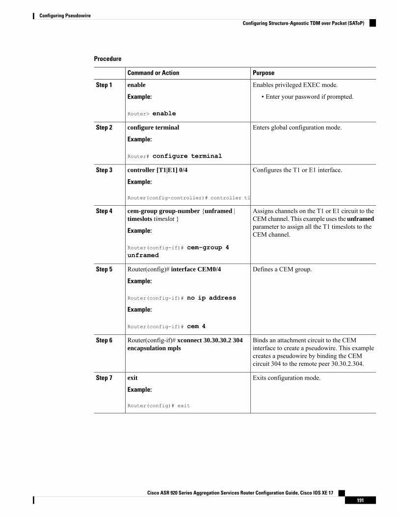
Procedure
PurposeCommand or Action
Enables privileged EXEC mode.enableStep 1
Example: • Enter your password if prompted.
Router> enable
Enters global configuration mode.configure terminal
Example:
Step 2
Router# configure terminal
Configures the T1 or E1 interface.controller [T1|E1] 0/4
Example:
Step 3
Router(config-controller)# controller t1
Assigns channels on the T1 or E1 circuit to theCEMchannel. This example uses the unframed
cem-group group-number {unframed |timeslots timeslot }
Step 4
parameter to assign all the T1 timeslots to theCEM channel.Example:
Router(config-if)# cem-group 4unframed
Defines a CEM group.Router(config)# interface CEM0/4
Example:
Step 5
Router(config-if)# no ip address
Example:
Router(config-if)# cem 4
Binds an attachment circuit to the CEMinterface to create a pseudowire. This example
Router(config-if)# xconnect 30.30.30.2 304encapsulation mpls
Step 6
creates a pseudowire by binding the CEMcircuit 304 to the remote peer 30.30.2.304.
Exits configuration mode.exit
Example:
Step 7
Router(config)# exit
Cisco ASR 920 Series Aggregation Services Router Configuration Guide, Cisco IOS XE 17191
Configuring PseudowireConfiguring Structure-Agnostic TDM over Packet (SAToP)
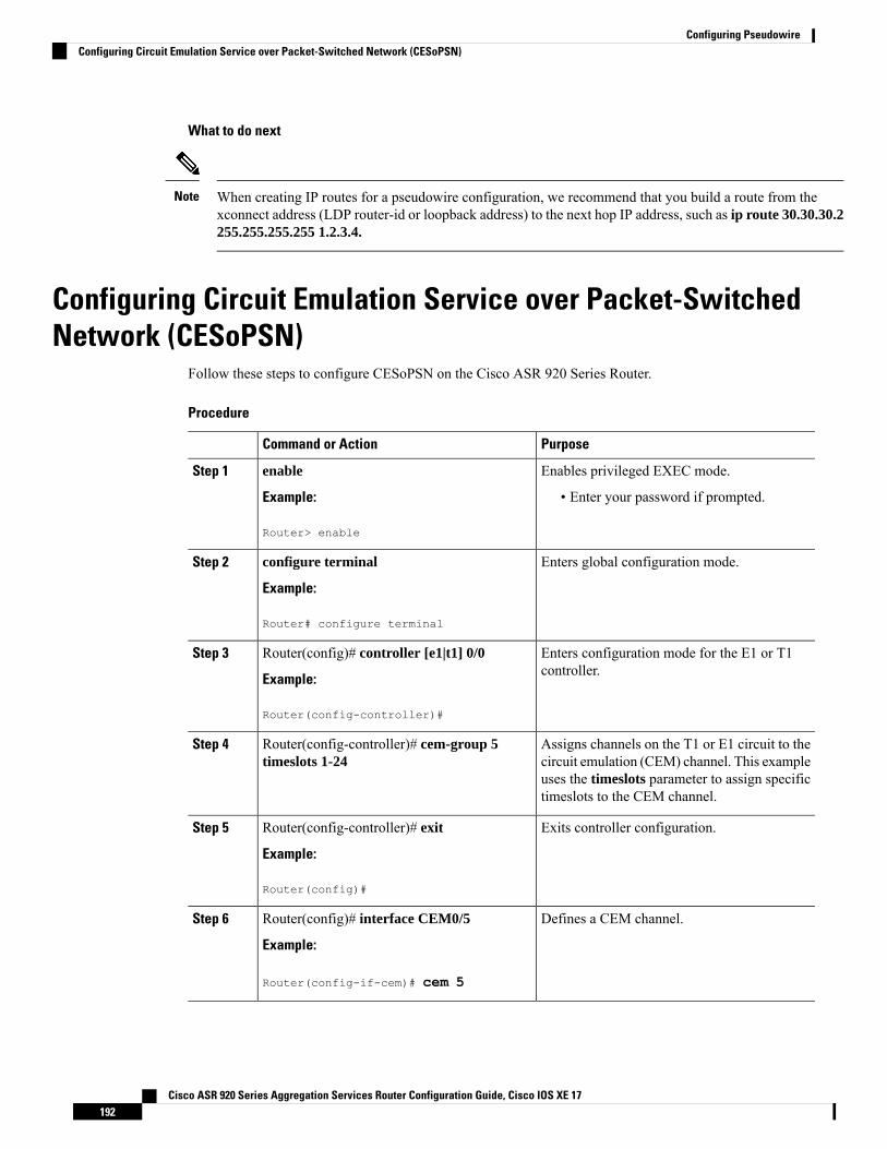
What to do next
When creating IP routes for a pseudowire configuration, we recommend that you build a route from thexconnect address (LDP router-id or loopback address) to the next hop IP address, such as ip route 30.30.30.2255.255.255.255 1.2.3.4.
Note
Configuring Circuit Emulation Service over Packet-SwitchedNetwork (CESoPSN)
Follow these steps to configure CESoPSN on the Cisco ASR 920 Series Router.
Procedure
PurposeCommand or Action
Enables privileged EXEC mode.enableStep 1
Example: • Enter your password if prompted.
Router> enable
Enters global configuration mode.configure terminal
Example:
Step 2
Router# configure terminal
Enters configuration mode for the E1 or T1controller.
Router(config)# controller [e1|t1] 0/0
Example:
Step 3
Router(config-controller)#
Assigns channels on the T1 or E1 circuit to thecircuit emulation (CEM) channel. This example
Router(config-controller)# cem-group 5timeslots 1-24
Step 4
uses the timeslots parameter to assign specifictimeslots to the CEM channel.
Exits controller configuration.Router(config-controller)# exit
Example:
Step 5
Router(config)#
Defines a CEM channel.Router(config)# interface CEM0/5
Example:
Step 6
Router(config-if-cem)# cem 5
Cisco ASR 920 Series Aggregation Services Router Configuration Guide, Cisco IOS XE 17192
Configuring PseudowireConfiguring Circuit Emulation Service over Packet-Switched Network (CESoPSN)
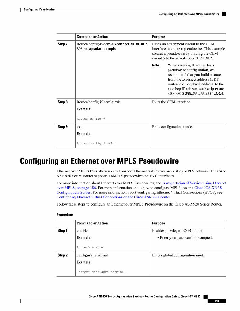
PurposeCommand or Action
Binds an attachment circuit to the CEMinterface to create a pseudowire. This example
Router(config-if-cem)# xconnect 30.30.30.2305 encapsulation mpls
Step 7
creates a pseudowire by binding the CEMcircuit 5 to the remote peer 30.30.30.2.
When creating IP routes for apseudowire configuration, werecommend that you build a routefrom the xconnect address (LDProuter-id or loopback address) to thenext hop IP address, such as ip route30.30.30.2 255.255.255.255 1.2.3.4.
Note
Exits the CEM interface.Router(config-if-cem)# exit
Example:
Step 8
Router(config)#
Exits configuration mode.exit
Example:
Step 9
Router(config)# exit
Configuring an Ethernet over MPLS PseudowireEthernet over MPLS PWs allow you to transport Ethernet traffic over an existing MPLS network. The CiscoASR 920 Series Router supports EoMPLS pseudowires on EVC interfaces.
For more information about Ethernet over MPLS Pseudowires, see Transportation of Service Using Ethernetover MPLS, on page 186. For more information about how to configure MPLS, see the Cisco IOS XE 3SConfiguration Guides. For more information about configuring Ethernet Virtual Connections (EVCs), seeConfiguring Ethernet Virtual Connections on the Cisco ASR 920 Router.
Follow these steps to configure an Ethernet over MPLS Pseudowire on the Cisco ASR 920 Series Router.
Procedure
PurposeCommand or Action
Enables privileged EXEC mode.enableStep 1
Example: • Enter your password if prompted.
Router> enable
Enters global configuration mode.configure terminal
Example:
Step 2
Router# configure terminal
Cisco ASR 920 Series Aggregation Services Router Configuration Guide, Cisco IOS XE 17193
Configuring PseudowireConfiguring an Ethernet over MPLS Pseudowire
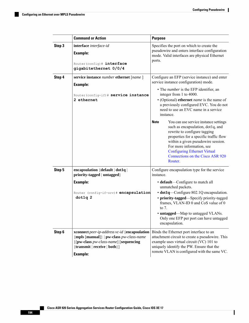
PurposeCommand or Action
Specifies the port on which to create thepseudowire and enters interface configuration
interface interface-id
Example:
Step 3
mode. Valid interfaces are physical Ethernetports.
Router(config)# interfacegigabitethernet 0/0/4
Configure an EFP (service instance) and enterservice instance configuration) mode.
service instance number ethernet [name ]
Example:
Step 4
• The number is the EFP identifier, aninteger from 1 to 4000.Router(config-if)# service instance
2 ethernet • (Optional) ethernet name is the name ofa previously configured EVC. You do notneed to use an EVC name in a serviceinstance.
You can use service instance settingssuch as encapsulation, dot1q, andrewrite to configure taggingproperties for a specific traffic flowwithin a given pseudowire session.For more information, seeConfiguring Ethernet VirtualConnections on the Cisco ASR 920Router.
Note
Configure encapsulation type for the serviceinstance.
encapsulation {default | dot1q |priority-tagged | untagged}
Step 5
Example: • default—Configure to match allunmatched packets.
Router (config-if-srv)# encapsulationdot1q 2
• dot1q—Configure 802.1Q encapsulation.• priority-tagged—Specify priority-taggedframes, VLAN-ID 0 and CoS value of 0to 7.
• untagged—Map to untagged VLANs.Only one EFP per port can have untaggedencapsulation.
Binds the Ethernet port interface to anattachment circuit to create a pseudowire. This
xconnect peer-ip-address vc-id {encapsulation{mpls [manual]} | pw-class pw-class-name
Step 6
example uses virtual circuit (VC) 101 to}[pw-class pw-class-name] [sequencing{transmit | receive | both}] uniquely identify the PW. Ensure that the
remote VLAN is configured with the same VC.Example:
Cisco ASR 920 Series Aggregation Services Router Configuration Guide, Cisco IOS XE 17194
Configuring PseudowireConfiguring an Ethernet over MPLS Pseudowire
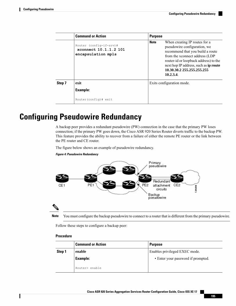
PurposeCommand or Action
Router (config-if-srv)#When creating IP routes for apseudowire configuration, werecommend that you build a routefrom the xconnect address (LDProuter-id or loopback address) to thenext hop IP address, such as ip route10.30.30.2 255.255.255.25510.2.3.4.
Note
xconnect 10.1.1.2 101encapsulation mpls
Exits configuration mode.exit
Example:
Step 7
Router(config)# exit
Configuring Pseudowire RedundancyA backup peer provides a redundant pseudowire (PW) connection in the case that the primary PW losesconnection; if the primary PW goes down, the Cisco ASR 920 Series Router diverts traffic to the backup PW.This feature provides the ability to recover from a failure of either the remote PE router or the link betweenthe PE router and CE router.
The figure below shows an example of pseudowire redundancy.
Figure 4: Pseudowire Redundancy
Youmust configure the backup pseudowire to connect to a router that is different from the primary pseudowire.Note
Follow these steps to configure a backup peer:
Procedure
PurposeCommand or Action
Enables privileged EXEC mode.enableStep 1
Example: • Enter your password if prompted.
Router> enable
Cisco ASR 920 Series Aggregation Services Router Configuration Guide, Cisco IOS XE 17195
Configuring PseudowireConfiguring Pseudowire Redundancy

PurposeCommand or Action
Enters global configuration mode.configure terminal
Example:
Step 2
Router# configure terminal
Specify the name of a Layer 2 pseudowire classand enter pseudowire class configurationmode.
pseudowire-class [pw-class-name]
Example:
Step 3
Router(config)# pseudowire-class mpls
Specifies MPLS encapsulation.encapsulation mpls
Example:
Step 4
Router(config-pw-class)# encapsulationmpls
Enters configuration mode for the serialinterface.
gigabitethernet slot/port
Example:
Step 5
The slot number is always 0.NoteRouter(config)# gigabitethernet 0/0/1
Configures the backup delay parameters.Router(config)# backup delay enable-delay{disable-delay | never}
Step 6
Where:
• enable-delay —Time before the backupPW takes over for the primary PW.
• disable-delay —Time before the restoredprimary PW takes over for the backup PW.
• never—Disables switching from thebackup PW to the primary PW.
Binds the Ethernet port interface to anattachment circuit to create a pseudowire.
Router(config-if)# xconnect 1.1.1.2 101encapsulation mpls
Step 7
Defines the address and VC of the backup peer.Router(config)# backup peerpeer-router-ip-address vcid [pw-class pw-classname ]
Step 8
Exits configuration mode.exit
Example:
Step 9
Router(config)# exit
Sample ConfigurationsThe following sections contain sample pseudowire configurations.
Cisco ASR 920 Series Aggregation Services Router Configuration Guide, Cisco IOS XE 17196
Configuring PseudowireSample Configurations
Example: CEM ConfigurationThe following example shows how to add a T1 interface to a CEM group as a part of a SAToP pseudowireconfiguration.
This section displays a partial configuration intended to demonstrate a specific feature.
controller T1 0/0/0framing unframedclock source internallinecode b8zscablelength short 110cem-group 0 unframedinterface CEM0/0/0no ip addresscem 0xconnect 18.1.1.1 1000 encapsulation mpls
Example: Ethernet over MPLS
PE 1 Configuration
!mpls label range 16 12000 static 12001 16000mpls label protocol ldpmpls ldp neighbor 10.1.1.1 targeted ldpmpls ldp graceful-restartmultilink bundle-name authenticated!!!!redundancymode sso!!!ip tftp source-interface GigabitEthernet0!!interface Loopback0ip address 10.5.5.5 255.255.255.255
!interface GigabitEthernet0/0/4no ip addressnegotiation auto!service instance 2 ethernetencapsulation dot1q 2xconnect 10.1.1.1 1001 encapsulation mpls!service instance 3 ethernetencapsulation dot1q 3xconnect 10.1.1.1 1002 encapsulation mpls!!interface GigabitEthernet0/0/5ip address 172.7.7.77 255.0.0.0negotiation auto
Cisco ASR 920 Series Aggregation Services Router Configuration Guide, Cisco IOS XE 17197
Configuring PseudowireExample: CEM Configuration
mpls ipmpls label protocol ldp!router ospf 1router-id 5.5.5.5network 5.5.5.5 0.0.0.0 area 0network 172.0.0.0 0.255.255.255 area 0network 10.33.33.33 0.0.0.0 area 0network 192.0.0.0 0.255.255.255 area 0!
PE 2 Configuration
!mpls label range 16 12000 static 12001 16000mpls label protocol ldpmpls ldp neighbor 10.5.5.5 targeted ldpmpls ldp graceful-restartmultilink bundle-name authenticated!!redundancymode sso!!!ip tftp source-interface GigabitEthernet0!!interface Loopback0ip address 10.1.1.1 255.255.255.255
!interface GigabitEthernet0/0/4no ip addressnegotiation auto!service instance 2 ethernetencapsulation dot1q 2xconnect 10.5.5.5 1001 encapsulation mpls!service instance 3 ethernetencapsulation dot1q 3xconnect 10.5.5.5 1002 encapsulation mpls!!interface GigabitEthernet0/0/5ip address 172.7.7.7 255.0.0.0negotiation autompls ipmpls label protocol ldp!router ospf 1router-id 10.1.1.1network 10.1.1.1 0.0.0.0 area 0network 172.0.0.0 0.255.255.255 area 0network 10.33.33.33 0.0.0.0 area 0network 192.0.0.0 0.255.255.255 area 0!
Cisco ASR 920 Series Aggregation Services Router Configuration Guide, Cisco IOS XE 17198
Configuring PseudowireExample: Ethernet over MPLS
Example: BGP PIC with TDM-PW ConfigurationThis section lists the configuration examples for BGP PIC with TDM and TDM–Pseudowire.
The below configuration example is for BGP PIC with TDM:
router bgp 1neighbor 18.2.2.2 remote-as 1neighbor 18.2.2.2 update-source Loopback0neighbor 18.3.3.3 remote-as 1neighbor 18.3.3.3 update-source Loopback0!address-family ipv4bgp additional-paths receivebgp additional-paths installbgp nexthop trigger delay 6neighbor 18.2.2.2 activateneighbor 18.2.2.2 send-community bothneighbor 18.2.2.2 send-labelneighbor 18.3.3.3 activateneighbor 18.3.3.3 send-community bothneighbor 18.3.3.3 send-labelneighbor 26.1.1.2 activate
exit-address-family!address-family vpnv4bgp nexthop trigger delay 7neighbor 18.2.2.2 activateneighbor 18.2.2.2 send-community extendedneighbor 18.3.3.3 activateneighbor 18.3.3.3 send-community extended
exit-address-family
The below configuration example is for BGP PIC with TDM PW:
pseudowire-class pseudowire1encapsulation mplscontrol-wordno status control-plane route-watchstatus peer topology dual-homed!Interface CEM0/0/0cem 1
xconnect 17.1.1.1 4101 encapsulation mpls pw-class pseudowire1
Adaptive Clock Recovery (ACR)Adaptive Clock Recovery (ACR) is an averaging process that negates the effect of random packet delayvariation and captures the average rate of transmission of the original bit stream. ACR recovers the originalclock for a synchronous data stream from the actual payload of the data stream. In other words, a synchronousclock is derived from an asynchronous packet stream. ACR is a technique where the clock from the TDMdomain is mapped through the packet domain, but is most commonly used for Circuit Emulation (CEM).ACR is supported on unframed and framed modes of SAToP.
Framing type should be maintained same in all routers end to end.Note
Cisco ASR 920 Series Aggregation Services Router Configuration Guide, Cisco IOS XE 17199
Configuring PseudowireExample: BGP PIC with TDM-PW Configuration
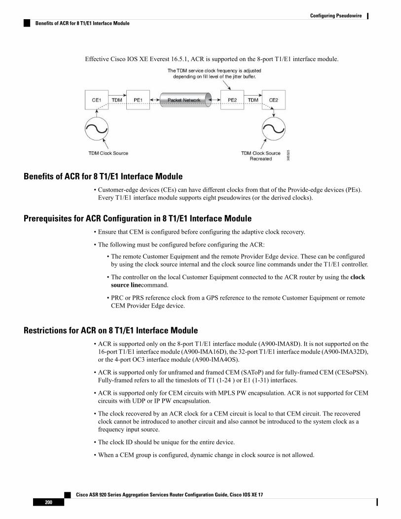
Effective Cisco IOS XE Everest 16.5.1, ACR is supported on the 8-port T1/E1 interface module.
Benefits of ACR for 8 T1/E1 Interface Module• Customer-edge devices (CEs) can have different clocks from that of the Provide-edge devices (PEs).Every T1/E1 interface module supports eight pseudowires (or the derived clocks).
Prerequisites for ACR Configuration in 8 T1/E1 Interface Module• Ensure that CEM is configured before configuring the adaptive clock recovery.
• The following must be configured before configuring the ACR:
• The remote Customer Equipment and the remote Provider Edge device. These can be configuredby using the clock source internal and the clock source line commands under the T1/E1 controller.
• The controller on the local Customer Equipment connected to the ACR router by using the clocksource linecommand.
• PRC or PRS reference clock from a GPS reference to the remote Customer Equipment or remoteCEM Provider Edge device.
Restrictions for ACR on 8 T1/E1 Interface Module• ACR is supported only on the 8-port T1/E1 interface module (A900-IMA8D). It is not supported on the16-port T1/E1 interfacemodule (A900-IMA16D), the 32-port T1/E1 interfacemodule (A900-IMA32D),or the 4-port OC3 interface module (A900-IMA4OS).
• ACR is supported only for unframed and framed CEM (SAToP) and for fully-framed CEM (CESoPSN).Fully-framed refers to all the timeslots of T1 (1-24 ) or E1 (1-31) interfaces.
• ACR is supported only for CEM circuits with MPLS PW encapsulation. ACR is not supported for CEMcircuits with UDP or IP PW encapsulation.
• The clock recovered by an ACR clock for a CEM circuit is local to that CEM circuit. The recoveredclock cannot be introduced to another circuit and also cannot be introduced to the system clock as afrequency input source.
• The clock ID should be unique for the entire device.
• When a CEM group is configured, dynamic change in clock source is not allowed.
Cisco ASR 920 Series Aggregation Services Router Configuration Guide, Cisco IOS XE 17200
Configuring PseudowireBenefits of ACR for 8 T1/E1 Interface Module
• Physical or soft IM OIR causes the APS switchover time to be higher (500 to 600 ms). Shut or no shutof the port and removal of the active working or protect also cause the APS switchover time to be high.
To overcome these issues, force the APS switchover.
Configuring ACR for T1 Interfaces for SAToPTo configure the clock on T1/E1 interfaces for SAToP in controller mode:
enableconfigure terminalcontroller t1 0/4/3clock source recovered 15cem-group 20 unframedexit
To configure the clock recovery on T1/E1 interfaces in global configuration mode:
recovered-clock 0 4clock recovered 15 adaptive cem 3 20exit
The clock source recovered configuration on the controller must be completed before configuring the clockrecovery in global configuration mode.
Note
On the controller, the clock source should be configured before CEM group is configured.Note
Follow a similar procedure to configure to configure CEM ACR for E1 Interfaces for SAToP. Also, followa similar procedure to configure CEMACR for T1 and E1 Interfaces for CESoPSN. Use cem-group circuit-idtimeslots <1-24> |<1-31> command instead of cem-group circuit-id unframed command for the configurationdepending on T1 or E1 controller.
Note
To remove the clock configuration in ACR, you must remove the recovery clock configuration in globalconfigurationmode, then remove the CEM circuit, and finally remove the clock source recovered configurationunder the controller.
For the 8-port T1/E1 interface module (A900-IMA8D), the configuration or unconfiguration of the clocksource recovered is not supported when the cem-group is already configured on the controller. To modify theclock source, you should remove the CEM group configuration from the controller.
Note
Verifying the ACR Configuration of T1 Interfaces for SAToPImportant Notes
Cisco ASR 920 Series Aggregation Services Router Configuration Guide, Cisco IOS XE 17201
Configuring PseudowireConfiguring ACR for T1 Interfaces for SAToP
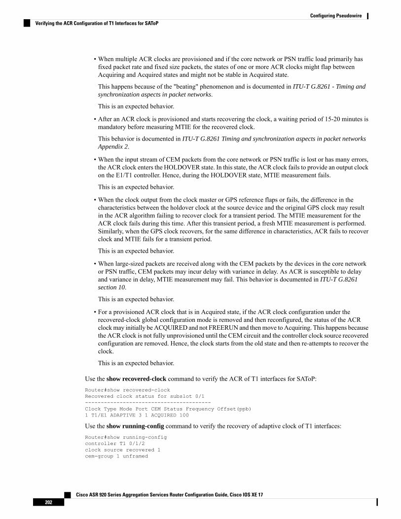
• When multiple ACR clocks are provisioned and if the core network or PSN traffic load primarily hasfixed packet rate and fixed size packets, the states of one or more ACR clocks might flap betweenAcquiring and Acquired states and might not be stable in Acquired state.
This happens because of the "beating" phenomenon and is documented in ITU-T G.8261 - Timing andsynchronization aspects in packet networks.
This is an expected behavior.
• After an ACR clock is provisioned and starts recovering the clock, a waiting period of 15-20 minutes ismandatory before measuring MTIE for the recovered clock.
This behavior is documented in ITU-T G.8261 Timing and synchronization aspects in packet networksAppendix 2.
• When the input stream of CEM packets from the core network or PSN traffic is lost or has many errors,the ACR clock enters the HOLDOVER state. In this state, the ACR clock fails to provide an output clockon the E1/T1 controller. Hence, during the HOLDOVER state, MTIE measurement fails.
This is an expected behavior.
• When the clock output from the clock master or GPS reference flaps or fails, the difference in thecharacteristics between the holdover clock at the source device and the original GPS clock may resultin the ACR algorithm failing to recover clock for a transient period. The MTIE measurement for theACR clock fails during this time. After this transient period, a fresh MTIE measurement is performed.Similarly, when the GPS clock recovers, for the same difference in characteristics, ACR fails to recoverclock and MTIE fails for a transient period.
This is an expected behavior.
• When large-sized packets are received along with the CEM packets by the devices in the core networkor PSN traffic, CEM packets may incur delay with variance in delay. As ACR is susceptible to delayand variance in delay, MTIE measurement may fail. This behavior is documented in ITU-T G.8261section 10.
This is an expected behavior.
• For a provisioned ACR clock that is in Acquired state, if the ACR clock configuration under therecovered-clock global configuration mode is removed and then reconfigured, the status of the ACRclockmay initially be ACQUIRED and not FREERUN and thenmove to Acquiring. This happens becausethe ACR clock is not fully unprovisioned until the CEM circuit and the controller clock source recoveredconfiguration are removed. Hence, the clock starts from the old state and then re-attempts to recover theclock.
This is an expected behavior.
Use the show recovered-clock command to verify the ACR of T1 interfaces for SAToP:Router#show recovered-clockRecovered clock status for subslot 0/1----------------------------------------Clock Type Mode Port CEM Status Frequency Offset(ppb)1 T1/E1 ADAPTIVE 3 1 ACQUIRED 100
Use the show running-config command to verify the recovery of adaptive clock of T1 interfaces:Router#show running-configcontroller T1 0/1/2clock source recovered 1cem-group 1 unframed
Cisco ASR 920 Series Aggregation Services Router Configuration Guide, Cisco IOS XE 17202
Configuring PseudowireVerifying the ACR Configuration of T1 Interfaces for SAToP
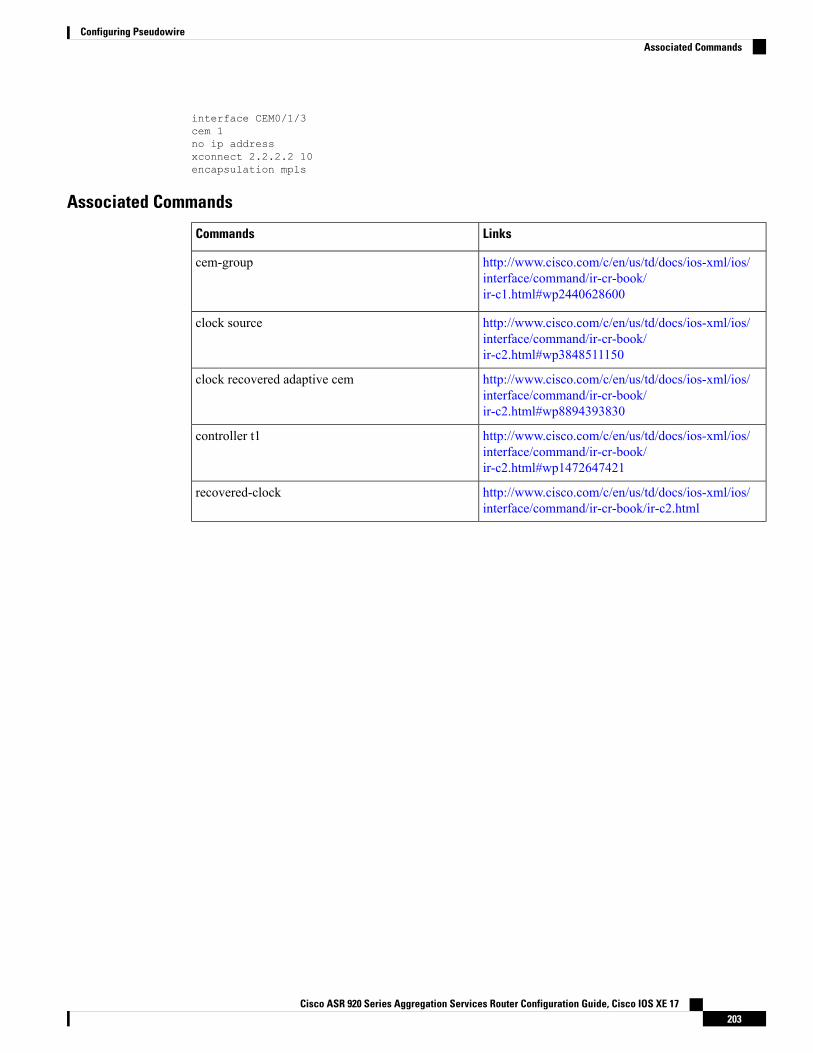
interface CEM0/1/3cem 1no ip addressxconnect 2.2.2.2 10encapsulation mpls
Associated Commands
LinksCommands
http://www.cisco.com/c/en/us/td/docs/ios-xml/ios/interface/command/ir-cr-book/ir-c1.html#wp2440628600
cem-group
http://www.cisco.com/c/en/us/td/docs/ios-xml/ios/interface/command/ir-cr-book/ir-c2.html#wp3848511150
clock source
http://www.cisco.com/c/en/us/td/docs/ios-xml/ios/interface/command/ir-cr-book/ir-c2.html#wp8894393830
clock recovered adaptive cem
http://www.cisco.com/c/en/us/td/docs/ios-xml/ios/interface/command/ir-cr-book/ir-c2.html#wp1472647421
controller t1
http://www.cisco.com/c/en/us/td/docs/ios-xml/ios/interface/command/ir-cr-book/ir-c2.html
recovered-clock
Cisco ASR 920 Series Aggregation Services Router Configuration Guide, Cisco IOS XE 17203
Configuring PseudowireAssociated Commands

Cisco ASR 920 Series Aggregation Services Router Configuration Guide, Cisco IOS XE 17204
Configuring PseudowireAssociated Commands
C H A P T E R 18Configuring and Monitoring Alarm
This chapter describes monitoring alarms, alarms filtering support and configuring external alarms for fantray alarm port.
This chapter includes the following sections:
• Monitoring Alarms, on page 205• Configuring External Alarm Trigger, on page 210• Alarm Filtering Support, on page 213• Facility Protocol Status Support, on page 215
Monitoring AlarmsOnce hardware is installed and operational, use alarms to monitor hardware status on a daily basis.
The routers are designed to send alarm notifications when problems are detected. Network administrators donot need to use show commands to poll devices on a routine basis and can monitor the network remotely.However, network administrators can perform onsite monitoring if they so choose.
Use snmp-server enable traps alarms <severity> command to enable the entity related Traps.
The default severity level is informational, which shows all alarms. Severity levels are defined as the following:
• 1—Critical. The condition affects service.• 2—Major. Immediate action is needed.• 3—Minor. Minor warning conditions.• 4—Informational. No action is required. This is the default.
The entity notifications ceAlarmAsserted and ceAlarmCleared are used to report the condition for e.g. whena physical entity asserted or cleared an alarm.
Effective from Cisco IOS XE Everest 16.6.1, on RSP3 module, alarm notification is enabled on 900 wattsDC power supply. There are 2 input feeds for 900 watts DC power supply, if one of the input voltage is lesserthan the operating voltage, critical alarm is generated for that particular feed and clears (stops) once the voltageis restored but the power supply state remains in OK state as the other power supply is operationally up.
Note
Cisco ASR 920 Series Aggregation Services Router Configuration Guide, Cisco IOS XE 17205
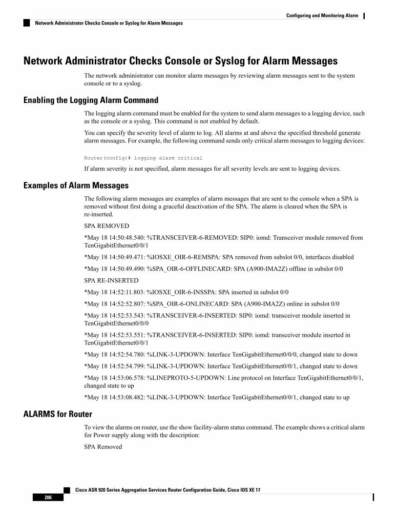
Network Administrator Checks Console or Syslog for Alarm MessagesThe network administrator can monitor alarm messages by reviewing alarm messages sent to the systemconsole or to a syslog.
Enabling the Logging Alarm CommandThe logging alarm command must be enabled for the system to send alarmmessages to a logging device, suchas the console or a syslog. This command is not enabled by default.
You can specify the severity level of alarm to log. All alarms at and above the specified threshold generatealarm messages. For example, the following command sends only critical alarm messages to logging devices:
Router(config)# logging alarm critical
If alarm severity is not specified, alarm messages for all severity levels are sent to logging devices.
Examples of Alarm MessagesThe following alarm messages are examples of alarm messages that are sent to the console when a SPA isremoved without first doing a graceful deactivation of the SPA. The alarm is cleared when the SPA isre-inserted.
SPA REMOVED
*May 18 14:50:48.540: %TRANSCEIVER-6-REMOVED: SIP0: iomd: Transceiver module removed fromTenGigabitEthernet0/0/1
*May 18 14:50:49.471: %IOSXE_OIR-6-REMSPA: SPA removed from subslot 0/0, interfaces disabled
*May 18 14:50:49.490: %SPA_OIR-6-OFFLINECARD: SPA (A900-IMA2Z) offline in subslot 0/0
SPA RE-INSERTED
*May 18 14:52:11.803: %IOSXE_OIR-6-INSSPA: SPA inserted in subslot 0/0
*May 18 14:52:52.807: %SPA_OIR-6-ONLINECARD: SPA (A900-IMA2Z) online in subslot 0/0
*May 18 14:52:53.543: %TRANSCEIVER-6-INSERTED: SIP0: iomd: transceiver module inserted inTenGigabitEthernet0/0/0
*May 18 14:52:53.551: %TRANSCEIVER-6-INSERTED: SIP0: iomd: transceiver module inserted inTenGigabitEthernet0/0/1
*May 18 14:52:54.780: %LINK-3-UPDOWN: Interface TenGigabitEthernet0/0/0, changed state to down
*May 18 14:52:54.799: %LINK-3-UPDOWN: Interface TenGigabitEthernet0/0/1, changed state to down
*May 18 14:53:06.578: %LINEPROTO-5-UPDOWN: Line protocol on Interface TenGigabitEthernet0/0/1,changed state to up
*May 18 14:53:08.482: %LINK-3-UPDOWN: Interface TenGigabitEthernet0/0/1, changed state to up
ALARMS for RouterTo view the alarms on router, use the show facility-alarm status command. The example shows a critical alarmfor Power supply along with the description:
SPA Removed
Cisco ASR 920 Series Aggregation Services Router Configuration Guide, Cisco IOS XE 17206
Configuring and Monitoring AlarmNetwork Administrator Checks Console or Syslog for Alarm Messages
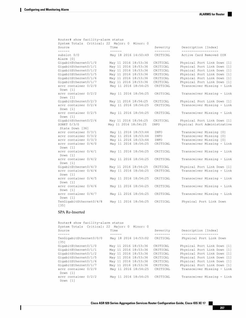
Router# show facility-alarm statusSystem Totals Critical: 22 Major: 0 Minor: 0Source Time Severity Description [Index]------ ------ -------- -------------------subslot 0/0 May 18 2016 14:50:49 CRITICAL Active Card Removed OIRAlarm [0]GigabitEthernet0/1/0 May 11 2016 18:53:36 CRITICAL Physical Port Link Down [1]GigabitEthernet0/1/1 May 11 2016 18:53:36 CRITICAL Physical Port Link Down [1]GigabitEthernet0/1/2 May 11 2016 18:53:36 CRITICAL Physical Port Link Down [1]GigabitEthernet0/1/5 May 11 2016 18:53:36 CRITICAL Physical Port Link Down [1]GigabitEthernet0/1/6 May 11 2016 18:53:36 CRITICAL Physical Port Link Down [1]GigabitEthernet0/1/7 May 11 2016 18:53:36 CRITICAL Physical Port Link Down [1]xcvr container 0/2/0 May 11 2016 18:54:25 CRITICAL Transceiver Missing - LinkDown [1]xcvr container 0/2/2 May 11 2016 18:54:25 CRITICAL Transceiver Missing - LinkDown [1]GigabitEthernet0/2/3 May 11 2016 18:54:25 CRITICAL Physical Port Link Down [1]xcvr container 0/2/4 May 11 2016 18:54:25 CRITICAL Transceiver Missing - LinkDown [1]xcvr container 0/2/5 May 11 2016 18:54:25 CRITICAL Transceiver Missing - LinkDown [1]GigabitEthernet0/2/6 May 11 2016 18:54:25 CRITICAL Physical Port Link Down [1]SONET 0/3/0 May 11 2016 18:54:25 INFO Physical Port AdministrativeState Down [36]xcvr container 0/3/1 May 11 2016 18:53:44 INFO Transceiver Missing [0]xcvr container 0/3/2 May 11 2016 18:53:44 INFO Transceiver Missing [0]xcvr container 0/3/3 May 11 2016 18:53:44 INFO Transceiver Missing [0]xcvr container 0/4/0 May 11 2016 18:54:25 CRITICAL Transceiver Missing - LinkDown [1]xcvr container 0/4/1 May 11 2016 18:54:25 CRITICAL Transceiver Missing - LinkDown [1]xcvr container 0/4/2 May 11 2016 18:54:25 CRITICAL Transceiver Missing - LinkDown [1]GigabitEthernet0/4/3 May 11 2016 18:54:25 CRITICAL Physical Port Link Down [1]xcvr container 0/4/4 May 11 2016 18:54:25 CRITICAL Transceiver Missing - LinkDown [1]xcvr container 0/4/5 May 11 2016 18:54:25 CRITICAL Transceiver Missing - LinkDown [1]xcvr container 0/4/6 May 11 2016 18:54:25 CRITICAL Transceiver Missing - LinkDown [1]xcvr container 0/4/7 May 11 2016 18:54:25 CRITICAL Transceiver Missing - LinkDown [1]TenGigabitEthernet0/4/8 May 11 2016 18:54:25 CRITICAL Physical Port Link Down[35]
SPA Re-Inserted
Router# show facility-alarm statusSystem Totals Critical: 22 Major: 0 Minor: 0Source Time Severity Description [Index]------ ------ -------- -------------------TenGigabitEthernet0/0/0 May 18 2016 14:53:02 CRITICAL Physical Port Link Down[35]GigabitEthernet0/1/0 May 11 2016 18:53:36 CRITICAL Physical Port Link Down [1]GigabitEthernet0/1/1 May 11 2016 18:53:36 CRITICAL Physical Port Link Down [1]GigabitEthernet0/1/2 May 11 2016 18:53:36 CRITICAL Physical Port Link Down [1]GigabitEthernet0/1/5 May 11 2016 18:53:36 CRITICAL Physical Port Link Down [1]GigabitEthernet0/1/6 May 11 2016 18:53:36 CRITICAL Physical Port Link Down [1]GigabitEthernet0/1/7 May 11 2016 18:53:36 CRITICAL Physical Port Link Down [1]xcvr container 0/2/0 May 11 2016 18:54:25 CRITICAL Transceiver Missing - LinkDown [1]xcvr container 0/2/2 May 11 2016 18:54:25 CRITICAL Transceiver Missing - LinkDown [1]
Cisco ASR 920 Series Aggregation Services Router Configuration Guide, Cisco IOS XE 17207
Configuring and Monitoring AlarmALARMS for Router
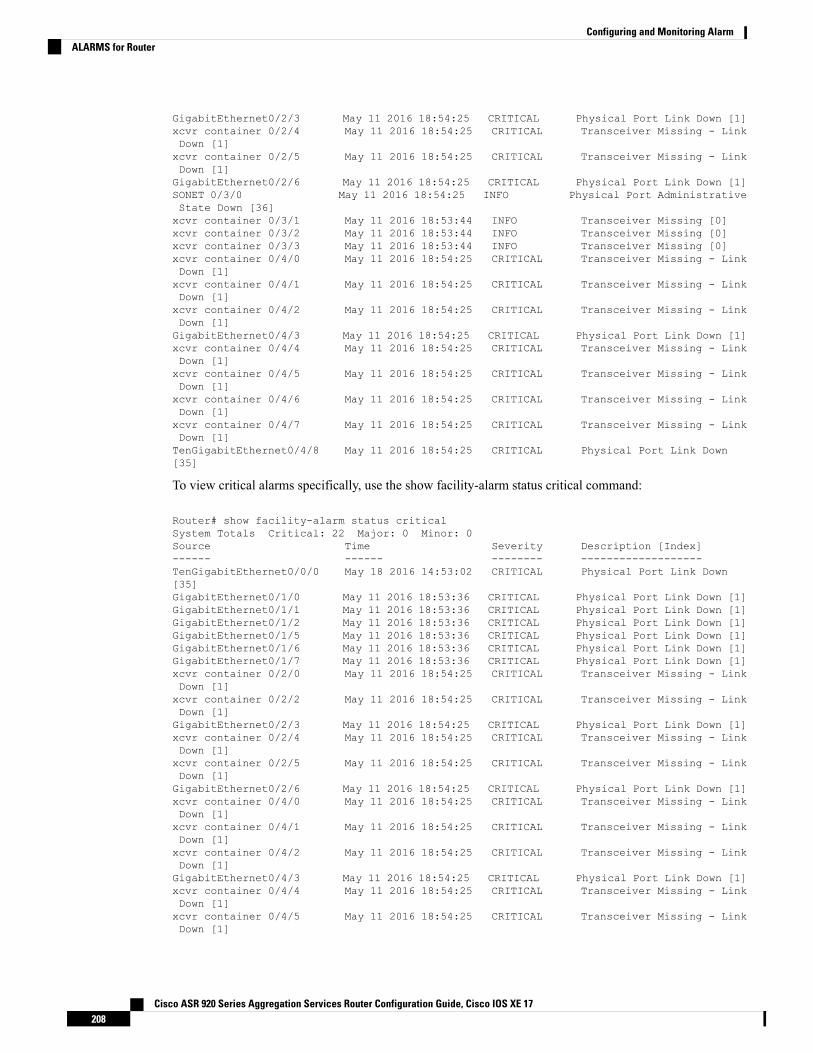
GigabitEthernet0/2/3 May 11 2016 18:54:25 CRITICAL Physical Port Link Down [1]xcvr container 0/2/4 May 11 2016 18:54:25 CRITICAL Transceiver Missing - LinkDown [1]xcvr container 0/2/5 May 11 2016 18:54:25 CRITICAL Transceiver Missing - LinkDown [1]GigabitEthernet0/2/6 May 11 2016 18:54:25 CRITICAL Physical Port Link Down [1]SONET 0/3/0 May 11 2016 18:54:25 INFO Physical Port AdministrativeState Down [36]xcvr container 0/3/1 May 11 2016 18:53:44 INFO Transceiver Missing [0]xcvr container 0/3/2 May 11 2016 18:53:44 INFO Transceiver Missing [0]xcvr container 0/3/3 May 11 2016 18:53:44 INFO Transceiver Missing [0]xcvr container 0/4/0 May 11 2016 18:54:25 CRITICAL Transceiver Missing - LinkDown [1]xcvr container 0/4/1 May 11 2016 18:54:25 CRITICAL Transceiver Missing - LinkDown [1]xcvr container 0/4/2 May 11 2016 18:54:25 CRITICAL Transceiver Missing - LinkDown [1]GigabitEthernet0/4/3 May 11 2016 18:54:25 CRITICAL Physical Port Link Down [1]xcvr container 0/4/4 May 11 2016 18:54:25 CRITICAL Transceiver Missing - LinkDown [1]xcvr container 0/4/5 May 11 2016 18:54:25 CRITICAL Transceiver Missing - LinkDown [1]xcvr container 0/4/6 May 11 2016 18:54:25 CRITICAL Transceiver Missing - LinkDown [1]xcvr container 0/4/7 May 11 2016 18:54:25 CRITICAL Transceiver Missing - LinkDown [1]TenGigabitEthernet0/4/8 May 11 2016 18:54:25 CRITICAL Physical Port Link Down[35]
To view critical alarms specifically, use the show facility-alarm status critical command:
Router# show facility-alarm status criticalSystem Totals Critical: 22 Major: 0 Minor: 0Source Time Severity Description [Index]------ ------ -------- -------------------TenGigabitEthernet0/0/0 May 18 2016 14:53:02 CRITICAL Physical Port Link Down[35]GigabitEthernet0/1/0 May 11 2016 18:53:36 CRITICAL Physical Port Link Down [1]GigabitEthernet0/1/1 May 11 2016 18:53:36 CRITICAL Physical Port Link Down [1]GigabitEthernet0/1/2 May 11 2016 18:53:36 CRITICAL Physical Port Link Down [1]GigabitEthernet0/1/5 May 11 2016 18:53:36 CRITICAL Physical Port Link Down [1]GigabitEthernet0/1/6 May 11 2016 18:53:36 CRITICAL Physical Port Link Down [1]GigabitEthernet0/1/7 May 11 2016 18:53:36 CRITICAL Physical Port Link Down [1]xcvr container 0/2/0 May 11 2016 18:54:25 CRITICAL Transceiver Missing - LinkDown [1]xcvr container 0/2/2 May 11 2016 18:54:25 CRITICAL Transceiver Missing - LinkDown [1]GigabitEthernet0/2/3 May 11 2016 18:54:25 CRITICAL Physical Port Link Down [1]xcvr container 0/2/4 May 11 2016 18:54:25 CRITICAL Transceiver Missing - LinkDown [1]xcvr container 0/2/5 May 11 2016 18:54:25 CRITICAL Transceiver Missing - LinkDown [1]GigabitEthernet0/2/6 May 11 2016 18:54:25 CRITICAL Physical Port Link Down [1]xcvr container 0/4/0 May 11 2016 18:54:25 CRITICAL Transceiver Missing - LinkDown [1]xcvr container 0/4/1 May 11 2016 18:54:25 CRITICAL Transceiver Missing - LinkDown [1]xcvr container 0/4/2 May 11 2016 18:54:25 CRITICAL Transceiver Missing - LinkDown [1]GigabitEthernet0/4/3 May 11 2016 18:54:25 CRITICAL Physical Port Link Down [1]xcvr container 0/4/4 May 11 2016 18:54:25 CRITICAL Transceiver Missing - LinkDown [1]xcvr container 0/4/5 May 11 2016 18:54:25 CRITICAL Transceiver Missing - LinkDown [1]
Cisco ASR 920 Series Aggregation Services Router Configuration Guide, Cisco IOS XE 17208
Configuring and Monitoring AlarmALARMS for Router
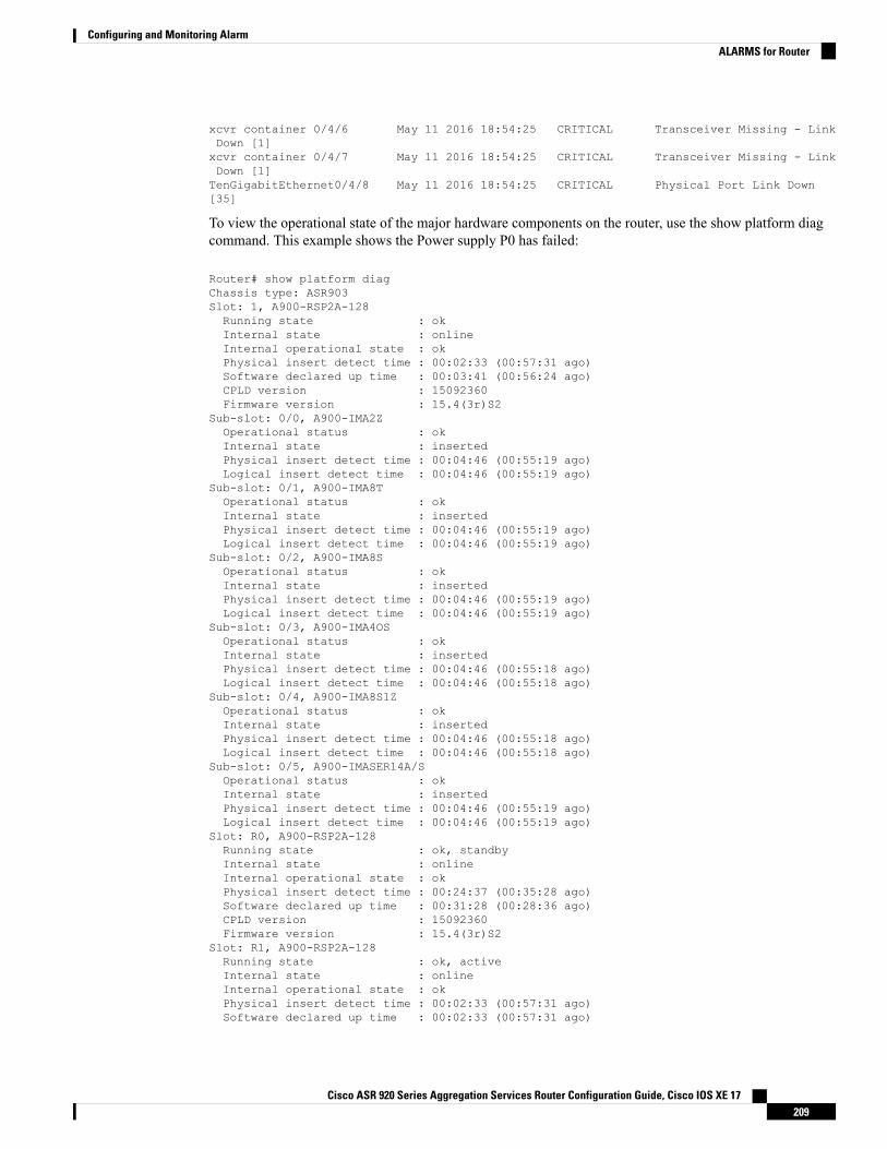
xcvr container 0/4/6 May 11 2016 18:54:25 CRITICAL Transceiver Missing - LinkDown [1]xcvr container 0/4/7 May 11 2016 18:54:25 CRITICAL Transceiver Missing - LinkDown [1]TenGigabitEthernet0/4/8 May 11 2016 18:54:25 CRITICAL Physical Port Link Down[35]
To view the operational state of the major hardware components on the router, use the show platform diagcommand. This example shows the Power supply P0 has failed:
Router# show platform diagChassis type: ASR903Slot: 1, A900-RSP2A-128Running state : okInternal state : onlineInternal operational state : okPhysical insert detect time : 00:02:33 (00:57:31 ago)Software declared up time : 00:03:41 (00:56:24 ago)CPLD version : 15092360Firmware version : 15.4(3r)S2
Sub-slot: 0/0, A900-IMA2ZOperational status : okInternal state : insertedPhysical insert detect time : 00:04:46 (00:55:19 ago)Logical insert detect time : 00:04:46 (00:55:19 ago)
Sub-slot: 0/1, A900-IMA8TOperational status : okInternal state : insertedPhysical insert detect time : 00:04:46 (00:55:19 ago)Logical insert detect time : 00:04:46 (00:55:19 ago)
Sub-slot: 0/2, A900-IMA8SOperational status : okInternal state : insertedPhysical insert detect time : 00:04:46 (00:55:19 ago)Logical insert detect time : 00:04:46 (00:55:19 ago)
Sub-slot: 0/3, A900-IMA4OSOperational status : okInternal state : insertedPhysical insert detect time : 00:04:46 (00:55:18 ago)Logical insert detect time : 00:04:46 (00:55:18 ago)
Sub-slot: 0/4, A900-IMA8S1ZOperational status : okInternal state : insertedPhysical insert detect time : 00:04:46 (00:55:18 ago)Logical insert detect time : 00:04:46 (00:55:18 ago)
Sub-slot: 0/5, A900-IMASER14A/SOperational status : okInternal state : insertedPhysical insert detect time : 00:04:46 (00:55:19 ago)Logical insert detect time : 00:04:46 (00:55:19 ago)
Slot: R0, A900-RSP2A-128Running state : ok, standbyInternal state : onlineInternal operational state : okPhysical insert detect time : 00:24:37 (00:35:28 ago)Software declared up time : 00:31:28 (00:28:36 ago)CPLD version : 15092360Firmware version : 15.4(3r)S2
Slot: R1, A900-RSP2A-128Running state : ok, activeInternal state : onlineInternal operational state : okPhysical insert detect time : 00:02:33 (00:57:31 ago)Software declared up time : 00:02:33 (00:57:31 ago)
Cisco ASR 920 Series Aggregation Services Router Configuration Guide, Cisco IOS XE 17209
Configuring and Monitoring AlarmALARMS for Router
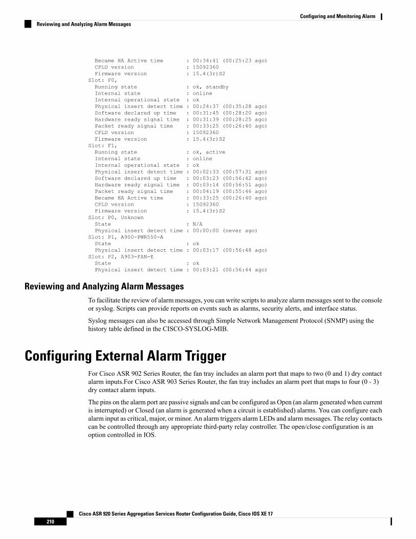
Became HA Active time : 00:34:41 (00:25:23 ago)CPLD version : 15092360Firmware version : 15.4(3r)S2
Slot: F0,Running state : ok, standbyInternal state : onlineInternal operational state : okPhysical insert detect time : 00:24:37 (00:35:28 ago)Software declared up time : 00:31:45 (00:28:20 ago)Hardware ready signal time : 00:31:39 (00:28:25 ago)Packet ready signal time : 00:33:25 (00:26:40 ago)CPLD version : 15092360Firmware version : 15.4(3r)S2
Slot: F1,Running state : ok, activeInternal state : onlineInternal operational state : okPhysical insert detect time : 00:02:33 (00:57:31 ago)Software declared up time : 00:03:23 (00:56:42 ago)Hardware ready signal time : 00:03:14 (00:56:51 ago)Packet ready signal time : 00:04:19 (00:55:46 ago)Became HA Active time : 00:33:25 (00:26:40 ago)CPLD version : 15092360Firmware version : 15.4(3r)S2
Slot: P0, UnknownState : N/APhysical insert detect time : 00:00:00 (never ago)
Slot: P1, A900-PWR550-AState : okPhysical insert detect time : 00:03:17 (00:56:48 ago)
Slot: P2, A903-FAN-EState : okPhysical insert detect time : 00:03:21 (00:56:44 ago)
Reviewing and Analyzing Alarm MessagesTo facilitate the review of alarmmessages, you can write scripts to analyze alarmmessages sent to the consoleor syslog. Scripts can provide reports on events such as alarms, security alerts, and interface status.
Syslog messages can also be accessed through Simple Network Management Protocol (SNMP) using thehistory table defined in the CISCO-SYSLOG-MIB.
Configuring External Alarm TriggerFor Cisco ASR 902 Series Router, the fan tray includes an alarm port that maps to two (0 and 1) dry contactalarm inputs.For Cisco ASR 903 Series Router, the fan tray includes an alarm port that maps to four (0 - 3)dry contact alarm inputs.
The pins on the alarm port are passive signals and can be configured as Open (an alarm generated when currentis interrupted) or Closed (an alarm is generated when a circuit is established) alarms. You can configure eachalarm input as critical, major, or minor. An alarm triggers alarm LEDs and alarmmessages. The relay contactscan be controlled through any appropriate third-party relay controller. The open/close configuration is anoption controlled in IOS.
Cisco ASR 920 Series Aggregation Services Router Configuration Guide, Cisco IOS XE 17210
Configuring and Monitoring AlarmReviewing and Analyzing Alarm Messages
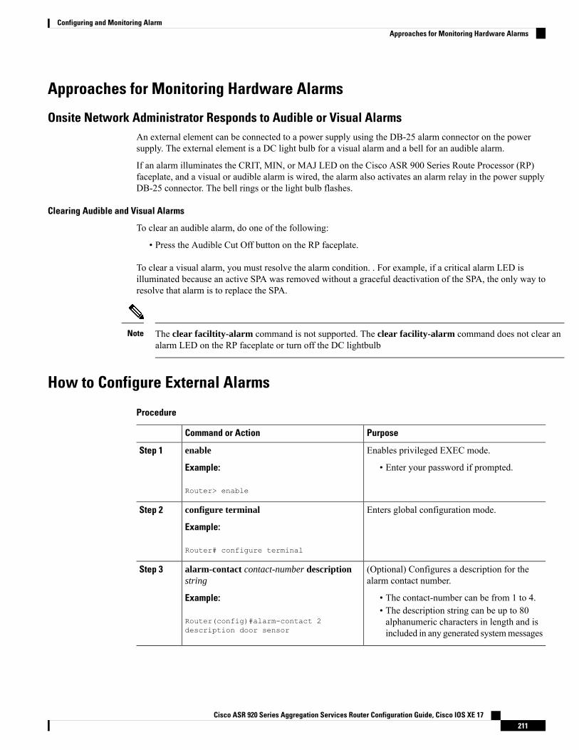
Approaches for Monitoring Hardware Alarms
Onsite Network Administrator Responds to Audible or Visual AlarmsAn external element can be connected to a power supply using the DB-25 alarm connector on the powersupply. The external element is a DC light bulb for a visual alarm and a bell for an audible alarm.
If an alarm illuminates the CRIT, MIN, or MAJ LED on the Cisco ASR 900 Series Route Processor (RP)faceplate, and a visual or audible alarm is wired, the alarm also activates an alarm relay in the power supplyDB-25 connector. The bell rings or the light bulb flashes.
Clearing Audible and Visual Alarms
To clear an audible alarm, do one of the following:
• Press the Audible Cut Off button on the RP faceplate.
To clear a visual alarm, you must resolve the alarm condition. . For example, if a critical alarm LED isilluminated because an active SPA was removed without a graceful deactivation of the SPA, the only way toresolve that alarm is to replace the SPA.
The clear faciltity-alarm command is not supported. The clear facility-alarm command does not clear analarm LED on the RP faceplate or turn off the DC lightbulb
Note
How to Configure External Alarms
Procedure
PurposeCommand or Action
Enables privileged EXEC mode.enableStep 1
Example: • Enter your password if prompted.
Router> enable
Enters global configuration mode.configure terminal
Example:
Step 2
Router# configure terminal
(Optional) Configures a description for thealarm contact number.
alarm-contact contact-number descriptionstring
Step 3
Example: • The contact-number can be from 1 to 4.• The description string can be up to 80alphanumeric characters in length and isincluded in any generated systemmessages
Router(config)#alarm-contact 2description door sensor
Cisco ASR 920 Series Aggregation Services Router Configuration Guide, Cisco IOS XE 17211
Configuring and Monitoring AlarmApproaches for Monitoring Hardware Alarms
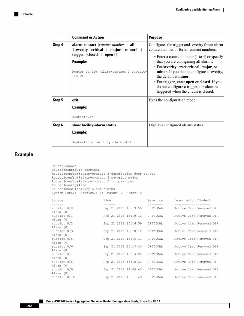
PurposeCommand or Action
Configures the trigger and severity for an alarmcontact number or for all contact numbers.
alarm-contact {contact-number | all{severity {critical | major | minor} |trigger {closed | open}}
Step 4
• Enter a contact number (1 to 4) or specifythat you are configuring all alarms.Example:
• For severity, enter critical, major, orminor. If you do not configure a severity,the default is minor.
Router(config)#alarm-contact 2 severitymajor
• For trigger, enter open or closed. If youdo not configure a trigger, the alarm istriggered when the circuit is closed.
Exits the configuration mode.exit
Example:
Step 5
Router#exit
Displays configured alarms status.show facility-alarm status
Example:
Step 6
Router#show facility-alarm status
Example
Router>enableRouter#configure terminalRouter(config)#alarm-contact 2 description door sensorRouter(config)#alarm-contact 2 severity majorRouter(config)#alarm-contact 2 trigger openRouter(config)#endRouter#show facility-alarm statusSystem Totals Critical: 15 Major: 0 Minor: 0
Source Time Severity Description [Index]------ ------ -------- -------------------subslot 0/0 Sep 21 2016 15:19:55 CRITICAL Active Card Removed OIRAlarm [0]subslot 0/1 Sep 21 2016 15:19:12 CRITICAL Active Card Removed OIRAlarm [0]subslot 0/2 Sep 21 2016 15:16:59 CRITICAL Active Card Removed OIRAlarm [0]subslot 0/3 Sep 21 2016 15:18:10 CRITICAL Active Card Removed OIRAlarm [0]subslot 0/5 Sep 21 2016 15:16:11 CRITICAL Active Card Removed OIRAlarm [0]subslot 0/6 Sep 21 2016 15:15:45 CRITICAL Active Card Removed OIRAlarm [0]subslot 0/7 Sep 21 2016 15:14:22 CRITICAL Active Card Removed OIRAlarm [0]subslot 0/8 Sep 21 2016 15:10:33 CRITICAL Active Card Removed OIRAlarm [0]subslot 0/9 Sep 21 2016 12:00:43 CRITICAL Active Card Removed OIRAlarm [0]subslot 0/10 Sep 21 2016 15:11:49 CRITICAL Active Card Removed OIR
Cisco ASR 920 Series Aggregation Services Router Configuration Guide, Cisco IOS XE 17212
Configuring and Monitoring AlarmExample
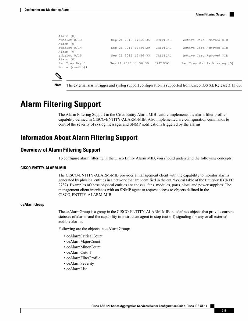
Alarm [0]subslot 0/13 Sep 21 2016 14:56:35 CRITICAL Active Card Removed OIRAlarm [0]subslot 0/14 Sep 21 2016 14:56:29 CRITICAL Active Card Removed OIRAlarm [0]subslot 0/15 Sep 21 2016 14:56:33 CRITICAL Active Card Removed OIRAlarm [0]Fan Tray Bay 0 Sep 21 2016 11:50:39 CRITICAL Fan Tray Module Missing [0]Router(config)#
The external alarm trigger and syslog support configuration is supported from Cisco IOS XE Release 3.13.0S.Note
Alarm Filtering SupportThe Alarm Filtering Support in the Cisco Entity Alarm MIB feature implements the alarm filter profilecapability defined in CISCO-ENTITY-ALARM-MIB. Also implemented are configuration commands tocontrol the severity of syslog messages and SNMP notifications triggered by the alarms.
Information About Alarm Filtering Support
Overview of Alarm Filtering SupportTo configure alarm filtering in the Cisco Entity Alarm MIB, you should understand the following concepts:
CISCO-ENTITY-ALARM-MIB
The CISCO-ENTITY-ALARM-MIB provides a management client with the capability to monitor alarmsgenerated by physical entities in a network that are identified in the entPhysicalTable of the Entity-MIB (RFC2737). Examples of these physical entities are chassis, fans, modules, ports, slots, and power supplies. Themanagement client interfaces with an SNMP agent to request access to objects defined in theCISCO-ENTITY-ALARM-MIB.
ceAlarmGroup
The ceAlarmGroup is a group in the CISCO-ENTITY-ALARM-MIB that defines objects that provide currentstatuses of alarms and the capability to instruct an agent to stop (cut off) signaling for any or all externalaudible alarms.
Following are the objects in ceAlarmGroup:
• ceAlarmCriticalCount• ceAlarmMajorCount• ceAlarmMinorCount• ceAlarmCutoff• ceAlarmFilterProfile• ceAlarmSeverity• ceAlarmList
Cisco ASR 920 Series Aggregation Services Router Configuration Guide, Cisco IOS XE 17213
Configuring and Monitoring AlarmAlarm Filtering Support
ceAlarmFilterProfileTable
The ceAlarmFilterProfileTable filters alarms according to configured alarm lists. The filtered alarms are thensent out as SNMP notifications or syslog messages, based on the alarm list enabled for each alarm type. Thistable is defined in the CISCO-ENTITY-ALARM-MIB and implemented in the group ceAlarmGroup.
ceAlarmFilterProfile
An alarm filter profile controls the alarm types that an agent monitors and signals for a corresponding physicalentity. The ceAlarmFilterProfile object holds an integer value that uniquely identifies an alarm filter profileassociated with a corresponding physical entity. When the value is zero, the agent monitors and signals allalarms associated with the corresponding physical entity.
ceAlarmHistTable:
This table contains the history of ceAlarmAsserted and ceAlarmCleared traps generated by the agent.
Each entry to the table will have physical index from entPhsicalTable and the severity of the alarm.
The ceAlarmAsserted and ceAlarmCleared trap varbinds are mostly from this table and the description fromceAlarmDescrTable.
ceAlarmDescrTable:
This table contains a description for each alarm type defined by each vendor type employed by the system.
This table has the list of possible severity levels and the description for the physical entity, Object“ceAlarmDescrSeverity” indicates the severity of an alarm (1 to 4 as above).
ceAlarmTable:
This table specifies alarm control and status information related to each physical entity contained by thesystem, including the alarms currently being asserted by each physical entity capable of generating alarms.
Prerequisites for Alarm Filtering Support• SNMP is configured on your routing devices.• Familiarity with the ENTITY-MIB and the CISCO-ENTITY-ALARM-MIB.
Restrictions for Alarm Filtering Support• The CISCO-ENTITY-ALARM-MIB supports reporting of alarms for physical entities only, includingchassis, slots, modules, ports, power supplies, and fans. In order to monitor alarms generated by a physicalentity,it must be represented by a row in the entPhysicalTable .
HowtoConfigureAlarmFilteringforSyslogMessagesandSNMPNotifications
Configuring Alarm Filtering for Syslog MessagesThis task describes how to configure the alarm severity threshold for generating syslog messages. When youuse this command, the alarm severity threshold is included in the running configuration and automaticallyapplied when the configuration is reloaded.
enableconfigure terminal
Cisco ASR 920 Series Aggregation Services Router Configuration Guide, Cisco IOS XE 17214
Configuring and Monitoring AlarmceAlarmFilterProfileTable
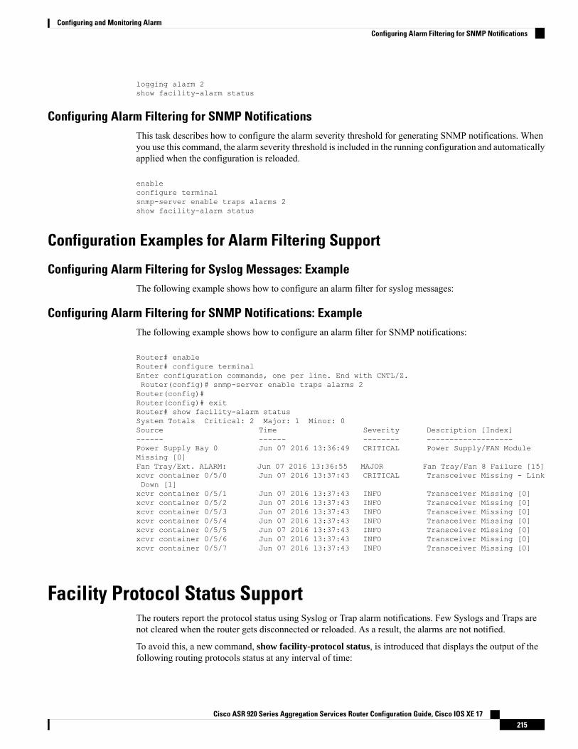
logging alarm 2show facility-alarm status
Configuring Alarm Filtering for SNMP NotificationsThis task describes how to configure the alarm severity threshold for generating SNMP notifications. Whenyou use this command, the alarm severity threshold is included in the running configuration and automaticallyapplied when the configuration is reloaded.
enableconfigure terminalsnmp-server enable traps alarms 2show facility-alarm status
Configuration Examples for Alarm Filtering Support
Configuring Alarm Filtering for Syslog Messages: ExampleThe following example shows how to configure an alarm filter for syslog messages:
Configuring Alarm Filtering for SNMP Notifications: ExampleThe following example shows how to configure an alarm filter for SNMP notifications:
Router# enableRouter# configure terminalEnter configuration commands, one per line. End with CNTL/Z.Router(config)# snmp-server enable traps alarms 2Router(config)#Router(config)# exitRouter# show facility-alarm statusSystem Totals Critical: 2 Major: 1 Minor: 0Source Time Severity Description [Index]------ ------ -------- -------------------Power Supply Bay 0 Jun 07 2016 13:36:49 CRITICAL Power Supply/FAN ModuleMissing [0]Fan Tray/Ext. ALARM: Jun 07 2016 13:36:55 MAJOR Fan Tray/Fan 8 Failure [15]xcvr container 0/5/0 Jun 07 2016 13:37:43 CRITICAL Transceiver Missing - LinkDown [1]xcvr container 0/5/1 Jun 07 2016 13:37:43 INFO Transceiver Missing [0]xcvr container 0/5/2 Jun 07 2016 13:37:43 INFO Transceiver Missing [0]xcvr container 0/5/3 Jun 07 2016 13:37:43 INFO Transceiver Missing [0]xcvr container 0/5/4 Jun 07 2016 13:37:43 INFO Transceiver Missing [0]xcvr container 0/5/5 Jun 07 2016 13:37:43 INFO Transceiver Missing [0]xcvr container 0/5/6 Jun 07 2016 13:37:43 INFO Transceiver Missing [0]xcvr container 0/5/7 Jun 07 2016 13:37:43 INFO Transceiver Missing [0]
Facility Protocol Status SupportThe routers report the protocol status using Syslog or Trap alarm notifications. Few Syslogs and Traps arenot cleared when the router gets disconnected or reloaded. As a result, the alarms are not notified.
To avoid this, a new command, show facility-protocol status, is introduced that displays the output of thefollowing routing protocols status at any interval of time:
Cisco ASR 920 Series Aggregation Services Router Configuration Guide, Cisco IOS XE 17215
Configuring and Monitoring AlarmConfiguring Alarm Filtering for SNMP Notifications
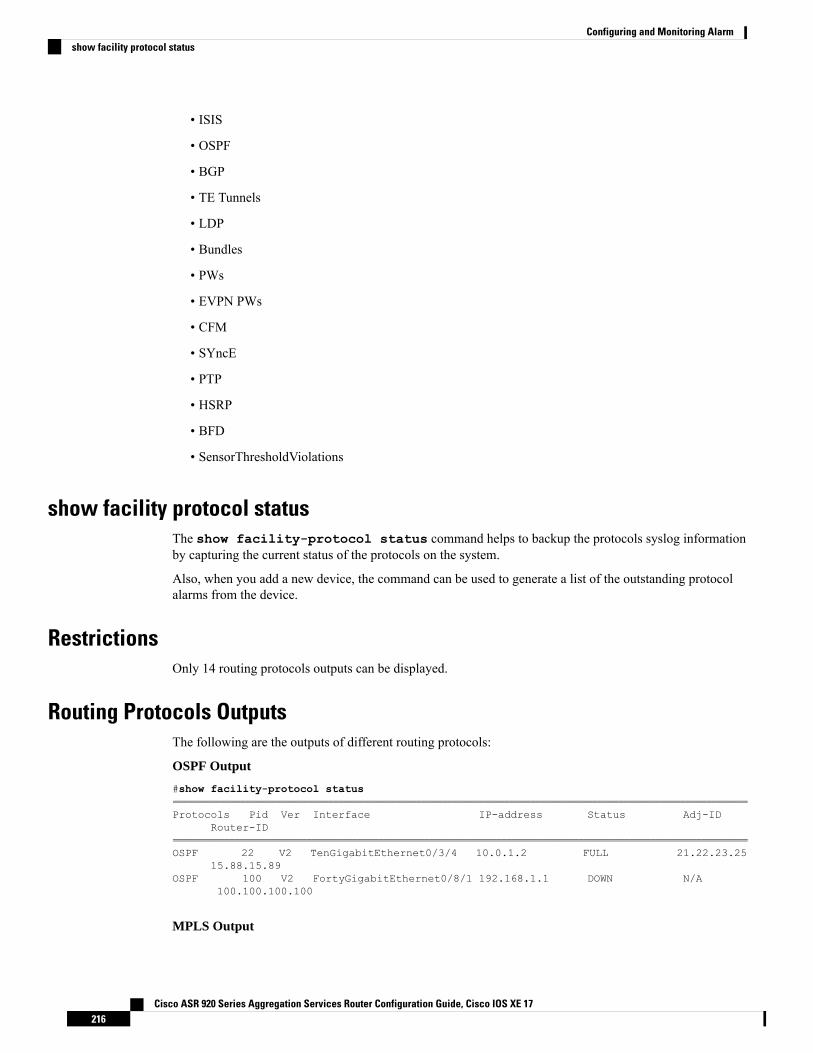
• ISIS
• OSPF
• BGP
• TE Tunnels
• LDP
• Bundles
• PWs
• EVPN PWs
• CFM
• SYncE
• PTP
• HSRP
• BFD
• SensorThresholdViolations
show facility protocol statusThe show facility-protocol status command helps to backup the protocols syslog informationby capturing the current status of the protocols on the system.
Also, when you add a new device, the command can be used to generate a list of the outstanding protocolalarms from the device.
RestrictionsOnly 14 routing protocols outputs can be displayed.
Routing Protocols OutputsThe following are the outputs of different routing protocols:
OSPF Output
#show facility-protocol status===============================================================================================================Protocols Pid Ver Interface IP-address Status Adj-ID
Router-ID================================================================================================================OSPF 22 V2 TenGigabitEthernet0/3/4 10.0.1.2 FULL 21.22.23.25
15.88.15.89OSPF 100 V2 FortyGigabitEthernet0/8/1 192.168.1.1 DOWN N/A
100.100.100.100
MPLS Output
Cisco ASR 920 Series Aggregation Services Router Configuration Guide, Cisco IOS XE 17216
Configuring and Monitoring Alarmshow facility protocol status
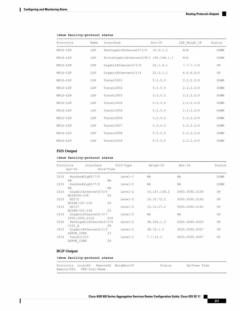
#show facility-protocol status=================================================================================================Protocols Name Interface Src-IP LDP_Neigh_IP Status===================================================================================================MPLS-LDP LDP TenGigabitEthernet0/3/4 10.0.1.2 N/A DOWN
MPLS-LDP LDP FortyGigabitEthernet0/8/1 192.168.1.1 N/A DOWN
MPLS-LDP LDP GigabitEthernet0/2/0 22.1.4.1 7.7.7.7:0 UP
MPLS-LDP LDP GigabitEthernet0/2/4 22.0.1.1 6.6.6.6:0 UP
MPLS-LDP LDP Tunnel2001 5.5.5.5 2.2.2.2:0 DOWN
MPLS-LDP LDP Tunnel2002 5.5.5.5 2.2.2.2:0 DOWN
MPLS-LDP LDP Tunnel2003 5.5.5.5 2.2.2.2:0 DOWN
MPLS-LDP LDP Tunnel2004 5.5.5.5 2.2.2.2:0 DOWN
MPLS-LDP LDP Tunnel2005 5.5.5.5 2.2.2.2:0 DOWN
MPLS-LDP LDP Tunnel2006 5.5.5.5 2.2.2.2:0 DOWN
MPLS-LDP LDP Tunnel2007 5.5.5.5 2.2.2.2:0 DOWN
MPLS-LDP LDP Tunnel2008 5.5.5.5 2.2.2.2:0 DOWN
MPLS-LDP LDP Tunnel2009 5.5.5.5 2.2.2.2:0 DOWN
ISIS Output
#show facility-protocol status==========================================================================================================================Protocols Interface ISIS-Type Neigh-IP Net-ID Status
Sys-ID Hold-Time==========================================================================================================================ISIS HundredGigE0/7/0 Level-1 NA NA DOWN
NA NAISIS HundredGigE0/7/0 Level-2 NA NA DOWN
NA NAISIS GigabitEthernet0/3/4 Level-2 10.147.158.2 0000.0000.0158 UP
NCS4206-158 26ISIS BDI72 Level-2 10.10.72.2 0000.0000.0162 UP
NCS4K-101-162 29ISIS BDI27 Level-2 10.10.27.2 0000.0000.0162 UP
NCS4K-101-162 23ISIS GigabitEthernet0/0/7 Level-2 NA NA UP
0000.0000.0152 250ISIS TenGigabitEthernet0/3/0 Level-2 38.206.1.3 0000.0000.0023 UP
C101_A 28ISIS GigabitEthernet0/2/3 Level-2 38.76.1.3 0000.0000.0007 UP
ASR9K_CORE 23ISIS Tunnel1315 Level-2 7.7.15.2 0000.0000.0007 UP
ASR9K_CORE 28
BGP Output
#show facility-protocol status=================================================================================================================Protocols LocalAS RemoteAS NeighborIP Status Up/Down TimeRemote-RID VRF-Inst-Name=================================================================================================================
Cisco ASR 920 Series Aggregation Services Router Configuration Guide, Cisco IOS XE 17217
Configuring and Monitoring AlarmRouting Protocols Outputs
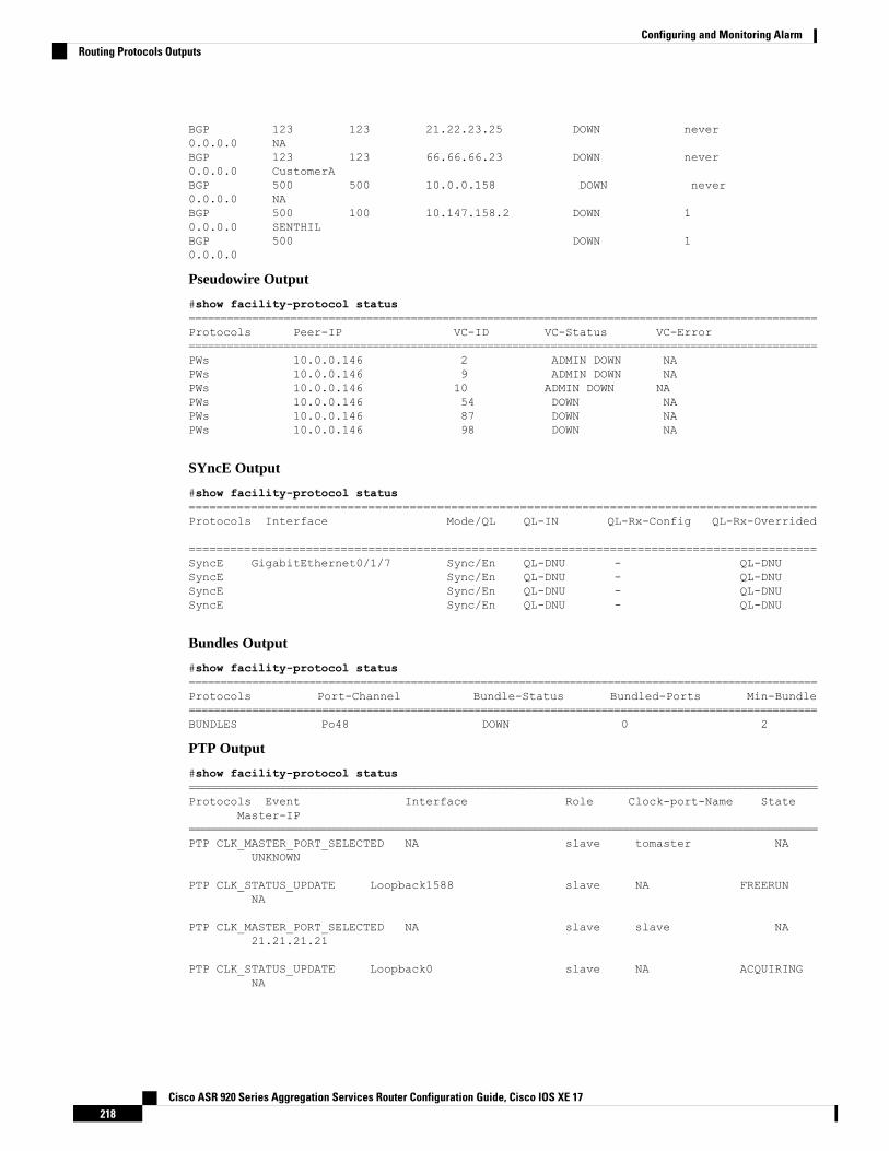
BGP 123 123 21.22.23.25 DOWN never0.0.0.0 NABGP 123 123 66.66.66.23 DOWN never0.0.0.0 CustomerABGP 500 500 10.0.0.158 DOWN never0.0.0.0 NABGP 500 100 10.147.158.2 DOWN 10.0.0.0 SENTHILBGP 500 DOWN 10.0.0.0
Pseudowire Output
#show facility-protocol status===================================================================================================Protocols Peer-IP VC-ID VC-Status VC-Error===================================================================================================PWs 10.0.0.146 2 ADMIN DOWN NAPWs 10.0.0.146 9 ADMIN DOWN NAPWs 10.0.0.146 10 ADMIN DOWN NAPWs 10.0.0.146 54 DOWN NAPWs 10.0.0.146 87 DOWN NAPWs 10.0.0.146 98 DOWN NA
SYncE Output
#show facility-protocol status===========================================================================================Protocols Interface Mode/QL QL-IN QL-Rx-Config QL-Rx-Overrided
===========================================================================================SyncE GigabitEthernet0/1/7 Sync/En QL-DNU - QL-DNUSyncE Sync/En QL-DNU - QL-DNUSyncE Sync/En QL-DNU - QL-DNUSyncE Sync/En QL-DNU - QL-DNU
Bundles Output
#show facility-protocol status===================================================================================================Protocols Port-Channel Bundle-Status Bundled-Ports Min-Bundle===================================================================================================BUNDLES Po48 DOWN 0 2
PTP Output
#show facility-protocol status==============================================================================================================Protocols Event Interface Role Clock-port-Name State
Master-IP==============================================================================================================PTP CLK_MASTER_PORT_SELECTED NA slave tomaster NA
UNKNOWN
PTP CLK_STATUS_UPDATE Loopback1588 slave NA FREERUNNA
PTP CLK_MASTER_PORT_SELECTED NA slave slave NA21.21.21.21
PTP CLK_STATUS_UPDATE Loopback0 slave NA ACQUIRINGNA
Cisco ASR 920 Series Aggregation Services Router Configuration Guide, Cisco IOS XE 17218
Configuring and Monitoring AlarmRouting Protocols Outputs
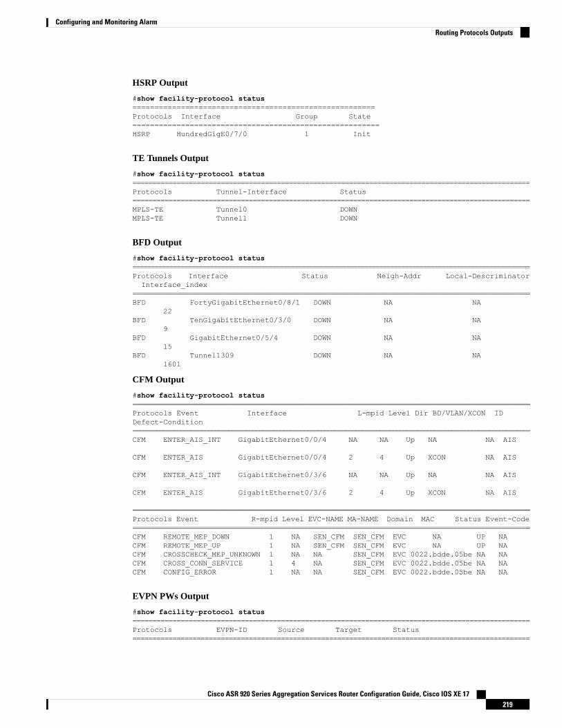
HSRP Output
#show facility-protocol status=======================================================Protocols Interface Group State========================================================HSRP HundredGigE0/7/0 1 Init
TE Tunnels Output
#show facility-protocol status===================================================================================================Protocols Tunnel-Interface Status===================================================================================================MPLS-TE Tunnel0 DOWNMPLS-TE Tunnel1 DOWN
BFD Output
#show facility-protocol status============================================================================================================Protocols Interface Status Neigh-Addr Local-DescriminatorInterface_index
================================================================================================================BFD FortyGigabitEthernet0/8/1 DOWN NA NA
22BFD TenGigabitEthernet0/3/0 DOWN NA NA
9BFD GigabitEthernet0/5/4 DOWN NA NA
15BFD Tunnel1309 DOWN NA NA
1601
CFM Output
#show facility-protocol status=================================================================================================================Protocols Event Interface L-mpid Level Dir BD/VLAN/XCON IDDefect-Condition====================================================================================================================CFM ENTER_AIS_INT GigabitEthernet0/0/4 NA NA Up NA NA AIS
CFM ENTER_AIS GigabitEthernet0/0/4 2 4 Up XCON NA AIS
CFM ENTER_AIS_INT GigabitEthernet0/3/6 NA NA Up NA NA AIS
CFM ENTER_AIS GigabitEthernet0/3/6 2 4 Up XCON NA AIS
==================================================================================================================Protocols Event R-mpid Level EVC-NAME MA-NAME Domain MAC Status Event-Code=====================================================================================================================CFM REMOTE_MEP_DOWN 1 NA SEN_CFM SEN_CFM EVC NA UP NACFM REMOTE_MEP_UP 1 NA SEN_CFM SEN_CFM EVC NA UP NACFM CROSSCHECK_MEP_UNKNOWN 1 NA NA SEN_CFM EVC 0022.bdde.05be NA NACFM CROSS_CONN_SERVICE 1 4 NA SEN_CFM EVC 0022.bdde.05be NA NACFM CONFIG_ERROR 1 NA NA SEN_CFM EVC 0022.bdde.05be NA NA
EVPN PWs Output
#show facility-protocol status===================================================================================================Protocols EVPN-ID Source Target Status===================================================================================================
Cisco ASR 920 Series Aggregation Services Router Configuration Guide, Cisco IOS XE 17219
Configuring and Monitoring AlarmRouting Protocols Outputs
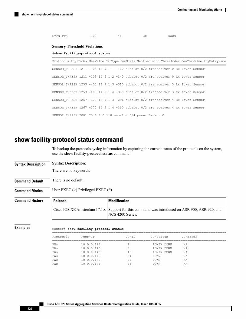
EVPN-PWs 100 41 30 DOWN
Sensory Threshold Violations
#show facility-protocol status============================================================================================================Protocols PhylIndex SenValue SenType SenScale SenPrecision ThresIndex SenThrValue PhyEntryName===============================================================================================================SENSOR_THRESH 1211 -103 14 9 1 1 -120 subslot 0/2 transceiver 0 Rx Power Sensor
SENSOR_THRESH 1211 -103 14 9 1 2 -140 subslot 0/2 transceiver 0 Rx Power Sensor
SENSOR_THRESH 1253 -400 14 9 1 3 -310 subslot 0/2 transceiver 3 Rx Power Sensor
SENSOR_THRESH 1253 -400 14 9 1 4 -330 subslot 0/2 transceiver 3 Rx Power Sensor
SENSOR_THRESH 1267 -370 14 9 1 3 -296 subslot 0/2 transceiver 4 Rx Power Sensor
SENSOR_THRESH 1267 -370 14 9 1 4 -310 subslot 0/2 transceiver 4 Rx Power Sensor
SENSOR_THRESH 2001 73 6 9 0 1 0 subslot 0/4 power Sensor 0
show facility-protocol status commandTo backup the protocols syslog information by capturing the current status of the protocols on the system,use the show facility-protocol status command.
Syntax Description Syntax Description:
There are no keywords.
Command Default There is no default.
Command Modes User EXEC (>) Privileged EXEC (#)
Command History ModificationRelease
Support for this command was introduced on ASR 900, ASR 920, andNCS 4200 Series.
Cisco IOSXEAmsterdam 17.1.x
Examples Router# show facility-protocol status===================================================================================================Protocols Peer-IP VC-ID VC-Status VC-Error===================================================================================================PWs 10.0.0.146 2 ADMIN DOWN NAPWs 10.0.0.146 9 ADMIN DOWN NAPWs 10.0.0.146 10 ADMIN DOWN NAPWs 10.0.0.146 54 DOWN NAPWs 10.0.0.146 87 DOWN NAPWs 10.0.0.146 98 DOWN NA
Cisco ASR 920 Series Aggregation Services Router Configuration Guide, Cisco IOS XE 17220
Configuring and Monitoring Alarmshow facility-protocol status command

C H A P T E R 19Tracing and Trace Management
• Tracing Overview, on page 221• How Tracing Works, on page 221• Tracing Levels, on page 222• Viewing a Tracing Level, on page 223• Setting a Tracing Level, on page 224• Viewing the Content of the Trace Buffer, on page 224
Tracing OverviewTracing is a function that logs internal events. Trace files are automatically created and saved to the tracelogsdirectory on the harddisk: file system on the router, which stores tracing files in bootflash:. Trace files areused to store tracing data.
The contents of trace files are useful for the following purposes:
• Troubleshooting—If a router is having an issue, the trace file output may provide information that isuseful for locating and solving the problem. Trace files can almost always be accessed through diagnosticmode even if other system issues are occurring.
• Debugging—The trace file outputs can help users get a more detailed view of system actions andoperations.
How Tracing WorksThe tracing function logs the contents of internal events on the router. Trace files with all trace output for amodule are periodically created and updated and are stored in the tracelog directory. Trace files can be erasedfrom this directory to recover space on the file system without impacting system performance.
The most recent trace information for a specific module can be viewed using the show platform softwaretrace message privileged EXEC and diagnostic mode command. This command can be entered to gathertrace log information even during an IOS failure because it is available in diagnostic mode.
Trace files can be copied to other destinations using most file transfer functions (such as FTP, TFTP, and soon) and opened using a plaintext editor.
Tracing cannot be disabled on the router. Trace levels, however, which set the message types that generatetrace output, are user-configurable and can be set using the set platform software trace command. If a user
Cisco ASR 920 Series Aggregation Services Router Configuration Guide, Cisco IOS XE 17221
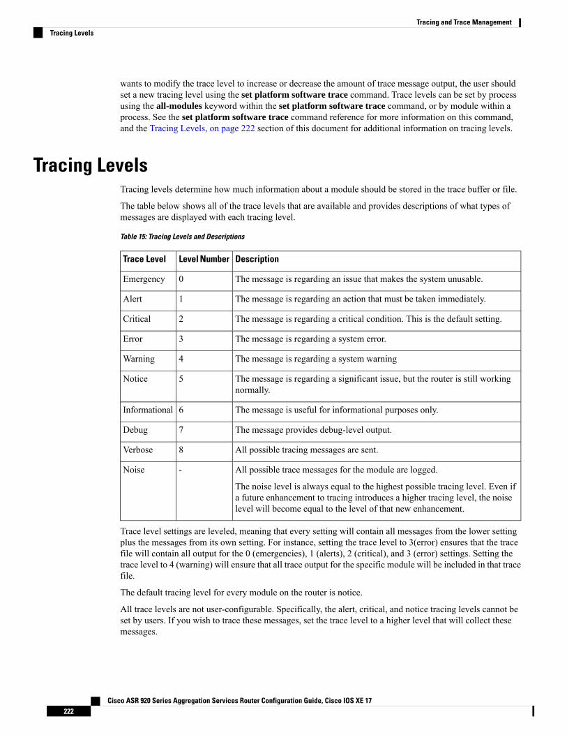
wants to modify the trace level to increase or decrease the amount of trace message output, the user shouldset a new tracing level using the set platform software trace command. Trace levels can be set by processusing the all-modules keyword within the set platform software trace command, or by module within aprocess. See the set platform software trace command reference for more information on this command,and the Tracing Levels, on page 222 section of this document for additional information on tracing levels.
Tracing LevelsTracing levels determine how much information about a module should be stored in the trace buffer or file.
The table below shows all of the trace levels that are available and provides descriptions of what types ofmessages are displayed with each tracing level.
Table 15: Tracing Levels and Descriptions
DescriptionLevel NumberTrace Level
The message is regarding an issue that makes the system unusable.0Emergency
The message is regarding an action that must be taken immediately.1Alert
The message is regarding a critical condition. This is the default setting.2Critical
The message is regarding a system error.3Error
The message is regarding a system warning4Warning
The message is regarding a significant issue, but the router is still workingnormally.
5Notice
The message is useful for informational purposes only.6Informational
The message provides debug-level output.7Debug
All possible tracing messages are sent.8Verbose
All possible trace messages for the module are logged.
The noise level is always equal to the highest possible tracing level. Even ifa future enhancement to tracing introduces a higher tracing level, the noiselevel will become equal to the level of that new enhancement.
-Noise
Trace level settings are leveled, meaning that every setting will contain all messages from the lower settingplus the messages from its own setting. For instance, setting the trace level to 3(error) ensures that the tracefile will contain all output for the 0 (emergencies), 1 (alerts), 2 (critical), and 3 (error) settings. Setting thetrace level to 4 (warning) will ensure that all trace output for the specific module will be included in that tracefile.
The default tracing level for every module on the router is notice.
All trace levels are not user-configurable. Specifically, the alert, critical, and notice tracing levels cannot beset by users. If you wish to trace these messages, set the trace level to a higher level that will collect thesemessages.
Cisco ASR 920 Series Aggregation Services Router Configuration Guide, Cisco IOS XE 17222
Tracing and Trace ManagementTracing Levels
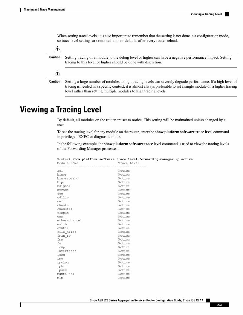
When setting trace levels, it is also important to remember that the setting is not done in a configuration mode,so trace level settings are returned to their defaults after every router reload.
Setting tracing of a module to the debug level or higher can have a negative performance impact. Settingtracing to this level or higher should be done with discretion.
Caution
Setting a large number of modules to high tracing levels can severely degrade performance. If a high level oftracing is needed in a specific context, it is almost always preferable to set a single module on a higher tracinglevel rather than setting multiple modules to high tracing levels.
Caution
Viewing a Tracing LevelBy default, all modules on the router are set to notice. This setting will be maintained unless changed by auser.
To see the tracing level for any module on the router, enter the show platform software trace level commandin privileged EXEC or diagnostic mode.
In the following example, the show platform software trace level command is used to view the tracing levelsof the Forwarding Manager processes:
Router# show platform software trace level forwarding-manager rp activeModule Name Trace Level-----------------------------------------------acl Noticebinos Noticebinos/brand Noticebipc Noticebsignal Noticebtrace Noticecce Noticecdllib Noticecef Noticechasfs Noticechasutil Noticeerspan Noticeess Noticeether-channel Noticeevlib Noticeevutil Noticefile_alloc Noticefman_rp Noticefpm Noticefw Noticeicmp Noticeinterfaces Noticeiosd Noticeipc Noticeipclog Noticeiphc Noticeipsec Noticemgmte-acl Noticemlp Notice
Cisco ASR 920 Series Aggregation Services Router Configuration Guide, Cisco IOS XE 17223
Tracing and Trace ManagementViewing a Tracing Level
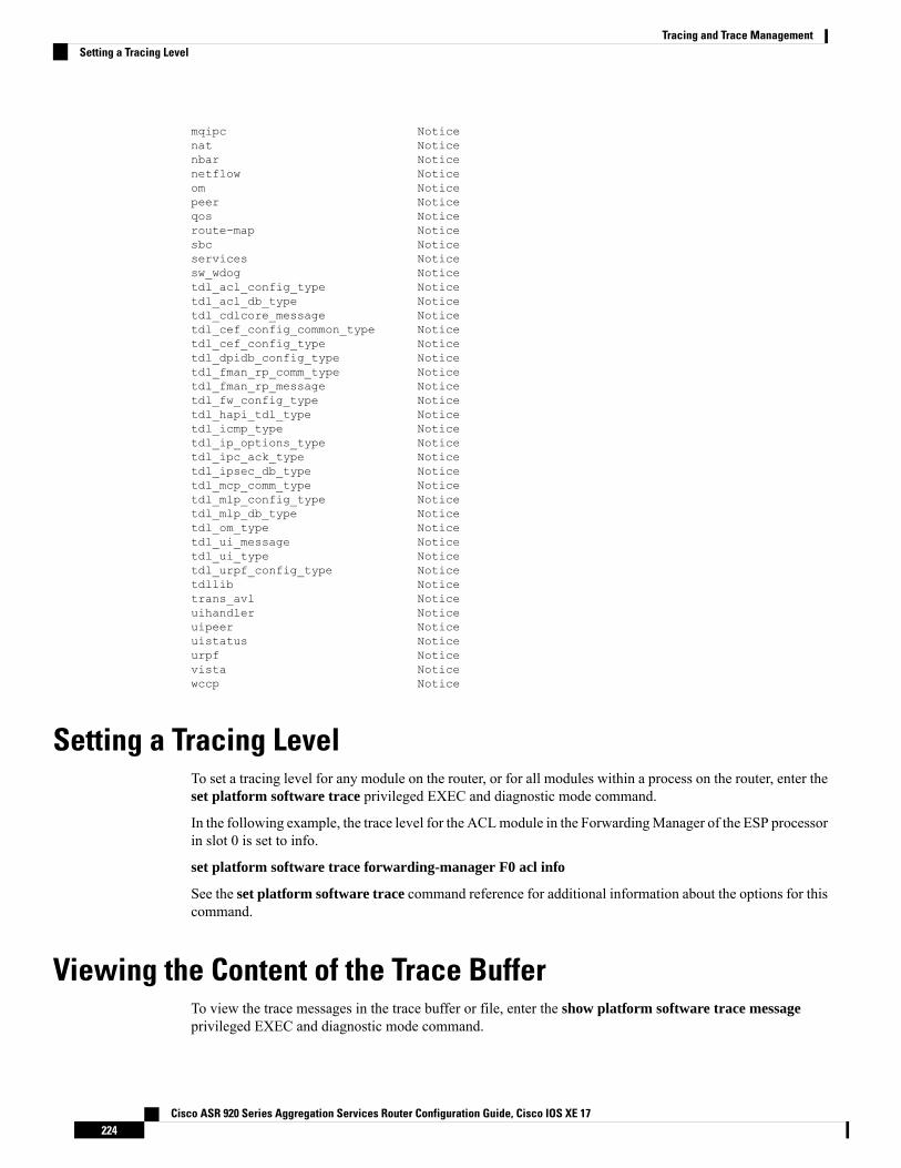
mqipc Noticenat Noticenbar Noticenetflow Noticeom Noticepeer Noticeqos Noticeroute-map Noticesbc Noticeservices Noticesw_wdog Noticetdl_acl_config_type Noticetdl_acl_db_type Noticetdl_cdlcore_message Noticetdl_cef_config_common_type Noticetdl_cef_config_type Noticetdl_dpidb_config_type Noticetdl_fman_rp_comm_type Noticetdl_fman_rp_message Noticetdl_fw_config_type Noticetdl_hapi_tdl_type Noticetdl_icmp_type Noticetdl_ip_options_type Noticetdl_ipc_ack_type Noticetdl_ipsec_db_type Noticetdl_mcp_comm_type Noticetdl_mlp_config_type Noticetdl_mlp_db_type Noticetdl_om_type Noticetdl_ui_message Noticetdl_ui_type Noticetdl_urpf_config_type Noticetdllib Noticetrans_avl Noticeuihandler Noticeuipeer Noticeuistatus Noticeurpf Noticevista Noticewccp Notice
Setting a Tracing LevelTo set a tracing level for any module on the router, or for all modules within a process on the router, enter theset platform software trace privileged EXEC and diagnostic mode command.
In the following example, the trace level for the ACLmodule in the ForwardingManager of the ESP processorin slot 0 is set to info.
set platform software trace forwarding-manager F0 acl info
See the set platform software trace command reference for additional information about the options for thiscommand.
Viewing the Content of the Trace BufferTo view the trace messages in the trace buffer or file, enter the show platform software trace messageprivileged EXEC and diagnostic mode command.
Cisco ASR 920 Series Aggregation Services Router Configuration Guide, Cisco IOS XE 17224
Tracing and Trace ManagementSetting a Tracing Level
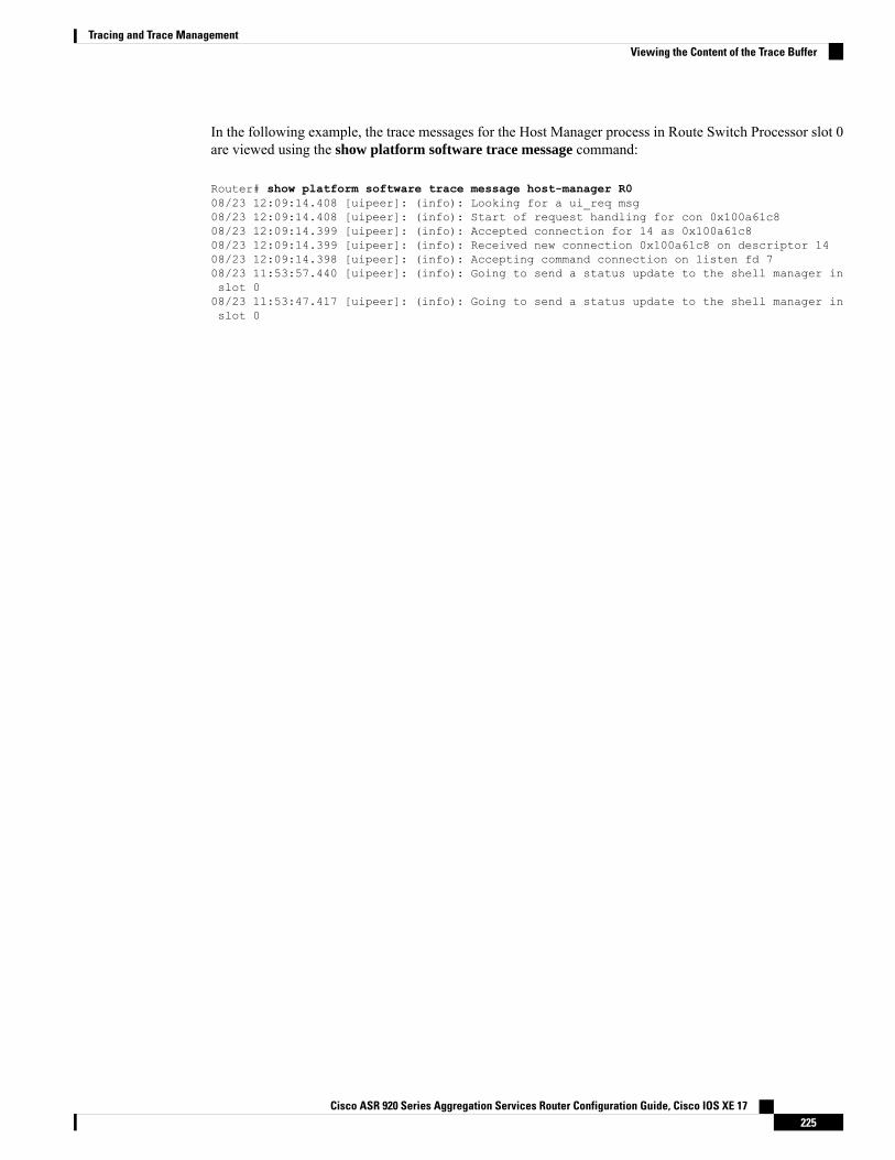
In the following example, the trace messages for the Host Manager process in Route Switch Processor slot 0are viewed using the show platform software trace message command:
Router# show platform software trace message host-manager R008/23 12:09:14.408 [uipeer]: (info): Looking for a ui_req msg08/23 12:09:14.408 [uipeer]: (info): Start of request handling for con 0x100a61c808/23 12:09:14.399 [uipeer]: (info): Accepted connection for 14 as 0x100a61c808/23 12:09:14.399 [uipeer]: (info): Received new connection 0x100a61c8 on descriptor 1408/23 12:09:14.398 [uipeer]: (info): Accepting command connection on listen fd 708/23 11:53:57.440 [uipeer]: (info): Going to send a status update to the shell manager inslot 008/23 11:53:47.417 [uipeer]: (info): Going to send a status update to the shell manager inslot 0
Cisco ASR 920 Series Aggregation Services Router Configuration Guide, Cisco IOS XE 17225
Tracing and Trace ManagementViewing the Content of the Trace Buffer

Cisco ASR 920 Series Aggregation Services Router Configuration Guide, Cisco IOS XE 17226
Tracing and Trace ManagementViewing the Content of the Trace Buffer
C H A P T E R 20BCP Support on MLPPP
This feature module describes how to configure Bridge Control Protocol (BCP) Support over Multilink PPP(MLPPP).
This feature is only applicable for Cisco ASR 900 RSP2 Module.Note
• Finding Feature Information, on page 227• Information About BCP Support on MLPPP, on page 228• How to Configure BCP Support on MLPPP, on page 229• Configuration Examples for BCP Support on MLPPP, on page 236• Additional References, on page 244• Feature Information for BCP Support on MLPPP, on page 245
Finding Feature InformationYour software release may not support all the features documented in this module. For the latest featureinformation and caveats, see the release notes for your platform and software release. To find informationabout the features documented in this module, and to see a list of the releases in which each feature is supported,see the Feature Information for BCP Support on MLPPP section.
Use Cisco Feature Navigator to find information about platform support and Cisco software image support.To access Cisco Feature Navigator, go to http://www.cisco.com/go/cfn. An account on Cisco.com is notrequired.
Prerequisites for BCP Support on MLPPP• Cisco IOS XE Everest 16.5.1 or a later release that supports the BCP Support on MLPPP feature mustbe installed previously on the Cisco ASR 900.
Restrictions for BCP Support on MLPPP• IPv6 is not supported.• Routing is not supported, hence, BDI is also not supported on BCP over MLPPP.
Cisco ASR 920 Series Aggregation Services Router Configuration Guide, Cisco IOS XE 17227
• Spanning Tree Protocol (STP) and Resilient Ethernet Protocol (REP) are not supported.• Jumbo frames are not supported.• Supports 16 T1/E1 and OC3 IM only. A maximum number of 16 (0-15) links per MLPPP bundle aresupported, where traffic rate is not beyond MLPPP bandwidth. For E1 link, 16 E1 serial interfaces canbe in one MLPPP bundle. For T1, 16 T1 links can be in one MLPPP bundle.
• The following encapsulations are not supported: QinQ, dot1ad, and dot1ad-dot1q .• You cannot configure default or untagged encapsulations on two different multilinks. When default isconfigured on a multilink, you can configure another EFP as untagged on the same multilink. Foruntagged, the same multilink cannot have another EFP configured as untagged.
• Two different multilinks cannot bridge the same encapsulated VLAN.• The same bridge domain cannot be configured twice on the same interface.• Connectivity Fault Management (CFM), Y.1731, and Layer 2 protocol forward tagged are not supported.• Set qos-group is not supported in the output policy of physical Gigabit interface and EVC of the multilinkinterface. Set qos-group on ASR 903 will not mark the packet. The scope of the set qos-group is limitedto the router.
• QoS policy is not supported on multilink at the interface level. However, it is supported on differentEVCs of the multilink interfaces.
• Qos-group classification will work only on the egress interface or EFP interface.
• The MLPPP interface bundle supports only a maximum of 64 EVCs.• A miximum of 64 VLANs are supported across all the MLPPPs.
• Layer 3 traffic with default encapsulation is not supported.• Multicast and IGMP is not supported.• For ingress classification to work, it should be classified based on “match cos inner <>” or “match vlaninner <>”.
• Layer 2 QoS behavior is supported only on tagged/priority tagged packets. It is not supported for untaggedpackets.
• Only 1r2C policer is supported at the egress.
• With BCP on MLPPP, the COS bits in the paylod are not preserved end to end.
Information About BCP Support on MLPPPThe BCP, as described in RFC 3518, is responsible for configuring, enabling and disabling the bridge protocolmodules on both ends of the point-to-point link. The BCP feature enables forwarding of Ethernet frames overserial networks, and provides a high-speed extension of enterprise LAN backbone traffic through ametropolitanarea.
When BCP is supported on MLPPP, it enables transport of Ethernet Layer 2 frames through MLPPP. In thefollowing diagram, Bridge-A is connected to Bridge-B using MLPPP. The MLPPP bundle acts as a trunk linkconnecting Bridge-A and Bridge-B, transportingmultiple VLANs. Using this feature, the hosts in VLAN 100,who are connected to Bridge-A, can talk to the hosts in VLAN 200, who are connected to Bridge-B.
Cisco ASR 920 Series Aggregation Services Router Configuration Guide, Cisco IOS XE 17228
BCP Support on MLPPPInformation About BCP Support on MLPPP
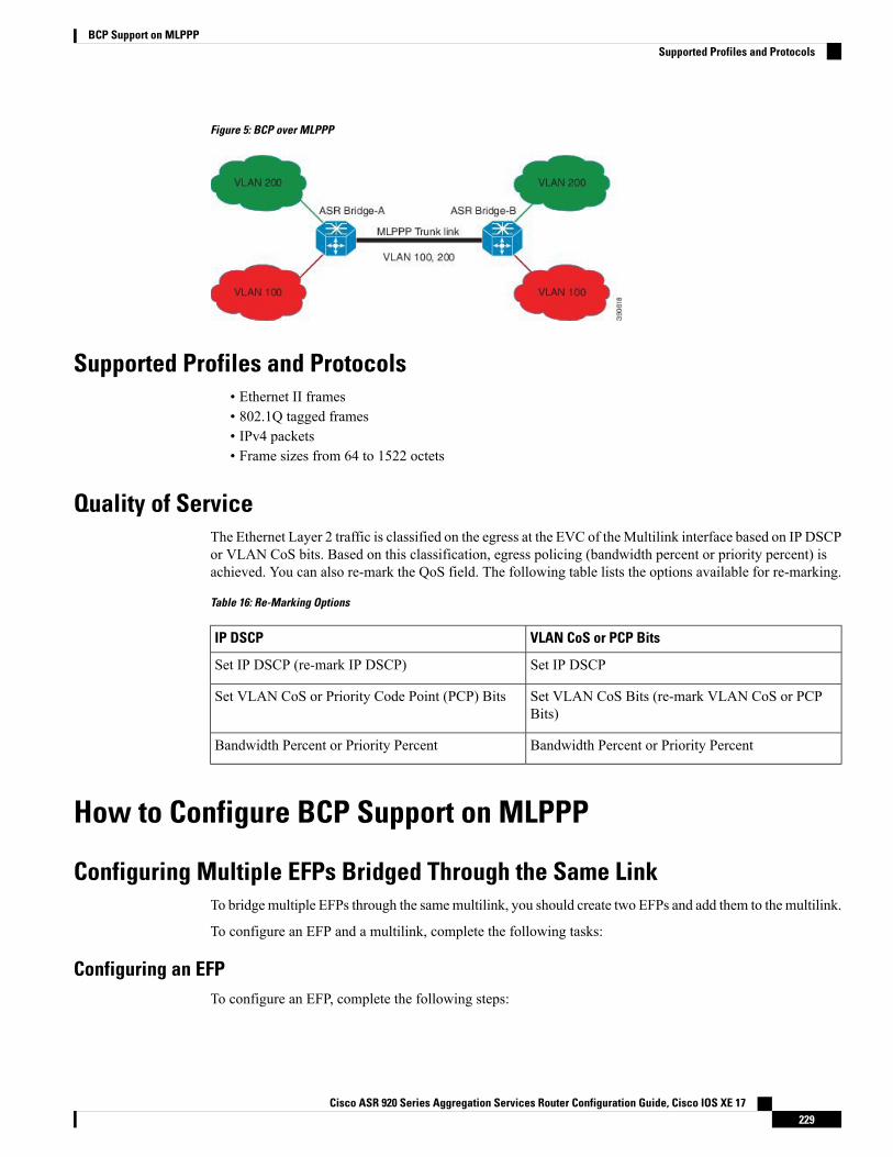
Figure 5: BCP over MLPPP
Supported Profiles and Protocols• Ethernet II frames• 802.1Q tagged frames• IPv4 packets• Frame sizes from 64 to 1522 octets
Quality of ServiceThe Ethernet Layer 2 traffic is classified on the egress at the EVC of theMultilink interface based on IP DSCPor VLAN CoS bits. Based on this classification, egress policing (bandwidth percent or priority percent) isachieved. You can also re-mark the QoS field. The following table lists the options available for re-marking.
Table 16: Re-Marking Options
VLAN CoS or PCP BitsIP DSCP
Set IP DSCPSet IP DSCP (re-mark IP DSCP)
Set VLAN CoS Bits (re-mark VLAN CoS or PCPBits)
Set VLAN CoS or Priority Code Point (PCP) Bits
Bandwidth Percent or Priority PercentBandwidth Percent or Priority Percent
How to Configure BCP Support on MLPPP
Configuring Multiple EFPs Bridged Through the Same LinkTo bridge multiple EFPs through the samemultilink, you should create two EFPs and add them to the multilink.
To configure an EFP and a multilink, complete the following tasks:
Configuring an EFPTo configure an EFP, complete the following steps:
Cisco ASR 920 Series Aggregation Services Router Configuration Guide, Cisco IOS XE 17229
BCP Support on MLPPPSupported Profiles and Protocols
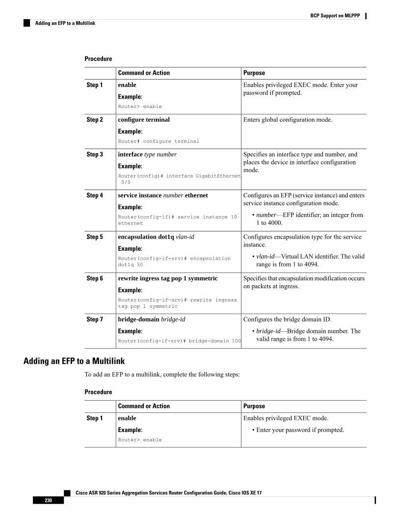
Procedure
PurposeCommand or Action
Enables privileged EXEC mode. Enter yourpassword if prompted.
enable
Example:
Step 1
Router> enable
Enters global configuration mode.configure terminal
Example:
Step 2
Router# configure terminal
Specifies an interface type and number, andplaces the device in interface configurationmode.
interface type number
Example:Router(config)# interface GigabitEthernet0/0
Step 3
Configures an EFP (service instance) and entersservice instance configuration mode.
service instance number ethernet
Example:
Step 4
• number—EFP identifier; an integer from1 to 4000.
Router(config-if)# service instance 10ethernet
Configures encapsulation type for the serviceinstance.
encapsulation dot1q vlan-id
Example:
Step 5
• vlan-id—Virtual LAN identifier. The validrange is from 1 to 4094.
Router(config-if-srv)# encapsulationdot1q 50
Specifies that encapsulationmodification occurson packets at ingress.
rewrite ingress tag pop 1 symmetric
Example:
Step 6
Router(config-if-srv)# rewrite ingresstag pop 1 symmetric
Configures the bridge domain ID.bridge-domain bridge-idStep 7
Example: • bridge-id—Bridge domain number. Thevalid range is from 1 to 4094.Router(config-if-srv)# bridge-domain 100
Adding an EFP to a MultilinkTo add an EFP to a multilink, complete the following steps:
Procedure
PurposeCommand or Action
Enables privileged EXEC mode.enableStep 1
Example: • Enter your password if prompted.Router> enable
Cisco ASR 920 Series Aggregation Services Router Configuration Guide, Cisco IOS XE 17230
BCP Support on MLPPPAdding an EFP to a Multilink
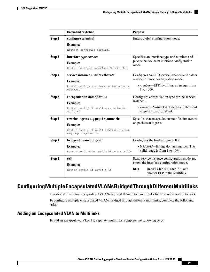
PurposeCommand or Action
Enters global configuration mode.configure terminal
Example:
Step 2
Router# configure terminal
Specifies an interface type and number, andplaces the device in interface configurationmode.
interface type number
Example:Router(config)# interface Multilink 5
Step 3
Configures an EFP (service instance) and entersservice instance configuration mode.
service instance number ethernet
Example:
Step 4
• number—EFP identifier; an integer from1 to 4000.
Router(config-if)# service instance 10ethernet
Configures encapsulation type for the serviceinstance.
encapsulation dot1q vlan-id
Example:
Step 5
• vlan-id—Virtual LAN identifier. The validrange is from 1 to 4094.
Router(config-if-srv)# encapsulationdot1q 60
Specifies that encapsulationmodification occurson packets at ingress.
rewrite ingress tag pop 1 symmetric
Example:
Step 6
Router(config-if-srv)# rewrite ingresstag pop 1 symmetric
Configures the bridge domain ID.bridge-domain bridge-idStep 7
Example: • bridge-id—Bridge domain number. Thevalid range is from 1 to 4094.Router(config-if-srv)# bridge-domain 100
Exits service instance configuration mode andenters the interface configuration mode.
exit
Example:
Step 8
Repeat Step 4 to Step 7 to addanother EFP to the Multilink.
NoteRouter(config-if-srv)# exit
ConfiguringMultipleEncapsulatedVLANsBridgedThroughDifferentMultilinksYou should create two encapsulated VLANs and add them to two multilinks for this configuration to work.
To configure multiple encapsulated VLANs bridged through different multilinks, complete the followingtasks:
Adding an Encapsulated VLAN to MultilinksTo add an encapsulated VLAN to separate multilinks, complete the following steps:
Cisco ASR 920 Series Aggregation Services Router Configuration Guide, Cisco IOS XE 17231
BCP Support on MLPPPConfiguring Multiple Encapsulated VLANs Bridged Through Different Multilinks
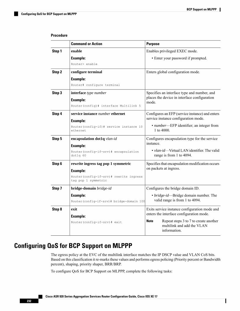
Procedure
PurposeCommand or Action
Enables privileged EXEC mode.enableStep 1
Example: • Enter your password if prompted.Router> enable
Enters global configuration mode.configure terminal
Example:
Step 2
Router# configure terminal
Specifies an interface type and number, andplaces the device in interface configurationmode.
interface type number
Example:Router(config)# interface Multilink 5
Step 3
Configures an EFP (service instance) and entersservice instance configuration mode.
service instance number ethernet
Example:
Step 4
• number—EFP identifier; an integer from1 to 4000.
Router(config-if)# service instance 10ethernet
Configures encapsulation type for the serviceinstance.
encapsulation dot1q vlan-id
Example:
Step 5
• vlan-id—Virtual LAN identifier. The validrange is from 1 to 4094.
Router(config-if-srv)# encapsulationdot1q 60
Specifies that encapsulationmodification occurson packets at ingress.
rewrite ingress tag pop 1 symmetric
Example:
Step 6
Router(config-if-srv)# rewrite ingresstag pop 1 symmetric
Configures the bridge domain ID.bridge-domain bridge-idStep 7
Example: • bridge-id—Bridge domain number. Thevalid range is from 1 to 4094.Router(config-if-srv)# bridge-domain 100
Exits service instance configuration mode andenters the interface configuration mode.
exit
Example:
Step 8
Repeat steps 3 to 7 to create anothermultilink and add the VLANinformation.
NoteRouter(config-if-srv)# exit
Configuring QoS for BCP Support on MLPPPThe egress policy at the EVC of the multilink interface matches the IP DSCP value and VLAN CoS bits.Based on this classification it re-marks these values and performs egress policing (Priority percent or Bandwidthpercent), shaping, priority shaper, BRR/BRP.
To configure QoS for BCP Support on MLPPP, complete the following tasks:
Cisco ASR 920 Series Aggregation Services Router Configuration Guide, Cisco IOS XE 17232
BCP Support on MLPPPConfiguring QoS for BCP Support on MLPPP
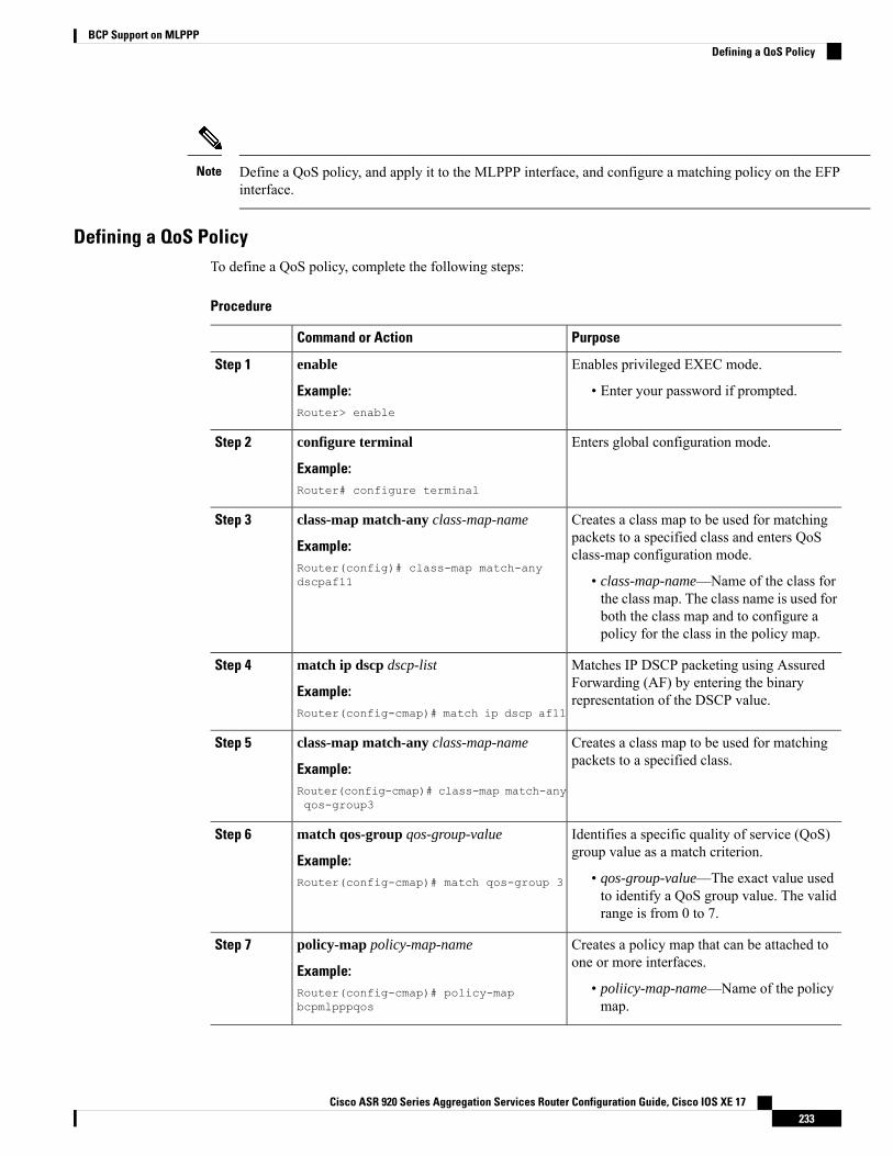
Define a QoS policy, and apply it to the MLPPP interface, and configure a matching policy on the EFPinterface.
Note
Defining a QoS PolicyTo define a QoS policy, complete the following steps:
Procedure
PurposeCommand or Action
Enables privileged EXEC mode.enableStep 1
Example: • Enter your password if prompted.Router> enable
Enters global configuration mode.configure terminal
Example:
Step 2
Router# configure terminal
Creates a class map to be used for matchingpackets to a specified class and enters QoSclass-map configuration mode.
class-map match-any class-map-name
Example:Router(config)# class-map match-anydscpaf11
Step 3
• class-map-name—Name of the class forthe class map. The class name is used forboth the class map and to configure apolicy for the class in the policy map.
Matches IP DSCP packeting using AssuredForwarding (AF) by entering the binaryrepresentation of the DSCP value.
match ip dscp dscp-list
Example:Router(config-cmap)# match ip dscp af11
Step 4
Creates a class map to be used for matchingpackets to a specified class.
class-map match-any class-map-name
Example:
Step 5
Router(config-cmap)# class-map match-anyqos-group3
Identifies a specific quality of service (QoS)group value as a match criterion.
match qos-group qos-group-value
Example:
Step 6
• qos-group-value—The exact value usedto identify a QoS group value. The validrange is from 0 to 7.
Router(config-cmap)# match qos-group 3
Creates a policy map that can be attached toone or more interfaces.
policy-map policy-map-name
Example:
Step 7
• poliicy-map-name—Name of the policymap.
Router(config-cmap)# policy-mapbcpmlpppqos
Cisco ASR 920 Series Aggregation Services Router Configuration Guide, Cisco IOS XE 17233
BCP Support on MLPPPDefining a QoS Policy
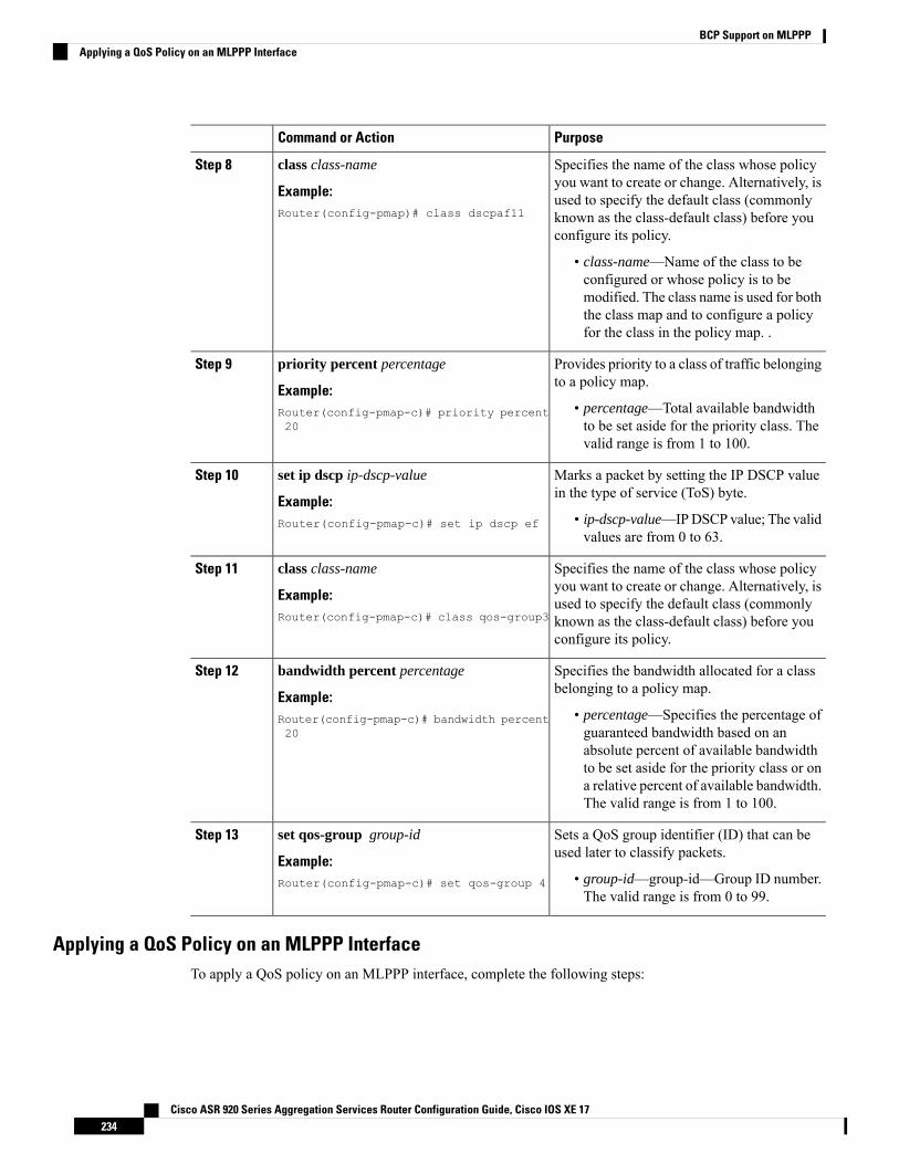
PurposeCommand or Action
Specifies the name of the class whose policyyou want to create or change. Alternatively, is
class class-name
Example:
Step 8
used to specify the default class (commonlyRouter(config-pmap)# class dscpaf11 known as the class-default class) before you
configure its policy.
• class-name—Name of the class to beconfigured or whose policy is to bemodified. The class name is used for boththe class map and to configure a policyfor the class in the policy map. .
Provides priority to a class of traffic belongingto a policy map.
priority percent percentage
Example:
Step 9
• percentage—Total available bandwidthto be set aside for the priority class. Thevalid range is from 1 to 100.
Router(config-pmap-c)# priority percent20
Marks a packet by setting the IP DSCP valuein the type of service (ToS) byte.
set ip dscp ip-dscp-value
Example:
Step 10
• ip-dscp-value—IPDSCP value; The validvalues are from 0 to 63.
Router(config-pmap-c)# set ip dscp ef
Specifies the name of the class whose policyyou want to create or change. Alternatively, is
class class-name
Example:
Step 11
used to specify the default class (commonlyRouter(config-pmap-c)# class qos-group3 known as the class-default class) before you
configure its policy.
Specifies the bandwidth allocated for a classbelonging to a policy map.
bandwidth percent percentage
Example:
Step 12
• percentage—Specifies the percentage ofguaranteed bandwidth based on an
Router(config-pmap-c)# bandwidth percent20
absolute percent of available bandwidthto be set aside for the priority class or ona relative percent of available bandwidth.The valid range is from 1 to 100.
Sets a QoS group identifier (ID) that can beused later to classify packets.
set qos-group group-id
Example:
Step 13
• group-id—group-id—Group ID number.The valid range is from 0 to 99.
Router(config-pmap-c)# set qos-group 4
Applying a QoS Policy on an MLPPP InterfaceTo apply a QoS policy on an MLPPP interface, complete the following steps:
Cisco ASR 920 Series Aggregation Services Router Configuration Guide, Cisco IOS XE 17234
BCP Support on MLPPPApplying a QoS Policy on an MLPPP Interface
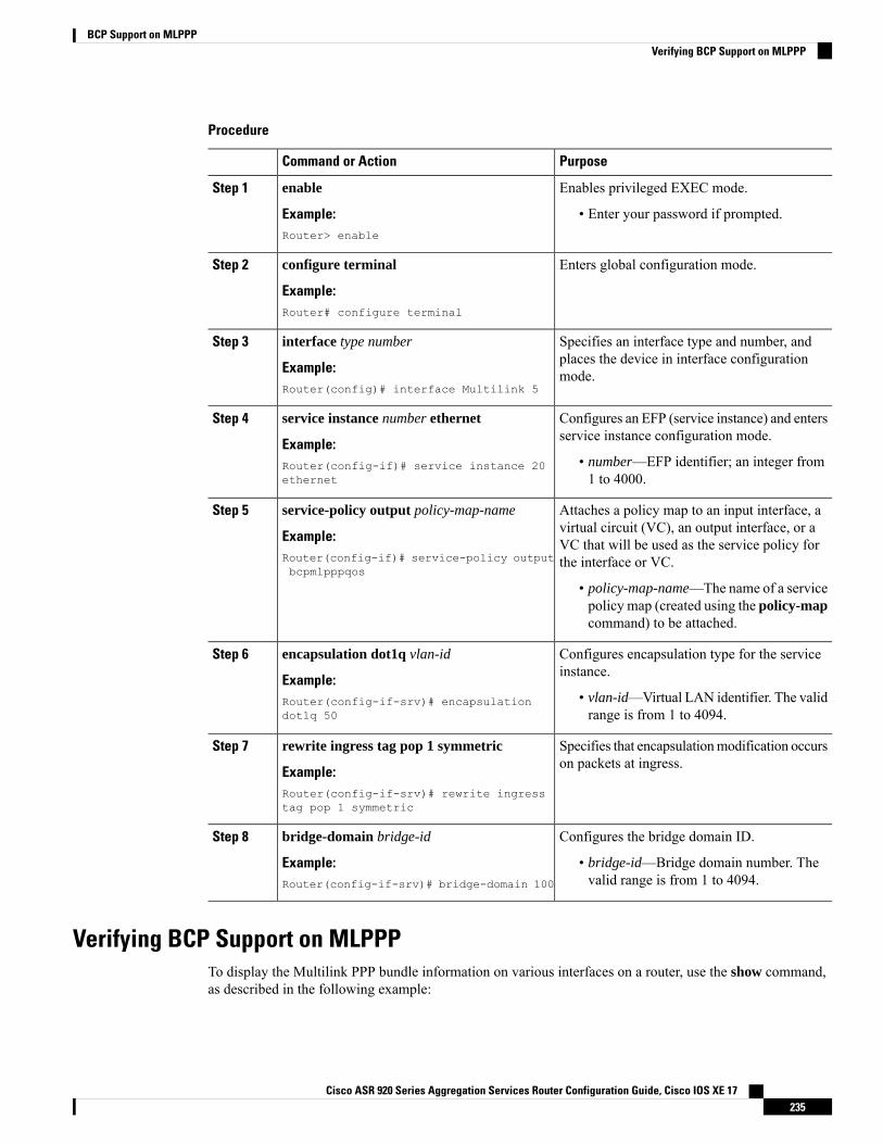
Procedure
PurposeCommand or Action
Enables privileged EXEC mode.enableStep 1
Example: • Enter your password if prompted.Router> enable
Enters global configuration mode.configure terminal
Example:
Step 2
Router# configure terminal
Specifies an interface type and number, andplaces the device in interface configurationmode.
interface type number
Example:Router(config)# interface Multilink 5
Step 3
Configures an EFP (service instance) and entersservice instance configuration mode.
service instance number ethernet
Example:
Step 4
• number—EFP identifier; an integer from1 to 4000.
Router(config-if)# service instance 20ethernet
Attaches a policy map to an input interface, avirtual circuit (VC), an output interface, or a
service-policy output policy-map-name
Example:
Step 5
VC that will be used as the service policy forthe interface or VC.Router(config-if)# service-policy output
bcpmlpppqos
• policy-map-name—The name of a servicepolicy map (created using the policy-mapcommand) to be attached.
Configures encapsulation type for the serviceinstance.
encapsulation dot1q vlan-id
Example:
Step 6
• vlan-id—Virtual LAN identifier. The validrange is from 1 to 4094.
Router(config-if-srv)# encapsulationdot1q 50
Specifies that encapsulationmodification occurson packets at ingress.
rewrite ingress tag pop 1 symmetric
Example:
Step 7
Router(config-if-srv)# rewrite ingresstag pop 1 symmetric
Configures the bridge domain ID.bridge-domain bridge-idStep 8
Example: • bridge-id—Bridge domain number. Thevalid range is from 1 to 4094.Router(config-if-srv)# bridge-domain 100
Verifying BCP Support on MLPPPTo display the Multilink PPP bundle information on various interfaces on a router, use the show command,as described in the following example:
Cisco ASR 920 Series Aggregation Services Router Configuration Guide, Cisco IOS XE 17235
BCP Support on MLPPPVerifying BCP Support on MLPPP
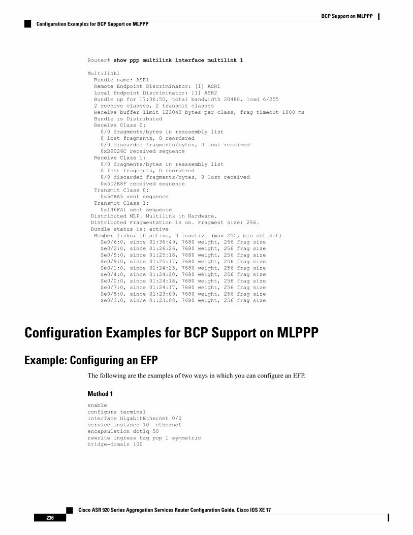
Router# show ppp multilink interface multilink 1
Multilink1Bundle name: ASR1Remote Endpoint Discriminator: [1] ASR1Local Endpoint Discriminator: [1] ASR2Bundle up for 17:06:50, total bandwidth 20480, load 6/2552 receive classes, 2 transmit classesReceive buffer limit 123040 bytes per class, frag timeout 1000 msBundle is DistributedReceive Class 0:0/0 fragments/bytes in reassembly list0 lost fragments, 0 reordered0/0 discarded fragments/bytes, 0 lost received0xB9026C received sequence
Receive Class 1:0/0 fragments/bytes in reassembly list0 lost fragments, 0 reordered0/0 discarded fragments/bytes, 0 lost received0x5D2E8F received sequence
Transmit Class 0:0x5CBA5 sent sequence
Transmit Class 1:0x146FA1 sent sequence
Distributed MLP. Multilink in Hardware.Distributed Fragmentation is on. Fragment size: 256.Bundle status is: activeMember links: 10 active, 0 inactive (max 255, min not set)Se0/6:0, since 01:36:49, 7680 weight, 256 frag sizeSe0/2:0, since 01:26:26, 7680 weight, 256 frag sizeSe0/5:0, since 01:25:18, 7680 weight, 256 frag sizeSe0/9:0, since 01:25:17, 7680 weight, 256 frag sizeSe0/1:0, since 01:24:25, 7680 weight, 256 frag sizeSe0/4:0, since 01:24:20, 7680 weight, 256 frag sizeSe0/0:0, since 01:24:18, 7680 weight, 256 frag sizeSe0/7:0, since 01:24:17, 7680 weight, 256 frag sizeSe0/8:0, since 01:23:09, 7680 weight, 256 frag sizeSe0/3:0, since 01:23:08, 7680 weight, 256 frag size
Configuration Examples for BCP Support on MLPPP
Example: Configuring an EFPThe following are the examples of two ways in which you can configure an EFP.
Method 1
enableconfigure terminalinterface GigabitEthernet 0/0service instance 10 ethernetencapsulation dot1q 50rewrite ingress tag pop 1 symmetricbridge-domain 100
Cisco ASR 920 Series Aggregation Services Router Configuration Guide, Cisco IOS XE 17236
BCP Support on MLPPPConfiguration Examples for BCP Support on MLPPP
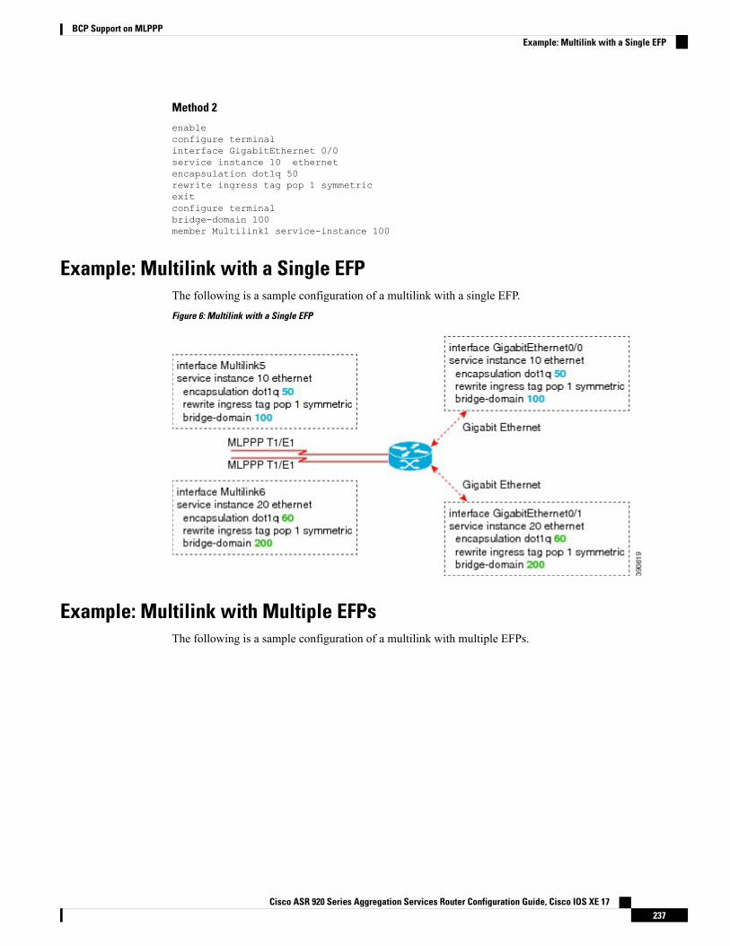
Method 2
enableconfigure terminalinterface GigabitEthernet 0/0service instance 10 ethernetencapsulation dot1q 50rewrite ingress tag pop 1 symmetricexitconfigure terminalbridge-domain 100member Multilink1 service-instance 100
Example: Multilink with a Single EFPThe following is a sample configuration of a multilink with a single EFP.
Figure 6: Multilink with a Single EFP
Example: Multilink with Multiple EFPsThe following is a sample configuration of a multilink with multiple EFPs.
Cisco ASR 920 Series Aggregation Services Router Configuration Guide, Cisco IOS XE 17237
BCP Support on MLPPPExample: Multilink with a Single EFP
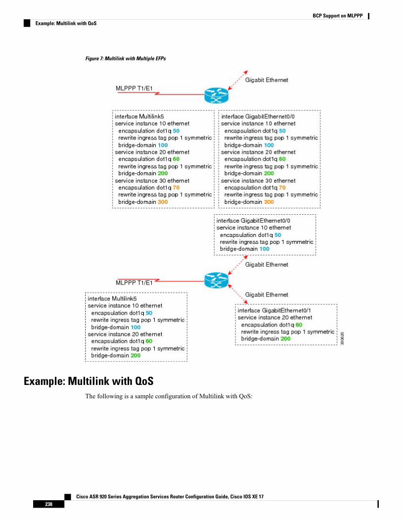
Figure 7: Multilink with Multiple EFPs
Example: Multilink with QoSThe following is a sample configuration of Multilink with QoS:
Cisco ASR 920 Series Aggregation Services Router Configuration Guide, Cisco IOS XE 17238
BCP Support on MLPPPExample: Multilink with QoS
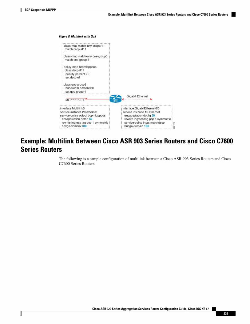
Figure 8: Multilink with QoS
Example: Multilink Between Cisco ASR 903 Series Routers and Cisco C7600Series Routers
The following is a sample configuration of multilink between a Cisco ASR 903 Series Routers and CiscoC7600 Series Routers:
Cisco ASR 920 Series Aggregation Services Router Configuration Guide, Cisco IOS XE 17239
BCP Support on MLPPPExample: Multilink Between Cisco ASR 903 Series Routers and Cisco C7600 Series Routers
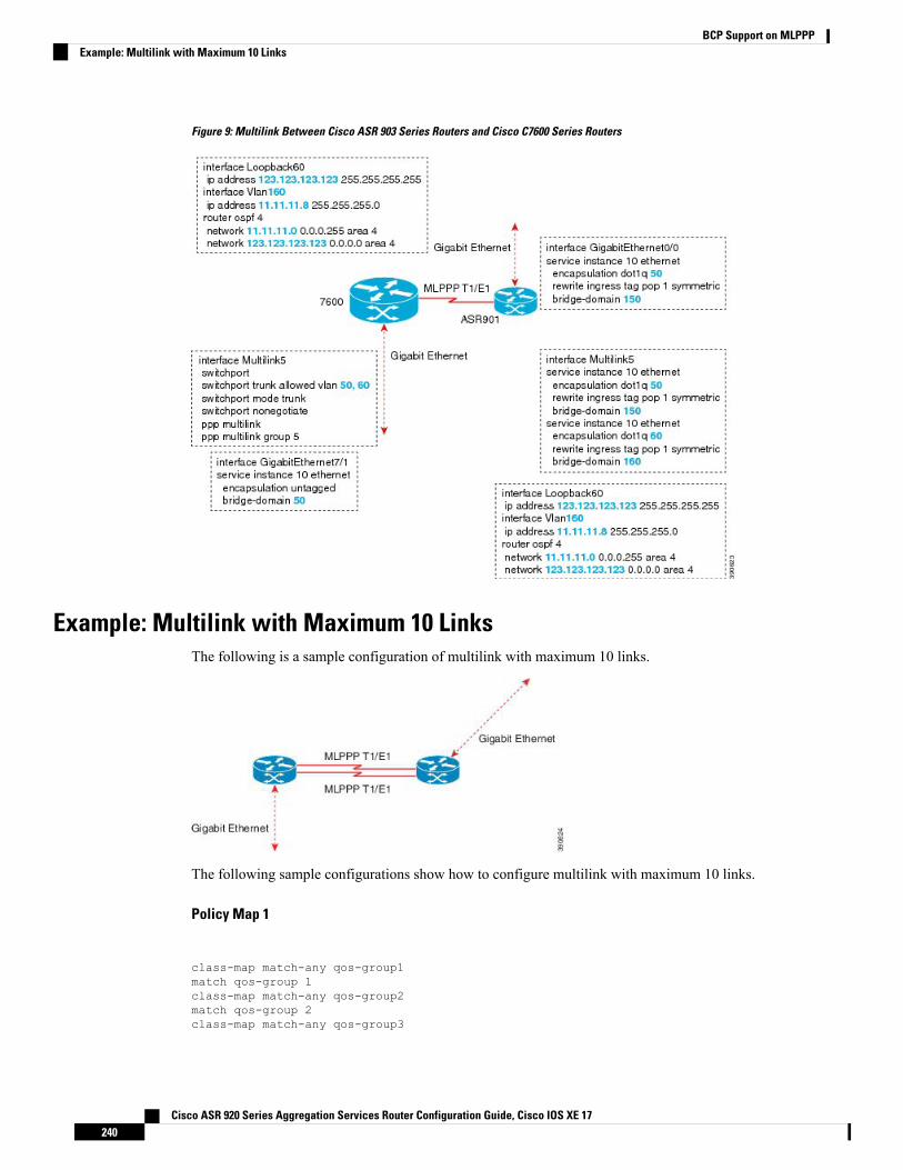
Figure 9: Multilink Between Cisco ASR 903 Series Routers and Cisco C7600 Series Routers
Example: Multilink with Maximum 10 LinksThe following is a sample configuration of multilink with maximum 10 links.
The following sample configurations show how to configure multilink with maximum 10 links.
Policy Map 1
class-map match-any qos-group1match qos-group 1class-map match-any qos-group2match qos-group 2class-map match-any qos-group3
Cisco ASR 920 Series Aggregation Services Router Configuration Guide, Cisco IOS XE 17240
BCP Support on MLPPPExample: Multilink with Maximum 10 Links
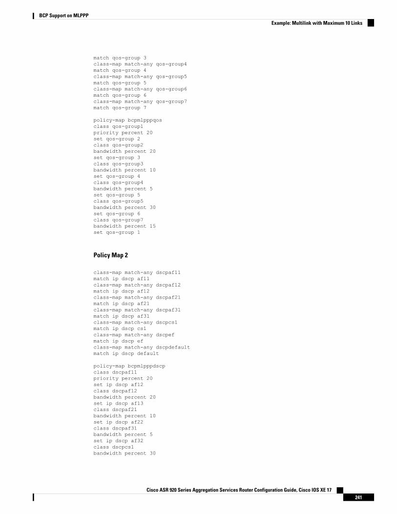
match qos-group 3class-map match-any qos-group4match qos-group 4class-map match-any qos-group5match qos-group 5class-map match-any qos-group6match qos-group 6class-map match-any qos-group7match qos-group 7
policy-map bcpmlpppqosclass qos-group1priority percent 20set qos-group 2class qos-group2bandwidth percent 20set qos-group 3class qos-group3bandwidth percent 10set qos-group 4class qos-group4bandwidth percent 5set qos-group 5class qos-group5bandwidth percent 30set qos-group 6class qos-group7bandwidth percent 15set qos-group 1
Policy Map 2
class-map match-any dscpaf11match ip dscp af11class-map match-any dscpaf12match ip dscp af12class-map match-any dscpaf21match ip dscp af21class-map match-any dscpaf31match ip dscp af31class-map match-any dscpcs1match ip dscp cs1class-map match-any dscpefmatch ip dscp efclass-map match-any dscpdefaultmatch ip dscp default
policy-map bcpmlpppdscpclass dscpaf11priority percent 20set ip dscp af12class dscpaf12bandwidth percent 20set ip dscp af13class dscpaf21bandwidth percent 10set ip dscp af22class dscpaf31bandwidth percent 5set ip dscp af32class dscpcs1bandwidth percent 30
Cisco ASR 920 Series Aggregation Services Router Configuration Guide, Cisco IOS XE 17241
BCP Support on MLPPPExample: Multilink with Maximum 10 Links
set ip dscp cs2class dscpefbandwidth percent 10set ip dscp cs7class dscpdefaultbandwidth percent 5set ip dscp cs5
MLPPP-GIG - 1
interface Multilink1service instance 1 ethernetservice-policy output bcpmlpppqosencapsulation untaggedbridge-domain 3000
interface Multilink2service instance 1 ethernetservice-policy output bcpmlpppqosencapsulation dot1q 50bridge-domain 2000
service instance 2 ethernetencapsulation dot1q 60bridge-domain 2001
interface gigabitethernet 0/5service instance 1 ethernetencapsulation dot1q 50bridge-domain 2000
service instance 2 ethernetencapsulation dot1q 60bridge-domain 2001
service instance 3 ethernetencapsulation untaggedbridge-domain 3000
ADD-MLPPP-GIG - 1
interface Multilink1service instance 2 ethernetservice-policy output bcpmlpppqosencapsulation dot1q 70bridge-domain 3001
interface gigabitethernet 0/5service instance 4 ethernetencapsulation dot1q 70bridge-domain 3001
MLPPP-GIG-2
interface Multilink1service instance 1 ethernetservice-policy output bcpmlpppdscpencapsulation untaggedbridge-domain 3000
Cisco ASR 920 Series Aggregation Services Router Configuration Guide, Cisco IOS XE 17242
BCP Support on MLPPPExample: Multilink with Maximum 10 Links
interface Multilink2service instance 2 ethernetservice-policy output bcpmlpppdscpencapsulation dot1q anybridge-domain 3001
interface gigabitethernet 0/5service instance 1 ethernetencapsulation untaggedbridge-domain 3000
service instance 2 ethernetencapsulation dot1q anybridge-domain 3001
MLPPP-GIG-3
interface Multilink1service instance 1 ethernetservice-policy output bcpmlpppdscpencapsulation defaultbridge-domain 3000
interface gigabitethernet 0/5service instance 1 ethernetencapsulation defaultbridge-domain 3000
Sample Configuration of MLPPP Bundled 10 Member Links
interface Multilink1no ip addressload-interval 30ppp pfc local requestppp pfc remote applyppp acfc local requestppp acfc remote applyppp multilinkppp multilink interleaveppp multilink group 1ppp multilink fragment size 256ppp multilink multiclassservice instance 102 ethernetservice-policy output bcpmlpppqosencapsulation dot1q 102rewrite ingress tag pop 1 symmetricbridge-domain 102!
interface Serial0/0:0no ip addressencapsulation pppppp multilinkppp multilink group 1interface Serial0/1:0no ip addressencapsulation pppppp multilink
Cisco ASR 920 Series Aggregation Services Router Configuration Guide, Cisco IOS XE 17243
BCP Support on MLPPPExample: Multilink with Maximum 10 Links
ppp multilink group 1interface Serial0/2:0no ip addressencapsulation pppppp multilinkppp multilink group 1interface Serial0/3:0no ip addressencapsulation pppppp multilinkppp multilink group 1interface Serial0/4:0no ip addressencapsulation pppppp multilinkppp multilink group 1interface Serial0/5:0no ip addressencapsulation pppppp multilinkppp multilink group 1interface Serial0/6:0no ip addressencapsulation pppppp multilinkppp multilink group 1interface Serial0/7:0no ip addressencapsulation pppppp multilinkppp multilink group 1interface Serial0/8:0no ip addressencapsulation pppppp multilinkppp multilink group 1interface Serial0/9:0no ip addressencapsulation pppppp multilinkppp multilink group 1
Additional ReferencesThe following sections provide references related to BCP Support on MLPPP feature.
Related DocumentsDocument TitleRelated Topic
Cisco IOS Master Commands List, All ReleasesCisco IOS commands
Cisco ASR 920 Series Aggregation Services Router Configuration Guide, Cisco IOS XE 17244
BCP Support on MLPPPAdditional References
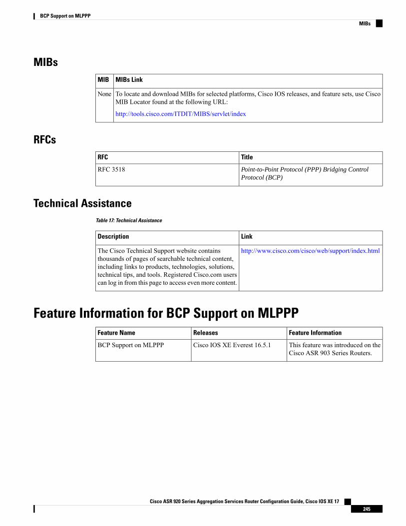
MIBsMIBs LinkMIB
To locate and download MIBs for selected platforms, Cisco IOS releases, and feature sets, use CiscoMIB Locator found at the following URL:
http://tools.cisco.com/ITDIT/MIBS/servlet/index
None
RFCsTitleRFC
Point-to-Point Protocol (PPP) Bridging ControlProtocol (BCP)
RFC 3518
Technical AssistanceTable 17: Technical Assistance
LinkDescription
http://www.cisco.com/cisco/web/support/index.htmlThe Cisco Technical Support website containsthousands of pages of searchable technical content,including links to products, technologies, solutions,technical tips, and tools. Registered Cisco.com userscan log in from this page to access even more content.
Feature Information for BCP Support on MLPPPFeature InformationReleasesFeature Name
This feature was introduced on theCisco ASR 903 Series Routers.
Cisco IOS XE Everest 16.5.1BCP Support on MLPPP
Cisco ASR 920 Series Aggregation Services Router Configuration Guide, Cisco IOS XE 17245
BCP Support on MLPPPMIBs

Cisco ASR 920 Series Aggregation Services Router Configuration Guide, Cisco IOS XE 17246
BCP Support on MLPPPFeature Information for BCP Support on MLPPP