CMTS Router Service Features - Cisco
146
CMTS Router Service Features First Published: 2008-02-14 Last Modified: 2014-06-16 Americas Headquarters Cisco Systems, Inc. 170 West Tasman Drive San Jose, CA 95134-1706 USA http://www.cisco.com Tel: 408 526-4000 800 553-NETS (6387) Fax: 408 527-0883 Text Part Number: OL-27605-02
-
Upload
khangminh22 -
Category
Documents
-
view
0 -
download
0
Transcript of CMTS Router Service Features - Cisco
CMTS Router Service FeaturesFirst Published: 2008-02-14
Last Modified: 2014-06-16
Americas HeadquartersCisco Systems, Inc.170 West Tasman DriveSan Jose, CA 95134-1706USAhttp://www.cisco.comTel: 408 526-4000 800 553-NETS (6387)Fax: 408 527-0883
Text Part Number: OL-27605-02

© 2008-2014 Cisco Systems, Inc. All rights reserved.
C O N T E N T S
C H A P T E R 1 Advanced-Mode DOCSIS Set-Top Gateway 1.2 for the Cisco CMTS Routers 1
Prerequisites for Advanced-Mode DSG Issue 1.2 2
Restrictions for Advanced-Mode DSG Issue 1.2 3
DSG Configuration File Transfer Operations 3
Multicast Configuration Restrictions 3
NAT for DSG Unicast-only Mapping 4
PIM and SSM for Multicast 4
Subinterfaces 4
Information About Advanced-Mode DSG Issue 1.2 4
DSG 1.2 Clients and Agents 5
FQDN Support 5
DSG Name Process and DNS Query 5
A-DSG Forwarding on the Primary Channel 6
DOCSIS 3.0 DSG MDF Support 6
Source Specific Multicast Mapping 6
How to Configure Advanced-Mode DSG Issue 1.2 7
Configuring the Default Multicast Quality of Service 7
Configuring Global Tunnel Group Settings for Advanced-Mode DSG 1.2 8
Global A-DSG 1.2 Tunnel Settings 8
Adding DSG Tunnel Group to a Subinterface 10
Configuring the DSG Client Settings for Advanced-Mode DSG 1.2 11
Configuring Downstream DSG 1.2 Settings for Advanced-Mode DSG 1.2 13
Configuring IP Multicast Operations 14
Enabling DNS Query and DSG Name Process 15
Configuring NAT to Support Unicast Messaging 16
Configuring WAN Interfaces for Multicast Operations 18
Configuring a Standard IP Access List for Packet Filtering 19
Configuring a Standard IP Access List for Multicast Group Filtering 20
CMTS Router Service Features OL-27605-02 iii

Disabling A-DSG Forwarding on the Primary Channel 21
How to Monitor and Debug the Advanced-mode DOCSIS Set-Top Gateway Feature 22
Displaying Global Configurations for Advanced-Mode DSG 1.2 22
show cable dsg cfr 22
show cable dsg host 25
show cable dsg tunnel 25
show cable dsg tunnel ID 26
show cable dsg tunnel ID statistics 26
show cable dsg tg 27
show running-config interface 28
show cable dsg static-group bundle 29
Displaying Interface-level Configurations for Advanced-Mode DSG 1.2 29
show cable dsg tunnel interfaces 29
show interfaces cable dsg downstream 29
show interfaces cable dsg downstream dcd 30
show interfaces cable dsg downstream tg 30
show interfaces cable dsg downstream tunnel 31
Debugging Advanced-Mode DSG 32
Configuration Examples for Advanced-Mode DSG 32
Example: Enabling DNS Query 35
Example: Disabling A-DSG Forwarding on the Primary Channel 35
Additional References 35
Feature Information for Advanced-Mode DSG 1.2 for the Cisco CMTS Routers 36
C H A P T E R 2 Call Home Feature for the Cisco CMTS Routers 41
Prerequisites for the Call Home Feature for the Cisco CMTS Routers 42
Information About the Call Home Feature for the Cisco CMTS Routers 42
Subscribing to Alert Groups 43
Sample Configuration Alert Notification in XML Format 43
Sample Inventory Alert Notification in Long-Text Format 48
Sample Inventory Alert Notification in XML Format 48
Sample Syslog Alert Notification in XML Format 59
Additional References 65
Feature Information for the Call Home Feature for the Cisco CMTS Routers 66
CMTS Router Service Featuresiv OL-27605-02
Contents
C H A P T E R 3 Cisco Network Registrar for the Cisco CMTS Routers 69
Servers Required on the HFC Network 70
Cisco Network Registrar Description 71
Overview of DHCP Using CNR 72
How Cisco Universal Broadband Routers and Cable Modems Work 72
DHCP Fields and Options for Cable Modems 73
Cisco Network Registrar Sample Configuration 74
Cable Modem DHCP Response Fields 76
DOCSIS DHCP Fields 77
DHCP Relay Option (DOCSIS Option 82) 77
Overview of Scripts 78
Two-way Cable Modem Scripts 78
Telco Return Cable Modem Scripts 78
Placement of Scripts 78
Windows NT 78
Solaris 78
Activating Scripts in Cisco Network Registrar 79
Configuring the Cisco CMTS Routers to Use Scripts 79
Configuring the System Default Policy 79
Cable Modems 79
PCs 80
Creating Selection Tag Scopes 80
General 80
Telco Return for the Cisco uBR7200 Series Router 80
Creating Network Scopes 81
Creating Policies for Class of Service or for Upgrading Cable Modem Cisco IOS Images 81
CNR Steps to Support Subinterfaces 82
Additional References 83
C H A P T E R 4 DHCP, ToD, and TFTP Services for the CMTS Routers 87
Prerequisites for DHCP, ToD, and TFTP Services 88
Restrictions for DHCP, ToD, and TFTP Services 88
Information About DHCP, ToD, and TFTP Services 88
Feature Overview 89
CMTS Router Service Features OL-27605-02 v
Contents

Internal DHCP Server 89
DHCP Field Options 89
DHCP Security Options 90
Multiple DHCP Pools 91
External DHCP Servers 92
Cable Source Verify Feature 92
Prefix-based Source Address Verification 93
Smart Relay Feature 93
GIADDR Field 93
DHCP Relay Agent Sub-option 94
Time-of-Day Server 94
TFTP Server 96
Benefits 97
How to Configure DHCP, ToD, and TFTP Services 97
Configuring DHCP Service 97
Creating and Configuring a DHCP Address Pool for Cable Modems 98
Creating and Configuring a DHCP Address Pool for CPE Devices 100
Configuring Time-of-Day Service 103
Enabling Time-of-Day Service 103
Disabling Time-of-Day Service 104
Configuring TFTP Service 105
Configuring A Basic All-in-One Configuration 108
Configuring an Advanced All-in-One Configuration 108
Optimizing the Use of an External DHCP Server 109
Configuring Cable Source Verify Option 109
Configuring Prefix-based Source Address Verification 111
Configuring Optional DHCP Parameters 112
Configuration Examples 115
DHCP Server Examples 115
DHCP Pools for Cable Modems 115
DHCP Pools for Disabling Cable Modems 116
DHCP Pools for CPE Devices 117
ToD Server Example 117
TFTP Server Example 118
Basic All-in-One Configuration Example 118
CMTS Router Service Featuresvi OL-27605-02
Contents

Advanced All-in-One Configuration Example 121
Additional References 126
Feature Information for the DHCP, ToD, and TFTP Services for the CMTS Routers 130
CMTS Router Service Features OL-27605-02 vii
Contents

CMTS Router Service Featuresviii OL-27605-02
Contents
C H A P T E R 1Advanced-Mode DOCSIS Set-Top Gateway 1.2for the Cisco CMTS Routers
First Published: February 14, 2008
Last Updated: February 9, 2009
Cisco IOS Release 12.2(33)SCA integrates support for this feature on the Cisco CMTS routers. Thisfeature is also supported in Cisco IOS Release 12.3BC, and this document contains information thatreferences many legacy documents related to Cisco IOS 12.3BC. In general, any references to Cisco IOSRelease 12.3BC also apply to Cisco IOS Release 12.2SC.
Note
TheAdvanced-ModeDOCSIS Set-Top Gateway (A-DSG) Issue 1.2 introduces support for the latest DOCSISSet-Top specification from CableLabs™, to include the following enhancements:
• DOCSIS Set-top Gateway (DSG) Interface Specification
• A-DSG 1.2 introduces support for the DOCS-DSG-IF MIB.
Cisco A-DSG 1.2 is certified by CableLabs™, and is a powerful tool in support of latest industry innovations.A-DSG 1.2 offers substantial support for enhanced DOCSIS implementation in the broadband cableenvironment. The set-top box (STB) dynamically learns the overall environment from the Cisco CMTSrouter, to include MAC address, traffic management rules, and classifiers.
Finding Feature Information
Your software release may not support all the features documented in this module. For the latest featureinformation and caveats, see the release notes for your platform and software release. To find informationabout the features documented in this module, and to see a list of the releases in which each feature issupported, see the Feature Information Table at the end of this document.
Use Cisco Feature Navigator to find information about platform support and Cisco software image support.To access Cisco Feature Navigator, go to http://tools.cisco.com/ITDIT/CFN/. An account on http://www.cisco.com/ is not required.
Contents
• Prerequisites for Advanced-Mode DSG Issue 1.2, page 2
CMTS Router Service Features OL-27605-02 1
• Restrictions for Advanced-Mode DSG Issue 1.2, page 3
• Information About Advanced-Mode DSG Issue 1.2, page 4
• How to Configure Advanced-Mode DSG Issue 1.2, page 7
• How to Monitor and Debug the Advanced-mode DOCSIS Set-Top Gateway Feature, page 22
• Configuration Examples for Advanced-Mode DSG, page 32
• Additional References, page 35
• Feature Information for Advanced-Mode DSG 1.2 for the Cisco CMTS Routers, page 36
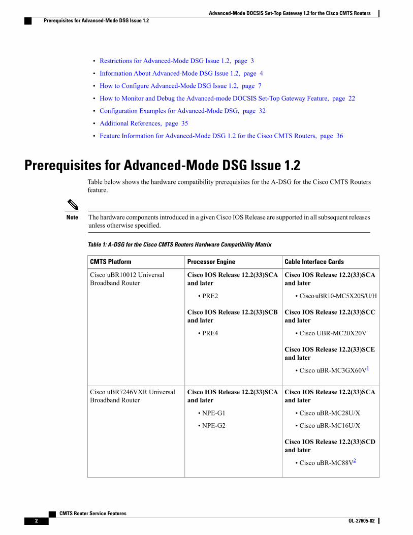
Prerequisites for Advanced-Mode DSG Issue 1.2Table below shows the hardware compatibility prerequisites for the A-DSG for the Cisco CMTS Routersfeature.
The hardware components introduced in a given Cisco IOS Release are supported in all subsequent releasesunless otherwise specified.
Note
Table 1: A-DSG for the Cisco CMTS Routers Hardware Compatibility Matrix
Cable Interface CardsProcessor EngineCMTS Platform
Cisco IOS Release 12.2(33)SCAand later
• CiscouBR10-MC5X20S/U/H
Cisco IOS Release 12.2(33)SCCand later
• Cisco UBR-MC20X20V
Cisco IOS Release 12.2(33)SCEand later
• Cisco uBR-MC3GX60V1
Cisco IOS Release 12.2(33)SCAand later
• PRE2
Cisco IOS Release 12.2(33)SCBand later
• PRE4
Cisco uBR10012 UniversalBroadband Router
Cisco IOS Release 12.2(33)SCAand later
• Cisco uBR-MC28U/X
• Cisco uBR-MC16U/X
Cisco IOS Release 12.2(33)SCDand later
• Cisco uBR-MC88V2
Cisco IOS Release 12.2(33)SCAand later
• NPE-G1
• NPE-G2
Cisco uBR7246VXR UniversalBroadband Router
CMTS Router Service Features2 OL-27605-02
Advanced-Mode DOCSIS Set-Top Gateway 1.2 for the Cisco CMTS RoutersPrerequisites for Advanced-Mode DSG Issue 1.2
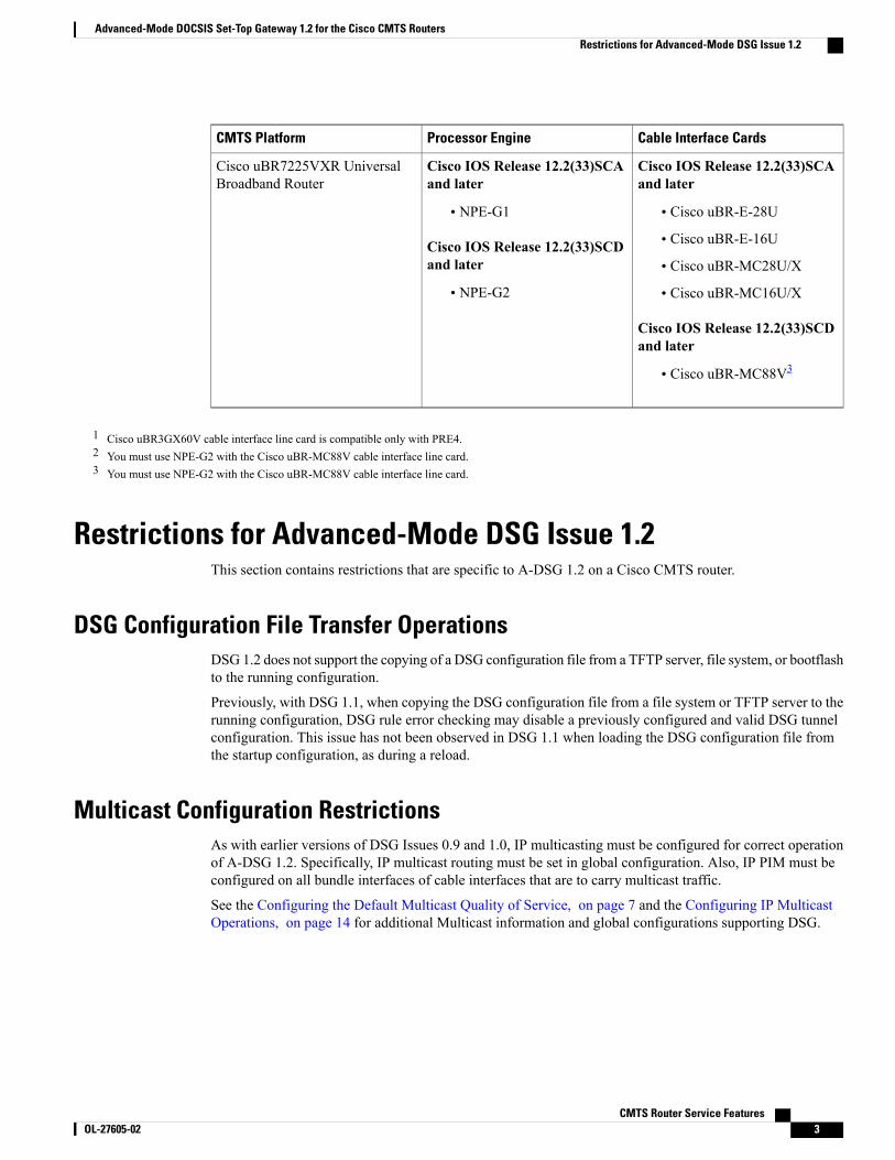
Cable Interface CardsProcessor EngineCMTS Platform
Cisco IOS Release 12.2(33)SCAand later
• Cisco uBR-E-28U
• Cisco uBR-E-16U
• Cisco uBR-MC28U/X
• Cisco uBR-MC16U/X
Cisco IOS Release 12.2(33)SCDand later
• Cisco uBR-MC88V3
Cisco IOS Release 12.2(33)SCAand later
• NPE-G1
Cisco IOS Release 12.2(33)SCDand later
• NPE-G2
Cisco uBR7225VXR UniversalBroadband Router
1 Cisco uBR3GX60V cable interface line card is compatible only with PRE4.2 You must use NPE-G2 with the Cisco uBR-MC88V cable interface line card.3 You must use NPE-G2 with the Cisco uBR-MC88V cable interface line card.
Restrictions for Advanced-Mode DSG Issue 1.2This section contains restrictions that are specific to A-DSG 1.2 on a Cisco CMTS router.
DSG Configuration File Transfer OperationsDSG 1.2 does not support the copying of a DSG configuration file from a TFTP server, file system, or bootflashto the running configuration.
Previously, with DSG 1.1, when copying the DSG configuration file from a file system or TFTP server to therunning configuration, DSG rule error checking may disable a previously configured and valid DSG tunnelconfiguration. This issue has not been observed in DSG 1.1 when loading the DSG configuration file fromthe startup configuration, as during a reload.
Multicast Configuration RestrictionsAs with earlier versions of DSG Issues 0.9 and 1.0, IP multicasting must be configured for correct operationof A-DSG 1.2. Specifically, IP multicast routing must be set in global configuration. Also, IP PIM must beconfigured on all bundle interfaces of cable interfaces that are to carry multicast traffic.
See the Configuring the Default Multicast Quality of Service, on page 7 and the Configuring IP MulticastOperations, on page 14 for additional Multicast information and global configurations supporting DSG.
CMTS Router Service Features OL-27605-02 3
Advanced-Mode DOCSIS Set-Top Gateway 1.2 for the Cisco CMTS RoutersRestrictions for Advanced-Mode DSG Issue 1.2
NAT for DSG Unicast-only MappingA-DSG 1.2 supports multicast IP addressing. However, it also supports unicast IP destination addresses. Onthe Cisco uBR7246VXR router, DSG 1.2 support is provided with the configuration of Network AddressTranslation (NAT) on the router, to include these settings:
•WAN interface(s) are configured with the ip nat outside command.
• Cable interface(s) are configured with the ip nat inside command.
• For each mapping, additional configuration includes the source static multicast IP address and the unicastIP address.
The unicast IP address is the unicast destination IP address of the DSG packets arriving at the Cisco CMTSrouter. The multicast IP address is the new destination IP address that is configured to map to one or a set ofDSG tunnels.
PIM and SSM for MulticastWhen using Source Specific Multicast (SSM) operation in conjunction with A-DSG 1.2, the followingsystem-wide configuration command must be specified:
• ip pim ssm
Refer to the Configuring IP Multicast Operations, on page 14.
SubinterfacesA-DSG 1.2 supports subinterfaces on the Cisco CMTS router starting fromCisco IOS Release 12.2(33)SCB4.
Effective with Cisco IOS Release 12.2(33)SCH3, ensure that the DSG downstream configuration isdisabled, before you remove a DSG tunnel group from a subinterface.
Note
Information About Advanced-Mode DSG Issue 1.2A-DSG 1.2 offers substantial upgrades over A-DSG 1.1 and earlier basic DSG on the Cisco CMTS router.A-DSG 1.2 offers these new or enhanced capabilities:
• A-DSG client and agent modes
• Advanced-mode MIBs supporting DSG 1.2, including the DOCS-DSG-IF-MIB
• Advanced-mode tunnels with increased security
• Cable interface bundling through virtual interface bundling
• Downstream Channel Descriptor
• IP multicast support
CMTS Router Service Features4 OL-27605-02
Advanced-Mode DOCSIS Set-Top Gateway 1.2 for the Cisco CMTS RoutersNAT for DSG Unicast-only Mapping
• Quality of Service (QoS)
DSG 1.2 Clients and AgentsA-DSG 1.2 supports the DSG client and agent functions outlined by the CableLabs™DOCSIS Set-top Gateway(DSG) Interface Specification , CM-SP-DSG-I05-050812.
FQDN SupportStarting with Cisco IOS Release 12.2(33)SCG, you can specify either a fully-qualified domain name (FQDN)or IP address for A-DSG classifier multicast group and source addresses using the cable dsg cfr commandin global configuration mode.We recommend that you use an FQDN to avoid modification of multicast groupand source addresses when network changes are implemented.
This feature allows you to use a hostname (FQDN) in place of the source IP address using the cable dsg cfrcommand. For example, you have two A-DSG tunnel servers, in two locations, sending multicast traffic tothe same multicast address. In this scenario, you can specify a hostname for the source IP address and let theDNS server determine which source is sending the multicast traffic.
If you configure an A-DSG classifier with a hostname, the Cisco CMTS router immediately verifies if thehostname can be resolved against an IP address using the local host cache. If not, the router does not enablethe classifier until the hostname is resolved. If the hostname cannot be resolved locally, the router performsa DNS query to verify the DSG classifiers.
The FQDN format does not support static Internet GroupManagement Protocol (IGMP) join requests initiatedon the Cisco CMTS router. The IGMP static group IP address created automatically under a bundle interfaceat the time of A-DSG configuration is not displayed in the show running-config interface command outputin Cisco IOS Release 12.2(33)SCG and later. To display the A-DSG static groups configured under a bundleinterface, use the show cable dsg static-group bundle command in privileged EXEC mode in Cisco IOSRelease 12.2(33)SCG and later.
DSG Name Process and DNS QueryEvery DNS record contains a time to live (TTL) value set by the server administrator, and this may vary fromseconds to weeks. The DSG name process supersedes the TTL value criterion to update A-DSG classifierson the Cisco CMTS router.
The DSG name process enables the Cisco CMTS router to query the DNS server for faster classifier updates.To enable the Cisco CMTS router to perform a DNS query for an A-DSG classifier verification, you mustconfigure one or more DNS servers using the ip name-server command in global configuration mode. Youcan also specify the DNS query interval using the cable dsg name-update-interval command in globalconfiguration mode.
During a Cisco IOS software reload or a route processor switchover, the router may fail to query the DNSserver if the interfaces are down, and the router may not wait for the interval specified using the cable dsgname-update-interval command to perform a DNS query. In this case, for an unresolved hostname, the routerautomatically performs a DNS query based on a system-defined (15 seconds) interval to facilitate faster DSGclassifier updates. You cannot change the system-defined interval.
CMTS Router Service Features OL-27605-02 5
Advanced-Mode DOCSIS Set-Top Gateway 1.2 for the Cisco CMTS RoutersDSG 1.2 Clients and Agents

A-DSG Forwarding on the Primary ChannelIn Cisco IOS Release 12.2(33)SCF and earlier, DSG tunnels are configured globally and applied to all MACdomain interfaces. This automatically creates DSG tunnels for all primary capable interfaces associated withthe MAC domain interfaces.
In Cisco IOS Releases earlier to 12.2(33)SCG, you cannot exclude A-DSG forwarding per primary capableinterface. However, you can disable A-DSG forwarding for the entire MAC domain by using the no form ofthe cable dsg tg command.
Starting with Cisco IOS Release 12.2(33)SCG, you can disable A-DSG forwarding per primary capableinterface using the cable downstream dsg disable command in interface configurationmode. Primary capableinterfaces include modular, integrated cable interfaces, and Cisco uBR10-MC5X20 and Cisco uBR-MC28Ucable interfaces.
For example, assume the cable interface 7/1/1 has A-DSG enabled and has four modular channels attachedto it. However, you want A-DSG forwarding enabled only on two of these four modular channels. You canexclude the channels of your choice using the cable downstream dsg disable command. For details on howto disable modular channels, see the Disabling A-DSG Forwarding on the Primary Channel, on page 21.
If A-DSG downstream forwarding is disabled on a primary capable interface, the router does not createmulticast service flows on the primary capable interface and stops sending DownstreamChannel Descriptor(DCD) messages.
Note
DOCSIS 3.0 DSG MDF SupportSupport for DOCSIS 3.0 DSG Multicast DSID Forwarding (MDF) is introduced in Cisco IOS Release12.2(33)SCG using DSG DA-to-DSID Association Entry type, length, value (TLV 13) in the MAC domaindescriptor (MDD) message to communicate the association between a downstream service identifier (DSID)and a group MAC address used for DSG tunnel traffic. This is automatically supported on the Cisco CMTSrouter.
DOCSIS 2.0 hybrid CMs andDOCSIS 3.0 CMs use Dynamic Bonding Change (DBC) to get DSID informationfrom the Cisco CMTS router, whereas DOCSIS 2.0 DSG hybrid embedded CMs and DOCSIS 3.0 DSGembedded CMs get DSID information from the Cisco CMTS router through MDD messages.
To disable MDF capability on all DSG embedded cable modems, including DOCSIS 3.0 DSG and DOCSIS2.0 DSG hybrid modems, use the cable multicast mdf-disable command with the dsg keyword in globalconfiguration mode.
Source Specific Multicast MappingSource Specific Multicast (SSM) is a datagram delivery model that best supports one-to-many applications,also known as broadcast applications. SSM is a core networking technology for the Cisco implementation ofIP multicast solutions targeted for audio and video broadcast application environments.
The following two Cisco IOS components together support the implementation of SSM:
• Protocol Independent Multicast source-specific mode (PIM-SSM)
CMTS Router Service Features6 OL-27605-02
Advanced-Mode DOCSIS Set-Top Gateway 1.2 for the Cisco CMTS RoutersA-DSG Forwarding on the Primary Channel
• Internet Group Management Protocol Version 3 (IGMPv3)
Starting with Cisco IOS Release 12.2(33)SCG, SSM mapping can be configured on Cisco CMTS routers.
For details on how to configure SSM mapping on a Cisco CMTS router, see the Source Specific Multicast(SSM) Mapping feature guide.
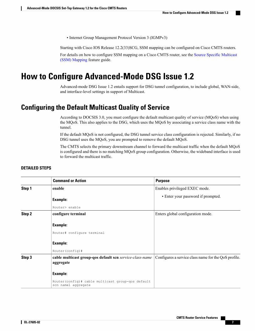
How to Configure Advanced-Mode DSG Issue 1.2Advanced-mode DSG Issue 1.2 entails support for DSG tunnel configuration, to include global, WAN-side,and interface-level settings in support of Multicast.
Configuring the Default Multicast Quality of ServiceAccording to DOCSIS 3.0, you must configure the default multicast quality of service (MQoS) when usingthe MQoS. This also applies to the DSG, which uses the MQoS by associating a service class name with thetunnel.
If the default MQoS is not configured, the DSG tunnel service class configuration is rejected. Similarly, if noDSG tunnel uses the MQoS, you are prompted to remove the default MQoS.
The CMTS selects the primary downstream channel to forward the multicast traffic when the default MQoSis configured and there is no matching MQoS group configuration. Otherwise, the wideband interface is usedto forward the multicast traffic.
DETAILED STEPS
PurposeCommand or Action
Enables privileged EXEC mode.enableStep 1
Example:
Router> enable
• Enter your password if prompted.
Enters global configuration mode.configure terminal
Example:
Router# configure terminal
Step 2
Example:
Router(config)#
Configures a service class name for the QoS profile.cable multicast group-qos default scn service-class-nameaggregate
Step 3
Example:
Router(config)# cable multicast group-qos defaultscn name1 aggregate
CMTS Router Service Features OL-27605-02 7
Advanced-Mode DOCSIS Set-Top Gateway 1.2 for the Cisco CMTS RoutersHow to Configure Advanced-Mode DSG Issue 1.2
PurposeCommand or Action
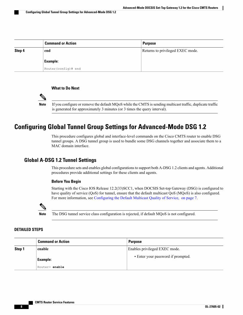
Returns to privileged EXEC mode.end
Example:
Router(config)# end
Step 4
What to Do Next
If you configure or remove the default MQoSwhile the CMTS is sending multicast traffic, duplicate trafficis generated for approximately 3 minutes (or 3 times the query interval).
Note
Configuring Global Tunnel Group Settings for Advanced-Mode DSG 1.2This procedure configures global and interface-level commands on the Cisco CMTS router to enable DSGtunnel groups. A DSG tunnel group is used to bundle some DSG channels together and associate them to aMAC domain interface.
Global A-DSG 1.2 Tunnel SettingsThis procedure sets and enables global configurations to support both A-DSG 1.2 clients and agents. Additionalprocedures provide additional settings for these clients and agents.
Before You Begin
Starting with the Cisco IOS Release 12.2(33)SCC1, when DOCSIS Set-top Gateway (DSG) is configured tohave quality of service (QoS) for tunnel, ensure that the default multicast QoS (MQoS) is also configured.For more information, see Configuring the Default Multicast Quality of Service, on page 7.
The DSG tunnel service class configuration is rejected, if default MQoS is not configured.Note
DETAILED STEPS
PurposeCommand or Action
Enables privileged EXEC mode.enableStep 1
Example:
Router> enable
• Enter your password if prompted.
CMTS Router Service Features8 OL-27605-02
Advanced-Mode DOCSIS Set-Top Gateway 1.2 for the Cisco CMTS RoutersConfiguring Global Tunnel Group Settings for Advanced-Mode DSG 1.2
PurposeCommand or Action
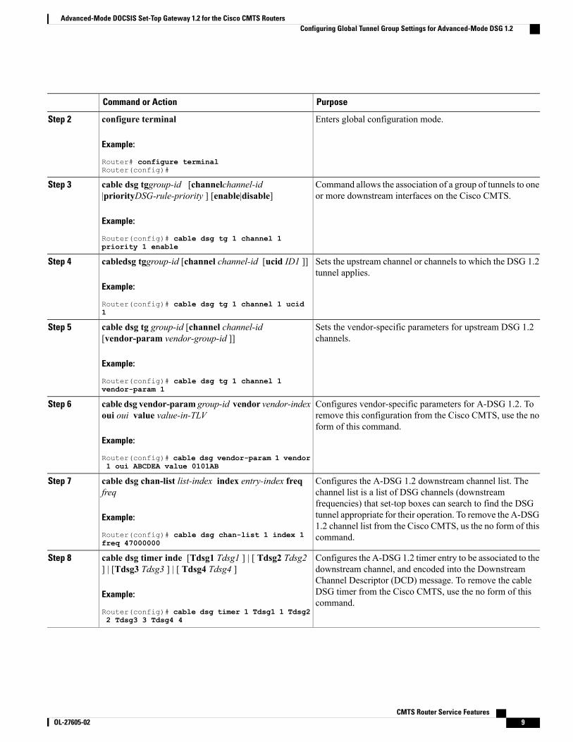
Enters global configuration mode.configure terminal
Example:
Router# configure terminalRouter(config)#
Step 2
Command allows the association of a group of tunnels to oneor more downstream interfaces on the Cisco CMTS.
cable dsg tggroup-id [channelchannel-id|priorityDSG-rule-priority ] [enable|disable]
Example:
Router(config)# cable dsg tg 1 channel 1priority 1 enable
Step 3
Sets the upstream channel or channels to which the DSG 1.2tunnel applies.
cabledsg tggroup-id [channel channel-id [ucid ID1 ]]
Example:
Router(config)# cable dsg tg 1 channel 1 ucid1
Step 4
Sets the vendor-specific parameters for upstream DSG 1.2channels.
cable dsg tg group-id [channel channel-id[vendor-param vendor-group-id ]]
Example:
Router(config)# cable dsg tg 1 channel 1vendor-param 1
Step 5
Configures vendor-specific parameters for A-DSG 1.2. Toremove this configuration from the Cisco CMTS, use the noform of this command.
cable dsg vendor-param group-id vendor vendor-indexoui oui value value-in-TLV
Example:
Router(config)# cable dsg vendor-param 1 vendor1 oui ABCDEA value 0101AB
Step 6
Configures the A-DSG 1.2 downstream channel list. Thechannel list is a list of DSG channels (downstream
cable dsg chan-list list-index index entry-index freqfreq
Step 7
frequencies) that set-top boxes can search to find the DSGExample:
Router(config)# cable dsg chan-list 1 index 1freq 47000000
tunnel appropriate for their operation. To remove the A-DSG1.2 channel list from the Cisco CMTS, us the no form of thiscommand.
Configures the A-DSG 1.2 timer entry to be associated to thedownstream channel, and encoded into the Downstream
cable dsg timer inde [Tdsg1 Tdsg1 ] | [ Tdsg2 Tdsg2] | [Tdsg3 Tdsg3 ] | [ Tdsg4 Tdsg4 ]
Step 8
Channel Descriptor (DCD) message. To remove the cableExample:
Router(config)# cable dsg timer 1 Tdsg1 1 Tdsg22 Tdsg3 3 Tdsg4 4
DSG timer from the Cisco CMTS, use the no form of thiscommand.
CMTS Router Service Features OL-27605-02 9
Advanced-Mode DOCSIS Set-Top Gateway 1.2 for the Cisco CMTS RoutersConfiguring Global Tunnel Group Settings for Advanced-Mode DSG 1.2
PurposeCommand or Action
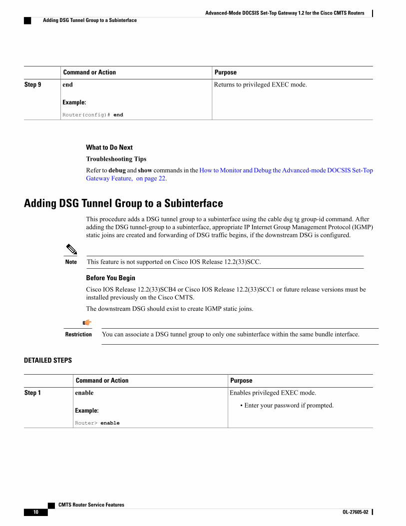
Returns to privileged EXEC mode.end
Example:
Router(config)# end
Step 9
What to Do Next
Troubleshooting Tips
Refer to debug and show commands in the How toMonitor and Debug the Advanced-mode DOCSIS Set-TopGateway Feature, on page 22.
Adding DSG Tunnel Group to a SubinterfaceThis procedure adds a DSG tunnel group to a subinterface using the cable dsg tg group-id command. Afteradding the DSG tunnel-group to a subinterface, appropriate IP Internet Group Management Protocol (IGMP)static joins are created and forwarding of DSG traffic begins, if the downstream DSG is configured.
This feature is not supported on Cisco IOS Release 12.2(33)SCC.Note
Before You Begin
Cisco IOS Release 12.2(33)SCB4 or Cisco IOS Release 12.2(33)SCC1 or future release versions must beinstalled previously on the Cisco CMTS.
The downstream DSG should exist to create IGMP static joins.
You can associate a DSG tunnel group to only one subinterface within the same bundle interface.Restriction
DETAILED STEPS
PurposeCommand or Action
Enables privileged EXEC mode.enableStep 1
Example:
Router> enable
• Enter your password if prompted.
CMTS Router Service Features10 OL-27605-02
Advanced-Mode DOCSIS Set-Top Gateway 1.2 for the Cisco CMTS RoutersAdding DSG Tunnel Group to a Subinterface
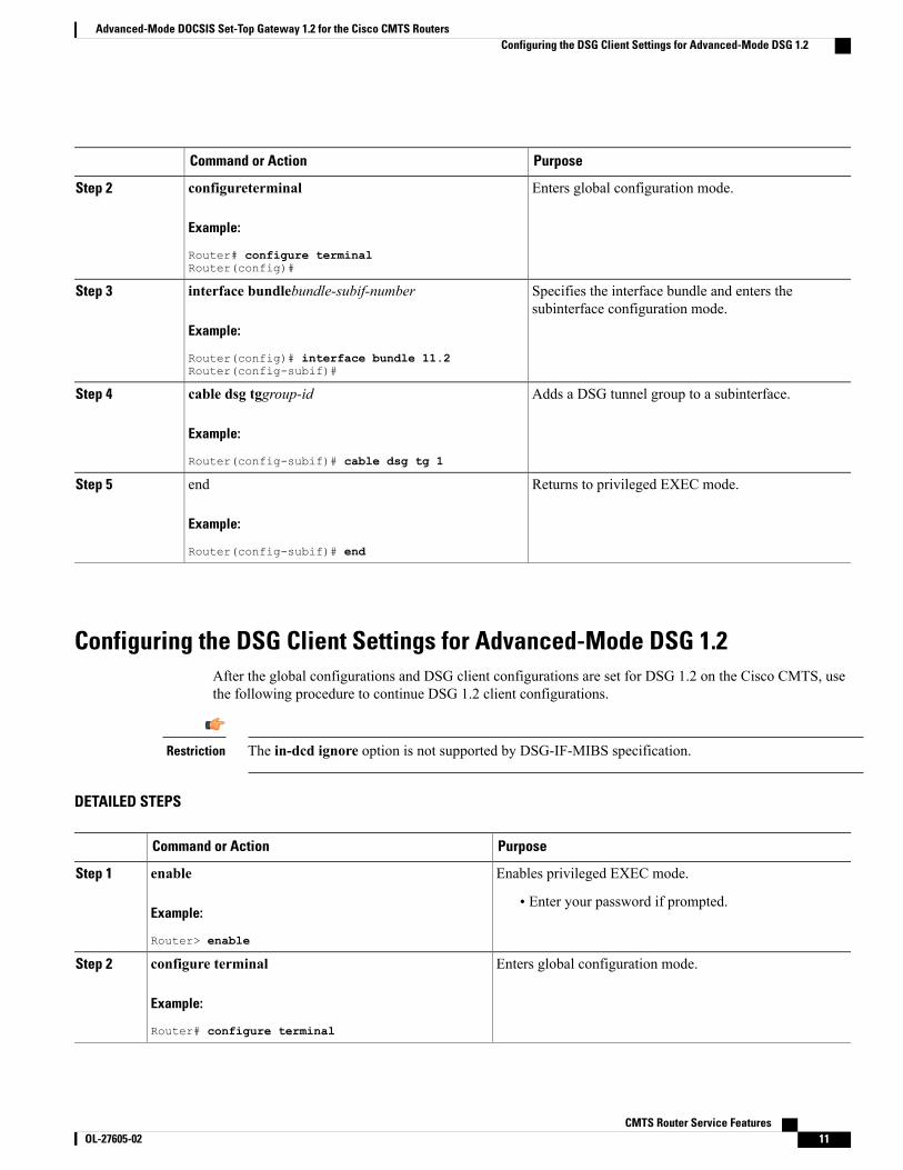
PurposeCommand or Action
Enters global configuration mode.configureterminal
Example:
Router# configure terminalRouter(config)#
Step 2
Specifies the interface bundle and enters thesubinterface configuration mode.
interface bundlebundle-subif-number
Example:
Router(config)# interface bundle 11.2Router(config-subif)#
Step 3
Adds a DSG tunnel group to a subinterface.cable dsg tggroup-id
Example:
Router(config-subif)# cable dsg tg 1
Step 4
Returns to privileged EXEC mode.end
Example:
Router(config-subif)# end
Step 5
Configuring the DSG Client Settings for Advanced-Mode DSG 1.2After the global configurations and DSG client configurations are set for DSG 1.2 on the Cisco CMTS, usethe following procedure to continue DSG 1.2 client configurations.
The in-dcd ignore option is not supported by DSG-IF-MIBS specification.Restriction
DETAILED STEPS
PurposeCommand or Action
Enables privileged EXEC mode.enableStep 1
Example:
Router> enable
• Enter your password if prompted.
Enters global configuration mode.configure terminal
Example:
Router# configure terminal
Step 2
CMTS Router Service Features OL-27605-02 11
Advanced-Mode DOCSIS Set-Top Gateway 1.2 for the Cisco CMTS RoutersConfiguring the DSG Client Settings for Advanced-Mode DSG 1.2
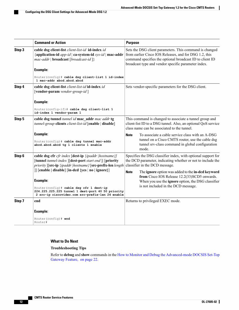
PurposeCommand or Action
Sets the DSG client parameters. This command is changedfrom earlier Cisco IOS Releases, and for DSG 1.2, this
cable dsg client-list client-list-id id-index id{application-id app-id | ca-system-id sys-id |mac-addrmac-addr | broadcast [broadcast-id ]}
Step 3
command specifies the optional broadcast ID to client IDbroadcast type and vendor specific parameter index.
Example:
Router(config)# cable dsg client-list 1 id-index1 mac-addr abcd.abcd.abcd
Sets vendor-specific parameters for the DSG client.cable dsg client-list client-list-id id-index id[vendor-param vendor-group-id ]
Step 4
Example:
Router(config-if)# cable dsg client-list 1id-index 1 vendor-param 1
This command is changed to associate a tunnel group andclient-list ID to a DSG tunnel. Also, an optional QoS serviceclass name can be associated to the tunnel.
cable dsg tunnel tunnel idmac_addr mac addr tgtunnel-group clients client-list-id [enable | disable]
Example:
Router(config)# cable dsg tunnel mac-addrabcd.abcd.abcd tg 1 clients 1 enable
Step 5
To associate a cable service class with an A-DSGtunnel on a Cisco CMTS router, use the cable dsgtunnel srv-class command in global configurationmode.
Note
Specifies the DSG classifier index, with optional support forthe DCD parameter, indicating whether or not to include theclassifier in the DCD message.
cable dsg cfr cfr index [dest-ip {ipaddr |hostname}][tunnel tunnel-index ][dest-port start end ]| [prioritypriority ][src-ip {ipaddr |hostname} [src-prefix-len length]] [enable | disable] [in-dcd {yes | no | ignore}]
Step 6
The ignore option was added to the in-dcd keywordfrom Cisco IOS Release 12.2(33)SCD5 onwards.When you use the ignore option, the DSG classifieris not included in the DCD message.
Note
Example:
Router(config)# cable dsg cfr 1 dest-ip224.225.225.225 tunnel 1 dest-port 40 50 priority2 src-ip ciscovideo.com src-prefix-len 24 enable
Returns to privileged EXEC mode.end
Example:
Router(config)# endRouter#
Step 7
What to Do Next
Troubleshooting Tips
Refer to debug and show commands in the How toMonitor and Debug the Advanced-mode DOCSIS Set-TopGateway Feature, on page 22.
CMTS Router Service Features12 OL-27605-02
Advanced-Mode DOCSIS Set-Top Gateway 1.2 for the Cisco CMTS RoutersConfiguring the DSG Client Settings for Advanced-Mode DSG 1.2
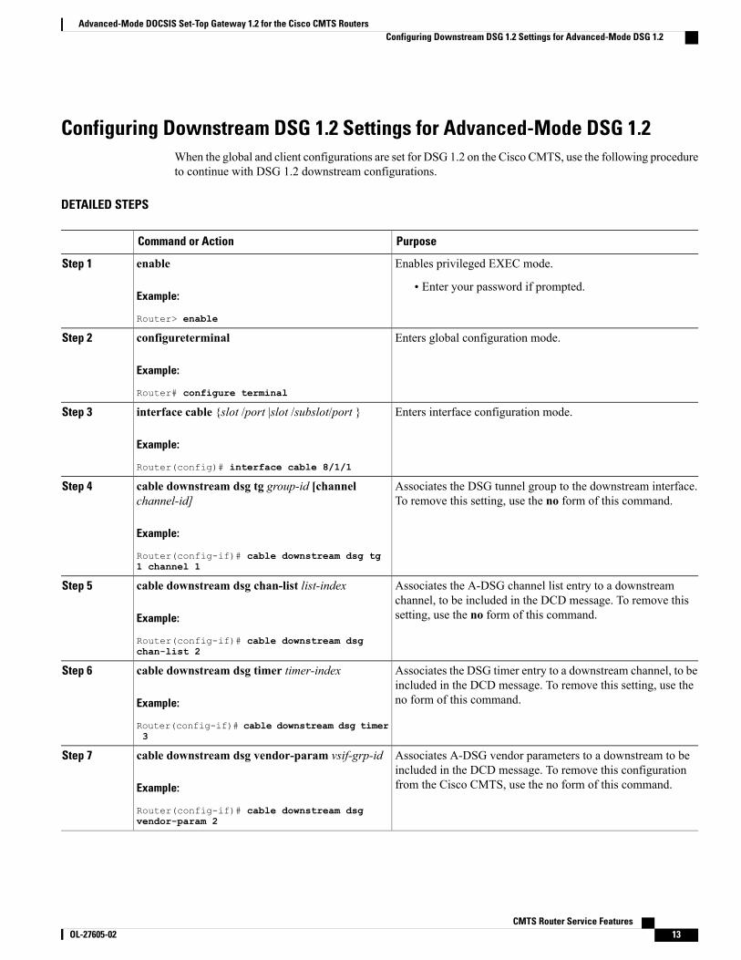
Configuring Downstream DSG 1.2 Settings for Advanced-Mode DSG 1.2When the global and client configurations are set for DSG 1.2 on the Cisco CMTS, use the following procedureto continue with DSG 1.2 downstream configurations.
DETAILED STEPS
PurposeCommand or Action
Enables privileged EXEC mode.enableStep 1
Example:
Router> enable
• Enter your password if prompted.
Enters global configuration mode.configureterminal
Example:
Router# configure terminal
Step 2
Enters interface configuration mode.interface cable {slot /port |slot /subslot/port }
Example:
Router(config)# interface cable 8/1/1
Step 3
Associates the DSG tunnel group to the downstream interface.To remove this setting, use the no form of this command.
cable downstream dsg tg group-id [channelchannel-id]
Example:
Router(config-if)# cable downstream dsg tg1 channel 1
Step 4
Associates the A-DSG channel list entry to a downstreamchannel, to be included in the DCD message. To remove thissetting, use the no form of this command.
cable downstream dsg chan-list list-index
Example:
Router(config-if)# cable downstream dsgchan-list 2
Step 5
Associates the DSG timer entry to a downstream channel, to beincluded in the DCD message. To remove this setting, use theno form of this command.
cable downstream dsg timer timer-index
Example:
Router(config-if)# cable downstream dsg timer3
Step 6
Associates A-DSG vendor parameters to a downstream to beincluded in the DCD message. To remove this configurationfrom the Cisco CMTS, use the no form of this command.
cable downstream dsg vendor-param vsif-grp-id
Example:
Router(config-if)# cable downstream dsgvendor-param 2
Step 7
CMTS Router Service Features OL-27605-02 13
Advanced-Mode DOCSIS Set-Top Gateway 1.2 for the Cisco CMTS RoutersConfiguring Downstream DSG 1.2 Settings for Advanced-Mode DSG 1.2
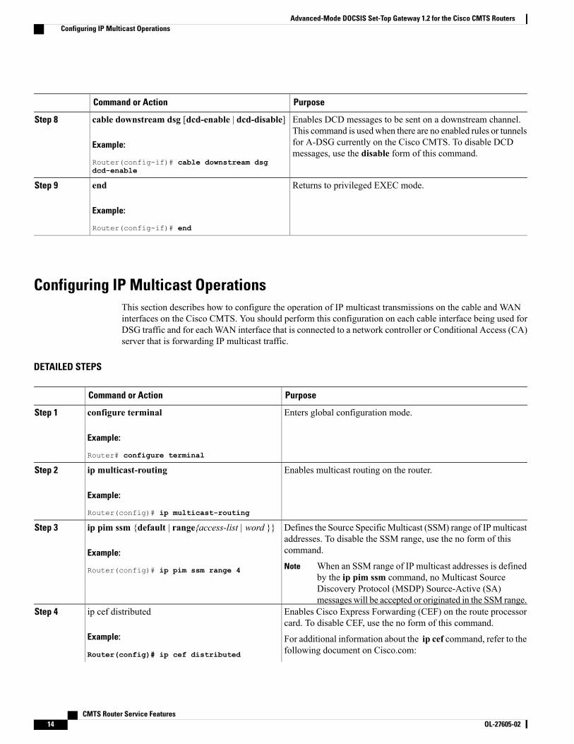
PurposeCommand or Action
Enables DCD messages to be sent on a downstream channel.This command is used when there are no enabled rules or tunnels
cable downstream dsg [dcd-enable | dcd-disable]
Example:
Router(config-if)# cable downstream dsgdcd-enable
Step 8
for A-DSG currently on the Cisco CMTS. To disable DCDmessages, use the disable form of this command.
Returns to privileged EXEC mode.end
Example:
Router(config-if)# end
Step 9
Configuring IP Multicast OperationsThis section describes how to configure the operation of IP multicast transmissions on the cable and WANinterfaces on the Cisco CMTS. You should perform this configuration on each cable interface being used forDSG traffic and for eachWAN interface that is connected to a network controller or Conditional Access (CA)server that is forwarding IP multicast traffic.
DETAILED STEPS
PurposeCommand or Action
Enters global configuration mode.configure terminal
Example:
Router# configure terminal
Step 1
Enables multicast routing on the router.ip multicast-routing
Example:
Router(config)# ip multicast-routing
Step 2
Defines the Source SpecificMulticast (SSM) range of IP multicastaddresses. To disable the SSM range, use the no form of thiscommand.
ip pim ssm {default | range{access-list | word }}
Example:
Router(config)# ip pim ssm range 4
Step 3
When an SSM range of IP multicast addresses is definedby the ip pim ssm command, no Multicast SourceDiscovery Protocol (MSDP) Source-Active (SA)messages will be accepted or originated in the SSM range.
Note
Enables Cisco Express Forwarding (CEF) on the route processorcard. To disable CEF, use the no form of this command.
ip cef distributed
Example:
Router(config)# ip cef distributed
Step 4
For additional information about the ip cef command, refer to thefollowing document on Cisco.com:
CMTS Router Service Features14 OL-27605-02
Advanced-Mode DOCSIS Set-Top Gateway 1.2 for the Cisco CMTS RoutersConfiguring IP Multicast Operations
PurposeCommand or Action
• Cisco IOS Switching Services Command Reference , Release12.3
http://www.cisco.com/en/US/docs/ios/12_3/switch/command/reference/swtch_r.html
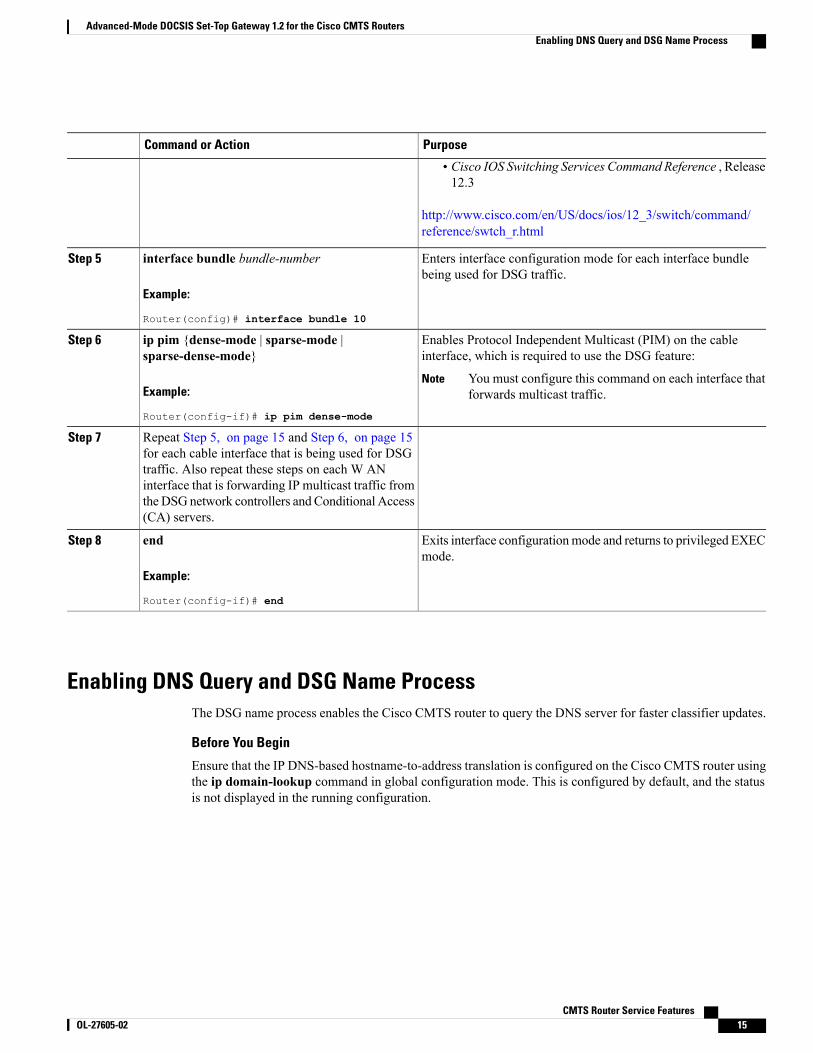
Enters interface configuration mode for each interface bundlebeing used for DSG traffic.
interface bundle bundle-number
Example:
Router(config)# interface bundle 10
Step 5
Enables Protocol Independent Multicast (PIM) on the cableinterface, which is required to use the DSG feature:
ip pim {dense-mode | sparse-mode |sparse-dense-mode}
Step 6
Example:
Router(config-if)# ip pim dense-mode
You must configure this command on each interface thatforwards multicast traffic.
Note
Repeat Step 5, on page 15 and Step 6, on page 15for each cable interface that is being used for DSG
Step 7
traffic. Also repeat these steps on each W ANinterface that is forwarding IP multicast traffic fromtheDSG network controllers and Conditional Access(CA) servers.
Exits interface configurationmode and returns to privileged EXECmode.
end
Example:
Router(config-if)# end
Step 8
Enabling DNS Query and DSG Name ProcessThe DSG name process enables the Cisco CMTS router to query the DNS server for faster classifier updates.
Before You Begin
Ensure that the IP DNS-based hostname-to-address translation is configured on the Cisco CMTS router usingthe ip domain-lookup command in global configuration mode. This is configured by default, and the statusis not displayed in the running configuration.
CMTS Router Service Features OL-27605-02 15
Advanced-Mode DOCSIS Set-Top Gateway 1.2 for the Cisco CMTS RoutersEnabling DNS Query and DSG Name Process
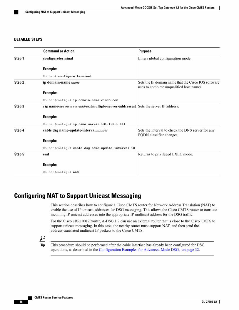
DETAILED STEPS
PurposeCommand or Action
Enters global configuration mode.configureterminal
Example:
Router# configure terminal
Step 1
Sets the IP domain name that the Cisco IOS softwareuses to complete unqualified host names
ip domain-name name
Example:
Router(config)# ip domain-name cisco.com
Step 2
Sets the server IP address.r ip name-serveserver-address[multiple-server-addresses]
Example:
Router(config)# ip name-server 131.108.1.111
Step 3
Sets the interval to check the DNS server for anyFQDN classifier changes.
cable dsg name-update-intervalminutes
Example:
Router(config)# cable dsg name-update-interval 10
Step 4
Returns to privileged EXEC mode.end
Example:
Router(config)# end
Step 5
Configuring NAT to Support Unicast MessagingThis section describes how to configure a Cisco CMTS router for Network Address Translation (NAT) toenable the use of IP unicast addresses for DSG messaging. This allows the Cisco CMTS router to translateincoming IP unicast addresses into the appropriate IP multicast address for the DSG traffic.
For the Cisco uBR10012 router, A-DSG 1.2 can use an external router that is close to the Cisco CMTS tosupport unicast messaging. In this case, the nearby router must support NAT, and then send theaddress-translated multicast IP packets to the Cisco CMTS.
This procedure should be performed after the cable interface has already been configured for DSGoperations, as described in the Configuration Examples for Advanced-Mode DSG, on page 32.
Tip
CMTS Router Service Features16 OL-27605-02
Advanced-Mode DOCSIS Set-Top Gateway 1.2 for the Cisco CMTS RoutersConfiguring NAT to Support Unicast Messaging

The Cisco CMTS router supports NAT only when it is running an “IP Plus” (-i-) Cisco IOS software image.Refer to the release notes for your Cisco IOS release for complete image availability and requirements.
Note
DETAILED STEPS
PurposeCommand or Action
Enters global configuration mode.configure terminal
Example:
Router# configure terminal
Step 1
Enters interface configuration mode for the specified WANinterface.
interface wan-interface
Example:
Router(config)# interface FastEthernet0/0
Step 2
Configures the WAN interface as the “outside” (public) NATinterface.
ip nat outside
Example:
Router(config-if)# ip nat outside
Step 3
Enters interface configuration mode for the specified interfacebundle.
interface bundle bundle-number
Example:
Router(config-if)# interface bundle 10
Step 4
This interface bundle should have previously beenconfigured for DSG operations.
Note
Configures the cable interface with an IP address and subnetthat should match the unicast address being used for DSG
ip address ip-address mask secondary
Example:
Router(config-if)# ip address 192.168.18.1255.255.255.0 secondary
Step 5
traffic. This IP address and its subnet must not be used by anyother cable interfaces, cable modems, or any other types oftraffic in the cable network.
Configures the cable interface as the “inside” (private) NATinterface.
ip nat inside
Example:
Router(config-if)# ip nat inside
Step 6
Exits interface configuration mode and returns to globalconfiguration mode.
exit
Example:
Router(config-if)# exit
Step 7
CMTS Router Service Features OL-27605-02 17
Advanced-Mode DOCSIS Set-Top Gateway 1.2 for the Cisco CMTS RoutersConfiguring NAT to Support Unicast Messaging
PurposeCommand or Action
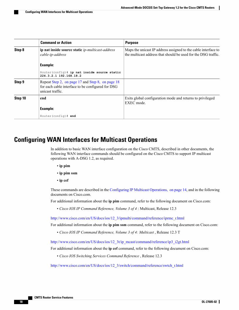
Maps the unicast IP address assigned to the cable interface tothe multicast address that should be used for the DSG traffic.
ip nat inside source static ip-multicast-addresscable-ip-address
Example:
Router(config)# ip nat inside source static224.3.2.1 192.168.18.2
Step 8
Repeat Step 2, on page 17 and Step 8, on page 18for each cable interface to be configured for DSGunicast traffic.
Step 9
Exits global configuration mode and returns to privilegedEXEC mode.
end
Example:
Router(config)# end
Step 10
Configuring WAN Interfaces for Multicast OperationsIn addition to basic WAN interface configuration on the Cisco CMTS, described in other documents, thefollowing WAN interface commands should be configured on the Cisco CMTS to support IP multicastoperations with A-DSG 1.2, as required.
• ip pim
• ip pim ssm
• ip cef
These commands are described in the Configuring IP Multicast Operations, on page 14, and in the followingdocuments on Cisco.com.
For additional information about the ip pim command, refer to the following document on Cisco.com:
• Cisco IOS IP Command Reference, Volume 3 of 4 : Multicast, Release 12.3
http://www.cisco.com/en/US/docs/ios/12_3/ipmulti/command/reference/iprmc_r.html
For additional information about the ip pim ssm command, refer to the following document on Cisco.com:
• Cisco IOS IP Command Reference, Volume 3 of 4: Multicast , Release 12.3 T
http://www.cisco.com/en/US/docs/ios/12_3t/ip_mcast/command/reference/ip3_i2gt.html
For additional information about the ip cef command, refer to the following document on Cisco.com:
• Cisco IOS Switching Services Command Reference , Release 12.3
http://www.cisco.com/en/US/docs/ios/12_3/switch/command/reference/swtch_r.html
CMTS Router Service Features18 OL-27605-02
Advanced-Mode DOCSIS Set-Top Gateway 1.2 for the Cisco CMTS RoutersConfiguring WAN Interfaces for Multicast Operations
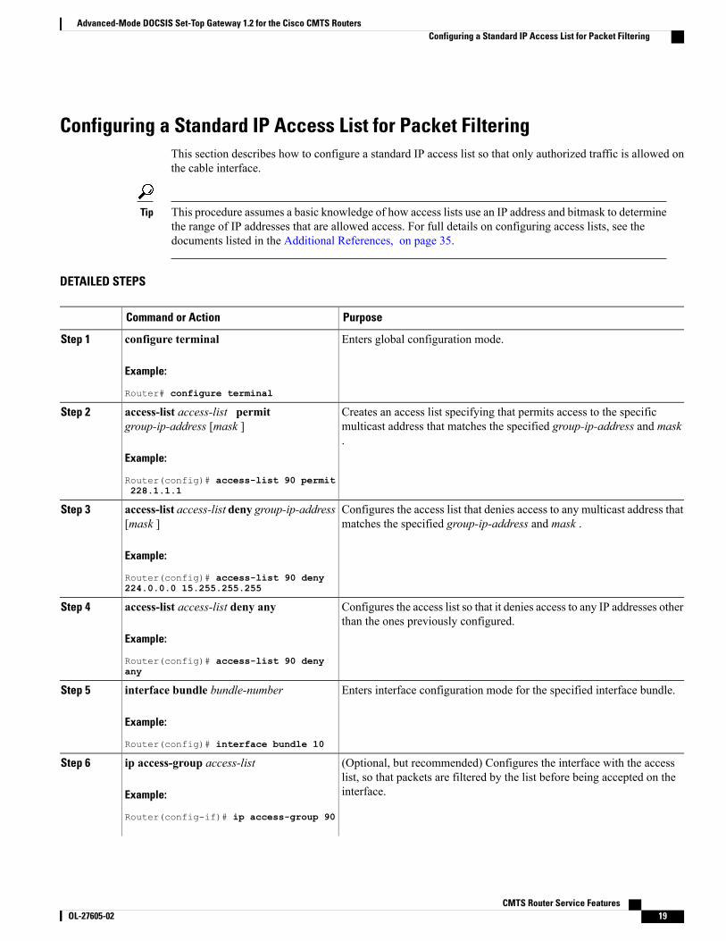
Configuring a Standard IP Access List for Packet FilteringThis section describes how to configure a standard IP access list so that only authorized traffic is allowed onthe cable interface.
This procedure assumes a basic knowledge of how access lists use an IP address and bitmask to determinethe range of IP addresses that are allowed access. For full details on configuring access lists, see thedocuments listed in the Additional References, on page 35.
Tip
DETAILED STEPS
PurposeCommand or Action
Enters global configuration mode.configure terminal
Example:
Router# configure terminal
Step 1
Creates an access list specifying that permits access to the specificmulticast address that matches the specified group-ip-address and mask.
access-list access-list permitgroup-ip-address [mask ]
Example:
Router(config)# access-list 90 permit228.1.1.1
Step 2
Configures the access list that denies access to any multicast address thatmatches the specified group-ip-address and mask .
access-list access-list deny group-ip-address[mask ]
Example:
Router(config)# access-list 90 deny224.0.0.0 15.255.255.255
Step 3
Configures the access list so that it denies access to any IP addresses otherthan the ones previously configured.
access-list access-list deny any
Example:
Router(config)# access-list 90 denyany
Step 4
Enters interface configuration mode for the specified interface bundle.interface bundle bundle-number
Example:
Router(config)# interface bundle 10
Step 5
(Optional, but recommended) Configures the interface with the accesslist, so that packets are filtered by the list before being accepted on theinterface.
ip access-group access-list
Example:
Router(config-if)# ip access-group 90
Step 6
CMTS Router Service Features OL-27605-02 19
Advanced-Mode DOCSIS Set-Top Gateway 1.2 for the Cisco CMTS RoutersConfiguring a Standard IP Access List for Packet Filtering
PurposeCommand or Action
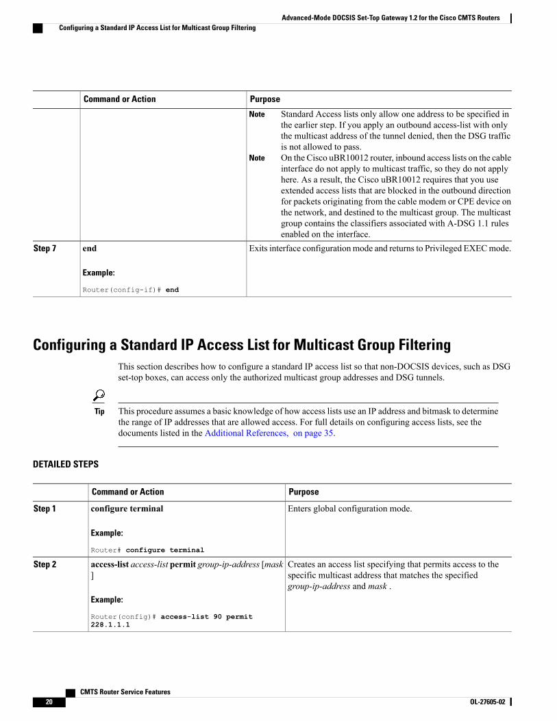
Standard Access lists only allow one address to be specified inthe earlier step. If you apply an outbound access-list with onlythe multicast address of the tunnel denied, then the DSG trafficis not allowed to pass.
Note
On the Cisco uBR10012 router, inbound access lists on the cableinterface do not apply to multicast traffic, so they do not applyhere. As a result, the Cisco uBR10012 requires that you useextended access lists that are blocked in the outbound directionfor packets originating from the cable modem or CPE device onthe network, and destined to the multicast group. The multicastgroup contains the classifiers associated with A-DSG 1.1 rulesenabled on the interface.
Note
Exits interface configuration mode and returns to Privileged EXECmode.end
Example:
Router(config-if)# end
Step 7
Configuring a Standard IP Access List for Multicast Group FilteringThis section describes how to configure a standard IP access list so that non-DOCSIS devices, such as DSGset-top boxes, can access only the authorized multicast group addresses and DSG tunnels.
This procedure assumes a basic knowledge of how access lists use an IP address and bitmask to determinethe range of IP addresses that are allowed access. For full details on configuring access lists, see thedocuments listed in the Additional References, on page 35.
Tip
DETAILED STEPS
PurposeCommand or Action
Enters global configuration mode.configure terminal
Example:
Router# configure terminal
Step 1
Creates an access list specifying that permits access to thespecific multicast address that matches the specifiedgroup-ip-address and mask .
access-list access-list permit group-ip-address [mask]
Example:
Router(config)# access-list 90 permit228.1.1.1
Step 2
CMTS Router Service Features20 OL-27605-02
Advanced-Mode DOCSIS Set-Top Gateway 1.2 for the Cisco CMTS RoutersConfiguring a Standard IP Access List for Multicast Group Filtering

PurposeCommand or Action
Configures the access list that denies access to any multicastaddress that matches the specified group-ip-address and mask.
access-list access-list deny group-ip-address [mask]
Example:
Router(config)# access-list 90 deny 224.0.0.015.255.255.255
Step 3
Configures the access list so that it denies access to any IPaddresses other than the ones previously configured.
access-list access-list deny any
Example:
Router(config)# access-list 90 deny any
Step 4
Enters interface configuration mode for the specified cableinterface.
interface cable interface
Example:
Router(config)# interface cable 3/0
Step 5
(Optional, but recommended) Configures the interface to accepttraffic only from the associated access list, so that onlyauthorized devices are allowed to access the DSG tunnels.
ip igmp access-group access-list [version ]
Example:
Router(config-if)# ip igmp access-group 90
Step 6
Exits interface configuration mode and returns to privilegedEXEC mode.
end
Example:
Router(config-if)# end
Step 7
Disabling A-DSG Forwarding on the Primary ChannelYou can disable A-DSG forwarding per primary capable interface.
DETAILED STEPS
PurposeCommand or Action
Enters global configuration mode.configure terminal
Example:
Router# configure terminal
Step 1
Specifies the modular cable interface and enters cable interfaceconfiguration mode. Variables for this command may vary
interface modular-cable slot /subslot/port:interface-number
Step 2
depending on the Cisco CMTS router and the Cisco IOS
CMTS Router Service Features OL-27605-02 21
Advanced-Mode DOCSIS Set-Top Gateway 1.2 for the Cisco CMTS RoutersDisabling A-DSG Forwarding on the Primary Channel
PurposeCommand or Action
Example:
Router(config)# interface modular-cable1/0/0:0
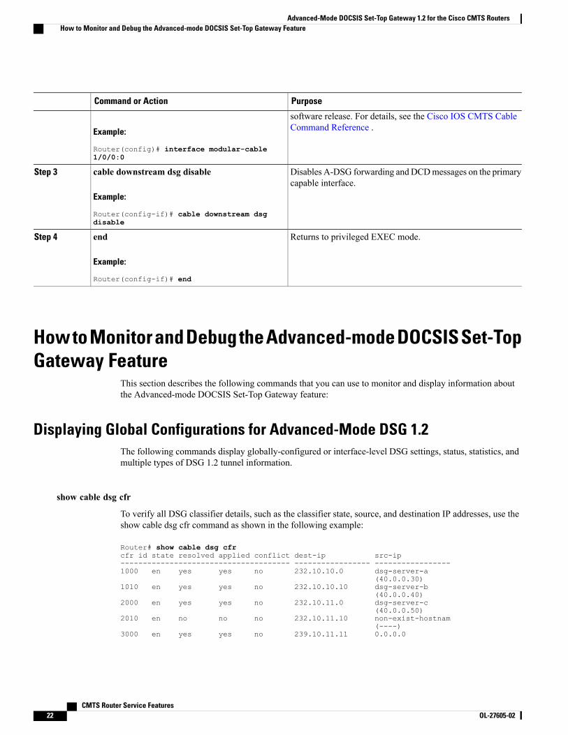
software release. For details, see the Cisco IOS CMTS CableCommand Reference .
Disables A-DSG forwarding and DCDmessages on the primarycapable interface.
cable downstream dsg disable
Example:
Router(config-if)# cable downstream dsgdisable
Step 3
Returns to privileged EXEC mode.end
Example:
Router(config-if)# end
Step 4
How to Monitor and Debug the Advanced-mode DOCSIS Set-TopGateway Feature
This section describes the following commands that you can use to monitor and display information aboutthe Advanced-mode DOCSIS Set-Top Gateway feature:
Displaying Global Configurations for Advanced-Mode DSG 1.2The following commands display globally-configured or interface-level DSG settings, status, statistics, andmultiple types of DSG 1.2 tunnel information.
show cable dsg cfr
To verify all DSG classifier details, such as the classifier state, source, and destination IP addresses, use theshow cable dsg cfr command as shown in the following example:
Router# show cable dsg cfrcfr id state resolved applied conflict dest-ip src-ip-------------------------------------- ----------------- -----------------1000 en yes yes no 232.10.10.0 dsg-server-a
(40.0.0.30)1010 en yes yes no 232.10.10.10 dsg-server-b
(40.0.0.40)2000 en yes yes no 232.10.11.0 dsg-server-c
(40.0.0.50)2010 en no no no 232.10.11.10 non-exist-hostnam
(----)3000 en yes yes no 239.10.11.11 0.0.0.0
CMTS Router Service Features22 OL-27605-02
Advanced-Mode DOCSIS Set-Top Gateway 1.2 for the Cisco CMTS RoutersHow to Monitor and Debug the Advanced-mode DOCSIS Set-Top Gateway Feature
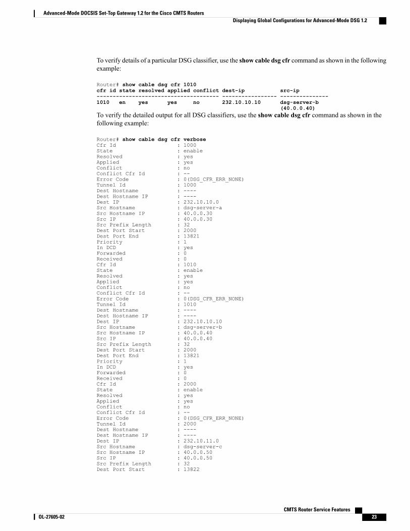
To verify details of a particular DSG classifier, use the show cable dsg cfr command as shown in the followingexample:
Router# show cable dsg cfr 1010cfr id state resolved applied conflict dest-ip src-ip-------------------------------------- ----------------- ---------------1010 en yes yes no 232.10.10.10 dsg-server-b
(40.0.0.40)To verify the detailed output for all DSG classifiers, use the show cable dsg cfr command as shown in thefollowing example:
Router# show cable dsg cfr verboseCfr Id : 1000State : enableResolved : yesApplied : yesConflict : noConflict Cfr Id : --Error Code : 0(DSG_CFR_ERR_NONE)Tunnel Id : 1000Dest Hostname : ----Dest Hostname IP : ----Dest IP : 232.10.10.0Src Hostname : dsg-server-aSrc Hostname IP : 40.0.0.30Src IP : 40.0.0.30Src Prefix Length : 32Dest Port Start : 2000Dest Port End : 13821Priority : 1In DCD : yesForwarded : 0Received : 0Cfr Id : 1010State : enableResolved : yesApplied : yesConflict : noConflict Cfr Id : --Error Code : 0(DSG_CFR_ERR_NONE)Tunnel Id : 1010Dest Hostname : ----Dest Hostname IP : ----Dest IP : 232.10.10.10Src Hostname : dsg-server-bSrc Hostname IP : 40.0.0.40Src IP : 40.0.0.40Src Prefix Length : 32Dest Port Start : 2000Dest Port End : 13821Priority : 1In DCD : yesForwarded : 0Received : 0Cfr Id : 2000State : enableResolved : yesApplied : yesConflict : noConflict Cfr Id : --Error Code : 0(DSG_CFR_ERR_NONE)Tunnel Id : 2000Dest Hostname : ----Dest Hostname IP : ----Dest IP : 232.10.11.0Src Hostname : dsg-server-cSrc Hostname IP : 40.0.0.50Src IP : 40.0.0.50Src Prefix Length : 32Dest Port Start : 13822
CMTS Router Service Features OL-27605-02 23
Advanced-Mode DOCSIS Set-Top Gateway 1.2 for the Cisco CMTS RoutersDisplaying Global Configurations for Advanced-Mode DSG 1.2
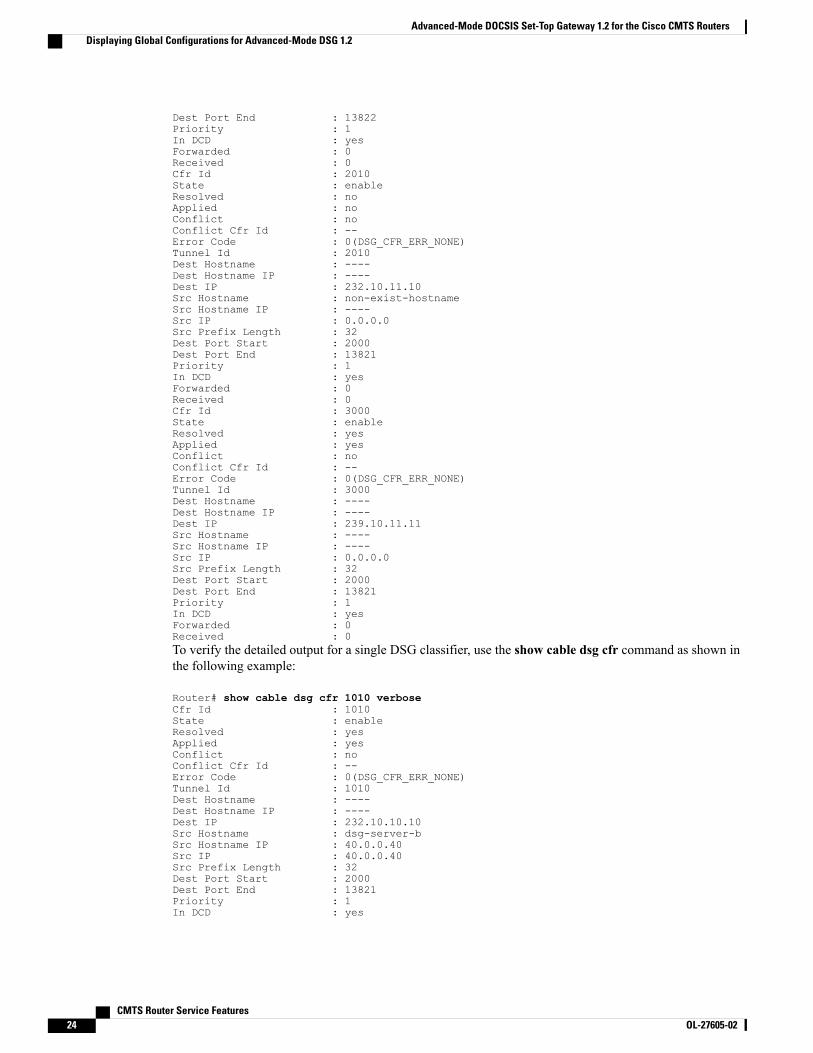
Dest Port End : 13822Priority : 1In DCD : yesForwarded : 0Received : 0Cfr Id : 2010State : enableResolved : noApplied : noConflict : noConflict Cfr Id : --Error Code : 0(DSG_CFR_ERR_NONE)Tunnel Id : 2010Dest Hostname : ----Dest Hostname IP : ----Dest IP : 232.10.11.10Src Hostname : non-exist-hostnameSrc Hostname IP : ----Src IP : 0.0.0.0Src Prefix Length : 32Dest Port Start : 2000Dest Port End : 13821Priority : 1In DCD : yesForwarded : 0Received : 0Cfr Id : 3000State : enableResolved : yesApplied : yesConflict : noConflict Cfr Id : --Error Code : 0(DSG_CFR_ERR_NONE)Tunnel Id : 3000Dest Hostname : ----Dest Hostname IP : ----Dest IP : 239.10.11.11Src Hostname : ----Src Hostname IP : ----Src IP : 0.0.0.0Src Prefix Length : 32Dest Port Start : 2000Dest Port End : 13821Priority : 1In DCD : yesForwarded : 0Received : 0To verify the detailed output for a single DSG classifier, use the show cable dsg cfr command as shown inthe following example:
Router# show cable dsg cfr 1010 verboseCfr Id : 1010State : enableResolved : yesApplied : yesConflict : noConflict Cfr Id : --Error Code : 0(DSG_CFR_ERR_NONE)Tunnel Id : 1010Dest Hostname : ----Dest Hostname IP : ----Dest IP : 232.10.10.10Src Hostname : dsg-server-bSrc Hostname IP : 40.0.0.40Src IP : 40.0.0.40Src Prefix Length : 32Dest Port Start : 2000Dest Port End : 13821Priority : 1In DCD : yes
CMTS Router Service Features24 OL-27605-02
Advanced-Mode DOCSIS Set-Top Gateway 1.2 for the Cisco CMTS RoutersDisplaying Global Configurations for Advanced-Mode DSG 1.2
Forwarded : 0Received : 0
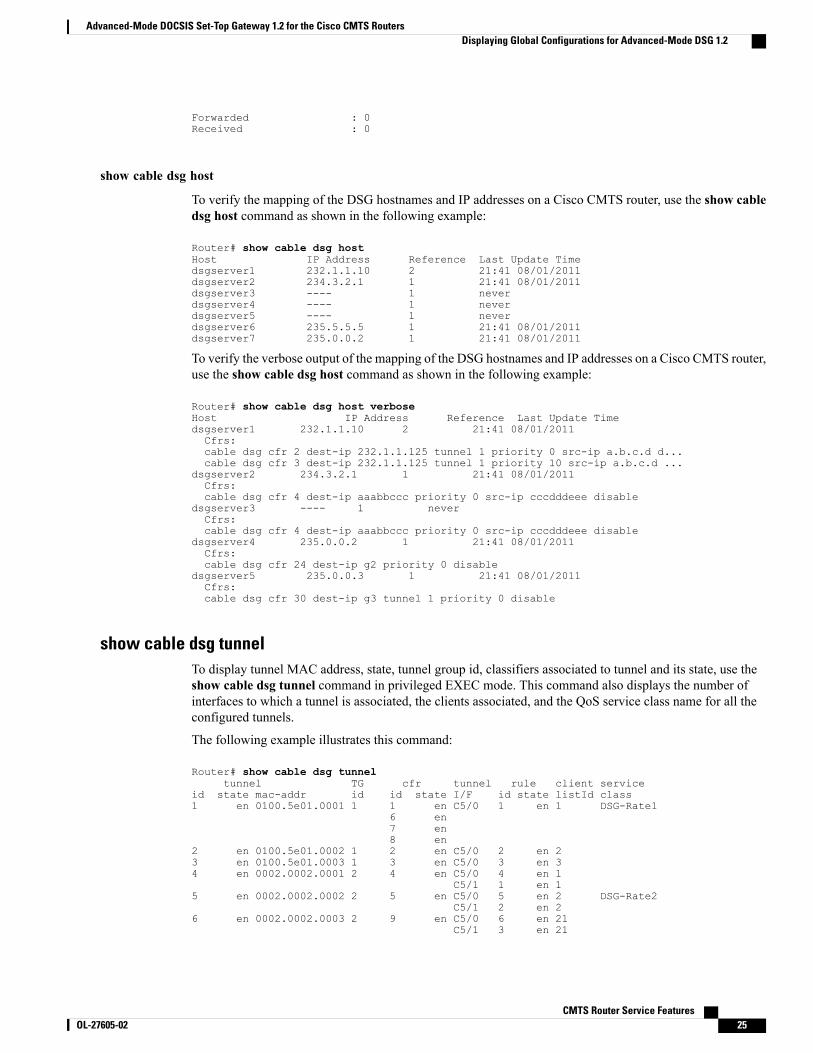
show cable dsg host
To verify the mapping of the DSG hostnames and IP addresses on a Cisco CMTS router, use the show cabledsg host command as shown in the following example:
Router# show cable dsg hostHost IP Address Reference Last Update Timedsgserver1 232.1.1.10 2 21:41 08/01/2011dsgserver2 234.3.2.1 1 21:41 08/01/2011dsgserver3 ---- 1 neverdsgserver4 ---- 1 neverdsgserver5 ---- 1 neverdsgserver6 235.5.5.5 1 21:41 08/01/2011dsgserver7 235.0.0.2 1 21:41 08/01/2011
To verify the verbose output of the mapping of the DSG hostnames and IP addresses on a Cisco CMTS router,use the show cable dsg host command as shown in the following example:
Router# show cable dsg host verboseHost IP Address Reference Last Update Timedsgserver1 232.1.1.10 2 21:41 08/01/2011Cfrs:cable dsg cfr 2 dest-ip 232.1.1.125 tunnel 1 priority 0 src-ip a.b.c.d d...cable dsg cfr 3 dest-ip 232.1.1.125 tunnel 1 priority 10 src-ip a.b.c.d ...
dsgserver2 234.3.2.1 1 21:41 08/01/2011Cfrs:cable dsg cfr 4 dest-ip aaabbccc priority 0 src-ip cccdddeee disable
dsgserver3 ---- 1 neverCfrs:cable dsg cfr 4 dest-ip aaabbccc priority 0 src-ip cccdddeee disable
dsgserver4 235.0.0.2 1 21:41 08/01/2011Cfrs:cable dsg cfr 24 dest-ip g2 priority 0 disable
dsgserver5 235.0.0.3 1 21:41 08/01/2011Cfrs:cable dsg cfr 30 dest-ip g3 tunnel 1 priority 0 disable
show cable dsg tunnelTo display tunnel MAC address, state, tunnel group id, classifiers associated to tunnel and its state, use theshow cable dsg tunnel command in privileged EXEC mode. This command also displays the number ofinterfaces to which a tunnel is associated, the clients associated, and the QoS service class name for all theconfigured tunnels.
The following example illustrates this command:
Router# show cable dsg tunneltunnel TG cfr tunnel rule client service
id state mac-addr id id state I/F id state listId class1 en 0100.5e01.0001 1 1 en C5/0 1 en 1 DSG-Rate1
6 en7 en8 en
2 en 0100.5e01.0002 1 2 en C5/0 2 en 23 en 0100.5e01.0003 1 3 en C5/0 3 en 34 en 0002.0002.0001 2 4 en C5/0 4 en 1
C5/1 1 en 15 en 0002.0002.0002 2 5 en C5/0 5 en 2 DSG-Rate2
C5/1 2 en 26 en 0002.0002.0003 2 9 en C5/0 6 en 21
C5/1 3 en 21
CMTS Router Service Features OL-27605-02 25
Advanced-Mode DOCSIS Set-Top Gateway 1.2 for the Cisco CMTS RoutersDisplaying Global Configurations for Advanced-Mode DSG 1.2
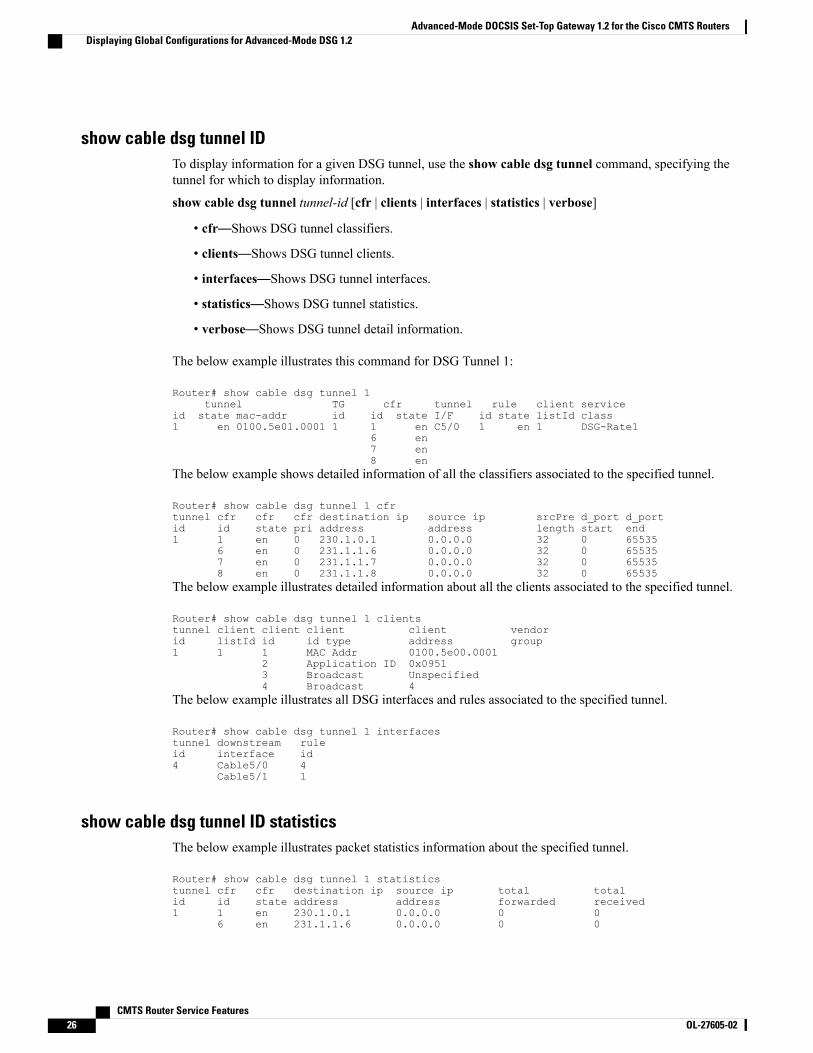
show cable dsg tunnel IDTo display information for a given DSG tunnel, use the show cable dsg tunnel command, specifying thetunnel for which to display information.
show cable dsg tunnel tunnel-id [cfr | clients | interfaces | statistics | verbose]
• cfr—Shows DSG tunnel classifiers.
• clients—Shows DSG tunnel clients.
• interfaces—Shows DSG tunnel interfaces.
• statistics—Shows DSG tunnel statistics.
• verbose—Shows DSG tunnel detail information.
The below example illustrates this command for DSG Tunnel 1:
Router# show cable dsg tunnel 1tunnel TG cfr tunnel rule client service
id state mac-addr id id state I/F id state listId class1 en 0100.5e01.0001 1 1 en C5/0 1 en 1 DSG-Rate1
6 en7 en8 en
The below example shows detailed information of all the classifiers associated to the specified tunnel.
Router# show cable dsg tunnel 1 cfrtunnel cfr cfr cfr destination ip source ip srcPre d_port d_portid id state pri address address length start end1 1 en 0 230.1.0.1 0.0.0.0 32 0 65535
6 en 0 231.1.1.6 0.0.0.0 32 0 655357 en 0 231.1.1.7 0.0.0.0 32 0 655358 en 0 231.1.1.8 0.0.0.0 32 0 65535
The below example illustrates detailed information about all the clients associated to the specified tunnel.
Router# show cable dsg tunnel 1 clientstunnel client client client client vendorid listId id id type address group1 1 1 MAC Addr 0100.5e00.0001
2 Application ID 0x09513 Broadcast Unspecified4 Broadcast 4
The below example illustrates all DSG interfaces and rules associated to the specified tunnel.
Router# show cable dsg tunnel 1 interfacestunnel downstream ruleid interface id4 Cable5/0 4
Cable5/1 1
show cable dsg tunnel ID statisticsThe below example illustrates packet statistics information about the specified tunnel.
Router# show cable dsg tunnel 1 statisticstunnel cfr cfr destination ip source ip total totalid id state address address forwarded received1 1 en 230.1.0.1 0.0.0.0 0 0
6 en 231.1.1.6 0.0.0.0 0 0
CMTS Router Service Features26 OL-27605-02
Advanced-Mode DOCSIS Set-Top Gateway 1.2 for the Cisco CMTS RoutersDisplaying Global Configurations for Advanced-Mode DSG 1.2
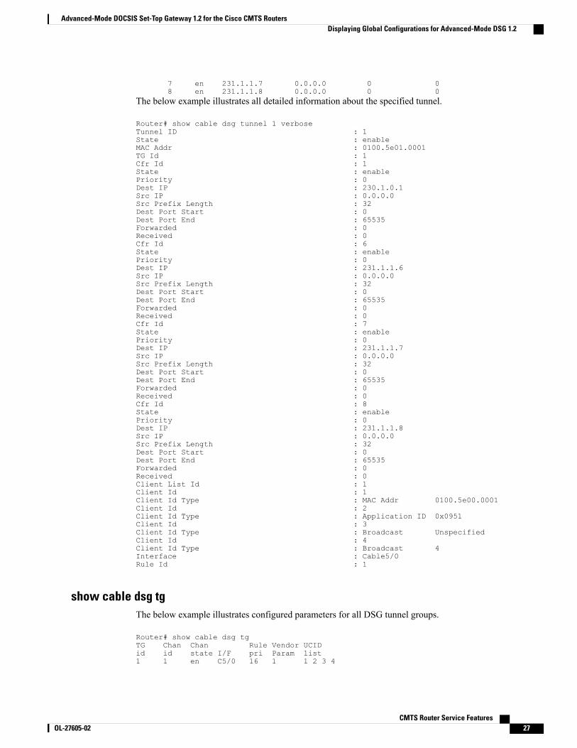
7 en 231.1.1.7 0.0.0.0 0 08 en 231.1.1.8 0.0.0.0 0 0
The below example illustrates all detailed information about the specified tunnel.
Router# show cable dsg tunnel 1 verboseTunnel ID : 1State : enableMAC Addr : 0100.5e01.0001TG Id : 1Cfr Id : 1State : enablePriority : 0Dest IP : 230.1.0.1Src IP : 0.0.0.0Src Prefix Length : 32Dest Port Start : 0Dest Port End : 65535Forwarded : 0Received : 0Cfr Id : 6State : enablePriority : 0Dest IP : 231.1.1.6Src IP : 0.0.0.0Src Prefix Length : 32Dest Port Start : 0Dest Port End : 65535Forwarded : 0Received : 0Cfr Id : 7State : enablePriority : 0Dest IP : 231.1.1.7Src IP : 0.0.0.0Src Prefix Length : 32Dest Port Start : 0Dest Port End : 65535Forwarded : 0Received : 0Cfr Id : 8State : enablePriority : 0Dest IP : 231.1.1.8Src IP : 0.0.0.0Src Prefix Length : 32Dest Port Start : 0Dest Port End : 65535Forwarded : 0Received : 0Client List Id : 1Client Id : 1Client Id Type : MAC Addr 0100.5e00.0001Client Id : 2Client Id Type : Application ID 0x0951Client Id : 3Client Id Type : Broadcast UnspecifiedClient Id : 4Client Id Type : Broadcast 4Interface : Cable5/0Rule Id : 1
show cable dsg tgThe below example illustrates configured parameters for all DSG tunnel groups.
Router# show cable dsg tgTG Chan Chan Rule Vendor UCIDid id state I/F pri Param list1 1 en C5/0 16 1 1 2 3 4
CMTS Router Service Features OL-27605-02 27
Advanced-Mode DOCSIS Set-Top Gateway 1.2 for the Cisco CMTS RoutersDisplaying Global Configurations for Advanced-Mode DSG 1.2
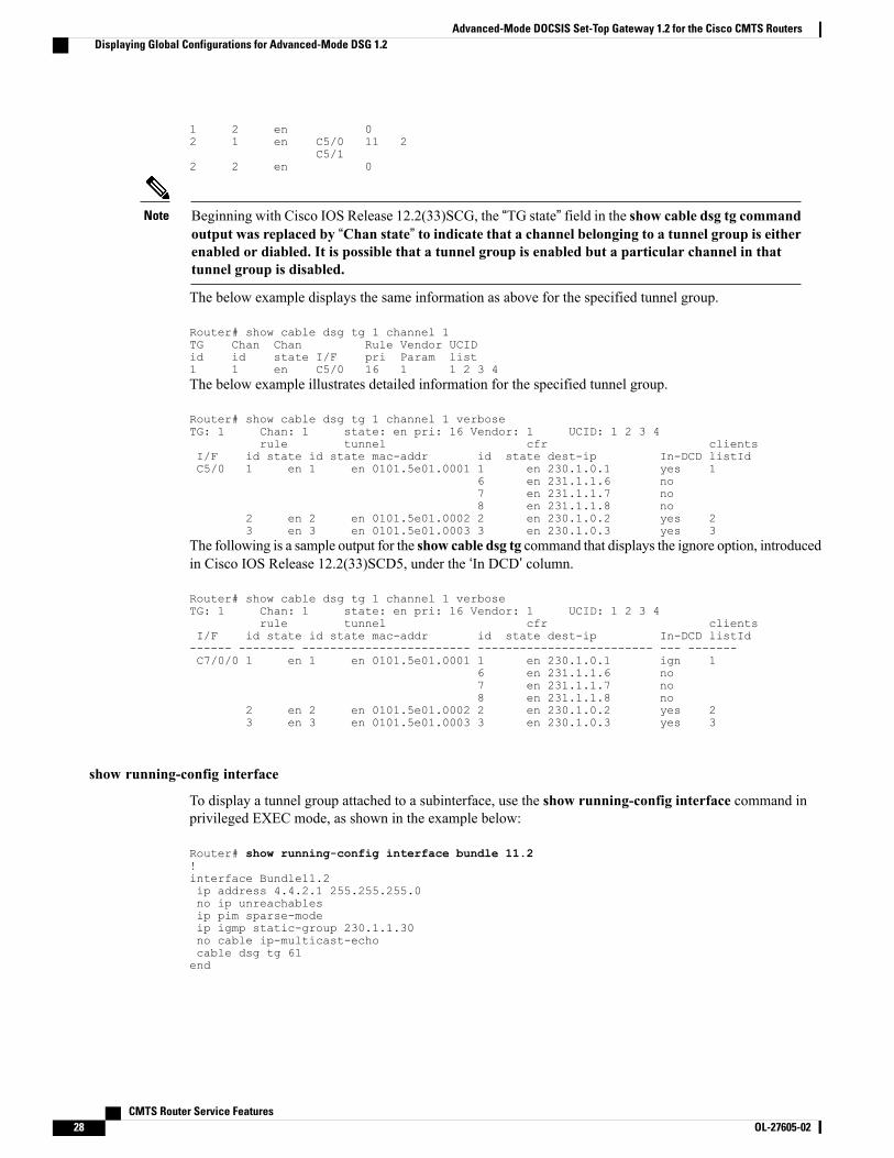
1 2 en 02 1 en C5/0 11 2
C5/12 2 en 0
Beginning with Cisco IOS Release 12.2(33)SCG, the “TG state” field in the show cable dsg tg commandoutput was replaced by “Chan state” to indicate that a channel belonging to a tunnel group is eitherenabled or diabled. It is possible that a tunnel group is enabled but a particular channel in thattunnel group is disabled.
Note
The below example displays the same information as above for the specified tunnel group.
Router# show cable dsg tg 1 channel 1TG Chan Chan Rule Vendor UCIDid id state I/F pri Param list1 1 en C5/0 16 1 1 2 3 4The below example illustrates detailed information for the specified tunnel group.
Router# show cable dsg tg 1 channel 1 verboseTG: 1 Chan: 1 state: en pri: 16 Vendor: 1 UCID: 1 2 3 4
rule tunnel cfr clientsI/F id state id state mac-addr id state dest-ip In-DCD listIdC5/0 1 en 1 en 0101.5e01.0001 1 en 230.1.0.1 yes 1
6 en 231.1.1.6 no7 en 231.1.1.7 no8 en 231.1.1.8 no
2 en 2 en 0101.5e01.0002 2 en 230.1.0.2 yes 23 en 3 en 0101.5e01.0003 3 en 230.1.0.3 yes 3
The following is a sample output for the show cable dsg tg command that displays the ignore option, introducedin Cisco IOS Release 12.2(33)SCD5, under the ‘In DCD’ column.
Router# show cable dsg tg 1 channel 1 verboseTG: 1 Chan: 1 state: en pri: 16 Vendor: 1 UCID: 1 2 3 4
rule tunnel cfr clientsI/F id state id state mac-addr id state dest-ip In-DCD listId------ -------- ------------------------ ------------------------- --- -------C7/0/0 1 en 1 en 0101.5e01.0001 1 en 230.1.0.1 ign 1
6 en 231.1.1.6 no7 en 231.1.1.7 no8 en 231.1.1.8 no
2 en 2 en 0101.5e01.0002 2 en 230.1.0.2 yes 23 en 3 en 0101.5e01.0003 3 en 230.1.0.3 yes 3
show running-config interface
To display a tunnel group attached to a subinterface, use the show running-config interface command inprivileged EXEC mode, as shown in the example below:
Router# show running-config interface bundle 11.2!interface Bundle11.2ip address 4.4.2.1 255.255.255.0no ip unreachablesip pim sparse-modeip igmp static-group 230.1.1.30no cable ip-multicast-echocable dsg tg 61end
CMTS Router Service Features28 OL-27605-02
Advanced-Mode DOCSIS Set-Top Gateway 1.2 for the Cisco CMTS RoutersDisplaying Global Configurations for Advanced-Mode DSG 1.2
The IGMP static group IP address created automatically at the time of DSG configuration is not displayedin the show running-config interface command output in Cisco IOS Release 12.2(33)SCG and later.
Note
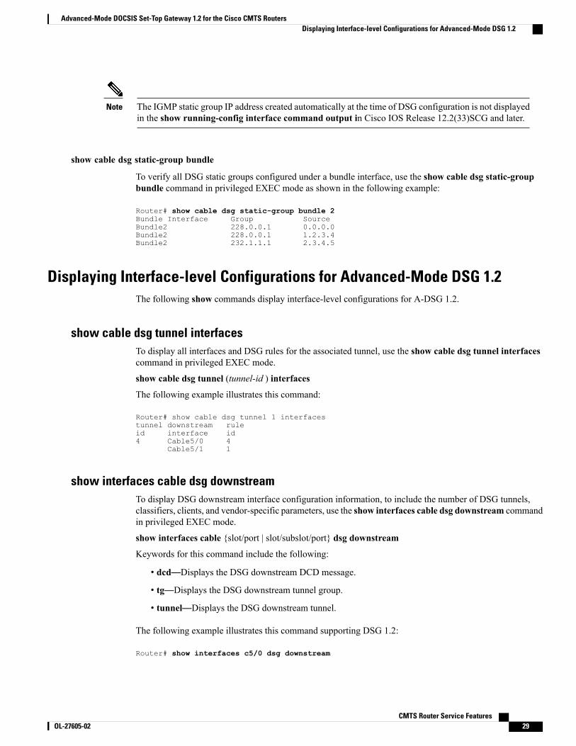
show cable dsg static-group bundle
To verify all DSG static groups configured under a bundle interface, use the show cable dsg static-groupbundle command in privileged EXEC mode as shown in the following example:
Router# show cable dsg static-group bundle 2Bundle Interface Group SourceBundle2 228.0.0.1 0.0.0.0Bundle2 228.0.0.1 1.2.3.4Bundle2 232.1.1.1 2.3.4.5
Displaying Interface-level Configurations for Advanced-Mode DSG 1.2The following show commands display interface-level configurations for A-DSG 1.2.
show cable dsg tunnel interfacesTo display all interfaces and DSG rules for the associated tunnel, use the show cable dsg tunnel interfacescommand in privileged EXEC mode.
show cable dsg tunnel (tunnel-id ) interfaces
The following example illustrates this command:
Router# show cable dsg tunnel 1 interfacestunnel downstream ruleid interface id4 Cable5/0 4
Cable5/1 1
show interfaces cable dsg downstreamTo display DSG downstream interface configuration information, to include the number of DSG tunnels,classifiers, clients, and vendor-specific parameters, use the show interfaces cable dsg downstream commandin privileged EXEC mode.
show interfaces cable {slot/port | slot/subslot/port} dsg downstream
Keywords for this command include the following:
• dcd—Displays the DSG downstream DCD message.
• tg—Displays the DSG downstream tunnel group.
• tunnel—Displays the DSG downstream tunnel.
The following example illustrates this command supporting DSG 1.2:
Router# show interfaces c5/0 dsg downstream
CMTS Router Service Features OL-27605-02 29
Advanced-Mode DOCSIS Set-Top Gateway 1.2 for the Cisco CMTS RoutersDisplaying Interface-level Configurations for Advanced-Mode DSG 1.2
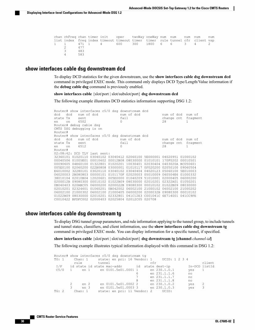
chan chFreq chan timer init oper twoWay oneWay num num num num numlist index freq index timeout timeout timer timer rule tunnel cfr client vsp1 1 471 1 4 600 300 1800 6 6 3 4 2
2 4773 4834 583
show interfaces cable dsg downstream dcdTo display DCD statistics for the given downstream, use the show interfaces cable dsg downstream dcdcommand in privileged EXEC mode. This command only displays DCD Type/Length/Value information ifthe debug cable dsg command is previously enabled.
show interfaces cable {slot/port | slot/subslot/port} dsg downstream dcd
The following example illustrates DCD statistics information supporting DSG 1.2:
Router# show interfaces c5/0 dsg downstream dcddcd dcd num of dcd num of dcd num of dcd num ofstate Tx sent fail change cnt fragmenten on 6502 0 28 1Router# debug cable dsgCMTS DSG debugging is onRouter#Router# show interfaces c5/0 dsg downstream dcddcd dcd num of dcd num of dcd num of dcd num ofstate Tx sent fail change cnt fragmenten on 6512 0 28 1Router#02:08:42: DCD TLV last sent:32360101 01020110 03040102 03040412 02060100 5E000001 04020951 0100010200040506 01005E01 00010602 00012B08 08030000 01010101 170F0202 0001050100090605 04E60100 01322801 01020201 10030401 02030404 0403020A BC050601005E0100 02060200 022B0808 03000001 01010117 0F020200 02050100 09060504E6010002 32280101 03020110 03040102 03040404 04020123 05060100 5E01000306020003 2B080803 00000101 0101170F 02020003 05010009 060504E6 0100033238010104 02010B04 12020601 005E0000 01040209 51010001 02000405 060002000200012B 09080300 00010102 01022B09 08030000 02010201 02322A01 010502010B040403 020ABC05 06000200 0200022B 09080300 00010102 01022B09 0803000002010201 02324601 01060201 0B042002 06002100 21000102 06002100 2100020206002100 21000302 06002100 21000405 06000200 0200032B 09080300 0001010201022B09 08030000 02010201 02332801 041C12E3 C001041C 6E714001 041CC9FEC0010422 BFDFC002 02000403 02025804 02012C05 020708
show interfaces cable dsg downstream tgTo display DSG tunnel group parameters, and rule information applying to the tunnel group, to include tunnelsand tunnel states, classifiers, and client information, use the show interfaces cable dsg downstream tgcommand in privileged EXEC mode. You can display information for a specific tunnel, if specified.
show interfaces cable {slot/port | slot/subslot/port} dsg downstream tg [channel channel-id]
The following example illustrates typical information displayed with this command in DSG 1.2:
Router# show interfaces c5/0 dsg downstream tgTG: 1 Chan: 1 state: en pri: 16 Vendor: 1 UCID: 1 2 3 4
rule tunnel cfr clientI/F id state id state mac-addr id state dest-ip In-DCD listIdC5/0 1 en 1 en 0101.5e01.0001 1 en 230.1.0.1 yes 1
6 en 231.1.1.6 no7 en 231.1.1.7 no8 en 231.1.1.8 no
2 en 2 en 0101.5e01.0002 2 en 230.1.0.2 yes 23 en 3 en 0101.5e01.0003 3 en 230.1.0.3 yes 3
TG: 2 Chan: 1 state: en pri: 11 Vendor: 2 UCID:
CMTS Router Service Features30 OL-27605-02
Advanced-Mode DOCSIS Set-Top Gateway 1.2 for the Cisco CMTS RoutersDisplaying Interface-level Configurations for Advanced-Mode DSG 1.2
rule tunnel cfr clientI/F id state id state mac-addr id state dest-ip In-DCD listIdC5/0 4 en 4 en 0002.0002.0001 4 en 230.2.2.1 no 1
5 en 5 en 0002.0002.0002 5 en 230.2.2.2 no 26 en 6 en 0002.0002.0003 9 en 231.1.1.9 no 21
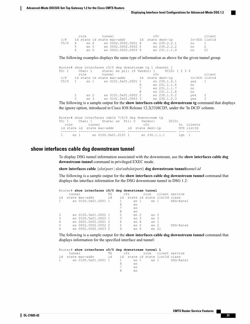
The following examples displays the same type of information as above for the given tunnel group.
Router# show interfaces c5/0 dsg downstream tg 1 channel 1TG: 1 Chan: 1 state: en pri: 16 Vendor: 1 UCID: 1 2 3 4
rule tunnel cfr clientI/F id state id state mac-addr id state dest-ip In-DCD listIdC5/0 1 en 1 en 0101.5e01.0001 1 en 230.1.0.1 yes 1
6 en 231.1.1.6 no7 en 231.1.1.7 no8 en 231.1.1.8 no
2 en 2 en 0101.5e01.0002 2 en 230.1.0.2 yes 23 en 3 en 0101.5e01.0003 3 en 230.1.0.3 yes 3
The following is a sample output for the show interfaces cable dsg downstream tg command that displaysthe ignore option, introduced in Cisco IOS Release 12.2(33)SCD5, under the ‘In DCD’ column.
Router# show interfaces cable 7/0/0 dsg downstream tgTG: 1 Chan: 1 State: en Pri: 0 Vendor: UCID:
rule tunnel cfr In clientsid state id state mac-addr id state dest-ip DCD listId-------- ------------------------ ------------------------- --- -------1 en 1 en 0100.5e01.0101 1 en 230.1.1.1 ign 1
show interfaces cable dsg downstream tunnelTo display DSG tunnel information associated with the downstream, use the show interfaces cable dsgdownstream tunnel command in privileged EXEC mode.
show interfaces cable {slot/port | slot/subslot/port} dsg downstream tunneltunnel-id
The following is a sample output for the show interfaces cable dsg downstream tunnel command thatdisplays the interface information for the DSG downstream tunnel in DSG 1.2:
Router# show interfaces c5/0 dsg downstream tunneltunnel TG cfr rule client service
id state mac-addr id id state id state listId class1 en 0100.5e01.0001 1 1 en 1 en 1 DSG-Rate1
6 en7 en8 en
2 en 0100.5e01.0002 1 2 en 2 en 23 en 0100.5e01.0003 1 3 en 3 en 34 en 0002.0002.0001 2 4 en 4 en 15 en 0002.0002.0002 2 5 en 5 en 2 DSG-Rate26 en 0002.0002.0003 2 9 en 6 en 21
The following is a sample output for the show interfaces cable dsg downstream tunnel command thatdisplays information for the specified interface and tunnel:
Router# show interfaces c5/0 dsg downstream tunnel 1tunnel TG cfr rule client service
id state mac-addr id id state id state listId class1 en 0100.5e01.0001 1 1 en 1 en 1 DSG-Rate1
6 en7 en8 en
CMTS Router Service Features OL-27605-02 31
Advanced-Mode DOCSIS Set-Top Gateway 1.2 for the Cisco CMTS RoutersDisplaying Interface-level Configurations for Advanced-Mode DSG 1.2

Debugging Advanced-Mode DSGTo enable debugging for A-DSG on a Cisco CMTS router, use the debug cable dsg command in privilegedEXEC mode.
Configuration Examples for Advanced-Mode DSGThis configuration example illustrates a sample DSG network featuring these components:
• Two Cisco universal broadband routers
• IP Multicast for each DSG implementation
• Two DSG Clients for each Cisco CMTS
• Two DSG Servers (one for each Cisco CMTS)
Each Cisco CMTS is configured as follows, and the remainder of this topic describes example configurationsthat apply to this architecture.
CMTS Headend 1
• DSG Server #1—Connected to Cisco CMTS via IP Multicast, with DSG Server having IP Address12.8.8.1
• Destination IP Address for the Cisco CMTS—228.9.9.1
• DSG Tunnel Address—0105.0005.0005
• Downstream #1 Supporting two DSG Clients:
◦DSG Client #1—ID 101.1.1
◦DSG Client #2—ID 102.2.2
CMTS Headend 2
• DSG Server #2—Connected to Cisco CMTS via IP Multicast, with DSG Server having IP Address12.8.8.2
• Destination IP Address for the Cisco CMTS—228.9.9.2
• DSG Tunnel Address—0106.0006.0006
• Downstream #2 Supporting two DSG Clients:
◦DSG Client #1—ID 101.1.1
◦DSG Client #2—ID 102.2.2
CMTS Router Service Features32 OL-27605-02
Advanced-Mode DOCSIS Set-Top Gateway 1.2 for the Cisco CMTS RoutersDebugging Advanced-Mode DSG

Example of Two DSG Tunnels with MAC DA Substitution
In this configuration, and given the two Cisco CMTS Headends cited above, below are the two sets of DSGrules, with each set applying to each Cisco CMTS, in respective fashion.
These settings apply to DSG #1 and two downstreams:
• DSG Rule ID 1
• DSG Client ID 101.1.1
• DSG Tunnel Address 105.5.5
These settings apply to DSG Rule #2 and two downstreams:
• DSG Rule ID 1
• DSG Client ID 102.2.2
• DSG Tunnel Address 106.6.6
DSG Example with Regionalization Per Downstream
In this configuration, and given the two Cisco CMTS Headends cited earlier in this topic, below are twodownstream rules that can be configured in this architecture, for example:
• Downstream Rule #1
◦DSG Rule ID #1
◦DSG Client ID—101.1.1
◦DSG Tunnel Address—105.5.5
• Downstream Rule #2
◦DSG Rule ID #2
◦DSG Client ID—102.2.2
◦DSG Tunnel Address—106.6.6
DSG Example with Regionalization Per Upstream
In this configuration, and given the two Cisco CMTS Headends cited earlier in this topic, below are twoupstream rules that can be configured in this architecture, for example:
• Upstream Rule #1
◦DSG Rule ID #1
◦DSG Client ID—101.1.1
◦DSG UCID Range—0 to 2
◦DSG Tunnel Address—105.5.5
• Upstream Rule #2
◦DSG Rule ID #2
CMTS Router Service Features OL-27605-02 33
Advanced-Mode DOCSIS Set-Top Gateway 1.2 for the Cisco CMTS RoutersConfiguration Examples for Advanced-Mode DSG
◦DSG Client ID—102.2.2
◦DSG UCID Range—3 to 5
◦DSG Tunnel Address—106.6.6
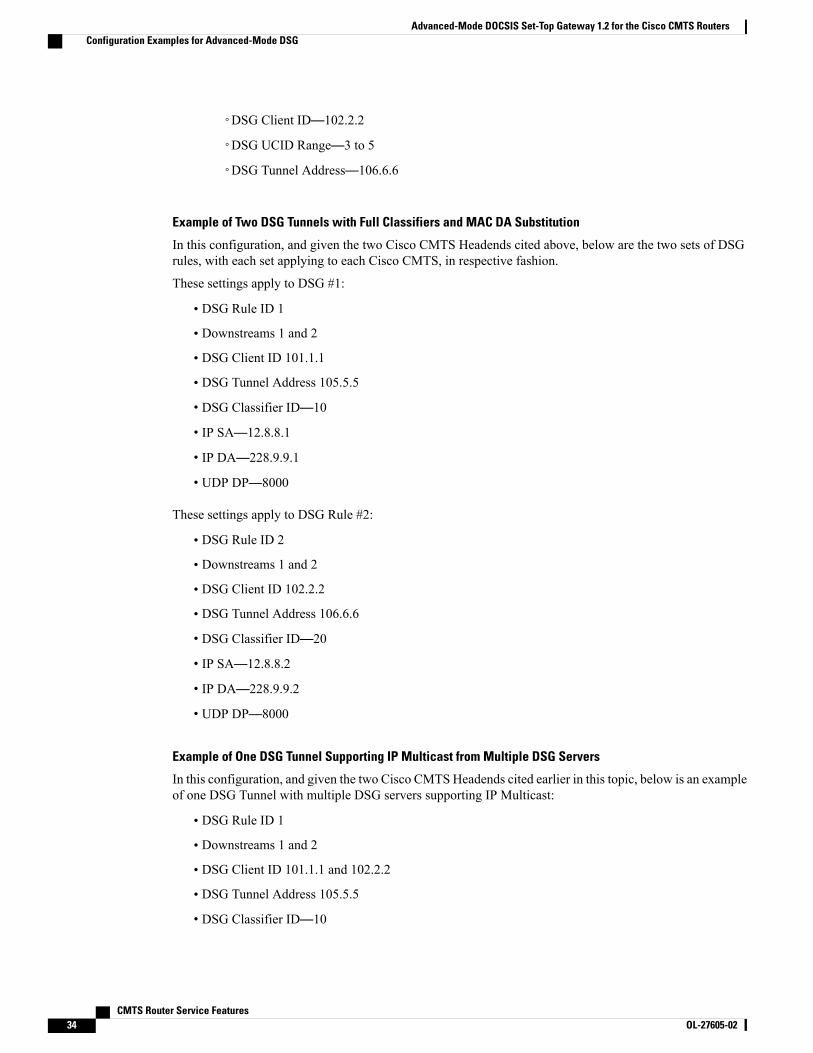
Example of Two DSG Tunnels with Full Classifiers and MAC DA Substitution
In this configuration, and given the two Cisco CMTS Headends cited above, below are the two sets of DSGrules, with each set applying to each Cisco CMTS, in respective fashion.
These settings apply to DSG #1:
• DSG Rule ID 1
• Downstreams 1 and 2
• DSG Client ID 101.1.1
• DSG Tunnel Address 105.5.5
• DSG Classifier ID—10
• IP SA—12.8.8.1
• IP DA—228.9.9.1
• UDP DP—8000
These settings apply to DSG Rule #2:
• DSG Rule ID 2
• Downstreams 1 and 2
• DSG Client ID 102.2.2
• DSG Tunnel Address 106.6.6
• DSG Classifier ID—20
• IP SA—12.8.8.2
• IP DA—228.9.9.2
• UDP DP—8000
Example of One DSG Tunnel Supporting IP Multicast from Multiple DSG Servers
In this configuration, and given the two Cisco CMTSHeadends cited earlier in this topic, below is an exampleof one DSG Tunnel with multiple DSG servers supporting IP Multicast:
• DSG Rule ID 1
• Downstreams 1 and 2
• DSG Client ID 101.1.1 and 102.2.2
• DSG Tunnel Address 105.5.5
• DSG Classifier ID—10
CMTS Router Service Features34 OL-27605-02
Advanced-Mode DOCSIS Set-Top Gateway 1.2 for the Cisco CMTS RoutersConfiguration Examples for Advanced-Mode DSG
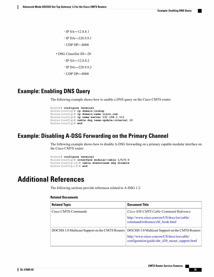
IP SA—12.8.8.1◦
◦IP DA—228.9.9.1
◦UDP DP—8000
• DSG Classifier ID—20
◦IP SA—12.8.8.2
◦IP DA—228.9.9.2
◦UDP DP—8000
Example: Enabling DNS QueryThe following example shows how to enable a DNS query on the Cisco CMTS router:
Router# configure terminalRouter(config)# ip domain-lookupRouter(config)# ip domain-name cisco.comRouter(config)# ip name-server 131.108.1.111Router(config)# cable dsg name-update-interval 10Router(config)# end
Example: Disabling A-DSG Forwarding on the Primary ChannelThe following example shows how to disable A-DSG forwarding on a primary capable modular interface onthe Cisco CMTS router:
Router# configure terminalRouter(config)# interface modular-cable 1/0/0:0Router(config-if)# cable downstream dsg disableRouter(config-if)# end
Additional ReferencesThe following sections provide references related to A-DSG 1.2.
Related Documents
Document TitleRelated Topic
Cisco IOS CMTS Cable Command Reference
http://www.cisco.com/en/US/docs/ios/cable/command/reference/cbl_book.html
Cisco CMTS Commands
DOCSIS 3.0Multicast Support on the CMTSRouters
http://www.cisco.com/en/US/docs/ios/cable/configuration/guide/ubr_d30_mcast_support.html
DOCSIS 3.0Multicast Support on the CMTSRouters
CMTS Router Service Features OL-27605-02 35
Advanced-Mode DOCSIS Set-Top Gateway 1.2 for the Cisco CMTS RoutersExample: Enabling DNS Query
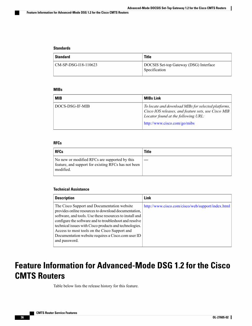
Standards
TitleStandard
DOCSIS Set-top Gateway (DSG) InterfaceSpecification
CM-SP-DSG-I18-110623
MIBs
MIBs LinkMIB
To locate and downloadMIBs for selected platforms,Cisco IOS releases, and feature sets, use Cisco MIBLocator found at the following URL:
http://www.cisco.com/go/mibs
DOCS-DSG-IF-MIB
RFCs
TitleRFCs
—No new or modified RFCs are supported by thisfeature, and support for existing RFCs has not beenmodified.
Technical Assistance
LinkDescription
http://www.cisco.com/cisco/web/support/index.htmlThe Cisco Support and Documentation websiteprovides online resources to download documentation,software, and tools. Use these resources to install andconfigure the software and to troubleshoot and resolvetechnical issues with Cisco products and technologies.Access to most tools on the Cisco Support andDocumentation website requires a Cisco.com user IDand password.
Feature Information for Advanced-Mode DSG 1.2 for the CiscoCMTS Routers
Table below lists the release history for this feature.
CMTS Router Service Features36 OL-27605-02
Advanced-Mode DOCSIS Set-Top Gateway 1.2 for the Cisco CMTS RoutersFeature Information for Advanced-Mode DSG 1.2 for the Cisco CMTS Routers

Use Cisco Feature Navigator to find information about platform support and software image support. CiscoFeature Navigator enables you to determine which software images support a specific software release, featureset, or platform. To access Cisco Feature Navigator, go to http://www.cisco.com/go/cfn . An account onCisco.com is not required.
Table below lists only the software release that introduced support for a given feature in a given softwarerelease train. Unless noted otherwise, subsequent releases of that software release train also support thatfeature.
Note
Table 2: Feature Information for DOCSIS Set-Top Gateway and A-DSG for the Cisco CMTS Routers
Feature InformationReleasesFeature Name
This feature was introduced for theCisco uBR7100 series and CiscouBR7246VXRuniversal broadbandrouters.
12.2(15)BC2DOCSIS Set-Top Gateway for theCisco CMTS Routers
Support for the Cisco uBR10012universal broadband router wasadded.
12.3(9a)BCDOCSIS Set-Top Gateway for theCisco CMTS Routers
This feature was introduced tosupport DOCSIS 1.1 on the CiscouBR7200 Series and CiscouBR10012 universal broadbandrouters.
Release 12.3(13)BCAdvanced-modeDOCSIS Set-TopGateway 1.1 for the Cisco CMTSRouters
This feature was introduced on theCisco uBR7246VXR and CiscouBR10012 universal broadbandrouters.
12.3(17a)BC2Advanced-modeDOCSIS Set-TopGateway 1.2 for the Cisco CMTSRouters
This feature was integrated intoCisco IOS Release 12.2(33)SCA.Support for the CiscouBR7225VXRuniversal broadbandrouter was added.
12.2(33)SCAAdvanced-modeDOCSIS Set-TopGateway 1.2 for the Cisco CMTSRouters
This feature was introduced on theCisco uBR7246VXR and CiscouBR10012 universal broadbandrouters.
12.2(33)SCB4Advanced-modeDOCSIS Set-TopGateway 1.2 on a Subinterface forthe Cisco CMTS Routers
CMTS Router Service Features OL-27605-02 37
Advanced-Mode DOCSIS Set-Top Gateway 1.2 for the Cisco CMTS RoutersFeature Information for Advanced-Mode DSG 1.2 for the Cisco CMTS Routers

Feature InformationReleasesFeature Name
This feature was modified toconfigure the service class name ofthe default multicast quality ofservice (MQoS) for the QoSprofile.
The following command wasintroduced or modified:
• cable multicast group-qosdefault
12.2(33)SCC1Default Multicast QoS
This feature was integrated intoCisco IOS Release 12.2(33)SCC1.
12.2(33)SCC1Advanced-modeDOCSIS Set-TopGateway 1.2 on a Subinterface forthe Cisco CMTS Routers
Support was added for the CiscouBR-MC88V line card.
12.2(33)SCDAdvanced-modeDOCSIS Set-TopGateway 1.2 on a Subinterface forthe Cisco CMTS Routers
This feature was modified to addthe ignore option to the in-dcdkeyword of the cable dsg cfrcommand to exclude DSGclassifiers from the DCD messageand enable the DSG rulesregardless of the DSG tunnelMACaddress.
The following commands wereintroduced or modified:
• cable dsg cfr
• show cable dsg tg
• show interfaces cable dsgdownstream tg
12.2(33)SCD5Advanced-modeDOCSIS Set-TopGateway 1.2 on a Subinterface forthe Cisco CMTS Routers
CMTS Router Service Features38 OL-27605-02
Advanced-Mode DOCSIS Set-Top Gateway 1.2 for the Cisco CMTS RoutersFeature Information for Advanced-Mode DSG 1.2 for the Cisco CMTS Routers

Feature InformationReleasesFeature Name
You can specify either an FQDNor IP address while configuring anA-DSG classifier on a CiscoCMTSrouter.
The following commands wereintroduced or modified:
• cable dsg cfr
• cable dsg tg default-priority
• cable dsg tg priority
• debug cable dsg
• show cable dsg cfr
• show cable dsg host
12.2(33)SCGFQDN Support
One or more DNS servers must beconfigured to enable a CiscoCMTS router to perform a DNSquery. The cable dsgname-update-interval commandwas introduced to support thisfeature.
The following sections provideinformation about this feature:
12.2(33)SCGDNS Query and DSG NameProcess
DOCSIS 3.0 DSGMDF support isintroduced using DSGDA-to-DSID Association EntryTLV in the MDD message. Fordetails about this feature, seeInformation AboutAdvanced-Mode DSG Issue 1.2,on page 4.
12.2(33)SCGDOCSIS 3.0 DSG MDF Support
CMTS Router Service Features OL-27605-02 39
Advanced-Mode DOCSIS Set-Top Gateway 1.2 for the Cisco CMTS RoutersFeature Information for Advanced-Mode DSG 1.2 for the Cisco CMTS Routers
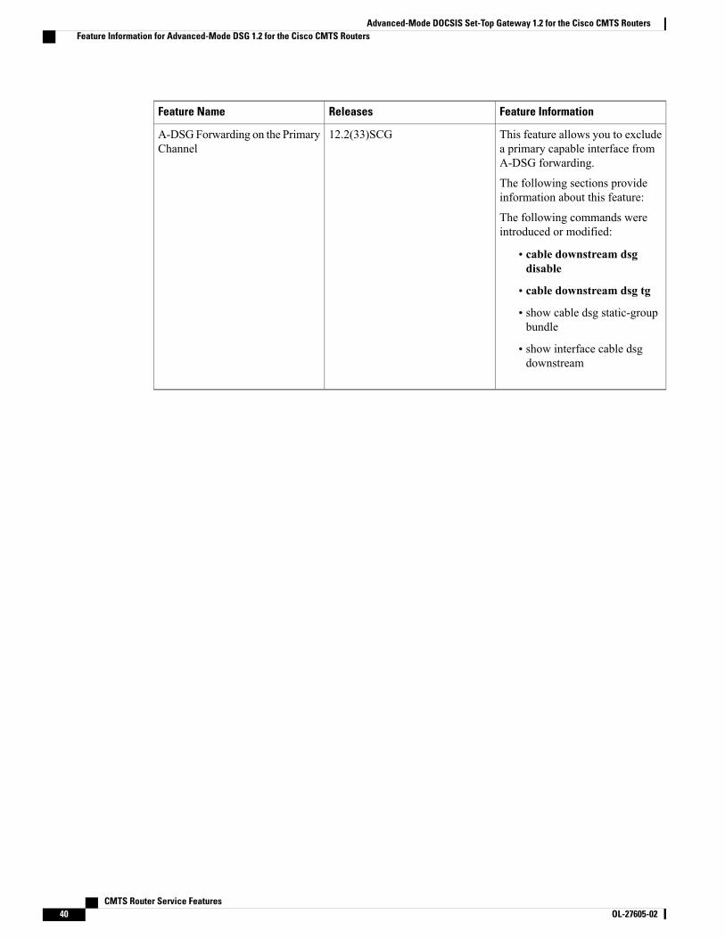
Feature InformationReleasesFeature Name
This feature allows you to excludea primary capable interface fromA-DSG forwarding.
The following sections provideinformation about this feature:
The following commands wereintroduced or modified:
• cable downstream dsgdisable
• cable downstream dsg tg
• show cable dsg static-groupbundle
• show interface cable dsgdownstream
12.2(33)SCGA-DSGForwarding on the PrimaryChannel
CMTS Router Service Features40 OL-27605-02
Advanced-Mode DOCSIS Set-Top Gateway 1.2 for the Cisco CMTS RoutersFeature Information for Advanced-Mode DSG 1.2 for the Cisco CMTS Routers
C H A P T E R 2Call Home Feature for the Cisco CMTS Routers
First Published: November 29, 2010
Use this document in conjunction with the Configuring Call Home for Cisco 7200 Series Routers featureguide.
Note
For Cisco IOS Release 12.2(33)SCE, the Call Home feature provides a mechanism to automatically createcases and update Cisco, customer, or a partner about events and changes on a Cisco device in a customernetwork. This feature provides e-mail and web-based notification of critical system events. Multiple messageformats are available for optimum compatibility with pager services, e-mail, or XML-based automatedparsing applications. Common uses of this feature include paging a network support engineer, sending ane-mail notification to a Network Operations Center, XML-based message delivery to a support website, andgenerating a direct case with the Cisco Systems Technical Assistance Center (TAC).
For more information, see the Configuring Call Home for Cisco 7200 Series Routers feature guide.
Finding Feature Information
Your software release may not support all the features documented in this module. For the latest featureinformation and caveats, see the release notes for your platform and software release. To find informationabout the features documented in this module, and to see a list of the releases in which each feature issupported, see the Feature Information Table at the end of this document.
Use Cisco Feature Navigator to find information about platform support and Cisco software image support.To access Cisco Feature Navigator, go to http://tools.cisco.com/ITDIT/CFN/. An account on http://www.cisco.com/ is not required.
Contents
• Prerequisites for the Call Home Feature for the Cisco CMTS Routers, page 42
• Information About the Call Home Feature for the Cisco CMTS Routers, page 42
• Additional References, page 65
• Feature Information for the Call Home Feature for the Cisco CMTS Routers, page 66
CMTS Router Service Features OL-27605-02 41
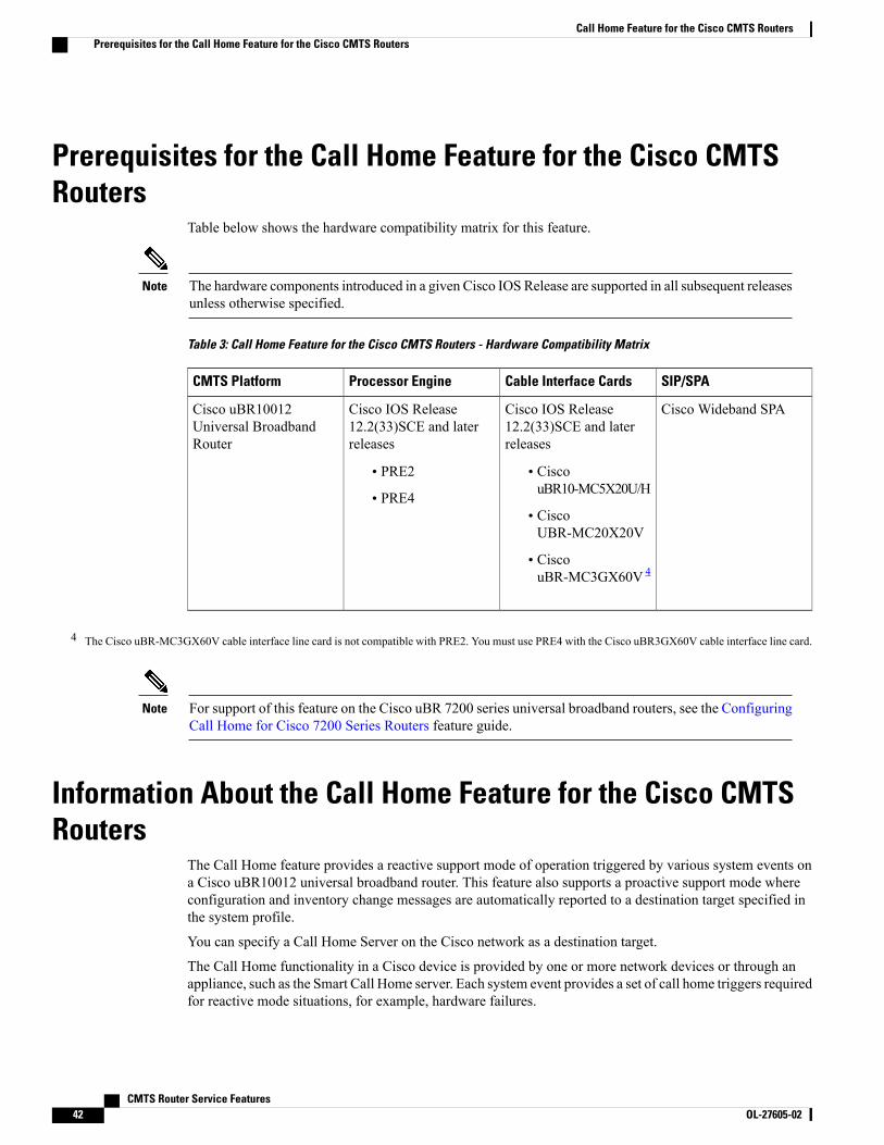
Prerequisites for the Call Home Feature for the Cisco CMTSRouters
Table below shows the hardware compatibility matrix for this feature.
The hardware components introduced in a given Cisco IOS Release are supported in all subsequent releasesunless otherwise specified.
Note
Table 3: Call Home Feature for the Cisco CMTS Routers - Hardware Compatibility Matrix
SIP/SPACable Interface CardsProcessor EngineCMTS Platform
Cisco Wideband SPACisco IOS Release12.2(33)SCE and laterreleases
• CiscouBR10-MC5X20U/H
• CiscoUBR-MC20X20V
• CiscouBR-MC3GX60V 4
Cisco IOS Release12.2(33)SCE and laterreleases
• PRE2
• PRE4
Cisco uBR10012Universal BroadbandRouter
4 The Cisco uBR-MC3GX60V cable interface line card is not compatible with PRE2. You must use PRE4 with the Cisco uBR3GX60V cable interface line card.
For support of this feature on the Cisco uBR 7200 series universal broadband routers, see the ConfiguringCall Home for Cisco 7200 Series Routers feature guide.
Note
Information About the Call Home Feature for the Cisco CMTSRouters
The Call Home feature provides a reactive support mode of operation triggered by various system events ona Cisco uBR10012 universal broadband router. This feature also supports a proactive support mode whereconfiguration and inventory change messages are automatically reported to a destination target specified inthe system profile.
You can specify a Call Home Server on the Cisco network as a destination target.
The Call Home functionality in a Cisco device is provided by one or more network devices or through anappliance, such as the Smart Call Home server. Each system event provides a set of call home triggers requiredfor reactive mode situations, for example, hardware failures.
CMTS Router Service Features42 OL-27605-02
Call Home Feature for the Cisco CMTS RoutersPrerequisites for the Call Home Feature for the Cisco CMTS Routers
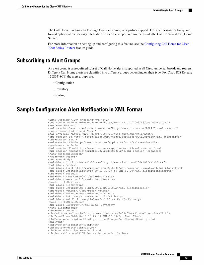
The Call Home function can leverage Cisco, customer, or a partner support. Flexible message delivery andformat options allow for easy integration of specific support requirements into the Call Home and Call HomeServer.
For more information on setting up and configuring this feature, see the Configuring Call Home for Cisco7200 Series Routers feature guide.
Subscribing to Alert GroupsAn alert group is a predefined subset of Call Home alerts supported in all Cisco universal broadband routers.Different Call Home alerts are classified into different groups depending on their type. For Cisco IOS Release12.2(33)SCE, the alert groups are:
• Configuration
• Inventory
• Syslog
Sample Configuration Alert Notification in XML Format
<?xml version="1.0" encoding="UTF-8"?><soap-env:Envelope xmlns:soap-env="http://www.w3.org/2003/05/soap-envelope"><soap-env:Header><aml-session:Session xmlns:aml-session="http://www.cisco.com/2004/01/aml-session"soap-env:mustUnderstand="true"soap-env:role="http://www.w3.org/2003/05/soap-envelope/role/next"><aml-session:To>http://tools.cisco.com/neddce/services/DDCEService</aml-session:To><aml-session:Path><aml-session:Via>http://www.cisco.com/appliance/uri</aml-session:Via></aml-session:Path><aml-session:From>http://www.cisco.com/appliance/uri</aml-session:From><aml-session:MessageId>MC2:SPE100202ZH:D060082A</aml-session:MessageId></aml-session:Session></soap-env:Header><soap-env:Body><aml-block:Block xmlns:aml-block="http://www.cisco.com/2004/01/aml-block"><aml-block:Header><aml-block:Type>http://www.cisco.com/2005/05/callhome/configuration</aml-block:Type><aml-block:CreationDate>2010-10-13 10:27:54 GMT+00:00</aml-block:CreationDate><aml-block:Builder><aml-block:Name>uBR10000</aml-block:Name><aml-block:Version>2.0</aml-block:Version></aml-block:Builder><aml-block:BlockGroup><aml-block:GroupId>GC3:SPE100202ZH:D060082A</aml-block:GroupId><aml-block:Number>0</aml-block:Number><aml-block:IsLast>true</aml-block:IsLast><aml-block:IsPrimary>true</aml-block:IsPrimary><aml-block:WaitForPrimary>false</aml-block:WaitForPrimary></aml-block:BlockGroup><aml-block:Severity>1</aml-block:Severity></aml-block:Header><aml-block:Content><ch:CallHome xmlns:ch="http://www.cisco.com/2005/05/callhome" version="1.0"><ch:EventTime>2010-10-13 10:27:39 GMT+00:00</ch:EventTime><ch:MessageDescription>Configuration Change</ch:MessageDescription><ch:Event><ch:Type>configuration</ch:Type><ch:SubType>delta</ch:SubType><ch:Brand>Cisco Systems</ch:Brand><ch:Series>Cisco uBR10K Series Routers</ch:Series>
CMTS Router Service Features OL-27605-02 43
Call Home Feature for the Cisco CMTS RoutersSubscribing to Alert Groups
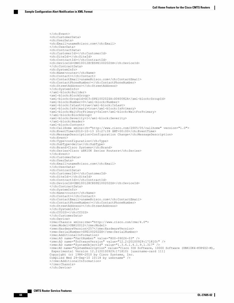
</ch:Event><ch:CustomerData><ch:UserData><ch:Email>[email protected]</ch:Email></ch:UserData><ch:ContractData><ch:CustomerId></ch:CustomerId><ch:SiteId></ch:SiteId><ch:ContractId></ch:ContractId><ch:DeviceId>UBR10012@C@SPE100202ZH</ch:DeviceId></ch:ContractData><ch:SystemInfo><ch:Name>router</ch:Name><ch:Contact></ch:Contact><ch:ContactEmail>[email protected]</ch:ContactEmail><ch:ContactPhoneNumber></ch:ContactPhoneNumber><ch:StreetAddress></ch:StreetAddress></ch:SystemInfo></aml-block:Builder><aml-block:BlockGroup><aml-block:GroupId>GC3:SPE100202ZH:D060082A</aml-block:GroupId><aml-block:Number>0</aml-block:Number><aml-block:IsLast>true</aml-block:IsLast><aml-block:IsPrimary>true</aml-block:IsPrimary><aml-block:WaitForPrimary>false</aml-block:WaitForPrimary></aml-block:BlockGroup><aml-block:Severity>1</aml-block:Severity></aml-block:Header><aml-block:Content><ch:CallHome xmlns:ch="http://www.cisco.com/2005/05/callhome" version="1.0"><ch:EventTime>2010-10-13 10:27:39 GMT+00:00</ch:EventTime><ch:MessageDescription>Configuration Change</ch:MessageDescription><ch:Event><ch:Type>configuration</ch:Type><ch:SubType>delta</ch:SubType><ch:Brand>Cisco Systems</ch:Brand><ch:Series>Cisco uBR10K Series Routers</ch:Series></ch:Event><ch:CustomerData><ch:UserData><ch:Email>[email protected]</ch:Email></ch:UserData><ch:ContractData><ch:CustomerId></ch:CustomerId><ch:SiteId></ch:SiteId><ch:ContractId></ch:ContractId><ch:DeviceId>UBR10012@C@SPE100202ZH</ch:DeviceId></ch:ContractData><ch:SystemInfo><ch:Name>router</ch:Name><ch:Contact></ch:Contact><ch:ContactEmail>[email protected]</ch:ContactEmail><ch:ContactPhoneNumber></ch:ContactPhoneNumber><ch:StreetAddress></ch:StreetAddress></ch:SystemInfo><ch:CCOID></ch:CCOID></ch:CustomerData><ch:Device><rme:Chassis xmlns:rme="http://www.cisco.com/rme/4.0"><rme:Model>UBR10012</rme:Model><rme:HardwareVersion>257</rme:HardwareVersion><rme:SerialNumber>SPE100202ZH</rme:SerialNumber><rme:AdditionalInformation><rme:AD name="PartNumber" value="800-09026-03" /><rme:AD name="SoftwareVersion" value="12.2(20100929:171810)" /><rme:AD name="SystemObjectId" value="1.3.6.1.4.1.9.1.317" /><rme:AD name="SystemDescription" value="Cisco IOS Software, 10000 Software (UBR10K4-K9P6U2-M),Experimental Version 12.2(20100929:171810) [username-card 111]Copyright (c) 1986-2010 by Cisco Systems, Inc.Compiled Wed 29-Sep-10 10:18 by username" /></rme:AdditionalInformation></rme:Chassis></ch:Device>
CMTS Router Service Features44 OL-27605-02
Call Home Feature for the Cisco CMTS RoutersSample Configuration Alert Notification in XML Format
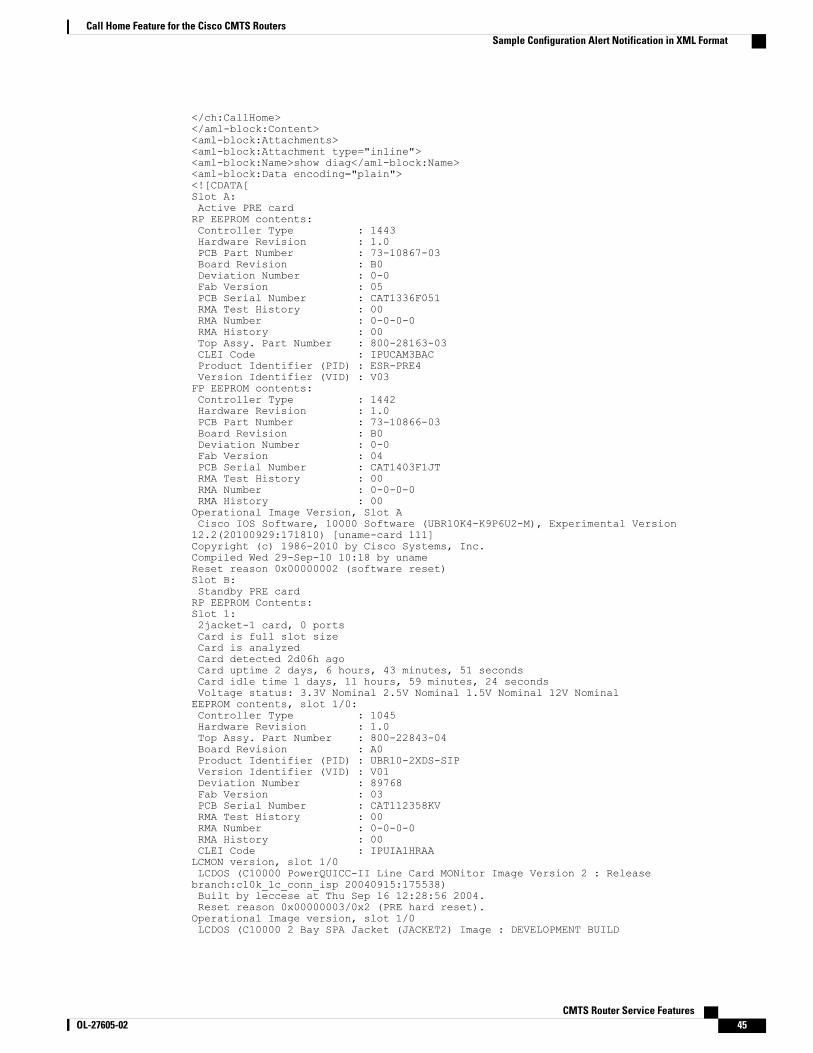
</ch:CallHome></aml-block:Content><aml-block:Attachments><aml-block:Attachment type="inline"><aml-block:Name>show diag</aml-block:Name><aml-block:Data encoding="plain"><![CDATA[Slot A:Active PRE cardRP EEPROM contents:Controller Type : 1443Hardware Revision : 1.0PCB Part Number : 73-10867-03Board Revision : B0Deviation Number : 0-0Fab Version : 05PCB Serial Number : CAT1336F051RMA Test History : 00RMA Number : 0-0-0-0RMA History : 00Top Assy. Part Number : 800-28163-03CLEI Code : IPUCAM3BACProduct Identifier (PID) : ESR-PRE4Version Identifier (VID) : V03FP EEPROM contents:Controller Type : 1442Hardware Revision : 1.0PCB Part Number : 73-10866-03Board Revision : B0Deviation Number : 0-0Fab Version : 04PCB Serial Number : CAT1403F1JTRMA Test History : 00RMA Number : 0-0-0-0RMA History : 00Operational Image Version, Slot ACisco IOS Software, 10000 Software (UBR10K4-K9P6U2-M), Experimental Version12.2(20100929:171810) [uname-card 111]Copyright (c) 1986-2010 by Cisco Systems, Inc.Compiled Wed 29-Sep-10 10:18 by unameReset reason 0x00000002 (software reset)Slot B:Standby PRE cardRP EEPROM Contents:Slot 1:2jacket-1 card, 0 portsCard is full slot sizeCard is analyzedCard detected 2d06h agoCard uptime 2 days, 6 hours, 43 minutes, 51 secondsCard idle time 1 days, 11 hours, 59 minutes, 24 secondsVoltage status: 3.3V Nominal 2.5V Nominal 1.5V Nominal 12V NominalEEPROM contents, slot 1/0:Controller Type : 1045Hardware Revision : 1.0Top Assy. Part Number : 800-22843-04Board Revision : A0Product Identifier (PID) : UBR10-2XDS-SIPVersion Identifier (VID) : V01Deviation Number : 89768Fab Version : 03PCB Serial Number : CAT112358KVRMA Test History : 00RMA Number : 0-0-0-0RMA History : 00CLEI Code : IPUIA1HRAALCMON version, slot 1/0LCDOS (C10000 PowerQUICC-II Line Card MONitor Image Version 2 : Releasebranch:c10k_lc_conn_isp 20040915:175538)Built by leccese at Thu Sep 16 12:28:56 2004.Reset reason 0x00000003/0x2 (PRE hard reset).Operational Image version, slot 1/0LCDOS (C10000 2 Bay SPA Jacket (JACKET2) Image : DEVELOPMENT BUILD
CMTS Router Service Features OL-27605-02 45
Call Home Feature for the Cisco CMTS RoutersSample Configuration Alert Notification in XML Format
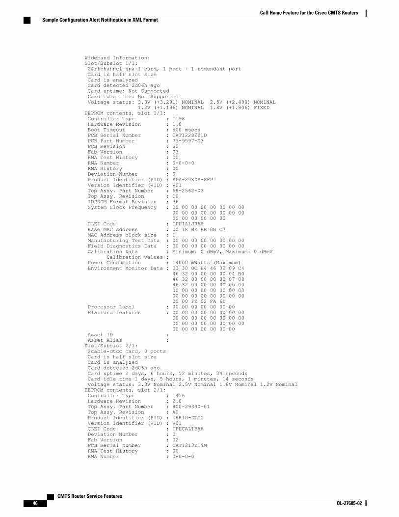
Wideband Information:Slot/Subslot 1/1:24rfchannel-spa-1 card, 1 port + 1 redundant portCard is half slot sizeCard is analyzedCard detected 2d06h agoCard uptime: Not SupportedCard idle time: Not SupportedVoltage status: 3.3V (+3.291) NOMINAL 2.5V (+2.490) NOMINAL
1.2V (+1.196) NOMINAL 1.8V (+1.806) FIXEDEEPROM contents, slot 1/1:Controller Type : 1198Hardware Revision : 1.0Boot Timeout : 500 msecsPCB Serial Number : CAT1228E21DPCB Part Number : 73-9597-03PCB Revision : B0Fab Version : 03RMA Test History : 00RMA Number : 0-0-0-0RMA History : 00Deviation Number : 0Product Identifier (PID) : SPA-24XDS-SFPVersion Identifier (VID) : V01Top Assy. Part Number : 68-2562-03Top Assy. Revision : C0IDPROM Format Revision : 36System Clock Frequency : 00 00 00 00 00 00 00 00
00 00 00 00 00 00 00 0000 00 00 00 00 00
CLEI Code : IPUIA1JRAABase MAC Address : 00 1E BE BE 8B C7MAC Address block size : 1Manufacturing Test Data : 00 00 00 00 00 00 00 00Field Diagnostics Data : 00 00 00 00 00 00 00 00Calibration Data : Minimum: 0 dBmV, Maximum: 0 dBmV
Calibration values :Power Consumption : 14000 mWatts (Maximum)Environment Monitor Data : 03 30 0C E4 46 32 09 C4
46 32 00 00 00 00 04 B046 32 00 00 00 00 07 0846 32 00 00 00 00 00 0000 00 00 00 00 00 00 0000 00 00 00 00 00 00 0000 00 FE 02 FA 6D
Processor Label : 00 00 00 00 00 00 00Platform features : 00 00 00 00 00 00 00 00
00 00 00 00 00 00 00 0000 00 00 00 00 00 00 0000 00 00 00 00 00 00
Asset ID :Asset Alias :Slot/Subslot 2/1:2cable-dtcc card, 0 portsCard is half slot sizeCard is analyzedCard detected 2d06h agoCard uptime 2 days, 6 hours, 52 minutes, 34 secondsCard idle time 1 days, 5 hours, 1 minutes, 14 secondsVoltage status: 3.3V Nominal 2.5V Nominal 1.8V Nominal 1.2V NominalEEPROM contents, slot 2/1:Controller Type : 1456Hardware Revision : 2.0Top Assy. Part Number : 800-29390-01Top Assy. Revision : A0Product Identifier (PID) : UBR10-DTCCVersion Identifier (VID) : V01CLEI Code : IPUCAL1BAADeviation Number : 0Fab Version : 02PCB Serial Number : CAT1213E19MRMA Test History : 00RMA Number : 0-0-0-0
CMTS Router Service Features46 OL-27605-02
Call Home Feature for the Cisco CMTS RoutersSample Configuration Alert Notification in XML Format
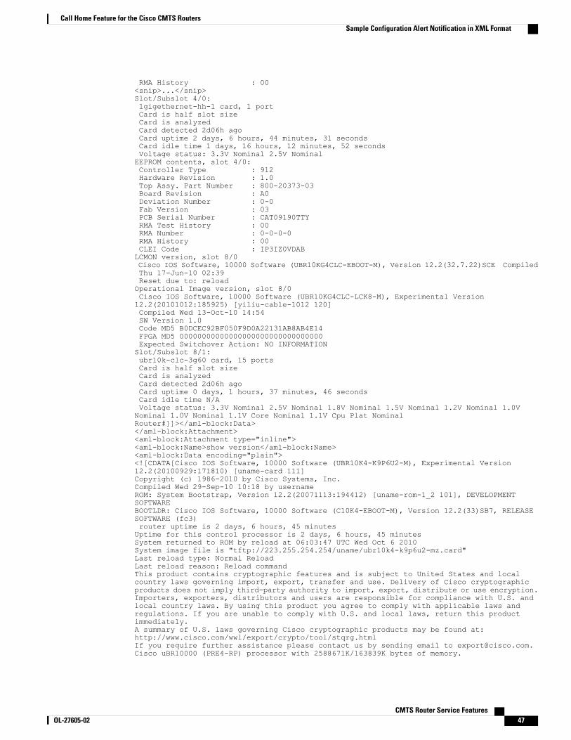
RMA History : 00<snip>...</snip>Slot/Subslot 4/0:1gigethernet-hh-1 card, 1 portCard is half slot sizeCard is analyzedCard detected 2d06h agoCard uptime 2 days, 6 hours, 44 minutes, 31 secondsCard idle time 1 days, 16 hours, 12 minutes, 52 secondsVoltage status: 3.3V Nominal 2.5V NominalEEPROM contents, slot 4/0:Controller Type : 912Hardware Revision : 1.0Top Assy. Part Number : 800-20373-03Board Revision : A0Deviation Number : 0-0Fab Version : 03PCB Serial Number : CAT09190TTYRMA Test History : 00RMA Number : 0-0-0-0RMA History : 00CLEI Code : IP3IZ0VDABLCMON version, slot 8/0Cisco IOS Software, 10000 Software (UBR10KG4CLC-EBOOT-M), Version 12.2(32.7.22)SCE CompiledThu 17-Jun-10 02:39Reset due to: reloadOperational Image version, slot 8/0Cisco IOS Software, 10000 Software (UBR10KG4CLC-LCK8-M), Experimental Version12.2(20101012:185925) [yiliu-cable-1012 120]Compiled Wed 13-Oct-10 14:54SW Version 1.0Code MD5 B0DCEC92BF050F9D0A22131AB8AB4E14FPGA MD5 00000000000000000000000000000000Expected Switchover Action: NO INFORMATIONSlot/Subslot 8/1:ubr10k-clc-3g60 card, 15 portsCard is half slot sizeCard is analyzedCard detected 2d06h agoCard uptime 0 days, 1 hours, 37 minutes, 46 secondsCard idle time N/AVoltage status: 3.3V Nominal 2.5V Nominal 1.8V Nominal 1.5V Nominal 1.2V Nominal 1.0VNominal 1.0V Nominal 1.1V Core Nominal 1.1V Cpu Plat NominalRouter#]]></aml-block:Data></aml-block:Attachment><aml-block:Attachment type="inline"><aml-block:Name>show version</aml-block:Name><aml-block:Data encoding="plain"><![CDATA[Cisco IOS Software, 10000 Software (UBR10K4-K9P6U2-M), Experimental Version12.2(20100929:171810) [uname-card 111]Copyright (c) 1986-2010 by Cisco Systems, Inc.Compiled Wed 29-Sep-10 10:18 by usernameROM: System Bootstrap, Version 12.2(20071113:194412) [uname-rom-1_2 101], DEVELOPMENTSOFTWAREBOOTLDR: Cisco IOS Software, 10000 Software (C10K4-EBOOT-M), Version 12.2(33)SB7, RELEASESOFTWARE (fc3)router uptime is 2 days, 6 hours, 45 minutesUptime for this control processor is 2 days, 6 hours, 45 minutesSystem returned to ROM by reload at 06:03:47 UTC Wed Oct 6 2010System image file is "tftp://223.255.254.254/uname/ubr10k4-k9p6u2-mz.card"Last reload type: Normal ReloadLast reload reason: Reload commandThis product contains cryptographic features and is subject to United States and localcountry laws governing import, export, transfer and use. Delivery of Cisco cryptographicproducts does not imply third-party authority to import, export, distribute or use encryption.Importers, exporters, distributors and users are responsible for compliance with U.S. andlocal country laws. By using this product you agree to comply with applicable laws andregulations. If you are unable to comply with U.S. and local laws, return this productimmediately.A summary of U.S. laws governing Cisco cryptographic products may be found at:http://www.cisco.com/wwl/export/crypto/tool/stqrg.htmlIf you require further assistance please contact us by sending email to [email protected] uBR10000 (PRE4-RP) processor with 2588671K/163839K bytes of memory.
CMTS Router Service Features OL-27605-02 47
Call Home Feature for the Cisco CMTS RoutersSample Configuration Alert Notification in XML Format
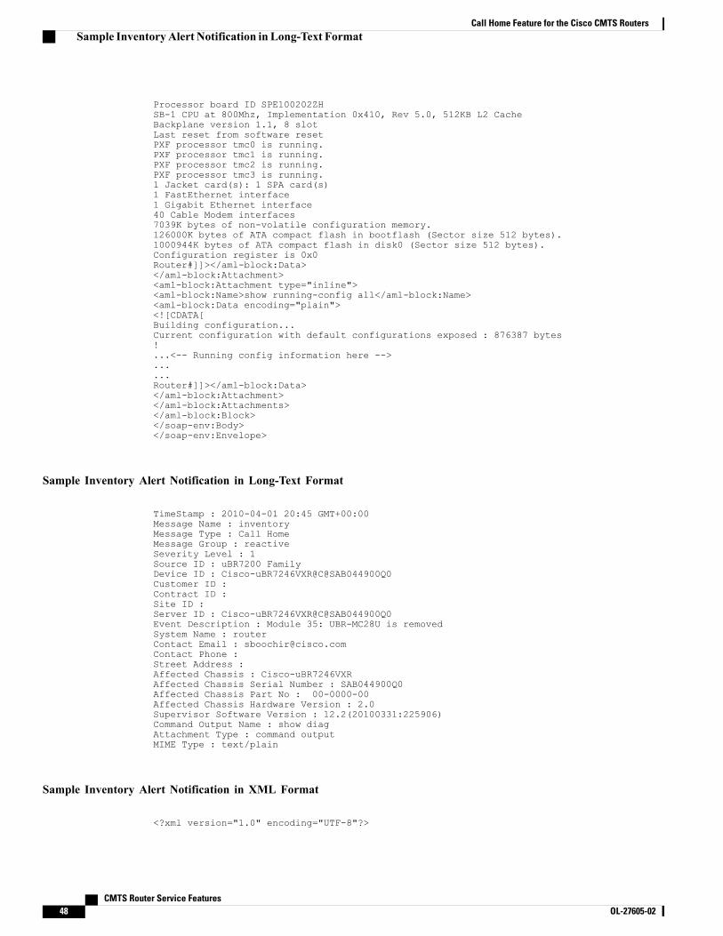
Processor board ID SPE100202ZHSB-1 CPU at 800Mhz, Implementation 0x410, Rev 5.0, 512KB L2 CacheBackplane version 1.1, 8 slotLast reset from software resetPXF processor tmc0 is running.PXF processor tmc1 is running.PXF processor tmc2 is running.PXF processor tmc3 is running.1 Jacket card(s): 1 SPA card(s)1 FastEthernet interface1 Gigabit Ethernet interface40 Cable Modem interfaces7039K bytes of non-volatile configuration memory.126000K bytes of ATA compact flash in bootflash (Sector size 512 bytes).1000944K bytes of ATA compact flash in disk0 (Sector size 512 bytes).Configuration register is 0x0Router#]]></aml-block:Data></aml-block:Attachment><aml-block:Attachment type="inline"><aml-block:Name>show running-config all</aml-block:Name><aml-block:Data encoding="plain"><![CDATA[Building configuration...Current configuration with default configurations exposed : 876387 bytes!...<-- Running config information here -->......Router#]]></aml-block:Data></aml-block:Attachment></aml-block:Attachments></aml-block:Block></soap-env:Body></soap-env:Envelope>
Sample Inventory Alert Notification in Long-Text Format
TimeStamp : 2010-04-01 20:45 GMT+00:00Message Name : inventoryMessage Type : Call HomeMessage Group : reactiveSeverity Level : 1Source ID : uBR7200 FamilyDevice ID : Cisco-uBR7246VXR@C@SAB044900Q0Customer ID :Contract ID :Site ID :Server ID : Cisco-uBR7246VXR@C@SAB044900Q0Event Description : Module 35: UBR-MC28U is removedSystem Name : routerContact Email : [email protected] Phone :Street Address :Affected Chassis : Cisco-uBR7246VXRAffected Chassis Serial Number : SAB044900Q0Affected Chassis Part No : 00-0000-00Affected Chassis Hardware Version : 2.0Supervisor Software Version : 12.2(20100331:225906)Command Output Name : show diagAttachment Type : command outputMIME Type : text/plain
Sample Inventory Alert Notification in XML Format
<?xml version="1.0" encoding="UTF-8"?>
CMTS Router Service Features48 OL-27605-02
Call Home Feature for the Cisco CMTS RoutersSample InventoryAlert Notification in Long-Text Format
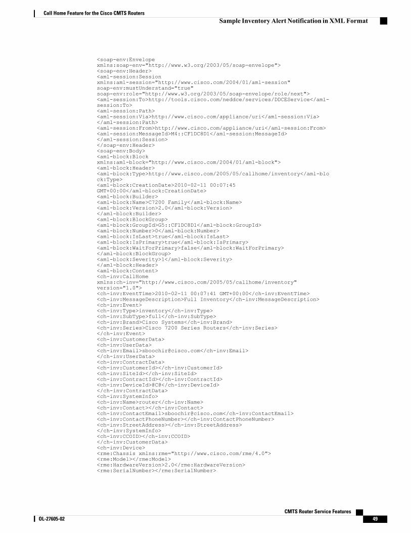
<soap-env:Envelopexmlns:soap-env="http://www.w3.org/2003/05/soap-envelope"><soap-env:Header><aml-session:Sessionxmlns:aml-session="http://www.cisco.com/2004/01/aml-session"soap-env:mustUnderstand="true"soap-env:role="http://www.w3.org/2003/05/soap-envelope/role/next"><aml-session:To>http://tools.cisco.com/neddce/services/DDCEService</aml-session:To><aml-session:Path><aml-session:Via>http://www.cisco.com/appliance/uri</aml-session:Via></aml-session:Path><aml-session:From>http://www.cisco.com/appliance/uri</aml-session:From><aml-session:MessageId>M4::CF1DC8D1</aml-session:MessageId></aml-session:Session></soap-env:Header><soap-env:Body><aml-block:Blockxmlns:aml-block="http://www.cisco.com/2004/01/aml-block"><aml-block:Header><aml-block:Type>http://www.cisco.com/2005/05/callhome/inventory</aml-block:Type><aml-block:CreationDate>2010-02-11 00:07:45GMT+00:00</aml-block:CreationDate><aml-block:Builder><aml-block:Name>C7200 Family</aml-block:Name><aml-block:Version>2.0</aml-block:Version></aml-block:Builder><aml-block:BlockGroup><aml-block:GroupId>G5::CF1DC8D1</aml-block:GroupId><aml-block:Number>0</aml-block:Number><aml-block:IsLast>true</aml-block:IsLast><aml-block:IsPrimary>true</aml-block:IsPrimary><aml-block:WaitForPrimary>false</aml-block:WaitForPrimary></aml-block:BlockGroup><aml-block:Severity>1</aml-block:Severity></aml-block:Header><aml-block:Content><ch-inv:CallHomexmlns:ch-inv="http://www.cisco.com/2005/05/callhome/inventory"version="1.0"><ch-inv:EventTime>2010-02-11 00:07:41 GMT+00:00</ch-inv:EventTime><ch-inv:MessageDescription>Full Inventory</ch-inv:MessageDescription><ch-inv:Event><ch-inv:Type>inventory</ch-inv:Type><ch-inv:SubType>full</ch-inv:SubType><ch-inv:Brand>Cisco Systems</ch-inv:Brand><ch-inv:Series>Cisco 7200 Series Routers</ch-inv:Series></ch-inv:Event><ch-inv:CustomerData><ch-inv:UserData><ch-inv:Email>[email protected]</ch-inv:Email></ch-inv:UserData><ch-inv:ContractData><ch-inv:CustomerId></ch-inv:CustomerId><ch-inv:SiteId></ch-inv:SiteId><ch-inv:ContractId></ch-inv:ContractId><ch-inv:DeviceId>@C@</ch-inv:DeviceId></ch-inv:ContractData><ch-inv:SystemInfo><ch-inv:Name>router</ch-inv:Name><ch-inv:Contact></ch-inv:Contact><ch-inv:ContactEmail>[email protected]</ch-inv:ContactEmail><ch-inv:ContactPhoneNumber></ch-inv:ContactPhoneNumber><ch-inv:StreetAddress></ch-inv:StreetAddress></ch-inv:SystemInfo><ch-inv:CCOID></ch-inv:CCOID></ch-inv:CustomerData><ch-inv:Device><rme:Chassis xmlns:rme="http://www.cisco.com/rme/4.0"><rme:Model></rme:Model><rme:HardwareVersion>2.0</rme:HardwareVersion><rme:SerialNumber></rme:SerialNumber>
CMTS Router Service Features OL-27605-02 49
Call Home Feature for the Cisco CMTS RoutersSample InventoryAlert Notification inXMLFormat
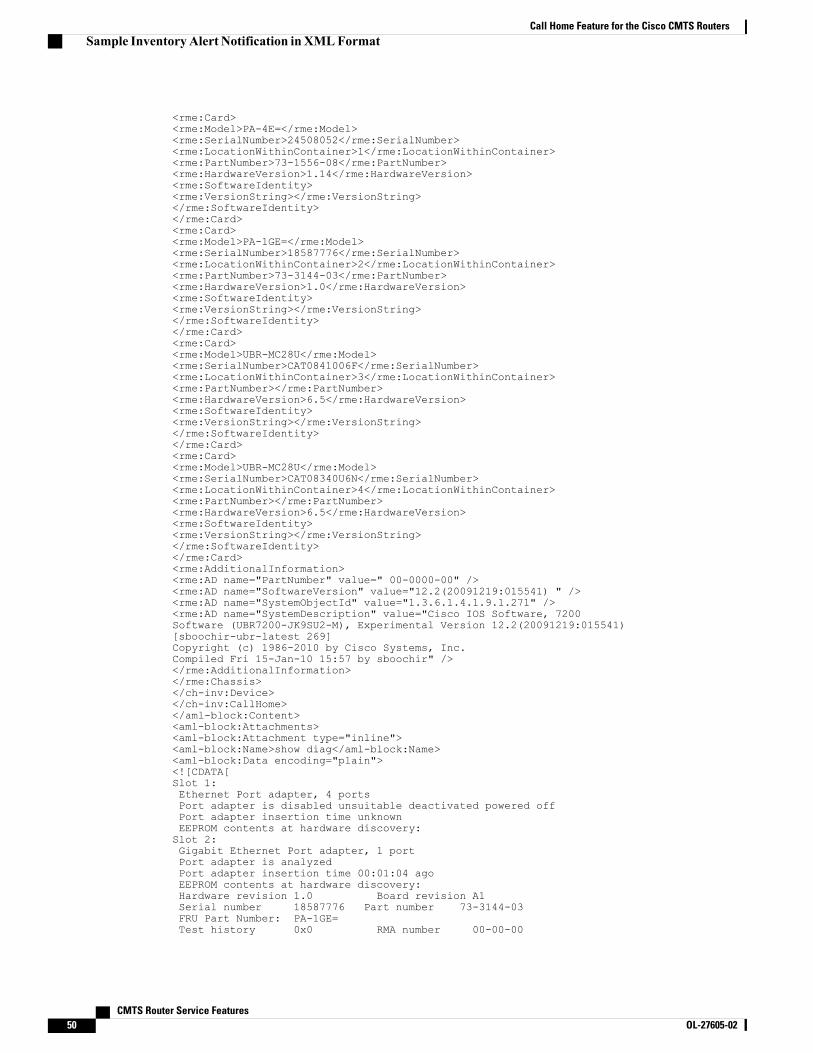
<rme:Card><rme:Model>PA-4E=</rme:Model><rme:SerialNumber>24508052</rme:SerialNumber><rme:LocationWithinContainer>1</rme:LocationWithinContainer><rme:PartNumber>73-1556-08</rme:PartNumber><rme:HardwareVersion>1.14</rme:HardwareVersion><rme:SoftwareIdentity><rme:VersionString></rme:VersionString></rme:SoftwareIdentity></rme:Card><rme:Card><rme:Model>PA-1GE=</rme:Model><rme:SerialNumber>18587776</rme:SerialNumber><rme:LocationWithinContainer>2</rme:LocationWithinContainer><rme:PartNumber>73-3144-03</rme:PartNumber><rme:HardwareVersion>1.0</rme:HardwareVersion><rme:SoftwareIdentity><rme:VersionString></rme:VersionString></rme:SoftwareIdentity></rme:Card><rme:Card><rme:Model>UBR-MC28U</rme:Model><rme:SerialNumber>CAT0841006F</rme:SerialNumber><rme:LocationWithinContainer>3</rme:LocationWithinContainer><rme:PartNumber></rme:PartNumber><rme:HardwareVersion>6.5</rme:HardwareVersion><rme:SoftwareIdentity><rme:VersionString></rme:VersionString></rme:SoftwareIdentity></rme:Card><rme:Card><rme:Model>UBR-MC28U</rme:Model><rme:SerialNumber>CAT08340U6N</rme:SerialNumber><rme:LocationWithinContainer>4</rme:LocationWithinContainer><rme:PartNumber></rme:PartNumber><rme:HardwareVersion>6.5</rme:HardwareVersion><rme:SoftwareIdentity><rme:VersionString></rme:VersionString></rme:SoftwareIdentity></rme:Card><rme:AdditionalInformation><rme:AD name="PartNumber" value=" 00-0000-00" /><rme:AD name="SoftwareVersion" value="12.2(20091219:015541) " /><rme:AD name="SystemObjectId" value="1.3.6.1.4.1.9.1.271" /><rme:AD name="SystemDescription" value="Cisco IOS Software, 7200Software (UBR7200-JK9SU2-M), Experimental Version 12.2(20091219:015541)[sboochir-ubr-latest 269]Copyright (c) 1986-2010 by Cisco Systems, Inc.Compiled Fri 15-Jan-10 15:57 by sboochir" /></rme:AdditionalInformation></rme:Chassis></ch-inv:Device></ch-inv:CallHome></aml-block:Content><aml-block:Attachments><aml-block:Attachment type="inline"><aml-block:Name>show diag</aml-block:Name><aml-block:Data encoding="plain"><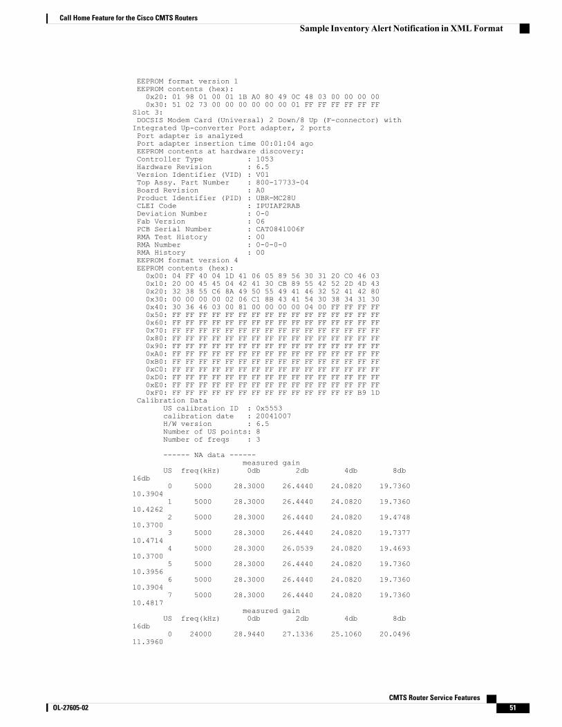
EEPROM format version 1EEPROM contents (hex):0x20: 01 98 01 00 01 1B A0 80 49 0C 48 03 00 00 00 000x30: 51 02 73 00 00 00 00 00 00 01 FF FF FF FF FF FF
Slot 3:DOCSIS Modem Card (Universal) 2 Down/8 Up (F-connector) withIntegrated Up-converter Port adapter, 2 portsPort adapter is analyzedPort adapter insertion time 00:01:04 agoEEPROM contents at hardware discovery:Controller Type : 1053Hardware Revision : 6.5Version Identifier (VID) : V01Top Assy. Part Number : 800-17733-04Board Revision : A0Product Identifier (PID) : UBR-MC28UCLEI Code : IPUIAF2RABDeviation Number : 0-0Fab Version : 06PCB Serial Number : CAT0841006FRMA Test History : 00RMA Number : 0-0-0-0RMA History : 00EEPROM format version 4EEPROM contents (hex):0x00: 04 FF 40 04 1D 41 06 05 89 56 30 31 20 C0 46 030x10: 20 00 45 45 04 42 41 30 CB 89 55 42 52 2D 4D 430x20: 32 38 55 C6 8A 49 50 55 49 41 46 32 52 41 42 800x30: 00 00 00 00 02 06 C1 8B 43 41 54 30 38 34 31 300x40: 30 36 46 03 00 81 00 00 00 00 04 00 FF FF FF FF0x50: FF FF FF FF FF FF FF FF FF FF FF FF FF FF FF FF0x60: FF FF FF FF FF FF FF FF FF FF FF FF FF FF FF FF0x70: FF FF FF FF FF FF FF FF FF FF FF FF FF FF FF FF0x80: FF FF FF FF FF FF FF FF FF FF FF FF FF FF FF FF0x90: FF FF FF FF FF FF FF FF FF FF FF FF FF FF FF FF0xA0: FF FF FF FF FF FF FF FF FF FF FF FF FF FF FF FF0xB0: FF FF FF FF FF FF FF FF FF FF FF FF FF FF FF FF0xC0: FF FF FF FF FF FF FF FF FF FF FF FF FF FF FF FF0xD0: FF FF FF FF FF FF FF FF FF FF FF FF FF FF FF FF0xE0: FF FF FF FF FF FF FF FF FF FF FF FF FF FF FF FF0xF0: FF FF FF FF FF FF FF FF FF FF FF FF FF FF B9 1D
Calibration DataUS calibration ID : 0x5553calibration date : 20041007H/W version : 6.5Number of US points: 8Number of freqs : 3
------ NA data ------measured gain
US freq(kHz) 0db 2db 4db 8db16db
0 5000 28.3000 26.4440 24.0820 19.736010.3904
1 5000 28.3000 26.4440 24.0820 19.736010.4262
2 5000 28.3000 26.4440 24.0820 19.474810.3700
3 5000 28.3000 26.4440 24.0820 19.737710.4714
4 5000 28.3000 26.0539 24.0820 19.469310.3700
5 5000 28.3000 26.4440 24.0820 19.736010.3956
6 5000 28.3000 26.4440 24.0820 19.736010.3904
7 5000 28.3000 26.4440 24.0820 19.736010.4817
measured gainUS freq(kHz) 0db 2db 4db 8db
16db0 24000 28.9440 27.1336 25.1060 20.0496
11.3960
CMTS Router Service Features OL-27605-02 51
Call Home Feature for the Cisco CMTS RoutersSample InventoryAlert Notification inXMLFormat
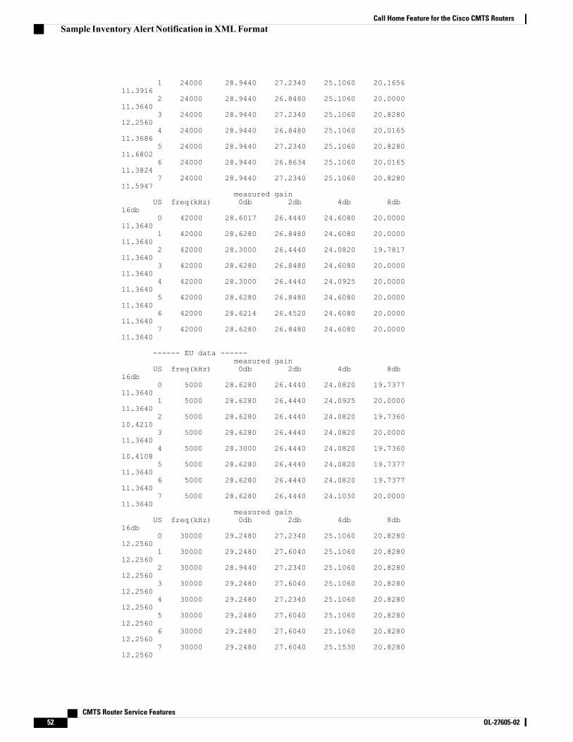
1 24000 28.9440 27.2340 25.1060 20.165611.3916
2 24000 28.9440 26.8480 25.1060 20.000011.3640
3 24000 28.9440 27.2340 25.1060 20.828012.2560
4 24000 28.9440 26.8480 25.1060 20.016511.3686
5 24000 28.9440 27.2340 25.1060 20.828011.6802
6 24000 28.9440 26.8634 25.1060 20.016511.3824
7 24000 28.9440 27.2340 25.1060 20.828011.5947
measured gainUS freq(kHz) 0db 2db 4db 8db
16db0 42000 28.6017 26.4440 24.6080 20.0000
11.36401 42000 28.6280 26.8480 24.6080 20.0000
11.36402 42000 28.3000 26.4440 24.0820 19.7817
11.36403 42000 28.6280 26.8480 24.6080 20.0000
11.36404 42000 28.3000 26.4440 24.0925 20.0000
11.36405 42000 28.6280 26.8480 24.6080 20.0000
11.36406 42000 28.6214 26.4520 24.6080 20.0000
11.36407 42000 28.6280 26.8480 24.6080 20.0000
11.3640
------ EU data ------measured gain
US freq(kHz) 0db 2db 4db 8db16db
0 5000 28.6280 26.4440 24.0820 19.737711.3640
1 5000 28.6280 26.4440 24.0925 20.000011.3640
2 5000 28.6280 26.4440 24.0820 19.736010.4210
3 5000 28.6280 26.4440 24.0820 20.000011.3640
4 5000 28.3000 26.4440 24.0820 19.736010.4108
5 5000 28.6280 26.4440 24.0820 19.737711.3640
6 5000 28.6280 26.4440 24.0820 19.737711.3640
7 5000 28.6280 26.4440 24.1030 20.000011.3640
measured gainUS freq(kHz) 0db 2db 4db 8db
16db0 30000 29.2480 27.2340 25.1060 20.8280
12.25601 30000 29.2480 27.6040 25.1060 20.8280
12.25602 30000 28.9440 27.2340 25.1060 20.8280
12.25603 30000 29.2480 27.6040 25.1060 20.8280
12.25604 30000 29.2480 27.2340 25.1060 20.8280
12.25605 30000 29.2480 27.6040 25.1060 20.8280
12.25606 30000 29.2480 27.6040 25.1060 20.8280
12.25607 30000 29.2480 27.6040 25.1530 20.8280
12.2560
CMTS Router Service Features52 OL-27605-02
Call Home Feature for the Cisco CMTS RoutersSample InventoryAlert Notification inXMLFormat

measured gainUS freq(kHz) 0db 2db 4db 8db
16db0 65000 28.9440 26.8480 24.6080 20.0000
11.36401 65000 28.9440 26.8480 24.6080 20.0000
11.36402 65000 28.6280 26.4440 24.0820 19.7360
10.38543 65000 28.9440 26.8480 24.6080 20.0000
11.36404 65000 28.9440 26.8480 24.6080 20.0000
11.36405 65000 28.9440 26.8480 24.6080 20.0000
11.36406 65000 28.9440 26.8480 24.1977 19.7483
11.36407 65000 29.2480 26.9406 24.6080 20.0000
11.3640Slot 4:DOCSIS Modem Card (Universal) 2 Down/8 Up (F-connector) withIntegrated Up-converter Port adapter, 2 portsPort adapter is analyzedPort adapter insertion time 00:01:05 agoEEPROM contents at hardware discovery:Controller Type : 1053Hardware Revision : 6.5Version Identifier (VID) : V01Top Assy. Part Number : 800-17733-04Board Revision : A0Product Identifier (PID) : UBR-MC28UCLEI Code : IPUIAF2RABDeviation Number : 0-0Fab Version : 06PCB Serial Number : CAT08340U6NRMA Test History : 00RMA Number : 0-0-0-0RMA History : 00EEPROM format version 4EEPROM contents (hex):0x00: 04 FF 40 04 1D 41 06 05 89 56 30 31 20 C0 46 030x10: 20 00 45 45 04 42 41 30 CB 89 55 42 52 2D 4D 430x20: 32 38 55 C6 8A 49 50 55 49 41 46 32 52 41 42 800x30: 00 00 00 00 02 06 C1 8B 43 41 54 30 38 33 34 300x40: 55 36 4E 03 00 81 00 00 00 00 04 00 FF FF FF FF0x50: FF FF FF FF FF FF FF FF FF FF FF FF FF FF FF FF0x60: FF FF FF FF FF FF FF FF FF FF FF FF FF FF FF FF0x70: FF FF FF FF FF FF FF FF FF FF FF FF FF FF FF FF0x80: FF FF FF FF FF FF FF FF FF FF FF FF FF FF FF FF0x90: FF FF FF FF FF FF FF FF FF FF FF FF FF FF FF FF0xA0: FF FF FF FF FF FF FF FF FF FF FF FF FF FF FF FF0xB0: FF FF FF FF FF FF FF FF FF FF FF FF FF FF FF FF0xC0: FF FF FF FF FF FF FF FF FF FF FF FF FF FF FF FF0xD0: FF FF FF FF FF FF FF FF FF FF FF FF FF FF FF FF0xE0: FF FF FF FF FF FF FF FF FF FF FF FF FF FF FF FF0xF0: FF FF FF FF FF FF FF FF FF FF FF FF FF FF E9 1C
Calibration DataUS calibration ID : 0x5553calibration date : 20040824H/W version : 6.5Number of US points: 8Number of freqs : 3
------ NA data ------measured gain
US freq(kHz) 0db 2db 4db 8db16db
0 5000 27.9580 26.0200 23.5220 19.370010.3700
1 5000 27.9580 26.0200 24.0820 19.436210.3854
2 5000 27.9580 26.0200 24.0820 19.417810.3700
CMTS Router Service Features OL-27605-02 53
Call Home Feature for the Cisco CMTS RoutersSample InventoryAlert Notification inXMLFormat
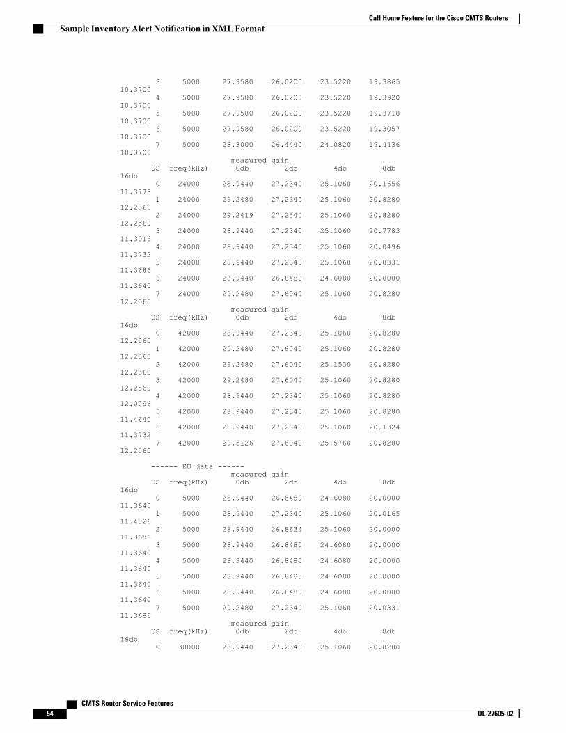
3 5000 27.9580 26.0200 23.5220 19.386510.3700
4 5000 27.9580 26.0200 23.5220 19.392010.3700
5 5000 27.9580 26.0200 23.5220 19.371810.3700
6 5000 27.9580 26.0200 23.5220 19.305710.3700
7 5000 28.3000 26.4440 24.0820 19.443610.3700
measured gainUS freq(kHz) 0db 2db 4db 8db
16db0 24000 28.9440 27.2340 25.1060 20.1656
11.37781 24000 29.2480 27.2340 25.1060 20.8280
12.25602 24000 29.2419 27.2340 25.1060 20.8280
12.25603 24000 28.9440 27.2340 25.1060 20.7783
11.39164 24000 28.9440 27.2340 25.1060 20.0496
11.37325 24000 28.9440 27.2340 25.1060 20.0331
11.36866 24000 28.9440 26.8480 24.6080 20.0000
11.36407 24000 29.2480 27.6040 25.1060 20.8280
12.2560measured gain
US freq(kHz) 0db 2db 4db 8db16db
0 42000 28.9440 27.2340 25.1060 20.828012.2560
1 42000 29.2480 27.6040 25.1060 20.828012.2560
2 42000 29.2480 27.6040 25.1530 20.828012.2560
3 42000 29.2480 27.6040 25.1060 20.828012.2560
4 42000 28.9440 27.2340 25.1060 20.828012.0096
5 42000 28.9440 27.2340 25.1060 20.828011.4640
6 42000 28.9440 27.2340 25.1060 20.132411.3732
7 42000 29.5126 27.6040 25.5760 20.828012.2560
------ EU data ------measured gain
US freq(kHz) 0db 2db 4db 8db16db
0 5000 28.9440 26.8480 24.6080 20.000011.3640
1 5000 28.9440 27.2340 25.1060 20.016511.4326
2 5000 28.9440 26.8634 25.1060 20.000011.3686
3 5000 28.9440 26.8480 24.6080 20.000011.3640
4 5000 28.9440 26.8480 24.6080 20.000011.3640
5 5000 28.9440 26.8480 24.6080 20.000011.3640
6 5000 28.9440 26.8480 24.6080 20.000011.3640
7 5000 29.2480 27.2340 25.1060 20.033111.3686
measured gainUS freq(kHz) 0db 2db 4db 8db
16db0 30000 28.9440 27.2340 25.1060 20.8280
CMTS Router Service Features54 OL-27605-02
Call Home Feature for the Cisco CMTS RoutersSample InventoryAlert Notification inXMLFormat
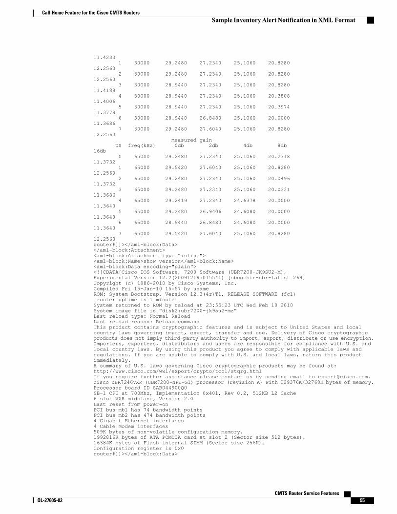
11.42331 30000 29.2480 27.2340 25.1060 20.8280
12.25602 30000 29.2480 27.2340 25.1060 20.8280
12.25603 30000 28.9440 27.2340 25.1060 20.8280
11.41884 30000 28.9440 27.2340 25.1060 20.3808
11.40065 30000 28.9440 27.2340 25.1060 20.3974
11.37786 30000 28.9440 26.8480 25.1060 20.0000
11.36867 30000 29.2480 27.6040 25.1060 20.8280
12.2560measured gain
US freq(kHz) 0db 2db 4db 8db16db
0 65000 29.2480 27.2340 25.1060 20.231811.3732
1 65000 29.5420 27.6040 25.1060 20.828012.2560
2 65000 29.2480 27.2340 25.1060 20.049611.3732
3 65000 29.2480 27.2340 25.1060 20.033111.3686
4 65000 29.2419 27.2340 24.6378 20.000011.3640
5 65000 29.2480 26.9406 24.6080 20.000011.3640
6 65000 28.9440 26.8480 24.6080 20.000011.3640
7 65000 29.5420 27.6040 25.1060 20.828012.2560router#]]></aml-block:Data></aml-block:Attachment><aml-block:Attachment type="inline"><aml-block:Name>show version</aml-block:Name><aml-block:Data encoding="plain"><![CDATA[Cisco IOS Software, 7200 Software (UBR7200-JK9SU2-M),Experimental Version 12.2(20091219:015541) [sboochir-ubr-latest 269]Copyright (c) 1986-2010 by Cisco Systems, Inc.Compiled Fri 15-Jan-10 15:57 by unameROM: System Bootstrap, Version 12.3(4r)T1, RELEASE SOFTWARE (fc1)router uptime is 1 minuteSystem returned to ROM by reload at 23:55:23 UTC Wed Feb 10 2010System image file is "disk2:ubr7200-jk9su2-mz"Last reload type: Normal ReloadLast reload reason: Reload commandThis product contains cryptographic features and is subject to United States and localcountry laws governing import, export, transfer and use. Delivery of Cisco cryptographicproducts does not imply third-party authority to import, export, distribute or use encryption.Importers, exporters, distributors and users are responsible for compliance with U.S. andlocal country laws. By using this product you agree to comply with applicable laws andregulations. If you are unable to comply with U.S. and local laws, return this productimmediately.A summary of U.S. laws governing Cisco cryptographic products may be found at:http://www.cisco.com/wwl/export/crypto/tool/stqrg.htmlIf you require further assistance please contact us by sending email to [email protected] uBR7246VXR (UBR7200-NPE-G1) processor (revision A) with 229376K/32768K bytes of memory.Processor board ID SAB044900Q0SB-1 CPU at 700Mhz, Implementation 0x401, Rev 0.2, 512KB L2 Cache6 slot VXR midplane, Version 2.0Last reset from power-onPCI bus mb1 has 74 bandwidth pointsPCI bus mb2 has 474 bandwidth points4 Gigabit Ethernet interfaces4 Cable Modem interfaces509K bytes of non-volatile configuration memory.1992816K bytes of ATA PCMCIA card at slot 2 (Sector size 512 bytes).16384K bytes of Flash internal SIMM (Sector size 256K).Configuration register is 0x0router#]]></aml-block:Data>
CMTS Router Service Features OL-27605-02 55
Call Home Feature for the Cisco CMTS RoutersSample InventoryAlert Notification inXMLFormat
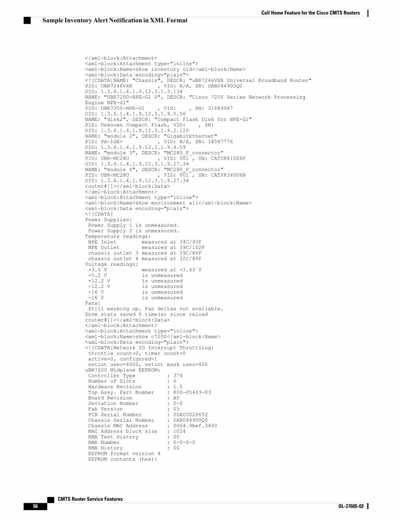
</aml-block:Attachment><aml-block:Attachment type="inline"><aml-block:Name>show inventory oid</aml-block:Name><aml-block:Data encoding="plain"><![CDATA[NAME: "Chassis", DESCR: "uBR7246VXR Universal Broadband Router"PID: UBR7246VXR , VID: N/A, SN: SAB044900Q0OID: 1.3.6.1.4.1.9.12.3.1.3.134NAME: "UBR7200-NPE-G1 0", DESCR: "Cisco 7200 Series Network ProcessingEngine NPE-G1"PID: UBR7200-NPE-G1 , VID: , SN: 31689947OID: 1.3.6.1.4.1.9.12.3.1.9.5.56NAME: "disk2", DESCR: "Compact Flash Disk for NPE-G1"PID: Unknown Compact Flash, VID: , SN:OID: 1.3.6.1.4.1.9.12.3.1.9.2.120NAME: "module 2", DESCR: "GigabitEthernet"PID: PA-1GE= , VID: N/A, SN: 18587776OID: 1.3.6.1.4.1.9.12.3.1.9.4.59NAME: "module 3", DESCR: "MC28U_F_connector"PID: UBR-MC28U , VID: V01 , SN: CAT0841006FOID: 1.3.6.1.4.1.9.12.3.1.9.27.34NAME: "module 4", DESCR: "MC28U_F_connector"PID: UBR-MC28U , VID: V01 , SN: CAT08340U6NOID: 1.3.6.1.4.1.9.12.3.1.9.27.34router#]]></aml-block:Data></aml-block:Attachment><aml-block:Attachment type="inline"><aml-block:Name>show environment all</aml-block:Name><aml-block:Data encoding="plain"><![CDATA[Power Supplies:Power Supply 1 is unmeasured.Power Supply 2 is unmeasured.Temperature readings:NPE Inlet measured at 34C/93FNPE Outlet measured at 39C/102Fchassis outlet 3 measured at 29C/84Fchassis outlet 4 measured at 32C/89FVoltage readings:+3.5 V measured at +3.43 V+5.2 V is unmeasured+12.2 V is unmeasured-12.2 V is unmeasured+16 V is unmeasured-16 V is unmeasuredFans:Still warming up. Fan deltas not available.Envm stats saved 0 time(s) since reloadrouter#]]></aml-block:Data></aml-block:Attachment><aml-block:Attachment type="inline"><aml-block:Name>show c7200</aml-block:Name><aml-block:Data encoding="plain"><
0x00: 04 FF 40 01 76 01 06 41 01 05 C0 46 03 20 00 150x10: 43 03 42 41 30 80 00 00 00 00 02 03 C1 8B 53 440x20: 41 30 35 30 32 30 36 35 32 C2 8B 53 41 42 30 340x30: 34 39 30 30 51 30 C3 06 00 04 9B EF 34 00 43 040x40: 00 03 00 81 00 00 00 00 04 00 C7 20 45 53 00 450x50: 00 50 00 40 00 44 00 3A 00 40 00 7F 00 7E 00 7F0x60: 00 84 00 88 00 BC A8 21 00 00 B8 9A FF FF FF FF0x70: FF FF FF FF FF FF FF FF FF FF FF FF FF FF FF FF
uBRuBR7246VXR CPU EEPROM:Controller Type : 859Hardware Revision : 1.4Top Assy. Part Number : 800-22164-05CLEI Code : CNSP30ZAABPCB Part Number : 73-6988-10Board Revision : A0PCB Serial Number : 31689947RMA History : 00Fab Version : 05Fab Part Number : 28-5082-05Product Identifier (PID) : UBR7200-NPE-G1Deviation Number : 0-0EEPROM format version 4EEPROM contents (hex):0x00: 04 FF 40 03 5B 41 01 04 C0 46 03 20 00 56 94 050x10: C6 8A 43 4E 53 50 33 30 5A 41 41 42 82 49 1B 4C0x20: 0A 42 41 30 C1 8B 33 31 36 38 39 39 34 37 00 000x30: 00 04 00 02 05 85 1C 13 DA 05 CB 8E 55 42 52 370x40: 32 30 30 2D 4E 50 45 2D 47 31 80 00 00 00 00 FF0x50: FF FF FF FF FF FF FF FF FF FF FF FF FF FF FF FF0x60: FF FF FF FF FF FF FF FF FF FF FF FF FF FF FF FF0x70: FF FF FF FF FF FF FF FF FF FF FF FF FF FF FF FF
TLB entries (43/64 used):Virt Address range Phy Address range Attributes0x4B000000:0x4B1FFFFF 0x14B000000:0x14B1FFFFF CacheMode=2, RW,Invalid0x4B200000:0x4B3FFFFF 0x14B200000:0x14B3FFFFF CacheMode=2, RW,Invalid0x10000000:0x10001FFF 0x0FC010000:0x0FC011FFF CacheMode=2, RW, Valid0x42000000:0x43FFFFFF 0x062000000:0x063FFFFFF CacheMode=2, RW, Valid0x46000000:0x47FFFFFF 0x066000000:0x067FFFFFF CacheMode=2, RW, Valid0x3C000000:0x3C7FFFFF 0x068000000:0x0687FFFFF CacheMode=2, RW,Invalid0x04000000:0x05FFFFFF 0x01F000000:0x020FFFFFF CacheMode=2, RW,Invalid0x08000000:0x09FFFFFF 0x076000000:0x077FFFFFF CacheMode=2, RW, Valid0x30000000:0x31FFFFFF 0x06C000000:0x06DFFFFFF CacheMode=2, RW, Valid0x38000000:0x39FFFFFF 0x078000000:0x079FFFFFF CacheMode=2, RW, Valid0x34000000:0x35FFFFFF 0x070000000:0x071FFFFFF CacheMode=2, RW,Invalid0x4C000000:0x4DFFFFFF 0x07C000000:0x07DFFFFFF CacheMode=2, RW,Invalid0x1FC00000:0x1FC7FFFF 0x01FC00000:0x01FC7FFFF CacheMode=2, RO, Valid0x1E000000:0x1E7FFFFF 0x01E000000:0x01E7FFFFF CacheMode=2, RW, Valid0x1E800000:0x1E9FFFFF 0x01E800000:0x01E9FFFFF CacheMode=2, RW, Valid0x32000000:0x33FFFFFF 0x01F000000:0x020FFFFFF CacheMode=2, RW,Invalid0x3A000000:0x3BFFFFFF 0x01F000000:0x020FFFFFF CacheMode=2, RW,Invalid0x36000000:0x37FFFFFF 0x052000000:0x053FFFFFF CacheMode=2, RW,Invalid0x4E000000:0x4FFFFFFF 0x05E000000:0x05FFFFFFF CacheMode=2, RW,Invalid0x60000000:0x61FFFFFF 0x000000000:0x001FFFFFF CacheMode=5, RO, Valid0x62000000:0x627FFFFF 0x002000000:0x0027FFFFF CacheMode=5, RO, Valid0x62800000:0x62FFFFFF 0x002800000:0x002FFFFFF CacheMode=5, RO, Valid0x63000000:0x631FFFFF 0x003000000:0x0031FFFFF CacheMode=5, RO, Valid0x63200000:0x6321FFFF 0x003200000:0x00321FFFF CacheMode=5, RO, Valid0x63220000:0x63227FFF 0x003220000:0x003227FFF CacheMode=5, RO, Valid0x63228000:0x6322FFFF 0x003228000:0x00322FFFF CacheMode=5, RO, Valid0x63230000:0x63231FFF 0x003230000:0x003231FFF CacheMode=5, RO, Valid0x63232000:0x63233FFF 0x003232000:0x003233FFF CacheMode=5, RO, Valid0x63234000:0x63235FFF 0x003234000:0x003235FFF CacheMode=5, RO, Valid0x63236000:0x63237FFF 0x003236000:0x003237FFF CacheMode=5, RW, Valid
CMTS Router Service Features OL-27605-02 57
Call Home Feature for the Cisco CMTS RoutersSample InventoryAlert Notification inXMLFormat
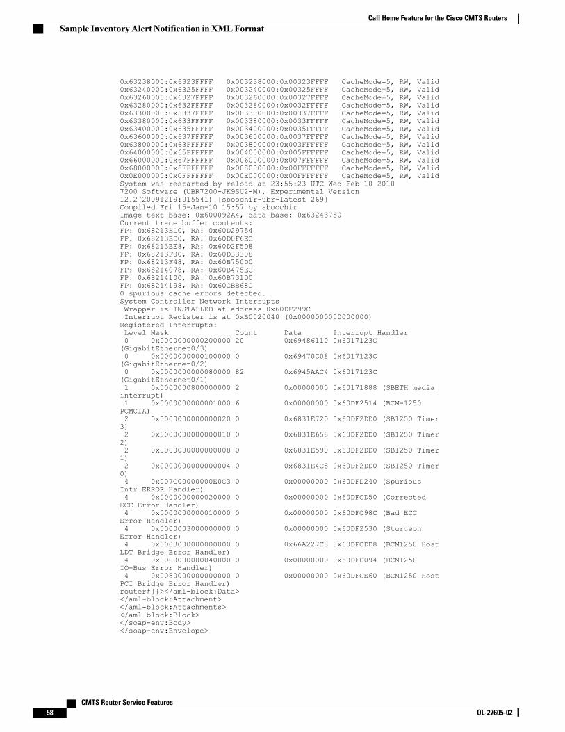
0x63238000:0x6323FFFF 0x003238000:0x00323FFFF CacheMode=5, RW, Valid0x63240000:0x6325FFFF 0x003240000:0x00325FFFF CacheMode=5, RW, Valid0x63260000:0x6327FFFF 0x003260000:0x00327FFFF CacheMode=5, RW, Valid0x63280000:0x632FFFFF 0x003280000:0x0032FFFFF CacheMode=5, RW, Valid0x63300000:0x6337FFFF 0x003300000:0x00337FFFF CacheMode=5, RW, Valid0x63380000:0x633FFFFF 0x003380000:0x0033FFFFF CacheMode=5, RW, Valid0x63400000:0x635FFFFF 0x003400000:0x0035FFFFF CacheMode=5, RW, Valid0x63600000:0x637FFFFF 0x003600000:0x0037FFFFF CacheMode=5, RW, Valid0x63800000:0x63FFFFFF 0x003800000:0x003FFFFFF CacheMode=5, RW, Valid0x64000000:0x65FFFFFF 0x004000000:0x005FFFFFF CacheMode=5, RW, Valid0x66000000:0x67FFFFFF 0x006000000:0x007FFFFFF CacheMode=5, RW, Valid0x68000000:0x6FFFFFFF 0x008000000:0x00FFFFFFF CacheMode=5, RW, Valid0x0E000000:0x0FFFFFFF 0x00E000000:0x00FFFFFFF CacheMode=5, RW, ValidSystem was restarted by reload at 23:55:23 UTC Wed Feb 10 20107200 Software (UBR7200-JK9SU2-M), Experimental Version12.2(20091219:015541) [sboochir-ubr-latest 269]Compiled Fri 15-Jan-10 15:57 by sboochirImage text-base: 0x600092A4, data-base: 0x63243750Current trace buffer contents:FP: 0x68213ED0, RA: 0x60D29754FP: 0x68213ED0, RA: 0x60D0F6ECFP: 0x68213EE8, RA: 0x60D2F5D8FP: 0x68213F00, RA: 0x60D33308FP: 0x68213F48, RA: 0x60B750D0FP: 0x68214078, RA: 0x60B475ECFP: 0x68214100, RA: 0x60B731D0FP: 0x68214198, RA: 0x60CBB68C0 spurious cache errors detected.System Controller Network InterruptsWrapper is INSTALLED at address 0x60DF299CInterrupt Register is at 0xB0020040 (0x0000000000000000)Registered Interrupts:Level Mask Count Data Interrupt Handler0 0x0000000000200000 20 0x69486110 0x6017123C(GigabitEthernet0/3)0 0x0000000000100000 0 0x69470C08 0x6017123C(GigabitEthernet0/2)0 0x0000000000080000 82 0x6945AAC4 0x6017123C(GigabitEthernet0/1)1 0x0000000800000000 2 0x00000000 0x60171888 (SBETH mediainterrupt)1 0x0000000000001000 6 0x00000000 0x60DF2514 (BCM-1250PCMCIA)2 0x0000000000000020 0 0x6831E720 0x60DF2DD0 (SB1250 Timer3)2 0x0000000000000010 0 0x6831E658 0x60DF2DD0 (SB1250 Timer2)2 0x0000000000000008 0 0x6831E590 0x60DF2DD0 (SB1250 Timer1)2 0x0000000000000004 0 0x6831E4C8 0x60DF2DD0 (SB1250 Timer0)4 0x007C00000000E0C3 0 0x00000000 0x60DFD240 (SpuriousIntr ERROR Handler)4 0x0000000000020000 0 0x00000000 0x60DFCD50 (CorrectedECC Error Handler)4 0x0000000000010000 0 0x00000000 0x60DFC98C (Bad ECCError Handler)4 0x0000003000000000 0 0x00000000 0x60DF2530 (SturgeonError Handler)4 0x0003000000000000 0 0x66A227C8 0x60DFCDD8 (BCM1250 HostLDT Bridge Error Handler)4 0x0000000000040000 0 0x00000000 0x60DFD094 (BCM1250IO-Bus Error Handler)4 0x0080000000000000 0 0x00000000 0x60DFCE60 (BCM1250 HostPCI Bridge Error Handler)router#]]></aml-block:Data></aml-block:Attachment></aml-block:Attachments></aml-block:Block></soap-env:Body></soap-env:Envelope>
CMTS Router Service Features58 OL-27605-02
Call Home Feature for the Cisco CMTS RoutersSample InventoryAlert Notification inXMLFormat
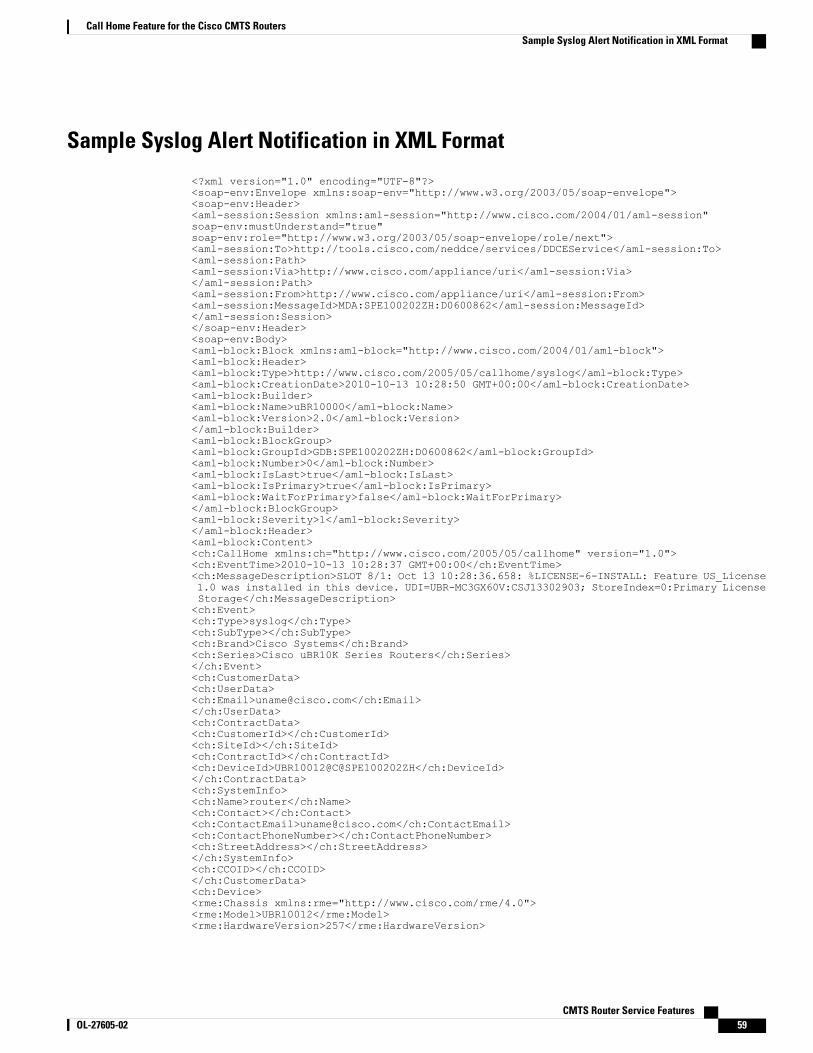
Sample Syslog Alert Notification in XML Format
<?xml version="1.0" encoding="UTF-8"?><soap-env:Envelope xmlns:soap-env="http://www.w3.org/2003/05/soap-envelope"><soap-env:Header><aml-session:Session xmlns:aml-session="http://www.cisco.com/2004/01/aml-session"soap-env:mustUnderstand="true"soap-env:role="http://www.w3.org/2003/05/soap-envelope/role/next"><aml-session:To>http://tools.cisco.com/neddce/services/DDCEService</aml-session:To><aml-session:Path><aml-session:Via>http://www.cisco.com/appliance/uri</aml-session:Via></aml-session:Path><aml-session:From>http://www.cisco.com/appliance/uri</aml-session:From><aml-session:MessageId>MDA:SPE100202ZH:D0600862</aml-session:MessageId></aml-session:Session></soap-env:Header><soap-env:Body><aml-block:Block xmlns:aml-block="http://www.cisco.com/2004/01/aml-block"><aml-block:Header><aml-block:Type>http://www.cisco.com/2005/05/callhome/syslog</aml-block:Type><aml-block:CreationDate>2010-10-13 10:28:50 GMT+00:00</aml-block:CreationDate><aml-block:Builder><aml-block:Name>uBR10000</aml-block:Name><aml-block:Version>2.0</aml-block:Version></aml-block:Builder><aml-block:BlockGroup><aml-block:GroupId>GDB:SPE100202ZH:D0600862</aml-block:GroupId><aml-block:Number>0</aml-block:Number><aml-block:IsLast>true</aml-block:IsLast><aml-block:IsPrimary>true</aml-block:IsPrimary><aml-block:WaitForPrimary>false</aml-block:WaitForPrimary></aml-block:BlockGroup><aml-block:Severity>1</aml-block:Severity></aml-block:Header><aml-block:Content><ch:CallHome xmlns:ch="http://www.cisco.com/2005/05/callhome" version="1.0"><ch:EventTime>2010-10-13 10:28:37 GMT+00:00</ch:EventTime><ch:MessageDescription>SLOT 8/1: Oct 13 10:28:36.658: %LICENSE-6-INSTALL: Feature US_License1.0 was installed in this device. UDI=UBR-MC3GX60V:CSJ13302903; StoreIndex=0:Primary LicenseStorage</ch:MessageDescription><ch:Event><ch:Type>syslog</ch:Type><ch:SubType></ch:SubType><ch:Brand>Cisco Systems</ch:Brand><ch:Series>Cisco uBR10K Series Routers</ch:Series></ch:Event><ch:CustomerData><ch:UserData><ch:Email>[email protected]</ch:Email></ch:UserData><ch:ContractData><ch:CustomerId></ch:CustomerId><ch:SiteId></ch:SiteId><ch:ContractId></ch:ContractId><ch:DeviceId>UBR10012@C@SPE100202ZH</ch:DeviceId></ch:ContractData><ch:SystemInfo><ch:Name>router</ch:Name><ch:Contact></ch:Contact><ch:ContactEmail>[email protected]</ch:ContactEmail><ch:ContactPhoneNumber></ch:ContactPhoneNumber><ch:StreetAddress></ch:StreetAddress></ch:SystemInfo><ch:CCOID></ch:CCOID></ch:CustomerData><ch:Device><rme:Chassis xmlns:rme="http://www.cisco.com/rme/4.0"><rme:Model>UBR10012</rme:Model><rme:HardwareVersion>257</rme:HardwareVersion>
CMTS Router Service Features OL-27605-02 59
Call Home Feature for the Cisco CMTS RoutersSample Syslog Alert Notification in XML Format

<rme:SerialNumber>SPE100202ZH</rme:SerialNumber><rme:AdditionalInformation><rme:AD name="PartNumber" value="800-09026-03" /><rme:AD name="SoftwareVersion" value="12.2(20100929:171810)" /><rme:AD name="SystemObjectId" value="1.3.6.1.4.1.9.1.317" /><rme:AD name="SystemDescription" value="Cisco IOS Software, 10000 Software (UBR10K4-K9P6U2-M),Experimental Version 12.2(20100929:171810) [pauhuang-card 111]Copyright (c) 1986-2010 by Cisco Systems, Inc.Compiled Wed 29-Sep-10 10:18 by pauhuang" /></rme:AdditionalInformation></rme:Chassis></ch:Device></ch:CallHome></aml-block:Content><aml-block:Attachments><aml-block:Attachment type="inline"><aml-block:Name>show logging</aml-block:Name><aml-block:Data encoding="plain"><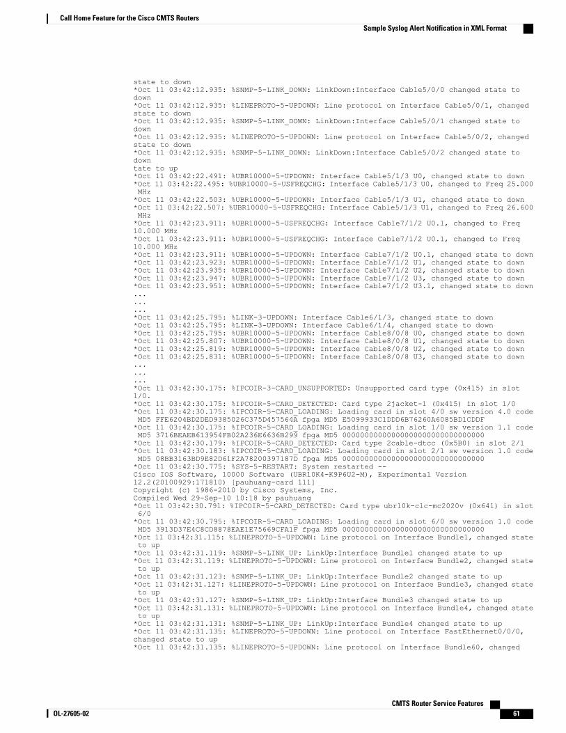
state to down*Oct 11 03:42:12.935: %SNMP-5-LINK_DOWN: LinkDown:Interface Cable5/0/0 changed state todown*Oct 11 03:42:12.935: %LINEPROTO-5-UPDOWN: Line protocol on Interface Cable5/0/1, changedstate to down*Oct 11 03:42:12.935: %SNMP-5-LINK_DOWN: LinkDown:Interface Cable5/0/1 changed state todown*Oct 11 03:42:12.935: %LINEPROTO-5-UPDOWN: Line protocol on Interface Cable5/0/2, changedstate to down*Oct 11 03:42:12.935: %SNMP-5-LINK_DOWN: LinkDown:Interface Cable5/0/2 changed state todowntate to up*Oct 11 03:42:22.491: %UBR10000-5-UPDOWN: Interface Cable5/1/3 U0, changed state to down*Oct 11 03:42:22.495: %UBR10000-5-USFREQCHG: Interface Cable5/1/3 U0, changed to Freq 25.000MHz*Oct 11 03:42:22.503: %UBR10000-5-UPDOWN: Interface Cable5/1/3 U1, changed state to down*Oct 11 03:42:22.507: %UBR10000-5-USFREQCHG: Interface Cable5/1/3 U1, changed to Freq 26.600MHz*Oct 11 03:42:23.911: %UBR10000-5-USFREQCHG: Interface Cable7/1/2 U0.1, changed to Freq10.000 MHz*Oct 11 03:42:23.911: %UBR10000-5-USFREQCHG: Interface Cable7/1/2 U0.1, changed to Freq10.000 MHz*Oct 11 03:42:23.911: %UBR10000-5-UPDOWN: Interface Cable7/1/2 U0.1, changed state to down*Oct 11 03:42:23.923: %UBR10000-5-UPDOWN: Interface Cable7/1/2 U1, changed state to down*Oct 11 03:42:23.935: %UBR10000-5-UPDOWN: Interface Cable7/1/2 U2, changed state to down*Oct 11 03:42:23.947: %UBR10000-5-UPDOWN: Interface Cable7/1/2 U3, changed state to down*Oct 11 03:42:23.951: %UBR10000-5-UPDOWN: Interface Cable7/1/2 U3.1, changed state to down.........*Oct 11 03:42:25.795: %LINK-3-UPDOWN: Interface Cable6/1/3, changed state to down*Oct 11 03:42:25.795: %LINK-3-UPDOWN: Interface Cable6/1/4, changed state to down*Oct 11 03:42:25.795: %UBR10000-5-UPDOWN: Interface Cable8/0/8 U0, changed state to down*Oct 11 03:42:25.807: %UBR10000-5-UPDOWN: Interface Cable8/0/8 U1, changed state to down*Oct 11 03:42:25.819: %UBR10000-5-UPDOWN: Interface Cable8/0/8 U2, changed state to down*Oct 11 03:42:25.831: %UBR10000-5-UPDOWN: Interface Cable8/0/8 U3, changed state to down.........*Oct 11 03:42:30.175: %IPCOIR-3-CARD_UNSUPPORTED: Unsupported card type (0x415) in slot1/0.*Oct 11 03:42:30.175: %IPCOIR-5-CARD_DETECTED: Card type 2jacket-1 (0x415) in slot 1/0*Oct 11 03:42:30.175: %IPCOIR-5-CARD_LOADING: Loading card in slot 4/0 sw version 4.0 codeMD5 FFE6204BD2DED9385026C375D457564A fpga MD5 E5099933C1DDD6B76260A6085BD1CDDF*Oct 11 03:42:30.175: %IPCOIR-5-CARD_LOADING: Loading card in slot 1/0 sw version 1.1 codeMD5 3716BEAEB613954FB02A236E6636B299 fpga MD5 00000000000000000000000000000000*Oct 11 03:42:30.179: %IPCOIR-5-CARD_DETECTED: Card type 2cable-dtcc (0x5B0) in slot 2/1*Oct 11 03:42:30.183: %IPCOIR-5-CARD_LOADING: Loading card in slot 2/1 sw version 1.0 codeMD5 08BB3163BD9E82D61F2A78200397187D fpga MD5 00000000000000000000000000000000*Oct 11 03:42:30.775: %SYS-5-RESTART: System restarted --Cisco IOS Software, 10000 Software (UBR10K4-K9P6U2-M), Experimental Version12.2(20100929:171810) [pauhuang-card 111]Copyright (c) 1986-2010 by Cisco Systems, Inc.Compiled Wed 29-Sep-10 10:18 by pauhuang*Oct 11 03:42:30.791: %IPCOIR-5-CARD_DETECTED: Card type ubr10k-clc-mc2020v (0x641) in slot6/0*Oct 11 03:42:30.795: %IPCOIR-5-CARD_LOADING: Loading card in slot 6/0 sw version 1.0 codeMD5 3913D37E4C8CD8878EAE1E75669CFA1F fpga MD5 00000000000000000000000000000000*Oct 11 03:42:31.115: %LINEPROTO-5-UPDOWN: Line protocol on Interface Bundle1, changed stateto up*Oct 11 03:42:31.119: %SNMP-5-LINK_UP: LinkUp:Interface Bundle1 changed state to up*Oct 11 03:42:31.119: %LINEPROTO-5-UPDOWN: Line protocol on Interface Bundle2, changed stateto up*Oct 11 03:42:31.123: %SNMP-5-LINK_UP: LinkUp:Interface Bundle2 changed state to up*Oct 11 03:42:31.127: %LINEPROTO-5-UPDOWN: Line protocol on Interface Bundle3, changed stateto up*Oct 11 03:42:31.127: %SNMP-5-LINK_UP: LinkUp:Interface Bundle3 changed state to up*Oct 11 03:42:31.131: %LINEPROTO-5-UPDOWN: Line protocol on Interface Bundle4, changed stateto up*Oct 11 03:42:31.131: %SNMP-5-LINK_UP: LinkUp:Interface Bundle4 changed state to up*Oct 11 03:42:31.135: %LINEPROTO-5-UPDOWN: Line protocol on Interface FastEthernet0/0/0,changed state to up*Oct 11 03:42:31.135: %LINEPROTO-5-UPDOWN: Line protocol on Interface Bundle60, changed
CMTS Router Service Features OL-27605-02 61
Call Home Feature for the Cisco CMTS RoutersSample Syslog Alert Notification in XML Format
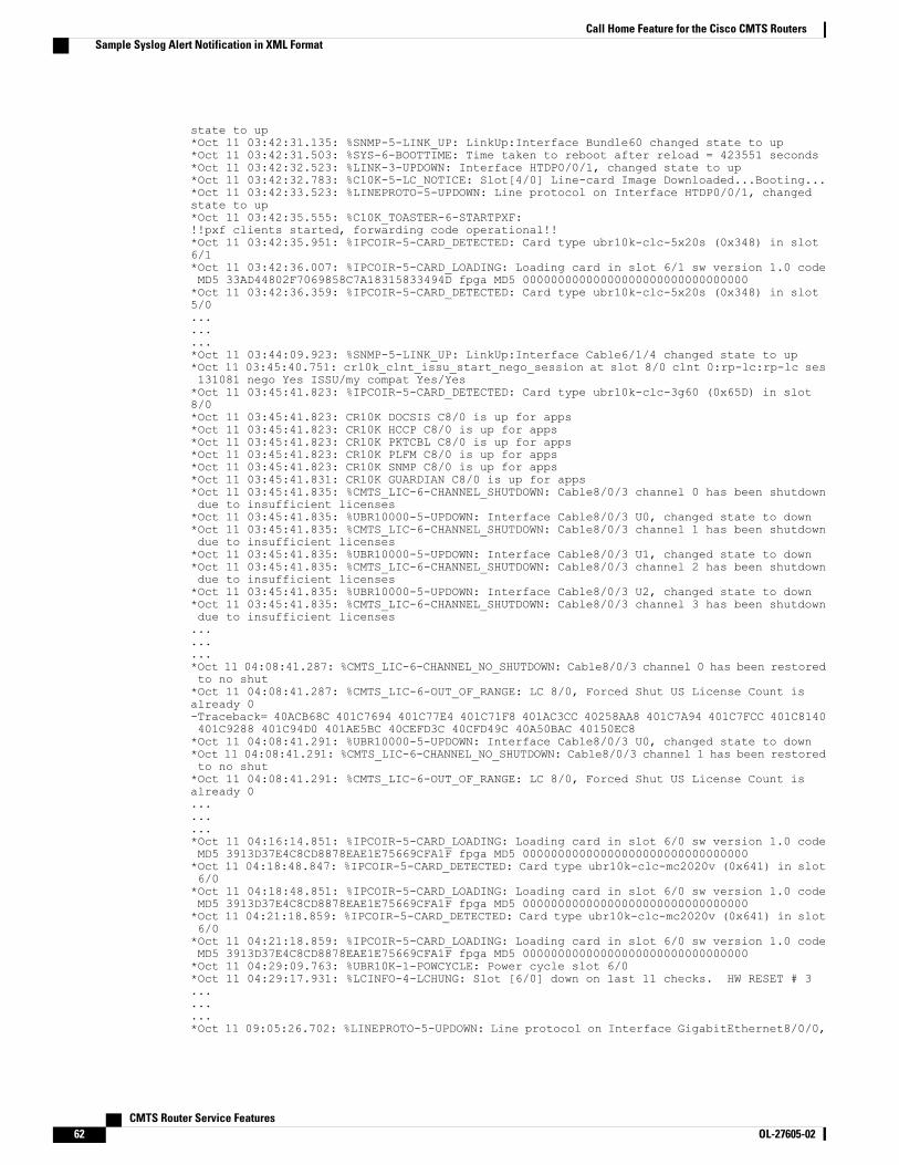
state to up*Oct 11 03:42:31.135: %SNMP-5-LINK_UP: LinkUp:Interface Bundle60 changed state to up*Oct 11 03:42:31.503: %SYS-6-BOOTTIME: Time taken to reboot after reload = 423551 seconds*Oct 11 03:42:32.523: %LINK-3-UPDOWN: Interface HTDP0/0/1, changed state to up*Oct 11 03:42:32.783: %C10K-5-LC_NOTICE: Slot[4/0] Line-card Image Downloaded...Booting...*Oct 11 03:42:33.523: %LINEPROTO-5-UPDOWN: Line protocol on Interface HTDP0/0/1, changedstate to up*Oct 11 03:42:35.555: %C10K_TOASTER-6-STARTPXF:!!pxf clients started, forwarding code operational!!*Oct 11 03:42:35.951: %IPCOIR-5-CARD_DETECTED: Card type ubr10k-clc-5x20s (0x348) in slot6/1*Oct 11 03:42:36.007: %IPCOIR-5-CARD_LOADING: Loading card in slot 6/1 sw version 1.0 codeMD5 33AD44802F7069858C7A18315833494D fpga MD5 00000000000000000000000000000000*Oct 11 03:42:36.359: %IPCOIR-5-CARD_DETECTED: Card type ubr10k-clc-5x20s (0x348) in slot5/0.........*Oct 11 03:44:09.923: %SNMP-5-LINK_UP: LinkUp:Interface Cable6/1/4 changed state to up*Oct 11 03:45:40.751: cr10k_clnt_issu_start_nego_session at slot 8/0 clnt 0:rp-lc:rp-lc ses131081 nego Yes ISSU/my compat Yes/Yes*Oct 11 03:45:41.823: %IPCOIR-5-CARD_DETECTED: Card type ubr10k-clc-3g60 (0x65D) in slot8/0*Oct 11 03:45:41.823: CR10K DOCSIS C8/0 is up for apps*Oct 11 03:45:41.823: CR10K HCCP C8/0 is up for apps*Oct 11 03:45:41.823: CR10K PKTCBL C8/0 is up for apps*Oct 11 03:45:41.823: CR10K PLFM C8/0 is up for apps*Oct 11 03:45:41.823: CR10K SNMP C8/0 is up for apps*Oct 11 03:45:41.831: CR10K GUARDIAN C8/0 is up for apps*Oct 11 03:45:41.835: %CMTS_LIC-6-CHANNEL_SHUTDOWN: Cable8/0/3 channel 0 has been shutdowndue to insufficient licenses*Oct 11 03:45:41.835: %UBR10000-5-UPDOWN: Interface Cable8/0/3 U0, changed state to down*Oct 11 03:45:41.835: %CMTS_LIC-6-CHANNEL_SHUTDOWN: Cable8/0/3 channel 1 has been shutdowndue to insufficient licenses*Oct 11 03:45:41.835: %UBR10000-5-UPDOWN: Interface Cable8/0/3 U1, changed state to down*Oct 11 03:45:41.835: %CMTS_LIC-6-CHANNEL_SHUTDOWN: Cable8/0/3 channel 2 has been shutdowndue to insufficient licenses*Oct 11 03:45:41.835: %UBR10000-5-UPDOWN: Interface Cable8/0/3 U2, changed state to down*Oct 11 03:45:41.835: %CMTS_LIC-6-CHANNEL_SHUTDOWN: Cable8/0/3 channel 3 has been shutdowndue to insufficient licenses.........*Oct 11 04:08:41.287: %CMTS_LIC-6-CHANNEL_NO_SHUTDOWN: Cable8/0/3 channel 0 has been restoredto no shut*Oct 11 04:08:41.287: %CMTS_LIC-6-OUT_OF_RANGE: LC 8/0, Forced Shut US License Count isalready 0-Traceback= 40ACB68C 401C7694 401C77E4 401C71F8 401AC3CC 40258AA8 401C7A94 401C7FCC 401C8140401C9288 401C94D0 401AE5BC 40CEFD3C 40CFD49C 40A50BAC 40150EC8*Oct 11 04:08:41.291: %UBR10000-5-UPDOWN: Interface Cable8/0/3 U0, changed state to down*Oct 11 04:08:41.291: %CMTS_LIC-6-CHANNEL_NO_SHUTDOWN: Cable8/0/3 channel 1 has been restoredto no shut*Oct 11 04:08:41.291: %CMTS_LIC-6-OUT_OF_RANGE: LC 8/0, Forced Shut US License Count isalready 0.........*Oct 11 04:16:14.851: %IPCOIR-5-CARD_LOADING: Loading card in slot 6/0 sw version 1.0 codeMD5 3913D37E4C8CD8878EAE1E75669CFA1F fpga MD5 00000000000000000000000000000000*Oct 11 04:18:48.847: %IPCOIR-5-CARD_DETECTED: Card type ubr10k-clc-mc2020v (0x641) in slot6/0*Oct 11 04:18:48.851: %IPCOIR-5-CARD_LOADING: Loading card in slot 6/0 sw version 1.0 codeMD5 3913D37E4C8CD8878EAE1E75669CFA1F fpga MD5 00000000000000000000000000000000*Oct 11 04:21:18.859: %IPCOIR-5-CARD_DETECTED: Card type ubr10k-clc-mc2020v (0x641) in slot6/0*Oct 11 04:21:18.859: %IPCOIR-5-CARD_LOADING: Loading card in slot 6/0 sw version 1.0 codeMD5 3913D37E4C8CD8878EAE1E75669CFA1F fpga MD5 00000000000000000000000000000000*Oct 11 04:29:09.763: %UBR10K-1-POWCYCLE: Power cycle slot 6/0*Oct 11 04:29:17.931: %LCINFO-4-LCHUNG: Slot [6/0] down on last 11 checks. HW RESET # 3.........*Oct 11 09:05:26.702: %LINEPROTO-5-UPDOWN: Line protocol on Interface GigabitEthernet8/0/0,
CMTS Router Service Features62 OL-27605-02
Call Home Feature for the Cisco CMTS RoutersSample Syslog Alert Notification in XML Format

changed state to down*Oct 11 09:05:39.382: cr10k_crane_delete_cdb Modular-Cable*Oct 11 09:05:39.382: in cr10k_crane_delete_cdb Modular-Cable*Oct 11 09:05:39.382: wbchannel_delete_context Modular-Cable*Oct 11 09:05:39.582: cr10k_crane_delete_cdb Modular-Cable*Oct 11 09:05:39.582: in cr10k_crane_delete_cdb Modular-Cable*Oct 11 09:05:39.582: wbchannel_delete_context Modular-Cable*Oct 11 09:05:39.782: cr10k_crane_delete_cdb Modular-Cable*Oct 11 09:05:39.782: in cr10k_crane_delete_cdb Modular-Cable*Oct 11 09:05:39.782: wbchannel_delete_context Modular-Cable*Oct 11 09:05:39.986: %C10K-3-DEACTIVATED: card in slot [8/0] disabled.*Oct 11 09:05:47.670: %UBR10000-5-USFREQCHG: Interface Cable8/0/0 U0, changed to Freq 10.000MHz.........*Oct 11 16:48:26.188: CR10K DOCSIS C8/1 is up for apps*Oct 11 16:48:26.188: CR10K HCCP C8/1 is up for apps*Oct 11 16:48:26.188: CR10K PKTCBL C8/1 is up for apps*Oct 11 16:48:26.188: CR10K PLFM C8/1 is up for apps*Oct 11 16:48:26.188: CR10K SNMP C8/1 is up for apps*Oct 11 16:48:26.704: CR10K GUARDIAN C8/1 is up for apps*Oct 11 16:48:28.068: cr10k_clnt_issu_start_nego_session at slot 8/0 clnt 0:rp-lc:rp-lc ses458761 nego Yes ISSU/my compat Yes/Yes*Oct 11 16:48:28.084: %IPCOIR-5-CARD_DETECTED: Card type ubr10k-clc-3g60 (0x65D) in slot8/0*Oct 11 16:48:28.084: CR10K DOCSIS C8/0 is up for apps*Oct 11 16:48:28.084: CR10K HCCP C8/0 is up for apps*Oct 11 16:48:28.084: CR10K PKTCBL C8/0 is up for apps*Oct 11 16:48:28.084: CR10K PLFM C8/0 is up for apps*Oct 11 16:48:28.084: CR10K SNMP C8/0 is up for apps*Oct 11 16:48:28.092: CR10K GUARDIAN C8/0 is up for apps*Oct 11 16:48:50.456: CR10K DOCSIS C8/0 is down for apps*Oct 11 16:48:50.456: CR10K HCCP C8/0 is down for apps*Oct 11 16:48:50.456: CR10K PKTCBL C8/0 is down for apps*Oct 11 16:48:50.456: CR10K PLFM C8/0 is down for apps*Oct 11 16:48:50.456: CR10K SNMP C8/0 is down for apps*Oct 11 16:48:50.456: CR10K GUARDIAN C8/0 is down for apps*Oct 11 16:48:50.460: %IPCOIR-3-TIMEOUT: Timeout waiting for a response from slot 8/0.*Oct 11 16:48:50.460: %IPCOIR-2-CARD_UP_DOWN: Card in slot 8/0 is down. Notifyingubr10k-clc-3g60 driver.*Oct 11 16:48:51.456: %C10K-5-SUBSLOT_RESET: Card in slot 8/0 has been reset*Oct 11 16:49:23.744: %IPCOIR-5-CARD_DETECTED: Card type ubr10k-clc-3g60 (0x65D) in slot8/0*Oct 11 16:49:23.744: %IPCOIR-5-CARD_LOADING: Loading card in slot 8/0 sw version 1.0 codeMD5 15247BBB545BF3FAE97D7E7D34C1177C fpga MD5 00000000000000000000000000000000*Oct 11 16:49:26.708: %CR10K_CLNT-3-TIMEOUT: Timeout waiting for RP-LIC: card license ready,slot 8/1-Traceback= 40ACB68C 40DCA7FC 401AE8E0 40CEDF00 40CF37CC 40BC79DC 40BC79C8*Oct 11 16:49:28.092: %CR10K_CLNT-3-TIMEOUT: Timeout waiting for RP-LIC: card license ready,slot 8/0.........*Oct 13 04:12:04.931: cr10k_clnt_issu_receive_nego_message at slot 8/1 clnt 0:rp-lc:rp-lcses 1179700 nego Yes ISSU/my compat Yes/Yes*Oct 13 04:12:05.143: CR10K HCCP C8/1 is up for apps*Oct 13 04:12:05.203: CR10K GUARDIAN C8/1 is up for apps*Oct 13 04:12:05.259: CR10K PLFM C8/1 is up for apps*Oct 13 04:12:05.271: CR10K PKTCBL C8/1 is up for apps*Oct 13 04:12:05.299: CR10K SNMP C8/1 is up for apps*Oct 13 04:12:05.795: CR10K DOCSIS C8/1 is up for apps*Oct 13 04:12:07.739: %IPCOIR-3-TIMEOUT: Timeout waiting for a response from slot 8/0.*Oct 13 04:12:07.739: %IPCOIR-2-CARD_UP_DOWN: Card in slot 8/0 is down. Notifyingubr10k-clc-3g60 driver.*Oct 13 04:12:07.739: %C10K-3-EEPROM_ERROR: c10k_load_slot_eeprom_copy failed on subslot8/0-Traceback= 40ACB68C 40CDD418 40CCE018 40CCE2F4 40A50BAC 40150EC8 40A7D068 40BC79DC 40BC79C8*Oct 13 04:12:07.743: %C10K-3-EEPROM_ERROR: c10k_load_slot_eeprom_copy failed on subslot8/0-Traceback= 40ACB68C 40CDD274 40CCE05C 40CCE2F4 40A50BAC 40150EC8 40A7D068 40BC79DC 40BC79C8*Oct 13 04:12:09.919: %LINK-3-UPDOWN: Interface Cable8/0/0, changed state to down*Oct 13 04:12:09.919: %LINK-3-UPDOWN: Interface Cable8/0/1, changed state to down
CMTS Router Service Features OL-27605-02 63
Call Home Feature for the Cisco CMTS RoutersSample Syslog Alert Notification in XML Format
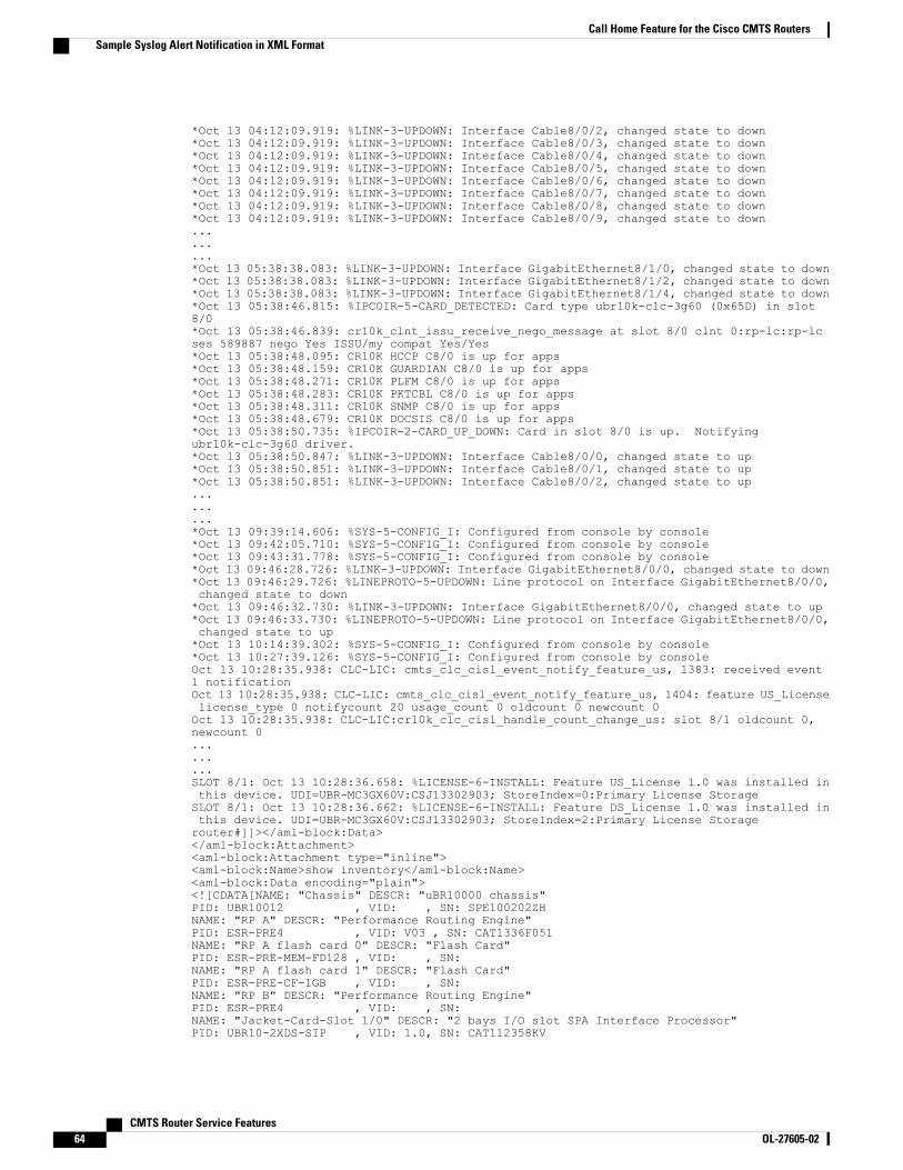
*Oct 13 04:12:09.919: %LINK-3-UPDOWN: Interface Cable8/0/2, changed state to down*Oct 13 04:12:09.919: %LINK-3-UPDOWN: Interface Cable8/0/3, changed state to down*Oct 13 04:12:09.919: %LINK-3-UPDOWN: Interface Cable8/0/4, changed state to down*Oct 13 04:12:09.919: %LINK-3-UPDOWN: Interface Cable8/0/5, changed state to down*Oct 13 04:12:09.919: %LINK-3-UPDOWN: Interface Cable8/0/6, changed state to down*Oct 13 04:12:09.919: %LINK-3-UPDOWN: Interface Cable8/0/7, changed state to down*Oct 13 04:12:09.919: %LINK-3-UPDOWN: Interface Cable8/0/8, changed state to down*Oct 13 04:12:09.919: %LINK-3-UPDOWN: Interface Cable8/0/9, changed state to down.........*Oct 13 05:38:38.083: %LINK-3-UPDOWN: Interface GigabitEthernet8/1/0, changed state to down*Oct 13 05:38:38.083: %LINK-3-UPDOWN: Interface GigabitEthernet8/1/2, changed state to down*Oct 13 05:38:38.083: %LINK-3-UPDOWN: Interface GigabitEthernet8/1/4, changed state to down*Oct 13 05:38:46.815: %IPCOIR-5-CARD_DETECTED: Card type ubr10k-clc-3g60 (0x65D) in slot8/0*Oct 13 05:38:46.839: cr10k_clnt_issu_receive_nego_message at slot 8/0 clnt 0:rp-lc:rp-lcses 589887 nego Yes ISSU/my compat Yes/Yes*Oct 13 05:38:48.095: CR10K HCCP C8/0 is up for apps*Oct 13 05:38:48.159: CR10K GUARDIAN C8/0 is up for apps*Oct 13 05:38:48.271: CR10K PLFM C8/0 is up for apps*Oct 13 05:38:48.283: CR10K PKTCBL C8/0 is up for apps*Oct 13 05:38:48.311: CR10K SNMP C8/0 is up for apps*Oct 13 05:38:48.679: CR10K DOCSIS C8/0 is up for apps*Oct 13 05:38:50.735: %IPCOIR-2-CARD_UP_DOWN: Card in slot 8/0 is up. Notifyingubr10k-clc-3g60 driver.*Oct 13 05:38:50.847: %LINK-3-UPDOWN: Interface Cable8/0/0, changed state to up*Oct 13 05:38:50.851: %LINK-3-UPDOWN: Interface Cable8/0/1, changed state to up*Oct 13 05:38:50.851: %LINK-3-UPDOWN: Interface Cable8/0/2, changed state to up.........*Oct 13 09:39:14.606: %SYS-5-CONFIG_I: Configured from console by console*Oct 13 09:42:05.710: %SYS-5-CONFIG_I: Configured from console by console*Oct 13 09:43:31.778: %SYS-5-CONFIG_I: Configured from console by console*Oct 13 09:46:28.726: %LINK-3-UPDOWN: Interface GigabitEthernet8/0/0, changed state to down*Oct 13 09:46:29.726: %LINEPROTO-5-UPDOWN: Line protocol on Interface GigabitEthernet8/0/0,changed state to down*Oct 13 09:46:32.730: %LINK-3-UPDOWN: Interface GigabitEthernet8/0/0, changed state to up*Oct 13 09:46:33.730: %LINEPROTO-5-UPDOWN: Line protocol on Interface GigabitEthernet8/0/0,changed state to up*Oct 13 10:14:39.302: %SYS-5-CONFIG_I: Configured from console by console*Oct 13 10:27:39.126: %SYS-5-CONFIG_I: Configured from console by consoleOct 13 10:28:35.938: CLC-LIC: cmts_clc_cisl_event_notify_feature_us, 1383: received event1 notificationOct 13 10:28:35.938: CLC-LIC: cmts_clc_cisl_event_notify_feature_us, 1404: feature US_Licenselicense_type 0 notifycount 20 usage_count 0 oldcount 0 newcount 0Oct 13 10:28:35.938: CLC-LIC:cr10k_clc_cisl_handle_count_change_us: slot 8/1 oldcount 0,newcount 0.........SLOT 8/1: Oct 13 10:28:36.658: %LICENSE-6-INSTALL: Feature US_License 1.0 was installed inthis device. UDI=UBR-MC3GX60V:CSJ13302903; StoreIndex=0:Primary License StorageSLOT 8/1: Oct 13 10:28:36.662: %LICENSE-6-INSTALL: Feature DS_License 1.0 was installed inthis device. UDI=UBR-MC3GX60V:CSJ13302903; StoreIndex=2:Primary License Storagerouter#]]></aml-block:Data></aml-block:Attachment><aml-block:Attachment type="inline"><aml-block:Name>show inventory</aml-block:Name><aml-block:Data encoding="plain"><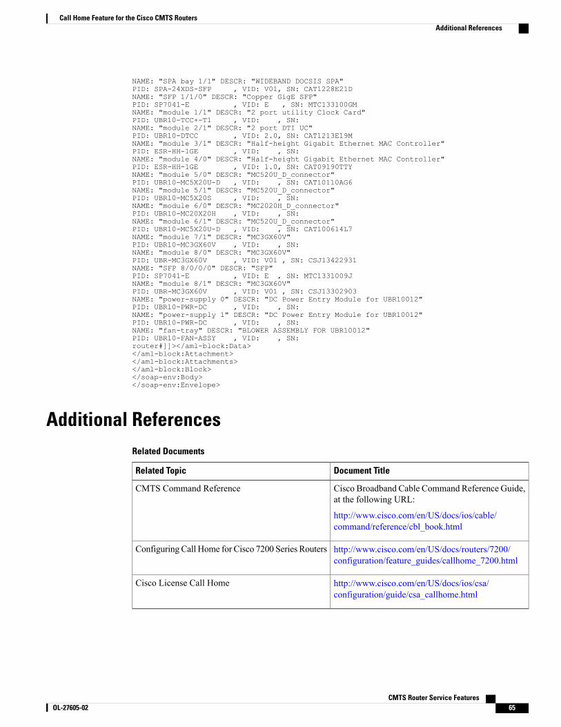
NAME: "SPA bay 1/1" DESCR: "WIDEBAND DOCSIS SPA"PID: SPA-24XDS-SFP , VID: V01, SN: CAT1228E21DNAME: "SFP 1/1/0" DESCR: "Copper GigE SFP"PID: SP7041-E , VID: E , SN: MTC133100GMNAME: "module 1/1" DESCR: "2 port utility Clock Card"PID: UBR10-TCC+-T1 , VID: , SN:NAME: "module 2/1" DESCR: "2 port DTI UC"PID: UBR10-DTCC , VID: 2.0, SN: CAT1213E19MNAME: "module 3/1" DESCR: "Half-height Gigabit Ethernet MAC Controller"PID: ESR-HH-1GE , VID: , SN:NAME: "module 4/0" DESCR: "Half-height Gigabit Ethernet MAC Controller"PID: ESR-HH-1GE , VID: 1.0, SN: CAT09190TTYNAME: "module 5/0" DESCR: "MC520U_D_connector"PID: UBR10-MC5X20U-D , VID: , SN: CAT10110AG6NAME: "module 5/1" DESCR: "MC520U_D_connector"PID: UBR10-MC5X20S , VID: , SN:NAME: "module 6/0" DESCR: "MC2020H_D_connector"PID: UBR10-MC20X20H , VID: , SN:NAME: "module 6/1" DESCR: "MC520U_D_connector"PID: UBR10-MC5X20U-D , VID: , SN: CAT100614L7NAME: "module 7/1" DESCR: "MC3GX60V"PID: UBR10-MC3GX60V , VID: , SN:NAME: "module 8/0" DESCR: "MC3GX60V"PID: UBR-MC3GX60V , VID: V01 , SN: CSJ13422931NAME: "SFP 8/0/0/0" DESCR: "SFP"PID: SP7041-E , VID: E , SN: MTC1331009JNAME: "module 8/1" DESCR: "MC3GX60V"PID: UBR-MC3GX60V , VID: V01 , SN: CSJ13302903NAME: "power-supply 0" DESCR: "DC Power Entry Module for UBR10012"PID: UBR10-PWR-DC , VID: , SN:NAME: "power-supply 1" DESCR: "DC Power Entry Module for UBR10012"PID: UBR10-PWR-DC , VID: , SN:NAME: "fan-tray" DESCR: "BLOWER ASSEMBLY FOR UBR10012"PID: UBR10-FAN-ASSY , VID: , SN:router#]]></aml-block:Data></aml-block:Attachment></aml-block:Attachments></aml-block:Block></soap-env:Body></soap-env:Envelope>
Additional ReferencesRelated Documents
Document TitleRelated Topic
Cisco Broadband Cable Command Reference Guide,at the following URL:
http://www.cisco.com/en/US/docs/ios/cable/command/reference/cbl_book.html
CMTS Command Reference
http://www.cisco.com/en/US/docs/routers/7200/configuration/feature_guides/callhome_7200.html
Configuring Call Home for Cisco 7200 Series Routers
http://www.cisco.com/en/US/docs/ios/csa/configuration/guide/csa_callhome.html
Cisco License Call Home
CMTS Router Service Features OL-27605-02 65
Call Home Feature for the Cisco CMTS RoutersAdditional References

Standards
TitleStandard
—None
MIBs
MIBs LinkMIB
To locate and downloadMIBs for selected platforms,Cisco software releases, and feature sets, use CiscoMIB Locator found at the following URL:
http://www.cisco.com/go/mibs
None
RFCs
TitleRFC
—None
Technical Assistance
LinkDescription
http://www.cisco.com/cisco/web/support/index.htmlThe Cisco Support website provides extensive onlineresources, including documentation and tools fortroubleshooting and resolving technical issues withCisco products and technologies.
To receive security and technical information aboutyour products, you can subscribe to various services,such as the Product Alert Tool (accessed from FieldNotices), the Cisco Technical Services Newsletter,and Really Simple Syndication (RSS) Feeds.
Access to most tools on the Cisco Support websiterequires a Cisco.com user ID and password.
Feature Information for the Call Home Feature for the CiscoCMTS Routers
Use Cisco Feature Navigator to find information about platform support and software image support.Cisco Feature Navigator enables you to determine which software images support a specific software release,
CMTS Router Service Features66 OL-27605-02
Call Home Feature for the Cisco CMTS RoutersFeature Information for the Call Home Feature for the Cisco CMTS Routers
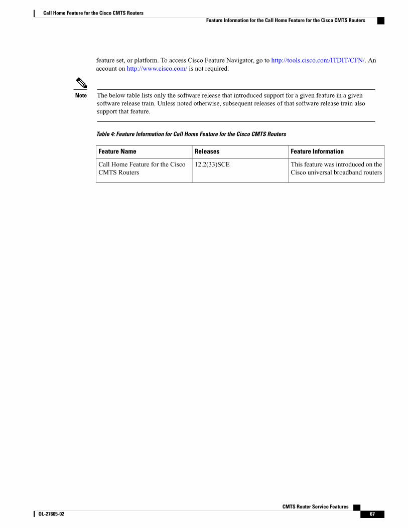
feature set, or platform. To access Cisco Feature Navigator, go to http://tools.cisco.com/ITDIT/CFN/. Anaccount on http://www.cisco.com/ is not required.
The below table lists only the software release that introduced support for a given feature in a givensoftware release train. Unless noted otherwise, subsequent releases of that software release train alsosupport that feature.
Note
Table 4: Feature Information for Call Home Feature for the Cisco CMTS Routers
Feature InformationReleasesFeature Name
This feature was introduced on theCisco universal broadband routers
12.2(33)SCECall Home Feature for the CiscoCMTS Routers
CMTS Router Service Features OL-27605-02 67
Call Home Feature for the Cisco CMTS RoutersFeature Information for the Call Home Feature for the Cisco CMTS Routers

CMTS Router Service Features68 OL-27605-02
Call Home Feature for the Cisco CMTS RoutersFeature Information for the Call Home Feature for the Cisco CMTS Routers
C H A P T E R 3Cisco Network Registrar for the Cisco CMTSRouters
First Published: February 14, 2008
Last Updated: February 9, 2009
This chapter supplements the Cisco Network Registrar (CNR) documentation by providing additionalcable-specific instructions to provision a hybrid fiber-coaxial (HFC) network using Cisco universal broadbandrouters as CMTSs at the headend of the network.
Finding Feature Information
Your software release may not support all the features documented in this module. For the latest featureinformation and caveats, see the release notes for your platform and software release. To find informationabout the features documented in this module, and to see a list of the releases in which each feature issupported, see the Feature Information Table at the end of this document.
Use Cisco Feature Navigator to find information about platform support and Cisco software image support.To access Cisco Feature Navigator, go to http://tools.cisco.com/ITDIT/CFN/. An account on http://www.cisco.com/ is not required.
Contents
• Servers Required on the HFC Network, page 70
• Cisco Network Registrar Description, page 71
• Overview of DHCP Using CNR, page 72
• How Cisco Universal Broadband Routers and Cable Modems Work, page 72
• DHCP Fields and Options for Cable Modems, page 73
• Cisco Network Registrar Sample Configuration, page 74
• Overview of Scripts, page 78
• Placement of Scripts, page 78
• Activating Scripts in Cisco Network Registrar, page 79
• Configuring the Cisco CMTS Routers to Use Scripts, page 79
CMTS Router Service Features OL-27605-02 69
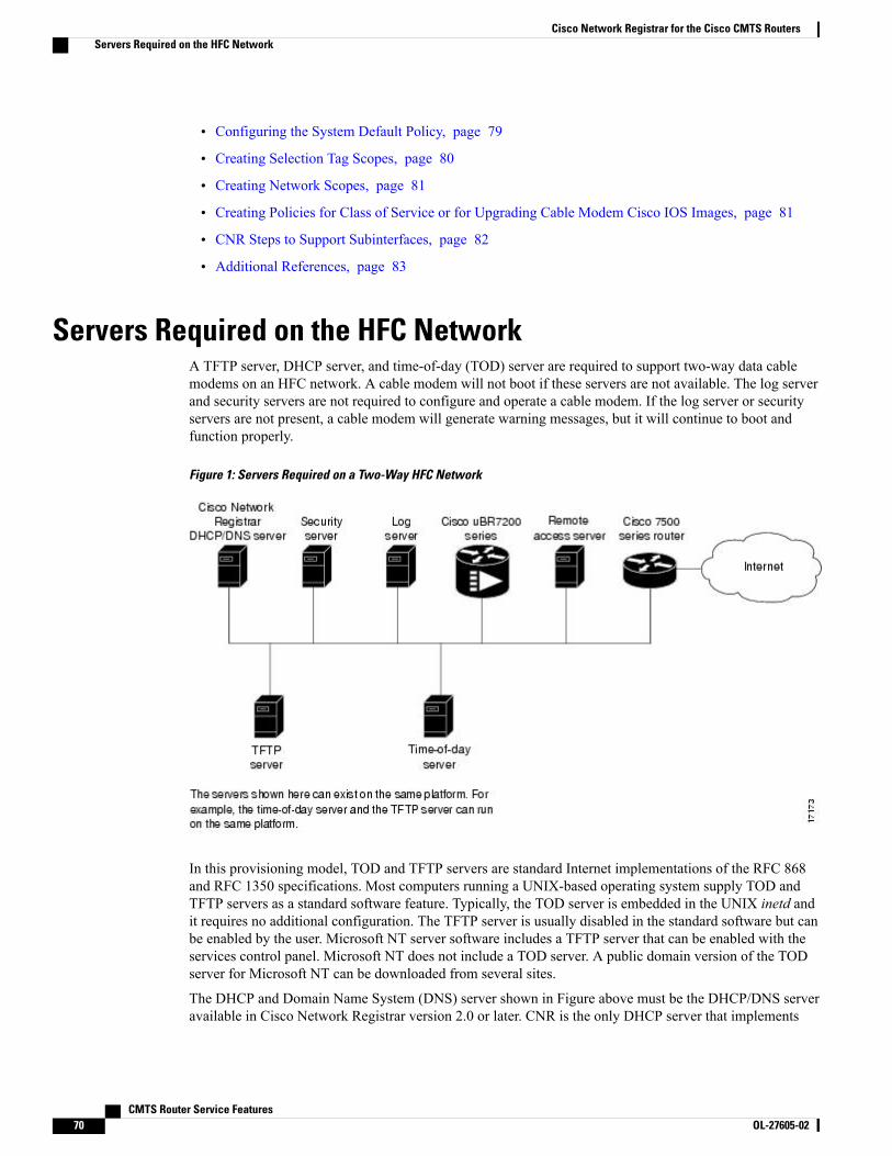
• Configuring the System Default Policy, page 79
• Creating Selection Tag Scopes, page 80
• Creating Network Scopes, page 81
• Creating Policies for Class of Service or for Upgrading Cable Modem Cisco IOS Images, page 81
• CNR Steps to Support Subinterfaces, page 82
• Additional References, page 83
Servers Required on the HFC NetworkA TFTP server, DHCP server, and time-of-day (TOD) server are required to support two-way data cablemodems on an HFC network. A cable modem will not boot if these servers are not available. The log serverand security servers are not required to configure and operate a cable modem. If the log server or securityservers are not present, a cable modem will generate warning messages, but it will continue to boot andfunction properly.
Figure 1: Servers Required on a Two-Way HFC Network
In this provisioning model, TOD and TFTP servers are standard Internet implementations of the RFC 868and RFC 1350 specifications. Most computers running a UNIX-based operating system supply TOD andTFTP servers as a standard software feature. Typically, the TOD server is embedded in the UNIX inetd andit requires no additional configuration. The TFTP server is usually disabled in the standard software but canbe enabled by the user. Microsoft NT server software includes a TFTP server that can be enabled with theservices control panel. Microsoft NT does not include a TOD server. A public domain version of the TODserver for Microsoft NT can be downloaded from several sites.
The DHCP and Domain Name System (DNS) server shown in Figure above must be the DHCP/DNS serveravailable in Cisco Network Registrar version 2.0 or later. CNR is the only DHCP server that implements
CMTS Router Service Features70 OL-27605-02
Cisco Network Registrar for the Cisco CMTS RoutersServers Required on the HFC Network

policy-based assignment of IP addresses. The headend must be a Cisco uBR7200 series universal broadbandrouter or Cisco uBR10012 universal broadband router. The remote access server is only required on HFCnetworks that are limited to one-way (downstream only) communication. In a one-way HFC network, upstreamdata from a PC through the headend to the Internet is carried over a dialup connection. This dialup connectionfor upstream data is referred to as telco return. For simplification, the model will not include a log or securityserver. Cable modems can be set up to use the logging and security servers by including the appropriate DHCPoptions in the cable modem policy as described in the Cisco Network Registrar User Manual.
Cisco Network Registrar DescriptionCNR is a dynamic IP address management system, running on Windows or Solaris, that uses the DynamicHost Configuration Protocol (DHCP) to assign IP addresses to cable interfaces, PCs, and other devices on thebroadband network. The CNR tool includes script extensions that allow a cable system administrator to defineand view individual DHCP options, define the identity or type of device on the network, and assign the deviceto a predefined class or group.
Using the CNR tool, a cable system administrator can specify policies to provide:
• Integrated DHCP and Domain Name Server (DNS) services
• Time of Day (ToD) and Trivial File Transfer Protocol (TFTP) server based on the size of the network
• DHCP safe failover and dynamic DNS updates
This is available only in CNR 3.0 or higher.Note
Using the CNR tool and the extension scripts identified in the Overview of Scripts, on page 78 section, acable system administrator can specify scopes, policies, and options for the network and each cable interfacebased on the services and configuration to support at each subscriber site.
Scopes refer to the administrative grouping of TCP/IP addresses; all IP addresses within a scope shouldbe on the same subnet.
Note
The cable system administrator defines system default policies for all standard options and uses scope-specificpolicies for options related to particular subnets, such as cable interfaces. This allows DHCP to send theinformation with the IP address.
Seven entry points exist for scripts:
• post-packet-decode
• pre-client-lookup
• post-client-lookup—Examines and takes action on results of the client-class process, places data itemsin the environment dictionary to use at the pre-packet-encode extension point, includes DHCP relayoption
• check-lease-acceptable
• pre-packet-encode
• post-sent-packet
CMTS Router Service Features OL-27605-02 71
Cisco Network Registrar for the Cisco CMTS RoutersCisco Network Registrar Description

• pre-dns-add-forward
Overview of DHCP Using CNRCisco Network Registrar (CNR) is a dynamic IP address management system that uses the Dynamic HostConfiguration Protocol (DHCP) and assigns IP addresses to PCs and other devices on a network based on apredefined set of policies, such as class of service. CNR assigns available IP addresses from address poolsbased on the identity or type of the requesting device and the policies in effect. For example, CNR candistinguish between registered devices, unregistered devices, and registered devices that have been assignedto a particular class of service.
CNR also provides extensions that can be customized (via programming or a script) so that you can viewindividual DHCP options, determine the identity or type of a device based on the content of the options, andassign a device to a predefined class or group. Using these extensions, you can determine the differencebetween PCs and cable modems and assign them IP addresses from different address pools.
In typical data-over-cable environments, service providers are interested in simplifying provisioning to limitthe amount of information that must be collected about subscribers’ customer premise equipment (CPEs). Tosupport current provisioning models, a field technician must be sent to a subscriber’s home or business toinstall and setup a cable modem. During this site visit, the technician might register the serial number andMAC address of the cable modem in the customer account database. Because a field technician must go to asubscriber’s site to replace a cable modem, you can easily track modem information.
Manually registering and tracking information about a cable subscriber’s PC is more difficult. A subscribermight purchase a new PC or exchange the network interface card (NIC) without notifying you of the change.Automatic provisioning with CNR reduces the amount of customer service involvement needed to trackcustomer equipment. To use the provisioning model described in this document, you must still track serialnumbers and MAC addresses for cable modems, but you do not need to track information about the PC orNIC cards installed at a subscriber site.
The remainder of this document describes how to configure CNR to support this model. The following sectionsdescribe the equipment and servers required for the cable headend, provide an overview of the interactionbetween DOCSIS-compatible cable modems and the Cisco universal broadband routers, and provide a guideon how to configure CNR to support this provisioning model.
How Cisco Universal Broadband Routers and Cable ModemsWork
Cisco universal broadband routers and cable modems are based on the Data Over Cable Service InterfaceSpecification (DOCSIS) standards. These standards were created by a consortium of cable service providerscalled Multimedia Cable Network Systems, Ltd. (MCNS) to that cable headend and cable modem equipmentproduced by different vendors will interoperate. The key DOCSIS standards provide the basis for a cablemodem to communicate with any headend equipment and headend equipment to communicate with any cablemodem.
Cable modems are assigned to operate on specific cable channels so activity can be balanced across severalchannels. Each Cisco uBR7200 series router installed at the headend serves a specific channel. Part of networkplanning is to decide which channel each cable modem can use.
A cable modem cannot connect to the network until the following events occur:
CMTS Router Service Features72 OL-27605-02
Cisco Network Registrar for the Cisco CMTS RoutersOverview of DHCP Using CNR

• The cable modem initializes and ranges through available frequencies until it finds the first frequencythat it can use to communicate to the headend. The cable modem might be another vendor’sDOCSIS-compatible device and the headend might have a Cisco uBR7200 series router installed. Atthis point on the initial connection, the cable modem cannot determine if it is communicating on thecorrect channel.
• The cable modem goes through the DHCP server process and receives a configuration file from theserver.
• One of the parameters in the configuration file tells the cable modem which channel it can use.
• If the assigned channel is not available on the Cisco uBR7200 series router to which the cable modemis currently connected, it resets itself and comes up on the assigned channel.
• During this second DHCP process, the modem will be connected to the correct CMTS. This time, theconfiguration file will be loaded. For a DOCSIS-compatible cable modem to access the network, it mightgo through the DHCP server two times on two different networks; therefore, one-lease-per-client IPaddressing is critical.
DHCP Fields and Options for Cable ModemsDHCP options and packet fields are required to enable cable modems to boot and operate properly. Tablebelow lists the required DHCP options and fields.
Table 5: Required DHCP Fields and Options
Value/DescriptionField/Option In Cisco NetworkRegistrar
Required Field/Option
Fields
IP address. As a DHCP packetpasses through the relay agent tothe DHCP server, the relay agentsupplies a unique IP address to thepacket and stores it in this field.The relay agent is a uBR7200series router with the iphelperattribute defined.
-giaddr
Subnet mask for the IP addressstored in the giaddr field. Thisvalue is also stored in the DHCPpacket by the relay agent.
-subnet-mask
Name of the cable modemconfiguration file that will be readfrom a TFTP server.
Packet-file-namefile
IP address of the TFTP serverwhere configuration files arestored.
Packet-siaddrsiaddr
CMTS Router Service Features OL-27605-02 73
Cisco Network Registrar for the Cisco CMTS RoutersDHCP Fields and Options for Cable Modems

Value/DescriptionField/Option In Cisco NetworkRegistrar
Required Field/Option
Options
List of hosts running the timeserver specified in the RFC 868standard.
-Time-servers
Time offset of a cable modeminternal clock fromUniversal TimeCoordinated (UTC). This value isused by cable modems to calculatethe local time that is stored intime-stamping error logs.
-Time-offset
IP address of the security server.This should be set if security isrequired. See RFC 1533 for details.
-MCNS-security-server
Cisco Network Registrar Sample ConfigurationYou can use the following information to set up Cisco Network Registrar in a trial configuration. Theconfiguration describes DHCP-related setup only; it does not cover setting up DNS or configuring dynamicDNS (DDNS). You should be familiar with important CNR concepts including scopes, primary and secondaryscopes, scope selection tags, client classes, and CNR policies. See the Using Network Registrar publicationfor detailed information on these concepts.
In the trial configuration, you can configure CNR to perform the following operations:
• Receive DHCP requests from a cable modem and a PC on an HFC network via a port supporting multiplenetwork numbers. The Cisco uBR7200 series router at the headend must be configured as a forwarder(iphelper is configured).
• Serve IP addresses on two networks; a net-10 network (non-Internet routable) and a net-24 network(Internet routable).
• Tell the difference between a cable modem and a PC based on the MAC address of the device andprovide net-24 addresses to the PC and net-10 addresses to the cable modem.
• Refuse to serve IP addresses to MAC addresses that it does not recognize.
To perform these options, you must implement the following CNR configuration items:
• Create two scope selection tags; one for PCs, one for cable modems.
• Create two client-classes; one for PCs , one for cable modems.
• Create a lease policy appropriate for the cable modem devices.
• Create a lease policy appropriate for the PC devices.
• Create a scope containing Class A net-24 (routable) addresses.
CMTS Router Service Features74 OL-27605-02
Cisco Network Registrar for the Cisco CMTS RoutersCisco Network Registrar Sample Configuration
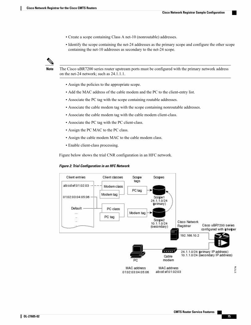
• Create a scope containing Class A net-10 (nonroutable) addresses.
• Identify the scope containing the net-24 addresses as the primary scope and configure the other scopecontaining the net-10 addresses as secondary to the net-24 scope.
The Cisco uBR7200 series router upstream ports must be configured with the primary network addresson the net-24 network; such as 24.1.1.1.
Note
• Assign the policies to the appropriate scope.
• Add the MAC address of the cable modem and the PC to the client-entry list.
• Associate the PC tag with the scope containing routable addresses.
• Associate the cable modem tag with the scope containing nonroutable addresses.
• Associate the cable modem tag with the cable modem client-class.
• Associate the PC tag with the PC client-class.
• Assign the PC MAC to the PC class.
• Assign the cable modem MAC to the cable modem class.
• Enable client-class processing.
Figure below shows the trial CNR configuration in an HFC network.
Figure 2: Trial Configuration in an HFC Network
CMTS Router Service Features OL-27605-02 75
Cisco Network Registrar for the Cisco CMTS RoutersCisco Network Registrar Sample Configuration
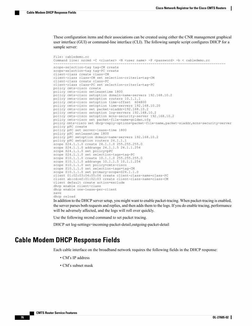
These configuration items and their associations can be created using either the CNR management graphicaluser interface (GUI) or command-line interface (CLI). The following sample script configures DHCP for asample server:
File: cabledemo.rcCommand line: nrcmd -C <cluster> -N <user name> -P <password> -b < cabledemo.rc---------------------------------------------------------------------------------------scope-selection-tag tag-CM createscope-selection-tag tag-PC createclient-class create class-CMclient-class class-CM set selection-criteria=tag-CMclient-class create class-PCclient-class class-PC set selection-criteria=tag-PCpolicy cmts-cisco createpolicy cmts-cisco setleasetime 1800policy cmts-cisco setoption domain-name-servers 192.168.10.2policy cmts-cisco setoption routers 10.1.1.1policy cmts-cisco setoption time-offset 604800policy cmts-cisco setoption time-servers 192.168.10.20policy cmts-cisco set packet-siaddr=192.168.10.2policy cmts-cisco setoption log-servers 192.168.10.2policy cmts-cisco setoption mcns-security-server 192.168.10.2policy cmts-cisco set packet-file-name=golden.cfgpolicy cmts-cisco set dhcp-reply-options=packet-file-name,packet-siaddr,mcns-security-serverpolicy pPC createpolicy pPC set server-lease-time 1800policy pPC setleasetime 1800policy pPC setoption domain-name-servers 192.168.10.2policy pPC setoption routers 24.1.1.1scope S24.1.1.0 create 24.1.1.0 255.255.255.0scope S24.1.1.0 addrange 24.1.1.5 24.1.1.254scope S24.1.1.0 set policy=pPCscope S24.1.1.0 set selection-tags=tag-PCscope S10.1.1.0 create 10.1.1.0 255.255.255.0scope S10.1.1.0 addrange 10.1.1.5 10.1.1.254scope S10.1.1.0 set policy=cmts-ciscoscope S10.1.1.0 set selection-tags=tag-CMscope S10.1.1.0 set primary-scope=S24.1.1.0client 01:02:03:04:05:06 create client-class-name=class-PCclient ab:cd:ef:01:02:03 create client-class-name=class-CMclient default create action=excludedhcp enable client-classdhcp enable one-lease-per-clientsavedhcp reloadIn addition to the DHCP server setup, youmight want to enable packet-tracing.When packet-tracing is enabled,the server parses both requests and replies, and then adds them to the logs. If you do enable tracing, performancewill be adversely affected, and the logs will roll over quickly.
Use the following nrcmd command to set packet tracing.
DHCP set log-settings=incoming-packet-detail,outgoing-packet-detail
Cable Modem DHCP Response FieldsEach cable interface on the broadband network requires the following fields in the DHCP response:
• CM’s IP address
• CM’s subnet mask
CMTS Router Service Features76 OL-27605-02
Cisco Network Registrar for the Cisco CMTS RoutersCable Modem DHCP Response Fields
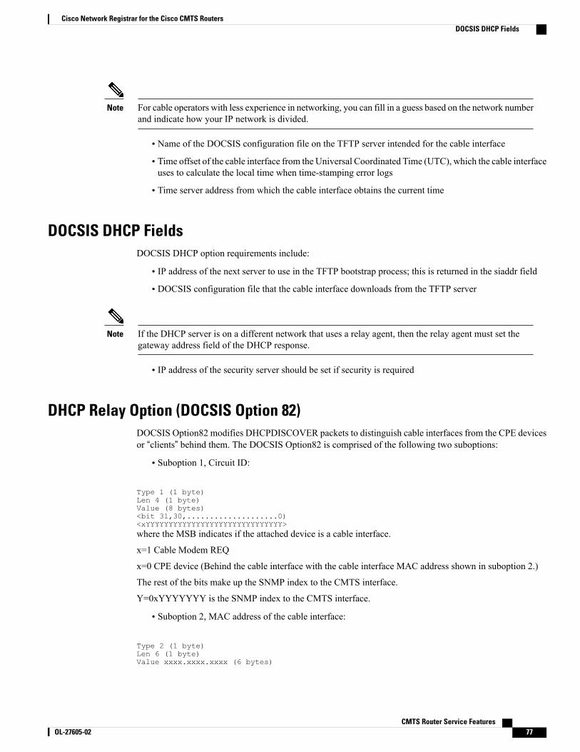
For cable operators with less experience in networking, you can fill in a guess based on the network numberand indicate how your IP network is divided.
Note
• Name of the DOCSIS configuration file on the TFTP server intended for the cable interface
• Time offset of the cable interface from the Universal Coordinated Time (UTC), which the cable interfaceuses to calculate the local time when time-stamping error logs
• Time server address from which the cable interface obtains the current time
DOCSIS DHCP FieldsDOCSIS DHCP option requirements include:
• IP address of the next server to use in the TFTP bootstrap process; this is returned in the siaddr field
• DOCSIS configuration file that the cable interface downloads from the TFTP server
If the DHCP server is on a different network that uses a relay agent, then the relay agent must set thegateway address field of the DHCP response.
Note
• IP address of the security server should be set if security is required
DHCP Relay Option (DOCSIS Option 82)DOCSIS Option82 modifies DHCPDISCOVER packets to distinguish cable interfaces from the CPE devicesor “clients” behind them. The DOCSIS Option82 is comprised of the following two suboptions:
• Suboption 1, Circuit ID:
Type 1 (1 byte)Len 4 (1 byte)Value (8 bytes)<bit 31,30,....................0)<xYYYYYYYYYYYYYYYYYYYYYYYYYYYYYY>where the MSB indicates if the attached device is a cable interface.
x=1 Cable Modem REQ
x=0 CPE device (Behind the cable interface with the cable interface MAC address shown in suboption 2.)
The rest of the bits make up the SNMP index to the CMTS interface.
Y=0xYYYYYYY is the SNMP index to the CMTS interface.
• Suboption 2, MAC address of the cable interface:
Type 2 (1 byte)Len 6 (1 byte)Value xxxx.xxxx.xxxx (6 bytes)
CMTS Router Service Features OL-27605-02 77
Cisco Network Registrar for the Cisco CMTS RoutersDOCSIS DHCP Fields

Overview of ScriptsThis section lists the scripts applicable to cable interface configuration.
Two-way Cable Modem ScriptsTo support two-way configurations at a subscriber site, use these scripts:
• Relay.tcl
• SetRouter.tcl
Telco Return Cable Modem ScriptsTo support telco return and two-way cable interface configurations on the same cable interface card or chassis,use these scripts:
• PostClientLookup.tcl
• PrePacketEncode.tcl
Placement of Scripts
Windows NTFor CNR running on Windows NT, place the appropriate scripts in the following directory:
\program files\network registrar\extensions\dhcp\scripts\tcl
SolarisFor CNR running on Solaris, place the appropriate scripts in the following directory:
/opt/nwreg2/extensions/dhcp/scripts/tcl
CMTS Router Service Features78 OL-27605-02
Cisco Network Registrar for the Cisco CMTS RoutersOverview of Scripts

Activating Scripts in Cisco Network RegistrarTo activate the scripts after you have placed them in the appropriate directory:
Step 1 Open up a text editor.Step 2 Open one of the scripts at the nrcmd> command prompt.Step 3 Create the extension points and attach them to the system.
The easiest way to do this is to simply cut and paste the command lines from the scripts to the nrcmd> commandline.
Note
Step 4 After you have created and attached the extension points, do a dhcp reload.The scripts are active.
Configuring the Cisco CMTS Routers to Use ScriptsEach cable interface must be set up as a BOOTP forwarder and have the relay option enabled. The primaryand secondary IP addresses for each cable interface must be in sync with the CNR tool.
To properly communicate with scripts in the system, use the following commands on the Cisco CMTS router:
• To enable option 82, use the ip dhcp relay info option command.
• To disable the validation of DHPC relay agent information in forwarded BOOTREPLY messages, usethe no ip dhcp relay information option check command.
You can also use the cable dhcp-giaddr command in cable interface configuration mode to modify theGIADDR field of DHCPDISCOVER and DHCPREQUEST packets to provide a relay IP address beforepackets are forwarded to the DHCP server. Use this command to set a “policy” option such that primaryaddresses are used for CMs and secondary addresses are used for hosts behind the CMs.
Note
Configuring the System Default PolicyAdd these options to the system default policy for:
• Cable modems to support on your network
• PCs to support behind each cable interface on your network
Cable ModemsDefine these settings following the CNR tool documentation:
CMTS Router Service Features OL-27605-02 79
Cisco Network Registrar for the Cisco CMTS RoutersActivating Scripts in Cisco Network Registrar
• TFTP server (IP address) for those cable interfaces using BOOTP
• Time-server (IP address)
• Time-offset (Hex value, 1440 for Eastern Standard Time)
• Packet-siaddr (IP address of CNR)
• Router (set to 0.0.0.0)
• Boot-file (name of .cm file for those cable interfaces using BOOTP)
• Packet-file-name (.cm file name)
PCsDefine these settings following the CNR tool documentation:
• Domain name
• Name servers (IP address of DNS servers)
Creating Selection Tag Scopes
GeneralWhen you create your scope selection tags:
Step 1 Cut and paste the scope selection tag create commands from the scripts into the nrcmd> command line.These names have to be exactly as they appear in the scripts.Note
Step 2 Then attach the selection tags to the appropriate scripts:Example:
CM_Scope tagCablemodem
PC_Scope tagComputer
Telco Return for the Cisco uBR7200 Series Router
Before You Begin
If you are using the prepacketencode and postclientlookup .tcl scripts for telco return, the telco returnscope does not have a selection tag associated to the scope.
Note
CMTS Router Service Features80 OL-27605-02
Cisco Network Registrar for the Cisco CMTS RoutersPCs
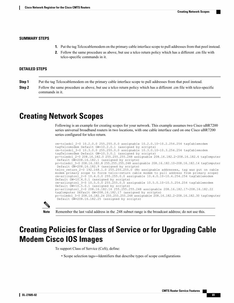
SUMMARY STEPS
1. Put the tag Telcocablemodem on the primary cable interface scope to pull addresses from that pool instead.2. Follow the same procedure as above, but use a telco return policy which has a different .cm file with
telco-specific commands in it.
DETAILED STEPS
Step 1 Put the tag Telcocablemodem on the primary cable interface scope to pull addresses from that pool instead.Step 2 Follow the same procedure as above, but use a telco return policy which has a different .cm file with telco-specific
commands in it.
Creating Network ScopesFollowing is an example for creating scopes for your network. This example assumes two Cisco uBR7200series universal broadband routers in two locations, with one cable interface card on one Cisco uBR7200series configured for telco return.
cm-toledo1_2-0 10.2.0.0 255.255.0.0 assignable 10.2.0.10-10.2.254.254 tagCablemodemtagTelcomodem Default GW=10.2.0.1 (assigned by scripts)cm-toledo1_3-0 10.3.0.0 255.255.0.0 assignable 10.3.0.10-10.3.254.254 tagCablemodemtagTelcomodem Default GW=10.3.0.1 (assigned by scripts)pc-toledo1_2-0 208.16.182.0 255.255.255.248 assignable 208.16.182.2-208.16.182.6 tagComputerDefault GW=208.16.182.1 (assigned by scripts)pc-toledo1_3-0 208.16.182.8 255.255.255.248 assignable 208.16.182.10-208.16.182.14 tagComputerDefault GW=208.16.182.9 (assigned by scripts)telco_return_2-0 192.168.1.0 255.255.255.0 (No assignable addresses, tag was put on cablemodem primary scope to force telco-return cable modem to pull address from primary scope)cm-arlington1_2-0 10.4.0.0 255.255.0.0 assignable 10.4.0.10-10.4.254.254 tagCablemodemDefault GW=10.4.0.1 (assigned by scripts)cm-arlington1_3-0 10.5.0.0 255.255.0.0 assignable 10.5.0.10-10.5.254.254 tagCablemodemDefault GW=10.5.0.1 (assigned by scripts)pc-arlington1_2-0 208.16.182.16 255.255.255.248 assignable 208.16.182.17-208.16.182.22tagComputer Default GW=208.16.182.17 (assigned by scripts)pc-toledo1_3-0 208.16.182.24 255.255.255.248 assignable 208.16.182.2-208.16.182.30 tagComputerDefault GW=208.16.182.25 (assigned by scripts)
Remember the last valid address in the .248 subnet range is the broadcast address; do not use this.Note
Creating Policies for Class of Service or for Upgrading CableModem Cisco IOS Images
To support Class of Service (CoS), define:
• Scope selection tags—Identifiers that describe types of scope configurations
CMTS Router Service Features OL-27605-02 81
Cisco Network Registrar for the Cisco CMTS RoutersCreating Network Scopes
This is needed for Option82.Note
• Client classes—Class with which a group of clients is associated
Scope selection tags are excluded from or included in client-classes.Note
• Client—Specific DHCP clients and the defined class to which they belong
To assign the CoS or use Option82, make a client entry with a MAC address and point to the appropriatepolicy. To use client-basedMAC provisioning, add a client entry “default - exclude,” then put inMAC addressesfor all devices (for example, cable interfaces and PCs) in the client tab and select the policy to use, includingthe appropriate tag.
CNR Steps to Support SubinterfacesThe CNR configuration is done differently if subinterfaces are configured. Here is an example. If you haveconfigured two ISP subinterfaces and one management subinterface on a Cisco uBR7200 series, make surethat the management subinterface is the first subinterface that is configured. If cable interface three—c3/0—isbeing used, create c3/0.1, c3/0.2 and c3/0.3 as three subinterfaces and c3/0.1 as the first subinterface configuredas the management subinterface.
The Cisco uBR7200 series requires management subinterfaces to route DHCP packets from CMs whenthey first initialize because the Cisco uBR7200 series does not know the subinterfaces they belong to untilit has seen the IP addresses assigned to them by gleaning DHCP reply message from CNR.
Note
In CNR, complete the following steps for such a configuration:
SUMMARY STEPS
1. Create two scope selection tags such as: isp1-cm-tag and isp2-cm-tag2. Configure three scopes; for example, mgmt-scope, isp1-cm-scope, and isp2-cm-scope such that
isp1-cm-scope and isp2-cm-scope each define mgmt-scope to be the primary scope3. Also configure two scopes for PCs for each of the ISPs; isp1-pc-scope and isp2-pc-scope. For scope
isp1-cm-scope, configure isp1-cm-tag to be the scope selection tag. For scope isp2-cm-scope, configureisp2-cm-tag to be the scope selection tag
4. Configure two client classes; for example, isp1-client-class and isp2-client-class5. Create client entries with their MAC addresses for CMs that belong to ISP1 and assign them to
isp1-client-class. Also assign the scope selection tag isp1-cm-tag6. Create client entries for CMs that belong to ISP2 and assign them to isp2-client-class. Also assign the
scope selection tag isp2-cm-tag7. Enable client class processing from the scope-selection-tag window
CMTS Router Service Features82 OL-27605-02
Cisco Network Registrar for the Cisco CMTS RoutersCNR Steps to Support Subinterfaces
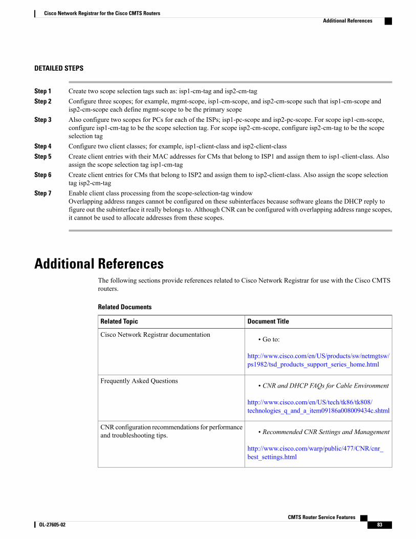
DETAILED STEPS
Step 1 Create two scope selection tags such as: isp1-cm-tag and isp2-cm-tagStep 2 Configure three scopes; for example, mgmt-scope, isp1-cm-scope, and isp2-cm-scope such that isp1-cm-scope and
isp2-cm-scope each define mgmt-scope to be the primary scopeStep 3 Also configure two scopes for PCs for each of the ISPs; isp1-pc-scope and isp2-pc-scope. For scope isp1-cm-scope,
configure isp1-cm-tag to be the scope selection tag. For scope isp2-cm-scope, configure isp2-cm-tag to be the scopeselection tag
Step 4 Configure two client classes; for example, isp1-client-class and isp2-client-classStep 5 Create client entries with their MAC addresses for CMs that belong to ISP1 and assign them to isp1-client-class. Also
assign the scope selection tag isp1-cm-tagStep 6 Create client entries for CMs that belong to ISP2 and assign them to isp2-client-class. Also assign the scope selection
tag isp2-cm-tagStep 7 Enable client class processing from the scope-selection-tag window
Overlapping address ranges cannot be configured on these subinterfaces because software gleans the DHCP reply tofigure out the subinterface it really belongs to. Although CNR can be configured with overlapping address range scopes,it cannot be used to allocate addresses from these scopes.
Additional ReferencesThe following sections provide references related to Cisco Network Registrar for use with the Cisco CMTSrouters.
Related Documents
Document TitleRelated Topic
• Go to:
http://www.cisco.com/en/US/products/sw/netmgtsw/ps1982/tsd_products_support_series_home.html
Cisco Network Registrar documentation
• CNR and DHCP FAQs for Cable Environment
http://www.cisco.com/en/US/tech/tk86/tk808/technologies_q_and_a_item09186a008009434c.shtml
Frequently Asked Questions
• Recommended CNR Settings and Management
http://www.cisco.com/warp/public/477/CNR/cnr_best_settings.html
CNR configuration recommendations for performanceand troubleshooting tips.
CMTS Router Service Features OL-27605-02 83
Cisco Network Registrar for the Cisco CMTS RoutersAdditional References
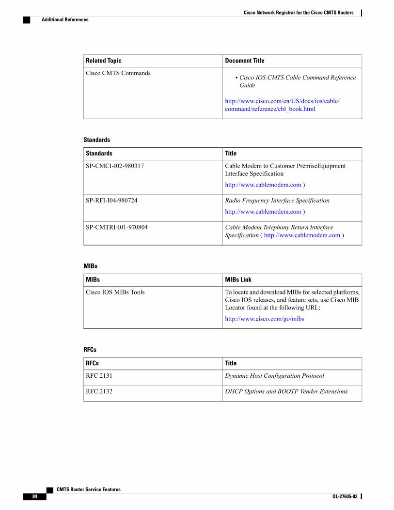
Document TitleRelated Topic
• Cisco IOS CMTS Cable Command ReferenceGuide
http://www.cisco.com/en/US/docs/ios/cable/command/reference/cbl_book.html
Cisco CMTS Commands
Standards
TitleStandards
Cable Modem to Customer PremiseEquipmentInterface Specification
http://www.cablemodem.com )
SP-CMCI-I02-980317
Radio Frequency Interface Specification
http://www.cablemodem.com )
SP-RFI-I04-980724
Cable Modem Telephony Return InterfaceSpecification ( http://www.cablemodem.com )
SP-CMTRI-I01-970804
MIBs
MIBs LinkMIBs
To locate and downloadMIBs for selected platforms,Cisco IOS releases, and feature sets, use Cisco MIBLocator found at the following URL:
http://www.cisco.com/go/mibs
Cisco IOS MIBs Tools
RFCs
TitleRFCs
Dynamic Host Configuration ProtocolRFC 2131
DHCP Options and BOOTP Vendor ExtensionsRFC 2132
CMTS Router Service Features84 OL-27605-02
Cisco Network Registrar for the Cisco CMTS RoutersAdditional References
Technical Assistance
LinkDescription
http://www.cisco.com/cisco/web/support/index.htmlTechnical Assistance Center (TAC) home page,containing 30,000 pages of searchable technicalcontent, including links to products, technologies,solutions, technical tips, and tools. RegisteredCisco.com users can log in from this page to accesseven more content.
CMTS Router Service Features OL-27605-02 85
Cisco Network Registrar for the Cisco CMTS RoutersAdditional References

CMTS Router Service Features86 OL-27605-02
Cisco Network Registrar for the Cisco CMTS RoutersAdditional References
C H A P T E R 4DHCP, ToD, and TFTP Services for the CMTSRouters
First Published: February 14, 2008
Last Updated: February 9, 2009
Cisco IOS Release 12.2(33)SCA integrates support for this feature on the Cisco CMTS routers. Thisfeature is also supported in Cisco IOS Release 12.3BC, and this document contains information thatreferences many legacy documents related to Cisco IOS 12.3BC. In general, any references to Cisco IOSRelease 12.3BC also apply to Cisco IOS Release 12.2SC.
Note
This document describes how to configure Cisco Cable Modem Termination System (CMTS) platforms sothat they support onboard servers that provide Dynamic Host Configuration Protocol (DHCP), Time-of-Day(ToD), and Trivial File Transfer Protocol (TFTP) services for use in Data-over-Cable Service InterfaceSpecifications (DOCSIS) networks. In addition, this document provides information about optionalconfigurations that can be used with external DHCP servers.
Finding Feature Information
Your software release may not support all the features documented in this module. For the latest featureinformation and caveats, see the release notes for your platform and software release. To find informationabout the features documented in this module, and to see a list of the releases in which each feature issupported, see the Feature Information Table at the end of this document.
Use Cisco Feature Navigator to find information about platform support and Cisco software image support.To access Cisco Feature Navigator, go to http://tools.cisco.com/ITDIT/CFN/. An account on http://www.cisco.com/ is not required.
Contents
• Prerequisites for DHCP, ToD, and TFTP Services, page 88
• Restrictions for DHCP, ToD, and TFTP Services, page 88
• Information About DHCP, ToD, and TFTP Services, page 88
• How to Configure DHCP, ToD, and TFTP Services, page 97
CMTS Router Service Features OL-27605-02 87
• Configuration Examples, page 115
• Additional References, page 126
• Feature Information for the DHCP, ToD, and TFTP Services for the CMTS Routers, page 130
Prerequisites for DHCP, ToD, and TFTP Services• Cisco recommends the most current Cisco IOS Release 12.1 EC software release for DOCSIS 1.0operations. For DOCSIS 1.1 operations, Cisco recommends the most current Cisco IOS Release 12.2BC software release.
• A separate DOCSIS configuration file editor is required to build DOCSIS 1.1 configuration files, becausethe internal DOCSIS configuration file editor that is onboard the Cisco CMTS router supports onlyDOCSIS 1.0 configuration files.
• To be able to use the Cisco CMTS as the ToD server, either alone or along with other, external ToDservers, you must configure the DHCP server to provide the IP address Cisco CMTS as one of the validToD servers (DHCP option 4) for cable modems.
Restrictions for DHCP, ToD, and TFTP Services• The “all-in-one” configuration should not be used as the only set of servers except for small cable plants(approximately 2,500 cable modems, lab environments, initial testing, small deployments, andtroubleshooting. The “all-in-one” configuration can be used in larger networks, however, to supplementother redundant and backup servers.
The CMTS does not support the configuration of both Local DHCP Pools and DHCPRelay at the same time.
Note
• The ToD server must use the UDP protocol to conform to DOCSIS specifications.
• For proper operation of the DOCSIS network, especially a DOCSIS 1.1 network using BPI+ encryptionand authentication, the system clock on the Cisco CMTS must be set accurately. You can achieve thisby manually using the set clock command, or by configuring the CMTS to use either the Network TimeProtocol (NTP) or the Simple Network Time Protocol (SNTP).
• The internal DHCP server that is onboard the Cisco CMTS router does not support the cable source-verifycommand.
• Cisco cBR series routers do not support internal DHCP servers.
Information About DHCP, ToD, and TFTP ServicesThis section provides the following information about the DHCP, ToD, and TFTP Services feature, and itsindividual components:
CMTS Router Service Features88 OL-27605-02
DHCP, ToD, and TFTP Services for the CMTS RoutersPrerequisites for DHCP, ToD, and TFTP Services
Feature OverviewAll Cisco CMTS platforms support onboard servers that provide DHCP, ToD, and TFTP proxy-services foruse in DOCSIS cable networks. These servers provide the registration services needed by DOCSIS 1.0- and1.1-compliant cable modems:
• Internal DHCP Servers—Provides the cable modemwith an IP address, a subnet mask, default gateway,and other IP related parameters. The cable modem connects with the DHCP server when it initiallypowers on and logs on to the cable network.
• External DHCP Servers—Provides DHCP services. External DHCP servers are usually part of anintegrated provisioning system that is more suitable when managing large cable networks.
• Time-of-DayServer_—Provides an RFC 868 -compliant ToD service so that cable modems can obtainthe current date and time during the registration process. The cable modem connects with the ToD serverafter it has obtained its IP address and other DHCP-provided IP parameters.
Although cable modems do not need to successfully complete the ToD request before coming online, thisallows them to add accurate timestamps to their event logs so that these logs are coordinated to the clock usedon the CMTS. In addition, having the accurate date and time is essential if the cable modem is trying to registerwith Baseline Privacy Interface Plus (BPI+) encryption and authentication.
• External TFTP_Server—Downloads the DOCSIS configuration file to the cable modem. The DOCSISconfiguration file contains the operational parameters for the cable modem. The cable modem downloadsits DOCSIS configuration file after connecting with the ToD server.
You can configure and use each server separately, or you can configure an “all-in-one” configuration so thatthe CMTS acts as a DHCP, ToD, and TFTP server. With this configuration, you do not need any additionalservers, although additional servers provide redundancy, load-balancing, and scalability.
You can add additional servers in a number of ways. For example, most cable operators use Cisco NetworkRegistrar (CNR) to provide the DHCP and TFTP servers. ToD servers are freely available for mostworkstations and PCs. You can install the additional servers on one workstation or PC or on differentworkstations and PCs.
Note
Internal DHCP ServerAt power-up, DOCSIS cable modems send a broadcast message through the cable interface to find a DHCPserver that can provide the information needed for IP connectivity across the network. After the cable modemcomes online, the CPE devices connected to the cable modem can also make their own DHCP requests. Youcan configure all Cisco CMTS platforms to act as DHCP servers that provide the IP addressing and othernetworking information that is needed by DOCSIS cable modems and their CPE devices.
DHCP Field OptionsIn its DHCP request message, the cable modem identifies itself by its MAC hardware address. In reply, aDOCSIS-compatible DHCP server should provide, at minimum, the following fields when replying to cablemodems that are authorized to access the cable network:
CMTS Router Service Features OL-27605-02 89
DHCP, ToD, and TFTP Services for the CMTS RoutersFeature Overview
• yiaddr—IP address for the cable modem.
• Subnet Mask (option 1)—IP subnet mask for the cable modem.
• siaddr—IP address for the TFTP server that will provide the DOCSIS configuration file.
• file—Filename for the DOCSIS configuration file that the cable modem must download.
• Router Option (option 3)—IP addresses for one or more gateways that will forward the cable modemtraffic.
• Time Server Option (option 4)—One or more ToD servers from which the cable modem can obtain itscurrent date and time.
• Time Offset (option 2)—Universal Coordinated Time (UTC) that the cable modem should use incalculating local time.
• giaddr—IP address for a DHCP relay agent, if the DHCP server is on a different network from the cablemodem.
• Log Server Option (option 7)—IP address for one or more SYSLOG servers that the cable modem shouldsend error messages and other logging information (optional).
• IP Address Lease Time (option 51)—Number of seconds for which the IP address is valid, at whichpoint the cable modem must make another DHCP request.
If you decide to also provide IP addresses to the CPE devices connected to the cable modems, the DHCPserver must also provide the following information for CPE devices:
• yiaddr—IP address for the CPE device.
• Subnet Mask (option 1)—IP subnet mask for the CPE device.
• Router Option, option 3—IP addresses for one or more gateways that will forward the CPE traffic.
• Domain Name Server Option (option 6)—IP addresses for the domain name system (DNS) servers thatwill resolve hostnames to IP addresses for the CPE devices.
• Domain Name (option 15)—Fully-qualified domain name that the CPE devices should add to theirhostnames.
• IP Address Lease Time (option 51)—Number of seconds for which the IP address is valid, at whichpoint the CPE device must make another DHCP request.
The DHCP server on the Cisco CMTS can also provide a number of options beyond the minimum that arerequired for network operation. A basic configuration is suitable for small installations as well as lab andexperimental networks.
You can also configure the CMTS in a more complex configuration that uses the functionality of DHCP pools.DHCP pools are configured in a hierarchical fashion, according to their network numbers. A DHCP pool witha network number that is a subset of another pool’s network number inherits all of the characteristics of thelarger pool.
DHCP Security OptionsBecause the DOCSIS specification requires cable modems to obtain their IP addresses from a DHCP server,cable networks are susceptible to certain types of configuration errors and theft-of-service attacks, including:
CMTS Router Service Features90 OL-27605-02
DHCP, ToD, and TFTP Services for the CMTS RoutersInternal DHCP Server
• Duplicate IP addresses being assigned to two or more cable modems or CPE devices
• Duplicate MAC addresses being reported by two or more cable modems or CPE devices
• Unauthorized use of a DHCP-assigned IP address as a permanent static address
• One user hijacking a valid IP address from another user and using it on a different network device
• Configuring IP addresses with network addresses that are not authorized for a cable segment
• Unauthorized ARP requests on behalf of a cable segment, typically as part of a theft-of-service attack
To help combat these attacks, the Cisco CMTS dynamically maintains a database that links the MAC and IPaddresses of known CPE devices with the cable modems that are providing network access for those CPEdevices. The CMTS builds this database using information from both internal and external DHCP servers:
•When using the internal DHCP server, the CMTS automatically populates the database from the DHCPrequests and replies that are processed by the server.
•When using an external server, the CMTS populates the database by inspecting all broadcast DCHPtransactions that are sent over a cable interface between the cable modems and CPE devices on thatinterface and the DHCP servers.
The Cisco CMTS also monitors IP traffic coming from CPE devices to associate their IP and MACaddresses with the cable modem that is providing their Internet connection.
Note
The CMTS can also use the DHCP Relay Agent Information option (DHCP option 82) to send particularinformation about a cable modem, such as its MAC address and the cable interface to which it is connectedto the DHCP server. If the DHCP server cannot match the information with that belonging to a cable modemin its database, the Cisco CMTS identifies that the device is a CPE device. This allows the Cisco CMTS andDHCP server to retain accurate information about which CPE devices are using which cable modems andwhether the devices should be allowed network access.
The DHCPRelay Agent Information option can also be used to identify clonedmodems or gather geographicalinformation for E911 and other applications. Using the cable dhcp-insert command, users configure theCisco CMTS to insert downstream, upstream, service class, or hostname descriptors into DHCP packets.Multiple types of strings can be configured as long as the maximum relay information option size is notexceeded.
Multiple DHCP PoolsYou can also configure any number of DHCP pools for the DHCP server to use in assigning IP addresses. Asingle pool can be used for a basic configuration, or you can optionally create separate pools for cable modemsand CPE devices. You can also use DHCP address pools to provide special services, such as static IP addresses,to customers who are paying for those service.
When creating multiple DHCP pools, you can configure them independently, or you can optionally create ahierarchical structure of pools that are organized according to their network numbers. A DHCP pool that hasa network number that is a subset of another pool’s network number inherits all of the characteristics of thelarger pool. In addition to the inherited characteristics, you can further customize each pool with any numberof options.
CMTS Router Service Features OL-27605-02 91
DHCP, ToD, and TFTP Services for the CMTS RoutersInternal DHCP Server
The advantage of DHCP pools is that you can create a number of different DHCP configurations for particularcustomers or applications, without having to repeat CLI commands for the parameters that the pools have incommon. You can also change the configuration of one pool without affecting customers in other pools.
External DHCP ServersThe Cisco CMTS router provides the following optional configurations that can enhance the operation andsecurity of external DHCP servers that you are using on the DOCSIS cable network:
Cable Source Verify FeatureTo combat theft-of-service attacks, you can enable the cable source-verify command on the cable interfaceson the Cisco CMTS router. This feature uses the router’s internal database to verify the validity of the IPpackets that the CMTS receives on the cable interfaces, and provides three levels of protection:
• Internal DHCP Server—Provides the cable modem with an IP address, a subnet mask, default gateway,and other IP related parameters. The cable modem connects with the DHCP server when it initiallypowers on and logs on to the cable network.
• At themost basic level of protection, the Cable Source Verify feature examines every IP upstream packetto prevent duplicate IP addresses from appearing on the cable network. If a conflict occurs, the CiscoCMTS recognizes only packets coming from the device that was assigned the IP address by the DHCPserver. The devices with the duplicate addresses are not allowed network address. The CMTS also refusesto recognize traffic from devices with IP addresses that have network addresses that are unauthorizedfor that particular cable segment.
• Adding the dhcp option to the cable source-verify command provides a more comprehensive level ofprotection by preventing users from statically assigning currently-unused IP addresses to their devices.When the Cisco CMTS receives a packet with an unknown IP address on a cable interface, the CMTSdrops the packet but also issues a DHCP LEASEQUERY message that queries the DHCP servers forany information about the IP and MAC addresses of that device. If the DHCP servers do not return anyinformation about the device, the CMTS continues to block the network access for that device.
•When you use the dhcp option, you can also enable the leasetimer option, which instructs the CiscoCMTS to periodically check its internal CPE database for IP addresses whose lease times have expired.The CPE devices that are using expired IP addresses are denied further access to the network until theyrenew their IP addresses from a valid DHCP server. This can prevent users from taking DHCP-assignedIP addresses and assigning them as static addresses to their CPE devices.
• In addition to the dhcp option, you can also configure prefix-based source address verification (SAV)on the Cisco CMTS using the cable source-verify group command. A CM may have a static IPv4 orIPv6 prefix configured, which belongs to an SAV group. When the SAV prefix processing is enabledon the Cisco CMTS, the source IP address of the packets coming from the CM is matched against theconfigured prefix and SAV group (for that CM) for verification. If the verification fails, the packets aredropped, else the packets are forwarded for further processing. For more information on SAV prefixprocessing and SAV prefix configuration, see Prefix-based Source Address Verification , on page 93and Configuring Prefix-based Source Address Verification, on page 111
CMTS Router Service Features92 OL-27605-02
DHCP, ToD, and TFTP Services for the CMTS RoutersExternal DHCP Servers
Prefix-based Source Address Verification
The Source Address Verification (SAV) feature verifies the source IP address of an upstream packet to ensurethat the SID/MAC and IP are consistent. The DOCSIS 3.0 Security Specification introduces prefix-basedSAVwhere every CMmay have static IPv4 or IPv6 prefixes configured. These prefixes are either preconfiguredon the CMTS, or are communicated to the CMTS during CM registration. The Cisco CMTS uses theseconfigured prefixes to verify the source IP address of all the incoming packets from that CM.
An SAV group is a collection of prefixes. A prefix is an IPv4 or IPv6 subnet address. You can use the cablesource-verify group command in global configuration mode to configure SAV groups. A total of 255 SAVgroups are supported on a CMTS, with each SAV group having a maximum of four prefixes. Prefixes can beconfigured using the prefix command.
During registration, CMs communicate their configured static prefixes to the CMTS using two TLVs, 43.7.1and 43.7.2. The TLV 43.7.1 specifies the SAV prefix group name that the CM belongs to, and TLV 43.7.2specifies the actual IPv4 or IPv6 prefix. Each CM can have a maximum of four prefixes configured. Whenthe Cisco CMTS receives these TLVs, it first identifies if the specified SAV group and the prefixes are alreadyconfigured on the Cisco CMTS. If they are configured, the Cisco CMTS associates them to the registeringCM. However if they are not configured, the Cisco CMTS automatically creates the specified SAV group andprefixes before associating them to the registering CM.
The SAV group name and the prefixes that are provided by these TLVs are considered valid by the CiscoCMTS. The packets received (from the CM) with the source IP address belonging to the prefix specified bythe TLV are considered authorized. For example, if a given CM has been configured with an SAV prefix of10.10.10.0/24, then any packet received from this CM (or CPE behind the CM) that is sourced with this addressin the subnet 10.10.10.0/24 is considered to be authorized.
For more information on how to configure SAV groups and prefixes see Configuring Prefix-based SourceAddress Verification, on page 111.
Smart Relay FeatureThe Cisco CMTS supports a Smart Relay feature (the ip dhcp smart-relay command), which automaticallyswitches a cable modem or CPE device to secondary DHCP servers or address pools if the primary serverruns out of IP addresses or otherwise fails to respond with an IP address. The relay agent attempts to forwardDHCP requests to the primary server three times. After three attempts with no successful response from theprimary, the relay agent automatically switches to the secondary server.
When you are using the cable dhcp-giaddr policy command to specify that the CPE devices should use thesecondary DHCP pools corresponding to the secondary addresses on a cable interface, the smart relay agentautomatically rotates through the available secondary in a round robin fashion until an available pool ofaddresses is found. This ensures that clients are not locked out of the network because a particular pool hasbeen exhausted.
GIADDR FieldWhen using separate IP address pools for cable modems and CPE devices, you can use the cable dhcp-giaddrpolicy command to specify that cable modems should use an address from the primary pool and that CPEdevices should use addresses from the secondary pool. The default is for the CMTS to send all DHCP requeststo the primary DHCP server, while the secondary servers are used only if the primary server does not respond.The different DHCP servers are specified using the cable helper commands.
CMTS Router Service Features OL-27605-02 93
DHCP, ToD, and TFTP Services for the CMTS RoutersExternal DHCP Servers
Beginning with Cisco IOS Release 12.2(33)SCD5, the GIADDR option simply changes the source IP addressof the DHCP request so that the DHCP server can use different subnets to assign the right IP address dependingon the types of CPE devices (namely cable modems, media terminal adapters [MTA], portal servers [PS], andset-top boxes [STB]). This enables faster processing of IP addresses; and in case the IP address does notbelong to the subnets on the DHCP server, there is minimal usage of CPU resources.
DHCP Relay Agent Sub-optionThe Cisco IOS Release 12.2(33)SCF2 introduces support for the DHCP Relay Agent Information sub-option(DHCP Option 82, Suboption 9) enhancement to simplify provisioning of the CPE devices. Using thissub-option, the cable operators can relay the service class or QoS information of the CPE to the DHCP serverto get an appropriate IP address.
To provision a CPE, the DHCP server should be made aware of the service class or QoS information of theCPE. The DHCP server obtains this information using the DHCP DISCOVER message, which includes theservice class or QoS information of the CM behind which the CPE resides.
During the provisioning process, the Cisco CMTS uses the DHCPv4 Relay Agent Information sub-option toadvertise information about the service class or QoS profile of the CMs to the DHCP server. Using the sametechnique, the CPE information is relayed to the DHCP server to get an appropriate IP address.
To enable the service classes option, the service class name specified in the CM configuration file must beconfigured on the Cisco CMTS. This is done by using the cable dhcp-insert service-class command.
To configure service-class or QoS-profile on the Cisco CMTS, see Configuring DHCP Service, on page 97.
To insert service class relay agent information option into the DHCP DISCOVER messages, the ip dhcprelay information option-insert command must be configured on the bundle interface.
Note
Time-of-Day ServerThe Cisco CMTS can function as a ToD server that provides the current date and time to the cable modemsand other customer premises equipment (CPE) devices connected to its cable interfaces. This allows the cablemodems and CPE devices to accurately timestamp their Simple Network Management Protocol (SNMP)messages and error log entries, as well as ensure that all of the system clocks on the cable network aresynchronized to the same system time.
The initial ToD server on the Cisco CMTS did not work with some cable modems that used an incompatiblepacket format. This problem was resolved in Cisco IOS Release 12.1(8)EC1 and later 12.1 EC releases,and in Cisco IOS Release 12.2(4)BC1 and later 12.2 BC releases.
Tip
The DOCSIS 1.0 and 1.1 specifications require that all DOCSIS cable modems request the followingtime-related fields in the DHCP request they send during their initial power-on provisioning:
• Time Offset (option 2)—Specifies the time zone for the cable modem or CPE device, in the form of thenumber of seconds that the device’s timestamp is offset from Greenwich Mean Time (GMT).
• Time Server Option (option 4)—Specifies one or more IP addresses for a ToD server.
CMTS Router Service Features94 OL-27605-02
DHCP, ToD, and TFTP Services for the CMTS RoutersTime-of-Day Server

After a cable modem successfully acquires a DHCP lease time, it then attempts to contact one of the ToDservers provided in the list provided by the DHCP server. If successful, the cable modem updates its systemclock with the time offset and timestamp received from the ToD server.
If a ToD server cannot be reached or if it does not respond, the cable modem eventually times out, logs thefailure with the CMTS, and continues on with the initialization process. The cable modem can come onlinewithout receiving a reply from a ToD server, but it must periodically continue to reach the ToD server at leastonce in every five-minute period until it successfully receives a ToD reply. Until it reaches a ToD server, thecable modem must initialize its system clock to midnight on January 1, 1970 GMT.
Initial versions of the DOCSIS 1.0 specification specified that the cable device must obtain a valid responsefrom a ToD server before continuing with the initialization process. This requirement was removed in thereleased DOCSIS 1.0 specification and in the DOCSIS 1.1 specifications. Cable devices running olderfirmware that is compliant with the initial DOCSIS 1.0 specification, however, might require receiving areply from a ToD server before being able to come online.
Note
Because cable modems will repeatedly retry connecting with a ToD server until they receive a successfulreply, you should consider activating the ToD server on the Cisco CMTS, even if you have one or more otherToD servers at the headend. This ensures that an online cable modem will always be able to connect with theToD server on the Cisco CMTS, even if the other servers go down or are unreachable because of networkcongestion, and therefore will not send repeated ToD requests.
To be able to use the Cisco CMTS as the ToD server, either alone or with other, external servers, youmust configure the DHCP server to provide the IP address Cisco CMTS as one of the valid ToD servers(DHCP option 4) for cable modems. See Creating and Configuring a DHCP Address Pool for CableModems, on page 98 for details on this configuration.
Tip
In addition, although the DOCSIS specifications do not require that a cable modem successfully obtain aresponse from a ToD server before coming online, not obtaining a timestamp could prevent the cable modemfrom coming online in the following situations:
• If DOCSIS configuration files are being timestamped, to prevent cable modems from caching the filesand replaying them, the clocks on the cable modem and CMTS must be synchronized. Otherwise, thecable modem cannot determine whether a DOCSIS configuration file has the proper timestamp.
• If cable modems register using Baseline Privacy Interface Plus (BPI+) authentication and encryption,the clocks on the cable modem and CMTS must be synchronized. This is because BPI+ authorizationrequires that the CMTS and cable modem verify the timestamps on the digital certificates being usedfor authentication. If the timestamps on the CMTS and cable modem are not synchronized, the cablemodem cannot come online using BPI+ encryption.
DOCSIS cable modems must use RFC 868 -compliant ToD server to obtain the current system time. Theycannot use the Network Time Protocol (NTP) or Simple Network Time Protocol (SNTP) service for thispurpose. However, the Cisco CMTS can use an NTP or SNTP server to set its own system clock, whichcan then be used by the ToD server. Otherwise, you must manually set the clock on the CMTS using theclock set command each time that the CMTS boots up.
Note
CMTS Router Service Features OL-27605-02 95
DHCP, ToD, and TFTP Services for the CMTS RoutersTime-of-Day Server

Additional servers can be provided by workstations or PCs installed at the cable headend. UNIX andSolaris systems typically include a ToD server as part of the operating system, which can be enabled byputting the appropriate line in the inetd.conf file. Windows systems can use shareware servers such asGreyware and Tardis. The DOCSIS specifications require that the ToD servers use the User DatagramProtocol (UDP) protocol instead of the TCP protocol for its packets.
Tip
TFTP ServerAll Cisco CMTS platforms can be configured to provide a TFTP server that can provide the following typesof files to DOCSIS cable modems:
• DOCSIS Configuration File—After a DOCSIS cable modem has acquired a DHCP lease and attemptedto contact a ToD server, the cable modem uses TFTP to download a DOCSIS configuration file froman authorized TFTP server. The DHCP server is responsible for providing the name of the DOCSISconfiguration file and IP address of the TFTP server to the cable modem.
• Software Upgrade File—If the DOCSIS configuration file specifies that the cable modem must berunning a specific version of software, and the cable modem is not already running that software, thecable modem must download that software file. For security, the cable operator can use different TFTPservers for downloading DOCSIS configuration files and for downloading new software files.
• Cisco IOS Configuration File—The DOCSIS configuration file for Cisco cable devices can also specifythat the cable modem should download a Cisco IOS configuration file that contains command-lineinterface (CLI) configuration commands. Typically this is done to configure platform-specific featuressuch as voice ports or IPSec encryption.
Do not confuse the DOCSIS configuration file with the Cisco IOS configuration file. The DOCSISconfiguration file is a binary file in the particular format that is specified by the DOCSIS specifications,and each DOCSIS cable modem must download a valid file before coming online. In contrast, the CiscoIOS configuration file is an ASCII text file that contains one or more Cisco IOS CLI configurationcommands. Only Cisco cable devices can download a Cisco IOS file.
Note
All Cisco CMTS platforms can be configured as TFTP servers that can upload these files to the cable modem.The files can reside on any valid device but typically should be copied to the Flash memory device insertedinto the Flash disk slot on the Cisco CMTS.
In addition, the Cisco CMTS platform supports an internal DOCSIS configuration file editor in Cisco IOSRelease 12.1(2)EC, Cisco IOSRelease 12.2(4)BC1, and later releases.When you create a DOCSIS configurationfile using the internal configuration file editor, the CMTS stores the configuration file in the form of CLIcommands.When a cable modem requests the DOCSIS configuration file, the CMTS then dynamically createsthe binary version of the file and uploads it to the cable modem.
The internal DOCSIS configuration file editor supports only DOCSIS 1.0 configuration files. To createDOCSIS 1.1 configuration files, you must use a separate configuration editor, such as the Cisco DOCSISConfigurator tool, which at the time of this document’s publication is available on Cisco.com at thefollowing URL: http://www.cisco.com/cgi-bin/tablebuild.pl/cpe-conf
Note
CMTS Router Service Features96 OL-27605-02
DHCP, ToD, and TFTP Services for the CMTS RoutersTFTP Server
For enhanced security, current versions of Cisco IOS software for Cisco CMTS platforms include a “TFTPEnforce” feature (cable tftp-enforce command) that allows you to require that all cable modems must attempta TFTP download through the cable interface before being allowed to come online. This prevents a commontheft-of-service attack in which hackers reconfigure their local network so that a local TFTP server downloadsan unauthorized DOCSIS configuration file to the cable modem. This ensures that cable modems downloadonly a DOCSIS configuration file that provides the services they are authorized to use.
Benefits• The “all-in-one” configuration allows you to set up a basic cable modem network without having toinvest in additional servers and software. This configuration can also help troubleshoot plant and cablemodem problems.
• The DHCP configuration can more effectively assigns and manages IP addresses from specified addresspools within the CMTS to the cable modems and their CPE devices.
• The Cisco CMTS can act as a primary or backup ToD server to ensure that all cable modems aresynchronized with the proper date and time before coming online. This also enables cable modems tocome online more quickly because they will not have to wait for the ToD timeout period before comingonline.
• The ToD server on the Cisco CMTS ensures that all devices connected to the cable network are usingthe same system clock, making it easier for you to troubleshoot system problems when you analyze thedebugging output and error logs generated by many cable modems, CPE devices, the Cisco CMTS, andother services.
• The Cisco CMTS can act as a TFTP server for DOCSIS configuration files, software upgrade files, andCisco IOS configuration files.
• Aa separate workstation or PC is not required to create and store DOCSIS configuration files.
• The “TFTP Enforce” feature ensures that users download only an authorized DOCSIS configuration fileand prevents one of the most common theft-of-service attacks.
How to Configure DHCP, ToD, and TFTP ServicesSee the following configuration tasks required to configure DHCP service, time-of-day service, and TFTPservice on a Cisco CMTS:
All procedures are required unless marked as optional (depending on the desired network configuration andapplications).
Configuring DHCP ServiceTo configure the DHCP server on the Cisco CMTS, use the following procedures to create the required addresspools for the server to use. You can create one pool for all DHCP requests (cable modems and CPE devices),or separate pools for cable modems and for CPE devices, as desired.
CMTS Router Service Features OL-27605-02 97
DHCP, ToD, and TFTP Services for the CMTS RoutersBenefits
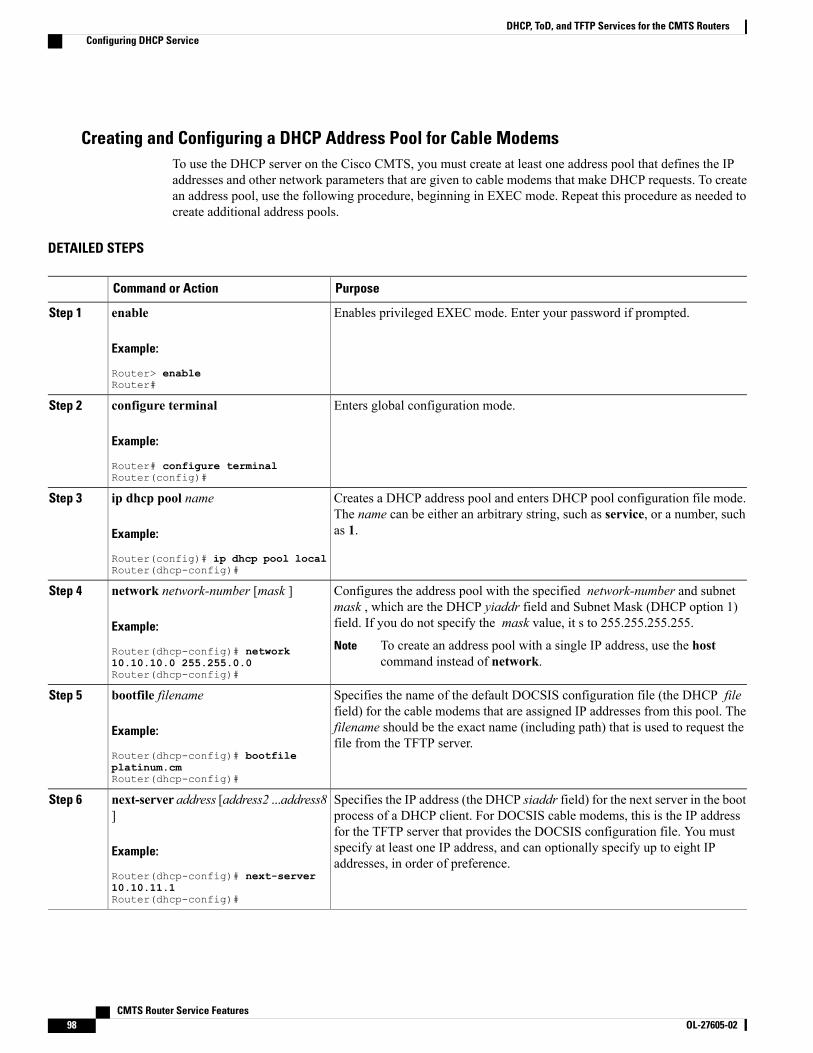
Creating and Configuring a DHCP Address Pool for Cable ModemsTo use the DHCP server on the Cisco CMTS, you must create at least one address pool that defines the IPaddresses and other network parameters that are given to cable modems that make DHCP requests. To createan address pool, use the following procedure, beginning in EXEC mode. Repeat this procedure as needed tocreate additional address pools.
DETAILED STEPS
PurposeCommand or Action
Enables privileged EXEC mode. Enter your password if prompted.enable
Example:
Router> enableRouter#
Step 1
Enters global configuration mode.configure terminal
Example:
Router# configure terminalRouter(config)#
Step 2
Creates a DHCP address pool and enters DHCP pool configuration file mode.The name can be either an arbitrary string, such as service, or a number, suchas 1.
ip dhcp pool name
Example:
Router(config)# ip dhcp pool localRouter(dhcp-config)#
Step 3
Configures the address pool with the specified network-number and subnetmask , which are the DHCP yiaddr field and Subnet Mask (DHCP option 1)field. If you do not specify the mask value, it s to 255.255.255.255.
network network-number [mask ]
Example:
Router(dhcp-config)# network
Step 4
To create an address pool with a single IP address, use the hostcommand instead of network.
Note10.10.10.0 255.255.0.0Router(dhcp-config)#
Specifies the name of the default DOCSIS configuration file (the DHCP filefield) for the cable modems that are assigned IP addresses from this pool. The
bootfile filename
Example:
Router(dhcp-config)# bootfile
Step 5
filename should be the exact name (including path) that is used to request thefile from the TFTP server.
platinum.cmRouter(dhcp-config)#
Specifies the IP address (the DHCP siaddr field) for the next server in the bootprocess of a DHCP client. For DOCSIS cable modems, this is the IP address
next-server address [address2 ...address8]
Step 6
for the TFTP server that provides the DOCSIS configuration file. You mustExample:
Router(dhcp-config)# next-server
specify at least one IP address, and can optionally specify up to eight IPaddresses, in order of preference.
10.10.11.1Router(dhcp-config)#
CMTS Router Service Features98 OL-27605-02
DHCP, ToD, and TFTP Services for the CMTS RoutersConfiguring DHCP Service

PurposeCommand or Action
Specifies the IP address for the Router Option (DHCP option 3) field, whichis the default router for the cable modems in this address pool. Youmust specify
default-router address [address2...address8 ]
Step 7
at least one IP address, and can optionally specify up to eight IP addresses,Example:
Router(dhcp-config)# default-router
where the default routers are listed in their order of preference (address is themost preferred server, address2 is the next most preferred, and so on).
The first IP address must be the IP address for the cable interface thatis connected to cable modems using this DHCP pool.
Note10.10.10.12Router(dhcp-config)#
Specifies the Time Offset field (DHCP option 2), which is the local time zone,specified as the number of seconds, in hexadecimal, offset from GreenwichMean Time (GMT). The following are some sample values for gmt-offset :
option 2 hex gmt-offset
Example:
Router(dhcp-config)# option 2 hex
Step 8
FFFF.8F80 = Offset of –8 hours (–28800 seconds, Pacific Time) FFFF.9D90=Offset of –7 hours (Mountain Time) FFFF.ABA0 =Offset of –6 hours (CentralTime) FFFF.B9B0 = Offset of –5 hours (Eastern Time)
FFFF.8F80Router(dhcp-config)#
Specifies the Time Server Option field (DHCP option 4), which is the IP addressof the time-of-day (ToD) server from which the cable modem can obtain itscurrent date and time.
option 4 ip address [address2 ...address8]
Example:
Router(dhcp-config)# option 4 ip
Step 9
You must specify at least one IP address, and can optionally specify up to eightIP addresses, listed in their order of preference.
10.10.10.13 10.10.11.2Router(dhcp-config)# If you want to use the Cisco CMTS as the ToD server, you must enter
its IP address as part of this command.Note
(Optional) Specifies the Log Server Option field (DHCP option 7), which isthe IP address for a System Log (SYSLOG) server that the cable modem shouldsend error messages and other logging information.
option 7 ip address [address2 ...address8]
Example:
Router(dhcp-config)# option 7 ip
Step 10
You can optionally specify up to eight IP addresses, listed in their order ofpreference.
10.10.10.13Router(dhcp-config)#
Specifies the IP Address Lease Time (option 51), which is the duration of thelease for the IP address that is assigned to the cable modem. Before the lease
lease{days [hours ][minutes ]|infinite}
Example:
Router(dhcp-config)# lease 0 12 30Router(dhcp-config)#
Step 11
expires, the cable modem must make another DHCP request to remain online.The default is one day.
You can specify the lease time as follows:
• days—Duration of the lease in numbers of days (0 to 365).
• hours— Number of hours in the lease (0 to 23, optional). A days valuemust be supplied before you can configure an hours value.
• minutes— Number of minutes in the lease (0 to 59, optional). A daysvalue and an hours value must be supplied before you can configure aminutes value.
• infinite— Unlimited lease duration.
In most cable networks, cable modems cannot come online if the leasetime is less than 3 minutes. For stability in most cable networks, theminimum lease time should be 5 minutes.
Note
CMTS Router Service Features OL-27605-02 99
DHCP, ToD, and TFTP Services for the CMTS RoutersConfiguring DHCP Service
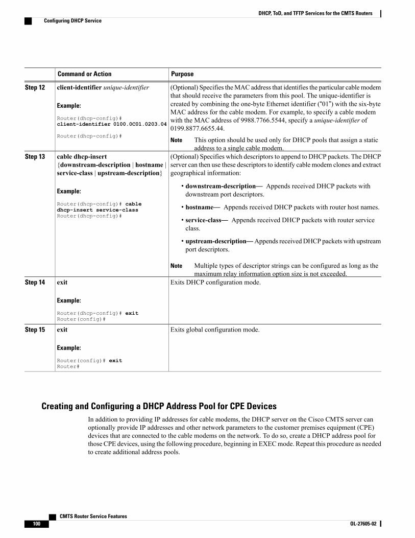
PurposeCommand or Action
(Optional) Specifies theMAC address that identifies the particular cable modemthat should receive the parameters from this pool. The unique-identifier is
client-identifier unique-identifier
Example:
Router(dhcp-config)#
Step 12
created by combining the one-byte Ethernet identifier (“01”) with the six-byteMAC address for the cable modem. For example, to specify a cable modemwith the MAC address of 9988.7766.5544, specify a unique-identifier of0199.8877.6655.44.
client-identifier 0100.0C01.0203.04
Router(dhcp-config)#This option should be used only for DHCP pools that assign a staticaddress to a single cable modem.
Note
(Optional) Specifies which descriptors to append to DHCP packets. The DHCPserver can then use these descriptors to identify cable modem clones and extractgeographical information:
cable dhcp-insert{downstream-description | hostname |service-class | upstream-description}
Step 13
Example:
Router(dhcp-config)# cable
• downstream-description— Appends received DHCP packets withdownstream port descriptors.
• hostname— Appends received DHCP packets with router host names.dhcp-insert service-classRouter(dhcp-config)#
• service-class— Appends received DHCP packets with router serviceclass.
• upstream-description—Appends receivedDHCP packets with upstreamport descriptors.
Multiple types of descriptor strings can be configured as long as themaximum relay information option size is not exceeded.
Note
Exits DHCP configuration mode.exit
Example:
Router(dhcp-config)# exitRouter(config)#
Step 14
Exits global configuration mode.exit
Example:
Router(config)# exitRouter#
Step 15
Creating and Configuring a DHCP Address Pool for CPE DevicesIn addition to providing IP addresses for cable modems, the DHCP server on the Cisco CMTS server canoptionally provide IP addresses and other network parameters to the customer premises equipment (CPE)devices that are connected to the cable modems on the network. To do so, create a DHCP address pool forthose CPE devices, using the following procedure, beginning in EXECmode. Repeat this procedure as neededto create additional address pools.
CMTS Router Service Features100 OL-27605-02
DHCP, ToD, and TFTP Services for the CMTS RoutersConfiguring DHCP Service
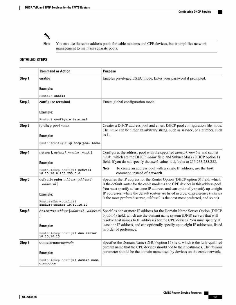
You can use the same address pools for cable modems and CPE devices, but it simplifies networkmanagement to maintain separate pools.
Note
DETAILED STEPS
PurposeCommand or Action
Enables privileged EXEC mode. Enter your password if prompted.enable
Example:
Router> enable
Step 1
Enters global configuration mode.configure terminal
Example:
Router# configure terminal
Step 2
Creates a DHCP address pool and enters DHCP pool configuration file mode.The name can be either an arbitrary string, such as service, or a number, suchas 1.
ip dhcp pool name
Example:
Router(config)# ip dhcp pool local
Step 3
Configures the address pool with the specified network-number and subnetmask , which are the DHCP yiaddr field and Subnet Mask (DHCP option 1)field. If you do not specify the mask value, it defaults to 255.255.255.255.
network network-number [mask ]
Example:
Router(dhcp-config)# network10.10.10.0 255.255.0.0
Step 4
To create an address pool with a single IP address, use the hostcommand instead of network.
Note
Specifies the IP address for the Router Option (DHCP option 3) field, whichis the default router for the cable modems and CPE devices in this address pool.
default-router address [address2...address8 ]
Step 5
You must specify at least one IP address, and can optionally specify up to eightExample:
Router(dhcp-config)#default-router 10.10.10.12
IP addresses, where the default routers are listed in order of preference (addressis the most preferred server, address2 is the next most preferred, and so on).
Specifies one or more IP address for the Domain Name Server Option (DHCPoption 6) field, which are the domain name system (DNS) servers that will
dns-server address [address2 ...address8]
Step 6
resolve host names to IP addresses for the CPE devices. You must specify atExample:
Router(dhcp-config)# dns-server10.10.10.13
least one IP address, and can optionally specify up to eight IP addresses, listedin order of preference.
Specifies the Domain Name (DHCP option 15) field, which is the fully-qualifieddomain name that the CPE devices should add to their hostnames. The domainparameter should be the domain name used by devices on the cable network.
domain-namedomain
Example:
Router(dhcp-config)# domain-namecisco.com
Step 7
CMTS Router Service Features OL-27605-02 101
DHCP, ToD, and TFTP Services for the CMTS RoutersConfiguring DHCP Service
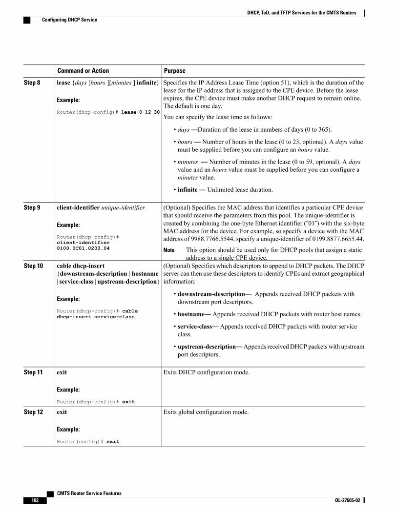
PurposeCommand or Action
Specifies the IP Address Lease Time (option 51), which is the duration of thelease for the IP address that is assigned to the CPE device. Before the lease
lease {days [hours ][minutes ]|infinite}
Example:
Router(dhcp-config)# lease 0 12 30
Step 8
expires, the CPE device must make another DHCP request to remain online.The default is one day.
You can specify the lease time as follows:
• days—Duration of the lease in numbers of days (0 to 365).
• hours— Number of hours in the lease (0 to 23, optional). A days valuemust be supplied before you can configure an hours value.
• minutes — Number of minutes in the lease (0 to 59, optional). A daysvalue and an hours value must be supplied before you can configure aminutes value.
• infinite— Unlimited lease duration.
(Optional) Specifies the MAC address that identifies a particular CPE devicethat should receive the parameters from this pool. The unique-identifier is
client-identifier unique-identifier
Example:
Router(dhcp-config)#
Step 9
created by combining the one-byte Ethernet identifier (“01”) with the six-byteMAC address for the device. For example, so specify a device with the MACaddress of 9988.7766.5544, specify a unique-identifier of 0199.8877.6655.44.
client-identifier0100.0C01.0203.04 This option should be used only for DHCP pools that assign a static
address to a single CPE device.Note
(Optional) Specifies which descriptors to append to DHCP packets. The DHCPserver can then use these descriptors to identify CPEs and extract geographicalinformation:
cable dhcp-insert{downstream-description | hostname| service-class | upstream-description}
Step 10
Example:
Router(dhcp-config)# cabledhcp-insert service-class
• downstream-description— Appends received DHCP packets withdownstream port descriptors.
• hostname— Appends received DHCP packets with router host names.
• service-class— Appends received DHCP packets with router serviceclass.
• upstream-description—Appends receivedDHCP packets with upstreamport descriptors.
Exits DHCP configuration mode.exit
Example:
Router(dhcp-config)# exit
Step 11
Exits global configuration mode.exit
Example:
Router(config)# exit
Step 12
CMTS Router Service Features102 OL-27605-02
DHCP, ToD, and TFTP Services for the CMTS RoutersConfiguring DHCP Service
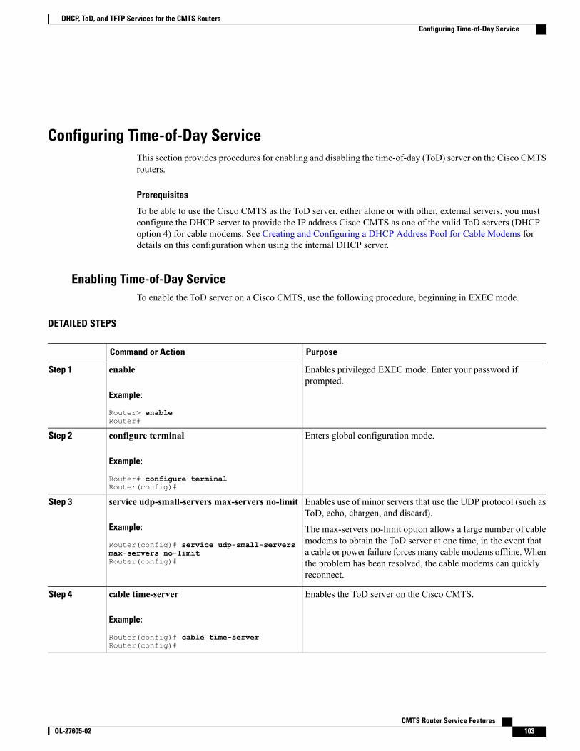
Configuring Time-of-Day ServiceThis section provides procedures for enabling and disabling the time-of-day (ToD) server on the Cisco CMTSrouters.
Prerequisites
To be able to use the Cisco CMTS as the ToD server, either alone or with other, external servers, you mustconfigure the DHCP server to provide the IP address Cisco CMTS as one of the valid ToD servers (DHCPoption 4) for cable modems. See Creating and Configuring a DHCP Address Pool for Cable Modems fordetails on this configuration when using the internal DHCP server.
Enabling Time-of-Day ServiceTo enable the ToD server on a Cisco CMTS, use the following procedure, beginning in EXEC mode.
DETAILED STEPS
PurposeCommand or Action
Enables privileged EXEC mode. Enter your password ifprompted.
enable
Example:
Router> enableRouter#
Step 1
Enters global configuration mode.configure terminal
Example:
Router# configure terminalRouter(config)#
Step 2
Enables use of minor servers that use the UDP protocol (such asToD, echo, chargen, and discard).
service udp-small-servers max-servers no-limit
Example:
Router(config)# service udp-small-servers
Step 3
The max-servers no-limit option allows a large number of cablemodems to obtain the ToD server at one time, in the event thata cable or power failure forces many cable modems offline.Whenmax-servers no-limit
Router(config)# the problem has been resolved, the cable modems can quicklyreconnect.
Enables the ToD server on the Cisco CMTS.cable time-server
Example:
Router(config)# cable time-serverRouter(config)#
Step 4
CMTS Router Service Features OL-27605-02 103
DHCP, ToD, and TFTP Services for the CMTS RoutersConfiguring Time-of-Day Service

PurposeCommand or Action
Exits global configuration mode.exit
Example:
Router(config)# exitRouter#
Step 5
Disabling Time-of-Day ServiceTo disable the ToD server, use the following procedure, beginning in EXEC mode.
DETAILED STEPS
PurposeCommand or Action
Enables privileged EXEC mode. Enter your password ifprompted.
enable
Example:
Router> enableRouter#
Step 1
Enters global configuration mode.configure terminal
Example:
Router# configure terminalRouter(config)#
Step 2
Disables the ToD server on the Cisco CMTS.no cable time-server
Example:
Router(config)# cable time-serverRouter(config)#
Step 3
(Optional) Disables the use of all minor UDP servers.no service udp-small-serversStep 4
Example:
Router(config)# no service udp-small-serversRouter(config)#
Do not disable the minor UDP servers if you arealso enabling the other DHCP or TFTP servers.
Note
Exits global configuration mode.exit
Example:
Router(config)# exitRouter#
Step 5
CMTS Router Service Features104 OL-27605-02
DHCP, ToD, and TFTP Services for the CMTS RoutersConfiguring Time-of-Day Service
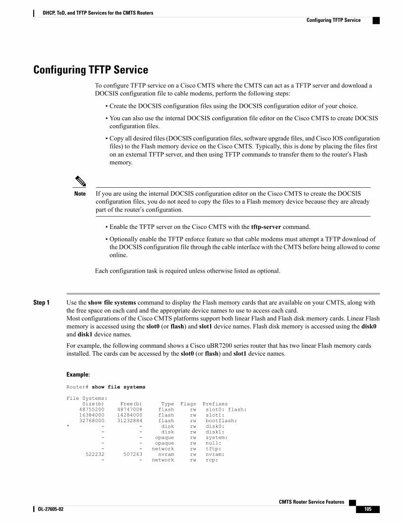
Configuring TFTP ServiceTo configure TFTP service on a Cisco CMTS where the CMTS can act as a TFTP server and download aDOCSIS configuration file to cable modems, perform the following steps:
• Create the DOCSIS configuration files using the DOCSIS configuration editor of your choice.
• You can also use the internal DOCSIS configuration file editor on the Cisco CMTS to create DOCSISconfiguration files.
• Copy all desired files (DOCSIS configuration files, software upgrade files, and Cisco IOS configurationfiles) to the Flash memory device on the Cisco CMTS. Typically, this is done by placing the files firston an external TFTP server, and then using TFTP commands to transfer them to the router’s Flashmemory.
If you are using the internal DOCSIS configuration editor on the Cisco CMTS to create the DOCSISconfiguration files, you do not need to copy the files to a Flash memory device because they are alreadypart of the router’s configuration.
Note
• Enable the TFTP server on the Cisco CMTS with the tftp-server command.
• Optionally enable the TFTP enforce feature so that cable modems must attempt a TFTP download ofthe DOCSIS configuration file through the cable interface with the CMTS before being allowed to comeonline.
Each configuration task is required unless otherwise listed as optional.
Step 1 Use the show file systems command to display the Flash memory cards that are available on your CMTS, along withthe free space on each card and the appropriate device names to use to access each card.Most configurations of the Cisco CMTS platforms support both linear Flash and Flash disk memory cards. Linear Flashmemory is accessed using the slot0 (or flash) and slot1 device names. Flash disk memory is accessed using the disk0and disk1 device names.
For example, the following command shows a Cisco uBR7200 series router that has two linear Flash memory cardsinstalled. The cards can be accessed by the slot0 (or flash) and slot1 device names.
Example:
Router# show file systems
File Systems:Size(b) Free(b) Type Flags Prefixes48755200 48747008 flash rw slot0: flash:16384000 14284000 flash rw slot1:32768000 31232884 flash rw bootflash:
* - - disk rw disk0:- - disk rw disk1:- - opaque rw system:- - opaque rw null:- - network rw tftp:
522232 507263 nvram rw nvram:- - network rw rcp:
CMTS Router Service Features OL-27605-02 105
DHCP, ToD, and TFTP Services for the CMTS RoutersConfiguring TFTP Service

- - network rw ftp:- - network rw scp:
Router#The following example shows a Cisco uBR10012 router that has two Flash disk cards installed. These cards can beaccessed by the disk0 and sec-disk0 device names.
Example:
Router# show file systems
File Systems:Size(b) Free(b) Type Flags Prefixes
- - flash rw slot0: flash:- - flash rw slot1:
32768000 29630876 flash rw bootflash:* 128094208 95346688 disk rw disk0:
- - disk rw disk1:- - opaque rw system:- - flash rw sec-slot0:- - flash rw sec-slot1:
* 128094208 95346688 disk rw sec-disk0:- - disk rw sec-disk1:
32768000 29630876 flash rw sec-bootflash:- - nvram rw sec-nvram:- - opaque rw null:- - network rw tftp:
522232 505523 nvram rw nvram:- - network rw rcp:- - network rw ftp:- - network rw scp:
Router#The Cisco uBR10012 router supports redundant processors, a primary and a secondary, and each processorcontains its own Flash memory devices. You typically do not have to copy files to the secondary Flash memorydevices (which have the sec prefix) because the Cisco uBR10012 router synchronizes the secondary processorto the primary one.
Tip
Step 2 Verify that the desired Flash memory card has sufficient free space for all of the files that you want to copy to the CMTS.Step 3 Use the ping command to verify that the remote TFTP server that contains the desired files is reachable. For example,
the following shows a ping command being given to an external TFTP server with the IP address of 10.10.10.1:
Example:
Router# ping 10.10.10.1Type escape sequence to abort.Sending 5, 100-byte ICMP Echos to 10.10.10.1, timeout is 2 seconds:!!!!!Success rate is 100 percent (5/5), round-trip min/avg/max = 5/6/6 ms
Step 4 Use the copy tftp devname command to copy each file from the external TFTP server to the appropriate Flash memorycard on the CMTS, where devname is the device name for the destination Flash memory card. You will then be promptedfor the IP address for the external TFTP server and the filename for the file to be transferred.The following example shows the file docsis.cm being transferred from the external TFTP server at IP address 10.10.10.1to the first Flash memory disk (disk0):
Example:
Router# copy tftp disk0Address or name of remote host []? 10.10.10.1
Source filename []? config-files/docsis.cm
CMTS Router Service Features106 OL-27605-02
DHCP, ToD, and TFTP Services for the CMTS RoutersConfiguring TFTP Service
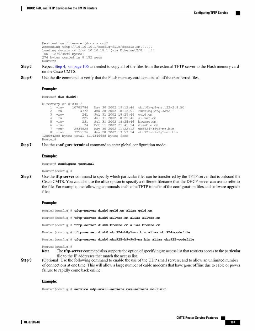
Destination filename [docsis.cm]?Accessing tftp://10.10.10.1/config-file/docsis.cm......Loading docsis.cm from 10.10.10.1 (via Ethernet2/0): !!![OK - 276/4096 bytes]276 bytes copied in 0.152 secsRouter#
Step 5 Repeat Step 4, on page 106 as needed to copy all of the files from the external TFTP server to the Flash memory cardon the Cisco CMTS.
Step 6 Use the dir command to verify that the Flash memory card contains all of the transferred files.
Example:
Router# dir disk0:
Directory of disk0:/1 -rw- 10705784 May 30 2002 19:12:46 ubr10k-p6-mz.122-2.8.BC2 -rw- 4772 Jun 20 2002 18:12:56 running.cfg.save3 -rw- 241 Jul 31 2002 18:25:46 gold.cm4 -rw- 225 Jul 31 2002 18:25:46 silver.cm5 -rw- 231 Jul 31 2002 18:25:46 bronze.cm6 -rw- 74 Oct 11 2002 21:41:14 disable.cm7 -rw- 2934028 May 30 2002 11:22:12 ubr924-k8y5-mz.bin8 -rw- 3255196 Jun 28 2002 13:53:14 ubr925-k9v9y5-mz.bin
128094208 bytes total (114346688 bytes free)Router#
Step 7 Use the configure terminal command to enter global configuration mode:
Example:
Router# configure terminal
Router(config)#
Step 8 Use the tftp-server command to specify which particular files can be transferred by the TFTP server that is onboard theCisco CMTS. You can also use the alias option to specify a different filename that the DHCP server can use to refer tothe file. For example, the following commands enable the TFTP transfer of the configuration files and software upgradefiles:
Example:
Router(config)# tftp-server disk0:gold.cm alias gold.cm
Router(config)# tftp-server disk0:silver.cm alias silver.cm
Router(config)# tftp-server disk0:bronze.cm alias bronze.cm
Router(config)# tftp-server disk0:ubr924-k8y5-mz.bin alias ubr924-codefile
Router(config)# tftp-server disk0:ubr925-k9v9y5-mz.bin alias ubr925-codefile
Router(config)#The tftp-server command also supports the option of specifying an access list that restricts access to the particularfile to the IP addresses that match the access list.
Note
Step 9 (Optional) Use the following command to enable the use of the UDP small servers, and to allow an unlimited numberof connections at one time. This will allow a large number of cable modems that have gone offline due to cable or powerfailure to rapidly come back online.
Example:
Router(config)# service udp-small-servers max-servers no-limit
CMTS Router Service Features OL-27605-02 107
DHCP, ToD, and TFTP Services for the CMTS RoutersConfiguring TFTP Service
Router(config)#
Step 10 (Optional) Use the cable tftp-enforce command in interface configuration mode to require that each cable modemperform a TFTP download of its DOCSIS configuration file through its cable interface with the CMTS before beingallowed to come online. This can prevent the most common types of theft-of-service attacks in which users configuretheir local networks so as to download an unauthorized configuration file to their cable modems.
Example:
Router(config)# interface cablex/y
Router(config-if)# cable tftp-enforce
Router(config-if)#You can also specify themark-only option so that cable modems can come online without attempting a TFTP download,but the cable modems are marked in the show cable modems command so that network administrators can investigatethe situation further before taking any action.
Example:
Router(config)# interface cablex/y
Router(config-if)# cable tftp-enforce mark-only
Router(config-if)#
Configuring A Basic All-in-One ConfigurationThe basic all-in-one configuration requires configuring the DHCP, ToD, and TFTP servers, as described inthe following sections in this document:
You must also have the necessary DOCSIS configuration files available for the TFTP server. You can do thisin two ways:
• Create the DOCSIS configuration files using the Cisco DOCSIS Configurator tool, and then copy themto the Flash memory device. For instructions on copying the configuration files to Flash memory, seethe Configuring TFTP Service, on page 105.
• Dynamically create the DOCSIS configuration files with the cable config-file command.
For an example of a basic all-in-one configuration, see the Basic All-in-One Configuration Example, on page118.
Configuring an Advanced All-in-One ConfigurationThe advanced all-in-one configuration sample is identical to the basic configuration except that it uses ahierarchy of DHCP pools. Any DHCP pool with a network number that is a subset of another pool's networknumber inherits all the characteristics of that other pool. This saves having to repeat identical commands inthe multiple DHCP pool configurations.
CMTS Router Service Features108 OL-27605-02
DHCP, ToD, and TFTP Services for the CMTS RoutersConfiguring A Basic All-in-One Configuration
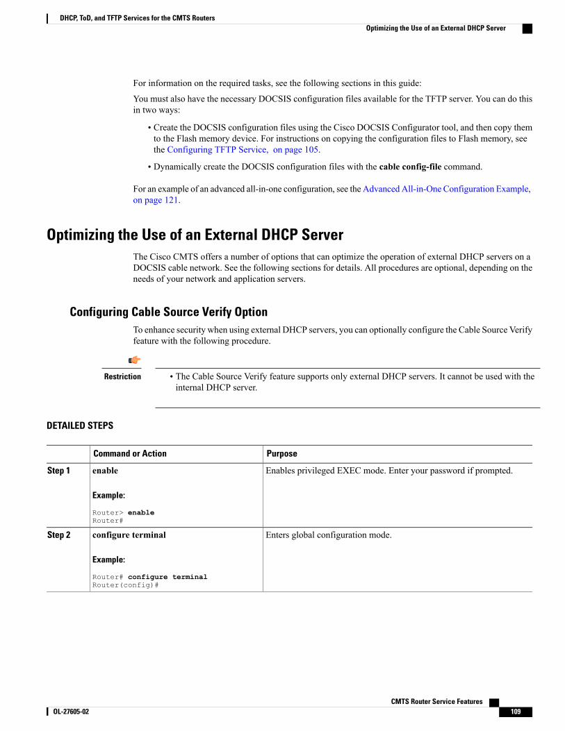
For information on the required tasks, see the following sections in this guide:
You must also have the necessary DOCSIS configuration files available for the TFTP server. You can do thisin two ways:
• Create the DOCSIS configuration files using the Cisco DOCSIS Configurator tool, and then copy themto the Flash memory device. For instructions on copying the configuration files to Flash memory, seethe Configuring TFTP Service, on page 105.
• Dynamically create the DOCSIS configuration files with the cable config-file command.
For an example of an advanced all-in-one configuration, see the Advanced All-in-One Configuration Example,on page 121.
Optimizing the Use of an External DHCP ServerThe Cisco CMTS offers a number of options that can optimize the operation of external DHCP servers on aDOCSIS cable network. See the following sections for details. All procedures are optional, depending on theneeds of your network and application servers.
Configuring Cable Source Verify OptionTo enhance security when using external DHCP servers, you can optionally configure the Cable Source Verifyfeature with the following procedure.
Restriction • The Cable Source Verify feature supports only external DHCP servers. It cannot be used with theinternal DHCP server.
DETAILED STEPS
PurposeCommand or Action
Enables privileged EXEC mode. Enter your password if prompted.enable
Example:
Router> enableRouter#
Step 1
Enters global configuration mode.configure terminal
Example:
Router# configure terminalRouter(config)#
Step 2
CMTS Router Service Features OL-27605-02 109
DHCP, ToD, and TFTP Services for the CMTS RoutersOptimizing the Use of an External DHCP Server
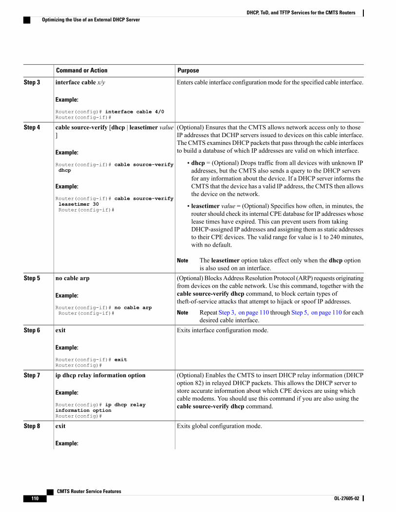
PurposeCommand or Action
Enters cable interface configurationmode for the specified cable interface.interface cable x/y
Example:
Router(config)# interface cable 4/0Router(config-if)#
Step 3
(Optional) Ensures that the CMTS allows network access only to thoseIP addresses that DCHP servers issued to devices on this cable interface.
cable source-verify [dhcp | leasetimer value]
Step 4
The CMTS examines DHCP packets that pass through the cable interfacesto build a database of which IP addresses are valid on which interface.Example:
Router(config-if)# cable source-verifydhcp
• dhcp = (Optional) Drops traffic from all devices with unknown IPaddresses, but the CMTS also sends a query to the DHCP servers
Example:
Router(config-if)# cable source-verify
for any information about the device. If a DHCP server informs theCMTS that the device has a valid IP address, the CMTS then allowsthe device on the network.
leasetimer 30Router(config-if)#
• leasetimer value = (Optional) Specifies how often, in minutes, therouter should check its internal CPE database for IP addresses whoselease times have expired. This can prevent users from takingDHCP-assigned IP addresses and assigning them as static addressesto their CPE devices. The valid range for value is 1 to 240 minutes,with no default.
The leasetimer option takes effect only when the dhcp optionis also used on an interface.
Note
(Optional) Blocks Address Resolution Protocol (ARP) requests originatingfrom devices on the cable network. Use this command, together with the
no cable arp
Example:
Router(config-if)# no cable arpRouter(config-if)#
Step 5
cable source-verify dhcp command, to block certain types oftheft-of-service attacks that attempt to hijack or spoof IP addresses.
Repeat Step 3, on page 110 through Step 5, on page 110 for eachdesired cable interface.
Note
Exits interface configuration mode.exit
Example:
Router(config-if)# exitRouter(config)#
Step 6
(Optional) Enables the CMTS to insert DHCP relay information (DHCPoption 82) in relayed DHCP packets. This allows the DHCP server to
ip dhcp relay information option
Example:
Router(config)# ip dhcp relay
Step 7
store accurate information about which CPE devices are using whichcable modems. You should use this command if you are also using thecable source-verify dhcp command.
information optionRouter(config)#
Exits global configuration mode.exitStep 8
Example:
CMTS Router Service Features110 OL-27605-02
DHCP, ToD, and TFTP Services for the CMTS RoutersOptimizing the Use of an External DHCP Server
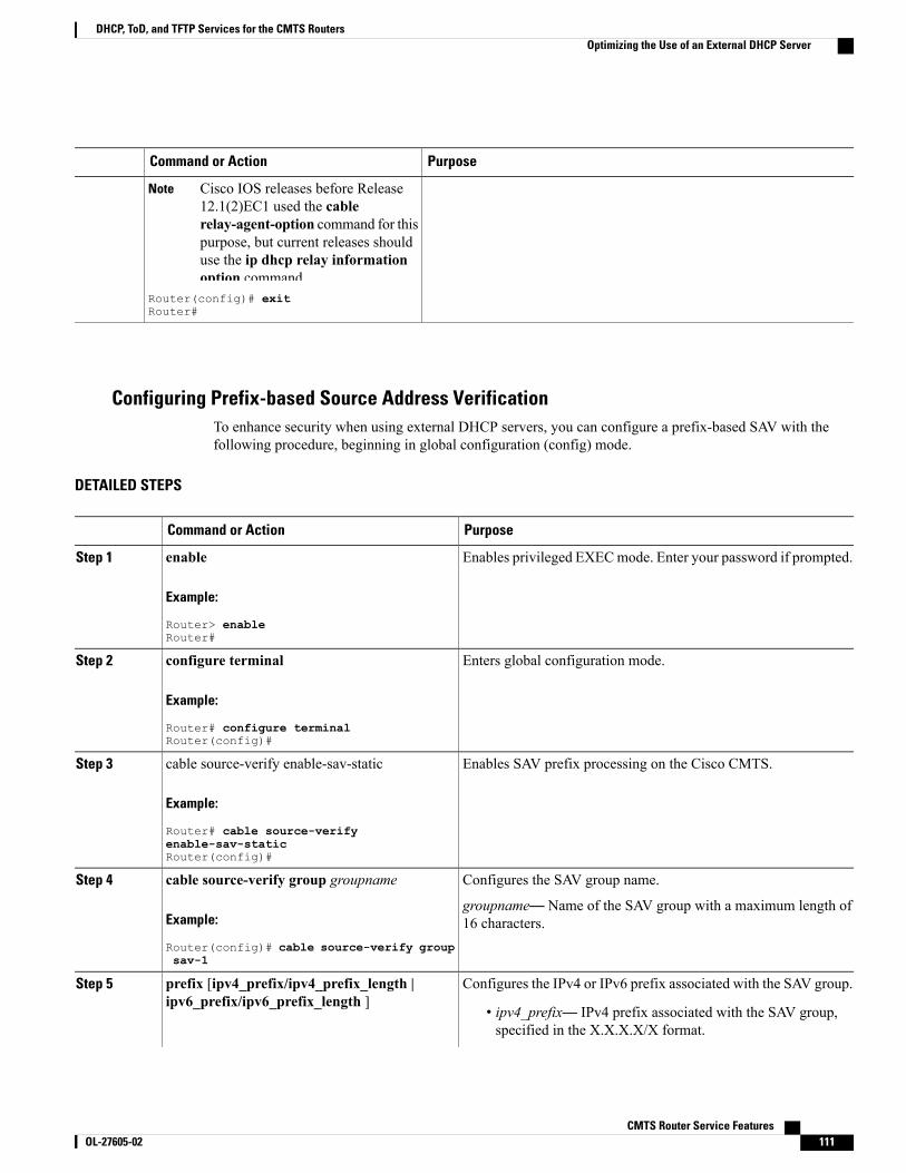
PurposeCommand or Action
Cisco IOS releases before Release12.1(2)EC1 used the cablerelay-agent-option command for thispurpose, but current releases shoulduse the ip dhcp relay informationoption command.
Note
Router(config)# exitRouter#
Configuring Prefix-based Source Address VerificationTo enhance security when using external DHCP servers, you can configure a prefix-based SAV with thefollowing procedure, beginning in global configuration (config) mode.
DETAILED STEPS
PurposeCommand or Action
Enables privileged EXECmode. Enter your password if prompted.enable
Example:
Router> enableRouter#
Step 1
Enters global configuration mode.configure terminal
Example:
Router# configure terminalRouter(config)#
Step 2
Enables SAV prefix processing on the Cisco CMTS.cable source-verify enable-sav-static
Example:
Router# cable source-verify
Step 3
enable-sav-staticRouter(config)#
Configures the SAV group name.cable source-verify group groupnameStep 4
Example:
Router(config)# cable source-verify groupsav-1
groupname— Name of the SAV group with a maximum length of16 characters.
Configures the IPv4 or IPv6 prefix associated with the SAV group.prefix [ipv4_prefix/ipv4_prefix_length |ipv6_prefix/ipv6_prefix_length ]
Step 5
• ipv4_prefix— IPv4 prefix associated with the SAV group,specified in the X.X.X.X/X format.
CMTS Router Service Features OL-27605-02 111
DHCP, ToD, and TFTP Services for the CMTS RoutersOptimizing the Use of an External DHCP Server
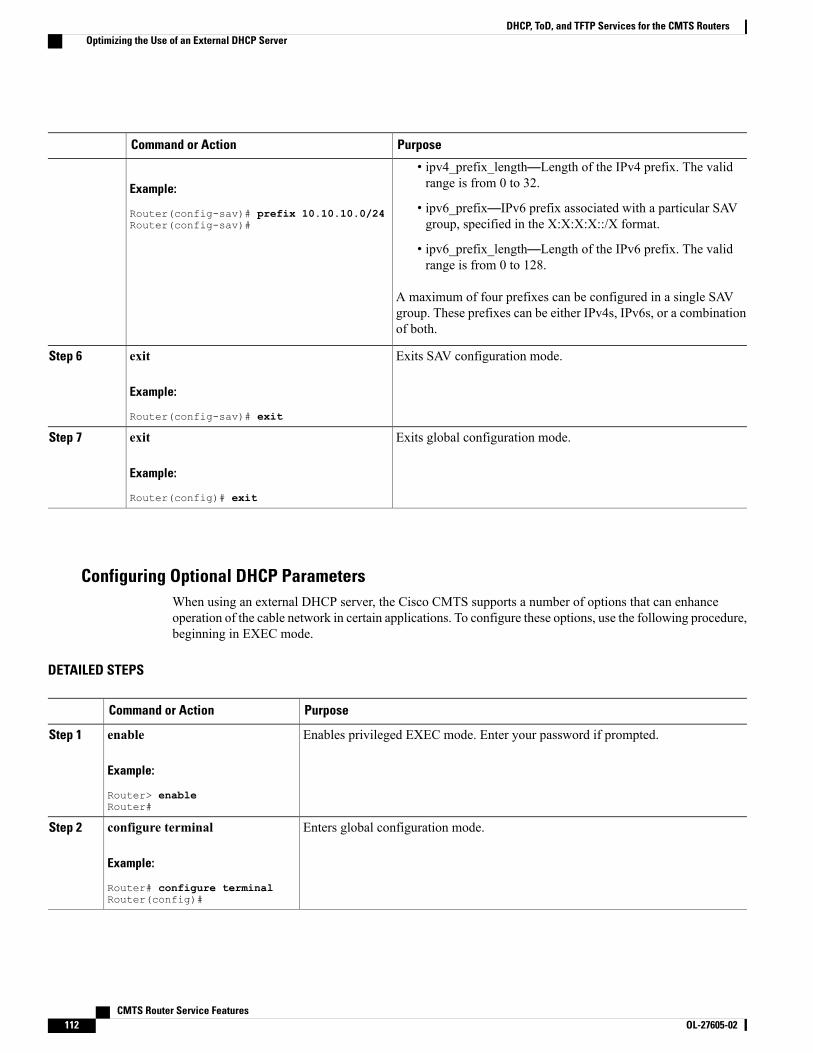
PurposeCommand or Action
Example:
Router(config-sav)# prefix 10.10.10.0/24Router(config-sav)#
• ipv4_prefix_length—Length of the IPv4 prefix. The validrange is from 0 to 32.
• ipv6_prefix—IPv6 prefix associated with a particular SAVgroup, specified in the X:X:X:X::/X format.
• ipv6_prefix_length—Length of the IPv6 prefix. The validrange is from 0 to 128.
A maximum of four prefixes can be configured in a single SAVgroup. These prefixes can be either IPv4s, IPv6s, or a combinationof both.
Exits SAV configuration mode.exit
Example:
Router(config-sav)# exit
Step 6
Exits global configuration mode.exit
Example:
Router(config)# exit
Step 7
Configuring Optional DHCP ParametersWhen using an external DHCP server, the Cisco CMTS supports a number of options that can enhanceoperation of the cable network in certain applications. To configure these options, use the following procedure,beginning in EXEC mode.
DETAILED STEPS
PurposeCommand or Action
Enables privileged EXEC mode. Enter your password if prompted.enable
Example:
Router> enableRouter#
Step 1
Enters global configuration mode.configure terminal
Example:
Router# configure terminalRouter(config)#
Step 2
CMTS Router Service Features112 OL-27605-02
DHCP, ToD, and TFTP Services for the CMTS RoutersOptimizing the Use of an External DHCP Server
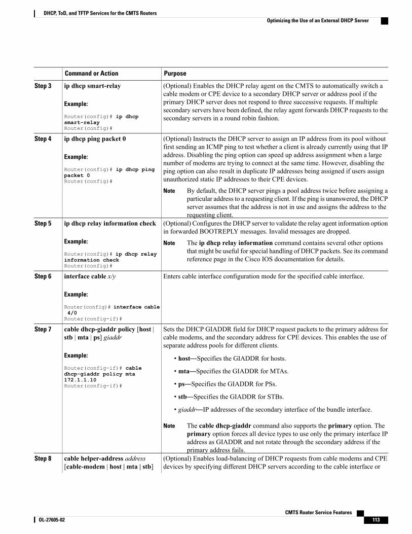
PurposeCommand or Action
(Optional) Enables the DHCP relay agent on the CMTS to automatically switch acable modem or CPE device to a secondary DHCP server or address pool if the
ip dhcp smart-relay
Example:
Router(config)# ip dhcp
Step 3
primary DHCP server does not respond to three successive requests. If multiplesecondary servers have been defined, the relay agent forwards DHCP requests to thesecondary servers in a round robin fashion.
smart-relayRouter(config)#
(Optional) Instructs the DHCP server to assign an IP address from its pool withoutfirst sending an ICMP ping to test whether a client is already currently using that IP
ip dhcp ping packet 0
Example:
Router(config)# ip dhcp ping
Step 4
address. Disabling the ping option can speed up address assignment when a largenumber of modems are trying to connect at the same time. However, disabling theping option can also result in duplicate IP addresses being assigned if users assignunauthorized static IP addresses to their CPE devices.packet 0
Router(config)#
By default, the DHCP server pings a pool address twice before assigning aparticular address to a requesting client. If the ping is unanswered, the DHCPserver assumes that the address is not in use and assigns the address to therequesting client.
Note
(Optional) Configures the DHCP server to validate the relay agent information optionin forwarded BOOTREPLY messages. Invalid messages are dropped.
ip dhcp relay information check
Example:
Router(config)# ip dhcp relay
Step 5
The ip dhcp relay information command contains several other optionsthat might be useful for special handling of DHCP packets. See its commandreference page in the Cisco IOS documentation for details.
Note
information checkRouter(config)#
Enters cable interface configuration mode for the specified cable interface.interface cable x/y
Example:
Router(config)# interface cable
Step 6
4/0Router(config-if)#
Sets the DHCP GIADDR field for DHCP request packets to the primary address forcable modems, and the secondary address for CPE devices. This enables the use ofseparate address pools for different clients.
cable dhcp-giaddr policy [host |stb |mta | ps] giaddr
Example:
Router(config-if)# cable
Step 7
• host—Specifies the GIADDR for hosts.
• mta—Specifies the GIADDR for MTAs.dhcp-giaddr policy mta172.1.1.10Router(config-if)# • ps—Specifies the GIADDR for PSs.
• stb—Specifies the GIADDR for STBs.
• giaddr—IP addresses of the secondary interface of the bundle interface.
The cable dhcp-giaddr command also supports the primary option. Theprimary option forces all device types to use only the primary interface IPaddress as GIADDR and not rotate through the secondary address if theprimary address fails.
Note
(Optional) Enables load-balancing of DHCP requests from cable modems and CPEdevices by specifying different DHCP servers according to the cable interface or
cable helper-address address[cable-modem | host | mta | stb]
Step 8
CMTS Router Service Features OL-27605-02 113
DHCP, ToD, and TFTP Services for the CMTS RoutersOptimizing the Use of an External DHCP Server
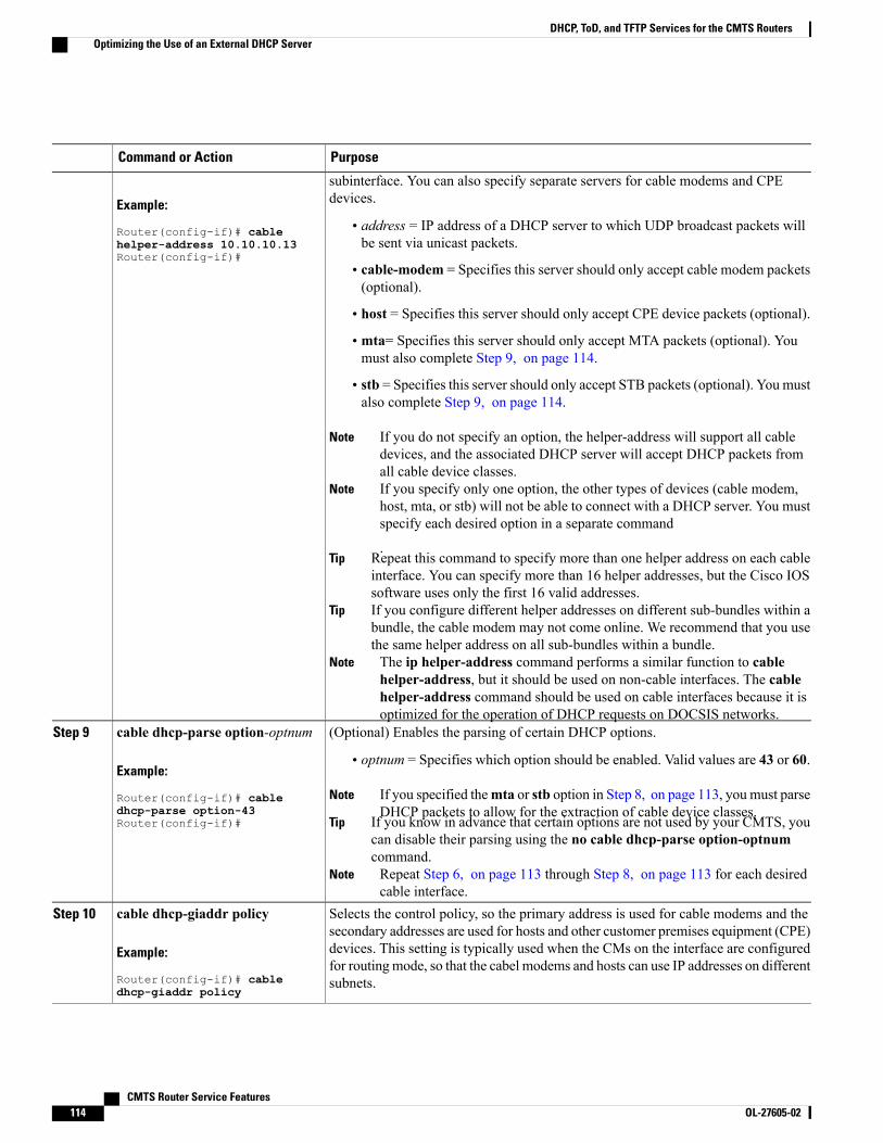
PurposeCommand or Action
subinterface. You can also specify separate servers for cable modems and CPEdevices.Example:
Router(config-if)# cable • address = IP address of a DHCP server to which UDP broadcast packets willbe sent via unicast packets.helper-address 10.10.10.13
Router(config-if)#• cable-modem = Specifies this server should only accept cable modem packets(optional).
• host = Specifies this server should only accept CPE device packets (optional).
• mta= Specifies this server should only accept MTA packets (optional). Youmust also complete Step 9, on page 114.
• stb = Specifies this server should only accept STB packets (optional). You mustalso complete Step 9, on page 114.
If you do not specify an option, the helper-address will support all cabledevices, and the associated DHCP server will accept DHCP packets fromall cable device classes.
Note
If you specify only one option, the other types of devices (cable modem,host, mta, or stb) will not be able to connect with a DHCP server. You mustspecify each desired option in a separate command
.
Note
Repeat this command to specify more than one helper address on each cableinterface. You can specify more than 16 helper addresses, but the Cisco IOSsoftware uses only the first 16 valid addresses.
Tip
If you configure different helper addresses on different sub-bundles within abundle, the cable modem may not come online. We recommend that you usethe same helper address on all sub-bundles within a bundle.
Tip
The ip helper-address command performs a similar function to cablehelper-address, but it should be used on non-cable interfaces. The cablehelper-address command should be used on cable interfaces because it isoptimized for the operation of DHCP requests on DOCSIS networks.
Note
(Optional) Enables the parsing of certain DHCP options.cable dhcp-parse option-optnumStep 9
Example:
Router(config-if)# cable
• optnum = Specifies which option should be enabled. Valid values are 43 or 60.
If you specified themta or stb option in Step 8, on page 113, you must parseDHCP packets to allow for the extraction of cable device classes.
Note
If you know in advance that certain options are not used by your CMTS, youcan disable their parsing using the no cable dhcp-parse option-optnumcommand.
Tip
Repeat Step 6, on page 113 through Step 8, on page 113 for each desiredcable interface.
Note
dhcp-parse option-43Router(config-if)#
Selects the control policy, so the primary address is used for cable modems and thesecondary addresses are used for hosts and other customer premises equipment (CPE)
cable dhcp-giaddr policy
Example:
Router(config-if)# cabledhcp-giaddr policy
Step 10
devices. This setting is typically used when the CMs on the interface are configuredfor routingmode, so that the cabel modems and hosts can use IP addresses on differentsubnets.
CMTS Router Service Features114 OL-27605-02
DHCP, ToD, and TFTP Services for the CMTS RoutersOptimizing the Use of an External DHCP Server

PurposeCommand or Action
Exits interface configuration mode.exit
Example:
Router(config-if)# exitRouter(config)#
Step 11
Exits global configuration mode.exit
Example:
Router(config)# exitRouter#
Step 12
Configuration ExamplesThis section provides examples for the following configurations:
DHCP Server ExamplesThe following sections gave sample configurations for configuring DHCP pools for cable modems and CPEdevices:
DHCP Pools for Cable ModemsThe following examples show three typical DHCP pools for cable modems. Each pool includes the followingfields:
• The dhcp pool command defines a unique string for the pool’s name, which in this case identifies theDOCSIS configuration file that is to be downloaded to the cable modem.
• The network command defines the range of IP addresses for each pool.
• The bootfile command specifies the DOCSIS configuration file to be downloaded to the cable modem.In these examples, three DOCSIS configuration files are specified (platinum.cm, gold.cm, and silver.cm).
• The next-server command specifies the IP address for the TFTP server.
• The default-router command specifies the default gateway.
• The three option commands specify the time offset, ToD server, and log server.
• The lease command specifies that the DHCP lease expires in is 7 days, 0 hours, and 10 minutes. (Thecable modem will typically attempt to renew the lease at the halfway mark of approximately 3 days and12 hours.)
!ip dhcp pool cm-platinum
CMTS Router Service Features OL-27605-02 115
DHCP, ToD, and TFTP Services for the CMTS RoutersConfiguration Examples
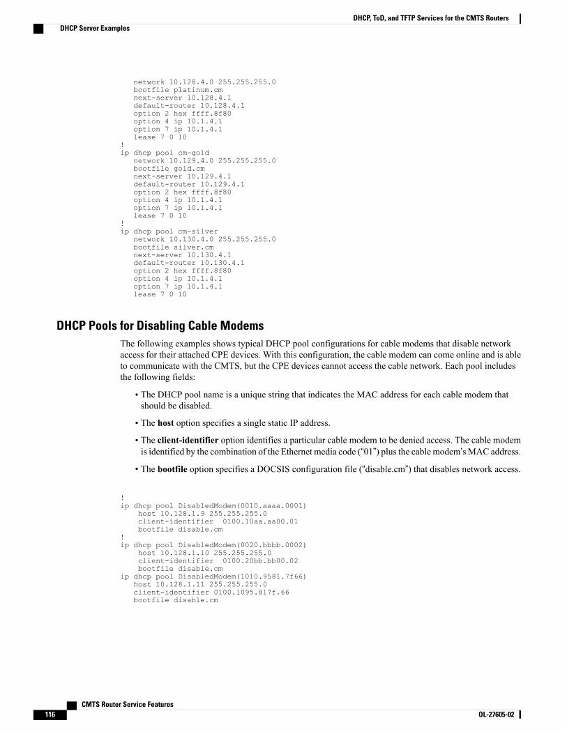
network 10.128.4.0 255.255.255.0bootfile platinum.cmnext-server 10.128.4.1default-router 10.128.4.1option 2 hex ffff.8f80option 4 ip 10.1.4.1option 7 ip 10.1.4.1lease 7 0 10
!ip dhcp pool cm-gold
network 10.129.4.0 255.255.255.0bootfile gold.cmnext-server 10.129.4.1default-router 10.129.4.1option 2 hex ffff.8f80option 4 ip 10.1.4.1option 7 ip 10.1.4.1lease 7 0 10
!ip dhcp pool cm-silver
network 10.130.4.0 255.255.255.0bootfile silver.cmnext-server 10.130.4.1default-router 10.130.4.1option 2 hex ffff.8f80option 4 ip 10.1.4.1option 7 ip 10.1.4.1lease 7 0 10
DHCP Pools for Disabling Cable ModemsThe following examples shows typical DHCP pool configurations for cable modems that disable networkaccess for their attached CPE devices. With this configuration, the cable modem can come online and is ableto communicate with the CMTS, but the CPE devices cannot access the cable network. Each pool includesthe following fields:
• The DHCP pool name is a unique string that indicates the MAC address for each cable modem thatshould be disabled.
• The host option specifies a single static IP address.
• The client-identifier option identifies a particular cable modem to be denied access. The cable modemis identified by the combination of the Ethernet media code (“01”) plus the cable modem’sMAC address.
• The bootfile option specifies a DOCSIS configuration file (“disable.cm”) that disables network access.
!ip dhcp pool DisabledModem(0010.aaaa.0001)
host 10.128.1.9 255.255.255.0client-identifier 0100.10aa.aa00.01bootfile disable.cm
!ip dhcp pool DisabledModem(0020.bbbb.0002)
host 10.128.1.10 255.255.255.0client-identifier 0100.20bb.bb00.02bootfile disable.cm
ip dhcp pool DisabledModem(1010.9581.7f66)host 10.128.1.11 255.255.255.0client-identifier 0100.1095.817f.66bootfile disable.cm
CMTS Router Service Features116 OL-27605-02
DHCP, ToD, and TFTP Services for the CMTS RoutersDHCP Server Examples

DHCP Pools for CPE DevicesThe following examples show a typical DHCP pool for CPE devices. Each pool includes the following fields:
• The network command defines the range of IP addresses to be assigned to the CPE devices. Typically,this command specifies a subnet in the secondary address range for the cable interface.
• The default-router command specifies the default gateway.
• The dns-server command specifies one or more IP addresses for the DNS name-resolution servers thatthe CPE devices should use.
• The domain-name command specifies the fully-qualified domain name that the CPE devices shoulduse.
• The lease command specifies that the DHCP lease expires in is 7 days, 0 hours, and 10 minutes. (TheCPE device will typically attempt to renew the lease at the halfway mark of approximately 3 days and12 hours.)
!ip dhcp pool hosts
network 10.254.1.0 255.255.255.0default-router 10.254.1.1dns-server 10.254.1.1 10.128.1.1domain-name ExamplesDomainName.comlease 7 0 10
!The following example shows a DHCP pool that assigns a permanent, static IP address to a particular CPEdevice. This example is identical to the previous pool except for the following commands:
• The host command is used (instead of the network command) to specify a single static IP address thatwill be assigned to the CPE device.
• The client-identifier command identifies the particular CPE device. The CPE device is identified bythe combination of the Ethernet media code (“01”) plus the device’s MAC address (0001.dddd.0001).
!ip dhcp pool staticPC(0001.dddd.0001)
host 10.254.1.12 255.255.255.0client-identifier 0100.01dd.dd00.01default-router 10.254.1.1dns-server 10.254.1.1 10.128.1.1domain-name ExamplesDomainName.comlease 7 0 10
ToD Server ExampleThe following example shows a typical ToD server configuration:
service udp-small-servers max-servers no-limitcable time-serverThese are the only commands required to enable the ToD server.
CMTS Router Service Features OL-27605-02 117
DHCP, ToD, and TFTP Services for the CMTS RoutersToD Server Example
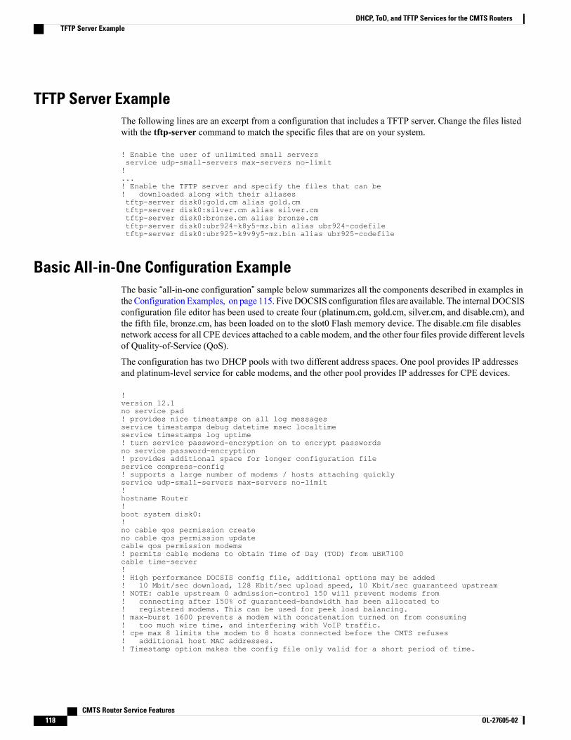
TFTP Server ExampleThe following lines are an excerpt from a configuration that includes a TFTP server. Change the files listedwith the tftp-server command to match the specific files that are on your system.
! Enable the user of unlimited small serversservice udp-small-servers max-servers no-limit!...! Enable the TFTP server and specify the files that can be! downloaded along with their aliasestftp-server disk0:gold.cm alias gold.cmtftp-server disk0:silver.cm alias silver.cmtftp-server disk0:bronze.cm alias bronze.cmtftp-server disk0:ubr924-k8y5-mz.bin alias ubr924-codefiletftp-server disk0:ubr925-k9v9y5-mz.bin alias ubr925-codefile
Basic All-in-One Configuration ExampleThe basic “all-in-one configuration” sample below summarizes all the components described in examples inthe Configuration Examples, on page 115. Five DOCSIS configuration files are available. The internal DOCSISconfiguration file editor has been used to create four (platinum.cm, gold.cm, silver.cm, and disable.cm), andthe fifth file, bronze.cm, has been loaded on to the slot0 Flash memory device. The disable.cm file disablesnetwork access for all CPE devices attached to a cable modem, and the other four files provide different levelsof Quality-of-Service (QoS).
The configuration has two DHCP pools with two different address spaces. One pool provides IP addressesand platinum-level service for cable modems, and the other pool provides IP addresses for CPE devices.
!version 12.1no service pad! provides nice timestamps on all log messagesservice timestamps debug datetime msec localtimeservice timestamps log uptime! turn service password-encryption on to encrypt passwordsno service password-encryption! provides additional space for longer configuration fileservice compress-config! supports a large number of modems / hosts attaching quicklyservice udp-small-servers max-servers no-limit!hostname Router!boot system disk0:!no cable qos permission createno cable qos permission updatecable qos permission modems! permits cable modems to obtain Time of Day (TOD) from uBR7100cable time-server!! High performance DOCSIS config file, additional options may be added! 10 Mbit/sec download, 128 Kbit/sec upload speed, 10 Kbit/sec guaranteed upstream! NOTE: cable upstream 0 admission-control 150 will prevent modems from! connecting after 150% of guaranteed-bandwidth has been allocated to! registered modems. This can be used for peek load balancing.! max-burst 1600 prevents a modem with concatenation turned on from consuming! too much wire time, and interfering with VoIP traffic.! cpe max 8 limits the modem to 8 hosts connected before the CMTS refuses! additional host MAC addresses.! Timestamp option makes the config file only valid for a short period of time.
CMTS Router Service Features118 OL-27605-02
DHCP, ToD, and TFTP Services for the CMTS RoutersTFTP Server Example
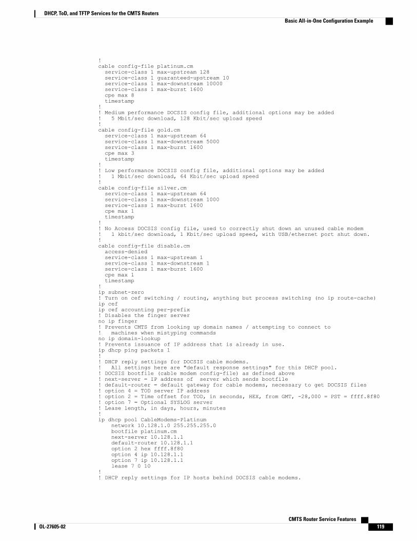
!cable config-file platinum.cmservice-class 1 max-upstream 128service-class 1 guaranteed-upstream 10service-class 1 max-downstream 10000service-class 1 max-burst 1600cpe max 8timestamp
!! Medium performance DOCSIS config file, additional options may be added! 5 Mbit/sec download, 128 Kbit/sec upload speed!cable config-file gold.cmservice-class 1 max-upstream 64service-class 1 max-downstream 5000service-class 1 max-burst 1600cpe max 3timestamp
!! Low performance DOCSIS config file, additional options may be added! 1 Mbit/sec download, 64 Kbit/sec upload speed!cable config-file silver.cmservice-class 1 max-upstream 64service-class 1 max-downstream 1000service-class 1 max-burst 1600cpe max 1timestamp
!! No Access DOCSIS config file, used to correctly shut down an unused cable modem! 1 kbit/sec download, 1 Kbit/sec upload speed, with USB/ethernet port shut down.!cable config-file disable.cmaccess-deniedservice-class 1 max-upstream 1service-class 1 max-downstream 1service-class 1 max-burst 1600cpe max 1timestamp
!ip subnet-zero! Turn on cef switching / routing, anything but process switching (no ip route-cache)ip cefip cef accounting per-prefix! Disables the finger serverno ip finger! Prevents CMTS from looking up domain names / attempting to connect to! machines when mistyping commandsno ip domain-lookup! Prevents issuance of IP address that is already in use.ip dhcp ping packets 1!! DHCP reply settings for DOCSIS cable modems.! All settings here are "default response settings" for this DHCP pool.! DOCSIS bootfile (cable modem config-file) as defined above! next-server = IP address of server which sends bootfile! default-router = default gateway for cable modems, necessary to get DOCSIS files! option 4 = TOD server IP address! option 2 = Time offset for TOD, in seconds, HEX, from GMT, -28,000 = PST = ffff.8f80! option 7 = Optional SYSLOG server! Lease length, in days, hours, minutes!ip dhcp pool CableModems-Platinum
network 10.128.1.0 255.255.255.0bootfile platinum.cmnext-server 10.128.1.1default-router 10.128.1.1option 2 hex ffff.8f80option 4 ip 10.128.1.1option 7 ip 10.128.1.1lease 7 0 10
!! DHCP reply settings for IP hosts behind DOCSIS cable modems.
CMTS Router Service Features OL-27605-02 119
DHCP, ToD, and TFTP Services for the CMTS RoutersBasic All-in-One Configuration Example

! All settings here are "default response settings" for this DHCP pool.! default-router = default gateway for cable modems, necessary to get DOCSIS files! dns-server = IP address for DNS server, place up to 8 addresses on the same! line as a list! NOTE: changing the DNS-server on a Windows PC, Mac, or Unix box require! reloading the OS, but changing it in the DHCP response is quick and easy.! domain-name = default domain name for the host! Lease length, in days, hours, minutes!ip dhcp pool hosts
network 10.254.1.0 255.255.255.0default-router 10.254.1.1dns-server 10.254.1.1 10.128.1.1domain-name ExamplesDomainName.comlease 1 0 10
!!!interface FastEthernet0/0ip address 10.17.123.1 255.255.255.0no ip mroute-cacheno shutdownduplex autospeed auto
!interface FastEthernet0/1no ip addressno ip mroute-cacheshutdownduplex autospeed auto
!! Primary address is for cable modems, use only one, so make it large enough!! Secondary addresses are for hosts, use as many as necessary! These addresses must match the remainder of the configuration file,! or modems won't work.! cable downstream frequency sets the upconverter frequency! cable down rf-power 55, sets the upconverter output power in dBmV! each upstream interface can have a description, use it!! All four upstreams have been set to the same default frequency, don't! connect wire them together while on the same frequency!! cable upstream 0 admission-control 150: limits the number of modems! which can connect with guaranteed-bandwidth.! NOTE: will prevent some modems from connecting once this limit is hit.!! High security option:! no cable arp: prevents the uBR7100 from ever arping towards the cable modems! for any IP-mac address pairing. Forces EVERY host to use DHCP at least! once every time the uBR7100 is reloaded, or the arp table is cleared out.! Forces users to use DHCP release/renew cycle on their computers if! ARP entry is ever lost.! Makes it impossible for an end user to type in a static IP address,! or steal somebody else's IP address.!! cable-source verify dhcp: -- Forces the CMTS to populate the arp table from! the DHCP server! If the DHCP server does not have a valid DHCP lease for that IP / MAC combination,! the host is unreachable.! cable dhcp-giaddr policy: use primary IP address for modems, secondary for! hosts behind modems!!interface Cable1/0description Cable Downstream Interfaceip address 10.254.1.1 255.255.255.0 secondaryip address 10.128.1.1 255.255.255.0no keepalivecable downstream rate-limit token-bucket shapingcable downstream annex Bcable downstream modulation 64qamcable downstream interleave-depth 32cable downstream frequency 851000000cable down rf-power 55
CMTS Router Service Features120 OL-27605-02
DHCP, ToD, and TFTP Services for the CMTS RoutersBasic All-in-One Configuration Example
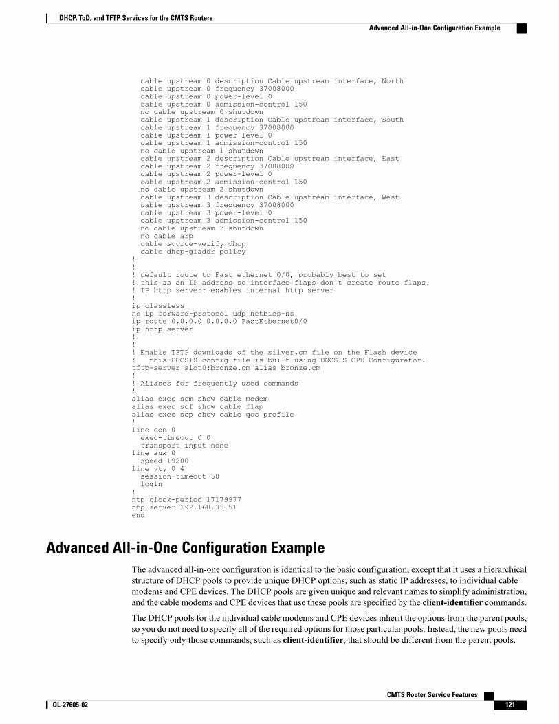
cable upstream 0 description Cable upstream interface, Northcable upstream 0 frequency 37008000cable upstream 0 power-level 0cable upstream 0 admission-control 150no cable upstream 0 shutdowncable upstream 1 description Cable upstream interface, Southcable upstream 1 frequency 37008000cable upstream 1 power-level 0cable upstream 1 admission-control 150no cable upstream 1 shutdowncable upstream 2 description Cable upstream interface, Eastcable upstream 2 frequency 37008000cable upstream 2 power-level 0cable upstream 2 admission-control 150no cable upstream 2 shutdowncable upstream 3 description Cable upstream interface, Westcable upstream 3 frequency 37008000cable upstream 3 power-level 0cable upstream 3 admission-control 150no cable upstream 3 shutdownno cable arpcable source-verify dhcpcable dhcp-giaddr policy
!!! default route to Fast ethernet 0/0, probably best to set! this as an IP address so interface flaps don't create route flaps.! IP http server: enables internal http server!ip classlessno ip forward-protocol udp netbios-nsip route 0.0.0.0 0.0.0.0 FastEthernet0/0ip http server!!! Enable TFTP downloads of the silver.cm file on the Flash device! this DOCSIS config file is built using DOCSIS CPE Configurator.tftp-server slot0:bronze.cm alias bronze.cm!! Aliases for frequently used commands!alias exec scm show cable modemalias exec scf show cable flapalias exec scp show cable qos profile!line con 0exec-timeout 0 0transport input none
line aux 0speed 19200
line vty 0 4session-timeout 60login
!ntp clock-period 17179977ntp server 192.168.35.51end
Advanced All-in-One Configuration ExampleThe advanced all-in-one configuration is identical to the basic configuration, except that it uses a hierarchicalstructure of DHCP pools to provide unique DHCP options, such as static IP addresses, to individual cablemodems and CPE devices. The DHCP pools are given unique and relevant names to simplify administration,and the cable modems and CPE devices that use these pools are specified by the client-identifier commands.
The DHCP pools for the individual cable modems and CPE devices inherit the options from the parent pools,so you do not need to specify all of the required options for those particular pools. Instead, the new pools needto specify only those commands, such as client-identifier, that should be different from the parent pools.
CMTS Router Service Features OL-27605-02 121
DHCP, ToD, and TFTP Services for the CMTS RoutersAdvanced All-in-One Configuration Example
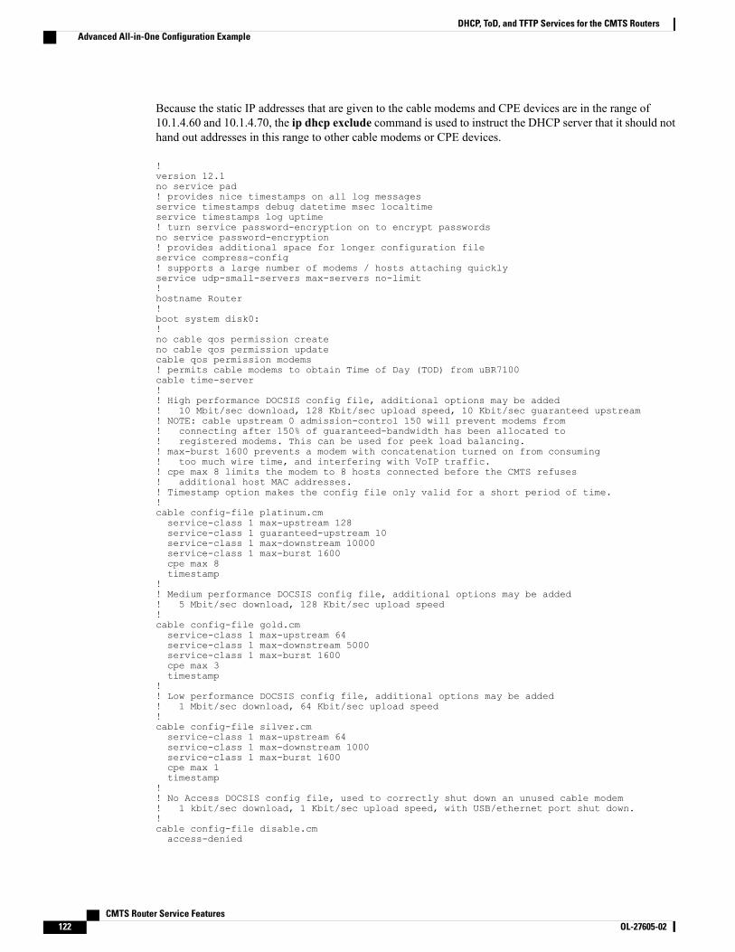
Because the static IP addresses that are given to the cable modems and CPE devices are in the range of10.1.4.60 and 10.1.4.70, the ip dhcp exclude command is used to instruct the DHCP server that it should nothand out addresses in this range to other cable modems or CPE devices.
!version 12.1no service pad! provides nice timestamps on all log messagesservice timestamps debug datetime msec localtimeservice timestamps log uptime! turn service password-encryption on to encrypt passwordsno service password-encryption! provides additional space for longer configuration fileservice compress-config! supports a large number of modems / hosts attaching quicklyservice udp-small-servers max-servers no-limit!hostname Router!boot system disk0:!no cable qos permission createno cable qos permission updatecable qos permission modems! permits cable modems to obtain Time of Day (TOD) from uBR7100cable time-server!! High performance DOCSIS config file, additional options may be added! 10 Mbit/sec download, 128 Kbit/sec upload speed, 10 Kbit/sec guaranteed upstream! NOTE: cable upstream 0 admission-control 150 will prevent modems from! connecting after 150% of guaranteed-bandwidth has been allocated to! registered modems. This can be used for peek load balancing.! max-burst 1600 prevents a modem with concatenation turned on from consuming! too much wire time, and interfering with VoIP traffic.! cpe max 8 limits the modem to 8 hosts connected before the CMTS refuses! additional host MAC addresses.! Timestamp option makes the config file only valid for a short period of time.!cable config-file platinum.cmservice-class 1 max-upstream 128service-class 1 guaranteed-upstream 10service-class 1 max-downstream 10000service-class 1 max-burst 1600cpe max 8timestamp
!! Medium performance DOCSIS config file, additional options may be added! 5 Mbit/sec download, 128 Kbit/sec upload speed!cable config-file gold.cmservice-class 1 max-upstream 64service-class 1 max-downstream 5000service-class 1 max-burst 1600cpe max 3timestamp
!! Low performance DOCSIS config file, additional options may be added! 1 Mbit/sec download, 64 Kbit/sec upload speed!cable config-file silver.cmservice-class 1 max-upstream 64service-class 1 max-downstream 1000service-class 1 max-burst 1600cpe max 1timestamp
!! No Access DOCSIS config file, used to correctly shut down an unused cable modem! 1 kbit/sec download, 1 Kbit/sec upload speed, with USB/ethernet port shut down.!cable config-file disable.cmaccess-denied
CMTS Router Service Features122 OL-27605-02
DHCP, ToD, and TFTP Services for the CMTS RoutersAdvanced All-in-One Configuration Example
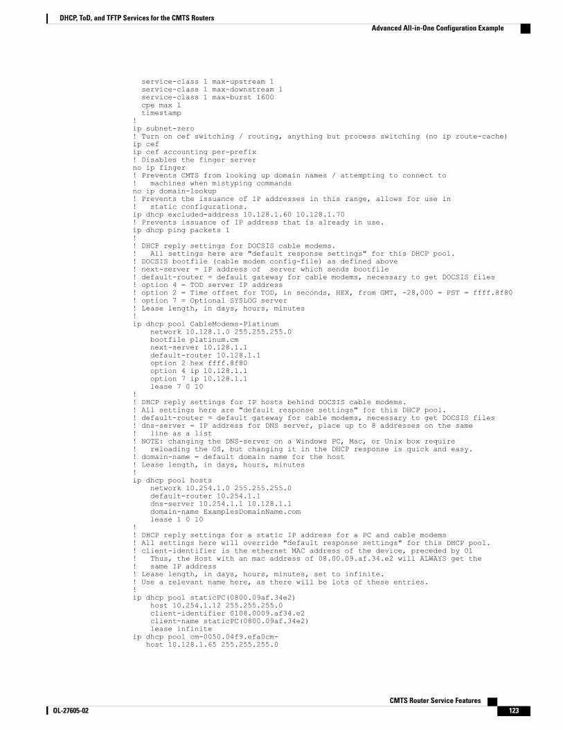
service-class 1 max-upstream 1service-class 1 max-downstream 1service-class 1 max-burst 1600cpe max 1timestamp
!ip subnet-zero! Turn on cef switching / routing, anything but process switching (no ip route-cache)ip cefip cef accounting per-prefix! Disables the finger serverno ip finger! Prevents CMTS from looking up domain names / attempting to connect to! machines when mistyping commandsno ip domain-lookup! Prevents the issuance of IP addresses in this range, allows for use in! static configurations.ip dhcp excluded-address 10.128.1.60 10.128.1.70! Prevents issuance of IP address that is already in use.ip dhcp ping packets 1!! DHCP reply settings for DOCSIS cable modems.! All settings here are "default response settings" for this DHCP pool.! DOCSIS bootfile (cable modem config-file) as defined above! next-server = IP address of server which sends bootfile! default-router = default gateway for cable modems, necessary to get DOCSIS files! option 4 = TOD server IP address! option 2 = Time offset for TOD, in seconds, HEX, from GMT, -28,000 = PST = ffff.8f80! option 7 = Optional SYSLOG server! Lease length, in days, hours, minutes!ip dhcp pool CableModems-Platinum
network 10.128.1.0 255.255.255.0bootfile platinum.cmnext-server 10.128.1.1default-router 10.128.1.1option 2 hex ffff.8f80option 4 ip 10.128.1.1option 7 ip 10.128.1.1lease 7 0 10
!! DHCP reply settings for IP hosts behind DOCSIS cable modems.! All settings here are "default response settings" for this DHCP pool.! default-router = default gateway for cable modems, necessary to get DOCSIS files! dns-server = IP address for DNS server, place up to 8 addresses on the same! line as a list! NOTE: changing the DNS-server on a Windows PC, Mac, or Unix box require! reloading the OS, but changing it in the DHCP response is quick and easy.! domain-name = default domain name for the host! Lease length, in days, hours, minutes!ip dhcp pool hosts
network 10.254.1.0 255.255.255.0default-router 10.254.1.1dns-server 10.254.1.1 10.128.1.1domain-name ExamplesDomainName.comlease 1 0 10
!! DHCP reply settings for a static IP address for a PC and cable modems! All settings here will override "default response settings" for this DHCP pool.! client-identifier is the ethernet MAC address of the device, preceded by 01! Thus, the Host with an mac address of 08.00.09.af.34.e2 will ALWAYS get the! same IP address! Lease length, in days, hours, minutes, set to infinite.! Use a relevant name here, as there will be lots of these entries.!ip dhcp pool staticPC(0800.09af.34e2)
host 10.254.1.12 255.255.255.0client-identifier 0108.0009.af34.e2client-name staticPC(0800.09af.34e2)lease infinite
ip dhcp pool cm-0050.04f9.efa0cm-host 10.128.1.65 255.255.255.0
CMTS Router Service Features OL-27605-02 123
DHCP, ToD, and TFTP Services for the CMTS RoutersAdvanced All-in-One Configuration Example
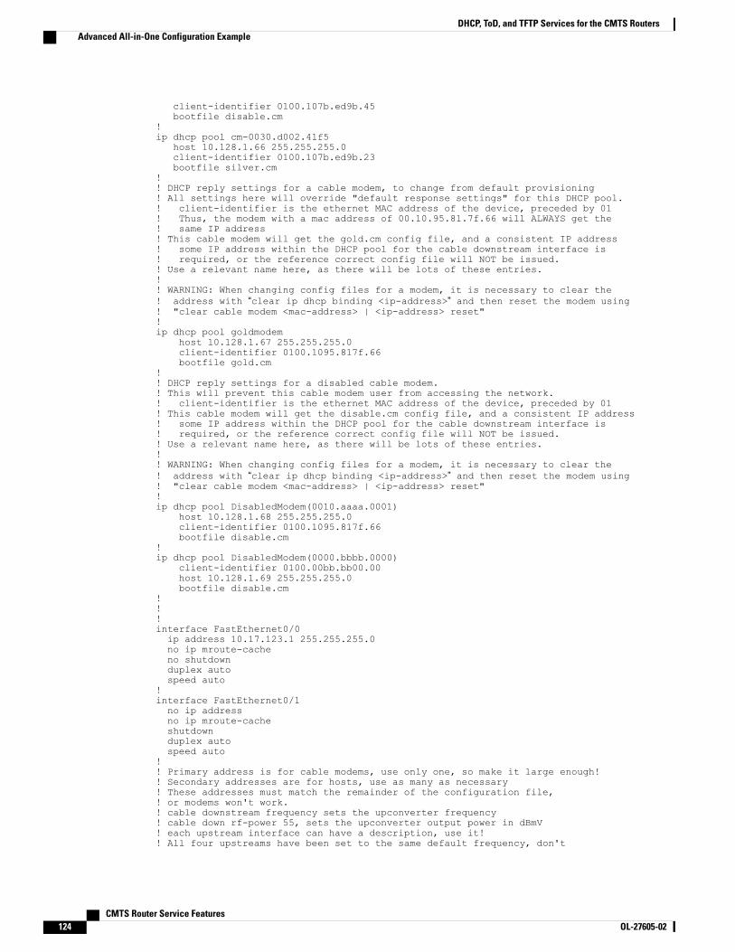
client-identifier 0100.107b.ed9b.45bootfile disable.cm
!ip dhcp pool cm-0030.d002.41f5
host 10.128.1.66 255.255.255.0client-identifier 0100.107b.ed9b.23bootfile silver.cm
!! DHCP reply settings for a cable modem, to change from default provisioning! All settings here will override "default response settings" for this DHCP pool.! client-identifier is the ethernet MAC address of the device, preceded by 01! Thus, the modem with a mac address of 00.10.95.81.7f.66 will ALWAYS get the! same IP address! This cable modem will get the gold.cm config file, and a consistent IP address! some IP address within the DHCP pool for the cable downstream interface is! required, or the reference correct config file will NOT be issued.! Use a relevant name here, as there will be lots of these entries.!! WARNING: When changing config files for a modem, it is necessary to clear the! address with “clear ip dhcp binding <ip-address>” and then reset the modem using! "clear cable modem <mac-address> | <ip-address> reset"!ip dhcp pool goldmodem
host 10.128.1.67 255.255.255.0client-identifier 0100.1095.817f.66bootfile gold.cm
!! DHCP reply settings for a disabled cable modem.! This will prevent this cable modem user from accessing the network.! client-identifier is the ethernet MAC address of the device, preceded by 01! This cable modem will get the disable.cm config file, and a consistent IP address! some IP address within the DHCP pool for the cable downstream interface is! required, or the reference correct config file will NOT be issued.! Use a relevant name here, as there will be lots of these entries.!! WARNING: When changing config files for a modem, it is necessary to clear the! address with “clear ip dhcp binding <ip-address>” and then reset the modem using! "clear cable modem <mac-address> | <ip-address> reset"!ip dhcp pool DisabledModem(0010.aaaa.0001)
host 10.128.1.68 255.255.255.0client-identifier 0100.1095.817f.66bootfile disable.cm
!ip dhcp pool DisabledModem(0000.bbbb.0000)
client-identifier 0100.00bb.bb00.00host 10.128.1.69 255.255.255.0bootfile disable.cm
!!!interface FastEthernet0/0ip address 10.17.123.1 255.255.255.0no ip mroute-cacheno shutdownduplex autospeed auto
!interface FastEthernet0/1no ip addressno ip mroute-cacheshutdownduplex autospeed auto
!! Primary address is for cable modems, use only one, so make it large enough!! Secondary addresses are for hosts, use as many as necessary! These addresses must match the remainder of the configuration file,! or modems won't work.! cable downstream frequency sets the upconverter frequency! cable down rf-power 55, sets the upconverter output power in dBmV! each upstream interface can have a description, use it!! All four upstreams have been set to the same default frequency, don't
CMTS Router Service Features124 OL-27605-02
DHCP, ToD, and TFTP Services for the CMTS RoutersAdvanced All-in-One Configuration Example
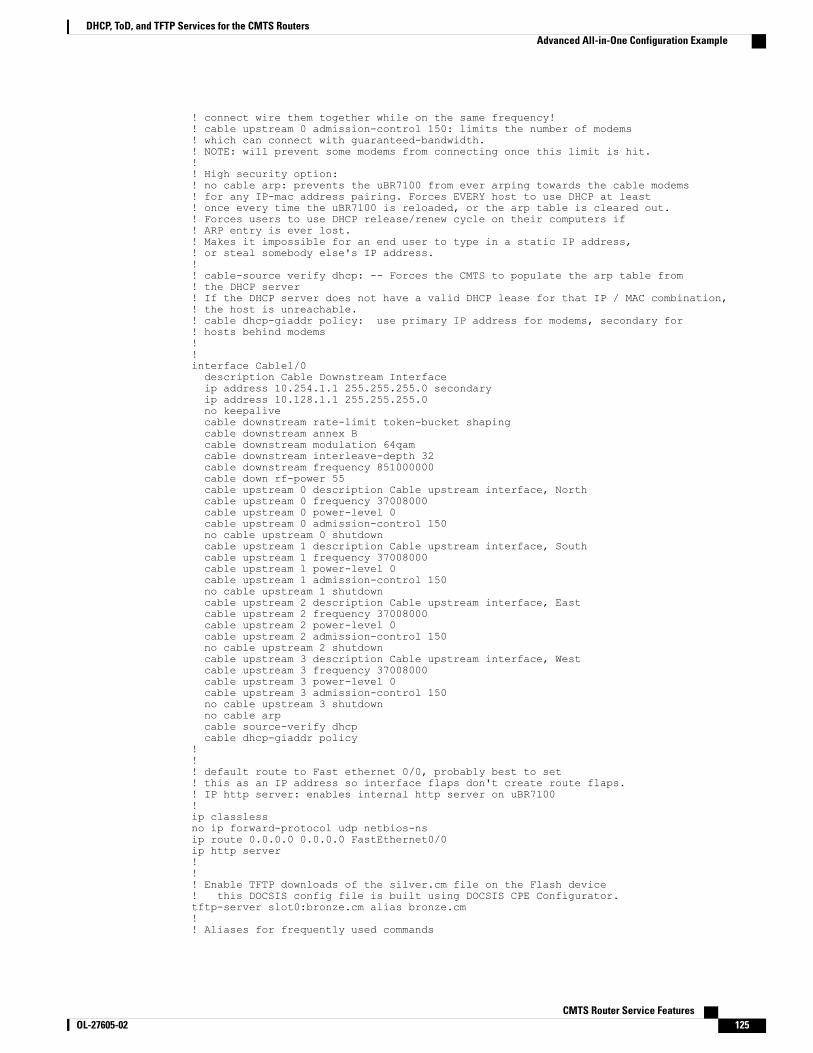
! connect wire them together while on the same frequency!! cable upstream 0 admission-control 150: limits the number of modems! which can connect with guaranteed-bandwidth.! NOTE: will prevent some modems from connecting once this limit is hit.!! High security option:! no cable arp: prevents the uBR7100 from ever arping towards the cable modems! for any IP-mac address pairing. Forces EVERY host to use DHCP at least! once every time the uBR7100 is reloaded, or the arp table is cleared out.! Forces users to use DHCP release/renew cycle on their computers if! ARP entry is ever lost.! Makes it impossible for an end user to type in a static IP address,! or steal somebody else's IP address.!! cable-source verify dhcp: -- Forces the CMTS to populate the arp table from! the DHCP server! If the DHCP server does not have a valid DHCP lease for that IP / MAC combination,! the host is unreachable.! cable dhcp-giaddr policy: use primary IP address for modems, secondary for! hosts behind modems!!interface Cable1/0description Cable Downstream Interfaceip address 10.254.1.1 255.255.255.0 secondaryip address 10.128.1.1 255.255.255.0no keepalivecable downstream rate-limit token-bucket shapingcable downstream annex Bcable downstream modulation 64qamcable downstream interleave-depth 32cable downstream frequency 851000000cable down rf-power 55cable upstream 0 description Cable upstream interface, Northcable upstream 0 frequency 37008000cable upstream 0 power-level 0cable upstream 0 admission-control 150no cable upstream 0 shutdowncable upstream 1 description Cable upstream interface, Southcable upstream 1 frequency 37008000cable upstream 1 power-level 0cable upstream 1 admission-control 150no cable upstream 1 shutdowncable upstream 2 description Cable upstream interface, Eastcable upstream 2 frequency 37008000cable upstream 2 power-level 0cable upstream 2 admission-control 150no cable upstream 2 shutdowncable upstream 3 description Cable upstream interface, Westcable upstream 3 frequency 37008000cable upstream 3 power-level 0cable upstream 3 admission-control 150no cable upstream 3 shutdownno cable arpcable source-verify dhcpcable dhcp-giaddr policy
!!! default route to Fast ethernet 0/0, probably best to set! this as an IP address so interface flaps don't create route flaps.! IP http server: enables internal http server on uBR7100!ip classlessno ip forward-protocol udp netbios-nsip route 0.0.0.0 0.0.0.0 FastEthernet0/0ip http server!!! Enable TFTP downloads of the silver.cm file on the Flash device! this DOCSIS config file is built using DOCSIS CPE Configurator.tftp-server slot0:bronze.cm alias bronze.cm!! Aliases for frequently used commands
CMTS Router Service Features OL-27605-02 125
DHCP, ToD, and TFTP Services for the CMTS RoutersAdvanced All-in-One Configuration Example
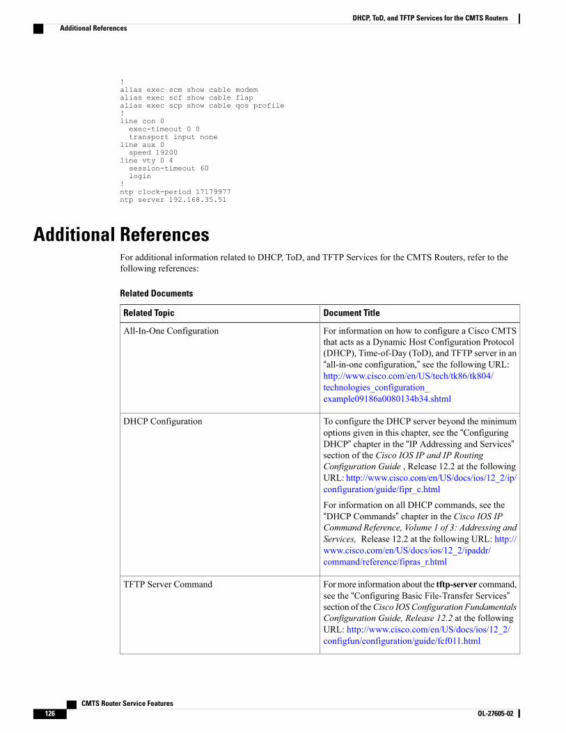
!alias exec scm show cable modemalias exec scf show cable flapalias exec scp show cable qos profile!line con 0exec-timeout 0 0transport input none
line aux 0speed 19200
line vty 0 4session-timeout 60login
!ntp clock-period 17179977ntp server 192.168.35.51
Additional ReferencesFor additional information related to DHCP, ToD, and TFTP Services for the CMTS Routers, refer to thefollowing references:
Related Documents
Document TitleRelated Topic
For information on how to configure a Cisco CMTSthat acts as a Dynamic Host Configuration Protocol(DHCP), Time-of-Day (ToD), and TFTP server in an“all-in-one configuration,” see the following URL:http://www.cisco.com/en/US/tech/tk86/tk804/technologies_configuration_example09186a0080134b34.shtml
All-In-One Configuration
To configure the DHCP server beyond the minimumoptions given in this chapter, see the “ConfiguringDHCP” chapter in the “IP Addressing and Services”section of the Cisco IOS IP and IP RoutingConfiguration Guide , Release 12.2 at the followingURL: http://www.cisco.com/en/US/docs/ios/12_2/ip/configuration/guide/fipr_c.html
For information on all DHCP commands, see the“DHCP Commands” chapter in the Cisco IOS IPCommand Reference, Volume 1 of 3: Addressing andServices, Release 12.2 at the following URL: http://www.cisco.com/en/US/docs/ios/12_2/ipaddr/command/reference/fipras_r.html
DHCP Configuration
Formore information about the tftp-server command,see the “Configuring Basic File-Transfer Services”section of theCisco IOS Configuration FundamentalsConfiguration Guide, Release 12.2 at the followingURL: http://www.cisco.com/en/US/docs/ios/12_2/configfun/configuration/guide/fcf011.html
TFTP Server Command
CMTS Router Service Features126 OL-27605-02
DHCP, ToD, and TFTP Services for the CMTS RoutersAdditional References
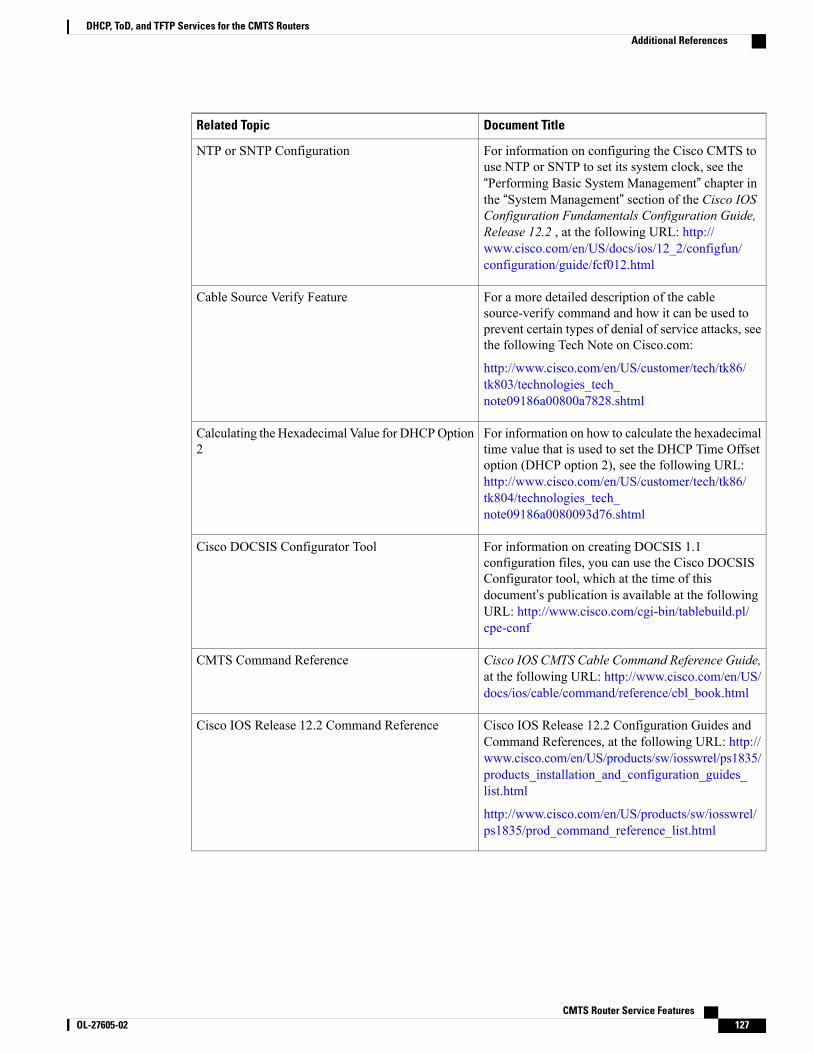
Document TitleRelated Topic
For information on configuring the Cisco CMTS touse NTP or SNTP to set its system clock, see the“Performing Basic System Management” chapter inthe “System Management” section of the Cisco IOSConfiguration Fundamentals Configuration Guide,Release 12.2 , at the following URL: http://www.cisco.com/en/US/docs/ios/12_2/configfun/configuration/guide/fcf012.html
NTP or SNTP Configuration
For a more detailed description of the cablesource-verify command and how it can be used toprevent certain types of denial of service attacks, seethe following Tech Note on Cisco.com:
http://www.cisco.com/en/US/customer/tech/tk86/tk803/technologies_tech_note09186a00800a7828.shtml
Cable Source Verify Feature
For information on how to calculate the hexadecimaltime value that is used to set the DHCP Time Offsetoption (DHCP option 2), see the following URL:http://www.cisco.com/en/US/customer/tech/tk86/tk804/technologies_tech_note09186a0080093d76.shtml
Calculating the Hexadecimal Value for DHCPOption2
For information on creating DOCSIS 1.1configuration files, you can use the Cisco DOCSISConfigurator tool, which at the time of thisdocument’s publication is available at the followingURL: http://www.cisco.com/cgi-bin/tablebuild.pl/cpe-conf
Cisco DOCSIS Configurator Tool
Cisco IOS CMTS Cable Command Reference Guide,at the following URL: http://www.cisco.com/en/US/docs/ios/cable/command/reference/cbl_book.html
CMTS Command Reference
Cisco IOS Release 12.2 Configuration Guides andCommand References, at the following URL: http://www.cisco.com/en/US/products/sw/iosswrel/ps1835/products_installation_and_configuration_guides_list.html
http://www.cisco.com/en/US/products/sw/iosswrel/ps1835/prod_command_reference_list.html
Cisco IOS Release 12.2 Command Reference
CMTS Router Service Features OL-27605-02 127
DHCP, ToD, and TFTP Services for the CMTS RoutersAdditional References
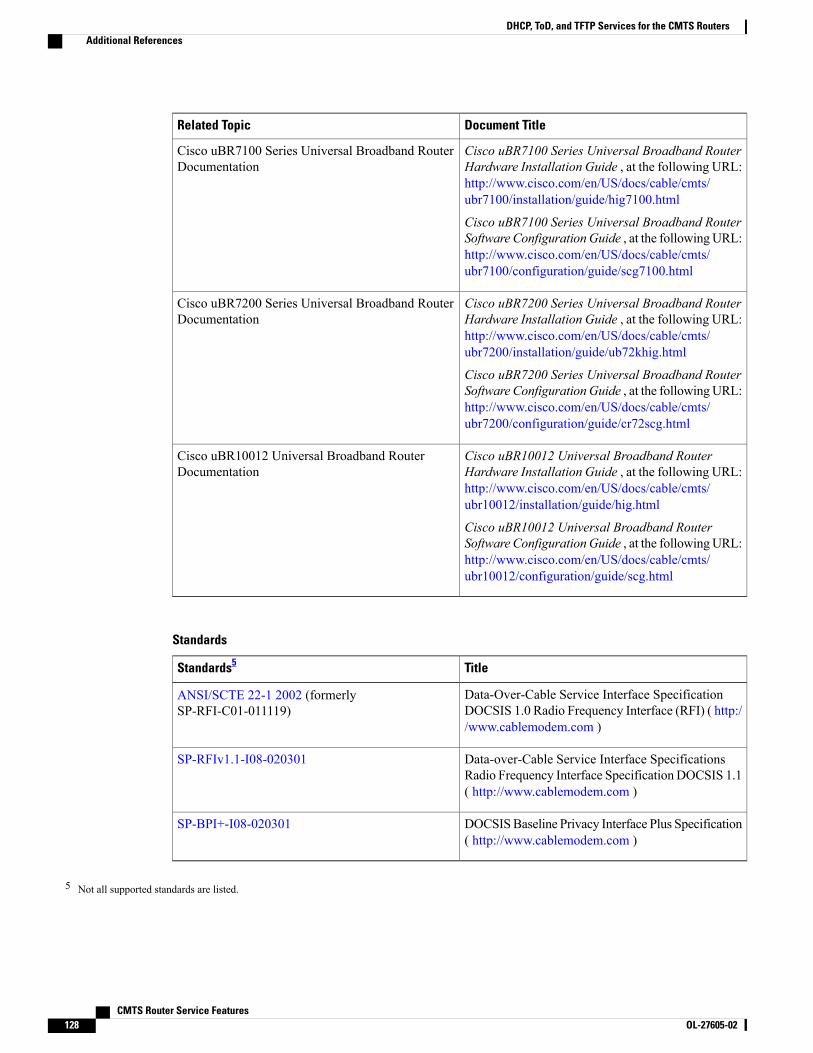
Document TitleRelated Topic
Cisco uBR7100 Series Universal Broadband RouterHardware Installation Guide , at the following URL:http://www.cisco.com/en/US/docs/cable/cmts/ubr7100/installation/guide/hig7100.html
Cisco uBR7100 Series Universal Broadband RouterSoftware ConfigurationGuide , at the followingURL:http://www.cisco.com/en/US/docs/cable/cmts/ubr7100/configuration/guide/scg7100.html
Cisco uBR7100 Series Universal Broadband RouterDocumentation
Cisco uBR7200 Series Universal Broadband RouterHardware Installation Guide , at the following URL:http://www.cisco.com/en/US/docs/cable/cmts/ubr7200/installation/guide/ub72khig.html
Cisco uBR7200 Series Universal Broadband RouterSoftware ConfigurationGuide , at the followingURL:http://www.cisco.com/en/US/docs/cable/cmts/ubr7200/configuration/guide/cr72scg.html
Cisco uBR7200 Series Universal Broadband RouterDocumentation
Cisco uBR10012 Universal Broadband RouterHardware Installation Guide , at the following URL:http://www.cisco.com/en/US/docs/cable/cmts/ubr10012/installation/guide/hig.html
Cisco uBR10012 Universal Broadband RouterSoftware ConfigurationGuide , at the followingURL:http://www.cisco.com/en/US/docs/cable/cmts/ubr10012/configuration/guide/scg.html
Cisco uBR10012 Universal Broadband RouterDocumentation
Standards
TitleStandards5
Data-Over-Cable Service Interface SpecificationDOCSIS 1.0 Radio Frequency Interface (RFI) ( http://www.cablemodem.com )
ANSI/SCTE 22-1 2002 (formerlySP-RFI-C01-011119)
Data-over-Cable Service Interface SpecificationsRadio Frequency Interface SpecificationDOCSIS 1.1( http://www.cablemodem.com )
SP-RFIv1.1-I08-020301
DOCSISBaseline Privacy Interface Plus Specification( http://www.cablemodem.com )
SP-BPI+-I08-020301
5 Not all supported standards are listed.
CMTS Router Service Features128 OL-27605-02
DHCP, ToD, and TFTP Services for the CMTS RoutersAdditional References

MIBs
MIBs LinkMIBs6
To locate and downloadMIBs for selected platforms,Cisco IOS releases, and feature sets, use Cisco MIBLocator found at the following URL:
http://www.cisco.com/go/mibs
• DOCS-CABLE-DEVICE-MIB ( RFC 2669 )
6 Not all supported MIBs are listed.
RFCs
TitleRFCs7
Time ProtocolRFC 868
The TFTP Protocol (Revision 2)RFC 1350
Dynamic Host Configuration ProtocolRFC 2131
DCHP Options and BOOTP Vendor ExtensionsRFC 2132
TFTP Timeout Interval and Transfer Size OptionsRFC 2349
DHCP Relay Agent Information OptionRFC 3046
DHCP Relay Agent Information Sub-OptionRFC4243
7 Not all supported RFCs are listed.
Technical Assistance
LinkDescription
http://www.cisco.com/cisco/web/support/index.htmlTechnical Assistance Center (TAC) home page,containing 30,000 pages of searchable technicalcontent, including links to products, technologies,solutions, technical tips, and tools. RegisteredCisco.com users can log in from this page to accesseven more content.
CMTS Router Service Features OL-27605-02 129
DHCP, ToD, and TFTP Services for the CMTS RoutersAdditional References
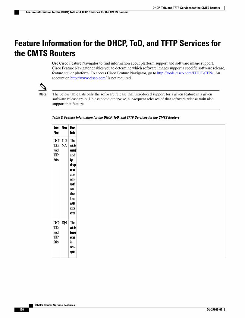
Feature Information for the DHCP, ToD, and TFTP Services forthe CMTS Routers
Use Cisco Feature Navigator to find information about platform support and software image support.Cisco Feature Navigator enables you to determine which software images support a specific software release,feature set, or platform. To access Cisco Feature Navigator, go to http://tools.cisco.com/ITDIT/CFN/. Anaccount on http://www.cisco.com/ is not required.
The below table lists only the software release that introduced support for a given feature in a givensoftware release train. Unless noted otherwise, subsequent releases of that software release train alsosupport that feature.
Note
Table 6: Feature Information for the DHCP, ToD, and TFTP Services for the CMTS Routers
FeatureInformation
ReleasesFeatureName
Thecablesource-verifyandipdhcpcommandsarenowsupportedontheCiscouBR7200seriesrouters.
11.3NA
DHCP,ToD,andTFTPServices
Thecabletime-servercommandisnowsupported.
12.0(4)XIDHCP,ToD,andTFTPServices
CMTS Router Service Features130 OL-27605-02
DHCP, ToD, and TFTP Services for the CMTS RoutersFeature Information for the DHCP, ToD, and TFTP Services for the CMTS Routers
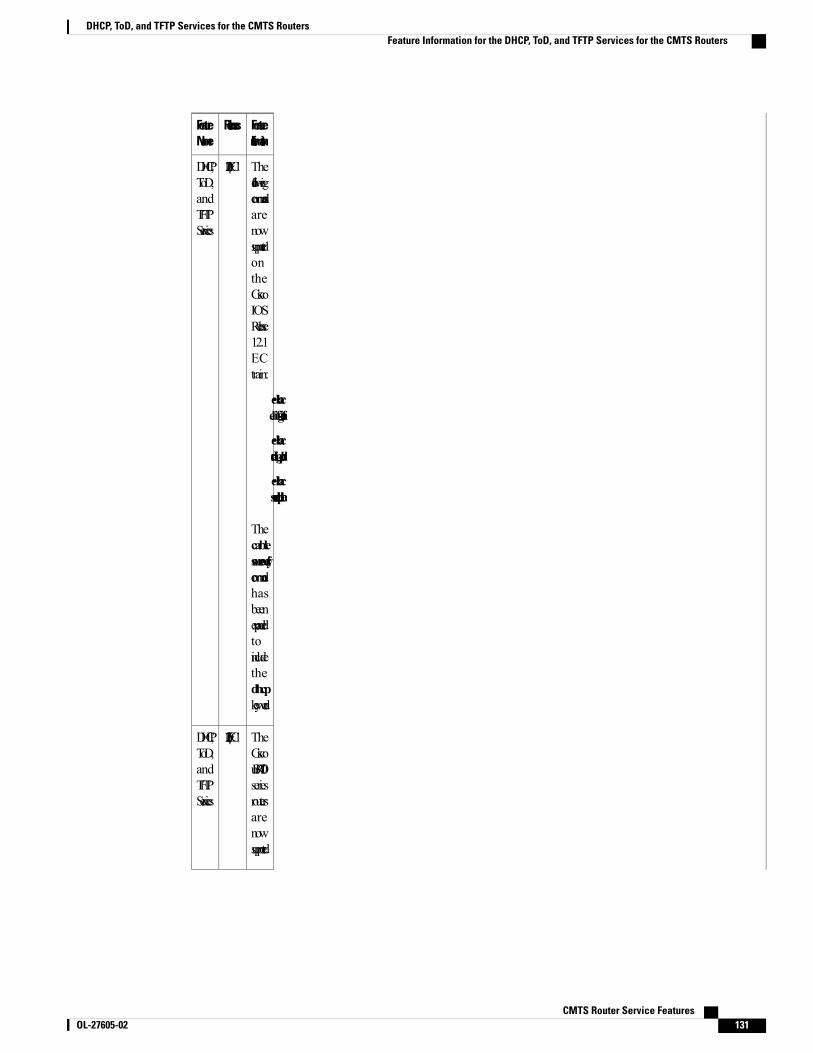
FeatureInformation
ReleasesFeatureName
ThefollowingcommandsarenowsupportedontheCiscoIOSRelease12.1ECtrain:
• cableconfig-file
• cabledhcp-giaddr
• cablehelper-address
Thecablesource-verifycommandhasbeenexpandedtoincludethedhcpkeyword.
12.1(2)EC1DHCP,ToD,andTFTPServices
TheCiscouBR7100seriesroutersarenowsupported.
12.1(5)EC1DHCP,ToD,andTFTPServices
CMTS Router Service Features OL-27605-02 131
DHCP, ToD, and TFTP Services for the CMTS RoutersFeature Information for the DHCP, ToD, and TFTP Services for the CMTS Routers
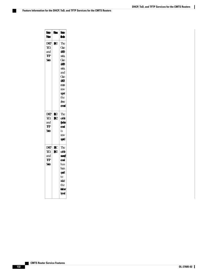
FeatureInformation
ReleasesFeatureName
TheCiscouBR7100series,CiscouBR7200series,andCiscouBR10012routersnowsupporttheabovecommands.
12.2(4)BC1DHCP,ToD,andTFTPServices
Thecabletftp-enforcecommandisnowsupported.
12.1(11b)EC112.2(8)BC2
DHCP,ToD,andTFTPServices
Thecablesource-verifycommandhasbeenexpandedtoincludetheleasetimerkeyword.
12.1(13)EC12.2(11)BC1
DHCP,ToD,andTFTPServices
CMTS Router Service Features132 OL-27605-02
DHCP, ToD, and TFTP Services for the CMTS RoutersFeature Information for the DHCP, ToD, and TFTP Services for the CMTS Routers
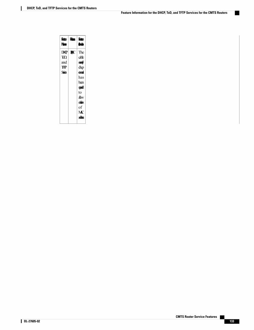
FeatureInformation
ReleasesFeatureName
Thecablesource-verifydhcpcommandhasbeenexpandedtoallowexclusionofMACaddresses.
12.3(13)BCDHCP,ToD,andTFTPServices
CMTS Router Service Features OL-27605-02 133
DHCP, ToD, and TFTP Services for the CMTS RoutersFeature Information for the DHCP, ToD, and TFTP Services for the CMTS Routers

FeatureInformation
ReleasesFeatureName
12.3(21)BCDHCP,ToD,andTFTPServices
CMTS Router Service Features134 OL-27605-02
DHCP, ToD, and TFTP Services for the CMTS RoutersFeature Information for the DHCP, ToD, and TFTP Services for the CMTS Routers

FeatureInformation
ReleasesFeatureName
Thecablehelper-addresscommandhasbeenexpandedtofurtherspecifywheretoforwardDHCPpacketsbasedonorigin:fromacablemodem,MTA,STB,orothercabledevices.
Thecabledhcp-insertcommandallowsuserstoconfiguretheCMTStoinsertdescriptorsintoDHCPpacketsusingoption82.DHCP
CMTS Router Service Features OL-27605-02 135
DHCP, ToD, and TFTP Services for the CMTS RoutersFeature Information for the DHCP, ToD, and TFTP Services for the CMTS Routers
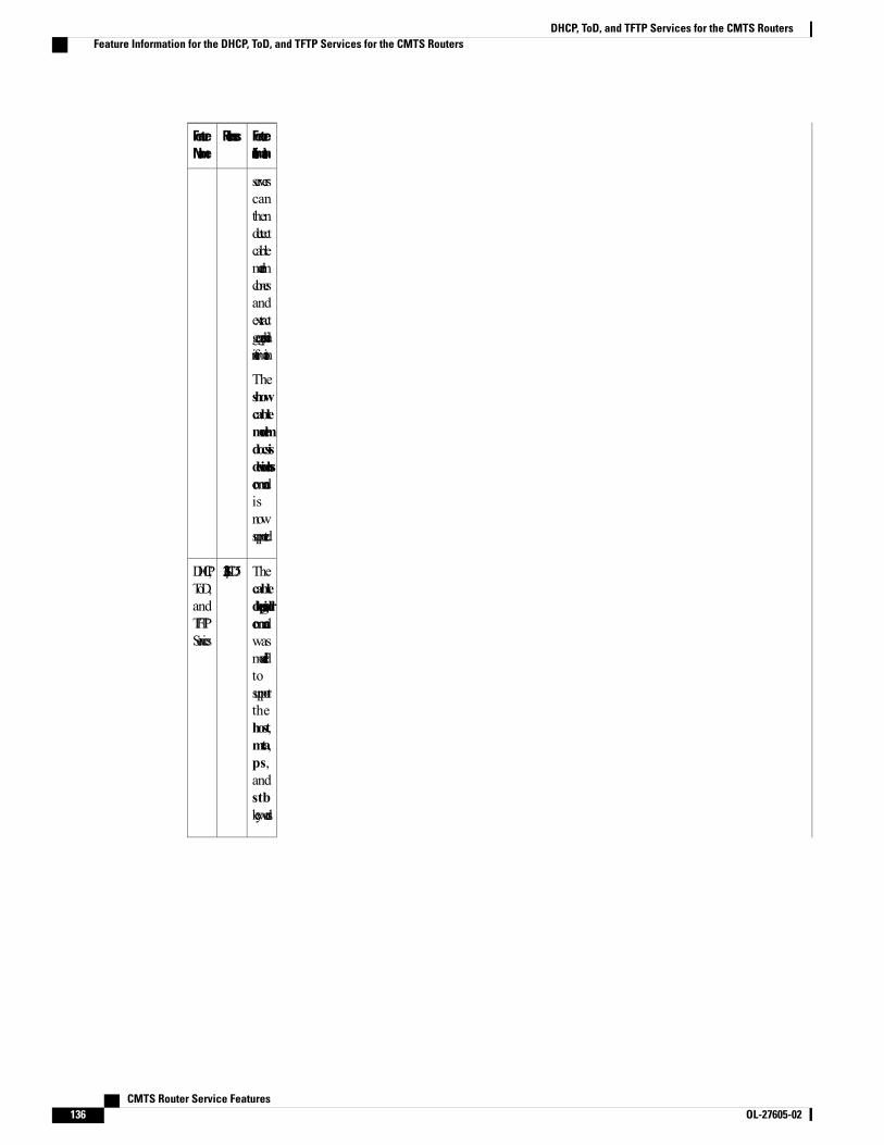
FeatureInformation
ReleasesFeatureName
serverscanthendetectcablemodemclonesandextractgeographicalinformation.
Theshowcablemodemdocsisdevice-classcommandisnowsupported.
Thecabledhcp-giaddrcommandwasmodifiedtosupportthehost,mta,ps,andstbkeywords.
12.2(33)SCD5DHCP,ToD,andTFTPServices
CMTS Router Service Features136 OL-27605-02
DHCP, ToD, and TFTP Services for the CMTS RoutersFeature Information for the DHCP, ToD, and TFTP Services for the CMTS Routers
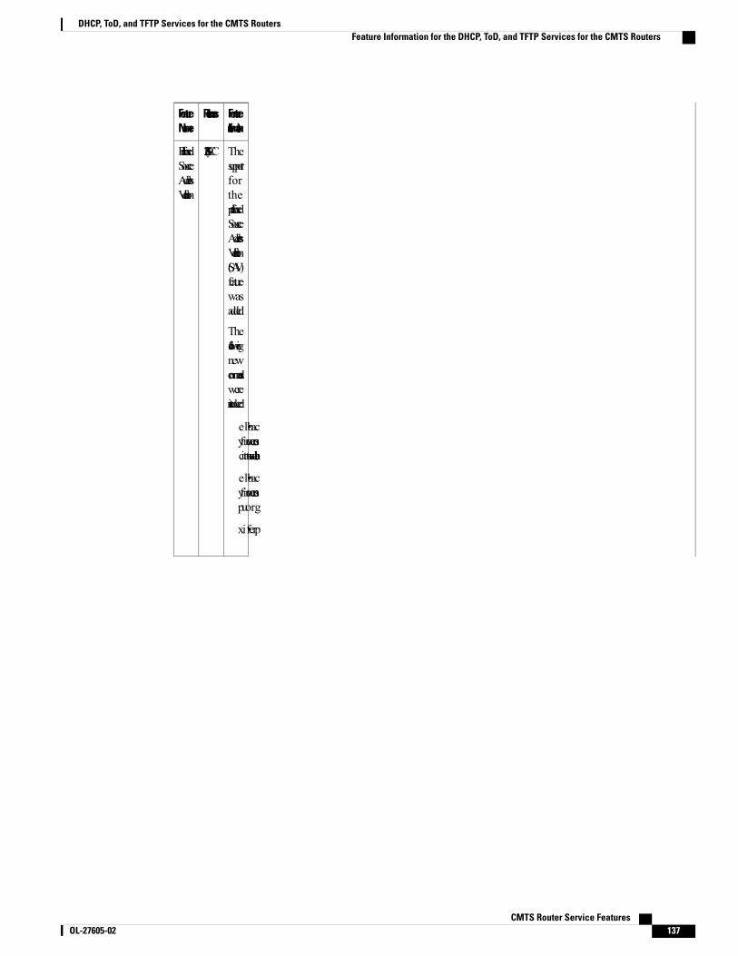
FeatureInformation
ReleasesFeatureName
Thesupportfortheprefix-basedSourceAddressVerification(SAV)featurewasadded.
Thefollowingnewcommandswereintroduced:
• cablesource-verifyenable-sav-static
• cablesource-verifygroup
• prefix
12.2(33)SCCPrefix-basedSourceAddressVerification
CMTS Router Service Features OL-27605-02 137
DHCP, ToD, and TFTP Services for the CMTS RoutersFeature Information for the DHCP, ToD, and TFTP Services for the CMTS Routers
FeatureInformation
ReleasesFeatureName
SupportwasaddedfortheDHCPRelayAgentInformationSub-Optionenhancement.
Thefollowingcommandswasmodified:
• cabledhcp-insertservice-class
12.2(33)SCF2DHCPRelayAgentSub-Option
Supported Platforms
Cisco uBR7100 series, Cisco uBR7200 series, Cisco uBR10012 universal broadband routers.
CMTS Router Service Features138 OL-27605-02
DHCP, ToD, and TFTP Services for the CMTS RoutersFeature Information for the DHCP, ToD, and TFTP Services for the CMTS Routers