DG Series - cnc-club.ru
32
RoHS-Compliant Hollow Rotary Actuators DG Series The DG Series is a rotary actuator featuring a hollow output table that allows large-inertia discs and arms to be installed directly. The range of applications has widened with the addition of models with a frame size of 200 mm (7.87 in.) and permissible torque of 50 Nm (440 lb-in).
-
Upload
khangminh22 -
Category
Documents
-
view
0 -
download
0
Transcript of DG Series - cnc-club.ru

RoHS-Compliant
Hollow Rotary Actuators
DG SeriesThe DG Series is a rotary actuator featuring a hollow output table that allows large-inertia discs and arms
to be installed directly. The range of applications has widened with the addition of models with a frame size of 200 mm (7.87 in.) and permissible torque of 50 N�m (440 lb-in).
DG
series
High Output, High Rigidity
High Accuracy Positioning without Backlash
Pinion
NEW
DG Series actuators feature a compact,
hollow output table that allows large-inertia discs and
arms to be installed directly.
Gear
Motor
Lineup
(With integrated cross-roller bearings)✽Except for DG60
Output Table
�Permissible Torque: 0.9 N m (7.9 lb-in)�Frame Size: 60 mm (2.36 in.)
�Permissible Torque: 2.8 N m (24 lb-in)�Frame Size: 85 mm (3.35 in.)
�Permissible Torque: 12 N m (106 lb-in)�Frame Size: 130 mm (5.12 in.)
�Permissible Torque: 50 N m (440 lb-in)�Frame Size: 200 mm (7.87 in.)
The hollow output table is integrated with a high rigidity cross-roller
bearing✽.
This structure improves permissible thrust load and moment load
while maintaining high torque.
✽Except for DG60
Repetitive positioning accuracy: �15 sec
Lost Motion: 2 min
2

3
Equipment tables and arms can be installed directly on the output table.
This saves you the hassle and cost of designing an installation
mechanism, arranging necessary parts, adjusting the belt tension, etc.,
when mechanical parts such as belt and pulley are used for installation.
Less Hassle with Direct Coupling
The DG Series conforms to the RoHS Directive that prohibits the use of six
chemical substances including lead and cadmium.
A Hollow hole (through hole) of sufficiently large diameter helps reduce the
complexity of wiring and piping, thus further simplifying your equipment
design.
Large-Diameter, Hollow Output Table Makes Possible Simple Wiring and Piping
Supporting Sudden Load Fluctuation and Rapid Acceleration The sensor set comes with all the parts required for the return to home
operation, meaning you will spend less time designing, fabricating and
procuring parts relating to sensor installation.
Home-Sensor Set is Available as an Accessory
RoHS-Compliant
RoHS (Restriction of Hazardous Substances) Directive:Directive on restriction of the use of certain hazardous substances in electrical and electronic equipment (2002/95/EC).The RoHS Directive prohibits the use of six chemical substances in electrical and electronic products sold in the EU member states. The six controlled substances are: lead, hexavalent chromium, cadmium, mercury and two specific brominated flame-retardants (PBB and PBDE).
DG60DG85DG130DG200
Frame Size [mm (in.)]60 (2.36)85 (3.35)
130 (5.12)200 (7.87)
60 (2.36)85 (3.35)
130 (5.12)200 (7.87)
Permissible Thrust Load [N (lb.)] 100 (22)500 (112)
2000 (450)4000 (900)NEW
DG60DG85DG130DG200
Frame Size [mm (in.)] Diameter of Hollow Section [mm (in.)]28 (1.1)33 (1.3)62 (2.44)
100 (3.94)NEW
Example of sensor installationon DG130
Example: DG200
Adopting a closed loop stepping motor designed to maintain
synchronism, the DG Series actuator eliminates the need for tuning to
prevent hunting upon sudden load fluctuation or rapid acceleration.
A built-in rotor position detection
sensor constantly monitors the
motor speed and position. If
synchronism is about to be lost,
closed-loop control is implemented
immediately. With the DG Series,
you can also enjoy greater reliability
because the positioning completion
signal and position detection
function can be used to check the
actuator condition.
Stable operation can be achieved
without adjustment, even when your
equipment is subject to load
fluctuation.
�20
0 m
m (�
7.87
in.)
�100 mm(�3.94 in.)

4
Type and Structure
DG60
Permissible Torque: 0.9 N�m (7.9 lb-in)Permissible Thrust Load: 100 N (22 lb.)Permissible Moment Load: 2 N�m (17.7 lb-in.)
���
DG85, DG130, DG200
Permissible Torque: 50 N�m (440 lb-in)Permissible Thrust Load: 4000 N (900 lb.)Permissible Moment Load: 100 N�m (880 lb-in)(The above value is for DG200.)
���
��
�
Deep-Groove Ball Bearings
Output Table
Output Table
Cross-Roller Bearing
Permissible TorqueThe hollow rotary actuators with larger permissible torque deliver stable, high speed positioning of larger inertial loads. Select the model that best suits your application.
0 50 100 150 250200
100
10
1
0.1
Speed [r/min]
Torq
ue [N
·m]
Torq
ue [l
b-in
]
0
8.85
88.5
885
50 N·m(440 lb-in)
DG200
DG130
DG85
DG60
12 N·m (106 lb-in)
2.8 N·m (24 lb-in)
0.9 N·m (7.9 lb-in)
RigidityThe output table uses deep-groove ball bearings (two pieces) for the 60 mm (2.36 in.) frame size type, and a cross-roller bearing for the 85 mm (3.35 in.), 130 mm (5.12 in.) and 200 mm (7.87 in.) frame size types. As the frame size increases, the permissible moment load also increases but the displacement caused by the moment load decreases.
Distance from centerof rotation L [mm]
Arm
F [N]
Disp
lace
men
t [�
m]
300
250
200
150
100
50
00 20 40 60 80 100
DG130
DG85
DG200
DG60
Disp
lace
men
t [µm
]
Disp
lace
men
t [in
ch �
10-3
]
4
2
0
6
8
10 High Permissible Moment
Displacement at distance L = 200 mm (7.87 in.)from center of rotation
High
Rigi
dity (
Small
Disp
lacem
ent)
Moment Load [N·m]
Moment Load [lb-in]0 200 400 600 800
Applications
Applications subject to changing load inertia
High accuracy positioning applications
��
�
Applications where a moment load is applied
High accuracy positioning applications using the hollow hole
�
�
Optical applications using the hollow hole
Air absorption applications using the hollow hole
�
�
5
System ConfigurationAn example of a single-axis system configuration with the EMP400 Series controller.
DG Series
Controller (Sold separately)
Selectable Accessories and Peripheral Equipment (Sold separately)
(Sold separately)
�Controller (➜ Page 31)
Actuator Driver
AC Power Supply(Main Power Supply)
�Home-Sensor Set (➜ Page 24)
�Driver Cables General-Purpose Type (➜ Page 28)
�Driver Cables Dedicated Type (Conforms to EMP Series) (➜ Page 28)
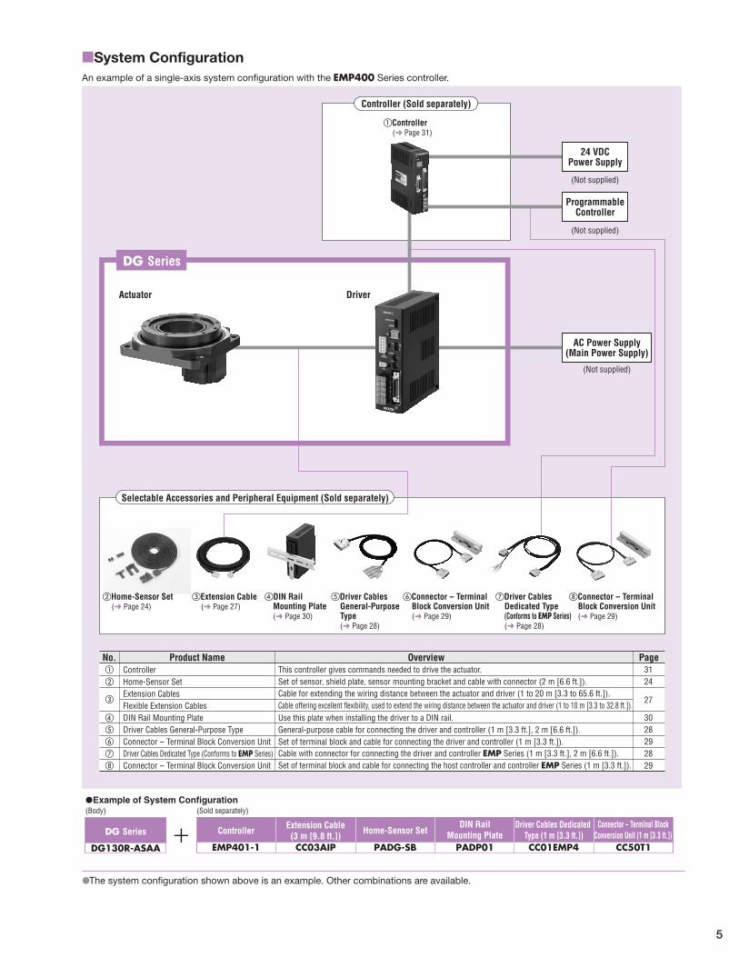
�Connector -- Terminal Block Conversion Unit (➜ Page 29)
�Connector -- Terminal Block Conversion Unit (➜ Page 29)
�DIN Rail Mounting Plate (➜ Page 30)
Driver Cables Dedicated Type (1 m [3.3 ft.])CC01EMP4EMP401-1
Connector -- Terminal BlockConversion Unit (1 m [3.3 ft.])
CC50T1
DIN RailMounting Plate
PADP01
Home-Sensor Set
PADG-SB
Controller Extension Cable(3 m [9.8 ft.])CC03AIP
ProgrammableController
(Not supplied)
(Not supplied)
24 VDCPower Supply
(Not supplied)
DG130R-ASAA
�Example of System Configuration(Body)
DG Series
No. Product Name Overview Page
24
30
27
28292829
�
�
�
�
�
Home-Sensor Set
DIN Rail Mounting PlateDriver Cables General-Purpose TypeConnector -- Terminal Block Conversion UnitDriver Cables Dedicated Type (Conforms to EMP Series)
Set of sensor, shield plate, sensor mounting bracket and cable with connector (2 m [6.6 ft.]).31� Controller This controller gives commands needed to drive the actuator.
Use this plate when installing the driver to a DIN rail.General-purpose cable for connecting the driver and controller (1 m [3.3 ft.], 2 m [6.6 ft.]).Set of terminal block and cable for connecting the driver and controller (1 m [3.3 ft.]).Cable with connector for connecting the driver and controller EMP Series (1 m [3.3 ft.], 2 m [6.6 ft.]).
Connector -- Terminal Block Conversion Unit Set of terminal block and cable for connecting the host controller and controller EMP Series (1 m [3.3 ft.]).
Extension Cable (➜ Page 27)
�
Extension CablesFlexible Extension Cables
Cable for extending the wiring distance between the actuator and driver (1 to 20 m [3.3 to 65.6 ft.]).Cable offering excellent flexibility, used to extend the wiring distance between the actuator and driver (1 to 10 m [3.3 to 32.8 ft.]).
The system configuration shown above is an example. Other combinations are available.
�
�

6
Product Number Code
DG 130 R - AS A A� � � � �
�
Product Line�DC Input �AC Input
24 VDC Single-Phase 100-115 VAC Single-Phase 200-230 VAC Three-Phase 200-230 VACModel Model Model Model
DG60-ASAK DG85R-ASAA � �
DG60-ASBK DG85R-ASBA � �
DG130R-ASAA DG130R-ASAC DG130R-ASASDG130R-ASBA DG130R-ASBC DG130R-ASBSDG200R-ASAA DG200R-ASAC DG200R-ASASDG200R-ASBA DG200R-ASBC DG200R-ASBS
Actuator, Driver, Connector for Input/Output Signal, Power Connector✽1, Mounting Bracket for Driver (with screws)✽2, Operating Manual1 Only for DG60 ✽2 Only for DG85, DG130 and DG200✽
The following items are included in each product.
Safety Standards and CE Marking
DG60Product Model Applicable Standards Certification Body Standards File No. CE Marking
Motor ASM34AK-D, ASM34BK-D UL 60950CSA C22.2 No.60950
UL E208200
EMC DirectivesDriver ASD10A-K
UL 508CCSA C22.2 No.14
ULE171462
UL 1950CSA C22.2 No.950
E208200
DG85, DG130, DG200Product Model Applicable Standards Certification Body Standards File No. CE Marking
Motor
ASM46AA-D, ASM46BA-DASM66AA-D, ASM66BA-DASM66AC-D, ASM66BC-DASM911AA-D, ASM911BA-DASM911AC-D, ASM911BC-D
UL 1004, UL 2111, CSA C22.2 No.100✽1
CSA C22.2 No.77✽1
UL E64199
Low Voltage Directives
EMC Directives✽4
EN 60950-1EN 60034-1EN 60034-5IEC 60664-1
Conformed Product
Driver
ASD13B-A, ASD24A-AASD30E-A, ASD12A-CASD20A-C, ASD12A-SASD20A-S
UL 508C✽2
CSA C22.2 No14UL E171462
EN 60950-1✽3
EN 50178Conformed Product
1 Except for DG852 Recognized by UL in accordance with UL 508C at Maximum Surrounding Air Temperature 50˚C (122˚F).3 Only pulse input drivers comply with EN 60950-1.4 The EMC value changes according to the wiring and layout. Therefore, the final EMC level must be checked with the actuator and driver incorporated in the user's equipment. For installation conditions, refer to operating manual.
�
��
�
✽
✽
✽
✽
� Series DG: DG Series
�Frame Size 60: 60 mm (2.36 in.) 85: 85 mm (3.35 in.)
130: 130 mm (5.12 in.) 200: 200 mm (7.87 in.)
�Type of Output Table Supporting Bearing Blank: Deep-Groove Ball Bearing
R: Cross-Roller Bearing
� Motor Type AS: � Motor Shaft A: Single Shaft B: Double Shaft
�Power Supply Voltage A: Single-Phase 100-115 VAC C: Single-Phase 200-230 VAC
S: Three-Phase 200-230 VAC K: 24 VDC

7
Specifications
Actuator �The DG85 is certified under CSA only for the driver.
Model
Frame Size mm (in.) 60 (2.36) 85 (3.35) 130 (5.12) 200 (7.87)
24 VDCSingle Shaft DG60-ASAK � � �
Double Shaft✽1 DG60-ASBK � � �
Single-Phase 100-115 VAC
Single Shaft � DG85R-ASAA DG130R-ASAA DG200R-ASAADouble Shaft✽1 � DG85R-ASBA DG130R-ASBA DG200R-ASBA
Single-Phase 200-230 VAC
Single Shaft � � DG130R-ASAC DG200R-ASACDouble Shaft✽1 � � DG130R-ASBC DG200R-ASBC
Three-Phase 200-230 VAC
Single Shaft � � DG130R-ASAS DG200R-ASASDouble Shaft✽1 � � DG130R-ASBS DG200R-ASBS
Motor Type
Type of Output Table Supporting Bearing Deep-Groove Ball Bearing Cross-Roller BearingPermissible Torque✽2 N�m (lb-in) 0.9 (7.9) 2.8 (24) 12 (106) 50 (440)Maximum Holding Torque✽3 N�m (lb-in) 0.45 (3.9) 1.8 (15.9) 12 (106) 36 (310)Inertial Moment✽4 J: kg�m2 (oz-in2) 4324�10-7 (24) 2534�10-6 (139) 15874�10-6 (870) 108160�10-6 (5900)Permissible Speed r/min 200 110Gear Ratio 1 : 18
Resolution✽5 9000 P/R (Resolution Setting: 0.04˚/step [500] [�1]) 18 000 P/R (Resolution Setting: 0.02˚/step [1000] [�1])90 000 P/R (Resolution Setting: 0.004˚/step [500] [�10]) 180 000 P/R (Resolution Setting: 0.002˚/step [1000] [�10])
Repetitive Positioning Accuracy sec �15 (�0.004˚ ) Lost Motion min 2 (0.033˚ ) Angular Transmission Error min 4 (0.067˚ ) 3 (0.05˚ ) 2 (0.033˚ )Permissible Thrust Load N (lb.) 100 (22) 500 (112) 2000 (450) 4000 (900)Permissible Moment Load N�m (lb-in) 2 (17.7) 10 (88) 50 (440) 100 (880)Runout of Output Table Surface mm (in.) 0.030 (0.0012) 0.015 (0.0006)Runout of Output Table Inner (Outer) Diameter mm (in.) 0.030 (0.0012) 0.015 (0.0006) 0.030 (0.0012)Parallelism of Output Table mm (in.) 0.050 (0.002) 0.030 (0.0012) 0.050 (0.002)Degree of Protection IP40 (IP20 for motor connector) Mass of Actuator Unit kg (lb.) 0.5 (1.1) 1.2 (2.6) 2.6 (5.7) 9.5 (20.9)
1 The back shaft of the motor in the double shaft type is intended for installing a slit plate. Do not apply load torque, overhung load or thrust load to the back shaft of the motor.2 Permissible torque refers to the mechanical-strength limit of the gear-reduction mechanism. Be sure to keep the torque, including acceleration torque, within the permissible limit.3 Maximum holding torque represents the holding torque of the output table when the actuator is at a standstill.4 Inertial moment is calculated through conversion at the output table of the motor rotor's inertial moment and the inertial moment in the reduction mechanism.5 You can set one of four resolutions using the driver-resolution select switch or driver-resolution select signal. The factory driver settings are [1000] [�1] and 18 000 P/R (0.02˚/step).
�
�
✽
✽
✽
✽
✽
How to Read Specifications
Type of Output Table Supporting BearingThe type of the bearing used for the output table.
Permissible TorqueThe limit of mechanical strength of the reduction mechanism. Make sure the applied torque, including the acceleration torque and load fluctuation, does not exceed the permissible torque.
Maximum Holding TorqueThe maximum holding torque that can be exerted by the hollow rotary actuator when the actuator is at standstill with power supplied (the driver's output current is set to maximum: F) and by actuating the current cutback function.
Inertial MomentThe total sum of the rotor inertial moment of the motor and the inertial moment of the reduction mechanism, converted to a moment on the output table.
Permissible SpeedThe output table speed that can be tolerated by the mechanical strength of the reduction mechanism.
ResolutionThe number of pulses needed to rotate the output table by one rotation.
Repetitive Positioning AccuracyA value indicating the degree of error that generates when positioning is performed repeatedly to the same position in the same direction.
Lost MotionThe difference in stopped angles achieved when the output table is positioned to the same position in the forward and reverse directions.
��
�
�
�
�
�
�
�
Angular Transmission ErrorThe difference between the theoretical rotation angle of the output table as calculated from the input pulse number, and the actual rotation angle.
Permissible Thrust LoadThe permissible value of thrust load applied to the output table in the axial direction.
Permissible Moment LoadWhen a load is applied to a position away from the center of the output table, the output table receives a tilting force. The permissible moment load refers to the permissible value of moment load calculated by multiplying the offset distance from the center by the applied load.
Runout of Output Table SurfaceThe maximum value of runout of the mounting surface of the output table when the output table is rotated under no load.
Runout of Output Table Inner (Outer) DiameterThe maximum value of runout of the inner diameter or outer diameter of the table when the output table is rotated under no load.
Parallelism of Output TableAn inclination of the mounting surface of the output table compared with the actuator mounting surface on the equipment side.
Degree of ProtectionIEC 60529 and EN 60034-5 (IEC 60034-5) classify the dust-resistance and waterproofing into grades.
�
�
�
�
�
�
�

8
Load Inertia – Positioning Time (Reference value)
DG60-ASAK/DG60-ASBK
0 5 10 15 20 3025
0.7
0.6
0.8
0.5
0.4
0.3
0.2
0.1
180˚
90˚
60˚45˚30˚
15˚
Moment of Load Inertia✽ JL [�10–3 kg·m2]
0 500 1000 1500Moment of Load Inertia✽ JL [oz-in2]
Posi
tioni
ng T
ime
[ s]
�
DG85R-ASAA/DG85R-ASBA
0 4020 60 80 100 140120
0.8
0.6
1.0
0.4
0.2
180˚
90˚
60˚45˚30˚
15˚
0 2000 4000 6000Moment of Load Inertia✽ JL [oz-in2]
Moment of Load Inertia✽ JL [�10–3 kg·m2]
Posi
tioni
ng T
ime
[ s]
Speed – Torque Characteristics
DG60-ASAK/DG60-ASBK
0.2
0.4
0.6
0.8
1.0
1.2
0 50 100 150 200 250
0 10 20 30 40 50 60 70
2
0
4
6
8
10
Speed [r/min]
Pulse Speed [kHz] (Resolution Setting: 18000P/R [1000] [X1])
Torq
ue [ N
·m]
Torq
ue [ l
b-in
]�
DG85R-ASAA/DG85R-ASBA
1.0
0.5
1.5
2.0
2.5
3.0
3.5
0 50 100 150 200 250
0 10 20 30 40 50 60 70
10
5
0
15
20
25
30
Speed [r/min]
Pulse Speed [kHz] (Resolution Setting: 18000P/R [1000] [X1])
Torq
ue [ N
·m]
Torq
ue [ l
b-in
]
DG130R-ASA�/DG130R-ASB�
6
4
2
8
10
12
14
16
0 50 100 150 200 250
0 10 20 30 40 50 60 70
60
40
20
0
80
100
120
140
Speed [r/min]
Pulse Speed [kHz] (Resolution Setting: 18000P/R [1000] [X1])
Torq
ue [ N
·m]
Torq
ue [ l
b-in
]
DG200R-ASA�/DG200R-ASB�
10
20
30
40
50
60
0 20 40 60 80 100 120
0 5 10 15 20 25 30 35
100
0
200
300
400
500
Speed [r/min]
Pulse Speed [kHz] (Resolution Setting: 18000P/R [1000] [X1])
Torq
ue [ N
·m]
Torq
ue [ l
b-in
]
115V230V
DG130R-ASA�/DG130R-ASB�
0 300200100 400 500 600 900800700
1.0
0.8
1.2
0.6
0.4
0.2
180˚
90˚
60˚45˚30˚
15˚
0 10000 20000 30000 40000Moment of Load Inertia✽ JL [oz-in2]
Moment of Load Inertia✽ JL [�10–3 kg·m2]
Posi
tioni
ng T
ime
[ s]
DG200R-ASA�/DG200R-ASB�
0 1000 2000 3000 600050004000
1.6
1.4
1.2
1.0
0.8
1.8
0.6
0.4
0.2
0 100000 200000 300000Moment of Load Inertia✽ JL [oz-in2]
Moment of Load Inertia✽ JL [�10–3 kg·m2]
Posi
tioni
ng T
ime
[ s]
180˚
90˚60˚45˚30˚15˚
115V230V
Enter A (Single-Phase 100-115 VAC), C (Single-Phase 200-230 VAC) or S (Three-Phase 200-230 VAC) in the box (�) within the model name.�
The load inertia refers to the inertia of the customer's work.Enter A (Single-Phase 100-115 VAC), C (Single-Phase 200-230 VAC) or S (Three-Phase 200-230 VAC) in the box (�) within the model name.
✽
�

9
Table Precision (at no load)
DG600.03
(0.0012)0.03
(0.0012)A
A0.05(0.002)
A0.05
(0.002)
✽2
✽1
✽1 Runout of output table surface✽2 Runout of output table inner diameter (hollow diameter)✽3 Parallelism of output table (against the mounting surface)
✽3
✽3
�
DG85, DG130, DG200
0.015(0.0006)
0.015(0.0006)A
A0.03
(0.0012)
A0.05
(0.002)
0.015(0.0006)
0.030(0.0012)
✽2 ✽1
✽1 Runout of output table surface✽2 Runout of output table inner and outer diameter✽3 Parallelism of output table (against the mounting surface)
✽3
✽3
ParallelismDG85, DG130 :
DG200 :
✽2
✽2
DG85, DG130 :
DG200 :
Displacement by Moment Load (Reference value) The output table will be displaced when it receives the moment load.The graph plots the table displacement that occurs at distance L from the rotation center of the output table when a given load is applied in the negative direction.The displacement becomes approximately twofold when the moment load is applied in both the positive and negative directions.
�
Moment Load [N·m] � 0.001�F�L
Distance from Center of Rotation L [mm]
Arm
F [N]
Disp
lace
men
t [μm
]
DG60-ASAK/DG60-ASBK
0 0.5 21.51
140
120
100
80
60
40
201
2
0
3
4
5
0 5 1510
Moment Load [N·m]
Moment Load [lb-in]
Disp
lace
men
t [µm
]
L�100 mm (3.94 in.)
L�75 mm (2.95 in.)
L�50 mm (1.97 in.)
Disp
lace
men
t [in
ch �
10-3
]
DG85R-ASAA/DG85R-ASBA
0 2 4 6 12108
80
70
60
50
40
30
20
10
Moment Load [N·m]
Disp
lace
men
t [µm
]
L�200 mm (7.87 in.)
L�150 mm (5.91 in.)
L�100 mm (3.94 in.)
0 20 80 1006040Moment Load [lb-in]
Disp
lace
men
t [in
ch �
10-3
]
1
0
2
3
DG130R-ASA�/DG130R-ASB�
0 10 20 30 605040
180
160
200
140
120
100
80
60
40
20
L�400 mm (15.7 in.)
L�300 mm (11.81 in.)
L�200 mm (7.87 in.)Di
spla
cem
ent [
µm]
Disp
lace
men
t [in
ch �
10-3
]
2
0
4
6
8
Moment Load [N·m]
0 400 500100 300200Moment Load [lb-in]
DG200R-ASA�/DG200R-ASB�
0 20 40 60 12010080
160
140
120
100
80
60
40
20
Moment Load [N·m]
Disp
lace
men
t [µm
]
0 200 800 1000600400Moment Load [lb-in]
Disp
lace
men
t [in
ch �
10-3
]
2
0
4
6 L�600 mm (23.62 in.)
L�400 mm (15.75 in.)
L�300 mm (11.81 in.)
L�500 mm (19.69 in.)
Enter A (Single-Phase 100-115 VAC), C (Single-Phase 200-230 VAC) or S (Three-Phase 200-230 VAC) in the box (�) within the model name.�

10
DriverDriver Model ASD10A-K ASD13B-A ASD24A-A ASD30E-A ASD12A-C ASD20A-C ASD12A-S ASD20A-S
Power SourceVoltage 24 VDC�10% Single-Phase 100-115 VAC �10%
�15% Single-Phase 200-230 VAC �10%�15% Three-Phase 200-230 VAC �10%
�15%
Frequency � 50/60 Hz 50/60 Hz 50/60 HzCurrent 1.0 A 3.3 A 5 A 6.5 A 3 A 4.5 A 1.5 A 2.4 A
Maximum Input Pulse Frequency 250 kHz (at 50% duty cycle)
Input Signal
Input Mode Photocoupler input, Input resistance 220 �, Input current 7�20 mA
CW Pulse (Pulse)
CW direction operation command pulse signal (Operation command pulse signal in 1-pulse input mode) Pulse width: 1 �s minimum, Pulse rise/fall time: 2 �s maximum (negative logic pulse input)
CCW Pulse(Rotation Direction)
CCW direction operation command pulse signal (Rotation direction signal in 1-pulse input mode) Pulse width: 1 �s minimum, Pulse rise/fall time: 2 �s maximum (negative logic pulse input)
Alarm Clear This signal is used when a protective function has been activated, for canceling the alarm without turning off the power to the driver.
All Windings Off When in the "photocoupler ON" state, the current to the motor is cut off and the output table can be rotated manually. When in the "photocoupler OFF" state, the current is supplied to the motor.
Resolution Select When in the "photocoupler ON" state, the resolution is 10 times of the initial resolution setting. When in the "photocoupler OFF" state, the initial resolution setting is selected. This function is effective when the resolution select switch is set to 9000 P/R or 18 000 P/R.
Output Signal
Output Mode
Photocoupler, Open-collector output, External use condition: 30 VDC maximum, 15 mA maximum [Positioning completion, Alarm, Timing (only for ASD10A-K)]
Transistor, Open-collector output, External use condition: 30 VDC maximum, 15 mA maximum [Quadrature A�B phase, Timing (except ASD10A-K)]
Line driver output, equivalent to 26C31 [Timing, Quadrature A�B phase] (except ASD10A-K)
Timing The signal is output every time the output table rotates 0.4˚. (Photocoupler: ON) A precise "Timing" signal cannot be obtained when the speed of the pulse input frequency is over 500 Hz.
Alarm The signal is output when one of the driver's protective functions has been activated. (Photocoupler: OFF) When the "Alarm" signal is output, the alarm indicator (red LED) blinks, and the actuator stops (non-excitation state).
Positioning Completion
The signal is output when positioning is completed. (Photocoupler: ON) This signal is output when the table position is less than �0.1˚ from the commanded position during operation with a pulse input frequency of 500 Hz or less.
Quadrature A•B Phase
This signal is output at the resolution set when the driver’s power was turned on. The phase difference between A and B is 90˚ electrical. There is a 1 ms (max.) time lag between real actuator motion and the output signals. These signals are only for position verification when the actuator stopped.
Protective FunctionOverheat, Overload, Overvoltage, Speed error, Overcurrent, Overspeed, EEPROM data error, Sensor error, System error (ASD10A-K does not have overheat and overcurrent protections.)
Degree of Protection IP00 IP10Indicator (LED) Operation indicator: Green LED, Alarm indicator: Red LED Cooling Method Natural Ventilation Mass kg (lb.) 0.25 (0.55) 0.8 (1.76)
Direction of rotation on CW input
Direction of rotation on CCW input
Note: The rotation directions of the driver input signals (CW and CCW) are opposite the actual rotation directions of the output table.When the CW signal is input, the output table will rotate in the counterclockwise direction. When the CCW signal is input, the output table will rotate in the clockwise direction.
�
�

11
General SpecificationsThis is the value after rated operation under normal ambient temperature and humidity.
Item Motor Driver
Insulation ClassClass B [130˚C (266˚F)][Recognized as class A (105˚C [221˚F]) by UL and CSA standards]
�
Insulation Resistance
100 M� or more when 500 VDC megger is applied between the following places: � Case – Motor and sensor windings
100 M� or more when 500 VDC megger is applied between the following places:[ASD10A-K]� Heat sink – Power supply input terminal[ASD13B-A, ASD24A-A, ASD30E-A, ASD12A-C, ASD20A-C, ASD12A-S, ASD20A-S]� Case – Power supply input terminal� Signal I/O terminal – Power supply input terminal
Dielectric Strength
Sufficient to withstand the following for 1 minute:[DGM60-ASAK, DGM60-ASBK]� Case – Motor and sensor windings 0.5 kV 50 Hz or 60 Hz[DGM85R-ASAA, DGM85R-ASBA]� Case – Motor and sensor windings 1 kV 50 Hz or 60 Hz[DGM130R-ASAA, DGM130R-ASBA, DGM130R-ASAC, DGM130R-ASBC, DGM200R-ASAA, DGM200R-ASBA, DGM200R-ASAC, DGM200R-ASBC]� Case – Motor and sensor windings 1.5 kV 50 Hz or 60 Hz
Sufficient to withstand the following for 1 minute:[ASD10A-K]� Heat sink – Power supply input terminal 0.5 kV 50 Hz or 60 Hz[ASD13B-A, ASD24A-A, ASD30E-A, ASD12A-C, ASD20A-C, ASD12A-S, ASD20A-S]� Case – Power supply input terminal 1.5 kV 50 Hz or 60 Hz� Signal I/O terminal – Power supply input terminal 2.3 kV (3.0 kV for 200-230 VAC input) 50 Hz or 60 Hz
Ambient Temperature
0��50˚C (�32�122˚F) (non-freezing) 0��40˚C (�32�104˚F) (non-freezing) when accessory home-sensor set is attached
[ASD13B-A, ASD24A-A, ASD30E-A, ASD12A-C, ASD20A-C, ASD12A-S, ASD20A-S]0��50˚C (�32�122˚F) (non-freezing)[ASD10A-K]0��40˚C (�32�104˚F) (non-freezing)
Ambient Humidity 85% or less (non-condensing)
Note: Do not measure insulation resistance or perform the dielectric strength test while the actuator and driver are connected.
�
�

12
Model Actuator Model Mass kg (lb.) CAD
DG85R-ASAA DGM85R-ASAA 1.2(2.6)
D518DG85R-ASBA DGM85R-ASBA
Protective Earth Terminal M4
12.5
( 0.4
9) 15.2(0.60)
37.9
( 1.4
9)
�42
( �1.
65)
�5�
0.01
2( 0.1
969�
0.00
05)
00
15�1(0.59�0.04)
100.4(3.95)35.5�0.3(1.398�0.012)
10.5(0.41)
13(0.51)7.5(0.30)
Motor Cable �7(0.28) 5557�10R(MOLEX)
400(16)
3(0.12)
14( 0
.55)
�33
( 1.3
0)
� 52 0
( 2.0
472 0
)� 0
.0012
� 0.03
0
� 70�
0.030
( 2.755
9�0.0
012)
00
2�M2.5✽ 4(0.16) Deep
85(3.35)78�0.1(3.071�0.004)
70�0.5(2.76�0.02)62.5�0.03(2.4606�0.0012)
29( 1
.14)
114(
4.49
)
58�
0.1
( 2.2
83�
0.00
4)
97.2�0.03(3.8268�0.0012)
2��5 0 (0.1969 0 ) Thru�0.0005�0.012
42(1.65)
31(1.22)
14(0.55)
� 91( 3.
58)
2��6.5(0.26) Thru
2��5 0 (0.1969 0 )6(0.24) Deep
�0.0005�0.012
2�M2.5✽ 4(0.16) Deep
30˚
51( 2
.01)
70�
0.5(
2.76
�0.
02)
85( 3
.35)
6�M4 8(0.31) Deep(at equal intervals of 60˚)
�62.5�0.1(2.461�0.004)
Rotating Part
FixedPart
Dimensions Unit = mm (inch)
ActuatorModel Actuator Model Mass kg (lb.) CAD
DG60-ASAK DGM60-ASAK 0.5(1.1)
D469DG60-ASBK DGM60-ASBK
5557-10R(MOLEX)150(6)
( Holl
ow Sh
aft)
Motor Leads
RotatingPart
11�1(0.43�0.04) 76(2.99)31�0.3(1.22�0.012)
10(0.39)
22.5(0.89)
2(0.08)
�4�
0.01
2
( 0.1
575�
0.00
05)
0
0
�28
( �1.
10)
5.5
( 0.2
2)
5(0.20)[�65(�2.56)]
�45
( 1.7
7)
� 28
0�
0.021
( 1.102
4 0
)�
0.000
8
60(2.36)
60( 2
.36)
28(1.10)
20.6(0.81)
78( 3
.07)
70.71�0.03
(2.7839�0.0012)
50�0.2(1.969�0.008)36�0.03
(1.4173�0.0012)�65�0.030(2.5591�0.0012)00
2��5 0 (0.1969 0 ) Thru�0.0005�0.012
2��5 0 (0.1969 0 )6(0.24) Deep
�0.0005�0.012
2��4.5(0.18) Thru�38�0.1(1.496�0.004)
50�
0.2( 1.
969�
0.008
)
35( 1
.38)
23(0.91)
18( 0
.71)
30˚
2�M2.5✽ 4(0.16) Deep
6�M3 8(0.31) Deep(at equal intervals of 60˚)
28.5
( 1.1
2)
��
These dimensions are for double shaft models.For single shaft models, ignore the colored ( ) areas.
� Use M2.5 screw holes when installing the home-sensor set (sold separately). Do not use these holes for any purpose other than to install the home sensor.
✽
These dimensions are for double shaft models.For single shaft models, ignore the colored ( ) areas.
� Use M2.5 screw holes when installing the home-sensor set (sold separately). Do not use these holes for any purpose other than to install the home sensor.
✽

13
Model Actuator Model Mass kg (lb.) CAD
DG130R-ASA� DGM130R-ASA� 2.6 (5.7)
D519DG130R-ASB� DGM130R-ASB�
5557-10R(MOLEX)
0�
8�0.
015( 0
.315
�0.
0006
)0
�60
( �2.
36)
12.5
( 0.4
9)
62.7
( 2.4
7)
15(0.59)12(0.47)7.5(0.30)
37�0.3
(1.457�0.012)
24�1(0.94�0.04)
100.6(3.96)
400(16)
Motor Cable �7(0.28)
15.2(0.60)
Protective Earth Terminal M4
3(0.12)
14( 0
.55)
�62
( 2.4
4)
�92
0
( 3.6
22
0
)�
0.00
14
�
0.03
5
�11
4�0.
035( 4
.488
2�0.
0014
)0
0
2�M2.5✽ 4(0.16) Deep
130(5.12)
120�0.1(4.724�0.004)110�0.5(4.33�0.02)
104�0.03(4.0945�0.0012)
40.2
( 1.5
8)90
�0.
1
( 3.5
43�
0.00
4)
170.
2(6.
70)
14(0.55)
31(1.22)
60(2.36)
150�0.03(5.9055�0.0012)
�104�0.1(4.094�0.004)
2��5 0 (0.1969 0 ) Thru�0.0005�0.012
Rotating Part
Fixed Part
30˚
73.5
( 2.8
9)
110�
0.5(
4.33
�0.
02)
130(
5.12
)
141(5.55)
4��9(0.35) Thru
2��5 0 (0.1969 0 )6(0.24) Deep
�0.0005�0.012
2�M2.5✽ 4(0.16) Deep
6�M5 8(0.31) Deep(at equal intervals of 60˚)
Enter A (Single-Phase 100-115 VAC), C (Single-Phase 200-230 VAC) or S (Three-Phase 200-230 VAC) in the box (�) within the model name.
�
Model Actuator Model Mass kg (lb.) CAD
DG200R-ASA� DGM200R-ASA� 9.5(20.9)
D1057DG200R-ASB� DGM200R-ASB�
5557-10R(MOLEX)
�8�
0.01
5( �0.
315�
0.00
06)
00
�85
( �3.
35)
15( 0
.59)
95( 3
.74)
22(0.87)15(0.59)
20(0.79)
8.5(0.33)
64�0.3(2.52�0.012)
21�1(0.83�0.04)
174(6.85)
400(16)
Motor Cable �7(0.28)
20.5(0.81)
65(2.56)
10(0.39)
3.5(0.14)
14( 0
.55)
�14
0
0
( �
5.51
18
0
)�
0.00
16�
0.04
0
�10
0 0
( �3.
937
0
)�
0.00
21�
0.05
4
8
0
( 0
.315
0
)
�0.
0006
�0.
015
�8 0 (�0.315 0 )8(0.31) Deep
�0.0006�0.015
�17
0�0.
040( �
6.69
29�
0.00
16)
00
�10
0.5
(�3.
96)
2�M2.5✽ 4(0.16) Deep
65�0.03(2.5591�0.0012)
Protective Earth Terminal M4
200(7.87)
170�0.5(6.69�0.02)
155�0.03(6.1024�0.0012)
52.5
( 2.0
7)98
.5( 3
.88)
252.
5(9.
94)
14(0.55)
31.7(1.25)
85(3.35)
�155�0.2(6.102�0.008)
4��11(�0.43) ThruRotating Part
Fixed Part
30˚
101(
3.98
)
170�
0.5(
6.69
�0.
02)
200(
7.87
)
�214(8.43) Thru
2��8 0 (0.3150 0 )8(0.31) Deep
�0.0006�0.015
2�M2.5✽ 4(0.16) Deep
6�M6 10(0.39) Deep(at equal intervals of 60˚)
These dimensions are for double shaft models.For single shaft models, ignore the colored ( ) areas.
� Use M2.5 screw holes when installing the home-sensor set (sold separately). Do not use these holes for any purpose other than to install the home sensor.
✽
Enter A (Single-Phase 100-115 VAC), C (Single-Phase 200-230 VAC) or S (Three-Phase 200-230 VAC) in the box (�) within the model name.
�
These dimensions are for double shaft models.For single shaft models, ignore the colored ( ) areas.
� Use M2.5 screw holes when installing the home-sensor set (sold separately). Do not use these holes for any purpose other than to install the home sensor.
✽

14
DriverDriver Model: ASD10A-KMass: 0.25 kg (0.55 lb.) B198
2�R1.75(0.07)
3.5(0.138)
3.5
( 0.1
38)
113
( 4.4
5)
18 (0.71)3.5
(0.138)
36 (1.42)45 max.
(1.77 max.)18.5 (0.73) 47 (1.85)70 (2.76)
120
( 4.7
2)11
1 ( 4
.37)
2��3.5 (�0.138) Thru
41 M
ax.
( 1.6
1 M
ax.)
4.5
( 0.1
8)
( Par
ts M
ount
ing
Side
)
Control I/O Connector (Included) Cover assembly: 54331-1361 (MOLEX) Connector: 54306-3619 (MOLEX)
Power Supply Connector (Included) Connector: 5557-02R (MOLEX) Connector crimp terminal: 5556TL (MOLEX)
Driver Model: ASD13B-A, ASD24A-A, ASD30E-A, ASD12A-C, ASD20A-C, ASD12A-S, ASD20A-SMass: 0.8 kg (1.76 lb.) B197
M4
3�M37�M3
17( 0
.67)
6.2
( 0.2
4)
5 Max.(0.20 Max.)
7.62
( 0.3
0)
120 (4.72) 41 Max.(1.61 Max.)
11 (0.43)
[ 6 ( 0
.24)
]13
4 ( 5
.28)
10( 0
.39)
23 (0.91)
9(0.35)
9(0.35)
45 (1.77)25
(0.98)10 (0.39)
150
( 5.9
1)18
0 ( 7
.09)
200
( 7.8
7)
89 ( 3
.50)
25( 0
.98)
3(0.12)
Control I/O Connector (Included) Cover assembly: 54331-1361 (MOLEX) Connector: 54306-3619 (MOLEX)
Mounting Bracket(2 pieces, included)
45 (1.77)
25 (0.98)
25(0.98)
2��3.5 (�0.138) Countersink
10 ( 0
.39)
10 ( 0
.39)
4.5 (0.177) 3 (0.12)
43 ( 1
.69)
�
�
�
�
�

15
Connection and Operation
Names and Functions of Driver Parts
DG60 DG85, DG130, DG200
Motor Connector
Not Used
Power Input Terminals
Protective Earth Terminal
�1
�2
�3
�4
�5
�3
�2
�1
�5
Motor Connector
Power Input Connector
�4
��
�1 Signal Monitor Display
�LED IndicatorIndication Color Function When Activated
OPERATION Green Power supply indication Lights when power is on. ALARM Red Alarm indication Blinks when protective functions are activated.
�AlarmBlink Count Function When Activated
1 Overheat✽The temperature of the heat sink inside the driver has reached approximately 85˚C (185˚F).
2 OverloadThe motor has been operated continuously over 5 seconds under a load exceeding the maximum torque.
3 OvervoltageThe primary inverter voltage of the driver has exceeded the allowable level.
4 Speed error The actuator cannot accurately follow at the indicated pulse speed.
5 Overcurrent✽An excessive current has flowed through the inverter power element inside the driver.
6 Overspeed The output table speed has exceeded 270 r/min. 7 EEPROM data error A motor control parameter has been damaged.
8 Sensor errorThe power has been turned on without the motor cable connected to the driver.
Lights (No blinking)
System error The driver has fatal error.
DG60 does not have "Overheat protection" and "Overcurrent protection" functions.
�2 Function SwitchIndication Switch Name Function
1000/500 �1/�10
Resolution select switch
This function is for selecting the actuator resolution.The resolution of output table is 18 times of indications. "500" "�1" �9000 P/R (0.04˚/step) "1000" "�1" �18 000 P/R (0.02˚/step) [factory setting]"500" "�10" �90 000 P/R (0.004˚/step) "1000" "�10" �180 000 P/R (0.002˚/step)
1P/2P Pulse input mode switch
The settings of this switch are compatible with the following two pulse input modes: "1P" for the 1-pulse input mode,"2P" for the 2-pulse input mode [factory setting].
Notes: Always turn the power OFF before switching resolution or pulse input, and turn it ON again after you have made the change.If the "Resolution Select" switch is set to "�10," it cannot control the resolution selected by input terminal. It is always "�10."
✽
�
�
�3 Current Adjustment SwitchIndication Switch Name Function
CURRENT Current adjustment switch
The motor running current can be lowered to suppress temperature rise in the motor and driver, or lower operating current in order to allow a margin for motor torque (a maximum of 16 settings).
�4 Velocity Filter Adjustment SwitchIndication Switch Name Function
V.FILVelocity filteradjustmentswitch
This switch is used to make adjustments when a smooth start-stop or smooth motion as low speed is required (a maximum of 16 settings). Time
Set to "0"
Set to "F"
Actu
ator
Spe
ed

16
�5 Input/Output Signal (36 pins)
�DG60Indication Input/Output Pin No. Signal Signal Name
CN3
External power input
2 GND Power supply for signal control
3 Vcc�24 V
Input signal
9 CCW (DIR.)CCW pulse (Rotation direction)✽
10 CCW (DIR.)11 CW (PLS)
CW pulse (Pulse)✽12 CW (PLS)
Output signal
13 BSG1 B-phase pulse output (Open-collector) 14 GND
15 ASG1 A-phase pulse output (Open-collector) 16 GND
Input signal 21 ACL
Alarm clear22 ACL
Output signal
23 TIM.1 Timing (Open-collector) 24 TIM.1
25 ALARMAlarm
26 ALARM29 END
Positioning completion30 END
Input signal
31 �10Resolution select
32 �1033 C.OFF
All windings off34 C.OFF
For more details, refer to the description of input/output signals.The factory setting is the 2-pulse input mode. Refer to ( ) when set to 1-pulse input mode.
�✽
�DG85, DG130, DG200Indication Input/Output Pin No. Signal Signal Name
CN4
External power input
1 Vcc�5 VPower supply for signal control2 GND
3 Vcc�24 V
Input signal
9 CCW (DIR.)CCW pulse (Rotation direction)✽
10 CCW (DIR.)11 CW (PLS)
CW pulse (Pulse)✽12 CW (PLS)
Output signal
13 BSG1 B-phase pulse output (Open-collector) 14 GND
15 ASG1 A-phase pulse output (Open-collector) 16 GND
17 BSG2 B-phase pulse output (Line driver)18 BSG2
19 ASG2 A-phase pulse output (Line driver) 20 ASG2
Input signal 21 ACL
Alarm clear 22 ACL
Output signal
23 TIM.1 Timing (Open-collector)24 GND
25 ALARM Alarm
26 ALARM 27 TIM.2 Timing
(Line driver)28 TIM.2 29 END
Positioning completion30 END
Input signal
31 �10 Resolution select
32 �1033 C.OFF
All windings off34 C.OFF
For more details, refer to the description of input/output signals.The factory setting is the 2-pulse input mode. Refer to ( ) when set to 1-pulse input mode.
�✽
Connection Diagrams
�DG60
Connector CN2
(Pin No.)Twisted-Pair Wire
Controller Driver
Actuator
Counter Tachometeretc.
BSG1
GND
ASG1
Vcc✽
�24 V
GND
CN3
All Windings OffSignal
Alarm Signal
Timing Signal
PositioningCompletion Signal
InputSignals
OutputSignals
V0
V0 (�30 VDC max.)0 V
0 V
R2
R2
R2
R1
R1
11
129
1021
34
29
3025
2623
24
15161314
Alarm ClearSignal
R12231
Resolution SelectSignal
R13233
R1
CN1
CW Pulse Signal(Pulse Signal)
CCW Pulse Signal(Rotation DirectionSignal)
�24 VGND
24 VDCPower Supply
��
Power Supply24 VDC�10%
3
�
�Input Signal ConnectionSignals can be connected directly when 5 VDC is supplied. If the signals are used at a voltage exceeding 5 VDC, be sure to provide an external resistor to prevent the current exceeding 20 mA from flowing. Internal components will be damaged if a voltage exceeding 5 VDC is supplied directly without using an external resistor.Example: If the voltage is 24 VDC, connect a resistor (R1) of 1.5 to 2.2 k� and 0.5 W or more.
�Output Signal ConnectionUse output signals at 30 VDC or less and 15 mA or less. If these specifications are exceeded, the internal components may be damaged. Check the specification of the connected equipment. If the current exceeds 15 mA, connect an external resistor R2.Check the connection on page 18 when using a 24 VDC power supply for control signals.
�Power SupplyUse an input power voltage of 24 VDC. Use a power supply that can supply sufficient input current. When power supply capacity is insufficient, a decrease in motor output can cause the following malfunction:�Actuator does not operate properly (insufficient torque).
�Notes on WiringUse multi-core, twisted-pair shielded wires of AWG28 or thicker for the control I/O signal lines (CN3), and keep wiring as short as possible (within 2 m [6.6 ft.]).Note that as the length of the pulse signal line increases, the maximum transmission frequency decreases.When it is necessary to extend the wiring distance between the actuator and driver, the accessory extension cable or flexible extension cable must be used. Accessories ➜ Page 27The range of wire for the power connector (CN1) is AWG24 to 18. Use wires of AWG20 or thicker for the power supply lines.Keep the control I/O signal lines at least 300 mm [1 ft.] away from power lines (e.g. lines carrying large current, such as AC lines and motor lines). Also, do not run these lines through the same ducts or pipes as power lines.The customer must furnish the cables for power supply lines and control I/O signal lines.Use included connector for connection of power supply connector.To install the pins, be sure to use the specified crimping tool made by MOLEX 57026-5000 (for UL 1007) or 57027-5000 (for UL 1015).
�
�
✽
�
�
�
�
�
���

17
�DG85, DG130, DG200
CW Pulse Signal(Pulse Signal)
CCW Pulse Signal(Rotation DirectionSignal)
All WindingsOff Signal
PositioningCompletion Signal
Timing Signal
Alarm SignalTerminal
Block
Power SupplySingle-Phase 100-115 VAC�15%��10% 50 Hz/60 Hz(For Single-Phase 100-115 VAC Input Driver)Single-Phase 200-230 VAC�15%��10% 50 Hz/60 Hz(For Single-Phase 200-230 VAC Input Driver)Three-Phase 200-230 VAC�15%��10% 50 Hz/60 Hz(For Three-Phase 200-230 VAC Input Driver)
(Pin No.)Twisted-Pair Wire
Counter Tachometeretc.
Vcc�5 V
Vcc�24 V
L
N
(L1)
(L2)
(L3)
CN4
Terminal Block
L
N
Terminal Block
L1
L2
L3
Single-Phase 100-115 VAC, Single-Phase 200-230 VAC
Three-Phase200-230 VAC
R2
11
12
0 V
0 V
R2
R2
Driver
0 V
R1
R1
BSG1
GND
GND
ASG1
BSG2
ASG2
GND
9
10
34
29
3025
2623
24
1315161314
192017182
V0 (�30 VDC max.)
Alarm ClearSignal
R1
ResolutionSelect Signal
R1
R1
33
21
2231
32
ControllerV0 Actuator
Protective Earth (P.E.)[Use wire of AWG18 or thicker.]
Protective Earth (P.E.)[Use wire of AWG18 or thicker.]
CN2Connector
Caution
InputSignals
OutputSignals
�Input Signal ConnectionSignals can be connected directly when 5 VDC is supplied. If the signals are used at a voltage exceeding 5 VDC, be sure to provide an external resistor to prevent the current exceeding 20 mA from flowing. Internal components will be damaged if a voltage exceeding 5 VDC is supplied directly without using an external resistor.Example: If the voltage is 24 VDC, connect a resistor (R1) of 1.5 to 2.2 k� and 0.5 W or more.
�Output Signal ConnectionUse output signals at 30 VDC or less and 15 mA or less. If these specifications are exceeded, the internal components may be damaged. Check the specification of the connected equipment. If the current exceeds 15 mA, connect an external resistor R2.
�Notes on WiringUse multi-core, twisted-pair shielded wires of AWG28 or thicker for the control I/O signal line (CN4), and keep wiring as short as possible (within 2 m [6.6 ft.]).Note that as the length of the pulse signal line increases, the maximum transmission frequency decreases.When it is necessary to extend the wiring distance between the actuator and driver, the accessory extension cable or flexible extension cable must be used. Accessories ➜ Page 27Use the following cable for the power supply line:Single-phase 100-115 VAC, Single-phase 200-230 VAC: 3-core cable of AWG18 or thicker.Three-phase 200-230 VAC: 4-core cable of AWG18 or thicker.Keep the control I/O signal line at least 300 mm [1 ft.] away from power lines (e.g. lines carrying large current, such as AC lines and motor lines). Also, do not run these lines through the same ducts or pipes as power lines.To ground the driver, lead the ground conductor from the protective earth terminal (M4) and connect the ground conductor to provide a common ground point.
CautionWhen the "Timing" signal output or "Pulse" signal output is used, 5 VDC or 24 VDC power supply is necessary. Power supply for "Timing" signal output or "Pulse" signal output should be connected to either 5 VDC or 24 VDC. Do not input 5 VDC and 24 VDC at the same time.Description of input/output signals ➜ Page 18
�Recommended Crimp Terminals
9 mm (0.35 in.) Min.6.2
mm
( 0.2
4 in
.) M
ax.
�3.2 mm (�0.13 in.) Min.
9 mm (0.35 in.) Min.6.2
mm
( 0.2
4 in
.) M
ax.
3.2 mm (0.13 in.) Min.
Crimp terminals are not provided with the products. They must be purchased separately.
�
�
�
�
�
�
�
�
�
�

18
All Windings Off (C.OFF) Input Signal Resolution Select (�10) Input SignalAlarm Clear (ACL) Input Signal
�Input Circuit and Sample Connection
DriverController
16 mA
Open-CollectorOutput
�When Using 5 VDC
Controller Driver
5 mA
4.7 kΩ Open-CollectorOutput
�When Using 24 VDC
Vcc�24V
0 V
V0 � 24 V
0 V
V0 � 5 V
21 31 33
22 32 34
22 32 34
3
220 Ω
Use pin No. 3 for the power input terminal.
� All Windings Off (C.OFF) Input SignalPin No.�33 , �34
This controller power supply offers a choice of either 5 VDC or 24 VDC. Inputting the "All Windings Off" (C.OFF) signal puts the actuator in a non-excitation (free) state. It is used when turning the output table externally or when positioning manually. This signal clears the deviation counter.
OFF ON OFFC.OFF
Excitation StateNon-Excitation State
Actuator
� Resolution Select (�10) Input SignalPin No.�31 , �32
This controller power supply offers a choice of either 5 VDC or 24 VDC. Inputting this signal when 18 000 P/R or 9000 P/R is selected as resolution via the function switch will increase the resolution ten times to 180 000 P/R or 90 000 P/R.Note:
While the resolution select switch is set to 180 000 P/R or 90 000 P/R, input of this signal will not change the resolution.
� Alarm Clear (ACL) Input SignalPin No.�21 , �22
This controller power supply offers a choice of either 5 VDC or 24 VDC. This signal is used for canceling the alarm without turning off power to the driver when a protective function has been activated.Note:
The following alarm cannot be cleared. To cancel the alarm, first resolve the cause and check for safety, and then turn power on again.� Overcurrent � EEPROM data error � System error
�
�
�
Description of Input/Output Signals
Photocoupler OFF ON
Indication of Input/Output Signal "ON""OFF"Input (output) "ON" indicates that the current is sent into the photocoupler (transistor) inside the driver. Input (output) "OFF" indicates that the current is not sent into the photocoupler (transistor) inside the driver.The input/output remains "OFF" if nothing is connected.
Common to DG60, DG85, DG130 and DG200CW (PLS) and CCW (DIR.) Pulse Input Signal
�Input Circuit and Sample Connection
CW
Driver
CW
720 mA
720 mA(DIR.)
CCW (DIR.)
(PLS)
(PLS)CCW
CCW(DIR.)
CW (PLS)
Controller
Open-CollectorOutput
0 V
R1
R1
0 V
10
9
12
11220 Ω
220 Ω
V0
The colored characters indicate signals under the 2-pulse input mode, while the black characters indicate signals under the 1-pulse input mode.
Note: The external resistor is not needed when V0 is 5 VDC. When the voltage exceeds 5 VDC, connect the external resistor R1 to keep input current at 20 mA or less. When 5 VDC or more is applied without the external resistor, the internal components may get damaged.
�Pulse Waveform Characteristics90%
10%ON ONOFF
1�s min.2�s min.
2�s max.2�s max.
For pulse signals, use input pulse waveforms like those shown in the figure above.
�Pulse Input Mode�2-Pulse Input ModeThe 2-pulse input mode uses "CW" and "CCW" pulses. When "CW" pulses are input, the actuator's output table rotates counterclockwise; when "CCW" pulses are input, the table rotates clockwise.Note:
The factory setting is 2-pulse input mode.
Actuator Movement
CW Pulse Signal OFFON
Clockwise
Counterclockwise
OFFONCCW Pulse Signal
2-Pulse Input Mode
�1-Pulse Input ModeThe 1-pulse input mode uses "Pulse" (PLS) and "Rotation Direction" (DIR.) signals. CW rotation is selected by inputting DIR. signal at high level (with the input photocoupler OFF), CCW rotation by inputting at low level (with input photocoupler ON).
Rotation Direction Signals Photocoupler "OFF": ClockwisePhotocoupler "ON": Counterclockwise
1-Pulse Input Mode
Counterclockwise
Pulse Signal
Actuator Movement
(PLS)ONOFF
OFFONRotation Direction(DIR.)
Clockwise
�
�
�
�
�

19
Positioning Completion (END) Output SignalAlarm (ALARM) Output Signal
�Output Circuit and Sample ConnectionController
Driver
30 VDC, 15 mA max.
V0
R2 25 29
26 300 V
� Positioning Completion (END) Output SignalPin No.�29 , �30
Circuits for use with 30 VDC, 15 mA maximum.This signal is output at the photocoupler ON state when positioning is completed. This signal is output when the table position is less than �0.1˚ from the command position, approximately 2 ms after the pulse input stops.
Pulse Signal(Speed Pattern) Rotation
Stop
END OFF ONON
Note: The END signal blinks during operation with a pulse input frequency of 500 Hz or less.
� Alarm (ALARM) Output Signal Pin No.�25 , �26
Circuits for use with 30 VDC, 15 mA maximum. The photocoupler turns OFF when one of the driver's protective functions has been activated. When an abnormality such as an overload or overcurrent is detected, the "Alarm" signal will be output, the driver's LED indicator (ALARM) blinks, and the actuator stops (non-excitation state). To cancel the alarm, first resolve the cause and check for safety, and then input an "Alarm Clear" (ACL) signal or reset power. Once power has been turned off, wait at least 10 seconds (5 seconds for DG60) before turning it on again.
Protective Function Normal Fault Normal
ON ONOFFALARM
ALARM LED Off Blinking Off
Pulse Signal (Speed Pattern)
Rotation Coast to a Stop
Notes: The "Alarm" output uses positive logic (normally closed), all other outputs use negative logic (normally open).The ALARM indicator lights (not blinks) when system error protective function has been activated.
�
�
�
DG60Timing (TIM.1) Output Signal
�Output Circuit and Sample Connection
TIM.1
TIM.1
Controller
Driver
30 VDC, 15 mA max.
V0
R223
240 V
Circuits for use with 30 VDC, 15 mA maximum.When the "Timing" signal is output, the transistor turns ON. This signal is used to detect the home position with greater precision. The number of pulses of this signal is 900 pulses per one table rotation.
CW Pulse
CCW Pulse
TIM. Output
1 2 3 4 17 18 19 20 2122
1 2
ONOFFONOFFONOFF
Note: A precise "Timing" signal output cannot be obtained when the speed of the pulse input frequency is over 500 Hz.
Quadrature (ASG1/BSG1) Output Signal
�Output Circuit and Sample ConnectionController
Driver
30 VDC,15 mA max.
BSG1
GND
GND
30 VDC,15 mA max.
GND
ASG1
V0
13
14
15
16
2
R2
R2
0 V
0 V
0 V
Circuits for use with 30 VDC, 15 mA maximum. A counter or similar device can be connected to monitor the position of the output table. The same pulse numbers as the setting resolution are output for each motor rotation.[Example: Resolution select switch (18 000 P/R) ➞ Output pulse number for each table rotation (18 000)]
The phase difference between A and B is 90˚ in electrical angle.Notes:
The pulse output accuracy of the motor is, regardless of resolution, within �0.36˚ (repetition accuracy: within �0.09˚).This signal is only for position verification when the motor has stopped. There is 1 ms (max.) time lag between real motor motion and the output signals.
�Pulse Waveform Characteristics
ASG1
(Clockwise Rotation of Motor)
BSG1
�
�
�

20
� Quadrature (ASG1/BSG1, ASG2/BSG2) Output Signal Pin No.�13 ��20
A counter or similar device can be connected to monitor the position of the output table. The same pulse numbers as the setting resolution are output for each motor rotation.[Example: Resolution select switch (18 000 P/R) ➞ Output pulse number for each table rotation (18 000)]
The phase difference between A and B is 90˚ in electrical angle.Notes:
The pulse output accuracy of the motor is, regardless of resolution, within �0.36˚ (repetition accuracy: within �0.09˚).When the pulse output is used, 5 VDC or 24 VDC power supply is necessary. This signal is only for position verification when the actuator has stopped. There is 1 ms (max.) time lag between real actuator motion and the output signals.
�Pulse Waveform CharacteristicsASG1
(ASG2)
(Clockwise Rotation of Motor)
BSG1(BSG2)
List of Actuator and Driver CombinationsModel names for actuator and driver combinations are shown below.
Model Actuator Model Driver Model
DG60-ASAK DGM60-ASAK ASD10A-KDG60-ASBK DGM60-ASBK ASD10A-KDG85R-ASAA DGM85R-ASAA ASD13B-ADG85R-ASBA DGM85R-ASBA ASD13B-ADG130R-ASAA DGM130R-ASAA ASD24A-ADG130R-ASBA DGM130R-ASBA ASD24A-ADG130R-ASAC DGM130R-ASAC ASD12A-CDG130R-ASBC DGM130R-ASBC ASD12A-CDG130R-ASAS DGM130R-ASAC ASD12A-SDG130R-ASBS DGM130R-ASBC ASD12A-SDG200R-ASAA DGM200R-ASAA ASD30E-ADG200R-ASBA DGM200R-ASBA ASD30E-ADG200R-ASAC DGM200R-ASAC ASD20A-CDG200R-ASBC DGM200R-ASBC ASD20A-CDG200R-ASAS DGM200R-ASAC ASD20A-SDG200R-ASBS DGM200R-ASBC ASD20A-S
�
�
�
DG85, DG130, DG200Timing (TIM.1, TIM.2) Output SignalQuadrature (ASG1/BSG1, ASG2/BSG2) Output Signal
� Output Circuit and Sample Connection
Open-Collector OutputController Driver
30 VDC,15 mA max.
GND
VCC�5 V✽
VCC�24 V✽
✽Power supply for "Timing" output signal should be connected to either 5 VDC or 24 VDC.Do not input 5 VDC and 24 VDC at the same time.
R2
0 V
0 V
13 15 23
14
2
16 24
13
V0
Circuits for use with 30 VDC, 15 mA maximum.
Line Driver Output
Controller
Driver
Equivalent of 26C31
Equivalent of 26C32
1
GND0 V 0 V
VCC�5 V✽
VCC�24 V✽
17 19 27
18 20 28
1
3
2
✽Power supply for "Timing" output signal should be connected to either 5 VDC or 24 VDC.Do not input 5 VDC and 24 VDC at the same time.
� Timing (TIM.1, TIM.2) Output SignalPin No.�23 , �24 , �27 , �28
When the "Timing" signal is output, the transistor turns ON (For the line driver output which is TIM.2, the output signal is ON). This signal is used to detect the home position with greater precision. The number of pulses of this signal is 900 pulses per one table rotation.
CW Pulse
CCW Pulse
TIM. Output
1 2 3 4 17 18 19 20 2122
1 2
ONOFFONOFFONOFF
Notes: A precise "Timing" signal output cannot be obtained when the speed of the pulse input frequency is over 500 Hz.When the "Timing" signal output is used, 5 VDC or 24 VDC power supply is necessary.
�
�

21
Selection Calculations
Calculate the Required Torque� Calculate the inertia (load inertia) of the work.
Use less than 30 times the actuator inertia as a reference for the inertia of the work.
� Determine the positioning angle.� If there is no friction torque, check the positioning time from the
load inertia – positioning time graph for the DG Series. Refer to page 8 for the load inertia – positioning time graph.
� Determine the positioning time and acceleration/deceleration time.However, make sure that: Positioning time � shortest positioning time identified from the
load inertia – positioning time graphAcceleration/deceleration time t1 � 2 � positioning time
� Determine the starting speed N1, and calculate the operating speed N2 using the following formula. Set N1 to a low speed [0 to several r/min] but be careful not to increase it more than necessary.
θ � 6N1t1�N2 [r/min]6 (t � t1)
N2 : Operating speed [r/min]θ : Positioning angle [deg]N1 : Starting speed [r/min]t : Positioning time [s]t1 : Acceleration (deceleration) time [s]
If you cannot achieve N1 � N2 � 200 [r/min] with the above formula, return to � and review the conditions.
� Calculate the acceleration torque using the following formula.(N2 � N1)� � �Acceleration torque Ta [N�m]
t1
π30
(J1 � JL)
J1 : Inertia of actuator [kg�m2]JL : Total inertia [kg�m2]N2 : Operating speed [r/min]N1 : Starting speed [r/min]t1 : Acceleration (deceleration) time [s]
� Calculate the required torque. The required torque is equal to the load torque due to friction resistance plus the acceleration torque due to inertia, multiplied by the safety factor.
Required torque T � (Load torque [N�m] � Acceleration torque [N�m]) � Safety factor � (TL � Ta) � S
Set the safety factor S to at least 1.5.
� Check whether the required torque T falls within the speed – torque characteristics. If the required torque does not fall within the range, return to � to change the conditions, and recalculate the value.
Required Torque
Speed [r/min](Pulse speed [kHz])
Torq
ue [N
�m]
Use the following formula to convert the speed into a pulse speed.
f [Hz]� θs6N
f : Pulse speed [Hz]N : Speed [r/min]θs : Output table step angle [deg/step]
Calculate the Thrust Load and Moment LoadIf the output table is subject to a load as indicated in the following diagram, use the formula below to calculate the thrust load and moment load, and check that the values are within the specified values.
F [N]L [m]
m1 [kg]
Thrust load [N] Fs � F � m1 � gMoment load [N�m] M � F � Lg: Gravitational acceleration 9.807 [m/s2]
F1 [N]
L [m
]
F2 [N]
m2 [kg]
Thrust load [N] Fs � F1 � m2 � gMoment load [N�m] M � F2 � (L � a)
Model a
DG60 0.01
DG85 0.02
DG130 0.03
DG200 0.04
�
Spee
d
Time
N2
N1
t1 t1
t
Spee
d
Time
N2
N1
t1 t1
t
Calculations are needed to select an appropriate product that meets the specifications required for your equipment. This section describes the selection calculations for the DG Series.

22
InstallationActuator Installation
Install the actuator onto the mounting plate from the direction shown in the figure. Two positioning pin holes are provided in the mounting surface of the actuator. (With the actuator with a frame size of 60 mm (2.36 in.), the mounting holes and positioning pin holes are the same.) Use these holes to determine the position of the actuator on your equipment. Be sure to firmly attach the positioning pins in the mounting plate.Provide relief holes in the mounting plate to prevent contact with the motor.
Mounting Screw(Not supplied)
Spring Washer(Not supplied)
Mounting Plate (iron or aluminum)DG60 : 5 mm (0.2 in.) or moreDG85 : 8 mm (0.31 in.) or moreDG130 : 10 mm (0.39 in.) or moreDG200 : 15 mm (0.59 in.) or more
Positioning Pin(Not supplied)
Positioning Pin HoleRefer to the table below.
Mounting HoleDG60: 5�0.012 (0.1969�0.005) and 10 mm (0.39 in.) in depth (Through hole)(The mounting holes and positioning pin holes are the same.)
0 0
Positioning Pin Hole
ModelPin Hole Diameter
mm (inch)Pin Hole Depth
mm (inch)Number of Pin Hole
DG855� 0.012
0 (0.1969� 0.0005 0 )
10.5 (0.41)(Through hole)
2
DG130 12 (0.47)(Through hole)
DG200 8� 0.015 0 (0.3150� 0.0006
0 )8 (0.31)
(Blind hole)2 (One hole is a slot.)
The actuator with a frame size of 60 mm (2.36 in.) can be installed from the direction shown in the figure using a pilot [65 0
� 0.030 (2.5591 0 � 0.0012 )]. However, installation from this direction is
not possible when the accessory home-sensor set is used.
Mounting Screw M4(Not supplied)
Spring Washer (Not supplied)
Mounting Hole
Thickness: 5 mm (0.2 in.) or more(iron, aluminum)
Pilot
� Attaching the Load to the Output TableAttach the load using the load-mounting screw holes (six locations) provided in the output table.Two load-mounting pin holes are provided in the output table. Use these holes and positioning pins to determine the position of the load. Be sure to firmly attach the positioning pins in the load.
Output Table
Load-Mounting Screw Hole (6 locations)
Load-Mounting Pin Hole (2 locations)DG60, DG85, DG130:5�0.012 (0.1969�0.0005) and 6 mm (0.24 in.) in depthDG200:8�0.015 (0.3150�0.0006) and 8 mm (0.31 in.) in depth
0 0
0 0
Installation ConditionsInstall the actuator in a location that meets the followingconditions, or the product may be damaged.
Indoors (This product is designed and manufactured to be installed within another device.) Ambient temperature: 0 to �50˚C (�32 to �122˚F) (non-freezing)
0 to �40˚C (�32 to �104˚F) (non-freezing) when home-sensor set is attached
Ambient humidity: 85% or less (non-condensing) Not exposed to explosive, flammable or corrosive gasesNot exposed to direct sunlightNot exposed to dustNot exposed to water, oil or other liquidA place where heat can escape easilyNot exposed to continuous vibration or excessive impact
�
�
�
�
�������

23
Driver Installation
Installation Direction and Method
AC Input Type
�Installing Using Driver Mounting Bracket1. Install the driver mounting brackets over the mounting holes at
the back of the driver, using screws included.2. Using the mounting holes in the driver mounting brackets and
four screws, install the driver by making sure no gaps remain along the metal plate.
Driver Mounting Bracket
Metal Plate
Screw M4(Not supplied)
Notes: Firmly install on a metal plate that has good heat conductivity, such as iron or aluminum of 2 mm (0.08 in.) or more in thickness.To directly install the driver without using the screws included, pay particular attention to the length of the screws used for the mounting holes.
�Installing to a DIN RailPull the DIN lever down, engage the upper hooks of the DIN rail mounting plate over the DIN rail, and push the DIN lever until it locks in place.
DIN Rail
DIN Lever
Notes: Use a DIN rail with a rail width of 35 mm (1.38 in.). Also, use an end plate for affixing the driver.The DIN rail and end plate are not supplied with the driver. Those items must be provided by the customer.
�Installation ClearancesWhen two or more drivers are connected, the ambient temperature will increase due to rise in the temperature of each driver. Provide a minimum clearance of 20 mm (0.79 in.) between the two adjacent drivers and a minimum clearance of 25 mm (0.98 in.) between each driver and other equipment or structure in all directions. If the ambient temperature exceeds 50˚C (122˚F), provide forced cooling via a fan.
��
�
�
�
�
DC Input TypeConsidering heat radiation, mount the driver as follows:
Installation in the Horizontal Direction�Using Mounting Holes on Circuit Board
Installation in the Vertical Direction�Using Mounting Holes at the Back
�Installation ClearancesThere must be a minimum clearance of 25 mm (0.98 in.) and 50 mm (1.97 in.) in the horizontal and vertical directions respectively, between the driver and enclosure or other equipment. When installing two or more drivers in parallel, provide a minimum clearance of 20 mm (0.79 in.) and 50 mm (1.97 in.) in the horizontal and vertical directions respectively, between adjacent drivers.
Installation ConditionsInstall the driver in a location that meets the following conditions, or the product may be damaged.
Indoors (This product is designed and manufactured to be installed within another device.) Ambient temperature: 0 to �40˚C (�32 to �104˚F) (non-freezing)
DG60: 0 to �50˚C (�32 to �122˚F) (non-freezing)DG85DG130DG200
Ambient humidity: 85% or less (non-condensing) Not exposed to explosive, flammable or corrosive gasesNot exposed to direct sunlightNot exposed to dustNot exposed to water, oil or other liquidA place where heat can escape easilyNot exposed to continuous vibration or excessive impact
Notes: When installing the driver in an enclosed space such as a control box, or somewhere close to a heat-radiating object, vent holes should be used to prevent the driver from overheating.Do not install the driver in a location where a source of vibration will cause the driver to vibrate.In situations where drivers are located close to a large noise source such as high frequency welding machines or large electromagnetic switches, take steps to prevent noise interference, either by inserting noise filters or connecting the driver to a separate circuit.Take care that pieces of conductive material (filings, pins, pieces of wire, etc.) do not enter the drivers.
�
�
�
�������
�
�
�
�
20 mm (0.79 in.) min. 20 mm (0.79 in.) min.
20 mm (0.79 in.) min. 20 mm (0.79 in.) min.

24
Product LineModel Sensor Output Applicable Product
PADG-SA NPNDG60-ASAK/DG60-ASBK
PADG-SAY PNP
PADG-SB NPN DG85R-ASAA/DG85R-ASBADG130R-ASA�/DG130R-ASB�
DG200R-ASA�/DG200R-ASB�PADG-SBY PNP
Enter A (Single-Phase 100-115 VAC), C (Single-Phase 200-230 VAC) or S (Three-Phase 200-230 VAC) in the box (�) within the model name.
�
�
Model: PADG-SBModel: PADG-SB
Home-Sensor Set A home-sensor set, which consists of a photomicro sensor, connector with robot cable, sensor mounting bracket, shielding plate and mounting screws, is provided to facilitate easy return to home operation.All parts needed for return to home operation are included in the set, so you will spend less time designing, fabricating or procuring parts in connection with sensor installation. Installation is very easy, so you can start using the sensor right away.
�
Accessories (Sold separately)
Sensor Specifications
�NPN Type
Model DG60: EE-SX672A (OMRON)DG85, DG130, DG200: EE-SX673A (OMRON)
Power Supply 5�24 VDC�10%, ripple (P-P) 10% or less Current Consumption 35 mA or less
Control Output NPN open-collector output, 5�24 VDC 100 mA or lessResidual voltage 0.8 V or less (at load current of 100 mA)
Indicator LED Detection display (red) Sensor Logic Normally open/normally closed (switchable, depending on connection)
�PNP Type
Model DG60: EE-SX672R (OMRON)DG85, DG130, DG200: EE-SX673R (OMRON)
Power Supply 5�24 VDC�10%, ripple (P-P) 10% or less Current Consumption 30 mA or less
Control Output PNP open-collector output, 5�24 VDC 50 mA or lessResidual voltage 1.3 V or less (at load current of 50 mA)
Indicator LED Detection display (red) Sensor Logic Normally open/normally closed (switchable, depending on connection)
� Installing the Home-Sensor SetBe aware of the following points when installing the accessory home-sensor set: � Set the operating conditions so that the operating temperature stays at 40˚C (104˚F) or less and the surface temperature of the actuator motor stays at 90˚C (194˚F) or less.
� When performing return to home operation using the counter-output shaft of the motor, the user must provide a separate sensor, mounting bracket and other necessary parts.
When Extending the Sensor LineUse shielded cable when extending the sensor line more than 2 m (6.6 ft.). The shielded cable must be grounded.
�
�
Dimensions of Sensor Installation Unit = mm (inch)
�DG60-ASAK/DG60-ASBK
�When mounting holes are provided at the table center
�When mounting holes are provided a distance from the table center
Machining Dimension Drawing [for Installation of Shielding Plate]
Center of Output Table
Center of Output Table
Photomicro Sensor)
37 �
0.2
( 1.4
6 �
0.01
)
37�0.2 (1.46�0.01)
7( 0
.28)
7( 0
.28)
62�0.2 (2.44�0.01)
2�M2.5
2�M2.56.4 (0.25)
26 (1.02)
28 (1.10)
40.9
( 1.6
1)
56.2
( 2.2
1)
16 (0.63)
10.9 (0.43) 28.6 (1.13) 2.4 (0.09)
[76 (2.99)][60 (2.36)]
[50 (1.97)]
[ 50
( 1.9
7)]
[ 60
( 2.3
6)]
[31 (1.22)]
[10 (0.39)]
[ 33.
5 ( 1
.32)
]
Connector with Cable: 2000 mm (78.74 inch)AWG 24 (OMRON EE-1010-R)
Whe
n m
ount
ing
hole
s ar
epr
ovid
ed a
t the
tabl
e ce
nter
[
]
�99 (�3.90) (Rotating Diameter of Shielding Plate)
6( 0
.24)
( Shi
eldin
g Pl
ate
Wid
th)
6( 0
.24)
( Shi
eldin
gPl
ate
Wid
th)
�

25
�DG85R-ASAA/DG85R-ASBA[100.4 (3.95)]
[10.5 (0.41)]
[ 54.
5 ( 2
.15)
]
[35.5 (1.40)] [85 (3.35)]
[ 85
( 3.3
5)]
[78 (3.07)]
[70 (2.76)]
[ 70
(2.7
6)]
[ 58
( 2.2
8)]
25 (0.98)24 (0.94)
4.5 (0.18)
6 ( 0
.24)
17.8(0.70)
43.5
( 1.7
1)
58 ( 2
.28)
79.5
( 3.1
3)
4 (0.16)
6.3 (0.25)
21 (0.83)
31.2 (1.23)4 (0.16)
Connector with Cable: 2000 mm (78.74 inch)AWG 24 (OMRON EE-1010-R)
�100 (�3.94)(Rotating Diameter of Shielding Plate)
Photomicro Sensor
�DG130R-ASA�/DG130R-ASB�
6 ( 0
.24)
4.5 (0.18)25.5 (1.00)
26.5 (1.04)
19.3(0.76)
4 (0.16)
32.7 (1.29)
4 (0.16)
21 (0.83)
6.3 (0.25)
66 ( 2
.60)
80.5
( 3.1
7)
102
(4.0
2)
[100.6 (3.96)]
[12 (0.47)]
[37 (1.46)] [130 (5.12)]
[120 (4.72)]
[110 (4.33)]
[ 130
( 5.1
2)]
[ 110
( 4.3
3)]
[ 90
( 3.5
4)]
[ 72.
5 ( 2
.85)
]
Connector with Cable:2000 mm (78.74 inch)AWG 24 (OMRON EE-1010-R)
�144 (�5.67)(Rotating Diameter of Shielding Plate)
Photomicro Sensor

26
Wiring the Sensor
�NPN TypePower supply voltage and current must be 5 to 24 VDC, 100 mA or below, respectively.If the current exceeds 100 mA, connect an external resistor R.GND for sensor power supply and customer's controller power supply should be common.
Pulse Input PackageHost Controller
HOMELS
GND
Photomicro SensorHOMELS Input
Sensor Power�5�24 V�5�24 V
R (NPN)
Connect the pink lead to the brown lead when the sensor logic is N.C. (normally closed).The pink lead is not connected when the sensor logic is N.O. (normally open).
Brown
Pink
Black
Blue
��PNP TypePower supply voltage and current must be 5 to 24 VDC, 50 mA or below, respectively.If the current exceeds 50 mA, connect an external resistor R.
Pulse Input Package
HOMELS
GND
Photomicro SensorHOMELS Input
Connect the pink lead to the brown lead when the sensor logic is N.C. (normally closed).The pink lead is not connected when the sensor logic is N.O. (normally open).
Sensor Power�5�24 V
0 V
R
Brown
Pink
Black
Blue
Host Controller
0 V0 V
(PNP)
�DG200R-ASA�/DG200R-ASB�
6 ( 0
.24)
5.5 (0.22)51.5 (2.03)52.5 (2.07)
45.3(1.78)
5 (0.20)
58.7 (2.31)
[174 (6.85)]
[15 (0.59)]
[64 (2.52)]
[ 100
( 3.9
4)]
Connector with Cable: 2000 mm (78.74 inch)AWG 24 (OMRON EE-1010-R)
Photomicro Sensor
4 (0.16)
21 (0.83)6.3 (0.25)
93.5
( 3.6
8)
107.
8 ( 4
.24)
129.
5 ( 5
.10)
[200 (7.87)][170 (6.69)]
[ 200
( 7.8
7)]
[ 170
( 6.6
9)]
�200 (�7.87)(Rotating Diameter of Shielding Plate)
Enter A (Single-Phase 100-115 VAC), C (Single-Phase 200-230 VAC) or S (Three-Phase 200-230 VAC) in the box (�) within the model name.�

27
Motor Cables
Extension CablesThese extension cables are used to extend the wiring distance between the actuator and driver.
�Product Line
Model Length L m (ft.)
CC01AIP 1 (3.3)
CC02AIP 2 (6.6)
CC03AIP 3 (9.8)
CC05AIP 5 (16.4)
CC07AIP 7 (23)
CC10AIP 10 (32.8)
CC15AIP✽ 15 (49.2)
CC20AIP✽ 20 (65.6)
Only for DG85, DG130 and DG200
�Dimensions Unit = mm (inch)
L
[ 30
( 1.1
8)]
24.3
( 0.9
6)
22.2
( 0.8
7)[14.5 (0.57)]12
(0.47) 11.6 (0.46)
Motor Side Driver Side�8 (�0.31)
��
✽
Flexible Extension CablesWe recommend these flexible cables when the actuator is installed on a moving section and the cable is bent and flexed.
�Product Line
Model Length L m (ft.)
CC01SAR 1 (3.3)
CC02SAR 2 (6.6)
CC03SAR 3 (9.8)
CC05SAR 5 (16.4)
CC07SAR 7 (23)
CC10SAR 10 (32.8)
�Dimensions Unit = mm (inch)
L
Motor Side Driver Side
[ 30
( 1.1
8)]
24.3
( 0.9
6)
22.2
( 0.8
7)
[14.5 (0.57)]12(0.47) 11.6 (0.46)
�9.5 (�0.37)
�
�Notes on Use of a Flexible Extension Cable� Do not allow the cable to bend at the
cable connector.
OK
Not OK
� Keep the bending radius to 60 mm or more.
OK
Not OK
� The motor cable is not a flexible cable. If the motor cable is to be bent, bend it at the flexible extension cable.
Motor Cable(Affix the cable.)
Flexible Extension Cable(Possible to bend)
Driver

28
Driver Cables
Dedicated Type (Conforms to EMP Series)One end of the cable is a half-pitch connector that snaps into the driver for the DG Series. The other end of the cable is equipped with the connector for the EMP Series controller.
�Product LineModel Length L m (ft.)
CC01EMP4 1 (3.3)
CC02EMP4 2 (6.6)
Note:The alarm clear function is not available on the EMP400 Series.
�Dimensions Unit = mm (inch)
L
L
Controller Side
�6
(�0.
24)
�6
(�0.
24)
39(1.54)
12.7 (0.5)
43.4
6( 1
.71)
39(1.54)
12.7(0.5)
37.1
1( 1
.46)
90 (3.54)
7 (0.28)
Driver Side
Sensor Side
��
�
General-Purpose TypeThis is a shielded cable equipped with, at one end of the cable, the half-pitch connector that snaps into the driver for the DG Series.
�Product LineModel Length L m (ft.) Connector
CC36D1-1 1 (3.3)Control input pin: 36 pins
CC36D2-1 2 (6.6)
�Dimensions Unit = mm (inch)
Conductor: AWG28
L
Pitch 1.27 (0.05)
Laminate12.7(0.5)
43.4
6( 1
.71)
10�3 (0.39�0.12)
10�3 (0.39�0.12)
10�3 (0.39�0.12)60�
15 (2
.36�
0.59
)
�7.5 (�0.295)
Shield
Driver Side Controller Side
30�10
(1.18�0.39)
0
0
�
29
Connector – Terminal Block Conversion Unit A conversion unit that connects a driver to a host controller using a terminal block.� With a signal name plate for easy, one-glance identification of driver signal names.� DIN-rail mountable� Cable length: 1 m (3.3 ft.)
Product LineModel Length m (ft.) Connector/Applicable Product
CC36T1 1(3.3)
Control input pin: 36 pins
CC50T1 For EMP Series
Dimensions Unit = mm (inch)
CC36T1 B438
326 27 28 29 30
1 2 4 5 631 32 33 34 35
7 8 9 10 11 12 13 14 15 16 17 1819 3620 21 22 23 24 25
81 (3.19)
2��4.5 (�0.177) Mounting Holes2��8 (�0.315) Countersink 3.5 (0.14) Deep
6.35(0.25)
1.27(0.05)
7.62(0.3)
120 (4.72)162 (6.38)
14( 0
.55)
26( 1
.02)
36( 1
.42)
3(0.12)
61 (2.4)
54 (2.13)
40 ( 1
.57)
DIN Rail
Terminal Block Pin Configuration
1000 (39.37)
43.4
6( 1
.71)
43.4
6( 1
.71)
8 (0.31) 8 (0.31)39 (1.54) 39 (1.54)12.7(0.50)
12.7(0.50)
CC50T1 B439
326 27 28 29 30
1 2 4 5 631 32 33 34 35
7 8 9 10 11 12 13 14 15 16 17 18 1936 37 38 39 40 41 42 43 44 45 46 47 48 49 50
20 21 22 23 24 25
2��4.5 (�0.177) Mounting Holes2��8 (�0.315) Countersink 3.5 (0.14) Deep
Terminal Block Pin Configuration
DIN Rail
14( 0
.55)
1.27(0.05)
7.62(0.3)
6.35 (0.25)
40 ( 1
.57)
100 (3.94)
160 (6.3)
26( 1
.02)
200 (7.87)
3(0.12)54 (2.13)
61 (2.4)
36( 1
.42)
�
�
�
CC36T1 CC50T1CC36T1 CC50T1
52.3
5 ( 2
.06)
52.3
5 ( 2
.06)
18(0.71)
18(0.71)
8(0.31)
8(0.31)
39 (1.54)39 (1.54)
1000 (39.37) Recommended Crimp Terminals� Terminal screw size: M3� Tightening torque: 1.2 N�m (170 oz-in)� Applicable minimum lead wire: AWG22
� 3.2 (0.13) Min.
6.2
( 0.2
4) M
ax.
5.8 (0.23) Min.4.2 (0.17) Max.
3.2 (0.13) Min.
6.2
( 0.2
4) M
ax.
5.8 (0.23) Min.4.2 (0.17) Max.

30
DIN Rail Mounting Plate This mounting plate is convenient for installing the drivers of DG85, DG130 and DG200 on DIN rails with ease. The plate enables a simple, one-touch attachment/detachment to/from the DIN rail.
Product LineModel Applicable Product
PADP01DG85DG130DG200
Dimensions Unit = mm (inch)
Mass: 20 g (0.71 oz.) Screws (Included) M3 Length 8 mm (0.31 in.) ��� 3 pieces
DIN Rail Center
34 (1.34)
49 ( 1
.93)
89 ( 3
.50)
18 (0.71)
11 ( 0
.43)
120
( 4.7
2)
16.8 (0.66)
145.
5 ( 5
.73)
8 (0.31)
4.5 (0.18)
�
�
�
�
DIN Rail Mounting PlateDIN Rail Mounting Plate
31
Controllers
Controller for Stepping Motor
SG8030JFeatures
All operations including data setting can easily be performed using the four touch pads on the top panel. In addition, the number of signal lines is reduced to a minimum for easy connection.
Jerk limiting control function to suppress motor drive vibrationsSequential-step positioning operation/external signal operation possibleMaximum oscillation frequency: 200 kHz1-pulse output/2-pulse output mode select possibleFour operating programs can be input.
�
��
���
Stored Program Controller
EMP400 SeriesFeatures
In addition to the superior oscillation function reflecting Oriental Motor's wealth of expertise in motor design and manufacturing, the EMP400 Series also provides the I/O control function and the sequence function that allow for programming of a series of operations.
32 different sequence programs can be input.Various operation patternsTeaching functionWhen an operator interface unit OP300 (accessory) is used, you can adjust the travel amount via teaching or monitor the current position. No special software is necessary.
Sample ProgramPositioning operation
45 000 Pulses
�
���
�
�
Product LineType Model
DIN Rail Mounting Model SG8030J-DRecessed Mounting Model SG8030J-U
�
Product LineModel Number of Axes Connector
EMP401-1Single axis
Without connectors
EMP401-2 With connectors
EMP402-1Dual axis
Without connectors
EMP402-2 With connectors
Operator Interface Unit OP300[1]VS1 500 ;Starting speed 500 Hz[2]V1 1000 ;Operating speed 1000 Hz[3]T1 20.0 ;Acceleration/deceleration rate 20.0 ms/kHz[4]D1 �45 000 ;Travel amount 45 000 pulses in the clockwise direction[5]INC1 ;Execute relative positioning operation
�
�
Operator Interface Unit(Sold separately)
DIN Rail Mounting Model Recessed Mounting Model
Dual AxisSingle Axis

This product is manufactured at a plant certified with the international standards ISO 9001 (for quality assurance) and ISO 14001 (for systems of environmental management).
Specifications are subject to change without notice.
This catalog was published in February, 2008.
ORIENTAL MOTOR U.S.A. CORPWestern Sales andCustomer Service CenterTel: (310) 715-3301 Fax: (310) 225-2594
Los AngelesTel: (310) 715-3301
San JoseTel: (408) 392-9735
Midwest Sales and Customer Service CenterTel: (847) 285-5100 Fax: (847) 843-4121
ChicagoTel: (847) 285-5100
DallasTel: (214) 432-3386
TorontoTel: (905) 502-5333
Eastern Sales andCustomer Service CenterTel: (781) 848-2426 Fax: (781) 848-2617
BostonTel: (781) 848-2426
CharlotteTel: (704) 696-1036
New YorkTel: (973) 359-1100
Technical SupportTel: (800) 468-3982 / 8:30 a.m. to 5:00 p.m., P.S.T. (M–F)
7:30 a.m. to 5:00 p.m., C.S.T. (M–F)E-mail: [email protected]
Obtain Specifications, Online Training and Purchase Products at: www.orientalmotor.com
Printed in Japan 08P 3K 14990T #387 (L-001U)Copyright ©2008 ORIENTAL MOTOR U.S.A. CORP.
This printed material uses ECF (Elementary Chlorine Free) paper and soy inks. This combination is environmentally friendly.