FPGA-based tool path computation: An application for shoe last machining on CNC lathes
13
FPGA-based tool path computation. An application for shoe last machining on CNC lathes. A. Jimeno, J. L. Sánchez, H. Mora, J. Mora, J. M. García-Chamizo 1 1 Computer Science Technology and Computation Department University of Alicante Apdo. Correos 99 03080 Alicante, Spain. Abstract. Tool path generation is one of the most complex problems in Computer Aided Manufacturing. Although some efficient strategies have been developed, most of them are only useful for standard machining. The algorithm called Virtual Digitizing computes the tool path by means of a virtually digitized model of the surface and a geometry specification of the tool and its motion, so it can even be used in non-standard machining. This algorithm is simple and robust and avoids the problem of tool-surface collision by its own definition. A Virtual Digitizing optimisation that makes the most of specific hardware in order to improve the algorithm efficiency is presented in this paper. A comparative study will show the gain achieved in terms of total computing time. We also present a FPGA-based architecture that can be used to produce rotations with more precision and speed than other well-known classic implementations. Keywords. Tool path computing, virtual digitizing, specific hardware architectures, reconfigurable computing. Introduction Problem Definition In order to machine a surface by means of a cutting tool on a CNC machine tool, a series of 3D or 2D coordinates that define its motion must be supplied. These points are usually referred to as tool centre positions. In this way, the problem can be expressed as obtaining a trajectory of tool centres that defines the desired object to be machined with a given precision, in literature the problem is also known as the tool compensation problem [1]. With a given object and tool, a solution cannot always be found because of the curvature of the surfaces [2]. In these cases, the problem is redefined in order to obtain a trajectory that defines the closest surface that contains the desired object (that is, without collision). Figure 1.a shows the trajectory (tool path) of a circle centre point in order to define a surface. In this case, for the sake of simplicity, the problem is presented in 2D. For 3D surfaces the problem becomes more complex. Partial solutions to this problem use surface offsets generated by different methods [2,3,4]. However, these offset-surfaces are restricted to one-radius tools (i.e spherical, cylindrical and conical) and are not valid for more complex tools, such as toroidal ones with two radii. Moreover, in most cases, self-intersection problems arise
Transcript of FPGA-based tool path computation: An application for shoe last machining on CNC lathes

FPGA-based tool path computation. An application for shoe last machining on CNC lathes.
A. Jimeno, J. L. Sánchez, H. Mora, J. Mora, J. M. García-Chamizo1
1Computer Science Technology and Computation Department University of Alicante
Apdo. Correos 99 03080 Alicante, Spain.
Abstract. Tool path generation is one of the most complex problems in Computer Aided Manufacturing. Although some efficient strategies have been developed, most of them are only useful for standard machining. The algorithm called Virtual Digitizing computes the tool path by means of a virtually digitized model of the surface and a geometry specification of the tool and its motion, so it can even be used in non-standard machining. This algorithm is simple and robust and avoids the problem of tool-surface collision by its own definition. A Virtual Digitizing optimisation that makes the most of specific hardware in order to improve the algorithm efficiency is presented in this paper. A comparative study will show the gain achieved in terms of total computing time. We also present a FPGA-based architecture that can be used to produce rotations with more precision and speed than other well-known classic implementations. Keywords. Tool path computing, virtual digitizing, specific hardware architectures, reconfigurable computing.
Introduction
Problem Definition
In order to machine a surface by means of a cutting tool on a CNC machine tool, a series of 3D or 2D coordinates that define its motion must be supplied. These points are usually referred to as tool centre positions. In this way, the problem can be expressed as obtaining a trajectory of tool centres that defines the desired object to be machined with a given precision, in literature the problem is also known as the tool compensation problem [1].
With a given object and tool, a solution cannot always be found because of the curvature of the surfaces [2]. In these cases, the problem is redefined in order to obtain a trajectory that defines the closest surface that contains the desired object (that is, without collision). Figure 1.a shows the trajectory (tool path) of a circle centre point in order to define a surface. In this case, for the sake of simplicity, the problem is presented in 2D. For 3D surfaces the problem becomes more complex.
Partial solutions to this problem use surface offsets generated by different methods [2,3,4]. However, these offset-surfaces are restricted to one-radius tools (i.e spherical, cylindrical and conical) and are not valid for more complex tools, such as toroidal ones with two radii. Moreover, in most cases, self-intersection problems arise

according to the surface curvature [5] (see figure 1.b). Thus, more sophisticated and higher cost computing techniques are needed to detect and solve these problems. Other solutions, based on ruled surfaces, compute the closest ruled surface to an object, although, once again, they are restricted to one-radius tools and 3-axis isoparametric machining [6].
[FIGURE 1]
This problem can be related to the dilation process from mathematics morphology
[7], where the object to be machined is the shape to be dilated and the tool is the structuring element; however, 3D versions of morphology operations are not efficient and techniques are still under development.
The Basic Virtual digitizing strategy
This algorithm, initially used for imitating the way traditional shoe last copier machines work [8], can be divided into four phases: 1. Definition of the tool motion 2. Obtain a discrete model of the part surface
3. Simulate the tool motion 4. Virtual digitization process
[FIGURE 2]
[TABLE 1]
The digitization algorithm becomes simple once the surface and tool motion is
well-defined. Basically, the behaviour can be described as follows: For each point of the trajectory, every part surface is transformed in order to face the cutting tool according to the machining strategy. For example, in order to simulate a turning lathe machine, the part surface is rotated around the rotation axis and the tool is moved along the translation axis for every trajectory point.
Once the part is positioned, the minimum distance from every grid point to the tool is computed in the direction of tool attack axis. This minimum distance determines the tool centre point for this step in the virtual digitization process. Physically, we select the point that touches the tool surface first when the tool is moved along the attack axis (see figure 2). The process is similar to the one used for obtaining z-maps of the tool envelope surface, typically used for 3-axis CNC machining: the inverse offsetting method [9] and the direct cutting simulation [10].
Obtaining a discrete model of a continuous surface for computing the tool path implies a loss in precision. On the other hand, the algorithm becomes simpler and faster when a discrete model is used (see grid points in figure 2). Because of the discrete model, there is an implicit error related to election of the grid points. There are several methods in literature [11] used to obtain a grid from a NURBS, given a maximum tolerance parameter. For the experiments presented in this paper, the grid generation time has been included.
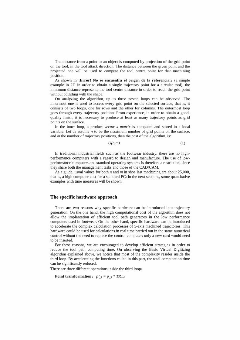
The distance from a point to an object is computed by projection of the grid point on the tool, in the tool attack direction. The distance between the given point and the projected one will be used to compute the tool centre point for that machining position.
As shown in ¡Error! No se encuentra el origen de la referencia.2 (a simple example in 2D in order to obtain a single trajectory point for a circular tool), the minimum distance represents the tool centre distance in order to reach the grid point without colliding with the shape.
On analyzing the algorithm, up to three nested loops can be observed. The innermost one is used to access every grid point on the selected surface, that is, it consists of two loops, one for rows and the other for columns. The outermost loop goes through every trajectory position. From experience, in order to obtain a good-quality finish, it is necessary to produce at least as many trajectory points as grid points on the surface.
In the inner loop, a product vector x matrix is computed and stored in a local variable. Let us assume n to be the maximum number of grid points on the surface, and m the number of trajectory positions, then the cost of the algorithm, is:
O(n.m) (1)
In traditional industrial fields such as the footwear industry, there are no high-performance computers with a regard to design and manufacture. The use of low-performance computers and standard operating systems is therefore a restriction, since they share both the management tasks and those of the CAD/CAM.
As a guide, usual values for both n and m in shoe last machining are about 25,000, that is, a high computer cost for a standard PC; in the next sections, some quantitative examples with time measures will be shown.
The specific hardware approach
There are two reasons why specific hardware can be introduced into trajectory generation. On the one hand, the high computational cost of the algorithm does not allow the implantation of efficient tool path generators in the low performance computers used in footwear. On the other hand, specific hardware can be introduced to accelerate the complex calculation processes of 5-axis machined trajectories. This hardware could be used for calculations in real time carried out in the same numerical control without the need to replace the control computer; only a new card would need to be inserted.
For these reasons, we are encouraged to develop efficient strategies in order to reduce the tool path computing time. On observing the Basic Virtual Digitizing algorithm explained above, we notice that most of the complexity resides inside the third loop. By accelerating the functions called in this part, the total computation time can be significantly reduced. There are three different operations inside the third loop:
Point transformation: p’ j,k = p j,k * TR4x4

A 3D transformation is applied to every surface point according to the selected strategy, so that the tool faces the surface. This operation is made by means of a 4x4 transformation matrix. From a generic standpoint, the process consists of a row x matrix post multiplying.
Distance computing: Dv(p’j,k,Tool) This function computes the distance between a surface point and the tool in the tool
attack direction. Depending on the complexity of the tool geometry - sphere, torus, cone, and so on - the function becomes more complex.
Comparison and assignment: If dist<Min_dist then Min_dist = dist
Finally, the third nested loop makes a comparison and an assignment if the computed distance is shorter than the current minimum distance.
These three different operations are carried out on every point of the tool trajectory and for every grid point on the original surface. Any optimization made at this level will significantly improve the total computation time. Specific hardware architectures will be used in order to reduce the computation time for some of the operations previously discussed.
Computing tool path for a turning lathe machine
Following the main aspects discussed so far, we are developing a hardware architecture that is also able to perform path computation efficiently using the Virtual Digitizing algorithm. Its performance will be tested in real mechanization systems.
The surface to be machined consists of a discretization of a free-form NURBS surface. The more grid points used in each dimension to represent a surface, the finer the spatial resolution of our discretization and the more accurate our trajectory. For an object of 10 x 10 x 200 mm, a grid of approximately 130 x 120 points is used, which implies a distance of 2 mm between points in each surface dimension.
[FIGURE 3] The machine selected is a traditional turning lathe, consisting of three different axes, as shown in figure 3. All of them perform a spiral movement around the object to be machined. The tool selected is a 3D torus that simulates the cutting tool in movement. Algorithm 1 is slightly transformed for the first lines into:
[TABLE 2]
Algorithm 2 consists of four nested loops, the first and second ones simulate the
tool movement around the object. The third and fourth loops analyse every surface point in order to find the nearest one to the tool. The transformation matrix consists of a basic 3D rotation matrix around the X axis. The distance function computes the distance between a 3D point and a 3D torus in the tool attack direction (Y axis) and can be expressed in equation 2.

( ) ( ) 22
22,, zTxrRyTzyxD xy −
−−+−−=
(2)
Where: Tx, Ty are the x,y coordinates of the torus centre. x,y,z are the 3D point coordinates R, r are the major and minor torus radii
The best hardware configuration must be selected for each task involved in the Virtual Digitizing process. Tool path generation tests have been made in order to evaluate the cost of every task in the inner loop and the best time achieved. For the prototype, Field Programmable Gate Arrays (FPGA) technology has been used.
[FIGURE 4]
Figure 4 represents the computing cost of each task as a percentage. Due to the fact
that not every point changes for every transformation, a specific hardware configuration that produces rotations will be presented.
MultiRotators
In this section, hardware architecture for computing rotations is presented, that is, improved architecture with more accuracy and speed than other classical well-known hardware versions. MultiRotators were introduced in [12].
In the virtual digitizing algorithm, rotations are always computed in the same way: every point is rotated at a fixed angle around the rotation axis for the whole circle (e.g. for an increment of 4 degrees the successive rotations will be: 0, 4, 8, 12 …, 352 and 356 degrees, using a configuration of 90 points per circle). Note that every rotation is made from the original surface location in order to avoid error accumulation.
Generally, the CORDIC (COordinate Rotation DIgital Computer) is used to perform generic spatial rotations based on tangent properties. CORDIC is an iterative algorithm for the approximation of the rotation of a two-dimensional vector, in linear, circular and hyperbolic coordinate systems, using only add and shift operations [18]. Each iteration in CORDIC is not a perfect rotation, it is a rotation which modifies the length of the vector in a quantity of -2i1 + 2 . Therefore, after N iterations its magnitude has changed and must be corrected. To satisfy an M-bit precision CORDIC operation, M+1 iterations are needed. Furthermore, the length of the data-path to compute the X and Y variables has to be N = M +2+ log2(M) and for the computation of Z only a precision of M+1 is needed in the operations [13]. In contrast, this architecture (also called MR), computes the rotation directly, using computed sine and cosine values, and achieves the maximum precision allowed by the binary representation of the geometric points. MR implementation could be carried out just by using Constant Coefficient Multipliers (KCMs) and/or distributed

arithmetic [14], achieving a response time equal or even better than the unrolled and bit parallel versions of CORDIC algorithms [15,16,17], using similar resources and keeping the maximum precision.
The approach consists of producing r rotations of the same 3D point p with coordinates (x,y,z). Every rotation step will be constant (∆θ). For the i rotation, the point p will be rotated as:
θi= θi-1+∆θ (3)
For this study, we assume that every rotation is made over the z-axis. The coordinates of the p point after the i-th rotation are shown in (4). Note that the z component will be unchanged due to the fact that the rotation is made around the z-axis:
xi’=xcosθi - ysinθi = xCi -ySi
yi’=ycosθi+ xsinθi= yCi+xSi
(4)
where Ci=cosθi, Si= sinθi .These equations could be expressed as a function of the previous iteration angle:
xi’=xcos(θi-1+∆θ) - ysin(θi-1+∆θ)
yi’=ycos(θi-1+∆θ)+ xsin(θi-1+∆θ)
(5)
Using trigonometric properties of the angle addition for the sine and cosine:
sin(a+b)=sina·cosb+cosa·sinb
cos(a+b)=cosa·cosb-sina·sinb
(6)
we obtain:
Ci’= C i-1 C∆ - Si-1 S∆
Si’= Si-1 C∆ + Ci-1 S∆
(7)
where C∆ = cos∆θ , S∆ = sin∆θ , Ci-1= cosθi-1 , Si-1= sinθi-1.
Every new sine and cosine could be obtained from the previous sine and cosine values. In short, both coordinates and trigonometric values are computed by products of constant coefficients (Ci, Si or C∆ and S∆). The KCMs are well suited to FPGA designs. They only require look up tables (LUTs), shifts and adders. However, the LUT size grows exponentially with n (n represents the binary precision selected for coordinate representation), therefore this number should be kept low in order to achieve a good FPGA spatial occupation. Thus, the rotation should be carried out using 4 or 8 bit precision, which is not a good value for most applications. In the next section, even the 16 bit representation will be discarded due to precision accuracy.

An alternative to KCMs consists of using Serial Distributed Arithmetic (SDA) in order to do products and additions at the same time; in this case the algorithm architecture is modified as shown in figure 5.
[FIGURE 5]
The architecture presented in figure 5 has two operation modes. The first
represents the rotation mode. In this mode, point coordinates are rotated. The one coefficient MAC blocks (1-C MAC) compute the products x·Ci, y·Ci x·Si and y·Si working on a serial mode. After n cycles, the four components of expression (4) are obtained (n+3 bits). In order to reduce resources, it is possible to use just an Add/Sub block in the final phase, by means of incrementing a cycle in the computing time. In short, the architecture consists of 1 Add and 1 Sub for an n+1 cycles computing time, or 1 Add/Sub block for a total time cost of n+2 cycles. Note that the rotation mode is used in the inner loop of the virtual digitizing algorithm.
The second mode represents the new cosine and sine computation. In this mode, S-Regs are loaded with incremented sines and cosines, so the architecture will compute the products presented in expression (7). Once new cosines and sines are computed, they are stored in 1-C MACs that are ready for the next coordinate rotation. Note that this mode has previously been used to coordinate computation in the external loop and therefore, its computing impact is not too high.
Every 1-C MAC module consists of a register that stores the current sine and cosine values for coordinate rotation (see figure 6). At the very beginning, these registers will contain the C∆ and S∆ values. The least significant bit of the shift registers controls the load of the register value in the 1-C MAC, so the multiplication is made serially by means of the scaling accumulator. The whole architecture will consist of: 2 multiplexers, 2 n-bit shift registers, 4 n+1 registers, 4 n+3-bit scaling accumulators, 1 n+3-bit adder, and 1 n+3-bit substracter.
[FIGURE 6]
In order to increase the processing speed of the MR architecture, it is possible to
use 1-C MACs based on Parallel Distributed Arithmetic (PDA). For instance, odd and even bits of each S-Reg (2-bit PDA) can be processed at the same time, thus reducing the number of cycles to a half. In that case, the number of registers inside the 1-C MACs is doubled and an additional scaling accumulator must be included in each module.
[TABLE 3]
Table 3 shows a performance and resource comparison between MR and the usual
CORDIC implementations. Every coordinate is represented by an n-bit number. CORDIC implementations use w iterations (w<n).
Bit serial CORDIC implementation offers the worst performance index because it requires n cycles (n shifts) per iteration, although it allows the highest work frequencies for the FPGAs. In the bit-parallel implementation, the n shifts are carried

out in a single cycle, using barrel shifters, so that the number of cycles is reduced up to n. On the other hand, the cycle period is about five times greater [18]. Both CORDIC implementations achieve a maximum precision that depends on the number of iterations (w). It is, however, always less than the precision reached with n-bit numbers. In MR implementations, the number of cycles is equal to or lower than the fastest CORDIC implementation and the simplicity of the resources required makes clock frequency rates similar to the bit-parallel one feasible. Moreover, the precision reached is the highest that could be obtained using n-bits and there is no magnitude error in coordinate computation.
Precision experiments vs. CORDIC
The MR architecture has been simulated and analyzed in terms of accuracy. The target platform we have used was the XC4000E FPGA family. The simulation tool was the Xilinx Foundation Series 2.1i software. Experiments simulate surface point rotations using the virtual digitizing algorithm. Every point is rotated many times using different angle degrees up to a complete circle (360 degrees). In this context, iteration refers to each single rotation (not to be confused with the term iteration used in CORDIC literature as an approximation stage).
Due to architecture scalability, experiments for both 16 and 32 bits in data word length have been made. The more bits used for data representation, the more hardware resources required. However, for 16-bit simulations, the results were not good in terms of application requirements, since a relative error of up to 0.6% was obtained (0.1% is the maximum relative error permitted in shoe last machining). For this reason, architecture resources must be doubled in order to improve precision. In this section, only the 32-bit results are analyzed. For a high iteration number, the relative error values are below 0.002%, that is, fifty times more accurate than the permitted maximum application error.
In absolute terms, the error obtained after a whole rotation (360º) for the 16-bit MR could reach ± 0’5 mm, which is no good for machining purposes. However, it could be suitable for other kinds of applications, such as graphic representation. On the other hand, after 720 iterations to complete a circle, the 32-bit MR obtains an absolute error of ±7’8 microns, which is excellent for a shoe last machining process.
Figure 7 shows the relative error evolution for both 32 bit CORDIC and 32-bit MR architecture. In this experiment, a single point is rotated at an angle which is in the [1,720] degree range. For the MR an increment of 1 degree is used. Note that, in the MR, relative error is linearly dependent on the number of iterations due to error accumulation; however, the MR achieved an improvement in accuracy of up to 60%.
In the previous experiment, we assumed a fixed increment of 1 degree. In Figure 8, different angle increments are tested for the MR architecture and every rotated point is compared with the equivalent global rotation using CORDIC algorithm. The rotation steps vary from 1 to 290 iterations. The experiment results show a better precision for the MR architecture, even for a high iteration number.
[FIGURE 7]
[FIGURE 8]
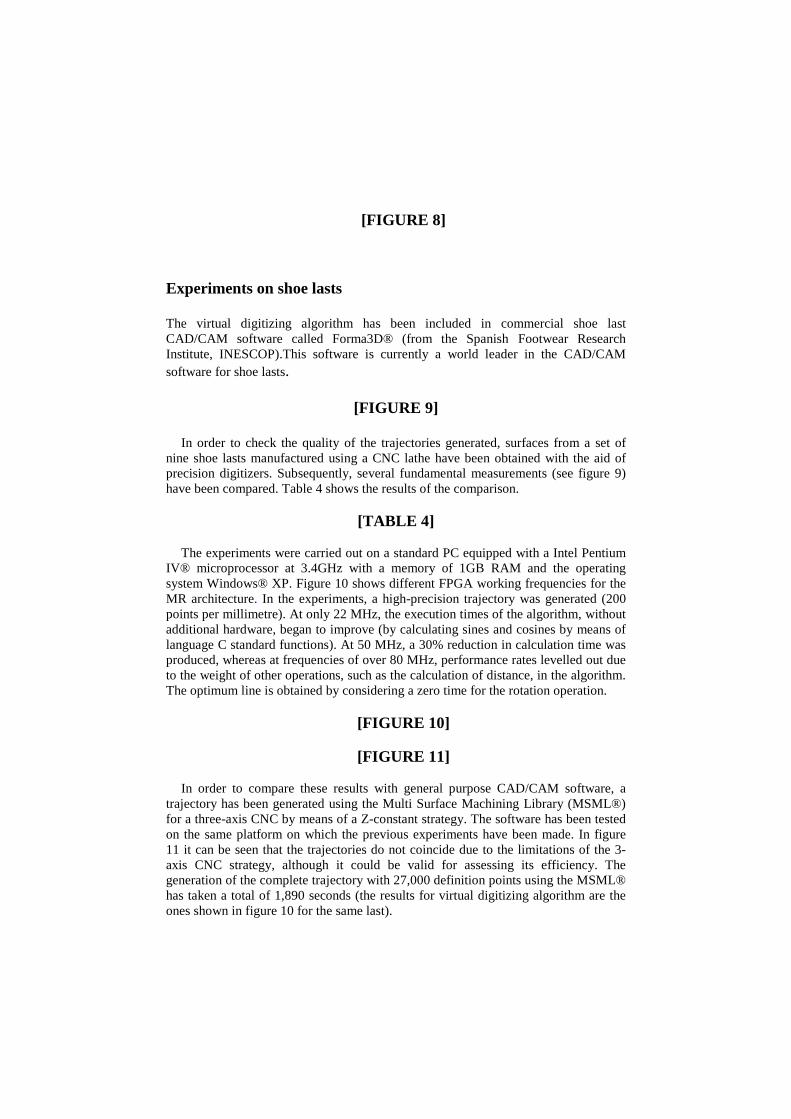
Experiments on shoe lasts
The virtual digitizing algorithm has been included in commercial shoe last CAD/CAM software called Forma3D® (from the Spanish Footwear Research Institute, INESCOP).This software is currently a world leader in the CAD/CAM software for shoe lasts.
[FIGURE 9]
In order to check the quality of the trajectories generated, surfaces from a set of nine shoe lasts manufactured using a CNC lathe have been obtained with the aid of precision digitizers. Subsequently, several fundamental measurements (see figure 9) have been compared. Table 4 shows the results of the comparison.
[TABLE 4]
The experiments were carried out on a standard PC equipped with a Intel Pentium IV® microprocessor at 3.4GHz with a memory of 1GB RAM and the operating system Windows® XP. Figure 10 shows different FPGA working frequencies for the MR architecture. In the experiments, a high-precision trajectory was generated (200 points per millimetre). At only 22 MHz, the execution times of the algorithm, without additional hardware, began to improve (by calculating sines and cosines by means of language C standard functions). At 50 MHz, a 30% reduction in calculation time was produced, whereas at frequencies of over 80 MHz, performance rates levelled out due to the weight of other operations, such as the calculation of distance, in the algorithm. The optimum line is obtained by considering a zero time for the rotation operation.
[FIGURE 10]
[FIGURE 11]
In order to compare these results with general purpose CAD/CAM software, a
trajectory has been generated using the Multi Surface Machining Library (MSML®) for a three-axis CNC by means of a Z-constant strategy. The software has been tested on the same platform on which the previous experiments have been made. In figure 11 it can be seen that the trajectories do not coincide due to the limitations of the 3-axis CNC strategy, although it could be valid for assessing its efficiency. The generation of the complete trajectory with 27,000 definition points using the MSML® has taken a total of 1,890 seconds (the results for virtual digitizing algorithm are the ones shown in figure 10 for the same last).

Conclusions and future investigation
The virtual digitising process is simple to implement, offers good results and avoids the problem of tool collision by its own definition. The algorithm requires the manufacturing strategy to be defined and it therefore adapts well to non-standard manufacturing environments, such as in the manufacture of shoe lasts. On the other hand, the algorithm is not suitable for general-purpose machining, since it is too slow compared with other types of tool path generation algorithms.
The specific hardware approach can be used to solve high cost problems arising from the CAD/CAM. In particular, it can be applied to the virtual digitizing algorithm as it achieves good results in tool path generation for low performance computers. Future studies aim to complete the hardware architecture so that it can support the distance calculation task (responsible for almost 60% of the calculation time) in the virtual digitizing algorithm. Other studies will be aimed at applying specific hardware techniques in order to accelerate trajectory calculation in 3 or 5-axis standard manufacturing environments. The idea of integrating trajectory generation into the numerical control itself is now becoming more common. The new ISO standard 14649 (also called STEP-NC) remedies the shortcomings of ISO 6983 by specifying the machining processes rather than machine tool motion by means of machining tasks [19]. In this new environment, the use of specific hardware could be used to facilitate trajectory generation in the control itself. In this way, complex calculations could be made in real time without having to replace the numerical control computer; only new specific processing hardware cards would have to be added.
References
[1] Farin, G. “Curves and Surfaces for Computer Aided Geometric Design. A Practical Guide”. Academic Press Inc., 1993.
[2] Wang, Y. “Intersection of offsets of parametric surfaces”. Computer Aided Geometric Design, vol. 13, pp.453-465, 1996.
[3] Choi, B. K. “Surface Modeling for CAD/CAM”. Elsevier Science Publishers, pp. 263-272, 1991.
[4] Held, M. “Voronoi Diagrams and Offset Curves of Curvilinear Polygons”. Computer-Aided Design, vol. 30, no. 4, pp. 287-300, 1998.
[5] Wallner, J., Sakkalis, T. “Self-intersections of offset curves and surfaces”. Journal of Shape Modeling, no 7, pp. 1-21, 2001.
[6] Elber, G., Fish, R. “5-Axis Freeform surface milling using piecewise surface approximation”. ASME Journal of Manufacturing Science and Engineering, vol. 119, no. 3, pp. 383-387, 1997.
[7] Jimeno, A.; Maciá, F.; García-Chamizo, J. “Trajectory-based morphological operators: a morphological model for tool path computation”, Proceedings of the international conference on algorithmic mathematics & computer science, AMCS 2004, Las Vegas (USA). Jun 2004.
[8] Jimeno A, García J., Salas F. “Shoe lasts machining using Virtual Digitizing”. International Journal of Advanced Manufacturing Technology. Vol 17, no. 10, pp.744-750. 2001

[9] Takeuchi, Y et al. ‘Development of a personal CAD/CAM system for mold manufacturing’ Annals of CIRP, Vol 38 No 1 (1989), pp.429-432
[10] Jerard, R B, Drysdale, R L and Hauck, K “Geometric simulation of numerically controlled machining” Proc. of ASME Int’l Conf. on Computers in Engineering, ASME, New York (1988), pp.129-136
[11] Farin, G., “Curves and surfaces for CAGD”, Academic Press. 1993 [12] Jimeno A, Cuenca S. “Reconfigurable Computing for Tool-Path Computation”
International Journal of Advanced Manufacturing Technology, vol. 21, no 12, pp. 945-951, 2003
[13] Valls J., Kuhlmann M., and Parhi K., “Evaluation of CORDIC Algorithms for FPGA Design” Journal of VLSI Signal Processing no. 32, pp. 207–222, Kluwer Academic Publishers 2002.
[14] Mehendale M.; “Area-Delay Tradeoff in Distributed Arithmetic Based Implementation of FIR Filters” .Proceedings of the Tenth International Conference on VLSI Design: VLSI in Multimedia Applications. Jan 1997
[15] Wang, S. and Piuri, V., “A Unified View of CORDIC Processor Design”, Application Specific Processors, Edited by Earl E.Swartzlander, Jr., Ch. 5, pp. 121-160, Kluwer Academic Press, Nov 1996.
[16] Andraka R. J; “Building a High Performance Bit-Serial Processor in an FPGA,” Proceedings of Design SuperCon ‘96, Jan 1996.
[17] H.X. Lin and H.J. Sips, “On-Line CORDIC Algorithms,” IEEE Trans. Computers, vol. 39, no. 8, pp. 1,038-1,052, Aug. 1990.
[18] Andraka R. J.; “A survey of CORDIC algorithms for FPGAs”, FPGA '98. Proceedings of the 1998 ACM/SIGDA sixth international symposium on Field programmable gate arrays, Feb. 22-24, 1998, Monterey, CA. pp191-200
[19] X.W. Xu*, Q. He ,“Striving for a total integration of CAD, CAPP, CAM and CNC”, Robotics and Computer-Integrated Manufacturing vol. 20 pp. 101–109. 2004

Antonio Jimeno is associate professor in the Computer Technology and Computation department at the University of Alicante (Spain). He received his PhD from the University of Alicante in 2003. He concluded his bachelor studies at the EPFL.(Ecole Polytechnique Fédérale de Lausanne- Switzerland) and received his BS degree in Computer Science from the Polytechnical University of Valencia (Spain) in 1994. His research interests include sculptured surface manufacturing, CAD/CAM, computational geometry for design and manufacturing, rapid and virtual prototyping, 3D surface flattening, and high performance computer architectures. Dr. Jimeno has
considerable experience in the development of 3D CAD systems for shoes. In particular, he has been involved in many government and industrial funded projects, most of them in collaboration with the Spanish Footwear Research Institute (INESCOP).
Jose-Luis Sanchez Romero received his BS degree in Computer Science from the Polytechnical University of Valencia (Spain) in 1995. At the present time, he is associate professor within the Computer Technology and Computation department of the University of Alicante (Spain). He is a member of the research group Informatica Industrial y Redes de Computadores (Industrial Informatics and Computer Networks), where he is developing his research work in specialized processor architectures and in computer arithmetic. He has participated in several international and Spanish conferences and in research projects.
Higinio Mora received the BS degree in Computer Science Engineering and the BS degree in Bussines Studies in University of Alicante, Spain, in 1996 and 1997, respectively. He was a member of the faculty of Information Systems at San Pablo University Fundation (Spain) from 1996 to 1998 where he was assistant professor. He received the Ph.D degree in computer science from the University of Alicante in 2003. Since 2002 he is a member of the faculty of the Computer Technology and Computation department at the same university where he is currently an associate professor. His current areas of research interest include computer arithmetic and the design of
floating points units and approximation algorithms related to VLSI design.
Jeronimo Mora received the BS degree in Computer Science Engineering from University of Valencia (Spain), in 1994. Since 1994, he has been a member of the faculty of the Computer Technology and Computation department at the University of Alicante, where he is currently an associate professor. PhD on Computer Science at University of Alicante in 2001. He has worked on neural networks and its VLSI implementation. His current areas of research interest include the design of floating points units and its application for Real-Time systems and processors for geometric calculus.
Juan M. García Chamizo received his BS in Physics at the University of Granada (Spain) in 1980, and the PhD degree in Computer Science at the University of Alicante (Spain) in 1994. He is currently a full professor and director of the Computer Technology and Computation department at the University of Alicante. His current research interests are computer vision, reconfigurable hardware, biomedical applications, computer networks and architectures and artificial neural networks. Dr. García Chamizo has directed several research projects related to the above mentioned interest areas. He is a member of a Spanish Consulting Commission on Electronics, Computer Science and Communications. He is also member and editor of some program committees conferences.

FIGURE AND TABLE LEGENDS
Fig. 1. a) Tool trajectory for part surface. Machined surface will differ from the original without collision in a; b) Trajectory by means of surface offsetting. Self-intersections in b and discontinuities in c will clash with part surface in shaded regions.
Fig. 2. Example of Virtual digitization process for 2D shapes.
Fig. 3 Axis implied on a shoe last turning lathe machine
Fig. 4. Inner loop computing time
Fig. 5. SDA-based MR architecture
Fig. 6. Structure of 1-C MAC based on Serial Distributed Arithmetic
Fig. 7. Precision comparison: 32 bit-CORDIC vs. 32 bit MultiRotator.
Fig. 8. Precision vs. iteration number: 32 bit-CORDIC vs. 32 bit MultiRotator.
Fig. 9: Fundamental measurements used in manufacturing experiments: a) Centre line, b) Bottom length, c) Cone heel line, d) Ball.
Fig. 10: Calculation time of the trajectory according to the FPGA working frequency for a 32-bit MR.
Fig. 11 Spiral trajectory for the manufacture of a shoe last: on the left, obtained using MSML®, on the right, obtained using virtual digitizing for a turning lathe machine.
Table 1. Basic virtual digitizing algorithm
Table 2. Changes introduced in algorithm 1 for simulating turning lathe movement.
Table 3. Comparison of Architectures
Table 4. Last manufacturing quality using virtual digitizing, maximum errors with regard to the original model. A typical value is shown next to the measurement.
IMAGES AND TABLES ARE STORED IN IMAGES.DOC