Inspection Strategies for Complex Curved Surfaces Using CMM
10
Inspection Strategies for Complex Curved Surfaces Using CMM R. wirza1, M.S. B~OOZ and J. is her^ Department of Computer Science, Faculty of Computer Science and Information Technology, University Putra Malaysia, Serdang, 43400, Selangor, Malaysia [email protected] 2 School of Mechanical Engineering, Leeds University, U.K. {m.s.bloor, j.fisher)@leeds.ac.uk Abstract. The accurate measurement of complex surfaces is difficult. Accuracy demands precision in measuring technology, i.e., the measuring machine and also precise mathematical representation of complex geometries. This paper introduces a method of measuring a complex surface by using a Coordinate Measuring Machine and representing the measured surfaces mathematically. This enables comparison with other surfaces, e.g.. the as-designed surface or the original unworn surface. The measurement of the knee prosthesis was taken as a case study. Background The amount of wear particles released from the knee joint during operation within the human body is critical to the life expectancy of the joint. The knee joint contains a self-lubricating piece of Ultra High Molecular Weight Polyethylene (UHMWPE). By accurately measuring the UHMWPE before wear or approximating the original surface geometry and the measuring after wear and determining the difference, the volume of material lost can be calculated. To measure accurately the complex surface, this paper proposes a method based on a surface fitting technique. From the many Polynomial based technique, the authors have decided to choose the Bezier technique [I]. In order to represent the complex surface with minimum measuring points, the author has chosen the technique of surface interpolation of scattered data and due to the complexity of the shape the use of triangular patches rather than rectangular patches is recommended. The work is an extension and combination of techniques suggested by Goodman and Said [I]. The need to measure accurately the amount of wear particles released from the knee joint implanted during operation within the human body is becoming important. This amount of wear is critical to the life expectancy of the joint. By accurately measuring the knee joint surface and subsequently determining the small difference between the measurements before and after wear testing, the volume of material can be calculated. P.M.A. Sloot et al. (Eds.): ICCS 2002, LNCS 2331, pp. 184-193, 2002. Springer-Verlag Berlin Heidelberg 2002
Transcript of Inspection Strategies for Complex Curved Surfaces Using CMM

Inspection Strategies for Complex Curved Surfaces Using CMM
R. wirza1, M.S. B~OOZ and J. is her^
Department of Computer Science, Faculty of Computer Science and Information Technology, University Putra Malaysia, Serdang, 43400, Selangor, Malaysia
[email protected] 2 School of Mechanical Engineering, Leeds University, U.K.
{m.s.bloor, j.fisher)@leeds.ac.uk
Abstract. The accurate measurement of complex surfaces is difficult. Accuracy demands precision in measuring technology, i.e., the measuring machine and also precise mathematical representation of complex geometries. This paper introduces a method of measuring a complex surface by using a Coordinate Measuring Machine and representing the measured surfaces mathematically. This enables comparison with other surfaces, e.g.. the as-designed surface or the original unworn surface. The measurement of the knee prosthesis was taken as a case study.
Background
The amount of wear particles released from the knee joint during operation within the human body is critical to the life expectancy of the joint. The knee joint contains a self-lubricating piece of Ultra High Molecular Weight Polyethylene (UHMWPE). By accurately measuring the UHMWPE before wear or approximating the original surface geometry and the measuring after wear and determining the difference, the volume of material lost can be calculated.
To measure accurately the complex surface, this paper proposes a method based on a surface fitting technique. From the many Polynomial based technique, the authors have decided to choose the Bezier technique [I]. In order to represent the complex surface with minimum measuring points, the author has chosen the technique of surface interpolation of scattered data and due to the complexity of the shape the use of triangular patches rather than rectangular patches is recommended. The work is an extension and combination of techniques suggested by Goodman and Said [I].
The need to measure accurately the amount of wear particles released from the knee joint implanted during operation within the human body is becoming important. This amount of wear is critical to the life expectancy of the joint. By accurately measuring the knee joint surface and subsequently determining the small difference between the measurements before and after wear testing, the volume of material can be calculated.
P.M.A. Sloot et al. (Eds.): ICCS 2002, LNCS 2331, pp. 184−193, 2002. Springer-Verlag Berlin Heidelberg 2002

In this paper the author proposes a planning strategy for the measurement. The main objective of this proposed planning strategy is accurately to measure and represent a complex surface, e.g. the surface of the knee joint prosthesis, so that minimal changes of the surface can be detected. The proposed plan involves:
i. choosing several points on the knee, and naming them as initial points, ii. with these initial points using the fitting technique to produce a set of
interpolated points, iii. producing a CMM program which uses the interpolated points which can
measure one whole knee for each different design, iv. approximating the original surface of the ex-plant, because in most cases, the
surgeon does not have a blue-print or original design for the knee joint, v. and finally, determining the small difference between the measurements after
wear testing, and the original surface and calculating the lost volume of material.
There are many papers discussing the problems related to a planning strategy for the measurement. Cho and Kim [2], Lee, Kim and Kim [3], introduced their new inspection planning strategy for complex surfaces, which introducing a measuring point selection strategy, a probe path generation strategy, and movement of the probe approaching the surface. Since the measurement time and cost increase with the number of measuring points, and an equi-interval grid pattern measurement may result in insufficient sampling when there are sharp changes in surface curvature, or unnecessary sampling in a relatively flat region, they [2,3] decided to introduce a technique of choosing a suitable sample size as the first step. Their proposed technique was based on analysis of the mean curvature of the surface. The density of the measuring points will vary according to the magnitude of the mean curvature of the surface. They decided that by changing the density of the measuring points according to the curvature of the surface, the object can be measured more effectively. As in the paper reviewed by Legge, they also generated appropriate probing paths so that the surface can be inspected effectively with minimum measuring errors and within the required time period. They introduced a technique which can select the probing sequence of measuring points optimally so that the moving distance of the probe and the inspection time can be reduced.
Touch probe selection is one critical step for inspection to be carried out on a CMM. Moroni et al. [5] report a preliminary study and the prototypical realisation of an expert system to generate touch probe configurations. Ziemian and Medeiros [6] also concentrate more on probe selection and part set-up rather than introducing the whole planning system.
Measurement Planning Algorithm
The proposed measuring planning procedure involves two phases. Phase 1 is the identification of the geometry of the knee prosthesis by digitising a set of initial measurement points, reading the data file produced by CMM on-line software, interpolating these initial measurement points, and finally defining a set of surface points. Phase 2 involves calculating the partial derivative of the surface at the
185Inspection Strategies for Complex Curved Surfaces Using CMM

interpolation part, calculating the vector direction IJK and producing the CMM program for the whole knee prosthesis.
A CMM on-line program is produced in Phase 1 which is used to measure the knee joint prosthesis geometry. This early version of CMM on-line program instructs the user to move the probe manually and measure the geometry of each condyle, by measuring 20 points on the inside edges of the condyle, 15 points on the inside surface, one point near to the middle of the condyle, to identi@ the bottom surface of the knee condyle. For the purpose of the worn knee, at least 15 measurement points on the worn area were added, depending on the size of the worn area. The partial derivatives at each digitised point are calculated, using least square minimisation introduced by Renka and Cline [8]. The Delaunay triangulation diagrams are constructed and finally, the Bezier interpolation surface is produced, which consists of a set of interpolation points with 1 rnrn space between each of them in x and y axis directions.
2.1 Surface fitting
There are a variety of methods and techniques involved in surface fitting. The problem which will be discussed here is to construct a smooth surface which passes
through scattered data, {(xi, yi , zi . For the purpose of the proposed strategy, it
was decided to apply the convex combination method, which was introduced by Goodman and Said [ l ] because it is a local interpolation method which can be
1 implemented on scattered data with C continuity and triangular patches which are the most suitable for the complex surfaces. This method, also known as the hybrid method, uses triangular patches, interpolating them to develop interpolation patches. A partial direction derivative was used on each edge of the triangular patches to
make sure the surface fit satisfied the first order continuity, c1 over each triangle boundary. To apply this method onto a set of scattered data points as
{(xi, y i , zi where we wish to interpolate zi = F(xi , yi ) ,i.e. z is a function of
x and y, three pre-processing steps are needed:
1. Triangulate the domain of the data points, which is the initial points, by using triangulation techniques, such as Delaunay triangulation.
2. Estimate the first-order partial derivatives at the data points to satisfy C' smoothness [8]
3. Compute the interpolate points in each triangle by the triangular scheme. For further explanation, the reader is referred to Goodman and Said [I].
186 R. Wirza, M.S. Bloor, and J. Fisher
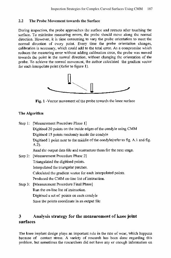
During inspection, the probe approaches the surface and retracts after touching the surface. To minimise measuring errors, the probe should move along the normal direction. However, it is time consuming to vary the probe orientation to meet the normal direction of every point. Every time the probe orientation changes, calibration is necessary, which could add to the total error. As a compromise which reduces the measuring error without adding calibration error, the probe was moved towards the point in the normal direction, without changing the orientation of the probe. To achieve the normal movement, the author calculated the gradient vector for each interpolate point (Refer to figure 1).
Fig. 1 -Vector movement of the probe towards the knee surface
The Algorithm
Step 1:
Step 2:
Step 3:
3
[Measurement Procedure Phase 11
Digitised 20 points on the inside edges of the condyle using CMM
Digitised 15 points randomly inside the condyle Digitised 1 point near to the middle of the condyle(refer to fig. A.l and fig. A.2).
Read the output data file and restructure them for the next stage.
[Measurement Procedure Phase 21
Triangulated the digitised points.
Interpolated the triangular patches.
Calculated the gradient vector for each interpolated points.
Produced the CMM on-line list of instruction.
[Measurement Procedure Final Phase]
Run the on-line list of instruction.
Digitised a set of points on each condyle
Save the points coordinate in an output file
Analysis strategy for the measurement of knee joint surfaces
The knee implant design plays an important role in the rate of wear, which happens because of contact stress. A variety of research has been done regarding this problem, but sometimes the researchers did not have any or enough information on
187Inspection Strategies for Complex Curved Surfaces Using CMM
2.2 The Probe Movement towards the Surface

the original design or blueprint of the knee joint. It is hoped that the technique suggested in this paper can (1) give the approximate shape of the unworn surface of the knee prosthesis, and thus (2) give a good approximation for the volume of wear that has occurred. In Legge's review paper [4], in addition to the planning strategy for the measurement, an evaluation procedure is also involved. In the case of this study, the evaluation procedure included the worn volume approximation and the approximation of the original surface. The next step was introducing the technique for the calculation of the volume between the measuring points and the plane datum.
3.1 Volume under the measurement points
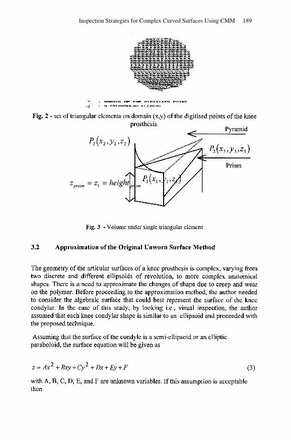
The first step of this technique was to construct a set of triangular elements with the measuring points as the vertices (refer to fig. 2 ). Each calculation of volume under the triangular element involved the calculation of prism and pyramid volume, with the datum plane, which is the jig plane as the base of the volume element (refer to fig. 3).
For the calculation of the prism volume the formula is:
Vprism = the area of the domain triangular element x height prism
- 1 - - 2
For the calculatior of the pyramid the formula is;
Vpyramid = x area of pyramid base x height pyramid
And finally for the whole element, (1) and (2) are added together for each element and all the elements under the chosen area totalled,
188 R. Wirza, M.S. Bloor, and J. Fisher
X : DOH-IN OF THE D I O I T I S E D POINT
Li] : R TRX RNOULRR ELEMENT
Fig. 2 - set of triangular elements on domain (x,y) of the digitised points of the knee prosthesis.
Pyramid
\
Prism
Fig. 3 - Volume under single triangular element
3.2 Approximation of the Original Unworn Surface Method
The geometry of the articular surfaces of a knee prosthesis is complex, varying from two discrete and different ellipsoids of revolution, to more complex anatomical shapes. There is a need to approximate the changes of shape due to creep and wear on the polymer. Before proceeding to the approximation method, the author needed to consider the algebraic surface that could best represent the surface of the knee condylar. In the case of this study, by looking i.e., visual inspection, the author assumed that each knee condylar shape is similar to an ellipsoid and proceeded with the proposed technique.
Assuming that the surface of the condyle is a semi-ellipsoid or an elliptic paraboloid, the surface equation will be given as
with A, B, C, D, E, and F are unknown variables. If this assumption is acceptable then
189Inspection Strategies for Complex Curved Surfaces Using CMM

By proceeding with the least square minimisation, finding the A,B,C,D,E and F, the algebraic surface equation to represent the unworn surface can be approximate.
3.3 Approximation of the Original Unworn Surface Procedure
The method that was established involved the measurement procedure with minor changes.
In the phase 1 measurement procedure, for the purpose of the analysing procedure, at least 15 measurement points on the worn area were added, depending on the size of the worn area. In the reading program in phase 1 procedure, one whole set of points will be saved in one data file and the subset of the worn points saved in another data file, the reader is referred to Wirza[l4], and the subset named as S1
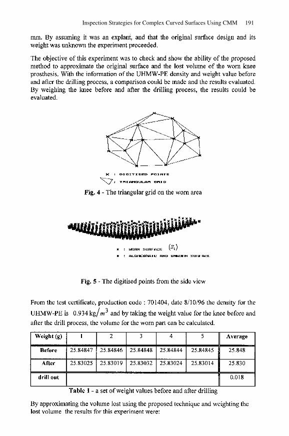
The triangulation procedure was applied on the Sl (refer to fig. 4), and the
results saved in a data file. These triangulation data points were named set S2
The phase 2 procedure was applied and the CMM on-line programming produced (refer to fig. 5). The on-line program was run, the results read and the points saved, under the name set S j , in a data file as in phase 2 measurement.
The volume procedure was applied. By applying Cramer's rule on data set S2 , points in S3 were identified that
digitised the unworn part and this set of points named as Steyp . The least square approximation and Gaussian elimination technique were applied to Stemp to approximate the surface equation.
The surface equation was used to approximate the new z values for the worn area.
With the digitised z values for the unworn part and the approximate z values for the worn part, the approximation of the original surface was established. By applying the volume procedure, the volume for the worn part could be calculated.
Experimental Results
Before proposing and implementing the algorithm, it was necessary to do some experiments to check the accuracy and the capability of the proposed technique. This experiment started with an implant knee prosthesis which the author weighed before and after drilling the knee left condylar to =: 0.5 rnrn depth and radii of =: 10
190 R. Wirza, M.S. Bloor, and J. Fisher
4
rnrn. By assuming it was an explant, and that the original surface design and its weight was unknown the experiment proceeded.
The objective of this experiment was to check and show the ability of the proposed method to approximate the original surface and the lost volume of the worn knee prosthesis. With the information of the UHMW-PE density and weight value before and after the drilling process, a comparison could be made and the results evaluated. By weighing the knee before and after the drilling process, the results could be evaluated.
X : D I G I T I S E D POINTS
p: TRISbNU3LDL-R -R ID
Fig. 4 - The triangular grid on the worn area
Y : WORN SURFfiCE ('1)
X : RLGREBRRIC RND UNWORN SURFfiCE
Fig. 5 - The digitised points from the side view
From the test certificate, production code : 701404, date 8110196 the density for the
UHMW-PE is 0.934 kg/rn3 and by taking the weight value for the knee before and after the drill process, the volume for the worn part can be calculated.
Table 1 - a set of weight values before and after drilling
Weight (g)
Before
After
drill out
By approximating the volume lost using the proposed technique and weighting the lost volume the results for this experiment were:
1
25.84847
25.83025
2
25.84846
25.83019
3
25.84848
25.83032
4
25.84844
25.83024
5
25.84845
25.83014
191Inspection Strategies for Complex Curved Surfaces Using CMM

I Total volume for the digitised points 1) 5542.242 II
Differences, i.e. approx. volume lost
Volume lost calculate from the weight
Total volume for the approx. unworn points
11 Computation Error 11 1.354 II
15560.3731
3 Table 2 - Results for the dummy experiment ( mm )
Summary and Conclusion
Most researchers such as Ries et. al.[ll], used the weight method to measure the weight loss in a knee joint implant. Other researchers with an inspection background [2,3,4,6] have proposed automated inspection systems for the purpose of modelling the product and inspecting the milled complex surfaces to determine whether the standard tolerance is satisfied. This study, especially the experiment in this chapter, proposed a method that can: (1) approximate the original surface from the worn part, (2) approximate the worn part or the lost weight, by using a surface fitting technique.
Results from the initial and validation experiments, where the computation error is
1.354 mm3, showed that this method is capable to give a good and satisfactory approximation. As explained earlier, by ten years, 25 percent of total knee replacements may look loose on x-ray, and about 10 percent will require re- operation [ l 1,12,13]. Since recent work has shown that wear in a knee prosthesis is
between 5 and 20 m n ~ ~ / ~ e a r [ l l ] , this means that by ten years, the wear in an
explant of knee prosthesis might be between 50 and 200 mm3. By assuming the depth of worn part is .= 0.5 mm, the proposed method will approximately contribute
errors between 0.43 and 1.72 mm3 (please refer to Wirza[l4]). This is considered adequately small. With the digitised z value for the unworn part and the approximation z value for the worn part, the approximation of the original surface is established. This means the proposed method used in this experiment achieved its two objectives, as mentioned earlier.
References
1. Goodman T., and Said H. B.: A C' triangular interpolant suitable for scattered data interpolation. Communications in Applied Numerical Methods, Vol. 7. (199 1) 479-485
192 R. Wirza, M.S. Bloor, and J. Fisher
5

Cho M. W., and Kim. K.: New Inspection Planning Strategy for Sculptured Surfaces using Coordinate Measuring Machine. Int. J. Prod. Res., Vol 33. no. 2. (1995) 427-444 Lee J. W., Kim M. K., and Kim K.: Optimal Probe Path Generation and New Guide Point selection Methods. Engng. Applic., Artif., Intell. Vol 7. NO. 4 (1994) 439-445 Legge D. I.: Integration of design and Inspection System - a literature review. Int. J. Prod. Res., Vol34. No. 5 (1996) 1221-1241 Moroni G., Polini W., and Semeraro Q.: Knowledge Based method for touch probe configuration in an automated inspection system. Journal of Materials Processing Technology, Vol76. (1 998) 153- 160 Ziemian C. W., and Medeiros D. J.: Automated Feature Accessibility Algorithm for Inspection on a Coordinate Measuring Machine. Int. J. Prod. Res., Vol. 35. No. 10. (1997) 2839-2856 Brassel K. E., and Reif D.: A Procedure to Generate Thiessen Polygon. Geographical Analysis, Vol 1 1. No. 3. (1 979) 289-303
Renka R. J., and Cline K.: A triangle-based C' surface interpolation. The Rocky Mountain Journal of Maths, Vol. 14. (1 984) 223-237 Kim S., and Chang S.: The Development of the Off-Line Measurement Planning System for Inspection Automation. Computers Ind. Engng., Vol. 30. NO. 3. (1996) 53 1-542 Derbyshire B., Hardaker C. S., Fisher J., and Brurnmitt K.: Assessment of the change in volume of acetabular cups using a Coordinate Measuring Machine. Proc Instn. Mech. Engrs., Vol. 208. (1 994) 15 1-1 58 Ries M., Banks S., Sauer W., and Anthony M., (inprint): Abrasive Wear Simulation in Total Knee Arthroplasty. Consensus @Knee. (1 998)
13. http://www.hipandkneesurgery.com/tka.htm. 14. R Wirza: Inspection Strategies for Complex Curved Surfaces. PhD theses.
The University of Leeds. April 2000
Fig A . l - The measuring points planned on the knee Fig. A.2 - The initial chosen measured
condyle points
193Inspection Strategies for Complex Curved Surfaces Using CMM