Dispersive cylindrical cloaks under nonmonochromatic illumination
12
arXiv:0905.2865v2 [physics.class-ph] 1 Oct 2009 Dispersive Cylindrical Cloaks under Non-Monochromatic Illumination Christos Argyropoulos, * Efthymios Kallos, and Yang Hao † Department of Electronic Engineering, Queen Mary, University of London, Mile End Road, London, E1 4NS, United Kingdom (Dated: January 28, 2010) Transformation-based cylindrical cloaks and concentrators are illuminated with non-monochromatic waves and unusual effects are observed with interesting potential applications. The transient responses of the devices are studied numerically with the Finite-Difference Time-Domain method and the results are verified with an- alytical formulas. We compute the effective bandwidth of several cloaking schemes as well as the effect of losses on the performance of the structures. We also find that narrowband behavior, frequency shift effects, time delays and spatial disturbances of the incoming waves are dominant due to the inherently dispersive nature of the devices. These effects are important and should be taken into account when designing metamaterial-based devices. I. INTRODUCTION Transformation electromagnetics provides the unprecedented opportunity to manipulate the propagation of electromagnetic waves in an artificial way [1, 2]. Form-invariant coordinate transformations cause the electromagnetic waves to perceive space compressed or dilated in different coordinate directions, which often requires materials with anisotropic and spatially-varying values of permittivity and permeability tensors. Many interesting applications have been proposed, derived from different co- ordinate transformations. One of the most widely studied application is the cloak of invisibility [1], an approximate design of which was constructed for microwaves using arrays of split-ring resonators [3]. Other proposed devices include carpet cloaking structures [4, 5], “cloaking” absorbers [6], concave mirrors for all angles [7], field concentrators [8], spherical [9] and cylindri- cal [10] superlenses, flat near-field and far-field focusing lenses [11], reflectionless beam shifters and beam splitters [12], field rotators [13], adaptive beam benders and expanders [14] and novel antenna designs [15, 16]. In order to achieve the required material values, the majority of the aforementioned devices are constructed with metamaterials consisting of resonating structures [17, 18], whose properties are usually dominated by high loss and frequency dispersion [19, 20]. Any material that exhibits permittivity and permeability values smaller than unity must be dispersive due to causality constraints [21], and hence, the corresponding devices operate properly only over very narrow bandwidths. One common example of such dispersive materials found in nature is the response of plasma electron gas to external radiation [22], which exhibits an effective refractive index smaller than one. Consequently, unless such a metamaterial-based device is illuminated by a unrealistic perfect monochromatic wave, a complete description of the response of such devices requires consideration of the full dispersive effects occurring over a range of frequencies. The goal of this paper is to investigate the physics of the broadband response of such dispersive devices. So far, two-dimensional (2D) cylindrical electromagnetic cloaks have been studied only under monochromatic plane wave il- lumination [1, 23, 24, 25, 26]. However, all electromagnetic waves extend over a finite bandwidth. Some dispersive effects have been revealed analytically for three-dimensional (3D) spherical cloaks [27, 28, 29]. For example, blueshift effects have been theoretically predicted [27], where waves with different frequencies penetrate differently inside the cloaking shell region. Fur- thermore, peculiar energy transport velocity distributions inside the same device have been predicted [28], using a Hamiltonian optics approach. Recently, the spatial energy distribution of a Gaussian light pulse after passing through such a spherical cloak has been shown to be distorted in a theoretical full-wave analysis [29]. However, these interesting effects have not been verified, until now, with a fully explicit numerical technique and especially for 2D cylindrical cloaks. In addition, the investigation of the cloaking bandwidth, which is constrained by the resonant nature of the metamaterial elements, has been very limited in the literature to mostly analytical treatments [27, 30]. In this paper, we utilize numerical simulations to examine the physics behind the dispersive and transient nature of 2D lossless cylindrical cloaks. The ideal [24] and matched reduced [31] cylindrical cloaks are illuminated with non-monochromatic Gaussian electromagnetic pulses, and their transient response is analyzed with a radially-dependent dispersive Finite-Difference Time- Domain (FDTD) method [26, 32]. The time-domain numerical technique presented here is advantageous compared to the Finite Element Method (FEM) used in previous works [24], since the transient response and the operational bandwidth of a device can be easily computed. First, we take advantage of the time-domain properties of FDTD to compute the bandwidth of some popular cloaking schemes. We show that the cloaking performance is very limited when reasonable losses are included in the * [email protected] † [email protected]
Transcript of Dispersive cylindrical cloaks under nonmonochromatic illumination

arX
iv:0
905.
2865
v2 [
phys
ics.
clas
s-ph
] 1
Oct
200
9
Dispersive Cylindrical Cloaks under Non-Monochromatic Illumination
Christos Argyropoulos,∗ Efthymios Kallos, and Yang Hao†
Department of Electronic Engineering, Queen Mary, University of London, Mile End Road, London, E1 4NS, United Kingdom(Dated: January 28, 2010)
Transformation-based cylindrical cloaks and concentrators are illuminated with non-monochromatic wavesand unusual effects are observed with interesting potential applications. The transient responses of the devicesare studied numerically with the Finite-Difference Time-Domain method and the results are verified with an-alytical formulas. We compute the effective bandwidth of several cloaking schemes as well as the effect oflosses on the performance of the structures. We also find thatnarrowband behavior, frequency shift effects, timedelays and spatial disturbances of the incoming waves are dominant due to the inherently dispersive nature ofthe devices. These effects are important and should be takeninto account when designing metamaterial-baseddevices.
I. INTRODUCTION
Transformation electromagnetics provides the unprecedented opportunity to manipulate the propagation of electromagneticwaves in an artificial way [1, 2]. Form-invariant coordinatetransformations cause the electromagnetic waves to perceive spacecompressed or dilated in different coordinate directions,which often requires materials with anisotropic and spatially-varyingvalues of permittivity and permeability tensors. Many interesting applications have been proposed, derived from different co-ordinate transformations. One of the most widely studied application is the cloak of invisibility [1], an approximate design ofwhich was constructed for microwaves using arrays of split-ring resonators [3]. Other proposed devices include carpetcloakingstructures [4, 5], “cloaking” absorbers [6], concave mirrors for all angles [7], field concentrators [8], spherical [9]and cylindri-cal [10] superlenses, flat near-field and far-field focusing lenses [11], reflectionless beam shifters and beam splitters[12], fieldrotators [13], adaptive beam benders and expanders [14] andnovel antenna designs [15, 16].
In order to achieve the required material values, the majority of the aforementioned devices are constructed with metamaterialsconsisting of resonating structures [17, 18], whose properties are usually dominated by high loss and frequency dispersion[19, 20]. Any material that exhibits permittivity and permeability values smaller than unity must be dispersive due to causalityconstraints [21], and hence, the corresponding devices operate properly only over very narrow bandwidths. One commonexample of such dispersive materials found in nature is the response of plasma electron gas to external radiation [22], whichexhibits an effective refractive index smaller than one. Consequently, unless such a metamaterial-based device is illuminated bya unrealistic perfect monochromatic wave, a complete description of the response of such devices requires consideration of thefull dispersive effects occurring over a range of frequencies. The goal of this paper is to investigate the physics of thebroadbandresponse of such dispersive devices.
So far, two-dimensional (2D) cylindrical electromagneticcloaks have been studied only under monochromatic plane wave il-lumination [1, 23, 24, 25, 26]. However, all electromagnetic waves extend over a finite bandwidth. Some dispersive effects havebeen revealed analytically for three-dimensional (3D) spherical cloaks [27, 28, 29]. For example, blueshift effects have beentheoretically predicted [27], where waves with different frequencies penetrate differently inside the cloaking shell region. Fur-thermore, peculiar energy transport velocity distributions inside the same device have been predicted [28], using a Hamiltonianoptics approach. Recently, the spatial energy distribution of a Gaussian light pulse after passing through such a spherical cloakhas been shown to be distorted in a theoretical full-wave analysis [29]. However, these interesting effects have not been verified,until now, with a fully explicit numerical technique and especially for 2D cylindrical cloaks. In addition, the investigation ofthe cloaking bandwidth, which is constrained by the resonant nature of the metamaterial elements, has been very limitedin theliterature to mostly analytical treatments [27, 30].
In this paper, we utilize numerical simulations to examine the physics behind the dispersive and transient nature of 2D losslesscylindrical cloaks. The ideal [24] and matched reduced [31]cylindrical cloaks are illuminated with non-monochromaticGaussianelectromagnetic pulses, and their transient response is analyzed with a radially-dependent dispersive Finite-Difference Time-Domain (FDTD) method [26, 32]. The time-domain numerical technique presented here is advantageous compared to the FiniteElement Method (FEM) used in previous works [24], since the transient response and the operational bandwidth of a devicecan be easily computed. First, we take advantage of the time-domain properties of FDTD to compute the bandwidth of somepopular cloaking schemes. We show that the cloaking performance is very limited when reasonable losses are included in the

model. We also find that, under such non-monochromatic illumination, even the ideal electromagnetic cloak can be detected dueto significant frequency shifts that occur because of the dispersion in the cloaking shell. This can be explained by the fact that thebehavior of the waves at frequencies below the operating frequency of the cloak, where a negative-index shell may be formed, isfundamentally different than the behavior of waves above that frequency, where the cloak is found to act more like a dielectricscatterer. The Drude dispersion model is used to explain theorigin of these results. In addition, variations in the group velocityand energy distribution across dispersive materials are found to cause severe distortion of the recomposed wavefrontsafter thecylindrical cloak and the electromagnetic concentrator devices. As a result, the incident pulses are distorted both temporally aswell as spatially. These findings are not limited to the transformation-based cloaks examined in this work, but are expected toarise in a similar fashion in any dispersive and anisotropicdevice based on transformation electromagnetics.
The rest of the paper is organized as follows. In Sec. II we present the details of the dispersive FDTD code utilized in thenumerical simulations. In Sec. III the bandwidth and loss limitations of different cylindrical cloaks are explored. InSec. IVthe dispersive effects in the ideal cylindrical cloak are analyzed by launching non-monochromatic pulses towards the device,where frequency shift effects are examined. In Sec. V the corresponding dispersive effects in the reduced cylindrical cloak areinvestigated. Finally, in Sec. VI the transient responses of the ideal cylindrical cloak and the ideal concentrator areinvestigated,which give rise to time-delay effects and non-uniform transmitted spatial energy distributions.
II. RADIALLY-DEPENDENT DISPERSIVE FDTD
In this section details of the FDTD simulations relevant to the modeling of dispersive devices are presented. For the 2D FDTDsimulations, transverse electric (TE) polarized wave incidence is assumed, without loss of generality, where only three fieldcomponents are non-zero:Ex, Ey andHz. The FDTD cell size, throughout the modeling, is chosen∆x = ∆y = λ/150, whereλ is the wavelength of the excitation signal in free space. Thedomain size is850×850 cells, or approximately5.66λ×5.66λ. Thetemporal discretization is chosen according to the Courantstability condition [33] and the time step is given by∆t = ∆x/
√2c,
wherec is the speed of light in free space. Throughout the paper the devices are designed to have an operating frequency off0 = 2.0 GHz, where the free space wavelength isλ ≃ 15 cm. The cloaked object is chosen to be a perfect electric conductor(PEC) material. Unless otherwise noted, the dimensions of the cloaking structure areR1 = 2λ
3andR2 = 4λ
3in terms of the
free space wavelength. HereR1 is the inner radius (radius of PEC cylinder) andR2 the outer radius of the cloaking shell. TheFDTD computational domain used throughout this paper is shown in Fig. 1(a).
Plane waves centered at different frequencies with variable temporal narrowband and broadband Gaussian envelopes areusedto illuminate the structures. TheHz field amplitude values after the cloak are averaged along twooverlapping line segments withdifferent lengths,L1 andL2, close to the right side of the domain, as can be seen in Fig. 1(a). These segments are located at thesame point along the y-axis, despite being depicted at slightly different locations for clarity purposes. The frequency spectra ofthe transmitted pulses are then retrieved after recording the time history of the evolution of the field amplitude along these linesegments.
In this paper, the two main examples of interest are the idealcloak and the matched reduced cloak. The parameters of theformer device are given in cylindrical coordinates as [24]:
εr(r) =r − R1
r
εφ(r) =r
r − R1
(1)
µz(r) =
(
R2
R2 − R1
)2r − R1
r
The parameters of the matched reduced cloak are instead [31]:
εr(r) =R2
R2 − R1
(
r − R1
r
)2
εφ(r) =R2
R2 − R1
(2)
µz(r) =R2
R2 − R1
HereR1 < r < R2 is an arbitrary radius inside the cloaking shell.The material parameters of the devices discussed here can have values less than one, as extracted from the coordinate trans-
formations, indicating that the required materials are frequency dispersive. The dispersive region of the parametersis mappedwith the Drude model [34] in the FDTD technique. For the results shown in this paper, it should be noted that physically similar

(a)
1 1.2 1.4 1.6 1.8 2 2.2 2.4 2.6 2.8 3-6
-5
-4
-3
-2
-1
0
1
Frequency (GHz)
Lorentz model
Drude model
Source Pulse
(b)
Cloak
PEC
Nonmonochromatic Source
R2
R1
y
x
Per
fect
ly M
atch
ed L
ayer
s Perfectly
Match
ed L
ayers
Averaging Line Segments
L1
L2
Perfectly Matched Layers
Perfectly Matched LayersS
ource
Am
plitu
de (arb
. units)
0
1
0.5
FIG. 1: (a) FDTD computational domain of the cylindrical cloaking structure for the case of non-monochromatic plane wave illumination.The fields are computed using the Total-Field Scattered-Field (TF-SF) technique [33]. (b) Comparison between Drude andLorentz dispersionmodels, when used to map theεr parameter at the pointr = R1. The bandwidth of a typical incident pulse is also plotted inthe same graphto illustrate the dispersion along its spectrum.
results are obtained, when the simulations are repeated using the Lorentz dispersion model [17]. For the case of the radialcomponents of the frequency-dependent relative permittivity εr and permeabilityµr in the FDTD code, they are given by:
εr(r, ω) = 1 −ω2
pε(r)
ω2 − ωγ(3)
µr(r, ω) = 1 −ω2
pµ(r)
ω2 − ωγ(4)
whereωpε andωpµ are the plasma frequencies andγ is the collision frequency, which is set to zero for the current lossless cloaks.The plasma frequencies are equal to:
ωpε(r) = ω0
√
1 − εr(r) (5)
ωpµ(r) = ω0
√
1 − µr(r) (6)
Hereω0 is the device’s operating frequency, whileεr(r) andµr(r) are the desired frequency-independent material parametersat the design frequencyω0 of the device. Equations (5) and (6) are substituted in Eq. (3) and the resulted material parameters ofthe cloak are explicitly obtained:
εr(r, ω) = 1 −ω2
0
ω2[1 − εr(r)] (7)
µr(r, ω) = 1 −ω2
0
ω2[1 − µr(r)] (8)
Note that the model is build such that the device’s design parameters are retrieved exactly whenω = ω0. In that caseεr(r, ω0) =εr(r) andµr(r, ω0) = µr(r).

Figure 1(b) shows the value of the real part ofεr as a function of frequency at the inner surface of an ideal cylindrical cloak,when either the Drude or Lorentz models are used. As a reference, the spectrum of an incident Gaussian pulse centered at2.0 GHz with a bandwidth of200 MHz (Full Width at Half Maximum - FWHM) is also plotted in the same graph, in orderto illustrate the variation due to frequency dispersion of the material parameters across a typical pulse. The graph shows that,independently of which dispersive model is used, waves at some frequencies perceive the inner core of the cloak as a negative-permittivity material, while waves at other frequency bands perceive it as a positive-permittivity material. As it shall be shown,this asymmetry in frequency, which is inherent to all dispersive materials, is the fundamental reason that gives rise tothe effectsthat are described in the sections IV and V.
The devices under consideration are anisotropic and highlydispersive. It has been shown in [35] that spatial resolutions of∆x < λ/80 are necessary for the FDTD modeling of dispersive left-handed media, in order to avoid spurious resonances whichare caused by numerical errors. Moreover, there are discrepancies between the analytical and the numerical values of the materialparameters due to the finite spatial grid size used in FDTD simulations. In earlier work on the computational aspects of cloakingdevices [26], we have demonstrated that spatial resolutionsmaller thanλ/80 is also necessary to accurately describe the materialparameters in such schemes. Hence, in the work presented in this paper, a very fine spatial resolution of∆x = λ/150 is safelychosen in order to avoid such issues.
Another major challenge in FDTD simulations of dispersive devices based on transformation electromagnetics is late-timenumerical instabilities [32]. These instabilities are mainly caused from the strong variations of the spatially varying materialparameters. The extreme parameter values, combined with the staircase approximation of the device’s cylindrical structure,can lead to spurious cavity resonances, which are visualized as accumulated charges at the interfaces between the boundariesof the device and the surrounding space. In order to mediate these instabilities, we have applied a locally spatial averagingtechnique [36] for the anisotropic field components of the constitutive equations. Finally, corrected values of the plasma andcollision frequencies have been used throughout the dispersive simulations, which are taking into account the finite time step ofthe FDTD technique.
III. BANDWIDTH OF DISPERSIVE CYLINDRICAL CLOAKS
In this section we use the time-domain capabilities of the FDTD technique in order to evaluate the bandwidth of certaincloaking devices. Since dispersive devices need to be constructed from resonant metamaterial elements in order to achieve thedesigned non-conventional material parameters, the cloaks theoretically operate correctly only for the single frequency for whichthe parameters of Eqs. (1) or (2) are satisfied. Here we define the cloak’s bandwidth through the frequency range over whichthe transmitted field components are enhanced compared to the corresponding transmitted field components observed whenthesame excitation input pulse is impinging on a bare non-cloaked PEC cylinder.
The domain of the FDTD simulations can be seen in Fig. 1(a) andthe dimensions of the devices are the same as mentioned insection II. The devices are excited with a plane wave pulse centered at2 GHz confined in a broadband Gaussian envelope witha FWHM bandwidth of1 GHz. The magnetic field valuesHz are spatially averaged along the parallel to the x-axis linesegmentL2, approximately2.8λ away from the device’s core. The transmitted spectrum is then retrieved from the time-dependence ofthe averaged field signals, which is next divided by the spectrum of the input pulse, yielding the transmission amplitudeas afunction of the frequency.
The bandwidth performance of the ideal cylindrical cloak [24], the matched reduced cylindrical cloak [31] and the practicalreduced cylindrical cloak [37] are compared to the transmission amplitude when a bare PEC cylinder is illuminated. The latterprovides a reference point as we assume that a cloak operatesonly when it enhances the transmission amplitude compared to thebare cylinder case. The comparison between the transmission amplitudes of the different cloaking devices is shown in Fig. 2(a).
We observe that the ideal cloak exhibits a transmission amplitude of1 at the operating frequency of2 GHz, when the corre-sponding value in the case of the bare cylinder is approximately 0.8. The calculated effective bandwidth is11.5%. Among theproposed cloaks, this is the most broadband device as the bandwidths of the practical reduced cloak and the matched reducedcloak are only4.6% and2.5%, respectively. Thus, the approximate nature of the latter two devices significantly impacts itsbandwidth performance. As expected, the transmission amplitude of both approximate devices is lower compared to the ampli-tude of the ideal cloak. However, the scattering performance of the matched reduced cloak is better compared to the practicalreduced cloak, because its design allows it to be matched to the surrounding free space. Thus, there is a trade-off between thebandwidth and the scattering performance for the two approximate cloaking designs.
As a final note, the cloaking bandwidth depends on the exact design of the cloak and its corresponding material parameters.For example, the PEC cylinder in these scenarios can be covered with thinner or thicker cloaks, other than the choices we havemade here. Thinner cloaks require more extreme material parameters, as indicated by Eqs. (1) and (2), and are thus expected tobe even more narrowband. On the other hand, by increasing thecloak’s dimensions, its effective bandwidth is also expected toincrease.
One of the major practical issues with metamaterial-based devices is the effect of the losses that are inherent in the dispersive
1 1.2 1.4 1.6 1.8 2 2.2 2.4 2.6 2.8 30
0.2
0.4
0.6
0.8
1
Frequency (GHz)
1 1.2 1.4 1.6 1.8 2 2.2 2.4 2.6 2.8 30
0.2
0.4
0.6
0.8
1
Frequency (GHz)
Tra
nsm
issi
on
Am
pli
tud
eT
ran
smis
sio
nA
mp
litu
de
(a)
(b)
Ideal cloakMatched reduced cloakPractical reduced cloakPEC
tand=0
tand=0.01tand=0.05tand=0.1PEC
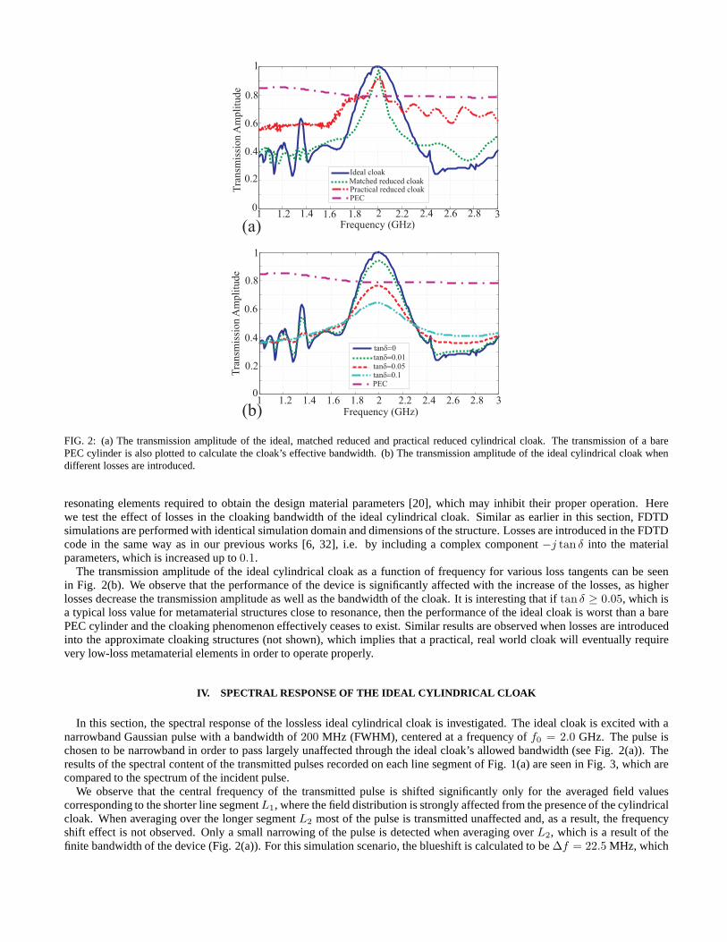
FIG. 2: (a) The transmission amplitude of the ideal, matchedreduced and practical reduced cylindrical cloak. The transmission of a barePEC cylinder is also plotted to calculate the cloak’s effective bandwidth. (b) The transmission amplitude of the ideal cylindrical cloak whendifferent losses are introduced.
resonating elements required to obtain the design materialparameters [20], which may inhibit their proper operation.Herewe test the effect of losses in the cloaking bandwidth of the ideal cylindrical cloak. Similar as earlier in this section,FDTDsimulations are performed with identical simulation domain and dimensions of the structure. Losses are introduced in the FDTDcode in the same way as in our previous works [6, 32], i.e. by including a complex component−j tan δ into the materialparameters, which is increased up to0.1.
The transmission amplitude of the ideal cylindrical cloak as a function of frequency for various loss tangents can be seenin Fig. 2(b). We observe that the performance of the device issignificantly affected with the increase of the losses, as higherlosses decrease the transmission amplitude as well as the bandwidth of the cloak. It is interesting that iftan δ ≥ 0.05, which isa typical loss value for metamaterial structures close to resonance, then the performance of the ideal cloak is worst than a barePEC cylinder and the cloaking phenomenon effectively ceases to exist. Similar results are observed when losses are introducedinto the approximate cloaking structures (not shown), which implies that a practical, real world cloak will eventuallyrequirevery low-loss metamaterial elements in order to operate properly.
IV. SPECTRAL RESPONSE OF THE IDEAL CYLINDRICAL CLOAK
In this section, the spectral response of the lossless idealcylindrical cloak is investigated. The ideal cloak is excited with anarrowband Gaussian pulse with a bandwidth of200 MHz (FWHM), centered at a frequency off0 = 2.0 GHz. The pulse ischosen to be narrowband in order to pass largely unaffected through the ideal cloak’s allowed bandwidth (see Fig. 2(a)).Theresults of the spectral content of the transmitted pulses recorded on each line segment of Fig. 1(a) are seen in Fig. 3, which arecompared to the spectrum of the incident pulse.
We observe that the central frequency of the transmitted pulse is shifted significantly only for the averaged field valuescorresponding to the shorter line segmentL1, where the field distribution is strongly affected from the presence of the cylindricalcloak. When averaging over the longer segmentL2 most of the pulse is transmitted unaffected and, as a result,the frequencyshift effect is not observed. Only a small narrowing of the pulse is detected when averaging overL2, which is a result of thefinite bandwidth of the device (Fig. 2(a)). For this simulation scenario, the blueshift is calculated to be∆f = 22.5 MHz, which

1.7 1.8 1.9 2 2.1 2.2 2.30
0.25
0.5
0.75
1.0
Frequency (GHz)
Fou
rier
Am
pli
tude
(arb
.unit
s) Source PulseL = R1 1
L = 4.25R2 2
FIG. 3: Blueshift effect observed in the normalized frequency spectra of transmitted Gaussian narrowband pulses through the ideal cylindricalcloak for two averaging line segmentsL1 andL2 of Fig. 1(a). The line segments are on the same position on they-axis,1.5λ away from thecloak’s outer shell, but have different lengths along the x-axis (L1 = R1, L2 = 4.25R2). The effect is stronger for the line segmentL1, nearthe center of the cloaking structure.
is 1.1% deviation from the central frequency of2 GHz. Hence, an instrument which is capable of resolving spectral deviationssmaller than1.1%, will detect the presence of the cloak.
To further investigate the blueshift effect, six narrowband Gaussian pulses are independently launched towards the ideal 2GHz cloak, at central frequencies of1.7, 1.8, 1.9, 2.1, 2.2, 2.3 GHz respectively. The FWHM bandwidth of each pulse is200MHz. The spectral distribution of the averaged field values of the transmitted pulses along the line segmentsL1 andL2 depictedin Fig. 1(a)1.5λ away of the cloak is once again evaluated, and is shown in Figs. 4(c), (d). In addition, we also record thetransmitted spectral distribution along two new line segments of the same lengthL1 andL2 using the same excitation signals,but this time the segments are positioned immediately afterthe cloaking structure. These results are shown in Figs. 4(a), (b).
Firstly, it is observed that when the fields are averaged overtheL2 line (Figs. 4(b), (d)) the differences between the pulsesabove and below the cloak’s central frequency are small. Thespectrum is affected symmetrically around the central frequencybecause of contributions from field energy away from the device that does not interact with the cloak. The lower amplitudesrecorded away from the central frequency region are caused by the overall finite bandwidth of the cloak, as shown in Fig. 2(a).Secondly, when recording over the short line segmentL1 (Figs. 4(a), (c)), it is observed that the pulses with central frequenciesgreater than the cloak’s operating frequency (f > f0) maintain their overall shape but are reinforced in amplitude. On thecontrary, the pulses with central frequencies less than thecloak’s operating frequency (f < f0) are dissipated, when they arepassing through the structure. This behavior gives rise to the frequency shift effect observed in Fig. 3. The effect is stronger
1.5 2 2.50
10
20
30
40
Frequency (GHz)Sp
ectr
alA
mp
litu
de
(arb
. u
nit
s) Average over L1
1.7 GHz1.8 GHz1.9 GHz2.1 GHz2.2 GHz2.3 GHz
1.5 2 2.50
10
20
30
401.7 GHz1.8 GHz1.9 GHz2.1 GHz2.2 GHz2.3 GHz
1.5 2 2.50
10
20
30
40
1.5 2 2.50
10
20
30
40
Sp
ectr
alA
mp
litu
de
(arb
. u
nit
s)
Frequency (GHz)
Average over L2
Average over L1
Sp
ectr
alA
mp
litu
de
(arb
. u
nit
s)
Frequency (GHz) Frequency (GHz)
1.7 GHz1.8 GHz1.9 GHz2.1 GHz2.2 GHz2.3 GHz
Average over L2
Sp
ectr
alA
mp
litu
de
(arb
. u
nit
s)
1.7 GHz1.8 GHz1.9 GHz2.1 GHz2.2 GHz2.3 GHz
(a)
(d)
(b)
(c)
Close to cloak
1.5 away from cloakl
FIG. 4: Frequency spectra of six transmitted narrowband pulses, centered at different frequencies, after impinging onthe ideal cloak. Thecloak’s design frequency is2 GHz. The fields are averaged over two different line segmentsL1 ((a), (c)) andL2 ((b), (d)) which are perpen-dicular to the direction of propagation as shown in Fig. 1(a). The line segments are positioned either right after the cloak’s outer boundary((a), (b)) or at a distance1.5λ away ((c), (d)).

Ideal Cloak
e<0,m>0
e<0,m<0
PEC
(b)
Reduced Cloak
PE
CW
all
(d)
e>0,m>0
PEC Wall
e>0,m>0
e<0,m>0
PEC
PEC Wall
PEC Wall
PMC Wall
1.5 1.6 1.7 1.8 1.9 2
1
1.1
1.2
1.3
1.4
1.5
1.6
1.7
1.8
Frequency [GHz]
Pen
etra
tion D
epth
rR
&e/
1r
Rm/
1
re: R /R = any2 1
rm: R /R =2 1 8
rm: R /R = 4.52 1
rm: R /R = 2.02 1
rm: R /R = 1.52 1
1.5 1.6 1.7 1.8 1.9 21
1.5
2
2.5
3
Pen
etra
tion D
epth
rR
e/1
Frequency [GHz]
FDTD Results
R /R =2 1 8
R /R = 4.52 1
R /R = 2.02 1
R /R = 1.52 1
(a)
(c)
FIG. 5: (a) Analytical normalized penetration depths for ideal cylindrical cloaks with different dimensions. (b) Regions formed inside theideal cylindrical cloak, when it operates atf < f0 frequencies. (c) Analytical normalized penetration depths for matched reduced cylindricalcloaks with different dimensions. The numerically estimated penetration depths are also shown for a cloak with thickness2λ/3. The error barsindicate numerical uncertainty on the field cutoff radius. (d) Regions formed inside the matched reduced cylindrical cloak, when it operates atf < f0 frequencies.
away from the cloak (Fig. 4(c)), as opposed to near the cloak (Fig. 4(a)), since the field has recombined behind the devicein the former case. At an even greater distance away from the device, the amplitudes of the transmitted pulses do not evolvesignificantly.
We now investigate the effective structure that an off-frequency incident wave perceives inside the dispersive cloaking shell.Depending on the frequency of the incident wave, the material parameters of the ideal cloak (Eq. (1)) may become equal tozero somewhere inside the cloaking shell. These locations are then effectively acting as a PEC wall (whenεr = 0) and perfectmagnetic conductor (PMC) wall (whenµz = 0) for that frequency, beyond which the fields theoretically do not penetrate [27].The radial locationsrε, rµ, where the permittivity and permeability respectively vanish for the ideal cloak, are given as a functionof frequency by (using Eqs. (7), (8), (1)):
rε(ω < ω0) = R1
ω2
0
ω2(9)
rµ(ω < ω0) =R1
1 −(
1 − ω2
ω2
0
)(
1 − R1
R2
)2(10)
The theoretical field penetration depths normalized to the object’s radiusR1 are plotted in Fig. 5(a) for different dimensionsof the cloak as a function of frequency, forf < f0 (for f > f0 no such walls are formed). It is observed that alwaysrε > rµ,

1.5 2 2.50
10
20
30
40
1.5 2 2.50
10
20
30
40Average over L1 Average over L2
1.7 GHz1.8 GHz1.9 GHz2.1 GHz2.2 GHz2.3 GHz
1.7 GHz1.8 GHz1.9 GHz2.1 GHz2.2 GHz2.3 GHz
1.7 GHz1.8 GHz1.9 GHz2.1 GHz2.2 GHz2.3 GHz
Spec
tral
Am
pli
tude
(arb
. unit
s)
Spec
tral
Am
pli
tude
(arb
. unit
s)
Frequency (GHz) Frequency (GHz)
(a) (b)
FIG. 6: Frequency spectra of six transmitted narrowband pulses, centered at different frequencies, after impinging onthe matched reducedcloak. The cloak’s design frequency is2 GHz. The fields are averaged over two different line segmentsL1 (a) andL2 (b), as shown in Fig.1(a), which are perpendicular to the direction of propagation. The line segments are positioned at a distance1.5λ away from the cloak’s outershell.
with rµ → rε for anyω asR2 ≫ R1. This implies that a PEC wall will form first as the wave approaches the core of thedevice, beyond whichεr < 0. If a material with positive index of refraction was formed between that wall and the device’sPEC core, no fields would penetrate further inside. However,further inside the cloak a PMC wall will be then formed, beyondwhich alsoµz < 0. Thus, a negative index shell will be formed for some frequencies near the core of the device, which cantrigger phenomena such as superscattering [7]. This three-layer effect is unique to the ideal cylindrical cloak (for TEor TMpolarizations) because two material parameters can becomesimultaneously negative due to dispersion, something thatis notoccurring in either the ideal spherical cloak or the matchedreduced cylindrical cloak. These layers are depicted graphically inFig. 5(b) forf < f0 frequencies.
In addition, since forf = f0 the material parameters become zero at the inner corer = R1, waves with frequenciesf < f0
will sample negative values of the material parameters nearthe core, while waves with frequenciesf > f0 will sample strictlypositive material parameters values everywhere in the cloaking shell. Thus, the former waves (f < f0) will perceive the deviceas conducting scatterer, while the latter (f > f0) will perceive it as a dielectric and magnetic material, with positive permittivityand permeability.
This latter effect, that waves at different frequencies perceive electromagnetically different devices, is demonstrated by launch-ing three monochromatic plane waves at frequencies1.7 GHz, 2.0 GHz and2.3 GHz against the ideal cloak. The real part ofthe converged magnetic field values are shown in Fig. 7(a)-(c). We observe in Fig. 7(a) that for the1.7 GHz wave, little fieldreaches the core of the device due to the aforementioned walls that form, and thus a strong shadow is observed behind the device.On the contrary, in Fig. 7(c), the2.3 GHz wave perceives the cloaking shell as a positive index material and field is distributedeven inside the device. As a reference, the field distribution on the nominal frequency of2.0 GHz is also shown in Fig. 7(b).The positive-to-negative material parameters transitions that occur forf < f0 but not forf > f0 give rise to the frequencymodulation that occurs inside the cloaking shell (shown in Fig. 4(a), (c)), as waves atf < f0 are dissipated due to the scatteringfrom a conductor, while others atf > f0 are scattered from a positive-index material. This ultimately produces the frequencyshift observed in Fig. 3.
V. SPECTRAL RESPONSE OF THE REDUCED CYLINDRICAL CLOAK
We now focus on the matched reduced cylindrical cloak [31], which is easier to be practically implemented compared to theideal cloak. This material parameter set is more similar to the ideal spherical cloak [1], in the sense that, for a given polarization,only one parameter is radially-dependent and dispersive (εr for TE waves), whereas the others are constant and conventional.FDTD simulations are performed over the same domain as before (Fig. 1(a)) and the cloak has the same dimensions. Again,narrowband Gaussian pulses at various central frequenciesare launched towards the cloak. The transmitted pulses in the fre-quency domain, after impinging on the cloak, recorded at thetwo line segmentsL1 andL2 of Fig. 1(a), at a distance1.5λ awayfrom the device, are seen in Figs. 6(a) and (b), respectively.
The transmitted pulses appear slightly distorted comparedto the ideal cloak (Fig. 4) due to the fact that the reduced cloak ex-amined here is designed to operate approximately. However,the features of the transmitted pulses are similar to the transmissionobserved through the ideal cloak, where frequenciesf < f0 are dissipated while frequenciesf > f0 are enhanced. The effect isonce again much stronger when averaging the fields near the cloak’s core, and gives rise to a similar frequency blueshift effect.
For some frequenciesf < f0, the dispersive parameterεr will become equal to zero at a specific location inside the cloakingshell, forming a boundary beyond which wave penetration is very weak. The penetration depth is calculated analyticallywith a

FIG. 7: Real part of the magnetic field amplitude distributions (Hz) when plane waves of different frequencies are impinging onthe ideal((a)-(c)) and matched reduced ((d)-(f)) cloak, after steady state is reached. The amplitude scale is normalized such that 1 is the maximumplane wave field amplitude without any device present. (a),(d): At 1.7 GHz a PEC wall is formed inside the cloaking shell where fieldscannotpenetrate. The devices behave as a conductive scatterer anda large shadow is observed behind them. (b),(e): At2.0 GHz the devices operate attheir nominal frequency. For (e) only, imperfections in thefield distributions are inherent in the limitations of the cloak’s approximate design.(c),(f): At 2.3 GHz the cloaking material is perceived as a dielectric scatterer from the incident wave. Thus no significant shadow is formedbehind the devices.
similar procedure as before and it is given by the equation:
rε(ω < ω0) =R1
1 −√
(
1 − ω2
ω2
0
)(
1 − R1
R2
)
(11)
It is normalized toR1 and plotted as a function of thef ≤ f0 frequencies in Fig. 5(c) for cloaks with different thicknesses.Moreover, the locations, where the impenetrable wall is formed, are deduced approximately through the FDTD simulationbyidentifying the points where the magnetic fieldHz becomes zero. They are also shown in Fig. 5(c) for a specific cloak designand are found to be in excellent agreement with the analytical predictions of the penetration depth derived from Eq. (11). Thelayers that form inside the reduced cloak are depicted graphically in Fig. 5(d) forf < f0 frequencies.
Similar to the procedure followed in the previous section for the ideal cloak, in order to explain the different behaviorof thepulses above and below the central frequency, along with theformation of the PEC wall, three monochromatic plane waves arelaunched with frequencies1.7, 2.0 and2.3 GHz towards the2 GHz matched reduced cloak. The real part of the converged fieldamplitude values are seen in Figs. 7(d)-(f). As a reference,Fig. 7(e) shows the field distribution at the cloak’s nominalfrequency,where the wave energy mostly recomposes smoothly behind thedevice. The imperfections observed in the wavefronts are dueto the approximate nature of the reduced cloak’s design.
For the plane wave with frequency1.7 GHz, according to Eq. (11), an impenetrable wall is expectedto form approximately0.36λ away from the inner core. This is indeed observed in Fig. 7(d), where little field reaches the metallic core. As wasdiscussed previously, due to the PEC wall the wave at that frequency should perceive the device as a conductive scatterer. Thisis confirmed in the simulation by observing the large shadow that appears behind the device, similar to the shadow that typicallyappears by the scattering of a plane wave off a conductive cylinder. This shadow is the reason for the reduced amplitude recordedfor wave pulses at frequenciesf < f0, as was pointed out in Fig. 6(a). The shadow is similar to the one observed in the case of

FIG. 8: Time-dependent snapshots of the real part of the magnetic field amplitude distribution (Hz) when a1 GHz (FWHM) Gaussian pulseis impinging on dispersive devices. (a)-(c): Ideal cloak. (d)-(f): Ideal concentrator. In (a),(d) the pulse has reached the first half of the devices.In (b),(e) the pulse leaves the dispersive regions. The wavefronts near the center of the devices are delayed compared tothe wavefronts awayfrom the central regions. In (c),(f) a delay appears near thecenter of the devices, even though the waves have recomposed. Reflections areobserved due to the broad bandwidth of the incident pulse.
the ideal cloak, as shown in Fig. 7(a).For the plane wave with frequency2.3 GHz, no PEC wall is predicted to exist. Instead, the wave perceives the cloaking shell
as a dielectric scatterer, since the relative permittivityvalues are always larger than zero forf > f0. Indeed, the field distributionshown in Fig. 7(f) indicates that the fields penetrate all theway into the inner core, and that no shadow appears behind thedevice. On the contrary, the interference effects cause thefield amplitude behind the cloak to be locally larger than theamplitudeof the incident field (equal to unity in Fig. 7), thus enhancing thesef > f0 frequencies compared to thef < f0 frequencies.This explains the modulation pattern that appears in Figs. 6(a) which ultimately causes the blueshift effect presentedin Fig. 3.
VI. TEMPORAL AND SPATIAL RESPONSES OF THE IDEAL CYLINDRICAL CLOAK AND CONCENTRATOR
Another interesting effect takes place in the ideal cloaks for non-monochromatic waves. While light rays that travel awayfrom the core of the cloak propagate at the speed of light in free space, rays that traverse the core region experience timedelays[28], due to the increased values of the permittivities and permeabilities introduced by the anisotropic cloaking materials. Thiseffect is stronger near the center of the cloak, where in theory some material parameters reach infinite (or realistically very large)values. As we shall show, the phenomenon is visible when a temporally finite pulse is incident towards the cloak: wavefrontspropagating away from the core reach the other side of the domain (behind the cloak) sooner than wavefronts propagating nearthe center.
The time-delay effect has been predicted theoretically fora 3D ideal spherical cloak [28, 29]. In this paper, this dynamiceffect is demonstrated and exploited with the FDTD method for the ideal cylindrical cloak. The same dimensions, as before, arechosen for the tested cloak. A broadband Gaussian pulse is launched and is passing through the 2D structure. It has a bandwidthof 1 GHz, centered at the cloak’s nominal frequency of2 GHz. The real part of the magnetic field amplitude distribution iscalculated as a function of time through the FDTD simulation. Three time snapshots of the pulse are depicted in Figs. 8(a)-(c),

0 1 2 3 4 50
0.5
1
1.5
x/lR
elat
ive
Ener
gy
Cloak Concentrator
R1
R2
Free space
FIG. 9: Relative accumulated energy distribution for idealcloak and concentrator. In the amplitude scale shown,1 is the accumulated energydistribution of free space propagation. The linesR1 andR2 indicate the inner and outer radii of the devices. The distributions are not perfectlysymmetric because of the finite discretization used in the FDTD simulations.
as the pulse is propagating through the device. When the pulse is recomposed after the cloak (Fig. 8(c)), the wavefronts are notflat anymore due to the experienced time delay, which is more intense closer to the cloak’s inner boundary. The group velocityis reduced close to the inner boundary of the structure, whereas the phase velocity is approaching large values.
In this example, the wavefronts near the center of the cloak are delayed by approximately0.27 ns compared to wavefrontsthat propagate mostly undisturbed away from the cloak. The bending of the waves is caused by the extremely high values ofthe radially-dependent cloaking parameters (Eq. (1)) due to the dilation of the domain from a point to a circle ring, the device’sinner core. Hence, the time delay of the pulse is inherent to the design of the cloak and, as a result, unavoidable. Thus, one couldtake advantage of this effect in order to detect the presenceof the cloaking device with an appropriate instrument. It ispresentin both the ideal and reduced (not shown here) 2D cylindricalcloaks. It is also the main reason for the long time required for theFDTD simulations to reach steady-state results [38] in suchsimulations.
The time-delay effect is not limited to cloaks, but generally appears whenever large variations of the values of the materialparameters are required for a given device. To illustrate a different scenario, Figs. 8(d)-(f) show time snapshots as the samebroadband Gaussian pulse is impinging on the ideal concentrator [8], a device designed to focus electromagnetic fields insidea small region of space (r < R1 in this case). The dimensions of the device are the same as thecloak’s discussed earlier. Thetime-delay effect is observed after the wave recomposes behind the device, especially near the core, where the wavefronts aredelayed by roughly0.18 ns compared to the unperturbed waves. The effect is weaker compared to the cloak, since none of thematerial parameters reach extreme values (maximum value ofpermittivities and permeability is3) [8]. Meanwhile, the phaseand group velocities have comparable values. It should alsobe noted that reflected waves emerge as the pulses impinge on eitherdevice (Figs. 8(c) and (f)). This is a result of the large number of frequency components contained in the Gaussian pulses, sincethe devices can only operate properly at their nominal frequency of2 GHz.
In addition to the temporal disturbances induced on the Gaussian pulses by the dispersive devices, their spatial distribution isaffected as well [29]. To illustrate this effect, the time-integrated energy distribution crossing the line segmentL2 (Fig. 1(a)) forboth ideal cloak and concentrator is recorded in the setup ofFig. 8, and it is shown in Fig. 9. We observe that the energy ofthe non-monochromatic source is not distributed uniformlyoutside of the devices due to scattering of the frequency componentsaway fromf0. The cloak has more extreme parameters than the concentrator, which leads to less accumulated energy inside thedevice and more scattered energy outside. It is interestingthat the energy reaching the center of both structures is lower than thescattered energy near the edges of the simulation domain. Hence, the energy is not properly spatially recombined behindeitherdevice.
VII. CONCLUSIONS
Concluding, the properties of the metamaterial dispersivedevices under non-monochromatic illumination are studied. Theinherent dispersive nature of the devices is the main reasonbehind the transient effects observed, which is affecting their broad-band performance. We investigate the origin of the frequency shifts that appear in both the ideal and matched reduced cylindricalcloaks through dispersive FDTD simulations, using narrowband Gaussian pulses as illumination. In addition, the time-delay andspatial non-uniformity effects that occur near the center of the dispersive regions of the ideal cloak as well as the ideal con-centrator are demonstrated. These are important effects that should be taken into account in future applications of dispersive

metamaterial devices.The ideal cylindrical cloak and concentrator, work properly only for monochromatic wave incidence. However, they become
non practical when they are excited with non-monochromaticradiation, which is the type of electromagnetic radiation found innature. The effect of losses is also significant for such dispersive devices. In general, the transmitted signal, passing throughdevices derived from coordinate transformations, will have its spectral, temporal and spatial profiles altered. Theserestraintscould be avoided if the cloak is constructed from broadband active metamaterials [39, 40]. Alternatively, novel non-dispersivedevices based on conventional materials [41] need to be implemented.
[1] J. B. Pendry, D. Schurig, and D. R. Smith, Science312, 1780 (2006).[2] U. Leonhardt, Science312, 17771780 (2006).[3] D. Schurig, J. J. Mock, B. J. Justice, S. A. Cummer, J. B. Pendry, A. F. Starr, and D. R. Smith, Science314, 977980 (2006).[4] J. Li and J. B. Pendry, Phys. Rev. Lett.101, 203901 (2008).[5] R. Liu, C. Ji, J. J. Mock, J. Y. Chin, T. J. Cui, and D. R. Smith, Science323, 366 (2009).[6] C. Argyropoulos, E. Kallos, Y. Zhao, and Y. Hao, Opt. Express17, 8467 (2009).[7] T. Yang, H. Chen, X. Luo, and H. Ma, Opt. Express16, 18545 (2008).[8] M. Rahm, D. Schurig, D. Roberts, S. Cummer, D. Smith, and J. Pendry, Phot. Nanostr. Fund. Appl.6, 8795 (2008).[9] M. Tsang and D. Psaltis, Phys. Rev. B77, 035122 (2008).
[10] M. Yan, W. Yan, and M. Qiu, Phys. Rev. B78, 125113 (2008).[11] D. Schurig, J. B. Pendry, and D. R. Smith, Opt. Express15, 14772 (2007).[12] M. Rahm, S. A. Cummer, D. Schurig, J. B. Pendry, and D. R. Smith, Phys. Rev. Lett.100, 063903 (2008).[13] H. Chen and C. T. Chan, Appl. Phys. Lett.90, 241105 (2007).[14] M. Rahm, D. Roberts, J. Pendry, and D. Smith, Opt. Express 16, 11555 (2008).[15] F. Kong, B. Wu, J. Kong, J. Huangfu, S. Xi, and H. Chen, Appl. Phys. Lett91, 253509 (2007).[16] W. Jiang, T. Cui, H. Ma, X. Yang, and Q. Cheng, Appl. Phys.Lett. 93, 221906 (2008).[17] J. B. Pendry, A. J. Holden, D. J. Robbins, and W. J. Stewart, IEEE Trans. Microwave Theory Tech.44, 2075 (1999).[18] D. Smith, W. Padilla, D. Vier, S. Nemat-Nasser, and S. Schultz, Phys. Rev. Lett.84, 4184 (2000).[19] D. R. Smith, J. B. Pendry, and M. C. K. Wiltshire, Science305, 788 (2004).[20] V. Podolskiy and E. Narimanov, Opt. Lett.30, 75 (2005).[21] S. Tretyakov and S. Maslovski, IEEE Ant. Propag. Magaz.49, 37 (2007).[22] F. Chen,Introduction to plasma physics and controlled fusion(Plenum Publishing Corporation, 1984).[23] Z. Ruan, M. Yan, C. W. Neff, and M. Qiu, Phys. Rev. Lett.99, 113903 (2007).[24] S. A. Cummer, B.-I. Popa, D. Schurig, D. R. Smith, and J. B. Pendry, Phys. Rev. E74, 036621 (2006).[25] B. Zhang, H. Chen, B.-I. Wu, Y. Luo, L. Ran, and J. A. Kong,Phys. Rev. B76, 121101(R) (2007).[26] Y. Zhao, C. Argyropoulos, and Y. Hao, Opt. Express16, 6717 (2008).[27] B. Zhang, B. Wu, H. Chen, and J. Kong, Phys. Rev. Lett.101, 063902 (2008).[28] H. Chen and C. Chan, J. Appl. Phys.104, 033113 (2008).[29] B. Zhang, B.-I. Wu, and H. Chen, Opt. Express17, 6721 (2009).[30] B. Ivsic, Z. Sipus, and S. Hrabar, IEEE Trans. Ant. Propag. 57, 1521 (2009).[31] M. Yan, Z. Ruan, and M. Qiu, Opt. Express15, 17772 (2007).[32] C. Argyropoulos, Y. Zhao, and Y. Hao, IEEE Trans. Ant. Propag.57, 1432 (2009).[33] A. Taflove and S. C. Hagness,Computational electrodynamics : the finite-difference time-domain method, 3rd Edition(Artech House,
2005).[34] J. B. Pendry, A. J. Holden, W. J. Stewart, and I. Youngs, Phys. Rev. Lett.76, 4773 (1996).[35] Y. Zhao, P. Belov, and Y. Hao, Jour. Opt. A: Pure Appl. Opt. 9, 468475 (2007).[36] J.-Y. Lee and N.-H. Myung, Microw. Opt. Tech. Lett.23, 245 (1999).[37] W. Cai, U. K. Chettiar, A. V. Kildishev, and V. M. Shalaev, Nat. Photonics1, 224227 (2007).[38] Z. Liang, P. Yao, X. Sun, and X. Jiang, Appl. Phys. Lett.92, 131118 (2008).[39] S. Tretyakov, Micr. Opt. Techn. Lett.31, 163 (2001).[40] H. Chen, W. Padilla, J. Zide, A. Gossard, A. Taylor, and R. Averitt, Nature444, 597 (2006).[41] E. Kallos, C. Argyropoulos, and Y. Hao, Phys. Rev. A79, 63825 (2009).