Buckling of timber columns exposed to fire
20
Jamova 2 1000 Ljubljana, Slovenija http://www3.fgg.uni-lj.si/ DRUGG – Digitalni repozitorij UL FGG http://drugg.fgg.uni-lj.si/ Ta članek je avtorjeva zadnja recenzirana različica, kot je bila sprejeta po opravljeni recenziji. Prosimo, da se pri navajanju sklicujete na bibliografske podatke, kot je navedeno: University of Ljubljana Faculty of Civil and Geodetic Engineering Jamova 2 SI – 1000 Ljubljana, Slovenia http://www3.fgg.uni-lj.si/en/ DRUGG – The Digital Repository http://drugg.fgg.uni-lj.si/ This version of the article is author's manuscript as accepted for publishing after the review process. When citing, please refer to the publisher's bibliographic information as follows: Schnabl, S., Turk, G. in Planinc, I. 2011. Buckling of timber columns exposed to fire. Fire Safety Journal 46: 431–439. Univerza v Ljubljani Fakulteta za gradbeništvo in geodezijo
Transcript of Buckling of timber columns exposed to fire

Jamova 2 1000 Ljubljana, Slovenija http://www3.fgg.uni-lj.si/
DRUGG – Digitalni repozitorij UL FGG http://drugg.fgg.uni-lj.si/
Ta članek je avtorjeva zadnja recenzirana različica, kot je bila sprejeta po opravljeni recenziji. Prosimo, da se pri navajanju sklicujete na bibliografske podatke, kot je navedeno:
University of Ljubljana Faculty of Civil and Geodetic Engineering
Jamova 2 SI – 1000 Ljubljana, Slovenia http://www3.fgg.uni-lj.si/en/
DRUGG – The Digital Repository http://drugg.fgg.uni-lj.si/
This version of the article is author's manuscript as accepted for publishing after the review process. When citing, please refer to the publisher's bibliographic information as follows:
Schnabl, S., Turk, G. in Planinc, I. 2011. Buckling of timber columns exposed to fire. Fire Safety Journal 46: 431–439.
Univerza v Ljubljani
Fakulteta za gradbeništvo in geodezijo

Buckling of timber columns exposed to fire
S. Schnabla,∗, G. Turka, I. Planinca
aUniversity of Ljubljana, Faculty of Civil and Geodetic Engineering, Jamova 2, SI-1115 Ljubljana, Slovenia
Abstract
A mathematical model for structural behavior of timber columns under fire has been proposed. The semi-
analytical study has been carried out for evaluating load-carrying capacity of timber columns exposed to
fire. Particular emphasis has been given to critical buckling loads. For this purpose, a parametric study has
been performed by which the influence of slenderness ratio, load level, and water content on critical buckling
loads of timber columns have been investigated. It has been proven, the two simplified calculation methods
offered by Eurocode 5 are non-conservative compared to the present semi-analytical method if the transfer
of water is neglected, while, on the other hand, the results agree well for water content of 12%. Moreover,
for higher water contents, the Eurocode 5 methods are conservative.
Keywords: fire, stability, buckling, timber, charring, semi-analytical solutions, column, Reissner beam,
critical load, moisture.
NomenclatureA cross-sectional area at room temperature (cm2)Ares residual cross-sectional area (cm2)b width of the cross section (cm)cm water capacity (kg/kg ◦M)cp specific heat (J/kgK)E elastic modulus (kN/cm2)h height of the cross section (cm)hc convective heat transfer coefficient (W/m2 K)hm convective water transfer coefficient (kg/s m2 ◦M)J moment of inertia at room temperature (cm4)kq thermal conductivity (W/mK)km water conductivity (kg/m s ◦M)L column length (cm)Lu effective buckling length (cm)M cross-sectional bending momentMY cross-sectional bending moment (kNcm)n surface unit normalNcr critical number of time intervalsN cross-sectional equilibrium axial internal force (kN)P centrally applied point force (kN)Pcr critical buckling load (kN)Pult ultimate axial load-carrying capacity at room temperature (kN)Q cross-sectional equilibrium shear internal force (kN)RX , X component of the cross-sectional equilibrium force (kN)RZ Z component of the cross-sectional equilibrium force (kN)
∗Corresponding authorEmail address: [email protected] (S. Schnabl)
Preprint submitted to Elsevier 19th February 2011

t time (min)tcr critical time-to-failure (min)T temperature (◦C)TA ambient temperature (◦C)TA,cr critical ambient temperature (◦C)T0 initial ambient temperature (◦C)u axial displacement (cm)V water content (%)w deflection (cm)Greek lettersαT thermal expansion coefficient (/K)δ thermogradient coefficient (◦M/K)∆D total strain increment∆DM mechanical strain increment∆DT thermal strain incrementε extensional strainεcr critical axial strainεm ratio of coefficients of vapour diffusion to total moisture diffusionεR effective surface emissivityθ moisture potential (◦M)θA ambient moisture potential (◦M)θ0 initial ambient moisture potential (◦M)κ pseudocurvature (rad/m)λ column slenderness ratioλe latent heat of evaporation (J/kg)λtr transitional column slenderness ratioρ density (kg/m3)σ Stephan-Boltzmann constant (σ = 5.671 · 10−8 W/m2K4)σC applied stress (kN/cm2)ϕ rotation (rad)Subscripts and superscriptsi time interval
1. Introduction
Timber, one of the oldest constructional material, has been used extensively in the construction of
residential and low-rise buildings. Nowadays, there is also a tendency to construct multi-storey timber
buildings. Since timber is a thermally degradable and combustible material, there have been frequent
doubts concerning its fire performance in such structures. Despite the fact that timber beams with large
sections show a good structural performance, design of fire resistant timber structures still plays a key issue
that has to be accurately considered during structural design.
The fire resistance of timber structures is usually established by full-scale furnace testing according to
ISO 834 [1], or a similar national standard such as ASTM 119 [2]. Accordingly, several full-scale fire tests
of timber columns have been performed [3, 4]. However, there could exist some drawbacks associated with
the fire testing in terms of expense, specimen limitations, confidentially of results, reproducibility and many
more [25].
Consequently, in recent years, a number of analytical, numerical, simplified semi-empirical, and empiri-
cal methods for calculating the fire resistance have been proposed [3–13], which present several advantages
2

compared to the experimental testing on timber structures. Majority of these methods are based on con-
stant charring rates and material properties at room temperature. In some cases higher rates are used to
compensate the loss in strength and stiffness of the unburnt timber [8, 12], or to compensate the loss of
section due to the ”round-off” effect at the corners [12]. For suitable fire safety design of timber columns,
a charring rate is an essential quantity for a reliable determination of fire resistance of such structures.
Therefore, the effect of charring of timber has been a subject of intensive research for many years and there
are many excellent literature reviews on this subject [11, 14–22].
The decreasing of the effective cross-section by charring and thermal degradation of strength and stiffness
properties of the unburnt region during fire strongly influence the stability behavior of timber columns
exposed to fire.
To the best of authors’ knowledge, there exist no advanced mathematical model in the literature that
would adequately determine the critical buckling loads of timber columns exposed to fire. Therefore, the
main goal of this paper is to analyse the buckling behaviour of timber columns under axial compression at
elevated temperatures. In the analysis, temperature dependent non-linear material properties of timber and
char are used [12, 13, 22–27]. Besides, the effect of moisture on load-carrying capacity of timber columns is
also investigated. For this purpose, heat and water (liquid and gas phase) transfer equations are solved using
finite-difference method. Furthermore, the critical buckling forces are determined by a linearized buckling
method described in detail by Planinc et al [28].
In the numerical examples, the calculated critical buckling loads are compared to the predictions in
the literature. A parametric study is conducted by which an influence of different geometric and material
parameters on load-carrying capacity of timber column exposed to standard fire conditions is investigated.
Afterwards, the solution is used to investigate the effect of initial moisture potential on the load-bearing
capacity of a timber column under fire.
2. Fire analysis of timber columns
2.1. Problem preliminaries
We consider an initially straight, planar, timber column of undeformed length L, see Fig. 1. The column
is placed in the (X, Z) plane of spatial Cartesian coordinate system with coordinates (X, Y, Z) and unit
base vectors EX ,EY and EZ = EX ×EY . The undeformed reference axis of the column coincides with its
centroidal axis. Local coordinate system (x, y, z) is assumed to coincide initially with spatial coordinates,
and then follows the deformation of the column. Thus, x ≡ X, y ≡ Y , and z ≡ Z in the undeformed
configuration. The so called ideal column is axially compressed by a centrally applied conservative point
force P at both ends. In addition, the timber column is exposed to a spatially uniform fire on all four sides.
3

Figure 1: Geometry and notation for a straight compressed timber column, its undeformed and deformed configuration and a
typical cross-section.
The process of calculating structural behavior of timber columns under fire conditions has generally three
mutually independent steps. Each individual step is based on essential component models which are: a fire
exposure model, a heat and water transfer model, and a structural model. In this study, it is assumed that
the fire exposure model or its expected time-temperature and time-water regime are estimated in advance in
accordance with the expected fire severity. Thus, only the last two steps are included in the present analysis
of timber columns exposed to fire. First, temperature and moisture potential distributions in the column
cross-section is determined by the heat and water transfer model. Second, the output from the heat and
water transfer model is used as an input to a structural model by which the stress-strain field due to the
simultaneous effect of mechanical and temperature loads is obtained. Below these two steps are described
in detail.
2.2. Heat and water transfer model
The interrelation between heat and water transfer in capillary porous materials, such as timber, is
governed by a coupled system of partial differential equations (1)–(2), see e.g. [29]. The Luikov system of
equations, however, is a highly non-linear system because the transfer coefficients are functions of either
moisture or temperature or both. For the two-dimensional case under constant pressure conditions, Luikov’s
basic conservation equations can be written as follows:
4

• Heat transfer equation:
∂
∂t(ρcqT ) = ∇ ·
[(kq +
εmλekmδ
cm
)∇T + εmλekm∇θ
], (1)
• Water transfer equation:∂
∂t(ρcmθ) = ∇ ·
[(kmδ
cm
)∇T + km∇θ
]. (2)
Eq. (1) represents a balance of thermal energy within the capillary porous body. The transfer of heat by
conduction is normally related to the temperature gradient, but in the case of a coupled system, it is also
weakly related to the moisture gradient, and this is known as the Dufour effect. Furthermore, the water
balance of a porous material is expressed by Eq. (2) which follows from the mass conservation law. The
water flux is not only related to the gradient of moisture but also to the temperature gradient, which is
known as the Sorret effect.
The initial and time-dependent convective-type boundary conditions are given below
• Initial conditions: Timber is assumed to have initially (at t = 0) uniform temperature and moisture
potential. Therefore,
T (y, z, 0) = T0, (3)
and
θ(y, z, 0) = θ0. (4)
• Time-dependent boundary conditions:
−kq∇T · n = hq(T − TA) + εRσ(T 4 − T 4A) + (1− εm)λehm(θ − θA), (5)
−km∇θ · n− kmδ∇T · n = hm(θ − θA). (6)
The second term in the right-hand side of Eq. (5) represents the radiative heat input, where εR is the effective
surface emissivity and σ is the Stephan-Boltzmann constant for radiation, (σ = 5.671 · 10−8 W/m2K4).
For a constant water capacity and small water contents, the moisture transfer potential θ can be assumed
as a linear function of the water content V of the body [29]
θ =1
cmV. (7)
The above-mentioned governing equations of heat and water transfer in porous body (1)–(2) along with the
boundary conditions (5)–(6) are non-linear. Therefore, the equations have to be solved numerically. Conse-
quently, the non-linear system of governing equations is discretized using a numerically stable Crank-Nicolson
finite difference scheme and solved by Gauss-Siedel iterative method. Moreover, a computer program is de-
veloped which operates in the Matlab environment [30].
5

2.3. Structural model
2.3.1. Basic equations
Once the temperature and moisture potential fields have been determined, the mechanical response of
the geometrically perfect timber column to the applied loading in fire conditions can be modelled by the
linearized Reissner equations of the beam theory [31]. The solution is found incrementally. For this reason,
a fire-exposure time is divided into shorter time intervals [ti−1, ti]; (i = 1, 2, . . . , Ncr). The stress-strain state
at each time ti is then determined iteratively. If the shear strains are neglected and only end forces are
considered, the governing equations of the structural model are, see e.g. [32, 33]:
F i1 = ui′ − ϕi = 0, (8)
F i2 = wi′ + (1 + εi)ϕi = 0, (9)
F i3 = ϕi′ − κi = 0, (10)
F i4 = Ri′
X = 0, (11)
F i5 = Ri′
Z = 0, (12)
F i6 = M i′
Y − (1 + εi)Qi = 0, (13)
F i7 = N i −Ri
X = 0, (14)
F i8 = Qi −Ri
Xϕi −RiZ = 0, (15)
F i9 = N i − Ci
11εi − Ci
12κi = 0, (16)
F i10 = Mi − Ci
21εi − Ci
22κi = 0, (17)
where, the prime (′) denotes the derivative with respect to x, and Ci11, C
i12, C
i21, and Ci
22 are the components
of the cross-sectional constitutive matrix. In the case of symmetrical cross-section they are defined as
Ci11(ε
i, κi = 0, DiT , T i) =
∫A
∂σiC
∂εidA, (18)
Ci12(ε
i, κi = 0, DiT , T i) = Ci
21(εi, κi = 0, Di
T , T i) =∫A
z∂σi
C
∂εidA = 0, (19)
Ci22(ε
i, κi = 0, DiT , T i) =
∫A
z2 ∂σiC
∂εidA. (20)
Eqs. (18)–(20) are the constitutive equations of the cross-section by which the axial force and the bending
moments are related to the normal stress, σiC , which is a function of the mechanical strain, Di
M. The
corresponding natural and essential boundary conditions to the Eqs. (8)–(17) are:
x = 0 :
ui(0) = 0, (21)
6

wi(0) = 0, (22)
r05M
iY (0) + r0
6ϕi(0) = 0, (23)
x = L :
rL1 Ri
X(L) + rL2 ui(L) = 0, (24)
rL3 Ri
Z(L) + rL4 wi(L) = 0, (25)
rL5 M i
Y (L) + rL6 ϕi(L) = 0. (26)
where rj ∈ {0, 1} are the parameters that determine different combinations of boundary conditions of
the timber column, where the superscripts ”0” and ”L” identify its value at x = 0 and x = L, respectively.
Eqs. (8)–(17) constitute a system of 10 linear algebraic and differential equations for 10 unknown functions
εi, κi, ui, wi, ϕi, RiX , Ri
Z , M iY , N i, and Qi along with the natural and essential boundary conditions
(21)–(26).
2.3.2. Mechanical properties of timber at elevated temperatures. Additivity of strains.
The mechanical properties of timber, namely, its compressive strength and stiffness are significantly
affected by water content and temperature of timber. These properties decrease, however, both as interior
water content and temperature increase. In general, timber properties are affected by evaporation and
condensation of water around 100◦C, timber begins to pyrolyse at about 200◦C and turn into char by
approximately 300◦C. Effectively, the strength and stiffness of timber can be considered to be essentially
depleted if the temperature exceeds 300◦C. Therefore, the knowledge of strength and stiffness reducing
effects of high temperatures and water content on timber are necessary for calculating structural performance
of timber structures when exposed to fire. In the present study, a comprehensive survey on these effects is
omitted and an interested reader is directed to a detailed review of these effect made by Gerhards [27].
In addition, the mechanical analysis of a timber structure exposed to fire requires consideration of the
principle of additivity of strains. The total or geometric extensional strain, Di = εi + zκi, is determined by
the following relation
Di = Di−1 + ∆Di, (27)
where ∆Di is the total strain increment at time ti, which consists, in the present case, of two components
as
∆Di = ∆DiM(σi
C , T i) + ∆DiT (T i), (28)
where ∆DiM(σi
C , T i) is the mechanical, or stress-related strain increment, being a function of both applied
stress, σiC , and the temperature, T i, and ∆Di
T (T i) is the thermal strain increment resulting from thermal
expansion of timber being a function of temperature, T i, only.
7

2.3.3. Exact buckling analysis
Eqs. (8)–(17) are linear, and hence, a critical buckling load can be calculated analytically. With the
systematic elimination of the primary unknowns and some regrouping, the system of linearized equations
can be reduced to a set of two simple un-coupled higher-order linear homogeneous ordinary differential
equations with constant coefficients for δui and δwi as
δui ′′ = 0, (29)
δwi IV +P i
cr(1 + εi)Ci
22
δwi ′′ = 0. (30)
The general solution to the system (29)–(30) is
δui = Ci1x + Ci
2, (31)
δwi = Ci3 cos kix + Ci
4 sin kix + Ci5x + Ci
6. (32)
Ci1, C
i2, C
i3, C
i4, C
i5, and Ci
6 are the unknown integration constants which are determined by imposing the
solution (31)–(32) into the boundary conditions (21)–(26).
The condition of the vanishing determinant of the system matrix KiT , see e.g. [28], along with the
fulfilled Eq. (14) at the boundary constitute a system of two non-linear algebraic equations
f i1(Pcr, εcr) = detKi
T = 0, (33)
f i2(Pcr, εcr) = N − Pcr = 0, (34)
for the two unknowns: the critical axial load, Pcr, and the critical axial strain, εcr.
The system (33)–(34) is solved numerically with the Newton-Raphson iterative method for the four
classical boundary conditions shown in Table 1.
3. Numerical results and discussion
The following numerical examples will demonstrate applicability and effectiveness of the proposed semi-
analytical model for prediction of critical buckling loads of timber columns in fire. Therefore, the semi-
analytical model presented in the paper will be numerically evaluated through the analysis of two examples:
(i) a determination of column buckling loads of Euler columns in fire and a comparison of these semi-
analytical results with the existing empirical results in the literature and (ii) a parametric analysis of the
influence of water content on critical buckling loads of timber columns during fire and a comparison of the
residual cross-section area with the one obtained by Eurocode 5 [12].
In both examples, a simple but indicative case of the timber column made of spruce which is subjected
to a conservative compressive force, P , and standard fire load [1], is considered. The corresponding thermo-
mechanical, geometric, and loading properties of the timber column are shown in Fig. 2.
8

Table 1: The boundary conditions and buckled shapes of Euler columns.
Column type P-P C-F C-P C-C
r05 = rL
4 = 1 r06 = rL
3 = 1 r06 = rL
4 = 1 r06 = rL
4 = 1Boundary rL
5 = 1 rL5 = 1 rL
5 = 1 rL6 = 1
conditions r06 = rL
3 = 0 r05 = rL
4 = 0 r05 = rL
3 = 0 r05 = rL
3 = 0rL6 = 0 rL
6 = 0 rL6 = 0 rL
5 = 0
Buckled shape
C =clamped (fixed); F= free; P=pinned
Figure 2: Geometrical and thermo-mechanical properties of timber column exposed to standard fire temperatures on four sides.
In the heat and water transfer analysis, it is additionally assumed that heat and water transfer occur
only across the cross-section of the timber column. The analysis is performed iteratively with the time
step, ∆t, of 3 s, and the uniform finite-difference mesh with nty = ntz = 41 nodes, namely, with constant
space intervals, ∆y = ∆z = 5 mm. On the other hand, in the structural response analysis the reduced
temperature-dependent compressive strength and modulus of elasticity of timber, are taken from [12].
9
3.1. Semi-analytical results for critical buckling loads of Euler columns exposed to fire and a comparison
with the existing empirical results in the literature
The semi-analytical results, for critical buckling load, Pcr, critical ambient temperature, TA,cr, and critical
time-to-failure time, tcr, of geometrically perfect timber columns in fire, obtained herein with the proposed
mathematical model, are compared to the existing empirical results in the literature. Consequently, the
critical buckling loads of timber columns in standard fire are evaluated for different types of end conditions;
i.e. clamped-free column (C-F), clamped-clamped column (C-C), clamped-pinned column (C-P), and pinned-
pinned column (P-P), see Table 1.
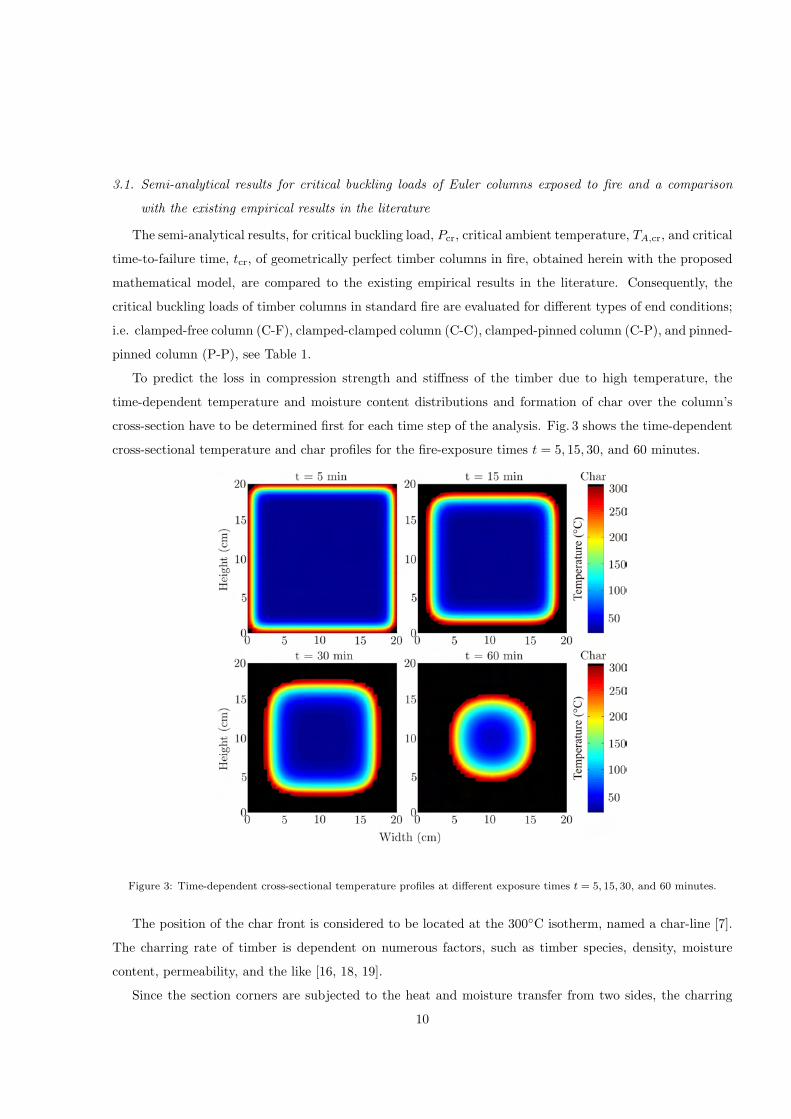
To predict the loss in compression strength and stiffness of the timber due to high temperature, the
time-dependent temperature and moisture content distributions and formation of char over the column’s
cross-section have to be determined first for each time step of the analysis. Fig. 3 shows the time-dependent
cross-sectional temperature and char profiles for the fire-exposure times t = 5, 15, 30, and 60 minutes.
Figure 3: Time-dependent cross-sectional temperature profiles at different exposure times t = 5, 15, 30, and 60 minutes.
The position of the char front is considered to be located at the 300◦C isotherm, named a char-line [7].
The charring rate of timber is dependent on numerous factors, such as timber species, density, moisture
content, permeability, and the like [16, 18, 19].
Since the section corners are subjected to the heat and moisture transfer from two sides, the charring
10

is faster at the corners. As a result, a rounding effect occurs and shortly after the ignition the initially
prismatic cross-section becomes oval, see Fig. 3.
As shown in the figures, the char layer grows in thickness as the fire progress, reducing the column’s
cross-sectional dimensions. It is interesting to note that the highest temperature gradients in the unburnt
timber are at the char-line. Consequently, the unburnt timber close to the char-line will experience thermal
degradation and thus a loss of its strength and stiffness properties, depending on the temperature obtained
during fire, while, on the other hand, the temperature of the core remains relatively low during fire, see
Fig. 3. This phenomenon can be attributed to the insulation properties of char, by which it has an ability
of keeping the internal temperature of the timber section relatively low.
Once the time-dependent temperature and char distributions throughout the cross-section of a timber
column have been determined, a critical buckling load of the timber column subject to the axial load and fire
can be calculated from Eqs. (33)–(34). The critical buckling loads of timber columns exposed simultaneously
to mechanical load and fire are then calculated by the present semi-analytical model for various types of
end conditions, different levels of loading, and different column slenderness, and compared to the results
published in the literature. The variation of column slenderness, which is defined as λ = Lu
√A/J , is
achieved by considering a range of column lengths.
A compressive axial load-carrying capacity of the column is governed by either crushing of the material
or buckling of the compression member. The axial load carrying capacity is calculated next at various times
of exposure for different type of end conditions and different lengths of the column. The results are given
in Table 2.
Table 2: Compressive axial load-carrying capacity of a timber column as a function of fire-exposure time and column length.
Pcr[kN] L = 370 cm L = 490 cm
Column type P-P C-F C-P C-C P-P C-F C-P C-C
Pult(T = 20◦C) 806.9 201.4 1000∗ 1000∗ 459.7 114.8 939.4 1000∗
t = 1 min 771.6 192.6 977.3∗ 977.3∗ 439.5 109.8 898.2 977.3∗
t = 5 min 577.2 144.1 842.5∗ 842.5∗ 328.8 82.14 671.9 842.5∗
t = 15 min 307.3 76.73 611.2∗ 611.2∗ 175.1 43.74 357.6 611.2∗
t = 30 min 134.8 33.69 275.5 398.9∗ 76.85 19.21 156.9 307.9
t = 60 min 23.56 5.889 48.11 94.39 13.43 3.358 27.42 53.78
∗ Crushing of material and no buckling
As anticipated, there is a general trend showing that for the specific column end-conditions the load-
carrying capacity reduces significantly with increasing the time of fire exposure and column length, respec-
tively.
11

For example, in the P-P column case, the axial load-carrying capacity, Pcr, reduces at the time of fire-
exposure t = 1 min to 95.6%, at t = 5 min to 71.5%, at t = 15 min to 38.1%, at t = 30 min to 16.8%, and
finally at t = 60 min to only 3% of the ultimate axial load-carrying capacity at room temperature, namely,
Pult(T = 20◦C)=806.9 kN for L = 370 cm, and Pult(T = 20◦C) = 459.7 kN for L = 490 cm, respectively.
Besides, it is clear from the Table 2 that the column failure mode, namely the crushing or buckling,
depends also on the type of column end-conditions. For instance, at the time of 15 min and column length
L = 370 cm, the P-P and C-F columns fail due to buckling, while the C-P and C-C columns fail by crushing.
The buckling strength or compressive axial load-carrying capacity of a column usually is indicated by
a dimensionless column curve which shows graphically the relationship between the buckling or crushing
load and the corresponding slenderness ratio. Thus, the critical buckling load is normalized by the ultimate
axial load-carrying capacity at room temperature, Pult(T = 20◦C), and plotted against a slenderness ratio
for different fire exposure times in Fig. 4. Note that the normalized buckling load, Pcr=Pcr/Pult(T = 20◦C),
Figure 4: Timber column buckling. The effect of the column slenderness ratio on the compressive load-carrying capacity for
different fire exposure times.
versus slenderness ratio, λ, is independent of the column boundary conditions. As a result, a single plot
for a specific time of fire exposure is shown in Fig. 4 for all types of column end conditions. It can be
observed also in Fig. 4, that increasing the time of fire exposure, t, decreases the normalized buckling load,
Pcr, in all cases of boundary conditions. For instance, when λ = 42, the normalized buckling load, Pcr, is
Pcr[t = 0 min] = 1.000; Pcr[t = 1 min] = 0.977; Pcr[t = 5 min] = 0.842; Pcr[t = 15 min] = 0.611; Pcr[t =
30 min] = 0.321; Pcr[t = 60 min] = 0.056, while, on the other hand, when λ = 64, Pcr[t = 0 min] = 0.807;
Pcr[t = 1 min] = 0.771; Pcr[t = 5 min] = 0.577; Pcr[t = 15 min] = 0.307; Pcr[t = 30 min] = 0.135; and
Pcr[t = 60min] = 0.024.
In addition, it can be seen, that the basic response mechanism, namely, crushing or buckling, changes
12

at a particular slenderness ratio. The slenderness ratio which marks the nominal transition from crushing
to buckling is called a transitional slenderness ratio and indicated here by λtr. Consequently, columns with
a slenderness ratio less than λtr will fail by crushing, while, on the other hand, columns with slenderness
ratio higher than λtr will fail by buckling. Furthermore, it should be noted that the likelihood of column
buckling, is increased as the fire progresses because the reduction of cross-sectional dimensions due to
charring of timber increases the slenderness ratio of the column. Thus, an increase of the fire exposure times
leads to a notable decrease of the transitional slenderness ratio, λtr. For example, it is interesting to note,
that the transitional slenderness ratio at different times of exposure is as follows: λtr[t = 0min] = 57.2;
λtr[t = 1min] = 55.4; λtr[t = 5min] = 52.1; λtr[t = 15min] = 45.0; λtr[t = 30min] = 36.4; and finally after
an hour of fire exposure, the λtr is only 24.3, which is approximately 42 % of the column’s initial slenderness
ratio.
The effect of column load level on time-to-failure and critical ambient temperature is investigated next.
The column is subjected to various load levels. The different levels of loading are obtained by subjecting the
column to axial loads proportional to the ultimate axial load-carrying capacity at the room temperature;
namely, Pult(T = 20◦C). At each time increment, the reduced buckling capacity of the column in standard
fire is compared to the load that column is expected to carry; and once the load exceeds that capacity,
the critical time-to-failure, tcr, or corresponding critical temperature, TA,cr, of the ambient is obtained and
column is considered to have failed. The calculated times-to-failure and critical temperatures for P-P timber
column exposed to standard fire conditions from four sides are plotted as a function of different slenderness
ratios and load levels in Fig. 5.
Figure 5: Effect of load level on failure times and failure temperatures.
It is apparent, that the increase of the load level leads to a significant decrease of the fire resistance. For
example, in the case of λ = 50, increasing the load ratio from 0.2 to 0.4, reduces the time-to-failure, tcr, by
13

approximately 13 minutes, which is approximately 40%. Besides, it reduces the failure temperature, TA,cr,
from 850 ◦C down to 773 ◦C, that is for 9 %. Moreover, Fig. 5 also shows a steadily decrease in the failure
times and failure temperatures due to the increase of the slenderness ratio for a specific load level. The effect
of column slenderness, however, becomes much less pronounced for short columns and high load levels, as
is shown in Fig. 5. Thus, for instance, for relatively short columns, i.e. for columns with slenderness ratios
λ = 32 and 42, and load level equal or above 0.5, the critical time-to-failure and critical temperature are the
same. Accordingly, we can conclude, that in this case the results are independent of the slenderness ratio.
This is due to the fact that the decisive failure mode in both cases is crushing and not buckling.
In addition, it is interesting to compare the results of the critical times-to-failure and critical temperatures
for P-P timber column exposed to standard fire conditions from four sides, with the results obtained by the
different calculation methods proposed in the literature. Herein, the results of these methods are compared
only and no attempt is made to compare their accuracy. A comparison is shown in Table 3.
Table 3: Comparison of critical times, tcr, and critical ambient temperatures, TA,cr, for timber columns in standard fire from
four sides obtained by different calculation methods.
Column Load Present EC5∗[12] EC5∗∗[12] Stiller [36] Lie [3]
type λ level tcr TA,cr [◦C] tcr TA,cr [◦C] tcr TA,cr [◦C] tcr TA,cr [◦C] tcr Tcr [◦C]
P-P
0.6 15′36
′′744 11
′48
′′705 8
′45
′′659 0
′0
′′20 13
′42
′′725
42 0.4 25′54
′′820 22
′42
′′800 24
′2
′′809 22
′48
′′801 27
′56
′′831
0.2 38′42
′′880 40
′41
′′887 42
′57
′′895 52
′39
′′926 47
′48
′′911
0.6 4′24
′′558 0
′12
′′163 0
′0
′′20 0
′0
′′20 10
′42
′′688
64 0.4 10′36
′′687 9
′48
′′675 8
′1
′′646 4
′18
′′554 12
′3
′′706
0.2 22′39
′′800 24
′30
′′805 27
′24
′′828 34
′12
′′861 30
′1
′′842
∗ Effective section method [12]∗∗ Reduced strength and stiffness method [12]
The calculation methods used in the comparison with the present results are the two simplified calculation
methods offered by Eurocode 5 [12], one being the ”Effective section method” and the other the ”Reduced
strength and stiffness method”, and the empirical methods proposed by Stiller [36] and Lie [3]. For a detailed
description and application of these methods, the reader is also referred to [25].
The parameters included in the comparison are load level and column slenderness. A comparison of
these methods is made for λ = 42 and 46, while various compression load levels are used; i.e. 0.2, 0.4, and
0.6. It can be seen from Table 3 that at the lower load levels, the results proposed by different methods
are non-conservative compared to the present method. On the other hand, when higher loads are applied,
the present method gives higher fire resistances than the simplified empirical methods. A discrepancy is
greater for lower values of column slenderness ratio. The present results are closer to the Eurocode 5 results
than results of other two methods. The differences between the results are probably because the methods of
14

calculation adopted in Eurocode 5 do not take into account the effect of load level on fire resistance. Besides,
in contrast to the present method, in all of the abovementioned simplified methods, a constant charring rate
and strength and stiffness losses of timber are used. It is important to note that in all the calculations made
by Lie’s equation, a general value of an exponent n having a value of 2 is used. As a consequence, the results
are overestimated for long columns, and underestimated for short column, see, e.g. [3].
3.2. Influence of initial water content and a comparison of area of the cross-section with the one obtained
by Eurocode 5
The objective of this section is to examine the influence of the initial water content of timber columns
on their fire resistance. Accordingly, numerical calculations are carried out to determine fire resistance of
timber columns in the case of various initial water contents and for different slenderness ratios and different
load levels. Values of 0 and 20 % water content are chosen to be the extreme values. The results are shown
in Figs. 6 and 7, and tabulated in Table 4.
Figure 6: Effect of water on time dependent temperatures profiles (the cut-out is made at the center of the P-P column’s
cross-section).
In Fig. 6, water dependent temperature profiles are shown as a function of different exposure times
and location in the cross-section. It is apparent, that initial water content has an important influence on
temperature distribution over the cross-section. E.g., the temperature, T , at the depth of 5 cm, reaches the
following values: T [t = 60 min, θ0 = 0 ◦M] = 255 ◦C; T [t = 60 min, θ0 = 12 ◦M] = 218 ◦C; T [t = 60 min, θ0 =
20 ◦M] = 165 ◦C; On the other hand, the influence of water content on near-the-surface temperatures is
negligible.
Similarly as in the previous section, the normalized buckling load, Pcr, is plotted against a slenderness
ratio for different fire exposure times and various initial water contents in Fig. 7. As would be expected, Fig. 7
indicates that increasing the initial water content, increases the normalized buckling load. For instance, when
15

λ = 42 and t = 5min, the normalized buckling load, Pcr, is Pcr[θ0 = 0 ◦M] = 0.842; Pcr[θ0 = 12 ◦M] = 0.855;
Pcr[θ0 = 20 ◦M] = 0.870; on the other hand, when t = 60 min, Pcr[θ0 = 0 ◦M] = 0.056; Pcr[θ0 = 12 ◦M] =
0.073; and Pcr[θ0 = 20 ◦M] = 0.112.
Figure 7: Effect of initial water content on compressive load-carrying capacity, Pcr, for different fire exposure times and different
slenderness ratios.
It is also apparent from Fig. 7, that the transitional slenderness ratio, λtr, is considerably affected by
the initial water content. Therefore, the λtr is at t = 15 min as follows: λtr[θ0 = 0 ◦M] = 45.0; λtr[θ0 =
12 ◦M] = 47.1; λtr[θ0 = 20 ◦M] = 48.2; at t = 30 min λtr[θ0 = 0 ◦M] = 36.4; λtr[θ0 = 12 ◦M] = 38.1;
λtr[θ0 = 20 ◦M] = 39.8; and at t = 60 min, the following: λtr[θ0 = 0 ◦M] = 24.3; λtr[θ0 = 12 ◦M] = 26.0;
λtr[θ0 = 20 ◦M] = 27.7.
Additionally to the results in the Table 3, critical time-to-failure times and corresponding critical tem-
peratures of the ambient are calculated for different initial water contents, load levels, and slenderness ratios.
The results are presented in Table 4.
Nevertheless, there is still a systematic difference between the results for critical times, tcr, and critical am-
bient temperatures, TA,cr, for columns with higher initial water contents and load levels, but the differences
are not significant. Furthermore, the results shown in Tables 3 and 4, indicate, that Eurocode 5 methods
agree well with the present calculation method for water content of 12%, while for higher water contents are
conservative.
Finally, a residual area of the column’s cross-section is calculated and plotted against time of exposure
in Fig. 8. As would be expected, Fig. 8 indicates that the residual area decreases with time. Note, that the
decrease of the residual area is non-linear with time of exposure. Unlike the present method, this decrease
is quadratic in case of Eurocode 5 methods [12], where a linear charring rate is employed.
It is shown once again that water has an important influence on charring of timber and consecutively
on the residual area. At the selected time of exposure, e.g. t = 30 min, the corresponding residual areas
16

Table 4: Comparison of critical times, tcr, and critical ambient temperatures, TA,cr, for timber columns in standard fire from
four sides obtained for different water contents.
Column Load no water water [θ0 = 12◦M] water [θ0 = 20◦M]
type λ level tcr TA,cr [◦C] tcr TA,cr [◦C] tcr TA,cr [◦C]
P-P
0.6 15′36
′′755 16
′42
′′755 18
′54
′′773
42 0.4 25′54
′′820 27
′39
′′830 31
′27
′′849
0.2 38′42
′′880 42
′12
′′892 47
′21
′′910
0.6 4′27
′′559 4
′51
′′572 5
′24
′′587
64 0.4 10′36
′′687 11
′21
′′697 12
′48
′′715
0.2 22′39
′′800 24
′12
′′810 27
′30
′′829
Figure 8: Residual area versus time of exposure.
obtained by the present method are: Ares[θ0 = 0 ◦M] = 217 cm2; Ares[θ0 = 12 ◦M] = 224 cm2; Ares[θ0 =
20 ◦M] = 241 cm2; while for Eurocode 5 methods are: Ares[ESM] = 190 cm2 and Ares[RSSM] = 236 cm2.
4. Conclusions
A semi-analytical mathematical model for buckling behavior of timber columns under fire has been
proposed. The proposed mathematical model has been used to study the the influence of various material
and geometric parameters, as well as water content on critical buckling forces. Based on the semi-analytical
results and the parametric study undertaken the following important conclusions can be drawn:
1. As anticipated, there is a general trend showing that the load-carrying capacity reduces significantly
with increasing the time of fire-exposure.
17

2. The likelihood of column buckling is increased as the fire progresses. An increase of the fire exposure
times leads to a notable decrease of the transitional slenderness ratio, λtr.
3. An increase of the load level leads to a significant decrease of the critical time-to-failure and criti-
cal ambient temperature. Moreover, it was shown, that the results for some specific load level are
independent on slenderness ratio because the decisive failure mode is crushing and not buckling.
4. Increasing the initial water content, increases the normalized buckling load. It is proven that the
transitional slenderness ratio, λtr, is considerably affected by the initial water content as well.
5. As would be expected, the residual area decreases with time. This decrease is non-linear with time of
exposure. Water content has an important influence on the decreasing of the residual area.
6. The results of the present method compared to the results of the two simplified calculation methods
offered by Eurocode 5 show that the Eurocode 5 method is non-conservative if the transfer of water
is neglected, while, on the other hand, the results agree well for water content of 12%. Moreover, for
higher water contents, the Eurocode 5 method is conservative.
Acknowledgement
The authors acknowledge the financial support from the state budget by the Slovenian Research Agency
(project No. Z2-2031).
References
[1] ISO 834, Fire-resistance test – Elements of building construction-Part 1. General requirements. ISO 834-1, International
organization for standardization, Geneva, Switzerland, 1999.
[2] American Society for Testing and Materials. Standard methods of fire tests of building construction and materials. ASTM
Stand. E 119. American Society for Testing and Materials. Philadelphia, 1980.
[3] T.T. Lie, A method for assessing the fire resistance of laminated timber beams and columns, Canadian Journal of Civil
Engineering 4(2) (1977) 161–169.
[4] F. Ali and S. Kavanagh, Fire resistance of timber columns, Journal of the Institute of Wood Science 17(2) (2005/06)
85–93.
[5] M.L. Janssens, Modeling of the thermal degradation of structural wood members exposed to fire, Fire and Materials 28
(2004) 199–207.
[6] J. Konig, Structural fire design according to Eurocode 5–design rules and their background, Fire and Materials 29 (2005)
147–163.
[7] P.B. Cachim and J.M. Franssen, Comparison between the charring rate model and the conductive model of Eurocode 5,
Fire and Materials 33 (2009) 129–143.
[8] P.B. Cachim, Assessment of Eurocode 5 for fire design of timber columns, Proceedings of the Institution of Civil Engineers,
Construction Materials 162 CM4 (2009) 151–156.
[9] E.L. Schaffer, Structural Fire Design: Wood, Research Paper FPL 450, Madison, WI: U.S. Department of Agriculture,
Forest Service, Forests Products Laboratory (1984) 16 p.
[10] H. Takeda, An Integrated Model to Predict Fire Resistance of Wood Floor Assemblies, Journal of Fire Protection Engi-
neering 19 (2009) 133–150.
18

[11] D.I. Lawson, C.T. Webster and L.A. Ashton, Fire endurance of timber beams and floors, Journal of Structural Engineering
30(2) (1952) 27–34.
[12] EN 1995-1-2, Eurocode 5, Design of timber structures Part 1-2: General-Structural fire design, 2004.
[13] N. Benichou, M.A. Sultan, Fire Resistance Performance of Lightweight Wood-Framed Assemblies, Fire Technology 36(3)
(2000) 184–219.
[14] B. Fredlund, A model for heat and mass transfer in timber structures during fire. A theoretical, numerical and experimental
study, Report LUTVDG/(TVBB–1033), Department of fire safety engineering, Lund institute of science and Technology,
Sweden, 1988.
[15] B. Fredlund, Modelling of heat and mass transfer in wood structures during fire, Fire Safety Journal 20 (1993) 39–69.
[16] S. Schnabl, I. Planinc, G. Turk and S. Srpcic, Fire analysis of timber composite beams with interlayer slip, Fire Safety
Journal 44(5) (2009) 770–778.
[17] T. Toratti, S. Schnabl, G. Turk, Reliability analysis of a glulam beam, Structural Safety 29(4) (2007) 279–293.
[18] E. Mikkola, Charring of wood, VTT Research Report 689, Technical Research Centre of Finland (1990).
[19] E.L. Schaffer, Charring rate of selected woods-transverse to grain, Research paper FPL-69, USDA Forest Product Labo-
ratory, Madison, Wisconsin, USA, 1967
[20] P.W.C Lau, R. White, I. Zeeland, Modelling the Charring Behaviour of Structural Lumber, Fire and Materials 23 (1999)
209–216.
[21] R.H. White and E.V. Nordheim, Charring rate of wood for ASTM E 119 exposure, Fire Technology 28(1) (1992) 5–30.
[22] E.L. Schaffer, State of structural timber fire endurance, Wood and Fiber 9(2) (1977) 145–170.
[23] A.H. Buchanan, Structural Design for Fire Safety, John Wiley & Sons, New York, 2001.
[24] A.H. Buchanan, Fire performance of timber construction, Progress in Structural Engineering and Materials 2(3) (2000)
278–289.
[25] J.A. Purkiss, Fire Safety Engineering Design of Structures, second ed., Oxford : Elsevier/Butterworth-Heinemann, 2007.
[26] I.M. Van Zeeland, J.J. Salinas and J.R. Mehaffey, Compressive strength of lumber at high temperatures, Fire and Materials
29 (2005) 71–90.
[27] C.C. Gerhards, Effect of moisture content and temperature on the mechanical properties of wood: An analysis of immediate
effects, Wood and Fiber 14 (1982) 4–36.
[28] I. Planinc, M. Saje, A quadratically convergent algorithm for the computation of stability points: the application of the
determinant of the tangent stiffness matrix, Computer Methods in Applied Mechanics and Engineering 169 (1999) 89–105.
[29] A.V. Luikov, Heat and Mass Transfer in Capillary-porous Bodies, Pergamon Press, Oxford, 1966.
[30] The MathWorks, Inc. MatLab Version 7.3.0.267 (R2006b) 2006.
[31] E. Reissner, On one-dimensional finite-strain beam theory: The plane problem, Journal of Applied Mechanics and Physics
ZAMP 23 (1972) 795–804.
[32] N. Krauberger, M. Saje, I. Planinc, S. Bratina, Exact buckling load of a restrained RC column, Structural Engineering
and Mechanics 27(3) (2007) 293–310.
[33] T. Hozjan, I. Planinc, M. Saje, S. Srpcic, Buckling of restrained steel columns due to fire conditions, International Journal
of Steel and Composite Structures 8(2) (2008) 159–178.
[34] B. Vratanar, M. Saje, A consistent equilibrium in a cross–section of an elastic–plastic beam, Journal of Solids and Structures
36 (1999) 311–337.
[35] F. Hartmann, The Mathematical Foundation of Structural Mechanics, Springer-Verlag Berlin and Heidelberg GmbH &
Co.K, 1985.
[36] J. Stiller, Berechnungsmethode fur brandbeanspruchte Holzstutzen und Holzbalken aus brettschichtverleimtem Nadelholz,
in Arbeitsbericht 1981–1983, SFB 148 Brandverhalten von Bauteilen Technische Universitat Braunschweig, 219–276, 1983.
19