analysis of prestress and bending stresses - coursecontent
50
ANALYSIS OF PRESTRESS AND BENDING STRESSES 1
-
Upload
khangminh22 -
Category
Documents
-
view
1 -
download
0
Transcript of analysis of prestress and bending stresses - coursecontent
ANALYSIS
OF
PRESTRESS
AND
BENDING STRESSES1

BASIC ASSUMPTIONS
1. Concrete is a homogeneous elastic material.
2. Within range of working stresses, both concrete and steel behave
elastically. (Does not withstand the small amount of creep which occurs in
both the materials under sustained loading)
3. A plane section before bending remains plane even after bending, which
implies a linear strain distribution across the depth of the member.
As long as tensile stresses do not exceed the limit of modulus of rupture of
concrete (corresponding to the stage of visible cracking of concrete), any
change in the loading of the member results in a change of stress in
concrete only, the sole function of the prestressing tendon being to impart
and maintain prestress in concrete.
Up to the stage of visible cracking on concrete, the changes in the stress
of steel, the loading being negligibly small, are generally not considered in
the computations.
2

ANALYSIS OF PRESTRESS
The stresses due to prestressing lone are generally combined stresses due to the
action of direct load and bending resulting from and eccentrically applied load.
The stresses are evaluated by using the well known relationship for combined
stresses used in the case of columns.
Following notations and sign conventions are used for the analysis of prestress:
P = Prestressing force (positive when producing direct compression)
e = Eccentricity of prestressing force (M = P.e = Moment)
A = Cross sectional area of the concrete member
I = Second moment of area of section about its centroid
Zt and Zb = Section modulus of the top and bottom fibres
fsup and finf = Prestress in concrete developed at the top and bottom fibres (positive
when compressive and negative when tensile in nature)
yt an yb = Distance of the top and bottom fibres from the centroid of the section
ί = Radius of gyration
3

ANALYSIS OF PRESTRESS
Stresses due to pre-stressing alone are generally combined stresses due
to action of direct load and bending resulting from an eccentrically
applied load.
Stresses are evaluated by using relationship for combined stresses in
columns.
Concentric Tendon
Which is compressive across the depth of the beam.
Generally applied loads and dead loads induce tensile stresses towards
soffit of the beam and are counterbalanced more effectively by
eccentric tendons.4
Concentric Prestressing
+
Stress = P/A
PP
Cross Section

Eccentric Tendon
5
Eccentric Prestressing
+
Direct Stress
PPee
+
-
Bending Stress
P/A
P/A
Cross Section
Pe/Zt
Pe/Zb
b tinf sup2 2
b t
e y e yP P e P P P e P 1 & 1
A Z A i A Z A if f
Resultant Stress
P/A + Pe/Zb
P/A - Pe/Zt
+
PRESTRESS
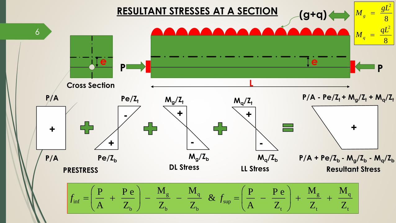
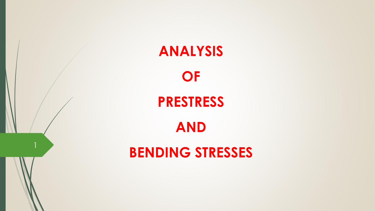
RESULTANT STRESSES AT A SECTION
6
+
PRESTRESS
PPee
+
-
P/A
P/A
Cross Section
Pe/Zt
Pe/Zb
g q g q
inf sup
b b b t t t
M M M MP P e P P e &
A Z Z Z A Z Z Zf f
Resultant Stress
P/A + Pe/Zb - Mg/Zb - Mq/Zb
P/A - Pe/Zt + Mg/Zt + Mq/Zt
+
L
(g+q)2
2
8
8
g
q
gLM
qLM
+
-
Mg/Zt
Mg/Zb
+
-
Mq/Zt
Mq/Zb
DL Stress LL Stress

A concrete beam of rectangular section, 150 mm wide by 300 mm deep,
prestressed by 4 high-tensile wires of 5 mm diameter stressed to
1200 N/mm2. The wires are located at an eccentricity of 50 mm. Examine
the stresses developed at the soffit of the beam by considering the
‘nominal concrete’ and ‘equivalent concrete’ section.
Prestressing force = 1200 x 80 = 96000 N
For, Nominal Concrete Section
A = 150 x 300 = 45000 mm2
I = 150 x 3003 /12 = 3375 x 105 mm4
Stress at the soffit of the section
=
= 2.13 + 2.13
= 4.27 N/mm2
Ex:1
For, Equivalent Concrete Section
Assuming modular ratio, m = 6
Equivalent area of steel = 400 mm2
Ae = 45000 + (m - 1) 80 = 45400 mm2
Position of centroid of the section from the soffit = 149 mm
Y = (44600 x 150) + (400 x 50) / (44600 + 400) = 149.11 mm
Ie = (3375 x 105) + ((150 x 300) x 12) + (400 x 492)
= 3385 x 105 mm4
Stresses at the soffit =
= 4.20 N/mm2
7
2
96000 96000(50)(6)
45000 150 x (300)
P Pe
A Z
6
96000 (96000 x 49) (150)
45000 3385 x 10
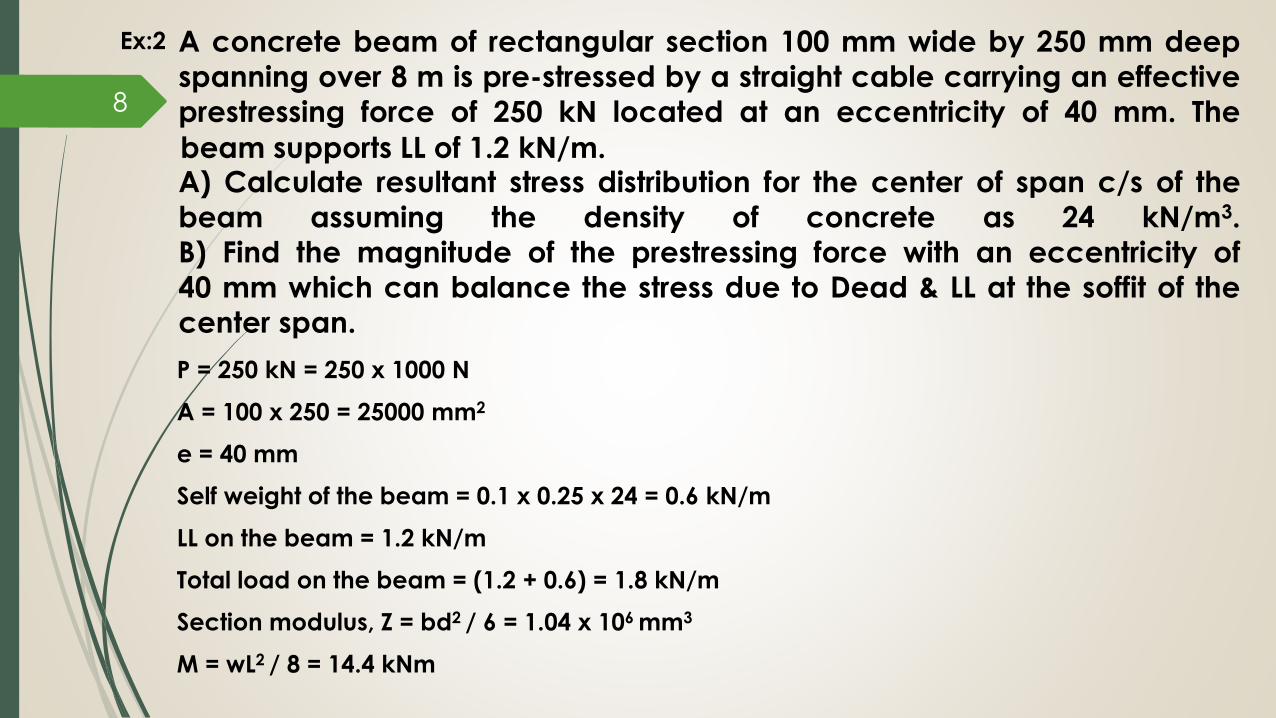
A concrete beam of rectangular section 100 mm wide by 250 mm deep
spanning over 8 m is pre-stressed by a straight cable carrying an effective
prestressing force of 250 kN located at an eccentricity of 40 mm. The
A) Calculate resultant stress distribution for the center of span c/s of the
beam assuming the density of concrete as 24 kN/m3.
B) Find the magnitude of the prestressing force with an eccentricity of
40 mm which can balance the stress due to Dead & LL at the soffit of the
center span.
P = 250 kN = 250 x 1000 N
A = 100 x 250 = 25000 mm2
e = 40 mm
Self weight of the beam = 0.1 x 0.25 x 24 = 0.6 kN/m
LL on the beam = 1.2 kN/m
Total load on the beam = (1.2 + 0.6) = 1.8 kN/m
Section modulus, Z = bd2 / 6 = 1.04 x 106 mm3
M = wL2 / 8 = 14.4 kNm
Ex:2
8
beam supports LL of 1.2 kN/m.

Stress due to loads = M / Z = ± 13.8 N/mm2
Pre-stress at top and bottom fibres = [ P/A ± Pe/Z] = [ 10 ± 9.6] N/mm2
A) Resultant stress at
Top fibre = 10 – 9.6 + 13.8 = 14.2 N/mm2 (comp)
Bottom fibre = 10 + 9.6 - 13.8 = 5.8 N/mm2 (comp)
B) If P is the pre-stressing force required to balance the stresses at soffit,
then
[P/A + Pe/Z] = [M/Z]
P [1/A + e/Z] = [M/Z]
P = 176.39 kN
9

A rectangular concrete of beam with c/s 30 cm deep and 20 cm wide is
prestressed by means of 15 wires of 5 mm diameter located 6.5 cm from
the bottom of the beam and 3 wires of diameter 5 mm, 2.5 cm from the
top. Assuming the pre-stress in the steel as 840 N/mm2, calculate the
stresses at the extreme fibres of the mid-span section when the beam is
supporting its own weight over a span of 6 m. If a UDL of 6 kN/m is
imposed, evaluate the maximum working stress in the concrete. Take,
Dc = 24 kN/m3.
Ex:3
10

Centroid of the prestressing force from the base
[(15 x 65 ) + (3 x 275)]
18
e = 50 mm
P = (18 x 840 x 19.7) = 3 x 10⁵ N
A = 300 x 200 = 6 x 104 mm2
Self wt. of the beam = 0.3 x 0.2 x 24 = 1.44 kN/m
Mg = 1.44 x 62 / 8 = 6.48 kNm
I = bD3 / 12 = 45 x 107 mm4
Zt and Zb = 45 x 107 / 150 = 3 x 106 mm3
LL on the beam = 6 kN/m
Mq = 6 x 62 / 8 = 27 kNm
= 100 mmy =11

12
Direct stress due to pre-stress (P/A) = 5 N/mm2
Bending stress due to prestress (Pe/Z) = 5 N/mm2
Self weight stress (Mg/Z) = 2.16 N/mm2
LL Stress (Mq/Z)= 9 N/mm2
+
PRESTRESS
+
-
5.0
5.0 5.0
5.0
Resultant Stress
1.16
11.16
++
-
2.16
2.16
+
-
9.0
9.0
DL Stress LL Stress
-
Stress distribution at mid span

An unsymmetrical I-section beam is used to support an imposed load of
2 kN/m over a span of 8 m. At the centre of the span, the effective
prestressing force of 100 kN is located at 50 mm from the soffit of the beam.
Estimate the stresses at the centre of span section of the beam for following
P = 100 kN
A = 46400 mm2
y = 156 mm (from top)
e = 400 - 156 - 50 = 194 mm
I = 75.8 x 107 mm4
Zt = (75.8 x 10⁷ / 156) = 485 x 104 mm3
Zb = (75.8 x 10⁷ / 244) = 310 x 104 mm3
g = (0.0464 x 1 x 24) = 1.12 kN/m
Mg = 1.12 x 82 / 8 = 8.96 kNm
Mq = 2 x 82 / 8 = 16 kNm
Ex:3
Load calculations:
A) Prestress + self-weight
B) Prestress + self-weight + live load
13
40
0 m
m
300 mm
80 mm
60 mm
60 mm
100 mm50 mm
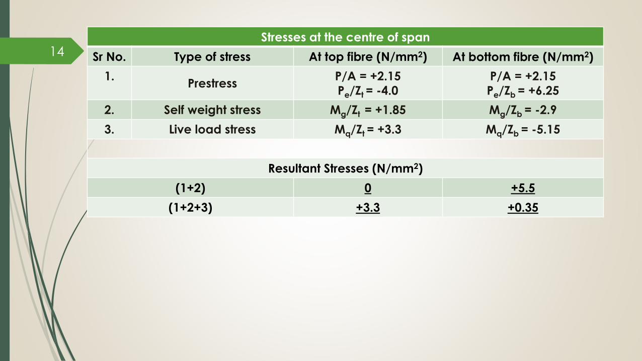
Stresses at the centre of span
Sr No. Type of stress At top fibre (N/mm2) At bottom fibre (N/mm2)
1.Prestress
P/A = +2.15
Pe/Zt = -4.0
P/A = +2.15
Pe/Zb = +6.25
2. Self weight stress Mg/Zt = +1.85 Mg/Zb = -2.9
3. Live load stress Mq/Zt = +3.3 Mq/Zb = -5.15
Resultant Stresses (N/mm2)
(1+2) 0 +5.5
(1+2+3) +3.3 +0.35
14

PRESSURE LINE or THRUST LINE At any given section of a prestressed concrete beam, the combined
effect of the prestressing force and the externally applied load will
result in a distribution of concrete stresses that can be resolved into a
single force.
The locus of points of the points of application of this resultant force in
any structure is termed as the ‘PRESSURE LINE or THRUST LINE’.
The concept is very useful in understanding the load-carrying
mechanism of a prestressed concrete section.
For prestressed concrete members, the location of pressure line
depends upon the magnitude and direction of moments applied at the
c/s and the magnitude, distribution of stress due to prestressing force.
15

Consider a concrete beam as shown in figure below, which is prestresed byforce P acting at an eccentricity e.
The beam supports a uniformly distributed load (including self-weight) of
intensity q per unit length.
The load is of such magnitude that the bottom fiber stress at the central span
section of the beam is zero.
Figure below shows the resultant stress distribution at support, center and
quarter span section of the beam.
16
2
At support, x = 0
P M - y = 0
A I
(P e) 6 d P =
b d 2 A
d=> e =
6

External moment at the quarter span section being smaller in magnitude, the
shift in the pressure line is also correspondingly smaller, being equal to h/4 fromthe initial position.
Similarly, it can be shown that a larger UDL on the beam would result in the
pressure line being shifted even higher at the center and quarter span sections.
17
Above observations lead to the following principle:
“A CHANGE IN THE EXTERNAL MOMENTS IN THE ELASTIC RANGE OF A PRESTRESSED CONCRETE BEAM RESULTS IN SHIFT OF PRESSURE LINE RATHER THAN IN AN INCREASE
IN THE RESULTANT FORCE IN THE BEAM”.

This is in contrast to RC beam, where an increase in the external moment result
in a corresponding increase in the tensile force and compressive force.
The increase in the resultant forces are due to a more or less constant lever
arm between the forces, characterized by the properties of the composite
section.
“Pressure line concept can also be used to evaluate the stresses”
18
For prestressed concrete
sections load carrying
mechanism is comprised of
a constant force with a
changing lever arm.
For RC constant lever arm
with changing forces.
Behaviour of Cracked
prestressed member = RC
member

METHOD INTERNAL RESISTING COUPLE METHOD OR C-LINE METHOD
The prestressed beam is analysed as a plain concrete elastic beam using principles of statics.
The prestressing force is considered as an external compressive force with a constant tensile
force T in the tendon throughout the span.
So, at any section of loaded prestressed beam, equilibrium is maintained by satisfying the
equations, H=0 and M=0.
Figure shows the FBD of segment of a beam without and with transverse loads respectively.
When gravity loads are zero, the C and T lines coincide as there is no moment in the section.
Under transverse loads, the C-line or center of pressure or thrust line, is at a varying distance afrom the T-line.
19

If M = BM at the section due to dead and live loads
e = Eccentricity of the tendon
T = P = Prestressing force in the tendon
Moments equilibrium yields the relation,
M = Ca = Ta = Pa and a = (M/P)
The shift of pressure line measured from the centroidal axis is obtained as e’ = (a - e) = (M/P) – e
The resultant stresses at the top and bottom fibers of the section are
expressed as,
fsup = (P / A) + (Pe’ / Zt)
finf = (P / A) - (Pe’ / Zb)
20

EX: A prestressed concrete beam with a rectangular section 120 mm wide by 300
mm deep supports a UDL of 4 kN/m, which includes self wt. of the beam. The
beam is concentrically prestressed by a cable carrying a force of 180kN.
Locate the position of pressure line in the beam. Pre-stressing force, P = 180 kN
Eccentricity, e = 0
A = 36E3 mm2
Zt = Zb = I/Ymax = 18E5 mm3
BM at the center of the span = 4 x 62 / 8 = 18 kNm
Direct stress = P/A = 180E3 / 36E3 = 5 N/mm2
Bending stress = M/ Z = 18E6 / 18E5 = 10 N/mm2
Resultant stress at the center of the span section:
Top = 5 + 10 = 15N/mm2 Bottom = 5 – 10 = -5 N/mm2
Assuming N is resultant thrust in the section, e is corresponding eccentricity (shift of pressure line) then,
N/A + Ne/Z = 15
Here, N = 180E3 N , A = 36E3 mm2 & Z = 18E5 mm3
e = 100 mm 21

Resultant stress distribution diagram and the pressure line is shown in figure:22

EX: A prestressed concrete beam of section 120 mm by 300 mm is used over an effective span of
6 m to support a UDL of 4 kN/m, which includes self weight of the beam. The beam isprestressed by a straight cable carrying a force of 180 kN and located at an eccentricity of
50 mm. Determine the location of thrust line in the beam and plot its position at quarter and
central span.
P = 180 kN, e = 50 mm, A = 36E3 mm2, Z = 18E5 mm3
P/A = 5 N/mm2 & Pe/Z = (180E3 x 50 / 18E3) = 5 N/mm2
BM at center span = 18 kNm
Bending stress at top and bottom = ± 10 N/mm2
Resultant stresses at central section:
Top = (5 - 5 +10) = 10 N/mm2 Bottom = (5 + 5 -10) = 0 N/mm2
Shift of pressure line from cable line = M / P = (18E6 / 18E4) = 100 mm
BM at quarter span section = (3/32) qL2 = (3/32) x 4 x 62 = 13.5 kNm
Bending stress at top and bottom = ± 7.5 N/mm2
Resultant stresses at quarter span section:
Top = (5 - 5 + 7.5) = 7.5 N/mm2 Bottom = (5 + 5 - 7.5) = 2.5 N/mm2
Shift of pressure line from cable line = M / P = (13.5E6 / 18E4) = 75mm23

The location of pressure line is shown in figure.24

EX: A box girder of prestressed concrete bridge of span 40 m has overall dimensions of 1200 mm
by 1800 mm. The uniform thickness of the walls is 200 mm. The live load analysis indicates amax live load moment of 2000 kNm at the center of the span. The beam is prestressed by
parabolic cables with an effective force of 7000 kN. The cables which are concentric at
support have an eccentricity of 800 mm at the center span section. Compute the resultant
stresses at the center of span section using the internal resisting couple method.
A = (1.2 X 1.8) – (0.8 X 1.4) = 1.04 m2
g = (1.04 x 24) = 25 kN/m
P = 7000 kN, e = 800 mm, L = 40 m
I = (1/12) [ (1200 x 18003) – (800 x 14003) ]
= 40 x 1010 mm4
25

Zb = Zt = Z = (40 x 1010) / 900 = 400 x 10E6 mm3
Mg = (0.125 x 25 x 402) = 5000 kNm
Mq = 2000 kNm
M = (Mg + Mq) = 7000 kNm
Lever arm, a = (M/P) = (7000E3 / 7000) = 1000 mm
Shift of pressure line, e’ = (a – e) = (1000 – 800) = 200 mm
The resultant stresses are obtained as,
fsup = [ P/A + Pe’/Zt]
= (7000E3/1.04E6) + (7000E3 x 200 / 444E6)
= 9.88 N/mm2
finf = [ P/A - Pe’/Zb] = (7000E3/1.04E6) - (7000E3 x 200 / 444E6)
= 3.58 N/mm2
26

LOAD BALANCING
27
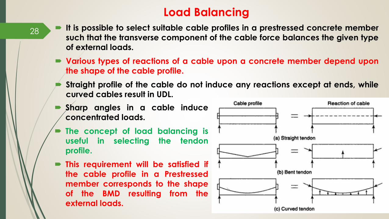
Load Balancing
It is possible to select suitable cable profiles in a prestressed concrete member
such that the transverse component of the cable force balances the given type
of external loads.
Various types of reactions of a cable upon a concrete member depend upon
the shape of the cable profile.
Straight profile of the cable do not induce any reactions except at ends, while
curved cables result in UDL.
28
Sharp angles in a cable induce
concentrated loads.
The concept of load balancing is
useful in selecting the tendon
profile.
This requirement will be satisfied if
the cable profile in a Prestressed
member corresponds to the shape
of the BMD resulting from the
external loads.

29
Tendon Profiles and Equivalent Loads in Prestressed Concrete Beams

30
Tendon Profiles and Equivalent Loads in Prestressed Concrete Beams

EX: A concrete beam with a single overhang is simply supported at A & B over a span of
8 m & the overhang BC is 2 m. The beam is of rectangular section 300 mm wide and
900 mm deep & supports a uniformly distributed live load of 3.52 kN/m over the entire
length in addition to its self-weight. Determine the profile of the prestressing cable
with an effective force of 500 kN which can balance the dead & live loads on the
beam. Sketch the profile of the cable along the length of the beam.
Span = 8 m, overhang = 2 m
Pre-stressing force in the cable, P = 500 kN
Self weight of the beam = (0.3 × 0.9 × 24)
= 6.48 kN/m
Live load on the beam = 3.52 kN/m
Thus, the total load = 10.00 kN/m
Reactions at A and B are
Ra = 37.5 kN; Rb = 62.5 kN
Mb = 0.5 × 10 × 22 = 20 kNm
32

Bending moment at a distance x from A is Mx = 37.5x - 0.5 × 10x2
For maximum BM (dMx/dx) = 0 ⇒ 37.5 -10x = 0 x = 3.75 m
Hence, maximum BM = 37.5 × 3.75 – 0.5 × 10 × 3.752 = 70.3 kNm (Assume point D)
Mx = 0, at x = 7.5 m [As, 5x2 – 37.5x = 0]
The eccentricity of the cable at the position of maximum BM is
e = Mmax / P = 70.3E6 / 500E3 = 140.6 mm
Eccentricity at B,= MB / P = 20E6 / 500E3 = 40 mm
Since the bending moment at point A and C are zero, the cable is concentric at these
points.
The cable profile is parabolic with eccentricity of 140.6 mm below the centroidal axis at D
and and 40 mm above the centroidal axis at support section B.
33

Ex: A beam of symmetrical I-section spanning 8 m has a flange width of 250 mm & flange
thickness of 80 mm respectively. The overall depth of the beam is 450 mm. Thickness of theweb is 80 mm. The beam is prestressed by a parabolic cable with an eccentricity of 150 mm
at the centre of the span & zero at the supports. The LL on the beam is 2.5 kN/m.
(a) Determine the effective force in the cable for balancing the DL & LL on the beams.
(b) Sketch the distribution of resultant stress at the centre of span section for the above case.
(c) Calculate the shift of the pressure line from the tendon–centre–line.
34

The properties of the I-section are as follows:
Area of the section, A = 20.63 m2
Moment of inertia, I = 1.553E9 mm4
Section modulus, Z = 6.9E6 mm3
Eccentricity, e = 150 mm
Span, L = 8 m
Live load, wq = 2.5 kN/m
Dead load, wg = 0.63 ×25 = 1.57 kN/m [Assuming unit weight of concrete as 25 kN/m3]
The BM at the centre of the span due to DL, Mg = (0.125 × 1.57 × 82) = 12.56 kNm
The BM at the centre of the span due to LL, Mq = (0.125 × 2.5 × 82) = 20 kNm
Total moment, M = (Mg + Mq) = 12.56 + 20 = 32.56 kNm
If , P = tendon force, For load balancing we have
P = (M/e) = 217 kN
The center–of-span section is subjected to a direct stress of intensity, (P/A) = (217E3 / 0.063E6) = 3.44 N/mm2
Shift of pressure line = (M / P) = 32.56E6 / 217E3 =150 mm
The pressure line coincides with the centroidal axis of the beam.
35

STRESSES IN TENDONS
36

Effect of Loading on Tensile
Stresses in Tendons A pre-stressed member undergoes deformation due to the action of the prestressing force
and transverse loads acting on the member.
Curvature of the cable changes, which results in a slight variation of stresses in the tendons.
Consider a concrete beam of span L as shown in figure. The beam is prestressed by a cable
carrying an effective force P at an eccentricity e, the rotation θp at the supports due to
hogging of the beam is obtained by applying Mohr’s theorem as,
Where, EI = Flexural rigidity of the beam
37
p
Area of BMD PeLθ =
Flexural Rigidity 2EI
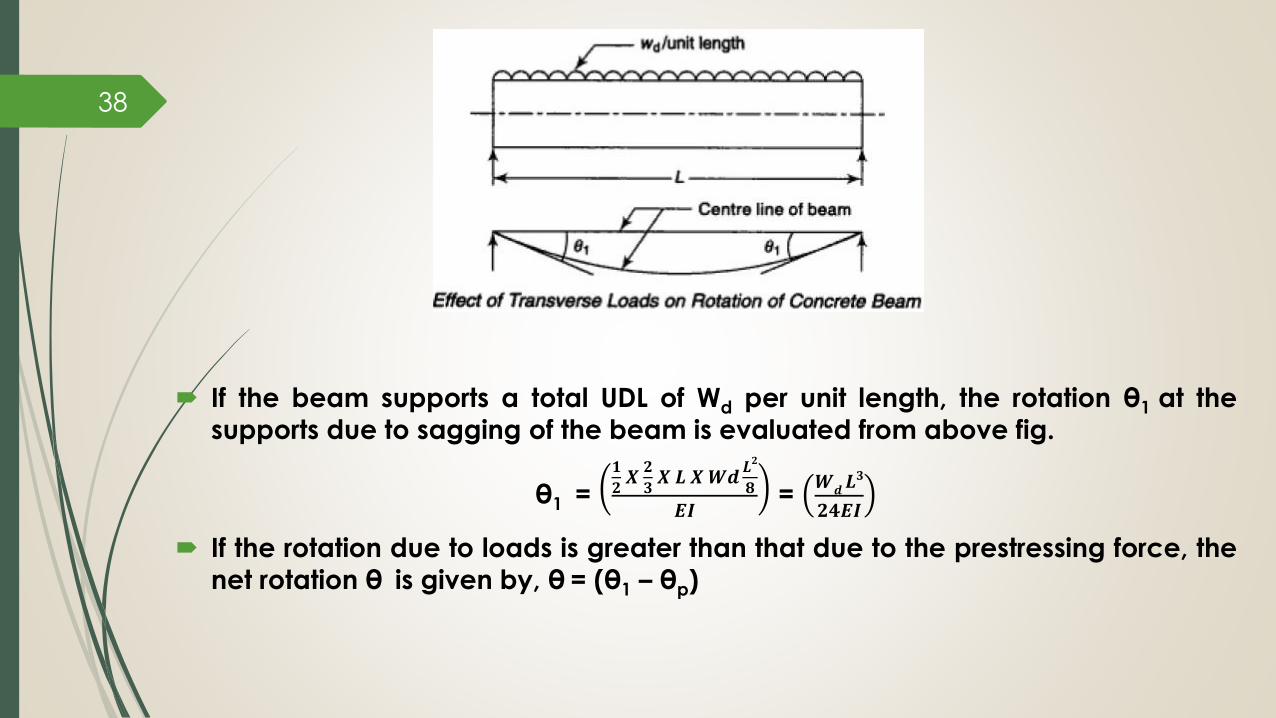
If the beam supports a total UDL of Wd per unit length, the rotation θ1 at the
supports due to sagging of the beam is evaluated from above fig.
θ1 = 𝟏
𝟐𝑿𝟐
𝟑𝑿 𝑳 𝑿𝑾𝒅
𝑳𝟐
𝟖
𝑬𝑰=
𝑾𝒅𝑳𝟑
𝟐𝟒𝑬𝑰
If the rotation due to loads is greater than that due to the prestressing force, the
net rotation θ is given by, θ = (θ1 – θp)
38
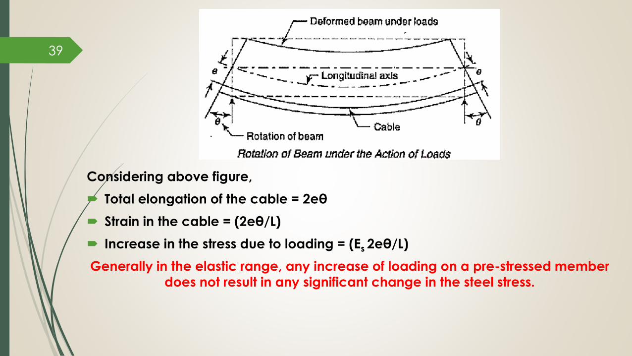
Considering above figure,
Total elongation of the cable = 2eθ
Strain in the cable = (2eθ/L)
Increase in the stress due to loading = (Es 2eθ/L)
Generally in the elastic range, any increase of loading on a pre-stressed member
does not result in any significant change in the steel stress.
39

EX: A pre-stressed concrete beam spanning over 6 m have the c/s of 100 mm wide
by 300 mm deep. The initial stress in the tendons located at a constant
eccentricity of 50 mm is 1000 N/mm2. The c/s area of the tendons is 100 mm2.
Find the percentage increase in stress in the wires when beam supports a Live
Load of 4 kN/m. Dc = 24 kN/m3, Ec = 36 kN/mm2, Es = 210 kN/mm2.
Pre-stressing force, P = (1000 x 100) = 100 kN
I = 100 x 3003 /12 = 225E6 mm4
Rotation due to prestress, θp = 𝑷𝒆𝑳
𝟐𝑬𝑰=
𝟏𝟎𝟎 𝑿 𝟓𝟎 𝑿 𝟔𝑬𝟑
𝟐 𝑿 𝟑𝟔 𝑿 𝟐𝟐𝟓𝑬𝟔= 0.001858 radians
Self weight of the beam, g = (0.1 x 0.3 x 24) = 0.72 kN/m
LL = 4 kN/m
Total Load = 4.72 kN/m
Wd = 0.00472 kN/mm
Rotation due to loads, θ1 = 𝑾
𝒅𝑳𝟑
𝟐𝟒𝑬𝑰
Net rotation = 0.00525 – 0.001858 = 0.0034 radians
Elongation of the cable = 2 x 50 x 0.0034 = 0.34 mm 40
Increase in the stress due to loading = 12 N/mm2
Initial stress in the cable = 1000 N/mm2
% increase in stress = (12 x 100 / 1000) = 1.2%
Variation of Steel Stress in Bonded
and Unbonded Members The rate of increase of stress in the tendons of prestressed concrete
member under loads depends upon the degree of bond between the high
tensile steel wires and the surrounding concrete.
For bonded members such as pretensioned elements or post-tensioned
grouted members, the composite action between steel and concrete
prevails and the stresses in steel are computed using the theory of
composite sections up to the stage of cracking.
For unbonded beams, the tendons are free to elongate independently
throughout their length under the action of transverse loads on the beam.
The increase of stress in steel depends on the average strain in concrete
at the level of steel.
41

Bonded Beams If M = Moment at the section due to loads
Es = Modulus of elasticity of steel
Ec = Modulus of elasticity of concrete
e = modular ratio
y = position of steel from the centroidal axis
f = Stress in concrete at level y from the centroidal axis
I = Second moment of area of the concrete section
Stress in steel = Modular ratio x Stress in concrete
= e f
= e (M y / I)
42

Unbonded Beams If M = Bending Moment at the cross-section
Es = Modulus of elasticity of steel
Ec = Modulus of elasticity of concrete
e = modular ratio
y = position of steel from the centroidal axis
f = Stress in concrete at level y from the centroidal axis
I = Second moment of area of the concrete section
δL = Total elongation of the cable at a distance y from the centroidal axis
Strain in concrete at the level of steel = (M y/Ec I)
Total elongation of fiber of concrete at the level of steel = δL = 𝟎𝑳 𝑴 𝒚
Ec 𝑰𝒅𝒙
Average Strain =𝛿𝑳
𝑳=
𝒚
𝑬𝒄𝑰 𝑳 𝟎𝑳𝑴𝒅𝒙
43

Stress in steel =𝑬𝒔
𝑬𝒄
𝒚
𝑰𝑳 𝟎𝑳𝑴𝒅𝒙
=𝛼𝒆𝒚
𝑰𝑳 𝟎𝑳𝑴𝒅𝒙
If A= area of the BMD under a system of loads,
A = 𝟎𝑳𝑴𝒅𝒙
stress in steel = 𝛼𝒆𝒚𝑨
𝑰𝑳
If the beam supports only a UDL of wd per unit length,
Then A = 𝟎𝑳𝑴𝒅𝒙 =
𝟐
𝟑𝑳 𝒘𝒅
𝑳𝟐
𝟖
= 𝒘𝒅
𝑳𝟑
𝟏𝟐
Increase of stress in steel =
44
2
12
e dy W L
I

45

The rate of increase of stress is larger in the case of bonded beams than in
unbonded beams both in the pre-cracking and post-cracking stages.
After the crack, the stress in steel increases at a faster rate in both types of
beams.
Since the steel does not reach its ultimate strength in the case of unbonded
beams, the ultimate load supported by the beam is smaller than that of abonded beam in which the steel attains its ultimate strength at the failure stage
of the member.
In the post-cracking stage, while the bonded beams are characterised by small
cracks, which are well distributed in the zone of larger moments, unbonded
beams develop only a few cracks, which are localized at weaker sections and
the crack widths are correspondingly larger in comparison with the bonded
beams.
In general, bonded beams are preferable due to their higher flexural strengthand predictable deformation characteristics.
46 Variation of stresses in steel in Bonded and Unbonded beams

EX: A pre-stressed concrete beam 200 mm wide by 300 mm deep supports a Live Load of
2.56 kN/m over an effective span of 10 m. The tendons housed in ducts are located at an
eccentricity of 100 mm. Calculate the increase in steel stress due to loading when:
a) The ducts are grouted so that the strains in the steel and adjacent concrete are equal
and
b) The ducts are ungrouted so that the tendons can move in ducts without friction.
Dc = 24 kN/m3, Ec = 35 kN/mm2, Es = 210 kN/mm2.
Self weight of the beam, g = (0.2 x 0.3 x 24) = 1.44 kN/m
LL, q = 2.56 kN/m
wd = 4 kN/m
I = 200 x 3003 /12 = 45E7 mm4
Modular ratio , e = (Es / Ec) = 6
BM at center span = 0.125 x 4 x 102 = 50 kNm
a) Bonded beam
Stress in concrete = (My / I) = (50E6 x 100 / 45E7) = 11.1 N/mm2
Stress in steel = ( e) (Stress in concrete) = (6 x 11.1) = 66.6 N/mm2
47
b) Unbonded beam
Stress in steel =
= 𝟔 𝑿 𝟏𝟎𝟎 𝑿 𝟒 𝑿 𝟏𝟎 𝑿 𝟏𝟎𝟎𝟎 𝟐
𝟏𝟐 𝑿 𝟒𝟓 𝑿 𝟏𝟎𝟕
= 44.4 N/mm2
2
12
e dy W L
I

Cracking Moment Bending Moment at which visible cracks develop in Pre-stressed concrete
members is referred as Cracking Moment.
After the transfer of pre-stress to concrete, the soffit of the beam will be under
compression.
Gradually, these comp stresses are balanced by the tensile stresses developed
due to the transverse loads on the beam, so that the resultant stresses at the
bottom fibre is zero.
A further increase in loading results in development of tensile stress at the soffit of
the beam.
As concrete is weak in tension, micro cracks develop as soon as the tensile stain
in concrete exceeds 80 – 100E-6 units and if the loads are further increased,
visible cracks appear in tension zone.
At this stage, it is estimated that the crack widths are of order of 0.01 – 0.02 mm.
48

Tensile stress developed when cracks become visible at the soffit of beams
depend upon the type and distribution of steel reinforcement and the quality of
concrete in the beam.
It is generally considered that visible cracks appear when the tensile stresses at
the soffit are approximately equal to the modulus of rupture of the material.
The widths of the cracks are highly influenced by the degree of bond
developed between concrete and steel.
49

EX: A rectangular prestressed concrete beam of c/s 120 mm wide by 300 mm deep is pre-
stressed by a straight cable carrying an effective force of 180 kN at an eccentricity of 50 mm.The beam supports an imposed load of 3.14 kN/m over a span of 6m. If the modulus of
rupture of concrete is 5 N/mm2, evaluate the load factor against cracking assuming self
weight of concrete as 24 kN/m3.
50
P = 180 kN I = 27E7 mm4 e = 50 mm
Z = 18E5 mm3 A = 36E3 mm2 g = (0.12 x 0.3 x 24) = 0.86 kN/m
Total load = 4 kN/m
Stresses due to prestress
P/A = 5 N/mm2 Pe/Z = 5 N/mm2
Stresses due to loads:
Max. Working moment = 0.125 x 4 x 62 = 18 kNm (M/Z) = 10 N/mm2
Stress at the bottom fiber at working load = (5 + 5 - 10) = 0 N/mm2
Stress corresponding to cracking moment at bottom fiber = 5 N/mm2
Extra moment required to create this stress = 5 x 18E5 = 9 kNm
Cracking moment = (18 + 9) = 27 kNm
Load factor against cracking = (cracking moment / working moment) = 27 / 18 = 1.5

51