Non-linear analysis of composite beams under positive bending
13
Non-linear analysis of composite beams under positive bending G. Fabbrocino, G. Manfredi *, E. Cosenza Dipartimento di Analisi e Progettazione Strutturale, Universita ` Federico II, Napoli, Italy Received 4 March 1997; received in revised form 4 August 1998 Abstract The structural behaviour of steel–concrete composite beams depends on the interaction between the steel beam and the concrete slab. Therefore, the connection largely influences the global behaviour of the beam and its modelling is a key issue in the analysis of these structures. An eective model requires the introduction of an explicit relationship between slip and interaction force given by each connector, which is strongly non-linear. In this paper, a numerical procedure that allows a reliable analysis of the structural behaviour of composite beams subjected to sagging moment due to short term loads, both in serviceability and ultimate state, is proposed. # 1998 Elsevier Science Ltd. All rights reserved. Keywords: Non-linear analysis; Steel-concrete beams; Structural behavior 1. Introduction The use of composite steel–concrete structures results in optimum performance of the two materials; but in the design process it is required to evaluate the influence of the connection on the structural behaviour of the element. In fact, as is suggested by the most advanced codes [1], the design may be based on the concept of partial shear connection, and, therefore, the slip between the concrete slab and the steel beam can- not be neglected [2]. Furthermore, in the plastic field, a large amount of the energy dissipation is related to the connection. Starting from these remarks, it is evident that: 1. the modelling of the structural behaviour of steel– concrete beams is complex, and must necessarily consider the slip between the concrete slab and the steel beam and the constitutive relationship of the shear connectors, which is strongly non-linear [3]; 2. the behaviour in terms of deformability and strength of composite beams depends directly on the distribution of the slip and the consequent inter- action force between the slab and the steel beam; 3. under sustained loads, creep and shrinkage can aect the deflection, [4, 5]. Therefore, to have a reliable model, these phenomena must be taken into account [6, 7]. In this paper a nu- merical procedure, based on well-known kinematic models [8, 9] and suitable to analyse the behaviour of composite beams under short term loads, is proposed. The introduction of an original moment–curvature generalised relationship for the cross section allows easy analysis of the structural behaviour, varying the connection level and the material properties in order to optimise the design in serviceability and ultimate state. 2. The structural modelling The composite beam consists of two components, identified in Fig. 1(b) by the subscript s for the lower steel beam and c for the concrete slab. The two com- ponents are characterised by the same displacement: in Computers and Structures 70 (1999) 77–89 0045-7949/99/$ - see front matter # 1998 Elsevier Science Ltd. All rights reserved. PII: S0045-7949(98)00173-4 PERGAMON * Corresponding author. Tel: 0039 81 768 3488; Fax: 0039 81 768 3491; E-mail: [email protected].
Transcript of Non-linear analysis of composite beams under positive bending

Non-linear analysis of composite beams under positivebending
G. Fabbrocino, G. Manfredi *, E. Cosenza
Dipartimento di Analisi e Progettazione Strutturale, UniversitaÁ Federico II, Napoli, Italy
Received 4 March 1997; received in revised form 4 August 1998
Abstract
The structural behaviour of steel±concrete composite beams depends on the interaction between the steel beam
and the concrete slab. Therefore, the connection largely in¯uences the global behaviour of the beam and itsmodelling is a key issue in the analysis of these structures. An e�ective model requires the introduction of anexplicit relationship between slip and interaction force given by each connector, which is strongly non-linear. In thispaper, a numerical procedure that allows a reliable analysis of the structural behaviour of composite beams
subjected to sagging moment due to short term loads, both in serviceability and ultimate state, is proposed. # 1998Elsevier Science Ltd. All rights reserved.
Keywords: Non-linear analysis; Steel-concrete beams; Structural behavior
1. Introduction
The use of composite steel±concrete structures
results in optimum performance of the two materials;
but in the design process it is required to evaluate the
in¯uence of the connection on the structural behaviour
of the element. In fact, as is suggested by the most
advanced codes [1], the design may be based on the
concept of partial shear connection, and, therefore, the
slip between the concrete slab and the steel beam can-
not be neglected [2]. Furthermore, in the plastic ®eld, a
large amount of the energy dissipation is related to the
connection.
Starting from these remarks, it is evident that:
1. the modelling of the structural behaviour of steel±
concrete beams is complex, and must necessarily
consider the slip between the concrete slab and the
steel beam and the constitutive relationship of the
shear connectors, which is strongly non-linear [3];
2. the behaviour in terms of deformability andstrength of composite beams depends directly on
the distribution of the slip and the consequent inter-action force between the slab and the steel beam;
3. under sustained loads, creep and shrinkage cana�ect the de¯ection, [4, 5].
Therefore, to have a reliable model, these phenomenamust be taken into account [6, 7]. In this paper a nu-
merical procedure, based on well-known kinematicmodels [8, 9] and suitable to analyse the behaviour ofcomposite beams under short term loads, is proposed.The introduction of an original moment±curvature
generalised relationship for the cross section allowseasy analysis of the structural behaviour, varying theconnection level and the material properties in order to
optimise the design in serviceability and ultimate state.
2. The structural modelling
The composite beam consists of two components,
identi®ed in Fig. 1(b) by the subscript s for the lowersteel beam and c for the concrete slab. The two com-ponents are characterised by the same displacement: in
Computers and Structures 70 (1999) 77±89
0045-7949/99/$ - see front matter # 1998 Elsevier Science Ltd. All rights reserved.
PII: S0045-7949(98 )00173-4
PERGAMON
* Corresponding author. Tel: 0039 81 768 3488; Fax: 0039
81 768 3491; E-mail: [email protected].

this way the two parts have the same rotation and the
same curvature in each section of the beam [8, 9].
In a more re®ned model, each component can be
regarded as a distinct beam, so that the two curvatures
may be di�erent, as the compatibility of the vertical
displacements may be imposed only in the sections
containing the shear connectors [10, 11]. Thus an uplift
of the slab may occur; nevertheless, this e�ect is not
relevant, as Johnson and Molenstra [12] have demon-
strated, and it will be neglected in the following. The
shear connectors are considered in their actual position
along the beam, so, from a static point of view, their
action consists of an interaction force applied at a dis-crete number of sections. The concrete slab is modelled
as a conventional reinforced concrete element, so itsanalysis is based on the two following hypotheses:
1. there is no slip between reinforcing bars and con-
crete;
2. concrete in tension is neglected.
These hypotheses are also acceptable at the ultimate
state; in fact analysis of the section behaviour shows
Fig. 1. The structural model.
G. Fabbrocino et al. / Computers and Structures 70 (1999) 77±8978
that the concrete slab is mainly in compression and,
whenever it is partially in tension, the steel strain is
small and comparable with that of the concrete.
Therefore, a more re®ned model for the reinforcing
steel in tension, including the slip between rebars and
concrete in tension [13], is not required when the com-
posite section is subjected to sagging moment.
The evaluation of the displacements w(x, y) of the
section not only depends on the rotation j and the dis-
placement of one of the centroids [ws, or wc, Fig. 1(c)],
but also on the slip between the slab and the steel pro-
®le:
s � wups ÿ wlo
c : �1�The ®rst term w up
s is the displacement of the upper
®ber of the steel beam, while w loc is the displacement of
the lower ®ber of the concrete slab.
The slip can be evaluated as a function of the displa-
cements of the centroid of each part:
s � �ws � f � ds� ÿ �wc ÿ f � dc� � ws ÿ wc � f � d �2�where j is the rotation, the same for the two parts of
the section; ds and dc are the distances between the
centroid axes of steel or concrete and the steel concrete
interface, and d is the distance between the two axes.
Eq. (2) can be derived with respect to the position of
the section along the beam, providing an equation con-
taining the curvature, the strain at the centroid of each
part and the derivative of the slip:
ds
dz� dws
dzÿ dwc
dz� w � d � Es ÿ Ec � w � d: �3�
Eqs. (1)±(3) represent the condition of compatibility,
which must be satis®ed at the interface between the
two parts of the cross section.
From a kinematic point of view, it is clear that the
solution depends on three variables: the displacements
of the two centroids and the rotation of the section, or
the strains of the two centroids and the curvature. For
equilibrium of the section, three equations govern:
. global rotational equilibrium of the cross section;
. translational equilibrium of the concrete slab;
. translational equilibrium of the steel pro®le.
Eq. (4) represents the rotational equilibrium of the sec-
tion evaluated with respect to the ®ber of contact
between the two parts of the beam:
M �Ms �Mc � Fs � ds ÿ Fc � dc: �4�
In this equation M is the global bending moment
acting on the section, Ms and Mc are the two parts of
the global bending moment acting on the steel beam,
and the concrete slab; Fs and Fc are the axial forces
applied on the steel beam and the concrete slab, re-
spectively. It is assumed that both axial force and
bending moment are applied at the centroid of each
component of the cross section.
The partial translational equilibrium of the concrete
slab gives:
Fc � ÿF: �5�
The partial translational equilibrium of the steel
beam gives:
Fs � F: �6�
From global translational equilibrium, Eq. (4) can
be modi®ed into the more useful form
Fs � ÿFc � F �7�so that global rotational equilibrium can be rewritten:
M �Ms �Mc � F � d: �8�
In this way the three independent Eqs. (5), (6), (8)
depend on the interaction force F, and the two bending
moments acting on the two parts of the composite sec-
tion.
These forces are the resultants of the normal stresses
acting on the two part of the section:
Fs ��As
ss�x; y� � dA; �9a�
Ms ��As
ss�x; y� � �yÿ ds� dA �9b�
Fc ��Ac
sc�x; y� � dAÿXj
Ajrs � sjrs; �9c�
Mc ��Ac
sc�x; y� � �yÿ dc� � dA
�Xj
sjrs � Ajrs � �yjrs ÿ dc�; �9d�
F �Xn�x�j�1
Fj: �9e�
The subscript rs de®nes the reinforcing steel; y rep-
resents the distance between each ®ber and the cen-
troid of the global section [see Fig. 1(c)]; Fj is the force
acting on connector j placed before the current section,
n(x) is the number of shear connectors, jR n(x).
Statically, the e�ect of the connection is represented
by the term F � d, therefore even if the bending
moment acting on each part of the section is equal to
zero (zero curvature), the composite section is able to
bear a global bending moment, depending on the value
of the interaction force F.
This remark is very signi®cant as the bearing ca-
pacity and thus the moment±curvature relationship
depends on the value of the interaction force.
G. Fabbrocino et al. / Computers and Structures 70 (1999) 77±89 79

3. The constitutive relationships
The above equations are not su�cient and the con-
stitutive relationships of the materials must be intro-
duced for the concrete in compression, for steel
reinforcement, the structural steel, and the shear con-
nectors. It is worth noting that the numerical pro-
cedure developed is not strictly related to the
constitutive laws discussed below and used to perform
the theoretical±experimental comparison, as even ex-
perimental stress±strain relationships can be used.
The mechanical behaviour of the reinforcing steel of
the slab is modelled using the Ramberg±Osgood for-
mulation, which is suitable for simulating the real
mechanical behaviour of cold-formed, tempered, or
low content of carbon steel. For concrete in com-
pression, the relationship given by Mander et al. [14]
has been used; the descending branch has been modi-
®ed as suggested by Hilleborg [15] in order to take
into account the size e�ect.
The proposed method regards only beams subjected
to sagging moment, so the buckling phenomena are
not signi®cant. A simple three-linear idealization, as
shown in Fig. 2 models the structural steel. In the
same ®gure the main parameters, needed to de®ne the
relationship, are shown.
For the shear connection consisting of headed studs,
the relationship de®ned by Olgaard [3] is used; it is
characterised by strong non-linearity and has been
extensively used. It is described by two independent
parameters: a and b. Some curves representing the
mechanical behaviour of the headed studs are plotted
in Fig. 3. They have been de®ned taking into account
typical values of the two coe�cients found in
literature [9, 12]: a=0.558 and b=1 mmÿ1 (type A),
a=0.989 and b=1.535 mmÿ1 (type B), or a=0.8and b=0.7 mmÿ1 (type C).
The relation between force Fj and slip sj assumes thefollowing form:
Fj � Pmax � �1ÿ eÿ b � sj�a: �12�
The two parameters a and b control the initial slopeof the curve and its shape, while the value of Pmax has
to be measured by means of push-out tests [1].
4. Moment curvature relationship of the cross section
The global bending moment on the composite sec-tion is given by axial force and bending acting on each
part of the section. Therefore, for a particular value ofthe curvature [Eqs. (3), (8), (9)] the value of the globalbending moment depends on the derivative of the slips, Eq. (3). Similarly, the curvature depends directly on
the value of the interaction force F, Eq. (8), if the glo-bal bending moment is given.It is therefore not possible to draw a single
moment±curvature curve, conversely, it is necessary tode®ne a family of curves corresponding to di�erentvalues of F. Thus, the complete solution of the ¯exural
problem of a composite section can be obtained arran-ging an array with this family of curves.In order to de®ne this family of curves, ®rstly, the
de®nition of the upper and lower limit of the inter-
action force F, positive if it gives compression on theslab, is required. The upper positive limit of the inter-action force Fmax is given by the minimum value
between the ultimate compressive axial force of theslab and the ultimate tension axial force of the steelpro®le. The lower negative limit Fmin is given by the
Fig. 2. Constitutive relationship for structural steel.
G. Fabbrocino et al. / Computers and Structures 70 (1999) 77±8980

maximum value between the ultimate tension axialforce of the slab and the ultimate compressive axial
force of the steel pro®le. These boundary values are
easy to be calculated and depend on the mechanical
properties of the coupling of the concrete slab and the
steel beam.
In the following, some numerical results are shown,
with reference to a tested beam called PI4 [11]; the
geometrical and mechanical properties of the cross sec-
tion are given in Fig. 4; and the constitutive laws used
are those previously described.
The complete solution of the ¯exural problem of thecomposite section is given in the graph of Fig. 6,
where two di�erent families of curves are plotted. The
continuous lines represent the moment curvature re-
lation for a particular value of the interaction force;
the dotted ones represent the moment±curvature
curves with a given value of the slip derivative ds/dz.
The last family of curves is very interesting, in fact
the curve corresponding to the value of the derivative
ds/dz equal to zero de®nes the moment±curvature re-
lation for the full interaction condition. The curve is
drawn using a thick line in the same ®gure and a circle
marks the corresponding ultimate state condition. This
curve is the only one consistent with the Bernoulli hy-
pothesis of linear deformation of the entire composite
cross section, which occurs when the slip and the de-
rivative at the slab pro®le interface are both zero. In
turn, the grey thick line plotted in the same ®gure
gives the moment±curvature relationship for the com-
posite section in absence of interaction (F=0); in this
particular condition, the curvature is related to the
bending moment by the following relation:
w � ÿ M
�EsIs � EcIc� �13�
where EsIs and EcIc are the ¯exural rigidities of the
steel pro®le and of the concrete slab [8].
The analysis of the curves plotted in Fig. 5 allows
some interesting remarks:
1. The ultimate curvature for the full interaction con-
dition is considerably lower than the maximum
values allowable when the two parts of the beam
can slip; the large in¯uence of the connection beha-
viour on the plastic deformation of the beam is
clear, and can be obtained by an appropriate design
of the strength and deformability of the shear con-
nectors.
2. The section subjected to positive bending may be
characterised by both negative and positive curva-
ture, as a function of the interaction force level. For
example it can be observed that when the bending
moment is low enough and, at the same time, the
concentrated action of the connectors provide a
large interaction force, tensile stresses can arise in
the upper ®bers of the slab, even though the cross-
section is under positive bending. This situation
usually occurs in the support regions of the simple
supported beams.
Fig. 3. Constitutive relationship for headed stud
connectors [3].
Fig. 4. Cross-section and material properties of beam PI4 [11].
G. Fabbrocino et al. / Computers and Structures 70 (1999) 77±89 81

3. When the value of the curvature is zero, the sectionis able to bear a non-zero bending moment, depend-
ing on the interaction level. In fact, as shown in
Eq. (8), when the curvature is zero the two bending
moments acting on each part of the section areequal to zero, but the term F�d is not zero, as it is a
linear function of the interaction force F.
4. The maximum positive bending moment which may
be borne by the section is given by the relation
Mmax=Fmax�d, where Fmax is the maximum positive
interaction force consistent with the mechanicalproperties of each part of the section. Therefore,
only a curvature equal to zero may be associated
with this value of the bending stress. This remark is
clearly shown in Fig. 5, where the greater the inter-action force, the lower the curvature range, so that
the moment±curvature curves tend to become a
point, corresponding to the co-ordinates w=0,M= Mmax=736.94 kN m, and marked by a tri-angle in the graph.
5. as F increases, a change in the shape of the M±wcurves can be observed; beyond a certain value ofthe interaction force, the moment±curvature re-lation does not cross the curvature axis and a non
zero lower limit of the bending moment exists. Thisbehaviour is better shown in Fig. 6, where typicalmoment±curvature relationships are plotted; the
®rst one, named type 1 curve, crosses the curvatureaxis, the second one, type 2 curve, shows a non zerovalue of the minimum bending moment Mmin(F).
The moment±curvature generalised relationship is avery useful tool in the design process, as it is possibleto de®ne the curvature of the section and the corre-
sponding value of the derivative ds/dz if both the valueof the interaction force F and the global bendingmoment are given.
5. The analysis of the beam
The solution of the equations governing the problem
is quite di�cult. In fact, the constitutive relationshipsare strongly non linear and also particular conditionsof coupling in the equations are present. Therefore, the
solution can be obtained only using a numerical pro-cedure. The solution of the entire beam at each stepmust be performed, with a signi®cant computational
e�ort.In general the boundary conditions can be written
corresponding to the extreme sections of the beamFig. 6. Typical moment±curvature curves.
Fig. 5. Moment-curvature generalised relationship.
G. Fabbrocino et al. / Computers and Structures 70 (1999) 77±8982

where two situations may occur: the connector can be
present or not. In the ®rst case, the interaction force is
equal to zero, in the second one the slip and the inter-
action force must satisfy the Ollgaard's constitutive re-
lationship (12).
In order to simplify the discussion, a case of a beam
characterised by both geometrical and mechanical sym-
metry will be considered. Moreover, changing only the
boundary conditions can solve any di�erent problem.
Due to the symmetry, the analysis can be restricted to
only a half beam. The boundary conditions can be
given in the ®rst section of the beam, where the slip
and the interaction force are related as discussed
before and in the section placed on the symmetry axis,
where the slip between the slab and the steel beam
must be equal to zero.
A reliable numerical solution of the equations may
be obtained using the ®nite di�erence method [16],
combined with a shooting type procedure, which allows
the transformation of a boundary conditions problem
into an initial value one. This approach allows trans-
forming the resolution of the problem into the search
of the root of a non-linear equation, which can be
evaluated by means of an iterative procedure. The
independent variable of this equation is the value of
the slip s in the ®rst pivotal section. In the numerical
procedure the half beam can be divided into n parts,
de®ned by a constant spacing of the nodes equal to
Dz. The only unknown parameter is the value assumed
by the function s(z) in each integration node.
In particular, the two following equations can be
used:
si�1j � sij �ds
dz
� �i
j
�Dz; �14a�
F i�1j � F i
j � �F ij �14b�
where j gives the iteration number, and i the node
number. Eq. (14a) gives the slip, while Eq. (14b) gives
the interaction force present in the node i+1. The
parameter F ij depends on the presence of a shear con-
nector at the node i. In fact, when there is not any
shear connector the parameter F ij is equal to zero, con-
versely if a shear connector is present, F ij has to be
evaluated by means of the non linear constitutive re-
lationship (12).
The value assumed in the node i by the derivative
ds/dz can be simply calculated. In fact, as the global
bending moment and the interaction force are known
in the current section, the corresponding value ds/dz
can be evaluated by a simple linear interpolation of
the data available in the moment±curvature array.
Therefore, the procedure allows de®nition of the
unknown value s i+1j in each node and so also in the
last node n+1, which is assumed as the convergenceparameter of the iterative process.
6. Computational aspects of the procedure
The condition governing the convergence may beexpressed by the equation:
E�s1j � � sn�1�s1j � � 0: �15�
An upper and a lower limit of the root of Eq. (15)may be de®ned, in order to restrict the range of thetentative values. In fact, the lower limit is given by the
full interaction condition. In this situation there is noslip between slab and steel beam:
s1min � 0: �16�
The upper limit is reached when shear connectorsare not provided at the slab±pro®le interface, there-
fore, it is given by the product of the rotation of the®rst section in absence of interaction and the distanced, see Fig. 1(c).
The above upper limit of the slip requires the evalu-ation of the rotation at the support; another e�ectiveupper limit for the slip in the ®rst integration node canbe evaluated in an easier way, extracting the maximum
modulus of the derivative ds/dz from the generalisedmoment±curvature relationship.Therefore, it can be assumed that the maximum
value of the slip corresponding to the ®rst integrationnode is given by:
s1max �L
2����� dsdz
����max
: �17�
This value is calculated assuming that the derivativeds/dz is constant; this is certainly the absolute maxi-
mum of the slip present in the ®rst section of thebeam.Typical shapes of the function E(s1) have been
plotted in Fig. 7. Four di�erent curves have beende®ned for a particular load. They depend on the levelof interaction, de®ned by the ratio N/Nf , where N is
the number of the shear connectors present along thebeam and Nf is the number strictly needed to ensurethe full interaction. The spacing of shear connectors isconstant along the beam. The curves represent the
function E(s1) throughout the entire existence domainS. It is clearly characterised by an upper and a lowerlimit depending on the ratio N/Nf , which are not co-
incident with the two limits discussed before.Nevertheless, the existence domain always strictlysatis®es the following condition:
S 2 �0; s1max�: �18�
G. Fabbrocino et al. / Computers and Structures 70 (1999) 77±89 83

This remark is obviously essential to schedule a re-
liable solution scheme.
It is also worth noting that the greater the ratio
N/Nf , the steeper the error function; therefore, the nu-
merical solution is more di�cult to obtain, when the
beam tends to the condition of full interaction.
Besides taking into account Fig. 7, it can be
observed that:
1. The upper limit of the tentative slip, marked by a
triangle, represents a limit state for an intermediate
section i, a�ected by an interaction force F corre-
sponding to a type 2 moment±curvature relation
(see Fig. 6) and a bending moment Mi lower than
the minimum consistent with the interaction level,
Mmin(F). Therefore, the evaluation of the curvature
and the derivative ds/dz is not possible because the
moment±curvature curve does not cross the hori-
zontal line representing the value of the bending
moment: whenever this situation occurs, the conver-
gence parameter cannot be calculated.
2. The lower limit of the tentative slip, marked by a
circle, is due to two possible limit states, depending
on the load level. The ®rst one is reached when a
negative value of the interaction force exceeds in
modulus the limit vFminv, de®ned in the last section;
the second one is reached when the global bending
moment exceeds the maximum value consistent with
the interaction force Mmax(F), Fig. 6.
The uniqueness of the solution in this structural pro-
blem ensures that the above critical conditions cannot
be replaced or modi®ed. So the values of the tentative
slip not included in the interval are not consistent with
the model and consequently are not possible.
These conditions must be considered to solve the
problem by means of a processing program, as the
existence domain of the function E(s1) cannot be pre-
viously de®ned. The numerical process assumes that a
discrete number of (w, M, ds/dz) curves must be calcu-
lated, so that an array is available for each interaction
level considered.
Thus, for a given bending moment and an inter-
action force, the corresponding values of the curvature
and of the derivative ds/dz can be evaluated by means
of a simple linear interpolation. Moreover, this
approach allows the minimisation of the time of calcu-
lation, in fact, during the iterations, the solution of the
complex problem of translational and rotational equili-
brium of the section in each integration node is not
requested.
The beams are statically determined, thus the global
bending moment is known in each node; therefore, the
fundamental steps of the procedure may be summar-
ised, in compliance with the ¯ow-chart drawn in Fig. 8:
1. de®nition of a suitable moment±curvature relation-
ship for the cross section of the composite beam to
be analysed;
2. evaluation of the maximum value of the tentative
slip between the slab and the steel pro®le, according
to Eqs. (16) and (17);
3. selection of a ®rst tentative slip to start the pro-
cedure;
4. calculation of the corresponding interaction force in
the section by means of the constitutive relationship
of the headed studs;
5. de®nition of the (M, w, ds/dz) relationship corre-
sponding to the calculated interaction force by
means of a linear interpolation;
6. evaluation of the curvature and the derivative of the
slip related to the given value of the bending
moment;
7. evaluation of the slip in the next node by Eq. (14a).
The knowledge of an interval containing the root of
Eq. (15) allows the use of a bracketing method for the
iterative solution of the problem. Moreover, the iter-
ations of the numerical procedure must consider the
adjustments to the tentative slip related to the critical
conditions de®ned before, whenever the convergence
parameter cannot be evaluated (steps a and b). In fact,
the slip must be reduced when the bending moment of
the section is lower than the value Mmin(F); on the
other hand, the attempt slip has to be increased when
the interaction force becomes inconsistent with its
lower limit, or the bending moment is greater than the
maximum Mmax(F) consistent with the current inter-
action level.
When the convergence condition is satis®ed, the
knowledge of the curvature allows the evaluation, by a
simple integration of the rotation and the vertical dis-
placement corresponding to each integration node
(step c).
Fig. 7. Typical curves of the convergence parameter.
G. Fabbrocino et al. / Computers and Structures 70 (1999) 77±8984

Fig. 8. Flow-chart of the numerical procedure.
G. Fabbrocino et al. / Computers and Structures 70 (1999) 77±89 85

7. A theoretical±experimental comparison
The proposed procedure has been validated using
di�erent tests with good results. In the present section
the simulation of a test by Aribert and Aziz [10, 11] is
presented. The beam, called PI4 in Ref. [11], is simply
supported and characterised by the cross-section and
material properties summarised in Fig. 4 and also by
the following geometrical and mechanical properties:
. e�ective span length 5000 mm;
. 18 headed stud connectors Nelson F 19;
. distance between studs 650 mm;
Fig. 9. Numerical and experimental results for the functions: s(z) (a); ds/dz (b); w (c).
G. Fabbrocino et al. / Computers and Structures 70 (1999) 77±8986
. stud constitutive relationship parameters:
Pmax=130 kN; a=0.8 e b=0.7 mmÿ1.
The numerical procedure presented before allows the
comparison of both local, such as slip at the slab±steel
beam interface, and global results, such as the load±
de¯ection relation. A complete solution of the struc-
tural scheme has been performed using an integration
interval equal to 5 mm; all the most signi®cant results
have been arranged in Figs. 9±11.
Fig. 9 shows the structural scheme and the plot of
the calculated functions: sÐFig. 9(a); ds/dzÐFig. 9(b);wÐFig. 9(c), for two di�erent load levels. The com-
parison in terms of slip shows good agreement of theexperimental and theoretical results and the following
remarks can be made:
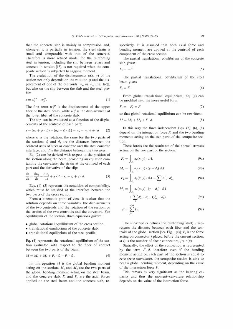
1. the midspan section is never characterised by the
full interaction condition (ds/dz=0), in turn, thegreater the load, the greater the value of the deriva-
tive itself;
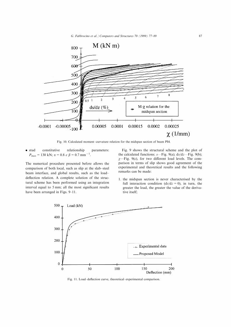
Fig. 11. Load±de¯ection curve, theoretical±experimental comparison.
Fig. 10. Calculated moment±curvature relation for the midspan section of beam PI4.
G. Fabbrocino et al. / Computers and Structures 70 (1999) 77±89 87

2. along the beam, it is possible to identify only threesections characterised by the full interaction
(ds/dz=0), Fig. 9(b).
The curvatures are plotted in Fig. 9(c); a zone a�ected
by a negative curvature in the support regions is pre-sent. The procedure allows solving of the problemboth in serviceability and at ultimate state, as it is easyto recognise the yielding of the midspan section and its
subsequent spreading.In this way, the entire load process can be ®tted, the
moment±curvature relationship for each section of the
beam can be obtained, and, in particular for the mid-span section, Fig. 10. The last point of the curve givesthe ultimate state condition for the beam, as it is
placed on the borderline of the moment±curvaturedomain; it is also easy to observe that:
1. the value of the derivative ds/dz is very close to
0.03;2. the value of the curvature is considerably greater
than maximum curvature consistent with the full in-
teraction condition (ds/dz=0).
At any load level, the mechanical behaviour of themidspan section is largely di�erent from the full inter-
action condition.The load±de¯ection curve is plotted in Fig. 11,
where the proposed model is compared with the exper-
imental results. The shapes of the theoretical and ex-perimental curves show good agreement.The experimental collapse has been reached for a
load (Pu)exp=490 kN and a de¯ection equal to
157 mm [11]. The calculated ultimate load is very closeto the experimental one: (Pu)cal=488 kN. On theother hand, for the ultimate de¯ection, the error is
greater, as the calculated ultimate de¯ection is 182 mm,with a scatter equal about to 16%. Therefore, theevaluation of the ultimate de¯ection is very di�cult, as
it depends strongly on the constitutive relationships ofboth the materials and the shear connectors.
8. Conclusions
The modelling of the structural behaviour of steel±concrete composite beams under short term loads has
been discussed in this paper. In particular, it has beenpresented an original approach, based on the extensionof the concept of moment±curvature relationship to
the composite cross-sections.The numerical procedure shows a good convergence
and some indications are provided on the choice of the
tentative values for the slip in the iterative solution.The proposed method allows a reliable analysis of thesteel±concrete composite beams, demonstrated by a
wide theoretical±experimental comparison. The theor-etical results show a substantial agreement with the ex-
perimental data in terms of both local and globalquantities. Nevertheless, it can be remarked that, evenif the results in terms of ultimate bearing capacity are
very good, the estimation of the ultimate de¯ectionsseems to be more in¯uenced by the constitutive re-lationships introduced for the materials and the shear
connectors.The structural behaviour is quite complex, but the
proposed model is suitable for describing the main
mechanical phenomena. Furthermore, the proposedmoment±curvature generalised relationship is a verye�ective tool for understanding the structural beha-viour and also to perform an optimisation of the de-
sign in terms of both strength and deformability forthe steel-concrete composite beams.
References
[1] Eurocode 4. Common Uni®ed rules for composite steel
and concrete structures. ENV 1994-1-1, 1992, 1992.
[2] Oehlers DJ, Bradford MA. Composite steel and concrete
structural members: fundamental behaviour. New York:
Pergamon, 1995.
[3] Ollgaard JG, Slutter RG, Fisher JW. Shear strength of
stud connectors in lightweight and normal weight con-
crete. AISC Engineering Journal 1971;8:55±64.
[4] Bradford MA, Gilbert RI. Composite beams with partial
interaction under sustained loads. Journal of Structural
Engineering, ASCE 1992;118 (7):1871±83.
[5] Dezi L, Tarantino AM. Creep in composite continuous
beams. I: Theoretical treatment. Journal of Structural
Engineering, ASCE 1993;7 (119):2095±111.
[6] Newmark NM, Siess CP, Viest IM. Tests and analysis of
composite beams with incomplete interaction. Proc. of
Society for Experimental Stress Analysis 1951;1:000.
[7] Ansourian P, Roderick JW. Analysis of composite
beams. Journal of Structural Division, Proceedings of the
American Society of Civil Engineers 1978;vol. 104:75±92.
[8] Cosenza E., Mazzolani S. 1993. Composite steel-concrete
structures and Eurocode 4; new research results: beha-
viour in service of beams with partial shear connections.
In: Lecture Notes, International Advanced School,
Eurocode 3 and 4. Iva ny M, Skaloud M, eds.
[9] Aribert JM, Labib AG. ModeÁ le de calcul eÁ lasto-plastique
de poutres mixtes a connexion partielle. Construction
Metallique 1982;4:3±51.
[10] Aribert JM, Abdel Aziz K. Calcul des poutres mixtes jus-
qu'aÁ l'e tat ultime avec un e�et de souleÁ vement aÁ l'inter-
face acier-beÁ ton. Construction Metallique 1985;4:3±41.
[11] Abdel Aziz K.. Modelisation et etude experimentale de
poutres mixtes acier-beton a connexion partielle ou espa-
cee. PhD thesis. Institut National des Sciences
Appliquees des Rennes, 1986.
[12] Johnson R.P., Molenstra N. 1991. Partial shear connec-
tion in composite beams in building. Proceedings
Institute of Civil Engineers. part 2. vol. 91, pp. 679±704.
G. Fabbrocino et al. / Computers and Structures 70 (1999) 77±8988

[13] Cosenza E., Fabbrocino G., Manfredi G.. The in¯uence
of rebar ductility on the rotational capacity of composite
beams. In: Proceedings of the 5th International
Colloquium on Stability and Ductility of Steel
Structures. Usami T, ed. Nagoya, Japan, 1997.
[14] Mander JB, Priesley MJN, Park R. Theoretical stress
strain model for con®ned concrete. Journal of Structural
Engineering ASCE 1988;114 (8):1804±25.
[15] Hilleborg A.. The compression stress-strain curve for de-
sign of reinforced concrete beams. In: Li C., Bazant Z.,
editors. Fracture mechanics: application to concrete. ACI
Sp-118, 1989.
[16] Salvadori M.G., Baron M.L. 1961. Numerical methods
in engineering. Englewood Cli�s: Prentice Hall.
G. Fabbrocino et al. / Computers and Structures 70 (1999) 77±89 89


![05-03ChapGere[1] | Bending | Beam (Structure) - xdocs.net](https://static.fdokumen.com/doc/165x107/6323c1d9be5419ea700ebf89/05-03chapgere1-bending-beam-structure-xdocsnet.jpg)