SHEAR STRESSES IN BEAMS - SNS Courseware
47
B. Ashok Kumar Prof. of Mechanical Engineering SHEAR STRESSES IN BEAMS
-
Upload
khangminh22 -
Category
Documents
-
view
3 -
download
0
Transcript of SHEAR STRESSES IN BEAMS - SNS Courseware

B. Ashok Kumar
Prof. of Mechanical Engineering
SHEAR STRESSES IN
BEAMS

SHEAR STRESSES IN BEAMSIntroduction:
In the earlier chapter, the variation of bending stress
across a beam section was studied. The bending stress is due
to bending moment at the section.
The bending stress act longitudinally and its intensity is directly
proportional to its distance from neutral axis.
A typical beam section is subjected to shear force in
addition to bending moment. The variation of shearing stress,
which is due to the presence of shear force, is studied in this
chapter.
SHEAR STRESSES IN BEAMS
The stresses induced by shear force at a section in a
beam may be analyzed as follows:
Consider an elemental length of a beam between the
sections AA and BB separated by a distance dx, as shown in
the following figure. Let the moments acting at AA and BB be
M and M+ dM respectively.
Let CD be a fibre of thickness dy at a distance y from the neutral
axis. Then bending stress at left side of the fibre CD = M y
I


Force on the left side of the layer CD = M y (b.dy)
I
is =
There are a number of such elements above the section CD.
Hence the unbalanced horizontal force above the section CD =
I∫
y
y t
dM.y.b.dy
and force on the right side of the layer CD = (M+dM).y.(b.dy)
I
Therefore unbalanced force, towards right, on the layer CD
dM.y.b.dy
I

This horizontal force is resisted by the resisting force provided
by shearing stresses acting horizontally on the plane at CD.
Let the intensity of shear stress be τ.Equating the
I
resisting force provided by the shearing stress to the
unbalanced horizontal force we have:
y t
dM .y . b. dy∫y
where da = b.dy is area of theelement .
where the term
y t
y
τ .b.dx =
∫y.da = ay = Moment of, area above the
fibre CD about the NA.
y t
1
dx I.by
or τ= dM . ∫ y.da

but the term dM / dx = F, the shear force. Substituting in the expression for τ, we obtain :
where :F a y
I bτ=
F = shear force at a section in a beam
a = area above or below a fibre (shaded area)
y = dist. from N.A. to the centroid of the shaded area
I = M.I. of the entire section about the N.A
b = breadth of the fibre.
Note :The above expression is for horizontal shear stress. From
The principle of complementary shear, this horizontal shear stress
Is accompanied by a vertical shear stress of the same intensity.

Shear stress variation across a few standard cross sections
1. Rectangular section:
Consider a rectangular section
of width b and depth d
subjected to shearing force F.
Let AA be a fibre at a distancey from the neutral axis as
shown in fig.
From the equation for shear
stress :
τ = F a y
I b
where :2
a = b[ d y]

and I = bd3/12
2y = y + 1/2 [ d y]
( bd3/ 12) . bsubstituting, τ=
2 2F. b [d y ]. 1/2[ d + y]
2= 1/2[ d + y]
2
3 4 y
bd
6 F d26F
d y
d y
2 2
bd 3
2 22 2 2 2 y
1 d y
1 d y
2 3 4
y bd
6 F d 2

Thus the shear stress variation is parabolic. When,
(iii) y = 0 , τ is maximum and its value is = 6 Fd2 1.5 F
4 bd3 bd=
1.5 Shear Force
Area
that is, τmax = 1.5 τavg , for a rectangular section, and this occurs
at the neutral axis. Where τavg = Shear force/ Area
ι = 0i) at y = d/2
ii) at y = - d/2 ι = 0

2. Circular section:
Consider a circular section of diameter d , as shown in fig. Let AA
be a fibre at a vertical distance y and angle Φ1,from N.A.,on which
shear stress is to be determined.To find moment of area above the fibre AA about the N.A.,
consider an element of thickness dz at a vertical distance z from
the N.A. Let the angular distance of the element be Φ, as shown
in fig.

Width of the element , b = d cos ø
cos ø =d/2
ø
b/2
area of the element, A = b dz
d / 2
b / 2

area of the element, A = b dz
2z
dsin
d 2
dz
dcos
2dz
d cos d
2
cos2dd 2
2
d A dcos cosd

Moment of area of the element about
the N.A.= area× z
Therefore moment of the entire area ,above the fibre AA,
about the N.A.= a y
cos sin d4
sind
2cos d
2
2
23
d
2
d
4cos2 sin d
1
/ 2 d3
if cosø = t , dt/dø = - sin ø , dt = - sin ø dø and –t3/3 is integration
3
2π
14
= d3 [-cos ø]ø3
121
3
1
3
[ cos ]
3
23
d
cos ][ cos12
3
d
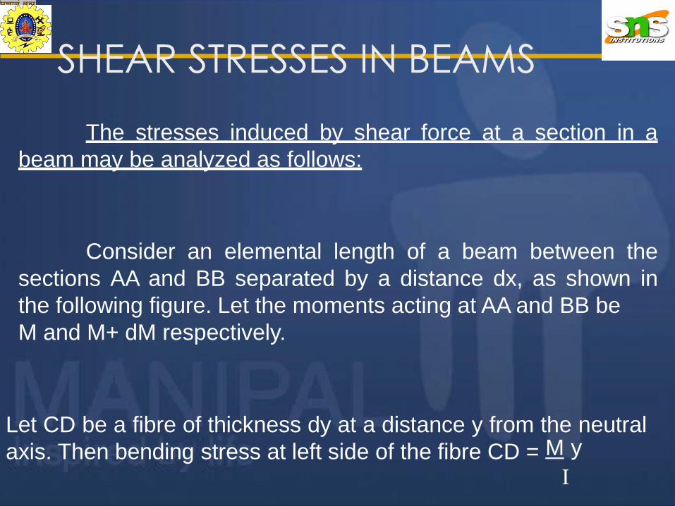
d4 / 64Moment of inertia of the section , I = π
64
1
2
1
2
1
1
3
(1sin )
cos 12
16
F
3 d 2
16 F
3 d 2
d cos d 4
F cos
Substituting in the expression for shear stress,
Fay
Ib
d 3
Where b = width of the fibre AA = d cos Φ1

y16 F [1 – ( d / 2 ) ]
2
=
3 πd2
Hence shear stress varies parabolically over the depth.
Its value is zero at the extreme fibres where y = d / 2 and its
value is maximum when y = 0 (at the N.A.) and is given by :
τmax = 163πFd2
4 F=
3 πd2 / 4= 4 F
3 A
F = Shear Force
A Area of cross section= Average shear stress
Thus in circular sections shear stress is maximum at the centre,
and is equal to 4 / 3 times the average shear stress.

3. Isosceles Triangular section :
Let AA be a fibre at a
distance y from the top.
b
b'
Shear stress in general , τ = F a y
I b
bh3
36b'
1 b' y 2h – 2y
2 3 3τ = F 1

At the centroid , y = 2h / 3 , substituting in equation 1,
τ=12 F 2h /3 (h – 2h / 3)
bh3
τ =12 F y (h - y)
bh3
8 F=
3 bh
i) at y = 0
ii) at y = h
ι = 0
ι = 0

or τ= 4 F
3 bh
2
=4 Shear Force
3 Area
= 4 τavg , at the N.A.
3
For shear stress ,τ, to be max., dτ
dy = 0,
12 F (h - 2y) = 0
bh3
or y = h / 2 , substituting in the expression for τ,
τmax = 12 F h (h - h)
bh3 2 2= 3F
bh= 1.5 F
bh / 2= 1.5 τavg
Thus, max. shear stress occurs at half the depth and its value is
1.5 times the average shear stress, in the case of an isosceles
triangle.

SOLVED PROBLEMS
1. A s. s. beam of span 8m carries a UDL of 20 kN/m over its
entire span. The c / s of the beam is a rectangle 120mm ×
180mm deep. Draw the shear stress distribution at 1m from
the left support, by considering horizontal fibres 30mm
apart from top to bottom in the cross section.
Solution:
c/s of beam
120mm
180mm8m
20 kN/m
RR Beam
R = 20 x 8
2= 80 kN

Shear stress at a horizontal fibre in a beam c/s is given by:
τ = F a y
I b
Here, F = Shear Force at 1m from left support
= + R – 20×1 = 80 – 20 = 60kN
I = M.I.of the entire section about N.A. = bd3/12
= 120 × 1803 / 12 = 58.3 × 106 mm4
b = breadth of the fibreNote:
a = area above or below the fibre under consideration
(shaded area)
y = distance from N.A. to the centroid of the shaded area

τtopmost
Shear stress values at fibres 30mm apart, starting from top
= τbottommost = 0 ,
AN
60mm
2 2
N A
3
90mm
3N A
30mm
1 1
120mm
180m
m
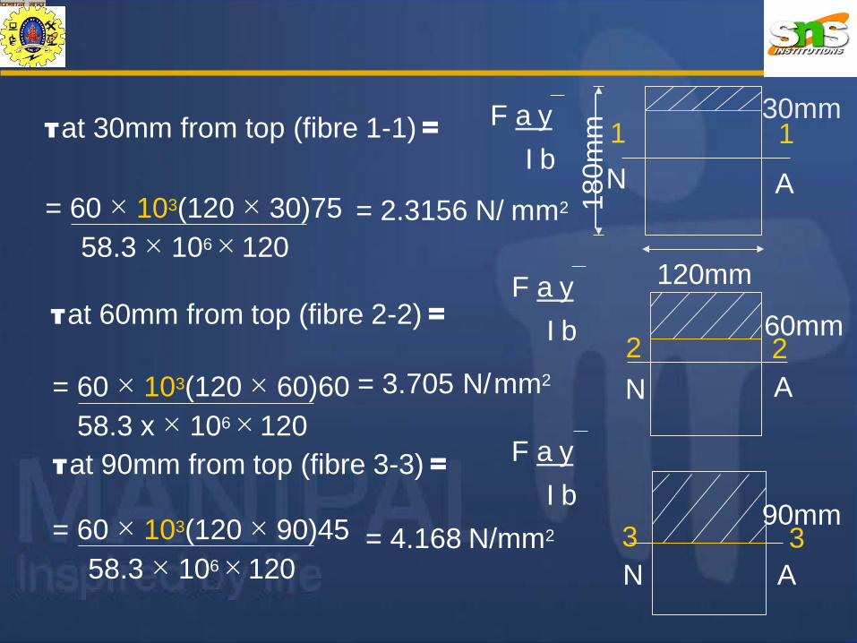
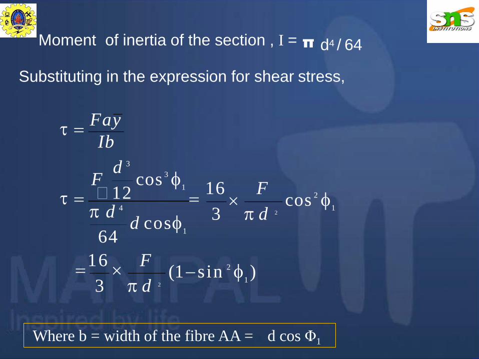
τ at 30mm from top (fibre 1-1)= F a y
I b
= 60 × 103(120 × 30)75 = 2.3156 N/ mm2
58.3 × 106 × 120
τ at 60mm from top (fibre 2-2) =F a y
I b
F a y
I b
= 60 × 103(120 × 60)60 = 3.705 N/mm2
58.3 x × 106 × 120
τ at 90mm from top (fibre 3-3) =
58.3 × 106 × 120
= 60 × 103(120 × 90)45 = 4.168 N/mm2
N A
130mm
1
120mm
180m
m
AN
260mm 2
90mm
N A
3 3

Due to symmetry of the section about the N.A., the corresponding
fibres below the N.A. have the same stresses. The shear stress
distribution diagram is as shown below.
N A
120mm
180m
m
30mm2.3156
2.3156
3.705
4.168
3.705
shear stress
distribution diagram
(Units : N/mm2)

2. The cross section of a beam is a T section of overall depth
140 mm, width of flange 200mm, thickness of flange 40mm
and thickness of web 20mm.Draw the shear stress distribution
diagram if it carries a shear force of 60 kN.
Solution:
140 mm
200mm
20mm c/s of beam
40mmTo locate the N.A.
y = (200x40x120) + (100x20x50)
200x40 + 100x20
= 106mm from bottom

I = I NA (1) + I NA (2)
200mm
20mm
To find M.I. of the section about the N.A.
140 mm
N
106mm
40mm A 34mmG1
G2
(1)
(2)
=[ (200 x 403) /12 + (200× 40)(34-20)2 ]
+ [20 × 1003 / 12 +(20 × 100)(106-50)2]
= 10.57 × 106 mm4
22
100 mm

Shear stress values at salient fibres :
To draw the shear stress variation diagram shear stress values
are obtained at a few significant (salient) fibres which are as
under :
(i) top most and bottom most fibres(where shear stress is
always = 0)
(ii) at the N.A.
(iii) two adjacent fibres, at the junction of flange and web, one
fibre just in flange and the other fibre just in web.
τ at the N.A.= F ay
I b
= (60 × 103)(200 × 34)(34/2)
(10.57 × 10⁶) (200)
= 3.28 N / mm2

τ at the junction of flange and web :
τ at fibre 1-1 = 60 × 103 (100 × 20)(106-50) = 3.18 N/mm2
(10.57 × 10⁶ )(200)
140 mm
200mm
20mm c/s of beam
22
N 40mm A
106mm
11
G
τ at fibre 1-1 = 60 × 103 (200 ×40)(34-20)
(10.57 × 10⁶ )(200)
= 3.18 N/mm2
area above the fibre under
consideration
area below the fibre under
considerationor
Consider two adjacent fibres
1-1 and 2-2 as shown in fig.

140 mm
200mm
c/s of beam
N A
shear stress
distribution diagram
(Units : N/mm2)
3.18 31.8
3.28
τ at fibre 2-2 = 60 × 103 (100 ×20)(106-50)(10.57 × 10⁶ )(20)
= 31.8 N/mm2

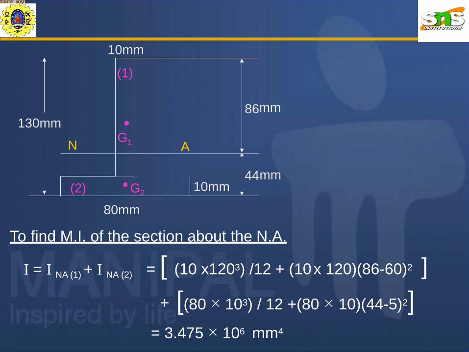
3. An inverted T section has an overall depth of 130mm,width and
thickness of flange 80mm and 10mm respectively and thickness
of web 10mm. Draw the shear stress distribution diagram across
its c/s if it carries a shear force of 90 kN.
Solution :
130mm
10mm
10mm
80mm
c/s of beam
To locate the N.A.
(120x10x70) + (80x10x5)y =
120x10 + 80x10
= 44 mm from bottom
10mm
130mm
N
(1)
G1
86
A
(2) G2
4410mm
mm
80mm
To find M.I. of the section about the N.A.
mm
I = I NA (1) + I NA (2) = [ (10 x1203) /12 + (10x 120)(86-60)2 ]
+ [(80 × 103) / 12 +(80 × 10)(44-5)2]= 3.475 × 106 mm4

Shear stress values at salient fibres :
I b
= (90 × 103)(86 × 10)(43)
(3.475 × 10⁶) (10)
= 95.78 N / mm2
τ at the junction of flange and web :
Consider two adjacent fibres
1-1 and 2-2
as shown in fig.
130mm
10mm
10mm
80mm
A
44mm
86mm
(2) G2
11 22
G
43mm N
(i) At top most and bottom most fibres shear stress is always = 0
(ii) τ at the N.A.= F ay

130mm
10mm
10mm
N A
44mm
86mm
(1)
G1
11 22
G
τ at fibre 1-1 = 90 × 103 (80 ×10)(44-5)
= 80.8 N/mm2
shear stress
distribution diagram
(Units : N/mm2)
80mm
130mm
80mm
221
N A
1 10.180.8
95.78
(3.475 × 10⁶ )(80)
= 10.1 N/mm2
τ at fibre 2-2 = 90 × 103 (80 ×10)(44-5)
(3.475 × 10⁶ )(10)

4. The c/s of a beam is an I–section as shown in fig. Draw the
shear stress variation diagram if it carries a shear force
of 200kN.
10mm
150mm
300mm
10m
Solution :
Due to symmetry about the centroidal x
axis , the N.A.lies at half the depth,i.e., at
150mm from the top.
m
10mm
150mm

To find M.I. of the section about the N.A.
10mm
300mm
150mm
AN
G1
G2
10mm
G3 10mm
150mm
(1)
(2)
(3)
I = I NA (1) + I NA (2) + I NA (3)
= 2 I NA (1) + I NA (2)
= 2[ 150 × 103/12 + 150 × 10(145)2]
+ [ 10 ×2803/12 ]
= 81.39 × 106 mm4
140 mm

Shear stress values at salient fibres :
81.39 × 10⁶ (10)
= 77.52 N/mm2
τ at the junction of flange and web :
Consider two adjacent fibres 1-1 and 2-2 as shown in fig.
Due to symmetry of the section about the N.A., the shear stress
variation diagram also is symmetric with corresponding fibres on
either sides of the N.A.carrying the same shear stress.
(i) At top most and bottom most fibres shear stress is always = 0
τ at the N.A.= F ay
I b
= 200 × 103 [(150 × 10)145 + (140 × 10)70 ]

10mm
300mm
150mm
AN
G
1 12 2
τ at fibre 1-1 = 200 × 103 (150 ×10)(145)
(81.39 × 10⁶ )(150)
= 3.56 N/mm2
10mm
10mm
150mm
τ at fibre 2-2 = 200 × 103 (150 ×10)(145)
(81.39 × 10⁶ )(10)
= 53.45 N/mm2

10mm
10mm
300mm
150mm
150mm
10mm
AN
G
1 12 2
77.52
3.56 53.45
53.453.56
shear stressdistribution diagram
(Units : N/mm2)

(5) A Symmetrical I section beam rests
freely on simple supports of
150
A260MM
20
20
span L . The beam carries a point load of W at the mid-span. The section
of the beam is 125mm × 300 mm deep with flange and web thickness of
20 mm. If maximum bending stress and maximum shear stress are
restricted to 150MPa and 45MPa respectively, calculate the values of L
and W. INA= 1.27×108 mm4
125MM
300MMN
20
150
W= ?
L = ?
L/2 L/2

To calculate maximum shear stress
Maximum Shear force F = W/2τ at the N.A.= F ay
I b
W [(125×20×140) + (20×130×65)]
(2 × 20 ×INA)max = --------(1)
But max = 45N/mm2 , INA
=1.27 ×108 mm4
Substituting in equation(1), W=441.47×10³ N = 441.47 kN
To calculate maximum bending stress
INA
M=
σь
y
Now,

b(max)=> σ =
Mmax × ymax
INA
(WL/4) × (150)= -----(2)=> σ
b(max)
σb will be maximum when y = ymax and M = Mmax
Mmax = WL/4 and ymax = 150mm
INA
But σbmax = 150N/mm2
W = 441.47 × 10³ N
INA= 1.27 × 108 mm4
Substituting in
equation (2)
L=1150 mm =
1.15 m

(6) A Cantilever beam of I section 150mm × 300 mm with a
uniform thickness of flange and web 30mm carries an UDL
throughout the span. Find the length of the beam if the max bending
stress is 4 times the maximum shear stress.
L = ?
w/ unit run
300A
150
120
240MM
30
30
150MM

To calculate maximum
bending stress
σb will be maximum when y = ymax and M = Mmax
The bending moment M will be maximum for the cantilever
beam at the fixed end.
M max = w × L × L /2= wL2/2
INA
M=
σь
y
Now,
M
INA
=σ
ь
y
Now,b(max)
σ = -----(1)
ymax =150mm
(wL2 × 150)
2INA

It is given that
To calculate maximum shear
stress (occurs at N.A.)τ at the N.A.= F ay
I b
Max shear Force F = wL
----(2) = =max NA
wL(150 × 30 × 135+120 × 30 × 60)
30INA
σb(max) = 4 max
150w L² wL(150 × 30 × 135 + 120 × 30 × 60)
2I 30INA
L=1464mm =1.464m
= 4 ×

EXERCISE PROBLEMS
1. Draw the shear stress variation diagram for a square section
placed with one of its diagonals horizontal. Show that the
maximum shear stress is equal to 9/8 times the average shear
stress.
2. A timber beam 150mm x 250mm deep in c/s is simply
supported at its ends and has a span of 3.5m.If the safe stress
in bending is 7.5MPa find the maximum safe UDL the beam
can carry. What is the maximum shear stress in the beam for
the UDL calculated? ( Ans: 7.66kN/m , 0.536N/mm2 )
3.The cross section of a beam is an isosceles triangle having
base width 400mm and height 600mm. It is placed with its base
horizontal and is subjected to a shear force of 90kN. Find the
intensity of shear stress at the neutral axis. (Ans: 1 MPa)
41

4. A beam of channel section 120mm x 60mm has a uniform
thickness of 15mm.Draw the shear stress diagram if it
carries a shear force of 50kN.Find the ratio of maximum
and mean shear stresses.
(Ans:Shear stress values at significant fibres from bottom:
0, 6.67, 26.67, 35.24, 26.67, 6.67, 0 MPa. Ratio = 2.22 )
5. The c/s of a beam is an unsymmetric I -section of overall
depth 350mm, topflange 250mmx50mm,bottomflange
150mmx50mm, and web thickness 50mm. Draw the shear
stress distribution diagram if it carries a shear force of
80 kN.
(Ans:Shear stress values at significant fibres from bottom:
0, 1.378, 4.134, 5.89, 5.06, 1.012, 0 MPa. )
42

6. A hollow rectangular box of outer dimensions 100mmx160mm
deep and wall thickness 10mm carries a shear force of
150kN.
Draw the shear stress variation diagram.
(Ans: 0, 8.23, 20.59, 31.18, 20.59, 8.23,0)
7. The c/s of a beam is an I- section of overall depth
240mm,width
of flanges 160mm,thickness of both flanges and web 20mm.
If it carries a shear force of 70kN,draw the shear stress
distribution diagram. Also find the percentage of shear carried
by the web alone.( Ans: Shear stress values at significant fibres from bottom:
0,1.69, 13.52,17.4,13.52,1.69,0. Percentage of shear carried
by the web alone = 92% )
43