Basic elements – principles of location - SNS Courseware
15
1 UNIT I LOCATING AND CLAMPING PRINCIPLES Advantages of Jigs and Fixtures– Basic elements – principles of location – Locating methods and devices – Redundant Location– Principles of clamping – Mechanical actuation – pneumatic and hydraulic actuation Standard parts – Drill bushes and Jig buttons – Tolerances and materials used-New ways of locating and clamping. PART B 1. With suitable examples, discuss the various methods of clamping. Different variety of clamps used with jigs and fixtures are classified into different categories are discussed here. Strap Clamp This is also called edge clamp. This type clamping is done with the help of a lever pressure acting as a strap on the workpiece. Different types of strap clamps are discussed below. Heel Clamp The simple form of a heel clamp is shown in Figure 4.9. Rotation of the clamp in clockwise direction is prevented and it is allowed in anticlockwise direction. For releasing the workpiece the clamping nut is unscrewed. The free movements in anticlockwise direction takes place before un-securing the nut to release the workpiece.
-
Upload
khangminh22 -
Category
Documents
-
view
1 -
download
0
Transcript of Basic elements – principles of location - SNS Courseware

1
UNIT I
LOCATING AND CLAMPING PRINCIPLES
Advantages of Jigs and Fixtures– Basic elements – principles of location – Locating
methods and devices – Redundant Location– Principles of clamping – Mechanical actuation
– pneumatic and hydraulic actuation Standard parts – Drill bushes and Jig buttons –
Tolerances and materials used-New ways of locating and clamping.
PART B
1. With suitable examples, discuss the various methods of clamping.
Different variety of clamps used with jigs and fixtures are classified into different categories are discussed here.
Strap Clamp
This is also called edge clamp. This type clamping is done with the help of a lever
pressure acting as a strap on the workpiece. Different types of strap clamps are discussed below.
Heel Clamp
The simple form of a heel clamp is shown in Figure 4.9. Rotation of the clamp in clockwise direction is prevented and it is allowed in anticlockwise direction. For releasing the workpiece the clamping nut is unscrewed. The free movements in anticlockwise direction takes place before un-securing the nut to release the workpiece.

2
Bridge Clamp
The bridge clamp is illustrated in Figure 4.10. It applies more clamping pressure as compared to heel clamp. The clamping pressure experienced by the workpiece depends on the distances ‗x‘and ‗y‘ marked in the Figure 4.10. To release the workpiece the nut named as clamping nut is unscrewed. The spring lifts the lever to release the workpiece.
Edge Clamp or Side Clamp
A side clamp is also known as edge clamp. In this case the surface to be machined is always clamped above the clamping device. This clamping device is recommended for fixed length workpiece. The clamping device is illustrated in Figure 4.11. Releasing and clamping of the workpiece can be accomplished by unscrewing and screwing of the clamping nut respectively.

3
Screw Clamp
The screw clamp is illustrated in Figure 4.12. It is also known as clamp screw. This clamping applies pressure directly on the side faces of the workpiece.
There is a floating pad at their end to serve the following purposes:
(a) It prevents displacement of workpiece and slip.
(b) It prevents denting of clamping area of workpiece.
(c) The available cushion prevents deflection of screw.
In addition to the above there are some disadvantages associated with this method. The clamping pressure largely depends on the workpiece, it varies from one workpiece to other. It is more time consuming and more efforts are required.
Latch Clamp
Latch clamps are used to clamp the workpiece, the clamping system is normally locked with the help of a latch provided. To unload the workpiece the tail end of the latch is pushed that causes the leaf to swung open, so releasing the workpiece. Here time consumed in loading and unloading is very less as no screw is tightened but clamping pressure is not so high as in other clamping devices. Life of this type of clamping device is small.
Equalizing Clamps
Equalizing clamp is illustrated in Figure 4.13. It is recommended to apply equal
pressure on the two faces of the work. The pressure applied can be varied by tightened or loosening the screw provided for the purpose.

4
Power Driven Clamping
Light duty clamps are used manually because small power is required to operate these clamps. Hand clamping leads to application of variable pressure, operators fatigue and more time consumed. The power driven clamping over comes the above mentioned problems of hand clamping. Power clamps are operated on the base of hydraulic or pneumatic power. Power clamps are high pressure clamping, these are quick acting, easily controllable, reliable and less time consuming.
2.Discuss the following with suitable sketches:
(i) Pneumatic clamps (ii) Plate clamps (iii) Quick action clamps (i) Pneumatic clamps

5
(ii) Plate clamps
(iii) Quick action clamps
Use of quick acting nut – a typical of such nut and its application is visualized schematically in below figure.

6
Cam clamping Quick clamping by cam is very effective and very simple in operation.
Some popular methods and systems of clamping by cam are shown in below Fig.. The cam and screw type clamping system is used for clamping through some interior parts where other simple system will not have access
7
3. Describe the functions and advantages of jigs and fixtures.
Functions of Jigs and Fixtures: Functions
of Jigs:
1. To locate the hole in the appropriate positions. 2. To clamp the work piece during drilling, reaming or tapping. 3. To guide the drills, reamers or tap into the proper position on the work piece.
Functions of Fixtures:
1. To locate and position the work piece relative to the cutting tool. 2. To clamp the work piece during machining, welding, inspection or assembly.
Advantages of Jigs and Fixtures:
PRODUCTIVITY:
Jigs and fixtures increase the productivity by eliminating the individual marking, positioning and frequent checking. The operation time is also reduced due to increase in speed, feed and depth of cut because of high clamping rigidity. INTERCHANGEABILITY AND QUALITY:
Jigs and fixtures facilitate the production of articles in large quantities with high degree of accuracy, uniform quality and interchangeability at a competitive cost. SKILL REDUCTION:
There is no need for skillful setting of work on tool. Jigs and fixtures makes possible to employ unskilled or semi skilled machine operator to make savings in labour cost. COST REDUCTION:
Higher production, reduction in scrap, easy assembly and savings in labour cost results in ultimate reduction in unit cost.
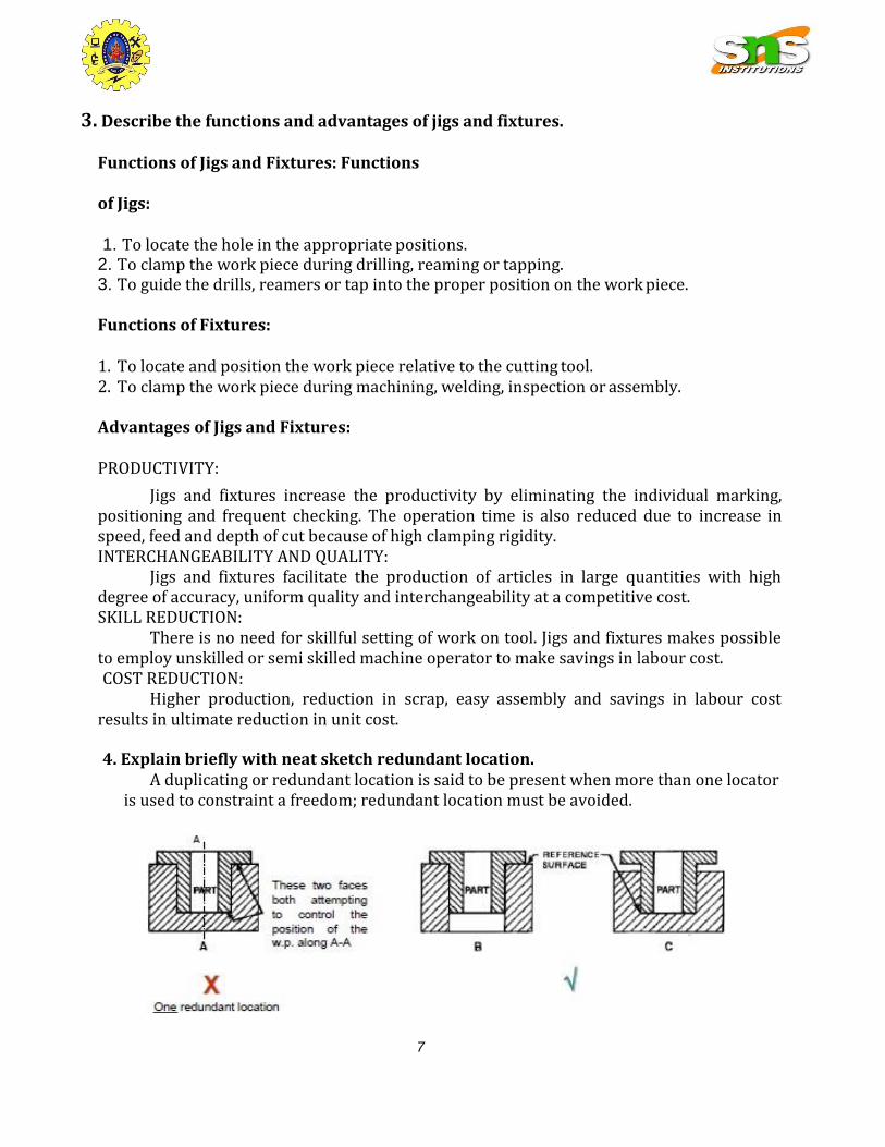
4. Explain briefly with neat sketch redundant location.
A duplicating or redundant location is said to be present when more than one locator is used to constraint a freedom; redundant location must be avoided.
8
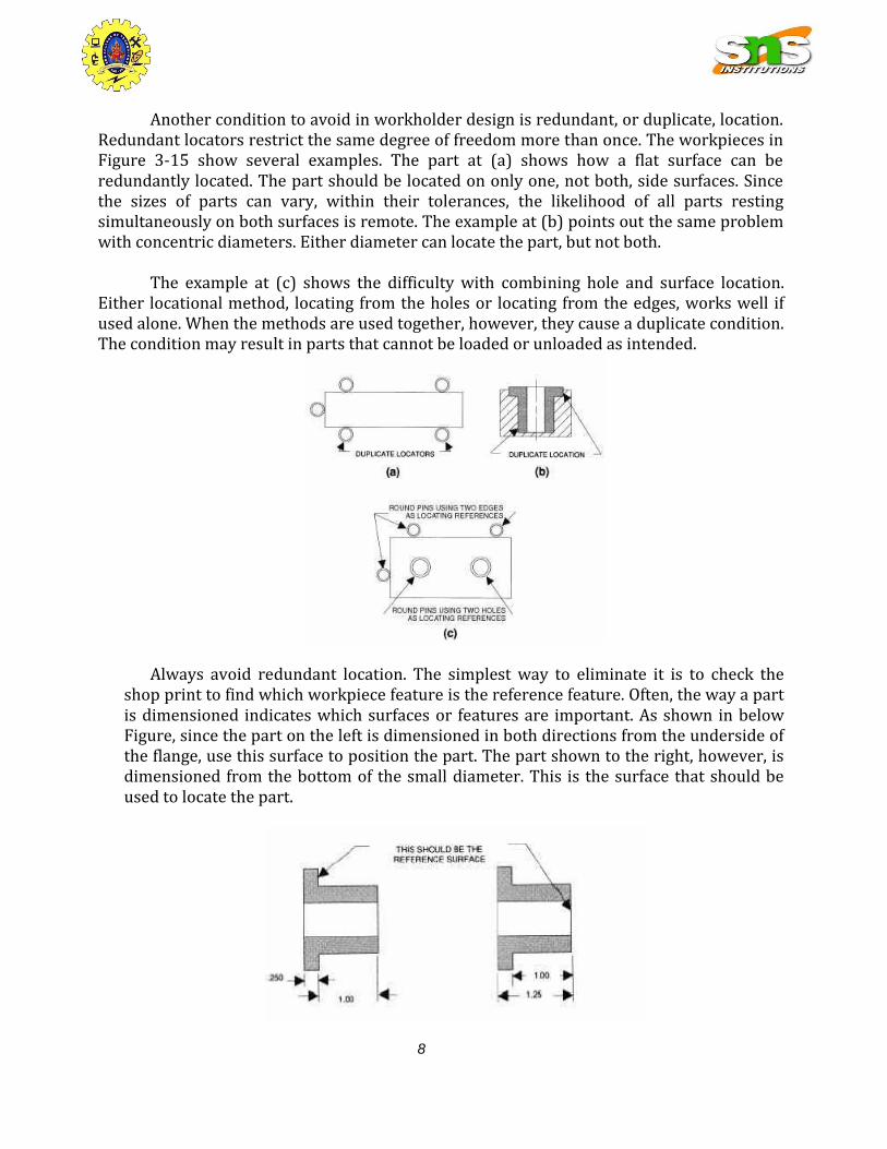
Another condition to avoid in workholder design is redundant, or duplicate, location. Redundant locators restrict the same degree of freedom more than once. The workpieces in Figure 3-15 show several examples. The part at (a) shows how a flat surface can be redundantly located. The part should be located on only one, not both, side surfaces. Since the sizes of parts can vary, within their tolerances, the likelihood of all parts resting simultaneously on both surfaces is remote. The example at (b) points out the same problem with concentric diameters. Either diameter can locate the part, but not both.
The example at (c) shows the difficulty with combining hole and surface location.
Either locational method, locating from the holes or locating from the edges, works well if used alone. When the methods are used together, however, they cause a duplicate condition. The condition may result in parts that cannot be loaded or unloaded as intended.
Always avoid redundant location. The simplest way to eliminate it is to check the shop print to find which workpiece feature is the reference feature. Often, the way a part is dimensioned indicates which surfaces or features are important. As shown in below Figure, since the part on the left is dimensioned in both directions from the underside of the flange, use this surface to position the part. The part shown to the right, however, is dimensioned from the bottom of the small diameter. This is the surface that should be used to locate the part.

9
The best locating surfaces are often determined by the way that the part is dimensioned
5. Explain the working of hydraulic clamps .
6. Draw and explain briefly the different types of drill bushes .
Jig Bushing:
Sometimes the stiffness of the cutting tool may be in sufficient to perform certain machining
operations. Then to locate the tool relative to the work, use is made of guiding parts such as
jigs bushing and templates. These must be precise, were resistance and changeable.
Jig bushes are used in drilling and boring, a bush fits into the hole of the jig, through which
the drill passes. The diameter of the bush depends on the diameter of the drill. Different type
of bushes is spot welded or screwed with the jig. Headless type bushes are press fit into the
hole of the job. Bushes are general made of a good grade of tool steel to insure hardening at
a fairly no temperature and to lesson the danger of fire cracking. Sometime the bushes for
guiding tools may be of cast iron. Hardened steel bushes are always preferable for guiding
drills, reamers and taps etc.
American standard bushes are classified in three categories.
1: press- fit wearing bushes
2: renewable wearing bushes
3: linear wearing bushes
Types of bushes (tool guide/jig bushes):
1: Press fit wearing bushes:

10
These bushes are used when little importance in put on accuracy or finish and tool used is a
twist drill. These bushing are installed directly in the jig body and are used mainly for short
protection. There are two design of press fit bushing:
A> Plain or headless bush
B> Headed or flanged bush
2: Renewable bushes:
When the guide bushes requires periodic replacement (due to wear of the inside diameter
of the bush). Its replacement is simply by using a renewable bush. These are of the flanged
types and sliding fit into the linear bush, which is installed press fitted into the jig plate. The
linear bush provides hardened wear resistance, mating surface to the renewable bush. The
renewable bushes must be prevented from rotating or lifting with the drill. One common
method is to use a retaining screw.

11
3: Linear bushes:
These bushes are also known as master bushing, are permanently fixed to the jig body.
These acts as guides for renewable type bushing. These bushes are be with or without
head.
7. With suitable sketches explain any four important principles of location.
LOCATING PRINCIPLES
To position the work piece w.r.t. to tool, to ensure precision in machining
Locating: dimensional and positional relationship b/w work piece and tool
Locator: device to establish and maintain position of a part in a jig or fixture
BASIC PRINCIPLES
a. Positioning the locator
b. Accuracy & tolerances
c. Fool proofing
d. Duplicate location
e. Motion economy

12
1- Positioning the locators
Locators should contact the work (preferably machines surface) on a solid and stable
point:
This permits accurate placement of the part in the tool & ensures the repeatability of
the jig and fixture
They should be placed as far as possible:
• This permits the use of fewer locators
• Ensures complete contact over the locating surface
2- Accuracy and Tolerance
The work piece itself determines the overall size of a locating element.
locators must be made to suit the MMC (Maximum-Material Condition) of the area to
be located. (The MMC of a feature is the size of the feature where is has the maximum
amount ofmaterial).
With external features, like shafts, the MMC is the largest size within the limits.
With internal features, like holes, it is the smallest size within the limits.
The main considerations are the size of the area to be located and the required
clearance between the locator and the workpiece.
Make the locating pin slightly smaller than the hole.

13
Here the hole is specified as 0.5 -0.51 inch in diameter. Following the rule of
MMC, the locator must fit the hole at its MMC of 0.5 inch. Allowing for a 0.0005
clearance between the pin and the hole, desired pin diameter is calculated at 0.4995
inch.
Tool tolerance should be between 20 and 50 percent of the part tolerance.
3- Fool proofing
Ensures that the part fits into the tool in its correct position only.
The simplest and most cost effective method is positioning a fool proof pin.
4- Duplicate Location
A redundant location is said to be present when more than one locator is used to
constraint a freedom; redundant location must be avoided.
5. Motion Economy
It involves use of easy, quick and economic loading of work pieces

14
8. Explain the various principles of clamping. a. clamping need to be strong and rigid enough to hold the blank firmly during
machining b. clamping should be easy, quick and consistently adequate c. clamping should be such that it is not affected by vibration, chatter or heavy
pressure d. the way of clamping and unclamping should not hinder loading and unloading the
blank in the jig or fixture e. the clamp and clamping force must not damage or deform the workpiece f. clamping operation should be very simple and quick acting when the jig or fixture is
to be used more frequently and for large volume of work g. clamps, which move by slide or slip or tend to do so during applying clamping
forces, should be avoided h. clamping system should comprise of less number of parts for ease of design,
operation and maintenance i. the wearing parts should be hard or hardened and also be easily replaceable j. clamping force should act on heavy part(s) and against supporting and locating
surfaces k. clamping force should be away from the machining thrust forces l. clamping method should be fool proof and safe m. clamping must be reliable but also inexpensive
9. Explain about the different materials used for the design of jigs and fixtures
Jigs and Fixtures are made of variety of materials, some of which can be hardened to resist wear. Materials generally used:
1. High speed Steel: Cutting tools like drills, reamers and milling cutters. 2. Die steels: Used for press tools, contain 1% carbon, 0.5 to 1% tungsten and less
quantities of silicon and manganese. 3. Carbon steels: Used for standard cutting tools. 4. Collet steels: Spring steels containing 1% carbon, 0.5% manganese and less of
silicon. 5. Non shrinking tool steels:
High carbon or high chromium Very little distortion during heat treatment. Used widely for fine, intricate press tools.
6. Nickel chrome steels: Used for gears. 7. High tensile steels: Used for fasteners like high tensile screws 8. Mild steel: Used in most part of Jigs and Fixtures
Cheapest material Contains less than 0.3% carbon
9. Cast Iron: Used for odd shapes to some machining and laborious fabrication CI usage requires a pattern for casting

15
Contains more than 2% carbon Has self lubricating properties Can withstand vibrations and suitable for base
10. Nylon and Fiber: Used for soft lining for clamps to damage to workpiece due to clamping pressure
11. Phospher bronze: used for nuts as have high tensile strength Used for nuts of the lead screw