Analysis On Bending Stress Of Helical Gear - NVEO
10
Nat. Volatiles & Essent. Oils, 2021; 8(5): 3384 - 3393 3384 Analysis On Bending Stress Of Helical Gear 1 D Jeeva, 2 V Vijayakumar, 3 J Kabir Basha, 4 R Dinesh, 5 R Mohanraj Department of Production Engineering, PSG College of Technology, Coimbatore-641004, India. * Corresponding email address: [email protected] Abstract Helical gears are used to transmit energy between parallel axes. They are made to transmit pressure evenly throughout the entire tooth. Helical gears operate smoother and quieter than other gears due to their tooth inclination and can transmit heavy loads efficiently. Helical gears are commonly employed in industry when power transmissions under heavy loads are required. This study used Finite Element Analysis (FEA) to determine how loads are distributed in helical gear. The helical gear, which is made of aluminum alloy and structural steel, was simulated for the process parameters derived from design considerations, and the bending stress distribution was calculated using ANSYS software. Solidworks, strong and current solid modeling software, is used to create three dimensional solid models for varying face widths, and ANSYS for a finite element analysis. In analytical research, the Lewis stress formula is employed. After that, the AGMA and FEA findings are compared. Keywords: Helical gear, Finite element analysis, Bending stress, AGMA. I. Introduction Helical gears are cylindrical gears having teeth that are angled away from the gear wheel's axis of rotation. A set of helical gears has similar helix angle, however the helix hand would be in the opposite. A helical gear has teeth that are arranged at an angle. This allows the tooth to progressively mesh as the interaction progresses, starting with point contact and proceeding to line contact. The load on the mating teeth gradually increases. Helical gear has such a greater contact ratio, much gentler, have little disturbance and therefore can deliver a lot of power compared to spur gears. In helical gear, many teeth are very much in contact, leading in less strain on every tooth. Axial force causes helical gears to become misaligned. Thrust bearings and increased lubrication can help to alleviate this problem. Reverberations and wearing are reduced as forces are transferred more smoothly through one tooth towards the next tooth. In helical gear, bending stress for aluminium alloy and structural steel material are studied by modifying face width in this study.. II.Literature review Naresh et al. [1] conducted an analysis by applying different loads to helical gear with different materials. The helical gear was developed in Solidworks software, and the analysis was carried out in ANSYS by applying various loads to various materials. Variable loads on various materials are used to investigate stress, strain, and displacement measurements. As a result of the findings, aluminum silicon carbide and grey cast iron are favored over chrome stainless steel, which showed breaking at a given load. Jadav et al. [2] performed an investigation on helical gear constructed of nylon 66 and stainless steel to estimate stress and pressure distribution. The two helical gears were developed with Pro/Engineer software, and the analysis was done with Altair Hyperwork Opti-Struct solver FEA software. According to the findings, in the first two load situations, the stress values on gear made up of nylon 66 are greater than the material's tensile strength. However, because Nylon 66 has low
-
Upload
khangminh22 -
Category
Documents
-
view
1 -
download
0
Transcript of Analysis On Bending Stress Of Helical Gear - NVEO
Nat. Volatiles & Essent. Oils, 2021; 8(5): 3384 - 3393
3384
Analysis On Bending Stress Of Helical Gear
1D Jeeva, 2V Vijayakumar, 3J Kabir Basha, 4R Dinesh, 5R Mohanraj
Department of Production Engineering, PSG College of Technology, Coimbatore-641004, India. *Corresponding email address: [email protected]
Abstract
Helical gears are used to transmit energy between parallel axes. They are made to transmit pressure evenly throughout
the entire tooth. Helical gears operate smoother and quieter than other gears due to their tooth inclination and can
transmit heavy loads efficiently. Helical gears are commonly employed in industry when power transmissions under heavy
loads are required. This study used Finite Element Analysis (FEA) to determine how loads are distributed in helical gear.
The helical gear, which is made of aluminum alloy and structural steel, was simulated for the process parameters derived
from design considerations, and the bending stress distribution was calculated using ANSYS software. Solidworks, strong
and current solid modeling software, is used to create three dimensional solid models for varying face widths, and ANSYS
for a finite element analysis. In analytical research, the Lewis stress formula is employed. After that, the AGMA and FEA
findings are compared.
Keywords: Helical gear, Finite element analysis, Bending stress, AGMA.
I. Introduction
Helical gears are cylindrical gears having teeth that are angled away from the gear wheel's axis of
rotation. A set of helical gears has similar helix angle, however the helix hand would be in the
opposite. A helical gear has teeth that are arranged at an angle. This allows the tooth to progressively
mesh as the interaction progresses, starting with point contact and proceeding to line contact. The
load on the mating teeth gradually increases. Helical gear has such a greater contact ratio, much
gentler, have little disturbance and therefore can deliver a lot of power compared to spur gears. In
helical gear, many teeth are very much in contact, leading in less strain on every tooth. Axial force
causes helical gears to become misaligned. Thrust bearings and increased lubrication can help to
alleviate this problem. Reverberations and wearing are reduced as forces are transferred more
smoothly through one tooth towards the next tooth. In helical gear, bending stress for aluminium
alloy and structural steel material are studied by modifying face width in this study..
II.Literature review
Naresh et al. [1] conducted an analysis by applying different loads to helical gear with different
materials. The helical gear was developed in Solidworks software, and the analysis was carried out in
ANSYS by applying various loads to various materials. Variable loads on various materials are used to
investigate stress, strain, and displacement measurements. As a result of the findings, aluminum
silicon carbide and grey cast iron are favored over chrome stainless steel, which showed breaking at
a given load. Jadav et al. [2] performed an investigation on helical gear constructed of nylon 66 and
stainless steel to estimate stress and pressure distribution. The two helical gears were developed
with Pro/Engineer software, and the analysis was done with Altair Hyperwork Opti-Struct solver FEA
software. According to the findings, in the first two load situations, the stress values on gear made
up of nylon 66 are greater than the material's tensile strength. However, because Nylon 66 has low
Nat. Volatiles & Essent. Oils, 2021; 8(5): 3384 - 3393
3385
stress value against the yield limit in the third case, it can be used as a substitute for stainless steel
in helical gear in high load scenario.
Gidado and Muhammad et al. [3] used ANSYS to analyse bending stress on helical gear. The main
purpose of is to see how changing a helical gear's face width affects its bending stress. The helical
gear was first modelled in Pro Engineer software, followed by analysis of stress in ANSYS. To
determine how stress fluctuates with face width, bending stress is computed on a theory based and
compared to the FEA result. Other characteristics like number of teeth, module, helix angle are kept
constant to produce five alternative helical models. Vijayarangan and Ganesan [4] employed 3D
finite element approaches to investigate displacements and stresses at different locations on helical
gear teeth. The stress for gear made of C-45 steel material was used to verify the validity of their
FEM results, and the results were compared to those obtained using a standard gear design
equation. Also compared the performance of composite helical gears to the performance of six
conventional carbon steel gears. According to the findings, composite materials can be utilised
securely for power transmission, however face width must be correct. Abishek Kulkarni et al. [5]
conducted a review on helical gear design and stress analysis. The root surface strength of the
helical gear tooth and the surface toughness of a helical gear are studied in this study because they
are a primary cause of gear pair failure. The high bending stress reduces as face width grows, and it
is larger on gear with a smaller face width and a higher helix angle, according to a review of
numerous research studies. Various influencing parameters such as gear ratio, helix angle and
contact ratio are optimised to increase the performance and efficiency of the helical gear.
III. Methodology
a. Modeling the helical gear as per requirements using Solidworks.
b. Importing the developed design on ANSYS for numerical analysis.
c. Analysis on the developed design, meshing was done on the created model.
d. Using ANSYS, most appropriate and proper material selection for the generated gear design was
performed.
e. Analysis of bending stress on the helical gear model.
f. Comparison of bending stress of helical gear made up of aluminum alloy and structural steel with
the theoretical formula.
IV. Design of gears
A) Design principles in broad sense
The projected transferred power, the speed of the driving gear, the speed of the driven gear, and
the centre distance all factor are considered for gear design for power transmission. The bending
stress equation of helical gear tooth is provided as, and the helical appropriate bending strength
criterion was designed in this study [3],
σb =Ft
bmjKvKo(0.93Km) (1)
Helical gears have a significantly lower sensitivity to mounting circumstances; hence a constant of
0.93 was added to the mounting element. The AGMA recommended equation.1 is used in all

Nat. Volatiles & Essent. Oils, 2021; 8(5): 3384 - 3393
3386
calculations. The diameter of a pinion gear's pitch circle was determined using the equation.2
below,
D ≥ 2T
bmj [σb]KvK0(0.93Km) (2)
Where,
Force transmitted (Ft) = 1326.26N
Normal module (m) = 10 mm
Face width (b) = 100 mm
Velocity Factor (Kv) = 1.34
Geometry factor (J) = 0.56
Overload factor (𝐾0) = 1.25
Load distribution factor (Km) = 1.3
B) Tangential force
The succeeding requirements were anticipated when manufacturing the gear as per the bending
strength criterion [3],
Power (P) = 25 kW
Speed (N) = 1200 R.P.M
Torque (TP) = 60×P
2πN=198.94Nm
Tangential force (Ft) =2000×Tp
300= 1326.26N
C) Bending Stress
For five distinct face widths (b = 100 mm, 95 mm, 90 mm, 85 mm, 80 mm) are considered, the
following is how the AGMA bending stress calculation is done [3],
σbAGMA1=
1326.26
100 × 10 × 0.56× 1.34 × 1.25(0.93 × 1.3) = 4.7960 MPa
σbAGMA2=
1326.26
95 × 10 × 0.56× 1.34 × 1.25(0.93 × 1.3) = 5.0497 MPa
σbAGMA3=
1326.26
90 × 10 × 0.56× 1.34 × 1.25(0.93 × 1.3) = 5.3289 MPa
σbAGMA4=
1326.26
85 × 10 × 0.56× 1.34 × 1.25(0.93 × 1.3) = 5.6423 MPa
σbAGMA5=
1326.26
80 × 10 × 0.56× 1.34 × 1.25(0.9 × 1.3) = 5.9950 MPa
V. Modeling of helical gear
Solidworks is a 3D solid modelling computer aided design tool. It includes comprehensive three-
dimensional software tools for creating, simulating, publishing, and handling information. Helical
gear was developed in Solidworks in this study. Five helical gear models were designed by altering
the face width of the helical gear. Fig.1 shows the helical gear design and Fig.2 shows the helical
gear pair in working condition. Table. I shows the gear design parameters.

Nat. Volatiles & Essent. Oils, 2021; 8(5): 3384 - 3393
3387
Table. I Gear parameters [3]
S.No. Title Value Units
1. No of Teeth (Z) 30 -
2. Module (M) 10 mm
3. Pitch diameter(D) 300 mm
4. Pressure angle(α) 20 degree
5. Helix angle (β) 15 degree
6. Face width (F) 100 mm
7. Addendum (A) 10 mm
8. Dedendum (B) 1.25×A mm
9. Power (P) 25 kW
10. Speed (N) 1200 Rev/min
Fig.1 Design of helical gear
Fig.2 Helical gear pair in working condition
VI.Finite Element Analysis
The ANSYS platform is one of the basis software for the complete variety of advanced engineering
simulation. By providing CAD connections, powerful strong mesh [4-5], an operation update
mechanism, widespread parameter management, and incorporated optimization techniques, it
enables detailed numerical study. Analysis was completed using ANSYS software. This paper used
Nat. Volatiles & Essent. Oils, 2021; 8(5): 3384 - 3393
3388
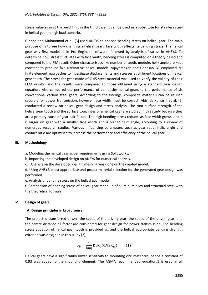
ANSYS modal and static structural analysis. Finite element analysis (FEA) is the method of simulating
a part's or assembly's response within limited circumstances. Theoretical and experimental studies
are modelled using FEA, which reduces the need for real life prototyping while also enabling part
improvement as part of the construction design [6-10], which is then loaded into ANSYS software.
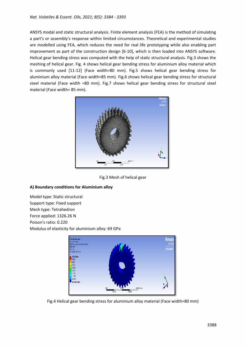
Helical gear bending stress was computed with the help of static structural analysis. Fig.3 shows the
meshing of helical gear. Fig. 4 shows helical gear bending stress for aluminium alloy material which
is commonly used [11-12] (Face width=80 mm). Fig.5 shows helical gear bending stress for
aluminium alloy material (Face width=85 mm). Fig.6 shows helical gear bending stress for structural
steel material (Face width =80 mm). Fig.7 shows helical gear bending stress for structural steel
material (Face width= 85 mm).
Fig.3 Mesh of helical gear
A) Boundary conditions for Aluminium alloy
Model type: Static structural
Support type: Fixed support
Mesh type: Tetrahedron
Force applied: 1326.26 N
Poison’s ratio: 0.220
Modulus of elasticity for aluminium alloy: 69 GPa
Fig.4 Helical gear bending stress for aluminium alloy material (Face width=80 mm)
Nat. Volatiles & Essent. Oils, 2021; 8(5): 3384 - 3393
3389
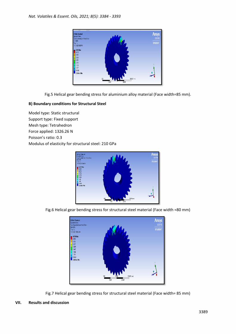
Fig.5 Helical gear bending stress for aluminium alloy material (Face width=85 mm).
B) Boundary conditions for Structural Steel
Model type: Static structural
Support type: Fixed support
Mesh type: Tetrahedron
Force applied: 1326.26 N
Poisson’s ratio: 0.3
Modulus of elasticity for structural steel: 210 GPa
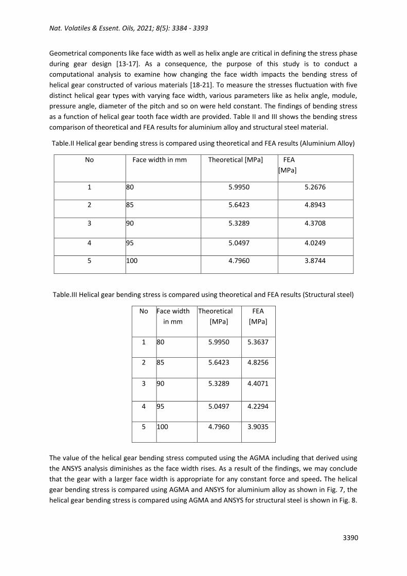
Fig.6 Helical gear bending stress for structural steel material (Face width =80 mm)
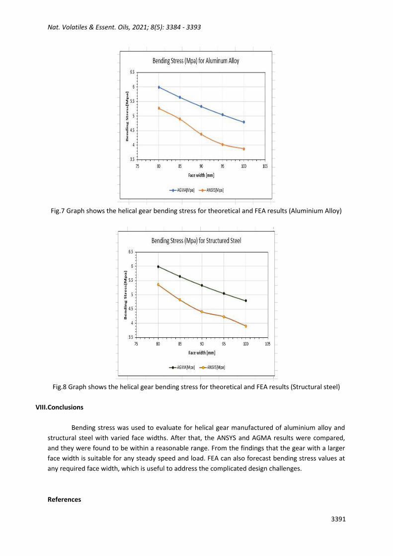
Fig.7 Helical gear bending stress for structural steel material (Face width= 85 mm)
VII. Results and discussion
Nat. Volatiles & Essent. Oils, 2021; 8(5): 3384 - 3393
3390
Geometrical components like face width as well as helix angle are critical in defining the stress phase
during gear design [13-17]. As a consequence, the purpose of this study is to conduct a
computational analysis to examine how changing the face width impacts the bending stress of
helical gear constructed of various materials [18-21]. To measure the stresses fluctuation with five
distinct helical gear types with varying face width, various parameters like as helix angle, module,
pressure angle, diameter of the pitch and so on were held constant. The findings of bending stress
as a function of helical gear tooth face width are provided. Table II and III shows the bending stress
comparison of theoretical and FEA results for aluminium alloy and structural steel material.
Table.II Helical gear bending stress is compared using theoretical and FEA results (Aluminium Alloy)
No Face width in mm Theoretical [MPa] FEA
[MPa]
1 80 5.9950 5.2676
2 85 5.6423 4.8943
3 90 5.3289 4.3708
4 95 5.0497 4.0249
5 100 4.7960 3.8744
Table.III Helical gear bending stress is compared using theoretical and FEA results (Structural steel)
No Face width
in mm
Theoretical
[MPa]
FEA
[MPa]
1 80 5.9950 5.3637
2 85 5.6423 4.8256
3 90 5.3289 4.4071
4 95 5.0497 4.2294
5 100 4.7960 3.9035
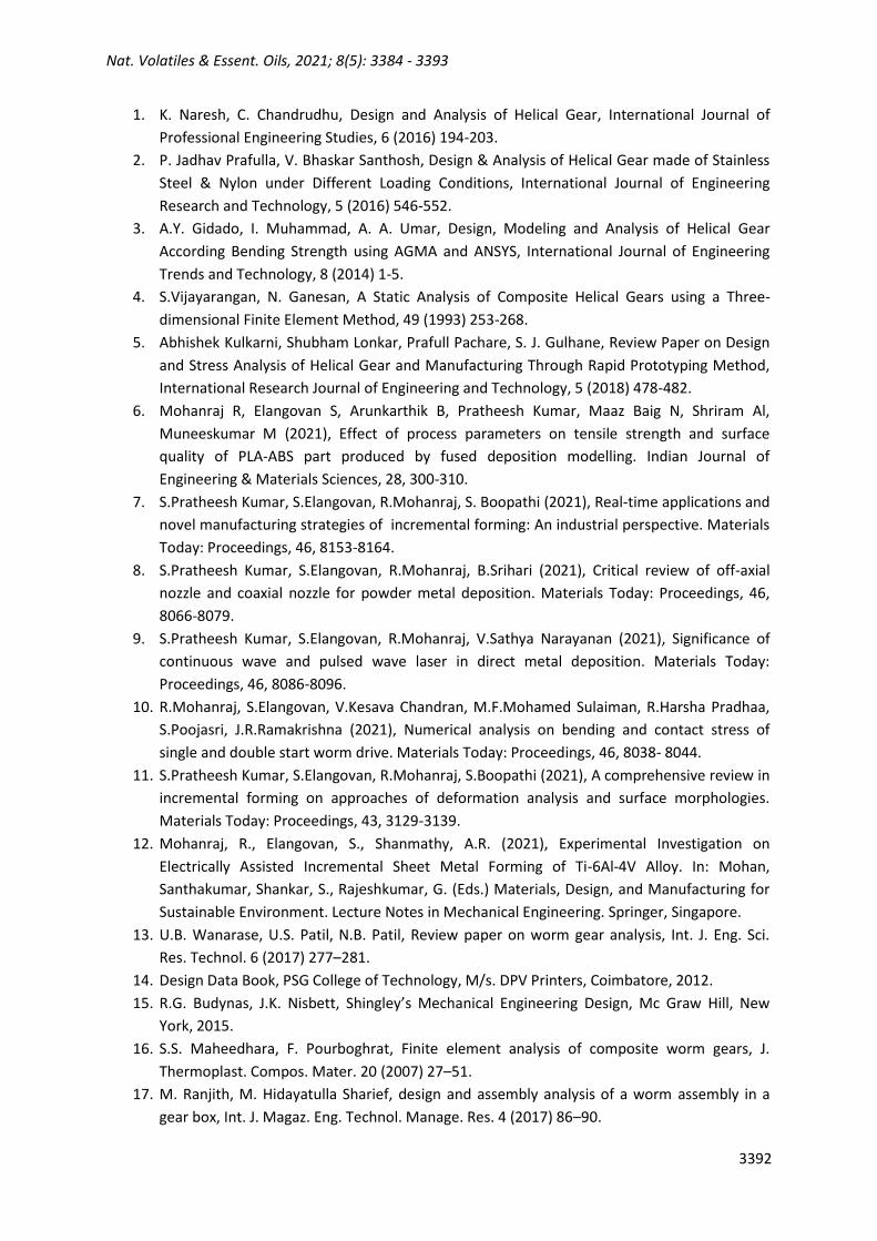
The value of the helical gear bending stress computed using the AGMA including that derived using
the ANSYS analysis diminishes as the face width rises. As a result of the findings, we may conclude
that the gear with a larger face width is appropriate for any constant force and speed. The helical
gear bending stress is compared using AGMA and ANSYS for aluminium alloy as shown in Fig. 7, the
helical gear bending stress is compared using AGMA and ANSYS for structural steel is shown in Fig. 8.
Nat. Volatiles & Essent. Oils, 2021; 8(5): 3384 - 3393
3391
Fig.7 Graph shows the helical gear bending stress for theoretical and FEA results (Aluminium Alloy)
Fig.8 Graph shows the helical gear bending stress for theoretical and FEA results (Structural steel)
VIII.Conclusions
Bending stress was used to evaluate for helical gear manufactured of aluminium alloy and
structural steel with varied face widths. After that, the ANSYS and AGMA results were compared,
and they were found to be within a reasonable range. From the findings that the gear with a larger
face width is suitable for any steady speed and load. FEA can also forecast bending stress values at
any required face width, which is useful to address the complicated design challenges.
References
Nat. Volatiles & Essent. Oils, 2021; 8(5): 3384 - 3393
3392
1. K. Naresh, C. Chandrudhu, Design and Analysis of Helical Gear, International Journal of
Professional Engineering Studies, 6 (2016) 194-203.
2. P. Jadhav Prafulla, V. Bhaskar Santhosh, Design & Analysis of Helical Gear made of Stainless
Steel & Nylon under Different Loading Conditions, International Journal of Engineering
Research and Technology, 5 (2016) 546-552.
3. A.Y. Gidado, I. Muhammad, A. A. Umar, Design, Modeling and Analysis of Helical Gear
According Bending Strength using AGMA and ANSYS, International Journal of Engineering
Trends and Technology, 8 (2014) 1-5.
4. S.Vijayarangan, N. Ganesan, A Static Analysis of Composite Helical Gears using a Three-
dimensional Finite Element Method, 49 (1993) 253-268.
5. Abhishek Kulkarni, Shubham Lonkar, Prafull Pachare, S. J. Gulhane, Review Paper on Design
and Stress Analysis of Helical Gear and Manufacturing Through Rapid Prototyping Method,
International Research Journal of Engineering and Technology, 5 (2018) 478-482.
6. Mohanraj R, Elangovan S, Arunkarthik B, Pratheesh Kumar, Maaz Baig N, Shriram Al,
Muneeskumar M (2021), Effect of process parameters on tensile strength and surface
quality of PLA-ABS part produced by fused deposition modelling. Indian Journal of
Engineering & Materials Sciences, 28, 300-310.
7. S.Pratheesh Kumar, S.Elangovan, R.Mohanraj, S. Boopathi (2021), Real-time applications and
novel manufacturing strategies of incremental forming: An industrial perspective. Materials
Today: Proceedings, 46, 8153-8164.
8. S.Pratheesh Kumar, S.Elangovan, R.Mohanraj, B.Srihari (2021), Critical review of off-axial
nozzle and coaxial nozzle for powder metal deposition. Materials Today: Proceedings, 46,
8066-8079.
9. S.Pratheesh Kumar, S.Elangovan, R.Mohanraj, V.Sathya Narayanan (2021), Significance of
continuous wave and pulsed wave laser in direct metal deposition. Materials Today:
Proceedings, 46, 8086-8096.
10. R.Mohanraj, S.Elangovan, V.Kesava Chandran, M.F.Mohamed Sulaiman, R.Harsha Pradhaa,
S.Poojasri, J.R.Ramakrishna (2021), Numerical analysis on bending and contact stress of
single and double start worm drive. Materials Today: Proceedings, 46, 8038- 8044.
11. S.Pratheesh Kumar, S.Elangovan, R.Mohanraj, S.Boopathi (2021), A comprehensive review in
incremental forming on approaches of deformation analysis and surface morphologies.
Materials Today: Proceedings, 43, 3129-3139.
12. Mohanraj, R., Elangovan, S., Shanmathy, A.R. (2021), Experimental Investigation on
Electrically Assisted Incremental Sheet Metal Forming of Ti-6Al-4V Alloy. In: Mohan,
Santhakumar, Shankar, S., Rajeshkumar, G. (Eds.) Materials, Design, and Manufacturing for
Sustainable Environment. Lecture Notes in Mechanical Engineering. Springer, Singapore.
13. U.B. Wanarase, U.S. Patil, N.B. Patil, Review paper on worm gear analysis, Int. J. Eng. Sci.
Res. Technol. 6 (2017) 277–281.
14. Design Data Book, PSG College of Technology, M/s. DPV Printers, Coimbatore, 2012.
15. R.G. Budynas, J.K. Nisbett, Shingley’s Mechanical Engineering Design, Mc Graw Hill, New
York, 2015.
16. S.S. Maheedhara, F. Pourboghrat, Finite element analysis of composite worm gears, J.
Thermoplast. Compos. Mater. 20 (2007) 27–51.
17. M. Ranjith, M. Hidayatulla Sharief, design and assembly analysis of a worm assembly in a
gear box, Int. J. Magaz. Eng. Technol. Manage. Res. 4 (2017) 86–90.
Nat. Volatiles & Essent. Oils, 2021; 8(5): 3384 - 3393
3393
18. F. Yang, D. Su, and C. R. Gentle, 2001, Finite Element Modelling and Load Share Analysis for
Involute Worm Gears with Localized Tooth Contact, Proceedings of the Institution of
Mechanical Engineers, Part C: Journal Of Mechanical
Engineering Science, 215 805–816.
19. A. P. Shah and Y. Jadhav, 2020 Design, Analysis and Experimental Study of Worm and Worm
Gear Pair for Plug Valve Application.
20. Wojciech Kacalak, Maciej Majewski and Zbigniew Budniak, Worm Gear Drives With
Adjustable Backlash, Journal of Mechanisms and Robotics, 8 (2015), 14504-14511.
21. I.H. Seol, F.L. Litvin, Computerized design, generation and simulation of meshing and contact
of modified involute, klingelnberg and flender type worm-gear drives, J. Mech. Des. 118
(1996) 551–555.