Study on a seawater hydraulic piston pump with check valves ...
11
University of Wollongong University of Wollongong Research Online Research Online Faculty of Engineering - Papers (Archive) Faculty of Engineering and Information Sciences 1-1-2012 Study on a seawater hydraulic piston pump with check valves for Study on a seawater hydraulic piston pump with check valves for underwater tools underwater tools X He University of Science and Technology, Wuhan, People’s Republic of China B Zhu University of Science and Technology, Wuhan, People’s Republic of China Y Liu University of Science and Technology, Wuhan, People’s Republic of China Z Jiang University of Wollongong, [email protected] Follow this and additional works at: https://ro.uow.edu.au/engpapers Part of the Engineering Commons https://ro.uow.edu.au/engpapers/4845 Recommended Citation Recommended Citation He, X; Zhu, B; Liu, Y; and Jiang, Z: Study on a seawater hydraulic piston pump with check valves for underwater tools 2012, 151-160. https://ro.uow.edu.au/engpapers/4845 Research Online is the open access institutional repository for the University of Wollongong. For further information contact the UOW Library: [email protected]
-
Upload
khangminh22 -
Category
Documents
-
view
2 -
download
0
Transcript of Study on a seawater hydraulic piston pump with check valves ...

University of Wollongong University of Wollongong
Research Online Research Online
Faculty of Engineering - Papers (Archive) Faculty of Engineering and Information Sciences
1-1-2012
Study on a seawater hydraulic piston pump with check valves for Study on a seawater hydraulic piston pump with check valves for
underwater tools underwater tools
X He University of Science and Technology, Wuhan, People’s Republic of China
B Zhu University of Science and Technology, Wuhan, People’s Republic of China
Y Liu University of Science and Technology, Wuhan, People’s Republic of China
Z Jiang University of Wollongong, [email protected]
Follow this and additional works at: https://ro.uow.edu.au/engpapers
Part of the Engineering Commons
https://ro.uow.edu.au/engpapers/4845
Recommended Citation Recommended Citation He, X; Zhu, B; Liu, Y; and Jiang, Z: Study on a seawater hydraulic piston pump with check valves for underwater tools 2012, 151-160. https://ro.uow.edu.au/engpapers/4845
Research Online is the open access institutional repository for the University of Wollongong. For further information contact the UOW Library: [email protected]
Study on a seawater hydraulic piston pumpwith check valves for underwater toolsX He1, B Zhu1*, Y Liu1, and Z Jiang2
1School of Mechanical Science and Engineering, Huazhong University of Science and Technology, Wuhan, People’s
Republic of China2School of Mechanical, Materials and Mechatronic Engineering, University of Wollongong, New South Wales, Australia
The manuscript was received on 24 July 2010 and was accepted after revision for publication on 20 January 2011.
DOI: 10.1177/0957650911399987
Abstract: The aim of this study is to develop a seawater hydraulic piston pump for the powerpack of an underwater tool system. A pump with check valves and oil–water-separated structurewas selected for the purpose of improving its tolerance to particles when applied in open-circuitsystem. A novel ‘anti-loosening’ structure was introduced for the piston/shoe assembly. Toimprove the anti-wear and anti-corrosion performances of the piston and sleeve pairs underseawater lubrication, carbon fibre-reinforced polyetheretherketone was injected as an inner ofthe sleeve, and synthesized WC was formed on the piston with improved surface hardness. Theunbalance problem of the shaft assembly was solved based on Solidworks software by adjustingthe centre of mass of the shaft to its rotation axis and making all the products of inertia close tozero for an arbitrary-given coordinate system in which one of its axes is at the rotation axis. Basicperformances and reliability experiments for the pump were carried out on a test rig. The shaftassembly was verified by experiment to reach very desirable balance effect. The pump has relativehigh efficiency at 10 MPa rated pressure and 14 MPa maximum pressure. After 300 h durabilitytest, neither excessive wear could be found for the piston/sleeve pairs as well as other parts in thepump, nor obvious performance degradation happened to the pump. The dynamic balancingmethod presented in this article provides an easy and effective way to solve the unbalance prob-lem for a shaft with special structure and can be widely used in other rotating machines. Newdesign on the seawater hydraulic pump was initially confirmed to be feasible, although furtherresearch needs to be conducted. The pump has been successfully applied in an underwaterseawater hydraulic tool system.
Keywords: seawater hydraulics, piston pump, design, dynamic balance, reliability
1 INTRODUCTION
Although oil-driven hydraulic system has been the
leading power source for all kinds of devices operated
underwater in the last few decades, using seawater
instead of mineral oil as the pressure medium of
fluid power systems has become the tendency with
the advancement of water hydraulic technology.
Seawater hydraulic systems can offer a number of
advantages over those using conventional mineral
oil [1].
1. The intrusion of seawater into hydraulic system
will not destroy the precision-machined compo-
nents or cause degradation to their performances.
2. The leakage from hydraulic system will not result
in environmental pollution.
3. Elimination of return hose will reduce not only the
pressure lose along the line, but also the drag force
from underwater current and surge, which help to
increase the operation depth and system
efficiency.
*Corresponding author: School of Mechanical Science and
Engineering, Huazhong University of Science and Technology,
Wuhan 430074, People’s Republic of China.
email: [email protected]
151
Proc. IMechE Vol. 226 Part A: J. Power and Energy
4. The medium is easily available, which will elimi-
nate the charge of storage, purchase, or shipment
of hydraulic fluids. Moreover, the waste fluids
treatment is no longer required.
In 2008, Huazhong University of Science and
Technology conducted the development of an under-
water tool system driven by seawater power. In this
study, the hydraulic power pack will be put on ship
deck or seacoast, the pressured seawater is fed into
different kinds of tools through a single hose. The
main demands for the power pack are that its rated
pressure is 10 MPa, maximum pressure 14 MPa, rated
flowrate 20 L/min, and mean time between failures
not less than 300 h. Without any doubt that the sea-
water hydraulic pump is one of the key components
in the power pack.
With respect to the seawater hydraulic pump, pre-
vious research has focused more on the type with port
plate.
The National Engineering Laboratory and
University of Hull (UK) [2] developed a seawater
hydraulic pump with port plate and fixed retaining
ring, as shown in Fig. 1. The pump can operate at
pressure up to 14 MPa with only 120mm filtration
without significant deterioration in performance
using advanced engineering ceramics sliding on
fibre-reinforced polymers for all moving interfaces
in the pump, and has been used in an autonomous
subsea control system for a gas wellhead. However,
the wear rate of the polyetheretherketone (PEEK) port
plate in the seawater environment was considered to
be too high after nearly 300 h test, although the coun-
ter face made of stainless steel was modified by a
ceramic plate.
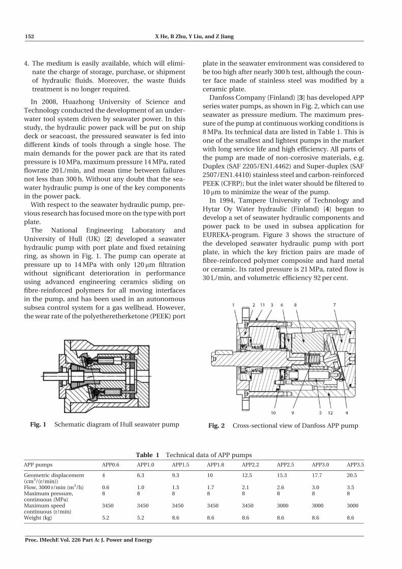
Danfoss Company (Finland) [3] has developed APP
series water pumps, as shown in Fig. 2, which can use
seawater as pressure medium. The maximum pres-
sure of the pump at continuous working conditions is
8 MPa. Its technical data are listed in Table 1. This is
one of the smallest and lightest pumps in the market
with long service life and high efficiency. All parts of
the pump are made of non-corrosive materials, e.g.
Duplex (SAF 2205/EN1.4462) and Super-duplex (SAF
2507/EN1.4410) stainless steel and carbon-reinforced
PEEK (CFRP); but the inlet water should be filtered to
10mm to minimize the wear of the pump.
In 1994, Tampere University of Technology and
Hytar Oy Water hydraulic (Finland) [4] began to
develop a set of seawater hydraulic components and
power pack to be used in subsea application for
EUREKA-program. Figure 3 shows the structure of
the developed seawater hydraulic pump with port
plate, in which the key friction pairs are made of
fibre-reinforced polymer composite and hard metal
or ceramic. Its rated pressure is 21 MPa, rated flow is
30 L/min, and volumetric efficiency 92 per cent.
Fig. 1 Schematic diagram of Hull seawater pump Fig. 2 Cross-sectional view of Danfoss APP pump
Table 1 Technical data of APP pumps
APP pumps APP0.6 APP1.0 APP1.5 APP1.8 APP2.2 APP2.5 APP3.0 APP3.5
Geometric displacement(cm3/(r/min))
4 6.3 9.3 10 12.5 15.3 17.7 20.5
Flow, 3000 r/min (m3/h) 0.6 1.0 1.5 1.7 2.1 2.6 3.0 3.5Maximum pressure,continuous (MPa)
8 8 8 8 8 8 8 8
Maximum speedcontinuous (r/min)
3450 3450 3450 3450 3450 3000 3000 3000
Weight (kg) 5.2 5.2 8.6 8.6 8.6 8.6 8.6 8.6
152 X He, B Zhu, Y Liu, and Z Jiang
Proc. IMechE Vol. 226 Part A: J. Power and Energy

Komatsu Limited [5] developed a seawater hydrau-
lic pump for an underwater manipulator, as shown in
Fig. 4. All bearings and frictional parts are constructed
of CFRP and ceramics. In addition, a seawater static
pressure lubrication mechanism is applied to these
parts in order to protect them from wear and seizing.
Figure 5 shows a seawater hydraulic pump devel-
oped by Mitsubishi Heavy Industries Limited [5]. The
basic construction is identical to axial swash plate
pump. However, all the inside bearings are of sliding
type and lubricated by water.
Kayaba Industry Company Limited [5] developed a
bent axis-type water hydraulic pump. The sliding
parts of the pump adopt resin and ceramic materials.
Ceramic journal bearings are used to provide radial
support instead of sliding bearings which are more
usual in other water hydraulic pumps.
Table 2 lists the main performances of the three
types of water hydraulic pumps from Japanese
companies.
It is worth noting that all the above-mentioned
water hydraulic pumps are port plate types and gen-
erally have the advantages of compact structures and
lightweight. However, on the other hand, they usually
have relative lower anti-contamination ability com-
pared with those of check valve types. As mentioned
in the literature [1], the weakness of this type of pump
lies in the excessive wear of the port plate/cylinder
block interface, especially when applied in ‘dirty’
water environment without fine filtration. For this
consideration, the seawater hydraulic pump with
check valves became the final selection for the proj-
ect, and was anticipated to achieve high reliability.
This article introduces some work on the develop-
ment of the seawater hydraulic pump with check
valves. First, the structure and characteristics of the
pump are illustrated, in which a novel structure of the
piston and sleeve pairs is presented, as well as the
associated materials selection. Then, a method of
using Solidworks software to solve the dynamic bal-
ancing problem of the shaft assembly is described
and verified by experiment. Finally, tests on the
basic performances and reliability of the pump are
conducted and some conclusions are subsequently
obtained.
2 STRUCTURE AND WORKING PRINCIPLE OF
THE SEAWATER HYDRAULIC PUMP
Figure 6 shows the developed seawater hydraulic
piston pump. The pump contains a seawater cham-
ber at the left side of the pistons 5 and an oil chamber
22, which are separated by Glyd rings 7. Bores 8 and
leakage port 23 provide channels for leakage flow
from water chamber and oil chamber. The pump
has seven groups of pistons 5 and sleeves 6, as well
as their associated pressure valves 3 and suction
valves 25. When the shaft 15 is rotating, some of the
Fig. 3 Construction of Hytar seawater hydraulic pump
Fig. 4 Construction of Komatsu seawater hydraulicpump
Fig. 5 Construction of Mitsubishi seawater hydraulicpump
Table 2 Specifications of water hydraulic pumps from
Japanese companies
Item
Specifications
Komatsupump
Mitsubishipump
Kayabapump
Working fluid Seawater Seawater WaterRated pressure (MPa) 21 21 14Rated flowrate (L/min) 30 100 24Rated revolution (r/min) 1500 1800 1500Efficiency (%) 92 81 84
Seawater hydraulic piston pump 153
Proc. IMechE Vol. 226 Part A: J. Power and Energy
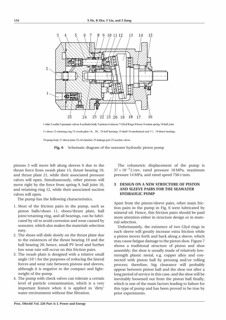
pistons 5 will move left along sleeves 6 due to the
thrust force from swash plate 13, thrust bearing 19,
and thrust plate 21, while their associated pressure
valves will open. Simultaneously, other pistons will
move right by the force from spring 9, ball joint 10,
and retaining ring 12, while their associated suction
valves will open.
The pump has the following characteristics.
1. Most of the friction pairs in the pump, such as
piston balls/shoes 11, shoes/thrust plate, ball
joint/retaining ring, and all bearings, can be lubri-
cated by oil to avoid corrosion and wear caused by
seawater, which also makes the materials selection
easy.
2. The shoes will slide slowly on the thrust plate due
to the existences of the thrust bearing 19 and the
ball bearing 20; hence, small PV level and further
low wear rate will occur on this friction pairs.
3. The swash plate is designed with a relative small
angle (10�) for the purposes of reducing the lateral
forces and wear rate between pistons and sleeves,
although it is negative to the compact and light-
weight of the pump.
4. The pump with check valves can tolerate a certain
level of particle contamination, which is a very
important feature when it is applied in ‘dirty’
water environment without fine filtration.
The volumetric displacement of the pump is
37� 10�3 L/rev, rated pressure 10 MPa, maximum
pressure 14 MPa, and rated speed 750 r/min.
3 DESIGN ON A NEW STRUCTURE OF PISTON
AND SLEEVE PAIRS FOR THE SEAWATER
HYDRAULIC PUMP
Apart from the piston/sleeve pairs, other main fric-
tion pairs in the pump in Fig. 6 were lubricated by
mineral oil. Hence, this friction pairs should be paid
more attention either in structure design or in mate-
rial selection.
Unfortunately, the existence of two Glyd rings in
each sleeve will greatly increase extra friction while
a piston moves forth and back along a sleeve, which
may cause fatigue damage to the piston shoe. Figure 7
shows a traditional structure of piston and shoe
assembly; the shoe is usually made of relatively low-
strength plastic metal, e.g. copper alloy and con-
nected with piston ball by pressing and/or rolling
process; therefore, big clearance will probably
appear between piston ball and the shoe not after a
long period of service in this case, and the shoe will be
inevitably loosened out from the piston ball finally,
which is one of the main factors leading to failure for
this type of pump and has been proved to be true by
prior experiments.
Fig. 6 Schematic diagram of the seawater hydraulic piston pump
154 X He, B Zhu, Y Liu, and Z Jiang
Proc. IMechE Vol. 226 Part A: J. Power and Energy
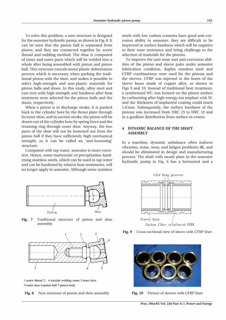
To solve this problem, a new structure is designed
for the seawater hydraulic pump, as shown in Fig. 8. It
can be seen that the piston ball is separated from
piston, and they are connected together by screw
thread and welding method. The shoe is composed
of inner and outer parts which will be welded into a
whole after being assembled with piston and piston
ball. This structure cancels metal plastic deformation
process which is necessary when packing the tradi-
tional piston with the shoe, and makes it possible to
select high-strength and non-plastic materials for
piston balls and shoes. In this study, alloy steel and
cast iron with high strength and hardness after heat
treatment were selected for the piston balls and the
shoes, respectively.
When a piston is in discharge stroke, it is pushed
back to the cylinder bore by the thrust plate through
its inner shoe, and in suction stroke, the piston will be
drawn out of the cylinder bore by spring force and the
retaining ring through outer shoe. Anyway, the two
parts of the shoe will not be loosened out from the
piston ball if they have sufficiently high mechanical
strength, so it can be called an ‘anti-loosening’
structure.
Compared with tap water, seawater is more corro-
sive. Hence, some martensitic or precipitation–hard-
ening stainless steels, which can be used in tap water
and can be hardened by relative heat treatments, will
no longer apply in seawater. Although some stainless
steels with low carbon contents have good anti-cor-
rosion ability in seawater, they are difficult to be
improved in surface hardness which will be negative
to their wear resistance and bring challenge to the
selection of materials for the pistons.
To improve the anti-wear and anti-corrosion abil-
ities of the piston and sleeve pairs under seawater
lubrication condition, duplex stainless steel and
CFRP combinations were used for the pistons and
the sleeves. CFRP was injected to the bores of the
sleeve bases made of copper alloy, as shown in
Figs 9 and 10. Instead of traditional heat treatment,
a synthesized WC was formed on the piston surface
by carburizing after high-energy ion implant with W,
and the thickness of implanted coating could reach
1.0 mm. Subsequently, the surface hardness of the
pistons was increased from HRC 25 to HRC 52 and
in a gradient distribution from surface to centre.
4 DYNAMIC BALANCE OF THE SHAFT
ASSEMBLY
In a machine, dynamic unbalance often induces
vibration, noise, wear, and fatigue problems [6], and
should be eliminated in design and manufacturing
process. The shaft with swash plate in the seawater
hydraulic pump in Fig. 6 has a horizontal and a
Fig. 7 Traditional structure of piston and shoeassembly
Fig. 8 New structure of piston and shoe assembly
Fig. 9 Cross-sectional view of sleeve with CFRP liner
Fig. 10 Picture of sleeves with CFRP liner
Seawater hydraulic piston pump 155
Proc. IMechE Vol. 226 Part A: J. Power and Energy
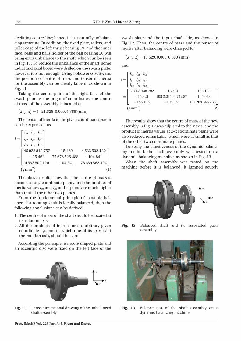
declining centre-line; hence, it is a naturally unbalan-
cing structure. In addition, the fixed plate, rollers, and
roller cage of the left thrust bearing 19, and the inner
race, balls and balls holder of the ball bearing 20 will
bring extra unbalance to the shaft, which can be seen
in Fig. 11. To reduce the unbalance of the shaft, some
radial and axial bores were drilled on the swash plate,
however it is not enough. Using Solidworks software,
the position of centre of mass and tensor of inertia
for the assembly can be clearly known, as shown in
Fig. 11.
Taking the centre-point of the right face of the
swash plate as the origin of coordinates, the centre
of mass of the assembly is located at
x, y, z� �
¼ �21:328, 0:000, 4:388ð Þ mmð Þ
The tensor of inertia to the given coordinate system
can be expressed as
I ¼
Ixx Ixy Ixz
Iyx Iyy Iyz
Izx Izy Izz
264
375
¼
45 028 810:757 �15:462 4 533 502:120
�15:462 77 676 526:488 �104:841
4 533 502:120 �104:841 78 639 562:424
264
375
gmm2� �
ð1Þ
The above results show that the centre of mass is
located at x–z coordinate plane, and the product of
inertia values Ixz and Izx at this plane are much higher
than that of the other two planes.
From the fundamental principle of dynamic bal-
ance, if a rotating shaft is ideally balanced, then the
following conclusions can be derived.
1. The centre of mass of the shaft should be located at
its rotation axis.
2. All the products of inertia for an arbitrary given
coordinate system, in which one of its axes is at
the rotation axis, should be zero.
According the principle, a moon-shaped plate and
an eccentric disc were fixed on the left face of the
swash plate and the input shaft side, as shown in
Fig. 12. Then, the centre of mass and the tensor of
inertia after balancing were changed to
x, y , z� �
¼ 8:629, 0:000, 0:000ð Þ mmð Þ
and
I ¼
Ixx Ixy Ixz
Iyx Iyy Iyz
Izx Izy Izz
264
375
¼
62 853 438:792 �15:421 �185:195
�15:421 108 226 406:742 87 �105:058
�185:195 �105:058 107 209 345:233
264
375
gmm2� �
ð2Þ
The results show that the centre of mass of the new
assembly in Fig. 12 was adjusted to the x axis, and the
product of inertia values at x–z coordinate plane were
also reduced remarkably, which were as small as that
of the other two coordinate planes.
To verify the effectiveness of the dynamic balanc-
ing method, the shaft assembly was tested on a
dynamic balancing machine, as shown in Fig. 13.
When the shaft assembly was tested on the
machine before it is balanced, it jumped acutely
Fig. 11 Three-dimensional drawing of the unbalancedshaft assembly
Fig. 12 Balanced shaft and its associated partsassembly
Fig. 13 Balance test of the shaft assembly on adynamic balancing machine
156 X He, B Zhu, Y Liu, and Z Jiang
Proc. IMechE Vol. 226 Part A: J. Power and Energy
due to its great unbalance level and the experiment
had to be stopped for safety. However, the shaft
assembly after it is balanced could rotate smoothly
on the flexible support of the machine.
Taking z axis in Fig. 12 as the origin of phase angle,
and the outer lanes of the eccentric disc and the
swash plate as the left and the right correction
faces, respectively, the test result was listed in
Table 3. It shows that 1.745 g mass at 146� on the
left correction face and 3.843 g mass at 210� on the
right should be added to achieve complete dynamic
balance. However, the unbalance values are too small
for the shaft assembly to produce any bad influences
to the seawater hydraulic pump, so further work
is unnecessary considering the economic cost. The
experiment testified that the method of using
Solidworks software for the dynamic balancing
design of a complex shaft was feasible and effective.
5 TEST RIG
To get the performances of the developed seawater
hydraulic pump, a seawater hydraulic components
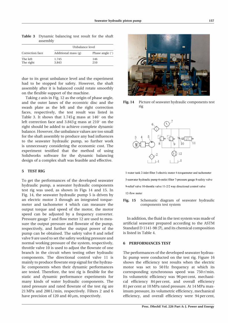
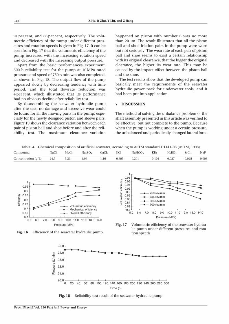
test rig was used, as shown in Figs 14 and 15. In
Fig. 14, the seawater hydraulic pump 5 is driven by
an electric motor 3 through an integrated torque-
meter and tachometer 4 which can measure the
output torque and speed of the motor, the motor
speed can be adjusted by a frequency converter.
Pressure gauge 7 and flow meter 12 are used to mea-
sure the output pressure and flowrate of the pump,
respectively, and further the output power of the
pump can be obtained. The safety valve 8 and relief
valve 9 are used to set the safety working pressure and
normal working pressure of the system, respectively,
throttle valve 10 is used to adjust the flowrate of one
branch in the circuit when testing other hydraulic
components. The directional control valve 11 is
mainly to produce flowrate step signal for the hydrau-
lic components when their dynamic performances
are tested. Therefore, the test rig is flexible for the
static and dynamic performance experiments for
many kinds of water hydraulic components. The
rated pressure and rated flowrate of the test rig are
21 MPa and 200 L/min, respectively. Filters 2 and 6
have precision of 120 and 40 mm, respectively.
In addition, the fluid in the test system was made of
artificial seawater prepared according to the ASTM
Standard D 1141-98 [7], and its chemical composition
is listed in Table 4.
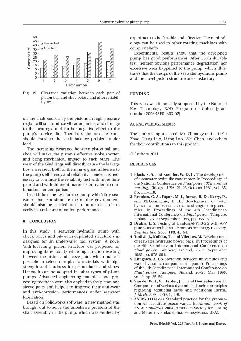
6 PERFORMANCES TEST
The performances of the developed seawater hydrau-
lic pump were conducted on the test rig. Figure 16
shows the efficiency test results when the electric
motor was set to 50 Hz frequency at which its
corresponding synchronous speed was 750 r/min.
Its volumetric efficiency was 96 per cent, mechani-
cal efficiency 84 per cent, and overall efficiency
81 per cent at 10 MPa rated pressure. At 14 MPa max-
imum pressure, its volumetric efficiency, mechanical
efficiency, and overall efficiency were 94 per cent,
Table 3 Dynamic balancing test result for the shaft
assembly
Correction face
Unbalance level
Additional mass (g) Phase angle (�)
The left 1.745 146The right 3.843 210
Fig. 14 Picture of seawater hydraulic components testrig
Fig. 15 Schematic diagram of seawater hydrauliccomponents test system
Seawater hydraulic piston pump 157
Proc. IMechE Vol. 226 Part A: J. Power and Energy
91 per cent, and 86 per cent, respectively. The volu-
metric efficiency of the pump under different pres-
sures and rotation speeds is given in Fig. 17. It can be
seen from Fig. 17 that the volumetric efficiency of the
pump increased with the increasing rotation speed
and decreased with the increasing output pressure.
Apart from the basic performances experiment,
300-h reliability test for the pump at 10 MPa rated
pressure and speed of 750 r/min was also completed,
as shown in Fig. 18. The output flow of the pump
appeared slowly by decreasing tendency with time
period, and the total flowrate reduction was
4 per cent, which illustrated that its performance
had no obvious decline after reliability test.
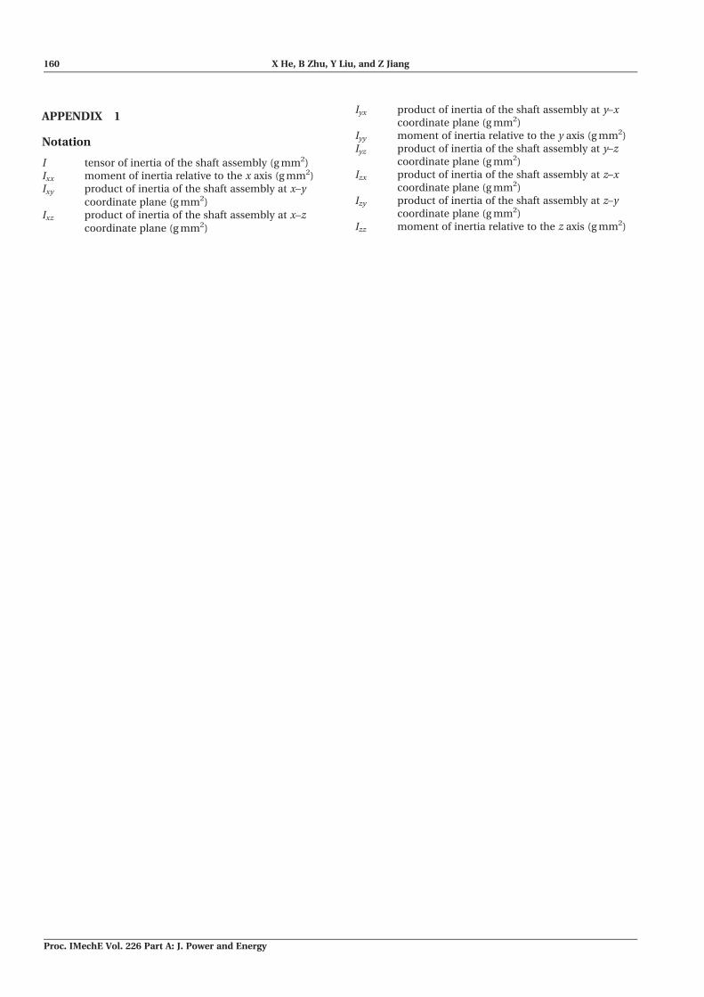
By disassembling the seawater hydraulic pump
after the test, no damage and excessive wear could
be found for all the moving parts in the pump, espe-
cially for the newly designed piston and sleeve pairs.
Figure 19 shows the clearance variation between each
pair of piston ball and shoe before and after the reli-
ability test. The maximum clearance variation
happened on piston with number 6 was no more
than 20 mm. The result illustrates that all the piston
ball and shoe friction pairs in the pump were worn
but not seriously. The wear rate of each pair of piston
ball and shoe seems to exist a certain relationship
with its original clearance, that the bigger the original
clearance, the higher its wear rate. This may be
caused by the impact effect between the piston ball
and the shoe.
The test results show that the developed pump can
basically meet the requirements of the seawater
hydraulic power pack for underwater tools, and it
had been put into application.
7 DISCUSSION
The method of solving the unbalance problem of the
shaft assembly presented in this article was verified to
be effective, but not complete to the pump. Because
when the pump is working under a certain pressure,
the unbalanced and periodically changed lateral force
Table 4 Chemical composition of artificial seawater, according to ASTM standard D1141-98 (ASTM, 1998)
Compound NaCl MgCl2 Na2SO4 CaCl2 KCl NaHCO3 KBr H3BO3 SrCl2 NaF
Concentration (g/L) 24.5 5.20 4.09 1.16 0.695 0.201 0.101 0.027 0.025 0.003
0.6
0.65
0.7
0.75
0.8
0.85
0.9
0.95
1
5.0 6.0 7.0 8.0 9.0 10.0 11.0 12.0 13.0 14.0
Pressure (MPa)
Effi
cien
cy
Volumetric efficiencyMechanical efficiencyOverall efficiency
Fig. 16 Efficiency of the seawater hydraulic pump
0.80.820.840.860.88
0.90.920.940.960.98
1
5.0 6.0 7.0 8.0 9.0 10.0 11.0 12.0 13.0 14.0
Pressure (MPa)
Vol
umet
ric e
ffici
ency
750 rev/min635 rev/min525 rev/min300 rev/min
Fig. 17 Volumetric efficiency of the seawater hydrau-lic pump under different pressures and rota-tion speeds
20.0
21.0
22.0
23.0
24.0
25.0
0 20 40 60 80 100 120 140 160 180 200 220 240 260 280 300
Time (h)
Flo
wra
te (
L/m
in)
Fig. 18 Reliability test result of the seawater hydraulic pump
158 X He, B Zhu, Y Liu, and Z Jiang
Proc. IMechE Vol. 226 Part A: J. Power and Energy
on the shaft caused by the pistons in high-pressure
region will still produce vibration, noise, and damage
to the bearings, and further negative effect to the
pump’s service life. Therefore, the next research
should consider the shaft balance problem under
load.
The increasing clearance between piston ball and
shoe will make the piston’s effective stoke shorten
and bring mechanical impact to each other. The
wear of the Glyd rings will directly cause the leakage
flow increased. Both of them have great influence to
the pump’s efficiency and reliability. Hence, it is nec-
essary to continue the reliability test with more time
period and with different materials or material com-
binations for comparison.
In addition, the test for the pump with ‘dirty sea-
water’ that can simulate the marine environment,
should also be carried out in future research to
verify its anti-contamination performance.
8 CONCLUSION
In this study, a seawater hydraulic pump with
check valves and oil–water-separated structure was
designed for an underwater tool system. A novel
‘anti-loosening’ piston structure was proposed for
improving its reliability while high friction existing
between the piston and sleeve pairs, which made it
possible to select non-plastic materials with high
strength and hardness for piston balls and shoes.
Hence, it can be adopted in other types of piston
pumps. Advanced engineering materials and pro-
cessing methods were also applied to the piston and
sleeve pairs and helped to improve their anti-wear
and anti-corrosion performances under seawater
lubrication.
Based on Solidworks software, a new method was
brought out to solve the unbalance problem of the
shaft assembly in the pump, which was verified by
experiment to be feasible and effective. The method-
ology can be used to other rotating machines with
complex shafts.
Experimental results show that the developed
pump has good performances. After 300 h durable
test, neither obvious performance degradation nor
excessive wear happened to the pump, which illus-
trates that the design of the seawater hydraulic pump
and the novel piston structure are satisfactory.
FUNDING
This work was financially supported by the National
Key Technology R&D Program of China [grant
number 2006BAF01B03-02].
ACKNOWLEDGEMENTS
The authors appreciated Mr Zhuangyun Li, Lizhi
Zhao, Liang Luo, Liang Luo, Wei Chen, and others
for their contributions to this project.
� Authors 2011
REFERENCES
1 Black, S. A. and Kuehler, W. D. Jr. The developmentof a seawater hydraulic vane motor. In Proceedings ofthe National Conference on Fluid power: 37th annualmeeting, Chicago, USA, 21–23 October 1981, vol. 35,pp. 111–118.
2 Brookes, C. A., Fagan, M. J., James, R. D., Kerry, P.,and McConnachie, J. The development of waterhydraulic pumps using advanced engineering cera-mics. In Proceedings of the 4th ScandinavianInternational Conference on Fluid power, Tampere,Finland, 26–29 September 1995, pp. 965–977.
3 Drabls, L. S. Testing of DanfossAPP1.0-2.2 with APPpumps as water hydraulic motors for energy recovery.Desalination, 2005, 183, 41–54.
4 Terava, J., Kuikko, T., and Vilenius, M. Developmentof seawater hydraulic power pack. In Proceedings ofthe 4th Scandinavian International Conference onFluid power, Tampere, Finland, 26–29 September1995, pp. 978–991.
5 Kitagawa, A. Co-operation between universities andwater hydraulic companies in Japan. In Proceedingsof the 6th Scandinavian International Conference onFluid power, Tampere, Finland, 26–28 May 1999,vol. 2, pp. 35–50.
6 Van der Wijk, V., Herder, J. L., and Demeulenaere, B.Comparison of various dynamic balancing principlesregarding additional mass and additional inertia.J. Mech. Rob., 2009, 1, 1–9.
7 ASTM-D1141-98. Standard practice for the prepara-tion of substitute ocean water. In Annual book ofASTM standards, 2004 (American Society for Testingand Materials, Philadelphia, Pennsylvania, USA).
05
101520253035404550
1 2 3 4 5 6 7Piston number
Cle
aran
ce (
µm)
Before test
After test
Fig. 19 Clearance variation between each pair ofpiston ball and shoe before and after reliabil-ity test
Seawater hydraulic piston pump 159
Proc. IMechE Vol. 226 Part A: J. Power and Energy
APPENDIX 1
Notation
I tensor of inertia of the shaft assembly (g mm2)Ixx moment of inertia relative to the x axis (g mm2)Ixy product of inertia of the shaft assembly at x–y
coordinate plane (g mm2)Ixz product of inertia of the shaft assembly at x–z
coordinate plane (g mm2)
Iyx product of inertia of the shaft assembly at y–xcoordinate plane (g mm2)
Iyy moment of inertia relative to the y axis (g mm2)Iyz product of inertia of the shaft assembly at y–z
coordinate plane (g mm2)Izx product of inertia of the shaft assembly at z–x
coordinate plane (g mm2)Izy product of inertia of the shaft assembly at z–y
coordinate plane (g mm2)Izz moment of inertia relative to the z axis (g mm2)
160 X He, B Zhu, Y Liu, and Z Jiang
Proc. IMechE Vol. 226 Part A: J. Power and Energy