FHDQ130 OM - Optoma Europe
67
Page 1 of 64 FHDQ130 Fully optimised 130" all-in-one (AIO) QUAD LED display Operation Manual 2020.09 Document version 1.90
-
Upload
khangminh22 -
Category
Documents
-
view
1 -
download
0
Transcript of FHDQ130 OM - Optoma Europe

Page 1 of 64
FHDQ130
Fully optimised 130" all-in-one (AIO) QUAD LED display
Operation Manual
2020.09Document version 1.90
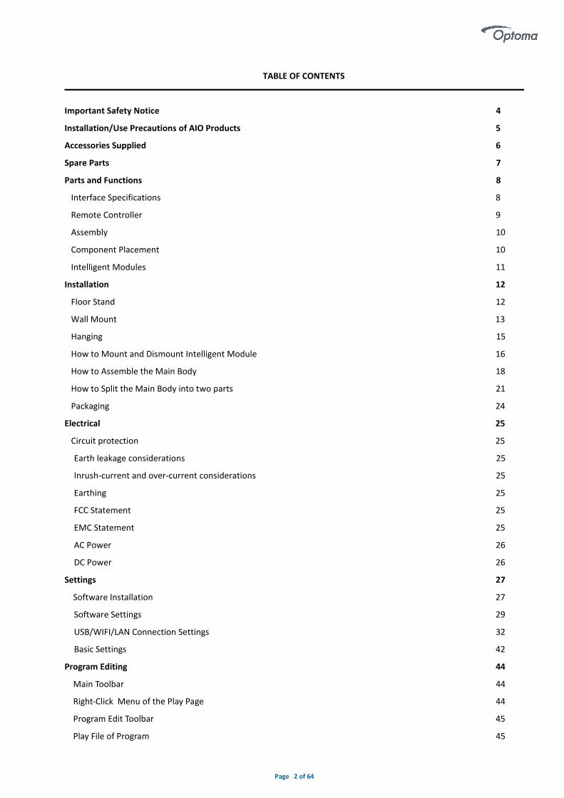
Page 2 of 64
TABLE OF CONTENTS
Important Safety Notice 4
Installation/Use Precautions of AIO Products 5
Accessories Supplied 6
Spare Parts 7
Parts and Functions 8
Interface Specifications 8
Remote Controller 9
Assembly 10
Component Placement 10
Intelligent Modules 11
Installation 12
Floor Stand 12
Wall Mount 13
Hanging 15
How to Mount and Dismount Intelligent Module 16
How to Assemble the Main Body 18
How to Split the Main Body into two parts 21
Packaging 24
Electrical 25
Circuit protection 25
Earth leakage considerations 25
Inrush-current and over-current considerations 25
Earthing 25
FCC Statement 25
EMC Statement 25
AC Power 26
DC Power 26
Settings 27
Software Installation 27
Software Settings 29
USB/WIFI/LAN Connection Settings 32
Basic Settings 42
Program Editing 44
Main Toolbar 44
Right-Click Menu of the Play Page 44
Program Edit Toolbar 45
Play File of Program 45

Page 3 of 64
Program Structure 45
Program Page 46
Program Window 47
Program Edit Process 48
Async Content Editing 48
Publish Programs through USB/WIFI/LAN 49
Publish Programs through USB disk 49
Sync Playing 51
Network and Management 52
Connection and Management 52
Add Group and Device 52
APP Operation Instructions 53
System Overview 53
APP Installation Instructions 53
APP Operating Instructions 53
Search Terminals 54
Terminal Control 54
Edit Program 56
Version Information 58
Appendix 59
59
61
61
62
64
A Specifications
B Procedure for Intelligent Module Replacement
C Troubleshooting Guide
D Mechanical Assembly
E RS232 Commands
F WiFi Hotspot SSID and Password
G Power for LED displays
64
65

Page 4 of 64
Important Safety Notice
CAUTION
ATTENTION
RISK OF ELECTRIC SHOCK
DO NOT OPEN
RISQUE DE CHOC ELECTRIQUE
NE PAS OUVRIR
▪ Always ensure that the unit is properly earthed and power connections correctly made.
▪ This equipment must be supplied from a power system providing a protective earth connection and having aneutral connection, which can be reliably identified.
▪ The power outlet supplying power to the unit should be close to the unit and easily accessible.
▪ Ensure whole system power off before connect or disconnect the network cable.
▪ Do not handle the power supply plug with wet hands.
▪ Do not place the display on sloped or unstable surfaces, otherwise it may fall off or tip over.
▪ Do not place any objects on top of the display.
▪ No naked flame sources, such as lighted candles.
▪ To prevent electric shock , do not remove cover.
▪ No user serviceable parts inside. Refer servicing to qualified service personnel.
▪ Don’t grab the four corners of display (after finishing assembling) when you want to move it from the floor, orthe display will become deformed and affect the alignment. You need to erect it up and move it.
▪ Don’t grab any sheet metal of the display when you assemble the display, otherwise the sheet metal willbecome deformed and affect the flatness .You can only catch the reinforcing rib.

Page 5 of 64
Installation/Use Precautions of FHDQ130 Products
The interior design of FHDQ130 LED display screen is very sophisticated, but it basically has no dustproof/waterproof
capability, please follow the following precautions during installation and use.
1) Screen storage/working environment requirements
Storage temperature:-10~50℃;Relative humidity:10%~60%;
Working temperature:0~40℃;Relative humidity:10%~60%.
2) Installation requirements
When looking to install an AIO please ensure that suitable area is located avoiding places of high condensation and
humidity( must be less than 60%non-condensation state). It is recommended to install dehumidifier in the
environment to control humidity.
3) Cleaning requirements
During the use of the screen, if there is any accumulation of dust on the surface, it is necessary to use anti-static soft
bristle brush or dust-free cloth to clean the screen. Please be careful in the cleaning process to avoid bumping and
damaging the LED. Do not use a damp cloth to scrub the screen.
4) Usage requirements
The LED screen is recommended to be turned on frequently. For the display screen or module that has been stored for
more than 3 days (including), the method of gradually increasing brightness should be adopted to remove accumulated
moisture by slowly heating, so as to avoid the abnormal quality such as dimming and dead lights caused by expansion
of moisture or moisture and electronic migration in the LED lamp during instantaneous high temperature.
Page 6 of 64
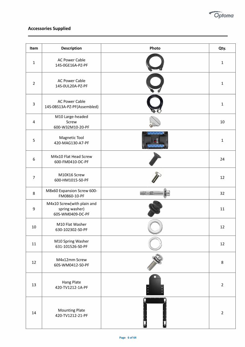
Accessories Supplied
Item Description Photo Qty.
1 AC Power Cable
14S-0GE16A-PZ-PF 1
2 AC Power Cable
14S-0UL20A-PZ-PF 1
3 AC Power Cable
14S-0BS13A-PZ-PF(Assembled) 1
4 M10 Large-headed
Screw 600-W32M10-20-PF
10
5 Magnetic Tool
420-MAG130-A7-PF1
6 M4x10 Flat Head Screw
600-FM0410-DC-PF24
7 M10X16 Screw
600-HM1015-S0-PF 12
8 M8x60 Expansion Screw 600-
FM0860-10-PF 32
9 M4x10 Screw(with plain and
spring washer) 60S-WM0409-DC-PF
11
10 M10 Flat Washer
630-102302-S0-PF 12
11 M10 Spring Washer 631-101526-S0-PF
12
12 M4x12mm Screw
60S-WM0412-S0-PF 8
13 Hang Plate
420-TV1212-1A-PF 2
14 Mounting Plate
420-TV1212-21-PF 2

Page 7 of 64
15 Mounting Brace
420-TV1212-31-PF
1
16 USB Flash Disk
333-DISK8G-00-PF
1
17 Screwdriver
690-A25SDR-10-PF 1
18 T-Hand Hex Key
690-DEM050-1A-PF
1
19 Screwdriver
690-A15PBT-10-PF
1
20 Infrared Remote Controller
898-IRC001-00-PF
1
21 WIFI Dongle
898-00WUSB-00-PF 1
22 Anti-static Gloves
690-ASHAND-20-PF
4
23 Cordless Anti-static Wristband
690-ASWA15-00-PF
4
24 EPE FOAM
540-A130BT-10/20-PF 4+1
25 Accessories Check List 1
Spare Parts
Item Description Photo Qty.
1 Intelligent Module
0-AM4-01G090FFEA-02P
3
2 M4x10 Flat Head Screw
600-FM0410-DC-PF
24
3 M4x10 Screw(with plain
and spring washer) 60S-WM0409-DC-PF
11

Page 8 of 64
Parts and Functions
◆ Interface Specifications
Access SPECIFICATIONS
HDBaseT input Qty : 1
LAN Qty : 1
Purpose: For Service Only
3G-SDI Qty : 1
RS232 Qty : 1
Purpose : External Control (AMX)
VGA input Qty : 1
Analog
Audio Output Qty : 1 / stereo output 1/8″ (3.5mm)TRS
HDMI input Qty : 2
HDMI : 1.4a
USB 3.0 Qty : 1
Purpose : Provide 5V Power or Image Processor FW upgrade only
USB 2.0 Qty : 2
Purpose : support external USB disc storage (128G in maximum) or communication equipment
or wifi dongle
USB Type B Qty : 1
Purpose : (Service use)
Button 4 keys.
Power on / Source/ Brightness + / Brightness -
LED indicator Solid red = Standby
Blinking green = Warm up
Solid green = Normal operation
Blink green / red alternately = Transfer / update data
Fast blinking green = Remove USB
Fast blinking green / red = Firmware update

Page 9 of 64
Remote Controller

Page 10 of 64
Assembly
Each FHDQ130 LED display is designed to be mounted with a specific fixing structure. Please refer to the Mechanical
Assembly (Appendix E) for the detail dimensions.
The list in table 1 is the main components of an FHDQ130 LED display. The intelligent modules are mounted to the front surface and the other main component locations are shown in Figure 1.
Item Description Qty
1 Intelligent Module 144
2 IR Receiver Board 1
3 Power and Mini Card Convertor Board(2in1) 72
4 Signal Control Board 1
5 Main Power Board 1
6 PV7 Board 1
7 System Control Board 1
8 System Core Board 72
9 4.2V /189W Switched Mode Power Supply 24
10 12V /200W Switched Mode Power Supply 1
11 EMI Filter 1
◆ Component Placement
There are seven kinds of system board worked for the LED display, IR Receiver Board, Power and Mini Card Convertor Board, Signal Control Board, Main Power Board, PV7 Board ,System Control Board and System Core Board. Please refer to the description for each board in the follow sections. FHDQ130 LED display is combined with intelligent module and case. The intelligent modules and case are fixed by magnetic structure.
Table 1 - Major components of FHDQ130 LED display
Note: The PSU output is adjustable, the actual value would subject to the label of manufacturing data
Figure 1 FHDQ130 Components
PSU 189W/4.2V
Signal Control Board
PV7 Board
Power and Mini Card Convertor Board (2in1)
PSU 200W/12V
System Control Board
Page 11 of 64
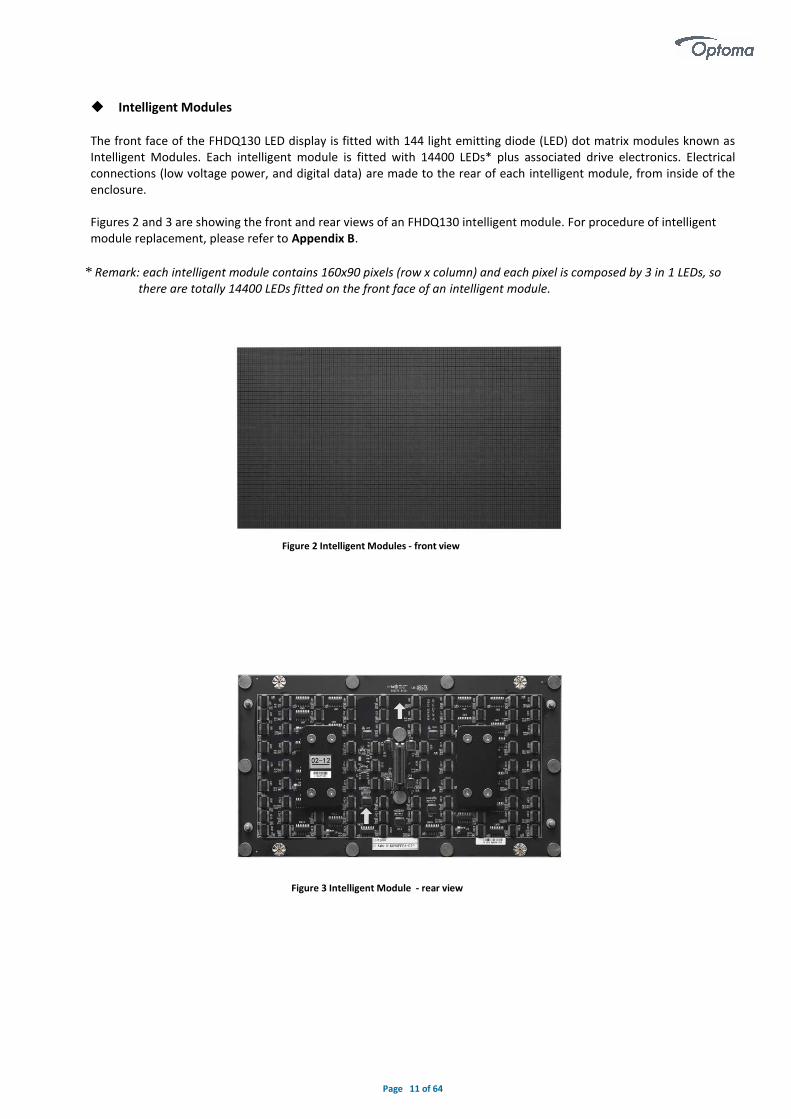
◆ Intelligent Modules
The front face of the FHDQ130 LED display is fitted with 144 light emitting diode (LED) dot matrix modules known as Intelligent Modules. Each intelligent module is fitted with 14400 LEDs* plus associated drive electronics. Electrical connections (low voltage power, and digital data) are made to the rear of each intelligent module, from inside of the enclosure.
Figures 2 and 3 are showing the front and rear views of an FHDQ130 intelligent module. For procedure of intelligent module replacement, please refer to Appendix B.
* Remark: each intelligent module contains 160x90 pixels (row x column) and each pixel is composed by 3 in 1 LEDs, sothere are totally 14400 LEDs fitted on the front face of an intelligent module.
Figure 3 Intelligent Module - rear view
Figure 2 Intelligent Modules - front view

Page 12 of 64
Installation
The FHDQ130 LED display, each intelligent module is equipped with 4 pcs guide pin, are fixed with magnetic structure and jointed together both vertically and horizontally, so that they can form one surface of screen-configuration.
The FHDQ130 LED display is designed to be mounted on the stand (sold separately), on the wall or hanged(wall and hanging brackets included). When installing, it is important to ensure that the entire screen is correctly aligned, both vertically and horizontally.
◆ Floor Stand
Step1. Assemble the floor stand.
Step2. Please use torque wrench to install 8 pcs M10 large-headed screws to the back side of display. The torque for these screws is 1.2Nm.Or you can use your hands to tighten them up, just make sure the screws are well installed.
Step3.Mount the display to the floor stand.
Page 13 of 64
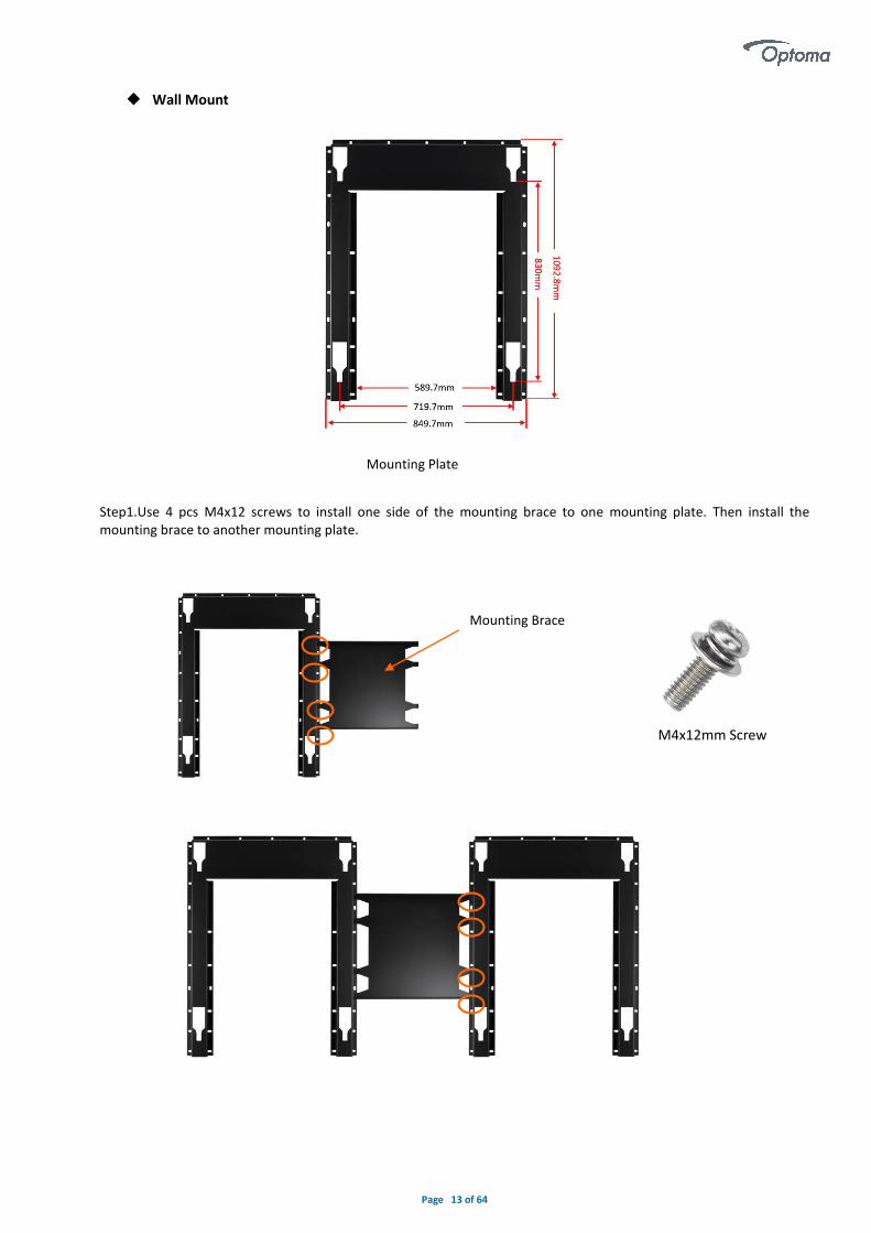
◆ Wall Mount
Step1.Use 4 pcs M4x12 screws to install one side of the mounting brace to one mounting plate. Then install the mounting brace to another mounting plate.
Mounting Plate
Mounting Brace
M4x12mm Screw
Page 14 of 64
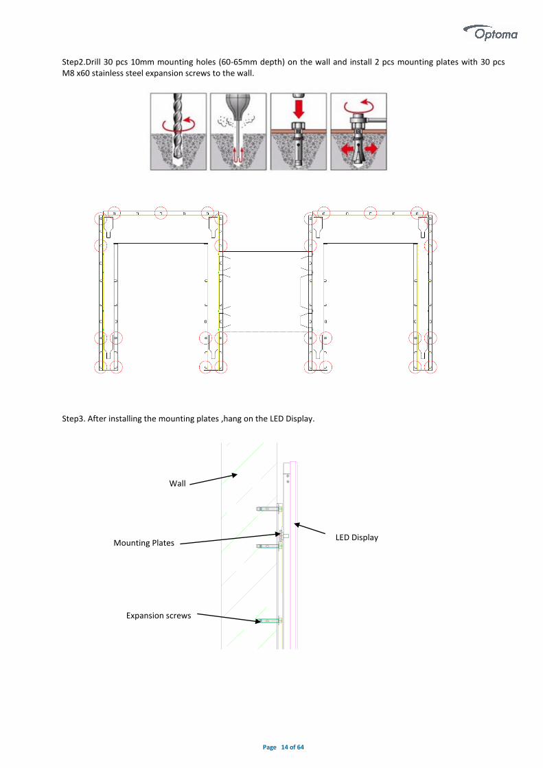
Step2.Drill 30 pcs 10mm mounting holes (60-65mm depth) on the wall and install 2 pcs mounting plates with 30 pcs M8 x60 stainless steel expansion screws to the wall. Step3. After installing the mounting plates ,hang on the LED Display.
LED Display
Wall
Mounting Plates
Expansion screws

Page 15 of 64
◆ Hanging Step1.Install 12pcs M10X16 screws(with a spring washer and flat washer) to the back side of LED display.
Step2.Hang the LED display. If there is a crane, hang the LED display with the help of the crane.
M10X16 Screw
M10 Flat Washer
M10 Spring Washer

Page 16 of 64
◆ How to Mount and Dismount Intelligent Module
The FHDQ130 LED display is designed for maintenance front access, When the intelligent module malfunction; please replace it by the following procedure.
Note:1.Install the modules after the display is assembled, cut off the power. 2 we recommend that you should pay much attention to protect the LEDs when you maintain the intelligent module. Please operate with anti-static gloves. 3.Please ensure the magnetic tool is used correctly.4.Please pay attention to the arrow direction on the back side of the modules.
☑
Dismount Intelligent Module
Step 1. Power off the LED display.
Step 2. Hold the 2pcs handles, push the lock inward and pull the right handle toward outside, and then take it up.
Step 3. Take the tool up and horizontally fit it closely to the display surface. Please pay more attention to the direction.
lock
handles

Page 17 of 64
Step 4. Pull the right handle towards the center. Step 5. Ensure the magnet is locked. Detach the tile carefully. Step 6. Put down the intelligent module and tool together carefully onto an EPE (or other soft pad). Step 7. Push the lock toward inside and pull the right handle toward outside and lift the tool up carefully. Mount Intelligent Module
1. Take out a spare intelligent module and locate the intelligent module to case, please pay attention to the arrow direction on the back side of it. 2. Apply pressure to the intelligent module.
Note: When mounting an intelligent module back, pay more attention to the guide pin which is located in corners to mount it smoothly.

Page 18 of 64
◆ How to Assemble the Main Body
The main body of display is split into two pieces, and all the accessories are attached to each part before shipping.
Please follow below procedures to assembly two parts into a whole display.
Note: 1.Don’t grab the four corners of display (after finishing assembling) when you want to move it from the floor, or
the display will become deformed and affect the alignment. You need to erect it up and move it.
2. Don’t grab any sheet metal of the display when you assemble the display, otherwise the sheet metal will become
deformed and affect the flatness .You can only catch the reinforced rib.
3.Before assembling the display ,you need to plug the AC power cable first. There are three AC power cables provided,
Euro plug, UK plug and US plug. Please use the screwdriver provided to loosen the screw circled below and take out
the cover. Then you can plug the AC power cable .
Step 1. Take out each part of the display and put them on the floor, please make sure all the parts are well protected.
Step 2. Move two parts to each other ,When the gap is minimal, lock the side-locks counterclockwise, you will feel the resistance when the side-locks are in place. (There are two side-locks for each panel)
Left
Right

Page 19 of 64
Note: Before locking the side-locks, you need to loosen the side-locks clockwise in place firstly.
Step3. Install 12 pcs M4 flat head screws.
Step4. Install 11 pcs M4 button head cap screws(with a plain washer and spring washer).
Step 5. Install and tighten 3 pcs black M4 flat head screws to both upper and lower side of the case.
Page 20 of 64
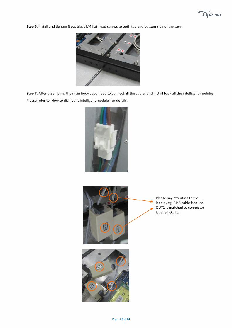
Step 6. Install and tighten 3 pcs black M4 flat head screws to both top and bottom side of the case.
Step 7. After assembling the main body , you need to connect all the cables and install back all the intelligent modules.
Please refer to ‘How to dismount intelligent module’ for details.
Please pay attention to the labels , eg. RJ45 cable labelled OUT1 is matched to connector labelled OUT1.

Page 21 of 64
Step 8. All the intelligent modules have labels stuck on the back side. Please follow below number to install back the
intelligent modules.
We recommend that all the intelligent modules are installed to the corresponding position on case ,or the screen will
show color difference. Also, there is a serial number at the left bottom of frame which match to the one on the back
side of intelligent modules and spares.
◆ How to Split the Main Body into two parts
Step 1 .Take down all the intelligent modules and put them onto an EPE (or other soft pad).
02-01 02-02 02-03 02-04 02-05 02-06 02-07 02-08 02-09 02-10 02-11 02-12
03-01 03-02 03-03 03-04 03-05 03-06 03-07 03-08 03-09 03-10 03-11 03-12
04-01 04-02 04-03 04-04 04-05 04-06 04-07 04-08 04-09 04-10 04-11 04-12
05-01 05-02 05-03 05-04 05-05 05-06 05-07 05-08 05-09 05-10 05-11 05-12
06-01 06-02 06-03 06-04 06-05 06-06 06-07 06-08 06-09 06-10 06-11 06-12
07-01 07-02 07-03 07-04 07-05 07-06 07-07 07-08 07-09 07-10 07-11 07-12
08-01 08-02 08-03 08-04 08-05 08-06 08-07 08-08 08-09 08-10 08-11 08-12
09-01 09-02 09-03 09-04 09-05 09-06 09-07 09-08 09-09 09-10 09-11 09-12
10-01 10-02 10-03 10-04 10-05 10-06 10-07 10-08 10-09 10-10 10-11 10-12
11-01 11-02 11-03 11-04 11-05 11-06 11-07 11-08 11-09 11-10 11-11 11-12
12-01 12-02 12-03 12-04 12-05 12-06 12-07 12-08 12-09 12-10 12-11 12-12
Front View
01-01 01-02 01-03 01-04 01-05 01-06 01-07 01-08 01-09 01-10 01-11 01-12
Page 22 of 64
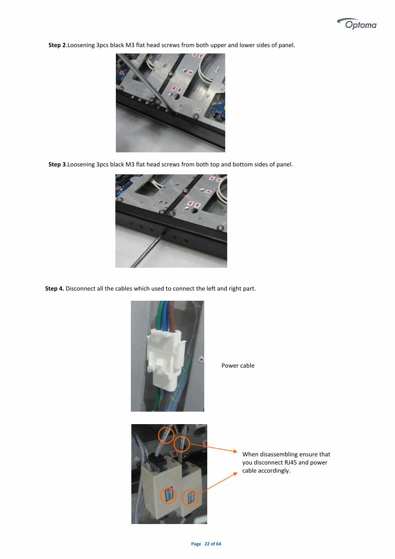
Step 2.Loosening 3pcs black M3 flat head screws from both upper and lower sides of panel.
Step 3.Loosening 3pcs black M3 flat head screws from both top and bottom sides of panel.
Step 4. Disconnect all the cables which used to connect the left and right part.
Power cable
When disassembling ensure that you disconnect RJ45 and power cable accordingly.

Page 23 of 64
Step 5. Rotate side-locks clockwise to loosen.
Step6. Loosening 12 pcs M4 flat head screws.
Step7. Loosening 11 pcs black M4 button head cap screws(with a plain washer and spring washer).
Step 8. Holding the reinforced rib and disassemble the display.

Page 24 of 64
◆ Packaging
1. Put all intelligent modules into antistatic bags separately and set them into the flight case.
2. Take out an PE bag and put one part of display into the bag. Seal the bag. Use the same method to package the
other part of display.
3. Put these two parts into the flight case next to the intelligent modules.
Flight Case

Page 25 of 64
Electrical (Please refer to 'Appendix G')
The power distribution system used must provide adequate protection against excess line current and leakage currents to earth.
Electrical Characteristics for ONE FHDQ130
At 200V AC Input At 240V AC Input
Parameter Unit Rating nom.
Max. Parameter Unit Rating nom.
Max.
Input current A 6.00 15.00 Input current A 5.00 12.50
Input freq. Hz 50 – 60 65 Input freq. Hz 50 – 60 65
Power VA 1200 3000 Power VA 1200 3000
◆ Circuit Protection
Each section of the screen should be protected by a Circuit Breaker to protect against high fault currents, and a Residual Current Device (RCD) to detect earth leakage currents.
◆ Earth Leakage Considerations
Each FHDQ130 LED display has earth leakage current contributions from twenty-five switched-mode power supplies and two filters. The total earth leakage current per LED display can be up to 25.35mA at 240V. If a 30mA RCD is used, then the maximum number of LED display s per section should be safely limited to 1.
◆ Inrush-current and over-current considerations
The inrush current of the switched mode power supplies used to provide LED and logic power to each LED display is specified by the manufacturer as 15-20A at 240volts for a duration of 3mS. However, maximum current in the steady-state for a LED display is considerably less: 12.50A at 240 volts and 15.00A at 200 volts. The circuit breaker used to control a section of the screen must be able to handle the short-term inrush current at switch-on, without causing unnecessary disconnection of the supply, and be able to detect excess currents due to faults within the equipment,
during normal operation. 30mA RCD with a 63A rated capacity is recommended.
◆ Earthing
Each LED display is separately connected to the AC power distribution system’s earth through green/yellow wires connection. All exposed metalwork is also connected to this earth.
◆ FCC Statement
This equipment has been tested and found to comply with the limits for a Class A digital device, pursuant to Part 15 of the FCC Rules. These limits are designed to provide reasonable protection against harmful interference when the equipment is operated in a commercial environment. This equipment generates, uses, and can radiate radio frequency energy and, if not installed and used in accordance with the instruction manual, may cause harmful interference to radio communications. Operation of this equipment in a residential area is likely to cause harmful interference in which case the user will be required to correct the interference at his own expense.
*Note: Modifications not authorized by the manufacturer may void users authority to operate this device.
◆ EMC Statement
Installations should be located at least 30 meters from other sensitive systems or installations and if situated in close proximity to a roadway it may create interference to vehicle radio communications.

Page 26 of 64
◆ AC Power
The AC power cable is connected to the EMI filters and distributes to the power supply units inside the display.
Color of Wire A.C. Supply connection (200V) A.C. Supply connection (240V)
Brown AC. Live AC. Live Blue AC. Neutral AC. Neutral Green/Yellow AC. Protective earth AC. Protective earth
◆ DC Power
DC power from each power supply unit provides low voltage power to the assigned electronics components, for example, intelligent modules and driver board. The responding color of the wire represents the power connection of the relevant component, please note the list below for a clear cabling configuration.
Color of wire D.C. Supply connection
White Red LED / Green LED / Blue LED / TTL Black GND
Page 27 of 64
Settings
◆ Software Installation
The software supports operating systems such as Windows XP \ Server 2003 \ Vista \ Windows 7 \ Windows 8\ Windows10. Recommended computer configuration is:
CPU 2.0 GHZ above;
Memory 1 GB or more;
Independent graphics card, display memory 512MB or more, and must has the DVI or HDMI output interface;
User can adjust configuration according to actual situation, mainly according to total LED screen pixels, program complexity and video whether is high-definition video source or not, etc.
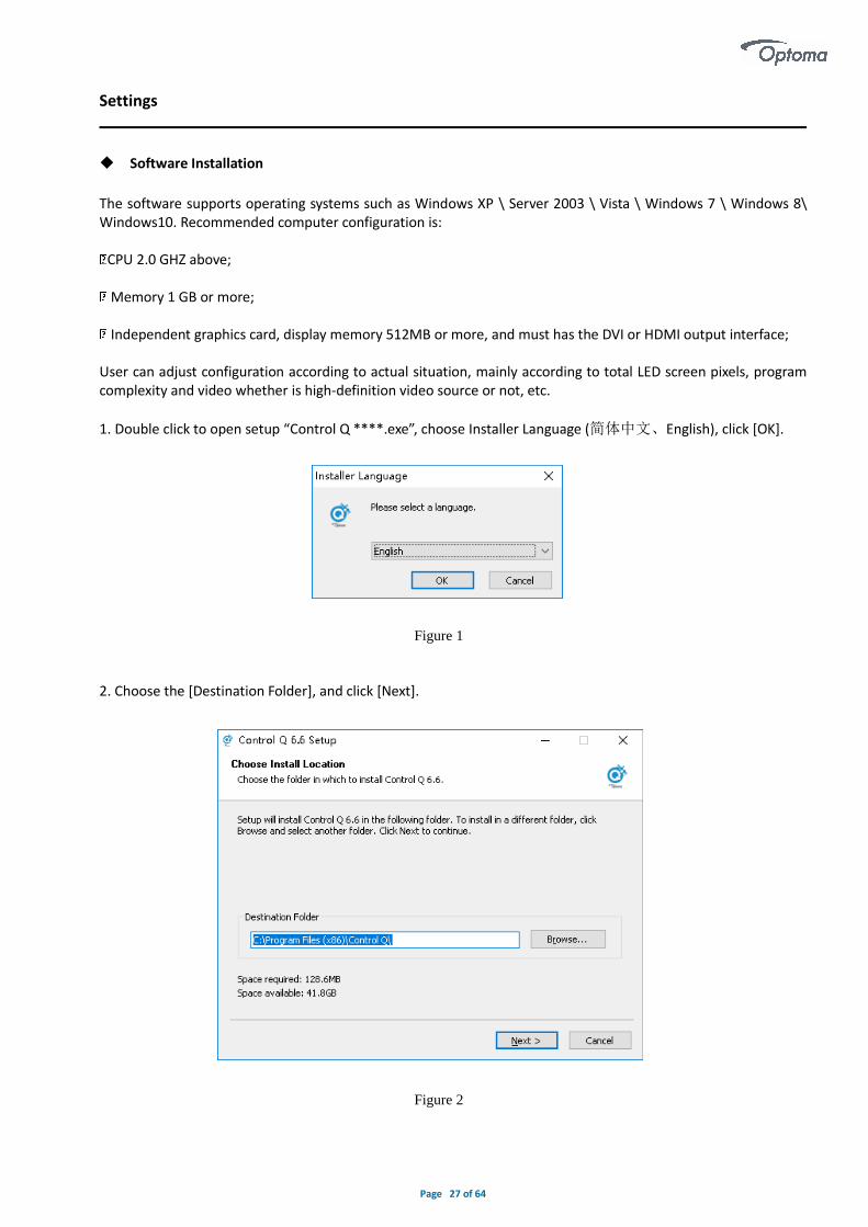
1. Double click to open setup “Control Q ****.exe”, choose Installer Language (简体中文、English), click [OK].
2. Choose the [Destination Folder], and click [Next].
Figure 1
Figure 2

Page 28 of 64
3. Check the components you want to install and uncheck the components you don’t want to install. Click [Install]to start the installation.
4. Click [Finish] when control Q has been installed on your computer.
5. The system automatically generates desktop shortcuts, double click to open the software.
6. If you want to uninstall the software , find out the program and choose uninstall .
Figure 3
Figure 4

Page 29 of 64
◆ Software Settings
After starting the Control Q software, you can see the software interface show as below. Include play interface
(Figure 5)and main interface(Figure 6).
Main interface include six section:1.Menu 2.Main Toolbar 3. Program Edit Toolbar 4. Program Public 5.Program
Property 6. Status bar.
Figure 5
Figure 6
6
5
1
2
3
4

Page 30 of 64
1. Click [Control]-[LED Screen Setting], there will show a popup window to input the password [optoma].
Figure 7
Figure 8

Page 31 of 64
Figure 9
Page 32 of 64
◆ USB/WIFI/LAN Connection Settings
After connecting successfully, you can send related screen parameters, upload programs, manage programs, cloud management, etc.
1. USB Connection
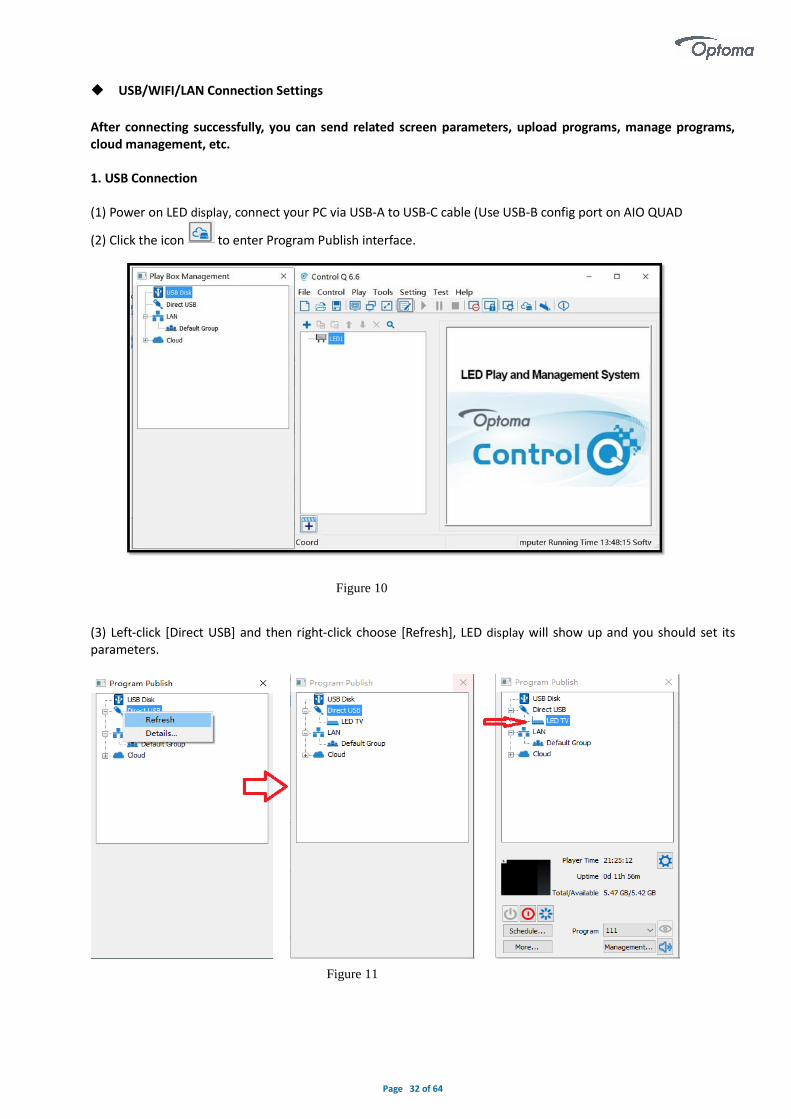
(1) Power on LED display, connect your PC via USB-A to USB-C cable (Use USB-B config port on AIO QUAD
(2) Click the icon to enter Program Publish interface.
(3) Left-click [Direct USB] and then right-click choose [Refresh], LED display will show up and you should set itsparameters.
Figure 10
Figure 11

Page 33 of 64
2. USB Disk Play Approach
There are two ways for playing the USB port media content:
Approach 1 : Plug & Play
Media content will be played automatically within alphabet order.
Approach 2: Programmed Play
1) Program needs to use Control Q to edit in advanced
2) Store program into USB
System Control Board supports the Media formats .ts .mp4 .avi .mkv .mov .bmp .jpg .png .jpeg
The media files and program are stored in the USB disk in the same time.
3) The priority of playback
a. Plug & Play
b. Program Play
Approach 1 : Plug & Play
Follow below step
Step 1. Put content into the root directory or \usb.files
Supported Media formats : .ts .mp4 .avi .mkv .mov .bmp .jpg .png .jpeg
Step 2. Use Remote controller or button to switch the signal source to internal media player
Step 3. Plug the USB disk in the USB port ,then System will play media content in alphabetical order.
Approach 2 : Programmed Play
Step 1. Insert your USB disk to the PC USB port The USB disk should be empty before publishing for best performance. Remove previously updated programs before using it to update or play new programs and to avoid any problems.
Figure 12

Page 34 of 64
Step 2. Click Control\Screen Size and Count Setting, then key in width=1920,Height=1080.
Figure 13
Figure 14
Figure 15
Page 35 of 64
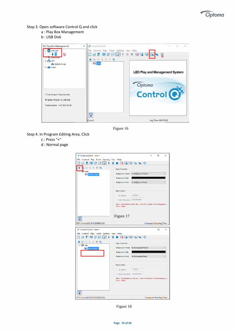
Step 3. Open software Control Q and click a : Play Box Management b : USB Disk
Step 4. In Program Editing Area, Click
c : Press “+” d : Normal page
Figure 16
Figure 17
Figure 18
a
b
Page 36 of 64
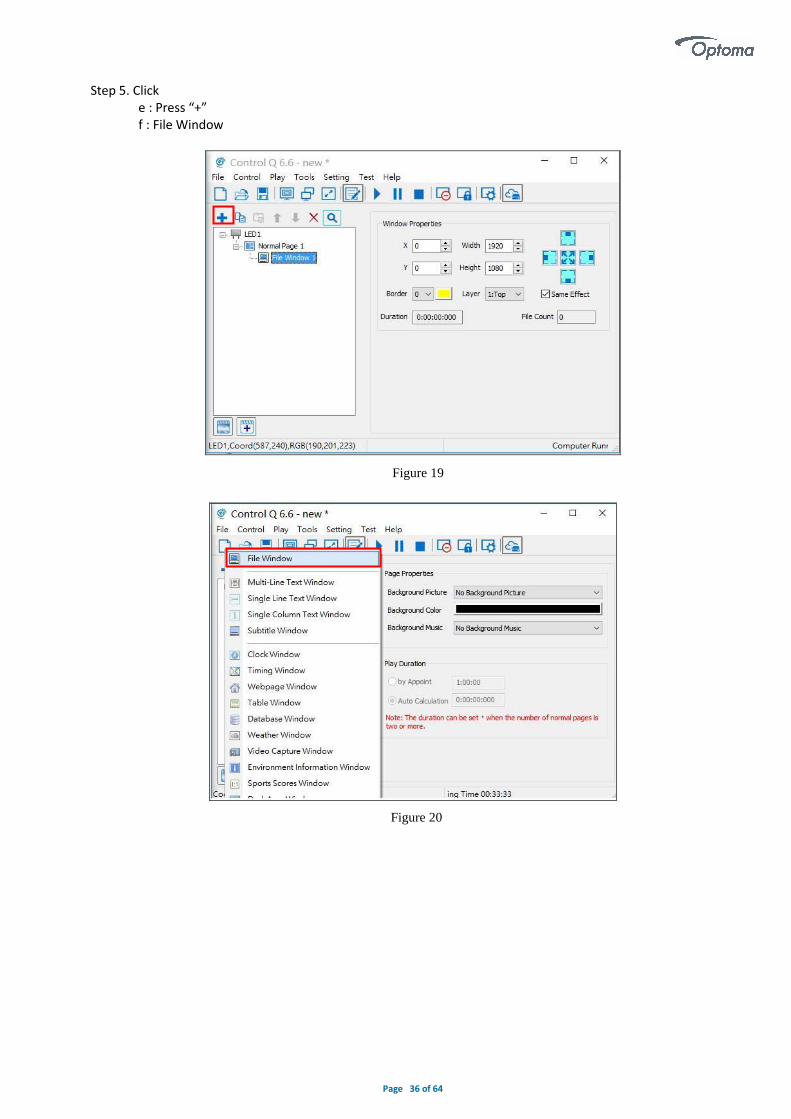
Step 5. Click e : Press “+” f : File Window
Figure 19
Figure 20

Page 37 of 64
Step 6. Click g : Press “+” h : then Add the file type what you want to play Note : In order to make the video to fit the screen, the Video resolution must be 1920x1080.
Step 7. Then we can see the content window for editing. If you want to add more content, repeat Step3~6. Step 8. Choose USB Disk Mode: Play the program from the USB disk (automatically play the USB disk content after inserting it into the System Control Board ; the content won’t be stored on the System Control Board) Update the program from the USB disk (automatically play the USB disk content after inserting it into the System Control Board; the content will be stored on the System Control Board)
h
Figure 21
Figure 22

Page 38 of 64
Step 9. Click Mouse right button / Publish program to the selected USB disk, key in Publishing Name / OK
Figure 23
Figure 24

Page 39 of 64
Step 10. After publishing program successfully Insert USB disk into System Control Board USB port Switch the signal source to the internal Media player(System Control Board) Wait a moment, the content will paly. Note: A rotating circle on the LED’s upper left corner will appear during the updating procedure. You may unplug the USB drive after the circle disappears.
Figure 25
Figure 26

Page 40 of 64
3. WIFI
Before using WiFi please connect USB dongle (provided) to the USB 2.0 port of the AIO QUAD and power on.
(1) Click LED display after connecting successfully, then click [More] and input password ‘optoma’ in the pop-upwindow, you will see the interface showed below. Check [WIFI] in network tab, and input your WIFI logininformation for [SSID] and [Password], then click [Apply] and [Refresh] to complete setting, click [ Detail...] tocheck connection status.
Figure 27
Figure 28

Page 41 of 64
4. WIFI Hotspot Input [SSID] and [Password] to use a WIFI Hotspot. [Band]: 2.4GHz or 5GHz, 5GHz is available if your smartphone or PC can support 5GHz WIFI. [Channel]: There are 1-14 optional channels to avoid network jam.
5. LAN
(1)Automatically Obtain IP Address (Default) When you connect your LED display LAN port to a router, LED display will automatically obtain an IP address to access LAN. (2)Use Following IP Address Enter information for [IP], [Subnet Mask] and [Gateway] manual setup, then connect LED display LAN port to the router to access LAN. (3)Details Check network connection information like connection status, Mac Address, Enabled DHCP,IP Address and Subnet Mask .
Figure 29
Figure 30

Page 42 of 64
◆ Basic Settings
▪ Ensure LED display is functioning normally before setting LED display parameters.
▪ Connect LED display to PC with a standard USB-A Male to USB-B Male cable to set LED display parameters.
1. Play Box Date and Time: Click [Modify] to set up date and time, or time zone as well.
2. Timing Settings: Set wake-up and sleeping time, which works once is checked.
3. Play box Time: Display the setting time.
Running Time: Calculate the running time once LED display is powered on.
Capacity/Remain: View memory utilization.
4. Power on/Sleep/Restart: click shortcut to perform LED display operation like power on, sleep and restart.
5. Playing: Use the drop-down menu to choose programs to display quickly.
Program Management: Check, delete and choose program, and much more.
Figure 31

Page 43 of 64
6. Playing Parameters
(1)Screen Resolution
The [Width] / [Height] has to be equal to or slightly larger than the actual screen resolution.
(2)Output
Every Frame (Default)
Every Other Frame (Choosing [every other frame] can help avoid lag when image loading area is too large).
(3)Control Area
Suggest to select [Custom] in control area, and modify the values according to your network interface control
area, click [Apply] to complete setting.
1
2
3
Figure 32

Page 44 of 64
Program Editing
◆ Main Toolbar
The main toolbar provides the most commonly used tool shortcut icons, including program file operation, display / hide of the play window, switch between dual monitor, editing / stowage of the software main interface, program playback, sending program to dual mode card , close / display large screen, cloud release, view help and other functions.
◆ Right-Click Menu of the Play Page
Right-click in the play window, pop-up menu as below, the menu supports a variety of operations on the program file , support the program playback page switching and related operations for the window.
Figure 1

Page 45 of 64
◆ Program Edit Toolbar
From left to right
1. Add program windows or play content bars: Add program windows or play content bars in the corresponding
position.
2. Copy: Copy the selected items and everything below.
3. Paste: Paste the copied contents
4. Move up: Move the selected content to the front.
5. Move down: Move the selected content to the back.
6. Delete: Remove the selected items and everything below.
7. Close /expand :Close /expand all the content under the selected item.
8. Search: enter keywords to find the required content to do the relevant operation
◆ Play File of Program
The play file of this software corresponds to a file saved as *.vsn, consisting of one or more program pages. There are
two types of program pages: normal page and global page. The normal program page is the main component of the
program, which can be played in sequence. There is only one global program page, which is played throughout the
whole program, mainly used for fixed content such as clock, company logo, etc. The program page consists of one or
more program Windows. The program window is used to display what the user wants to play.
◆ Program Structure
The Control Q program tree area consists of four levels , they are the LED display, program page, program window, and
play content.
Figure 2

Page 46 of 64
LED display: It decided what to display to the LED large screen. Each "LED display" is a parallel relationship and can add multiple program pages. Program page: normal page and global page.
Play content: The specific content displayed on the LED screen. Including video, picture, GIF, FLASH, text files, Office
files, Excel worksheet, clock, timing, web page, database, weather forecast, external video, environmental information,
sports score, desktop copies. Depending on the content, there are different attribute settings.
◆ Program Page
Depending on the nature, the program page is divided into global page and normal page.
Normal page: Normal page can contain multiple Windows, each of which has a different window layout. The same playtime can contain more than one normal page. Multiple normal pages loop through the top to bottom. In most cases, a playtime only requires a normal page.
Figure 4
Figure 3
Page 47 of 64
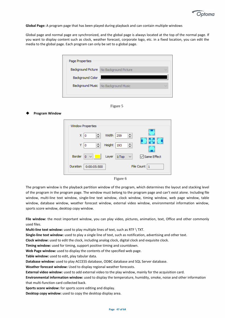
Global Page: A program page that has been played during playback and can contain multiple windows Global page and normal page are synchronized, and the global page is always located at the top of the normal page. If you want to display content such as clock, weather forecast, corporate logo, etc. in a fixed location, you can edit the media to the global page. Each program can only be set to a global page. ◆ Program Window The program window is the playback partition window of the program, which determines the layout and stacking level
of the program in the program page. The window must belong to the program page and can’t exist alone. Including file
window, multi-line text window, single-line text window, clock window, timing window, web page window, table
window, database window, weather forecast window, external video window, environmental information window,
sports score window, desktop copy window.
File window: the most important window, you can play video, pictures, animation, text, Office and other commonly
used files.
Multi-line text window: used to play multiple lines of text, such as RTF \ TXT.
Single-line text window: used to play a single line of text, such as notification, advertising and other text.
Clock window: used to edit the clock, including analog clock, digital clock and exquisite clock.
Timing window: used for timing, support positive timing and countdown.
Web Page window: used to display the contents of the specified web page.
Table window: used to edit, play tabular data.
Database window: used to play ACCESS database, ODBC database and SQL Server database.
Weather forecast window: Used to display regional weather forecasts.
External video window: used to add external video to the play window, mainly for the acquisition card.
Environmental information window: used to display the temperature, humidity, smoke, noise and other information
that multi-function card collected back.
Sports score window: for sports score editing and display.
Desktop copy window: used to copy the desktop display area.
Figure 5
Figure 6

Page 48 of 64
◆ Program Edit Process
1. Set the screen size
It is very important to set the screen size correctly , Otherwise, the program may display incomplete or abnormal
display .
2. How to set the screen size
Click the main menu [Control Screen] → [Screen Management], pop-up screen management window, set the number
of LED screen, the starting position, size, etc.. Note: The size of the LED screen corresponds to the actual size of the LED
display, the unit is the pixel.
◆ Async Content Editing
When you open the software, you will see [LED1] in program editing area. Left-click to choose [ LED1 ]then right-
click to add [ Normal Page ], you can add [ File Window ] in [ Normal Page ], then [Add Image ] and [ Add Video ]
under the [ File Window ] to add media for asynchronous play.
Figure 8
Figure 7

Page 49 of 64
◆ Publish Programs through USB/WIFI/LAN
The same method can be used in USB/WIFI/LAN connections.
(1)In program editing area , after finishing program editing, select the program page that you are going to publish;
(2)In [Program Publish], click [Normal Page 1] and then right-click LED display to choose [Publish current program
to the selected player], rename and upload the program to publish.
◆ Publish Programs through USB disk (1) Connect USB disk to PC USB port.
(2) Click icon to extend program publish window.
Figure 9
Figure 10

Page 50 of 64
Note: Recommend to remove previous contents of the USB disk before using it to update or play new contents, so as to avoid any problems.
(3) Auto identify the inserted USB disk click [USB Disk] to choose [F].
1. Select [ Normal Page 1] in program editing area.
2. Choose[ Update Program by USB Disk]
● Play Program from USB Disk (Autoplay USB disk contents after inserting to LED display and the content won’t
be stored in LED display).
● Update Program by USB Disk (Autoplay USB disk content after inserting to LED display, the content will be
stored in LED display).
3.Click[F]under [USB Disk], and then right-click to choose [ Publish current program to the selected USB disk ],
after publishing program successfully, connect USB disk to LED display USB port and you can update
programs.
Figure 11
Figure 12

Page 51 of 64
Note: A rotating circle in LED upper left corner will appear during the update procedure. You may unplug the USB
disk after the circle disappears.
◆ Sync Playing
In sync play, your LED display plays contents sent to its HDMI port by an external source like your PC.
Note: LED display will automatically switch to play sync signal content when an external HDMI signal input is
detected. You can press [ INPUT SWITCH ] button to return async signal content playing.
Figure 13

Page 52 of 64
Network and Management
◆ Connection and Management
(1)LAN connection: Connect LED display to LAN through WIFI or LAN port.
(2) Network management: After the controlled terminal (PC, Mobile devices, etc) and LED display are connected
into the same LAN, unplug the USB cable,select [LAN] ,right-click and choose[Refresh], FHDQ130 processor will
auto identify LED display and place it into Default Group. You can manage your LED display under Default Group.
◆ Add Group and Device
(1)Add Group: select [LAN] , right-click to choose [Add Group].
(2) Add Device: Select any player group you need, and right-click to choose [Manually Add Player], then input LED
display’s corresponding IP (Even if your device did not connect to network).
Figure 1
Figure 2

Page 53 of 64
APP Operation Instructions
◆ System Overview
1) Optoma Control Q supports system which is higher than Android 5.0.
2) Optoma Control Q supports all the C series products.
◆ APP Installation Instructions
Log in Google Play and search LH display , download and install the App.
◆ APP Operating Instructions
1) Network Connections
The client phone needs to be controlled within the same LAN as the C series play box. There are two ways, one is
to connect the hot spot of the C series with the mobile phone, and the other is to connect the C series play box
and mobile phone to the same network.
2) USB/WIFI/LAN/ Connection Section
Screen connection via PC USB.You can set up the display screen, program content management.
WIFI/LAN connects to screen. You can set up the display screen, program content management.(You need to use
a USB connected to PC to set screen parameters, this function can be achieved.)
3) Language Switching
The downloaded APP will automatically adapt the language of the mobile phone system.

Page 54 of 64
◆ Search Terminals
Click the icon at the top left corner and select the terminal list. The terminal list will display all the devices in the
current LAN, as shown below.
If the list doesn’t display any device, you can pull down or hit the to refresh list. If this doesn’t work, please check the network connection of the mobile phone.
◆ Terminal Control
Select the terminal to be controlled in the terminal list, and click to enter the control interface.
A. Control
Select the required functions to control directly.
Page 55 of 64
Signal: Asynchronous and synchronous HDMI switching
Terminal:on/off switch,volume adjustment
Screen: on/off switch
Brightness and color temperature:Brightness/color temperature adjustment
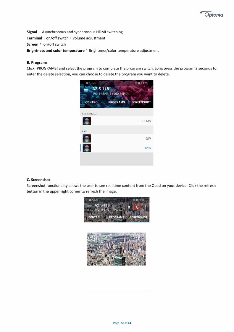
B. Programs
Click [PROGRAMS] and select the program to complete the program switch. Long press the program 2 seconds to
enter the delete selection, you can choose to delete the program you want to delete.
C. Screenshot
Screenshot functionality allows the user to see real time content from the Quad on your device. Click the refresh
button in the upper right corner to refresh the image.
Page 56 of 64
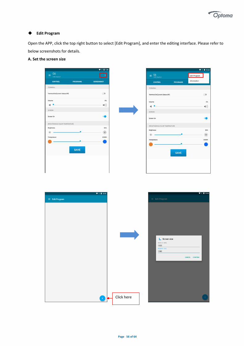
◆ Edit Program
Open the APP, click the top right button to select [Edit Program], and enter the editing interface. Please refer to
below screenshots for details.
A. Set the screen size
Click here

Page 57 of 64
B. Set the window size and add content
Manually drag to change window size
Set the window size
Border setting
Maximize the window
Add file(phote,video,text,clock)
Delete ,Item ,Upload

Page 58 of 64
C. Upload program
◆ Version Information
Select the terminal in the terminal list, and then click the upper right button to view it, as shown below.
Upload Program
Layer selection
New program
Long press to move the program up and down

Page 59 of 64
Appendix A SPECIFICATIONS
Parameter Unit Value
Brightness Nits 600(Max)
Color temperature deg. K 6,500
Viewing angle - Horizontal (50% brightness) deg. 160(+80/-80)
Viewing angle - Vertical (50% brightness) deg. 160(+80/-80)
Panel weight(max) kg / lb 125/275.5
weight(max)(sq.m) kg / lb 26/57
Panel diagonal/ Display diagonal mm / ft 3357.5/11.02 3304.4/10.84
Panel width / Display width mm / ft 2919/9.58 2880/9.45
Panel height / Display height mm / ft 1659/5.44 1620/5.31
Panel depth(min) mm / ft 38/0.125
Panel area / Display area sq.m / sq.ft 4.84/52 4.67/50
Panel material Aluminum
Panel Color / Pantone Matte Black
Aspect ratio 16:9
Ingress protection(Front/rear) IP IP40/IP20
Operating / storage temperature deg. C 0 to +40 / -10 to 60
Operating / storage humidity % < 90 (Without condensation)
Pixel type and configuration R/G/B SMD 4 in 1
Pixel pitch mm 1.5
Pixel matrix per Panel 1,920x1,080
Pixel per Panel 2,073,600
Pixel Lines per meter 666
Pixel per sq. meter 444,444
Recommended minimum viewing distance m 1.5
Colors 281 Trillion
Grey scale (linear) Levels 65,536 levels per color
Brightness control Levels 100
Contrast ratio 5,000:1
Processing depth bit 16
Video frame rate Hertz 50/60
Display refresh rate Hertz ≥3,000
Input voltage (nominal) VAC 200 to 240
Input power frequency Hertz 50 to 60
Input power (max) VA 3,000
Lifetime (50% brightness) Hours ≥100,000
Panel input format USB/HDMI/LAN/VGA/3G-SDI/WIFI
Data interconnection HDMI/LAN/VGA/3G-SDI/WIFI
Mounting system Wall Mount, Hanging or Stand with support
Panel Maintenance Front Access (PA) * Specification subjected to change without prior notice

Page 60 of 64
PC Compatibility
Mode Resolution
Refresh Rate (Hz) SDI HMDI 1 HDBT HDMI 2 VGA
SVGA 800 x 600 56 NO YES YES YES YES
60 NO YES YES YES YES
XGA 1024 x 768 60 NO YES YES YES YES
720p 1280 x 720 50 YES YES YES YES YES
60 YES YES YES YES YES
WXGA 1280 x 800 60 NO YES YES YES YES
SXGA 1280 x 1024 60 NO YES YES YES YES
FWXGA 1366 x 768 60 NO YES YES YES YES
SXGA+ 1400 x 1050 60 NO YES YES YES YES
WXGA+ 1440 x 900 60 NO YES YES YES YES
UXGA 1600 x 1200 60 NO YES YES YES YES
1080i
1920 x 1080
50 YES YES YES YES YES
60 YES YES YES YES YES
1080p
24 YES YES YES YES YES
30 YES YES YES YES YES
50 YES YES YES YES YES
60 YES YES YES YES YES

Page 61 of 64
Appendix B Procedure for Intelligent Module Replacement
When you find the intelligent module is malfunctioning, you can replace it with the following procedure: 1. Power off the LED display;2. Locate the problem intelligent module;3. Remove the intelligent module with the magnetic tool;4. Mount a new intelligent module back to the same position as the problem one;5. Make sure the intelligent module is firmly mounted;6. Power on the LED display ;7. Please check and make sure the replaced intelligent module is functioning well.
Appendix C Troubleshooting Guide
Description Inspection Remove/replace
1 The screen is blurred. Check if the source is correct. Whether the wire and connector are damaged.
Signal source, signal source connection
2 Picture discontinuity. Check if the screen reference has been modified.
Recorrect screen parameters (reference
manual or operated by a professional)
3 The picture is too dark. Check if the source is correct. Whether the wire and connector are damaged. Use the remote control to adjust the
brightness or use the on-screen buttons to adjust the brightness.
-
4 Unable to enter system. Professional after-sales support required.
-
5 The green light keeps flashing after starting.
Professional after-sales support required.
-
6 The remote control is not working.
Check and replace with the same type of remote control battery, Whether the
IR is aligned with the screen when using.
Replace with the same type of remote control
battery.
7 The left and right of the screen are not horizontal.
Check if placement is horizontal. Whether the screen is installed
correctly.
-
8 Audio no output. Check and replace with the same type of remote control battery, Whether the
IR is aligned with the screen when using. Whether the signal source has
audio or not, the audio is not controlled by remote control when
synchronizing signals.
-
9 Audio output volume is too low. Whether the signal source has an audio source or not, the volume can’t be
controlled on the screen when synchronizing signals. Whether the IR is
aligned with the screen when using. Check if the screen button function is
normal.
-

Page 62 of 64
Appendix D Mechanical Assembly

Page 63 of 64

Page 64 of 64
Appendix E RS232 Command List
Appendix F WiFi Password
123456789

Power for LED displays
Supplying power to an LED screen installation is a relatively simple process, the information we have provided is for reference only and a qualified electrician must always be consulted to ensure the relevant local electrical safety stand-ards and processes are followed at all times.
There are however a number of common, and not necessarily obvious issues that can be faced, the below looks to act as a guide for overcoming these:
When initially powered up, the inrush current may be 150 times larger than the max operating current (but only for a very short time) LED screens are designed to leak a small current down to earth. Earth leakage sensors / breakers may behave erratically unless properly selected and rated.
THD Series multiple feeds – How many?When building normal sized screens that are 16:9 ratio, the number of electrical feeds should equal the number of rows of panels (up to the limits described below)
Over Current Breakers and their Ratings:Generally, fuses are no longer used in power distribution systems. They have instead been replaced by small overload-sensor switches called MCBs (Micro Circuit Breakers). When designing a Powerbox for LED screens, there are two parameters to an MCB rating that must be considered:
The Amps at which the MCB detects an overload and trips.
The Amps rating is shown as a numeric value i.e. “16” for a 16 Amp MCB. A letter is used to denote the speed / sensitivi-ty of the MCB, B being “fast” and D being “slow”.Given that THD series & QUAD displays contain connectors that are rated at 16 Amps, each feed from a Powerbox should be fitted with a 16 Amp MCB.
The information we have provided is for reference only and a qualified electrician must always be consulted to ensure the relevant local electrical safety standards and processes are followed at all times.
Figure 1: 10x10 THD series display with 10 Power Feeds
Page 65 of 67

The speed at which this happens.
Domestic MCBs are normally B curve. These won’t work with LED screens because the power-up behaviour after a power cut causes a large inrush of current that would trip B curve MCBs. Instead, Optoma recommends D curve breakers are used. Typically found in industrial applications, D curve MCBs are much less sensitive to the start-up in-rush. As such, they are much more appropriate for LED screens.
If D Curve cannot be used:Optoma, as the equipment manufacturer of the THD series and QUAD LED Displays, recommends that D Curve MCBs are used. If however, local electrical considerations mean that C Curve breakers are insisted on, these may work some of the time but are not recommended.If C Curve MCBs are used in the Powerbox, the system will operate much closer to the thresholds where a cut-out (trip) are triggered.This narrow threshold may be fine in some locations or may be problematic in others.
Earth Fault Protection:Earth Fault Protection is a relatively new type of electrical circuit protection developed to monitor whether any faulty electrical equipment has been connected to the power. Devices called RCDs monitor the balance between power IN and power OUT and trigger an immediate disconnect should an imbalance be detected.
When building normal sized screens that are 16:9 ratio, the number of electrical feeds should equal the number of rows of panels (up to the limits described below)
The technology works well in domestic situations with vacuum cleaners, microwave ovens and TVs. Outside of the domestic environment however this is not always the case. Some industrial equipment however such as IT Comms room racks, radio equipment or medical equipment is designed and intended to use the earth connection as a drain connection, even under normal and safe operating conditions. LED screens fall into this category. It is safe, normal and as per design for an LED screen to drain a small electrical current away via the earth connection.
As such, if earth fault monitoring is installed, such devices would incorrectly see this earth current as a “fault” and trigger a disconnection. RCDs are generally considered incompatible with LED screens.
My Electrician says I must use RCDs:The IEEE 18th Edition electrical regulations, while endorsing RCD protection for most applications do in fact allow, under special circumstances, devices to be installed with no RCD protection in their power feed.
Regulation 411.3.3 of BS 7671:2018 (comes into effect from 1st January 2019):
The information we have provided is for reference only and a qualified electrician must always be consulted to ensure the relevant local electrical safety standards and processes are followed at all times.
Figure 2: 30mA RCD with a 63A rated capacity
Page 66 of 67
In AC systems, additional protection by means of an RCD with a rated residual operating current not exceeding 30 mA shall be provided for:(i) socket-outlets with a rated current not exceeding 32A, and(ii) mobile equipment with a rated current not exceeding 32A for use outdoors.
An exception to (i) is permitted where, other than for an installation in a dwelling, a documented risk assessment determines that RCD protection is not necessary.
The information we have provided is for reference only and a qualified electrician must always be consulted to ensure the relevant local electrical safety standards and processes are followed at all times.
Page 67 of 67