Introducing and Implementing IBM FlashSystem V9000 - IBM ...
Upload
khangminh22Category
view
1download
0
• "
Systems Reference Library
IBM System/360 Model 20
Card Programming Support
Basic Assembler Language
,Ji:rile'~o.S360 (Mo,d. 20) -21 ·Ofi~(~:..tIOft GC26 'J602.-:5
This reference publication provides programmers with the information required to write programs in the Basic Assembler language of the IBM System/360 Model 20.
The Basic Assembler language provides the user with a convenient means of making full use of the operational capabilities of the Model 20. Programs written in the Basic Assembler language (source programs) are translated into machine-language by means of the Basic Assembler program.
The description of th~ language includes rules for writing source programs and explanations of the instructions for controlling the Basic Assembler program. In addition, this publication includes a number of tables for convenient reference and conversion. Time and storage requirements are listed in a separate section. An extensive sample program is given to illustrate Basic Assembler language programming.
The description of the card and tape versions of the Basic Assembler program is confined to the aspects that affect the planning and writing of source programs.
Readers of this publication should be thoroughly familiar with the contents of the SRL publication IBM System/360 Model 20, Functional Characteristics, Order No. GA26-5847. Titles and abstracts of other Model 20 SRL publications are contained in the publication IBM System/360 Model 20, Bibliography, Order No. GA26-3565 .
CPS ',.
Seventh Edition (May, 1969; reprinted January, 1971)
This is a reprint of GC26-3602-5 incorporating changes issued in Technical Newsletter GN33-8612, dated April 6, 1970.
This edition applies to the following program version and modification levels of IBM System/360 Model 20, Card Programming Support, Basic Assembler, and to all subsequent versions and modifications until otherwise indicated in new editions and Technical Newsletters.
Program Number Version/Modification
360T-AS-OOl 3/7
360T-AS-110 2/0
360U-AS-130 2/2
360U-AS-153 2/0
Changes are continually made to the information herein; before using this pUblication in connection with the operation of IBM systems, consult the latest SRL Newsletter, Order No. GN20-0361, for the editions that are app~icable and current.
Requests for copies of IBM publications should be made to your IBM representative or to the IBM branch office serving your locality.
A form for reader's comments is provided at the back of this pUblication. If the form has been removed, comments may be addressed to IBM Laboratory, Publications Department, P.O. Box 24, Uithoorn, Netherlands.
© Copyright International Business Machines Corporation 1965,1966,1967,1969
o
I
o
o
o
o
o
Prerequisite to using this publication is a thorough knowledge of IBM System/360 Model 20 machine operations, particularly storage addressing, data formats, and machine instruction formats and functions. It is assumed that the reader has experience with programming concepts and techniques or has completed basic courses of instruction in these areas.
Publications closely related to this one are:
Functional Characteristics, Form A26=5847~-----------------
PREFACE
~~~Q~rog££~~ing_~Y£EQrt'~2ic_A2§gm= ~lef_JTapgLL~Eg£at~~Q£gQurg§, Form C24-9011.
l~Q!LOutEy!_Con!ro~_sys!g~_fQf_!hg_~Qm~ . ~un1cation§_!daE!g~, Form C26-3606.
InEQ!LQ~!EQ!_~Qn!~Ql_~~~!em_ior ing ~ina£Y~~n£h£QnQQ§_fommun!£~!iQn§_AQ£E1= g£, Form C33-4001.
fard_grog££mming_~~£EQ£iL~£~!£_YiiliiY grog£g~L_XQn£!1Qn§_~ng_Q~££!ing_~£Q£~ gure§, Form C26-3604.
Titles and abstracts of other Model 20 SRL publications are contained in the 1~~ ~Y~iemL36~~~Qgi_20_liiblio~aphy, Form A26-3565.
CONTENTS
INTRODUCTION ••••••• Definitions • • • • • • • • • • • • • Basic Assembler Language Statements BASIC ASSEMBLER LANGUAGE FEATURES Minimum System Configuration •
5 5 5 6 6 7 8
Maximum System Configuration ••••• Language Compatihility ••••••
CHARACTERISTICS OF THE BASIC ASSEMBLER LANGUAGE • • . • • • • •• Coding Conventions
Statement Formats and Components. The Language Structure •
The Character Set ••••• Self-Defining Terms Symbols ••••• • • • • • Expressions Location Counter.
9 9
11 • 14 • 14 • 14
15 16 17
Assigned Addresses • • • • • • • • • • 19
FUNCTIONS OF THE ASSEMBLER LANGUAGE Storage Addresses • • • • • • • •
Effective Addressing • • • • • • Symbolic (Implie~) Addressing Explicit Addressing •••• Absolute (Di rect) Addressing • •
20 • • • 20
• 20 • 20 • 21 • 22
General and Pseudo-Registers • • • Base Registers • • • • • • • • • • • •
Using -- Use Base Register • •
• 22 • 23 • 23
BASR -- BRANCH and STORE Register DROP -- RELEASE Pase Register
• • 23 • • 25
ABSOLUTE AND RELOCATABLE PROGRAMMING •• 26
PROGRAM LINKING S,:mple Program
DEFINITION INSTRUCTIONS EQU -- Equate Symbol • DC Define Constant DS -- Define Storage •
• 27 • • 28
29 • 29
29 • 32
BASIC ASSEMBLER CONTROL INSTRUCTIONS • • 34 START -- Start Program • • • • • • 34 END -- End of Program •• • • • • 34 ORG -- Reset Location Counter • 35
INPUT/OUTPUT INSTR~CTIONS • 37 XIO -- Execute Input/Output ••••• 37 CIO -- Control Input/Output • • • • • 37 TIOB -- Test Input/Output and Branch • 39 Sequence of I/O Instructions • • • •• 40
Input/Output Macro Instructions • 40 I/O Routines -- Including Interrupts •• 41
MACHINE-INSTRUCTION STATEMENTS • • Machine-Instruction Mnemonic Codes Instruction Formats
RR Format HX Format ••• •
• 43 • 45
• • 45 • • 45 • • 45
51 Format •••••• SS Format ••••••
Types of Machine Operations Binary Arithm Etic •••• Instructions for Binary Arithmetic • Decimal Arithmetic ••••••••• Instructions for Decimal Arithmetic Non-Arithmetic Operations Instructions for Non-Arithmetic Operations • • • • ••••• Bran~hing • • • • • • • • Instructions for Branch Operations.
THE BASIC ASSEMBLER PROGRAM Basic Assembler (Card Versions) Basic Assembler (Tape Version~
DIAGNOSTIC MESSAGES Loading Object Programs
PERFORMANCE DATA • • • • •• Main storage Requirements Time Requirements -- Card Version Time Requirements -- Tape Version
WRITING A PROGRAM IN BASIC ASSEMBLER LANGUAGE •••••••••• Stating theP ro blem • • • • Writing the Source Program •
The Flowchart' • • • • • • Initializing the Program (STMT1-STMT3) ••••• Data Constants and Work Areas (STMT4-STMT15) ••••••••• Program Routine (STMT16-STMT24) Ou tp u t (STMT 25-STMT 3 5) • • . Program End (STMT 36) • • • •
Assembling the Source Program Control Card. •••• Diagnostic Ru IJ • • •
APPENDIX A. SUM~ARY OF BASIC ASSEMBLER INSTRUCTIONS • • • • • • • • • •
· 47
· 48
· 49
· 49
· 51
· 53
· 55
· 61
· 62
· 69
· 70
· 72
· 72
· 73
74
· 74
· 75
· 75 75 75
· 76
· 76
· 76
· 76
· 76
· 77
· 78
· 79
· 80
· 80
· 80
· 80
• 82
APPENDIX B. SUMMARY OF MACHINE-INSTRUCTIONS. • • 83
APPENDIX C. SUMMARY OF INPUT/OUTPUT INSTRUCTIONS • • • • • • • • • • • • • • 84
APPENDIX D. SUMMARY OF DIAGNOSTIC MESS AGES . . . . . . . · 86
APPENDIX E. CONDITION CODES · 88
APPENDIX F. CHAR ACTER CODES · 89
APPENDIX G. HEXADECIMAL-DECIMAL NUMBER CONVERSION TABLE . . . · 93
APPENDIX H. GLOSSARY • 99
INDEX 104
0
I
OJ
o

o
o
o
Computer programs may be expressed either in machine languag~, in other words, language directly interpreted by the computer, or in a symbolic language, which is more meaningful to the programmer. The symbolic language, however, must be translated into machine language before the computer can execute the program. This function is accomplished by an associated processing program.
Of the various symbolic programming languages, Assembler languages are closest to machine language in form and content.
The Basic Assembler language discussed in this manual is a symbolic programming language for the I~M System/360 Model 20. It enables the programmer to use all .Model 20 machine functions, as if he were coding in Model 20 machine language.
The Basic Assembler program translates or processes programs written in Basic Assembler language into machine language for execution by the computer. The program written in the Basic Assembler language used as input to the Basic Assembler program is called the §Q~£~~_E£Qg£E~; the machine-language program produced as output from the Basic Assembler program is called the Q£j~f~_££Q~m. The translation or processing procedure performed by the Basic Assembler program to produce the object program is called as§emblillg or assemblY.
Four versions of the Basic Assembler program are availahle:
a. Two card versions. These are two-pass programs for a Model 20 system that includes only card input/output devices. One of the versions permits the assembly o~ the macro instructions associated with the Input/Output Control System for the Binary Synchronous Communications Adapter (BSCA IOCS).
b. Two tape versions. These versions differ from the card versions by being one-pass programs and by using magnetic tape as an intermediate storage medium, thus reducing card-handling and assembly time.
~Q!g: The CPS Input/Output Control System (IOCS) routines can be assembled by means of either version.
DEFINITIONS
Terms used in this publication are defined in the glossary provided in !E£gndi!_B.
BASIC ASSEr.BLER LANGUAGE STATEMENTS
Program statements (source statements) written in Basic Assembler language may consist of: a name to identify the statement; a symbolic operatiop coae JmnemonicJ. to identify the function the statement I
represents; one or more items called operands, to designate the data or storage locations used in the operation; and comments.
Programs written in Basic Assembler language may consist of up to five types of instructions: definition instructions, trogram linkingipi?tructiori~t: Basic· Assem
leI' control instru~t~Q~~1 in£UEtOU~put instruct10U& (1ncluding IBM-supp 1e I/O J 1 ..,
macro 1nstructions) , a nd rna chine j p str \lC
tions. There are predeflned mnemonic codes tor nl 5.nstructions in the Basic Assembler language.
Definition instructions are used to reserve sto(aae, to define constantsJ and to equate symbols to the attr1butes of an expression.
Program linking instructions are used to link prOqraUL.~g~.tj 9ij§~ f.Q,h.j,,!il~t., ~~.~~~tion ._
Basic Assembler control instructions are used to begin assembly, end assembly. anAL set the location counter.
Input/output instructions designate the units use devices and con t.,.?~.~r 02~,qtjQP, The use of IOCS macro instructions saves programming time because it relieves the user of having to code, test, and pr~vide linkages to his own I/O routines.
Machine instructions direct the computer to execute certain opera lions. The Basic Assembler pr~duces an equivalent internal machine instruction in the object program from each machine instruction in the source prog ram.
Introduction 5
BASIC ASSEMBLER LANGUAGE FEATURES
Decimal, hexadecimal, or character representation of machine-language binary values may be employed by the programmer in writing source statements. The programmer ~elects the represp.ntation best suited to his purpose.
The Model 20 Basic Assembler language provides for two methods of addressiny:
1. The address may be specified as a displacement plus a base register the contents of which are added to the displacement. The base register may be one of the general registers 8 through 15 or one of the pseudo base registers 0 through 3. (If a Submodel 5 is used, pseudo registers 0-7 are available. However, 0-3 are the only pseudo registers recognized in CPS programs.)
a. When using a general register, the register contents can be controlled by the programmer.
b. When using a pseudo base register, the register contents are assumed to be fixed (i.e., 0, 4096, 8192, and 12288). This corresponds to what is termed direct addressing in the Model ?O SRt pubIl.catl.on !t!U~.f:= tiQnal_~haI~f!~Ii§tif§, Form A26-5847.
2. The address may be specified symbolically without the use of a base register. In this case, the Basic Assembler assumes the clerical burden of computing storage locations in terms of a base address and a displacement.
The object programs produced by the Basic Assembler may be in a format enabling relocation from the originally assigned storage area to any other suitable area.
The linking facilities of the Basic Assembler language and program allow symbols to be defined in one assembly and referred to Ln another, thus e~fecting a link between separately assembled programs. This permits reference to ~ata and/or transfer of control between programs. A discussion of linking is contained under Program Linking.
A listing of the source-program statements and the resulting object-program statements is produced by the Basic Assembler for each source program it assembles. The programmer can partly control the form and contents of the listing.
As a source program is assembled, it is analyzed for actual or potential errors in the use of the Basic Assembler language. Detected err:>rs are indicated in the program listing.
MINIMUM SYSTEM CONFIGURATION
The minimum system configuration for assembling and executing Basic Assembler programs is as follows. The configuration applies to all versions of the program except where indicated.
• An IBM 2020 Central Processing Unit, Model B2 for the normal version, or C2 for the BSCA version (4096 or 8192 bytes of main storage);
• one of the f:>llowing card units: IBM 2560 Multi-Function Card Machine, Model A 1, IBM 2520 Card Read-Punch, Model A1, IBM 2501 Card Reader, Model A1 or A2 wi th either an IB l': 2520 Card Pu nch, Model A2 or A3, or an IBM 1442 Card Punch, Model 5;
• an IBM 2415 Magnetic Tape Unit, Model or 4 (for the tape versions only);
• one of the following printers: IBM 1403 Printer, Model N1, 2, or 1, IBM 2203 Printer, Model A1;
• an IBM 2020 Central Processing Unit, Model B3 (4096 bytes of main storage);
• an IBM 2560 Multi-Function Card Machine, Model A2;
• an IBM 2203 Printer, Model A2.
• an IBM 2020 Central Processing Unit, Model B4 (4096 bytes of main storage)
• an IBM 2560 Multi-Function Card Machine, Model A2;
6 System/360 Model 20 Basic Assembler Language
o
I
0'< II.'
o
o
o
'0
• an IBM 2203 Printer, Model A2.
• an IBM 2020 Central Processing Unit, Model C5 (8192 hytes of main storage)
• one of the following card units: IBM 2560 Multi-~unction Card Machine, Model A 1, IBM 2520 Card Read Punch, Model A1, IBM 2501 Card Reader, Model A1 or A2 with either an TBM 2520 Card Punch, Model A2 or A3, or an IBM 1442 Card Punch, Model 5;
• an IBM 2415 Magnetic Tape Unit, Model or 4 (for the tape versions only)
• one of the following printers: IBM 1403 Printer, Model N1, 2, or 7, IBM 2203 Printer, Model A1.
!~~: CPS does not support main storage sizes of 24K and 32K, but CPS programs will run on Models DC5 and E5 although only 16K bytes are used. (The maximum value of the location counter i~ X'3FFF'. Therefore, the Basic Assembler will not permit references to addresses greater than this.)
]Q1g_~: If 7-track tapes are used, the data-conversion feature is required.
MAXIMUM SYSTEM CONFIGURATION
Basic Assembler obiect programs may be produced for the following maximum system configurations.
• An IBM 2020 Central Processing Unit, Model D2 (16,38 U bytes of main storage); with or without IBM Binary Synchronous Communications Adapter, Feature No. 2074;
• two IBM 2311 Disk Storage Drives, Model 11 or 12 (both must be the same model);
• an IBM 2415 Magnetic Tape Unit, Model 1 through 6;
• an IBM 2501 Card Reader, Model A1 or A2;
• an IBM 1442 Card Punch, Model 5;
• one of the following card units: IBM 2520 Card Read-Punch, Model A1, IBM 2520 Card Punch, Model A2 or A3, IBM 2560 Multi-Function Card Machine, Model A 1;
• one of the following printers: IBM 1403 Printer, Model N1, 2, or 7, IBM 2203 Printer, Model A1;
• one of the f~llowing magnetic character readers: IBM 1419 Magnetic Character Reader, Model 1 or 31, IBM 1259 Magnetic Character Reader, Model 1, 31, or 32;
• an IBM 2152 Printer-Keyboard.
• an IBM ~020 Central Processing Unit, Model D3 (16,384 bytes of main storage);
• an IBM 2560 Multi-Function Card Machine, Model A2;
• an IBM 2203 Printer, Model A2.
• an IBM 2020 Central Processing Unit, Model D4 (16,384 bytes of main storage) with or with~ut IBM Binary Synchronous Communications Adapter, Feature No. 2074;
• two IBM 2311 Disk Storage Drives, Model 12;
• an IBM 2560 Multi-Function Card Machine, Model A2;
• an IBM 2203 Pr{nter, Model A2;
• an IBM 2152 Printer-Keyboard.
• an IBM 2020 Central Processing Unit, Model D5 (16,384 bytes of main storage); with or without IBM Binary Synchronous Communications Adapter, Feature No. 2074;
• four IBM 2311 Disk Storage Drives, Model 11 or 12;
• an IBM 2415 Magnetic Tape Unit, Model 1 through 6;
• an IBM 2501 Card Reader, Model A1 or A2;
• an IBM 1442 Card Punch, Model 5;
• one of the following card units: IBM 2520 Card Read-Punch, Model A1, IBM 2520 Card Punch, Model A2 or A3, IBM 2560 Multi-Function Card Machine, Model A 1;
• one of the following printers: IBM 1403 Printer, Model N1, 2, or 7, IBM 2203 Printer, Model A1;
• one of the following magnetic character readers:
Introduction 7
IBM 1419 Magnetic Character Reader, Model 1 or 31, IBM 1259 Magnetic Character Reader, Model 1, 31, or 32;
• an IBM 2152 Printer-Keyboard.
Rote: CPS does not support main storage s~zes of 24K and 32K, but CPS programs will run on Models DCS and E5 although only 16K bytes are used.
LANGUAGE COMPATIBILITY
The IBM System/360 Model 20 Basic Assembler language is compatible with the Basic Assembler language for the other models of the IBM System/360, except where differences in machine design make it necessary to include some instructions in the Model 20 Basic Ass~mbler language that are not contained in the System/360 Basic Assembler language. The mnemonics of these Model 20 instructions are:
BAS BASR CIa HPR SPSW TIOB XIO
The use of the CIa, SPSW, TIOB, and XIO instructions in Model 20 programs can be avoided by using laCS macro instructions to satisfy input/output requirements.
Programs that are written in the Model 20 Basic Assembler language and contain statements with blank operands cannot be assembled by other System/360 Assembler programs.
In addition, the use and the functions of registers 0 through 3 in Model 20 programming differ from the corresponding registers on other models of the IBM System/360.
8 System/360 ~odel 20 Basic Assembler Language
o
I
()
o
o
o
o
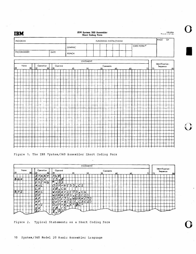
Statements in Basic Assembler language can be written in free format; in other words, the statement components need not begin in a specified column of the coding sheet. (The name of a statement, which must begin in column 25, is an exception to this rule.) However, the statement components must be separated from each other by at least one blank column.
For the purpose of clarity, most programmers do not use the free format but prefer to begin each type of statement component in a specific column of the coding sheet.
The coding form shown in Figure 1 is designed to satisfy this preference. This form -- the IBM systemj360 Assembler Short
Coding Form (No. X28-6506-2) -- contains a statement field which extends from column 25 to column 71 and is broken down into three sub-fields: the name field (eols.
25-30), the operation field (cols. 32-36), and the operand field (cols. 38-71).
The column numbers on the coding form refer to the column numbers on the cards into which the source program is to be punched.
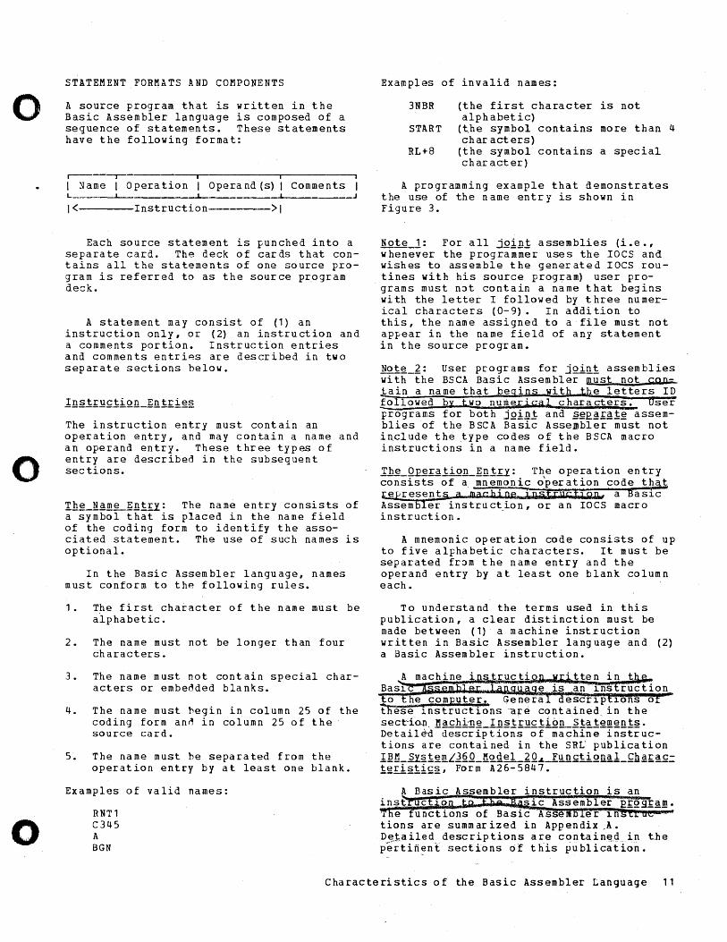
For the purpose of alignment, each entry in one of the sub-fields should begin in the leftmost column of the sub-field. Thus, the operation entry should begin in column 32 and the operand entry should begin in column 38. (Note that the name entry .!!!.Y.§1 begin in column 25.) Figure 2 shows a coding form with a number of typical statements in the Basic Assembler language.
Characteristics of the Basic Assembler Language 9
IBM IBM System 360 Assembler Short Coding Form
PROGRAM PUNCHING INSTRUCTIONS
GRAPHIC
PROGRAMMER I DATE PUNCH
STATEMENT
Name Operation Operand Comments 25 30 32 36 38 45 50 55 60
!
--r-f- f-t- -~- -+ f--f- - ~-f-+- ~-f- - t-- -1-- ---t
: I I
r -- --- - +-. t-. -
-- - --- +-- -- .-~-- -
.-f--"-f-- --
Figure 1. The IBM ~ystem/360 Assembler £hort Coding Form
Name Operation 25 30 32 36
S TA Rr IBGN BASR
USING M vic LH
IR TI M VC 11) P
STATEMENT
Operand 38
t 3 .. I~ r*. i 3
45
o vlT + If ( 3 ) • C t
WOI< K+ 2 (17 ) f cl4
50
WORKI(19) • (21( 2)
Comments 55
Figure 2. Typical Statements on a Short Coding Form
10 System/360 Model 20 Basic Assembler Language
60
CARD FORM H
65 71 73
I
1
65 71 73
X28-6506 PTll1h'J 10 U. S.A.
PAGE OF
Identification-Sequence
t
I
IdentificationSequence
80
80
o
I
o
o
o
o
o
STATEMENT FORMATS AND COMPONENTS
A source program that is written in the Basic Assembler language is composed of a sequence of statements. These statements have the following format:
r------,-----------.-----------~i----------~
1 Name 1 Operation 1 Operand (s) 1 Comments L ______ ~ _____________ ~ _____________ ~ __ __
1 <---------Instruction ---->1
Each source statement is punched into a separate card. The deck of cards that contains all the statements of one source program is referred to as the source program deck.
A statement may consist of (1) an instruction only, or (2) an instruction and a comments portion. Instruction entries and comments entries are described in two separate sections below.
The instruction entry must contain an operation entry, and may contain a name and an operand entry. These three types of entry are described in the subsequent sections.
Ih~~~~~ntry: The name entry consists of a symbol that is placed in the name field of the coding form to identify the associated statement. The use of such names is optional.
In the Basic Assembler language, names must conform to thp. following rules.
1. The first character of the name must be alphabetic.
2. The name must not be longer than four characters.
3. The name must not contain special characters or embedded blanks.
4. The name must hegin in column 25 of the coding form an~ in column 25 of the source card.
5. The name must he separated from the operation entry by at least one blank.
Examples of valid names:
RNT1 C345 A BGN
Examples of invalid names:
3NBR (the first character is not alphabetic)
START (the symbol contains more than 4 ch ar act ers)
RL+8 (the symbol contains a special char act er)
A programming example that demonstrates the use of the name entry is shown in Figure 3.
Note-1: For all jg1n! assemblies (i.e., whenever the programmer uses the IOCS and wishes to assemble the generated IOCS routines with his source program) user programs must n3t contain a name that begins with the letter I followed by three numerical characters (0-9). In addition to this, the name assigned to a file must not appear in the name field of any statement in the source pLogram.
Note_~: UseL pLogLams for joi~i assemblies with the BSCA Basic AssembleL must not cgp-1ain a name that begins with hhe letters ID followed by bWO numerical characters. aser programs for both jQin.t andgE.~'£I!!~ assemblies of the BSCA Basic Assembler must not include the type codes of the BSCA macro instructions in a name field.
Th~_Operation_~n.t±Y: T~e operation entry consists of a mn eman ic opel" ation code t~aJ; ~presen ts. amacihl: ne::XMf filco:IJJSii, a Bas1c Assembler instruction, or an laCS macro instruction. '
A mnemonic operation code consists of up to five alphabetic characters. It must be separated fLom the name entry and the operand entry by at least one blank column each.
To understand the terms used in this publication, a cleaL distinction must be made between (1) a machine instruction written in Basic Assembler language and (2) a Basic Assembler instruction.
. tten in Bas1 a e is an 1ns ruction to the computer. GeneLa escr1p 10ns 0
these Instructions are contained in the sect~io.l1 Machi'TIe I nst'ruc tion Sta temen ts. Detail~d-descriptions-of-machln;-rnstructions aLe contained in the SRL publication I~!1_~Y2i§t!!lLJ2Q_!1.odel_£Q.L_.El!.~£ti2nal_~h~£~£.:: i~ri2ii£21 FOLm A26-5847.
Assembler instruction is an inst c sic Assembler PI~gII!ID.
e functions of Basic Ass m er 1n tions are summaLized in Appendix .A. D ~J;, a i led de sc rip t ion sal' e con ta i n~.g in t,h e p~Ltift~nt sections 6f t~is ~ublicatiori.
ChaLacteristics of the Basic Assembler Language 11
The IOCS macro instructions are summarized in the section lnE~lLQQ1EQ1_~~~XQ In§l£~fiiQn§. Det~iled descriptions of these macro instructions are contained in the SRL publication 1~~_~Y§!~illLl~~_~Qg~1_1~ ~~£~~£Qg£~mming_~QEEQ~lL_lnE~lLQ~!EQ!_~Qn= i£QI_~Y§igill, Form r26-3603.
The following are examples of valid operation codes:
LH AH MVC ORG TIOB
load halfword add halfword move characters reset location 'counter test I/O and branch
lhg_QEg£~nQ~l£Y: The operand entry provides the Basic Assembler program or the computer with the information required to carry out the instruction specified in the ope ra tion f iel d.
An operand may consist of a symbol ..1p.aIDe), a constant, or a CQlDPopn2 exW-es-:sion. Two examples of compound expressions are shown below.
X'BF' defines the hexadecimal constant ~F, which is equal to decimal 191.
GAMA-150 -- designates the storage address of GAM~ minus 150 bytes.
Each operand entry must be separated from the associaten operation entry by at least one blank column. In addition, each operana entry must be delimited by at least one blank column; i.e., any associated comments entry must be separatec from the operand entry by at least one blank column.
For example, the AH instruction requests the computer to ad~ a halfword to the contents of a register. The operand, therefore, must specify (1) the number of the register and (2) the storage address of this halfword, as shown in the sample statement
AH 8, VALX
The above statement specifies that the value (halfword) stored at the location whose address is VALX be added to the contents of register R.
The operand entry of the AH instruction in the above example consists of two operands: the register number 8 and the
symbolic address VALX. These two operands must be separated from each other by a comma.
NQ!~: Operand entries that consist of two operands must conform to the format
operand1,operand2
The attributes and functions of symbols and expressions that may appear in the operand field of a statement are described in a later section.
The comments entry in a statement provides for the insertion of explanatory information into a program listing. Comments do not affect the assembly or the execution of a Frogram, but they facilitate the reading and understanding of a program listing by explaining the purpose or function of a particular statement.
Any valid character, including blanks, can be used in a comment. Comments entries are punched into a statement card to the right of the operand entry and separated from it by at least one blank column. Comments entries must not extend beyond column 71.
If the desired comments entry cannot be accommodat~d in the spac~ avail~ble on the right of t,he. op.erand-e.ntry, or if comments consi~t Qf geperal information that pertains.to a seq-uence. of statements, the "comments card" can be used.
Comments Cards must contain an asterisk in C"O!i:i m n 25 ; co 1 umns 1-~ ~a-26=-~1'-a't"e'~'" ava'1!a~! e'OO! r 0 r ~.~ ~A";y-~ll'ilnimrr'YSo~~~menEs! ca\'ds,M'may be' inserted anywhere in a source~program deck.
The identification-sequence field (columns 73-80 Qt the coding form) can be used to ~pecify identifying tnformation and/or to provide the statemeritS of a program with seqJ-1ence numbers'. So~e lypical identificatIon-sequence entries are shown in 1he example below.
Example 1: SALE0001 SAL E0002
SALE0813
12 System/360 ~odel 20 Basic Assembler Language
o
I
o
o
o
o
o
Example 2:
Ex ample 3:
MAIN001 MAINOf'2
MAINO<l7 ROUT1/01
ROUT1/65 MAINO<l8
MAIN4f>6
MILLE" MILLE~
MILLE~
Any identification-sequence entry is printed in the program listing as it is read. Identification-sequence entries do not affect the assp.mbly or the execution of the program.
~~~l~_~gg~~nc~Q1-~tatem~ni~
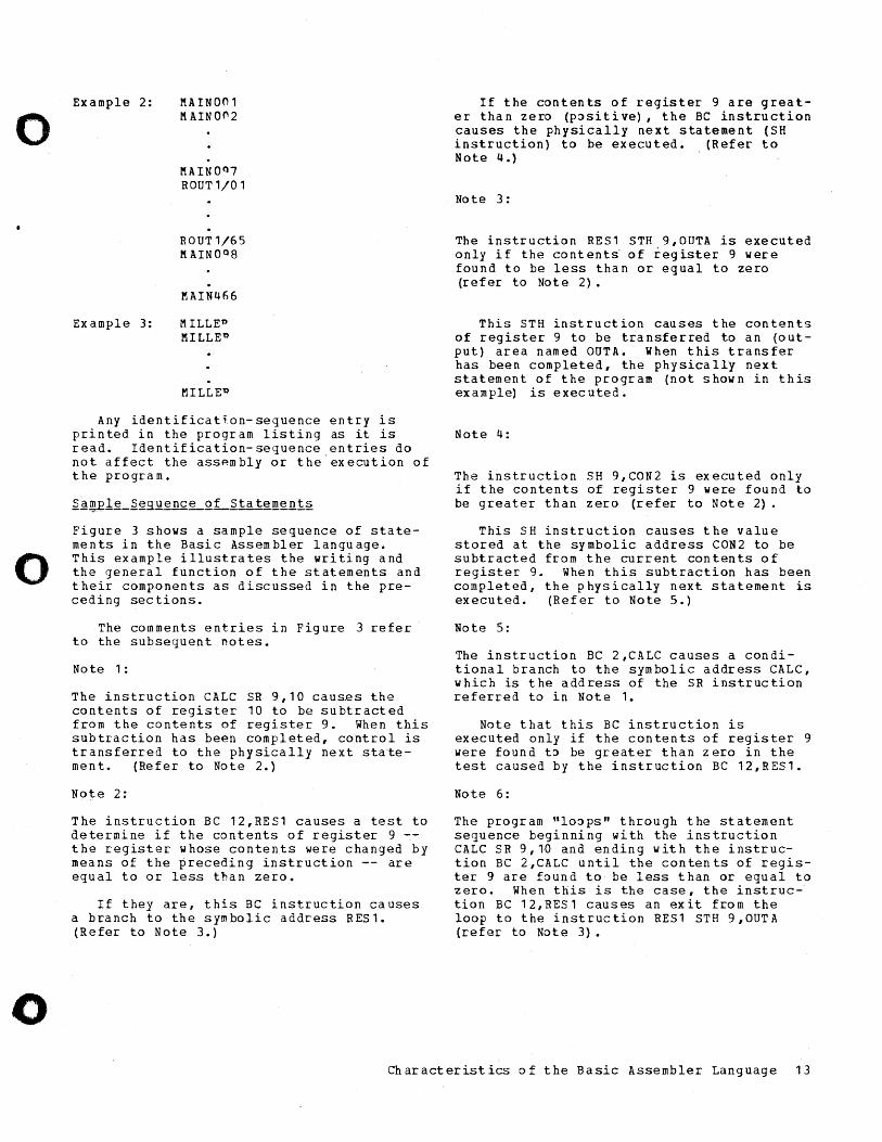
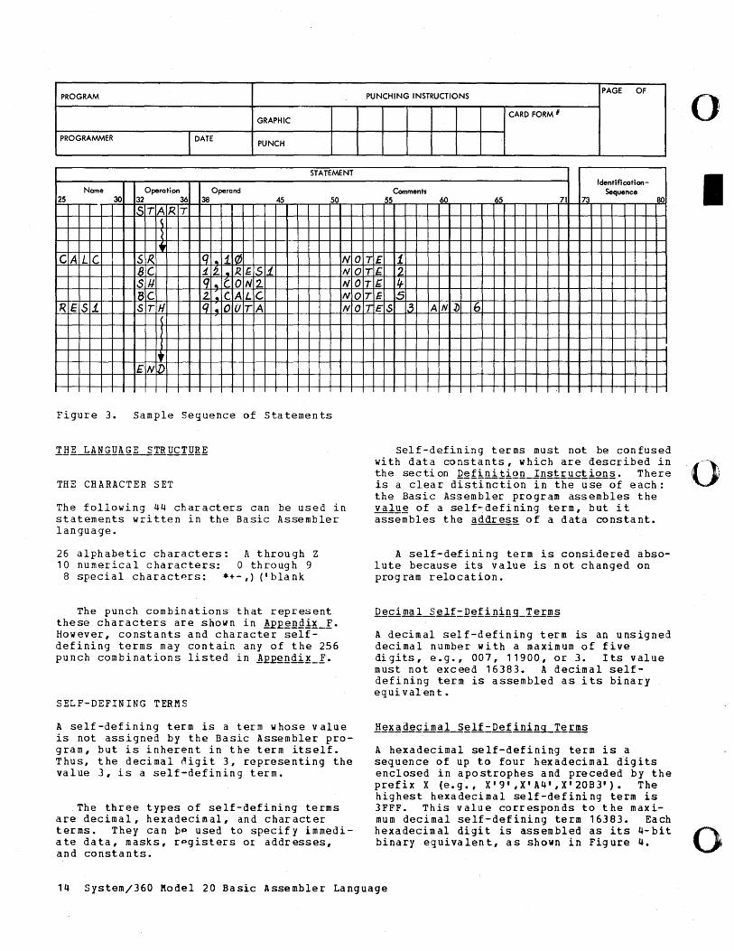
Figure 3 shows a sample sequence of statements in the Basic Assembler language. This example illustrates the writing and the general function of the statements and their components as discussed in the preceding sec tions.
The comments entries in Figure 3 refer to the subsequent notes.
Note 1:
The instruction CALC SR 9,10 caus.es the contents of register 10 to be subtracted from the contents of register 9. When this subtraction has been completed, control is transferred to the physically next statement. (Refer to Note 2.)
Note 2:
The instruction BC 12,RES1 causes a test to determine if the contents of register 9 -the register whose contents were changed by means of the preceding instruction -- are equal to or less than zero.
If they are, this BC instruction causes a branch to the symbolic address RES1. (Refer to Note 3.)
If the contents of register 9 are greater than zero (p::>sitive), the BC instruction causes the physically next statement (SH instruction) to be executed. (Refer to Note 4.)
Note 3:
The instruction RES1 STH 9,OUTA is executed only if the content~ of iegister 9 were found to be less than or equal to zero (refer to Note 2).
This STH instruction causes the contents of register 9 to be transferred to an (output) area named OUTA. When this transfer has been completed, the physically next statement of the program (not shown in this example) is executed.
Note 4:
The instruction SH 9,CON2 is executed only if the contents of register 9 were found to be greater than zero (refer to Note 2) .
This SH instruction causes the value stored at the symbolic address CON2 to be subtracted from the current contents of register 9. When this subtraction has been completed, the physically next statement is executed. (Refer to Note 5.)
Note 5:
The instruction BC 2,CALC causes a conditional branch to the symbolic address CALC, which is the address of the SR instruction referred to in Note 1.
Note that this BC instruction is executed only if the contents of register 9 were found t::> be greater than zero in the test caused by the instruction BC 12,RES1.
Note 6:
The program "lo::>ps" through the statement sequence beginning with the instruction CALC SR 9,1D and ending with the instruction BC 2,CALC until the contents of register 9 are found to be less than or equal to zero. When this is the case, the instruction BC 12,RES1 causes an exit from the loop to the instruction RES1 STH 9,OUTA (refer to Note 3).
Characteristics of the Basic Assembler Language 13
PROGRAM
GRAPHIC
PROGRAMMER I DATE PUNCH
STATEMENT
Name Operation Operand 25 30 32 36 38 45 50
5T A R T
I. CA LC SR.. q .. i QJ NO
BC 1.2- ~ R. f.S1.. NO SJI q" CO N2. NO Be 2. .. CA LG NO
'R.E 51 ST H Iq " 0 UT A NO
I" EN l)
Figure 3. Sample Sequence of Statements
THE CHARACTER SET
The following 44 characters can be used in statements written in the Basic Assembler language.
26 alphabetic characters: A through Z 10 numerical characters: 0 through 9
8 special charact~rs: *+- ,) (' bla nk
The punch combinations that represent these characters are shown in !££~ngi!_X. However, constants and character selfdefining terms may contain any of the 256 punch combinations listed in !E£gndi~_X.
SELF-DEFINING TERMS
A self-defining term is a term whose value is not assigned by the Basic Assembler program, but is inherent in the term itself. Thus, the decimal digit 3, representing the value 3, is a self-defining term.
.The three types of self-defining terms are decimal, hexadecimal, and character terms. They can b~ used to specify immediate data, masks, rpgisters or addresses, and constants.
PUNCHING INSTRUCTIONS PAGE OF
CARD FORM #
Identification-Comments Sequence
55 60 65 71 73 80
T£ i IE. 2 T~ q. TE 5 IES .3 AN 1> 6
Self-defining terms must not be confused with data constants, which are described in the secti on Defini tion Instruct ions. There is a clear dIstInction-in-the-use-of each: the Basic Assembler program assembles the valQ~ of a self-defining term, but it assembles the ~ddres2 of a data constant.
A self-defining term is considered absolute because its value is not changed on prog ram relocation.
A decimal self-defining term is an unsigned decimal number with a maximum of five digits, e.g., 007, 11900, or 3. Its value must not exceed 16383. A decimal selfdefining term is assembled as its binary equi val en t.
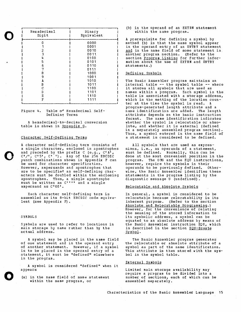
A hexadecimal self-defining term is a sequence of up to four hexadecimal digits enclosed in apostrophes and preceded by the prefix X (e.g., X'9',X'A4',X'20B3'). The highest hexadecimal self-defining term is 3FFF. This value corresponds to the maximum decimal self-defining term 16383. Each hexadecimal digit is assembled as its 4-bit binary equivalent, as shown in Figure 4.
14 System/360 Model 20 Basic Assembler Language
o
I
()i
o
o
o
o
r----------------------,----------------------, I I J
Hex adecima I Digit
o 1 2 3 4 5 6 7 8 9 A B C D E F
Binary Equivalent
0000 0001 0010 0011. 0100 0101 0110 011.1 1000 1001 1010 1011 1100 1101 1110 1111
Figure 4. Table o~ Hexadecimal SelfDefining Terms
A hexadecimal-to-decimal conversion table is shown in ]EE~ngi!_g.
A character self-defining term consists of a single character, enclosed in apostrophes and preceded by the prefix C (e.g., C'A', C'I', C1 5', c' '). Any of the 256 EBCDIC punch combinations shown in Appendix F can be used for character specification. However, ampersands and apostrophes that are to be specifien as self-defining characters must be doubled within the enclosing apostrophes. Thus, a single apostrophe must be written as C"" and a single ampersand as C'SS'.
Each character self-defining term is assembled as its 8-bit EBCDIC code equivalent (see Appendix F).
SYMBOLS
Symbols are used to refer to locations in main storage by name rather than by the ac t ual add ress.
A symbol may be placed in the name field of one statement and in the operand entry of another statement. However, if a symbol is to be placed in the operand entry of a statement, it must be "defined" elsewhere in the program.
A symbol is considered "defined" when it appears
(a) in the name field of some statement within the samp. program, or
(b) in the operand of an EXTRN statement within the same program.
A prerequisite for defining a symbol by method (b) is that the same symbol appear in the operand entry of an ENTRY statement ~nd in the name field of some statement in. another progr am section. (R efer to the section irog£~~_Lin~ing for further information about the use of EXTRN and ENTRY statemen ts.)
The Basic Assembler program maintains an internal table -- the symbol table -- where it stores all symbols that are used as names within a program. Each symbol in the table is ass~ciated with a storage address, which is the setting of the location counter at the time the symbol is read. A program-generated length attribute and a name identification are added. The length attribute depends on the basic instruction format. The name identification indicates whether the symbol is relocatable or absolute, and whether it is external (defined in a separately assembled program section). Thus, a symbol entered in the name field of a statement is considered to be defined.
All symbols that are used as expressions, i.e., as operands of a statement, must be defined. Normally, this can be done at the most convenient position in the program. The 0 RG and the EQU instructions, however, require the symbols in their operands to be previously defined. Otherwise, the Basic Assembler identifies these statements in the program listing by the diagnostic message U (undefined).
In general, a symbol is considered to be relocatable because relocatability is its inherent purpose. (Refer to the section !Q~~lu!~~~~~~l~catable pro~mming.) However, for the convenience of relating the meaning of the stored information to its symbolic address, a symbol can be equated to an absolute address by means of the Basic Assembler instruction EQU, which is described in the section ~Q-Eg~~!~ ~Y~.Qol.
The Ba~ic Assembler program generates the relocatable or absolute attribute of a symbol as part of the name identification. This attribute is then stored with the symbol in the symbol table.
Limited main storage availability may require a pr~gram to be divided into a number of sections, each of which can be assembled separately.
Characteristics of the Basic Assembler Language 15
In one program section, the operand entry of a statement may contain a symbol that is defined in a different program section. This symbol must be introduced by an EXTRN statement into the section in which it is not defined. In the program section where the symbol is defined, it must be specified in an EN~RY statement. The Basic Assembler instructions, ENTRY and EXTRN, are described in the section E£Qg£E~ 1in~ing·
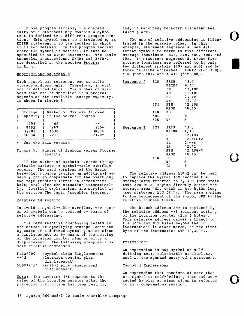
Each symbol can represent one specific storage address only. Therefore, it must not be defined twice. The number of symbols that can be specified in a program depends on the available storage capacity, as shown in Figure 5.
r I Storage Num ber of Sym boIs Allowed I capacity in the Source Program ~ I 4096 165 I 8192 847 805* I 12288 1530 1487* I 16384 2213 2170* L-_______ ~
* for the BSCA version
, I I ~ I I I I
Figure 5. Number of Symbols versus Storage Capacity
If the number o~ symbols exceeds the applicable maximum, a symbol-table overflow occurs. The card versions of the Basic Assembler program require an additional assembly run to compensate for the overflow; the tape versions (after an informative halt) deal with the situation automatically. Detailed explanations are supplied in the sectio n !ll.~L~asi£_A sse mbler PrQ.9.ram..
To avoid a symbol-table overflow, the number of symbols can he reduced by means of relative addressing.
The term relative addressing refers to the method of specifying storage locations by means of a defined symbol plus or minus a displacement, or by means of the setting of the location counter plus or minus a displacement. The following examples show some relative addresses.
FLDA-200 *+12
FLDB+X' F'
(symbol min us displacement) (location counter plus displacement)
(symbol plus hexadecimal displacement)
Note: The asterisk (*) represents the value of the location counter after the preceding instruction has been read in,
and, if required, boundary alignment has taken place.
The use of relative addressing is illustrated in the example below. In this example, statement sequence A uses different symbols to refer to five different storage locations: BGN, SYM, AUG, ADD, and SUM. In statement sequence B, these five storage locations are referred to by only two different symbols (BGN and AUG) and by three relative addresses: AUG+2 (for ADD), *+6 (for SYM), and AUG+4 (for SUM) •
I
BGN BASR 13,0 USING *, 13 LH 12,AUG AH 12, A DD BC 2,SYM SR 12,12
SYM STH 12,SU£'1 BASR 14,15
AUG DS H ADD DS H SUM DS H
~~9J! en .f.!L!! BGN BASR 13,0 USING *, 13 LH 12, A UG AH 12, AUG+2 BC 2,* +6 SR 12,12
'STH 12,AUG+4 BASR 14,15
AUG DS H DS H DS H
The relative address AUG+2 can be used to replace the symbol ADD because the storage area referred to by ADD (see statement ADD DS H) begins directly behind the storage area AUG , which is two bytes-long (see statement KUG DS H). The same applies to the replacement of the symbol SUM by the relative address AUG+4.
The branch address SYM is replaced by the relative address *+6 (current setting of the location counter plus 6 bytes). This relative address causes a branch to the location six bytes beyond the BC instruction; in other words, to the first byte of the instruction STH 12,AUG+4.
EXPRESSIONS
An expression is any symbol or selfdefining term, relocatable or absolute, used in the ~perand entry of a statement.
An expression that consists of more than one symbol or self-defining term and connected by plus or minus signs is referred to as a compound expression.
16 System/360 Model 20 Basic Assembler Language
o
I
0
o
o
o
o
Examples: BETA-10+200 FLD+X'2D' *-GAMA+200
Rgstf!£tiQll2. The ~asic Assembler program considers an expression to be terminated by a blank or a comma, depending on the type of expression. An expression must noi
• begin with a plus or minus sign,
• comprise more than three symbols and/or self-defining terms,
• have a negative value at object time (if it is absolute),
• contain another relocatable symbol if an external symbol is part of the expression,
• contain any self-defining term with a value >4095 if used as operand of a machine instruction, and
• exceed 16383 (decimal).
The Basic Assembler replaces symbolic expressions with their numerical equivalents by evaluating compound expressions, executing arithmetic calculations, and inserting the results into the instruction.
An expression is considered absolute if it con tains
(1) only self-defining terms and/or absolute symbols, or
(2) one positive an~ one negative relocatable symbol.
Some examples of absolute expressions are shown below. (The symbols PHS 1 an d PHS2 are considered relocatable.)
2510 PHS2+2510-PHS1
PHS2-PHS1 2510-PHS2+PHS1
The value of a relocatable expression is changed by the Basic Assembler program on
program relocation, in other words, the relocation factor is applied to its numerical equivalent to compute the new storage address.
Relocatable expressions must conform to the following rules:
• A relocatable expression must contain either one or three relocatable symbols.
• If a relocatable expression contains three relocatable symbols, one and only one of these symbols must be preceded by a minus sign.
• If a relocatable expression contains only one relocatable symbol, this symbol must not be negative.
Some examples of valid relocatable expressions are shown below. (R stands for "reloca table sym bol".)
R+1, R-8, R-R+R, *-X'DO'
The following examples show some invalig relocatable expressions.
R+R (contains two relocatable symbols)
R+R+R (one of the relocatable symbols should be negative)
16-R (the relocatable symbol must not be negative)
R-R-R (two negative relocatable symbols)
LOCATION COUNTER
The Basic Assembler program uses a counter to record the address assigned to each statement read into main storage. This counter is referred to as ~he location counter.
At assembly time, as soon as an instruction statement has been read into main storage, and, if required, boundary alignment has taken place, the location counter is incremented by the number of bytes occupied by that statement. The location coun'ter then indicates the next available storage location.
Characteristics of the Basic Assembler Language 17
LOC.: OBJECT CODE SOURCE STATEMENTS CTR I
I 0154 INOA srARr 340 01~4 0000 BASR 13.0 LOAD BASE REG. 01-56 USING ~. 13 ASSIGN BASE RE. 0156 47FO 0048 Be 15.CALe CIRCLE THE CONS T OOOA RIO eQU 10 ..... 015A PRT OS CLl7 016B 0000 0000 0000 0000 00 WORK DC Xt,9:'O' 0174 0000 0000 0000 00 ACCU-i DC XL7'0' 0178 2400 DC CPH DC X'Z4000C' 017E 025e RATE DC X'025C' 0180 0000 0000 0000 5C ROUN DC X'0000000000005C' 018B 0152 CNT DC H'338' 018A 0001 DEeR DC H'l' 018C 4020 bB20 2020 bA20 2020 bB MASK DC X'40206B202020bR?020206B' 0197 2020 2148 2020 DC X'2020214R2020' 019E 48AO 0032 CALC LH RIO,CNT LOAD COUNT 01"'2 ~2 0022 0025 ",,~y.,C.) ACCU+4(31,CPTL LOAD ACCU OlA8 06 01)17 DOlE lOOP MVC. WORK+l( 71, ACCU LOAD \~ORK:::,. OlAe FD81 0015 0028 OP WORK,RATE COMPUTE IMTEREST 0184 FAb6 ODIE 0015 AP AeeU,WORK( H INCREMENT CAPITAL 018A FA66 DOlE 002A AP AeCU,ROUN ROUND DEC I flAl OlCO noc 0024 104 V I ACCU+6,X'OC' RESTORE LAST DIGIT 01C4 48AO 0034 SH Rlo,DEeR DECRFASE: COU~T
0le8 4720 0052 Be 2,lOOP TEST FOR CO~PlETION Olee 0210 0004 0036 MVC PRT,MASK MASK TO PRINT AREA 0102 DElO 0004 DOlE ED PRT,Aceu EDIT RESULT 0108 0040 0004 0011 FINE XIO PRTlX '40' 1,17 PRINT RESULT OlOE 4710 OOAO BC 1,PERR TfST PRINTE~ NOT OK 01E2 4740 DOB2 Be 4,FINE TEST PRINTER WORKNG 0lE6 9A40 0090 TIOB ~,X'40' TEST ENU OF 1/0 OlEA 9A4l OOAO TIOB PERR,X'41' TEST PRINTER ERROR OlEE 9900 0999 HALT HPR X'999',0 DISPLAY 999 OlF2 47fO 0098 Be l5,HAlT lOCK RESTART 01f6 9900 0111 PERR HPR X'lll',O DISPLAY III OlFA 47fO 0082 Be l5,FINE REPEAT PRINT 0154 END INOA
Figure 6A. Assignment of Storage Addresses
r --,-------------T , Location Counter Setting , , i-------T ----. Instruction, Length Statement , In Hex J In Decimal , , ~ I I I
0154 34n START , none 01 0154 340 BASR I 2 bytes 02 0156 342 USING , none 03 0156 342 BC , 4 bytes 04 01SA 346 EQU I none 05 015A 346 DS I 17 bytes 06 016B 361 DC , 9 bytes 07 0174 37? , , I , , I I I , , I , ,
V V V I V 019E 414 LH I 4 bytes 16 01A2 418 MVC I 6 bytes 17 01A8 42U MVC , 6 bytes 18 01AE 430 DP I 6 bytes 19 01B4 43~ , I
I I V I
etc. I L-_____ --L -.J
Figure 6B. Assignment of storage Addresses
18 System/360 Model 20 Basic Assembler Language
:OBJ. ICRD I
SIMTOI onl SIMI02 002 SIMT03 002 SIMT04 OOZ ST:oH05 002 ST~T06 007. STMT07 003 STMT08 003 STMT09 003 ST~TlO 003 STI-ITll 003 S T"'TlZ 003 SIMTl3 003 SI"1Tl4 003 STMTl5 003 SIMTl6 003 STMTl7 003 STMTl8 004 ST 'H 19 004 ST'H20 004 STMT21 004 ST,H22 004 STiH23 004 S T:-1T24 004 STAT25 004 STMT26 004 STMT27 004 ST'-1T28 005 S TiH 29 005 STMT30 005 ST~T31 005 STMT32 005 S T;H33 005 STMT34 005 STMT35 005 STMT36 006
/
/
a (
I
o
0
o
o
o
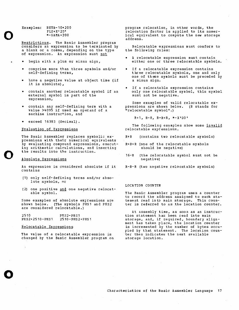
ASSIGNED ADDRESSES
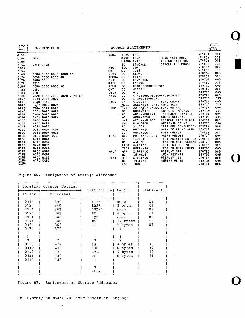
If a printer is attached to the Model 20 during the assembly of a source program, a program listing is produced, as shown in Figure 6A. The listing includes all statements translated into machine language. To the left of the machine-language statements, the listing contains the address assigned to each statement; i.e., the current setting of the location counter at the time the statement is read into main storage.
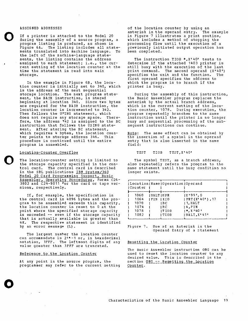
In the example in Figure 6B, the location counter is initially set to 340, which is the address of t.he 'next sequential storage location. The next program statement, the BASR instruction, is stored beginning at location 340. Since two bytes are required for the BASR instruction, the location counter is incremented to 342. Then follows the U~ING statement, which does not require any storage space. Therefore, the address 142 is assigned to the BC instruction that follows the USING statement. After storing the BC statement, which requires 4 bytes, the location counter points to stor~ge address 346. This procedure is contin~ed until the entire program is assembled.
The location-counter setting is limited to the storage capacity specified in the control card. The control card is described in the SRL publications 1]~_~Y~1~IDLl~Q ~Qg~1_l~£~£~Proqramming_Su£EoriL~~2ic !E§~IDQ1~£~_QEerating Procedures, Forms C26-3802 and C24-9011 ~or the card or tape versions, respectively.
If, for example, the specification in the control card is 4096 bytes and the program to be assemblp.d exceeds this capacity, the location counter is reset to 0 at the point Where the specified storage capacity is exceeded -- even if the storage capacity that is actually available is greater than 4K. The respective statement is identified by an error message (L).
The largest numner the location counter can accommodate is 2 14 -1 or, in hexadecimal notation, 3FFF. The leftmost digits of any value greater than 3FFF are truncated.
At any point in the source program, the programmer may refer to the current setting
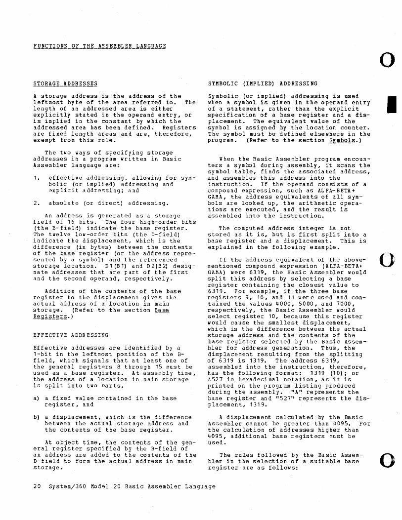
of the location counter by using an asterisk in the operand entry. The example in Figure 7 illustrates a print routine, which includes a method of stopping the processing flow until the execution of a previously initiated output operation has been completed.
The instruction TIOB *,X'40' tests to determine if the attached 1403 printer is still busy with the execution of the last print command. The second operand (X'40') specifies the unit and the function. The first operand specifies the address to which the pr~gram is to branch if the printer is busy_
During the assembly of this instruction, the Basic Assembler program replaces the asterisk by the actual branch address, which is the current setting of the location counter, 1078. During execution, the program repeatedly branches to the same instruction until the printer is no longer busy and sequential processing of the subsequent instructions can continue.
No1~: The same effect can be obtained by the insertion of a symbol in the operand entry that is also inserted in the name fiel d:
TEST TIOB TEST,X'40'
The symbol TEST, as a branch address; also repeatedly refers the program to the same statement until the busy condition no longer exists.
r I I I
ILocationlNamelOperationlOperand I Cou nt er I
1060 1064 1070 1074 1078 1082
I I I I IHALTIHPR IFIN IXIO I I BC I I BC I IT IOB I ITIOB
'------"---
IX'99',0 IPRT(X'40'),17 11,HALT \4,FIN 1*, X '40 ' IHALT,X'41'
Fiyure 7. Use of an Asterisk in the Operand Entry of a statement
The Basic Assembler instruction ORG can be used to reset the location counter to any desired value. This is described in the section QR~_==_R~§g1!ing_lh~-1Q£~liQn ~Q.unl~£·
, I I ~ I I I I I I
J
Characteristics of the Basic Assembler Language 19
A storage address is the address of the leftmost byte of the area referred to. The length of an addressed area is either explicitly stated in the operand entry, or is implied in the constant by which the addressed area has been defined. Registers are fixed length areas and are, therefore, exempt from this rule.
The two ways of specifying storage addresses in a program written in Basic Assembler language are:
1. effective addressing, allowing for symbolic (or implied) addressing and explicit addressing; and
2. absolute (or direct) addressing.
An address is generated as a storage field of 16 bits. The four high-order bits (the B-field) indicate the base register. The twelve low-order bits (the D-field) indicate the displacement, which is the difference (in bytes) between the contents of the ~ase register (or the address represen ted by a sym bol) an d the referenced s tor age lo cat ion. D 1 (B 1) and D 2 (B 2) des i g -nate addresses that are part of the first and the second operand, respectively.
Addition of the contents of the base register to the displacement gives the actual address of a location in main storage. (Refer to the section ~~se Reg:i~j;&£§· )
EFFECTIVE ADDRESSING
Effective addresses are identified by a 1-bit in the leftmost position of the Bfield, which signals that at least one of the general registers 8 through 15 must be used as a base register. At assembly time, the address of a location in main storage is split into two narts,
a) a fixed value contained in the base register, and
b) a displacement, which is the difference between the actual storage address and the contents of the base register.
At object time, the contents of the general register specified by the B-field of an address are added to the contents of the D-field to form the actual address in main storage.
o SYMBOLIC (IMPLIED) A DDRE551 NG
5y mbolic (or implied) addressing is used I when a symbol is given in the operand entry of a statement, rather than the explicit specification of a base register and a displacement. The equivalent value of the symbol is assigned by the location counter. The symbol must be defined elsewhere in the program. (Refer to the section ~~.QoI2.)
When the Basic Assembler program encounters a symbol during assembly, it scans the symbol table, finds the associated address, and assembles this address into the instruction. If the operand consists of a compound expression, such as ALFA-BETA+ GAMA, the address equivalents of all symbols are looked up, the arithmetic operations are executed, and the result is assembled into the instruction.
The computed address integer is not stored as it is, but is first split into a base register and a displacement. This is explained in the following example.
If the address equivalent of the above- (~) mentioned compound expression (ALFA-BETA+ " GAMA) were 6319, the Basic Assembler would split this address by selecting a base register containing the closest value to 6319. For example, if the three base registers 9, 10, and 11 wer e used and contained the values 4000, 5000, and 7000, respectively, the Basic Assembler would select register 10, because this register would cause the smallest displa cement, which is the difference between the actual storage address and the contents of the base register selected by the Basic Assem-bler for address generation. Thus, the displacement resulting from the splitting of 6319 is 1319. The address 6319, assembled into the instruction, therefore, has the following format: 1319 (10); or A527 in hexadecimal notation, as it is printed on the program listing produced during the assembly. "A" represents the base register and "527" represents the displacement, 1319.
A displacement calculated by the Basic Assembler cannot be greater than 4095. For the calculation of addresses higher than 4095, additional base registers must be used.
The rules followed by the Basic Assem- 0 bIer in the selection of a suit able base ' register are as follows:
20 System/360 Model 20 Basic Assembler Language
o
o
o
1. If more than one register would produce d valid displar.ement (not exceeding 4095), the Basic Assembler uses the register that produces the smallest displacement.
2. If two or more registers produce the same displacement, the Basic Assembler uses the highest-numbered register.
3. If none of the specified registers produces a valid oisplacement, the address field in the instruction that contains the invalid opprand is set to zero. An appropriate error message appears in the program listing.
The advantages of symbolic addressing are the simplicity of the method itself and the resulting relocatability of the program.
EXPLICIT ADDRESSING
Explicit addressing requires the specification of a base register and a displacement in the operand entry of a statement.
~~~llig.!. M V I 800 (8) , X I A '
The above statement causes the immediate data (X'A') to be stored in the location identified by D1=8no and B1=8.
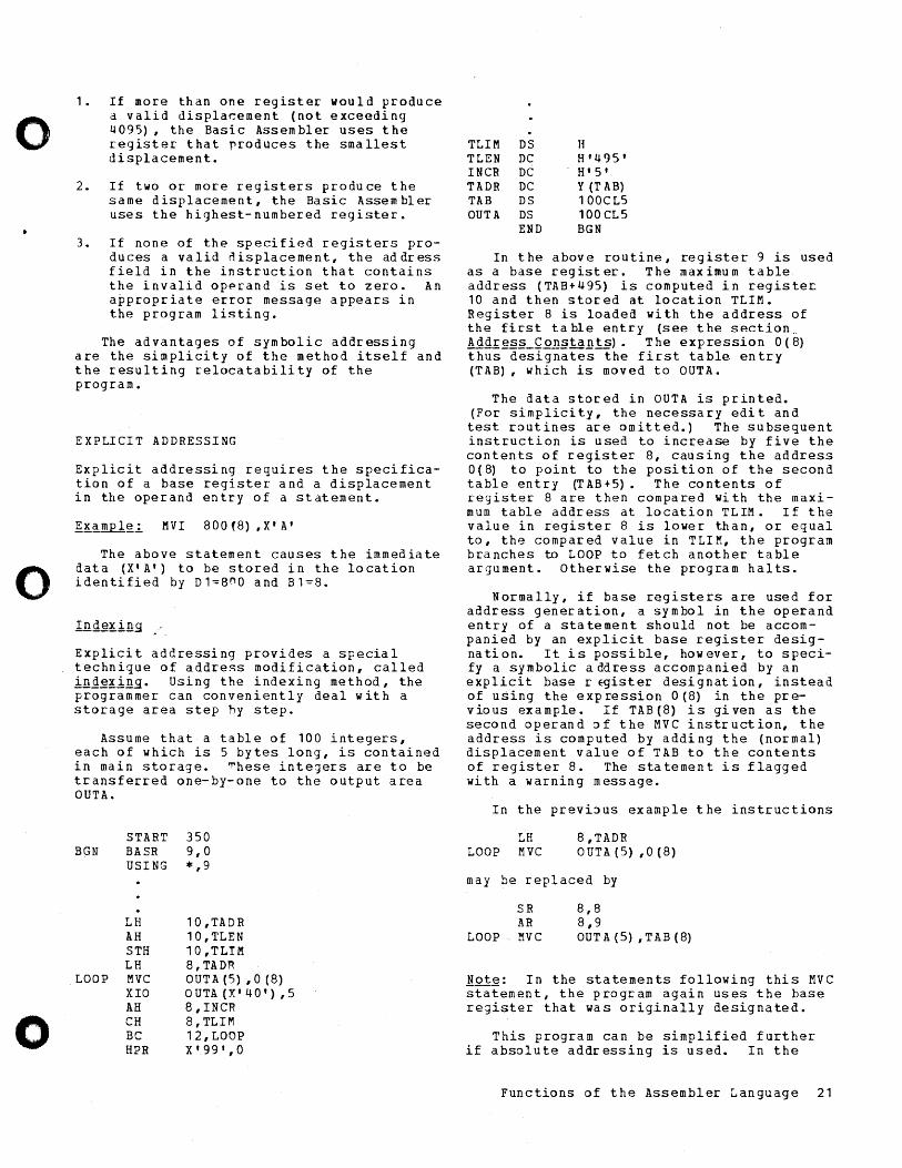
Explicit addressing provides a special technique of address modification, called ing~~ing. Using the indexing method, the programmer can conveniently deal with a storage area step hy step.
Assume that a table of 100 integers, each of which is 5 bytes long, is contained in main storage. ~hese integers are to be transferred one-by-one to the output area OUTA.
BGN START 350 BASR 9,0 USING *,9
LH AH STH LH
LOOP MVC XIO AH CH BC HPR
10,TADR 10,TLEN 10,TLIM 8, TADR OUTA (5) ,0 (8) OUTA(X'40'),5 8,INCR 8,TLIM 12,LOOP X'99',0
TLIM DS Ii TLEN DC H'495' INCR DC H'5' TADR DC Y (T AB) TAB DS 100CL5 OUTA DS 100CL5
END BGN
In the above routine, register 9 is used as a base register. The maximum table address (TAB+495) is computed in register. 10 and then stored at location TLIM. Register 8 is loaded with the address of the first table entry (see the section, Addres~_~on~ta~ts). The expression 0(8) thus designates the first table entry (TAB), which is moved to OUTA.
The data stored in OUTA is printed. (For simplicity, the necessary edit and test routines are omitted.) The subsequent instruction is used to increase by five the contents of register 8, causing the address 0(8) to point to the posi ti on of the second table entry (TAB+5). The contents of register 8 are then compared with the maximum table address at location TLIM. If the value in register 8 is lower than, or equal to, the compared value in TLIM, the program branches to LOOP to fetch another table argument. Otherwise the program halts.
Normally, if base re.gisters are used for address generation, a symbol in the operand entry of a statement should not be accompanied by an explicit base register designation. It is possible, however, to specify a symbolic address accompanied by an explicit base rEgister designation, instead of using the exp ression 0 (8) in the previous example. If TAB(8) is given as the second operand:> f the MVC instruction, the address is computed by adding the (normal) displacement value of TAB to the contents of register 8. The sta temen t is flagged with a warning message.
In the previ:>us example the instructions
LH LOOP MVC
8,TADR OUTA(5) ,0(8)
may be replaced by
SR AR
LOOP MVC
8,8 8,9 OUTA (5) ,TAB (8)
!ot~: In the statements following this MVC statement, the program again uses the base register that was originally designated.
This program can be simplified further if absolute addressing is used. In the
Functions of the Assembler Language 21
following example pseudo register 0 is used as a base register.
BGN
LOOP
TLIM INCR TAB OUTA
START USING
SR MVC XIa AH CH BC HPR
DC DC DS DS END
350 *,0
8,8 OUTA(5) ,TAB(8) OUTA (X'40'),5 8,INCR 8,TLIM 12,LOOP X'99',0
H'495' H' 5' 100CLS 100CtI, BGN
Register 8 is initially set to zero. Thus, TAB (8) refers to the first table entry. When the last MVC instruction has been executed, register 8 contains the value 500 and the program halts.
ABSOLUTE (DIRECT) ADDRESSING
Absolute addresses are identified by a zero in the leftmost bit position of the B-field. In absolute addressing, the 14 low-order bits of the combined Band D-field represent the complete address value and refer directly to byte locations in main storage. Absolute addresses are specified by decimal ~ntegers or absolute symbols in the operand entry of a sta tement.
r----.--------~
INamelOperationlOpprand • I I I I S TH I 1 3, 24 4 0
I ~ I L-___ ~ _______ ~
--.-J
The above statement causes the contents of register 13 to be stored in position 2440 of main storaqe.
Absolute addresses are also split into base register and ~isplacement by the Basic Assembler program, as Idescribed in the section ~ffe£tive-hgg~g§§ing. This addressing method, however, requires the specification of pseudo-registers to be used as base registers. A program that contains absolute addresses is not relocatable.
The Model 20 uses eight auxiliary storage units which are referred to as general registers. Each of these general registers has a length pf one halfword (two bytes). The general registers are numbered from 8 to 15 and are used for temporary atorag~of information during execution of indexing, fixed-point arithmetic~ address generation, and logical Jperations.
Information that requires the use of registers can be transferred
(1) from register to registe r,
(~ from register to main storage, or
(3) from main storage to register.
The direction of the information flow is implied in the machine-instruction format. (Refer to the section Ma£hine Instru£iion '§i~iemen t§.)
When general registers are used for addressing, they are referred to as Qsse registe~§. Base registers are assigned by a USING statement, as explained in the section Ba2~_Regi§t~rs_
An advantage of using general registers for fixed-point arithmetic is that data need not be packed prior to computation. All calculat ions ar e ex ecut ed in binary form.
Examples of the use of general registers:
AR 9,10 The contents of register 10 are added to the contents of register 9. The result is contained in register 9.
LH 12,AREA The first 2 bytes of the field AREA are loaded into register 12. (Note that in this case the field)AREA must be aligned at a halfword boundary.)
STH 13,aUTA The contents of register 13 are stored in the field OUTA. (Note that in this case the field OUTA must be aligned at a halfword boundary.)
When using the IOCS, the following restrictions on general registers apply_
• Register 15 must not be used by the programmer at any time.
22 System/360 Model 20 Basic Assembler Language
o
I
(}
o
o
o
o
• Register 14 is available only for restricted use, since its contents are changed each time a macro instruction is executed.
• Registers 11-15 are used by the 1419 IOCS.
In addition to the eight general registers there are four pseudo-registers numbered 0 to 3. (If a Submodel 5 is used, pseudo registers 0-7 are available. However, 0-3 are the only pseudo registers recognized in CPS programs.) The pseudo-registers are assumed to have the following permanent con ten ts:
o 1 2 3
o 4096 8192
12288
The pseudo-registers may be used only for storage addressing, i.e., as base registers. The advantage, in comparison to the use of general registers, is that pseudo-registers need not be loaded with a base address. Thus, program execution is faster and the general registers are available for other purposes. However, pseudoregisters can be used only for the specification of absolute addresses. Additional information is given in the section !E§Q= IJ!i~L!gg£gssing •
Base registers are general registers that are used for addressing main storage locations. The contents of a base register are subtracted from each storage address during program assembly; the remainder is referred to as the displacement. The base-register number, together with the displacement, is assembled into the instruction.
At least one general register must be assigned as a base register at the beginning of a relocatable program. In addition, this register must be loaned with the desired base address, which is normally the start address of the program.
USING -- USE BASE ~EGISTER
The USING statement is used to assign base registers. It also informs the Basi~ Assembler program of the anticipated contents of the respective base registers.
iii 1
I NamelOperationl Operand I I~---+I--------+I------------~-------~ I I US ING I * , 11 I L---L. ___ _
-J
The above statement designates register 11 as a base register and informs the Basic Assembler pngram that it may expect register 11 to contain the current value of the location counter.
!ote: A name entry is not used. If a symbol appears in the name field of the USING statement, it is disregarded by the Basic Assembler program -- if it conforms to symbol specifications. Otherwise, it is identified by a dia gnostic message in the program listing.
All registers that are assigned by means of USING statements must be loaded. This can be achieved by means of BASR instructions.
BASR -- BRANCH AND STORE REGISTER
For example, the statement BA~R 12,12 causes register 12 to be loaded with the current value of the location counter. This is followed by a branch to the address ErevioJ!21y contained in register 12.
Thus, in the above USING-statement example, register 11 can be loaded as follows:
r-, i --,
INamelOperationlOperand I ~-+-----+----------------------~ I I BASR I 11,0 I L __ .L-, .1..
____________ . ___________ ----J
Register 11 now contains the address of the next storage location; that is, the current value of the location counter at assembly time. The second operand, which normally specifies the register that contains the branch address, prevents branching because it refers to register O. Accordingly, the first instructions of a progrdm may be the following:
Functions of the Assembler Language 23
BGN
START BASR USING
356 11,0 *, 11
The largest displacement that can be calculated by the Basic Assembler is 4095. Therefore, an additional base register mustbe assigned for each additional 4096 bytes of main storage required.
Additional base registers may be specified also for other programming purposes, such as creating d~fined areas (dummy sections) in main storage where c~rtain program subroutines can be executed or where intermediate data is stored. However, if several base registers are specified by subsequent USING statements, an adequate method of loading these base registers must be found.
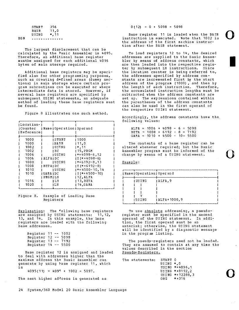
Figure 8 illustrates one such method.
r-------T ---,- , I Location- I I I I ICounter INamelOperationlOperand I IReferencel I I I ~ I -+----+- 1
1000 START I 1000 1000 BASR 111,0 1002 USING I * , 11 1002 BC 115,PRGM 1006 USING I * + 4098-' 6 , 1 2 1006 ALFA DC I Y (*+4098-6) 1008 USING 1*+6192-8,13 1008 BETA DC I Y (*+6192-8) 1010 USING I * + 4 5 0 0- 1 0, 1 4 1010 GAMA DC I Y (*+4500-10)
PRGM LH 112,ALFA 1016 LH I 13, BETA 1020 LH 114,GAMA
~---------~
Figure 8. Example of Loading Base Registers
~KRlan~tiQn: The ~ollowing base registers are assigned by USING statements: 11,12, 13, and 14. In this example, the base registers are loaded with the following base addresses.
Register 11 Register 12 Register 13 Register 14
1002 5098 7192 5500
Base register 12 is assigned and loaded to deal with addresses higher than the maximum address th~ Basic Assembler can generate by using ~ase register 11, which is
4095(11) = 409C; + 1002 = 5097.
The next higher address is generated as
o ( 12) = 0 t 5098 = 5098
Base register 11 is loaded w hen the BA SR instruction is executed. Note that 1002 is the address ~f the first machine instruction after· the BASR sta temen t.
To load registers 12 to 14, the desired addresses are supplied to the Basic Assembler by means of address constants, which are then loaded into the respective register by subsequen t LH instructions. Since the location counter is being referred to, the addresses specified by address constants are incremented first by the start address of the program (1000), and then by the length of each instruction. Therefore, the accumulated instruction lengths must be subtracted when the address constants are set up. The expressions contained within the parentheses of the address constants can also be used in the first operand of the respective USING statement.
Accordingly, the address constants have tha following values:
ALFA BETA GAMA
1006 + 4098 - 6 = 5098 1008 + 6192 - 8 = 7192 1010 + 4500 - 10= 5500
The contents of a base register can be altered whenever required; but the Basic Assembler program must be informed of the change by means of a USING statement.
r--~---------T-----------------------'
INamelOperationlOperand I r--+- I 1 I IUSING IALFA,9 I I I I I I I I I I I I I I I I I I V I I I IUSING IALFA+1000,9 I L--________________ ~
To use absol~t~ addressing, a pseudoregister must be specified in the second operand of the USING statement. In addition, the first operand must be an asterisk; otherwise,' the USING statement will be identified by a diagnostic message in the progr am listing.
The pseudo-registers need not be loaded. They are assumed to contain at any time the values described in the section Pseudo::.Registef:~
The statements: START 0 USING USING USING USING ORG
*,0 *+4096,1 *+8192,2 *+12288,3 * +316
24 System/360 Model 20 Basic Assembler Language
o
I
o
o
o
o
inform the Basic Assembler program that pseudo-registers 0 through 3, the contents of which are 0, 4096, 8192 and 12288 are to be used as base reqisters.
For example, in this case storage address 3091 is split into displacement C13(hexadecimal equivalent for 3091) and base register 0, and assembled as OC13. In like manner, storage address 6000 is assembled as 1770, address 10000 as 2710, and address 16000 as 3E80.
A program cannot be relocated if pseudoregisters are used as base registers. This disadvantage, however, may be outweighed by having all the general registers available for other purposes.
DROP -- RELEASE BASE REGISTER
If a general register has been assigned the functions of a base register, it cannot be used for other proqramming purposes unless the programmer cancels the assignment. This can be done by means of a DROP
statement.
ri----Ti--------~lr-------------------------__,
INamelOperationlOperand I I +-- --J IUSING IADDR,11 I I I I· I I I I I I I I , / / / / 'V , , ,DROP /11 ,
~ __ -4' ________ ~I~ ______________________ ----J
After the DROP statement in the above example, register 11 can be used as an index register, an accumulator for arithmetic operations, etc. A name entry is not used in the DROP statement. If a name is specified, it is disregarded by the Basic Assembler program -- if it conforms to symbol specifications. Otherwise, the statement is identified by a diagnostic message in the program listing.
Functions of the Assembler.Language 25
A program is relocatable if it fulfills the following conditions:---
1. It must contain all of the loader information produced by the Basic Assembler program (i.e., the punching of ESD and RLD cards must not be suppressed during the assembly of such programs).
2. At least one of the general registers 8 to 15 must be used for address generation.
3. It must not contain absolute expressions to refer to areas that are to be relocated.
A program is ~~§Q!utg if at least one of pseudo-registers 0 to 3 is specified and used for address generation throughout the program.
Absolute pro g:amming has the advantage of saving general registers for programming purposes other than address generation. In addi tio n, t he Basic Assembler p rog ram is not required to split the specified absolute addresses if pseudo-register 0 is specified in an appropriate USING statement. Absolute programming does not restrict the application of symbolic addressing.
Absolute programming must not be used under the following conditions:
1. If (1) the Ioes is used, and (2) the source program and the symbolic Ioes routines are to be assembled separately.
2. If subsequent parts of a program are loaded and executed together. In this case, only the program loaded first may be absolu tee
26 System/360 Model 20 Basic Assembler Language
o
I
o
o
o
o
o
Extensive programs that exceed the available main storage capacity must be subdivided into sections that are assembled separately.
Since the Basic Assembler program is no longer required during object program execution, storage availability is increased, which may allow the loading and simultaneous execution of more than one object program.
Two jointly executed program sections may contain the same symbols, provided these symbols are ~efined in only one of the two programs. In addition, these two program sections must be linked together by means of EXTRN and ENTRY statements. These statements are described below.
For the joint execution of two programs (A and B), EXTRN statements must be used in program B to introduce symbols that are used in program B hut defined in program A.
r i i
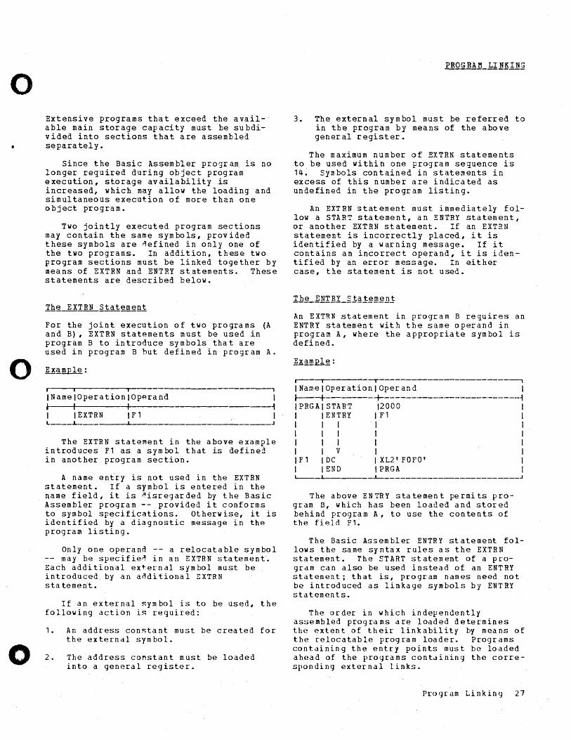
INamelOperationlOperand ~ I I 1 I EXTRN 1 F 1 L ____ ..L-
1 ~ I
J
The EXTRN statement in the above example introduces F1 as a symbol that is defined in another program section.
A name entry is not used in the EXTRN statement. If a symbol is entered in the name field, it is ~isregarded by the Basic Assembler program -- provided it conforms to symbol specifications. otherwise, it is identified by a diagnostic message in the program listing.
Only one operand -- a relocatable symbol -- may be specifie~ in an EXTRN statement. Each additional external symbol must be introduced by an anditional EXTRN sta tement.
If an external symbol is to be used, the following action is required:
1. An address constant must be created for the external symbol.
2. The address constant must be loaded into a general register.
PROGRAM LI NKING
3. The external symbol must be referred to in the program by means of the above general register.
The maximum number of EXTRN statements to be used within one program sequence is 14~ Symbols contained in statements in excess of this number are indicated as undefined in the program listing.
An EXT RN stat ement must immediately folIowa START statement, an ENTRY statement, or another EXTRN statement. If an EXTRN statement is incorrectly placed, it is identified by a warning message. If it contains an incorrect operand, it is identified by an error message. In either case, the statement is not used.
An EXTRN statement in program B requires an ENTRY statement with the same operand in program A, where the appropriate symbol is defined.
r---~--------~-------------------------'
INamelOperationlOperand 1 ~-+---------1--------------------------~ IPRGAISTART 12000 I 1 IENTRY IF1 I I I I I I I I I I I I I I I I I I V I I I F 1 IDe I X L2' F 0 F 0 ' I I lEND IPRGA I L----L-________ ..L-_________________________ J
The above ENTRY statement permits program D, which has been loaded and stored behind program A, to use the contents of the field Fl.
The Basic Assembler ENTRY statement follows the same syntax rules as the EXTRN statement. The START statement of a program can also be used instead of an ENTRY statement; that is, program names need not be introduced as linkage symbols by ENTRY statements.
The order in which independently assembled programs are loaded determines the extent of their linkability by means of the relocatable program loader. Programs containing the entry points must be loaded ahead of the programs containing the corresponding external links.
Program Linking 27
r------------------------------------------~ ---, I !1!I~_R.ftQ~R!!i I ~Q1H!QQTl1!] I I I I l-------T---------~ . I ---,---------.--T------------------------~ I Name I Operation I Operand I Name I Operation I Operand I ,.---.....:t---------+----.~--------------~--_+_ ~ ~
CRDT ST ART r-----+->CVB ST ART 1000
GET
F ,
YCVB
I I I I I·
ENTRY F1 EXTRN F1 EXTRN C VB . BASR 11,'0 I3ASR USING LH XIO
I I I v
MVC 'BASR SR
.1 I I v
Be DC DC END
8, a US I NG *, 11 *,8 MVC WAN,KOO 12,YCVB LH 10,YFl INPT(X'12'),80 MVN WAN+l(1),O(10)
Fl,INPT+l0 9,12 <--------~ 13,14<
15,GET C'OO' Y (C VB) CRDT
I I I V
AH rj -+---~--+-B C R
J WAN DS KOO DC
YFl DC END
13,WAN 15,9 H H' 0'
Y (F 1) CVB
L-_____ ~ ________ ~ ____ ~---------~----------------------
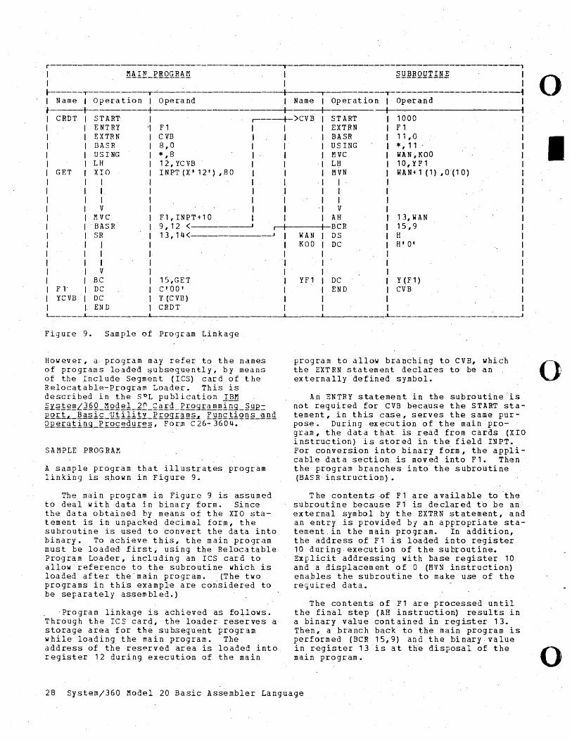
Figure 9. Sample of Program Linkage
o
I
However, a, program may refer to the names of programs loaded subsequently, by means of .the Include Segment (ICS) card of the Relocatable-Program Loader. This is described in the SPL publication 1]~ ~y~!~mL1QQ_!1QQgl-1~_~~~Q_Erog~amming_~~E= EQ£iL_~asi£~~!ili!y_R.~Qg~~m~L E~n£tiQn~_~nQ Q.E e r ~.ti.!l.9:_R..£Q£gQQ~g~, F 0 r.m C 26- 360 4.
program to allow branching to cva, which (-)1 the EXTRN statement declares to be an externally defined symbol.
SAMPLE PROGRAM
A sample' program that illustrates program linking is shown in Figure 9.
The main program in Figure 9 is assumed to deal with data in binary form. Since the data obtained by means of the XIO statement is in u~packed decimal form, the subroutine is used to convert the data into. binary. To achieve this, the main program must be loaded first l using the Relocatable Program Loader, including an IeS card to allow reference to the subroutine which is loaded after the'main program. (The two programs in thi~ example are corisidered to be separately assembled.)
'Program linkage is achieved as fo+lows. Through the rcs card, the loader reserves a storage area for the subsequent program while loading the main program. The address of the reserved area is loaded into register 12 during execution of the main
An ENTRY statement in the subroutine'is not required for eVB because the START statement I in this ca'se, serves the s arne purpose. During execution of the main program, the data that is read from cards (XIO instruction) is stored in the field INPT. For conversion into binary f6rm, the applicable data section is moved into Fl. Then the program branches into the subroutine (BASR instruction).
The contents ~f F1 are available to the subroutine because Fl is declared to be an external symbol by the EXTRN statement, and an entry is provided by an appropriate statement. in the main program. In addition, the address of Fl is loaded ~nto register 10 during execution of the subroutine. Explicit addressing with base register 10 and a displacement of a (MVN instruction) enables the subroutine to make use of the reguired data.
The contents of Fl are processed until the final step (AH instru6tio~ results in a binary value contained in register 13. Then, a branch back to the main program is performed (BCR 15,9) and the binary value in register 13 is at the disposal of the main program.
28 System/360 Model 20 Basic Assembler Language
o
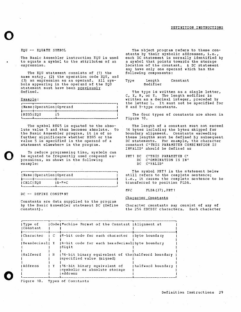
o
o
o
EQU -- EQUATE SYMBOL
The Basic Assembler instruction EQU is used to equate a symbol to the attributes of an expression.
The EQU statement consists of (1) the name entry, (2) the operation code EQU, and (3) an expression as a n operand. All symbols appearing in the operand of the EQU statement must have been E£~viouslL defined.
r i i 1
IName I Operation IOperand I r----+ ----~I------------------------~, IREGSIEQU 15 I L. __ ~ ___
J
The symbol REG5 is equated to the absolute value 5 and thus becomes absolute. To the Basic Assembler program, it is of no further significance whether REGS or the value 5 ~s specified in the operand of a statement elsewher~ in the program.
To reduce programming time, symbols can be equated to frequently used compound expressions, as shown in the following example:
r i j ,
INamelOperationlOperand I ~---+ -+I----------------------~, ICALCIEQU IA-R+C I L ____ ~ _________ ~___ J
DC -- DEFINE CONST~NT
Constants are data supplied to the program by the Basic Assembler stateme~t DC (define constant) •
r---------~-~
The object program refers to these constants by their symbolic addresses,i.~., each DC statement is normally identified by a symbol that point~ towards the storage location of the constant. A DC statement may have only one operand which has the following components:
Type Length Modifier
Constan t
The type is written as a single letter, C, X, H, or Y. The length modifier is written as a decimal integer, preceded by the letter L. It must not be specified for Hand Y-type constants.
The four types of constants are shown in Figure 10.
The length of a constant must not exceed 16 bytes including the bytes skipped for boundary alignment. Constants exceeding these lengths must be defined by subsequent DC statements. For example, the character constant C'THIS PARAMETER COMBINATION IS INVALID' should be defined as
PRT 1 DC DC DC
C'THIS PARAMETER C' C'OMBINATION IS IN' C'VALID'
The symbol PRT1 in the statement below still refers to the complete sentence; i.e., it causes the complete sentence to be transferred to position FLDA.
MVC FLDA(37),PRTl
Character constants may consist of any of the 256 EBCDIC characters. Each character
i
I Type 0 f I Co del ~ a chi n e Fo r mat 0 f the Con s tan t IAlignment at I I
-1 I Constant I I I ~----------+----+--- I ICharacter I C 18-bit code for each character by te bounda ry I I I IHexadecimall X 14-bit code for each hexadecimal byte boundary I I Idigit I I I IHalfword I H 116-bit binary equivalent of the halfword boundary I I Ispecified value (signed) I I I I Address I y 116-bit binary equivalent of halfword boundary I I Isymbolic or absolute storage I I I~ddress L ___________ L ____ L
Figure 10. Types of Con~;tants
Definition Instructions 29
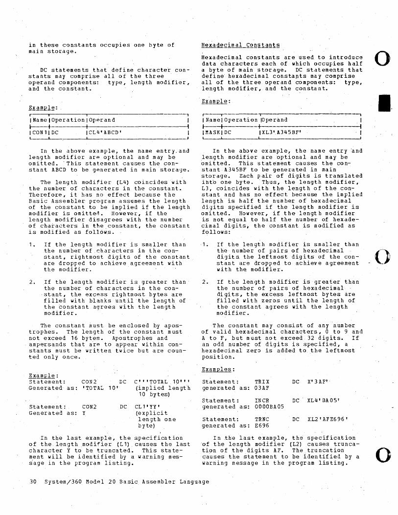
in these constants occupies one byte of main storage.
DC statements that define character constants may comprise all of the three operand components: type, length modifier, and the constant.
~lf~!!!E1~: r---,-- -,--l.ameIOperationIOp~rand
l----f-------+ ICON11DC ICL4'ABCD' L __ ~_
, I , I
J
In the above example, the name entry,and length modifier are optional and may be omitted. 'This statement causes the constant ABCD to be generated in main storage.
The length modifier (L4) coincides with the number of characters in the constant. Therefore, it has no effect because the Ba~ic Assembler program assumes the length of the constant to be implied if the length modifier is omi tten. However, if the length modifier disagrees with the number of chatacters in the constant, the constant is modified as follows.
1. rf the length modifier is smaller than the number of .characters in the constant, rightmost digits of the constant are dropped to achieve.agreement with the modifier.
2. If the length modifier is greater than the number of characters in the con-stant, the excess rightmost bytes are fille~ with blanks until ·the length of the constant agrees with the len~th modifier.
The constant must be enclosed by apostrophes. The length of the constant must not exceed 16 bytes. Apostrop hes and ampersands that aie to appear within constants must be written twice but are counted only once.
Ex~llig: statement: CON2 DC C" 'TOTAL 1 0' , , Generated as: ' TOTAL 1 0' (implied lengt h
10 bytes)
Sta tement: CON2 DC CL l' YY' Generated as: Y (explici t
length one byte)
In the last example, the specification of the length modifier (L1) causes the last character y to be truncated. This statement will be identified by a warning mesiage in the program listing.
Hexadecimal constants are used to introduce data characters each of which occupies half a byte of main storage. DC statements that define hexadecimal constapts may comprise all of the three operand components: type, length modifier, and the constant.
r----r i ..,.----,
I Namel Operation IOperand . I ~-+------+------""'--------"'-----~ IMASKIDC IXL3'A345BF' I __ ~ _________________________ ----J
In the ab~ve example, the name entry ~nd length modifier are nptional and may be 6mitted. This stat~ment causes the constantA345BF to be generated in main storage. Each pair of digits is translated into one byte. ThUS, the length modifier, L3, coincides with the length of the constant and has no effect because the implied length is half the number of hexadecimal digits specified if the length modifier is omitted. However, if the length modifier is not equal to half the number of hexadecimal digits i the constant is modified as follows:
·1. If the length modifier is smaller than
o
I.
the number of pairs of hexadecimal 0 digits the leftmost digits of the con- I stant are dropped to achieve agreement ~ ,.:.. with the modifier.
2. If the length modifier is·greater than the number of pairs of hexadecimal· di gits, t he ex cess leftmost by tes are filled with zeros until the length of the constant agrees with the length modifier.
The constant may consist of any number of valid hexadecimal charaqters, 0 to 9 and A to F, but must not exceed 32 digits. If an odd number of digits is specifie~, a hexadecimal zer~ is added to the leftmost position.
~gmple§.:
Statement: TRIX DC X' 3 AF" genera ted as: 03AF
Statement: INCR DC XL4' BAOS' generated as: 0000BA05
statement: TRNC DC XL2' AFE696' generated as: E696
In the last example, th~ specification 'of the length modifier (L2) causes truncation of the digits AF. The truncation causes the statement to be identified by a warning message in the program listing. o
30 System/360 Model 20 Basic Assembler Language
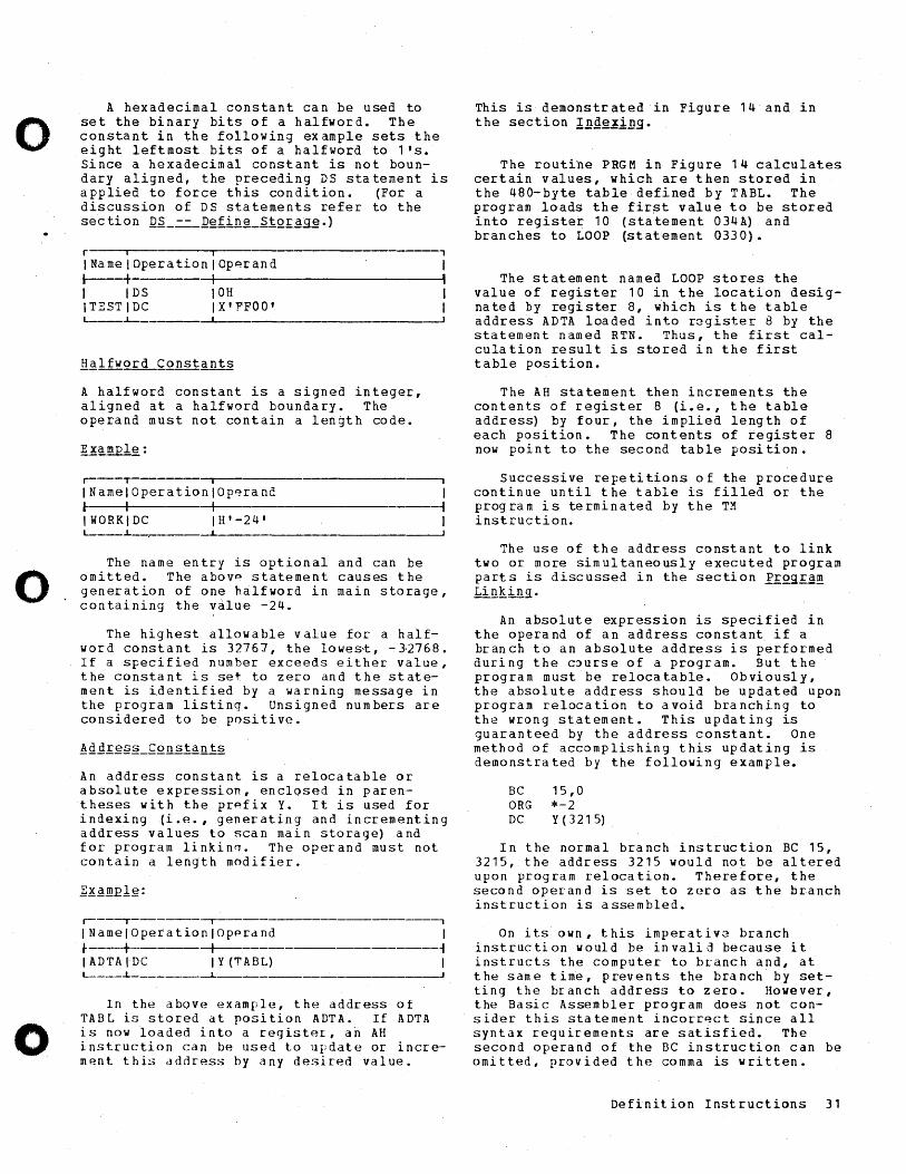
o
o.
o
A hexadecimal constant can be used to set the binary bits of a halfword. The constant in the following example sets the eight leftmost bits of a halfword to 1's. Since a hexadecimal constant is not boundary aligned, the preceding DS statement is applied to force this condition. (For a discussion of DS statements refer to the section Q~-==-]efin~_StQ£~g~.)
r i I ,
INamelOperationlOp~rand I ~---+- -+I--------------------~~, I I DS 10H I ITESTIDC IX'FFOO' I L--...L-
A half word constant is a signed integer, aligned at a halfword boundary. The operand must not contain a length code.
r----~-------~----------------------____.
INamelOperationlOp~rand I ~ I -+-- ~ IWORKIDC IH'-24' I L-___ ~ __ . ______ ~ ----J
The name entry is optional and can be omitted. The abov~ statement causes the generation of one halfword in main storage, containing the value -24.
The highest allowable value for a halfword constant is 32767, the lowes~, -~2768. If a specified number exceeds either value, the constant is set to zero and the statement is identified by a warning message in the program listing. Unsigned numbers are considered to be positive.
An address constant is a relocatable or absolute expression, enclosed in parentheses with the prpfix Y. It is used for indexing {i.e. , generating and incrementing address values to scan main storage) and for program linkin0. The operand must not contain a length modifier.
r----.--------~--------------------------,
INamelOpetationlOpprdnd I ~ I -+----------------------~ IADTAtDC IY(TABL) I L-___ ~ ________ ~ __________________________ J
In the above example, the address of TABL is stored at position ADTA. If ADTA is now loaded into a register, ari AH instruction can be used to update or increment this dddress by any desired value.
This is demonstrated in Figure 14 and in the section IDg~iDg.
The routine PRGM in Figure 14 calculates certain values, which are then stored in the 480-byte table defined by TABL. The program loads the fir?t value to be stored into register 10 (sta tement 034 A) and branches to LOOP (statement 0330).
The statement named LOOP stores the value of register 10 in the location designated by register 8, ~hich is the table address ADTA loaded into r~gister 8 by the statement named RTN. Thus, the first calCUlation result is stored in the first table position.
The AH statement then increments the contents of register 8 (i.e., the table address) by four, the implied length of each position. The contents of register 8 now point to the second table position.
Successive repetitions of the procedure continue until the table is filled or the program is terminated by the TM instruction.
The use of the address constant to link two or more simultaneously executed program parts is discussed in the section PrQgra~ LinKing.
An absolute expression is specified in the operand of an address constant if a branch to an absolute address is performed during the C3urse of a program. But the program must be relocatable. Obviously, the absolute address should be updated upon program relocation to avoid branching to the wrong statement. This updating is guaranteed by the address constant. One method of accomplishing this updating is demonstrated by the following example.
BC 15,0 ORG *-2 DC Y(3215)
In the normal branch instruction BC 15, 3215, the address 3215 would not be altered upon program relocation. Therefore, the second operand is set to zero as the branch instruction is assembled.
On its own, this imperativ3 branch instruction would be invalid because it instructs the computer to branch and, at the same time, prevents the brilnch by setting the branch address to zero. However, the Basic Assembler program does not consider this statement incorr~ct since all syntax requirements are satisfied. The second operand of the BC instruction can be omitted, provided the comma is written.
Definition Instructions 31
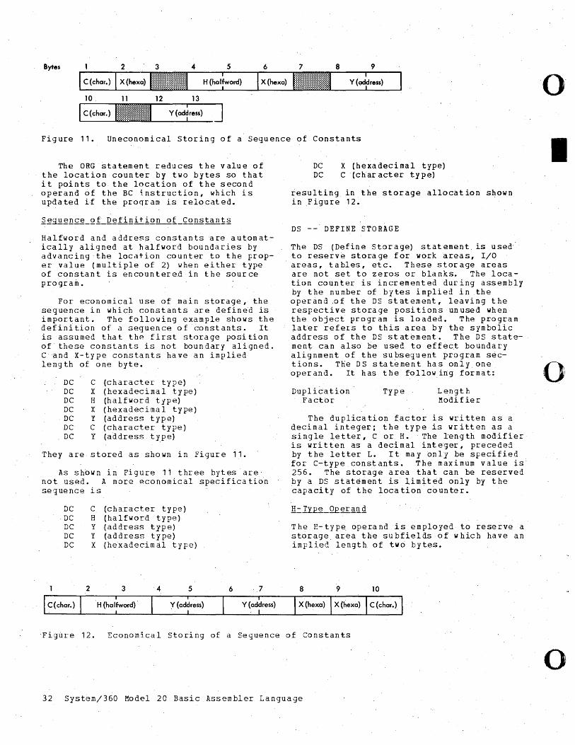
Bytes 2 3 4 5 6 7 8 9
10. 11 12 13
Figure 11. Uneconomical Storing of a Sequence of Constants
The ORG statement reduces the value of the location counter by two bytes so that it points to the location of the second operand of the BC instruction, which is updated if the proqram is relocated.
Halfword and address constants are automatically aligned at halfword boundaries by advancing the location counter to the proper value (multiple of 2) when either type of constant is encountered in the source program.
For economical use of main storage, the sequence in which constants are defined 1S important. The following example shows the definition of a sequence of ~onstants. It is assumed that the first storage position of these constants is not boundary aligned. CandX-type constants have an implied length of one byte.
DC C (character type) DC X (hexadecimal type) DC H (halfword type) DC X (hexadecimal type)
. DC y (address type) DC C (character type) DC y (address type)
They are stored as shown in Figure 11.
As shown in Figure 11 three bytes are' not used. A more economical specification sequence is
DC C (character type) DC H (halfwordtype) DC y (address type) DC y (address type) D~ X (hexadecim~ltype)
DC X (hexadecimal type) DC C (character type)
resulting in the storage allocation shown in Figure 12.
DS -- DEFINE STORAGE
The DS (Define Storage) statement is used" to reserv~ storage for work areas, I/O areas, tables, etc. These storage areas are not set to zeros or blanks. The location counter is incremented during assembly by the number of bytes implied in the operand .of the DS statement, leaving the respective storage positions unused when the object pcogcam is loaded. The program later refeLS to this area by the symbolic address of the DS statement. The DS statement can also be used to effect boundary alignment of the subsequent program sections. The DS statement has only one operand. It has the following format:
Duplication' Factor
Type L engt h Modifier
The duplication factor is written as a decimal integer; the type is written as a single letter, C or H. The length modifier is wri t ten as a deci mal int eger, precede:i by the letter L. It may only be ~pecified for C-typeconstants. The maximum value is 256. The storage area that can be reserved by a DS stat~ment is limited only by the ~apacity of the location counter.
The H-type o~erand is employed to reserve a storage area the subfields of which have an implied length of two bytes.
Figfire 12. Economical Storing of a Sequence of Constants
32 System/360 Model 20 Basic Assembler Language
o
I
o
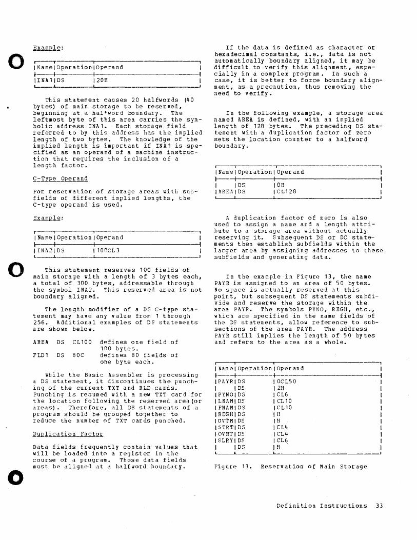
o
o
o
.------,- i ---------------, INamelOperationlOpprand t I I IINA11DS 120H
I -f I
L---_~ ____ ~I~ ______________ • ____________ ~
This statement causes 20 halfwords (40 bytes) of main storage to be reserved, beginning at a hal~word boundary. The leftmost byte of this area carries the symbolic address INA1. Each storage field referred to by this address has the implied length of two bytes. The knowledge of the implied length is important if INA1 is specified as an operand of a machine instruction that requires the inclusion of a length factor.
For reservation of storage areas with subfields of different implied lengths, the C-type operand is used.
r I --r , INamelOperationlOperand I r----t -+I-------------------------~ IINA21DS 110nCL3 I L J
This statement reserves 100 fields of main storage with a length of 3 bytes each, a total of 300 bytes, addressable through the symbol INA2. This reserved area is not boundary aligned.
The length modifier of a DS C-type statement may have any value from 1 through 256. Additional examples of DS statements are shown below.
AREA DS CL100 defines one field of 1no bytes.
FLD1 DS 80C defines 80 fields of one byte each.
While the Basic Assembler is processing a DS statement, it discontinues the punching of the current TXT and RLD cards. Punching is resumed with a new TXT card for the location following the reserved area(or areas}. Therefore, all DS statements of a program should be qrouped together to reduce the number of TXT cards punched.
Data fields frequently contain values that will be loaded into a register in the course of a program. These data fields must be aligned at a halfword boundary.
If the data is defined as character or hexadecimal constants, i.e., data is not automatically boundary aligned, it may be difficult to verify this alignment, especially in a complex program. In such a case, it is better to force boundary alignment, as a precaution, thus removing the need to verify.
In the following example, a storage area named AREA is defined, with an implied length of 128 bytes. The preceding DS statement with a duplication factor of zero sets the location counter to a halfword boundary.
I I ,--------------------------,
INamelOperationlOperand I /----_+_ I ~ I IDS 10H I IAREAIDS ICL128 I ~--~----------~------------------------~
A duplication factor of zero is also used to assign a name and a length attribute to a st:>rage area without actually reserving it. Subseguent DS or DC statements then establish subfields within the larger area by aSSigning addresses to these subfields and generating data.
In the example in Figure 13, the name PAYR is assigned to an area of 50 bytes. No space is actually reserved at this point, but subseguent DS statements subdivide and reserve the storage within the area PAYR. The symbols PYNO, REGH, etc., which are specified in the name fields of the DS statements, allow reference to subsections of the area PAYR. The address PAYR still implies the length of 50 bytes and refers to the area as a whole.
r----r- ~I-------------------------
INamelOperationlOperand J---+-------+ IPAYRIDS OCL50 I IDS 2H IPYNOIDS CL6 ILNAMIDS CL10 IFNAMIDS CL10 IREGHIDS H IOVTMIDS H I STRTI DS CL4 IOVRTIDS CL4 ISLRYIDS CL~ I IDS H L--l...
Figure 13. Reservation of Main storage
, I ~
Definition Instructions 33
Basic Assembler control instructions are used to begin assembly (START), end assembly (END), and set the location counter to a value at a halfword boundary (ORG).
START -- START PROGRAM
When a program is loaded, a start address normally specifies the point where the first byte of information is to be stored. Bytes 0 to 155 of main storage lie within an area that contains information required for the execution of a program. This information must not be overwritten. Therefore, the lowpst usable start address is 156 (hexadecimal 009C). nefore a source program or the Basic Assembler program can be loaded, a program to execute the loading functions is required. such a program (the Absolute-Program Loader or the RelocatableProgram Loader) is stored from location 156 upward. The Absolute-Program Loader, for example, requires '60 bytes of main storage, which increases the possible start address for the source program to 316 (hexadecimal 013C). A start address of 156 can be used in this case, provided the subsequent 160 bytes are reserved for the Absolute-Program Loader by means of an appro~riate DS or nRG statement.
The start address is specified in a START statement. The operand of the START statement specifies the tentative loading point in the form of an absolute address. The value of the location counter is incremented to represent this address as soon as the START statement is read by the Basic Assembler program. If the START statement is omitted, the location counter is automatically set to 340. (A START statement without an operand should not be used and is flagged with a C.)
START 1000
This statement causes the location counter to be advanced to 1000. Since the START statement does not consume any storage space itself, the specified start address is assigned to the instruction that follows the START statement. If a symbol is entered in the name field of a START statement, it is considered to be the program name and is entered in the symbol table, together with the start address of the program. In addition, the Basic Assembler program causes the name to be punched
into columns 73 to 76 of each object progr am car d.
]~i~: For the purpose of boundary alignment, the start address should be an even number. If it is an odd number, the Basic Assembler program advances the location counter to the next higher even value above the specified start address.
END -- END OF PROGRAM
A program written in Basic Assembler language must be terminated by an END statement, which supplies the branch address required for program execution after the program is loaded.
The operand :::>f the END statement contains the address of the point to which control is t:::> be transferred on completion of the loading process. This is normally the address ~f the first machine instruction in the problem program.
r---~---------T--------------------------'
INamelOperationlOperand 1 I I I ~ IPBL11START 1340 I IBGN IBASR 110,0 I I I I I 1 I I I I 1 I I V I I I lEND IBGN I ~ __ ~ ___________ ~ _________________________ ----J
In the ab:::>ve example, the start address for program execution is BGN. When the END card is read, the address contained in the operand of the END statement is loaded into register 12 by the Absolute-Program Loader, followed by a branch to the address in register 12, which initiates program execution.
If it is desired to load more than one program for simUltaneous execution, the Relocatable-Program Loader must be used and a load terminate (LDT) card must be supplied. In this case, the loader program disregards the END card. For further details refer to the SRL publication l]~ ~y§!emLl§~od~l_~CaXQ_Progx~~~ing_~gE= EQ~!~~asi~!ility_Pro~ams~_E~n£1iQn§_anQ Q£§~atln~R~Q~~Q~~~§, Form C26-3604.
34 System/360 Model 20 Basic Assembler Language
o
I
o
o
o
o
o
ORG -- RESET LOCATION COUNTER
The ORG statement is used to reset the location counter to any desired value.
The statement ORG *+500 causes the present value of the location counter to be incremented by 500. The operand of an ORG statement is invalid if it is not a relocatable expression, if the expression consists of or includes a symbol that has not been E£gviously_defingg, or if the name field of the statement contains an invalid symbol. A valid symbol in the name field is disregarded by the Basic Assembler program. Invalid operands are identified by error messages in the program listing. The location counter should not be reset to a value lower than the start address of the program unless it is to be loaded by the AbsoluteProgram Loader. The ORG statement can be used when source and object programs exceed the available main storage capacity and must, therefore, be assembled and executed in separate phases.
The program shown in Figure 14 executes certain scientific-mathematical calculations and stores the results in a 480-byte table, which is printed out later. The calculations are assumed to consist of two phases, each of which requires 3200 bytes. This means that (with an available storage capacity of 4096 bytes) each calculation rou ti ne must be as~em bled sep ar at ely. The resulting object programs are executed one after the other.
For this reason, the table area where the results of the calculations are stored, was reserved at the first available positions of main storage, followed immediately by the constants and program routines required for all successive calculation phases. This information occupies storage locations 013C to "340 (the 'addresses are given in hexadecimal notation to facilitate reference to Figure 14), and will not be overwritten when subsequent program phases for execution of the assembly are loaded.
The statement PPGM MVC X(5) ,Y, which is stored at position 0344, is the firststatement of the calculation routine. All other statements o~ this procedure have been omitted, excent those that demonstrate the chaining of the various program routines.
When the first result has been calculated, it is loaded into register 10 (statement 034A). The program then branches to LOOP (statement 0330). The following program segment stores the result in the first position of the table area (a detailed explanation is given in the section ~~_== ~efilJ~L£onst~nt) , and tests a switch to determine if the program must go through the calculation routine again to compute another result.
If this is the case, the program branches to PRGM. Otherwise, the calculation phase has been completed and the program branches to the loader area (statement 033C) to read calculation phase 2 into main storage.
Calculation phase 2, as a separately assembled program, also begins with a START instruction. H~wever, since the loader does not use it, register 14 has the same contents as during the previous assembly. Therefore, the BASR instruction can be omitted and the START address becomes 318. However, the USING instruction is required.
Now the previous program part must be linked to the subsequent one. The ORG statement is used to reset the location counter to position 0344. This is the start address of the calculation routine phase 1, which is no longer required and can be overwritten by phase 2.
Since the operand of the ORG statement must be relocatable and hexadecimal 0344 is an absolute address, the location counter is set to 0 (*-318) and the desired address 0344, which is e gua I to PH2, is added. The operand *-318+PH2 thus obtained is relocatable. The address 0344 can be determined only from the program listing, after the assembly of phase 1. It must then be inserted int~ a previously prepared statement card.
The location counter setting of 0344 causes the subsequent program (a) to be 10dded, starting at this position, and (b) to overwrite phase 1.
By following this procedure, any number of programs can be assembled separately and then be linked for successive execution.
Definition Instructions 35
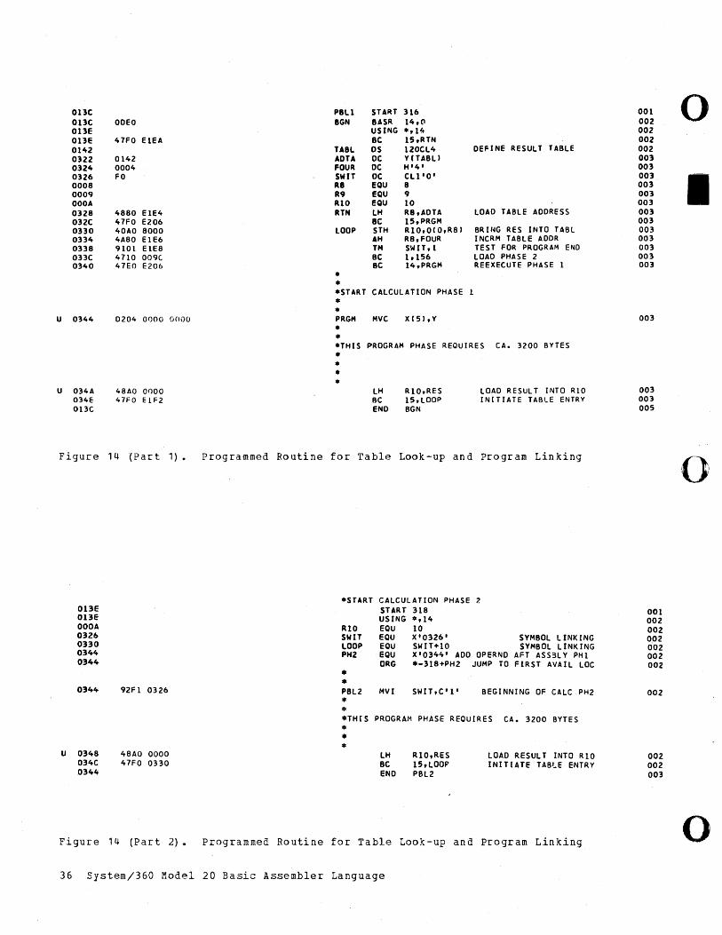
onc PBli START 316 001 0 onc ODEO BGN BASR 14,(l 002 013E USING ·,14 002 OnE 41FO EIEA BC 15,RTN 002 0142 TABl OS 120Cl4 DEFINE RESULT TABLE 002 0322 0142 ADTA De Y(TABU 003 0324 0004 FOUR De H'4' 003 0326 FO SWIT DC el1'O' 003
I 0008 R8 EQU 8 003 0009 R9 EQU 9 003 OOOA RIO EQU 10 003 0328 4880 EIE4 RTN LH R8,ADTA LOAD TABLE ADDRESS 003 032C 47FO E206 BC 15,PRGM 003 0330 40AO 8000 lOOP 5TH R10,0(O,R81 BRING RES INTO TABL 003 0334 4A80 EIE6 AH R8,FOUR I NeRM TABLE ADDR 003 0338 9101 EIE8 TM SW IT, 1 TEST FOR PROGRAM END 003 aBC 4710 009C Be 1,156 lOAD PHASE 2 003 0340 47EO E206 BC 14,PRGM REEXEeUTE PHASE 1 003
• • ·START CALCULATION PHASE • •
U 0344 0204 0000 O(li)O PRGM Mve X(5I,Y 003
• • .THIS PROGRAM PHASE REOUIRES CA. 3200 BYTES • • • •
U 034A 48AO onoo lH R10,RES LOAD RESULT INTO RIO 003 034E 47FO ElF2 BC 15,LOOP INITIATE TABLE ENTRY 003 ODC END BGN 005
Figure 14 (Part 1). Programmed Routine for Table Look-up and Program Linking o
·START CALCULATION PHASE 7. 013E START 318 001 OBE USING .,14 002 ODOA RIO EQU 10 002 0326 SWIT EQU X'0326' SYMBOL LINKING 002 0330 lOOP EQU SWIT+10 SYMBOL LINK ING 002 0344 PH2 EQU X'0344' ADD OPERND AFT ASS3LY PHI 002 0344 ORG .-318+PH2 JUMP TO FIRST AVAI L LOC 002
• • 0344 92FI 0326 PBl2 MVI SWIT,C'l' BEGINNING OF CALC PH2 002 • • .THIS PROGRAM PHASE REQUIRES CA. 3200 BYTES • • •
U 0348 48AO 0000 lH R10,RES lOAD RESULT INTO RIO 002 034C 47FO 0330 BC IS,lOOP INITIATE TABLE ENTRY 002 0344 END PBl2 003
Figure 14 (Part 2). Programmed Routine for Table Look-up and Program Linking o 36 System/360 Model 20 Basic Assembler Language
o
o
o
Input/output ope~~tions can be caused in two ways:
1. by means of thp Input/Output Cont~ol System (laCS), or
2. by w~iting I/O ~outines using the Basic Assembler I/O inst~uctions.
The use of laCS dllow~ the writing of mac~o inst~uctions, as explained in a subsequent section. ~he second mathod, the writing of individual I/O ~outines, is explained in the following parag~aphs.
Three types of T/O inst~uctions a~e available in the Basic Assembler language:
1 • XIO instructions (execute input and output) .
2. CIa instructions (control input and output) •
3. TIOB instructions (test input and out-rut and b~anch' •
The XIO statement has an SS format, and CIa and TIOB statements have 51 formats, as explained in the spction ~achi!!.~.-lns1.£uc= liQ.!l_IQI!!l~1~·
All three instructions include the unit and function (UF) specification field. Data in this field must be specified in hexadecimal notation.
XIO -- EXECUTE INpnT/OUTPUT
The operand entry of an XIO instruction is w~itten
Dl (UF,El) ,D2(B2)
o~ when using symbolic addressing,
Symbol 1 (UF), Sym bol 2.
U designates the Qnit used as the I/O device and F designates the assigned function, i.e., the oppration to be executed.
For example, a 2501 reader is attached and X'12' is specif"ied in the UF field of the XIO instruction. The hexadecimal digit 1 tells the Basic ~ssembler program that the 2501 is used and the hexadecimal digit 2 indicates that the unit must read a card. A complete list of all UF codes is provided in Appendix C.
Depending on the specification in the UF field of the XIO instruction, the second symbol designates the amount of data to be handled du~ing the I/O ope~ation; i.e., the number of ca~d columns to be read or punched, or the number of characte~s to be printed. Samples of XIO instructions are shown in Figure 15.
~Q1g: If the XIO statement refers to a card unit, the value in the second operand must not exceed 80. If it refers to a p~inte~, the maximum value is 144 for a 2 2 0.1 P r i n t e ~ ; 1 3 2 for a 1 40 3 Mo del 2 0 r N 1 ; and 120 for a 1403 Model 7.
T---------------------, INotelName Ope~ationlOperand I t--+ I 1 I ICARD EQU 180 I I ILINE EQU I 100 I 11. lOUT XIO IFLDA(X'40') ,LINE I 12. lOUT XIO I OUTB (X' 40' ) ,20 I 13. IPNCH XIO IOUTA(X'36') ,CARD I I 4. IINPT XIO I IN 1 (X' 23') ,16 I 15. IINPT XIO I EXAR (X' 24') ,CARD I ~ __ _L_---L-________ ~ ____________________ J
Figu~e 15. Sample of XIO Instructions
1. Prints 100 characters on the attached 1403 or 2203 printer.
2. Prints 20 characte~s on the attached 1403 or 2203 printer.
3. Punches 80 columns on the attached 1442 Card Punch, Model 5.
4. Reads the first 16 columns of a card f~om the se CDnda~y hopper of the attached 2560 MFCM.
5. Punches 80 columns of a card from the primary hopper of the attached 2560 MFCM or 2520.
CIa -- CONTROL INPUT/OUTPUT
CIa instructions are used to control the operation of attached I/O devices. With card I/O devices, the CIa instruction is used for stacker or print-head selection; with a printe~, the CIa instruction is used to cause spacing or Skipping.
The instruction is written in the following format:
C 10 D 1 (B 1) , UF or
CIa 51, UF (S=sy mbol)
Input/Output Instructions 37
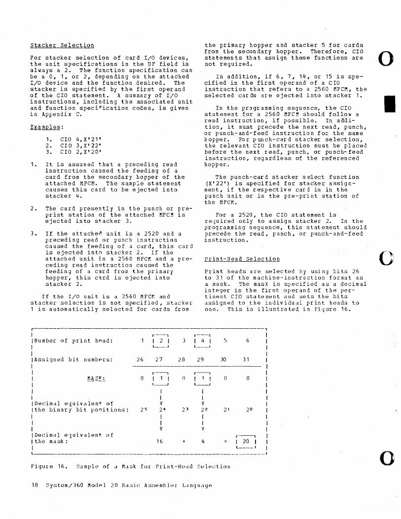
For stacker selection of card I/O devices, the unit specifications in the UF field is always a 2. The function specification can be a 0, 1, or 2, depending on the attached I/O device and the function desired. The stacker is specified by the first operand of the CIa statement. A summary of I/O instructions, including the associated unit and function speci~ication codes, is given in Appendix C.
1 • CIO 4, X' 21 ' 2. CIa 3,X' 22' 3. CIa 2, X'20'
1. It is assumed that a preceding read instruction caused the feeding of a card from the secondary hopper of the attached MFCM. The sample statement causes this card to be ejected into stacker 4.
2. The card presently in the punch or preprint station of the attached MFCM is ejected into stacker 3.
3. If the attache~ unit is a 2520 and a preceding read or punch instruction caused the feeding of a card, this card is ejected into stacker 2. If the attached unit is a 2560 MFCM and a preceding read instcuction caused the feeding of a card from the primary hopper, this card is ejected into stacker 2.
If the I/O uni t is a 2560 MFCr. and stacker selection is not specified, stacker 1 is automatically selected for cards from
.--r----,
Number of print h~ad: I 2 I 3 L-_J
Assigned bit numbf>rs: 26 27 28
r----, f!~d~.!.. 0 ! 1 ! 0
L-----.J
I I
Decimal equivalent of V the binary bi t positions: 2 5 24 2 3
I I V
Decimal e(]ui valent of I the mask: 16 + I
the primary hopper and stacker 5 for cards from the secondary hopper. Therefore, CIa statements that assign these functions are not required.
In addition, if 6, 7, 14, or 15 is specified in the first operand of a CIa instruction that refers to a 2560 MFCM, the selected cards are ejected into stacker 1.
In the pr~gramming sequence, the CIa statement for a 2560 MFCM should follow a read instruction, if possible. In addition, it must precede the next read, punch, or punch-and-feed instruction for the same hopper. For punch-card stacker selection, the relevant CIa instruction must be placed before the next read, punch, or punch-feed instruction, regardless of the referenced hopper.
The punch-card stacker select function (X'22') is specified for stacker assignment, if the respective card is in the punch unit or in the pre-print station of the MFCl'!.
For a 2520, the CIa statement is required only to assign stacker 2. In the programming sequence, this statement should precede the read, punch, or punch-and-feed instruction.
Print heads are selected by using bits 26 to 31 of the machine-instruction format as a mask. The mask is specified as a decimal integer in the first operand of the pertinent CIa statement and sets the bits assigned to the individual print heads to one. This is illustrated, in Figure 16 •
, r---, I 4 I 5 6 L-__ J
29 30 31
r--, ! 1 ! 0 0 L-----.J
I I V 22 21 20
I I V
r---, 4 I 20 I
L ___ J L ____________ ~ ___________________________________________ ~
Figur-e 16. Sample of a Mask for Print-Head Selection
o
I
0_-'·,
, ?
o
o
o
o
In the above ex~mple, print heads 2 and 4 are selected bec~use the bits assigned to these are set to 1 by the ma~k. The decimal equivalent of the mask is specified in the first operand of the CIa statement as follows:
CIa 20,X'2.3'
The operand X'23' refers to ·a card I/O device and specifies the print-head-select function.
The highest decimal number that can be used as a mask for print head selection is 63, which activates all available print heads. The mask can also be expressed in hexadecimal notation or in the format D1(B1).
A CIa statement that refers to a printer must contain the unit address (U) hexadecimal 4. If a spacing function is requested, the first operand ~pecifies the number of space to be performed. This can be expressed in decimal or hexadecimal form, or as D1 (B1). The maximum number of spaces allowed is 3.
The appropriate function codes are shown in the summary of I/O instructions in Appendix C.
CIa 2,X'4C'
This statement causes the immediate spacing of 2 lines on both carriages of an attached 2203 Printer.
If a skipping function is requested, the first operand specifies the channel number of the carriage control tape that identifies the line at which the skipping is te rmina ted.
CIa 6,X'45'
This statement causes the skipping of a page on the attached 1403 Printer, up to the line identifie~ by a punch in channel 6 of the carriage control tape.
All CIa statements that refer to the serial I/O channel must contain the unit address hexadecimal 6. For the appropriate function specification refer to Appenaix C. The use of the first oper and D 1 (B 1) is described in the following SRL publication:
l~~_~Y~ig~Ll~Q_~~Qgl_~QL_~l~_~~gngiif ~h~£9.fig£_Rg~Qg£, For· m A 2 4-1499.
A CIa statement that refers to the Model 20 Communications Adapter or the Binary Synchronous Communications Adapter must contain the unit address hexadecimal 5. For the appropriate function srecification, refer to Append ix C.
The first operand, D1 (B1), of a CIa statement that refers to one of the communications adapters is ignored. However, it must be contained in the statement, and must resemble a valid address.
TIOB -- TEST INPUT/OUTPUT AND BRANCH
TIOB statements are used to test the operation al co ndit ions of the a ttached I/O devices or the proper execution of an I/O function; e.g., print error, last card, feed error, device busy.
If a busy condition exists, a branch is performed to the address specified in the first operand of the pertinent statement. Otherwise, the subse1uent program statement is processed.
The operands of a TIOB statement are written in the following form:
D1(B1),UF
or
S 1 , U F
1. 2. 3.
TIOB TIOB TIOB
AREA,X'24' *,X'40' HALT,X'33'
1. This instruction causes a branch to position AREA after the last card has been read on the attached I/O device wi th the device addr ess 2.
2. This statement causes the program to loop until the attached printer has completed the current print cycle.
3. This instruction causes a branch to the procedure named HALT if a punch error has occurred on the attached 1442 Card Pun ch.
A summary of the Basic Assembler I/O instructions, t~gether with the associated function specification codes, is provided in Appendix c.
Input/Output Instructions 39
SEQUENCE OF I/O IN~TRUCTIONS
The proper sequence of the input-output instructions for different cases is shown in the following examples:
CARRIAGE CONTROL:
OR
PRINTER CONTROL:
CARD READER CONTROL:
PUNCH CONTROL:
TIOB TIOB CIa CIa
TIOB TIOB XIO BC BC
TIOB XIO BC BC TIOB TIOB
TIOB C 10 XIO BC TIOB TIOB TIOB
*,X'46' *,X'40' 1,X'45' 3,X'44'
*,X'46' *,X'40' PR T (X' 41 ' ) , 120 (0) 4,*-6 1,HLT
*,X'20' CR D (X' 22') , 80 ( O) 4, *-6 1,HLT END,X'24' HLT,X'25'
*,X'20' 2,X'22' PC H (X ' 25 ') , 80 ( O) 5,HLT HLT,X'21' END,X'24' HLT,X'25'
A major part of most programs written in Basic Assembler language consists of the routines required to read data into the system and to produce the output of the
TEST CARRIAGE BUSY TEST PRINTER BUSY SKIP TO CHANNEL ONE IMMEDIATELY SPACE THREE TIMES IMMEDIATELY
TEST CARRIAGE BUSY TEST PRINTER BUSY PRINT AND SPACE SUPPRESS BRANCH IF PRINTER WORKING BRANCH IF PRINTER NOT OPERATIVE
TEST READER BUSY READ THE CARD BRANCH IF READZR WORKING BRANCH IF READER NOT OPERATIVE BRANCH IF LAST CARD BRANCH IF FEED ERROR
TEST READER/PUNCH BUSY SELECT STACKER TWO PUNCH SECONDARY CARD BRANCH IF PUNCH NOT OPERAT IVE TEST READER/PUNCH ERROR TEST LAST CARD TEST FEED ERROR
processing perf3rmed on the input data. IBM provides the user of the Model 20 Basic Assembler language with a library of tested I/O routines, which is part of the IBM System/360 Model 20 Card Programming Support, Input/Output Control System (CPS IOeS) .
o
I
0 "
o
o
o
o
r ~----------------------------,
IMacro 1 1 IInstructionlFunction 1 t--------_+_--------------------~ IGET IMakes the next record avail- 1 1 lable in the area specified bYI I Ithe user. I r------.---.-._t_ -i 1 PUT IMakes a record (in an area I I IS{Jecified by the user) avail-I I lable ~or an I/O operation. I
• I ~ 10PEN 10pens the file, i.e., ensuresl I Ithat all information neces- I I Isary to handle a file has I 1 Ibeen provided. I
• I ~ ·1 CLOSE I Closes the file, i. e., I I lensures proper handling of I I Ithe file after all records I I I ha ve hee n processed. I
• _+_ -I ICRDPR I Moves the information to be I I Iprinted on a card from the I I Iwork area into the specified I I Iprint area. Used only in 1 1 Iconnection with a 2560 MFCM. I ~-------+- ~ ICNTRL ICauses the performance of 1 I Icertain I/O functions, e.g., I 1 Iskipping, spacing, stacker I 1 Iselection. I t---------_+_ ~ ILOM IStarts processing of files inl 1 Inon-overlap mode. I
• 1 ~ IEOM IStarts processing of files inl I loverlap mode, in case of a I I Iprecening LOM macro I Iii nstruction. I
• I ~ IPRTOV IChecks for printer overflow I 1 I cond i tions. 1
• I ~ IWAITC ICauses the problem program tol 1 Iwait for the completion of 1 1 lall pending card I/O opera- I 1 Itions before processing the I 1 Inext sequential instruction. I L-
Figure 17. Summary of IOCS Macro Instructions
In the source program, the IOCS routines are called by statements referred to as macro instructions. The use of IOCS macro instructions saves programming time because it relieves the user of coding, testing, and providing linkages to his own I/O routines. In addition, the IOCS routines take advantage of the time-sharing capability of the Model 20, thereby optimizing throughput.
For detailed information on the Model 20 IOCS, refer to the SRL publication IBM
Figure 17 contains a summary of the IOCS macro instructions and their functions.
Additional macro instructions, and the associated I/O routines, are available to users of the Communications Adapter and the 1419 Magnetic Character Reader. For detailed information refer to the following SRL publications:
lrrE~lLOui£~l_f~lll£~l_System_for_ihg ~in~£Y_~ll£h~~no~~_f~mmuni£~iion§_&Q~E1~ ~£, Form C33-4001;
lrrEQt-Oul~~l_font£~1_System for_lhg-1 BM j~1_~~~li£_fh~ra£1~£_Rea~~£, Form C26-3607.
A user program which enables the interrupt mode with an SPSW statement that changes the channel mask bit of the current program status word from 1 to 0 must ensure that the pending interrupts caused by the loader do not interfere with the execution of the object program.
Both the Absolute-Program Loader and the Relocatable-Program Loader cause two pending interrupts. Interrupt 1 is caused when the program is read on a 2501, 2520, or 2560; interrupts 1 and 2 are caused when the program is read on a 2520 or a 2560.
llli~£ru~l-1: Associated with the l~st_£eag instru£ti~rr of the loader, interrupt 1 is pending when the execution of the object program begins. This interrupt becomes effective after the first SPSW instruction in the user program has been processed. The program in this case branches to the programmed interrupt routine, although the condition on which the interrupt routine is based has not occurred.
An example of the programming sequence that enables thf interrupt mode through an SPSW statement js shown in Figure 18. For this purpose, the first two TIOB statements in the figure may be disregarded.
lni~~ruE!-1: This interrupt is issued at the end of program loading. After the END card of the object program has been read, an XIO instruction in the loader program causes a dummY_~Qrrfh_fY~l~ that moves the
Input/Output Instructions 41
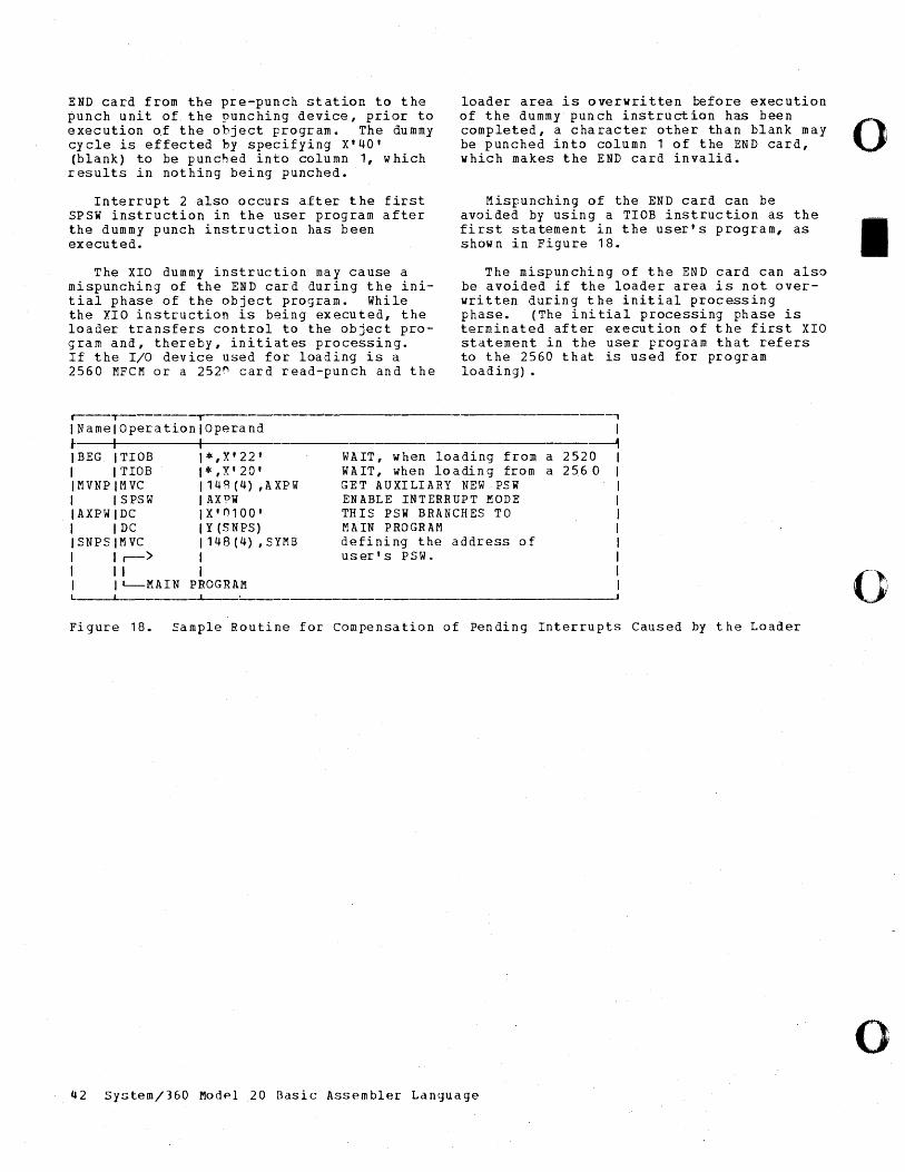
END card from the pre-punch station to the punch unit of the punching device, prior to execution of the object program. The dummy cycle is effected by specifying X'40' (blank) to be punched into column 1, which results in nothing being punched.
Interrupt 2 also occurs after the first SPSW instruction in the user program after the dummy punch instruction has been executed.
The XIO dummy instruction may cause a mispunching of the END card during the initial phase of the object program. While the XIO instruction is being executed, the loader transfers control to the object program and, thereby, initiates processing. If the I/O device used for loading is a 2560 MFCM or a 252~ card read-punch and the
loader area is overwritten before execution of the dummy punch instruction has been completed, a character other than blank may be punched into column 1 of the END card, which makes the END card invalid.
Mispunching of the END card can be avoided by using a TIOB instruction as the first statement in the user's program, as shown in Figure 18.
The mispunching of the END card can also be avoided if the loader area is not overwritten during the initial processing phase. (The initial processing phase is terminated after execution of the first XIO statement in the user program that refers to the 2560 that is used for program loading) •
r----,--- ·~1--------------~--------------------------- , IName OperationlOperand ~ I IBEG TIOB 1*,X'22' 1 TIOB 1*,X'20' IMVNP MVC 1148 (4) ,AXPW 1 SPSW J AX?W IAXPW DC IX'0100' 1 DC 1 Y (SNPS) ISNPS MVC 1148 (4) ,SYMB 1 r-> 1 1 1 I 1 ~MAIN PROGRAM L ____ ~ __
1 ---------------~
WAIT, when loading from a 2520 WAIT, when loading from a 2560 GET AUXILIARY NEW PSW ENABLE INTERRUPT MODE THIS PSW BRANCHES TO MAIN PROGRAM defining the address of user's PSW.
Figure 18. Sample Routine for compensation of Pending Interrupts Caused by the Loader
42 Sy~tem/360 Modpl .20 Basic Assembler Language
o
I
()
o
o
o
o
This section describes the coding of the machine instructions written in Basic Assembler language and translated into machine language. The machine-language format and the functions of each machine instruction are described and the use of each instruction is illustrated by an ex ample.
A machine instruction is a direction given to the computer to cause the execution of a certain operation. In Basic Assembler language, these instructions are written in the form of mnemonic codes, which are translated by the Basic Assembler program into System/360 internal or machine code, respectively. The codes are printed in the leftmost part of the program listing, next to the location counter reference.
Machine instructions are divided into four groups, according to basic operand format:
1. RR instructions (register to register), length: 2 bytes.
2. RX instructions (register to storage or storage to register), length: 4 bytes.
3. 51 instruction~ (storage - immediate), length: 4 bytes.
4. 55 instructions (storage to storage) , length: 6 bytes.
A summary of th~se formats, together with their associated operation codes, is shown in Figure 19.
All machine-instruction statements are automatically aligned at halfword boundaries. All bytes skipped are filled with hexadecimal zeros.
Any machine instruction can be identified by a symbOl, which can be used as a
branch address in operand(s) of other sta temen t (s) •
1. R1 and R2 are absolute expressions that specify general registers. The general register numbers are 8 through 15.
2. D1 and D2 are absolute expressions that specify displacements. A value of 0 through 4095 may be specified.
3. B 1 and B2 are absol ute exp ressions that specify base registers. Register numbers are 0-3 and 8-15.
4. M1 is an absolute expression representing a condition code.
5. L, L1, and L2 are absolute expressions that specify field lengths. An L expr essio n can sp eci fy a v alu e of 1 -256. L1 and L2 expressions can speci~ fy a value of 1 - 16. In all cases, the assembled value will be one less than the specified value.
6. 12 is an absolute expression that provides immediate data. The value of the expression may be 0 - 255.
7. 51 and S2 are absolute or relocatable expressions that specify an address.
8. 5I instruction fields that are crossed out in the machine formats are not examined during instruction execution. The fields are not written in the symbolic operand, but are assembled as binary zer:>s.
9. UF is an absolute expression representing an input/output unit address and a function.
Machine-Instruction statements 43
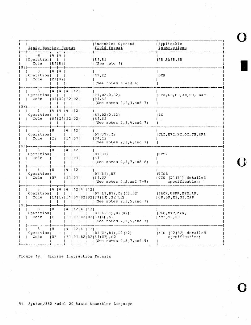
r--T I T---------------------------, o I I I Assembler: Ope r: and I App Ii ca ble I I I !2~§i£_1:1~s::hi!!.g2Q.!:!!!.~i I Pi eIQ_Por: m~i Ill! st.f~~.!iQll§ I • ~~--T---------+-----------------_'_t_ 1 I I 8 14 14 I I I I I IOper:ationl I I IR1,R2 IAR ~ASR,SR I I I Code IR11R21 I (See note 1) I I IRRl---------t-+--+ I +-------------~------------~ I I 8 14 14 I I I I I I I Oper:a tion I I I I Ml ,R2 IBCR I I I Code I M 11 R21 I I I I I I I 1 I (See notes and 4) I I r--+---------t--+--+--.--.---+__ t-------~------------~---~ I I 8 1414141121 I I I I IOper:ationl I I I I IR1,D2(0,B2) ISTH,LP.,CH,AH,SH, BAS I I I Code IR11X21B21D21 IR1,S2 I I I I I I I I I I (See notes 1,2,3,and 7) I I I R X l--------t-+--+--+_+_ I +--~-----------------~ I I 8 1414141121 I I I I IOper:ationl I I I I IMl ,D2 (0,B2) IBC I I I Code IM11X21B21D21 IM1,S2 I I I I I I I I I I (See notes 2,3,4,and 7) I I l--+--------t~_+_+__t--_+__ t--~--------------------~
I 8 18 141121 I I I IOper:ationl I I I ID1(Bl),I2 ICLI,MVI,NI,OI,TM,HPR I I Code 112 IB11Dli IS1,I2 I I I I I I I I (See notes 2,3,6,and 7) I 1
SIl---------t-----t--+__t I t------------------------~ I 8 18 141121 I I I IOper:ationl I I I ID1(Bl) ISPSW 1 I Code 1-- IB11D11 ISl I I I I I I I I (See notes 2,3,7,ana 8) I I l---------t----+--+__t--_+__ +------~------------------1 o I 8 18 141121 I I 1 IOper:ationl J I 1 1 Dl (Bl) ,UF ITIOB 1 I Code IUF IB11Dli IS1,UF ICIO (Dl (Bl) detailed I I 1 1 I 1 1 (See notes 2,3,and 7-9) 1 specification)' 1
l--+---------t I I +__+ I I +-----------------------'--~
I 8 141414112141121 I I IOper:ationl I I I I 1 ID1 (Ll ,Bl) ,D2 (L2,B2) IPACK,UNPK,MVO,AP, I I Cod elL 1 I L 2 I B 1 I D 1 I B 2 I D 2 I S 1 (L 1) , S 2 ( L 2) I C P , D P , M P , S P , ZA P 1 I 1 I I I I I I (See notes 2,3,S,and 7) 1 I
S S f---------t~+-I I 1 I +------------------------~
I 8 18 1411214112 I I IOper:ationl I I I I D1 (L,B1) ,D2 (B2) ICLC,MVC,MVN, I I Code IL IB11D11B21D2 S1(L) ,S2 IMVZ,TR,ED I I I I 1 I I (See notes 2,3,S,and 7) I I l--------t I I I I +----------------------~
I 8 18 14 I 12 I 4 I 12 I I IOper:ationl 1 I 1 1 Dl(UF,B1),D2(B2) IXIO (D2(B2) detailed I I Code !UF !Bl!Dl!B2!D2 Sl(UF):,S2 ! specification) 1 I I 1 1 1 (See notes 2,3,7,and 9)
L-_..L-______ --J... I I ~ I .L.-_____________________ J
Fig ure 19. Machi ne Instru ction For:mats
o 44 System/360 Mod~l 20 Basic Assembler: Language
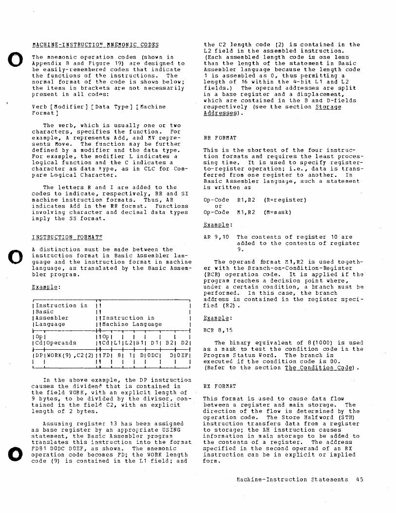
o
o
o
The mnemonic oper-ation codes (shown in A p pen d i x Ban d Fig u r- e 1 9) a r- e des i 9 ned to be easily-remember-ed codes that indicate the functions of the instr-uctions. The nor-mal for-mat of the code is shown below; the items in br-ackets ar-e not necessar-ily pr-esent in all codps:
Ver-b [Modifier-] [Data Type] [Machine For-mat]
The ver-b, which is usually Dne or- two char-acter-s, specifies the function. Forexample, A r-epresents Add, and MV r-epr-esents Move. The function may be fur-the~ defined by a modifier- and the data type. For example, the modifier L indicates a logical function and the C indicates a character- as data type, as in CLC for Compar-e Logical Character-.
The letters R and I ar-e added to the codes to indicate, respectively, RR and SI machine instruction for-mats. Thus, AR indica tes Add in the RR form at. Funct ions involving character and decimal data types imply the SS format.
A distinction must be made between the instruction format in Basic Assembler language and the instruction for-mat in machine language, as translated by the Basic AssembIer- program.
r--- --~i-l--------------------------'
I Instruction in 11 IBasic " I Assembler I,Instruction in ILanguage I,Machine Language ~-~------------t4--T--T--~--r---~ I Op I I 1 Op I I I I I I C d lOp e r- and s I 1 C d I~ L 1 , L 2 I B 1 I D 1 , I- I ++ I I I I I IDPIWORK(9) ,C2(2) I,FDI 81 11 DIODCI I I " I I I I I
I I I I
-.----~ I I
B 21 D21 -+--~ DIOEFI
I I
In the above example, the DP instruction causes the dividend that is contained in the field WORK, with an explicit length of 9 bytes, to be divided by the divisor, contained in the field C2, with an explicit length of 2 bytes.
Assuming register 13 has been assigned as base register by an approFr-iate USING statement, the Basic Assembler program translates this instruction into the format FD81 DODC DOEF, as shown. The mnemonic operation code becomes FD; the WORK length code (9) is contained in the L 1 field; and
the C 2 1 eng t h cod e ( 2) is con ta i ne din the L2 field in the assembled instr-uction. (Each assembled leng~h code is one less than the length of the statement in Basic Assembler- language because the length code 1 is assembled as 0, thus per-mitting a length of 16 within the 4-bit L1 and L2 fields.) Theoper-and addr-esses ar-e split in a base register- and a displacement, which are contained in lhe Band D-fields re$pectively (see the section ~iQ~~gg ! dd!:es.§~.§) •
RR FORMAT
This is the shor-test of the four instr-uction formats and r-equires the least pr-ocessing time. It is used to specifyregister-to-r-egister operation; i.e., data is transferr-ed fr-om one register- to another-. In Basic Assembler language, such a statement is wr-itten as
Op-Code R1, R2 (R=r-egister) or
Op - Co d e M 1 , R 2 ( M = m as k )
AR 9,10 The contents of register- 10 are added to the contents of register 9.
The oper-and for-mat r-:.1,R2 is used together with the Br-anch-on-Condition-Register (BCR) operation code. It is applied if the' program reaches a decision point where, under a certain condition, a branch must be performed. In this case, the branch address is contained in the register- srecified (R2)
BCR 8,15
The binary e:juivalent of 8 (1000) is used as a mask to test the condition code in the Program Status Word. The branch is executed if the condition code is 00. (Refer to the section !hg_~~nditio~~QQg)
RX FORMAT
This format is used to cause data flow between a register and main storage. The direction of the flow is determined by the operation code. The Store Halfword (STH) instruction transfers data from a register to storage; the AH instruction causes information in main st6rage to be added to the contents of a register. The address specified in the second operand of an RX instruction can be in explicit or implied form.
Machine-Instruction statements 45
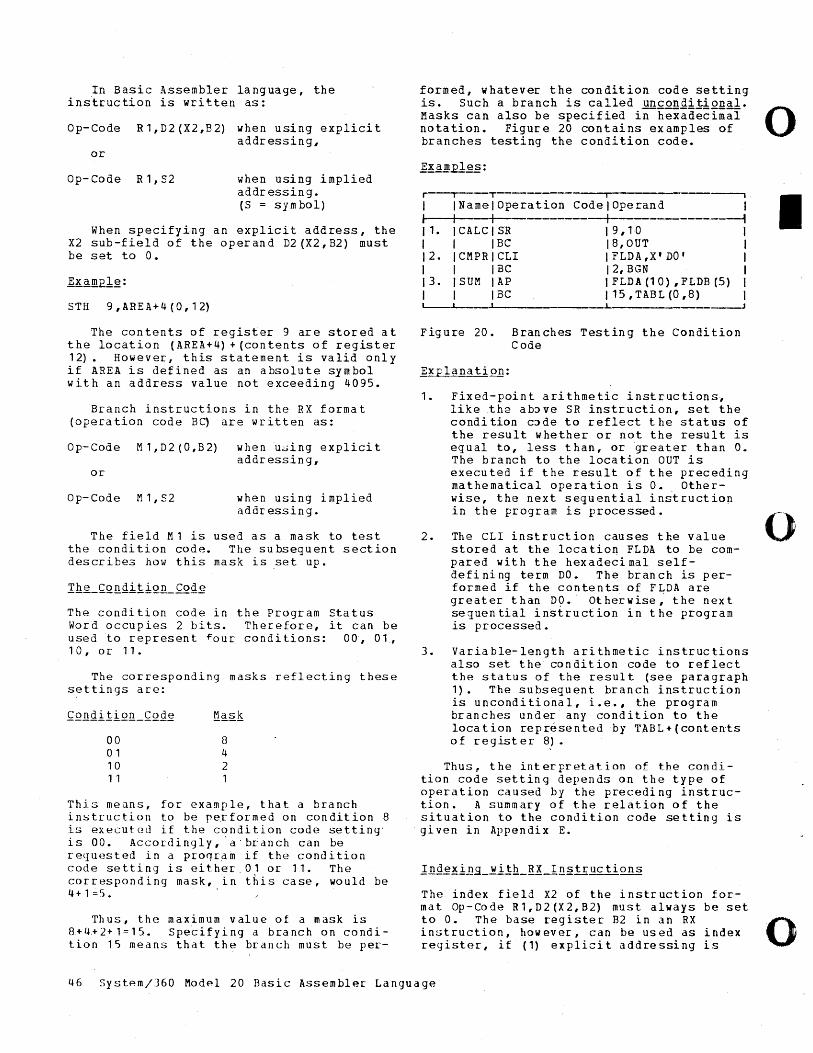
In Basic Assembler language, the ins~ruction is written as:
Op-Code R1,D2(X2#B2) when using explicit addressing,
or
Op-Code R1,S2 when using implied addressing. (S = sym boll
When specifying an explicit address, the X2 sub-field of the operand D2 (X2, B2) must be set to O.
STH 9,AREA+4 (0, 12)
The contents of register 9 are stored at the location (AREA+4) + (contents of register 12). However, this statement is valid only if AREA is defined as an absolute symbol with an address value not exceeding 4095.
Branch instructions in the RX format (operation code BC) are written as:
o p- Cod e M 1 , D 2 (0, B 2) w hen u;;,; i n g ex pI i cit addr essin g,
or
Op-Code M1,S2 when using implied addressing.
The field M1 is used as a mask to test the condition code. The subsequent section describes how this mask is .set up.
The condition code in the Program Status Word occupies 2 bits. Therefore, it can be used to represent ~our conditions: 00, 01, 10, or 11.
The corresponding masks reflecting these s~ttings are:
00 01 10 11
8 4 2 1
This meuns, for example, that a branch inst~uction to be pe~formed on condition 8 is executed if the condition code setting' is 00. Accordingly,· a· br:anch can be requested in a proqr~m if the condition code setting is either 01 or 11. The corresponding mask, in this case, would be 4+1:5. .
Thus, the maximum value of a mask is 8+4~2+1=15. spe~ifying a branch on condition 15 means that the branch must be per-
formed, whatever the condition code setting is. Such a branch is called unconditional. Masks can also be specified in-hexadecimal 0 notation. Figure 20 contains examples of branches testing the condition code.
Exam.12les:
i i I --, I INamelOperation Code lOpe rand I I I I I -i I 1. ICALCISR \ 9,10 I I I IBC 18,OUT I \2. ICMPRICLI I FLDA ,X' DO' I \ I IBC 12,BGN I I 3. ISUM lAP I FLDA (1 0) , FLDB (5) I I I IBC I 15 , TAB L (0,8) I '---I , J ----.J
Figure 20. Branches Testing the Condition Code
i!!..£lEJ1~ t ion:
1. Fixed-point arithmetic instructions, like the ab~ve SR instruction, set the condition c~de to reflect the status of the result whether or not the result is equal to, less than, or greater than O. The branch to the location OUT is executed if the result of the preceding mathematical operation is o. Otherwise, the next sequential instruction in the program is processed.
2. The eLI instruction causes the value stored at the location FLDA to be compared with the hexadecimal selfdefining term DO. The branch is performed if the contents of FLDA are greater than D9.· Otherwise,· the next sequential instruction in the program is processed.
3. Variable-length arithmetic instructions also set the condition code to reflect the status of the result (see paragraph 1). The subsequent branch instruction is unconditional, i.e., the program branches under any condition to the location repr~sented by TABL+(contents of register 8).
Thus~ the interpretation of the condition code setting depends on the type of operation caused by the preceding instruction. A summary of the relation of the situation to the condition code setting is given in Appendix E.
The index field X2 of the instruction form atOp - Co de R 1 , D 2 (X 2 , B 2) m us tal way s be set to O. The base register B2 in an RX in~truction, however, can be used as index reqister, if (1) explicit addressing is
I
o
o 46 Systpm/J60 Modpl 20 Basic Assembler Language
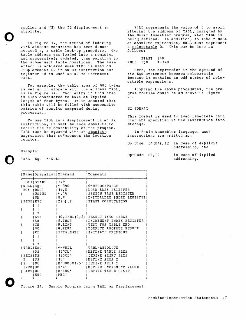
o
o
o
applied and (2) the D2 displacement is a Lsolu teo
In Figur~ 14, the method of indexing with address constants has been demonstrated by a table look-up procedure. The table address was loaded into a register and successively undated, thus pointing to the subsequent table positions. The same effect is achieved when TABL is used as displacement D2 in an RX instruction and register R8 is used as B2 to increment TABL.
For example, thp table area of 480 bytes is set up in storage with the address TABL, as in· Figure 14. l:'ach entry in this area is also considered to have an implied length of four bytes. It is assumed that this table will be filled with successive entries of results computed during processing.
To use TABL as a displacement in an RX instruction, it must be made absolute to retain the relocat~bility of the program. TABL must be eguatpd with an ER~olut~ expression that re~erences the location counter.
TABL EQU *-NULL
NULL represents the value of 0 to avoid altering the address of TABL, assigned by the Basic Assembler program, when TABL is being defined. In addition, to make *-NULL an absolute expression, NULL must represent a I~lo£~!~~lg O. This can be done as follows:
ST ART 340 NULL EQU *-340
Here, the expression in the operand of the EQU statement becomes relocatable because it contains an odd number of relocatable expressions.
Adopting the above procedures, the program routine could be as shown in Figure 21.
SI FORMAT
This format is used to load immediate data that are specified in the instruction into storage.
In Basic Assembler language, such instructions are written as:
Op-Code D1(B1),I2 in case of explicit addressing, and
Op-Code S1,I2 in case of implied addressing.
r----T-------, INamelOperationlOperand
._----_.,
j- I I PBL1 START 34 n NULL EQU *-140 BGN BASR 14,0
USING *,'4 SR 8, R
PRG M MVC X (Cj) , y
I I V
STH AH CH BC
lED I I I I I V
TABLI EQU IDS
PRTAIDS X IDS Y I DC INCRIDC LIMTI DC
lEND
10 , T A BL ( 0 , 8) 8,INCR 8,LIr-!T 4,PRGM PRTA, MASK
*-~TULL
120CL 4 120CL4 10Q H'00000175' H' 4' H'480' PBL1
IComments I I , I 10=RELOCATABLE ILOAD BASE REGISTER IASSIGN BASE REGISTER IINITIALIZE INDEX REGISTER ISTART COMPUTATION I I
RESULT INTO TABLE INCREMENT INDEX REGISTER TEST FOR TABLE END COMPUTE ANOTHER RESULT INITIATE PRINTOUT
TABL=ABSOLUTE DEFINE TABLE AREA DEFINE PRINT AREA DEFINE AREA X DEFINE AREA Y DEFINE INCREMENT VALUE
IDEFINE TABLE LIMIT I
Figure 21. Sample Program Using TABL as Displacement
Machine-Instruction Statements 47
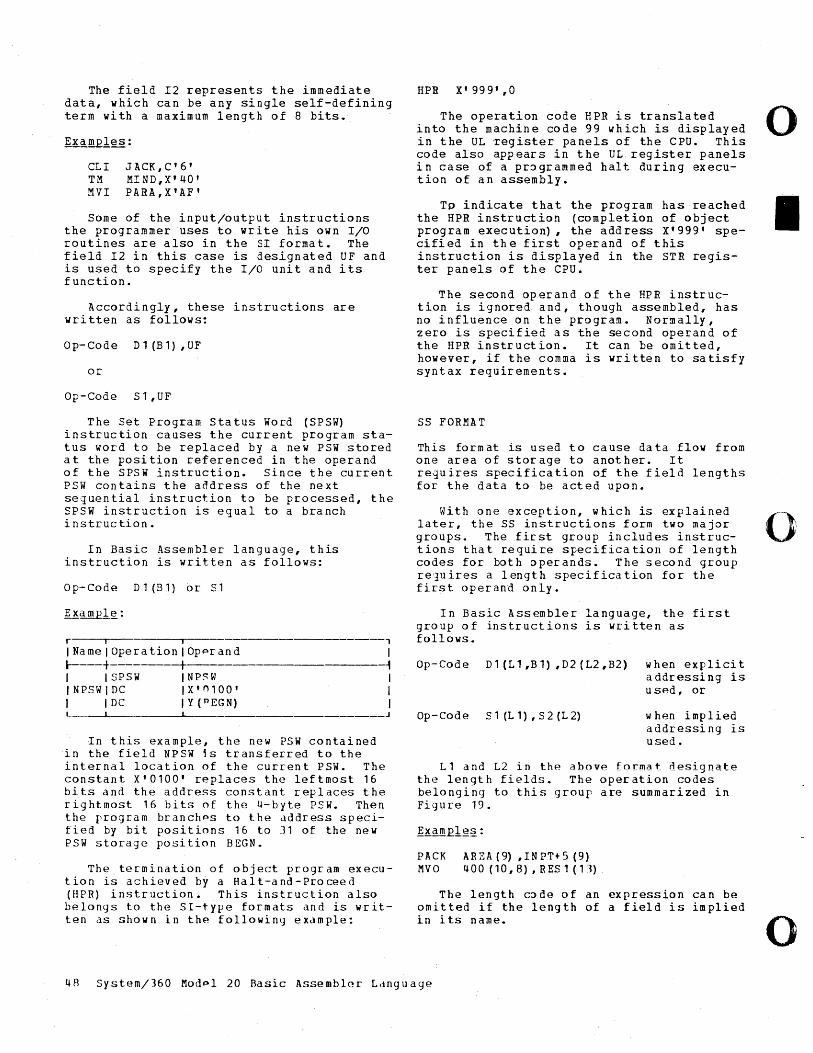
The field 12 represents the immediate data, which can be any single self-defining term with a maximum length of 8 bits.
CLI JACK, C' 6' TM MIND,X'40' MVI PARA,X'AF'
Some of the input/output instructions the programmer uses to write his own I/O routines are also in the SI format. The field 12 in this case is designated UF and is used to specify the I/O unit and its function.
Accordingly, these instructions are written as follows:
o p- Cod e D 1 (B 1) , U F
or
Op-Code S 1 , UF
The Set Program Status Word (SPSW) instruction causes the current program status word to be replaced by a new PSW stored at the position referenced in the operand of the SPSW instruction. Since the current PSW contains the address of the next sequential instruction to be processed, the SPSW instruction is equal to a branch instruction.
In Basic Assembler language, this instruction is written as follows:
o p- Cod e D 1 (B 1 ) 0 r S 1
r i i ,
INamelOperationlOpprand I 1----+-------+ ~ I ISPSW INP~W I INPSWIDC IX'n100' I I IDC IY(PEGN) I L-.L J
In this example, the new PSW contained in the field NPSW is transferred to the internal location of the current PSW. The constant X'0100' replaces the leftmost 16 bits and the address constant replaces the rightmost 16 bits of the 4-byte PSW. Then the program branchps to the address specified by bit positions 16 to 31 of the new PSW storage position BEGN.
The termination of object program execution is achieved by a Halt-and-Proceeo (lIFR) instruction. This instruction also belongs to the SI-type formats and is written as shown in the following example:
HPR X' 999' ,0
The operation code APR is translated into the machine code 99 which is displayed in the UL xegister panels of the cpu. This code also appears in the UL.register panels in case of a pr~grammed halt during execution of an assembly.
TO indicate that the program has reached the HPR instruction (completion of object program execution), the add ress X' 999' specified in the first operand of this instruction is displayed in the STR register panels of the cpu.
The second operand of the HPR instruction is ignored and, though assembled, has no influence on the program. Normally, zero is specified as the second operand of the HPR instruction. It can be omitted, however, if the comma is written to satisfy syntax requirements.
SS FORMAT
This format is used to cause da ta flow from one area of storage to another. It requires specification of the field lengths for the data to be acted upon.
with one exception, which is explained later, the SS instructions form two major groups. The first group includes instructions that require specification of length codes for both operands. The second group reluires a length specification for the first operand only.
I n Basic Ass emble r la nguage, the fi rs t group of instructions is written as follows.
Op-Code D1(L1,B1) ,D2(L2,B2) when explicit a ddressi ng is used, or
Op-Code S1(L1),S2(L2) when implied addressing is used.
L1 and L2 in the above format designate the length fields. The operation codes belonging to this group are summarized in Figure 19.
PACK AREA (9) ,INPT+5 (9) MVO 400 (10,8) , RES 1 (1:J)
The length c~de of an expression can be omitted if the length of a field is implied in its name.
4A System/360 Moopl 20 Basic Assembler Ldnguage
o
I
o
o
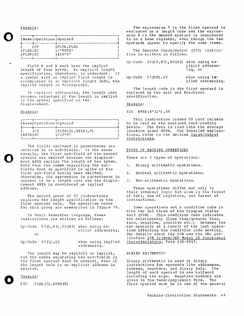
o
o
o
r i ~--------------------------,
INamelOperationlOperand I ... ----+---------+--------------~ I ICP IFLDA,FLDD I IFLDAIDC IC'OOOO' I IFLDBIDC IXLtl'O' I L_---L _______ -L ________________________ J
Field A and B each have the implied length of four bytps. An explicit length specification, therefore, is redundant. If a symbol with an implied field length is dccompdnied by an pxplicit length code, the implied length is ~isregarded.
In explicit addressing, the length code becomes redundant if the length is implied in the symbol specified as the displacemen t.
r----T--------~ -, INamelOperationlOpprand ~---+-----+ I ICP IFLDA(2),AREA(,8) IAREAIDC ICL2'0' L
I ~ I I
J
The fields enclosed in parentheses are referred to as sub-fields. In the above example, the first sub-field of the second operand was omitteo because the displacement AREA implies the length of two bytes. Note that the comma separating the subfields must be specified in spite of the first sub-field having been omitted. Otherwise, the expression in parentheses is assumed to be a length code and the displacement AREA is considered an implied address.
The second groun of SS instructions requires the length specification in the first operand only. The operation codes for this group are summarized in Figure 19.
In Basic Assembler language, these instructions are written as follows:
Op-Code Dl (L,B1) ,D2 (B2) when using explicit add£essing,
or
Op-Code S1(L),S2 when using implied addressing.
The length may be explicit or implied, but the comma separating the sub-fields in the first operand must be entered, even if the length code in an explicit address is omitted.
M V C F LD A (5) , W 0 R K (8 )
The eXFression 5 in the first operand is evaluated as a length code and the expression 8 in the second operand is considered to be a base register, even though the two operands appear to specify the same items •
The Execute Input/Output (XIO) instruction is written as follows.
Op-Code Dl(UF,Bl),D2(B2) wh9n using exp lici t addressing, or
Op-Code S 1 (U F) , S 2 w hen using i mplied addressing.
The length code in the first operand is replaced by the unit and functions specification.
XIO AREA(X'22') ,50
This instruction causes 50 card columns to be read on the assigned card-reading device. The data is read into the storage location named AREA. For detailed explanations, refer to the section In£B!LQ~iEut l!l~iru£tion§..
There are 3 types of operations:
1. Binary arithmetic operations.
2. Decimal arithmetic operations.
3. Non-arithmetic operations.
These operations differ not only in their internal logic but also in the format of data, use of registers, and format of instructions.
Some operations set a condition code in bits two and three of the Program status Word (PSW). This condition code indicates the relationship (less than/greater than, zero, negative, positive etc.) between the
·two operands as a result of the last operation effecting the condition code setting. For details ab~~t the PSW see the SRL publica tion 112I.:L~1 st~.!!!L..}§Q_ Model_~.Q_K~n£iiQn al ~Baracteristi£§, Form A26-5847.
BINARY ARITHMETIC
Binary arithmetic is used by binary instructions for operands like addresses, indexes, counters, and binary data. The length of each operand is one halfword including the sign. Negative numbers are, given in the twos-complement form. The first operand must be in one of the general
Machine-Instruction Statements 49
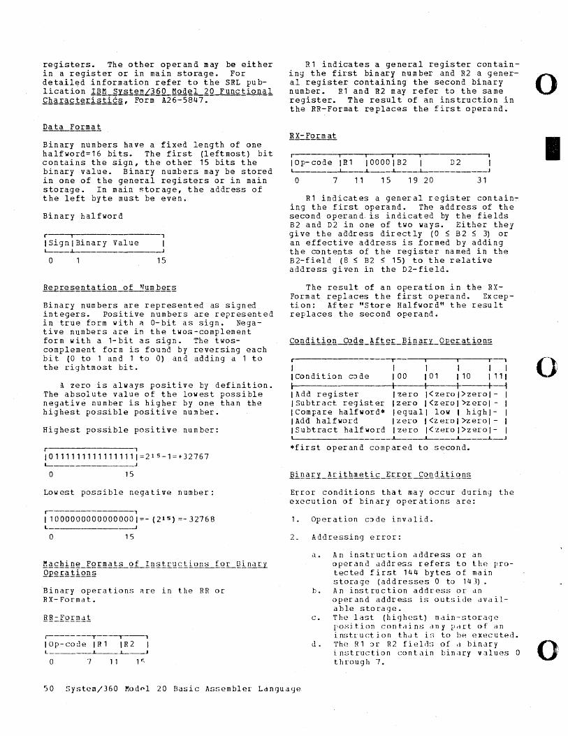
registers. The other operand may be either in a register or in main storage. For detailed information refer to the SRL publication IBM SystemL360 Model 20 Functional fh~±actg£istic§# Form A26-5847.
Binary numbers have a fixed length of one halfword=16 bits. The first (leftmost) bit contains the sign, the other 15 bits the binary value. Binary numbers may be stored in one of the general registers or in main storage. In main storage, the address of the left byte must be even.
Binary halfword
r i ,
ISignlBinary Value I
o 15
Binary numbers are represented as signed integers. Positive numbers are represented in true form with a O-bit as sign. Negative numbers are in the twos-complement form with a 1-bit as sign. The twoscomplement form is found by reversing each bit (0 to 1 and 1 to 0) and adding a 1 to the rightmost bit.
A zero is always positive by definition. The absolute value of the lowest possible negative number is higher by one than the highest possible positive nu~ber.
Highest possible positive number:
r , 101111111111111111=2 15 -1=+32767 L-_______________ J
o 15
Lowest possible negative number:
r----------------, 110000000000000001=- (2 15 ) =-32768 L ________________ J
o 15
~~£hi!l~_IQ£.!!!~l~Q.LI!l~.t.I.l!£1.iQ.ll~_fQL~i!l~.u Q.Eg!:~!iQ!l§
Binary operations ~re in the RR or RX- Forma t.
r--------T----,----, lOp-code IRl IR2 L _____ ---L ____ L-___ J
o 7 1 1 1 r:;
Rl indicates a general register containing the first binary number and R2 a general register containing the second binary number. R1 and R2 may refer to the same register. The result of an instruction in the RR-Format replaces the first operand.
I I I I
lOp-code IRl 10000182 D2 ~ _____ --i-___ ~ ____ i--__ ~ ___________ J
o 7 11 15 19 20 31
R1 indicates a general register contain~ ing the first operand. The address of the second operand. is indicated by the fields 82 and D2 in one of two ways. Either they give the address directly (05 B2 5 3) or an effective address is formed by adding the contents of the register named in the B2-field (8 ~ B2 5 15) to the relative address given in the D2-field.
The result of an operation in the RXFormat replaces the first operand. Exception: After "Store Halfword" the result replaces the second operand.
r--------- r ,
I I I I I I I Condi tion c:> de 100 101 110 \11\ I I I I I ~ IAdd register Izero I<zerol>zerol- I
Izero I<zerol>zerol - I lequall low I highl- I Izero I<zerol>zerol- I Izero I<zerol>zerol- I
Isubtract register ICompare halfword* IAdd halfword Isubtract halfword L---_______________ L-____ L-____ L--___ L __ J
*first operand compared to second.
Error conditions that may occur during the execution of binary operations are:
1. Operation c:>de invalid.
2. Addressing error:
a. An instruction address or an ope ran dad d r es s ref er s tot h E-~ protected first 144 bytes of main storage (addresses 0 to 143).
b. An instruction address or dn operand address is outside available storage.
c. The last (high(~st) main-storage position contains any part of an instruction that i~:; to be executed.
<.1. The R1:>r R2 fi(~ld,; of a binary instruction contain binary values 0 through 7.
50 System/360 Modpl 20 Basic Assembler Language
o
I
o
o
0
o
o
3. Specification error:
a. The low-oraer bit of an instruction address is one, i.e., no halfword boundary.
b. The halfword second operand is not located on a half word boundary.
c. Bi ts 12 through 15 of an RX format instruction are not all zero.
4. Binary overflow check.
5. CPU parity error.
INSTRUCTIONS FOR BINARY ARITHMETIC
r , I 1 I I I IName 10p-codelFormatlMnemonicl i-- 1 I I , I Add Register ,1A I RR I AR I I Subtract Register 1 1 BIRR I SR I I Store Halfword 1 40 I RX I STH I ILoad Halfword 1 48 I RX I LH I I Compare Halfword ,49 I RX I CH I I Add H a I f w 0 r d 1 Ig I R X I A H I I Subtract Halfwordt 413 I RX I SH I
Forma t: RR Op-code 1A
Machine instruction: AR R1,R2
Function: The contents of the first operana-field are added to the contents of the second operand field. The result is stored in the register specified by the first operand. Thp second operand remains unchanged.
The sign is determined by the rules of algebra. A zero rpsult is always positive. A sum consisting of more than 15 numeric bits plus the sign caus~s an overflow. In detail, this is what haprens: First all 16 bits of both operands are added. The result is correct if the addition results in a carry out of both the sign-bit position and the high order numeric-bit position or in no carry at all. However, if the addition causes a carry out of only one of the two positions a binary overflow will take rlace.
~ot~: An overflow will change the sign of the result.
00 01 10
Result=zero Result<zero Result>zero
~~£lg: Assume register 8 con tains hexa-decimal 0123 and register 9 con tains hexa-decimal 0532.
Source statement:
Op-code R1 R2
AR 8,9
From this sourc e sta tement the Basic Assem-bler creates th E following object code:
T ~------,
Op-code I R1 R2 I ~------------+I-------+----~
1 A I 8 9 I ~ _____ ~ __ J
After execut ion register 8 contains hexadecimal 0655. The condition code is 10.
Format: RR o p-code 1B
Machine instruction: SR R 1, R 2
Fun~tion: The contents of the second operand field are subtracted from the contents of the first operand field. The result will be in the register specified by R1. Both operands and the result consist of 15 numeric bits plus the sign. The second operand remains unchanged.
The subtraction is performed by adding the twos-complement of the second operand to the first operand. All 16 bits of both operands are added. If this results in a carry out of both the sign-bit position and the high order numeric-bit position or in no carry at all, then the result is correct. If there is, however, a carry out of only one of the two positions a binary overflow will occur.
A register may be cleared to zero by subtraction from itself.
There is no twos-complement for the highest negative number. This number remains unchanged when a complementation is performed. Nonetheless, the subtraction is still executed correctly.
00 01 10
Result==zer:> Resul t<zero Res u 1 t> zero
]~~~El~: Assume register 0 contains hexadecimal 047F and register q contains hexadecimal 0007.
r.achine-Instruction statements 51
Source statement:
Op-code R 1 R'2
SR 8, 1.1
From this source statement the Basic Assembler credtes the following object code:
.---------,--~,
1 0 p- co del R 1 I R 2 I ~---. -+--+-~ I 1 B 18 I D I '--_____ .J.. __ L--J
After execution register 8 contains hexadecimal 03A8. The condition code is 10.
Forma t: RX Op-code 40
Machine instruction: STH R 1 ,D 2 (0 , B 2)
Function: The contents of the register specified by Rl are stored in the half word at the main-storage location addressed by B2 and D2. The first operand remains unchanged.
~~~~£1~: Assume register 9 contains hexadecimal 68AF, register 11 contains hexadecimal 001E, and the displacement in the second operand is hexadecimal 29E (decimal 670) •
Source statement:
Op-code R1 D2 X2=0 B2
STH 9,670(0,1')
From this source statement the Basic Assembler creates the following object code:
r • ~ • I ,
IOp-codeIRlIX2~0IB2ID2 I l-------+-_+_ I I -t I 40 19 lOIS 129EI L
After execution the field starting at storage location hexadecimal 2BC (decimal 700) contains 68AF.
Format: RX Op-code 48
Machine instruction: I.H R1,D2(0,B2)
I]n£ii2n: The hal~word at the main storage location addressed by B2 and D2 is placed into the 16 bit positions of the register
specified by Rl. The second operand remains unchanged.
~~amElg: Assume register 9 contains hexadecimal AAAA, register 12 contains 0032, the displacement in the second operand is lF4 (decimal 500) , and the field starting at storage l:>cation hexadecimal 226 (decimal 550) contains 80AF.
Sour ce st atem ent :
Op-code R1 D2 X2=0 B2
L.H 9,500(0,12)
From this source statement the Basic Assembler creates the following object code:
I .--.----,--T---' IOp-cod e IR1IX2=0IB2ID2 I ~---+ I -t--+----i I 48 19 I 0 IC 11F41 ~ ___ --L--L-___ ~_~ __ J
After execution register 9 contains hexadecimal 80AF.
Format: RX Op -code 49
Machine instruction: CH R1 ,D2 {O, B2}
Iun£tiQ.!l: The 16 bits 0 f the register specified by R1 are compared with the halfword at the main storage location addressed by B2 and D2. The comparison is algebraic, i.e., the signs must be taken into consideration. B:>th operands remain unchanged. A condition code is set.
00 01 10
First operand=second operand First operand(second operand First operand>second operand
Exam£1e: Assume register 9 contains hexadecimal 0001, the displacement in the second operand is hexadecimal 690 {decimal 1680}, and register 13 contains hexadecimal 0026, and the halfword at storage location hexadecimal 6B6 is AF99.
Source statement:
Op- code R 1 D2 X2=0 B2
CH 9,1680{0,13)
From this source statement the Basic Assembl er cr eat es t he following object code:
52 System/360 Model 20 Basic Assembler Language
o
I
(~)
o
o
o
o
r-----~-~~___r___,
IOp-codeIRlIX2=0182ID2 I .. I I I +--~ I 49 I~ I 0 ID 1690 1 L-_____ ~ __ i----i--i-__ J
After comparison the resulting condition code setting will he: 10.
Format: RX Op-code 4A
Machine instruction: AH R1,D2(0,82)
K~nc!iQn: The hal~word in main storage, addressed by B2 ann D2, is added to the 16 bits of the register specified by Rl. The sign is determined by the rules of algebra. A zero result is positive by definition.
If the resultinq sum is larger than 15 bits plus the sign, an overflow occurs. All 16 bits of both operands are added. If there is a carry out of both the sign-bit position and the high-order numeric bit position or if there is no carry at all, the result is correct. A binary overflow will occur if there is a carry out of only one position. A condition code is set.
00 Resul t=zero 01 Resul t<zero 10 Result>zero
~~~m~l~: Assume register 9 contains hexadecimal 047F, register 11 contains hexadecimal 0028, the displacement in the second operand is lEA (decimal 490), and the field at storage location hexadecimal 212 (530) contains hexadecimal 1F29.
Source statement:
Op-code Rl D2 X2=O 82
AH 9,490(0,11}
From this source statement the Basic Assembler creates the following object code:
r-----~__,__ i 1__'
IOp-codeIRlIX2=0IB2ID2 I .. 1 1 I I 1 14A 19 10 IB IlEAl L-____ -L-~ __ ~~_~
After execution register 9 contains hexadecimal 23A8 and the condition code is 10.
Format: RX Op-code 4B
Machine instruction: SH R 1 , D 2 (0 , D 2)
Function: This instruction is identical to the-Ada-Halfword instruction with the following exce~tion: The twos-complement of the second operand, addressed by B2 and D2, is added in place of the true value.
00 01 10
Resu It =z ero Result<zer3 Resu I t>ze ro
~~amplg: Assume register 9 contains hexadecimal 047F, register 11 contains hexadecimal 0050, the displacement in the second operand is hexadecimal 320 (decimal 800), and the field starting at storage location hexadecimal 370 (decimal 880) contains hexadecim al 00 D7 •
Source statement:
Op-code Rl D2 X2=0 B2
SH 9,800 (0, 11)
From this source statement the Basic Assembler creates the following object code:
Iii I i
IOp-codeIRlIX2=0IB2I TI 2 1 ~----+--+----+--+---~ I 4B I 9 I 0 I B I 3201 L-
After execution register 9 contains hexadecimal 03A8 and the condition code is 10.
DECIMAL ARITHMETIC
Decimal arithmetic can be performed only with data in packed format. Packed format means that there are two digits in one byte except for the low order byte. It contains one digit and the sign.
Data is transferred to and from the external I/O devices in zoned format. Thus, the data has to be packed and unpacked bef3re and after processing respectively. In zoned format, each byte contains a zone in the left halfbyte and a digit in the right halfbyte except the last one which contains the sign and a digit. The add re ss in an instru ction always s pecifies the left-most byte of the operand. The length field in an assembled instruction indicates how many bytes are part of the operand in addition to the addressed (left) byte.
Decimal operations are performed in main storage. The operands have a length from
Machine-Instruction Statements 53
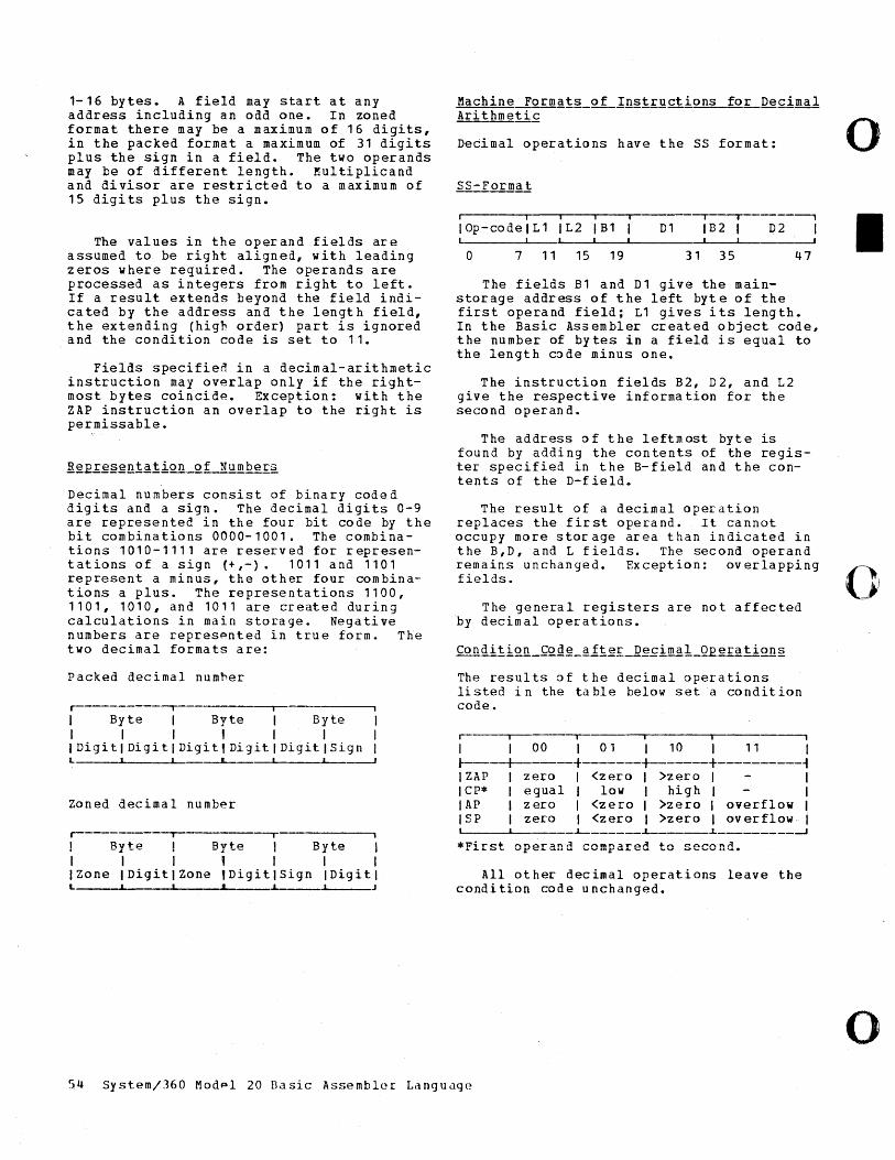
1-16 bytes. A field may start at any address including an odd one. In zoned format there may be a maximum of 16 digits, in the packed format a maximum of 31 digits plus the sign in a field. The two operands may be of different length. Multiplicand and divisor are restricted to a maximum of 15 digits plus the sign.
The values in the operand fields are assumed to be right aligned, with leading zeros where required. The operands are processed as integers from right to left. If a result extends beyond the field indicated by the address and the length field, the extending (high order) part is ignored and the condition code is set to 11.
Fields specifien in a decimal-arithmetic instruction may overlap only if the rightmost bytes coincide. Exception: with the ZAP instruction an overlap to the right is permissable.
R~E£esentation of Numbers
Decimal numbers consist of binary coded digits and a sign. The decimal digits 0-9 are represented in the four bit code by the bit combinations 0000-1001. The combinations 1010-1111 are reserved for representations of a sign (+,-). 1011 and 1101 represent a minus, the other four combinations a plus. The representations 1100, 1101, 1010, and 1011 are created during calculations in main storage. Negative numbers are represpnted in true form. The two decimal formats are:
Packed decimal numher
r----------~----------~----------~
I Byte I Byte Byte I I I I I I IDigitlDigitlDigitlDigitlDigitlSign L ~
Zoned decimal number
r---------~----------r----------~
! Byte ! Byte 1 Rvh:~ -.I --
I I I , I I I IZone IDigitlZone ,DigitlSign IDigitl L ______ ~ ____ ~ ____ -A_ ,.A.-____ ...L.. _____ J
Machine Formats of Instructions for Decimal Arithmetic
Decimal operations have the SS format:
• iii -.-~------,
IOp-codelL1 IL2 IB1 D1 I B 2 I D2 I
o 7 11 15 19 31 35 47
The fields B1 and D1 give the mainstorage address of the left byt e of the first operand field; L1 gives its length. In the Basic Assembler created object code, the number of bytes in a field is equal to the length c~de minus one.
The instruction fields B2, D2, and L2 give the respective information for the second operand.
The address ~f the leftmost byte is found by adding the contents of the register specified in the B-field and the contents of the D-field.
The result of a decimal operation replaces the first operand. It cannot occupy more storage area than indicated in the B,D, and L fields. The second operand remains unchanged. Exception: overlapping fields.
The general registers are not affected by decimal operations.
The results af the decimal operations listed in the table below set a condition code.
r- , I I 00 I 01 I 10 I 11 I r-----+-------+-------+-------+----------~ I ZAP I zero I <zero I >zero I I I cp* I equal I low I high I I lAP I zero ,<zero, >zero , overflow I ,SP 'zero I <zero, >zero , overflow,
~ ______ ~ ______ ~ _________ _J
All other decimal operations leave the condition code unchanged.
54 system/360 Modpl 20 Dasic Assembler Langudge
o
I
o
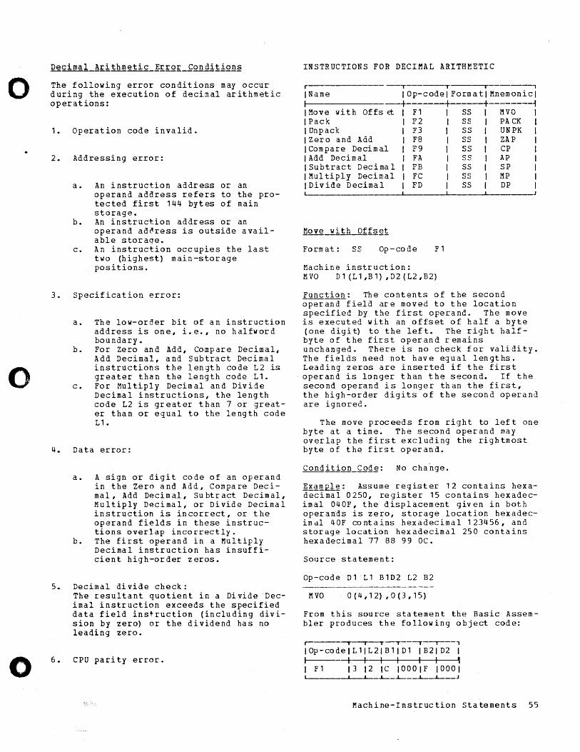
o
o
o
The following error condition& may occur during the execution of decimal arithmetic operations:
1. Operation code invalid.
2. Addressing error:
a. An instruction address or an operand address refers to the protected first 144 bytes of main storage.
b. An instruction address or an operand address is outside available storaqe.
c. An instruction occupies the last two (highest) main-storage positions.
3. Specification error:
a. The low-order bit of an instruction address is one, i.e., no halfword boundary.
b. For Zero and Add, Compare Decimal, Add Decimal, and Subtract Decimal instructions the length code L2 is greater than the length code L1.
c. For Multiply Decimal and Divide Decimal instructions, the length code L2 is greater than 7 or greater than or equal to the length code L1.
4. Data error:
a. A sign or digit code of an operand in the Zero and Add, Compare Decimal, Add Decim aI, su btr act Decimal, Multiply Decimal, or Divide Decimal instruction is incorrect, or the operand fields in these instructions overlap incorrectly.
b. The first operand in a Multiply Decimal instruction has insufficient high-order zeros.
5. Decimal divide check: The resultant quotient in a Divide Decimal instruction exceeds the specified data field instruction (including division by zero) or the dividend has no leading zero.
6. CPU parity error.
INSTRUCTIONS FOR DECIMAL ARITHMETIC
r IName
---T-------T----~--------,
lOp-code FormatlMnemonicl I -+ ---+--------~ I Move with IPack
Offs Et I F 1 ss I £'II VO I
I Unpack IZero and Add I Compare Decim al 1 Add Decimal ISubtract Decimal IMultiply Decimal IDivide Decimal
I F 2 S SIP A CK I I F3 ss I UNPK I I F8 SS I ZAP I I F9 SS I CP I I FA SS I AP 1 1 FB SS I SP I I FC SS I MP I I FD SS I DP I
~ ________________ ~~ ______ ~ ______ ~ _________ J
Form at: SS Op -co de F1
Machine instruction: MVO D1 (L1,B1) ,D2(L2,B2)
fQnctio~: The contents of the second operand field are moved to the location specified by the first operand. The move is executed with an offset of half a byte (one digi~ to the left. The right halfbyte of the first operand remains unchanged. There is no check for validity. The fields need not have e~ual lengths. Leading zeros are inserted if the first operand is longer than the second. If the second operand is longer than the first, the high-order digits ·of the second operand are ignored.
The move proceeds from right to left one byte at a time. The second operand may overlap the first excluding the rightmost byte of the first operand.
~~~~~: Assume register 12 contains hexadecimal 0250, register 15 contains hexadecimal 040F, the displacement given in both operands is zero, storage location hexadecimdl 40F contains hexadecimal 123456, and storage location hexadecimal 250 contains hexadecimal 77 88 99 OC.
Source statement:
Op-code D1 L1 B1D2 L2 B2
M VO 0 ( 4 , 1 2) , a (3 , 15)
From this source statement the Basic Assembler produces the following object code:
r- iii T---T--"---' IOp-codeIL 1IL2I B1 ID1 IB21D2 I 1--------+--+ 1 I I I , I F1 13 12 Ie 1000lF 10001
...l.-_...l.-__ ...l.-_.L-__ J
Machine-Instruction Statements 55
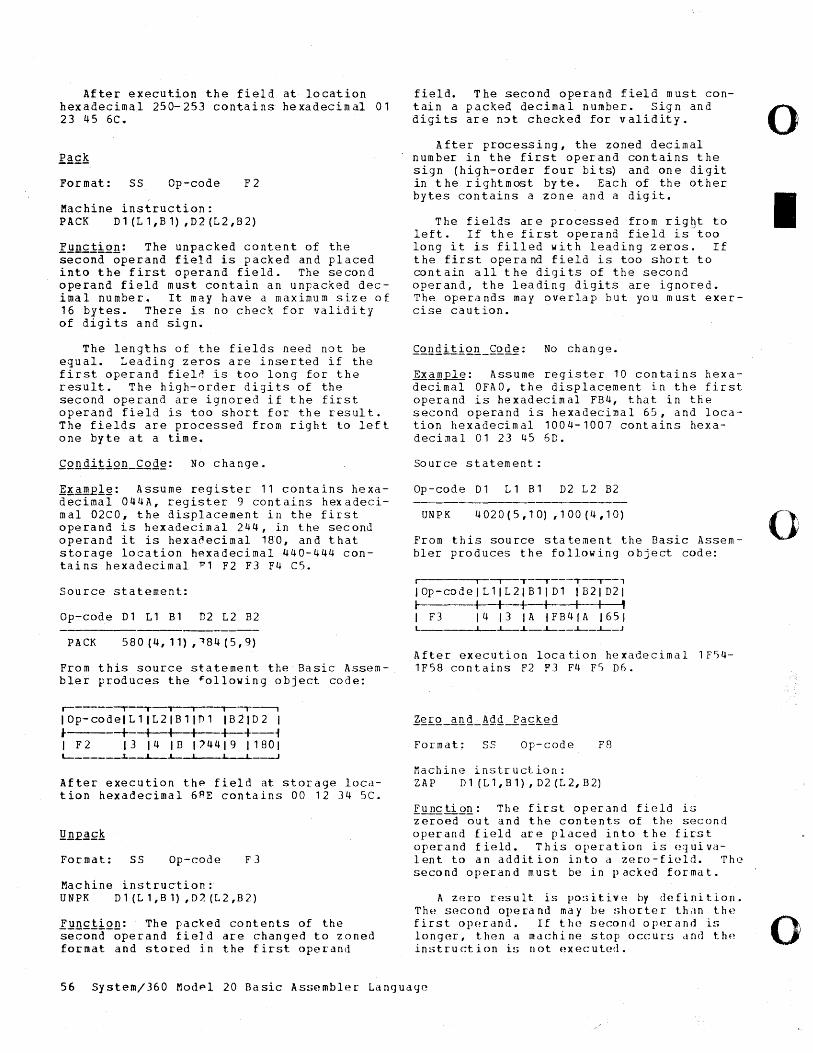
After execution the field at location hexadecimal 250-253 contains hexadecimal 01 23 45 6C.
Format: SS Op-code F2
Machine instruction: PACK D 1 (L 1, B 1) , D 2 (L 2, B 2)
Function: The unpacked content of the second-operand field is packed and placed into the first operand field. The second operand field must contain an unpacked decimal number. It may have a maximum size of 16 bytes. There is no check for validity of digits and sign.
The lengths of the fields need not be equal. Leading zeros are inserted if the first operand fieln is too long for the result. The high-order digits of the second operand are ignored if the first operand field is too short for the result. The fields are processed from right to left one byte at a time.
~KamEl~: Assume register 11 contains hexadecimal 044A, register 9 contains hexadecimal 02CO, the displacement in the first operand is hexadecimal 244, in the second operand it is hexanecimal 180, and that storage location hexadecimal 440-444 contains hexadecimal ~1 F2 F3 F4 C5.
Source statement:
Op-code 01 Ll Bl D2 L2 B2
PACK 580 (4, 11) ,184 (5,9)
From this source statement the Basic Assembler produces the ~ollowing object code:
r-----~_,_-~ i i-'-----' IOp-codeILlIL2IBllT11 IB2102 I J----_+_ I I I +-+---{ I F2 1314 IB 12441911801
After execution the field at storage location hexadecimal 6RE contains 00 12 34 5C.
Format: SS Op-code F3
Machine instruction: UNPK D1{L1,B1) ,D:'.(L2,B:?)
1~n£1iQn: The packed contents of the second operand fieJd are changed to zoned format and stored in the first operand
field. The second operand field must contain a packed decimal number. Sign and digits are n~t checked for validity.
After processing, the zoned decimal number in the first operand contains the sign (high-order four bit~ and one digit in the rightmost byte. Each of the other bytes contains a zone and a digit.
The fields are processed from right to left. If the first operand field is'~too long it is filled with leading zeros. If the first operand field is too short to contain all the digits of the second operand, the leading digits are ignored. The operands may overlap but you must exercise caution.
]~~~~: Assume register 10 contains hexadecimal OFAO, the displacement in the first operand is hexadecimal FB4, that in the second operand is hexadecimal 65, and location hexadecimal 1004-1007 contains hexadecimal 01 23 45 6D.
Source statement:
Op-code 01 L1 Bl D2 L2 B2
UNPK 4020(5,10) ,100(4,10)
From this source statement the Basic Assembler produces the following object code:
I --'-~-T-_'_---T--T--'
IOp-code1L11L21B1101 IB21021 I I I I I I t----1 I F3 14 13 IA IFB41A 1651 L _____ ~~_~ __ ~ __ ~_~_J
After execution location hexa~ecimal 1FS4-1F58 contains F2 F3 F4 F5 06.
Format: S5 Op-code F8
Machine instruction: ZAP D1 (Ll,Bl) ,D2(L2,B2)
functign: The first operand field is zeroed out and the contents of the second operand field are placed into the first operand field. This operation is (~quivalent to an addit ion into d zero-field. The second operand must be in packed format.
A zp.ro result is po~)itiv(~ by (lefinition. The sp.cond operand may b(~ short(~r th,ln th~~
first operand. If th(~ second oI)(~ri1nd is long(~r, then il machine stop occurs and th(~
ins t rue t ion i!:; not (~ x e cut e (1.
56 System/360 Modpl 20 Basic Assembler Language
o
I
o
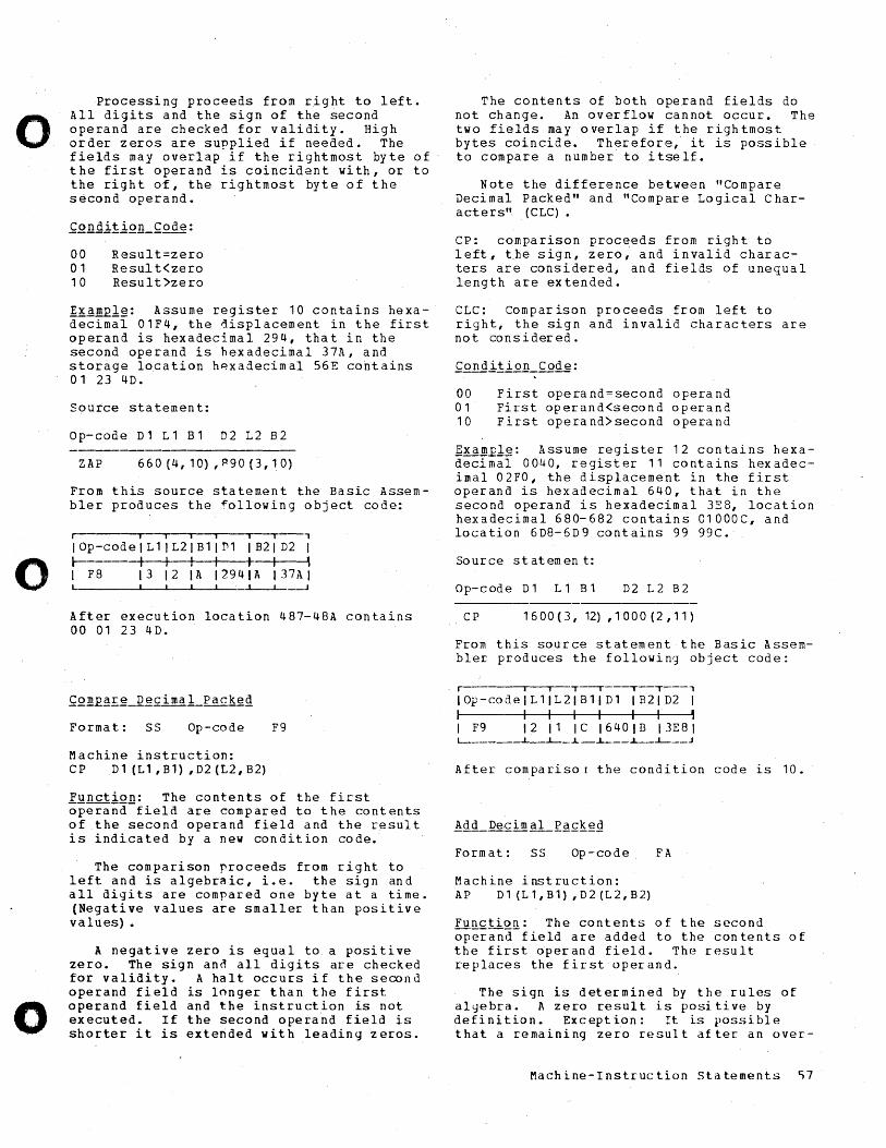
o
o
o
Processing proceeds from right to left. All digits and the sign of the second operand are checked for validity. High order zeros are supplied if needed. The fields may overlap if the rightmost byte of the first operand is coincident with, or to the right of, the rightmost byte of the second operand.
00 Result=zero 01 Resul t<zero 10 Result>zero
~x~~l~: Assume register 10 contains hexadecimal 01F4, the displacement in the first operand is hexadecimal 294, that in the second operand is hexadecimal 37A, and storage location h~xadecimal 56E cohtains 01 23 4D.
Source statement:
o p- cod e D 1 L 1 B 1 D 2 L 2 B 2
ZAP 660(4,10),P90(3,10)
From this source statement the Basic Assembler produces the ~ollowing object code:
I iii i I I ,
lOp-code I L 1 I L2 I B 1 I D1 I B21 D2 I r-------t I I I I I • I F8 1312 IA 12941A 137AI
After execution location 487-48A contains 00 01 23 4D.
Forma t: SS Op-code F9
Machine instruction: CP D1(L1,B1),D2(L2,B2)
Function: The contents of the first operand-field are compared to the contents of the second operand field and the result is indicated by a new condition code.
The comparison proceeds from right to left and is algebraic, i.e. the sign and all digits are compared one byte at a time. (Negative values are smaller than positive values) •
A negative zero is egual to a positive zero. The sign and all digits are checked for validity. A halt occurs if the second operand field is longer than the first operand field and the instruction is not executed. If the second operand field is shorter it is extended with leading zeros.
The contents of both operand fields do not change. An overflow cannot occur. The two fields may overlap if the rightmost bytes coincide. Therefore, it is possible to compare a number to itself.
Note the difference between "Compare Decimal Packed" and "Compare Logical Characters" (CLC).
CP: comparison proceeds from right t6 left, t.he sign, zero, and invalid characters are considered, and fields of unequal length are extended.
CLC: Comparison proceeds from left to right, the sign and invalid characters are not co n sid er e d .
00 01 10
First operand=second operand First operand<second operand First operand)second operand
~xa~ple: Assume register 12 contains hexadecimal 0040, register 11 contains hexadecimal 02FO, the displacement in the first operand is hexadecimal 640, that in the second operand is hexadecimal 3E8, location hexadecimal 680-682 contains 01000C, and location 6D8-6D9 contains 99 99C.
Source statemen t:
o p- cod e D 1 L 1 B 1 D2 L 2 B 2
CP 1600(3,12) ,1000(2,11)
From this source statement the Basic Assembler produces the following object code:
r i I T--'---~--"--'
IOp-code1Ll1L21B11D1 IB21D2 I I I I I I I I , I F9 12 11 IC 1640lB 13E81
..L_-L-__ -L--L-__ J
After comparisor the condition code is 10.
Format: SS Op-code FA
Machine instruction: AP Dl (Ll,B1) ,D2 (L2,B2)
Functi~~: The contents of the second operand field are added to the contents of the first operand field. The result replaces the first operand.
The sign is determined by the rules of alyebra. A zero result is positive by definition. Exception: It is possible that a remaining zero result after an over-
Machine-Instruction statements ~7
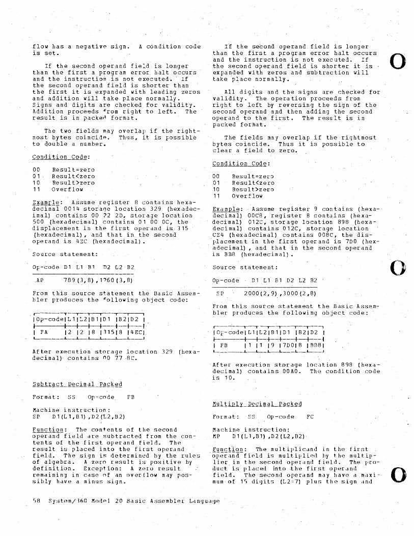
flow has a negative sign. is set.
A condition code
If the second operand field is longer than the first a program error halt occurs and the instruction is not executed. If the second operand field is shorter than the first it is eipanded with leading zeros and addition will take place normally. Signs and digits are checked for validity. Addition proceeds ~rom right to left. The result is in packen format.
The ~wo fields may overlap if the rightmost bytes cointid~. Thus; it is Fossibl~ to double a number.
00 Result=zero 01· Result(zero 1 a Re suI t >zero 1 1 '0 v e r flo w
];.!~l!u?lg: Assume register 8 contai.ns hexadecimal 00 14 storage location 329 (hex adecimal) cont~ins 00 '2 2D, storage location 500 (hexadecimal) contains 01 00 OC, the displacement in the first operand i5·315 (hexadecimal)1 and that in the second operand is 4EC (hexadecimal).
Source statement:
Op-code D1 L 1 B1 'D2 L2· B2
,AP 789 (3,8) ,1')60 (3,8)
From this source statement the Basic Assembler produces the ~ollowing object code:
,--------T--,- I, I I ---r--, IOp-code1L11L21B11Dl IB21D2 I ~--, --4-- I I I +--+---~ , I FA 1 2 I 2 1 8 1 11 5 I 8 1 4 EC I. L-__ ,-__ J.._-..l.. .L_-.L __ ..J
After executio'n storage location 329 (hexadecimal), contains no 77 ,8C.
Format: S5 Or-code FB
Machine instruction: SP D1(L1,B1) ,D2(L2,B2)
funct!.Q..!!: The contents of the second operand field are subtracted from the contents of the first operand field. The result is placed into the first operand field. The sign is determined by the rules of algebra. A zero result is positive by definition. Exception: A zero result remaining in case of an over·flow may, possibly have a minus sign.
If the se~ond 'operand, field is longer than the first a program error halt occurs and the instruction is not executed~ If 0 the second operand field is shorter it is ' expanded with zeros and subtraction will take place n~rmally~
All digits and the signs are checked for validity. The opera~ion proceeds from right to left by reversing the sign of the second ~perand and then adding the second operand to the'first. The result is in packed format.
The fields ~ay overlap if the rightmost bytes cointide. Thus it is possible to clear a field to zero.
Condition'Code:
00 01 10 11
Result=zer~ Result(zerb Result>zero Overflow
£;.xam£l~: Assume register 9 contains (hexadecimal) 00t8,register8 contains (hexadecimal) 012C, storage location 898 (hexadecimal) contains 012C, storage loea'tion CE4 (hexadecimal) contains 008C, the dis-'~lacement in the first operand is7DO (hexadecimal) , and tha t in the second operand is BB8 (hexadecimal).
Source statement:
Op-code D 1 L" B 1 D 2 L2 B2
SP 2000(2,9) ,3000(2,8)
From this soutce statement the Basic Assembler produces the following object code:
r I 1--'--'-- 1-'
IOr-codeIL1IL2IB1ID1 IB21D2 I 1 -+-+-~+--+---+-+~--~ 1 FB 111119 17DOl8 IRn81 L ___ --.L_L--L--L--.L_L--_..J
After execution storage locatioh 898 (hexadecimal) contains OOAO. Th(~ condition code is 10.
Fo rm d t : (~(~ Op-code FC
Machine instruction: MP Dl(Ll,B1) ,D2(L2,B2)
I!!.!l~i'!'Q.!l: The multiplicand in th(~ first opl~rilnd field is multiplied by t.he multiplier in the second operand fi('~ld. The IJro-
o
duct is placed into ,thf~ first ()IH~rancl 0 fif~lrl. The second oper'dnd may havc~ cl mdxi- I
mum of 1c) c1i{jits (L2=7) plu!. t.h(~!.:;i:gn <ind
58 System/J60 Modpl 20 Basic Assembler ~dnguaqe
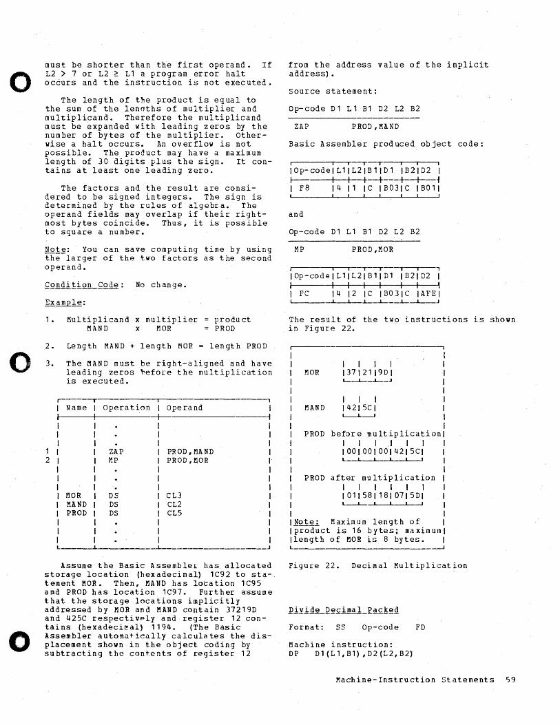
o
0
o
must be shorter than the first operand. If L2 > 7 or L2 ~ Ll a program error halt occurs and the instruction is not executed.
The length of the product is equal to the sum of the lenaths of multiplier and mUltiplicand. Therefore the multiplicand must be expanded with leading zeros by the number of bytes of the multiplier. Otherwise a hal t occurs. An overflow is not possible. The product may have a maximum length of 30 digits plus the sign. It contains at least one leading zero.
The factors and the result are considered to be signed integers. The sign is determined by the rules of algebra. The operand fields may overlap if their rightmost bytes coincide. Thus, it is possible to square a number.
EQ1~: You can save computing time by using the larger of the two factors as the second operand.
1 • Mul tiplicand x multiplier = produ ct MAND x MOR = PROD
2. Length MAND + length MOR = length PROD
3. The MAND must be right-aligned and have leading zeros ~efore the multiplication is executed.
r------T -, I Name I Operation I Operand I l- I +- ~
I I I
1 ZAP PROD,MAND I 2 r-!P PROD,~OR I
I I . I
MOR DS CL3 I MAND DS CL2 I PROD DS CL5 I
I I I
~ __________________ J
Assume the Basic Assembler has allocated storage location (hexadecimal) lC92 to sta-. tement MOR. Then, HAND has location lC95 amd PROD has location lC97. Further assume that the storage locations implicitly addressed by MOR and HAND contain 37219D and 425C respectivply and register 12 con-t a ins (h e x a dec i I". a I ) 1 1 9 4 • (T h e Bas i c Assembler. automatically calculates the displacement shown in the object coding by subtracting the contents of register 12
from the address value of the implicit address).
Source statement:
Op-code D 1 L 1 81 D2 L2 B2
ZAP PROD, HAND
Basic Assembler produced object code:
I I I T--r I I i
I 0 p- co del L 1 I L 2 I B 1 I D 1 I B 2 I D 2 I I- I I +--+----+-+--~ I F8 14 11 IC IB031C IBOll '---
and
Op-code Dl L1 B1 D2 L2 B2
MP PROD,MOR
I I I ~-T---T--'---'
IOp-codelL1lL2lBllDl IB21D2 1 I -+ I 1 I I 1 •
1 FC 14 12 IC IB031C IAFEI , I .L-_.L-__ .L- I ,
The result of the two instructions is shown in Figure 22.
I I l I MOR 13712119DI
MAND
L--.L-_.L-_J
1 I I 14215CI
PROD before multiplication I I I .1 I I 10010010014215CI L __ ~~ __ ~~ __ ~
PROD after multiplication I I I 1 I I 10115811810715DI L--L-~ __ ~~ __ ~
!Q.!.~"!' Maximum length of product is 16 bytes; maximum
Ilength of MOR is 8 bytes. L
Figure 22. Decimal Multiplication
Format: SS Op-code FD
Machine instruction: DP D1 (L 1, B1) , D2 (L2, B2)
Machine-Instruction Statements 59
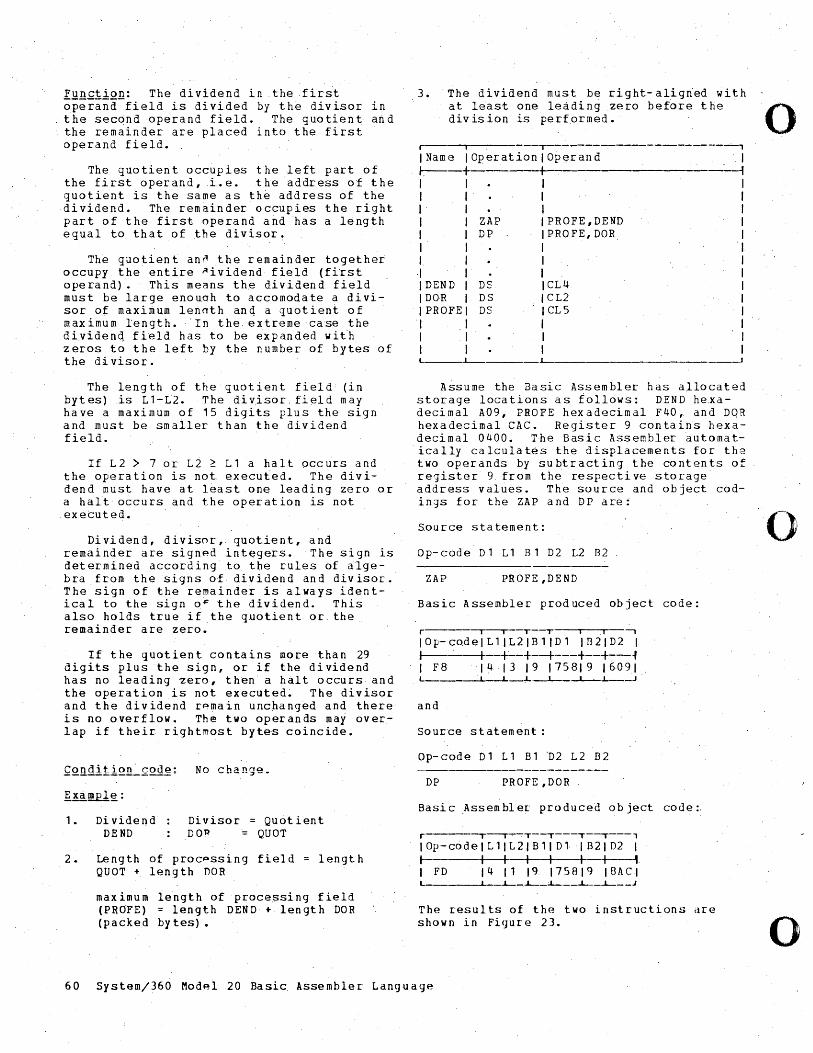
. .
Function: The dividend in .the .firs·t operand-field is divided by the divisor in the second operand field. The quotient and the remainder are placed into the first operand field.
The quotient occupies the left part of the first operand, .L.e. the address of the quotient is the same as the address of the dividend. The remainder occupies the right part of the first operand and has a l~ngth equal to that of the divisor!
Th~ quotient an~ the remainder togethei occupy the entire ~ividend field (first operand). This means the dividend field must be large enouqh to accomodate a divisor of maxi~um lenoth an~ a quotient of maximum length. 'In the extreme case the diyiden~ field has to be expanded wit'h zeros to the left by the number of bytes of the di visor.
The length of the quotient field (in bytes) is Ll-L2. The div.isor, field may have a maximum of 15 digits plus the sign and must be smaller than the dividend field.
If L2 > 7 or L2 ~ Ll a halt occurs and the operation is not execu~~d. The dividend must have at least one leading zero or a hal~ o6curs and the operation is not
. executed.
Dividend, divisor, quotient, and remainder are signed integers. The sign is determined according to the rules of ~lgebra from the ~igns of dividend and divisor. The sign of the remainder is always identical to the sign o~ the dividend. This also holds true if the quotient or the re~ainder are zero.
If the quotient contains more than 29 digits plus the sign, or if the dividend has no leading zero, then' a halt occurs and the operation is not executed~ The divisor and the dividend r~main unchang~d and there is no overflow. The two operands may overlap if their rightmost bytes coincide.
1.
2.
Di vidend DEND
Divisor = Quotient DO~ QUOT
Length of procpssing field QUOT + length nOR
length
maximum length of proce$sing field (PROFE) = length DEN D +- len gt h DOR (packed bytes).
3. The dividend must be right-aligried with at least one leading zero before the division is performed.
r--- I -.---~---~------------~-~,
IName IOperationlOperand I r,---t I ~ I 1 1 I I I I.
·1 1 DEND IDOR
ZAP DP
DS DS
- 1 PROFE DS I 1 I
PROFE,DEND PRO FE, DaR.
CL4 CL2 CL5
L _____ L--________ .~ ______________________ ~
Assume the Basic Assembler has allocated storage locations as tollows: DEND hexadecimal A09, PROFE hexadecimal F40, and DOH hexadeci~al CAC. Register 9 contaihs hexadecimal 0400. The Basic Assembler automatically calculat~s the displacements for the two operands by subtracting the contents of register 9 from the respective storage address values. The source and object codings for the ZAP and DP are:
Source statement:
Op-code Dl Ll B1 D2 L2 82
ZAP PROFE ,DEND
Basic Assembler produced object code:
r --r--r--T--T' I -,
10 p- cod elL 1 1 L 2 I B 1 I D liB 2 I D 2 I ~~--+~-+--+---+--~-~~ I F8 14 13 19 175819 16091
.,L-L-- I ~.
and
Source statement:
Op-code Dl Ll Bl n2 L2 82
DP PROFE ,DaR
Basic Assembler produced object code:.
r -'--'-~T--T-~-T--'---'
lOp-code 1 L llL 21 B 11 D l I 821 D2 I 1-----+-+ I I 1 +--1 1 FD 14 11 19 175819 ISACI L -L-_-L-_L-__ -L-_...l....-__ J
The results of the two instructions dre shown in Figure 23.
60 System/360 Model 20 Basi~ Assembler Language
o
o
o
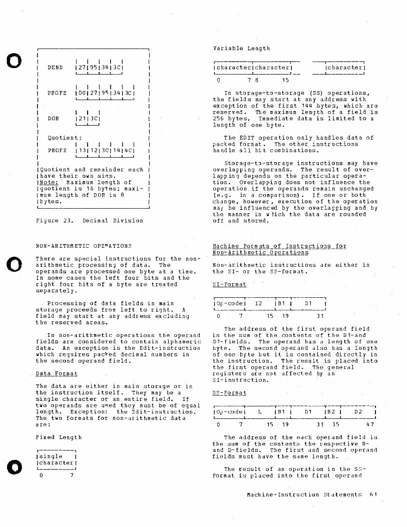
o
o
o
r--- --------------, I I I DEND
I I I I I 12719513 4 13CI
I I
L----'-_-'-__ ..L.---1
I I I I I I PROFE I0012719~13413CI
~~ __ ~_.I_-i-_J
I I I DOR 12113CI
L_~~
Quotien t: I I I I I I
PROFE 11311213CI1414CI ~-L __ ~ __ ~-J
Quotient and remaindet each have their own siqn. MQ!~~ Maximum length of quotient is 16 bytes; maximum length of DOR is 8 bytes.
L- -1
Figure 23. Decimal Division
NON-ARITHMETIC OPEPATIONS
There are special instructions for the nonarithmetic processing of data. The operands are processed one byte at a tim~. In some cases the left four bits and the right four bits of a byte are treated separately.
Processing of data fields in main storage proceeds from left to right. A field may start at any address excluding the reserved areas.
In non-arithmetic operations the operand fields are c6nsidered t6 contain alphameric data. An ex~eption is the Edit-instruction which requires packed decimal numbers in the second operand field.
The data are either in main storage or in the instruction itself. 'They may be a single character or an entire field. If two operands are used they must be of equal length. Exception: the Edit-instruction. The two formats for non-arithmetic data are:
Fixed Length
r---------, lsingle I Icharacter I L _________ J
a 7
Variable Length
Iii
Icharacterlcharacterl
o 7 8 15
I -,
Icharacter I __ ..L-_______ J
In storage-to-storage (S5) operations, the fields may start at any address with exception of the first 144 bytes, which are reserved. The maximum lenr;th of a field is 256 byte s. I m m e d i ate d a t a is 1 i mit edt 0 a length of one byte.
The EDIT operation only handles data of packed format. The other instructions ha nd Ie all bi t com bi n a tio ns •
Storage-t~-storage instructions may have overlapping operands. The result of overlapping depends on the particular operation. Overlapping does not influence the operation if the operands remain unchanged (e.g. in a comparison). If one or both change, however, execution of the operation may be influenced by the overlapping and by the manner in w tich the data are rounded off and stored.
Non-arithmetic instructions are either in the SI- or the SS-format.
r------,-----T---T--------, IOp-codel 12 IB1 I D1 L ___ ----L ___ '_--L---L-__ , ____ -1
a 7 15 19 31
The address of the first operand field is the sum of the contents of the B1-and D1-fields. The operand has a length of one byte. The second operand also has a length of one byte but it is contained directly in the instruction. The result is placed into the first operand field. The general registe['s are not affected by an 51-instruction.
r-------,-----T---T--------.--~--------,
I a i) - co u elL I B 1 I D 1 I B 2 I D 2 I L ______ -L---__ -L ___ L- J,
a 7 15 19 31 35 47
The address of the each operand field is the sum of the contents the respective Band D-fields. The first and second operand fields must have the same length.
The ['esult of an operation in the S~Format is placed into the first operand
Machine-Instruction stdtement~ 61
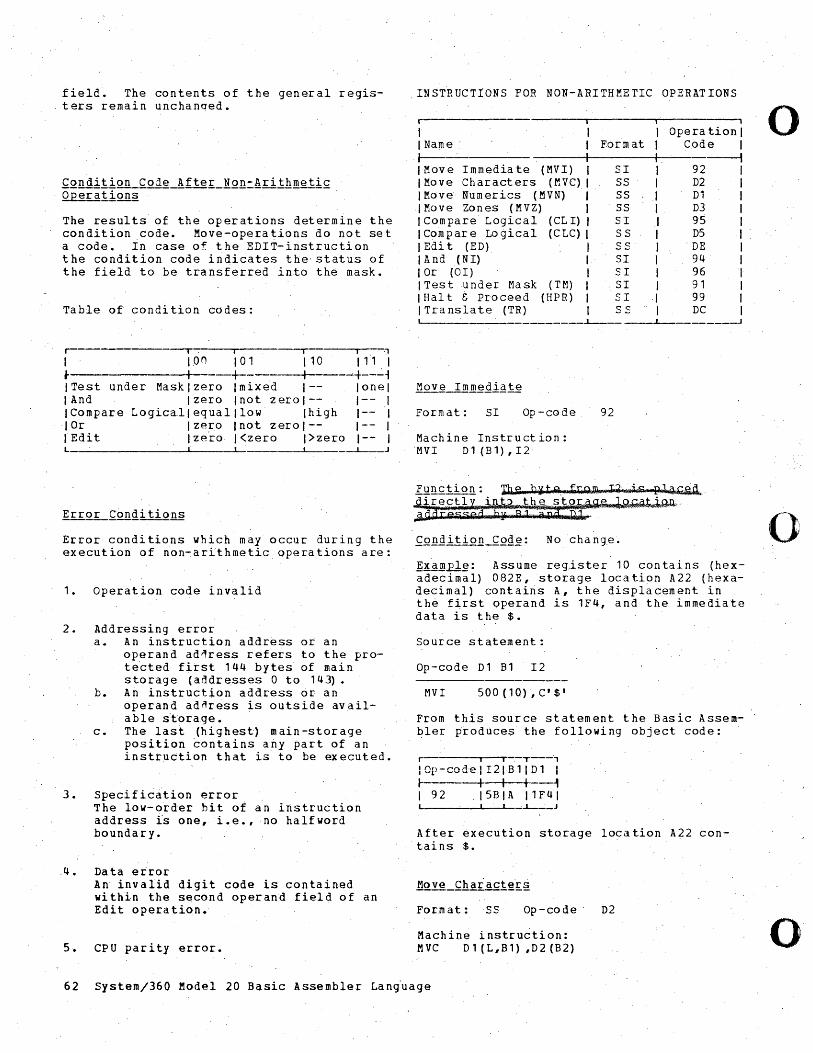
field. The contents of the general registers remain unchanqed.
Condition Code After Non-Arithmetic Q£eratIon~------------------------- .
The results of the operations determine the condition code. Move-operations do not set a code. In case of the EDIT-instruction the condition code indicates the' status of the field to be transferred into the mask.
Table of condition codes:
,--- iii, ·1
I 1.0 () I a 1 I 10 I f1 I .-------------;I-----rl-------rl--- ~-~~ 1 Test under Mask I zero I mixed 1-- lone I lAnd Izero Inot zerol-- I-~ I ICompare Logicalleguaillow Ihigh 1-- I lOr Izero Inot zerol-- 1-- I IEdit Izeio I<zero I>zero 1-- I L
______________ ~l ____ ~~ ~J
Error conditions which may occur during the execution of non-ar~thmetic operations are:
1. Operation code invalid
2. Addressing error a. An instruction address or an
operand ad~ress refers to the prote~ted first 144 bytes of main storage (addresses a to 143).
b. An instruction address or an operand adnress is outside avail-able ~torage. .
c. The last (highest) main-storage position ~ontains ariy part of an instruetion that is to be executed.
3. Specific~tion error
4.
The low-order bit of an irtstruction address is one, i.e., no halfword boundary.
Data error An invalid digit code is contained within the second operand field of an Edit operation.
5. CPU parity error.
INSTRUCTIONS FOR NON-ARITHMETIC OPERAT IONS
i 1
I 1 I Opera tion I 1 Name· I Format I Code I I--- I I ~ I Move Immedia te (MVI) SI J 92 1
Move Characters (MVC) SS I D2 I Move Numerics (MVN) SS I D1 1 Move Zones (MVZ) SS I D3 I Compare Logical (CL I) SI I 95 I Co m p ar e Lo 9 i cal (CLC) 5S I D5 ·1 Edi t (ED) SS 1 . DE 1 And (N I) 51 1 94 1 Or (OI) SI 1 96 I Test under Mask (TM) 51 I 91 I Hal t & Proceed (HPR) SI I 99 J Translate (TR) SS 1 DC I
~ ______ L--_______ ~
Format: SI Op-code 92
Machine Instruction: MVI D1(B1),I2
]xa.!!!.E1,g: Assume reg,ister 10 contains (hexadecimal) 082E,storage location A22 (hexadecimal) contains A, the displacement in th~ first operand is 1F4, and the immediate data is the $.
Source statement:
Op-code D1 B1 12
MVI 500(10),C'$'
From this source statement the Basic Assembler produces the following object code:
r i i T---·' Inn_~n~~IT~IQ1In1 I I '-'1:' ....... ...., \..ol ~ I ... L" I j.J , I LJ I I
I I I 1--1 192 .15BIA 11F4J
.L-__ J
After execution storage location A22 contains $.
Format :SS Op-code· D2
Machine instruction: MVC D1(L,B1),D2(B2)
62 System/360 Modei 20 Basic Assembler Lan~uage
0
o
o
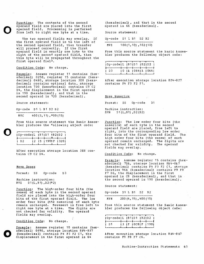
o
o
o
Function: The contents of the second operana-field are placed into the first operand field. Processing is performed from left to right one byte at a time.
The two operand fields may overlap. If the first operand field is to the left of the second operand field, then transfer will proceed correctly. If the first operand field is exactly one byte to the right of the secon~ operand field, then this byte will be propagated throughout the first operand fiel~.
£~ndition Code: No change.
~.!amplg: Assume register 11 contains (hexadecimal) 0258, register 15 contains (hexadecimal) 04BO, storage location 3E8 (hexadecimal) contains optional data, storage location 7DO (hexa~ecimal) contains C9 C2 D4, the displacement in the first operand is 190 (hexadecimal), and that in the second operand is 120 (hexadecimal).
Source statement:
Op-code D1 L B1 D2 B2
MVC 400(3,11) ,POO(15)
From this source statement the Basic Assembler Froduces the ~ollowing object code:
I -.- j I i j
IOp-codelL IB11D1 ,B21D2 r---+--+-I '1 I ~ I D2 12 IB 1190,F 13201
After execution storage location 3E8 contains C9 C2 D4.
Format: SS Op-code D3
Machine instruction: MVZ D1(L,Bl) ,D2(~2)
XQnc!iQQ: The high-order four bits (the zones) of each byte in the second operand field are placed into the high-order four bits of the first operand field. The low order four bits (the numerics) of each byte remain unchanged. Movement is from left to right one byte at a time. The digits are not checked for validity. The operand fields may overlap.
~.!~mElg: Assume register 10 contains (hexadecimal) 0890, storage location 8F4-8F7 (hexadecimal) contains F4 F3 F2 C1, the displacement in thp. first operand is 64
(hexadecimal) , and that in the second operand is 66 (hexadecimal).
Source statement:
Op-code D1 L B1 D2 B2
MVZ 100(1,10) ,102(10)
From this source statement the Basic Assembler "produces the following object code:
Iii iii
IOp-codelL IBllDl IB21D2 1 I I I +--+--+---1 I D3 lOlA 10641A 106 6 1
, j J I
After execution storage location 8F4-8F7 contains F4 F3 F2 F1.
Form at: ss Op-code D1
Machine instruction: MVN D 1 (L,B1) ,D2 (B2)
Function: The low order four bits (the numerics) of each byte in the second operand field are placed, from left to right, into the corresponding low order four bits of the first operand field. The high order four bits (the zones) of each operand remain unchanged. The digits are not checked f or v alidi ty • The ope rand fields may overlap.
£.Qnditi.2j! Code: No change.
Example: Assume reg"ister 15 contains (hexadecimal) 7DA, storage location 8A4-8A 7 (hexadecimal) contains F4 F3 F2 C1, stor.:-age loca tion 96 A (h exadecimal) contain s F9 F 8 F7 D6, the displacement in the first operand is C8 (hexadecimal), and that in the second operand is 190 (hexadecimal).
Source statement:
Op-code D1 L B1 D2 B2
MVN 200(4,15),400(15)
From this source statement the Basic Assembler produces the following object code:
Iii T I i -,
lOp-cadelL IB11D1 IB21D2 I r-- I I +--+--+--~ I D1 13 IF IOC81F 11901 L ________ L-~ __ ~ __ ~J_-L--~
Aft er ex ecu t ion storage IOCd tion 8 A4 -8 A7 contains F9 F8 F7 C6.
Machine-Instruction Statements 63
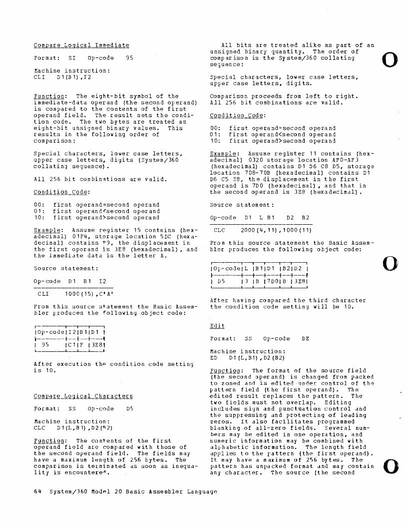
Format: S.I Op-code 95
Machine instruction: CLI D1(Bl),I2
Function: The eight-bit symbol of the immediate-data operand (the second operand) is compared to the contents of the first operand field. The result sets the condition code. The two bytes are treated as eight-bit unsigned binary values. This results in the following order of comparison:
Special characters, lower case letters, upper case letters, digits (System/360 collating sequence).
All 256 bit combinations are valid.
00: first operand=second operand 01: first operand~second operand 10: first operand>second operand
~~~~Elg: Assume register 15 contains (hexadecimal) 01F4, sto.rage location 5DC (hexadecimal) contains ~9, the displacement in the first operand is 3E8 (hexadecimal), and the immediate data is the letter A.
Source statement:
Op-code D1 B1 I2
C LI 1 00 0 ( 1 5) , C' A '
From this source statement the Basic Assembler produces the following object code:
r-----,----.--~
I Op- code I I2 I B 1 I D 1 , ~------+--+--+-~ I 95 ICllF 13E81 L ____ --L_-L--L---J
After execution the condition code setting is 10.
Format: SS Op-code D5
Machine instruction: CLC D1(L,B1) ,D2(~2)
Function: The contents of the first ~~e~i~d-field are compared with those of the second operand field. The fields may have a maximum length of 256 bytes. The comparison is terminated as soon as inequality is encounteren •
All bits are treated alike as part of an unsigned binary quantity. The order of 0 comparison is the System/360 collating sequence:
Special characters, lower case letters, upper case letters, digits.
Comparison proceeds from left to right. All 256 bit combinations are valid.
00: first operand=second operand 01: first operand(second operand 10; first operand)second operand
~Kam~: Assume register 11 contains (hexadecimal) 0320 storage location AFO-AF3 (hexadecimal) contains Dl D6 C8 D5., storage location 708-70B (hexadecimal) contains D1 D6 C5 E8, the displacement in the first operand is 7DO (hexadecimal), and that in the second operand is 3E8 (hexadecimal).
Source statement:
Op-code D1 L B 1 D2 B2
Ctc 2000(4,11),1000(11)
From this source statement the Basic Assembler produces the following object code:
r------,---,- I -,
10 f- cod elL I B 1 I D 1 I B 21 D 2 I ~------+--+--+---+--+---~ I D5 13 IB 17DOIB 13E81
-L~L __ ~~~ __ ~
After having compared the third character the condition code setting will be 10.
For-mat: SS Op-code DE
Machine instruction: ED Dl(L,B1),D2(B2)
Fu nction: The forma t of the so urce fi eld (the-second ~perand) is changed from packed to zoned and is edited under con~rol of the pattern field (t he first operand). The edited result replaces the pattern. The two fields must not overlap. Editing in cl u des s i g nan d pu n c t u a t ion con t r 0 I and the suppressing and protecting of leading zeros. It also facilitates programmed blanking of all-zero fields. Several numbers may be edited in one operation, and numeric information may be combined with alphabetic information. The length field d p P lies tot her a t t ern (t h (~ fir s top era n d) •
o
It may h d V e a m ax i mu m 0 f 256 by t es • The 0 pattern has unpacked format and may contain any character. The source (the second
64 System/360 Modpl 20 Basic Assembler Language
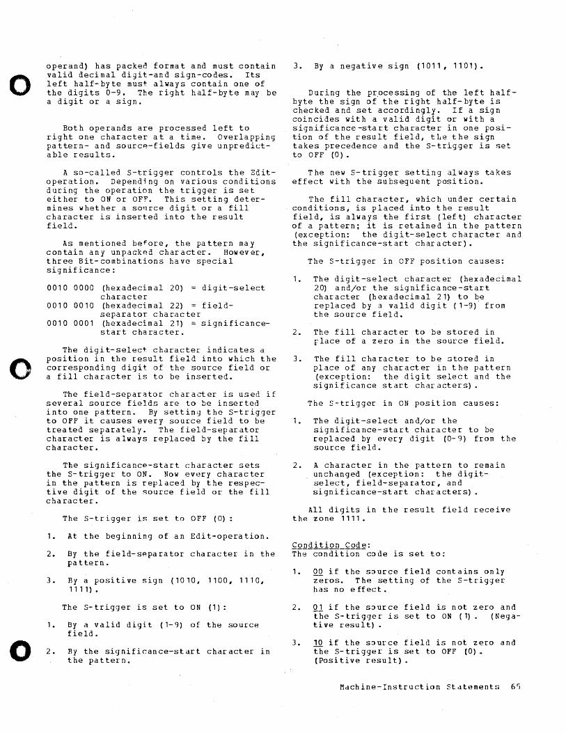
o
o
o
operand} has packed format and must contain valid decimal digit-and sign-codes. Its left half-byte must always contain one of the digits 0-9. The right half-byte may be a digit or a sign.
Both operands are processed left to right one character at a time. Overlapping pattern- and sourcp.-fields give unpredictable results.
A so-called s-trigger controls the Editoperation. Depending on various conditions during the operation the trigger is set either to ON or OFF. This setting determines whether a sonrce digit or a fill character is inserted into the result field.
As mentioned be~ore, the pattern may contain any unpac:kp.d character. However, three Bit-combinations have special significance:
0010 0000 (hexadecimal 20) = digit-select character
0010 0010 (hexadecimal 22) = fieldseparator character
00100001 (hexadecimal 21) = significancestart character.
The digit-select character indicates a position in the result field into which the corresponding digit of the source field or a fill character is to be inserted.
The field-separator character is used if several source fields are to be inserted into one pattern. By settin,] the S-trigger to OFF it causes every source field to be treated separately. The field-separator character is always replaced by the fill character.
The significancp-start character sets the S-trigger to ON. Now every character in the pattern is replaced by the respective digit of the source field or the fill character.
The S-trigger is set to OFF (0):
1. At the beginning of an Edit-operation.
2. By the field-spparator character in the pattern.
3. By a positive sign (1010, 1100, 1110, 1111).
The s- trigger is set to ON (1):
1. By a valid digit (1-9) of the source field.
2. By the significance-start character in the pattern.
3. By a negative sign (lOll, 1101).
During the processing of the left halfbyte the sign of the right half-byte is checked and set accordingly. If a sign coincides with a valid digit or with a significance-start character in one position of the result field, tIle the sign takes precedence and the S-trigger is set to OFF (0).
The new S-trigger setting always takes effect with the subsequent position.
The fill character, which under certain conditions, is placed into the result field, is always the first (left) character of a pattern; it is retained in the pattern (exception: the digit-select character and the significance-start character).
The S-trigger in OFF position causes:
1. The digit-select character (hexadecimal 20) and/or the significance-start character (hexadecimal 21) to be replaced by a valid digit (1-9) from the source field.
2. The fill character to be stored in rlace of a zero in the source field.
3. The fill character to be stored in place of any character in the pattern (exception: the digit select and the significance start characters).
The S-trigger in ON position causes:
1. The digit-select and/or the significance-start character to be replaced by every digit (0- 9) from the source field.
2. A character in the pattern to remain unchanged (exception: the digitselect, field-separator, and significance-start characters).
All digits in the result field receive the zone 1111.
Condition Code: Th~-condition-code is set to:
1. QQ if the source field contains only zeros. The setting of the S-trigger has no e ffeet •
2. Ql if the source field is not zero and the S-trigger is set to ON (1) (Nega-tive result) •
3. 10 if the source field is not zero and the S-trigger is set to OFF (0). ( Po sit i v ere suI t) .
Machine-Instruction statements 6S
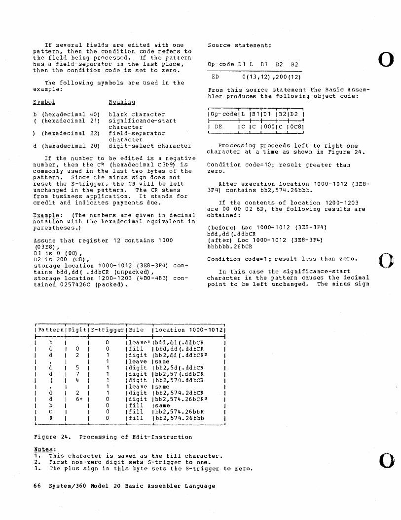
If several fields are edited with one pattern, then the condition code refers to t he field being processed. If th e p at tern has a field-separator in the last place, then the oondition code is set to zero.
The following symbols are used in the example:
~..Y.!!lbOl t!~ani!l51
b (hexadecimal 40) blank character ( (hexadecimal 21 ) significance-start
character (he xadeci m al 22) field-separator
character d (hexadecimal 20) digi t-select character
If the number to be edited is a negative number, then the CR (hexadecimal C 3D9) is commonly used in the last two bytes of the pattern. Since the minus sign does not reset the s-trigger, the CR will be left unchanged in the pattern. The CR stems from business application. It stands for credit and indicates payments due.
~xamEl~: (The numbers are given in decimal notation with the hexadecimal equivalent in parentheses.)
Assume that register 12 contains 1000 (03E8),
Source statement:
Op-code D1 L B1 D2 B2
ED 0(13,12) ,200(12)
From this source statement the Basic Assembler produces the following object code:
Iii T , ,--,
I 0 p- co del LIB 1 I D 1 I B 2 I D 2 I I t I +---+-+--f I DE IC IC 1000lC IOC81
Processing proceeds left to right one character at a time as shown in Figure 24.
Condition code=10; result greater than zero.
After execution location 100~-'012 (3E8-3F4) contains bb2,574.26bbb.
If the contents of location 1200-1203 are 00 00 02 6D, the following results are obtained:
(before) Loc 1000-1012 (3E8-3F4) bdd,dd(.ddbCR (after) Loc 1000-1012 (3E8-3F4) bbbbbb.26bCR
o
D 1 is 0 (00), D2 is 200 (C8), storage location 1000-1012 (3E8-3F4) contains bdd, dd ( • ddbCR (unpacked) I
Condition code=1; result less than zero. 01
In this case the significance-start storage location 1200-1203 (4BO-4B3) contained 0257426C (packed).
character in the pattern causes the decimal point to be left unchanged. The minus sign
r I , , I Pa ttern I Digi t S-trigger Rule I Location 1000-10121 l- I I I b 0 leave 1 Ibdd,dd (.ddbCR I d 0 0 fill I bbd, dd (. ddbCR I d 2 1 digit Ibb2,dd (.ddbCR2 I , 1 leave Isame I d 5 1 digit I bb2, 5d (. ddbCR I d 7 1 digit Ibb2,57 (.ddbCR
4 ~;,..,.;.a.. I l-.l-."'I a::~11 .::a.::a~ .... .., u. ... ~ ..... 11J1.JL.,JI"'.U.U..uI...4\
I 1 lea ve I same I d 2 1 digit Ibb2,574.2dbCR I d 6+ 0 digit Ibb2,574.26bCR3 I b 0 fill Isame I C 0 fill Ibb2,574.26bbR I R 0 fill Ibb2,574.26bbb L -L--
Figure 24. Processing of Edit-Instruction
!!Ql~2: 1. This character is saved as the fill character. 2. First non-zero digit sets S-trigger to one. 3. The plus sign in this byte sets the S-trigger to zero.
66 System/360 Model 20 Basic Assembler Language
o
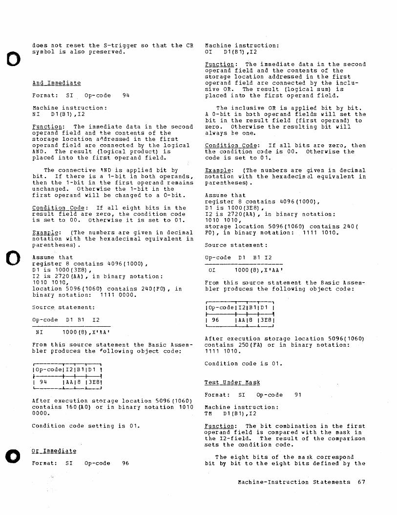
o
o
o
does not reset the S-trigger so that the CR symbol is also preserved.
Format: SI Op- code 94
Machine instruction: NI Dl (Bl) ,I2
Function: The immediate data in the second operand-field and the contents of the storage location a~dressed in the first operand field are connected by the logical AND. The result (logical product) is placed into the first operand field.
The connective AND is applied bit by bit. If there is a 1-bit Ln both operands, then the 1-bit in the first operand remains unchanged. Otherwise the 1-bit in the first operand will be changed to a O-bit.
Condition Code: If all eight bits in the result fiela-are zero, the condition code is set to 00. Otherwise it is set to 01.
]~.2:.!!l.El~: (The numbers are given in decimal notation with the hexadecimal equivalent in par ent heses) .
Assume tha t reg is t e r S con t a ins 4 0 9 6 ( 1 00 0) , D 1 is 1000 (3ES) , I2 is 2720 (AA), in binary nota tion: 1010 1010, lo cat ion 5 0 96 (1 06 0, con t a ins 240 ( F 0), in binary notation: 1111 0000.
Source statement:
Op-code D1 Bl I2
NI 1000(S),X'J\A'
From this source statement the Basic Assembler produces the ~ollowing object code:
r-- I I ~
IOp-codelI2lB 1 lDl 1 ~ I I I ~ I 94 IAAIS 13ESt L-_____ -L __ i--L---~
After execution storage location 5096 (1060) contains 160(AO) or in binary notation 1010 0000.
Condition code setting is 01.
Format: SI Op-code 96
Machine instruction: OI Dl(B1),I2
Function: The immediate data in the second operand field and the contents of the storage location addressed in the first operand field are connected by the inclusive OR. The result (logical sum) is placed into the first operand field.
The inclusive OR is applied bit by bit. A O-bit in b~th operand fields will set the bit in the resul t field (first operand) to zero. Otherwise the resulting bit will always be one.
Condition Code: If all bits are zero, then the condition c~de is 00. Otherwise the code is set to 01.
]~.2:~ple: (The numbers are given in decimal notation with the hexadecimal equivalent in parentheses) •
Assume that register S contains 4096(1000), Dl is 1000(3ES), I2 is 2720 (AA), in binary nota tion : 1010 1010, storage location 5096(1060) contains 240( FO), in binary notation: 1111 1010.
Source statement:
Op-code D1 B1 I2
OI 1000(S),X'AA'
From thi s so urce st atem ent the Bas ic A ssembIer produces the following object code:
I I I ,----,
IOp-code1I21B11D1 I I IJ~ I 96 IAAI8 13E81 ~ ______ ~ ____ ~ ___ J
After execution storage location 5096(1060) contains 250 (FA) or in binary notation: 1111 1010.
Condition code is 01.
Form at: SI Op-code 91
Machine instruction: TM D1 (Bl) ,I2
Function: The bit combination in the first operana-field is compared with the mask in the I2-field. The result of the comparison sets the condition code.
The eight bits of the ma~k correspond bit by bit to the eight bits defined by the
Machine-Instruction Statements 67
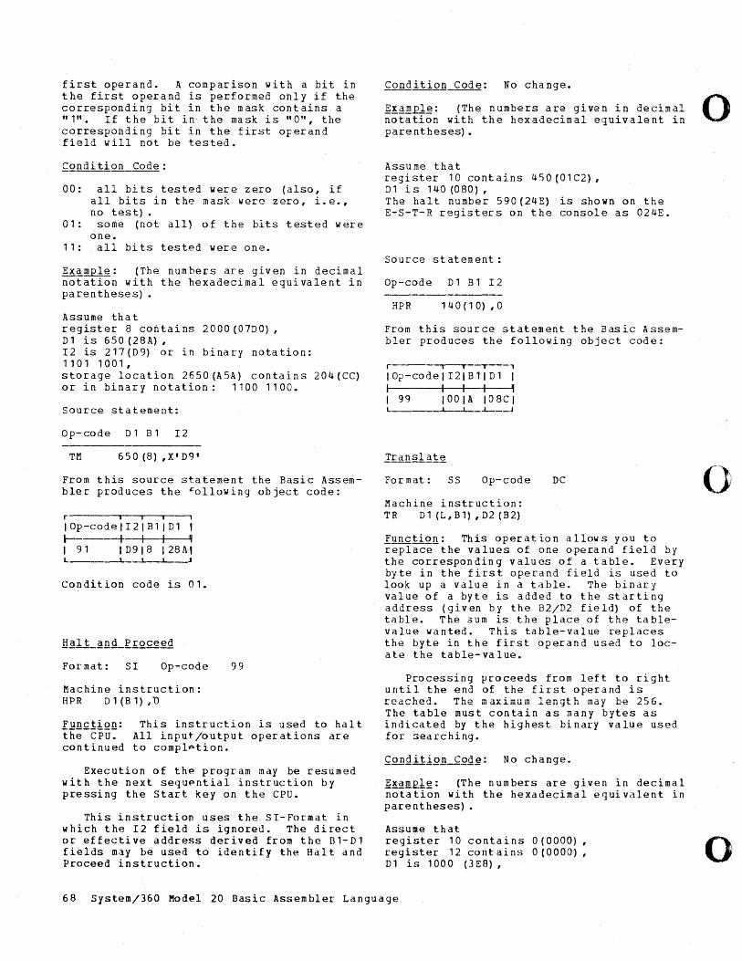
first operand. A comparison with a bit in the first operand is performed ohly if the corresponding bit in the mask contains a "1". If the bit in the mask is "0", the corresponding bit in the first operand field will not be tested.
00: all bits tested were zero (also, if all bits in the mask were zero, i.e., no test) •
01: some (not all) of the bits tested were one.
11: all bits tested were one.
Example: (The numbers are given in decimal notation with the hexadecimal equivalent in pa ren these s) •
Assume tha t register 8 contains 2000 (07DO) , Dl is 650 (28A) , I2 is 217(D9) or in binary notation: 1101 1001, storage location 2650(A5A) contains 204(CC) or in binary notation: 1100 1100.
Source statement:
o p - co de D 1 B 1 I 2
TM 650 (8) ,X'D9'
From this source statement the Basic Assembler produces the +ollowing object code:
r i j •
IOp-codelI2l BllDl 1 l-------+--+-+_~ I 91 I D9 I 8 I 28 A, L ______ ~~~ __ ~ J
Condition code is 01.
Format: SI Op-code
Machine instruction: HPR D1(B1);'0
99
Function: This instruction is used to hal t th;;-CPU:- All input/output operations are continued to complption.
Execution of the program may be resumed with the next sequpntial instruction by pressing the start key on the cpu.
This instruction uses the SI-Format in which the I2 field is ignored. The direct or effective address derived from the 81-Dl fields may be used to identify the Halt and Proceed instruction.
fQnaitiQB_Cod~: No change.
~!.ample: (The numbers are given in decimal 0 notation with the hexadecimal equivalent in parentheses).
Assume that register 10 cont ains 450 (01 C2) , Dl is 140 (080) , The halt number 590 (24E) is shown on the E-S-T-R registers on the console as 024E.
Source statement:
Op-code Dl Bl I2
HPR 140 (10) ,0
From this source statement the Basic Assembler produces the following object code:
r .--'--T---' lOp - co del I2 I B 1 I D 1 I I I I I • I 99 100lA I08CI L---____ ~_i_ __ J
For mat: ss Op-code DC
Machine instruction: TR Dl(L,Bl),D2(B2)
Iy'nctiQ.!l: This operation allows you to replace the values of one operand field by the corresponding values of a table. Every byte in the first operand field is used to look up a value in a table. The binary value of a byte is added to the starting address (given by the B2/D2 field) of the table. The 3um is the place of the tablevalue wanted. This table-value replaces the byte in the first operand used to locate the table-value.
Processing proceeds from left to right until the end of the first operand is rea c he d • The m ax i m U in 1 eng t h may be 25 6 • The table must contain as many bytes as indicated by the highest binary value used for !iearching.
~xam£lg: (The numbers are given in decimal notation with the hexadecimal equivalent in parentheses) •
Assume that register 10 contains 0 (0000) , register 12 cont ains 0(0000), Dl is 1000 (3ES),
o
o 68 System/360 Model 20 Basic Assembler Language
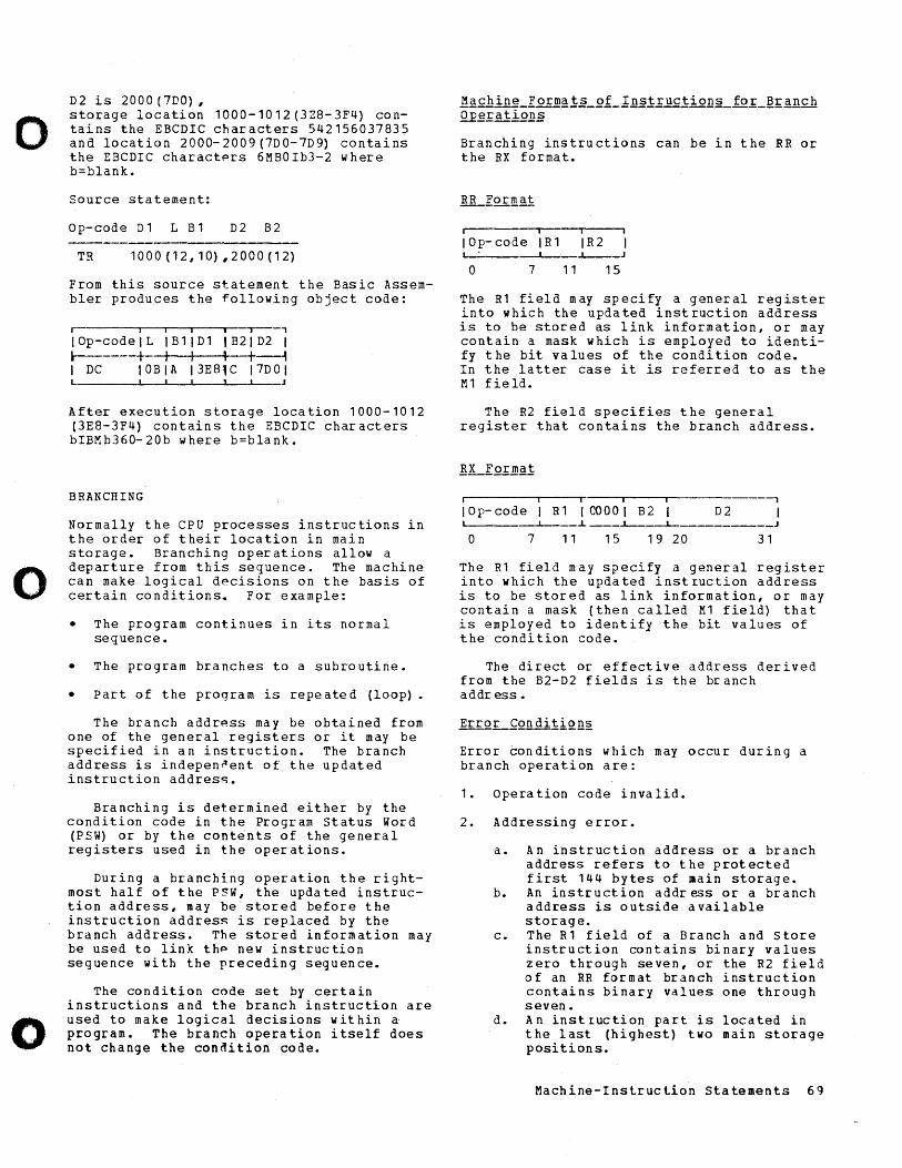
o
o
o
D2 is 2000(7DO), storage location 1000-1012(3Z8-3F4) contains the EBCDIC characters 542156037835 and location 2000-2009 (7DO-7D9) contains the EBCDIC charactprs 6MBOIb3-2 where b=blank.
Source statement:
Op-code D1 L B1 D2 B2
TR 1000(12,10},2000(12)
From this source statement the Basic Assembler produces the following object code:
r iii i -r--, IOp-codelL IB1JD1 IB21D2 I 1----+ I I , l---t I DC 10BIA 13E81C 17DOI
After execution storage location 1000-1012 (3E8-3F4) contains the EBCDIC characters bIBMb360-20b where b=blank.
BRANCHING
Normally the CPU processes instructions in the order of their location in main storage. Branching operations allow a departure from this sequence. The machine can make logical d~cisions on the basis of certain conditions. For example:
• The program continues in its normal sequence.
• The program branches to a subroutine.
• Part of the progra m is repe ate d (loop).
The branch addr~ss may be obtained from one of the general registers or it may be specified in an instruction. The branch address is indepen~ent of the updated instruction addres~.
Branching is determined either by the condition code in the Program status Word (PSW) or by the cont~nts of the general registers used in the operations.
During a branching operation the rightmost half of the P~W, the updated instruction address, may be stored before the instruction addres~ is replaced by the branch address. The stored information may be used to link thp new instruction sequence with the preceding sequence.
The condition code set by certain instructions and the branch instruction are used to make logical decisions within a program. The branch operation itself does not change the condition code.
llach,ine_E orma!§_.Q.b_l.n.§t r uc!i 0]}2_ fo ~_£!!;:~.nc h Q.E era t l.Q.!L§
Branching instructions can be in the RR or the RX format.
, i i
I 0 p- co del R 1 I R 2 i ' I .l.--_J
o 7 11 15
The Rl field may specify a general register into which the updated instruction address is to be stored as link information, or may contain a mask which is employed to identify the bit values of the condition code. In the latter case it is referred to as the M1 field.
The R2 field specifies the general register that contains the branch address.
iii i
lOp-code I R1 100001 B2 D2 L-___ ----L--__ ~ __ ..l.------1..-_________ J
o 7 11 15 19 20 31
The R1 field may specify a general register into which the updated instruction address is to be stored as link information, or may contain a mask (then called M1 field) that is employed to identify the bit values of the condition code.
The direct or effective address derived from the B2-D2 fields is the branch addr ess.
Error conditions which may occur during a branch operation are:
1. Operation code invalid.
2. Addressing error.
a. An instruction address or a branch address refers to the protected first 144 bytes of main storage.
b. An instruction addr ess or a branch address is outside available storage.
c. The R1 field of a Branch and store instruction contains binary values zero through seven, or the R2 field of an RR format branch instruction contains binary values one through seven.
d • An instruction, pa rtis located in the last (highest) two main storage positions.
Machine-Instruclion statements 69
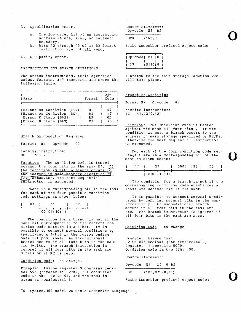
3. Specification ~rror.
a. The low-order bit of an instru ction address is one, i. e. , no half word boundary.
b. Bits 12 through 15 of an RX format instruction are not all zero.
4. CPU pari ty error.
INSTRUCTIONS FOR BPANCH OPERATIONS
The branch instructions, their operation codes, formats, ann mnemonics are shown the following table:
r , I I Name l-
Op- I I Format I Code I +----+---~ I I I I
IBranch IBranch IBranch IBranch L
on Condition (BCR) I RR I 07 I on Condition (BC) I RX I 47 I ~ Store (BlI,SR) I RR I aD I ~ Store (BAS) I RX I 4D I
--'---___ .L-
Format: RR Op-code 07
Machine instruction: BCR M1,R2
Function: The condition code is tested agains~the four bits in the mask M1. If the con d i t ion i ? met ,g ,l,u;; a Q hll:l. Q hi k Il .. ~ to-:'" the address i-wllll1r~~J~~tQ~Q&1.~ ~"'Ji6iL'j.~~ ~, it~. of her wise, the next sequential !'nstruction is executed.
There is a corresponding bit in the mask for each of the four possible condition code settings as shown below:
07 1 M1 R2 L 1 -,-,----r--+------J
1001011101'11
The condition for a branch is met if the mask bit correspon~ing to the current condition code settin~ is a 1-bit. It is possible to connect several conditions by specifying a 1-bit in the corresponding mask-bit positions. An unconditional branch occurs if all four bits in the mask are 1-bits. The branch instruction is ignored if all four bits in the mask are a-bits or if R2 is zero.
~~dm~: Assume r~gister 9 contains decimal 555 (hexadecimal 22B), the condition code in the PSW is 01, and the mask is given as hexadecimal 6.
Source statement: Op-code M 1 R2
BCR X'6',9
Basic Assembler produced object code:
I '" IOp-codel l'11 IR21 I I I ~ 107 1011019 I
J
A branch to the main storage location 22B will take place.
Format RX Op-code 47
Machine instruction: BC M1,D2(0,B2)
Function: The condition code is tested a g a I n s t-the m as k M 1 ( f 0 u r bits). If the condition is met, a branch occurs to the address in main storage specified by B2/D2. Otherwise the next sequential instruction is executed.
For each ~f the four condition code settings there is a corresponding bit of the mask as shown below:
47 M1 I 0000 IB2 D2 L-- I" --,-- +1 _____ --1. __ "'--_
I 00 101 1 101 11 I
The condition for a branch is met if the corresponding condition code exists for at least one defined bit in the mask.
It is possible to connect several cdnditions by defining several bits in the mask accordingly. An unconditional branch occurs if all four bits in t he mask are one. The branch instruction is ignored if all four bits in the mask are zero.
]~A~~~: Assume that D2 is 875 decimal (36B hexadecimal), Register 11 contains 0000, Co n d it ion co d e i nth e P S W : a a •
Source statement:
Op-code M1 D2 a B2
BC X'O',875(0,11)
Basi c Ass embler pr oduced ob ject code:
70 system/360 Model 20 Dasic Assembler Language
o
o
o
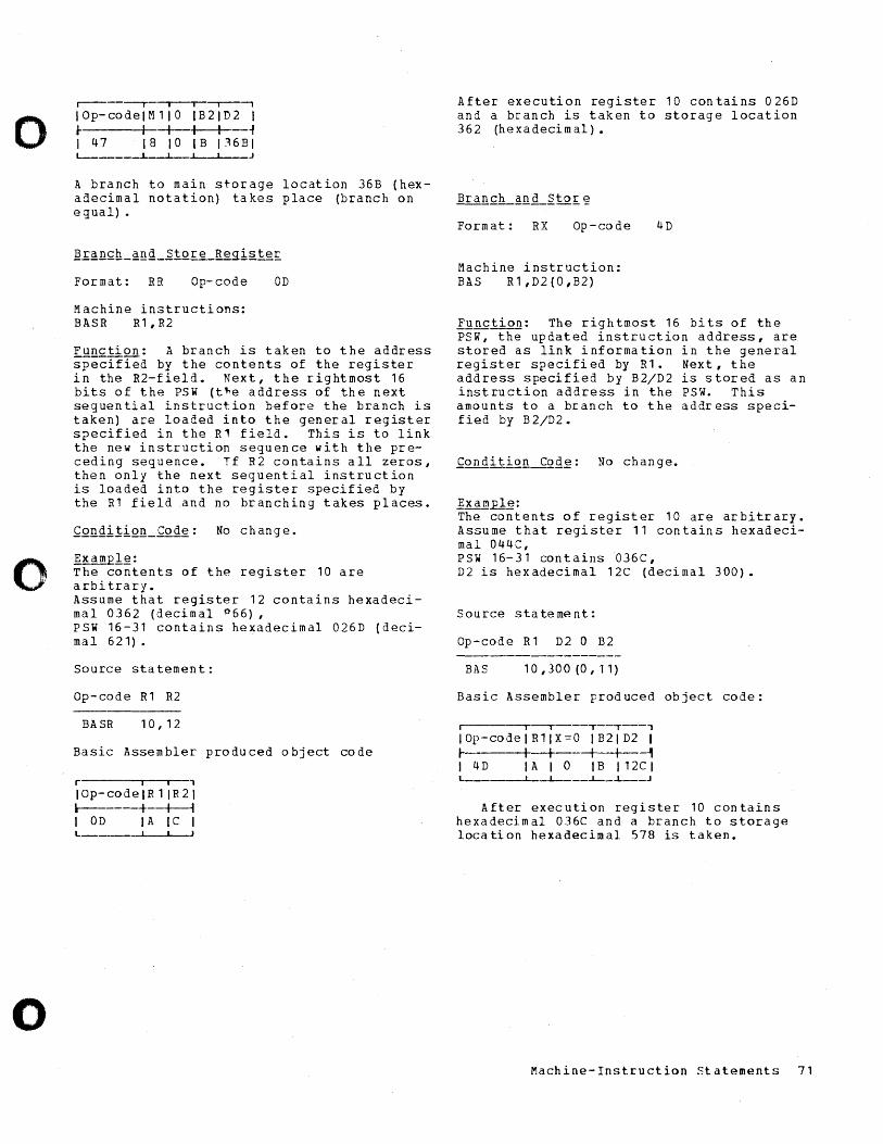
o
o
o
r----~ i i~--'
I Op- co de 1M 1 10 1 B 21 D 2 I r I -+--+--+---~ I 47 18 10 IB 116BI L--____ .1._-L- I J
A branch to main storage location 36B (hexadecimal nota tion) ta kes place (branch on egual) .
Format: RR Op-code OD
Machine instructions: BASR R1,R2
Function: A branch is taken to the address specified by the contents of the register in the R2-field. Next, the rightmost 16 bits of the PSW (t~e address of the next seguential instruction before the branch is taken) are loaded into the general register specified in the R1 field. This is to link the new instruction seguence with the preceding seguence. Tf R2 contains all zeros, then only the next seguential instruction is loaded into the register specified by the R1 field and no branching takes places.
Ex~l~: The contents of the register 10 are arbi trary. Assume that register 12 contains hexadecimal 0362 (decimal ,:)66), PSW 16-31 contains hexadecimal 026D {decimal 621}.
Source statement:
Op- code R 1 R2
BA SR 10, 12
Basic Assembler produced object code
r i I ,
IOp-codelR 11R21 1-------+-_+_~ I OD I A I C I L
After execution register 10 contains 026D and a branch is taken to storage location 362 (hexadecimal).
Form at: RX Op-code 4D
Machine instruction: BAS R1,D2{0,B2}
Functign: The rightmost 16 bits of the PSW, the updated instruction address, are stored as link information in the general register specified by R1. Next, the address specified by B2/D2 is stored as an instruction address in the PSW. This amounts to a branch to the address specified by B 2/D2.
~x a.m.2.1.g: The contents of register 10 are arbitrary. Assume that register 11 contains hexadecimal 044C, psw 16-31 contains 036C, D2 is hexadecimal 12C (decimal 300).
Source statement:
Op-code R 1 D2 0 B2
BAS 10,300(0,11}
Basic Assembler produced object code:
j I~---T--T---'
IOp-codeIR1IX=0 IB21D2 I I I I I I ~ I 4 D I A I 0 I B I 12C I L ______ ~I_-.l..--__ ~_~ __ J
After execution register 10 contains hexadecimal 036C and a branch to storage location hexadecimal 578 is taken.
Machine-Instruction Statements 71
The Basic Assembler program is available in both card and tape versions.
The card versions are used if only card I/O devices are included in the system configuration. The tape versions can be used if an IBM 2415 Magnetic Tape Unit Model 1 or 4 is available. in addition to the card I/O units.
The card versions require two passes. During the first pass the Basic Assembler program (phase 1) produces pass information required during pass 2. This information is punched into columns 1-24 of the source cards or into the corres[onding columns of duplicated source cards. In addition, a listing of all source statements is supplied if a printer is attached to the system and if an appropriate entry has been made in the control card.
During the second pas3, the source cards containing the pass information are processed by the Basic Assembler program (phases 2 and 3). Then the symbol table generated in storage is punched into cards, if desired. At thp end of the assembly the followin] output is obtained:
• a Clear-storage card and an AbsoluteProgram Loader card for loading of the object program.
• TXT cards containing the source statements, translated into machine language.
• ESD and RLD cards containing information for program lin~ing and relocation.
• A program listing, as shown in Figure 34.
liQ1~: The first three items above are referred to as the object deck.
In order to asspmble a source program written in Basic Assembler language, the source deck must be supplemented by a control (CTL) card, specifying the system configuration used for the assembly and the desired output. The CTL card as well as the card handling required during an assembly is described in the SRL publication 1]~ ~Y2iemL36Q_tlQQel_lQL_~~!Q_E~Qg!~~~ing_~~£= £QrtL_Qasi~_!§2~~~1~!_J~~!g_yg!~iQn~LL Q£~!£iing_~!Q~edy!~§, Form C26-3802.
The control car~ can also be used to specify a diagnostic run. In this case,
the punching of all cards is suppressed. The only output produced is a listing of all statements in Basic Assembler language. Most of the erroneous statements are identified by diagnostic messages.
For the card versions of the Basic Assembler program, a reassembly feature is pro~ vided that permits the reassembly of a partially or completely assembled program in less time than would be required by the repetition of the total assembly. For a reassembly, at least pass 1, phase 1, and pass 2, phase 2 of the Basic Assembler program (i.e., the punching and/or printing of the symbol table) must be completed.
A reassembly can be executed to correct erroneous statements and/or to compensate for a symbol-table overflow, which occurs if the number of symbols specified in the source program exceeds the limit in regard to the storage capacity used. Refer also to the sections ~Y~QQl~ and ~!es2iQn§.
When a reassembly is to be performed, the same amount of main storage must be specified to the Basic Assembler program as for the original assembly.
The symbol-table overflow can be eliminated by:
• making use of relative addressing, described in the section referenced above, thereby reducing the number of symbols in the ~rogram;
• performing an additional assembly run, as described in a subsequent section; or
• subdividing the program into segments and performing a separate assembly for each segm en t.
A program that is to be reassembled can be changed in any manner:. New symbols can be added, existing symbols can be redefined (i f the rei s r a :> min the' s y m bo I tab Ie) , existing symbols can be deleted except from the symbol table, and new statements can be added to the program. A statement that is to be changed must be repunched, leaving columns 1 through 24 blank.
.AQQiiiQ.!!.~1_!~§'~!!!'Q1Y_.R~D.. This increasps the number of symhols permitted in regard to the storage capacity used during an assembly.
72 System/360 Modpl 20 Basic Assembler Language
o
o
o
o
o
During pass 2 o~ the original assembly, the portion of the object deck already assembled is completed. On completion of pass 2, a programmed halt occurs to enable the user to remove this rortion of the object deck.
When the system is restarted after an overflow, the Basic Assembler generates a new control card that contains the USING table and the valu~ of the location counter at the time the overflow occurred. After generation of this control card, the remaining portion of the source deck is d up lica ted.
The duplicated source cards contain the following:
~~~~_lnfQ£~~tiQB_J£Q1~mB~_j~1~1: For example, a diagnostic message or the punch 12-11-0-7-8, the operation code, and one or more pointers desi0nating the location of storage addresses of related symbols.
~Q~£~~_~1~1~ill~nt_~Ql~mn~_I2~1l1: The identification sequence fielc1 (columns 73 to 80) is not duplicated.
The new control card and the duplicated source cards are the input for the first (or only) additioni'll assembly run. If another symbol-table overflow occurs, this first additional assembly run is considered to be the original assembly run and another additional assembly run can be performed.
This again increases, at the rate permitte~"for a new assembly, the number of symbols that can bp used in the program.
The tape versions of the Basic Assembler program use tape as an intermediate storage medium, which reduces card handling time. The Ba~jc Assembler program and the first source pro'Jram (both contained in punched cards) are read into the system during the initial run. Intermediate information is not punched in to ca rds (a s wi th the pa ss informdtion of the card version) but is written on tape, from which it can be ret r i eve d b Y the pro g ram w hell r (~(l u ire d •
Once the appropriate tdpe version of the Basic Assembler is written on a work tape,
it can be used for the assembly of any number of source programs during the same run. Each source program is read in after the object deck for the preceding program has been punched. The subsequent source decks must be separated by blank cards.
For the assembly of a source program with the tape version of the Basic Assembler program, a control card similar to the control card of the card version, must be crea ted. The con trol ca rd a nd the card handling requir Ed during an assembly run are described in the SRL publication l~~ ~~1~~Ll~Q~Qdel_1QL_Ca£Q~£Qg££mming~Q£= ~or~~_]asi~_As~~ill~le£_J1~~~_l~£§iQn§lL .Q£gL~.!:i}}SLProc~Q~£~~, FOL"m C24-9011.
The input decks of the tape versions of the Basic Assembler consist of (1) the Basic Assembler pre-phase and (2) the five Basic Assembler phase decks. The pre-phase is used to read and evaluate the control card and to write the Basic Assembler program onto tape. The first four Basic Assembler phases are used to read the cards containing the source program, to check the statement formats, to translate the program into machine language, to print the program listings, and to punch the object program deck.
The fifth Basic Assembler phase is used to deal with a possible symbol-table overflow. at herw is e it is not used.
In case of a symbol-table overflow, the tape versions of the Basic Assembler program automatically initiate a routine to compensate f~r the overflow. The punching of the object program is discontinued at t he po int w here the overflow occurs. Phase 5 0 f the pro g ram c au s es the g en era t ion 0 f ddditional intermediate information, which is required by the Basic Assembler program to initiate another assembly run. The assembly is then repeated, from the beginning, to process the subsequent part of the source program and punch the remaining ob ject ca rds.
The printed output produced by the tape versions of the Bdsic Assembler is the same d s the p r i n t f~c1 0 u t put r ron u c (~d b Y ttl f~ car d versions of the Basic Assembler.
Thp Ba~ic A~i!;(~mblp[ Program 73
Errors in the syntax of source statements and other violations of programming conventions are marked by diagnostic messages in the program listina to the left of the statements involved. These diagnostic messages, produced by both versions of the
'Basic Assembler program, are subdivided into two groups:
1. Warning messages.
2. Error messages.
Warning messages indicate violations of programming rules that do not affect execution of the assembly. The pertinent message codes are D, L, R, T, and W.
Error messages identify incorrect statements that prevent the Basic Assembler program from completing an assembly. The pertinent message codes are C, M, N, 0, S, and U. A summary of all diagnostic messages is provided in Appendix D.
Two routines for the loading of object programs are available: (1) the AbsoluteProgram Loader and (2) the RelocatableProgram Loader.
The Absolute-program Loade~ is punched into a single card by the Basic Assembler program when the object deck is punched. Any loader control cards that may have been produced by the Basic Assembler (ESD and RLD) are ignored by the Absolute-Program Loader.
If the program is to be relocated on loading, the operator must replace the Absolute-Program Loader card with the deck containing the Relocatable-Program Loader. The loading routines are described in detail in the SRL publication, IBM_~Y2i~illL 360 Mo~~l-1Q_~~£Q_R£Qg£~~mi~g_~~ortL ~asi£_gtility_g£Qg£~ill2L_Funfti2n~anQ Q£erati~g Pr~£~~~res, Form C26-3604.
74 System/360 Modpl 20 Basic Assembler Language
o
o
o
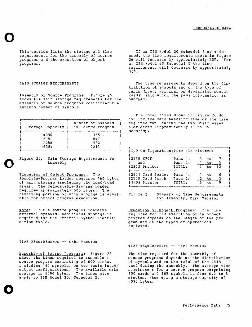
o
o
o
This section lists the storage and time requirements for the assembly of source programs and the execution of object programs.
MAIN STORAGE REQUIREMENTS
!ssemblLQ!. Source R!:Q.9..£~1!l'§.: Figure 25 shows the main storage requirements for the assembly of source programs containing the maximum number of symbols.
r- ------~----------------------,
I Number of in Sour ce
Symbols I I Storage Capacity Program 1
l-I 4096 I 8192 I 12288 I 16384
165 847
1530 2213
Figure 25. Main Storage Requirements for Assembly
,
Execution_Qf Object_Rf.Q~l£~ms: The Absolute-Program Loader re1uires 160 bytes of main storage (including the load/read area). The Relocatable-Program Loader requires approximately 500 bytes. The remaining portion of main storage is available for object program execution.
liQ!g: If the source program contains external symbols, additional storage is required for the External Symbol Identification table.
TIME REQUIREMENTS -- CARD VERSION
!~~g1)lQ1Y_Qf-1QQf.£g_R£Qgf.~m~: Figure 26 shows the times required to assemble a source program consisting of 600 cards, including 165 symbols, on two basic input/ output configurations. The available main storage is 4096 bytes. The times given apply to IBM Model 20, Submodel 2.
If an IBM Model 20 Submodel 3 or 4 is used, the time requirements shown in Figure 26 will increase by approximately 50lf,. For an IBM Model 20 Submodel 5 the time requirements will decrease by approximately 10r,.
The time requirements depend on the distribution of symbols and on the type of cards (i.e., original or duplicated source card~ into which the fass information is punched.
The total times shown in Figure 26 do not include card handling time or the time required for loading the two Basic Assembler decks (approximately 10 to 15 seconds) .
I I 1
11/0 ConfigurationlTime (in Minutes) 1
~ I ~ 12560 MFCM IPass 1: 4 to 7 I I and IPass 2: _i--1Q ___ 2 1
12203 Printer ITOTAL: 8 to 12 I I I ~ 12501 Card Reader IPass 1: 4 to 6 1 12520 Card Punch I Pass 2: 2 to 3 1 11403 Printer ITOTAL: -6-to---g 1 L---______________ ~ ____________________ ~
Figure 26. Summary of Time Requirements for Assembly, Card Version
Execution of_Q~~~t_~£QE£Em.§: The time required for the execution of an object program depends on the length of the program and on the typ es 0 f op erat ions employed.
TIME REQUIREMENTS -- TAPE VERSION
The time required for the assembly of source programs depends on the distribution of symbols and on the model of the 2415 used during the assembly. The average time requirement for a source program comprising 600 cards and 165 symbols is from 6.2 to 8 minutes, when using a storage capacity of 4096 bytes.
Performance Data 75
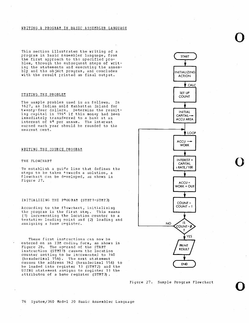
This section illustrates the writing of a program in Basic Assembler language, from the first approach to th~ specified problem, through the subsequent steps of writing the statements and executing the assembly and the object program, and concludes with the result rrinted as final output.
The sample problem used is as follows. In 1627, an Indian sold Manhattan Island for twenty-four dollars. Determine the resulting capital in 196~ if this money had been immediately transfp.rred to a bank at an interest of 4~ per annum. The interest earned each year should be rounded to the nea rest cen t.
THE FLOWCHART
To establish a gui~e line that defines the steps to be taken towards a solution, a flowchart can be dpveloped, as shown in Figure 27.
IN I TIA LI ZI NG THE pnOG RAM (ST MT 1-STMT 3)
According to the flowchart, initializing the program is the first ste~. This means (1) incrementing the loca tion co un ter to a tentative loading point and (2) loading and assigning a base register.
These first instructions can now be entered on an In~ codiny form, as shown in Figure 28. The opprand of the START instruction (STMT1) causes the location counter setting to be incremQnte~ to 340 (hexadecimal 154). The next statement causes the address 342 (hexadecimal 156) to be loaded i n t 0 register 1 3 ( S T M T 2 ) and the USING statement assigns to register 13 the attributes of a base register (STMT3).
NO
INITIALIZING ACTION
CALC
SET UP COUNT
INITIAL CAPITALACCU AREA
LOOP
ACCUWORK
INTEREST = CAPITAL
: RATE/H)O
ACCU = WORK + OUT
COUNT = COUNT - 1
Figure 27. Sample Program Flowchart
76 5ystem/360 Modp.1 20 Basic Assembler Language
o
()
o
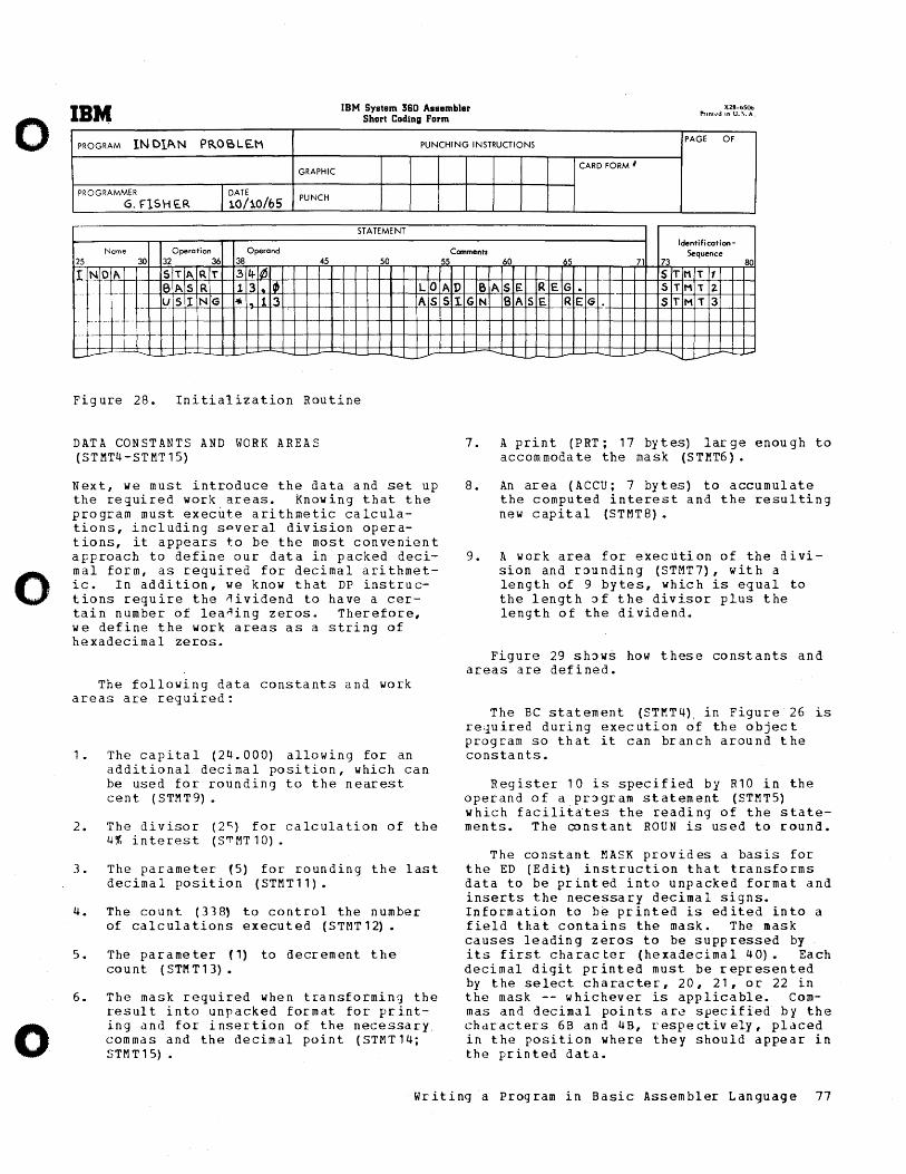
o
o
o
IBM IBM System 360 Assembler Short Coding Form
X28-bSOo Pnnl,,·c.I an U.I\. A.
INDl~N PROSLE.M PUNCHING INSTRUCTIONS PAGE OF
PROGRAM
GRAPHIC
PROGRAMMER I DATE PUNCH G. f"lSH E.R 10/10/65
STATEMENT
Name Operation Operand 25 30 32 36 38 45 50
II NOA ST ART .34-~ -- 61\ S R 1 3 .. I~ LO
- f-f--I N'G
-- - US ""I" 1 3 AS f--
-- --- - -
--
-'-"-_c--- - --,--v
Figure 28. Initialization Routine
DATA CONSTANTS AND WORK AREAS (STMT4-STMT15)
Next, we must introduce the data and set up the required work areas. knowing that the program must execute arithmetic calculations, including spveral division operations, it appears to be the most convenient approach to define our data in packed decimal form, as required for decimal arithmetic. In addi tion, we know that DP instru ctions require the nividend to have a certain number of leaning zeros. Therefore, we define the work areas as a string of hexadecimal zeros.
The following data constants and work areas are required:
1. The capital (24.000) allowing for an additional decimal position, which can be used for rounding to the nearest cent (STMT9).
2. The divisor (2") for calculation of the 4% interest (S'rMT10).
3. The parameter (S) for rounding the last decimal position (STMT11).
4. The count (33~ to control the number of calculations executed (STMT12) •
S. The parameter (1) to decrement the co u n t ( S TM T 1 3) •
6. The mask required when transforming the result into unpacked format for printing and for insertion of the necessary commas and the decimal point (STMT14; STMT1S).
CARD FORM /I
Identification-Comments Sequence
55
AD S1
SA GN
7.
60 65 71 73 80 S T MT ,
S£ RE G • S T Hi 2-SA SE. RE G. ST MT3
"- - ..... -....... ...... 1..--" ---
A print (PRT; 17 bytes) large enough to accommodate the mask (STMT6).
8. An area (ACCU; 7 by t es) to accumul ate the computed interest and the resulting new capital (STMT8).
9. A work area for execution of the division and r~unding (STMT7), with a length of 9 bytes, which is equal to the length ~f the divisor plus the length of the dividend.
Figure 29 sh~ws how these constants and areas are defined.
The BC statement (STMT4), in Figure 26 is rejuired during execution of the object program so that it can branch around the constants.
Register 10 is specified by R10 in the operand of a pr~gram statement (STMTS) which facilitates the reading of the statements. The constant ROUN is used to round.
The constant MASK provides a basis for the ED (Edi~ instruction that transforms data to be printed into unpacked format and inserts the necessary decimal signs. Information to be printed is edited into a field that contains the mask. The mask causes leading zeros to be suppressed by its first character (hexadecimal 40). Each decimal digit printed must be represented by the select character, 20, 21, or 22 in the mask -- whichever is applicable. Commas and decimal points ar~ specified by the characters 6B and 4B, respectively, placed in the position where they should appear in the printed data.
Writing a Program in Basic Assembler Language 77
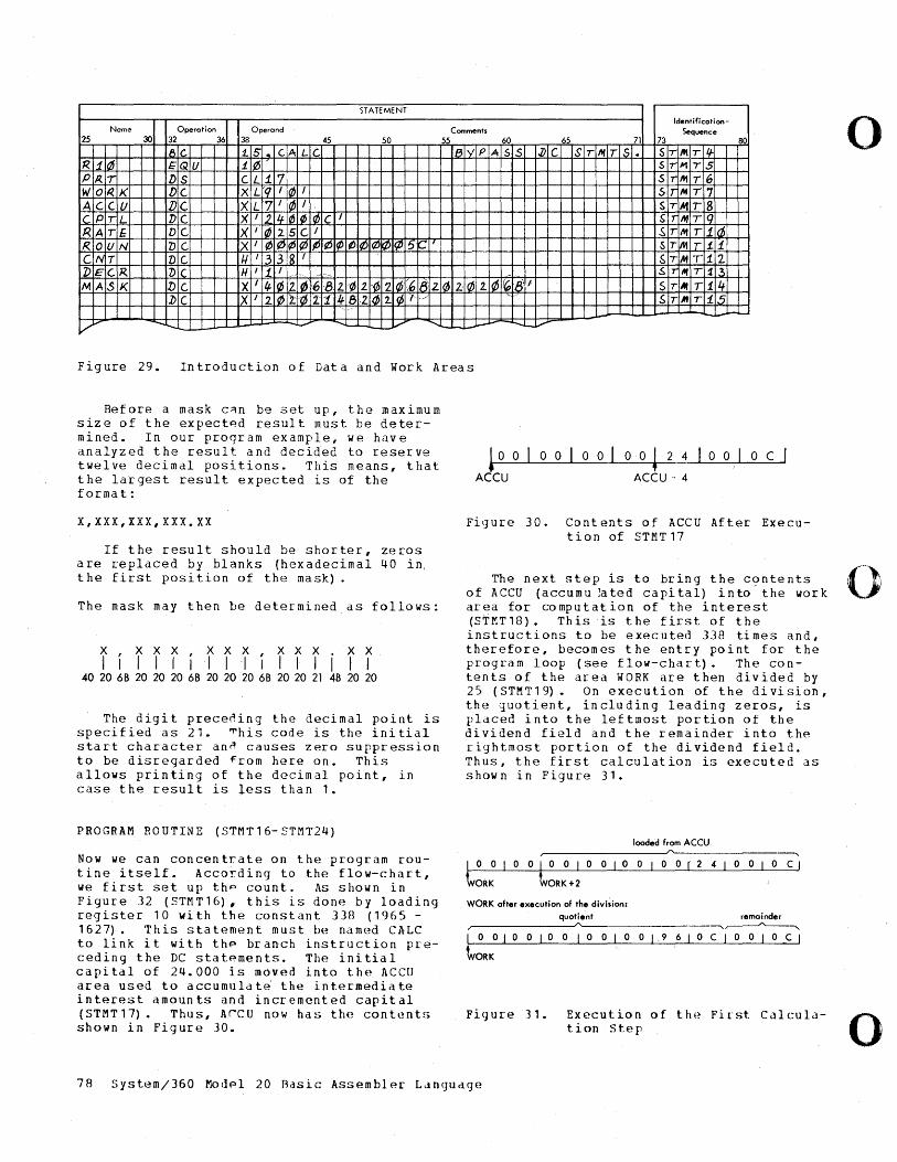
STATEMENT Identification-
Name Operation Operand Comments Sequence 25 30 32 36 38 45 50 55 60 65 71 73 80
18 C- 15 • c ALc' 181'1 PA 5S J)C Sr "'T Is • Sr It\rtf R jim I:QU 11~ Sr JIlTS
PP.. T DS CL 17 Sr It1r6 "10 I<.K DC XL rq '0 '
sir /11117 AC cu DC. XL 7 I o I $T MTS CP TL DC. X I 2.11f 0¢ o C I SIT If1Tlq RA Tf DC X' 10 25 C I ~r MT 1.iiJ 1<0 UN DC IX I ¢~ ¢I¢ I¢¢ I¢ ¢ 15-(1-1 f 1 ST Mr 1.i elN T DC 1-1 I 33 g I Sr MT 1..1 J)E C,R DIC H I t I
10~ .sIr AfT i3
MA SK 1)C X I II-Ias 210 16 8l 1-0 2. 1-(62 10~6 18z las 2.: I~ 2. 18'1 Sr AfT 1.4 :DC Ix I 21~ tl'~ 21 '/fe 2 I~ 2. 1<6 f". " $r "T i5
'I' -I.-
V~ "'- ....... ...... ....... _o.-t.,...- '" '-- ..... "'- ..... [.....-
Figure 29. Introduction of Data and Work Areas
Before a mask c~n be set up, the maximum size of the expect~d result must be determin e d • In 0 u r pro q ram ex a,m pIe, w e h a v e analyzed the result and decided to reserve twelve decimal positions. This means, that the latgest result expected is of the format:
X,XXX,XXX,XXX.XX
o C
ACCU ACCU -, 4
Figure 30. Contents of ACCU After Execution of STMT17
o
If the result should be shorter, zeros are replaced by blanks (hexadecimal 40 in, t he first posi tion of the mask) . The next step is to br:ing the conte nts 0
of ACCU (accumu ~ated capital) into-the work The mask may then be determined as follows:
x , X X X , X X X , X X X . X X I I I I I I I II I I II I I I
40 20 68 20 20 20 68 20 20 20 68 20 20 21 48 20 20
The digit prece~ing the decimal point is specified as 21. ~his code is the initial start character an~ causes zero suppression to be disregarded ~rom here on. This allows printing of the decimal point, in case the result is !ess than 1.
PROGRAM ROUTINE (STMT16-STMT24)
Now we can concentrate on the program routine itself. According to the flow-chart, we first set up thp count. ~s shown in Figure 32 (STMT16), this is done by loading reg i s t e r 1 0 wit h the co n s tan t 3 3 B ( 1 9 6 5 -1627). This statement must be nam(~d CALC to link it with thp branch instruction preceding the DC statpments. The initial capital of 24.000 is moved into the ACCU area used to accumuldt~ the intermediate interest amounts and incremented capital (STMT17). Thus, Arcu now has the conb.~nts shown in Figure 30.
area for computation of the interest (STMT18). This is the first of the instructions to be executed 338 times and, therefore, becomes the entry point for the program loop (see flow-chart). The con-tents of the area WORK are then divided by 25 (STMT19). On execution of the division, the quotient, including leading zeros, is placed into the leftmost portion of the dividend field and the remainder into the r:ightmost portion of the dividend field. Thus, the first calculation is executed as shown in Figure 31.
loaded from ACCU
LO 0 1 0 0 to 0 I 0 0 I 0 0 1 0 0 r 2 4 o 0 1 0 C I
ORK ORK+2
WORK ofter execution of the division:
quotient remainder ,~ ____________ ~A~ ________________ ~,~
1001001000010019610CI0010CI
Figur:e 31. Execution of the Fi~st Calculation St.ep
78 System/360 Modpl 20 Basic; Assembler Ldnguage
o
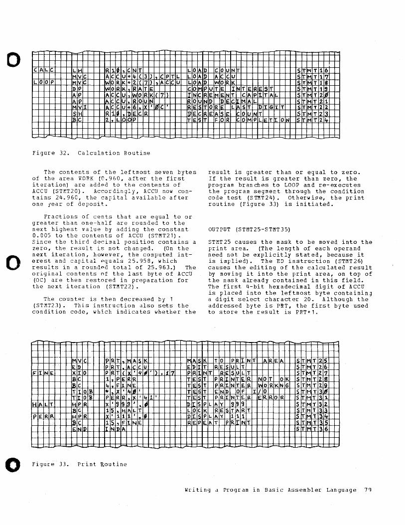
o
o
o
- r--..-
CA \..C LH R1 10 I., CNT LO IMVC AC CU -t,+ ( 3 ) I'J CP TL LO
LO o P IMVC Wo RI< +2. 'C 7 I) 'J. A C' CU LO DP .V'JO RK , R ATE CO IA P AC CU ,W OR KI( 17 ) ,I N IAlp AC CU • R OU N IR 0 IMVI A.C CU + 6 , X I IfJ C' RE: Is H R1 I~ I, 1>E CR I)) E [Bc 2. , LO OP rrE
,-"_v-'--- ,- ---Figure 32. Calculation Routine
The contents of the leftmost seven bytes of the area WORK (0.960, after the first iteration) are added to the co-ntents of ACCU (ST~T20). Accordingly, ACCU now contains 24.960, the capital available after one year of deposit.
Fractions of cents that are equal to or greater than one-half are rounded to the next highest value by adding the constant 0.005 to the contents of ACCU (STMT21). Since the third decimal position contains a zero, the result is not changed. (On the next iteration, however, the computed interest and capital equals 25.958, which results in a rounded total of 25.963.) The original contents of the last byte of ACCO (Oe) are then restored in preparation for the next i tera tion (STMT22).
The counter is then decreased by 1 (STMT23) • This instruction also sets the condition code, which indicates whether the
-
IMVIc. Ip Ri .. 1M A.IS K M,I\ ,
ED Ip RT , A Ie c u E]) ~I NE XIO P R T ( Ix ' 'I; , ) ,1117 Ip R
Be 11, PE RR TE IBC It I, FJ. N£. TIE: T1 OB *1 .. X • ,+1' I ITE lrI O'B PiE RR • Ix 'It l' T£
H ALl' IHP R x' Is 9 1.9 ' .. IJ ~Ir Is c. 115 I, H ALT L 0
PE Rf\ HPR X • 11 l' I. CI DI. ~C 115 1'1 F IN£. RE I~N :1) IN i» A
-Figure 33. Print Routine
AD C 0 UNT S:r MT 16 AD AC c.u SrI" MT 17 AD WO RK IS TM T 1 8 MIP UTE IN TE RiE ST ST MT 119 CR ElM ENT CA PI TAL l~ TM T 2 JI. UNO DIE: C[ MAt.. 15 TM T21 IS T clR ST
IslK iI T
ORE: L IA ST DI GI.T S TM T 2 2 EIA 51E CO U NT ST MT 23
FOR CO MP LE TI. ON 15 TM T2 4
- --.
result is greater than or equal to zero. If the result is greater than zero, the program branches to LOOP and re-executes the program segment through the condition code test (STMT24). Otherwise, the print routine (Figure 33) is initiated.
OUTPUT (STMT25-STMT35)
STMT25 causes the mask to be moved into the pr in t area. (The Ie ng th of eac h operand need not be explicitly stated, because it is implied). The ED instruction (STMT26) causes the editing of the calculated result by moving it into the print area, on top of the mask already contained in this field. The first 4-bit hexadecimal digit of ACCU is placed into the leftmost byte containinJ a digit select character 20. Although the addressed byte is PRT, the first byte used to store the result is PRT+1.
~-,... --, -T 0 PR INT IA RE. IA is TM T 215 RE IS U L T S~ MT 2.6
lINT RE Is IJLT S TM T2 17 Is T PR IrlN TIE R NO T OK S TM IT 12.IS Is T PR I.N TE. IR WO RK NG ST NT 2.19 ST ENl> OF I/O S ITN TI3 IJ1 Is T PR IN rE. :p. ER RO R 'S ITM IT 13 1.
5 P LAY 19 ~ 9 5 ITM T32. elK IR Eis IT ".RT S TM T 3 3 Is P LI\'( 1 1 1 _5 trM TL3 I .... PE. ".T Ip R .rlN IT s T.N TI3 Is
sir 'MT 136
- '-- -
W~iting d Program in Basic Assembler Language 79
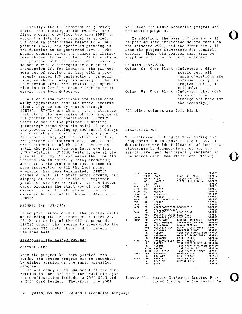
Finally, the XIO instruction (STMT27) causes the printing of the result. The first operand specifies the area (PRT) in which the data to be printed is stored. The code in parentheses refers to a 1403 printer (U=4), and specifies printing as the function to be performed (F=O). The second operand gives the number of characters (bytes) to be printed. At this stage, the program could be terminated. However, we would risk a disregard of our print instruction if, for instance, the printer were out of servicp , or busy with a rreviously issued I/O instruction. In addition, we should delay processing of the HPR instruction until the previous I/O operation is completed to ensure that no Frint errors have been d~tected.
All of these conditions are taken care of by appropriate test and branch instructions, represented by STMT28 through STMT31. STMT28 branches to the instruction that stops the processing of the program if the printer is not operational. STMT29 tests to see if the printer is working ("Working" means that the Model 20 is in the process of setting up mechanical delays and circuitry or still executing a previous XIO instruction, n01 that it is executing the present XIO instruction.) and causes the re-execution o~ the XIO instruction until the printer has completed the last I/O operation. ST~T30 tests to see if the printer is busy ("Pusy" means that the XIO instruction is actually being executed.) and causes the pronram to loop around the same instruction until the last print operation has been terminated. STMT31 causes a halt, if a print error occurs, and display of code 111 in the STR register panels on the CPU (STMT34). In the latter case, pressing the start key of the CPU causes the print instruction to be reexecuted because o~ the branch address in STMT35.
PROGRAM END (STMT3f)
If no print error occurs, the program halts on reaching thl~ HPR instruction (STMT12). If the start key of the CPU is pressed, STMT33 causes the nrogram to re-execute the previous HPR instrnction and to return to the same halt.
CONTIWL CARD
When the program h~s been punched into cards, the source program can be assembled by either version of the Basic A~sembler program.
In our case, it is assumed that the card version is used an~ that the available system configuration includes a 2S60 MFCM dnd a 2S01 Card Reader. Therefore, the 2S01
will read the Basic Assembler program and the source program.
In addition, the pass information will be punched into duplicated source cards on the attached 2560, and the first run will scan the program statements for possible errors. Thus, t he control card will be supplied with the following entries:
Columns 1-5://CTL Column 6: a or blank (Indicates a diag
nostic run; all punch operations are bypassed; only the program listing is prin ted.)
Column 8: a or blank (Indicates that 4096 bytes of main storage are used for the a sse m b 1 j • )
All other columns are left blank.
DIAGNOSTIC RUN
The statement listing printed during the diagnostic run is shown in Figure 34. To demonstrate the identification of incorrect statements by diagnostic messages, two errors have been deliberately included in the source deck (see STMT 19 and STMT29).
I ",r'A ~TAPT 'i4( ~T"'H:l
~:ASR 13,() lui'll) eA')t ,.'\-(,. Ql"f;·2 UQNr; .,11 AS~ It;N BAl'".C" p~G. ~T~r,);
I:\C 15,CALC C I RCLf 'H~ CCJNST. STMT'i4 I'l" !-CU 1 '1 ';Polloe; PI,l PS CLl7 ~HH06
'.,IIPI< DC Xl9'n' STMT01 AceU nc XL 1'0' STMTG8 ( PH nc X'?4000C' ~HIT OQ IlA 11 DC X'025C' S,"',) 0
'" \l1'~' DC x'oonooooorLOO5C~ <;T"'Il1 (lin DC H'3~8' qMTll flffl< DC H'l' <HITP MA S~ DC .'40206B20?020bB20?0706H' ~TMTl4
DC X' 20?02lltll?')20' HIIlTl':: CAt ( LH Rlo,eNT LOAD (OUIIoT STMT Ii·
MVC ACCU+It 131 .CPH LOAD A(ClJ QM'lf LOPP MVC WORK+2C71,ACCU LOAO ~f'kK Sl "" 11\
M LOPP OP WCRK,RAl'E COMPUTf. INTERl'ST STfoH19 AP AeCU,WORKCH I NCRI.'MFI'41 C.APlTAL qMT"O AP ACCU,ROUN ROUNO nfCIMAL S'MT?) "'VI ACCt..+6,X'OC' RESTORE LAST DIGIT STMTn SH R1O,OFCR DECREASE COUNT STMT 2'~ IIC ;>,LO(lP TEST FeR COMPLET IO~ <:fMT?4 MVC PRT,MASK MASK TO PRINT AREA S'MT7" 10 PflT,ACCU EDIT RfSULT H",T'It.
f I ~If X III PRTC X' 40' 1,17 PRINT RESULT STMT;l1 IIC I,PERR TEST PrllHfR NOT ClK <;''''T71l IIC 4,fINF TEST PPI/IITf P WLRK INC.5T"'T;(9· TIOB .,X'ltO' TEST £ONO Of lIlt ,)T"'T'lO T 1110 PERR,X'ltl' TEST PP INTI II IRICOR ST",nl
'IAI T HPfl X'99Q',O DISPLAY qq') ., T",T '~? 1'( 15,HALT LOCK fll~lA~l Q"'T 1i
PHI< tIP/( X'll1',O DI<;PLAY III ',HIT '4 lit l".,f I Nr H!-prAI PI>IINT <, I",T " ~ /IIU INPA ~,T "'I '.f,
F i'JU re 14. Saml'lp. S td tP. mp.n t Li sti ng Pro-duced OU r in <J t h (~ Did C] no!,. tic Run
o
o
0
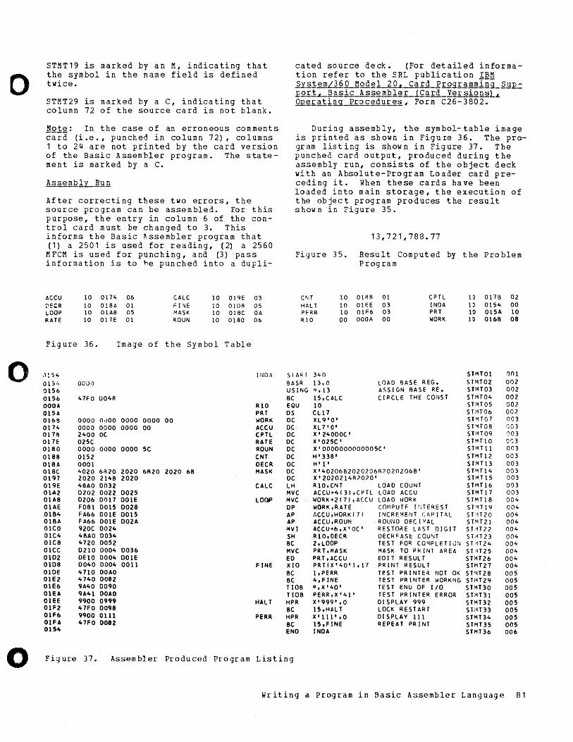
o
0
0
STMT19 is marked by an M, indicating that the symbol in the name field is defined twice.
STMT29 is marked by a C, indicating that column 72 of the source card is not blank.
Note: In the case of an erroneous comments card (i.e., punched in column 72), columns 1 to 24 are not printed by the card version of the Basic Assembler program. The statement is marked by a C.
AssemblL1H!.!1
After correcting these two errors, the source program can be assembled. For this purpose, the entry in column 6 of the control card must be changed to 3. This informs the Basic Assembler program that (1) a 2501 is used for reading, (2) a 2560
MFCM is used for punching, and (3) pass information is to he punched into a dupli-
ACCU ",EI:R LOOP RATE
Fig ure
,) 154 015:. 0156 0156 OOOA 015A 0168 0174 0178 017E 0180 0188 018A 018C 0197 019E 01"'2 OlA8 aLAE 0184 OlBA OlCO 01C4 01C8 OlCC 0102 0108 alOE 01E2 01E6 OlEA OlEE OU:2 01F6 OlFA 0154
10 0174 06 10 018A 01 10 01A8 05 10 017E 01
36. Image
OOL>iJ
47FO 004A
0000 OilOO 0000 0000 0000 0000 2400 OC 025C 0000 0000 0000 0152 0001 4020 6i320 2020 2020 2148 2020 48AO 0032 0202 0022 0025 0206 01)17 DOLE F081 0015 0028 FA66 DOLE 0015 FA66 DOLE D02A noc 0024 4BAO 0034 4720 0052 0210 0004 0036 DE10 0004 DOLE 0040 0004 0011 4710 OOAO 4740 0082 9A40 0090 9A41 OOAO 9900 0999 47FO 0098 9900 0111 47FO 0082
of
0000 00
5C
6R20
CALC FINE MASK ROUN
10 019E 03 10 OlDR 05 10 OIBC OA 10 01BO 06
the Symbol Table
INOA
RIO PRT
00 WORK ACeu ePH RATE ROUN eNT OECR
2020 68 MASK
CALC
lOOP
FINE
HALT
PERR
cated source deck. (For detailed information refer to the SRL publication 1~~ ~ystem/3&~od~1~~~~RrogI~mming_~]~ EQrt~asic Assembler (Card VersionsLL Q£g£ati~ pr~£g~~re~, Form C26-3802.
During assembly, the symbol-table image is printed as shown in Figure 36. The program listing is shown in Figure 37. The punched card output, produced during the assembly run, consists of the object deck with an Absolute-Program Loader card preceding it. When these cards have been loaded into main storage, the execution of the object program produces the result shown in Figure 35.
13,721,788.77
Figure 35. Result Computed by the Problem Program
CNT HALT PFRR RIO
10 01138 01 10 01F.E 03 10 01F6 03 00 OOOA 00
CPH INOA PRT WORK
1;) 017B 02 lD 0154 00 11> 015A 10 Ii> 016B 08
SIARI 340 STMT01 Q01 8ASR 13,0 LOAD F3ASE REG. STrH02 002 USING ~~ , 13 ASSIGN BASE RE. SHH03 002 BC 15,CAlC CIRCLE THE CONS T STMT04 002 EQU 10 ST~H05 007. OS CLl7 S PIT06 007. DC XL9'O' ST~T01 003 DC XL7'0' 5T"1T08 GG3 DC X' 24000C' ST:H09 ()O3 DC X'025C' S T~Tl 0 0')3 DC X'OOOOOOOOOOOO5C' STrH 11 003 De H'33S' STMT12 003 DC H' l' S TMTl3 003 DC X'40206B20207.06R?07.0206B' SPH14 003 DC X'2020214R707.0' STMT15 003 lH RIO, CNT LOAD COUIIIT S TMTl6 003 MVC ACCU+4( 31 ,CPH LOAD ACCU STMTl7 003 MVC WORK+2(71,ACCU LOAD WORK STMT18 004 DP WORK,RATE (Ol-'PUTF Ir,TEREST SHT19 004 AP '.CCU,I-/ORK( 7 1 INCREMENT (APITAL SHT20 004 AP ACCU,ROUN ROUND DEC I i/AL ST~T21 004 MVI ACCU+6,X'OC' RESTO~E LAST DIGIT ST.-1T22 ()04 SH RIO,OECR DECRFASf: COU~T ST;H 23 004 BC 2,lOOP TEST FO~ CO~PLETION S T:01T 24 004 MVC PRT,MASK MASK TO PRINT AREA STH25 004 ED PRT,ACCU EDIT RESULT ST1'o1T26 004 XIO PRTCX'40'I.l7 PRINT RESULT ST"1T27 004 BC 1,PERR T~ST PRINTE~ NOT OK S T'n 28 005 BC 4,FINE TEST PRINTER WORKNG STiH29 005 TIOB *,X'40' TEST ENU OF 110 STMT30 005 Tl08 PERR,X'41' TEST PRINTER ERROR ST~T31 005 HPR X'999',0 DISPLAY 999 S l1-lT32 005 Be 15,HAlT LOCK RESTART ST:H33 005 HPR X'lll',o DISPLAY 11 1 STMT34 005 Be 15,FINE REPEAT PRINT STMT35 005 END INOA STMT36 006
Fig ure 37. Assem bIer Pro du c(~cl Pro gr am Listing
Writing a Program in Basic A!:isembler Language 81
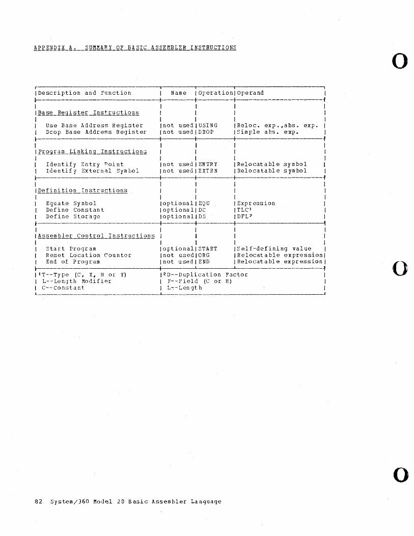
APPENDIX A. SUMMARY OF BASIC ASSEMBL~R INSTRUCTIONS
o r ---. I ~----------------------~ I Description and Function I Name I Operation I Operand I I- I I -+--------------~
I I I I I I]~§g_]ggi§lg~_±nstr~~ii~~~ I I I I I I I I I I Use Base Address Register Inot usejlUSING IReloc. exp.,abs. exp. I I Drop Base Address Register Inot usedlDROP ISimple abs. exp. 1 l- I I -+-------------~
I I I I 1 IRIQgI~~_1inking_Insi£Q£ii~ll~ I I I I I I I I I I Identify Entry Point Inot usedlENTRY IRelocatable symbol I I Identify External Symbol I not used I EXTRN I Relocatable symbol I I- -+------+-----+------------------~
I 'I I I I l.Qgfi!!i.tiQll_Instruclion~ I I I I I I I I I I Equate Symbol 10ptionallEQU IExpression I I Define Constan t I optiona 11 DC I TLCI I I Define Storage 10ptionaliDS IDYL? I • -+-----+-----+---. I I I I I I !§.~g~.hlef._~Q!!1IQ1_1!!~.tI.!!£liQ!!§ I I I I I I I I I I Start Program 10ptionaliSTART ISelf-defining value I I Reset Location Counter Inot usedlORG IRelocatable expressionl I End of Program Inot usedlEND I Relocatable expressionl l-----------------------+-----L ~
IIT--Type (C, X, H or Y) 12 D--Duplication Factor I o I L--Length Modifipr I F--Field (C or H) I I C--Constant I L--Length I L _________________________ ~ _____________ J
o 82 System/360 Model 20 Rasic Assembler Language
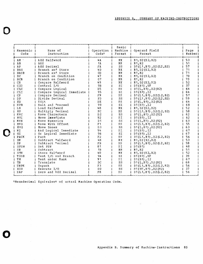
APPENDIX B. SUMMARY OF MACHINE-INSTRUCTIONS
0 r------~ -.-I I Basic I I Mnemonic I Name of Opera tion Machine Operand Field I Page I I Code I Instruction Code1 Format Format I Number I
• I +- , AH Add Halfword 4A RX R1, D2 (X2, B2) 53 AR Add 1A RR R1,R2 51 AP Add Decimal FA SS D1 (L1 ,B1) ,D2 (L2 ,B2) 57 BAS Branch ann Store 4D RX R1,D2(X2,B2) 71 BASR Branch an'! Store OD RR R 1, R2 71 BC Branch on Condition 47 RX M1, D2 (X2, B2) 70 BCR Branch on Condition 07 RR M1,R2 70 CH Compare Halfword 49 RX R1, D2 (X2,B2) 52 CIa Control 1/0 9B SI D 1 (B 1) , UF 37 CLC Compare Logical D5 SS D 1 (L, B 1) , D 2 (B 2) 64 CLI Compare Logical Immediate 95 SI D1 (B1) ,I2 64 CP Compare Decimal F9 SS D1 (L1,B1) ,D2(L2,B2) 57 DP Di vide Decim al FD SS D 1 ( L 1 , B 1) , D 2 (L2 , B2 ) 59 ED Edit DE SS D1 (L, B1), D2 (B2) 64 HPR Halt and Proceed 99 SI D1 (B1) ,12 68 LH Load Halfword 48 RX R1,D2(X2,B2) 52 MP Multiply Decimal FC SS D 1 (L 1 , B 1) , D 2 (L 2, B 2) 58 MVC Move Characters D2 SS D1 (L,B1) ,D2 (B2) 62 MVI Move Immeoiate 92 SI D1(B1),I2 62 MVN Move Numerics D1 SS D1 (L,B1) ,D2 (B2) 63 MVO Move with Offset F1 SS D1 (L1,B1) ,D2(L2,B2) 55 MVZ Move Zones D3 SS D1 (L,B1) ,D2 (B2) 63
0 NI And Logical Immediate 94 SI D1(B1),I2 67 01 Or Logical Immediate 96 SI D1 (B1) ,12 67 PACK Pack F2 SS D 1 (L 1 , B 1) , D 2 (L 2 , B 2 ) 56 SH subtract Halfword 4B RX R 1 , D 2 (X2 , B 2) 53 SP Subtract necimal FB SS D1 (L1,B1) ,D2 (L2,B2) 58 SPSW set PSW 81 SI D1 (B1) 48 SR Subtract 1B RR R1,R2 51 STH store Halfword 40 RX R1,D2(X2,B2) 52 TIOB Test I/O and Branch 9A SI D 1 (B 1) , UF 39 TM Test under Mask 91 SI D1(B1),I2 67 TR Translate DC SS D1 (L,B1) ,D2 (B2) 68 UNPK Unpack F3 SS D1 (L1,B1) ,D2(L2,B2) 56 XIO Execute 1/0 DO SS n 1 ( UF , B 1) , D 2 (B 2) 37 ZAP Zero and Add Decimal F8 SS D 1 (L 1 , B 1) , D 2 (L 2, B 2) 56
L---_____ ..L.---'--- ---L- ..L--__ -A
1 He xadecimal Equivalent. of actual Machine Operation Code.
o Appendix B. Summary of Machine-Instructions 83
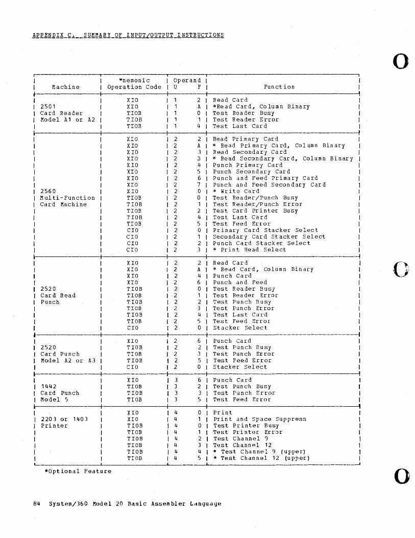
r --,-I I I Machine I • I I I I 2501 I I Card Reader I I Model A1 or A2 I I I 1------------+
2560 Multi-Function Card Machine
1-----------+ I I I I I I I I I 2520 I I Card Read I I Punch I I I I I I I I I
""nemonic Operation Code
XIO XIO TIOB TIOB TIOB
XIO XIO XIO XIO XIO XIO XIO XIO XIO TIOB T IOB TIOB TIOB TIOB CIO CIO CIa CIO
XIO XIO XIO XIO TIOB TIOB TIOB TIOB TIOB TIOB CIO I
---.---------------------------------------~i
Operand I I U F I Fun ct ion I
I , 1 2 I Read Card I 1 A I *Read Card, Column Binary I 1 0 I Test Reader Busy I 1 1 I Test Reader Error I 1 4 I Test Last Card I
I -f 2 2 I 2 A I 2 3 I 2 B I 2 4 I 2 5 I 2 6 2 7 2 0 2 0 2 1 2 2 2 4 2 5 2 0 2 1 2 2 2 3
2 2 2 A 2 4 2 6 2 0 2 1 2 2 2 3 2 4 2 5 2 0
Read Primary Card * Read Primary Card, Column Binary Read Secondary Card * Read Secondary Card, Column Binary Punch Primary Card Punch Secondary Card Punch and Feed Primary Card Punch and Feed Secondary Card * write Card Test Reader/Punch Busy Test Reader/Punch Error Test Card Printer Busy Test Last Card Test Feed Error Primary Card Stacker Select Secondary Card Stacker Select Punch Card Stacker Select * Print Head Select
Read Card * Read Card, Column Bin ary Punch Card Punch and Feed Test Reader Busy Test Reader Error Test Punch Busy Test Punch Error Test Last Card Test Feed Error Stacker Select
-f I I I I I I I I I I I
.----------+----------+--------+ ~ I I XIO I 2 6 I Punch Card I I 2520 I T lOB I 2 2 I Test Punch Busy I I Card Punch I TIOB I 2 3 I Test Punch Error I I Model A2 or A3 I TIOB I 2 5 I Test Feed Error I I I CIO I 2 0 I Stacker Select t I---------------+-----------+------+_ -1 I I XIO I 3 6 t Punch Card I I 1442 I TIOB I 3 2 I Test Punch Busy I ! Card Punch TIOB I 'l 3 I Test n,, __ l... Error i I J I ~' u." \....11
I Model 5 I TIOB I 3 5 I Test Feed Error I 1---------------+----------+------+ ----1
~IO 4 0 Print I 2203 or 1403 XIO 4 1 Prin t and Space Suppress I Printer: T lOB 4 0 Test Printer Busy I
TIOB 4 1 Test Printer Err:'>r I TIOB 4 2 Test Channel 9 I TIOB 4 .3 Test Channel 12 I TIOB 4 4 * Test Chann(~l 9 (u ppe r) I TIOD 4 5 * Test Channel 12 (upper) I
~ _______________ ~ ______________ L_ _______ ~ ______________ ~ ______________ ~
*Optional Feature
84 System/360 Model 20 Basic Assembler Ldnguage
o
(-~ ,);1
o
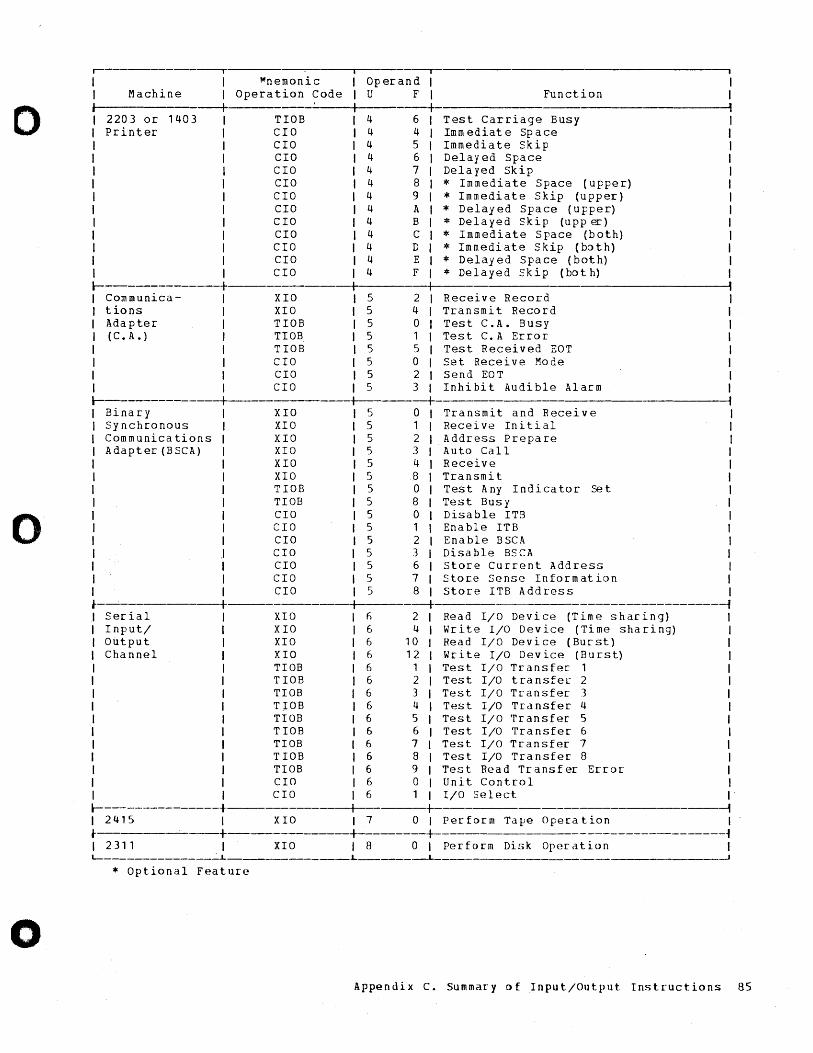
o
o
o
~---------------.------- -,-Operand I U F I
I I ~nemonic I Machine I Operation Code Function j --+----- +
2203 or 1403 TIOS 4 6 Test Carriage Busy Imm ediat e Sp ace Immediate Skip Delayed Space Delayed Skip
Printer
l--------------+ I Communica- I I tions I I Adapter I I (C. A.) I I I I I I I I I
CIO CIO CIO CIO CIO CIO CIO CIO CIO CIO CIO CIO
XIO XIO TIOB TIOB TIOB CIa CIa CIO
4 4 4 5 4 6 4 7 4 8 4 9 4 A 4 B 4 C 4 D 4 E 4 F
5 5 5 5 5 5 5 5
2 4 o 1 5 o 2 3
* Immediate Space (upper) * Immediate Skip (upper) * Delayed Space (upper) * Delayed Skip (upp~) * Immediate Space (both) * Immediate Skip (both) * Delayed Space (both) * Delayed Skip (bot h)
Receive Record Transmit Record Test C.A. Busy Test C.A Error Test Received EOT Set Receive Mode Send EOT Inhibit Audible Alarm
l----------------+------------ -+ o Sinary
Synchronous Communications Adapter (BSCA)
I I I
~--------+ Serial Input/ Output Channel
XIO XIO XIO XIO XIO XIO TIOS TIOS CIa CIO CIO CIO CIa CIO CIa
5 5 5 5 5 5 5 5 5 5 5 5 5 5 5
1 2 3 4 8 o 8 o 1 2 3 6 7 8
--+
Transmit and Receive Receive Initial Address Prepare Auto Call Receive Transmit Test Any Indicator Test Busy Disable ITB Enable ITB Enable BSCA Disa ble BS CA
Set
Store Current Address Store Sense Information store ITB Address
XIO h 2 Read I/O Device (Time sharing) XIO 6 4 write I/O Device (Time sharing) XIO 6 10 Read I/O Device (Burst) XIO 6 12 Write I/O Device (Burst) TIOB 6 1 Test I/O Transfer 1 TIOS 6 2 Test I/O transfe~ 2 TIOB 6 3 Test I/O Transfer 1 TIOB 6 4 Test I/O Transfer 4 TIOB 6 5 Test I/O Transfer 5 TIOB 6 6 Test I/O Transfer 6 TIOB 6 7 Test I/O Transfer 7 TIOB 6 8 Test I/O Transfer 8 TIOB 6 9 Test Read Transfer Error CIa 6 0 Unit Control CIa 6 1 I/O Select
I I I I I I I I I I I I I I I ~
l----------------t-------------t-- t --i I 2415 I XIO I 7 0 I Perform Tape Operation I ~----. --+----------+--------+--------------------------------~ I 2 3 1 1 I X I a I 8 0 I Pe r for m D i ~i k Ope rat i () n I L-______________ ~L ______________ L _______ __L_
* Optional Feature
Appendix C. Summary of Input/Output Instructions 85
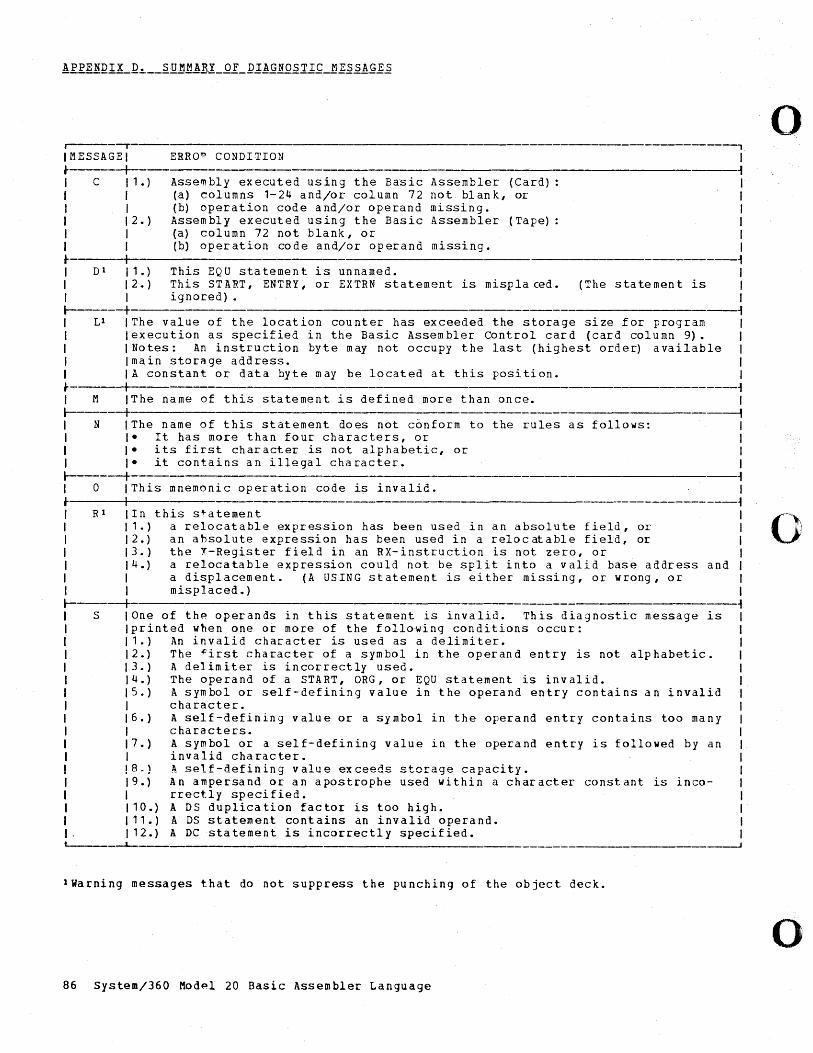
I -r --, IMESSAGEI ERROo CONDITION I ~ I ~ I C 11.) Assembly executed using the Basic Assembler (Card): I I I (a) columns 1-24 and/or column 72 not blank, or I I I (b) operation code and/or operand missing. I I 12.) Assembly executed using the Basic Assembler (Tape) I I I (a) col umn 72 not blank, or I 1 I (b) operation code and/or operand missing. 1 ~ 1 ~ I Dl 11.) This EQU statement is unnamed. I I 12.) This START, ENTRY, or EXTRN statement is misplaced. (The statement is I I I ignored) • 1 r-------+ ~ 1 Ll 1 The value of the location counter has exceeded the storage size for program I 1 lexecution as specified in the Basic Assembler Control card (card column 9). 1 I 1 Notes: An instruction byte may not occupy the last (highest order) available I I Imain storage address. I 1 I A constant or dat a byt e may be located at this posi ti on. I ~ I ~ 1 M IThe name of this statement is defined more than once. I 1------+ ---f 1 N IThe name of this statement does not conform to the rules as follows: I I Ie It has more than four characters, or I I Ie its first character is not alphabetic, or I 1 Ie it contains an illegal character. 1 r-------+ ~ I 0 IThis mnemonic operation code is invalid. I ~ I ~ I Rl lIn this statement I I 11.) a relocatable expression has been used in an absolute field, or I I 12.) an absolute expression has been used in a relocatable field, or I I 13.) the X-Register field in an RX-instruction is not zero, or I 1 14.) a relocatable expression could not be split into a valid base address and I 1 I a displacement. (A USING statement is either missing, or wrong, or 1 I I misplaced.) I 1-----+ --i
S One of th~ operands in this statement is invalid. This diagnostic message is printed when one or more of the follo~ing conditions occur: 1.) An invalid character is used as a delimiter. 2.) The -f'irst character of a symbol in the operand entry is not alphabetic. 3.) A delimiter is incorrectly used. 4.) The operand of a START, ORG, or EQU statement is invalid. 5.) A symbol or self-defining value in the operand entry contains an invalid
character. 6.) A self-defining value or a symbol in the operand entry contains too many
characters. 7.) A symbol or a self-defining value in the operand entry is followed by an
invalid character. 8.) A self-defining value exceeds storage capacity. 9.) An ampersand or an apostrophe used within a character constant is inco-
rrectly specified. 10.) A DS duplication factor is too high. 11.) A DS statement contains an invalid operand. 12.) A DC statement is incorrectly specified.
-L-
lWarning messages that do not suppress the punching of the object deck.
86 System/360 Mod~l 20 Basic Assembler Language
o
o
o
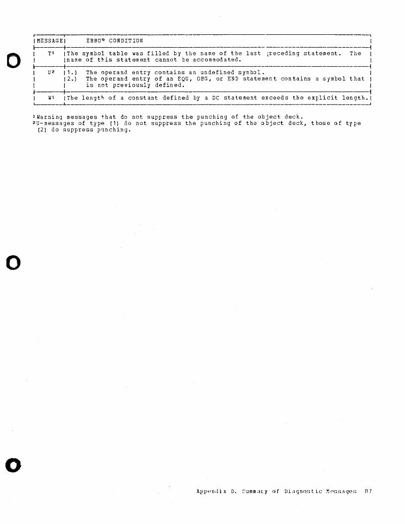
o
o
o
r-------,------------- --, IMESSAGEI ERRO~ CONDITION I ~----+ ----------------------~ I Tl' IThe symbol table was filled by the name of the last ~eceding statement. The I I Iname of this statement cannot be accommodated. ~---+ 1 U2 11.) I I 2.) I I
The operand entry contains an undefined symbJl. The operand entry of an EQU, ORG, or END statement contains a symbol that is not previously defined.
I ~ I I I
t I I W1 IThe length of a constant defined by a DC statement exceeds the explicit
~ length. I
'---____ .L
lWarning messages that do not suppress the punching of the object deck. 2U-messages of type (1) do not suppress the punching of the object deck, those of type
(2) do suppress punching.
J
Appendi x D. !:ummilry ()f Di,lgn()~;t ic Mns~iiHJ(~!; 87
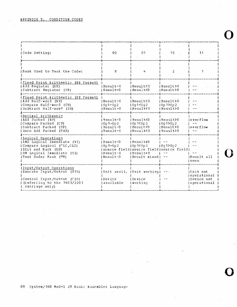
o r T------------,------------, 1 1 1 , 1 1 1 I ICode setting: 00 01 I 10 I 11 , 1 I I I ~ +------------+------------~ I I 1 I I I I I ,Mask Used to Test the Code: 8 4 I 2 1 1 I , 1 1 1 l- --+- -+--------+------------+----------~ 'Ii~~Q_Poig~£ithm~ii£_JRR_[Q£m~1l 1 1 1 1 1 IAdd Register' CAR) IResult=O IResult<O IResult>O .1 -- 1 ISubtract Register (SR) 1 Result=O 1 Result<O IResult>O 1 -- 1 ~ --+ I +------------+----------~ IKi~~Q_fQint_!£ilh~~1i£_JR~_IQ£~~1l 1 , , 1 1 ,Add Half-word (AR) IResult=O IResult<O IResult>O 1 1 1 Compare Half-word (CH) IOpl=Op2 1 Op1 <Op2 lOp 1>Op2 1 1 1 Subtract Half-worn (SH) IResult;.=O IResult<O IResult>O 1 1 I- +----------+ 1 --+--------~ 1~~£im~1_!£i1hmetic 1 1 1 1 , IAdd Packed CAP) Iqesult=O I Result<O IResult>O loverflow I ICompare Packed (CP) IOp1=Op2 IOp1<Op2 IOp1>0l-.2 I -- I ISubtract Packed (SP) IResult=O IResult<O IResult>O loverflow I 1 Zero Add Packed (ZAP) IResult=O IResult<O IResult>O ,-- 1 I- +----------+------+------t-------~ 11Qgi££1_2£~ratiQns I 1 I I 1 I lI. N D Lo g i cal I m m e d i ate ( ~ I) IRes u 1 t= 0 IRe suI t i 0 I - - I I ICompare Logical (r'LC,CLI) IOpl=Op2 IOp1<Op2 IOpl>Op2 1 I 1 Edi t and M ark (ED) I source field I source field 1 source fie ld I I 0 ... lOR Logical Immediate (OI) IResult=O IResultiO 1 I , ITest Under Mask ('T'M) I Result:::O I Result mixed I -- IResult all I , 'I' lones, I------------------------+-----------_+_ +--------:-+-----------~ 'lnEQiLQQ1£~1_Q£~£~1iQn~ , I I I I ,Execute Input/Outrut (XIO) ,Unit avail. ,Unit working I ,Unit not I I 'I" opera tional 1 IControl Input/Outnut (CIO) ,Device IDevicf~ I IDevice not I 1 (referring to the 1403/2203 lavailable Iworking I loperational , , carriage only) I" I I L-____________________________ ----L _______ ---L __________ i-___________ ~ ____________ J
o 00 Sysb~m/160 Modnl 20 Da!.ic lI.!;!;t~mbl{~r L<1Il<Jllcl!JE'
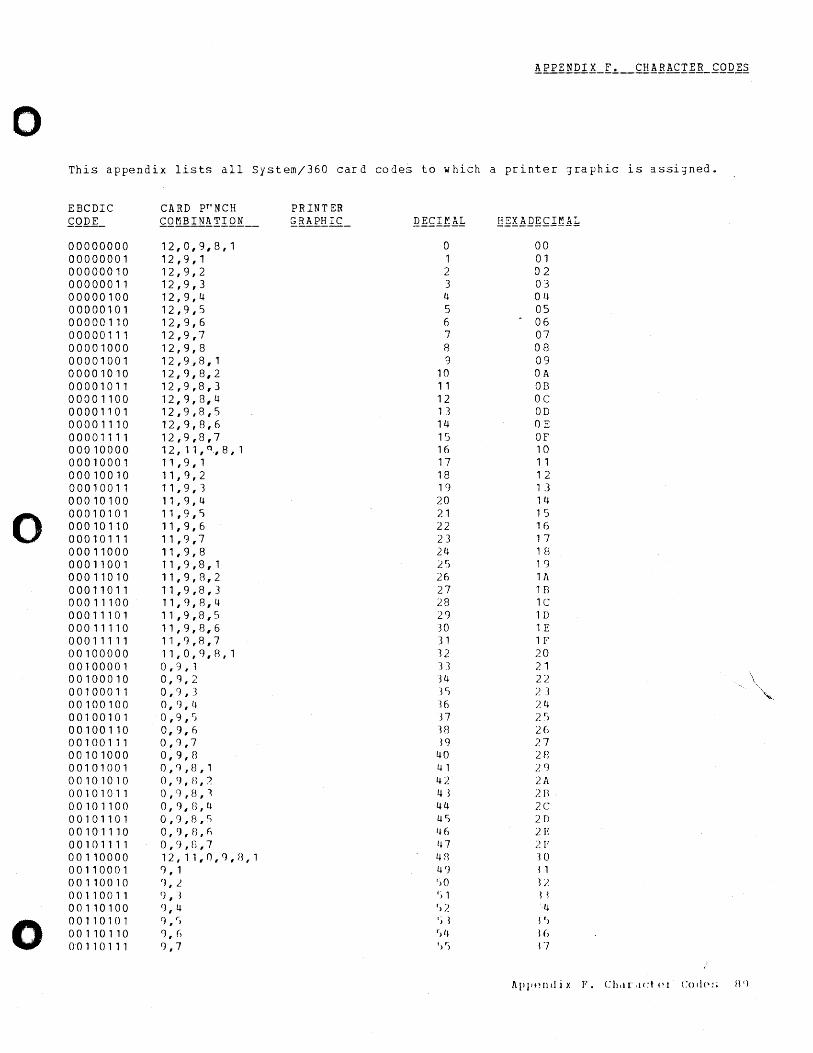
o This appendix lists all Systemj360 card codes to which a printer graphic is assigned.
EBCDIC CARD PfTNCH PRINT ER ~QDE_ £QMBlli!IlQ!{ __ ~JIAP[IC_ Q££lfAL li£X~~~~1!:1A1
00000000 12,0,9,8,1 0 00 00000001 12,9,1 1 01 00000010 12,9,2 2 02 00000011 12,9,3 3 03 00000100 12,9,4 4 04 00000101 12,9,5 5 05 00000110 12,9,6 6
. 06
00000111 12,9,7 7 07 00001000 12,9,8 8 08 00001001 12 ,9,8, 1 9 09 00001010 12,9,8,2 10 OA 00001011 12,9,8,3 11 08 0000 1100 12,9,8,4 12 oc 00001101 12,9,8,5 1 3 OD 00001110 12,9,8,6 14 OE 00001111 12,9,8,7 15 OF 00010000 12,11, Q ., 8, 1 Hi 10 00010001 11,9,1 17 1 1 00010010 11,9,2 18 1 2 00010011 11,9,1 19 1 3 00010100 11,9,4 20 14
0 00010101 11,9,S 21 1 5 00010110 11,9,6 22 16 00010111 11,9,7 23 17 00011000 11,9,8 24 1 t3 00011001 11,9,8,1 25 1 g 00011010 11,9,8,2 26 lA 00011011 11,9,8,3 27 1 B 00011100 11,9,8,4 28 lC 00011101 11,9,8,5 29 1 D 00011110 11,9,8,6 30 1 E 00011111 11,9,8,7 31 1 F 00100000 11,0,9,8,1 32 20 00100001 0,9 , 1 U 21 00100010 0,9,2 -34 22 \ 00100011 0,9,3 3S 2 3 "-,-00100100 0,9,4 36 24 00100101 O,9,S n 2r. ,> 00100110 0,9,6 38 26 00100111 0,1),7 19 27 00101000 0,9,8 40 28 00101001 O,Cf,B,l 41 2g 00101010 0,9,n,) 42 2A 00101011 0,9,B,1 43 7.B 00101100 0,9,n,U 44 7.C 00101101 0,9,B,S 4S 2D 00101110 0,9,O,h 46 2E 00101111 0,9,n,1 In 21" 00110000 12,11,n,9,n,1 4fl '10
00110001 g, 1 49 1 1 00110010 '),2 '>0 J)
00110011 () ,3 'i 1 11 00110100 (), 4 '>2 4
0 00110101 () , r) 'd i')
00110110 9, () f)4 16 001 101 11 () , 7 ') r) l7
J\ppl'lItlix F. Chtl[,lct (~I Cocip:; fI'l
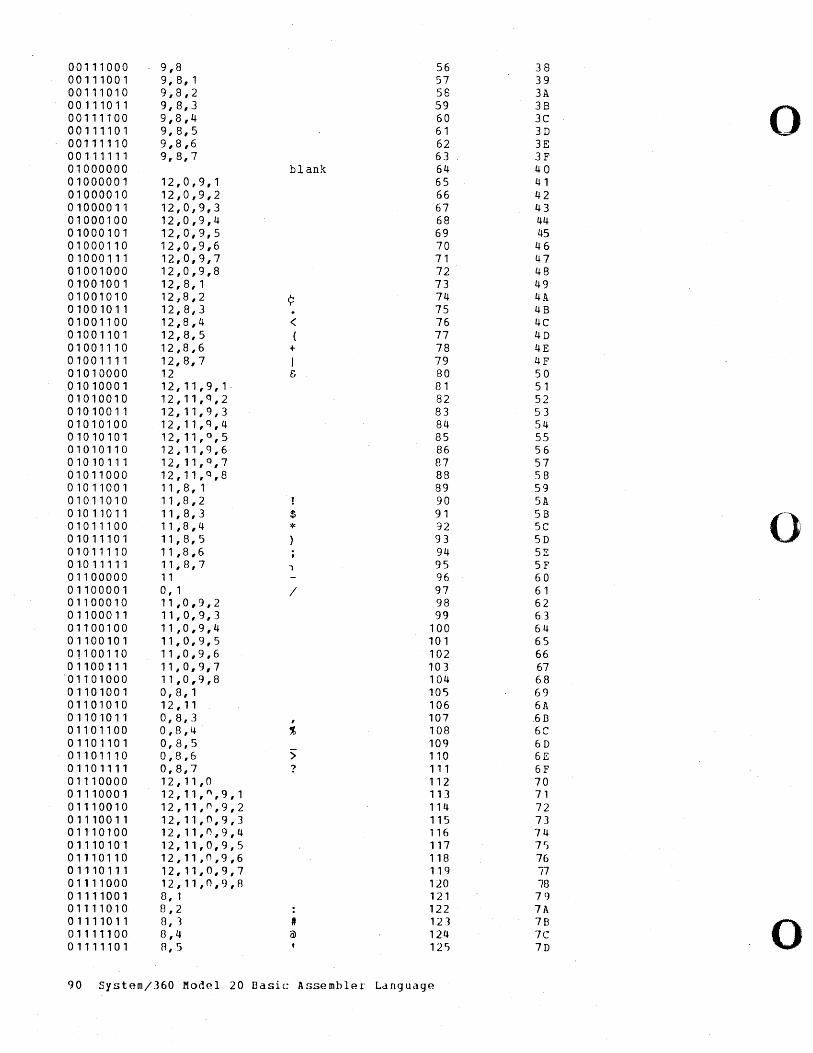
00111000 9,8 56 38 00111001 9, 8, 1 57 39 00111010 9;8,2 58 3A 00111011 9,8,3 59 3B
0 00111100 9,8,4 60 3C 00111101 9,8,5 61 3D 00111110 9,8,6 62 3E 00111111 9,8,7 63 3F 01000000 blank 64 40 01000001 12,0,9,1 65 41 01000010 12,0,9,2 66 42 01000011 12,0,9,3 67 43 01000100 12,0,9,4 68 44 01000101 12,0,9,5 69 45 01000110 12,0,9,6 70 46 01000111 12,0,9,7 71 47 01001000 12,0,9,8 72 48 01001001 12,8,1 73 49 01001010 12,8,2 ~ 74 4A 01001011 12,8,3 75 4B 01001100 12,8,4 < 76 4C 01001101 12,8,5 ( 77 4D 01001110 12,8,6 + 78 4E 01001111 12,8,7 I 79 4F 01010000 12 & 80 50 01010001 12,11,9,1 81 51 01010010 12,11,Q,2 82 52 01010011 12,11,9,3 83 53 01010100 12,11,Q,4 84 54 01010101 12,11,°,5 85 55 01010110 12,11,9,6 86 56 01010111 12,11,0,7 87 57 01011000 12,11,0,8 88 58 01011001 11,8,1 89 59 01011010 11,8,2 90 SA 01011011 11,8,3 $ 91 5B
0 01011100 11,8,4 * 92 5C 01011101 11,8,5 93 5D 01011110 11,8,6 94 52 010 11111 11,8,7 , 95 SF 01100000 11 96 60 01100001 0, 1 / 97 61 01100010 11,0,9,2 98 62 01100011 11,0,9,3 99 63 01100100 11,0,9,4 100 64 01100101 11,0,9,5 101 65 01100110 11,0,9,6 102 66 01100111 11,0,9,7 103 67 01101000 11,0,9,8 104 68 01101001 0, 8, 1 105 69 01101010 12,11 106 6A 01101011 0,8,3 , 107 .6B 01101100 0,8,4 % 108 6C 01101101 0,8,5 109 6D 01101110 0,8,6 > 110 6E 01101111 0,8,7 ? 111 6F 01110000 12,11,0 112 70 01110001 12,11,",9,1 113 71 01110010 12,11,",9,2 114 72 01110011 12,11,0,9,3 115 73 01110100 12,11,n,9,4 116 74 01110101 12,11,0,9,5 117 7~
01110110 12,11,0,9,6 118 76 01110111 12,11,0,9,7 119 77 01111000 1 2 , 11 , ° , 9. , 8 120 78 01111001 8, 1 121 79 01111010 8,2 122 7A 01111011 8, 1 # 121 7B
0 01111100 £3,4 ii) 124 7C 01111101 8,5 125 7D
90 System/360 Model 20 Basic Assembler Language
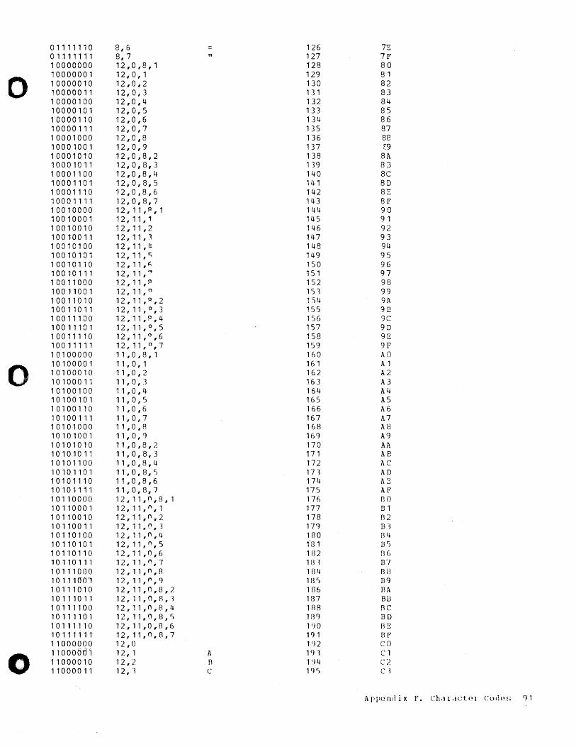
01111110 8,6 126 7E 01111111 8, 7 " 127 7F 10000000 12,0,8,1 128 80
0 10000001 12,0,1 129 81 10000010 12,0,2 130 82 10000011 12,0,3 131 83 10000100 12,0,4 132 84 10000101 12,0,5 133 85 10000110 12,0,6 134 86 10000111 12,0,7 135 87 10001000 12,0,8 136 88 10001001 12,0,9 137 [9 10001010 12,0,8,2 138 8A 10001011 12,0,8,3 139 8B 10001100 12,0,8,4 140 8C 10001101 12,0,8,5 141 8D 10001110 12,0,8,6 142 8E 10001111 12,0,8,7 143 8F 10010000 12,11,P,1 144 90 10010001 12,11,1 145 91 10010010 12,11,2 146 92 10010011 12,11,1 147 93 10010100 12,11,U 148 94 10010101 12,11,C; 149 95 10010110 12,11,fi 150 96 10010111 12,11,'" 151 97 10011000 12,11,0 152 98 10011001 12,11, 0 151 99 10011010 12,11, p ,2 l 'S4 9A 10011011 12,11, p ,3 155 98 10011100 12,11,°,4 156 9C 10011101 12,11, Q , 5 157 9D 10011110 12,11, 0 ,6 158 9E 10011111 12,11,Q,7 159 9F 10100000 11,0,8,1 160 AO
0 10100001 11,0,1 161 A 1 10100010 11,0,2 162 A2 10100011 11,0,3 163 1\3 10100100 11,0,4 164 1\4 10100101 11,0,5 165 A5 10100110 11,0,6 166 A6 10100111 11,0,7 167 A7 10101000 11,0,8 168 A8 10101001 11,0,9 169 A9 10101010 11,0,8,2 170 AA 10101011 11,0,8,3 171 AB 10101100 11,0,8,4 172 AC 10101101 11,0,8,5 171 AD 10101110 11,0,8,6 174 hE 10101111 11,0,8,7 175 I\F 10110000 12,11,O,8,1 176 130 10110001 12,11,O,1 177 I31 10110010 12,11,O,2 178 R2 10110011 12,11,O,3 179 131 10110100 12,11,O,4 180 B4 10110101 12,11,O,5 "81 BS 10110110 12,11,0,6 lB2 Bo 10110111 12,11,",7 181 137 10111000 12,11,n,8 184 An 10 11100'1 12,11,",9 1BS [39 10111010 12,11,0,8,2 186 Bl\ 10111011 12,11,0,8,l 187 1313 10111100 12,11,0,8,4 188 BC 10111101 12,11,0,8,r) lBfJ I3D 10111110 12,11,0,8,6 1 () ° BE 1 0 1 1 1 1 11 12,11,O,S,7 191 I3F 110000'00 12,0 192 co
0 11000001 12, 1 A 1 <) 1 Cl 11000010 12,2 11 l'l4 C2 11000011 1 2 ,-~ C 19 S C ~
A P pp nd i x F. c: h ,1 r, 1 C t. (> I c: () d (~ ! ; () 1
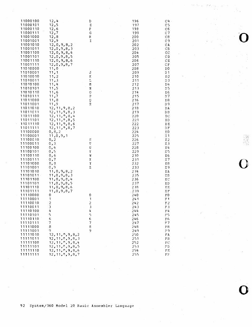
11000100 12,4 D 196 C4 11000101 12,5 E 197 C5 11000110 12,6 F 198 C6 11000111 12,7 G 199 C7 "0 11001000 12,8 H 200 C8 11001001 12,9 I 201 C9 11001010 12,0,9,8,2 202 CA 11001011 12,0,9,8,3 203 CB 11001100 12,0,9,8,4 204 CC 11001101 12,0,9,8,5 205 CD 11001110 12,0,9,8,6 206 CE 11001111 12,0,9,8,7 207 CF 11010000 11 , 0 208 DO 11010001 11 , 1 J 209 D1 11010010 11 , 2 K 210 D2 11010011 11 ,3 L 211 D3 11010100 11 , 4 M 212 D4 11010101 11 ,5 N 213 D5 11010110 11 ,6 0 214 D6 11010111 11 ,7 p 215 D7 11011000 11 , 8 Q 216 D8 11011001 11 ,9 R 217 D9 11011010 12,11,9,8,2 218 DA 11011011 12,11,Q,8,3 219 DB 11011100 12,11,°,8,4 220 DC 11011101 12,11, Q ,8,5 221 DD 11011110 12,11,9,8,6 222 DE 11011111 12,11, Q ,8,7 223 DF 11100000 0,8,2 224 EO 11100001 11,0,9,1 225 E1 11100010 0,2 S 226 E2 11100011 0,3 T 227 E3 11100100 0,4 U 228 E4 11100101 0,5 V 229 E5 11100110 0,6 w 230 E6 11100111 0,7 X 231 E7 () 11101000 0,8 y 232 E8 11101001 0,9 Z 233 E9 11101010 11,0,9,8,2 214 EA 11101011 11,0,9,8,3 235 EB 11101100 11,0,9,8,4 236 EC 11101101 11,0,9,8,5 237 ED 11101110 11,0,9,8,6 238 EE 11101111 11,0,9,8,7 239 EF 11110000 0 0 240 FO 11110001 1 1 241 F1 11110010 2 2 242 F2 11110011 3 3 243 F3 11110100 4 4 244 F4 11110101 5 5 245 F5 11110110 6 6 246 F6 11110111 7 7 247 F7 11111000 8 8 248 F8 11111001 9 9 249 F9 11111010 12,11,n,9,8,2 250 FA 11111011 12,11,n,9,8,3 2 r) 1 FB 11111100 12,11,",9,8,4 2 r )2 FC 11111101 12,11,n,9,8,5 253 FD 11111110 12,11,n,9,8,6 254 FE 11111111 12,11,"',9,8,7 2')5 PI-'
o 92 System/J60 Modpl 20 8dSic Assembler Langudge
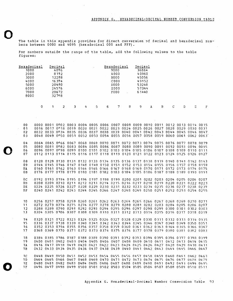
o
0
0
The table in this appendix provides for direct conversion ~f decimal and hexadecimal numbers between 0000 and 4095 (hexadecimal 000 and FFF) •
For numbers outside the range of the table, add the following values to the table figures:
li~.!~g~£iJ1l.~l Decimal !!.~l£~Q.§.£imal De.£i!!!~l 1000 -4096- 9000 36864 2000 8192 AOOO 40960 3000 12288 BOOO 45056 4000 16384 COOO 49152 5000 20480 DOOO 53248 6000 24576 EOOO 57344 7000 28672 FOOO 61440 8000 327fi8
0 2 3 4 5 6 7 8 9 A B C D E
00 0000 0001 0002 0003 0004 0005 0006 0007 0008 0009 0010 0011 0012 0013 0014 01 0016 0017 on18 0019 0020 0021 0022 0023 0024 0025 0026 0027 0028 0029 0030 02 0032 0033 on34 0035 0036 0037 0038 0039 0040 0041 0042 0043 0044 0045 0046 03 0048 0049 on50 0051 0052 0053 0054 0055 0056 0057 0058 0059 0060 0061 0062
04 0064 0065 0066 0067 0068 0069 0070 0071 0072 0073 0074 0075 0076 0077 0078 05 0080 0081 on82 0083 0084 0085 0086 0087 0088 0089 0090 0091 0092 0093 0094 06 0096 0097 00.98 0099 0100 0101 0102 0103 0104 0105 0106 0107 0108 0109 0110 07 0112 0113 0114 0115 0116 0117 0118 0119 0120 0121 0122 0123 0124 0125 0126
08 0128 0129 0130 0131 0132 0133 0134 0135 0136 0137 0138 0139 0140 0141 0142 09 0144 0145 0146 0147 0148 0149 0150 0151 0152 0153 0154 0155 0156 0157 0158 OA 0160 0161 0162 0163 0164 0165 0166 0167 0168 0169 0170 0171 0172 0173 0174 OB 0176 0177 0178 0179 0180 0181 0182 0183 0184 0185 0186 0187 0188 0189 0190
oc 0192 0193 0194 0195 0196 0197 0198 0199 0200 0201 0202 0203 0204 0205 0206 OD 0208 0209 0210 0211 0212 0213 0214 0215 0216 0217 0218 0219 0220 0221 0222 OE 0224 0225 07.26 0227 0228 0229 0230 0231 0232 0233 0234 0235 0236 0237 0238 OF 0240 0241 0242 0243 0244 0245 0246 0247 0248 0249 0250 0251 0252 0253 0254
10 0256 0257 0258 0259 0260 0261 0262 0263 0264 0265 0266 0267 0268 0269 0270 11 0272 0273 0274 0275 0276 0277 0278 0279 0280 0281 0282 0283 0284 0285 0286 12 0288 0289 0290 0291 0292 0293 0294 0295 0296 0297 0298 0299 0300 o JO 1 0302 13 0304 0305 0106 0307 0308 0309 0310 0311 0312 0313 0314 0315 0316 0317 0318
14 0320 0321 0122 0323 0324 0325 0326 0327 0328 0329 0330 0311 0332 0333 0334 15 0336 0337 0138 0339 0340 0341 0342 0343 0344 0345 0346 0347 0348 0349 0350 16 0352 0353 0.154 0355 0356 0357 0358 0359 0360 0361 0362 0363 0164 0365 0366 17 0368 0369 0370 0371 0372 0373 0374 0375 0376 0377 0178 0379 0380 0381 OJA 2
18 0384 0385 0186 0.187 0.388 0389 0390 0391 O]C} 2 0393 0394 039'1 0396 01')7 019 A 19 0400 0401 0402 0403 0404 0405 0406 0407 0408 0409 0410 0411 0412 0413 0414 11\ 0416 0417 0418 0419 0420 0421 0422 0423 0424 0425 0426 0427 0428 0429 04.10 lB 0432 0433 0434 04.15 0436 04.17 0438 0439 0440 0441 04,42 0443 0444 0445 0446
lC 0448 0449 0450 0451 0452 0453 0454 045'1 0456 0457 04 SA 0459 0460 0461 0462 lD 0464 0465 0466 0467 0468 0469 0470 0471 0472 0473 0474 0475 0476 0477 0478 1E 0480 0481 0482 0483 0484 0485 0486 0487 0488 0409 01~90 o l~ ') 1 0492 0491 0494 1F 0496 0497 0498 0499 0500 0501 0502 0503 0504 0505 0506 0'107 or) 08 050<) or>10
F
0015 0031 00 It 7 0063
0079 0095 0111 0127
0143 0159 0175 0191
0207 0223 0239 0255
0271 02fl7 0303 0319
0135 0351 0367 03B3
0399 0415 04 -31 0447
0461 0479 049 r) 0511
l\PFendix G. Hexddecim,11-DHcimal Numb(~l" ConvPl-slon Tablp 93
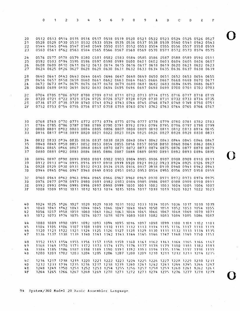
20 21 22 23
o 2 3 4 5 6 7 8 9 A B c D F
0512 0513 OS14 0515 0516 0517 0518 0519 0520 0521 0522 0523 0524 0525 0526 0527 0528 0529 0~30 0531 0532 0533 0534 0535 0536 0537 0538 0539 0540 0541 0542 0543 0544 0545 0~46 0547 0548 0549 0550 0551 05S2 0553 0554 0555 0556 0557 0558 0559 0560 0561 0~62 0563 0564 0565 0566 0567 0568 0569 0570 0571 0572 0573 0574 0575
24 0576 0577 OS78 0579 0580 0581 0582 0583 0584 0585 0586 0587 0588 0589 0590 0591 25 0592 0593 0~94 0595 0596 0597 0598 0599 0600 0601 0602 0603 0604 0605 0606 0607 26 0608 0609 0~10 0611 0612 0613 0614 0615 0616 0617 0618 0619 0620 0621 0622 0623 27 0624 0625 0~26 0627 0628 0629 0630 0631 0632 0633 0634 0635 0636 0637 0638 0639
28 0640 0641 0~42 0643 0644 0645 0646 0647 0648 0649 0650 0651 0652 0653 0654 0655 29 0656 0657 0~58 0659 0660 0661 0662 0663 0664 0665 0666 0667 0668 0669 0670 0671 2A 0672 0673 0~74 0675 0676 0677 0678 0679 0680 0681 0682 0683 0684 0685 0686 0687 28 0688 0689 On90 0691 0692 0693 0694 0695 0696 0697 0698 0699 0700 0701 0702 0703
2C 0704 0705 0~06 0707 0708 0709 0710 0711 0712 0713 0714 0715 0716 0717 0718 0719 2D 0720 0721 0~22 0723 0724 0725 0726 0727 0728 0729 0730 0731 0732 0733 0734 0735 23 0736 0737 0~38 0739 0740 0741 0742 0743 0744 0745 0746 0747 0748 0749 0750 0751 2f 0752 0753 0~54 0755 0756 0757 0758 0759 0760 0761 0762 0763 0764 0765 0766 0767
30 0768 0769 0~70 0771 0772 0773 0774 0775 0776 0777 0778 0779 0780 0781 0782 0783 31 0784 0785 0~86 0787 0788 0789 0790 0791 0792 0793 0794 0795 0796 0797 0798 0799 32 0800 0801 OP02 0803 0804 0805 0806 0807 0808 0809 0810 0811 0812 C813 0814 0815 33 0816 0817 0 0 18 0819 0820 0821 0822 0823 0824 0825 0826 0827 0828 0829 0830 0831
34 35 36 37
38 39 3A 38
0832 0833 OP34 0835 0836 0837 0838 0839 0840 0841 0842 0843 0844 0845 0846 0847 0848 0849 OP50 0851 0852 0853 0854 0855 08S6 0857 0858 0859 0860 0861 0862 0863 0864 0865 OR66 0867 0868 0869 0870 0871 0872 0873 0874 0875 0876 0877 0878 0879 0880 0881 OP82 0883 0884 0885 0886 0887 0888 0889 0890 0891 0892 0893 0894 0895
0896 0897 OR98 0899 0900 0901 0902 0903 0904 0905 0906 0907 0908 0909 0910 0911 0912 0913 0 0 14 0915 0916 0917 0918 0919 0920 0921 0922 0923 0924 0925 0926 0927 0928 0929 OQ30 0931 0932 0933 0934 0935 0936 0937 0938 0939 0940 0941 0942 0943 0944 0945 OQ46 0947 0948 0949 0950 0951 0952 0953 0954 0955 0956 0957 0958 0959
3C 0960 0961 0 0 62 0963 0964 0965 0966 0967 0968 0969 0970 0971 0972 0973 0974 0975 3D 0976 0977 OQ78 0979 0980 0981 0982 0983 0984 0985 0986 0987 0988 0989 0990 0991 3E 0992 0993 OQ94 0995 0996 0997 0998 0999 1000 1001 1002 1003 1004 1005 1006 1007 3F 1008 1009 1010 1011 1012 1013 1014 1015 1016 1017 1018 1019 1020 1021 1022 1023
40 1024 1025 l n26 1027 1028 1029 1030 1031 1032 10331034 1035 1036 1017 1038 1039 41 1040 1041 ,ri42 1043 1044 1045 1046 1047 1048 1049 1050 1051 1052 1053 1054 10~)S 42 1056 1057 1058 1059 1060 1061 1062 1063 1064 106S 1066 1067 1068 1069 1070 1071 43 1072 1073 1074 1075 1076 1077 1078 1079 1080 1081 1082 1083 1084 1085 1086 1087
44 1088 1089 1090 10<)1 10921093 1094 1095 1096 1097 1098 1099 1100 1101 1102 1101 45 1104 1105 1106 1107 1108 1109 1110 1111 1112 1113 1114 1115 1116 1117 1110 1119 46 1120 1121 1122 1121 1124 1125 1126 1127 1128 1129 1130 1131 1132 1111 1134 1135 47 1136 1137 1138 1139 1140 1141 1142 1143 1144 1145 1146 1147 1148 1149 1150 11S1
48 1152 1153 1154 1155 1156 1157 1158 1159 1160 1161 1162 1161 1164 1165 1166 11h7 49 1168 1169 1170 1171 1172 1173 1174 1175 1176 1177 1178 1179 1180 1181 1182 1181 4A 1184118511861187119811891190119111921193 11CJ4 1195 11<)6 11()7 119B 11<)() 4B .1200 1201 1702 1203 1204 1205 1206 1207 1208 120<) 1210 1211 1212 1211 1214 121S
4C 4D 4E 4F
1216 1217 1218 121<) 1220 1221 1222 1223 1224 1225 1226 1227 17.2B 1229 12]0 1211 1 2 3 2 1 2 3 31 7 ) 4 1 2 .1 ') 1 2 .1 6 1 2 17 1 2 3 8 1 2 .1 <) 1 /. 4 0 1 2 4 1 1 2 4 2 1 2 4·3 1 2 4 I! 1 7. 4 r) 1 24 (, 1 2 I~ 7 1248 1249 1750 12')1 1252 1253 1254 1255 1256 12 r)7 125fl 12')<) 1260 1261 1262 126 ~ 1264 1265 1766 1267 1260 1269 1270 1271 1272 1273 1274 127'> 1276 1277 127B 1279
94 System/360 Modf'l 20 Bd!;ic As!:;pmbl(~[ Ldngud<jP
o
()
o
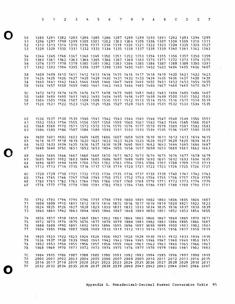
0 2 3 4 5 6 7 8 9 A B C D E F
0 50 1280 1281 1282 1283 1284 1285 1286 1287 1288 1289 1290 1291 1292 1293 1294 1295 51 1296 1297 1?98 1299 1300 1301 1302 1303 1304 1305 1306 1307 1308 1309 1310 1311 52 1312 1313 1314 1315 1316 1317 1318 1319 1320 1321 1322 1323 1324 1325 1326 1327 53 1328 1329 1330 1331 1332 1333 1334 1335 1336 1337 1338 1339 1340 1341 1342 1343
54 1344 1345 1346 1347 1348 1349 1350 1351 1352 1353 1354 1355 1356 1357 1358 1359 55 1360 1361 1362 1363 1364 1365 1366 1367 1368 1369 1370 1371 1372 1373 1374 1375 56 1376 1377 1178 1379 1380 1381 1382 1383 1384 1385 1386 1387 1388 1389 1390 1391 57 1392 1393 1 ~94 1395 1396 1397 1398 1399 1400 1401 1402 1403 1404 1405 1406 1407
58 1408 1409 1410 1411 1412 1413 1414 1415 1416 1417 1418 1419 1420 1421 1422 1423 59 1424 1425 1426 1427 1428 1429 1430 1431 1432 1433 1434 1435 1436 1437 1438 1439 5A 1440 1441 1442 1443 1444 1445 1446 1447 1448 1449 1450 1451 1452 1453 1454 1455 5B 1456 1457 1458 1459 1460 1461 1462 1463 1464 1465 1466 1467 1468 1469 1470 1471
5C 1472 1473 1474 1475 1476 1477 1478 1479 1480 1481 1482 1483 1484 1485 1486 1487 5D 1488 1489 1490 1491 1492 1493 1494 1495 1496 1497 1498 1499 1500 1501 1502 1503 5E 1504 1505 lr:;06 1507 1508 1509 1510 1511 1512 1513 1514 1515 1516 1517 1518 1519 5F 1520 1521 lr:;22 1523 1524 1525 1526 1527 1528 1529 1530 1531 1532 1533 1534 1535
60 1536 1537 11:)38 1539 1540 1541 1542 1543 1544 1545 1546 1547 1548 1549 1550 1551 61 1552 1553 lr:;54 1555 1556 1557 1558 1559 1560 1561 1562 1563 1564 1565 1566 1567 62 1568 1569 1,70 1571 1572 1573 1574 1575 1576 1577 1578 1579 1580 1581 1582 1583 63 1584 1585 1"86 1587 1588 1589 1590 1591 1592 1593 1594 1595 1596 1597 1598 1599
64 1600 1601 1602 1603 1604 1605 1606 1607 1608 1609 1610 1611 1612 1613 1614 1615 65 1616 1617 lF18 1619 1620 1621 1622 1623 1624 1625 1626 1627 1628 1629 1630 1631 66 1632 1633 1634 1635 1636 1637 1638 1639 1640 1641 1642 1643 1644 1645 1646 1647
0 67 1648 1649 1 fi50 1651 1652 1653 1654 1655 1656 1657 1658 1659 1660 1661 1662 1663
68 1664 1665 1666 1667 1668 1669 1670 1671 1672 1673 1674 1675 1676 1677 1678 1679 69 1680 1681 lfi82 1683 1684 1685 1686 1687 1688 1689 1690 1691 1692 1693 1694 1695 6A 1696 1697 1698 1699 1700 1701 1702 1703 1704 1705 1706 1707 1708 1709 1710 1711 6B 1712 1713 1"714 1715 1716 1717 1718 1719 1720 1721 1722 1723 1724 1725 1726 1727
6C 1728 1729 1"730 1731 1732 1733 1734 1735 1736 1737 1738 1739 1740 1741 1742 1743 6D 1744 1745 1146 1747 1748 1749 1750 1751 1752 1753 1754 1755 1756 1757 1758 1759 6E 1760 1761 1"762 1763 1764 1765 1766 1767 1768 1769 1770 1771 1772 1773 1774 1775 6F 1776 1777 1"778 1779 1780 1781 1782 1783 1784 1785 1786 1787 1788 1789 1790 1791
70 1792 1793 1"794 17<)5 1796 1797 1798 1799 1800 1801 1802 1803 1804 1805 1806 1807 71 1808 1809 l P l0 1811 1812 1813 1814 1815 1816 1817 1818 1819 1820 1821 1822 1823 72 1824 1825 1P 26 1827 1828 1829 1830 1831 1832 1833 1834 1835 1836 1837 1838 1839 73 1840 1841 1P 42 1843 1844 1845 1846 1847 1848 1849 1850 1851 1852 1853 1854 1855
74 1856 1857 1A58 1859 1860 1861 1862 1863 1864 1865 1866 1867 1868 1869 1870 1871 75 1872 1873 lA74 1875 1876 1877 1878 1879 1880 1881 1882 1883 1884 1885 1886 1887 76 1888 1889 1fl90 1891 1892 1893 1894 1895 1896 1897 1898 1899 1900 1901 1902 1903 77 1904 1905 lQ06 1907 1908 1909 1910 1911 1912 1913 1914 1915 1916 1917 1918 1919
78 1920 1921 lQ22 1923 1924 1925 1926 1927 1928 1929 1930 1931 1932 1933 -1934 1935 79 1936 1937 lQ 38 1939 1940 1941 1942 1943 1944 1945 1946 1947 1948 1949 1950 1951 7A 1952 1953 lq54 1955 1956 1957 1958 1959 1960 1961 1962 1963 1964 1965 1966 1967 7B 1968 1969 lQ70 1971 1972 1973 1974 1975 1976 1977 1978 1979 1980 1981 1982 1983
7C 1984 1985 lQ86 1987 1988 1989 1990 1991 1992 1993 1994 1995 1996 _ 1997 1990 1999 7D 2000 2001 2002 2003 2004 2005 2006 2007 2008 2009 2010 2011 2012 2013 2014 2015 7E 2016 2017 2('18 2019 2020 2021 2022 2023 2024 2025 2026 2027 2028 2029 2030 2031
0 7F 2032 2033 2034 2035 2036 2037 2038 2039 2040 2041 2042 2043 2044 2045 2046 2047
Appendix G. Hexadecimal-Decimal Number Conversion Table 95
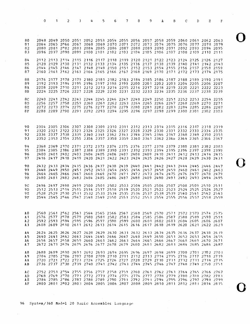
80 81 82 83
o 2 3 4 5 6 7 8 9 A B e D E F
2048 2049 2050 2051 2052 2053 2054 2055 2056 2057 2058 2059 2060 2061 2062 2063 2064 2065 2n66 2067 2068 2069 2070 2071 2072 2073 2074 2075 2076 2077 2078 2079 2080 2081 2 0 82 2083 2084 2085 2086 2087 2088 2089 2090 2091 2092 2093 2094 2095 2096 2097 2098 2099 2100 2101 2102 2103 2104 2105 2106 2107 2108 2109 2110 2111
84 2112 2113 2114 2115 2116 2117 2118 2119 2120 2121 2122 2123 2124 2125 2126 2127 85 2128 2129 2130 2131 2132 2133 2134 2135 2136 2137 2138 2139 2140 2141 2142 2143 86 2144 2145 2146 2147 2148 2149 2150 2151 2152 2153 2154 2155 2156 2157 2158 2159 87 2160 2161 2162 2163 2164 2165 2166 2167 2168 2169 2170 2171 2172 2173 2174 2175
88 2176 2177 2178 2179 2180 2181 2182 2183 2184 2185 2186 2187 2188 2189 2190 2191 89 2192 2193 2194 2195 2196 2197 2198 2199 2200 2201 2202 2203 2204 2205 2206 2207 8A 2208 2209 2)10 2211 2212 2213 2214 2215 2216 2217 2218 2219 2220 2221 2222 2223 88 2224 2225 2/.26 2227 2228 2229 2230 2231 2232 2233 2234 2235 2236 2237 2238 2239
8e 2240 2241 2242 2243 2244 2245 2246 2247 2248 2249 2250 2251 2252 2253 2254 2255 8D 2256 2257 2)58 2259 2260 2261 2262 2263 2264 2265 2266 2267 2268 2269 2270 2271 8E 2272 2273 2274 2275 2276 2277 2278 2279 2280 2281 2282 2283 2284 2285 2286 2287 8F 2288 2289 2/.90 2291 2292 2293 2294 2295 2296 2297 2298 2299 2300 2301 2302 2303
90 2304 2305 2306 2307 2308 2309 2310 2311 2312 2313 2314 2315 2316 2317 2318 2319 91 2320 2321 2122 2323 2324 2325 2326 2327 2328 2329 2330 2331 2332 2333 2334 2335 92 2336 2337 2338 2339 2340 2341 2342 2343 2344 2345 2346 2347 2348 2349 2350 2351 93 2352 2353 2354 2355 2356 2357 2358 2359 2360 2361 2362 2360 2364 2365 2366 2367
94 95 96 97
98 99 9A 98
2368 2369 2170 2371 2372 2373 2374 2375 2376 2377 2378 2379 2380 2381 2382 2383 2384 2385 2386 2387 2388 2389 2390 2391 2392 2393 2394 2395 2396 2397 2398 2399 2400 2401 2402 2403 2404 2405 2406 2407 2408 2409 2410 2411 2412 2413 2414 2415 2416 2417 2418 2419 2420 2421 2422 2423 2424 2425 2426 2427 2428 2429 2430 2431
2432 2433 2434 2435 2436 2437 2438 2439 2440 2441 2442 2443 2444 2445 2446 2447 2448 2449 2450 2451 2452 2453 2454 2455 2456 2457 2458 2459 2460 2461 2462 2463 2464 2465 2466 2467 2468 2469 2470 2471 2472 2473 2474 2475 2476 2477 2478 2479 2480 2481 2482 2483 2484 2485 2486 2487 2488 2489 2490 2491 2492 2493 2494 2495
ge 2496 2497 2498 2499 2500 2501 2502 2503 2504 2505 2506 2507 2508 2509 2510 2511 9D 2512 2513 2~14 2515 2516 2517 2518 2519 2520 2521 2522 2523 2524 2525 2526 2527 9E 2528 2529 2~30 2531 2532 2533 2534 2535 2536 2537 2538 2539 2540 2541 2542 2543 9F 2544 2545 2~46 2547 2548 2549 2550 2551 2552 2553 2554 2555 2556 2557 2558 2559
AO 2560 2561 2~62 2563 2564 2565 2566 2567 2568 2569 2570 2571 2572 2573 2574 2575 A1 2576 2577 2~78 2579 2580 2581 2582 2583 2584 2585 2586 2587 2588 2589 2590 2591 A2 2592 2593 2~94 2595 2596 2597 2598 2599 2600 2601 2602 2603 2604 2605 2606 2607 A3 2608 2609 2~10 2611 2612 2613 2614 2615 2616 2617 2618 2619 2620 2621 2622 2623
A4 2624 2625 2626 2627 2628 2629 2630 2631 2632 2633 2634 2615 26]6 2637 26J8 2639 A5 2640 2641 2~42 2643 2644 2645 2646 2647 2648 2649 2650 2651 2652 2651 2654 2655 A6 2656 2657 2~58 2659 2660 2661 2662 2661 2664 2665 2666 26b7 2668 2669 2670 2671 A7 2672 2673 2~74 2675 2676 2677 2678 2679 2680 2681 2682 2681 2684 2685 2686 2687
A8 2688 2689 2~90 2691 2692 2693 2694 2695 2696 2697 2698 2699 2700 2701 2702 2701 A9 2704 2705 2~06 2707 2708 2709 2710 2711 2712 271] 2714 2715 2716 2717 2718 271q AA 2720 2721 2~22 2723 2724 2725 2726 2727 2728 2729 2710 2711 2712 2711 2714 2715 A8 2736 2737 2~]8 2739 2740 2741 2742 2743 2744 2745 2746 2747 2748 2749 27S0 2751
Ae AD AE AF
2752 2751 2~54 2755 2756 2757 2758 27SQ 2760 2761 2762 2761 2764 2765 2766 2767 2768 2769 2~70 2771 2772 2773 2774 2775 2776 2777 2778 2779 2780 2781 2782 2783 2784 2785 2""'06 2787 2788 2789 2790 2791 2792 27c)·3 2794 279~) 2796 2797 279B 279q 2800 2801 2P 02 2803 2804 2801) 2806 2A07 2808 280g 2810 2011 2812 2fl1l 2814 2.8 F>
96 Syst~m/360 Modpl 20 Busic A!:;s(~mblp.l Ldl1(Jllll<JP
o
()
o
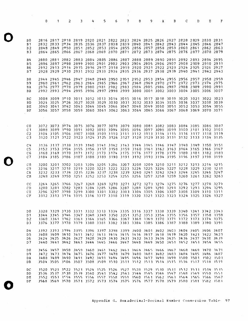
o
o
o
BO Bl B2 B3
o 2 3 4 5 6 7 8 9 A B C D E F
2816 2817 2818 2819 2820 2821 2822 2823 2824 2825 2826 2827 2828 2829 2830 2831 2832 2833 '2 P 34 2835 2836 2837 2838 2839 2840 2841 2842 2843 2844 2845 2846 2847 2848 2849 2 A50 2851 2852 2853 2854 2855 2856 2857 2858 2859 2860 2861 2862 2863 2864 2865 2866 2867 2868 2869 2870 2871 2872 2873 2874 2875 2876 2877 2878 2879
B4 2880 2881 2882 2883 2884 2885 2886 2887 2888 2889 2890 2891 2892 2893 2894 2895 B5 2896 2897 2~98 2899 2900 2901 2902 2903 2904 2905 2906 2907 2908 2909 2910 2911 B6 2912 2913 2q14 2915 2916 2917 2918 2919 2920 2921 2922 2923 2924 2925 2926 2927 B7 2928 2929 20 30 2931 2932 2933 2934 2935 2936 2937 2938 2939 2940 2941 2942 2943
B8 2944 2945 2946 2947 2948 2949 2950 2951 2952 2953 2954 2955 2956 2957 2958 2959 B9 2960 2961 2q62 2963 2964 2965 2966 2967 2968 2969 2970 2971 2972 2973 2974 2975 BA 2976 2977 2 Q 78 2979 2980 2981 2982 2983 2984 2985 2986 2987 2988 2989 2990 2991 BB 2992 2993 2094 2995 2996 2997 2998 2999 3000 3001 3002 3003 3004 3005 3006 3007
BC 3008 3009 3~10 3011 3012 3013 3014 3015 3016 3017 3018 3019 3020 3021 3022 3023 BD 3024 3025 3n 26 3027 3028 3029 3030 3031 3032 3033 3034 3035 3036 3037 3038 3039 BE 3040 3041 3042 3043 3044 3045 3046 3047 3048 3049 3050 3051 3052 3053 3054 3055 BF 3056 3057 3058 3059 3060 3061 3062 3063 3064 3065 3066 3067 3068 3069 3070 3071
co 3072 3073 3n74 3075 3076 3077 3078 3079 3080 3081 3082 3083 3084 3085 3086 3087 Cl 3088 3089 3n 9D 3091 3092 3093 3094 3095 3096 3097 3098 3099 3100 3101 3102 3103 C2 3104 3105 3106 3107 3108 3109 3110 3111 3112 3113 3114 3115 3116 3117 3118 3119 C3 3120 3121 3122 3123 3124 3125 3126 3127 3128 3129 3130 3131 3132 3133 3134 3135
C4 C5 C6 C7
C8 C9 CA CB
3136 3137 3138 3139 3140 3141 3142 3143 3144 3145 3146 3147 3148 3149 3150 3151 3152 3153 3154 3155 3156 3157 3158 3159 3160 3161 3162 3163 3164 3165 3166 3167 3168 3169 3170 3171 3172 3173 3174 3175 3176 3177 3178 3179 3180 3181 3182 3183 3184 3185 3186 3187 3188 3189 3190 3191 3192 3193 3194 3195 3196 3197 3198 3199
3200 3201 3202 3203 3204 3205 3206 3207 3208 3209 3210 3211 3212 3213 3214 3215 3216 3217 3218 3219 3220 3221 3222 3223 3224 3225 3226 3227 3228 3229 3230 3231 3232 3233 3'34 3235 3236 3237 3238 3239 3240 3241 3242 3243 3244 3245 3246 3247 3248 3249 3'50 3251 3252 3253 3254 3255 3256 3257 3258 3259 3260 3261 3262 3263
CC 3264 3265 3'66 3267 3268 3269 3270 3271 3272 3273 3274 3275 3276 3277 3278 3279 CD 3280 3281 3282 3283 3284 3285 3286 3287 3288 3289 3290 3291 3292 3293 3294 32q5 CE 3296 3297 3'98 3299 3300 3301 3302 3303 3304 3305 3306 3307 3308 3309 3310 3311 CF 3312 3313 3114 3315 3316 3317 3318 3319 3320 3321 3322" 3323 3324 3325 3326 3327
DO 3328 3329 3130 3331 3332 3333 3334 3335 3336 3337 3338 3339 3340 3341 3342 3343 Dl 3344 3345 3146 3347 3348 3349 3350 3351 3352 3353 3354 3355 3356 3157 3358 3359 D2 3360 3361 3162 3]63 3164 3365 3366 3367 3368 3369 3370 3371 3372 3373 3374 3375 D3 3376 3377 ]178 3179 3380 3381 3382 3383 ]384 3385 3386 3387 3188 3389 3190 3391
D4 3392 3393 3194 3395 3396 3397 3398 3399 3400 3401 3402 3403 ]404 340S 3406 3407 D5 3408 3409 1410 3411 3412 1413 3414 3415 3416 3417 3418 341q 3420 3421 3422 3423 D6 3424 3425 3426 3427 3428 3429 3430 3431 3432 3433 3434 343S 3436 3437 3438 3439 D7 3440 3441 3442 3443 3444 3445 3446 3447 3448 3449 3450 3451 34S2 J453 3454 345S
D8 3456 3457 3458 3459 3460 3461 1462 3463 3464 3465 1466 3467 1468 1469 1470 3471 D9 3472 3473 3474 3475 3476 3477 3478 3479 3480 3481 3482 3483 3484 3485 J486 3407 D A 3488 J 48 9 3490 341) 1 3492 3493 3494 3495 349 f) 3497 J 4 9 B 1499 3 r) 00 150 1 350 2 3 r; 0 3 DB 3504 j505 3~06 3507 3508 3509 3510 3511 3512 J513 1514 3515 3~1f) 3S17 1S18 3519
DC DD DE DF
3')20 3521 ]';22 3S21 3524 F)2') 3526 1')27 1 c,20 "l·)29 V)]O 3531 JC)32 JS31 3514 "Je) Jf)
3 ') 3 6 3 5 J 7 ] r; 38 3 5 J 9 3 ') 4 0 35 4 1 3 r) 4 2 3 S 4 3 3 e) 4 4 3 r) 4 S 3 S 4 6 3 S 4 7 3 ') 4 8 J S 4 q J S 5 0 J f, f) 1 3552 3553 3~54 35SS F)56 "3557 3(lS8 15 r)9 3560 3')61 1S62 P")63 Jf ,64 j')6 r) 1 r)66V)67 3568 3569 3';70 3571 3572 .3S73 3574 357 r ) 1576 1577 V,7H ")·)79 J580 JSB1 "jr)B2 lSH l
AppE-~I1dix G. IIf!xadpcimal-Dpcimdl Numhp[" COI1vPI"!.ion Tdblp <n
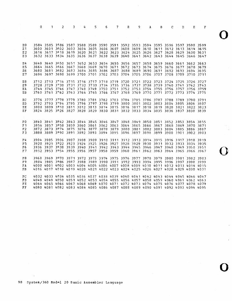
0 2 3 4 5 6 7 8 9 A B C D E F
0 EO 3584 3585 3586 3587 3588 3589 3590 3591 3592 3593 3594 3595 3596 3597 3598 3599 E1 3600 3601 3602 3603 3604 3605 3606 3607 3608 3609 3610 3611 3612 3613 3614 3615 E2 3616 3617 3~18 3619 3620 3621 3622 3623 3624 3625 3626 3627 3628 3629 3630 3631 E3 3632 3633 3634 3635 3636 3637 3638 3639 3640 3641 3642 3643 3644 3645 3646 3647
E4 3648 3649 3n50 3651 3652 3653 3654 3655 3656 .3657 3658 3659 3660 3661 3662 3663 E5 3664 3665 3f166 3667 3668 3669 3670 3671 3672 3673 3674 3675 3676 3677 3678 3679 E6 3680 3681 3f182 3683 3684 3685 3686 3687 3688 3689 3690 3691 3692 3693 3694 3695 E7 3696 3697 3698 3699 3700 3701 3702 3703 3704 3705 3706 3707 3708 3709 3710 3711
E8 3712 3713 T'14 3715 3716 3717 3718 3719 3720 3721 3722 3723 3724 3725 3726 3727 E9 3728 3729 3'30 3731 3732 3733 3734 3735 3736 3737 3738 3739 3740 3741 3742 3743 EA 3744 3745 3746 3747 3748 3749 3750 3751 3752 3753 3754 3755 3756 3757 3756 3759 EB 3760 3761 31 62 3763 3764 3765 3766 3767 3768 3769 3770 3771 3772 3773 3774 3775
EC 3776 3777 31 78 3779 3780 3781 3782 3783 3784 3785 3786 3787 3788 3789 3790 3791 ED 3792 3793 3'94 3795 3796 3797 3798 3799 3800 3801 3802 3803 3804 3805 3806 3807 EE 3808 3809 3R10 3811 3812 3813 3814 3815 3816 3817 3818 3819 3820 3821 3822 3823 EF 3824 3825 3R26 3827 3828 3829 3830 3831 3832 3833 3834 3835 3836 3837 3838 3839
FO 3840 3841 3842 3843 3844 3845 3846 3847 3848 3849 3850 3851 3852 3853 3854 3855 F1 3856 3857 3858 3859 3860 3861 3862 3863 3864 3865 3866 3867 3868 3869 3870 3871 F2 3872 3873 3 R74 3875 3876 3877 3878 3879 3880 3881 3882 3883 3884 3885 3886 3887 F3 3888 3889 3 R90 3891 3892 3893 3894 3895 3896 3897 3898 3899 3900 3901 3902 3903
F4 3904 3905 3906 3907 3908 3909 3910 3911 3912 3913 3914 3915 3916 3917 3918 3919 F5 3920 3921 3 0 22 3923 3924 3925 3926 3927 3928 3929 3930 3931 3932 3933 3934 3935 F6 3936 3937 3Q38 3939 3940 3941 3942 3943 3944 3945 3946 3947 3948 3949 3950 3951
0 F7 3952 3953 3°54 3955 3956 3957 3958 3959 3960 3961 3962 3963 3964 3965 3966 3967
F8 3968 3969 3070 3971 3972 3973 3974 3975 3976 3977 3978 3979 3980 3981 3982 3983 F9 3984 3985 3 0 86 3987 3988 3989 3990 3991 3992 3993 3994 3995 3996 3997 3998 3999 FA 4000 4001 4002 4003 4004 4005 4006 4007 4008 4009 4010 4011 4012 4013 4014 4015 FB 4016 4017 4018 4019 4020 4021 4022 4023 4024 4025 4026 4027 4028 4029 4030 4031
Fe 4032 4033 4034 4035 4036 4037 4038 4039 4040 4041 4042 4043 4044 4045 4046 4047 FD 4048 4049 4050 4051 4052 4053 4054 4055 4056 4057 4058 4059 4060 4061 4062 4063 FE 4064 4065 4066 4067 4068 4069 4070 4071 4072 4073 4074 4075 4076 4077 4078 4079 FF 4080 4081 4082 4083 4084 4085 4086 4087 4088 4089 4090 4091 4092 4093 4094 4095
o 98 System/360 Mod~l 20 Basic Assembler Language
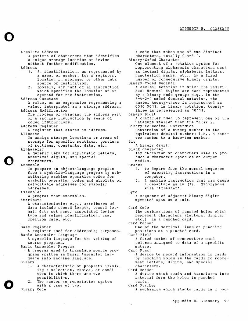
o
o
o
Absolute Address A pattern of characters that identifies a unique storage location or device without further modification.
Address 1. An identification, as represented by
a name, or number, for a register, location in storage, or other data source or destination.
2. Loosely, any part of an instruction which speci~ies the location of an operand for the instruction.
Address Constant A value, or an expression representing a value, interpreted as a storage address.
Address Modification The process of ~hanging the address part of a machine instruction by means of coded instructions.
Address Register A register that stores an address.
Alloca te To assign storage locations or areas of storage for specific routines, portions of routines, constants, data, etc.
Alphameric A generic term for alphabetic letters, numerical digits, and special characters.
Assemble To prepare an ohject-language program from a symbolic-language program by substituting machine operation codes for symbolic operation codes and absolute or relocatable addresses for symbolic addresses.
Assembler A program that assembles.
Attribute A characteristic; e.g., attributes of data include record length, record format, data set name, associated device type and volume identification, use, creation date, ~tc.
Base Register A register used for addressing purposes.
Basic Assembler Language A symbolic language for the writing of source programs.
Basic Assembler Program A program used to translate source programs written in Basic Assembler language into machine language.
Binary 1.
2.
Hinary
A characteristic or property involving a selection, choice, or condition in which there are two possibilitips. The number representation system with a base of two. Code
A code that makes use of two distinct characters, usually 0 and 1.
Binary-Coded Character One element of a notation system for representing alphameric characters such as decimal digits, alphabetic letters, punctuation marks, etc., by a fixed number of consecutive binary digits.
Binary-Coded Decimal A decimal notation in which the individual decimal digits are each represented by a binary code group; e.g., in the 8-4-2-1 c~ded decimal notation, the number twenty-three is represented as 0010 0011, in binary notation, twentythree is represented as 10111.
Binary Digit A character usp.d to represent one of the integers smaller than the ra6ix 2.
Binary-to-Decimal Conversion
Bit
Conversion of a binary number to the eguivalellt decimal number; i.e., a basetwo numbeI." t~ a base-ten number.
A binary digit. Blank Character
Any characteI." or characters used to produce a character space on an output medium.
Branch 1.
2.
Byte
To depart from the normal sequence of executing instructions in a computer. A machine instruction that can cause a departure as in (1). Synonymous with' transfer'.
A sequence of adjacent binary digits ope rat e d up 0 n as a u nit.
Card Code The combinations of punched holes which represent characters (letters, di<)its, etc.) in a punched card.
Card Column One of the vertical lines of punching positions on a punched card.
Card Field A fixed number of consecutive card columns assigned to data of a specific nature.
Card Punch A device to record information in caI."ds by punching holes in the cards to represent letters, digits, and special characters.
Card Reader-A device which reads and translates into internal form the holes in punched cards.
Cal-d stacker A mechanism which stacks cards in d poc-
Appendix II. Glossary g()
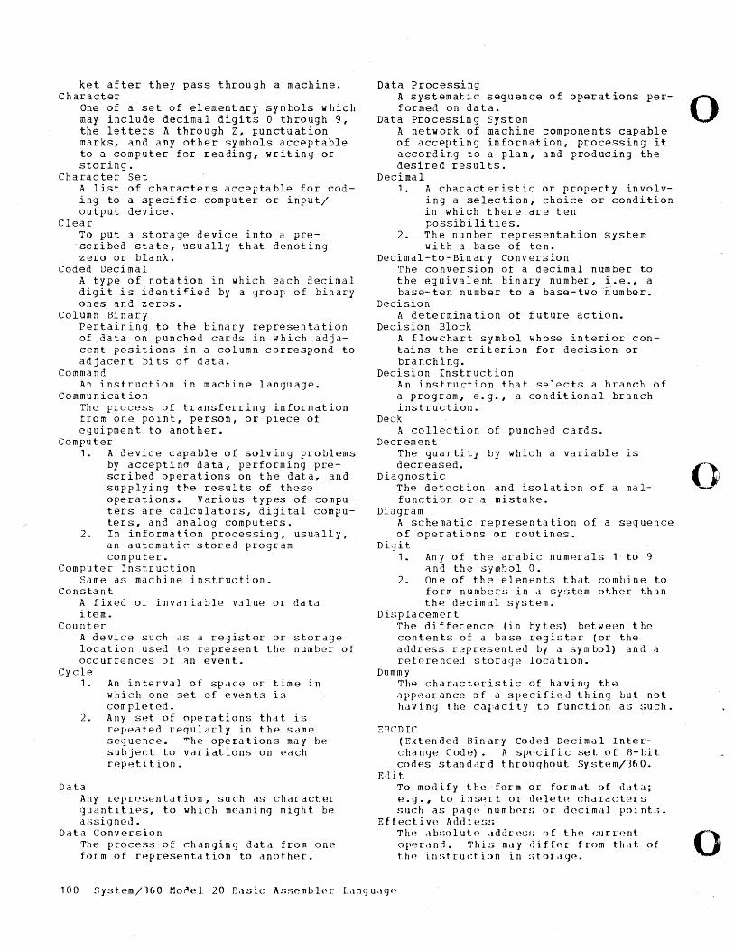
ket after they pass through a machine. Character
One of a set of elementary symbols which may include decimal digits 0 through 9, the letters A through Z, punctuation marks, and any other symbols acceptable to a computer for reading, writing or storing.
Character Set A list of characters acceptable for coding to a specific computer or input/ output device.
Clear T~ put a storage device into a prescribed state, usually that denoting zero or blank.
Coded Decimal A type of notation in which each. decimal digit is identi~ied by a group of binary ones and zeros.
Col umn 8i na ry Pertaining to the binary representation of data on punched cards in which adjacent positions in a column correspond to adjacent bits of data.
Command An instruction in machine language.
Communication The process of transferring information from one point, person, or piece of equipment to another.
Computer 1. A device capable of solving problems
by acceptino data, performing prescribed operations on the data, and supplying the results of these operations. Various types of computers are calculators, digital computers, and analog computers.
2. In information processing, usually, an automatic stored-program computer.
Computer Instruction Same as machine instruction.
Constant A fixed or invariable value or data item •
Counter A device such clS a re'jister or location used tn represent the occurrences of an event.
storage number of
Cycle 1.
2.
Data
An interval of space or time in which one set of events is completed. Any set of operations that is repeated reqularly in the Sdme sequence. ~he operations may be subject to variations on each repetition.
Any repre~>ent<.ltion, such clS chdract{~r quantities, to which meaning might be assigned..
Data Conversion The process of changing datcl from one form of representation to dnother.
Data Processing A systematic sequence of operat ions per- 0 formed on data.
Data Processing System A network of machine components capable of accepting information, processing it according to a plan, and producing the desired results.
Decimal 1. A characteristic or property involv
ing a selection, choice or condition in which there are ten possibili ties.
2. The number representation system with a base of ten.
Decimal-to-Binary Conversion The conversion of a decimal number to the equivalent binary number, i.e., a base-ten number to a base-two~umber.
Decision A determination of future action.
Decision Block A flowchart symbol whose interior contains the criterion for decision or branching.
Decision Instruction An instruction that selects a branch of a program, e.g., a conditional branch instruction.
Deck A collection of punched cards.
Decrement The quantity by which a variable is decreased. ()
Diagnostic The detection and isolation of a mal- --function or a mistake.
Diagram A schematic representation of a sequence of operations or routines.
D it] it 1. Any of the arabic numerals 1 to 9
~nd the symbol O. 2 • 0 n e 0 f the e 1 em en t s t hat co m bin e to
form numbers in d system other than the decimal system.
Displacement The difference (in bytes) betwe(~n the contents of a base register (or the add res s rep res e n ted by a s y m bo 1 ) and a referenced storage location.
Dumm y The characteristic of having the appearance of d specified thing but not hLiving the caracity to function as such.
EBCDIC (Extended Binary Coded Decimal Interchanc]e Code). A sp<'cific set of B-bit codes standdrd throughout System/360.
Edit Tom 0 <1 i f Y the f () r m 0 I' form d t () f (1. 1 t a ; e . 9 ., t () i n s(~ r tor del e t P C h d r' d etc r' s sllch as pa(J(~ numhpl:S or decim.ll poi nt:;.
Eftective Addu~!.;!;
Thp ab!;olutf~ <lddr(~!;!; of t.hp ClJrrpnt 0 op(-~rcln(L Thi!i mtly (liffor· fn>m thdt of thp in!;tructic)n in !.tor.l(jP.
100 System/J60 Mo~el 20 I3.1sic A!;semblpr: Lln(Jucl<J(~

o
o
o
Error A general term +:0 indicate that a data value is not correct or that a machine component is malfunctioning.
ESD card ESD cards contain all information required for the linking of program segments (such as all symbols defined in one segment but referred to in another segmen t) •
Execute To carry out an instruction or perform a routine.
Explicit Addressing Specification of an address by a base register and a ~isplacement in the form D (8) •
File A collection of related records treated as a unit, e.g., in inventory control, one line of an invoice forms an item, a complete invoice forms a record, and the complete set of such records forms a file.
Flowchart A graphical representation for the definition, analysis, or solution of a problem in which symbols are used to represent operations, data, flow, and equ ipmen t.
Hexadecimal Number System A number system using the e~uivalent of the decimal number sixteen as a base.
Hopper A device that holds cards and makes them available to a card feed mechanism. Contrast with card stacker.
Identification A code number or code name which uniquely identifies a record, block, file or other unit of information.
Image An exact logical du~licate stored in a different medium.
Immediate Address The designation of an instruction address which is used as data by the instruction of which it is a part.
Implied Address The address assigned to a symbol by the Basic Assembler program.
Index Register A register whosp content is added to or subtracted from the operand address prior to or during the execution of an instruction.
Indexing A technique of address modification often implemented by mean~ of index registers.
Initialize To set certain counters, ~;witche!"; and addresses at sppcified times in a computer routine.
Input
1. The data to be processed. 2. The state or sequence of states
occurring on a specified input channel.
3. The device or collective set of devices used for bringing data into another device.
4. A channel for imFressing a state on a device or logic element.
InFut Area The area ~f internal storage into which data is transferred from external storage.
Input/Output 1. Common a tbreviation I/O. A general
term for the equipment used to communicate with a computer.
2. The data involved in such communication.
3. The media carrying the data for input/output.
Instruction A statement that specifies an operation and the values or locations of all operands. In this context, the term instruction is preferable to the terms command or order which are sometimes used as synonyms. Command should be reserved for electronic signals. Order should be reserved for sequence, interpolation and related usage.
Instruction Format The allocation of bits or characters of a machine instruction to specific functions.
Interrupt 1. A break in the normal flow of a sys
tem or routine such that the flow can be resumed from that point at a later time.
2. To cause an interrupt.
Language 1. A defined set of characters which
are used to form symbols, words, etc., and the rules for combining these into meaningful communication, e.g., Enylish, French, Algol, FORTRAN, COBOL, etc.
2. A combination of a vocabulary and I' u I es 0 f s y n t a x •
Linkage The interconnections between a main routine and a closed routine, i.(~., entry and exit for d closed routine from the main routine.
LO,ld To place data into internal storage.
Loca tion A position in stora(je that is uSlldlly identified by an ild(lres~;.
Loop A sequ(->.nce of in!;tructi()n~; th,lt i!. [' e p edt p dun til d t (~r- min 11 1 con (1i t i () n occllrs.
M d chi n (~ Add r e ~-' :-; ~)dm(! d~; <lb~;ol ut(l ddd[-(~!;~;.
Apppndix II. (;los:;.Jr-y 101
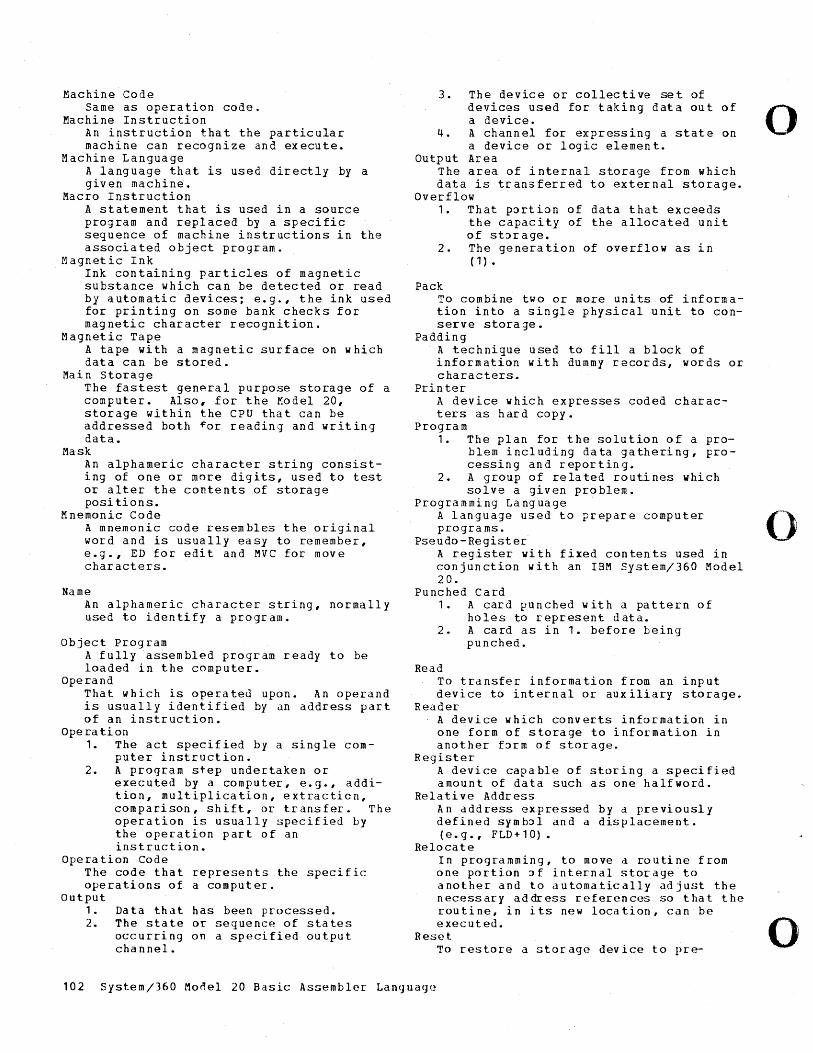
Machine Code Same as operation code.
Machine Instruction An instruction that the particular machine can recognize and execute.
Machine Language A language that is used directly by a given machine.
Macro Instruction A statement that is used in a source program and replaced by a specific sequence of machine instructions in the associated object program.
Magnetic Ink Ink containing particles of magnetic substance which can be detected or read by automatic devices; e.g., the ink used for printing on some bank checks for magnetic character recognition.
Magnetic Tape A tape with a magnetic surface on which data can be stored.
Mai n Storage The fastest general purpose storage of a computer. Also, for the Model 20, storage within the CPU that can be addressed both ~or reading and writing data.
Mask An alphameric character string consisting of one or more digits, used to test or alter the contents of storage posi tions.
Mnemonic Code A mnemonic code resembles the original word and is usually easy to remember, e.g., ED for edit and MVC for move characters.
Name An alphameric character string, normally used to identify a program.
Object Program A fully assembled program ready to be loaded in the computer.
Operand That which is operateu upon. An operand is usually identified by an address part of an instruction.
Opera tion 1. The act specified by a single com
puter instruction. 2. A program step undeLtaken or
executed by a computer, e.g., addition, multiplication, extLacticn, comparison, shift, or transfer. The operation is usually specified by the operation part of an instruction.
Ope ra tion Code The code that represents the specific operations of a computer.
Output 1. 2.
Data that has been processed. The state or sequence of states occurring on a specified output channel.
3. The device or collective set of devices used for taking data out of a device.
4. A channel for expressing a state on a device or logic element.
Output Area The area of internal storage from which data is tLansferred to external storage.
Overflow 1. That portion of data that exceeds
the capacity of the allocated unit of st::>rage.
2. The generation of overflow as in ( 1) •
Pack To combine two or more units of information into a single physical unit to conserve stora ge •
Padding A technique used to fill a block of information with dummy records, words or characters.
Printer A device which expresses coded characters as hard copy.
Program 1. The plan for the solution of a pro
blem including data gathering, processing and reporting.
2. A group of related routines which solve a given problem.
Programming Language A language used to prepare computer programs.
Pseudo-Register A register with fixed contents used in conjunction with an IBM System/360 Model 20.
Punched Card 1 • A car d pun c h e d wit h a pa t t ern 0 f
holes to represent data. 2. A card as in 1. before being
punched.
Read To transfer information from an input device to internal or auxiliary storage.
Reader A device which converts information in one form of storage to information in another f::>rm of storage.
Register A device capable of storing a specified amount of data such as one halfword.
Rela ti ve AddL ess An address expressed by a previously defined symh::>l and a displacement. ( e • g ., F LD + 1 0) •
Relocate In programming, to move d routine fLom one portion ::>f internal storage to another and to automatically adjust the necessary address refer(!nces so that the routine, in its new location, can be executed.
Reset To restore a stoLage device to pre-
102 System/360 Mo~el 20 Basic Assembler Language
o
o
o
o
o
o
scribed initial state, not necessarily that denoting zeros.
Restart To return to a previous point in a program and resume operation from that point.
RLD card RLD cards identify portions of the text that require m00ification owing to relocation (such as address constants).
Self-Defining Term A term with an implied value (e.g., 300, X' 2A' , C' F ' )
Source Lang uage A language that is an input to a given translation process.
Source Program A program written in a source language.
Special Character In a character set, a character that is neither a numeral nor a letter, e.g., -* $ = and blank.
Statement In computer programming, a meaningful expression or g~neralized instruction in a source language.
Step 1. One instruction in a computer
routine. 2. To cause d computer to execute one
instruction. storage
1. Pertaining to a device into which data can be entered and from which it can be retrieved at a later time.
2. Loosely, any device that can store data.
storage Capacity The amount of data (in bytes) that can be contained in a storage device.
Store 1. To enter data into a storage device. 2. To retain data in a storage device.
Subroutine A routine that can be part of another routine.
Switch
1. A symbol used to indicate a branching point, or a set of instructions to condition a branch.
2. A physical device which can alter flow.
Symbol Table A mapping for a set of symbols to another set of symbols or numbers.
Sym boli c A ddr ess An address expressed in symbols convenient to the programmer.
Symbolic Language An artificial language used in logical expressions, that avoids all ambiguities and inadequacies of natural languages.
System 1. A collection of consecutive opera
tions and procedures required to accomplish a specific objective.
2. An assembly of objects united to form a functional unit.
Table A collection of data, each item being uniquely identified either by some label or by its relative position.
Table Look-Up A procedure for obtaining the function value corresponding to an argument from a table of function values.
Truncate To cut off at a specified spot (as contrasted with round or pad).
TXT card TXT cards contain the user program in machine language.
Unpack To recover the original data from packed data.
Zero Suppression The elimination of non-significant zeros in a number.
Zone The 12, 11, or 0 punches in IBM card code.
Appendix II. Glossary 101
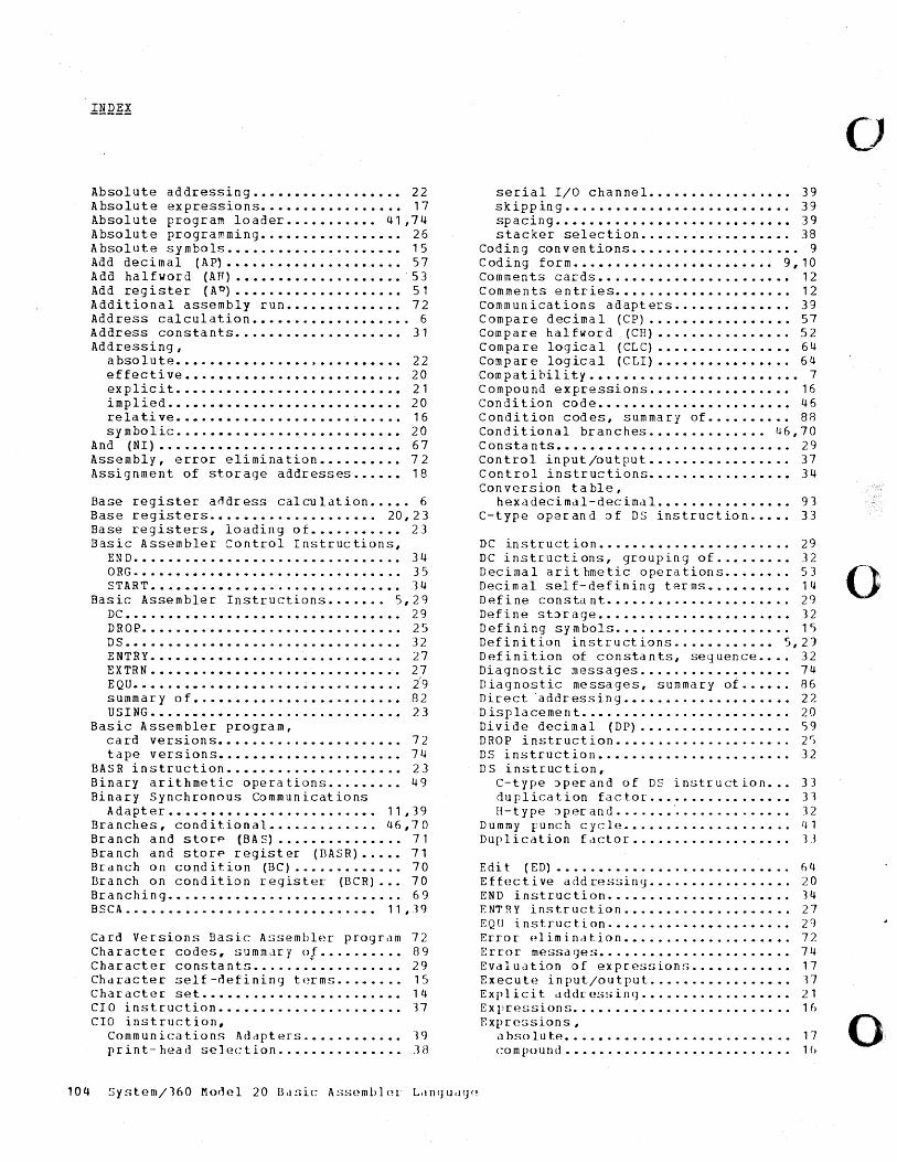
Absol u te ad dressin g • • • • • • • • • • • • • • • • •• 22 Absolute expressions................. 17 Absolute program loader ••••••••••• 41,74 Absolute programming ••••••••••••••••• 26 Absolute symbols ••••••••••••••••••••• 15 Add decimal (AP) ••••••••••••••••••••• 57 Add halfword (AR) •••••••••••••••••••• 53 Add register (A1) •••••••••••••••••••• 51 Additional assembly run •••••••••••••• 72 Address calculation ••••••••••••••••••• 6 Address constants.................... 31 Addressing,
absolute ••••••••••••••••••••••••••• 22 effective •••••••••••••••••••••••••• 20 explicit ••••••••••••••••••••••••••• 21 implied •••••••••••••••••••••••••••• 20 relative ••••••••••••••••••••• · •••••• 16 symbolic ••••••••••••••••••••••••••• 20
And (NI) ••••••••••••••••••••••••••••• 67 Assembly, error elimination •••••••••• 72 Assignment of storage addr.-esses •••••• 18
Base register.- aodr.-ess calculation ••••• 6 Base register.-s •••••••••••••••••••• 20,23 Base r.-egister.-s, loading of ••••••••••• 23 Basic Assembler Contr.-ol Instr.-uctions,
END •••••••••••••••••••••••••••••••• 34 ORG •••••••••••••••••••••••••••••••• 35 START •••••••••••••••••••••••••••••• 34
Basic Assembler.- Instr.-uctions ••••••• 5,29 DC. • • • • • • • • • • • • • • • • • • • • • • • • • • • • • • •• 29 DROP ••••••••••••••••••••••••••••••• 25 D S • • • • • • • • • • • • • • • • • • • • • • • • • • • • • • • •• 32 ENTRy •••••••••••••••••••••••••••••• 27 EXTRN •••••••••••••••••••••••••••••.• 27 EQU •••••••••••••••••••••••••••••••• 2'9 summar.-y of ••••••••••••••••••••••••• 82 USING •••••••••••••••••••••••••••••• 23
Basic Assembler progr.-am, car.-d ver.-sions ••••••••.••••••••••••• 72 tape versions •••••••••••••••••••••• 74
BASR instr.-uction ••••••••••••••••••••• 23 Binar.-y arithmetic oper.-ations •••••••.• 49 Binary Synchronous Communications
Adapter ••••••••••••••••••••••••• 11,39 Branches, conditional •••.••••.•.•• 46,70 Branch and storp (BAS) ••••••••••••••• 71 Branch and stor.-p register (BASR) ••••• 71 Br.-anch on condition (BC) ••••••••••••• 70 Branch on condition r.-egister (BCR) .•• 70 Branching •••••••••••••••••••••••••••• 69 BSCA ••••••••••••••••••.••••••••••• 11,39
Card Ver.-sions Basic Assembler.- program 72 Character.- codes, summdr.-y ot .......... 89 Character constants •••..•••.••••••••• 29 Chdracter self-Clefininq b~rms •••••••• 15 Char.-acter set •••••••••••••••••••••••• 14 CIa instr.-uction ••••••••••.•••.••••••• 17 CIa instruction,
Communications Addpters .•••.••••••• 19 print-head sel(~Gtion ••••••••••••••• .1H
1 0 4 S Y s t e m / 160M 0 del 2 0 B <l ~. i cAs s e m bIn r L, lI}(J II d (J (>
serial I/O channeL •••••••••••••••• 39 skipping ••••••••••••••••••••••••••• 39 spacing •••••••••••••••••••••••••••• 39 stacker selection •••••••••••••••••• 38
Coding conventions •••••••••••••••••••• 9 Coding form •••••••••••••••••••••••• 9,10 Comments cards ••••••••••••••••••••••• 12 Comments entries ••••••••••••••••••••• 12 Communications adapters •••••••••••••• 39 Com par e d ec i mal ( C P) • • • • • • • • • • • • • • • •• 5 7 Compare halfword (CH) •••••••••••••••• 52 Compare logical (CLC) •••••••••••••••• 64 Compare logical (CLI) •••••••••••••••• 64 Compatibility ••••••••••••••••••••••••• 7 Compound expressions ••••••••••••••••• 16 Condition code ••••••••••••••••••••••• 46 Condition codes, summar.-y of •••••••••• 88 Condi tional branches •••• ~ • • • • • • • •• 46, 70 Constants •••••••••••••••••••••••••••• 29 Control input/output ••••••••••••••••• 37 Control instructions ••••••••••••••••• 34 Conversion table,
hexadecimal-decimal •••••••••••••••• 93 C-type oper.-and of DS instr.-uction ••••• 33
DC instr.-uction ••••••••••••••••••••••• 29 DC instructions, gr.-ouping of ••••••••• 32 Decimal arithmetic oper.-ations •• ~ ••••• 53 Decimal self-defining terms •••••••••• 14 Define constant ••••••••.••••••••••••. 29 Define stor.-age ••••••••••••••••••••••• 32 Defining symbols ••••••••••••••••••••• 1') Definition instructions •••••••••••• 5,2) Definition of constants, sequence •••• 32 Diagnostic messages •••••••••••••••••• 74 Diagnostic messages, summary of •••••• 86 Directaddr.-essing •••••••••••••••••••• 22 Displacement ••••••••••••••••••••••••• 20 Divide decimal (DP) •••••••••••••••••• ')9
DROP instr.-uction •••••••.••••••••..••• 2S DS instruction ••••••••••••••••••••••• 32 DS instruction,
C-type operand of DS instruction ••• 33 duplication factor- •••••••••.••••••• 31 II-type :>perand •••••••...•••.••.••••• 32
Dummy punch cycle •••••••••.•••••••••• 41 Duplication fdctor •.••••.•••••••••••• 13
Edit (ED) ••••••••••••••.••••••••••••. 64 Effective addn~ssinq ••••••••••••••••. 20 END instruction •••••••••••••••••••••• 14 ENTRY instruction ••.••••••••••••••••• 27 EQlJ instruction .••••••••.•••••••••••• 29 Error elimination ••••••••••••.••••••• 72 Error messages ••••••••••••••••••••••• 74 EVdluation of expressions •.••.••••••• 17 Execut~~ input/outpul. •••••••••••••••• 17 Explicit dddressing .•••.•••••.••••••• 21 EXI'rf~!.;si()ns ••••••••••••••.••••••••••• 16 Expre!.isions,
ahsolute •••••••••••••••••••••.••••• 17 compound •••••.••••••••.••••••••.••• 1b
o
o
o
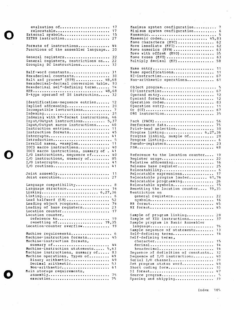
o
o
o
evaluation of •••••••••••••••••••••• 17 relocatable •••••••••••••••••••••••• 17
External sy mbols.. • ••• • • • • • • •• • • •• • •• 15 EXTRN instruction •••••••••••••••••••• 27
Formats of instructions •••••••••••••• 44 Functions of the assembler language •• 20
General registers •••••••••••••••••••• 22 General registers, restrictions on ••• 22 GroupinJ DC instructions ••••••••••••• 32
Half-word constants •••••••••••••••••• 31 Hexadecimal constants •••••••••••••••• 30 Hal t and proceen (HPR) •••••••••••• 48,68 Hexadecimal-decimal conversion table. 93 Hexadecimal sel~-defining terms •••••• 14 HPR ••••••••••••••••••••••••••••••• 48,68 H-type operand of DS instruction ••••• 32
Identification-sequence entries •••••• 12 Implied addressing ••••••••••••••••••• 20 Incompatible instructions ••••••••••••• 7 Indexing ••••••••••••••••••••••••••••• 21 Indexing with RY-format instructions. 46 Input/Output instructions •••••••••• 5,37 Input/Output macro instructions •••••• 40 Instruction entries •••••••••••••••••• 11 Instruction formats •••••••••••••••••• 45 Interrupts ••••••••••••••••••••••••••• 41 Introduction •••••••••••••••••••••••••• 5 Invalid names, pxamples.............. 11 laCS macro instructions •••••••••••••• 40 laCS macro instructions, summary of • 41 I/O instructions, sequence of •••••••• 40 I/O instructions, summary of ••••••••• 85 I/O interrupts ••••••••••••••••••••••• 41 I/O routines ••••••••••••••••••••••••• 41
Joint assembly ••••••••••••••••••••••• 11 Joint execution •••••••••••••••••••••• 27
Language compatibility •••••••••••••••• 8 Language structure ••••••••••••••••••• 14 Linking ••••••••••••••••••••••••• 6,27,36 Listing ••••••••••••••••••••••••••••••• 6 Load halfword (LH) ••••••••••••••••••• 52 Loading object programs •••••••••••••• 74 Loading of base registers •••••••••••• 23 Location counter ••••••••••••••••••••• 17 Location counter,
reference to •••••••••••••.•.••••••• 19 resetting of •••••••••••••••••••• 19,35
Location-counter overflow •••••••••••• 19
Ma chi n ere qui rem e n t s. • • • • • • • • • • • • • • • •• 6 Machine-instruction formats ••.••••••• 45 Machine-instruction formats,
summary of ••••••••••••••••••••••••• 44 Machine-instruction statements ••••• 5,43 Machine instructions, summary of ••••• 83 Machine operations, Types of ••••••••• 49
Bin a r y a r it h mf> tic. • • • • • • • • • • • • • • • •• 49 Decimal arithmetic ••••••••••••••••• 53 Non-arithmetic ••••••••••••••••••••• 61
Main storage requirements, assembly ••••••••••••••••••••••••••• 75 execution •••••••••••••••••••••••••• 75
Maximum system configuration •••••••••• 7 Minimum system configuration •••••••••• 6 Mnemonic •••••••••••••••••••••••••••.•• 5 Mnemonic cod.es •••••••••••••••••••• 45,83 Move characters (MVC) •••••••••••••••• 62 Move immediate (MVI) ••••••••••••••••• 62 Move numerics (MVN) •••••••••••••••••• 63 Move with offset (MVO) ••••••••••••••• 55 Move zones (MVZ) ••••••••••••••••••••• 63 Multiply decimal (MP) •••••••••••••••• 58
Name entry........................... 11 Name specifications •••••••••••••••••• 11 NI-instruction ••••••••••••••••••••••• 67 Non-arithmetic operations •••••••••••• 61
Object program ••••••••••.••.••••.••••• 5 aI-instruction ••••••••••••••••••••••• 67 Operand entry •••••••••••••••••••••••• 12 Ope ran d for ma t s. . . . . . . . . . . . . . . . . . . • .. 1 2 Ope rat ion cod es. • • • • • • • • • • • • • • • • • • • •• 8 3 Operation entry •••••••••••••••••••••• 11 Or (01) •••••••••••••••••••••••••••••• 67 ORG instruction •••••••••••••••••••••• 35
Pack (PACK) •••••••••••••••••••••••••• 56 Performance data ••••••••••••••••••••• 75 Print-head selection ••••••••••••••••• 38 Program linking ••••••••••••••••• 6,27,36 Program linking, sample of ••••••••••• 28 Program listing ••••••••••••..••••••••••• 6 Pseudo-registers ••••••••••••••••••••• 23 PSW •••••••••••••••••••••••••••••••••• 48
Reference to the location counter •••• 19 Register usage ••••••••••••••••••••••• 22 R ela ti ve addressi ng. • • • • • • • • • • • • • • • •• 16 Release base register •••••••••••••••• 25 Relocatability •••••••••••••••••••••••• 6 Relocatable expressions •••••••••••••• 17 Relocatable program loader •••••••• 41,74 Relocatable programming •••••••••••••• 26 Relocatable symbols •••••••••••••••••• 15 Resetting the location counter •••• 19,35 Restriction on
general registers .••••••••••••••••• 22 symbols •••••••••••••••••••••••••••• 16
RR format •••••••••••••••••••••••••••• 45 RX format •••••••••••••••••••••••••••• 45
Sample of pr~gram linking •••••••••••• 28 Sample of XIO instructions ••••••••••• 37 Sample prJ gram in Basic Assembler
language •••••••••••••••••••••••••••• 76 Sample seluence of statements •••••••• 13 Self-defining terms •••••••••••••••••• 14 Self-defining terms,
character .•••••••••••••••••••.••••. 15 decimal •••••••••••••••••••••••••••• 14 hexadecimal ••••••• w •••••••••••••••• 14
Sequence Jf definition of constdnts •• 32 Sequence of I/O instructions ••••.•••• 40 S er i a 1 I/O c han n e 1. . . . • . . . . . . . . . . . . .. J ') Set program status wor-d .••••••••••••• 4B Short coding form •••••••••••••••••••• 10 51 format •••••••••••••••••••••••••••• 47 Source program •••••••••.••••••.•••.••• ~
5 pac i n 9 and 5 kip pin g • • • • • • • • • • • • • • • •. .3')
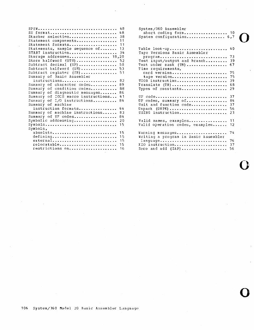
SPSW ••••••••••••••••••••••••••••••••• 48 SS format •••••••• ~ ••• ~ ••••••••••••••• 48 Stacker selection.................... 38 Statement components ••••••••••••••••• 11 Statement formats •••••••••••••••••••• 11 Statements, sample sequence of ••••••• 13 START instruction •••••••••••••••••••• 34 Storage addresses ••••••••••••••••• 18,20 Store halfword {STH) ••••••••••••••••• 52 Subtract decimal (SP) •••••••••••••••• 58 Subtract halfword (SH} ••••••••••••••• 53 Subtract registp.r (SR) ••••••••••••••• 51 Summary of Basic Assembler
instructions ••••••••••••••••••••••• 82 Summary of character codes ••••••••••• 89 Summary of condition codes ••••••••••• 88 Summary of diagnostic messages ••••••• 86 Summary of laCS macro instructions ••• 41 Summary of I/O instructions •••••••••• 84 Summary of machine
instruction forma ts •••••••••••••••• 44 Summary of machine instructions •••••• 83 Summary of UF codes •••••••••••••••••• 84 Symbolic addressing •••••••••••••••••• 20 Symbols •••••••••••••••••••••••••••••• 15 Symbols,
absolute ••••••••••••.•••••••••••••• 15 defining ••••••••••••••••••••••••••• 15 external •••••••••••••••..••••••.••• 15 relocatable •••••••••••••••••••••••• 15 restrictions on •••• ; .•••••••••••••• 16
106 System/360 Mooel 1.0 FLlSic A!;sembler Ldn(JUi1<J(~
System/360 Assembler short coding form •••••••••••••••••• 10 0
Sy stern config ura tion. • • • • • • • • •• • • ••• 6,7 ...
Table look -up. • • • • • • • • • • • • • • • • • • • • • •• 4 a Tape Versions Basic Assembler
program •••••••••••••••••••••••••••• 73 Test input/output and branch ••••••••• 39 Test under mask (TM) ••••••••••••••••• 67 Time requirements,
card version ••••••••••••••••••••••• 75 ta pe ver si on. • • • • • • • • • • • • • • • • • • • • •• 75
TIOB instru ct ion. • • • • • • • • • • • • •• • • •• •• 39 Translate (TR) ••••••••••••••••••••••• 68 Types of constants ••••••••••••••••••• 29
UF code •••••••••••••••••••••••••••••• 37 UF codes, summary of ••••••••••••••••• 84 Unit and function code ••••••••••••••• 37 Unpack (UNPK) •••••••••••••••••••••••• 56 USING instruction •••••••••••••••••••• 23
Valid names, examples •••••••••••••••• 11 Valid oper.-ation codes, examples •••••• 12
Warning messages ••••••••••••••••••••• 74 Writing a program in Basic Assembler language •••••••..••••••••••••••••••• 76
XIO instruction •••••••••••••••••••••• 37 Zero and add (ZAP) ••••••••••••••••••• 56
o
o

o
o
o
GC26-3602-6
International Business Machines Corporation Data Processing Division 112 East Post Road, White Plains, N.Y.IOSOI [USA Only]
IBM World Trade Corporation 821 United Nations Plaza, New York, New York 10017 [International]
o
OJ s: en W O"l 0
s: 0 Co !!? I\J 0
0 (") "0 en OJ III en (i.
» en en CD 3 ?" r III ::l 'P
en w O"l 0
~ 0 Co N 3 ~ ~
~ :j" .-+ CD Co
5·
c en » G) (") I\J C(> W O"l 0 I\J a,
0
o
o
o
IBM System/360 Model 20 Card Programming Support Basic Assembler Langu;:Ige
Order No. GC26-3602-6
READER'S COMMENT FORM
This sheet is for comments and suggestions about this manual. We would appreciate your views, favorable or unfavorable, in order to aid us in improving this publication. This form will be sent directly to the author's department. Please include your name and address if you wish a reply. Contact your IBM branch office for answers to technical questions about the system or when requesting additional publications. Thank you.
Name
Address
What is your occupation?
Your comments* and suggestions:
* We would especially appreciate your comments on any of the following topics:
Clarity of the text Organization of the text
Accuracy Cross-references
Index Tables
Illustrations Examples
How did you use this manual?
As a reference source
As a classroom text
As a self-study text
Appearance Printing
Paper Binding
GC26-3602 -6
YOUR COMMENTS, PLEASE ...
This manual is part of a library that serves as a reference source for systems analysts, programmers and operators of IBM systems. Your answers to the questions on the back of this form, together with your comments, will help us produce better publications for your use. Each reply will be carefully reviewed by the persons responsible for writing and publishing this material. All comments and suggestions become the property of IBM.
Please note: Requests for copies of publications and for assistance in utilizing your IBM system should be directed to your IBM representative or to the IBM sales office serving your locality.
Fold
n C -i
» r 0 Z C)
-i I en r Z n1
Fold
................................... -................................................................................... :
BUS I NESS REP L Y M A I L
NO POSTAGE STAMP NECESSARY IF MAILED IN THE UNITED STATES
Attention: Department 813 U
POSTAGE WILL BE PAID BY ...
IBM Corporation
112 East Post Road
White Plains, N.Y. 10601
FIRST CLASS
PERMIT NO. 1359
WHITE PLAINS. N. Y.
t •••••••••••••••••••••••••••••••••••••••••••••••••••••••••••••••••••••••••••••••••••••••••••••••••••••••••••••••••••••••
Fold
International Business Machines Corporation Data Processing Division 112 East Post Road, White Plains, N.Y. 10601 (USA Only)
IBM World Trade Corporation 821 United Nations Plaza, New York, New York 10017 (International)
Fold
0
OJ s:: C/)
W 0> 0
s:: 8. ~ I\.) 0 (")
0 "tI C/)
OJ III I/) c:;.
» I/) I/)
CD 3 ?" r III ::::s cp
en w 0> 0
~ 0 a. ~ 0
;G
~ ~.
CD a. 5· c en l>
C) (") I\.) 0> W 8 I\.)
en
0
o
o
o
IBM System/360 Model 20 Card Programming Support Basic Assembler Language
Order No. GC26-3602·6
READER'S COMMENT FORM
This sheet is for comments and suggestions about this manual. We would appreciate your views, favorable or unfavorable, in order to aid us in improving this publication. This form will be sent directly to the author's department. Please include your name and address if you wish a reply. Contact your IBM branch office for answers to technical questions about the system or when requesting additional publications. Thank you.
Name
Address
What is your occupation?
Your comments* and suggestions:
* We would especially appreciate your comments on any of the following topics:
Clarity of the text Organization of the text
Accuracy Cross-references
Index Tables
Illustrations Examples
How did you use this manual?
As a reference source
As a classroom text
As a self-study text
Appearance Printing
Pape~8 j BiD) ..
GC26-3602-6
YOUR COMMENTS, PLEASE ...
This manual is part of a library that serves as a reference source for systems analysts, programmers and operators of IBM systems. Your anSwers to the questions on the back of this form, together with your comments, will help us produce better publications for your use. Each reply will be carefully reviewed by the persons responsible for writing and publishing this material. All comments and suggestions become the property of IBM.
Please note: Requests for copies of publications and for assistance in utilizing your IBM system should be directed to your IBM representative or to the IBM sales office serving your locality.
Fold
n C -i
» r 0 Z C')
-i I en r Z m
Fold
. • • • • • • • • • • • • • • • • • • • • • • • • • • • • • • • • • • • • • • • • • • •• • • • • • • • • • • • • • • • • • • • .. • • • • • • • • • • • • • • • • • • • • • • • • • • • • • • • • • .. • • • • • • • • • • • • e.- •••••• :
BUSINESS REPLY MAIL
NO POSTAGE STAMP NECESSARY IF MAILED IN THE UNITED STATES
Attention: Department 813 U
POSTAGE WILL BE PAID BY ...
I BMCorporation
112 East Post Road
White Plains, N.Y. 10601
FIRST CLASS
PERMIT NO. 1359
WHITE PLAINS. N. Y.
........................................................................................................................
Fold
International Business Machines Corporation Data Processing Division 112 East Post Road, White Plains, N.Y. 10601 (USA Only)
:, "~ World Trade Corporation . '\. . !t'i'ited Nations Plaza, New York, New York 10017
· .. /
tIanalJ
Fold
to s: C/l W (j) o s: o Co ~
r-..> o
0
qo-" C/l I to til CJ)
('5'
o
•
Copyright © 2022 FDOKUMEN