Compact circuit-breaker NZM up to 1600 A Compact switch ...
234
1 NZM1-4 December 2011 www.eaton.com.cn/electrical 1 ATEX Model series NZM1 – NZM4 Only four compact switches cover all applications +++ 3- and 4-pole +++ Flexible mounting through modular functions groups +++ Complete nominal current up to 50 °C ambient temperature +++ Suitable for use worldwide Page 17/4 Door coupling rotary handles Very wide range of variants for each application +++ All applications have identical drilling template +++ Automatic centering +++ Shaft support for years of operational safety +++ Sidewall installation for space-saving main switch installation Page 17/118 Standard auxiliary contacts, trip-indicator auxiliary contacts from the Eaton command device program. Favorably priced identical parts from the Titan program reduce variety of types and stockkeeping +++ Installation from front to same position +++ Easy clip-in reduces assembling costs Page 17/106 Remote operators Unified functions concept for all variants +++ Small closing delays from 60 – 100 ms +++ Can be locked and sealed to provide safety Page 17/134 Diagnostics software NZM-XPC-SOFT Diagnostics in fault scenario +++ Error-free commissioning +++ Load analysis in operation Page 138 Safe energy control, switching and control in industrial settings, buildings and machinery construction: innovative protection concept coupled with diagnostic and communication functions make it possible. The NZM circuit-breaker assortment offers an interface for the SmartWire-Darwin communication system. Page 17/140 Compact circuit-breaker NZM up to 1600 A Compact switch-disconnectors N, PN up to 1600 A Eaton After Sales Service Testing switching devices in com- pliance with regulations applicable to this technology S22/2
-
Upload
khangminh22 -
Category
Documents
-
view
2 -
download
0
Transcript of Compact circuit-breaker NZM up to 1600 A Compact switch ...

1 NZM1-4 December 2011 www.eaton.com.cn/electrical
1
ATEX
Model series NZM1 – NZM4
Only four compact switches cover all applications +++ 3- and 4-pole +++ Flexible mounting through modular functions groups +++ Complete nominal current up to 50 °C ambient temperature +++ Suitable for use worldwide Page 17/4
Door coupling rotary handles
Very wide range of variants for each application +++ All applications have identical drilling template +++ Automatic centering +++ Shaft support for years of operational safety +++ Sidewall installation for space-saving main switch installation Page 17/118
Standard auxiliary contacts, trip-indicator auxiliary contacts from the Eaton command
device program.
Favorably priced identical parts from the Titan program reduce variety of types and stockkeeping +++ Installation from front to same position +++ Easy clip-in reduces assembling costs Page 17/106
Remote operators
Unified functions concept for all variants +++ Small closing delays from 60 – 100 ms +++ Can be locked and sealed to provide safety Page 17/134
Diagnostics software NZM-XPC-SOFT
Diagnostics in fault scenario +++ Error-free commissioning +++ Load analysis in operation Page 138
Safe energy control, switching and control in industrial settings, buildings and machinery
construction: innovative protection concept coupled with diagnostic and communication
functions make it possible.
The NZM circuit-breaker assortment offers an interface for the SmartWire-Darwin
communication system. Page 17/140
Compact circuit-breaker NZM up to 1600 A
Compact switch-disconnectors N, PN up to
1600 A
Eaton After Sales Service
Testing switching devices in com-pliance with regulations applicable to this technology S22/2

Compact circuit-breakers and switch-disconnectors up to 1600 AContents
2 NZM1-4 December 2011 www.eaton.com.cn/electrical
1 1.1 System overview
Circuit-breakers, switch-disconnectors 3/4 pole .................................................................................................
1.2 System overviewTechnical overview
Circuit-breakers, switch-disconnectors 3/4 pole .................................................................................................
1.3 System overviewOrdering
Circuit-breakers, thermomagnetic releases pole ..............................................................................................Circuit-breakers, magnetic short-circuit releases, 3 pole ..................................................................................Circuit-breakers, electronic releases, 3 pole .....................................................................................................Circuit-breakers, thermomagnetic releases, 4 pole ..........................................................................................Circuit-breakers, electronic releases, 4 pole .....................................................................................................Switch-disconnectors, 3 pole ...........................................................................................................................Switch-disconnectors, 4 pole ...........................................................................................................................Circuit-breakers for 1000 V AC, 3 pole .............................................................................................................Switch-disconnectors for 1000 V DC, 2 pole ....................................................................................................Switch-disconnectors in ATEX type ..................................................................................................................
1.4 System overviewTechnical overview
Circuit-breakers, switch-disconnectors for North America, 3/4 pole ................................................................
1.5 System overviewOrdering
Circuit-breakers UL/CSA, IEC, thermomagnetic releases, 3 pole .....................................................................Circuit-breakers UL/CSA, IEC, magnetic short-circuit releases, 3 pole .............................................................Circuit-breakers UL/CSA, IEC, electronic releases, 3 pole ................................................................................Circuit-breakers UL/CSA, IEC, thermomagnetic releases, 4 pole .....................................................................Molded case switches for North America ........................................................................................................
1.6 System overviewOrdering
Terminals ..........................................................................................................................................................Plug-in units, withdrawable units ....................................................................................................................Auxiliary contacts ............................................................................................................................................Undervoltage releases ....................................................................................................................................Shunt releases ................................................................................................................................................Door coupling rotary handles ..........................................................................................................................Door coupling rotary handles for North America ............................................................................................Rotary handles with door interlock .................................................................................................................Main switch assembly kit ...............................................................................................................................Accessories .................................................................................................................................................... Mechanical interlock .......................................................................................................................................Paralleling mechanism ....................................................................................................................................Multifunction component adapter ..................................................................................................................Remote drive ..................................................................................................................................................Earth-fault release ...........................................................................................................................................Earth-fault release, residual-current relay .......................................................................................................Diagnostics, energy metering, communication ..............................................................................................SmartWire-DT communication module ..........................................................................................................Insulated enclosures .......................................................................................................................................
4
6
83182228364244464950
52
5472647880
82105106108114118120123124127130131122134135137138140142

Compact circuit-breakers and switch-disconnectors up to 1600 AContents
NZM1-4 December 2011 www.eaton.com.cn/electrical 3
11.7 Engineering
Selectivity: incoming circuit-breaker, outgoing circuit-breaker ........................................................................Cable protection, back-up protection ..............................................................................................................Direction of blow-out, minimum clearances, tube cable lugs .........................................................................Auxiliary contacts, trip-indicating auxiliary contacts ........................................................................................Mechanical interlock for (door-coupling) rotary handles .................................................................................Mechanical interlock for remote operator, residual-current relay ...................................................................Remote operator, main switch assembly kit, terminals .................................................................................Tripping characteristic .....................................................................................................................................Let-through characteristics ..............................................................................................................................Residual-current release of the frequency response ......................................................................................
1.8 Technical data
Circuit-breakers, switch-disconnectors ...........................................................................................................Circuit breakers ...............................................................................................................................................Circuit-breakers, switch-disconnectors for 1000 V .........................................................................................Switch-disconnectors .....................................................................................................................................Moulded case switches ..................................................................................................................................Current limiting values, weights .....................................................................................................................Temperature dependency, thermomagnetic release .....................................................................................Temperature dependency, electronic release ................................................................................................Active power loss ...........................................................................................................................................Terminal capacities .........................................................................................................................................Switch-disconnectors for 1000 V, bridge kits: temperature dependency .......................................................Auxiliary contacts, equipping time differences ...............................................................................................Undervoltage release, shunt release, capacitor unit .......................................................................................Remote operator, residual-current relay .........................................................................................................Residual-current releases ...............................................................................................................................Data management interface (DMI module) ....................................................................................................Fieldbus connection ........................................................................................................................................SmartWire-DT communication module ..........................................................................................................Measuring and communication module .........................................................................................................
1.9 Dimensions
Construction size 1: basic devices ..................................................................................................................Construction size 1: accessories .....................................................................................................................Construction size 2: basic devices ..................................................................................................................Construction size 2: accessories ....................................................................................................................Construction size 3: basic devices .................................................................................................................Construction size 3: accessories ....................................................................................................................Construction size 4: basic devices .................................................................................................................Construction size 4: accessories ....................................................................................................................Measuring and communication module .........................................................................................................SmartWire-DT communication module ..........................................................................................................
144148149150151152153154158164
165166168169170171172173174176178179180181182183184186188
189190198199210211220221233233

4 NZM1-4 December 2011 www.eaton.com.cn/electrical
1.1 Circuit-breakers, switch-disconnectorsAuxiliary contacts, trip-indicating auxiliary contacts
1
System overview
10
78
9
22
38
21
15
33
34
5
6
4
36
19
23
24
25
26
20
11
13
14
17
18
16
27
12
1
35
3132
29
30
23
37
28
ATEX
NZM

NZM1-4 December 2011 www.eaton.com.cn/electrical 5
Circuit-breakers, switch-disconnectorsBasic devices 1.1
1
Basic devices
Rated uninterrupted current up to1600ASwitching capacity 25, 36, 50, 150kA at 415 VAdjustable releases for overloadand short-circuitAdjustable time selectivityProtection of systems, cables, motors, generators3 and 4 pole; IEC/EN 60947
Rated uninterrupted current upto 1600 ACan be tripped remotely withundervoltage or shunt release3 and 4 pole; IEC/EN 60947
Page 42
Rated uninterrupted current upto 1200 ASwitching capacity 25, 35,100 kA at 480 VAdjustable release foroverload and short-circuitAdjustable time selectivityProtection of systems, cables,motors, generators3 and 4 pole, UL 489/CSA 22.2no. 5.1, IEC/EN 60947
Page 54
Rated uninterrupted current upto 1200 ACan be tripped remotely withundervoltage or shunt release3 pole, UL489/CSA 22.2 no. 5.1
Page 80
Add-on functions
Switches with the maincontacts. Performs signalling andinterlock functions
Page 106
General trip indication '+',when tripped by voltagerelease, overload release orshort-circuit release
Page 106
For interlock andload-shedding circuits
Safety switches (maintenanceand manual override switches)approved for use in potentiallyexplosive areas in Zone 22.Degree of protection IP66
Delay unit for undervoltage 37releases
Rear-mounted drives 18
Door coupling rotary 20handles 22• Lockable• With door interlock
Main switch rotary handles 19 for side wall installation
Can be cut to required length
Lockable
For remote switching ofcircuit-breakers and switch-disconnectors
Residual-current protection 17device
Toggle lever locking device 27
Side operator handle 28
Mechanical interlocks 29
For reading status data,current values, switch modeland set values
For reading current, voltage,power and energyMODBUS interface on board
Connectable to modulesNZM…XMC-MBWith templates for viewingXMC readingsIndication of min. and max.values
Access to diagnostics andoperational dataAcquisition of current valuesMotor starter functionParameterization and controlof circuit-breakers withelectronic releases
PROFIBUS-DP interface 32
Mounting accessories
Connection width 9extensions
For two terminal locations attop or bottom
NZM3 Page 84
Standard with control circuitterminal
NZM2 Page 86
NZM4 Page 102
Standard equipment onconstruction size 1Flush mounting within theswitch housing
Protection against directcontact where cable lugs, barsor tunnel terminals are used
NZM1-XC35 for 35-mm-top-hat railNZM2-XC75 for 75-mm-top-hat rail
Busbar adapters 12
Rear connection terminals 13
Plug-in units and 10 withdrawable units
Page 105
Insulating surround 24For toggle levers, rotary mechanisms and remote operators
Page 129
External warning plate/ 25designation labels
Page 54
Spacers 14 Page 129
For box terminals
NZM2 Page 88
For covers
Page 8→
→
→
→
→
Page 106→ Page 140
Page 135
→ Page 129
→ Page 128
→ Page 130
→
Page 122
→ Page 134
→
Page 118
→
Page 125
→
Page 118
→
Page 127
→
Page 114→
→
→
Page 142→
Page 141→
Page 141→
Page 139→
Page 139→
NZM3 Page 92→
NZM4 Page 103→
NZM1 Page 84→
NZM2 Page 88→
→
NZM4 Page 104→
NZM1 Page 82→
→
NZM3 Page 194→
→
NZM1 Page 82→
NZM2 Page 86→
NZM3 Page 92→ NZM3 Page 98→
NZM2 Page 88→
NZM1 Page 84→
NZM3 Page 98→
→
NZM1 Page 84→
→
→
→
→
Terminal covers, 3knockout
NZM1 Page 84NZM2 Page 88NZM3 Page 98NZM4 Page 104→
→
→
→
NZM4 Page 102→
Page 132→
Page 129→
NZM3 Page 94→
NZM2 Page 86→
NZM1 Page 82→
NZM1 Page 84NZM2 Page 88NZM3 Page 98NZM4 Page 104→
→
→
→
→
ATEX
1
Switch-disconnectors 1
Circuit-breakers for 1North America
Molded case switches for 1North America
Standard auxiliary contacts 15(HIV)
Trip-indicating auxiliary 15contacts (HIA)
Early-make auxiliary 36contacts
Insulated enclosures 38
Extension shaft 21
Rotary handles 23
Remote operators 26
Communication module 33NZM for SmartWire-Darwin
Measuring and 16communication module
Display 30zz
Box terminals 7
Tunnel terminals for Al and 6copper cables
IP2X protection against 5contact with finger
IP2X protection against 2contact with finger
Clips 11
Terminal covers 4
Data management interface 31(DMI module)
Control cable terminals 8
Undervoltage releasesShunt releases
Page 108→
Voltage releases 15

6 NZM1-4 December 2011 www.eaton.com.cn/electrical
1.2 Circuit-breakers, switch-disconnectorsAuxiliary contacts, trip-indicating auxiliary contacts
1NZM1, NZM2, NZM3, NZM4
Circuit-breakersWith main switch characteristicsto IEC/EN 60204 andIsolator characteristics toIEC/EN 60947, VDE 0660
Rated uninterrupted currentIu=Rated current In
Adjustable overload releases Ir
Adjustable short-circuit releases Ii
Delayed short-circuit releases Isd
Thermomagnetic releases System cable protection
Ambient temperature at 100% Iu
min./max. -25/+50 °C
8 – 14xIn
8 – 14xIn
8 – 14xIn
8 – 14xIn
8 – 14xIn
8 – 14xIn
8 – 14xIn
Notes The stated switching capacity values are rated ultimate short-circuit breaking capacities (Icu)
Switch-disconnectors With main switch characteristics to IEC/EN 60204 and VDE 0113 Isolating characteristics to IEC/EN 60947, VDE 0660 without overload and short-circuit release
Rated uninterrupted current Iu=
Motor protection
0.8 - 1xIn
0.8 - 1xIn
0.8 - 1xIn0.8 - 1xIn
0.8 - 1xIn
0.8 - 1xIn
0.8 - 1xIn
0.8 - 1xIn
0.8 - 1xIn
0.8 - 1xIn
0.8 - 1xIn
0.8 - 1xIn
0.8 - 1xIn
0.8 - 1xIn
0.8 - 1xIn
0.8 - 1xIn
0.8 - 1xIn
0.8 - 1xIn
0.8 -1xIn
0.8 -1xIn
0.8 -1xIn0.8 -1xIn
0.8 -1xIn
0.8 -1xIn
0.8 -1xIn
0.8 -1xIn
0.8 -1xIn
0.8 -1xIn
0.8 -1xIn
0.8 -1xIn
0.8 -1xIn
0.8 -1xIn
0.8 -1xIn
0.8 -1xIn
0.8 -1xIn
0.8 -1xIn
6 - 10xIn
6 - 10xIn
6 - 10xIn
6 - 10xIn
6 - 10xIn
6 - 10xIn
6 - 10xIn
6 - 10xIn
6 - 10xIn
6 - 10xIn
6 - 10xIn
6 - 10xIn
6 - 10xIn
8 - 10xIn 8 - 14xIn
8 - 14xIn
8 - 14xIn
8 - 14xIn
Basic switching capacity
Comfort switching capacity
Normal switching capacity
High switching capacity
Rated short-time withstand current Icw(1s-1s-currentrms) Rated short-circuit making capacity Icm Type N can be triggered with U/A shunt release
350350350
350350
NZM1:8xIn
NZMB1-A... NZMB2-A... NZMB2-M... NZMB2-M...
NZMB2-M... NZMB2-M...
NZMH2-M...
NZMC1-A... NZMC2-A... NZMC3-A...
NZMN1-A... NZMN2-A... NZMN3-A...
NZMH1-A... NZMH2-A... NZMH3-A...
63 - 160 160 - 250 400 - 630 630 - 1600
Iu
AIu
AIo
AIr
AIi
AIu
AIu
AIr
AIi
A
20253240506380100100100100
100100100
100100100
20253240506380100
20253240506380100
20253240506380100
20253240506380100
125160200250
125160200250
125160200250320400500
320400500
320400500
10 - 14xIn
NZM1:8 – 12.5xIn
NZM2:8 – 14xIn
125160200
400/415V
400/415V
440V
440V525V690V
400/415V440V525V690V
400/415V440V525V690V
kA/p.fkA/p.f
kA/p.fkA/p.fkA/p.fkA/p.f
kA/p.fkA/p.fkA/p.fkA/p.f
kA/p.fkA/p.fkA/p.fkA/p.f
2525
3630128
50352010
100352010
0.250.25
0.250.250.50.5
0.250.250.300.50
0.200.250.300.50
2525
3630128
50352010
1501305020
0.250.25
2525
0.250.25
2525
0.250.25
0.250.250.50.5
0.250.250.250.30
50352010
0.250.250.300.50
50352010
0.250.250.250.30
0.200.200.250.30
1501305020
0.200.200.250.30
3630128
50352010
1501306535
0.250.250.50.5
0.250.250.250.30
0.200.200.200.25
kAkA
PN1-... PN1-...2.82
2.82
PN1-... PN1-...2.82
2.82
PN1-... PN1-...2.82
2.82
PN1-... PN1-...2.82
2.82
Rated current In

NZM1-4 December 2011 www.eaton.com.cn/electrical 7
Circuit-breakers, switch-disconnectorsMechanical interlock for (door-coupling) rotary handles 1.2
1
Iu
A
Iu
AIo
AIr
A
Ii
A
Iu
AIu
A
Ir
AIi
A
NZMN2-...E... NZMN3-...E... NZMN4-...E...
NZMH2-...E... NZMH3-...E... NZMH4-...E... NZMH2-ME... NZMH3-ME... NZMH4-ME...
NZMN2-ME... NZMN3-ME... NZMN4-ME...
Motor protection
0.5 - 1 x In 0.5 - 1 x In 2 - 14 x Ir2 - 12 x In2 - 10 x Ir
2 - 8 x Ir2 - 6 x Ir
50352520
1501305020
0.250.250.250.30
0.200.200.250.30
50352520
1501306535
0.250.250.250.30
0.200.200.200.30
50352520
851)
856550
0.250.250.250.30
0.200.200.200.25
50352520
1501305020
0.250.250.250.30
0.200.200.250.30
50352520
1501306535
0.250.250.250.30
0.200.200.200.30
50352520
851)
856550
0.250.250.250.30
0.200.200.200.25
Electronic releasesSystems,cable, selectivity and generator protection
100160250
250400630 630
800100012501600
901402203504505508751400
A selection of approved circuit-breakers and switch-disconnectors for world-wide use→Page 17/54 1)For higher switching capacity please inquire

8 NZM1-4 December 2011 www.eaton.com.cn/electrical
1.3 Circuit-breakers, switch-disconnectorsAuxiliary contacts, trip-indicating auxiliary contacts
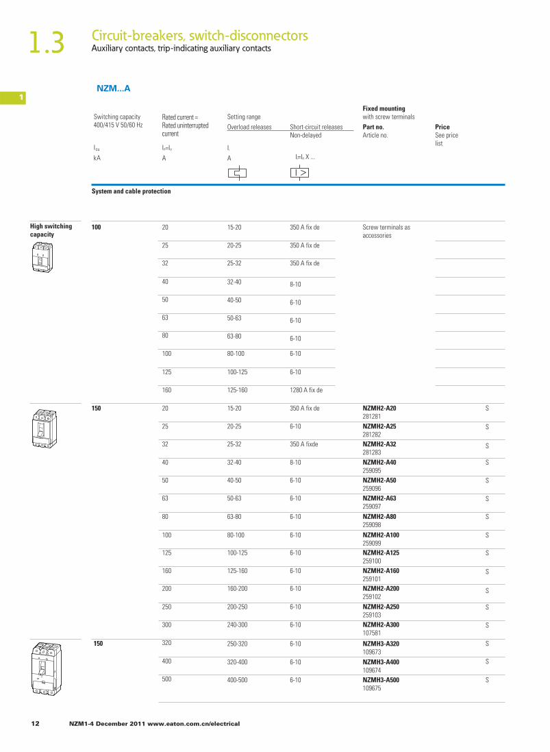
1NZM...A
Ordering
Fixed mountingwith screw terminals
PriceSee pricelist
Ir
A
Icu
Ak
I
Rated current =Rated uninterrupted current
Switching capacity400/415 V 50/60 Hz
Setting rangeOverload releases
Non-delayedShort-circuit releases
Ii=In X ...
System and cable protection
A
In=Iu
Basic switching capacity
Basic switching capacity
Part no.Article no.
Comfort switchingcapacity
36 Screw terminals asaccessories
20
5
32
40
50
63
80
100
125
160
15-20
20-25
25-32
32-40
40-50
50-63
63-80
80-1000
100-125
125-160
350A fixed
350A fixed
350A fixed
1280 A fixed
8-10
6-10
6-10
6-10
6-10
6-10
25
25
Screw terminals asaccessories
NZMB2-A160259088
S
S
S
S
20
5
32
40
50
63
80
100
125
160
160
200
250
300
15-20
20-25
25-32
32-40
40-50
50-63
63-80
80-1000
100-125
125-160
125-160
160-200
200-250
240-300
350A fixed
350A fixed
350A fixed
1280 A fixed
8-10
6-10
6-10
6-10
6-10
6-10
6-10
6-10
6-10
6-10 NZMB2-A300107518
NZMB2-A250259090
NZMB2-A200259089

NZM1-4 December 2011 www.eaton.com.cn/electrical 9
Circuit-breakers, switch-disconnectorsMechanical interlock for (door-coupling) rotary handles 1.3
1
NZMC1-A20-SVE112753
Fixed mountingwith screw terminals
PriceSee pricelist
PriceSee pricelist
Std.pack
Notes
Plug-in units
Part no.Article no.
Order baseseparately
B = box terminals
IEC/EN 60947-21 off
IEC/EN 60947-21 off
Part no.Article no.
S = screw terminalsFor further terminal types seeaccessories
NZMC1-A160283296
NZMC1-A125271397
NZMC1-A100271396
NZMC1-A80271395
NZMC1-A63271394
NZMC1-A50271393
NZMC1-A40271392
NZMC1-A32283295
NZMC1-A25283294
NZMC1-A20283293
NZMB2-A300-BT110214
NZMB2-A250-BT110217
NZMB2-A200-BT110216
NZMB2-A160-BT110215
NZMB1-A160281230
NZMB1-A125259080
NZMB1-A100259079
NZMB1-A80259078
NZMB1-A63259077
NZMB1-A50259076
NZMB1-A40259075
NZMB1-A32280989
NZMB1-A25280988
NZMB1-A20280987
–
NZMC1-A125-SVE112742
NZMC1-A100-SVE112741
NZMC1-A80-SVE112740
NZMC1-A63-SVE112739
NZMC1-A50-SVE112738
NZMC1-A40-SVE112737
NZMC1-A32-SVE112755
NZMC1-A25-SVE112754
–
NZMB2-A250-SVE113195
NZMB2-A200-SVE113194
NZMB2-A160-SVE113193
–
NZMB1-A125-SVE112708
NZMB1-A100-SVE112707
NZMB1-A80-SVE112706
NZMB1-A63-SVE112705
NZMB1-A50-SVE112704
NZMB1-A40-SVE112703
NZMB1-A32-SVE112735
NZMB1-A25-SVE112734
NZMB1-A20-SVE112733
B
B
B
B
B
B
B
B
B
B
B
B
B
B
B
B
B
B
B
B
B
B
B
B

10 NZM1-4 December 2011 www.eaton.com.cn/electrical
1.3 Circuit-breakers, switch-disconnectorsAuxiliary contacts, trip-indicating auxiliary contacts
1NZM...A
Fixed mountingwith screw terminals
PriceSee pricelist
Ir
A
Icu
Ak
I
Rated current =Rated uninterrupted current
Switching capacity400/415 V 50/60 Hz
Setting rangeOverload releases
Non-delayedShort-circuit releases
Ii=In X ...
System and cable protection
A
In=Iu
Part no.Article no.
50
50
50
36
36
NZMC2-A160271421
S
S
S
S
S
S
S
S
S
S
S
S
S
S
Screw terminals asaccessories
Comfort switching capacity
Normal switching capacity
20
25
32
40
50
63
80
100
125
160
160
200
250
300
320
400
500
160
200
250
300
320
400
500
125-160
160-200
200-250
240-300
250-320
320-400
400-500
20-25
20-2520-25
25-32
32-40
40-50
50-63
63-80
80-100
100-125
125-160
125-160
160-200
200-250
240-300
250-320
320-400
400-500
6-10
6-10
6-10
6-10
6-10
6-10
6-10
350 A fixde
350 A fix de
350 A fixde
1280 A fixde
8-10
6-10
6-10
6-10
6-10
6-10
6-10
6-10
6-10
6-10
6-10
6-10
6-10
NZMC3-A500109667
NZMC3-A400109666
NZMC3-A320109665
NZMC2-A300107519
NZMC2-A250271423
NZMC2-A200271422
NZMN2-A160259092NZMN2-A200259093NZMN2-A250259094NZMN2-A300107580NZMN3-A320109669NZMN3-A400109670NZMN3-A500109671

NZM1-4 December 2011 www.eaton.com.cn/electrical 11
Circuit-breakers, switch-disconnectorsMechanical interlock for (door-coupling) rotary handles 1.3
1
IEC/EN 60947-2
IEC/EN 60947-2
Fixed mountingwith screw terminals
PriceSee pricelist
PriceSee pricelist
Std.pack
Notes
Plug-in units
Part no.Article no.
Order baseseparately
B = box terminals
1 off
1 off
Part no.Article no.
S = screw terminalsFor further terminal types seeaccessories
B
B
B
B
B
B
B
B
B
B
B
B
B
B
B
B
B
B
B
B
B
B
B
B
NZMC2-A160-SVE113220NZMC2-A200-SVE113221NZMC2-A250-SVE113222–
NZMC3-A320-AVE113509NZMC3-A320-AVE113510NZMC3-A500-AVE113511
NZMC2-A160-BT110219NZMC2-A200-BT110280NZMC2-A250-BT110281NZMC2-A300-BT110218
NZMC3-A320-BT110299NZMC3-A400-BT110300NZMC3-A500-BT110301
NZMN1-A20281231NZMN1-A25281232NZMN1-A32281233NZMN1-A40259081NZMN1-A50259082NZMN1-A63259083NZMN1-A80259084NZMN1-A100259085NZMN1-A125259086NZMN1-A160281234
NZMN2-A160-BT110283NZMN2-A200-BT110284NZMN2-A250-BT110285
NZMN2-A300-BT110282NZMN3-A320-BT110302NZMN3-A400-BT110303NZMN3-A500-BT110304
NZMN3-A500-AVE110860
NZMN3-A400-AVE110859
NZMN2-A320-AVE110858
–
NZMN2-A250-SVE113246
NZMN2-A200-SVE113245
NZMN2-A160-SVE113244
NZMN1-A20-SVE112776NZMN1-A25-SVE112777NZMN1-A32-SVE112778NZMN1-A40-SVE112757NZMN1-A50-SVE112758NZMN1-A63-SVE112759NZMN1-A80-SVE112760NZMN1-A100-SVE112761NZMN1-A125-SVE112762–
12 NZM1-4 December 2011 www.eaton.com.cn/electrical
1.3 Circuit-breakers, switch-disconnectorsAuxiliary contacts, trip-indicating auxiliary contacts
150
150
100
S
S
S
S
S
S
S
S
S
S
S
S
S
S
S
S
Screw terminals asaccessories
High switching capacity
20
25
32
40
50
63
80
100
125
160
20
25
32
40
50
63
80
100
125
160
200
250
300
320
400
500
20-25
15-20
25-32
32-40
40-50
50-63
63-80
80-100
100-125
125-160
20-25
15-20
25-32
32-40
40-50
50-63
63-80
80-100
100-125
125-160
160-200
200-250
240-300
250-320
320-400
400-500
350 A fixde
350 A fix de
350 A fix de
350 A fix de
350 A fix de
1280 A fix de
8-10
6-10
6-10
6-10
6-10
6-10
8-10
6-10
6-10
6-10
6-10
6-10
6-10
6-10
6-10
6-10
6-10
6-10
6-10
6-10
NZMH2-A20281281NZMH2-A25281282NZMH2-A32281283NZMH2-A40259095NZMH2-A50259096NZMH2-A63259097NZMH2-A80259098NZMH2-A100259099NZMH2-A125259100NZMH2-A160259101NZMH2-A200259102NZMH2-A250259103NZMH2-A300107581
NZMH3-A320109673NZMH3-A400109674NZMH3-A500109675
1NZM...A
Fixed mountingwith screw terminals
PriceSee pricelist
Ir
A
Icu
Ak
I
Rated current =Rated uninterrupted current
Switching capacity400/415 V 50/60 Hz
Setting rangeOverload releases
Non-delayedShort-circuit releases
Ii=In X ...
System and cable protection
A
In=Iu
Part no.Article no.

NZM1-4 December 2011 www.eaton.com.cn/electrical 13
Circuit-breakers, switch-disconnectorsMechanical interlock for (door-coupling) rotary handles 1.3
1Fixed mountingwith screw terminals
PriceSee pricelist
PriceSee pricelist
Std.pack
Notes
Plug-in units
Part no.Article no.
Order baseseparately
Part no.Article no.
IEC/EN 60947-2
B = box terminals
1 off
S = screw terminalsFor further terminal types seeaccessories
B
B
B
B
B
B
B
B
B
B
B
B
B
B
B
B
B
B
B
B
B
B
B
B
B
NZMH1-A20284376NZMH1-A25284377NZMH1-A32284378NZMH1-A40284379NZMH1-A50284410NZMH1-A63284411NZMH1-A80284412
NZMH1-A100284413NZMH1-A125284414NZMH1-A160284415NZMH2-A20-BT110296NZMH2-A25-BT110297NZMH2-A32-BT110298NZMH2-A40-BT110287NZMH2-A50-BT110288NZMH2-A63-BT110289NZMH2-A80-BT110290NZMH2-A100-BT110291NZMH2-A125-BT110292NZMH2-A160-BT110293NZMH2-A200-BT110294NZMH2-A250-BT110295NZMH2-A250-BT110286NZMH3-A320-BT110305NZMH3-A400-BT110306NZMH3-A500-BT110307
NZMH1-A20-SVE112795NZMH1-A25-SVE112796NZMH1-A32-SVE112797NZMH1-A40-SVE112798NZMH1-A50-SVE112799NZMH1-A63-SVE112800NZMH1-A80-SVE112801NZMH1-A100-SVE112802NZMH1-A125-SVE112803
NZMH2-A20-SVE113351NZMH2-A25-SVE113352NZMH2-A32-SVE113353NZMH2-A40-SVE113328NZMH2-A50-SVE113329NZMH2-A63-SVE113330NZMH2-A80-SVE113331NZMH2-A100-SVE113332NZMH2-A125-SVE113333NZMH2-A160-SVE113334NZMH2-A200-SVE113335NZMH2-A250-SVE113336–
–
NZMH3-A320-AVE110861NZMH3-A320-AVE110862NZMH3-A500-AVE110863

14 NZM1-4 December 2011 www.eaton.com.cn/electrical
1.3 Circuit-breakers, switch-disconnectorsAuxiliary contacts, trip-indicating auxiliary contacts
1 NZM...M
Short-circuitreleasesNon-delayed
Fixed mountingwith screw terminals
PriceSee pricelist
AIcu
AkIr
A
Setting range
Overload releases
I
Ii=In X ...In=Iu
Switchingcapacity400/415 V 50/60 Hz
Rated current =Rated uninterrupted current
Rated operationalpowerAC-350/60 Hz
Rated operationalcurrent
400V 400VPW
Ie
A
Motor protection
• NZM...1-M...: with phase failure sensitivity• Tripping class 10 A
Normal switching capacity
Basic switchingcapacity
36
36
50
50
25
25
Screw terminals asaccessories
40
50
63
80
100
125
160
200
40
50
63
80
100
125
160
200
32-40
40-50
50-63
63-80
80-100
100-125
125-160
160-200
8-14
8-14
8-14
8-14
8-12.5
8-14
8-14
8-14
18.5
22
30
37
45
45
75
110
36
41
55
68
81
99
134
196
32-40
40-50
50-63
63-80
80-100
100-125
125-160
160-200
8-14
8-14
8-14
8-14
8-12.5
8-14
8-14
8-14
18.5
22
30
37
45
45
75
110
36
41
55
68
81
99
134
196
Screw terminals asaccessories
S
S
S
S
S
S
40
50
63
80
100
125
160
200
32-40
40-50
50-63
63-80
80-100
100-125
125-160
160-200
8-14
8-14
8-14
8-14
8-12.5
8-14
8-14
8-14
18.5
22
30
37
45
45
75
110
36
41
55
68
81
99
134
196
Screw terminals asaccessories
S
S
S
Comfortswitching capacity
Part no.Article no.
NZMN2-M125265723NZMN2-M160265724NZMN2-M200265725
NZMC2-M125271424NZMC2-M160271425NZMC2-M200271426
NZMB2-M125265715NZMB2-M160265716NZMB2-M200265717

NZM1-4 December 2011 www.eaton.com.cn/electrical 15
Circuit-breakers, switch-disconnectorsMechanical interlock for (door-coupling) rotary handles 1.3
1
NZM...M
Fixed mountingwith screw terminalsPart no.Article no.
PriceSee pricelist
PriceSee pricelist
Std.pack
Notes
Plug-in units
Part no.Article no.
Order baseseparately
B = box terminalsS = screw terminalsFor further terminal types seeaccessories
1 off
Terminals asaccessory
IEC/EN 60947-4-1, IEC/EN 60947-2
Trippingclass
Tripping time Tp withload on all poles of 7.2times set current value. 2 s < Tp ≦10 s4 s < Tp ≦10 s6 s < Tp ≦20 s9 s < Tp ≦30 s
10A102030
The circuit-breakers fulfill allrequirements for utilizationcategory AC-3.
1
NZMB1-M40265710NZMB1-M50265711NZMB1-M63265712NZMB1-M80265713NZMB1-M100265714
B
B
B
B
B
B
NZMB1-M40-SVE112709
NZMB1-M50-SVE112720
NZMB1-M63-SVE112721
NZMB1-M80-SVE112722
NZMB1-M100-SVE112723
NZMB2-M125-SVE113196
NZMB2-M160-SVE113197
NZMB2-M200-SVE113198
Terminals asaccessory
Terminals asaccessory
NZMC1-M40271398NZMC1-M50271399NZMC1-M63271400NZMC1-M80271401NZMC1-M100271402
NZMN1-M40265718NZMN1-M50265719NZMN1-M63265720NZMN1-M80265721NZMN1-M100265722
B
B
B
B
B
B
B
B
B
B
B
B
NZMC1-M40-SVE112743
NZMC1-M50-SVE112744
NZMC1-M63-SVE112745
NZMC1-M80-SVE112746
NZMC1-M100-SVE112747
NZMC2-M125-SVE113223
NZMC2-M160-SVE113224
NZMC2-M200-SVE113225NZMN1-M40-SVE112763
NZMN1-M50-SVE112764
NZMN1-M63-SVE112765
NZMN1-M80-SVE112766
NZMN1-M100-SVE112767
NZMN2-M125-SVE113250
NZMN2-M160-SVE113251
NZMN2-M200-SVE113252

16 NZM1-4 December 2011 www.eaton.com.cn/electrical
1.3 Circuit-breakers, switch-disconnectorsAuxiliary contacts, trip-indicating auxiliary contacts
1
40
50
30
80
100
20
25
32
40
50
63
80
100
125
160
200
32-40
40-50
50-63
63-80
80-100
16-20
20-25
25-32
32-40
40-50
50-63
63-80
80-100
100-125
125-160
160-200
8-14
8-14
8-14
8-14
8-14
8-14
8-14
8-14
8-14
8-14
8-14
8-14
10-14
8-12.5
350 A fixed
350 A fixed
18.5
22
30
37
45
7.5
11
15
18.5
22
30
37
45
45
75
110
36
41
55
68
81
16
21.7
29.3
36
41
55
68
81
99
134
196
NZM...M
Short-circuitreleasesNon-delayed
Fixed mountingwith screw terminals
PriceSee pricelist
AIcu
AkIr
A
Setting range
Overload releases
I
Ii=In X ...In=Iu
Switchingcapacity400/415 V 50/60 Hz
Rated current =Rated uninterrupted current
Rated operationalpowerAC-350/60 Hz
Rated operationalcurrent
400V 400VPW
Ie
A
Motor protection
• NZM...1-M...: with phase failure sensitivity• Tripping class 10 A
High switchingcapacity
High switchingcapacity
150
100 Screw terminals asaccessories
Part no.Article no.
NZMH2-M20281299
NZMH2-M25281300
NZMH2-M32281301
NZMH2-M40281302
NZMH2-M50281303NZMH2-M63281304NZMH2-M80281305NZMH2-M100281306NZMH2-M125281307NZMH2-M160281308NZMH2-M200281309
S
S
S
S
S
S
S
S
S
S
S

NZM1-4 December 2011 www.eaton.com.cn/electrical 17
Circuit-breakers, switch-disconnectorsMechanical interlock for (door-coupling) rotary handles 1.3
1Fixed mountingwith screw terminalsPart no.Article no.
PriceSee pricelist
PriceSee pricelist
Std.pack
Notes
Plug-in units
Part no.Article no.
Order baseseparately
B = box terminalsS = screw terminalsFor further terminal types seeaccessories
1 off
Terminals asaccessory
IEC/EN 60947-4-1, IEC/EN 60947-2
Trippingclass
Tripping time Tp withload on all poles of 7.2times set current value. 2 s < Tp ≦10 s4 s < Tp ≦10 s6 s < Tp ≦20 s9 s < Tp ≦30 s
10A102030
The circuit-breakers fulfill allrequirements for utilizationcategory AC-3.
B
B
B
B
B
B
NZMH1-M40115450
NZMH1-M50115451
NZMH1-M63115452
NZMH1-M80115453
NZMH1-M100115454
NZMH1-M40-SVE115790
NZMH1-M50-SVE115791
NZMH1-M63-SVE115792
NZMH1-M80-SVE115793
NZMH1-M100-SVE115794
NZMH2-M20-SVE113354
NZMH2-M25-SVE113355
NZMH2-M32-SVE113356
NZMH2-M40-SVE113357
NZMH2-M50-SVE113358
NZMH2-M63-SVE113359
NZMH2-M80-SVE113360
NZMH2-M100-SVE113361
NZMH2-M125-SVE113362
NZMH2-M160-SVE113363
NZMH2-M200-SVE113364

18 NZM1-4 December 2011 www.eaton.com.cn/electrical
1.3 Circuit-breakers, switch-disconnectorsAuxiliary contacts, trip-indicating auxiliary contacts
1
Motor protection in conjunction with overload relay• With short-circuit releases• Without overload releases Ir
Short-circuit protection
36
36
36
50
25
25
Basic switchingcapacity
Screw terminals asaccessories
Screw terminals asaccessories
Screw terminals asaccessories
Comfort switchingcapacity
Normal switching capacity
NZM...M
Short-circuitreleases
Fixed mountingwith screw terminals
PriceSee pricelist
Icu
Ak
Setting range
Ii=In X ...AIn=Iu
Switchingcapacity400/415 V 50/60 Hz
Rated current =Rated uninterrupted current
Rated operationalpowerAC-350/60 Hz
Rated operationalcurrent
400V 400V
PW
Ie
A
Part no.Article no.
Non-delayed
40
50
63
80
100
125
160
200
40
50
63
80
100
125
160
200
250
320
400
500
40
50
63
80
100
8-14
8-14
8-14
8-14
8-14
8-14
8-14
8-14
8-14
8-14
8-14
8-14
6-10
6-10
8-14
8-14
8-12.5
8-12.5
8-12.5
8-14
8-14
8-14
8-14
8-12.5
8-12.5
18.5
22
30
37
45
45
75
110
18.5
22
30
37
45
45
75
110
132
160
200
250
18.5
22
30
37
45
max.36
max.41
max.55
max.68
max.99
max.99
max.134
max.196
max.36
max.41
max.55
max.68
max.99
max.99
max.134
max.196
max.231
max.279
max.349
max.437
max.36
max.41
max.55
max.68
max.99
NZMB2-S125265736
NZMB2-S160265737
NZMB2-S200265738
NZMC2-S125271427
NZMC2-S160271428
NZMC2-S200271429
NZMC3-S250109676
NZMC3-S320109677NZMC3-S400109678
NZMC3-S500109679
S
S
S
S
S
S
S
S
S
S
S

NZM1-4 December 2011 www.eaton.com.cn/electrical 19
Circuit-breakers, switch-disconnectorsMechanical interlock for (door-coupling) rotary handles 1.3
Plug-in/withdrawable units1
B = box terminalsS = screw terminals
For further terminal types seeaccessories
Fixed mountingwith screw terminalsPart no.Article no.
PriceSee pricelist
PriceSee pricelist
Std.pack
NotesPart no.Article no.
Order baseseparately
IEC/EN 60947-4-1, IEC/EN 60947-2
Trippingclass
Tripping time Tp withload on all poles of 7.2times set current value. 2 s < Tp ≦10 s4 s < Tp ≦10 s6 s < Tp ≦20 s9 s < Tp ≦30 s
10A102030
The circuit-breakers fulfill allrequirements for utilizationcategory AC-3.
Selection of circuit-breakers without overload release when combining for instance with ZEV electronic motor-protective relays:
The tripping response of the motor-protective relay is matched by setting the tripping class to match the starting behavior of the motor to be protected.
In in A Maximum permissible tripping class
NZM...1-S...
NZM...2-S...
NZM...3-S...
40
50
63
80
100
40
50
63
80
100
125
160
200
250
320
400
500
30
30
30
20
15
30
30
30
30
30
30
20
10
30
30
30
20
NZMB1-S40265726
NZMB1-S50265727
NZMB1-S63265728
NZMB1-S80265729
NZMB1-S100265730
Terminals asaccessory
Terminals asaccessory
NZMC1-S40271403
NZMC1-S50271404
NZMC1-S63271405
NZMC1-S80271406
NZMC1-S100271407
NZMC1-S40271403
NZMC1-S50271404
NZMC1-S63271405
NZMC1-S80271406
NZMC1-S100271407
NZMB1-S40-SVE112724
NZMB1-S50-SVE112725
NZMB1-S63-SVE112726
NZMB1-S80-SVE112727
NZMB1-S100-SVE112728
NZMB2-S125-SVE113199
NZMB2-S160-SVE113200
NZMB2-S200-SVE113201
NZMC1-S40-SVE112748
NZMC1-S50-SVE112749
NZMC1-S63-SVE112750
NZMC1-S80-SVE112751
NZMC1-S100-SVE112752
NZMC2-S125-SVE113226
NZMC2-S160-SVE113227
NZMC2-S200-SVE113228
NZMC3-S250-AVE113512
NZMC3-S320-AVE113513
NZMC3-S400-AVE113514
NZMC3-S500-AVE113515
NZMN1-S40-SVE112768
NZMN1-S50-SVE112769
NZMN1-S63-SVE112770
NZMN1-S80-SVE112771
NZMN1-S100-SVE112772
B
B
B
B
B
B
B
B
B
B
B
B
B
B
B

20 NZM1-4 December 2011 www.eaton.com.cn/electrical
1.3 Circuit-breakers, switch-disconnectorsAuxiliary contacts, trip-indicating auxiliary contacts
1
Motor protection in conjunction with overload relay• With short-circuit releases• Without overload releases Ir
Short-circuit protection
50Normal switching capacity
High switchingcapacity 100
150
125
160
200
250
320
400
500
8-14
8-14
8-12.5
8-14
8-14
6-10
6-10
S
S
S
S
S
S
S
NZMN2-S125265739NZMN2-S160265740NZMN2-S200265741NZMN3-S250109680NZMN3-S320109681NZMN3-S400109682NZMN3-S500109683
45
75
110
132
160
200
250
max.99
max.134
max.196
max.231
max.279
max.349
max.437
S
S
S
S
S
S
S
S
S
S
S
S
Screw terminals asaccessories
40
50
63
80
100
40
50
63
80
100
125
160
200
250
320
400
500
8-14
8-14
8-14
8-14
8-14
8-14
8-14
8-14
8-14
8-14
8-14
8-14
8-12.5
8-14
8-14
6-10
6-10
18.5
22
30
37
45
18.5
22
3037
45
45
75
110
132
160
200
250
max.36
max.41
max.55
max.68
max.99
max.36
max.41
max.55
max.68
max.99
max.99
max.134
max.196
max.231
max.279
max.349
max.437
NZMH2-S40265742NZMH2-S50265743NZMH2-S63265744NZMH2-S80265745NZMH2-S100265746NZMH2-S125265747NZMH2-S160265748NZMH2-S200265749NZMH3-S250109684NZMH3-S320109685NZMH3-S400109686NZMH3-S500109687
NZM...-S
Short-circuitreleases
Fixed mountingwith screw terminals
PriceSee pricelist
Setting range
Ii=In X ...Icu
Ak AIn=Iu
Switchingcapacity400/415 V 50/60 Hz
Rated current =Rated uninterrupted current
Rated operationalpowerAC-350/60 Hz
Rated operationalcurrent
400V 400V
PW
Ie
A
Part no.Article no.
Non-delayed

NZM1-4 December 2011 www.eaton.com.cn/electrical 21
Circuit-breakers, switch-disconnectorsMechanical interlock for (door-coupling) rotary handles 1.3
1
B = box terminalsS = screw terminalsFor further terminal types seeaccessories
1 off
1 off
Terminals asaccessory
Terminals asaccessory
B
B
B
B
B
IEC/EN 60947-4-1, IEC/EN 60947-2
Trippingclass
Tripping time Tp withload on all poles of 7.2times set current value. 2 s < Tp ≦10 s4 s < Tp ≦10 s6 s < Tp ≦20 s9 s < Tp ≦30 s
10A102030
The circuit-breakers fulfill allrequirements for utilizationcategory AC-3.
Selection of circuit-breakers without overload release when combining for instance with ZEV electronic motor-protective relays:
The tripping response of the motor-protective relay is matched by setting the tripping class to match the starting behavior of the motor to be protected.
In in A Maximum permissible tripping class
NZM...1-S...
NZM...2-S...
NZM...3-S...
30
30
30
20
15
30
30
30
30
30
30
20
10
30
30
30
20
40
50
63
80
100
40
50
63
80
100
125
160
200
250
320
400
500
NZMH1-S40284436NZMH1-S50284437NZMH1-S63284438NZMH1-S80284439NZMH1-S100284440
NZMN2-S125-SVE113253NZMN2-S160-SVE113254NZMN2-S200-SVE113255NZMN3-S250-AVE113523NZMN3-S320-AVE113524NZMN3-S400-AVE113525NZMN3-S500-AVE113526
NZMH1-S40-SVE112805NZMH1-S50-SVE112806NZMH1-S63-SVE112807NZMH1-S80-SVE112808NZMH1-S100-SVE112809NZMH2-S40-SVE113340NZMH2-S50-SVE113341NZMH2-S63-SVE113342NZMH2-S80-SVE113343NZMH2-S100-SVE113344NZMH2-S125-SVE113345NZMH2-S160-SVE113346NZMH2-S200-SVE113347NZMH3-S250-AVE113566NZMH3-S320-AVE113567NZMH3-S400-AVE113568NZMH3-S500-AVE113569
Plug-in/withdrawable unitsFixed mountingwith screw terminalsPart no.Article no.
PriceSee pricelist
PriceSee pricelist
Std.pack
NotesPart no.Article no.
Order baseseparately

22 NZM1-4 December 2011 www.eaton.com.cn/electrical
1.3 Circuit-breakers, switch-disconnectorsCircuit-breakers, electronic releases, 3 pole
1 NZM...AE
I
System and cable protection
Fixed mountingwith screw terminals
Switching capacity400/415 V 50/60 Hz
Rated current = Rated uninterrupted current
Setting range Part no.Article no.
PriceSee price listOverload releases Short-circuit releases
Non-delayedIcu In = I u Ir I i = I n x …kA A A
Normal switching capacity
High switching capacity
Earth fault protection
NZMN3-AE630259115
S
NZMN4-AE630265758
S
NZMN4-AE800265759
S
NZMN4-AE1000265760
S
NZMN4-AE1250265761
S
NZMN4-AE1600265762
S
NZMH3-AE630259118
S
NZMH4-AE630265763NZMH4-AE800265764NZMH4-AE1000265765NZMH4-AE1250265766NZMH4-AE1600265767
S
S
S
S
S
NZMN3-AE250-T110888NZMN3-AE400-T110889NZMN3-AE630-T110890NZMH3-AE250-T110894NZMH3-AE400-T110895NZMH3-AE630-T110896
S
S
S
S
S
S
50
50
150
85
50
150
630
800
1000
1250
1600
630 315-630
315-630
400-800
500-1000
630-1250
800-1600
2-8
2-12
2-12
2-12
2-12
2-12
630
630
800
1000
1250
1600
315-630
315-630
400-800
500-1000
630-1250
800-1600
2-8
2-12
2-12
2-12
2-12
2-12
250
400
630
250
400
630
2-11
2-11
2-8
2-11
2-11
2-8
125-250
200-400
315-630
125-250
200-400
315-630

NZM1-4 December 2011 www.eaton.com.cn/electrical 23
Circuit-breakers, switch-disconnectorsCircuit-breakers, electronic releases, 3 pole 1.3
1Fixed mountingwith box terminals
Withdrawable units
Part no.Article no.
PriceSee price list
Part no.Article no.
PriceSee price list
Std. pack
Notes
Order base separately
B = box terminalsS = screw terminals
For further terminal types see accessories
111656NZMN3-AE630-BT B NZMN3-AE630-AVE
1108421 off
R.m.s. value measurement and “thermal memory”
Terminals as accessory Withdrawable units as accessories
Terminals as accessory NZMH3-AE630-AVE110851
1 off
Withdrawable units as accessories
Terminals as accessory NZMN3-AE250-T-AVE113527
1 off
NZMN3-AE400-T-AVE113528
NZMN3-AE630-T-AVE113093
NZMH3-AE250-T-AVE113570
NZMH3-AE400-T-AVE113571NZMH3-AE630-T-AVE113572
IEC/EN 60947-2

1.3 Circuit-breakers, switch-disconnectorsCircuit-breakers, electronic releases, 3 pole
1 NZM...VEFixed mountingwith screw terminals
PriceSee pricelist
Rated current =Rated uninterrupted current
Switching capacity400/415 V 50/60 Hz
Setting rangePart no.Article no.
Ir
A
Icu
Ak
I
Overload releases Non-delayed
Short-circuit releases
Ii=In X ... Isd=Ir X ...A
In=Iu
Delayed
I
Normal switching capacity S
S
S
S
S
S
S
S
S
S
S
NZMN2-VE100259122NZMN2-VE160259123NZMN2-VE250259124NZMN3-VE250259131NZMN3-VE400259132NZMN3-VE630259133NZMN4-VE630265768NZMN4-VE800265769NZMN4-VE1000265770NZMN4-VE1250265771NZMN4-VE1600265772
Systems protection, cable protection, selectivity, generator protection
100
160
250
250
400
630
630
800
1000
1250
1600
50-100
80-160
125-250
125-250
200-400
315-630
315-630
400-800
500-1000
630-1250
800-1600
1200 A fixed
1920 A fixed
3000 A fixed
2-11
2-11
2-8
2-12
2-12
2-12
2-12
2-12
2-10
2-10
2-10
2-10
2-10
1.5-7
1.5-7
2-10
2-10
2-10
2-10
24 NZM1-4 December 2011 www.eaton.com.cn/electrical
High switching capacity SNZMH2-VE100259125
S
S
S
S
S
S
S
S
S
S
NZMH2-VE160259126NZMH2-VE250259127NZMH3-VE250259134NZMH3-VE400259135NZMH3-VE630259136NZMH4-VE630265773NZMH4-VE800265774NZMH4-VE1000265775NZMH4-VE1250265776NZMH4-VE1600265777
100
160
250
250
400
630
630
800
1000
1250
1600
50-100
80-160
125-250
125-250
200-400
315-630
315-630
400-800
500-1000
630-1250
800-1600
1200 A fixed
1920 A fixed
3000 A fixed
2-11
2-11
2-8
2-12
2-12
2-12
2-12
2-12
2-10
2-10
2-10
2-10
2-10
1.5-7
1.5-7
2-10
2-10
2-10
2-10
Earth fault protection SNZMN3-VE250-T110891
S
S
S
S
S
NZMN3-VE400-T110892NZMN3-VE630-T110893NZMH3-VE250-T110897NZMH3-VE400-T110898NZMH3-VE630-T110899
250
400
630
250
400
630
125-250
200-400
315-630
125-250
200-400
315-630
2-11
2-11
2-8
2-11
2-11
2-8
2-10
2-10
1.5-7
2-10
2-10
1.5-7
50
150
85
50
150

NZM1-4 December 2011 www.eaton.com.cn/electrical 25
Circuit-breakers, switch-disconnectorsCircuit-breakers, electronic releases, 3 pole 1.3
1Fixed mountingwith screw terminals
PriceSee pricelist
PriceSee pricelist
Std.pack
Notes
Withdrawable units
Part no.Article no.
Order baseseparately
Part no.Article no.
B = box terminalsS = screw terminalsFor further terminal types see accessories
Terminals as accessory
NZMN3-VE400-BT111659
1,467.3743
B
NZMN3-VE630-BT111730
1,914.2243
B
Terminals as accessory
111731
111732
NZMN2-VE100-SVE113247
1 off
R.m.s. value measurement and “thermal memory”
Adjustable delay setting t r• 2 – 20 s at 6 x Ir and infinite
(without overload release)
Adjustable delay t sd• Steps: 0, 20, 60, 100, 200, 300, 500, 750,
1000 ms
i2t constant function• NZM2 fixed OFF• NZM3, NZM4 switchable
NZMN2-VE160-SVE113248NZMN2-VE250-SVE113249NZMN3-VE250-AVE110843NZMN3-VE400-AVE110844NZMN3-VE630-AVE110845
IEC/EN 60947-2
Terminals as accessory
NZMH3-VE400-BT 1,668.5243
B
NZMH3-VE630-BT 2,079.9243
B
Terminals as accessory
Terminals as accessory
NZMH2-VE100-SVE113337
1 off
NZMH2-VE160-SVE113338NZMH2-VE250-SVE113339NZMH3-VE250-AVE110852NZMH3-VE400-AVE110853NZMH3-VE630-AVE110854
1 offNZMN3-VE250-T-AVE113529NZMN3-VE400-T-AVE113530
NZMN3-VE630-T-AVE113531NZMH3-VE250-T-AVE113573NZMH3-VE400-T-AVE113574NZMH3-VE630-T-AVE113575
Withdrawable units asaccessories

26 NZM1-4 December 2011 www.eaton.com.cn/electrical
1.3 Circuit-breakers, switch-disconnectorsCircuit-breakers, electronic releases, 3 pole
1 NZM...M
Short-circuitreleases
Fixed mounting
with screw terminals
Price
See pricelist
AIcu
AkIr
A
Setting range
Overload releases
I
Ii=In X ...In=Iu
Switchingcapacity400/415 V 50/60 Hz
Rated current =Rated uninterrupted current
Rated operationalpowerAC-350/60 Hz
Rated operationalcurrentAC-350/60 Hz
400VPkW
690VPkW
690V400VIe
AIe
A
Part no.
Article no.
Non-delayed
NZMN2-ME90265778NZMN2-ME140265779NZMN2-ME220265780
Motor protectionWith phase-failure sensitivityNormal switching capacity
HPL17026EN
50
NZMN3-ME220265781NZMN3-ME350265782NZMN3-ME450284468
NZMN4-ME550265783NZMN4-ME875265784NZMN4-ME1400265785
S
S
S
S
S
S
S
S
S
High switching capacity
90
140
220
220
350
450
550
875
1400
45-90
70-140
110-220
110-220
175-350
225-450
275-550
438-875
700-1400
2-14
2-14
2-14
2-14
2-14
2-12
2-14
2-14
2-14
45
75
110
110
200
250
315
500
630
75
132
200
200
315
450
560
600
600
81
134
196
196
349
437
544
820
1066
78
134
202
202
316
446
550
588
588
NZMH2-ME90265786NZMH2-ME140265787NZMH2-ME220265788NZMH3-ME220265789NZMH3-ME350265790NZMH3-ME450284469
NZMH4-ME550265791NZMH4-ME875265792NZMH4-ME1400265793
S
S
S
S
S
S
S
S
S
90
140
220
220
350
450
550
875
1400
45-90
70-140
110-220
110-220
175-350
225-450
275-550
438-875
700-1400
2-14
2-14
2-14
2-14
2-14
2-12
2-14
2-14
2-14
45
75
110
110
200
250
315
500
630
45
132
200
200
315
450
560
600
600
81
134
196
196
349
437
544
820
1066
78
134
202
202
316
446
550
588
588
150
85

NZM1-4 December 2011 www.eaton.com.cn/electrical 27
Circuit-breakers, switch-disconnectorsCircuit-breakers, electronic releases, 3 pole 1.3
1
PriceSee pricelist
Std.pack
Notes
Plug-in units
Part no.Article no.
Order baseseparately
B = box terminalsS = screw terminalsFor further terminal types see accessories
1 off
1 off
NZMN2-ME90-SVE113256NZMN2-ME140-SVE113257NZMN2-ME220-SVE113258NZMN3-ME220-AVE110846NZMN3-ME350-AVE110847NZMN3-ME450-AVE110848
NZMH2-ME90-SVE113348NZMH2-ME140-SVE113349NZMH2-ME220-SVE113350NZMH3-ME220-AVE110855NZMH3-ME350-AVE110856NZMH3-ME450-AVE110857
Withdrawable units asaccessories
Withdrawable units asaccessories
IEC/EN 60947-4-1, IEC/EN 60947-2
The circuit-breakers fulfill all requirements for utilization category AC-3
R.m.s. value measurement and "thermal memory"
Adjustable delay setting t,•2-20 s at 6 x I and infinite (without overload release)

1
28 NZM1-4 December 2011 www.eaton.com.cn/electrical
1.3 Circuit-breakers, switch-disconnectorsCircuit-breakers, thermomagnetic releases, 4 pole
NZM...AFixed mountingwith screw terminals
Switching capacity400/415 V 50/60 Hz
Rated current = Rated uninterrupted current
Setting range Part no.Article no.
PriceSee price listOverload releases Short-circuit
releasesPhase conductors Neutral conductor
Phase conductors Non-delayed
Icu In = I u Ir x % of phase conductor
Ir Ir I i = I n x …
kA A % A A
System and cable protection
Basic switching capacity 25 20 100 15-20 15…20 350 A fixed Screw terminals as accessories
25 100 20-25 20…25 350 A fixed
32 100 25-32 25…32 350 A fixed
40 100 32-40 32…40 8-10
50 100 40-50 40…50 6-10
63 100 50-63 50…63 6-10
80 100 63-80 63…80 6-10
100 100 80-100 80…100 6-10
125 100 100-125 100…125 6-10
160 100 125-160 125…160 1280 A fixed
160 100 125-160 125…160 6-10 NZMB2-4-A160265849
S
160 60 125-160 80…100 6-10 NZMB2-4-A160/100265850
S
200 100 160-200 160…200 6-10 NZMB2-4-A200265852
S
200 60 160-200 100…125 6-10 NZMB2-4-A200/125265853
S
250 100 200-250 200…250 6-10 NZMB2-4-A250265855
S
250 60 200-250 125…160 6-10 NZMB2-4-A250/160265856
S
300 100 240-300 240…300 6-10 NZMB2-4-A300107582
S
300 60 240-300 160…200 6-10 NZMB2-4-A300/200107583
S
Comfort switching capacity
36 20 100 15-20 15…20 350 A fixed Screw terminals as accessories
25 100 20-25 20…25 350 A fixed
32 100 25-32 25…32 350 A fixed
40 100 32-40 32…40 8-10
50 100 40-50 40…50 6-10
63 100 50-63 50…63 6-10
80 100 63-80 63…80 6-10
100 100 80-100 80…100 6-10
125 100 100-125 100…125 6-10
160 100 125-160 125…160 1280 A fixed
I
Basic switching capacity

1
NZM1-4 December 2011 www.eaton.com.cn/electrical 29
Circuit-breakers, switch-disconnectorsMechanical interlock for (door-coupling) rotary handles 1.3
Fixed mountingwith box terminals
Plug-in units
Part no.Article no.
PriceSee price list
Part no.Article no.
PriceSee price list
Std. pack Notes
Order base separately
B = box terminalsS = screw terminalsFor further terminal types see accessories
NZMB1-4-A20281237
B – – 1 off IEC/EN 60947-2
Set value for neutral conductor is same as set value I r for main pole.
NZMB1-4-A25281239
B –
NZMB1-4-A32281241
B –
NZMB1-4-A40265799
B –
NZMB1-4-A50265801
B –
NZMB1-4-A63265803
B –
NZMB1-4-A80265805
B –
NZMB1-4-A100265807
B –
NZMB1-4-A125265809
B –
NZMB1-4-A160281243
B –
Terminals as accessory NZMB2-4-A160-SVE113209NZMB2-4-A160/100-SVE113210NZMB2-4-A200-SVE113212NZMB2-4-A200/125-SVE113213NZMB2-4-A250-SVE113215NZMB2-4-A250/160-SVE113216–
–
NZMC1-4-A20283300
B – – 1 off
NZMC1-4-A25283302
B –
NZMC1-4-A32283304
B –
NZMC1-4-A40271408
B –
NZMC1-4-A50271410
B –
NZMC1-4-A63271412
B –
NZMC1-4-A80271414
B –
NZMC1-4-A100271416
B –
NZMC1-4-A125271418
B –
NZMC1-4-A160283306
B –

30 NZM1-4 December 2011 www.eaton.com.cn/electrical
1.3 Circuit-breakers, switch-disconnectorsCircuit-breakers, thermomagnetic releases, 4 pole
1
I
System and cable protection
Fixed mountingwith screw terminals
Switching capacity400/415 V 50/60 Hz
Rated current = Rated uninterrupted current
Setting range Part no.Article no.
PriceSee price listOverload releases
releasesPhase conductors
Neutral conductor
Phase conductors
Non-delayed
Icu In = I u Ir x % of phase conductor
Ir Ir I i = I n x …
kA A % A A
Comfort switchingcapacity
NZM...-4-A
Short-circuit
6-10
6-10
6-10
6-10
6-10
6-10
6-10
6-10
6-10
6-10
6-10
6-10
6-10
6-10
6-10Normal switching capacity
NZMC2-4-A125271430
S
NZMC2-4-A160271432
S
NZMC2-4-A160/100271433
S
NZMC2-4-A200271435
S
NZMC2-4-A200/125271436
S
NZMC2-4-A250271438
S
NZMC2-4-A250/160271439
S
NZMC2-4-A300107584
S
NZMC2-4-A300/200107585
S
NZMC3-4-A320109688
S
NZMC3-4-A320/200109689
S
NZMC3-4-A400109690
S
NZMC3-4-A400/250109691
S
NZMC3-4-A500109692
S
NZMC3-4-A500/320109693
S
36 125
160
160
200
200
250
250
300
300
320
320
400
400
500
500
100
100
60
100
60
100
60
100
60
100
60
100
60
100
60
100-125
125-160
125-160
160-200
160-200
200-250
200-250
240-300
240-300
250-320
250-320
320-400
320-400
400-500
400-500
100...125
125...160
80...100
160...200
100...125
200...250
125...160
240...300
160...200
250...320
160...200
320...400
200...250
400...500
250...320
50 Screw terminals as accessories
20253240506380100125160
100100100100100100100100100100
15-2020-2525-3232-4040-5050-6363-8080-100100-125125-160
15...2020...2525...3232...4040...5050...6363...8080...100100...125125...160
350 A fixed350 A fixed350 A fixed8-106-106-106-106-106-101280 A fixed

NZM1-4 December 2011 www.eaton.com.cn/electrical 31
Circuit-breakers, switch-disconnectorsCircuit-breakers, thermomagnetic releases, 4 pole 1.3
1
Fixed mountingwith screw terminals
PriceSee pricelist
PriceSee pricelist
Std.pack
Notes
Plug-in units
Part no.Article no.
Order baseseparately
Part no.Article no.
B = box terminalsS = screw terminalsFor further terminal types see accessories
NZMC2-4-A125-SVE113231
1 off IEC/EN 60947-2
Set value for neutral conductor is same as set value Ir for main pole.
NZMC2-4-A160-SVE113233
NZMC2-4-A160/100-SVE113234
NZMC2-4-A200-SVE113236
NZMC2-4-A200/125-SVE113237
NZMC2-4-A250-SVE113239
NZMC2-4-A250/160-SVE113240
––NZMC3-4-A320-AVE113516
NZMC3-4-A320/200-AVE113517
NZMC3-4-A400-AVE113518
NZMC3-4-A400/250-AVE113519
NZMC3-4-A500-AVE113520
NZMC3-4-A500/320-AVE113521
NZMN1-4-A20281245
B – 1 off
NZMN1-4-A25281247
B –
NZMN1-4-A32281249
B –
NZMN1-4-A40265811
B –
NZMN1-4-A50265813
B –
NZMN1-4-A63265815
B –
NZMN1-4-A80265817
B –
NZMN1-4-A100265819
B –
NZMN1-4-A125265821
B –
NZMN1-4-A160281251
B –
Terminals as accessory

32 NZM1-4 December 2011 www.eaton.com.cn/electrical
1.3 Circuit-breakers, switch-disconnectorsCircuit-breakers, thermomagnetic releases, 4 pole
1 NZM...-4-AFixed mountingwith screw terminals
PriceSee pricelist
Part no.Article no.
Icu
Ak
Ir
A
Ir
A
I
Rated current =Rated uninterrupted current
Switchingcapacity400/415 V 50/60 Hz
Setting rangeOverload releases Short-circuit
releasesNon-delayed
Ii=In X ...
A
In=Iu
Phaseconductors
Phase conductors
Neutral conductor
Ir x % of phase conductor%
System and cable protection
Normal switchingcapacity
50
High switching capacity
100
NZMN2-4-A160265860
S
NZMN2-4-A160/100265861
S
NZMN2-4-A200265863
S
NZMN2-4-A200/125265864
S
NZMN2-4-A250265866
S
NZMN2-4-A250/160265867
S
NZMN2-4-A300107586
S
NZMN2-4-A300/200107587
S
NZMN3-4-A320109694
S
NZMN3-4-A320/200109695
S
NZMN3-4-A400109696
S
NZMN3-4-A400/250109697
S
NZMN3-4-A500109698
S
NZMN3-4-A500/320109699
S
Screw terminals as accessories
160
160
200
200
250
250
300
300
320
320
400
400
500
500
100
60
100
60
100
60
100
60
100
60
100
60
100
60
125-160
125-160
160-200
160-200
200-250
200-250
240-300
240-300
250-320
250-320
320-400
320-400
400-500
400-500
125...160
80...100
160...200
100...125
200...250
125...160
240...300
160...200
250...320
160...200
320...400
200...250
400...500
250...320
6-10
6-10
6-10
6-10
6-10
6-10
6-10
6-10
6-10
6-10
6-10
6-10
6-10
6-10
350 A fixed350 A fixed350 A fixed8-106-106-106-106-106-101280 A fixed
15...2020...2525...3232...4040...5050...6363...8080...100100...125125...160
15-2020-2525-3232-4040-5050-6363-8080-100100-125125-160
100100100100100100100100100100
20253240506380100125160

NZM1-4 December 2011 www.eaton.com.cn/electrical 33
Circuit-breakers, switch-disconnectorsCircuit-breakers, thermomagnetic releases, 4 pole 1.3
1NZM...-4-A
Fixed mountingwith box terminals
Plug-in units
Part no.Article no.
PriceSee price list
Part no.Article no.
PriceSee price list
Std. pack Notes
Order base separately
B = box terminalsS = screw terminals
For further terminal types see accessories
Terminals as accessory NZMN2-4-A160-SVE113266
1 off IEC/EN 60947-2
Set value for neutral conductor is same as set value Ir for main pole.
NZMN2-4-A160/100-SVE113267NZMN2-4-A200-SVE113269NZMN2-4-A200/125-SVE113270NZMN2-4-A250-SVE113272NZMN2-4-A250/160-SVE113273––NZMN3-4-A320-AVE113532NZMN3-4-A320/200-AVE113533NZMN3-4-A400-AVE113534NZMN3-4-A400/250-AVE113535NZMN3-4-A500-AVE113536NZMN3-4-A500/320-AVE113537
NZMH1-4-A20284416
B – 1 off
NZMH1-4-A25284418
B –
NZMH1-4-A32284420
B –
NZMH1-4-A40284422
B –
NZMH1-4-A50284424
B –
NZMH1-4-A63284426
B –
NZMH1-4-A80284428
B –
NZMH1-4-A100284430
B –
NZMH1-4-A125284432
B –
NZMH1-4-A160284434
B –

34 NZM1-4 December 2011 www.eaton.com.cn/electrical
1.3 Circuit-breakers, switch-disconnectorsCircuit-breakers, thermomagnetic releases, 4 pole
1 NZM...-4-A
I
Fixed mountingwith screw terminals
Switching capacity400/415 V 50/60 Hz
Rated current = Rated uninterrupted current
Setting range Part no.Article no.
PriceSee price listOverload releases
releasesNon-delayed
Icu
Phase conductorsIn = I u
Neutral conductorIr x % of phase conductor
Phase conductors
Ir Ir I i = I n x …
kA A % A A
System and cable protection
150 20 100 15-20 15…20 350 A fixed
25 100 20-25 20…25 350 A fixed
32 100 25-32 25…32 350 A fixed
40 100 32-40 32…40 6-10
50 100 40-50 40…50 6-10
63 100 50-63 50…63 6-10
80 100 63-80 63…80 6-10
100 100 80-100 80…100 6-10
125 100 100-125 100…125 6-10
160 100 125-160 125…160 6-10
160 60 125-160 80…100 6-10
200 100 160-200 160…200 6-10
200 60 160-200 100…125
250 100 200-250 200…250 6-10
250 60 200-250 125…160 6-10
300 100 240-300 240…300 6-10
300 60 240-300 160…200 6-10
150 320 100 250-320 250…320 6-10
320 60 250-320 160…200 6-10
400 100 320-400 320…400 6-10
400 60 320-400 200…250 6-10
500 100 400-500 400…500 6-10
500 60 400-500 250…320 6-10
NZMH2-4-A20281287
S
NZMH2-4-A25281289
S
NZMH2-4-A32281291
S
NZMH2-4-A40265823
S
NZMH2-4-A50265825
S
NZMH2-4-A63265827
S
NZMH2-4-A80265829
S
NZMH2-4-A100265831
S
NZMH2-4-A125265833
S
NZMH2-4-A160265871
S
NZMH2-4-A160/100265872
S
NZMH2-4-A200265874
S
NZMH2-4-A200/125265875
S
NZMH2-4-A250265877
S
NZMH2-4-A250/160265878
S
NZMH2-4-A300107588
S
NZMH2-4-A300/200107589
S
NZMH3-4-A320109700
S
NZMH3-4-A320/200109701
S
NZMH3-4-A400109702
S
NZMH3-4-A400/250109703
S
NZMH3-4-A500109704
S
NZMH3-4-A500/320109705
S
High switching capacity
Short-circuit

NZM1-4 December 2011 www.eaton.com.cn/electrical 35
Circuit-breakers, switch-disconnectorsCircuit-breakers, thermomagnetic releases, 4 pole 1.3
1
B = box terminalsS = screw terminalsFor further terminal types see accessories
Fixed mountingwith box terminals
Plug-in units
Part no.Article no.
PriceSee price list
Part no.Article no.
PriceSee price list
Std. pack Notes
Order base separately
Terminals as accessory NZMH2-4-A20-SVE113396
IEC/EN 60947-2Set value for neutral conductor is same as set value Ir for main pole.
NZMH2-4-A25-SVE113398NZMH2-4-A32-SVE113400NZMH2-4-A40-SVE113367NZMH2-4-A50-SVE113369NZMH2-4-A63-SVE113371NZMH2-4-A80-SVE113373NZMH2-4-A100-SVE113375NZMH2-4-A125-SVE113377NZMH2-4-A160-SVE113379NZMH2-4-A160/100-SVE113380NZMH2-4-A200-SVE113382NZMH2-4-A200/125-SVE113383NZMH2-4-A250-SVE113385NZMH2-4-A250/160-SVE113386–
–
NZMH3-4-A320-AVE113578
1 off
NZMH3-4-A320/200-AVE113579NZMH3-4-A400-AVE113580NZMH3-4-A400/250-AVE113581NZMH3-4-A500-AVE113582NZMH3-4-A500/320-AVE113583
1 off

36 NZM1-4 December 2011 www.eaton.com.cn/electrical
1.3 Circuit-breakers, switch-disconnectorsCircuit-breakers, electronic releases, 4 pole
1
NZM...-4-AE
I I
Fixed mountingwith screw terminals
Switching capacity400/415 V 50/60 Hz
Rated current = Rated uninterrupted current
Setting range Part no.Article no.
PriceSee price list
Overload releasesPhase conductors
Neutral conductor
Phase conductors
Non-delayed
Delayed
Icu In = I u Ir x % of phase conductor
Ir Ir Ii = I n x … I sd = I r x …
kA A % A A
System and cable protection
Normal switchingcapacity
50 630 100 315-630 315…630 2-8 –
630 60 315-630 200…400 2-8 –
800 100 400-800 400…800 2-12 –
800 60 400-800 250…500 2-12 –
1000 100 500-1000 500…1000 2-12 –
1000 60 500-1000 315…630 2-12 –
1250 100 630-1250 630…1250 2-12 –
1250 60 630-1250 400…800 2-12 –
1600 100 800-1600 800…1600 2-12 –
1600 60 800-1600 500…1000 2-12 –
High switchingcapacity
150 630 100 315-630 315…630 2-8 –
150 630 60 315-630 200…400 2-8 –
85 800 100 400-800 400…800 2-12 –
800 60 400-800 250…500 2-12 –
1000 100 500-1000 500…1000 2-12 –
1000 60 500-1000 315…630 2-12 –
1250 100 630-1250 630…1250 2-12 –
1250 60 630-1250 400…800 2-12 –
1600 100 800-1600 800…1600 2-12 –
1600 60 800-1600 500…1000 2-12 –Earth fault protection
50
400 100 200-400 200…400 2-11 –
400 60 200-400 125…250 2-11 –
630 100 315-630 315…630 2-8 –
630 60 315-630 200…400 2-8 –
150 400 100 200-400 200…400 2-11 –
400 60 200-400 125…250 2-11 –
630 100 315-630 315…630 2-8 –
630 60 315-630 200…400 2-8 –
NZMN3-4-AE630265894
S
NZMN3-4-AE630/400265895
S
NZMN4-4-AE800265909
S
NZMN4-4-AE800/500265910
S
NZMN4-4-AE1000265912
S
NZMN4-4-AE1000/630265913
S
NZMN4-4-AE1250265915
S
NZMN4-4-AE1250/800265916
S
NZMN4-4-AE1600
NZMN4-4-AE1600/1000265918
S
265919S
NZMH3-4-AE630265900
S
NZMH3-4-AE630/400265901
S
NZMH4-4-AE800265921
S
NZMH4-4-AE800/500265922
S
NZMH4-4-AE1000265924
S
NZMH4-4-AE1000/630265925
S
NZMH4-4-AE1250265927
S
NZMH4-4-AE1250/800265928
S
NZMH4-4-AE1600265930
S
NZMH4-4-AE1600/1000265931
S
NZMN3-4-AE400-T110902
S
NZMN3-4-AE400/250-T110903
S
NZMN3-4-AE630-T110904
S
NZMN3-4-AE630/400-T110905
S
NZMH3-4-AE400-T110906
S
NZMH3-4-AE400/250-T110907 S
NZMH3-4-AE630-T110908 S
NZMH3-4-AE630/400-T110909 S
Short-circuit releases

NZM1-4 December 2011 www.eaton.com.cn/electrical 37
Circuit-breakers, switch-disconnectorsCircuit-breakers, electronic releases, 4 pole 1.3
1
Fixed mountingwith screw terminals
PriceSee pricelist
PriceSee pricelist
Std.pack
Notes
Plug-in units
Part no.Article no.
Order baseseparately
Part no.Article no.
B = box terminalsS = screw terminals
B
1 off
NZMN3-4-AE630-BT111658
NZMN3-4-AE630-AVE110875
1 off For further terminal types see accessoriesIEC/EN 60947-2
R.m.s. value measurement and “thermal memory”
Set value for neutral conductor is same as set value Ir for main pole.
Terminals as accessory
NZMN3-4-AE630/400-AVE113544
Withdrawable units as accessories
NZMH3-4-AE630-AVE110879NZMH3-4-AE630/400-AVE113590Withdrawable units as accessories
Terminals as accessory
NZMN3-4-AE400-T-AVE113538
1 off
NZMN3-4-AE400/250-T-AVE113539NZMN3-4-AE630-T-AVE113540NZMN3-4-AE630/400-T-AVE113541
NZMH3-4-AE400-T-AVE113584NZMH3-4-AE400/250-T-AVE113585NZMH3-4-AE630-T-AVE113586NZMH3-4-AE630/400-T-AVE113587

38 NZM1-4 December 2011 www.eaton.com.cn/electrical
1.3 Circuit-breakers, switch-disconnectorsCircuit-breakers, electronic releases, 4 pole
1
Fixed mountingwith screw terminals
PriceSee pricelist
Part no.Article no.
Icu
Ak
Ir
A
Ir
A
I
Rated current =Rated uninterrupted current
Switchingcapacity400/415 V 50/60 Hz
Setting rangeOverload releases
Short-circuit releases
Ii=In X ...
A
In=Iu
Phaseconductors
Phase conductors
Neutral conductor
Ir x % of phase conductor%
Non-delayed
Delayed
Isd= Ir x...
I
Normal switchingcapacity
50 NZMN2-4-VE100265933
S
NZMN2-4-VE160265935
S
NZMN2-4-VE160/100265936
S
NZMN2-4-VE250265938
S
NZMN2-4-VE250/160265939
S
NZMN3-4-VE400265957
S
NZMN3-4-VE400/250265958
S
NZMN3-4-VE630265960
S
NZMN3-4-VE630/400265961
S
NZMN4-4-VE800265975
S
NZMN4-4-VE800/500265976
S
NZMN4-4-VE1000265978
S
NZMN4-4-VE1000/630265979
S
NZMN4-4-VE1250265981
S
NZMN4-4-VE1250/800265982
S
NZMN4-4-VE1600265984
S
NZMN4-4-VE1600/1000265985
S
NZM...-4-VE
100
160
160
250
250
400
400
630
630
800
800
1000
1000
1250
1250
1600
1600
100
100
60
100
60
100
60
100
60
100
60
100
60
100
60
100
60
50-100
80-160
80-160
125-250
125-250
200-400
200-400
315-630
315-630
400-800
400-800
500-1000
500-1000
630-1250
630-1250
800-1600
800-1600
50...100
80...160
50...100
125...250
80...160
200...400
125...250
315...630
200...400
400...800
250...500
500...1000
315...630
630...1250
400...800
800...1600
500...1000
2-10
2-10
2-10
2-10
2-10
2-10
2-10
1.5-7
1.5-7
2-10
2-10
2-10
2-10
2-10
2-10
2-10
2-10

NZM1-4 December 2011 www.eaton.com.cn/electrical 39
Circuit-breakers, switch-disconnectorsCircuit-breakers, electronic releases, 4 pole 1.3
1
Fixed mountingwith screw terminals
PriceSee pricelist
PriceSee pricelist
Std.pack
Notes
Plug-in units
Part no.Article no.
Order base separately
Part no.Article no.
B = box terminalsS = screw terminalsFor further terminal types see accessories
Terminals as accessory
NZMN2-4-VE100-SVE113275
r
r and infinite
r and
sd
IEC/EN 60947-2
Set value for neutral conductor is same as set value Ir for main pole.
R.m.s. value measurement and “thermal memory”
Adjustable delay setting t• 2 – 20 s at 6 x I
(without overload release)– NZM...3-4-VE400(630):2 – 14 s at 6 x Iinfinite (without overload release)
Adjustable delay t• Steps: 0, 20, 60, 100, 200,
300, 500, 750, 1000 ms
i2t constant function• NZM2 fixed OFF• NZM3, NZM4 switchable
NZMN2-4-VE160-SVE113277NZMN2-4-VE160/100-SVE113278NZMN2-4-VE250-SVE113280NZMN2-4-VE250/160-SVE113281NZMN3-4-VE400-AVE110876NZMN3-4-VE400/250-AVE113546NZMN3-4-VE630-AVE110877NZMN3-4-VE630/400-AVE113548Withdrawable units as accessories
HPL17039EN
1 off

40 NZM1-4 December 2011 www.eaton.com.cn/electrical
1.3 Circuit-breakers, switch-disconnectorsCircuit-breakers, electronic releases, 4 pole
1
PriceSee pricelist
Part no.Article no.
Icu
Ak
Ir
A
Ir
A
I
Rated current =Rated uninterrupted current
Switchingcapacity400/415 V 50/60 Hz
Setting rangeOverload releases
Short-circuit releases
Ii=In X ...
A
In=Iu
Phaseconductors
Phase conductors
Neutral conductor
Ir x % of phase conductor%
Non-delayed
Delayed
Isd= Ir x...
I
High switching capacity
NZM...-4-VE
150 NZMH2-4-VE100265941
S
NZMH2-4-VE160265943
S
NZMH2-4-VE160/100265944
S
NZMH2-4-VE250265946
S
NZMH2-4-VE250/160265947
S
NZMH3-4-VE400265963
S
NZMH3-4-VE400/250265964
S
NZMH3-4-VE630265966
S
NZMH3-4-VE630/400265967
S
85 NZMH4-4-VE800265987
S
NZMH4-4-VE800/500265988
S
NZMH4-4-VE1000265990
S
NZMH4-4-VE1000/630265991
S
NZMH4-4-VE1250265993
S
NZMH4-4-VE1250/800265994
S
NZMH4-4-VE1600265996
S
NZMH4-4-VE1600/1000265997
S
50 –
–
150 –
–
100
160
160
250
250
400
400
630
630
800
800
1000
1000
1250
1250
1600
1600
100
100
60
100
60
100
60
100
60
100
60
100
60
100
60
100
60
50-100
80-160
80-160
125-250
125-250
200-400
200-400
315-630
315-630
400-800
400-800
500-1000
500-1000
630-1250
630-1250
800-1600
800-1600
50...100
80...160
50...100
125...250
80...160
200...400
125...250
315...630
200...400
400...800
250...500
500...1000
315...630
630...1250
400...800
800...1600
500...1000
1200 Afixed1920 Afixed1920 Afixed3000 Afixed3000 Afixed2-11
2-11
2-8
2-8
2-12
2-12
2-12
2-12
2-12
2-12
2-12
2-12
2-10
2-10
2-10
2-10
2-10
2-10
2-10
1.5-7
1.5-7
2-10
2-10
2-10
2-10
2-10
2-10
2-10
2-10
400
630
400
630
100
100
100
100
200-400
315-630
200-400
315-630
200...400
315...630
200...400
315...630
2-11
2-8
2-11
2-8
2-10
1.5-7
2-10
1.5-7
Earth fault protection

NZM1-4 December 2011 www.eaton.com.cn/electrical 41
Circuit-breakers, switch-disconnectorsCircuit-breakers, electronic releases, 4 pole 1.3
1
Fixed mountingwith screw terminals
PriceSee pricelist
PriceSee pricelist
Std.pack
Notes
Plug-in units
Part no.Article no.
Order baseseparately
Part no.Article no.
B = box terminalsS = screw terminalsFor further terminal types see accessories
Terminals as accessory
NZMH2-4-VE100-SVE113388
IEC/EN 60947-2
Set value for neutral conductor is same as set value Ir for main pole.
R.m.s. value measurement and “thermal memory”
Adjustable delay setting tr• 2 – 20 s at 6 x Ir and infinite
(without overload release)– NZM...3-4-VE400(630): 2 – 14 s at 6 x I r and infi-nite (without overload release)
Adjustable delay t sd• Steps: 0, 20, 60, 100, 200,
300, 500, 750, 1000 ms
i2t constant function• NZM2 fixed OFF• NZM3, NZM4 switchable
NZMH2-4-VE160-SVE113390NZMH2-4-VE160/100-SVE113391NZMH2-4-VE250-SVE113393NZMH2-4-VE250/160-SVE113394NZMH3-4-VE400-AVE110880NZMH3-4-VE400/250-AVE113592NZMH3-4-VE630-AVE110881NZMH3-4-VE630/400-AVE113594Withdrawable units as accessories
1 off
1 off
– NZMN3-4-VE400-T-AVE119902
1 off
– NZMN3-4-VE630-T-AVE119903
– NZMH3-4-VE400-T-AVE119900
– NZMH3-4-VE630-T-AVE119901

42 NZM1-4 December 2011 www.eaton.com.cn/electrical
1.3 Circuit-breakers, switch-disconnectorsSwitch-disconnectors, 3 pole
1
with screw terminalsFixed mountingFixed mountingwith box terminals
Rated current = Rated uninterrupted current
Short-circuit protection, max. fuse gL-characteristic
Part no.Article no.
PriceSee price list
Part no.Article no.
PriceSee price list
In = I u
A A gL
Switch-disconnectors
2 switch positionsl , 0
PN..., N...
Screw terminals as accessories
PN1-63259140PN1-100259141
B
B
B
B
B
B
B
B
B
PN1-125259142PN1-160281235
PN2-160266005
S PN2-160-BT110308
PN2-200266006
S PN2-200-BT110309
PN2-250266007
S PN2-250-BT110310
PN3-400266017
S PN3-400-BT110314
PN3-630266018
S PN3-630-BT110315
63
100
125
160
160
200
250
400
630
125
125
125
160
250
250
250
630
630
3 switch positions I, +, 0Can be remotely operated with shunt release XU/XA, remote operator XR, Can be equipped with trip-indicating auxiliary contact M22-K..
Screw terminals as accessories
N1-63259143N1-100259144N1-125259145N1-160281236
N2-160266008
S N2-160-BT110311
N2-200266009
S N2-200-BT110312
N2-250266010
S N2-250-BT110313
N3-400266019
S N3-400-BT110316
N3-630266020
S N3-630-BT110317
B
B
B
B
B
B
B
B
B
63
100
125
160
160
200
250
400
630
125
125
125
160
250
250
250
630
630
N4-800266025
S Terminals as acces-sory
N4-1000266026
S
N4-1250266027
S
N4-1600266028
S
800
1000
1250
1600
1600
1600
1600
1600

NZM1-4 December 2011 www.eaton.com.cn/electrical 43
Circuit-breakers, switch-disconnectorsSwitch-disconnectors, 3 pole 1.3
1
Std. pack Notes
B = box terminalsS = screw terminalsFor further terminal types see accessoriesIEC/EN 60947-3Main switch characteristics including positive operation to IEC/EN 60204, VDE 0113Isolating characteristics to IEC/EN 60947-3, VDE 0660Contact protection to VDE 0160 part 100
Plug-in/withdrawable units
Part no.Article no.
PriceSee price list
N1-63-SVE113729N1-100-SVE113730N1-125-SVE113731–
N2-160-SVE113733N2-200-SVE113734N2-250-SVE113735N3-400-AVE110768N3-630-AVE110769
Withdrawable units as accessories
1 off
1 off– –

44 NZM1-4 December 2011 www.eaton.com.cn/electrical
1.3 Circuit-breakers, switch-disconnectorsSwitch-disconnectors, 4 pole
1Fixed mountingwith screw terminals
Fixed mountingwith box terminals
Rated current = Rated uninterrupted current
Short-circuit protection, max. fuse gL-characteristic
Part no.Article no.
PriceSee price list
Part no.Article no.
PriceSee price
In = I uA A gL
Switch-disconnectors2 switchpositionsl, 0
Screw terminals as accessories
PN2-4-160266011PN2-4-200266012PN2-4-250266013PN3-4-400266021PN3-4-630266022
PN1-4-63265999
B
PN1-4-100266000
B
PN1-4-125266001
B
PN1-4-160281253
B
S PN2-4-160-BT118880
B
S PN2-4-200-BT118881
B
S PN2-4-250-BT118882
B
S PN3-4-400-BT111653
B
S PN3-4-630-BT111654
B
3 switch positions I, +, 0Can be remotely operated with shunt release XU/XA, remote operator XR, Can be equipped with trip-indicating auxiliary contact M22-K..
Screw terminals as accessories
N1-4-63266002
B
N1-4-100266003
B
N1-4-125266004
B
N1-4-160281254
B
N2-4-160266014
S N2-4-160-BT118883
B
N2-4-200266015
S N2-4-200-BT118884
B
N2-4-250266016
S N2-4-250-BT118885
B
N3-4-400266023
S N3-4-400-BT111651
B
N3-4-630266024
S N3-4-630-BT111652
B
N4-4-800266029
S Terminals as acces-sory
N4-4-1000266030
S
N4-4-1250266031
S
N4-4-1600266032
S
PN...-4, N...-4
63
100
125
160
160
200
250
400
630
125
125
125
160
250
250
250
630
630
63
100
125
160
160
200
250
400
630
800
1000
1250
1600
125
125
125
160
250
250
250
630
630
1600
1600
1600
1600

NZM1-4 December 2011 www.eaton.com.cn/electrical 45
Circuit-breakers, switch-disconnectorsSwitch-disconnectors, 4 pole 1.3
1Plug-in units
Part no.Article no.
PriceSee price list
Std. pack Notes
Order base separately
B = box terminalsS = screw terminals
For further terminal types see accessories
1IEC/EN 60947-3
Main switch characteristics including positive operation to IEC/EN 60204, VDE 0113Isolating characteristics to IEC/EN 60947-3, VDE 0660Contact protection to VDE 0160 part 100
1 off
1 off
Withdrawable units as accessories
N2-4-160-SVE113736N2-4-200-SVE113737N2-4-250-SVE113738N3-4-400-AVE110872N3-4-630-AVE110873
–
–
–
–
–
–
–
–
–
–
–
–

46 NZM1-4 December 2011 www.eaton.com.cn/electrical
1.3 Circuit-breakers, switch-disconnectorsTechnical overview for 1000 V
1
1000 V kA/p.f.Ics
Iu Iu Iu Iu Iu Iu Iu Iu Iu IuRated uninterrupted current Iu =Rated current InAmbient air temperature at 100% Iu
min./max. –25/+50 °CN... S1-DC max. +70 °C
A A A A A A A A A A
Rated short-time withstand current Icw(0.1s currentrms)
kA 3 6 25
NZM...-S1, N...-S1With main switch characteristics to IEC/EN 60204 and isolating characteristics to IEC/EN 60947, VDE 660
Circuit-breakers for 1000 V AC, 3 pole
Switch-disconnectors for 1000 V DC, 2 poleWithout overload and short-circuit release
System and cable protectionSwitching capacity
Selectivity protection Motor protection
cuI 10/0.53/0.5
15/0.510/0.5
20/0.315/0.3
10/0.53/0.5
20/0.315/0.3
15/0.510/0.5
20/0.315/0.3
NZMH2-A...-S1
NZMH3-AE...-S1
NZMH4-AE...-S1
NZMH2-VE...-S1
NZMH4-VE...-S1
NZMH3-ME...-S1
NZMH4- N2-...-S1-DC
N3-...-S1-DC
N4-...-S1-DC
20253240506380100125160200250300
250400630
630800100012501600
100160250
630800100012501600
220350450
5508751400
160200
320400500
800100012501400

NZM1-4 December 2011 www.eaton.com.cn/electrical 47
Circuit-breakers, switch-disconnectorsCircuit-breakers for 1000 V AC, 3 pole 1.3
1Fixed mountingSwitching capacity1000 V 50/60 Hz
Rated current = Rated uninterrupted current
Setting range Part no.Article no.
PriceSee price list
Std. packOverload releases
Short-circuit releases
Non-delayed DelayedIcu In = I u Ir I i = I n x … I sd = I r x …kA A A
I I
System and cable protectionThermomagnetic releases
10 NZMH2-A20-S1290355 S 1 offNZMH2-A25-S1290356 S
NZMH2-A32-S1290357 S
NZMH2-A40-S1290358 S
NZMH2-A50-S1290359 S
NZMH2-A63-S1290360 S
NZMH2-A80-S1290361 S
NZMH2-A100-S1290362 S
NZMH2-A125-S1290363 S
NZMH2-A160-S1290364 S
NZMH2-A200-S1290365 S
NZMH2-A250-S1290366 S
NZMH2-A300-S1107577 S
Electronic releasesR.m.s. value measurement and “thermal memory”15 NZMH3-AE250-S1
119361S 1 off
NZMH3-AE400-S1119362
S
NZMH3-AE630-S1119363
S
20 NZMH4-AE630-S1290370
S
NZMH4-AE800-S1290371
S
NZMH4-AE1000-S1290372
S
NZMH4-AE1250-S1290373
S
NZMH4-AE1600-S1290374
S
Notes
20
25
32
40
50
63
80
100
125
160
200
250
300
15-20
20-25
25-32
32-40
40-50
50-63
63-80
80-100
100-125
125-160
160-200
200-250
240-300
350 A fixed
350 A fixed
350 A fixed
8-10
6-10
6-10
6-10
6-10
6-10
6-10
6-10
6-10
6-10
–
–
–
–
–
–
–
–
–
–
–
–
–
–
–
–
–
–
–
–
–
250
400
630
630
800
1000
1250
1600
125-250
200-400
315-630
315-630
400-800
500-1000
630-1250
800-1600
2-11
2-11
2-8
2-12
2-12
2-12
2-12
2-12
S = screw terminalsIEC/EN 60947-2Terminal type:NZM2: Cover NZM2-XKSA requiredNZM3: Cover NZM3-XKSA requiredNZM4: Isolated bar connection (screw terminal NZM4-XKS)
B = box terminals

48 NZM1-4 December 2011 www.eaton.com.cn/electrical
1.3 Circuit-breakers, switch-disconnectorsCircuit-breakers for 1000 V AC, 3 pole
1Std. pack
Fixed mountingSwitching capacity1000 V 50/60 Hz
Rated current = Rated uninterrupted current
Setting range Part no.Article no.
PriceSee price list
Overload releases
Short-circuit releases
Non-delayed DelayedIcu In = I u Ir I i = I n x … I sd = I r x …kA A A
I I
10 NZMH2-VE100-S1100777NZMH2-VE160-S1100778
S
S
NZMH2-VE250-S1100779
S
NZMH3-VE400-S1119367
S
NZMH3-VE630-S1119368
S
20 NZMH4-VE630-S1290375
S
NZMH4-VE800-S1290376
S
NZMH4-VE1000-S1290377
S
NZMH4-VE1250-S1290378
S
NZMH4-VE1600-S1290379
S
15 NZMH3-ME220-S1119364NZMH3-ME350-S1119365
S
S
NZMH3-ME450-S1119366
S
20 NZMH4-ME550-S1290383
S
NZMH4-ME875-S1290384
S
NZMH4-ME1400-S1290385
S
NotesS = screw terminals
Terminal type:NZM2: Cover NZM2-XKSA requiredNZM3: Cover NZM3-XKSA requiredNZM4: Isolated bus connection (screw terminal NZM4-XKS)
Systems protection, cable protection, selectivity, generator protectionIEC/EN 60947-2R.m.s. value measurement and "thermal memory"Adjustable delay setting tr
• 2-20 s at 6 x Ir and infinite (without overload release)Adjustable delaytsd
• Steps: 0, 20, 60, 100, 200, 300, 500, 750, 1000 ms i2t constant function• NZM2 fixed OFF• NZM3. NZM4 switchable
100
160
250
400
630
630
800
1000
1250
1600
50-100
80-160
125-250
200-400
315-630
315-630
400-800
500-1000
630-1250
800-1600
1200 A fixed
1920 A fixed
3000 A fixed
2-11
2-8
2-12
2-12
2-12
2-12
2-12
2-10
2-10
2-10
2-10
1.5-7
2-10
2-10
2-10
2-10
2-10
1 off
1 off220
350
450
550
875
1400
1 10-220
175-350
225-450
275-550
438-875
700-1400
2-14
2-14
2-12
2-14
2-14
2-14
–
–
–
–
–
–
B = box terminals

NZM1-4 December 2011 www.eaton.com.cn/electrical 49
Circuit-breakers, switch-disconnectorsSwitch-disconnectors for 1000 V DC, 2 pole 1.3
1
Fixed mounting
Part no.Article no.
PriceSee price list
Rated current = Rated uninterrupted
Short-circuit protection, max. fuse gR-
current characteristicIn = I u Std. pack NotesA A gR
Switch-disconnectorsfor 1000 V DC
N2-4-160-S1-DC127732N2-4-200-S1-DC127733
N3-4-320-S1-DC127734
N3-4-400-S1-DC142267
N3-4-500-S1-DC142268
N4-4-800-S1-DC119890
N4-4-1000-S1-DC119891
N4-4-1250-S1-DC119886
N4-4-1400-S1-DC119887
S
S
S
S
S
S
S
S
S
For use with Degree of protection
Part no.Article no.
PriceSee price list
Std. pack
Jumper kitsModel contains parts for upper switch side for 4 pole switches,N...-S1-DC that are used as 2 pole switches for DC The jumpers each connect two current paths in series.Incomer and outgoer at bottom or top, freely selectable.≥1250 A: For 65 °C ambient air temperature connection at bottom through module plates NZM4-4-XKM2S-1600.Jumper kit with cover
160 at 70 °CN2-4-…S1-DC
2 poleIP2X NZM2-4-XKV2P
1317301 off
Terminal jumpers with cover
400 at 70 °C2 pole
IP2X NZM3-4-XKV2P131731
Jumper kit with insulating plates
500 at 50 °C400 at 70 °C
N3-400(500)-S1-DC 4 pole/2 pole
IP00 NZM3-4-XKVI2P142269
Jumper kit with cover and heat sink
400 at 70 °C500 at 55 °C500 at 40 °C
N3-400(500)-S1-DC 4 pole/2 pole
IP1X
IP2X
NZM3-4-XKV2P-K142271
Jumper kit with insulating plates and heat sinks
500 at 65 °C2 pole
IP00 NZM3-4-XKVl2P-K142270
Jumper kit with cover1250 at 65 °C
N4-4-…S1-DC2 pole
IP2X NZM4-4-XKV2P119888
Jumper kit with heat sink
N4-4-1400-S1-DC2 pole
IP00 NZM4-4-XKV2P-1400119905
B = box terminalsS = screw terminals
Main switch characteristics including positive operation to IEC/EN 60204, VDE 0113.Isolating characteristics to IEC/EN 60947, VDE 0660.Protection against electric shock to VDE 0160 part 100.Switch-disconnectors N can, in addition, be combined with shunt releases NZM...-XU, NZM...-XA and auxiliary contacts as well as with remote operator NZM...-XR...
Connection types:For 2 pole switching, series connection of two poles each is required. See jumper kits under accessories
Terminals as accessorySwitch can not be combined with plug-in/withdrawable
N...DC
160
200
320
400
500
800
1000
1250
1400
200
200
500
500
500
1600
1600
1600
1400
1 off
polesNumber of Rated
currentIn
A
operational
200 at 65 °C 4 pole/
4 pole/
1400 at 40 °C
4 pole/
N3-500-S1-DC
4 pole/
1400 at 65 °C 4 pole/
N3-320(400)-S1-DC

50 NZM1-4 December 2011 www.eaton.com.cn/electrical
1.3 Circuit-breakers, switch-disconnectorsSwitch-disconnectors, ATEX
1
Number of conductors
Rated current = Rated uninterrupted current
Short-circuit protection, max. fuse gL-characteristic
Fixed mountingPart no.Article no.
PriceSee price list
Std. pack
In = I u
A A gL
Notes Main switch characteristics including positive operation to IEC/EN 60204, VDE 0113.Isolating characteristics to IEC/EN 60947-3, VDE 0660.Protection against electric shock to VDE 0160 part 100.ATEX = Atmosphères explosibles = explosive atmospheresEaton supplies switch-disconnectors PN1, PN2 and PN3 for a current range of up to 630 A as complete device according to ATEX Directive 94/9 EG (binding as of 06/2003).The switches are approved for device group II, the application “everything, except for mining” and for category 3 (normal safety).Switch-disconnectors in surface mounting enclosure with ATEX approval are used in potentially explosive dust-laden areas, such as mills, metal grinding works, wood processing operations, cement works, the aluminum industry, the foodstuffs industry, grain storage and processing plants, agriculture, and in the pharmaceuticals industry.ATEX switches for EMC are suitable for use with screened cables.For important general flush mounting and application notes, see the included installation instructions AWA1230-2480, which you can also download from our homepage www.moeller.net.
Switch-disconnectors for ATEX type2 switch positions l, 0
PN1-125/HIV/DA-SVD-SW/ATEX22119386
1 off
PN1-160/HIV/DA-SVD-SW/ATEX22119387
PN2-200/HIV/DA-SVD-SW/ATEX22119388
PN2-250/HIV/DA-SVD-SW/ATEX22119389
PN3-400/HIV/DA-SVD-SW/ATEX22119410
PN3-630/HIV/DA-SVD-SW/ATEX22119411
2PN1-160/HIV/DA-SVD-SW/ATEX22119418
2PN2-250/HIV/DA-SVD-SW/ATEX22119419
ATEX switches forEMC type
PN1-125/HIV/DA-SVD-SW/EMV/ATEX22119412
PN1-160/HIV/DA-SVD-SW/EMV/ATEX22119413
PN2-200/HIV/DA-SVD-SW/EMV/ATEX22119414
PN2-250/HIV/DA-SVD-SW/EMV/ATEX22119415
PN3-400/HIV/DA-SVD-SW/EMV/ATEX22119416
PN3-630/HIV/DA-SVD-SW/EMV/ATEX22119417
PN...ATEX
125
160
200
240
400
630
160
250
125
160
200
240
400
630
125
160
250
250
630
630
160
250
125
160
250
250
630
630
3 pole
6 pole
6 pole
3 pole

NZM1-4 December 2011 www.eaton.com.cn/electrical 51
Circuit-breakers, switch-disconnectorsMechanical interlock for (door-coupling) rotary handles 1.4
1

52 NZM1-4 December 2011 www.eaton.com.cn/electrical
1.4 Circuit-breakers, switch-disconnectorsCircuit-breakers, switch-disconnectors for North America, 3 pole
1
Circuit-breakers
UL/CSA approved to UL 489, CSA-C22.2 No. 5-09as well as IEC/EN 60947
With main switch characteristics to IEC/EN 60204 and isolating characteristics to IEC/EN 60947, VDE 0660
Rated uninterrupted current Iu = Rated current InAdjustable overload releases IrAdjustable short-circuit releases IiDelayed short-circuit releases Isd
Thermomagnetic releasesOverload release
enoNelbatsujdAdexiFIu Iu Ir Iu
AAAA
NZM1, NZM2, NZM3, NZM4
NZM1 NZM2 NZM1 NZM2 NZM1 NZM215-250 20-125 20-250 0.8-1 x In 1.2-100 1.6-25015-125
240 V 60 Hz480 V 60 Hz600 V 60 Hz400/415 V440 V
240 V 60 Hz480 V 60 Hz600 V 60 Hz400/415 V440 V525 V690 V
240 V 60 Hz480 V 60 Hz600 V 60 Hz400/415 V440 V525 V690 V
sym. rms kAsym. rms kAsym. rms kAkA/p.fkA/p.t
sym. rms kAsym. rms kAsym. rms kAkA/p.f.kA/p.f.kA/p.f.kA/p.f.
sym. rms kAsym. rms kAsym. rms kAkA/p.f.kA/p.f.kA/p.f.kA/p.f.
NZMB2-...-NA NZMB2-...-NA35252)
–2525
3525184)
2525
NZMN1-...-NA NZMN2-...-NA
NZMH2-..: NA
85352)
–50352010
8535254)
50352520
150100653)4)
1501305020
0.250.250.300.50
0.250.25
0.250.250.250.30
0.200.200.250.30
0.250.25
Basic switching capacity1)
NEMA Test ProcedureSCCR
IEC/EN 60947
Normal switching capacity1)
NEMA Test ProcedureSCCR
IEC/EN 60947
High switching capacity1)
NEMA Test ProcedureSCCR
IEC/EN 60947
1) Switches correspond with both UL/CSA and IEC regulations IEC switching performance values shown on type label.→Technical data2) For NZM...1-...-NA 480Y/277V3) For NZMH2>125 A: 50 kA4) For NZM...2: 600Y/347 V
Notes

NZM1-4 December 2011 www.eaton.com.cn/electrical 53
Circuit-breakers, switch-disconnectorsCircuit-breakers, switch-disconnectors for North America, 3 pole 1.5
1
Electronic releasesOverload release Short-circuit releases
Motor protectionIu Iu Ir Iu Iu Iu Ir Iu Iu Iu Ir Isd Ii Ii
Molded case switchUL/CSA approved to UL 489, CSA 22.2 No. 5-09 as well as IEC/EN 60947-2 Annex L
With main switch characteristics to IEC/EN 60204, VDE 0113 Isolating characteristics to IEC/EN 60947 Without overcurrent protectionWith short-circuit releaseRated uninterrupted current Iu = I n
Notes
8535254)
50352520
85351)
–50352010
0.250.250.250.30
85423550352520
0.250.250.250.30
150100501501306535
0.200.200.250.25
150100504)
1501305020
0.200.200.250.30
85423550352520
150100504)
1501305020
150100501501306535
85654270654035
0.250.250.250.30
125855085856550
0.200.200.250.25
A A A A A A A A A A A A A A150-250 100-250 0.5-1x1n 0.5-1x1n 0.5-1x1n 2-10x1n 2-12x1n 2-14x1n90-220 250-600 250-600 220-450 600-
1200800- 1200
NZMN2-...E...-NA NZMN3-...E...-NA NZMN4-...E...-NA
NZMH2-...E...-NA NZMH3-...E...-NA NZMH4-...E...-NA
The approved switches are suitable for world-wide use. The UL and CSA certificates can be found at www.ul.com and www.csa.comUL certificates: File No.:E 31593(NZM1-4), E 148671 (NIS11-4)CSA certificates: File No.165628(NZM1-4)
63100125
160200250
400600
80010001200
NS1-...-NA NS1-...-NA NS1-...-NA NS1-...-NASwitching capacityaccording to UL 489, CSA 22.2SCCR
IEC/EN 60947
1) For NS1-...-NA: 480Y/277V4) For NZM...2: 600Y/347 V
240 V480 V600 V400/415 V440 V525 V690

54 NZM1-4 December 2011 www.eaton.com.cn/electrical
1.5 Circuit-breakers, switch-disconnectorsCircuit-breakers UL/CSA, IEC, thermomagnetic releases, 3 pole
1
Basic switchingcapacity
−
−
−
−
−
−
−
−
−
−
−
−
−
−
20
25
30
35
40
45
50
60
70
80
90
100
110
125
20
25
30
35
40
45
50
60
70
80
90
100
110
125
350 A fixed
350 A fixed
350 A fixed
Approx. 8-10
Approx. 8-10
Approx. 6-10
Approx. 6-10
Approx. 6-10
Approx. 6-10
Approx. 6-10
Approx. 6-10
Approx. 6-10
Approx. 6-10
Approx. 6-10
System and cable protectionFixed overload releases Ir25
Fixed mountingSwitching capacity Rated current =
Rated uninterrupted current
Setting range Part no.Article no.
PriceSee price list
SCCR 480Y/277 V 60 Hz
SCCR 480 V 60 Hz
SCCR 600Y/347 V 60 Hz
SCCR 600 V 60 Hz
Overload releases
Short-circuit releases
FixedIcu Icu Icu Icu In = I u Ir I i = I n x …
I
NZM...AF...NA
kA kA kA kA kA A A
Non-delayed
− −− Screw terminals asaccessories
NZMB2-AF15-NA269142NZMB2-AF20-NA269143NZMB2-AF25-NA269144NZMB2-AF30-NA269145NZMB2-AF35-NA269146NZMB2-AF40-NA269147NZMB2-AF45-NA269148NZMB2-AF50-NA269149NZMB2-AF60-NA269160NZMB2-AF70-NA269161NZMB2-AF80-NA269162NZMB2-AF90-NA269163NZMB2-AF100-NA269164NZMB2-AF110-NA269165NZMB2-AF125-NA269166NZMB2-AF150-NA269167
S
S
S
S
S
S
S
S
S
S
S
S
S
S
S
S
− 350 A fixed
350 A fixed
350 A fixed
350 A fixed
Approx. 8-10
Approx. 8-10
Approx. 6-10
Approx. 6-10
Approx. 6-10
Approx. 6-10
Approx. 6-10
Approx. 6-10
Approx. 6-10
Approx. 6-10
Approx. 6-10
Approx. 6-10
15
20
25
30
35
40
45
50
60
70
80
90
100
110
125
150
15
20
25
30
35
40
45
50
60
70
80
90
100
110
125
150
25 25 18

NZM1-4 December 2011 www.eaton.com.cn/electrical 55
Circuit-breakers, switch-disconnectorsCircuit-breakers UL/CSA, IEC,thermomagnetic releases, 3 pole 1.5
1
NZMB1-AF20-NA281554NZMB1-AF25-NA281555NZMB1-AF30-NA281556NZMB1-AF35-NA272204NZMB1-AF40-NA272205NZMB1-AF45-NA272206NZMB1-AF50-NA272207NZMB1-AF60-NA272208NZMB1-AF70-NA272209NZMB1-AF80-NA272250NZMB1-AF90-NA272251NZMB1-AF100-NA272252NZMB1-AF110-NA281557NZMB1-AF125-NA281558NZMB2-AF15-BT-NA107611NZMB2-AF20-BT-NA107612NZMB2-AF25-BT-NA107613NZMB2-AF30-BT-NA107614NZMB2-AF35-BT-NA107615NZMB2-AF40-BT-NA107616NZMB2-AF45-BT-NA107617NZMB2-AF50-BT-NA107618NZMB2-AF60-BT-NA107619NZMB2-AF70-BT-NA107620NZMB2-AF80-BT-NA107621NZMB2-AF90-BT-NA107622NZMB2-AF100-BT-NA107623NZMB2-AF110-BT-NA107624NZMB2-AF125-BT-NA107625NZMB2-AF150-BT-NA107626
B
B
B
B
B
B
B
B
B
B
B
B
B
B
B
B
B
B
B
B
B
B
B
B
B
B
B
B
B
B
1 off Product Standards
UL File No.UL CCNCSA File No.CSA Class No.NA CertificationSpecially designed for NASuitable forCurrent Limiting CBMax. Voltage RatingDegree of Protection
UL 489; CSA-C22.2 No. 5-09; IEC60947-2; CE markingE31593DIVA0220861432-01UL Listed, CSA certifiedYesFeeder circuits, branch circuitsYes480Y/277 VIEC: IP20; UL/CSA Type:-
1 off Product Standards
UL File No.UL CCNCSA File No.CSA Class No.NA CertificationSpecially designed for NASuitable forCurrent Limiting CBMax. Voltage RatingDegree of Protection
UL 489; CSA-C22.2 No. 5-09; IEC60947-2; CE markingE31593DIVA0220861432-01UL Listed, CSA certifiedYesFeeder circuits, branch circuitsYes600Y/347 V, 480 VIEC: IP20; UL/CSA Type:-
Switches correspond with both UL/CSA andIEC regulations. IEC switching performancevalues shown on type label.
Fixed mountingwith box terminalsPart no.Article no.
PriceSee price list
Std. pack Information relevant for export to North America Notes

1
System and cable protectionFixed overload releases Ir
Basic switchingcapacity
Fixed mounting
Switching capacity Rated current = Rated uninterrupted current
Setting range Part no.Article no.
PriceSee price list
SCCR 480Y/277 V 60 Hz
SCCR 480 V 60 Hz
SCCR 600Y/347 V 60 Hz
SCCR 600 V 60 Hz
Overload releasesFixed
Icu Icu Icu Icu In = I u Ir
I
NZM...AF...NA
25
kA kA kA kA kA A
Short-circuit releases
Ii = I n x …A
Non-delayed
18
S
S
S
S
S
S
S
S
S
S
S
S
S
S
s
s
s
s
s
s
s
−25
35 2535
35
56 NZM1-4 December 2011 www.eaton.com.cn/electrical
1.5 Circuit-breakers, switch-disconnectorsCircuit-breakers UL/CSA, IEC, thermomagnetic releases, 3 pole
1
175
200
225
250
175
200
225
250
Approx. 6-10
Approx. 6-10
Approx. 6-10
Approx. 6-10
NZMB2-AF175-NA269168NZMB2-AF200-NA269169NZMB2-AF225-NA271089NZMB2-AF250-NA271100
20
25
30
35
40
45
50
60
70
80
90
100
110
125
20
25
30
35
40
45
50
60
70
80
90
100
110
125
15
20
25
30
35
40
45
50
60
70
15
20
25
30
35
40
45
50
60
70
350 A fixed
350 A fixed
350 A fixed
Approx. 8-10
Approx. 8-10
Approx. 6-10
Approx. 6-10
Approx. 6-10
Approx. 6-10
Approx. 6-10
Approx. 6-10
Approx. 6-10
Approx. 6-10
Approx. 6-10
NZMN2-AF15-NA269170NZMN2-AF20-NA269171NZMN2-AF25-NA269172NZMN2-AF30-NA269173NZMN2-AF35-NA269174NZMN2-AF40-NA269175NZMN2-AF45-NA269176NZMN2-AF50-NA269177NZMN2-AF60-NA269178NZMN2-AF70-NA269179
350 A fixed
350 A fixed
350 A fixed
350 A fixed
Approx. 8-10
Approx. 8-10
Approx. 6-10
Approx. 6-10
Approx. 6-10
Approx. 6-10
Screw terminals asaccessories
Normal switching capacity
− − −
−

Fixed mountingwith box terminalsPart no.Article no.
PriceSee price list
Std. pack Information relevant for export to North America Notes
NZM1-4 December 2011 www.eaton.com.cn/electrical 57
Circuit-breakers, switch-disconnectorsCircuit-breakers UL/CSA, IEC, 1.5
1
1 off Product StandardsUL File No.UL CCNCSA File No.CSA Class No.NA CertificationSpecially designed for NASuitable forCurrent Limiting CBMax. Voltage RatingDegree of Protection
Switches correspond with both UL/CSA andIEC regulations. IEC switching performancevalues shown on type label.
NZMB2-AF175-BT-NA107627NZMB2-AF200-BT-NA107628NZMB2-AF225-BT-NA107629NZMB2-AF250-BT-NA107630
B
B
B
B
B
B
B
B
B
B
B
B
B
B
B
B
B
B
B
B
B
B
B
B
1 off Product Standards
UL File No.UL CCNCSA File No.CSA Class No.NA CertificationSpecially designed for NASuitable forCurrent Limiting CBMax. Voltage RatingDegree of Protection
UL 489; CSA-C22.2 No. 5-09; IEC60947-2; CE markingE31593DIVA0220861432-01UL Listed, CSA certifiedYesFeeder circuits, branch circuitsYes600Y/347 V, 480 VIEC: IP20; UL/CSA Type:-
1 off Product Standards
UL File No.UL CCNCSA File No.CSA Class No.NA CertificationSpecially designed for NASuitable forCurrent Limiting CBMax. Voltage RatingDegree of Protection
UL 489; CSA-C22.2 No. 5-09; IEC60947-2; CE markingE31593DIVA0220861432-01UL Listed, CSA certifiedYesFeeder circuits, branch circuitsYes480Y/277 VIEC: IP20; UL/CSA Type:-
NZMN1-AF20-NA281565NZMN1-AF25-NA281566NZMN1-AF30-NA281567NZMN1-AF35-NA274220NZMN1-AF40-NA274223NZMN1-AF45-NA274230NZMN1-AF50-NA274231NZMN1-AF60-NA274232NZMN1-AF70-NA274233NZMN1-AF80-NA274234NZMN1-AF90-NA274235NZMN1-AF100-NA274236NZMN1-AF110-NA281568NZMN1-AF125-NA281569NZMN2-AF15-BT-NA107631NZMN2-AF20-BT-NA107632NZMN2-AF25-BT-NA107633NZMN2-AF30-BT-NA107634NZMN2-AF35-BT-NA107635NZMN2-AF40-BT-NA107636NZMN2-AF45-BT-NA107637NZMN2-AF50-BT-NA107638NZMN2-AF60-BT-NA107639NZMN2-AF70-BT-NA107640
UL 489; CSA-C22.2 No. 5-09; IEC60947-2; CE markingE31593DIVA0220861432-01UL Listed, CSA certifiedYesFeeder circuits, branch circuitsYes600Y/347 V, 480 VIEC: IP20: UL/CSA Tvoe:-
B
B
B
B
B=box terminalsS=screw terminals

System and cable protectionFixed overload releases Ir
Basic switchingcapacity
Fixed mountingSwitching capacity Rated current =
Rated uninterrupted current
Setting range Part no.Article no.
PriceSee price list
SCCR 480Y/277 V 60 Hz
SCCR 480 V 60 Hz
SCCR 600Y/347 V 60 Hz
SCCR 600 V 60 Hz
Overload releases
Short-circuit releases
FixedIcu Icu Icu Icu In = I u Ir I i = I n x …
I
NZM...AF...NA
35
kA kA kA kA kA A A
Non-delayed
25 −
−
−
35
25 25 18
100 100 50
58 NZM1-4 December 2011 www.eaton.com.cn/electrical
1.5 Circuit-breakers, switch-disconnectorsCircuit-breakers UL/CSA, IEC, thermomagnetic releases, 3 pole
1
NZMH2-AF15-NA269188NZMH2-AF20-NA269189NZMH2-AF25-NA269190NZMH2-AF30-NA269191NZMH2-AF35-NA269192NZMH2-AF40-NA269193NZMH2-AF45-NA269194NZMH2-AF50-NA269195NZMH2-AF60-NA269196NZMH2-AF70-NA269197NZMH2-AF80-NA269198NZMH2-AF90-NA269199NZMH2-AF100-NA269200NZMH2-AF110-NA269201NZMH2-AF125-NA269202NZMH2-AF150-NA269203NZMH2-AF175-NA269204NZMH2-AF200-NA269205NZMH2-AF225-NA271103NZMH2-AF250-NA271104
S
S
S
S
S
S
S
S
S
S
S
S
S
S
S
S
S
S
S
S
High switching capacity
Approx. 6-10
Approx. 6-10
Approx. 6-10
Approx. 6-10
Approx. 6-10
Approx. 6-10
Approx. 6-10
Approx. 6-10
Approx. 6-10
Approx. 6-10
NZMN2-AF80-NA269180NZMN2-AF90-NA269181NZMN2-AF100-NA269182NZMN2-AF110-NA269183NZMN2-AF125-NA269184NZMN2-AF150-NA269185NZMN2-AF175-NA269186NZMN2-AF200-NA269187NZMN2-AF225-NA271101NZMN2-AF250-NA271102
S
S
S
S
S
S
S
S
S
S
80
90
100
110
125
150
175
200
225
250
80
90
100
110
125
150
175
200
225
250
15
20
25
30
35
40
45
50
60
70
80
90
100
110
125
150
175
200
225
250
15
20
25
30
35
40
45
50
60
70
80
90
100
110
125
150
175
200
225
250
350 A fixed
350 A fixed
350 A fixed
350 A fixed
Approx. 8-10
Approx. 8-10
Approx. 6-10
Approx. 6-10
Approx. 6-10
Approx. 6-10
Approx. 6-10
Approx. 6-10
Approx. 6-10
Approx. 6-10
Approx. 6-10
Approx. 6-10
Approx. 6-10
Approx. 6-10
Approx. 6-10
Approx. 6-10

NZM1-4 December 2011 www.eaton.com.cn/electrical 59
Circuit-breakers, switch-disconnectorsCircuit-breakers UL/CSA, IEC,thermomagneticreleases, 3 pole 1.5
Fixed mountingwith box terminalsPart no.Article no.
PriceSee price list
Std. pack Information relevant for export to North America Notes1
B
B
B
B
B
B
B
B
B
B
B
B
B
B
B
B
B
B
B
B
1 off Product Standards
UL File No.UL CCNCSA File No.CSA Class No.NA CertificationSpecially designed for NASuitable forCurrent Limiting CBMax. Voltage RatingDegree of Protection
UL 489; CSA-C22.2 No. 5-09; IEC60947-2; CE markingE31593DIVA0220861432-01UL Listed, CSA certifiedYesFeeder circuits, branch circuitsYes600Y/347 V, 480 VIEC: IP20; UL/CSA Type:-
NZMH2-AF15-BT-NA107809NZMH2-AF20-BT-NA107810NZMH2-AF25-BT-NA107811NZMH2-AF30-BT-NA107812NZMH2-AF35-BT-NA107813NZMH2-AF40-BT-NA107814NZMH2-AF45-BT-NA107815NZMH2-AF50-BT-NA107816NZMH2-AF60-BT-NA107817NZMH2-AF70-BT-NA107818NZMH2-AF80-BT-NA107819NZMH2-AF90-BT-NA107820NZMH2-AF100-BT-NA107821NZMH2-AF110-BT-NA107822NZMH2-AF125-BT-NA107823NZMH2-AF150-BT-NA107824NZMH2-AF175-BT-NA107825NZMH2-AF200-BT-NA107826NZMH2-AF225-BT-NA107827
NZMH2-AF250-BT-NA107828
1 off Product Standards
UL File No.UL CCNCSA File No.CSA Class No.NA CertificationSpecially designed for NASuitable forCurrent Limiting CBMax. Voltage RatingDegree of Protection
UL 489; CSA-C22.2 No. 5-09; IEC60947-2; CE markingE31593DIVA0220861432-01UL Listed, CSA certifiedYesFeeder circuits, branch circuitsYes600Y/347 V, 480 VIEC: IP20; UL/CSA Type:-
Switches correspond with both UL/CSA andIEC regulations. IEC switching performancevalues shown on type label.
NZMN2-AF80-BT-NA107641NZMN2-AF90-BT-NA107642NZMN2-AF100-BT-NA107643NZMN2-AF110-BT-NA107644NZMN2-AF125-BT-NA107645NZMN2-AF150-BT-NA107646NZMN2-AF175-BT-NA107647NZMN2-AF200-BT-NA107648NZMN2-AF225-BT-NA107649NZMN2-AF250-BT-NA107650
B
B
B
B
B
B
B
B
B
B

System and cable protectionFixed overload releases Ir
Basic switchingcapacity
Basic switchingcapacity
Basic switchingcapacity
Fixed mountingSwitching capacity Rated current =
Rated uninterrupted current
Setting range Part no.Article no.
PriceSee price list
SCCR 480Y/277 V 60 Hz
SCCR 480 V 60 Hz
SCCR 600Y/347 V 60 Hz
SCCR 600 V 60 Hz
Overload releases
Short-circuit releases
FixedIcu Icu Icu Icu In = I u Ir I i = I n x …
I
NZM...A...NA
35
kA kA kA kA kA A A
Non-delayed
25 −
−
−
35
25 25 18
35 − −
S
S
S
S
S
S
S
S
S
S
S
S
S
S
S
S
S
S
S
S
S
60 NZM1-4 December 2011 www.eaton.com.cn/electrical
1.5 Circuit-breakers, switch-disconnectorsCircuit-breakers UL/CSA, IEC, thermomagnetic releases, 3 pole
1
Screw terminals as accessories
NZMB2-A20-NA269206
NZMB2-A25-NA269207
NZMB2-A32-NA269208
NZMB2-A40-NA269209
NZMB2-A50-NA269210
NZMB2-A63-NA269211
NZMB2-A80-NA269212
NZMB2-A100-NA269213
NZMB2-A125-NA269214
NZMB2-A160-NA269215
NZMB2-A200-NA269216
NZMB2-A250-NA271105
Screw terminals as accessories
15-20
20-25
25-32
32-40
40-50
50-63
63-80
80-100
100-125
350 A fixed
350 A fixed
350 A fixed
8-10
6-10
6-10
6-10
6-10
6-10
20
25
32
40
50
63
80
100
125
350 A fixe
350 A fixe
350 A fixe
8-10
6-10
6-10
6-10
6-10
6-10
6-10
6-10
6-10
15-20
20-25
25-32
32-40
40-50
50-63
63-80
80-100
100-125
125-160
160-200
200-250
20
25
32
40
50
63
80
100
125
160
200
250
20
25
32
40
50
63
15-20
20-25
25-32
32-40
40-50
50-63
350 A fixed
350 A fixed
350 A fixed
8-10
6-10
6-10

Fixed mountingwith box terminalsPart no.Article no.
PriceSee price list
Std. pack Information relevant for export to North America
B
B
B
B
B
B
B
B
B
B
B
B
B
B
B
B
B
B
B
B
B
B
B
B
B
B
B
1 off
1 off
Product Standards
UL File No.UL CCNCSA File No.CSA Class No.NA CertificationSpecially designed for NASuitable forCurrent Limiting CBMax. Voltage RatingDegree of Protection
UL 489; CSA-C22.2 No. 5-09; IEC60947-2; CE markingE31593DIVA0220861432-01UL Listed, CSA certifiedYesFeeder circuits, branch circuitsYes480Y/277 VIEC: IP20; UL/CSA Type:-
Product Standards
UL File No.UL CCNCSA File No.CSA Class No.NA CertificationSpecially designed for NASuitable forCurrent Limiting CBMax. Voltage RatingDegree of Protection
UL 489; CSA-C22.2 No. 5-09; IEC60947-2; CE markingE31593DIVA0220861432-01UL Listed, CSA certifiedYesFeeder circuits, branch circuitsYes600Y/347 V, 480 VIEC: IP20; UL/CSA Type:-
1 off Product Standards
UL File No.UL CCNCSA File No.CSA Class No.NA CertificationSpecially designed for NASuitable forCurrent Limiting CBMax. Voltage RatingDegree of Protection
UL 489; CSA-C22.2 No. 5-09; IEC60947-2; CE markingE31593DIVA0220861432-01UL Listed, CSA certifiedYesFeeder circuits, branch circuitsYes600Y/347 V, 480 VIEC: IP20; UL/CSA Type:-
Switches correspond with both UL/CSA andIEC regulations. IEC switching performancevalues shown on type label.
Notes
NZM1-4 December 2011 www.eaton.com.cn/electrical 61
Circuit-breakers, switch-disconnectorsCircuit-breakers UL/CSA, IEC, thermomagnetic releases, 3 pole 1.5
1
NZMB1-A20-NA281559
NZMB1-A25-NA281560
NZMB1-A32-NA281561NZMB1-A40-NA272253
NZMB1-A50-NA272254
NZMB1-A63-NA272255
NZMB1-A80-NA272256
NZMB1-A100-NA272258
NZMB1-A125-NA281562
NZMB2-A20-BT-NA107773
NZMB2-A25-BT-NA107774
NZMB2-A32-BT-NA107775
NZMB2-A40-BT-NA107776
NZMB2-A50-BT-NA107777
NZMB2-A63-BT-NA107778
NZMB2-A80-BT-NA107779
NZMB2-A100-BT-NA107780
NZMB2-A125-BT-NA107781
NZMB2-A160-BT-NA107782
NZMB2-A200-BT-NA107783
NZMB2-A250-BT-NA107784
NZMN1-A20-NA281570
NZMN1-A25-NA281571
NZMN1-A32-NA281572
NZMN1-A40-NA274237
NZMN1-A50-NA274239
NZMN1-A63-NA274240

System and cable protectionFixed overload releases Ir
Basic switchingcapacity
Fixed mountingSwitching capacity Rated current =
Rated uninterrupted current
Setting range Part no.Article no.
PriceSee price list
SCCR 480Y/277 V 60 Hz
SCCR 480 V 60 Hz
SCCR 600Y/347 V 60 Hz
SCCR 600 V 60 Hz
Overload releases
Short-circuit releases
FixedIcu Icu Icu Icu In = I u Ir I i = I n x …
I
NZM...A...NA
35
kA kA kA kA kA A A
Non-delayed
−
−35 35 25
100 100 50
150 150 65High switching capacity
62 NZM1-4 December 2011 www.eaton.com.cn/electrical
1.5 Circuit-breakers, switch-disconnectorsCircuit-breakers UL/CSA, IEC, thermomagnetic releases, 3 pole
1
Screw terminals as accessories
NZMN2-A20-NA269217
S
NZMN2-A25-NA269218
S
NZMN2-A32-NA269219
S
NZMN2-A40-NA269220
S
NZMN2-A50-NA269221
S
NZMN2-A63-NA269222
S
NZMN2-A80-NA269223
S
NZMN2-A100-NA269224
S
NZMN2-A125-NA269225
S
NZMN2-A160-NA269226
S
NZMN2-A200-NA269227
S
NZMN2-A250-NA271106
S
NZMH2-A20-NA269228
S
NZMH2-A25-NA269229
S
NZMH2-A32-NA269230
S
NZMH2-A40-NA269231
S
NZMH2-A50-NA269232
S
NZMH2-A63-NA269233
S
NZMH2-A80-NA269234
S
NZMH2-A100-NA269235
S
NZMH2-A125-NA269236
S
NZMH2-A160-NA269237
S
NZMH2-A200-NA269238
S
NZMH2-A250-NA271107
S
6-10
6-10
6-10
350 A fixed
350 A fixed
350 A fixed
8-10
6-10
6-10
6-10
6-10
6-10
6-10
6-10
6-10
63-80
80-100
100-125
15-20
20-25
25-32
32-40
40-50
50-63
63-80
80-100
100-125
125-160
160-200
200-250
80
100
125
20
25
32
40
50
63
80
100
125
160
200
250
350 A fixed
350 A fixed
350 A fixed
8-10
6-10
6-10
6-10
6-10
6-10
6-10
6-10
6-10
15-20
20-25
25-32
32-40
40-50
50-63
63-80
80-100
100-125
125-160
160-200
200-250
20
25
32
40
50
63
80
100
125
160
200
250
−−

Fixed mountingwith box terminalsPart no.Article no.
PriceSee price list
Std. pack Information relevant for export to North America Notes
NZM1-4 December 2011 www.eaton.com.cn/electrical 63
Circuit-breakers, switch-disconnectorsMechanical interlock for (door-coupling) rotary handles 1.5
1
B
B
B
B
B
B
B
B
B
B
B
B
B
B
B
B
B
B
B
B
B
B
B
B
B
B
B
1 off Switches correspond with both UL/CSA andIEC regulations. IEC switching performancevalues shown on type label.
NZMN1-A80-NA274241
NZMN1-A100-NA274242
NZMN1-A125-NA281573
NZMN2-A20-BT-NA107785
NZMN2-A25-BT-NA107786
NZMN2-A32-BT-NA107787
NZMN2-A40-BT-NA107788
NZMN2-A50-BT-NA107789
NZMN2-A63-BT-NA107790
NZMN2-A80-BT-NA107791
NZMN2-A100-BT-NA107792
NZMN2-A125-BT-NA107793
NZMN2-A160-BT-NA107794
NZMN2-A200-BT-NA107795
NZMN2-A250-BT-NA107796
NZMH2-A20-BT-NA107797
NZMH2-A25-BT-NA107798
NZMH2-A32-BT-NA107799
NZMH2-A40-BT-NA107800
NZMH2-A50-BT-NA107801
NZMH2-A63-BT-NA107802
NZMH2-A80-BT-NA107803
NZMH2-A100-BT-NA107804
NZMH2-A125-BT-NA107805
NZMH2-A160-BT-NA107806
NZMH2-A200-BT-NA107807
NZMH2-A250-BT-NA107808
B=boxterminalsS=screw terminalsProduct Standards
Max. Voltage RatingOther Standards as NZMN2... below
UL 489; CSA-C22.2 No. 5-09; IEC60947-2; CE marking480Y/277 V
Product Standards
UL File No.UL CCNCSA File No.CSA Class No.NA CertificationSpecially designed for NASuitableforCurrent Limiting CBMax. Voltage RatingDegree of Protection
UL 489; CSA-C22.2 No. 5-09; IEC60947-2; CE markingE31593DIVA0220861432-01UL Listed, CSA CertifiedYesFeeder circuits, Branch CircuitsYes600Y/347 V,480 VIEC: IP20; UL/CSA Type:-

I
NZM...AF...NA
64 NZM1-4 December 2011 www.eaton.com.cn/electrical
1.5 Circuit-breakers, switch-disconnectorsCircuit-breakers UL/CSA, IEC, electronic releases, 3 pole
1
NZMH3-AEF250-NA269283
1 off
NZMH3-AEF300-NA269284
NZMH3-AEF350-NA269285
NZMH3-AEF400-NA269286
NZMH3-AEF450-NA269287
NZMH3-AEF500-NA269288
NZMH3-AEF550-NA269289
NZMH3-AEF600-NA269290
NZMH4-AEF600-NA271114
NZMH4-AEF700-NA271115
NZMH4-AEF800-NA271116
NZMH4-AEF900-NA271117
NZMH4-AEF1000-NA271118
NZMH4-AEF1200-NA271119
Fixed mounting
Switching capacity Rated current =
Rated uninterrupted current
Setting range Part no.
Article no.
Price
See price list
Std. pack
SCCR 480Y/277 V 60 Hz
SCCR 480 V 60 Hz
SCCR 600Y/347 V 60 Hz
SCCR 600 V 60 Hz
Overload releases
Short-circuit releasesNon-delayed
Icu Icu Icu Icu In = I u Ir I i = I n x …kA kA kA kA A A
100 100 50 50
85 85 50 50
S
S
S
S
S
S
S
S
S
S
S
S
S
S
250
300
350
400
450
500
550
600
600
700
800
900
1000
1200
250
300
350
400
450
500
550
600
600
700
800
900
1000
1200
2-11
2-11
2-11
2-11
2-8
2-8
2-8
2-8
2-12
2-12
2-12
2-12
2-12
2-12
NZMN3-AEF250-NA269275
NZMN3-AEF300-NA269276
NZMN3-AEF350-NA269277
NZMN3-AEF400-NA269278
NZMN3-AEF450-NA269279
NZMN3-AEF500-NA269280
NZMN3-AEF550-NA269281
NZMN3-AEF600-NA269282
NZMN4-AEF600-NA271108
NZMN4-AEF700-NA271109
NZMN4-AEF800-NA271110
NZMN4-AEF900-NA271111
NZMN4-AEF1000-NA271112
NZMN4-AEF1200-NA271113
1 offNormal switching capacity
42 42 35 35
42 42 35 35
S
S
S
S
S
S
S
S
S
S
S
S
S
S
250
300
350
400
450
500
550
600
600
700
800
900
1000
1200
250
300
350
400
450
500
550
600
600
700
800
900
1000
1200
2-11
2-11
2-11
2-11
2-8
2-8
2-8
2-8
2-12
2-12
2-12
2-12
2-12
2-12
High switching capacity
System and cable protectionFixed overload release IR.m.s. value measurement and "thermal memory"
r

NZM1-4 December 2011 www.eaton.com.cn/electrical 65
Circuit-breakers, switch-disconnectorsCircuit-breakers UL/CSA, IEC, electronic releases, 3 pole 1.5
1
Normal switching capacity
Fixed mounting
Switching capacity Rated current = Rated uninterrupted current
Setting range Part no.Article no.
PriceSee price list
Std. pack
SCCR 480Y/277 V 60 Hz
SCCR 480 V 60 Hz
SCCR 600Y/347 V 60 Hz
SCCR 600 V 60 Hz
Overload releases
Short-circuit releasesNon-delayed
Icu Icu Icu Icu In = I u Ir I i = I n x …
I
kA kA kA kA A A
42 42 35 35
42 42 35 35
100 100 50 50
85 85 50 50
NZMN3-AE250-NA269299NZMN3-AE400-NA269300NZMN3-AE600-NA269301
S
S
NZMN4-AE800-NA271120
S
NZMN4-AE1000-NA271121
S
NZMN4-AE1200-NA271122
S
NZMH3-AE250-NA269302
NZMH3-AE400-NA269303
S
S
NZMH3-AE600-NA269304
S
NZMH4-AE800-NA271123
S
NZMH4-AE1000-NA271124
S
NZMH4-AE1200-NA271125
S
1 off
1 off250
400
600
125-250
200-400
300-600
2-11
2-11
2-8
800
1000
1200
400-800
500-1000
600-1200
2-12
2-12
2-12
250
400
600
800
1000
1200
125-250
200-400
300-600
400-800
500-1000
600-1200
2-11
2-11
2-8
2-12
2-12
2-12
Notes Switches correspond with both UL/CSA and IEC regulations. IECswitching performance values shown on type label.B=boxterminalsS=screwterminals
Information relevant for export to North America
Product Standards
UL File No.UL CCNCSA File No.CSA Class No.NA CertificationSpecially designed for NASuitable for
Current Limiting CB
Max. Voltage RatingDegree of Protection
UL 489; CSA-C22.2 No. 5-09;IEC 60947-2; CE markingE31593DIVQ0220861432-01UL Listed, CSA certifiedYesFeeder circuits, branchcircuits1) Yes2) No600 VIEC: IP20; UL/CSA Type:-
System and cable protectionFixed overload release IR.m.s. value measurement and "thermal memory"
r

66 NZM1-4 December 2011 www.eaton.com.cn/electrical
1.5 Circuit-breakers, switch-disconnectorsCircuit-breakers UL/CSA, IEC, electronic releases, 3 pole
1
Fixed mounting
Switching capacity Rated current =
Rated uninterrupted current
Setting range Part no.Article no.
PriceSee price list
SCCR 480Y/277 V 60 Hz
SCCR 480 V 60 Hz
SCCR 600Y/347 V 60 Hz
SCCR 600 V 60 Hz
Overload releases
Short-circuit releases
Fixeddelayed
Delayed
Icu Icu Icu Icu In = I u Ir I i = I n x... …
I I
NZM...VEF...NA
sd = I r x I
Non-
kA kA kA kA A A
Normal switchingcapacity
Normal switchingcapacity
Normal switchingcapacity
35 35 25 – 150 150 1800 A 2-10 NZMN2-VEF150-NA271126
S
175 175 2100 A 2-10 NZMN2-VEF175-NA271127
S
200 200 2400 A 2-10 NZMN2-VEF200-NA271128
S
225 225 2700 A 2-10 NZMN2-VEF225-NA271129
S
250 250 3000 A 2-10 NZMN2-VEF250-NA271130
S
42 42 35 35 250 250 2-11 2-10 NZMN3-VEF250-NA269308
S
300 300 2-11 2-10 NZMN3-VEF300-NA269309
S
350 350 2-11 2-10 NZMN3-VEF350-NA269310
S
400 400 2-11 2-10 NZMN3-VEF400-NA269311
S
450 450 2-8 1.5-7 NZMN3-VEF450-NA269312
S
500 500 2-8 1.5-7 NZMN3-VEF500-NA269313
S
550 550 2-8 1.5-7 NZMN3-VEF550-NA269314
S
600 600 2-8 1.5-7 NZMN3-VEF600-NA269315
S
42 42 35 35 600 600 2-12 2-10 NZMN4-VEF600-NA271136
S
700 700 2-12 2-10 NZMN4-VEF700-NA271137
S
800 800 2-12 2-10 NZMN4-VEF800-NA271138
S
900 900 2-12 2-10 NZMN4-VEF900-NA271139
S
1000 1000 2-12 2-10 NZMN4-VEF1000-NA271140
S
1200 1200 2-12 2-10 NZMN4-VEF1200-NA271141
S
Systems protection, cable protection, selectivity, generator protectionFixed overload release I,R.m.s. value measurement and "thermal memory"

NZM1-4 December 2011 www.eaton.com.cn/electrical 67
Circuit-breakers, switch-disconnectorsCircuit-breakers UL/CSA, IEC, electronic releases, 3 pole 1.5
1
Fixed mountingwith box terminalsPart no.Article no.
PriceSee price list
Std. pack Information relevant for export to North America Notes
NZMN2-VEF150-BT-NA107593
NZMN2-VEF175-BT-NA107594
B
B
NZMN2-VEF200-BT-NA107595
B
NZMN2-VEF225-BT-NA107596
B
NZMN2-VEF250-BT-NA107597
B
Terminals as accessory
Terminals as accessory 1 off
1 off
1 off Product Standards
UL File No.UL CCNCSA File No.CSA Class No.NA CertificationSpecially designed for NASuitable forCurrent Limiting CBMax. Voltage RatingDegree of Protection
UL 489; CSA-C22.2 No. 5-09; IEC60947-2; CE markingE31593DIVA0220861432-01UL Listed, CSA certifiedYesFeeder circuits, branch circuitsYes600Y/347 V,480 VIEC: IP20; UL/CSA Type:-
Product Standards
UL File No.UL CCNCSA File No.CSA Class No.NA CertificationSpecially designed for NASuitable forCurrent Limiting CBMax. Voltage RatingDegree of Protection
UL 489; CSA-C22.2 No. 5-09; IEC60947-2; CE markingE31593DIVA0220861432-01UL Listed, CSA certifiedYesFeeder circuits, branch circuitsYes600 VIEC: IP20; UL/CSA Type:-
Switches correspond with both UL/CSA and IEC regulations. IEC switching performance values shown on type label.
Adjustable delay setting t r• 2 – 20 s at 6 x Ir
Adjustable delay t sd• Steps 0, 20, 60, 100, 200, 300, 500,
750, 1000 ms
i2t constant function• NZM2 fixed OFF• NZM3, NZM4 switchable (ex-works OFF)

R.m.s. value measurement and "thermal memory"
68 NZM1-4 December 2011 www.eaton.com.cn/electrical
1.5 Circuit-breakers, switch-disconnectorsCircuit-breakers UL/CSA, IEC, electronic releases, 3 pole
1
Circuit-breakers UL/CSA, IEC, electronic releases, 3 pole
Fixed overload release Ir
High switchingcapacity
100 100 50 – 150 150 1800 A fixed
2-10 NZMH2-VEF150-NA271131
S
– 175 175 2100 A fixed
2-10 NZMH2-VEF175-NA271132
S
– 200 200 2400 A fixed
2-10 NZMH2-VEF200-NA271133
S
– 225 225 2700 A fixed
2-10 NZMH2-VEF225-NA271134
S
– 250 250 3000 A fixed
2-10 NZMH2-VEF250-NA271135
S
100 100 50 50 250 250 2-11 2-10 NZMH3-VEF250-NA269316
S
300 300 2-11 2-10 NZMH3-VEF300-NA269317
S
350 350 2-11 2-10 NZMH3-VEF350-NA269318
S
400 400 2-11 2-10 NZMH3-VEF400-NA269319
S
450 450 2-8 1.5-7 NZMH3-VEF450-NA269320
S
500 500 2-8 1.5-7 NZMH3-VEF500-NA269321
S
550 550 2-8 1.5-7 NZMH3-VEF550-NA269322
S
600 600 2-8 1.5-7 NZMH3-VEF600-NA269323
S
85 85 50 50 600 600 2-12 2-10 NZMH4-VEF600-NA271142
S
700 700 2-12 2-10 NZMH4-VEF700-NA271143
S
800 800 2-12 2-10 NZMH4-VEF800-NA271144
S
900 900 2-12 2-10 NZMH4-VEF900-NA271145
S
1000 1000 2-12 2-10 NZMH4-VEF1000-NA271146
S
1200 1200 2-12 2-10 NZMH4-VEF1200-NA271147
S
Fixed mounting
Switching capacity Rated current =
Rated uninterrupted current
Setting range Part no.
Article no.
PriceSee price list
SCCR 480Y/277 V 60 Hz
SCCR 480 V 60 Hz
SCCR 600Y/347 V 60 Hz
SCCR 600 V 60 Hz
Overload releases
Short-circuit releases
Fixed Non-delayed
Delayed
Icu Icu Icu Icu In = I u Ir I i = I n x … I sd = I r x …
I I
NZM...VEF...NA
kA kA kA kA A A
Systems protection, cable protection, selectivity, generator protection

NZM1-4 December 2011 www.eaton.com.cn/electrical www.eaton.com 69
Circuit-breakers, switch-disconnectorsCircuit-breakers UL/CSA, IEC, electronic releases, 3 pole 1.5
1Fixed mountingwith box terminalsPart no.Article no.
PriceSee price list
Std. pack Information relevant for export to North America Notes
NZMH2-VEF150-BT-NA107598
B
NZMH2-VEF175-BT-NA107599
B
NZMH2-VEF200-BT-NA107840
B
NZMH2-VEF225-BT-NA107841
B
NZMH2-VEF250-BT-NA107842
B
Terminals as accessory
Terminals as accessory
1 off
1 off Product Standards
UL File No.UL CCNCSA File No.CSA Class No.NA CertificationSpecially designed for NASuitable forCurrent Limiting CBMax. Voltage RatingDegree of Protection
UL 489; CSA-C22.2 No. 5-09; IEC60947-2; CE markingE31593DIVA0220861432-01UL Listed, CSA certifiedYesFeeder circuits, branch circuitsYes600Y/347 V,480 VIEC: IP20; UL/CSA Type:-
Product Standards
UL File No.UL CCNCSA File No.CSA Class No.NA CertificationSpecially designed for NASuitable forCurrent Limiting CBMax. Voltage RatingDegree of Protection
UL 489; CSA-C22.2 No. 5-09; IEC60947-2; CE markingE31593DIVA0220861432-01UL Listed, CSA certifiedYesFeeder circuits, branch circuitsYes600 VIEC: IP20; UL/CSA Type:-
IEC switching performance values shown ontype label.Adjustable delay setting t,• 2-20sat6xl, Adjustable delay tsd• Steps 0, 20, 60, 100, 200, 300, 500, 750, 1000 ms izt constant function NZM2 fixed OFF• NZM3, NZM4 switchable (ex-works OFF)

70 NZM1-4 December 2011 www.eaton.com.cn/electrical
1.5 Circuit-breakers, switch-disconnectorsCircuit-breakers UL/CSA, IEC, electronic releases, 3 pole
1
25 – 100 50-100 1200 A fixed
– 160 80-160 1920 A fixed
– 250 125-250 3000 A fixed
35 35 250 125-250 2-11 2-10
400 200-400 2-11 2-10
600 300-600 2-8 1.5-7
35 35 800 400-800 2-12 2-10
1000 500-1000 2-12 2-10
1200 630-1200 2-12 2-10
50 – 100 50-100 1200 A fixed
160 80-160 1920 A fixed
250 125-250 3000 A fixed
50 50 250 125-250 2-11 2-10
400 200-400 2-11 2-10
600 300-600 2-8 1.5-7
50 50 800 400-800 2-12 2-10
1000 500-1000 2-12 2-10
1200 630-1200 2-12 2-10
Fixed mounting
Switching capacity Rated current = Rated uninterrupted current
Setting range Part no.Article no.
PriceSee price list
SCCR 480Y/277 V 60 Hz
SCCR 480 V 60 Hz
SCCR 600Y/347 V 60 Hz
SCCR 600 V 60 Hz
Overload releases
Short-circuit releases
Non-delayed
Delayed
Icu Icu Icu Icu In = I u Ir I i = I n x … I sd = I r x …
kA kA kA kA A A
Systems protection, cableprotection, selectivity, generator protection
Adjustable overload release IrR.m.s. value measurement and “thermal memory”
Normal switchingcapacity
35 35 2-10 NZMN2-VE100-NA271148
S
2-10 NZMN2-VE160-NA271149
S
2-10 NZMN2-VE250-NA271150
S
42 42 NZMN3-VE250-NA269332
S
NZMN3-VE400-NA269333
S
NZMN3-VE600-NA269334
S
42 42 NZMN4-VE800-NA271154
S
NZMN4-VE1000-NA271155
S
NZMN4-VE1200-NA271156
S
High switching capacity
100 100 2-10 NZMH2-VE100-NA271151
S
2-10 NZMH2-VE160-NA271152
S
2-10 NZMH2-VE250-NA271153
S
100 100 NZMH3-VE250-NA269335
S
NZMH3-VE400-NA269336
S
NZMH3-VE600-NA269337
S
85 85 NZMH4-VE800-NA271157
S
NZMH4-VE1000-NA271158
S
NZMH4-VE1200-NA271159
S
I I
NZM...VE...NA

NZM1-4 December 2011 www.eaton.com.cn/electrical 71
Circuit-breakers, switch-disconnectorsCircuit-breakers UL/CSA, IEC, electronic releases, 3 pole 1.5
1
Fixed mountingwith box terminalsPart no.Article no.
PriceSee price list
Std. pack Information relevant for export to North America Notes
NZMN2-VE100-BT-NA107843NZMN2-VE160-BT-NA107844
B
B
NZMN2-VE250-BT-NA107845
B
Terminals as accessory
NZMH2-VE100-BT-NA107846
B 1 off
NZMH2-VE160-BT-NA107847
B
NZMH2-VE250-BT-NA107848
B
Terminals as accessory
1 off Product Standards
UL File No.UL CCNCSA File No.CSA Class No.NA CertificationSpecially designed for NASuitable forCurrent Limiting CBMax. Voltage RatingDegree of Protection
UL 489; CSA-C22.2 No. 5-09;IEC 60947-2; CE markingE31593DIVA0220861432-01UL Listed, CSA certifiedYesFeeder circuits, branch circuitsYes600Y/347 V,480 VIEC: IP20; UL/CSA Type:-
Product Standards
UL File No.UL CCNCSA File No.CSA Class No.NA CertificationSpecially designed for NASuitable forCurrent Limiting CBMax. Voltage RatingDegree of Protection
UL 489; CSA-C22.2 No. 5-09;IEC 60947-2; CE markingE31593DIVA0220861432-01UL Listed, CSA certifiedYesFeeder circuits, branch circuitsYes600 VIEC: IP20; UL/CSA Type:-
Product Standards
UL File No.UL CCNCSA File No.CSA Class No.NA CertificationSpecially designed for NASuitable forCurrent Limiting CBMax. Voltage RatingDegree of Protection
UL 489; CSA-C22.2 No. 5-09;IEC 60947-2; CE markingE31593DIVA0220861432-01UL Listed, CSA certifiedYesFeeder circuits, branch circuitsYes600Y/347 V,480 VIEC: IP20; UL/CSA Type:-
Product StandardsUL File No.UL CCNCSA File No.CSA Class No.NA CertificationSpecially designed for NASuitable forCurrent Limiting CBMax. Voltage RatingDegree of Protection
UL 489; CSA-C22.2 No. 5-09;IEC 60947-2; CE markingE31593DIVA0220861432-01UL Listed, CSA certifiedYesFeeder circuits, branch circuitsYes600 VIEC: IP20; UL/CSA Type:-
Switches correspond with both UL/CSA and IECregulations. IEC switching performance valuesshown on type label.
Adjustable delay setting t,• 2-20sat6xh
Adjustable delay tsd• Steps: 0, 20, 60, 100, 200, 300, 500, 750,1000 ms
i2t constant function• NZM2 fixed OFF• NZM3, NZM4 switchable (ex-works OFF)

72 NZM1-4 December 2011 www.eaton.com.cn/electrical
1.5 Circuit-breakers, switch-disconnectorsCircuit-breakers UL/CSA, IEC magnetic short-circuit releases, 3 pole
1
Short-circuit protectionMotor protection in conjunction with contactor and overload relay• With short-circuit release• Without overload release Ir
Basic switchingcapacity
21-72.1 Screw terminals as accessories
11-62
11-63
11-65
11-68
21-721
21-781
31-862
41-833
41-804
41-805
41-836
41-808
31-8001
41-86.1 NZMB2-S1.6-CNA269472
S
41-84.2 NZMB2-S2.4-CNA269473
S
11-65 NZMB2-S5-CNA103034
S
11-68 NZMB2-S8-CNA103035
S
21-721 NZMB2-S12-CNA103036
S
21-781 NZMB2-S18-CNA103037
S
31-862 NZMB2-S26-CNA103038
S
41-833 NZMB2-S33-CNA103039
S
41-804 NZMB2-S40-CNA269243
S
41-805 NZMB2-S50-CNA269244
S
41-836 NZMB2-S63-CNA269245
S
41-808 NZMB2-S80-CNA269246
S
41-8001 NZMB2-S100-CNA269247
S
41-8521 NZMB2-S125-CNA269248
S
41-8061 NZMB2-S160-CNA269249
S
31-8002 NZMB2-S200-CNA269250
S
01-8052 NZMB2-S250-CNA102478
S
Fixed mountingwith screw terminalsPart no.Article no.
PriceSee price list
NZM...-S...CNA
Rated current = Rated uninterrupted current
Setting rangeShort-circuit releases
In = I u Non-delayed
A Ii = I n x …
I I

NZM1-4 December 2011 www.eaton.com.cn/electrical 73
Circuit-breakers, switch-disconnectorsCircuit-breakers UL/CSA, IEC magnetic short-circuit releases, 3 pole 1.5
1
B = box terminalsS = screw terminalsFor further terminal types see accessories
NZMB1-S1.2-CNA102906
B 1 off
NZMB1-S2-CNA102907
B
NZMB1-S3-CNA102908
B
NZMB1-S5-CNA102909
B
NZMB1-S8-CNA103020
B
NZMB1-S12-CNA103021
B
NZMB1-S18-CNA103022
B
NZMB1-S26-CNA103023
B
NZMB1-S33-CNA103024
B
NZMB1-S40-CNA281263
B
NZMB1-S50-CNA281264
B
NZMB1-S63-CNA281265
B
NZMB1-S80-CNA281266
B
NZMB1-S100-CNA281267
B
NZMB2-S1.6-BT-CNA107651
B 1 off
NZMB2-S2.4-BT-CNA107652
B
NZMB2-S5-BT-CNA107653
B
NZMB2-S8-BT-CNA107654
B
NZMB2-S12-BT-CNA107655
B
NZMB2-S18-BT-CNA107656
B
NZMB2-S26-BT-CNA107657
B
NZMB2-S33-BT-CNA107658
B
NZMB2-S40-BT-CNA107659
B
NZMB2-S50-BT-CNA107660
B
NZMB2-S63-BT-CNA107661
B
NZMB2-S80-BT-CNA107662
B
NZMB2-S100-BT-CNA107663
B
NZMB2-S125-BT-CNA107664
B
NZMB2-S160-BT-CNA107665
B
NZMB2-S200-BT-CNA107666
B
NZMB2-S250-BT-CNA107667
B
Fixed mountingwith box terminalsPart no.Article no.
PriceSee price list
Std. pack Information relevant for export to North America Notes
Product Standards
UL File No.UL CCNCSA File No.CSA Class No.NA CertificationConditions of Acceptability
Specially designed for NASuitable forMax. Voltage RatingDegree of Protection
UL 489; CSA-C22.2 No. 5-09; IEC60947-2; CE markingE31593DKPU20220861432-01UL Recognized, CSA certifiedOnly used in motor circuits inconjunction with suitablecontactor and overload relay.SCCR value applies for completecombination starter only,consisting of instantaneous tripcircuit breaker, contactor andoverload relay.YesBranch circuits, feeder circuits480Y厂277 VIEC: IP20; UL/CSA Type:-
Switches correspond with bothUL/CSA and IEC regulations. IECswitching performance valuesshown on type label.
Product Standards
UL File No.UL CCNCSA File No.CSA Class No.NA CertificationConditions of Acceptability
Specially designed for NASuitable forMax. Voltage RatingDegree of Protection
UL 489; CSA-C22.2 No. 5-09; IEC60947-2; CE markingE31593DKPU20220861432-01UL Recognized, CSA certifiedOnly used in motor circuits inconjunction with suitablecontactor and overload relay.SCCR value applies for completecombination starter only,consisting of instantaneous tripcircuit breaker, contactor andoverload relay.YesBranch circuits, feeder circuits600Y厂347 V, 480 VIEC: IP20; UL/CSA Type:-

74 NZM1-4 December 2011 www.eaton.com.cn/electrical
1.5 Circuit-breakers, switch-disconnectorsCircuit-breakers UL/CSA, IEC magnetic short-circuit releases, 3 pole
1
Fixed mountingwith screw terminals
Rated current = Rated uninterrupted current
Setting range Part no.Article no.
PriceSee price list
Std. pack
Short-circuit releasesIn = I u Non-delayedA Ii = I n x …
I
NZM...-S...CNA
Normal switching capacity 21-72.1 1) B 1 off
11-62 B
11-63 B
11-65 B
11-68 B
21-721 B
21-781 B
31-862 B
41-833 B
41-804 B
41-805 B
41-836 B
41-808 B
31-8001 B
41-86.1 2) S
41-84.2 S
11-65 S
11-68 S
21-721 S
21-781 S
31-862 S
41-833 S
41-804 S
41-805 S
41-836 S
41-808 S
41-8001 S
41-8521 S
41-8061 S
31-8002 S
01-8052
NZMN1-S1.2-CNA103025NZMN1-S2-CNA103026NZMN1-S3-CNA103027NZMN1-S5-CNA103028NZMN1-S8-CNA103029NZMN1-S12-CNA103030NZMN1-S18-CNA103031NZMN1-S26-CNA103032NZMN1-S33-CNA103033NZMN1-S40-CNA281276NZMN1-S50-CNA281277NZMN1-S63-CNA281278NZMN1-S80-CNA281279NZMN1-S100-CNA281280NZMN2-S1.6-CNA269478NZMN2-S2.4-CNA269479NZMN2-S5-CNA103040NZMN2-S8-CNA103041NZMN2-S12-CNA103042NZMN2-S18-CNA103043NZMN2-S26-CNA103044NZMN2-S33-CNA103045NZMN2-S40-CNA269255NZMN2-S50-CNA269256NZMN2-S63-CNA269257NZMN2-S80-CNA269258NZMN2-S100-CNA269259NZMN2-S125-CNA269260NZMN2-S160-CNA269261NZMN2-S200-CNA269262NZMN2-S250-CNA102479
S
Motor protection in conjunction with contactor and overload relay• With short-circuit release• Without overload release Ir
Short-circuit protection

6
NZM1-4 December 2011 www.eaton.com.cn/electrical 75
Circuit-breakers, switch-disconnectorsMechanical interlock for (door-coupling) rotary handles 1.5
1
41-8.1 2) NZMH2-S1.6-CNA269482
41-84.2 NZMH2-S2.4-CNA269483
S
11-65 NZMH2-S5-CNA103046
S
11-68 NZMH2-S8-CNA103047
S
NZMH2-S12-CNA103048
S
NZMH2-S18-CNA103049
S
NZMH2-S26-CNA103050
S
NZMH2-S33-CNA103051
S
NZMH2-S40-CNA269267
S
NZMH2-S50-CNA269268
S
NZMH2-S63-CNA269269
S
NZMH2-S80-CNA269270
S
NZMH2-S100-CNA269271
S
NZMH2-S125-CNA269272
S
NZMH2-S160-CNA269273
S
NZMH2-S200-CNA269274
S
21-721
9-581
31-862
41-833
41-804
41-805
41-836
41-808
41-8001
41-8521
41-8061
31-8002
01-8052 NZMH2-S250-CNA102490
S
Fixed mountingwith screw terminals
Rated current = Rated uninterrupted current
Setting range Part no.Article no.
PriceSee price list
Std. pack
In = I uA
Short-circuit releasesNon-delayedIi = I n x …
I
High switching capacity
Notes B = box terminalsS = screw terminals
For further terminal types see accessories
Switches correspond with both UL/CSA and IEC regulations. IEC switching performance values shown on type label.
Information relevant for export to North America
S 1 off
Motor protection in conjunction with contactor and overload relay• With short-circuit release• Without overload release Ir
Short-circuit protection
Product Standards
UL File No.UL CCNCSA File No.CSA Class No.NA CertificationConditions of Acceptability
Specially designed for NASuitableforMax. Voltage Rating
Degree of Protection
UL 489; CSA-C22.2 No. 5-09; IEC60947-2; CE markingE31593DKPU20220861432-01UL Recognized, CSA certifiedOnly used in motor circuits inconjunction with suitable contactorand overload relay. SCCR valueapplies for complete combinationstarter only, consisting ofinstantaneous trip circuit breaker,contactor and overload relay.YesBranch circuits, feeder circuits1) 480Y/277 V2) 600Y/347 V, 480 VIEC: IP20; UL/CSA Type:-

76 NZM1-4 December 2011 www.eaton.com.cn/electrical
1.5 Circuit-breakers, switch-disconnectorsCircuit-breakers UL/CSA, IEC, electronic releases, 3 pole
1
Fixed mountingNZM...ME...NA, NZM...SE...CNA
35 35 90 45-90 2-14 60 NZMN2-ME90-NA118964
S
NZMN2-ME140-NA118965
S
200 100-200 2-14 150 NZMN2-ME200-NA118966
S
High switchingcapacity
100 100 90 45-90 2-14 60 NZMH2-ME90-NA118967
S
140 70-140 2-14 100
140 70-140 2-14 100
NZMH2-ME140-NA118968
S
200 100-200 2-14 150 NZMH2-ME200-NA118969
S
Fixed mountingwith screw terminals
Rated current = Rated uninterrupted current
Setting range
Part no.Article no.
PriceSee price list
Std. pack Information relevant for export to North America Notes
Short-circuit releases
In = I u Non-delayed
A I i = I n x …
Normal switchingcapacity
with screw terminalsSwitching capacity
Rated uninterrupted current
rewop rotoMegnar gnitteS Part no.Article no.
PriceSee Price list
SCCR 480Y/277 V 60 Hz
SCCR 480 V 60 Hz
Overload releasesreleasess
460 V480 V
Non-delayed
Icu Icu In = I u Ir I i = I n x …kA kA A A
Short-circuit Rated current =
HP
Motor protection100% ratedAdjustable overload releasesFor use in motor circuits with contactor.Additional motor protective characteristics (calibration) to UL508, CSA-C22.2 No. 14-05
Short-circuit protectionMotor protection in conjunction withcontactor and overload relay• With short-circuit release• Without overload release ,,
B=boxterminalsS=screw terminalsForfurtherterminaltypessee accessories
90 2-14 NZMN2-SE90-CNA271160
S 1 off
140 2-14 NZMN2-SE140-CNA271161
S
220 2-14 NZMN2-SE220-CNA271162
S
Product Standards
UL File No.UL CCNCSA File No.CSA Class No.NA Certification
Conditions of Acceptability
Specially designed for NASuitable for
Max. Voltage RatingDegree of Protection
UL 489; CSA-C22.2 No.5-09; IEC 60947-2; CEmarkingE31593DKPU20220861432-01UL Recognized, CSAcertifiedOnly used in motorcircuits in conjunctionwith suitable contac-for and overload relay.SCCR value appliesfor complete combi-nation starter only,consisting of instanta-neous trip circuitbreaker,contactorand overload relay.YesBranch circuits,feeder circuits480 VIEC: IP20; UL/CSAType:-
Switchescorrespond withboth UL/CSA andIEC regulations.IEC switchingperformancevalues shown ontype label.

NZM1-4 December 2011 www.eaton.com.cn/electrical 77
1
Circuit-breakers, switch-disconnectorsCircuit-breakers UL/CSA, IEC, electronic releases, 3 pole 1.5
Fixed mountingwith screw terminals
Rated current = Rated uninterrupted current
Setting range
Part no.Article no.
PriceSee price list
Std. pack Information relevant for export to North America Notes
Short-circuit releases
In = I u Non-delayed
A I i = I n x …
B = box terminalsS = screw terminalsFor further terminal types see accessories
NZMN2-ME90-BT-NA142421
Switches correspond with both UL/CSA and IEC regulations. IEC switching performance values shown on type label.
Adjustable delay setting tr• 2 – 20 s at 6 x Ir
NZMN2-ME140-BT-NA142422NZMN2-ME200-BT-NA142423NZMH2-ME90-BT-NA142424
1 offNZMH2-ME140-BT-NA142425NZMH2-ME200-BT-NA142426
S 1 off
S
S
S
S
S
Fixed mounting
Part no.Article no.
PriceSee Price list
Std. pack Information relevant for export to North America Notes
Normalswitching capacity
Short-circuit protectionMotor protection in conjunction withcontactor and overload relay• With short-circuit release• Without overload release ,,
B=boxterminalsS=screw terminalsForfurtherterminaltypessee accessories
220 2-14 NZMN3-SE220-CNA269341
S 1 off
350 2-14 NZMN3-SE350-CNA269342
S
450 2-12 NZMN3-SE450-CNA284465
S
Product Standards
UL File No.UL CCNCSA File No.CSA Class No.NA Certification
Conditions of Acceptability
Specially designed for NASuitable for
Max. Voltage RatingDegree of Protection
UL 489; CSA-C22.2 No.5-09; IEC 60947-2; CEmarkingE31593DKPU20220861432-01UL Recognized, CSAcertifiedOnly used in motorcircuits in conjunctionwith suitable contac-for and overload relay.SCCR value appliesfor complete combi-nation starter only,consisting of instanta-neous trip circuitbreaker,contactorand overload relay.YesBranch circuits,feeder circuits480 VIEC: IP20; UL/CSAType:-
Switchescorrespond withboth UL/CSA andIEC regulations.IEC switchingperformancevalues shown ontype label.
Product Standards
UL CCNNA CertificationSpecially designed for NA
Suitable for
Max. Voltage RatingDegree of Protection
UL 489; CSA-C22.2 No. 5-09;IEC 60947-2; CE markingDIVARequest filed for UL and CSAYes, additionally calibratedaccording to UL 508Feeder circuits, branchcircuits480 VIEC: IP20; UL/CSA Type:-

78 NZM1-4 December 2011 www.eaton.com.cn/electrical
1.5 Circuit-breakers, switch-disconnectorsCircuit-breakers UL/CSA, IEC, thermomagnetic releases , 4 pole
1
NZM...-4-AF...NA detaR = tnerruc detaRyticapac gnihctiwS
uninterrupted current
Setting range
SCCR 480Y/277 V 60 Hz
SCCR 480 V 60 Hz
SCCR 600Y/347 V 60 Hz
SCCR 600 V 60 Hz
Overloadreleases
Neutral conductor
Short-circuit releases
Ir × % of phase conductor
Non-delayedIcu Icu Icu Icu In = I u Ir I i = I n x …
System and cable protectionFixed overload releases Ir
– – 125 125 100 Approx. 6 - 10
– – 150 150 100 Approx. 6 - 10
– – 175 175 100 Approx. 6 - 10
– – 200 200 100 Approx. 6 - 10
– – 225 225 100 Approx. 6 - 10
– – 250 250 100 Approx. 6 - 10
– – 125 125 100 Approx. 6 - 10
– – 150 150 100 Approx. 6 - 10
– – 175 175 100 Approx. 6 - 10
– – 200 200 100 Approx. 6 - 10
– – 225 225 100 Approx. 6 - 10
– – 250 250 100 Approx. 6 - 10
– – 125 125 100 Approx. 6 - 10
– – 150 150 100 Approx. 6 - 10
– – 175 175 100 Approx. 6 - 10
– – 200 200 100 Approx. 6 - 10
– – 225 225 100 Approx. 6 - 10
– – 250 250 100 Approx. 6 - 10
25 25
150 150
100 100
Basic switching apacity
35 35Normal switching capacity
High switchingcapacity
%kA kA kA kA A A
I

NZM1-4 December 2011 www.eaton.com.cn/electrical 79
Circuit-breakers, switch-disconnectorsCircuit-breakers UL/CSA, IEC, thermomagnetic releases , 4 pole 1.5
1
Fixed mountingwith box terminalsPart no.Article no.
PriceSee price list
Std. pack Information relevant for export to North America Notes
B = box terminalsS = screw terminalsFor further terminal types see accessories
NZMB2-4-AF125-BT-NA113011NZMB2-4-AF150-BT-NA113012NZMB2-4-AF175-BT-NA113013NZMB2-4-AF200-BT-NA113014NZMB2-4-AF225-BT-NA113015NZMB2-4-AF250-BT-NA113016
B
B
B
B
B
B
NZMN2-4-AF125-BT-NA113005NZMN2-4-AF150-BT-NA113006
B
NZMN2-4-AF175-BT-NA113007
B
NZMN2-4-AF200-BT-NA113008
B
NZMN2-4-AF225-BT-NA113009
B
NZMN2-4-AF250-BT-NA113010
B
B
NZMH2-4-AF125-BT-NA113017
B
NZMH2-4-AF150-BT-NA113018
B
NZMH2-4-AF175-BT-NA113019
B
NZMH2-4-AF200-BT-NA113020
B
NZMH2-4-AF225-BT-NA113021
B
NZMH2-4-AF250-BT-NA113022
B
Product StandardsUL File No.UL CCNCSA File No.CSA Class No.NA CertificationSpecially designed for NASuitable forCurrent Limiting CBMax. Voltage RatingDegree of Protection
UL 489; CSA-C22.2 No. 5-09; IEC60947-2; CE markingE31593DIVDUL ListedYesFeeder circuits, branch circuitsYes480 VIEC: IP20; UL/CSA Type:-
Switches correspond with bothUL/CSA and IEC regulations. IECswitching performance values shownon type label.
1 off
1 off
1 off

80 NZM1-4 December 2011 www.eaton.com.cn/electrical
1.5 Circuit-breakers, switch-disconnectorsMolded case switches for North America
1Fixed mountingwith screw terminals
Rated current = Rated uninterrupted current
esnopseRyticapac gnihctiwSvalue of short-circuit releases
Part no.Article no.
PriceSee price list
SCCR 480Y/277 V 60 Hz
SCCR 480 V 60 Hz
SCCR 600Y/347 V 60 Hz
SCCR 600 V 60 Hz
In = I u Icu Icu Icu Icu Ii
AAkAkAkAkA
Molded case switches for North AmericaWith permanently set short-circuit release (self-protection)3 switch positions I, +, 0Can be remotely operated with shunt release XU/XA, remote operator XR, Can be equipped with trip-indicating auxiliary contact M22-K..
63 35 – – – 1250 Screw terminals as accessories0521––001
0521–
–
–521
160 100 100 NS2-160-NA102684
S
0052002 NS2-200-NA102685
S
0052052 NS2-250-NA102686
S
400 100 100 NS3-400-NA102687
S
0066006 NS3-600-NA102688
S
800 NS4-800-NA102689
S
000520001 NS4-1000-NA102690
S
000520021 NS4-1200-NA102691
S
NS...NA
2500
6600
65 65
50
50
42
50
42

NZM1-4 December 2011 www.eaton.com.cn/electrical 81
Circuit-breakers, switch-disconnectorsMolded case switches for North America 1.5
1Fixed mountingwith box terminalsPart no.Article no.
Price
list
Std. pack Information relevant for export to North America
B = box terminalsS = screw terminalsFor further terminal types see accessories
NS1-63-NA102681
B 1 off IEC/EN 60947-2: circuit-breaker without overcurrent protection (CBI-X) with main switch characteristics and isolating characteristics to IEC/EN 60204
NS1-100-NA102682
B
NS1-125-NA102683
B
NS2-160-BT-NA107578
B 1 off
NS2-200-BT-NA107579
B
NS2-250-BT-NA107610
B
Terminals as accessory
1 off
See price
Product Standards
UL File No.UL CCNCSA File No.CSA Class No.NA CertificationSpecially designed for NASuitable forMax. Voltage RatingDegree of Protection
UL 489; CSA-C22.2 No. 5-09; IEC60947-2; CE markingE148671WJAZ0220864652-06UL Listed, CSA certifiedYesFeeder circuits, branch circuits480Y/277 VIEC: IP20; UL/CSA Type:-
Notes

82 NZM1-4 December 2011 www.eaton.com.cn/electrical
1.6 Circuit-breakers, switch-disconnectorsTerminals
1Max. cable connection area
Number of poles
yticapac lanimreTyticapac lanimreThtiw esu roF
CableCable lugs
Terminal capacity
AWG/kcmilNo. of discs × width × disc thickness
Copper bar width x thickness
mmmm²mmBox terminalStandard equipment PN1,
N(S)1
Copper cable2 x 6 - 251)
1 x 12 - 2/0 ≧ 2 x 9 x 0.8
PN1-4, N1-4
Screw terminalsPN1, N(S)1
Copper cable lugs Aluminium cable lugs
1 x 10 - 702 x 6 - 251 x 10 - 352 x 10 - 351)
1 x 12 - 2/0 ≧12 x 5
PN1-4, N1-4
Tunnel terminalPN1, N(S)1
Copper cable Aluminium cable
1 x 16 - 951)
1 x 6 - 3/0
4 polePN1-4, N1-4
Rear terminal bolts
Not UL/CSA approved
3 pole
3 pole
3 pole
3 pole
PN1,
N1
Copper cable lugs
Aluminium cable lugs
1 x 10-702 x 6-251 x 10-352 x 10-351)
1 x 10-702 x 6-251 x 10-352 x 10-351)
min. 12 x 5
max. 16 x 5
min. 12 x 5
max. 16 x 5
4 pole
4 pole
4 pole
4 pole
PN1-4, N1-4
Notes 1) Up to 95 mm 2 can be connected depending on make of cable.
10
12
7o 6.5
16
14.5
NZM1
HPL17082EN
Copper strip
NZM1-4,
NZM1,
NZM1,
NZM1-4,
NZM1,
NZM1-4,
NZM1,
–
–
1 x 10 - 702 x 6 - 251 x 10 - 352 x 10 - 351)
1 x 12 - 2/0 ≧12 x 5–
–
–
–
–
–
–
–
1 x 16 - 951)
1 x 6 - 3/0
–
1 x 10 - 70
2 x 6 - 251)
1 x 12 - 2/0 ≧ 2 x 9 x 0.8 –1 x 10 - 70
NZM1-4,

NZM1-4 December 2011 www.eaton.com.cn/electrical 83
Circuit-breakers, switch-disconnectorsTerminals 1.6
1Part no.Article no.
separately
PriceSee price list
Std. pack aciremA htroN ot tropxe rof tnaveler noitamrofnIsetoN
NZM1-XKC260015
1 set Standard connection with all NZM1, PN1 and N(S)1 switches.Conversion kit for circuit-breaker with screw terminal.Contains parts for a 3 or 4 pole switch side.Fitted within the switch housing.Use ferrules with flexible and highly flexible conductors. Max. cross section shown can only be connected when flexible and without ferrules.
NZM1-4-XKC267075
NZM1-XKS260019
1 set Contains parts for a terminal located at top or bottom for 3 or 4 pole circuit-breakers. Flush mounting outside the switch housing.Cover NZM1(-4)-XKSA must be fitted (included as standard).
NZM1-4-XKS266725
NZM1-XKA266730
1 set Contains parts for a terminal located at top or bottom for 3 or 4 pole switches.With control circuit terminal for 1 x 0.75 - 2.5 mm 2 (18 - 14 AWG) or 2 x 0.75 - 1.5 mm 2 (18 - 14 AWG) copper conductor.Flush mounting outside the switch housing.Use ferrules with flexible and highly flexible conductors. Max. cross section shown can only be connected when flexible and without ferrules.Cover NZM1(-4)-XKSA must be fitted (included as standard).
NZM1-4-XKA266731
NZM1-XKR266734
1 set Contains parts for a terminal located at top or bottom for 3 or 4 pole switches.
NZM1-4-XKR266737
HPL17083EN
when ordered
Product Standards
UL File No.UL CCNCSA File No.CSA Class No.NA CertificationSuitable for
UL489; CSA-C22.2 No. 5-09; IEC60947,CE markingE31593DIHS0220861437-01UL Listed, CSA certifiedReferto main component information
Product Standards
UL File No.UL CCNCSA File No.CSA Class No.NA CertificationSuitable for
UL489; CSA-C22.2 No. 5-09; IEC60947,CE markingE31593DIHS0220861437-01UL Listed, CSA certifiedReferto main component information
Product Standards
UL File No.UL CCNCSA File No.CSA Class No.NA CertificationSuitable for
UL489; CSA-C22.2 No. 5-09; IEC60947,CE markingE31593DIHS0220861437-01UL Listed, CSA certifiedReferto main component information
1 set
1 set

84 NZM1-4 December 2011 www.eaton.com.cn/electrical
1.6 Circuit-breakers, switch-disconnectorsTerminals
1
Max. cable connection area
Number of poles
For use with
Terminal capacity1) AWG/kcmilmm²
NZM1
Connection
Control cable terminals
5.2-57.0 x 1slanimret wercS)4-(1)S(N ,)4-(1NP ,)4-(1MZNelop 4 dna 3–2 x 0.75-1.5
1 x 18-14 2 x 18-16
5.2-57.0 x 1lanimret xoB)4-(1)S(N ,)4-(1NP ,)4-(1MZNelop 4 dna 3–2 x 0.75-1.5
1 x 18-14 2 x 18-16
Terminal covers knockoutNot UL/CSA approved
For box terminal
–––1N ,1NP ,1MZNelop 3–
–––4-1N ,4-1NP ,4-1MZNelop 4–
Cover –––1)S(N ,1NP ,1MZNelop 3–
–––4-1N ,4-1NP ,4-1MZNelop 4–
IP2X protection against contactwith finger
For box terminal
–––1N ,1NP ,1MZNelop 3–
–––4-1N ,4-1NP ,4-1MZNelop 4–
For covers NZM1(-4)-XKSA or NZM1…(C)NA, N(S)1…NA–––1SN ,1NP ,1MZNelop 3–
–––4-1N ,4-1NP ,4-1MZNelop 4–
Phase isolators –––1)S(N ,1NP ,1MZNelop 3–
–––4-1N ,4-1NP ,4-1MZNelop 4–

NZM1-4 December 2011 www.eaton.com.cn/electrical 85
Circuit-breakers, switch-disconnectorsTerminals 1.6
1Part no.Article no. when ordered separately
PriceSee price list
Std. pack aciremA htroN ot tropxe rof tnaveler noitamrofnIsetoN
NZM1-XSTS260150
NZM-XSTK266739
NZM1-XKSFA100780NZM1-4-XKSFA100781
NZM1-XKSA260021
NZM1-4-XKSA266741
NZM1-XIPK266744NZM1-4-XIPK266745
NZM1-XIPA266748NZM1-4-XIPA266749
NZM1-XKP119862
NZM1-4-XKP119863
HPL17085EN
1 off
1 off
1 off
1 set
1 set
1 set
1 off
1 off
1 off
1 set
1 set
1 set
Containsfortwoterminallocationslocated attopor bottom for 3 or 4 pole circuit-breakers.Included as standard with tunnel terminal.Degree of protection IP1XHeight orthickness of connections: 2 mm
Containsfortwoterminallocationslocated attopor bottom for 3 or 4 pole circuit-breakers.Included as standard with tunnel terminal.Degree of protection IP1XHeight orthickness of connections: 2 mm
Contains parts for a terminal located at top orbottom for 3 or 4 pole switches.Enhanced contact protection (simplified fingerprotection.Cannot be combined with NZM-XSTK controlcircuit terminal
Contains parts for a terminal located at top orbottom for 3 or 4 pole switches.Contact protection against direct contact wherecable lugs, bars or tunnel terminals are used.Contained in the set with tunnel terminals andscrewterminals.When using insulated conductor material todegree of protection IP1X.
Contains parts for a terminal located at top orbottom for 3 or 4 pole switches.Enhanced contact protection to IP2X.Protection when reaching into the cableconnection area with the connection of cablesin the box terminal.Cannot be combined with NZM-XSTK controlcircuit terminal
Contains parts for a terminal located at top orbottom for 3 or 4 pole switches.Enhanced contact protection to IP2X.
Contains parts, including insulating plate formounting plate,fora terminal located attop orbottom for 3 or 4 pole circuit-breakers.Insulation protection up to a rated operatingvoltage Ua of 415 V AC when minimum distancesare not maintained.Can not be combined with connection on rearNZM11-41-XKR.
ProductStandards
UL File No.UL CCNCSA File No.CSA Class No.NA Certification
Suitable for
UL489; CSA-C22.2No. 5-09; IEC60947,CE markingE140305DIHS0220861437-01UL Listed,CSA certifiedRefer to main compo-nent information
ProductStandards
UL File No.UL CCNCSA File No.CSA Class No.NA Certification
Suitable for
UL489; CSA-C22.2No. 5-09; IEC60947,CE markingE140305DIHS0220861437-01UL Listed,CSA certifiedRefer to main compo-nent information
UL/CSA certification not required
UL/CSA certification not required
UL/CSA certification not required
–
–
–
–
–
–

86 NZM1-4 December 2011 www.eaton.com.cn/electrical
1.6 Circuit-breakers, switch-disconnectorsTerminals
1Max. cable connection area
Number of poles
CableCable lugs
Terminal capacity1)
AWG/kcmilNo. of discs × width × disc thickness
Copper bar width x thickness
mmmm²mm
Box terminal 3 pole≤ 160 A
Copper cable2 x 4-70
1 x 12 - 350 ≧ 2 x 9 x 0.8
NZM2, PN2, N(S)2> 160 A
4 poleN2-4 ≤ 160 ANZM2-4, PN2-4, N2-4 > 160 A
15
18
Screw terminalsStandard equipment
3 polelugs
Aluminium cable lugs
1 x 10 - 1852 x 4 - 701 x 10 - 502 x 10 - 50
1 x 12 - 350 ≧ 2 x 16 x 0.8 ≧ 16 x 5
4 poleN2-4
8o 8.5
24
Tunnel terminal 3 poleAluminium cable
1 x 16 - 1851 x 16 - 185Up to 240 mm² can be connected depending on the cable manufacturer.
1 x 6 - 350 – –
4 poleN2-4
20.5
Rear terminal bolts
Not UL/CSA approvedWhen using cable lugs without NZM3(-4)-XKSA cover, they must be insulated.
lugs
Aluminium cable lugs
1 x 10 - 1852 x 4 - 701 x 10 - 502 x 10 - 50
– ≧ 2 x 16 x 0.8≦ 6 x 24 x 0.5
≧ 16 x 5≦ 20 x 5
4 poleN2-4
Notes 1) Up to 240 mm can be connected depending on the cable manufacturer.2
NZM2
Copper strip
For use with Terminal capacity Terminal capacity
NZM2, PN2, N(S)2
NZM2-4, PN2-4,
Copper cable NZM2, PN2, N(S)2
NZM2-4, PN2-4,
1 x 10-185 –
Copper cableNZM2, PN2, N(S)2
NZM2-4, PN2-4,
NZM2-4, PN2-4,
Copper cable NZM2, PN2, N23 pole–

NZM1-4 December 2011 www.eaton.com.cn/electrical 87
Circuit-breakers, switch-disconnectorsTerminals 1.6
1Part no. suffixArticle no. for ordering with basic device
PriceSee price list
Part no.Article no. when ordered separately
PriceSee price list
Std. packNorth America
+NZM2-160-XKCO262218
NZM2-160-XKC262240
1 set
+NZM2-160-XKCU262223
– 1 set
+NZM2-250-XKCO262242
NZM2-250-XKC262244
1 set
+NZM2-250-XKCU262243
– 1 set
+NZM2-4-160-XKCO266751
NZM2-4-160-XKC266755
+NZM2-4-160-XKCU266753
– 1 set
1 set
+NZM2-4-250-XKCO266752
NZM2-4-250-XKC266756
1 set
+NZM2-4-250-XKCU266754
– 1 set
NZM2-XKS260030
1 set
1 setNZM2-4-XKS266750
NZM2-XKA271457
1 set
NZM2-4-XKA271458
+NZM2-XKRO266763
NZM2-XKR266765
+NZM2-XKRU266764
– 1 set
1 set
1 set
+NZM2-4-XKRO266766
NZM2-4-XKR266768
1 set
+NZM2-4-XKRU266767
– 1 set
HPL17087ENNotes Information relevant for export to
Part no. suffix and part no.contain partsfor a circuit-breaker side at top or bottomfor 3 or 4 pole switches.Conversion kit for circuit-breaker withscrew terminal.Fitted within the switch housing.0=for fitting at the topU=for fitting at the bottom
Ue≧525 V AC:
Use NZM21-41-XKSA coverUse ferrules with flexible and highlyflexible conductors. Max. cross sectionshown can only be connected whenflexible and without ferrules
Product StandardsUL489; CSA-C22.2
UL File No.UL CCNCSA File No.CSA Class No.NA Certification
Suitable for
No. 5-09; IEC60947,CE markingE31593DIHS0220861432-01UL Listed,CSA certifiedReferto main compo-nent information
Product StandardsUL489; CSA-C22.2
UL File No.UL CCNCSA File No.CSA Class No.NA Certification
Suitable for
No. 5-09; IEC60947,CE markingE31593DIHS0220861432-01UL Listed,CSA certifiedReferto main compo-nent information
Product StandardsUL489; CSA-C22.2
UL File No.UL CCNCSA File No.CSA Class No.NA Certification
Suitable for
No. 5-09; IEC60947,CE markingE31593DIHS0220861432-01UL Listed,CSA certifiedReferto main compo-nent information
Contains parts for a terminal located attop or bottom for 3 or 4 pole switches.Standard connection with all NZM2, PN2and N2 circuit-breakers.Conversion kitfor circuit-breakerwith boxterminal.Use special cable lugs narrow version,→17/88Fitted within the switch housing.If a bar is used, insulation (400 mm) e.gsleeving and a NZM21-41-XKSA cover arerequired.U0 - 525 V AC:With all other connection materials, e.g.cables and strips, use coverNZM21-41-XKSA.
Contains parts for a terminal located attop or bottom for 3 or 4 pole switches.With control circuitterminal for1 x 0.75-2.5 mmz (18-14 AWG) or2 x 0.75-1.5 mmz (18-16 AWG) copperconductor.Flush mounting outside the switch housingUse ferrules with flexible and highlyflexible conductors. Max. cross sectionshown can only be connected whenflexible and without ferrules.Cover NZM21-4}-XKSA must be fitted(included as standardl.
Part no. suffix and part no.contain partsfor a circuit-breaker side at top or bottomfor 3 or 4 pole switches.0=for fitting at the topU=for fitting at the bottom
–
–
–

88 NZM1-4 December 2011 www.eaton.com.cn/electrical
1.6 Circuit-breakers, switch-disconnectorsTerminals
1
Control cable terminals
3 and 4 pole2 x 0.75 - 1.5
1 x 18 - 14 2 x 18 - 16
–
3 and 4 pole
Cable lug cover 3 pole
4 polelugsAluminium cable lugs
1 x 10-1852 x 4-701 x 10-502 x 10-50
– –
– –
Cover ––––
––––
Phase isolators
Terminal covers,knockout
+NZM2-XKSFAO108269+NZM2-XKSFAU108270+NZM2-4-XKSFAO108271+NZM2-4-XKSFAU108272
IP2X protection against contact with fingerFor box terminal
–
–
For covers NZM2(-4)-XKSA or NZM2(-4) or NZM2…(C)NA and N(S)2…NA
–
–
Copper cable lug Not UL/CSA approvedWhen using cable lugs without NZM3(-4)-XKSA cover, they must be insulated.
3 and 4 pole – –
120 mm2
150 mm2
– –
95 mm2 – –
185 mm2 –
–
–
–
– –
NZM2
Number of poles
For use with Part no. suffixArticle no. for ordering with basic device
PriceSee price listConnection
capacity1)
AWG/kcmil
mm²
Terminal
Terminal capacity
1 x 0.75 - 2.5
2 x 0.75 - 1.51 x 18 - 14 2 x 18 - 16
–1 x 0.75 - 2.5
Copper cable NZM2, PN2, NS3
3 pole NZM2, PN2, NS2
Box terminalNZM2(-4), PN2(-4), N(S)2(-4)
Screw terminalsNZM2(-4), PN2(-4), N(S)2(-4)
NZM2-4, PN2-4, N2-4
4 pole NZM2-4, PN2-4, N2-4
––––
––––
3 pole NZM2, PN2, N(S)2
–––3 pole NZM2, PN2, N(S)2
4 pole NZM2-4, PN2-4, N2-4
–––
–––
–––
4 pole NZM2-4, PN2-4, N2-4
–––3 pole NZM2, PN2, N(S)2
–––4 pole NZM2-4, PN2-4, N2-4
–––3 pole NZM2, PN2, N(S)2
–––4 pole NZM2-4, PN2-4, N2-4
NZM2(-4), PN2(-4), N2(-4)

NZM1-4 December 2011 www.eaton.com.cn/electrical 89
Circuit-breakers, switch-disconnectorsTerminals 1.6
1
NZM2-XSTS260156
1 set Contains parts for two terminal locations located at top or bottom for 3 or 4 pole switches.Included as standard with tunnel terminal.Degree of protection IP1XNZM-XSTK cannot be combined with NZM1(-4)-XIPK IP2X protection against contact with a finger.Height or thickness of connections: 2 mm
NZM-XSTK266739
1 set
NZM2-XKSAE119868
1 set Contains parts for a terminal located at top or bottom for 3 or 4 pole switches.Contact protection where cable lugs are used on screw terminals .
When using insulated conductor material, degree of protection IP2X
UL/CSA certification not required
NZM2-4-XKSAE119870
–tes 1
NZM2-XKSA260038
1 off Contains parts for a terminal located at top or bottom for 3 or 4 pole switches.Contact protection where cable lugs, bars or tunnel terminals are used.When using insulated conductor material, degree of protection IP1X
NZM2-4-XKSA266770
–ffo 1
NZM2-XKP119864
1 set
Contains parts, including insulating plate for mounting plate, for a terminal located at top or bottom for 3 or 4 pole circuit-breakers.Can not be combined with connection on rear NZM2(-4)-XKR.Insulation protection up to a rated operating voltage Ueof 415 V AC when minimum distances are not maintained.
UL/CSA certification not required
NZM2-4-XKP119865
–tes 1
NZM2-XKSFA104640
1 off Contains parts for a terminal located at top or bottom for 3 or 4 pole switches.Enhanced contact protection (simplified finger protection).O = for fitting at the topU = for fitting at the bottom
UL/CSA certification not required
1 offNZM2-4-XKSFA104641
NZM2-XIPK266773
1 set
Contains parts for a terminal located at top or bottom for 3 or 4 pole switches.Enhanced contact protection to IP2X.Protection on grasping terminal chamber when connecting cables in box terminals.With two conductors maximum cross-section 25 mm2or AWG4.Can not be combined with control cable terminal NZM-XSTK.
UL/CSA certification not required
NZM2-4-XIPK266774
–tes 1
NZM2-XIPA266777
1 set Contains parts for a terminal located at top or bottom for 3 or 4 pole switches.Enhanced contact protection to IP2X.When fitting to NZM2-..-(C)NA or NZM...-NA:With 2 conductors maximum cross-section 25 mm2or AWG4.
UL/CSA certification not required
NZM2-4-XIPA266778
–tes 1
Part no.Article no. when ordered separately
PriceSee price list
Std. packNorth America
KS150-NZM7059777
3 off
KS120-NZM7059776
KS95-NZM7059775
NZM2-XKS185260032
Special cable lug, narrow styleContains a cable lug for 3 or 4 pole switch.
Notes Information relevant for export to
Product StandardsUL489; CSA-C22.2 No. 5-09; IEC60947
UL File No.UL CCNCSA File No.CSA Class No.NA CertificationSuitable for
CE markingE140305DIHS0220861437-01UL Listed, CSA certifiedRefer to main component information
Product StandardsUL489; CSA-C22.2 No. 5-09; IEC60947
UL File No.UL CCNCSA File No.CSA Class No.NA CertificationSuitable for
CE markingE140305DIHS0220861437-01UL Listed, CSA certifiedRefer to main component information

90 NZM1-4 December 2011 www.eaton.com.cn/electrical
1.6 Circuit-breakers, switch-disconnectorsTerminals
1Max. cable connection area
Number of poles
For use withcurrent1)
CableCable lugs
Terminal capacities1)
AWG/kcmilNo. of discs × width × disc thickness
Copper bar width x thickness
In
mmmm²mmABox terminal
3 polePN3(-4), N(S)3(-4)
max. 500400 UL/CSA
Copper cableCopper cable
1 x 35 - 2402 x 16 - 120
1 x 2 - 350 min. 6 x 16 x 0.8max. 10 x 24 x 1.0ormax. 11 x 21 x 1
–
630 Copper cable 1 x 35 - 2402 x 16 - 120
1 x 2 - 350 10 x 24 x 1.0+ 5 x 24 x 1.0or (2 x) 8 x 24 x 1.0
4 poleScrew connection, standard
3 polePN3, N(S)3
630
Max. 400
Copper cable lugs
Aluminium cable lugs
1 x 16 - 3002 x 16 - 240
1 x 10 - 1202 x 10 - 120
1 x 4 - 3502 x 350
1 x 4 - 3502 x 350
10 x 32 x 1.0+ 5 x 32 x 1.0
30 x 10+ 30 x 5
4 polePN3-4, N(S)3-4
Connection width extensionOne hole, for screws or terminals
3 polePN3, N(S)3
630lugs
Aluminium cable lugs
2 x 300 2 x 500 (2 x) 10 x 50 x 1.0 (2 x) 10 x 50
4 pole
3 pole
PN3-4, N3-4
Two holes, for screws or terminals–
N(S)3630
lugsNZM3-XKV70-2: 4 x 35 - 185NZM3-XKV70-2 + NZM4-XKA: 4 x 50 - 240
NZM3-XKV70-2: 2 x 350NZM3-XKV70-2 + NZM4-XKA: 4 x 500
NZM3-XKV70-2 + NZM4-XKB: ≧ 6 x 16 - 0.8≦ (2 x) 10 x 32 x 1
(2 x) 10 x 50
4 pole
3 pole
PN3-4, N3-4
One threaded stud–
N(S)3630
lugs2 x 95-300 2 x 500 (2x) 10 x 32 x 1.0 (2 x) 10 x 40
16
25
15
o 10.5
32
NZM3 HPL17090ENTerminal capacity Terminal ca pa city
Copper strip
NZM3,
NZM3(-4),
NZM3-4,
Copper cable NZM3,
NZM3-4,
NZM3-4,
NZM3, PN3,
NZM3,PN3,
Rated
Copper cable
Copper cable

NZM1-4 December 2011 www.eaton.com.cn/electrical 91
Circuit-breakers, switch-disconnectorsTerminals 1.6
1Part no. suffixArticle no. for ordering with basic device
PriceSee price list
Part no.Article no.
separately
PriceSee price list
Std. pack ot tr opxsetoN e rof tnaveler noitamrofnINorth America
+NZM3-XKCO262246
NZM3-XKC260042
1 set Part no. suffix and part no.contain parts for a circuit-breaker side at top or bottom for 3 or 4 pole switches.Conversion kit for circuit-breaker with screw terminal.Fitted within the switch housing.O = for fitting at the topU = for fitting at the bottomUe ≧ 525 V AC:Use NZM3(-4)-XKSA cover.Use ferrules with flexible and highly flexible conductors. Observe limited cable cross-section through sleeve.
+NZM3-XKCU262245
–
+NZM3-4-XKCO266781
NZM3-4-XKC266783
+NZM3-4-XKCU266782
–
–
–
–
–
–
–
–
–
– –
–
– –
–
–
– –
NZM3-XKS260039
1 set
1 set
Contains parts for a terminal located at top or bottom for 3 or 4 pole switches.Standard connection with all NZM3, PN3 and N3 circuit-breakers.Conversion kit for circuit-breaker with box terminal.Use special cable lugs narrow version, � 17/88Fitted within the switch housing.If a bar is used, insulation (400 mm) heat-shrink tubing and a cover NZM3(-4)-XKSA are required.Ue ≧ 525 V AC:For all other connection types use cover NZM3(-4)-XKSA.
NZM3-4-XKS266780
NZM3 HPL17091EN
Product Standards
UL File No.UL CCNCSA File No.CSA Class No.NA Certification
Suitable for
UL489; CSA-C22.2No. 5-09; IEC60947,CE markingE31593DIHS0220861437-01UL Listed,CSA certifiedRefer to main com-ponentinformation
Product Standards
UL File No.UL CCNCSA File No.CSA Class No.NA Certification
Suitable for
UL489; CSA-C22.2No. 5-09; IEC60947,CE markingE31593DIHS0220861437-01UL Listed,CSA certifiedRefer to main com-ponentinformation
NZM3-XKV70100514
1 set
1 set
Contains parts for a terminal located at top or bottom for 3 or 4 pole switches.Central drilling for e.g. up to 2 cable lugs per phase.For fitting to switches with screw terminal.Phase isolator and insulation plate are included as standard.Distance between pole centres with NZM3(-4)-XKV70: 70 mmHole for control wire exists.Connection terminals NZM3(-4)-XK300 and NZM3(-4)-XK22X21 can be installed.
NZM3-4-XKV70100515
NZM3-XKV70-2119860
1 set
1 set
2
Contains parts for a terminal located at top or bottom for 3 pole circuit-breakers.Double hole fitting for up to four 185 mmcable lugs, 50 mm bbar or large flat cable terminal NZM4-XKB or large tunnel terminal NZM4-XKAFor fitting to switches with screw terminal.Phase isolator, insulation plate and 2 control circuit terminals supplied.
NZM3-4-XKV70-2132673
NZM3-XKV70KB112884
1 set
1 set
Contains parts for a terminal located at top or bottom for 3 pole circuit-breakers.Threaded stud for cable lugs up to 2 × 300 mm2
For fitting to switches with screw terminal.Phase isolator, insulation plate and 2 control circuit terminals supplied.
Product Standards
UL File No.UL CCNCSA File No.CSA Class No.NA Certification
UL489; CSA-C22.2No. 5-09; IEC60947,CE markingE140305DIHS0220861432-01UL Listed,CSA certified
Product Standards
UL File No.UL CCNCSA File No.CSA Class No.NA Certification
UL489; CSA-C22.2No. 5-09; IEC60947,CE markingE140305DIHS0220861432-01UL Listed,CSA certified

92 NZM1-4 December 2011 www.eaton.com.cn/electrical
1.6 Circuit-breakers, switch-disconnectorsTerminals
1
4 polePN3-4, N3-4
4 polePN3-4, N3-4
Rear terminal boltsNot UL/CSA approved
3 polePN3, N3
Max. 630
Max. 500
Copper cable lugs
Aluminium cable lugs
1 x 16-2402 x 16-240
1 x 10-1202 x 10-120
min. 6 x 16 x 0.8max. 10 x 32 x 1.0
min. 20 x 5max. 30 – 10
4 polePN3-4, N3-4
Notes 1) The rated operational current values have been determined according to IEC/EN 60947 (switchgear standard). They generally relate to the max. defined cross-sections and are intended as a general guide.The engineering standards which apply in each case must be observed.
Max. cable connection area
Number of poles
For use withcurrent1)
yticapac lanimreTyticapac lanimreT
CableCable lugs
Terminal capacities1)
AWG/kcmilNo. of discs × width × disc thickness
Copper bar width x thickness
In
mmmm²mmATerminals for connection width extension
3 pole
4 pole
3 pole
4 pole
3 pole
3 pole
PN3, N(S)3
Max. 500
Not UL/CSA approved
N(S)3
PN3-4, N3-4Tunnel terminal
PN3, N(S)3Max. 350
cable Aluminium cable
1 x 16 - 185
PN3-4, N3-4
PN3, N(S)3
Max. 630cable Aluminium cable
1 x 50-2402 x 50-240
1 x 0-5002 x 0-500
20.5
22.5
Control cable terminals3 and 4 pole
NZM3, PN3, N(S)3
Screw terminals2 x 0.75-1.5
1 x 18-14 2 x 18-16
3 and 4 pole
NZM3-4, PN3, N(S)3-4
Box terminal2 x 0.75-1.5
1 x 18-14 2 x 18-16
NZM3Rated
–––
–––
Copper strip
1 x 120 - 300Copper cable
NZM3-4,
NZM3,
NZM3, PN3,
NZM3-4,
NZM3,
NZM3-4,
NZM3,
–(2 ×) 11 x 21 x 1.0
Copper
Copper
1 x 6 - 350
NZM3-4,
NZM3,
NZM3-4,
1 x 0.75-2.5
1 x 0.75-2.5
630

NZM1-4 December 2011 www.eaton.com.cn/electrical 93
Circuit-breakers, switch-disconnectorsTerminals
1
NZM3-XK300100782
1 set
Part no. suffixArticle no. for ordering with basic device
PriceSee price list
Part no.Article no. when ordered separately
PriceSee price list
Std. packNorth America
NZM3
1.6
– Contains parts for a terminal located attop or bottom for 3 or 4 pole switches.Only in combination with connectionwidth extension NZM3}-4}-XKV70.Use ferrules with flexible and highlyflexible conductors.With control cable terminal for1 x 0.75一2.5 mmz or 2 x 0.75一1.5 mmzcopper conductor as standard.
Information relevant for export toNotes
Product Standards
UL File No.UL CCNCSA File No.CSA Class No.NA Certification
Suitable for
UL489; CSA-C22.2No. 5-09; IEC60947,CE markingE31593DIHS0220861432-01UL Listed,CSA certifiedRefer to main com-ponentinformation
266790
266791
266793
266794
NZM3-XK22X21100784NZM3-4-XK22X21100785
1 set
NZM3-XKA12)
271459NZM3-4-XKA12)
2714601 set
1 set
1 set
NZM3-XKA2271461
1 set
1 setNZM3-4-XKA2271462
+NZM3-XKRO NZM3-XKR266792
+NZM3-XKRU – 1 set
1 set
+NZM3-4-XKRO NZM3-4-XKR266795
1 set
+NZM3-4-XKRU – 1 set
NZM3/4-XSTS266797
1 set
NZM-XSTK266739
1 set
–
–
–
–
–
– –
–
NZM3-4-XK300100783
1 set– –
–
–Contains parts for a terminal located attop or bottom for 3 or 4 pole circuit-breakers.With control cable terminal for1 x 0.75-2.5 mmz (18-14 AWG) or2 x 0.75-1.5 mmz (18-16 AWG) coppercable as standard.Fitting outside switch housing.Use ferrules with flexible and highlyflexible conductors. Max. cross sectionshown can only be connected whenflexible and without ferrules.Cover NZM31-4}-XKSA must be fitted(included as standard).
Part no. suffix and part no.contain partsfor a circuit-breaker side attop or bottomfor 3 or 4 pole switches.0=forfitting atthe topU=forfitting atthe bottom
Contains for two terminal locations locatedattop or bottom for 3 or 4 pole circuit-breakers.Included as standard with tunnel terminal.Degree of protection IP1XHeight or thickness of connections: 2 mm
Contains for two terminal locations locatedattop or bottom for 3 or 4 pole circuit-breakers.Included as standard with tunnel terminal.Degree of protection IP1XNZM-XSTK cannot be combined withNZM1}-4}-XIPK IP2X protection againstcontactwith a finger.Height or thickness of connections: 2 mm
Product StandardsUL489; CSA-C22.2
UL File No.UL CCNCSA File No.CSA Class No.NA CertificationSuitable for
N o.5-09;IEC60947,CE markingE31593DIHS0220861432-01UL Listed, CSA certifiedReferto main compo-nent information
Product StandardsUL489; CSA-C22.2
UL File No.UL CCNCSA File No.CSA Class No.NA CertificationSuitable for
N o.5-09;IEC60947,CE markingE31593DIHS0220861432-01UL Listed, CSA certifiedReferto main compo-nent information

94 NZM1-4 December 2011 www.eaton.com.cn/electrical
1.6 Circuit-breakers, switch-disconnectorsTerminals
1 NZM3
Max. cable connection area
Number of poles
For use with Part no.Article no. when ordered separately
PriceSee price list
Std. pack
Cable lug cover– – 3 pole NZM3, PN3, N(S)3 NZM3-XKSAE
1198691 set
– – 4 pole NZM3-4, PN3-4, N3-4 NZM3-4-XKSAE119871
1 set
Cover – – 3 pole NZM3, PN3, N(S)3 NZM3-XKSA260045
1 off
– – 4 pole NZM3-4, PN3-4, N3-4 NZM3-4-XKSA266801
1 off
Phase isolators– – 3 pole NZM3, PN3, N(S)3 NZM3-XKP
1005121 set
– – 4 pole NZM3-4, PN3-4, N3-4 NZM3-4-XKP100513
1 set
Terminal covers, knockout– – 3 pole NZM3, PN3, N(S)3 NZM3-XKSFA
1046421 off
– – 4 pole NZM3-4, PN3-4, N3-4 NZM3-4-XKSFA104643
1 off
Large cover for connection width extension– – 3 pole NZM3, PN3, N3
+ NZM3-XKV70(-2)NZM3-XKSAV119858
1 off
4 pole NZM3-4, PN3-4, N3-4+ NZM3-4-XKV70
NZM3-4-XKSAV132675
1 off
IP2X protection against contact with fingerFor box terminal
– – 3 pole NZM3, PN3, N3 NZM3-XIPK266804
1 set
– – 4 pole NZM3-4, PN3-4, N3-4 NZM3-4-XIPK266805
1 set
For covers NZM3(-4)-XKSA or NZM3...(C)NA and N(S)3…NA– – 3 pole NZM3, PN3, N(S)3 NZM3-XIPA
2668081 set
– – 4 pole NZM3-4, PN3-4, N3-4 NZM3-4-XIPA266809
1 set
Copper cable lugNot UL/CSA approvedWhen using cable lugs without NZM3(-4)-XKSA cover, they must be insulated.
185 mm 2
poleNZM3(-4), PN3(-4), N(S)3(-4)
NZM3-XKS185260040
3 off
240 mm 2 – NZM3-XKS240260041
3 off
3and4

NZM1-4 December 2011 www.eaton.com.cn/electrical 95
Circuit-breakers, switch-disconnectorsTerminals 1.6
1
Notes Information relevant for export to North America
NZM3
Contains parts for a terminal located at top or bottom for 3 or 4 pole switches.Contact protection where cable lugs are used on screw terminals .
When using insulated conductor material, degree of protection IP2X.
UL/CSA certification not required
–
Contains parts for a terminal located at top or bottom for 3 or 4 pole switches.Insulation/protection against direct contact where cable lugs, bars or tunnel terminals are used.Included in set with tunnel terminals.When using insulated conductor material to degree of protection IP1X.
Contains parts, including insulating plate for mounting plate, for a terminal located at top or bottom for 3 or 4 pole circuit-breakers.Included with the connection width extension.Cannot be combined with the NZM3(-4)-XKA tunnel terminal, NZM3(-4)-XKR connection on rear.Insulation protection where cable lugs, bars, or flat conductor are used.
Contains parts for a terminal located at top or bottom for 3 or 4 pole switches.Enhanced contact protection (simplified finger protection).
UL/CSA certification not required
–
Contains parts for a terminal located at top or bottom for 3 pole circuit-breakers.Insulation protection/protection against direct contact for connection of cable lugs or bars to connection width extension.Can also be used fir connection width extension NZM3-XKV70 with terminals NZM3-XK300, NZM3-XK22x21 or NZM4-XKA.When using insulated conductor material, degree of protection IP2X.
–
Contains parts for a terminal located at top or bottom for 3 or 4 pole circuit-breakers.Enhanced contact protection to IP2X.Protection when reaching into the cable connection area with the connection of cables in the box terminal.with 2 conductors max. cross section 70 mm2.Cannot be combined with NZM-XSTK control circuit terminal.
UL/CSA certification not required
–
Contains parts for a terminal located at top or bottom for 3 or 4 pole switches.Enhanced contact protection to IP2X.When fitting to NZM3...-(C)NA or N3...-NA:with 2 conductors max. cross section 70 mm2.
UL/CSA certification not required
–
The part no. contains a cable lug for 3 or 4 pole switch.Special cable lug, narrow style
––
Product Standards
UL File No.UL CCNCSA File No.CSA Class No.NA CertificationSuitable for
UL489; CSA-C22.2 No. 5-09; IEC60947,CE markingE31593DIHS0220861437-01UL Listed, CSA certifiedRefer to main component information
Product Standards
UL File No.UL CCNCSA File No.CSA Class No.NA CertificationSuitable for
UL489; CSA-C22.2 No. 5-09; IEC60947,CE markingE31593DIHS0220861437-01UL Listed, CSA certifiedRefer to main component information

96 NZM1-4 December 2011 www.eaton.com.cn/electrical
1.6 Circuit-breakers, switch-disconnectorsTerminals
1 NZM4 HPL17096ENSpace requirement Rated
current1)
Number of poles
For use with
yticapac lanimreTyticapac lanimreT
CableCable lugs
Terminal capacity
AWG/kcmilNo. of discs × width × disc thickness
Copper bar width x thickness
In
mmmm²mmA
Screw terminalsThreaded stud standard equipment
.xaMeloh-21600
3 and 4 pole
NZM4(-4)N4(-4)N(S)4
Copper cable lugs
1 x 120-1854 x 50-185
1 x 250-3504 x 0-350
(2 x) 10 x 50 x 1.0
(2 x) 50 x 10
Screws N(S)4
N4-4
Module plate .xaM–eloh-1
1250 N(S)4Copper cable lugs
1 x 120-3002 x 95-300
1 x 250-6002 x 000-600
(2 x) 10 x 40 x 1.0(2 x) 10 x 50 x 1.0
(2 x) 40 x 10(2 x) 50 x 10
N4-4
.xaM–eloh-21400 N(S)4
2 x 95-1854 x 35-185
2 x 000-3504 x 2-350
(2 x) 10 x 50 x 1.0
(2 x) 50 x 10
N4-4 .xaM–eloh-2
1250 N(S)4Copper cable lugs
2 x 95-300 2 x 000-600 (2 x) 10 x 40 x 1.0(2 x) 10 x 50 x 1.0
(2 x) 40 x 10(2 x) 50 x 10
N4-4 .xaM–
1600 N(S)4
N4-4
Copper strip
25
50
20
o 10.5o 10.5NZM4,
NZM4-4,
NZM4,
NZM4-4,
NZM4,
NZM4-4,
NZM4,
NZM4-4,
NZM4,
NZM4-4, 4 pole
4 pole
3 pole
4 pole
3 pole
4 pole
3 pole
4 pole
3 pole
3 pole

NZM1-4 December 2011 www.eaton.com.cn/electrical 97
Circuit-breakers, switch-disconnectorsTerminals 1.6
1Part no.Article no. when ordered separately
PriceSee price list
Std. pack aciremA htroN ot tropxe rof tnaveler noitamrofnIsetoN
Double hole fitting with M10 threaded stud at 25 mm spacing.Use special cable lug narrow version.
–
NZM4-XKS127736
1 set Double hole fitting with M10 screw at 25 mm spacing.Use special cable lug narrow version.
UL/CSA certification not required
NZM4-4-XKS127737
–tes 1
NZM4-XKM1266814
1 set Contains parts for a terminal located at top or bottom for 3 or 4 pole switches.For M10 screws. Can be enlarged for M12 screws.Use special cable lug narrow version.Can be fitted to circuit-breaker with screw terminal.Insulation using cover NZM4(-4)-XKSA or phase divider NZM4(-4)-XKP necessary.
NZM4
NZM4-4-XKM1266815
–tes 1
NZM4-4-XKM2266821
–tes 1
NZM4-XKM2S-1250284471
1 set Contains parts for a terminal located at top or bottom for 3 or 4 pole circuit-breakers.Insulation using cover NZM4(-4)-XKSA or phase divider NZM4(-4)-XKP necessary.
NZM4-4-XKM2S-1250284472
–tes 1
NZM4-XKM2S-1600284473
1 set
NZM4-4-XKM2S-1600284474
–tes 1
NZM4-XKM2266820
1 set
Product Standards
UL File No.UL CCNCSA File No.CSA Class No.NA CertificationSuitable for
UL489; CSA-C22.2No. 5-09; IEC60947,CE markingE31593DIHS220861432-01UL Listed, CSA certifiedRefer to main componentinformation
Product Standards
UL File No.UL CCNCSA File No.CSA Class No.NA CertificationSuitable for
UL489; CSA-C22.2No. 5-09; IEC60947,CE markingE31593DIHS220861432-01UL Listed, CSA certifiedRefer to main componentinformation
Product Standards
UL File No.UL CCNCSA File No.CSA Class No.NA CertificationSuitable for
UL489; CSA-C22.2No. 5-09; IEC60947,CE markingE31593DIHS220861432-01UL Listed, CSA certifiedRefer to main componentinformation
Product Standards
UL File No.UL CCNCSA File No.CSA Class No.NA CertificationSuitable for
UL489; CSA-C22.2No. 5-09; IEC60947,CE markingE31593DIHS220861432-01UL Listed, CSA certifiedRefer to main componentinformation

98 NZM1-4 December 2011 www.eaton.com.cn/electrical
1.6 Circuit-breakers, switch-disconnectorsTerminals
1Rated current 1) Number
of polesyticapac lanimreTyticapac lanimreThtiw esu roF
In CableCable lugs
Terminal capacity
AWG/kcmilNo. of discs × width × disc thickness
Copper bar width x thickness
mmmm²mmAFlat cable terminal
max. (2 x) 10 x 32 x 1.0–
NZM4-4, N4-4max. (2 x) 10 x 32 x 1.0
–– – –
– – –
Tunnel terminal
cable Aluminium cable
1 x 50-2404 x 50-240
1 x 0-5004 x 0-500
––
––
4-4N ,4-4MZNelop 4
Rear terminal boltsNot UL/CSA approved
lugs
Aluminium cable lugs
1 x 120-1852 x 95-1854 x 35-1851 x 1852 x 70-1854 x 50-185
– (2 x) 10 x 50 x 1.0 (2 x) 50 x 10
Notes 1) The rated operationa l current values have been determ ined according to IEC/EN 60947 (switc hgear standard). They generally relate to the max. defined cross-sections and are intended as a general guide.The engineering standards which apply in each case must be observed.
22.5
NZM4
Copper strip
min. 6 x 16 x 0.8
min. 6 x 16 x 0.8
Max. 1100 3 pole NZM4, N(S)4
Max. 1100 3 pole NZM4, N(S)4
4 pole
Copper
Copper cable NZM4, N43 poleMax. 1250
NZM4(-4), N4(-4)4 pole

NZM1-4 December 2011 www.eaton.com.cn/electrical 99
Circuit-breakers, switch-disconnectorsTerminals 1.6
1Part no.Article no. when ordered separately
PriceSee price list
Std. pack aciremA htroN ot tropxe rof tnaveler noitamrofnIsetoN
NZM4-XKB266829
1 set Contains parts for a terminal located at top or bottom for 3 or 4 pole switches.Conversion kit for circuit-breaker with screw terminal.Insulation using cover NZM4(-4)-XKSA or phase divider NZM4(-4)-XKP necessary.When the circuit-breaker is installed on a conductive mounting plate, cover NZM4(-4)-XKSA must be usedWith control circuit terminal for 1 x 0.75-2.5 mm 2 or 2x 0.75-1.5 mm 2 copper conductors as standard.
Product StandardsUL489; CSA-C22.2 No. 5-09; IEC60947, CE marking
NA Certification Request filed for UL and CSANZM4-4-XKB266831
–tes 1
NZM4-XKA266836
1 set Contains parts for a terminal located at top or bottom for 3 or 4 pole switches.With control circuit terminal for 1 x 0.75-2.5 mm 2 (18-14 AWG) or 2 x 0.75-1.5 mm 2 (18-16 AWG) copper cable as standard.Can be fitted to circuit-breaker with screw terminal.Use ferrules with flexible and highly flexible conductors.Cover NZM4(-4)-XKSA must be fitted (included as standard).
NZM4-4-XKA266837
–tes 1
NZM4-XKR266842
Contains parts for a terminal located at top or bottom for 3 or 4 pole switches.Can also be retrofitted:Module plate NZM4...-XKM... or connection width extension NZM4-...-XKV...
–
NZM4-4-XKR266843
–tes 1
tes 1
NZM4
Product Standards
UL File No.UL CCNCSA File No.CSA Class No.NA CertificationSuitable for
UL489; CSA-C22.2 No. 5-09;IEC60947, CE markingE31593DIHS220861432-01UL Listed, CSA certifiedRefer to main component information

100 NZM1-4 December 2011 www.eaton.com.cn/electrical
1.6 Circuit-breakers, switch-disconnectorsTerminals
1 NZM4
Space requirementcurrent1)
Number of poles
For use with
yticapac lanimreTyticapac lanimreT
CableCable lugs
Terminal capacity
AWG/kcmilNo. of discs × width × disc thickness
Copper bar width x thickness
mmmm²mm
In
A
Connection width extension .xaM–
16003 pole
N(S)4Copper cable lugs
4 x 3006 x 95-240
4 x 6006 x 000-500
max. (2 x) 10 x 80 x 1.0
max. (2 x) 80 x 10
–
.xaM–1600
4 poleN4-4
–
With two threaded studs ,4MZNelop 30061–
N(S)4Copper cable lugs
4 x 50010 x 80 x 1.0
(2 x) 10 x 80
Notes 1) The rated operational current values have been determined according to IEC/EN 60947 (switchgear standard). They generally relate to the max. defined cross-sections and are intended as a general guide.The engineering standards which apply in each case must be observed.
25
50
20
o 10.5o 10.5
25
50
20
o 10.5o 10.5
Copper strip
Rated
(2x) 4 x 95-300
NZM4,
NZM4-4,

NZM1-4 December 2011 www.eaton.com.cn/electrical 101
1.6Circuit-breakers, switch-disconnectorsTerminals
1Part no.Article no. when ordered separately
PriceSee price list
Std. pack aciremA htroN ot tropxe rof tnaveler noitamrofnIsetoN
NZM4-XKV95281591
1 set
1 set
Contains parts for a terminal located at top or bottom for 3 or 4 pole switches.Five-hole fitting, for example, for up to nine cable lugs per phase.Can be fitted to circuit-breaker with screw terminal.Phase isolator supplied.Distance between pole centres with NZM4(-4)-XKV95: 95 mmInstallation conditions for current transformer up to 130 mm width with 80 mm bar width.Distance between pole centers with NZM4-XKV110: 107.5 mmInstallation conditions for current transformer up to 135 mm width with 80 mm bar width.Distance between pole centers with NZM4-4-XKV120: 122 mmInstallation conditions for current transformer up to 164 mm width with 80 mm bar width.4 mm holes predrilled for control cable terminal.NZM4-XKV95 contains hole for large cover NZM4-XKSAV.
NZM4-XKV110281593
NZM4-4-XKV95281592
NZM4-4-XKV120281594
–
NZM4-XKV95-2KB119861
1 set Contains parts for a terminal located at top or bottom for 3 pole circuit-breakers.Threaded stud for cable lugs up to 4 × 300 mm 2
Can be fitted to circuit-breaker with screw terminal.Phase isolator, insulation plate and 2 control circuit terminals supplied.
NZM4
Product Standards
UL File No.UL CCNCSA File No.CSA Class No.NA CertificationSuitable for
UL489; CSA-C22.2 No. 5-09;IEC60947, CE markingE31593DIHS0220861432-01UL Listed, CSA certifiedRefer to main componentinformation
–

102 NZM1-4 December 2011 www.eaton.com.cn/electrical
1.6 Circuit-breakers, switch-disconnectorsTerminals
1 NZM4Number of poles
Connectionmm²
Control cable terminals3 and 4 poel
PN3, N(S)3(-4)
Screw terminals2 x 0.75-1.5
1 x 18-14 2 x 18-16
Cover3 pole
N(S)44 pole
N4-4
Cover sizeFor connection width extension
3 pole
4 pole
Insulation plate
+ NZM4-XKV…
+ NZM4-4-XKV…
Terminal covers, knockout3 pole
N(S)44 pole
N4-4
Phase isolators3 pole
N(S)4
4 pole
Cable lugNot UL/CSA approvedWhen using cable lugs without NZM3(-4)-XKSA cover, they must be insulated.
mm 581 2
240 mm 2
NZM3(-4),
NZM4,
NZM4-4,
For use with Terminal capacity Terminal capacity AWG/kcmil
3 pole+ NZM4-XKV95(KB)NZM4, N(S)4
NZM4, N(S)4
NZM4(-4), N(S)4(-4)
NZM4,
NZM4-4,
NZM4
NZM4-4, N4-4
3 and 4 pole NZM41-41, NIS141-4)
1 x 0.75-2.5
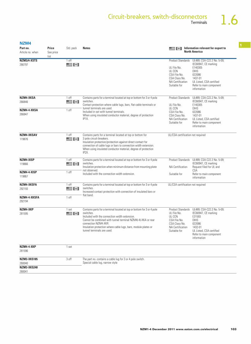
NZM1-4 December 2011 www.eaton.com.cn/electrical 103
1.6Circuit-breakers, switch-disconnectorsTerminals
1Part no.Article no. when
PriceSee price list
Std. pack setoN
NZM3/4-XSTS266797
1 off
ot tropxe rof tnaveler noitamrofnINorth America
NZM4
Product Standards
UL File No.UL CCNCSA File No.CSA Class No.NA CertificationSuitable for
UL489; CSA-C22.2 No. 5-09;IEC60947, CE markingE140305DIHS0220861437-01UL Listed, CSA certifiedRefer to main componentinformation
NZM4-XKSA266846
1 off Contains parts for a terminal located at top or bottom for 3 or 4 pole switches.Contact protection where cable lugs, bars, flat cable terminals or tunnel terminals are used.Included in set with tunnel terminals.When using insulated conductor material, degree of protection IP1X.
NZM4-4-XKSA266847
1 off
NZM4-XKSAV119876
1 off
Contains parts for a terminal located at top or bottom for 3 pole circuit-breakers.Insulation protection/protection against direct contact for connection of cable lugs or bars to connection width extension.When using insulated conductor material, degree of protection IP2X.
UL/CSA certification not required
NZM4-XISP119866
1 off Contains parts for a terminal located at top or bottom for 3 or 4 pole switches.Insulation protection when minimum distance from mounting plate not observed.Included with the connection width extension.NZM4-4-XISP
1198671 off
NZM4-XKSFA292193
1 off Contains parts for a terminal located at top or bottom for 3 or 4 pole switches.Increased contact protection with connection of insulated bars or flat band.
UL/CSA certification not required
NZM4-4-XKSFA292194
1 off
NZM4-XKP281595
1 set Contains parts for a terminal located at top or bottom for 3 or 4 pole switches.Included with the connection width extension.Cannot be combined with tunnel terminal NZM4(-4)-XKA or rear connection NZM4-XKR.Insulation protection where cable lugs, bars, module plates or tunnel terminals are used.
NZM4-4-XKP281596
1 set
NZM3-XKS185260040
3 off The part no. contains a cable lug for 3 or 4 pole switch.Special cable lug, narrow style
NZM3-XKS240260041
Product Standards
UL File No.UL CCNCSA File No.CSA Class No.NA CertificationSuitable for
UL489; CSA-C22.2 No. 5-09;IEC60947, CE markingE140305DIHS0220861437-01UL Listed, CSA certifiedRefer to main componentinformation
Product Standards
NA Certification
Suitable for
UL489; CSA-C22.2 No. 5-09;IEC60947, CE markingRequest filed for UL andCSARefer to main componentinformation
Product StandardsUL File No.UL CCNCSA File No.CSA Class No.NA CertificationSuitable for
UL489; CSA-C22.2 No. 5-09;IEC60947, CE markingE31593DIHS0220861432-01UL Listed, CSA certifiedRefer to main componentinformation

104 NZM1-4 December 2011 www.eaton.com.cn/electrical
1.6 Circuit-breakers, switch-disconnectorsTerminals
1Rated current For use with Part no.
Article no. when ordered separately
PriceSee price list
Std. pack
In
AAdapter set N(ZM)4/N(ZM)12Not UL/CSA approvedMax. 1000 N4 3 pole N4-XAS12-1000
285609
Max. 1250 N4 3 pole N4-XAS12-1250285610
1 set
Max. 1600 N4 3 pole N4-XAS12-1600285611
1 set
1 set
1 setMax. 1000 NZM4 3 pole NZM4-XAS12-1000285612
Max. 1250 NZM4 3 pole NZM4-XAS12-1250285613
1 set
Max. 1600 NZM4 3 pole NZM4-XAS12-1600285614
1 set
1 setMax. 1250 NZM4, N4 3 pole NZM4-XAS14-1250283291
Notes
Conversion kit from N(ZM)12 to N(ZM)4.With the terminal lugs of the replacement kit all three-pole NZM12 and N12 can be adapted to the connection dimensions of the NZM4 or N4 supplied from model year 1983.4 pole basic devices, withdrawable units and basic devices with remote operator can not be replaced.
Contents of replacement kits N(ZM)4-XAS12…:3 connection extensions on outlet side3 connection extensions on trip block side2 mounting brackets4 fixing screws4 phase isolators6 fixing screws, nuts and washersPaper drilling template in the instructional leaflet (AWA)The replacement kits have the same dimensions as models N(ZM)12…, which correspond to production status 02/97 to the present.
Special feature:Prior to 02/97 the N(ZM)12-800 was supplied with 10 mm instead of 8 mm terminal lugs. With these models the customer must determine the device’s year of manufacture by measuring the thickness of the terminal lug and order replacement kit N(ZM)4-XAS12-1250.
Example:N(ZM)12-800…(1000) > N(ZM)4-XAS12-1000N(ZM)12-800 before 02/97 > N(ZM)4-XAS12-1250N(ZM)12-1250 > N(ZM)4-XAS12-1250N(ZM)12-1600 > N(ZM)4-XAS12-1600
Addition for devices constructed prior to 1983!Here the replacement kit for switch-disconnectors can be used in full. For circuit-breakers with “long” ZM design, the adapter fit only at the top! At the bottom the devices are about 65 mm longer and the lower connection is about 26 mm deeper. Consequently the bottom adapters are too short and the heights do not corre-spond.
(NZM4-XKA), connection on rear
Conversion kit for NZM14 to NZM4. Same connections as NZM14. Contains for both sides of switch.3 connection extensions on outlet side3 connection extensions on trip block side.1 long shroud for the outlet sidePaper drilling template in the instructional leaflet (AWA)Cannot be combined with the module plate (NZM4-XKM...), flat cable terminal (NZM4-XKB), connection width extension (NZM4-XKV...), tunnel terminal (NZM4-XKR) and withdrawable unit (NZM4-XAV...).
1600 NZM4, N4 3 pole NZM4-XAS14-1600283292
1 set
NZM4

NZM1-4 December 2011 www.eaton.com.cn/electrical 105
1.6Circuit-breakers, switch-disconnectorsPlug-in units, withdrawable units
1For use with Number of poles Part no.
Article no.PriceSee Price List
Std. pack
Notes
Plug-in unitsFor circuit-breakers NZM and switch-disconnectors NNot UL/CSA approvedNot for U e > 690 V
B = box terminalsS = screw terminalsFor further terminal types see accessories
Plug-in socketCompletion through switches with plug-in insert NZM...-SVE...
NZM1N1
3 pole NZM1-XSVS109777
NZM2N2
3 pole NZM2-XSVS266699
B 1 off Inmax. at:20°C: 125 A (NZM1)70°C: 100 A (NZM1)Mounting position: vertical, 90° right, 90° leftOrder control circuit plug unit separately!
B 1 off Inmax. at:20°C: 250 A40°C: 230 A (NZM…2-…)250 A (NZM…2-E…)Mounting position: vertical, 90° right, 90° leftOrder control circuit plug unit separately!
NZM2-4N2-4
4 pole NZM2-4-XSVS266700
S 1 off
NZM1, NZM2, NZM3, NZM4
Control circuit plug unit– NZM1, N1
NZM2(-4)N2(-4)
For auxiliary contact,shunt/over-voltage release
NZM2-XSVHI266705
– 1 off 10 terminals
– NZM2(-4)N2(-4)
For remote operator
NZM2-XSVR266706
– 1 off
For use with
Number of poles
Part no. suffixArticle no. for order with basic
PriceSee Price List
Std. pack
Part no.Article no. for separate order
PriceSee Price List
Std. pack
Notes
Withdrawable unitFor circuit-breakers NZM and switch-disconnectors NNot UL/CSA approvedNot for Ue > 690 VSocket baseFor switches with withdrawable carrier. Also for reserved compartments.
S 1 off
S 1 off
S 1 off
NZM3N3
3 pole –
NZM3-4N3-4
4 pole –
NZM4N4
3 pole –
NZM4-4N4-4
4 pole –
NZM3-XAVS266711NZM3-4-XAVS266712NZM4-XAVS266713NZM4-4-XAVS266714
S 1 off
Withdrawable carrierSuitable for socket baseOnly in combination with switch
NZM4N4
3 pole +NZM4-XAVE266717
1 off –
NZM4-4N4-4
4 pole +NZM4-4-XAVE266718
1 off –
–
–
Inmax. at:20 °C: 605 A (NZM3), 1600 A (NZM4)40 °C: 550 A (NZM3), 1500 A (NZM4)Mounting position:NZM3: vertical, 90° leftNZM4: vertica
3 positions:l Connected, test, disconnected
Position indication is mechanicalwith pointers.Additional electrical indication withauxiliary contacts possible.One N/O or NC contact M22-(C)K01or M22-(C)K10 each per position.Alternatively also double contactsM22-CK...
Complete with control circuit plugunit.
All auxiliary contact (HIA, HIN, HIV)and shunt release connections tothe control circuit plug unit arealready present.
Maximum configuration: 3 contactsHIN, 2 contacts HIA, 2 contacts HIVCannot be combined with adapter set NZM4/NZM14 (NZM4-XSAS14-...) orN(ZM)4/N(ZM)12.

106 NZM1-4 December 2011 www.eaton.com.cn/electrical
1.6 Circuit-breakers, switch-disconnectorsAuxiliary contacts with screw terminals/spring-cage terminal
1For use with Contact
sequencesPart no.Article no. when ordered separately
PriceSee price list
Std. pack
Trip indicating auxiliary contact (HIA), (HIAFI)1)
General trip indication “+”, when tripped by shunt release, overload release, short-circuit release or earth-fault release due to fault current.
Information relevant for export to North America
1) Product Standards IEC/EN 60947-5; UL 508; CSA-C22.2 No. 14-05; CSA-C22.2 No. 94-91; CE marking
UL File No. E29184UL CCN NKCR
CSA File No. 012528CSA Class No. 3211-03NA Certification UL Listed, CSA certifiedDegree of Protection UL/CSA Part no.:
NZM1, M22-...
Auxiliary contactsStandard auxiliary contacts (HIN)1)
Switches with the main contacts. Used for indicating and interlocking tasks.Single contact
PN1(-4), 2(-4), 3(-4)N(S)1(-4), 2(-4), 3(-4), 4(-4)
1 N/O M22-K10216376M22-K01216378
1 N/O
2 N/O
For interlocking and load shedding circuits, as well as for early make of the undervoltage release in main switch/emergency switching off applications
Early-make auxiliary contact2)
1.X3
1.X4
1.X1
1.X2
1.X3
1.X4
1.X1
1.X2
1.X1
1.X2
1.X1
1.X2
1.X3
1.X4
1.X3
1.X4
2 NC →
1 NC →
→1 NC
20 off
20 off
20 off
1 off
Contact configuration: = safety function by positive
opening according to IEC/EN 60947-5-1N/O = normally open contact
NC = normally closed contact
→
NZM1(-4), 2(-4), 3(-4), 4(-4)
Double contactPN1(-4), 2(-4), 3(-4)N(S)1(-4), 2(-4), 3(-4), 4(-4)
NZM1(-4), 2(-4), 3(-4), 4(-4)
With clamp terminal on left switch side.
NZM1(-4)PN1(-4)N(S)1(-4)
2 N/O – NZM1-XHIV259426
With clamp terminal on right switch side.
2 N/O –
With 3 m connection cable instead of screw connection.
NZM1-XHIVR292195
3.13 3.23
3.14 3.24
3.13 3.23
3.14 3.24
2 N/O – NZM1-XHIVL259432
3.13 3.23
3.14 3.24
NZM2(-4), 3(-4)PN2(-4), 3(-4)N(S)2(-4), 3(-4)
2 N/O – NZM2/3-XHIV259430
NZM4(-4)N(S)4(-4)
2 N/O – NZM4-XHIV266172
3.13 3.23
3.14 3.24
3.13 3.23
3.14 3.24
–
Single contactPN1(-4), 2(-4), 3(-4)N(S)1(-4), 2(-4), 3(-4), 4(-4)
1 N/O
1 N/O
M22-K10216376
M22-K01216378
Double contact
2 N/O
1.X3
1.X4
1.X1
1.X2
1.X3
1.X4
1.X1
1.X2
1.X1
1.X2
1.X1
1.X2
1.X3
1.X4
1.X3
1.X4
1 NC →
1 NC →
2 NC →PN1(-4), 2(-4), 3(-4)N(S)1(-4), 2(-4), 3(-4), 4(-4)
NZM1(-4), 2(-4), 3(-4), 4(-4)
NZM1(-4), 2(-4), 3(-4), 4(-4)

NZM1-4 December 2011 www.eaton.com.cn/electrical 107
1.6Circuit-breakers, switch-disconnectorsAuxiliary contacts with screwterminals/spring-cage terminal
1Part no.Article no. when ordered separately
PriceSee price list
Std. pack Notes Notes
Not in conjunction with undervoltage release NZM…-XU… or shunt release NZM…-XA…Early make with switch on and switch off (manual actuation): approx. 20 ms
Not in conjunction with undervoltage release NZM…-XU…, shunt release NZM…-XA… or remote operator NZM…-XR…Early make (manual operation): approx. 20...90 ms
M22-CK10216384
The following applies for the std. pack:M22-(C)K… : Std. pack = 20 off
‐(C)K.…
The following can be clipped into the switch:• NZM1 - one trip-indicating auxiliary switch• NZM2 - one trip-indicating auxiliary switch M22-(C)K…• NZM3 - one trip-indicating auxiliary switch M22-(C)K…• NZM4 ‐ up to two trip-indicating auxiliary switches M22Any combinations of the auxiliary contact types are possible. Not in combination with switch-disconnector PN…Marking on switch: HIALabeling in residual-current block: HIAFI.If the trip-indicating auxiliary contacts are used in the residual-current block, the NC contacts operates as N/O contacts and the N/O contact operates as an NC contact.
M22-CK01216385
M22-CK11107940
M22-CK02107899
M22-CK20107898
2) Product Standards UL489; CSA-C22.2 No. 5-09; IEC60947, CE markingUL File No. E140305UL CCN DIHS
CSA File No. 022086CSA Class No. 1437-01NA Certification UL Listed, CSA certified
NZM1, M22-... HPL17107EN
M22-CK10216384
The following applies for the std. pack:M22-(C)K… : Std. pack = 20 off
The following can be clipped into the switch:• NZM1: one standard auxiliary contact• NZM2: up to two standard auxiliary contacts M22-(C)K...• NZM3: up to three standard auxiliary contacts M22-(C)K...• NZM4: up to three standard auxiliary contacts M22-(C)K...Any combinations of the auxiliary contact types are possible.Marking on switch: HINOn combination with remote operator NZM-XR... the right mounting location of standard auxiliary contact HIN can be fitted only with individual contacts.
M22-CK01216385
M22-CK11107940
M22-CK02107899
M22-CK20107898
20 off
20 off
20 off
20 off
20 off
20 off

108 NZM1-4 December 2011 www.eaton.com.cn/electrical
1.6 Circuit-breakers, switch-disconnectorsUndervoltage releases
1
Undervoltage releasesWithout auxiliary contactsNon-delayed disconnection of circuit-breaker NZM or switch-disconnector N when control voltage drops below 35 – 70% US.For use with emergency switching off devices in conjunction with emergency switching off button.
For use with Part no.Article no. for separate order
PriceSee price list
Std. pack NotesUs
V
When the undervoltage release is de-energized, accidental contact with the main contacts of the switch during attempts to switch on is reliably prevented.
Undervoltage releases cannot be installed simultaneously with early-make auxiliary contact NZM...-XHIV... or shunt release NZM...-XA...
NZM1Rated control voltage
With clamp terminal on left switch side.
NZM1(-4), N(S)1(-4)
24 V 50/60 Hz NZM1-XU24AC259434
48 V 50/60 Hz NZM1-XU48AC259436
60 V 50/60 Hz NZM1-XU60AC259438
110 V-130 V 50/60 Hz NZM1-XU110-130AC259440
208 V-240 V 50/60 Hz NZM1-XU208-240AC259442
380 V-440 V 50/60 Hz NZM1-XU380-440AC259444
480 V-525 V 50/60 Hz NZM1-XU480-525AC259446
600 V 50/60 Hz NZM1-XU600AC259448
12 V DC NZM1-XU12DC259450
24 V DC NZM1-XU24DC259452
110 V-130 V DC NZM1-XU110-130DC259458
220 V-250 V DC NZM1-XU220-250DC259460
With 3 m connection cable instead of screw terminal.
NZM1(-4), N(S)1(-4)
24 V 50/60 Hz NZM1-XUL24AC259462
110 V-130 V 50/60 Hz NZM1-XUL110-130AC259468
208 V-240 V 50/60 Hz NZM1-XUL208-240AC259471
380 V-440 V 50/60 Hz NZM1-XUL380-440AC259473
480 V-525 V 50/60 Hz NZM1-XUL480-525AC259475
600 V 50/60 Hz NZM1-XUL600AC259477
12 V DC NZM1-XUL12DC259479
24 V DC NZM1-XUL24DC259481
110 V-130 V DC NZM1-XUL110-130DC259487
220 V-250 V DC NZM1-XUL220-250DC259489
Information relevant for export to North America Product Standards UL489;CSA-C22.2 No. 5-09; IEC60947, CE markingUL File No.UL CCNCSA File No.CSA Class No.NA Certification
E140305DIHS0220861437-01UL Listed, CSA certified
1 off
1 off

NZM1-4 December 2011 www.eaton.com.cn/electrical 109
1.6Circuit-breakers, switch-disconnectorsUndervoltage releases
1For use with Part no.
Article no. when ordered separately
PriceSee price list
Std. pack NotesUs
V
NZM2/3..., NZM4
Information relevant for export to North America Product Standards UL489;CSA-C22.2 No. 5-09; IEC60947, CE markingUL File No.UL CCNCSA File No.CSA Class No.NA Certification
E140305DIHS0220861437-01UL Listed, CSA certified
1 off
1 off
Undervoltage releasesWithout auxiliary contactsNon-delayed disconnection of circuit-breaker NZM or switch-disconnector N when control voltage drops below 35 – 70% US.For use with emergency switching off devices in conjunction with emergency switching off button
NZM2(-4), N(S)2(-4)NZM3(-4), N(S)3(-4)
24 V 50/60 Hz NZM2/3-XU24AC259491
When the undervoltage release is de-energized, accidental contact with the main switches of the switch during attempts to switch on is reliably prevented.
Undervoltage release cannot be installed simultaneously with early-make auxiliary contact NZM...-XHIV... or undervoltage release NZM...-XA...
48 V 50/60 Hz NZM2/3-XU48AC259493
60 V 50/60 Hz NZM2/3-XU60AC259495
110 V-130 V 50/60 Hz NZM2/3-XU110-130AC259497
208 V-240 V 50/60 Hz NZM2/3-XU208-240AC259499
380 V-440 V 50/60 Hz NZM2/3-XU380-440AC259501
480 V-525 V 50/60 Hz NZM2/3-XU480-525AC259503
600 V 50/60 Hz NZM2/3-XU600AC259505
12 V DC NZM2/3-XU12DC259507
24 V DC NZM2/3-XU24DC259509
110 V-130 V DC NZM2/3-XU110-130DC259515
220 V-250 V DC NZM2/3-XU220-250DC259517
NZM4(-4), N(S)4(-4) NZM4-XU24AC266189
48 V 50/60 Hz NZM4-XU48AC266190
60 V 50/60 Hz NZM4-XU60AC266191
110 V-130 V 50/60 Hz NZM4-XU110-130AC266192
208 V-240 V 50/60 Hz NZM4-XU208-240AC266193
380 V-440 V 50/60 Hz NZM4-XU380-440AC266194
480 V-525 V 50/60 Hz NZM4-XU480-525AC266195
600 V 50/60 Hz NZM4-XU600AC266196
12 V DC NZM4-XU12DC266203
24 V DC NZM4-XU24DC266204
110 V-130 V DC NZM4-XU110-130DC266207
220 V-250 V DC NZM4-XU220-250DC266208
24 V 50/60 Hz
Rated control voltage

110 NZM1-4 December 2011 www.eaton.com.cn/electrical
1.6 Circuit-breakers, switch-disconnectorsUndervoltage releases
1 For use with
Rated control voltage Part no.Article no. for separate order
PriceSee price list
Std. pack NotesUs
V
Undervoltage releasesWith two early-make auxiliary contacts,For interlocking and load-shedding circuits, as well as for early-make of the undervoltage release in main-switch applications.For use with emergency switching off devices in conjunction with emergency switching off button. With clamp terminal on left switch side.
NZM1(-4), N(S)1(-4)
24 V 50/60 Hz NZM1-XUHIV24AC259531
When the undervoltage release is de-energized, accidental contact with the main contacts of the switch during attempts to switch on is reliably prevented.Early-make of auxiliary contacts on switching on and off (manual operation): approx. 20 msUndervoltage releases cannot be installed simultaneously with early-make auxiliary contact NZM...-XHIV... or shunt release NZM...-XA... .
48 V 50/60 Hz NZM1-XUHIV48AC259533
60 V 50/60 Hz NZM1-XUHIV60AC259535
110 V-130 V 50/60 Hz NZM1-XUHIV110-130AC259537
208 V-240 V 50/60 Hz NZM1-XUHIV208-240AC259539
380 V-440 V 50/60 Hz NZM1-XUHIV380-440AC259541
480 V-525 V 50/60 Hz NZM1-XUHIV480-525AC259543
12 V DC NZM1-XUHIV12DC259545
24 V DC NZM1-XUHIV24DC259547
110 V-130 V DC NZM1-XUHIV110-130DC259553
220 V-250 V DC NZM1-XUHIV220-250DC259555
With 3 m connection cable instead of screw connection.
NZM1(-4), N(S)1(-4)
24 V 50/60 Hz NZM1-XUHIVL24AC259557
110 V-130 V 50/60 Hz NZM1-XUHIVL110-130AC259563
208 V-240 V 50/60 Hz NZM1-XUHIVL208-240AC259565
380 V-440 V 50/60 Hz NZM1-XUHIVL380-440AC259567
480 V-525 V 50/60 Hz NZM1-XUHIVL480-525AC259569
12 V DC NZM1-XUHIVL12DC259571
24 V DC NZM1-XUHIVL24DC259573
110 V-130 V DC NZM1-XUHIVL110-130DC259579
220 V-250 V DC NZM1-XUHIVL220-250DC259581
NZM2(-4), N(S)2(-4)NZM3(-4), N(S)3(-4)
24 V 50/60 Hz NZM2/3-XUHIV24AC259583
When the undervoltage release is de-energized, accidental contact with the main contacts of the switch during attempts to switch on is reliably prevented.Early-make of auxiliary contacts on switching on and off (manual operation): approx. 20 msCannot be used in conjunction with remote operator NZM...-XR....Undervoltage releases cannot be installed simultaneously with early-make auxiliary contact NZM...-XHIV... or shunt release NZM...-XA....
48 V 50/60 Hz NZM2/3-XUHIV48AC259585
60 V 50/60 Hz NZM2/3-XUHIV60AC259587
110 V-130 V 50/60 Hz NZM2/3-XUHIV110-130AC259589
208 V-240 V 50/60 Hz NZM2/3-XUHIV208-240AC259591
380 V-440 V 50/60 Hz NZM2/3-XUHIV380-440AC259594
480 V-525 V 50/60 Hz NZM2/3-XUHIV480-525AC259598
12 V DC NZM2/3-XUHIV12DC259600
24 V DC NZM2/3-XUHIV24DC259602
110 V-130 V DC NZM2/3-XUHIV110-130DC259608
220 V-250 V DC NZM2/3-XUHIV220-250DC259610
D1 3.13
3.14D2
NZM1, NZM2/3
D1 3.13
3.14D2
1 off
1 off
1 off
D1 3.13
3.14D2

NZM1-4 December 2011 www.eaton.com.cn/electrical 111
1.6Circuit-breakers, switch-disconnectorsUndervoltage releases
1For use with
Part no.Article no. when ordered separately
PriceSee price list
Std. pack NotesRated operating voltageUs
V
Undervoltage releasesWith two early-make auxiliary contactsFor interlocking and load-shedding circuits, as well as for early-make of the undervoltage release in main-switch applications.For use with emergency switching off devices in conjunction with emergency switching off button.NZM4(-4), N(S)4(-4)
24 V 50/60 Hz NZM4-XUHIV24AC266217
When the undervoltage release is de-energized, accidental contact with the main contacts of the switch during attempts to switch on is reliably pre-vented.Early make of auxiliary contacts on switching on (manual operation): approx. 90 msCannot be used in conjunction with remote operator NZM...-XR....Undervoltage release cannot be installed together with early-make auxiliary contact NZM…-XHIV… or shunt release NZM…-XA…
48 V 50/60 Hz NZM4-XUHIV48AC266218
60 V 50/60 Hz NZM4-XUHIV60AC266219
110 V-130 V 50/60 Hz NZM4-XUHIV110-130AC266220
208 V-240 V 50/60 Hz NZM4-XUHIV208-240AC266221
380 V-440 V 50/60 Hz NZM4-XUHIV380-440AC266222
480 V-525 V 50/60 Hz NZM4-XUHIV480-525AC266223
12 V DC NZM4-XUHIV12DC266231
24 V DC NZM4-XUHIV24DC266232
110 V-130 V DC NZM4-XUHIV110-130DC266235
220 V-250 V DC NZM4-XUHIV220-250DC266236
With 2 separate early-make auxiliary contactsWith 3 m connection cable instead of screw terminal.NZM1(-4), N(S)1(-4)
24 V 50/60 Hz NZM1-XUHIV20L24AC259612
When the undervoltage release is de-energized, accidental contact with the main switches of the switch during attempts to switch on is safely prevented.Early make of auxiliary contacts on switching on and off (manual operation): approx. 20 msCannot be used in conjunction with remote operator NZM...-XR....Undervoltage release cannot be installed simultaneously with early-make auxiliary contact NZM...-XHIV... or shunt release NZM...-XA...
110 V-130 V 50/60 Hz NZM1-XUHIV20L110-130AC259620
208 V-240 V 50/60 Hz NZM1-XUHIV20L208-240AC259622
380 V-440 V 50/60 Hz NZM1-XUHIV20L380-440AC259624
24 V DC NZM1-XUHIV20L24DC259630
Contacts 3.23 and 3.24 with separate 3 m connection cables.NZM2(-4), N(S)2(-4)NZM3(-4), N(S)3(-4)
24 V 50/60 Hz NZM2/3-XUHIV2024AC259640
110 V-130 V 50/60 Hz NZM2/3-XUHIV20110-130AC259648
208 V-240 V 50/60 Hz NZM2/3-XUHIV20208-240AC259651
380 V-440 V 50/60 Hz NZM2/3-XUHIV20380-440AC259653
24 V DC NZM2/3-XUHIV2024DC259659
3.23
3.24
3.13
3.14D2
D1
1 off
1 off
1 off
Information relevant for export to North America Product Standards UL489;CSA-C22.2 No. 5-09; IEC60947, CE markingUL File No.UL CCNCSA File No.CSA Class No.NA Certification
E140305DIHS0220861437-01UL Listed, CSA certified
3.23
3.24
3.13
3.14D2
D1
D1 3.13
3.14D2
NZM1, NZM2/3..., NZM4

112 NZM1-4 December 2011 www.eaton.com.cn/electrical
1.6 Circuit-breakers, switch-disconnectorsUndervoltage releases
1
Information relevant for export to North America Product Standards UL489;CSA-C22.2 No. 5-09; IEC60947, CE markingUL File No.UL CCNCSA File No.CSA Class No.NA Certification
E140305DIHS0220861437-01UL Listed, CSA certified
For use with
Rated control voltage Part no.Article no. when ordered separately
PriceSee price list
Std. pack Notes
Us
V
Undervoltage releasesWith 2 separate early-make auxiliary contactsFor use with emergency switching off devices in conjunction with emergency switching off button.Coil connections wired to clamp terminals, auxiliary contact connections with 3 m loose connection cables.
Early make of auxiliary contacts on switching on and off (manual operation): approx. 20 ms
Cannot be used in conjunction with remote operator NZM...-XR....
Undervoltage release cannot be installed simul-taneously with early-make auxiliary contact NZM...-XHIV... or shunt release NZM...-XA...
Coil connections with 3 m loose connection cables, auxiliary contact connec-tions wired to clamp terminals.NZM1(-4), N(S)1(-4)
24 V 50/60 Hz NZM1-XUHIV20LK24AC284402
110 V-130 V 50/60 Hz NZM1-XUHIV20LK110-130AC284403
208 V-240 V 50/60 Hz NZM1-XUHIV20LK208-240AC284404
24 V DC NZM1-XUHIV20LK24DC284401
NZM2(-4), N(S)2(-4)NZM3(-4), N(S)3(-4)
24 V 50/60 Hz NZM2/3-XUHIV20LK24AC285291
110 V-130 V 50/60 Hz NZM2/3-XUHIV20LK110-130AC284407
208 V-240 V 50/60 Hz NZM2/3-XUHIV20LK208-240AC284408
24 V DC NZM2/3-XUHIV20LK24DC284405
Contacts 3.23 and 3.24 with separate 3 m connection cables.NZM4(-4), N(S)4(-4)
24 V 50/60 Hz NZM4-XUHIV2024AC266244
110 V-130 V 50/60 Hz NZM4-XUHIV20110-130AC266247
208 V-240 V 50/60 Hz NZM4-XUHIV20208-240AC266248
380 V-440 V 50/60 Hz NZM4-XUHIV20380-440AC266249
24 V DC NZM4-XUHIV2024DC266258
NZM1, NZM2/3..., NZM4
NZM1(-4), N(S)1(-4)
24 V 50/60 Hz NZM1-XUHIV20KL24AC284388
When the undervoltage release is de-energized, accidental contact with the main contacts of the switch during attempts to switch on is reliably prevented.
110 V-130 V 50/60 Hz NZM1-XUHIV20KL110-130AC284389
208 V-240 V 50/60 Hz NZM1-XUHIV20KL208-240AC284400
24 V DC NZM1-XUHIV20KL24DC284387
1 off
1 off
1 off
1 off3.23
3.24
3.13
3.14D2
D1
3.23
3.24
3.13
3.14D2
D1
3.23
3.24
3.13
3.14D2
D1
3.23
3.24
3.13
3.14D2
D1

NZM1-4 December 2011 www.eaton.com.cn/electrical 113
1.6Circuit-breakers, switch-disconnectorsUndervoltage releases, off-delayed
1For use with Part no.
Article no. when ordered separately
PriceSee price list
Std. pack Notes
Undervoltage releases, off-delayedCombination of separate delay unit and special releases. For use with emergency switching off devices in conjunction with emer-gency switching off button. Not UL/CSA approvedDelay unitVoltage dips of less than 0.06 – 16 s do not cause disconnection of the NZM circuit-breaker or N switch-disconnector.NZM1(-4), 2(-4), 3(-4), 4(-4)N(S)1(-4), 2(-4), 3(-4), 4(-4)
50/60 Hz220 V-240 V380 V-440 V480 V-550 V
DC/AC24 V
UVU-NZM260154
1 offWith additional external capacitor:• 30,000 µF ≧ 35 V up to 8 s• 90,000 µF ≧ 35 V up to 16 sA special release is required.Cannot be installed simultaneously with early-make auxiliary contact NZM...-XHIV... or shunt releaseNZM...-XA... .Delay unit for separate installation (mounting: top-hat rail or screws).For other operating voltages use a control transformer.
Special trip blockFor combination with separate delay unitWithout auxiliary contactsNZM1 with 3 m loose connection cables instead of screw terminal, NZM2, 3, and 4 with screw terminalsNZM1(-4)N(S)1(-4)
NZM1-XUVL271607
1 off Delay unit UVU-NZM is additionally required.Cannot be installed simultaneously with separate early-make auxiliary contact NZM...-XHIV... or shunt release NZM...-XA....
NZM2(-4), N(S)2(-4)NZM3(-4), N(S)3(-4)
NZM2/3-XUV259527
NZM4(-4)N(S)4(-4)
NZM4-XUV266588
With two early-make auxiliary contactsNZM1(-4)N(S)1(-4)
NZM1-XUVHIVL271608
1 off Cannot be used in conjunction with remote operator NZM...-XR....Delay unit UVU-NZM is additionally required.Cannot be installed simultaneously with separate early-make auxiliary contact NZM...-XHIV... or shunt release NZM...-XA....NZM1, 2, 3: Early make of auxiliary contacts on switching on and off (manual operation): approx. 20 ms.NZM4: Early make of auxiliary contacts on switching on (manual operation): approx. 90 ms.
NZM2(-4), N(S)2(-4)NZM3(-4), N(S)3(-4)
NZM2/3-XUVHIV259684
NZM4(-4)N(S)4(-4)
NZM4-XUVHIV266596
With two independently operating early-make auxiliary contactsNZM1 with 3 m separate connection cables instead of screw terminal, NZM2, 3, 4 with screw terminal, contact 3.23 and 3.24 with 3 m separate connection cables.NZM1(-4)N(S)1(-4)
NZM1-XUVHIV20L271609
1 off
NZM2(-4), N(S)2(-4)NZM3(-4), N(S)3(-4)
NZM2/3-XUVHIV20259688
NZM4(-4)N(S)4(-4)
NZM4-XUVHIV20266604
D1
D2
U
D1 3.13
3.14D2
U
3.23
3.24
3.13
3.14D2
D1
Delay time can be set from 70 ms – 4 s.

114 NZM1-4 December 2011 www.eaton.com.cn/electrical
1.6 Circuit-breakers, switch-disconnectorsShunt releases
1For use with
voltagePart no.Article no. when ordered
PriceSee price
Std. pack Notes
Us
VShunt releasesWithout auxiliary contactsSwitches are tripped by a voltage pulse or by the application of uninterrupted voltage.With clamp terminal on left switch side.
NZM1(-4), N(S)1(-4) NZM1-XA12AC/DC259706
When the shunt release is live, contact with the switch’s main contacts on switching on is reliably prevented.Undervoltage releases cannot be installed simultaneously with early-make auxiliary contact NZM...-XHIV... or shunt release NZM...-XU... .
24 V AC/DC NZM1-XA24AC/DC259708
48 V AC/DC NZM1-XA48AC/DC259720
60 V AC/DC NZM1-XA60AC/DC259722
110 V-130 V AC/DC NZM1-XA110-130AC/DC259724
208 V-250 V AC/DC NZM1-XA208-250AC/DC259726
380 V-440 V AC/DC NZM1-XA380-440AC/DC259728
C1
C2
Information relevant for export to North America Product StandardsUL File No.UL CCNCSA File No.CSA Class No.NA Certification
NZM1, NZM2/3, NZM4Rated cntrol
12 V AC/DC 1 off
NZM2(-4), N(S)2(-4)NZM3(-4), N(S)3(-4)
12 V AC/DC NZM2/3-XA12AC/DC259752
24 V AC/DC NZM2/3-XA24AC/DC259754
48 V AC/DC NZM2/3-XA48AC/DC259756
60 V AC/DC NZM2/3-XA60AC/DC259758
110 V-130 V AC/DC NZM2/3-XA110-130AC/DC259760
208 V-250 V AC/DC NZM2/3-XA208-250AC/DC259763
380 V-440 V AC/DC NZM2/3-XA380-440AC/DC259766
C1
C2
1 off
With 3 m connection cable instead of screw terminal.
NZM1(-4), N(S)1(-4) NZM1-XAL12AC/DC259734
24 V AC/DC NZM1-XAL24AC/DC259736
110 V-130 V AC/DC NZM1-XAL110-130AC/DC259742
208 V-250 V AC/DC NZM1-XAL208-250AC/DC259744
380 V-440 V AC/DC NZM1-XAL380-440AC/DC259746
C1
C2
1 off12 V AC/DC
NZM4(-4), N(S)4(-4) NZM4-XA12AC/DC266446
24 V AC/DC NZM4-XA24AC/DC266447
48 V AC/DC NZM4-XA48AC/DC266448
60 V AC/DC NZM4-XA60AC/DC266449
110 V-130 V AC/DC NZM4-XA110-130AC/DC266450
208 V-250 V AC/DC NZM4-XA208-250AC/DC266451
380 V-440 V AC/DC NZM4-XA380-440AC/DC266452
C1
C2
1 off12 V AC/DC When the shunt release is live,contact with the switch' s maincontacts on switching on isreliably prevented.Early make of attxiliarv contacton switching on (manualoperation):approx. 90 ms.Cannot be used in conjunctionwith remote operatorNZM... -XR.…Undervoltage release cannotbe installed simttltaneottslvwith early-make attxiliarvcontact NZM...-XHIV... orundervoltage releaseNZM... -XU…
E140305DIHS0220861437-01UL Listed, CSA certified
UL489; CSA-C22.2 No. 5-09; IEC60947, CE marking

NZM1-4 December 2011 www.eaton.com.cn/electrical 115
1.6Circuit-breakers, switch-disconnectorsShunt releases
1
With screw terminal
For use with Part no.Article no.
With screw terminal
PriceSee price list
Std. pack Notes
Std. packPart no.Article no.With screw terminal
PriceSee price list
Notes
Shunt releasesCapacitor unit 230 V 50/60 Hzin conjunction with shunt release NZM...-XA208-250 AC/DCEnclosure: degree of protection IP20Not UL/CSA approved
Enables the reliable use of circuit-breakers as mesh network circuit-breakers in the range from 0 – 110 % Un with constant switch-off time of 40 ms.If the mains voltage is absent, the installed capacitor supplies power for actuating the shunt release for at least 12 hours.The capacitor unit is arranged independently of the circuit-breaker.Connect NZM‐XCM to the power feed side.Note on engineering: Connect a standard auxiliary contact (HIN) as N/O in series with the coil of the shunt release!Standard auxiliary contact not included as standard.
NZM1(-4), N(S)1(-4)NZM2(-4), N(S)2(-4)NZM3(-4), N(S)3(-4)NZM4(-4), N(S)4(-4)
NZM-XCM229413
1 off
Shunt releases For mesh network circuit-breakersFor intermittent operationMaximum On-time = 1 sOperating range 10-110 % Us
Not UL/CSA approved
Rated control voltage230 V ACFor use withNZM3(-4), N3(-4) and NZM4(-4), N4(-4)Cannot be installed simultaneously with early-make auxiliary contact NZM...-XHIV... or undervoltage release NZM...-XU... .Intermittent operation guaranteed by series connection of a make contact M22-(C)K10.The maximum duty factor of the shunt releases for mesh network circuit-breakers is 1 s.
NZM...-XAHIV:Cannot be used in conjunction with remote operator NZM...-XR....NZM3: Early make of auxiliary contact on switching on and off (manual operation):approx. 20 ms.NZM4: Early make of auxiliary contact on switching on (manual operation): approx. 90 ms.
① Reverse power relay contact from mesh network relay
-S11 Remote offq Standard auxiliary contacts-Q1 Shunt releases
1.13
1.14
C1
C2-Q1
L1 (L+)
QHIN
-S110
NZM...-XA...-MNS
M22-...K10
N (L-, L2)
a
Without auxiliary contacts
NZM3-XA-230AC-MNS274097
1 off
With early-make auxiliary contact
NZM3-XAHIV-230AC-MNS274141
1 off
Without auxiliary contacts
NZM4-XA-230AC-MNS274138
With early-make auxiliary contact
NZM4-XAHIV-230AC-MNS274143
1 off
C1
C2
C1
C2
3.13
3.14
C1
C2
C1
C2
3.13
3.14
NZM...-XA...

116 NZM1-4 December 2011 www.eaton.com.cn/electrical
1.6 Circuit-breakers, switch-disconnectorsShunt releases
1For use with Part no.
Article no. when ordered separately
PriceSee price list
Std. pack Notes
When the shunt release is live, contact with the switch’s main contacts on switching on is reliably prevented.Early make of auxiliary contact on switching on and off (manual operation): approx. 20 ms.Undervoltage release cannot be installed simultaneously with early-make auxiliary contact NZM...-XHIV... or undervoltage release NZM...-XU...
Information relevant for export to North America Product StandardsUL File No.UL CCNCSA File No.CSA Class No. NA Certification
NZM1, NZM2/3, NZM4
voltageUs
V
Rated control
Shunt releasesWith early-make auxiliary contactNot in combination with remote operator.With clamp terminal on left switch side.
NZM1(-4), N(S)1(-4) NZM1-XAHIV12AC/DC259772
24 V AC/DC NZM1-XAHIV24AC/DC259774
48 V AC/DC NZM1-XAHIV48AC/DC259776
60 V AC/DC NZM1-XAHIV60AC/DC259778
110 V-130 V AC/DC NZM1-XAHIV110-130AC/DC259780
208 V-250 V AC/DC NZM1-XAHIV208-250AC/DC259782
380 V-440 V AC/DC NZM1-XAHIV380-440AC/DC
12 V AC/DC
NZM4(-4), N(S)4(-4) NZM4-XAHIV12AC/DC266470
When the shunt release is live, contact with the switch’s main contacts on switching on is reliably prevented.Early make of auxiliary contact on switching on (manual operation): approx. 90 ms.Cannot be used in conjunction with remote operator NZM...-XR....Undervoltage release cannot be installed simultaneously with early-make auxiliary contact NZM...-XHIV... or undervoltage release NZM...-XU...
24 V AC/DC NZM4-XAHIV24AC/DC266471
48 V AC/DC NZM4-XAHIV48AC/DC266472
60 V AC/DC NZM4-XAHIV60AC/DC266473
110 V-130 V AC/DC NZM4-XAHIV110-130AC/DC266474
208 V-250 V AC/DC NZM4-XAHIV208-250AC/DC266475
380 V-440 V AC/DC NZM4-XAHIV380-440AC/DC266476
12 V AC/DC
1 off
259784
NZM2(-4), N(S)2(-4)NZM3(-4), N(S)3(-4)
12 V AC/DC NZM2/3-XAHIV12AC/DC259808
24 V AC/DC NZM2/3-XAHIV24AC/DC259810
48 V AC/DC NZM2/3-XAHIV48AC/DC259812
60 V AC/DC NZM2/3-XAHIV60AC/DC259814
110 V-130 V AC/DC NZM2/3-XAHIV110-130AC/DC259816
208 V-250 V AC/DC NZM2/3-XAHIV208-250AC/DC259818
380 V-440 V AC/DC NZM2/3-XAHIV380-440AC/DC259820
With 3 m connection cable instead of screw connection
NZM1-XAHIVL12AC/DC259790
24 V AC/DC NZM1-XAHIVL24AC/DC259792
110 V-130 V AC/DC NZM1-XAHIVL110-130AC/DC259798
208 V-250 V AC/DC NZM1-XAHIVL208-250AC/DC259800
380 V-440 V AC/DC NZM1-XAHIVL380-440AC/DC259802
NZM1(-4), N(S)1(-4) 12 V AC/DC 1 off
1 off
1 off
E140305DIHS022086
UL489; CSA-C22.2 No. 5-09; IEC60947, CE marking
UL Listed, CSA certified1437-01
C1
C2
3.13
3.14
C1
C2
3.13
3.14
C1
C2
3.13
3.14
C1
C2
3.13
3.14

NZM1-4 December 2011 www.eaton.com.cn/electrical 117
1.6Circuit-breakers, switch-disconnectorsMechanical interlock for (door-coupling) rotary handles
1

118 NZM1-4 December 2011 www.eaton.com.cn/electrical
1.6 Circuit-breakers, switch-disconnectorsDoor coupling rotary handles
1Standard
htiw esu roFweiv tcudorP Part no.Article no. when ordered separately
PriceSee price list
Std. pack Notes
Door coupling rotary handlesComplete including rotary drive and coupling partsAn additional extension shaft is necessary with the NZM...‐XT(V)D(V)(R)(-60) part numbers.Degree of protection IP66/UL/CSA type 4X, 12Standard, black/grey
Lockable in 0 position on handle with up to 3 padlocks. With door interlock.
NZM1(-4), PN1(-4), N(S)1(-4)
NZM1-XTVD260166
Door interlock• Not defeated in the
locked OFF and ON positions
• Can be modified such that it can be defeated from the outside using a screwdriver, when it is in the unlocked ON position.
• Door can be opened in OFF
NZM…-XTVD(V)• External warning plate/
designation label can be clipped on
NZM2(-4), PN2(-4), N(S)2(-4)
NZM2-XTVD260168
NZM3(-4), PN3(-4), N(S)3(-4)
NZM3-XTVD260170
NZM4(-4), N(S)4(-4) NZM4-XTVD266614
Lockable on handle and switch with up to 3 padlocks. Can be locked in 0 position, with adequate modification also in I position. With door interlock. Lockable on switch in 0 position.
NZM1(-4), PN1(-4), N(S)1(-4)
NZM1-XTVDV260172
NZM2(-4), PN2(-4), N(S)2(-4)
NZM2-XTVDV260174
NZM3(-4), PN3(-4), N(S)3(-4)
NZM3-XTVDV260176
NZM4(-4), N(S)4(-4) NZM4-XTVDV266616
1 off
Red-yellowfor emergency witching off
Lockable on handle and switch with up to 3 padlocks. Lockable in 0 position on handle. With door interlock. Lockable on switch in 0 position.
NZM1(-4), PN1(-4), N(S)1(-4)
NZM1-XTVDVR260178
Door interlock• Not defeated in the
locked OFF position.• Can be modified such that
it can be defeated from the outside using a screwdriver, when it is in the unlocked ON position.
• Door can be opened in OFFNZM…-XTVDVR
• External warning plate/designation label can be clipped on
NZM2(-4), PN2(-4), N(S)2(-4)
NZM2-XTVDVR260180
NZM3(-4), PN3(-4), N(S)3(-4)
NZM3-XTVDVR260182
NZM4(-4), N(S)4(-4) NZM4-XTVDVR266618
1 off
– 400 mm max. mounting depthN(S)1(-4)NZM2(-4), PN2(-4), N(S)2(-4)
NZM1/2-XV4261232
1 off Length 290 mm, can be cut to required length.
NZM3(-4), PN3(-4), N(S)3(-4)NZM4(-4), N(S)4(-4)
NZM3/4-XV4261234
600 mm max. mounting depthN(S)1(-4)NZM2(-4), PN2(-4), N(S)2(-4)
NZM1/2-XV6260191
Length 425 mm, can be cut to required length.
NZM3(-4), PN3(-4), N(S)3(-4)NZM4(-4), N(S)4(-4)
NZM3/4-XV6260193
Notes Circuit-breaker can also be installed in a horizontal position 90° left/right, with the handle still in the same position.
Extension shaft
NZM1, NZM2, NZM3, NZM4
NZM1(-4), PN1(-4),
NZM1(-4), PN1(-4),

NZM1-4 December 2011 www.eaton.com.cn/electrical 119
1.6Circuit-breakers, switch-disconnectorsDoor coupling rotary handles
1
NZM1-XTVD-60271504
Door interlock• Can not be defeated in
the locked OFF and ON positions
• Can be modified such that it can be defeated from the outside using a screwdriver, when it is in the unlocked ON position.
• Door can be opened in OFFNZM…-XTVD(V)-60
• For maximum shaft length 60 mm
• Without shaft support• Cannot be combined
with additional handle NZM...-XDZ
• External warning plate/designation label can be clipped on.
NZM1-XTVD-0279392
1 off Door interlock• Can not be defeated in
the locked OFF and ON positions
• Can be modified such that it can be defeated from the outside using a screwdriver, when it is in the unlocked ON position.
• Door can be opened in OFFNZM…-XTVD(V)-0
• For extremely narrow fittings
• With special short extension shaft
• Cannot be combined with additional handle NZM...-XDZ
• External warning plate/designation label can be clipped on.
Product StandardsUL489;CSA-C22.2No. 5-09;IEC60947,CE markingE140305DIHS022086UL Listed,CSA certified
IEC: IP66,UL/CSAType 4X, 12
UL File No.UL CCNCSA File No.CSA Class No.NA Certification
Degree of Protection
NZM2-XTVD-60271505
NZM2-XTVD-0279393
NZM3-XTVD-60271506
NZM3-XTVD-0279394
NZM4-XTVD-60271507
NZM4-XTVD-0279395
NZM1-XTVDV-60271508
NZM1-XTVDV-0279396
NZM2-XTVDV-60271509
NZM2-XTVDV-0279397
NZM3-XTVDV-60271510
NZM3-XTVDV-0279398
NZM4-XTVDV-60271511
NZM4-XTVDV-0279399
1 off
– – – deriuqer ton noitacifitrec ASC/LU–– –– –– –
For maximum shaft length 60 mm
Extremely narrow fittings
Part no.Article no. when ordered separately
PriceSee price list
Std. pack Notes Part no.Article no. when ordered separately
PriceSee price list
Std. pack Information relevant for export to North America
Note
1 off NZM1-XTVDVR-0279400
1 off Door interlock• Can not be defeated in
the locked OFF position.• Can be modified such
that it can be defeated from the outside using a screwdriver, when it is in the unlocked ON position.
• Door can be opened in OFFNZM…-XTVDVR-0
• For extremely narrow fittings
• With special short extension shaft
• Cannot be combined with additional handle NZM...-XDZ
• External warning plate/designation label can be clipped on.
NZM2-XTVDVR-0279401
NZM3-XTVDVR-0279402
NZM1-XTVDVR-60271512
NZM2-XTVDVR-60271513
NZM3-XTVDVR-60271514
NZM4-XTVDVR-60271515
NZM4-XTVDVR-0279403
Door interlock
the locked OFF position.• Can be modified such
that it can be defeated from the outside using a screwdriver, when it is in the unlocked ON position.
• Door can be opened in OFFNZM…-XTVDVR-60
• For maximum shaft length 60 mm
• Without shaft support• Cannot be combined
with additional handle NZM...-XDZ
• External warning plate/designation label can be clipped on.
• Can not be defeated in

120 NZM1-4 December 2011 www.eaton.com.cn/electrical
1.6 Circuit-breakers, switch-disconnectorsDoor coupling rotary handles for North America
1 NZM1, NZM2, NZM3, NZM4 HPL17120ENProduct view Part no.
Article no. when ordered separately
PriceSee price list
Std. pack NotesFor use with
Door coupling rotary handlesComplete including rotary drive and coupling partsExtension shaft additionally required.Degree of protection IP66/UL/CSA type 4X, 12Difference to normal IEC handles: Door opening only possible with active rotation beyond the 0 position.Standard, black/grey
1 off
1 off
Door interlock• Can not be defeated in the locked
OFF position.• Door opening with active rotation
beyond the 0 position.• Cannot be combined with mechanical
interlock• External warning plate/designation
label can be clipped on.
Door interlock• Can not be defeated in the locked
OFF position.• Door opening possible with active
defeated from the outside using a screwdriver.
• Cannot be combined with mechanical interlock
• External warning plate/designation label can be clipped on.
Lockable in 0 position on handle. With door interlock.
NZM1, N1 NZM1-XTVD-NA271445
NZM2, N2 NZM2-XTVD-NA271446
NZM3, N3 NZM3-XTVD-NA271447
NZM4, N4 NZM4-XTVD-NA271448
Lockable on handle and switch with up to 3 padlocks. Lockable in 0 position on handle. With door interlock. Lockable on switch in 0 position.
NZM1, N(S)1 NZM1-XTVDV-NA100683
NZM2, N(S)2 NZM2-XTVDV-NA100684
NZM3, N(S)3 NZM3-XTVDV-NA100685
NZM4, N(S)4 NZM4-XTVDV-NA100686
Red-yellow for emergency switching off
Lockable on handle and switch with up to 3 padlocks. Lockable in 0 position on handle. With door interlock. Lockable on switch in 0 position.
NZM1, N(S)1 NZM1-XTVDVR-NA271449
1 off Door interlock• Can not be defeated in the locked
OFF position.• Door opening with active rotation
beyond the 0 position.• Cannot be combined with mechanical
interlock• External warning plate/designation
label can be clipped on.
NZM2, N(S)2 NZM2-XTVDVR-NA271450
NZM3, N(S)3 NZM3-XTVDVR-NA271451
NZM4, N(S)4 NZM4-XTVDVR-NA271452
Extension shaft400 mm max. mounting depth
NZM1(-4), PN1(-4), N(S)1(-4)NZM2(-4), PN2(-4), N(S)2(-4)
NZM1/2-XV4261232
1 off
NZM3(-4), PN3(-4), N(S)3(-4)NZM4(-4), N(S)4(-4)
NZM3/4-XV4261234
600 mm max. mounting depth
NZM1(-4), PN1(-4), N(S)1(-4)NZM2(-4), PN2(-4), N(S)2(-4)
NZM1/2-XV6260191
NZM3(-4), PN3(-4), N(S)3(-4)NZM4(-4), N(S)4(-4)
NZM3/4-XV6260193
Notes Circuit-breaker can also be installed in a lying position 90° left/right, with the handle still in the same position.
rotation beyond the 0 position. Can be
Length 290 mm, can be cut to requiredlength.
Length 290 mm, can be cut to requiredlength.

NZM1-4 December 2011 www.eaton.com.cn/electrical 121
1.6Circuit-breakers, switch-disconnectorsDoor coupling rotary handles for North America
1
60 mmExtremely narrow fittings
Part no.Article no.
PriceSee price list
Std. pack Notes Part no.Article no.
PriceSee price list
Std. pack Notes Information relevant for export to North America
NZM1-XTVDVR-60-NA100671
1 off Door interlock• Can not be defeated in
the locked OFF position.• Door opening with
active rotation beyond the 0 position.
• Cannot be combined with mechanical interlock
• External warning plate/ designation label can be clipped on.
NZM…-XTVDVR-60-NA• For a maximum shaft
length of 60 mm• Without shaft support• Cannot be combined
with additional handle NZM...-XDZ
• External warning plate/ designation label can be clipped on.
NZM1-XTVDVR-0-NA100679
1 off Door interlock• Can not be defeated in
the locked OFF position.• Door opening with
active rotation beyond the 0 position.
• Cannot be combined with mechanical interlock
• External warning plate/ designation label can be clipped on.
NZM…-XTVDVR-0-NA• For extremely narrow
fittings• With special short
extension shaft• Cannot be combined
with additional handle NZM...-XDZ
• External warning plate/ designation label can be clipped on.
Product Standards
NZM2-XTVDVR-60-NA100672
NZM2-XTVDVR-0-NA100680
NZM3-XTVDVR-60-NA100673
NZM3-XTVDVR-0-NA100681
NZM4-XTVDVR-60-NA100674
NZM4-XTVDVR-0-NA100682
– – – ton noitacifitrec ASC/LU–required– –
– –– –
– – – sdradnatS tcudorP–
– –
– –
– –
NZM1-XTVDV-60-NA100667
1 off Door interlock• Can not be defeated in
the locked OFF position.• Door opening possible
with active rotation beyond the 0 position. Can be defeated from the outside using a screwdriver.
• Cannot be combined with mechanical interlock
• External warning plate/ designation label can be clipped on.
NZM…-XTVDV-60-NA• For a maximum shaft
length of 60 mm• Without shaft support• Cannot be combined
with additional handle NZM...-XDZ
• External warning plate/ designation label can be clipped on.
NZM1-XTVDV-0-NA100675
1 off Door interlock• Can not be defeated in
the locked OFF position.• Door opening possible
with active rotation beyond the 0 position. Can be defeated from the outside using a screwdriver.
• Cannot be combined with mechanical interlock
• External warning plate/ designation label can be clipped on.
NZM…-XTVDV-0-NA• For extremely narrow
fittings• With special short
extension shaft• Cannot be combined
with additional handle NZM...-XDZ
• External warning plate/ designation label can be clipped on.
NZM2-XTVDV-60-NA100668
NZM2-XTVDV-0-NA100676
NZM3-XTVDV-60-NA100669
NZM3-XTVDV-0-NA100677
NZM4-XTVDV-60-NA100670
NZM4-XTVDV-0-NA100678
NZM1, NZM2, NZM3, NZM4 HPL17121EN
UL489; CSA-C22.2 No. 5-09; IEC60947, CE marking
UL File No.UL CCNCSA File No.CSA Class No.NA Certification
UL Listed, CSA certified
Degree of ProtectionIEC: IP66, UL/CSA Type 4X, 12
E140305DIHS0220861437-01
UL489; CSA-C22.2 No. 5-09; IEC60947, CE marking
UL File No.UL CCNCSA File No.CSA Class No.NA Certification
UL Listed, CSA certified
Degree of ProtectionIEC: IP66, UL/CSA Type 4X, 12
E140305DIHS0220861437-01

122 NZM1-4 December 2011 www.eaton.com.cn/electrical
1.6 Circuit-breakers, switch-disconnectorsRotary handles
1
NZM1(-4), PN1(-4), N(S)1(-4) NZM1-XDV260125
NZM2(-4), PN2(-4), N(S)2(-4) NZM2-XDV260127
NZM3(-4), PN3(-4), N(S)3(-4) NZM3-XDV260129
NZM4(-4), N(S)4(-4) NZM4-XDV266608
NZM1(-4), PN1(-4), N(S)1(-4) NZM1-XDVG285247
NZM2(-4), PN2(-4), N(S)2(-4) NZM2-XDVG285248
NZM1(-4), PN1(-4), N(S)1(-4) NZM1-XDVR260135
NZM2(-4), PN2(-4), N(S)2(-4) NZM2-XDVR260137
NZM3(-4), PN3(-4), N(S)3(-4) NZM3-XDVR260140
NZM4(-4), N(S)4(-4) NZM4-XDVR266610
NZM1(-4), PN1(-4), N(S)1(-4) NZM1-XDVGR285249
NZM2(-4), PN2(-4), N(S)2(-4) NZM2-XDVGR285280
NZM...-XDV
For use with Part no.Article no. for separate order
PriceSee price list
Std. pack NotesNorth AmericaInformation relevant for export to
Rotary handle on circuit-breakerComplete with rotary drive
Standard, black-greyLockable in0 position onswitch with upto3 padlocks.
Lockable in0 position onhandle with upto3 padlocks.
Red-yellow for emergency switching offLockable in0 position onswitch with upto3 padlocks.
Lockable in0 position onhandlewith upto3 padlocks.
1 off
1 off
1 off
1 off
NZM1, 2, 3: Canalso be combinedwith insulatingsurround.MODAN handleposition detectionby wire releasecan be retrofitted
Can also becombined withinsulatingsurround
NZM1, 2, 3: Canalso be combinedwith insulatingsurround.MODAN handleposition detectionby wire releasecan be retrofitted
Can also becombined withinsulatingsurround
Product Standards
UL File No.UL CCNCSA File No.CSA Class No.NA Certification
UL489;CSA-C22.2N o. 5-09;IEC60947,CE markingE140305DIHS0220861437-01UL Listed,CSA certified
Product Standards
UL File No.UL CCNCSA File No.CSA Class No.NA Certification
UL489;CSA-C22.2N o. 5-09;IEC60947,CE markingE140305DIHS0220861437-01UL Listed,CSA certified
Notes Circuit-breaker can also be installed in a lying position 900 1e川right, with the handle still in the same position

NZM1-4 December 2011 www.eaton.com.cn/electrical 123
1.6Circuit-breakers, switch-disconnectorsRotary handles with door interlock
1NZM...-XDTVFor use with Part no.
Article no. for separate order
PriceSee price list
Std. pack NotesNorth AmericaInformation relevant for export to
NZM1(-4), PN1(-4), N(S)1(-4)
NZM1-XDTV260131
NZM2(-4), PN2(-4), N(S)2(-4)
NZM2-XDTV260133
NZM1(-4), PN1(-4), N(S)1(-4)
NZM1-XDTVR260142
NZM2(-4), PN2(-4), N(S)2(-4)
NZM2-XDTVR260144
NZM1, N(S)1 NZM1-XDTV-NA271453
NZM2, N(S)2 NZM2-XDTV-NA271454
NZM1, N(S)1 NZM1-XDTVR-NA271455
NZM2, N(S)2 NZM2-XDTVR-NA271456
1 off
1 off
1 off
1 off
Product Standards
UL File No.UL CCNCSA File No.CSA Class No.NA Certification
UL489;CSA-C22.2N o. 5-09;IEC60947,CE markingE140305DIHS0220861437-01UL Listed,CSA certified
Product Standards
UL File No.UL CCNCSA File No.CSA Class No.NA Certification
UL489;CSA-C22.2N o. 5-09;IEC60947,CE markingE140305DIHS0220861437-01UL Listed,CSA certified
Rotary handles on switch with door interlockComplete with rotary drive and insulating surroundStandard, black-grey
Lockable in 0 positionon handle with up to3 padlocks, can alsobe modified for theI position. Alsoavailable with doorinterlock e.g. for MCCservice distribution
Red-yellow for emergency switching offLockable in 0 positionon handle with up to3 padlocks. Alsoavailablewith doorinterlock e.g. for MCCservice distribution
Rotary handles on switch with door interlock forUL/CSA approved NA switchesDifferenceto normal IEC handles: Door opening onlypossible with active rotation beyond the 0 position.Complete with rotary drive and insulating surround
Standard, black-greyLockable in 0 positionon handle with up to3 padlocks, can alsobe modified for theI position. Alsoavailable with doorinterlock e.g. for MCCservice distribution
Lockable in 0 positionon handle with up to3 padlocks. Alsoavailablewith doorinterlock e.g. for MCCservice distribution
In the ON position, can be defeatedfrom the outside using a 1 mm pin.Can not be defeated inthe locked OFF and ON positions Door can be opened in OFF.Can onlybe switched ON when the door is closed
Door interlock In the ON position, can be defeatedfrom the outside using a 1 mm pin.Can not be defeated inthe locked OFF and ON positions Door opening only possible with active rotation beyondthe 0 position..Can onlybe switched ON when the door is closed.Cannot be combined with mechanical interlock
Red-yellow for emergency switching off
Notes Circuit-breaker can also be installed in a lying position 900 le川right, with the handle still in the same position

124 NZM1-4 December 2011 www.eaton.com.cn/electrical
1.6 Circuit-breakers, switch-disconnectorsMain switch assembly kit
1Model Price
See price list
Std. pack Information relevant for export to North America
NZM...-XHB..., NZM...-XS...
Main switch assembly kitEquipment supplied:• Door coupling rotary handle• Extension shaft NZM...-XV4• External warning plate/designation label in German/English• Black and yellowflash
Part no.Article no.forseparateorder
For use with
PN1(-4), N(S)1(-4) NZM1-XHB266626
PN2(-4), N(S)2(-4) NZM2-XHB266627
PN3(-4), N(S)3(-4) NZM3-XHB266628
N(S)4(-4) NZM4-XHB271779
PN1(-4), N(S)1(-4) NZM1-XHBR266632
PN2(-4), N(S)2(-4) NZM2-XHBR266633
PN3(-4), N(S)3(-4) NZM3-XHBR266634
N(S)4(-4) NZM4-XHBR271842
For operation on the left
NZM1(-4)PN1(-4), N(S)1(-4)
NZM1-XS-L266641
NZM2(-4)PN2(-4), N(S)2(-4)
NZM2-XS-L266642
NZM3(-4)PN3(-4), N(S)3(-4)
NZM3-XS-L266643
NZM4(-4)N(S)4(-4)
NZM4-XS-L289806
For operation on the right
NZM1(-4)PN1(-4), N(S)1(-4)
NZM1-XS-R266644
NZM2(-4)PN2(-4), N(S)2(-4)
NZM2-XS-R266645
NZM3(-4)PN3(-4), N(S)3(-4)
NZM3-XS-R266646
NZM4(-4)N(S)4(-4)
NZM4-XS-R289807
For operation on the left
NZM1(-4)PN1(-4), N(S)1(-4)
NZM1-XSR-L266653
NZM2(-4)PN2(-4), N(S)2(-4)
NZM2-XSR-L266654
NZM3(-4)PN3(-4), N(S)3(-4)
NZM3-XSR-L266655
NZM4(-4)N(S)4(-4)
NZM4-XSR-L289808
For operation on the right
NZM1(-4)PN1(-4), N(S)1(-4)
NZM1-XSR-R266656
NZM2(-4)PN2(-4), N(S)2(-4)
NZM2-XSR-R266657
NZM3(-4)PN3(-4), N(S)3(-4)
NZM3-XSR-R266658
NZM4(-4)N(S)4(-4)
NZM4-XSR-R289809
With black door coupling rotary handleLockable in 0 position on handlewith up to 3 padlocks, can also bemodified for the I position. Withdoor interlock
–
–
–
–
W ith red door coupling rotary handlefor use of switch as emergency switching off device to IEC/EN 60204-1
Lockable in 0 position on handlewith up to 3 padlocks. Lockabledoor as additional feature, lockingfacility on circuit-breaker in0 position.
For side wall installationActuation of the switch on the control panel side wallSwitch mounting on mounting plate
Standard, black/greyLockable in 0 position on handlewith up to 3 padlocks, withadequate modification also inI position.
Red-yellow for emergency switching offLockable in 0 position on handlewith up to 3 padlocks.
1 off
1 off
1 off
For enhanced protection against direct contact on the incomer side, IP2X protectionagainst contact with a finger can be ordered → Page 17/84Other external warning plates/designation labels can be clipped on.Degree of protection IP66/UL/CSA type 4X, 12
Product Standards
UL File No.UL CCNCSA File No.CSA Class No.NA Certification
Degree of Protection
Product Standards
UL File No.UL CCNCSA File No.CSA Class No.NA Certification
Degree of Protection
Product Standards
UL File No.UL CCNCSA File No.CSA Class No.NA Certification
Degree of Protection
UL489;CSA-C22.2No. 5-09;IEC60947,CE markingE140305DIHS0220861437-01UL Listed,CSA certi-PiedIEC:IP66,UL/CSAType 4X,12
UL489;CSA-C22.2No. 5-09;IEC60947,CE markingE140305DIHS0220861437-01UL Listed,CSA certi-PiedIEC:IP66,UL/CSAType 4X,12
UL489;CSA-C22.2No. 5-09;IEC60947,CE markingE140305DIHS0220861437-01UL Listed,CSA certi-PiedIEC:IP66,UL/CSAType 4X,12

NZM1-4 December 2011 www.eaton.com.cn/electrical 125
1.6Circuit-breakers, switch-disconnectorsMechanical interlock for (door-coupling) rotary handles
1For use with Part no.
Article no. when ordered separately
PriceSee price list
Std. pack Information relevant for export to North America
NZM1(-4)PN1(-4), N(S)1(-4)
NZM1-XSM-L266663
NZM2(-4)PN2(-4), N(S)2(-4)
NZM2-XSM-L266664
NZM1(-4)PN1(-4), N(S)1(-4)
NZM1-XSM-R266665
NZM2(-4)PN2(-4), N(S)2(-4)
NZM2-XSM-R266666
NZM1(-4)PN1(-4), N(S)1(-4)
NZM1-XSRM-L266671
NZM2(-4)PN2(-4), N(S)2(-4)
NZM2-XSRM-L266672
NZM1(-4)PN1(-4), N(S)1(-4)
NZM1-XSRM-R266673
NZM2(-4)PN2(-4), N(S)2(-4)
NZM2-XSRM-R266674
PN1(-4), N(S)1(-4)NZM2(-4),N(S)2(-4)
NZM1/2-XZB266676
NZM...XS(R)M...
1 off
1 off
1 off Product Standards
UL File No.UL CCNCSA File No.CSA Class No.NA Certification
Degree of Protection
Product Standards
UL File No.UL CCNCSA File No.CSA Class No.NA Certification
Degree of Protection
Main switch assembly kit for side wall installation with mountingbracket.For direct mounting of circuit-breaker and handle in the side wall of the control cabinetEquipment supplied:.Door coupling rotary handle.Mounting bracket.Special short extension shaft.External warning plate/designation label in German/English.Black and yellowflashFor enhanced protection against direct contact on the incomer side,IP2X protection against contact with a finger can be ordered } Page 17/84Other external warning plates/designation labels can be clipped on.Degree of protection IP66/UL/CSAtype 4X, 12
Standard, black/greyLockable in 0 positionwith adequatemodification also inI position. Minimumclearance betweencontrol panel sidewalls and circuit-breaker is defined bymounting bracket.Extension cannot beused
Red-yellow for emergency switching offLockable in 0 positionon handle. Minimumclearance betweencontrol panel sidewalls and circuit-breaker is defined bymounting bracket.Extension cannot beused
Foroperationon the left
Foroperationon the left
Foroperationon the left
Foroperationon the left
Foroperationon the left
Foroperationon the left
Foroperationon the left
Foroperationon the left
Additional plateFor fitting to the mounting bracket when using neutral conductor orPE conductor terminals K25. K50. K95 or K150.
– –
Notes Additional terminal arrangement for side wall operator with mounting bracket→Engineering, Page 17/153
Model
UL/CSA certification not required
UL489;CSA-C22.2N o. 5-09;IEC60947,CE markingE140305DIHS0220861437-01UL Listed,CSA certifiedIEC:IP66,UL/CSAType 4X,12
UL489;CSA-C22.2N o. 5-09;IEC60947,CE markingE140305DIHS0220861437-01UL Listed,CSA certifiedIEC:IP66,UL/CSAType 4X,12

126 NZM1-4 December 2011 www.eaton.com.cn/electrical
1.6 Circuit-breakers, switch-disconnectorsMain switch assembly kit
1Model For use with Part no.
Article no. when ordered separately
PriceSee price list
Std. pack Information relevant for export to North America
NZM...XS(R)M...
Main switch assembly kit with additional rotary handleMain switch assembly kit with additional rotary handle for switching with openedcontrol panel doorEquipment supplied:• Door coupling rotary handle• Additional rotary handle on switch with "Deliberate Action" operation• Extension shaft NZM...-XV6for mounting depth 600 mm, NZM1/2-XV4with NZM1 for mounting depth 400 mm• External warning plate/designation label in German/English• Black and yellowflashFor enhanced protection against direct contact on the incomer side,IP2X protection against contact with a finger can be ordered→Page 17/84Other external warning plates/designation labels can be clipped on.Degree of protection IP66/UL/CSAtype 4X, 12
With black door coupling rotary handleon handle with up to3 padlocks,canalso bemodified for theI position. Lockabledoor as additionalfeature, locking facilityon circuit-breaker in0 position.
W ith red door coupling rotary handleFor use of switch as emergency switching off device
Lockable in 0 positionon handle with up to3 padlocks. With doorinterlock and lockableon switch in 0 position.
NZM1(-4)PN1(-4), N1(-4)
NZM1-XHB-DA125956
NZM1(-4)PN1(-4), N(S)1(-4)
NZM1-XHB-DA-NA125958
NZM2(-4)PN2(-4), N(S)2(-4)
NZM2-XHB-DA116895
NZM2(-4)PN2(-4), N(S)2(-4)
NZM2-XHB-DA-NA116897
NZM3(-4)PN3(-4), N(S)3(-4)
NZM3-XHB-DA118988
NZM3(-4)PN3(-4), N(S)3(-4)
NZM3-XHB-DA-NA119000
NZM4(-4)PN4(-4), N(S)4(-4)
NZM4-XHB-DA119002
NZM4(-4)PN4(-4), N(S)4(-4)
NZM4-XHB-DA-NA119004
IEC
UL/CSA
IEC
UL/CSA
IEC
UL/CSA
IEC
UL/CSA
NZM1(-4)PN1(-4), N1(-4)
NZM1-XHB-DAR125957
NZM1(-4)PN1(-4), N(S)1(-4)
NZM1-XHB-DAR-NA125959
NZM2(-4)PN2(-4), N(S)2(-4)
NZM2-XHB-DAR116896
NZM2(-4)PN2(-4), N(S)2(-4)
NZM2-XHB-DAR-NA116898
NZM3(-4)PN3(-4), N(S)3(-4)
NZM3-XHB-DAR118989
NZM3(-4)PN3(-4), N(S)3(-4)
NZM3-XHB-DAR-NA119001
NZM4(-4)PN4(-4), N(S)4(-4)
NZM4-XHB-DAR119003
NZM4(-4)PN4(-4), N(S)4(-4)
NZM4-XHB-DAR-NA119005
IEC
UL/CSA
IEC
UL/CSA
IEC
UL/CSA
IEC
UL/CSA
1 off
1 off
Product StandardsUL File No.UL CCNCSA File No.CSA Class No.NA CertificationDegree of Protection
UL489;CSA-C22.2N o. 5-09;IEC60947,CE markingE140305DIHS0220861437-01UL Listed,CSA certifiedIEC:IP66,UL/CSAType 4X,12
Product StandardsUL File No.UL CCNCSA File No.CSA Class No.NA CertificationDegree of Protection
UL489;CSA-C22.2N o. 5-09;IEC60947,CE markingE140305DIHS0220861437-01UL Listed,CSA certifiedIEC:IP66,UL/CSAType 4X,12

NZM1-4 December 2011 www.eaton.com.cn/electrical 127
1.6Circuit-breakers, switch-disconnectorsMain switch assembly kit
1
For use with Part no.Article no.
PriceSee price list
Std. pack Notes
NZM...-XRAV..., ZFS..., BPF-...
Rear-mounted drivesFor direct rear connection ofthe switchtothe side of the control panel or control panel door. Switch actuation on rearthrough side wall or control panel door.For switch with toggle lever.For enhanced protection against direct contact on the incomer side,IP2X protection against contact with a finger can be ordered → Page 17/84. Degree of protection IP66, UL/CSA type 4X, 12
Lockable in 0 position on handle with up to 3 padlocks.
Lockable in 0 position on handle with up to 3 padlocks.
NZM1, N1, NS1, PN1 NZM1-XRAV107245
NZM2, N2, NS2, PN2 NZM2-XRAV107247
NZM1, N1, NS1, PN1 NZM1-XRAVR107249
NZM2, N2, NS2, PN2 NZM2-XRAVR107261
N(S)1(-4)NZM2(-4), PN2(-4), N(S)2(-4)
BPF-NZM7217294
N(S)3(-4)NZM4(-4), N(S)4(-4)
BPF-NZM10231363
UVW
L1L2L3
T1T2T3
XYZ
N
PE
PEN
UVW
L1L2L3
T1T2T3
XYZ
N
PE
PEN
1 off
1 off
Standard, blacK/grey
Red-yellow for emergency switching off
External warning plate/designation label
"Main switch-open in 0 position"
Symbol
N(S)1(-4)NZM2(-4), PN2(-4), N(S)2(-4)NZM3(-4), PN3(-4), N(S)3(-4)NZM4(-4), N(S)4(-4)
ZFS61/62-NZM7272525
ZFS61-NZM7051089
ZFS62-NZM7065957
ZFS63-NZM7065958
ZFS82-NZM104910
ZFS83-NZM105945ZFS*-NZM7999978
ZFS-LS-NZM104829
ZFS-LTS-NZM104828
ZFS-TS-NZM115365
ZFS60-NZM7065896
German
English
French
Chinese/EnglishChinese
Further languages
Circuit-breakersymbol
Switch-disconnector symbol
Disconnector symbol
Blank(for engraving orprinting)
German/English
Chinese
10 off
1 off
10 off
10 off
Blank
A bilingual external warning plate/designation label in German/English isalready included in the main switchassembly kit.
External warning plates are availablein the following languages:64 Bulgarian65 Danish66 Finnish67 Dutch681talian69 Greek70 Norwegian71 Polish72 Portuguese73 Romanian
74 Russian75 Swedish76 Serbo-Croatian77 Spanish78 Czech79 Turkish80 Hungarian81 Afrikaans82 Chinese/English83 Chinese
To obtain the order number, insert thelanguage code number into the partnumber required.Ordering exampleExternal warning plate in Finnish:ZFS66-NZM7
Lightning symbolIncluding terminal marking for main switch
Small
Large
Included as standard in main switchassembly kitMarking of the input side of the switchis possible
Information relevant for export to North America Product Standards UL File No.UL CCN CSA File No.CSA Class No. NA CertificationDegree of Protection
UL489; CSA-C22.2 No. 5-09;E140305 DIHS 0220861437-01 UL Listed, CSA certifiedIEC: IP66, UL/CSA Type 4X, IEC60947, CE marking12

128 NZM1-4 December 2011 www.eaton.com.cn/electrical
1.6 Circuit-breakers, switch-disconnectorsSide-mounted handle
1
NZM2…-NA, NS2…-NANZM3…-NA, NS3…-NA
NZM3-XSHM-NA107267
NZM-XSHBZ36-NA107263
NZM-XSHBZ48-NA107264
NZM-XSHBZ60-NA107265
NZM...-XSH...-NA
1 off
For use with Part no.Article no.
PriceSee price list
Std. pack NotesNorth AmericaInformation relevant for export to
Side-mounted handleFor mounting outside the control panel door.Actuation of a switch with toggle lever using aBowden cable and mechanical componentsmounted on the front of the switch.For switch with toggle lever.
Bowden cablesNominallength 36"=91.4 cm
Nominallength 48"=121.9 cm
Nominallength 60"=152.4 cm
Caution! Intended exclusively for use outside thescope of validity of the IEC/EN 60947 area.Handle, metal, black/red
NZM2…-NA, NS2…-NANZM3…-NA, NS3…-NA
NZM-XSHGVR12-NA107269
NZM-XSHGVR4X-NA107268
Degree ofprotectionUL/CSAType 12
Degree ofprotectionUL/CSAType 4X
Mechanical unit
Lockable in 0-position onhandle with up to3 padlocks, for 1 door ofan American stylecontrol panel(door pluswide bar beside thedoor.For each handle1 additional mechanicalunit and 1 Bowden cableis required.
ProductStandards
UL489; CSA-C22.2N o. 5-09E140305DIHS2367701437-01UL Listed,CSA certified
UL File No.UL CCNCSA File No.CSA Class No.NA Certification
Danraa of Prntartinn
IEC: IP66, UL/CSAType 12
ProductStandardsUL File No.UL CCNCSA File No.CSA Class No.NA Certification
UL489; CSA-C22.2N o. 5-09E140305DIHS2367701437-01UL Listed,CSA certified
Degree of Protection
IEC: IP66, UL/CSAType 4X
NZM2…-NA, NS2…-NANZM3…-NA, NS3…-NA
NZM2-XSHM-NA107266
1 off For mounting on the frontof a switch with togglelever, including fixingsundries
UL/CSA certification not required
ProductStandardsUL File No.UL CCNCSA File No.CSA Class No.NA Certification
UL489; CSA-C22.2N o. 5-09E140305DIHS2367701437-01UL Listed,CSA certified
ProductStandardsUL File No.UL CCNCSA File No.CSA Class No.NA Certification
UL489; CSA-C22.2N o. 5-09E140306DIHS2367711437-02UL Listed,CSA certified

NZM1-4 December 2011 www.eaton.com.cn/electrical 129
1.6Circuit-breakers, switch-disconnectorsMechanical interlock for (door-coupling) rotary handles
1For use with Part no.
Article no. when ordered separately
PriceSee price list
Std. pack Notes
NZM1(-4), PN1(-4), N(S)1(-4)NZM2(-4), PN2(-4), N(S)2(-4)
NZM1/2-XDZ266621
NZM3(-4), PN3(-4), N(S)3(-4)NZM4(-4), N(S)4(-4)
NZM3/4-XDZ266622
NZM1(-4)PN1(-4), N(S)1(-4)
NZM1-XBR260195
NZM2(-4)PN2(-4), N(S)2(-4)
NZM2-XBR260197
NZM3(-4)PN3(-4), N(S)3(-4)
NZM3-XBR284645
NZM4(-4)N(S)4(-4)
NZM4-XBR284646
NZM1(-4)PN1(-4), N(S)1(-4)
NZM1-XKAV260199
NZM2(-4), PN2(-4), N(S)2(-4)NZM3(-4), PN3(-4), N(S)3(-4)
NZM2/3-XKAV260201
NZM...-XDZ, NZM...-XBR, NZM...-X...
1 off
1 off
1 off
Additional handleEnables switching when control panel door is open
Insulating surroundFor toggle levers, rotary handles with rotary drive andremote operatorsDegree of protection IP40
Toggle lever locking deviceLockable in Off position with up to three padlocks(haspthickness4一8 mm)
Push-fits on to the extension shaft.100 mm free extension shaft required.Cannot be combined with door coupling rotary handlesNZM...-XT...-60 or NZM...-XT...0.
For rectangular cut-out on doors and enclosures withmaterial thicknesses of 1.5一5 mm.External warning plate/designation label can be clipped on.NZM4-XBR can not be combined with rotary handle withrotary mechanism.
Cannot be combined with insulating surround
NZM1(-4), PN1(-4), N(S)1(-4)NZM2(-4), PN2(-4), N(S)2(-4)
NZM1/2-XAB260203
NZM3(-4)PN3(-4), N(S)3(-4)NZM4(-4)N(S)4(-4)
NZM3-XAB260211
1 off
SpacersEnables fast and attractively priced offsetting of varyingconstruction sizeswith/without rotary handle or remoteoperatortothe samefrontdepth
NZM1(-4)PN1(-4)N(S)1(-4)
NZM1-XC35260213
1 off
ClipsAllows switches to be clipped orrto DIN rails
Information relevant for export to North America
Grid depth 17.5 mm, M4 threadOne set contains 4 spacersMaximum componentfitting:NZM1: 4 off perfixing screw,NZM2: 2 off perfixing screw,2(NZM1) or 4(NZM2) fixing screws contained per switch
Grid depth 17.5 mm, M5 threadOne set contains 4 spacersNZM3, NZM4: 1 off perfixing screw4 fixing screws per switch included
For 35 mm top-hat rails
NZM2(-4)PN2(-4)N(S)2(-4)
NZM2-XC75260215
For 75 mm top-hat railsNot in combination with remote operator
Product StandardsUL File No.UL CCNCSA File No.CSA Class No.NA Certification
UL489; CSA-C22.2 No. 5-09; IEC60947, CE markingE140305DIHS0220861437-01UL Listed, CSA certified

130 NZM1-4 December 2011 www.eaton.com.cn/electrical
1.6 Circuit-breakers, switch-disconnectorsMechanical interlock
1For use with Part no.
Article no. for separate order
PriceSee price list
Std. pack NotesNZM...XMV(R)(L), NZM-XBZ...
export to North AmericaInformation relevant for
Mechanical interlock for (door coupling) rotary handles
1 offNZM1(-4)PN1(-4), N(S)1(-4)
NZM1-XMV281581
NZM2(-4)PN2(-4), N(S)2(-4)
NZM2-XMV281582
NZM3(-4)PN3(-4), N(S)3(-4)
NZM3-XMV281583
NZM4(-4)N(S)4(-4)
NZM4-XMV281584
Allows interlocking of 2, 3or 4 switches, includingdifferent construction sizedswitches, with Bowdencables.For every switch an interlockingmodule NZM...-XMV and a rotary handle on switchNZM...-XDV or a doorcoupling rotary handleNZM...-XTVD and Bowdencables are required.Possible combinations andinterlock variants,→EngineeringCannot be combined withUL/CSA door couplingrotary handlesNZM...-XTV...-NA,paralleling mechanisms,side wall operators, remoteoperators or insulatingsurrounds. Selection andcombinations of requiredBowden cables→Engineering
Product Standards
UL File No.UL CCNCSA File No.CSA Class No.NA Certification
UL489;CSA-C22.2N o. 5-09;IEC60947,CE markingE140305DIHS0220861437-01UL Listed,CSAcertified
Bowden cablesFor mechanical interlock for (door coupling) rotary handles
Length: 225 mm
NZM1(-4), PN1(-4), N(S)1(-4)NZM2(-4), PN2(-4), N(S)2(-4)NZM3(-4), PN3(-4), N(S)3(-4)NZM4(-4), N(S)4(-4)
NZM-XBZ225281585
Length: 600 mm
NZM-XBZ600281586
Length: 1000 mm
NZM-XBZ1000281587
1 off Selection and combina-tions of Bowden cables→Engineering
Product Standards
UL File No.UL CCNCSA File No.CSA Class No.NA Certification
UL489;CSA-C22.2N o. 5-09;IEC60947,CE markingE140305DIHS0220861437-01UL Listed,CSAcertified
Mechanical interlock for remote operatorFor 2 switches of the same or different construction size with opposed operation.Adjacent mounting.
NZM2(-4), N(S)2(-4)+NZM2(-4), N(S)2(-4)
NZM2-XMVR104543
NZM2(-4), N(S)2(-4)+NZM3(-4), N(S)3(-4)
NZM2/3-XMVR104544
NZM3(-4), N(S)3(-4)+NZM3(-4), N(S)3(-4)
NZM3-XMVR104545
NZM3(-4), N(S)3(-4)+NZM4(-4), N(S)4(-4)
NZM3/4-XMVR104546
NZM4(-4), N(S)4(-4)+NZM4(-4), N(S)4(-4)
NZM4-XMVR104547
1 off Contains parts for bothswitch sides.Extension shaft additionally required.Maximum switch spacing→EngineeringCan not be combined withrotary handles, doorcoupling rotary handles,early-make auxiliarycontacts, and direct-switching remote operatorNZM2-XRD
For 2 switches of the same or different construction size with opposed operation.Extra long Bowden cable for mounting one above the other or in adjacent enclosures.
NZM2(-4), N(S)2(-4)+NZM2(-4), N(S)2(-4)
NZM2-XMVRL104548
NZM2(-4), N(S)2(-4)+NZM3(-4), N(S)3(-4)
NZM2/3-XMVRL104549
NZM3(-4), N(S)3(-4)+NZM3(-4), N(S)3(-4)
NZM3-XMVRL104550
NZM3(-4), N(S)3(-4)+NZM4(-4), N(S)4(-4)
NZM3/4-XMVRL104551
NZM4(-4), N(S)4(-4)+NZM4(-4), N(S)4(-4)
NZM4-XMVRL104552
1 off Contains parts for bothswitch sides.Extension shaft additionallyrequired.Maximum switch spacing→EngineeringCan not be combined withrotary handles, doorcoupling rotary handles,early-make auxiliarycontacts, and direct-switching remote operatorNZM2-XRD

NZM1-4 December 2011 www.eaton.com.cn/electrical 131
1.6Circuit-breakers, switch-disconnectorsMechanical interlock,paralleling mechanism
1
1 offPN1(-4) + PN1(-4) PN1-XPA283471
PN2(-4) + PN2(-4) PN2-XPA283472
PN3(-4) + PN3(-4) PN3-XPA283473
NZM1(-4), PN1(-4), N(S)1(-4)NZM2(-4), PN2(-4), N(S)2(-4)
NZM1/2-XV4261232
NZM3(-4), PN3(-4), N(S)3(-4)NZM4(-4), N(S)4(-4)
NZM3/4-XV4261234
NZM1(-4), PN1(-4), N(S)1(-4)NZM2(-4), PN2(-4), N(S)2(-4)
NZM1/2-XV6260191
NZM3(-4), PN3(-4), N(S)3(-4)NZM4(-4), N(S)4(-4)
NZM3/4-XV6260193
1 off
PN...XPA. NZM...-XV...
For use with Part no.Article no. for separate order
PriceSee price list
Std. pack Notes
Paralleling mechanismSimultaneous actuation of 2 PN switch-disconnectors of the sametype mounted side-by-side.Not UL/CSA approvedswitch-disconnectors of the same
PN1, PN2• 1 x rotary handle on switch (-XD) supplied.• 1 x door coupling rotary handle (-XTVD) supplied.
PN3• 1 x rotary handle on switch (not lockable) supplied.• 1 x door coupling rotary handle (not lockable) supplied.• Not suitable for use as a main switch
Notes Extension shaft(-XV4(6)) additionally required for the door coupling rotary handle.Cannot be combined with mechanical interlock, insulating surrounds, side wall operators or remote operators
For use as emergency switching off deviceForthis the door coupling rotary handle requires an exchange thumb-grip in red/yellow according to the following order number• for PN1 and PN2: NZM2-XDGVR →100747• for PN3: NZM4-XDGVR →100774Note: The locking function of these handles must not be used
Extension shaft400 mmmax. built-in depth
600 mmmax. built-in depth
Notes Circuit-breaker can also be installed in a lying position 900 left/right, with the handle still in the same position
Length 290 mm,can be cut to required length
Length 425 mmcan be cut to required length
Ul/CSA certificationnot required
Information relevantforexporttoNorth America

132 NZM1-4 December 2011 www.eaton.com.cn/electrical
NZM...-XAD...
1.6 Circuit-breakers, switch-disconnectorsMulti-function component adapterss
1Number of poles
Rated operational current
Adapter with Part no. suffixArticle no. for ordering with basic device
PriceSee price listIe
mmA
For use with
Component adapters for circuit-breakers and switch-disconnectorsFor mounting on flat copper bars 12-30x5-10 mm, double T and triple T profileRated operating voltage Ua: 690 V• Temperature resistant to 120 0C• Self-extinguishing to UL 94• Track resistance CTI 200
3 pole 160 90 NZM1,PN1,NIS11
–
+NZM2-XKR4O281664
+NZM2-XKR4U281665
+NZM3-XKR13O281667
+NZM3-XKR13U115796
+NZM2-4-XKR4O118905
+NZM2-4-XKR4U118906
+NZM3-4-XKR13O118908
+NZM3-4-XKR13U118909
3 pole
3 pole
3 pole
250
630
250
630
250
630
250
630
106
140
140
185
Above
Below
Above
Below
Above
Below
Above
Below
NZM2,PN2,NIS12
NZM3,PN3,NIS13
NZM2-4,PN2-4,N 2-4
N Z-4NZM3-4PN3-4,N 3-4
Connection block for component adaptersFor NZM2, NZM3 circuit-breakers
NZM2,PN2,N(S)2
NZM2PN2,N(S)2
NZM3,PN3,N(S)3
NZM3-4,PN3-4,N (S)3-4
NZM2-4,PN2-4,N(S)2-4
NZM3,PN3,N(S)3
NZM3-4,PN3-4,N(S)3-4
NZM2-4,PN2-4,N (S)2-4
–
–
–
–
–
–
–
–

NZM-XAD
NZM1-4 December 2011 www.eaton.com.cn/electrical 133
1.6Circuit-breakers, switch-disconnectorsMulti-function component adapterss
1Part no.Article no. for separateorder
PriceSee pricelist
Std. pack Notes Information relevantforexporttoNorth America
UL508A;CSA-C22.2 No. 14; IEC 60439-1;CE markingE300273NMTR, NMTR72362173211-37UL Listed, CSA certified
Refer to approbation reportFeeder circuits600 V ACFeeder circuits
For switch and standard connection with boxterminal.Connection to the system at top using supplied connectioncable.In conjunction with IP2X protection against contact with afinger.Enhanced contact protection on the switch secondary side.Clips onto busbar with combination foot.Combination foot for adjustment to 5 and 10 mm railthickness , terminal capacity 6 x 9 x 0.8.Rated short-circuit switching capacity 35 kA at 480 V.Mounted by latching onto de-energized busbar.
NZM1-XAD160104554
Product Standards
UL File No.UL CCNCSA File No.CSA Class No.NA CertificationConditions of Acceptability
Suitable forMax. Voltage RatingDegree of Protection
–
–
–
–
Product Standards
UL File No.UL CCNCSA File No.CSA Class No.NA CertificationSpecially designed for NASuitable for
Current Limiting CBMax. Voltage RatingDegree of Protection
UL 489; CSA-C22.2N o.5-09;IEC 60947-2;CE markingE31593DIVA0220861432-01UL Listed, CSA certifiedYesFeeder circuits, branchcircuitsYes480Y/277 VIEC: IP20; UL/CSA Type:
Connection to the system possible at top or bottom viaconnection on rear(+)NZM2-XKR4...Mounting using clamp and screwfixing.Rated short-circuit switching capacity 65 kA at 480 V, 50 kAat 600 V.Mounted by latching onto de-energized busbar.
Connection to the system possible at top or bottom viaconnection on rear(+)NZM3-XKR13...For mounting use claw terminal.Rated short-circuit switching capacity 65 kA at 480 V, 50 kAat 600 V.Mounted by latching onto de-energized busbar.
Connection to the system possible at top via connection onrear with (+}NZM2-4-XKR4...Mounting using clamp and screwfixing.
Connection to the system possible at top via connection onrear with (+}NZM3-4-XKR13...Mounting using clamp and screwfixing.
Part no. and part no. suffix include parts for one switch sideat top or bottom (for NZM3 top only.Required with component adapter and switch withconnection on rear
NZM2-XAD250104555
NZM3-XAD630107206
NZM2-4-XAD250138388
NZM3-4-XAD630138389
NZM2-XKR4281666
NZM3-XKR13281668
NZM2-4-XKR4118907
NZM3-4-XKR13119020
1off
1off

134 NZM1-4 December 2011 www.eaton.com.cn/electrical
1.6 Circuit-breakers, switch-disconnectorsRemote operators
1 NZM...-XR
For use withvoltage
Part no.Article no. when ordered separately
PriceSee price list
Std. pack Notes
Us
V
Rated control
Remote operators
NZM2(-4)N(S)2(-4)
NZM3(-4)N(S)3(-4)
NZM4(-4)N(S)4(-4)
110-130 V 50/60 Hz
208-240 V 50/60 Hz
380-440 V 50/60 Hz
24-30 V DC
110-130 V DC
220-250 V DC
110-130 V 50/60 Hz
208-240 V 50/60 Hz
380-440 V 50/60 Hz
24-30 V DC
48-60 V DC
110-130 V DC
220-250 V DC
110-130 V 50/60 Hz
208-240 V 50/60 Hz
380-440 V 50/60 Hz
24-30 V DC
48-60 V DC
110-130 V DC
220-250 V DC
110-130 V 50/60 Hz
208-240 V 50/60 Hz
380-440 V 50/60 Hz
24-30 V DC
48-60 V DC
110-130 V DC
220-250 V DC
NZM2-XRD110-130AC115390NZM2-XRD208-240AC115391NZM2-XRD380-440AC115392NZM2-XRD24-30DC115393NZM2-XRD110-130DC115394NZM2-XRD220-250DC115395
NZM2-XR110-130AC259830NZM2-XR208-240AC259832NZM2-XR380-440AC259834NZM2-XR24-30DC259836NZM2-XR48-60DC259838NZM2-XR110-130DC259840NZM2-XR220-250DC259842NZM3-XR110-130AC259848NZM3-XR208-240AC259850NZM3-XR380-440AC259852NZM3-XR24-30DC259854NZM3-XR48-60DC259856NZM3-XR110-130DC259858NZM3-XR220-250DC259860NZM4-XR110-130AC266684NZM4-XR208-240AC266685NZM4-XR380-440AC266686NZM4-XR24-30DC266691NZM4-XR48-60DC266692NZM4-XR110-130DC266693NZM4-XR220-250DC266694
Closing delay 110-170 ms, opening delay 110-170 msNZM2(-4)N (S)2(-4)
Closing delay 60-100 ms, opening delay 300-3000 msCan be svnchronized
NotesTwo-andthree-wire control, circuit diagram→ Engineering, Page 17/153
Local switching by hand possible.Lockable in the 0 position of the remote operator with up to3 padlocks(hasp thickness: 4-8 mm)
For remote switching of circuit-breakers and switch-disconnectcON and OFF switching and resetting by means of two-wire orthree-wire control.
1off
1off
Sliding switch for "Auto" or "Manual"Max. number auxiliary contacts:-Standard auxiliary contacts: 2-Trip-indicating auxiliary contact: 1Cannot be combined with switch-disconnectorPN...Cannot be combined with mechanical interlock1)Not UL/CSA approved
Cannot be combined with switch-disconnectorPN...Dual auxiliary switch M 22-CK11 (20/02) can not becombined with remote operator NZM3-XR...
Information relevant for export to North America
Product StandardsUL File No.UL CCNCSA File No.CSA Class No.NA C ifi i
UL489; CSA-C22.2 No. 5-09; IEC60947, CE markingE140305DIHS0220861437-01UL Li d CSA ifi d

NZM1-4 December 2011 www.eaton.com.cn/electrical 135
1.6Circuit-breakers, switch-disconnectorsRemote operators
1For use with Part no.
Article no. when ordered separately
PriceSee price list
Std. pack Notes
Cover for 4th pole
Sealing device for "Auto" position
Protective cover for door cutout
NZM2-4N2-4NZM3-4N3-4
NZM2(-4)N(S)2(-4)
NZM2-XRNZM3-XRNZM4-XR
NZM2-XAVPR266677NZM3-XAVPR266678
NZM2-XRDPL137305
RTR-NZM10034825
NZMH2-A125-FIA30129710
NZMH2-A160-FIA30112627
NZMH2-A200-FIA30112628
NZMH2-A250-FIA30112629
NZMH2-A125-FIA30-BT129711
NZMH2-A160-FIA30-BT116304
NZMH2-A200-FIA30-BT116305
NZMH2-A250-FIA30-BT116306
NZM2, NZM3, NZM4, NZM...FI
Additional shroud formounting the NZM2-XR...and NZM3-XR... on a 4 poleswitch
Manual operation possiblennlv aftar ramnvinn seal
1off
1off
1off
1off
–
Suitable for remote operator NZM2-XRD
Electrical remote switching and manual tripping (push to trip) are stillpossible.
High switching capacity
150 kA; 415 V 50/60 HzNumber of poles
Rated current = Rated uninterrupted current
Setting range Part no.Article no.
PriceSee price list
Std. packOverload releases
Short-circuit releases
B = box terminalsS = screw terminals
I
Iu
AIr
AIi
A
Circuit-breakers with earth-fault release, 3 poleFor apparatus with power electronics,such as power inverters and frequency inverters
AC/DC sensitive according to core-balance principle in range of 0一100 kHz residual-current frequencyNot UL/CSA approved.Suitable for use in three-phase systems.Rated operating voltage: 400 V (50/60 HyRated fault current log二0.03 AInternal power supply U。二50一400 VTurnkey combination of current-limiting circuit-breaker and residual-current device.Adjusting buttons can be sealed.
125
160
200
250
125
160
200
250
100-125
125-160
160-200
200-250
100-125
125-160
160-200
200-250
750...1250
960...1600
1200...2000
1500...2500
750...1250
960...1600
1200...2000
1500...2500
S
S
S
S
B
B
B
B
1off3 pole

136 NZM1-4 December 2011 www.eaton.com.cn/electrical
1.6 Circuit-breakers, switch-disconnectorsAuxiliary contacts, trip-indicating auxiliary contacts
1For use with
Number of conductors
Part no.Article no.
PriceSee price list
Std. pack NotesNZM...XFI...
NZM1N(S)1
NZM1-4N1-4
NZM1N(S)1
NZM1-4N1-4
NZM1N(S)1
NZM1-4N1-4
NZM1N(S)1
NZM1-4N1-4
NZM1N(S)1
NZM1-4N1-4
NZM1N(S)1
NZM1-4N1-4
NZM2-4N2-4NZM2-4N2-4
NZM2-4N2-4NZM2-4N2-4
Earth-fault releaseTo IEC/EN 60947-2Not UL/CSA approvedSuitable for use in three- and single-phase systems
Pulse-current sensitive according to core-balance principleFor 3 and 4 pole NZM1}-4) circuit-breakers and N1}-4)switch-disconnectors, dependant on mains power U。二200 ...415 V 50/60 Hz
Mounting on right side up to In=160 A at Icu=50 kA
Rated fault currentI△n=0.03A
Rated fault currentI△n=0.3A
Rated fault currentI△n=0.03-0.1-0.3-0.5-1-3 ADelay timetv=10-60-150-300-450 ms
Mounting below up to 100 A
Mounting below up to 250 A
Pulse-current sensitive according to core-balance orinciole
NZM1-XF130R104603NZM1-4-XF130R104606NZM1-XF1300R104604NZM1-4-XF1300R104607NZM1-XFIR104605NZM1-4-XFIR104608
NZM1-XF130U104609NZM1-4-XF130U104612NZM1-XF1300U104610NZM1-4-XF1300U104613NZM1-XFIU104611NZM1-4-XFIU104614
3 pole
4 pole
3 pole
4 pole
3 pole
4 pole
3 pole
4 pole
3 pole
4 pole
3 pole
4 pole
Rated fault currentI△n=0.03A
Rated fault currentI△n=0.3A
Rated fault currentI△n=0.03-0.1-0.3-0.5-1-3 ADelay timetv=10-60-150-300-450 ms
Rated fault currentI△n=0.03ARated fault currentI△n=0.03-0.1-0.3-0.5-1-3 ADelay timetv=10-60-150-300-450 ms
Rated fault currentI△n=0.03ARated fault currentI△n=0.03-0.1-0.3-0.5-1-3 ADelay timetv=10-60-150-300-450 ms
4 pole
4 pole
4 pole
4 pole
Core-balance principle with AC/DC current sensitivity(in range 0...100 kHz)
For 4 pole circuit-breaker NZM2-4 and switch-disconnector N2-4inrlananrlant of mains vnltana Ue=280...690V50/60Hz
For 4 pole circuit-breaker NZM2-4 and switch-disconnector N2-4Internal voltage supply Ue=50 ...400 V
+NZM2-4-XF130292343
+NZM2-4-XFI292344
+NZM2-4-XFIA30292345
+NZM2-4-XFIA292346
Observeresponsethreshold dependenceon frequency!See "Frequency response" characteristiccurve.Adjusting buttons can be sealed.
Auxiliary contacts (1 N/0,1 NC built-in )arereset with the reset button.Not in combination with plug-in units,insulated enclosure or main switchassembly kit for side wall installation withmounting bracket.
Rated ultimate short-circuit breakingcapacity is determined byfitted NZM2 and,when using a switch-disconnector N2, bythe back-up fuse used→Technical data.Adjusting buttons can be sealed.
Atl△n=0.03 A: delaytime tv always fixed at10 ms.Alarm indication>30% l△n by yellow LED.Trip indication by up to 2 auxiliary contacts(HIAFI) can be retrofitted: N/0=M22-K01,NC=M22-K10 are reset with the resettoggle lever.If the trip-indicating auxiliary contact in thefault current block is used,the NC contactsoperates as a N/0 contact and the NCcontact operates as N/0 contacts. Doublecontact not permissible.
Not in combination with insulatedenclosure or main switch assembly kit forside wall installation with mountingbracket.NZM1-XFL..R can not be used incombination with lower coverNZM1-XKSA.NZM1-XFI...U not in combination withshunt or undervoltage release, early-makeauxiliary contacts.
Rated ultimate short-circuit breakingcapacity is determined by the fitted NZM1or NS1, or, lif a switch-disconnector N1 isused, by the fitted back-up fuse→Technical data.Adjusting buttons can be sealed.
1off
1off
1off
1off

1.6Circuit-breakers, switch-disconnectorsEarth-fault release, residual-current relay
NZM1-4 December 2011 www.eaton.com.cn/electrical 137
1For use with Part no. suffix
Article no. for ordering with basic device
PriceSee price list
Std. pack Notes
NZM4NS4NZM4-4
+NZM4-XT266721+NZM4-4-XT266722
1 off
1 off
PFR-003285555
PFR-03285556PFR-5285557
PFR-5-110AC116963
NZM3, NZM4, PFR-...
Earth-fault release, 3 pole, 4 poleNot dependent on mains and control voltagesIg=0.35-0.4-0.5-0.6-0.7-0.8-0.9-1.0 x In
tg=0-20-60-100-200-300-500-750-1000 ms
Not UL/CSA approvedPart no.Article no.
PriceSee price list
Std. pack Notes
Description Rated current
Enerav MotorIn
AIn
A
Only suitable for use in conjunction with circuit-breakers with electronic releases.Not in combination with motor-protective circuit-breakersNZM...-ME... Indication of the earth-fault in optional DMIcommunication module.
Residual-current relaysPulsed current sensitiveRated control voltage: Us=230 V AC (50/60 Hz)Integrated auxiliary contact (1 C/0)Ring-type transformer must also be ordered.Not UL/CSA approved
Rated fault current I△N=0.03 A
Rated fault current I△N=0.3 A
Rated fault current I△N=0.03-5 AAdjustable fault current and delay timeFault current early warning by flashing,red LED
– –
– –
– –
– –
PFR-W-20285558
PFR-W-30285559
PFR-W-35285600
PFR-W-70285601
PFR-W-105285602
PFR-W-140285603
PFR-W-210285604
PFR-WMA-35286001
PFR-WMA-70286002
PFR-WMA-105286003
PFR-WMA-140286004
PFR-WMA-210286005
PFR-WC286006
Ring-type transformerRated operating voltage: 690 V (50/60 Hz)Not UL/CSA approved
Internal diameter: 20 mm
Internal diameter: 30 mm
Internal diameter: 35 mm
Internal diameter: 70 mm
Internal diameter: 105 mm
Internal diameter: 140 mm
Internal diameter: 210 mm
Magnetic shieldingNot UL/CSA approved
50 50
150 100
150 100
400 200
600 250
1200 630
1800 800
PFR-W-35
PFR-W-70
PFR-W-105
PFR-W-140
PFR-W-210
– –
– –
– –
– –
– –
– –Mounting clip
For the DIN rail mounting currenttransformers PFR-W-35 and larger
1off
1off
1off
1off 1 set=2 off
Required for load circuits withhigh inrush currents>4 x In, e.g. motors andcapacitors.
Includes screwfixingAlternative: fixing clip for DINmounting railNote on engineering:The current transformerdiameter must be selected 1.5times largerthanthe envelopediameterofthepassedthroughconductor
Includes fixing clip for DIN railmounting
Adjustable fault current:0.03,0.1,0.3,0.5,1,3,5AAdjustable delay time:0.02,0.1,0.3,0.5,1,3,5A

138 NZM1-4 December 2011 www.eaton.com.cn/electrical
1.6 Circuit-breakers, switch-disconnectorsComponents for energy metering and communication
1Components for energy metering and communicationDescription
XMC-DISP
PKE
XMC-S0
NZM
NZM
NZM
CAN Modbus RTU
PROFIBUS-DP
EU5C-SWD
XDMI612
PC
XPC-Soft
CurveSelect
XSWD-704
XMC-MB
OverviewForthecompactcircuit-breakers NZMEaton supplies the following energymeasurement and communicationcomponents:• NZM-XPC-Soft: Diagnostics software• CurveSelect: Software for viewing characteristic curves• NZM-XMC-S0: Energy measuring module• NZM-XMC-MB: Measuring and communication module• NZM-XSWD-704: Communication interface for SmartWire-Darwin with SO input for energy data• NZM-XDM1612: Data management interface with field bus connection for PRDFIBUS-DP and bus diagnostics software
XPC-SoftCircuit-breakers NZM with electronictrip block provide all requireddiagnostics data directlytothe USB orCOM interface of a connected PCthrough a built-in interface.On overload or short-circuit, the NZMinstantly switches off the system and,if a PC is connected, documents theevents complete with date and time.With the software XPC-Soft, users canviewthe history and analyze possiblecauses. The software can also outputpower consumption trend graphs asMS Excel table
CurveSelectThefree characteristic curve programMoeller CurveSelect allows a settings-specific representation of the trippingcharacteristics of several protectivedevices with the same time andcurrent scales.This clearly simplifies an assessmentof the interaction of Eaton's circuit-breakers NZM and IZM, motor-protective circuit-breakers PKZ,overload relays ZB, miniature circuit-breakers, and LV h力.c. fuses.Available for free download fromwww.moeller.net:Products&Solutions>PowerDistribution>Switching andProtecting Power > CurveSelect:Characteristics program for short-circuit- and overload protection.
Measuring and communicationmoduleFor measuring and optimizing energyconsumption, Eaton provides moduleNZM-XMC. This compact device withbuilt-in current converter determinesthe power and energy values perphase from the measured voltage andcurrent. The module can operate thecircuit-breaker through a remoteoperator. The data is made availableon the MODBUS RTU.With the XMC applications up to 500 Acan be operated; the readings have ahigh accuracy of 0.5 %. Cables, strip orbar can be used. The conductors passthrough a tunnel in the device and donot have to be severed. An optionalexternal door display provides real-time local indication of the measuredvalues
Communication interface forSmartWire-DarwinFor remote diagnostics of the circuit-breaker, communication moduleNZM-XSWD-704 is used. With thismodule, the switch settings, tripcauses, and actual currents can betransmitted to a field bus throughSmartWire-Darwin. The circuit-breaker can therefore also beoperated through SmartWire-Darwin,like the electronic motor protectionPKE and the typical devices such asRMQ and D比.As a special feature, the XSWDfeatures a built-in power meter, whichcan be supplied from an externalenergymeasurementmoduleXMC-S0.This provides everything that isnecessary for optimizing energyusage.With the data from the XSWD-704 allrelevant information about energysupply or the respective outgoer onthe desiredfield bus are available.Thisallows visualization and logging of themachines or system components.For visualization, the free softwareBreakerVisu can, for example, beused, available for download fromwww.moeller.net:www.moeller.net, Products&Solutions>Power Distribution>Switching and Protecting PowerDistribution>Moeller BreakerVisu:Visualization for circuit-breakers
Data Management with PRDFI-BUS-DP interfaceAn alternative to the XSWD-704 isprovided by data managementinterface NZM-XDM1612 with a fieldbus connection for PRDFIBUS-DPThe advantages of this solution are.For motor starter applications a ZMR function is available that does not trip the circuit-breaker in the event of an overload butthat deactivatesthe contactorthrough the DMI..The built-in display provides a local indication of all parameters of the circuit-breaker..The DMI can change the circuit- breakers'tripping parameters. (remote parameterization).The DMI's six inputs and six outputs can be used for remote control and for any user functions..Through the outputs a "Tripped" signal can be issued locally..A central diagnosis across the entire bus to the FDT standard can be implemented through the DMI withthe DPV1 module. Forthis purpose, software NZM-XPC-DTM and, in some cases, FDT-FAVIGATOR are required.

NZM1-4 December 2011 www.eaton.com.cn/electrical 139
1.6Circuit-breakers, switch-disconnectorsDiagnostics, communication
1Description Part no.
Article no.PriceSee price list
Std. pack Notes
NZM-XPC-KIT265631
EASY-USB-CAB107926
NZM-XDMI612260217
NZM-XDMI-DPV1270333
EASY400-POW212319
ESCOK
DELALT
Power
NZM2, NZM3, NZM4
Diagnostics and configuration software for NZM and DMI (local)PC software for direct connection to all new NZMcircuit-breakers with electronic releases pEC and UL/CSAdevices) or for direct connection to the DM I module,including the required connection cable to NZM.• Protection parameter: online display and curve display, export option to curve characteristics program "Moeller CurveSelect".• Warning and release messages: reading of diagnostic memory also in voltage-free state.• Load currents: display and trend indication.• Recording and export options to Excel for load currents and diagnostic messages.• Configuration of the DMI: motor starter, remote operator, assignment of the DMI inputs and outputs and displays.
Connecting cable PC (USB) to DMI• Fortransmission of DMI configuration between PC with XPC-Soft and DMI• For upgrading DMI firmware
Data management interface (DMI modulel• Access to diagnostics and operational data.• Recording current values, motor starter function, and setting parameters.• Control of the circuit-breakers with electronic trip block.• Comprehensive remote diagnostic options and remote operation via fieldbus in combination with a field Bus connection
Fieldbus interface for DMIConnection to the DMI module• Transfer of phase currents, parameter data, status data and diagnostics data.• Transfer of circuit-breaker position (wiring of auxiliary contacts to DMI inputs.• Actuation of the DM I motor starter functions and the NZM remote operator.• Detection of digital inputs and actuation via field Bus.• PRDFIBUS-DPV1-Slave fieldbus interface. Can be operated with class 1 and class 2 masters. Addresses available: 1 to 126
Switched-mode power supply unitFor DMI module
• Rated input voltage: 50/60 HZ: 115/230 V AC• Rated output voltage (residual ripple) 24VDC/13%)• Rated output current: 1.25 A
Telescopic adapterFor DMI moduleFor equalization of the mounting depth when rear mounted in CI-K... enclosuresand cabinets
W ith 35 mm top-hat rail IEC/EN 60715, adjustable from75一115 mm. Screw and snap fitting.
Information relevant for export to North America Product StandardsUL File No.UL CCNCSA File No.CSA Class No.NA Certification
IEC/EN 60947-5; UL 508; CSA-C22.2 No. 14-05; CSA-C22.2No. 94-91; CE markingE29184NKCR0125283211-03UL Listed, CSA certified
M22-TA226161
1 off
1 off
1 off
1 off
1 off
1 off
Only for use in combination withcircuit-breakers with electronicreleases.Download the manualAWB1230-1459 and demo-software atwww.moeller.net.Order connecting cable to DMIseparately: EASY-USB-CAB.
Can also be used forprogrammingeasy small controllers.
Includes connection cable NZM-XDM卜CAB between NZM and DM(length: 2 m).Onlyfor use in combination withcircuit-breakers with electronicreleases
Connected to the DMI moduleand has the same contourappearance.

140 NZM1-4 December 2011 www.eaton.com.cn/electrical
1.6 Circuit-breakers, switch-disconnectorsDiagnostics, communication
1
Description Part no.Article no.
PriceSee price list
Std. pack Notes
FDT frame software for operating field devices
FDT-NAVIGATOR
281623
DTM software module to FTD standard
NZM-XPC-DTM
281624
NZM interface module to SmartWire-Darwin
NZM-XSWD-704
135530
NZM, easy
PC software for integration of software modules (DTM's)according to the FDT standard V1.2 (e.g. NZM-XPC-DTM}.• Operation of a temporary or stationary service station for engineering, remote diagnostics, remote operation and remote parameter definition of networked switchgear and field devices.• Engineering of the network topology of networked field devices.• Overview representation of the topology with online status information.• Access to the device-specific DTM's for configuration, operation, parameterization and diagnostics of the devices.
PC software module (Device Type Manager) to FDT/DTMstandard V1.2 for integration in the FDT navigator or otherFDT-capable framework software packages (primarycontrol system, PLC engineering systems.• Remote diagnostics, remote monitoring, remote parameter definition and remote operation of the new NZM2,3,4 circuit-breakers with electronic trip release via PRDFIBUS-DPV1.• Indication of the circuit-breaker state (on/off/tripped, the phase currents, parameter data, status data and diagnostics data.• Definition of the trip parameters.• Display and setting the DMI motor starter functions and assignment of the DMI inputs and outputs. Control of the motor starter functions
The module implements the data connection between theNZM2/3/4 with electronic release and SmartWire-Darwin.The following data is transmitted:• Digital status data (ON/OFF/Tripped)• Load warnings• Reason for last trip• The actual currents• Switch model• The current settings of the rotary coding switches The switch can also be operated with a remote operator.• Two digital inputs for the switch status• Two transistor outputs for remote switching• Retentive memory for energy data (kWh) Energy data is transmitted through digital input(S) from an external energy measuring module NZN...-XMC-S0.
1 off
1 off
The connection of thefield devices can be implemented via the PROFIBUS DPV1 master or via gateways (e.g.:USB/PRDFIBUS, Ethernet/PROFIBUS).Communication interfacing for the PC and a communication DTM(driver) is necessary for this purpose.
For connection of the circuit-breakerto thePRDFIBUS-DPfieldbus,the accessorydevice NZM-XDM1612 and the fieldbus interfaceNZM-XDMI-DPV1 arerequired.
A connection cable to the circuit-breaker and auxiliary contacts NZMis included as standard.
+NZM-XMC-MB135524+NZM-XMC-1A0135525+NZM-XMC-2D0-R135526+NZM-XMC-4D0-R135527+NZM-XMC-4D卜4D0135528

NZM1-4 December 2011 www.eaton.com.cn/electrical 141
1.6Circuit-breakers, switch-disconnectorsDiagnostics, communication
1Number of conductors
Description Part no.Article no.
PriceSee price list
Std. pack
Notes
Energy measuring module
NZM2-XMC-S0129839
NZM3-XMC-S0129960
NZM2-4-XMC-S0129963
NZM3-4-XMC-S0129964
Measuring and communication module
Digital display device
Power supply
Add-on cards for NZM-XMC modules
NZM...-XMC
Energy measuring moduleFor measuring the electrical active energy.The module has three built-in current transformers and three voltage taps, whichcontacted with self-tapping screws that penetrate the cable insulation.Power supply 24 VDCThe module supplies SO pulses, which can be counted with an external device.One pulse output for active energy. The pulse rate is fixed.
For measuring current, voltage, power and energy.The module has three built-in current transformers and three voltage taps, which arecontacted with self-tapping screws that penetrate the cable insulation.Power supply 24 VDCTwo SO pulse outputsMODBUS interface (slave)The total energy consumption value is permanently stored in the module.Display device NZM-XMC-DISP can be connected for local indication of the readingsCan be extended with up to two add-on cards +NZM-XMC.
For door-mounting (connection to local displayFor all measurement and communication modules with MODBUS interfacePer-phase indication of current, voltage, power and energy valuesIncludes fixed display configurations
Power supply 230 V AC
Every measurement and communication module canbe equipped with up to two expansion cards.
3 pole
4 pole
3 pole
4 pole
3/4 pole
3/4 pole
NZM2 300A<=
NZM2 500A<=
NZM2 300A<=
NZM3 500A<=
NZM2-XMC-S0129839
NZM3-XMC-S0129960
NZM2-4-XMC-S0129963
NZM3-4-XMC-S0129964
NZM2 300A<=
NZM2 500A<=
NZM2 300A<=
NZM3 500A<=
–
–
–
–
–
–
–
–
–
–
–
–
–
–
–
For use with
When mounting,observe the minimumclearancesto circuit-breaker NZM.The module can befittei on the input or output side.
Order add-on cardstogether with basicdevice.The cards are thensupplied readily fitted in the basicdevice.
When mounting,observe theminimum clearancesto circuit-breaker NZM.The module can befitted on the inputor output side.
1 off
1 off
1 off
1 off
1 off
1 off
1 off
1 off
1 off
1 off
1 off
1 off
1 off
1 off
1 off
Front cutout96 x 96 knockout
NZM...XMC-MB NZM-XMC-DISP129967
Can be plugged onto basicdevice
NZM...XMC-MB NZM-XMC-AC129968
MODBUS interface
Analog outputfor4-20 mA pointer-typeinstruments
4 digital inputs and4 digital outputs
4 relay outputs(changeover contact)
+NZM-XMC-MB135524+NZM-XMC-1A0135525
+NZM-XMC-2D0-R135526
+NZM-XMC-4D0-R135527
+NZM-XMC-4DI-4D0135528
2 relay outputs(changeover contact)

142 NZM1-4 December 2011 www.eaton.com.cn/electrical
1.6
1NZM-XCI…
Circuit-breakers, switch-disconnectorsInsulated enclosures
Degree ofprotection
Max. rateduninterruptedcurrent
For use with
Insulated enclosuresWith door coupling rotary handleComplete includes all necessaryfunctional partsNot UL/CSA approved
Standard, black/greyLockable in 0 position on handle with up to 3padlocks. Additionally with cover interlock.
Red-yellowfor emergency switching offLockable on handle and switch with up to 3padlocks. Lockable in 0 position on handle.Additionally with cover interlock and lockingfacility on circuit-breaker in 0 position.
NZM1-XCIK5-TVD271521
NZM1-XCI23-TVD271522
NZM1-XCI43-TVD271523
NZM1-XCI43/2-TVD104645
NZM2-XCI43-TVD271524
NZM2-XCI45-TVD280418
NZM3-XCI48-TVD271525
Part no.Article no. whenordered separately
PriceSee pricelist
Std. pack
IP65 ≦63A
≦63A
≦125A
≦160A
≦200A
≦250A
≦400A
PN1, N(S)1
IP65 NZM1, PN1, N(S)1
IP64 NZM1(-4), PN1(-4), N(S)1(-4)
IP64 NZM1(-4), PN1(-4), N(S)1(-4)
IP64 NZM2(-4), PN2(-4), N(S)2(-4)
IP64 NZM2(-4), PN2(-4), N(S)2(-4)
IP64 NZM3(-4), PN3(-4), N(S)3(-4)
1 of
1 of
1 of
1 of
1 of
1 of
1 of
NZM1-XCIK5-TVDVR271526
NZM1-XCI23-TVDVR271527
NZM1-XCI43-TVDVR271528
NZM1-XCI43/2-TVDVR104646
NZM2-XCI43-TVDVR271529
NZM2-XCI45-TVDVR279356
NZM3-XCI48-TVDVR271530
1 of
1 of
1 of
1 of
1 of
1 of
1 of
≦63A
≦63A
≦125A
≦160A
≦200A
≦250A
≦400A
IP65 PN1, N(S)1
IP65 NZM1, PN1, N(S)1
IP64 NZM1(-4), PN1(-4), N(S)1(-4)
IP64 NZM1(-4), PN1(-4), N(S)1(-4)
IP64 NZM2(-4), PN2(-4), N(S)2(-4)
IP64 NZM2(-4), PN2(-4), N(S)2(-4)
IP64 NZM3(-4), PN3(-4), N(S)3(-4)
K10/1093827
K25/1096200
K50/1098573
K95/1N/BR012336
K150/1/BR014709
K240/1/BR017082
K2X240/1/BR019455
Part no.
Article no. whenordered separately
Price
See pricelist
Std. pack
10 of
10 of
10 of
10 of
10 of
10 of
10 of
Rated uninterrupted current Iu
mm2AInsulated additional terminals
For passing through the neutral and protective conductor1 pole
32
63
100
160
250
400
630
Flexible. 1 x 11.5-61
Flexible, 1 x (6-161, stranded, 1 x (16-25)
Flexible, 1 x (10-351, stranded,1 x (16-50)
Stranded, 1 x (16-95)
Stranded, 1 x (35-1501,2x(16-70)
Stranded, 1 x (50-2401, 2 x (25-120)
Stranded, 1 x (240-3001, 2 x (50-240)
Terminal capacity

NZM1-4 December 2011 www.eaton.com.cn/electrical 143
1.6
1
Enclosures for separate mounting with top and bottom cable entry, suitable for installation ofcircuit-breakers and switch-disconnectors.Include fixing straps for wall mounting.Short-circuit resistance at 415 V 50/60 Hz up to 10 kA.
Cannot be used in combination with remote operator NZM...-XRplug-in unit NZM...-XSV or withdrawable unit NZM...-XAV.Order insulated additional terminal for 4th or 5th pole separately
Enclosure C卜K5 with hard metric knock-outsEnclosure CI23 with flangesC143, CI45 and C148 feature gland plates.
Only for switches with box terminals for direct connection of cables.
CI-K5-160-M
C123-150
C143-150
C143-200
C143-200
C145-200
C148-250
CI-K5-160-M
C123-150
C143-150
C143-200
C143-200
C145-200
C148-250
K10/1, K25/1, K50/1, K95/1N/BR, K150/1/BR, K240/1/BR
K10/1, K25/1, K50/1, K95/1N/BR, K150/1/BR, K240/1/BR
K 10/ I. K25/ I. K50/ I. K95/1N/BR
K 10/ I. K25/ I. K50/ I. K95/1N/BR
K10/1, K25/1
K10/1, K25/1
K95/1N/BR, K150/1/BR, K240/1/BR, K2X240/1/BR
K10/1, K25/1, K50/1, K95/1N/BR, K150/1/BR, K240/1/BR
K10/1, K25/1, K50/1, K95/1N/BR, K150/1/BR, K240/1/BR
K95/1N/BR, K150/1/BR, K240/1/BR, K2X240/1/BR
K10/1, K25/1
K10/1, K25/1
K10/1, K25/1, K50/1, K95/1N/BR
K10/1, K25/1, K50/1, K95/1N/BR
NZM-XCI…Basicenclosure
Terminals for 3-pole switches fitted by userfor fourth and fifth conductor (N and PE),on 4 pole switches: for fifth conductor (PE)
Notes
Circuit-breakers, switch-disconnectorsInsulated enclosures

144 NZM1-4 December 2011 www.eaton.com.cn/electrical
1.7 Circuit-breakers, switch-disconnectorsAuxiliary contacts, trip-indicating auxiliary contacts
Notes T:total selectivity
Incoming circuit-breakerOutgoing circuit-breaker
Selectivity 415 V AC
between circuit-breakers enables separate shut-down of faulty system sections. Selectivity (discrimination) exists between incoming breaker 1 and outgoing breaker 2 if,only outgoing breaker 2 trips at position 2 during a short-circuit.System sections 3 and 4 continue to be operational.
Outgoing circuit-
breaker (S2)
In
[A]Icu(415V) [kA]
2
1
3 4
NZM,FAZ-B(C),PKZ
Engineering
In[A]Icu[kA]
FAZ-B(C)... 123461013162025324050630.160.250.40.6311.62.546.31012162025320.61.01.62.446101625324016253240505863
151515151515151515151515151510010010010010010010010010010050505050501001001001001001001001003030301001005050505050
PKZMO...
PKZ2/ZM-...
PKZM4...
Incoming circuit-breaker (S1)
NZM...1-A... NZM...2-A...
25(36)(50)(100) 25(36)(50)(150)20-40 50 63 80 100 125 160 20-40 50 63 80 100 125 160 200 250 300
1
Selectivity threshold Is [kA] for selectivity between S2 and S1, overload and short-circuit release set to max. valueT T T T T T T T T T T T T T T T TT T T T T T T T T T T T T T T T TT T T T T T T T T T T T T T T T TT T T T T T T T T T T T T T T T TT T T T T T T T T T T T T T T T TT T T T T T T T T T T T T T T T TT T T T T T T T T T T T T T T T TT T T T T T T T T T T T T T T T TT T T T T T T T T T T T T T T T TT T T T T T T T T T T T T T T T TT T T T T T T T T T T T T T T T TT T T T T T T T T T T T T T T T TT T T T T T T T T T T T T T T T TT T T T T T T T T T T T T T T T TT T T T T T T T T T T T T T T T TT T T T T T T T T T T T T T T T TT T T T T T T T T T T T T T T T TT T T T T T T T T T T T T T T T TT T T T T T T T T T T T T T T T TT T T T T T T T T T T T T T T T TT T T T T T T T T T T T T T T T TT T T T T T T T T T T T T T T T TT T T T T T T T T T T T T T T T TT T T T T T T T T T T T T T T T TT T T T T T T T T T T T T T T T TT T T T T T T T T T T T T T T T TT T T T T T T T T T T T T T T T TT T T T T T T T T T T T T T T T TT T T T T T T T T T T T T T T T TT T T T T T T T T T T T T T T T TT T T T T T T T T T T T T T T T TT T T T T T T T T T T T T T T T TT T T T T T T T T T T T T T T T TT T T T T T T T T T T T T T T T TT T T T T T T T T T T T T T T T TT T T T T T T T T T T T T T T T TT T T T T T T T T T T T T T T T TT T T T T T T T T T T T T T T T TT T T T T T T T T T T T T T T T TT T T T T T T T T T T T T T T T TT T T T T T T T T T T T T T T T TT T T T T T T T T T T T T T T T TT T T T T T T T T T T T T T T T TT T T T T T T T T T T T T T T T TT T T T T T T T T T T T T T T T TT T T T T T T T T T T T T T T T TT T T T T T T T T T T T T T T T T

NZM1-4 December 2011 www.eaton.com.cn/electrical 145
1.7Circuit-breakers, switch-disconnectorsMechanical interlock for (door-coupling) rotary handles
NZM
Incoming circuit-breaker (S1)
Prospective short-circuit current (kA). Set the overload and short-circuit release of the incoming circuit-breaker to the max. value.
NZM...2-VE... NZM...3-A... NZM...3-AE... NZM...3-VE... NZM...4-AE... NZM...4-VE...
50(150) 50(150) 50(150) 50(150) 50(150)36(50)(150)100 160 250 250 320 400 500 250 400 630 250 400 630 630 800 1000 1250 1600 630 800 1000 1250 1600
1
T T T T T T T T T T T T T T T T T T T T T T TT T T T T T T T T T T T T T T T T T T T T T TT T T T T T T T T T T T T T T T T T T T T T TT T T T T T T T T T T T T T T T T T T T T T TT T T T T T T T T T T T T T T T T T T T T T TT T T T T T T T T T T T T T T T T T T T T T T1010101010
10 1010 1010 1010 1010 1010 1010 1010 1010 10
T T T T T T T T T T T T T T T T T T TT T T T T T T T T T T T T T T T T T TT T T T T T T T T T T T T T T T T T TT T T T T T T T T T T T T T T T T T TT T T T T T T T T T T T T T T T T T T
8 T T T T T T T T T T T T T T T T T T T7 T T T T T T T T T T T T T T T T T T T6 T T T T T T T T T T T T T T T T T T T6
10101010108766 T T T T T T T T T T T T T T T T T T T
T T T T T T T T T T T T T T T T T T T T T T TT T T T T T T T T T T T T T T T T T T T T T TT T T T T T T T T T T T T T T T T T T T T T TT T T T T T T T T T T T T T T T T T T T T T TT T T T T T T T T T T T T T T T T T T T T T TT T T T T T T T T T T T T T T T T T T T T T TT T T T T T T T T T T T T T T T T T T T T T TT T T T T T T T T T T T T T T T T T T T T T TT T T T T T T T T T T T T T T T T T T T T T TT T T T T T T T T T T T T T T T T T T T T T TT T T T T T T T T T T T T T T T T T T T T T TT T T T T T T T T T T T T T T T T T T T T T TT T T T T T T T T T T T T T T T T T T T T T TT T T T T T T T T T T T T T T T T T T T T T TT T T T T T T T T T T T T T T T T T T T T T TT T T T T T T T T T T T T T T T T T T T T T TT T T T T T T T T T T T T T T T T T T T T T TT T T T T T T T T T T T T T T T T T T T T T T10 T T T T T T T T T T T T T T T T T T T T T8 T 10 T T T T T T T T T T T T T T T T T T T4 5 5 6 9 T 5 13 5 T T T T T T T T T T T3 4 4 4 5 30 4 7 4 T T T T T T T T T T T2 3 3 3 4 10 3 5 3 T T T T T T T T T T2 3 3 3 4 8 3 3.5 3 T T T T T T T T T T2 2.5 2 3 4 8 2.5 3.5 2.5 T T T T T T T T T T5 6 5 10 13 30 6 16 6 T T T T 45 T T T T5 3.3 5 6 10 15 3.3 10 3.3 T T T 25 42 T T T4 3 4 5 7 12 3 8 3 45 T T 18 30 45 T T3 3 3 5 7 12 3 8 3 45 T T 18 30 45 T T2.5 3 2.5 5 7 10 3 8 3 45 T T 18 30 45 T T2.5 2.5 2.5 4 6 10 2.5 6.5 2.5 40 T T 15 25 40 T T2
1084322255432.52.52 22.5 4 6 10 2.5 6.5
13753.53.516108886.56.52.5
20151545251818181515
TT20151545251818181515
45251818181515
423030302525 40 T T 15 25 40 T T

146 NZM1-4 December 2011 www.eaton.com.cn/electrical
1.7 Circuit-breakers, switch-disconnectorsAuxiliary contacts, trip-indicating auxiliary contacts
1
Incoming circuit-breakerOutgoing circuit-breaker
Selectivity 415 V AC
between circuit-breakers enables separate shut-down of faulty system sections. Selectivity (discrimination) exists between incoming breaker 1 and outgoing breaker 2 if,only outgoing breaker 2 trips at position 2 during a short-circuit.System sections 3 and 4 continue to be operational.
Outgoing circuit-
breaker (S2)
In
[A]Icu(415V) [kA]
2
1
3 4
NZM
In[A]Icu[kA]
NZM...1-A... 20-4050638010012516020-405063801001251602002503004050638010020-12160200100160250901402202503204005006302504006302203504506308001000125016006308001000125016005508751400
25-10025-10025-10025-10025-10025-10025-10025-15025-15025-15025-15025-15025-15025-15025-15025-15025-15025-15025-15025-15025-15025-15025-15025-15025-15025-15050-15050-15050-15050-15050-15050-15050-15050-15050-15050-15050-15050-15050-15050-15050-15050-15050-15050-15050-8550-8550-8550-8550-8550-8550-8550-8550-8550-8550-85
NZM...2-A...
NZM...1-M...
NZM...2-M...
NZM...2-VE...
NZM...2-ME...
NZM...3-AE...
NZM…3-VE...
NZM...3-ME...
NZM...4-AE...
NZM…4-VE
NZM...4-ME..
Incoming circuit-breaker (S1)
Prospective short-circuit current (kA). Set the overload and short-circuit release of the incoming circuit-breaker to the max. value.
NZM...1-A... NZM...2-A...
25(36)(50)(100) 25(36)(50)(150)20-40 50 63 80 100 125 160 20-40 50 63 80 100 125 160 200 250 300
−−−−−−−−−−−−−−−−−−−−−−−−−−−−−−−−−−−−−−−−−−−−−−−−−−−−−−−
−−−−−−−−−−−−−−−−−−−−−−−−−−−−−−−−−−−−−−−−−−−−−−−−−−−−−−−
0.5−−−−−−0.5−−−−−−−−−−−−−−−−−−−−−−−−−−−−−−−−−−−−−−−−−−−−−−−
0.70.6−−−−−0.60.6−−−−−−−−−−−−−−−−−−−−−−−−−−−−−−−−−−−−−−−−−−−−−−
0.80.80.8−−−−0.80.80.8−−−−−−−0.8−−−−−−−−−−−−−−−−−−−−−−−−−−−−−−−−−−−−−
1.51.51.51.5−−−1111−−−−−−1−−−−−−−−−−−−−−−−−−−−−−−−−−−−−−−−−−−−−
1.51.51.51.51.5−−11111−−−−−111−−−−−−−−−−−−−−−−−−−−−−−−−−−−−−−−−−−
−−−−−−−−−−−−−−−−−−−−−−−−−−−−−−−−−−−−−−−−−−−−−−−−−−−−−−−
−−−−−−−−−−−−−−−−−−−−−−−−−−−−−−−−−−−−−−−−−−−−−−−−−−−−−−−
0.6−−−−−−0.5−−−−−−−−−−−−−−−−−−−−−−−−−−−−−−−−−−−−−−−−−−−−−−−
0.80.8−−−−−0.60.6−−−−−−−−−−−−−−−−−−−−−−−−−−−−−−−−−−−−−−−−−−−−−−
1.51.51.5−−−−0.80.80.8−−−−−−−−−−−−−−−−−−−−−−−−−−−−−−−−−−−−−−−−−−−−−
1.51.51.51.5−−−1111−−−−−−−−−−−−−−−−−−−−−−−−−−−−−−−−−−−−−−−−−−−−
1.51.51.51.51.5−−1.21.21.21.21.2−−−−−1.21.21.2−−−−−1.2−−1.2−−−−−−−−−−−−−−−−−−−−−−−−−−
−−−−
−−−−1.6−−1.6−−−−−−−−−−−−−−−−−−−−−−−−−−
−−−−−−−−−−−−−−−−−−−−−−−−−−
−−−
−−−
−−
−−−−−−−−−−−−−−−−−−−−−−−−−−
33333332222222
22222
2
2
−−−
−−−
−−
33333332222222
22222
2
2
22222221.61.61.61.61.61.6
1.61.61.61.6
Notes T:total selectivity
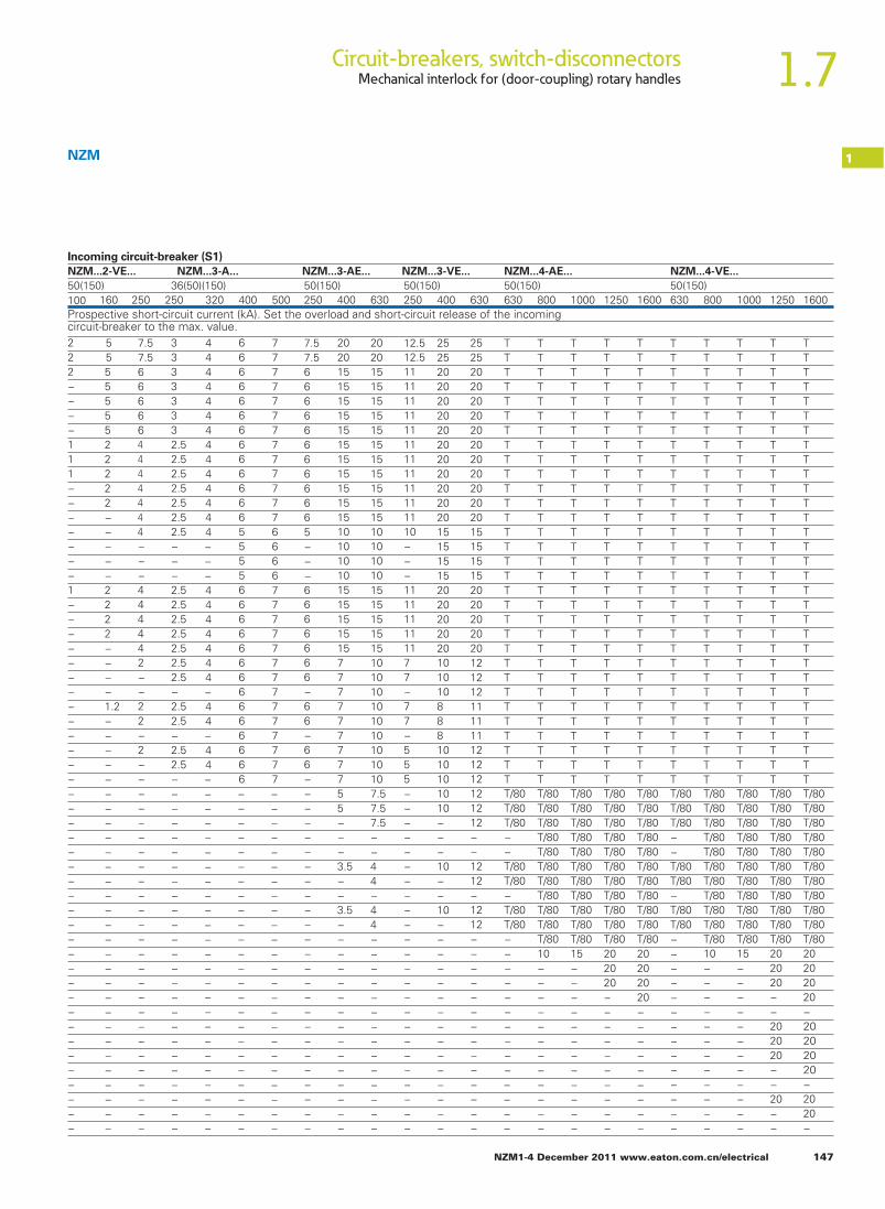
NZM1-4 December 2011 www.eaton.com.cn/electrical 147
1.7Circuit-breakers, switch-disconnectorsMechanical interlock for (door-coupling) rotary handles
1NZM
Incoming circuit-breaker (S1)
Prospective short-circuit current (kA). Set the overload and short-circuit release of the incoming circuit-breaker to the max. value.
NZM...2-VE... NZM...3-A... NZM...3-AE... NZM...3-VE... NZM...4-AE... NZM...4-VE...
50(150) 50(150) 50(150) 50(150) 50(150)36(50)(150)100 160 250 250 320 400 500 250 400 630 250 400 630 630 800 1000 1250 1600 630 800 1000 1250 1600
222−−−−111−−−−−−−1−−−−−−−−−−−−−−−−−−−−−−−−−−−−−−−−−−−−−
555555522222−−−−−2222−−−−1.2−−−−−−−−−−−−−−−−−−−−−−−−−−−−−
7.57.5666664444444−−−444442−−22−2−−−−−−−−−−−−−−−−−−−−−−−−−−
33333332.52.52.52.52.52.52.5−−−2.52.52.52.52.52.52.5−2.52.5−2.52.5−−−−−−−−−−−−−−−−−−−−−−−−−
44444444444444−−−4444444−44−44−−−−−−−−−−−−−−−−−−−−−−−−−
6666666666666555566666666666666−−−−−−−−−−−−−−−−−−−−−−−−
7777777777777666677777777777777−−−−−−−−−−−−−−−−−−−−−−−−
7.57.5666666666665−−−6666666−66−66−−−−−−−−−−−−−−−−−−−−−−−−−
202015
10101010
−−−
15
77777777755−−−3.5−−3.5−−−−−−−−−−−−−−−
202015
15 1515 1515 1515 1515 1515 1515 1515 1515 1515 15
10
1515 1515 1515 1515 15
1010101010101010107.57.57.5−−44−44−−−−−−−−−−−−−−
12.512.5111111111111111111111110
101010
111111111177−77−555−−−−−−−−−−−−−−−−−−−−−−−−
1010108881010101010−−−10−−10−−−−−−−−−−−−−−−
25252020202020202020202020151515152020202020
25252020202020202020202020151515152020202020
121212111111121212121212−−1212−1212−−−−−−−−−−−−−−
T/80 T/80 T/80 T/80 T/80 T/80 T/80 T/80 T/80 T/80T/80 T/80 T/80 T/80 T/80 T/80 T/80 T/80 T/80 T/80T/80 T/80
T/80T/80T/80T/80T/80T/80T/80T/80
T/80 T/80 T/80 T/80T/80 T/80 T/80T/80 T/80 T/80T/80 T/80 T/80 T/80T/80 T/80 T/80 T/80T/80 T/80 T/80T/80 T/80 T/80 T/80T/80 T/80 T/80 T/80T/80 T/80 T/80
T/80 T/80 T/80 T/80T/80 T/80 T/80 T/80T/80 T/80 T/80 T/80T/80 T/80 T/80 T/80T/80 T/80 T/80 T/80T/80 T/80 T/80 T/80T/80 T/80 T/80 T/80T/80 T/80 T/80 T/80T/80 T/80 T/80 T/80
−−T/80T/80−T/80T/80−−−−−−−−−−−−−−
10−−−−−−−−−−−−
15−−−−−−−−−−−−
20
−−−−−−−−−−
2020 2020 20
20−−−−−−−−−
−
−
−
−−
−−−−−−−−−−−−
−−−−−−−−−
−−−−−−−−−
−202020−−20−−
−− − −− − 20− − 2010 15 20 20
202020
20202020−2020−
TTTTTTTTTTTTTTTTTTTTTTTTTTTTTTT
TTTTTTTTTTTTTTTTTTTTTTTTTTTTTTT
TTTTTTTTTTTTTTTTTTTTTTTTTTTTTTT
TTTTTTTTTTTTTTTTTTTTTTTTTTTTTTT
TTTTTTTTTTTTTTTTTTTTTTTTTTTTTTT
TTTTTTTTTTTTTTTTTTTTTTTTTTTTTTT
TTTTTTTTTTTTTTTTTTTTTTTTTTTTTTT
TTTTTTTTTTTTTTTTTTTTTTTTTTTTTTT
TTTTTTTTTTTTTTTTTTTTTTTTTTTTTTT
TTTTTTTTTTTTTTTTTTTTTTTTTTTTTTT

148 NZM1-4 December 2011 www.eaton.com.cn/electrical
1.7 Circuit-breakers, switch-disconnectorsAuxiliary contacts, trip-indicating auxiliary contacts
1Cable protection, back-up protectionProtection of PVC insulated cables against thermal overload dueto short-circuits
According to VDE 0100 Part 430 Wiring Regulations,cables and conductors must be protected fromoverload and short-circuits. In circuit-breakersNZM, overload protection is implemented throughthe adjustable, current-dependently delayed over-load release.
Short-circuit protection is provided by adjustableinstantaneous releases, which open the maincontacts in less than 25 ms. The short-circuit totalopening time restricts the temperature rise of thecable to a minimum.
The tables indicate the minimum conductor cross-section reliably protected by circuit-breakersduring a short-circuit.(Operating voltage UN= 415 V)
Minimum protectedcross-section mm2 copper
NZM...1(-4)-...20 6NZM...1(-4)-...25 – 160 10NZM...2(-4)-...20 – 300 10NZM...3(-4)-...250 – 630 16NZM...4(-4)-...630 – 1600 95
Backup protectionbetween incoming circuit-breaker NZM(N)(H) and outgoing circuit-breaker NZMB(N)(H)
Incoming circuit-breaker ①
NZM1 NZM2 NZM3
In Up to 160 A Up to 250 A Up to 500 A Up to 630 AIcu(415 V) 25 kA 36 kA 50 kA 100 kA 25 kA 36 kA 50 kA 150 kA 36 kA 50 kA 150 kA
Outgoing circuit-breaker ②Icu(415 V) In
NZMB1 25 kA Up to 160 A 36 50 100 25 36 50 100 36 50 100NZMC1 36 kA Up to 160 A – 36 50 100 – 36 50 100 36 50 100NZMN1 50 kA Up to 160 A – – 50 100 – – 50 100 – 50 100NZMH1 100 kA Up to 160 A – – – 100 – – – 100 – – 100NZMB2 25 kA Up to 300 A 25 36 50 100 25 36 50 150 36 50 150NZMC2 36 kA Up to 300 A – 36 50 100 – 36 50 150 36 50 150NZMN2 50 kA Up to 300 A – – 50 100 – – 50 150 – 50 150NZMH2 150 kA Up to 300 A – – – – – – – 150 – – 150NZMC3 36 kA Up to 500 A – – – – – – – – – 50 150NZMN3 50 kA Up to 630 A – – – – – – – – – 50 150NZMH3 150 kA Up to 630 A – – – – – – – – – – 150
Where the prospective fault current at the mountinglocation of circuit-breakers is very high current-limiting circuit-breakers NZMN(H) are normally used.A cost-effective alternative if the fault level is too highfor circuit-breakers NZMB(C)(N) is to fit a current-limiting circuit-breaker NZMN(H) upstream of anarrangement of standard circuit-breakers NZMB(C)(N).
The table shows which current-limiting circuit-breakers NZMN(H) provide reliable protection atnetwork locations with high short-circuit ratingsin combination with NZMB(C)(N).
The selectivity limit is determined by the responsecurrent of the non-delayed short-circuit release inthe upstream incoming circuit-breaker. In manyapplications this is sufficient.
between incoming circuit-breaker NZM...1-A... and outgoing circuit-breaker FAZ-B(C)/PLSM-B(C)...
Outgoing circuit-breaker Incoming circuit-breaker
NZMB1-A... NZMC(N)(H)1-A...
FAZ-B(C)...0.5 – 16 25 kA 30 kA20 – 40 20 kA 20 kA50, 63 15 kA 15 kA
PLSM-B(C)...(/...)0.5 – 16 25 kA 30 kA20 – 40 20 kA 20 kA50, 63 15 kA 15 kA
between incoming circuit-breaker NZM...2-A... and outgoing circuit-breaker FAZ-B(C)/PLSM-B(C)...
Outgoing circuit-breaker Incoming circuit-breaker
NZMB2-A... NZMN(H)2-A...
FAZ-B(C)...0.5 – 10 25 kA 50 kA13 – 32 25 kA 30 kA40 – 63 20 kA 20 kA
PLSM-B(C)...(/...)0.5 – 10 25 kA 50 kA13 – 32 25 kA 30 kA40 – 63 20 kA 20 kA
b
Icc
a
NZM...
NZM...
Icc
FAZ...PLSM...
NZM...
Icc
FAZ...PLSM...
NZM...
NZM1, NZM2, NZM3
25

NZM1-4 December 2011 www.eaton.com.cn/electrical 149
1.7Circuit-breakers, switch-disconnectorsMechanical interlock for (door-coupling) rotary handles
1Direction of blow-out
Tube cable lugs, dimensions
For pressing the cable lugs a press tool K22, HK60/22 or EK22from Klauke with the following press inserts is required:R22/95 for 95 mm2
R22/120 for 120 mm2
R22/150 for 150 mm2
R22/185 for 185 mm2
R22/240 for 240 mm2
Top, front
Bottom, rear
NZM1 X –NZMB(C)2-A... 250 X –(P)N2(-4)-... X –NZMN(H)2... X XNZM...2-4.. X XNZM3 X XNZM4 X –
Minimum clearances
b ba
cd
g
ed
a
ifb
hc
NZM1, NZM2, NZM3, NZM4
between two adjacently mounted switchesMinimum clearance a in mm
between switches and other partsMinimum clearances in mm
NZM1
NZM2
NZM3
NZM4
dcb1000 V 1000 V
NZM1
NZM21)
NZM3
NZM4
1)NZMB(C)2 – A … ≦440 V: C= 20 mm, d = 0 mm ≦690 V: C= 60 mm, d = 0 mm
2)At 690 V IT network: 200 mm
05515
−5515
30201) 351)
1001)
3050
60
60
05515
55515
55515
−3560200
035600
−35600
≦440V ≦690V 1000 V≦690V ≦690V
NZM1 NZM2 NZM3
15151515
NZM4
Nominal cross section
Terminal bolt
mm2
KS95-NZM7KS120-NZM7KS150-NZM7NZM2-XKS185NZM3-XKS185NZM3-XKS240
NZM2NZM2NZM2NZM2NZM3,NZM4NZM3,NZM4
Cable lug For use with Dimensions in mm
95120150185185240
M8M8M8M8M10M10
Ø a b c d e f g h i53+2
56+2
61+2
65±1.5
6572
23±0.5
23±0.5
23±0.5
22±1
24.531
18±0.2
19.5±0.2
21±0.2
24±0.3
2426
10±1
10±1
10±1
11.511.5
19 8.5 25 13.5 4.419 8.5 26 15 4.419 8.5 30 16.5 4.4
1819
10.510.5
30±2
3035
19±0.4
0.7±0.8
5.0±0.8
1921
79-0.5+1 19-0.5
+2.5 8.5-0.5+0.05

150 NZM1-4 December 2011 www.eaton.com.cn/electrical
1
1.7 Circuit-breakers, switch-disconnectorsAuxiliary contacts, trip-indicating auxiliary contacts
Engineering
Front cut-outs Cut-out aRocker lever
Cut-outbRotary handle, remote operator
Distance from mounting plate and door cut-out
Cut-out Cut-out
Contact sequence of the auxiliary contacts Standard auxiliary contacts (HIN)
■ Contact closed□ Contact opened
0 → I Switch-on0 ← I Switch-off+← I Trip
Notes If early-make contacts are required in combination with shunt orundervoltage releases, please select the combination type in section “Releases”
f
e
Y
X
f
e
Y
X X
c
d
b
a
L1L2L3
HIN
L1L2L3
HIN
L1L2L3
HIN
I
I
+ I
+
+
+
L1L2L3
HIV
I
I
++
+
+
I
L1L2L3
HIV
L1L2L3
HIV
NZM 1, 2, 3
L1L2L3
HIV
I
I
++
+
+
I
L1L2L3
HIV
L1L2L3
HIV
NZM 1, 2, 3
L1L2L3
HIA
L1L2L3
HIA
L1L2L3
HIA
+
+
+I
I
+I
NZM1, NZM2, NZM3, NZ M4
NZM1NZM2NZM3NZM4
68103120.5138
68103120.5138
68103120.5138
68103120.5138
68103120.5138
68
103
120.5138
c d e f e f
mm mm mm mm mm mm
Trip-indicating auxiliary contacts(HIA)Early-make auxiliary contact(HIV)

1
NZM1-4 December 2011 www.eaton.com.cn/electrical 151
1.7Circuit-breakers, switch-disconnectorsMechanical interlock for (door-coupling) rotary handles
Mechanical interlock for (door-coupling) rotary handles
Interlock variations and combination possibilities
X3p = switch spacing, 3 poleX4p = switch spacing, 4 pole
NZM- Right switchMax. switch spacing
NZM-XBZ600
Max. switch spacing
NZM-XBZ1000
Max. switch spacing
A B
A B C
A B C
A B DC
x3Px4P
x3Px4P
NZM, NZM...-XBZ-...
OFF
OFF OFF OFF
OFF OFFOFFOFF
OFF
ON/TRIP
ON/TRIP
ON/TRIP
ON/TRIPON/TRIP
ON/TRIP
ON/TRIP
ON/TRIP
ONON
ON
ON
ON
ON
ON
ON
ONON
ONON ON
ON
ON
ON/TRIP
ON/TRIP ON/TRIP
ON/TRIP
A B
A B C
A B C
A B C D
NZM-2 NZM-1 NZM-3 NZM-4 X3P X4P X3P X4P X3P X4P X3P X3P
NZM1NZM2NZM3NZM4
3/4 pole3/4 pole3/4 pole3/4 pole
Left switch mm mm mm mm mm mm mm mm1351359050
1051057535
1201207540
85853515
1351358525
909040−
1251258015
808045−
NZM-2 NZM-1 NZM-3 NZM-4 X3P X4P X3P X4P X3P X4P X3P X3P
NZM1NZM2NZM3NZM4
3/4 pole3/4 pole3/4 pole3/4 pole
Left switch mm mm mm mm mm mm mm mm510510460400
480480430370
495495450380
460460410340
510510460400
465465415375
475475460390
405405390320
NZM-2 NZM-1 NZM-3 NZM-4 X3P X4P X3P X4P X3P X4P X3P X3P
NZM1NZM2NZM3NZM4
3/4 pole3/4 pole3/4 pole3/4 pole
Left switch mm mm mm mm mm mm mm mm910910820750
880880790720
895895850730
860860810700
910910860800
865865815775
865865860790
795795790720

1.7 Circuit-breakers, switch-disconnectorsMechanical interlock for remote operator, residual-current relay
152 NZM1-4 December 2011 www.eaton.com.cn/electrical
1
2010 CA08103002Z-EN www.eaton.com
Residual-current relay PFRRing-type transformer PFR-W...
Mechanical interlock XMVRNZM...-XMVR (mounted side-by-side)Max. switch spacing
X3p elop 3 gnicaps hctiws .xam = X4p elop 4 gnicaps hctiws .xam =
Mechanical interlock XMVRLNZM...-XMVRL (mounted side-by-side, in adjacent enclosures)Max. switch spacing Right switch
NZM2 NZM3 NZM4X3p X4p X3p X4p X3p X4p
mm mm mm mm mm mm350 315 420 385 – –
– – 400 365 460 390
hctiws tfeLelop 4/32MZN
NZM3 3/4 poleNZM4 3/4 pole – – – – 420 350
Mechanical interlock XMVRLNZM…-XMVRL (mounted one above the other)Max. switch spacing Switch at
topNZM2 NZM3 NZM4
3/4 pole 3/4 pole 3/4 poleY Y Ymm mm mm220 225 –– 220 230– – 230
Switch at bottomNZM2 3/4 poleNZM3 3/4 poleNZM4 3/4 pole
Y = max. switch spacing
Right switchNZM2 NZM3 NZM4
X3p X4p X3p X4p X3p X4p
Left switch mm mm mm mm mm mmNZM2 3/4 pole 130 95 95 50 – –NZM3 3/4 pole – – 135 90 155 85NZM4 3/4 pole – – – – 120 50
x3P
x4P
Y
Maximum rated operational current [A]
Diameter
Power distribution Motor/capacitor Transformer part no. PFR-W-…d1
Maximum conductor circum-ference (mm)d2
50 50 20 13150 100 30 20150 100 35 23400 200 70 47600 250 105 70
1200 630 140 931800 800 210 140
d2
d1 f 1.5 x d2
NZM...-XMVR(L)

1.7 Circuit-breakers, switch-disconnectorsSide wall operator, 2/3-wire control remote operator
NZM1-4 December 2011 www.eaton.com.cn/electrical 153
1
Side wall operator, 2/3-wire control remote operator
Additional terminal arrangement for side wall operator with mounting bracket.NZM1-XS(R)M-..., NZM2-XS(R)M-... Additional terminals K25, K50, K95, K150Actuation:
Example : In mounting area MI, variation option 1 allows the K25 additional terminal to be mounted twice.
elop 4elop 3For operation on the right For operation on the left For operation on the right For operation on the left
MIMII MI MII MI MII
IIMIMsaera gnitnuoM2V1V4V3V2V1Vsnoitpo noitairaV
Maximum number of additional terminals
K25 2 x – – – – –K50 – 2 x – – – –K95 – – 1 x – 1 x –K150 – – – 1 x – 1 x
2/3-wire control remote operator Please note for engineering:
:17/07 lanimreTlortnoc eriw-eerhTNZM-XR: Contact loading according to technical dataNZM2-XRD: Full current flows though the contact during make and break!RMQ series contact elements can be used fo r the remote operators.NZM2(3.4)-XR(D)...
:57 lanimreTlortnoc eriw-owTNZM-XR: Operational readiness signal when cover closed and not locked.NZM2-XRD: Operational readiness signal when sliding switch set to Auto.Sliding switch with three positions: Manual/Auto/Locked for reliable differentiation of operating positions.AC-15: 400 V; 2 ADC-13: 220 V; 0.2 A
Three-wire control with auto matic reset to the 0 positi on after the switch has tripped
Switching cycle:RX-2MZNDRX-2MZN
NZM3-XR
The time interval between OFF and ON is 3 seconds. ON commands received during the time interval are ignored within the first 3 seconds after switch off.
NZM4-XR
71 7270
7475
N(L1–, L2)
L1(L1+)
H10 I
71 7270
7475
N(L1–, L2)
L1(L1+)
H1S
0 I
71 7270
7475
N(L1–, L2)
L1(L1+)
H1HIA0 I
r r r 170 ms
r OFF ON OFF ONON OFF
F 170 msr r r
60 ms t > 3 sr
60 ms
OFF ON OFF ONON OFF
r r r80 ms t > 3 s
r 80 ms
OFF ON OFF ONON OFF
r r r100 ms t > 3 s
r 100 ms
OFF ON OFF ONON OFF
NZM-XS(R)M, NZM...XRD

1.7 Circuit-breakers, switch-disconnectorsConstruction size 1, 2:tripping characteristics
154 NZM1-4 December 2011 www.eaton.com.cn/electrical
1
Trip
ping
tim
e [s
]
Setting range
Toler
ance
t r [s]
2 3 4 5 6 7 8 9 10 15 20 30 40 50 60 70 80 100
x Ir
10.001
0.002
0.0040.0060.008
0.01
0.02
0.040.060.08
0.1
0.2
0.40.60.8
1
2
468
10
20
40 60
600
80100
60002.5 h
200
400
8001000
2000
4000
8000
(10 min)
(1 min)
10 x I nIi = 6
NZM1(-4)-A...
Trip
ping
tim
e [s
]
Setting range
Toler
ance
t r [s]
NZM1-M...
2 3 4 5 6 7 8 9 10 15 20 30 40 50 60 70 80 10010.001
0.002
0.0040.0060.008
0.01
0.02
0.040.060.08
0.1
0.2
0.40.60.8
1
2
468
10
20
40 60
600
80100
60002.5 h
x Ir
14x InIi = 8
200
400
8001000
2000
4000
8000
(10 min)
(1 min)
Trip
ping
tim
e [s
]
Setting range
Toler
ance
t r [s]
2 3 4 5 6 7 8 9 10 15 20 30 40 50 60 70 80 100
x Ir
10.001
0.002
0.0040.0060.008
0.01
0.02
0.040.060.08
0.1
0.2
0.40.60.8
1
2
468
10
20
40 60
600
80100
60002.5 h
200
400
8001000
2000
4000
8000
(10 min)
(1 min)
10 x I nIi = 6
NZM2(-4)-A...
Trip
ping
tim
e [s]
Setting range
Toler
ance
t r [s]
NZM2-M...
2 3 4 5 6 7 8 9 10 15 20 30 40 50 60 70 80 10010.001
0.002
0.0040.0060.008
0.01
0.02
0.040.060.08
0.1
0.2
0.40.60.8
1
2
468
10
20
40 60
600
80100
60002.5 h
200
400
8001000
2000
4000
8000
(10 min)
(1 min)
x Ir
14x InIi = 8
NZM1, NZM2
System and line protection with NZM1 Motor protection with NZM1
System and line protection with NZM2 Motor protection with NZM2
With the free CurveSelect software you can quickly and easily create detailed representations of individual settings:www.moeller.net, Products & Solutions>Power Distribution>Switching and Protecting Power Distribution>CurveSelect: Characteristics program.
Notes

1.7Circuit-breakers, switch-disconnectorsConstruction size 2, 3:tripping characteristics
NZM1-4 December 2011 www.eaton.com.cn/electrical 155
1
Characteristics for I r = 1,0 x I n
Trip
ping
tim
e [s]
1000 750 500
300 200
100 60
20 2 3 4 5 6 7 8 9 10
0
Ii = 12 x In
Isd = x Ir
tsd [ms]
20 tr [s]
17 14 10
6 8
4
2
2 3 4 5 6 7 8 9 10 15 20 30 40 50 60 70 80 100
x Ir
1 0.001
0.002
0.004 0.006 0.008
0.01
0.02
0.04 0.06 0.08
0.1
0.2
0.4 0.6 0.8
1
2
4 6 8
10
20
40 60
600
80 100
6000 2.5 h
200
400
800 1000
2000
4000
8000
(10 min)
(1 min)
NZM2(-4)-VE...
2 3 4 5 6 8 10 12 14 Ii = x Ir
20 tr [s]
17 14 10
6 8
4
2
NZM2-ME...
2 3 4 5 6 7 8 9 10 15 20 30 40 50 60 70 80 100
x Ir
1 0.001
0.002
0.004 0.006 0.008
0.01
0.02
0.04 0.06 0.08
0.1
0.2
0.4 0.6 0.8
1
2
4 6 8
10
20
40 60
600
80 100
6000 2.5 h
200
400
800 1000
2000
4000
8000
(10 min)
(1 min)
Trip
ping
tim
e [s]
Characteristics for I r = 1,0 x I n
Trip
ping
tim
e [s]
Setting range
Toler
ance
t r [s]
Characteristics for Ir = 1,0 x In
2 3 4 5 6 7 8 9 10 15 20 30 40 50 60 70 80 100
x I r
1 0.001
0.002
0.004 0.006 0.008
0.01
0.02
0.04 0.06 0.08
0.1
0.2
0.4 0.6 0.8
1
2
4 6 8
10
20
40 60
600
80 100
6000 h 5.2
200
400
800 1000
2000
4000
8000
10 x I n
NZM3(-4)-A...
I i = 6
(10 min)
(1 min)
Trip
ping
tim
e [s] Characteristics for I r = 1,0 x I n
65432 7 8 9 11 250 A, 400 Ax InIi =
63.52.5 32 854 7 630 AIi = x In
2 3 4 5 6 7 8 9 10 15 20 30 40 50 60 70 80 100
x Ir
10.001
0.002
0.0040.0060.008
0.01
0.02
0.040.060.08
0.1
0.2
0.40.60.8
1
2
468
10
20
40 60
600
80100
60002.5 h
200
400
8001000
2000
4000
8000
(10 min)
(1 min)
NZM3(-4)-AE...
NZM2, NZM3
Systems, cable, selectivity and generator protection with NZM2 Motor protection with NZM2
System and line protection with NZM3
With the free CurveSelect software you can quickly and easily create detailed representations of individual settings:www.moeller.net, Products & Solutions>Power Distribution>Switching and Protecting Power Distribution>CurveSelect: Characteristics program
Notes

1.7 Circuit-breakers, switch-disconnectorsConstruction size 3, 4:tripping characteristics
156 NZM1-4 December 2011 www.eaton.com.cn/electrical
1
Trip
ping
tim
e [s
] Characteristics for I r = 1,0 x I n
without “I 2t = constant” function
250 A, 400 A
250 A, 400 A
1000750500300200
10060
20
2 3 4 5 6 7
7
8 9 10
6
0
5432 7 8 9 11 x I nIi =
Isd =
6543.52.5 32 7 8 630 AIi = x In
x Ir
tsd [ms]
62 3 3.52.51.5 4 5 630 AIsd = x Ir
20tr [s]
171410
68
4
2
2 3 4 5 6 7 8 9 10 15 20 30 40 50 60 70 80 100
x Ir
10.001
0.002
0.0040.0060.008
0.01
0.02
0.040.060.08
0.1
0.2
0.40.60.8
1
2
468
10
20
40 60
600
80100
60002.5 h
200
400
8001000
2000
4000
8000
(10 min)
(1 min)
NZM3(-4)-VE...
Characteristics for I r = 1,0 x I n
I2t = constant
Trip
ping
tim
e [s
]
250 A, 400 A
250 A, 400 A
2 3 4 5 6 8 910 x I r
21.5 2.5 3.53 4 5 6 7
7
Isd =
Isd =
x Ir
20tr [s]
171410
68
4
2
630 A
2 3 4 5 6 7 8 9 11Ii = x In
2 2.5 3.53 4 5 6 8Ii = x In7 630 A
1 2 3 4 5 6 7 8 9 10 15 20 30 40 50 60 70 80 100
x Ir
tsd [m
s] = 20.....
...1000
0.001
0.002
0.0040.0060.008
0.01
0.02
0.040.060.08
0.1
0.2
0.40.60.8
1
2
468
10
20
40 60
600
80100
60002.5 h
200
400
8001000
2000
4000
8000
(10 min)
(1 min)
NZM3(-4)-VE...
2 3 4 5 6 8 10 12 14Ii = x Ir
20tr [s]
171410
68
4
2
NZM3-ME...
2 3 4 5 6 7 8 9 10 15 20 30 40 50 60 70 80 100
x Ir
10.001
0.002
0.0040.0060.008
0.01
0.02
0.040.060.08
0.1
0.2
0.40.60.8
1
2
468
10
20
40 60
600
80100
60002.5 h
200
400
8001000
2000
4000
8000
(10 min)
(1 min)
Characteristics for I r = 1,0 x I n
Trip
ping
tim
e [s
]
NZM3, NZM4Systems, cable, selectivity and generator protection with NZM3
Motor protection with NZM3
With the free CurveSelect software you can quickly and easily create detailed representations of individual settings:www.moeller.net, Products & Solutions>Power Distribution>Switching and Protecting Power Distribution>CurveSelect: Characteristics program
Notes

1.7Circuit-breakers, switch-disconnectorsConstruction size 4: tripping characteristics
NZM1-4 December 2011 www.eaton.com.cn/electrical 157
1Construction size 4: tripping characteristics
Trip
ping
tim
e [s]
Characteristics for I r = 1,0 x I n
10.001
0.002
0.0040.0060.008
0.01
0.02
0.040.060.08
0.1
0.2
0.40.60.8
1
2
468
10
20
40 60
600
80100
60002.5 h
200
400
8001000
2000
4000
8000
(10 min)
(1 min)
65432 7 8 10 12x I nIi =
2 3 4 5 6 7 8 9 10 15 20 30 40 50 60 70 80 100
x Ir
NZM4(-4)-AE...
Trip
ping
tim
e [s
] Characteristics for I r = 1,0 x I n
without “I 2t = constant” function
NZM4(-4)-VE(F)...
10007505003002001006020
6542 3 7 8 9 10
0
x IrIsd =
6542 3 7 8 10 12 x InIi =
tsd [ms]
20tr [s]
171410
68
4
2
2 3 4 5 6 7 8 9 10 15 20 30 40 50 60 70 80 100
x Ir
10.001
0.002
0.0040.0060.008
0.01
0.02
0.040.060.08
0.1
0.2
0.40.60.8
1
2
468
10
20
40 60
600
80100
60002.5 h
200
400
8001000
2000
4000
8000
(10 min)
(1 min)
Trip
ping
tim
e [s]
Characteristics for I r = 1,0 x I n
I2t = constant
6542 3 7 8 9 10
2 3 4 5 6 7 8 9 10 15 20 30 40 50 60 70 80 100
Isd =
t sd [m
s] =
20..........
..1000
6542 3 7 8 10 12 x In
x Ir
Ii =
20tr [s]
171410
68
4
2
x Ir
10.001
0.002
0.0040.0060.008
0.01
0.02
0.040.060.08
0.1
0.2
0.40.60.8
1
2
468
10
20
40 60
600
80100
60002.5 h
200
400
8001000
2000
4000
8000
(10 min)
(1 min)
NZM4(-4)-VE...
Characteristics for I r = 1,0 x I n
Trip
ping
tim
e [s
]
2 3 4 5 6 8 10 12 14Ii = x Ir
20tr [s]
171410
68
4
2
NZM4-ME...
2 3 4 5 6 7 8 9 10 15 20 30 40 50 60 70 80 100
x Ir
10.001
0.002
0.0040.0060.008
0.01
0.02
0.060.04
0.080.1
0.2
0.40.60.8
1
2
468
10
20
40 60
600
80100
60002.5 h
200
400
8001000
2000
4000
8000
(10 min)
(1 min)
NZM4System and line protection with NZM4 Systems, cable, selectivity and generator protection with NZM4
Systems, cable, selectivity and generator protection with NZM4 Motor protection with NZM4

1.7 Circuit-breakers, switch-disconnectorsConstruction size 1: let-through characteristsics
158 NZM1-4 December 2011 www.eaton.com.cn/electrical
1
3
6
4
20
108
100
60
200
40
80
1 6 5 108 15 20 41 3 052 40 8060 100 15030
2 x I cc
415 V+440 V
[kA]ÎD NZMB1(-4)-A(M,S)1,2...160
[kA]Icc rms
2
6
4
20
108
100
60
200
40
80
1 6 5 108 15 20 41 3 0510012 3525
2 x I cc
[kA]ÎD
50 8560
NZMB1-A(AF)...-NA
480 V
240 V
[kA]Icc rms
NZMC1-A20...160
3
6
4
20
10 8
100
60
200
40
80
1 6 5 10 8 15 20 4 1 3 05 2 40 80 60 100 150 30
2 x I cc
415 V
[kA] ÎD
690 V
440 V
525 V
[kA] Icc rms
3
6
4
20
108
100
60
200
40
80
1 6 5 108 15 20 41 3 052 40 8060 100 15030
2 x I cc
415 V
525 V690 V
[kA]ÎD NZMN1(-4)-A(M,S)1,2...160
[kA]Icc rms
2
6
4
20
108
100
60
200
40
80
1 6 5 108 15 20 41 3 0510012 3525
2 x I cc
[kA]ÎD
50 8560
NZMN1-A(AF)...-NA
480 V
240 V
[kA]Icc rms
NZMH1(-4)-A20...160
3
6
4
20
10 8
100
60
200
40
80
1 6 5 10 8 15 20 4 1 3 051 001 2 30
690 V
525 V
415 V
2 x I cc
[kA] ÎD
50 40 80 60 [kA] Icc rms
NZM1Let-through current ÎD

1.7Circuit-breakers, switch-disconnectorsConstruction size 2: let-through characteristics
NZM1-4 December 2011 www.eaton.com.cn/electrical 159
1
3
6
4
20
108
100
60
200
40
80
1 6 5 108 15 20 41 3 052 40 8060 100 15030
2 x I cc
[kA]ÎD NZMB2(-4)-A(M,S)1,6...300
440 VNZMB2-A160...300
415 V+440 VNZMB2(-4-A)-M20...250NZMB2...
[kA]Icc rms
2
6
4
20
10 8
100
60
200
40
80
1 6 5 10 15 8 18 20 4 1 3 051 001 2
2 x I
cc
[kA] ÎD
50 80 60
NZMB2-A(AF)...-NA
25 35
480 V
600 V
240 V
[kA]I cc rms
3
6
4
20
108
100
60
200
40
80
1 6 5 108 15 20 41 3 052 40 8060 100 15030
2 x I cc
[kA]ÎD NZMC2-A160...300
690 V525 V
440 V
[kA]Icc rms
NZMN2(-4)-A(M,S,VE,ME,SE)1,6...300
3
6
4
20
108
100
60
200
40
80
1 6 5 108 15 20 41 3 0510012 30
2 x I cc
[kA]ÎD
5040 8060
690 V
525 V
415 V
[kA]Icc rms
480 V
600 V
2
6
4
20
10 8
100
60
200
40
80
1 6 5 10 8 15 20 4 1 3 051 001 2 25
2 x I
cc
[kA] ÎD
50 35 85 60
NZMN2-A(AF)...-NA
240 V
[kA] I cc rms
2
6
4
20
10 8
100
60
200
40
80
1 6 5 10 8 18 4 1 3 051 001 2 25 30
2 x I
cc
[kA] ÎD
50 35 85 60
NZMN2-VE(VEF)...-NA
480 V
600 V
240 V
[kA] I cc rms
[kA]ÎD
3
6
4
20
108
100
60
200
40
80
1 6 5 108 15 20 41 3 0510012 30
415 V525 V
2 x I cc
5040 8060
NZMH2(-4)-A(M,VE,ME)15...300
690 V
[kA]Icc rms
2
6
4
20
10 8
100
60
200
40
80
1 6 5 10 8 15 20 4 1 3 051 001 2 30
2 x I
cc
[kA] ÎD
50 40 80 60
NZMH2-A(AF)...-NA
480 V
600 V
240 V
[kA] I cc rms
3
6
4
20
10 8
100
60
200
40
80
1 6 5 10 8 15 20 4 1 3 051 001 2 30
2 x I
cc
[kA] ÎD
50 40 80 60
NZMH2-VE(VEF)...-NA
480 V
600 V
240 V
[kA] I cc rms
NZM2Let-through current ÎD

1.7 Circuit-breakers, switch-disconnectorsConstruction size 3: let-through characteristics
160 NZM1-4 December 2011 www.eaton.com.cn/electrical
1
[kA]ÎD
5 6 108 15 20 41 2 3 100 15030 5040 8060
NZMC3(-4)-A...
415 V
525 V
40
20
108
6
4
3
1
200
10080
60
2 x Icc
[kA]Icc rms
5 6 108 15 20 41 2 3 100 15030 5040 8060
NZMN3(-4)-A...
525 V
690 V
415 V
40
20
108
6
4
3
1
200
10080
60
2 x Icc
[kA]ÎD
[kA]Icc rms
40
20
108
6
4
3
1
200
10080
60
5 6 108 15 20 41 2 3 100 15030 5040 8060
NZMH3(-4)-A...
525 V
690 V
415 V
2 x Icc
[kA]ÎD
[kA]Icc rms
3
6
4
20
108
100
60
200
40
80
1 6 5 108 15 20 41 3 0510012 30
2 x I cc
[kA]ÎD
5040 8060
NZMN3(-4)-AE(VE,ME)220...630
415 V
525 V
690 V
[kA]Icc rms
2
6
4
20
10 8
100
60
200
40
80
1 6 5 10 8 15 20 4 1 3 051 001 2 35
2 x I
cc
[kA] ÎD
42 85 60
NZMN3-VE...-NA
240 V
480 V
600 V
[kA] I cc rms
3
6
4
20
108
100
60
200
40
80
1 6 5 108 15 20 41 3 0510012 30
2 x I cc
[kA]ÎD
5040 8060
NZMH3(-4)-AE(VE,ME)220...630
690 V
525 V
415 V
[kA]Icc rms
2
6
4
20
10 8
100
60
200
40
80
1 6 5 10 8 15 20 4 1 3 051 001 2 30
2 x I
cc
[kA] ÎD
50 40 80 60
NZMH3-VE...-NA
240 V
480 V
600 V
[kA] I cc rms
NZM3Let-through current ÎD

1.7Circuit-breakers, switch-disconnectorsConstruction size 1: let-through characteristics
NZM1-4 December 2011 www.eaton.com.cn/electrical 161
1
① 1 half-cycle ① 1 half-cycle
415 V
a
2
6
4
4
2
8
68
6
4
2
8
105
106
107
104
6 5 108 15 20 41 3 0510012 30
[A2 s]
5040 8060
NZMB1(-4)-A(M,S)1,2...160
440 V
[kA]Icc rms
2
6
4
4
2
8
68
6
4
2
8
105
106
107
104
6 5 108 15 20 25 41 3 0510012 35
[A2 s]
50 8560
NZMB1-A(AF)...-NA
104
2
I cc
480 V
240 V
[kA]Icc rms
NZMC1-A20...160
690 V
a
2
6
4
4
2
8
68
6
4
2
8
105
106
107
104
6 5 108 15 20 41 3 0510012 30
[A2 s]
5040 8060
440 V
525 V
415 V
[kA]Icc rms
415 V
690 V
525 V
a
2
6
4
4
2
8
68
6
4
2
8
105
106
107
104
6 5 108 15 20 41 3 0510012 30
[A2 s]
5040 8060
NZMN1(-4)-A(M,S)1,2...160
[kA]Icc rms
2
6
4
4
2
8
68
6
4
2
8
105
106
107
104
6 5 108 15 20 41 3 0510012 35
[A2 s]
50 8560
NZMN1-A(AF)...-NA
104
2
I cc
480 V
240 V
[kA]Icc rms
a
415 V
525 V
690 V
2
6
4
4
2
8
6 8
6
4
2
8
105
106
107
104
6 5 10 8 15 20 4 1 3 051 001 2 30
[A2 s] NZMH1(-4)-A20...160
50 40 80 60
[kA] Icc rms
NZM1Let-through energy I2t
∫i2dt ∫i2dt ∫i2dt
∫i2dt∫i2dt∫i2dt

1.7 Circuit-breakers, switch-disconnectorsConstruction size 2: let-through characteristics
162 NZM1-4 December 2011 www.eaton.com.cn/electrical
1 NZM2Let-through energy I2t
a
2
6
4
4
2
8
68
6
4
2
8
105
106
107
104
6 5 108 15 20 41 3 0510012 30 5040 8060
NZMB2(-4)-A(M,S)1,6...300
415 V+440 VNZMB2(-4-A)M20...300NZMB2...
440 VNZMB2-A160...300
2
6
4
4
2
8
6 8
6
4
2
8
10 5
10 6
10 7
10 4
6 5 10 8 15 18 4 1 3 051 001 2 25 50 35 80 60
NZMB2-A(AF)...-NA
104 2
I cc
480 V
600 V
240 V
a
2
6
4
4
2
8
68
6
4
2
8
105
106
107
104
6 5 108 15 20 41 3 0510012 30 5040 8060
NZMC2-A160...300
690 V
440 V
525 V
a
2
6
4
4
2
8
68
6
4
2
8
105
106
107
104
6 5 108 15 20 41 3 0510012 30 5040 8060
415 V
525 V
690 V
NZMN2(-4)-A(M,S,VE,ME,SE)1,6...300
2
6
4
4
2
8
6 8
6
4
2
8
10 5
10 6
10 7
10 4
6 5 10 8 15 25 4 1 3 051 001 2 35 50 85 60
NZMN2-A(AF)...-NA
104 2
I cc
480 V
600 V
240 V
a
2
6
4
4
2
8
68
6
4
2
8
105
106
107
104
6 5 108 15 20 41 3 0510012 30 5040 8060
415 V
525 V
690 V
NZMH2(-4)-A(M,VE,ME)15...300
2
6
4
4
2
8
6 8
6
4
2
8
10 5
10 6
10 7
10 4
6 5 10 8 15 18 4 1 3 051 001 2 25
50 40 35 85 60
NZMN2-VE(VEF)...-NA
104 2
I cc
480 V
600 V
240 V
2
6
4
4
2
8
6 8
6
4
2
8
10 5
10 6
10 7
10 4
6 5 10 8 15 20 4 1 3 051 001 2 30 50 40 80 60
NZMH2-A(AF)...-NA
104 2
I cc
480 V
600 V
240 V
2
6
4
4
2
8
6 8
6
4
2
8
10 5
10 6
10 7
10 4
6 5 10 8 15 20 4 1 3 051 001 2 30 50 40 80 60
NZMH2-VE(VEF)...-NA
104 2
I cc
480 V
600 V
240 V
∫i2dt[A2 s]
∫i2dt[A2 s]
∫i2dt[A2 s]
∫i2dt[A2 s]
∫i2dt[A2 s]
∫i2dt[A2 s]
∫i2dt[A2 s]
∫i2dt[A2 s]
∫i2dt[A2 s]
①1 half-cycle ①1 half-cycle

1.7Circuit-breakers, switch-disconnectorsConstruction size 3: let-through characteristics
NZM1-4 December 2011 www.eaton.com.cn/electrical 163
1NZM3
a
2
6
4
4
2
8
68
6
4
2
8
105
106
107
104
6 5 108 15 20 41 3 0510012 30 5040 8060
NZMN3(-4)-AE(VE,ME)220...630
415 V
525 V
690 V
415 V
525 V
690 V
a
2
6
4
4
2
8
68
6
4
2
8
105
106
107
104
6 5 108 15 20 41 3 0510012 30 5040 8060
NZMH3(-4)-AE(VE,ME)220...630
2
6
4
4
2
8
68
6
4
2
8
105
106
107
104 5 6 108 15 20 41 2 3 10015030 5040 8060
NZMC3(-4)-A...
525 V
415 V
a
a
2
6
4
4
2
8
68
6
4
2
8
5 6 108 15 20 41 2 3 100 15030 5040 8060
NZMN3(-4)-A...
690 V
525 V
415 V
105
106
107
104
2
6
4
4
2
8
68
6
4
2
8
105
106
107
104 5 6 108 15 20 41 2 3 100 15030 5040 8060
NZMH3(-4)-A...
690 V
525 V
415 V
a
2
6
4
4
2
8
6 8
6
4
2
8
10 5
10 6
10 7
10 4
6 5 10 8 15 20 4 1 3 051 001 2 35 50 42 85 60
NZMN3-VE...-NA
104 2
I cc
480 V
600 V
240 V
2
6
4
4
2
8
6 8
6
4
2
8
10 5
10 6
10 7
10 4
6 5 10 8 15 20 4 1 3 051 001 2 30 50 40 80 60
NZMH3-VE...-NA
104 2
I cc
480 V
600 V
240 V
∫i2dt[A2 s]
∫i2dt[A2 s]
∫i2dt[A2 s]
∫i2dt[A2 s]
I2t[A2 s]
I2t[A2 s]
I2t[A2 s]
Let-through energy I2t

1.7 Circuit-breakers, switch-disconnectorsConstruction size 3: let-through energy
164 NZM1-4 December 2011 www.eaton.com.cn/electrical
1 NZM2...XFIAFrequency response+NZM2-4-XFIA3030 mA
+NZM2-4-XFIA100 mA
1 10 100 1000
1000
10000
100
1010000 100000
[Hz]f
1 10 100 1000
1000
10000
100
1010000 100000
[Hz]f
1 10 100 1000
1000
10000
100
1010000 100000
[Hz]f
1 10 100 1000
10000
100000
1000
10010000 100000
[Hz]f
I∆n[mA]
I∆n[mA]
I∆n[mA]
I∆n[mA]
+NZM2-4-XFIA300 mA 1000 mA

1.8Circuit-breakers, switch-disconnectors
NZM1-4 December 2011 www.eaton.com.cn/electrical 165
1Technical data
Direction of incoming supplyDegree of protection
DeviceEnclosure
Terminal type
Any
In the area of the HMI devices: IP20 (basic degree of protection)With insulating surround: IP40With door coupling rotary handle: IP66Tunnel terminal: IP10Phase isolator and cable terminal: IP00Rated uninterrupted current max. 160 A max. 300 A max. 630 A max. 1600 ANZMB1 NZMC1 NZMN1 NZMB2 NZMC2 NZMN2 NZMC3 NZMN3 NZMN4 NZMH4
NZMH1 NZMH2 NZMH3
6000 6000 6000 8000 8000 8000 8000 8000 8000 80006000 6000 6000 6000 6000 6000 6000 6000 6000 6000440 690 690 440 690 690 690 690 690 690– – 500 – – 750 750 – – –III/3 III/3 III/3 III/3 III/3 III/3 III/3 III/3 III/3 III/3690 690 690 690 690 1000 1000 1000 1000 1000440 690 690 440 690 690 690 690 525 6902)
With residual-current release XFI:- NZM1, N1, NZM2, N2: vertical and 90° in all directionsWith plug-in adapter elements- NZM1, N1, NZM2, N2: vertical, 90° right/leftWith withdrawable unit:- NZM3, N3: vertical, 90° left- NZM4, N4: verticalWith remote operator:- NZM2, N(S)2, NZM3, N(S)3, NZM4, N(S)4: vertical and 90°in all directions
90�
90�
90�
90�
NZM, PN, N, NS
GeneralStandardsContact protectionClimatic proofing
Ambient temperatureStorageOperationMechanical shock resistance QEC/EN 60068-2-27)Safe isolation according to EN 61140Between auxiliary contacts andmain contactsBetween the auxiliary contactsBuilt-in position
0C0C9
VAC
VAC
IEC/EN 60947 and VDE 0660Finger and back-of-hand proofto DIN EN 50274/VDE 0660 Part 514Damp heat, constant,to IEC 60068-2-78Damp heat, cyclic,to IEC 60068-2-30
-25...+70-25...+7020 (half-sinusoidal shock 20 ms)
500
300Vertical and 900 in all directions
Circuit-breakerRated impulse withstand voltage Uimp
Main contactsAuxiliary contactsRated operating voltage
Overvoltage category/degree of pollutionRated insulation voltageFor use in IT electrical power networks
2)
1) Details apply for 3 pole system protection circuit-breaker with thermomagnetic release NZMN(H)1(2)(3)-A... up to 500 A. For rated operating voltage switching on 3 contacts the following applies DC correction factor for instantaneous release response value NZM1: 1.25, NZM2: 1.35, NZM3: 1.45 Setting for Ii at DC=setting Ii AC/correction factor DC
Notes
Switching of one pole via two series contacts Switching of one pole via three series contacts
2)>800 A=525
VVV ACV DC1)
VV
Ui
Ue

1.8 Circuit-breakers, switch-disconnectors
166 NZM1-4 December 2011 www.eaton.com.cn/electrical
1
63 121 187 22053 76 105 22053 63 74 74– 24 40 40– 14 17 17
30 55 85 10025 36 50 10025 30 35 70– 12 20 20– 8 10 10– – 15 30– – – –30 55 85 10025 36 50 5018.5 22.5 35 35– 6 10 10– 4 7.5 7.5
AC-1
AC-3
DC-13)
DC-33)
AC-1
AC-3
DC-13)
DC-33)
kAkAkAkAkA
kAkAkAkAkAkAkAkAkAkAkAkA
kAkA
AAAAAAAA
– – – –– – – –A A A A
160 160 160 160160 160 160 160160 160 160 160160 160 160 160– – 125 125– – – –– – 125 125– – – –20000 20000 20000 20000
7500 7500 10000 10000– 5000 7500 7500– – 7500 7500– – 5000 5000– – 10000 10000– – – –– – 5000 5000– – – –120 120 120 12016.7 16.7 16.7 16.7< 10 < 10 < 10 < 10
35 – 85 –251) – 351) –– – – –
NZM...1, NZM...2, NZM...3, NZM...4Max. rated uninterrupted current 160 ANZMB1
Switching capacityRated short-circuit making capacity
Rated short-circuit breaking capacity Icy Icy according to IEC/EN 60947 Operating sequence O-t-CO
Ins according to IEC/EN 60947Operating sequence O-t-CO-t-CO
Maximum LV h.b.c. fuses6)
Rated short-time withstand current t=0.3 s t=1sUtilization category according to IEC/EN 60947-2 Rated making and breaking capacity
Rated operationalcurrent
Max. operating frequencyHeat dissipation per pole at Iuc
Total opening delay on short-circuitTechnical data that diverge from products for the IEC marketSwitching capacity of NA switch (UL489, CSA 22.2 No. 5-09)Short-circuit current rating (SCCR)
Lifespan, mechanicalof which max. 50%trip by shunt/undervoltage releaseLifespan, electrical
240 V 50/60 Hz400/415 V 50/60 Hz440 V 50/60 H525 V 50/60 Hz690 V 50/60 Hz500 V DC3)
750 V DC3)
240 V 50/60 Hz400/415 V 50/60 Hz440 V 50/60 Hz525 V 50/60 Hz690 V 50/60 Hz
400/415 V 50/60 Hz690 V 50/60 Hz400/415 V 50/60 Hz690 V 50/60 Hz500 V DC750 V DC500 V DC750 V DC
400/415 V 50/60 Hz690 V 50/60 Hz400/415 V 50/60 Hz690 V 50/60 Hz500 V DC750 V DC500 V DC750 V DC
240 V400/415 V440 V525 V690 V
240 V 60 Hz480 V 60 Hz600 V 60 Hz
Icm
Icm
Icm
Icm
Icm
Icu
Icu
Icu
Icu
Icu
Icu
Icu
Ics
Ics
Ics
Ics
Ics
Icw
Icw
Ie
Ie
Ie
Ie
Ie
Ie
Ie
Ie
Operations
OperationsOperationsOperationsOperationsOperationsOperationsOperationsOperations
Ops/hWmS
kAkAkA
NZMC1 NZMN1 NZMH1
Notes 1) Switching capacity of NA switches with NZM...1-...(C)NA: 480 Y/277 V2) For rated operational current AC-3 with NZM4: 400 V: max. 650 kW; 690 V: max. 600 kW3) DC data apply only for NZM...A... with thermomagnetic release4) For switching capacity NZM2...NA: 600 V/347 V5) For thermal losses per pole the specification refers to the maximum rated operational current of the construction size6) Maximum back-up fuse, if the expected short-circuit currents at the installation location exceed the switching capacity of the circuit-breaker7)For higher switching capacity please inquire
A gG/gL NZM.1-...20...100: 20CNZM.1-...125,160: 315

1.8Circuit-breakers, switch-disconnectorsMechanical interlock for (door-coupling) rotary handles
NZM1-4 December 2011 www.eaton.com.cn/electrical 167
1Max. rated uninterrupted current 300 A Max. rated uninterrupted current 630 A Max. rated uninterrupted current 1600 ANZMB2 NZMC2 NZMN2 NZMH2 NZMC3 NZMN3 NZMH3 NZMN4 NZMH4
NZM...1, NZM...2, NZM...3, NZM...4
63 121 187 330 121 187 330 105 27553 76 105 330 76 105 330 105 18753 63 74 286 63 74 286 74 187– 24 53 105 24 53 143 53 143– 9 40 40 14 40 74 40 105
30 55 85 150 55 85 150 50 12525 36 50 150 36 50 150 50 8525 30 35 130 30 35 130 35 857)
– 12 25 50 12 25 65 25 65– 8 20 20 8 20 35 20 50– – 30 60 – 30 70 – –– – 30 60 – 30 70 – –30 55 85 150 55 85 150 37 6325 36 50 150 36 50 150 37 4318.5 22.5 35 130 22.5 35 130 26 43– 6 25 37.5 9 13 33 19 49– 4 5 5 4 5 9 15 37355 355 355 355 NZMC3...500: 630 NZMH3-...250,
400: 400NZMH3...500: 630NZMH3...630: 630
NZMH3-...250,400: 400NZMH3...500: 630NZMH3...630: 630
NZMN4-…630…1250: 2 x 630NZMN4-…1600: 2 x 800
– – 1.9 1.9 3.3 3.3 3.3 19.2 19.2– – 1.9 1.9 3.3 3.3 3.3 19.2 19.2A A A A A A A B B
300 300 300 300 500 630 630 1600 1600250 250 250 250 500 630 630 1600 1600300 300 300 300 450 450 450 16002) 16002)
250 250 250 250 450 450 450 16002) 16002)
– – 250 250 – 500 500 – –– – 250 250 – 500 500 – –– – 250 250 – 500 500 – –– – 250 250 – 500 500 – –20000 20000 20000 20000 15000 15000 15000 10000 10000
7500 7500 10000 10000 5000 5000 5000 3000 3000– 7500 7500 7500 3000 3000 3000 2000 2000– – 6500 6500 2000 2000 2000 2000 2000– 5000 5000 5000 2000 2000 2000 1000 1000– – 7500 7500 – 5000 5000 – –– – 7500 7500 – 5000 5000 – –– – 3000 3000 – 2000 2000 – –– – 3000 3000 – 2000 2000 – –120 120 120 120 60 60 60 60 6019 19 19 19 31 31 31 97 97< 10 < 10 < 10 < 10 < 10 < 10 < 10 < 25≤415 V; < 35 > 415 V < 25≤415 V; < 35 > 415 V
35 – 85 150 – 85 150 85 12525 – 35 100 – 42 100 42 85184) – 254) 504) – 35 50 35 50

1.8 Circuit-breakers, switch-disconnectorsCircuit-breakers, switch-disconnectors for 1000 V AC/DC
168 NZM1-4 December 2011 www.eaton.com.cn/electrical
1 NZMH...S1, N...-4...S1-DCCircuit-breakers for 7000 V AC NZMH2...S1
max. 300 ANZMH3...S1max. 630 A
NZMH4...S1max.1600 A
1000 1000 1000
300/50 °C 630/50 °C 1600/50 °C
300 630 1600
17 17 40
10 15 20
3 10 15
A A A/B120 60 60
20000 15000 10000
3000 1000 5001000 1000 1000– – –
Rated operating voltageRated uninterrupted currentRated operational current AC-1Rated short-circuit making capacity 1000 V 50/60 HzRated short-circuit breaking capacity Icn
Iucaccording to IEC/EN 60947 Operating sequence O-t-CO Ics according to IEC/EN 60947 Operating sequence O-t-CO-t-COUtility categoryMaximum operating frequencyDurability Mechanical(of which max. 50% trip by shunt/ undervoltage release) Electrical, AC-1 1000 VRated insulation voltageFor use in IT electrical power networks
V ACA
kA
kA
kA
Ops/h
Operations
OperationsV AC
Ue
Iu
Icm
Icu
Ics
Ui
N2-4...S1-DCmax. 200 A
N3-4...S1-DCmax. 500 A
N4-4...S1-DCmax. 1400 A
1000 1000 1000200/65 °C 500/65 °C 1400/65 °C200 (DC 22-B) 500 (DC 22-B) 1400 (DC 21-B)3 6 2515 15 –200 500 –120 60 60
20000 15000 10000
2500 (DC 22-B) 1000 (DC 22-B) 500 (DC 21-B)1250 1250 12501000 1000 1000
Rated operating voltageRated uninterrupted current withterminaljumpersRated operational currentRated short-time withstand current t =0.1 sRated conditional short-circuit current With back-up fuseMaximum operating frequencyDurability Mechanical (of which max. 50%trip by shunt/ undervoltage release) Electrical, 1000 V DCRated insulation voltageFor use in IT electrical power networks
V DCA
kAkAA9ROps/h
Operations
OperationsV DCV DC
NZM...S1 and N...S1一DC can not be combined with withdrawable units and/or connection on rear.Can not be combined with early-make auxiliary contacts NZM一~.XHIV or boxterminal NZM2-4-XKC at U;>1000 V DCTerminal type N...S1-DC:for 2 pole switches series connection of two poles each is required. See jumper kit NZM...-4-XKV2P
Notes
Ue
Iu
Ie
Icw
Iq
Ui
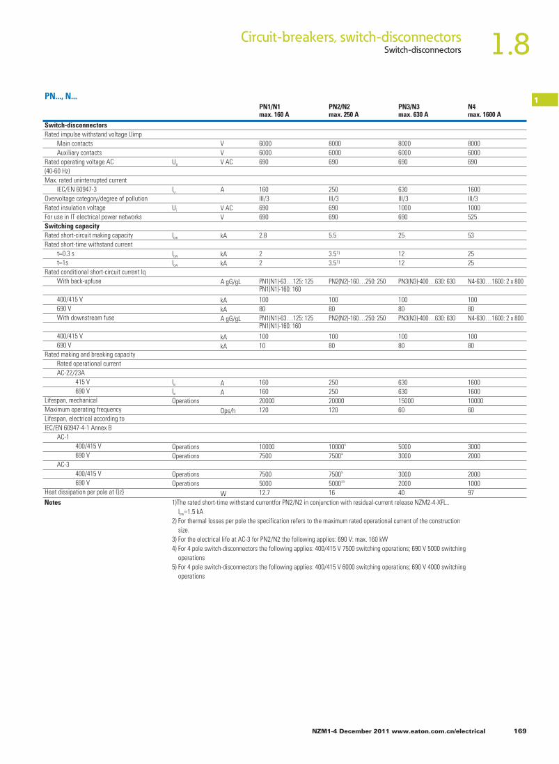
1.8Circuit-breakers, switch-disconnectorsSwitch-disconnectors
NZM1-4 December 2011 www.eaton.com.cn/electrical 169
1PN1/N1max. 160 A
PN2/N2max. 250 A
PN3/N3max. 630 A
N4max. 1600 A
PN..., N...
6000 8000 8000 80006000 6000 6000 6000690 690 690 690
160 250 630 1600III/3 III/3 III/3 III/3690 690 1000 1000690 690 690 525
2.8 5.5 25 53
2 3.51) 12 252 3.51) 12 25
PN1(N1)-63…125: 125PN1(N1)-160: 160
PN2(N2)-160…250: 250 PN3(N3)-400…630: 630 N4-630…1600: 2 x 800
100 100 100 10080 80 80 80PN1(N1)-63…125: 125PN1(N1)-160: 160
PN2(N2)-160…250: 250 PN3(N3)-400…630: 630 N4-630…1600: 2 x 800
100 100 100 10010 80 80 80
160 250 630 1600160 250 630 160020000 20000 15000 10000120 120 60 60
10000 100004) 5000 30007500 75004) 3000 2000
7500 75005) 3000 20005000 50003)5) 2000 100012.7 16 40 97
Ue
Iu
Ui
Icm
Icw
Icw
Ie
Ie
Switch-disconnectorsRated impulse withstand voltage Uimp Main contacts Auxiliary contactsRated operating voltage AC(40-60 Hz)Max. rated uninterrupted current IEC/EN 60947-3Overvoltage category/degree of pollutionRated insulation voltageFor use in IT electrical power networksSwitching capacityRated short-circuit making capacityRated short-time withstand current t=0.3 s t=1sRated conditional short-circuit current Iq With back-upfuse
400/415 V 690 V With downstream fuse
400/415 V 690 VRated making and breaking capacity Rated operational current AC-22/23A 415 V 690 VLifespan, mechanicalMaximum operating frequencyLifespan, electrical according toIEC/EN 60947-4-1 Annex B AC-1 400/415 V 690 V AC-3 400/415 V 690 VHeat dissipation per pole at I}z}
OperationsOperations
OperationsOperations
Operations
VVV AC
A
V ACV
kA
kAkA
A gG/gL
kAkAA gG/gL
kAkA
AA
Ops/h
WNotes 1)The rated short-time withstand currentfor PN2/N2 in conjunction with residual-current release NZM2-4-XFL..
Icw=1.5 kA2) For thermal losses per pole the specification refers to the maximum rated operational current of the construction size.3) For the electrical life at AC-3 for PN2/N2 the following applies: 690 V: max. 160 kW4) For 4 pole switch-disconnectors the following applies: 400/415 V 7500 switching operations; 690 V 5000 switching operations5) For 4 pole switch-disconnectors the following applies: 400/415 V 6000 switching operations; 690 V 4000 switching operations

1.8 Circuit-breakers, switch-disconnectorsMolded Case Switch
170 NZM1-4 December 2011 www.eaton.com.cn/electrical
1
Molded Case SwitchRated peak withstand current
Main contactsAuxiliary contacts
Rated operating voltageMax. rated uninterrupted current
IEC/EN 60947-2 Annex LUL489/CSA 22.2 No. 5.1
Overvoltage category/pollution degreeRated insulation voltage
240 V 60 Hz480 V 60 Hz600 V 60 Hz
240 V 50/60 Hz
440 V 50/60 Hz400/415 V 50/60 Hz
400/415 V 50/60 Hz
400/415 V 50/60 Hz
525 V 50/60 Hz690 V 50/60 Hz240 V 50/60 Hz
440 V 50/60 Hz525 V 50/60 Hz690 V 50/60 Hz
240 V 50/60 Hz440 V 50/60 Hz525 V 50/60 Hz690 V 50/60 Hz
400/415 V 50/60690 V 50/60 Hz400/415 V 50/60690V 50/60 Hz
V 6000 8000 8000 8000V 6000 6000 6000 6000VAC 690 690 690 690
A 125 250 600 1200A 125 250 600 1200
III/3 III/3 III/3 III/3V 690 1000 1000 1000
KA 85 150 150 85KA 35 100 100 65KA – 50 50 42
KA 187 330 330 187KA 105 330 330 154KA 74 286 286 143KA 53 105 143 84KA 17 53 74 74KA 85 150 150 85KA 50 150 150 70KA 35 130 130 65KA 20 50 85 40KA 10 20 35 35KA 85 150 150 43KA 50 150 150 35KA 35 130 130 33KA 10 37.5 33 20KA 7.5 5 9 18
20000 20000 15000 10000
120 120 60 6010000 10000 5000 30007500 7500 3000 20007500 6500 2000 20005000 5000 2000 10008.7 19 40 97< 10 < 10 < 10
NS...-...NA
Switching capacity according to UL 489, CSA 22.2 No. 5.1
Switching capacity divergent from products for North America.Rated short-circuit making capacity
Rated short-circuit breaking capacityLcc=Luc
To IEC/EN 60947-2 Annex L
Lifespan, mechanical(of which max. 50%trip by shunt/undervoltage release)Maximum operating frequency
Heat dissipation per pole at Iu1)
Total downtime on short-circuit
Icu toIEC/EN 60947test cycleO-t-CO
IcsSaccordingtoIEC/EN 60947test cycleO-t-CO-t-CO
AC-1
AC-3
NS1-...-NAmax. 125A
NS2-..: NAmax. 250A
NS3-...-NAmax. 600A
NS4-..: NAmax.1200A
Uimp
Uimp
Ue
lcm
lcm
lcm
lcm
lcm
lcu
lcu
lcu
lcu
lcu
lcs
lcs
lcs
lcs
lcs
ln
<25 415V<35 > 415V
<=
Operations
OperationsOperationsOperationsOperations
ops./h
wms
Lifespan, electrical
Notes 1)Figures apply to the maximum rated operational current of the construction size

1.8Circuit-breakers, switch-disconnectorsCircuit-breaker
NZM1-4 December 2011 www.eaton.com.cn/electrical 171
1Circuit-breaker Volts AC
60HzThreshold current Intermediate current High interrupting capacity
Part no. Maximum Maximum Maximumrms sym Peak I2dt rms sym Peak I2dt rms sym Peak I2dt
(A) (V) (kA) (kA) (kA 2s) (kA) (kA) (kA 2s) (kA) (kA) (kA 2s)NZM B1 125 A 240 8.125 7.4 0.18 22 13.53 0.33 35 16.78 0.35A.../AF...NA 480 8.125 9.22 0.38 18 15.16 0.67 25 26.55 0.78
NZM N1- 125 A 240 8.125 7.4 0.18 50 18.53 0.38 85 19.16 0.36A.../AF...NA 480 8.125 9.22 0.38 22 18.55 0.97 35 20.58 1.02
NZMB2-A.../AF...NA
250 A 240 16.25 13.00 0.4 22 14.5 0.6 35 15.5 0.4480 15 14 0.6 22 13.5 0.45 25 16.5 0.6600 10 12 0.5 14 14.5 0.75 18 15.5 0.75
NZMN2-A.../AF...NA
250 A 240 16.25 13 0.4 50 17 0.45 85 19.5 0.45480 16.25 13.5 0.6 22 14.5 0.6 35 20 0.65600 15 14.5 0.7 22 16.5 0.8 25 17 0.75
NZMN2-VE(F)-NA
250 A 240 16.25 12 0.45 50 18 0.4 85 19.5 0.4480 16.25 14.5 0.5 22 18 0.65 35 20 0.6600 15 14.5 0.6 22 17 0.75 25 18 0.65
NZMH2-A.../AF...NA
125 A 240 8.125 9 0.3 100 19 0.35 200 21.5 0.35480 8.125 9 0.35 55 23 0.7 150 29 0.85600 8.125 10 0.4 42 22.5 0.7 55 26 0.8
NZMH2-A... /AF...NA
250 A 240 16.25 13 0.4 100 20.5 0.4 150 20 0.4480 16.25 13.5 0.5 65 24 0.9 100 27 0.8600 16.25 13 0.6 30 20 0.7 50 25 0.9
NZMH2-VE.../VEF...NA
250 A 240 16.25 11.5 0.4 100 18.5 0.3 150 21 0.4480 16.25 14.5 0.5 65 24 0.6 100 27 0.7600 16.25 14.5 0.5 30 20 0.6 50 25 0.8
NZMN3-VE...NA
250 A 39 24.5 1 - - - 85 33.5 1.1 24025 27 1.8 - - - 42 35 1.8 48020 25 1.8 - - - 35 34 2.6 600
NZMH3-VE...NA
600 A 240 39 45 4.5 100 35 2 150 40 2.5480 39 35 2.5 65 39 3 100 47 3600 30 31 2.4 42 37 3 50 42 2.8
NZM1, NZM2, NZM3...-NA
60Hzamps
Part no.
Circuit-breakers
Weightkg
Part no. Weightkg
NZM...1-...NZM...1-4...NZM...2-...NZM...2-4...NZM...3-...NZM...3-4...NZM...4-...NZM...4-4...
1.0461.3252.3453.56.348.42127
Plug-in adapter elements+NZM2-XSV+NZM2-4-XSV
Withdrawable units+NZM3-XAV+NZM3-4-XAV+NZM4-XAV+NZM4-4-XAV
4.75 .9
21275265
Switch-disconnectorsPN1-..,N1-...PN1-4-..., N1-4-...PN2-..., N2-...PN2-4-..., N2-4-...PN3-...,N3-...PN3-4-..., N3-4...N4-...N4-4-
0.9261.3252.152.655.77.11722

1.8 Circuit-breakers, switch-disconnectorsTemperature dependency, derating
1 NZM...A(F), NZM...M(S)
172 NZM1-4 December 2011 www.eaton.com.cn/electrical
1 1 1 1 1 1 11 1 1 1 0.86 0.83 0.81 1 1 0.95 0.9 0.85 0.81 1 1 1 1 1 11 0.92 0.87 0.81 – – –1 1 1 1 1 1 11 1 1 1 0.9 0.85 0.81 1 1 1 1 1 11 0.97 0.92 0.87 0.81 – –1 1 1 0.94 0.88 0.85 0.821 1 0.94 0.88 0.82 0.79 0.76Motor protection (reference temperature 20 °C)1 1 1 1 1 1 11 1 1 1 0.86 0.83 0.81 0.92 0.87 0.81 – – –1 1 1 1 1 1 11 1 1 1 1 1 11 1 1 0.94 0.88 0.85 0.821 1 1 0.94 0.88 0.85 0.821 1 1 1 1 1 11 1 1 1 1 0.97 0.94
Device part no Release type
Response time of the overload release at temperatures deviating from the referencetemperaturesTemperature compensation coefficient20 0C 30 0C 40 0C 50 0C 60 0C 65 0C 70 0C
Device part no Release type Response time of the overload release at temperatures deviating from the referencetemperaturesTemperature compensation coefficient20 0C 30 0C 40 0C 50 0C 60 0C 65 0C 70 0C
TMTMTMTM with SVETMTMTM with SVETM with SVETMTM with XAV
TMTMTM with SVETMTM with SVETM with/without XAV
TMTMTMTM with SVETMTMTM with SVETM with SVETMTM with XAV
TMTMTM with SVETMTM with SVE
TM with/without XAVTMTM with/without XAV
System protection(reference temperature 40 0C)1.141.141.081.141.041.041.041.041.121.06
1.071.071.041.071.021.021.021.021.061
1111111110.94
0.930.930.960.930.980.980.980.980.940.88
0.860.860.920.860.960.960.960.960.880.82
0.830.830.900.830.950.950.950.950.850.79
0.790.790.880.790.940.940.940.940.820.76
Motor protection(reference temperature 20 0C)111111
0.980.980.980.980.981
0.950.950.950.960.961
0.930.930.930.940.941
0.900.900.900.920.921
0.890.890.890.910.911
0.880.880.880.900.901
Thermomagnetic release (TM)System protection
NZM…1(-4)-A(F)15…80(-NA)NZM…1(-4)-A(F)90…125(-NA)NZM…1(-4)-A160NZM…1-A20…125-SVENZM…2(-4)-A(F)15…200(-NA)NZM…2(-4)-A(F)250(-NA)NZM…2(-4)-A20…200-SVENZM…2(-4)-A250-SVENZM…3(-4)A-250…500NZM…3(-4)A-250…500
Short-circuit/motor protectionNZM…1-M(S)40…80(-CNA)NZM…1-M(S)100(-CNA)NZM…1-M(S)40…100-SVENZM…2-M(S)20…200(-CNA)NZM…2-M(S)20…200-SVENZM…3-S250…500
Notes
Thermomagnetic release (TM)System protection
NZM…1(-4)-A(F)15…80(-NA)NZM…1(-4)-A(F)90…125(-NA)NZM…1(-4)-A160NZM…1-A20…125-SVENZM…2(-4)-A(F)15…200(-NA)NZM…2(-4)-A(F)250(-NA)NZM…2(-4)-A20…200-SVENZM…2(-4)-A250-SVENZM…3(-4)A-250…500NZM…3(-4)A-250…500
Short-circuit/motor protectionNZM…1-M(S)40…80(-CNA)NZM…1-M(S)100(-CNA)NZM…1-M(S)40…100-SVENZM…2-M(S)20…200(-CNA)NZM…2-M(S)20…200-SVENZM…3-S250…500NZM…3-S250…500NZM…3-S250…500NZM…3-S250…400
Notes
If temperatures deviate from the reference temperature, a slight change of the overload protection properties occurs.To determine the response time from the tripping characteristics, the temperature compensation coefficients listed inthe table must be considered.Example:An NZM1-A100 is calibrated for a reference temperature of 40 0C.What happens when it is operated at an ambient temperature of 60 0C?At 60 0C, the temperature compensation coefficient of 0.86 results in a reduced operating current of Ir=100A x 0.86二86 A. In other words at an ambient temperature of 60 0C the NZM1-A100 trips as if it were set to 86 A.
In determining the maximum permissible current loads at different ambient temperatures, the derating coefficientslisted inthetable must be considered.Example:An NZM2-A250 should be operated at an ambient airtemperature of 65 0C.How high is the permissible rated operational current le?At 65 0C the derating coefficient is 0.85, i.e.le=250Ax0.85=212.5 A.At an ambient temperature of 650C the NZM2-A250 can therefore be operated at up to le=212.5 A.

1.8Circuit-breakers, switch-disconnectorsDerating
NZM1-4 December 2011 www.eaton.com.cn/electrical 173
1NZM1, NZM2, NZM3, NZM4
Device part no Release type
Reduction of the rated operational current (derating) under particular ambient conditions(according to IEC 947)berating coefficient20 0C 30 0C 40 0C 50 0C 60 0C 65 0C 70 0C
Electronic release (E) System protection NZM...31-41-AEIF1250...500(-NA) NZM...31-41-AEIF1550...630(-NA) NZM...31-41-AE250...400+XAV NZM...31-41-AE630+XAV NZM...41-41-AEIF1600...1250(-NA) NZM...41-41-AE1600 NZM...41-41-AE630...1250+XAV NZM...41-41-AE1600+XAVSelectivity and generator protection NZM...21-41-VEIF1100...175(-NA) (-S1) NZM...21-41-VEIF1200...250(-NA) (-S1) NZM...21-41-VE100...160+XSV NZM...21-41-VE250+XSV NZM...31-41-VEIF1250...500(-NA) NZM...31-41-VEIF1550...630(-NA) NZM...31-41-VE250...400+XAV NZM...31-41-VE630+XAV NZM...41-41-VEIF1600...1250(-NA) (-S1) NZM...41-41-VE1600 (-S1) NZM...41-41-VE630...1250+XAV NZM...41-41-VE1600+XAVMotor protection NZM...2-ME(SE)90...140(-CNA) NZM...2-ME(SE)220(-CNA) NZM...2-ME90...140+XSV NZM...2-ME220+XSV NZM...3-ME(SE)220...350(-CNA) (-S1) NZM...3-ME(SE)450(-CNA) (-S1) NZM...3-M E220...350+XAV NZM...3-ME450+XAV NZM...4-ME550...875 (-S1) NZM...4-ME1400 (-S1) NZM...4-M E550...875+XAV NZM...4-ME1400+XAVSwitch-disconnectors/Molded Case Switch N (-4)-63, PN1(-4)-63, NS1-63-NA N 1(-4)-100...125, PN1(-4)-100...125, NS1-100...125-NA N (-4)-160, PN1(-4)-160 N2(-4)-160...200, PN2(-4)-160...200, NS2-160...200-NA N21-4)-250, PN2(-4)-200, NS2-250-NA N2(-4)-160...200+XSV N2(-4)-250, NS2-250-NA N3(-4)-400. PN3(-4)-400. NS3-400-NA N3(-4)-630, PN3(-4)-630, NS3-600-NA N3(-4)-400+XAV N3(-4)-630+XAV N4(-4)-630...1250, NS4-800...1200-NA N4(-4)-1600 N4(-4)-630...1250+XAV N4(-4)-1600+XAVMulti-function component adaptersNZM...3-630...+NZM3-XAD630 with XAD
EEE with XAVE with XAVEEE with XAVE with XAV
EEE with XAVEE with XAVEEE with XAVE with XAVEEE with XAVE with XAV
EEE with XAVE with XAVEEE with XAVE with XAVEEE with XAVE with XAV
1110.961111
11111110.961111
11111110.961111
11111111110.961111
1
1110.921110.98
11111110.921110.98
11111110.921110.98
1111110.971110.921110.98
0.96
1110.871110.93
11111110.871110.93
11111110.871110.93
1111110.921110.871110.93
0.92
1110.831110.89
1110.941110.831110.89
1110.941110.831110.89
110.951110.8710.9410.831110.89
0.88
10.910.7810.8710.85
10.910.8810.910.7810.8710.85
10.910.881110.781110.85
10.860.910.910.8110.8910.7810.8710.85
0.84
10.8510.7510.8510.83
10.8510.8410.8510.7510.8510.83
10.8510.841110.751110.83
10.830.8510.851110.8610.7510.8510.83
0.82
10.810.7310.8210.8
10.810.8110.810.7310.8210.8
10.810.811110.731110.8
10.80.810.81110.8410.7310.8210.8
0.8Notes In determining the maximum permissible current loads at different ambient temperatures,
the derating coefficients listed in the table must be considered.Example:An NZM2-A250 should be operated at an ambient air temperature of 65 0C.How high is the permissible rated operational current le?At 65 0C the derating coefficient is 0.85, this means le=250Ax0.85=212.5 A.The NZM2-A250 may be operated at an ambient temperature of 65 0C with a maximumle=212.5 A.

1.8 Circuit-breakers, switch-disconnectorsActive power loss
174 NZM1-4 December 2011 www.eaton.com.cn/electrical
1
1.21.622.4358121518202526303233354045506063708090100110125150160175200225250300
– – – – – – 1.8 413000 – – – –– – – – – – – – – – – –– – – – – – 0.8 66000 – – – –– – – – – – – – – – – –– – – – – – 1.8 66000 – – – –– – – – – – 0.7 9180 – – – –– – – – – – 1.8 9180 – – – –– – – – – – 0.7 1670 – – – –– – – – 5.5 8180 – – – – – –– – – – – – 1.6 1670 – – – –9.8 8180 – – 9.8 8180 – – – – – –8.8 4680 – – 8.8 4680 – – – – – –– – – – – – 2.0 1050 – – – –– – – – 8.2 3030 – – – – – –9.3 3030 – – – – – – – – – –– – – – – – 3.4 1050 – – – –– – – – 8.2 2220 – – – – – –10.7 2220 13.5 2810 10.7 2220 2.7 562 – – – –– – – – 10.7 1760 – – – – – –13.2 1760 14.1 1880 13.2 1760 4.2 562 – – – –– – – – 12.9 1190 – – – – – –14.2 1190 14.9 1250 – – 6.7 562 6.7 562 6 380– – – – 12.5 850 – – – – – –16.3 850 20.8 1085 16.3 850 10.8 562 – – – –– – – – 17.7 730 – – – – – –21.9 730 23.9 795 21.9 730 16.9 562 16.9 562 11.4 380– – – – 20.7 570 – – – – – –26.7 570 – – 26.7 570 – – 26.3 562 17.8 380– – – – – – – – – – – –36.1 470 – – – – – – – – 29.2 380– – – – – – – – – – – –– – – – – – – – – – – –– – – – – – – – – – – –– – – – – – – – – – – –– – – – – – – – – – – –– – – – – – – – – – – –
400500
NZM1, NZM2, NZM3, NZM4NZM up to 500 A with thermomagnetic release(3 and 4 pole)
Fixed mountedNZM1-
Ln[A]
Ln[A]
A...(-NA)
P[W]
B[µohms]
P[W]
B[µohms]
B[µohms]
B[µohms]
B[µohms]
B[µohms]
B[µohms]
P[W]
P[W]
P[W]
P[W]
P[W]
NZM2/3/4 with electronic release Fixed mounted
N2/3/4, PN2/3Fixed mountedN2-...PN2-...
N2-4-..: S1-DCIN+L1+L2+L31
Additional plug-in units
200250
–52
–275
Ln[A] P[W]
B[µohms]
450630
–119
–100
NZM3-...
Ln[A] P[W]
B[µohms]
125014001400
––
––
52 275
NZM4-...
Ln[A] P[W]
B[µohms]
250 19 100
NZM2-...
Ln[A] P[W]
B[µohms]
630 83 70
NZM3-...
Ln[A] P[W]
B[µohms]
1600 77 10
NZM4-...
P[W]
B[µohms]
–48
–256
P[W]
B[µohms]
–107
–90
NZM3-...
P[W]
B[µohms]
––
––
NZM4-...
P[W]
B[µohms]
44–
275–
P[W]
B[µohms]
122–
150–
NZM3-...
P[W]
B[µohms]
231290
3737
284 37 – –
NZM4-...
NZM2-... Ln[A] P[W]
B[µohms]
125 14 300
NZM1-...
Additional withdrawahle units

1.8Circuit-breakers, switch-disconnectorsActive power loss
NZM1-4 December 2011 www.eaton.com.cn/electrical 175
1
– – – – – – – – – – – – – –– – – – – – 5.8 750000 – – – – – –– – – – – – – – – – – – – –– – – – – – 7.8 450000 – – – – – –– – – – – – – – – – – – – –– – – – – – 0.3 4600 – – – – – –– – – – – – 0.9 4600 – – – – – –– – – – – – 0.5 1200 – – – – – –– – – – 2.9 4250 – – – – – – – –– – – – – – 1.2 1200 – – – – – –5.1 4250 5.1 4250 5.1 4250 – – – – – – – –8 4250 8 4250 5.9 3140 – – – – – – – –– – – – – – 1.6 780 – – – – – –– – – – 8.5 3140 – – – – – – – –9.6 3140 9.6 3140 – – – – – – – – – –– – – – – – 2.5 780 – – – – – –– – – – 10.3 2800 – – – – – – – –13.4 2800 13.4 2800 13.4 2800 1.5 317 – – – – – –– – – – 13.8 2270 – – – – – – – –17 2270 17 2270 17 2270 2.4 317 – – – – – –– – – – 18.4 1700 – – – – – – – –20.2 1700 20.2 1700 – – 3.8 317 – – – – – –– – – – 15.7 1070 – – – – – – – –20.5 1070 20.5 1070 20.5 1070 6.1 317 – – – – – –– – – – 20.8 855 – – – – – – – –25.7 855 25.7 855 25.7 855 9.5 317 – – – – – –– – – – 21.4 589 – – – – – – – –27.6 589 27.6 589 27.6 589 14.9 317 – – – – – –– – – – 33.6 500 – – – – – – – –38.4 500 38.4 500 – – 24.3 317 24.3 317 19.7 256– – – – 36.8 400 – – – – – –48 400 48 400 48 400 38 317 38 317 30.7 256– – – – 47.1 310 – – – – – –58.1 310 – – 58.1 310 59.4 317 59.4 317 48 256 68 36483.7 310 – – 83.7 310 85.6 317 – – – – 79 256
72 15193 124
NZM1, NZM2, NZM3, NZM4
P[W]
B[µohms]
B[µohms]
B[µohms]
B[µohms]
P[W]
P[W]
P[W]
B[µohms]
B[µohms]
P[W]
P[W]
B[µohms]
P[W]
Fixed mountecNZM2-A...(-NA)
Notes: The values stated in the table apply for 3 and 4 pole fixedmounted devices with an equal load distribution.On 4 pole devices the current in the neutral conductor is equal to zeroThe total resistive load is the measured value for a 3 pole or a 4 poleswitch(independent of I} and the type of release.
Thetotal resistive load for a switch orwithdrawable plug results fromthe resistive value for fixed mounting+resistive valuefor plug-in orwithdrawable.The heat dissipation can be calculated with theformula: P=3xRxl2

Copper strip (number of segments x width x segment thickness)
1.8 Circuit-breakers, switch-disconnectorsTerminal capacities
176 NZM1-4 December 2011 www.eaton.com.cn/electrical
1 NZM…, PN…, NS…, N…
Terminal capacitiesStandard equipmentAccessories
In1)
AIn
1)
AIn
1)
ANZM1, PN1, N1NS1 160A
NZM2, PN2, N2NS2 300 A
NZM3, PN3, N3, NS3630 A
Copper conductors and cablesBox terminal
BoxterminalScrewterminalsTunnel terminalsRearterminal bolts
ScrewterminalBoxterminalTunnel terminalsRearterminal bolts
ScrewterminalBoxterminalTunnel terminalsRearterminal bolts
1 x (10-16) ,2x(6-16)1 x (25-70)3) ,2x(6-25)1x16 1 x (25-95)–
–
1 x (10-16) ,2x(4-16)1 x (25-185)3) ,2x(25-70)1x16 1 x (25-185)–
–
2x161 x (35-240 ,2x(25-120)–1 x (25-185)2)
1 x (50-240)2 x (50-240)–
1 x (10-16) ,2x(6-16)1 x (25-70)3) ,2x25––––
1 x 16 1 x (25-95)––
1 x 16 1 x (25-185)––
1 x 16 1 x (25-185)3)
1 x (50-240) ,2x (50-240)–
1 x (10-16) ,2x(4-16)1 x (25-185) ,2x(25-70)––––
1 x (10-16) ,2x(10-16)1 x (25-35) ,2x(25-35)–––
2x9x0.89x9x0.8
–––
2x9x0.810x16x0.82x8x15.5x0.8
–––
6x16x0.810x24x1.0+5x24x1.0(2x)8x24x1.0–––
1 x (10-16) ,2x(10-16)1 x (25-50) ,2x(25-50)–––
1 x16 ,2x(10-16)1 x (25-120) ,2x(25-120)–––
1 x16,2x161 x (25-240) ,2x (25-240)––––2x300
SolidStrandedSolidStranded
Tunnel terminal1-holeDouble-hole
4-hole
mm2
mm2
mm2
mm2
mm2
mm2
mm2
mm2
mm2
mm2
mm2
mm2
mm2
mm2
mm2
mm2
mm2
mm2
mm2
mmmm
mm
mmmm
mmmm
Screwterminals and connection on rearDirectly on switch Solid
StrandedModule plate
Module plate
Connection width extension
Aluminium conductors and cablesTunnel terminal Solid
Stranded
Screwterminals and connection on rearDirectly on switch Solid
StrandedModule plate
Module plate
1-hole
2-holeConnection width extension
Screwterminals and connection on rear
Copper bar(width x thickness)Screwterminals and connection on rear
Screw terminalsDirectly on switch
Module plate
Module plateConnection width extension
min.maxmin.max
1-holeDouble-hole4-hole
min.max.
mmmm
Box terminal min.max.
mmmmmm
Singleflat cableterminal
Module plate 1-hole
min.max.
min.max.
min.max.
min.max.
– –
160
160
300
300
–
500
–3506302x185–
mm2
mm2
mm2mm2
mm2
mm2
1-hole
2-hole
M612x516x5
M816x524x8
M1020x530 x 10, +30 x 5
–––––
–––––
––––2x(10x50)
–
–
–
–
160
160
160
–160
–––––
––––
––
–––
160
–––
300
250
250
–300
–––––
––––
––
–––
300
–––
630 ,2x185
350
400
2x16x0.810x24x0.8––
6x16x0.810x32x1.0+5x32x1.0(2x)10x50x1.0
mmmm
Copper strip, perforatedCopper strip, perforated
Connection width extension
min.max.
––
–
––
–
300
–
630
–630
–––63010x40
––––630 ,2x185
630–
–––
630
–––
Notes 1)The rated currents In have been determined according to IEC/EN 60947(switchgear standard) and generally relate to the max. defined cross-sections.They are given for general reference here.The engineering standards which apply in each case must be observed2)To 240 mm2 can be connected depending on the make of cable.3)To95 mm2 can be connected depending on the make of cable.
1-hole
2-hole
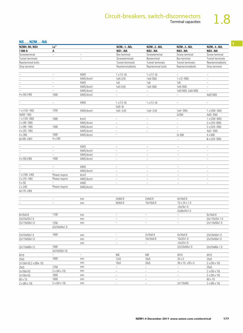
1.8Circuit-breakers, switch-disconnectorsTerminal capacities
NZM1-4 December 2011 www.eaton.com.cn/electrical 177
1NS…, NZM…-NANZM4, N4, NS47 600 A
Ln1)
ANZM...1...NA,NS1...NA
NZM...2...NA,NS2...NA
NZM...3...NA,NS3...NA
NZM...4...NA,NS4...NA
ScrewterminalTunnel terminalsRearterminal boltsStrip terminal
– ––
Box terminalScrewterminalsTunnel terminalsRearterminalbolts
ScrewterminalBoxterminalTunnel terminalsRearterminal bolts
Screw terminalBox terminalTunnel terminalsRearterminalbolts
Screw terminalTunnel terminalsRearterminalboltsStrip terminal
AWGAWG/kcmilAWGAWG/kcmilAWG/kcmilAWG/kcmil
AWG
AWG/kcmil
kcmilAWG/kcmilAWG/kcmilAWG/kcmilAWG/kcmil
AWGAWG/kcmilAWG/kcmilAWG/kcmil
mmmm
mmmmmm
mmmmmm
mmmmmm
mmmmmm
––mm
–––––4x(0-500)
–
1 x (250-350)4x(0-350)1 x (250-600)2 x (3/0-600)2 x (3/0-350)4x(2-350)4 x 6006 x (3/0-500)–
––––
–––––
6x16x0.8(2x) 10x32x 1.0(2x110x50x1.0
–1 x (2-500)1x61x(4-350)1x(0-500) ,2x(0-500)–
–
1x(4-350)2x350––––2x 500–
––––
–––––
–––
6x16x0.810 x 24 x 1.0+5x24x1.0(2x)8x24x1.0
1 x (12-6)1x(4-350)1x61x(4-350)––
1 x (12-6)
1x(4-2/0)
––––
––––
–––––
–––
2x9x0.810x16x0.8
1 x (12-6)1x(4-2/0)1x61x(4-3/0)––
1 x (12-6)2x(9-6)1x(4-2/0)
–––––
––––
–––––
–––
2x9x0.89x9x0.8
(2x)10x50x1.0(2x)10x50x1.0
(2x)10x80x 1.0
M1025x52 x (50 x 10)25x52 x (50 x 10)2 x (50 x 10)60 x 102 x (80 x 10)
6x16x0.810x32x1.0+5x32x1.0(2x)10x50x1.0
M1020 x 530 x 10, +30 x 5––––2x110x50)
2x16x0.810x16x0.8–
M816x520x5–––––
–––
M612x516x5–––––
–––––
–––––
–
4 x (50-240)
–
1 x (120-185)4x(50-185)1 x (120-300)2 x (95-300)2 x (95-185)4 x (35-185)4 x 3006x195-2401
––
–
–
–
–––
–––
4 x (50-240)
––
––
6x16x0.8(2x)10x32x1.0(2x110x50x1.0
(2x)10x50x1.0(2x110x50x1.0
(2x110x80x1.0
M1025x52x150x10),2 x (80x 10)25x52x150x10)2x150x10)60 x 102 x (80 x 10)
1 x (185-240)2 x (70-185)4 x 502 x 2406x170-240)
AWGAWG/kcmilkcmilAWG/kcmilAWGAWG/kcmil
12502 x (40 x 10)160016002 x (50 x 10)
1600
1600
1100
1400
1400
1400
1000
1250
16002x(10x50x1.0)
1250(2x)10x40x1.0
Please inquire
Please inquirePlease inquire
16004 x 240

1.8 Circuit-breakers, switch-disconnectorsTemperature dependency
178 NZM1-4 December 2011 www.eaton.com.cn/electrical
1 N...S1-DC
Basic devicesReduction of the rated operational current (derating) under particular ambient conditionsContactprotection
Mountingposition
N2-4-160-S1-DC
N2-4-200-S1-DC
N3-4-320(400)-S1-DC
N 3-4-500-S 1-DC
N2-4-160-S1-DC
N4-4-800110001-S1-DC
N 4-4-1250-S 1-DC
N 4-4-1400-S 1-DC
Switch-disconnectors+NZM2-4-XKV2P
+NZM2-4-XKV2P
+NZM3-4-XKV2P
+NZM3-4-XKVI2P
+NZM3-4-XKVI2P-K
+NZM3-4-XKVI2P
+NZM3-4-XKV2P-K
+NZM3-4-XKV2P-K
+NZM4-4-XKV2P
+NZM4-4-XKV2P
+NZM4-4-XKV2P
+NZM3-4-XKV2P-1400
Jumper kits Temperature compensation coefficient20 0C 20 0C 20 0C 20 0C 20 0C 20 0C 20 0C 20 0C
IP2X
IP2X
IP2X
IP00
IP00
IP00
IP1X
IP2X
IP2X
IP2X
IP2X
IP00
vh
vh
vh
vh
vh
vh
vh
vh
vh
vh
vh
vh
11
11
11
11
11
11
11
11
11
11
11
11
11
11
11
11
11
11
11
11
11
11
11
11
11
11
11
11
11
11
11
10.98
11
11
10.97
11
11
11
11
11
11
10.97
11
0.950.93
11
11
0.940.91
11
11
11
11
11
11
0.970.95
10.97
0.920.9
11
11
0.92–
11)
11)
11
11
11
11
11
0.950.92
0.980.94
0.890.87
11
11
0.9–
11)
11)
11
10.95
11
11
10.97
0.920.89
0.950.91
0.860.84
11
10.97
––
11)
11)
11
0.950.92
11
11
0.970.95
0.890.87
0.920.89
0.830.81
11
0.970.95
––
0.970.97
Notes Mounting position:v=vertical, h=horizontalIncomer and outgoer at bottom or top, freely selectable1)Incomer at from bottom only.

1.8Circuit-breakers, switch-disconnectorsAuxiliary contacts, equipping, time differences
NZM1-4 December 2011 www.eaton.com.cn/electrical 179
1M22-K…, XHI(V)
a
bc
Main contact
Auxiliary contact, early make (HIV)
Auxiliary contact, normal (HIN)
a b
a b
Auxiliary contactsRated operating voltageAC voltageDC voltageConventional thermal currentRated operational current
At AC=50/60 Hz
24 V42 V60 V110 V220 V
AC-15 115 V230 V400 V500 V
DC-13
Ua
Ua
Lth=Le
V ACV DCA
5002204
2302204
5002204
M22-K... M22-CK... XHIV
Short-circuit protectionMax.fuseMax. miniature circuit-breakerEarly make times compared to main contactson make and break(switching times on manualoperation.
Le
Le
Le
Le
Le
Le
Le
Le
Le
Le
AAAAAAAAA
A gG/gLAms
442131.11.20.80.3
44––310.80.50.2
442131.50.80.50.2
10PKZMO-10/FAZ-B6–
10FAZ-B6/B 1–
10FAZ-B6–NZM1, PN1, N(S)1: approx.20NZM2, PN2, N(S)2: approx.20NZM3, PN3, N(S)3: approx.20NZM4, N(S)4: approx. 90With NZM4/N}S}4the HIVdoes not feature early break.
Terminal capacitiesSolid or flexible conductor with ferrule
1 x (0.75-2.5)2 x (0.75-2.5)1x(18-14)2x(18-14)
1 x (0.5-1.5)2 x (0.5-1.5)1x(20-18)2x(20-18)
1 x (0.75-2.5)2 x (0.75-2.5)1x(18-14)2x(18-14)
mm2
AWG
10A...600 V AC1A-250 V DCA600/P300via 300 V ACsame polarity
A
2.5 A-240 V AC1A-250 V DCC300/R300
Maximum equiment andposition of the built-in accessories
③-XHIV(2S)or-XAor-XU
②HIA
①HIN
NZM1, N/S}1NZM2, N/S}2NZM3, N/S}3NZM4, N/S}4PN1PN2PN3
1111111
1112–––
1233123
Time differences ON-OFF
UL/CSARated operational current
Heavy Pilot Duty
On combination with remote operator NZM-XR...,the rightslotfor standard auxiliary contacts HIN can be equippedonlywith single contacts.
Notes
Time difference a (ms)Manual operationHIV HIV
HIVHlNK10
NZM1
NZM2
NZM3
NZM4
202)
202)
202)
902)
202)
202)
202)
01)2)
0
3.5
4
7
2.5
6.5
8
11
–
NotpermissibleNotpermissibleNotpermissible
–
2.5
2
Pleaseinquire
–
4.5
NZM1
Pleaseinquire
0
3
3.5
12
2.5
4.5
8
15
–
NotpermissibleNotpermissibleNotpermissible
–
3
3
Pleaseinquire
–
4
6.5
Pleaseinquire
1)With NZM4/N}S}4the HIV does not feature early break.2) Minimum value, as it is dependent on the switching speed
Notes
K01 K01 K01 K01
Motor driveHIV HIN
K10HINK10
HINK10
Time difference b (ms)Manual operation
Motor drive

1.8 Circuit-breakers, switch-disconnectorsUndervoltage releases, shunt releases, capacitor unit
180 NZM1-4 December 2011 www.eaton.com.cn/electrical
1NZM112/31-XU... NZM4-XU...
V ACV DC
x Us
x Us
24...60012...250
0.35-0.70.85-1.1
24...60012...250
0.35-0.70.85-1.1
Undervoltage releasesRated control voltage AC voltage at 50/60 Hz DC voltageOperating range Drop-out voltage Pick-up voltagePower consumption AC voltage AC pick-up rating AC consumption when closedDC voltage DC pick-up rating DC consumption when closed Max. opening delay(response time until the main circuitsopen)Minimum signal durationTerminal capacities Solid or flexible conductor with ferrule
VAVA
1.51.5
3.63.6
WW
0.80.8
2.52.5
ms
mm2
A WG
1X(0.75-2.5)2X(0.75-2.5)
1X(18-14)2X(18-14)
1X(18-14)2X(18-14)
1X(0.75-2.5)2X(0.75-2.5)
Undervoltage releases, off-delayedRated operating voltageAC voltage at 50/60 HzDC voltageInrush current (peak value)Power consumptionDeceleration timeWith additional external capacitor 90,000 uF- 35 VWith additional external capacitor 30,000 uF- 35 VTerminal capacitiesSolid or flexible conductor with ferrule
24, 220-55024<5005070-4000To 16To 8
1 x (0.5-2.5)2 x 10.5-1.5)
UVU-NZM NZM-XCM
V ACV DCmAV Amsss
mm2
Us
Us
Ue
Ue
le
tsd mm2
Capacitor unit for shunt release
Rated operating voltageRated operational currentInrush current}peak value)Terminal capacitySolid or flexible conductor withferrule
1 x (0.5-2.5)1 x (20-14)2x120-16)
V ACmA
Ue
le
le A
AWG
Shunt releases (for power circuit breaker)Rated control voltageAC voltageDC voltageFrequency rangeOperating rangeAC voltageDC voltagePower consumptionAC/DC pick-up ratingAC/DC consumption when closedMaximum power consumption at 110%认(230 V 50 Hz)Max. opening delay(response time until the main circuits opeyMax. duty factorMinimum signal durationTerminal capacitySolid or flexible conductor with ferrule
NZM112/31-XA... NZM4-XA… NZM2/3-XA...-MNS NZM4-XA...-MNS
10-15
8
10-15
8
10-15
1000ms
10-15
1000ms
1 x (0.75-2.5)2 x (0.75-2.5)1x(18-14)2x(18-14)
1 x (0.75-2.5)2 x (0.75-2.5)1x(18-14)2x(18-14)
1 x (0.75-2.5)2 x (0.75-2.5)1x(18-14)2x(18-14)
1 x (0.75-2.5)2 x (0.75-2.5)1x(18-14)2x(18-14)
msms
mm2
AWG
Us
Us
12...44012...4400-400
12...44012...4400-400
230–50/60
230–50/60
0.7...1.10.7...1.1
0.7...1.10.7...1.1
0.1...1.1–
0.1...1.1–
2.52.5
2.52.5
––
––
–22
0.520
122
V ACV DCHz
x Usx Us
VA/WVA/WAms
NZM...-XU, NZM...-XA...

1.8Circuit-breakers, switch-disconnectorsMechanical interlock for (door-coupling) rotary handles
NZM1-4 December 2011 www.eaton.com.cn/electrical 181
1
Remote operatorsRated control voltageAC voltageDC voltageOperating rangeAC voltageDC voltageRated operational powerAC voltage
DC voltage
Total make timeTotal opening delayMinimum signal durationWith switch onWith switch offLifespan, mechanicalMaximum operating frequencyTerminal capacitiesSolid or flexible conductor with ferrule
ElectricalStandardsSensitivityRated control voltageMotor ratingRated fault currentsDeceleration timeRelay contactsRated operating voltage of the relay contactsRated operational current of the relay contactsFault current early warning
MechanicalStandard front dimensionDevice heightBuilt-in widthMountingTerminals top and bottomTerminal protectionTerminal capacitiesSealing facility for setting buttons
110 V...130VAC208 V...240 V AC380 V...440 V AC24 V...30 V D C110 V...130VDC220 V...250 V DC
NZM2-XRD... NZM2-XR... NZM3-XR... NZM4-XR...
Us
Us
Us
Pe
V ACV DC
VAVAVAWWWmsms
msms
Opa/h
mm2
AWG
100...44024...250
100...44024...250
100...44024...250
100...44024...250
0.85...1.10.85...1.1
0.85...1.10.85...1.1
0.85...1.10.85...1.1
0.85...1.10.85...1.1
550550650450450450110-170110-170
350350350250(max. 17A 30 ms)250250603000
350350350250250250801000
3503503502502502501003000
3050020000120
3015020000120
302501500060
305001000020
0.75-2.518-14
0.75-2.518-14
0.75-2.518-14
0.75-2.518-14
PFR-003 PFR-03 PFR-5
IEC/EN 60947-2, IEC 755, IEC 1008, IEC 1009Pulse-current sensitive, type A230 120% (50/60 Hz)30.030.02 (non-delayed)
30.030.02 (non-delayed)
30.03,0.1,0.3,0.5,3,50.02,0.1,0.3,0.5,3,5
1 built-in changeover contact250/1006−
1 built-in changeover contact250/1006−
1 built-in changeover contact250/10060.5=25%-50% 1=50%-75% 2=75%-100%
∆nl∆nl∆nl
458536
458536
458536
Quick attachment fortop-hat rail DIN 46277, EN 50022BoxterminalsFinger and back-of-hand proof BGV A2, VDE 106 Part 1002 x 0.75-2.5 solid, 2 x 0.75-1.5 flexible/with sleeve− − Yes
V ACWAs
VAC/DCAHz
mmmmmm
mm2
Operations
L∆n
tv

1.8 Circuit-breakers, switch-disconnectorsEarth-fault releases
182 NZM1-4 December 2011 www.eaton.com.cn/electrical
1 NZM...-XFI...
ElectricalStandardsSensitivityMin. operating voltageFor detecting type A/AC faultcurrentsFor detecting type B fault currents
NZM11-41-XFI30RNZM11-41-XFI300RNZM11-41-XFIR
NZM11-41-XFI30UNZM11-41-XFI300UNZM11-41-XFIU
+NZM2-4-XFI30+NZM2-4-XFI
+NZM2-4-XFIA30+NZM2-4-XFIANZMH2..: XFIA30
IEC/EN 60947-2Pulse-current sensitive, type A
80 V (dependent onmains power)–
80 V (dependent onmains power)–
80 V (dependent onmains power)–
80 V (dependent onmains power)–
Three-and single-phase systems200...415(3~)50/603/415...160
Three-and single-phase systems200...415(3~)50/603/415...100
Three-and single-phase systems280..69050/603/415...250
Three-and single-phase systems50...400(3~)50/603/415...250
Suitable for use in
Rated operating voltageRated frequencyNumber of polesRated operational current rangeRated fault currentsNZM1}-4}-XFI30RNZM1}-4}-XFI300RNZM1}-4}-XFIRNZM1}-4}-XFI30UNZM1}-4}-XFI300UNZM1}-4}-XFIU+NZM2-4-XFI30+NZM2-4-XFI+NZM2-4-XFIA30+NZM2-4-XFIANZMH2..: XFIA30Detection range of fault current
Rated ultimate short-circuit making andrated breaking capacityFault current early warningShock resistance (IEC 60068-2-27)Lifespan, mechanical(50%with fault current)MechanicalStandard front dimensionMountingMounting positionFeederDegree of protectionAmbient temperatureTerminal capacitiesFlexible without ferruleFlexible with ferruleSealability
0.030.30.03-0.1-0.3-0.5-1-3
0.030.30.03-0.1-0.3-0.5-1-3
0.030.3-10.03
0.030.03-0.1-0.3-0.5-1-3
50/60 Hz 50/60 Hz 50/60 Hz With AC voltage:0-100 kHzWith pulsed DCvoltage: 50 Hz
=Lcu =Lcu =Lcu=Lcu
≧0.3 x l∆n ≧0.3 x l∆n – –20(ha1f-sinusoidal shock20 ms)20000 20000 ≧20000 ≧20000
NZMH2: 20000
45On right side
45Bottom
96Bottom
96Bottom
Vertical and 900 in all directions
IP20 inthe operating component area-5...+40 -5...+40 -25...+70 -25...+70
Same as NZM1 standardterminalSame as NZM1 standardterminalYes, setting buttons
NZM1 from above NZM1 from above Any Bottom
mm2
mm2
mm
OC
HzV AC
AA
A
Operations
Ue
ln
f
∆ml
∆nl

1.8Circuit-breakers, switch-disconnectorsData Management Interface (DMI module)
NZM1-4 December 2011 www.eaton.com.cn/electrical 183
1NZM…-XU, NZM…-XA…
GeneralDimensions (W x H x D)Modular spacing(space units)WeightMountingAmbient climatic conditionsOperating ambienttemperatureBuilt-in positionCondensationLCD display (clearly legible)Storage/transportRelative humidity, non-condensing (IEC/EN 60068-2-30)Air pressure(in operation)Corrosion resistanceIEC/EN 60068-2-42
IEC/EN 60068-2-43
Ambient mechanical conditionsPollution degreeDegree of protection IEC/EN 60529Vibrations (IEC/EN 60068-2-6)Constant amplitude 0.15 mmConstant acceleration, 2 gMechanical shock resistance (IEC/EN 60068-2-27) semi-sinusoidal 15 g/11Drop IEC/EN 60068-2-3
Free fall, packaged (IEC/EN 60068-2-32)Power supplyRated operating voltagePermissible rangeResidual rippleInput current at 24 V DCVoltage dips (IEC/EN 61131-2)Power loss at 24 V DC
107.5 x 90 x 536 SU (space units) wide0.3Top-hat rail IEC/EN 60715, 35 mm
0 to +55Horizontal/verticalPrevent condensation by means of suitable measures0 to +55-40 to +705 ...95795...1080
10
1
2IP20
10...5757...1501850
1
2420.4...28.8 5210105
<=
DMI
mm
mm
OC
OCOC%
%
msW
V DCV DC
hPa
mA
cm3/m3
cm3/m3
HzHzShocks
kg
m
4 daysSO2
4 daysHZS
Dropheight
Ue

1.8 Circuit-breakers, switch-disconnectorsFieldbus interface
184 NZM1-4 December 2011 www.eaton.com.cn/electrical
1
GeneralStandardsDimensions (VV x H x D)
WeightMounting
Terminal capacitySolidFlexible with ferruleStandard screwdriverMax. tightening torque
Ambient climatic conditionsOperating ambienttemperature
CondensationStorageRelative humidity, non-condensing (IEC/EN 60068-2-30)Air pressure (in operation)Corrosion resistanceIEC/EN 60068-2-42IEC/EN 60068-2-43
Ambient mechanical conditionsPollution degreeDegree of protection (IEC/EN 60529)Vibrations (IEC/EN 60068-2-6)Constant amplitude 0.15 mmConstant acceleration, 2 gMechanical shock resistance (IEC/EN 60068-2-27)semi-sinusoidal 15 g/11msDrop (IEC/EN 60 068-2-31)Free fall, packaged (IEC/EN 60068-2-32)Mounting position
Electromagnetic compatibility (EMC)Electrostatic discharge (IEC/EN 61000-4-2, Level 3, ESD)Air dischargeContact dischargeElectromagnetic fields (IEC/EN 61000-4-3, RFI)Radio interference suppression (EN 55011)
Burstimpulse (IEC/EN 61000-4-4, Level 3)Supply cablesSignal cablesHigh-energy pulses}surge)(IEC/EN 61000-4-5, Level 2)Immunity to line-conducted interference(IEC/EN 61000-4-6)
EASY22..., NZM-XDMIEASY221-CO EASY222-DN NZM-XDMI-DPV1
EN 55011, EN 55022, EN 61000-4, IEC 60068-2-6, IEC 60068-2-2735.5x90x58(2 space units)
35.5x90x58(2 space units)
35.5x90x58(2 space units)
0.15Top-hat rail EN 50022, 35 mm or screw fixing using fixing bracketsZB4-101-GFi (accessories)
0.2x4 (AWG 22-12)0.2x2.5 (AWG 22-12)
-25 to 55, low temperatures to IEC 60068-2-1,high temperatures to IEC 60068-2-2
40-705-95795-1080
40-705-95795-1080
40-705-95795-1080
101
101
101
2IP20
2IP20
2IP20
10-5757-15018
10-5757-15018
10-5757-15018
501horizontal xvertical
501horizontal xvertical
501horizontal xvertical
8610EN 55011 ClassBEN 55022 ClassB
8610
8610EN 55011 ClassAEN 55022 ClassA
22
22
22
0.5 (supply cables, symmetrical)
10 10 10
Prevent condensation by means of suitable measures
3.5 x 0.80.6
3.5 x 0.80.6
3.5 x 0.80.6
mm
kg
mm2
mm2
mmNm
OC
OC%hPa
cm3/m3
cm3/m3
HzHzShocks
mmm
kVkVV/m
kVkVkV
V
4 day SO2
4 day SO2
Drop height

1.8Circuit-breakers, switch-disconnectorsFieldbus interface
NZM1-4 December 2011 www.eaton.com.cn/electrical 185
1EASY..., NZM-...EASY221-CO EASY222-DN NZM-XDMI-DPV1Insulation resistance
Clearances and creepagedistancesInsulation resistancePower supplyRated operating voltagePermissible rangeRippleAt 24 V D CVoltage dips (IEC/EN 61131-2)
Heat dissipation at 24 V DCPolarity reversal protectionPower supplyLED indicatorsPower supplyLED display
NetworkTerminal type
Potential isolation
FunctionInterfaceBus protocolBaud rates
Bus terminating resistors
Bus addressesServicesCyclical
Acyclical
EN 50178, UL 508, CSA C22.2, No. 142
24(-15/+20%)20.4-28.8< 5typ. 20010
4.8
Yes
24(-15/+20%)20.4-28.8< 5typ. 20010
4.8
Yes
24(-15/+20%)20.4-28.8< 5typ. 20010
4.8
Yes
Power LED (POW):greenPROFIBUS一DP LED (BUST: red
SUB-D 9 pole, socket
Between bus and power supply(simple, between bus andpower supply andNZM-XD M1612PROFIBUS一DP slaveRS 485PROF旧US一DPAutomatic search up to12 MBit/sSeparate external bustermination required
1-126 via D MI
StatusOn/Dff,tripped[detailed)load early warnings, phasecurrents I}/h/13[A], remoteoperator acutation, display/operation NZM-XDM1612inputs/outputs, motor starterfunctionsDisplay/match protectionprotection settings, event list,identification, hours ofoperation, switchingoperations, time
RUN LED (RUN1: greenLED ERROR (ERRI: red
Module status LED (MSS: greenNetwork status LED (NSF:red/green
RJ45 5 pole, pluggable screwterminal
Between busand powersupply(simple, between bus andpower supply andNZM-XDM16121safe isolation)
Between busand powersupply(simple, between bus andpower supply andNZM-XDM16121safe isolation)
CANopen slaveCANCANopenAutomatic search up to1 MBit/sSeparate external bustermination required (120 0)NZM-XDM16121-127 addressed via display
DeviceNet slaveCANDeviceNetAutomatic search up to500 kBit/sSeparate external bustermination required (120 0)NZM-XDM16120-63 addressed via display
All data R1-R16,S1-S8 All data R1-R16,S1-S8
Read/write, real-time, day,summer/winter time,all parameters of theeasyfunction relay
Read/write, real-time, day,summer/winter time,all parameters of theeasyfunction relay
%
ms
W
VV DC
mA
Ue

1.8 SmartWire-DarwinSWD input/output modules
186 NZM1-4 December 2011 www.eaton.com.cn/electrical
1NZM-XSWD-704
IEC/EN 61131-2EN 5017835 x 90 x 1010.1Top-hat rail IEC/EN 60715, 35 mm Vertical
IP20
5 … 8.48.4 … 1509
500.3
II2
84
1031EN 55011 Class A
211–10
–25 … +55Prevent with suitable measures –40…705 … 95
SmartWire-Darwin station (slave)AutomaticGreen8-pin connectorConnection plug: External device plug SWD4-8SF2-5See separate table
Push-In0.2-1.5 (AWG 24-16)0.25-1.5
–––
NZM-XSWD
GeneralStandards
Dimensions (W x H x D)WeightMountingBuilt-in positionAmbient mechanical conditionsDegree of protection (IEC/EN 60529)VibrationsllEC/EN 61131-2:2008)Constant amplitude 3.5 mmConstant acceleration, 1 gMechanical shock resistance (IEC/EN 60068-2-27)semi-sinusoidal 15 g/11 msDrop (IEC/EN 60068-2-31)Free fall, packaged (IEC/EN 60068-2-32)Electromagnetic compatibility (EMC)Overvoltage categoryPollution degreeElectrostatic discharge (IEC/EN 61131-2:2008)Air discharge (Level 3)Contact discharge (Level 2)Electromagnetic fields (IEC/EN 61131-2:2008)80 -1000 M Hz1.4-2 GHz2-2.7 GHzRadio interference suppression (SmartWire-Darwin)Burst (IEC/EN 61131-2:2008, Level 3)Supply cablesSignal cablesSmartWire-Darwin cablesSurge (IEC/EN 61131-2:2008, Level 1)Radiated RFIIIEC/EN 61131-2:2008,Level3)Ambient climatic conditionsOperating ambient temperature (IEC 60068-2)CondensationStorageRelative humidity, non-condensing (IEC/EN 60068-2-30)SmartWire-Darwin statusStation typeBaud rate settingSmartWire-Darwin statusConnection
Power consumption (15 V SWD supplySupply and I/0 connectionConnection typeSolidFlexible with ferrule's24 V DC supply for output supplyRated operating voltageInput voltage residual ripplePolarity reversal protection reversalNotes
mm
kg
HzHzShocks
mmm
kVkV
kVkV
kV
V/mV/mV/m
V
OC
OC%
LED
mm2
mm2
V%
Ue
Drop height
1)Minimum length 8 mm

1.8SmartWire-DarwinSWD input/output modules
NZM1-4 December 2011 www.eaton.com.cn/electrical 187
1NZM-XSWD-704
2Typically 4 at 24 V DC
Low < 5 V DC; High > 15 V DC High → Low typically < 0.2 msLow → High typically < 0.2 msYellow
Yes, with diagnosticsEN 60947-5-1 utilization category DC-13
––
–––––––––
YesYes––––
NZM-XSWD
Digital inputsNumberInput currentVoltage level to IEC/EN 61131-2Limit value type 1Input delay
Status display inputsDigital semiconductor outputsNumberOutput currentShort-circuittripping currentLamp loadOverload proofSwitching capacityRelay outputsNumberContact typeOperationsUtilization category AC-1, 250 V, 6 AUtilization category AC-15, 250 V, 3 AUtilization category DC-13, 24 V, 1 ASafe disconnectionMinimum load currentResponse/reset timeBounce durationShort-circuit protectionStatus display outputsPotential isolationInputs for SmartWire-DarwinSemiconductor outputs to SmartWire-DarwinSemiconductor outputs to inputsRelays to SmartWire-DarwinRelays to inputsRelays to relays
mA
mA
mSmS
LED
20.2 at 24 V DC––
AAW
V AC
LED
RLL

1.8 Circuit-breakers, switch-disconnectorsMeasuring and communication module
188 NZM1-4 December 2011 www.eaton.com.cn/electrical
1NZM2-XMC-S0 NZM3-XMC-S0 NZM2/3-XMC-MB209 × 91 × 132 (3 pole)251 × 91 × 132 (4 pole)
209 × 91 × 132 (3 pole)251 × 91 × 132 (4 pole)
209 × 91 × 132 (3 pole)251 × 91 × 132 (4 pole)
850 (3 pole)975 (4 pole)
850 (3 pole)975 (4 pole)
850 (3 pole)975 (4 pole)
UL94-V0 UL94-V0 UL94-V0
-15-+65 -15-+65 -15-+65-40-+80 -40-+80 -40-+805-95 5-95 5-952000 2000 2000IP 20 IP 20 IP 20
18 – 36 18 – 36 18 – 36200 200 200Phoenix Contact GMVSTBR 2.5-2-ST-7.62
Phoenix Contact GMVSTBR 2.5-2-ST-7.62
Phoenix Contact GMVSTBR 2.5-2-ST-7.62
690 690 6908 8 8800 800 8001 1 145-65 45-65 45-650.4 % measured value +0.05 % FS
0.4 % measured value 0.4 % measured value +0.05 % FS +0.05 % FS
CAT IV (600 V) CAT IV (600 V) CAT IV (600 V)
300 500 300 (NZM2)/500 (NZM3)350 740 3030 30 3045-200 45-200 45-200CAT IV-600 V CAT IV-600 V CAT IV-600 V
− − 280− − 0.95 % measurement
+ 0.05 % FSClass 1 (IEC62053-21) Class 1 (IEC62053-21) Class 1 (IEC62053-21)− − Class 2 (IEC62053-23)
NPN-isolated transistor NPN-isolated transistor NPN-isolated transistor80 80 800.4 0.4 0.450 50 5010 10 103 3 32 2 4120 120 ≥ 2015 7.5
− −− − 350− − 120− − 2.5
− − 50− − 3
− − 9600, 19200, 38400, 56000, 57600
− − 1, 2 − − None, odd, even− − 3
− − 5− − 180
NZM-...XMCGeneralDimensions
Weight
Material characteristicEnvironmental conditionsOperating temperatureStorage temperatureHumidity (non-condensed)Maximum operating altitudeIP protection classSupplyVoltageMaximum currentConductors
Voltage measurementRated operating voltageMaximum surge voltage at8/加msMaximum voltageSurge impedance (impedance)FrequencyAccuracy
Overvoltage category according to EN61010Current measurementRated operational currentMaximum currentMaximum currentimpulse 1sFrequencyCategory EN61010Power measurementMaximum power (per phase)Accuracy
Accuracy, active powerAccuracy, reactive energyPulse outputOutputtypeVCE maxVCE satIc maxIc recommendedIsolationMax. switching frequencyPulse widthPulse rate powerDigital outputTypeMaximum voltageMaximum currentIsolationDigital inputMaximum voltageVIHmaxMODBUS output-RS485Data rate
Stop bitsParityIsolationOutput-displayDC supply voltageMaximum current
mm
9
0C0C%m
V DCmA
V ACkVV ACkohmsHz
A ACA ACkAHz
kwh
VVmAmAkVH2msPulses/kN
VmAkV
VV
bit/s
kV
VDCmA

1.9Circuit-breakers, switch-disconnectorsConstruction size 1: basic devices, accessories
NZM1-4 December 2011 www.eaton.com.cn/electrical 189
1Dimensions
NZM1(-4)-XIPA
60 21
5
R104
68
84.5
44.630
120
112
126
9.5
145
16
41.5
45
SW4 M4 x 50
a
63
64
89
f 60
N
① 3 pole② 4 pole
SW 4
80
IP2X
16
90a
120b
296
4
21
M6 x 14
59
34
26
64
158
7
288.5
629.5
681.5
340.5
322.5
16
190
234.5
~ 743
NZM1, PN1, N1, NS1
Circuit-breakersSwitch-disconnectors3 poleNZMB1NZMC1NZMN1NZMH1PN1N1NS1
3016
9.5 10.2
112
126
f 60
145
63
64 41.5
45
21
5
R 104
68
NZM...1-...-(C)NA
84.5
30
90
44.6SW4 M4 x 50/10
a
162
57
F 90°
①Blow-out area, minimum distance to other parts ≧ 60 mm
Circuit-breakersSwitch-disconnectors4 poleNZMB1-4NZMC1-4NZMN1-4NZMH1-4PN1-4N1-4
①Blow-out area, minimum distance to other parts ≧ 60 mm
CoversNZM 11-41-XKSAScrew terminalsNZM 11-41-XKSIP2Xprotectionagainstcontact with a fingerfor cover
Switch-disconnectorsATEX22-type3 polePN 1../ATEX22

1.9 Circuit-breakers, switch-disconnectorsAuxiliary contacts, trip-indicating auxiliary contacts
190 NZM1-4 December 2011 www.eaton.com.cn/electrical
1
① 3 pole② 4 pole
20
32
64
48
M6 x 14
90
20
SW 4
a
120b
SW 5
① 3 pole② 4 pole
90
108
89
a
120b
90
64
13
46 10
7691
a
120b
NZM1...-XK..., NZM1...XIPK, NZM-XSTK
Tunnel terminalNZM 11-41-XKA
Rear terminal boltsNZM 1141-XKR
Control cable terminalsNZM1-XIPK, NZM-XSTK
IP2X protection against contact with fingerNZM11-41-XIPK
128
63
126
15
30
o 22
M415
10
M6 x 14
2 – 5
64
18
10 50
102
o 6.6
6
M6 x 20
120
90
SW 4
M430
128
126
63
o 22
30 30 30
30 15

1.9Circuit-breakers, switch-disconnectorsConstruction size 1: accessories
NZM1-4 December 2011 www.eaton.com.cn/electrical 191
1
23
85
85
ZFS...-NZM7
R46
o 8
71
8
27.5
71
o 40
73.5
2 – 5
NZM1-XDV..., NZM1-XTVD...Rotary mechanismRotary handle on circuit-breaker
35
①
① Up to 3 padlocks
d b
d = 4 – 8b 34<=
Construction size 1: accessories
80 80F 43
36
a
5353
45
45
54
80.3
90
120
NZM1-XDVNLM-XDVR
NZM1-XDTV
① Up to 3 padlocks
d b
d = 4 – 8b 34<=
Door coupling rotary handlesNZM1-XTVDIVIIRII-NA)

1.9 Circuit-breakers, switch-disconnectorsConstruction size 1: accessories
192 NZM1-4 December 2011 www.eaton.com.cn/electrical
1
8
27.5
73.5
210 – 400(400 – 600)
55
2 – 5
36NZM1/2-XV4(NZM1/2-XV6) 23g 0.5
o 4
58
23g 0.5
NZM1/2-XV...
167 – 210
16 – 60
① Special tip
23g 0.5
a
128 – 167
41 – 75
NZM...1-... f 130
Door coupling rotary handle with extension shaftNZM1-XTVDIVIIRII-NA)NZM 1/2-XV416)
NZM1-XTVDIVIIRI-601-NA) NZM1-XTVDIVIIRI-0(一NA)
Minimum distance of door coupling rotary handle from door pivot point
NZM1-XTVD...

1.9Circuit-breakers, switch-disconnectorsConstruction size 1: accessories
NZM1-4 December 2011 www.eaton.com.cn/electrical 193
1NZM1-XS, NZM1...HIVMain switch assembly kit for side wall installationNZM1-XSIRI-L
9095-31073.5
122-5 129
90 95-310 73.5
12 2-5 129 15
41
51.5
131.4
176
178.5
12
73.5
2-5
57.2
163
195.5
NZM1/2-XZB
145
131.4
176
178.5
12
73.5
2-5
57.2
163
145
195.5
NZM1/2-XZB
①NZM1-XA(HIV)NZM1-XU(HIV)(20)NZM1-XHIV② NZM1-XA(HIV)(L)NZM1-XU(V)(HIV)(L)(20)NZM1-XHIV(L)③ NZM1-XHIVR
23.2
38.6
39.3
39.3
2020
a c
b
Main switch assembly kit for side wall installation with mounting bracketNZM1-XSIRIM-RNZM1-XSIRIM-L
Undervoltage releasesShunt releases (for power circuit breaker)Early-make auxiliary contacts
SpacersNZM1/2-XAB
17.5
103
35
30
90
126
9.5
145
157
1.5
8.4
Clip plateNZM1-XC35

1.9 Circuit-breakers, switch-disconnectorsConstruction size 1: accessories
194 NZM1-4 December 2011 www.eaton.com.cn/electrical
1
1.5 – 5
9.5
132
11.5
19
53
ZFS...-NZM764
117
148.5
23
82
87
61
10
17.5
1 – 3
9.5
64
78
104
23
ZFS...-NZM7
a
1.5 – 5
9.5
32
11.5
19
9
14.4
132
53
11
40
o 4
NZM...-X...
Insulating surroundNZM1-XBR
Mounting aperture
Insulating surroundNZM1-XBRS
Rotary handle on switch with door interlockNZM1-XDTVIR)
Mounting aperture
145
115
① NZM1-XRAV(R)② NZM1-4-XRAV(R)
117
148
ab
32
a
45
46.3
1
F 80
Rear-mounted drivesNZM1-XRAV(R)NZM1-4-XRAVIR)
Toggle lever locking deviceNZM-XKAV
① Up to 3 padlocks
d b
d = 4 – 8b 34<=

1.9Circuit-breakers, switch-disconnectorsConstruction size 1: accessories
NZM1-4 December 2011 www.eaton.com.cn/electrical 195
1NZM1-XMV, NZM1-XTV...
① Special tip
90
120
45
40
40 143
5
7
29.2
80.3
45
22.5
51
31
27
NZM1/2-XV4 (NZM1/2-XV6)
245 – 400 (400 – 600)
Part no. xNZM1/2-XV4 245 – 400NZM1/2-XV6 400 – 600
202 – 245
NZM1/2-XV...
163 – 202
a
Mechanical interlockNZM1-XMV+NZM1-XDVIR)
NZM1-XMV+NZM1-XTVDIVIIR)
NZM1-XMV+NZM1-XTVD(V)(R)-60 NZM1-XMV+NZM1-XTVD(V)(R)-60

1.9 Circuit-breakers, switch-disconnectorsConstruction size 1: accessories
196 NZM1-4 December 2011 www.eaton.com.cn/electrical
1 PN1-XPA, NZM1-XCI..., NZM1-XAD, NZM1...XSVS
Paralleling mechanismPN1-XPA
40
40143
5
7
3127
90
120
95/110 (125/140)
45
5/20
2
80.3
45
R 64
22.5
NZM1/2-XV4(NZM1/2-XV6)
245 – 400 (400 – 600)
160
231
200
280
8
187.5
250
175
248.5
8
250
80
375
495
8
60
60
175
248.5
60
225
298.5
250
80
375
495
8
60
NZM1-...SVE
2130
48.5
62.3
117
145
202.
3
SW4
171
126
30
90
100
190
NZM1-XSVS
a
200
6490
Insulated enclosuresNZM1-XCIKS-T
NZM1-XC123-T
NZM1-XCI43-T NZM 1-XC 143/2-T
Component adapterNZM1-XAD160
Plug-in unitsNZM1-XSVS withNZM.1一~SVEN1--SVE
① Up to 2 padlocks
d b
d = 4 – 8b 34<=

1.9Circuit-breakers, switch-disconnectorsConstruction size 1: accessories
NZM1-4 December 2011 www.eaton.com.cn/electrical 197
1
NZM1(-4)-XFI...U
5 6 7 8
1 2 3 4
684436
73
45 67 85Fixing on TH35 top-hat rail to IEC/EN 60715
G
H
J I
F
B
33
46
C D
A
E
F
6.5
Part no. F G H I JPFR-W-20 32 60 24 46 21PFR-W-30 32 70 30 59 30
A B C D E FPFR-W-35 100 79 26 48.5 35 35PFR-W-70 130 110 32 66 70 52PFR-W-105 170 146 38 94 105 72PFR-W-140 220 196 48.5 123 140 97PFR-W-210 299 284 69 161 210 141
51.7
32.7
6.0
12.5
ØB
ØC
A1 A2
A
Part no. A B C A1 A2PFR-WMA-35 91 28 40 35 28PFR-WMA-70 105 62 75 35 35PFR-WMA-105 153 98 110 35 60PFR-WMA-140 153 133 145 35 60PFR-WMA-210 153 203 215 35 60
135 105
68
45
42.5
80.1
220 14
5
220
145
120
145
90.15
145
23.1
45
42.5
68 80.1
NZM1...-XFI..., PFR-...Residual-current relaysPFR-003PFR-03PFR-5
Ring-type transformerPFR-W-20...30
PFR-W-35...210
Mounting clipPFR-WC
Magnetic shieldingPFR-WMA
Earth-fault releaseNZM 11-41-XFL..R

1.9 Circuit-breakers, switch-disconnectorsConstruction size 2: basic devices
198 NZM1-4 December 2011 www.eaton.com.cn/electrical
1
64
217
70
35
135
19.5
145
184
SW5
a
140
a
100
b
b
f 3
5f
35
f 5f 5
N
25 5
R 12
4
22xM8
85/20xM4
103
149
24.5 3
95
78.7
8072
.5
7
288.
5
629.
5 681.
5
340.5
322.5
16
190
276
~ 743
NZM2, PN2, N2, NS2
Circuit-breakersSwitch-disconnectors3 poleNZMB2NZMC2NZMN2NZMH2PN2N2NS2
Circuit-breakersSwitch-disconnectors4 poleNZMB2-4NZMC2-4NZMN2-4NZMH2-4PN2-4N 2-4
Switch-disconnectorsATEX22-type3 polePN2.../ATEX22
35 NZM...2-...(C)NA
105
35
135
19.5
14
5
184
11
SW5
a
a b
b
f 3
5
f 3
5
f 5 f 5
100
NZM...2-...-(C)NA(> NS2-...-NA
①②
Blow-out area, minimum distance to other parts 35 mmMinimum distance to adjacent parts 5 mm
①②
Blow-out area, minimum distance to other parts 35 mmMinimum distance to adjacent parts 5 mm
<=
5
R 12
4
103
149
25
24.5
3
95
78.7
80
72.5
M4 x 85/20
M8 x 22
480 V)

1.9Circuit-breakers, switch-disconnectorsConstruction size 2: accessories
NZM1-4 December 2011 www.eaton.com.cn/electrical 199
1
① 3 pole② 4 pole
65
25
22.1F
20
111
80
M10
① 3 pole② 4 pole
140
105 ab
19
SW 5
30
80
M8 x 223755
SW 8
SW 5
105
140
ab
25
① 3 pole② 4 pole
73.3
310.
7
103.3
105 a
138.4
140 b
M8 x 22
NZM2-XKS185
64
63.5
NZM2-(4)-XKSAE
87
80
175
M8 x 22
81
337
SW 5
105
140
a
b
93
8888
35 35 35
140
140
105 a
b
100
105
NZM2...-XK..., NZM2...-XIP..., NZM2-XST...Box terminal(+INZM21-4)一~XKCIOIIU)IP2X protection against contact with fingerNZM21-41-XIPK
Tunnel terminalNZM21-41-XKA
CoversNZM21-41-XKSACable lugNZM2-XKS185IP2X protection against contact with a finger for coverNZM21-41-XI PA
Cable lug coverNZM2-141-XKSAE
Jumper kitNZM2-4-XKVP
Control cable terminalsNZM2-XSTSNZM-XSTK

1.9 Circuit-breakers, switch-disconnectorsConstruction size 2: accessories
200 NZM1-4 December 2011 www.eaton.com.cn/electrical
1 NZM2...-XKR..., NZM2-XDV..., NZM2-XDTV...
Rear terminal bolts(+INZM21-41-XKRIOIIU)
17.5
70
35 35 35
M4
Ø 22.5
72
145
80
160
18
35
35 35
M4
Ø 22.5
72
145
80
160
8018
10 48 10
100
105
140
6
o
20
M8 x 30
SW 4
3 – 5Ø 8.6
140
52
104
95
R46
100
75
NZM2-XDVNZM2-XDVR
59
8888
67F
a
35 35
Rotary mechanismRotary handle on circuit-breaker
NZM2-XDTVNZM2-XDTV2
① Up to 3 padlocks
d b
d = 4 – 8b 34<=
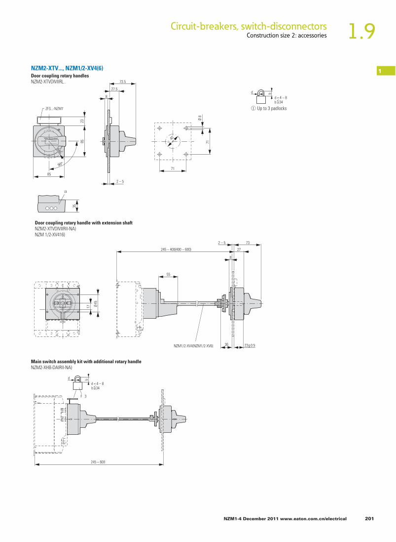
1.9Circuit-breakers, switch-disconnectorsConstruction size 2: accessories
NZM1-4 December 2011 www.eaton.com.cn/electrical 201
1NZM2-XTV..., NZM1/2-XV4(6)Door coupling rotary handlesNZM2-XTVDIVIIRL..
2385
85
35
a
ZFS...-NZM7
R46
Ø 8
71
8
27.5
71
o 40
73.5
2 – 5
8
27
73
55
2 – 5
36 NZM1/2-XV4(NZM1/2-XV6)
Ø 45
17
23g 0.5
245 – 400(400 – 600)
245 – 600
F 3
① Up to 3 padlocks
d b
d = 4 – 8b 34<=
d b
d = 4 – 8b 34<=
Door coupling rotary handle with extension shaftNZM2-XTVDIVIIRII-NA)NZM 1/2-XV416)
Main switch assembly kit with additional rotary handleNZM2-XHB-DAIRII-NA)

202 NZM1-4 December 2011 www.eaton.com.cn/electrical
1.9 Circuit-breakers, switch-disconnectorsConstruction size 2: accessories
1
23g 0.5
NZM1/2-XV...
205 – 249
16 – 60
① Special tip
23g 0.5
a
172 – 205
41 – 75
NZM...2-... f 130
NZM2-XTVD..., NZM2-XS...
Door coupling rotary handle with extension shaftNZM2-XTVDIVIIRI-601-NAI
NZM2-XTVDIVIIRI-0(一NAI Minimum distance of door coupling rotary handle from doorpivot point
NZM2-XS(R)-R
170.510595-31073.5
0.52-5
170.5
15
41
51.5
105 95-310 73.5
0.5 2-5
Main switch assembly kit for side wall installationNZM2-XSIRI-L

NZM1-4 December 2011 www.eaton.com.cn/electrical 203
Circuit-breakers, switch-disconnectorsConstruction size 2: accessories 1.9
1
168
73.5
0.52-5
47.2
200.5
185
NZM1/2-XZB
172.1
216
218.5
168
73.5
0.5 2-5 172.1
47.2
200.5
216
218.5
185
NZM1/2-XZB
① NZM2-XRAV(R)② NZM2-4-XRAV(R)
184
145133
168 ba
NZM2-XS..., NZM2...-XRAV...Main switch assembly kit for side wall installation with mounting bracket.NZM2-XSIRIM-L
NZM2-XSIRIM-R
Rear-mounted drivesNZM21-41-XRAVIR)

204 NZM1-4 December 2011 www.eaton.com.cn/electrical
1.9 Circuit-breakers, switch-disconnectorsConstruction size 2: accessories
1
Construction size 2: accessories
NZM2/3-XBRS
① Mounting aperture
17.5
120.5
NZM1/2-XAB
35
130
169
10517
2
① Mounting apertureZFS...-NZM7
127
132
23 158.5
64
1.5 – 5
9.5
10
17.5
142
103
a
10
17.5
1 – 3
9.5
78
138
a
154
23
95
64 ZFS...-NZM7
① Mounting aperture
1.5 – 5
9.5
32
63
9
103
9
o 4
10.4
142 10
17.5
NZM2-XDTV(R) a
NZM...-XAB, NZM2-XBR, NZM2-XDTV...
SpacersNZM1/2-XAB
Clip plateNZM2-XC75
Insulating surroundNZM2-XBR
Rotary handle on switch with door interlockNZM2-XDTVIR)

Toggle lever locking deviceNZM2/3-XKAV
NZM1-4 December 2011 www.eaton.com.cn/electrical 205
Circuit-breakers, switch-disconnectorsConstruction size 2: accessories 1.9
1
F 88
a
92.5
1.3
50
a
① Up to 3 padlocks
d b
d = 4 – 8b f 34
① Up to 3 padlocks
d b
d = 4 – 8b f 34
F 600
80
184
54
30
25
f R75
R180
Drilling template
35
19.5
145
174.
4
NZM2...-XKAV, NZM2...-XSH
Part no.NZM2, PN2, N2NZM3, PN3, N3
a
52.570
Side-mounted handleNZM2...-XS H

206 NZM1-4 December 2011 www.eaton.com.cn/electrical
1.9 Circuit-breakers, switch-disconnectorsConstruction size 2: accessories
1
36
47.5
95
75
140
50
52.5
105 41
46 180
6
9.6
73
50
50
NZM1/2-XV4 (NZM1/2-XV6)
245 – 400 (400 – 600)
NZM2-XMV, NZM2-XTVD..., NZM2-XD
Mechanical interlockNZM2-XMV+NZM2-XD
NZM2-XMV+NZM2-XTVDIVIIR)
NZM1/2-XV...
240 – 284
① Special tip
a
207 – 240
NZM2-XMV+NZM2-XTVDIVIIRI-60 NZM2-XMV+NZM2-XTIVIDIVIIRI-0

NZM1-4 December 2011 www.eaton.com.cn/electrical 207
Circuit-breakers, switch-disconnectorsConstruction size 2: accessories 1.9
1
NZM2-XRD…
11
140
50
105/125 (140/160)
52.5
105
42
6.5
9.95/20
R 87
46180
5050
o 45
17
NZM1/2-XV4(NZM1/2-XV6)
245 – 400 (400 – 600)
59.5
52.5
140
105
953
250
105
7814
59.9
52.5
105
21.5
1253535 10
11.9225
F 10.6
7.2
NZM2-XAVPR
a
b
PN2-XPA, NZM2-XR...Paralleling mechanismPN2-XPA
Remote operatorsNZM2-XR
35
7.2
105
NZM2-XAVPR
140
52.5
105
21.5
105
250
135
F 13.7
235.5
322.8
a
b
① Up to 3 padlocks② Remote operator folded
d b
d = 4 – 8b 34<=

208 NZM1-4 December 2011 www.eaton.com.cn/electrical
1.9 Circuit-breakers, switch-disconnectorsConstruction size 2: accessories
1
250
80
375
187.
517
495
60
60
225
298.5
190
250
500
660
80
17
375 225
298.5
60
184
241
25
87.5 148.3
92.3
190.5
M4 x 93
M4 x 85
M8 x 22
NZM2(-4)-XSVS
NZM2(-4)-XSVE
78.7
237396
109.
7
15.7
205
67.1
57.5
SW5
35
35
105
140
NZM2-XCI..., NZM2-XAD, NZM2...-XSVS
Insulated enclosuresNZM2-XC143-T
NZM2-XC145-T...
145
20
145
20
190
35
35 35
106
63
Component adapterNZM2-XAD250
Plug-in unitsNZM2-...-SVEN2-...SVENZM21-41-XSVS

NZM1-4 December 2011 www.eaton.com.cn/electrical 209
Circuit-breakers, switch-disconnectorsConstruction size 2: accessories 1.9
1
70
35
29.5
140
6 103
108
149
252
265
291
22
29.5
22
22
29.5
22
87.7
70 35
140
6 103
108
149
252
265
291
29.5
110.75
35
105
35
52.52222
NZM2(-4)-XFI, NZM-XDMI..., UVU-NZMEarth-fault releaseNZM21-41-XFL..
Earth-fault releaseNZMH2...-XFIA30
85 100
78
50
60
M4 X 16
115
M5 X 16
Undervoltage releases, off-delayedUVU-NZMCapacitor unitNZM-XCM
Data management interface (DMI module)NZM-XDM1612
NZM-XDM卜DPV1EASY2
NZM-XDMIEASY2
90 102
110
M4
107.5
75 16.2516.25
M4
7.5
35.5
7.5
45
58
56.5
47.5
4.5

210 NZM1-4 December 2011 www.eaton.com.cn/electrical
1.9 Circuit-breakers, switch-disconnectorsConstruction size 3: basic devices
1
① Blow-out area, minimum clearance to other parts ≧ 60mm
② Minimum clearance to adjacent parts ≧ 5mm
① Blow-out area, minimum clearance to other parts ≧ 60mm
② Minimum clearance to adjacent parts ≧ 5mm
NZM...3-...-4(C)NA
45
135
45SW5
140
216
234
20.5
275
11
a
a
f 6
0f
60
f 5f 5
b
b
31
M10 x 30
5
120.5
166
29.5
2895
69.7
123.
511
7
M5 x 75
R 20
5
315.5
90
135
216
5.02432 275
SW545
185
a
a b
b
f 6
0f
60
f 5f 5
N
31 5
R 20
5120.5
166
29.5
2895
69.7
123.
411
7
M5 x 75
M10 x 30
288.
553
288.
553
340.
57
288.
5
1023
.5
340.5
320.5
16
230
316
~ 114
6
NZM3, PN3, N3, NS3
Circuit-breakersSwitch-disconnectors3 poleNZMC3PN3N3NS3
Circuit-breakersSwitch-disconnectors4 poleNZMC3-4NZMN3-4NZMH3-4PN3-4N 3-4
Switch-disconnectorsATEX22-type3 polePN3.../ATEX22

NZM1-4 December 2011 www.eaton.com.cn/electrical 211
Circuit-breakers, switch-disconnectorsConstruction size 3: accessories 1.9
1
140
26.5
185
31
M12
75
F 18.7
124
172
25
SW 5
2580
35
32 27
54
25
140
185
124
M10 x 30
SW 8
SW 8 SW 8
459
96
124
103140
185
253
SW 8 M10 x 30
① 3 pole② 4 pole
130 73.5
68
175
79.7
410.
8
M10 x 30
NZM3-XKS185/240 NZM3(-4)-XKSAE
140 a
185 b
NZM3...-XK, NZM3...-XIP..., NZM3-XST...Box terminal(+INZM31-41-XKCIOIIU)IP2X protection against contact with fingerNZM31-41-XIPK
Tunnel terminalNZM31-41-XKAi (2)
CoverNZM31-41-XKSACable lugNZM3-XKS185IP2X protection against contact with a fingerNZM31-41-XI PA
Cable lug coverNZM3-141-XKSAE

212 NZM1-4 December 2011 www.eaton.com.cn/electrical
1.9 Circuit-breakers, switch-disconnectorsConstruction size 3: accessories
1
① NZM3(-4)-XK22X21② NZM3(-4)-XK300
43
200
433
401
401
295
45 45
140
188
255
24 36.5
616
433
295
123.
5
49
5.75
11.5
28
70
33
70
45 26.5
20 18 50 50 6
M10 x 30
a
b
6
37 24
70 70 70
45 45 45
185
258
325
Ø13
Ø6.4
23
21
44
170.
4
200
161.
6
598.
2
45
70 70
185
25
35 34
116
255
M12
60.5
230
90
140
31
119.3
134.3210
10
Ø28
M10X35
123.
522
571111
112
3 – 5Ø11
140
185
117
234
247
124
M590
45 45 45Ø30SW 8
M522
45
45 45
Ø30
117
234
247
124
NZM3...XK...
Connection width extensionNZM31-41-XKV70TerminalsNZM31-41-XK22X21NZM31-41-XK300
Length with phaseisolators approx.599 mm
Connection width extensionNZM3-XKV70KB
Connection width extensionNZM3-XKV70-2Cover, largeNZM3-XKSAV
Rear terminal bolts(+INZM31-41-XKRIOIIU)
① 3 pole② 4 pole
140
185
148
149
ab
Control cable terminalsNZM3/4-XSTSNZM-XSTK

NZM1-4 December 2011 www.eaton.com.cn/electrical 213
Circuit-breakers, switch-disconnectorsConstruction size 3: accessories 1.9
1
45 45 45
185 185
106
31
110 155 66.25
32539
0
200
191.
55
445.
5
M5 x 25M10 x 40
100
161.
6
45
90
210
255
3.5
200
599
616
138
17.5
NZM3-XAB
ZFS...-NZM7
162
132
23 193.5
64
① Mounting aperture
1.5 – 5
9.5
10
17.5
177
110
a
NZM3...-XKP, NZM3-XAB, NZM3-XBR, NZM3-XKV2PJumper kitNZM31-41-XKV2P
Phase isolatorsNZM3-4-XKP
SpacersNZM3-XAB

214 NZM1-4 December 2011 www.eaton.com.cn/electrical
1.9 Circuit-breakers, switch-disconnectorsConstruction size 3: accessories
1
82.6
95
R87
105
124
140
185
109
35
a
NZM3-XDVNZM3-XDVR
35
Ø8
71
8
27.5
71
o 40
95
2 – 5
a
2385
85
ZFS...-NZM7
R87
NZM3-XDV..., NZM3-XTVD...
Rotary driveRotary handle on circuit-breaker
Door coupling rotary handlesNZM3-XTVDIVIIRL..
① Up to 3 padlocks
d b
d = 4 – 8b 34<=
< =

NZM1-4 December 2011 www.eaton.com.cn/electrical 215
Circuit-breakers, switch-disconnectorsConstruction size 3: accessories 1.9
1
① Special tip
2 – 5
8
27
95
X
59
36 23g 0.5NZM3/4-XV4(6)
32.5 Ø
60
29
23g 0.5
NZM3/4-XV...
18 – 60
235 – 27723g 0.5
a
199.5 – 235
42 – 77.5
NZM3-XTVD
Door coupling rotary handle with extension shaftNZM3-XTVDV(R)(-NA)NZM3/4-XV4(6)
Part noNZM3/4-XV4NZM3/4-XV6
X270 – 400400 – 600
NZM3-XTVDVIRI-60(-NA) NZM3-XTVDVIRI-0(-NA)
Minimum distance of door coupling rotary handle from door pivot point
NZM...3-... 180<=

216 NZM1-4 December 2011 www.eaton.com.cn/electrical
1.9 Circuit-breakers, switch-disconnectorsConstruction size 3: accessories
1
NZM3-XS(R)-R
95
2 – 5
2 – 5
195
105
86 – 433
86 – 433 2 – 5
2 – 5
195
39.1
105
24.1
95
600
80
23572
22.5
f R75
R180
NZM3-XS..., NZM3
Main switch assembly kit for side wall installationNZM3-XSIRI-L
Side-mounted handleNZM3... XSH
<=

NZM1-4 December 2011 www.eaton.com.cn/electrical 217
Circuit-breakers, switch-disconnectorsConstruction size 3: accessories 1.9
1
47.5
95
105
99
140
185
96.5
40
69 196
5
20
34.5
73.2
50
50
305 – 400(400 – 600)
NZM3/4-XV4(NZM3/4-XV6)
① Special tip
NZM3/4-XV...
270 – 312
a
235 – 270
NZM-XMV, NZM3-XTVD..., NZM3-XDV
Mechanical interlockNZM3-XMV+NZM3-XDV(R)
NZM3-XMV+NZM3-XTVDIVIIR)
NZM3-XMV+NZM3-XTVDIVIIRI-60 NZM3-XMV+NZM3-XTVDIVIIRI-0

218 NZM1-4 December 2011 www.eaton.com.cn/electrical
1.9 Circuit-breakers, switch-disconnectorsConstruction size 3: accessories
1
Component adapterNZM3-XAD550
99
30
30
185
180/225
105
47.5
95
(40)
140
40
5
20
69196
5050R 137
PN3-XPA
305 – 400 (400 – 600)
NZM3/4-XV4(NZM3/4-XV6)
190
29 60
275
370375
375
750
910 32.5
80
270
38
229
45 45
140 63
NZM3-XMV, NZM3-XTVD..., NZM3-XDV
Paralleling mechanismPN3-XPA
Insulated enclosuresNZM3-XC148-TD

NZM1-4 December 2011 www.eaton.com.cn/electrical 219
Circuit-breakers, switch-disconnectorsConstruction size 3: accessories 1.9
1
① 3 pole② 4 pole
60.5
NZM3-XAVPR
143.5
10
260.5
358
13
5.5
140
9528
291.
5
140 70
140
185
a
b
17
① Up to 3 padlocks② Remote operator folded
d b
d = 4 – 8b f 34
45
96
200 a
227 a
250 b
272 b
200
2525 15
1.8
SW 8
c
170.
817
5.8
R 130
341.
6
313.
5
171
309 d
299 e
271 f
225.5 5
91
130
31 M10X30
400
520
④ Disconnected⑤ Test⑥ Connected
③ Up to 3 padlocks
d b
d = 4 – 8b f 34
NZM3-X2..., NZM3...XSVS
Remote operatorsNZM3-XR
Withdrawable unit with auxiliary plug-in adapterNZM3-...-SVEN3...-SVENZM3-XSVS
<=

220 NZM1-4 December 2011 www.eaton.com.cn/electrical
1.9 Circuit-breakers, switch-disconnectorsConstruction size 4: basic devices
1
Circuit-breakersSwitch-disconnectors3 poleNZMN4NZMH4N4NS4
① Blow-out area, minimum clearance to other parts ≧ 100mm up to 690 V; ≧ 200 mm up to 1000 V② Minimum clearance to adjacent parts ≧ 15mm
4 poleNZMN4-4NZMH4-4N4-4
① Blow-out area, minimum clearance to other parts ≧ 100 mm② Minimum clearance to adjacent parts ≧ 15 mm
70
210
70
204 207
138
33 8
4421 117
119
F
100 100
171.
587
.5
401
313
180
108
a
1515
25
45
100
15
b Ø10.5 M5 x 110
b
M5 x 110
70
280
140 207
138
33 8
4421
117
119
100
171.
587
.5401
31318
010
8
a
25100
1515
45
100
15
b
b
N
Ø10.5
NZM, N4, NS4
< =
<= 15<=
<= 15<=

NZM1-4 December 2011 www.eaton.com.cn/electrical 221
Circuit-breakers, switch-disconnectorsConstruction size 4: accessories 1.9
1NZM4...-XK
② 4 pole③ Clearance from conductive parts ≧ 100 mm up to 690 V; ≧ 200 mm up to 1000 V
① 3 pole
c
210 a
280 b
531
100
108.
5
128
① 3 pole② 4 pole③ Clearance from conductive parts
≧ 100 mm up to 690 V; ≧ 200 mm up to 1000 V
Part no. a bNZM4(-4)-XKM1 36 47NZM4(-4)-XKM2 32 40NZM4(-4)-XKB – 47
M10 x 50
210
280
504043
25
a
a
b
43
171.
5b
SW5NZM4-XKM2
Ø11
NZM4-XKM1
SW16
NZM4(-4)-XKB NZM4(-4)-XKB
CoversNZM41-41-XKSA
210
280
53
25
100
ab
c
30.5
171.
573
.5
32
60
M10 x 604 x SW8
2 x SW16
Tunnel terminalNZM4-4-XKA
Screw terminalsModule plate1-holeNZM41-41-XK M 12-holeNZM41-41-XKM2
Flat cable terminalNZM41-41-XKB
< =
< =

1.9 Circuit-breakers, switch-disconnectorsConstruction size 4: accessories
222 NZM1-4 December 2011 www.eaton.com.cn/electrical
1
M 10X50
SW16
50
280
50
210
171.
5
x70
32
16
70 7070 70
33
o 13
Ø13
486
518
32
1648
6
518
95 95
50 77 18
210 28.5
543
573
48
15
171.
5
15 15
107.5 107.5
50 77 30.5
210
267 292
360
41
543
320
573
781
800
30 30 113.5
M10 x 50
Ø11
NZM4-XKV110
Ø11
NZM4-XKV95
NZM4-XISP
SW16
NZM4...-XKM, XKV
Module plate2 hole, verticalNZM41-41-XKM2S
Part no.NZM4(-4)-XKM2S-1250NZM4(-4)-XKM2S-1600
X
12
20
Connection width extensionNZM4-XKV95NZM4-XKV110Insulation plateNZM4-XISPPhase isolatorsNZM4-XKP

1.9Circuit-breakers, switch-disconnectorsConstruction size 4: accessories
NZM1-4 December 2011 www.eaton.com.cn/electrical 223
1
95 47.547.5 95
5050
42 42
15
427730
18 1818
30 18
80122 122 122
543
573
781
280 834159
5
625
800
1532
0
4815
M1
171.
5
30
NZM4-4-XKV120 NZM4-4-XKV95
NZM4-4-XISP
Ø11Ø11
95 95
44 86 9
210 116
190
33
541
573
30
48
15
171.
5
276
781
800
M10x50
M12
SW16
360
140
210
33
120
290
38
401
230
NZM4...-XKVNZM4-4-XKV95 NZM4-4-XKV120 NZM4-4-XISP
NZM4-4-XKP
Connection width extensionNZM4-XKV95-2KB
Cover, largeNZM4-XKSAV

1.9 Circuit-breakers, switch-disconnectorsConstruction size 4: accessories
224 NZM1-4 December 2011 www.eaton.com.cn/electrical
1
Rear connection possible also rotated by 90°.① 3 pole② 4 pole
208
104
M5
35
70
180
411
87.5
7220
5.5
45 25
o 11
172
15
30
16
3-5
9.5
M10
210
280
SW16
ab
278
139
M5
70
140
180
88
27 602
411
NZM4(-4)-XKP, NZM4(-4)-XKR
NZM4-4-XKV95 NZM4-4-XKV120 NZM4-4-XISPNZM4-4-XKP
114
190
70
140
3.5
50
280
7070 70 2033
o 13
NZM4-4-XKV2P
32 56
16
466
280 125.5
522
171.5
108.5
SW 16
M10 x 60SW 16
NZM4-4-XKM2S-1600
Connection width extensionNZM4-XKV95-2KB
Cover, largeNZM4-XKSAV

1.9Circuit-breakers, switch-disconnectorsConstruction size 4: accessories
NZM1-4 December 2011 www.eaton.com.cn/electrical 225
1Jumper kitNZM4-4-XKV2P-1400
① Module plate NZM4-XAS12-1000(1250)② Holes for mounting bracket NZM4-XAS12(M5)③ Mounting bracket NZM4-XAS12④ Mounting rail NZM12
2033
50
280
7070 70
Ø13
NZM4-4-XKV2P-1400
32 56
16
613
201
240 80.5
M10 x 65SW 16
M10 x 55SW 16
NZM4-4-XKM2S-1600
78.5
8
32
108
78.5
500
14
45
50 14
43
530
108
98.5
32
218
118
98.5
540
570
11
31
50 20
66
(38)
118
NZM4-XAS..., NZM12
210
79 79
70
276
100
4.5
95.5
93.5
1964
.518
0
536.
5
343
98
a
218
60
50
b
c
d
Drilling template NZM12-1000 (1250) conversion to NZM4

1.9 DimensionsConstruction size 4: NZM12 replacement
226 NZM1-4 December 2011 www.eaton.com.cn/electrical
1
55.5
68.5
2514
1.5
536.
5
578.
5
192.
598
536.
5
578.
5
95.5
34
39.5
39.5 10 (NZM12-1000)
15 (NZM12-1250)
59
60
98.5
248
276
215.8
50
57
79 79
79
93.5
184
79
210 186.5
243.7
264.1
10 (NZM12-1000)
15 (NZM12-1250)
59
10 (NZM12-1250)8 (NZM12-1000)6
6
48.5
93.5
8 (NZM12-1000)
10 (NZM12-1250)
55.5
68.5
55
2214
141.
5
599
192.
512
8
599
128
39.5
22
39.5 15
59
60
98.5
248
276
50
57
79 79
79
96.5
15
184
79
210
186.5
243.7
264.1
48.5
96.5
15
59 15
6
215.8
50
2214
2322
NZM12, NZM4-XAS...
Replacement of NZM12-1000(1250) with NZM4 with module plate,fixed mounting on mounting plateNZM4-XAS12-1000(1250)
Replacement of NZM12-1600 with NZM4 with module plate,fixed mounting on mounting plateNZM4-XAS12-1600

1.9DimensionsConstruction size 4: N12 replacement
NZM1-4 December 2011 www.eaton.com.cn/electrical 227
129
.5
68.5
2514
1.5
374
319
411
192.
545
438
475
50
34
39.5
39.5
59
60
98.5
248
276
215.8
50
57
79 79
79
93.5
184
79
210
186.5
243.7
264.1
59
10 (N12-1250)8 (N12-1000)
6
8.5
48.5
93.5
8 (N12-1000)
10 (N12-1250)
8.5
13.5
68.5
55
2214
141.
5
476
192.
5
515
8686
39.5
22
39.5 15
74
60
98.5
248
276
50
57
79 79
79
96.5
15
184
79
210
186.5
243.7
264.1
48.5
96.5
15
15
74
6
215.8
50
2214
2322
N4-XAS-12
Replacement of N12-1000(1250) with N4 with module plate,fixed mounting on mounting plateN4-XAS12-1000(1250)
Replacement of N12-1600 with N4 with module plate,fixed mounting on mounting plateN4-XAS12-1600

1.9 Circuit-breakers, switch-disconnectorsConstruction size 4: accessories
228 NZM1-4 December 2011 www.eaton.com.cn/electrical
1
Rotary handle on circuit-breakerNZM4-XDV(R)
Door coupling rotary handlesNZM4-XTVD(V)(R)...
① Up to 3 padlocks
210
280
a
58.5
162
R 137
204
117
73.5
60.5
221.
5
57 69
5
33
89.
5
① Up to 3 padlocks
d b
d = 4 – 8b f 34
70
18
o 8
71
71
o 40
23
85
85
ZFS...-NZM7
R137
a
d b
d = 4 – 8b f 34
NZM4-XDV..., NZM4-XTVD...
< =

1.9Circuit-breakers, switch-disconnectorsConstruction size 4: accessories
NZM1-4 December 2011 www.eaton.com.cn/electrical 229
1NZM4-XTV..., NZM4...-XV, NZM4-XS...
Construction size 4: accessories
Door coupling rotary handle with extension shaftNZM4-XTVD(V)(R)(-NA)NZM3/4-XV4(6)
① Special tip
57
5
21
Ø 60
2 – 5
8
27
95
300 – 400(400 – 600)
59
36 23g 0.5
NZM3/4-XV4(NZM3/4-XV6)
23g 0.5
NZM3/4-XV...
18 – 60
270 – 312 23g 0.5
42 – 77.5
234.5– 270
a
NZM...4-... <=
86 – 433
229
221.
5
100
24.1
34.1
2 – 5
NZM4-XTVDIVIIRI-601-NA) NZM4-XTVDIVIIRI-0I-NA)
Minimum distance of door coupling rotary handle from door pivot point
Main switch assembly kit for side wall installationNZM4-XS(R)-LNZM4-XS(R)-R
180

1.9 Circuit-breakers, switch-disconnectorsConstruction size 4: accessories
230 NZM1-4 December 2011 www.eaton.com.cn/electrical
1Insulating surroundNZM4-XBR
① Mounting aperture
① Mounting aperture
NZM4-XBRS
Mechanical interlockNZM4-XMV + NZM4-XDV(R)
ZFS...-NZM7
231
154
23
262.5
246
125
64
1.5 – 5
9.5
10
17.5
a
163
123
1 – 3
9.5
10
17.5
136
179
23
a
64ZFS...-NZM7
47.5
95
221.
5
34.5
162
210
280
40
69 230
5
20
73.2
50
50
NZM4-XBR, NZM4-XMV, NZM4-X...

1.9Circuit-breakers, switch-disconnectorsConstruction size 4: accessories
NZM1-4 December 2011 www.eaton.com.cn/electrical 231
1
335 – 400(400 – 600)
NZM3/4-XV4(NZM3/4-XV6) NZM3/4-XV...
305 – 347
① Special tip
a
270 – 305
NZM4-XMV + NZM4-XTVD(V)(R)-0Mechanical interlockNZM4-XMV+NZM4-XTVDIVIIR) NZM4-XMV+NZM4-XTVDIVIIRI-60
NZM4-XMV+NZM4-XTVDIVIIRI-0

Circuit-breakers, switch-disconnectorsAuxiliary contacts, trip-indicating auxiliary contacts1.9
232 NZM1-4 December 2011 www.eaton.com.cn/electrical
1
Withdrawable unit+NZM4-4-XAV
Remote operatorsNZM4-XR…
204
b
84.4
a
189.5
208
210
55.6
189.5
208
210 280
435.2
313.4
175.4
12.5
F 13.4
45.5
19.4
117 189
306.
4
454.
4
① Up to 3 padlocks② Remote operator folded
d b
d = 4 – 8bf 34
① Up to 3 padlocks
d b
d = 4 – 8bf 34
① 3 pole② 4 pole
④ Disconnected⑤ Test⑥ Connectedf
70 131
275
297
350
367
560
33
680
353.5d
341e
313
8342
509
451
217
274.
5
R 130
2525
2525
300
a
b
c
M6x12
NZM4...-XAV

1.9Circuit-breakers, switch-disconnectorsMechanical interlock for (door-coupling) rotary handles
NZM1-4 December 2011 www.eaton.com.cn/electrical 233
1
NZM2 (3)(-4)...XMC-SO(MB)
56.5
108
43.7
5Ø5.5
Ø27.5
132
209191
140 42
R 10.5
91
56.5
108
43.7
5
Ø5.5
Ø27.5
132
250232
182 42
R 10.5
91
35
90
4.5
97
Measuring and communication moduleNZM2 (3)...XMC-SO(MB)
NZM...XMC, NZM-XSWD
Communication interface for SmartWire-DarwinNZM-XSWD-704

© 2011 Eaton CorporationAll Rights ReservedPrinted in ChinaNZM1-4(12-2011)
Eaton Corporation
Asia Pacific Headquarter
No.3, Lane 280, Linhong Road, Changning District, Shanghai 200335Tel: 86-21-52000099 Fax: 86-21-52000200
Eaton is dedicated to ensuring that reliable, efficient and safe power is available when it’s needed most. With unparalleled knowledge of electrical power management across industries, experts at Eaton deliver customized, integrated solutions to solve our customers’ most critical challenges.
Our focus is on delivering the right solution for the application. But, decision makers demand more than just innovative products. They turn to Eaton for an unwavering commitment to personal support that makes customer success a top priority. For more information, visit www.eaton.com.cn/electrical.
Eaton is a registered trademark of Eaton Corporation.
All trademarks are property of their respective owners.