Sentron™ Systems Breaker - IIS Windows Server
92
s Sentron ™ Systems Breaker Energy Communicating Trip Unit Information and Instruction Guide Bulletin IPIM-2208B
-
Upload
khangminh22 -
Category
Documents
-
view
2 -
download
0
Transcript of Sentron™ Systems Breaker - IIS Windows Server

s
Sentron™ Systems BreakerEnergy Communicating Trip UnitInformation and Instruction Guide
Bulletin IPIM-2208B
Courtesy of NationalSwitchgear.com

IMPORTANT
The information contained herein is general in nature and not intended forspecific application purposes. It does not relieve the user of responsibility touse sound practices in application, installation, operation, and maintenanceof the equipment purchased. The successful and safe operation of thisequipment is dependent upon proper handling, installation, operation, andmaintenance.
Siemens reserves the right to make changes at any time without notice orobligations. Should a conflict arise between the general information con-tained in this publication and the contents of drawings or supplementarymaterial, or both, the latter shall take precedence.
Qualified Person
For the purposes of this manual, a qualified person is one who is familiar withthe installation, construction, or operation of the equipment and the hazardsinvolved. In addition, this person has the following qualifications:
(a)
is trained and authorized
to de-energize, clear, ground, and tag circuitsand equipment in accordance with established safety practices.
(b)
is trained
in the proper care and use of protective equipment such asrubber gloves, hard hat, safety glasses or face shields, flash clothing,etc., in accordance with established safety procedures.
(c)
is trained
in rendering first aid.
Danger
For the purpose of this manual and product labels,
DANGER
indicates animminently hazardous situation which, if not avoided will result in death orserious injury.
Warning
For the purpose of this manual and product labels,
WARNING
indicates apotentially hazardous situation which, if not avoided could result in death orserious injury.
Caution
For the purpose of this manual and product labels,
CAUTION
indicates apotentially hazardous situation which, if not avoided may result in minor ormoderate injury.
Courtesy of NationalSwitchgear.com

SB Energy-Comm Trip UnitTable of Contents
i
Introduction 1Product Overview 1Principles of Operation 1SB Encased Systems Breaker 3Front Panel Interface 4Overcurrent Protective Functions 5Alarm Setpoints 5Extended Protective Relaying 5Metering Functions 6Features By Model Number 6Logs 7Communications 7
Installation 8Quick Reference Guide 8Unpacking and Inspection 8Selecting a Power Source 8Selecting a PT 8Wiring 8Installing the Trip Unit in a Systems Breaker 10Inserting and Removing the Rating Plug 13Communications 15Removing the Trip Unit from a Systems Breaker 15Starting Up 16
User Interface 17Front Panel Display 17Front Panel Keys 17Menu Structure 18Front Panel LEDs 19Idle Display Mode 20
System Configuration 21Viewing System Configuration 21Setting System Configuration Parameters 21Setting Other Device Parameters 23
Overcurrent Protection Configuration 24Protective Functions Menu 24Viewing Settings 25Long Time Fault Protection 25Short Time Fault Protection 26Instantaneous Fault Protection 27Ground Fault Protection 27Ground Fault Sensing Scheme 28
Alarm Setpoints 29
Alarms 29Overcurrent 30Ground Overcurrent 30Overcurrent Demand 31Total Harmonic Distortion 31Over Real Power 32Over Power Demand 32Over Reactive Power 33Over Apparent Power 33Under PF Lagging 34Over PF Leading 34
Extended Protective Relaying 35Overview 35Tripping and Alarming 35Neutral Overcurrent 36Current Unbalance 36Undervoltage 37Voltage Unbalance 37Overvoltage 38Reverse Power 38Over Frequency 39Under Frequency 39
Metering 40Overview 40Metered Data 40Demand Configuration 42Harmonics 42Metered Data Waveforms 43Phase Balance 44Reset Meter Data 45
Logs 46Event Log 46Trip Log 46Min/Max Log 47
Communications 49Overview 49Viewing Communications Settings 49PC Communication 49ACCESS Communication 49Setting the Address and Baud Rate 50Supervisory Software 51Remote Operation 51
Microsoft is a registered trademark, and Windows is a trademark of Microsoft Corporation. ACCESS, Isolated Multi-Drop, SEAbus, Sentron, and WinPM are trademarks of Siemens Energy & Automation, Inc. SIEMENS is a registered trademark of Siemens AG.
Courtesy of NationalSwitchgear.com
SB Energy-Comm Trip UnitTable of Contents
ii
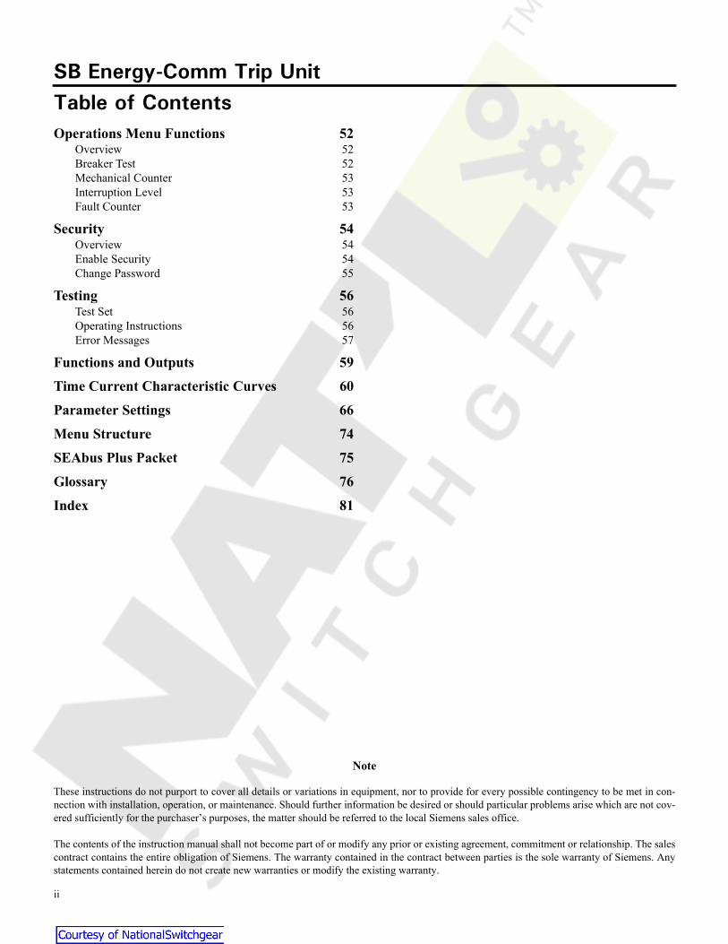
Operations Menu Functions 52Overview 52Breaker Test 52Mechanical Counter 53Interruption Level 53Fault Counter 53
Security 54Overview 54Enable Security 54Change Password 55
Testing 56Test Set 56Operating Instructions 56Error Messages 57
Functions and Outputs 59
Time Current Characteristic Curves 60
Parameter Settings 66
Menu Structure 74
SEAbus Plus Packet 75
Glossary 76
Index 81
Note
These instructions do not purport to cover all details or variations in equipment, nor to provide for every possible contingency to be met in con-nection with installation, operation, or maintenance. Should further information be desired or should particular problems arise which are not cov-ered sufficiently for the purchaser’s purposes, the matter should be referred to the local Siemens sales office.
The contents of the instruction manual shall not become part of or modify any prior or existing agreement, commitment or relationship. The salescontract contains the entire obligation of Siemens. The warranty contained in the contract between parties is the sole warranty of Siemens. Anystatements contained herein do not create new warranties or modify the existing warranty.
Courtesy of NationalSwitchgear.com
Introduction
1
1 Introduction
1.1 Product Overview
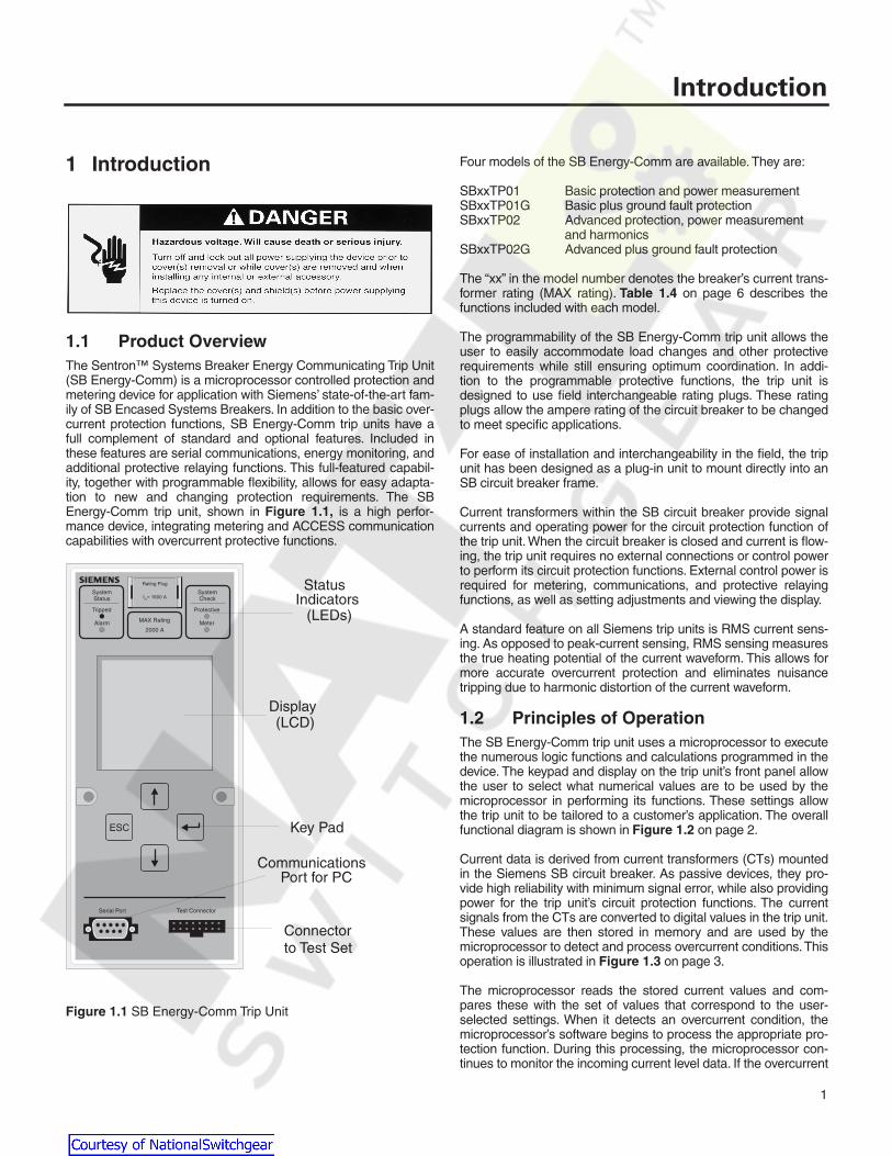
The Sentron™ Systems Breaker Energy Communicating Trip Unit(SB Energy-Comm) is a microprocessor controlled protection andmetering device for application with Siemens’ state-of-the-art fam-ily of SB Encased Systems Breakers. In addition to the basic over-current protection functions, SB Energy-Comm trip units have afull complement of standard and optional features. Included inthese features are serial communications, energy monitoring, andadditional protective relaying functions. This full-featured capabil-ity, together with programmable flexibility, allows for easy adapta-tion to new and changing protection requirements. The SBEnergy-Comm trip unit, shown in
Figure 1.1,
is a high perfor-mance device, integrating metering and ACCESS communicationcapabilities with overcurrent protective functions.
Figure 1.1
SB Energy-Comm Trip Unit
Four models of the SB Energy-Comm are available. They are:
SBxxTP01 Basic protection and power measurementSBxxTP01G Basic plus ground fault protectionSBxxTP02 Advanced protection, power measurement
and harmonicsSBxxTP02G Advanced plus ground fault protection
The “xx” in the model number denotes the breaker’s current trans-former rating (MAX rating).
Table 1.4
on page 6 describes thefunctions included with each model.
The programmability of the SB Energy-Comm trip unit allows theuser to easily accommodate load changes and other protectiverequirements while still ensuring optimum coordination. In addi-tion to the programmable protective functions, the trip unit isdesigned to use field interchangeable rating plugs. These ratingplugs allow the ampere rating of the circuit breaker to be changedto meet specific applications.
For ease of installation and interchangeability in the field, the tripunit has been designed as a plug-in unit to mount directly into anSB circuit breaker frame.
Current transformers within the SB circuit breaker provide signalcurrents and operating power for the circuit protection function ofthe trip unit. When the circuit breaker is closed and current is flow-ing, the trip unit requires no external connections or control powerto perform its circuit protection functions. External control power isrequired for metering, communications, and protective relayingfunctions, as well as setting adjustments and viewing the display.
A standard feature on all Siemens trip units is RMS current sens-ing. As opposed to peak-current sensing, RMS sensing measuresthe true heating potential of the current waveform. This allows formore accurate overcurrent protection and eliminates nuisancetripping due to harmonic distortion of the current waveform.
1.2 Principles of Operation
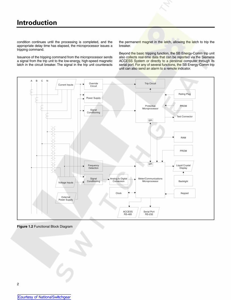
The SB Energy-Comm trip unit uses a microprocessor to executethe numerous logic functions and calculations programmed in thedevice. The keypad and display on the trip unit’s front panel allowthe user to select what numerical values are to be used by themicroprocessor in performing its functions. These settings allowthe trip unit to be tailored to a customer’s application. The overallfunctional diagram is shown in
Figure 1.2
on page 2.
Current data is derived from current transformers (CTs) mountedin the Siemens SB circuit breaker. As passive devices, they pro-vide high reliability with minimum signal error, while also providingpower for the trip unit’s circuit protection functions. The currentsignals from the CTs are converted to digital values in the trip unit.These values are then stored in memory and are used by themicroprocessor to detect and process overcurrent conditions. Thisoperation is illustrated in
Figure 1.3
on page 3.
The microprocessor reads the stored current values and com-pares these with the set of values that correspond to the user-selected settings. When it detects an overcurrent condition, themicroprocessor’s software begins to process the appropriate pro-tection function. During this processing, the microprocessor con-tinues to monitor the incoming current level data. If the overcurrent
MAX Rating
2000 A
SystemStatus
SystemCheck
Tripped Protective
Alarm Meter
Rating Plug
In= 1600 A
ESC
Serial Port Test Connector
Display(LCD)
StatusIndicators
(LEDs)
Key Pad
Communications
Connectorto Test Set
Port for PC
Courtesy of NationalSwitchgear.com
Introduction
2
condition continues until the processing is completed, and theappropriate delay time has elapsed, the microprocessor issues atripping command.
Issuance of the tripping command from the microprocessor sendsa signal from the trip unit to the low-energy, high-speed magneticlatch in the circuit breaker. The signal in the trip unit counteracts
the permanent magnet in the latch, allowing the latch to trip thebreaker.
Beyond the basic tripping function, the SB Energy-Comm trip unitalso collects real-time data that can be reported via the SiemensACCESS System or directly to a personal computer through itsserial port. For any of several functions, the SB Energy-Comm trip
ip
unit can also send an alarm to a remote indicator.
Figure 1.2 Functional Block Diagram
Meter/CommunicationsMicroprocessor
ProtectiveMicroprocessor
Liquid CrystalDisplay
Keypad
Test Connector
Rating Plug
SPI
SPI
RAM
PROM
Backlight
PROM
OverrideCircuit
SignalConditioning
SignalConditioning
Power Supply
FrequencyDetection
Analog to DigitalConversion
Clock
Trip CircuitCurrent Inputs
Voltage Inputs
ExternalPower Supply
Serial PortRS-232
ACCESSRS-485
A B C N
Courtesy of NationalSwitchgear.com

Introduction
3
Figure 1.3 Operational Overview
1.3 SB Encased Systems BreakerSiemens SB Encased Systems Breakers come in four (4) princi-pal frame sizes with MAX Ratings ranging from 400 to 5000amperes. The rating is determined by the current transformerswithin the frame. All frames are rated for 100% continuous opera-tion. Rated trip units are available for all SB Encased SystemsBreakers.
Trip units are fully field installable by authorized personnel. Aspecial rejection scheme is built into the frames and trip units toprevent the installation of a trip unit into a frame for which it is notintended.
The combinations of frame sizes and frame ampere ratings areillustrated in Table 1.1.
Field interchangeable rating plugs are used to set the continuouscurrent rating of the circuit breaker. For a list of available ratingplugs, refer to Table 2.2 on page 13.
The interrupting rating of the SB breaker is specified on the frontcover label and is further identified by the use of a “color bar” atthe top left of the breaker label.
Several short circuit interrupting ratings are available to meet spe-cific applications. The interrupting ratings and short time ratingsare given in Table 1.2 on page 4. The trip unit that may be usedwith a specific circuit breaker is identified on the front cover label ofthe breaker.
Decide ActSense CurrentP
N
Trip Breaker
Collect/Transmit Data
Set Off Alarm
I = 1427 AI = 1375 AI = 1415 A
A
B
C
V = 276 VV = 278 VV = 279 V
A
B
C
Frame Rating
2000 A
SystemStatus
SystemCheck
Tripped Protective
Alarm Meter
Rating Plug
I = 1600 Ar
ESC
Serial Port Test Connector
Table 1.1 Breaker Frame Size and Rating Combinations
Breaker Frame Size(A) Breaker Frame Ampere Rating
1200 400, 800, 1200
2000 1200, 1600, 2000
3200 2500, 3200
5000 2500, 3200, 4000, 5000
Courtesy of NationalSwitchgear.com

Introduction
4
1.4 Front Panel InterfaceEach SB Energy-Comm trip unit features a rating plug (purchasedseparately), front panel keypad, liquid crystal display (LCD), and aEIA-232 communications port for use with a PC or laptop. The tripunit’s integral front panel keypad and LCD provide the user withdirect access to device data and settings. Through detailedmenus and graphical displays, the user may view and modify thesystem configuration and communication parameters, as well asprotective and metering function settings. Both real-time andaccumulated data are available, in addition to current and voltagewaveforms. The user may also view information in the trip logassociated with the five most recent trips.
1.4.1 Keypad
The front panel provides the user with four keypad buttons foreasy touch-control interface which uses no switches or knobs formaking adjustments to this trip unit. The keypad buttons permitnavigation through the displays to allow the local programming ofsettings and viewing of those settings.
The Up and Down arrow keys are used for scrollingthrough a menu of choices displayed on the LCD. The Enter key is used to select a choice or move between two selections.The Escape key is used to exit from a given menu to the nexthigher level.
Table 1.2 UL 489 Symmetrical RMS Amperes Interrupting Rating (kA)
Optional Ratings and Application Voltage Breaker Frame Size
1200A 2000A 3200A 5000A
Alternate A.I.R. (kA): Blue Label “SBA”
@ 240V AC 65 85 N/A N/A
@ 480V AC 65 65 N/A N/A
@ 600V AC 42 50 N/A N/A
Standard A.I.R. (kA): Black Label “SBS”
@ 240V AC 100 100 150 150
@ 480V AC 100 100 100 100
@ 600V AC 50 65 85 85
High A.I.R. (kA): Red Label “SBH”
@ 240V AC 200 200 200 200
@ 480V AC 150 150 150 150
@ 600V AC 100 100 100 100
Short Time Delay Rating (kA) t=0.5 sec. 25 35 50 65
Table 1.3 IEC 947-2 Rating–Standard SBS
Interrupting Ratings Symmetrical RMS Kiloamperes 50/60 Hz.
AC VoltageBreaker Frame Size
1200A 2000A 3200A 5000A
415IcuIcsIcw
10010025
10010035
10010050
100kA100kA65kA
690IcuIcsIcw
656525
656535
656550
65kA65kA65kA
Courtesy of NationalSwitchgear.com

Introduction
5
Figure 1.4 Display and Keypad on Front Panel
1.4.2 LCD
The LCD displays the menu of options and the status of thedevice. The menu allows the user to request configuration settingsand protective or metered data, as well as time-stamped informa-tion stored in the various logs. Pickup and delay settings for alarmand protective relay functions can also be viewed and modified.
1.4.3 LED Indicators
Two green status LEDs indicate the proper operation of the meter-ing and protective functions. A separate yellow LED indicates analarm condition. A red LED indicates that a trip has occured.
1.5 Overcurrent Protective FunctionsLike the standard electronic trip unit for SB Encased Systemsbreakers, the SB Energy-Comm trip unit provides configurablelong time, short time, and instantaneous over-current protection.Trip units with integral ground fault protection are available as anoption.
The pickup and delay settings for each protective function areuser-configurable through the integral keypad and LCD screen, aswell as through communications. In addition, short time andinstantaneous protection may be disabled, although not at thesame time.
1.6 Alarm SetpointsThe SB Energy-Comm trip unit’s full-featured model offers the tenalarm functions listed below:
• Overcurrent
• Ground Overcurrent
• Overcurrent Demand
• Total Harmonic Distortion (THD)
• Over Real Power (kW)
• Over Power Demand (kW Demand)
• Over Reactive Power (kVAR)
• Over Apparent Power (kVA)
• Under Power Factor (PF) Leading
• Under Power Factor (PF) Lagging
Each alarm function is configured separately to include its enable/disable status and associated pickup and delay. When enabled, afunction causes the trip unit’s relay contact to close if its alarm limit(pickup) is exceeded for the time specified by the delay. Assumingthat no other alarm conditions exist, a time-stamped entry is alsomade to the event log at this time. (Restrictions are discussed inSection 1.10.2.) If the alarm condition ends, the relay contact isopened, assuming that no other alarm conditions are causing it toremain closed. All alarm settings are stored in nonvolatile mem-ory.
The full-featured models (SBxxTP02 and SBxxTP02G) offer morealarm functions than the base models (SBxxTP01 andSBxxTP01G).
1.7 Extended Protective RelayingIn addition to the ten alarm functions described earlier, the SBEnergy-Comm trip unit also provides the following optional pro-grammable protective relay functions:
• Neutral Overcurrent
• Current Unbalance
• Undervoltage
• Voltage Unbalance
• Overvoltage
• Over Reverse Power (kW)
• Over Frequency
• Under Frequency
Software allows the user to configure each of these functions indi-vidually for alarm and trip, alarm only, or neither. Separate pickupand delay settings are assigned for alarming and for trippingactions. In this way, an alarm can be activated to warn of a poten-tial trip.
When enabled for alarm activity, a particular function will close therelay contact if its alarm pickup setting is exceeded for the speci-fied delay. When also enabled for tripping, the function controlsthe breaker tripping actuator to trip the breaker if the separate trippickup is exceeded for the trip delay time. An event log records
MAX Rating
2000 A
SystemStatus
SystemCheck
Tripped Protective
Alarm Meter
Rating Plug
In= 1600 A
ESC
Serial Port Test Connector
Display(LCD)
Keypad
LEDIndicators
Courtesy of NationalSwitchgear.com

Introduction
6
alarm activity, while the trip log stores tripping information. All pro-tective relay settings are stored in nonvolatile memory.
1.8 Metering Functions
The SB Energy-Comm trip unit measures and stores severaltypes of metered data for evaluation or monitoring. The meteringincludes real-time measurement of current, voltage and powervalues, and demand measurements. It also includes additionaloptions, including programmable protective relay and alarm func-tions, harmonic distortion analysis, and separate logs to recordevent and min/max data.
1.9 Features By Model Number
Table 1.4
summarizes the features available with each of the fourtrip unit models. The full-featured models (SBxxTP02 andSBxxTP02G) offer more alarm functions; the extended protectiverelay functions, and harmonic analysis that the base models(SBxxTP01 and SBxxTP01G) do not. Models with Ground Faultprotection have that additional protective function available. Thismanual describes all these functions. Your particular model mayor may not have all the features discussed in this manual.
Table 1.4
Features by Model Number
Features Models
SBxxTP01 SBxxTP01G SBxxTP02 SBxxTP02G
Integral Keypad and Display
Voltage/Current Waveform Displays
� � � �
Protective Functions
Long Time, Short Time, Instantaneous
� � � �
Metering Functions
Volts, Amps, PF, Frequency, Watts, VARs, VA, Crest Factor,Ampand Watt Demand, Voltage and Current Waveforms,Voltage and Current Unbalance
� � � �
Communications
PC (RS-232), ACCESS (RS-485)
� � � �
Counters
Breaker Test (Trip/No Trip), Mechanical Counter,Interruption Level Fault Counter
� � � �
Security
Password Protection
� � � �
Event Log
Time-Stamped –10 Most Recent Events
� � � �
Trip Log
Time-Stamped – 5 Most Recent Trips
� � � �
Alarms
(Alarm Only) Overcurrent, Gnd. Overcurrent, Over Amp Demand, Over kW, Over kW Demand, Over KVAR, Over KVA, Under/Over PF
� � � �
Advanced Alarms
Total Harmonics
� �
Min./Max. Logs
Volt/Amp., Power, PF, Frequency, %THD
� �
Harmonic Analysis
Up to 19th Per Phase, THD
� �
Protective Relay Functions
(Alarm and/or Trip)
Neutral Overcurrent, Current Balance, Under/Over Voltage, Voltage Unbalance, Reverse Power, Under/Over Frequency
� �
Ground Fault Protection
Residual or Ground Return
��
Courtesy of NationalSwitchgear.com

Introduction
7
1.10 LogsThe SB Energy-Comm trip unit maintains three logs: a trip log innonvolatile memory to document up to five of the most recenttrips, an event log to document up to ten of the most recentalarms, and a min/max log containing minimum and maximummetered values.
1.10.1 Trip Log
All SB Energy-Comm trip unit models maintain a trip log in nonvol-atile memory to store information for up to five of the most recentdevice trips. Each log entry records the trip’s cause, its date andtime, and the measured quantities associated with the trippingaction. The trip log may be viewed and cleared through the tripunit’s LCD menu or through communications.
1.10.2 Event Log
All SB Energy-Comm trip unit models provide an event log tostore the ten most recent alarms. Each entry includes a sequen-tial event number (used by the ACCESS master), an alarm IDindicating the alarm type, the start and stop time stamps, and upto five parameters associated with the alarm.
The ten alarm functions are prioritized (that is, overcurrent alarmis highest priority, total harmonic distortion alarm is lowest). This isdone to insure that only one alarm will be recorded in the eventlog at a time. If two alarm functions become active simultaneously,the higher priority alarm (Alarm #1) will be written to the event log.The lower priority alarm (Alarm #2) will not be recorded untilAlarm #1 conditions have ended. If Alarm #2 conditions ceasebefore those associated with Alarm #1, Alarm #2 will not appear inthe event log.
Like the trip log, the event log may be viewed and cleared locallyusing the trip unit’s keypad and LCD menu or through EIA-232 orEIA-485 communications. However, because the event logresides only in RAM, it is lost if control power is removed.
1.10.3 Min/Max Log
The SB Energy-Comm trip unit’s full-featured model also main-tains a min/max log for metered quantities. This includes the mini-mum and/or maximum values detected for currents, voltages,leading and lagging power factors, instantaneous VA and VARs,crest factors, frequency, kW and amp demand, as well as totalharmonic distortion. Like the trip log, the min/max log may beviewed and cleared at the trip unit or through communications.The min/max log resides only in RAM and is lost if control power isremoved. These logs are described in detail in Chapter 10,Logs.
1.11 Communications
1.11.1 ACCESS Communications
The EIA-485 communications port is located on the back of theSB Energy-Comm trip unit. This port allows the trip unit to be con-nected as a slave device in an ACCESS master/slave network.Data is transmitted serially between the trip unit and a remoteACCESS master (e.g., Power Monitor) using a shielded, twisted-pair EIA-485 cable. The EIA-485 communications standard issuperior to EIA-232 for industrial applications, providing betternoise rejection and faster transmission rates over greaterdistances.
With few exceptions, the device information available locally at thetrip unit is accessible to the ACCESS bus master (for example,configuration parameters, function settings, and real-time data).Although the ACCESS master may request information from thetrip unit at any time, it is prevented from making device changeswhile an operator is using the trip unit’s keypad to locally view/modify device information. In fact, a local operator at the keypad isgiven priority over both EIA-485 and EIA-232 communications toensure against data access violations.
1.11.2 Serial Communications
The EIA-232 serial port on the face of the SB Energy-Comm tripunit allows a PC or laptop running custom software to view and/ormodify device information in much the same way as the ACCESShost. Settings can be easily downloaded to the trip unit, providinga faster, more convenient means for device configuration than themanual keypad method. EIA-232 communications can occur with,and are independent of, EIA-485 ACCESS communications.
Courtesy of NationalSwitchgear.com

Installation
8
2 Installation
2.1 Quick Reference Guide
This section summarizes the required procedures to install thetrip unit before energizing the breaker. Follow the steps listedbelow to install the SB Energy-Comm trip unit.
1. Unpack and inspect the trip unit as described in
Section2.2, Unpacking and Inspection.
2. Select a power source for the trip unit. See
Section 2.3,Selecting a Power Source
.
3. Select and install the proper potential transformer (PT) foryour system. See
Section 2.4, Selecting a PT
.
4. Wire the trip unit as described in
Section 2.5, Wiring
.
5. Install the trip unit into the breaker. The step-by-step pro-cedure is described in
Section 2.6, Installing the TripUnit in a Systems Breaker
.
6. Select and install the rating plug. See
Section 2.7, Insert-ing and Removing the Rating Plug
. Be sure the plug hasthe proper rating.
7. Read
Section 3, User Interface
to familiarize yourselfwith the front panel controls and display.
8. Configure the trip unit’s system parameters, including fre-quency, wiring configuration, PT rating, short circuit pro-tection type, and neutral CT. Instructions on setting theseparameters are listed in
Section 4.2, Setting SystemConfiguration Parameters
.
9. Configure the trip unit’s overcurrent protection. Instructionson setting these parameters are listed in
Section 5, Over-current Protection Configuration
.
These are the minimum configuration requirements beforeenergizing the breaker. Additional configuration parametersare described in
Section 4.3, Setting Other Device Parame-ters
and in
Sections 6
through
10
inclusive.
2.2 Unpacking and Inspection
When unpacking the SB Energy-Comm trip unit, inspect thedevice for any damage and report any problems to your localSiemens representative.
The SB Energy-Comm trip unit has been factory tested to strin-gent requirements. The Siemens factory that produced this trip
unit has a quality system that is certified to an ISO 9000 inter-national standard.
All settings are factory preset to the minimum values.
2.3 Selecting a Power Source
The SB Energy-Comm trip unit depends either on power fromthe current transformers (CTs) or independent control power.The protective functions use the power from the CTs; the meter-ing and communications require separate control power froman external power supply. This requirement allows communica-tion with the trip unit during all load current conditions, evenwith the circuit breaker switched off.
The ratings for the power supply are:
• Input: 110V AC = SBEPS Catalog Number
24V DC = SBEPS24 Catalog Number
• Output: +5V DC @ 4A, +12V DC @ 0.3A, -12V DC @ 0.3A
2.4 Selecting a PT
A potential transformer (PT) module is required to provide volt-age signals to the trip unit for metering functions and providesisolation from the primary circuits. Class CC IA 600V fuses canbe added during installation to protect against internal PT mod-ule faults. The PT modules are encapsulated in polymericmaterial to protect the transformer windings and withstandmechanical vibration. The PT module’s primary inputs are fromthe three phases plus neutral. For three-wire systems, the neu-tral conductor input is not used. To choose a PT module, selectthe one rated closest to, but higher than the rated voltage:
2.5 Wiring
Before operation, the SB Energy-Comm trip unit must be properlywired to the external power supply and the PT module. Panel-boards manufactured by Siemens are shipped with all requiredwiring. Retrofit applications require a retrofit kit, which includesinstructions for mounting and wiring the power supply and PTmodule.
Figure 2.1
shows the proper wiring connections.
If you are connecting the SB Energy-Comm trip unit to anACCESS Host device, you must also connect the SEAbus RS-485 cabling to the secondary disconnects or terminal blocksas shown in
Figure 2.1
.
Refer to the
Individual Instruction Sheets
for wiring the vari-ous accessories, the PT module, and the trip unit power supply.
Table 2.1
PT Module Selection
For System Voltage of: Select This PT Module:
120/208V, 120/240V, 220V SBPTM240
277/480V, 415V SBPTM480
575V SBPTM600
Courtesy of NationalSwitchgear.com

Installation
9
Figure 2.1
SB Energy-Comm Wiring to External Power Supply, PT Module, and ACCESS System
Courtesy of NationalSwitchgear.com

Installation
10
2.6 Installing the Trip Unit in a Systems Breaker
The Siemens SB circuit breaker has a built-in interlock devicethat prevents the circuit breaker from being closed when thereis not an installed trip unit. This same interlock device trips thecircuit breaker when the trip unit is removed.
Before installing the trip unit, make sure that the indicators inthe top center of the front of the breaker show that the spring isdischarged and the contacts are open. Refer to the breaker’sinformation and instruction guide for the proper operating pro-cedure.
Figure 2.4
Breaker Indicators
Follow these steps to install the trip unit into an SB circuitbreaker.
1. To install the trip unit, the front cover of the circuit breakermust first be removed. This is done by removing the eightPhillips head screws that hold the front cover in place.
2. Lift off the front cover.
CAUTIONSpring under compression.May cause personal injury, or maydamage equipment.Make certain that the breaker has thespring discharged and contacts open.
Spring Charged Contacts Closed
Spring Discharged Contacts Open
1
234
5
6 7 8
Courtesy of NationalSwitchgear.com

Installation
11
3. Set the ground fault mode switch.
On trip units with ground fault protection, the ground faultselection switch on the side of the trip unit must be set to theappropriate sensing scheme—Residual or Ground Return—prior to installing the trip unit. The ground fault sensingschemes are discussed
in
Section 5.7, Ground Fault Sens-ing Scheme
.
Residual is the factory pre-setting and is the setting most com-monly used.
4. Check the label on the side of the trip unit.
Before attempting to install the trip unit, check the label on theside of the device to make sure that it is the proper device forthe SB circuit breaker.
5. Check alignment of pins and holes.
If there is any doubt about a trip unit being the proper devicefor an SB circuit breaker, check the alignment of the pins andholes. A built-in rejection scheme will prevent the installation ofa trip unit into a breaker for which it is not intended.
This scheme consists of two pins on the support plate on whichthe trip unit will set into two matching holes in the bottom of thetrip unit. If the holes in the bottom of the trip unit cannot bealigned with the pins, the trip unit cannot be installed in the SBcircuit breaker.
6. Mate the pin connectors.
Mate the connector half on the back of the trip unit with its cor-responding connector half in the circuit breaker.
Gro
und
Faul
t Mod
e S
witc
hG
roun
dR
etur
nR
esid
ual
Ground Fault Mode Switch
ResidualGroundReturn
Trip Device
Cat. No:
For use with Types SB Circuit Breakers Frame Rating
Listed Circuit Breaker Trip Unit Issue No. G-1126
Siemens Energy & Automation, Inc. Bellefountaine, OH 43311
Courtesy of NationalSwitchgear.com

Installation
12
7. Lower the trip unit onto the support plate.
After the connector has been mated, lower (push) the trip unitonto the support plate. The pins on the support plate will fit intothe holes in the bottom of the trip unit.
8. Secure the trip unit.
Secure the trip unit in place with the retaining screw located atthe top of the device. Torque 6 to 8 in-lbs. If the trip unit top isnot secured correctly the interlock will stop the breaker fromclosing.
9. Replace the front cover.
Replace the front cover and the eight (8) front cover screws.Torque 6 to 8 in-lbs.
Courtesy of NationalSwitchgear.com
Installation
13
Note: Before energizing the breaker, install a proper rat-ing plug. Refer to
Section 2.7, Inserting andRemoving the Rating Plug
.
Note: Take care not to pinch any wires when replacing thefront cover of the breaker.
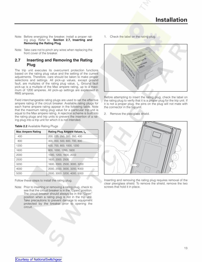
2.7 Inserting and Removing the Rating Plug
The trip unit executes its overcurrent protection functionsbased on the rating plug value and the setting of the currentadjustments. Therefore, care should be taken to make properselections and settings. All pick-up values, except groundfault, are multiples of the rating plug value, I
n
. Ground faultpick-up is a multiple of the Max ampere rating, up to a maxi-mum of 1200 amperes. All pick-up settings are expressed inRMS amperes.
Field interchangeable rating plugs are used to set the effectiveampere rating of the circuit breaker. Available rating plugs foreach frame ampere rating appear in the following table. Notethat the maximum rating plug value for a particular trip unit isequal to the Max ampere rating. A rejection scheme is built intothe rating plugs and trip units to prevent the insertion of a rat-ing plug into a trip unit for which it is not intended.
Follow these steps to install the rating plug.
Note: Prior to inserting or removing a rating plug, check tosee that the circuit breaker is in the “Open” position.The circuit breaker should always be in the “Open”position when a rating plug is not in the trip unit.Take precautions to prevent damage to equipmentprotected by the breaker prior to opening thecircuit.
1. Check the label on the rating plug.
Before attempting to insert the rating plug, check the label onthe rating plug to verify that it is a proper plug for the trip unit. Ifit is not a proper plug, the pins on the plug will not mate withthe connector in the trip unit.
2. Remove the plexiglass shield.
Inserting and removing the rating plug requires removal of theclear plexiglass shield. To remove the shield, remove the twoscrews that hold it in place.
Table 2.2
Available Rating Plugs
Max Ampere Rating Rating Plug Ampere Values, I
n
400 200, 225, 250, 300, 350, 400
800 400, 450, 500, 600, 700, 800
1200 600, 700, 800, 1000, 1200
1600 800, 1000, 1200, 1600
2000 1000, 1200, 1600, 2000
2500 1600, 2000, 2500
3200 1600, 2000, 2500, 3000, 3200
4000 2000, 2500, 3000, 3200, 4000
5000 2500, 3000, 3200, 4000, 5000
Cat No
.
Use With Type SB
Trip Unit RatedRatin
g P
lug
Ir =
2000 A
Courtesy of NationalSwitchgear.com
Installation
14
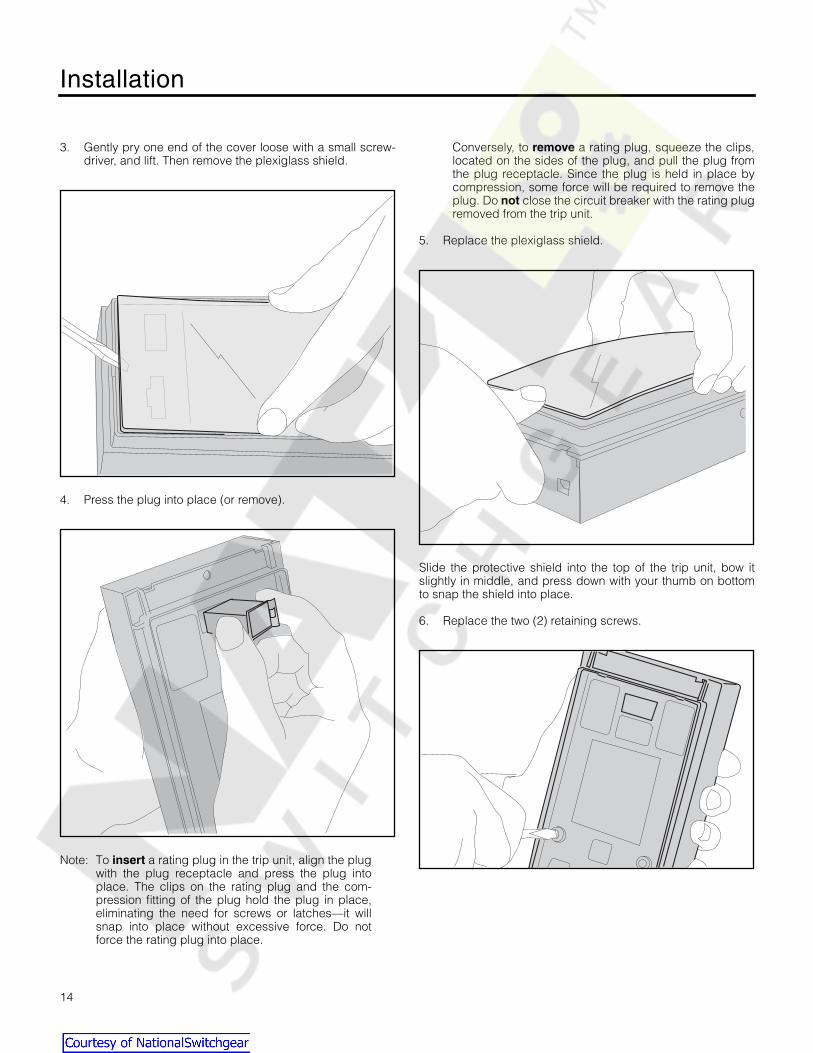
3. Gently pry one end of the cover loose with a small screw-driver, and lift. Then remove the plexiglass shield.
4. Press the plug into place (or remove).
Note: To
insert
a rating plug in the trip unit, align the plugwith the plug receptacle and press the plug intoplace. The clips on the rating plug and the com-pression fitting of the plug hold the plug in place,eliminating the need for screws or latches—it willsnap into place without excessive force. Do notforce the rating plug into place.
Conversely, to
remove
a rating plug, squeeze the clips,located on the sides of the plug, and pull the plug fromthe plug receptacle. Since the plug is held in place bycompression, some force will be required to remove theplug. Do
not
close the circuit breaker with the rating plugremoved from the trip unit.
5. Replace the plexiglass shield.
Slide the protective shield into the top of the trip unit, bow itslightly in middle, and press down with your thumb on bottomto snap the shield into place.
6. Replace the two (2) retaining screws.
Courtesy of NationalSwitchgear.com

Installation
15
7. Seal the cover as needed with a lead seal for tamper evi-dent protection.
After the cover has been replaced a wire lock may be insertedthrough holes in the screws and sealed with a lead seal. Thiswill help prevent tampering by unauthorized personnel.
2.8 Communications
To connect the trip unit for communications with a PC, connecta serial cable to the Serial Port on the front panel of the trip unit.
Refer to the
ACCESS Systems Installation Guide
for a thor-ough explanation of how to connect several devices on theSEAbus network to a personal computer.
2.9 Removing the Trip Unit from a Systems Breaker
Follow the steps below when removing the trip unit from an SBEncased Systems Breaker. Before starting to remove the tripunit, set the circuit breaker to the “Open” and “Discharged”positions. If the circuit breaker is in the “Closed” position, thebreaker will trip when the trip unit is removed.
Make sure that the circuit breaker is in the open position. Referto the breaker’s information and instruction guide for the properoperating procedure.
1. Remove the eight screws from the breaker front cover. Liftoff the front cover.
Spring Charged Contacts Closed
Spring Discharged Contacts Open
1
234
5
6 7 8
Courtesy of NationalSwitchgear.com

Installation
16
2. Remove the trip unit retaining screw.
Remove the front cover of the breaker and trip unit retainingscrew. Lift the trip unit from the support plate and unmate theconnector. Note that the trip unit must be lifted from the supportplate high enough for the pins on the support plate to clear theholes in the bottom of the trip unit; otherwise, the connectorcannot be unmated.
3. Remove the trip unit.
2.10 Starting Up
1. Remove the screws from the seals to access the displayinterface keypad.
The screws are on both sides of the display shield as shownbelow.
2. Turn on external 120 VAC control power. The “Protective”light flashes when the protection functions are operational.The “Meter” light flashes when the metering functions areoperational. Now you are ready to learn how to use thefront panel to configure the trip unit for protection andmetering.
MAX Rating
2000 A
SystemStatus
SystemCheck
Tripped Protective
Alarm Meter
Rating Plug
In= 1600 A
ESC
Serial Port Test Connector
ScrewLocations
Courtesy of NationalSwitchgear.com

User Interface
17
3 User Interface
3.1 Front Panel DisplayThe integral front panel keypad and display of the SB Energy-Comm trip unit provide the user with direct access to devicedata and settings. Through custom menus and graphical dis-plays, the user may view and modify the system configurationand communication parameters, as well as protective andmetering function settings. Both real-time and accumulateddata are available, in addition to current and voltage wave-forms. The user may also view information in the trip log asso-ciated with the five most recent trips.
The large liquid crystal display (LCD) on the front panel showsmenus of commands and graphical information about the sta-tus of the trip unit and the circuit breaker. It is a 128 x128 pixelbacklit display, which is viewable in many types of lighting. TheLCD displays many types of information about the trip unit andabout the circuit breaker.
Figure 3.1 Display and Keypad on Front Panel
Note: On trip units with software version 3.00 or later, the LCDbacklighting is activated by pressing any keypad button. Thebacklight is turned off 5 minutes after the last keypad button ispushed.
The LCD displays the menu of options and the status of thedevice. The menu allows the user to request configuration set-tings and protective or metered data, as well as time-stampedinformation stored in the various logs of the trip unit. Pickupand delay settings for alarm and protective relay functions canalso be viewed and modified.
If the device is powered and left idle for five minutes, it will gointo idle display mode and cycle between several informationalscreens repeatedly. See Section 3.5, Idle Display Mode fordescriptions of the screens displayed in idle display mode. To
end the scrolling of these screens, press Escape and thepreviously selected menu appears.
3.2 Front Panel KeysThe front panel provides the user with a keypad with four keysfor easy touch-control interface. No switches or knobs areneeded to set the device parameters. The keypad includesfour keys that allow the user to navigate through the menus, tochoose parameter settings, and to view data.
Menu Screens
For menu screens, the up and down arrow buttons help navi-gate among the options listed vertically. When a menu is firstdisplayed, the top choice on the list is highlighted. To scrolldown to an option lower in the list, press the down arrow but-ton. Continuing to press the Up or Down Arrow will cyclethrough to the top of the list again.
To select a highlighted option, press Enter .
For example, to choose a menu choice from the Main Menu,press the Up or Down Arrow until the selection you wantis highlighted and press Enter .
Press Escape to leave a menu without choosing any of theselections.
Figure 3.2 Selecting a Menu Option
MAX Rating
2000 A
SystemStatus
SystemCheck
Tripped Protective
Alarm Meter
Rating Plug
In= 1600 A
ESC
Serial Port Test Connector
Display(LCD)
Keypad
MAX Rating
2000 A
SystemStatus
SystemCheck
Tripped Protective
Alarm Meter
Rating Plug
Ir = 1600 A
ESC
Serial Port Test Connector
Courtesy of NationalSwitchgear.com

User Interface
18
Parameter Setting Screens
Besides menus, the front panel display also shows settingsthat can be changed by pressing the keys on the front panel.Several actions are available for parameter setting screens.When several parameters are displayed on one screen, thefirst choice is darkened (highlighted). The Enter key moves thehighlighting from one parameter to the next. The up and downarrow buttons scroll through available values for a particularparameter.
Press Enter to move from one parameter to the next. For agiven parameter, press the Up or Down Arrow keys toview the possible settings. After the setting is at the desiredvalue, press Enter to move to the next parameter.
Press Escape to leave this group of parameter settings. Ifsecurity is inactive, an additional screen appears.
Press Enter to accept the settings or press Escape toleave without changing or choosing any of the selections. Ifsecurity is active, you cannot change parameters without firsttyping in the password.
To review, general functions of the keypad are summarized in
Figure 3.3
.
Figure 3.3
Key Functions
3.3 Menu Structure
The user interface displays provide the functions and statusinformation. They are organized in a menu structure with theMain Menu being the highest level of organization. Refer to theappendix,
Menu Structure
for additional details about menuorganization. On start-up the Main Menu is the first display.
The
Main Menu
lists the major groupings of menus or displaysthat allow the user to view or set various settings of the deviceor data collected about the breaker. These menus are summa-rized next.
The
System Configuration
menu shows the options used toconfigure the system. This menu is used to set the application-specific parameters for the trip unit after the device is installed.It involves such settings as the voltage sensor rating and sys-tem frequency.
The
Protective
menu shows the types of protective functionsfor the user to configure. Within each type of protection, theuser can set the extent of protection. For each type of protec-tion, the user may select parameter settings or use defaultsettings.
ESC
Up Arrow
Enter
Down Arrow
Escape
for incrementing parameter
for moving to next parameter,or selecting a highlighted menuselection
for decrementing parameter
for returning to previous screen
Courtesy of NationalSwitchgear.com

User Interface
19
The
Metering
menu shows the types of metered data and con-figuration settings for demand values. It also includes thescreen for resetting the meter data.
The
Communications
menu shows the various parameters forcommunicating remotely with the device from a PC.
The
Log
menu shows a list of the logs that can be viewed orreset. Each log has metered values or data about trips andevents that have occurred.
The
Operations
menu is used for troubleshooting and forreviewing the history of the breaker. It shows a list of tests andcounters that can be viewed.
The
Security
menu allows the user to set the password andenable the password protection.
The
View Data
menu places the SB Energy-Comm trip unit intoidle display mode.
For each menu, the user can view the present settings and canchange any of the parameter settings (if the user has propersecurity clearance.)
3.4 Front Panel LEDs
At the top of the front panel are four light-emitting diode (LED)indicators which provide information about the operation of thetrip unit and the status of the breaker. These indicators are theSystem Check LEDs (for trip unit function information) and theSystem Status LEDs (for breaker status information).
3.4.1 System Check LEDs
Two green LEDs indicate the proper operation of the SBEnergy-Comm trip unit. The System Check LEDs blink approxi-mately once every 3 seconds when the microprocessors areproperly cycling through their protection and metering routines.
SystemCheck
Protective
Metering
Courtesy of NationalSwitchgear.com
User Interface
20
The Protective LED indicates the operation of the protectivefunctions of the trip unit and blinks when operating properly.This LED operates at current levels over 20% of the rated loadwithout external power, and at all current levels with externalpower.
The Metering LED indicates the operation of the metering func-tions of the trip unit and blinks when operating properly. Sincethe metering function requires external power, this LED will notlight when the external power supply is not supplying power.
3.4.2 System Status LEDs
These two LEDs indicate the status of the breaker and associ-ated power line. The Tripped LED is red and indicates a trip.The Alarm LED is yellow and indicates an alarm condition.These LEDs require the external power supply to be opera-tional and supplying power.
The Tripped LED will light when the trip unit senses that thebreaker has tripped.
For more information about breaker monitoring, refer to thebreaker’s seperate information and instruction guide.
The Alarm LED will light when one of the alarm functions hasexceeded a limit set by the user. For more information aboutAlarms, refer to
Chapter 6, Alarm Setpoints.
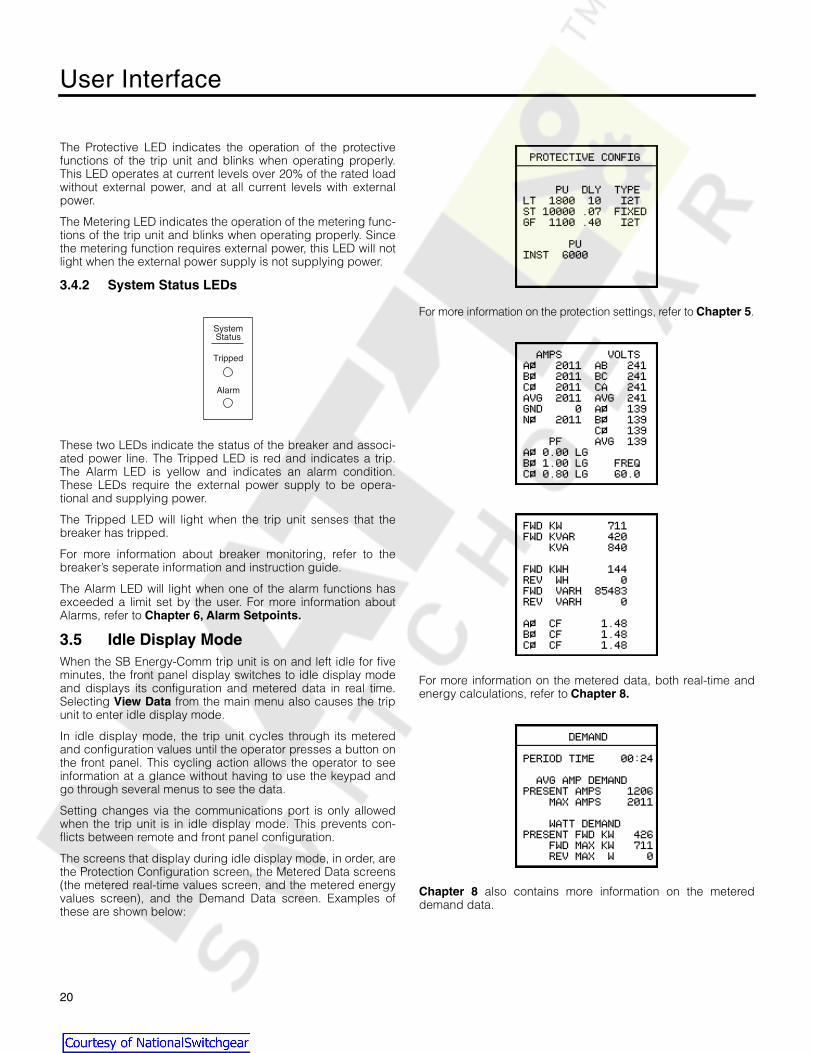
3.5 Idle Display Mode
When the SB Energy-Comm trip unit is on and left idle for fiveminutes, the front panel display switches to idle display modeand displays its configuration and metered data in real time.Selecting
View Data
from the main menu also causes the tripunit to enter idle display mode.
In idle display mode, the trip unit cycles through its meteredand configuration values until the operator presses a button onthe front panel. This cycling action allows the operator to seeinformation at a glance without having to use the keypad andgo through several menus to see the data.
Setting changes via the communications port is only allowedwhen the trip unit is in idle display mode. This prevents con-flicts between remote and front panel configuration.
The screens that display during idle display mode, in order, arethe Protection Configuration screen, the Metered Data screens(the metered real-time values screen, and the metered energyvalues screen), and the Demand Data screen. Examples ofthese are shown below:
For more information on the protection settings, refer to
Chapter 5
.
For more information on the metered data, both real-time andenergy calculations, refer to
Chapter 8.
Chapter 8
also contains more information on the metereddemand data.
SystemStatus
Tripped
Alarm
Courtesy of NationalSwitchgear.com

System Configuration
21
4 System Configuration
4.1 Viewing System ConfigurationThe System Configuration function allows you to set up thedevice to match the line frequency, phase sequence, andbreaker connection settings of your system.
Configure the trip unit using the System Configuration menu.
At system power-up, the time and date starts at 12:00 Jan. 1,1997. To set the time and date, select the Time and Dateoption from the System Configuration menu and press Enter
. See 4.3, Setting Other Device Parameters for detailedinformation on setting device parameters.
.
To see how the device is configured for your system, selectView Config from the System Configuration menu and pressEnter . A screen similar to the following appears.
This display shows the time and the date and lists the softwareversion in the device, the settings, and the catalog number.The software version numbers and catalog number may be dif-ferent from the illustration above.
4.2 Setting System Configuration Parameters
Several of the system configuration parameters can be setusing the System Configuration menu. These parametersinclude:
• System Frequency
• System Wiring Configuration
• Phase Sequence
• Potential Transformer (PT) Rating
• Short Circuit Protection
• External Neutral Sensing (Neutral CT)
System Frequency
To select the frequency of AC power, begin from the SystemConfiguration menu, select Frequency, and press Enter .Select 50 or 60 Hz by pressing the Up or Down Arrowkey; when finished, press Escape , and then press Enter to accept the change.
System Wiring Configuration
To inform the SB Energy-Comm trip unit that your system iseither a three-wire or four-wire configuration, select Wiring fromthe
System Configuration
menu. Use the Up or Down Arrow key to select either one and press Escape , and thenpress Enter to accept the change.
For three-wire delta systems, select
3 Wire
. For four-wire wyesystems, select
4 Wire
.
Phase Sequence Protection
A phase sequence configuration screen SEQUENCE CONFIGis available on trip units with software version 3.00 or later. TheSequence Config screen will display a POSITIVE sequencecheck box, a NEGATIVE sequence check box, and an ALARMON INCORRECT SEQUENCE check box. The default configu-ration settings are positive sequence selected (checked) andalarm disabled (unchecked).
Courtesy of NationalSwitchgear.com

System Configuration
22
The SEQUENCE CONFIG screen will open with both the posi-tive and negative sequence boxes highlighted. When the Up
key is pressed, positive sequence is selected (checked).When the Down key is pressed, negative sequence isselected (checked). Pressing the Enter key moves the high-light to the ALARM ON INCORRECT SEQUENCE check box.When the Up key is pressed, the alarm is enabled(checked). When the Down key is pressed, the alarm is dis-abled (unchecked). Another press of the Enter key movesthe highlight back to the positive and negative sequencecheck boxes. Pressing the Escape key at any time will exitthe screen and, (if changes were made) the standard changeconfirmation screen will be displayed. If the Alarm box ischecked and the system phase sequence does not match theselected phase sequence configuration, an alarm will beissued. This is a local alarm only and is not reported viaACCESS communication, but will activate the Alarm Relay ifinstalled.
A PHASE SEQUENCE ALARM screen will be displayed anytime the phase sequence alarm is active. Pressing any key willexit the alarm screen and return the user to the normal menuscreens. The user can then change the phase sequence con-figuration or disable the phase sequence alarm if desired.Thirty seconds after the last key press, if the alarm is stillactive, the phase sequence alarm screen will again bedisplayed.
Potential Transformer Rating
To inform the trip unit which potential transformer (PT) is usedin your system, select
PT Rating
from the
System Configura-tion
menu. The following screen appears:
Make sure the PT installed in the system matches the PT Rating(line-to-line) setting. Use the table below for various systemvoltages:
Table 4.1
PT Ratings
Use the Up or Down Arrow keys to select the desiredvalue. When finished, press Escape , and then press Enter
to accept the change.
Short Circuit Protection
The short time and instantaneous overcurrent protective func-tions can be enabled or disabled from the
System Configura-tion
menu. To specify the extent of such short circuit protectionrequired in your system, select
Short Circuit Prot
from the
System Configuration
menu. The following screen appears:
For short circuit protection either short time, or instantaneoustripping, or both can be chosen. Select these types of protec-tion by pressing the Up or Down Arrow key until a checkappears in the desired box(es). When the desired box(es) arechecked, press Escape , and then press Enter to acceptthe change.
For System Voltage of: Select This PT Rating:
120/208V, 120/240V, 220V 240V
277/480V, 415V 480V
575V 600V
Courtesy of NationalSwitchgear.com
System Configuration
23
To set the pickup and time delay values for short time pro-tection and the pickup value for instantaneous protection,refer to the sections
5.4, Short Time Fault Protection,
and
5.5, Instantaneous Fault Protection
.
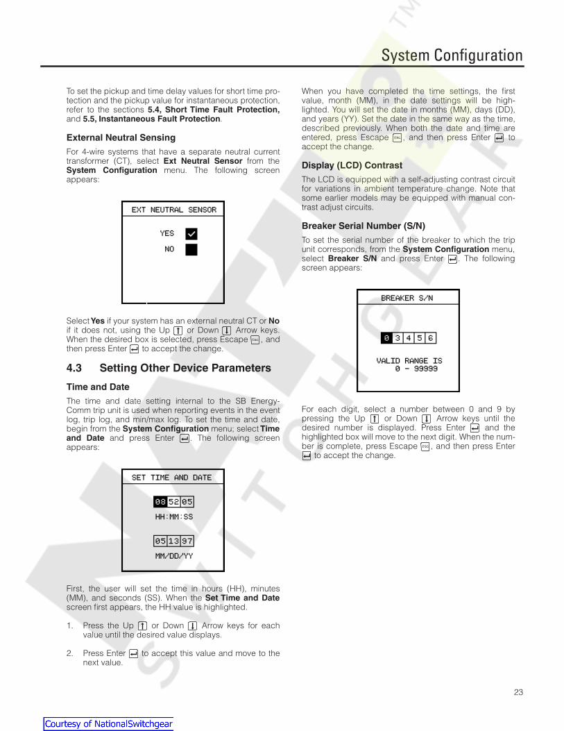
External Neutral Sensing
For 4-wire systems that have a separate neutral currenttransformer (CT), select
Ext Neutral Sensor
from the
System Configuration
menu. The following screenappears:
Select
Yes
if your system has an external neutral CT or
No
if it does not, using the Up or Down Arrow keys.When the desired box is selected, press Escape , andthen press Enter to accept the change.
4.3 Setting Other Device Parameters
Time and Date
The time and date setting internal to the SB Energy-Comm trip unit is used when reporting events in the eventlog, trip log, and min/max log. To set the time and date,begin from the
System Configuration
menu; select
Timeand Date
and press Enter . The following screenappears:
First, the user will set the time in hours (HH), minutes(MM), and seconds (SS). When the
Set Time and Date
screen first appears, the HH value is highlighted.
1. Press the Up or Down Arrow keys for eachvalue until the desired value displays.
2. Press Enter to accept this value and move to thenext value.
When you have completed the time settings, the firstvalue, month (MM), in the date settings will be high-lighted. You will set the date in months (MM), days (DD),and years (YY). Set the date in the same way as the time,described previously. When both the date and time areentered, press Escape , and then press Enter toaccept the change.
Display (LCD) Contrast
The LCD is equipped with a self-adjusting contrast circuitfor variations in ambient temperature change. Note thatsome earlier models may be equipped with manual con-trast adjust circuits.
Breaker Serial Number (S/N)
To set the serial number of the breaker to which the tripunit corresponds, from the
System Configuration
menu,select
Breaker S/N
and press Enter . The followingscreen appears:
For each digit, select a number between 0 and 9 bypressing the Up or Down Arrow keys until thedesired number is displayed. Press Enter and thehighlighted box will move to the next digit. When the num-ber is complete, press Escape , and then press Enter
to accept the change.
Courtesy of NationalSwitchgear.com

Overcurrent Protection Configuration
24
5 Overcurrent Protection Configuration
5.1 Protective Functions Menu
The SB Energy-Comm trip unit provides configurable overcur-rent protection functions that can trip the SB circuit breaker.The user can easily accommodate load changes and otherprotection requirements while still assuring optimum coordina-tion. A standard feature of the SB Energy-Comm trip unit isRMS current sensing. As opposed to peak-current sensing,RMS sensing measures the true heating potential of the currentwaveform. This allows more accurate overcurrent protectionand eliminates nuisance tripping that results from harmonicdistortion of the current waveform. The current transformers(CTs) in the circuit breaker provide operating power as well ascurrent level data. When the circuit breaker is carrying loadcurrents, the trip unit requires no external connections or con-trol power to perform the basic overcurrent protective func-tions.
To set the overcurrent protection, from the
Main Menu
, select
Protective
and press Enter . This displays the
ProtectiveMenu
, which includes the functions for setting the characteris-tics of the time-current curve.
Long time overcurrent protection is always enabled. For themodels with ground fault protection, this protective function issimilarly always enabled. The short time and instantaneousprotective functions can be enabled or disabled from the
System Configuration
menu; either the short time or instanta-neous protection must be enabled. Refer to Short Circuit Pro-tection in
4.2, Setting System Configuration Parameters.
The
Time Current Curve
, which displays a graphical represen-tation of the time-current curve is available only on trip unitswith software version 3.00 or later.
Figure 5.1
shows a typical time-current curve that summarizesthe protection. The settings in the
Protective Menu
allow theuser to define this overall curve by selecting parameters thatdefine parts of that curve. The overall curve is then a summa-tion of the individual parts. This gives the user the maximumflexibility in defining the appropriate protection for a specificapplication.
Figure 5.1
Time-Current Curve
For each part of the curve, there is a set of adjustable parame-ters. When each set of parameters is adjusted, if security isinactive, press Escape and the verification screen appears.
Press Enter to accept the changes (accept the settings youhave entered). If you want to quit without saving thesechanges, press Escape .
Each of the menu options available for the
Protective Menu
isdiscussed next. Note that chapters 6 and 7 are devotedentirely to alarms and protective relays, respectively.
10000
1000
100
10
1
0.1
Tim
e (S
econ
ds)
Current (Amperes)
Long Time Delay
Long Time Pickup
Short Time Pickup
Instantaneous
Short Time Delay
Ground Fault
Courtesy of NationalSwitchgear.com

Overcurrent Protection Configuration
25
5.2 Viewing Settings
To check the protection settings from the
Protective Menu
,select
View Settings
. The screen lists the values for the longtime, short time, ground fault and instantaneous protection.
The abbreviations used in the screen are:
LT Long Time
ST Short Time
GF Ground Fault
INST Instantaneous
PU Pickup Value (amperes)
DLY Time Delay Value (seconds)
TYPE Mode of protection, Fixed or I
2
t
The values that appear on this screen and on the other screensshown in this chapter depend on which rating plug is used.Actual values rather than percentages are displayed. Forexample, the screen shows 1800A, instead of 90% for a 2000Abreaker.
5.3 Long Time Fault Protection
The long time setting establishes the highest current limit atwhich the circuit breaker will continuously operate without initi-ating a tripping sequence. This protective function is alwaysenabled and cannot be disabled. Two values must be set toadequately specify this protection: the continuous current andthe time delay. The continuous current is the amplitude of thecurrent in amperes above which the trip unit will pick up.
To set these values for the long time fault protection, from the
Protective Menu
select
Long Time
and press Enter . Thefollowing screen appears:
The protection may be set to one of several values of continu-ous current from 50% to 100% of the rating plug. For example,for a 2000A rating plug, the long time continuous current maybe set to values between 1000A and 2000A. For a complete listof possible values for all ratings, refer to the Appendix,
Parameter Settings
.
The long time delay scale is used to set the tripping delay inseconds, based on the amplitude of the overcurrent condition.The long time delay, which is an inverse I
2
t ramp function, maybe set to one of ten values calibrated at a current equal to 6times I
n
for each frame rating.
To program this value from the front panel, with the CONTINU-OUS CURRENT scale selected, press the Up or Down Arrow until the scale shows the desired value. When displayed,press Enter to select the DELAY parameter. Press the Up or Down Arrow to set the desired value. After setting thecurrent level and delay, press Escape then Enter toaccept these settings.
10000
1000
100
10
1
Tim
e (S
econ
ds)
Current (Amperes)
Long Time
Courtesy of NationalSwitchgear.com

Overcurrent Protection Configuration
26
5.4 Short Time Fault Protection
The short time setting establishes the maximum current level atwhich the circuit breaker will operate for brief durations withoutinitiating a tripping sequence. Two values must be set toprovide this protection: the continuous current Pickup and theDelay.
To select short time fault protection, from the
Protective Menu
select
Short Time
and press Enter . The following screenappears:
The short time pickup sets the maximum level of current the cir-cuit breaker is allowed to carry for a short period of time with-out tripping. This pickup, together with the short time delay,allows downstream circuit breakers time to clear short circuitfaults without tripping the upstream circuit breakers. When thepickup level is exceeded, the trip unit initiates the short timefault protection sequence. On trip units for the 1200A and2000A breaker frame sizes, the short time pickup may be set to1.5, 2, 2.5, 3, 4, 5, 6, 7, 8, or 9 times the rating plug, I
n
. On tripunits for the 3200A and 5000A breaker frame size, the shorttime pickup may be set to 1.5, 2, 2.5, 3, 3.5, 4, 5, 6, 7, or 8times I
n
.
To program this value from the front panel, with the PICKUPscale selected, press the Up or Down Arrow until thescale shows the desired value. When displayed, press Enter
to go to the DELAY parameter or press Escape toaccept these settings.
The short time delay setting is used to set the time interval thebreaker will wait before initiating a trip command at the currentvalue selected on the short time pickup setting. This settinghas two modes of operation: a fixed delay, and an inverse I
2
tramp delay.
To set the mode, press Enter until the I
2
T and the FIXEDcheckbox is highlighted. Press the Up or Down Arrowkey so that a check appears in the desired selection box.
To program the delay value, press Enter until the
Delay
parameter is selected. Press the Up or Down Arrow keyuntil the scale shows the value. When selected, press Enter to go to the mode parameter or press Escape then Enter to accept these settings.
The I
2
t ramp delay has the characteristic of being inverselyproportional to the square of the magnitude of the overcurrentcondition. This means that higher overcurrent conditions haveshorter delays and conversely lower overcurrent conditionshave longer delays. This characteristic can provide bettercoordination with downstream circuit breakers and fuses.
In the fixed delay mode, the short time delay may be set to0.07, 0.1, 0.15, 0.2, or 0.3 seconds.
In the inverse I
2
t ramp short time delay mode, the delay maybe set to a calibrated value of 0.07, 0.10, 0.15, 0.2, or 0.3seconds at a current equal to 8 times I
n
.
100
10
1
0.1
Tim
e (S
econ
ds)
Current (Amperes)
Short Time,Fixed Delay
100
10
1
0.1
Tim
e (S
econ
ds)
Current (Amperes)
Short Time,I2t Ramp
Courtesy of NationalSwitchgear.com

Overcurrent Protection Configuration
27
5.5 Instantaneous Fault Protection
The instantaneous pickup sets the level of high current atwhich the trip unit will trip the circuit breaker without a timedelay. Non-delayed tripping, in response to a severe overcur-rent condition, minimizes potential damage to electrical sys-tems and equipment. The instantaneous pickup may be set toa range of continuous current values depending on the breakerrating. The pickup is independent of the long time setting.
To select instantaneous fault protection, from the
ProtectiveMenu
, select
Instantaneous
and press Enter . The followingscreen appears:
The pickup value is the only value to set. To program this value,press the Up or Down Arrow key until the scale showsthe desired value. When displayed, press Escape thenEnter to accept this setting.
5.6 Ground Fault Protection
Trip units equipped with the protective ground fault option canbe configured to accommodate the following ground faultsensing schemes:
• Residual
• Ground Return
To configure the trip unit to support these protection schemes,the user is required only to set the ground fault selection switch tothe desired configuration. The selection switch is on the top rightside of the trip unit and must be set prior to the installation of thetrip unit in the circuit breaker. Refer to
Chapter 2, Installation
.
Two values must be set to provide the ground fault protection:the Pickup value and the Delay value. The pickup value is usedto set the level of ground current at which circuit interruptionwill be initiated. Together with the delay value, this settingallows selective tripping between main and feeder or otherdown-stream breakers. In compliance with the National ElectricCode (NEC 230-95), no trip point setting exceeds 1200A. Acomplete listing of the available ground fault pickup settings isgiven in a table in Appendix,
Parameter Settings
.
To select ground fault protection, from the
Protective Menu
select
Ground Fault
and press Enter . The following screenappears:
To program the pickup first make sure the Pickup scale isselected, pressing Enter as necessary to move the highlightto the Pickup parameter. Then press the Up or Down Arrow key until the scale shows the desired value. When dis-played, press Enter to move to the delay parameter, orpress Escape to accept these settings.
The Ground Fault Delay value is used to set the time intervalthe breaker will wait before responding once the ground faultpickup level has been reached. This setting has two modes ofoperation: a fixed delay, and an inverse I
2
t ramp delay.
In the fixed delay mode, the Ground Fault Delay may be set to0.1, 0.2, 0.3, 0.4, or 0.5 seconds. In the inverse I
2
t ramp delaymode, the delay may be set to a calibrated value of 0.1, 0.2,0.3, 0.4, or 0.5 seconds at a current equal to 0.5 times the MAXRATING. The inverse I
2
t ramp delay reverts to a fixed delay ofthe same value when the ground current (I
g
) exceeds 50 per-cent of the MAX RATING.
10
1
0.1
Tim
e (S
econ
ds)
Current (Amperes)
Instantaneous
10
1
0.1
Tim
e (S
econ
ds)
Current (Amperes)
Ground Fault
Courtesy of NationalSwitchgear.com
Overcurrent Protection Configuration
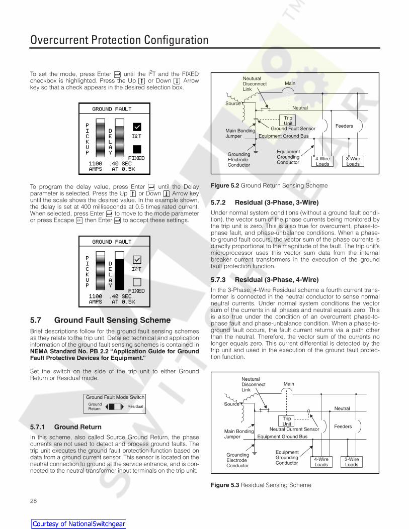
28
To set the mode, press Enter until the I
2
T and the FIXEDcheckbox is highlighted. Press the Up or Down Arrowkey so that a check appears in the desired selection box.
To program the delay value, press Enter until the Delayparameter is selected. Press the Up or Down Arrow keyuntil the scale shows the desired value. In the example shown,the delay is set at 400 milliseconds at 0.5 times rated current.When selected, press Enter to move to the mode parameteror press Escape then Enter to accept these settings.
5.7 Ground Fault Sensing Scheme
Brief descriptions follow for the ground fault sensing schemesas they relate to the trip unit. Detailed technical and applicationinformation of the ground fault sensing schemes is contained in
NEMA Standard No. PB 2.2 “Application Guide for GroundFault Protective Devices for Equipment.”
Set the switch on the side of the trip unit to either GroundReturn or Residual mode.
5.7.1 Ground Return
In this scheme, also called Source Ground Return, the phasecurrents are not used to detect and process ground faults. Thetrip unit executes the ground fault protection function based ondata from a ground current sensor. This sensor is located on theneutral connection to ground at the service entrance, and is con-nected to the neutral transformer input terminals on the trip unit.
Figure 5.2
Ground Return Sensing Scheme
5.7.2 Residual (3-Phase, 3-Wire)
Under normal system conditions (without a ground fault condi-tion), the vector sum of the phase currents being monitored bythe trip unit is zero. This is also true for overcurrent, phase-to-phase fault, and phase-unbalance conditions. When a phase-to-ground fault occurs, the vector sum of the phase currents isdirectly proportional to the magnitude of the fault. The trip unit’smicroprocessor uses this vector sum data from the internalbreaker current transformers in the execution of the groundfault protection function.
5.7.3 Residual (3-Phase, 4-Wire)
In the 3-Phase, 4-Wire Residual scheme a fourth current trans-former is connected in the neutral conductor to sense normalneutral currents. Under normal system conditions the vectorsum of the currents in all phases and neutral equals zero. Thisis also true under the condition of an overcurrent phase-to-phase fault and phase-unbalance condition. When a phase-to-ground fault occurs, the fault current returns via a path otherthan the neutral. Therefore, the vector sum of the currents nolonger equals zero. This current differential is detected by thetrip unit and used in the execution of the ground fault protec-tion function.
Figure 5.3
Residual Sensing Scheme
Ground Fault Mode Switch
ResidualGroundReturn
Neutral
TripUnit
Main
Source
NeuturalDisconnectLink
Ground Fault SensorMain BondingJumper
4-WireLoads
3-WireLoads
Feeders
Equipment Ground Bus
EquipmentGroundingConductor
GroundingElectrodeConductor
Neutral
TripUnit
Main
Source
NeuturalDisconnectLink
Neutral Current SensorMain BondingJumper
4-WireLoads
3-WireLoads
Feeders
Equipment Ground Bus
EquipmentGroundingConductor
GroundingElectrodeConductor
Courtesy of NationalSwitchgear.com

Alarm Setpoints
29
6 Alarm Setpoints
6.1 Alarms
The SB Breaker has an optional relay output contact for con-trolling audible or visible alarms. The trip unit can be config-ured to initiate an alarm based on any or all of ten measuredparameters. (The protective relaying functions discussed in thenext chapter can also be configured to initiate an alarm. Thefunctions discussed in this chapter are alarm-only functions.)Exceeding the configured setpoint will result in the followingactions by the trip unit:
• Close the optional relay output contact, which may be con-nected to a visible or audible alarm (or both)
• Store a record of the event in the event log including thedate and time of the alarm
• Communicate with any supervisory device that an alarmcondition is reached
The following parameters can be configured to cause an alarmand a record in the event log.
• Line Overcurrent
• Ground Overcurrent
• Overcurrent Demand
• Total Harmonic Distortion (THD)
• Over Real Power (kW)
• Over Power Demand (kW Demand)
• Over Reactive Power (kVAR)
• Over Apparent Power (kVA)
• Under Power Factor Lagging
• Over Power Factor Leading
To view the setting of or to set these alarms, from the
MainMenu
, select
Protective Functions
. From the
ProtectiveMenu
, select
Alarms
. The
Alarms Menu
is displayed:
Each alarm limit has three parameters:
• Pickup value
• Delay value
• Alarm enabled or disabled
Setting these alarms involves enabling the alarm, setting thelimit above which the trip unit considers alarmable (pickup),and setting the time interval the device will wait before settingoff the alarm (delay). The pickup and delay values can be cho-sen from a range based on the rating of the device. The defaultsetting is for all alarm limits to be disabled.
To set the pickup and delay values and to turn the alarm fea-ture on or off for each of these parameters, select them fromthe
Alarms Menu
. For each of these three parameters, use theUp or Down Arrow keys to increment or decrement thevalue. When satisfied with a particular setting, press Enter to move to the next parameter.
To enable the alarm for a given limit, highlight the Alarm boxand press the Up Arrow key to select it. A check mark in thealarm box indicates that the alarm is enabled.
Press Escape to leave this group of parameters. An addi-tional screen, called the Verification screen, appears if securityis inactive (if no password protection is on). Press Enter toaccept the settings, or press Escape to leave withoutchanging or choosing any of the selections.
Alarm DisabledCheckbox empty
Alarm EnabledCheckbox checked
Courtesy of NationalSwitchgear.com

Alarm Setpoints
30
6.2 Overcurrent
To alarm on overcurrent:
1. From the
Alarms Menu
, select
Over Current.
.
2. Select a pickup value by pressing the Up or Down Arrow keys until the value is at the desired level. The val-ues will depend on the rating of the breaker. The possiblevalues are, for any breaker rating, one of the following per-centages of the breaker current rating:115%, 125%,150%, 200%, or 250%. For example, if your trip unit ismounted to a 2000A breaker, the lowest pickup would be115% of 2000A or 2300A (as illustrated above). The high-est setting for this breaker would be 5000A (250% of2000A). For a complete list of pickup values, refer to theappendix,
Parameter Settings
. When the desired value isset, press Enter .
3. Select a delay time by pressing the Up or Down Arrow keys until the value is at the desired level. Possibletime delay settings are 1, 2, 3, 5, 10, 20, 30, 60, 120, and300 seconds. When the desired value displays, pressEnter .
4. Highlight the ALARM box and press the Up Arrow keyso that a checkmark appears in the box.
5. Press Escape to leave the menu and press Enter atthe verification screen to accept the new settings andleave the menu.
6.3 Ground Overcurrent
The Ground Overcurrent alarm provides a preset ground faultindication, similar in function to the Ground Fault Monitor (SB-GFM) accessory module for the standard SB trip unit. Note thatthis ground overcurrent alarm feature is available on
all
SBEnergy-Comm trip units with or without ground fault protectionand is independent of the ground overcurrent tripping function.
To alarm on ground overcurrent:
1. From the
Alarms Menu
, select
Ground Over Current
.
2. Select a pickup value by pressing the Up or Down Arrow keys until the value is at the desired level. The val-ues will depend on the rating of the breaker.
The possible values for any breaker rating range from 20%of the CT rating up to a 1200A maximum or the CT rating,whichever is lower. For example, if your system is a 2000Abreaker with 2000A CTs, the lowest pickup would be 20%of 2000A or 400A (as illustrated above). The highest set-ting would be 1200A. For a complete list of pickup values,refer to the appendix,
Parameter Settings
. When thedesired value is set, press Enter .
3. Select a delay time by pressing the Up or Down Arrow keys until the value is at the desired level. When thedesired value displays, press Enter . Possible timedelay settings are 1, 2, 3, 5, 10, 20, 30, 60, 120, and 300seconds. When the desired value displays, press Enter
.
4. Highlight the ALARM box and press the Up Arrow keyso that a checkmark appears in the box.
5. Press Escape to leave the menu and press Enter atthe verification screen to accept the new settings andleave the menu.
Courtesy of NationalSwitchgear.com

Alarm Setpoints
31
6.4 Overcurrent Demand
To alarm on demand overcurrent:
1. From the
Alarms Menu
, select
Over-Amp Demand.
2. Select a pickup value by pressing the Up or Down Arrow keys until the value is at the desired level. The valueswill depend on the rating of the breaker.
The possible values are, for any breaker rating, one of thefollowing percentages of the breaker current rating: 115%,125%, 150%, 200%, or 250%. For example, if your trip unitis mounted to a 2000A breaker, the lowest pickup wouldbe 115% of 2000A or 2300A. The highest setting for thisbreaker would be 5000A (250% of 2000A). For a completelist of pickup values, refer to the appendix,
Parameter Set-tings
. When the desired value is set, press Enter .
3. Select a delay time by pressing the Up or Down Arrow keys until the value is at the desired level. Possibletime delay settings are 1, 2, 3, 5, 10, 20, 30, 60, 120, and300 seconds. When the desired value is displayed, pressEnter .
4. Highlight the ALARM box and press the Up Arrow keyso that a checkmark appears in the box.
5. Press Escape to leave the menu and press Enter atthe verification screen to accept the new settings andleave the menu.
6.5 Total Harmonic Distortion
To alarm on total harmonic distortion:
1. From the
Alarms Menu
, select
Total Harmonics.
2. Select a pickup value by pressing the Up or Down Arrow keys until the value is at the desired level. The valueswill depend on the rating of the breaker and are given in thetable below. When the desired value is set, press Enter .
3. Select a delay time by pressing the Up or Down Arrow keys until the value is at the desired level. Possibletime delay settings are 1, 2, 3, 5, 10, 20, 30, 60, 120, and300 seconds. When the desired value displays, pressEnter .
4. Highlight the ALARM box and press the Up Arrow keyso that a checkmark appears in the box.
5. Press Escape to leave the menu and press Enter atthe verification screen to accept the new settings andleave the menu.
Harmonic Distortion Alarm Settings
Pickup Values (%)
5 10 15 20
25 30 40 50
Courtesy of NationalSwitchgear.com

Alarm Setpoints
32
6.6 Over Real Power
To alarm on over real power (kilowatts):
1. From the
Alarms Menu
, select
Over kW.
2. Select a pickup value by pressing the Up or Down Arrow keys until the value is at the desired level. For acomplete list of pickup values, refer to the appendix,
Parameter Settings
. Press Enter .
3. Select a delay time by pressing the Up or Down Arrow keys until the value is at the desired level. Possibletime delay settings are 1, 2, 3, 5, 10, 20, 30, 60, 120, and300 seconds. When the desired value displays, pressEnter .
4. Highlight the ALARM box and press the Up Arrow keyso that a checkmark appears in the box.
5. Press Escape to leave the menu and press Enter atthe verification screen to accept the new settings andleave the menu.
6.7 Over Power Demand
To alarm on over power (kilowatt) demand:
1. From the
Alarms Menu
, select
Over kW Demand
2. Select a pickup value by pressing the Up or Down Arrow keys until the value is at the desired level. For acomplete list of pickup values, refer to the appendix,
Parameter Settings
. Press Enter .
3. Select a delay time by pressing the Up or Down Arrow keys until the value is at the desired level. Possibletime delay settings are 1, 2, 3, 5, 10, 20, 30, 60, 120, and300 seconds. When the desired value is displayed, pressEnter .
4. Highlight the ALARM box and press the Up Arrow keyso that a checkmark appears in the box.
5. Press Escape to leave the menu and press Enter atthe verification screen to accept the new settings andleave the menu.
Courtesy of NationalSwitchgear.com

Alarm Setpoints
33
6.8 Over Reactive Power
To alarm on over reactive power (kilovolt-amps reactive):
1. From the
Alarms Menu
, select
Over kVAR.
2. Select a pickup value by pressing the Up or Down Arrow keys until the value is at the desired level. You canchoose between ten values, based on the frame rating.Press Enter .
3. Select a delay time by pressing the Up or Down Arrow keys until the value is at the desired level. Possibletime delay settings are 1, 2, 3, 5, 10, 20, 30, 60, 120, and300 seconds. When the desired value displays, pressEnter .
4. Highlight the ALARM box and press the Up Arrow keyso that a checkmark appears in the box.
5. Press Escape to leave the menu and press Enter atthe verification screen to accept the new settings andleave the menu.
6.9 Over Apparent Power
To alarm on over apparent power (kilovolt-amps):
1. From the
Alarms Menu
, select
Over kVA
2. Select a pickup value by pressing the Up or Down Arrow keys until the value is at the desired level. You canchoose between ten values, based on the frame rating.Press Enter .
3. Select a delay time by pressing the Up or Down Arrow keys until the value is at the desired level. Possibletime delay settings are 1, 2, 3, 5, 10, 20, 30, 60, 120, and300 seconds. When the desired value displays, pressEnter .
4. Highlight the ALARM box and press the Up Arrow keyso that a checkmark appears in the box.
5. Press Escape to leave the menu and press Enter atthe verification screen to accept the new settings andleave the menu.
Courtesy of NationalSwitchgear.com

Alarm Setpoints
34
6.10 Under PF Lagging
To alarm on under power factor lagging:
1. From the
Alarms Menu
, select
Under PF Lagging.
2. Select a pickup value by pressing the Up or Down Arrow keys until the value is at the desired level. PressEnter . Values appear in the following table.
3. Select a delay time by pressing the Up or Down Arrow keys until the value is at the desired level. Possibletime delay settings are 1, 2, 3, 5, 10, 20, 30, 60, 120, and300 seconds. When the desired value displays, pressEnter .
4. Highlight the ALARM box and press the Up Arrow keyso that a checkmark appears in the box.
5. Press Escape to leave the menu and press Enter atthe verification screen to accept the new settings andleave the menu.
6.11 Over PF Leading
To alarm on over power factor leading:
1. From the
Alarms Menu
, select
Over PF Leading
2. Select a pickup value by pressing the Up or Down Arrow keys until the value is at the desired level. PressEnter . Values appear in the following table.
3. Select a delay time by pressing the Up or Down Arrow keys until the value is at the desired level. Possibletime delay settings are 1, 2, 3, 5, 10, 20, 30, 60, 120, and300 seconds. When the desired value displays, pressEnter .
4. Highlight the ALARM box and press the Up Arrow keyso that a checkmark appears in the box.
5. Press Escape to leave the menu and press Enter atthe verification screen to accept the new settings andleave the menu.
Under Power Factor (Lagging) Alarm Settings
Pickup Values
0.50 0.60 0.70 0.80
0.90 0.95
Over Power Factor (Leading)Alarm Settings
Pickup Values
0.50 0.60 0.70 0.80
0.90 0.95
Courtesy of NationalSwitchgear.com

Extended Protective Relaying
35
7 Extended Protective Relaying
7.1 Overview
The SB Energy-Comm trip unit offers several protective relay-ing functions beyond the standard trip unit functionality. Theseextended functions include types of current, voltage, and fre-quency protection usually associated with a protective relay.
• Neutral Overcurrent
• Current Unbalance
• Undervoltage
• Voltage Unbalance
• Over Voltage
• Reverse Power
• Over Frequency
• Under Frequency
Exceeding the configured setpoint (limit) will result in the fol-lowing actions by the trip unit:
If set to trip and alarm:
• Trip the circuit breaker
• Store a record of the event in the trip log including the timeand date of the trip
• Close the optional breaker relay output contact, which maybe connected to a visible or audible alarm (or both)
• Communicate with any supervisory device that a trip con-dition was reached
If set to alarm only:
• close the relay output contact, which may be connected toa visible or audible alarm (or both)
• Store a record of the event in the event log including thetime and date of the alarm
• Communicate with any supervisory device that an alarmcondition was reached
To find settings for the protective relay functions:
1. From the
Main Menu
, select
Protective Functions
.
2. From the
Protective Menu
, select
Protective Relays
.
For each protection type, users may choose that the trip uniteither alarms, or trips and alarms, when these parametersexceed a set value.
7.2 Tripping and Alarming
For the protective relaying functions, users may either alarm onthe function, or both trip and alarm on the function. You cannottrip without alarming. In the examples below, the first caseshows no alarm or trip; the second shows the alarm set, andthe third shows both trip and alarm set.
To activate this function:
1. Press the Up Arrow key when either the alarm or thetrip checkbox is highlighted.
2. If you select tripping, the alarm checkbox is automaticallyhighlighted as well.
Courtesy of NationalSwitchgear.com

Extended Protective Relaying
36
7.3 Neutral Overcurrent
If an external neutral sensor has been selected during configu-ration, the allowable overcurrent on the neutral line can be setusing the parameters from the
Neutral Over Current
selectionof the
Protective Relays Menu
.
To alarm, or to trip and alarm, on neutral overcurrent:
1. From the
Protective Relays Menu
, select
Neutral Over-current.
The Alarm checkbox is highlighted, but alarminghas not yet been set.
2. To enable alarming, press the Up Arrow key, then pressEnter . If you have enabled alarming, a checkmarkappears and the pickup settings are highlighted.
3. Select a pickup value by pressing the Up or Down Arrow keys until the value is at the desired level. The pos-sible pickup values depend on the rating of the breaker;see the table in the appendix,
Parameter Settings
. PressEnter .
4. Then select a delay time by pressing the Up or Down Arrow keys until the value is at the desired level. Possi-
ble time delay settings are 1, 2, 3, 4, 5, 7, 10 and 15 sec-onds. Press Enter .
7.4 Current Unbalance
Current unbalance is a protective relay function that protectsagainst an unbalance in the phase currents. Each phase cur-rent is compared to the arithmetic average of the three phasecurrents. Tripping or alarming occurs when any phase currentexceeds the unbalance pickup for a period of time equal to thedelay time setting. To alarm, or to trip and alarm, on currentunbalance:
1. From the
Protective Relays Menu
, select
Current Unbal-ance
. The Alarm checkbox is highlighted, but alarminghas not yet been set.
2. To enable alarming, press the Up Arrow key, then pressEnter . If you have enabled alarming, a checkmarkappears and the pickup settings are highlighted.
3. Select a pickup value by pressing the Up or Down Arrow keys until the value is at the desired level. The pos-sible pickup values depend on the rating of the breaker;see the table in the appendix,
Parameter Settings
. PressEnter .
4. Then select a delay time by pressing the Up or Down Arrow keys until the value is at the desired level. Possi-
ble time delay settings are 1, 2, 3, 4, 5, 7, 10 and 15 sec-onds. Press Enter .
If you want to enable...
Then...
alarming only follow steps 2–4 and press Escape . Then press Enter at the verifi-
cation screen.
alarming and tripping follow steps 2–4, press Enter to highlight the Trip checkbox, then repeat the process you used in steps 2–4 to set pickup and delay values. After setting both the alarm and trip values, press Escape . Then press Enter at the verifica-tion screen.
If you want to enable...
Then...
alarming only follow steps 2–4 and press Escape . Then press Enter at the verifi-
cation screen
alarming and tripping follow steps 2–4, press Enter to highlight the Trip checkbox, then repeat the process you used in steps 2–4 to set pickup and delay values. After setting both the alarm and trip values, press Escape . Then press Enter at the verifica-tion screen
Courtesy of NationalSwitchgear.com

Extended Protective Relaying
37
7.5 Undervoltage
If the amount of voltage on any phase goes below a specifiedlevel, the trip unit can alarm or trip by setting the parametersfrom the
Undervoltage
selection of the
Protective RelaysMenu
. To alarm, or to trip and alarm, on undervoltage:
1. From the
Protective Relays Menu
, select
Under Voltage.
The Alarm checkbox is highlighted, but alarming has notyet been set.
2. To enable alarming, press the Up Arrow key, then pressEnter . If you have enabled alarming, a checkmarkappears and the pickup settings are highlighted.
3. Select a pickup value by pressing the Up or Down Arrow keys until the value is at the desired level. The pos-sible pickup values depend on the rating of the breaker;see the table in the appendix,
Parameter Settings
. PressEnter .
4. Then select a delay time by pressing the Up or Down Arrow keys until the value is at the desired level. Possi-
ble time delay settings are 1, 2, 3, 4, 5, 7, 10 and 15 sec-onds. Press Enter .
7.6 Voltage Unbalance
Voltage unbalance is a protective relay function that protectsagainst an unbalance in the line to line voltages. Each line-to-line voltage is compared to the arithmetic average of the threevoltages. Tripping or alarming occurs when any voltageexceeds the unbalance pickup for a period of time equal to thedelay time setting. To alarm, or to trip and alarm, on currentunbalance:
1. From the
Protective Relays Menu
, select
Voltage Unbal-ance
. The Alarm checkbox is highlighted, but alarminghas not yet been set.
2. To enable alarming, press the Up Arrow key, then pressEnter . If you have enabled alarming, a checkmarkappears and the pickup settings are highlighted.
3. Select a pickup value by pressing the Up or Down Arrow keys until the value is at the desired level. The pos-sible pickup values depend on the rating of the breaker;see the table in the appendix,
Parameter Settings
. PressEnter .
4. Then select a delay time by pressing the Up or Down Arrow keys until the value is at the desired level. Possi-
ble time delay settings are 1, 2, 3, 4, 5, 7, 10 and 15 sec-onds. Press Enter .
If you want to enable...
Then...
alarming only follow steps 2–4 and press Escape . Then press Enter at the verifi-
cation screen.
alarming and tripping follow steps 2–4, press Enter to highlight the Trip checkbox, then repeat the process you used in steps 2–4 to set pickup and delay values. After setting both the alarm and trip values, press Escape . Then press Enter at the verifica-tion screen.
If you want to enable...
Then...
alarming only follow steps 2–4 and press Escape . Then press Enter at the verifi-
cation screen.
alarming and tripping follow steps 2–4, press Enter to highlight the Trip checkbox, then repeat the process you used in steps 2–4 to set pickup and delay values. After setting both the alarm and trip values, press Escape . Then press Enter at the verifica-tion screen.
Courtesy of NationalSwitchgear.com

Extended Protective Relaying
38
7.7 Overvoltage
If the amount of voltage on any phase goes above a specifiedlevel, the trip unit can alarm or trip by setting the parametersfrom the
Over Voltage
selection of the
Protective RelaysMenu
. To alarm, or to trip and alarm, on overvoltage:
1. From the
Protective Relays Menu
, select
Over Voltage
.The alarm checkbox is highlighted, but alarming has notbeen set.
2. To enable alarming, press the Up Arrow key, then pressEnter . If you have enabled alarming, a checkmarkappears and the pickup settings are highlighted.
3. Select a pickup value by pressing the Up or Down Arrow keys until the value is at the desired level. The pos-sible pickup values depend on the rating of the breaker;see the table in the appendix,
Parameter Settings
. PressEnter .
4. Then select a delay time by pressing the Up or Down Arrow keys until the value is at the desired level. Possi-
ble time delay settings are 1, 2, 3, 4, 5, 7, 10 and 15 sec-onds. Press Enter .
7.8 Reverse Power
If the amount of reverse power goes above a specified level,the trip unit can alarm or trip by setting the parameters from the
Reverse Power
selection of the
Protective Relays Menu
. Toalarm, or to trip and alarm, on over reverse kilowatts:
1. From the
Protective Relays Menu
, select
Reverse Power.
The Alarm checkbox is highlighted, but alarming has notyet been set.
2. To enable alarming, press the Up Arrow key, then pressEnter . If you have enabled alarming, a checkmarkappears and the pickup settings are highlighted.
3. Select a pickup value by pressing the Up or Down Arrow keys until the value is at the desired level. The pos-sible pickup values depend on the rating of the breaker;see the table in the appendix,
Parameter Settings
. PressEnter .
4. Then select a delay time by pressing the Up or Down Arrow keys until the value is at the desired level. Possi-
ble time delay settings are 1, 2, 3, 4, 5, 7, 10 and 15 sec-onds. Press Enter .
5. Refer to the individual PT Module instruction sheet for PTModule connections for bottom-fed breakers.
If you want to enable...
Then...
alarming only follow steps 2–4 and press Escape . Then press Enter at the verifi-
cation screen.
alarming and tripping follow steps 2–4, press Enter to highlight the Trip checkbox, then repeat the process you used in steps 2–4 to set pickup and delay values. After setting both the alarm and trip values, press Escape . Then press Enter at the verifica-tion screen.
Courtesy of NationalSwitchgear.com

Extended Protective Relaying
39
7.9 Over Frequency
The trip unit can alarm or trip on the frequency of the monitoredpower by setting the parameters from the
Over Frequency
selection of the
Protective Relays Menu
. To alarm, or to tripand alarm, on over frequency:
1. From the
Protective Relays Menu
, select
Over Fre-quency
. The Alarm checkbox is highlighted, but alarminghas not yet been set.
2. To enable alarming, press the Up Arrow key, then pressEnter . If you have enabled alarming, a checkmarkappears and the pickup settings are highlighted.
3. Select a pickup value by pressing the Up or Down Arrow keys until the value is at the desired level. The possi-ble pickup values are 1, 2, 3, 4, 5, 7, 9, 12 Hz above thenominal frequency. Press Enter .
4. Then select a delay time by pressing the Up or Down Arrow keys until the value is at the desired level. Possibletime delay settings are 1, 2, 3, 4, 5, 7, 10 and 15 seconds.Press Enter .
7.10 Under Frequency
The trip unit can alarm or trip on the frequency of the monitoredpower by setting the parameters from the
Under Frequency
selection of the
Protective Relays Menu
. To alarm, or to tripand alarm, on under frequency:
1. From the
Protective Relays Menu
, select
Under Fre-quency
. The Alarm checkbox is highlighted, but alarminghas not yet been set.
2. To enable alarming, press the Up Arrow key, then pressEnter . If you have enabled alarming, a checkmarkappears and the pickup settings are highlighted.
3. Select a pickup value by pressing the Up or Down Arrow keys until the value is at the desired level. The pos-sible pickup values are 1, 2, 3, 4, 5, 7, 9, 12 Hz below thenominal frequency. Press Enter .
4. Then select a delay time by pressing the Up or Down Arrow keys until the value is at the desired level. Possi-
ble time delay settings are 1, 2, 3, 4, 5, 7, 10 and 15 sec-onds. Press Enter .
If you want to enable...
Then...
alarming only follow steps 2–4 and press Escape . Then press Enter at the verifi-
cation screen.
alarming and tripping follow steps 2–4, press Enter to highlight the Trip checkbox, then repeat the process you used in steps 2–4 to set pickup and delay values. After setting both the alarm and trip values, press Escape . Then press Enter at the verifica-tion screen.
Courtesy of NationalSwitchgear.com

Metering
40
8 Metering
8.1 Overview
The SB Energy-Comm trip unit measures and communicatesreal-time and accumulated metering data as well as harmonicsand waveform data. Current level values are derived from cur-rent transformers (CTs) mounted in the circuit breaker. Thesevalues can be viewed on the front panel display or viewed on apersonal computer when it is connected properly to the tripunit’s communications port. The list below summarizes themetering features available for the trip unit.
• Phase Currents
• Average Phase Current
• Neutral Current
• Ground Current
• Crest Factor (each phase)
• Current Demand
• Line-to-Line Voltages
• Average Line-to-Line Voltage
• Line-to-Neutral Voltages
• Average Line-to-Neutral Voltage
• Frequency (phase A)
• Power Factor (each phase)
• Real Power (kilowatts)
• Real Energy (kilowatt hours, forward and reverse)
• Power Demand (kW Demand)
• Apparent Power (kVA)
• Reactive Power (kVAR)
• Reactive Energy (kVARhr, forward and reverse)
All metered parameters are RMS values up to at least the 19thharmonic of a 60 Hz system. Trip unit accuracy for current ismeasured to +2% over the range of 10 to 200% of the ratedvalue.
The flashing green LED on the front panel of the trip unit indi-cates that the metering functions are operational.
To access the metering functions and data, from the
MainMenu
select
Metering
and press Enter .
The following screen appears:
From the Metering menu, you may examine the metered data inreal time, configure how the demand values are calculated, orzero out and reset the metered data.
8.2 Metered Data
The values reported for the metered data are displayed in realtime and can be viewed from the
Metering Menu
by choosingthe
Metered Data
option. From the
Metering Menu
, select
Metered Data
and press Enter . The following screenappears:
To view the real-time data from the display:
SystemCheck
Protective
Metering
Courtesy of NationalSwitchgear.com

Metering
41
From the
Metering Menu
, select
Metered Data
and select thefirst choice,
V,A,PF, and Freq
.
The following screen appears:
On this screen, the current for each phase is shown in Amps.The voltage between any two lines and from each line toground is shown in Volts. Also shown are the per phase powerfactors and whether each is leading (LD) or lagging (LG). Thefrequency is a calculated value in Hertz and may differ slightlyfrom the system frequency. In the example above, the fre-quency was calculated to 60.0 Hz.
The SB Energy-Comm trip unit calculates the averages of themetered parameters every second and calculates the Watt,VAR, and VA values. The frequency calculation task is per-formed once per second.
The conventions for power flow and power polarity are shownin
Figure 8.1
and
Figure 8.2,
respectively.
Figure 8.1
Power Flow Conventions
Figure 8.2
Power Polarity Conventions
To view the calculated values, select
Metering Data
from the
Metering Menu
and then select the second choice,
W, VAR,VA, and CF
.
The following display appears:
The forward real power (kW), reactive power (kVAR), andapparent power (kVA) are shown first, followed by the realenergy (kWhr) values. Finally the crest factor is shown for eachphase (A, B, and C).
V Source
Load
ExportReverseNegative
(kW/kVAR suppliedby the load)
ImportForwardPositive
(kW/kVAR consumedby the load)
kVA
I
IV
II
III
+kW (Real Power)
+kVAR (Reactive Power)
+kW (Forward)+kVAR (Forward)+PF (Lagging)
+kW (Forward)-kVAR (Reverse)-PF (Leading)
-kW (Reverse)+kVAR (Forward)-PF (Leading)
-kW (Reverse)-kVAR (Reverse)+PF (Lagging)
Ø
Ø=0ºPF=1
Ø=180ºPF=-1
Ø=90ºPF=0
Ø=270ºPF=0
Courtesy of NationalSwitchgear.com
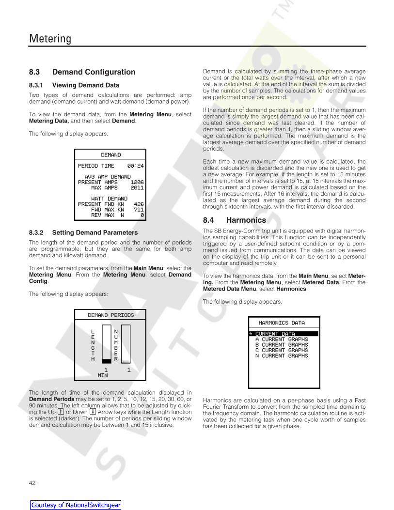
Metering
42
8.3 Demand Configuration
8.3.1 Viewing Demand Data
Two types of demand calculations are performed: ampdemand (demand current) and watt demand (demand power).
To view the demand data, from the
Metering Menu
, select
Metering Data,
and then select
Demand
.
The following display appears:
8.3.2 Setting Demand Parameters
The length of the demand period and the number of periodsare programmable, but they are the same for both ampdemand and kilowatt demand.
To set the demand parameters, from the
Main Menu
, select the
Metering Menu
. From the
Metering Menu
, select
DemandConfig
.
The following display appears:
The length of time of the demand calculation displayed in
Demand Periods
may be set to 1, 2, 5, 10, 12, 15, 20, 30, 60, or90 minutes. The left column allows that to be adjusted by click-ing the Up or Down Arrow keys while the Length functionis selected (darker). The number of periods per sliding windowdemand calculation may be between 1 and 15 inclusive.
Demand is calculated by summing the three-phase averagecurrent or the total watts over the interval, after which a newvalue is calculated. At the end of the interval the sum is dividedby the number of samples. The calculations for demand valuesare performed once per second.
If the number of demand periods is set to 1, then the maximumdemand is simply the largest demand value that has been cal-culated since demand was last cleared. If the number ofdemand periods is greater than 1, then a sliding window aver-age calculation is performed. The maximum demand is thelargest average demand over the specified number of demandperiods.
Each time a new maximum demand value is calculated, theoldest calculation is discarded and the new one is used to geta new average. For example, if the length is set to 15 minutesand the number of intervals is set to 15, at 15 intervals the max-imum current and power demand is calculated based on thefirst 15 measurements. After 16 intervals, the demand is calcu-lated as the largest average demand during the secondthrough sixteenth intervals, with the first interval discarded.
8.4 Harmonics
The SB Energy-Comm trip unit is equipped with digital harmon-ics sampling capabilities. This function can be independentlytriggered by a user-defined setpoint condition or by a com-mand issued from communications. The data can be viewedon the display of the trip unit or it can be sent to a personalcomputer and read remotely.
To view the harmonics data, from the
Main Menu
, select
Meter-ing.
From the
Metering Menu
, select
Metered Data
. From the
Metered Data Menu
, select
Harmonics
.
The following display appears:
Harmonics are calculated on a per-phase basis using a FastFourier Transform to convert from the sampled time domain tothe frequency domain. The harmonic calculation routine is acti-vated by the metering task when one cycle worth of sampleshas been collected for a given phase.
Courtesy of NationalSwitchgear.com
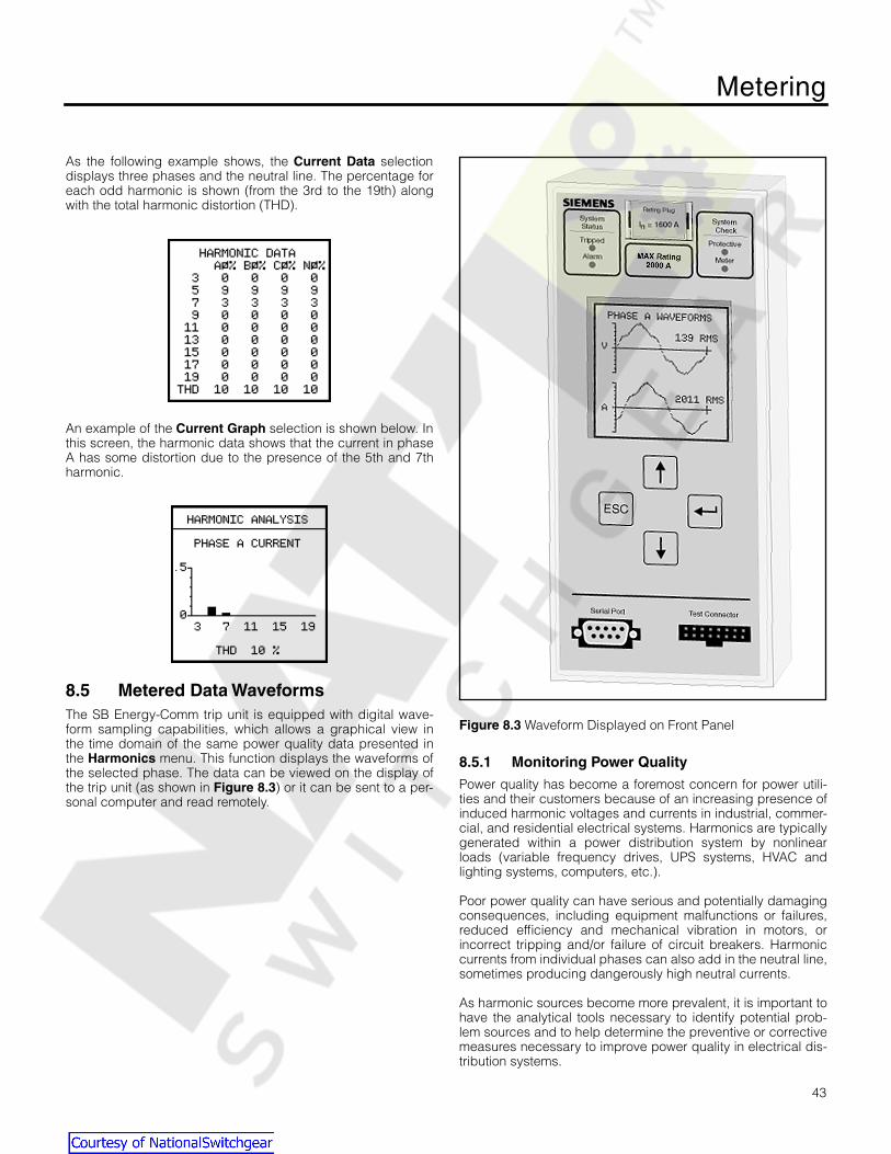
Metering
43
As the following example shows, the
Current Data
selectiondisplays three phases and the neutral line. The percentage foreach odd harmonic is shown (from the 3rd to the 19th) alongwith the total harmonic distortion (THD).
An example of the
Current Graph
selection is shown below. Inthis screen, the harmonic data shows that the current in phaseA has some distortion due to the presence of the 5th and 7thharmonic.
8.5 Metered Data Waveforms
The SB Energy-Comm trip unit is equipped with digital wave-form sampling capabilities, which allows a graphical view inthe time domain of the same power quality data presented inthe
Harmonics
menu. This function displays the waveforms ofthe selected phase. The data can be viewed on the display ofthe trip unit (as shown in
Figure 8.3
) or it can be sent to a per-sonal computer and read remotely.
Figure 8.3
Waveform Displayed on Front Panel
8.5.1 Monitoring Power Quality
Power quality has become a foremost concern for power utili-ties and their customers because of an increasing presence ofinduced harmonic voltages and currents in industrial, commer-cial, and residential electrical systems. Harmonics are typicallygenerated within a power distribution system by nonlinearloads (variable frequency drives, UPS systems, HVAC andlighting systems, computers, etc.).
Poor power quality can have serious and potentially damagingconsequences, including equipment malfunctions or failures,reduced efficiency and mechanical vibration in motors, orincorrect tripping and/or failure of circuit breakers. Harmoniccurrents from individual phases can also add in the neutral line,sometimes producing dangerously high neutral currents.
As harmonic sources become more prevalent, it is important tohave the analytical tools necessary to identify potential prob-lem sources and to help determine the preventive or correctivemeasures necessary to improve power quality in electrical dis-tribution systems.
Courtesy of NationalSwitchgear.com

Metering
44
8.5.2 Waveform Graphs
Waveform graphs allow the user to view the line and neutralvoltages and currents on a per-phase basis.
Sampled waveform data is stored in memory and can be readvia the communications port. The sampling rate used by theSB Energy-Comm trip unit produces high-resolution data whichallows analysis of frequency components to the 19th harmonic.
To view the waveforms on the display of the trip unit, select
Metering
from the
Main Menu
. Then select
Metered Data,
andthen
Waveforms
.
The following screen is displayed:
The list lets you select the data to be viewed from a particularphase or neutral.
An example of the waveform on phase A as it appears on thefront display is shown below:
The display includes one full cycle of data of the rms voltage(V) and the rms current (A). As this example shows, there areharmonics that distort the waveform. Also note that the phaserelationship between voltage and current is shown.
An example of the waveform for the neutral line is shown withonly the current data in Amps (A).
Viewing the waveforms remotely from a personal computerrequires the Siemens WinPM or SB Win software. This softwarecan be used to upload waveform data from the trip unit to apersonal computer and display the waveforms on the com-puter screen. WinPM software automatically performs a FastFourier Transformation on each waveform. It then provides anindication of total harmonic distortion and a breakdown of indi-vidual frequency components in both graphical and tabularform. This wide variety of data formats can help to quickly pin-point the source and severity of harmonics, evaluate whichsources must be minimized, and develop corrective strategies.
8.5.3 Triggering Manually via Communications
With Siemens supervisory software, you can obtain graphicalwaveforms for each of the eight possible inputs. A commandfrom the computer initiates data transfer from the trip unit. Thecomputer then uploads the data and displays the waveformson the screen.
8.6 Phase Balance
To view the phase balance data, from the
Metering Menu
,select
Metered Data,
and then select
Phase Balance.
The following display appears:
Courtesy of NationalSwitchgear.com
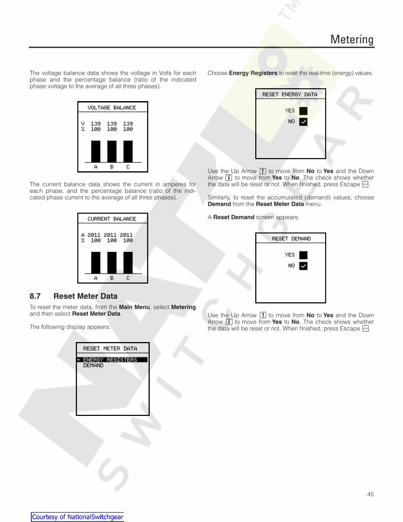
Metering
45
The voltage balance data shows the voltage in Volts for eachphase and the percentage balance (ratio of the indicatedphase voltage to the average of all three phases).
The current balance data shows the current in amperes foreach phase, and the percentage balance (ratio of the indi-cated phase current to the average of all three phases).
8.7 Reset Meter Data
To reset the meter data, from the
Main Menu
, select
Metering
and then select
Reset Meter Data
.
The following display appears:
Choose
Energy Registers
to reset the real-time (energy) values.
Use the Up Arrow to move from
No
to
Yes
and the DownArrow to move from
Yes
to
No
. The check shows whetherthe data will be reset or not. When finished, press Escape .
Similarly, to reset the accumulated (demand) values, choose
Demand
from the
Reset Meter Data
menu.
A
Reset Demand
screen appears:
Use the Up Arrow to move from
No
to
Yes
and the DownArrow to move from
Yes
to
No
. The check shows whetherthe data will be reset or not. When finished, press Escape .
Courtesy of NationalSwitchgear.com
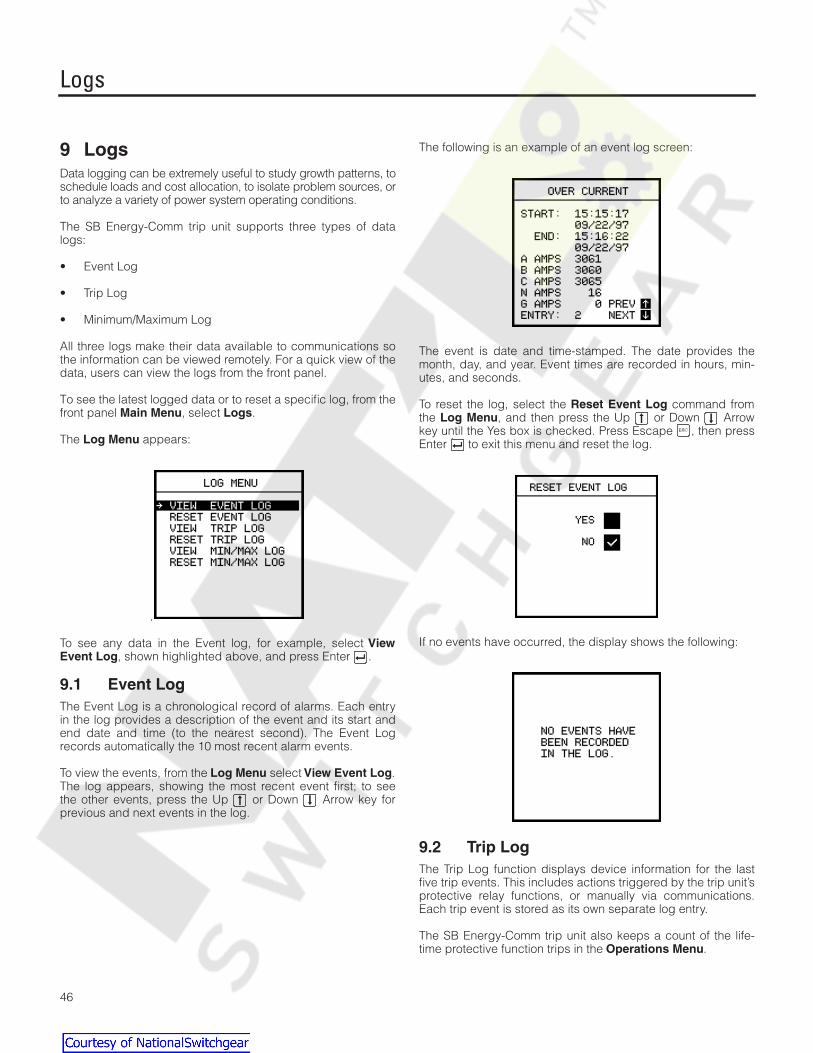
Logs
46
9 Logs
Data logging can be extremely useful to study growth patterns, toschedule loads and cost allocation, to isolate problem sources, orto analyze a variety of power system operating conditions.
The SB Energy-Comm trip unit supports three types of datalogs:
• Event Log
• Trip Log
• Minimum/Maximum Log
All three logs make their data available to communications sothe information can be viewed remotely. For a quick view of thedata, users can view the logs from the front panel.
To see the latest logged data or to reset a specific log, from thefront panel
Main Menu
, select
Logs
.
The
Log Menu
appears:
.
To see any data in the Event log, for example, select
ViewEvent Log
, shown highlighted above, and press Enter .
9.1 Event Log
The Event Log is a chronological record of alarms. Each entryin the log provides a description of the event and its start andend date and time (to the nearest second). The Event Logrecords automatically the 10 most recent alarm events.
To view the events, from the
Log Menu
select
View Event Log
.The log appears, showing the most recent event first; to seethe other events, press the Up or Down Arrow key forprevious and next events in the log.
The following is an example of an event log screen:
The event is date and time-stamped. The date provides themonth, day, and year. Event times are recorded in hours, min-utes, and seconds.
To reset the log, select the
Reset Event Log
command fromthe
Log Menu
, and then press the Up or Down Arrowkey until the Yes box is checked. Press Escape , then pressEnter to exit this menu and reset the log.
If no events have occurred, the display shows the following:
9.2 Trip Log
The Trip Log function displays device information for the lastfive trip events. This includes actions triggered by the trip unit’sprotective relay functions, or manually via communications.Each trip event is stored as its own separate log entry.
The SB Energy-Comm trip unit also keeps a count of the life-time protective function trips in the
Operations Menu
.
Courtesy of NationalSwitchgear.com
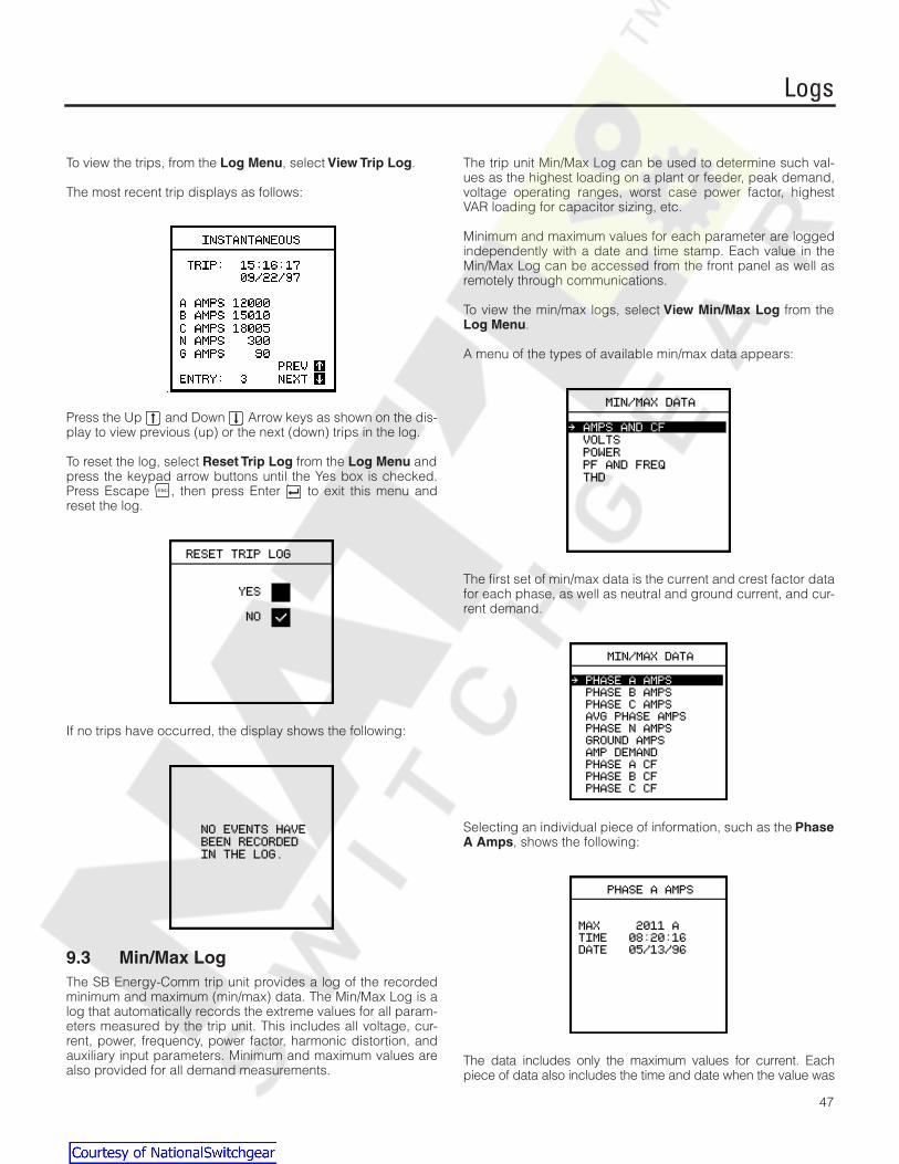
Logs
47
To view the trips, from the
Log Menu
, select
View Trip Log
.
The most recent trip displays as follows:
.
Press the Up and Down Arrow keys as shown on the dis-play to view previous (up) or the next (down) trips in the log.
To reset the log, select
Reset Trip Log
from the
Log Menu
andpress the keypad arrow buttons until the Yes box is checked.Press Escape , then press Enter to exit this menu andreset the log.
If no trips have occurred, the display shows the following:
9.3 Min/Max Log
The SB Energy-Comm trip unit provides a log of the recordedminimum and maximum (min/max) data. The Min/Max Log is alog that automatically records the extreme values for all param-eters measured by the trip unit. This includes all voltage, cur-rent, power, frequency, power factor, harmonic distortion, andauxiliary input parameters. Minimum and maximum values arealso provided for all demand measurements.
The trip unit Min/Max Log can be used to determine such val-ues as the highest loading on a plant or feeder, peak demand,voltage operating ranges, worst case power factor, highestVAR loading for capacitor sizing, etc.
Minimum and maximum values for each parameter are loggedindependently with a date and time stamp. Each value in theMin/Max Log can be accessed from the front panel as well asremotely through communications.
To view the min/max logs, select
View Min/Max Log
from the
Log Menu
.
A menu of the types of available min/max data appears:
The first set of min/max data is the current and crest factor datafor each phase, as well as neutral and ground current, and cur-rent demand.
Selecting an individual piece of information, such as the
PhaseA Amps
, shows the following:
The data includes only the maximum values for current. Eachpiece of data also includes the time and date when the value was
Courtesy of NationalSwitchgear.com

Logs
48
recorded. An example of data with both minimum and maximumvalues is the voltage data.
To view the max/min voltage data, select
Volts
from the
Min/Max Data Menu
. The following screen appears:
Then select
AB Line Volts
, for example, to see the minimumand maximum values of the line-to-line (A-B) voltage:
The various data values for power included in the min/max logsinclude instantaneous and demand values. From the
Min/MaxData Menu
, select
Power
.
The following menu appears:
The maximum values for power are given for both forward andreverse power:
To reset this log, select
Reset Min/Max Log
from the
LogMenu
. Press the keypad arrow buttons until the Yes box ischecked. Press Escape , then press Enter to exit thismenu and reset the log.
Courtesy of NationalSwitchgear.com
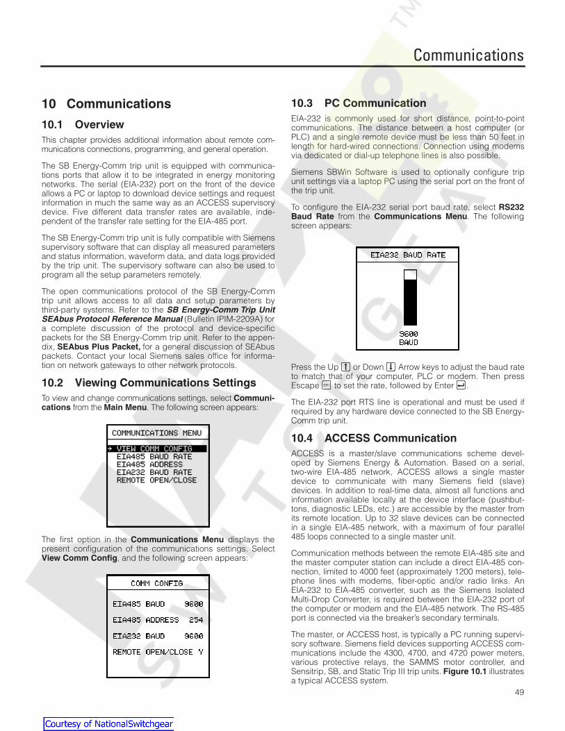
Communications
49
10 Communications
10.1 Overview
This chapter provides additional information about remote com-munications connections, programming, and general operation.
The SB Energy-Comm trip unit is equipped with communica-tions ports that allow it to be integrated in energy monitoringnetworks. The serial (EIA-232) port on the front of the deviceallows a PC or laptop to download device settings and requestinformation in much the same way as an ACCESS supervisorydevice. Five different data transfer rates are available, inde-pendent of the transfer rate setting for the EIA-485 port.
The SB Energy-Comm trip unit is fully compatible with Siemenssupervisory software that can display all measured parametersand status information, waveform data, and data logs providedby the trip unit. The supervisory software can also be used toprogram all the setup parameters remotely.
The open communications protocol of the SB Energy-Commtrip unit allows access to all data and setup parameters bythird-party systems. Refer to the
SB Energy-Comm Trip UnitSEAbus Protocol Reference Manual
(Bulletin IPIM-2209A) fora complete discussion of the protocol and device-specificpackets for the SB Energy-Comm trip unit. Refer to the appen-dix,
SEAbus Plus Packet,
for a general discussion of SEAbuspackets. Contact your local Siemens sales office for informa-tion on network gateways to other network protocols.
10.2 Viewing Communications Settings
To view and change communications settings, select
Communi-cations
from the
Main Menu
. The following screen appears:
The first option in the
Communications Menu
displays thepresent configuration of the communications settings. Select
View Comm Config
, and the following screen appears:
10.3 PC Communication
EIA-232 is commonly used for short distance, point-to-pointcommunications. The distance between a host computer (orPLC) and a single remote device must be less than 50 feet inlength for hard-wired connections. Connection using modemsvia dedicated or dial-up telephone lines is also possible.
Siemens SBWin Software is used to optionally configure tripunit settings via a laptop PC using the serial port on the front ofthe trip unit.
To configure the EIA-232 serial port baud rate, select
RS232Baud Rate
from the
Communications Menu
. The followingscreen appears:
Press the Up or Down Arrow keys to adjust the baud rateto match that of your computer, PLC or modem. Then pressEscape to set the rate, followed by Enter .
The EIA-232 port RTS line is operational and must be used ifrequired by any hardware device connected to the SB Energy-Comm trip unit.
10.4 ACCESS Communication
ACCESS is a master/slave communications scheme devel-oped by Siemens Energy & Automation. Based on a serial,two-wire EIA-485 network, ACCESS allows a single masterdevice to communicate with many Siemens field (slave)devices. In addition to real-time data, almost all functions andinformation available locally at the device interface (pushbut-tons, diagnostic LEDs, etc.) are accessible by the master fromits remote location. Up to 32 slave devices can be connectedin a single EIA-485 network, with a maximum of four parallel485 loops connected to a single master unit.
Communication methods between the remote EIA-485 site andthe master computer station can include a direct EIA-485 con-nection, limited to 4000 feet (approximately 1200 meters), tele-phone lines with modems, fiber-optic and/or radio links. AnEIA-232 to EIA-485 converter, such as the Siemens IsolatedMulti-Drop Converter, is required between the EIA-232 port ofthe computer or modem and the EIA-485 network. The RS-485port is connected via the breaker’s secondary terminals.
The master, or ACCESS host, is typically a PC running supervi-sory software. Siemens field devices supporting ACCESS com-munications include the 4300, 4700, and 4720 power meters,various protective relays, the SAMMS motor controller, andSensitrip, SB, and Static Trip III trip units.
Figure 10.1
illustratesa typical ACCESS system.
Courtesy of NationalSwitchgear.com

Communications
50
All information transferred between the master and slavedevices is sent within a SEAbus protocol message packet.SEAbus is a byte-count oriented open protocol originally devel-oped for ACCESS communications between the devices. EachACCESS device supports the SEAbus protocol.
The SB Energy-Comm trip unit is one of several field devices thatcan communicate with a monitoring supervisory device in anACCESS supervisory and control system. In order to communi-cate in an ACCESS system, the device must be connected usingthe EIA-485 network connection. This connection is through therear connector of the SB Energy-Comm trip unit. EIA-485 commu-nication can be used to concurrently connect up to thirty-tworemote devices on a single communications loop. Each device isgiven an address, a unique unit ID (identification number). In thisway, each remote device may be monitored and controlled fromone location by a single computer or PLC. For more informationon setting up and installing an ACCESS system network, see
I
nstalling the ACCESS System
.
Figure 10.1
Typical ACCESS Communications System
10.5 Setting the Address and Baud Rate
Before communication with the host computer/PLC is possible,users must ensure that the SB Energy-Comm trip unit and allother connected devices are configured for the required com-munications standard (EIA-232 or EIA-485).
The next step is to program the communication parameters ofthe SB Energy-Comm trip unit and all other connected devices.The Address and Baud Rate parameters of the SB Energy-Comm trip unit can be programmed via the front panel. Theaddress is the number that will uniquely represent the trip unitas a unique slave device in a master/slave system. It must beset to a unique value between 1 and 254.
To configure the device address, select
Slave Address
formthe
Communications Menu
. The following screen appears:
Use the Up and Down Arrow keys to select the value foreach digit. Press Enter to move between digits. PressEscape to set the new address and then exit.
The baud rate of each device on the network must be set tocorrespond with the baud rate selected from the computer.Options include 1200, 2400, 4800, 9600 or 19,200 baud.
To change the baud rate, select
EIA 485 Baud Rate
from theCommunications menu.
Use the Up and Down Arrow keys to select the baudrate. Press Escape then Enter to exit and set the newbaud rate setting.
When using a modem interface between the host computerand any remote device(s), ensure that the host computer is notused to set the BAUD RATE parameter of any selected deviceoutside the working range of the modem. Doing so will causethat device to cease communicating.
Courtesy of NationalSwitchgear.com

Communications
51
10.6 Supervisory Software
10.6.1 SBWin™ and WinPM™ Software
WinPM electrical distribution communication software operatesin the Microsoft® Windows™ 95 operating environment on apersonal computer (PC). Through communications drivers,WinPM software collects and displays real-time data from Sie-mens ACCESS field devices. WinPM software displays infor-mation and adds the capabilities of programming, monitoringalarms, and logging system events. WinPM software also mon-itors and displays historical data, minimum and maximum data,and waveform data. In addition, WinPM software can deliver itsdata to other compatible Windows applications, in real-time,through dynamic data exchange (DDE), a method of sharinginformation that is supported by Windows applications.
Your computer running WinPM software can be connected tointelligent field devices via a Siemens Isolated Multi-Drop Con-verter or through a modem and a Siemens Isolated Multi-DropConverter to the ACCESS system’s SEAbus communicationsbus.
SBWin software is available from Siemens to allow viewing real-time data and to view and set all trip unit parameters via a lap-top PC connected to the EIA-232 connector on the front of thetrip unit.
10.6.2 Third-Party System Compatibility
The SB Energy-Comm trip unit communications use anadvanced object- and register-based open protocol whichsupports an efficient exception reporting methodology. Thisfeature allows the SB Energy-Comm trip unit to be easilyadapted to third-party PLC, DCS, EMS, and SCADA systems.Protocol converters are also available from Siemens to connectto many different PLC and supervisory protocols.
All data and configuration registers are accessible via commu-nications. All configuration and control operations haveembedded password protection.
Contact Siemens for complete documentation on the SBEnergy-Comm trip unit SEAbus communications protocol or todiscuss a specific application.
10.7 Remote Operation
Remote, automatic open and close operation of the breaker ispossible via the ACCESS Communication System or a 120VAChard-wired input. For remote operation via ACCESS communi-cations, the shunt trip and remote open/close relay accesso-ries are required for the remote open function, and theelectrical operator accessory is required in addition for bothremote open and close operation. For remote operation via a120VAC hard-wired input, only the shunt trip accessory is nec-essary for the remote open function, and the electrical operatoraccessory is additionally required for both remote open andclose operations. Refer to the SB breaker instruction manual forinformation on the breaker accessories.
To allow remote operation of the breaker via ACCESS commu-nications, you must enable the trip unit to open the breakerremotely. If the trip unit has this function disabled, remote oper-ation of the breaker via ACCESS communications will not bepossible.
To enable or disable the remote open/close function, select
Remote Open/Close
from the
Communications Menu
. Thefollowing screen appears:
Use the Up and Down Arrow keys to move the selectionmark between Enabled and Disabled. Press Escape thenEnter to exit and set the remote open/close control.
Courtesy of NationalSwitchgear.com

Operations Menu Functions
52
11 Operations Menu Functions
11.1 Overview
The
Operations Menu
contains testing options and breakerinformation.
Four test options are provided to verify that the SB Energy-Comm trip unit can initiate a trip for overcurrent and groundfault conditions. These tests are performed from the BreakerTest Menu.
To assist the operator in servicing the breaker and the trip unit,the SB Energy-Comm trip unit provides several counters.These counters may be used for troubleshooting or reviewingthe history of the breaker when it is changed out. The countersinclude:
• Mechanical counter
• Interruption level
• Fault counter
Trip units with software version 3.00 or later provide an optionto turn off the trip LED via the trip Unit’s keypad.
To access the maintenance counters and the test menus,select the Operations from the Main Menu . The followingscreen appears:
11.2 Breaker Test
The breaker test consists of five separate tests: overcurrent,overcurrent with trip, ground fault, ground fault with trip, andalarm test. In these tests, the trip unit simulates an overcurrentor ground fault signal from the CTs and checks the circuitry thatinitiates a trip. The overcurrent with trip and ground fault withtrip tests actually trip the breaker, while the other two phaseand GF tests only check that the trip unit generates the signalto trip.
When the Alarm Test is initiated, the alarm LED will be turned onfor four seconds, and if an alarm relay is installed in the breakerit will be activated, for a period of four seconds. The Reset Tripped LED and Alarm Test function are available on units withsoftware version 3.00 or later.
Note: The overcurrent with trip and ground fault withtrip tests will cause the circuit breaker to trip,thus interrupting power to protected circuits.
Take precautions to prevent damage to equip-ment protected by the breaker prior to perform-ing the tests.
To run a breaker test, select Operations from the Main Menu .Then select Breaker Test . The test selection menu appears:
To select a particular test, press the up or down arrowkeys until a check appears next to the desired test. PressEscape to confirm the selection. The Breaker Test Menuappears:
Press Enter to start the test, or press Escape to cancelthe test. A progress screen appears:
Courtesy of NationalSwitchgear.com

Operations Menu Functions
53
Leader dots appear after the word “Progress” to indicate thetest is running. After the test is successfully completed, themessage “Test Passed” appears:
If the message “Test Failed” appears, contact Siemens cus-tomer service for assistance
Press Escape to return to the
Operations Menu
.
Note: Phase or GF trip tests require a minimum cur-rent equal to 20% of the breakers MAX RATINGto be flowing through the breaker in order to tripthe breaker.
11.3 Mechanical Counter
The mechanical counter lists the total number of breaker oper-ations and the serial number for the breaker. To view thiscounter, select
Mechanical Counter
from the Operationsmenu. The following screen appears:
:
This example screen summarizes the number of mechanicaloperations of the breaker regardless of the cause.
The total number of operations reported on this screen is iden-tical to the total reported in the
Interruption Level
screen.
From the Fault counter example, described in
Section 11.5,Fault Counter
, the total trips caused by electrical faults isreported as 10. The difference between the total operationsand the total operations caused by faults (11 in this example)would be operations that were caused by the operator, directlyfrom the manual interface on the breaker.
11.4 Interruption Level
The Interruption Level counter lists the number of operations ofthe breaker; that is, the number of times the breaker tripped. Itlists the number of operations for each level of currentrecorded as a multiple of the breaker’s MAX RATING value. Toview the Interruption Level counter, select
Interruption Level
from the
Operations Menu
. The following screen appears:
For example, in the screen shown here, the breaker had thir-teen trips at less than the nominal current rating of the breaker,so the trips must have been caused manually by an operator orby the Ground Fault trip.
11.5 Fault Counter
The fault counter lists the number of faults recorded by the SBEnergy-Comm trip unit. Each of these faults should correspondto a breaker trip. The faults are listed by type of protection.
• OL overload
• ST short time
• INST instantaneous
• GF ground fault
In this example, the trip unit registered four overload trips
.
Courtesy of NationalSwitchgear.com

Security
54
12 Security
12.1 Overview
To prevent inadvertent changes to the configuration of the tripunit, the SB Energy-Comm trip unit has password protection.Note that the device password does not prohibit configurationchanges from a PC running SBWin or WinPM via the communi-cations ports.
To change the password or to enable this security feature, fromthe
Main Menu
, select
Security
.
The
Security Menu
shows the password related options. If thepassword has never been changed, the screen looks like this:
Once the password is set or changed, the screen looks like this:
12.2 Enable Security
With the security enabled, the user cannot change any of thesettings without first entering the password. If the operatorattempts to change a setting such as the protective relay oralarms, and then presses Escape to leave the particularparameter setting screen, the following message displays:
The operator must then press Escape to continue.
To enable security, follow these steps:
1. From the
Main Menu
, select
Security
. The
Security Menu
is displayed:
2. Select
Enable Security
by pressing Enter .
3. Use the Up or Down Arrow key to select Yes toenable or No to disable the security feature. Press Escape
to confirm.
Courtesy of NationalSwitchgear.com

Security
55
12.3 Change Password
To enable security on the trip unit, the user must first changethe password.
1. From the
Main Menu
, select
Security
. The
Security Menu
appears:
Select
Change Password
. The
Change Password
screenlets you enter a new password one digit at a time.
2. With the leftmost digit highlighted, press the Up or Down Arrow key to increment or decrement the number. When
you press the Up Arrow key once, the number incre-ments to 0. When you have entered the desired digit, pressEnter to highlight the next digit.
3. Press the Up or Down Arrow until the desired digit isdisplayed. Then press Enter to highlight the next digit.Follow this procedure for all the digits in the password.Press Escape , followed by Enter when finished.
4. The trip unit will prompt you to re-enter your new password.Repeat steps 2 and 3.
Contact Siemens customer service if you have forgotten thepassword.
Courtesy of NationalSwitchgear.com

Testing
56
13 Testing
13.1 Test Set
The TS-31 test set is used to test the operation of the fault pro-tection functions of the SB Energy-Comm trip unit. It has beendesigned to be convenient and easy to use. The user isprompted on a front panel display, in a step-by-step format,about the required input information and test instruction. Thetest results are displayed on the front panel.
Note: Use individual instructions supplied with the TS-31Test Set for SB Encased Circuit Breaker testing.
Note: The long time, short time, instantaneous, and groundfault tests will cause the circuit breaker to trip, thusinterrupting power to protected circuits. Take precau-tions to prevent damage to equipment protected bythe breker prior to performing the tests.
13.2 Operating Instructions
1. Remove electrical loads from the circuit breaker.
2. Plug the TS-31 test set into a grounded 120V AC recepta-cle and turn it on. The following startup message appears:
Siemens Energy & Automation, Inc. TS-31 Test Set. Press ENTER to continue
3. Select the appropriate ribbon cable assembly per theinstructions supplied with the TS-31 test set, and connectit between the TS-31 and the circuit breaker, making sureof alignment and polarity. Press ENTER, and the TS-31 willprompt:
Enter Catalog Number
4. Type in the catalog number and then press ENTER. Thecatalog number can be found on the nameplate of the cir-cuit breaker, or can be viewed via the
System Configura-tion
menu (see
4.1, Viewing System Configuration
onpage 21). The TS-31 will respond with:
Searching Catalog. . .Searching Family Series. . .
If an invalid catalog number has been entered, the TS-31 will respond with:
Catalog Number xxxxxx Not Found. Press Enter to Continue
and you will be asked to enter another catalog number.
5. If a valid catalog number has been entered, the TS-31 willprompt for the Breaker switch settings. The TS-31 willrespond with:
Enter continuous current setting in %
Note: Energy Com Trip Units display current in Amps, therefore Ampsmust be converted to % Current Setting.
Enter the Rating Plug Value in Amps:
Enter long time delay in seconds.
Enter Short Circuit Protection Setting1 = Short 2 = Int. 3 = Both:
Note: The Short Circuit Protection Setting can be viewed via the
ShortCircuit Protection
Menu, which is located in the System ConfigurationMenu (see
4.2, Setting System Configuration Parameters
on page 21).
Enter short time Pickup.
Select Short Time Delay: 1-Fixed 2-I2t
Enter short time delay in seconds
Enter instantaneous pickup setting.
For breakers with ground fault you will be prompted:
Enter ground fault pickup setting in %
Note: Energy Com Trip Units display current in Amps, therefore % Cur-rent Setting must be converted to Amps.
Enter ground fault delay in seconds
In each case, enter your breaker’s switch settings. Forexample if your breaker is set for a continuous current of70%, type 70 and then press enter. Entry of erroneousdata in the above steps will result in false tests and results.
6. Select the test you wish to perform after entering thebreaker switch setting. The TS-31 will prompt:
Enter test to perform; see instructions.
Type in one of the following letters, depending upon thetest you wish to perform:
“L” - Long time or overload test,
“S” - Short time test,
“I” - Instantaneous test.
“G” - Ground fault test,
“C” - Current transformer continuity test,
The TS-31 will report the type of test you selected and giveyou a chance to abort the test. For example, if “I” waspressed above. The TS-31 will display:
Instantaneous Test Press ENTER to continue or A to abort
A B C D E F G
H I J K L M N
O P Q R S T U
V W X Y Z
1 2 3
4 5 6
7 8 9
0
Courtesy of NationalSwitchgear.com

Testing
57
If you pressed the letter “A” to abort, you will be asked again:
Enter Test to perform
If you press ENTER, you will be prompted for the phase totest: The TS-31 will display:
Enter phase to test.
7. Enter one of the following letters:
“A” - Phase A or left pole.
“B” - Phase B or center pole.
“C” - Phase C or right pole.
Press Enter again to start the test. Press any other key toSTOP the test.
Once a test has been started, the TS-31 will respond with:
Testing. Be careful at this time.Any key press will abort the test
The test may take anywhere from a fraction of a second tominutes to complete, depending on which procedure wasrun. If the test passes, the display will show the following,depending on whether the breaker tripped or not.
Passed Test xxx.xx seconds Press ENTER to continue.
8. If the circuit breaker tripped during the test, RESET the cir-cuit breaker before continuing.
The TS-31 will prompt for the next instructions. The displaywill show:
Change: 1 - Test 2 - Catalog 3 - Settings
9. Enter one of the following numbers: “1” - Select a new test;“2” - Enter a new catalog number; “3” - Enter new switchsettings.
If you enter “1” you will be sent to step 6. Choosing a “2”will send the program back to step 3. Entering “3” sendsyou back to step 5, which will be slightly different the sec-ond time through.
On the second line after the prompt for the setting, a num-ber or text in angle brackets will appear. This will indicatethe last setting you entered.
10. If you DON’T wish to change a setting, just press ENTER. Ifyou DO wish to change a setting, type in the new settingand press ENTER.
11. In step 6, if you pressed “C” when asked
Enter test to perform; see instructions
you will first be prompted by,
Current Transformer Test Press ENTER to continue or A to abort,
and then by the phase to test. One of the following mes-sages will then appear depending on the test results:
CT Resistance Test. Phase X Passed Press ENTER to exit test and continue
CT Resistance Test. Phase X Failed Press ENTER to exit test and continue
CT Resistance Test. Phase X Open Press ENTER to exit test and continue
CT Resistance Test. Phase X Short Press ENTER to exit test and continue
The “Phase X Failed” message indicates that the CT resis-tance is neither open nor shorted, but is not within designtolerance.
13.3 Error Messages
There are additional ERROR messages which may appear on thedisplay during this operation which were not covered previously:
Test Not Running! Check test cable connection Press ENTER to continue.
This message indicates that the test set has sensed that cur-rent is not flowing properly in the breaker under test and thatthere is either an open or short circuit between the TS-31 andthe breaker trip unit.
Function Not Available Press ENTER to continue
You will get this error message if you enter a choice that is notavailable, such as entering “G” in step 6 for ground fault test ona catalog number that does not have the ground fault function.
Inconclusive Test, check settings Press ENTER to continue or A to abort
This warning will appear if you attempt to run a short time testwith the instantaneous pickup set equal to or below the shorttime pickup. It would also appear if you tried to run a long timetest with short time pickup set too low. This is only a warning;the test can still be run. However, passing or failing the testmay not be conclusive.
Invalid Input Press Enter to continue
Courtesy of NationalSwitchgear.com
Testing
58
This message will appear if you enter a setting value that doesnot exist. For example, if the trip unit has continuous currentsettings of 50, 60, 65, 70, 75, 80, 85, 90, 95, and 100 percent,and you enter any other value than those listed, the abovemessage will appear.
Test exceeds capability of TS-31 Press ENTER to continue
If this message occurs, it means that a test requires more cur-rent to run than the TS-31 can produce.
Unit too hot! please wait
Running many successive, high-current, long time tests mayover-heat the test set. It will protect itself from thermal damageby asking the user to wait and allowing the TS-31 to cool down.
Courtesy of NationalSwitchgear.com

Functions and Outputs
59
Function Alarm Trip Event Log Trip Log
AlarmSetpoints(10)
Overcurrent (Alarm)
� �
Ground Overcurrent
� �
Overcurrent Demand
� �
Total Harmonics (THD)
� �
Over kW
� �
Over kW Demand
� �
Over kVAR
� �
Over kVA
� �
Under PF Lag
� �
Over PF Lead
� �
OvercurrentProtection(4)
Long Time
� �
Short Time
� �
Instantaneous
� �
Ground Fault (models SBxxTP01G, SBxxTP02G)
� �
ExtendedProtectiveRelaying(8)
Neutral Overcurrent
� � � �
Current Unbalance
� � � �
Voltage Unbalance
� � � �
Reverse Power
� � � �
Under Voltage
� � � �
Over Voltage
� � � �
Over Frequency
� � � �
Under Frequency
� � � �
Courtesy of NationalSwitchgear.com
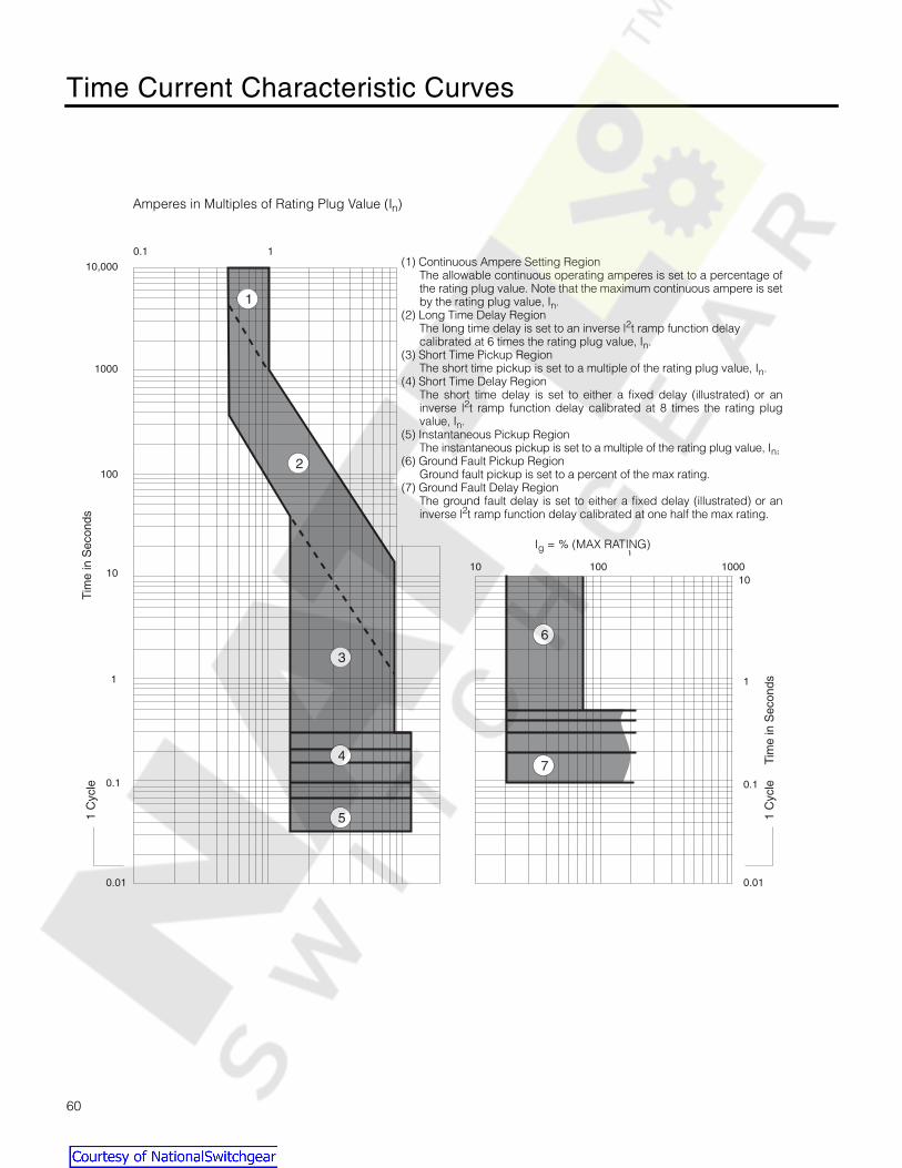
Time Current Characteristic Curves
60
1010 100 1000
1
0.1
0.010.01
0.1
1
10
100
1000
10,000
0.1 1
1 C
ycle
1 C
ycle
Tim
e in
Sec
onds
Tim
e in
Sec
onds
Ig = %In
(1) Continuous Ampere Setting RegionThe allowable continuous operating amperes is set to a percentage ofthe rating plug value. Note that the maximum continuous ampere is setby the rating plug value, Ir.
(2) Long Time Delay RegionThe long time delay is set to an inverse I2t ramp function delaycalibrated at 6 times the rating plug value, Ir.
(3) Short Time Pickup RegionThe short time pickup is set to a multiple of the rating plug value, Ir.
(4) Short Time Delay RegionThe short time delay is set to either a fixed delay (illustrated) or aninverse I2t ramp function delay calibrated at 8 times the rating plugvalue, Ir.
(5) Instantaneous Pickup RegionThe instantaneous pickup is set to a multiple of the rating plug value, Ir.
(6) Ground Fault Pickup RegionGround fault pickup is set to a percent of the frame ampere rating, In.
(7) Ground Fault Delay RegionThe ground fault delay is set to either a fixed delay (illustrated) or aninverse I2t ramp function delay calibrated at one half the frame ampererating, In.
Amperes in Multiples of Rating Plug Value (Ir)
1
2
3
4
5
6
7
Amperes in Multiples of Rating Plug Value (In)
(1) Continuous Ampere Setting RegionThe allowable continuous operating amperes is set to a percentage ofthe rating plug value. Note that the maximum continuous ampere is setby the rating plug value, In.
(2) Long Time Delay RegionThe long time delay is set to an inverse l2t ramp function delay calibrated at 6 times the rating plug value, In.
(3) Short Time Pickup RegionThe short time pickup is set to a multiple of the rating plug value, In.
(4) Short Time Delay RegionThe short time delay is set to either a fixed delay (illustrated) or aninverse l2t ramp function delay calibrated at 8 times the rating plugvalue, In.
(5) Instantaneous Pickup RegionThe instantaneous pickup is set to a multiple of the rating plug value, In.
(6) Ground Fault Pickup RegionGround fault pickup is set to a percent of the max rating.
(7) Ground Fault Delay RegionThe ground fault delay is set to either a fixed delay (illustrated) or aninverse l2t ramp function delay calibrated at one half the max rating.
Ig = % (MAX RATING)
Courtesy of NationalSwitchgear.com

Time Current Characteristic Curves
61
1 C
ycle
Tim
e in
Sec
onds
1010 100 1000
1
0.1
0.01
Ig = %(Max Rating)
1
10
100
1000
10,000
0.1
0.01
1 C
ycle
Tim
e in
Sec
onds
0.1 1 10
Amperes in Multiples of Rating Plug Value (In )
Continuous Ampsset at 70% of In
Long Time Delayset at 25 sec., cali-brated at 6 times In
Short Time Pickupset at 2.5 times In
Short Time Delay setat 0.2 sec. (I 2t), cali-brated at 8 times In
InstantaneousPickup set at10 times In
Ground Fault Pickupset at 30% ofMax Rating
Ground Fault Delayset at 0.4 sec.(I2t),calibrated at 0.5(Max Rating)
Courtesy of NationalSwitchgear.com
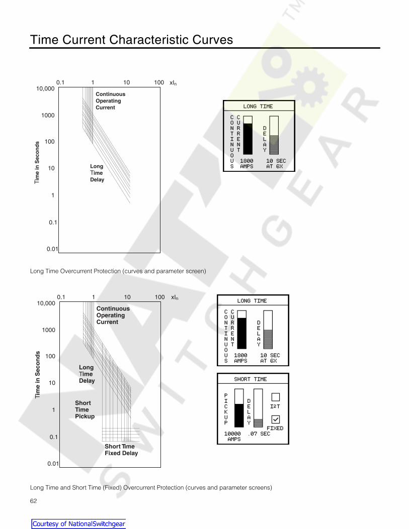
Time Current Characteristic Curves
62
Long Time Overcurrent Protection (curves and parameter screen)
Long Time and Short Time (Fixed) Overcurrent Protection (curves and parameter screens)
1
0.1
0.01
0.1 1 10 100
10
100
1000
10,000xIn
Tim
e in
Sec
on
ds
LongTimeDelay
ContinuousOperatingCurrent
1
0.1
0.01
0.1 1 10 100
10
100
1000
10,000xIn
Tim
e in
Sec
on
ds
LongTimeDelay
ShortTimePickup
Short TimeFixed Delay
ContinuousOperatingCurrent
Courtesy of NationalSwitchgear.com

Time Current Characteristic Curves
63
Long Time and Short Time (I2t) Overcurrent Protection (curves and parameter screens)
Long Time and Instantaneous Overcurrent Protection (curves and parameter screens)
1
0.1
0.01
0.1 1 10 100
10
100
1000
10,000xIr
Tim
e in
Sec
onds Long
TimeDelay
ShortTimePickup
Short TimeI2t Delay
ContinuousOperatingCurrent
xIn
1
0.1
0.01
0.1 1 10 100
10
100
1000
10,000xIr
Tim
e in
Sec
onds
LongTimeDelay
InstantaneousPickup
ContinuousOperatingCurrent
xIn
Courtesy of NationalSwitchgear.com
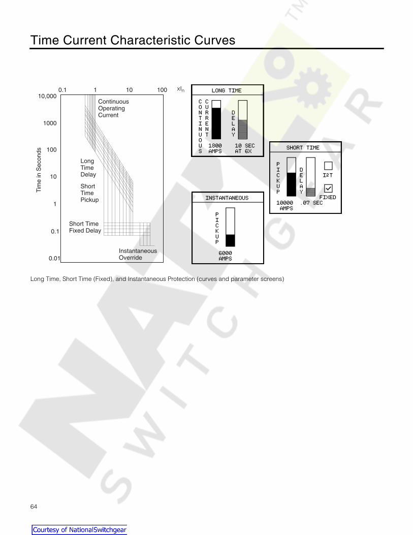
Time Current Characteristic Curves
64
Long Time, Short Time (Fixed), and Instantaneous Protection (curves and parameter screens)
InstantaneousOverride
1
0.1
0.01
0.1 1 10 100
10
100
1000
10,000xIr
Tim
e in
Sec
onds
LongTimeDelay
ShortTimePickup
Short TimeFixed Delay
ContinuousOperatingCurrent
xIn
Courtesy of NationalSwitchgear.com

Time Current Characteristic Curves
65
Ground Fault Protection (curves and parameter screens for units with Ground Fault Protection)
0.1
0.1
1
1
10
10
100
100
xIr
xIr
10
10
1
1
0.1
0.1
0.01
0.01
Tim
e in
Sec
onds
Tim
e in
Sec
onds
Ground FaultFixed Delay
Ground FaultI2t Delay
GroundFaultPickup
GroundFaultPickup
xIn
xIn
Courtesy of NationalSwitchgear.com

Parameter Settings
66
.
Long Time ProtectionSettings
% I
n
50% 60% 65% 70% 75% 80% 85% 90% 95% 100%
I
n
= Rating Plug (A) Pickup (A)
200
100 120 130 140 150 160 170 180 190 200
225
112 135 146 157 168 180 191 202 213 225
250
125 150 162 175 187 200 212 225 237 250
300
150 180 195 210 225 240 255 270 285 300
350
175 210 227 245 262 280 297 315 332 350
400
200 240 260 280 300 320 340 360 380 400
450
225 270 292 315 337 360 382 405 427 450
500
250 300 325 350 375 400 425 450 475 500
600
300 360 390 420 450 480 510 540 570 600
700
350 420 455 490 525 560 595 630 665 700
800
400 480 520 560 600 640 680 720 760 800
1000
500 600 650 700 750 800 850 900 950 1000
1200
600 720 780 840 900 960 1020 1080 1140 1200
1600
800 960 1040 1120 1200 1280 1360 1440 1520 1600
2000
1000 1200 1300 1400 1500 1600 1700 1800 1900 2000
2500
1250 1500 1625 1750 1875 2000 2125 2250 2375 2500
3000
1500 1800 1950 2100 2250 2400 2550 2700 2850 3000
3200
1600 1920 2080 2240 2400 2560 2720 2880 3040 3200
4000
2000 2400 2600 2800 3000 3200 3400 3600 3800 4000
5000
2500 3000 3250 3500 3750 4000 4250 4500 4750 5000
Long Time ProtectionDelay Settings (at 6x)
Time (s)
2.5 4 5.5 8
10 14 17 21
25 30
Courtesy of NationalSwitchgear.com

Parameter Settings
67
Short Time ProtectionSettings
% I
n
150% 200% 250% 300% 350% 400% 500% 600% 700% 800% 900%
Max Rating I
n
= Rating Plug (A) Pickup (A)
400
200
300 400 500 600 800 1000 1200 1400 1600 1800
225
337 450 562 675 900 1125 1350 1575 1800 2025
250
375 500 625 750 1000 1250 1500 1750 2000 2250
300
450 600 750 900 1200 1500 1800 2100 2400 2700
350
525 700 875 1050 1400 1750 2100 2450 2800 3150
400
600 800 1000 1200 1600 2000 2400 2800 3200 3600
800
400
600 800 1000 1200 1600 2000 2400 2800 3200 3600
450
675 900 1125 1350 1800 2250 2700 3150 3600 4050
500
750 1000 1250 1500 2000 2500 3000 3500 4000 4500
600
900 1200 1500 1800 2400 3000 3600 4200 4800 5400
700
1050 1400 1750 2100 2800 3500 4200 4900 5600 6300
800
1200 1600 2000 2400 3200 4000 4800 5600 6400 7200
1200
600
900 1200 1500 1800 2400 3000 3600 4200 4800 5400
700
1050 1400 1750 2100 2800 3500 4200 4900 5600 6300
800
1200 1600 2000 2400 3200 4000 4800 5600 6400 7200
1000
1500 2000 2500 3000 4000 5000 6000 7000 8000 9000
1200
1800 2400 3000 3600 4800 6000 7200 8400 9600 10800
1600
800
1200 1600 2000 2400 3200 4000 4800 5600 6400 7200
1000
1500 2000 2500 3000 4000 5000 6000 7000 8000 9000
1200
1800 2400 3000 3600 4800 6000 7200 8400 9600 10800
1600
2400 3200 4000 4800 6400 8000 9600 11200 12800 14400
2000
1000
1500 2000 2500 3000 4000 5000 6000 7000 8000 9000
1200
1800 2400 3000 3600 4800 6000 7200 8400 9600 10800
1600
2400 3200 4000 4800 6400 8000 9600 11200 12800 14400
2000
3000 4000 5000 6000 8000 10000 12000 14000 16000 18000
2500
1600
2400 3200 4000 4800 6400 8000 9600 11200 12800 14400
2000
3000 4000 5000 6000 8000 10000 12000 14000 16000 18000
2500
3750 5000 6250 7500 10000 12500 15000 17500 20000 22500
3200
1600
2400 3200 4000 4800 6400 8000 9600 11200 12800 14400
2000
3000 4000 5000 6000 8000 10000 12000 14000 16000 18000
2500
3750 5000 6250 7500 10000 12500 15000 17500 20000 22500
3000
4500 6000 7500 9000 12000 15000 18000 21000 24000 27000
3200
4800 6400 8000 9600 12800 16000 19200 22400 25600 28800
4000
2000
3000 4000 5000 6000 7000 8000 10000 12000 14000 16000
2500
3750 5000 6250 7500 8750 10000 12500 15000 17500 20000
3000
4500 6000 7500 9000 10500 12000 15000 18000 21000 24000
3200
4800 6400 8000 9600 11200 12800 16000 19200 22400 25600
4000
6000 8000 10000 12000 14000 16000 20000 24000 28000 32000
5000
2500
3750 5000 6250 7500 8750 10000 12500 15000 17500 20000
3000
4500 6000 7500 9000 10500 12000 15000 18000 21000 24000
3200
4800 6400 8000 9600 11200 12800 16000 19200 22400 25600
4000
6000 8000 10000 12000 14000 16000 20000 24000 28000 32000
5000
7500 10000 12500 15000 17500 20000 25000 30000 35000 40000
Short Time Protection—Delay Settings (I
2
T at 8x)
Time (s)
0.07 0.1 0.15 0.20 0.30
Courtesy of NationalSwitchgear.com

Parameter Settings
68
Instantaneous ProtectionSettings
% I
n
150% 200% 300% 400% 500% 600% 700% 800% 900% 1000% 1200%
Max Rating I
n
= Rating Plug (A) Pickup (A)
400
200
300 400 600 800 1000 1200 1400 1600 2000 2400
225
337 450 675 900 1125 1350 1575 1800 2250 2700
250
375 500 750 1000 1250 1500 1750 2000 2500 3000
300
450 600 900 1200 1500 1800 2100 2400 3000 3600
350
525 700 1050 1400 1750 2100 2450 2800 3500 4200
400
600 800 1200 1600 2000 2400 2800 3200 4000 4800
800
400
600 800 1200 1600 2000 2400 2800 3200 4000 4800
450
675 900 1350 1800 2250 2700 3150 3600 4500 5400
500
750 1000 1500 2000 2500 3000 3500 4000 5000 6000
600
900 1200 1800 2400 3000 3600 4200 4800 6000 7200
700
1050 1400 2100 2800 3500 4200 4900 5600 7000 8400
800
1200 1600 2400 3200 4000 4800 5600 6400 8000 9600
1200
600
900 1200 1800 2400 3000 3600 4200 4800 6000 7200
700
1050 1400 2100 2800 3500 4200 4900 5600 7000 8400
800
1200 1600 2400 3200 4000 4800 5600 6400 8000 9600
1000
1500 2000 3000 4000 5000 6000 7000 8000 10000 12000
1200
1800 2400 3600 4800 6000 7200 8400 9600 12000 14400
1600
800
1200 1600 2400 3200 4000 4800 5600 6400 8000 9600
1000
1500 2000 3000 4000 5000 6000 7000 8000 10000 12000
1200
1800 2400 3600 4800 6000 7200 8400 9600 12000 14400
1600
2400 3200 4800 6400 8000 9600 11200 12800 16000 19200
2000
1000
1500 2000 3000 4000 5000 6000 7000 8000 10000 12000
1200
1800 2400 3600 4800 6000 7200 8400 9600 12000 14400
1600
2400 3200 4800 6400 8000 9600 11200 12800 16000 19200
2000
3000 4000 6000 8000 10000 12000 14000 16000 20000 24000
2500
1600
2400 3200 4800 6400 8000 9600 11200 12800 16000 19200
2000
3000 4000 6000 8000 10000 12000 14000 16000 20000 24000
2500
3750 5000 7500 10000 12500 15000 17500 20000 25000 30000
3200
1600
2400 3200 4800 6400 8000 9600 11200 12800 16000 19200
2000
3000 4000 6000 8000 10000 12000 14000 16000 20000 24000
2500
3750 5000 7500 10000 12500 15000 17500 20000 25000 30000
3000
4500 6000 9000 12000 15000 18000 21000 24000 30000 36000
3200
4800 6400 9600 12800 16000 19200 22400 25600 32000 38400
4000
2000
3000 4000 6000 8000 10000 12000 14000 16000 18000 20000
2500
3750 5000 7500 10000 12500 15000 17500 20000 22500 25000
3000
4500 6000 9000 12000 15000 18000 21000 24000 27000 30000
3200
4800 6400 9600 12800 16000 19200 22400 25600 28000 32000
4000
6000 8000 12000 16000 20000 24000 28000 32000 36000 40000
5000
2500
3750 5000 7500 10000 12500 15000 17500 20000 22500 25000
3000
4500 6000 9000 12000 15000 18000 21000 24000 27000 30000
3200
4800 6400 9600 12800 16000 19200 22400 25600 28000 32000
4000
6000 8000 12000 16000 20000 24000 28000 32000 36000 40000
5000
7500 10000 15000 20000 25000 30000 35000 40000 45000 50000
Courtesy of NationalSwitchgear.com

Parameter Settings
69
OvercurrentAlarm Settings
% I
n
115% 125% 150% 200% 250%
I
n
= Rating Plug (A) Pickup (A)
200
230 250 300 400 500
225
258 281 337 450 562
250
287 312 375 500 625
300
345 375 450 600 750
350
402 437 525 700 875
400
460 500 600 800 1000
450
517 562 675 900 1125
500
575 625 750 1000 1250
600
690 750 900 1200 1500
700
805 875 1050 1400 1750
800
920 1000 1200 1600 2000
1000
1150 1250 1500 2000 2500
1200
1380 1500 1800 2400 3000
1600 1840 2000 2400 3200 4000
2000 2300 2500 3000 4000 5000
2500 2875 3125 3750 5000 6250
3000 3450 3750 4500 6000 7500
3200 3680 4000 4800 6400 8000
4000 4600 5000 6000 8000 10000
5000 5750 6250 7500 10000 12500
Max Rating (A)
Ground Fault Protection Pickup Settingsand
Ground Overcurrent Alarm Settings
Pickup (A)
400 80 100 120 160 200 240 280 320 360 400
800 160 200 240 320 400 480 560 640 720 800
1200 240 300 360 480 600 720 840 960 1080 1200
1600 320 416 512 608 704 800 896 992 1088 1200
2000 400 460 540 600 700 800 900 1000 1100 1200
2500 500 575 650 725 800 875 950 1025 1100 1200
3200 640 672 736 800 864 928 992 1056 1120 1184
4000 800 840 880 920 960 1000 1040 1080 1120 1200
5000 1200
Courtesy of NationalSwitchgear.com

Parameter Settings
70
Neutral OvercurrentRelay Settings
% Max Rating 115% 125% 150% 200% 250%
Max Rating (A) Pickup (A)
400 460 500 600 800 1000
800 920 1000 1200 1600 2000
1200 1380 1500 1800 2400 3000
1600 1840 2000 2400 3200 4000
2000 2300 2500 3000 4000 5000
2500 2875 3125 3750 5000 6250
3200 3680 4000 4800 6400 8000
4000 4600 5000 6000 8000 10000
5000 5750 6250 7500 10000 12500
Overcurrent Demand Alarm Settings
% In 60% 70% 80% 90% 95% 100%
In = Rating Plug (A) Pickup (A)
200 120 140 160 180 190 200
225 135 157 180 202 213 225
250 150 175 200 225 237 250
300 180 210 240 270 285 300
350 210 245 280 315 332 350
400 240 280 320 360 380 400
450 270 315 360 405 427 450
500 300 350 400 450 475 500
600 360 420 480 540 570 600
700 420 490 560 630 665 700
800 480 560 640 720 760 800
1000 600 700 800 900 950 1000
1200 720 840 960 1080 1140 1200
1600 960 1120 1280 1440 1520 1600
2000 1200 1400 1600 1800 1900 2000
2500 1500 1750 2000 2250 2375 2500
3000 1800 2100 2400 2700 2850 3000
3200 1920 2240 2560 2880 3040 3200
4000 2400 2800 3200 3600 3800 4000
5000 3000 3500 4000 4500 4750 5000
Courtesy of NationalSwitchgear.com

Parameter Settings
71
.
Current UnbalanceRelay Settings
% In 5% 10% 15% 20% 30% 40% 50%
In = Rating Plug (A) Pickup (A)
200 10 20 30 40 60 80 100
225 11 22 33 45 67 90 112
250 12 25 37 50 75 100 125
300 15 30 45 60 90 120 150
350 17 35 52 70 105 140 175
400 20 40 60 80 120 160 200
450 22 45 67 90 135 180 225
500 25 50 75 100 150 200 250
600 30 60 90 120 180 240 300
700 35 70 105 140 210 280 350
800 40 80 120 160 240 320 400
1000 50 100 150 200 300 400 500
1200 60 120 180 240 360 480 600
1600 80 160 240 320 480 640 800
2000 100 200 300 400 600 800 1000
2500 125 250 375 500 750 1000 1250
3000 150 300 450 600 900 1200 1500
3200 160 320 480 640 960 1280 1600
4000 200 400 600 800 1200 1600 2000
5000 250 500 750 1000 1500 2000 2500
Alarm Delay Settings
Time (s)
1 2 3 5
10 20 30 60
120 300
Voltage Unbalance Alarm Settings
% of Rating 5% 10% 15% 20% 30% 40% 50%
PT (V) Pickup (V)
240 12 24 36 48 72 96 120
480 24 48 72 96 144 192 240
600 30 60 90 120 180 240 300
Courtesy of NationalSwitchgear.com

Parameter Settings
72
Undervoltage Alarm Settings
% of PT Rating 50% 60% 70% 80% 90% 95%
PT Rating (V) Pickup (V)
240 120 144 168 192 216 228
480 240 288 336 384 432 456
600 300 360 420 480 540 570
Overvoltage Alarm Settings
% of PT Rating 105% 110% 115% 120% 125%
PT Rating (V) Pickup (V)
240 252 264 276 288 300
480 504 528 552 576 600
600 630 660 690 720 750
Miscellaneous Pickup Settings
Overfrequency (Hz) 1 2 3 4 5 7 9 12
Underfrequency (Hz) 1 2 3 4 5 7 9 12
Total Harmonic Distortion (%) 5 10 15 20 25 30 40 50
Over Power Factor 0.50 0.60 0.70 0.80 0.90 0.95
Under Power Factor 0.50 0.60 0.70 0.80 0.90 0.95
Max Rating (A) Over kW, Reverse Power, Over kW Demand (kW)
40020 40 60 80 100 125 150 175 200
225 250 275 300 325 350 375 400 425
80040 80 120 160 200 250 300 350 400
450 500 550 600 650 700 750 800 850
120060 120 180 240 300 375 450 525 600
675 750 825 900 975 1050 1125 1200 1275
160080 160 240 320 400 500 600 700 800
900 1000 1100 1200 1300 1400 1500 1600 1700
2000100 200 300 400 500 625 750 875 1000
1125 1250 1375 1500 1625 1750 1875 2000 2125
2500125 250 375 500 625 800 950 1100 1250
1400 1550 1700 1875 2050 2200 2350 2500 2650
3200160 320 480 640 800 1000 1200 1400 1600
1800 2000 2200 2400 2600 2800 3000 3200 3400
4000200 400 600 800 1000 1250 1500 1750 2000
2250 2500 2750 3000 3250 3500 3750 4000 4250
5000250 500 750 1000 1250 1550 1875 2200 2500
2800 3125 3450 3750 4050 4375 4700 5000 5300
Courtesy of NationalSwitchgear.com

Parameter Settings
73
Max Rating (A) Over kVA (kW)
40020 40 60 80 100 125 150 175 200
225 250 275 300 325 350 375 400 425
80040 80 120 160 200 250 300 350 400
450 500 550 600 650 700 750 800 850
120060 120 180 240 300 375 450 525 600
675 750 825 900 975 1050 1125 1200 1275
160080 160 240 320 400 500 600 700 800
900 1000 1100 1200 1300 1400 1500 1600 1700
2000100 200 300 400 500 625 750 875 1000
1125 1250 1375 1500 1625 1750 1875 2000 2125
2500125 250 375 500 625 800 950 1100 1250
1400 1550 1700 1875 2050 2200 2350 2500 2650
3200160 320 480 640 800 1000 1200 1400 1600
1800 2000 2200 2400 2600 2800 3000 3200 3400
4000200 400 600 800 1000 1250 1500 1750 2000
2250 2500 2750 3000 3250 3500 3750 4000 4250
5000250 500 750 1000 1250 1550 1875 2200 2500
2800 3125 3450 3750 4050 4375 4700 5000 5300
Max Rating (A) Over kVAR (kW)
40020 40 60 80 100 125 150 175 200
225 250 275 300 325 350 375 400 425
80040 80 120 160 200 250 300 350 400
450 500 550 600 650 700 750 800 850
120060 120 180 240 300 375 450 525 600
675 750 825 900 975 1050 1125 1200 1275
160080 160 240 320 400 500 600 700 800
900 1000 1100 1200 1300 1400 1500 1600 1700
2000100 200 300 400 500 625 750 875 1000
1125 1250 1375 1500 1625 1750 1875 2000 2125
2500125 250 375 500 625 800 950 1100 1250
1400 1550 1700 1875 2050 2200 2350 2500 2650
3200160 320 480 640 800 1000 1200 1400 1600
1800 2000 2200 2400 2600 2800 3000 3200 3400
4000200 400 600 800 1000 1250 1500 1750 2000
2250 2500 2750 3000 3250 3500 3750 4000 4250
5000250 500 750 1000 1250 1550 1875 2200 2500
2800 3125 3450 3750 4050 4375 4700 5000 5300
Courtesy of NationalSwitchgear.com

Menu Structure
74
Cou
nter
sP
assw
ord
Logs
Com
mun
icat
ions
Set
tings
Met
erin
gD
ata
Pro
tect
ion
Set
tings
Rel
ays
Set
tings
Ala
rms
Set
tings
Con
figur
atio
nS
ettin
gs
Dem
and
Dat
a
Wav
efor
ms
Har
mon
icD
ata
Met
ered
Dat
a
Min
/Max
Log
Eve
ntLo
g
Trip
Log
Front Panel Men Structure
Courtesy of NationalSwitchgear.com

SEAbus Plus Packet
75
SEAbus Plus Packet
Both SEAbus and SEAbus Plus use a simple byte-countapproach to realize communications between a master and itsslave devices. Information is arranged in message packets. Allpacket fields are one byte in length except Data which canvary between 0 and 255 bytes, depending on the particularmessage and device type. Communications is standard asyn-chronous, using one start bit, eight data bits, no parity, and onestop bit. All values are expressed in hex, with multiple-byte val-ues sent least significant byte (LSB) first, most significant byte(MSB) last.
Each packet begins with a 4-byte header (Sync, Devt, Msgt,Len) to indicate the message source, destination, type, andlength. The variable length data field (Data) follows the headerand contains any actual data. All packets end with the LRCerror checksum byte.
The SEAbus Plus protocol is very similar to the original SEAbusprotocol in its format and timing requirements. The primary dif-ference is a 16-bit cyclical redundancy check (CRC16)included in the Data field of the message packet to improveerror detection. This checksum is produced for each SEAbusPlus packet by treating the data to be transmitted as a binarypolynomial and dividing it by a generating polynomial. Thistechnique assures 100% detection of all errors in data up to 16bits in length and 99.9997% in data 17 bits or longer. SEAbusPlus uses an additional error check byte equal to the invertedSync byte (~Sync). It follows immediately after the CRC16 atthe end of the Data field. A brief description of each messagefield in a SEAbus Plus packet follows.
Synchronization (Sync) Byte
The Sync byte indicates both the start and direction of a newmessage packet. The direction is either master-to-slave orslave-to-master. A message sent from the ACCESS host to afield device always begins with 14h(exadecimal). Anyresponse packet sent by a slave back to the ACCESS masteruses a value of 27h in the Sync byte. Any messages sent with-out the proper Sync byte are ignored by all devices.
Device Type (Devt) Byte
Each device placed in an ACCESS system is assigned a uniqueaddress to distinguish it from other slave devices on the bus. Therange of address values permitted for a particular devicedepends on the device type’s addressing scheme. Slave devicesusing direct addressing must use an address between 1 and 224,inclusive. Indirectly addressed devices may use any value from 1to 254. (0 and 255 are reserved by the ACCESS host for universaland global packets, respectively.)
The meaning of the second byte in a SEAbus Plus packet,Devt, changes depending on the addressing scheme used bythe field device. For directly addressed devices, such as theSB Energy-Comm trip unit, the Devt byte is simply the device’sunique slave address. For devices using indirect addressing,Devt takes on the value of the single-byte “device-type” codeassigned to a specific type of device. The device’s uniqueslave address is included later as the first byte in the Data field.
Message Type (Msgt) Byte
The message type byte, Msgt, identifies the particular mes-sage being sent. This, in turn, determines the length and typeof data (if any) to follow in the Data field of the SEAbus Pluspacket. Whenever a slave device responds to a message oftype Msgt sent by the ACCESS host, it uses that same value asthe message type byte in its return packet.
In the SEAbus Plus protocol, Devt and Msgt define a uniquemessage. With the exception of global messages, differentdevice types can use the same message type value for differ-ent purposes without conflict.
Length (Len) Byte
The fourth byte in a SEAbus Plus packet specifies the totalnumber of bytes to follow in the packet’s variable-length Datafield. The count given by the length byte, Len, includes anyactual data bytes, the 2-byte CRC16, and the inverted Syncbyte. In the case of indirectly addressed devices, Len alsoincludes the slave address byte appearing as the first byte inthe Data subpacket.
Data Subpacket
The Data subpacket contains the actual data to be passedbetween the ACCESS host and slave device. The particularmessage type (Msgt) determines both the type and amount ofdata. For indirectly addressed devices, the first byte appearingin the data field is the device’s unique slave address. This isfollowed immediately by any data values to be sent. The SEA-bus Plus protocol requires that a two-byte cyclical redundancycheck (CRC16) and another error check byte equal to theinverted Sync byte (~Sync) be placed after the data to com-plete the Data subpacket.
The receiving device also computes its own CRC16 and ~Syncbased on the incoming packet bytes. If these newly calculatedcheck bytes do not equal the received error check values, themessage is invalid.
Longitudinal Redundancy Check (LRC) Byte
Both SEAbus and SEAbus Plus terminate all packets with an LRCbyte for error checking. For SEAbus, the LRC is the one’s comple-ment of the sum (no carry) of all preceding bytes in the packetexcept the initial Sync byte. SEAbus Plus performs the same sum-ming procedure, but does not take the one’s complement.
The LRC is calculated at both the transmitting device andreceiving device for each packet. If the receiving device calcu-lates a different LRC based on the incoming bytes than thatreceived at the end of the packet, an error has occurred duringtransmission and the packet is ignored.
Note: Refer to ACCESS SEAbus Protocol Reference ManualIPIM-2209 and SG6213-00 for detailed information.
Courtesy of NationalSwitchgear.com

Glossary
76
Glossary
A
ACCESS system
A power monitoring and control system bySiemens. The SB Energy-Comm trip unit is one of severalACCESS system field devices that can communicate with a per-sonal computer or other supervisory device.
ACCESS baud rate
See Baud Rate.
ACCESS port
The RS-485 port on the trip unit that allows it tocommunicate on the ACCESS system. The physical connectionis made on the terminal strip on the left side of the breaker.
acceptance test
A preliminary check performed when thedevice is first received to ensure that it has not been damaged inshipment or retrieval from storage. The SB Energy-Comm trip unitprovides a trip test to determine that the trip unit will send theproper trip signal to the breaker, and that the breaker will tripwhen signalled.
accessory
An optional device that can add functionality to thetrip unit. All accessories for the SB Energy-Comm unit are exter-nal to the trip unit.
address
The programmable, unique identifier of the device onthe ACCESS system. It is used by the supervisory device to iden-tify the device when communicating.
alarm
A signal from the trip unit that can trigger an alert, suchas a buzzer or flashing light, that an event has taken place.
alarm setpoint
A programmable value, such as current or volt-age, which if exceeded, the trip unit will send an alarm signal.
American Wire Gauge (AWG)
A standard system for desig-nating wire diameter. Primarily used in the United States.
amps demand
See
Current Demand
.
ANSI
American National Standards Institute.
B
baud rate
The rate of data transfer. The baud rate can be setseparately for the ACCESS communications RS-485 port and thefront RS-232 port.
breaker
See
Circuit Breaker
.
breaker frame size
The physical size of the breaker based onits maximum current rating. The SB breaker has five frame sizes.Each breaker frame size has a range of available breaker currentratings.
breaker rating
The current rating of the breaker. SB breakerratings vary from 400 A to 5000 A. It is set by the rating plug.
breaker serial number (S/N)
A five-digit number entered inthe trip unit that uniquely identifies its associated breaker. Validnumbers range from 00000 to 99999.
C
catalog number
See
Order Number
.
circuit breaker
The circuit interrupting device (Sentron Sys-tems Breaker) that the SB Energy-Comm trip unit is mounted in.
Communications menu
The menu selection available from theMain menu which allows the configuration of communicationswith a supervisory device.
communications
The interchange of data and informationbetween the SB Energy-Comm trip unit and a supervisory device.The trip unit has a serial port for communications with a PC plus aRS-485 port for communications between a network of ACCESSfield devices and a supervisory device.
continuous current
See
Long Time
.
counters
The SB Energy-Comm trip unit tracks the number ofbreaker operations. There are three types of counters: mechani-cal, interruption, and fault.
crest factor
The ratio between the peak and RMS current,measured per phase.
CT
current transformer. A device which generates a current pro-portional to that in the measured line.
current balance
See
Phase Balance
.
current demand
The measurement and summation of meteredcurrent over a specified time.
current rating
See
Breaker Rating
.
current unbalance alarm
An alarm activated when the phasecurrent for any one phase exceeds the average current by a setvalue. The breaker may also be programmed to trip at this, oranother value. This feature is available from the Protective Relaysmenu.
D
delay
The amount of time that the trip unit waits before trippingor alarming after a monitored value exceeds the alarm or trip set-ting.
Courtesy of NationalSwitchgear.com
Glossary
77
demand
The measurement and summation of current or energyover a specified time, typically 15 or 30 minutes.
demand period
The specified time, typically 15 or 30 minutes,over which current or energy data is collected and from which thedemand value is calculated.
device address
See
Address
.
DLY
Time delay (value).
display contrast
A setting that can be adjusted to increase ordecrease the contrast of the panel display.
E
EIA
Electronic Industries Association.
EIA-232
See
RS-232.
EIA-485
See
RS-485
.
Electronic Bell Alarm
Accessory that attaches to the trip unitand provides a solid-state relay contact for remote indication ofbreaker tripping.
EP
Expansion Plug.
event log
A record of faults and alarms, including the date andtime they occurred.
Expansion Plug
Interface between the trip unit and the Multi-plexer Translator for zone interlocking.
extended protective relaying
See
Protective Relay Functions
.
external neutral sensor
The current transformer located onthe neutral bus of a four-wire electrical system.
external power supply
An AC/DC converter which suppliespower for the trip unit’s metering and communications functions.
F
fault
Electrical disturbance such as a short circuit or open cir-cuit.
fault counter
The counter on the trip unit that records breakeroperations.
fixed delay
A trip time delay that is a constant value, regardlessof the magnitude of the overcurrent.
frame size
See
Breaker Frame Size
.
G
GF
ground fault (protection).
ground fault mode switch
The switch on the side of the tripunit that selects the ground fault sensing scheme, either Residual(all three phases added) or Ground Return.
ground fault protection
Protection against shorts to ground.
ground overcurrent alarm
An alarm activated by current inthe ground line exceeding a set limit.
ground return
The ground fault sensing scheme in which theground fault sensor is located at the neutral connection toground.
H
harmonic analysis
Mathematical analysis of a waveform todetermine its harmonic components.
I, J
ICCB
Insulated Case Circuit Breaker.
idle display mode
The trip unit’s mode of operation when leftidle for five minutes or longer. The display shows several screensof data and configuration settings in sequence until a key on thekeypad is pressed. Remote configuration of the trip unit is allowedonly while it is in this mode. It is also available from the View Dataselection on the main menu.
IEC
International Electrotechnical Committee. The internationalstandards organization for electrical and electronic equipment.
I
n
Rating Plug value.
I
2
t
A variable time delay in which the delay is progressivelyshorter as the overcurrent value increases. I
2
t describes the rela-tionship between the overcurrent magnitude and time.
INST
Instantaneous fault (protection).
instantaneous
Overcurrent protection that occurs immediately,without any delay.
Courtesy of NationalSwitchgear.com

Glossary
78
L
logs
Tables in the trip unit’s memory to store trip information,event information, and metered value minimum/maximum values.
Log menu
The menu selection, available from the Main menu,that allows the operator to view or reset the logs.
long time
Overcurrent protection that is only activated after auser-defined period, typically several seconds in duration. This isfor the lowest levels of overcurrent activity.
LT
long time fault (protection).
M
Main menu
The primary menu screen on the trip unit. Itappears on powering the unit, and after pressing a key while inidle display mode.
maintenance counter
The counter on the trip unit that keepstrack of all breaker operations, both openings and trips.
MAX Rating
The maximum amount of continuous current thebreaker is capable of carrying.
mechanical counters
The counters in the trip unit (mechani-cal and fault) that keep track of the number of breaker operationsthat are caused by manual or mechanical means and not due toelectrical fault or remote command.
metering menu
The menu selection on the Main menu thatallows the operator to view metered parameters.
min/max values
Minimum and maximum metered values.
mode switch
See
Ground Fault Mode Switch
.
model number
See
Order Number
.
MT
Multiplexer Translator. Device that allows up to eight fielddevices to be attached for remote communications and/or zoneinterlocking. Used with the SB Energy-Comm trip unit only forzone interlocking.
N
NEMA
National Electrical Manufacturers Association.
O
operations
Openings or trippings of the circuit breaker.ordernumber
The number used to describe which model when ordering. Theorder number designates which features are on the trip unit.
over amp demand alarm
The alarm signal from the trip unitwhen the system exceeds a specified current demand setting.
overcurrent alarm
The alarm signal from the trip unit when thesystem exceeds a user-specified current setting.
overcurrent protection
Protection provided by the trip unitwhen a line current exceeds a user-specified value. Availableforms of overcurrent protection are instantaneous, short time, andlong time.
over power demand alarms
The alarm signal from the trip unitwhen the system exceeds a user-specified current power value;either over apparent power (KVA), over reactive power (KVAR) orover real power (Over KW).
over frequency alarm
The alarm signal from the trip unit whenthe system exceeds a user-specified line frequency value.
over voltage alarm
The alarm signal from the trip unit whenthe system exceeds a user-specified voltage value.
P, Q
packet
SEAbus communications unit of information that istransmitted between the field device and supervisory device.
password
A number, entered from the security menu, used toprevent users from inadvertently changing parameters. Thedefault setting is no password.
period
See
Demand Period
.
phase balance
The ratio of current or voltage in a particularphase to the average current for all three phases.
pickup
The value at which the trip unit detects a trip or alarmcondition.
power factor
The ratio of resistance to impedance. The ratio ofan actual power of an alternating current to apparent power.Mathematically, the cosine of the angle between the voltageapplied and the current resulting.
power supply
See
External Power Supply
.
Portable Test Set
Equipment for verifying the operation of thetrip unit; for example, the TS-31 test set may be used to test theprotective functions of the SB Energy-Comm trip unit.
protective relay functions
Protective functions including trip-ping when the system exceeds user-defined pickup values forover and under voltage, under and over frequency, reverse power,and unbalance.
Courtesy of NationalSwitchgear.com

Glossary
79
Protective menu The available protection functions, includingLong Time, Short Time, Instantaneous, and Ground Fault.
PT Potential Transformer. A transformer which generates a volt-age in the secondary proportional to the voltage in the primary ata specified ratio.
PT rating The ratio between the potential transformer voltagesensed, and voltage transmitted.
PU Pickup (value).
RRS-232 (EIA-232) An industry standard (EIA-232) serial com-munications interface through which data is sent one bit (binarydigit) at a time. The physical and electrical specifications thatapply to the transfer of data between Data Terminal Equipment(DTE) and Data Communication Equipment (DCE), typicallybetween a personal computer and a peripheral device.
RS-485 (EIA-485) Commonly used communications standard(EIA-485) typically for communication among several fielddevices.
remote operations Opening or closing of the breaker by a sig-nal from the communications port. This is distinguished from tripscaused by actual faults.
residual ground sensing scheme The method of sensingground current based on the vectorial summation of currents in allphases.
Reverse Power Power flow from the load towards the source.kW and kVAR supplied by the load.
RX Receive signal (communications).
SSB Systems Breaker. The family of encased systems breakerson which the trip unit operates.
SEAbus The protocol used by the SB Energy-Comm trip unitand other Siemens ACCESS field devices.
Security menu The menu selection, available from the Mainmenu, that allows the operator to choose the password andenable security.
serial number See Breaker Serial Number.
serial port The data port on the front of the trip unit that allowsRS-232 communications to a personal computer.
short time Overcurrent protection that is activated after a briefdelay. This is for higher levels of overcurrent activity than the longtime protective function.
ST Short Time (protection).
supervisory device A device that can remotely configure, readback, check the configuration of, and poll real-time data from fielddevices. Supervisory devices display the information and add thecapabilities of programming, monitoring alarms, and logging sys-tem events.
System Check LEDs The indicators on the front panel of thetrip unit that indicate the proper operation of the trip unit’s protec-tive and metering functions.
System Configuration menu The menu selection, availablefrom the Main menu, that allows the operator to view and config-ure power system characteristics.
System Status LEDs The two indicators on the front panel ofthe trip unit that indicate the status of the breaker, whether it hasbeen sent a trip command and whether an alarm has occurred.
Ttest set See Portable Test Set.
total harmonic distortion (THD) The ratio of the sum of theparts of the system power waveform that resides in the harmon-ics to the value of the power residing in the fundamental line fre-quency.
trip The opening of the circuit breaker or the command to openthe circuit breaker originating at the trip unit.
trip unit The field device connected to a circuit breaker thatsenses overcurrent conditions and sends a signal to open thebreaker. The SB Energy-Comm trip unit also includes metering,protective relay, and communications capabilities.
trip log The list of trips or breaker openings stored in memory ofthe trip unit.
TS-31 See Portable Test Set.
TX Transmit signal (communications).
Uunbalance See Phase Balance.
under voltage alarm The alarm signal that is output by the tripunit when the control voltage drops below a user-specified set-ting.
Courtesy of NationalSwitchgear.com

Glossary
80
under frequency alarm The alarm signal from the trip unitwhen the system drops below a user-specified line frequencyvalue.
Vvoltage balance See Phase Balance.
VT Voltage transformer. See PT.
W, X, Ywaveform The graphical depiction of the current or voltage overtime.
waveform capture The function of saving the measurement ofthe current or voltage over one cycle.
WinPM™ Windows-based electrical distribution and communi-cations software designed for personal computers. Through com-munications drivers, WinPM software collects and displays real-time data from ACCESS field devices. WinPM also monitors anddisplays historical data, minimum and maximum data, and wave-form data. In addition, WinPM can deliver its data to other com-patible Windows applications in real-time through dynamic dataexchange (DDE).
Zzone interlock The interconnecting of several circuit protectiondevices, to protect a specified portion of a power system, andcoordinate in timing the action of those devices.
Courtesy of NationalSwitchgear.com

Index
81
Index
A
ACCESS Baud Rate 76ACCESS Baud Rate Menu Option 50ACCESS Bus Master 7
device changes 7device information 7local operation 7
ACCESS Communications 7, 49ACCESS port 49
defined 76EIA-485 communications standard 7
ACCESS system defined 76address 49and SEAbus protocol 50field devices supporting 49master/slave network 7, 49
Accumulated Demand Values 45resetting 45
Address 50changing 50defined 76setting 50slave address menu option 50
Alarm LED 20Alarm Setpoints 5, 29
defined 76exceeding 29parameters 29
alarm enabled or disabled 29delay value 29pickup value 29
Alarms 29actions when setpoint is exceeded 29alarm setpoints 29configuration 29defined 76delay settings 71functions 5
prioritization of 6menu 29protective relay functions 35setting parameters 29
Alarms Menu 30ground over current option 30over current option 30over KVA option 33over KVAR option 33over KW demand option 32over KW menu option 32
over-amp demand option 31pf lagging 34pf leading 34total harmonics option 31
B
Baud Rate 50changing 50setting 50
Breaker
See
Circuit Breaker
C
Change Password Menu Option 54, 55Circuit Breaker
defined 76frame sizes 3introduction 1serial number (S/N) 23, 53
Circuit Breaker Operations 52faults recorded 53number of 53overview 3testing 52
Circuit Breaker Test Menu Option 52Communication Ports 49
EIA-232 serial port 49EIA-485 ACCESS port 49
Communications 49ACCESS communications 7, 49ACCESS master/slave network 7between remote EIA-485 and master station 49connecting to intelligent field devices 51connecting with a PC 15defined 76introduction 7modem 49open protocol 49overview 49PC communication 49protocol 51remote operation 49, 51SEAbus protocol 49serial communications 7setting the address and baud rate 50supervisory (WinPM) software 51third-party system compatibility 51viewing settings 49with the Sensitrip EC 49with Windows 95 Operating System 51
Communications Menu 19, 49ACCESS baud rate option 50defined 76
Courtesy of NationalSwitchgear.com

Index
82
remote open option 51RS232 baud rate option 49slave address option 50view comm config option 49
Compatibility with Supervisory Software 49Counters 76
fault 53mechanical 53
Current Balance
See
Phase BalanceCurrent Transformers (CTs) 1Current Unbalance 36
alarm 36, 76relay settings 71
D
Data Logs
See
LogsDelay 5, 76Demand
calculation 42data 42defined 76, 77periods 42, 77
calculation of 42setting parameters 42
Demand Config Menu Option 42demand data 42
Demand Menu Option 42Digital Harmonics Sampling 42Digital Waveform Sampling 43Display (LCD) Contrast 23, 77
E
EIA-232 (RS-232) Port 7, 49, 79EIA-232 to EIA-485 conversion 49EIA-485 (RS-485) Port 7, 49, 79
compared to EIA 232 7connection to master computer station 49
Electronic Bell Alarm 77Enable Security Menu Option 54Energy Registers 45Event Log 6, 46
defined 77Exceeding the Configured Setpoint 29Extended Protective Relaying
See
Protective Relay Func-tions
External Neutral Sensor (Neutral CT) 21, 77setting 22
External Power Supply 8, 77
F
Fault Counter 53, 77Fault Counter Menu Option 53Faults 53
by type of protection 53defined 77number recorded 53
Field Interchangeable Rating Plugs 3Fixed Delay 77Frame Sizes
See
Circuit Breaker, Frame SizesFront Panel Display 17
availability of real-time and accumulated data 17custom menus and graphical displays 17liquid crystal display 17viewing the trip log 17
Front Panel Interface 4Front Panel Keys 4, 17
access to parameter setting screens 18features of 4menu screen navigation 17
Front Panel LCD Display 5Front Panel LEDs 5, 19
system check LEDs 19metering LED 20, 40protective LED 20
system status LEDs 20alarm LED 20tripped LED 20
G
Glossary of Terms 76Graphical Phase Waveforms
displaying 43graphs 44inputs 44
triggering manually via communications 44Ground Fault Menu Option 27Ground Fault Mode Switch 10, 28, 77Ground Fault Protection 10, 27, 30, 77
time characteristics curve 65Ground Fault Sensing Scheme 28
ground return mode 28residual (3-phase, 3-wire) mode 28residual (3-phase, 4-wire) mode 28
Ground Fault Test 52Ground Fault with Trip Test 52Ground Overcurrent Alarm Settings 69, 77Ground Overcurrent Menu Option 30Ground Return Mode 28, 77
Courtesy of NationalSwitchgear.com
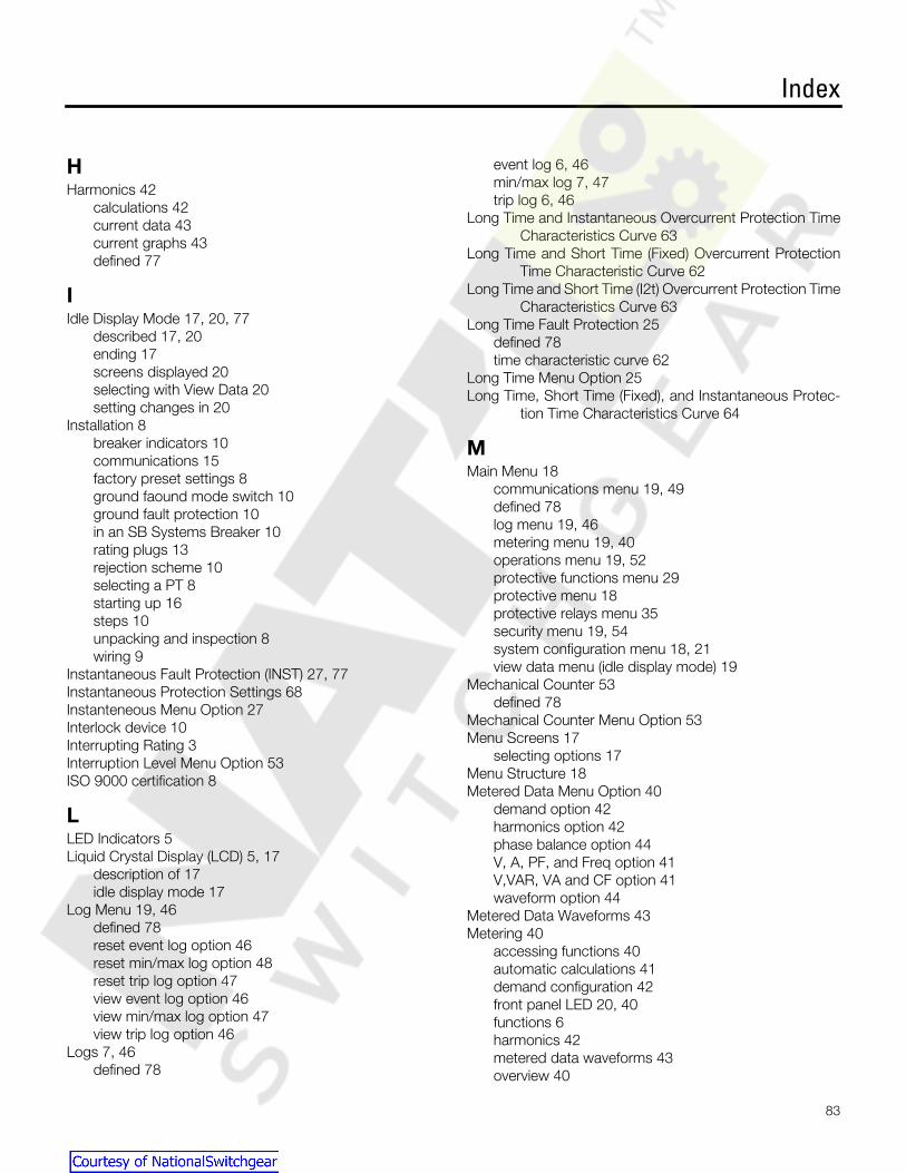
Index
83
H
Harmonics 42calculations 42current data 43current graphs 43defined 77
I
Idle Display Mode 17, 20, 77described 17, 20ending 17screens displayed 20selecting with View Data 20setting changes in 20
Installation 8breaker indicators 10communications 15factory preset settings 8ground faound mode switch 10ground fault protection 10in an SB Systems Breaker 10rating plugs 13rejection scheme 10selecting a PT 8starting up 16steps 10unpacking and inspection 8wiring 9
Instantaneous Fault Protection (INST) 27, 77Instantaneous Protection Settings 68Instanteneous Menu Option 27Interlock device 10Interrupting Rating 3Interruption Level Menu Option 53ISO 9000 certification 8
L
LED Indicators 5Liquid Crystal Display (LCD) 5, 17
description of 17idle display mode 17
Log Menu 19, 46defined 78reset event log option 46reset min/max log option 48reset trip log option 47view event log option 46view min/max log option 47view trip log option 46
Logs 7, 46defined 78
event log 6, 46min/max log 7, 47trip log 6, 46
Long Time and Instantaneous Overcurrent Protection TimeCharacteristics Curve 63
Long Time and Short Time (Fixed) Overcurrent ProtectionTime Characteristic Curve 62
Long Time and Short Time (I2t) Overcurrent Protection TimeCharacteristics Curve 63
Long Time Fault Protection 25defined 78time characteristic curve 62
Long Time Menu Option 25Long Time, Short Time (Fixed), and Instantaneous Protec-
tion Time Characteristics Curve 64
M
Main Menu 18communications menu 19, 49defined 78log menu 19, 46metering menu 19, 40operations menu 19, 52protective functions menu 29protective menu 18protective relays menu 35security menu 19, 54system configuration menu 18, 21view data menu (idle display mode) 19
Mechanical Counter 53defined 78
Mechanical Counter Menu Option 53Menu Screens 17
selecting options 17Menu Structure 18Metered Data Menu Option 40
demand option 42harmonics option 42phase balance option 44V, A, PF, and Freq option 41V,VAR, VA and CF option 41waveform option 44
Metered Data Waveforms 43Metering 40
accessing functions 40automatic calculations 41demand configuration 42front panel LED 20, 40functions 6harmonics 42metered data waveforms 43overview 40
Courtesy of NationalSwitchgear.com

Index
84
parameters 40power flow conventions 41power polarity conventions 41reset meter data 45summary of features 40viewing calculated values 41viewing demand data 42
Metering Menu 19, 40defined 78demand config option 42metered data menu option 40reset meter data option 45
Microprocessor 1Microsoft Windows 95 51
communication with 51WinPM Software connection 51
Min/Max Log 7, 47phase X amps 47power 48reset 48types of data 47volts 48XY line volts 48
Models, SB Trip Unitavailable models 1
Monitoring Power Quality 43
N
Neutral Overcurrent 36alarm settings 70
O
Operations Menu 19, 52circuit breaker test option 52fault counter option 53interruption level option 53mechanical counter option 53overview 52
Order Number 78Over Amp Demand 78Over Apparent Power Condition 33Over Current Menu Option 30Over Frequency Condition 39, 78Over KVA Condition Parameter Settings 72Over KVA Menu Option 33Over KVAR Menu Option 33Over KW Demand Menu Option 32Over KW Demand Parameter Settings 72Over KW Menu Option 32Over Power Demand Condition 32, 78Over Power Factor (Leading) Condition 34Over Power Factor Pickup Settings 72
Over Reactive Power Condition 33Over Real Power Condition 32Over Voltage 78Over-Amp Demand Menu Option 31Overcurrent Alarm 78
settings 69Overcurrent Condition 1, 30Overcurrent Demand Condition 31
alarm settings 70Overcurrent Protection Configuration 24
defined 78ground fault sensing scheme 28protective functions menu 24RMS current sensing 24security inactive 24time-current curve 24
Overcurrent Protective Functions 5pickup and delay settings 5
Overcurrent Test 52Overcurrent With Trip Test 52Overfrequency Pickup Settings 72Overvoltage 38
alarm settings 72
P
Parameter Settings 18, 70alarm delay settings 71current unbalance relay settings 71ground overcurrent alarm settings 69instantaneous protection settings 68keypad access 18miscellaneous pickup settings 72neutral overcurrent relay settings 70over k2 reverse power, over kw demand 72over kVA 72over kVAR 72overcurrent alarm settings 69overvoltage alarm settings 72short time protection delay settings 67short time protection settings 67undervoltage alarm settings 72voltage unbalance alarm settings 71
Password Protection 54changing password 54, 55defined 78enabling security 54
PC Communication 49baud rate 49
PF Leading Menu Option 34Phase Balance Data 44, 45, 78Pickup 5, 78
values 13
Courtesy of NationalSwitchgear.com
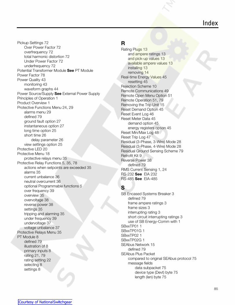
Index
85
Pickup Settings 72Over Power Factor 72overfrequency 72total harmonic distortion 72Under Power Factor 72underfrequency 72
Potential Transformer Module
See
PT ModulePower Factor 78Power Quality 43
monitoring 43waveform graphs 44
Power Source/Supply
See
External Power SupplyPrinciples of Operation 1Product Overview 1Protective Functions Menu 24, 29
alarms menu 29defined 79ground fault option 27instantaneous option 27long time option 25short time 26
delay parameter 26view settings option 25
Protective LED 20Protective Menu 18
protective relays menu 35Protective Relay Functions 5, 35, 78
actions when setpoints are exceeded 35alarms 35current unbalance 36neutral overcurrent 36optional Programmable functions 5over frequency 39overview 35overvoltage 38reverse power 38settings 35tripping and alarming 35under frequency 39undervoltage 37voltage unbalance 37
Protective Relays Menu 35PT Module 8
defined 79illustration of 8primary inputs 8rating 21, 79rating setting 22selecting 8settings 8
R
Rating Plugs 13and ampere ratings 13and pick-up values 13available ampere values 13installing 13removing 14
Real-time Energy Values 45resetting 45
Rejection Scheme 10Remote Communications 49Remote Open Menu Option 51Remote Operation 51, 79Removing the Trip Unit 15Reset Demand Option 45Reset Event Log 46Reset Meter Data 45
demand option 45energy registers option 45
Reset Min/Max Log 48Reset Trip Log 47Residual (3-Phase, 3-Wire) Mode 28Residual (3-Phase, 4-Wire) Mode 28Residual Ground Sensing Scheme 79Retrofit Kit 9Reverse Power 38
defined 79RMS Current Sensing 1, 24RS-232
See
EIA 232RS-485
See
EIA-485
S
SB Encased Systems Breaker 3defined 79frame ampere ratings 3frame sizes 3interrupting rating 3short circuit interrupting ratings 3use of SB Energy-Comm with 1
SBxxTP01 1SBxxTP01G 1SBxxTP02 1SBxxTP02G 1SEAbus Network 15
defined 79SEAbus Plus Packet
compared to original SEAbus protocol 75message fields
data subpacket 75device type (Devt) byte 75length (len) byte 75
Courtesy of NationalSwitchgear.com

Index
86
longitudinal redundancy check (lrc) byte 75message type (msgt) byte 75synchronization (sync) byte 75
specifications 75Security Inactive Screen 24Security Menu 19, 54
change password option 54, 55defined 79enable security option 54overview 54password protection 54
Selecting a PT 8module primary inputs 8protection against internal faults 8
Selecting an External Power Supply 8Sensitrip EC 49Serial Communications 7, 79Setting Other Device Parameters 22
circuit breaker serial number (S/N) 23display (LCD) contrast 23time and date 22
Setting System Configuration Parameters 21external neutral sensor 22potential transformer rating 22short circuit protection 22system frequency 21system wiring configuration 21
Short Circuit Interrupting Ratings 3Short Circuit Protection 21
setting 22short time and instantaneous tripping 22
Short Time 79fault protection 26protection settings 67
Short Time Menu Option 26delay parameter 26
Siemans Isolated Multi-Drop Converter 49Starting Up 16Supervisory Software
defined 79WinPM Software 51
System Check LEDs 19blinking patterns 19defined 79metering LED 20, 40protective LED 20
System Configuration 21at power-up 21defined 79setting other device parameters 23setting system configuration parameters 21setting time and date 21
view config menu 21viewing 21
System Configuration Menu 18, 21System Configuration Parameters 21
external neutral sensor (neutral CT) 21potential transformer (PT) rating 21short circuit protection 21system frequency 21system wiring configuration 21
System Frequency 21setting 21
System Status LEDs 20alarm LED 20defined 79tripped LED 20
System Wiring Configuration 21setting 21
T
Testing 56options 52TS-31 test set
defined 78operating instructions 56
TS-31 test setPortable Test Set
See
TestingThird-Party System Compatibility 51Time and Date 22
setting 21Time Characteristics Curves
ground fault protection 65long time and instantaneous overcurrent protection 63long time and short time (fixed) overcurrent protection
62long time and short time overcurrent protection 63long time overcurrent protection 62long time, short time (fixed), and instantaneous protec-
tion 64Time-Current Curve 24
adjustable parameters 24Total Harmonic Distortion 31, 79
pickup settings 72Total Harmonics Menu Option 31Trip 79Trip Log 6, 46
defined 79viewing and clearing 6
Tripped LED 20Tripping and Alarming 35Tripping command 2TS-31 Test Set
See
Testing
Courtesy of NationalSwitchgear.com

Index
87
U
Under Frequency 39defined 80
Under Power Factor (Lagging) Condition 34Under Power Factor Pickup Settings 72Under Voltage
defined 79Underfrequency Pickup Settings 72Undervoltage 37
alarm settings 72Unpacking and Inspection 8User Interface 17
communications menu 19front panel display 17front panel keys 17front panel LEDs 19
system check LEDs 19metering LED 19protective LED 19
system status LEDs 20alarm LED 20tripped LED 20
idle display mode 20log menu 19main menu 18menu screens 17menu structure 18metering menu 19operations menu 19parameter setting screens 18protective menu 18security menu 19system configuration menu 18view data menu 19
V
View Config Menu 21View Data Menu 19View Settings 25
screen abbreviations 25View Settings Menu Option 25Viewing Protection Settings 25Voltage Balance
See
Phase BalanceVoltage Unbalance 37
alarm settings 71
W
Waveform Capture 80Waveform Graphs 44
defined 80WinPM Software 51, 80Wiring 9
accessories 9connecting to an ACCESS Host device 9illustration of connections 9panelboards 9retrofit applications 9retrofit kit 9
Z
Zone Interlock 80
Courtesy of NationalSwitchgear.com

Siemens Energy & Automation, Inc. For Nearest Sales OfficeDistribution Products Division 1.800.964.41143333 Old Milton Parkway www.sea.siemens.com/Alpharetta, GA 30005 sales/salesoffices.html
©Siemens Energy & Automation, Inc. Bulletin IPIM-2208BSiemens is a registered trademark of Siemens AG (Supercedes 4.5-2.A)Specifications are subject to change without notice. 2.5M1299SP Printed in U.S.A.
Courtesy of NationalSwitchgear.com