Circuit breaker control function block description
30
Application guide to the differential protection and restricted earth-fault protection functions for autotransformers Budapest, May 2016
-
Upload
khangminh22 -
Category
Documents
-
view
5 -
download
0
Transcript of Circuit breaker control function block description

Circuit breaker control function block description
Document ID: PRELIMINARY VERSION
Budapest, October 2009
Application guide to the differential protection and restricted
earth-fault protection functions for autotransformers
Budapest, May 2016

Application guide to the differential protection and restricted earth-fault protection function for autotransformers
Version 1.0 2/30 17.09.2014
Setting guide version information
Version Date Modification Compiled by
V1.0 17.09.2014 First edition Petri
V1.1 19.05.2016 Correction of the calculation of „TR Neutral Comp” in chapter 4.1 Calculation of the amplitude compensation for the restricted earth-fault protection function
Seida

Application guide to the differential protection and restricted earth-fault protection function for autotransformers
Version 1.0 3/30 17.09.2014
CONTENTS 1 Example for the application .................................................................................................4 2 Setting the CT input function blocks ....................................................................................7 3 Setting the differential protection function ........................................................................ 10
3.1 Vector shift compensation ......................................................................................... 12
3.2 Calculation of the amplitude compensation for the differential protection function ... 14
3.3 Considerations, related to the harmonic restraint ..................................................... 15
3.4 Considerations, related to the differential characteristic for the differential protection function ................................................................................................................................. 15
3.5 Considerations for zero sequence elimination .......................................................... 17 4 Setting the restricted earth-fault protection function......................................................... 18
4.1 Calculation of the amplitude compensation for the restricted earth-fault protection function ................................................................................................................................. 20
4.2 Considerations, related to the differential characteristic for the restricted earth-fault protection function ................................................................................................................ 20
4.3 Considerations, related to the directional check ....................................................... 21 5 Testing instructions .......................................................................................................... 22
5.1 Testing the differential protection .............................................................................. 22
5.2 Testing the restricted earth-fault protection .............................................................. 26 5.2.1 Characteristic accuracy tests ............................................................................. 26 5.2.2 Single shot fault simulation ................................................................................ 27

Application guide to the differential protection and restricted earth-fault protection function for autotransformers
Version 1.0 4/30 17.09.2014
1 Example for the application For the application example consider an autotransformer equipped with tertiary, according to Figure 1-1. The coils for the primary and secondary sides are auto-connected with solidly grounded neutral. The tertiary coils are delta connected, and applied also for power transmission.
Figure 1-1 Autotransformer application
Example transformer data for the application: Rated voltages: 220 kV / 132 kV / 11 kV Rated power: 100 MVA / 100 MVA / 30 MVA Calculated rated currents: 262 A / 437 A / 1575 A (5249 A) NOTE: for the tertiary coil two currents are calculated, one is based on the coil rated power; this is 1575 A and one for the highest reference power (5249 A). This higher value is needed for balancing the differential protection function. Current transformers installed for the application are shown in Figure 1-2. The P1 points are arranged towards the transformer, except the CT in the grounding. For this CT the P2 point is toward the transformer.
Figure 1-2 Current transformers, assigned to the differential protection and restricted
earth-fault protection functions
Current transformer data: Primary side 300 A / 1 A Secondary side 500 A / 1 A Tertiary side 2000 A / 1 A Grounding 300 A / 1 A
P1
P1 P1 P2
Primary Secondary
Tertiary
Application guide to the differential protection and restricted earth-fault protection function for autotransformers
Version 1.0 5/30 17.09.2014
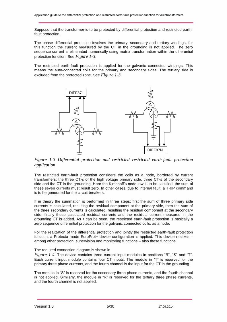
Suppose that the transformer is to be protected by differential protection and restricted earth-fault protection. The phase differential protection involves the primary, secondary and tertiary windings, for this function the current measured by the CT in the grounding is not applied. The zero sequence current is eliminated numerically using matrix transformation within the differential
protection function. See Figure 1-3.
The restricted earth-fault protection is applied for the galvanic connected windings. This means the auto-connected coils for the primary and secondary sides. The tertiary side is
excluded from the protected zone. See Figure 1-3.
Figure 1-3 Differential protection and restricted restricted earth-fault protection
application
The restricted earth-fault protection considers the coils as a node, bordered by current transformers: the three CT-s of the high voltage primary side, three CT-s of the secondary side and the CT in the grounding. Here the Kirchhoff’s node-law is to be satisfied: the sum of these seven currents must result zero. In other cases, due to internal fault, a TRIP command is to be generated for the circuit breakers. If in theory the summation is performed in three steps: first the sum of three primary side currents is calculated, resulting the residual component at the primary side, then the sum of the three secondary currents is calculated, resulting the residual component at the secondary side, finally these calculated residual currents and the residual current measured in the grounding CT is added. As it can be seen, the restricted earth-fault protection is basically a zero sequence differential protection for the galvanic connected coils, as a node. For the realization of the differential protection and jointly the restricted earth-fault protection function, a Protecta made EuroProt+ device configuration is applied. This device realizes – among other protection, supervision and monitoring functions – also these functions. The required connection diagram is shown in Figure 1-4. The device contains three current input modules in positions “R”, “S” and “T”.
Each current input module contains four CT inputs. The module in “T” is reserved for the primary three phase currents, and the fourth channel is the input for the CT in the grounding. The module in “S” is reserved for the secondary three phase currents, and the fourth channel is not applied. Similarly, the module in “R” is reserved for the tertiary three phase currents, and the fourth channel is not applied.
DIFF87
DIFF87N

Application guide to the differential protection and restricted earth-fault protection function for autotransformers
Version 1.0 6/30 17.09.2014
Figure 1-4 EuroProt+ connection diagram for differential protection and restricted
earth-fault protection application
NOTE: In this diagram, as default, all CT P1 points are towards the protected object. Due to the reverse connection of the CT in the grounding, applied in the example, this direction is reverted by parameter setting.
L1
S2 S1
S1 P1
P2 S2
P2 P1 Prim
L2
L3
L1
L2
L3
Sec P2 P1
S2
P2 P1
S2
Tert
S1
T7 T8
IL1Sec
IL2Sec
IL3Sec
IL1Tert
IL2Tert
IL3Tert
IL1Prim
IL2Prim
IL3Prim
S2
S3
S4
S5
S6
T1
T2
T3
T4
T5
T6
R1
R2
R3
R4
R5
R6
E5-TR_F
S1
S1
X
X
X

Application guide to the differential protection and restricted earth-fault protection function for autotransformers
Version 1.0 7/30 17.09.2014
In all three sides of the transformer, connect the CT in Y, with the neutral point at the transformer side, according to Figure 1-4. The vector group compensation, required in Primary/Tertiary and in
Secondary/Tertiary relationship is performed numerically within the differential protection function, together with magnitude compensation. Similarly the required zero sequence elimination is solved numerically. No interposing current transformers are required.
2 Setting the CT input function blocks In the EuroProt+ devices the CT inputs are assigned to CT function blocks. They need
parameter setting and also displaying functions are assigned to them. Figure 2-1 shows the
parameter screen, when there is Internet connection with the device. For details about this communication see the Protecta document “Remote user interface description” available in Protecta WEB site www.protecta.hu. NOTE: the parameters can be set also using the local LCD touch-screen of the device, if no internet connection is available. For details about this communication see the Protecta document “LCD touchscreen interface description” available in Protecta WEB site www.protecta.hu. The parameters of the current input function are explained in the following tables. Enumerated parameters
Parameter name Title Selection range Default
Rated secondary current of the first three input channels. 1A or 5A is selected by parameter setting, no hardware modification is needed.
CT4_Ch13Nom_EPar_ Rated Secondary I1-3 1A,5A 1A
Rated secondary current of the fourth input channel. 1A or 5A (0.2A, 1A) is selected by parameter setting, no hardware modification is needed.
CT4_Ch4Nom_EPar_ Rated Secondary I4 1A,5A (0.2A, 1A)
1A
Definition of the positive direction of the first three currents, given by location of the secondary star connection point
CT4_Ch13Dir_EPar_ Starpoint I1-3 Line,Bus Line
Definition of the positive direction of the fourth current, given as normal or inverted
CT4_Ch4Dir_EPar_ Direction I4 Normal,Inverted Normal
Table 2-1 The enumerated parameters of the current input function
Floating point parameters
Parameter name Title Dim. Min Max Default
Rated primary current of channel1-3
CT4_PriI13_FPar_ Rated Primary I1-3 A 100 4000 1000
Rated primary current of channel4
CT4_PriI4_FPar_ Rated Primary I4 A 100 4000 1000
Table 2-2 The floating point parameters of the current input function
NOTE: The rated primary current of the channels is not needed for the current input function block itself. These values are passed on to the subsequent function blocks.

Application guide to the differential protection and restricted earth-fault protection function for autotransformers
Version 1.0 8/30 17.09.2014
Figure 2-1 EuroProt+ parameter screen for the CT input modules

Application guide to the differential protection and restricted earth-fault protection function for autotransformers
Version 1.0 9/30 17.09.2014
Using the information given in this example above, the following setting values are assigned: Primary side and grounding CT:
Rated Secondary I1-3 1A Selected, according to the CT applied at the primary side.
Rated Secondary I4 1A Selected, according to the CT applied in the grounding.
Starpoint I1-3 Line “Line” in this case means “Toward protected object = Transformer”
Direction I4 Inverted In this application all P1 points of the CT-s are on the transformer side, except the CT in the grounding, which has P2 point at the transformer side. This is the reason why the positive direction is “Inverted” to fulfill the Kirchhoff’s node law.
Rated Primary I1-3 300 Setting, according to the CT applied at the primary side. This parameter is used for scaling the displayed values only
Rated Primary I4 300 Setting, according to the CT applied in the grounding. This parameter is used for scaling the displayed values only
Secondary side:
Rated Secondary I1-3 1A Selected, according to the CT applied at the secondary side.
Rated Secondary I4 Not applied, the value is not considered.
Starpoint I1-3 Line “Line” in this case means “Toward protected object = Transformer”
Direction I4 Not applied, the value is not considered.
Rated Primary I1-3 500 Setting, according to the CT applied at the secondary side. This parameter is used for scaling the displayed values only
Rated Primary I4 Not applied, the value is not considered.
Tertiary side:
Rated Secondary I1-3 1A Selected, according to the CT applied at the tertiary side.
Rated Secondary I4 Not applied, the value is not considered.
Starpoint I1-3 Line “Line” in this case means “Toward protected object = Transformer”
Direction I4 Not applied, the value is not considered.
Rated Primary I1-3 2000 Setting, according to the CT applied at the tertiary side. This parameter is used for scaling the displayed values only
Rated Primary I4 Not applied, the value is not considered.
Table 2-3 Summary of the CT parameter setting
Application guide to the differential protection and restricted earth-fault protection function for autotransformers
Version 1.0 10/30 17.09.2014
3 Setting the differential protection function The parameters of the differential protection function are explained in the following tables. Enumerated parameters for the differential protection function:
Parameter name Title Selection range Default
Parameter to enable the differential protection function:
DIF87_Op_EPar_ Operation Off, On On
Parameter to select connection group of the transformer coils in primary-secondary relation:
DIF87_VGrSec_EPar_ Pri-Sec VGroup*
Dy1,Dy5,Dy7,Dy11,Dd0,Dd6,Dz0,Dz2,Dz4,Dz6,Dz8,Dz10,Yy0,Yy6,Yd1,Yd5,Yd7,Yd11,Yz1,Yz5,Yz7,Yz11
Dd0
Parameter to select connection group of the transformer coils in primary-tertiary relation:
DIF87_VGrTer_EPar_ Pri-Ter VGroup*
Dy1,Dy5,Dy7,Dy11,Dd0,Dd6,Dz0,Dz2,Dz4,Dz6,Dz8,Dz10,Yy0,Yy6,Yd1,Yd5,Yd7,Yd11,Yz1,Yz5,Yz7,Yz11
Dd0
Table 3-1 The enumerated parameters of the differential protection function
* If the connection of the primary winding in primary-secondary and primary tertiary relation is selected in contradiction then the protection function is automatically disabled, and the function generates a warning signal. Boolean parameter for the differential protection function:
Parameter name Title Default Explanation
DIF87_0Seq_BPar_ Zero Seq Elimination True
Table 3-2 The Boolean parameter of the differential protection function
Integer parameters
Parameter name Title Unit Min Max Step Default
Parameters for the current magnitude compensation:
DIF87_TRPr_IPar_ TR Primary Comp % 20 500 1 100
DIF87_TRSec_IPar_ TR Secondary Comp % 20 500 1 100
DIF87_TRTer_IPar_ TR Tertiary Comp % 20 200 1 100
Parameter of the second harmonic restraint:
DIF87_2HRat_IPar_ 2nd Harm Ratio % 5 50 1 15
Parameter of the fifth harmonic restraint:
DIF87_5HRat_IPar_ 5th Harm Ratio % 5 50 1 25
Parameters of the percentage characteristic curve:
Base sensitivity:
DIF87_f1_IPar_ Base Sensitivity % 10 50 1 20
Slope of the second section of the characteristics:
DIF87_f2_IPar_ 1st Slope % 10 50 1 20
Bias limit of the first slope:
DIF87_f3_IPar_ 1st Slope Bias Limit % 200 2000 1 200
Unrestrained differential protection current level:
DIF87_HCurr_IPar_ UnRst Diff Current % 800 2500 1 800
Table 3-3 The integer parameters of the differential protection function

Application guide to the differential protection and restricted earth-fault protection function for autotransformers
Version 1.0 11/30 17.09.2014
Figure 3-1 EuroProt+ parameter screen for the differential protection function
These parameters need basic considerations some of them need also calculation. This is explained in the table below:

Application guide to the differential protection and restricted earth-fault protection function for autotransformers
Version 1.0 12/30 17.09.2014
Operation On Set this parameter to “On” for enabling the function.
NOTE: In tests, when other protection functions are tested. Switch this parameter to “Off” to prevent false test results
Pri-Sec VGroup Yy0 This setting is selected according to the protected object. For autotransformers select always Yy0. NOTE: see explanation in paragraph 3.1.
Pri-Ter VGroup Yd11 This setting is selected according to the protected object. (Example) NOTE: see explanation in paragraph 3.1
Zero Seq Elimination False Not checked. This parameter is needed only if there is isolated (Not grounded) side of the transformer and there is and additional neutral grounding transformer within the protected zone. As this additional neutral grounding transformer is not supposed to be present, the checkbox can remain unchecked. This is described in paragraph
TR Primary Comp 87 This value needs calculation. This is described in paragraph 3.2
TR Secondary Comp 87 This value needs calculation. This is described in paragraph 3.2
TR Tertiary Comp 262 This value needs calculation. This is described in paragraph 3.2
2nd Harm Ratio 15 This value needs some considerations. These are described in paragraph 3.3
5nd Harm Ratio 25 This value needs some considerations. These are described in paragraph 3.3
Base Sensitivity 50 Parameter for the differential characteristic. This value needs some considerations. These are described in paragraph 3.4
1st Slope 50 Parameter for the differential characteristic. This value needs some considerations. These are described in paragraph 3.4
1st Slope Bias Limit 400 Parameter for the differential characteristic. This value needs some considerations. These are described in paragraph 3.4
UnRst Diff Current 800 Parameter for the differential characteristic. This value needs some considerations. These are described in paragraph 3.4
Table 3-4 Summary of the differential protection parameter setting
3.1 Vector shift compensation The Protecta EuroProt+ configurations perform numerical vector shift compensation. The secondary wires of the current transformers are connected in Y, and the three phase currents secondary values are input directly into the current inputs of the device. No interposing CT-s are required. The principle of the vector shift compensation is the numerical realization of the old principle: on Y side of the transformer apply delta connected secondary, on delta side of the transformer apply Y connected secondary. The advantage of this method is that the zero sequence current elimination is “automatic”. The numerical solution is matrix multiplication: on Y side a phase shifting matrix is applied, e.g. for Yd11 transformation it is:

Application guide to the differential protection and restricted earth-fault protection function for autotransformers
Version 1.0 13/30 17.09.2014
tI
sI
rI
TshiftI
SshiftI
RshiftI
1
1
1
101
110
011
3
1
1
1
1
On delta side of the transformer phase shift is not applied, the realization is the unit matrix.
tI
sI
rI
TshiftI
SshiftI
RshiftI
2
2
2
100
010
001
2
2
2
This means that the reference vector is the “r = L1” phase current of the delta side. The Y side currents are transformed to this reference for comparison. The details are described in the document “Differental protection function block description”, available in Protecta WEB site www.protecta.hu. The related parameter setting is easy: consider the clock notation of the transformer. In the example above it is YNyn0d11. The software requires setting for the primary-secondary relationship: it is YNyn0, and the setting for the primary tertiary relationship: it is Ynd11. Then the vector shift compensation is performed automatically.
Application guide to the differential protection and restricted earth-fault protection function for autotransformers
Version 1.0 14/30 17.09.2014
3.2 Calculation of the amplitude compensation for the differential protection function
The basic principle is that in case of power transfer at rated current the currents to be compared should be the same, 100% . This means that in case of any external faults there will be no current difference, the differential function is balanced and stable. For a two winding transformer, usually the rated current of the transformer is considered to be the base current, considered to be 100%. The ratio of the secondary and primary rated currents is the turn’s ratio of the transformer. For the setting calculation, calculate the ratio of the transformer rated current and the CT rated primary current. These values expressed in % are the parameter values to be set for parameters „TR Primary Comp” and “TR Secondary Comp”. For a three winding transformer in the example the rated power of the winding is not the same (100MVA, 100 MVA and 30 MVA), consequently the ratio of rated currents for the windings do not match the turn’s ratio of the coils. In this case the usual procedure is to consider the rated current of the primary side, and transform this current both for the secondary and to the tertiary side. These calculated currents should be related to the rated currents of the CT-s. These values expressed in % are the parameter values to be set for parameters „TR Primary Comp”, “TR Secondary Comp” and .“TR Tertiary Comp” In the example: The rated primary current is 262 A, see the transformer data above. This is the reference current. This current is transformed to the secondary is 437 A. This current is transformed to the tertiary is 5249 A. (Here the rated current would be 1575 A, this value is not considered!) The calculation of the setting values is as follows
„TR Primary Comp”= 100* 262 A / 300 A= 87% „TR Secondary Comp”= 100* 437 A / 500 A= 87% „TR Tertiary Comp” = 100* 5249 A / 2000 A= 262%
Using this setting, the reference current on the secondary side is displayed by the differential protection function as 100%.

Application guide to the differential protection and restricted earth-fault protection function for autotransformers
Version 1.0 15/30 17.09.2014
3.3 Considerations, related to the harmonic restraint When a transformer is energized then due to the asymmetric saturation of the iron core a high “inrush current” can flow from one side into the transformer. This is a pure differential current. To prevent unwanted operation of the differential protection the special waveform of the inrush current is identified. The principle is the detection of the second harmonic content, which is present in the inrush current, but its value can be neglected in any fault current. For the differential current, the second harmonic component in the evaluation is related to the value of the base harmonic. This is the parameter „2nd Harm Ratio”. If this ration gets higher due to inrush current, the trip command is blocked. When a transformer is overexcited then the iron core is saturated symmetrically, resulting high current peaks, distorting both the positive and the negative sinusoidal current shape. In this current shape the fifth harmonic is characteristic. To prevent mal-operation, this component of the differential current is analyzed and compared to the base harmonic. If the ratio is high, then the differential current is caused by the over-excitation, the trip command is blocked. If however the fifth harmonic content is low, then the high differential current, which is a fault current, results trip command. The ratio is the parameter „5th Harm Ratio”. If no results of detailed harmonic analysis are available, apply the factory setting, which can be corrected later. The proposed setting values are:
„2nd Harm Ratio”.= 15 % and
„„5th Harm Ratio”= 25 %
3.4 Considerations, related to the differential characteristic for the differential protection function
The differential characteristic is shown in Figure 3-2. If the calculated (Ibias,Idiff) operating
point is above the characteristic, then the differential protection operates.
Figure 3-2 The differential characteristic This characteristic has four sections; each of them is a straight line. The parameters define the position of these lines on the Idiff-Ibias plane. The first parameter is “Base Sensitivity”, it defines the minimum differential current for the operation. Its role is to prevent mal-operation in case of current noises and measuring errors for small currents. In this example the selected setting value is the less sensitive selection:
Ibias
Idiff
1. 2.
3.
4.
Application guide to the differential protection and restricted earth-fault protection function for autotransformers
Version 1.0 16/30 17.09.2014
„Base Sensitivity” = 50 %,
This value can be tested easily: inject three phase symmetrical currents from one side only and increase its value. The operation is expected if this current gets above 50% of the reference current. (In this example it is 0.5*0.87A. NOTE: for asymmetrical fault current this value changes due to the matrix transformation.) The second section of the characteristic is a line trough the origin of the Idiff-Ibias plane. The slope of this line serves to compensate the not correct matching of the CT-s, e.g. due to the different tap-changer positions and the CT errors. Due to these causes the error current increases if the current flowing through the transformer increases. The parameter is “1st Slope”. The mathematical expression of the second section of the characteristic is: The steps for getting the parameter value are as follows: - Calculate the error in percent, due to not correct matching (To be calculated for all three voltage levels): - The unbalance of the differential protection at top or bottom position of the tap changer in percent, related to the value of 0 position (rmax%): Select the biggest value of the calculated x% values above. The setting value is advised to be above this value.
Example: suppose the voltage control range to be +18%/12 %, and the reference position for current balancing is the 0 position, then the parameter value with 1,5x safety is:
„1st Slope” = 1,5*18 = 27 30 % Another choice for calculation is the selection the mid-position of the tap-changer. This is in this example as follows: The full position range is 18 + 12 = 30 %, The half value is 15 %, accordingly the mid-position is +3 %. With his the voltage ratio of the transformer to be considered is to be increased by 118 /115, and the balancing of the current is to be
determined for this voltage. In this case only 15 % tap position range can be considered, and the value of this parameter is decreased to:
„1st Slope” = 1,5*15 = 22,5 25 % The slope of the third section of the characteristic is higher. This is to compensate the increased CT error, due to the CT saturation at higher currents. This higher sloe is a factory setting: 200%. The parameter “1st Slope Bias Limit” defines the intersection point of section 2 and 3. This parameter value is influenced by the highest fault current in the protected object and the applied current transformer saturation point related to the rated value. If the current transformer is less over-dimensioned then select the parameter vale for “1st Slope Bias Limit” low. The usual consideration is: for relatively high currents select 200 %, for low fault currents select 1000 %. The fourth section of the characteristic is the unrestrained section. The related parameter is “UnRst Diff Current”. This parameter serves unrestrained fast operation if the high magnitude of the fault current indicates internal fault. The calculation determines the maximal external fault current, and the setting value should be above this current.
IIbiasstSlope
Idiff 100
1
1001
_11%
matchingI
matchingrequiredIx
%r%x max

Application guide to the differential protection and restricted earth-fault protection function for autotransformers
Version 1.0 17/30 17.09.2014
3.5 Considerations for zero sequence elimination In solidly grounded high voltage networks, in case of external earth faults, the Y-delta transformers revert zero sequence current, which is present on the Y side only. No zero sequence current can flow on the delta side. When comparing the currents in the differential protection, this could cause unwanted operation. The differential protection function in the Protecta EuroProt+ devices eliminates the Y side zero sequence current by matrix transformation (simulating the old type delta connected CT secondary behavior). This elimination is automatic, no additional solution is needed. In several cases, however, there is additional neutral grounding transformer on the delta side fo the transformer within the protected zone. Between the neutral point of this additional transformer an arc suppression Petersen coil, or a grounding resistor is connected. The Petersen coil minimizes the earth-fault current to some Ampers, the resistor limits the earth-fault current to 100 A (in some cases to 200 A). If the neutral grounding transformer is not in the protected zone, it is ouside the current transformers, then set:
„ZeroSeq Elimination” = „False” (Not checked) In some cases, however, the neutral grounding transformer is closely connected to the main transformer’s delta side terminals, it is in the protected zone. The advantage of this arrangement is that the energizing the transformer immediately solves the neutral grounding problems. In case of external earth-fault the zero sequence current of the neutral grounding transformer is detected by the delta side current transformers. The zero sequence elimination is needed. In this case set
„ZeroSeq Elimination” = „True” (Checked)

Application guide to the differential protection and restricted earth-fault protection function for autotransformers
Version 1.0 18/30 17.09.2014
4 Setting the restricted earth-fault protection function The restricted earth-fault protection function is basically a zero sequence (residual) differential protection (DIF87N), applied for the galvanic interconnected coils. The parameters of the restricted earth-fault protection function are explained in the following tables. Enumerated parameter for the restricted earth-fault protection function:
Parameter name Title Selection range Default
Parameter to enable the differential protection function:
DIF87N_Op_EPar_ Operation Off, On On
Table 4-1 The enumerated parameter of the restricted earth-fault protection function
Boolean parameter for the differential protection function:
Parameter name Title Default Explanation
DIF87N_DirCheck_BPar_ Directional check True
Table 4-2 The Boolean parameter of the restricted earth-fault protection function
Integer parameters
Parameter name Title Unit Min Max Step Default
Parameters for the current magnitude compensation:
DIF87N_TRPri_IPar_ TR Primary Comp % 4 500 1 100
DIF87N_TRSec_IPar_ TR Secondary Comp % 4 500 1 100
DIF87N_TRNeut_IPar_ TR Neutral Comp % 4 1000 1 500
Parameters of the percentage characteristic curve:
Base sensitivity:
DIF87N_f1_IPar_ Base Sensitivity % 10 50 1 20
Slope of the second section of the characteristics:
DIF87N_f2_IPar_ Slope % 50 100 1 70
Bias limit of the first slope:
DIF87N_f2Brk_IPar_ Base Sensitivity Bias Limit
% 100 200 1 125
Table 4-3 The integer parameters of the restricted earth-fault protection function

Application guide to the differential protection and restricted earth-fault protection function for autotransformers
Version 1.0 19/30 17.09.2014
Figure 4-1 EuroProt+ parameter screen for the restricted earth-fault protection
function
These parameters need basic considerations some of them need also calculation. This is explained in the table below:
Operation On Set this parameter to “On” for enabling the function.
NOTE: In tests, when other protection functions are tested, switch this parameter to “Off” to prevent false test results
Directional check False Not checked. This parameter is needed to increase the security of the function in case of low level external faults. This is described in paragraph 4.3
TR Primary Comp 15 This value needs calculation. This is described in paragraph 4.1
TR Secondary Comp 9 This value needs calculation. This is described in paragraph 4.1
TR Neutral Comp 15 This value needs calculation. This is described in paragraph
Base Sensitivity 50 Parameter for the differential characteristic. This value needs some considerations. These are described in paragraph 4.2
1st Slope 50 Parameter for the differential characteristic. This value needs some considerations. These are described in paragraph 4.2
1st Slope Bias Limit 125 Parameter for the differential characteristic. This value needs some considerations. These are described in paragraph 4.2
Table 4-4 Summary of the CT parameter setting

Application guide to the differential protection and restricted earth-fault protection function for autotransformers
Version 1.0 20/30 17.09.2014
4.1 Calculation of the amplitude compensation for the restricted earth-fault protection function
The basic principle is that in case of any external faults there will be no current difference, the zero sequence differential function is balanced and stable. The setting of the restricted earth-fault protection function is independent of the setting of the differential protection function. Here the same current is freely selected as the base current for the whole, galvanic connected coil system. The choice of the current is free. For more sensitive protection select a relatively low value. In the example the following value is selected:
IBase = 44 A This is a primary value, which is transformed by the current transformers to the secondary side. For the setting, it is related to the rated primary currents of the current transformers:
„TR Primary Comp”= 100* 44 A / 300 A= 15% „TR Secondary Comp”= 100* 44 A / 500 A= 9% „TR Neutral Comp” = 100* 44 A / 300 A= 15%
In the restricted earth-fault protection these values are used for amplitude matching the secondary currents
4.2 Considerations, related to the differential characteristic for the restricted earth-fault protection function
The differential characteristic is shown in Figure 4-2. If the calculated (Ibias,Idiff) operating
point is above the characteristic, then the differential protection operates.
Figure 4-2 The differential characteristic for the restricted earth-fault protection
function This characteristic has two sections; each of them is a straight line. The parameters define the position of these lines on the Idiff-Ibias plane.
Ibias
Idiff
1. 2.

Application guide to the differential protection and restricted earth-fault protection function for autotransformers
Version 1.0 21/30 17.09.2014
The parameters are expressed in percent, the basis is the “IBase” selected current. The first parameter is “Base Sensitivity”, it defines the minimum differential current for the operation. Its role is to prevent mal-operation in case of current noises and measuring errors for small currents. In this example the selected setting value is the less sensitive selection:
„Base Sensitivity” = 50 %,
NOTE: The percent value is related to the “IBase” selected current. In the example the restricted earth-fault protection summarizes the secondary currents of seven current transformers. It is advised to avoid too sensitive setting, due to the accumulated errors os several CT-s. Similarly select not too low current for “IBase” base current for the reference and for the calculation. This value can be tested easily: inject a single residual current e.g. into the grounding CT input and increase its value. The operation is expected if this current gets above 50% of the reference current. (In this example it is 0.5*44A/300A*1A= 73.3 mA. The slope of the second section of the characteristic intends to compensate the not correct matching of the CT-s, e.g. due to the CT errors. Consider that the error current increases if the zero sequence current flowing through the transformer increases. In the example the selected setting value is:
„1st Slope” = 50 %,
NOTE: The percent value is related to the IBias current. The third parameter defines the intersection point of the two characteristic lines. Do not select this point too high, because near to the intersection point it leaves too much area, where error currents can intersect the characteristic. In the example the selected setting value is:
„1st Slope Bias Limit” = 125 %.
NOTE: The percent value is related to the “IBase” selected current.
4.3 Considerations, related to the directional check
Figure 4-3 Principle of the directional check In the directional check the vector position of the residual current measured in the grounding (INFour) and that of the vectorial sum of all other currents (3IoFour) is compared.
Figure 4-3 shows a vector position which blocks the operation of the restricted earth fault
protection, if the Boolean parameter “Directional check” is True (Checked). If the checkbox is not checked then the directionality is not considered. This parameter is needed to increase the security of the function in case of low level external faults
3IoFour
BLOCK
INFour
Application guide to the differential protection and restricted earth-fault protection function for autotransformers
Version 1.0 22/30 17.09.2014
5 Testing instructions
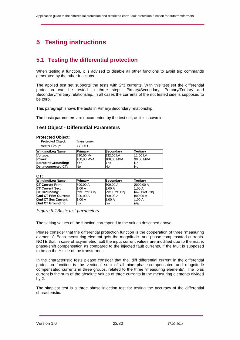
5.1 Testing the differential protection When testing a function, it is advised to disable all other functions to avoid trip commands generated by the other functions. The applied test set supports the tests with 2*3 currents. With this test set the differential protection can be tested in three steps: Pimary/Secondary, Primary/Tertiary and Secondary/Tertiary relationship. In all cases the currents of the not tested side is supposed to be zero. This paragraph shows the tests in Pimary/Secondary relationship. The basic parameters are documented by the test set, as it is shown in
Test Object - Differential Parameters Protected Object: Protected Object: Transformer
Vector Group: YY0D11
Winding/Leg Name: Primary Secondary Tertiary Voltage: 220,00 kV 132,00 kV 11,00 kV Power: 100,00 MVA 100,00 MVA 30,00 MVA Starpoint Grounding: Yes Yes No Delta-connected CT: No No No
CT: Winding/Leg Name: Primary Secondary Tertiary CT Current Prim: 300,00 A 500,00 A 2000,00 A CT Current Sec: 1,00 A 1,00 A 1,00 A CT Grounding: tow. Prot. Obj. tow. Prot. Obj. tow. Prot. Obj. Gnd CT Prim Current: 200,00 A 800,00 A 800,00 A Gnd CT Sec Current: 1,00 A 1,00 A 1,00 A Gnd CT Grounding: n/a n/a n/a
Figure 5-1Basic test parameters
The setting values of the function correspond to the values described above. Please consider that the differential protection function is the cooperation of three “measuring elements”. Each measuring element gets the magnitude- and phase-compensated currents. NOTE that in case of asymmetric fault the input current values are modified due to the matrix phase-shift compensation as compared to the injected fault currents, if the fault is supposed to be on the Y side of the transformer. In the characteristic tests please consider that the Idiff differential current in the differential protection function is the vectorial sum of all nine phase-compensated and magnitude compensated currents in three groups, related to the three “measuring elements”. The Ibias current is the sum of the absolute values of three currents in the measuring elements divided by 2. The simplest test is a three phase injection test for testing the accuracy of the differential characteristic.

Application guide to the differential protection and restricted earth-fault protection function for autotransformers
Version 1.0 23/30 17.09.2014
Test Results for Fault Location L1-L2-L3 at Reference Side Primary Ibias Idiff
Nominal Idiff Actual Dev (rel) Dev (abs) Check Test State Result
0,50 In 0,500 In 0,497 In -0,62 % -0,0031 In Tested Passed 1,00 In 0,500 In 0,505 In 1,00 % 0,0050 In Tested Passed 1,50 In 0,750 In 0,747 In -0,38 % -0,0028 In Tested Passed 2,00 In 1,000 In 0,997 In -0,34 % -0,0034 In Tested Passed 2,50 In 1,250 In 1,246 In -0,32 % -0,0040 In Tested Passed 3,00 In 1,500 In 1,495 In -0,31 % -0,0046 In Tested Passed 4,00 In 2,000 In 1,991 In -0,43 % -0,0087 In Tested Passed 5,00 In 4,000 In 3,948 In -1,31 % -0,0523 In Tested Passed 6,00 In 6,000 In 5,954 In -0,77 % -0,0463 In Tested Passed 7,00 In 8,000 In 7,966 In -0,43 % -0,0342 In Tested Passed 8,00 In 8,000 In 7,972 In -0,35 % -0,0281 In Tested Passed 9,00 In 8,000 In 7,972 In -0,35 % -0,0281 In Tested Passed 10,00 In 8,000 In 7,966 In -0,43 % -0,0344 In Tested Passed
Operating Characteristic Diagram
Ibias [In]
1 2 3 4 5 6 7 8 9 10
Idiff [In]
0
1
2
3
4
5
6
7
8
9
Figure 5-2 Result of three phase fault test, the fault is at the secondary side, supplied
from the primary side
NOTE that the measured points match the original characteristic.

Application guide to the differential protection and restricted earth-fault protection function for autotransformers
Version 1.0 24/30 17.09.2014
For asymmetric fault tests the expected characteristic is modified to cover the current modification of the vector shift compensation.
Test Results for Fault Location L2-L3 at Reference Side Primary Ibias Idiff
Nominal Idiff Actual Dev (rel) Dev (abs) Check Test State Result
0,50 In 0,433 In 0,430 In -0,72 % -0,0031 In Tested Passed 1,00 In 0,495 In 0,498 In 0,54 % 0,0027 In Tested Passed 1,50 In 0,745 In 0,742 In -0,40 % -0,0030 In Tested Passed 2,00 In 0,995 In 0,991 In -0,37 % -0,0036 In Tested Passed 2,50 In 1,245 In 1,241 In -0,34 % -0,0043 In Tested Passed 3,00 In 1,495 In 1,490 In -0,33 % -0,0049 In Tested Passed 4,00 In 1,995 In 1,992 In -0,16 % -0,0031 In Tested Passed 5,00 In 2,495 In 2,491 In -0,15 % -0,0037 In Tested Passed 6,00 In 2,995 In 2,991 In -0,15 % -0,0044 In Tested Passed 7,00 In 3,600 In 3,586 In -0,41 % -0,0146 In Tested Passed 8,00 In 5,606 In 5,626 In 0,35 % 0,0197 In Tested Passed 9,00 In 6,930 In 6,903 In -0,39 % -0,0274 In Tested Passed 10,00 In 6,930 In 6,900 In -0,43 % -0,0298 In Tested Passed
Operating Characteristic Diagram
Ibias [In]
1 2 3 4 5 6 7 8 9 10
Idiff [In]
0
1
2
3
4
5
6
7
8
Figure 5-3 Result of double phase fault test, the fault is at the secondary side,
supplied from the primary side
NOTE The matrix vector shift compensation decreases the compared current by SQRT3. Consequently the detected knee points of the characteristic are shifted to increased current values. (The setting values of the differential protection function are the same as those applied in three-phase fault test.) Similarly, in case of single phase faults, the expected characteristic is modified. (The setting values of the differential protection function are the same as those applied in three-phase fault test.) This is shown in Figure 5-4.

Application guide to the differential protection and restricted earth-fault protection function for autotransformers
Version 1.0 25/30 17.09.2014
Operating Characteristic Diagram
Ibias [In]
1 2 3 4 5 6 7 8 9 10
Idiff [In]
0
1
2
3
4
5
6
7
8
9
10
Figure 5-4 Result of single phase fault test, the fault is at the secondary side, supplied
from the primary side

Application guide to the differential protection and restricted earth-fault protection function for autotransformers
Version 1.0 26/30 17.09.2014
5.2 Testing the restricted earth-fault protection When testing a function, it is advised to disable all other functions to avoid trip commands generated by the other functions. The applied test set supports the tests with 2*3 currents. With this test set the restricted earth-fault protection can be tested in two steps: Pimary/Neutral, and Secondary/Neutral relationship. In all cases the currents of the not tested sides (Secondary or Primary respectively) is supposed to be zero. Note that the Tertiary side is not involved in the restricted earth-fault protection. In the characteristic tests please consider that the Idiff differential current in the restricted earth-fault protection function is the vectorial sum of six phase currents plus the neutral current. The Ibias current is the maximum of these seven currents.
5.2.1 Characteristic accuracy tests
This paragraph shows the tests in Pimary/Neutral relationship. Three-phase current are injected in the Primary side and the sum of the other three current set is injected in the Neutral.
Test Results for Fault Location L1-E at Reference Side Primary Ibias Idiff
Nominal Idiff Actual Dev (rel) Dev (abs) Check Test State Result
0,50 In 0,500 In 0,503 In 0,63 % 0,0031 In Tested Passed 1,00 In 0,500 In 0,447 In -10,62 % -0,0531 In Tested Passed 1,50 In 0,625 In 0,612 In -2,17 % -0,0136 In Tested Passed 2,00 In 0,875 In 0,838 In -4,29 % -0,0375 In Tested Passed 4,00 In 1,876 In 1,880 In 0,20 % 0,0037 In Tested Passed 6,00 In 2,877 In 2,791 In -2,97 % -0,0855 In Tested Passed 8,00 In 3,877 In 3,798 In -2,05 % -0,0796 In Tested Passed 10,00 In 4,878 In 4,838 In -0,82 % -0,0401 In Tested Passed 12,00 In 5,878 In 5,848 In -0,52 % -0,0304 In Tested Passed 14,00 In 6,879 In 6,811 In -0,99 % -0,0681 In Tested Passed 16,00 In 7,880 In 7,802 In -0,98 % -0,0775 In Tested Passed 18,00 In 8,880 In 8,748 In -1,49 % -0,1320 In Tested Passed 20,00 In 9,881 In 9,885 In 0,04 % 0,0043 In Tested Passed

Application guide to the differential protection and restricted earth-fault protection function for autotransformers
Version 1.0 27/30 17.09.2014
Operating Characteristic Diagram
Ibias [In]
2,5 5,0 7,5 10,0 12,5 15,0 17,5 20,0 22,5 25,0
Idiff [In]
0
2
4
6
8
10
12
14
16
Figure 5-5 Result of characteristic accuracy test of the restricted earth-fault
protection
5.2.2 Single shot fault simulation
In this test an external earth-fault is supposed at the secondary side with 1500A primary current. The primary current distribution is shown in Figure 5-6.
Figure 5-6 Primary current distribution
~
~
~
500A
3*500A 3*500A
2*500A
500A
500A
500A
500A

Application guide to the differential protection and restricted earth-fault protection function for autotransformers
Version 1.0 28/30 17.09.2014
The currents are transformed to the device side by the current transformers: Iprimary L1= 2*500A*1/300= 3.33A Iprimary L2= Iprimary L3 = 500 A*1/300=1.66A Isecondary L1= 3*500A*1/500=3 A Ineytral = 3*500A*1/300=3.33 A These currents are drawn in Figure 5-7. Note that the Kirchhoff’s node law is satisfied with primary currents only. The secondary currents are transformed with CT with different ratios. (This deviation is compensated by the current matching parameters of the restricted earth-fault protection function.)
Figure 5-7 Secondary current distribution
NOTE. The current in the neutral point is measured with a CT of reverse polarity. This is not indicated in the figure. Figure 5-8 below shows the measured (secondary) currents of the CT modules. The first module shows the three currents of the primary side and the current in the grounding CT. The second nodule measures the single fault current of the secondary side. (The currents of the tertiary side are all zero.)
~
~
~
1.66A
3A IN=5A
3.33A
1.66A

Application guide to the differential protection and restricted earth-fault protection function for autotransformers
Version 1.0 29/30 17.09.2014
Figure 5-8 Measured currents of the CT modules
Figure 5-9 shows the displayed values by the restricted earth-fault protection function. The differential current value is small (not zero due to the not accurate current injection). The high bias (restraint) current prevents operation, i.e. the “General Trip” box is not checked in the figure. The behavior is correct.
Figure 5-9 On-line display of the restricted earth-fault function with correct CT
connection
If for example the grounding CT is reversed connected, then the function generates the trip command, due to the false high differential current (i.e. the “General Trip” box is checked in the figure). The behavior is correct.

Application guide to the differential protection and restricted earth-fault protection function for autotransformers
Version 1.0 30/30 17.09.2014
Figure 5-10 On-line display of the restricted earth-fault function with reverse CT
connection in the grounding
5.2.3 Checking the directional blocking
Figure 5-11 Checking the directional blocking
For checking the directional blocking, consider Figure 5-11. For external fault the restricted earth-fault is balanced, the function does not generate the trip command. In this state the “3IoFour” vector, which is the sum of the currents of all phase current transformers has the same magnitude as “INFour” (solid vector on the figure), but the direction is opposite. Now suppose that due to any measuring errors this balance is not fulfilled for external fault, and suppose that ““INFour” is different in magnitude and/or phase angle. This is illustrated with dotted vectors. It is obvious that the difference of the solid “INFour” vector and the dotted version is the “Idiff” differential current, detected by the restricted earth-fault protection function. If this “Idiff” error current is large enough, the function generates the trip command. For the test consider a balanced state, as shown in Figure 5-7. Here the “INFour” current corresponds to IN=5A. Increase /decrease the magnitude and/or phase angle of this vector to generate sufficient “Idiff” current for the operation of the restricted earth-fault protection function, if the Boolean parameter “Directional check” is FALSE (not checked). NOTE: Remember that the “Ibias” is the maximum of any applied phase currents or the IN neutral current. Considering this, for the trip command, the (IBias,Idiff) point must be above the characteristic. Now change the parameter “Directional check” to TRUE (checked). In this state no trip command is generated if the phase angle between “3IoFour” and “INFour” is out of the range
-90° to +90°, this is the left side of Figure 5-11. (An internal fault supposes that the phase angle between these vectors is in the range -90° to +90°, this is the right side of Figure 5-11.)
3IoFour
BLOCK
INFour