MDU Breaker Programming Manual CC-Link
59
1 KGA120334-C MELSEC-Q Series Sequencer CC-Link Communication Version Applicable models *The “800A Frame” circuit breaker includes specifications of 630A rating and 800A rating. ● The marks used mean the following. In the event of incorrect handling, a dangerous situation may arise, a possibility of being subject to moderate injury or minor injury, or only physical damage may occur. Always follow instructions. Please read the instruction manual for MDU breaker and sequencer for proper use safely before use. ・MDU Breaker Operation Manual ・CC-Link System Master / Local Module User's Manual type QJ61BT11 ・CC-Link System Master / Local Module User's Manual type QJ61BT11N *The version of CC-Link is "CC-Link Ver. 1.10". 250A Frame NF250-SEV with MDU、NF250-HEV with MDU 400A Frame NF400-SEW with MDU、NF400-HEW with MDU 800A Frame* NF800-SEW with MDU、NF800-HEW with MDU Caution MDU Breaker Programming Manual
-
Upload
khangminh22 -
Category
Documents
-
view
0 -
download
0
Transcript of MDU Breaker Programming Manual CC-Link

1 KGA120334-C
MELSEC-Q Series Sequencer CC-Link Communication Version
Applicable models
*The “800A Frame” circuit breaker includes specifications of 630A rating and 800A rating.
● The marks used mean the following.
In the event of incorrect handling, a dangerous situation may arise, a possibility of
being subject to moderate injury or minor injury, or only physical damage may occur.
Always follow instructions.
Please read the instruction manual for MDU breaker and sequencer for proper use safely before use.
・MDU Breaker Operation Manual
・CC-Link System Master / Local Module User's Manual type QJ61BT11
・CC-Link System Master / Local Module User's Manual type QJ61BT11N
*The version of CC-Link is "CC-Link Ver. 1.10".
250A Frame NF250-SEV with MDU、NF250-HEV with MDU
400A Frame NF400-SEW with MDU、NF400-HEW with MDU
800A Frame* NF800-SEW with MDU、NF800-HEW with MDU
Caution
MDU Breaker
Programming Manual

2 KGA120334-C
Introduction
Thank you very much for purchasing our MDU breaker.
Please read this manual before use and fully understand the functions and performance of the MDU breaker
( hereinafter referred to as "MDU") for safe and proper operation.
Table of Contents
1. General Description .............................................................................................................................. 3
2. Overall configuration of the CC-Link system ........................................................................................ 4
3. CC-Link communication specifications of the MDU .............................................................................. 5
4. Establishment of communication between the sequencer CPU and the MDU .................................... 6 4.1 Overview of communication ............................................................................................................. 6 4.2 Parameter setting ............................................................................................................................ 7
4.2.1 Parameter storage area .............................................................................................................. 7 4.2.2 Parameter setting and start of the data link ................................................................................ 7 4.2.3 Setting items of the network parameter ...................................................................................... 8
4.3 Parameter setting by GX Developer ................................................................................................ 9 4.3.1 Setting of the master station network parameter ........................................................................ 9 4.3.2 Master station automatic refresh parameter setting ................................................................. 13
4.4 Data link status check .................................................................................................................... 15 4.4.1 Master station I/O signal check ................................................................................................ 15 4.4.2 Master station link special register check ................................................................................. 16
5. Communication between the sequencer CPU and the MDU ............................................................. 17 5.1 Overview of communication ........................................................................................................... 17 5.2 Remote input and output and remote register of the MDU ............................................................ 18
5.2.1 Remote input (RX) .................................................................................................................... 18 5.2.2 Remote output (RY) .................................................................................................................. 19 5.2.3 Remote register (RWw), remote register (RWr) ....................................................................... 20 5.2.4 Relation with the sequencer CPU devices ............................................................................... 20
5.3 Initial communication ..................................................................................................................... 26 5.4 Normal communication .................................................................................................................. 26 5.5 Error communication ...................................................................................................................... 27
6. Commands supported by the MDU .................................................................................................... 28 6.1 List of commands ........................................................................................................................... 28 6.2 Details of commands ..................................................................................................................... 29
7. Error occurrence ................................................................................................................................. 48
8. Sample program ................................................................................................................................. 49 8.1 Contents of the sample program ................................................................................................... 49 8.2 Device configuration ...................................................................................................................... 49 8.3 Device allocations .......................................................................................................................... 50 8.4 Parameter setting .......................................................................................................................... 51
8.4.1 Network parameter and automatic refresh parameter setting .................................................. 51 8.4.2 Operation setting ...................................................................................................................... 52 8.4.3 Station information setting ........................................................................................................ 52
8.5 Sample program (Circuit form) ...................................................................................................... 53
9. Abbreviations and terms used in this manual ..................................................................................... 58

3 KGA120334-C
1. General Description
The MDU breaker ( hereinafter referred to as "MDU" ) supports also the communication via the Control & Communication
Link ( hereinafter referred to as "CC-Link" ).
In order to monitor the measurement values and breaker information in the MDU or to configure each setting of the MDU
from MELSEC-Q series sequencer ( hereinafter referred to as "Q sequencer" ) with QJ61BT11N type CC-Link system
master local unit or QJ61BT11 type CC-Link system master local unit, users need to create a sequence program
appropriate for the intended purpose.
This manual explains the communication procedures, commands, and response to commands that are necessary when a
user creates a sequence program appropriate for the intended purpose.
This manual is described based on the assumption that SWnD5C-GPPW ( n = 4 or more ) and GX Developer are used.
Before starting actual programming, please read the following reference manuals in addition to this manual.
Table 1.1 Reference manuals
Manual name Manual No.
CC-Link System Master/Local Module User's Manual
type QJ61BT11
SH-080016
(13JL91)
CC-Link System Master/Local Module User's Manual
type QJ61BT11N
SH-080394E
(13JR64)
Instruction Manualf for MDU Breaker Included in the same package with the product

4 KGA120334-C
2. Overall configuration of the CC-Link system
The CC-Link system is currently offered in Ver. 2 and available in four modes depending on various systems. Table 2.1
shows the outline of each mode. In consideration of concurrent existence of the CC-Link system master local units of
QJ61BT11N type and QJ61BT11 type, this programming manual is described based on the assumption of the use of the
CC-Link system master local unit in the "Remote net Ver. 1 mode". The devices of the CC-Link system in the "Remote net
Ver. 1 mode" include the remote I/O station, remote device station, local station, and intelligent device station. Up to total
of 64 remote I/O stations, remote device stations, and local stations can be connected to one master station.
The MDU is a remote device station and a slave station supporting Ver. 1. (It can be connected also to the master local
unit supporting Ver. 2 and used in the remote net Ver. 1 mode, remote net Ver. 2 mode, or remote net add mode).
As the condition for connection in the "Remote net Ver. 1 mode", it is necessary to satisfy the followings.
(1) {(1 x a) + (2 x b) + (3 x c) + (4 x d)} 64 a: Number of units occupying one station (The MDU falls into this category.) b: Number of units occupying two stations c: Number of units occupying three stations d: Number of units occupying four stations
(2) {(16 x A) + (54 x B) + (8C)} 2304
A: Number of remote I/O stations 64 stations
B: Number of remote device stations (The MDU falls into this category.) 42 stations
C: Local station, intelligent device station 26 stations
The diagram below shows the overall system configuration in the "Remote net Ver. 1 mode".
Analog-digital conversion unit AJ65BT-64AD
Remote I/O unit AJ65BTB1-16D AJ65BTC1-32D
RS-232C interface unit AJ65BT-R2
Master station
QJ61BT11N QJ61BT11
Terminating resistor (Required)
A1SJ61QBT11 AJ61QBT11
Local station
QJ61BT11N QJ61BT11
Local station
A1SJ61BT11 AJ61BT11
Local station
Max. 26 units
Intelligent device station
Max. 26 units
Terminating resistor
(Required)
Remote device station
Max. 42 units
Remote I/O station
Max. 64 units
CC-Link dedicated cable
CC-Link dedicated cable
Total number: 64
Fig. 2.1 Overall system configuration

5 KGA120334-C
Table 2.1 List of modes of CC-Link system
Mode Connectable station Overview
Remote net Ver. 1 mode Remote I/O station
Remote device station Intelligent device station
Local station Standby master station
Mode fully compatible with the existing unit (QJ61BT11). This mode is selected when there is no need to increase the number of cyclic units or when the existing unit is replaced with QJ61BT11N as a spare unit.
Remote net Ver. 2 mode This mode is selected when a new system is developed by increasing the number of cyclic units.
Remote net add mode This mode is selected when a slave station supporting Ver. 2 is added to the existing system and the number of cyclic units is increased.
Remote I/O net mode Remote I/O station
This mode is selected in the case of the system configuration comprised only of the master station and remote I/O station. The link scan time can be reduced since cyclic transmission is performed at a high speed.
3. CC-Link communication specifications of the MDU
Table 3.1 shows the CC-Link communication specifications of the MDU.
Table 3.1 CC-Link communication specifications of the MDU
Item Description
Unit type Remote device station
Number of occupied stations One station
Number of connectable units Max. 42 units (When only the remote device station occupying one station is
connected)
Transmission speed Select from 156 kbps, 625 kbps, 2.5 Mbps, 5 Mbps, and 10 Mbps.
Number of remote inputs/outputs 32 points each
Number of remote registers 4 points each
Up to 42 MDUs are connectable. (When only the MDU series is connected)
MDU
MDU
MDU
MDU
MDU
MDU
MDU series system configuration example (CC-Link)
MDU
CC
-Lin
k m
aste
r sta
tio
n

6 KGA120334-C
4. Establishment of communication between the sequencer CPU and the MDU
4.1 Overview of communication
When using the attached CC-Link system master local unit, set it as the master station. ( For the details of the setting, see the manual of the CC-Link system master local unit. ) The sequencer CPU and the MDU communicate with each other via the master station. The overview of establishment of the communication is shown below.
Sequencer CPU
MDU (Up to 42)
Network parameter
Network parameter
Master station
Buffer memory
Remote input (RX)
Remote register (RWw)
[2]
Remote input (RX)
Remote register (RWw)
Remote register (RWr)
Bit device
(e.g.: X)
Word device
(e.g.: W)
Word device
(e.g.: W)
Remote output (RY)
MDU: 1st
Remote input (RX)
Remote register (RWw)
Remote register (RWr)
MDU: 42nd
~
~
~
~
MDU: 1st
~
MDU: 42nd
Remote output (RY)
... [3]
[1]
[2]
MDU: 1st
MDU: 42nd
...
...
...
[2]
Remote output (RY)
[2]
Bit device
(e.g.: Y) [3]
MDU: 1st
MDU: 42nd
...
... [3]
[2]
[2]
Remote register (RWr)
MDU: 1st
MDU: 42nd
...
...
[2]
[2]
[3]
Automatic refresh
parameter
[1]Start of data link : The sequencer CPU transmits a network parameter in the sequencer CPU to the master station
and sets the parameter when the power supply is turned on or reset. The master station
automatically starts data link with each connected MDU according to the parameter setting and
starts up the CC-Link system automatically.
[2]Link scan : The master station automatically and regularly reads the remote input (RX) and remote register
(RWr) of each data-linked MDU in succession, stores them in the buffer memory, and write the
remote output (RY) and remote register (RWw) stored in the buffer memory to each MDU.
[3]Matic refresh : The sequencer CPU automatically and regularly writes and updates the data of each device of
the sequencer CPU in the remote output (RY) and remote register (RWw) in the buffer memory
of the master station, reads data from the remote input (RX) and remote register (RWr) in the
buffer memory of the master station, stores the data in each device in the sequencer CPU, and
updates (= refreshes) the data of the MDU.

7 KGA120334-C
4.2 Parameter setting
This section explains the parameter setting necessary for the establishment of communication between the sequencer
CPU and the MDU.
4.2.1 Parameter storage area This section explains the relation between the parameter area of the sequencer CPU and the parameter memory of the
master station.
(1) Parameter area of the sequencer CPU
This is an area where the basic values to control the sequencer system is set. The network parameter to control the
CC-Link system and the automatic refresh parameter are also set in this area.
(2) Parameter memory of the master station
This is an area where the network parameter of the CC-Link system is stored.
When the power supply of the unit is turned off or the sequencer CPU is reset, the network parameter disappears.
However, every time the power supply is turned on or the sequencer CPU is reset, the network parameter is set
from the sequencer CPU.
Sequencer CPU
Master station
CC-Link system network parameter
area
CC-Link system network parameter
area
Power ON
CPU reset
Parameter area
Parameter memory
Automatic refresh parameter area
4.2.2 Parameter setting and start of the data link
The setting of the network parameter for starting the data link and the setting of the automatic refresh parameter for
executing the automatic refresh are made from GX Developer. The figure below shows the procedure from the parameter
setting by GX Developer to the start of the data link.
Master station
Using GX Developer, the
network parameter and the
automatic refresh parameter
are created and written in the
sequencer CPU.
Network parameter
Sequencer CPU
Automatic refresh
parameter
Network parameter
Network parameter
Automatic refresh
parameter
GX Developer
Parameter memory
Master station
When the sequencer system
is powered ON or the
sequencer CPU is reset, the
network parameter in the
sequencer CPU is transferred
to the master station and the
data link automatically starts.
Network parameter
Sequencer CPU
Automatic refresh
parameter
Network parameter
Network parameter
Automatic refresh
parameter
GX Developer
Parameter memory
CC-Link system parameter area
CC-Link system parameter area
Note:The parameter setting by GX Developer has the following characteristics.
Necessity of the
program for setting
the parameter
Automatic
refresh
Number of
attachable
units
Parameter change while
the sequencer CPU is
running
Setting by GX Developer Not necessary ○ 4 x

8 KGA120334-C
4.2.3 Setting items of the network parameter
The following table lists the items of the network parameter stored in the parameter memory of the master station.
Table 4.2.3
Setting item Description
Setting of data link error station
Set the input data status from the station having a data link error.
Default value:Clear
Setting range:Hold, clear
Setting when the CPU is stopped
Select whether to refresh or forcibly clear the slave station when the sequencer CPU is stopped.
Default value:Refresh
Setting range:Refresh, forcibly clear
Number of connected units
Set the number of remote stations, local stations, intelligent device stations, and standby master stations connected to the master station (including the reserve station).
Default value:64 ( stations )
Setting range:1 - 64 ( station(s) )
Number of retries
Set the number of retries of the communication to the station having an error.
Default value:3 ( times )
Setting range:1 - 7 ( time(s) )
Number of automatically restored units
Set the number of remote stations, local stations, intelligent device stations, and standby master stations that can be restored by one link scan.
Default value:1 ( station )
Setting range:1 - 10 ( station(s) )
Standby master station specification
Specify the station number of the standby master station.
Default value:0 ( 0:The standby master station is not specified. )
Setting range:0 - 64 ( 0:The standby master station is not specified. )
CPU shut down specification
Specify the data link status when a failure occurs in the master station sequencer CPU.
Default value:0 ( Stop )
Setting range:0 ( Stop ), 1 ( Continue )
Scan mode specification
Specify the synchronization or non-synchronization of the link scan for the sequence scan.
Default value:0 ( Non-synchronize )
Setting range:0 ( Non-synchronize ), 1 ( Synchronize )
Delay time setting
Specify the interval of the link scan. (Unit: 50 μs)
Default value:0 (0: Not specified)
Setting range:0 - 100 (0: Not specified)
* Actual link scan interval = Setting value x 50 μs
Reserve station specification
Specify the reserve station.
Default value: 0 ( Not specified )
Setting range:Turn on the bit corresponding to the station number.
Error invalid station specification
Specify the error invalid station.
Default value:0 ( Not specified )
Setting range:Turn on the bit corresponding to the station number.
Station information
Set the type of the connected remote station, local station, intelligent device station, and standby master station.
Default value:Remote I/O station supporting Ver. 1, one occupied
station, station No. 1 - Remote I/O station supporting Ver. 1, one occupied station, station No. 64
Setting range
Station type:Remote I/O station, remote device station, and intelligent
device station /Ver. 1 and Ver. 2 ( Set as 1, 2, 4, and 8 times )
Number of occupied stations:One occupied station, two occupied
stations, three occupied stations, and four occupied stations
Station number:1 - 64
Note:The MDU is a remote device station occupying one station.

9 KGA120334-C
4.3 Parameter setting by GX Developer
This section explains the parameter setting using GX Developer. In the parameter setting using GX Developer, the master
station network parameter and automatic refresh parameter are set.
For the detailed information on the operation of GX Developer, see the operating manual of GX Developer.
The following shows a system configuration example.
Master station (X00 - X1F) (Y00 - Y1F)
1st MDU (One occupied
station)
Station No. 1
2nd MDU (One occupied
station)
Station No. 2
4.3.1 Setting of the master station network parameter (1) The following shows an example of the setting. See (2) for the actual setting.
2
5
1
10
(2) Set the network parameter in the following procedure.
(a) Set the "Number of units" for which the network parameter is set.
Do not include the unit whose parameter is set by the dedicated instruction ( RLPASET instruction ) in the
"Number of units".
Default value: None
Setting range: 0 - 4 ( unit(s) )
Example Set it to 1 ( unit ).

10 KGA120334-C
(b) Set the "First I/O No." of the master station.
Default value: None
Setting range: 0000 - 0FE0
Example Set it to 0000.
(c) Set the parameter name in the "Operation setting".
Even if the parameter name is not set, it does not affect the operation of the CC-Link system.
Default value: None
Setting range: Single-byte, eight characters or less
Example Set it to "SAMPLE".
(d) Set the input status of the data link error station in the "Operation setting".
Default value: Clear ( No tick mark in "Hold the input data" )
Setting range: Hold ( Tick mark in "Hold the input data" )
Clear ( No tick mark in "Hold the input data" )
Example Set it to Clear ( Put no tick mark in "Hold the input data" ).

11 KGA120334-C
(e) Set whether to refresh or forcibly clear the slave station when the sequencer CPU is stopped in the "Operation
setting".
Default value: Refresh ( No tick mark in "Forced clear" )
Setting range: Refresh ( No tick mark in "Forced clear" )
Forced clear ( Tick mark in "Forced clear" )
Example Set it to Refresh ( Put no tick mark in "Forced clear" ).
(f) Set the type of the station in "Type".
Default value: Master station
Setting range: Master station, master station ( supporting the duplication function ), local station, standby
master station
Example Set it to Master station.
(g) Set the mode of CC-Link in the "Mode setting".
Default value: Remote net - Ver. 1 mode
Setting range: Remote net - Ver. 1 mode, remote net - Ver. 2 mode,
remote net - add mode, remote I/O net mode, off line
Example Set it to Remote net - Ver. 1 mode.
(h) Set the total number of units connected on the CC-Link system including the reserve station in the "Total number
of connected units".
Default value: 64 ( units )
Setting range: 1 - 64 ( unit (s) )
Example Set it to 2 ( units ).
(i) Set the number of retries in the event of a communication error in the "Number of retries ".
Default value: 3 ( times )
Setting range: 1 - 7 ( time(s) )
Example Set it to 5 ( times ).
(j) Set the number of units that can be restored by one link scan in the "Number of automatically restored units".
Default value: 1 ( unit )
Setting range: 1 - 10 ( unit (s) )
Example Set it to 1 ( units ).

12 KGA120334-C
(k) Set the station number of the standby master station in the "Standby master station number".
Default value: Blank ( Standby master station not specified )
Setting range: Blank, 1 - 64 ( Standby master station not specified )
Example Set it to Blank ( Standby master station not specified ).
(l) Set the data link status when an error occurs in the master station sequencer CPU in the "CPU shutdown
specification".
Default value: Stop
Setting range: Stop, continue
Example Set it to Stop.
(m) Set whether or not to synchronize the link scan with the sequence scan in the "Scan mode specification".
Default value: Not synchronize
Setting range: Synchronize, not synchronize
Example Set it to Not synchronize.
(n) Set the link scan interval in the "Delay time setting".
Default value: 0 ( Not specified )
Setting range: 0 - 100 ( Unit: 50 μs )
Example Set it to 10 ( 500 μs ).
(o) Set the station information in the "Station information setting".
Default value: Remote I/O station, one time setting, one occupied station, 32 points, reserve station/error
invalid station not specified
Setting range Station type: Not specified, remote I/O station, remote device station, intelligent device station
( including local station and standby master station )
Extended cyclic setting ( Not changeable ):
One time setting
Number of occupied stations: Not specified, one occupied station, two occupied stations, three
occupied stations, four occupied stations
Number of remote stations ( Not changeable ):
32 points [ in the case of one occupied station ], 64 points [ in the case of two
occupied stations ], 96 points [ in the case of one occupied station ], 128 points
[ in the case of one occupied station ]
Reserve/invalid station specification:
Not specified, reserve station, invalid station ( error invalid station )
Intelligent buffer specification ( word ):
Not specified, send 0, 64-4096, receive 0, 64-4096, automatic 0, 64-4096
Example Set the station information according to the system configuration described in 4.3.
Since the MDU is a remote device station occupying one station, configure the setting as follows.

13 KGA120334-C
4.3.2 Master station automatic refresh parameter setting
(1) The following shows an example of the setting. See (2) for the actual setting.
2
X1000
Y1000
W0
W100
SB0
SW0
5
1
10
(2) Set the automatic refresh parameter in the following procedure.
(a) Set the refresh device of remote input (RX) in the "Remote input (RX) refresh device".
Default value: None
Setting range: Device name - Select from X, M, L, B, D, W, R, and ZR.
Device number - Select from within the range of number of device points possessed by the
sequencer CPU
Example Set it to X1000.
(b) Set the refresh device of remote output (RY) in the "Remote output (RY) refresh device".
Default value: None
Setting range: Device name - Select from Y, M, L, B, T, C, ST, D, W, R, and ZR.
Device number - Select from within the range of number of device points possessed by the
sequencer CPU
Example Set it to Y1000.
(c) Set the refresh device of remote register (RWr) in the "Remote register (RWr) refresh device".
Default value: None
Setting range: Device name - Select from M, L, B, D, W, R, and ZR.
Device number - Select from within the range of number of device points possessed by the
sequencer CPU
Example Set it to W0.

14 KGA120334-C
(d) Set the refresh device of remote register (RWw) in the "Remote register (RWw) refresh device".
Default value: None
Setting range: Device name - Select from M, L, B, T, C, ST, D, W, R, and ZR
Device number - Select from within the range of number of device points possessed by the
sequencer CPU
Example Set it to W100.
(e) Set the refresh device of the special relay (SB) in the "Special relay (SB) refresh device".
Default value: None
Setting range: Device name - Select from M, L, B, D, W, R, SB, and ZR.
Device number - Select from within the range of number of device points possessed by the
sequencer CPU
Example Set it to SB0.
(f) Set the refresh device of the special register (SW) in the "Special register (SW) refresh device".
Default value: None
Setting range: Device name - Select from M, L, B, D, W, R, SW, and ZR.
Device number - Select from within the range of number of device points possessed by the
sequencer CPU
Example Set it to SW0.
When you set X, Y, B, W, SB, or SW to the refresh device, avoid using the device numbers already used for
other network, etc.
Point

15 KGA120334-C
4.4 Data link status check
4.4.1 Master station I/O signal check
The data link status of the master station itself and the MDU connected to the master station can be checked by the
status of the input signal status of the master station. The following table lists the I/O signals of the master station (= CC-
Link system master local unit).
Table 4.4.1 List of I/O signals of master station
Signal direction: Sequencer CPU <= Master station Signal direction: Sequencer CPU =>
Master station
Input number (Note 1)
Signal name Description Output number
(Note 1) Signal name Description
Xn0 Unit error ON: Error, OFF: Normal (Note 2) Yn0
Use prohibited
Xn1 Own station data link
status ON: During data link, OFF: During stop Yn1
Xn2 Use prohibited Yn2
Xn3 Other station data link
status ON: Error station exists, OFF: All stations
are normal (Note 3) Yn3
Xn4 Yn4
Xn5 Yn5
Xn6 Yn6
Xn7 Yn7
Xn8 Yn8
Xn9 Use prohibited Yn9
XnA YnA
XnB YnB
XnC YnC
XnD YnD
XnE YnE
XnF Unit ready ON: Enable, OFF: Disable (Note 4) YnF
X(n+1)0
Use prohibited
Y(n+1)0
X(n+1)1 Y(n+1)1
X(n+1)2 Y(n+1)2
X(n+1)3 Y(n+1)3
X(n+1)4 Y(n+1)4
X(n+1)5 Y(n+1)5
X(n+1)6 Y(n+1)6
X(n+1)7 Y(n+1)7
X(n+1)8 Y(n+1)8
X(n+1)9 Y(n+1)9
X(n+1)A Y(n+1)A
X(n+1)B Y(n+1)B
X(n+1)C Y(n+1)C
X(n+1)D Y(n+1)D
X(n+1)E Y(n+1)E
X(n+1)F Y(n+1)F
Note 1: "n" in the table is determined by the first I/O number (= determined by the attached position of the master station and the unit attached preceding the master station) of the master station (= CC-Link system master local unit). When the first I/O number of the master station is "X/Y30", Xn0 - X(n+1)F => X30 - X4F, Yn0 - Y(n+1)F => Y30 - Y4F.
Note 2: When unit error (Xn0) is ON, unit ready (XnF) turns OFF. Note 3: This signal has the same contents as those of the link special relay SB0080 of the master station.
The status of each station is stored in the link special register SW0080 - SW0083 of the master station. Note 4: Immediately after the power supply is turned on, the signal turns off. When the unit becomes operable,
the signal automatically turns ON. When there is an error in the switch setting of the unit or when unit error (Xn0) is ON, the signal turns OFF.
Users cannot use the output signals described as use prohibited since they are used by the system. If such
signals are used ( turned on/off ), the normal operation is not guaranteed.
Point

16 KGA120334-C
4.4.2 Master station link special register check The data link status of each MDU connected to the master station can be checked by the status of each bit of the link
special register SW0080 to SW0083 of the master station.
Register No.
b15
b14
b13
b12
-
b3
b2
b1
b0
Master station buffer memory address
SW0080 16 15 14 13 - 4 3 2 1 …………680h SW0081 32 31 30 29 - 20 19 18 17 …………681h SW0082 48 47 46 45 - 36 35 34 33 …………682h SW0083 64 63 62 61 - 52 51 50 49 …………683h
In the table, 1 to 64 indicate station numbers. The data link status of each station number is stored in each bit. When the bit value is 0, the data link is normal. When the bit value is 1, the data link has an error.
In the case that special link register SW0 in the sequencer CPU is set in the special register (SW) refresh device as
shown in the example described in "4.3.2 Master Station automatic refresh parameter setting", the contents shown in the
table above is stored in SW0080 - SW0083 in the sequencer CPU by the automatic refreshing. Therefore, the data link
status of each MDU connected to the master station can also be checked by each bit of SW0080 - SW0083 in the
sequencer CPU.

17 KGA120334-C
5. Communication between the sequencer CPU and the MDU
5.1 Overview of communication In the communication between the sequencer CPU and the MDU, there are three communication statuses including
initial communication, normal communication, and error communication.
In the normal communication, the following setting is possible:
• Monitoring of ON/OFF information (bit data) of an alarm (PAL, etc.) and a cause for interruption (LTD, STD/INST, etc.)
• Monitoring of measurement value of the electric current, voltage, and electric energy (word data) • Setting of the values of the demand time delay and time data (word data)
In the MDU, dedicated commands are provided for each measurement and setting item. It becomes possible to monitor
each measurement value and to set values by writing a command assigned to an item to be monitored or to be set as
well as the data associated with it to each device of the sequencer CPU set in the automatic refresh parameter.
Sequencer CPU
[8]
Command/data
Remote register (RWw)
Remote register (RWr)
[1] By the automatic refresh, commands and the associated data stored in the word device of the sequencer CPU
are stored in the remote register (RWw) of the master station.
[2] By the link scan, commands and the associated data stored in the remote register (RWw) of the master station
are sent to the MDU and stored in the remote register (RWw) of the MDU.
[3] By the automatic refresh, the command execution request stored in the bit device of the sequencer CPU is
stored in the remote output (RY) of the master station.
[4] By the link scan, the command execution request stored in the remote output (RY) of the master station is sent
to the MDU and stored in the remote output (RY) of the MDU. Then, the MDU executes the command
according to the command and the associated data.
[5] By the link scan, the command completion reply stored in the remote output (RY) of the MDU is sent to the
mater station and stored in the remote output (RY) of the master station.
[6] By the automatic refresh, the command completion reply stored in the remote input (RX) of the master station is
stored in the bit device of the sequencer CPU.
[7] By the link scan, the reply data for the command stored in the remote register (RWr) of the MDU is sent to the
master station and stored in the remote register (RWr) of the master station.
[8] By the automatic refresh, the reply data for the command stored in the remote register (RWr) of the master
station is stored in the word device of the sequencer CPU.
Outline of command sending/receipt to/from the MDU
Command/data
Remote register (RWw)
Reply data for
command
Remote register (RWr)
Master station
MDU
[7]
Reply data for
command
Reply data for
command
Command/data
Word device (e.g.: W)
Word device (e.g.: W)
[1]
[2]
Command execution request
Bit device (e.g.: Y)
Remote output (RY)
Command completion reply
Bit device (e.g.: X)
Command completion reply
Command completion reply
Command execution request
Command execution request
Remote output (RY)
Remote input (RX)
Remote input (RX)
Au
tom
atic r
efr
esh
Lin
k S
can
[4]
[5]
[6]
[3]
Co
mm
an
d e
xe
cu
tio
n

18 KGA120334-C
5.2 Remote input and output and remote register of the MDU
The remote input (RX) and remote output (RY) are used when the bit data is communicated between the sequencer
CPU and the MDU. The remote register (RWw) and remote register (RWr) are used when the word data is
communicated between the sequencer CPU and the MDU.
5.2.1 Remote input (RX) Since the MDU is a remote device station occupying one station, it has 32 points of the remote input (RX).
The following table lists the allocation of the remote input (RX) of the MDU.
"n" of the device No. in the table below can be obtained by converting the calculation result of "(Station number -1) x 2"
into the hexadecimal number.
Example When the station number of the MDU is 41, "(41 - 1) x 2 = 80". When this calculation result is converted into
the hexadecimal number, the result is "50". Therefore, RXn0 - RX (n+1) F indicates RX500 - RX51F.
Remote input (RX) device No.
Signal name
Description
Remark Inside the master station
Inside the MDU
OFF (0) ON (1)
RXn0 RX00 AX (on/off status) OFF or trip ON Note 1
RXn1 RX01 AL (Trip status) OFF or ON Trip Note 2
RXn2 RX02 PAL (Pre-alarm) No alarm occurred Alarm occurred Note 5
RXn3 RX03 Unusable - -
RXn4 RX04 Unusable - -
RXn5 RX05 Unusable - -
RXn6 RX06 LTD Not occurred Occurred Note 3, 6
RXn7 RX07 STD/INST Not occurred Occurred Note 3, 4, 6
RXn8 RX08 Lower limit alarm Not occurred Occurred Note 5
RXn9 RX09 Upper limit alarm Not occurred Occurred Note 5
RXnA RX0A IDM _ AL (Current demand alarm) Not occurred Occurred Note 5
RXnB RX0B IUB _ AL (Current unbalanced alarm) Not occurred Occurred Note 5
RXnC RX0C OVER (Overcurrent alarm) No alarm occurred Alarm occurred Note 5
RXnD RX0D ILA _ AL (Current open-phase alarm) Not occurred Occurred Note 5
RXnE RX0E Unusable - -
RXnF RX0F Command completion reply flag No reply data received Reply data received Note 7
RX(n+1)0 RX10 Unusable - -
RX(n+1)1 RX11 Unusable - -
RX(n+1)2 RX12 Unusable - -
RX(n+1)3 RX13 Unusable - -
RX(n+1)4 RX14 Unusable - -
RX(n+1)5 RX15 Unusable - -
RX(n+1)6 RX16 Unusable - -
RX(n+1)7 RX17 Unusable - -
RX(n+1)8 RX18 Initial data processing request flag POWER OFF, remote READY ON,
or error staus flag is ON Power supply is turned
ON or reset Note 7
RX(n+1)9 RX19 Unusable - -
RX(n+1)A RX1A Error flag No error occurred Error occurred Note 7
RX(n+1)B RX1B Remote ready Command sending disabled
Normal communication status
(Command sending enabled)
Note 7
RX(n+1)C RX1C Unusable - -
RX(n+1)D RX1D Unusable - -
RX(n+1)E RX1E Unusable - -
RX(n+1)F RX1F Unusable - -
Note 1: This becomes available when the AX switch for transmission with MDU breaker (optional) is attached to the MDU breaker.
Note 2: This becomes available when the AL switch for transmission with MDU breaker (optional) is attached to the MDU breaker.
AL (Trip status) shows the status of the main body mechanism of the MDU breaker. Note 3: Any one of the causes of the fault is regarded as "Occurred". Note 4: The causes of the fault by INST becomes available when the AL switch for transmission with MDU breaker
(optional) is attached to the MDU breaker. Note 5: The reset method of PAL (self-retention or automatic reset) is set by the data set (2h) of the intermodel
standard command. (See page 40.) The reset method of OVER (overcurrent alarm) is "automatic reset" regardless of the setting. Note 6: The reset of LTD, STD/INST, and respective upper/lower limit alarm are set in the data set (2h) of the
intermodel standard command. (See page 40.) Note 7: For the details, see "5.3 Initial communication", "5.4 Normal communication", and "5.5 Error communication".

19 KGA120334-C
5.2.2 Remote output (RY) Since the MDU is a remote device station occupying one station, it has 32 points of the remote output (RY).
The following table lists the allocation of the remote outputs (RY) of the MDU.
"n" of the device No. in the table below can be obtained by converting the calculation result of "(Station number -1) x 2"
into the hexadecimal number.
Example When the station number of the MDU is 42, "(42 - 1) x 2 = 82". When this calculation result is converted into
the hexadecimal number, the result is "52".
Therefore, RYn0 - RY (n+1) F => RY520 - RY53F.
Remote output (RY) device No.
Signal name
Description
Remark Inside the master station
Inside the MDU
ON (1) → OFF (0) OFF (0) → ON (1)
RYn0 RY00 Unusable - -
RYn1 RY01 Unusable - -
RYn2 RY02 Unusable - -
RYn3 RY03 Unusable - -
RYn4 RY04 Unusable - -
RYn5 RY05 Unusable - -
RYn6 RY06 Unusable - -
RYn7 RY07 Unusable - -
RYn8 RY08 Unusable - -
RYn9 RY09 Unusable - -
RYnA RY0A Unusable - -
RYnB RY0B Unusable - -
RYnC RY0C Unusable - -
RYnD RY0D Unusable - -
RYnE RY0E Unusable - -
RYnF RY0F Command execution
request flag
When the command execution request is
cancelled
When the command execution is requested
Note 1
RY(n+1)0 RY10 Unusable - -
RY(n+1)1 RY11 Unusable - -
RY(n+1)2 RY12 Unusable - -
RY(n+1)3 RY13 Unusable - -
RY(n+1)4 RY14 Unusable - -
RY(n+1)5 RY15 Unusable - -
RY(n+1)6 RY16 Unusable - -
RY(n+1)7 RY17 Unusable - -
RY(n+1)8 RY18 Initial data processing
completion flag
When the remote ready request is
cancelled
When the remote ready is requested
Note 1
RY(n+1)9 RY19 Unusable - -
RY(n+1)A RY1A Error reset request flag When the error status
reset request is cancelled
When the error status reset is requested
Note 1
RY(n+1)B RY1B Unusable - -
RY(n+1)C RY1C Unusable - -
RY(n+1)D RY1D Unusable - -
RY(n+1)E RY1E Unusable - -
RY(n+1)F RY1F Unusable - -
Note 1: For the details, see "5.3 Initial communication", "5.4 Normal communication", and "5.5 Error communication".
When an unusable device is turned ON or OFF in the sequence program, we will not guarantee the MDU
functions.
Point

20 KGA120334-C
5.2.3 Remote register (RWw), remote register (RWr)
Since the MDU is a remote device station occupying one station, it has the remote registers (RWw) and remote registers
(RWr) of four words respectively as shown below.
"m" of the address shown in the table below can be obtained by converting the calculation result of "(Station number -1) x 4"
into the hexadecimal number.
"n" of the address shown in the table below can be obtained by converting the calculation result of "(Station number -1) x 4"
into the hexadecimal number.
Example When the station number of the MDU is 42, "(42-1) x 4 = 164". When this calculation result is converted into
the hexadecimal number, the result is "A4".
Therefore, RWwm - RWw (m+3) => RWwA4 – RWwAF, and RWrn – RWr (n+3) => RWrA4 - RWrAF.
Remote register (RWw) Remote register (RWr)
Address Address
Inside the
MDU
Inside the
master station
b15 ·················· b0
Inside the
MDU
Inside the
master station
b15 ················· b0
RWw0 RWwm RWr0 RWrn
RWw1 RWw(m+1) RWr1 RWr(n+1)
RWw2 RWw(m+2) RWr2 RWr(n+2)
RWw3 RWw(m+3) RWr3 RWr(n+3)
5.2.4 Relation with the sequencer CPU devices
(1) Relation of the sequencer CPU device and remote register (RWw), remote register (RWr)
In the automatic refresh parameter setting, assuming that the word device i of the sequencer CPU is set in the
remote register (RWw) refresh device and that the word device j of the sequencer CPU is set in the remote
register (RWr) refresh device, the relation among them is as shown in the table below.
"n" and "m" in the table below can be obtained by converting the calculation result of "(Station number -1) x 4" into
the hexadecimal number.
The word devices in the sequencer CPU that can be used for the word devices i and j are D (data register), W
(link register), R (file register), and ZR (file register).
For the word device number "i" and "j", use a device number usable within the range of the number of points of
word devices to be used. (See "4.3.2 Master station automatic refresh parameter setting".)
Example Assuming that the link register W0 is set for the word device i, that the link register W100 is set for
the word device j, and that the station number of the MDU is 42, "(42-1) x 4 = 164 ". When this
calculation result is converted into the hexadecimal number, the result is "A4 ".
Therefore, (i+m) - (i+ (m+3)) => WA4 - WA7 corresponds to RWwm - RWw (m+3) => RWwA4 -
RWwA7,and (j+m)- ( j+ (n+3)) => W1A4 - W1A7 corresponds to RWrn - RWr (n+3) => RWrA4 –
RWrA7
Table 5.2.4.1 Relation of the sequencer CPU word device and remote register (RWw), remote register (RWr)
Word device No.
Remote register (RWw)
Word device No.
Remote register (RWr)
Inside the master station
Inside the MDU Inside the master
station Inside the MDU
(i + m) RWwm RWw0 (j + n) RWrn RWr0
(i + (m+1)) RWw(m+1) RWw1 (j + (n+1)) RWr(n+1) RWr1
(i + (m+1)) RWw(m+2) RWw2 (j + (n+2)) RWr(n+2) RWr2
(i + (m+1)) RWw(m+3) RWw3 (j + (n+3)) RWr(n+3) RWr3

21 KGA120334-C
The table below shows the relation of the sequencer CPU device, remote register (RWw) of the master station, and remote
register (RWw) of the MDU when the link register W100 of the sequencer CPU is set in the remote register (RWw) refresh
device of the automatic refresh parameter.
In addition, the table shows the relation of the station number for the remote register (RWw) and link register W in the
sequencer CPU.
Sequencer CPU
MDU (Up to 42)
Master station
Buffer memory
Remote register (RWw)
Link register W
...
...
Device No.
Remote register (RWw)
For MDU Station No. 2
For MDU Station No. 3
For MDU Station No. 1
For MDU Station No. 42
...
1st MDU (Station No. 1)
...
...
2nd MDU (Station No. 2)
3rd MDU (Station No. 3)
42nd MDU (Station No. 42)
...
W100
W101
W102
W103
W104
W105
W106
W107
W108
W109
W10A
W10B
W1A4
W1A5
W1A6
W1A7
RWw 0
RWw 1
RWw 2
RWw 3
RWw 4
RWw 5
RWw 6
RWw 7
RWw 8
RWw 9
RWw A
RWw B
RWw A4
RWw A5
RWw A6
RWw A7
RWw 0
RWw 1
RWw 2
RWw 3
RWw 0
RWw 1
RWw 2
RWw 3
RWw 0
RWw 1
RWw 2
RWw 3
RWw 0
RWw 1
RWw 2
RWw 3
Table 5.2.4.2 Relation of the station number for the remote register (RWw) and the link register W in the sequencer CPU
Sta
tio
n N
o.
Link register No.
Sta
tio
n N
o.
Link register No.
Sta
tio
n N
o.
Link register No.
Sta
tio
n N
o.
Link register No.
Sta
tio
n N
o.
Link register No.
1 W100 - W103 14 W134 - W137 27 W168 - W16B 40 W19C - W19F 53 W1D0 - W1D3
2 W104 - W107 15 W138 - W13B 28 W16C - W16F 41 W1A0 - W1A3 54 W1D4 - W1D7
3 W108 - W10B 16 W13C - W13F 29 W170 - W173 42 W1A4 - W1A7 55 W1D8 - W1DB
4 W10C - W10F 17 W140 - W143 30 W174 - W177 43 W1A8 - W1AB 56 W1DC - W1DF
5 W110 - W113 18 W144 - W147 31 W178 - W17B 44 W1AC - W1AF 57 W1E0 - W1E3
6 W114 - W117 19 W148 - W14B 32 W17C - W17F 45 W1B0 - W1B3 58 W1E4 - W1E7
7 W118 - W11B 20 W14C - W14F 33 W180 - W183 46 W1B4 - W1B7 59 W1E8 - W1EB
8 W11C - W11F 21 W150 - W153 34 W184 - W187 47 W1B8 - W1BB 60 W1EC - W1EF
9 W120 - W123 22 W154 - W157 35 W188 - W18B 48 W1BC - W1BF 61 W1F0 - W1F3
10 W124 - W127 23 W158 - W15B 36 W18C - W18F 49 W1C0 - W1C3 62 W1F4 - W1F7
11 W128 - W12B 24 W15C - W15F 37 W190 - W193 50 W1C4 - W1C7 63 W1F8 - W1FB
12 W12C - W12F 25 W160 - W163 38 W194 - W197 51 W1C8 - W1CB 64 W1FC - W1FF
13 W130 - W133 26 W164 - W167 39 W198 - W19B 52 W1CC - W1CF

22 KGA120334-C
The table below shows the relation of the sequencer CPU device, remote register (RWr) of the master station, and remote
register (RWr) of the MDU when the link register W0 of the sequencer CPU is set in the remote register (RWr) refresh device
of the automatic refresh parameter.
In addition, the table shows the relation of station number for the remote register (RWr) and link register W in the sequencer
CPU.
Sequencer CPU
MDU (Up to 42)
Master station
Buffer memory
Remote register (RWr)
Link register W
...
...
Device No.
Remote register (RWr)
For MDU Station No. 2
For MDU Station No. 3
For MDU Station No. 1
For MDU Station No. 42
...
1st MDU (Station No. 1)
...
...
2nd MDU (Station No. 2)
3rd MDU (Station No. 3)
42nd MDU (Station No. 42)
...
W0
W1
W2
W3
W4
W5
W6
W7
W8
W9
WA
WB
WA4
WA5
WA6
WA7
RWr 0
RWr 1
RWr 2
RWr 3
RWr 4
RWr 5
RWr 6
RWr 7
RWr 8
RWr 9
RWr A
RWr B
RWr A4
RWr A5
RWr A6
RWr A7
RWr 0
RWr 1
RWr 2
RWr 3
RWr 0
RWr 1
RWr 2
RWr 3
RWr 0
RWr 1
RWr 2
RWr 3
RWr 0
RWr 1
RWr 2
RWr 3
Table 5.2.4.3 Relation of the station number for the remote register (RWr) and the link register W in the sequencer CPU
Sta
tio
n N
o.
Link register No.
Sta
tio
n N
o.
Link register No.
Sta
tio
n N
o.
Link register No.
Sta
tio
n N
o.
Link register No.
Sta
tio
n N
o.
Link register No.
1 W0 - W3 14 W34 - W37 27 W68 - W6B 40 W9C - W9F 53 WD0 - WD3
2 W4 - W7 15 W38 - W3B 28 W6C - W6F 41 WA0 - WA3 54 WD4 - WD7
3 W8 - WB 16 W3C - W3F 29 W70 - W73 42 WA4 - WA7 55 WD8 - WDB
4 WCH - WF 17 W40 - W43 30 W74 - W77 43 WA8 - WAB 56 WDC - WDF
5 W10 - W13 18 W44 - W47 31 W78 - W7B 44 WAC - WAF 57 WE0 - WE3
6 W14 - W17 19 W48 - W4B 32 W7C - W7F 45 WB0 - WB3 58 WE4 - WE7
7 W18 - W1B 20 W4C - W4F 33 W80 - W83 46 WB4 - WB7 59 WE8 - WEB
8 W1C - W1F 21 W50 - W53 34 W84 - W87 47 WB8 - WBB 60 WEC - WEF
9 W20 - W23 22 W54 - W57 35 W88 - W8B 48 WBC - WBF 61 WF0 - WF3
10 W24 - W27 23 W58 - W5B 36 W8C - W8F 49 WC0 - WC3 62 WF4 - WF7
11 W28 - W2B 24 W5C - W5F 37 W90 - W93 50 WC4 - WC7 63 WF8 - WFB
12 W2C - W2F 25 W60 - W63 38 W94 - W97 51 WC8 - WCB 64 WFC - WFF
13 W30 - W33 26 W64 - W67 39 W98 - W9B 52 WCC - WCF

23 KGA120334-C
(2) Relation of the sequencer CPU device and remote input (RX), remote output (RY) In the automatic refresh parameter setting, assuming that the bit device □i of the sequencer CPU is set in the remote input (RX) refresh device and that the bit device j of the sequencer CPU is set in the remote output (RY) refresh device, the relation among them is as shown in the table below. "n" of the remote input (RX) and remote output (RY) in the table below can be obtained by converting the calculation result of "(Station number -1) x 2" into the hexadecimal number. "k" of the bit device number in the table below can be obtained by converting the calculation result of "(Station number -1) x 32" into the hexadecimal number. The bit devices in the sequencer CPU that can be used for the bit device i are X (input device), M (internal relay), L (latch relay), and B (link relay). The bit devices in the sequencer CPU that can be used for the bit device j are Y (output device), M (internal relay), L (latch relay), B (link relay), T (timer), C (counter), and ST (integration timer). For the bit device number "i" and "j", use a device number usable within the range of the number of points of bit devices to be used. (See "4.3.2 Master station automatic refresh parameter setting".)
Example Assuming that the bit device i is the input device X1000, that bit device j is the output device
Y1000, and that the station number of the MDU is 42, "n" = "(42-1) x 2 = 82". When this calculation result is converted into the hexadecimal number, "n" is "52". "k" is "(42-1) x 32 = 1312". When this result is converted into the hexadecimal number, "k" is "520". Therefore, RXn0 - RX (n+1) F => RX520 - RX53F corresponds to ( i+k ) - ( i+ (k+1F)) => X1520 - X153F, and RYn0 - RY (n+1) F => RY520 - RY53F corresponds to ( j+k ) - ( j+ (k+1F)) => Y1520 - Y153F.
Table 5.2.4.4 Relation of the sequencer CPU bit device and remote input and output (RX), (RY)
Bit device No.
Remote input (RX)
Bit device No.
Remote output (RY)
Inside the master station
Inside the MDU Inside the
master station Inside the MDU
(i+k) RXn0 RX00 (j+k) RYn0 RY00
(i+(k+1)) RXn1 RX01 (j+(k+1)) RYn1 RY01
(i+(k+2)) RXn2 RX02 (j+(k+2)) RYn2 RY02
(i+(k+3)) RXn3 RX03 (j+(k+3)) RYn3 RY03
(i+(k+4)) RXn4 RX04 (j+(k+4)) RYn4 RY04
(i+(k+5)) RXn5 RX05 (j+(k+5)) RYn5 RY05
(i+(k+6)) RXn6 RX06 (j+(k+6)) RYn6 RY06
(i+(k+7)) RXn7 RX07 (j+(k+7)) RYn7 RY07
(i+(k+8)) RXn8 RX08 (j+(k+8)) RYn8 RY08
(i+(k+9)) RXn9 RX09 (j+(k+9)) RYn9 RY09
(i+(k+A)) RXnA RX0A (j+(k+A)) RYnA RY0A
(i+(k+B)) RXnB RX0B (j+(k+B)) RYnB RY0B
(i+(k+C)) RXnC RX0C (j+(k+C)) RYnC RY0C
(i+(k+D)) RXnD RX0D (j+(k+D)) RYnD RY0D
(i+(k+E)) RXnE RX0E (j+(k+E)) RYnE RY0E
(i+(k+F)) RXnF RX0F (j+(k+F)) RYnF RY0F
(i+(k+10)) RX(n+1)0 RX10 (j+(k+10)) RY(n+1)0 RY10
(i+(k+11)) RX(n+1)1 RX11 (j+(k+11)) RY(n+1)1 RY11
(i+(k+12)) RX(n+1)2 RX12 (j+(k+12)) RY(n+1)2 RY12
(i+(k+13)) RX(n+1)3 RX13 (j+(k+13)) RY(n+1)3 RY13
(i+(k+14)) RX(n+1)4 RX14 (j+(k+14)) RY(n+1)4 RY14
(i+(k+15)) RX(n+1)5 RX15 (j+(k+15)) RY(n+1)5 RY15
(i+(k+16)) RX(n+1)6 RX16 (j+(k+16)) RY(n+1)6 RY16
(i+(k+17)) RX(n+1)7 RX17 (j+(k+17)) RY(n+1)7 RY17
(i+(k+18)) RX(n+1)8 RX18 (j+(k+18)) RY(n+1)8 RY18
(i+(k+19)) RX(n+1)9 RX19 (j+(k+19)) RY(n+1)9 RY19
(i+(k+1A)) RX(n+1)A RX1A (j+(k+1A)) RY(n+1)A RY1A
(i+(k+1B)) RX(n+1)B RX1B (j+(k+1B)) RY(n+1)B RY1B
(i+(k+1C)) RX(n+1)C RX1C (j+(k+1C)) RY(n+1)C RY1C
(i+(k+1D)) RX(n+1)D RX1D (j+(k+1D)) RY(n+1)D RY1D
(i+(k+1E)) RX(n+1)E RX1E (j+(k+1E)) RY(n+1)E RY1E
(i+(k+1F)) RX(n+1)F RX1F (j+(k+1F)) RY(n+1)F RY1F

24 KGA120334-C
The table below shows the relation of the sequencer CPU device, remote input (RX) of the master station, and remote
input (RX) of the MDU when the input device X1000 of the sequencer CPU is set in the remote input (RX) refresh device
of the automatic refresh parameter.
In addition, the table shows the relation of the station number for the remote input (RX) and input device X in the
sequencer CPU.
Sequencer CPU
MDU (Up to 42)
Master station
Buffer memory
Remote input (RX)
Input device X
...
1st MDU (Station No. 1)
41st MDU (Station No. 41)
42nd MDU (Station No. 42)
...
Device No.
Remote input (RX)
...
X100F - X1000
X101F - X1010
For MDU
Station No. 2
For MDU
Station No. 3
For MDU
Station No. 4
For MDU
Station No. 5
For MDU
Station No. 1
For MDU
Station No. 41
For MDU
Station No. 42
...
...
...
2nd MDU (Station No. 2)
3rd MDU (Station No. 3)
4th MDU (Station No. 4)
5th MDU (Station No. 5)
X102F - X1020
X103F - X1030
X104F - X1040
X105F - X1050
X106F - X1060
X107F - X1070
X108F - X1080
X109F - X1090
X150F - X1500
X151F - X1510
X152F - X1520
X153F - X1530
RX0F - RX00
RX1F - RX10
RX2F - RX20
RX3F - RX30
RX4F - RX40
RX5F - RX50
RX6F - RX60
RX7F - RX70
RX8F - RX80
RX9F - RX90
RX50F - RX500
RX51F - RX510
RX52F - RX520
RX53F - RX530
RX0F - RX00
RX1F - RX10
RX0F - RX00
RX1F - RX10
RX0F - RX00
RX1F - RX10
RX0F - RX00
RX1F - RX10
RX0F - RX00
RX1F - RX10
RX0F - RX00
RX1F - RX10
RX0F - RX00
RX1F - RX10
Table 5.2.4.5 Relation of the station number for the remote input (RX) and the input device X in the sequencer CPU
Sta
tio
n N
o.
Input device No.
Sta
tio
n N
o.
Input device No.
Sta
tio
n N
o.
Input device No.
Sta
tio
n N
o.
Input device No.
Sta
tio
n N
o.
Input device No.
1 X1000 - X101F 14 X11A0 - X11BF 27 X1340 - X135F 40 X14E0 - X14FF 53 X1680 - X169F 2 X10²⁰ - X103F 15 X11C0 - X11DF 28 X1360 - X137F 41 X1500 - X151F 54 X16A0 - X16BF 3 X1040 - X105F 16 X11E0 - X11FF 29 X1380 - X139F 42 X1520 - X153F 55 X16C0 - X16DF 4 X1060 - X107F 17 X1200 - X121F 30 X13A0 - X13BF 43 X1540 - X155F 56 X16E0 - X16FF 5 X1080 - X109F 18 X1220 - X123F 31 X13C0 - X13DF 44 X1560 - X157F 57 X1700 - X171F 6 X10A0 - X10BF 19 X1240 - X125F 32 X13E0 - X13FF 45 X1580 - X159F 58 X1720 - X173F 7 X10C0 - X10DF 20 X1260 - X127F 33 X1400 - X141F 46 X15A0 - X15BF 59 X1740 - X175F 8 X10E0 - X10FF 21 X1280 - X129F 34 X1420 - X143F 47 X15C0 - X15DF 60 X1760 - X177F 9 X1100 - X111F 22 X12A0 - X12BF 35 X1440 - X145F 48 X15E0 - X15FF 61 X1780 - X179F
10 X1120 - X113F 23 X12C0 - X12DF 36 X1460 - X147F 49 X1600 - X161F 62 X17A0 - X17BF 11 X1140 - X115F 24 X12E0 - X12FF 37 X1480 - X149F 50 X1620 - X163F 63 X17C0 - X17DF 12 X1160 - X117F 25 X1300 - X131F 38 X14A0 - X14BF 51 X1640 - X165F 64 X17E0 - X17FF 13 X1180 - X119F 26 X1320 - X133F 39 X14C0 - X14DF 52 X1660 - X167F

25 KGA120334-C
The table below shows the relation of the sequencer CPU device, remote output (RY) of the master station, and remote
output (RY) of the MDU when the output device Y1000 of the sequencer CPU is set in the remote output (RY) refresh
device of the automatic refresh parameter.
In addition, the table shows the relation of the station number for the remote output (RY) and output device Y in the
sequencer CPU.
Sequencer CPU
MDU (Up to 42) Master station
Buffer memory
Remote output (RY) Output device Y
...
1st MDU (Station No. 1)
41st MDU (Station No. 41)
42nd MDU (Station No. 42)
...
Device No.
Remote output (RY)
...
Y100F - Y1000
Y101F - Y1010
For MDU
Station No. 2
For MDU Station No. 3
For MDU
Station No. 4
For MDU
station No. 5
For MDU Station No. 1
For MDU Station No. 41
For MDU Station No. 42
...
...
...
2nd MDU (Station No. 2)
3rd MDU (Station No. 3)
4th MDU (Station No. 4)
5th MDU (Station No. 5)
Y102F - Y1020
Y103F - Y1030
Y104F - Y1040
Y105F - Y1050
Y106F - Y1060
Y107F - Y1070
Y108F - Y1080
Y109F - Y1090
Y150F - Y1500
Y151F - Y1510
Y152F - Y1520
Y153F - Y1530
RY0F - RY00
RY1F - RY10
RY2F - RY20
RY3F - RY30
RY4F - RY40
RY5F - RY50
RY6F - RY60
RY7F - RY70
RY8F - RY80
RY9F - RY90
RY50F - RY500
RY51F - RY510
RY52F - RY520
RY53F - RY530
RY0F - RY00
RY1F - RY10
RY0F - RY00
RY1F - RY10
RY0F - RY00
RY1F - RY10
RY0F - RY00
RYF - RY10
RY0F - RY00
RY1F - RY10
RY0F - RY00
RY1F - RY10
RY0F - RY00
RY1F - RY10
Table 5.2.4.6 Relation of the station number for the remote output (RY) and the output device Y in the sequencer CPU
Sta
tio
n N
o.
Output device No.
Sta
tio
n N
o.
Output device No.
Sta
tio
n N
o.
Output device No.
Sta
tio
n N
o.
Output device No.
Sta
tio
n N
o.
Output device No.
1 Y1000 - Y101F 14 Y11A0 - Y11BF 27 Y1340 - Y135F 40 Y14E0 - Y14FF 53 Y1680 - Y169F
2 Y1020 - Y103F 15 Y11C0 - Y11DF 28 Y1360 - Y137F 41 Y1500 - Y151F 54 Y16A0 - Y16BF
3 Y1040 - Y105F 16 Y11E0 - Y11FF 29 Y1380 - Y139F 42 Y1520 - Y153F 55 Y16C0 - Y16DF
4 Y1060 - Y107F 17 Y1200 - Y121F 30 Y13A0 - Y13BF 43 Y1540 - Y155F 56 Y16E0 - Y16FF
5 Y1080 - Y109F 18 Y1220 - Y123F 31 Y13C0 - Y13DF 44 Y1560 - Y157F 57 Y1700 - Y171F
6 Y10A0 - Y10BF 19 Y1240 - Y125F 32 Y13E0 - Y13FF 45 Y1580 - Y159F 58 Y1720 - Y173F
7 Y10C0 - Y10DF 20 Y1260 - Y127F 33 Y1400 - Y141F 46 Y15A0 - Y15BF 59 Y1740 - Y175F
8 Y10E0 - Y10FF 21 Y1280 - Y129F 34 Y1420 - Y143F 47 Y15C0 - Y15DF 60 Y1760 - Y177F
9 Y1100 - Y111F 22 Y12A0 - Y12BF 35 Y1440 - Y145F 48 Y15E0 - Y15FF 61 Y1780 - Y179F
10 Y1120 - Y113F 23 Y12C0 - Y12DF 36 Y1460 - Y147F 49 Y1600 - Y161F 62 Y17A0 - Y17BF
11 Y1140 - Y115F 24 Y12E0 - Y12FF 37 Y1480 - Y149F 50 Y1620 - Y163F 63 Y17C0 - Y17DF
12 Y1160 - Y117F 25 Y1300 - Y131F 38 Y14A0 - Y14BF 51 Y1640 - Y165F 64 Y17E0 - Y17FF
13 Y1180 - Y119F 26 Y1320 - Y133F 39 Y14C0 - Y14DF 52 Y1660 - Y167F

26 KGA120334-C
5.3 Initial communication The chart below shows the communication made first after the control power of the MDU is turned on or reset.
Write values to each device (bit device set for each refresh device in the automatic refresh parameter) of the
corresponding sequencer CPU or read values from each device so that each signal changes as shown in the chart below.
[1]
[2]
[4]
[3]
Initial data processing demand flag (Remote input (RX (n + 1) 8))
Initial data processing completion flag (Remote output (RY (n + 1) 8))
Remote ready (Remote input (RX (n + 1) B))
[3]
ON(1)
OFF(0)
ON(1)
OFF(0)
ON(1)
OFF(0)
[1] After the control power of the MDU is turned on, after a power failure, or after the reset switch is turned on, the
initial data processing request flag is turned on.
[2] After the initial data processing request flag is turned on, turn on the initial data processing completion flag.
[3] After the initial data processing completion flag is turned on, the initial data processing request flag is turned off
and the remote ready is turned on.
[4] After the initial data processing request flag is turned off, turn off the initial data processing completion flag.
Note: The clock is not backed up in the MDU. Therefore, it is recommended to set the clock by the command
transmitted first after the initial data processing request flag is turned on.
5.4 Normal communication After the initial communication is complete, the status changes to the normal communication (remote ready is on), and it
becomes possible to monitor measurement values or send and receive a command to configure the setting. The chart
below shows the procedure of sending and receiving a command.
Write values to each device (bit device and word device set for each refresh device in the automatic refresh parameter) of
the corresponding sequencer CPU or read values from each device so that each signal changes as shown in the chart
below.
Command/Data
Remote register (RWw)
Command execution
request flag (Remote output (RYnF))
Reply data
Command completion reply flag
(Remote input (RXnF))
[1]
[3]
[4]
[5]
[2]
Remote register (RWr)
ON(1)
OFF(0)
ON(1)
OFF(0)
[1] After completing the writing of the command allocated for the item to be monitored or set and the associated
data to the remote register (RWw), turn on the command execution request flag.
[2] After receiving the reply data corresponding to the sent command, the command completion reply flag is
turned on.
[3] After the command completion reply flag is turned on, read the reply data from the remote register (RWr).
[4] After completing the reading of the reply data, turn off the command execution request flag to cancel the
command execution request.
[5] When the command execution request flag is turned off, the command completion reply flag is turned off.
Note1:To send commands in succession, repeat the above steps [1] to [5].
Note2:It is possible to send and receive a command only when the remote ready (remote input (RX (n+1) B)) is ON (1).

27 KGA120334-C
5.5 Error communication
When an error occurs in the MDU, the status changes to the error communication. The chart below shows the procedure
to cancel the error.
Write values to each device (bit device and word device set for each refresh device in the automatic refresh parameter) of
the corresponding sequencer CPU or read values from each device so that each signal changes as shown in the chart
below.
Error
occurrence
[1]
[2]
[4]
Error status flag
(Remote input (RX (n + 1) A))
Error reset request flag
(Remote output (RY (n + 1) A))
Remote ready
(Remote input (RX (n + 1) B))
[3]
[5]
Error code
[2]
Remote register (RWr)
[1]
ON(1)
OFF(0)
ON(1)
OFF(0)
ON(1)
OFF(0)
[1] When an error occurs in the MDU, the error flag is turned on and the remote ready is turned off.
[2] When the error flag is turned on, read the error code from the remote register (RWr). Remove the cause for the
error by reading the error code and turn on the error reset request flag when restarting the communication with
the MDU.
[3] When the error reset request flag is turned on, the error flag is turned off.
[4] After the error flag is turned off, turn off the error reset request flag.
[5] After the error reset request flag is turned off, the remote ready is turned on and the normal communication is
restarted.
Note:For the error code, see "7. Error occurrence" to be mentioned later.

28 KGA120334-C
6. Commands supported by the MDU To monitor or set each measurement value or setting value of the MDU, write the command, group number, channel
number, and unit number to the remote register RWw of the MDU. Then, you can monitor the measurement values
and set the setting values.
(Group number and unit number are required only for the intermodel standard commands.)
(1) Commands
Commands show contents of a request given by the sequencer to the MDU.
Intermodel standard commands and model specific commands are used. See "6.1 List of commands" for details.
(2) Group numbers and channel numbers
These numbers are allocated to various data of the MDU so that they are identified when intermodel standard
commands are used. Numbers are allocated in the matrix structure of group numbers and channel numbers. See
the list of group channels of each intermodel standard command for details of the numbers.
Description
Group No. The number allocated to each measurement factor (current, voltage, etc.)
Channel No. The number allocated to each category according to the details of each measurement factor ( phase 1, phase 2, etc.)
(3) Unit numbers
The unit number of the MDU is fixed to 0h.
For intermodel standard commands, the number is indicated by an 8-bit data consisting of high 4 bits (unit number)
and low 4 bits (command).
Command: 1h, 2h, 3h
b7
b4
b3
b0
Unit No.: 0h
For example, when the unit number is 0h and the command is 1h, the unit number is indicated by "01h".
6.1 List of commands The following table lists the commands supported by the MDU. See "6.2 Details of commands" for details of each
command.
Table 6.1 List of commands
Command Name Description Remark
01h Data monitor Monitor of various data
(measurement data, setting data, etc.)
02h Data set Setting of various data
(phase wire system, demand time, etc.) Other than date and clock time data
03h Clock data set Setting of date and clock time data
Note 1:Command sending is available only when the Remote ready (Remote input (RX (n+1) B)) is ON (1).
Note 2:To send commands and receive reply data, use the command execution request flag (Remote output (RYnF)
and the command completion reply flag (Remote input (RXnF)). See "5.4 Normal communication " for details.
Note 3:When the present value and the maximum value are monitored in succession, a maximum value smaller than
the present value may be monitored depending on the data update timing of the MDU.

29 KGA120334-C
6.2 Details of commands This section describes details of the commands and reply data supported by the MDU. The following figure shows the way of understanding the details of each command to be explained in the subsequent pages.
1h Data monitor (For measurement value, setting value, and bit information) A group number and a channel number are allocated to the measurement value data, clock time data, setting value data, and bit information data. (See Table 6.2.1.)
Remote register RWw (Sequencer => MDU) Remote register RWr (MDU => Sequencer)
b15 b8 b7 b4 b3 b0
m Group No. 0h*1
1h
m+1 00h Channel No.
m+2 00h 00h
m+3 00h 00h
*1 Unit No. (Fixed to 0h)
<For data other than clock/clock time data>
b15 b8 b7 b4 b3 b0
n Channel Number Group Number
n+1 Exponent part 00h
n+2 Lower Medium Level of Data Lower Level of Data
n+3 Upper Level of Data Upper Medium Level of Data
Command value Command name Explanation of command sending/receipt
This is the content of a register sent from the master station to the MDU (remote device station). Store the command value in the lower 1 byte of the first word; and data and the unit number in the second and subsequent words. The length of the send data is fixed to the 4-word length. Therefore, store 00h in the area having no data.
This is the content of a register sent from the MDU (remove device station) to the master station. The length of the received data is fixed to the 4-word length. Therefore, 00h is stored in the area having no reply data.
Fixed unit
number (0h)
Command

30 KGA120334-C
1h Data monitor A group number and a channel number are allocated to the measurement value data, clock time data, setting value
data, and bit information data. (See Table 6.2.1.) As shown below, write Command 1h and the group and channel numbers of the data to be monitored to the remote
register RWw (the unit number is fixed to 0h); and set the command execution request flag (Remote output (RYnF)) to ON (1).
If the contents of the remote register RWr are read after the command completion reply flag (Remote input (RXnF)) turns ON (1), you can monitor measurement values, clock time, setting values, and bit information of the specified group and channel numbers.
The format and configuration of the data sent from the MDU vary depending on the channel number. (See Table 6.2.2.)
Stored measurement and setting values vary depending on the model name and setting value of the MDU. Note that an out-of-channel range error occurs when any measurement or setting value not stored is requested. (See Table 6.2.1.)
You can also monitor bit information such as circuit breaker alarm and interruption causes using this command. Remote register RWw (Sequencer => MDU) Remote register RWr (MDU => Sequencer)
b15 b8 b7 b4 b3 b0
m Group No. 0h*1
1h
m+1 00h Channel No.
m+2 00h 00h
m+3 00h 00h
*1 Unit No. (Fixed to 0h)
<For data other than clock/clock time data>
b15 b8 b7 b4 b3 b0
n Channel No. Group No.
n+1 Exponent part 00h
n+2 Lower medium data Lower data
n+3 Upper data Upper medium data
b15 b8 b7 b4 b3 b0
m Group No. 0h*1
1h
m+1 00h Channel No.
m+2 00h 00h
m+3 00h 00h
*1 Unit No. (Fixed to 0h)
<For clock/clock time data>
b15 b8 b7 b4 b3 b0
n Channel No. Group No.
n+1 Year Month
n+2 Day Hour
n+3 Minute Second
m, n: Addresses allocated in the station number setting

31 KGA120334-C
Table 6.2.1 Data monitor: Group and channel number allocation ( 1/3 (Note 1, 2, 3, and 4) )
Group No. (h)
Channel No. (h)
Data type Data name Data format
15 01 Measurement value Fault current (A) [1]
01 21
Measurement value Load current
Phase 1
Present value
* (A)
[1]
01 41 Phase 2 (A)
01 61 Phase 3 * (A)
01 81 Phase N (A)
01 01 - Present average value (A)
01 A1 Max. phase Present value (A)
02 21 Phase 1
Demand value
* (A)
02 41 Phase 2 (A)
02 61 Phase 3 * (A)
02 81 Phase N (A)
02 A1 Max. phase (A)
02 A2 - Demand maximum value (A)
02 A3 Date and time Time of occurrence of maximum demand value in all phases [3]
03 21
Measurement value Line voltage
Phase 1-N
Present value
* (V)
[1]
03 41 Phase 2-N (V)
03 61 Phase 3-N * (V)
05 21 Line 1-2 * (V)
05 41 Line 2-3 (V)
05 61 Line 3-1 * (V)
05 01 - Present average value (V)
05 A2 Max. phase Present value (V)
05 A3 Date and time Time of occurrence of maximum value in all lines [3]
07 01
Measurement value Electric power
Present value (kW)
[1] 08 01 Demand value (kW)
08 02 Demand maximum value (kW)
08 03 Date and time Time of occurrence of maximum demand value [3]
09 01
Measurement value Reactive power
Present value (kvar)
[1] 0A 01 Demand value (kvar)
0A 02 Demand maximum value (kvar)
0A 03 Date and time Time of occurrence of maximum demand value [3]
80 01
Measurement value Electric energy
Integrated value (kWh)
[2] 80 21 Amont of last 1 hour (kWh)
80 22 Maximum value of amont of last 1 hour (kWh)
80 23 Date and time Time of occurrence of max. value [3]
81 01
Measurement value Reactive energy
Integrated value (kvarh)
[2] 81 21 Amont of last 1 hour (kvarh)
81 22 Maximumvalue of amont of last 1 hour (kvarh)
81 23 Date and time Time of occurrence of max. value [3]
0D 01
Measurement value
Power factor
Present value (%)
[1] 0D 02 Maximum value (%)
0F 01 Frequency Present value (Hz)
32 KGA120334-C
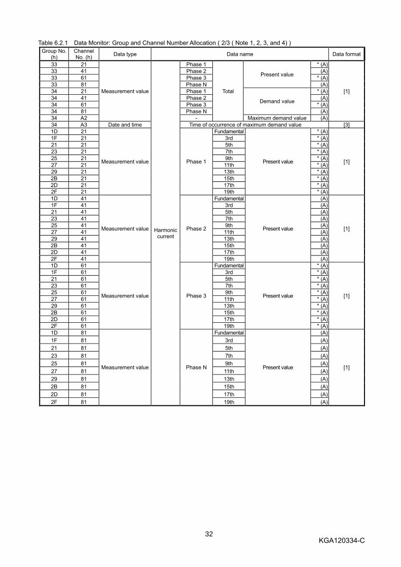
Table 6.2.1 Data Monitor: Group and Channel Number Allocation ( 2/3 ( Note 1, 2, 3, and 4) )
Group No. (h)
Channel No. (h)
Data type Data name Data format
33 21
Measurement value
Harmonic current
Phase 1
Total
Present value
* (A)
[1]
33 41 Phase 2 (A)
33 61 Phase 3 * (A)
33 81 Phase N (A)
34 21 Phase 1
Demand value
* (A)
34 41 Phase 2 (A)
34 61 Phase 3 * (A)
34 81 Phase N (A)
34 A2 - Maximum demand value (A)
34 A3 Date and time Time of occurrence of maximum demand value [3]
1D 21
Measurement value Phase 1
Fundamental
Present value
* (A)
[1]
1F 21 3rd * (A)
21 21 5th * (A)
23 21 7th * (A)
25 21 9th * (A)
27 21 11th * (A)
29 21 13th * (A)
2B 21 15th * (A)
2D 21 17th * (A)
2F 21 19th * (A)
1D 41
Measurement value Phase 2
Fundamental
Present value
(A)
[1]
1F 41 3rd (A)
21 41 5th (A)
23 41 7th (A)
25 41 9th (A)
27 41 11th (A)
29 41 13th (A)
2B 41 15th (A)
2D 41 17th (A)
2F 41 19th (A)
1D 61
Measurement value Phase 3
Fundamental
Present value
* (A)
[1]
1F 61 3rd * (A)
21 61 5th * (A)
23 61 7th * (A)
25 61 9th * (A)
27 61 11th * (A)
29 61 13th * (A)
2B 61 15th * (A)
2D 61 17th * (A)
2F 61 19th * (A)
1D 81
Measurement value Phase N
Fundamental
Present value
(A)
[1]
1F 81 3rd (A)
21 81 5th (A)
23 81 7th (A)
25 81 9th (A)
27 81 11th (A)
29 81 13th (A)
2B 81 15th (A)
2D 81 17th (A)
2F 81 19th (A)

33 KGA120334-C
Table 6.2.1 Data Monitor: Group and Channel Number Allocation (3/3 (Note 1, 2, 3, and 4))
Group No. (h)
Channel No. (h)
Data type Data name Data format
1D A2 Measurement value
Harmonic current
- Fundamental maximum value (A) [1]
1F A2 Measurement value - 3rd maximum value (A) [1]
1F A3 Date and time Time of occurrence of max. value of 3rd-harmonic current [3]
21 A2 Measurement value - 5th maximum value (A) [1]
21 A3 Date and time Time of occurrence of max. value of 5th-harmonic current [3]
23 A2 Measurement value - 7th maximum value (A) [1]
23 A3 Date and time Time of occurrence of max. value of 7th-harmonic current [3]
25 A2 Measurement value - 9th Maximum value (A) [1]
25 A3 Date and time Time of occurrence of max. value of 9th-harmonic current [3]
27 A2 Measurement value - 11th Maximum value (A) [1]
27 A3 Date and time Time of occurrence of max. value of 11th-harmonic current [3]
29 A2 Measurement value - 13th maximum value (A) [1]
29 A3 Date and time Time of occurrence of max. value of 13th-harmonic current [3]
2B A2 Measurement value - 15th maximum value (A) [1]
2B A3 Date and time Time of occurrence of max. value of 15th-harmonic current [3]
2D A2 Measurement value - 17th Maximum value (A) [1]
2D A3 Date and time Time of occurrence of max. value of 17th-harmonic current [3]
2F A2 Measurement value - 19th Maximum value (A) [1]
2F A3 Date and time Time of occurrence of max. value of 19th-harmonic current [3]
02 14 Setting value
Upprer limit alarm (A) [4]
02 15 Lower limit alarm (A)
AE 80 Alarm status 16-bit monitor [5]
F0 80
Setting value
MDU series code
[6]
E0 70 Rated current (In) (A)
E0 72 Number of poles
E0 16 Demand time (Minute)
E0 88 Alarm reset method
E0 13 Phase wire system
E0 87 Phase switch (1- to 3-phase connection)
F0 85 Measurement value
Open/close count (Note 5) (Number of Times) [1]
F0 86 Trip count (Note 6) (Number of Times)
E0 71
Setting value
Current setting (Ir) (A)
[6]
E0 7E INST pickup ratio (%)
F0 A2 INST reference value (%)
E0 76 PAL pickup current (Ip) (%)
E0 7C STD pickup current (Is) (Times)
E0 7D STD operating time (Ts) (ms)
E0 7B LTD operating time (TL) (s)
F0 D0 Alarm ON/OFF setting [7]
F0 D1 IDM_AL (Current demand alarm) pickup current (%) [6]
F0 D2 IDM_AL (Current demand alarm) demand time (Minute)
E0 01 Clock time Current time [3]
Note 1: Some channel numbers cannot be used depending on the model of the MDU breaker to be used.
MDU breaker model Unusable group and channel numbers
3-pole (3P) product 01h/81h, 02h/81h, 03h/21h, 03h/41h, 03h/61h, 33h/81h, 34h/81h, 1Dh/81h, 1Fh/81h, 21h/81h, 23h/81h, 25h/81h, 27h/81h, 29h/81h, 2Bh/81h, 2Dh/81h, 2Fh/81h
Note 2: Items with an asterisk mark (*) refer to items that can be switched by the phase switch setting value.
Note 3: When any group/channel number other than that specified in the list of group and channel number allocations
described above is specified, an out-of-group range error (Error code 41h) and an out-of channel range error
(Error code 42h) occur.
Note 4: When the present value and the maximum value are monitored in succession, a maximum value smaller than
the present value may be monitored depending on the data update timing of the MDU.
Note 5: This becomes available when the AX switch for transmission with MDU breaker (optional) is attached to the
MDU breaker.
Note 6: This becomes available when the AL switch for transmission with MDU breaker (optional) is attached to the
MDU breaker.

34 KGA120334-C
Table 6.2.2 Data formats and their configurations ( 1 / 6 )
Data format Configuration
[1] Measurement value
Other than electric energy and
reactive electric energy
Multiple
Value x Multiple = Actual value
32-bit integer data with a code: -2147483648 - 2147483647 (80000000h - 7FFFFFFFh)
Value
Lower data
b7 b0
Lower medium data
b15 b8
Upper medium data
b23 b16
Upper data
b31 b24 b7 b0
Exponent part
b15 b8
Fixed to 00h
<Multiples>
Exponent part = 00h: Multiple = 1, "Value x 1" is the actual value. Exponent part = FFh: Multiple = 0.1, "Value x 0.1" is the actual value.
<Values>
The negative value is a two’s-complement number. e.g. Electric energy present value
Data = Value 000000FFh, Exponent part FFh => 255 x 0.1 = 25.5 [kW] Data = Value FFFFFF01h, Exponent part FFh => -255 x 0.1 = - 25.5 [kW]
Note:The multiples vary depending on the measurement value. Therefore, calculate values based
on the multiple information. (See Table 6.2.3.)
[2] Measurement value
Electric energy and reactive
electric energy
Multiple
Value x Multiple = Actual value
32-bit integer data with a code: Effective range: 0 - 999999(0 - 000F423Fh)
Value
Lower data
b7 b0
Lower medium data
b15 b8
Upper medium data
b23 b16
Upper data
b31 b24 b7 b0
Exponent part
b15 b8
Fixed to 00h
Applicable
models Exponent part Data range Measurement value range Unit
Electric energy
250A Frame FFh
(Multiple = 0.1) 0 - 999999d
(0 - 000F423Fh) 0.0 - 99999.9 [kWh]
0001h (0.1 [kWh])
400/800A Frame 00h
(Multiple = 1) 0 - 999999d
(0 - 000F423Fh) 0 - 999999 [kWh]
0001h (1 [kWh])
Reactive energy
250A Frame FFh
(Multiple = 0.1) 0 - 999999d
(0 - 000F423Fh) 0.0 - 99999.9 [kvarh]
0001h (0.1 [kvarh])
400/800A Frame 00h
(Multiple = 1) 0 - 999999d
(0 - 000F423Fh) 0 - 999999 [kvarh]
0001h (1 [kvarh])
e.g. Electric energy (Integrated value) Data = Exponent part FFh, Value 000000FFh => 255 x 0.1 = 25.5 [kWh]
[3] Time of occurrence of maximum value
Current time
Year data (BCD code)
Month data (BCD code)
Day data (BCD code)
Hour data (BCD code)
Minute data (BCD code)
Year data: Last 2 digits of the Christian era (e.g., 18h indicates year 2018.) Month data: Month data (e.g., 11h indicates November.) Day data: Day data (e.g., 16h indicates day 16th.) Hour data: Hour data (e.g., 17h indicates 17 o’clock.) Minute data: Minute data (e.g., 15h indicates 15 minutes.)
b15 b8 b7 b8 b8 b7
b15 b0
Year
Second
b0 b15
Minute
Hour
Day
b0
Month
b7
00h

35 KGA120334-C
Table 6.2.2 Data formats and their configurations ( 2 / 6 )
Data format Data configuration
[4] Setting value
Upper limit alarm and lower
limit alarm
FFh
(Multiple = x 0.1)
Lower data
b7 b0
Lower medium data
b15 b8
Upper medium data
b7 b0
Upper data
b15 b8 b7 b0
Exponent part
b15 b8
Fixed to 00h
Fixed to 00h
Fixed to 00h
Data section
[Upper limit alarm]
Group No. (h)
Channel No. (h)
Applicable models
Data range Upper limit value Unit Default
02 14
250A Frame 0000h – 1388h 0.0 – 500.0 [A] 0001h (0.1[A])
1388h (500.0[A])
400A Frame 0000h – 1F40h 0.0 – 800.0 [A] 0001h (0.1[A])
1F40h (800.0[A])
800A Frame
0000h – 270Fh 0.0 – 999.9 [A] 0001h (0.1[A]) 04ECh
(1260[A]) 03E8h – 04ECh 1000 – 1260 [A]
0001h (1[A])
0000h – 270Fh 0.0 – 999.9 [A] 0001h (0.1[A]) 0640h
(1600[A]) 03E8h – 0640h 1000 – 1600 [A]
0001h (1[A])
*The data is calculated by multiplying the upper limit value by 10.
[Lower limit alarm]
*The data is calculated by multiplying the lower limit value by 10.
Group No. (h)
Channel No. (h)
Applicable models
Data range Lower limit value Unit Default
02 15
250A Frame 0000h – 1388h 0.0 – 500.0 [A] 0001h (0.1[A])
0000h (0[A])
400A Frame 0000h – 1F40h 0.0 – 800.0 [A] 0001h (0.1[A])
0000h (0[A])
800A Frame
0000h – 270Fh 0.0 – 999.9 [A] 0001h (0.1[A]) 0000h
(0[A]) 03E8h – 04ECh 1000 – 1260 [A]
0001h (1[A])
0000h – 270Fh 0.0 – 999.9 [A] 0001h (0.1[A]) 0000h
(0[A]) 03E8h – 0640h 1000 – 1600 [A]
0001h (1[A])

36 KGA120334-C
Table 6.2.2 Data formats and their configurations ( 3 / 6 )
Data format Data configuration
[5] Alarm status
16-bit monitor
[16-bit monitor] (Group number: AEh, channel number: 80h)
Fixed to 00h
Lower data
b7 b0
Lower medium data
b15 b8
Upper medium data
b7 b0
Upper data
b15 b8 b7 b0
Exponent part
b15 b8
Fixed to 00h
Fixed to 00h
Fixed to 00h
Alarm/Interruption cause data
bit Description For 1 For 0 Remark
Upper m
ediu
m d
ata
b0 AX (ON/OFF status) ON OFF or trip Note 1 b1 AL (Trip status) Trip ON or OFF Note 2 b2 PAL (Pre-alarm) Alarm occurred Alarm not occurred Note 5 b3 Reserved - -
b4 Reserved - - b5 Reserved - - b6 LTD Occurred Not occurred Note 3, 6 b7 STD/INST Occurred Not occurred Note 3, 4, 6
Upper data
b8 Lower limit alarm Occurred Not occurred Note 5 b9 Upper limit alarm Occurred Not occurred Note 5 b10 IDM_AL (Current demand alarm) Occurred Not occurred Note 5 b11 IUB_AL (Current unbalance alarm) Occurred Not occurred Note 5 b12 OVER (Overcurrent alarm) Alarm occurred Alarm not occurred Note 5 b13 ILA_AL (Current open-phase alarm) Occurred Not occurred Note 5 b14 Reserved - - b15 Reserved - -
Note 1: This becomes available when the AX switch for transmission with MDU breaker (optional) is attached to the MDU breaker.
Note 2: This becomes available when the AL switch for transmission with MDU breaker (optional) is attached to the MDU breaker.
AL (Trip status) shows the status of the main body mechanism of the MDU breaker. Note 3: Any one of the causes of the fault is regarded as "Occurred". Note 4: The causes of the fault by INST becomes available when the AL switch for transmission
with MDU breaker (optional) is attached to the MDU breaker. Note 5: The reset method of PAL (self-retention or automatic reset) is set by the data set (2h) of the
intermodel standard command. (See pages 44, 46, 51, and 52.) The reset method of OVER (overcurrent alarm) is "automatic reset" regardless of the setting.
Note 6: The reset of LTD, STD/INST, and respective upper/lower limit alarm are set in the data set (2h) of the intermodel standard command. (See pages 44, 48, and 50.)

37 KGA120334-C
Table 6.2.2 Data formats and their configurations ( 4 / 6 )
Data format Data configuration
[6] Setting value
Other than upper limit
alarm, lower limit alarm, and alarm ON/OFF
setting
Fixed to 00h
Lower data
b7 b0
Lower medium data
b15 b8
Upper medium data
b7 b0
Upper data
b15 b8 b7 b0
Exponent part
b15 b8
Fixed to 00h
Fixed to 00h
Fixed to 00h
Data section
[ MDU series code ]
Group No. (h)
Channel No. (h)
Data Default
F0 80 0001h Molded Case Circuit Breaker
[ Rated current ( In ) ]
Group No. (h)
Channel No. (h)
Applicable models
Data Rated current ( In )
E0 70
250A Frame 00FAh 250 [A]
400A Frame 0190h 400 [A]
800A Frame 0276h 630 [A]
0320h 800 [A]
[ Number of poles ]
Group No. (h)
Channel No. (h)
Data Number of poles
E0 72 0003h 3-pole
0004h 4-pole
[ Demand time ]
Group No. (h)
Channel No. (h)
Data range Demand time
delay Unit Default
E0 16 0000h (0d) - 000Fh (15d) 0 - 15 [minutes] 0001h
( 1 [minute] ) 0002h
( 2 [minutes] )
[ Alarm reset method ]
Group No. (h)
Channel No. (h)
Data Alarm reset method
E0 88 0000h Automatic reset 0001h Self-retention
[ Phase wire system ]
Group No. (h)
Channel No. (h)
Data Phase wire system Default
E0 13
0001h Single-phase 2-wire
0003h ( 3-phase 3-wire ) 0002h Single-phase 3-wire
0003h 3-phase 3-wire
0004h 3-phase 4-wire
[ Phase switch ( 1 to 3-phase connection ) ]
Group No. (h)
Channel No. (h)
Data Phase wire system Default
E0 87
0000h Phase not switched
(1 to 3-phase connection) 0000h Phase not switched
(1 to 3-phase connection) 0001h Phase switched
(3 to 1-phase connection)

38 KGA120334-C
Table 6.2.2 Data formats and their configurations ( 5 / 6 )
Data format Data configuration
[6] Setting value
Other than upper limit
alarm, lower limit alarm, and alarm ON/OFF
setting
[ Current setting ( Ir ) ]
Group No. (h)
Channel No. (h)
Applicable models
Data Current setting ( Ir )
E0 71
250A Frame 0096h - 00FAh 125 [A] - 250 [A]
400A Frame 00C8h - 0190h 200 [A] - 400 [A]
800A Frame 012Ch - 0276h 300 [A] - 630 [A]
0190h - 0320h 400 [A] - 800 [A]
Note:The current is adjustable in steps of 12.5A. ( 125 A ⇔ 137.5A ⇔ 150A … )
For communication data, the fractional portion of the number is rounded up.
e.g. 137.5A setting ⇒ 138 A
[ INST pickup ratio ]
Group No. (h)
Channel No. (h)
Applicable models
Data INST pickup ratio Unit Step
E0 7E
250A Frame 0014h - 008Ch 20 - 140
0.1[%] 1 400A Frame 0028h - 00A0h 40 - 160
800A Frame 0028h - 0096h 40 - 150
0028h - 0078h 40 - 120
[ INST refernce ratio ]
Group No. (h)
Channel No. (h)
Applicable models
Data INST pickup ratio Unit Step
E0 A2
250A Frame 0028h - 0064h 40 - 100 [%] 1
400/800A Frame
0064h 100 [%] Fixed
* The INST pickup current Ii is obtained by the following formula.
Ii = ( Rated current ( In ) x INST pickup ratio x INST reference value ) / 1000 ( Unit:A )
e.g. When the Rated current is 250 (A), the INST pickup ratio is 140 (x 0.1%), and
The INST reference value is 95%:
Ii = (250 x 140 x 95) / 1000 = 3325 A
[6] Setting value
Other than current
demand alarm upper limit value, current demand alarm lower limit value,
and alarm ON/OFF setting
[ PAL pickup current ( Ip ) ]
Group No. (h)
Channel No. (h)
Data INST pickup ratio Unit Default
E0 76 0046h - 0064h 70 – 100 [%] 0005h ( 5[%] )
0046h ( 70[%] )
[ STD pickup current ( Is ) ]
Group No. (h)
Channel No. (h)
250A Frame 400/800A Frame
Data STD pickup current ( Is )
Data STD pickup current ( Is )
E0 7C
0014h ( 20d ) x 2.0 0014h ( 20d ) x 2.0
0019h ( 25d ) x 2.5 0019h ( 25d ) x 2.5
001Eh ( 30d ) x 3.0 001Eh ( 30d ) x 3.0
0023h ( 35d ) x 3.5 0023h ( 35d ) x 3.5
0028h ( 40d ) x 4 0028h ( 40d ) x 4
0032h ( 50d ) x 5 0032h ( 50d ) x 5
003Ch ( 60d ) x 6 003Ch ( 60d ) x 6
0046h ( 70d ) x 7 0046h ( 70d ) x 7
0050h ( 80d ) x 8 0050h ( 80d ) x 8
005Ah ( 90d ) x 9
0064h (100d) x 10 0064h (100d) x 10
*The data is calculated by multiplying the STD pickup current by 10.
[ STD operating time ( Ts ) ]
Group No. (h)
Channel No. (h)
250A Frame 400/800A Frame
Data STD pickup current ( Is )
Data STD pickup current ( Is )
E0 7D
0000h 60 [ms]
0001h 100 [ms] 0001h 100 [ms]
0002h 200 [ms] 0002h 200 [ms]
0003h 300 [ms] 0003h 300 [ms]

39 KGA120334-C
Table 6.2.2 Data formats and their configurations ( 6 / 6 )
Data format Data configuration
[6] Setting value
Other than upper limit
alarm, lower limit alarm, and alarm ON/OFF setting
[ LTD operating time ( TL ) ]
Group No. (h)
Channel No. (h)
250A Frame 400/800A Frame
Data STD pickup current ( Is )
Data STD pickup current ( Is )
E0 7B
0078h ( 120d ) 12 [s] 0078h ( 120d ) 12 [s]
0258h ( 600d ) 60 [s] 0258h ( 600d ) 60 [s]
0320h ( 800d ) 80 [s] 03E8h (1000d) 100 [s]
03E8h (1000d) 100 [s] 05DCh (1500d) 150 [s]
*The data is calculated by multiplying the LTD operating time by 10.
[ IDM_AL ( Current demand alarm ) pickup current ]
Group No. (h)
Channel No. (h)
Data range IDM_AL pickup
current Unit Default
F0 D1 0032h - 0064h 50 – 100 [%] 0005h ( 5[%] )
0064h ( 100[%] )
[ IDM_AL ( Current demand alarm ) demand time ]
Group No. (h)
Channel No. (h)
Data range IDM_AL demand
time Unit Default
F0 D2
0001h – 000Ah 1 – 10 [Minutes] 0001h
( 1[Minute] )
0002h ( 2[Minute] )
000Fh 15 [Minutes]
0014h 20 [Minutes]
0019h 25 [Minutes]
001Eh 30 [Minutes]
[7] Setting value
Alarm ON/OFF setting
[Alarm ON/OFF Setting] (Group Number: F0h, Channel Number: D0h)
Fixed to 00h
Lower data
b7 b0
Lower medium data
b15 b8
Upper medium data
b7 b0
Upper data
b15 b8 b7 b0
Exponent part
b15 b8
Fixed to 00h
Fixed to 00h
Fixed to 00h
Data section
bit Description For 1 For 0 Remark
Low
er data
b0 IDM _ AL (Current demand alarm) OFF ON b1 IUB _ AL (Current unbalanced alarm) OFF ON b2 ILA _ AL (Current open-phase alarm) OFF ON b3 Reserved Fixed to 1 b4 Reserved Fixed to 1 b5 Reserved Fixed to 1 b6 Reserved Fixed to 1 b7 Reserved Fixed to 1
Low
er m
ediu
m d
ata
b8 Reserved Fixed to 1 b9 Reserved Fixed to 1 b10 Reserved Fixed to 1 b11 Reserved Fixed to 1 b12 Reserved Fixed to 1 b13 Reserved Fixed to 1 b14 Reserved Fixed to 1 b15 Reserved Fixed to 1

40 KGA120334-C
Table 6.2.3 Data ranges and units of measurement values ( 1 / 2 )
Applicable
models Rated
current Measurement range Data range Data unit
Exponent part
Remark
Load current
250A Frame 125~250A 0.0 - 499.9 A 500 A or more
0 - 4999 Fixed to 5000
0.1 A 0.1 A
FF h FF h
Fixed to 0 A for less than 2.5 A
400A Frame 400 A 0.0 - 799.9 A 800 A or more
0 - 7999 Fixed to 8000
0.1 A 0.1 A
FF h FF h
Fixed to 0 A for less than 4.0 A
800A Frame
630 A 0.0 - 999.9 A 1000 - 1259 A
1260 A or more
0 - 9999 1000 - 1259
Fixed to 1260
0.1 A 1 A 1 A
FF h 00 h 00 h
Fixed to 0 A for less than 6.3 A
800 A 0.0 - 999.9 A 1000 - 1599 A
1600 A or more
0 - 9999 1000 - 1599
Fixed to 1600
0.1 A 1 A 1 A
FF h 00 h 00 h
Fixed to 0 A for less than 8.0 A
Line voltage common common 0.0 - 99.9 V 100 - 758 V
759 V or more
0 - 999 100 - 758
Fixed to 759
0.1 V 1 V 1 V
FF h 00 h 00 h
Fixed to 0 V for less than 22 V
Harmonic
current
250A Frame 125~250A 0.0 - 99.9 A 100 - 249 A
250 A or more
0 - 999 100 - 249
Fixed to 250
0.1 A 1 A 1 A
FF h 00 h 00 h
Fixed to 0 A for less than 5.0 A
400A Frame 400 A 0.0 - 99.9 A 100 - 399 A
400 A or more
0 - 999 100 - 399
Fixed to 400
0.1 A 1 A 1 A
FF h 00 h 00 h
Fixed to 0 A for less than 8.0 A
800A Frame
630 A 0.0 - 99.9 A 100 - 629 A
630 A or more
0 - 999 100 - 629
Fixed to 630
0.1 A 1 A 1 A
FF h 00 h 00 h
Fixed to 0 A for less than 12.6 A
800 A 0.0 - 99.9 A 100 - 799 A
800 A or more
0 - 999 100 - 799
Fixed to 800
0.1 A 1 A 1 A
FF h 00 h 00 h
Fixed to 0 A for less than 16.0 A
Electric power
250A Frame 125~250A
-657.3kW or less
-657.2 - 0.0 kW
0.0 - 657.2 kW
657.3 kW or more
Fixed to -6573
-6572 - 0
0 - 6572
Fixed to 6573
0.1 kW
0.1 kW
0.1 kW
0.1 kW
FF h
FF h
FF h
FF h
Also fixed when the current or
the voltage is equal to or more
than the measurement
maximum value.
400A Frame 400 A
-1052 kW or less
-1051 - 1000 kW
-999.9 - 0.0 kW
0.0 - 999.9 kW
1000 - 1051 kW
1052 kW or more
Fixed to -1052
-1051 - 1000
-999 - 0
0 - 999
1000 - 1051
Fixed to 1052
1 kW
1 kW
0.1 kW
0.1 kW
1 kW
1 kW
00 h
00 h
FF h
FF h
00 h
00 h
800A Frame
630 A
-1656 kW or less
-1655 - 1000 kW
-999.9 - 0.0 kW
0.0 - 999.9 kW
1000 - 1655 kW
1656 kW or more
Fixed to -1656
-1055 - 1000
-999 - 0
0 - 999
1000 - 1055
Fixed to 1656
1 kW
1 kW
0.1 kW
0.1 kW
1 kW
1 kW
00 h
00 h
FF h
FF h
00 h
00 h
800 A
-2103 kW or less
-2102 - 1000 kW
-999.9 - 0.0 kW
0.0 - 999.9 kW
1000 - 2102 kW
2103 kW or more
Fixed to -2103
-2102 - 1000
-999 - 0
0 - 999
1000 - 2102
Fixed to 2103
1 kW
1 kW
0.1 kW
0.1 kW
1 kW
1 kW
00 h
00 h
FF h
FF h
00 h
00 h
Reactive power
250A Frame 125~250A
-657.3 kvar or less
-657.2 - 0.0 kvar
0.0 - 657.2 kvar
657.3 kvar or more
Fixed to -6573
-6572 - 0
0 - 6572
Fixed to 6573
0.1 kvar
0.1 kvar
0.1 kvar
0.1 kvar
FF h
FF h
FF h
FF h
Also fixed when the current or
the voltage is equal to or more
than the measurement
maximum value.
400A Frame 400 A
-1052 kvar or less
-1051 - 1000 kvar
-999.9 - 0.0 kvar
0.0 - 999.9 kvar
1000 - 1051 kvar
1052 kvar or more
Fixed to -1052
-1051 - 1000
-999 - 0
0 - 999
1000 - 1051
Fixed to 1052
1 kvar
1 kvar
0.1 kvar
0.1 kvar
1 kvar
1 kvar
00 h
00 h
FF h
FF h
00 h
00 h
800A Frame
630 A
-1656 kvar or less
-1655 - 1000 kvar
-999.9 - 0.0 kvar
0.0 - 999.9 kvar
1000 - 1655 kvar
1656 kvar or more
Fixed to -1656
-1055 - 1000
-999 - 0
0 - 999
1000 - 1055
Fixed to 1656
1 kvar
1 kvar
0.1 kvar
0.1 kvar
1 kvar
1 kvar
00 h
00 h
FF h
FF h
00 h
00 h
800 A
-2103 kvar or less
-2102 - 1000 kvar
-999.9 - 0.0 kvar
0.0 - 999.9 kvar
1000 - 2102 kvar
2103 kvar or more
Fixed to -2103
-2102 - 1000
-999 - 0
0 - 999
1000 - 2102
Fixed to 2103
1 kvar
1 kvar
0.1 kvar
0.1 kvar
1 kvar
1 kvar
00 h
00 h
FF h
FF h
00 h
00 h

41 KGA120334-C
Table 6.2.3 Data ranges and units of measurement values ( 2 / 2 )
Applicable
models Rated
current Measurement
range Data range Data unit
Exponent part
Remark
Electric energy
250A Frame 125~250A 0.0 - 99999.9 kWh 0 - 999999 0.1 kWh FFh
When the electric energy
exceeds 99999.9 kWh, the
value is reset to 0 kWh and
calculation continues.
400/800A Frame
common 0 - 999999 kWh 0 - 999999 1 kWh 00h
When the electric energy
exceeds 999999 kWh, the
value is reset to 0 kWh and
calculation continues.
Reactive
energy
250A Frame 125~250A 0.0 - 99999.9 kvarh 0 - 999999 0.1 kvarh FFh
When the reactive electric
energy exceeds 99999.9 kvarh,
the value is reset to 0 kvarh and
calculation continues.
400/800A Frame
common 0 - 999999 kWh 0 - 999999 1 kvarh 00h
When the electric energy
exceeds 999999 kvarh, the
value is reset to 0 kvarh and
calculation continues.
Electric energy
amount for last
1-hour
250A Frame 125~250A 0.0 – 657.3 kWh 0 - 6573 0.1 kWh FFh
400/800A Frame
common 0 - 3824 kWh 0 - 3824 1 kWh 00h
Reactive
energy amount
for last 1-hour
250A Frame 125~250A 0.0 - 657.3 kvarh 0 - 6573 0.1 kvarh FFh
400/800A Frame
common 0 - 3824 kvarh 0 - 3824 1 kvarh 00h
Power factor common common Lead of 0 - 100 to
lag of 0%
Lead of 0 - 1000 -
lag of 0 0.1% FFh Lead is indicated in minus (-).
Fault current
Long time delay
Short time
delay
Instantaneous
250A Frame 125~250A 0 - 3999 A
4000 A or more
0 - 3999
Fixed to 4000
1 A
1 A
00h
00h
400A Frame 400A 0 - 6399 A
6400 A or more
0 - 6399
Fixed to 6400
1 A
1 A
00h
00h
800A Frame
630A 0 - 10079 A
10080 A or more
0 - 10079
Fixed to 10080
1 A
1 A
00h
00h
800A 0 - 12799 A
12800 A or more
0 - 12799
Fixed to 12800
1 A
1 A
00h
00h
Frequency common common 0.0, 45 - 65 0, 450 - 650 0.1 Hz 00h
Fixed to 450 and 650 when the
frequency is 45 Hz or less or 65
Hz or more respectively.
Fixed to 0 when voltage is no
input.

42 KGA120334-C
2h Data set
You can change each setting value of the MDU from the sequencer side.
As shown below, write Command 2h and the group and channel numbers of the measurement and setting values
to be set to the remote register RWw (the unit number is fixed to 0h); and set the command execution request flag
(Remote output (RYnF)) to ON (1).
When the command completion reply flag (Remote input (RXnF)) turns ON (1), the measurement and setting
values of the specified group and channel numbers are set.
See Table 6.2.4 for the group and channel numbers that can be set.
See Table 6.2.5 for data formats and their configurations.
You can also reset or erase bit information such as breaker alarm and interruption causes by using this command.
* When the setting of this unit is changed, it takes a few seconds until its operation becomes stable. The unit does
not perform the measurement during this time. Remote register RWw (Sequencer => MDU) Remote register RWr (MDU => Sequencer)
b15 b8 b7 b4 b3 b0
m Group No. 0h*1
2h
m+1 Exponent part Channel No.
m+2 Lower medium data Lower data
m+3 Upper data Upper medium data
*1 Unit No. (Fixed to 0h)
b15 b8 b7 b4 b3 b0
n Channel No. Group No.
n+1 00h 00h
n+2 00h 00h
n+3 00h 00h
m, n: Addresses allocated in the station number setting
Table 6.2.4 Data set: Group and channel number allocations
Group No. (H)
Channel No. (H)
Data type Data name Data format
02 14 Setting value
Upper limit alarm (A) [1]
02 15 Lower limit alarm (A) AF 80 Reset 16-bit set/Reset [3] E0 16
Setting value
Demand time (Minute)
[2] E0 88 Alarm reset method E0 13 Phase wire system E0 87 Phase switch (1- to 3-phase connection)
F0 D0 Alarm ON/OFF setting [4] F0 D1 IDM_AL (Current demand alarm) pickup current (%)
[2] F0 D2 IDM_AL (Current demand Alarm) demand time (Minute) 80 01 Electric energy/
Reactive energy set Electric energy (kWh)
[5] 81 01 Reactive energy (kvarh)
Note 1: When any channel number other than those described above is specified or any data other than that in the
setting data range specified in Table 6.2.5 is specified, the normal operation is not guaranteed.
Note 2: Each setting value is registered in the non-volatile memory (E2PROM) at the time of setting.

43 KGA120334-C
Table 6.2.5 Data formats and their configurations ( 1 / 4 )
Data format Data configuration
[1] Setting value
Current demand alarm upper limit value, and current demand alarm
lower limit value
FFh
(Multiple = x 0.1)
Lower data
b7 b0
Lower medium data
b15 b8
Upper medium data
b7 b0
Upper data
b15 b8 b7 b0
Exponent part
b15 b8
Fixed to 00h
Fixed to 00h
Fixed to 00h
Data section
[ Upper limit alarm ]
Group No. (h)
Channel No. (h)
Applicable models
Rated current
Setting data range
Upper limit value
Unit Default
02 14
250A Frame 125 – 250A 0000h-1388h 0.0 - 500.0 [A] 0001h (0.1[A])
1388h (500.0[A])
400A Frame 400A 0000h-1F40h 0.0 - 500.0 [A] 0001h (0.1[A])
1F40h (800.0[A])
800A Frame
630A
0000h-270Fh 0.0 - 999.9 [A] 0001h (0.1[A]) 04ECh
(1260[A]) 03E8h-04ECh 1000 -1260[A]
0001h (1[A])
800A
0000h - 270Fh 0.0 - 999.9 [A] 0001h (0.1[A]) 0640h
(1600[A]) 03E8h-0640h 1000 -1600[A]
0001h (1[A])
Note 1: Values lower than the lower limit value cannot be set.
Note 2: The maximum value among the current demand present values of each phase is monitored. [ Lower limit alarm ]
Group No. (h)
Channel No. (h)
Applicable models
Rated current
Setting data range
Lower limit value
Unit Default
02 14
250A Frame 125 – 250A 0000h-1388h 0.0 - 500.0 [A] 0001h (0.1[A])
0h (0[A])
400A Frame 400A 0000h-1F40h 0.0 - 500.0 [A] 0001h (0.1[A])
0h (0[A])
800A Frame
630A
0000h-270Fh 0.0 - 999.9 [A] 0001h (0.1[A]) 0h
(0[A]) 03E8h-04ECh 1000 -1260[A]
0001h (1[A])
800A
0000h - 270Fh 0.0 - 999.9 [A] 0001h (0.1[A]) 0h
(0[A]) 03E8h-0640h 1000 -1600[A]
0001h (1[A])
Note 1: Values higher than the upper limit value cannot be set. Note 2: The maximum value among the current demand present values of each phase is monitored
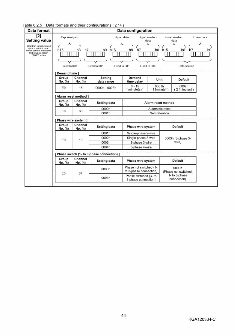
44 KGA120334-C
Table 6.2.5 Data formats and their configurations ( 2 / 4 )
Data format Data configuration
[2] Setting value
Other than current demand
alarm upper limit value, current demand alarm lower
limit value, and alarm ON/OFF setting
Fixed to 00h
Lower data
b7 b0
Lower medium data
b15 b8
Upper medium data
b7 b0
Upper data
b15 b8 b7 b0
Exponent part
b15 b8
Fixed to 00h
Fixed to 00h
Fixed to 00h
Data section
[ Demand time ]
[ Alarm reset method ]
[ Phase wire system ]
[ Phase switch (1- to 3-phase connection) ]
Group No. (h)
Channel No. (h)
Setting data range
Demand time delay
Unit Default
E0 16 0000h - 000Fh 0 - 15
[ minute(s) ] 0001h
( 1 [minute] ) 0002h
( 2 [minutes] )
Group No. (h)
Channel No. (h)
Setting data Alarm reset method
E0 88 0000h Automatic reset
0001h Self-retention
Group No. (h)
Channel No. (h)
Setting data Phase wire system Default
E0 13
0001h Single-phase 2-wire
0003h (3-phase 3-wire)
0002h Single-phase 3-wire
0003h 3-phase 3-wire
0004h 3-phase 4-wire
Group No. (h)
Channel No. (h)
Setting data Phase wire system Default
E0 87
0000h Phase not switched (1- to 3-phase connection)
0000h (Phase not switched:
1- to 3-phase connection) 0001h
Phase switched (3- to 1-phase connection)

45 KGA120334-C
Table 6.2.5 Data formats and their configurations ( 3 / 4 )
Data format Data configuration
[2] Setting value
Other than upper limit
alarm, lower limit alarm, and alarm ON/OFF
setting
[ IDM_AL (Current demand alarm) pickup current ]
[ IDM_AL (Current demand alarm) demand time delay ]
[3] 16-bit
set/Reset
[16 bit set/Reset] (Group number: AFh, Channel number: 80h)
Fixed to 00h
Lower data
b7 b0
Lower medium data
b15 b8
Upper medium data
b7 b0
Upper data
b15 b8 b7 b0
Exponent part
b15 b8
Fixed to 00h
Fixed to 00h
Fixed to 00h
Set data
Details of data configurations
bit Description "0" "1" Remark
Up
per
Med
ium
data
b0 Reset(collective) Circuit breaker alarm - Reset execution
b1 All memory clear - Execution of all
clear Notes 1, 2, and 5
b2 Memory clear
(collective) Order-specific harmonic current
maximum value - Clear execution Notes 1, 3, and 5
b3 Reserved Fixed to 0 Note 4
b4 Memory clear Power factor maximum value - Clear execution Notes 1 and 5
b5 Reserved Fixed to 0 Note 4
b6 Memory clear Electric power demand maximum
value - Clear execution Notes 1 and 5
b7 Memory clear Fault information (cause + current) - Clear execution Note 5
Up
per
data
b8 Memory clear Reactive power demand maximum
value - Clear execution Notes 1 and 5
b9 Memory clear Reactive energy (Integrated value) - Clear execution Note 5
b10 Memory clear Reactive energy (Maximum value of
amont of last 1 hour) - Clear execution Notes 1 and 5
b11 Memory clear Current demand maximum value - Clear execution Notes 1 and 5
b12 Memory clear Voltage maximum value - Clear execution Notes 1 and 5
b13 Memory clear Total harmonic current demand
maximum value - Clear execution Notes 1 and 5
b14 Memory clear Electric energy (Integrated value) - Clear execution Note 5
b15 Memory clear Electric energy (Maximum value of
amont of last 1 hour) - Clear execution Notes 1 and 5
Note 1: This clear includes the clear of the memory of date and time of occurrence of each maximum value.
Note 2: All memory clear refers to the clear of all items from items b2 to b15 above (zero clear). (Alarm reset is not included.)
Note 3: 3rd-, 5th-, 7th-, 9th-, 11th-, 13th-, 15th-, 17th-, and 19th-order harmonic current maximum values are collectively reset.
Note 4: b3 and b5 cannot be used. Note 5: When b1 to b15 are cleared, contents stored in the non-volatile memory (E2PROM) are cleared.
Group No. (h)
Channel No. (h)
Setting data range IDM_AL pickup current Unit Default
F0 D1 0032h - 0064h 50 - 100 [%] 0001h
( 1 [%] ) 0064h
( 100 [%] )
Group No. (h)
Channel No. (h)
Setting data range IDM_AL pickup current Unit Default
F0 D2
0001h – 000Ah 1[minute] - 10 [minutes] 0001h
( 1 [minute] )
0002h ( 1 [minute] )
000Fh 15 [minutes]
0014h 20 [minutes]
0019h 25 [minutes]
001Eh 30 [minutes]

46 KGA120334-C
Table 6.2.5 Data formats and their configurations ( 4 / 4 )
Data format Data configuration
[4] Setting value
Alarm ON/OFF setting
[Alarm ON/OFF setting] (Group Number: F0h, Channel Number: D0h)
Fixed to 00h
Lower data
b7 b0
Lower medium data
b15 b8
Upper medium data
b7 b0
Upper data
b15 b8 b7 b0
Exponent part
b15 b8
Fixed to 00h
Fixed to 00h
Fixed to 00h
Data section
Bit Description For 1 For 0 Low
er le
vel o
f data
b0 IDM _ AL (Current demand alarm) OFF ON b1 IUB _ AL (Current unbalanced alarm) OFF ON b2 ILA _ AL (Current open-phase alarm) OFF ON b3 Reserved Fixed to 1 b4 Reserved Fixed to 1 b5 Reserved Fixed to 1 b6 Reserved Fixed to 1 b7 Reserved Fixed to 1
Mediu
m lo
wer le
vel
of data
b8 Reserved Fixed to 1 b9 Reserved Fixed to 1
b10 Reserved Fixed to 1 b11 Reserved Fixed to 1 b12 Reserved Fixed to 1 b13 Reserved Fixed to 1 b14 Reserved Fixed to 1 b15 Reserved Fixed to 1
Note: Be sure to set 1 to the unused bit.
[5] Setting value
Electric energy and
reactive energy
Multiple
Value x Multiple = Actual value
32-bit integer data with a code: Effective range: 0 - 999999(0 - 000F423Fh)
Value
Lower data
b7 b0
Lower medium data
b15 b8
Upper medium data
b23 b16
Upper data
b31 b24 b7 b0
Exponent part
b15 b8
Fixed to 00h
Applicable
models Exponent part Data range
Measurement value range
Unit
Electric energy
250A Frame FFh
(Multiple = 0.1) 0 - 999999d
(0 - 000F423Fh) 0.0 - 99999.9 [kWh]
0001h (0.1 [kWh])
400/800A Frame 00h
(Multiple = 1) 0 - 999999d
(0 - 000F423Fh) 0 - 999999 [kWh]
0001h (1 [kWh])
Reactive energy
250A Frame FFh
(Multiple = 0.1) 0 - 999999d
(0 - 000F423Fh) 0.0 - 99999.9 [kvarh]
0001h (0.1 [kvarh])
400/800A Frame 00h
(Multiple = 1) 0 - 999999d
(0 - 000F423Fh) 0 - 999999 [kvarh]
0001h (1 [kvarh])
e.g.: Electric energy (Integrated value)
Data = Exponent FFh, Value 000000FFh => 255 x 0.1 = 25.5 [kWh]

47 KGA120334-C
3h Clock data set
You can change the clock data of the MDU from the sequencer side. You cannot set the second in the MDU. Set
00h for the second data.
As shown below, write Command 3h and year-month-day-hour-minute-second (00h) to be set to the remote
register RWw (the unit number is fixed to 0h); and set the command execution request flag (Remote output (RYnF))
to ON (1).
If the command completion reply flag (Remote input (RXnF)) turns ON (1), the clock data will be set.
See Table 6.2.6 for data formats and their configurations. Remote register RWw (Sequencer => MDU) Remote register RWr (MDU => Sequencer)
b15 b8 b7 b4 b3 b0
m 00h 0h*1
3h
m+1 Year Month
m+2 Day Hour
m+3 Minute Second (00h)
*1 Unit No. (Fixed to 0h)
b15 b8 b7 b4 b3 b0
n 00h 0h*1 3h
n+1 00h 00h
n+2 00h 00h
n+3 00h 00h
*1 Unit No. (Fixed to 0h)
m, n: Addresses allocated in the station number setting
Note: You cannot set the second in the MDU.
Table 6.2.6 Data formats and their configurations
Data format Data configuration
Current time [Present year-month-day-hour-minute] (Group number: E0h, Channel number: 01h)
Year
Second
Minute
Hour
Day
Month
b15 b8 b7 b8 b8 b7
b15 b0 b0 b15 b0 b7
Year data
(BCD code)
Month data
(BCD code)
Day data
(BCD code)
Hour data
(BCD code)
Minute data
(BCD code)
00h
Year data: Lower 2 digits of the Christian era (e.g.12h indicates year 2012.) Month data: Month data (e.g.11h indicates November.) Day data: Day data (e.g.16h indicates day 16th.) Hour data: Hour data (e.g.17h indicates 17 o’clock.) Minute data: Minute data (e.g.15h indicates 15 minutes.)
Note: You cannot set the second in the MDU.

48 KGA120334-C
7. Error occurrence
When any command sent to the MDU or the associated data has an error or a H/W error occurs in the MDU, the error flag (Remote input (RX (n + 1) A)) turns ON (1) and the error code shown in Table 7.1 is returned as a reply data.
Table 7.1 Error codes
Error description Error code (Hex number) Undefined Command 01h Out of group range 41h Out of channel range 42h Out of setting value range 51h Upper/Lower limit value cross 53h H/W error 10h
When an error occurs, the error code is written in the remote register RWr and the error flag (Remote input (RX (n + 1) A)) turns ON (1: Error occurrence state) and the Remote Ready (Remote input (RX (n + 1)B)) turns OFF (0: Normal communication stop) as shown in the table below. See "5.5 Error Communication" for the error state cancelation method.
Remote register RWr (MDU => Sequencer) Remote register RWr (MDU => Sequencer)
b15 b8 b7 b0
n Channel No. Group No.
n+1 00h 00h
n+2 00h Error Code
n+3 00h 00h
b15 b8 b7 b0
<For intermodel standard commands>
b15 b8 b7 b0
n 00h Error Code
n+1 00h 00h
n+2 00h 00h
n+3 00h 00h
<For model specific commands>
n: Addresses allocated in the station number setting
Note: Note that Remote inputs (RXn2) to (RXn9) do not change while an error is occurring (Remote Ready (Remote input RX (n+1) B) is off).

49 KGA120334-C
8. Sample program
8.1 Contents of the sample program
This sample program is assumed to have the following system configuration. This is a program to monitor the 1-phase current present value, electric energy, alarm status and fault causes of the MDU in order and in succession. At the start, the sample program stores the sent data for monitoring the load current present values(phase 1), electric energy, alarm status, and fault causes in the data register; and check the condition of the data link between the CC-Link system master local unit and the MDU. Next, if the data link is normal, the sample program conducts initial communication, sets the date and clock time data once, and monitors 1-phase current present values, electric energy, alarm status, and fault causes in series. When an error occurs during the monitor communication, the sample program communicates the error and stores the error code in the data register. Note) This sample program was created by using SW8D5C-GPPW GX Developer.
8.2 Device configuration
Power unit Output unit
CC-Link system master local unit
CPU unit Input unit
MDU
Slot No. 0 (Transmission speed: 10 Mbps, Station No. 0)
Q62P Q02HCPU QJ61BT11N
(32 points)
X00 Y00
X1F Y1F
QX40
(16 points)
X20
X2F
...
QY10
(16 points)
Y30
Y3F
...
CC-Link dedicated cable
Slot No. 1
Slot No. 2
...
...
Terminating resistor
Terminating resistor
(Transmission speed: 10 Mbps, Station No. 1)
In the sample program, the first input/output number is 00h (or 0000) because the CC-Link master unit (QJ61BT11N) is
equipped to the slot No. 0 of the base unit as shown in the configuration above.
· Since the sample program is the minimum content required to monitor the MDU breaker,
please eventually change to a program that suits your environment. In addition, we are not responsible for damages, secondary damage, accident compensation, damages to products other than our products, and other operations arising from programs created by you, including sample programs.
· When programming in order not to cause abnormality in the system at the end, please pay
attention to safety design by reading process twice.
Carry out safety design
Caution

50 KGA120334-C
8.3 Device allocations
Allocation of sending and receiving devices
Item Description Device No. Remark
Remote input (RX) Contents of remote input (RX00 - RX1F) of the MDU station No. 1
X1000 - X1031 Set X1000 to the refresh device.
Remote output (RY) Contents of remote output (RY00 - RY1F) of the MDU station No. 1
Y1000 - Y1031 Set Y1000 to the refresh device.
Remote register (RWr) Contents of remote register (RWr0 - RWr3) of the MDU station No. 1
W0 - W3 Set W0 to the remote register (RWr) refresh device.
Remote register (RWw) Contents of remote register (RWw0 - RWw3) of the MDU station No. 1
W100 - W103 Set W100 to the remote register (RWw) refresh device.
Ling special relay SB Contents of link special relay (SB0 - SB01FF) of the master station
SB0 - SB01FF Set SB0 to the link special relay (SB) refresh device.
Link special register SW
Contents of link special register (SW0 - SW01FF) of the master station
SW0 - SW01FF Set SW0 to the link special register (SW) refresh device.
Date setting Send data D200 - D203
Received data D210 - D213
Clock time setting Send data D205 - D208
Received data D215 - D218
MDU circuit 1 1-phase current
present value monitor
Send data D300 - D303
Received data (value of this time)
D510 - D513
Received data (value of the previous time)
D514 - D517
Medium and low bytes of the measurement data
D550 Unit: 1 [A] (Multiply 1/10 when 0.1 A is used for the unit.)
High byte of the measurement data
D551
MDU circuit 1 electric energy monitor
Send data D310 - D313
Received data (value of this time)
D520 - D523
Received data (value of the previous time)
D524 - D527
Medium and low bytes of the measurement data
D570 Unit: 1 [kWh] (Multiply 1/10 when 0.1 kWh is used for the unit.)
High byte of the measurement data
D571
MDU circuit 1 alarm/interruption
cause monitor (16-bit monitor)
Send data D320 - D323
Received data (value of this time)
D530 - D533
Received data (value of the previous time)
D534 - D537
Alarm/interruption cause monitor data (16-bit monitor data)
D580 See "6.2 Details of commands" for the allocation of alarm and fault causes to each bit.
Error code Error communication received data
D10 - D13

51 KGA120334-C
8.4 Parameter setting
Set the parameters using GX Developer as described later.
8.4.1 Network parameter and automatic refresh parameter setting
The settings for the CC-Link network parameters and automatic refresh parameters are as follows.
2
X1000
Y1000
W0
W100
SB0
SW0
7
1
0

52 KGA120334-C
8.4.2 Operation setting The contents of the operation setting are as follows.
8.4.3 Station information setting
The station information settings are as follows.

53 KGA120334-C
8.5 Sample program (Circuit form)
Data link check and command set.
Check of the data link between the master station and the MDU
Module error
X0
Module ready
X0F
BMOV SW80 K4M1 K4
SET M100
Datalink Status
X1
MDU Link error
MDU Link error
M1
ON for 1 scan
SM402
MOVP H101 D300 I1 command
MOVP H21 D301
H0 D302 K2 FMOVP
MOVP H8001 D310 Wh command
MOVP H1 D311
H0 D312 K2 FMOVP
MOVP H0AE01 D320 16bit monitor
MOVP H80 D321
H0 D322 K2 FMOVP
MOVP H0 Z0
MOVP H0 Z1
CALL P0
FEND
Module error
X0
Module ready
X0F
Datalink Status
X1
M100
Sets sending data of I1 of station 1 to D-device
Sets of sending data of fault cause and alarm of station 1 to D-device
Execution of communication
Sets sending data of Wh of station 1 to D-device
SET SM213 Clock read
SET M200 Request Time set
Time setting calling

54 KGA120334-C
Initial communication and error communication.
RX(n+1)8
X1018
SET Y1018 RY(n+1)8
RST Y100F RYnF
SET SM213 Clock read
SET M200 Request Time set
RST M300 Request I1,Wh,16
RST Y1018 RY(n+1)8
RX(n+1)8
X1018
RX(n+1)A
X101A
W0 D10 RWr0
MOVP
W1 D11 RWr1
MOVP
W2 D12 RWr2
MOVP Error code
W3 D13 RWr3
MOVP
RST Y100F RYnF
Y101A
RY(n+1)A
Turning on of initial data processing completion flag
Turning off of command execution request flag
Time setting calling
Error code reading
Turning on of error reset request flag
Turning off of initial data processing completion flag
Turning off of command execution request flag
Initial data processing request flag
Error flag
Initial data processing request flag

55 KGA120334-C
Current time setting (executed once at the time of the MDU startup).
RYnF
Y100F
Request Time set
M200
MOVP H3 D200
D201 K3
RX(n+1)B
X101B
Time set command
RYnF
Y100F
RXnF
X100F
SD210 BMOV Time data
W100 K4 D200 BMOV RWw0 Time set
command
RST SM213 Clock read
SET Y100F RYnF
T0
Time out
K100
RXnF
X100F
Time out
T0
Time out
T0
D210 K4 W0 BMOV Data set Reply
RWr0
SET M300 Request I1,Wh,16
RST M200 Request Time set
RST Z1
RST Y100F RYnF
INC Z1
SET M300 Request I1,Wh,16
RST M200 Request Time set
RST Z1
RXnF
X100F
= K3 Z1 Retry stop
Set of the time setting command
Set of the time data
MDU station number 1 RWw writing
Turning on of command execution request flag
MDU station number 1 RWr reading
Time setting request cancellation
Consecutive monitors calling
Retry in case of an error
Receiving timeout measurement (10s is set.)
Command completion reply flag
Command execution request flag
Command completion reply flag
Command completion reply flag
Remote ready
Turning off of command execution request flag
Time setting request cancellation

56 KGA120334-C
Monitoring of alarm/fault cause, load current present value of phase 1(=I1) and electric energy.
RYnF
Y100F
Request I1,Wh,16
M300
MOV D580 K4M580
RX(n+1)B
X101B
AX
RYnF
Y100F
RXnF
X100F
Y32
RX(n+1)B
X101B
SET Y100F RYnF Remote ready
Alarm
PAL
M582
LTD
M586
STD/INST
M587
Y36
Y37
D300Z0 D500 K4 BMOVP I1 comaand
Comaand
D500 W100 K4 BMOVP Comaand RWw0
T0
Time out
K100 Receiving timeout measurement (10s is set.)
RXnF
X100F
Time out
T0
Time out
T0
D510Z0 K4 W0 BMOVP Reply RWr0
SET M301 Reply check
RST Y100F RYnF
MDU station number 1 RWr reading
Command execution request flag
Command completion reply flag
Remote ready
Command completion reply flag
MDU station number 1 RWw writing
Turning on of command execution request flag
Turning off of command execution request flag
To the double check for matching
Command set for monitor
PAL output
LTD output
STD/INST output

57 KGA120334-C
Double check for matching and data conversion.
INC Z1
Reply check
M301
D<> D510Z0 D514Z0 Last reply
Reply
D<> D512Z0 D516Z0 Last reply
Reply
= K3 Z1 SET M303 Next comaand
RST Z1
D= D510Z0 D514Z0 D= D512Z0 D516Z0 Last reply
Reply Last reply
Reply SET M302
Data receipt
SET M303 Next command
RST Z1
DMOV D514Z0 Last reply
D510Z0 Reply
DMOV D516Z0 Last reply
D512Z0 Reply
RST M301 Reply check
Data receipt
M302
= K0 Z0 = H0FF00 D511 Reply
= H0 D511 Reply
DMOV D550 I1
D512 Reply
D512 D550 K10 Reply
/ I1
= K10 Z0 = H0FF00 D521
= H0 D521
DMOV D570 Wh
D522
D522 D570 K10 D/ Wh
MOV D580 Alarm
D533
RST M302 Data receipt
= K20 Z0
Mismatch number count up
Go to the next command when mismatch occurs 3 times in succession.
When the value matches with the previous value, go to the data conversion
To the next command.
Previous value ← This value
(Lower 2 words)
Previous value ← This value
(Upper 2 words)
Load current(I1)
In case of "Multiplying Factor = x 1"
In case of "Multiplying Factor = x 0.1"
Electric energy
In case of "Multiplying Factor = x 1"
In case of "Multiplying Factor = x 0.1"
Alarm/fault cause monitor result storage
Repetition handling of command
K10 Z0
Next command
M303
= K30 Z0
RST M303 Next comaand
RET
END
+
RST Z0
To the next command. Z0 = 0:Load current (I11) Z0 = 10:Electric energy Z0 = 20:Alarm/fault cause

58 KGA120334-C
9. Abbreviations and terms used in this manual
Abbreviations and terms used in this Manual are explained below.
Abbreviation/Term Description
Master station A station that controls remote stations and local stations. One station is required for one system.
Local station A station that has a CPU and can communicate with other local stations. Remote I/O station A remote station that handles bit information only.
Remote device station A remote station that handles bit information and word information.
Remote station A general name for remote I/O stations and remote device stations. These stations are controlled by the master station.
Intelligent device station A station that can conduct transient transmission (including local stations). RX Remote input RY Remote output
RWw Remote register (writing area) RWr Remote register (reading area)
Hourly electric energy Hourly electric energy calculated based on the internal clock time data between the hour (00 minute, 00 second) and the hour (00 minute, 00 second) of the MDU.
Demand value The demand value is an approximate average value of the demand time delay. When the demand time delay is set to 0 minute, each demand present value is equal to the present value.
Command An identification code allocated by the monitor or the item to be set. The MDU monitors each measurement value and sets setting values by sending the dedicated commands.
GX Developer Designing and maintenance tool for the sequencer. A general product name of the following product types: SWnD5C-GPPW ("n" of the type name is 4 or larger.)

59 KGA120334-C
MDU Breaker Programming Manual
HEAD OFFICE : TOKYO BUILDING, 2-7-3 MARUNOUCHI, CHIYODA-KU, TOKYO 100-8310,
JAPAN FUKUYAMA WORKS : 1-8 , MIDORIMACHI , FUKUYAMA-SHI , HIROSHIMA 720-8647
Specifications subject to change without notice.
This instruction manual is made from recycled paper.