


Type "LK" Circuit Breaker Teardown Procedure
66
K - Type " LK " Circuit Breaker Teardown Procedure ! Note : This procedure is written for an LK - 8 Circuit Breaker , With very few exceptions , the operating mechanism for every LK Circuit Breaker is identical Refer to the specific drawings for differences in the contact structure and base molding. / Removal of Miscellaneous Components Note : To facilitate circuit breaker teardown , the sequence of removal / disassembly of various components or assemblies may be performed at the discretion of the performer . 2 ! s - • ? S s i s - Remove arc chutes. , - Remove the three guard plates surrounding the arcing and main stationary contacts which sit just behind the are chptes . - Remove front cover . - Remove top cover plate . There are nuts on the bottom of the two cover plate screws which secure the P - clips for the wiring harness . » Remove solid state trip unit . - Rack the circuit breaker to the " test " position. - Capture the closing springs as follows : 1 . Manually charge the closing springs . 2 . Place the special sleeves over the spring guide rods and secure with 1/ 2 " nuts . Leave approximately 1 / 4 " play between the bottom of the closing spring guides and the capture sleeves . 3 . Discharge the closing springs ( manually shut the breaker ) . 4 . Trip the circuit breaker to release the tension on the opening springs . [ DrawingNo . L - 13087 ] - Unhook the lower ends of both opening springs ( 6 ) . - Remove the bracket for the electric close and trip push buttons and charging motor switch . - Remove the side plates ( 8 , 18 ) . - Remove the MOC Actuator ( 7 ) . - Remove the Anti - Bounce Latch ( 20) from the left side plate . - Unhook and remove the upper ends of the opening springs ( 6 ) from the opening spring pins ( 1 , 5) . Remove the two flatwashers ( 3 ) and the bushing ( 4 ) from the left side opening spring ( 1 ) . - Remove the Front Frame Channel ( 12 ) . [Drawing No . L - I 3088 ] - Remove the Escutcheon Assembly ( 6 ) and Front Frame Angle ( 3) . Ti ; * h , ' { ' 4 . * : i ; < • i . 4 : : 1 c . 1 \ ; • • • • . . . v ' - » • I I
-
Upload
khangminh22 -
Category
Documents
-
view
3 -
download
0
Transcript of Type "LK" Circuit Breaker Teardown Procedure

K -
Type "LK" Circuit Breaker Teardown Procedure !
Note:This procedure is written for an LK-8 Circuit Breaker, With veryfew exceptions, the operating mechanism for every LK CircuitBreaker is identical Refer to the specific drawings for differencesin the contact structure and base molding. /
Removal of Miscellaneous Components
Note:To facilitate circuit breaker teardown, the sequence ofremoval/disassembly of various components or assemblies may beperformed at the discretion of the performer.
2!
s -•?Ss
is- Remove arc chutes. ,- Remove the three guard plates surrounding the arcing and main stationary
contacts which sit just behind the are chptes.- Remove front cover.- Remove top cover plate. There are nuts on the bottom of the two cover platescrews which secure the P-clips for the wiring harness.» Remove solid state trip unit.- Rack the circuit breaker to the "test" position.- Capture the closing springs as follows:
1. Manually charge the closing springs.2. Place the special sleeves over the spring guide rods and securewith 1/2" nuts. Leave approximately 1/4" play between the bottomof the closing spring guides and the capture sleeves.3. Discharge the closing springs (manually shut the breaker).4. Trip the circuit breaker to release the tension on the openingsprings.
[DrawingNo. L-13087]-Unhook the lower ends of both opening springs (6).- Remove the bracket for the electric close and trip push buttons and chargingmotor switch.- Remove the side plates (8, 18).- Remove the MOC Actuator (7).- Remove the Anti-Bounce Latch (20) from the left side plate.- Unhook and remove the upper ends of the opening springs (6) from the openingspring pins (1, 5). Remove the two flatwashers (3) and the bushing (4) from theleft side opening spring (1).- Remove the Front Frame Channel (12).
[Drawing No. L-I 3088]- Remove the Escutcheon Assembly (6) and Front Frame Angle (3).
Ti
;*
h,'
{ '4. * :i;< •i.4:
: 1
c .1 \ ;••••. .
.v '
-» •
I
I
Courtesy of NationalSwitchgear.com

Removal of Wiring Assembly and Electrical Components
The only terminal connections lifted during this step will be current transformer leads.V . j
[Various Drawings]Remove the following components in this order:
1. Disconnect the movable arm of the auxiliary switch from the left side of thetoggle assembly. Remove the three mounting screws for the auxiliary switch.2. Remove the Motor Cutoff Switch. If necessary, manually charge the operatingmechanism to rotate the motor cutoff switch cam to facilitate removal of the motorcutoff switch. Once the motor cutoff switch is removed, fUUy charge the operatingmechanism, then close and trip the breaker. With the opening springs removed, toopen the breaker, hold up the manual trip lever, then manually pull the contactsopen. •»
3. Remove the Magnetic Latch. Disconnect the mag latch knife connections fromthe wiring bundle.4. Remove the Overcurrent Alarm Switch.
[Drawing L-l1530 Sheet 1 of 2]5. The lower lead from the closing coil will need to be cut and knife lugs installedon either side of the cut. Cut the lower wire approximately midway between the"Y" Relay and the rear guide for the slow close bracket. On most newer LK TypeCircuit Breakers, this is done at the factory. Remove the Basic Close Device (23).6. Remove the Shunt Trip (17),7. Flip the circuit breaker upside down so that the breaker is resting on the uppermolding.8. Disconnect the terminal connections from the Current Transformers.9. Remove the Secondary Disconnect Assembly (with molding fingers connectedto bracket). The bolts securing the side support plate will need to be loosened tofacilitate removal of the secondary disconnect assembly alignment pins in the sidesupport plate.
[Drawing El1530 Sheet 2 of 2]10. Remove the *Y" Relay Assembly (20) and Interference Clip (19) by removingtwo 1/4 - 20 screws (18).11. Disconnect the Charging Motor leads at the knife connection lugs.12. The entire wring harness can now be removed from the breaker.13. Return the circuit breaker to it's upright position.
.’"A( "J
Removal of Operating Mechanism from Circuit Breaker Frame.
[Drawing No.El3088]- Remove the Arc Chute Support (5).[Drawing El3086]- Remove the pin (item 1) from the toggle linkage.-Remove the two pins (item 6) securing the closing springs to the jackshaft.- From the rear of the breaker, remove the two hex head screws (item 7, Detail A)V. ••
Courtesy of NationalSwitchgear.com

1 <
securing the mechanism to the lower molding.- The operating mechanism can now be separated from the frame.Q
Disassembly of the Upper Molding Assembly
[Drawing L-11542]- Remove the three Contact Adjustment Screws (item 11) connecting the PushRods (item 1) to the couplings (item 10) on the Jackshaft (item 13).- Remove the four screws (16, 17) for the Jackshaft Supports (14), then removethe Jackshaft (item 13) and Shield (item 8).- Remove Rubber Boots (not shown) and couplings (10) from the Jackshaft Sub-Assembly (13).- Remove the Push Rods (item 1) from the Movable Contact Assemblies.
[Drawing L-l157f ]- Remove the three current transformers (not shown) for the solid state trip unit.- Remove the three movable contact assemblies (1) and shields (2).- Remove the upper stationary contact assemblies (1) and shields (2).
[Drawing L-l1514]- Disassemble the movable contact assemblies as follows:1. Remove the bridge pivot screw (18), nut (12) and flat washers(13).2. Remove the two Lower Lead Supports (11) from the lower lead(6). Note: the lower lead will not be separated.3. Remove the two shouldered pins (16), spring washers (14) andbushing (17) from the lower lead.4. Remove the Bridge Blade Assembly (15) from the lower lead.
(::y
[Drawing L-l1575]- Remove the side supports (15, 17) from the molded housing. Note: there shouldbe two large flatwashers used as shims between the molding and the side supportin the front, and one thin shim in the rear.
Disassembly of the Operating Mechanism
Note:The following steps may be performed in any order to facilitatedisassembly of the operating mechanism.
[Drawing L-l1530 Sheet 2 of 2] . r
- Remove the closing springs, right hand side (26).- Remove the right side Connecting Rod Assembly (32) by first removing theretainer (24) and thrust race (23).
[Drawing L-l1530 Sheet 1 of 2]- Remove the closing springs, left hand side (31).
Courtesy of NationalSwitchgear.com

- Remove the left side Connecting Rod Assembly (30) by first removing theretainer (26) and thrust race (25).
[Drawing L-l1529]- Remove the upper closing spring pin (9), including all bushings (1, 2).- Remove the lower closing spring pin (22).
[Drawing L-l1530 Sheet 1 of 2]- Remove the Ground Clip Sub-Assembly (Detail A) from the rear of themechanism frame. Completely disassemble the Ground Clip Sub-Assembly.
[Drawing L-l1530 Sheet 2 of 2]- Remove the Motor Link Assembly (15). Note: Do not change the overall lengthof the-Mo,tor Link Assembly. If disassembly is required, measure the overalllength and record for reference when reassembling.- Remove the Charging Motor (12).
[Drawing L-l1529]- Remove the Latch Pin (16) and Guide Pin (13).- Remove the racking adjustment screw (5) from the racking nut (6). This willallow the Position Indicator Plate (3) to be removed from the breaker.- Remove the two latch plates (14),
(© A [Drawing L-l1528 Sheet 2 of 2]- Remove the extension spring (8) for the Yoke Assembly (6).- Remove the two retainers (4) connecting the Rachet and Pawl Assembly LinkArm (1) to the Yoke Assembly (6). Remove the associated pin (5).- Remove the Yoke Assembly (6).- Remove the Manual Charge Handle Assembly (9) from the Yoke Assembly (6).
[Drawing L-l1529]- Remove the racking shaft guide (20).- Using the racking hand-crank, turn the racking shaft (19) until it is fullydisengaged from the racking nut (6). Remove the racking nut. Remove theracking shaft from the rear of the mechanism frame.- Remove the two bearing plates (7) from the lower half of the mechanism frame.
[Drawing L-l1528 Sheet 2 of 2]- Remove the Rachet and Pawl Assembly from the rachet shaft (1).
[Drawing L-l1509]- Completely disassemble the Rachet and Pawl Assembly.
[Drawing L-l1528 Sheet 1 of 2]- Slide the left side Crank Arm Assembly (35) still connected to the Rachet Shaft©
Courtesy of NationalSwitchgear.com

(36) from the circuit breaker operating mechanism. Do not remove the lockout(39) from the end of the Rachet Shaft. It will not be necessary to separate thesetwo components.- Remove the Closing Cam Assembly (16), Interlock Lever Assembly (15), twobushings (33, 2) and left and right side Camshaft Bushing Assemblies (1, 32).- Disassemble the Closing Cam Assembly (item 16) by removing the retainer (17),pin (19) and two Close Latch Rollers (18),
,r
[Drawing L-l1528 Sheet 1 of 2]- Remove the Motor Switch Lever (28), it's associated spring (30) and retainer(26) from pin (27).- Remove the pin (31) which captures the springs for the indicator assembly andcam track assembly.- Remove,.Toggle and Link Assembly (item 40). Disassemble Toggle and LinkAssembly [Drawing L-l3009]- Remove the flex-lock nut (11), spring (12) and upper bearing plate (14) for thevisual and reset rod assembly (16). [Drawing L-l1530 Sheet 1 of 2]- Remove pin (27) for the Motor Lever Switch (28), Cam Track Assembly (8),Springs (7, 9) and Bushing (5). Remove those components from the mechanism.
[Drawing L-l1530 Sheet 1 of 2]- Remove lower bearing plate (14) and bushing (15) from shaft of Visual and ResetRod Assembly (16).
[Drawing L-l1528 Sheet 1 of 2]- Slide Pin (25) from the mechanism frame and remove the Position IndicatorAssembly (24),- Slide pin (23) from the mechanism frame, removing the Close Latch Assembly(20) and the associated spring (21).
[Drawing L-l1527]- Remove the Springs Charged Indicator (21) and spring (22).- Remove the following components retained by pin (21): Shunt Trip TripperAssembly (25) and the associated spring (26), bushing (24), Mag Latch TripperAssembly (27) and the associated spring (26) and Auto Trip Indicator Assembly
-Remove the prop latch pin (19). Remove the prop latch (8), and both bushings
( \y.i
(23).(9).- Remove the Padlock Hasp (14).- Remove the Trip Latch Assembly (12) and it‘s associated spring (13).- Remove the Lock Plate Assembly (18).- Remove the Latch Assembly (3).
r .v- s
Courtesy of NationalSwitchgear.com

Type "LK" Circuit Breaker Rebuild ProceduremNote
Lubricate conductive pivot surfaces with NO-OX-ID A SpecialGrease. Lubricate non-conductive pivot points with Anderol 757Grease.
Rebuilding the Basic Molding and Contact Assemblies
Install side plates and rollers.[Drawing L-11575]
- Use one thin 3/8" spacer between the side support plates (2, 16) and molding (1,14), for thp rear roller wheels (8) and studs (9). No flat washer is required underthe lock washer and nut.- Use two 3/8" x 1 1/8" flat between support and molding on front wheels, and oneof the same sized flats under the lock washer and nut.
Rebuild movable contact assemblies.[Drawing L-11514]
Replace lock nuts (12) with those provided in overhaul kit.Bolt head (1) should be on the left side.To obtain proper bridge pivot pressure:
- Tighten nut (12) until spring washers (14) are fully compressed.* Strike the movable arm at the tip of the arcing contact face. Thecontact arm should not fall completely to the full open position (orcomplete it's full motion of travel).- Adjust nut (12) as necessary to obtain proper bridge pivotpressure.
Have movable contact assemblies inspected at this point. Data Sheet entry required.
©
Install upper stationary and lower movable contact assemblies in moldedhousing.[Drawing L-11576]
Rebuild the Jackshaft Assembly[Drawing L-11542]
Connect the push rods (1) to movable contact arms.Rebuild jack shaft- Install push rod couplings (10) in jackshaft (13).
- Replace rubber boots (not shown in drawing) and secure with tiewraps.- Start contact adjustment screws (11) in push rod couplings(approximately 1/2 turn).
©
Courtesy of NationalSwitchgear.com
Ensuring shield (8) is mounted between jackshaft and push rods, thread contactadjustment screws into push rods. Alternate between all three poles to preventbinding of jackshaft assembly as it is connected to the contact assemblies.Mount jackshaft assembly to the molded housing with the two jackshaft supports(9, 14).
"'A( )< « v. .
Mount Current Transformers on rear molding.
Have completed housing assembly inspected at this point. Data Sheet entry required.
Rebuilding the Operating Mechanism
If not already accomplished, drill and tap mounting holes in mechanism frame for mounting of theMagnetic Latch (piag latch) for the MPS-C Solid State Trip Unit.
Assemble the following in this order:[Drawing L-l 1527 ]
Tripper Assembly - Consists of Auto Trip Indicator Assembly (23), Bushing (24),Shunt Trip Tripper Assembly (25), Torsion Springs (26), Mag Latch TripperAssembly (27), and Pin (20).- Orientate Auto Trip Indicator Assembly and Mag Latch Tripper
Assembly as shown in drawing.- Use special spring insertion tool to line up spring in betweenassemblies. Longer, thin side of tool faces upward.- Mount both assemblies with tool holding the torsion spring underthe mag latch/shunt trip mounting plate on the operating mechanismframe.- Slide pin (20) through the proper mounting holes in themechanism frame, capturing both assemblies and spring. Ensureproper orientation of pin (two groves in pin should be on left sideof mechanism frame). Right side of spring must be captured byback edge of mag latch/shunt trip mounting plate.- Place bushing (24) on pin so it will mount between the shunt tripand mag latch tripper assemblies.- Load the other torsion spring into the spring insertion tool, andmount the shunt trip tripper assembly (25) just opposite the maglatch tripper assembly. Capture the spring with pin (20), ensuringthe right side of the spring is captured by the back edge of the maglatch/shunt trip mounting plate.- Install the springs charged indicator (21) and it's associatedtorsion spring (22) on the left hand side of pin (20).
Latch Assembly (3)- After mounting, test the latch assembly for proper operation bypushing down on the mag latch tripper assembly (as the mag latchplunger would), and verily the tripper assembly springs back to it's
( . \
J\ »! * •
Courtesy of NationalSwitchgear.com

normal position and the reset flag drops. Pushing up on the resetflag should return it to it’s normal position.
Lock Plate Assembly (18)- Ensure the guide slots in the mechanism frame for the lock plateassembly are free of burrs or anything which may inhibit movementof the lock plate. A small square file is ideal for accomplishing this.- Insert the lock plate assembly (18) and spring (17) as shown.
Trip Latch (12)- Ensure trip latch bearings are packed with Anderol 757 grease.- Spring (13) for trip latch will initially capture under bottom edgeof lock plate assembly. It ultimately will be captured on top of theleft side bushing (9) for the prop latch (8) in the next step.
CB
NoteThree pins, 0.187" diameter, initially appear to be the samelength. Two of the pins (16), usedfor the trip latch and padlockhasp, are actually slight shorter than the third pin (item 23,drawing L-l1528) which will be usedfor the trip lever, withdrawn(item 22, drawing L-l1528).
Prop Latch (8)- Mount prop latch roller assembly (10) on prop latch (8) with pin(11). Ensure roller assembly bearings are packed with Anderol757.v>xAc - Mount prop latch (8) on pin (19) with bushings (9) on either side.Capture the trip latch spring on top of the left side bushing.
Padlock Hasp (14)- Trip Latch Bumper (40) will only be used if the modified trip latchis installed. The modified trip latch can be identified by a limegreen paint mark on the lower most tab of the trip latch, which willrest on the bumper.
Build Toggle and Link Assembly[Drawing L-l3009]
- Install the left and right hand link assemblies (15, 18) in the Cam Arm Assembly(1).- Ensure bearings (13, 16) are packed with Anderol 757 Grease.- Install the inner raceway sleeve (12), bearings (13, 16), and cam rollers (14, 17)through the link assemblies. Note the larger bearing (16) and cam roller (17) goesin the center position. The bearings will already be pressed into the cam rollers.New bearings are provided in the overhaul kit to replace if necessary.- Secure the ends of the inner raceway sleeve with the special washers (11) andcountersunk screws (10).- Mount the toggle links (6) and bushings (5, 7, 8) on pin (4) through the cam armassembly (1). Mount the two stop bushings (2) on the ends of pin (4) outside of
• '•r'J
* t. v >
Courtesy of NationalSwitchgear.com

the cam arm assembly (1).m Build Rachet and Pawl Assembly.[Drawing L-11509]
NotePay particular attention to the configuration of the rachet platewith respect to the "skipped tooth". The hole in the pawlassemblies must align with the hole in the rachet plate.
- Install the rachet pawl assembly (5) and spring (8) on the pin (3) in the ElectricalPawl Carrier Assembly (1).* Install the two rachet pawl assemblies (6) and springs (7) on the pins (3) in theManual Pawl Carrier Assembly (9).- Insert thS rachet plate (2) in the two pawl carrier assemblies, aligning the threeholes with a pin or similar device (shown by "Note 1" in drawing), and preloadingthe springs.- Install Link Arm (12) and spacers (13, 14) with pin (10). Note the thicker of thetwo spacers (13) goes on the right hand side of the link arm.
Install the Rachet Shaft with left side Crank Arm Assembly , Bearings and Inner Races InterlockLever Assembly and Closing Cam as follows:[Drawing L-11528 Sheet 1 of 2]- On the interlock lever assembly (15), install the bushing (12) with pin (13). Place
spring (14) on the hook as illustrated.- Join the two sides of the closing cam (16) with pin (19) and two rollers (18).Flat side of roller is against cam. Note the orientation of the cam and pin withrespect to the "kidney" indention on cam and flush head of pin.
U
NotePositioning of the Crank Arm Assemblies and Closing Cam on theRachet Shaft is extremely critical to the proper operation of thecircuit breaker. Closely refer to drawing for orientation.
- Insert left hand crank arm assembly (35) on to rachet shaft (36). Hole throughright side of rachet shaft should be 90° from pin on left crank arm.- Install shorter of the two inner races (33) on to rachet shaft.- Lubricate the bearing in the cam shaft bushing assembly (32) with Anderol 757.Install cam shaft bushing assembly (32) on to inner race (33).- Positioning interlock lever assembly (15) in place inside the mechanism housing,insert the rachet shaft into the mechanism, Position the closing cam in themechanism housing and continue sliding the rachet shaft through the mechanism.Note: the rollers on closing cam must be 180° from pin on left hand crank armassembly.- Replace the cam shaft spacer (42) if provided.
\
':n s':.i% ..
Courtesy of NationalSwitchgear.com

- Install the right side (longer of the two) inner race (2) on to the rachet shaft (36).- Lubricate the bearing in the cam shaft bushing assembly (I). Install the cam shaftbushing assembly (1) in place on the right side of the mechanism housing.
[Drawing L-11528 Sheet 2 of 2]- Place the rachet and pawl assembly (1) on the rachet shaft ensuring properorientation as illustrated. Once the assembly is securely on the rachet shaft thealignment pin can be removed.- Check to ensure all rachet pawls are still engaged to the teeth in the rachet plate.- Install the right hand crank arm assembly (2) on the rachet shaft. Ensure the pinson the left and right hand crank arm assemblies are in the same relative position onthe rachet shaft.- Insert the pin (3) into the right hand crank arm assembly, securing it to the rachetshaft. Drive the pin in until it is flush with the surface of the crank arm.
Have mechanism assembly checked at this point. Data Sheet entry required.
( : 1:• i
Install the Cam Track Assembly, Motor Switch Lever and Visual Actuator as follows:[Drawing L-11528 Sheet 1 of 2]
- Pack bearings in roller for cam track assembly (8) with Anderol 757. Installroller in cam track assembly with pin. (Cam track assembly is not illustratedbroken down into individual components.)- Insert pin (27) into mechanism housing from right side.- Inside mechanism frame place bushing (5), on pin (27).- Insert visual actuator (6) and it's spring (7) in the cam track assembly (8), asillustrated, and mount on pin (27),
- Hook cam track assembly spring (9) on left side on cam track assembly and finishinserting pin (27) through mechanism housing. Note: springs for the cam trackassembly and visual actuator will be captured in a later step.- Mount bushing (29), if provided and required, on pin (27) on left hand side ofmechanism housing,- Mount motor switch lever (28) and it's spring (30) on the left hand end of pin(27). This spring will also be captured in a later step.
(X.
Install Open/Closed Indicator as follows:[Drawing L-JJ530J- Insert arm of visual reset rod assembly (open/closed indicator) (16) through
center hole in mag latch/shunt trip mounting plate.-Thread bushing (15) with bearing plate (14) on to visual reset rod assembly (16).- Insert bushing (15) through hole in visual actuator (illustrated in dotted lines),and secure in place with bearing plate (14), spring (12) and nut (11). Thread nuton to visual reset rod assembly until approximately four threads are showing. Thiswill later be adjusted during final testing if necessary.
Install the Toggle Assembly.[Drawing L-11528 Sheet 1 of 2]
Courtesy of NationalSwitchgear.com

Capture springs for Cam Track Assembly, Motor Switch and Visual Actuator as follows:[Drawing L-l1528 Sheet 1 of 2]- Insert pin (31) from right to left first capturing the visual actuator spring (7), then
the cam track assembly spring (9), and finally the motor switch lever spring (30).
Install Trip Lever (Withdrawal), Close Latch Assembly and pin for Interlock Lever Spring asfollows:[Drawing L-l1528 Sheet 1 of 2]- Place the mechanism on it's front side (so the bottom is facing you), being careful
not to bend the padlock hasp.- Lubricate the close latch assembly bearings with Anderol 757.- Mount the close latch assembly (20) and it's spring (21) inside the mechanismframe with pin (23). Capture the spring on the forward base support bar (whichalso serves as a guide for the slow close bracket). Ensure the prop arm of theclose latch rests against roller of the prop latch.- Install the trip lever, withdrawal (22) on pin (23), as illustrated.- Insert pin (3) for interlock lever spring per detail A in drawing. Hook theinterlock lever spring (14) on the pin as it is inserted through the frame. Note:Excess length of pin should be on the rachet and pawl side of the mechanism.
Racking Mechanism Assembly[Drawing L-l1529]- Install racking screw (19) into mechanism from the rear of the housing.
- Install racking nut (6) with the flat side facing forward and thread racking screwinto nut about half way up the threads.- Install the racking shaft guide (20) orientated per detail A. The rachet and pawlassembly will have to be turned to allow access to the slot for the guide to beinstalled.- Secure the racking shaft guide (20) with cotter pin (21).- Install latch arms (14) on to either side of the racking nut (6). Ensure properorientation as per the drawing,
- Thread racking adjustment screw (5) into racking nut (6). Leave approximately1/2 inch of threads exposed through the racking nut. Loosely thread a 1/4" nut (4)on the end of the adjustment screw (5).- Install Racking Position Indicator Plate (3). Guide the rear of the plate so it restson the racking adjustment screw (5).
[Drawing L-l1528 Sheet 1 of 2]- Insert Racking Position Indicator Assembly (24) as follows:- Place pin on racking position indicator position indicator (24) in
slot on racking position indicator plate (Drawing L-l1529, Item 3).- Align lower edge of racking position indicator plate (Drawing L-11529, Item 3) with groove in guide wheel on racking positionindicator (24).- Insert pin (25) through guide wheel on racking position indicator" Di
Courtesy of NationalSwitchgear.com

(24) and prop latch assembly inside mechanism,
© [Drawing L-11529]- Set the racking adjustment as follows:- Turn the drawout shaft (racking shaft)(19) in the clock-wisedirection (as if you were racking the breaker to the connectedposition) until the racking nut (6) is as far forward as possible.- Turn the drawout shaft in the counter clock-wise direction untilhole in the shaft aligns with the tab on the lock plate assemblywhich will allow the lockout plate to release, locking into the slot inthe drawout shaft ,- Position the racking position indicator plate (3) so that the pinattached to the arm of the lock plate assembly will guide into therear hole.- Adjust the racking adjustment screw (5) so a nut (4) can bejammed on either side of the racking position indicator plate,holding it in place.- After final tightening of the jam nuts (4), verify the lock plateassembly moves freely without binding.
- Install guide pin (13) with four flatwashers (12). Latch pin (16), should beinstalled prior to placing retainers on guide pin (13),
Install the Manual Charging Assembly as follows:[Drawing L-11528 Sheet 2 of 2]
- Install pin (5) in rachet and pawl assembly link arm [Drawing L-l1509, Item 12],
- Install yoke (6) on pin (5) and pin [Drawing L-l1528 Sheet 1 of 2, Item 27]securing latch arm, indicator assembly and motor lever switch,
- Install spring (8) as illustrated.- Connect the manual charge handle (9) to yoke (6).
C \yr e-
install the Ground Contact Assembly as follows:[Drawing L-l1530 Detail A]- Place a light coat of NO-OX-ID Special A Lubricant on what will be the inside
surfaces of the ground contact plates (1).- Connect the two sides of the ground contact (1) with pin (3), spring (4) andflatwasher (5).- Install the ground contact assembly on the rear of the mechanism as illustrated.
Install the Charging Motor as follows:[Drawing L-l1530 Sheet 2 of 2]- Install the charging motor (12) in the mechanism frame as illustrated with three
5/16“ hex head bolts (2, 9).- Install the charging motor link assembly (15). Use one of the thin spacers for thethrust race (16), which mounts on the motor charging arm,
- Connect the upper end of the charging motor link assembly (15) to the electricpawl carrier with pin (13) as illustrated.
Courtesy of NationalSwitchgear.com

Install the Closing Springs and Assemblies[Drawing L-l1529]
- Replace the two bearing plates (7) in the mechanism housing orientated asshown.- Install lower closing spring pin (22) through the bearing plates (7).
[Drawing L-l1530 Sheet 1 of 2]- Install connecting rod assemblies (30) to the lower closing spring pin and crankarm assemblies as illustrated. Ensure the thin spacers used as thrust races (25) aremounted between the connecting rod assemblies (30) and retainers (26).
[Drawing L-l1529]- Install the upper closing spring pin (9) in the operating mechanism frame andtoggle and link assembly [Drawing 11528 Sheet 1 of 2, Item 40]. Ensure the twothin bushings (1) are inserted between the sides of the mechanism frame and thetoggle and link assembly.
•- Slide the' two larger bushings (2) on the upper closing spring pin (9) on eitherside of the mechanism frame.
[Drawing L-l1530 Sheet 1 of 2]- Install the left side closing spring assembly (31).- Install any washers (spacers) (29) if present or required, on the lower closingspring pin prior to installing the retainer (28).
[Drawing L-l1530 Sheet 2 of 2]- Install the right side closing spring assembly (26).
/ \v;.y Have completed mechanism assembly checked at this point. Data Sheet entry required.
Final Assembly
Replace the Operating Mechanism in the Molded Housing[Drawing L-l3086]- Set the molding unit upright and slide the completed operating mechanism into
the housing.- Connect the operating mechanism to the housing with pins (6) inserted throughthe upper portion of the closing springs, lower section of the jackshaft supportsand mechanism frame.- Connect the toggle assembly to the center section of the jackshaft with pin (1)and spacers (3 and 4).- From the rear of the circuit breaker, replace the two 5/16-18 x 1 1/2" bolts (7)connecting the lower molding to the mechanism frame.- Fully charge the closing springs and remove the closing spring capturing devices.Lubricate with Anderol 757 the closing spring guide shafts. Use extreme cautionsince the closing springs will be charged. *
NoteWith the opening springs removed, to open the circuit breaker,lift the trip lever and manually pull the movable contacts open.
Courtesy of NationalSwitchgear.com

NoteWhile slow closing the circuit breaker main contact pressure willhave to be set. Continuously measure the main contact gap for0.170" while manually cranking the breaker closed. FAILURE TODO SO WILL RESULT IN DAMAGE TO THE CIRCUITBREAKER..
- Slow close the circuit breaker while setting main contact gap to 0.170",
- Fast close the circuit breaker and, if necessary, readjust main contact gap to0.170".
[Drawing L-l3088]- Slide the Arc Chute Support in place and secure with two 1/4-20 alien bolts.Replace the two insulating caps over the bolt heads.
Replace the Wiring Harness
- Replace the Y-Relay Crank Arm Torsion Spring (8). If necessary, disassembleand clean all moving components of the "Y" Relay Assembly [Drawing L-l1523],
Upon reassembly, lubricate all pivot points with Anderol 757.- Flip the circuit breaker upside down so it is resting on the top side of the moldedhousing.- Arrange the wiring "halo" around the mechanism, orientating it to facilitateproper connections.
{
[Drawing L-l1530 Sheet 2 of 2]- Install the "Y" Relay (20) and interference clip (19) on the mechanism frame asshown in Detail "C" of drawing,
- Connect the two knife lugs for the motor leads to leads 32 and 33 in the wiringharness.- Install the Secondary Disconnect Assembly. The screws securing the sidesupport plates may have to be loosened to facilitate placement of the secondarydisconnect assembly alignment pins in the side support plate. [No drawings]- Connect the current transformer terminal leads per the wiring diagram, SPEC#TD~9063.- Return the circuit breaker to it's upright position, being careful not to damage anywiring or electrical components.- Replace the Basic Close Device (Close Coil) as follows:[Drawing L-l1530 Sheet 1 of 2]- Insert the basic close device (23) in position in the mechanism
frame.- Ensure the hook assembly [Drawing L-l1522, Item 11] rests ontop of and over the arm ion the close latch [Drawing L-l1528 Sheet• *
Cl
Courtesy of NationalSwitchgear.com

1 of 2, Item 20].- Secure the basic close device (23) with two #8 self tapping screws/I (22).- Insert pin (21) through the mechanism frame and basic closedevice (23) to further secure it as illustrated.- Lug two knife connectors on the wiring ends cut when the closedevice was removed. Secure the connectors together and coverwith insulating tubing.
- Replace the following in the order listed:- Shunt Trip Assembly- Over-current Alarm Switch- Motor Cutoff Switch- Auxiliary Switch - Note: Close breaker to connect aux switch armto toggle.- Magnetic Latch
Frame Completion
[Drawing L-13087]- Install the two pins (1, 5) to which the upper end of the opening springs willattach.- On the left side opening spring pin (1), install the bushing (4) and flatwasher (3).Place the upper end of the left side opening spring (6) on the pin (1) as shown.Place the other flatwasher (3) on the pin (1) so there is a flatwasher (3) on eitherside of the upper end of the left side opening spring. Secure with retainers (2).-Hook the upper end of right side opening spring (6) to the right side openingspring pin (5).- Install the Front Frame Channel (12) to the bottom of the operating mechanismframe.- After ensuring the bushing [DrawingL-l1530 Sheet lo f 2, Item 27] is on theleft side of the upper closing spring pin, install the left side support assembly (18)- Install the anti-bounce latch (20) on the left side support assembly (18).- Mount the charging motor switch and open and close switch bracket on the leftside support assembly.- Connect the upper end of the Mechanism Operated Cell (MOC) Actuator (7) tothe right side opening spring pin (5).- After ensuring the bushing [DrawingL-l1530 Sheet 2 of 2, Item 27] is in placeon the right side of the upper closing spring pin, install the right side supportassembly (8) [Drawing L-l3087].- Connect the lower end of the MOC Actuator (7) to the right side supportassembly. Place a thin spacer if provided, on the lower mounting pin for the MOCactuator, then the bushing (17).- Connect the Opening Springs (6) to the lower pins on the side support assemblies(8, 18). Secure the opening springs with a flatwasher (16) and retainer (15).
e
( '• A
Courtesy of NationalSwitchgear.com

[Drawing L-13088]- If necessary, remove the remote tripper (13) and spring (16) from the escutcheonassembly. Then clean, lubricate and reinstall. Install the Escutcheon Assembly (6).
C:'3\
- Install the front frame angle (3) on to upper operating mechanism frame.- Install and connect the Solid State Trip Unit.- Replace the front cover plate.- Replace the top cover plate.- Replace the Arc Chutes.
Have completed circuit breaker checked at this point. Data entry required.
/- :;r - \V :]V;
•A ';*
Courtesy of NationalSwitchgear.com

T D - 9 0 6 34 4 40.LICbU 40,DUVCIIOt « - r -E Eiecmcai Powe< Equipment
LJl UWI IManufacturer MO.I
•//
FACTORY SPECIFICATIONSM0DE1
SECTION f !TYPE PAGE JLOF cLK
30MPILE0 ^ NF— ICH'O.DATE J~A-n DATE 1 [DATE
APRREV. 4
REAR VIEW£E ; ~H 2 Ti t Per.
g] UArir^r (2cvi ;/-•FLAG £ 9 CONDUCTOR
CABLE. ACCOMSLY
® (MLrypeG T+LSS61 -CSS—<?/e
MR?
<^/7"
<S>
'A'phaz?"C“phase "3"phaseHIHIHI m SENDOR5
O TD fta a f\ \j62® y63© ^64©
X2 XIX2 XI’ X /*f
. TEST J
A£$k
$ N z9)
i i67 T® 66 66 ®f4 I ,
J 4
M- S I S H O C T O U T F O R O V E K C U R R E M TT C I P -r e^T i A J C r^k 6C.-re.Sl)Frtove.$V) 3 -rearA = TERMINATE. DO NOT CONNECT TO
SEC.DISCONNECT.(HOWEVERIN/RES .66j 67 $68 SHOULD 8ELONG ENOUGH TO REACH IFREQUIRED LATER.)
A** *J «• - A A A A A A A6 14- »3' IZ H io 9 6SECONDARYDISCONNECTS(MHEN.REQ'D)
i
H5<A«
* D»t 5>t **s.,"A5 2 4
*0 * STATE TRIF WIRING FOR:PHASE ONLY OR PHASEGROUND TRIP
FIGi.N-5
Ja <«\SCL /D*-* * ^ 3 \A/ fF~
<n ft Y\«0 w2 •- * b4o ft *1 ***1 u.K u0** S'KiUJ
V*o: .-7
<9A
Courtesy of NationalSwitchgear.com

Type "LK" Circuit Breaker Data Sheet( - i>*
Circuit Breaker Teardown Complete
All individual components cleaned and inspected.List damaged components requiring replacement (do not list springs, retainers andother items included in overhaul kits):
Movable contact assemblies inspected for proper lubrication and proper bridge pivot pressure.
Molded housing assembly with contacts, jackshaft and CT's completed and inspected.
Operating mechanism inspections:1. Inspect upon installation of cam shaft and crank arm assembly.2. Inspect completed mechanism.
*r; ?v
( Inspect entire circuit breaker upon completion of rebuild... y
Post Maintenance Testing
Racking MechanismThe racking mechanism shall have three distinct spring locked points when the breaker is rackedfrom connected to disconnected position.
1. Starting with the racking mechanism in the "out" position, verify the lock platelocks into the racking shaft in the following positions:
DisconnectedTestConnected
Manually charge the closing springs, but DO NOT shut the circuit breaker.1. Rack the circuit breaker to the "out" position. Verify the charging springsdischarge when the racking system is moved for the "Disconnect" to the "Out"position.
ContactsSet Contact Gap to 0.170 ± 0.010
1. Charge the closing springs and SLOW CLOSE the circuit breaker.2. Turn adjusting screw(s) as necessary to obtain proper gap.3. Trip the circuit breaker open.
Courtesy of NationalSwitchgear.com

4. Fast close the circuit breaker.5. Measure contact gap and adjust as necessary to obtain 0.170 ± 0.010.
CautionExcessive turning of adjustment screw should be avoided. TheLoctite material on the adjusting screw will become worn and mustbe replaced if the screw is turned in and out repeatedly.
Operating MechanismClosing Latch Pressure
1. The closing latch pressure measured at the close button using a spring scaleshall be three (3) to eight (8) pounds for type LK-8, LK-16 and LK-20 circuitbreakers, and five (5) to eight (8) pounds for type LK-25 and above.
Trip Latch Pressure1, The trip latch pressure required to trip the circuit breaker is measured by usinga spring scale at the end of the trip latch lever and shall be (1.5) to (4) poundsmaximum.
Dielectric TestTest voltages to be applied for one minute to verify the ability of the insulation to withstandovervoltages.
Breaker OpenLine to Load( 2300 VDC
:S‘; Breaker ClosedPrimary to GroundPhase to PhaseCharging Motor (secondary pins 1 and 2 with
motor switch ON)
2300 VDC2300 VDC
750 VDC
NoteExposing charging motor to voltages in excess of 750 VDC canpotentially cause damage to motor insulation. To preventaccidentally meggering of the charging motor, ensure the motorswitch is OFF prior to meggering secondary disconnects.
Secondary disconnect pins to ground (withexception of pins 1 and 2) 1600 VDC
Manual OperationManually charge, close and open the circuit breaker a total of five (5) times.
Electrical OperationElectrically charge, close and open the circuit breaker a total of ten (10) times.Test the "Y" Relay (Anti-Pump)
7
Courtesy of NationalSwitchgear.com

1. Charge and close the circuit breaker.2. While maintain the closing signal, trip the circuit breaker. The "Y" relay shouldprevent the reclosing of the circuit breaker until the close signal is removed andthen re-applied.
mOver Current Trip TestingUse the applicable guide to test the MPS/MPS-C Solid State Trip Unit.
(
©
Courtesy of NationalSwitchgear.com

?<
*1 Testing ABB MPS and MPS-C Trip Unitswith the Type 606 Test Set
Prerequisites1. Obtain Type 606 Circuit Breaker Test Set.2. Record required setpoints on applicable tables.3. Ensure I2T switch is in the OUT position (if applicable).
ProcedurePreparation1. Record information requested below:
Date:WCD:TPNS No:Breaker S/N:
Unit:Load Center/Cubicle:Breaker Type:MPS Device Model No:
2. Record as found tap pin settings below:Range Selector:Long Time Pickup:Short Time Pickup:Instantaneous Pickup:
Long Time Delay:.Short Time Delay:
3. Turn Charging Power Switch OFF and rack circuit breaker to TEST position.4. Remove the top metal cover of the breaker to gain access to the MPS system harness plug.
5. Remove the two nylon screws joining the circuit breaker harness to the MPS solid state box(if provided), and unplug the harness from the top of the box^
6. Remove the front clear plastic cover from the MPS trip system.
Test Equipment Setup
1. After familiarization with the controls, displays, and test cables of the Type 606 Test Set,connect the MPS System Umbilical to the MPS box. Make sure the plug is oriented properlybefore attempting to push it in; it should only go in one way.
2. Connect the Maglatch Umbilical to the circuit breaker wiring harness.
3. Making sure the Power Switch is OFF, plug the power cord in a 120VAC, 60Hz source.
4. With the Input Current Adjustment at the minimum fully counterclockwise position, switchon the Type 606 Test Set. The POWER ON INDICATOR, TIMER DISPLAY, andCURRENT DISPLAY should illuminate with zeroes in the two display windows (the INPUT
/‘r. H( i )
Courtesy of NationalSwitchgear.com

. •/'
ea CURRENT DISPLAY may show a value in the least significant digit of the display). TheSELF MONITOR light on the MPS system should begin blinking at approximately one blinkper second.
NOTEIf an orange tip indicator (target) was showing on the solid state box before thepower was turned on, it should reset automatically within a few seconds.
Toroid Transformer Board Test
1, Position the 606 Test Set switches as follows:POWER....INPUT POWER............GROUND DEFEATTEST SELECTIONMAGNETIC LATCHCIRCUIT BREAKER SENSOR AMPSPHASE SELECTIONCURRENT ADJUSTMENT..
ONLOWONPHASEOFFMatch Circuit Breaker Sensor01MINIMUM (Fully CCW)
2. Position the MPS/MPS-C System front panel switches as follows:TEST FUNCTION....RANGE SELECTORLONG-TIME SETTING-LONG-TIME DELAYSHORT-TIME SETTINGSHORT-TIME DELAY....INST SETTING.....
LT* *
LOWER0.5MIN10 (if applicable)MAX (if applicable)12 (if applicable)
3. IF TESTING AN MPS TRIP UNIT: Switch the INPUT POWER switch to HIGH and holdit. The threshold light should light and remain on, as the TIMER begins its count. After 3 to6 seconds of elapsed time on the timer, the LONG TIME TARGET should flip to orange.Immediately release the INPUT POWER switch allowing it to return to LOW. Recordresults of the test on the following table.IF TESTING AN MPS^'C" TRIP UNIT: Switch the INPUT POWER switch to HIGH andhold it. The threshold light should light and remain on, if not already illuminated, as theTIMER begins its count. After 1.5 to 10 seconds of elapsed time on the timer, the LONGTIME TARGET should flip to orange. Immediately release the INPUT POWER switchallowing it to return to LOW. Record results of the test on the following table.
NOTEFailure to release the INPUT POWER switch within two seconds after TARGETindication may cause the MPS system internal clock to time out, thus stopping theblinking of the SELF MONITOR light on the MPS trip unit. If this occurs, turnthe 606 Test Set OFF, wait several seconds, then switch it back ON to reset the
Courtesy of NationalSwitchgear.com

© MPS System.
4. Wait until the LONG TIME TARGET resets, then repeat step three (3) with the PHASESELECTION switch on 02, then 03. If testing an MPS-C Trip Unit, the Type 606 Test Setmay need to be momentarily turned OFF to reset the Long Time Target.
TRANSFORMER TEST RESULTSPHASE SELECTOR SWITCH POSITION
SAT / UNSAT01
SAT / UNSAT02
SAT / UNSAT03
Long Time Tesjts
Threshold (Pickup!Test1. Position the 606 Test Set switches as follows:
POWER...........INPUT POWER.....GROUND DEFEATTEST SELECTION.MAGNETIC LATCHCIRCUIT BREAKER SENSOR AMPSPHASE SELECTIONCURRENT ADJUSTMENT
ONLOWONPHASEOFFMatch Circuit Breaker Sensor02MINIMUM
2. Position the MPS/MPS-C System front panel switches as follows:TEST FUNCTIONRANGE SELECTOR......LONG-TIME SETTING.LONG-TIME DELAY....
LTPer Setpoint DocumentPer Setpoinf DocumentMAX
3. Depress the START TEST button.NOTE
The elapsed time meter will begin timing indicating the test is in progress. Forthe threshold test, the time reading is irrelevant.
NOTEIf testing an MPS-"C" trip device, all current injection values will need to beraised by 25%. Example: If the optimum threshold value is 800 amps, theexpected reading would be 1000 amps (+10, -0%).
4. Slowly increase the INPUT CURRENT ADJUSTMENT clockwise until the 606 Test SetTHRESHOLD LIGHT lights continuously.
Courtesy of NationalSwitchgear.com

) NOTEOnce the threshold point is reached, depress the STOP TEST pushbutton tosuspend the test current applied to the MPS system components.
5. FOR MPS TRIP UNITS: Record the Input Current value (X1000) as "Actual Value"on the following table.FOR MPS-C TRIP UNITS: Multiply the Input Current value (X1000) reading by .75and record this value as "Actual Value" on the following table.
ACTUAL VALUEMINIMUM MAXIMUMLTPU SETTING OPTIMUM
Delay Test1. Position the 606 Test Set switches as follows:
POWER.....INPUT POWERGROUND DEFEATTEST SELECTIONMAGNETIC LATCHCIRCUIT BREAKER SENSOR AMPSPHASE SELECTION....... ...CURRENT ADJUSTMENT......
•JVV'
ONLOWONPHASENORMALMatch Circuit Breaker Sensor02( \
J MINIMUM
2. Position the MPS/MPS-C System front panel switches as follows:TEST FUNCTIONRANGE SELECTORLONG-TIME SETTING.LONG-TIME DELAY....
LTPer Setpoint DocumentPer Setpoint DocumentPer Setpoint-Document
3. Preset the INPUT CURRENT ADJUSTMENT to the test value specified in the SetpointDocument.
NOTEThe input current displayed on the 606 Test Set must be 125% of the long timetest current specified in the Setpoint Document if testing an MPS-"C" trip unit.
4. Reset the trip RESET latch on the circuit breaker operating mechanism, if necessary, thenclose the circuit breaker.
5. Press START TEST. The threshold indicating will illuminate as the elapsed time meterbegins its count. Maintain the test current for the duration of the test. After the appropriatetime delay, the long time target will show and the circuit breaker will trip. On the 606 TestSet, the Threshold Light will extinguish and the elapsed time meter will show the trip time.Note this value and record on the following table.
V<;
Courtesy of NationalSwitchgear.com

f :
MINIMUM TRIP TIMETST CURRENT MAXIMUMLTD SETTING OPTIMUM
Short Time Tests
Threshold (Pickup') Test1. Position the 606 Test Set switches as follows:
POWERINPUT POWER..GROUND DEFEATTEST SELECTION....MAGNETIC LATCHCIRCUIT BREAKER SENSOR AMPSPHASE SELECTIONCURRENT ADJUSTMENT
ONLOWONPHASEOFFMatch Circuit Breaker Sensor02MINIMUM
2. Position the MPS/MPS-C System front panel switches as follows:TEST FUNCTION....RANGE SELECTORSHORT-TIME SETTINGSHORT-TIME DELAY....
STPer Setpoint DocumentPer Setpoint DocumentMAX
NOTEIf testing an MPS-"C" trip device, all current injection values will need to beraised by 25%. Example: If the optimum threshold value expected is 1600 amps,the expected reading would be 2000 amps (+10, -0%).
3. FOR MPS-C TRIP UNITS: Preset the INPUT CURRENT ADJUSTMENT to a valuejust below the minimum value listed for the STPU.
1. Slowly increase the INPUT CURRENT ADJUSTMENT clockwise until theshort time threshold is reached, signified by the target on the MPS-C Trip Unitindicating and the timer stopping (disregard the threshold light).
4. Depress the START TEST button.NOTE
The elapsed time meter will begin timing indicating the test is in progress. Forthe threshold test, the time reading is irrelevant.
5. FORMPS TRIP UNITS: Slowly increase the INPUT CURRENT ADJUSTMENTclockwise until the 606 Test Set THRESHOLD LIGHT lights continuously.
( 7
Courtesy of NationalSwitchgear.com
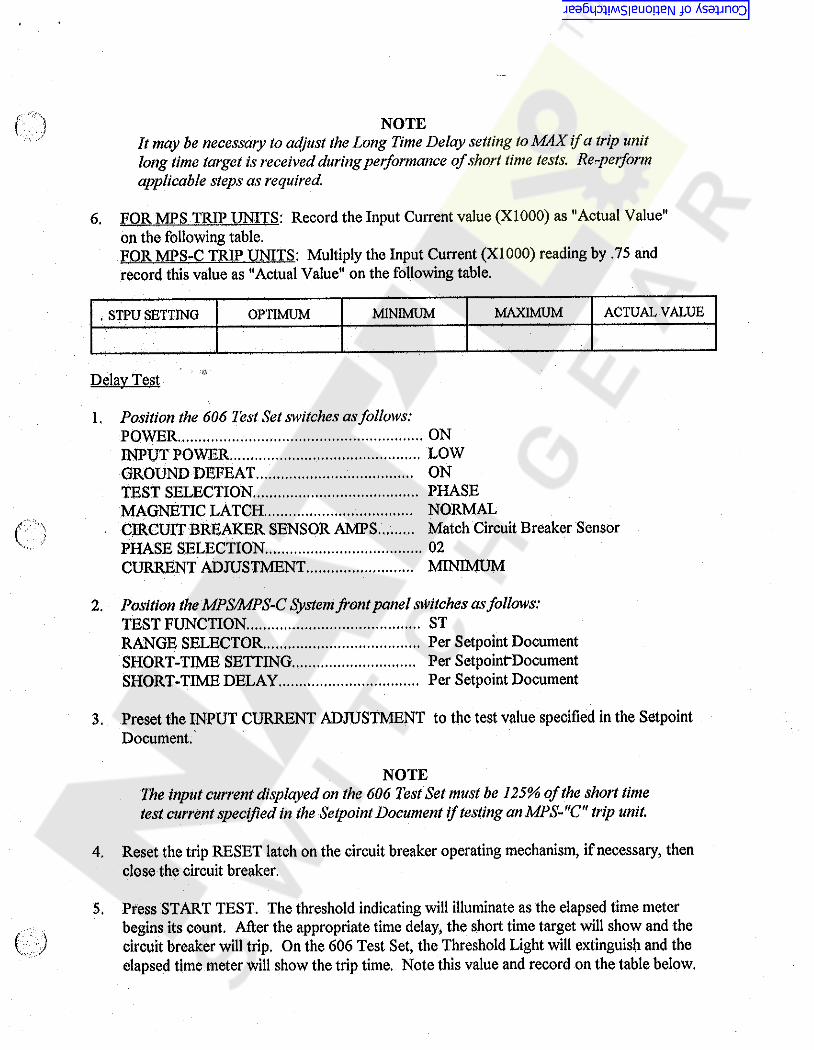
m NOTEIt may be necessary to adjust the Long Time Delay setting to MAX if a trip unitlong time target is received during performance of short time tests. Re-performapplicable steps as required.
6. FOR MPS TRIP UNITS: Record the Input Current value (X1000) as "Actual Value"on the following table.FOR MPS-C TRIP UNITS: Multiply the Input Current (XI000) reading by .75 andrecord this value as "Actual Value" on the following table.
ACTUAL VALUEMAXIMUMOPTIMUM MINIMUM. STPU SETTING
Delay Test
1. Position the 606 Test Set switches as follows:POWER................INPUT POWERGROUND DEFEATTEST SELECTION...MAGNETIC LATCHCIRCUIT BREAKER SENSOR AMPSPHASE SELECTIONCURRENT ADJUSTMENT
ONLOWONPHASENORMALMatch Circuit Breaker Sensorc ;•
02MINIMUM
2. Position the MPS/MPS-C System font panel switches as follows:TEST FUNCTIONRANGE SELECTORSHORT-TIME SETTINGSHORT-TIME DELAY....
STPer Setpoint DocumentPer SetpointDocumentPer Setpoint Document
3. Preset the INPUT CURRENT ADJUSTMENT to the test value specified in the SetpointDocument.
NOTEThe input current displayed on the 606 Test Set must be 125% of the short timetest current specified in the Setpoint Document if testing an MPS-"C" trip unit.
4, Reset the trip RESET latch on the circuit breaker operating mechanism, if necessary, thenclose the circuit breaker.
Press START TEST. The threshold indicating will illuminate as the elapsed time meterbegins its count. After the appropriate time delay, the short time target will show and thecircuit breaker will trip. On the 606 Test Set, the Threshold Light will extinguish and theelapsed time meter will show the trip time. Note this value and record on the table below.
5.c )
Courtesy of NationalSwitchgear.com
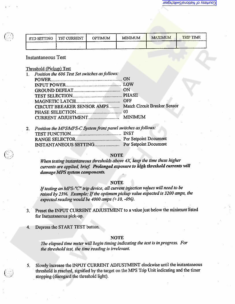
k :- - v TRIP TIMETST CURRENT MAXIMUMSTD SETTING OPTIMUM MINIMUM
Instantaneous Test
Threshold (Pickup!Test1. Position the 606 Test Set switches as follows:
POWER.. .,INPUT POWER.GROUND DEFEATTEST SELECTION.....MAGNETIC LATCHCIRCUIT BREAKER SENSOR AMPSPHASE SELECTIONCURRENT ADJUSTMENT
ONLOWONPHASEOFFMatch Circuit Breaker Sensor03MINIMUM
Position the MPS/MPS-C System front panel switches as follows:TEST FUNCTION...RANGE SELECTORINSTANTANEOUS SETTING
2 .INSTPer Setpoint DocumentPer Setpoint Document
*
NOTEWhen testing instantaneous thresholds above 4X, keep the time these highercurrents are applied, brief Prolonged exposure to high threshold currents willdamage MPS system components.
NOTEIf testing an MPS-"C" trip device, all current injection values will need to beraised by 25%. Example: If the optimum pickup value expected is 3200 amps, theexpected reading would be 4000 amps (+10, -0%).
Preset the INPUT CURRENT ADJUSTMENT to a value just below the minimum listedfor Instantaneous pick-up.
3.
4. Depress the START TEST button.
NOTEThe elapsed time meter will begin timing indicating the test is in progress. Forthe threshold test, the time reading is irrelevant.
Slowly increase the INPUT CURRENT ADJUSTMENT clockwise until the instantaneousthreshold is reached, signified by the target on the MPS Trip Unit indicating and the timerstopping (disregard the threshold light).
5.( . ‘1
/
Courtesy of NationalSwitchgear.com
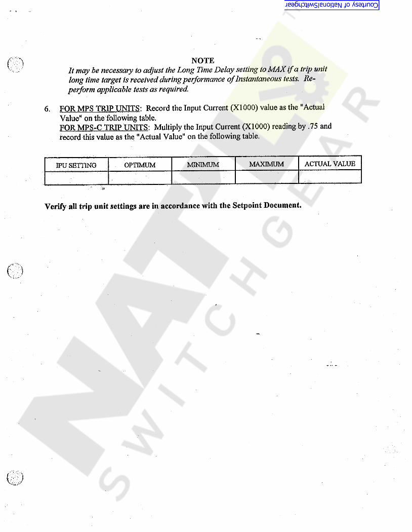
m NOTEIt may be necessary to adjust the Long Time Delay setting to MAX if a trip unitlong time target is received during performance of Instantaneous tests. Re-perform applicable tests as required.
6. FOR MPS TRIP UNITS: Record the Input Current (XI000) value as the "ActualValue" on the following table.FOR MPS-C TRIP UNITS: Multiply the Input Current (XI000) reading by .75 andrecord this value as the "Actual Value" on the following table.
MAXIMUM ACTUAL VALUEMINIMUMIPU SETTING OPTIMUM
•»v
Verify all trip unit settings are in accordance with the Setpoint Document.
(
m
Courtesy of NationalSwitchgear.com

I y f l‘ )Ua \: :
'r
i
1235 4*>.I PAAIS tisr
ITCH PANTKSCfHfTtOMotvNO.NO.
1 to* AW. < IKS 116 fccn. )1 PM* Aw* <025*32 I *2 ftoO1 UTCH AW*X $c*w, to Ho <*250*20 X .56 «.)1 UCXWAIH < *2S0 i »o»)
1 712383-K12 7123334*5 713913-T3A $*3*34*$ 5510546 7031564 W PtTAlNCN7 6$0**042 2 totAlWA8 71*7634 1 PROP LATCH9 650501473
10 713913-TUU 6500504612 71S92M313 71*72741* 712196415 71217041$ 650050-CS17 712181413 712195-K1 1 UcicPurtAw.19 7123*74 1 PIN, Pivot <*621 X **2$ U. XPAQP UTCH)
20 6500524 1 PIN, Pivot <.13* X 3*69 u.)1 INDICATOR (SMINCI CKAAOCOI1 toiwo* TOM ION1 Avto TRIP INDICATOR Aw.1 Im m (.20 X .35 X .218 w. )1 TRIPP** Aw* <W t S«WT t*lP>2 >\m, TOPTION1 him* Am. <HAO. UTCH)1 $1«; tom* Puuc <IUe , UTCH)
2 STUD <13-32 X 1.50 m. >2 lo«KA$Hc* 08)2 to*.* Hex <13-32)t {Mfituri1 PIN* ifttt <.153 X 2.00 u.)1 BMCC1 $c«w, Scir TAP <16*32 X 25 to.)
1 UCKMAI** <16)1 PLATI (Q.F.T * LOCKOUT)1 TMPPM A$»v. <IUo UTCH)
AR VAtHtN* BftASi <.191 13 X .335 oo X 1/32)
1 Butm^TAiP UTCH(.150 t .o. * 1.00 to. TUIINOI
D
2 Xmm (.63* X .750 X .59* u.)1 totUA Aw* <Pwf UTCH)2 PIN* Pivot <.137 X 1.09 u.)1 TRIP UTCH Aw.1 SMINO* TORIION1 PADCOCK HAINt $MUM* EXTENSION2 PIN, PIVOT <*187 X 2.70 w.)1 SPRIIW* fcmmtoN
!36 !35 t
ITT* NO. IT.M.W,I JMSOMXi
tSD 0NLT, ;
M X 1* 71*21*1* ,
'•fl
21 7123564• 22 712615-8
23 713003-Ki2* 650301-B625 71U92-K126 712161427 71*1934123 71*836429 65016*45130 $5103-031 5**00-C32 703156433 650050-053* 7130*0435 50337436 53103-C37 712127433 71*1934239 . 50706-A72*0 71*8174
ct
Q>cj
0)\
;A
-j• ^ 4> 0%
NOTESt1, foe PART KO'I. WITH *T «rw To EPLVfo* VARIOUS NAHIS.
m1X25* 322, 1X8 8 16 PM* Aiiv* WOHN. $«(A)'l(g)3*2 pRA* Aw. C0NM6UHATI0N DirriACNCn
3. ter« to EPt 7122194$* Uito **N QPCN Fuse tmrDevice II 1MTACUD ON UCD,
*. Iten to* 27 Vico ON 1X3 « 16« ItCH to. 33 wio ON U25* 32. *2
a
v
laKaraaraaray,.BASIC OPERATING MECHANISM
STAGE I*CAU » m A
*<m.T»| ; )
4 itott u, wfeoti -AX ITCT H V H TIMO^A r.VTV1'
x fiydrr*''.»* *****
LK eai.tv .y5K
BBSS. -1
L-11527 6r >
)5#»r-; < •; 16.- : . | ,| |
t|gtR . , _ „*/ ?:
IVIV 4V/ PAUTf
A:*
:
, . ***&£ • t.* '.. :8
. .,r- •
i
Courtesy of NationalSwitchgear.com

1£«»« tt TUI MCmu
PARTS LISTPARTITEM
DESCRIPTION1 PIN (.996 Q.D. X 1,69 LGJ2 RETAINER, TRUARC1 SPACER, ( .502 I.O', X .88 O.D, X .191)1 SPACER, (.502 i.o‘. X .621 O.D. X .969 )
9 RETAINER, TRUARC2 PIN2 SCREW, SOC HD ( .312-18 X 1.50 w. )2 LOCKWASHER (.312 I.O. X .596 O.D.)2 FLATWASHER (.312 I.D. X .688 O.D.)
QTYNO. NO.1 650050-B992 650990-J3 650301-E899 650301-E885 650990-H6 712320-B7 650191-B568 53103-G9 59500-G
j D Di
ATTACH SAME ASL,H* SICE USINGITEMS NO* 5 t 6
5
c
\ lr'\y • •
'v .?•1,{
.!V -
B B:
!i
•ii
lt
l' t ir.\
i
SCALE:HALF SCALE i
AM .V t*». tn\t +\ tHC.
MAHOAHO lOiCMUCt #**0 0*10* 'MOt* 1TCM.**A*Ct» - in OK. ».)•T.
!
BASIC BREAKERSTAGE 1Tl.f 3 AA LK 8 & 16.
BBC Brown Boveri Electric, Inc. L“13086 1«MIIt HO ] Of >1
_ jCONt, ON JttJttv ICH^ hPAT*
W'WJXViEB$w Alt,/ M*CHO.3 I lITEH 7 ^ <390-66 1.0.4VMM MUIMn(« tt««HIOHW <* ft*0*% *HO CO* **% * •f.pUitMH MtOftMAttOM*+*<HVglf OvS -C*»»0 VtIO «•0»trvW4 t» * » <M *» *«AV'**:.WfL* 44itMOAL»6 tort* lilCrtM* W.
\7? r ' ^vBY A BY1BY *REVISIONS NO, NO. REVISIONSREVISIONSDATE DATE DATE v*
Courtesy of NationalSwitchgear.com

' ’'-&£v-.1'^'3H
1H*C UMt M< 1441«
PARTS LIST
ITEM PARTNO, DESCRIPTION
2 SCREW, FLAT HO {,250-20 x .50 L6)2 SHKPRF LOCKWASHER(COUNTERSUNK)1 FRONT FRAME ANGLE2 SCREW, HEX HD SOCKET(5/16-18 X 5/8 LG.)1 SUPPORT, ARC CHUTE1 ESCUTCHEON ASSVV2 SCREW, RD HD t.f50-20 X2 LOCKWASHER(v2S0)•
2 FLATWASHER(9/52 ID X 1/2 OD X .032)2 NUT, HEX (#10-32)2 LOCKWASHER(#10!2 SCREW, RD HD(#30-32 X .50 LG.)1 REMOTE TRIPPER !1 FLATWASHER (?28.l ID -X .625 oo X .080)1 RETAINER1 SPRING1 NAMEPLATE2 SCREW, SELF TAP (#H X .25 LG.)
NO. QTY
1 5R357-F62 650379-E3 713371-K1A 650W8-B525 712195-A6 712369-K17 59393-F3
. 8. 53103-F9 650351-A2910 5W00-D11 53103-E12 5R3A3-D613 712391-AM - 59500-F15 703250-A16 712528-A17 712363-A18 59389-A2
DD
!iJ
‘**•4 ... • A •K I «»
131 LG 4) 1«^
* 4.
o.v<
rCP* »>
X - ..A
V
V .+
?C* c
«.1»!
-v.••* ir«
/
\• »•4 ««* *l *•
Y}
»
*£r*i</ * «• »
IA<*> ••... g
>•4’*i t *
*• ,t
B>••... . p»• >.1'. • .
I»i *• * •*•!
4
•P.u.. .6
v
IV
A'i»»I i* 1
•>-!i
e-. *V-.' ‘- 4• »«
SCALE: KALE SIZE<vUiMtH£<ONi AMI
1 t f\ oecSTANDARD lOUAAHtt WOO ON OH «U «*IOUAAHCCS. UMUtt omWWISt lAICiFUO > At OIC 1
\ •'BAfMRMKER [ V * vf/
;I
•>: •*
% -A'X A/ EH* 71220t~T1 e T 3
EPL 71223I-Ti|
4
,2'A lLKQ e 16i
1413088Brown Boverl Electric, Inc,ManuUctuter «1 t *T «6 tlccU«ca< Power tti ptncni
1
1 -18 1.
. *j-~"''."A'S.%'* " " * " "I* bOr^\ t* c o n r ON *
' • •|0At^yA£t>,
<A1</~ Hj -tHiSOAAWINOU f**4f AADPIAIrO* «AOWf4 •dv4Mi*UC(r.fC '{vf- A N O 4-M i^w)!«Hf ANDfiDCNHAlwrOAUAriONWmtH wgt ) HOT «|OuAitCAltD U >I.A OD 0 •K ( t tiMOululU to*H At| *Mif f,„tYAutHOAi/co"'"AOWK *ov(Amtc<ruc/,mc '
ITEM.I WA$‘
5434>F6}.tfEM 2.yAS650373-A; AOOE^EPl 712231-T4 TO
•• .#•
4
r«>BY /f/tChf*** [ CHO.oAte //* OATI
Lfi^i -- Ell %.*;:TITLE BLOCK4.S.O. 1 I
iBY 4 BY 4NO B6V1SIONS evt i
NO. REVISIONS NO. REVISIONS*‘vk ‘
OAte
JOATE OATE r* . '-Ij:* i'
i
v^ <.im -
4..t3 ,-442 •• ?
TYr•. «•' \
# *.(1 . .* * •;
. ••: ».
A#{.IA ;« >\'7h
Courtesy of NationalSwitchgear.com

{'••’X • '
'( : 1 14 i 25 37 68< > >* - 11 •< V),«««#
PARIS lISIISCALC REDUCEOI It .N PART
SCREW, Hf.x H0 vi51**1$ X 5,00 ..i*1 SCREW, Hex Ho < « 5 U-1S X 5.002 Nut, Hex t.250-2012 tocxwASHER < *25011 tOCXHAlHtft < »Ji fcyilNAl,*1 Nut, HEX <5/16*18>1 IcXxwASMtR iJi tioamO1 Nut , Hex 45/16-1S >1 Scat-, Hex Ho ( ,510’!$ X .00 {
j toCKWASHER 1* 51 ttO«|SAl*t Hut, Hex £5/ 16-I8>i MOTOR1 PIN <> 572 oo X 1.1/9 u»2 fcUINEK, TRUARC < » 57$t1 MOTOR UNA AS**, (ADJUSTABLE »1 RACE , THRUST1 RETAINER * IRUARCj SCREW, RD HD < "250-/0 X */f* u >l Cur ( INTERFERENCE )
1 *r RELAYi RETAINER
U50 ONLY OM H- l , NO.U.O. MECHANISM : 54390-BU
S4590-BU3 54400-F4 53103-F9 S3103-6f 54400-67 53103-611 wwo-o
54J90-B8It.’ 53105-0i: 54400-611 709799-1
714471-A1« 650440- G19 715923-12
j »•. 19156S-A, i;. 65<mo-A2
U . 54343-F8= If 712J80-A
2C- 712218- t2J 703250-A
1 >
D$££ SHEET 1D FOR REST Of
STAGE U29 ASSEMBLY
use ONLY OH M.O. MECHANISEWITH ITEMS HO. M » « •
|SCALE REOUCCOl
(SCALE REDUCED| 1.-OTfj REFER to
(SHOWN WITHOUT*Y* RELAY!
• •
; n1 RACE, THRUST1 RETAINER1 RETAINER. TRUARC (.879)
1 CLOSING SPRING A***,1 BUSHING <1*009 ID X 1,1/ QD X l *
1 SCREW, Hex HD < *^-20 X *02 iu >l BUSHING <.34 (0 X .7^ oo X 7.l?r> »1 Ret AT NCR, IRUARC ( ,W >1 PIN <5*97 i.Ui CONNECTINO too ASSY *1 O.OSTNG $fRIM Asst,
• 2? 191565-A‘ 192500-Ai 2S 65044C-A4! n 713910-m\ 27 65O30H66
2t 94390-A2i 2* 650301-669
5C 650440-J51 714477-A52 713923- T451 715910*113
\ P 711910*114 1 CLOSING SPRING ASSY *
cc
;
*• .*
26— MOVESi{ , 1K8 i IS <E*0. > SHOWN, KOIOR SHOWN IN umuto MvlMON ,
USE ITEM No. 26 OH LK8 I 16, Use ITCH No, 55 ON IK.M* i V.Use ITCH No, 54 ON U42,
3334 BmuB
V, REFER to (A>(|)© :roR USAGE OF PARTS ON (K.0,I,
K, Mens NO,h:h 4,7, 8* % 10, U 12, M, 14. 19, 1!..17, 18, 19, 20, t 21 USED ON <6 *0* 1 ONLY.
J,, PART NOU WITH * T AFTER THEN, REFER to IPl FOR USAU .JI
VARIOUS RAfttS »
Q>
SCALEi FULL SUE***! > «
t *»*y **. n y . |~HTS1C OPERATING MECHANISM IR.K SIDE)STAGE B£
AA
IK mm.TK.Ti> WIlHKlHf
BBC Brown Boveri Electric* Inc.i— ... . ... . . - T 1 i* Of ..T
o*H Hmf.tf Wu A •< ) * <* |»*M| < >. » %
^ *c.“ “ -Ui v •
1*11530REVISED NOTE|RY MUTIHO
^I* JJ.
ITEMS U t ».DCLETEQ ITEM ,REVISED 4 RCORAWN TONEW COMKCURATIOH
3I < > ».*
' . 1 1 i "T i i .Hi
VH H
Im•Y 4 RlVlSIOHjNO. OAI(KVUKXM RCVlWOHt DATE * *
»lW
2•* 1347i*» «rn 8 s * *
•>
Courtesy of NationalSwitchgear.com

>*»:
;
f
'• '•
;\
i
D‘
:
i
c
V; 'i
r$
*
* :
t
B !I
A
U5 3JL 6 A7 4 , 18V
Hr***, * * »*Vfr ‘***•> “« *1“** * l***r *a#**».M- r^yp^rfi VX
.. .:• vu:>wji» /r».£TO
( t tT Vfv‘ ry /», \I
Courtesy of NationalSwitchgear.com

iJ
2 f 1
PARTS LISTfi
IITEH PARTI NO. DESCRIPTION
1 PAWL CARRIER ASSY.(ELECTRICAL)1 RATCHET PLATE3 PIN (.372 X 1.125 LG)6 RETAINER1 RATCHET PAWL ASSY.2 RATCHET PAWL ASSY.2 SPRING, TORSION1 SPRING, TORSION1 PAWL CARRIER ASSY.(MANUAL)1 PIN(.372 X 1.125 LG)2 RETAINER, TRUARC.1 LINK1 SPACER (.406 X .75 X .275 LG)1 SPACER (.006 X .75 X .180 LG)
NO. QTYD1 714476-K22 714456-B3 714471-A
j 4 6S0M40-6i 5 714871-K21 6 714871-K17 714868-88 714868-A9 719482-1(20 714471-A1 650440-G2 714459-A3 714474-A4 714474-B
D!
'
* I. '!
c:
# •
r>) *
tv
4 v*
ROTESiB l. REMOVE ALIGNMENT SCREW 193.747-B.AFTERASSEMBLING RATCHET AND PAWL ASSY. TOMECHANISM SIDE FRAME.
B
v
f
ITEM 0 VA$ 650213 - CITEM.** GEOSI? * F— a « «*• «•« » »» a » •ne/i5 WAS csoo<W‘C(s)lTf«& WAS 12X307’A fa)it\iH 1 WAS 7/4?<IOA rr.)r w WAS TuriO'f*
fAHIpCALEi PULL SIZE
Sr/HOAKd tOU«AKCt »HM» IWIRIicnt«Anc» *« < mo.•5 |HU< hVolts Alll <•« Hh«1>.
* J IN IH»* *RATCHET AND PAWL ASSY.m4 AOOGO ITEM'S NO.•+ - «**A
(1ST AITEM 1 WA'
I TlVMO^KIImS A WAD ?m4St » Aen WA5 TI39IJ - TI2NC- KT A$SY WA« fHOlOAODCO KCV ITCH. ^<t£n 0 WAT
I,
RL^'HtO f Krt)* Ay/H illfw <*< < «».>
IKBBS Brown Boverl Electric, Inc."WAN wviw r>l 1*1 I W» < I^KTHK*
3 L-1 1 5 0 9_:]tinn *M<I 1 oi l* . IMt, *\v." v *.•HA>f ?./ »> « » <?
M*WAi*m *««*««ovt*«<44* n<» *» *m»,>,*«u'.««*•V*.» *- »*4-. »*•»*0*411*4.w»WK*Wmwi«tmlih*W*<M MjmftM AIM* irJ*. ,m.••* *.*I f AylHAW/ffmVfMWN ftfiVlM MtiMAt*. **
iltxCO*« t
I MW.!«*Cr <304^
1 '~ r
V rrr OAf£HIB
l•l
1.0.'*•i.**'*'
eveNO. flYtREVISIONS 0Y4,NO. REVISIONS NO.«•* REVISIONSDATE DATE DATEWGilH
4 TT
A3 2 1\Ax
I1
I
f‘v'I
Courtesy of NationalSwitchgear.com

V1r '-'r1: !
± 123457 Ih6> 8> rMM ** •*«•\ PARTS LIST
;••
IT01 fMT! KfCItlPTION1 RATCHCT * PAK, AW.1 CAAMK AW Am. < R.H «)
1 Pm <CftA*K Aw R»K,>4 RCTAIHCK1 Pm <,572 X 31,51U.)1 Y<#* AW,1 PtTAINCA, TAUWC1 fXKNMON1 Hwou AIIY* (KWUAC CHAwe)
1 Pm <.572 X .75 u.)
OTY#0,1 7159254$2 714725415 .»4 19257S-A5 71252$^6 714801417 $$QUM8 $0402-059 71479941
10 65005042
t
Dt D !1
!NOTtSi -t, Utt THJI HOU TO* In« *0, 6 0« IK8 & 16,2* Utt THU HOU ro* ITCH w, 6 ON 025,52 t 42.0
l
<
C!>C:
<5
1i
> :
:
*v..
BB
—9
fI\
1L
l
soil Ui tIMM,>»»« «M. M.H, M.IMWW mHiMI« *> *< * . ABASIC OPE^ATiNOj.HECHANISHAlajf.n.w.OMUM
KBS te*&LS£gSja Jr41528_i 0y
»,vpsTIJM *MMVWOHIl Kwl*0, «*#**# ©ATIHOJ: 2 1y 3
W45 \67 V . •mm 8k i•* >.*»•vf *? T., -"A " * :
“ • * ;w 'Y' * •,\.i
Courtesy of NationalSwitchgear.com

IPARTS LIST
PARTNO, QTY DESCRIPTION
712509-K2719980-A650990-J719979-A650301-E75712167-A650301-E88650301-E89650990-A16713961-A712306-A7123Q9-A196860-A
. 712301-A719919-Kl75597-A3712301-B719919-K2
1 CAM ARM ASSY.2 STOP BUSHING2 RETAINER, TRUARC1 PIN ( ,997 X 2.679 LG, )2 BUSHING ( . 506 X ,56 X ,125 LG. )9 TOGGLE LINK1 BUSHING (.502 X ,621 X ,996 LG,)1 BUSHING ( .502 X ,88 X ,191 LG,)2 RETAINER, TRUARC2 SCREW (010-32 X ,50 LG.)2 WASHER (SPECIAL)1 INNER RACEWAY SLEEVE (.500 X 1,899 LG.)9 NEEDLE BEARING (1/2 ID X 11/16 OD X 5/16 LG.)9 CAM ROLLER (,688 X ,996 X ,312 LG,)1 LINK ASSY, (RH SIDE)1 NEEDLE BEARING (1/2 ID X 11/16 OD X 1/2 LG , )1 CAM ROLLER ( .688 X ,996 X ,500 LG,)1 LINK ASSY, (LH SIDE)
D D
f A
C c
v ;
:
!
13 B
?
rScale; 1 to 1 STANDARD IQU- P. ANCE INFO. ON OR. BJOIt
lOUAANCMXfVJIIIM OIHIAWISI SMCIFICO - 3K.OIC. *DIMENSION* ARE IN INCHES
} ft. DEC. I
TOGGLE & LINK ASSY.*£-*- T' :v, •
*
Ami LK 6.16.25.32.42BBC Brown cloveri Electric, Inc. L~13009BROWN flovt i Manufacturer o!I‘T*E Etecirtcal Power Equipment — «r -*-5 — ^ ^^
DATC 4 / |OATB >*» / ?* M (L ' I
v0
16Y10AT!
CHO.3.O.
Courtesy of NationalSwitchgear.com

lt
i
\
A 125 4 37 68«•4 »* <1*.* -« UiIfm PARTS list
ITEM FAREOCSCRlfTJONOTY«0.Ho,
im6 UFf*R TERMINAL6 SHIELD
1$ SCREW# to Ho <«312-11 X 1« Q0 L«.)
6 SCREW, Ito Ho <*>12-18 X 1.50 U.)
2% lOCKNASHCft («312128 Hut, Hex < *312-18)3 Axe CONTACT STOF
1 713908-T32 713068-AJ 58383-4108 58383-4135 53103-4$ 58800-47 713850-A
D
U226 OFFER TERMINAL6 SHIELD
18 SCACW, to Ko (.312-18 X 1.00 LO.)
6 SCREW, to HO (.312-18 X 1.50 U.)
28 lOCKWASHER (.312)28 HUT, H«x (.312-13)
3 Axe CONTACT STOF
1 713908-T32 713068-A3 58383-4108 58383-4135 53103*48 58800-47 713850-A
U826 OFFER TERMINAL6 SHIELD
18 SCREW, to Ho <.312-18 X 1.00 L6.)
6 SCREW, to Ho (.312-18 X 1.50 LO.)
28 lOCKMASHER (.312)
28 HUT, HEX (.312-18)3 Axe CONTACT STOP
X 715908-T32 713068-A3 * 58383-4108 58383-4135 53103-4$ 58800-47 713850-A
G
•:
<4i
8
REAR viewlooking towards FRONT
<
\\
if ****** *»**0«MtMNIHItfV«*i«*Mggfj *»«0.4*» > * »tc t
m m **«** n We i A|SE MOLDING ASSY. (Upper terminals )STAGE n I
(LW 4.M * 4J)
L-11578Drown Boveri Electric, Inc.M*w4C**«WM-EEWCVKH(WtI*****
0V- l-f I- -*•£I£Z
IsggKBgs^ asB - ssara
(Mltv A•AM. //
M<*0.
ta.?iui£IV*WVHMOW# OATSMVWOH* ©ATI I DAT!NO.
r1345w» mt 678 .V* *****•mWf :
<L Sit, I. .f*» - tt** A,. »f.. . f 3VT*I -,r.8a>."I V « ,
Courtesy of NationalSwitchgear.com

137 4 .6 58«•4 *H ***<•
( )
/. .i
D
7?
c
i
!( "V f
j.
i
B
i
;
i
J(
1, LEFT TERMINAL SHOWN,I‘ r
2 , RIGHT TERMINAL SAME AS LEFT ESITEMS NO '. 1 1 21 ARE INSERTED
\!
OPPOSITE AS SHOWN,
iA\ii
TYPTI pRoo,gp# fcr
NEXT A«$M.snrt /
PcT^7l3S 17* *T3^X4] Ktp: TBBC Browrt Boveri Electric, Inc, C*“"***<* L—
nm AuSniniaoxzaaQ! 3) HAND,l«K 14 w* muf*c. ITCH 14 M« S494MHlre* 17 *** *4H)rWU
'
i1PATE
CHO,•Vi•ViSftl"* MVUKMtHO.,S •iVWOHt OAffl*Y1«*W* •AWWX
L-1I 5 I &31 4".7 567•*< WM 8"I.1 r 8H..NO. { QF 1 \ \ ZCMZ
0V(W £Lfc, C- «<<? Ai&C0+4»AW«>icvMtUAVA«0CO*rtoMiui1«,/ «oupuc^ffo.utfo.OA DUCU» «<OOI,.CA U.* H *t C/MUC*
I--1 *1i
V V. tll«UA*„\
Courtesy of NationalSwitchgear.com

«D
C
C c
\
C
B[
Ai
tU was *•13, I i
'
i M• ] Q( ^ |SCALE
**
•Y *»Y * •Y It APT.MO.CHO.ItCVttlONS NO. RWWIONtAPP.CHO, APP. REVISIONSNO, CHO, DATEOATS I DATE
\
Courtesy of NationalSwitchgear.com

234 XPARTS LIST :
PARTITEMDESCRIPTIONNO. OTVNO.
2 NUT, HEX HD(.375-16)1 54437-H2 53103-H3 713836-A •
4 <;'712136-A5 712121-A
. 6 71M630-A7 712181-C8 712492-A9 714639-A10 712495-B11 714628-A12 650446-B13 54383-06
>14 714631-A15 714632-A16 712116-C
‘ 17 714626-K318 712126-A19 714626-K.420 714629-A21 650446-A
LOCKWASHER(.375)2D SHIELD(UPPER LEAD)2
SUPPORT (UPPER LEAD)22 RETAINER8 SPRING BUSHING(MAIN CONTACT)8 SPRING(MAIN CONTACT)16 CONTACTS(MAIN)2 UPPER LEAD8 " PLATE STOP8 PIN(1.305 LG.)2 RING, RETAINING2 SCREW, HEX HD(.375-16 X 1.50 LG.)
PEN (2.390 LG.)12 SPRING BusHtNG(ARC CONTACT)
' 2 SPRING1 CONTACT ASSY, ARC(R.H.)1 PLATE STOP1 CONTACT ASSY, ARC(L.H.)c 8 HASHER (.188 ID, X ,438 OD,)16.. RING, RETAINING
.)
B
UPPER TERMINAL LK-820 * 71306*4nmwi replaced by -T7 *
%AVthI c» Misma f <ttM n
tttM in wXi‘Irghl9 . WAS .hi4tf6tfyK.finet Nftoo,|cussNEXT A$$M.
• L- / /f 76
*> 0,EPL 713906-T7
cust. ITEM|T«« Mt If W* f/Wf-KI(tttiwo,If W< T/V3M-K,31A P. 0,
2IT6N ITWA*iren *»*% U««*«*K46
L-11510 If'wl
ftip
MS«=.KSRI *L5^ Amo ITCH X \K ItM t$ WAS VtfiW
iUH ti MSirfrt «NTH * v/«
1L::>7 /
IfMREY131GNI
i -A SH..NO, 1 OF 1 I SCAltWW0'W.feKO W fH<^Of^«YQf »WWH40y(AV£UCtWC
,IHiT*«t) COHI K* MCiVpi^UftvX><0 COK*f»fHMtfiWpW'AtWKWWCHWVlt KOI f«MinICATtO.ytCO.OAOt'ClOMO OtKCA tWAM At IMAtK'
!
*Y iBY 4 BY 4 CUD.NO. HCY1MONS NO.CHO. ANN.NEVISIONSCHO. ANN. NO. DATEDATE C*TC.\ .
AV'U'i»«vw _
Courtesy of NationalSwitchgear.com
4 3 2KAK 1*1111IM1HCtllf* 1PARTS LISTNOTE 2
m PARTITEM2NO ,NO , OTY DESCRIPTION
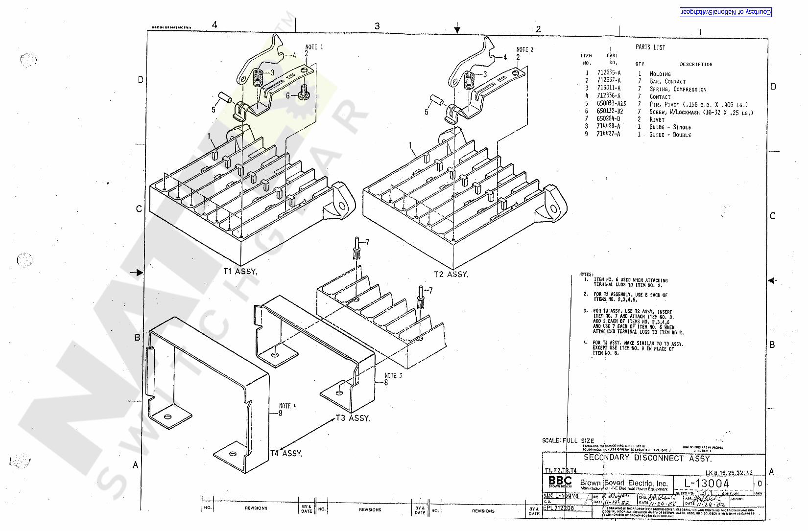
1 712655-A2 712637-A3 713011- AA 712636-A5 650033-A136 650132-D27 650289-D8 719928-A9 719927-A
Q 1 MOLOING7 BAR, CONTACT7 SPRING, COMPRESSION7 CONTACT7 PIN, PIVOT (.156 o, D , X .906 LG.)7 SCREW, W/IOCKWASH (10-32 X .25 LG.)2 RIVET1 GUIDE - SINGLE1 GUIDE - DOUBLE
D
c
<r3V
T2 ASSY. NOTES:1. ITEM NO. 6 USEO WHEN ATTACHING
TERMINAL LUGS TO ITEM NO. 2.2. FOR T2 ASSEMBLY, USE 6 EACH OFITEMS NO. 2,3,4,6.
<
3. .FOR T3 ASSY. USE T2 ASSY. INSERTITEM HO. 7 AND ATTACK ITEM NO. 8.ADO 2! EACH OF ITEMS NO. 2,3,4,6AND USE 7 EACH OF ITEM NO. 6 WHENATTACHING TERMINAL LUGS TO ITEM NO.2.
4. FOR Til ASSY. MAKE SIMILAR TO T3 ASSY.EXCEPT USE ITEM NO. 9 IN PLACE OFITEM NO. 8. B
NOTE 3—8
i
NOTE 9
T3 ASSY.
SCALE: FULL SIZE * . IItAMOAAO fOUAAHCC.WO. ON OR.«704«TQtCflANCCt »[ VNlttt OTHtftWHC SfCClflCO - ) fl,0*C. *
DIMENSIONS AflEW INCHES? H. DEC. *e> SECONDARY DISCONNECT ASSY.I A 5v „y
TLT2JU1 ALK 8.16.25,32, 42BBC Brown 'Boveri Electric, Inc.i * |
CH MumHncuW of M-E £iocif *cal Rowor Equipment L:1 3 0 0 4sneer >VQ. 1 oT T . poNT.oNT IAPr.M^Ji.7.' IMICHO.
/ / Z 4 - &X I0* / / • l <tOAAWINOIt fHE tROPEfttYOf 8ROWN-«OVfft! ClCCIRIC,INC.ANO COMtAINS pftOfflltlAUV A«0 COM-yOENHAlINrOftMAUOH WHICHWUSr.NOT « OUPKCAttO.UUO.OP OISCLOStb QtHCft 1HAH A $ EXPRESS* ,V* AU*HOft«co a Y tftowNeovcfti CLECIAIC. we. •
0SW. L:1 )978 HCV .
cm.JW/P'iUr*:OAtei s.o.art EPL 712£08NO. REVISIONS QY &NO, BY AREVISIONS NO. REVISIONSDATE DATE DATE
1
Courtesy of NationalSwitchgear.com

Dn tB61F62 60R
W
9
Cv CLOOP TO *R*
*62*
*.
(5
it *
:
LEGEND
TB HIRE CAP
FUSTIC STRAPS(CLAMP)
ClXO) #10 TERMINAL LUG
KNIFE DISCONNECT
GUIDE NAILS IN BOARD
63 B&
L#
uNOTEi .IF WIRES NO , "K" *68* SNAND *M" *67*ARE TOO SHORT,USE KNIFE DISCONNECTS ANDSHRINK TUBING AS SHOWN.
OiAtAHC* WFO. OK DA. <tOl«\ -jWUllOTHCWWItt IfCClFIEO - jn.Die.t
STAIIUWIRING HARNESS(SMALL FRAME BREAKER!
IIANOAAO I OlMCNflOM AM IN INCHCItn.oec,tlOlfKAHCtl
A iREE 611000 -T1 LK 8 ond 16I ABrown Boveri Electric, Inc,Manufacturer ^l*T*£ Electrical Power Equipment* “ ^
wty.tf '&z . . — —OAAW1«a 4« IMC tAOfCAIVOf IAOWNIOV «ItCOlWC,*4C.ANO f J S u f l lJuUtlAtWtOAMMtOMWI«C*MUlt HOT1C 4HJFUCAUO,U«0.0*4MtCt<5«0OTHtAIMAMAtCUMWMLY'AUtHOAIitOlYtflOWH'eOVfMEUetWC.We,. . .4—-i
L- 11589:E?“
0•AOWW eOYfw
) I«YM dfy MV .m tyt,MICflO.
C.0. »29 -62OATtNO..; BY itREVISIONS 0V 4NO, REVISIONSDATE OVtNO. REVISIONS0AT6WC4IM DATE4 3 2 I
Courtesy of NationalSwitchgear.com

1
V '
k
*. * *»
; - i* *
* *?:v ‘v
#
1
i
\
• *%
'0 t *3
*
4
%
< «-! 4-,>.V
1 - / /S77L\
U600:
C3® »10 Slit L*CXe) * si>« u«KMLRE DIKOMMCCT
P——1 PtMTlC $T»W <Ctw*)
t &VIM AMU IM S»Mt*f
\MOMH'KiH»!«»«« It * tmw» * —•Ml-Ml
WIRINO HARNESS UK 25.LK 32 and LK 4- 2 }
* 55? P'jCiWeR»-»« /X -f' Cr
MlWtltil**»-•**> **•*»<*-»
1».SA|~ r> 4*Cv'**0** •fY**0»** ftAtl
Courtesy of NationalSwitchgear.com

t ii
«
LEGENDt
CDCD ,io S *ZE WG
<§!X3 16 SIZE LUG
^ C~1 KNIFE DISCONNECT
Qm PLASTIC .STRAP <CLA«P)
•GUIDE NAILS (IN BOARD)
SCALEi FULL SIZE(IUOAM rOUAAftCC OH 6*.mi< 0M*4Wl9*t AM WWCMI
Ar«H»NWf«* - WMM OM<mM -1n,«C 4
WIRING HARNESS - LK 8 THRU 20
Aim L-1 1 5 7 4H«« TWP / y I »M-.g«L£sf—I
IHrtpMwM (4 A M O O H4M M««***<*****0 0 0** KrtMTUl WOAWAfuJH*MCMWtTNOlM9V*.«CA«0,VM»,W Of*HHMAM A4t****t’t* ApMO*WtO 4»4W**><>VtMl <l<^ ««,«<. '
ASEA BROWN BOVERI 2J. Mj> >* Xwft M,
~s>., RCVI5C0 m fiEOflAVH roiiw TlJ^V/CltCUir HtAKU OtVItlON«<*•*>«KM*MM #v «. OV*-v**
oAr« s / H/ayMtw.CMO,iCOHf tWMHOK, VOCfiCO *£ ¥, 0 OAT*REVISIONS ar A 6Y 4NO REVISIONS REVISIONSWO.OAtC UAI6 OAtCy*
X Ai\ \A 'XyV 9 ii
Courtesy of NationalSwitchgear.com
i4 3 12*>»< (Mt MClUlt
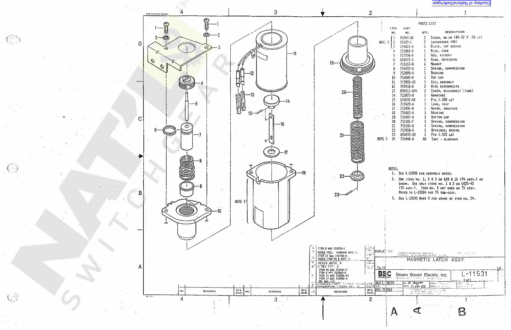
PARTS LISTPART
DESCRIPTION
SCREW, RD HD (06-32 X .50 I.G )
LOCKWASHER ( 06)
PLATE, TOP KEEPERPLUG, COREROD, KICKOFPRING, RETAININGMAGNETSPRING, COMPRESSIONBUSHINGTOP CAPCOIL ASSEMBLYWIRE DISCONNECTSCOVER, DISCONNECT ( TUBE)
ARMATUREPiN; ( .280 LG)LINK, TRIPGUIDE, ARMATUREHOUSINGBOTTOM CAPSPRING, COMPRESSIONSPRING, COMPRESSIONRETAINER, SPRINGPIN ( .422 to)TAPE - ALUMINUM
QTY .NO./•r
S9393- B6 2NOTE 2 2 53103- C 2
. 3 719621-A 1N 712868-B 15 713356-A 16 G50933- A 17 713153-8 18 719932- A 19 712869-A 1
10 719605-A 111 713856-K2 112 703918-A 213 6S0311-A99 219 712873-B 115 650032-A8 116 713929-A 117 712892- B 1
, 18 71H603-A 119 719607-A 120 712181-F 121 712181*0 122 713858“ A 123 650032-A9 1
NOTE 3 29 " 719896-8 AR
D
11
—12iI
5
c16<£>
7 * fill
NOTESi1. SEE L-13030 FOR ASSEMBLY NOTES,2. USE ITEMS NO. 1/ 2 8 3 ON LK8 8 16 (T9 ASSY.) AS
SHOWN. USE ONLY ITEMS NO, 18 2 ON LK25-92(T5 ASSY.) , ITEM NO. 3 NOT USED ON T5 ASSY.
. REFER TO L-13019 FOR T5 SUB-ASSY,3. SEE L-13030 NOTE 9 FOR USAGE OP ITEM NO. '29.
18
BNOTE 3 '
Ns
IITEM 8 WAS 712539-CSCALE j 1:1'? AOOCD (T5) » CHANGED NOTE '2.
* fUin? WAS 714748-A .ADDED ITEM 24 l NOTE 3.
• «.i i » m -ACVBO. NOTS' X9- '*^*# * * » • 4jt .«
A ' DHV SV- |.ITEM ZO WAS mm »tITEM 4 . **« 7I2860-AITEM 11 WAS 7I3856-K 1ITEM 17 WAS 712892-A
MlsMlftAWH )! ^
» rfc f.1 - jr.
i. -i i t.A 'nt '.,'i H-( •.' c i .«,n •.*. > <(Mn«*.«M H.MI I•<.
£ MAGNETIC LATCH ASSY.tr
4" /> cA T4.T58 • LKA*.. +*^f+***r*"
§IS L-1 1 5 3 1Brown Boveri Electric, Inc,7M » i '* lei J 4 ' \ , . 10( 1 iJf.
MM )
<iv (A#/**'UAt < 7 * /d•SA JIM ( ,
* -’4. 42 . \ 9 . ‘1»/UEPL .71129 30YI - ! A "1.’.” > < ‘I... » ’ , > . •. -
oVi.no REVISIONS .7,REVISIONS REVISIONSNO. >.<DAieOAtEDATE
J-i‘4.
4 23 1!
Courtesy of NationalSwitchgear.com

3<+ 2 1
t
vD
D
C c
*c: \
14PARTS LIST PARTS LIST
ITEM PART' HO. < QTY. DESCRIPTION
1 712330-K1 1 CRANK ASSY.2 712329-A3 703250-A4 59398-A10 2 BOLT5 702312-A6 706721-A7 709107-A8 70M722-T20 1 CONTACT (HSG, 1ST STAGE)9 , 709722-T84 1 CONTACT (HSG, 2ND STAGE)
10 650908-E11 712927-A
B ITEM PARTBNO NO, NO QTY, DESCRIPTION» ii
12 650351-B22 1 WASHER13 709953-A19 712185-A15 709103-A16 709958-A17 59371-C318 705956-A219 705956-B220 705956-C2 . 121 705956-D222 709952-B
. “A 1 LINK1 RETAINER
1 DUST COVER1 SHAFT (2 STAGE)2 BEARING (MLDG)1 SUPT, PLATE1 SCREW, SELF TAP1 LABEL (CONTACT NO ,)
$ ;4
2 RETAINER (ON SHAFT)1 0.C, LABEL1 HOUSING (DETENT MLDG))
15;
1 H
it M
2 NUT (FLEXLOC)1 NAMEPLATE
1 H ‘ H%2 COVER (WINDOW)
*I
t
16
tM TYPt|PROO.ICUSScusr.BYft* GACAStODATE
ITEMA AP, 0. LB AUXILARY SWITCH ...IAPP; "" V
•*. »
EPL N 2210-T1iten if, on. VAS UroJAoW Aijt ot Jw \HR* ITCH ». rtfrt iszRSVL -U5 / 9liJPjQ Btown Boverl Electric, Inc. C
Oi 4*t £ POw£f E<l\*0fnQrHISHS- zt A00C0 ITEM NOS. 18.,19 , 20 , 21 , 2217s
SH..NO. 1 o f -1 | SPACEtHU OAUVIM9 1«1«;**p>MjVof lAOttMiOVCAlHCClAlC,*C AMO COStAUM # AOr,ilY( AftV AKO CO* .
A.’.•
BY &NO. BY ABY «REVISIONS CHO. AW, NO. REVISIONS REVISIONS CHO. AW,NO.CHO. AW.DATE GATE DATE
X r\
Courtesy of NationalSwitchgear.com

1o
D Dr-
c c
•4
f
ft#
B B
*
AA
sifttr ? -i f1 :) . o\
B* v <.o
\
f
Courtesy of NationalSwitchgear.com

Mv»*.tv <<*/ **»**«
"Y" RELAY(T10) U
BBC Brown Boveri Electric, Inc. L- ; 523 uenowN eovtw Manulacturof of l*T*£ fc’leclncai Power Equipment — — «-* -XF F ~ ~ —. ILV 4 r 1 $H CT NO, £.Ur 2 _ CONT,ON
0AT&r.«»g/ / 0AT* 1 /J5I&J«|£L-11374 ev /£.
OATC ^&SSICHO. MICRO.
$.0.EPl 7I2218-T10 fMIS DRAWING ( S THE PftQfEftTV Of VtAlUCCTfllC.INC.ANO CONf AtNSM0PW6TAAY AMO COM-WCNflAl iNEOflMAliOM WHICH MUStNOtIt OUPUCAtfO.USCO.OAOl$Gi.O«OOTMtA IMAM ASCXPAfSS-IV AOtHORi/ f0 BY BROWN-ftOVCRl EUCtfl'C, INC
DIMENSIONS ARE IN INCHESin otc JL
StANOAAO lOURANCl iNfO ON 0« 6201«IOVERAMCCS *• UNLESS OTHERWISE SPfCiritO • 3 Pi 0(C *
PARTS LIST PAKlS LISTIT EH PART ITEM PARTNO. DESCRIPTION
SCREW, RD. HD. (#a-32 X 1")SWITCH(N.O.)LOCKWASHERFLAT WASHERSHEET, INSUIBUSHINGSCREW, RD. HD. (#10-32 X 1.50 LG)CRANK ASSY.SPRING, TORSIONSCREW, RD. HD. ( #10-32 X .62 LG)PLATE, MOUNTINGCOTTER PINSPRING, EXT.RETAINERLINK, TRIPPIN(SHOULDERED)MAGNET ASSY,
NO QTY NO. OTY. DESCRIPTIONNO.1 • 34343-C1U2 713916-T13 53103-0A 54500-D5 70767o-A6 640301-E597 54343-1)14
713391-XI9 714882-A
10 54345-D711 ’ 713333-A12 53113-B113 712170-C14 703156-A15 713390-A16 712377-A17 713385-K118 54400-D19 54400-C20 50369-F21 G50U5G-322 50374-E23 713393-XX24 713389-A
2 25 713439-A26 712131-B27 650301-380 2 BUSHING2a 650051-A25 2 PIN29 713387-K130 650351-A6231 53105-E
1 LINK1 1 SPRING, COMP.221 1 ARMATURE ASSY.
1 FLAT n'ASHEx3 LOCKWASHER
I »
111- a lii l]il01ssbfeb 1gjfe: 1 flOTES:1 iiUT
1. USE ITEM NO. 25(COILS) PER .EPL 712218- T1, T3, T6, \1 & T 8 .
S«1?|i&K
rb /!<•«[?
2 HUTO
NUT,- PLEXLOC(#10-32)1oc1 PIN
HUT, SQUARE(#10-32)COILRETAINER, COIL
111
;
tsum i Or 2 (o si/e)WC »V?f
i
Courtesy of NationalSwitchgear.com

. •!
34 2 1PARTS LIST
ITEM PARTDESCRIPTIONQTY.NO 4 NO
1 FRAME ASSY .1 SUPPORTI PLUNGER1 SUPPORT, SPRING1 PLUNGER1 RETAINER, COIL1 COIL
1 713837-K12 713093-A3 71W-A4 713106-A5 71W6-A6 712427-A7 712438-XX8 650352*^42 4 WASHER
•xDi\
D•v;
910 650030-B11 713838-K112 713320-A13 6SQ301-E4614 712429-A15 650301-F816 59343-01017 50402-B4018 54400-F19 53103-F20 53103-E21 54400-D22 54343-F623 703156-A24 650051-A2425 650051-A23
1 PIN1 HOOK ASSY,1 SPRING, EXT.2 BUSHING1 LINK1 BUSHING1 SCREW, RO , HO, ( #10-32 x 1') „1 SPRING, EXT,1 NUT, HEX (.250)1 LOCKWASHER (.250)1 LOCKWASHER (#10)1 NUT, HEX (#10-32)1 SCREW, RO. HO. (.250 x .50 LG.)4 RETAINER1 PIN1 PIN
N
\
c ci
• V
<ivj
V7
NOTES:1. USE ITEMS NO. 6 t 7 AS PER -EPL 712217-T1, T3, T6, T7/ T8, T9 t T12,
iBE7—
it
8-®\
\
it«M ifU * t.f .J ‘ n *P4?‘ K’lV’ll .WM&ITabw ififc'MR. *» .1
m&.N.ITEM 3 WAS 7 V2432-K3
%
ITEM 5 WAS m«WCl
TYPE I PROO |cussOUST*P. 0. | ym ITEMt/A CLOSE COIL
P jffgg‘BBd Brown Boverl, lnc.L9XM15 22 ,L.
. | SCAtC ~IU.MWAVMH'iii liif Mlr. Wh'.Vl *ill^hi|' -W V..L 1 Wt1nAfA«.V*T•f*
* **""I ^|N|.< 4 (WvRMMiiH, Aii;i|H.,.:.lt,MlW *. »» », - •* I- VM..VU. J*m ». :..«* *1I .^ ilt Wi.vm.(iii < »>,
Vl CHO.EPL 7i2f17-TtG DATE
rcr
v'.A >M4lt«M No. 9 deUted(WAX mew*A|1
(»4. L.SM. NO l Of I4,tY Afir A 0Y * (APP.NO.CHO,REVISIONS NO. REVISIONSCHO. APP. CHO, AH*.REVISIONS NO. DATEDATE DATE
jita*A
* -<y
\
\;
t
Courtesy of NationalSwitchgear.com

I4 3 2 1NOTESi PARTS LIST1. USE ITEM NO. 25 ON (T12> BASIC A.C. ONLY.
USE ITEM NO. 26 ON(T13) BASIC D.C. ONLY.2. USE ITEM NO, 28 ON (T13) BASIC D.C. ONLY,3. Use ITEM NO. 32 (COILS) AS PER T1 THRU T9.9. USE ITEM NO. 27 ON (T12) BASIC A.C, ONLY.
HEM PARTHO. NO,1 712693-K2 12 7128S1-A3 650351-821 21 S9381-C1 25 59100-D 2C 53103-E 27 703156-A 108 S1313-D12 29 719827-A 1
10 711815-A 211' 719829-A 112 51100-D 113 719952-A 119 712950-A 115 713301-C 116.650050-B88 3 PIN17 719995-A18 650316-A7619 650093-A2820 650093-A921 650033-A19 2 PIN22 712993-K123 713981-A29 713155-A25 712653-A26 712653-B27 650305-D 228 712997-A
' 29 712993-K2 - 130 712939-A?1I77356-A19 . 132 712516-XX 1 COIL33 650119-A1 139 712495-K1 . ' 135 719817-K1 1
• 36 650301-E72 137 HWS'k 138 712659-0 * 139 P301-F390 59500-F91 650301-F992 I19969-A 1
QTY.FRAME ASSY.
1 " INSULATIONSPACER (.250 x .156 to)SCREW, SELF TAP (/(8 x .375 LG)Hut (#10-32)tOCKWASHER (#10)RETAINERSCREW (#10-32 x 1.25 to)BUSHINGLATCHPIN (LATCH-TRIP ROD)
HEX NUT (#10-32)
TRIP RODRETAINER (SPRING)SPRING
4D D
2 LINK2 BUSHING1 ROLL PIN2 ROLL PINc c1 ARMATURE2 ADJUSTING HUT2 ROD, SPRING,2 SPRING (WHITE)2 SPRING (BLUE)
BUSHING2 SHIM (AIR GAP)
HAGNET"1 RETAINER (COIL)
ROLL PIN<
i-V
7 SCREW,.HEX (#10 x .562 LG)LEVER ASSY (TRIP)LEVER(TIME DELAY ASSY.)BUSHING,(SPACER)ROLLERSPRING »
BUSHINGFLATWASHER (.281 to x ,625 ’6D)
1 BUSHINGTRIP ROD HEAD
o- 24 NOTE 3 12526B B
1•24• 927 25
26NOTE1
Item 16 vis qty. of 4 ;Iten 3 was qty. of 4 \EPL 712215 was TIO,TilNote t was TlO,mNote 2 was TilUM 7 was 1
( ten 9 was ...
* Item 10 was 712644-A IIten 11 was 6SU05<J*B89| •Iten 12 was 6*>03b1-B23Iten J5 was 7l3a$l-Kl ‘Iten 37 was 712047-AAdded Item 39,40
!
NOTE 4
qty.IS s713148-A . - UNDERVOLTAGE TRIP/ V
t : ‘•*>
Im, T13 . ir.;
NtXT ASSM. littkOUST. TYPE PftOo CtASS PA P. 0. L-11304OELETCO ITEH 12 (650301-P2 ) :A00E0 NEW ITEM 12: AO0E0IKM 42: ITEM 13 was 712402-A:AOilE ITEM 41:IT M 17 WAS *
7’i4267-A: ITEMS S 4 6i 8WAS QTY..OF IJ A00E0 NOTE 4:ITEM 1 WA$ M iCOMP1GURAT1ON CHANGES:
Clunked NOTE I: Was •(TMI Sasic O.C. only C , A <*(TIO) Basic A.C. only. •
w * *erxom C ' Xi - 9(
CHO.OAU £*• CPt 7122157\ V OAtC
\v isAtvitfo ii;»vicw-TdWw
tvsHWa Atyteafo
AEORAWH VftevtseoPARTS LIST
Tp.. BBC Brown Boyer; Electric. Inc, C L~11521r * ..
ZT3TI f hb*1 *H.y 1I»f
«.VJtMIWH',it AY*" f‘+*M * (*'* W-1Xtiii 1 •>!W 1 '’tCWivi \ < Klim *!< ' *.Ml» * .*•* .
4» li,iMWj.'itun <.urfi'Mi«I.*,- << .
J7T•Mr •t 4or 4 CMO. AIT.REVISION! A(VISIONSHO. REVISIONS NO.APT.cwo. NO. OATXOATE<Y3fc
• \ : .
f\
Courtesy of NationalSwitchgear.com

o c. 1V1*T
PARTS LISTITEM PART
NO. OTY.1 713837-K1 12 719796-A 13 712927-A 19 712938-XX 15 650352-A92 16 719796-B 17 6^0030-B 1.8 650301-E96 29 712929-A 1
10 593«-DIO 111 650301-F8 112 50902-890 113 703156-A 919 650051-A19 115 S3103-E 116 5990Q-D 1
DESCRIPTIONNO,FRAME ASSYPLUNGERRETAINER, COUCOILHASHERPLUNGER
13D D/
f"\& i PINBUSHINGLINKSCREW, Ro. HD. (#10-32)BUSHINGSPRING, EXT.RETAINER
r* %—6
V3?
PINLOCKWASHER (#10)NUT, HEX (#10-32)t
1718 650051-A29 1 PIN12c cNOTES:l
ITEM NO. 9 (cons). USE PEREPL 712219 (Tl . T3. T6, T.7, T8, T9, a T12)
1.13
4* 4r
N,i
18 :
:t
»
— 4B B •* ‘NOTE 1ili
(M)~5
ii
\/rr*« ti &W' jit.r
M t -A w.-fAtTn -ft i iTCM IH V I. ' ivni* ntvi •*» • * •'
A WA u<91.0r‘ *!
. .A, *
V'.4- i
I CUST; NFXT ASSM. ITEM TYPEIPROD. cussI l. AL-11303A P. 0. SHUNT TRIP LK
B*10~ 6pv5ty&Zu*i
CHO. vDATE *A: EPL mu4 -no oAte DATE4 » /C‘ ta r 6i3 * J
ITEM 10 WAS 54373-010ITEM 17 WAS ?U432-K1AOOEO MOTE iITCH Ko, 6 OEICTCD V ^,,> cf|J3C iBrown Boveri Electric, lac. L-11520i v
94 * 4 f 4
SH. NO. / SCAlt / /V.SOAWHQ 'i »fwip|Wf*W •wovYwVt.vj*.(,IWw XT *fi*4 t,;*i* *,sM; u V.' r T T H T*4 *»••***< MHM Hjil iq |t ...11» i\H > . UHMMS t,l.rutw> s *>« < n>,
BY ABY A BY A CHO. ATP.REVISIONSREVISIONS CHO. APP, NO.NO. REVISIONS CHO. APP. HO. OATEOATE OATE1
i •;
v.!
\
1
Courtesy of NationalSwitchgear.com

4 I3 2 1PARTS LISTITEM PARTNO OTY, ' DESCRIPTION
1' ARC CHUTE(SUB ASSY)MOLDING(ARC CHUTE SUPPORT)FLAT HASHER < ,250)lOCKWASHER(.250)
1 HEX HD. SCREW(.250)1 ' RETAINER1 BARRIER(SUPPORT)2 RIVET(PLASTIC)
NO.1 712207-TOE
712598-A54500-F53103-F54390-A3714366-A713132-A650284-D
X21 1.\
3D I4 1 c5678
NOTE:ITEMS No. 9 THRU 13 MAKE UP 712207-T04 SUB-ASSY1. ARC PLATES (ITEM NO, 12) MUST BE ASSEMBLED
WITH CONTOURS ALTERNATELY POSITIONED
9. 714364-B10. 714388-A11. 714364-A12. 714361-A'13. 714925-A
1 REAR ARC RUNNER2 SIDE BARRIERS1 FRONT ARC RUNNER18 ARC PLATES4 INSULATION STRIPS
I
4
V
CC
XI)
( . ii
A.r
i
I
‘s• *.B
B
<s> f
L,II Hi*.MU
ARC CHUTE ASSEMBLY-!i
EH M2207'*T02 < 8 THRU 20lA Wsf, NOCTASSM. ITtM PROD.I OttS'STYPE AI*.0. L-11640BY /Y. CHO.$. 0. DATEl V s
>/. ABBASEABROWN BOVERI c REV «rL-1.1539 2Aooen rtRH i3I \ V" £ WAS 7M40S-A 1/1/9S? ASCAeAOWNeOVtrt , SH..NO. 1 of 1 ( SCAUS IU0UCE.D,"6W A( «LJc T Aib/INC.kws LiIAUI'tK Mi(\AfAUtffcwrNO, BY «(WltlONf BY AOHO.I APP, - BY 1 YNO. »rvt*ioN< otjr\ ADO u* •*W»
3
Courtesy of NationalSwitchgear.com
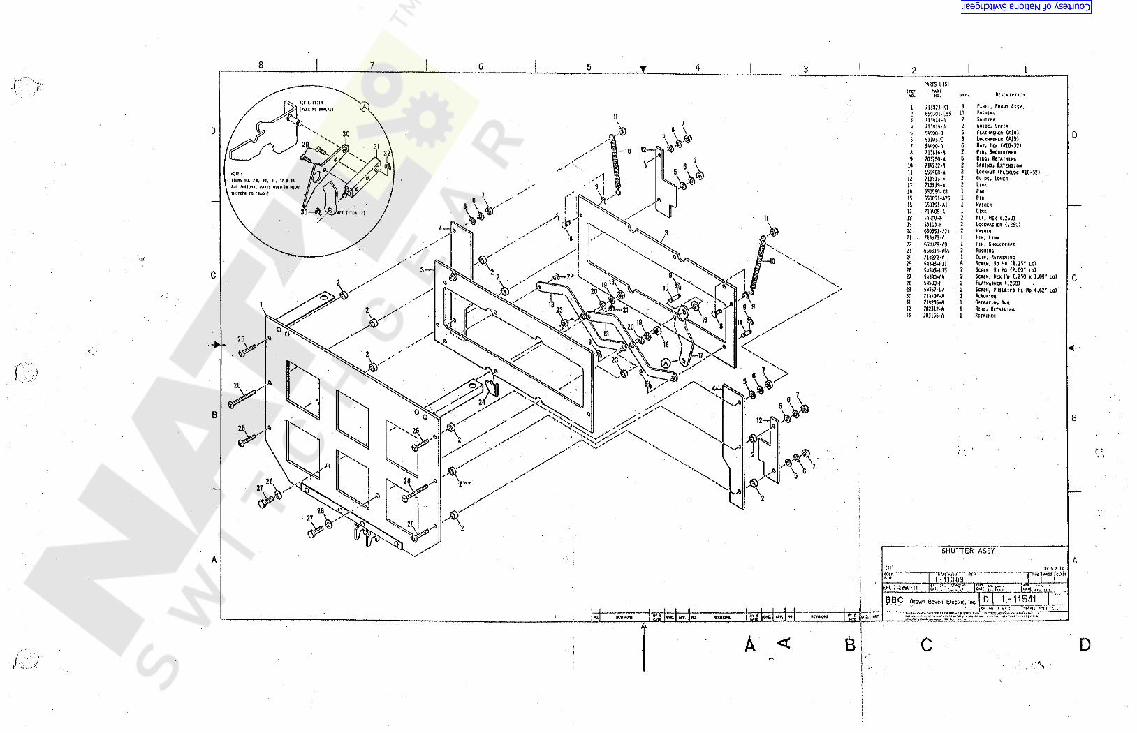
i8 7 6 5 4 3 12
5 D
C C
B B
A A
6 t
{,'*t ...I ) ,' «*.I,' •
sr
Courtesy of NationalSwitchgear.com