Premset Catalog 2017 - LK mobile
152
schneider-electric.com/premset 2017 Catalog Premset 17.5 kV Compact modular vacuum switchgear with Shielded Solid Insulation System Medium Voltage Distribution
-
Upload
khangminh22 -
Category
Documents
-
view
4 -
download
0
Transcript of Premset Catalog 2017 - LK mobile

schneider-electric.com/premset
2017 Catalog
Premset 17.5 kV Compact modular vacuum switchgearwith Shielded Solid Insulation System
Medium Voltage Distribution


General Contents
schneider-electric.com | 3Premset Catalog
Overview 10
Building your solution 26
General characteristics 38
Core units 46
Protection, monitoring and control 88
Connections 118
Technical appendix 130

schneider-electric.com4 | Premset Catalog
The new generation of Medium Voltage Switchgear
PM
1058
00
A concentrate of innovation dedicated to customer safety
Safety
A smart solution entirely designed to optimize customer assets
Efficiency
A long-lasting performance securing customer service continuity
Reliability
A compact and modular design for all customer application
Flexibility

schneider-electric.com | 5Premset Catalog
Peace of mind and safety through the SSIS technologyExtending protection to the entire switchgear assembly Premset switchgear is the first global product to offer shielded solid insulation throughout. Therefore it extends equipment service life, resulting in a lower total cost of ownership (TCO).
With no part of the main circuit exposed to free air and shielded by earthed screen, the system is accidentally touchable and significantly reduces the risk of internal arc.
The system is applicable for all network functions, including:
• Load break switches or circuit breaker
• Integrated metering units current and voltage transformers
High safety for the operator during cable testing and diagnosisThis integrated cable test feature, implemented by dedicated earthed rods, accessible from the front, without needing to enter the cable box, operate the main switches or dismantle cable terminations. This device meets IEC 62271-200 standard requirements.
A concentrate of innovation dedicated to customer safety
Simple and user-friendly operationThe Premset 3-in-1 system has proven itself to be one of the most reliable and end-user friendly MV switchgear system, providing:
• Earthing in a single operation
• Intuitive mimic diagram and operation
• Direct downstream earthing
• Positively driven built-in interlocks
• Easy front access to cable test injection points
1 2 3
Closed Open and disconnected
Earthed
PM
1040
62
position scheme
Safety
PM
1058
01

schneider-electric.com6 | Premset Catalog
A smart solution entirely designed to optimize customer assets
Intelligent, Smart grid-ready solutionsTo enhance your electrical distribution networks through advanced monitoring and control, Premset architecture is designed with such features as:
• Feeder automation, with switchgear including built-in communication and local intelligence
• Load management, with integrated smart metering
• Asset management, with advanced switchgear and transformer monitoring
• Automatic Transfer System, with integrated source transfer solution to reduce power supply interruption
The efficiency you deserve, optimal, maximum Because the range uses the same design for every configuration, customizing your switchgears is easier than ever before. And with standardized dimensions, reduced footprint, and simple front power connections, time and money spent installing Premset is greatly reduced.
Every aspect of the system is designed with the intention of making installation and adaptations as seamless as possible, including:
• Straightforward assembly with identical busbar and cable connections for the entire range
• Easy-to-install patented universal flat power connection system
• Easy cabling since all cable connections are at a height of 700 mm
• Associating an innovative maintenance program for your total peace of mind
Efficiency
PE
9082
2_1

schneider-electric.com | 7Premset Catalog
Architecture with distributed intelligenceThe intelligent electronic devices (IEDs) used in Premset solutions allow easy integration, based on a standard communications protocol, with a plug-and-play scanning system for easy configuration.
All this adds up to a flexible system with integrated Web technology, pre-engineered and pre-tested, which you can easily upgrade as necessary. With Premset architecture, you can easily build a smarter MV distribution system.
PM
1058
02
Intelligent Electronic Devices
Communication Network
Radio / GSM /
GPRS / Ethernet
Fault detection
Protection
Measurement
Local control
Remote control

schneider-electric.com8 | Premset Catalog
A long-lasting performance securing customer service continuityReliability
Few minutes to choose it, a life time to enjoy it Extending protection to the entire switchgear assembly, Premset is the first global product to offer shielded solid insulation throughout, enhancing long-term peace of mind.
The system is applicable for all network functions, including:
• Load break switches or circuit breakers
• Integrated metering units
• Current and voltage transformers
Intuitive operation reduces worker riskWith only two operations from line to earth – one to open and disconnect, and one to earth – the Premset range optimises operating safety, keeping all aspects as simple as possible.
Additionally, standard built-in interlocking between the main and earthing functions is keyless and positively driven, making every interaction with the unit as safe and easy as possible.
Faithfull on long term End-of-life management is easier, because SF6-free design eliminates worries about future regulations.
PM
1005
99
PM
1005
95
• Shielded Solid Insulation System (SSIS)
• SSIS is applicable for any function such as load break switches or circuit breakers, SSIS compact metering functions, or current and voltage transformers

schneider-electric.com | 9Premset Catalog
PM
1000
21
A compact and modular design for all customer applicationFlexibility
From easy customisation to very specific needs Whether you choice will be for ready-to-buy, easy configuration and design, with short delivery time, or whether you need a tailored-made solution to suit your specific requirements, Premset offers the answer your are expecting.
Premset range proffers a large choice of functions to meet any kind of application: switches, circuit breakers, metering functions, to adapt any substation room and cabling - simple and easy operating.
All-in-one solution• A unique connection interface for all elements, result of
a patented design from Schneider-electric: one set of three connections for cables, that can be used in various directions (front, rear, bottom, top)
• Embedded voltage and current sensors, optimising protection and control, with integrated CT, VT around core function: no need for extra nor larger cubicle
• A universal flat power connection system, ensuring earth shield continuity (Schneider Electric patented design)
• A large choice of cable box dimensions, to adapt any substation room and cabling, with option of embedded voltage
Premset - by Schneider Electric: The greatest innovation in Medium Voltage
Switchgear in the last 10 years

schneider-electric.com10 | Premset Catalog
Overview

schneider-electric.com | 11Premset Catalog
Overview
Presentation 12
Architecture and components 15
Distributed intelligence 20

Overview
schneider-electric.com12 | Premset Catalog
Shielded Solid Insulation SystemThe entire main circuit is solid insulated with epoxy or EPDM, eliminating all live
parts in free air:
• Insensitive to harsh environments (humidity, dust, pollution)
• Drastic reduction of risk of phase-to-phase faults
The solid insulation is shielded, i.e. its surface is at earth potential everywhere
(no electrical field in free air):
• System is “accidentally touchable”,
in accordance with PA class of IEC 62271-201
• Extended life expectancy
All functions with shielded solid insulation have a longer life expectancy, including
the M06S compact metering unit.
Innovative single line diagram, new arrangement of main functionsThe Premset single line diagram is composed of:
• Switch-disconnector using vacuum interrupters
• Earthing switch within sealed tank with air at atmospheric pressure
– MV cables can be directly earthed, via earthing switch, without the contribu-tion of any other device
– The arrangement of two devices in series provides double isolation between busbars and cables
– The system does not contain SF6 and is RoHS and REACH compliant, for your total peace of mind regarding end of life treatment and environmental concerns.
“3 in 1” integrated core unitsAll the necessary functions: breaking, disconnection and earthing,
are embedded in a single device:
• Simple operation, with just 3 positions for all units:
connected – opened & disconnected – earthed
• Intuitive mimic diagram, with two clear and reliable indicators (in accordance
with IEC 62271-102)
• All interlocks between functions are built-in as standard, positively driven and
without keys.
This applies to all types of circuit breakers and load-break switches.
Shielded Solid Insulation System
PM
1000
18P
M10
0595
PM
1000
15
Operation of earthing switch
Breaking anddisconnection
Operation of main switch
Earthingswitch
Presentation

Overview
schneider-electric.com | 13Premset Catalog
Presentation
Consistent range of switches and circuit breakers to suit any applicationThe range of core units is composed of 3 switches and 5 circuit breakers:
• I06T: simple load-break switch for cable incomers or feeders
• I06H / I12H: heavy duty switch for transfer between multiple sources
• D01N and D02N: fast clearing circuit breakers for fuseless MV/LV transformer
overcurrent protection
• D06N: simple circuit breaker for general protection
• D06H / D12H: O-CO-CO heavy duty circuit breaker with fast reclosing capacity
for line protection.
Modular system architecture, simplifying installation and upgradingThe entire range of core units is optimized for dedicated applications, sharing:
• Same dimensions and footprint, 375 mm width in particular
• Same auxiliaries such as electrical operation devices, accessories and options
• Same easy operation and possibility of installation against a wall
• Extensive cable entry possibilities including bottom-front, bottom-rear, top-rear
• Same cable connections with type C (type "C" from EN 50181), 700 mm above
floor
Also it is applicable as well to other units, such as:
• Compact metering M06S and M12S with shielded solid insulation
• Bus riser G06 and G12
• Voltage metering or Power supplier VTM, VTP, VTM-D, VTP-D

Overview
schneider-electric.com14 | Premset Catalog
Innovative auxiliary feature (optional)• Live cable interlock
– Electrical interlock helps to avoid the earthing of live cables.
• Cable test device, interlocked with earthing switch, simplifying cable testing and diagnosis:
– Cable testing without accessing cable box or dismantling cable connections
– Test device connection from the front of the switchboard, while cables remain earthed
– Reliable interlocks with earthed star point
• Circuit breaker testing with dedicated device for primary injection
– Primary test current injection without disconnectiong CTs or modifying relay setting
• Source changeover controller devices
Ready for smart grids• D06H heavy duty circuit breaker:
– Dedicated to line management (with fast reclosing capacity and O-CO-CO cycle)
– Very small footprint (375 mm width)
• Built-in self-powered protection, embedding communication
• Integrated metering and power measurement functions
– Compact metering unit with 375 mm width and shielded solid insulation
– Integration of power measurement in incomers or feeders without additional space
• Feeder automation features:
– Modular architecture for scalable solutions (distributed intelligence)
– Linked by field bus using standard RJ45 Modbus protocol
– Easy to integrate in SCADA systems via multiple protocols (IEC 61850)
– Embedded web interface
PM
1005
67
2.25 m
Presentation

Overview
schneider-electric.com | 15Premset Catalog
Architecture and components
The core units are optimized for each typical application and
the assembly for ms a totally insulated functional unit insensitive to
the environment.
This Premset medium voltage system makes it possible to meet most
of your application needs.
• Flexibility and simplicity in the design of functional units for any application
• Safety and reliability of type-test assemblies
• Space savings
• Freedom from environmental constraints
• Shorter delivery and the possibility of making last minute modifications
• Easy extension and upgrades
Functional unit = An assembly of functional blocks
Switchboard
= +
Functional unit
Core unit
• Switch• Circuit breaker• Metering unit• Riser unit
DM
1000
08
PM
1000
00
Top connections
• Busbars• Cables
Bottom compartment
• Cable box• Reduced height• Extra plinth
Bottom connections
• Cables• Bars
Cable test
LV cabinet
• Protection relay• Measurement• Control
Premset switchboards are made up of functional units, each representing a type-tested assembly composed of a basic core unit and other functional blocks designed to work together in any combination.

Overview
schneider-electric.com16 | Premset Catalog
PM
1005
97
Architecture and components
Unsurpassed simplicity with mix-and-match modular architecture based on functional blocks.
Cable compartmentDifferent heights and
depths
Core unitDifferent types
Low Voltage cabinetDifferent heights
Cable testTop connections
Bottom connections
Internal arc gas exhaust duct
SensorsCTs and VTs
SensorsCTs and VTs

Overview
schneider-electric.com | 17Premset Catalog
Architecture and components
A big step for safety and reliability with SSIS Shielded Solid Insulation System.
Built-in current sensors for optimised protection and control,
available in versions with shielded solid
insulation where required
Modular busbar system with shielded solid insulation
Vacuum bottles with shielded solid insulation for breaking and
disconnection
Integrated air-insulated line earthing switch enclosed in tank with shielded solid insulation
Front aligned cable connections with shielded solid insulation, designed
for easy clamping
PM
1005
98

Overview
schneider-electric.com18 | Premset Catalog
Architecture and components
PM
1058
03
Current transformers located around cables • Ring-type current transformer for power
metering or protection (ARC6)
• Earth fault toroidal current transformer for high
sensitivity earth fault protection (CSH120/200)
• Measurement current transformer for fault
passage indication or Ammeter (MF1)
Voltage transformers located behind the cablesPhase-to-earth voltage transformers (VRU1)
Protection current transformer or sensors located under the core unit • Dedicated current transformer (CuA, CuB) for VIP
integrated self-powered protection
• Low power current transformer (TLPU1) for Sepam
• 1 A ring-type current transformer (ARU2)
for Sepam, MiCOM, Easergy range, or any
conventional relay
Current transformers located around bushings• Measurement current transformer
for power measurement (ARU1)
• Measurement current transformer
for fault passage indication or
Ammeter (CTR2200)
Internal arc gas exhaust ductUpwards exhaust or downwards exhaust
Current and voltage transformers integrated in main functions.
Front bottom connection

Overview
schneider-electric.com | 19Premset Catalog
Architecture and components
Flexible cable connection easy substation arrangement to meet all the applications.
Rear top connection
Evacuation duct conduitInternal arc gas upwards
exhaust
PM
1058
04
Rear bottom connection
Internal arc gas exhaust ductUpwards exhaust or
downwards exhaust
PM
1058
05

Overview
schneider-electric.com20 | Premset Catalog
Premset is Web-enabled to let you access information on your electrical installation via a PC with a standard Web browser.
With Premset, intelligence can be added to functional units by integrating
protection, control and monitoring IEDs (Intelligent Electrical Devices).
The IEDs have dedicated locations and cabling and are daisy-chained throughout
the various functional units using RJ45 connectors
and Modbus protocol.
A gateway can be used to connect the IEDs to supervision systems
via Ethernet, TCP-IP and/or radio-frequency communication.
Distributed intelligenceP
M10
0016
Radio / GSM / GPRS / Ethernet
RadioGSMGPRS
R200
Protection Power Meter / Quality Network control & monitoring
Sensors
Communication Network
PM
1058
06

Overview
schneider-electric.com | 21Premset Catalog
Premset switchboards are designed to integrate distributed intelligence for feeder automation, protection and energy quality applications.
Energy quality applications
Energy costs
Continuity of service
Power quality
DM
1000
33
Distributed intelligence
LOCAL CONTROL PROTECTION RELAYS
FAULT DETECTIONMEASUREMENT
REMOTE CONTROL
• Motor control: SC110
• Control panel: SC-MI20
• Self-powered: VIP 40 and VIP 45, VIP 400 and VIP 410
• Auxiliary powered: Sepam, MiCOM and Easergy ranges
• Fault Passage Indicators: Flair 21D/22D, Flair 23DM
• Voltage indicators: VPIS, VDS
• Voltage relay: VD23
• Ammeter: AMP21D
• Power Meter: PM5000
• Power/Quality Meter: PM8000
• Embedded intelligent devices
• Switch controller for remote communication network : SC110
• Remote communication network (GSM /GPRS / Ethernet/Radio): R200
• Automatic Transfer System: ATS100
• Backup power supply: PS100
R200
SC-MI20
PS100
SC110A ATS100
MiCOM
Sepam
Easergy P5
Flair 23DMPM8000
VIP 410????
????
?

Overview
schneider-electric.com22 | Premset Catalog
Distributed intelligence
Distributed architecture for easy installation, operation and scalabilityThe IEDs (Intelligent Electrical Devices) used in the Premset system have been
designed to optimise substation performance and compactness.
They can be used to build a robust distributed architecture suited to harsh
environments.
• Modular architecture for scalable solutions from local control up to complex
feeder automation, optimising cost and performance by letting you choose only
what you need
• Each IED is fully integrated in a functional unit with a dedicated location and
cabling
• Pre-engineered, pre-tested and cost effective, the system includes
the necessary sensors, switchgear interfaces, power supplies, communication
solutions and HMIs
• Easy integration based on field bus communication between IEDs with a plug
and play system that scans and configures the system
• The field bus uses standard RJ45 Modbus protocol open to third-part devices
• Each IED has a compatible XML description file based on CIM (Common
Information Model) / IEC 61850 standard. This allows easy configuration to
communicate with any RTU (Remote Teminal Unit) or SCADA (Supervisory
Control And Data Acquisition) system.
Ready for smart gridsIn the 80s and 90s, RTUs (Remote Terminal Units) were mainly used in feeder
automation applications to improve energy availability and reduce the number
and duration of outages. Today RTUs have evolved to integrate functions such as
automatic meter reading and load management.
Ready for the future, the Premset system R200 RTU has downloadable firmware to
keep pace with these and other evolving possibilities of smart grids.
Web technologyPremset integrates Web technologies so that access to information on your
electrical installation is as easy as opening a Web page.
All you need is a standard Web browser and a PC connected via:
• Your local area network
• A pluggable connection to the Premset switchboard
• A mobile network access (3G, 4G, GPRS).
DM
1000
34
IP Communication network
PE
5830
0

Overview
schneider-electric.com | 23Premset Catalog
VIP 400/410
PM
1005
76
VIP 40/45
PM
1005
73
Distributed intelligence
VIP self-powered protection relay For higher MV network availability
VIP relays are self-powered while Sepam relays require an auxiliary power supply.
Self-powered protection relays increase the availability of the MV network
and are suited to most applications.
• Insensitive to voltage drop due to faults
• Not dependent on UPS systems
• Less dependent on the external environment (EMC, LV overvoltages) because
they require no external connections.
In addition, the VIP 410 offers enhanced sensitivity to low earth-fault currents
and provides additional diagnostics with time-stamped logs thanks to a dual power
supply and a communication port.
Circuit breaker For improved MV/LV transformer protection
With the VIP 40/45, Premset circuit breakers provide MV/LV transformers superior
protection compared to traditional MV switch-fuse solutions - at an equivalent
lifetime cost.
The main advantages are:
• Better discrimination with other MV and LV protection devices
• Improved protection performance for inrush current, overloads, low magnitude phase-faults and earth-faults
• Greater harsh climate withstand.
• Fast clearing time, to limit the consequences of internal arcing in the transformer.
Auto-adapting Fault Passage Indicator With remote communication for higher power network availabilityThe Flair range offers cost-effective auto-adapting fault passage indicators (FPI)
that can be fully integrated in the cubicle.
In addition to the Flair 21D /22D self-powered FPIs, the range includes the Flair 23DM ,
a powerful IED with a communication port.
• The Flair 23DM is linked to the voltage presence indication system (VPIS) to confirm faults by undervoltage instead of current measurement, thereby avoiding transient faults
• The Flair 23DM provides an integrated output voltage relay for automatic transfer switch (ATS100) or other applications
• Phase fault and standard earth fault detection are maintained even if the power supply is lost. The auxiliary power supply is only needed for communication and the voltage presence relay
• The communication port provides the current values, records diagnostic information (voltage drops, transient fault indications) and makes it possible to modify settings remotely.
Flair FPI
EM
S58
355

Overview
schneider-electric.com24 | Premset Catalog
Distributed intelligence
Full range of protection relaysSchneider Electric is a trusted, global provider of protection relays and control
solutions as well as a leader in electical distribution innovation.
Our ranges of protection relays represents the outcome of more than 100 years of
manufacturing and power system experience.
Sepam range
Sepam series digital protection relays take full advantage of Schneider Electric’s
experience in electrical network protection to meet your needs needs with effective
protection of life and property.
MiCOM range
MiCOM protection provides the user with a choice of cost-optimized solutions for
specific protection requirements within the distribution network. The MiCOM relay
series offers comprehensive protective function solutions for all power supply
systems, as well as for various functional and hardware project.
Easergy P5: a fusion of new ideas and proven expertise
Easergy P5 combines fresh thinking on modern electrical challenges with a strong
heritage from two popular protection relay ranges: Sepam and MiCOM.
Easergy P5’s modern, digital features provide a unique combination of services
designed to boost operational efficiency and safety for the user.
Product selection, configuration, and ordering have been made easy with the latest
online tools. The asset database provides a management platform, which stores
and organizes all information securely and is quickly accessible. Easergy SmartApp
provides simple access to key functions and settings for nonexpert users and
enables quick access to all information and documentation.
Simplify your Easergy P5 daily operation via the Easergy P5 SmartApp!
MiCOM range
PM
1058
40
Sepam range
PE
8803
0
Easergy P5
PM
1040
85
PM
1058
08
Easergy P5 provides access to an extended warranty program when users register their product using the QR code and follow a simple process with the mySchneider mobile app.
10years
Warranty
Easergy

Overview
schneider-electric.com | 25Premset Catalog
Distributed intelligenceP
M10
0592
PS100
Backup power supplyBackup power supplies (UPSs or batteries) are now common in industrial and
commercial premises. However, they often represent a weak link in the power
supply chain and their failure can have serious consequences.
Given the harsh environment and critical nature of substations, the Premset system
includes the PS100, a dedicated solution with a high insulation level designed to
provide 24 hours of backup power to electronic devices.
Maintenance is easy with:
• Just one battery to replace
• End-of-life alarm possible via Modbus communication
PE
5757
0p
DM
1031
001
R200 ATS100
Easergy R200 and ATS100The power and experience of Easergy FRTUs embedded in Cubicles for cost
effective remote control and monitoring of MV substations:
• Easergy R200 is a Remote Terminal Unit (RTU) that integrates all the functions
for remote supervision and control of an MV switchboard cubicle.
• The ATS100 drives automatic transfer from the normal MV source to the backup
source in order to keep supplying the MV substation in case of failure of the
normal source. ATS100 can drive either Load Break Switch or Circuit Breaker.
Easergy TH110 wireless thermal sensor *The power connections in the Medium Voltage products are one of the most critical
points of the substations. Loose and faulty connections cause an increase of
resistance in localized points that will lead to thermal runaway until the complete
failure of the connections
Easergy TH110 is part of the new generation of wireless smart sensors ensuring
the continuous thermal monitoring of all the critical connections made on field
allowing to:
• Prevent unscheduled downtimes
• Increase operators and equipments safety
• Optimize maintenance with predictive information
PM
1056
23
TH110
* Please consult us for availability

schneider-electric.com26 | Premset Catalog
Building your solution

schneider-electric.com | 27Premset Catalog
Building your solution
Main applications 29
Incomer and feeder functions 32
Transformer protection functions 33
Bus section functions 34
Bus riser functions 35
Metering & measurement functions 36
Special functions 36

Premset all-in-one
Best-in-class switchgear
First-class terminal
Download the free application, now available for iOs

Building your solution
schneider-electric.com | 29Premset Catalog
Main applications
PM
1051
49
Typical applicationsPremset applications can be found in all Medium Voltage secondary distribution
substations.
Buildings and industry
• MV/MV consumer substation direct connection
• MV/LV consumer substation double feeder
• MV/LV consumer substation loop connection
• MV/LV consumer substation radial connection
• MV/LV consumer substation with MV backup
• MV private network
• MV/LV substation.
Distribution networks
• MV/MV switching substation
• MV/LV distribution substation
• MV/LV Ring Main Unit
• MV distributed generation.
Premset advanced communication possibilities open the way to applications such as:
• Local control up to complex feeder automation
• MV Automatic Transfer System (ATS)
• RTU with new Smart Grid functions for load management.
PM
1040
63P
M10
4064
PE
5813
Why Premset?Premset switchboards are modular, compact, smart, with optimized safety and insensitivity to harsh environments.
For these reasons, they offer very high reliability and efficiency for a wide range of applications.
PM
1040
65

schneider-electric.com30 | Premset Catalog
Building your solution
DM
1000
32E
N
Energy & infrastructure
GG
HV/MV
MV/LV consumer substation double feeder
MV/LV consumer substation loop connection
MV/LV consumer substation radial connection
MV/LV substation
MV private network
MV/MV consumer substation direct connection
MV/LV consumer substation with MV backup
M
M
M
M M
M
M
GG
HV/MV
MV/MV switchingsubstation
MV/LV distribution substation
Distributed generation
MV/LV distribution substation (Ring Main Unit)
Line incomer or Line feeder
Generator incomer
Line protection
Transformer protection
General protection
Bus section
Bus riser
Main applicationsDistribution network selection chart

Building your solution
schneider-electric.com | 31Premset Catalog
Buildings
Industry
Datacentres & networks
GG
HV/MV
MV/LV consumer substation double feeder
MV/LV consumer substation loop connection
MV/LV consumer substation radial connection
MV/LV substation
MV private network
MV/MV consumer substation direct connection
MV/LV consumer substation with MV backup
M
M
M
M M
M
M
GG
HV/MV
MV/MV switchingsubstation
MV/LV distribution substation
Distributed generation
MV/LV distribution substation (Ring Main Unit)
GG
HV/MV
MV/LV consumer substation double feeder
MV/LV consumer substation loop connection
MV/LV consumer substation radial connection
MV/LV substation
MV private network
MV/MV consumer substation direct connection
MV/LV consumer substation with MV backup
M
M
M
M M
M
M
GG
HV/MV
MV/MV switchingsubstation
MV/LV distribution substation
Distributed generation
MV/LV distribution substation (Ring Main Unit)
Main applicationsBuildings & Industry selection chart

schneider-electric.com32 | Premset Catalog
Building your solution
Incomer and feeder functions
Function Line incomer/ Line feeder Line incomer/ Line feeder Transformer protection
Core unit type l06T I06H I12H D06N D06H D12H G06 M06S M06A M12A D01N D02N
Typical application of protection Line incomer or line feeder General protection Line protection Line protection Line incomer or line feeder Transformer protection
Generator protect. Generator protect.
Core unit Disconnecting switch with lever-operated CIT mechanism and integrated earthing switch
Disconnecting switch with stored-energy OCO mechanism and integrated earthing switch
Disconnecting switch with stored-energy OCO mechanism and integrated earthing switch
Disconnecting circuit breaker with latching CI1 mechanism and integrated earthing switch
Disconnecting circuit breaker with stored-energy OCO mechanism and integrated earthing switch
Disconnecting circuit breaker with stored-energy OCO mechanism and integrated earthing switch
Direct connection to busbars
Solid-insulatedearth-screenedmetering unit
Air-insulated metering unit
Air-insulated metering unit
Disconnecting circuit breaker with latching CI1 mechanism and integrated earthing switch
Disconnecting circuit breaker with latching CI1 mechanism and integrated earthing switch
Dimension: width (mm) 375 375 750 375 375 750 375 375 750 750 375 375
Single-line diagram
See details Page 48 50 52 56 58 43 44 45 46 46 40 40
Earthing switch 71
Cable testing device 124
Live cable interlock 105
Protection *
VIP 40/45 Self-powered 93
VIP 400 Self-powered 95
VIP 410 Dual powered 95
Easergy P5 Auxiliary powered 98
Sepam Auxiliary powered 98
MiCOM Auxiliary powered 98
FPI (2) - Flair 21/22D/23DM * 100
Integrated measurement *
AMP21D Ammeter 107
PM5000 Power Meter 108
PM8000 Power/Quality Meter 109
Control
Electrical operation 110
Additional opening coil (MX or MN) 75 (1) (1) (1) (1)
Auxiliary contacts 76
Voltage indication *
VPIS or VDS Voltage indication 103 p p p p p
VD23 Voltage relay 104
Metering current transformers *
ARU1 Ring CTs 81
ARC6 Ring CTs 82
ARC5 Ring CTs 82
ARM3 / AD12 Block CTs 84
ARPJ3 / AD13 Block CTs 84
Metering voltage transformers *
Ph
ase
- to
-ea
rth VRU1 Screened VTs 83
VDF11/VDF21 DIN VTs 86
VRQ2 Block VTs 87
Pha
se-
to-p
hase VRU2 Auxiliary power 83
VDC11/VDC21 DIN VTs 86
VRC2 Block VTs 87
VT protection - Fuses
* Only one option possible Standard offer Option (1) Optional possible only wih VIP relay (2) FPI: Fault Passage Indicator

Building your solution
schneider-electric.com | 33Premset Catalog
Incomer & feeder / Transformer protection functions
Function Line incomer/ Line feeder Line incomer/ Line feeder Transformer protection
Core unit type l06T I06H I12H D06N D06H D12H G06 M06S M06A M12A D01N D02N
Typical application of protection Line incomer or line feeder General protection Line protection Line protection Line incomer or line feeder Transformer protection
Generator protect. Generator protect.
Core unit Disconnecting switch with lever-operated CIT mechanism and integrated earthing switch
Disconnecting switch with stored-energy OCO mechanism and integrated earthing switch
Disconnecting switch with stored-energy OCO mechanism and integrated earthing switch
Disconnecting circuit breaker with latching CI1 mechanism and integrated earthing switch
Disconnecting circuit breaker with stored-energy OCO mechanism and integrated earthing switch
Disconnecting circuit breaker with stored-energy OCO mechanism and integrated earthing switch
Direct connection to busbars
Solid-insulatedearth-screenedmetering unit
Air-insulated metering unit
Air-insulated metering unit
Disconnecting circuit breaker with latching CI1 mechanism and integrated earthing switch
Disconnecting circuit breaker with latching CI1 mechanism and integrated earthing switch
Dimension: width (mm) 375 375 750 375 375 750 375 375 750 750 375 375
Single-line diagram
See details Page 48 50 52 56 58 43 44 45 46 46 40 40
Earthing switch 71
Cable testing device 124
Live cable interlock 105
Protection *
VIP 40/45 Self-powered 93
VIP 400 Self-powered 95
VIP 410 Dual powered 95
Easergy P5 Auxiliary powered 98
Sepam Auxiliary powered 98
MiCOM Auxiliary powered 98
FPI (2) - Flair 21/22D/23DM * 100
Integrated measurement *
AMP21D Ammeter 107
PM5000 Power Meter 108
PM8000 Power/Quality Meter 109
Control
Electrical operation 110
Additional opening coil (MX or MN) 75 (1) (1) (1) (1)
Auxiliary contacts 76
Voltage indication *
VPIS or VDS Voltage indication 103 p p p p p
VD23 Voltage relay 104
Metering current transformers *
ARU1 Ring CTs 81
ARC6 Ring CTs 82
ARC5 Ring CTs 82
ARM3 / AD12 Block CTs 84
ARPJ3 / AD13 Block CTs 84
Metering voltage transformers *
Ph
ase
- to
-ea
rth VRU1 Screened VTs 83
VDF11/VDF21 DIN VTs 86
VRQ2 Block VTs 87
Pha
se-
to-p
hase VRU2 Auxiliary power 83
VDC11/VDC21 DIN VTs 86
VRC2 Block VTs 87
VT protection - Fuses
* Only one option possible Standard offer Option (1) Optional possible only wih VIP relay (2) FPI: Fault Passage Indicator

schneider-electric.com34 | Premset Catalog
Building your solution
Bus section functions
Function Bus section Bus riser Metering & measurement
Core unit type l06T I06H I12H D06N D06H D12H G12 G06 M06S M12S M06A M12A M06A M12A
Typical application of protection Bus section Bus riser Metering & measurement
Core unit Disconnecting switch with lever-operated CIT mechanism and integrated earthing switch
Disconnecting switch with stored-energy OCO mechanism and integrated earthing switch
Disconnecting switch with stored-energy OCO mechanism and integrated earthing switch
Disconnecting circuit breaker with latching CI1 mechanism and integrated earthing switch
Disconnecting CB with stored-energy OCO mechanism and integrated earthing switch
Disconnecting CB with stored-energy OCO mechanism and integrated earthing switch
SSIS bus riser
SSISbus riser
SSISmetering unit
SSISmetering unit
Air-insulated metering unit
Air-insulated metering unit
Air-insulated metering unit
Air-insulated metering unit
Dimension: width (mm) 375 375 750 375 375 750 375 375 375 375 750 750 750 750
Single-line diagram
See details Page 48 50 52 56 58 60 62 66 63 63 64 64 64 64
Earthing switch 71
Cable testing device 124
Live cable interlock 105
Protection *
VIP 40/45 Self-powered 93
VIP 400 Self-powered 95
VIP 410 Dual powered 95
Easergy P5 Auxiliary powered 98
Sepam Auxiliary powered 98
MiCOM Auxiliary powered 98
FPI (2) - Flair 21/22D/23DM * 100
Integrated measurement *
AMP21D Ammeter 107
PM5000 Power Meter 108
PM8000 Power/Quality Meter 109
Control
Electrical operation 110
Controller and accessories
Additional opening coil (MX or MN) 75 (1) (1)
Auxiliary contacts 76
Voltage indication *
VPIS or VDS Voltage indication 103
VD23 Voltage relay 104
Metering current transformers *
ARU1 Ring CTs 81
ARC6 Ring CTs 82
ARC5 Ring CTs 82
ARM3 / AD12 Block CTs 84
ARPJ3 / AD13 Block CTs 84
Metering voltage transformers *
Ph
ase
- to
-ea
rth VRU1 Screened VTs 83
VDF11/VDF21 DIN VTs 86
VRQ2 Block VTs 87
Pha
se-
to-p
hase VRU2 Auxiliary power 83
VDC11/VDC21 DIN VTs 86
VRC2 Block VTs 87
VT protection - Fuses
* Only one option possible Standard offer Option (1) Optional possible only wih VIP relay (2) FPI: Fault Passage Indicator

Building your solution
schneider-electric.com | 35Premset Catalog
Bus riser + Metering & measurement functions
Function Bus section Bus riser Metering & measurement
Core unit type l06T I06H I12H D06N D06H D12H G12 G06 M06S M12S M06A M12A M06A M12A
Typical application of protection Bus section Bus riser Metering & measurement
Core unit Disconnecting switch with lever-operated CIT mechanism and integrated earthing switch
Disconnecting switch with stored-energy OCO mechanism and integrated earthing switch
Disconnecting switch with stored-energy OCO mechanism and integrated earthing switch
Disconnecting circuit breaker with latching CI1 mechanism and integrated earthing switch
Disconnecting CB with stored-energy OCO mechanism and integrated earthing switch
Disconnecting CB with stored-energy OCO mechanism and integrated earthing switch
SSIS bus riser
SSISbus riser
SSISmetering unit
SSISmetering unit
Air-insulated metering unit
Air-insulated metering unit
Air-insulated metering unit
Air-insulated metering unit
Dimension: width (mm) 375 375 750 375 375 750 375 375 375 375 750 750 750 750
Single-line diagram
See details Page 48 50 52 56 58 60 62 66 63 63 64 64 64 64
Earthing switch 71
Cable testing device 124
Live cable interlock 105
Protection *
VIP 40/45 Self-powered 93
VIP 400 Self-powered 95
VIP 410 Dual powered 95
Easergy P5 Auxiliary powered 98
Sepam Auxiliary powered 98
MiCOM Auxiliary powered 98
FPI (2) - Flair 21/22D/23DM * 100
Integrated measurement *
AMP21D Ammeter 107
PM5000 Power Meter 108
PM8000 Power/Quality Meter 109
Control
Electrical operation 110
Controller and accessories
Additional opening coil (MX or MN) 75 (1) (1)
Auxiliary contacts 76
Voltage indication *
VPIS or VDS Voltage indication 103
VD23 Voltage relay 104
Metering current transformers *
ARU1 Ring CTs 81
ARC6 Ring CTs 82
ARC5 Ring CTs 82
ARM3 / AD12 Block CTs 84
ARPJ3 / AD13 Block CTs 84
Metering voltage transformers *
Ph
ase
- to
-ea
rth VRU1 Screened VTs 83
VDF11/VDF21 DIN VTs 86
VRQ2 Block VTs 87
Pha
se-
to-p
hase VRU2 Auxiliary power 83
VDC11/VDC21 DIN VTs 86
VRC2 Block VTs 87
VT protection - Fuses
* Only one option possible Standard offer Option (1) Optional possible only wih VIP relay (2) FPI: Fault Passage Indicator

schneider-electric.com36 | Premset Catalog
Building your solution
Metering & measurement functions + Special functions
Function Metering & measurement Special functions Special functions
Core unit type VTM VTM-D VTP VTP-D ES-B I06T cable in/out
I06H cable in/out
D01/02/06N cable in/out
D06H cable in/out
Typical application of protection Metering & measurement Special functions Special functions
Core unit Metering voltage transformer:three SSIS(2) phase-to-earth VTs
Metering voltage transformer: threeSSIS(2)phase-to-earth VTs, with D01N circuit-breaker
Auxiliary power supply, voltage transformer: one SSIS phase-to-phase VT
Auxiliary power supply, voltage transformer: one SSIS phase-to-phase VT, with D01N circuit breaker protection
Dedicated to busbar earthing Disconnecting switch with lever-operated CIT mechanism and integrated earthing switch
Disconnecting switch with stored-energy OCO mechanism and integrated earthing switch
Disconnecting circuit breaker with latching CI1 mechanism and integrated earthing switch
Disconnecting circuit breaker with stored-energy OCO mechanism and integrated earthing switch
Dimension: width (mm) 375 375 375 375 375 375 375 375 375
Single-line diagram
See details Page 65 66 68 69 71 48 50 54 58
Earthing switch 71
Cable testing device 124
Live cable interlock 105
Protection *
VIP 40/45 Self-powered 93
VIP 400 Self-powered 95
VIP 410 Dual powered 95
Easergy P5 Auxiliary powered 98
Sepam Auxiliary powered 98
MiCOM Auxiliary powered 98
FPI (3) - Flair 21/22D/23DM * 100
Integrated measurement *
AMP21D Ammeter 107
PM5000 Power Meter 108
PM8000 Power/Quality Meter 109
Control
Electrical operation 110
Controller and accessories
Additional opening coil (MX or MN) 75 (1) (1)
Auxiliary contacts 76
Voltage indication *
VPIS or VDS Voltage indication 103
VD23 Voltage relay 104
Metering current transformers *
ARU1 Ring CTs 81
ARC6 Ring CTs 82
ARC5 Ring CTs 82
ARM3 / AD12 Block CTs 84
ARPJ3 / AD13 Block CTs 84Metering voltage transformers *
Ph
ase
- to
-ea
rth VRU1 Screened VTs 83
VDF11/VDF21 DIN VTs 86
VRQ2 Block VTs 87
Pha
se-
to-p
hase VRU2 Auxiliary power 83
VDC11/VDC21 DIN VTs 86
VRC2 Block VTs 87
VT protection - Fuses
* Only one option possible Standard offer Option (1) Optional possible only wih VIP relay (2) Shielded Solid Insulation System (3) FPI: Fault Passage Indicator

Building your solution
schneider-electric.com | 37Premset Catalog
Special functions
Function Metering & measurement Special functions Special functions
Core unit type VTM VTM-D VTP VTP-D ES-B I06T cable in/out
I06H cable in/out
D01/02/06N cable in/out
D06H cable in/out
Typical application of protection Metering & measurement Special functions Special functions
Core unit Metering voltage transformer:three SSIS(2) phase-to-earth VTs
Metering voltage transformer: threeSSIS(2)phase-to-earth VTs, with D01N circuit-breaker
Auxiliary power supply, voltage transformer: one SSIS phase-to-phase VT
Auxiliary power supply, voltage transformer: one SSIS phase-to-phase VT, with D01N circuit breaker protection
Dedicated to busbar earthing Disconnecting switch with lever-operated CIT mechanism and integrated earthing switch
Disconnecting switch with stored-energy OCO mechanism and integrated earthing switch
Disconnecting circuit breaker with latching CI1 mechanism and integrated earthing switch
Disconnecting circuit breaker with stored-energy OCO mechanism and integrated earthing switch
Dimension: width (mm) 375 375 375 375 375 375 375 375 375
Single-line diagram
See details Page 65 66 68 69 71 48 50 54 58
Earthing switch 71
Cable testing device 124
Live cable interlock 105
Protection *
VIP 40/45 Self-powered 93
VIP 400 Self-powered 95
VIP 410 Dual powered 95
Easergy P5 Auxiliary powered 98
Sepam Auxiliary powered 98
MiCOM Auxiliary powered 98
FPI (3) - Flair 21/22D/23DM * 100
Integrated measurement *
AMP21D Ammeter 107
PM5000 Power Meter 108
PM8000 Power/Quality Meter 109
Control
Electrical operation 110
Controller and accessories
Additional opening coil (MX or MN) 75 (1) (1)
Auxiliary contacts 76
Voltage indication *
VPIS or VDS Voltage indication 103
VD23 Voltage relay 104
Metering current transformers *
ARU1 Ring CTs 81
ARC6 Ring CTs 82
ARC5 Ring CTs 82
ARM3 / AD12 Block CTs 84
ARPJ3 / AD13 Block CTs 84Metering voltage transformers *
Ph
ase
- to
-ea
rth VRU1 Screened VTs 83
VDF11/VDF21 DIN VTs 86
VRQ2 Block VTs 87
Pha
se-
to-p
hase VRU2 Auxiliary power 83
VDC11/VDC21 DIN VTs 86
VRC2 Block VTs 87
VT protection - Fuses
* Only one option possible Standard offer Option (1) Optional possible only wih VIP relay (2) Shielded Solid Insulation System (3) FPI: Fault Passage Indicator

schneider-electric.com38 | Premset Catalog
General
characteristics

schneider-electric.com | 39Premset Catalog
General characteristics
Characteristics 40
Standards 41
Internal arc fault withstand 42
Operating conditions 44

schneider-electric.com40 | Premset Catalog
General
characteristics
Dimensions
Uniform dimensions for the entire system
• Width: 375 mm for all 630 A switch, circuit breaker and metering units with
shielded solid insulation
• 1250 A switch, circuit breaker and air insulation metering units: 750 mm wide,
but still fully compatible with the rest of the system
• Depth: 910 mm (1135mm for cable front connection with arc control design,
1208 mm for cable rear connection with arc control design)
• Cable connections: 700 mm high front-aligned connections (500 mm with low-
height bottom compartment)
• Height: 1350 to 2195 mm, depending on LV cabinet (can be reduced to a
minimum of 1350 mm with low-height bottom compartment
PM
10
05
99
500 mm or 700 mm front or rear cabling
375 mm
910 or 1135 mmor 1208mm
1350 mm to2195 mm
Main electrical characteristicsVoltage
Rated voltage kV 7.2 12 17.5
Rated frequence Hz 50/60
Insulation levelRated short-duration power-frequence withstand voltage
- phase to phase, phase to earth, open contact gap 20 28 42 38
- across the isolating distance 23 32 48 45
Rated lightning impulse withstand voltage
- phase to phase, phase to earth, open contact gap 60 75 75 (1) 95
- across the isolating distance 70 85 85 (1) 110
CurrentRated normal current for the busbar up to A 1250
Rated short-time withstand current for switchgear with tk=1 s up to kA 25
for switchgear with tk=3 s up to kA 25
for switchgear with tk=4 s up to kA 20
Rated short-circuit breaking current Isc
Circuit breaker: D01N, D02N,D06N, D06H, D12H up to kA 25
Internal arc withstandA-FLR kA/1s 21
A-FLR kA/1s 25 (2)
(1) Higher values of the rated lightning impulse withstand voltage available with -95 kV for phase-to-phase, phase-to-earth, open contact gap as well as -110 kV
across the isolating distance
(2) except M06A, M12A
(3) LSC1 for bus riser and metering functions
Characteristics

General
characteristics
schneider-electric.com | 41Premset Catalog
IEC standards
Premset units meet all the following recommendations, and standards:
• IEC 62271-1:
High voltage switchgear and controlgear - Part 1: Common specifi cations
• IEC 62271-200:
Part 200: A.C. metal-enclosed switchgear and controlgear for rated voltage
above 1 kV and up to and including 52 kV
• IEC 62271-103:
Part 103: Switches for rated voltages above 1 kV and less than 52 kV
• IEC 62271-100:
Part 100: High-voltage alternating current circuit breakers
• IEC 62271-102:
Part 102: High-voltage alternating current disconnectors and earthing switches
• IEC 62271-206:
Part 206: High-voltage prefabricated switchgear and controlgear assemblies -
Voltage presence indicating systems
• IEC 60529:
Degrees of protection provided by enclosures (IP Code)
• IEC 60044-8:
Instrument transformers - Part 8: Low Power Current Transducers
• IEC 61869-2:
Instrument transformers – Part 2: Current transformers
• IEC 61869-3:
Instrument transformers – Part 3: Voltage transformers
• IEC 60255:
Measuring relays and protection equipment
• IEC 62271-210:
Part 210: Seismic qualifi cation for metal enclosed switchgear up to 52 kV
Standards

schneider-electric.com42 | Premset Catalog
General
characteristics
Standard version
Qualifi ed for neutral networks with arc extinction coil
earthing system
The effect of low phase-to-earth internal faults has been type-tested for the standard
version of Premset.
Premset is IAC qualifi ed for earth fault current of 100 A (IAe). It has successfully
passed all the tests in every compartment, in accordance with the latest edition of
the IEC 62271-200 standard (edition 2). This demonstrates the ability of standard
Premset to withstand internal arcing for tuned (Petersen coil) neutral networks
without any specifi c precautions.
Arc-control version, 21 kA 1 s or 25 kA 1 s (1)
class A-FLR (2)
Four-sided internal arc protection
The effect of high internal faults, up to 25 kA 1s, has been type-tested on a special
version of Premset designed for arc control with two options for gas exhausting
(upwards exhaust or downwards exhaust).
Premset has successfully passed all the type tests of standard IEC 62271-200
(5 acceptance criteria).
The thermal and mechanical forces that an internal arc can produce are absorbed
by the enclosure.
Operators safety is improved, whatever the installation layout:
• Access to all four sides when not installed against a wall
• Front or lateral access when installed against a rear wall
Internal arc fault withstand
Standard IEC 62271-200 defi nes internal arc
classifi cations to characterise the performance
level for protection of persons against effects of
internal arcing fault. It also defi nes the testing
procedure and acceptance criteria.
The aim of this classifi cation is to show that an
operator situated around the switchboard would
be protected against the effects of an internal
fault.
Downwards exhaust
Premset
Premset
Premset
Premset
Premset
Premset
Premset
Premset
DM
10
54
11
Upwards exhaust,gas releases outside room
Premset
Premset
Premset
Premset
DM
105411
Top exhaust, gas releases inside room (3)
DM
10
000
4
(1) Except M06A, M12A
(2) IAC (internal arc classifi cation): classifi cation code refers to different types of accessibility
according to standard IEC 62271-200.
Class A-FLR:
• A: access restricted to authorised personnel only
• F: access to the front side
• L: access to the lateral side
• R: access to the rear side
(3) Please consult us for availability

General
characteristics
schneider-electric.com | 43Premset Catalog
Internal arc fault withstand
Three gas exhausting options
• Downwards exhaust
21 kA 1s or 25 kA 1s
(details information see " Civil engineering, & gas exhaust ": p 140)
• Upwards exhaust, gas releases outside room
21 kA 1s or 25 kA 1s A-FLR
(for installation details, see p 139)
• Upwards exhaust, gas releases inside room (1)
up to 25 kA 1s
Installation against a wall
For detailed civil engineering information, please refer to page 138.
Note: When 500 mm height of cable connection is selected, 16 kA/1 s IAC is
max reached.
Drastically reduced risk of internal arc fault
Premset shielded solid insulation technology provides phase-per-
phase insulation and screening, and thereby make phase-to-phase
fault impossible by design : this have been proven by tests. For all
networks earthed through an impedance, this is of great advantage,
as the phase-to-earth fault is limited to a low value, drastically
mitigating the effects of the internal arc.
Premset arc controlled version has been successfully type-tested in
accordance with the edition 2 of the IEC 62271-200 standard, 25kA-
1s, A-FLR. Thus all types of earthing systems are covered, including
solidly grounded and isolated ones.
(1) Please consult us for availability

schneider-electric.com44 | Premset Catalog
General
characteristicsOperating conditions
Partition class and loss of service continuity category
• Partition class: PM (1)
• Loss of service continuity category: LSC2 (2) (3)
Protection index
• All external faces of the switchgear: IP3X / IP41 (available as option) /
IP32 - IP42 (please consult us for availability)
• Between compartments: IP2X
• Main circuit and all HV parts: IP67 (except air insulated metering cubicle:
M06A, M12A).
Mechanical impact strength
IK07 for standard version.
Seismic
Seismic withstand type test in accordance with standard IEC62271-210
Flooding
• Service continuity reached for 96 hours of fl ooding for all MV functions (except
air insulated metering M06A, M12A)
• After fl ooding, accessories, auxiliaries and relays may require maintenance or
replacement
Environmental characteristics
Altitude • Up to 3000 m, no particular precautions except
screened cable connections
• Over 3000m, please consult us
Temperature (indoor version) • Storage : from – 40°C° to + 80 C°
• Operation: from – 25°C to + 40°C
(normal conditions) IEC 60721 - level 3K6
• Operation: from +40°C to + 55°C
(consult us for special precautions)
Condensation / humidity IEC 60721: level 3K6 & 3Z7
Chemical / pollution IEC 60721: level 3C2
Dust IEC 60721: level 3S2
Fire and extinguishability Test at 850°C according to IEC 60695-2-10 /-11 /-12
UL version Premset
Consult us for UL Premset version
Outdoor version
Consult us for specifi c outdoor IP54 version
(1) PM class according to IEC 62271-200: metallic partitioning between compartments.
(2) LSC2 (loss of service continuity) according to IEC 62271-200: this category offers
the possibility of keeping other compartments energised when opening a main compartment.
(3) or LSC1 for metering and bus riser functions
Indoor Premset
PM
10
05
67
b
Indoor Premset

Notes
schneider-electric.com | 45Premset Catalog

schneider-electric.com46 | Premset Catalog
Core units

schneider-electric.com | 47Premset Catalog
Core units
Disconnecting switch 48
I06T - General purpose 48
I06H - Heavy duty 50
I12H - Heavy duty 52
Disconnecting circuit breaker 54
D01N, D02N - MV/LV transformer protection 54
D06N - General protection 56
D06H - Heavy duty line protection 58
D12H- Heavy duty line protection 60
Bus riser 62
G06 - Bus riser 62
G12 - Bus riser 62
Metering 63
M06S - M12S compact metering 63
M06A - M12A Air-insulated metering 64
VTM - Voltage transformer 65
VTM-D - Voltage transformer with circuit-breaker protection 66
Special functions 68
VTP - Auxiliary power supply 68
VTP -D - Auxiliary power supply with circuit-breaker protection 69
ES-B - Busbar earthing switch 71
Cable in/out function 72
Operating mechanism 73
Introduction 73
Accessories 75
Padlocking and keylocking 77
SSIS current and voltage transformers 79
AIS current and voltage transformers 84

schneider-electric.com48 | Premset Catalog
Core Units Disconnecting switch
I06T - General purpose
Basic equipment‘3 in 1’’ core unit • Vacuum disconnecting load-break switch providing both
load breaking and disconnection function
• Earthing switch use air technology in sealed-for-life tank
at atmospheric pressure
Mechanism • Operating load switch with anti-refl ex lever-operated
mechanism (CIT type), independent of operator action
• Operating earthing switch with anti-refl ex lever-operation
mechanism, indepent of operator action
• Full failsafe interlocking between the main switch and
earthing switch
Three-phase busbars for top connection (630 A)
Bottom
connection
• C-type bushing for dry type cable connection or
• Three phase bottom busbar for bus coupling
Voltage presence indicator
Cable box With 700 mm length cable connection & 290 mm deep door
Standard built-in
padlocking facility
For main switch, earthing switch and operation selector
(shackle diameter <9 mm)
AccessoriesOperation accessory options Connection options
• Visibility of earthing contacts
• Electrical operation
• Auxiliary contacts on switch and
earthing switch
• Voltage present/absent contact
• Local/remote control switch
• Auxiliary power shut down switch
• Operation counter
• 1250 A three-phase upper busbars
when cable connection
• Rear cable entry (top or bottom)
connection
• Deeper cable box door (500 mm)
• Compact cable box with 500 mm
length cable connection
• Enlarged low-voltage cabinet
• Raising plinth (260 mm or 520 mm)
Locking options
• Key-type interlocking
– main switch in open-disconnected position (1 or 2 keylocks)
– earthing switch in cable earthed position (1 or 2 keylocks)
– earthing switch in ‘line’ position (1 or 2 keylocks)
• Interlocking between cable box door and main switch & earthing switch for front
cable connection
• Live cable interlocking
The I06T uses vacuum and SSIS technology:
• Compact solution, only 375 mm width
• Rated current is 630 A
PM
10
58
10
DM
10
00
11
DM
10
00
22
PM
10
58
11

Core Units
schneider-electric.com | 49Premset Catalog
Disconnecting switch
I06T - General purpose
Technical characteristicsRated voltage U
r(kV) 7.2 12 17,5
Rated current Ir
A 630
Rated short-time withstand
current and duration
Ik
for switchgear with tk=1 s up to kA 21 25 21 25 21 25
for switchgear with tk=3 s 21 25 21 25 21 25
for switchgear with tk=4 s 20 - 20 - 20 -
Rated making capacity of main
switch and earhing switches
Ima
when fr=50 Hz kA peak 52 62 52 62 52 62
when fr=60 Hz kA peak 54 65 54 65 54 65
No-load mechanical endurance
of main switch
M1 class
(IEC 62271-103)
Number of operation cycles 1000
Electrical endurance
of main switch
E3 class
(IEC 62271-103)
Number of operation cycles 100
Making capacity endurance
of main switch
E3 class
(IEC 62271-103)
Number of operation cycles 5
No-load mechanical endurance
of earthing switch
M0 class
(IEC 62271-102)
Number of operation cycles 1000
Making capacity endurance
of earthing switch
E2 class
(IEC 62271-102)
Number of operation cycles 5

schneider-electric.com50 | Premset Catalog
Core Units Disconnecting switch
I06H - Heavy-duty
Basic equipment‘3 in 1’’ core unit • Vacuum disconnecting circuit breaker providing both
breaking and disconnection function
• Three phase bottom busbar for outgoing
Mechanism • Operating load switch with stored energy type operating
mechanism (OCO type) with pushbutton opening and
closing and spring charging using a lever
• Heavy-duty operating cycle (O-0.3 s-CO-15 s-CO)
• Anti-refl ex lever-operated mechanism for earthing switch,
independent of operator action
• Full failsafe interlocking between the main switch and
earthing switch
Three-phase busbars for top connection (630 A)
Bottom
connection
• C-type bushing for dry type cable connection or
• three phase bottom busbar for bus coupling
Voltage presence indicator
Cable box With 700 mm length cable connection & 290 mm deep door
Standard built-in
padlocking facility
For main switch, earthing switch and operation selector
(shackle diameter <9 mm)
AccessoriesOperation accessory options Connection options
• Visibility of earthing contacts
• Electrical operation
• Auxiliary contacts on switch and
earthing switch
• Voltage present/absent contact
• Local/remote control switch
• Auxiliary power shut down switch
• Operation counter
• Pushbutton protection cover
• 1250 A three-phase upper busbars
when cable connection
• Rear cable entry (top or bottom)
connection
• Deeper cable box door (500 mm)
• Compact cable box with 500 mm
length cable connection
• Enlarged low-voltage control cabinet
• Raising plinth (260 mm or 520 mm)
Locking options
• Key-type interlocking
– main switch in open-disconnected position (1 or 2 keylocks)
– earthing switch in cable earthed position (1 or 2 keylocks)
– earthing switch in ‘line’ position (1 or 2 keylocks)
• Interlocking between cable box door and main switch & earthing switch for front
cable connection
• Live cable interlocking
The I06H uses vacuum and SSIS technology:
• Compact solution, only 375 mm width
• Rated current is 630 A
PM
10
58
12
PM
10
58
13
DM
10
00
11
DM
10
00
21
bis
DM
10
54
20

Core Units
schneider-electric.com | 51Premset Catalog
Disconnecting switch
I06H - Heavy-duty
Technical characteristicsRated voltage Ur (kV) 7.2 12 17,5
Rated current Ir A 630
Rated short-time withstand
current and duration
Ik for switchgear with tk=1 s up to kA 21 25 21 25 21 25
for switchgear with tk=3 s 21 25 21 25 21 25
for switchgear with tk=4 s 20 - 20 - 20 -
Rated making capacity of main
switch and earhing switches
Ima when fr=50 Hz kA peak 52 62 52 62 52 62
when fr=60 Hz kA peak 54 65 54 65 54 65
No-load mechanical endurance
of main switch
M1 class
(IEC 62271-103)
Number of operation cycles 5000
Electrical endurance
of main switch
E3 class
(IEC 62271-103)
Number of operation cycles 100
Making capacity endurance
of main switch
E3 class
(IEC 62271-103)
Number of operation cycles 5
No-load mechanical endurance
of earthing switch
M0 class
(IEC 62271-102)
Number of operation cycles 1000
Making capacity endurance
of earthing switch
E2 class
(IEC 62271-102)
Number of operation cycles 5

schneider-electric.com52 | Premset Catalog
Core Units Disconnecting switchI12H - Heavy-duty
PM
1058
14
PM
1058
15
DM
1000
11
DM
1000
21b
is
DM
1054
20
Basic equipment‘3 in 1’’ core unit • Vacuum disconnecting load-break switch providing both
load breaking breaking and disconnection function
• Earthing switch use air technology in sealed-for-life tank
at atmospheric pressure
Mechanism • Operating load switch with stored energy type operating
mechanism (OCO type) with pushbutton opening and
closing and spring charging using a lever
• Heavy-duty operating cycle (O-0.3 s-CO-15 s-CO)
• Anti-reflex lever-operated mechanism for earthing switch,
independent of operator action
• Full failsafe interlocking between the main switch and
earthing switch
Three-phase busbars for top connection (1250 A)
Bottom connection
• C-type bushing for dry type cable connection or
• Three phase bottom busbar for bus coupling
Voltage presence indicator
Cable box With 700 mm length cable connection & 290 mm deep door
Standard built-in
padlocking facility
For main switch, earthing switch and operation selector
(shackle diameter <9 mm)
AccessoriesOperation accessory options Connection options
• Visibility of earthing contacts
• Electrical operation
• Auxiliary contacts on switch and earthing switch
• Voltage present/absent contact
• Local/remote control switch
• Auxiliary power shut down switch
• Operation counter
• Pushbutton protection cover
• Rear cable entry (top or bottom) connection
• Deeper cable box door (450 mm 1250A)
• Enlarged low-voltage control cabinet
• Raising plinth (260 mm or 520 mm)
Locking options
• Key-type interlocking
– main switch in open-disconnected position (1 or 2 keylocks)
– earthing switch in cable earthed position (1 or 2 keylocks)
– earthing switch in ‘line’ position (1 or 2 keylocks)
• Interlocking between cable box door and main switch & earthing switch for front cable connection
• Live cable interlocking
The I12H uses vacuum and SSIS technology:
• Compact solution, only 750 mm width
• Rated current is 1250 A

Core Units
schneider-electric.com | 53Premset Catalog
Disconnecting switch
I12H - Heavy-duty
Technical characteristicsRated voltage U
r(kV) 7.2 12 17,5
Rated current Ir
A 1250
Rated short-time withstand
current and duration
Ik
for switchgear with tk=1 s up to kA 21 25 21 25 21 25
for switchgear with tk=3 s 21 25 21 25 21 25
for switchgear with tk=4 s 20 - 20 - 20 -
Rated making capacity of main
switch and earhing switches
Ima
when fr=50 Hz kA peak 52 62 52 62 52 62
when fr=60 Hz kA peak 54 65 54 65 54 65
No-load mechanical endurance
of main switch
M1 class
(IEC 62271-103)
Number of operation cycles 5000
Electrical endurance
of main switch
E3 class
(IEC 62271-103)
Number of operation cycles 100
Making capacity endurance
of main switch
E3 class
(IEC 62271-103)
Number of operation cycles 5
No-load mechanical endurance
of earthing switch
M0 class
(IEC 62271-102)
Number of operation cycles 1000
Making capacity endurance
of earthing switch
E2 class
(IEC 62271-102)
Number of operation cycles 5

schneider-electric.com54 | Premset Catalog
Core Units Disconnecting circuit breaker
D01N, D02N - MV/LV transformer
protection
PM
10
58
16
PM
10
58
17
DM
10
00
13
Basic equipment‘3 in 1’’ core unit • Vacuum disconnecting circuit breaker providing both
breaking and disconnection function
• Earthing switch use air technology in sealed-for-life tank
at atmospheric pressure
Mechanism • Operating circuit breaker with CI1 type operating
mechanism featuring pushbutton opening and antirefl ex
lever-operated closing
• Both operation speed is independent of operator action
• Full failsafe interlocking between the circuit breaker and
earthing switch
Three-phase busbars for top connection (630 A)
Bottom
connection
C-type bushing for dry type cable connection
Voltage presence indicator
Cable box With 700 mm length cable connection & 290 mm deep door
Standard built-in
padlocking facility
For main switch, earthing switch and operation selector
(shackle diameter <9 mm)
AccessoriesOperation accessory options Connection options
• Visibility of earthing contacts
• Electrical operation
• Auxiliary contacts on switch and
earthing switch
• Voltage present/absent contact
• Local/remote control switch
• Auxiliary power shut down switch
• Operation counter
• Additional opening coil (1)
• Pushbutton protection cover
• 1250 A three-phase upper busbars
• Rear cable entry (top or bottom)
connection
• Deeper cable box door (500 mm)
• Compact cable box with 500 mm
length cable connection
• Enlarged low-voltage control cabinet
• Raising plinth (260 mm or 520 mm)
Locking options
• Key-type interlocking
– main switch in open-disconnected position (1 or 2 keylocks)
– earthing switch in cable earthed position (1 or 2 keylocks)
– earthing switch in ‘line’ position (1 or 2 keylocks)
• Interlocking between cable box door and main switch & earthing switch for front
cable connection
• Live cable interlocking
Protection relay and current transformers options
Protection relay
• VIP 45 / 410
• Sepam
• MiCOM
• Easergy P5
Protection current
transformer
• CuA
• TLPU1
• ARU2
• ARC6
Protection voltage
transformer
• VRU1
• LPVT
(1) only with VIP relay
The D01N, D02N use vacuum and SSIS technology:
• The smallest VCB in the world, only
375mm width
• Rated current is 100 A / 200 A, dedicated
design for transformer protection
• With self power relay optimise
performance, fast clearing time of
transformer short-circuit < 60s

Core Units
schneider-electric.com | 55Premset Catalog
Disconnecting circuit breaker
D01N, D02N - MV/LV transformer
protection
Technical characteristicsRated voltage U
r(kV) 7.2 12 17,5
Rated current Ir
A 100 (D01N); 200 (D02N)
Rated short-time withstand
current and duration
Ik
for switchgear with tk=1 s up to kA 21 25 21 25 21 25
for switchgear with tk=3 s 21 25 21 25 21 25
for switchgear with tk=4 s 20 - 20 - 20 -
Short-circuit breaking capacity Isc
up to kA 21 25 21 25 21 25
Rated making capacity of main
switch and earhing switches
Ima
when fr=50 Hz kA peak 52 62 52 62 52 62
when fr=60 Hz kA peak 54 65 54 65 54 65
Capacitive breaking capacity (IEC 62271-100) Capacitive breaking class Line charging current 10A, class C2
Cable charging current 25A, class C2
No-load mechanical endurance
of circuit breaker
M1 class
(IEC 62271-100)
Number of operation cycles 2000
Electrical endurance
of circuit breaker
E2 class
(IEC 62271-100)
25 kA
Operating sequence (when electrical operation
on circuit breaker)
CO-15s-CO
Maximum number of operation
at 100% Isc
5
Total clearing time at Isc Fault detection to arc extinguishing ms <60
No-load mechanical endurance
of earthing switch
M0 class
(IEC 62271-102)
Number of operation cycles 1000
Making capacity endurance
of earthing switch
E2 class
(IEC 62271-102)
Number of operation cycles 5

schneider-electric.com56 | Premset Catalog
Core UnitsP
M1
05
81
8
PM
10
58
19
DM
10
00
13
DM
10
00
13
bis
DM
10
54
23
Disconnecting circuit breaker
D06N - General protection
Basic equipment‘3 in 1’’ core unit • Vacuum disconnecting load-break switch providing both
load breaking breaking and disconnection function
• Earthing switch use air technology in sealed-for-life tank
at atmospheric pressure
Mechanism • CI1 type operating mechanism featuring pushbutton
opening and antirefl ex lever-operated closing
• Both operation speed is independent of operator action
• Full failsafe interlocking between the circuit breaker and
earthing switch
Three-phase busbars for top connection (630 A)
Bottom
connection
• C-type bushing for dry type cable connection or
• Three phase bottom busbar for bus coupling
Voltage presence indicator
Cable box With 700 mm length cable connection & 290 mm deep door
Standard built-in
padlocking facility
For main switch, earthing switch and operation selector
(shackle diameter <9 mm)
AccessoriesOperation accessory options Connection options
• Visibility of earthing contacts
• Electrical operation
• Auxiliary contacts on switch and
earthing switch
• Voltage present/absent contact
• Local/remote control switch
• Operation counter
• Additional opening coil (1)
• Pushbutton protection cover
• 1250A three-phase upper busbars
when cable connection
• Rear cable entry (top or bottom)
connection
• Deeper cable box door (500 mm)
• Compact cable box with 500 mm
length cable connection
• Enlarged low-voltage control cabinet
• Raising plinth (260 mm or 520 mm)
Locking options
• Key-type interlocking
– main switch in open-disconnected position (1 or 2 keylocks)
– earthing switch in cable earthed position (1 or 2 keylocks)
– earthing switch in ‘line’ position (1 or 2 keylocks)
• Interlocking between cable box door and main switch & earthing switch for front
cable connection
• Live cable interlocking
Protection relay and current transformers options
Protection relay
• VIP 400 / 410
• Sepam
• MiCOM
• Easergy P5
Protection current
transformer
• CuB
• TLPU1
• ARU2
• ARC6
Protection voltage
transformer
• VRU1
• LPVT
(1) only with VIP relay
The D06N uses vacuum and SSIS technology:
• The smallest VCB in the world, only
375mm width
• Rated current is 630 A
• With self power relay optimise
performance, and it is also open to all of
auxilairy power relay

Core Units
schneider-electric.com | 57Premset Catalog
Disconnecting circuit breaker
D06N - General protection
Technical characteristicsRated voltage U
r(kV) 7.2 12 17,5
Rated current Ir
A 630
Rated short-time withstand
current and duration
Ik
for switchgear with tk=1 s up to kA 21 25 21 25 21 25
for switchgear with tk=3 s 21 25 21 25 21 25
for switchgear with tk=4 s 20 - 20 - 20 -
Short-circuit breaking capacity Isc
up to kA 21 25 21 25 21 25
Rated making capacity of main
switch and earhing switches
Ima
when fr=50 Hz kA peak 52 62 52 62 52 62
when fr=60 Hz kA peak 54 65 54 65 54 65
Capacitive breaking capacity (IEC 62271-100) Capacitive breaking class Line charging current 10A, class C2
Cable charging current 25A, class C2
No-load mechanical endurance
of circuit breaker
M1 class
(IEC 62271-100)
Number of operation cycles 2000
Electrical endurance
of circuit breaker
E2 class
(IEC 62271-100)
25 kA
Operating sequence (when electrical operation
on circuit breaker)
CO-15s-CO
Maximum number of operation
at 100% Isc
30
Total clearing time at Isc Fault detection to arc extinguishing ms <100
No-load mechanical endurance
of earthing switch
M0 class
(IEC 62271-102)
Number of operation cycles 1000
Making capacity endurance
of earthing switch
E2 class
(IEC 62271-102)
Number of operation cycles 5

schneider-electric.com58 | Premset Catalog
Core UnitsP
M1
05
82
0
PM
10
582
1
DM
10
00
13
DM
10
00
13
bis
DM
10
54
23
Disconnecting circuit breaker
D06H - Heavy duty line protection
Basic equipment‘3 in 1’’ core unit • Vacuum disconnecting load-break switch providing both
load breaking breaking and disconnection function
• Earthing switch use air technology in sealed-for-life tank
at atmospheric pressure
Mechanism • Operating circuit breaker with stored energy type
operating mechanism (O-CO-CO) with pushbutton
opening and closing and spring charging using a lever,
independent of operator action
• Heavy duty operating cycle (O-0.3 s-CO-15 s-CO)
• Anti-refl ex lever-operated mechanism for earthing switch,
independent of operator action
• Full failsafe interlocking between the circuit breaker and
earthing switch
Three-phase busbars for top connection (630 A)
Bottom
connection
• C-type bushing for dry type cable connection or
• Three phase bottom busbar for bus coupling
Voltage presence indicator
Cable box With 700 mm length cable connection & 290 mm deep door
Standard built-in
padlocking facility
For main switch, earthing switch and operation selector
(shackle diameter <9 mm)
AccessoriesOperation accessory options Connection options
• Visibility of earthing contacts
• Electrical operation
• Auxiliary contacts on switch and earthing switch
• Voltage present/absent contact
• Local/remote control switch
• Operation counter
• Additional opening coil (1)
• Pushbutton protection cover
• 1250 A three-phase upper busbars when cable connection
• Rear cable entry (top or bottom) connection
• Deeper cable box door (500 mm)
• Compact cable box with 500 mm length cable connection
• Enlarged low-voltage control cabinet
• Raising plinth (260 mm or 520 mm)
Locking options
• Key-type interlocking
– main switch in open-disconnected position (1 or 2 keylocks)
– earthing switch in cable earthed position (1 or 2 keylocks)
– earthing switch in ‘line’ position (1 or 2 keylocks)
• Interlocking between cable box door and main switch & earthing switch for front cable connection
• Live cable interlocking
Protection relay and current transformers options
Protection relay
• VIP 45 / 400 /410
• Sepam 20, 40, 60, 80
• MiCOM
• Easergy P5
Protection current
transformer
• CuA or CuB
• TLPU1
• ARU2
• ARC6
Protection voltage
transformer
• VRU1
• LPVT
(1) only with VIP relay
The D06H uses vacuum and SSIS technology:
• The smallest VCB in the world, only
375mm width
• Rated current is 630 A
• With fast reclose function operating
mechanism which could be motorised,
it use for line protection and generator
protection

Core Units
schneider-electric.com | 59Premset Catalog
Disconnecting circuit breaker
D06H - Heavy duty line protection
Technical characteristicsRated voltage U
r(kV) 7.2 12 17,5
Rated current Ir
A 630
Rated short-time withstand
current and duration
Ik
for switchgear with tk=1 s up to kA 21 25 21 25 21 25
for switchgear with tk=3 s 21 25 21 25 21 25
for switchgear with tk=4 s 20 - 20 - 20 -
Short-circuit breaking capacity Isc
up to kA 21 25 21 25 21 25
Rated making capacity of main
switch and earhing switches
Ima
when fr=50 Hz kA peak 52 62 52 62 52 62
when fr=60 Hz kA peak 54 65 54 65 54 65
Capacitive breaking capacity (IEC 62271-100) Capacitive breaking class Line charging current 10A, class C2
Cable charging current 25A, class C2
Single capacitor bank: class BC2
No-load mechanical endurance
of circuit breaker
M2 class
(IEC 62271-100)
Number of operation cycles 10000
Electrical endurance
of circuit breaker
E2 class
(IEC 62271-100)
25 kA, reclosing duty
Operating sequence (when electrical operation
on circuit breaker)
O - 0.3s - CO-15s - CO
Maximum number of operation
at 100% Isc
50
Total clearing time at Isc Fault detection to arc extinguishing ms <100
No-load mechanical endurance
of earthing switch
M0 class
(IEC 62271-102)
Number of operation cycles 1000
Making capacity endurance
of earthing switch
E2 class
(IEC 62271-102)
Number of operation cycles 5

schneider-electric.com60 | Premset Catalog
Core UnitsP
M1
05
82
2
PM
10
58
23
DM
10
00
13
DM
10
00
13
bis
DM
10
54
23
Disconnecting circuit breaker
D12H - Heavy duty line protection
Basic equipment‘3 in 1’’ core unit • Vacuum disconnecting load-break switch providing both
load breaking breaking and disconnection function
• Earthing switch use air technology in sealed-for-life tank
at atmospheric pressure
Mechanism • Operating circuit breaker with stored energy type
operating mechanism (O-CO-CO) with pushbutton
opening and closing and spring charging using a lever,
independent of operator action
• Heavy duty operating cycle (O-0.3 s-CO-15 s-CO)
• Anti-refl ex lever-operated mechanism for earthing switch,
independent of operator action
• Full failsafe interlocking between the circuit breaker and
earthing switch
Three-phase busbars for top connection (1250 A)
Bottom
connection
• C-type bushing for dry type cable connection or
• Three phase bottom busbar for bus coupling
Voltage presence indicator
Cable box With 700 mm length cable connection & 290 mm deep door
Standard built-in
padlocking facility
For main switch, earthing switch and operation selector
(shackle diameter <9 mm)
AccessoriesOperation accessory options Connection options
• Visibility of earthing contacts
• Electrical operation
• Auxiliary contacts on switch and earthing switch
• Voltage present/absent contact
• Local/remote control switch
• Operation counter
• Pushbutton protection cover
• Rear cable entry (top or bottom) connection
• Deeper cable box door (450 mm)
• Enlarged low-voltage control cabinet
• Raising plinth (260 mm or 520 mm)
Locking options
• Key-type interlocking
– main switch in open-disconnected position (1 or 2 keylocks)
– earthing switch in cable earthed position (1 or 2 keylocks)
– earthing switch in ‘line’ position (1 or 2 keylocks)
• Interlocking between cable box door and main switch & earthing switch for front cable connection
• Live cable interlocking
Protection relay and current transformers options
Protection relay
• Sepam
• MiCOM
• Easergy p5
Protection current
transformer
• ARU2
Protection voltage
transformer
• VRU1
• LPVT
The D12H uses vacuum and SSIS technology :
• 750mm width
• Rated current is 1250 A
• With fast reclose function operating
mechanism which could be motorised,
it use for line protection and generator
protection
• With Sepam auxiliary power relay, and it
is also open to the other kind of auxilairy
power relay

Core Units
schneider-electric.com | 61Premset Catalog
Disconnecting circuit breaker
D12H - Heavy duty line protection
Technical characteristicsRated voltage U
r(kV) 7.2 12 17,5
Rated current Ir
A 1250
Rated short-time withstand
current and duration
Ik
for switchgear with tk=1 s up to kA 21 25 21 25 21 25
for switchgear with tk=3 s 21 25 21 25 21 25
for switchgear with tk=4 s 20 - 20 - 20 -
Short-circuit breaking capacity Isc
up to kA 21 25 21 25 21 25
Rated making capacity of main
switch and earhing switches
Ima
when fr=50 Hz kA peak 52 62 52 62 52 62
when fr=60 Hz kA peak 54 65 54 65 54 65
Capacitive breaking capacity (IEC 62271-100) Capacitive breaking class Line charging current 10A, class C2
Cable charging current 25A, class C2
Single capacitor bank: class BC2
No-load mechanical endurance
of circuit breaker
M2 class
(IEC 62271-100)
Number of operation cycles 10000
Electrical endurance
of circuit breaker
E2 class
(IEC 62271-100)
25 kA, reclosing duty
Operating sequence (when electrical operation
on circuit breaker)
O - 0.3s - CO-15s - CO
Maximum number of operation
at 100% Isc
50
Total clearing time at Isc Fault detection to arc extinguishing ms <100
No-load mechanical endurance
of earthing switch
M0 class
(IEC 62271-102)
Number of operation cycles 1000
Making capacity endurance
of earthing switch
E2 class
(IEC 62271-102)
Number of operation cycles 5

schneider-electric.com62 | Premset Catalog
Core UnitsP
M1
05
82
4
PM
10
582
5
DM
10
00
14
DM
10
00
23
bis
DM
10
00
23
bis
G06 G06 / G12 G06 / G12
Bus Riser
G06, G12
Technical characteristicsRated voltage U
r(kV) 7.2 12 17,5
Rated current Ir
A 630 (G06), 1250 (G12)
Rated short-time
withstand
current and duration
Ik
for switchgear
with tk=1 s
up to
kA21 25 21 25 21 25
for switchgear
with tk=3 s21 25 21 25 21 25
for switchgear
with tk=4 s20 - 20 - 20 -
Basic equipmentThree-phase busbars for top connection (630 A for G06, 1250 A for G12)
Bottom
connection
• C-type bushing for dry type cable connection for G06
• Three phase bottom busbar for bus coupling
Voltage presence indicator
Cable box With 700 mm length cable connection & 290 mm deep door
AccessoriesConnection options
• 1250A three-phase upper busbars when cable connection (only for G06)
• Rear cable entry (top or bottom) connection (only for G06)
• Deeper cable box door (500 mm)
• Compact cable box with 500 mm length cable connection (only for G06)
• Enlarged low-voltage control cabinet
• Raising plinth (260 mm or 520 mm)
The G06 and G12 core unit is a simple bus riser
• G06 can be used in various functional
units: direct cable incomer, bus riser.
G12 is only bus riser
• 375 mm width

Core Units
schneider-electric.com | 63Premset Catalog
PM
10
58
26
PM
10
582
7
DM
100016-A
DM
100077
DM
105424
M06S M06S / M12S M06S / M12S
PM
10
05
79
Metering
M06S, M12S - SSIS compact metering
Technical characteristicsRated voltage U
r(kV) 7.2 12 17,5
Rated current Ir
A 630 (M06S), 1250 (M12S)
Rated short-time
withstand
current and duration
Ik
for switchgear
with tk=1 s
up to
kA21 25 21 25 21 25
for switchgear
with tk=3 s21 25 21 25 21 25
for switchgear
with tk=4 s20 - 20 - 20 -
Basic equipmentThree-phase busbar riser with shielded solid insulation
Three ring-type current transformer with shielded solide insulation (ARC5)
Three phase to
earth voltage
transformer
• With shielded solid insulation (VRU1), located in front
compartment to provide easy access for maintenance and
esay disconnection for commissioning
Three-phase busbars for top connection
Bottom
connection
• C-type bushing for dry type cable connection (only M06S)
• Three phase bottom busbar for bus coupling
Voltage presence indicator
Cable box With 700 mm length cable connection & 290 mm deep door
AccessoriesConnection options
• 1250 A three-phase upper busbars when cable connection (only for M06S)
• Rear cable entry (top or bottom) connection (only for M06S)
• Deeper cable box door (500 mm)
• Compact cable box with 500 mm length cable connection (only for M06S)
• Enlarged low-voltage control cabinet
• Raising plinth (260 mm or 520 mm)
Locking options
• Keylocking of front panel to prevent access to voltage transformer when busbar/
cable energized
The M06S and M12S core unit is a compact metering unit, insensitive to harsh environments thanks to SSIS design.
• A cost-effective alternative to traditional
air-insulated metering units
• Fully compatible with the Premset system
• M06S could be used in wide of
applications: tariff metering, metered
incomer, feeders and risers, cable with
VT incomer and feeder
• Easy to disconnect VT from front of
cubicle
• Compact soluton, only 375 mm width

schneider-electric.com64 | Premset Catalog
Core Units Metering
M06A, M12A - Air-insulated metering
Technical characteristicsRated voltage U
r(kV) 7.2 12 17,5
Rated current Ir
A 630 (M06A), 1250 (M12A)
Rated short-time
withstand
current and duration
Ik
for switchgear
with tk=1 s
up to
kA21 25 21 25 21 25
for switchgear
with tk=3 s21 25 21 25 21 25
for switchgear
with tk=4 s20 - 20 - 20 -
Internal arc proof, type tested A-FLR: 21kA 1 s
The M06A, M12A core unit is a traditional air-insulated metering unit
• Designed for easy adaptation to any type of
conventional block CT or VT
• Bare copper primary circuit in totally closed
IP3X metal housing
• Wide choice of arrangement, including
metered incomer, feeder, busbar metering
and risers
• Compatible with Premset connection system
• 750 mm width
Basic equipmentThree-phase busbar riser: bare copper bar
Two or three block-type current transformer
Two or three phase to phase or phase to earth voltage transformer
Three-phase busbars for top connection
Bottom
connection
• Connection pads for dry type cable or
• Three phase bottom busbar for bus coupling
Voltage presence indicator for metering incomer or feeder
Cable box With 700 mm length cable connection & 290 mm deep door
AccessoriesConnection options• 1250 A three-phase upper busbars for cable connection (only for M06A)
• Fuses for voltage transformer: length 360 mm, diameter 45 mm
• Enlarged low-voltage control cabinet
• Raising plinth (260 mm or 520 mm)
Locking options • Keylocking of front panel to prevent access to voltage transformer when busbar/
cable energized
Choice of arrangements
Bus riser metering Bus riser metering Metered
feeder / incomer
Busbars metering
PM
10
58
33
PM
10
58
28
DM
10
00
17
-A
DM
10
00
17
-B
DM
105425
DM
100073b
is

Core Units
schneider-electric.com | 65Premset Catalog
Metering
VTM - Voltage transformer
Technical characteristicsRated voltage U
r(kV) 7.2 12 17,5
Rated current Ir
A 630
Rated short-time
withstand
current and duration
Ik
for switchgear
with tk=1 s
up to
kA21 25 21 25 21 25
for switchgear
with tk=3 s21 25 21 25 21 25
for switchgear
with tk=4 s20 - 20 - 20 -
The VTM core units are voltage transformer units.
• Three phase to earth voltage transformer
with shielded solid insulation (VRU1)
• VTM directly connected to the busbars,
dedicated to voltage metering.
• It is compact, only 375 mm width
• It is insensitive to harsh environments
thanks to SSIS design
• Easy to disconnect VT from front of
cubicle
Basic equipmentThree-phase busbar riser with shielded solid insulation
Three phase to earth voltage transformer with shielded solid insulation
(VRU1)
Three-phase busbars for top connection (630 A)
Cable box With 700 mm high & 290 mm deep door
Front panel which access to voltage transformer
AccessoriesConnection options• 1250A three-phase upper busbars
• Deeper cable box door (500 mm)
• Compact cable box with 500 mm high
• Enlarged low-voltage control cabinet
• Raising plinth (260 mm or 520 mm)
Locking options • Keylocking of front panel to prevent access to voltage transformer when the
busbar is energized
PM
10
58
29
PM
10
58
30
DM
10
00
27

schneider-electric.com66 | Premset Catalog
Core Units Metering
VTM-D - Voltage transformer
with circuit-breaker protection
The VTM-D dedicated core unit including a D01N circuit breaker protect three phase to earth screened voltage transformer (VRU1).
• Directly connected to the busbars ,
dedicated to voltage metering.
• Very compact solution, only 375 mm
width
• It is insensitive to harsh environments
thanks to SSIS design
Basic equipment100 A disconnecting circuit
breaker
With associated earthing switch
(see D01, page 54)
Three-phase busbars for top connection (630 A)
Cable box With 700 mm high & 290 mm deep door
AccessoriesOperation accessory optionsRefer to accessories of D01N core unit, page 54
PM
10
58
31
PM
105
832
DM
10
00
87

Core Units
schneider-electric.com | 67Premset Catalog
Metering
VTM-D - Voltage transformer
with circuit-breaker protection
Technical characteristicsRated voltage U
r(kV) 7.2 12 17,5
Rated current Ir
A rms 100
Rated short-time withstand current and duration
Ik
for switchgear with tk=1 s up to kA 21 25 21 25 21 25
for switchgear with tk=3 s 21 25 21 25 21 25
for switchgear with tk=4 s 20 - 20 - 20 -
Short-circuit breaking capacity Isc
up to kA 21 25 21 25 21 25
Rated making capacity of main switch and earhing switches
Ima
when fr=50 Hz kA peak 52 62 52 62 52 62
when fr=60 Hz kA peak 54 65 54 65 54 65
No-load mechanical endurance of circuit breaker
M1 class (IEC 62271-100)
Number of operation cycles 2000
Electrical endurance of circuit breaker
E2 class(IEC 62271-100)
25kA
Operating sequence (when electrical operation
on circuit breaker)
CO-15s-CO
Maximum number of operationat 100% Isc
5
Total clearing time at Isc Fault detection to arc extinguishing
ms <60
No-load mechanical endurance of earthing switch
M0 class(IEC 62271-102)
Number of operation cycles 1000
Making capacity endurance of earthing switch
E2 class(IEC 62271-102)
Number of operation cycles 5

schneider-electric.com68 | Premset Catalog
Core Units Special functions
VTP - Auxiliary power supply
The VTP core units are voltage transformer units.
• VTP directly connected to the busbars
and dedicated to auxiliary power supply
• It is compact, only 375 mm width
• It is insensitive to harsh environments
thanks to SSIS design
• Easy to disconnect VT from front of
cubicle
Basic equipmentThree phase busbar riser With shielded solid insulation
Screened voltage transformer One VRU2 phase-to-phase screened
voltage transformer, dedicated to
auxiliary power supply (see page 83)
Three-phase busbars for top busbar connection (630 A)
Cable box With 700 mm high
AccessoriesConnection options• 1250A three-phase upper busbars
• Deeper cable box door (500 mm)
• Compact cable box with 500 mm high
• Enlarged low-voltage control cabinet
• Raising plinth (260 mm or 520 mm)
Technical characteristicsRated voltage U
r(kV) 7.2 12 17,5
Rated current Ir
A 630
Rated short-time
withstand
current and duration
Ik
for switchgear
with tk=1 s
up to
kA21 25 21 25 21 25
for switchgear
with tk=3 s21 25 21 25 21 25
for switchgear
with tk=4 s20 - 20 - 20 -
PM
10
58
29
DM
10
00
78

Core Units
schneider-electric.com | 69Premset Catalog
Special functions
VTP -D - Auxiliary power supply
with circuit-breaker protection
The VTP-D dedicated core unit is a D01N circuit breaker protect the phase to phase screened voltage transformer (VRU2).
• Directly connected to the busbars ,
dedicated to auxiliary power supply
• 375 mm width
• it is insensitive to harsh environments
thanks to SSIS design
Basic equipmentSSIS design (Shielded Solid Insulation System), composed of:
100 A disconnecting circuit
breaker
With associated earthing switch
(see D01, page 54)
Three-phase busbars for top busbar connection (630 A)
Cable box With 700 mm high & 290 mm deep door
Screened voltage transformer One VRU2 phase-to-phase screened voltage
transformer, dedicated to auxiliary power
supply (see page 83)
AccessoriesOperation accessory optionsRefer to accessories of D01N core unit, page 54.P
M1
05
83
1
PM
105
832
DM
10
00
87

schneider-electric.com70 | Premset Catalog
Core Units Special functions
VTP -D - Auxiliary power supply
with circuit-breaker protection
Technical characteristicsRated voltage U
r(kV) 7.2 12 17,5
Rated current Ir
A rms 100
Rated short-time withstand current and duration
Ik
for switchgear with tk=1 s up to kA 21 25 21 25 21 25
for switchgear with tk=3 s 21 25 21 25 21 25
for switchgear with tk=4 s 20 - 20 - 20 -
Short-circuit breaking capacity Isc
up to kA 21 25 21 25 21 25
Rated making capacity of main switch and earhing switches
Ima
when fr=50 Hz kA peak 52 62 52 62 52 62
when fr=60 Hz kA peak 54 65 54 65 54 65
No-load mechanical endurance of circuit breaker
M1 class (IEC 62271-100)
Number of operation cycles 2000
Electrical endurance of circuit breaker
E2 class(IEC 62271-100)
25 kA
Operating sequence (when electrical operation
on circuit breaker)
CO-15s-CO
Maximum number of operationat 100% Isc
5
Total clearing time at Isc Fault detection to arc extinguishing
ms <60
No-load mechanical endurance of earthing switch
M0 class(IEC 62271-102)
Number of operation cycles 1000
Making capacity endurance of earthing switch
E2 class(IEC 62271-102)
Number of operation cycles 5

Core Units
schneider-electric.com | 71Premset Catalog
Special functions
ES-B - Busbar earthing switch
The ES-B core unit is dedicated to busbar earthing:
• The main application is coupled busbars
(2 incomers + 1 bus coupler system) but
it can also be used for any application
requiring busbar earthing prior to
accessing the busbars
Basic equipmentEarthing switch air technology Earthing switch use air technology in sealed-
for-life tank at atmospheric pressure with
shielded solid insulation, totally SF6 free
solution.
Mechanism Operating load switch with anti-refl ex lever-
operated mechanism (CIT type), independent
of operator action
Three-phase busbars for top busbar connection (630 A)
Cable box With 700 mm high & 290 mm deep door
Standard built-in padlocking
facility
for earthing switch (shackle diameter <9 mm)
AccessoriesConnection options• 1250 A three-phase upper busbars
• Compact cable box with 500 mm high
• Deeper cable box door (500 mm)
• Enlarged low-voltage control cabinet
• Raising plinth (260 mm or 520 mm)
Locking options
• Optional keylocking facilities with fl at or tubular key types
– 1 or 2 keylocks for locking the ES-B fonction in "open" position
Auxiliary switches
• Auxiliary contacts on earthing switch
Technical characteristicsRated voltage U
r(kV) 7.2 12 17,5
Rated current Ir
A rms 630
Rated short-time withstand current and duration
Ik
for switchgear with tk=1 s up to kA 21 25 21 25 21 25
for switchgear with tk=3 s 21 25 21 25 21 25
for switchgear with tk=4 s 20 - 20 - 20 -
No-load mechanical endurance of circuit breaker
M1 class (IEC 62271-100)
Number of operation cycles 1000
Making capacity endurance of earthing switch
E2 class(IEC 62271-102)
Number of operation cycles 5
PM
10
58
36
PM
105
837
DM
10
00
15

schneider-electric.com72 | Premset Catalog
Core Units Special functions
Cable in/out function
The Cable In/Out function uses vacuum and SSIS technology
• Compact solution, only 375 mm width
• Rated current is 630 A
• It is stand alone solution, the application
could be for one transformer protection
• The core unit could be I06T, I06H, D01N,
D02N, D06N or D06H
Basic equipment‘3 in 1’’ core unit For details refer to I06T or I06H or D01N or D02N or D06N or
D06H page.
Top connection C-type bushing for dry type cable connection
(1 cable/phase)
Bottom
connection
C-type bushing for dry type cable connection
(1 cable/phase)
Voltage presence indicator (only for front cable)
Front cable box With 700 mm length cable connection & 290 mm deep door
Rear cable box 290 mm Depth
Standard built-in
padlocking facility
For main switch, earthing switch and operation selector
(shackle diameter <9 mm)
Only standard design (without arc control version)
AccessoriesOperation accessory options
Refer to I06T or I06H or D01N or D02N orD06N or D06H, pages 48, 54, 58.
Locking options
• Key-type interlocking
– main switch in open-disconnected position (1 or 2 keylocks)
– earthing switch in cable earthed position (1 or 2 keylocks)
– earthing switch in ‘line’ position (1 or 2 keylocks)
• Interlocking between cable box door and main switch & earthing switch for front cable connection
• Live cable interlocking (only for front cable)
Other options
• Fault passage indicators for front cable
• Cable test device (only for front cable)
• Visibility of earthing contacts
Note: the cubicle is non-IAC version
PM
10
58
38
PM
1058
39
DM
10
54
26
DM
10
54
27

Core Units
schneider-electric.com | 73Premset Catalog
Three operating mechanisms have been designed together with the core units to
optimize performance and ensure user-friendly operation.
They are totally integrated within the core units and will operate over the total life
expectancy of the switchgear.
Periodic checkup of the mechanism can be done to ensure the performance
depending on the environmental conditions.
All three mechanisms share the same features:
• Intuitive operation principles
• Position indications and easy-to-read mimic diagrams
• Range of auxiliary including motor-mechanism, opening coils (MX, MN), closing
coils (XF) and auxiliary switches
• Range of accessories including padlocking and keylock devices
• Earthing switch mechanism, fully interlocked with the main device
Specifi c care has been taken to reinforce the harsh environment
withstanding on mechanism and auxiliaries as well:
• Specifi c care has been taken to select the mechanism parts plating and tested
accordingly in harsh environment
• Tripping and operating coil are encased in a sealed core, so protected against
condensation and droping water
• Motor is encased in a protection aluminium cover
• Auxiliary switches are sealed-type, waterproof
PM
1005
11
Operating mechanisms
Introduction
A rational range of operating mechanisms
CIT CI1 OCOUnits Type of operating mechanism
I06T pI06H pI12H pD01N,D02N,D06N pD06H pD12H pVTM-D,VTP-D pES-B p
Three spring charge store energy operating
mechanisms meet all the needs of the
various core units of the Premset range.
They provide user-friendly operation over
the entire life of your switchgear.
They share the same range of auxiliairies for
electrical operation and remote indications.
PM
10
00
09
CI1 mechanism
in D02N unit
PM
10
06
00
OCO mechanism
in D06H unit
CIT mechanism
in I06T unit

Operating mechanisms
Introduction
PM
10
00
09
PM
10
06
00
PM
10
05
11
CIT mechanism in I06T unit
Double-function operating mechanism CIT
• Switch function
independent-operation opening or closing by lever or motor
• Earthing-switch function: Independent-operation opening or closing by lever operating energy is provided
by a compressed spring which causes the contacts to open or close when released
• Auxiliary contacts
- switch 1 or 2 block (2NO+2NC/block)
- earthing switch 1 or 2 block (1NO+1NC/block) (1)
• Motor option
• Operation counter
CI1 mechanism in D02N unit
Double-function operating mechanism CI1
• Circuit breaker function
- independent-operation closing by lever or motor
- operating energy is provided by a compressed spring which causes the contacts to open or close when
released
- independent-operation opening or closing by push button (O) or trip unit
• Earthing-switch function: independent-operation opening or closing by lever. Operating energy is
provided by a compressed spring which causes the contacts to open or close when released
• Auxiliary contacts
- switch 1 or 2 blocks (2NO+2NC/block)
- earthing switch 1 or 2 blocks (1NO+1NC/block) (1)
• Motor option
• opening releases
- low Energy shunt trip (Mitop) with SDE contact
- open release (MX)
- undervolatge release (MN)
• operation counter
OCO mechanism in D06H unit
Double-function operating mechanism OCO
• Switch or circuit breaker function
- independent-operation closing by two steps:
1. operating mechanism recharging by lever or motor
2. stored energy released by push-button (I) or trip unit
- independent-operation opening by push button (O) or trip units
• Earthing-switch function: independent-operation opening or closing by lever. Operating energy is
provided by a compressed spring which causes the contacts to open or close when released
• Auxiliary contacts
- switch 1 or 2 blocks (2NO+2NC/block)
- earthing switch 1 or 2 blocks (1NO+1NC/block) (1)
• Motor option
• Closing releases
• Opening releases
- low energy shunt trip (Mitop) with SDE contact
- open release (MX)
- undervolatge release (MN)
• Operation counter
(1) When motor is selected, only 1 block earthing switch auxiliary contact is available
schneider-electric.com74 | Premset Catalog
Core Units

Core Units
schneider-electric.com | 75Premset Catalog
Operating mechanisms
Accessories
PM
10
05
82
Motor mechanism (MCH)
The MCH electrical motor mechanism is used to charge the main springs that store
the operating energy for the core unit mechanism.
• on the CIT mechanism, it allows electrical opening and closing of the core unit.
• on the CI1 mechanism, it allows electrical charging and closing of the core unit.
• on the OCO mechanism, it allows electrical charging of the core unit
The motor mechanism is equipped with a “spring charged” limit switch that stops
spring charging when the springs are fully charged. This contact is also used
to indicate the “spring charged” status.
CharacteristicsPower supply • 24-30VDC
• 48-60VDC/AC
• 100-130VDC/AC
• 200-250VDC/AC
Threshold 0.85 to 1.1 Un
Consumption (VA or W) 180
Motor overcurrent 2 to 3 In for 0.1 s
PM
10
00
02 Shunt closing release (XF) and opening release (MX)
XF shunt closing release: This release, dedicated to the OCO mechanism, allows
electrical closing as soon as the springs are charged.
MX shunt trip release: This release, dedicated to the CI1 or OCO mechanisms,
allows electrical opening of the core unit. It can lock the unit in open position as long
as the remote order is maintained.
CharacteristicsPower supply • 24-30VDC
• 48-60VDC/AC
• 100-130VDC/AC
• 200-250VDC/AC
Threshold XF 0.85 to 1.1 Un *
MX 0.7 to 1.1 Un
Consumption
(VA or W)
Triggering 250
Latched 2.5
* please consult us when you need more than 1.1Un
PM
100001 Undervoltage release (MN)
This release allows the electrical opening of the core unit in the event of an undervoltage.
It can be used also for positive opening and locking in case of an emergency caused by
a voltage drop, loss of auxiliary power. It can be associated with a time delay unit.
CharacteristicsPower supply • 24-30VDC
• 48-60VDC/AC
• 100-130VDC/AC
• 200-250VDC/AC
Threshold Opening 0.35 to 0.7 Un
Closing 0.85 Un
Consumption
(VA or W)
Triggering 250
Latched 2.5

schneider-electric.com76 | Premset Catalog
Core Units Operating mechanisms
Accessories
MT
66
04
2
Time delay for MN
To eliminate spurious tripping of the circuit breaker when there are brief voltage drops,
the MN action is controlled with a time delay.
This function is achieved by adding a time delay unit outside of the undervoltage release
(MN) circuit (adjustable time delay).
This unit is placed outside the circuit breaker and can be inhibited by an emergency stop
button to obtain instant circuit breaker opening.
Characteristics
Power supply See 'Order Form' page
Threshold OpeningClosing
0.35 to 0.7 Ur
0.85 Ur
Consumption
(VA or W)
Triggering 200 (for 200 ms)
Latched 4.5
Time delay 0.5 s - 0.9 s - 1.5 s - 3 s
Rotary type contacts (OC)
PM
10
00
32
“On/Off” auxiliary position contacts
These auxiliary contacts indicate the “open” or “closed” position of the circuit breaker.
• Rotary type changeover contacts directly controlled by the circuit breaker
mechanism.
• Indication contacts are proposed:
- for standard relaying applications
- for low level control applications with PLCs or electronic circuits
This version is compatible with Sepam series 20, series 40 and series 80 units.
Characteristics
Breaking capacity (A) Standard Minimum load:
100 mA/24 V
Cos : 0.3
Utilisation category:
AC12/DC12
V AC 240/380 10/6 (1)
480 10/6 (1)
690 6
V DC 24/48 10/6 (1)
125 10/6 (1)
250 3
(1) Standard contacts: 10 A Optional contacts: 6 A (temperature derating)

Core Units
schneider-electric.com | 77Premset Catalog
Operating mechanisms
Padlocking and keylocking
Padlocking
Current cubicle design provides the possibility to padlock the following devices:
It is also possible to padlock the push button cover (option).
Electrical operation
inhibition switch
Cable test access Earthing
switch
Main/Earthing switch
operation selector
• Main switch
and spring arming
(according to the core unit type)
Connection
compartment
PM
10
00
11
b

schneider-electric.com78 | Premset Catalog
Core Units Operating mechanisms
Padlocking and keylocking
Keylocking (optional)
Up to 7 key lockings available as an option on the switching device.
The key lock confi guration can be modifi ed after commissioning.
Live cable interlockOveride key lock position
Main lock for locking the earthing switch in the line/open
positionMain lock for locking the earthing
switch in the earthed/
closed position
Additional lock for locking the earthing
switch in the line/open
position
Additional lock for locking the earthing
switch in the earthed/
closed position
Main lock
for locking the main switch selector in the open
and disconnected position
Additional lock for locking the main
switch selector in
the open and
disconnected
position
These 6 Key lock options provide the possibility to have interlocking between/among different cubicles.
PM
10
00
11

Core Units
schneider-electric.com | 79Premset Catalog
Unit type
Current sensors Voltage sensors
Protection sensorsZero sequence
FPI & Ammeter Metering CT Screened
Under core unit Cable Bushing Cable Bushing Cable Rising
CT
Busbar
or cable
Busbar
CuA CuB TLPU1 ARU2 CSH120
CSH200
CTR2200 MF1 ARU1 ARC6 ARC5 VRU1 VRU2
I06T p p p p pI06H p p p p pI12H p pD01N p p p p p p p p pD02N p p p p p p p p pD06N p p p p p p p p pD06H p p p p p p p p pD12H p p p p pM06S p pM12S p pVTM pVTM-D pVTP pVTP-D p
Synthesis table by unit
SSIS Current and voltage
Transformer for Premset
CuA, CuB
Dedicated current sensors(power and measurement)
CSH120/200
Optional zero sequence sensor for high sensitive earthing fault protection
DM
10
00
35
CuA, CuB
The sensors are dedicated design for Premset self power protection system which
includes sensors, VIP relay and an actuator.
The sensors are made up of one block of three CTs , it provides protection function
and the measurement function, also it provide power for an actuator.
The sensors are located under the core unit:
• Characteristics according to IEC 60044-8
• Double secondary winding for measurement and protection
• Frequency 50-60Hz
CharacteristicsHighest voltage for equipement Um 0.72 kV
Power frequency withstand voltage 3 kV - 1 min
Rated short-time withstand current Ith (kA) 25
Withstand time t (s) 3
Rated primary current Ipr CuA: 0-200 A,
CuB:0- 630 A
Secondary voltage Us 22.5 mV
at rated primary current
Rated burden > 2 k
Measurement Accuracy
class
CI 1.0
Protection 5P30

schneider-electric.com80 | Premset Catalog
Core Units SSIS Current and voltage
Transformer for Premset
DM
10
00
36
TLPU1 (LPCT)
Low Power Current Transfomers (TLPU1) use optimised technology that offers a
number of advantages in Premset cubicles.
• Simpler selection: a single sensor can be used for both measurement or
protection over the entire range of operating currents
• Easy and safe installation: the LPCT output is plugged directly into the Sepam
relay with no risk of overvoltage when disconnecting
• Flexibility of use: easy adaptation to changes in power levels and/or protection
settings during MV system design or service life
• High accuracy up to the short-time circuit current with low saturation
• Compact design: small size and weight allow easy integration in Premset
cubicles
• Comply to IEC 60044-8
• One secondary winding for measurement or protection
• Frequency 50-60Hz
CharacteristicsHighest voltage for equipement Um 0.72 kV
Power frequency withstand voltage 3 kV - 1 min
Rated short-time withstand current Ith (kA) 25
Withstand time t (s) 3
Rated primary current Ipr 100 A
Secondary voltage Us 22.5 mV
Rated burden > 2 k
Measurement Accuracy class 0.5 up to Ipr 630 A
Protection 5P250
PM
105800
New LPVT options *
Premset can now be specifi ed with compact high accuracy Low Power Voltage
Transformer. The innovative sensors are ideal for the new generation of electronic
protection devices and monitor energy consume:
• Up to Class 0.5 accuracy levels for metering
• Linear wide spectrum voltage range with no ferro resonance characteristics
• Low power consumption and reduced size -ideal for new or retrofi t solutions
• Excellent harmonic performance for Power Quality monitoring
• Increased quality and safety under over-voltage, open circuit, or short circuit
conditions
• Easy to install, operate and test
• Comply to IEC 60044-7
CSH120/200
• For Sepam or third party protection relays, if the sensitive earth fault protection
is required, an earth fault toroidal CT of the CSH120 or CSH200 type around the
cables should be installed.
• CSH120 and CSH200 core balance CT’s, provide more sensitive protection by
the direct measurement of earth fault currents.
• CSH120 - 120mm internal diameter
• CSH200 - 200mm internal diameter
* please consult us for availability

Core Units
schneider-electric.com | 81Premset Catalog
SSIS Current and voltage
Transformer for Premset
ARU2 CTs
DM
10
00
37
ARU2
A standard ring type current transformer of the ARU2 type (1A, 5P20 class) can be
located under the core unit.
• Characteristics according to IEC 61869-2
• One secondary winding for protection
• Frequency 50-60Hz
ARU1
ARC6
DM
10
00
38 ARU1
The ARU1 is a block comprising three ring-type current transformer.
The ARU1 is located around bushing, for all of switchgear units: I06T, I06H, D01N,
D02N, D06N, D06H, I12H and D12H
Characteristics I06H, I06T, D01N, D02N, D06N, D06H, G06
I12H, D12H
Rated primary and
secondary current
lpr/lsr(A) 100/1 200/1 400/1 600/1 300/5 400/5 600/5 800/5 1000/5 1250/5
Rated short-time
current
Ith (kA) 25 25
Withstand time t (s) 3 s 3 s
Measurement Rated burden 2.5 VA 5 VA
Accuracy class CI 0.5 s CI 0.2 s Fs≤5
Note: Please consult us for the availability of the other current ratios and performances
Characteristics D01N,D02N,D06N,D06H D12H
Rated primary and
secondary current
lpr/lsr(A) 100/1 200/1 400/1 600/1 800/1 1000/1 1250/1
Rated short-time
current
Ith (kA) 25 25 25
Withstand time t (s) 3 s 3 s 3 s
Protection Rated
burden
1.5 VA 2.5 VA 5 VA
Accuracy
class
5P-20
Note: Please consult us for the availability of the other current ratios and performances
Three different types of current transformers (ARU1, ARC6 and ARC5) are used for tariff metering on Premset switchboards.
They are all designed for easy installation and long service life.
Compliance with standard IEC 61896-2 and 50/60 Hz frequency for all current transformers.

schneider-electric.com82 | Premset Catalog
Core Units SSIS Current and voltage
Transformer for Premset
PE
58
38
2
ARC5
The ARC5 is a ring-type current transformer used in the M06S, M12S metering core
unit.
• Compact dimensions for easy installation on a Premset bus riser.
• Cost-effective compared to standard MV CT block or DIN solutions
Characteristics M06S M12SRated primary and
secondary current
lpr/lsr(A) 100/5 200/5 400/5 600/5 800/5 1000/5 1205/5
Rated short-time
current
Ith (kA) 25 25
Withstand time t (s) 3 s 3 s
Measurement Rated
burden
5 VA 5 VA
Accuracy
class
Cl 0.2s FS ≤5
Note: Please consult us for the availability of the other current ratios and performances
PE
90
92
5 ARC6
The ARC6 is a ring-type current transformer.
The ARC6 is located around cable, for all of switchgear units: I06T, I06H, D01N,
D02N, D06N, D06H and D12H. (1)
The ARC6 offers higher accuracy than ARU1 when primary current less 630A.
The ARC6 only installed on single-core screened cable, with deeper cable
compartment door.
Characteristics *Rated primary and
secondary current
lpr/lsr(A) 100/5 150/5 200/5 300/5 400/5 600/5
Rated short-time
current
Ith (kA) 25 25
Withstand time t (s) 3 s 3 s
Measurement Rated
burden
5 VA 15 VA
Accuracy
class
Cl 0.2s FS ≤5
* Except for D12H
Note: Please consult us for the availability of the other current ratios and performances
* please consult us for availability

Core Units
schneider-electric.com | 83Premset Catalog
SSIS Current and voltage
Transformer for Premset
Different types of voltage transformers are used for tariff metering on Premset switchboards. They are all designed for easy installation and long service life. Compliance with standard IEC 61869-3 and 50/60 Hz frequency for all voltage transformers.
By using Phase-Earth VTs connected between phase and earth in a NOT solid earthed neutral system is the most favourable case for ferroresonance to occur. In order to face ferroresonance issues it is always advisable to use the following solutions (mandatory one of the two):
• The usage of a dumping resistor connected to the open delta terminals of the residual voltage secondary circuit will help to dump ferroresonance.
• The usage of VTs working at lower induction level to avoid that over voltages could initiate ferroresonance.
The offer of lower induction VTs is available on request depending on the neutral system status, please contact us
PE
58
41
2
VRU2 for auxiliary power supply
The VRU2 is a phase-to-phase screened voltage transformer used in VTP and VTP-D
auxiliary power supply functions.
• Compact dimensions and screened design for easy installation in Premset core
units, insensitivity to harsh environments.
• Designed to withstand power frequency tests (no need for disconnection during
commissioning)
• Power: 300 VA continuous, 500 VA for 1 minute
CharacteristicsRated voltage kV 7.2 12 17.5
Primary voltage kV 6 6.6 6 10 11 10 13.8 15
Rated insulation
and lighting
impulse voltage
kV 20/60 20/60 32/60 28/75 28/75 42/75 38/95 38/95
1st secondary
voltage
V 230
Rated burden and
accuracy class
30 VA cl 3
Characteristics
Rated voltage kV 7.2 12 17.5
Primary voltage kV 6/3 6.6/3 6/3 10/3 11/3 10/3 11/3 13.8/3 15/3
Rated insulation and lighting impulse voltage kV 20/60 20/60 32/60 28/75 28/75 42/75 38/95 38/95 38/95
1st secondary voltage V 1003 1103 1003 1003 1103 1003 1103 1103 1003
Rated burden and accuracy class 10 VA Cl 0.2
2nd secondary voltage V 100/3 110/3 100/3 100/3 110/3 100/3 110/3 110/3 100/3
Rated burden and accuracy class 30 VA 3P
Note: Please consult us for the availability of the other current ratios and performances
PE
58
41
1
VRU1
The VRU1 is a phase-to-earth screened voltage transformer used in SSIS M06S,
M12S, VTM and VTM-D metering core units. VRU1 is also uses for incomer or feeder
cubicle (I06T,I06H,I12H, D01N,D02N,D06N, D06H, D12H) for embedded metering,
installed behide cable
• Compact dimensions and design for easy installation in Premset core units
• Easy front access for disconnection for commissioning
• SSIS design for insensitivity to harsh environments

schneider-electric.com84 | Premset Catalog
Core Units AIS Current and voltage
Transformer for Premset
DE
52
37
8
AD12
PE
58
37
9
AD13
AD12 and AD13
AD12 and AD13 are the medium voltage current transformer used in the M06A and
M12A air-insulated metering core unit.
• Widely used type of current transformer with overall dimensions in accordance
with DIN 42600 Teil 8 standard 12 kV size
• High accuracy over the entire measurement range.
• Single primary winding
• One secondary winding for metering(1)
AD12 characteristicsRated primary and
secondary current
Ipr/Isr (A) 50/5 100/5 200/5 400/5 600/5
Rated short-time
withstand current
Ith (kA) 25
Withstand time t (s) 1
Measurement Rated
burden
(min-max)
2.5 - 10 VA 2.5 - 15 VA
Accuracy
class
Cl 0.2s Fs<5
AD13 characteristicsRated primary and
secondary current
Ipr/Isr (A) 800/5 1000/5 1200/5
Rated short-time
withstand current
Ith (kA) 25
Withstand time t (s) 1
Measurement Rated
burden
(min-max)
2.5 - 15 VA
Accuracy
class
Cl 0.2 s Fs<5
Note: Please consult us for the availability of the other current ratios and performances
Current sensors
Unit type Metering CT Block DIN Block
Block CT Phase-Earth Phase-Phase Phase-Earth Phase-Phase
AD12 AD13 ARM3 ARJP3 VDF11/21 VDC11/21 VRQ2 VRC2
M06A p p p p p p
M12A p p p p p p
Synthesis table by unit
Three different types of current transformers are used for tariff metering on
Premset switchboards. They are all designed for easy installation and long service
life.
Compliance with standard IEC 61896-2 and 50/60 Hz frequency for all current
transformers.

Core Units
schneider-electric.com | 85Premset Catalog
AIS Current and voltage
Transformer for Premset
PE
58
38
3
ARM3
The ARM3 is a block type medium voltage current transformer used in the M06A and
M12A air-insulated metering core unit.
• Standard type of current transformer for Schneider Electric applications.
• High accuracy over the entire measurement range.
• Single primary winding
• One secondary winding for metering(1)
PE
58
38
9
ARJP3
The ARJP3 is a block type medium voltage current transformer used in 12A
air-insulated metering core unit.
• Standard type of current transformer for Schneider Electric applications
• High accuracy over the entire measurement range
• Single primary winding
• One secondary winding for metering and one for protection
CharacteristicsRated primary and
secondary current
Ipr/Isr (A) 50/5 100/5 200/5 400/5 600/5
Rated short-time
withstand current
Ith (kA) 25
Withstand time t (s) 1
Measurement Rated
burden
(min-max)
2.5 - 15 VA
Accuracy
class
Cl 0.2 s Fs<5
Note: Please consult us for the availability of the other current ratios and performances
CharacteristicsRated primary and
secondary current
Ipr/Isr (A) 800/5-5 1000/5-5 1200/5-5
Rated short-time
withstand current
Ith (kA) 25
Withstand time t (s) 1
Measurement Rated burden &
accuracy class
30 VA CI 0.5
Rated burden &
accuracy class
10 VA 5P20
Note: Please consult us for the availability of the other current ratios and performances

schneider-electric.com86 | Premset Catalog
Core Units AIS Current and voltage
Transformer for Premset
Different types of voltage transformers are used for tariff metering on Premset switchboards. They are all designed for easy installation and
long service life.
Compliance with standard IEC61896-3 and 50/60 Hz frequency for all voltage transformers.
By using Phase-Earth VTs connected between phase and earth in a NOT solid earthed neutral system is the most favourable case for
ferroresonance to occur.
In order to face ferroresonance issues it is always advisable to use the following solutions (mandatory one of the two):
• The usage of a dumping resistor connected to the open delta terminals of the residual voltage secondary circuit will help to dump
ferroresonance.
• The usage of VTs working at lower induction level to avoid that over voltages could initiate ferroresonance.
The offer of lower induction VTs is available on request depending on the neutral system status, please contact us
PM
10
30
42
VDF11
PE
58
40
1
VDF21
VDF11 and VDF21
VDF11 and VDF21 phase-to-earth voltage transformers are used in the M06A and
M12A air-insulated metering unit. Widely used type of voltage transformer with
overall dimensions in accordance with DIN 42600 Teil 9 standard 17.5 kV size
Easy to adapt to local practices or specifi cations.
PE
58
44
6
PE
58
39
8
VDC11 VDC21
VDC11 and VDC21
VDC11 and VDC21 phase-to-phase voltage transformers are used in the M06A and
M12A air-insulated metering unit.
• Widely used type of voltage transformer with overall dimensions in accordance
with DIN 42600 Teil 9 standard 17.5 kV size
• Easy to adapt to local practices or specifi cations
Characteristics VDF11 VDF21Rated voltage kV 7.2 12 17.5
Primary voltage kV 3/3 to
6.6/36/3 6/3 to
11/310/3 10/ 3 to
15/ 3
Rated insulation and lighting impulse voltage V 20/60 32/60 28/75 42/75 38/95
1st secondary voltage V 100/3 or
110/3100/3 100/3 or
110/3100/3 100/ 3 or
110/3
Rated burden and accuracy class 5 VA to 10 VA class 0.2, or 5 VA to 20 VA class 0.5
2nd secondary voltage V 100/3 or
110/3
100/3 100/3 or
110/3
100/3 100/3 or
110/3
Rated burden and accuracy class 30 VA 3P
Note: Please consult us for the availability of the other current ratios and performances
Characteristics VDC11 VDC21Rated voltage kV 7.2 12 17.5
Primary voltage kV 3 to 6.6 6 6 to 11 10 10 to 15
Rated insulation and lighting impulse voltage V 20/60 32/60 28/75 42/75 38/95
1st secondary voltage V 100 or
110
100 100 or
110
100 100 or
110
Thermal power an accuracy class 5VA to 10VA class 0.2, or 5VA to 20VA class 0.5
Note: Please consult us for the availability of the other current ratios and performances

Core Units
schneider-electric.com | 87Premset Catalog
AIS Current and voltage
Transformer for Premset
VRQ2
PE
58
40
8
VRQ2
VRQ2 phase-to-earth voltage transformers are used in the M06A and M12A
air-insulated metering unit.
• Standard type of voltage transformer for Schneider Electric applications, VRQ2
and VRC2 already used in SM6 and RM6 metering cubicles.
VRC2
PE
58403
VRC2
VRC2 phase-to-earth voltage transformers are used in the M06A and M12A
air-insulated metering unit.
• Standard type of voltage transformer for Schneider Electric applications, VRC2 or
already used in SM6 and RM6 metering cubicles
CharacteristicsRated voltage kV 7.2 12 17.5
Primary voltage kV 3/3 to
6.6/36/3 6/3 to
11/310/3 10/3 to
15/3
Rated insulation and lighting impulse voltage V 20/60 32/60 28/75 42/75 38/95
1st secondary voltage V 100/3 or
110/3100/3 100/3 or
110/3100/3 100/3 or
110/3
Rated burden and accuracy class 5 VA to 30 VA class 0.2, or 5 VA to 50 VA class 0.5
2nd secondary voltage V 100/3 or
110/3
100/3 100/3 or
110/3
100/3 100/3 or
110/3
Rated burden and accuracy class 30 VA 3P
Note: Please consult us for the availability of the other current ratios and performances
CharacteristicsRated voltage kV 7.2 12 17.5
Primary voltage kV 3 to 6.6 6 6 to 11 10 10 to 15
Rated insulation and lighting impulse voltage V 20/60 32/60 28/75 42/75 38/95
1st secondary voltage V 100 or
110
100 100 or
110
100 100 or
110
Rated burden and accuracy class 5VA to 30VA class 0.2, or 5VA to 50VA class 0.5
Note: Please consult us for the availability of the other current ratios and performances

schneider-electric.com88 | Premset Catalog
Protection, monitoring
and control

schneider-electric.com | 89Premset Catalog
Protection, monitoring
and control
Protection 90
Selection guide 90
VIP 40 and VIP 45 93
VIP 400 and VIP 410 95
VIP integrated system 97
Protection relay selection 98
Fault passage indicators 100
Flair 21D, 22D and 23DM 100
Voltage indicator and relay 103
VPIS and VDS 103
VD23 voltage relay 104
Live cable interlock 105
Functions 105
Thermal monitoring 106
Easergy T110: wireless thermal sensors 106
Integrated measurement 107
AMP21D ammeter 107
PM5000 series Power Meter 108
PM800 series Power Quality Meter 109
Control 110
SC110: electrical operation auxiliaries 110
Architecture of feeder automation 111
Easergy R200 :control unit 112
ATS100: automatic transfert system 114
PS100: high-availability power supply 116

schneider-electric.com90 | Premset Catalog
Protection, monitoring
and control
VIP self-powered integrated protection
Optimised performance for Premset
• Integrated protection relay
- complete engineered and pre-tested protection system: dedicated CT and
low power actuator (Mitop)
- savings on space and cabling time
• Self-powered protection
• Optimised for Premset: core unit switchgear and protection designed to work
together in an optimum manner:
- optimisation of the breaking time
• Simple protection, easy to implement
• Perfectly adapted to dedicated applications.
VIP 40 and VIP 45: designed for D01N and D02N transformer pro-
tection circuit breakers
• MV/LV 100 A (D01N) or 200 A (D02N) transformer protection
• Dedicated protection curve to protect against overloads, short-circuits and earth
faults with straight-forward settings
• Fast clearing time or transformer short-circuits (< 60 ms): no fuse needed.
VIP 400 and VIP 410: designed for D06N and D06H general pro-
tection circuit breakers
• Substation protection (incomers, feeders, bus risers) using D06N (standard
duty) or D06H (heavy duty) 630 A circuit breakers
• MV/LV transformer protection instead of VIP 40 and VIP 45 if more functions are
required
• DT (Defi nite Time) and standard IDMT (Inverse Defi nite Minimum Time) tripping
curves
• Switchgear diagnostics
• Multi-language display
• VIP 410 includes a dual supply (self-powered plus auxiliary) for communication
and high sensitivity earth fault protection.
High sensitivity sensors
A VIP integrated protection system is composed of sensors, a processing unit and
an actuator, designed together to provide the highest level of reliability and
sensitivity from 0.2 A to 20 In for VIP 400 and VIP 410 and 5 A to 20 In for VIP 40
and VIP 45 (see page 93).
VIP 400 and VIP 410
PM
10
05
76
VIP 40 and VIP 45
PM
10
05
73
Protection
Selection guide

schneider-electric.com | 91Premset Catalog
Protection, monitoring
and controlProtection
Selection guide
MiCOM series
PM
10
58
40
Sepam series
PE
88
03
0
Easergy P5 series
PM
10
40
85
Sepam series
Protection relays of the Sepam series are also available and have the following
characteristics:
• External auxiliary power
• Open range
• From basic to more sophisticated protection
• Standard CTs and trip actuators (see page 79).
MiCOM series
MiCOM protection provides the user with a choice of cost-optimised solutions for
specifi c protection requirements within the distribution network.
The MiCOM relay series offers comprehensive protective function solutions for
all power supply systems as well as for various functional and hardware project
stages.
Easergy P5 series: a fusion of new ideas
and proven expertise
Easergy P5 relays provide best-in-class protection for all types of installations,
together with new smart grid features and a lower total cost of ownership.
Fast delivery and multivendor interoperability make the range that much simpler to
integrate into your electrical network. Furthermore, a unique combination of modern
features and proven components make it the right choice for forward-looking
network operators.
Easergy protection relays bring new benefi ts in addition to compliance with the
latest international standards:
• Enhanced safety and security
• Outstanding ease of use
• Greater effi ciency
• Optimised total cost of ownership
The Easergy P5 series includes a variety of models:
P5 (20TE)
Current or voltage
P5 (30TE) *
Current and Voltage
Feeder P5F20 P5F30 With directional
Voltage P5V20
Motor P5M20 P5M30
Generator P5G30
* Please consult us for availability

schneider-electric.com92 | Premset Catalog
Protection, monitoring
and control
VIP series Sepam / MiCOM series
Easergy series
Integrated self-powered protection
optimised for PremsetGeneral
Transformerprotection
Generalprotection
VIP 40 VIP 45 VIP 400 VIP 410 Sepam MiCOM P5
Protection functions
Phase overcurrent (ANSI 50-51) p p p p p p p
Earth fault phase (ANSI 51N) Standard (sum of current method) p p p p p p
High sensitivity (earth fault CTs) p p p p
Thermal overload (ANSI 49) p p p p p
Cold load pick-up p p p p
Other protection functions (1) p p p
Measurement functions
Phase current p p p p p p p
Earth current p p p p p p
Phase peak demand current p p p p p p p
Load history Cumulative time p p p p p
Control and monitoring functions
Trip indication Local (with origin of the fault) p p p p p p p
Remote (one contact) p p p p p p p
Output relays p (2) p p pTrip circuit supervision (ANSI
74TC)p p p p p p p
Time-tagged events Local on display (5 last trips) p p p p p
Remote, via communication p p p p
External tripping input p p p p
Overcurrent and breaking profi le Number of phase and earth trips (3) p p p p p
Serial communication port Modbus RS485 p p p p
Digital inputs/outputs for control functions p p p
Power supply
Type of supply Self-powered or auxiliary Self Self Self Dual (4) Auxiliary Auxiliary Auxiliary
Minimum 3 phase load currents
to activate the VIP4 A 4 A 7 A (5) –
(1) See Sepam user guide.(2) Signalling relays: (use of output relays may be change): O1 = phase fault (I>, I>>, I>>>) O2 = earth fault (Io>, Io>>) O3 = thermal overload alarm.(3) The number of trips is displayed in 4 levels: For D01 and D02: < 200 A, < 2 kA, < 8 kA, > 8 kA For D06 and D06H: < 630 A, < 10 kA, < 20 kA, > 20 kA.(4) The protection is self-powered. Auxiliary power is used only for communication and high sensitivity earth fault protection.(5) 14 A with 630 A CBs.
Protection
Selection guide

schneider-electric.com | 93Premset Catalog
Protection, monitoring
and controlProtection
VIP 40 and VIP 45
Application
• Entry level MV/LV transformer protection
• Dependent-time phase overcurrent tripping curve dedicated to MV/LV
transformer protection
• Defi nite-time earth fault protection
• Phase current and peak demand current measurement
Main features
Self-powered operation
• Energised by the CTs: no auxiliary power needed
Complete pre-tested protection system
• Functional block ready to be integrated
Designed for Premset to protect transformers
• Designed for D02N 200 A and D01N 100 A circuit breakers to replace fuse-
switch solutions
• Setting is as simple as fuse selection
• Maximum setting possibilities consistent with circuit breaker characteristics
Phase overcurrent protection
• Tripping curve optimised for MV/LV transformer protection
• Protection against overloads and secondary and primary short-circuits
• Second harmonic restraint fi ltering
• Only one setting (I >)
• Discrimination with LV circuit breakers or LV fuses
• Compliant with TFL (Time Fuse Link) operating criteria
Earth fault protection
• Defi nite-time tripping curve
• Settings: Io > (phase current sum method) and to >
• Second harmonic restraint element
Measurement
• Load current on each phase
• Peak demand current.
Front panel and settings
• Current measurements displayed on a 3 digit LCD
• Settings with 3 dials (I >, Io >, to >) protected by a lead-sealable cover
• Trip indication powered by dedicated integrated battery with reset by pushbutton
or automatically
PM
10
05
74
Schneider Electric recommends circuit breakers for transformer protection instead of fuses.
They offer the following advantages:
• Easy to set
• Better discrimination with other MV and
LV protection devices
• Improved protection performance
for inrush currents, overloads, low
magnitude phase faults and earth faults
• Greater harsh climate withstand
• Reduced maintenance and spare parts
• Availability of additional functions such
as measurement, diagnostics and remote
monitoring
And with the recent development of low
cost circuit breakers and self-powered
relays, life time costs are now equivalent to
those of traditional MV switch fuse solutions

schneider-electric.com94 | Premset Catalog
Protection, monitoring
and control
Dual core CTsin a block under the core unit
Dual core CTs: for power and for measurement
Mitop
VIP
DM
10
00
09
Protection
VIP 40 and VIP 45
Other features
• Complete pre-tested solution that eliminates complicated CT selection
• Complies with MV protection relay standard IEC 60255
• No PC or specifi c tool required for setting or commissioning
• Maximum setting possibilities consistent with circuit breaker features
• Self-powered by dual core CTs: CuA
• Environment: -40°C / +70°C.
Primary injection test
• A primary injection circuit may be permanently installed (option) through the
CTs, inside the Premset cubicle, to test the physical integrity of the complete
protection system including the CTs
• The test is carried out without disconnecting the CTs and the VIP 40 and VIP 45
displays the injected current during testing
• If required, a temporary VIP 40 and VIP 45 test mode can be activated to test
the tripping of the circuit breaker by pressing a test pushbutton.
Test with the Pocket Battery module
• This accessory can be connected on the VIP 40 and VIP 45 front plate to
energise the relay to carry out a quick test even when the relay is not powered
(the temporary “VIP 40/45 test mode” can be activated for the circuit breaker).
PB
10
37
90
Pocket battery
Pocket battery for VIP
This unit is used to power the VIP 40, VIP 45, VIP 400 and VIP 410 units, making it
possible to operate and test the protection system.
It can also be used to power Schneider Electric LV circuit breakers.

schneider-electric.com | 95Premset Catalog
Protection, monitoring
and control
Applications
• MV distribution substation incomer or feeder protection relay
• MV/LV transformer protection.
VIP 410 ready for smart grids
Dual supply for communication with:
• DMS and RTUs
• Remote alarming
• Time stamped events
• Measurements of current, load history, overcurrent and breaking profi le
Dedicated to intelligent MV loops with automation:
• Remote confi guration
• Setting groups selectable according to the confi guration of the MV loop
• Remote asset management
• Plug and play system with Easergy RTUs (R200) to integrate all protocols
(IEC 60870-104, DNP3, IEC 61850) and remote Web pages
Main features
VIP 400: Self-powered protection relay
This version is energised by the current transformers (CTs). It does not require
an auxiliary power supply to operate.
• Overcurrent and earth fault protection
• Thermal overload protection
• Current measurement functions
VIP 410: Dual powered protection relay
• Offers the same self-powered functions as the VIP 400
• In addition, the VIP 410 has an AC or DC auxiliary supply to power certain
- Additional functions that cannot be self-powered
- Sensitive earth fault protection
- External tripping input
- Cold load pick-up
- Communication (Modbus RS485 port)
- Signalling
• If the auxiliary power fails during an MV short-circuit, the protection functions
are maintained
PM
10
05
80
Protection
VIP 400 and VIP 410
• VIP 400 is a self-powered relay
energised by the CTs; it does not
require an auxiliary power supply to
operate
• VIP 410 is a dual powered relay
offering self-powered functions and
additional functions powered by an
AC or DC auxiliary supply

schneider-electric.com96 | Premset Catalog
Protection, monitoring
and control
Other features• Designed for Premset D02N 200 A and D06N 630 A circuit breakers
• Complete pre-tested solution that eliminates complicated CT selection
• Complies with MV protection relay standard IEC 60255
• No PC or specifi c tool required for setting or commissioning
• Self-powered by dual core CTs
• Environment: - 40°C / +70°C.
Primary injection test
A primary injection circuit may be permanently installed (option) through the CTs,
inside the Premset cubicle, to test the physical integrity of the complete protection
system including the CTs.
• The test is carried out without disconnecting the CTs and the VIP relay displays
the injected current during testing
• If required, a temporary VIP test mode can be activated to test the tripping
of the circuit breaker by pressing a test pushbutton.
Test with the Pocket Battery module
• This accessory can be connected on the VIP relay front plate to energise the
relay to carry out a quick test even though the relay is not powered. This module
also makes it possible to test the circuit breaker.
Tests of protection system and circuit breaker
DM
10
00
40
VIP
Testpocketbattery
Injectiontest case
Protection
VIP 400 and VIP 410
PB
10
37
90
Pocket battery
Pocket battery for VIP
This unit is used to power the VIP 40, VIP 45, VIP 400 and VIP 410 units, making it
possible to operate and test the protection system.
It can also be used to power Schneider Electric LV circuit breakers.

schneider-electric.com | 97Premset Catalog
Protection, monitoring
and controlProtection
VIP integrated system
High sensitivity sensors
VIP integrated protection system
The VIP integrated protection system is composed of sensors, a processing unit
and an actuator, designed together to provide the highest level of reliability and
sensitivity from 0.2 A to 20 In for VIP 400 and VIP 410 and 5 A to 20 In for VIP 40
and VIP 45.
Actuators
• The actuator is a dedicated low power tripping coil (Mitop) specifi cally designed
to operate with the sensors and the processing unit with minimum energy.
• The integrity of the Mitop circuit is continuously supervised
(Trip Circuit Supervision function).
Connection diagrams
VIP 40, VIP45 & VIP 400
VIP 410
Test pocketbattery
Mitop
Injection test
L1
L2
L3
DM
10
00
29
Mitop
Injection test
L1
L2
L3
AC/DCsupply
OC EFExt.trip
Thermal
Communication RS485
Test pocketbattery
DM
100030
The VIP series is an integrated protection system:
• Dedicated sensors located under
the core unit provide protection and
measurement outputs
• Optional additional earth fault sensors
are available
• Actuators are low power tripping coils
(Mitop).

schneider-electric.com98 | Premset Catalog
Protection, monitoring and control
Function
Sepam series 20/40
MiCOM series 20
Easergy P5
Function
Easergy Sepam series 60
Easergy Sepam series 80
Easergy Micom series 30
PE
9051
1
PE
9036
6
PM
1040
85
PE
9048
8
PE
9051
2
PE
9062
2
Feeder
Phase and earth-fault
Feeder
Phase and earth-fault
With directional (1) With directional
With line differential With line differential
With distance With distance
Voltage Voltage and frequency (1) Voltage Voltage and frequency
TransformerPhase and earth-fault
TransformerPhase and earth-fault
With transformer differential
With transformer differential
Motor
Phase and earth-fault
Motor
Phase and earth-fault
With voltage (1) With voltage
With machine differential With machine differential
Generator
Phase and earth-fault
Generator
Phase and earth-fault
With directional (1) With directional
With machine differential With machine differential
Busbar With busbar differential Busbar With busbar differential
Capacitor bank Capacitor bank
Sensors • CT (1 or 5 A) or LPCT• VT
• CT (1 or 5 A) • VT
• CT (1 or 5A) • VT
Sensors • CT (1 or 5 A) or LPCT• VT
• CT (1 or 5 A) or LPCT• VT
• CT (1 or 5 A)• VT
Display • Standard UMI• Remote UM
Standard UMI Standard UMI Display • Standard UMI• Remote UM• Mimic based UMI
• Standard UMI• Remote UM• Mimic based UMI
• Standard UMI• Remote UMI• Mimic based UMI
Other characteristics Withdrawable hardware
Withdrawable hardware Other characteristics Removable S/W cartridge Removable S/W cartridge • Bay controller• High firmware/hardware
variability
Input/Output (up to) 10/8 12/11 10/8 Input/Output (up to) 28/16 42/23 80/45
I/O terminals • Screw type• Ring lug
Ring lug Screw type I/O terminals • Screw type• Ring lug
• Screw type• Ring lug
• Screw type• Ring lug
Temp. sensors (up to) 8 or 16 (1) 10 (motor) 8 Temp. sensors (up to) 8 to 16 8 to 16 10
Communication protocol
• Modbus RTU
• IEC 60870-5-103
• DNP3
• Modbus TCP/IP
• IEC 61850 (1) (2)
• RSTP
• Modbus RTU
• IEC 60870-5-103
• DNP3
• Modbus RTU
• Modbus TCP/IP
• IEC 61850
Communication protocol
• Modbus RTU
• IEC 60870-5-103
• DNP3
• Modbus TCP/IP
• IEC 61850 with GOOSE
• RSTP
• Modbus RTU
• IEC 60870-5-103
• DNP3
• Modbus TCP/IP
• IEC 61850 with GOOSE
• RSTP
• Modbus RTU• IEC 60870-5-101/103
• DNP3
• IEC 61850 with GOOSE
• RSTP/SHP/DHP
• PRP
Logic equations Comprehensive logic equations (1)
Basic logic equations Matrix Logic equations Comprehensive logic equations
Control logic by ladder diagram
Comprehensive logic equations
Standards IEC, EAC, CE, UL, CSA IEC, EAC, CE, UL, CSA • Cyber security (IEC 62351)
• IEC, CE, UL, CSA, EAC
Standards UL, CSA, EAC, ATEX IEC 61508-SIL2, UL, CSA, EAC, ATEX
IEC, EAC, ATEX
ProtectionProtection relay selectionSepam, MiCOM and Easergy
(1) Sepam 40 series
(2) Without GOOSE message
New

schneider-electric.com | 99Premset Catalog
Protection, monitoring
and control
Function
Easergy Sepam
series 60
Easergy Sepam
series 80
Easergy Micom
series 30
PE
90
48
8
PE
90
51
2
PE
90
62
2
Feeder
Phase and earth-fault
With directional
With line differential
With distance
Voltage Voltage and frequency
Transformer
Phase and earth-fault
With transformer
differential
Motor
Phase and earth-fault
With voltage
With machine differential
Generator
Phase and earth-fault
With directional
With machine differential
Busbar With busbar differential
Capacitor bank
Sensors • CT (1 or 5 A) or LPCT• VT
• CT (1 or 5 A) or LPCT• VT
• CT (1 or 5 A)• VT
Display • Standard UMI• Remote UM• Mimic based UMI
• Standard UMI• Remote UM• Mimic based UMI
• Standard UMI• Remote UMI• Mimic based UMI
Other characteristics Removable S/W cartridge Removable S/W cartridge • Bay controller• High fi rmware/hardware
variability
Input/Output (up to) 28/16 42/23 80/45
I/O terminals • Screw type• Ring lug
• Screw type• Ring lug
• Screw type• Ring lug
Temp. sensors (up to) 8 to 16 8 to 16 10
Communication protocol
• Modbus RTU
• IEC 60870-5-103
• DNP3
• Modbus TCP/IP
• IEC 61850 with GOOSE
• RSTP
• Modbus RTU
• IEC 60870-5-103
• DNP3
• Modbus TCP/IP
• IEC 61850 with GOOSE
• RSTP
• Modbus RTU• IEC 60870-5-101/103
• DNP3
• IEC 61850 with GOOSE
• RSTP/SHP/DHP
• PRP
Logic equations Comprehensive logic
equations
Control logic by ladder
diagram
Comprehensive logic
equations
Standards UL, CSA, EAC, ATEX IEC 61508-SIL2, UL,
CSA, EAC, ATEX
IEC, EAC, ATEX
Protection
Protection relay selection
Easergy Sepam and Easergy MiCOM

schneider-electric.com100 | Premset Catalog
Protection, monitoring
and control
Applications and main featuresThe Flair range increases your power availability by providing indicators suitable for
fault locating and MV network load management.
• Indication of phase-phase and phase-earth faults
• Display of settings
• Indication of the faulty phase
• Display of the load current including peak demand and frequency
• Fault passage indication and voltage detection combination (Flair 23DM)
• RJ45 communication (Flair 23DM only).
These fault passage indicators are reliable and easy to use.
• Automatic setting on the site
• Fault indication with LED or outdoor lamp
• 15-year battery life for Flair 22D
• More accurate fault detection if Flair 22D or 23DM is connected to voltage
presence indication system (VPIS) voltage output
• Can be factory-mounted in Premset cubicles or added on the site
• Easy on-site addition without removing MV cables using split-type current
sensor.
Fault detection functions
Overcurrent detection
• Automatic mode for adjustment-free calibration of detection thresholds
• Manual mode for special override settings:
- Flair 21D: 4 detection thresholds from 200 A to 800 A, in 200 A increments,
selectable via microswitches
- Flair 22D and Flair 23DM: 8 detection thresholds from 100 A to 800 A, in 50 A
increments, confi gurable via the front panel keypad.
• Fault acknowledge time:
- Flair 21D: 60 ms
- Flair 22D and Flair 23DM (confi gurable via the front panel keypad)
- from 40 to 100 ms in 20 ms increments
- from 100 to 300 ms in 50 ms increments.
Earth fault detection
The detector checks the 3 phases for current variations (di/dt).
A time delay of 70 s is applied for fault confi rmation by the upstream
protective device.
• Automatic mode for adjustment-free calibration of detection thresholds
• Manual mode for special override settings:
- Flair 21D: 6 detection thresholds from 40 to 160 A, via microswitches
- Flair 22D and Flair 23DM (confi gurable via the front panel keypad):
- Type A from 20 to 200 A, in 10 A increments
- Type B from 5 to 30 A in 5 A increments and 30 to 200 A in 10 A.
Inrush function: prevents unnecessary detection in the event of load switch-on.
Incorporates a 3 s time delay for fault fi ltering at network power up.
The Inrush function can be disabled via confi guration on Flair 22D and 23DM.
Fault passage indicators
Flair 21D, 22D and 23DM
Flair 21D, 22D, 23DM is a family of
DIN format fault passage indicators.
They are small in size, self-powered and
adapt automatically to the network.
These devices use cutting-edge technology
to detect earth faults on underground MV
networks with isolated, resistor-earthed or
directly earthed neutral and overcurrents on
all networks.
• Self-powered, the fault current passage
detection and indication system operates
continuously
• Adjustment-free, they are immediately
operational (numerous manual
adjustments
are however possible)
• Compact, their DIN format easily fi ts
in MV cubicles
• Smart, they offer an ammeter/digital
maximeter function
• Comprehensive, the Flair 23DM version
incorporates a highly sophisticated
voltage presence/absence relay function
with RJ45 Modbus communication.
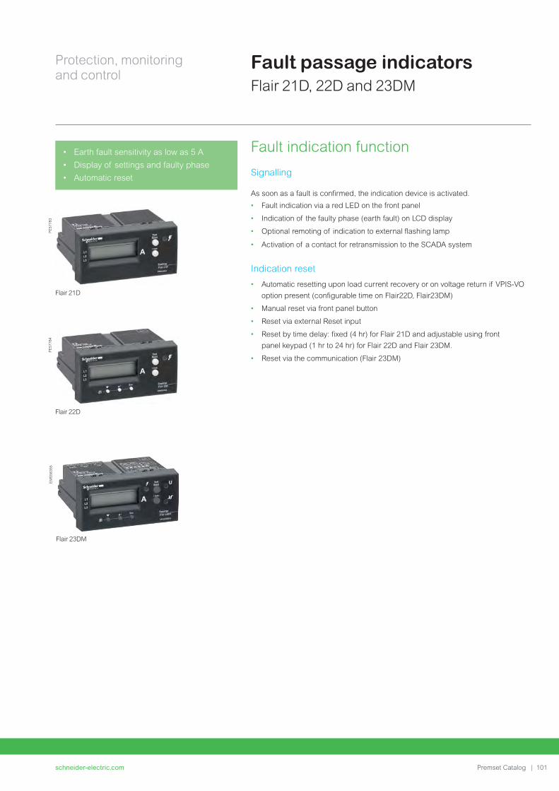
schneider-electric.com | 101Premset Catalog
Protection, monitoring
and control
Flair 21D
Flair 22D
PE
57
78
3P
E5
77
84
Flair 23DM
EM
S5
83
55
Fault passage indicators
Flair 21D, 22D and 23DM
• Earth fault sensitivity as low as 5 A
• Display of settings and faulty phase
• Automatic reset
Fault indication function
Signalling
As soon as a fault is confi rmed, the indication device is activated.
• Fault indication via a red LED on the front panel
• Indication of the faulty phase (earth fault) on LCD display
• Optional remoting of indication to external fl ashing lamp
• Activation of a contact for retransmission to the SCADA system
Indication reset
• Automatic resetting upon load current recovery or on voltage return if VPIS-VO
option present (confi gurable time on Flair22D, Flair23DM)
• Manual reset via front panel button
• Reset via external Reset input
• Reset by time delay: fi xed (4 hr) for Flair 21D and adjustable using front
panel keypad (1 hr to 24 hr) for Flair 22D and Flair 23DM.
• Reset via the communication (Flair 23DM)

schneider-electric.com102 | Premset Catalog
Protection, monitoring
and control
Display principle
• The load current is displayed continuously
• When a fault is detected, the faulty phase is indicated
• Use the buttons on the front panel to scroll through settings and measurements.
Flair
21D 22D 23DM
Power supply Self-powered p p pDual-powered p (1) p
Detection Overcurrent p p pEarth-fault p p p
Display
(4 digit LCD)
Ammeter p p pMaximeter p p p
Options SCADA interface (relay) p p pExternal lamp p p pExternal reset p pExtended setting (keypad) p p
Communication 2-voltage output relays pSerial communication port p
(1) By lithium battery
Characteristics per product
Model Description
Fault passage indicator with single power supply (self-powered)
Flair 21D • Detector with autonomous power supply
• External indicator lamp output powered by battery (BVP)
Fault passage indicator with dual power supply
Flair 22D • Detector with autonomous power supply and lithium battery
• External indicator lamp output powered by the Flair (BVE)
• Interface with VPIS-VO possible to confi rm the fault by voltage
absence
• Service life: 15 years
Fault passage indicator with dual power supply and voltage presence/absence
Flair 23DM • Detector with 24-48 Vdc external and autonomous power supply
• External indicator lamp output powered by the Flair (BVE)
• Voltage presence and absence detector (same as for VD23)
• Interface with VPIS-VO needed for the voltage presence
• Communication on an RS485 serial link with Modbus protocol with
access to states and measurements and remote parameter-setting
Standard applications
Flair 21D Maintenance-free, adjustment-free fault detector
Flair 22D Fault detector for networks with very low load current (< 2 A) with
possibility of manual adjustments.
Flair 23DM • Adapted to Feeder Automation. Forwarding of current
measurement,
fault passage indication and voltage outage information to the
SCADA via a serial communication port.
• Combination fault passage indicator and voltage detector, ideal for
use with an Automatic Transfer System.
Clear, comprehensive display
Flair 22DEasergy
L1L2L3
I max.
EMS58352
AEsc
TestReset
DE
58
71
5
L3 L2L1
Reset
Reset
Reset
VPIS-VOoption
Flair 21D
Flair 22D
Flair 23DM
SCADA Reset
L3 L2L1
L3 L2L1
Indication
Indication
Indication
VPIS-VOoption
Voltagerelays
+ -
ComRS485
DM
10
00
04
8
Fault passage indicators
Flair 21D, 22D and 23DM
Sensors
The Flair 21D, 22D, 23DM range uses
an integrated detection system composed
of indicators and dedicated CTs.
Integrated sensors are normally placed
around the bushings. Split CTs can be
placed around cables for retrofi t purposes.
Connection diagrams

schneider-electric.com | 103Premset Catalog
Protection, monitoring
and control
PE
56
83
0
Voltage presence indicators
A voltage presence indicating device can be integrated in all the functional units,
either on the cable or busbar side. It can be used to check whether or not a voltage
is present across the cables.
Two devices are available:
• VPIS:
Voltage Presence Indicator System, as defi ned by standard IEC 62271-206
• VDS:
Voltage Detecting System, as defi ned by standard IEC 61243-5.
The VPIS can be fi tted with a voltage output (VPIS-VO) dedicated to various voltage
detection applications such as automatic transfer switches, voltage absence or
presence contacts, live-cable earthing switch lockout.
Voltage sensors
A voltage sensor is integrated in all the functional units. It provides a signal with
an accuracy of 5% to the VPIS through a 30 pF capacitive divider.
The sensor is integrated in the tightening cap used to fi x the busbar or cable
connections. The voltage can be detected either on the cable side or the busbar
side.
Phase concordance unit
This unit is used to check phase concordance.
VPIS
Phase concordance unit
Voltage presence sensors
Voltage presence sensors on busbars or cables
PE
56
36
6P
M1
00
03
3
Voltage indicator and relay
VPIS and VDS

schneider-electric.com104 | Premset Catalog
Protection, monitoring
and control
FeaturesThe VD23 is a compact voltage relay for 3 kV to 36 kV, 50/60 Hz medium
voltage networks. It is associated with a capacitive divider and a VPIS-VO.
• 2 output relays based on 2 functional modes:
- R1 = Voltage presence (typically used for automatic transfer switching)
- R2 = Voltage absence (typically used for interlocking of earthing switch).
• Thresholds can be set as a percent of phase-to-neutral voltage (V),
phase-to-phase voltage (U) or residual voltage (VO)
• All combinations of voltage conditions are possible:
- 3 phases and residual: V1+V2+V3+VO
- 3 phases: V1+V2+V3 or U12+U13+U23
- Single phase: Vo, V1, V2, V3, U12, U13 or U23
• Output is a tripping order via two output relays with a normal or inverse active
position
• Signalling and tripping outputs may be set with a delay.
Display principle
• Voltage value (% of Un) of L1, L2 and L3 shown on the display
• Voltage presence/absence indication via LED
• Settings by front pushbuttons and LCD
thresholds, delays and smart parameters
display of all settings on LCD.
• Auto-adaptation of the nominal system voltage
• Check on voltage status.
Advanced settings
All the combinations can be set with microswitches on the rear of the device.
The use of two relays provides safety backup operation for each combination
6 microswitches: 1. Ph-N voltage(V) / Ph-Ph voltage(U)
2. Direct / inverse action on output relays
3. Phase 1 used / not used
4. Phase 2 used / not used
5. Phase 3 used / not used
6. Residual voltage used / not used
1
1
0
2 3 4 5 6
Wiring (with VPIS-VO)
All the combinations can be set with microswitches on the rear of the device.
The use of two relays provides safety backup operation for each combination.
VD23
PE
57
78
7
L1L2L3
VD23
VPIS-VO
DM
100060
Voltagepresence
24-48 Vdc
Voltageabsence
Voltage indicator and relay
VD23 voltage relay
The VD23 is a voltage detecting system for automatic transfer system or interlock applications.
Various combinations:
• Presence or absence voltage relay
• Zero sequence voltage relay
• Phase-to-neutral or phase-to-phase
voltage
• Phase selection.
Easy to install:
• Compact 96 x 48 mm DIN format
• Terminal connection for VPIS-VO
• No need for HV transformer
• Hot installation
• Auto-adaptation of nominal voltage.
• Optional communication port and fault
detector (Flair 23DM)

schneider-electric.com | 105Premset Catalog
Protection, monitoring
and control
The “live cable interlock” function is an electrical interlock helping to prevent
the operator from closing the earthing switch on live cables.
Even if all the earthing switches integrated in Premset core units have full making
capacity performance, it may be useful to avoid creating intempestive faults by
inadvertently earthing live cables.
PrincipleThe system is composed of:
• A mechanical locking assembly acting directly on the line / earth selector,
including an override key that can be used to bypass the locking device
• An undervoltage coil for high failsafe operation of the mechanical lockout system
(see MN, page 75)
• A dedicated electronic auxiliary-powered voltage relay (ESL) fi tted with an
auxiliary contact for remote indication of “locked” position
• A VPIS indicator on the cable side, with a voltage output (VPIS-VO), to detect
and send the voltage signal to the relay.
Operation• Normal case : the system is powered by auxiliary power. It is then impossible
to move the selector from “line” to “earth”, as long as voltage is detected on the
cable by the VPIS.
In case of auxiliary power loss, cables live or not, a failsafe features blocks the
system so the selector cannot be operated.
Override is possible only by unlocking the system with key or when auxiliary power
is restored.
Technical data
• Auxiliary power:
- 24-48 VDC
- 110-220 VAC /
110-250 VDC
• Key types:
- Ronis
- Profalux
Live cable interlock
Functions
DM
10
00
24
Ø
AC/DC supply
VPIS-VO
LCIElectronic
Device
LCIElectricDevice
Technical data
Auxiliary power • 24-48 VDC: ESL100 A
• 110-220 VAC / 110-250 VDC: ESL100 E
Key types • Tubular
• Flat
Undervoltage coil

schneider-electric.com106 | Premset Catalog
Protection, monitoring
and control Thermal monitoring
Easergy T110: wireless thermal sensors *
Continuous thermal monitoringThe power connections in the Medium Voltage products are one of the most critical
points of the substations especially for those made on site like:
• MV Cable connections
• Bus bar connections
• Withdrawable CB connections
Loose and faulty connections cause an increase of resistance in localized points
that will lead to thermal runaway until the complete failure of the connections.
Preventive maintenance can be complicated in severe operating conditions also
due to limited accessibility and visibility of the contacts.
The continuous thermal monitoring is the most appropriate way to early detect a
compromised connection.
Easergy TH110 thermal sensorEasergy TH110 is part of the new generation of wireless smart sensors ensuring
the continuous thermal monitoring of all the critical connections made on fi eld
allowing to:
• Prevent unscheduled downtimes
• Increase operators and equipments safety
• Optimize maintenance with predictive information
Thanks to its very compact footprint and its wireless communication, Easergy
TH110 allows an easy and widespread installation in every possible critical points
without impacting the performance of the MV Switchgears.
By using Zigbee Green Power communication protocol, Easergy Th110 ensure
a reliable and robust communication that can be used to create interoperable
solutions evolving in the Industrial Internet of Things (IIoT) age.
Easergy TH110 is self powered by the network current and it can ensure high
performances providing accurate thermal monitoring being in direct contact with
the measured point.
Substation monitoring deviceEasergy TH110 is connected to the Substation Monitoring Device (SMD) that
harvest the data for local signaling, data analyses and nearby display.
Specifi c monitoring algorithms allow to detect drifts from the threshold based on the
specifi c installation characteristics also in regards of the variable loads or abnormal
behaviors coming from phases comparison.
The remote monitoring and alarming ensure full peace of mind thanks to remote
connection for SCADA or Services, access to Cloud-based Apps and digital
services and alarming through SMS or Facility Hero mobile App.
Key benefi ts
• Battery free
• Wireless communications
• High performances
• In contact measuring point
• Easy installation
• Compact footprint
• Remote monitoring and alarming
Characteristics
Power supply Self powered.
Energy harvested from power circuit.
Minimum activation current 5 A
Accuracy +/- 1°C
Range -25 °C / +115°C
Wireless communication ZigBee Green Power 2,4 GHz
Dimension - Weight 31 x 31 x 13 mm - 15 g
SCADA
BMS Com’X
GSM
Facility Hero
Local HMI
Nearby HMI
Wireless Smart Sensors
TH110 TH110
SMD
DM
10
53
20

schneider-electric.com | 107Premset Catalog
Protection, monitoring
and controlIntegrated measurement
AMP 21D ammeter
FunctionsThe Easergy Amp 21D is an ammeter dedicated to the display of the load current
on Medium Voltage networks.
It is particularly suited to network load management applications.
• Display of the 3 phase currents: I1 , I2 , I3 (range: 3 A to 800 A)
• Display of the 3 phase current maximums: M1, M2 , M3 (range: 3 A to 800 A)
Display principle
• Load currents are displayed by default, with continuous scrolling of L1, then L2,
then L3.
• The maximeter is displayed by pressing a dedicated pushbutton, with
continuous scrolling of maximum currents M1, then M2, then M3.
• The maximums are reset by pressing a combination of two pushbuttons
Design
Small enclosure
• DIN format: 93 x 45 mm
• Secured, extraction-proof mounting
• Terminal connections
AMP 21D
PE
57
78
6
L1
L2
L3
Connection diagram
AMP 21D
DM
10
00
50
• Traditionally, three analogue dial-type
ammeters were installed on MV feeders
with a costly and bulky TC to power
them . These devices had poor accuracy
(cl. 1.5) and no maximeters to provide
feedback on the maximum load
• Now, with the AMP 21D digital ammeter,
all feeders can be equipped with small
CTs that provide accurate measurements
and a maximeter function, all at a lower
price
• The AMP 21D is self-powered to display
currents continuously
• Its compact DIN format easily fi ts in
Premset MV cubicles
• Versatile, it displays phase current and
maximum current
Technical data
Frequency 50 Hz and 60 Hz
Load current Minimum current 3 A
Measurement Range Phase current 3 to 800 A
Accuracy (I < 630 A) ± 3%, ± 2 A
Reset of maximeter Manual from device Yes
Power supply Self powered From the current
sensors
I load > 3 A
Battery No
Auxiliary supply No
Display Display
• Current per phase
• Maximeter current
per phase
4 digits LCD
• Yes (resolution 1 A)
• Yes
Sensors Phase CTs 3 ring or split core CT(1)
Other Test Yes
(1) CT selection refer to page 79

schneider-electric.com108 | Premset Catalog
Protection, monitoring
and control
PM5000 series Power Meter
Applications and main features
The PowerLogic PM5000 power meter is the ideal fi t for cost management
applications. It provides the measurement capabilities needed to allocate energy
usage, perform tenant metering and sub-billing, pin-point energy savings, optimize
equipment effi ciency and utilization, and perform a high level assessment of the
power quality of the electrical network.
In a single 96 x 96 mm unit, with a graphical display, (plus optional remote display)
all three phases, neutral and ground can be monitored simultaneously.
Highly accurate devices with 3rd party certifi cation.
The Power Meter series 5000 is available in multiple versions including:
• PM5100, basic version with pulse output, class 0.5S accuracy
• PM5110, RS485 port with Modbus communication, class 0.5S accuracy
• PM5340, multi-tariff, data logging, Ethernet communication, class 0.5S accuracy
• PM5560, multi-tariff, data logging, WAGES metering, Gateway, class 0.2S
accuracy, simultaneous communication via Modbus TCP and BACnet/IP
Characteristics
• * High-accuracy energy metering: IEC 62053-22 Class 0.5S or Class 0.2S
• Multiple communication options: RS485, Ethernet or both
• Dual Ethernet ports (PM5560 models) to daisy chain meters together - less
wiring, simpler installation
• Ethernet-to-serial gateway functionality (PM5560)
• Protocol options include Modbus RTU, Modbus TCP and BACnet/IP
• Data logging (PM5340, PM5560 models)
• Multiple tariffs (PM5340, PM5560 models)
• Complete WAGES monitoring with 4 Digital Inputs & 2 Digital Outputs
• Onboard web pages (PM5560 models) for viewing real-time and logged
information
• Bright, anti-glare graphical display with intuitive menu-driven navigation
PB
11
17
76
Integrated measurement
PM5000 series Power Meter
PowerLogic PM5000 series help you:
• Reduce energy costs
• Simplify installation
• Improve continuity of service for optimal
management of your electrical installation
and higher productivity

schneider-electric.com | 109Premset Catalog
Protection, monitoring
and control
PM8000 series Power Quality Meter
Applications and main features
The PowerLogic PM8000 series meter is a highly accurate, extremely reliable power
and energy meter with unmatched fl exibility and usability. The meter combines
accurate 3-phase energy and power measurements with data logging, power
quality analysis, alarming and I/O capabilities not typically available in such a
compact meter.
The PM8000 series meters are compliant with stringent international standards
that guarantee their metering accuracy and power quality measurements. Ideal for
industrial and critical power installations that are responsible for maintaining the
operation and profi tability of a facility.
The PM8000 series is available in the versions:
• PM8240, panel mount, integrated display
• PM8244, DIN rail mount, remote display
Characteristics
• High-accuracy energy metering: IEC 62053-22 Class 0.2S
• Time synchronization
• Multi-tariff support
• WAGES metering support
• PQ compliance monitoring: IEC 61000-4-30 class S, IEC 62586, EN 50160,
IEEE 519
• PQ analysis capabilities: Dip & swell detection, waveform capture, disturbance
direction detection, trending & forecasting
• Protocols: ION, Modbus, DNP3, IEC 61850
• Ports: RS-485, dual-port Ethernet, Ethernet-to-serial gateway
• Graphical, color display
• Onboard, customizable web pages
• Modular I/O extension modules.
PB
11
36
83
Integrated measurement
PM8000 series Power Quality Meter
PowerLogic PM8000 series:
Compact, high-performance meters for cost
and network management applications on
feeders and critical loads.
• Detailed PQ compliance reporting, and
expert-level root-cause analytics.
• Power monitoring, logging, and
forecasting to help ensure your electrical
system stays within safe operating
tolerances, avoiding the risk of overloads,
unbalances, or high peak demand

schneider-electric.com110 | Premset Catalog
Protection, monitoring
and controlControl
SC110: electrical operation auxiliaries
The SC110 is an intelligent electronic device designed to control and monitor all the components involved in the remote control of core units.
It integrates all the necessary functions
for reliable remote control:
• Electrical interlocking
• Remote control supervision
• Front panel interface for local operation
• Built-in Modbus communication and
“Plug and play” design makes the SC110
and the remote control facility:
- easy to use
- easy to upgrade.
SC110 types SC110-A SC110-E
24-60 Vdc p
110 Vdc/Vac - 240Vac/250Vdc p
Network communication p p
SC-MI control panels SC-MI 10 SC-MI 20
On/Off pushbuttons p p
Remote/local switch p
SC110 universal intelligent controller
SC110 is a compact device with digital inputs and outputs to monitor all the
components associated with the electrical operation of the core unit:
MCH, MX, XF, auxiliary contacts.
It can be associated with a control panel (SC-MI).
Switchgear control functions
• Coil and motor operation
• Information on core unit status: main switch, earthing switch, lever insertion
• Built-in electrical interlocks: anti-pumping and anti-refl ex functions
• External interlocking feature
• Lockout of electrical operation after tripping (option)
• Modbus communication for remote control via data transmission
Switchgear monitoring
• Diagnosis information: motor consumption
• Core unit auxiliary contacts status
• Logging of time-stamped events
• Modbus communication for remote indication of monitoring information
SC-MI control panel
PM
10
00
38
SC110A 3 RJ45 Modbus plugs
PM
10
00
43
SC110
Modbus
MCH MX XF
DM
10
00
25
Auxiliary contacts
The SC110 is installed in the Low Voltage
cabinet of the functional unit. It controls
and monitors all the devices needed for
electrical operation: MCH, MX, XF, auxiliary
contacts.

schneider-electric.com | 111Premset Catalog
Protection, monitoring
and control
Continuity of service supervised
by an overall telecontrol solution
DM
10
00
07
Communication network: radio, PSTN, GSM/GPRS, Ethernet …
Feeder automationSubstation automation
Control
Architecture of feeder automation
Schneider Electric offers you a complete solution, including:
• The Easergy R200 telecontrol interface
• Premset switchgear that can be easily
adapted for telecontrol
• The SCADA and DMS system
Premset range, more than ready
Premset switchgear is suited to telecontrol thanks to options such as:
• LV control cabinet including an
R200 RTU
• Motorised operating mechanism
• Auxiliary fault and position indication contacts
• Current sensors for fault detection
DM
10
00
10
EN
Network control centre
HV/MV
Communication network
Premset Premset Premset
Premset Premset Premset
Easergy R200
Easergy R200
Easergy R200
MV ring
PE
58
30
1
Telvent DMS system

schneider-electric.com112 | Premset Catalog
Protection, monitoring
and control
Easergy R200: an interface designed for
telecontrol of MV networks
The Easergy R200 “plug and play” RTU integrates all the functional units necessary
for remote supervision and control of an MV switchboard cubicle:
• Transmission of switch open/close orders
• Exchanges with the control centre.
Easergy R200 is of proven reliability and availability, ready to ensure switchgear
operation at any time. It is simple to set up and to operate.
Communication
Easergy R200 can manage both “serial type” and IP protocols.
It is thus possible to mix serial and IP transmission media in a given application.
Communication possibilities are continuously evolving to keep pace with your
needs:
• IEC 870-5-101 and IEC 870-5-104 protocols
• DNP3 serial and TCP protocols
• Modbus serial and TCP protocols
• Other proprietary protocols
An extensive choice of integrated modems and interfaces:
• RS232/485 serial interface
• GSM/GPRS modem
• 3G Modem
• Voice modem (PSTN)
• FSK radio modem
• FFSK radio modem
• Ethernet port
Local control in SCADA
Easergy R200 incorporates a Web data server in HTML page form for data
confi guration and monitoring. All that is needed to log on is a PC with a Web
browser.
Remote access is possible via GSM, GPRS, Ethernet or PSTN transmission
networks and can be implemented in parallel from the remote control centre.
Thanks to this remote access and its capability to send e-mails and SMSs,
the R200 offers you a cost-effective solution to monitor your MV substation
without a SCADA system.
The embedded Web server allows local monitoring of the substation.
Control
Easergy R200: control unit
Easergy R200 is a Remote Terminal Unit (RTU) intended for typical remote management applications in the Energy industry and for MV infrastructures in general.
PE
57
57
0p

schneider-electric.com | 113Premset Catalog
Protection, monitoring
and control
Premset
R200
PM
10
00
16
_Fo
rme
r _???
PE
57
57
0p
Control
Easergy R200: control unit
Built-in solutions for protecting, monitoring
and controlling your installation.
Energy availability
• Measurement
• Remote fault detection
• Remote control and protection devices.
Easy to use
• Compact design with built-in devices - no engineering required
• Scalable with “just enough” dedicated solutions from monitoring to remote
control
• Robust devices designed for harsh environments
• Easy and safe plug and play connection
• Open to standard protocols, ensuring easy SCADA connection

schneider-electric.com114 | Premset Catalog
Protection, monitoring
and controlControl
ATS100: automatic transfert system
Source transfer
The ATS100 drives automatic transfer from the normal MV source to the back-up
source in order to keep supplying the MV substation in case of failure of the normal
source. ATS100 can drive either Load Break Switch or Circuit Breaker.
There are 3 types of ATS100 depending of single line diagram and sources.
ATS100-ACO: 2 line incomers
L1 and L2 can be either normal or backup source. Upon loss of Normal source,
Backup source will automatically supply the substation. When Normal source
recover there are 3 possibilities depending of the confi guration :
• Self-return : The Normal source will automatically supply the substation
• No-return : Only a manual operation will be possible for Line to supply again the
substation.
• Auto-return : The Normal source will automatically supply the substation only in
case of loss of the back-up sources.
ATS100-GEN (*): 1 line and 1 generator incomers
L1 and L2 can be either Line or Generator source. Only the Line can be the Normal
source. Upon loss of it, Generator source will automatically be started and the
supply the substation. When Line source recover there are 3 possibilities depending
of the confi guration:
• Self-return : The Line source will automatically supply the substation and
generator will be shut down
• No-return : Only a manual operation will be possible for Line to supply again the
substation
• Auto-return : The Line source will automatically supply the substation only in
case of loss of the generator sources
ATS100-BTA : 2 line incomers with bus tie
Normal situation is L1 and L2 closed and Bus Tie open. In case of loss of one of
the lines, the bus tie is automatically closed to recover the supply of the substation.
When both lines are back, depending of the confi guration, the Normal situation is
automatically recovered or not.
An MV power supply interruption is unacceptable, especially in critical applications.
The Premset system therefore proposes an automatic source transfer solution.
ATS100
DM
10
31
00
1
ATS100-ACO:
2 line incomers
L1 L2
ATS100-BTA :
2 line incomers
with bus tie
L1 L2
ATS100-GEN: 1 line and
1 generator incomers
L1 L2G
* Please consult us for availability

schneider-electric.com | 115Premset Catalog
Protection, monitoring
and controlControl
ATS100: automatic transfert system
Typical diagram
M M
DM
10
00
61
2 VPIS-VOs
Flair23DM
Flair23DM
SC110 SC110 ATS100
Field bus
L1 L2
Voltage sensor: dedicated version of VPIS with Voltage Output signal.
Voltage detector + Fault Passage Indicator: a relay is activated when a loss of voltage is detected from
the VPIS voltage output signal. If a fault current is detected,
the Automatic Transfer System is locked out in order to avoid
closing the healthy line on the fault.
Based on inputs coming from the Flair 23DMs, the decision
is made to switch from one line to the other.
• Communication facilities may be added
• Communication to SCADA or BMS (optional)
• Web Server: confi guration, diagnostics, alar ms, logs
2 Flair 23DMs
1 ATS100 +switch or CB function
SCADA, BMS
Characteristics
Switch response time 0.5s to 3s
Parallel coupling Coonfi gurable to avoid black-out when restoring
normal situation
Load shedding Confi gurable to adapt load to the capacity of the
generator or to restart loads in sequence after black-
out.
Time delay before
changing source
Confi gurable up to 120s
Time delay before recovering
normal situation
Confi gurable up to 30mn
Remote
communication
Ethernet, GSM, GPRS, or 3G communication with:
• IEC 870-5-101 and IEC 870-5-104 protocols
• DNP3 serial and TCP protocols
• Modbus serial and TCP protocols
WebServer Easergy ATS100 incorporates a Web data server
in HTML page form for data confi guration and
monitoring. All that is needed to log on is a PC with
a Web browser.

schneider-electric.com116 | Premset Catalog
Protection, monitoring
and control
PM
10
05
92
PS100
Control
PS100: high-availability power supply
PS100 backup power supply
for MV substations
Applications
The power supply unit supplies backup operating power for:
• MV switchgear motor mechanisms and circuit breaker coils
• Transmission equipment (e.g. radio)
• Control units such as RTU (R200) or Automatic Transfer System (ATS100)
• Protection relays, Fault Passage Indicators and other electronic devices
High availabilty power supply
A battery provides uninterrupted operation of the whole substation in the event of
loss of the main supply. The backup power supply unit:
• Includes a regulated and temperature-compensated charger
• Stops the battery before deep discharge
• Carries out a battery check every 12 hours
• Measures battery ageing
• Forwards monitoring information via a Modbus communication port and
output relays
PS100 benefi ts
Only one battery
Traditional backup power supplies require a set of 2 or 4 batteries to produce
24 V or 48 V, with complicated replacement and adjustment of the battery pack.
The PS100 needs only one battery, simplifying replacement.
The battery is a standard sealed lead-acid 12 V battery with a 10-years service.
It can be purchased easily, anywhere in the world.
Improved availability of MV substations
The PS100 is designed to ride through power network interruptions of up to 48
hours. It is associated with a battery selected to meet the required backup time.
For example, a 38 Ah battery provides 12 hours of backup time to a Premset
switchboard including 4 Sepam units.
The PS100 protects and optimises the battery with state-of-the-art monitoring.
A Modbus communication port forwards monitoring data to allow optimised
maintenance operations.
Backup solution for MV switchgear power needs in the event of micro outages and power interruptions.
• Easy maintenance with only one battery
• Remote battery monitoring
• High level of insulation to protect
the electronic devices in harsh MV
environments
• End-of-life alarm possible via Modbus
communication
• Compliant with standards IEC 60 255-5
(10 kV level).
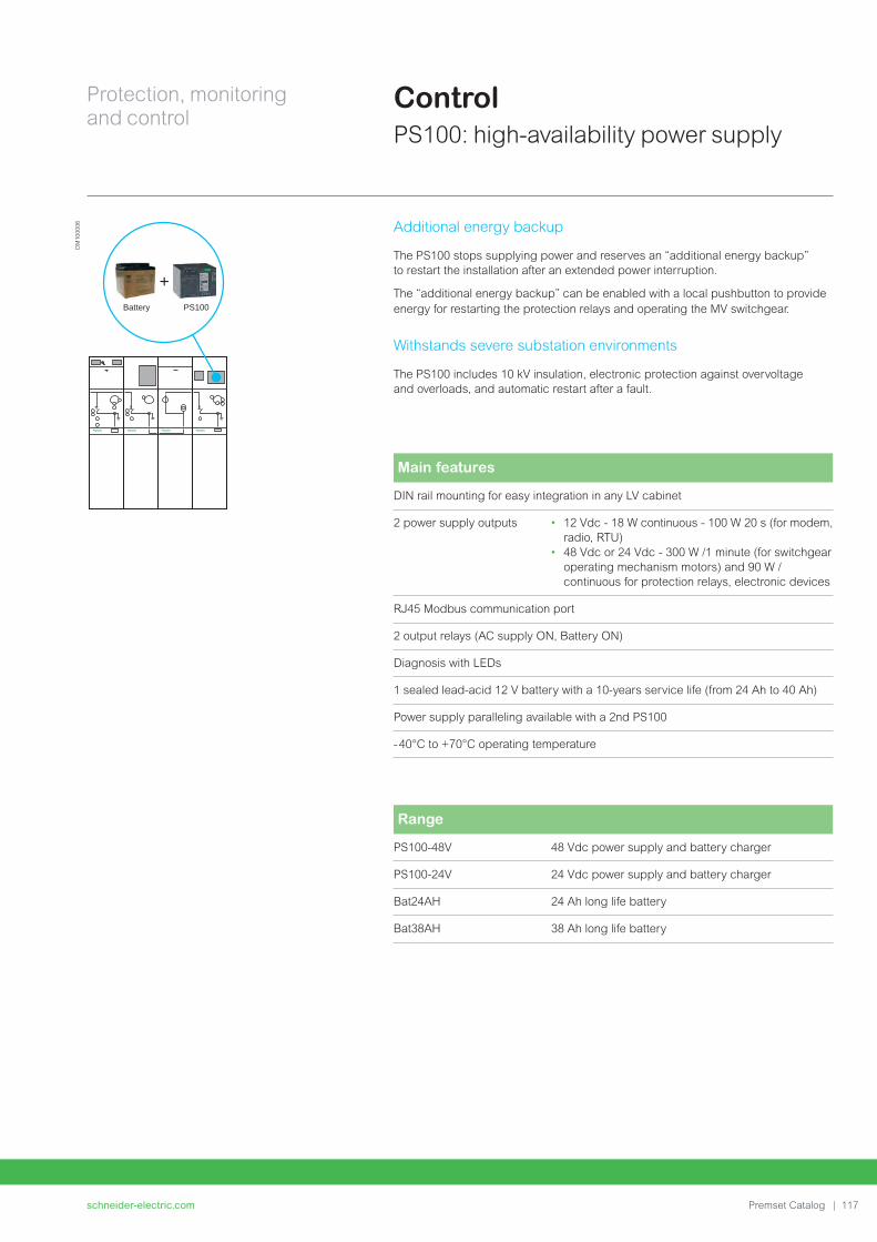
schneider-electric.com | 117Premset Catalog
Protection, monitoring
and control
DM
10
00
06
Battery PS100
+
Control
PS100: high-availability power supply
Additional energy backup
The PS100 stops supplying power and reserves an “additional energy backup”
to restart the installation after an extended power interruption.
The “additional energy backup” can be enabled with a local pushbutton to provide
energy for restarting the protection relays and operating the MV switchgear.
Withstands severe substation environments
The PS100 includes 10 kV insulation, electronic protection against overvoltage
and overloads, and automatic restart after a fault.
Main features
DIN rail mounting for easy integration in any LV cabinet
2 power supply outputs • 12 Vdc - 18 W continuous - 100 W 20 s (for modem,
radio, RTU)
• 48 Vdc or 24 Vdc - 300 W /1 minute (for switchgear
operating mechanism motors) and 90 W /
continuous for protection relays, electronic devices
RJ45 Modbus communication port
2 output relays (AC supply ON, Battery ON)
Diagnosis with LEDs
1 sealed lead-acid 12 V battery with a 10-years service life (from 24 Ah to 40 Ah)
Power supply paralleling available with a 2nd PS100
- 40°C to +70°C operating temperature
Range
PS100-48V 48 Vdc power supply and battery charger
PS100-24V 24 Vdc power supply and battery charger
Bat24AH 24 Ah long life battery
Bat38AH 38 Ah long life battery

schneider-electric.com118 | Premset Catalog
Connections
schneider-electric.com | 119Premset Catalog
Connections
Busbar and cable arrangements 120
Cable connections 121
Network cable testing and diagnosis device 124
Schneider Electric services 126
Facility Hero 128

schneider-electric.com120 | Premset Catalog
Connections
Universal system of power connectionsThe Premset system is based on a set of common elements, used throughout the system:
• 2 types of bar elements, used to make up the busbar system as well as risers
and downstream connections between cubicles.
• One set of 3 connections for cables, used in various directions: front, rear,
bottom, top…
The connection interface between these elements is always the same (Schneider Electric patented design), allowing a wide variety of arrangements.
For example, the set of cable connections can be fitted in different directions to implement various cable entry arrangements: front bottom, top rear, bottom rear, direct connection to busbars, cable in cable out.
Busbar and cable arrangements
• SSIS connections with shielded solid insulation, eliminating all electric fields in open air.
• Flat and smooth interface between connections, allowing flexibility and misalignment in any direction: easier floor installation
• Only one cable connection set, used everywhere: many possibilities for cable entry arrangements
PM
1000
23
PM
1006
01
PM
1000
24
DM
1000
47
PM
1000
25
PM
1000
27
Busbars with shielded solid insulation
PM
1000
26
Cable connections with shielded solid insulation

Connections
schneider-electric.com | 121Premset Catalog
• Only one type of bushing to simplify installation, but various arrangements of connections to fit any application.
• Large choice of cable box and bottom compartment dimensions.
Bottom compartment
The bottom compartment is the lower part of Premset cubicles. It has been designed separately from the rest of the cubicle to offer different versions.
It comes in two different heights to match the space required for cable bending and switchgear installation:
• Standard height, for cable connections at a height of 700 mm.
• Low-height version for cable connections at a height of 500 mm, allowing
installation of switchgear in rooms with low ceilings (total height of switchgear
as low as 1350 mm, depending on LV cabinet dimensions).
• For higher installations, raising plinths can be fitted as accessories, with two
different heights.
Cable connections
• Cable boxes are available in 2 different depths to meet the needs of various
types of installations: number of cables, type of connections, bending radius
of cables, surge arresters.
Cable boxes can be interlocked with main and earthing switches (see core unit
pages) and can be fitted with two transparent windows (not compatible with
internal arc performance).
• Cable bushings are standardised Type "C" (EN50181), M16 screw type
bushings as defined by standard IEC 60137, in order to simplify the choice and
installation of connections.
• Cable connections are always horizontally aligned, 700 or 500 mm high
depending on height of the bottom compartment (please refer to dimension
drawings in the technical appendix).
LV cabinet
Top connection
Cable test
Core unit
Bottom connection
Bottom compartment
D06H
PM
1000
00
Cable connections
Compatible cable connections
• 1 cable per phase
DM
1054
30
• 2 cables per phase
DM
1054
31

schneider-electric.com122 | Premset Catalog
Connections Cable connectionsCompatible cable connections except for I12H and D12H
Check the cables that you are using are compatible with the recommendations supplied in the catalog.
Otherwise use other compatible cables with these recommendations.
2 cables / phase (2 c/p)
Supplier Performance Cr. section (mm²)
Reference Type 2 c/p + Surge arrester
+ VRU1 + Surge arrester + VRU1
Euromold (Nexans)
Up to 12 kV, 630 A
25-300 400LB E
35-300 400TB T ²
35-300 430TB T
185-630 440TB T ²
35-300 400TB + 400PB-XSA T + S ² ²
35-300 430TB + 300SA T + S ²
185-630 440TB + 400 PB-XSA T + S ² ²
Up to 17,5 kV, 630 A
25-300 K400LB E ²
35-300 K400TB T
35-300 K430TB T ²
185-630 K440TB T
35-300 K400TB + K400PB-XSA T + S ² ²
35-300 K430TB + 300SA T + S ²
185-630 K440 TB + K400 PB-XSA T + S ² ²
NKT Cables GmbH
Up to 12 kV, 630 A
25-300 CB12-630 T
CB12-630 + CSA12 T + S ²
Up to 17,5 kV, 630 A
25-300 CB24-630 T
CB24-630 + CSA24 T + S ²
Südkabel Up to 12 kV, 630 A
50-300 SET12 T
185-500 SEHDT13 T ³ ²
185-500 SEHDT13 + MUT13 T + S ² ²
Up to 17,5 kV, 630 A
25-240 SET24 T
185-630 SEHDT23 T ³ ²
185-630 SEHDT23 + MUT23 T + S ² ²
Tyco / Raychem(insulated adapter)
Up to 12 kV, 630 A
25-50 RICS-5113 T
70-150 RICS-5123 T
185-240 RICS-5133 T
300 RICS-5143 T
185-240 RICS-5139 T + S
300 RICS-5149 T + S
Up to 17,5 kV, 630 A
25-70 RICS-5123 T
95-185 RICS-5133 T
240-300 RICS-5143 T
95-185 RICS-5139 T + S
240-300 RICS-5149 T + S
3M Up to 12 kV, 630 A
50-240 93-EE 705-6 T
300-400 93-EE 715-6 T ²
300-400 93-EE 715-6 + MUT23 T + S ² ²
Up to 17,5kV, 630 A
25-240 93-EE 705-6 T
300-400 93-EE 715-6 T
300-400 93-EE 715-6 + MUT23 T + S ² ²
(1) For 2 cables/phase, 2 cables/phase + Surge arrester, 2 cables/phase + VRU1, please consult Schneider Electric
(2) Need deeper cable (500mm) compartment door(3) Need deeper cable (500mm) compartment door for internal arc with standard version
E: Elbow connectorT: T connectorT + S = T connector + surge arrester

Connections
schneider-electric.com | 123Premset Catalog
Cable connectionsCompatible cable connections for I12H and D12H
Check the cables that you are using are compatible with the recommendations supplied in the catalog.
Otherwise use other compatible cables with these recommendations.
4 cables / phase (4 c/p)
Supplier Performance Cr. section (mm²)
Reference Type 4 c/p + Surge arrester
+ VRU1 + Surge arrester + VRU1
Euromold (Nexans)
Up to 12 kV, 630 A
25-300 400LB E
35-300 400TB + 400TB T ²
35-300 430TB + 430TB T
185-630 440TB + 440TB T ²
35-300 400TB + 400TB + 400PB-XSA T + S ² ²
35-300 430TB + 430TB + 300SA T + S ²
185-630 440TB + 440TB + 400 PB-XSA T + S ² ²
Up to 17,5 kV, 630 A
25-300 K400LB+K400LB E
35-300 K400TB+K400TB T ²
35-300 K430TBK430TB T
185-630 K440TB+K440TB T ²
35-300 K400TB+K400TB + K400PB-XSA T + S ² ²
35-300 K430TB+K430TB + 300SA T + S ²
185-630 K440 TB+K440 TB + K400 PB-XSA T + S ² ²
NKT Cables GmbH
Up to 12 kV, 630 A
25-300 CB12-630+CB12-630 T
CB12-630+CB12-630 + CSA12 T + S ²
Up to 17,5 kV, 630 A
25-300 CB24-630+CB24-630 T
CB24-630 +CB24-630 + CSA24 T + S ²
Südkabel Up to 12 kV, 630 A
50-300 SET12+SET12 T
185-500 SEHDT13+SEHDT13 T ³ ²
185-500 SEHDT13 +SEHDT13 + MUT13 T + S ² ²
Up to 17,5 kV, 630 A
25-240 SET24+SET24 T
185-630 SEHDT23+SEHDT23 T ³ ²
185-630 SEHDT23+SEHDT23 + MUT23 T + S ² ²
Tyco / Raychem(insulated adapter)
Up to 12 kV, 630 A
25-50 RICS-5113 + RICS-5113 T
70-150 RICS-5123 + RICS-5123 T
185-240 RICS-5133 + RICS-5133 T
300 RICS-5143 + RICS-5143 T
185-240 RICS-5133 + RICS-5139 T + S
300 RICS-5143 + RICS-5149 T + S
Up to 17,5 kV, 630 A
25-70 RICS-5123 + RICS-5123 T
95-185 RICS-5133 + RICS-5133 T
240-300 RICS-5143 + RICS-5143 T
95-185 RICS-5133 + RICS-5139 T + S
240-300 RICS-5143 + RICS-5149 T + S
3M Up to 12 kV, 630 A
50-240 93-EE 705-6 + 93-EE 705-6 T
300-400 93-EE 715-6 + 93-EE 715-6 T ²
300-400 93-EE 715-6 + 93-EE 715-6 + MUT23 T + S ² ²
Up to 17,5kV, 630 A
25-240 93-EE 705-6 T
300-400 93-EE 715-6 T ²
300-400 93-EE 715-6 + 93-EE 715-6 + MUT23 T + S ² ²
(1) For more or less than 2 cables/phase, please consult Schneider Electric(2) Need deeper cable compartment door: 500mm (450mm for I12H and D12H)(3) Need deeper cable compartment door 500mm (450mm for I12H and D12H)
for internal arc withstand version
E: Elbow connectorT: T connectorT + S = T connector + surge arrester

schneider-electric.com124 | Premset Catalog
Connections
Cable testing and cable diagnosisMedium voltage cable testing is a demanding task that leaves no room
for error
• Work is carried out on the main circuit with a high-voltage test bench
• Earthing is removed during testing
• Access to the main circuit for test connections may require access to the cable
box and dismantling of cable termination insulation
• Procedures must be followed strictly to ensure the safety of personnel
• Cable connections must be properly reassembled to restore full insulation
Intuitive and easy cable access with PremsetPremset switchboards can be fitted with a dedicated cable testing device
that greatly increases safety during cable testing
• Cable testing can be carried out without accessing the cable box (cables
remain connected) and without touching the cable terminations
• The test device can be connected from the front of the switchboard, prior to
removing the earth link
• Earth link removal is the last operation to be carried out, using a special
earthing bar disconnection system, without any operation of the main switching
device or main earthing switch
• Earth link removal featuring full failsafe interlocking, i.e. the earth link can be
opened only if the main earthing switch is closed (cable earthed) and the main
earthing switch can be opened only if the earthing link is closed
• Test bench connections are delivered separately. They can also be adapted
locally to any specific test set.
PM
1027
15
Network cable testing and diagnosis device
Premset offers an original primary circuit arrangement allowing direct access to cable conductors without operating the main switches or dismantling the cables connections.
Combined with a dedicated cable test device, it provides high operator safety during cable testing and diagnosis.

Connections
schneider-electric.com | 125Premset Catalog
Network cable testing and diagnosis device
The cable testing device can be used on both ends of cable to be tested, in order to isolate completely the cable section from the network.
PM
1000
28
DM
1000
59
Cable
Double isolating gap during testing
Safe and fully interlocked device
Direct access to cable conductor without operating the main switch
Technical characteristicsCable testing device can be used for various testing and diagnosis purposes:
• DC tests up to 36 kV DC x 15 min
• Very low frequency testing from 0.1 Hz up to 20 kV x 30 min (sinusoidal signal),
and 28 kV x 30 min for cos2 signal.
• 50/60 Hz dielectric tests up to 14 kV x 1 min
• Tan Delta diagnosis: power dissipation 18 kV.
• Performance characteristics have been validated in accordance with standard
IEC 62271-200, edition 2

schneider-electric.com126 | Premset Catalog
Connections
PlanSchneider Electric helps you to plan the full design and execution of your solution,
looking at securing your process and optimizing your time:
• Technical feasibility studies:
Accompany customer to design solution in his given environment
• Preliminary design:
Accelerate turnround time to come to a final solution design
InstallSchneider Electric will help you to install efficient, reliable and safe solutions based
on your plans.
• Project management:
Designed to help you complete your projects on time and within budget
• Commissioning:
Ensures your actual performance versus design, through on site testing &
commissioning, tools & procedures
OperateSchneider Electric helps you maximize your installation uptime and control your
capital expenditures through its service offering.
• Asset operation solutions:
The information you need to increase safety, enhance installation performance,
and optimize asset maintenance and investment
• Advantage service plans:
Customized service plans which cover preventive, predictive and corrective
maintenance
• On site maintenance services:
Extensive knowledge and experience in electrical distribution maintenance
• Spare parts management:
Ensure spare parts availability and optimized maintenance budget of your
spare parts
• Technical training:
To build up necessary skills and competencies. in order to properly operate
your installations in safety
OptimizeSchneider Electric provides recommendations for improved safety, availability,
reliability & quality.
• MP4 electrical assessment:
Define improvement & risk management program
Schneider Electric ServicesPeace of mind throughout your installation life cycle
PlanWhat are my options?
InstallHow do I install and commission?
OperateHow do I operate and maintain?
OptimizeHow do I optimize?
RenewHow do I renew my solution?
Life Cycle Services
DM
4088
43
How can you cut costs and improve performance at the same time?
When it comes to your electrical distribution infrastructure, the answer is straight-forward - get professional expertise.
Life cycle services

Connections
schneider-electric.com | 127Premset Catalog
Schneider Electric ServicesPeace of mind throughout your installation life cycle
When it comes to your electrical distribution installation, we can help you:
• Increase productivity, reliability, and
safety
• Mitigate risk and limit downtime
• Keep equipment up to date and
extend lifespan
• Cut cost and increase savings
• Improve your return on investment
CONTACT US!
www.schneider-electric.com/electricaldistributionservices
RenewSchneider Electric extends the life of your system while providing upgrades.
Schneider Electric offers to take full responsibility for the end-of-life processing of
old electrical equipments.
• ECOFIT™:
Keep up to date & improve performance of your electrical installations (LV, MV,
Protection Relays)
• MV product end of life:
Recycle & recover outdated equipment with end of life services

schneider-electric.com128 | Premset Catalog
Connections Facility HeroPreventive & predictive maintenanceusing QR codes
What is Facility Hero?Facility Hero is a smart maintenance log book that can be accessed from any
smartphone, tablet, or computer. This 100% collaborative, connected system keeps
maintenance technicians in the field in constant contact with their maintenance
community: manager, customer, contractors and peers for fast and effective
interventions.
Accessible by anyone, anywhere, anytime
Facility Hero works on 3G, 4G, and Wi-fi networks and can also be used offline.
Simply download the application right to your smartphone or tablet, set up an
account, and get started.
The right information, fast
• Overall view of equipment (status, tasks, the week's reminders)
• Full maintenance logs (breakdowns, maintenance reports)
• Fast access to history equipment maintenance logs via the QR code on the
equipment
• Rich maintenance reports including voice memos, notes, photos, and
measurements
The right decision and the right action at the right time
• Quickly add a new piece of equipment
• Access periodic reading measurements, recent malfunctions
• Locate equipment by GPS in real time
• Monitor equipment remotely and in real time
Manage your maintenance teams and interventions effectively
• Real-time work orders sharing, and reporting with selected users
• Get inspection reports by mail and share them in just two clicks
• Monitor all regular operations such as scheduling, and incomplete or upcoming
tasks

Connections
schneider-electric.com | 129Premset Catalog
Facility HeroPreventive & predictive maintenanceusing QR codes
FACILITY HERO BENEFITS
Enhance the efficiency of maintenance operations and insure your uptime:
• Access automatically to the
maintenance recommendations of
your equipments by flashing the
QR codes
• Cloud Logbook to organise and
follow your maintenance
• Remote alarming
Facility HeroNew improve the efficiency on maintenance!
• Access automatically to your Premset equipment maintenance planning by
flashing the QR code
• Find the QR codes on your products or on the catalogue product data sheet MV
product end of life:
Recycle & recover outdated equipment with end of life services
> Download the free version of Facility Hero:
Circuit breaker function
Switch function
Metering & other functions
> Access to the maintenance of your equipement:

schneider-electric.com130 | Premset Catalog
Technical appendix

schneider-electric.com | 131Premset Catalog
Technical appendix
Dimensions 132
Civil engineering 137
Ground preparation 137
Standard design 138
Arc control design (upwards exhaust) 139
Arc control design (downwards exhaust) 140
Raising plinths 142
VIP tripping curves 143
VIP 40 and VIP 45 tripping curve 143
VIP 400 and VIP 410 tripping curves 144
Order form - Premset (indoor) standard offer 146

schneider-electric.com132 | Premset Catalog
Technical appendix Dimensions
Fixing of units
With each other
The units are simply bolted together to form the MV switchboard (bolts supplied).
To the floor
• For switchboards comprising up to three units, the four corners of the
switchboard must be fixed to the floor using:
- bolts (not supplied) screwed into nuts set into the floor using a sealing pistol
- threaded rods grouted into the ground
• For switchboards comprising more than three units, the number and position of
fixing points depends on local criteria (earthquake withstand capacities).
Unit type Height Width Depth (1)
Weight
(2)
Weight with packing
(mm) (mm) (mm) (kg) (kg)
I06T 1550 375 910 200 275
I06H 1550 375 910 200 275
D01N 1550 375 910 200 275
D02N 1550 375 910 200 275
D06N 1550 375 910 200 275
D06H 1550 375 910 200 275
E-SB 1550 375 910 200 275
G06 1550 375 910 100 175
M06S 1550 375 910 250 275
M06A 1550 750 910 350 425
VTM 1550 375 910 150 225
VTP 1550 375 910 150 225
VTM-D 1550 375 910 250 325
VTP-D 1550 375 910 250 325
VTM-C 1550 375 910 150 225
VTM-F 1550 375 910 150 225
VTF 1550 375 910 150 225
I12H 1550 750 910 500 650
D12H 1995 750 910 500 650
M12S 1550 375 910 250 275
M12A 1550 750 910 450 425
G12 1550 375 910 100 175
(1) With arc control design, when it is front cable connection, the depth: 1135 mm, when it is rear cable connection, the depth : 1208 mm
(2) With arc control design, when it is front cable connection, the weight increases 20 kg, when it is rear cable connection, the weight increases 50 kg
Floor preparation
Units may be installed on ordinary concrete floors, with or without trenches depending on the type and cross-section of cables.
Required civil works are identical for all units.

Technical appendix
schneider-electric.com | 133Premset Catalog
Front cable connection
Rear cable connection
Dimensions
Fixing the Switchboard on the floor• Use spit drills to fix the cubicles on the floor
• Fix each cubicle using the 2 holes at the rear bottom corners and the 2 ground
fixing brackets at the front
Nota: the rear brackets are not required except for seismic constraints
Fixing with internal arc exhaustingFixing without internal arc exhausting
DM
1007
18
284
4 holes Ø 14826
375Front
fixations
40
SM
1003
26 4 holes Ø 141076
375Front
fixations
40
315Chimney
DM
1041
86
5 holes Ø 14
375Front
fixations
375Front
fixations
659
826
40
SM
1003
27
315Chimney
315Chimney
7 holes Ø 14
375Front
fixations
375Front
fixations
40
1076
DM
1039
87D
M10
3989
All dimensions in mm.
All dimensions in mm.
1208
250Chimney
250Chimney
125
375Front
fixations
375Front
fixations
7 holes Ø 14
1208
250Chimney
4 holes Ø 14
375Front
fixations

schneider-electric.com134 | Premset Catalog
Technical appendix DimensionsFor non internal arc application
Front cable connection
375 mm wide cubicle, 630 A
Cable termination height: 500 mm
SM
1004
48
D & EB
C
A
700
B1 H1
79
289
D140
75.575.5 112 112375
H2H3
H4
H
C-Max
H5
SM
1004
47
D & EB
C
A
500
B1H1
H
D1
4075.575.5 112 112
375
H2H3
H479
289
C-Max
H5
All dimensions in mm.
H LV cabinet A 1127
H1 LV cabinet A (when no cable testing device)
1350
H2 LV cabinet D & E 1461
H3 LV cabinet B 1573
H4 LV cabinet C 1795
H5 LV cabinet C-Max 2045
B1 Non internal arc 1336
D1 Without internal arc exhausting 910
Note: Dimensions are the same for bar-connected cubicles.
H LV cabinet A 1327
H1 LV cabinet A (when no cable testing device)
1550
H2 LV cabinet D & E 1661
H3 LV cabinet B 1773
H4 LV cabinet C 1995
H5 LV cabinet C-Max 2245
B1 Non internal arc 1536
D1 Without internal arc exhausting 910
Note: Dimensions are the same for bar-connected cubicles.
All dimensions in mm.
375 mm wide cubicle, 630 A
Cable termination height: 700 mm
(For I12H and D12H: 750 mm wide cubicle)

Technical appendix
schneider-electric.com | 135Premset Catalog
DimensionsFor internal arc application
Front cable connection
375 mm wide cubicle, 630 A
Cable termination height: 500 mm
SM
1003
21
D & E
B
C
A
700
B2B3
H1
79
289
4075.575.5
D2112 112
375
H2H3
H4B4
H
C-Max
H5
354263
SM
1003
20
D & E
B
C
C-Max
A
500
B2
B3
H1
4075.575.5
D2112 112
375
H2H3
H4H5
79
289
H
350263
All dimensions in mm.
H LV cabinet A 1127
H1 LV cabinet A (when no cable testing device)
1350
H2 LV cabinet D & E 1461
H3 LV cabinet B 1573
H4 LV cabinet C 1795
H5 LV cabinet C-Max 2045
B2 Internal arc bottom exhaust 1349
B3 Internal arc top exhaust 1664
D2 With internal arc exhausting 1135
Note: Dimensions are the same for bar-connected cubicles.
H LV cabinet A 1327
H1 LV cabinet A (when no cable testing device)
1550
H2 LV cabinet D & E 1661
H3 LV cabinet B 1773
H4 LV cabinet C 1995
H5 LV cabinet C-Max 2245
B2 Internal arc bottom exhaust 1549
B3 Internal arc top exhaust 1864
D2 With internal arc exhausting 1135
Note: Dimensions are the same for bar-connected cubicles.
All dimensions in mm.
375 mm wide cubicle, 630 A
Cable termination height: 700 mm
(For I12H and D12H: 750 mm wide cubicle)

schneider-electric.com136 | Premset Catalog
Technical appendix DimensionsFor internal arc application
Rear cable connection
375 mm wide cubicle, 630 A
Cable termination height: 700 mm
(For I12H and D12H: 750 mm wide cubicle)
SM
1006
47
D & E
B
C
A
C-Max
700
B2
B1
B3
H1
79
354263
4075.575.5
D2112 112
375
H2H3
H479
239
H5
H
All dimensions in mm.
All dimensions in mm.
H1 LV cabinet A (when no cable testing device)
1550
H2 LV cabinet D & E 1661
H3 LV cabinet B 1773
H4 LV cabinet C 1995
H5 LV cabinet C-Max 2245
B1 Door top entryDoor bottom entry
1332792
B2 Internal arc bottom exhaust 1549
B3 Internal arc top exhaust 1864
D2 With internal arc exhausting 1262
Note: Dimensions are the same for bar-connected cubicles.
C
B2
B3
H1
79
40
75.575.5D2
112 112750
H4
700
75.575.5 112112
B1
79
239
A
H
354
H LV cabinet A 1327
H1 LV cabinet A (when no cable testing device)
1550
H4 LV cabinet C 1995
B2 Internal arc bottom exhaust 1549
B3 Internal arc top exhaust 1864
D2 With internal arc exhausting 1262
Note: Dimensions are the same for bar-connected cubicles.
750 mm Wide Cubicle, 1250 A Cable termination height: 700 mm
SM
1003
18

Technical appendix
schneider-electric.com | 137Premset Catalog
Civil engineering Ground preparation
To ensure the internal arc performance, ground implementation must comply
with following requirements:
• Floor flatness tolerance is within 7mm per 2m
Failure to follow these instructions can result in equipment damage, not
maintain the internal arc performance.
OK
OK
O
I
OK
OK
OK
OK
SM
1003
75
DM
1026
39

schneider-electric.com138 | Premset Catalog
Technical appendix
Cable connection and cable trench
PR
≥ 50 mm ≥ 50 mm
DM
1000
49
Trench depth P for Premset without plinth.
Position of cubicles in a substation
Installation of a switchboard with standard design
Cable insulation
Cable Cross-section (mm2)
Bending radius R (mm)
Cable trench depth P (mm)
Dry insulation
Single-core ≤ 150 500 400
185 to 300 600 520
Three-core ≤ 150 550 660
185 650 770
Paper impregnatednon-draining type
Single-core ≤ 150 500 580
185 to 300 675 800
Three-core ≤ 95 635 750
150 to 300 835 970
Note: trench depths can be reduced and sometimes eliminated by adding a plinth.
Civil engineering Standard design
(1) 500 mm is recommended for ease of installation and maintenance. (2) 500 mm is requested if there is M06A, M12A, D12H and I12H.
DE
5865
8
100 mm
910 mm
100 mm (minimum) 500 mm(minimum)
(1)
(2)

Technical appendix
schneider-electric.com | 139Premset Catalog
Civil engineering Arc control design (upwards exhaust)Front cable connection
Installation of a switchboard With arc control design: A-FLR with upwards exhaust left side (ceiling height ≥ 2500mm)
DE
5866
0
340 mm
680 mm41
719 mm
1550 mmPremset
Evacuation duct conduitTo enable the evacuation of gases by the top, users
must install a conduit fixed to the coupling flange at
right or left of the switchboard. For IP3X protection
performance, a flap must be installed with this
coupling flange on the lateral side of the cubicle duct.
The end of the duct must block water, dust, moisture,
animals, from entering and at the same time enable
the evacuation of gases into a dedicated area through
a device situated at the outer and of the duct (not
supplied).
PE
5723
5Coupling flange (supplied)
Duct (not supplied)
The thickness of metal ≥ 1.5mm
Evacuation duct conduit example
The evacuation duct must be made of metal sheet
of sufficient thickness to withstand pressure and hot
gases.
DE
5866
1
100 mm(1) (2)
1135 mm
100 mm (minimum) 500 mm(minimum)
(1) 500 mm is recommended for ease of installation and maintenance.(2) 500 mm is requested if there is M06A, M12A, D12H and I12H
Note:evacuation duct must be manufactured in accordance with the architecture of the building from switchboard to outside
Position of cubicle in a substation With arc control design: A-FLR with upwards exhaust
For cable connection and cable trench request please consult “Standard design”

schneider-electric.com140 | Premset Catalog
Technical appendix
Position of cubicle in a substationInstallation of a switchboard with arc control design: A-FLR with downwards exhaust
Cable connection and cable trenchCable insulation
Cable Cross-section (mm2)
Bending radius R (mm)
Cable trench depth P (mm)
Dry insulation Single-core y 150 500 550
185 to 300 600 550
Three-core y 150 550 660
185 650 770
Paper impregnatednon-draining type
Single-core y 150 500 580
185 to 300 675 800
Three-core y 95 635 750
150 to 300 835 970
Note: trench depths can be reduced and sometimes eliminated by adding a plinth.
DE
5866
1
100 mm(1) (2)
1135 mm
100 mm (minimum) 500 mm(minimum)
PR
≥ 50 mm ≥ 50 mm
DM
1000
49
Trench depth P for Premset without plinth.(1) Only required when internal arc withstand
downwards exhaust.
≥ 750 mm(1)
Layout of a downwards exhaust internal arc switchboard
DM
1000
64
(1) 500 mm is recommended for ease of installation and maintenance.(2) 500 mm is requested if there is M06A, M12A, D12H and I12H
Civil engineering Arc control design (downwards exhaust)Front cable connection
Trench Depth for MV Cables
The civil engineering preparation need consider minimum gas expansion.

Technical appendix
schneider-electric.com | 141Premset Catalog
Layout of cable top entry and top exhaust internal arc classified switchboard
Trench depth for MV cables
Civil engineering Arc control designRear cable connection
DM
1039
24
DM
1039
90
PR
183 mm
≥ 100 mm
≥ 830 mm
≥ 50 mm
100 mm is the minimum distance from the wall to ensure proper operation of the switchboard.
100 mm is the minimum distance from the wall to ensure proper operation of the switchboard.
DM
1039
88
1380 mm
100 mm (minimum) 800 mm(minimum)
800 mm
Top exhaust
Bottom exhaust
SM
1006
26

schneider-electric.com142 | Premset Catalog
Technical appendix Civil engineeringRaising plinths
If the trench depth is too small to take into account the proper bending of cables,
the switchboard can be fitted with optional raising plinth.
These plinths exist in two different heights, 260 mm or 520 mm, which moreover
can be stacked together in order to reach a total height of 780 mm.
The cell is to be assembled on the plinth prior to fix the whole on the floor.
Types of raising plinths
Raising plinth 260 mm
(1) for downward exhaust, the minimum distance of
cable trench and raising plinth (H) is 550 mm
DM
1025
67
260
H (1
)
Raising plinth 520 mm
(1) for downward exhaust, the minimum distance of
cable trench and raising plinth (H) is 770 mm
DM
1025
68
520
H (1
)
Right and left panel
raising plinth
DM
1025
64
260
/ 520
Middle panel raising plinth:
use 2 plinths for 1 cubicle 1250 A
DM
1025
65
260
/ 520
Fixing the raising plinth to the floor
Position of holes to fix the raising
plinth on the floor
DM
1025
66 857
340
4 holes Ø 12
2 raising plinths will be used to
assemble a 750 mm wide cubicle
DM
1041
59 8 holes Ø 12
715
375
Note: for rear connection raising plinths availability, please consult us

Technical appendix
schneider-electric.com | 143Premset Catalog
VIP tripping curvesVIP 40 and VIP 45 tripping curve
DM
1000
31
1. Overload
2. Secondary short-circuit
3. Primary short-circuit
4. Activation of discrimination with a Low Voltage circuit breaker
1 2 3
I / I>
t (s)
10000
1000
100
10
1
1 10 100
0.1
0.01
4
Phase overcurrent protection (ANSI 50-51)

schneider-electric.com144 | Premset Catalog
Technical appendix VIP tripping curvesVIP 400 and VIP 410 tripping curves
IEC Standard Inverse Time Curve (IEC/SIT or IEC/A)
IEC Very Inverse Time Curve (IEC/VIT or IEC/B)
DM
1000
51
10.8
0.6
100
10
1
0.1
0.011 10
2
1.5
0.1
0.05
0.02
0.4
0.3
0.2
t(s)
I/Is
TMSD
M10
0052
10.80.6
1000
100
10
1
0.1
0.011 10
21.5
0.1
0.05
0.02
0.40.3
0.2
t(s)
I/Is
TMS
IEC Long Time Inverse Curve (IEC/LTI)
IEC Extremely Inverse Time Curve (IEC/EIT or IEC/C)
DM
1000
53
DM
1000
54
10.80.6
1000
100
10
1
0.1
0.011 10
21.5
0.1
0.050.02
0.40.3
0.2
t(s)
I/Is
TMS10.80.6
10000
1000
100
10
1
0.11 10
21.5
0.1
0.05
0.02
0.40.3
0.2
t(s)
I/Is
TMS

Technical appendix
schneider-electric.com | 145Premset Catalog
IEEE Moderately Inverse Curve (IEEE/MI or IEC/D)
IEEE Very Inverse Curve (IEEE/VI or IEC/E)
DM
1000
55
108
6
100
10
1
0.1
0.011 10
1512
1
2
0.5
54
3
t(s)
I/Is
TD
DM
1000
56
1086
1000
100
10
1
0.1
0.011 10
1512
2
1
0.5
543
t(s)
I/Is
TD
IEEE Extremely Inverse Curve (IEEE/EI or IEC/F)
RI Curve
DM
1000
57
1086
1000
100
10
1
0.1
0.011 10
1512
2
1
0.5
543
t(s)
I/Is
TD
DM
1000
58
10.8
0.6
t(s)
100
10
1
0.1
0.011 10 I/Is
TMS
21.5
0.1
0.05
0.02
0.4
0.3
0.2
VIP tripping curvesVIP 400 and VIP 410 tripping curves

schneider-electric.com146 | Premset Catalog
Technical appendix
Switchboard arrangementCubicle type 1 2 3 4 5 6 7 8 9 10
Cubicle type 11 12 13 14 15 16 17 18 19 20
Order formPremset (indoor) standard offer
Accessories supplied with switchboard:• User manual: operation manual and installation guide
• Side plate
• Switchboard earthing connection (1 set)
• Operating handle
Switchboard technical characteristics
Rated voltage Ur 7.2 kV 12 kV 17.5 kV
Service voltage (kV)
Rated short-time withstand current and duration
(Ik,tk) 21 kA 1 s 21kA 3 s 25 kA 1 s 25 kA 3 s
Service current (A) 630 A
Auxiliary voltage supply (Ik,tk) 24V dc 48V dc 110V dc 220V dc
Busbar current (A) 630 A 1250 A
Internal arc withstand A-FLR 21 kA 1s 25 kA 1 s
Switchboard accessories
Type Options Qty
Phase concordance unit
Pocket battery for VIP
• Green box X corresponds to none priced functions
• Only one of the boxes (ticked X or filled by the needed value) have to be considered between each horizontal line
Basic unit including:• MV stand alone Premset for indoor installation
• earthing switch with making performance
• VPIS Voltage Presence Indication
• 1 x set of busbars
• C type M16 bolted bushings. Front bottom connections.
• 700mm for cable connection
• Interlock between switch, circuit breaker & earthing switch and door
• Internal arc withstand downwards exhaust
• Low voltage cabinet type C

Technical appendix
schneider-electric.com | 147Premset Catalog
Incomer or feeder - Circuit breakerType Rating Mech Type
& Operation
Protection Relay
Protection CT Qty
D02N 200A CI1Motorized
Sepam T20 TLPU1 Cable testing
Sepam T40 ARU2: 100/1 ARU2: 200/1
CSH120
D06N 630A CI1Motorized
Sepam S20 TLPU1 Cable testing
Sepam S40 ARU2: 400/1 ARU2: 600/1
CSH120
D06H 630A OCOMotorized
Sepam T20 TLPU1 Cable testing
Sepam T40 ARU2: 100/1 ARU2: 200/1
Sepam S20 ARU2: 400/1 ARU2: 600/1
Sepam S40 CSH120
VRU1: 6√3 kV/100√3 V 7.2-20-60 Kv
VRU1: 6.6√3 kV/110√3 V 7.2-20-60 Kv
VRU1: 10√3 kV/100√3 V 12-28-75 kV
VRU1: 11√3 kV/110√3 V 12-28-75 kV
VRU1: 11√3 kV/110√3 V 17.5-38-95 kV
VRU1: 13.8√3 kV/100√3 V 17.5-38-95 kV
VRU1: 15√3 kV/100√3 V 17.5-38-95 kV
D02N 200A CI1Manual
VIP45 motorisation Cable testing
VIP410 CSH120 when VIP410 only
D06N 630A CI1Manual
VIP400 motorisation Cable testing
VIP410 SCH120 when VIP410 only
D06H 630A OCOMotorized
VIP410 C CSH120 uB Cable testing
Order formPremset (indoor) standard offer
Incomer or feeder - SwitchType Rating Mech Type
& Operation
Options Qty
I06T 630 A CITMotorized
Motorisation + Flair 23DM Cable testing

schneider-electric.com148 | Premset Catalog
Technical appendix
Incomer or feeder - Direct cable connectionType Rating Mech
Type & Operation
Options Qty
G06 630 A N/A
M06S 630 A N/A ARC5: 100/5 VRU1: 6√3 kV/100√3 V 7.2-20-60 Kv
VRU1: 6.6√3 kV/110√3 V 7.2-20-60 Kv
ARC5: 200/5 VRU1: 10√3 kV/100√3 V 12-28-75 kV
VRU1: 11√3 kV/110√3 V 12-28-75 kV
ARC5: 400/5 VRU1: 13.8√3 kV/100√3 V 17.5-38-95 kV
VRU1: 15√3 kV/100√3 V 17.5-38-95 kV
ARC5: 600/5 VRU1: 11√3 kV/110√3 V 17.5-38-95 kV
Power meter PM850
Bus section - Switch or circuit breakerType Rating Mech Type
& Operation
Protection Relay Protection CT Qty
D06N 630 A CI1Motorised
SEPAM S20 TLPU1
SEPAM S40 ARU2: 400/1 ARU2: 600/1
Busbar *to right *to left
D06H 630 A OCOMotorised
SEPAM S20 TLPU1
SEPAM S40 ARU2: 400/1 ARU2: 600/1
Busbar *to right *to left
D06N 630 A CI1Manual
VIP400 Motorisation
VIP410
Busbar *to right *to left
I06T 630 A CI1Manual
Motorisation
Busbar to right to left
D06H 630 A OCOMotorized
VIP410
Busbar to right to left
Order formPremset (indoor) standard offer

Technical appendix
schneider-electric.com | 149Premset Catalog
Bus riser
Type Rating Operation Options Qty
G06 630 A N/A Busbar to right to left
M06S 630 A N/A ARC5: 100/5 VRU1: 6√3kV/100√3V 7.2-20-60 Kv
VRU1: 6.6√3kV/110√3V 7.2-20-60 Kv
ARC5: 200/5 VRU1: 10√3kV/100√3V 12-28-75 kV
VRU1: 11√3kV/110√3V 12-28-75 kV
ARC5: 400/5 VRU1: 13.8√3kV/100√3V 17.5-38-95 kV
VRU1: 15√3kV/100√3V 17.5-38-95 kV
ARC5: 600/5 VRU1: 11√3kV/110√3V 17.5-38-95 kV
Power meter PM850
Busbar to right to left
Voltage measurement
Type Rating Operation Options Qty
VTM 630 A N/A VRU1: 6√3 kV/100√3 V 7.2-20-60 Kv
VRU1: 6.6√3 kV/110√3 V 7.2-20-60 Kv
VRU1: 10√3 kV/100√3 V 12-28-75 kV
VRU1: 11√3 kV/110√3 V 12-28-75 kV
VRU1: < 13.8√3 kV/100√3 V 17.5-38-95 kV
VRU1: 15√3 kV/100√3 V 17.5-38-95 kV
VRU1: 11√3 kV/110√3 V 17.5-38-95 kV
Order formPremset (indoor) standard offer

Notes
schneider-electric.com150 | Premset Catalog

Notes
schneider-electric.com | 151Premset Catalog

AR
T.
83
78
48
- L
ife
Is O
n S
ch
ne
ide
r E
lec
tric
is a
tra
de
ma
rk a
nd
th
e p
rop
ert
y o
f S
ch
ne
ide
r E
lec
tric
SE
, it
s s
ub
sid
iari
es a
nd
aff
ilia
ted
co
mp
an
ies.
All
rig
hts
re
se
rve
d.
Schneider Electric Industries SAS
35 rue Joseph Monier
92500 Rueil-Malmaison, France Tel : +33 (0)1 41 29 70 00
www.schneider-electric.com
SAS capital social 928 298 512 € 954 503 439 RCS Nanterre
19, 12, 2016
AMTED310010EN
©2016 Schneider Electric. All Rights Reserved.
All trademarks are owned by Schneider Electric Industries SAS or its affiliated companies.
AMTED310010EN