


PacT Series - VigiPacT - LK mobile
122
PacT Series Vigi PacT Catalog 2021 Residual-Current Protection Relays se.com
-
Upload
khangminh22 -
Category
Documents
-
view
2 -
download
0
Transcript of PacT Series - VigiPacT - LK mobile

CO2 and P&L impact through… Resource PerformanceGreen Premium brings improved resource efficiency throughout an asset’s lifecycle. This includes efficient use of energy and natural resources, along with the minimization of CO2 emissions.
Cost of ownership optimization through… Circular PerformanceWe’re helping our customers optimize the total cost of ownership of their assets. To do this, we provide IoT-enabled solutions, as well as upgrade, repair, retrofit, and remanufacture services.
Peace of mind through… Well-being PerformanceGreen Premium products are RoHS and REACh compliant. We’re going beyond regulatory compliance with step-by-step substitution of certain materials and substances from our products.
Improved sales through… DifferentiationGreen Premium delivers strong value propositions through third-party labels and services. By collaborating with third-party organizations we can support our customers in meeting their sustainability goals such as green building certifications.
The Green Premium program stands for our commitment to deliver customer valued sustainable performance. It has been upgraded with recognized environmental claims and extended to cover all offers including Products, Services and Solutions.
Discover what we mean by greenCheck your products!
An industry leading portfolio of offers delivering sustainable value
Green PremiumTM
More than 75% of our product sales offer superior transparency on the material content, regulatory information and environmental impact of our products:
• RoHS compliance• REACh substance information• Industry leading # of PEP’s*• Circularity instructions
*PEP: Product Environmental Profile (i.e. Environmental Product Declaration)

Same Technology, Same Offer, Same Reference, Simpler Names Vigirex range is becoming VigiPacT to make it easier for you to navigate across the wide range of our world-class digital offerings and select with confidence the offers that are right for you and your needs.
Future-proof your installation with Schneider Electric’s low and medium voltage PacT Series.
Built on legendary Schneider Electric innovation, the PacT Series comprises world-class circuit breakers, switches, residual current devices and fuses, for all standard and specific applications. Experience robust performance with this comprehensive range of EcoStruxure-ready electrical panel, for all applications from 16 to 6300 A in low-voltage and up to 40.5 kV in medium-voltage.
PacT Series Building on the strengths of the PacT Series, Vigirex name will be progressively changed into VigiPacT to become a complete range of protection and monitoring devices. VigiPacT residual current relays, with associated toroids, measure the earth leakage current in the electrical installation to provide earth leakage protection and earth leakage monitoring.
Old names New namesCompact ComPacTMasterpact MasterPactMicrologic MicroLogic
Transferpact TransferPacTFupact FuPacTVigirex VigiPacT
EcoStruxure Architecture To enable brand consistency, relevance and impact, we are reinforcing our EcoStruxureTM architecture and digital customer lifecycle tools to ensure a seamless experience from the CAPEX to OPEX phases of each project, bridging our entire ecosystem of partners, services providers and end users.
EcoStruxure is our IoT-enabled open and interoperable system architecture and platform. EcoStruxure delivers enhanced values around safety, reliability, efficiency, sustainability and connectivity for our customers. EcoStruxure leverages advancements in IoT, mobility, sensing, cloud, analytics, and cybersecurity technologies to deliver Innovation At Every Level from Connected Products; Edge Control; and Apps, Analytics & Services: our IoT technology Levels.
Old names New namesEcodial EcoStruxure Power Design
Ecoreal EcoStruxure Power Build
Ecoreach EcoStruxure Power Commission
Masterpact MTZ mobile App EcoStruxure Power Device App

Unleashing digital intelligenceSchneider Electric’s portfolio of LV switchboards and breakers -- from individual units to cloud-connected smart panels and app-based interfaces -- brings breakthrough innovation to power distribution with plug and play modules with built-in connectivity that are both backward compatible and forward thinking to enable the digitization for multiple generations of our switchboard and breaker products.
Connectivity revolutionizes the experience of people who work with these connected products, liberating from on-site checking to receiving remote, real-time updates once the data is integrated into a monitoring system. Connectivity will keep evolving and enhancing the experience for anyone working with our breakers of the future.
For the electrical distribution industry, these breakers and switchboards of the future will set the foundation for an All Digital All Electric world. With Schneider MCCBs in 30-40% of buildings around the globe, and 10 years as the leading breaker with 1.5M units installed per year, ComPacT and its series of modular accessories are already enabling connected capabilities across generations of breakers, changing the game for power distribution while elevating all expectations, experience and capabilities for our breakers now and well into the future.
Life
Schneider Electric simplifies the complexity of electrical installations for channel partners and propose some added value content around 3 mains topics:
b Fire prevention
b Power availability
b Renewability and efficiency/ Green and circularity installations.
se.com/vigipactII | VigiPact

CertificationThe VigiPacT residual current relays comply with all the major standards worldwide, in particular those dealing with:p Earth leakage protection: IEC 60755 and IEC 60947-2 annex M (sequences MI/MII/MIII/MIV) for
the protection of life and property,p Installation: IEC 60364,p Electromagnetic compatibility (EMC): IEC 61000,p Insulation coordination: IEC 60664.And North American standards:p Ground fault protection: UL 1053 and CSA 22.2 No. 144 (protection of equipment and property).
Certified quality: ISO 9001: 2000Our efforts are based on a Quality Management System to enhance the effectiveness of our processes, the goal being to ensure continuous improvement in compliance with standard ISO 9001: 2000.Our quality objectives are built into our products right from the design phase.We are committed to implementing the five key points of our quality policy:p Measurement of customer satisfactionp Solidly built productsp Control of the manufacturing processp Management of development projectsp Commitment of all those involved.
CE marking The CE marking, created by European legislation, is designed to provide assurance that the product is not dangerous, non-polluting and immune to electromagnetic disturbances (EMC directive).
All the promises of a leading brand
Environmentally friendly productsSchneider Electric is committed to an environmental approach, manufacturing products in line with the requirements of European Directive RoHS (Restriction of Hazardous Substances) in non-polluting ISO 14001-certified manufacturing units.
Achieve Green Building certificationIn compliance with ISO 14025 PEP Ecopassport program, Schneider Electric publishes a comprehensive Life Cycle Analysis of our product, providing the environmental data you need to achieve Green Building certificationsExperience the difference today at se.com. Green
Premium™
se.com/vigipact VigiPact | III

The overrun of leakage current thresholds may represent a threat to life and property if it is not immediately located. Through permanent monitoring of this overrun, the VigiPacT range makes the protection efficient.
Absolute protection of life and property
VigiPacT residual current devices (RCDs) with appropriate settings provide effective protection of life and property. The characteristics of the relay/toroid combination ensure reliable measurements.
Operation in less than 40 msClearing of faults by VigiPacT relays set to 30 mA and combined with any of its circuit breakers rated up to 630 A.
Overvoltage category IVThe reinforced insulation of VigiPacT relays (overvoltage category IV, i.e. the most severe category) makes direct connection possible at the head of the installation or on the upstream busbars without any additional galvanic isolation.
Continuous self-monitoringVigiPacT relays continuously monitor the power supply, relay/toroid link and internal electronics. Failure of the detection circuit is signalled and may be used to trip the circuit breaker. The LEDs on the front panel can also be used to check operation at any time.
Settings protected by a lead-sealable cover or passwordAccess to settings can be protected by a cover with a lead seal. The test and reset buttons remain accessible on the front panel of the relay. For RHU and RMH relays, settings are protected by a password through the keyboard.
VigiPacTAll Schneider Electric’s expertise in earth leakage protection
p A very wide range of applications.p Efficiency of all protection chain
components.p Optimized continuity of supply
and protection of people and equipment, unmatched on the market.
se.com/vigipactIV | VigiPact

Easy to choose
A three-step process
Detection with associated toroid
Alarm with the VigiPacT relay
Protection with the circuit breaker
1
2
3
A type passive closed toroid
OA type passive split toroid B type active closed toroid
RHBRHUs and RHURH197M/RH197PRH10M/RH10P, RH21M/RH21P, RH68M, RH86M, RH99M/RH99P
ComPacT NSX100 to 630 ComPacT NSXm NG125 C120
Rectangular sensor
se.com/vigipact VigiPact | V

Selecting the appropriate RCDResidual current devices (RCDs) should be coordinated properly to achieve total selectivity, in addition to overcurrent protection. The selection of the appropriate type of RCD, in particular the type (AC, A, B, etc.) follows the same fire prevention as for protection against electric shock. See when to use each type of RCD.
Earth Leakage sensitivity
Rating
5 A 10 A 30 A300 mA30 mA
16 A
160 A
250 A
630 A
3200 A
100 A
NSX100-250
MTZ1 / MTZ2
NSXm
500 mA
30 mA–30 A
RH99M RHU
MicroLogic 7.0 X + Rectangular sensor
(500 mA–30 A)
MicroLogic NA/TMD/2/5/6 + VigiPacT Add-on (300 mA–30 A)
MicroLogic 4.3/7.3 (300 mA–10 A) (1)
MicroLogic NA/TMD/2/5/6 + VigiPacT Add-on (30 mA–30 A)
MicroLogic 4.2/7.2 (30 mA–5 A)
MicroLogic 4.1 (30 mA–5 A)
+NSXm NA/TMD/2/5/6
+ Separate toroid
+MicroLogic
NA/TMD/2/5/6+ Separate toroid
+
+
MicroLogic NA/TMD/2/5/6
+ Separate toroid
NSX400-630
The tables below are an illustration of breakers with appropriate RCD
se.com/vigipactVI | VigiPact

Earth Leakage sensitivity
Rating
1 A300 mA30 mA10 mA
10 A
iC60 RCBO
iDPN Vigi / iCV 40
iC60
C120
16 A
4 A0.5 A
32 A
40 A
63 A
125 A
160 A
100 mA 500 mA
10 mA / 300 mAInstantaneous
VigiPacT Add-on (30/300 mA/1 A) Instantaneous / Selective
4 A to 40 A
NG125
NSXm160
MicroLogic 4.1 (30 mA–5 A)Delay adjustable
4 A to 40 A
3 A 5 A
+
0.5 A to 63 A
30 mA/300 mAInstantaneous
63 A to 125 A
+
10 A to 125 A
+
VigiPacT Add-on 10/30/100/300/500 mA/1 AInstantaneous / Selective
VigiPacT Add-on 30/100/300/500 mA/1/3 AInstantaneous / Selective / Delayed
10 A to 32 A
se.com/vigipact VigiPact | VII

Earth Leakage sensitivity
Rating
100 mA30 mA
63 A
125 A
160 A
250 A
400 A
80 A
NSX100-250
NSX100-160 NSXm
300 mA 500 mA
30 mA–3 A
RHB
MicroLogic 2/5/6NA
MicroLogic 2/5/6NATMD/TMG/MA
NSX400
1 A 3 A
MicroLogic 2/5/6NATMD/TMG/MA
NATMD/TMG/MA
se.com/vigipactVIII | VigiPact

Formats for all installation systemsSchneider Electric Molded Circuit Breaker format devices in the VigiPact range can be mounted on a DIN rail (RH10,RH21, RH68, RH86, RH99, RH197 and RHB) or on a universal mounting plate using mounting lugs (RH10, RH21 RH68, RH86 and RH99). The 72 x 72 mm front-panel mount devices (RH10, RH21, RH68, RH86, RH99, RH197, RMH, RHUs and RHU) are mounted on panels, doors or front plates using clips.
Installation system Suitable formatFront-panel mount DIN rail
Main LV switchboard b
Power distribution switchboard instrument zone b
modular-device zone b
Motor Control Centre (MCC) b with clip-in toroidAutomatic control panel or machine panel b with mounting lugs Final distribution enclosures b
RHU
p Panel device
p Adjustable tripping threshold from 30 mA to 30 A
p Adjustable pre-alarm of the tripping threshold value
p New HMI with keyboard unit display by LED
p Modbus communication RS485-SL
DIN device With mounting lugs fixed to a mounting plate
Front-panel mount device
Clip-in toroid and plug-in connectors Plug-in connectors allow easy disconnection for switchboard acceptance dielectric tests. DIN-format VigiPacT relays can be equipped with a toroid of 30 to 50 mm in diameter.
Easy to installschneider-electric.com/compact-nsx IX | VigiPact

1
Gen
eral
con
tent
sA
B
C
D
E
F
VigiPacT(Residual-Current Protection Relays)
Functions and Characteristics
Installation Recommendations
Dimensions and Connections
Wiring Diagrams
Additional Characteristics
Catalog Numbers

2
Other Information
ComPacT NSX & NSXM Catalog
LVPED221001EN
ComPact NS Catalog
LVPED211021EN
> ComPacT
MasterPact NT & NW Catalog
LVPED208008EN
MasterPact MTZ Catalog
LVPED216026EN
> MasterPact
PowerPacT Multistandard Catalog
LVPED212023EN
> PowerPacT
Selectivity, Cascading and Coordination Guide
LVPED318033EN
> Selectivity Guide
RHU User Guide
DOCA0107EN
RHB User Guide
DOCA0160EN
RMH User Guide
DOCA0108EN
RHU Instruction Sheet
NHA34634 NHA34635
RMH Instruction Sheet
5100512206
RM12T Instruction Sheet
> Relays
Electrical Distribution Guide ESXP2G001EN
> Electrical Distribution GuideRCD Earth Fault Protection Guide
CA908066E
> RCD Earth Fault Guide

Functions and Characteristics
Selection Guide ........................................................................A-2
Operation and Use..................................................................A-6
General Characteristics ........................................................A-7
Selectivity Between Residual-Current Devices ......... A-14
Electromagnetic Compatibility ........................................ A-15
DescriptionRH10M, RH21M, RH68M, RH86M and RH99M Relays ................ A-16RH197M Relays ............................................................................. A-17RH10P, RH21P and RH99P Relays ................................................ A-18RH197P Relays .............................................................................. A-19RHUs and RHU Relays .................................................................. A-20RMH Relay and RM12T Multiplexer ............................................... A-21RHB Relay ...................................................................................... A-23Sensors .......................................................................................... A-24
CharacteristicsProtection Relays with Output Contact Requiring Local Manual Reset After a Fault .................................................................................... A-26Monitoring Relays with Output Contact That Automatically Resets After Fault Clearance ..................................................................... A-32Sensors .......................................................................................... A-36
CommunicationRH99, RHU and RMH .................................................................... A-38
Other ChaptersOther ChaptersInstallation Recommendations...........................................................................B-1Dimensions and Connection .............................................................................C-1Wiring Diagrams ................................................................................................D-1Additional Characteristics .................................................................................. E-1Catalog Numbers ...............................................................................................F-1
A-1
A
www.se.com

Protection [1] RelaysRH10 RH21 RH68 RH86 RH99 RH197 RHUs or RHU RHB
PB10
0435
.eps
PB10
0430
-19_
SE.e
ps
PB10
0433
.eps
PB10
0431
-19_
SE.e
ps
PB10
8177
-22.
eps
PB10
8176
-22.
eps
PB10
0434
_SE.
eps
PB10
0432
-19_
SE.e
ps
PB10
4914
-R.e
ps
PB10
0715
-19_
SE.e
ps
PB11
3909
-R3.
eps
Failsafe mode or non-failsafe mode by wiring by wiring by wiring by wiring by wiring by settings by settings non-failsafe mode only
Protection [1] b b b b b b b b
Monitoring - - - - b b b -Compliant with IEC 60947-2 Annex M setting = 30 mA ComPacT NSX (opening in 60ms)
b b b b b b b b
Compliant with IEC 60947-2 Annex M setting >30 mA all Schneider Electric circuit breakers
b b b b b b b b
Relay typeA b b b b b b b b
AC b b b b b b b b
B - - - - - - - b
MountingDIN rail RH10M RH21M RH68M RH86M RH99M RH197M - RHBFront-panel mount RH10P RH21P - - RH99P RH197P RHU & RHUs -Rated operational voltage12 to 24 V AC - 12 to 48 V DC RH10M, RH10P RH21M - - RH99M, RH99P RH197M, RH197P - -48 V AC - - - RH99M - - -110 to 130 V AC RH10M, RH10P - - - RH99M, RH99P RH197M, RH197P RHUs, RHU -220 to 240 V AC RH10M, RH10P RH21M & RH21P RH68M RH86M RH99M, RH99P RH197M, RH197P RHUs, RHU -380 to 415 V AC RH10M RH21M & RH21P - - RH99M, RH99P RH197M, RH197P - -440 to 525 V AC - - - - RH99M RH197M, RH197P - -100 to 250 V AC/DC - - - - - - RHBThresholdslΔn 1 fixed instantaneous threshold
choose from 0.03 A to 1 A2 user-selectable thresholds 0.03 A or 0.3 A
6 user-selectable thresholds from 0.03 A to 3 A
8 user-selectable thresholds from 0.03 A to 10 A
9 user-selectable thresholds from 0.03 A to 30 A
19 user-selectable thresholds from 0.03 A to 30 A
1 adjustable thresholdfrom 0.03 A to 30 A
1 ajustable thresholdfrom 0.03 A to 3 A
Pre-warning - - - - - Fixed: 50 % IΔnor 100 % IΔn
1 adjustable threshold from 0.015 A to 30 A
1 ajustable threshlod from 0.015 A to 3 A
Time delaylΔn Instantaneous 1 user-selectable time delay
instantaneous or 0.06 s for lΔln = 0.3 A
Instantaneous for lΔn = 0.03 A 8 user-selectable time delay instantaneous to 1 s
Instantaneous for lΔln = 0.03 A 6 user-selectable time delay instantaneous to 0.5 s
Instantaneous for lΔln = 0.03 A 9 user-selectable time delay instantaneous to 4.5 s
7 user-selectable time delayinstantaneous to 4.5 s
1 adjustable time delay instantaneous to 4.5 s
1 adjustable time delay instantaneous to 10 s
Pre-warning - - - - - instantaneous 1 adjustable time delay instantaneous to 4.5 s
1 adjustable time delay instantaneous to 10 s
Display and indicationsVoltage presence (LED and/or relay) b b b b b b [2] b b [4]
Threshold overrun lΔn (LED and relay) b b b b b b b b
pre-warning (LED and relay)
- - - - - b b b
Leakage current (digital) - - - - - by bargraph b b
Settings (digital) - - - - - - b b
Test with or without actuation of output contactsLocal b b b b b b b b [5]
Remote (hard-wired) b b b b b b b b
Remote (hard-wired for several relays) b b b b b - - -Remote (via communication) - - - - - - b except RHUs -Characteristics
page A-26 page A-26 page A-29 page A-29 page A-26 page A-29 page A-29 page A-29Sensors [3]
Schneider Electric A and TOA toroids
up to 630 A b b b b b b b -
Schneider Electric L rectangular sensors
up to 3200 A b b b b b b b -
Schneider ElectricTB toroids
up to 400 A - - - - - - - b
[1] Relay with output contact requiring local, manual reset after fault clearance[2] Voltage presence relay feature depending of the setting on failsafe or non-failsafe[3] See characteristics page A-36
[4] No voltage presence relay[5] For RHB, with actuation of the contacts only
Selection GuideFunctions and Characteristics
A-2
A
www.se.com

Protection [1] RelaysRH10 RH21 RH68 RH86 RH99 RH197 RHUs or RHU RHB
PB10
0435
.eps
PB10
0430
-19_
SE.e
ps
PB10
0433
.eps
PB10
0431
-19_
SE.e
ps
PB10
8177
-22.
eps
PB10
8176
-22.
eps
PB10
0434
_SE.
eps
PB10
0432
-19_
SE.e
ps
PB10
4914
-R.e
ps
PB10
0715
-19_
SE.e
ps
PB11
3909
-R3.
eps
Failsafe mode or non-failsafe mode by wiring by wiring by wiring by wiring by wiring by settings by settings non-failsafe mode only
Protection [1] b b b b b b b b
Monitoring - - - - b b b -Compliant with IEC 60947-2 Annex M setting = 30 mA ComPacT NSX (opening in 60ms)
b b b b b b b b
Compliant with IEC 60947-2 Annex M setting >30 mA all Schneider Electric circuit breakers
b b b b b b b b
Relay typeA b b b b b b b b
AC b b b b b b b b
B - - - - - - - b
MountingDIN rail RH10M RH21M RH68M RH86M RH99M RH197M - RHBFront-panel mount RH10P RH21P - - RH99P RH197P RHU & RHUs -Rated operational voltage12 to 24 V AC - 12 to 48 V DC RH10M, RH10P RH21M - - RH99M, RH99P RH197M, RH197P - -48 V AC - - - RH99M - - -110 to 130 V AC RH10M, RH10P - - - RH99M, RH99P RH197M, RH197P RHUs, RHU -220 to 240 V AC RH10M, RH10P RH21M & RH21P RH68M RH86M RH99M, RH99P RH197M, RH197P RHUs, RHU -380 to 415 V AC RH10M RH21M & RH21P - - RH99M, RH99P RH197M, RH197P - -440 to 525 V AC - - - - RH99M RH197M, RH197P - -100 to 250 V AC/DC - - - - - - RHBThresholdslΔn 1 fixed instantaneous threshold
choose from 0.03 A to 1 A2 user-selectable thresholds 0.03 A or 0.3 A
6 user-selectable thresholds from 0.03 A to 3 A
8 user-selectable thresholds from 0.03 A to 10 A
9 user-selectable thresholds from 0.03 A to 30 A
19 user-selectable thresholds from 0.03 A to 30 A
1 adjustable thresholdfrom 0.03 A to 30 A
1 ajustable thresholdfrom 0.03 A to 3 A
Pre-warning - - - - - Fixed: 50 % IΔnor 100 % IΔn
1 adjustable threshold from 0.015 A to 30 A
1 ajustable threshlod from 0.015 A to 3 A
Time delaylΔn Instantaneous 1 user-selectable time delay
instantaneous or 0.06 s for lΔln = 0.3 A
Instantaneous for lΔn = 0.03 A 8 user-selectable time delay instantaneous to 1 s
Instantaneous for lΔln = 0.03 A 6 user-selectable time delay instantaneous to 0.5 s
Instantaneous for lΔln = 0.03 A 9 user-selectable time delay instantaneous to 4.5 s
7 user-selectable time delayinstantaneous to 4.5 s
1 adjustable time delay instantaneous to 4.5 s
1 adjustable time delay instantaneous to 10 s
Pre-warning - - - - - instantaneous 1 adjustable time delay instantaneous to 4.5 s
1 adjustable time delay instantaneous to 10 s
Display and indicationsVoltage presence (LED and/or relay) b b b b b b [2] b b [4]
Threshold overrun lΔn (LED and relay) b b b b b b b b
pre-warning (LED and relay)
- - - - - b b b
Leakage current (digital) - - - - - by bargraph b b
Settings (digital) - - - - - - b b
Test with or without actuation of output contactsLocal b b b b b b b b [5]
Remote (hard-wired) b b b b b b b b
Remote (hard-wired for several relays) b b b b b - - -Remote (via communication) - - - - - - b except RHUs -Characteristics
page A-26 page A-26 page A-29 page A-29 page A-26 page A-29 page A-29 page A-29Sensors [3]
Schneider Electric A and TOA toroids
up to 630 A b b b b b b b -
Schneider Electric L rectangular sensors
up to 3200 A b b b b b b b -
Schneider ElectricTB toroids
up to 400 A - - - - - - - b
[1] Relay with output contact requiring local, manual reset after fault clearance[2] Voltage presence relay feature depending of the setting on failsafe or non-failsafe[3] See characteristics page A-36
[4] No voltage presence relay[5] For RHB, with actuation of the contacts only
Selection Guide
PB12
1667
_L94
.eps
Functions and Characteristics
A-3
A
www.se.com

Selection Guide
Monitoring RelaysRH99 RH197 RHUs or RHU RMH
PB10
0434
_SE.
eps
PB10
0432
-19_
SE.e
ps
PB10
4914
-R.e
ps
PB10
0715
-19_
SE.e
ps
PB11
3909
-R3.
eps
PB11
4667
-R2.
eps
+
0594
85-2
0_SE
.eps
[1]
Failsafe mode or non-failsafe mode by wiring by settings by settings by settingsProtection b b b -Monitoring b b b b
Compliant with IEC 60947-2 Annex M setting = 30 mA ComPacT NSX (opening in 60ms)
b b b No
Compliant with IEC 60947-2 Annex M setting >30 mA all Schneider Electric circuit breakers
b b b No
Relay typeA b b b b
AC b b b b
B - - - -MountingDIN rail RH99M RH197M - RM12TFront-panel mount RH99P RH197P RHU & RHUs RMHRated operational voltage12 to 24 V AC - 12 to 48 V DC RH99M, RH99P RH197M, RH197P - -110 to 13\0 V AC RH99M, RH99P RH197M, RH197P RHUs, RHU -220 to 240 V AC RH99M, RH99P RH197M, RH197P RHUs, RHU RMH, RM12T380 to 415 V AC RH99M RH197M, RH197P - -440 to 525 V AC RH99M RH197M, RH197P - -100 to 250 V AC/DC - - - -ThresholdslΔn 9 user-selectable thresholds
from 0.03 A to 30 A19 user-selectable thresholds from 0.03 A to 30 A
1 adjustable thresholdfrom 0.03 A to 30 A
1 adjustable threshold/channelfrom 0.03 A to 30 A
Pre-warning - Fixed: 50 % IΔnor 100 % IΔn
1 adjustable threshold from 0.015 A to 30 A
1 adjustable threshold/channelfrom 0.015 A to 30 A
Time delaylΔn Instantaneous for lΔln = 0.03 A
9 user-selectable time delay instantaneous to 4.5 s
7 user-selectable time delayinstantaneous to 4.5 s
1 adjustable time delay instantaneous to 4.5 s 1 adjustable time delay/channel instantaneous to 4.5 s
Pre-warning - instantaneous 1 adjustable time delay instantaneous to 4.5 s 1 adjustable time delay/channel instantaneous to 4.5 sDisplay and indicationsVoltage presence (LED and/or relay) [1] b b [3] b b
Threshold overrun lΔn (LED and relay) b b b b
pre-warning (LED and relay)
- - b b
Leakage current (digital) - by bargraph b b
Settings (digital) - - b b
Test with or without actuation of output contactsLocal b b b b
Remote (hard-wired) b b b -Remote (hard-wired for several relays) b - - -Remote (via communication) - - b except RHUs b
Characteristicspage A-26 page A-29 page A-29 page A-29
Sensors [2]
Schneider Electric A and TOA toroids [3]
up to 630 A b b b b
Schneider Electric rectangular sensors
up to 3200 A b b b b
Schneider ElectricTB toroids
up to 400 A - - - -
[1] Voltage presence relay feature depending of the setting on failsafe or non-failsafe[2] See characteristics page A-36[3] No voltage presence relay
Functions and Characteristics
A-4
A
www.se.com

Selection Guide
Monitoring RelaysRH99 RH197 RHUs or RHU RMH
PB10
0434
_SE.
eps
PB10
0432
-19_
SE.e
ps
PB10
4914
-R.e
ps
PB10
0715
-19_
SE.e
ps
PB11
3909
-R3.
eps
PB11
4667
-R2.
eps
+
0594
85-2
0_SE
.eps
[1]
Failsafe mode or non-failsafe mode by wiring by settings by settings by settingsProtection b b b -Monitoring b b b b
Compliant with IEC 60947-2 Annex M setting = 30 mA ComPacT NSX (opening in 60ms)
b b b No
Compliant with IEC 60947-2 Annex M setting >30 mA all Schneider Electric circuit breakers
b b b No
Relay typeA b b b b
AC b b b b
B - - - -MountingDIN rail RH99M RH197M - RM12TFront-panel mount RH99P RH197P RHU & RHUs RMHRated operational voltage12 to 24 V AC - 12 to 48 V DC RH99M, RH99P RH197M, RH197P - -110 to 13\0 V AC RH99M, RH99P RH197M, RH197P RHUs, RHU -220 to 240 V AC RH99M, RH99P RH197M, RH197P RHUs, RHU RMH, RM12T380 to 415 V AC RH99M RH197M, RH197P - -440 to 525 V AC RH99M RH197M, RH197P - -100 to 250 V AC/DC - - - -ThresholdslΔn 9 user-selectable thresholds
from 0.03 A to 30 A19 user-selectable thresholds from 0.03 A to 30 A
1 adjustable thresholdfrom 0.03 A to 30 A
1 adjustable threshold/channelfrom 0.03 A to 30 A
Pre-warning - Fixed: 50 % IΔnor 100 % IΔn
1 adjustable threshold from 0.015 A to 30 A
1 adjustable threshold/channelfrom 0.015 A to 30 A
Time delaylΔn Instantaneous for lΔln = 0.03 A
9 user-selectable time delay instantaneous to 4.5 s
7 user-selectable time delayinstantaneous to 4.5 s
1 adjustable time delay instantaneous to 4.5 s 1 adjustable time delay/channel instantaneous to 4.5 s
Pre-warning - instantaneous 1 adjustable time delay instantaneous to 4.5 s 1 adjustable time delay/channel instantaneous to 4.5 sDisplay and indicationsVoltage presence (LED and/or relay) [1] b b [3] b b
Threshold overrun lΔn (LED and relay) b b b b
pre-warning (LED and relay)
- - b b
Leakage current (digital) - by bargraph b b
Settings (digital) - - b b
Test with or without actuation of output contactsLocal b b b b
Remote (hard-wired) b b b -Remote (hard-wired for several relays) b - - -Remote (via communication) - - b except RHUs b
Characteristicspage A-26 page A-29 page A-29 page A-29
Sensors [2]
Schneider Electric A and TOA toroids [3]
up to 630 A b b b b
Schneider Electric rectangular sensors
up to 3200 A b b b b
Schneider ElectricTB toroids
up to 400 A - - - -
[1] Voltage presence relay feature depending of the setting on failsafe or non-failsafe[2] See characteristics page A-36[3] No voltage presence relay
Functions and Characteristics
A-5
A
www.se.com

I n (A)
RH99MVigiPacT
t (s)
DB4
3844
4.ep
s
FunctionVigiPacT relays measure the earth-leakage current in an electrical installation via their associated sensors. VigiPacT relays may be used for:
b Residual-current protection (RH10, RH21, RH68, RH86 some references of RH99 and RHB)
b Earth-leakage monitoring (RMH and some references of RH99) b Residual-current protection or earth-leakage monitoring (RH197, RHUs and RHU)
Residual-Current Protection RelayProtection relays control the power supply interruption to the monitored systems to protect:
b People against indirect contact and direct contact b Property against fire hazards b Motors
A relay trips the associated circuit breaker when the set residual operating current IΔn is overrun. Depending on the relay, you can fix a threshold (IΔn).The overrun is indicated by a LED and measured current is displayed depending of the relay. The leakage current is displayed:
b For RH197: on a bargraph made up of 4 LEDs indicating levels corresponding to 20, 30, 40, 50 and 70 % of IΔn
b For RHUs and RHU: by digital display of the leakage current valueCircuit breaker tripping can be either instantaneous or delayed. Some relays provide a time delay adjustment feature.The protection relays store the residual-current fault in memory. Once the fault has been cleared and the output contact has been manually reset, the relay can be used again.
Earth-Leakage Monitoring RelaysEarth-leakage monitoring relays can be used to monitor drops in electrical insulation due to ageing cables or extensions in the installation.Thanks to a continuous measurement of leakage currents, it is possible to plan preventive maintenance on the faulty circuits. An increase in the leakage currents may lead to a complete shutdown of the installation.The relay sends a control signal when the residual-current operating threshold is overrun.Depending on the relay, the threshold can be adjustable or user-selectable and the overrun can be signalled via a LED, a bargraph or a digital display of the measured current and an output contact.The leakage current is displayed:
b For the RH197: on a bargraph made up of 4 LEDs indicating levels corresponding to 20, 30, 40, 50 and 70 % of IΔn
b For the RHUs, RHU, RMH and RHB: by digital display of the leakage current valueThe control signal can be either instantaneous or delayed. Some relays provide a time delay adjustment feature.Earth-leakage monitoring relays do not store the residual-current fault in memory and their output contact is automatically reset when the fault is cleared. When used in conjunction with a PLC controller (Zelio, ...), they protect against earth faults due to insulation failures. Typical applications include telephone relay and radio repeater stations. In the event of a transient fault, this system can be used to automatically restore the supply of electrical power to an unattended station, thereby increasing availability and continuity of service.
UseVigiPacT relays may be used for protection and maintenance at all levels in the installation. Depending on the relays, they may be used in TT, IT or TNS low-voltage AC installations for voltages up to 1000 V and frequencies from 50/60 Hz up to 400 Hz.VigiPacT protection relays are suitable for use with all electrical switchgear devices available on the market. They have been tested:
b With ComPacT NSX range: proper functioning and fault clearance time is ensured according to the IEC 60947-2, Annex M, standard, in particular for the 30 mA RCD function.
b With ComPacT NSXm: compatibility with MX or MN coils is ensured, the global clearance time needs to be checked by the designer.
b With third party device: compatibility of output contact and third party coils, and global clearance time shall be checked when selecting the devices.
IΔn (A): residual operating-current setting(the relay operates for a fault current u IΔn)Schneider Electric guarantees non-operation for all fault currents < 0.8 IΔnΔt (s): minimum non-operating time
Operation and Use
A-6
Functions and Characteristics
A
www.se.com

General Characteristics
DB4
0357
1.ep
sD
B101
079.
eps
Compliance with StandardsVigiPacT relays are designed to comply with the following standards:
b IEC/EN 60755: general rules for residual-current protection devices b IEC/EN 60947-2 annex M: low-voltage switchgear and controlgear, part 2 (circuit breakers)
b IEC/EN 60947-5-1: low-voltage switchgear and controlgear, part 5-1 (electromechanical devices)
b IEC/EN 61000-4-2: electrostatic-discharge immunity test b IEC/EN 61000-4-3: radiated, radio-frequency, electromagnetic-field immunity test b IEC/EN 61000-4-4: electrical fast transient/burst immunity test b IEC/EN 61000-4-5: surge immunity test b IEC/EN 61000-4-6: immunity to conducted disturbances, induced by radio-frequency fields
b CISPR 11: limits and methods of measurement of electromagnetic disturbance characteristics of industrial, scientific and medical (ISM) radiofrequency equipment
b Mandatory for CE marking: v EN 61000-6-2: immunity to industrial environments v EN 50081-1: emissions for commercial and residential environments
b IEC/EN 60664-1: insulation coordination for equipment within low-voltage systems, part 1
b EN 50102: degrees of protection provided by electrical enclosures against external mechanical impact
b IEC 60364 and NF C 15100: installation rules for low-voltage electrical distribution b UL 1053 and CSA 22.2 No. 144: relays RH10, RH21 and RH99 up to and including 220/240 V comply with these standards
Ground Fault Sensing and Relaying Equipment UL 1053 and CSA 22.2 No. 144 for North American and North American Influenced MarketsThe basic standard used to investigate products in this category is UL1053 “Ground-Fault Sensing and Relaying Equipment”.The Listing Mark of Underwriters Laboratories Inc. on the products is the only method provided by UL to identify products manufactured under its Listing and Follow Up Service.The listing mark for these products includes the name and/or symbol of Underwriters Laboratories Inc. (as illustrated on the label) together with the word “LISTED”, a control number and the following product name “Ground Fault Sensing and Relaying Equipment”.This category covers ground fault current sensing devices, relaying equipment, or combinations of ground fault current sensing devices and relaying equipment which will operate to cause a disconnecting means to function at predetermined values of ground fault current in accordance with the National Electrical Code, ANSI/NFPA70.The RH99, RH21 and RH10 (M and P) ground fault relays are control powered ground-fault protection devices used to protect an electrical distribution system from ground faults. The relay receives input from sensors, processes the information and if necessary closes output contacts which will cause the associated protection device to trip.The product is a class 1 combination ground fault current sensor and relay. This equipment is intended to operate devices with shunt trip coils such as molded case circuit breakers, molded case switches and the like, which constitute the disconnecting means, by opening all ungrounded conductors at predetermined values of ground fault current.This product is designed to protect circuits of not more than 600 V AC, 50/60 Hz only.The relay should be marked with the following electrical ratings, for the two types M and P:
b Type M: DIN format (Acti 9 type fast mounting or screw mounting) b Type P: front-panel mount (on panel, door, etc.) b Ratings:
v Fixed IΔn threshold (a number of choices) and no time delay (instantaneous) or v Selectable IΔn threshold from 0.03 to 30 A and user-selectable time delay From 0 to 4.5 s (see settings on pages A-26 to A-35)
b Input voltages: v AC: 20 to 24 V AC, 48 V AC, 110 to 130V AC or 220 to 240 V AC, 50/60 Hz, or v DC: 12 to 48 V DC
b Maximum consumption: 4 W
A-7
Functions and Characteristics
A
www.se.com

General CharacteristicsPB
1004
30-3
6_SE
.eps
Environmental Withstand CapacityVigiPacT relays meet the environmental requirements contained in the following standards:
b IEC/EN 60068-2-30: damp heat, equipment not operating; relative humidity 95 % at 55 °C (hot and humid climate)
b IEC/EN 60068-2-52: salt mist; KB test severity level 2 b IEC/EN 60068-2-56: damp heat, equipment operating; 48 h, environment Category C2
They may consequently be used in all parts of the world.
Degree of PollutionVigiPacT relays are suitable for operation in the most severe industrial environments. They meet the requirements of degree of pollution 3 (2 for RHB) as per standard IEC/EN 60664-1 and IEC/EN 60947-1 for low-voltage switchgear and controlgear.
Ambient TemperatureVigiPacT relays are designed for use in ambient temperatures from -35 °C to +70 °C. Relays equipped with a digital display (RHU, RHUs, RMH) or bargraph (RH197) are limited to -25 °C to +55 °C.Start-up should be carried out within the temperature range indicated above.The temperature range for device storage, in the original packing, is:
b Between -55 °C and +85 °C for VigiPacT RH10 to RH99 b Between -40 °C and +85 °C for VigiPacT RH197, RHUs, RHU and RMH b Between -25°C and +55°C for VigiPacT RHB
Reinforced Insulation for Direct Connection to Upstream Distribution SystemThe reinforced insulation of VigiPacT relays (overvoltage category IV, the most severe) makes possible, without any additional galvanic isolation:
b Direct connection of the relay power supply to the upstream circuit (connection upstream of an LV incoming device such as a MasterPact circuit breaker, for example)
b Direct connection to the upstream busbarsInsulation classAll VigiPacT relays, whether DIN or front-panel mount format, have class II insulated fronts as per standards IEC/EN 60664-1 and NF C 15100.The communication outputs on the RHU and RMH relays are also class II.
Degree of ProtectionAccording to EN 60529 (IP degree of protection) and EN 50102 (IK external mechanical impact protection) standards, the devices are rated IP40 and IK07 for the front face through a door or on a front plate, IP30 for the other faces and IP20 for connections.
Front-panel mount device
PB10
0434
_SE.
eps
DIN device
A-8
Functions and Characteristics
A
www.se.com
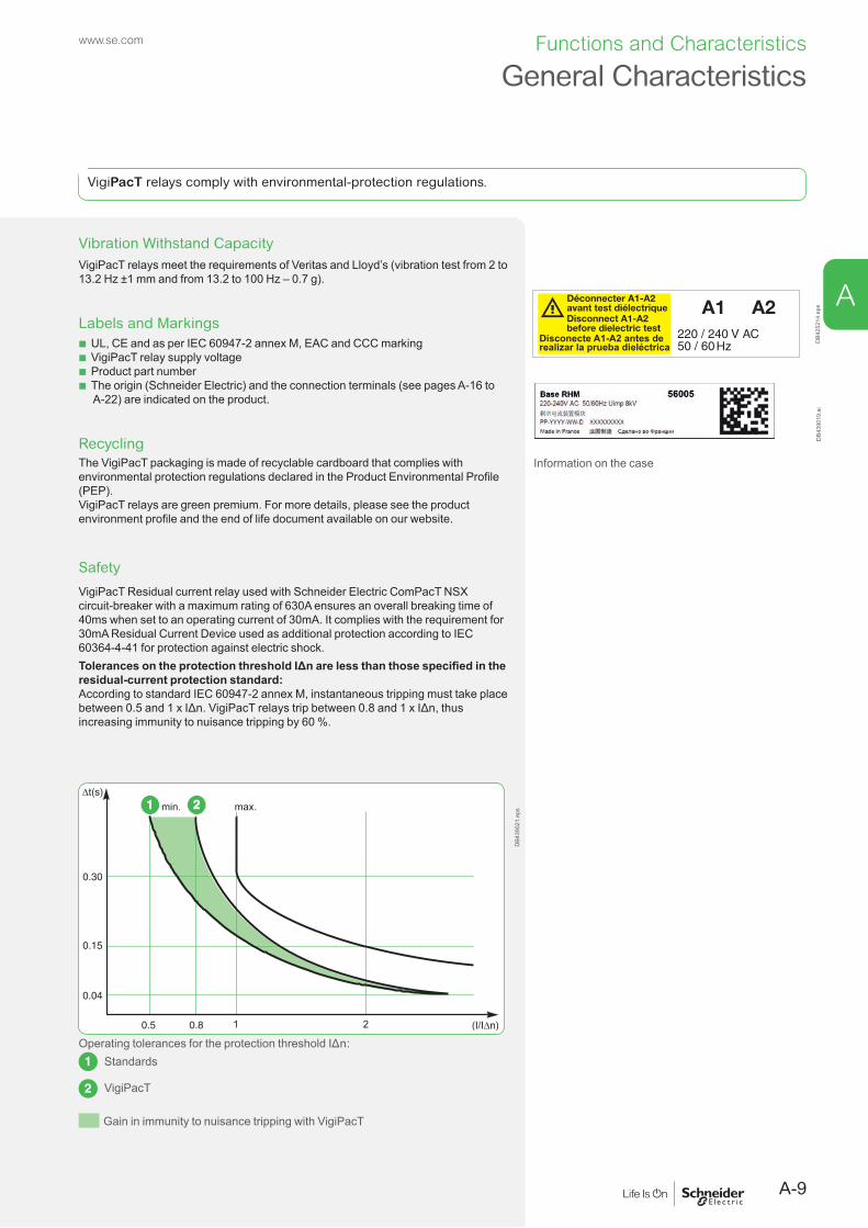
Vibration Withstand CapacityVigiPacT relays meet the requirements of Veritas and Lloyd’s (vibration test from 2 to 13.2 Hz ±1 mm and from 13.2 to 100 Hz – 0.7 g).
Labels and Markings b UL, CE and as per IEC 60947-2 annex M, EAC and CCC marking b VigiPacT relay supply voltage b Product part number b The origin (Schneider Electric) and the connection terminals (see pages A-16 to A-22) are indicated on the product.
RecyclingThe VigiPacT packaging is made of recyclable cardboard that complies with environmental protection regulations declared in the Product Environmental Profile (PEP).VigiPacT relays are green premium. For more details, please see the product environment profile and the end of life document available on our website.
DB4
2521
4.ep
sD
B439
019.
ai
Information on the case
Safety
VigiPacT Residual current relay used with Schneider Electric ComPacT NSX circuit-breaker with a maximum rating of 630A ensures an overall breaking time of 40ms when set to an operating current of 30mA. It complies with the requirement for 30mA Residual Current Device used as additional protection according to IEC 60364-4-41 for protection against electric shock.Tolerances on the protection threshold IΔn are less than those specified in the residual-current protection standard:According to standard IEC 60947-2 annex M, instantaneous tripping must take place between 0.5 and 1 x IΔn. VigiPacT relays trip between 0.8 and 1 x IΔn, thus increasing immunity to nuisance tripping by 60 %.
DB4
3902
1.ep
s
Operating tolerances for the protection threshold IΔn:Standards
VigiPacT
Gain in immunity to nuisance tripping with VigiPacT
General Characteristics
VigiPacT relays comply with environmental-protection regulations.
A-9
Functions and Characteristics
A
www.se.com

Inverse-time tripping curve:When circuits are energized, the inverse-time tripping curve avoids nuisance tripping due to short, transient phase-sequence currents, which are caused by:
b The high transient currents caused by certain loads (e.g. motors, LV/LV Transformers, etc.)
b The charging of capacitances between live conductors and earth
DB4
2538
7.ep
s
Curve 1: inverse-time tripping curve as per IEC 60947-2 annex M
Curve 2: tripping curve with fixed threshold I = IΔn
Curve 3: transient zero phase-sequence current upon load energisation
Zone of optimized continuity of service due to the inverse-time tripping curve
Non-tripping zone (curve 2)
Frequency filtering:Frequency converters (e.g. variable-speed drives) implementing IGBTs (Insulated Gate Bipolar Transistor) generate significant levels of high-frequency (HF) leakage currents.During normal operation (no fault), these capacitive HF leakage currents flowing in the installation conductors do not represent a danger for users. In general, residual-current protection relays are sensitive to these HF natural leakage currents.If an insulation fault occurs downstream of the frequency converter, the fault current comprises a HF-current component. These HF fault currents do not produce the same physiological effects on the human body as 50/60 Hz currents (see IEC 60479).
DB4
2538
9.ep
s
Variation in the ventricular-fibrillation threshold depending on the frequency from 50/60 Hz up to 1000 Hz
Gain in immunity to nuisance tripping with VigiPacT
General Characteristics
A-10
Functions and Characteristics
A
www.se.com

Frequency filtering on the VigiPacT range of residual-current protection relays is designed to provide:
b Maximum protection if an insulation fault occurs. b Continuity of service that has been specially optimized for this type of load.
Rms measurements of residual currentRms measurement of fault currents provides the residual-current protection relays with the means to measure all types of signals and to calculate the weighted true rms value depending on the frequency filtering.Rms measurement of residual current, frequency filtering, the reduced tolerances on the protection threshold and the inverse-time tripping curve built into the VigiPacT relays optimize protection of life and property and enhance the continuity of service.
DB4
2539
0.ep
s
Non-tripping zone
Gain in immunity to nuisance tripping with VigiPacT = optimized continuity of service
Reduced tolerances zone
Mandatory protection zone
VigiPacT Relays Continuous Self-MonitoringVigiPacT relays carry out continuous monitoring of:
b Relay/toroid link (RH10, RH21, RH68, RH86, RH99, RH197, RHU , RMH and RHB)
b Link between the RMH relay and the RM12T multiplexer b Power supply b Internal electronics
In the event of problem, the fault or voltage-presence output contact on the protection relays (RH10, RH21, RH68, RH86, RH99, RH197, RHUs, RHU and RHB) is actuated. The cause of the fault must be cleared.
Two Wiring Techniques for Protection RelaysTwo different wiring techniques are recommended:
b The first places a premium on safety. The voltage-presence contact on the VigiPacT residual-current protection relay (RH10, RH21, RH68, RH86, RH99 or RHUs and RHU, RHB) is wired in series with the fault contact. This technique allows failsafe operation.
b The second technique places a premium on continuity of service if the supply to the residual-current relay is cut.
For more information, see the wiring diagrams in chapter D.
General Characteristics
A-11
Functions and Characteristics
A
www.se.com

Test and Reset
TestAccording to IEC 60364 and NF C 15100 standards, a periodic test is required to check correct operation of the residual-current protection system.There are two testing modes (trip and no-trip) which actuate the output contact or not:
b Trip mode: the complete protection system with actuation of the output contacts (this trips the circuit breaker).
b No trip-mode: the protection system without actuation of the output contacts (this does not trip the circuit breaker) to maintain the installation up and running.
In both modes, the tests check the correct operation of the displays (RHUs, RHU, RMH, RH197 and the RHB bargraph), the LEDs, and the internal electronics.
ResetWhatever the test mode is, it clears the memory, resets the LEDs and the relay status condition.
Test and reset modesFour possible modes Actuation of output contacts
No [1] YesLocal via button in front
Remote 1 relay [1] [1]
a number of relays [2] [2]
Via communication RHU/RMH RHU/RMH[1] Except for RMH and RHB.[2] Except for the RHU, RMH, RH197M/P and RHB.
Easy Switchboard Acceptance TestsDuring acceptance of a switchboard and prior to dielectric testing, isolation of the residual-current relays by disconnecting the supply is mandatory. VigiPacT relays except RHB are supplied via a plug-in connector for easy and secure connection and disconnection.All connections for the front-panel mount relays of the VigiPacT range use plug-in connectors.
t (S)
I n (A)
0.51 3
5
10
30
0.3
0.1
0.03
Test
0.250.31 0.5
0.8
1
4.50
0.15
0.06
Reseton
fault
Test no trip
Vigirex RH99M
t (S)
I n (A)
0.3
Test no trip t (S)
I n (A)
0.3
Test no trip
DB4
2539
2.ep
s
DB4
2539
3.ep
s
Supply connections for the DIN and front-panel mount formats
Formats for All Installation SystemsVigiPacT relays are available in two formats:
b Front-panel mount format 72 x 72 mm (RH10P, RH21P, RH99, RH197P, RHUs, RHU, RMH)
On the DIN-format relays, it is possible to simply clip in: b The toroids 30 mm and Ø50 mm b Three mounting lugs for relay installation on mounting plates in control cabinets b DIN format (RH10M, RH21M, RH68M, RH86M, RH99, RH197M, and RHB).
General CharacteristicsPB
1004
45_S
E.ep
s
DIN device with mounting lugs fixed to a mounting plate
A-12
Functions and Characteristics
A
www.se.com

PB10
0444
-47_
SE_R
.eps Formats for All Installation Systems (Cont.)
PB11
1556
_23.
eps
PB11
5604
_27.
eps
PB11
1807
_104
.eps
DIN device
PB10
0436
.eps
Automatic control panel or machine panel
Power distribution switchboard
Main LV switchboard
iPM
CC
_14.
eps
DIN device with clip-in toroid
PB11
3882
-R5.
eps
Motor Control Centre (MCC)
Installation SystemsVigiPacT relays can be installed in original manufactured low voltage switchboard like OKKEN, BlokSeT MB, BlokSeT, iPMCC. They can also be installed in panel building systems like PrismaSeT G, PrismaSeT P, PrismaSeT iPM, Spacial SF/SFP, and PrismaSeT PH.Front-panel mount device
PB10
0431
-36_
SE.e
ps CoversAll VigiPacT relays, except RHU/RHUs and RMH, are equipped with lead-sealable covers to block access to settings while maintaining access to the device test and reset buttons.VigiPacT relays RHU/RHUs and RMH are protected by a password on the display.
PB12
1667
.eps
Lead-sealable cover
General Characteristics
A-13
Functions and Characteristics
A
www.se.com

DB4
2539
4.ep
s
It is possible to divide the installation into a number of groups of circuits and to protect each group using the suitable residual-current device.The many fault, alarm and pre-alarm settings and time delays available in the VigiPacT range makes it easy to integrate the residual-current relays at all levels in the electrical installation.Coordination between the upstream and downstream devices in an installation makes it possible to cut the supply (by the protection relay) exclusively in the part of the installation where the fault occurred.
Implementing SelectivitySelectivity between upstream and downstream residual-current devices is necessarily of the current and time type.This is done by correctly adjusting:
b The operating-current settings b The non-operating and overall breaking times
For correct operation, follow these general selectivity rules: b Current: the upstream device setting must be three times the downstream device setting (in accordance with the standardized rules for the operating/non-operating currents. Better performances can be reached by using the Schneider Electric devices, refer to the Selectivity, Cascading and Coordination Guide for better performances).
b Time: the upstream device non-operating time (time delay) must be greater than the total time (the intentional residual-current device delay and the breaking time of the breaking device) for the downstream device.
For more details about how to select a Residual Current Device, please refer to the Schneider Electric Earth Fault Protection Guide.
> Selectivity, Cascading and Coordination Guide
LVPED318033EN
Selectivity Between Residual-Current Devices
A-14
Functions and Characteristics
A
www.se.com

Electromagnetic DisturbancesVigiPacT relays are immune to:
b Overvoltages produced by switching (e.g. lighting circuits) b Overvoltages produced by atmospheric disturbances b Radio-frequency waves emitted by devices such as mobile telephones, radio transmitters, walky-talkies, radar, etc.
b Electrostatic discharges produced directly by users.To guarantee immunity, VigiPacT relays are tested in compliance with the following standards:
b IEC/EN 60947-2: low-voltage switchgear and controlgear, part 2 circuit breakers) b IEC/EN 61000-4-1: overview of the IEC/EN 61000-4 series b IEC/EN 61000-4-2: electrostatic-discharge immunity test b IEC/EN 61000-4-3: radiated, radio-frequency, electromagnetic-field immunity test b IEC/EN 61000-4-4: electrical fast transient/burst immunity test b IEC/EN 61000-4-5: surge immunity test b IEC/EN 61000-4-6: immunity to conducted disturbances, induced by radio-frequency fields
b CISPR 11: limits and methods of measurement of electromagnetic disturbance characteristics of industrial, scientific and medical (ISM) radiofrequency equipment
The high immunity levels of VigiPacT relays ensure safety without nuisance tripping.Behavior during micro-outages in the auxiliary supplyVigiPacT relays are not affected by micro-outages lasting less than 60 ms.The maximum break time during micro-outages complies with standard IEC/EN 60947-2 annex M.
Electromagnetic Compatibility
A-15
Functions and Characteristics
A
www.se.com

Application TypeFunctional DescriptionThe earth-fault protection consists of measuring the residual current in an electrical installation and disconnecting the installation when the leaked current becomes dangerous to life and property. FunctionsThe main functions of VigiPact RH10M, RH21M, RH68M, RH86M and RH99M relays are to measure the residual current detected by the toroid and trip the installation protection circuit breaker through shunt release MN or MX.1- Protection against residual current2- Local earth-leakage indication on the relay.If the residual current exceeds the threshold IΔN for a time greater than delay Δt, the relay implements one insulation monitoring threshold.
b Earthing system TN-S, IT & TT b Measurement of r.m.s. value, internal current measurements range 80 – 100% b Adjustable time delay and current settings depending of version b Remote and local testing b Continuous monitoring of electronics, power supply and CT connection.
Relay Marking1 Type of relay4 Customer marking zone (circuit identification)11 Sensitivity (RH10M): IΔn (A)/Δt (s)14 Relay class
Controls7 Press and hold the Reset button, then press the Test button to test the device
without actuating the output contacts.12 Test button13 Reset button
Indications5 Green voltage-presence LED (on)6 Red insulation-fault LED (fault)
LED status Meaningon fault
Normal operationFault current detected
Relay/sensor link faultNo voltage or device not in serviceMalfunction detected
Key: off ( ) green (or red) flashing
Settings15 Threshold and time-delay selectors (RH21): IΔn (A)/Δt (s) Three possible settings:
b 0.03 A sensitivity, instantaneous b 0.3 A sensitivity, instantaneous b 0.3 A sensitivity, 0.06 s delay
16 Time-delay selector: Δt (s) b RH68M: 8 possible time settings (instantaneous – 0.06 s – 0.15 s – 0.25 s – 0.31 s – 0.5 s – 0.8 s – 1 s)
b RH86M: 6 possible time settings (instantaneous – 0.06 s – 0.15 s – 0.25 s – 0.31 s – 0.5 s)
b RH99: 9 possible time settings (instantaneous, 0.06s - 4.5 s)17 Threshold selector (RH99): IΔn (A)
b RH68M: 6 possible time settings (instantaneous – 0.03 s – 0.1 s – 0.3 s – 0.5 s – 1 s – 3 s)
b RH86M: 8 possible time settings (instantaneous – 0.03 s – 0.1 s – 0.3 s – 0.5 s – 1 s – 3 s – 5 s – 10 s)
b RH99: 9 possible current settings (0.03A - 30A)
Connection2 Sensor3 Plug-in supply8 Fault contact9 Voltage-presence contact10 Remote reset/test
DescriptionRH10M, RH21M, RH68M, RH86M and RH99M Relays
PB10
0437
-32_
SE_r.
eps
RH10M
PB10
0440
-32_
SE_r.
eps
RH21M
PB10
8173
-48.
eps
RH68M
PB10
8174
-48.
eps
RH86M
PB10
0439
-32_
SE_r.
eps
RH99M
DB4
3844
5.ep
sD
B438
446.
eps
Functions and Characteristics
A-16
A
www.se.com
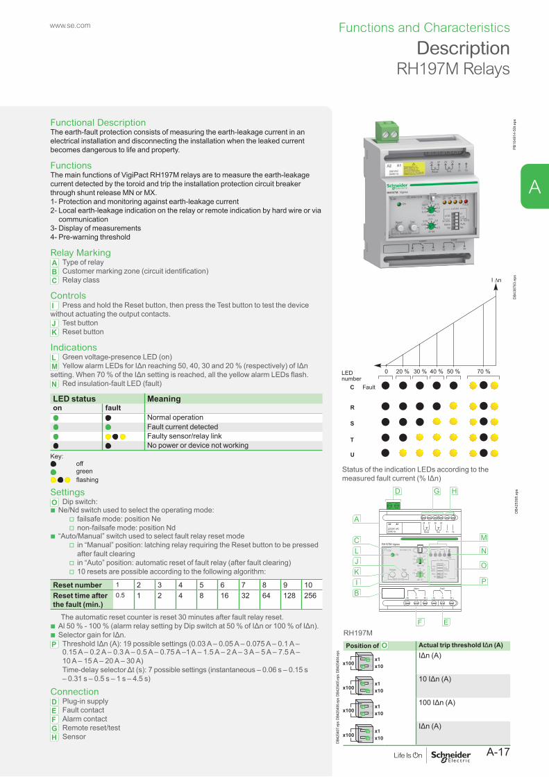
Functional DescriptionThe earth-fault protection consists of measuring the earth-leakage current in an electrical installation and disconnecting the installation when the leaked current becomes dangerous to life and property.
FunctionsThe main functions of VigiPact RH197M relays are to measure the earth-leakagecurrent detected by the toroid and trip the installation protection circuit breaker through shunt release MN or MX.1- Protection and monitoring against earth-leakage current2- Local earth-leakage indication on the relay or remote indication by hard wire or via
communication3- Display of measurements4- Pre-warning threshold
Relay MarkingA Type of relayB Customer marking zone (circuit identification)C Relay class
ControlsI Press and hold the Reset button, then press the Test button to test the device without actuating the output contacts.J Test buttonK Reset button
IndicationsL Green voltage-presence LED (on)M Yellow alarm LEDs for IΔn reaching 50, 40, 30 and 20 % (respectively) of IΔn setting. When 70 % of the IΔn setting is reached, all the yellow alarm LEDs flash.N Red insulation-fault LED (fault)
PB10
4914
-50t
.eps
I �n
70 %50 %40 %30 %20 %0
FaultC
R
S
T
U
LED number
DB4
3876
3.ep
s
Status of the indication LEDs according to the measured fault current (% IΔn)
LED status Meaningon fault
Normal operationFault current detected
Faulty sensor/relay linkNo power or device not working
Key: off green flashing
SettingsO Dip switch: b Ne/Nd switch used to select the operating mode:
v failsafe mode: position Ne v non-failsafe mode: position Nd
b “Auto/Manual” switch used to select fault relay reset mode v in “Manual” position: latching relay requiring the Reset button to be pressed after fault clearing
v in “Auto” position: automatic reset of fault relay (after fault clearing) v 10 resets are possible according to the following algorithm:
Reset number 1 2 3 4 5 6 7 8 9 10Reset time after the fault (min.)
0.5 1 2 4 8 16 32 64 128 256
The automatic reset counter is reset 30 minutes after fault relay reset. b Al 50 % - 100 % (alarm relay setting by Dip switch at 50 % of IΔn or 100 % of IΔn). b Selector gain for IΔn.
P Threshold IΔn (A): 19 possible settings (0.03 A – 0.05 A – 0.075 A – 0.1 A – 0.15 A – 0.2 A – 0.3 A – 0.5 A – 0.75 A –1 A – 1.5 A – 2 A – 3 A – 5 A – 7.5 A – 10 A – 15 A – 20 A – 30 A) Time-delay selector Δt (s): 7 possible settings (instantaneous – 0.06 s – 0.15 s – 0.31 s – 0.5 s – 1 s – 4.5 s)
ConnectionD Plug-in supplyE Fault contactF Alarm contactG Remote reset/testH Sensor
0.1
I n
0.05
0.03
0.0750.2
0.3
0.15
(A)0.31
t
0.06
0
0.151
4.5
0.5
(s)
RH197M Vigirex
IEC 60947-2 / M50403020
%
x10x1
NeAuto
Al50% Al100%
NdManu
x100
k x I nFault
FaultAlarm
Reset Test T1
28
42 41 44 32 31 34
A2
220/240 VAC50/60 Hz
A1 27 26 25
T2
ON
Reset Test
Test no trip
HG
EF
D
M
N
O
P
A
JKIB
LC
DB4
2539
5.ep
s
RH197M
DescriptionRH197M Relays
Position of O Actual trip threshold IΔn (A)
DB42
5404
.eps IΔn (A)
DB42
5405
.eps 10 IΔn (A)
DB42
5406
.eps 100 IΔn (A)
DB42
5407
.eps IΔn (A)
Functions and Characteristics
A-17
A
www.se.com

B
D
C
E
AI
GF
H
DB4
2539
6.ep
s
RH10P
B
D
C
E
AI
J
GF
DB4
2539
7.ep
s
RH21P
B
K
D
C
E
AI
L
GF
DB4
2539
9.ep
s
RH99P
N
O
M
P
Q
DB4
2540
0.ep
s
Connections at the back of the relay
DescriptionRH10P, RH21P and RH99P Relays
Application TypeFunctional DescriptionThe earth-fault protection consists of measuring the residual current in an electrical installation and disconnecting the installation when the leaked current becomes dangerous to life and property.
FunctionsThe main functions of VigiPact RH10P, RH21P and RH99P relays are to measure the residual current detected by the toroid and trip the installation protection circuit breaker through shunt release MN or MX.1- Protection against residual current2- Local earth-leakage indication on the relay.
Relay MarkingA Type of relayD Customer marking zone (circuit identification)H Sensitivity (RH10P): IΔn (A)/Δt (s)I Relay class
ControlsE Test buttonF Reset buttonG Press and hold the Reset button, then press the Test button to test the device without actuating the output contacts
IndicationsB Green voltage-presence LED (on)C Red insulation-fault LED (fault)
LED status Meaningon fault
Normal operationFault current detected
Relay/sensor link faultNo voltage or device not in serviceMalfunction detected
Key: off ( ) green (or red) flashing
SettingsJ Threshold and time-delay selectors (RH21): IΔn (A)/Δt (s)Three possible settings:
b 0.03 A sensitivity, instantaneous b 0.3 A sensitivity, instantaneous b 0.3 A sensitivity, 0.06 s delay
K Time-delay selector: Δt (s)RH99: 9 possible time settings (instantaneous – 0.06 s – 0.15 s – 0.25 s – 0.31 s – 0.5 s – 0.8 s – 1 s – 4.5 s)L Threshold selector: IΔn (A)RH99: 9 possible current settings (0.03 A – 0.1 A – 0.3 A – 0.5 A – 1 A – 3 A – 5 A – 10 A – 30 A)
ConnectionAll connections for front-panel mount relays are of the plug-in typeM Fault contactN SensorO Plug-in supplyP Voltage-presence contactQ Remote reset/test
Functions and Characteristics
A-18
A
www.se.com

C
U
E
AI
F
KL
DV
S
B
T
R
DB4
3876
4.ep
s
RH197P
Connections on the back of the relay
N
OP
M
Q
DB4
2540
2.ep
s
I ∆n
70 %50 %40 %30 %20 %0
FaultC
R
S
T
U
LED number
DB4
2540
3.ep
s
Status of the indication LEDs according to the measured fault current (% IΔn)
DescriptionRH197P Relays
Position of S and T Actual trip threshold IΔn (A)
DB4
2540
4.ep
s IΔn (A)
DB4
2540
5.ep
s 10 IΔn (A)
DB4
2540
6.ep
s 100 IΔn (A)
DB4
2540
7.ep
s IΔn (A)
Functional DescriptionThe earth-fault protection consists of measuring the earth-leakage current in an electrical installation and disconnecting the installation when the leaked current becomes dangerous to life and property.
FunctionsThe main functions of VigiPact RH197P relays is to measures the earth-leakage current detected by the toroid andtrips the installation protection circuit breaker through shunt release MN or MX1- Protection and monitoring against earth-leakage current2- Local earth-leakage indication on the relay or remote indication by hard wire or via
communication3- Display of measurements4- Pre-warning threshold
Relay MarkingA Type of relayD Customer marking zone (circuit identification)I Relay class
ControlsE Test buttonF Reset button
IndicationsB Green voltage-presence LED (on)C Red insulation-fault LED (fault)R Yellow alarm LEDs for IΔn reaching 50, 40, 30 and 20 % (respectively) of IΔn setting. When 70 % of the IΔn setting is reached, all the yellow alarm LEDs ( R ) and the red insulation-fault LED flash.
LED status Meaningon fault
Normal operationFault current detected
Relay/sensor link faultNo voltage or device not in service
Key: off ( ) green (or red) flashing
SettingsK Time-delay selector: 7 possible settings (instantaneous – 0.06 s – 0.15 s – 0.31 s – 0.5 s – 1 s – 4.5 s)L Threshold selector: 19 possible settings (0.03 A – 0.05 A – 0.075 A – 0.1 A – 0.15 A – 0.2 A – 0.3 A 0.5 A – 0.75 A –1 A – 1.5 A – 2 A – 3 A – 5 A – 7.5 A – 10 A – 15 A – 20 A – 30 A)U Ne/Nd switch used to select the operating mode:
b Failsafe mode: position Ne b Non-failsafe mode: position Nd
V “Auto/Manual” switch used to select fault relay reset mode b In “Manual” position: latching relay requiring the Reset button to be pressed after fault clearing
b In “Auto” position: automatic reset of fault relay (after fault clearing) b 10 resets are possible according to the following algorithm:
Reset number 1 2 3 4 5 6 7 8 9 10Reset time after the fault (min.)
0.5 1 2 4 8 16 32 64 128 256
The automatic reset counter is reset 30 minutes after fault relay reset.
ConnectionAll connections for front-panel mount relays are of the plug-in type.M Plug-in supplyN Fault contactO Alarm contactP Remote reset/testQ SensorS - T Gain selector for threshold selector 12 (IΔn):The IΔn = 0.030 A setting is not modified by the gain selector
Functions and Characteristics
A-19
A
www.se.com

FunctionsThe VigiPacT RHU is used together with a toroid (open or closed) or a rectangular sensor.VigiPacT RHU:
b Measures the residual current detected by the toroid. b Displays the residual current. b Trips the installation protection circuit breaker through an MN or MX release if the residual current exceeds the threshold IΔN for a time greater than the delay Δt.
b Activates a pre-alarm when the residual current on a circuit exceeds pre-alarm threshold.
b Activates an alarm when the residual current on a circuit exceeds alarm threshold. b Integrates perfectly in the Smart Panel architecture system by communicating with the Modbus communication (except RHUs which is without communication).
HMI Description and Navigation Principles Overview
Legend Display DescriptionA LCD screen Displays the parameter settings and the measurement
values.
B Status LEDs Indicates power on, status of alarm, pre-alarm, and communication.
C Allows to navigate.
Status LEDStatus LED
Color Description
ON Green Is switched on when the VigiPacT relay is powered.Alarm Red Is switched on when an alarm is active.Pre-alarm Orange Is switched on when a pre-alarm is active.COM Green Blinks when the VigiPacT relay detects or sends a
Modbus frame.
Navigation ButtonsButton Icon DescriptionValidation
OK
Allows to: b Modify parameter. b Select an item. b Validate current setting. b Start test mode. b Exit test mode at the end of the test.
Down Allows to move to: b The next screen. b The next menu item.
Allows to decrease the numerical value while setting theparameters.
Up Allows to move to: b The previous screen. b The previous menu item.
Allows to increase the numerical value while setting the parameters.
Home b Allows to access the home menu.
ConnectionD Terminal block to connect the pre-alarm contact and the alarm contactE Terminal block to connect the toroid and the Test/Reset contactsF Terminal block to connect the power supply and voltage presence contactG Modbus SL port
Instruction sheet RHU NHA34634
User guide RHU DOCA0107EN
DescriptionRHUs and RHU Relays
PB11
3909
-36.
eps
OK
Vigirex RHU
IEC 60947-2 / M
A
B
C
DB4
2540
8.ep
s
OK
DB4
1927
7.ep
s
Modbus SL
32alarmpre-al
34314144
1114 onA1A2
T1 T227Tno wire
R
2625
D
G
E
F
DB4
2541
0.ep
sFunctions and Characteristics
A-20
A
www.se.com

DescriptionRMH Relay and RM12T Multiplexer
FunctionsThe VigiPacT RMH is used together with a VigiPacT RM12T and toroid (open or closed) or a rectangular sensor.VigiPacT RMH:
b Measures the residual current detected by the toroids (12 maximum). b Displays the residual current. b Activates a pre-alarm when the residual current on a circuit exceeds its pre-alarm threshold.
b Activates an alarm when the residual current on a circuit exceeds its alarm threshold.
b Integrates perfectly in the Smart Panel architecture system by communicating with the Modbus communication.
Alarm DetectionAn alarm is active when the measured residual current is greater than the set alarm threshold (I alarm) on at least one toroid for a period of time greater than the set alarm delay (t alarm in milliseconds or seconds) for that particular toroid.When an alarm is active:
b The ALARM and PRE-AL LED are switched on. b When only one alarm is detected, the Metering screen of the corresponding toroid is displayed, and the residual current value blinks.
b When more than one alarm are detected, the Alarm screen is displayed.
Pre-Alarm DetectionA pre-alarm is active when the measured residual current is greater than the set pre-alarm threshold on at least one channel for a period of time greater than the set pre-alarm trip delay (t pre-alarm in milliseconds or seconds) for that particular toroid.When a pre-alarm is active:
b The PRE-AL LED is switched on and the displayed value blinks. b When only one pre-alarm is detected, the Metering screen of the corresponding toroid is displayed, and the residual current value blinks.
b When more than one alarm are detected, the Pre-alarm screen is displayed.HMI Description and Navigation PrinciplesOverview
Legend Display DescriptionA LCD screen Displays the parameter settings and the measurement
values.
B Status LEDs Indicates power on, status of alarm, pre-alarm, and communication
C Navigation buttons Allows to navigate
Status LED
Status LED
Color Description
ON Green Is switched on when the VigiPacT relay is powered.Alarm Red Is switched on when an alarm is active.Pre-alarm Orange Is switched on when a pre-alarm is active.COM Green Blinks when the VigiPacT relay detects or sends a
Modbus frame.
Navigation Buttons
Button Icon DescriptionValidation
OK
Allows to: b select an item. b modify parameter. b validate current setting. b start test mode. b exit test mode at the end of the test.
Down Allows to move to: b next screen. b next menu item.
Allows you to decrease the numerical value.Up Allows to move to:
b previous screen. b previous menu item.
Allows to increase the numerical value.Home Allows to access the home menu.
PB11
4667
.eps
OK
Vigirex RMH
A
B
C
DB4
2540
9.ep
s
OK
DB4
1927
7.ep
s
Instruction sheet RMH NHA34635
User guide RMH DOCA0108EN
Functions and Characteristics
A-21
A
www.se.com
Modbus SL
no wire23 24 21 22
RM12T23 24 21 22
32alarmpre-al
34314144
1114 onA1A2
D
G
E
F
DB4
2541
1.ep
s
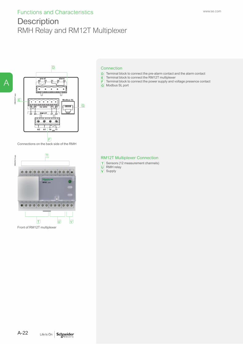
ConnectionD Terminal block to connect the pre-alarm contact and the alarm contactE Terminal block to connect the RM12T multiplexerF Terminal block to connect the power supply and voltage presence contactG Modbus SL port
Connections on the back side of the RMH
T
T U V
DB4
2541
2.ep
s
RM12T Multiplexer ConnectionT Sensors (12 measurement channels)U RMH relayV Supply
Front of RM12T multiplexer
DescriptionRMH Relay and RM12T Multiplexer
Functions and Characteristics
A-22
A
www.se.com

FunctionsThe VigiPacT RHB:
b Measures the residual current detected by the toroid. b Displays the residual current. b Trips the installation protection circuit breaker through an MN or MX release if the residual current exceeds the threshold IΔN for a time greater than the delay Δt.
The relay implements two insulations monitoring thresholds, one corresponding to a pre-alarm and another to an alarm.
Alarm DetectionThe alarm threshold I alarm corresponds to an residual current that is dangerous for the installation.An alarm is active when the measured residual current is greater than the set alarm threshold (I alarm) on toroid for a period of time greater than the set alarm delay (t alarm in milliseconds or seconds).
b When an alarm is active, AL1 and AL2 LEDs are switched on. b When an alarm is detected, the residual current value in the LCD display blinks.
Pre-Alarm DetectionThe pre-alarm threshold I pre-alarm corresponds to an earth leakage level that must be eliminated before being dangerous for the installation. A pre-alarm is active when the measured residual current is greater than the set pre-alarm threshold for a period of time greater than the set pre-alarm trip delay (t pre-alarm in milliseconds or seconds).
b When a pre-alarm is active, AL1 LED is switched on. b When a pre-alarm is detected, the residual current value in the LC display blinks.
Time DelaysTon1 and Ton2 delay the alarm output through LEDs and relays.
b Ton1 time delay is related to pre-alarm b Ton2 time delay is related to alarm.
RHB Installation b On a DIN rail (flush mounted or in cublicle) b Screwed on a plate (with optional kit LV..., sold separately) b Install the connectors delivered with the RHB.
DescriptionRHB Relay
PB12
1667
.eps
VigiPacT RHB
IEC 60947-2 / M
VigiPact RHB
11 12 14
Test/Reset 21 22 24
Test/Reset A1 A2
1
ON ALARMPRE-AL
Test Reset OK
B
C
DGE
H
A
F
DB4
3867
7.ai
A Status LEDs: On, Pre-alarm, AlarmB Multifunctional LCD displayC Test/UP buttonD Reset/DOWN buttonE MENU/OK buttonF DIN clip G Lead-seal coverH QR code to access device informationI Socket for toroid connection with the wiring kit
Functions and Characteristics
A-23
A
www.se.com

Compatibility with ToroidsVigiPacT RH10, RH21, RH68, RH86, RH99, RH197, RHUs, RHU and RMH relays may be used with the following sensors:
b Closed toroids (A type) b Split toroids (OA type) b Rectangular sensors (L type).
VigiPacT RHB relays may only be used with closed toroid (B type).
Adaptation to Installations b Closed toroids are suitable for new installations up to 630 A. Certain toroids may be mounted on DIN rails, plates or brackets, clipped onto the VigiPacT relay or tied to the cables (see page B-6).
b Split toroids (from 80 to 120 mm) facilitate installation in existing systems up to 250 A. Thank to a trigger, it’s very useful to open the toroid, put the cables and re-close the toroid. These toroids could be installed directly on plates or as a modular product through a specific part.
b Rectangular sensors are for busbars in installations with currents y 3200 A.
Compatibility with Rectangular SensorsThe RH10, RH21, RH68, RH86, RH99, RH197, RHUs, RHU and RMH relays may be used with rectangular sensors (L type) 280 x 115 mm and 470 x 160 mm. The VigiPacT sensitivity must be set to u 500 mA.
Withstand Capacity for High Residual-Current FaultsTests guarantee accurate measurements after a high phase-sequence current flowing through the toroid during a short-circuit between a phase and the PE conductor.
Temperature Ranges b The temperature range for toroid operation is:
v A/OA type toroids: -35 °C/+70 °C v Rectangular sensors: -35 °C/+80 °C v B type toroids: -25 °C/+70 °C
b The temperature range for toroid storage is: v A/OA type toroids: -55 °C/+85 °C v L type rectangular sensors: -55 °C/+100 °C. v B type toroids: -25 °C/+70 °C.
DescriptionSensors
0594
70-2
8_SE
.eps
A type passive closed toroid
PB11
5812
.eps
PB11
5819
_L16
.eps
OA type passive split toroid
0594
76-4
9_SE
.eps
Rectangular sensor
LV48
1012
_Im
age.
eps
B type active closed toroid
Functions and Characteristics
A-24
A
www.se.com

VigiPacT Protection Relays RH10 RH21General characteristicsMonitored distribution system: LV AC/System voltage 50/60/400 Hz y 1000 V 50/60/400 Hz y 1000 VSystem earthing arrangement TT, TNS, IT TT, TNS, ITType class as per IEC 60947-2 appendix M [1] A AOperating-temperature range -35 °C/+70 °C -35 °C/+70 °CStorage-temperature range -55 °C/+85 °C -55 °C/+85 °CElectrical characteristicsPower supply: rated operational voltage Ue
12 to 24 V AC -12 to 48 V DC 50/60 Hz/DC b RH21M only48 V AC - 24 to 130 V DC 50/60 Hz/DC - -48 V AC 50/60 Hz - -110 to 130 V AC 50/60 Hz b -220 to 240 V AC 50/60 Hz b b
380 to 415 V AC 50/60 Hz RH10M only b
440 to 525 V AC 50/60 Hz - -Operational voltage tolerances
Ue: 12 to 24 V AC - 12 to 48 V DC 55 % to 120 % Ue [2] 55 % to 120 % Ue [2]
Ue: 48 V AC - 24 to 130 V DC - -Ue: 48 to 415 V 55 % to 110 % Ue 55 % to 110 % UeUe: 110 to 415 V - -Ue: 220 to 240 V - -Ue > 415 V 70 % to 110 % Ue 70 % to 110 % Ue
Overvoltage category 4 4Rated impulse withstand voltage up to Ue = 525 V AC Uimp (kV) 8 8Maximum consumption AC 4 VA 4 VA
DC 4 W 4 WInsensitive to micro-outages y 60 ms relay can operate even if there is a power outage for less than 60ms
b b
Toroid loss detection b b
Leakage-current measurements Measurement range from 15 mA to 60 A from 15 mA to 60 AMeasurement accuracy ±7 % ±7 %Display refresh time - -
lΔn current detection Threshold IΔn 1 fixed threshold 0.03 A - 0.05 A - 0.1 A - 0.25 A 0.3 A - 0.5 A - 1 A
2 user-selectable thresholds 0.03 A or 0.3 A
lΔn-current detection range 80 % IΔn to 100 % IΔn 80 % IΔn to 100 % IΔnTime delay Δt instantaneous instantaneous for IΔn = 0,03 A
1 user-selectable time delayinstantaneous or 0.06 s for IΔn = 0.3 A
Δt settings (s) 0 0 0.06Maximum non-operating time at 2 IΔn (s) - - 0.06Maximum operating time at 5 IΔn (s) (residual-current relay alone)
0.015 0.015 0.13
Maximum total time at 5 IΔn [6] (s) 0.04 0.04 0.15Setting none selectorOutput contact changeover with latching changeover with latching
Pre-warning current detection I pre-warning threshold - -Pre-warning-current detection range - -Time delay Δt pre-warning - -Δt pre-warning settings - -Maximum non-detection time at 2 I pre-warning - -Maximum detection time at 5 I pre-warning - -Setting - -Output contact - -Hysteresis - -
Test with or without actuationof the output contacts andoutput-contact resetfollowing a fault
Local b b
Remote (hard-wired) (10 m maximum) b b
Remote (hard-wired for several relays) (10 m maximum) b b
Remote (via communication) - -Self-monitoring Relay/sensor link continuous continuous
Power supply continuous continuousElectronics continuous continuous
[1] Type A relays up to 5 A and type AC above 5 A.[2] 80 % to 120 % Ue if Ue < 20 V.[3] 80 % to 110 % Ue if Ue < 28 V.
[4] 85 % during energisation.[5] < 10 % of IΔn: display = 0 and > 200 % of IΔn: display = SAT.
CharacteristicsProtection Relays with Output Contact Requiring Local Manual Reset After a Fault
A-26
Functions and Characteristics
A
www.se.com

VigiPacT Protection Relays RH10 RH21General characteristicsMonitored distribution system: LV AC/System voltage 50/60/400 Hz y 1000 V 50/60/400 Hz y 1000 VSystem earthing arrangement TT, TNS, IT TT, TNS, ITType class as per IEC 60947-2 appendix M [1] A AOperating-temperature range -35 °C/+70 °C -35 °C/+70 °CStorage-temperature range -55 °C/+85 °C -55 °C/+85 °CElectrical characteristicsPower supply: rated operational voltage Ue
12 to 24 V AC -12 to 48 V DC 50/60 Hz/DC b RH21M only48 V AC - 24 to 130 V DC 50/60 Hz/DC - -48 V AC 50/60 Hz - -110 to 130 V AC 50/60 Hz b -220 to 240 V AC 50/60 Hz b b
380 to 415 V AC 50/60 Hz RH10M only b
440 to 525 V AC 50/60 Hz - -Operational voltage tolerances
Ue: 12 to 24 V AC - 12 to 48 V DC 55 % to 120 % Ue [2] 55 % to 120 % Ue [2]
Ue: 48 V AC - 24 to 130 V DC - -Ue: 48 to 415 V 55 % to 110 % Ue 55 % to 110 % UeUe: 110 to 415 V - -Ue: 220 to 240 V - -Ue > 415 V 70 % to 110 % Ue 70 % to 110 % Ue
Overvoltage category 4 4Rated impulse withstand voltage up to Ue = 525 V AC Uimp (kV) 8 8Maximum consumption AC 4 VA 4 VA
DC 4 W 4 WInsensitive to micro-outages y 60 ms relay can operate even if there is a power outage for less than 60ms
b b
Toroid loss detection b b
Leakage-current measurements Measurement range from 15 mA to 60 A from 15 mA to 60 AMeasurement accuracy ±7 % ±7 %Display refresh time - -
lΔn current detection Threshold IΔn 1 fixed threshold 0.03 A - 0.05 A - 0.1 A - 0.25 A 0.3 A - 0.5 A - 1 A
2 user-selectable thresholds 0.03 A or 0.3 A
lΔn-current detection range 80 % IΔn to 100 % IΔn 80 % IΔn to 100 % IΔnTime delay Δt instantaneous instantaneous for IΔn = 0,03 A
1 user-selectable time delayinstantaneous or 0.06 s for IΔn = 0.3 A
Δt settings (s) 0 0 0.06Maximum non-operating time at 2 IΔn (s) - - 0.06Maximum operating time at 5 IΔn (s) (residual-current relay alone)
0.015 0.015 0.13
Maximum total time at 5 IΔn [6] (s) 0.04 0.04 0.15Setting none selectorOutput contact changeover with latching changeover with latching
Pre-warning current detection I pre-warning threshold - -Pre-warning-current detection range - -Time delay Δt pre-warning - -Δt pre-warning settings - -Maximum non-detection time at 2 I pre-warning - -Maximum detection time at 5 I pre-warning - -Setting - -Output contact - -Hysteresis - -
Test with or without actuationof the output contacts andoutput-contact resetfollowing a fault
Local b b
Remote (hard-wired) (10 m maximum) b b
Remote (hard-wired for several relays) (10 m maximum) b b
Remote (via communication) - -Self-monitoring Relay/sensor link continuous continuous
Power supply continuous continuousElectronics continuous continuous
[1] Type A relays up to 5 A and type AC above 5 A.[2] 80 % to 120 % Ue if Ue < 20 V.[3] 80 % to 110 % Ue if Ue < 28 V.
[4] 85 % during energisation.[5] < 10 % of IΔn: display = 0 and > 200 % of IΔn: display = SAT.
RH68 RH86 RH99
50/60/400 Hz y 1000 V 50/60/400 Hz y 1000 V 50/60/400 Hz y 1000 VTT, TNS, IT TT, TNS, IT TT, TNS, ITA A A-35 °C/+70 °C -35 °C/+70 °C -35 °C/+70 °C-55 °C/+85 °C -55 °C/+85 °C -55 °C/+85 °C
- - b
- - -- - RH99M only- - b
b b b
- - b
- - RH99M only- - 55 % to 120 % Ue [2]
- - -55 % to 110 % Ue 55 % to 110 % Ue 55 % to 110 % Ue- - -55 % to 110 % Ue 55 % to 110 % Ue -- - 70 % to 110 % Ue4 4 48 8 84 VA 4 VA 4 VA4 W 4 W 4 Wb b b
b b b
from 15 mA to 60 A from 15 mA to 60 A from 15 mA to 60 A±7 % ±7 % ±7 %- - -6 user-selectable thresholds 0.03 A - 0.1 A - 0.3 A - 0.5 A - 1 A - 3 A
8 user-selectable thresholds 0.03 A - 0.1 A - 0.3 A - 0.5 A - 1 A - 3 A - 5 A - 10 A
9 user-selectable thresholds 0.03 A - 0.1 A - 0.3 A - 0.5 A - 1 A - 3 A - 5 A - 10 A - 30 A
80 % IΔn to 100 % IΔn 80 % IΔn to 100 % IΔn 80 % IΔn to 100 % IΔninstantaneous for IΔn = 0.03 A8 user-selectable time delaysinstantaneous to 1 s
instantaneous for IΔn = 0.03 A6 user-selectable time delaysinstantaneous to 0.5 s
instantaneous for IΔn = 0.03 A9 user-selectable time delaysinstantaneous to 4.5 s
0 0.06 0.15 0.25 0.31 0.5 0.8 1 0 0.06 0.15 0.25 0.31 0.5 0 0.06 0.15 0.25 0.31 0.5 0.8 1 4.5- 0.06 0.15 0.25 0.31 0.5 0.8 1 - 0.06 0.15 0.25 0.31 0.5 - 0.06 0.15 0.25 0.31 0.5 0.8 1 4.50.015 0.13 0.23 0.32 0.39 0.58 0.91 1.2 0.015 0.13 0.23 0.32 0.39 0.58 0.015 0.13 0.23 0.32 0.39 0.58 0.91 1.2 4.8
0.04 0.15 0.25 0.34 0.41 0.6 0.93 1.22 0.04 0.15 0.25 0.34 0.41 0.6 0.04 0.15 0.25 0.34 0.41 0.6 0.93 1.22 4.82selector selector selectorchangeover with latching changeover with latching changeover with latching- - -- - -- - -- - -- - -- - -- - -- - -- - -b b b
b b b
b b b
- - -continuous continuous continuouscontinuous continuous continuouscontinuous continuous continuous
[6] Maximum time to clear the fault current when combined with a Schneider Electric circuit breaker or switch rated y 630 A.[7] Depending on version.
CharacteristicsProtection Relays with Output Contact Requiring Local Manual
Reset After a Fault
A-27
Functions and Characteristics
A
www.se.com

CharacteristicsProtection Relays with Output Contact Requiring Local Manual Reset After a Fault
[1] Type A relays up to 5 A.[2] Maximum time to clear the fault current when combined with a Schneider Electric circuit breaker or switch rated y 630 A.[3] 110 V AC, 230 V AC and 400 VAC only.[4] 85 % during energisation.[5] < 20 % of IΔn: display = 0 and > 200 % of IΔn: display = SAT.[6] Depending on version.[7] Not available for DC version.[8] For RHB, without actuation of the contacts only.
VigiPacT Protection Relays RH197M RH197P RHUs and RHU RHBGeneral characteristicsMonitored distribution system: LV AC/System voltage 50/60/400 Hz y 1000 V 50/60/400 Hz y 1000 V 50/60/400 Hz y 1000 V 0 to 2000 Hz < 800 VSystem earthing arrangement TT, TNS, IT TT, TNS, IT TT, TNS, IT TT, TNSType class as per IEC 60947-2 appendix M [1] A A A BOperating-temperature range -25 °C/+55 °C -25 °C/+55 °C -25 °C/+55 °C -25 °C/+55 °CStorage-temperature range -40 °C/+85 °C -40 °C/+85 °C -40 °C/+85 °C -40 °C/+85 °CElectrical characteristicsPower supply: rated operational voltage Ue
12 to 24 V AC -12 to 48 V DC 50/60 Hz/DC - - - -48 V AC - 24 to 130 V DC 50/60 Hz/DC b b - -110 to 130 V AC 50/60 Hz b [3] b b -220 to 240 V AC 50/60 Hz b [3] b b -380 to 415 V AC 50/60 Hz b [3] b - -440 to 525 V AC 50/60 Hz - - - -100 to 250 V AC/DC 50/400 Hz/DC - - - b
Operational voltage tolerances
Ue: 12 to 24 V AC - 12 to 48 V DC - - - -Ue: 48 V AC - 24 to 130 V DC 80 % to 110 % Ue 70 % to 110 % Ue - -Ue: 48 to 415 V - - 70 % to 110 % Ue [4] 70 % to 120 % UeUe: 110 to 415 V 85 % to 110 % Ue 70 % to 110 % Ue - -Ue > 415 V - - - -
Overvoltage category 4 4 4 3Rated impulse withstand voltage up to Ue = 525 V AC Uimp (kV) 8 8 8 4Maximum consumption AC 4 VA 4 VA 8 VA 6.5 VA
DC 4 W 4 W - 6.5 WInsensitive to micro-outages y 60 ms b b b < 200 ms at 70 % UeMaximum break time on toroid failure (as per standard IEC 60947-2) b b b b
Leakage-current measurements Measurement range - - from 15 mA to 60 A from 0 mA to 6 AMeasurement accuracy ±7 % ±7 % ±7 % ±17.5 % or ± 2 digitsDisplay measurement 4 DEL 20, 30, 40 and 50 % of IΔn 4 DEL 20, 30, 40 and 50 % of IΔn from ±20 % [5] to 200 % of IΔn from 0 % to 200 % of IΔnDisplay refresh time 0.5 s 0.5 s 2 s 0.5 s
Fault current detection (Alarm for RHU)(Alarm 2 for RHB)
Threshold IΔn 19 user-selectable thresholds0.03 A - 0.05 A - 0.075 A - 0.1 A -0.15 A - 0.2 A 0.3 A - 0.5 A - 0.75 A - 1 A - 1.5 A - 2 A - 3 A - 5 A 7.5 A - 10 A - 15 A - 20 A - 30 A
19 user-selectable thresholds0.03 A - 0.05 A - 0.075 A - 0.1 A -0.15 A - 0.2 A 0.3 A - 0.5 A - 0.75 A - 1 A - 1.5 A - 2 A - 3 A - 5 A 7.5 A - 10 A - 15 A - 20 A - 30 A
1 adjustable threshold from 0.03 A to 1 A in 0.001 A steps from 1 A to 30 A in 0.1 A steps
1 adjustable thresholdfrom 0.03 A to 100 mA in 0.001 A steps
Fault-current detection range 80 % IΔn to 100 % IΔn 80 % IΔn to 100 % IΔn 80 % IΔn to 100 % IΔn 50 % IΔn to 100 % IΔnTime delay Δt instantaneous for IΔn = 0.03 A
7 user-selectable time delaysinstantaneous to 4.5 s
instantaneous for IΔn = 0.03 A 7 user-selectable time delaysinstantaneous to 4.5 s
instantaneous for IΔn = 0.03 A1 adjustable time delay to 4.5 s in 10 ms steps
instantaneous for IΔn = 0.03A1 adjustable time delay to 10s in:0-1s: 10ms steps & 1s-10s: 100ms steps
Δt settings (s) 0 0.06 0.15 0.31 0.5 1 4.5 0 0.06 0.15 0.31 0.5 1 4.5 0 0.06 y Δt 0...10 sMaximum non-operating time at 2 IΔn (s) - 0.06 0.15 0.31 0.5 1 4.5 - 0.06 0.15 0.31 0.5 1 4.5 - same as for RH99 Δt + 30 msMaximum operating time at 5 IΔn (s) (residual-current relay alone)
0.020 0.13 0.32 0.39 0.58 1.2 4.8 0.020 0.13 0.32 0.39 0.58 1.2 4.8 0.015 same as for RH99 Δt + 23 ms
Maximum total time at 5 IΔn [2] (s) 0.04 0.20 0.34 0.41 0.6 1.22 4.82 0.04 0.20 0.34 0.41 0.6 1.22 4.82 0.04 same as for RH99 Δt + 40 ms
Setting selector selector keypad keypadOutput contact changeover with latching in manual
position; 10 automatic resets in auto position (see algorithm)
changeover with latching in manual position; 10 automatic resets in auto position (see algorithm)
changeover with latching changeover with latching
Alarm (Pre-Alarm for RHU) Alarm 1 for RHB
I alarm threshold setting by Dip switch at 50 % of IΔn or 100 % of IΔn
fixed at 50 % of IΔn or 100 % of IΔn [7] 1 adj. threshold from 20 to 100 % IΔn0.015 A to 1 A in 0.001 A steps1 A to 30 A in 0.1 A steps0.015 A < I < 30 A
1 adj. threshold from 20 to 100 % IΔn0.015 A to 1 A in 0.001 A steps1 A to 30 A in 0.1 A steps0.015 A < I < 30 A
Alarm-current detection range 80 % I alarm to 100 % I alarm 80 % I alarm to 100 % I alarm 80 % I alarm to 100 % I alarm 50 % I alarm 1 to 100% I alarm 1Time delay Δt alarm instantaneous instantaneous 1 adjustable time delay
instantaneous to 4.5 s in 10 ms steps1 adjustable time delay instantaneous to 10 s in 10 ms & 100 ms steps
Δt alarm settings - - 0 s 0.06 s y Δt Δt + 30 ms
Maximum non-detection time at 2 I alarm - - - same as for IΔn Δt + 23 msMaximum detection time at 5 I alarm - - 0.015 s same as for IΔn Δt + 40 msSetting - - keypad keypadOutput contact NO without latching NO without latching YES YESHysteresis 0, -10 % IΔn 0, -10 % IΔn alarm deactivated at 70 % of I alarm
thresholdrequires manual reset
Test with or without actuationof the output contacts andoutput-contact resetfollowing a fault
Local b b b b [8]
Remote (hard-wired) (10 m maximum) b [7] b b b [8]
Remote (hard-wired for several relays) (10 m maximum) - b b b [8]
Remote (via communication) - - b RHU only -Self-monitoring Relay/sensor link continuous continuous continuous continuous
Power supply continuous continuous continuous continuousElectronics watch-dog in microprocessor watch-dog in microprocessor continuous continuous
A-28
Functions and Characteristics
A
www.se.com

VigiPacT Protection Relays RH197M RH197P RHUs and RHU RHBGeneral characteristicsMonitored distribution system: LV AC/System voltage 50/60/400 Hz y 1000 V 50/60/400 Hz y 1000 V 50/60/400 Hz y 1000 V 0 to 2000 Hz < 800 VSystem earthing arrangement TT, TNS, IT TT, TNS, IT TT, TNS, IT TT, TNSType class as per IEC 60947-2 appendix M [1] A A A BOperating-temperature range -25 °C/+55 °C -25 °C/+55 °C -25 °C/+55 °C -25 °C/+55 °CStorage-temperature range -40 °C/+85 °C -40 °C/+85 °C -40 °C/+85 °C -40 °C/+85 °CElectrical characteristicsPower supply: rated operational voltage Ue
12 to 24 V AC -12 to 48 V DC 50/60 Hz/DC - - - -48 V AC - 24 to 130 V DC 50/60 Hz/DC b b - -110 to 130 V AC 50/60 Hz b [3] b b -220 to 240 V AC 50/60 Hz b [3] b b -380 to 415 V AC 50/60 Hz b [3] b - -440 to 525 V AC 50/60 Hz - - - -100 to 250 V AC/DC 50/400 Hz/DC - - - b
Operational voltage tolerances
Ue: 12 to 24 V AC - 12 to 48 V DC - - - -Ue: 48 V AC - 24 to 130 V DC 80 % to 110 % Ue 70 % to 110 % Ue - -Ue: 48 to 415 V - - 70 % to 110 % Ue [4] 70 % to 120 % UeUe: 110 to 415 V 85 % to 110 % Ue 70 % to 110 % Ue - -Ue > 415 V - - - -
Overvoltage category 4 4 4 3Rated impulse withstand voltage up to Ue = 525 V AC Uimp (kV) 8 8 8 4Maximum consumption AC 4 VA 4 VA 8 VA 6.5 VA
DC 4 W 4 W - 6.5 WInsensitive to micro-outages y 60 ms b b b < 200 ms at 70 % UeMaximum break time on toroid failure (as per standard IEC 60947-2) b b b b
Leakage-current measurements Measurement range - - from 15 mA to 60 A from 0 mA to 6 AMeasurement accuracy ±7 % ±7 % ±7 % ±17.5 % or ± 2 digitsDisplay measurement 4 DEL 20, 30, 40 and 50 % of IΔn 4 DEL 20, 30, 40 and 50 % of IΔn from ±20 % [5] to 200 % of IΔn from 0 % to 200 % of IΔnDisplay refresh time 0.5 s 0.5 s 2 s 0.5 s
Fault current detection (Alarm for RHU)(Alarm 2 for RHB)
Threshold IΔn 19 user-selectable thresholds0.03 A - 0.05 A - 0.075 A - 0.1 A -0.15 A - 0.2 A 0.3 A - 0.5 A - 0.75 A - 1 A - 1.5 A - 2 A - 3 A - 5 A 7.5 A - 10 A - 15 A - 20 A - 30 A
19 user-selectable thresholds0.03 A - 0.05 A - 0.075 A - 0.1 A -0.15 A - 0.2 A 0.3 A - 0.5 A - 0.75 A - 1 A - 1.5 A - 2 A - 3 A - 5 A 7.5 A - 10 A - 15 A - 20 A - 30 A
1 adjustable threshold from 0.03 A to 1 A in 0.001 A steps from 1 A to 30 A in 0.1 A steps
1 adjustable thresholdfrom 0.03 A to 100 mA in 0.001 A steps
Fault-current detection range 80 % IΔn to 100 % IΔn 80 % IΔn to 100 % IΔn 80 % IΔn to 100 % IΔn 50 % IΔn to 100 % IΔnTime delay Δt instantaneous for IΔn = 0.03 A
7 user-selectable time delaysinstantaneous to 4.5 s
instantaneous for IΔn = 0.03 A 7 user-selectable time delaysinstantaneous to 4.5 s
instantaneous for IΔn = 0.03 A1 adjustable time delay to 4.5 s in 10 ms steps
instantaneous for IΔn = 0.03A1 adjustable time delay to 10s in:0-1s: 10ms steps & 1s-10s: 100ms steps
Δt settings (s) 0 0.06 0.15 0.31 0.5 1 4.5 0 0.06 0.15 0.31 0.5 1 4.5 0 0.06 y Δt 0...10 sMaximum non-operating time at 2 IΔn (s) - 0.06 0.15 0.31 0.5 1 4.5 - 0.06 0.15 0.31 0.5 1 4.5 - same as for RH99 Δt + 30 msMaximum operating time at 5 IΔn (s) (residual-current relay alone)
0.020 0.13 0.32 0.39 0.58 1.2 4.8 0.020 0.13 0.32 0.39 0.58 1.2 4.8 0.015 same as for RH99 Δt + 23 ms
Maximum total time at 5 IΔn [2] (s) 0.04 0.20 0.34 0.41 0.6 1.22 4.82 0.04 0.20 0.34 0.41 0.6 1.22 4.82 0.04 same as for RH99 Δt + 40 ms
Setting selector selector keypad keypadOutput contact changeover with latching in manual
position; 10 automatic resets in auto position (see algorithm)
changeover with latching in manual position; 10 automatic resets in auto position (see algorithm)
changeover with latching changeover with latching
Alarm (Pre-Alarm for RHU) Alarm 1 for RHB
I alarm threshold setting by Dip switch at 50 % of IΔn or 100 % of IΔn
fixed at 50 % of IΔn or 100 % of IΔn [7] 1 adj. threshold from 20 to 100 % IΔn0.015 A to 1 A in 0.001 A steps1 A to 30 A in 0.1 A steps0.015 A < I < 30 A
1 adj. threshold from 20 to 100 % IΔn0.015 A to 1 A in 0.001 A steps1 A to 30 A in 0.1 A steps0.015 A < I < 30 A
Alarm-current detection range 80 % I alarm to 100 % I alarm 80 % I alarm to 100 % I alarm 80 % I alarm to 100 % I alarm 50 % I alarm 1 to 100% I alarm 1Time delay Δt alarm instantaneous instantaneous 1 adjustable time delay
instantaneous to 4.5 s in 10 ms steps1 adjustable time delay instantaneous to 10 s in 10 ms & 100 ms steps
Δt alarm settings - - 0 s 0.06 s y Δt Δt + 30 ms
Maximum non-detection time at 2 I alarm - - - same as for IΔn Δt + 23 msMaximum detection time at 5 I alarm - - 0.015 s same as for IΔn Δt + 40 msSetting - - keypad keypadOutput contact NO without latching NO without latching YES YESHysteresis 0, -10 % IΔn 0, -10 % IΔn alarm deactivated at 70 % of I alarm
thresholdrequires manual reset
Test with or without actuationof the output contacts andoutput-contact resetfollowing a fault
Local b b b b [8]
Remote (hard-wired) (10 m maximum) b [7] b b b [8]
Remote (hard-wired for several relays) (10 m maximum) - b b b [8]
Remote (via communication) - - b RHU only -Self-monitoring Relay/sensor link continuous continuous continuous continuous
Power supply continuous continuous continuous continuousElectronics watch-dog in microprocessor watch-dog in microprocessor continuous continuous
CharacteristicsProtection Relays with Output Contact Requiring Local Manual
Reset After a Fault
A-29
Functions and Characteristics
A
www.se.com

CharacteristicsProtection Relays with Output Contact Requiring Local Manual Reset After a FaultVigiPacT Protection Relays RH10 - RH21 - RH68 - RH86 - RH99 RH197 RHUs and RHU RHBElectrical characteristics as per IEC 60755 and EN 60755, IEC 60947-2 and EN 60947-2, UL 1053 and CSA C22.2 N° 144 for RH10 to 99 with Ue y 220 V (cont.)Characteristics of output contactsas per standard IEC 60947-5-1
Rated thermal current (A) 8 8 8 5Minimum load 10 mA at 12 V 10 mA at 12 V 10 mA at 12 V 1 mA at 10 V
Rated operational current (A) Utilization category AC12 AC13 AC14 AC 15 DC12 DC13 AC12 AC13 AC14 AC 15 DC12 DC13 AC12 AC13 AC14 AC15 DC12 DC13 AC12 AC13 AC14 AC15 DC12 DC1324 V 6 6 5 5 6 2 6 6 5 5 6 2 6 6 5 5 6 2 - - - - 1 -48 V 6 6 5 5 2 - 6 6 5 5 2 - 6 6 5 5 2 - - - - - - -110-130 V 6 6 4 4 0.6 - 6 6 4 4 0.6 - 6 6 4 4 0.6 - - - - - 0.2 -220-240 V 6 6 4 4 - - 6 6 4 4 - - 6 6 4 4 - - - 5 3 - 0.1 -250 V - - - - 0.4 - - - - - 0.4 - - - - - 0.4 - - - - - - -380-415 V 5 - - - - - 5 - - - - - 5 - - - - - - - - - - -440 V - - - - - - - - - - - - - - - - - - - - - - - -660-690 V - - - - - - - - - - - - - - - - - - - - - - - -
Display and indications Voltage presence (LED and/or relay) [1] b b [3] b b
Threshold overrun fault (LED) b b b b
alarm (LED and relay) - b b b
Leakage current and settings (digital) - b [4] b b
Setting protection sealable cover sealable cover by password on the display sealable cover and password protectedCommunicationSuitable for supervision (internal bus) - - b (RHU only) -Mechanical characteristics DIN Front-panel mount DIN Front-panel mount Front-panel mountDimensions 6 modules x 9 mm 72 x 72 mm 8 modules x 9 mm - H 89 mm 72 x 72 mm 72 x 72 mm 4 modules x 9 mm - H 90 mmWeight 0.3 kg 0.3 kg 0.3 kg 0.3 kg 0.3 kg 0.15 kgInsulation class (IEC 60664-1) Front face 2 2 2 2 2 2
Communication output - - - - 2 -Degree of protection IP (IEC 60529) Front face IP40 IP40 IP40 IP40 IP40 IP40
Other faces IP30 IP30 IP30 IP30 IP30 IP30Connections IP20 IP20 IP20 IP20 IP20 IP20
Mechanical impact on front face IK (EN 50102) IK07 (2 joules) IK07 (2 joules) IK07 (2 joules) IK07 (2 joules) IK07 (2 joules) IK07 (2 joules)Sinusoidal vibrations (Lloyd’s and Veritas) 2 to 13.2 Hz ±1 mm
and 13.2 to 100 Hz - 0.7 g2 to 13.2 Hz ±1 mm and 13.2 to 100 Hz - 0.7 g
2 to 13.2 Hz ±1 mm and 13.2 to 100 Hz - 0.7 g
2 to 13.2 Hz ±1 mm and 13.2 to 100 Hz - 0.7 g
2 to 13.2 Hz ±1 mm and 13.2 to 100 Hz - 0.7 g
2 to 13.2 Hz ±1 mm and 13.2 to 100Hz - 0.7 g
Fire (IEC 60695-2-10) b b b b b -EnvironmentDamp heat, equipment not in service (IEC 60068-2-30) 28 cycles +25 °C/+55 °C/RH 95 % 28 cycles +25 °C/+55 °C/
RH 95 %28 cycles +25 °C/+55 °C/RH 95 %
28 cycles +25 °C/+55 °C/RH 95 % 28 cycles +25°C/+55°C/RH 95%
Damp heat, equipment in service (IEC 60068-2-56) 48 hours, Environment category C2 48 hours, Environment category C2
48 hours, Environment category C2
48 hours, Environment category C2 48 hours, Environnement category C2
Salt mist (IEC 60068-2-52) KB test, severity 2 KB test, severity 2 KB test, severity 2 KB test, severity 2 KB test, severity 2Degree of pollution (IEC 60664-1) 3 3 3 3 2Electromagnetic compatibility [2] Electrostatic discharges (IEC 61000-4-2) Level 4 Level 4 Level 4 Level 4 Level 3
Radiated susceptibility (IEC 61000-4-3) Level 3 Level 3 Level 3 Level 3 Level 3Low-energy conducted susceptibility (IEC 61000-4-4) Level 4 Level 4 Level 4 Level 4 Level 4High-energy conducted susceptibility (IEC 61000-4-5) Level 4 Level 4 Level 4 Level 4 Level 4Radiofrequency interference (IEC 61000-4-6) Level 3 Level 3 Level 3 Level 3 Level 3Conducted and radiated emissions (CISPR11) Class B Class B Class B Class B Class A
Sensors and accessoriesSensors A, TOA type toroids b b b -
L type rectangular sensorsfor IΔn u 500 mA
b b b -
TB Type toroids - - - bCables Relay/sensor link via standard twisted pair
not suppliedb b RHU only
Relay/sensor link via connection kit, 1m, 2.5m - - - b
[1] Depending on the type of wiring (optimum continuity of service or optimum protection).[2] Compatibility for both relay and sensor.[3] No voltage presence relay.[4] By bargraph.
A-30
Functions and Characteristics
A
www.se.com

VigiPacT Protection Relays RH10 - RH21 - RH68 - RH86 - RH99 RH197 RHUs and RHU RHBElectrical characteristics as per IEC 60755 and EN 60755, IEC 60947-2 and EN 60947-2, UL 1053 and CSA C22.2 N° 144 for RH10 to 99 with Ue y 220 V (cont.)Characteristics of output contactsas per standard IEC 60947-5-1
Rated thermal current (A) 8 8 8 5Minimum load 10 mA at 12 V 10 mA at 12 V 10 mA at 12 V 1 mA at 10 V
Rated operational current (A) Utilization category AC12 AC13 AC14 AC 15 DC12 DC13 AC12 AC13 AC14 AC 15 DC12 DC13 AC12 AC13 AC14 AC15 DC12 DC13 AC12 AC13 AC14 AC15 DC12 DC1324 V 6 6 5 5 6 2 6 6 5 5 6 2 6 6 5 5 6 2 - - - - 1 -48 V 6 6 5 5 2 - 6 6 5 5 2 - 6 6 5 5 2 - - - - - - -110-130 V 6 6 4 4 0.6 - 6 6 4 4 0.6 - 6 6 4 4 0.6 - - - - - 0.2 -220-240 V 6 6 4 4 - - 6 6 4 4 - - 6 6 4 4 - - - 5 3 - 0.1 -250 V - - - - 0.4 - - - - - 0.4 - - - - - 0.4 - - - - - - -380-415 V 5 - - - - - 5 - - - - - 5 - - - - - - - - - - -440 V - - - - - - - - - - - - - - - - - - - - - - - -660-690 V - - - - - - - - - - - - - - - - - - - - - - - -
Display and indications Voltage presence (LED and/or relay) [1] b b [3] b b
Threshold overrun fault (LED) b b b b
alarm (LED and relay) - b b b
Leakage current and settings (digital) - b [4] b b
Setting protection sealable cover sealable cover by password on the display sealable cover and password protectedCommunicationSuitable for supervision (internal bus) - - b (RHU only) -Mechanical characteristics DIN Front-panel mount DIN Front-panel mount Front-panel mountDimensions 6 modules x 9 mm 72 x 72 mm 8 modules x 9 mm - H 89 mm 72 x 72 mm 72 x 72 mm 4 modules x 9 mm - H 90 mmWeight 0.3 kg 0.3 kg 0.3 kg 0.3 kg 0.3 kg 0.15 kgInsulation class (IEC 60664-1) Front face 2 2 2 2 2 2
Communication output - - - - 2 -Degree of protection IP (IEC 60529) Front face IP40 IP40 IP40 IP40 IP40 IP40
Other faces IP30 IP30 IP30 IP30 IP30 IP30Connections IP20 IP20 IP20 IP20 IP20 IP20
Mechanical impact on front face IK (EN 50102) IK07 (2 joules) IK07 (2 joules) IK07 (2 joules) IK07 (2 joules) IK07 (2 joules) IK07 (2 joules)Sinusoidal vibrations (Lloyd’s and Veritas) 2 to 13.2 Hz ±1 mm
and 13.2 to 100 Hz - 0.7 g2 to 13.2 Hz ±1 mm and 13.2 to 100 Hz - 0.7 g
2 to 13.2 Hz ±1 mm and 13.2 to 100 Hz - 0.7 g
2 to 13.2 Hz ±1 mm and 13.2 to 100 Hz - 0.7 g
2 to 13.2 Hz ±1 mm and 13.2 to 100 Hz - 0.7 g
2 to 13.2 Hz ±1 mm and 13.2 to 100Hz - 0.7 g
Fire (IEC 60695-2-10) b b b b b -EnvironmentDamp heat, equipment not in service (IEC 60068-2-30) 28 cycles +25 °C/+55 °C/RH 95 % 28 cycles +25 °C/+55 °C/
RH 95 %28 cycles +25 °C/+55 °C/RH 95 %
28 cycles +25 °C/+55 °C/RH 95 % 28 cycles +25°C/+55°C/RH 95%
Damp heat, equipment in service (IEC 60068-2-56) 48 hours, Environment category C2 48 hours, Environment category C2
48 hours, Environment category C2
48 hours, Environment category C2 48 hours, Environnement category C2
Salt mist (IEC 60068-2-52) KB test, severity 2 KB test, severity 2 KB test, severity 2 KB test, severity 2 KB test, severity 2Degree of pollution (IEC 60664-1) 3 3 3 3 2Electromagnetic compatibility [2] Electrostatic discharges (IEC 61000-4-2) Level 4 Level 4 Level 4 Level 4 Level 3
Radiated susceptibility (IEC 61000-4-3) Level 3 Level 3 Level 3 Level 3 Level 3Low-energy conducted susceptibility (IEC 61000-4-4) Level 4 Level 4 Level 4 Level 4 Level 4High-energy conducted susceptibility (IEC 61000-4-5) Level 4 Level 4 Level 4 Level 4 Level 4Radiofrequency interference (IEC 61000-4-6) Level 3 Level 3 Level 3 Level 3 Level 3Conducted and radiated emissions (CISPR11) Class B Class B Class B Class B Class A
Sensors and accessoriesSensors A, TOA type toroids b b b -
L type rectangular sensorsfor IΔn u 500 mA
b b b -
TB Type toroids - - - bCables Relay/sensor link via standard twisted pair
not suppliedb b RHU only
Relay/sensor link via connection kit, 1m, 2.5m - - - b
[1] Depending on the type of wiring (optimum continuity of service or optimum protection).[2] Compatibility for both relay and sensor.[3] No voltage presence relay.[4] By bargraph.
CharacteristicsProtection Relays with Output Contact Requiring Local Manual
Reset After a Fault
A-31
Functions and Characteristics
A
www.se.com

CharacteristicsMonitoring Relays with Output Contact That Automatically Resets After Fault Clearance
PB10
0434
_SE.
eps
RH99M
PB10
0432
-36_
SE.e
ps
RH99P
PB11
3909
-R4.
eps
RMH
0594
85-5
1_SE
.eps
RM12T
[1] Type A relays up to 5A and type AC up to 30 A.
[2] 80 % to 120 % Ue if Ue < 20 V.[3] -15 % during energisation.[4] < 20 % of IΔn: display = 0 and > 200 % of IΔn: display = SAT.
+
VigiPacT Monitoring Relays RH99 RHUs and RHU RMH and RM12T associatedGeneral characteristicsMonitored distribution system: LV AC/System voltage 50/60/400 Hz y 1000 V 50/60/400 Hz y 1000 V 50/60/400 Hz y 1000 VSystem earthing arrangement TT, TNS TT, TNS, IT TT, TNSType class as per IEC 60947-2 appendix M [1] A A AOperating-temperature range -35 °C/+70 °C -25 °C/+55 °C -25 °C/+55 °CStorage-temperature range -55 °C/+85 °C -40 °C/+85 °C -40 °C/+85 °CElectrical characteristicsPower supply: rated operational voltage Ue
12 to 24 V AC - 12 to 48 V DC 50/60 Hz/DC b - -110 to 130 V AC 50/60 Hz b b -220 to 240 V AC 50/60 Hz b b b
380 to 415 V AC 50/60 Hz RH99M only - -440 to 525 V AC 50/60 Hz RH99M only - -
Operational voltage tolerances Ue: 12 to 24 V AC -12 to 48 V DC 55 % to 120 % Ue [2] - -48 V y Ue y 415 V 55 % to 110 % Ue 70 % to 110 % Ue 70 % to 110 % Ue [3]
Ue > 415 V 70 % to 110 % Ue - -Overvoltage category 4 4 4Rated impulse withstand voltage up to Ue = 525 V AC Uimp (kV) 8 8 8Maximum consumption AC 4 VA 8 VA 8 VA
DC 4 W - -Insensitive to micro-outages y 60 ms b b b
Maximum break time on toroid failure (as per standard IEC 60947-2) b b b
Leakage-current measurements Measurement range from 15 mA to 60 A from 15 mA to 60 A from 15 mA to 60 A on 12 measurement channelsMeasurement accuracy ±7 % ±7 % ±10 % Measurement time for 1 channel - < 200 ms < 200 msMeasurement time for 12 channels - - < 2.4 s (< n x 200 ms if n toroids)Display measurement - from 20 % [3] to 200 % of IΔn from 20 % [4] to 200 % of IΔnDisplay refresh time - 2 s 2 s
Alarm IΔn threshold
9 user-selectable thresholds0.03 A - 0.1 A - 0.3 A - 0.5 A - 1 A - 3 A - 5 A - 10 A - 30 A
1 adjustable threshold from 0.03 A to 1 A in 0.001 A stepsfrom 1 A to 30 A in 0.1 A steps
1 adjustable threshold/channelfrom 0.03 A to 1 A in 0.001 A stepsfrom 1 A to 30 A in 0.1 A steps
Alarm-current detection range 80 % IΔn to 100 % IΔn 80 % IΔn à 100 % IΔn 80 % IΔn à 100 % IΔnTime delay Δt alarm instantaneous for IΔn = 0.03 A
9 user-selectable time delays: instantaneous to 4.5 sinstantaneous for IΔn = 0.03 A1 adjustable time delayto 4.5 s in 10 ms steps
instantaneous for IΔn = 0.03 A1 adjustable delay/channelinstantaneous to 4.5 s in 10 ms steps
Δt alarm settings (s) 0 0.06 0.15 0.25 0.31 0.5 0.8 1 4.5 0 s other time delaysMaximum non-detection time at 2 IΔn (2 I alarm for RMH) (s) - 0.06 0.15 0.25 0.31 0.5 0.8 1 4.5 0.2 s 0.2 s + Δt alarmMaximum detection time at 5 IΔn (5 I alarm for RMH) (s) 0.015 0.13 0.23 0.32 0.39 0.58 0.91 1.2 4.8 2.4 s 2.4 s + (1.2 x Δt alarm)Setting selector keypad keypadOutput contact changeover changeover changeoverHysteresis none alarm contact deactivated at 80 % of I alarm threshold alarm contact deactivated at 80 % of I alarm threshold
Pre-alarm I pre-alarm threshold - 1 adj. threshold from 20 to 100 % IΔn 0.015 A to 1 A in 0.001 A steps1 A to 30 A in 0.1 A steps
1 adj. threshold/channel from 20 to 100 % IΔn0.015 A to 1 A in 0.001 A steps1 A to 30 A in 0.1 A steps0.015 A y I pre-alarm y I alarm y 30 A
Pre-alarm current detection range - 80 % I pre-alarm to 100 % I pre-alarm 80 % I pre-alarm to 100 % I pre-alarmTime delay Δt pre-alarm - 1 adjustable delay instantaneous
to 4.5 s in 10 ms steps1 adjustable delay/channelinstantaneous to 4.5 s in 10 ms steps
Accuracy - 0/-20 % for all settings not including polling time
0/-20 % for all settings not including polling time
Setting - keypad keypadOutput contact - YES YESHysteresis - pre-alarm contact deactivated
at 70 % of I pre-alarm thresholdpre-alarm contact deactivatedat 70 % of I pre-alarm threshold
Test with or without activation of output contacts
Local b b b
Remote (hard-wired) (10 m maximum) b b -Remote (hard-wired for several relays) (10 m maximum) b - -Remote (via communication) - b (RHU only) b
Self-monitoring Relay/sensor link continuous continuous continuousSensor/multiplexer RM12T and RM12T/RMH link - - continuousPower supply continuous continuous continuousElectronics continuous continuous continuous
A-32
Functions and Characteristics
A
www.se.com

CharacteristicsMonitoring Relays with Output Contact That Automatically Resets
After Fault ClearanceVigiPacT Monitoring Relays RH99 RHUs and RHU RMH and RM12T associatedGeneral characteristicsMonitored distribution system: LV AC/System voltage 50/60/400 Hz y 1000 V 50/60/400 Hz y 1000 V 50/60/400 Hz y 1000 VSystem earthing arrangement TT, TNS TT, TNS, IT TT, TNSType class as per IEC 60947-2 appendix M [1] A A AOperating-temperature range -35 °C/+70 °C -25 °C/+55 °C -25 °C/+55 °CStorage-temperature range -55 °C/+85 °C -40 °C/+85 °C -40 °C/+85 °CElectrical characteristicsPower supply: rated operational voltage Ue
12 to 24 V AC - 12 to 48 V DC 50/60 Hz/DC b - -110 to 130 V AC 50/60 Hz b b -220 to 240 V AC 50/60 Hz b b b
380 to 415 V AC 50/60 Hz RH99M only - -440 to 525 V AC 50/60 Hz RH99M only - -
Operational voltage tolerances Ue: 12 to 24 V AC -12 to 48 V DC 55 % to 120 % Ue [2] - -48 V y Ue y 415 V 55 % to 110 % Ue 70 % to 110 % Ue 70 % to 110 % Ue [3]
Ue > 415 V 70 % to 110 % Ue - -Overvoltage category 4 4 4Rated impulse withstand voltage up to Ue = 525 V AC Uimp (kV) 8 8 8Maximum consumption AC 4 VA 8 VA 8 VA
DC 4 W - -Insensitive to micro-outages y 60 ms b b b
Maximum break time on toroid failure (as per standard IEC 60947-2) b b b
Leakage-current measurements Measurement range from 15 mA to 60 A from 15 mA to 60 A from 15 mA to 60 A on 12 measurement channelsMeasurement accuracy ±7 % ±7 % ±10 % Measurement time for 1 channel - < 200 ms < 200 msMeasurement time for 12 channels - - < 2.4 s (< n x 200 ms if n toroids)Display measurement - from 20 % [3] to 200 % of IΔn from 20 % [4] to 200 % of IΔnDisplay refresh time - 2 s 2 s
Alarm IΔn threshold
9 user-selectable thresholds0.03 A - 0.1 A - 0.3 A - 0.5 A - 1 A - 3 A - 5 A - 10 A - 30 A
1 adjustable threshold from 0.03 A to 1 A in 0.001 A stepsfrom 1 A to 30 A in 0.1 A steps
1 adjustable threshold/channelfrom 0.03 A to 1 A in 0.001 A stepsfrom 1 A to 30 A in 0.1 A steps
Alarm-current detection range 80 % IΔn to 100 % IΔn 80 % IΔn à 100 % IΔn 80 % IΔn à 100 % IΔnTime delay Δt alarm instantaneous for IΔn = 0.03 A
9 user-selectable time delays: instantaneous to 4.5 sinstantaneous for IΔn = 0.03 A1 adjustable time delayto 4.5 s in 10 ms steps
instantaneous for IΔn = 0.03 A1 adjustable delay/channelinstantaneous to 4.5 s in 10 ms steps
Δt alarm settings (s) 0 0.06 0.15 0.25 0.31 0.5 0.8 1 4.5 0 s other time delaysMaximum non-detection time at 2 IΔn (2 I alarm for RMH) (s) - 0.06 0.15 0.25 0.31 0.5 0.8 1 4.5 0.2 s 0.2 s + Δt alarmMaximum detection time at 5 IΔn (5 I alarm for RMH) (s) 0.015 0.13 0.23 0.32 0.39 0.58 0.91 1.2 4.8 2.4 s 2.4 s + (1.2 x Δt alarm)Setting selector keypad keypadOutput contact changeover changeover changeoverHysteresis none alarm contact deactivated at 80 % of I alarm threshold alarm contact deactivated at 80 % of I alarm threshold
Pre-alarm I pre-alarm threshold - 1 adj. threshold from 20 to 100 % IΔn 0.015 A to 1 A in 0.001 A steps1 A to 30 A in 0.1 A steps
1 adj. threshold/channel from 20 to 100 % IΔn0.015 A to 1 A in 0.001 A steps1 A to 30 A in 0.1 A steps0.015 A y I pre-alarm y I alarm y 30 A
Pre-alarm current detection range - 80 % I pre-alarm to 100 % I pre-alarm 80 % I pre-alarm to 100 % I pre-alarmTime delay Δt pre-alarm - 1 adjustable delay instantaneous
to 4.5 s in 10 ms steps1 adjustable delay/channelinstantaneous to 4.5 s in 10 ms steps
Accuracy - 0/-20 % for all settings not including polling time
0/-20 % for all settings not including polling time
Setting - keypad keypadOutput contact - YES YESHysteresis - pre-alarm contact deactivated
at 70 % of I pre-alarm thresholdpre-alarm contact deactivatedat 70 % of I pre-alarm threshold
Test with or without activation of output contacts
Local b b b
Remote (hard-wired) (10 m maximum) b b -Remote (hard-wired for several relays) (10 m maximum) b - -Remote (via communication) - b (RHU only) b
Self-monitoring Relay/sensor link continuous continuous continuousSensor/multiplexer RM12T and RM12T/RMH link - - continuousPower supply continuous continuous continuousElectronics continuous continuous continuous
A-33
Functions and Characteristics
A
www.se.com

CharacteristicsMonitoring Relays with Output Contact That Automatically Resets After Fault Clearance (Cont.)
+
PB10
0434
_SE.
eps
RH99M
PB10
0432
-36_
SE.e
ps
RH99P
PB11
3909
-R4.
eps
0594
85-5
1_SE
.eps
RM12T
VigiPacT Monitoring Relays RH99 RHUs and RHU RMH and RM12T Associated
RMH RM12TElectrical characteristics (cont.)Characteristics of output contacts as per standard IEC 60947-5-1
Rated thermal current (A) 8 8 8Minimum load 10 mA at 12 V 10 mA at 12 V 10 mA at 12 V
Rated operational current (A) Utilization category AC12 AC13 AC14 AC15 DC12 DC13 AC12 AC13 AC14 AC15 DC12 DC13 AC12 AC13 AC14 AC15 DC12 DC1324 V 6 6 5 5 6 2 6 6 5 5 6 2 6 6 5 5 6 2110-130 V 6 6 4 4 0.6 - 6 6 4 4 0.6 - 6 6 4 4 0.6 -220-240 V 6 6 4 4 - - 6 6 4 4 - - 6 6 4 4 - -250 V - - - - 0.4 - - - - - 0.4 - - - - - 0.4 -380-415 V 5 - - - - - 5 - - - - - 5 - - - - -440 V - - - - - - - - - - - - - - - - - -660-690 V - - - - - - - - - - - - - - - - - -
Display and indications Voltage presence (LED and/or relay) b b b b LEDThreshold overrun alarm (LED and relay) b (fault indication) b b -
pre-alarm (LED and relay) - b b -Leakage current and settings (digital) - b b -
Setting protection sealable cover by password on the display by password on the display
-
CommunicationSuitable for supervision (internal bus) - b (RHU only) b
Mechanical characteristics DIN Front-panel mount Front-panel mount Front-panel mount DIN
Dimensions 6 modules x 9 mm 72 x 72 mm 72 x 72 mm 72 x 72 mm 12 modules x 9 mmWeight 0.3 kg 0.3 kg 0.3 kg 0.3 kg 0.42 kgInsulation class (IEC 60664-1) Front face 2 2 2 2 -
Communication output - - 2 2 -Degree of protection IP (IEC 60529) Front face IP40 IP40 IP40 IP40 IP40
Other faces IP30 IP30 IP30 IP30 IP30Connections IP20 IP20 IP20 IP20 IP20
Mechanical impact on front face IK (EN 50102) IK07 (2 joules) IK07 (2 joules) IK07 (2 joules) IK07 (2 joules) IK07 (2 joules)Sinusoidal vibrations (Lloyd’s and Veritas) 2 to 13.2 Hz ±1 mm and
13.2 to 100 Hz – 0.7 g2 to 13.2 Hz ±1 mm and 13.2 to 100 Hz – 0.7 g
2 to 13.2 Hz ±1 mm and 13.2 to 100 Hz - 0.7 g
2 to 13.2 Hz ±1 mm and 13.2 to 100 Hz - 0.7 g
2 to 13.2 Hz ±1 mm and 13.2 to 100 Hz - 0.7 g
Fire (IEC 60695-2-1) b b b b b
EnvironmentDamp heat, equipment not in service (IEC 60068-2-30) 28 cycles +25 °C/+55 °C/RH 95 % 28 cycles +25 °C/+55 °C/RH 95 % 28 cycles +25 °C/+55 °C/RH 95 %Damp heat, equipment in service (IEC 60068-2-56) 48 hours, Environment category C2 48 hours, Environment category C2 48 hours, Environment category C2Salt mist (IEC 60068-2-52) KB test, severity 2 KB test, severity 2 KB test, severity 2Degree of pollution (IEC 60664-1) 3 3 3Electromagnetic compatibility [1] Electrostatic discharges (IEC 61000-4-2) Level 4 Level 4 Level 4
Radiated susceptibility (IEC 61000-4-3) Level 3 Level 3 Level 3Low-energy conducted susceptibility (IEC 61000-4-4) Level 4 Level 4 Level 4High-energy conducted susceptibility (IEC 61000-4-5) Level 4 Level 4 Level 4Radiofrequency interference (IEC 61000-4-6) Level 3 Level 3 Level 3Conducted and radiated emissions (CISPR11) Class B Class B Class B
Sensors and accessoriesSensors A, TOA type toroids b b b
L type rectangular sensor for IΔn u 500 mA b b b
TB type toroids - - -Cables Relay/sensor link via standard twisted pair not supplied b b b
Relay/sensor link via connection kit, 1m, 2.5m, 5m or 10m
- - -
[1] Compatibility for both relay and sensor.
A-34
Functions and Characteristics
A
www.se.com

PB10
0434
_SE.
eps
RH99M
PB10
0432
-36_
SE.e
ps
RH99P
PB11
3909
-R4.
eps
0594
85-5
1_SE
.eps
RM12T
VigiPacT Monitoring Relays RH99 RHUs and RHU RMH and RM12T Associated
RMH RM12TElectrical characteristics (cont.)Characteristics of output contacts as per standard IEC 60947-5-1
Rated thermal current (A) 8 8 8Minimum load 10 mA at 12 V 10 mA at 12 V 10 mA at 12 V
Rated operational current (A) Utilization category AC12 AC13 AC14 AC15 DC12 DC13 AC12 AC13 AC14 AC15 DC12 DC13 AC12 AC13 AC14 AC15 DC12 DC1324 V 6 6 5 5 6 2 6 6 5 5 6 2 6 6 5 5 6 2110-130 V 6 6 4 4 0.6 - 6 6 4 4 0.6 - 6 6 4 4 0.6 -220-240 V 6 6 4 4 - - 6 6 4 4 - - 6 6 4 4 - -250 V - - - - 0.4 - - - - - 0.4 - - - - - 0.4 -380-415 V 5 - - - - - 5 - - - - - 5 - - - - -440 V - - - - - - - - - - - - - - - - - -660-690 V - - - - - - - - - - - - - - - - - -
Display and indications Voltage presence (LED and/or relay) b b b b LEDThreshold overrun alarm (LED and relay) b (fault indication) b b -
pre-alarm (LED and relay) - b b -Leakage current and settings (digital) - b b -
Setting protection sealable cover by password on the display by password on the display
-
CommunicationSuitable for supervision (internal bus) - b (RHU only) b
Mechanical characteristics DIN Front-panel mount Front-panel mount Front-panel mount DIN
Dimensions 6 modules x 9 mm 72 x 72 mm 72 x 72 mm 72 x 72 mm 12 modules x 9 mmWeight 0.3 kg 0.3 kg 0.3 kg 0.3 kg 0.42 kgInsulation class (IEC 60664-1) Front face 2 2 2 2 -
Communication output - - 2 2 -Degree of protection IP (IEC 60529) Front face IP40 IP40 IP40 IP40 IP40
Other faces IP30 IP30 IP30 IP30 IP30Connections IP20 IP20 IP20 IP20 IP20
Mechanical impact on front face IK (EN 50102) IK07 (2 joules) IK07 (2 joules) IK07 (2 joules) IK07 (2 joules) IK07 (2 joules)Sinusoidal vibrations (Lloyd’s and Veritas) 2 to 13.2 Hz ±1 mm and
13.2 to 100 Hz – 0.7 g2 to 13.2 Hz ±1 mm and 13.2 to 100 Hz – 0.7 g
2 to 13.2 Hz ±1 mm and 13.2 to 100 Hz - 0.7 g
2 to 13.2 Hz ±1 mm and 13.2 to 100 Hz - 0.7 g
2 to 13.2 Hz ±1 mm and 13.2 to 100 Hz - 0.7 g
Fire (IEC 60695-2-1) b b b b b
EnvironmentDamp heat, equipment not in service (IEC 60068-2-30) 28 cycles +25 °C/+55 °C/RH 95 % 28 cycles +25 °C/+55 °C/RH 95 % 28 cycles +25 °C/+55 °C/RH 95 %Damp heat, equipment in service (IEC 60068-2-56) 48 hours, Environment category C2 48 hours, Environment category C2 48 hours, Environment category C2Salt mist (IEC 60068-2-52) KB test, severity 2 KB test, severity 2 KB test, severity 2Degree of pollution (IEC 60664-1) 3 3 3Electromagnetic compatibility [1] Electrostatic discharges (IEC 61000-4-2) Level 4 Level 4 Level 4
Radiated susceptibility (IEC 61000-4-3) Level 3 Level 3 Level 3Low-energy conducted susceptibility (IEC 61000-4-4) Level 4 Level 4 Level 4High-energy conducted susceptibility (IEC 61000-4-5) Level 4 Level 4 Level 4Radiofrequency interference (IEC 61000-4-6) Level 3 Level 3 Level 3Conducted and radiated emissions (CISPR11) Class B Class B Class B
Sensors and accessoriesSensors A, TOA type toroids b b b
L type rectangular sensor for IΔn u 500 mA b b b
TB type toroids - - -Cables Relay/sensor link via standard twisted pair not supplied b b b
Relay/sensor link via connection kit, 1m, 2.5m, 5m or 10m
- - -
[1] Compatibility for both relay and sensor.
CharacteristicsMonitoring Relays with Output Contact That Automatically Resets
After Fault Clearance (Cont.)
A-35
Functions and Characteristics
A
www.se.com

CharacteristicsSensors
5043
7_L3
2.ep
s
5043
8_L3
2.ep
s
A type closed toroid: PA30 and PA50
5044
0_L2
7.ep
s
A type closed toroid: MA120
0594
70-2
7_SE
.eps
A type passive closed toroid: IA80
PB11
5811
.eps
PB11
5819
_L16
.eps
OA type passive split toroid: TOA80
0594
76-4
8_SE
.eps
Type L rectangular sensor
LV48
1012
_Im
age.
eps
B type active closed toroid: TB60 & TB60P
Sensors A Type Closed Toroid TOA Type Split Toroid
L Type Rectangular Sensor [1]
B Type Closed Toroid
Associated relaysMonitoring relays RH99, RMH, RHUs and RHU RH99, RMH, RHUs and RHU RH99, RMH, RHUs and RHU -Protection relays RH10, RH21, RH68, RH86, RH99, RH197, RHUs
and RHURH10, RH21, RH68, RH86, RH99, RH197, RHUs and RHU
RH10, RH21, RH68, RH86, RH99, RH197, RHUs and RHU
RHB
General characteristicsMonitored distribution system BT 50/60/400 Hz BT 50/60/400 Hz BT 50/60/400 Hz BT 50/60/2000 HzInsulation level Ui 1000 V 1000 V 1000 V 800 VClosed sensor b - b b
Split sensor - b - -Operating-temperature range -35 °C/+70 °C -35 °C/+70 °C -35 °C/+80 °C -25 °C/+70 °CStorage-temperature range -55 °C/+85 °C -55 °C/+85 °C -55 °C/+100 °C -25 °C/+70 °CDegree of protection IP30 (connections IP20) IP40 (connections IP20) IP30 (connections IP20) IP40 (connections IP20)Electrical characteristicsTransformation ratio 1/1000 1/1000 1/1000 1/600Overvoltage category 4 4 4 3Rated impulse withstand voltage Uimp (kV) 12 12 12 8
Sensor characteristicsSensor characteristics TA30 PA50 IA80 MA120 SA200 GA300 TOA80 TOA120 L1 = 280 x 115
L2 = 470 x 160
TB35TB35P
TB60TB60P
TB120 TB210
Rated operational current Ie (A) 65 85 160 250 400 630 160 250 1600 3200 63 160 250 400Rated short-time withstand current Icw kA/0.5 s 25 50 50 85 85 85 50 85 100 100 25 25 25 25Residual short-circuit withstand current (IEC 60947-2)
IΔw kA/0.5 s 25 50 50 85 85 85 50 85 85 85 36 36 36 36
Mechanical characteristicsType of sensor Dimensions Ø
(mm)Weight (kg) Dimensions Ø
(mm)Weight (kg)
Inside dimensions (mm)
Weight (kg)
Dimensions (mm)
Weight (kg)
TA30 toroid 30 0.120 - - - - - -PA50 toroid 50 0.200 - - - - - -IA80 toroid 80 0.420 - - - - - -MA120 toroid 120 0.450 - - - - - -SA200 toroid 200 1.320 - - - - - -GA300 toroid 300 2.280 - - - - - -TOA80 toroid - - 80 0.9 - - - -TOA120 toroid - - 120 1.5 - - - -L1 rectangular sensor - - - - 280 x 115 11 - -L2 rectangular sensor - - - - 470 x 160 20 - -TB35 toroid - - - - - - 35 0.310TB60 toroid - - - - - - 60 0.530TB120 toroid - - - - - - 120 1.460TB210 toroid - - - - - - 210 4.290TB35P toroid - - - - - - 35 0.390TB60P toroid - - - - - - 60 0.690Wiring
Wire size (mm²) for resistance R = 3 Ω Max. link length (m) Max. link length (m) Max. link length (m) Max. link length (m)0.22 18 18 - -0.75 60 60 10 [2] 101 80 80 10 [2] 101.5 100 100 10 [2] 10MountingClip-on mounting on rear of VigiPacT relay TA30, PA50 - - -Symmetrical DIN rail (horizontal or vertical mounting) TA30, PA50, IA80, MA120 b - b
Plain, slotted or profiled plate TA30, PA50, IA80, MA120, SA200, GA300 b - b
On cable IA80, MA120, SA200, GA300 b b b
On busbars - - b -Opening/closing (number of operation) - 10 maximum - -EnvironmentDamp heat, equipment not in service (IEC 60068-2-30) 28 cycles +25 °C/+55 °C/RH 95 % 28 cycles +25 °C/+55 °C/RH
95 %28 cycles +25 °C/+55 °C/RH 95 % 28 cycles +25 °C/+55 °C/RH 95 %
Damp heat, equipment in service (IEC 60068-2-56) 48 hours, environment category C2 48 hours, environment category C2
48 hours, Environment category C2
48 hours, environment category C
Salt mist (IEC 60068-2-52) KB test, severity 2 KB test, severity 2 KB test, severity 2 KB test, severity 2Degree of pollution (IEC 60664-1) 3 3 4 3
[1] With RH10, RH21, RH99, RH197, RHUs and RHU, IΔn must be u 300 mA[2] From 0.5 to 2.5 mm².
A-36
Functions and Characteristics
A
www.se.com

Sensors A Type Closed Toroid TOA Type Split Toroid
L Type Rectangular Sensor [1]
B Type Closed Toroid
Associated relaysMonitoring relays RH99, RMH, RHUs and RHU RH99, RMH, RHUs and RHU RH99, RMH, RHUs and RHU -Protection relays RH10, RH21, RH68, RH86, RH99, RH197, RHUs
and RHURH10, RH21, RH68, RH86, RH99, RH197, RHUs and RHU
RH10, RH21, RH68, RH86, RH99, RH197, RHUs and RHU
RHB
General characteristicsMonitored distribution system BT 50/60/400 Hz BT 50/60/400 Hz BT 50/60/400 Hz BT 50/60/2000 HzInsulation level Ui 1000 V 1000 V 1000 V 800 VClosed sensor b - b b
Split sensor - b - -Operating-temperature range -35 °C/+70 °C -35 °C/+70 °C -35 °C/+80 °C -25 °C/+70 °CStorage-temperature range -55 °C/+85 °C -55 °C/+85 °C -55 °C/+100 °C -25 °C/+70 °CDegree of protection IP30 (connections IP20) IP40 (connections IP20) IP30 (connections IP20) IP40 (connections IP20)Electrical characteristicsTransformation ratio 1/1000 1/1000 1/1000 1/600Overvoltage category 4 4 4 3Rated impulse withstand voltage Uimp (kV) 12 12 12 8
Sensor characteristicsSensor characteristics TA30 PA50 IA80 MA120 SA200 GA300 TOA80 TOA120 L1 = 280 x 115
L2 = 470 x 160
TB35TB35P
TB60TB60P
TB120 TB210
Rated operational current Ie (A) 65 85 160 250 400 630 160 250 1600 3200 63 160 250 400Rated short-time withstand current Icw kA/0.5 s 25 50 50 85 85 85 50 85 100 100 25 25 25 25Residual short-circuit withstand current (IEC 60947-2)
IΔw kA/0.5 s 25 50 50 85 85 85 50 85 85 85 36 36 36 36
Mechanical characteristicsType of sensor Dimensions Ø
(mm)Weight (kg) Dimensions Ø
(mm)Weight (kg)
Inside dimensions (mm)
Weight (kg)
Dimensions (mm)
Weight (kg)
TA30 toroid 30 0.120 - - - - - -PA50 toroid 50 0.200 - - - - - -IA80 toroid 80 0.420 - - - - - -MA120 toroid 120 0.450 - - - - - -SA200 toroid 200 1.320 - - - - - -GA300 toroid 300 2.280 - - - - - -TOA80 toroid - - 80 0.9 - - - -TOA120 toroid - - 120 1.5 - - - -L1 rectangular sensor - - - - 280 x 115 11 - -L2 rectangular sensor - - - - 470 x 160 20 - -TB35 toroid - - - - - - 35 0.310TB60 toroid - - - - - - 60 0.530TB120 toroid - - - - - - 120 1.460TB210 toroid - - - - - - 210 4.290TB35P toroid - - - - - - 35 0.390TB60P toroid - - - - - - 60 0.690Wiring
Wire size (mm²) for resistance R = 3 Ω Max. link length (m) Max. link length (m) Max. link length (m) Max. link length (m)0.22 18 18 - -0.75 60 60 10 [2] 101 80 80 10 [2] 101.5 100 100 10 [2] 10MountingClip-on mounting on rear of VigiPacT relay TA30, PA50 - - -Symmetrical DIN rail (horizontal or vertical mounting) TA30, PA50, IA80, MA120 b - b
Plain, slotted or profiled plate TA30, PA50, IA80, MA120, SA200, GA300 b - b
On cable IA80, MA120, SA200, GA300 b b b
On busbars - - b -Opening/closing (number of operation) - 10 maximum - -EnvironmentDamp heat, equipment not in service (IEC 60068-2-30) 28 cycles +25 °C/+55 °C/RH 95 % 28 cycles +25 °C/+55 °C/RH
95 %28 cycles +25 °C/+55 °C/RH 95 % 28 cycles +25 °C/+55 °C/RH 95 %
Damp heat, equipment in service (IEC 60068-2-56) 48 hours, environment category C2 48 hours, environment category C2
48 hours, Environment category C2
48 hours, environment category C
Salt mist (IEC 60068-2-52) KB test, severity 2 KB test, severity 2 KB test, severity 2 KB test, severity 2Degree of pollution (IEC 60664-1) 3 3 4 3
[1] With RH10, RH21, RH99, RH197, RHUs and RHU, IΔn must be u 300 mA[2] From 0.5 to 2.5 mm².
CharacteristicsSensors
A-37
Functions and Characteristics
A
www.se.com

VigiPacT in Communication Architecture
+24VDC
13
O1
+
I1
24VDC
I2I3
I4I5
I6
C
C
C
1423
2433
34T1 T2
O2
O3
A1
LV434063
IO
I1
A1
O1
O2
O3I2I3
I4I5
I6
APP
Test
LV434002
Enerlin'X IFE
F
VigirexRHUs
OK
Vigirex
RMU
AB
CG
DE
H
DB4
3852
6.ep
s
A IFE gateway (LV34001)
B IFM (LV434000)
C IO Module (LV434063)
D ULP cable
E Dedicated wiring
F Cable for Modbus SL - 1 x RJ45 and 1 x Free wires
G VigiPacT relay without communication RH99M
H VigiPacT relay with communication RHU
CommunicationRH99, RHU and RMH
ULP system IFE interfaceULP to Ethernet interface module
IFMULP to Modbus Interface module
I/O I/O application module
A-38
Functions and Characteristics
A
www.se.com

Overview of FunctionsCommunication provides a means to identify the device, indicate status conditions, control the device, set the protection and alarms and analyse the instantaneous and maximum residual currents to assist operation and maintenance. It involves the transmission of data (bits or words) in real time, periodically or on request.Note: a complete description of the communication system and the protocol are provided in the RHU or RMH user guide.
Remote Control RHU RMHDevice identificationAddress setType of device RHU RMHStatus indicationsPre-alarm
AlarmControlsTest with actuation of the output contacts
Test without actuation of the output contacts
Output-contact reset following a fault
Alarm-display memory resetProtection settingsI pre-alarm threshold
Pre-alarm time delay
Alarm threshold
Alarm time delay
Alarm reset
Toroid selectionOperating and maintenance aidsMeasurements Alarm threshold value
Mesured earth leakage as percentage of alarm threshold valueMaximum leakage current
Fault readings Malfunction detected
RMH/RM12T link fault
Saturation of fault-current measurements
Sensor link fault
Communication
RHU and RMH are equipped for Modbus communication serial in line.
A-39
Functions and Characteristics
A
www.se.com

B-1
B
www.se.com
Installation Recommendations
Relays and Associated Toroids ..........................................B-2
Toroid Compatibility with ComPacT NSX .......................B-4
Possible Installation PositionsRH10-21-68-86-99M/P, RH197M/P, RHUs, RHU, RMH and RHB .... B-5A and OA Type Toroids and Rectangular Sensors ......................... B-6B Type Toroids and Rectangular Sensors ....................................... B-7
ConnectionRelays and Sensors ........................................................................ B-8Toroids and Rectangular Sensors ................................................. B-10
Selection and Installation Instructions for Toroids and Rectangular Sensors .................................................. B-11
Other ChaptersOther ChaptersFunctions and Characteristics ...........................................................................A-1Dimensions and Connection .............................................................................C-1Wiring Diagrams ................................................................................................D-1Additional Characteristics .................................................................................. E-1Catalog Numbers ...............................................................................................F-1

B-2
Installation Recommendations
B
www.se.com
Residual-current protection relayModular format (DIN rail mount)
Vigirex RH10M
DB1
2599
2.ep
s
Vigirex RH21M
DB1
2599
3.ep
s
Vigirex RH99M
DB1
2599
4.ep
s
DB4
0320
7.ep
s
DB4
3848
5.ep
s
RH10M RH21M RH68M, RH86M, RH99M RH197M RHB
Modular format (with mounting accessories [1])
Vigirex RH10M
DB1
2599
5.ep
s
Vigirex RH21M
DB1
2599
6.ep
s
Vigirex RH99M
DB1
2599
7.ep
s
RH10M RH21M RH99M
[1] Supplied as option, to be clipped into relay for installation on a mounting plate.
Front-panel mount format
Vigirex RH197P
DB1
2600
0.ep
s
Vigirex RH21P
DB1
2600
1.ep
s
Vigirex RH99P
DB1
2600
2.ep
s
0.15
.25.5 1
2.5
5
IEC 60947-2 / M
.03.05.075
.1.1 .15.2
.3
x1
Vigirex RH197P
DB1
2600
3.ep
s
VigirexRHUs
OK
Vigirex
RMU
DB4
1906
5.ep
s
RH10P RH21P RH99P RH197P RHUs and RHU
Residual Current Monitoring RelaysModular format
Mounting accessories [1]
Vigirex RH99M
DB1
2600
5.ep
s
Vigirex RH99M
DB1
2600
6.ep
s
Vigirex RH99M
DB1
2600
7.ep
s
RH68M, RH86M, RH99M RM12T RH99M[1] Supply as an option.
Front-panel mount format
Vigirex RH99P
DB1
2600
2.ep
s
VigirexRHUs
OK
Vigirex
RMU
DB4
1906
5.ep
s
The VigiPacT RMH always requires a RM12T multiplexer.
RH99P RMH
Relays and Associated Toroids
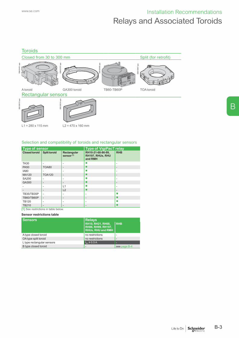
B-3
Installation Recommendations
B
www.se.com
ToroidsClosed from 30 to 300 mm Split (for retrofit)
DB4
3245
1.ep
s
DB4
0379
7.ep
s
≤0.1
0.1 ≤ 0.5
>0.5
I∆n (A)
ON / ALARMT
-+ GND
I TK1
PP-YYYY-Www-D
Serial Number
DB4
3848
6.ep
s
DB4
1906
7.ep
s
A toroid GA300 toroid TB60-TB60P TOA toroidRectangular sensors
DB1
2601
3.ep
s
DB1
2601
4.ep
s
L1 = 280 x 115 mm L2 = 470 x 160 mm
Selection and compatibility of toroids and rectangular sensorsType of sensor Type of VigiPacT relayClosed toroid Split toroid Rectangular
sensor [1]RH10-21-68-86-99, RH197, RHUs, RHU and RMH
RHB
TA30 - - b -PA50 TOA80 - b -IA80 - - b -MA120 TOA120 - b -SA200 - - b -GA300 - - b -- - L1 b -- - L2 b -TB35/TB35P - - - b
TB60/TB60P - - - b
TB120 - - - b
TB210 - - - b
[1] See restrictions in table below.
Sensor restrictions tableSensors Relays
RH10, RH21, RH68, RH86, RH99, RH197, RHUs, RHU and RMH
RHB
A type closed toroid no restrictions -OA type split toroid no restrictions -L type rectangular sensors IΔn u 0.5 A -B type closed toroid - see page B-4
Relays and Associated Toroids

B-4
Installation Recommendations
B
www.se.com
Toroid Compatibility with ComPacT NSX
Toroid selection table to be fully compliant with IEC 60947-2 annex M standard
40 A
63 A
80 A
125 A
160 A250 A320 A400 A630 A
1600 A3200 A
30 mA 300 mA 500 mA 1A 3A 30A100 mA
NS63
0bM
TZNWNT
NSX
C2NS
X C1
NSXm
[1]
Type
A
TA30
[ ²]
PA50
[ ²]
IA80
[ ²]
MA1
20 [ ²]
SA20
0
GA3
00
40 A
63 A
80 A
125 A
160 A250 A320 A400 A630 A
1600 A3200 A
1A 3A 30A
NS63
0bM
TZNWNT
NSX
C2NS
X C1
NSXm
[1]
Type
OA
TOA8
0
TOA1
20
40 A
63 A
80 A
125 A
160 A250 A320 A400 A630 A
1600 A3200 A
1A 3A 30A
NS63
0bM
TZNWNT
NSX
C2NS
X C1
NSXm
[1]
Type
L
L1
L2
40 A
63 A
80 A
125 A
160 A250 A320 A400 A630 A
1600 A3200 A
1A 3A 30A
NS63
0bM
TZNWNT
NSX
C2NS
X C1
NSXm
[1]
Type
B
TB35
TB35
P
TB60
TB60
P
TB12
0
TB21
0
IΔn30 mA 300 mA 500 mA100 mA
30 mA 300 mA 500 mA100 mA
30 mA 300 mA 500 mA100 mA
30 mA 300 mA 500 mA100 mA
IΔn
IΔn
IΔn
DB4
3927
8.ai
For circuits with high transient currents (6 In)
Magneticring
DB4
3246
7.ep
s
[1] NSXm not compliant with 30 mA setting.
[2] The addition of a shielding ring allows immunisation with respect to false zero-sequence currents (tested at 6 In as per IEC 60947-2 annex M) to help prevent nuisance tripping for the settings indicated in table below. (Doted line to show toroid range covers. Ie: TA30 can be used from IDn=30 mA to 30A).

B-5
Installation Recommendations
B
www.se.com
Possible installation positionsModular format
Vigirex RH10M
DB1
2601
5.ep
s
Vigirex RH10M
DB1
2601
6.ep
s
Vig
irex
RH
10M
DB1
2601
7.ep
s
DB4
3851
3.ep
s
DB4
3851
4.ep
s
DB4
3851
5.ep
s
Front-panel mount format
OK
Vigirex
RMU
OK
Vigirex
RMU
DB4
1906
8.ep
s
OK
Vigirex
RMUOK
Vigire
xR
MU
DB4
1907
0.ep
s
OK
Vigirex
RMU
DB4
1907
1.ep
s
Relay mounting possibilities
Vigirex RH10M
DB1
2601
5.ep
s
Vigirex RH10M
DB1
2602
2.ep
s Mounting of modular format relays RH10M-21M-68M-86M-99M-RH197M RHBThe relay can be mounted in three ways:
b On a DIN rail (only this mounting for RH197M) b On a mounting plate using 3 M4 screws (not supplied) and 3 removable mounting accessories (supplied).
Mounting of front-panel mount relays RH10P-21P-86P-99P, RHUs, RHU and RMHNo special tools are required to mount the relay. Simply insert the device through the cutout. The size of the cutout complies with standard DIN 43700.Front panel thickness: 1 mm minimum/2.5 mm maximum.The relay clips onto the panel.Mounting of relay RH197PNo tools are required to mount the relay in position. Simply insert the device through the cutout and tighten the clamp by turning the knurled nut.The size of the cutout complies with standard DIN 43700.Front panel thickness: 1 mm minimum/4 mm maximum.Mounting of RM12T multiplexerThe multiplexer must always be mounted on a DIN rail.
DIN rail Mounting plate
OK
Vigirex
DB4
2541
5.ep
s
Vigirex RH10P
DB4
2541
6.ep
s
Front-panel mount RHUs, RHU and RMH details Front-panel mount RH10P, RH21P and RH99P detail
Vigirex RM12T
DB1
2602
5.ep
s
Vigirex RH10P
DB4
2541
7.ep
s
RM12T: DIN rail only Front-panel mount RH197P detail
Possible Installation PositionsRH10-21-68-86-99M/P, RH197M/P, RHUs, RHU, RMH and RHB

B-6
Installation Recommendations
B
www.se.com
Toroid mounting possibilitiesOn DIN rail (TA30, PA50, IA80 and MA120) using supplied accessories
DB4
3245
2.ep
s
DB4
3245
3.ep
s
DB4
3245
4.ep
s
Accessory
On a plate (TA30, PA50, IA80, MA120, SA200, GA300, TOA80 and TOA120) or bracketScrews not supplied
DB4
3245
6.ep
s
DB4
3245
5.ep
s Screw Ø4 Screw Ø5TA30 IA80PA50 MA120
SA200GA300TOA80TOA120
Clipped on the back of the relay (TA30 and PA50)
DB4
3245
7.ep
s
Tied to cables (IA80, MA120, SA200 and GA300), cable-ties not suppliedCable-ties with 9 mm maximum width and 1.5 mm maximum thickness
DB4
3245
8.ep
s
DB4
3245
9.ep
s
Tied to cables (rectangular sensors)
DB1
2603
5.ep
s
DB1
2603
6.ep
s
On bars with chocks (rectangular sensors)
DB1
2603
7.ep
s
DB1
2603
8.ep
s
Possible Installation PositionsA and OA Type Toroids and Rectangular Sensors

B-7
Installation Recommendations
B
www.se.com
Toroid mounting possibilitiesOn DIN rail (TB35 and TB35P) using supplied accessories
≤0.1
0.1 ≤ 0.5
>0.5
I∆n (A)
ON / ALARMT
-+ GND
I TK1
PP-YYYY-Www-D
Serial Number
DB4
3850
1.ep
s
≤0.1
0.1≤ 0.5
>0.5
I∆n (A)
ON
/ ALARMT
-+
GN
D
I
T
K1
PP-YYYY-Ww
w-D
Serial Num
ber
DB4
3850
2.ep
s
On a plate (TB35, TB35P, TB60, TB60P, TB120 and TB210)
≤0.1
0.1 ≤ 0.5
>0.5
I∆n (A)
ON / ALARMT
-+ GND
I TK1
PP-YYYY-Www-D
Serial Number
DB4
3850
3.ep
s
≤0.1
0.1≤ 0.5
>0.5
I∆n (A)
ON
/ ALARMT
-+
GN
D
I
T
K1
PP-YYYY-Ww
w-D
Serial Num
ber
DB4
3850
4.ep
s
Screw Ø5 Screw Ø6TB35 TB60TB35P TB60P
TB120TB210
Tied to cables cable-ties not supplied
≤0.1
0.1 ≤ 0.5
>0.5
I∆n (A)
ON / ALARMT
-+ GND
I TK1
PP-YYYY-Www-D
Serial Number
shielded cable
DB4
3852
5.ep
s
Possible Installation PositionsB Type Toroids and Rectangular Sensors

B-8
Installation Recommendations
B
www.se.com
Product, terminal or screw
Cable type Terminal capacity (mm2) Conduct. size
Stripping Tightening torque
Rigid Flexible Flexible with ferrule AWG Rigid/flexiblemin. max. min. max. min. max. (mm) (inch) (N.m) (In-lbs)
RH10M, RH21M, RH68M, RH86M and RH99M11, 14 0.2 4 0.2 2.5 0.25 2.5 24-12 8 .31 0.6 0.067831, 32, 34 0.2 4 0.2 2.5 0.25 2.5 24-12 8 .31 0.6 0.0678A1, A2 0.2 2.5 0.2 2.5 0.25 2.5 24-12 7 .27 0.6 0.0678T1, T2 twisted pair 0.14 1.5 0.14 1 0.25 0.5 26-16 5 .19 0.25 0.0282525, 26, 27 3 twisted wires L<10 m 0.14 1.5 0.14 1 0.25 0.5 26-16 5 .19 0.25 0.02825RH197MA1, A2 0.2 2.5 0.2 2.5 0.25 2.5 24-12 7 .27 0.6 0.067831, 32, 34 0.2 2.5 0.2 2.5 0.25 2.5 24-12 7 .27 0.6 0.067825-26, 27-28 0.2 2.5 0.2 2.5 0.25 2.5 24-12 7 .27 0.6 0.0678T1, T2 0.2 2.5 0.2 2.5 0.25 2.5 24-12 7 .27 0.6 0.067841, 42, 44 0.2 2.5 0.2 2.5 0.25 2.5 24-12 7 .27 0.6 0.0678RH10P, RH21P, RH99P11, 14 or 41, 44 0.2 2.5 0.2 2.5 0.25 2.5 24-12 7 .27 0.6 0.067831, 32, 34 0.2 2.5 0.2 2.5 0.25 2.5 24-12 7 .27 0.6 0.0678A1, A2 0.2 2.5 0.2 2.5 0.25 2.5 24-12 7 .27 0.6 0.0678T1, T2 twisted pair 0.2 2.5 0.2 2.5 0.25 2.5 24-12 7 .27 0.6 0.067825, 26, 27 3 twisted wires L<10 m 0.2 2.5 0.2 2.5 0.25 2.5 24-12 7 .27 0.6 0.0678RH197P11, 14 0.2 2.5 0.2 2.5 0.25 2.5 24-12 7 .27 0.6 0.067831, 32, 34 0.2 2.5 0.2 2.5 0.25 2.5 24-12 7 .27 0.6 0.0678A1, A2 0.2 2.5 0.2 2.5 0.25 2.5 24-12 7 .27 0.6 0.0678T1, T2 twisted pair 0.2 2.5 0.2 2.5 0.25 2.5 24-12 7 .27 0.6 0.067825, 26, 27 3 twisted wires L>10 m 0.2 2.5 0.2 2.5 0.25 2.5 24-12 7 .27 0.6 0.0678RHUs and RHUA1, A2 0.2 2.5 0.2 2.5 0.25 2.5 22-12 6 .23 0.5 0.056511, 14 0.2 2.5 0.2 2.5 0.25 2.5 22-12 6 .23 0.5 0.056531, 32, 34 0.2 2.5 0.2 2.5 0.25 2.5 22-12 6 .23 0.5 0.056541, 44 0.2 2.5 0.2 2.5 0.25 2.5 22-12 6 .23 0.5 0.0565T1, T2 twisted pair 0.2 2.5 0.2 2.5 0.25 2.5 22-12 6 .23 0.5 0.056525, 26, 27 3 twisted wires
L<10 m0.2 2.5 0.2 2.5 0.25 2.5 22-12 6 .23 0.5 0.0565
Bus [1] 24 V, 0 V twisted pair 0.2 2.5 0.2 2.5 0.25 2.5 22-12 6 .23 0.5 0.0565-, + twisted pair 0.2 2.5 0.2 2.5 0.25 2.5 22-12 6 .23 0.5 0.0565
RMHA1, A2 0.2 2.5 0.2 2.5 0.25 2.5 22-12 6 .23 0.5 0.056511, 14 0.2 2.5 0.2 2.5 0.25 2.5 22-12 6 .23 0.5 0.056531, 32, 34 0.2 2.5 0.2 2.5 0.25 2.5 22-12 6 .23 0.5 0.056541, 44 0.2 2.5 0.2 2.5 0.25 2.5 22-12 6 .23 0.5 0.056521, 22 twisted pair L<10 m 0.2 2.5 0.2 2.5 0.25 2.5 22-12 6 .23 0.5 0.056523, 24 twisted pair L<10 m 0.2 2.5 0.2 2.5 0.25 2.5 22-12 6 .23 0.5 0.0565Bus 24 V, 0 V twisted pair 0.2 2.5 0.2 2.5 0.25 2.5 22-12 6 .23 0.5 0.0565
-, + twisted pair 0.2 2.5 0.2 2.5 0.25 2.5 22-12 6 .23 0.5 0.0565RM12T12 toroid connections 1 to 12 and 15 to 20
1 twisted pair/toroid L < 10 m
0.2 2.5 0.2 2.5 0.25 2.5 22-12 6 .23 0.5 0.0565
21, 22 twisted pair L<10 m 0.2 2.5 0.2 2.5 0.25 2.5 22-12 6 .23 0.5 0.056523, 24 twisted pair L<10 m 0.2 2.5 0.2 2.5 0.25 2.5 22-12 6 .23 0.5 0.056525, 26 0.2 2.5 0.2 2.5 0.25 2.5 22-12 6 .23 0.5 0.0565RHBA1, A2, T/R, 11, 12, 14, 21, 22, 24
0.2 2.5 0.2 2.5 0.25 2.5 24-12 6 .23 0.5 0.0565
Toroid and sensorsTA30 and PA50 Ø30 to 50 mmconnectors supplied
twisted Cu/Al 0.2 2.5 0.2 2.5 0.2 1.5 24-14 6 .23 0.5 0.0565
IA80 to GA300Ø80 to 300 mm twisted Cu/Al 0.2 2.5 0.2 2.5 0.2 1.5 24-1 6 .23 0.5 0.0565
TOA80 - TOA120 Ø5 mm round lugs note supplied:
0.2 2.5 0.2 2.5 0.2 1.5 24-14 6 .23 0.6 5.2
S1, S2 twisted Cu/Al - - - - - - - - - 3 0.339Mounting on a mounting plate and DIN Rail clip
- - - - - - - - - 3.5 31
L1, L2 twisted pair L<10 m 0.5 2.5 0.5 2.5 0.5 2.5 20-14 8 to 9 .33 - -[1] RHU only.
ConnectionRelays and Sensors

B-9
Installation Recommendations
B
www.se.com
Connection of relays
[1]
[1]
DB4
2541
9.ep
s Modular format
Déconnecter A1-A2avant test diélectrique
Desconecte A1-A2 antes de realizar la prueba dieléctrica
Disconnect A1-A2before dielectric test
A1 A2
220 / 240 VAC50 / 60 Hz
Vigire x RH99M
RH99MVigirex
DB4
3246
0.ep
s[1] See table page B-8.
Front-panel mount format
T
DB4
2564
8.ep
s
MFR39443
Connection of toroidsTA30 and PA50 closed toroids (connectors supplied)
IA80, MA120, SA200 and GA300 closed toroids
[1]
[1]
DB4
3246
1.ep
s
[1]
[1]
DB4
3246
2.ep
s
[1] See table page B-8. [1] See table page B-8.
ConnectionRelays and Sensors

B-10
Installation Recommendations
B
www.se.com
Connection of toroids (cont.)
TOA80 and TOA120 split toroids (Ø5 mm round lugs not supplied)
[1]
[1]
DB4
3246
3.ep
s
[1] See table page B-8.
Connection of rectangular sensors and conductor layout
L1: frame 280 x 115 mm L2: frame 470 x 160 mmBusbars with 70 mm spacing Busbars with 115 mm spacing
[1]
[1]
DB4
2542
3.ep
s M1 M2 M3
DB1
2606
3.ep
s
2 bars 50 x 10 mm (1600 A) The neutral can be located on the right or the left.
4 bars 100 x 5 mm (3200 A) The neutral can be located on the right or the left.
[1] See table page B-8.
[1]
[1]
DB4
2542
4.ep
s
M1 M2 M3
DB1
2606
5.ep
s
2 bars 100 x 5 mm (1600 A)The neutral can be located on the right or the left.
4 bars 125 x 5 mm (3200 A) The neutral can be located on the right or the left.
[1] See table page B-8.
[1]
[1]
DB4
2542
5.ep
s
4 cables 240 mm2 (1600 A)[1] See table page B-8.
Note: connect M1 and M2 with VigiPacT.
ConnectionToroids and Rectangular Sensors
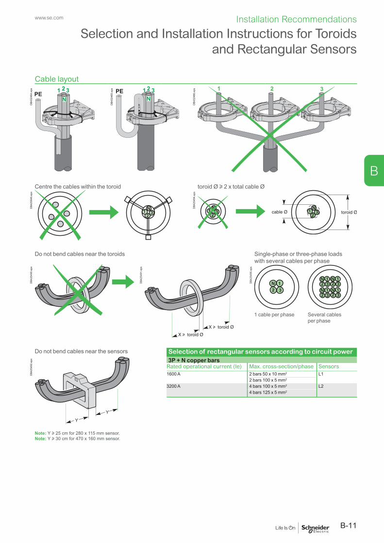
B-11
Installation Recommendations
B
www.se.com
Cable layout
DB4
3246
4.ep
s
DB4
3246
5.ep
s
DB4
3246
6.ep
s
Centre the cables within the toroid toroid Ø u 2 x total cable Ø
DB4
2564
6.ep
s
DB4
2549
4.ep
s
Do not bend cables near the toroids Single-phase or three-phase loads with several cables per phase
DB4
2549
0.ep
s
DB4
2549
1.ep
s
DB4
2549
5.ep
s
1 cable per phase Several cables per phase
Do not bend cables near the sensors Selection of rectangular sensors according to circuit power
DB4
2549
2.ep
s 3P + N copper barsRated operational current (Ie) Max. cross-section/phase Sensors1600 A 2 bars 50 x 10 mm2 L1
2 bars 100 x 5 mm2
3200 A 4 bars 100 x 5 mm2 L24 bars 125 x 5 mm2
Note: Y u 25 cm for 280 x 115 mm sensor.Note: Y u 30 cm for 470 x 160 mm sensor.
Selection and Installation Instructions for Toroids and Rectangular Sensors

B-12
Installation Recommendations
B
www.se.com
Connection between VigiPacT relays and sensorsVigiPacT relays must be connected to the sensors as indicated:
Cross-section (Cu) Maximum length
Vigire x RH99M
DB4
3246
8.ep
s
Toroids0.22 mm2 [1] 18 m0.75 mm2 [1] 60 m1 mm2 [1] 80 m1.5 mm2 [1] 100 m
Rectangular sensors0.5 mm2 min./2.5 mm2 max. 10 m[1] Wire size for resistance R maximum = 3 W.
Cable typeStandard twisted pair (not to be run alongside power cables).A wiring kit is mandatory for RHB.
In highly disturbed environments:
WiringShielded twisted pair (not to be run alongside power cables).The shielding must be earthed at both ends by connection to the equipotential bonding circuit.The cable between the toroid and the relay should be as short as possible.If this is not sufficient, use a transformer with high frequency (HF) shielding.A wiring kit is mandatory for RHB.
Vigirex RH99M
DB4
2550
0.ep
s
Auxiliary power supply via external transformer
Selection and Installation Instructions for Toroids and Rectangular Sensors

C-1
C
www.se.com
1.2
Dimensions and Connection
DimensionsRH10M, RH21M, RH68M, RH86M, RH99M and RH197M Relays . C-2RH10P, RH21P, RH99P, RH197P, RHUs, RHU, RMH and RM12T Relays ........................................................................... C-3RHB .................................................................................................. C-4A Type Closed Toroids ..................................................................... C-5OA Type Split Toroids and Rectangular Sensors ............................ C-6B Type Active Closed Toroids .......................................................... C-7
Other ChaptersOther ChaptersFunctions and Characteristics ...........................................................................A-1Installation Recommendations...........................................................................B-1Wiring Diagrams ................................................................................................D-1Additional Characteristics .................................................................................. E-1Catalog Numbers ...............................................................................................F-1

C
www.se.com
Mounting on a DIN railRH10M, RH21M, RH68M, RH86M and RH99M RH197M
DB4
2550
2.ep
s
RH10MVigirexD
B126
039.
eps
71.2
8998.7
45
45
65.8
DB4
2550
3.ep
s
Mounting on a mounting plate
RH10M, RH21M, RH68M, RH86M and RH99MPlate drilling layout
DB1
2604
0.ep
s
RH10MVigirex
DB1
2604
1.ep
s
DB1
2604
2.ep
s
Door cutoutMounting on a DIN rail Mounting on a mounting plate
DB1
2604
3.ep
s
DB1
2604
4.ep
s
72 max.
[1]
[1]
[2]
DB4
2550
5.ep
s
[1] For IP4 requirements.[2] For RH197M.
DimensionsRH10M, RH21M, RH68M, RH86M, RH99M and RH197M Relays
C-2
Dimensions and Connection

C
www.se.com
Front-panel mount relays (cutout complying with standard DIN 43700)RH10P, RH21P and RH99P RH197P
DB1
0108
0.ep
s
RH10PVigirex
DB1
2604
6.ep
s
DB1
0172
8.ep
s
RH197PVigirex
DB1
2604
7.ep
s
RHUs, RHU and RMH Door Cutout
DB1
2605
0.ep
s
DIN rail mounting onlyRM12T
Door cutout
DB1
2605
1.ep
s
RM12TVigirex
DB1
2605
2.ep
s
[1]
[1]
DB4
2550
4.ep
s
[1] For IP4 requirements.
DimensionsRH10P, RH21P, RH99P, RH197P, RHUs, RHU, RMH
and RM12T Relays
OK
DB4
1908
5.ep
s
65x65
117
DB4
1908
4.ep
s
C-3
Dimensions and Connection

C
www.se.com
DimensionsRHB
Mounting on a DIN rail
31.1
47.5
70.5
45
DB4
3850
5.ep
s
36
45 67.5 90D
B438
510.
eps
Mounting on a mounting platePlate drilling layout
70.5
DB4
3851
9.ep
s
100 116
DB4
3852
0.ep
s 2 Ø5
116
DB4
3852
1.ep
s
Door cutoutMounting on a DIN rail Mounting on a mounting plate
50
DB4
3852
2.ep
s
54.5
DB4
3852
3.ep
s
37max.
46max.
DB4
3852
4.ep
s
C-4
Dimensions and Connection
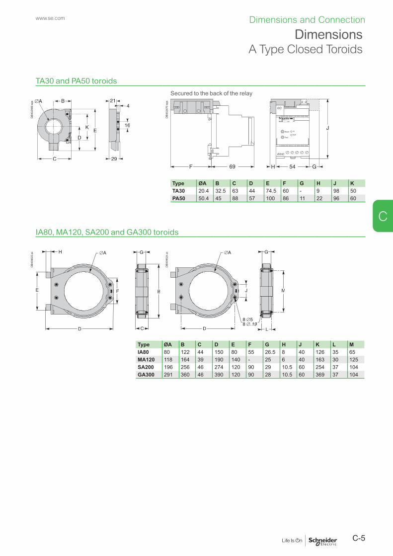
C
www.se.com
TA30 and PA50 toroidsSecured to the back of the relay
DB4
3246
9.ep
s
DB4
3247
0.ep
s
Type ØA B C D E F G H J KTA30 20.4 32.5 63 44 74.5 60 - 9 98 50PA50 50.4 45 88 57 100 86 11 22 96 60
IA80, MA120, SA200 and GA300 toroids
DB4
3902
3.ai
DB4
3902
4.ai
Type ØA B C D E F G H J K L MIA80 80 122 44 150 80 55 26.5 8 40 126 35 65MA120 118 164 39 190 140 - 25 6 40 163 30 125SA200 196 256 46 274 120 90 29 10.5 60 254 37 104GA300 291 360 46 390 120 90 28 10.5 60 369 37 104
DimensionsA Type Closed Toroids
C-5
Dimensions and Connection

C
www.se.com
TOA80 and TOA120 toroids
TOA120
391.54
TOA80
C
Ø B
A
F
DE
C
1003.94
DB4
1907
9.ep
s
Type Dimensions (mm)A ØB C D E F
TOA80 177 80 28 108 235 156TOA120 225 120 50 150 303 205
Rectangular sensorsL1: frame 280 x 115 mm
198223
241
72
363388
DB4
2521
9.ep
s
L2: frame 470 x 160 mm
553576
243266
284
DB4
2521
6.ep
s
DimensionsOA Type Split Toroids and Rectangular Sensors
C-6
Dimensions and Connection

C
www.se.com
DimensionsB Type Active Closed Toroids
TB35/TB35P toroids TB60/TB60P toroids
B
A
K
ØD
B
F
G
E
DB4
3850
6.ep
s
F
E
B
C
A
ØD
DB4
3850
7.ep
s
TB120/TB210 toroids
C
F
E
B
G
ØD
A
DB4
3850
8.ep
s
Type A B C ØD E F GTB35/ TB35P
97 130 47 35 46 61 -
TB60/TB60P
126 151 57 60 56 78 -
TB120 188 225 96 120 65 96 139TB210 339 339 153 210 67 113 277
Electronic Module for TB35/TB60/TB120/TB210/TB35P/TB60P
32
4.6
75
30
44
DB4
3850
9.ep
s
C-7
Dimensions and Connection

D-1
D
www.se.com
1.1
Wiring Diagrams
Wiring DiagramsRH10, RH21, RH68M, RH86M, RH99M, RH10, RH21, RH86 and RH99P ....................................................................................... D-2RH86, RH99 Monitor ........................................................................ D-4RH197M with MX Shunt Release ..................................................... D-5RH197M with MN Undervoltage Release ........................................ D-6RH197P with MX Shunt Release ...................................................... D-7RH197P with MN Undervoltage Release ........................................ D-8RHUs and RHU ................................................................................ D-9RMH ............................................................................................... D-10Communication Bus, Test and Remote Reset Functions, Power Supply ................................................................................. D-11RHB ................................................................................................ D-12
Other ChaptersOther ChaptersFunctions and Characteristics ...........................................................................A-1Installation Recommendations...........................................................................B-1Dimensions and Connection .............................................................................C-1Additional Characteristics .................................................................................. E-1Catalog Numbers ...............................................................................................F-1

D
www.se.com
RH10M, RH21M, RH68M, RH86M and RH99M Wiring with MX Shunt ReleaseAll diagrams are shown with circuits de-energized, all devices open and relays in released position.
See page D-11
DB4
2550
6.ep
s
L1: lampMX: shunt releaseQ1: circuit breaker protecting the main circuitQ2: DPN circuit breakerRH10M, RH21M, RH68M, RH86M and RH99M:
b A1-A2: auxiliary power supply b T1-T2: A or TOA type toroid or rectangular sensor (if IΔn u 500 mA)
b 11-14: “voltage-presence” contact b 26-25: relay test b 27-25: “fault” reset b 31-32-34: “fault” contact.
Note: for the RH99 earth leakage monitor use the “fault” contact 31, 32, 34.
RH10P, RH21P and RH99P Wiring with MX Shunt ReleaseL1: lampMX: shunt releaseQ1: circuit breaker protecting the main circuitQ2: DPN circuit breakerRH10P, RH21P and RH99P:
b A1-A2: auxiliary power supply b T1-T2: A or TOA type toroid or rectangular sensor (if IΔn u 500 mA)
b 11-14: “voltage-presence” contact b 26-25: relay test b 27-25: “fault” reset b 31-32-34: “fault” contact.
See page D-11
DB4
2550
7.ep
s
Note: for the RH99 earth leakage monitor use the “fault” contact 31, 32, 34.
Wiring DiagramsRH10, RH21, RH68, RH86, RH99M, RH10, RH21, RH86 and RH99PWiring for optimum continuity of service
D-2
Wiring Diagrams

D
www.se.com
Wiring DiagramsRH10, RH21, RH68, RH86, RH99M, RH10, RH21, RH86 and RH99P
Wiring for optimum protection
RH10M, RH21M, RH68M, RH86M and RH99M Wiring with MN Undervoltage ReleaseAll diagrams are shown with circuits de-energized, all devices open and relays in released position.
DB4
2550
8.ep
s
See page D-11
MN: undervoltage releaseQ1: circuit breaker protecting the main circuitQ2: DPN circuit breakerRH10M, RH21M, RH68M, RH86M and RH99M:
b A1-A2: auxiliary power supply b T1-T2: A or TOA type toroid or rectangular sensor (if IΔn u 500 mA)
b 11-14: “voltage-presence” contact b 26-25: relay test b 27-25: “fault” reset b 31-32-34: “fault” contact.
Note: for the RH99 earth leakage monitor use the “fault” contact 31, 32, 34.
RH10P, RH21P and RH99P Wiring with MN Undervoltage ReleaseMN: undervoltage releaseQ1: circuit breaker protecting the main circuitQ2: DPN circuit breakerRH10MP, RH21P and RH99P:
b A1-A2: auxiliary power supply b T1-T2: A or TOA type toroid or rectangular sensor (if IΔn u 500 mA)
b 11-14: “voltage-presence” contact b 26-25: relay test b 27-25: “fault” reset b 31-32-34: “fault” contact.
DB4
2550
9.ep
s
See page D-11
Note: for the RH99 earth leakage monitor use the “fault” contact 31, 32, 34.
D-3
Wiring Diagrams

D
www.se.com
RH86M, RH99M Monitor Wiring with ATm Auto-Reclosing ControllerAll diagrams are shown with circuits de-energized, all devices open and relays in released position.
DB4
2551
0.ep
s
See page D-11
Zelio Logic: Programmable logic controllerH: red lightMT: motor mechanism moduleMX: shunt releaseQ1: circuit breaker protecting the main circuitQ4 to Q6: DPN circuit breakersRH86M, RH99M monitor:
b A1-A2: auxiliary power supply b T1-T2: A or TOA type toroid or rectangular sensor (if IΔn u 500 mA)
b 11-14: “voltage-presence” contact b 26-25: relay test b 27-25: “fault” reset b 31-32-34: “fault” contact
S1 et S2: single-pole switchSD: auxiliary fault indication contactT: sensor
RH99P Monitor Wiring with ATm Auto-Reclosing ControllerZelio Logic: Programmable logic controllerH: red lightMT: motor mechanism moduleMX: shunt releaseQ1: circuit breaker protecting the main circuitQ4 to Q6: DPN circuit breakersRH99P monitor:
b A1-A2: auxiliary power supply b T1-T2: A or TOA type toroid or rectangular sensor (if IΔn u 500 mA)
b 11-14: “voltage-presence” contact b 26-25: relay test b 27-25: “fault” reset b 31-32-34: “fault” contact
S1 et S2: single-pole switchSD: auxiliary fault indication contactT: sensor
DB4
2551
1.ep
s See page D-11
Additional Information b The SD auxiliary contact is mandatory b Manual operation of the MT motorized operating mechanism always overides the ATm3 auto-reclosing controller
b Use a single power supply (L/N) for all inputs (I), the ATm3 and the MX auxiliary.
Wiring DiagramsRH86, RH99 MonitorAuto-reclosing application for unattended stations
D-4
Wiring Diagrams

D
www.se.com
RH197M Wiring for Optimum Continuity of ServiceAll diagrams are shown with circuits de-energized, all devices open and relays in released position.
M
28
Reset Test
Alarm Fault
42
A2 A1
H1
DB4
2551
2.ep
s See page D-11
Switch setting:
DB4
2551
4.ep
s
L1: lamp and audio alarmMX: shunt releaseQ1: circuit breaker protecting the main circuitQ2: DPN circuit breakerRH197M:
b A1-A2: auxiliary power supply b T1-T2: A or TOA type toroid or rectangular sensor (if IΔn u 500 mA)
b 41-44: “alarm contact” b 26-25: relay test b 27-25: “fault” reset b 31-32-34: “fault” contact
RH197M Wiring for Optimum ProtectionAll diagrams are shown with circuits de-energized, all devices open and relays in released position. A2 A1
M
28
Reset Test
Alarm Fault
42
A2 A1
H1
DB4
2551
3.ep
s
Switch setting:
DB4
2551
5.ep
s
WarningThe supply for A1-A2 must be different from that of the MX shunt release.
L1: lamp and audio alarmMX: shunt releaseQ1: circuit breaker protecting the main circuitQ2: DPN circuit breakerRH197M:
b A1-A2: auxiliary power supply b T1-T2: A or TOA type toroid or rectangular sensor (if IΔn u 500 mA)
b 41-44: “alarm contact” b 26-25: relay test b 27-25: “fault” reset b 31-32-34: “fault” contact
Wiring DiagramsRH197M with MX Shunt Release
See page D-11
D-5
Wiring Diagrams

D
www.se.com
RH197M Wiring for Optimum Continuity of ServiceAll diagrams are shown with circuits de-energized, all devices open and relays in released position.
M
28
Reset Test
Alarm
A2 A1
H1
A2 A1
42
Fault
DB4
2551
6.ep
s See page D-11
Switch setting:
DB4
2551
8.ep
s
L1: lamp and audio alarmMN: undervoltage releaseQ1: circuit breaker protecting the main circuitQ2: DPN circuit breakerRH197M:
b A1-A2: auxiliary power supply b T1-T2: A or TOA type toroid or rectangular sensor (if IΔn < 500 mA)
b 41-44: “alarm contact” b 26-25: relay test b 27-25: “fault” reset b 31-32-34: “fault” contact
RH197M Wiring for Optimum ProtectionAll diagrams are shown with circuits de-energized, all devices open and relays in released position.
See page D-11
M
28
Reset Test
Alarm Fault
A2 A1
H1
A2 A1
42
DB4
2551
7.ep
s
Switch setting:
DB4
2551
9.ep
s
L1: lamp and audio alarmMN: undervoltage releaseQ1: circuit breaker protecting the main circuitQ2: DPN circuit breakerRH197M:
b A1-A2: auxiliary power supply b T1-T2: A or TOA type toroid or rectangular sensor (if IΔn y 500 mA)
b 41-44: “alarm contact” b 26-25: relay test b 27-25: “fault” reset b 31-32-34: “fault” contact
Wiring DiagramsRH197M with MN Undervoltage Release
D-6
Wiring Diagrams

D
www.se.com
RH197P Wiring for Optimum Continuity of ServiceAll diagrams are shown with circuits de-energized, all devices open and relays in released position.
DB4
2552
0.ep
s See page D-11
Switch setting:
DB4
2552
2.ep
s
L1: lamp and audio alarmMX: shunt releaseQ1: circuit breaker protecting the main circuitQ2: DPN circuit breakerRH197P:
b A1-A2: auxiliary power supply b T1-T2: A or TOA type toroid or rectangular sensor (if IΔn y 500 mA)
b 41-44: “alarm contact” b 26-25: relay test b 27-25: “fault” reset b 31-32-34: “fault” contact
RH197P Wiring for Optimum ProtectionAll diagrams are shown with circuits de-energized, all devices open and relays in released position.
DB4
2552
1.ep
s See page D-11
Switch setting:
DB4
2552
3.ep
s
WarningThe supply for A1-A2 must be different from that of the MX shunt release.
L1: lamp and audio alarmMX: shunt releaseQ1: circuit breaker protecting the main circuitQ2: DPN circuit breakerRH197P:
b A1-A2: auxiliary power supply b T1-T2: A or TOA type toroid or rectangular sensor (if IΔn y 500 mA)
b 41-44: “alarm contact” b 26-25: relay test b 27-25: “fault” reset b 31-32-34: “fault” contact
Wiring DiagramsRH197P with MX Shunt Release
D-7
Wiring Diagrams

D
www.se.com
RH197P Wiring for Optimum Continuity of ServiceAll diagrams are shown with circuits de-energized, all devices open and relays in released position.
DB4
2552
4.ep
s See page D-11
Switch setting:
DB4
2552
6.ep
s
L1: lamp and audio alarmMN: undervoltage releaseQ1: circuit breaker protecting the main circuitQ2: DPN circuit breakerRH197P:
b A1-A2: auxiliary power supply b T1-T2: A or TOA type toroid or rectangular sensor (if IΔn < 500 mA)
b 41-44: “alarm contact” b 26-25: relay test b 27-25: “fault” reset b 31-32-34: “fault” contact
RH197P Wiring for Optimum ProtectionAll diagrams are shown with circuits de-energized, all devices open and relays in released position.
DB4
2552
5.ep
s See page D-11
Switch setting:
DB4
2552
7.ep
s
L1: lamp and audio alarmMN: undervoltage releaseQ1: circuit breaker protecting the main circuitQ2: DPN circuit breakerRH197P:
b A1-A2: auxiliary power supply b T1-T2: A or TOA type toroid or rectangular sensor (if IΔn y 500 mA)
b 41-44: “alarm contact” b 26-25: relay test b 27-25: “fault” reset b 31-32-34: “fault” contact
Wiring DiagramsRH197P with MN Undervoltage Release
D-8
Wiring Diagrams

D
www.se.com
RHUs and RHU Wiring with MX Shunt Release: Optimum Continuity of ServiceAll diagrams are shown with circuits de-energized, all devices open and relays in released position.
DB4
2553
3.ep
s See page D-11
L1: lamp and audio alarmL2: lampMX: shunt releaseQ1: circuit breaker protecting the main circuitQ2: DPN circuit breakerRHUs and RHU:
b A1-A2: auxiliary power supply b T1-T2: A or TOA type toroid or rectangular sensor (if IΔn u 0.5 A)
b 11-14: “voltage-presence” contact b 26-25: relay test b 27-25: “fault” reset b 31-32-34: “fault” contact b 41-44: “alarm contact”.
[1] RHU only.
RHUs and RHU Wiring with MN Undervoltage Release: Optimum ProtectionL1: lamp and audio alarmMN: undervoltage releaseQ1: circuit breaker protecting the main circuitQ2: DPN circuit breakerRHUs and RHU:
b A1-A2: auxiliary power supply b T1-T2: A or TOA type toroid or rectangular sensor (if IΔn u 0.5 A)
b 11-14: “voltage-presence” contact b 26-25: relay test b 27-25: “fault” reset b 31-32-34: “fault” contact b 41-44: “alarm contact”.
DB4
2552
9.ep
s See page D-11
[1] RHU only.
Wiring DiagramsRHUs and RHU
D-9
Wiring Diagrams

D
www.se.com
RMH Wiring with RM12T Multiplexer
DB4
3927
9.ep
s
L1, L2: lamp and audio alarmL3: lampQA: switchboard incoming circuit breaker for the main circuitQB: circuit breaker protecting the RMH and RM12T power supply circuitQ1 to Q12: circuit breakers on main outgoing circuits 1 to 12T: transformer with 220/240 V secondary (if required), rating u 4 VAT1 to T12: residual current measurement toroids for circuits 1 to 12 (or rectangular sensor if IΔn u 0.5 A)
RM12T multiplexer b Terminals 1 to 12 and 15 to 20: connection of toroids b Terminals 21 to 24: connection of RMH earth leakage monitor b Terminals 25 to 26: auxiliary power supply.
RMH earth leakage monitor b A1-A2: auxiliary power supply b 11-14: “voltage-presence” contact b 21 to 24: connection of RM12T multiplexer b 31-32-34: “alarm” contact b 41-44: “pre-alarm” contact.
Wiring DiagramsRMH
All diagrams are shown with circuits de-energized, all devices open and relays in released position.
D-10
Wiring Diagrams

D
www.se.com
Connection of Test and Remote Reset FunctionsCableThe cable must not exceed 10 m in length. Use a cable with 3 twisted wires.ContactsUse pushbuttons with low-level contacts suitable for the minimum load of 1 mA at 4 V.
DB4
0319
3.ep
s
[1] Not available on DC version/Hold on for a time equivalent to the time delay setting for others versions.
Connection of RH10, RH21, RH99, RH197, RHUs and RHU Power Supply
u 48 V AC > 48 V AC
[1][2]D
B403
208.
eps
12/24 V AC 48 V AC
[1][2]
DB4
0320
9.ep
s
12/24 V DC 24/130 V DC
[1][2]D
B403
210.
eps
[1] RH10, RH21 and RH99.[2] RH197.
T: class 2 isolation transformer mandatory: b for VA1,A2 y 24 V AC for RH10, RH21 and RH99
b for VA1,A2 = 48 V AC for RH197P
The DC power supply must be galvanically isolated from the AC power system.
Wiring DiagramsCommunication Bus, Test and Remote Reset Functions,
Power Supply
28272625
RH197M
Test [1]
DB4
1413
7.ep
s
D-11
Wiring Diagrams

D
www.se.com
Wiring with MNAll diagrams are shown with circuits de-energized, all devices open and relays in released position.
L1N
TestReset
L
1N 2 3
Q2
Q1MN
T/R 21 22 24 141211
T/R A1 A2
RHBK I T_ 0 +
1 2 3 4
K I_ 0 + T
LV481017LV481018
Q3
K1K2
DB4
3849
5.ep
s
L1: lamp and audio alarmMN: undervoltage releaseQ1: circuit breaker protecting the main circuitQ2: Voltage release protectionQ3: RHB relay protection:b 6 A circuit breaker (phase + neutral)b 6 A fuse.RHB:
b A1-A2: connection to supply voltage Us b 1: socket for connection cable of measuring current transformer
b T/R : connection for a combined external test and reset button
b 11-12-14: Output relay K1 (alarm) b 21-22-24: Output relay K2
Wiring with MXL1: lamp and audio alarmMX: shunt releaseQ1: circuit breaker protecting the main circuitQ2: DPN circuit breakerQ3: RHB relay protection:b 6 A circuit breaker (phase + neutral)b 6 A fuse.RHB:
b A1-A2: connection to supply voltage Us b 1: socket for connection cable of measuring current transformer
b T/R : connection for a combined external test and reset button
b 11-12-14: Output relay K1 (alarm) b 21-22-24: Output relay K2
L1N
TestReset
L
1N 2 3
Q2
Q1
T/R 21 22 24 141211
T/R A1 A2
RHB
C
K I T_ 0 +
1 2 3 4
K I_ 0 + T
MX
K2 K1
Q3
LV481017LV481018
DB4
3849
6.ep
s
Wiring DiagramsRHB
D-12
Wiring Diagrams

E
Additional Characteristics
VigiPacT DevicesRCD Operating Principle ..................................................................E-2Residual-Current Measurements .....................................................E-4Applications ....................................................................................E-10Questions and Answers ..................................................................E-16
Leakage-Current Monitoring Using RCDs ...................E-17
Tripping Curves and Frequency FilteringRH10, RH21, RH68, RH86 and RH99 ............................................E-23RH197M ..........................................................................................E-24RH197P ...........................................................................................E-25RHUs and RHU ...............................................................................E-26RHB .................................................................................................E-27
Other ChaptersOther ChaptersFunctions and Characteristics ...........................................................................A-1Installation Recommendations...........................................................................B-1Dimensions and Connection .............................................................................C-1Wiring Diagrams ................................................................................................D-1Catalog Numbers ...............................................................................................F-1
E-1
www.se.com

E
www.se.com
VigiPacT devices are primarily intended to protect life and property on industrial, commercial or similar sites.VigiPacT RCDs implement:
b An electronic relay supplied by an auxiliary source b Measurements using a separate toroid.
When there is no insulation fault, the vector sum of the currents flowing in the live conductors is equal to zero.If an insulation fault occurs, the sum is no longer equal to zero and the fault current creates in the toroid a magnetic field which generates a current on the secondary winding. This current is monitored by a measurement circuit and, if it overruns the set threshold for a time greater than the set intentional time delay, the relay orders the current-breaking device to open.VigiPacT devices comply with standard IEC 60755 (the general standard governing RCDs) and with standard IEC 60947-2 annex M. These standards define the various device characteristics and the necessary tests for the products.
DB4
2556
0.ep
s
RCD operating principle.
VigiPacT DevicesRCD Operating Principle
E-2
Additional Characteristics
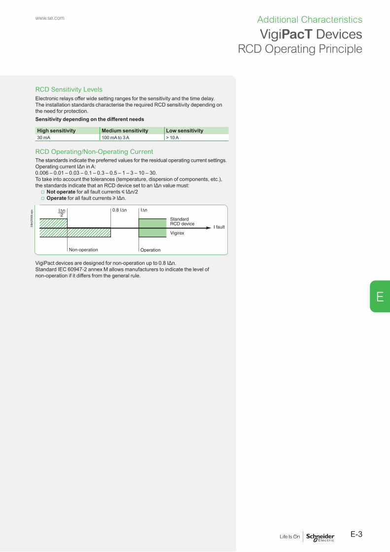
E
www.se.com
VigiPacT DevicesRCD Operating Principle
RCD Sensitivity LevelsElectronic relays offer wide setting ranges for the sensitivity and the time delay.The installation standards characterise the required RCD sensitivity depending on the need for protection.Sensitivity depending on the different needs
High sensitivity Medium sensitivity Low sensitivity30 mA 100 mA to 3 A > 10 A
RCD Operating/Non-Operating CurrentThe standards indicate the preferred values for the residual operating current settings.Operating current IΔn in A:0.006 – 0.01 – 0.03 – 0.1 – 0.3 – 0.5 – 1 – 3 – 10 – 30.To take into account the tolerances (temperature, dispersion of components, etc.), the standards indicate that an RCD device set to an IΔn value must:
v Not operate for all fault currents y IΔn/2 v Operate for all fault currents u IΔn.
DB4
2556
8.ep
s
VigiPact devices are designed for non-operation up to 0.8 IΔn.Standard IEC 60947-2 annex M allows manufacturers to indicate the level of non-operation if it differs from the general rule.
E-3
Additional Characteristics

E
www.se.com
Toroid CharacteristicsThe toroids used for VigiPacT devices enable the electronic relay to measure the different zero-sequence currents flowing in the monitored circuit. They are designed to:
b Measure currents b Withstand overvoltages b Withstand short-circuit currents.
Measurement of Zero-Sequence Currents b Measurement dynamics
The necessary measurement dynamics require a special magnetic circuit to measure very low currents and correct adaptation of the impedance (to avoid saturation) when measuring higher currents.To that end, the correct compromise is required between:
v A material with high magnetic permeability μr and the saturation phenomena v Toroid size (cross-sectional area) and acceptable dimensions v A high number (n) of turns and: - sufficiently low resistance - sufficient signal amplitude (gain 1/n).
b Measurement limits When a three-phase current flows through the measurement toroid and there is no insulation fault (the sum of the currents is equal to zero), a secondary current equivalent to a false zero-sequence fault current is created. This is due to leakage flows caused by manufacturing tolerances. It is necessary to qualify this phenomenon by indicating the rated operational current for a given zero-sequence leakage current. Table indicating the limits for IΔn/rated currentSee page B-11.Note: strict compliance with the installation rules for the cables passing through the toroid is indispensable. The addition of a “regulator sleeve” for the magnetic field considerably increases the rated operational current.
DB4
2557
0.ep
s
Measurement of Disturbed CurrentsToroids can capture the waveforms of currents comprising low-frequency harmonics. The main challenge is to measure current with a DC component, which can saturate the magnetic circuit and reduce the sensitivity of measurements. In this case, there is a risk that a fault current might not be detected. To help avoid this problem and ensure that the toroid provides an accurate output signal, it is necessary to use a magnetic material that does not have a horizontal saturation curve, with low residual induction Br. This is type A measurements.
Toroid hysterisis cycle for type A measurements.Id: primary currentIm = Id - Ih
VigiPacT DevicesResidual-Current Measurements
E-4
Additional Characteristics

E
www.se.com
Short-Circuit Withstand CapacityThe RCD must be sized for the short-circuit currents corresponding to the controlled protection device, at the point in the installation where it is placed. Standard IEC 60947-2 annex M requests that the various short-circuit currents that the RCD supports must be declared to ensure correct operation without damage to the interconnected devices.
b Isc: rated short-circuit current b Icw: rated short-time withstand current b IΔw: rated conditional residual short-circuit withstand current.
Note: the requested characteristics are required for an RCD-circuit breaker combination. For an RCD-switch combination, more in-depth study is required if the fault current that must be interrupted is greater than 6 In (where In is the switch rating). The VigiPacT range is consistent with the characteristics of the monitored circuits and the protection circuit breakers.
VigiPacT with TA 30, PA 50, IA 80, MA120 toroids combined with a Schneider Electric brand circuit breaker, rated y 630 A
VigiPacT with SA 200 and GA 300 toroids combined with a ComPacT NS630b to 3200 A or a MasterPact MTZ circuit breaker up to 6300 A
Icw 100 kA/0.5 s 100 kA/0.5 sIsc 150 kA 100 kAIΔw 85 kA/0.5 s 85 kA/0.5 s
Considering the above, the combination of a VigiPacT device with a ComPacT NS, NSX or NSXm or MasterPact circuit breaker ensures optimal operation regardless of the system earthing arrangement (particularly for TN-S).Overvoltage Withstand CapacityThe overvoltage withstand capacity of VigiPacT devices is tested to comply with the requirements in standard IEC 60947-1 appendix H (which reuses those in standard IEC 60664-1 on insulation coordination).
b Impulse withstand voltageThe distribution-system voltage and the position of the device in the system determine the overvoltage levels to which the electrical devices may be subjected (see table H1 in standard IEC 60947-1).A VigiPacT device (relay + toroid) may be installed at the head of an installation. The overvoltage withstand capacity of VigiPacT type A device (relays + toroid) is suitable to be installed at the head of an installation of a low voltage distribution system up. Rated installation voltage
Position
DB1
2607
2.ep
s
Head of the LV installation
On the distribution circuits
Near the loads
230/400 V 6 kV 4 kV 2.5 kV400/690 V 8 kV 6 kV 4 kV…/1000 V 12 kV 8 kV 6 kVCategory 4 3 2
b VigiPacT implementationThe characteristics listed below are specified.For Type A Sensors Supply
(for Us > 48 V)Relay output contacts
Reference voltage 1000 V 525 V 400 VCategory 4 4 4Uimp 12 kV 8 kV 6 kVFor Type B (RHB)
Sensors Supply (for Us > 48 V)
Relay output contacts
Reference voltage 800 V 240 V 240 VCategory 3 3 3Uimp 8 kV 4 kV 4 kV
VigiPacT DevicesResidual-Current Measurements
E-5
Additional Characteristics

E
www.se.com
Characteristics of Measurement Relays: Immunity to Natural Leakage CurrentsVigiPacT relays implement four techniques:
b To manage the leakage-current measurements without causing nuisance tripping b And to trip when a line to earth fault occurs.
Nuisance TrippingNuisance trippings are due to non dangerous leakage currents existing in theinstallation.They can come from:
b Transient or permament high-frequency currents (high-frequency harmonics) b Low-frequency leakage currents.
DB4
2557
1.ep
s
Flow of leakage currents in a frequency converter.
These currents may reach levels of several tens or hundreds of milliamperes (rms value).Standard IEC 60479 provides information on the human body sensitivity depending on the frequency. The figure below shows the result of the filters on VigiPacT in reducing the effects of the harmonic currents and malfunctions due to transient currents.
DB4
3928
0.ep
s
Frequency factor for the fibrillation threshold (IEC 60749-2).
Limiting values of the natural leakage currents downstream of a rectifier.
VigiPacT DevicesResidual-Current Measurements
E-6
Additional Characteristics

E
www.se.com
Rms MeasurementsVigiPacT devices carry out rms measurements of the residual current. This is the means to:
b Accurately measure the harmonic currents and avoid nuisance tripping due to non-dangerous currents with high crest factors
b Correctly calibrate the energies of the fault currents because, for both fire hazards and the protection of property, it is the energy of the fault current that must be taken into account.
Curve IΔn/Non-Delayed Relay TimesProtection for people requires the use of non-delay type relays. These relays must comply with standards. Standards IEC 60947-2 annex M and IEC 60755 indicate the preferred values for the operating-current setting.They stipulate the maximum break time depending on the residual fault current.See table B in B.4.2.4.1 in standard IEC 60947-2 annex M.If = IΔn 2 IΔn 5 IΔn 10 IΔnTime Tps 0.3 s 0.15 s 0.04 s 0.04 s
Key: Time Tps: total time required to break the current (including the time for the associated protection device to open) If: leakage current IΔn: residual operating current settingFor devices set to 30 mA, 5 IΔn can be replaced by 0.25 A, in which case 10 IΔn is replaced by 0.5 A. VigiPacT uses this type of response curve to manage the false fault currents caused by switching in of loads (transformers, motors).
Schneider Electric VigiPacT protection relays are in accordance with IEC 60947-2/M standard. The only restriction is for 30 mA setting which require association with ComPacT NSX circuit breaker up to 630 A.
Non-Operation up to 0.8 IΔnThis function equipping VigiPacT relays significantly increases (from 0.5 IΔn to 0.8 IΔn) the immunity of relays to continuous leakage currents, both natural and intentional.
VigiPacT DevicesResidual-Current Measurements
DB4
2557
6.ep
s
Standardized RCD response curve as per the table.
Leakage-current curve for switching in of a load with leakage capacitance.
E-7
Additional Characteristics

E
www.se.comD
B425
578.
eps Characteristics of the Relay/Toroid Combination:
Measurement IntegrityThe integrity of measurements depends on the capacity of the RCD to handle the various disturbances on the distribution system. The generic standard for EMC is IEC 61000-6-2 which defines the minimum immunity level. The test standards in the IEC 61000 series define the various requirement levels. Standard IEC 60947-2 annex M determines the required level for RCDs with separate toroids. Schneider has established for the VigiPacT RCDs its own requirements that are similar or more demanding than those in the standard. The table below lists the required tests.
VigiPacT wired for optimum protection
Description of phenomena for A Type
Test standard Standardized tests as per IEC 60947-2 annex M
VigiPacT tests
Title CodeDischarges, due to the accumulation of static electricity, can lead to malfunctions and destruction.
Electrostatic-discharge immunity test
IEC 61000-4-2 8 kV contact8 kV in air
8 kV contact15 kV in air
Radiated EM fields (radio-telephones, transmitters) can disturb operation of devices.
Radiated (radio-frequency) EM field immunity test
IEC 61000-4-3 10 V /m80 to 1000 MHzmodulated at 1 kHz
12 V /m80 to 1000 MHzmodulated at 1 kHz
Switching of LV devices (contactors, contact bouncing, breaking of inductive loads, etc.) may cause malfunctions and destruction.
Electrical fast transients/bursts immunity test
IEC 61000-4-4 4 kV on supply2 kV on I/O5 kHz fast burst/transient lasting 15 ms every 300 ms
4 kV on supply2 kV on I/O5 kHz fast burst/transient lasting 15 ms every 300 ms
Atmospheric overvoltages, switching of MV devices may cause malfunctions and destruction.
Surge immunity test
IEC 61000-4-5 b On supply > 100 V AC 4 kV between line and earth 4 kV between lines
b On supply < 100 V AC 2 kV between line and earth 1 kV between lines
b On DC supply 0.5 kV between line and earth 0.5 kV between lines
b On input/output (I/O) 2 kV between line and earth 1 kV between lines 1.2/50 µs wave, open circuit 8/20 µs short-circuit
b On supply > 100 V AC 4 kV between line and earth 4 kV between lines
b On supply < 100 V AC [1]
4 kV between line and earth 4 kV between lines
b On DC supply 2 kV between line and earth 1 kV between lines
b On input/output (I/O) 2 kV between line and earth 1 kV between lines 1.2/50 µs wave, open circuit
8/20 µs short-circuit
EM fields (radio-telephones, transmitters) can cause HF currents resulting in device malfunctions.
Immunity test for conducted disturbances induced by radio-frequency fields
IEC 61000-4-6 10 V 150 kHz to 80 MHzmodulated at 1 kHz
10 V 150 kHz to 80 MHzmodulated at 1 kHz
Faults on the distribution system may cause malfunctions.
Voltage-dip immunity test
IEC 61000-4-11 Specific RCD-device tests -
VigiPacT DevicesResidual-Current Measurements
E-8
Additional Characteristics

E
www.se.com
Voltage-Dip Withstand CapacityStandard IEC 60947-2 annex M defines precise criteria for the voltage-dip withstand capacity of RCDs that depend on the supply voltage. Even if the auxiliary source fails, the RCD must operate correctly to 70 % of the rated auxiliary-source voltage.VigiPacT devices comply with the standard.
b Operation under downgraded voltage conditions (see the characteristics on Pages A-28 to A-37). Additional standard functions are built in to make the protection as dependable as possible:
v Failsafe operation is possible, see relay wiring v A voltage LED provides a local indication that voltage is not present.
VigiPacT DevicesResidual-Current Measurements
E-9
Additional Characteristics

E
www.se.com
Example of Protection Using RCDsThe diagram below shows a low-voltage distribution system (TT system) in a one-story building containing a number of workshops. The measured resistance of the earth electrodes is 1 Ω for the transformer, 1 Ω for the engine-generator set, 5 Ω for workshop A and 10 Ω for workshop B.Workshop B has machines with high intentional leakage currents (filters, etc.). The limiting touch voltage is 50 V, corresponding to a normal environment.
Acti 9iID
NSX MicroLogic 43 A 150 ms
Compact NSX MicroLogic 7.01 A 150 ms
VigiPacT RH995 A/500 ms
VigiPacT RH995 A/500 ms
NG125Vigi
iC60 SI Vigi
NSX MicroLogic 4.21A 60 ms
DB4
3928
1.ep
s
Distribution diagram with selectivity.The RCD settings as shown in the diagram:
b Provide for the safety of life and property b Ensure total selectivity in the event of an insulation fault in the installation b Eliminate problems concerning malfunctions due to natural leakage current.
VigiPacT DevicesApplications
E-10
Additional Characteristics

E
www.se.com
Requirements of Standards
Protection against electric shock, protection in case of fault (indirect contact)An RCD (indicated in the diagram on page E-10) must be installed at the origin of the installation (see page E-24). The authorized settings are:
b Operating current thresholdthe maximum setting is IΔn = 50 V/10 Ω = 5 ANote: even though the earthing resistance of the main LV switchboard is 1 Ω, the RCD at the head of the installation shall protect against faults occurring downstream whatever their position and the greatest earth resistance must therefore be considered, i.e. 10 Ω. (see page E-24)
b Non-operating time (time delay)the non-operating time must not exceed Δt = 1 s. (according to IEC 60364-4-41 see EIG/RCD guide).Additional protectionAdditional protection must mainly be provided or final circuits in the workshops, in particular for the socket-outlets. It is provided by instantaneous high-sensitivity 30 mA RCDs.
Protection Implementation
Taking leakage currents into accountThe leakage currents must be measured or estimated. Tables provide estimates for various loads (see page E-10) and for computer hardware (see page E-19).The minimum setting for an RCD is:IΔn > 2 IL (where IL is the total leakage current downstream of the RCD).
b On the circuits supply power outlets, the leakage current must therefore be limited to IL < 30 mA/2 = 15 mA
e.g. downstream of the 30 mA iID 63 A, no more than 4 PCs can be installed (from the table on page E-19, the estimated leakage current for a PC is 3.5 mA, giving 4 x 3.5 for 4 PCs = 14 mA < 15 mA)
b In Workshop B, there are 20 frequency converters equipped with 100 nF filters (see page E-10), corresponding to a leakage current of approximately 21 mA per converter. The sum of the leakage currents is therefore 420 mA. The RCD upstream must therefore be set to at least 2 x IL, i.e. 1 A.
Taking selectivity into account (see page A-14) b Current-based selectivity
The following two conditions must be satisfied: v IΔn of upstream RCD > 2 IΔn of downstream RCD (selectivity requirement) v IΔn of upstream RCD > 2 IL (leakage current requirement).
b Time-based selectivity The following condition must be satisfied:upstream non-operating time > downstream total operating time (relay + breaking device).
VigiPacT DevicesApplications
E-11
Additional Characteristics

E
www.se.comD
B425
586.
eps Single-Source Diagram RCD at the Head
of an InstallationThe fault current on the transformer incomer can be calculated two ways:
b By measuring the sum of the currents in the live conductors (3 Ph + N) b By measuring the fault current directly on the earthing conductor.
The latter method is useful because at the head of sizeable installations, the cables or busbars are large and it is difficult to install the measurement toroid.
Installation of the VigiPacT measurement toroid at the head of an installation. Advantages Disadvantages Comments
Rectangular sensor
Standard solutionTests in factory
Difficult to install Good solution for new installations
Measurement toroid on earthing conductor
Size of toroidEasy installation at any time
“Custom” solutionSpecial toroid mounting and wiring outside the switchboardOn-site tests
Good solution for existing installationsPossible only with RCDs with separate toroid
Note: the rectangular sensors in the VigiPacT range are specifically designed for this type of installation.
Multi-Source Diagram with TT SystemAt this level in the installation and in the event of an insulation fault, continuity of service is obtained by:
b Selectivity between the RCDs for faults on the output circuits b Source redundancy for faults on the main busbars.
The sources must not be disconnected simultaneously.
Each Source Has a Separate Earth ElectrodeThe measurement toroid for the header RCD is positioned in the same manner as for a single source.
b The two sources are never coupledThis is the typical situation for a normal source with an engine generator set as a backup source. Each RCD monitors the fault current in the part of the installation in which it is installed.D
B425
588.
eps
The two sources are never coupled.
DB4
2559
0.ep
s b The two sources may be coupledIt is not possible to use the system presented above because if a fault occurs, each of the measurement toroids for the RCDs detects only a part of the fault current, i.e. the protection of persons is not ensured. To correctly set up protection using an RCD, the two earth electrodes must both be run through the measurement toroids for the two header RCDs. This diagram is in fact identical to that for a single-source system with two parallel-connected transformers (as concerns insulation faults).Note: in the event of a fault, even when the sources are not coupled, the two protection devices trip. There is no selectivity in clearing the faulty source. This system downgrades the continuity of service.
The two sources may be coupled.
VigiPacT DevicesApplications
E-12
Additional Characteristics

E
www.se.com
The Sources Are Connected to the Same Earth Electrode
Caution is required in setting up the RCDs. b The two sources are never coupled
Installation of the toroids at points A allows for correct monitoring of the insulation fault and selectivity in clearing the faulty part of the installation.
DB4
2559
2.ep
s
The two sources are never coupled.
b The two sources may be coupled The same conditions (each source has an earthing conductor, two sources with a closed coupling) means the measurement toroids must be installed at point B, on the common earth electrode.This system has the same disadvantages, i.e. no selectivity in clearing the sources.
DB4
2559
4.ep
s
The two sources may be coupled.
IMPORTANT Coupling may be carried out by a source coupling device (the most frequent case), particularly when there is a DC bus downstream. D
B425
595.
eps
Example. DC bus shared by a number of rectifiers.
Coupling via the load and DC bus.
Multi-Source Diagram with TN SystemUse of RCDs at the head of an installation with the TN system for the protection of persons is uncommon. The reason for their use can be the long length of cables and/or the low Isc value. It is possible to use them for the protection of property when the fault impedance is not controlled. The functional diagram is identical to that for a multi-source TT system with a single earth electrode. The limiting conditions mentioned above are identical (except for the fact that the sensitivity of the settings is very low and thus not comparable with the natural leakage currents or the coupling currents). The main limiting factor is the possible flow of neutral current in the earthing circuits. For selectivity and in order to avoid malfunctions, each situation must be carefully studied.
DB4
2559
6.ep
s
Multi-source diagram with TN system.
E-13
Additional Characteristics

E
www.se.comD
B107
433.
eps
Magnetic ring for conductors.
Recommendations for Toroid InstallationFor measurements of residual currents using RCDs with separate toroids, a number of simple rules must be observed to avoid nuisance tripping, i.e.:
b Install the conductors in the measurement toroids b Take into account the operational current of the toroids b Install the toroid on a straight section of the conductors b Use a magnetic ring if:
v Transient currents are high (≈ 6 In where In is the maximum permissible continuous current for the toroid)
v The application requires high sensitivity (eg. IΔn = 30 mA) v The nominal current fo the application is in the neighbourhood of the maximum permissible current of the toroid.
Further information is provided on these rules in the section on device installation.
Rated Operational Current of the SensorsParticular precautions may be required for toroid installation. This is because high currents “but not an insulation fault” can locally saturate the magnetic circuit of the toroid, creating abnormal flows that are interpreted on the secondary winding as zero-sequence currents.The rated operational current for the toroids used with VigiPacT devices:
b Is indicated for the minimum setting value at 30 mA b Takes into account inrush currents (up to 6 In).
Selection of toroids and rectangular sensors depending on the power circuitSee page B-11.
Example 1. A motor feeder (30 kW/57 A at 400 V) must be monitored by a VigiPacT device with a toroid having a minimum diameter of 30 mm (TA30).This means that the device may be set to 30 mA instantaneous without risk of nuisance tripping.The rated operational current must be taken into account to avoid nuisance tripping, however, higher currents will not damage the toroid.
Example 2. On the motor feeder mentioned in example 1, the inrush current is, in fact, significantly higher than 6 In.To avoid possible tripping, it may be necessary to:
b Use a toroid having a larger diameter b Set up a time delay complying with the safety rules (< 1 s) and selectivity requirements for the upstream RCDs.
These two measures may be implemented simultaneously.
VigiPacT DevicesApplications
E-14
Additional Characteristics

E
www.se.com
Disturbed EnvironmentsMeasurements in disturbed environments may require special precautions:
b Greater distance between the toroid wires and power circuits b Use of shielded, twisted cables with the shielding connected at each end. It is necessary to check that equipotential bonding exists between the exposed conductive parts to which the shielding is connected on the toroid side and those to which the shielding is connected on the VigiPacT side. If that is not the case, the shielding may act as the equipotential bond for the low-frequency currents and that is not its job. There is the risk that the cable may be damaged and/or the VigiPacT device may malfunction. A PE conductor is required for equipotential bonding.
b Reduction to the shortest length possible for the cable between the toroid and the relay
b Use of a dedicated supply with galvanic isolation to eliminate conducted disturbances.
Vigire x RH99M
DB4
3247
1.ep
s
VigiPacT DevicesApplications
E-15
Additional Characteristics

E
www.se.com
VigiPacT DevicesQuestions and Answers
Combinations of RCDsIs it possible to combine different types of RCDs (type AC, A and B)? To confirm the validity of the combination, it is necessary to check the type of insulation fault downstream that the RCD combination will have to monitor. If each of the RCDs in the combination is compatible with all the possible types of faults, selectivity between the RCDs is achieved, even when different types are employed, as long as the selectivity rules are observed.The table below sums up the possible combinations:
Possible combinations of RCD types
Optimized solutions for type B fault
DB4
2560
0.ep
s
RCD1 type AC or A or B A or B B A A and check proper coordinationSee Guide RCD CA908066E
RCD2 type[1]
AC or A or B A or B B B + isolating transformer or A + class 2 insulation
B
Type of fault AC A B B B
[1] Capable of handling the fault.
Earth Fault Protection Guide
E-16
Additional Characteristics

E
www.se.com
An isolation fault causes a zero-sequence leakage current and, depending on the system earthing arrangement, tripping of the protection device specified by the installation rules. But a zero-sequence current can also be caused by:
b Intentional leakage current, e.g. a high-frequency filter installed between the system and earth
b Non-dangerous leakage currents, e.g. a progressive insulation fault or an insulation fault on the neutral conductor.
These two types of leakage current do not create dangerous situations and the continuity of service must be maintained, consequently the protection devices must not react and operation must continue.These currents can, however:
b Degenerate and become dangerous (risk of fire or electrocution), and as a result force the operator to shut down the dangerous part of the installation
b Create disturbances on the distribution system leading to the malfunction of sensitive equipment.
Measurement of the leakage current is the means to prevent the risk of a dangerous fault.
Monitoring the Neutral Conductor in TN-S SystemsIn the TN-S system, the neutral conductor is connected to the PE at the head of the installation. The neutral conductor can be accidentally earthed due to an insulation fault.
b Safety of life and propertyThere is no problem because no dangerous touch voltages are created given that the natural voltage of the neutral conductor is the same as that of the PE.
b Power qualityIn the TN-S system, accidental earthing of the neutral conductor can cause malfunctions due to the flow of currents from the neutral conductor to the protective conductor and the exposed conductive parts. This type of fault in fact transforms the TN-S system into a TN-C, which is forbidden for the supply of sensitive equipment.
DB4
2560
5.ep
s
Insulation fault on the neutral conductor. The system is TN-C upstream of A.
Tolerance for an insulation fault on the neutral conductor depending on the system earthing arrangement
TN-C TN-S TT ITEquipment sensitive to EM disturbances
ForbiddenPE and neutralare the same
OKBut PE and neutralmust not be in contact
ExcellentNo problem even if PE and neutral are in contact
ExcellentNo problem even if PE and neutral are in contact
Leakage-Current Monitoring Using RCDs
E-17
Additional Characteristics

E
www.se.com
Consequences of an Isolation Fault on the Neutral ConductorIn the TN-S system, an earth fault on the neutral causes:
b “noise” in the earthing circuits for sensitive equipment b Emission of EM fields (disturbances).
Note: the currents in the exposed conductive parts are zero-sequence currents, i.e. with significant EM radiation. What is more, computer equipment is sensitive. A force of 1 A at a distance of one meter disturbs the screen of a PC.
b Differences in potential between the 0V of the different equipment.
DB4
2560
6.ep
s
Effects of a fault on the neutral conductor in the TN-S system.
The gravity of these phenomena is increased by: b The presence of non-linear loads with high THDI values b The presence, often significant, of third-order harmonics and their multiples.
In this case, the neutral current represents from 50 to over 100 % of the current in the phases.These new constraints require the use of a device to monitor the zero-sequence currents.
Leakage-Current Monitoring Using RCDs
E-18
Additional Characteristics

E
www.se.com
Measurement of Leakage Currents b Management of leakage currents
RMH and RM12T devices provide the means to monitor circuit loading and equipment layout and make sure the leakage currents are distributed correctly and do not disturb the protection system.
b Table for leakage currentsElectrical equipment Measured leakage current (mA)Printer < 1Workstation (UC, screen and printer) 1 to 3Photocopy machine 0.5 to 1.5Floor heating 1 mA/kWSingle-phase and three-phase filters 1 mA/loadComputer equipment as per standard IEC 60950
Maximum leakage current (mA)
Class 2 All equipment 0.25Class 1 Portable 0.75Class 1 A-type fixed or mobile [1] 3.5Class 1 B-type fixed [2] 3.5 or 5 % In
[1] A-type equipment: equipment intended for connection to the electrical installation of building via a non-industrial outlet, a non-industrial connector or both.[2] B-type equipment: equipment intended for connection to the electrical installation of building via an industrial outlet, an industrial connector or both in compliance with standard IEC 60309 or similar national standards.
In addition to sensitive equipment and loads, the lighting circuits must also be monitored.The starters for fluorescent lighting have more or less significant levels of natural leakage current. Damage to a starter often causes a major increase in the leakage current.
Leakage-Current Monitoring Using RCDs
E-19
Additional Characteristics

E
www.se.com
RHUs and RHU Application DiagramSmall Distribution SystemsThe RHUs and RHU may be used to measure the leakage currents.Selection tableProducts Part no.RHUs or RHU
LV481000 to LV481003
A-type toroids [1] 50437 to 50442TOA-type toroids [2] 50420 or 50421
New. Renovation.
[2] In this case, the diameter of the toroid is generally much smaller than [1].
SettingDepending the leakage currents of the supplied equipment, from 30 mA to 1 A.Installation
b Head of LV distribution system
DB1
2608
4.ep
s
Small distribution systems.
b The natural leakage currents caused by lighting are significant and interfere with insulation monitoring of the monitored equipment. Measurements are made directly on the monitored equipment.
DB1
0179
1.ep
s
Leakage-Current Monitoring Using RCDs
E-20
Additional Characteristics

E
www.se.com
RMH Application DiagramComputer RoomsSelection tableProducts Part no.RMH LV481004RM12T 28566A-type toroids [1] 50437 to 50442TOA-type toroids [2] 50420 or 50421
New. Renovation.
[2] In this case, the diameter of the toroid is generally much smaller than [1].
SettingThese relays are installed in situations where the leakage currents can be high, up to 5 % of the rated load current:
b A few amperes for the shielding earthing b From 0.3 to 1 A for each device and the lighting.
Leakage-Current Monitoring Using RCDs
Main equipotential-bond link
DB4
3928
2.ep
s
Computer room.
E-21
Additional Characteristics

E
www.se.com
PC NetworkSelection tableProducts Part no.RMH LV481004RM12T 28566A-type toroids [1] 50437 to 50442TOA-type toroids [2] 50420 or 50421
New Renovation
[2] In this case, the diameter of the toroid is generally much smaller than [1].
b Check on the overall leakage current, from 1 to a few amperes b Check on the distribution of the leakage currents in each distribution system, Ileakage = 300 mA to 1 A
b Fluorescent lighting from 0.3 to 1 A.If there is a significant difference between each supply, reconsider the supply for the workstations.
Vigirex RH99M
Vigirex RM12T
OK
Vigirex
RMU
DB4
2560
9.ep
s
PC network.
Leakage-Current Monitoring Using RCDs
E-22
Additional Characteristics

E
Instantaneous Relay, IΔn Setting = 30 MA Instantaneous Relay, IΔn Setting > 30 MA
DB4
2561
1.ep
s
DB4
2561
2.ep
s
Non-operating time.
Operating time.
Total break time.
Frequency Filtering Delayed Relay for IΔn > 30 MA
DB4
2561
3.ep
s
DB4
2561
4.ep
s
ExampleAt 50 Hz, the tripping threshold is IΔn.At 900 Hz, the tripping threshold is k x IΔn (where k = 5).
Tripping Curves and Frequency FilteringRH10, RH21, RH68, RH86 and RH99
E-23
Additional Characteristicswww.se.com

E
Instantaneous Relay, IΔn Setting = 30 MA Instantaneous Relay, IΔn Setting > 30 MA
DB4
2561
5.ep
s
DB4
2561
6.ep
s
Non-operating time.
Operating time.
Total break time.
Frequency Filtering Delayed Relay for IΔn > 30 MA
DB4
2561
7.ep
s
DB4
2561
8.ep
s
ExampleAt 50 Hz, the tripping threshold is IΔn.At 900 Hz, the tripping threshold is k x IΔn (where k = 5).
Tripping Curves and Frequency FilteringRH197M
E-24
Additional Characteristics www.se.com

E
Instantaneous Relay, IΔn Setting = 30 MA Instantaneous Relay, IΔn Setting > 30 MA
DB4
2561
9.ep
s
DB4
2562
0.ep
s
Non-operating time.
Operating time.
Total break time.
Frequency Filtering Delayed Relay for IΔn > 30 MA
DB4
2562
1.ep
s
DB4
2562
2.ep
s
ExampleAt 50 Hz, the tripping threshold is IΔn.At 900 Hz, the tripping threshold is k x IΔn (where k = 5).
Tripping Curves and Frequency FilteringRH197P
E-25
Additional Characteristicswww.se.com
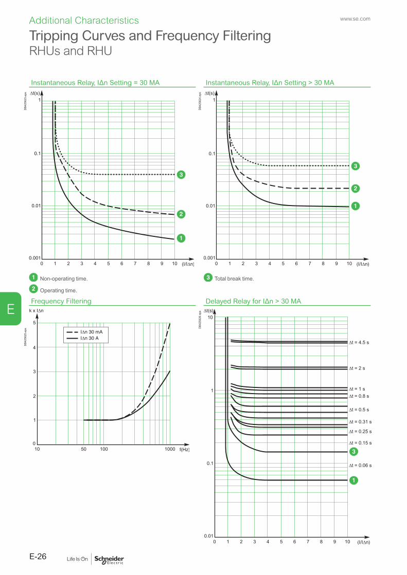
E
Instantaneous Relay, IΔn Setting = 30 MA Instantaneous Relay, IΔn Setting > 30 MA
DB4
2562
3.ep
s
DB4
2562
4.ep
s
Non-operating time.
Operating time.
Total break time.
Frequency Filtering Delayed Relay for IΔn > 30 MA
DB4
2562
5.ep
s DB4
2562
6.ep
s
Tripping Curves and Frequency FilteringRHUs and RHU
E-26
Additional Characteristics www.se.com

E
Tripping Time without Circuit Breaker
Tripping time IEC 60947-2 (-20 ms) Tripping time for RHB without circuit breaker
DB4
3868
5.ai
Tripping Time with UVR and Circuit Breaker
Tripping time IEC 60947-2 (-20 ms) Tripping time for RHB with circuit breaker
DB4
3868
6.ai
Tripping Curves and Frequency FilteringRHB
E-27
Additional Characteristicswww.se.com

E
Frequency Curve MRCD
0
1
2
3
4
5
6
7
8
9
10 100 1000 100000,01 0,1 0,1
Response factor Tolerance limit
Hz
DB4
3868
7.ai
Tripping Curves and Frequency FilteringRHB
E-28
Additional Characteristics www.se.com

Catalog Numbers
Residual-Current Protection Relays ................................. F-2
Residual-Current Protection Relays or Monitoring Relays .......................................................................................... F-4
Toroids and Rectangular Sensors, Communication Module, Accessories ...................................................................F-5
Other ChaptersOther ChaptersFunctions and Characteristics ...........................................................................A-1Installation Recommendations...........................................................................B-1Dimensions and Connection .............................................................................C-1Wiring Diagrams ................................................................................................D-1Additional Characteristics .................................................................................. E-1
Version : 1.1 - 14/10/2021435E5000TDM
F-1
F
www.se.com

F
Residual-Current Protection RelaysRH10 with Local Manual Fault Reset
System to be protected LV y 1000 V RH10M RH10P
Vigirex RH10M
DB1
2608
8.ep
s
1A/inst
Test no trip
Test
Reset
Vigirex RH10P
DB1
2608
9.ep
s
DIN-rail mount. Front-panel mount.Sensitivity 0.03 A - instantaneous
Power supply 12 to 24 V AC -12 to 48 V DC 50/60 Hz 56100110 to 130 V AC 50/60 Hz 56120220 to 240 V AC 50/60 Hz 56130 56230380 to 415 V AC 50/60 Hz 56140
Sensitivity 0.1 A - instantaneous Power supply 110 to 130 V AC 50/60 Hz 56122
380 to 415 V AC 50/60 Hz 56142Sensitivity 0.25 A - instantaneous
Power supply 220 to 240 V AC 50/60 Hz 56234Sensitivity 0.3 A - instantaneous
Power supply 12 to 24 V AC - 12 to 48 V DC 50/60 Hz 56105 56205110 to 130 V AC 50/60 Hz 56125 56225220 to 240 V AC 50/60 Hz 56135 56235380 to 415 V AC 50/60 Hz 56145
Sensitivity 0.5 A - instantaneous 110 to 130 V AC 50/60 Hz 56226
Power supply 220 to 240 V AC 50/60 Hz 56136Sensitivity 1 A - instantaneous
Power supply 220 to 240 V AC 50/60 Hz 56137380 to 415 V AC 50/60 Hz 56147
RH21 with Local Manual Fault ResetSystem to be protected LV y 1000 V RH21M RH21P
Vigirex RH21M
DB1
2609
0.ep
s
Vigirex RH21P
DB1
2609
1.ep
s
DIN-rail mount. Front-panel mount.
Sensitivity 0.03 A - instantaneous Sensitivity 0.3 A - instantaneous or with 0.06 s time delay
Power supply 12 to 24 V AC - 12 to 48 V DC 50/60 Hz 56160220 to 240 V AC 50/60 Hz 56163 56263380 to 415 V AC 50/60 Hz 56164 56264
RHUs with Local Manual Fault ResetSystem to be protected LV y 1000 V RHUs
OK
Vigirex
RMH
DB4
1908
6.ep
s
Alarm: sensitivity 0.015 A to 30 A - instantaneous or with 0 to 4.5 s time delay Fault: sensitivity 0.03 A to 30 A - instantaneous or with 0 to 4.5 s time delay
Single-phase power supply 110 to 130 V AC 50/60 Hz LV481000220 to 240 V AC 50/60 Hz LV481001
Residual-Current Protection Relays
F-2
Catalog Numbers www.se.com

F
RHU with Local Manual Fault Reset (Communicating)System to be protected LV y 1000 V RHU
OK
Vigirex
RMH
DB4
1908
6.ep
s
Alarm: sensitivity 0.015 A to 30 A - instantaneous or with 0 to 4.5 s time delay Fault: sensitivity 0.03 A to 30 A - instantaneous or with 0 to 4.5 s time delay
Single-phase power supply 110 to 130 V AC 50/60 Hz LV481002220 to 240 V AC 50/60 Hz LV481003
RH68 with Local Manual Fault ResetSystem to be protected LV y 1000 V RH68M
RH68M Vigirex DB4
1573
4.ep
s
DIN-rail mount.Sensitivity 30 mA to 3A - instantaneous or with 0 to 1 s time delay
Power supply 220 to 240 V AC 50/60 Hz 56168
RH86 with Local Manual Fault ResetSystem to be protected LV y 1000 V RH86M
RH86M Vigirex DB4
1573
3.ep
s
DIN-rail mount.Sensitivity 30 mA to 10A - instantaneous or with 0 to 5 s time delay
Power supply 220 to 240 V AC 50/60 Hz 56500
RH99 with Local Manual Fault ResetSystem to be protected LV y 1000 V RH99M RH99P
Vigirex RH99M
DB1
2609
2.ep
s
Vigirex RH99P
DB1
2609
3.ep
s
DIN-rail mount. Front-panel mount.Sensitivity 0.03 A to 30 A - instantaneous or with 0 to 4.5 s time delay
Power supply 12 to 24 V AC - 12 to 48 V DC 50/60 Hz 56170 5627048 V AC 50/60 Hz 56171110 to 130 V AC 50/60 Hz 56172 56272220 to 240 V AC 50/60 Hz 56173 56273380 to 415 V AC 50/60 Hz 56174 56274440 to 525 V AC 50/60 Hz 56175
Residual-Current Protection Relays
F-3
Catalog Numberswww.se.com
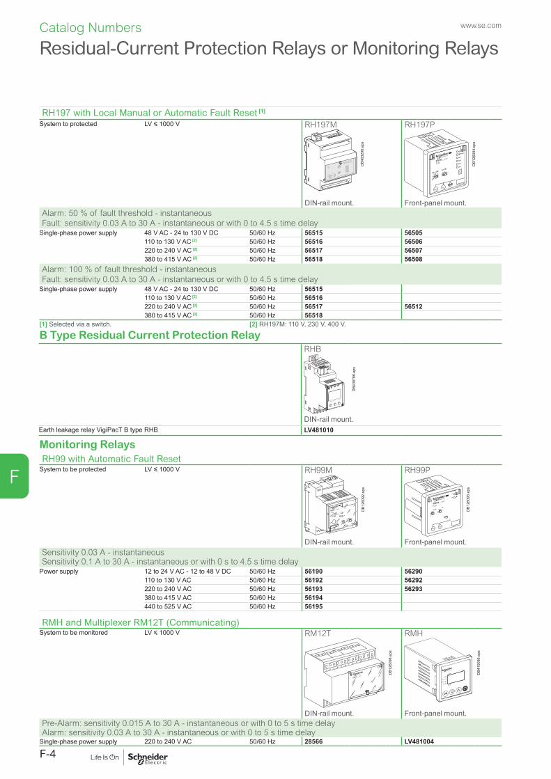
F
Monitoring RelaysRH99 with Automatic Fault Reset
System to be protected LV y 1000 V RH99M RH99P
Vigirex RH99M
DB1
2609
2.ep
s
Vigirex RH99P
DB1
2609
3.ep
s
DIN-rail mount. Front-panel mount.Sensitivity 0.03 A - instantaneous Sensitivity 0.1 A to 30 A - instantaneous or with 0 s to 4.5 s time delay
Power supply 12 to 24 V AC - 12 to 48 V DC 50/60 Hz 56190 56290110 to 130 V AC 50/60 Hz 56192 56292220 to 240 V AC 50/60 Hz 56193 56293380 to 415 V AC 50/60 Hz 56194440 to 525 V AC 50/60 Hz 56195
RMH and Multiplexer RM12T (Communicating)System to be monitored LV y 1000 V RM12T RMH
Vigirex RM12T
DB1
2609
6.ep
s
OK
Vigirex
RMH
DB4
1908
6.ep
s
DIN-rail mount. Front-panel mount.Pre-Alarm: sensitivity 0.015 A to 30 A - instantaneous or with 0 to 5 s time delay Alarm: sensitivity 0.03 A to 30 A - instantaneous or with 0 to 5 s time delay
Single-phase power supply 220 to 240 V AC 50/60 Hz 28566 LV481004
Residual-Current Protection Relays or Monitoring Relays
RH197 with Local Manual or Automatic Fault Reset [1]
System to protected LV y 1000 V RH197M RH197P
DB4
0320
6.ep
s
.03.05.075
.1.1 .15.2
.3
x1
0.15
.25.5 1
2.5
5
20%
30%
40%
50%
on
Fault
ResetTest
IEC 60947-2 / M
Vigirex RH197P
DB1
2609
4.ep
s
DIN-rail mount. Front-panel mount.Alarm: 50 % of fault threshold - instantaneous Fault: sensitivity 0.03 A to 30 A - instantaneous or with 0 to 4.5 s time delay
Single-phase power supply 48 V AC - 24 to 130 V DC 50/60 Hz 56515 56505110 to 130 V AC [2] 50/60 Hz 56516 56506220 to 240 V AC [2] 50/60 Hz 56517 56507380 to 415 V AC [2] 50/60 Hz 56518 56508
Alarm: 100 % of fault threshold - instantaneous Fault: sensitivity 0.03 A to 30 A - instantaneous or with 0 to 4.5 s time delay
Single-phase power supply 48 V AC - 24 to 130 V DC 50/60 Hz 56515110 to 130 V AC [2] 50/60 Hz 56516220 to 240 V AC [2] 50/60 Hz 56517 56512380 to 415 V AC [2] 50/60 Hz 56518
[1] Selected via a switch. [2] RH197M: 110 V, 230 V, 400 V.
B Type Residual Current Protection RelayRHB
DB4
3876
6.ep
s
DIN-rail mount.Earth leakage relay VigiPacT B type RHB LV481010
F-4
Catalog Numbers www.se.com

F
SensorsClosed toroids, A type
DB4
3247
2.ep
s
Type Ie (A) rated operational current
Inside diameter (mm)
TA30 65 30 50437PA50 85 50 50438IA80 160 80 50439MA120 250 120 50440SA200 400 200 50441GA300 630 300 50442
Accessory for closed toroidsMagnetic ring For TA30 toroid 56055
DB1
0703
2.ep
s
For PA50 toroid 56056For IA80 toroid 56057For MA120 toroid 56058
Closed toroids, B Type
≤0.1
0.1 ≤ 0.5
>0.5
I∆n (A)
ON / ALARMT
-+ GND
I TK1
PP-YYYY-Www-D
Serial Number
DB4
3849
7.ep
s
Closed toroid VigiPacT B typeTB35 LV481011type TB60 LV481012type TB120 LV481013type TB210 LV481014type TB35P LV481015type TB60P LV481016
Split toroids, OA-type
DB4
1908
7.ep
s
Type Ie (A) rated operational current
Inside diameter (mm)
TOA80 160 80 50420TOA120 250 120 50421
Rectangular sensors
DB1
2610
0.ep
s
Inside dimensions (mm)
Ie (A)
L1 1600 280 x 115 56053L2 3200 470 x 160 56054
Wiring Kit for Toroids, B Type
DB4
3849
8.ep
s
Wiring kit 1meter B type LV481017Wiring kit 2.5meters B type LV481018
Communication Module
DB4
2149
8.ep
s Cable for Modbus serial link 1 x RJ45 and free wires at other end - Cable 3 m
VW3A8306D30
LV43
4211
.ai
Connector Modbus adaptor LV434211
Note: sensor-relay link: twisted cable not supplied (see “Installation and connection” chapter).
Toroids and Rectangular Sensors, Communication Module, Accessories
F-5
Catalog Numberswww.se.com


0
Schneider Electric Industries SAS
35, rue Joseph MonierCS 3032392506 Rueil Malmaison Cedex France
RCS Nanterre 954 503 439Capital social 928 298 512 €www.schneider-electric.com
10-2021
© 2021 - Schneider Electric. All Rights Reserved.All trademarks are owned by Schneider Electric Industries SAS or its affiliated companies. LVPED220034EN