Melton Lab Centrifuge Series Owners Manual - LK Industries
20
Lab Centrifuge Model #’s A-4-115-C, A-4-220-C, B-4-115-C, B-4-220-C, C-4-115-C, C-4-220-C, D-4-115-C, D-4-220-C Melton Series Owners Manual Serial Numbers 85500 & Above
-
Upload
khangminh22 -
Category
Documents
-
view
6 -
download
0
Transcript of Melton Lab Centrifuge Series Owners Manual - LK Industries

Lab CentrifugeModel #’s A-4-115-C, A-4-220-C, B-4-115-C, B-4-220-C,
C-4-115-C, C-4-220-C, D-4-115-C, D-4-220-C
Melton SeriesOwners Manual
Serial Numbers 85500 & Above

All Rights Reserved
© 2014 L-K Industries, Inc.
NOTICEWire this centrifuge according to the electrical
codes and standards conforming to Class 1, Group D, Division 2 Areas
PRODUCT WARRANTYL-K Industries, Inc. warrants products manufactured by L-K Industries to be free of defective material and workmanship for one year from the date of shipment by L-K Industries. Th e liability of L-K Industries for defective equipment during the warranty period shall be limited to the repair of such equipment or replacement thereof without charge for parts or labor provided by L-K Industries. L-K Industries shall be so liable only if L-K Industries is contacted in regard to such defect immediately aft er its discovery.Buyer should return the defective product under warranty to L-K industries only aft er receipt of L-K Industries’ specifi c permission to do so. Th is warranty does not extend to any L-K Industries product which has been subject to misuse, neglect, accident, modifi cation or improper installation, or any product which has been repaired or altered by persons not expressly approved by L-K Industries. L-K Industries will not be liable for damages, loss or expense directly or indirectly arising from the use of the products or for any liability from their use either separately or in combination with other equipment or material or for any other cause.

L-K INDUSTRIES, INC. | III
Table of Contents 1 Getting Started 1
2 Installation 1
3 Maintenance 2
Trunion Arm & Cup Balance . . . . . . . . . . . 2
Adjusting Heat . . . . . . . . . . . . . . . . . 2
Replacement Parts & Repair Services . . . . . . . 3
Housekeeping . . . . . . . . . . . . . . . . . 3
Be Careful! . . . . . . . . . . . . . . . . . . . 4
4 Operation 4
5 Part No’s, Assembly Drawings & Wiring Diagram 6-13
14 Index 14


L-K INDUSTRIES, INC. | 1
2 Installation
For best results, the centrifuge should be housed in a controlled environment. Be sure to use the Shock Mounts supplied (Item 45) for vibration control. Because of varying voltage from source to
source, a voltage regulator may be worth consideration.
Assemble Shock Mounts (Item 45) to the centrifuge base using the 1/4-20 X 1 1/4” bolts sup-
1 Getting Started
For best results, the centrifuge should be housed in a controlled environment. Be sure to use the Shock Mounts supplied (Item 45) for vibration control. Because of varying voltage from source to source, a voltage regulator may be worth consideration.
Assemble Shock Mounts (Item 45) to the centrifuge base using the 1/4-20 X 1 1/4” bolts sup-plied. Mount the centrifuge on a sturdy, level stand or counter top using #10 screws (4 per Shock Mount - total of 16, not supplied.
Wire the centrifuge according to the electrical codes and standards
conforming to Class I , Group D, Division 2 Areas. See the wir-ing Diagram for your particular model on page 6 & 7 of this manual.
Install the Tachometer Driver (Item 40) onto the Tachometer Shaft. Note:Use the Tachometer Driver only while checking rpm’s. Remove the Driver for normal operation and store in a conve-nient place.
Drop the cushions (Item 44) into the shields (Item 43). Be sure the orientation of the cushion is correct.

2 | Melton Centrifuge Owners Manual
Adjusting HeatYour Melton Centrifuge comes factory pre-set at 150 degrees F. However, because voltage can vary from source to source, and normal wear from usage, adjustment may become necessary from time to time. Each cup is individually controlled and heated. TURN POWER OFF! Disconnect power to the centrifuge.
To adjust the heat setting, fi rst remove the wing nuts on the outside cover plate located just above the switches. Completely remove the cover plate. Th is will
plied. Mount the centrifuge on a sturdy, level stand or counter top using #10 screws (4 per Shock Mount - total of 16, not supplied.
Wire the centrifuge according to the electrical codes and standards conforming to Class I , Group D, Division 2 Areas. See the wir-ing Diagram for your particular model on page 6 & 7 of this manual.
Install the Tachometer Driver (Item 40) onto the Tachometer Shaft. Note:Use the Tachometer Driver only while checking rpm’s. Remove the Driver for normal operation and store in a conve-nient place.
Drop the cushions (Item 44) into the shields (Item 43). Be sure the orientation of the cushion is correct.
3 Maintenance
Trunnion Arm &
Cup BalanceYour Melton Centrifuge has been carefully balanced prior to shipment. Balancing in the fi eld is seldom required. When changing out heating elements, thermostats and other parts in the trun-nion cup, note the mark on the outer cup housing and replace the housing on the same trunnion cup from which it was removed. Th is will maintain balance. (Use a drop of oil on the threads when replacing.)
L-K INDUSTRIES, INC. | 3
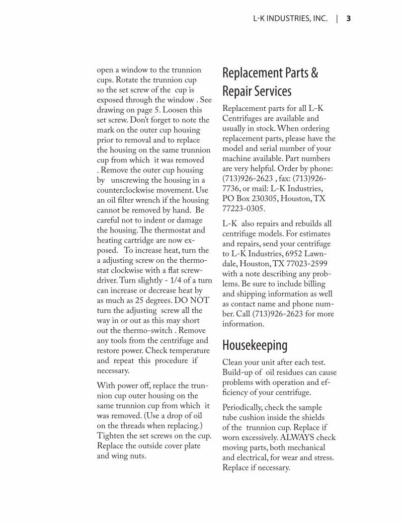
open a window to the trunnion cups. Rotate the trunnion cup so the set screw of the cup is exposed through the window . See drawing on page 5. Loosen this set screw. Don’t forget to note the mark on the outer cup housing prior to removal and to replace the housing on the same trunnion cup from which it was removed . Remove the outer cup housing by unscrewing the housing in a counterclockwise movement. Use an oil fi lter wrench if the housing cannot be removed by hand. Be careful not to indent or damage the housing. Th e thermostat and heating cartridge are now ex-posed. To increase heat, turn the a adjusting screw on the thermo-stat clockwise with a fl at screw-driver. Turn slightly - 1/4 of a turn can increase or decrease heat by as much as 25 degrees. DO NOT turn the adjusting screw all the way in or out as this may short out the thermo-switch . Remove any tools from the centrifuge and restore power. Check temperature and repeat this procedure if necessary.
With power off , replace the trun-nion cup outer housing on the same trunnion cup from which it was removed. (Use a drop of oil on the threads when replacing.) Tighten the set screws on the cup. Replace the outside cover plate and wing nuts.
Replacement Parts &
Repair ServicesReplacement parts for all L-K Centrifuges are available and usually in stock. When ordering replacement parts, please have the model and serial number of your machine available. Part numbers are very helpful. Order by phone: (713)926-2623 , fax: (713)926-7736, or mail: L-K Industries, PO Box 230305, Houston, TX 77223-0305.
L-K also repairs and rebuilds all centrifuge models. For estimates and repairs, send your centrifuge to L-K Industries, 6952 Lawn-dale, Houston, TX 77023-2599 with a note describing any prob-lems. Be sure to include billing and shipping information as well as contact name and phone num-ber. Call (713)926-2623 for more information.
HousekeepingClean your unit after each test. Build-up of oil residues can cause problems with operation and ef-fi ciency of your centrifuge.
Periodically, check the sample tube cushion inside the shields of the trunnion cup. Replace if worn excessively. ALWAYS check moving parts, both mechanical and electrical, for wear and stress. Replace if necessary.

4 | Melton Centrifuge Owners Manual
Th is Unit was designed and fabri-cated to work in compliance with API & ASTM standards. For op-
4 Operation
Be Careful!Your L-K Centrifuge was designed to optimize operator safety. Realizing the limits of any powered mechanical device and carefully following safety guide-lines will help assure accident-free use. Observe and follow carefully all instructions and guidelines in this manual as well as OSHA safety standards.
• Be sure there are no for-eign objects in the centrifuge bowl.
• Keep bowl lid closed while samples are spinning.
• NEVER try to slow the trun-nion arm down with your hands or place your hands or any object inside the bowl while the trunnion arm is spinning. Allow the trunnion arm to come to a complete stop before removing your sample. Use Brake to slow
trunnion arm.
• Turn all switches off when not in use.
• NEVER leave your centri-fuge unattended while the samples are spinning.
• NEVER leave the centrifuge unattended while unit is on.
• Disconnect power supply before removing or replac-ing electrical or mechanical parts.
• DO NOT leave oily rags or any type of combus-tible material in or around your centrifuge.
• DO NOT allow unauthor-ized visitors access to your centrifuge.
• STAY ALERT. Watch what you are doing. Use Common Sense. Do not operate this unit when you are tired or while under the infl uence of medication , alcohol, or drugs.
timum results, we recommend you use L-K Sample Tubes. All L-K Sample tubes are fabricated in

L-K INDUSTRIES, INC. | 5
specifi ed time period for spinning, push the motor and heat switch to the off position. Allow time for the motor to slow down before opening the lid. Use the brake to slow the trunnion arm. See draw-ing on page 5. DO NOT try to slow the trunnion arm down with your hands or place your hands or any object inside the bowl while the trunnion arm is spinning. Al-low the trunnion arm to come to a complete stop before removing your sample.
Open the lid. Remove your sam-ples and close the lid. Keep the lid to the bowl closed at all times. Th is will minimize heat loss and provide greater operator safety.
When the centrifuge is not in use, be sure all knobs and switches are turned off .
compliance with API & ASTM standards. Verifi ed and certifi ed tubes are also available.
Open the lid and place the fi lled tubes into the shields. (For faster performance, use a pre-heater to bring samples up to temperatu re prior to spinning.) In the bottom of the shield there is a cushion for the tube to rest on. Do not remove this cushion and be sure there is no oil residue build-up. Always check to be sure there are no foreign objects inside the bowl. Check temperature until the heat comes up to operating level. Close and latch the lid. Pull the motor switch to its on position. Fol-low ASTM and API guidelines. Rpm’s can be checked by install-ing the tachometer driver prior to spinning. Keep bowl lid closed while motor is running . After the
The following pages show wiring diagrams and breakdowns
for repair and assembly, including component part numbers.
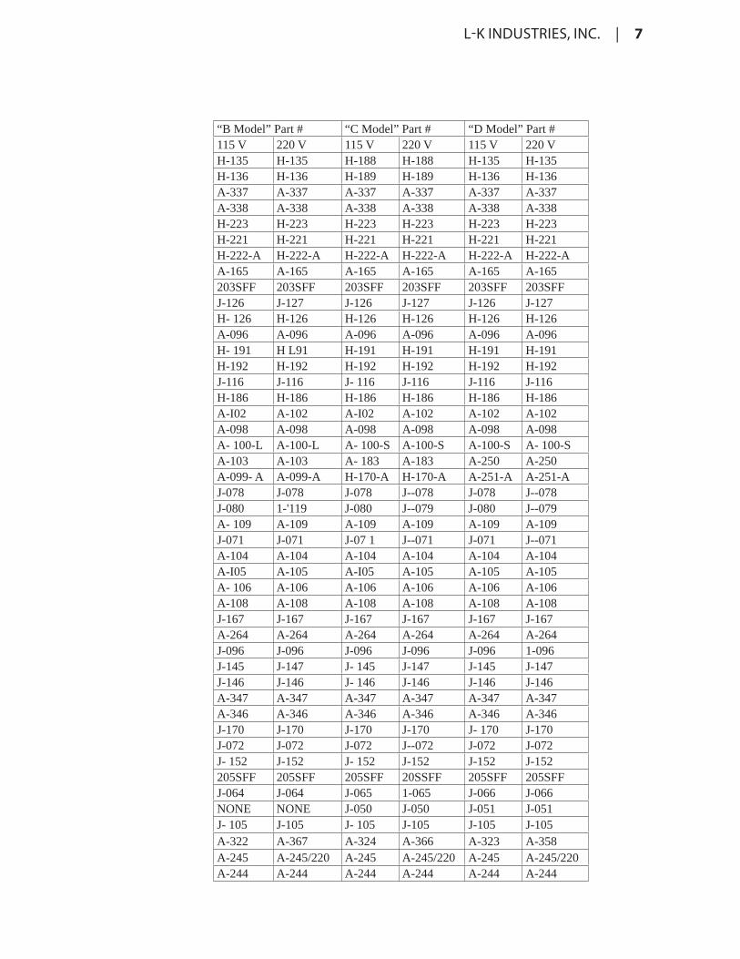
When ordering replacement parts, please have the model
and serial number of your machine available.

6 | Melton Centrifuge Owners Manual
ITEM QTY DESCRIPTION "A Model" Part #115 V 220 V
1 1 Base H-135 H-1352 1 Bowl H-136 H-1363 1 Cover H-137 H-1374 1 Cover Ring H-138 H-1385 1 Motor Housing H-223 H-2236 1 Bottom Bearing Plate H-221 H-2217 1 Motor Shaft with Rotor H-222-A H-222-A8 1 Stator A-165 A-16510 1 Bearing 203SFF 203SF'FI I 1 Macro Start Switch J-126 J-12712 1 Brush Cover H-126 H-12613 1 Bowl Washer A-096 A-09614 1 Switch Box H-191 H-19115 1 Switch Box Cover H-192 H-19216 1 Resistor (p-36) J-116 J-11617 1 Trunnion Arm H-186 H-18618 1 Trunnion Cap A-102 A-10219 8 Trunnion Plug A-098 A-09820 8 Trunnion Connector Ass'y A-100-L A-100-L22 4 Trunnion Shield A-I03 A-103 23 4 Trunnion Cup with Ring A- 152-A A-152-A24 4 Thermostat J-078 J-07825 4 Heating Element J-080 J-07926 1 Collector Ring A-109 A-10927 1 Tachometer J-071 J-07128 1 Tachometer Housing A-104 A-10429 1 Brake Handle A-105 A-10530 1 Brake Housing A-106 A-10631 1 Latch Assembly A-I08 A-10832 1 Hinge J-167 J-16733 1 Brush Holder A-264 A-26434 1 Capacitor J-096 J-09635 1 Heat Switch J-145 J-14736 1 Motor Switch J-146 J-14637 1 Heat Switch Knob A-347 A-34738 1 Motor Switch Knob w/Link A-346 A-34639 1 Brake Pad J-170 J-17040 1 Tachometer Driver J-072 J-07241 2 Brushes J-152 J-15242 1 Bearing 205SFF 205SFF43 4 Inner Shield J-063 J-06344 4 Cushion J-053 J-05345 4 Shock Mount J-105 J-105MISC 1 Trunnion Arm & Cup Ass’y. A-326MISC 1 Complete Motor Assembly A-245 A-245/220MISC 1 Lid Assembly A-244 A-244
L-K INDUSTRIES, INC. | 7
“B Model” Part # “C Model” Part # “D Model” Part #115 V 220 V 115 V 220 V 115 V 220 VH-135 H-135 H-188 H-188 H-135 H-135H-136 H-136 H-189 H-189 H-136 H-136A-337 A-337 A-337 A-337 A-337 A-337A-338 A-338 A-338 A-338 A-338 A-338H-223 H-223 H-223 H-223 H-223 H-223H-221 H-221 H-221 H-221 H-221 H-221H-222-A H-222-A H-222-A H-222-A H-222-A H-222-AA-165 A-165 A-165 A-165 A-165 A-165203SFF 203SFF 203SFF 203SFF 203SFF 203SFFJ-126 J-127 J-126 J-127 J-126 J-127H- 126 H-126 H-126 H-126 H-126 H-126A-096 A-096 A-096 A-096 A-096 A-096H- 191 H L91 H-191 H-191 H-191 H-191H-192 H-192 H-192 H-192 H-192 H-192J-116 J-116 J- 116 J-116 J-116 J-116H-186 H-186 H-186 H-186 H-186 H-186A-I02 A-102 A-I02 A-102 A-102 A-102A-098 A-098 A-098 A-098 A-098 A-098A- 100-L A-100-L A- 100-S A-100-S A-100-S A- 100-SA-103 A-103 A- 183 A-183 A-250 A-250A-099- A A-099-A H-170-A H-170-A A-251-A A-251-AJ-078 J-078 J-078 J--078 J-078 J--078J-080 1-'119 J-080 J--079 J-080 J--079A- 109 A-109 A-109 A-109 A-109 A-109J-071 J-071 J-07 1 J--071 J-071 J--071A-104 A-104 A-104 A-104 A-104 A-104A-I05 A-105 A-I05 A-105 A-105 A-105A- 106 A-106 A-106 A-106 A-106 A-106A-108 A-108 A-108 A-108 A-108 A-108J-167 J-167 J-167 J-167 J-167 J-167A-264 A-264 A-264 A-264 A-264 A-264J-096 J-096 J-096 J-096 J-096 1-096J-145 J-147 J- 145 J-147 J-145 J-147J-146 J-146 J- 146 J-146 J-146 J-146A-347 A-347 A-347 A-347 A-347 A-347A-346 A-346 A-346 A-346 A-346 A-346J-170 J-170 J-170 J-170 J- 170 J-170J-072 J-072 J-072 J--072 J-072 J-072J- 152 J-152 J- 152 J-152 J-152 J-152205SFF 205SFF 205SFF 20SSFF 205SFF 205SFFJ-064 J-064 J-065 1-065 J-066 J-066NONE NONE J-050 J-050 J-051 J-051J- 105 J-105 J- 105 J-105 J-105 J-105A-322 A-367 A-324 A-366 A-323 A-358A-245 A-245/220 A-245 A-245/220 A-245 A-245/220A-244 A-244 A-244 A-244 A-244 A-244

8 | Melton Centrifuge Owners Manual

L-K INDUSTRIES, INC. | 9

10 | Melton Centrifuge Owners Manual
This Diagramed parts list is for
centrifuges with serial numbers
85500 & above. When ordering
parts, please have the model
and serial number of your
machine available.

L-K INDUSTRIES, INC. | 11

12 | Melton Centrifuge Owners Manual

L-K INDUSTRIES, INC. | 13

14 | Index
IndexA
API & ASTM standards 6
C
Circuit Breaker 7Cleaning 5Continuity 7Crimp tool 4Current 7
H
Heat loss 6Heat Loss 6High Temperatures 6
I
Installation 4
O
Ohm Meter 7
P
Parts 5Power Source 7
R
Replacement Parts & Repair Service 5
Returns 8
S
Solenoid 4
V
Vibration 5
W
Warranty Period 8

L-K INDUSTRIES, INC. | 15

L-K Industries, Inc. 6952 Lawndale ¤ Houston TX 77023 ¤ 713 926•2623, fax 713 926•7736 ¤ www.lk-ind.com