


circuit cellar
100
SIGNAL PROCESSING Build a Variable-Frequency Signal Generator A Do-It-Yourself Embedded Server Application Hardware Emulation & Prototype Development Shielding Strategies to Reduce Noise Coupling A Radio Interface with GPS Tracking Noncontact IR Temp Sensing CIRCUIT CELLAR www.circuitcellar.com THE MAGAZINE FOR COMPUTER APPLICATIONS $5.95 U.S. ($6.95 Canada) #219 October 2008 An Intro to USB MCUs (p. 24) • Menu Code for a Remote Control (p. 42) • A Serial Terminal Quick Fix (p. 58)
-
Upload
khangminh22 -
Category
Documents
-
view
1 -
download
0
Transcript of circuit cellar
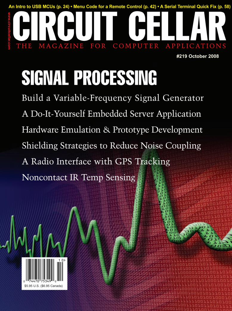
SIGNAL PROCESSINGBuild a Variable-Frequency Signal Generator
A Do-It-Yourself Embedded Server Application
Hardware Emulation & Prototype Development
Shielding Strategies to Reduce Noise Coupling
A Radio Interface with GPS Tracking
Noncontact IR Temp Sensing
CIRCUIT CELLAR
ww
w.circuitcellar.com T H E M A G A Z I N E F O R C O M P U T E R A P P L I C AT I O N S
$5.95 U.S. ($6.95 Canada)
#219 October 2008
An Intro to USB MCUs (p. 24) • Menu Code for a Remote Control (p. 42) • A Serial Terminal Quick Fix (p. 58)
Cover.qxp 9/2/2008 3:33 PM Page 1

Information and Sales | [email protected] | www.netburner.com
Telephone | 1-800-695-6828
NetBurner Customer Feedback: Why are you using NetBurner? The excellent out-of-the-box experienceI would like to comment on the quality of a product that I purchased - the MOD5270. I’ve purchased products in the past from other companies that claim“plug and play”functionality. Usually this means plug it in and try to figure out why it doesn’t work.With the MOD5270 I literally plugged in the power, connected it to my router, and ran the factory demo.
I am also impressed with the number of example applications that are included and the fact that all the development tools are included. It was nice to be able to create a new project, import one of the examples, and run it within 5 minutes.
Keith Gilman, Sr. Design Engineer
The complete hardware and software solutionWe did a previous project using different companies for the RTOS, network stack, and compiler.Yeah, three vendors and all the associated finger pointing. We had to buy the flash file system as an extra/add-on. We put an 8M flash device on our proces-sor bus, and a guy had to write a driver for the device (data register, command register, poll the ready bit, blah, blah), it was a 3+ month job. I thought I was in for the same thing. Thanks to you, we will drop the soldered-on Flash and put on the SD connec-tor which will be ready to roll with your file system that runs ‘right out of the box’. I was sweating about all the Flash work, and now its gone.
John Ramsy, Project Engineer
The active forum filled with NB GurusNetBurner offers a highly versatile and affordable solution set for embedded design, remote control, and product develop-ment. From the very active user forum (with Netburner gurus in attendance), to the great IDE and tool chain. NetBurner is the first and only solution for TCP/IP-Internet-Web product automation in my book.
Chris Ruff, Software Engineer
The quality of the technical supportI’ve been really impressed with the quality of the tech support. The guys answering the questions are right on and super helpful (probably has to do with your policy of having the engineers handle the tickets).
Nicolae P. Costescu, Project Engineer
The full-featured tool set, examples, and documentationThe device and the NetBurner tool-set far exceeded our expectations. I spent a week familiarizing myself with the NetBurn-er tools, and then I wrote a first-cut of the original application that I had envisioned for the SB72EX. As it turned out, two of the example applications formed the core of the networking capabilities of my application.The bulk of my time was spent implementing a simple command interface to cause the device to interrupt its default IP-to-serial modes to receive and store a stream of data and then FTP that data to a remote server.
The NNDK interface to the IP/socket facilities of the SB72EX proved to be the simplest part of the application - the inter-face is straightforward and the documentation is excellent (the large collection of application examples didn’t hurt). Mid-way through my efforts I had a couple of questions that I elected to send to the NetBurner support group - the response was almost immediate, the person(s) responding were obviously knowledgeable and experienced - how refreshing!
The SB72EX device and (perhaps more importantly) the NetBurner tool-set have proven to exceed our immediate needs and have started the gears turning as to how we might use them to address other requirements.
Fred Craft, Software Engineer
C2.qxp 8/6/2008 9:20 AM Page 1

3x faster
and backward
compatible with TS-72xx
TS-7200 shown with optional A/D converter,Compact Flash and RS-485
Embedded Single Board Computers
Most products stocked and available
for next day shippingEngineers on Tech Support
Design your solution with one of our engineers (480) 837-5200
Custom configurations and designs w/
excellent pricing and turn-around time
Over 20 years in business
Never discontinued a product
Low Price, Low Power, High Reliability
using Linux development tools
options include:onboard temperature sensor, A/D Converter 8 channel 12 bit, Extended Temperature,
Battery Backed Real Time Clock, USB Flash, USB WiFi
8 boards, over
2000 configurations
2 USB ports
10/100 Ethernet - up to 2
DIO lines - up to 55
Fanless, no heat sink
Flash - up to 128MB onboard
SDRAM - up to 128MB
Linux, Real Time extension, Debian
COM ports- up to 10
200 MHz ARM9Power as low as 1/4 Watt
Open Source Vision
Programmable FPGAs
High-End Performance
with Embedded Ruggedness
128MB DDR RAM
Gigabit ethernet
2 host USB 2.0 480 Mbps
12K LUT programmable FPGA
512MB high-speed
(17MB/sec) onboard Flash
Sleep mode uses 200 microamps
2 SD sockets
Linux 2.6 and Debian by default
10 serial ports
qty 100229$Unbrickable
design
5 ADC (10-bit) 2 SATA ports
110 GPIO
Boots Linux in < 2 seconds
Internal PCI Bus, PC/104 connectorshown w/ optional SD Cards
TS-7800
500 MHz ARM9
Low power - 4W@5V
qty 1269$
qty 10099$
qty 1129$
as low as
SD card
option
VGA video
LCD ready
72.qxp 8/11/2008 2:02 PM Page 1

SystemsTechnologic
Visit our TS-7800 powered website at
We use our stuff.
www.embeddedARM.com
TS-ADC16
ADC, DAC and Digital I/O
Up to 100Ksps (10us)
Prog. pacing clock
1KB ADC RAM-FIFO
TS-RELAY8
see our website for more boards and option details
Featured Products and PC/104 Peripherals
qty 1169$
16 16-bit ADCs
4 ADC voltage ranges
qty 189$
TS-TPC-7390
64MB SDRAM (128MB opt)
Dedicated framebuffer- 8MB RAM
800x480 customizable video core
Programmable FPGA- 5K LUT
512MB Flash w/ Debian Linux
Runs Eclipse IDE out-of-the-box
Boots Linux 2.6 in about 1 second
Unbrickable, boots from SD or NAND
Runs X Windows GUI applications
7” Color TFT-LCD Touch-Screen
Mountable aluminum frame
Low Power, Industrial Quality Design
Eight Software Controlled Relays
see our website for x86 SBCs, peripherals and option details
4 inputs, 1 output
4 16 bit counters
4 12-bit DACs
Externally triggered
Up to 277 VAC @ 5A
Up to 30 VDC@ 5A
8 SPDT relays
40mA draw per coil
I/O jumpers
Software controlled
qty 1449$
Audio codec with speaker
200MHz ARM9 Touch Panel Computer
73.qxp 8/11/2008 2:12 PM Page 1

4 Issue 219 October 2008 www.circuitcellar.comCIRCUIT CELLAR®
FOUNDER/EDITORIAL DIRECTORSteve Ciarcia
MANAGING EDITORC. J. Abate
WEST COAST EDITORTom Cantrell
CONTRIBUTING EDITORSJeff Bachiochi Ingo Cyliax Robert LacosteGeorge MartinEd Nisley
NEW PRODUCTS EDITORJohn Gorsky
PROJECT EDITORSGary BodleyKen Davidson David Tweed
ASSOCIATE EDITORJesse Smolin
ADVERTISING860.875.2199 • Fax: 860.871.0411 • www.circuitcellar.com/advertise
PUBLISHERSean Donnelly Direct: 860.872.3064, Cell: 860.930.4326, E-mail: [email protected]
ADVERTISING REPRESENTATIVEShannon BarracloughDirect: 860.872.3064, E-mail: [email protected]
ADVERTISING COORDINATORValerie LusterE-mail: [email protected]
CONTACTSSUBSCRIPTIONS
Information: www.circuitcellar.com/subscribe, E-mail: [email protected]: 800.269.6301, www.circuitcellar.com/subscribe, Circuit Cellar Subscriptions, P.O. Box 5650, Hanover, NH 03755-5650Address Changes/Problems: E-mail: [email protected]
GENERAL INFORMATION860.875.2199, Fax: 860.871.0411, E-mail: [email protected] Office: Editor, Circuit Cellar, 4 Park St., Vernon, CT 06066, E-mail: [email protected] Products: New Products, Circuit Cellar, 4 Park St., Vernon, CT 06066, E-mail: [email protected]
AUTHORIZED REPRINTS INFORMATION860.875.2199, E-mail: [email protected]
AUTHORS Authors’ e-mail addresses (when available) are included at the end of each article.
CIRCUIT CELLAR®, THE MAGAZINE FOR COMPUTER APPLICATIONS (ISSN 1528-0608) is published monthly by Circuit CellarIncorporated, 4 Park Street, Vernon, CT 06066. Periodical rates paid at Vernon, CT and additional offices. One-year (12 issues)subscription rate USA and possessions $23.95, Canada/Mexico $34.95, all other countries $49.95.Two-year (24 issues) sub-scription rate USA and possessions $43.95, Canada/Mexico $59.95, all other countries $85. All subscription orders payable inU.S. funds only via Visa, MasterCard, international postal money order, or check drawn on U.S. bank. Direct subscription ordersand subscription-related questions to Circuit Cellar Subscriptions, P.O. Box 5650, Hanover, NH 03755-5650 or call800.269.6301.
Postmaster: Send address changes to Circuit Cellar, Circulation Dept., P.O. Box 5650, Hanover, NH 03755-5650.
Circuit Cellar® makes no warranties and assumes no responsibility or liability of any kind for errors in these programs or schematics or for theconsequences of any such errors. Furthermore, because of possible variation in the quality and condition of materials and workmanship of read-er-assembled projects, Circuit Cellar® disclaims any responsibility for the safe and proper function of reader-assembled projects based upon orfrom plans, descriptions, or information published by Circuit Cellar®.
The information provided by Circuit Cellar® is for educational purposes. Circuit Cellar® makes no claims or warrants that readers have a right tobuild things based upon these ideas under patent or other relevant intellectual property law in their jurisdiction, or that readers have a right toconstruct or operate any of the devices described herein under the relevant patent or other intellectual property law of the reader’s jurisdiction.The reader assumes any risk of infringement liability for constructing or operating such devices.
Entire contents copyright © 2008 by Circuit Cellar, Incorporated. All rights reserved. Circuit Cellar is a registered trademark of Circuit Cellar, Inc.Reproduction of this publication in whole or in part without written consent from Circuit Cellar Inc. is prohibited.
CHIEF FINANCIAL OFFICERJeannette Ciarcia
MEDIA CONSULTANTDan Rodrigues
CUSTOMER SERVICEDebbie Lavoie
CONTROLLERJeff Yanco
ART DIRECTORKC Prescott
GRAPHIC DESIGNERSGrace Chen
Carey Penney
STAFF ENGINEER John Gorsky
Cover photography by Chris Rakoczy—Rakoczy Photographywww.rakoczyphoto.com
PRINTED IN THE UNITED STATES
TASK MANAGER
This month, you will read two articles by designers who have published withus in the past. During the last four years, both Neal Martini (“DIY SignalGeneration,” p. 12) and Peter Montgomery (“Dynamic Animatronic Remote(Part 2),” p. 42) have presented articles about interesting projects. This isn’tanything new. As I recently told a first-time author who was preparing an arti-cle for an upcoming issue, we have dozens of repeat writers—designers whofound presenting their ideas to the Circuit Cellar community to be a rewarding,career-enhancing experience. Many of you long-time readers could probablylist the names of several talented designers who have published more thanone helpful article. But have you ever wondered what makes those designerstick? Sure, you’ve read the short bios at the ends of their articles, but have youever wanted to know a bit more about how they became engineers, how theydeveloped and coded their designs, or what designs they’re planning for thefuture?
If so, consider subscribing to Circuit Cellar News Notes, which is our freemonthly interactive electronic newsletter. In addition to in-depth interviews withworking engineers, the newsletter features a variety of useful content rangingfrom reader polls and product sample announcements to information aboutembedded community events. Go to www.circuitcellar.com/newsletter to signup and read the latest installment.
After reading this issue, you may want to learn more about one of the engi-neers. If so, feel free to e-mail me your questions. If there’s demand for a par-ticular interview, we’ll make it happen. It doesn’t get any more interactive thanthat!
This month, Neal Martini describes how to create a signal source for RFapplications. The design generates frequencies from 0 to 3 GHz with a fre-quency accuracy of less than 200 Hz.
If you’re interested in USB connectivity, turn to Jeff Bachiochi’s spe-cial feature about Microchip Technology’s line of USB PIC microcon-trollers (p. 24). With Microchip’s 8-, 16-, and 32-bit USB MCUs, embeddedhost and On-The-Go (OTG) solutions are at your fingertips.
Starting on page 42, Peter Montgomery presents the final article in hisseries about his animatronic remote. He covers the software and menuingcode associated with the project.
In a detailed article titled “Automated Data Mining,” Matt Pennell and AaronThomas describe how they designed an amazing embedded server applica-tion to help them with their travel plans (p. 50). The WIZnet W5100-based sys-tem uses an online travel search engine to look for flights.
Authors Phil Laird and Jeff Shewan recently built a robust hardware plat-form to run rule sets for old pinball machines (p. 62).The custom design emu-lates the hardware for nearly 500 pinball machines.
As usual, our columnists touch on a wide variety of topics. Ed Nisley cov-ers the topics of combined audio-digital circuitry and GPS technology (p. 34).In his second article of the issue, Jeff Bachiochi explains how he tackled anRS-232-port-related problem with an innovative serial terminal solution(p. 58). Robert Lacoste describes the process of reproducing old cableshielding experiments and then explains the results (p. 70). And finally, begin-ning on page 78, Tom Cantrell introduces you to infrared noncontact temper-ature sensing. Perhaps his article will lead you to implement an infrared non-contact temperature-sensing IC in your next design.
What Makes an Engineer Tick?
Task_Masthead_219.qxp 9/8/2008 11:40 AM Page 4

TM
logic
Encased in anodized aluminum,
Logic delivers 8 channels, a sample
rate of up to 24MHz, and a sample
depth in the hundreds-of-millions.
Beautiful Utility
Logic comes standard with
professional-grade E-Z-Hook XKM
Micro-Hook probes and an
ultra-flexible wire harness.
Only the Best
While just below the surface Logic
provides some serious problem-
solving horsepower, you won’t
have to struggle to get it up and
running.
Intuitive & Powerful
Logic ships with support for Serial, SPI, and I2C protocols. Setup is quick and intuitive with Logic’s graphical analyzer setup dialogs. An SDK is also available to make your own custom protocol analyzer.
Protocol AnalyzersClick and drag, or even flick the
viewport to scroll. Seamlessly
zoom in and out with the scroll
wheel. Comprehensive meta data
is displayed wherever you point,
and timing markers conveniently
snap to waveform edges.
Viewport Bliss
Logic provides several ways to export data and take screenshots. It also lets you save and load complete sessions. These sessions are compressed and can even be emailed to colleagues.
Data Export
Decide if Logic is worthy of your workbench on saleae.com.
5.qxp 8/28/2008 2:07 PM Page 1

6 Issue 219 October 2008 CIRCUIT CELLAR® www.circuitcellar.com
October 2008: Signal Processing
4 TASK MANAGERWhat Makes an Engineer Tick?C. J. Abate
8 NEW PRODUCT NEWSedited by John Gorsky
93 CROSSWORD
FEATURES
DEPARTMENTS94 INDEX OF ADVERTISERS
November Preview
96 PRIORITY INTERRUPT Horses and Hard DrivesSteve Ciarcia
34 ABOVE THE GROUND PLANEHT Audio, GPS for APRS, and What Works Ed Nisley
58 FROM THE BENCHSerial Terminal SolutionJeff Bachiochi
70 THE DARKER SIDECable Shielding ExperimentsRobert Lacoste
78 SILICON UPDATEHot Enough for You?Seeing Red (Infrared, That Is)Tom Cantrell
12 DIY Signal GenerationCreate a Signal Source for a Variety of RF ApplicationsNeal Martini
24 SPECIAL FEATUREGet Started with PIC USB ConnectivityJeff Bachiochi
42 Dynamic Animatronic Remote (Part 2)Software and Menuing CodePeter Montgomery
COLUMNS
Signal Source Solution (p. 12) Software for Remote Control (p. 42)
A Rebuilt Radio Interfacewith GPS Tracking (p. 34)
50 Automated Data MiningBuild an Embedded Server ApplicationMatt Pennell and Aaron ThomasHonorable Mention WIZnet iEthernet Design Contest 2007
62 Universal Machine ControlHow Hardware Emulation Leads to Prototype DevelopmentPhil Laird and Jeff Shewan
Prototype Development (p. 62)
219_TOC.qxp 9/8/2008 11:41 AM Page 6

© 2008 Atmel Corporation. All rights reserved. Atmel®, logo and Everywhere You Are® are registered trademarks of Atmel Corporation or its subsidiaries.Other terms and product names may be trademarks of others.
Everywhere You Are®
Performance and power consumption have always been key elements in the development of AVR® microcontrollers. Today’s
increasing use of battery and signal line powered applications makes power consumption criteria more important than ever.
To meet the tough requirements of modern microcontrollers, Atmel® has combined more than ten years of low power research and
development into picoPower technology.
picoPower enables tinyAVR®, megaAVR® and XMEGA™ microcontrollers to achieve the industry’s lowest power consumption. Why be satisfied with
microamps when you can have nanoamps? With Atmel MCUs today’s embedded designers get systems using a mere 650 nA running a real-time
clock (RTC) and only 100 nA in sleep mode. Combined with several other innovative techniques, picoPower microcontrollers help you reduce your
applications power consumption without compromising system performance!
Visit our website to learn how picoPower can help you hammer down the power consumption of your next designs. PLUS, get a chance to apply
for a free AVR design kit!
Hammer Down Your Power Consumption with picoPower™!
http://www.atmel.com/picopower/
THE Performance Choice of Lowest-Power Microcontrollers
picoPower 2008ad indd 1 8/8/2008 8:35:17 AM
7.qxp 8/11/2008 3:17 PM Page 1

Visit www.circuitcellar.com/npnfor more New Product News.
8 Issue 219 October 2008CIRCUIT CELLAR® www.circuitcellar.com
NEW PRODUCT NEWS Edited by John Gorsky
DUAL-CHANNEL 40-MHz DIGITAL STORAGE OSCILLOSCOPEThe new Model 2532 dual-channel digital storage oscilloscope (DSO)
delivers an unmatched combination of performance and value. Thisversatile bench-top unit is a 40-MHz digital oscilloscope with analogstyle knobs, controls, and a 500-Msps sample rate. The AUTO buttonmakes this oscilloscope easy to use. Advanced triggering, automaticmeasurements, and FFT functions provide you with many tools todebug circuits.
The Model 2532 comes with PC software that can be used to easilycapture, save, and analyze waveforms and measurement results. It isan ideal oscilloscope for use in education, training, maintenance, man-ufacturing, and quality control.
The Model 2532’s features include a color LCD, a 4,000-point recordlength for each channel, and one-touch automatic setup for ease of use.It also offers a USB device port on the back, eleven automatic measure-ments, FFT standard plus four additional math functions, and extensivetriggering capabilities including pulse-width and line-selectable videotrigger.
Measuring 11.4″ wide × 11.8″ deep × 5.9″ high, the Model 2532
weighs 10 lb. and comes complete with anoperating manual, a 10:1 probe set (twopieces), a power cord, a USB interface cable,and a PC software installation disk. The unitcosts $699 and is available for immediatedelivery.
B&K Precision Corp.www.bkprecision.com
I2C DAC FAMILY WITH AN INTERNAL REFERENCE IN A TSOT-23 PACKAGEThe LTC2631 is a family of pin- and software-compatible 12-bit, 10-bit, and 8-bit DACs in a tiny TSOT-23 package,
making it the smallest I2C DAC family with an internal reference on the market today. DACs in such small packages areideal for fine-tuning bias voltages in applications such as optical networking andRFID systems. The LTC2631 makes the integrated 10 ppm/°C reference outputavailable to drive the reference inputs for all other data converters on the board,while maintaining good stability over temperature.
The LTC2631 releases alongside a SPI-equivalent LTC2640 12-/10-/8-bit family,each offering the choice of a 2.5- or 4.096-V full-scale output range. Alternatively,an external reference can be applied if more accuracy or a nonstandard voltagerange is required. The LTC2631/LTC2640 DAC outputs can power up to zero-scale or mid-scale with the internal or external reference, allowing more flexibili-ty for designs that cannot be forced to ground when power is first applied.
The LTC2631 and LTC2640 DACs both offer excellent 12-bit DC performanceof ±1 LSB (max) integral nonlinearity error, enabling operation in open-loop aswell as closed-loop systems.
The controllers begin at $1.03 each in 1,000-piece quantities.
Linear Technology Corp.www.linear.com
PROGRAMMABLE SMART VIBRATION SWITCHThe Series 686B USB Programmable Smart Vibration Switch is designed for 24/7 contin-
uous monitoring and protection of cooling towers, fin fans, pumps, HVAC systems, andother critical machinery.
The 686B offers a smart alternative to unreliable mechanical switch technology. Theelectronic switch has much better accuracy and reliability than traditional mechanicalswitches and is easily installed in place of existing mechanical switches because it requiresonly two wires and can replace legacy switches without the need for additional cable runs.The Series 686B also offers a remote reset capability and USB programmable delays toavoid false trips. This universally powered unit switch is hermetically sealed for use in theharshest of environments and mounts with a single stud like a sensor. It is available for usein hazardous areas.
The Series 686B switches cost under $700 each and are available from stock.
IMI Sensorswww.pcb.com
npn219.qxp 9/8/2008 11:43 AM Page 8

www.circuitcellar.com CIRCUIT CELLAR® Issue 219 October 2008 9
NEW PRODUCT NEWSENERGY HARVESTING MODULE
The Joule-Thief Energy Harvesting Module is a com-pact, fully self-contained vibration energy harvester. Themodule contains an energy harvesting beam based on pro-prietary ruggedized laminated piezo (RLP) technology, aswell as proprietary energy collection and storage circuitry.The module is the highest output vibration ener-gy-harvesting device per unitweight and volume of anycommercially availableenergy harvester.
The module isdesigned to provide you with a stan-dard 3.6-VDC output. Several energystorage options are available includingcapacitors as well as several batterytechnologies. The various energystorage options available allow thestorage capacity to be matched toyour application. The standard modulesstore from 1.4 to 430 mJ depending on thestorage device used.
The Joule-Thief module is capable of harvestingusable energy at vibration amplitudes that are below thethreshold of human perception to power electronics
devices such as wireless sensors. The modules aredesigned to harvest energy from typical AC-powereddevices. Thus, they are available in standard frequenciesof 60 and 120 Hz with custom frequencies available uponrequest.
A wireless sensor demonstration kit is available aswell. That mates the module to a sensor board, which
includes a Texas Instruments MSP430 microcontrollerand a Texas Instruments CC2500 wireless trans-
ceiver. The sensor board includes a temper-ature, pressure, and light sensor, as
well as a switch and potentiome-ter to allow experimentation withvibration-powered wireless sens-ing, switching, and proportionalcontrol. All of the sensors, themicrocontroller, and the transceiv-er are completely powered by themodule. The sensor data is thentransmitted to any PC. Demon-stration kits are available for $699.
AdaptivEnergy www.RLPenergy.com
npn219.qxp 9/8/2008 11:43 AM Page 9
10 Issue 219 October 2008 CIRCUIT CELLAR® www.circuitcellar.com
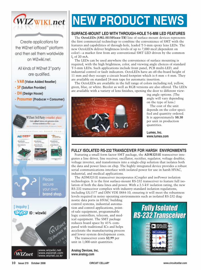
SURFACE-MOUNT LED WITH THROUGH-HOLE T-5-MM LED FEATURESThe OctoLEDs (SML-H1505xxx-TR) line of surface-mount devices represents
the first commercial technology to combine the convenience of SMT with thefeatures and capabilities of through-hole, leaded T-5-mm epoxy lens LEDs. Thenew OctoLEDs deliver brightness levels of up to 7,000 mcd (dependent oncolor)—a market first from any conventional SMT LED driven by the commonIF of 20 mA.
The LEDs can be used anywhere the convenience of surface mounting isrequired, with the high brightness, color, and viewing angle choices of standardT-5-mm LEDs. Such applications include front panel, PCB multi-LED, andindustrial control or fault indicators. OctoLEDs have an off-the-board height of11 mm and they occupy a circuit board footprint which is 6 mm × 6 mm. Theyare available on standard 24-mm tape for automatic insertion.
The OctoLEDs are available in the full range of colors including red, yellow,green, blue, or white. Bicolor as well as RGB versions are also offered. The LEDsare available with a variety of lens finishes, opening the door to different view-
ing angle options. (Theangle will vary dependingon the type of lens.)
The cost of the unitdepends on the color speci-fied and quantity ordered.It is approximately $0.30per unit in productionquantities.
Lumex, Inc.www.lumex.com
FULLY ISOLATED RS-232 TRANSCEIVER FOR HARSH ENVIRONMENTSFeaturing a small form factor SMT package, the ADM3251E transceiver inte-
grates a line driver, line receiver, oscillator, rectifier, regulator, voltage doubler,voltage inverter, and transformers into a single-chip solution that isolates boththe data and power lines on chip. The highly integrated device provides a robustserial communications interface with isolated power for use in harsh HVAC,industrial, and medical applications.
The ADM3251E transceiver incorporates iCoupler and isoPower isolationtechnologies. It is the first surface-mount RS-232 transceiver to feature full iso-lation of both the data lines and power. With a 2.5-kV isolation rating, the newRS-232 transceiver complies with industry-standard isolation regulations,including UL1577 and DIN VDE 0884-10, ensuring it will meet the robustnesslevels required in noisy operating environments such as isolated RS-232 diag-nostic data ports in HVAC buildingcontrol systems, industrial automa-tion and control applications, point-of-sale equipment, programmablelogic controllers, telecom, and med-ical equipment. The SMT packagereduces board space by 45% com-pared with traditional ICs and helpsaccelerate the manufacturing processand lower system development costs.
The transceiver costs $2.99 perunit in 1,000-unit quantities.
Analog Devices, Inc.www.analog.com
NEW PRODUCT NEWS
npn219.qxp 9/8/2008 11:43 AM Page 10

NEW PRODUCT NEWS
www.circuitcellar.com CIRCUIT CELLAR® Issue 219 October 2008 11
POWER-OVER-ETHERNET CONTROLLER TO OPTIMIZE SUB-13-W DESIGNSThe TPS23753 is a 13-W PoE-powered device controller with an on-board
DC/DC converter specifically designed to meet the needs of IEEE 802.3af-compliant applications. The highly integrated device eases system design andsize for PoE applications, including IP phones, IP security cameras, wirelessaccess points, security card readers, and RFID scanners, to name a few. TheTPS23753 is optimized for isolated DC/DC switching topologies, includingflyback topology.
The TPS23753 will operate on a wide range of local power supplies in caseswhere PoE power is not available. The device operates from 12 to 57 V,including operation down to 9.5 V to support droop on any 12-V local powersupply. The DC/DC converter allows for operation in this range with an80% duty cycle and current slope compensation, reducing output rectifierstress for 12-V adapters.
To ease design with local power supplies, the TPS23753 features adapterpriority programming that enables you toselect which power source to use whenboth PoE and local power are available.Native support for this prioritizationeases design and reduces system size byeliminating external components.
The suggested resale price is $1.45 inquantities of 1,000. Evaluation moduleswith the TPS23753 are also available.
Texas Instruments, Inc.www.ti.com
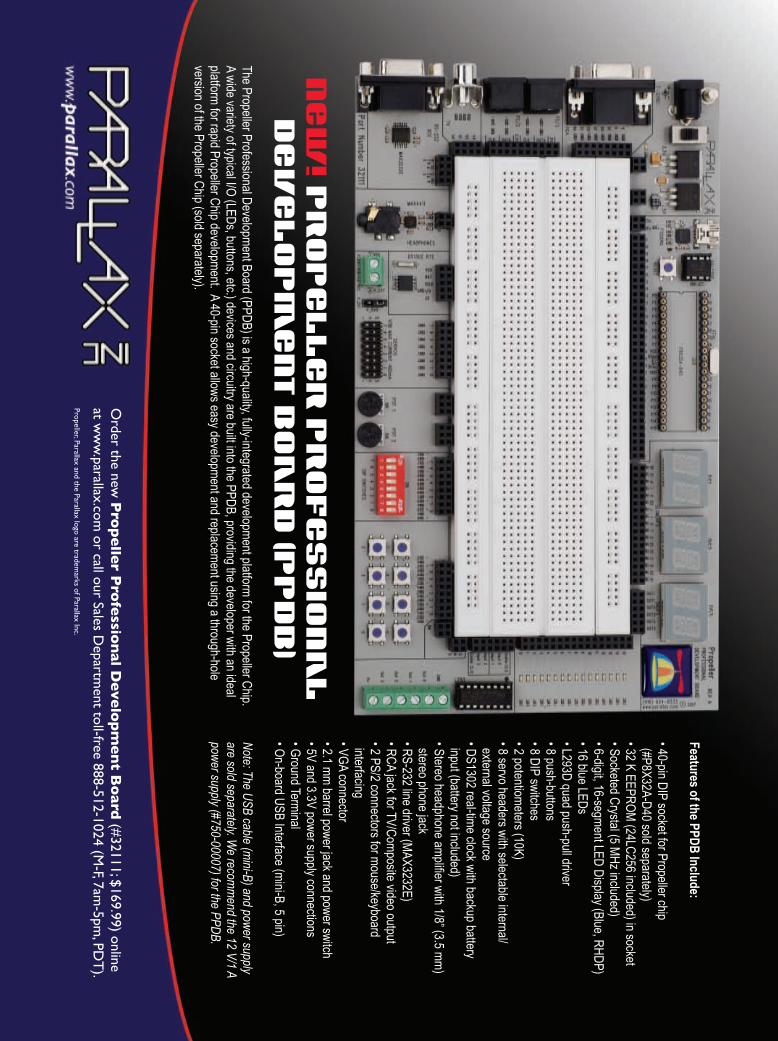
ICC FOR PROPELLERThe ICC for Propeller is an ANSI C development tool for the Parallax Pro-
peller chip. The IDE features project-based design and supports C86 dialectsource and C-based Propeller objects. The Propellent library is directly support-ed by the IDE for ease in build-to-run development cycles.
ICC for Propeller comes in both a standard version and a non-commercial ver-sion. Both versions feature an ANSI C compiler for Propeller LMM code genera-tion with an editor, project manager, and code browser. The non-commercialversion supports programs as large as 16 KB while the standard version supportsprograms as large as hub RAM.
The Propeller chip makes it easy to rapidly develop embedded applications.Its eight processors (cogs) can operate simultaneously, either independently orcooperatively, sharing common resources through a central hub. The developerhas full control over how andwhen each cog is employed.There is no compiler-driven oroperating system-driven splittingof tasks among multiple cogs. Ashared system clock keepseach cog on the same timereference, allowing for truedeterministic timing and syn-chronization.
The standard version costs$249. The non-commercialversion is only $99.
ImageCraft, Inc.www.imagecraft.com
npn219.qxp 9/8/2008 11:43 AM Page 11

12 Issue 219 October 2008 CIRCUIT CELLAR® www.circuitcellar.com
required several stable, high-frequencysignal sources located at multiplephysical locations simultaneously.Rather than build several narrowbandsources or purchase a number ofexpensive wideband sources, I decidedto build a variable-frequency stablesource that was general-purpose, accu-rate, and affordable.
If you pursue designs that take youinto the world of radio frequency (RF)technology, you may need a stable,high-frequency signal source. If youare interested in a quality source thatwon’t break the bank, read on.
Last fall, I began working on a projectinvolving high-frequency narrow-bandfrequency shift keying. The project
The goal for the RF signal generatorwas for it to deliver an operator-select-ed frequency from 0 to 3 GHz with afrequency accuracy of less than 200 Hz(see Photo 1). The targeted output powerlevel was 10 dBm, with a phase noisespecification of –80 dBc at a 10-kHz off-set. My other goal was to keep theharmonic levels greater than 40 dBbelow the fundamental. To controlcosts, I decided to implement thedesign on a single two-sided PCB,including the power supply.
Many of these design goals weremet or exceeded. Some are still“works in progress.” I think you willagree that this design will serve as anexcellent signal source for many RFapplications.
ARCHITECTURAL TRADE-OFFSA phase-locked loop (PLL) is an
obvious choice for controlling fre-quency in signal generator designs.But a PLL alone does not work in thisapplication.
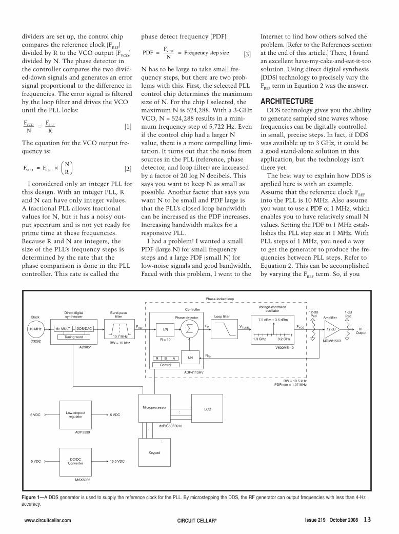
Look at the dotted-line box in Figure 1.These are the primary elements of atypical PLL. It contains a voltage-con-trolled oscillator (VCO), a PLL con-troller, and a loop filter. Typically, afixed-frequency clock provides a stablereference for the PLL control chip.The PLL output frequency is con-trolled by setting the values of the“R” and “N” dividers. Once the
FEATURE ARTICLE by Neal Martini
Neal describes how he built an inexpensive and accurate variable-frequency signal generatoron a two-sided PCB. The system delivers frequencies from 0 to 3 GHz with a frequencyaccuracy of less than 200 Hz.
DIY Signal GenerationCreate a Signal Source for a Variety of RF Applications
Photo 1—Two RF generators and an off-the-shelf passive RF mixer are used to generate lower frequencies. If, forexample, one generator is set to 2 GHz and the other generator is set to 2.3 GHz, the difference signal output ofthe mixer will be a 300-MHz signal.
2810018_Martini.qxp 9/8/2008 11:58 AM Page 12
www.circuitcellar.com CIRCUIT CELLAR® Issue 219 October 2008 13
phase detect frequency (PDF):
[3]
N has to be large to take small fre-quency steps, but there are two prob-lems with this. First, the selected PLLcontrol chip determines the maximumsize of N. For the chip I selected, themaximum N is 524,288. With a 3-GHzVCO, N = 524,288 results in a mini-mum frequency step of 5,722 Hz. Evenif the control chip had a larger Nvalue, there is a more compelling limi-tation. It turns out that the noise fromsources in the PLL (reference, phasedetector, and loop filter) are increasedby a factor of 20 log N decibels. Thissays you want to keep N as small aspossible. Another factor that says youwant N to be small and PDF large isthat the PLL’s closed-loop bandwidthcan be increased as the PDF increases.Increasing bandwidth makes for aresponsive PLL.
I had a problem! I wanted a smallPDF (large N) for small frequencysteps and a large PDF (small N) forlow-noise signals and good bandwidth.Faced with this problem, I went to the
PDF FN
Frequency step sizeVCO= =
dividers are set up, the control chipcompares the reference clock (FREF)divided by R to the VCO output (FVCO)divided by N. The phase detector inthe controller compares the two divid-ed-down signals and generates an errorsignal proportional to the difference infrequencies. The error signal is filteredby the loop filter and drives the VCOuntil the PLL locks:
[1]
The equation for the VCO output fre-quency is:
[2]
I considered only an integer PLL forthis design. With an integer PLL, Rand N can have only integer values.A fractional PLL allows fractionalvalues for N, but it has a noisy out-put spectrum and is not yet ready forprime time at these frequencies.Because R and N are integers, thesize of the PLL’s frequency steps isdetermined by the rate that thephase comparison is done in the PLLcontroller. This rate is called the
F F NRVCO REF= × ⎛
⎝⎜⎞⎠⎟
FN
FR
VCO REF=
Internet to find how others solved theproblem. (Refer to the References sectionat the end of this article.) There, I foundan excellent have-my-cake-and-eat-it-toosolution. Using direct digital synthesis(DDS) technology to precisely vary theFREF term in Equation 2 was the answer.
ARCHITECTUREDDS technology gives you the ability
to generate sampled sine waves whosefrequencies can be digitally controlledin small, precise steps. In fact, if DDSwas available up to 3 GHz, it could bea good stand-alone solution in thisapplication, but the technology isn’tthere yet.
The best way to explain how DDS isapplied here is with an example.Assume that the reference clock FREF
into the PLL is 10 MHz. Also assumeyou want to use a PDF of 1 MHz, whichenables you to have relatively small Nvalues. Setting the PDF to 1 MHz estab-lishes the PLL step size at 1 MHz. WithPLL steps of 1 MHz, you need a wayto get the generator to produce the fre-quencies between PLL steps. Refer toEquation 2. This can be accomplishedby varying the FREF term. So, if you
Figure 1—A DDS generator is used to supply the reference clock for the PLL. By microstepping the DDS, the RF generator can output frequencies with less than 4-Hzaccuracy.
:
Clock
C3292
10 MHz
AD9851
Band-passfilter
Direct digitalsynthesizer
10.7 MHz
BW = 15 kHz
6× MULT DDS/DAC
Tuning word
FREF
Controller
Phase detector
R = 10
1/R
R B A 1/N
Control
ADF4113HV
RFin
Loop filter
Phase-locked loop
VTUNE
Voltage-controlledoscillator
7.5 dBm ± 3.5 dBm
1.3 GHz 3.2 GHzf
12-dBPad
1-dBPad
12 dB
Amplifier
MGM81563
V600ME-10
RFOutput
BW = 19.5 kHzPDFnom = 1.07 MHz
LCDMicroprocessor
dsPIC30F3010
:
:
Keypad
ADP3339
MAX5026
5 VDC
16.5 VDC
6 VDC
5 VDC
Low-dropoutregulator
DC/DCConverter
CP FVCO
2810018_Martini.qxp 9/8/2008 11:58 AM Page 13

14 Issue 219 October 2008 CIRCUIT CELLAR® www.circuitcellar.com
vary the FREF frequency in small steps,you vary the VCO output frequency insmall steps as well. In my example,let’s say you have R and N set up togenerate a 3-GHz signal. Therefore,with a PDF of 1 MHz, R = 10, and N =3,000. Keeping R and N fixed andincreasing the FREF by, say, one to10,000,001 Hz, you get:
[4]
This is a frequency step size of 300 Hz at3 GHz. As it turns out, you can getmuch smaller FREF steps using DDS(0.014 Hz), which yields much smallerVCO output steps (4-Hz steps at 3 GHz).Consequently, I have what I want:small, precise step sizes using DDSand excellent output noise perform-ance using a large PLL PDF.
Now let’s consider the RF generator’sflow diagram shown in Figure 1, starting
F 10,000,001 3,00010
3,000,000,300 HzVCO = × =
with the PLL enclosed by the dashed-line rectangle. To simplify the design,I cover as much of the desired outputspectrum with a single VCO. Here Iemploy a wideband VCO that pro-duces a sinusoid with a frequency of1.3 to 3.2 GHz. The output of theVCO is fed back to the PLL controller.This feedback signal is divided by Nand then compared to the input refer-ence clock divided by R, as describedearlier. The controller’s error signaloutput is then filtered by the loop fil-ter to drive the VCO. When the looplocks:
[5]
The VCO also feeds an RF bufferamplifier, which delivers the desiredoutput levels.
The FREF input to the PLL is providedby the DDS generator. The DDS section
FRREF F
NVCO=
consists of a fixed-frequency inputclock, a DDS generator chip, and anoutput filter. A 10-MHz clock is inputto the DDS controller and is multiplied
Figure 2—This RF generator schematic shows the simplicity of the design. The main PLL components are an Analog Devices ADF4113HV and a Z-CommunicationsV600ME10-LF. The heart of the DDS is an Analog Devices AD9851. Also note the simplicity of the power supplies.
Photo 2—The RF generator fits on a single two-sided PCB,including the power supply. The bottom side is mostlyground plane, and most of the components are SMDs.The LCD and keypad plug directly into the PCB as well.
2810018_Martini.qxp 9/8/2008 11:58 AM Page 14

www.circuitcellar.com CIRCUIT CELLAR® Issue 219 October 2008 15
That is the function of the 10.7-MHzfilter located at the output of the DDScontroller. It should be noted that aslong as the DDS signal falls within thebandwidth of the filter, it will passintact. Therefore, the allowable outputfrequency range for the DDS controlleris 10.7 MHz ±7.5 kHz. As I willexplain, this is adequate for varying theFREF to the PLL enough to cover the fre-quency gaps between the availablesteps in the PLL.
The rest of the flow is fairlystraightforward. The microprocessorcontrols all of the registers in thechips, the keypad is used to input fre-quency settings, and the LCD is used todisplay the current state of the genera-tor. A 5-VDC regulator and a 16.5-VDCregulator are included to generate the
by the DDS control chip to develop a60-MHz internal system clock. TheDDS controller generates a sampledsine wave whose frequency is a func-tion of the value in the controller’stuning word. The sampled sine waveis internally converted to analog via a10-bit high-speed DAC. The nominalfrequency generated by the DDS is10.7 MHz. (I’ll explain the reason forthis frequency later.) But the exactfrequency varies from the nominal10.7 MHz by an amount required tomicrostep the output of the VCO.
The raw output of the DDS controlleris not a clean sine wave. Because the sig-nal is inherently a sampled sine wave,standard Nyquist criteria apply. Conse-quently, there are a variety of aliascomponents that need to be filtered out.
needed DC supply voltages.
HARDWAREA schematic of the RF signal gener-
ator is shown in Figure 2. The PCB isshown in Photo 2.
You want a VCO that covers a widefrequency range. A single VCO thatcovers 0 to 3 GHz is not available. So,I selected a Z-CommunicationsV600ME10-LF, which operates from 1.3to 3.2 GHz. It was chosen for its widefrequency coverage and because it oper-ates off a 5-V power supply. It’s speci-fied output level is 7.5 dBm ±3.5 dBm,which is sufficient to deliver thepower levels I want. Its phase noisespecification is –89 dBc at 10 kHz offset,which meets my stated goals. TheVTUNE input that controls the VCO’s
Figure 3—The ADIsimPLL tool from Analog Devices does a thorough job designing the PLL loop filter. The PLL step response and closed-loop transfer plots shown here are afew examples of output generated by the tool.
2.6
2.5
2.4
2.3
2.2
2.1
2.0
1.9
1.8
1.7
1.6
1.5
500 100 150 200 250 300 350 80 450
Time (µs)
Frequency (GHz)
10
0
-10
-20
-30
-40
-50
-60
-70
-80
100 1k 10k 100k 1M
Frequency (Hz)
Gain (dB)
0
-20
-40
-60
-80
-100
-120
-140
-160
-180
Phase (deg)
Amplitude Phase
2810018_Martini.qxp 9/8/2008 11:58 AM Page 15

50-Ω resistor that feeds back tothe PLL RFIN is 0.133 VRMS. Thiscorresponds to a –4.5-dBmsignal level required by theADF4113HV PLL chip. Thesame is true for the signallevel into the RF bufferamplifier.
Assuming I have the nomi-nal REFIN clock input to thePLL of 10.7 MHz and that Iwant to have a nominal PDFof 1.07 MHz, I so far have astable, low-noise PLL with a
frequency step size of 1.07 MHz.Next, I need to microstep the REFIN
clock so I can have the PLL generatefrequencies between the 1.07-MHzsteps. If you examine Equation 2,REFIN must be able to vary over arange of ±3,578 Hz to microstep with-in the 1.07-MHz PLL step. The finerthe REFIN steps, the better the outputresolution. Now let’s examine howthis is done with the DDS portion ofthe schematic.
The heart of the DDS circuit is theAD9851 DDS synthesizer chip. Ittakes a 10-MHz CLK IN, multipliesthe frequency by six, digitally synthe-sizes a sine wave, and D/A converts itto generate a sinusoid with precise fre-quency control. The equation control-ling this device is:
AD9851 output frequency = (TuningWord) (6) (CLK IN)/232
The Tuning Word is 32 bits long, so highresolution is possible. With a 10-MHzCLK IN, the AD9851 frequency stepsize is 0.014 Hz. A 0.014-Hz step sizein the DDS corresponds to an RF gen-erator output step size of less than 4 Hzover the full operating range of 1.3 to3.2 GHz. That’s excellent frequencyresolution!
The AD9851 is a digitally sampledwaveform generator, so it has severalcomponents in its output spectrumthat you need to clean up. That iswhy the AD9851 is followed by a nar-rowband crystal filter. The filter’s band-width is wide enough to pass the signalover the ±3,578-Hz variations requiredfor microstepping, but it is narrowenough to eliminate the undesiredcomponents of the AD9851 sampled
16 Issue 219 October 2008 CIRCUIT CELLAR® www.circuitcellar.com
frequency has a range of 0 to20 V.
I used an Analog DevicesADF4113HV PLL control chip.I picked it because it operatesfrom 200 MHz to 4 GHz. Moreimportantly, however, this rel-atively new component fromAnalog has an internal high-voltage charge pump. Thiseliminates the need for anexternal op-amp at the outputof the control chip, which isnormally included to convertthe low-voltage charge pump signal toa level high enough to drive the VTUNE
control line of the VCO. There are five components (R17,
R18, C26, C27, and C28) that makeup the PLL loop filter. The filter’smain purpose is to take the currentpulse error signal generated by thePLL control chip and generate a cleanproportional DC voltage to the VCO’sVTUNE control line. This filter affectsloop stability, loop BW, and the overallPLL output noise. There are textbooksthat describe how to design these filters.Fortunately, there are online resourcesavailable to help with the heavy lifting. Iused the ADIsimPLL tool from Analogto design the filter for this application.Because I used an Analog PLL controlchip, I just needed to input the specifica-tions of the Z-Communications VCOand the phase detector frequency Iwanted. The ADIsimPLL did the rest. Itoutput a schematic and open- andclosed-loop transfer plots, step response
plots, and a variety of other perform-ance data. Some examples of the outputof the tool are shown in Figure 3. Theresulting PLL designed using this toolhas a bandwidth of 19.5 kHz and an out-put phase noise of –81 dBc at a 10-kHzoffset (assuming an ideal referenceclock input).
On the output side of the VCO, a net-work of resistors is used to feed backthe output signal to the control chip.The network interfaces the VCO to anoutput RF amplifier. When workingwith RF frequencies, make sure that theloads seen by devices like the VCO are50 Ω. This minimizes the effects ofsource/load mismatches like powerlevel variations and frequency shifting.Attenuating the output is a techniqueused to minimize mismatch effects. Inaddition, you need to feed back theVCO’s output to the ADF4113HV.However, the feedback signal must bein the range of 0 to –10 dBm. Attenua-tion of 12 dB solves both problems.
The 12-dB attenuationis accomplished by usingresistor pads. Figure 4shows how the resistornetwork is constructed.The network consists oftwo 6-dB T pads in series.Each pad has an inputand output impedance of50 Ω. Consequently, thez1, z2, and z3 impedancesin Figure 4 are all 50 Ω(this assumes that theamplifier input is 50 Ω).Assuming the VCO outputis at 7.5 dBm (0.54 VRMS),and doing the voltagedivider math, you will seethat the signal level at the
Photo 3—To view the fundamental and harmonics of a 3-GHz signal, anolder-model spectrum analyzer was used. The right-most line is the 3-GHzfundamental. Moving left, the next two lines are the 6- and 9-GHz, secondand third harmonics, respectively. The other lines are due to the analyzer’sharmonic mixing and can be ignored.
Figure 4—Two 6-dB pads in series accomplish the attenuation to provide theright signal level to the PLL control chip. The attenuation also minimizes theeffects of source/load mismatches at the output of the VCO.
2810018_Martini.qxp 9/8/2008 11:58 AM Page 16

http://cc.nkksmartswitch.com1.877.2BUYNKK (228.9655)
DO YOU SEE WITH INFINITE CLARITY?With NKK’s new line of OLED products, now you can! From themarket leader for miniature and illuminated switches comes thenewest and most cutting-edge technology offered in broadlineOLED programmable switches and displays. Suitable for a rangeof industries, NKK’s OLED devices feature:
• 180° Viewing angle• 65,536 colors• Real-time sequencing• Less power consumption• Higher contrast• Brighter • Vivid clarity
OLED SmartSwitch™
Development Kit
INFINITE CLARITY
New OLED
Switch & Display
17.qxp 8/22/2008 9:54 AM Page 1

18 Issue 219 October 2008 CIRCUIT CELLAR® www.circuitcellar.com
waveform. An inexpensive 10.7-MHzcrystal filter was selected for thisfunction, and it is the reason why thenominal reference frequency to thePLL was set at 10.7 MHz.
The input impedance of the crystalfilter is nominally 3,000 Ω/2 pF, and it
is driven from a 50-Ω source, so animpedance-matching network isrequired. Crystals are sensitive to hav-ing their input and output impedancesmatched to deliver their specified fil-tering. An LC network is used toaccomplish this matching. The L and C
values were determined using anonline tool. (Refer to the Referencessection at the end of this article.) Thetool called for L = 5.7 µH and C = 38 pF.Taking into account stray capacitance,the 2 pF of internal capacitance at thecrystal input, and the standard valuesavailable, the values of 33 pf and 5.6 µHwere selected. How do these smallcomponents match a 50-Ω source to a3,000-Ω load? An intuitive explana-tion is that the shunt capacitor isthere to lower the crystal’s 3,000-Ωinput impedance to 50 Ω, and theinductor is included to cancel out thereactive component introduced by thecapacitor. Mathematically, if you lookat the impedance of the shunt capaci-tor (38 pF) and the 3,000-Ω crystalinput in parallel, you get:
[6]
So, if you get rid of the –385j reactiveterm, you will have the 50-Ω imped-ance you want. To do this, because theinductor’s impedance adds in serieswith the above Z, set jwL = 385j, yield-ing L = 5.7 µH. This leaves you withthe desired 50-Ω impedance. Inciden-tally, the beauty of impedance match-ing with an LC is that you also getsome additional filtering at 10.7 MHz.There is also an LC at the output ofthe crystal, but it is not there for
Z 3,000
1,173,000
=−( )( )− +
= −
−
391 3 000391
903 025
7 4
jj
,,
.
o
o
==−
= −
388
50 385j
82 6. o
Z
Photo 4a—This is the output obtained using two RF generators and a mixer. b—This is the output of an expensive generator set at 300 MHz.
a) b)
2810018_Martini.qxp 9/8/2008 11:59 AM Page 18

www.circuitcellar.com CIRCUIT CELLAR® Issue 219 October 2008 19
impedance matching becausethe crystal is driving a 3-kΩload. It is simply an LC tunedto 10.7 MHz (it takes intoaccount the 10-pF inputimpedance of theADF4113HV) to provide addi-tional filtering.
I chose a Microchip Tech-nology dsPIC30F3010 micro-processor because it is fast, ithas an internal clock, it hasenough memory to allow for Cprogramming (including stdiofunctions), and it has enough I/O pinsto satisfy the design. Plus, I had a fewleft over from another project. I wantedto make sure I had plenty of bandwidthto expand the functionality of the RFgenerator in the future. The micro-processor controls all the registers inthe ADF4113HV and the AD9851, andit performs all of the calculations usinghigh-speed integer arithmetic. Theinterfaces to the keypad and LCD arealso handled by the microprocessor.
I used an ADP3339 low-dropout reg-ulator to generate the 5-V supply. It isa good solution because it can provideall of the necessary power withoutany heatsinking. The ADF4113HValso requires an available low-current16.5-VDC regulated supply. I generat-ed the supply with a MAX5026DC/DC converter. It takes the 5 Vavailable from the main supply andgenerates 16.5 V of clean output. The16.5-V output is determined by thevalues of R1 and R2. The 16.5-V levelcovers the tuning range of the VCOwhile not exceeding the maximumlevel allowed by the ADF4113HVhigh-voltage charge pump supply.
RF LAYOUT There are a few layout considera-
tions to think about when building RFcircuits. Pay close attention to supplybypassing. Suppliers of RF compo-nents will typically suggest capacitorvalues, SMD component sizes, and, insome cases, even tell you how closethe bypass capacitor needs to be to thepin you are bypassing. It is also goodpractice to return all ground connectsto ground with separate vias. In otherwords, if you have several pins on anIC that need to be grounded, connect
them to the ground plane with theirown via to avoid any subtle interactions.
In this two-sided design, the bottomof the PCB is almost completely aground plane. It is not a single plane.Instead, it is three separate planes con-nected to the power supply ground at acommon point. This “star” configura-tion of the ground plane helps keep thedifferent sections of the circuit frominteracting via unwanted ground loops.
Finally, there are those who will dis-agree with me on this, but if you keepyour high-frequency traces short (less
than 0.1× the wavelength), youdon’t have to be too concernedabout having PCB trace widthsdesigned to yield a 50-Ω load-ing. You are better off if youkeep things short and matchthe trace width to the SMDparts you are interconnecting.
FIRMWAREI have been using C to pro-
gram my past few projects. Itwas a little painful coming upto speed, but now I am a real
convert. Using C enabled me to do64-bit integer arithmetic with easeand gave me access to some built-infunctions that were extremely useful.The sprintf built-in standard I/Ofunction, for example, lets you easilycreate a formatted ASCII array, mak-ing formatted LCD output quite sim-ple. For example:
sprintf(Array,"Frequency = %u Hz", Fvco);
The sprintf statement is all that isneeded to have the LCD read “Frequency
Table 1—This table shows the frequency locations of the n × FLO ± m ×FRF. The dashes are “don’t care” values because they fall above the fre-quency range of the spectrum analyzer used. FLO = 2 GHz, FRF = 2.3 GHz,and FIF = 300 MHz.
m x FRF
n x FLO 2.3 GHz 4.6 GHz 6.9 GHz 9.2 GHz 11.5 GHz
2 GHz 0.3 1.4 — — —
4 GHz — 0.6 — — —
6 GHz — 1.4 0.9 — —
8 GHz — — 1.1 1.2 —
10 GHz — — — 0.8 1.5
Visit us at ESC — Booth #321
2810018_Martini.qxp 9/8/2008 11:59 AM Page 19

20 Issue 219 October 2008 CIRCUIT CELLAR® www.circuitcellar.com
= 300 Hz,” assuming FVCO is 300 at thetime the command is executed.
Likewise, the standard I/O functionsscanf lets you go the other way bytaking formatted ASCII input and con-verting it to numerical values. This isextremely useful when you areinputting keypad values that you wantto convert to numbers.
If you are tired of rewriting LCDand keypad interface programsbecause you are using different I/Opins on the microprocessor, look atthe C code in this project. You don’thave to rewrite the two programs forfuture projects. The two programs arewritten in such a way that you haveto change only the pin assignments inthe header files and you’re set to go.For experienced C gurus, don’t be toocritical of my C skills. As I said, I amcoming up to speed.
HOW IS IT WORKING SO FAR?Take a look at how the RF genera-
tor performs. For operating at 3 GHz,the only instrument I have access tothat shows the frequency spectrumup to 9 GHz (to see harmonics) is anold Hewlett-Packard 141T/8555Aspectrum analyzer. Be careful whenlooking at the output of the analyzerbecause it uses harmonic mixing anddisplays the resulting spectrum in abit of a confusing manner.
Photo 3 shows the analyzer’s out-put. Starting on the right, the 3-GHz
fundamental is displayed. Moving left,the next line is the second harmonicat 6 GHz. The next left line is thethird harmonic at 9 GHz. The otherlines on the display are just the samethree components that were shiftedinto the display spectrum by harmon-ics of the internal local oscillator.Consequently, they can be ignored.The analyzer was used to check theoutput levels because the frequency ofthe RF generator was varied.
The results show the output level isconsistently between 8 and 10 dBm asthe frequency is varied from 1.3 to3.2 GHz. Also, the second and thirdharmonics are typically at –42 dBc and–54 dBc, respectively.
I tested for frequency accuracy byconnecting the output of the RF gen-erator to a 3-GHz universal counterthat is sensitive enough to detect sig-nals as low as –15 dBm. I was pleasedwith the results. To have the exactoutput frequency, I had to add thecapability (in the firmware) ofinputting (via the keypad) the actual fre-quency of the clock into the AD9851. A1-Hz error assumed for this clock resultsin an output error of 280 Hz at 3 GHzand 140 Hz at 1.5 GHz. In retrospect, Ishould have used a higher-qualitytemperature-compensated part for theclock into the AD9851. The part Iused required me to measure theclock more often than I wanted for anexact frequency output. With that
said, once the actual AD9851 inputclock was measured and input, the fre-quency was accurate to less than 4 Hzover the full range of frequency. Ifound that impressive!
FREQUENCIES BELOW 1.3 GHzAt this point, you might be saying:
“Wait a minute! I thought you saidthe generator was capable of generat-ing signals from 0 to 3 GHz. So far, Isee only 1.3 to 3.2 GHz.”
Look at Photo 1 to see how thelower frequencies are obtained. TwoRF generators (one in an enclosure andone with only the PCB) are pluggedinto an off-the-shelf passive RF mixer(Mini-Circuits ZX05-43LH). One gen-erator provides the RF input to themixer and the other serves as thelocal oscillator. The third port is theintermediate frequency (IF) output,which contains, among other things,the difference frequency that is thedesired signal. For example, if onegenerator is set at 2 GHz and the otheris set at 2.3 GHz, the generated differ-ence frequency will be 300 MHz.
Because I was now much lower infrequency, I was able to use a modernspectrum analyzer to look at theresulting spectrum. The output spec-trum of the RF generator is shown inPhoto 4. For comparison, you can seethe output of an expensive signalgenerator, also generating a 300-MHzsignal.
Photo 5—To look at phase noise, you need to look closer in frequency at the fundamental. a—This is the fundamental of an expensive generator. b—This plot is my RF generator.Things are comparable at 100-kHz offset, but closer in, the expensive unit has less noise.
a) b)
2810018_Martini.qxp 9/8/2008 11:59 AM Page 20

SIL-003_CC_8.375x11.125.indd 1 1/31/08 3:06:47 PM
34.qxp 3/3/2008 4:00 PM Page 1
Photo 4 shows that the harmoniclevels of the RF generator are notdown as far as the expensive genera-tor, but they are still relatively low.The second harmonic for the RF gen-erator is down 45 dB. To put this inperspective, say you have a 10-dBm(0.71 VRMS) fundamental. Theunwanted second harmonic would be–35 dBm (0.004 VRMS). That is a smalldistortion.
There are other frequency compo-nents in the RF generator’s output
www.circuitcellar.comCIRCUIT CELLAR®22 Issue 219 October 2008
spectrum. Unlike the previous examplewhere the spectrum analyzer caused theextra spectral components, the compo-nents are real and result from the mix-ing process. Besides the normallyexpected sum and difference frequen-cies generated when mixing, outputcomponents are generated by the har-monics of the local oscillator and har-monics of the RF input signal. Thelocation of the components is calculat-ed by the equation n × FLO ± m × FRF.Using this equation, Table 1 shows
the location of these components forthe 300-MHz signal that’s generating.As you can see in Photo 4, the compo-nents are located exactly where the tablepredicts they should be. Again, the com-ponents are still down at least 40 dBfrom the fundamental, which is justfine in most cases. If you generate this300-MHz signal by mixing a 2.7-GHzsignal with a 3-GHz signal, none ofthe components of n × FLO ± m × FRF
would be seen in the displayed spec-trum because they would fall outsidethe frequency range displayed by thespectrum analyzer.
Note that there are also attenuatedversions of the RF and local oscilla-tor signals that leak through anymixing process. They are usuallyattenuated by greater than 30 dB andcan be filtered out by low-pass filter-ing if your application requires it.They do not appear in Photo 4because they fall outside the frequen-cy range displayed by the spectrumanalyzer.
Frequency accuracy and signal lev-els are important, but the quality ofthe output signal in terms of noise ismore important. Photo 5 shows acloser frequency look at the funda-mental for an expensive signal gener-ator and my RF generator side byside.
At a 100-kHz offset from the funda-mental center frequency, the noise levelis comparable. But below 100 kHz, theexpensive generator is less noisy.This really bothered me when I firstobserved it until I figured out whythis was happening. It turns out thatthe source of this added noise in theRF generator is the clock source Iused for the AD9851. The part wasspecified to have phase jitter lessthan 1 picosecond. I thought this wasexcellent at the time; but after pre-cise measurements, I found that theclock’s phase noise was –80 dBc at a10-kHz offset. If you put that intothe ADIsymPLL tool, the resultsshown in Photo 5 are exactly what ispredicted. Using a part with a phasenoise of –110 dBc would reduce thenose levels of the generated signal foroffsets below 100 kHz. A part likethis is not a simple drop-in replace-ment; however, because this kind of
2810018_Martini.qxp 9/8/2008 11:59 AM Page 22
www.circuitcellar.com CIRCUIT CELLAR® Issue 219 October 2008 23
SOURCESAD9851 DDS Synthesizer,ADF4113HV charge pump, ADIsim-PLL software, and ADP3339 low-dropout regulatorAnalog Devices, Inc.www.analog.com
Neal Martini ([email protected]) holds an M.S.E.E. from the Uni-versity of Missouri, Rolla. He isretired after 24 years of working forHewlett-Packard in the LaserJet andInkJet printing businesses. In additionto being involved with a variety ofboards, Neal works independently inproduct development in several appli-cation areas. In his spare time, heenjoys spending time with family,woodworking, racquetball, golf, andplaying the piano.
RESOURCES“L/C Impedance Matching NetworkDesign Tool,” www.hoflink.com/~mkozma/match19c.html.
P. Nelson, “PLL Combines With Digital
PROJECT FILESTo download code, go to ftp://ftp.circuitcellar.com/pub/Circuit_Cellar/2008/219.
141T/8555A Spectrum analyzerHewlett-Packardwww.hp.com
dsPIC30F3010 DSCMicrochip Technology, Inc.www.microchip.com
ZX05-43LH Frequency mixerMini-Circuitswww.minicircuits.com
V600ME10-LF VCOZ-Communications, Inc.www.zcomm.com
Synthesis,” EE TIMES, September 2003.
S. Sprowls, “Scotty’s ModularizedSpectrum Analyzer Web Site,”www.scottyspectrumanalyzer.com.
clock chip comes with a 0.8-VPP out-put, an additional chip is needed toconvert to the CMOS level requiredby the AD9851. This is the work inprogress that I mentioned at the begin-ning of the article.
WHAT’S NEXT Besides adding a better AD9851 clock
source, I intend to add FM modulationcode to the generator’s feature set. Witha 30-MIPs processor, a 19.5-kHz PLLbandwidth, and a 3.3-MHz update ratefor the DDS chip, there is plenty ofhorsepower to FM-modulate the signal.
Currently, I use off-the-shelf Mini-Circuits attenuators to vary the out-put signal level a fixed amount. Theyconnect directly to the RF generator’soutput. But for more flexibility, I amalso in the process of designing a sepa-rate PCB to accomplish output levelcontrol and AM modulation. In addi-tion to having its own microprocessorand supply, it will use a variable-gainRF amplifier and RF log detector in aclosed-loop system.
This project was fun. It caused meto learn new things and ultimatelyyielded a high-precision RF signalsource. That’s what keeps me comingback for more! I
Electrical engineers agree: with a Protomat S-Seriesprototyping machine at your side, you’ll arrive at thebest solutions, fast. These highly accurate benchtopPCB milling machines eliminate bread-boarding andallow you to create real, repeatable test circuits—including plated vias—in minutes, not days.
• Declare your independence from board houses
• Affordable, entry-level price tag
• The best milling speed, resolution, and accuracyin the industry
• Single-sided, double-sided, and multilayeredmachining without hazardous chemicals
• Optional vacuum table and autosearch camerafor layer alignment
For complete details visit:www.lpkfusa.com
or call:1-800-345-LPKF
ProtoMat® S-SeriesPCB Milling Machines
2810018_Martini.qxp 9/8/2008 11:59 AM Page 23

Get Started with PIC USB Connectivity
24 Issue 219 October 2008 www.circuitcellar.com
insertion (enumerate the device andmatch it with a particular class driver)and extraction (close and clean up afteritself). It also provides power to theperipheral. (For more informationabout USB and its inner workings,refer to my columns listed at the endof this article.)
A USB connection is made via acable with differentiated plugs (seePhoto 2). The host is mated using atype-A plug/receptacle while theperipheral is connected with a type-B
USB peripheral support (see Photo 1).Let’s look a little closer at the sup-ported USB capabilities.
USB (AS WE KNEW IT)We know the PC as a USB host device
consisting of complex software applica-tions with an operating system andprocessor. The host must manage andcontrol all USB functions. It initiates alldata packet activity on the bus, man-aging data flow and doing error check-ing. The host must detect peripheral
CIRCUIT CELLAR®
Many of us are just coming togrips with the idea of supporting aUSB interface as the communica-tions medium of choice for our prod-uct designs. PC manufactures haveeliminated the DE9 (standard foryears on every PC) and replaced itwith USB (and FireWire) connectors.We’ve been forced to learn moreabout the protocols than we everwanted to know. Unless my productincorporates PC-type architecture, Ican’t take advantage of all theperipherals out there. So, I can forgetabout adding a storage device, key-board, or other USB peripheral to myproject. Microcontrollers just don’thave the room to handle a USB host’sresponsibilities.
USB On-The-Go (OTG) technologywas announced on December 18, 2001,by the USB Implementers Forum (USB-IF). Let’s see, that’s about seven yearsago. You’d think by now that wewould have access to all of those USBproducts that have shipped to date—atleast that was the promise made backthen. About all that comes to mind issome high-priced digital camera thatsupports downloading directly into aprinter. That’s hardly what I would callutopian connectivity.
Well, stand back, because the tools tomake this a reality are finally here.Microchip Technology has released 16-and 32-bit microcontrollers that sup-port embedded hosting, dual-role, andOTG capabilities, complementing theoriginal 8-bit microcontrollers with
SPECIAL FEATURE by Jeff Bachiochi
You can add USB to your next project with Microchip Technology’s new array of parts. The8-, 16-, and 32-bit microcontrollers will complement your designs with USB peripheralsupport, embedded hosting, and dual-role and OTG capabilities.
Photo 1—If you need a full-speed USB 2.0 device, an embedded host, or dual-role and OTG solutions, you’re inthe right place. These should work for you.
2810020-bachiochi-PRINT.qxp 9/8/2008 12:00 PM Page 24

plug/receptacle. Some peripher-als have a micro type-Bplug/receptacle to save space.
A USB peripheral responds onlyto a host and does not have thecapability to initiate data trans-fers. It must be concerned withpower consumption and check forerrors in the data from the host.
EMBEDDED HOST An embedded host is defined
as a product with limited hostcapabilities. That is, while itmust provide management andcontrol of the bus, it can supportonly the peripherals that it wasdesigned for. This can be as spe-cific as a peripheral or class ofperipherals. An embedded host will havea full-size type-A receptacle. The embed-ded host may optionally support SRP.(I’ll present more on the power conserva-tion session request protocol a bit later.)
ON THE GOOTG technology has its own limi-
tations and extensions. An OTGdevice has a dual-role capability: itcan act as an embedded host or a
peripheral. It is designated by the useof one micro type-AB plug/recepta-cle. The receptacle can accept eithera micro type-A plug or a type-B plug.OTG devices must support bothHNP (Am I the host or peripheralnegotiation protocol?) and SRP.
DUAL ROLEThis term can be confusing
depending on how it is used. An
OTG device can be considered adual-role device. A dual-roledevice needs both a standard Aconnector and one of the B-typeconnectors. However, there areapplications that might requirean embedded host device toserve as a host to one peripheraland as a peripheral to anotherhost.
NEW PROTOCOLSThe ability to host a connec-
tion brings with it a new com-plexity for the interface circuit-ry as the device’s role changesfrom that of a peripheral, andthat includes new protocols (seeFigure 1). The HNP protocol
enables the OTG devices to negotiatewho will be the boss when the twoare connected. Let’s assume you havean OTG camera and an OTG PDA.An OTG cable (micro-type-A tomicro-type-B) connects the two. Eachdevice can be a host to, say, a print-er. When connected together, thecable determines which device willbegin as the host.
This OTG cable has a fifth connection
www.circuitcellar.com CIRCUIT CELLAR® Issue 219 October 2008 25
Figure 1—Peripheral devices need simple USB interfacing (right). Embedded host and OTG devices require a more sophisticated arrangement to tackle both up- and downstreamconnections (left).
USB Clock from the oscillator module
USB Control and configuration
Registers and
controlinterface
USB Module
48-MHz USB Clock
USBVoltage
comparators
SIE
SRP Charge
SRP Discharge
Full-speed pull-up
Host pull-down
Low-speed pull-up
Host pull-down
VBUS
D+
D-
Transceiver
ID Pull-up
ID
VBUSON
VUSB Transceiver power 3.3 V
DMAController
256-ByteUSB RAM
USBSIE
FSENUPUEN
3.3-V Regulator
FS
Transceiver
Internal pull-up
P
P
VUSB
D+D-
Photo 2—USB type-A connectors are used upstream for connection tohost, hub, and embedded host devices. USB type-B connectors areused downstream for connection from hubs, dual-role embedded host(as peripheral), and peripheral devices. USB type-AB connectors arethe only connectors used for OTG devices.
2810020-bachiochi-PRINT.qxp 9/8/2008 12:00 PM Page 25

26 Issue 219 October 2008 CIRCUIT CELLAR® www.circuitcellar.com
with pin 5 connected to groundon the type-B side.Ra_PLUG_ID is 10 Ω max andRb_PLUG_ID is 100 kΩ min.The type-A side becomes thehost and must supply power,at least 8 mA, to the type-Bperipheral. The host will iden-tify its peripheral as an OTGdevice and can allow theperipheral to ask for a swap infunctionality. (You mayremember that a peripheralcan indicate its operatingspeed as full by attaching apull-up on the D+ line. Newinterface circuitry enables adevice to enable/disable functions soit can act as a host or a peripheral.)Once the device at the type-B end ofthe cable takes over, it can relin-quish control back to the type-Aside, if necessary, by the same proce-dure. With this approach, you neverhave to worry about which end of thecable to plug into which OTGdevice. It’s all automatic.
One of the main concerns withembedded hosts and OTG devices ispower consumption because most arebattery powered. The second newprotocol SRP addresses this concern.OTG hosts are allowed to turn offVBUS in the USB connection when thebus is idle. Even with no VBUS on theUSB connection, the peripheraldevice can ask for service when nec-essary. This is done by first togglingD+ with its pull-up. If the host moni-tors the data lines, it can respond byturning on VBUS and initiating a ses-sion. In this case, the peripheral willsee VBUS and abort its SRP. If the hostdoesn’t respond to the data toggling,the peripheral toggles VBUS (8 mA ofcurrent max). If the host monitorsVBUS, it can respond by turning on VBUS
and initiating a session. OTG devicesare the only ones required to use SRP,although it can be (optionally) support-ed by any device. Detailed signalinformation for HNP and SRP can befound at www.usb.org/developers/docs/USB_OTG_1-3.pdf.
TPLAlthough an OTG device must sup-
port some host qualities, it is limited
to a specific set of support peripheralsdesignated by the designer. OTGdevices require a targeted peripherallist (TPL) to decide whether a con-nected peripheral is supported or not.
The TPL requires a manufacturer,model number, and description ofthose peripherals it can handle. If theperipheral is not in the TPL, theOTG device is required to indicatethe problem to the user in somefashion, preferably in an error mes-sage (e.g., an LED or a beep). Classsupport is not part of OTG. Althoughthere is no reason it couldn’t beused, that would void OTG certifica-tion. (This should be revisited by theUSB-IF.)
CLASS SUPPORTThe USB-IF standard classes sup-
ported for an embedded host are list-ed in Table 1. With memory at a pre-mium for embedded devices, sup-porting every class would be virtual-ly impossible. Designing for a classminimum makes sense. This at leastenables your product to continuefunctioning with any manufacturer’swidget of that class.
A BIRD IN THE HANDThere is something about having a
product in your hands to assure youit’s real. But that’s just the start.Microchip Technology’s parts get youthinking about how completely theysupport USB. The 8-bit PIC18F14K50(20-pin), PIC18F4550 (40-pin), andPIC18F66J50 (64-pin) function asUSB peripherals. The 16-bit
PIC24FJ256GB110 (100-pin)supports USB embedded host-ing, peripheral, and OTGfunctions. The 32-bitPIC32MX460F512L (100-pin)also supports USB embeddedhosting, peripheral, and OTGfunctions.
While these parts just hintat all of the USB variantsavailable, they demonstratethe extensive products sup-ported that use a single (free)integrated development envi-ronment. Common softwarelibraries provide an easymigration path across all
devices. Each of the parts has adevelopment, demo, or starter kitavailable for under $60. Let’s take aquick look at these offerings.
COMMON FEATURESThe chips I’m covering feature on-
chip transceivers and are USB 2.0-compliant. They support low-speed (LS,1.5 Mbps) and full-speed (FS, 12 Mbps)connections and all four types oftransfer: control, interrupt, isochro-nous, and bulk. Table 2 comparesthese side by side.
The 8-bit chips can source/sink 25 mAthrough their I/O pins, while the 16-and 32-bit chips can handle 18 mA.All of the chips support dedicatededge-triggered interrupts as well asinterrupt-on-change (with internalpull-ups) on some or all of their I/Opins.
In terms of on-chip peripherals,each chip includes one or more cap-ture/compare/PWM modules, somewith enhanced PWM features. Theenhanced PWM features includedual- (half-bridge) and quad-PWM(full-bridge) outputs with selectablepolarity, dead time, and auto shut-down/restart. The master synchro-nous serial port (MSSP) module sup-ports four modes of SPI and bothmaster and slave I2C modes. Anenhanced USART supports RS-232/485as well as LIN 1.2/2.0 and IrDA inter-faces in some cases. The 10-bit ADCmodule has automatic acquisitionand conversion during sleep capabili-ty. Analog comparators offer rail-to-rail operation and independent input
Table 1—The left column lists functions covered by standard class support.The right column lists functions that may require special support beyond thestandard class.
USB-IF Class specifications Proprietary protocols (potential)
HID Bluetooth HCI
Hub MS RNDIS
Printer USB-to-Serial
Digital image capture USB-to-Ethernet
Audio MP3 Players
Mass storage (MSD) Still digital cameras
Communications (CDC) Webcams
USB Chip/smart card Video capture devices
IrDA Host-to-host cables
USB Monitor control
Video
2810020-bachiochi-PRINT.qxp 9/8/2008 12:00 PM Page 26

28 Issue 219 October 2008 CIRCUIT CELLAR® www.circuitcellar.com
multiplexing. Each microcontroller’s external crys-
tal/clock input can run the oscillatorup to 48 MHz (32 MHz on thePIC24FJ256GB110). A 4× phase-lockedloop (PLL) can boost input when neces-sary for the USB. The system clock cancome from the USB block, one of twoalternate internal RC oscillators, or theoptional low-frequency RTC clock.(Timer1 uses an external 32.768-kHzcrystal.) There is even a failsafe clockmonitor that allows for shutdown in theevent of an oscillator failure. There arealso an RTC oscillator and a watchdogtimer that operate independently of theCPU. The watchdog timer runs from the31-kHz internal RC oscillator source.
Each chip includes an internal reg-ulator that can operate the core logic.Power is managed through three ormore states: Run, Idle, and Sleep.Brown-out reset (BOR) and power-onreset (POR) functions are implemented
as well as optional two-speed start-up that allows execution from theinternal oscillator. The oscillatorstart-up timer (OST) waits for themandatory 1,024-cycle delay of theexternal oscillator.
PIC18F14K50The 8-bit PIC18F14K50 is the small-
est member of the group with a 20-pinpackage (PDIP, SSOP, or SOIC). It isgeared toward low-cost, tiny devicesthat need USB connectivity. It hassome special features to support suchdevices, including interrupt on changefor D± (detect connection). The slewrate on each output port can bereduced as an aid to EMI reduction. A1.024-V fixed internal reference for theADC is available.
This part has a 3.6-V internal volt-age regulator derived from a 5.5-Vinput. The LF version operates froma 3.6-V maximum input voltage and
does not have the regulator. Bothversions can run down to 1.8 V (with-out the internal regulator).
The low-pin-count development kit(DV164126) was created with the USBnovice in mind. It includes a self-directed course and lab materialdesigned to ease the learning curveassociated with adding USB connectivi-ty to embedded systems. The kit con-tains two development boards, onefully populated and one unpopulatedspare development board, onePIC18F14K50 debug header, a CD con-taining the user guide, course materi-als, and product documentation. Inaddition, a PICkit 2 (and USB cable) isincluded for debugging and program-ming. The PIC18F14K50 costs $2.50per unit and the demo board costs $60.
PIC18F66J50The 8-bit PIC18F66J50 is for cost-
sensitive applications that need more
Table 2—These five chips support a wide range of USB-enabled applications, from the low-pin-count PIC18F14K50 to the high-performance PIC32MX460F512L. This table showssome of the key differences among them.
Feature PIC18F14K50 PIC18F66J50 PIC18F4550 PIC24FJ256GB110 PIC32MX460F512L
USB Modes Device Device Device Device, OTG, embedded host Device, OTG, embedded host
USB Endpoints 16 32 32 32 32
USB Dual-port RAM 256 bytes 3.9 KB 1 KB DMA DMA
Power managementstates (maximum speed)
Run (12 mA), Idle (5 mA),Sleep (0.7 µA)
Run (15 mA), Idle (6.5 mA), Sleep (1.4 µA)
Run (40 mA), Idle (18 mA), Sleep (0.1 µA)
Run (24 mA), Idle (5.6 mA),Doze, Sleep (1 µA)
Run (75 mA), Idle (30 mA),Sleep (28 µA)
RTC Current 1.3 µA 24 µA 4.5 µA 7 µA 10 µA
WDT Current 3.6 µA 7 µA 3.8 µA 3 µA 10 µA
I/O Pin current 25 mA 25 mA 25 mA 18 mA 18 mA
I/O Interrupts Three edge-triggered,seven change-of-state
Four edge-triggered,four change-of-state
Three edge-triggered,four change-of-state
Five edge-triggered, allchange-of-state
Five edge-triggered, allchange-of-state
CCP with PWM One enhanced Two standard, threeenhanced
One standard, oneenhanced
Nine standard Five standard
MSSP One Two One Three Two
Enhanced USART One RS-232/485 LIN 2.0 Two RS-232/485 LIN1.2
One RS-232/485 LIN2.0
Four RS-232/485 LIN, IrDA Four RS-232/485 LIN 1.2,IrDA
ADC 10 bits, nine channels 10 bits, eight channels,100 ksps
10 bits, 13 channels,100 ksps
10 bits, 16 channels, 500 ksps 10 bits, 16 channels, 500 ksps
Analog comparator Two Two Two Three Two
Parallel port — PMP SPP PMP/PSP PMP/PSP
Maximum CPU clock 48 MHz, 12 MIPS 48 MHz, 12 MIPS 48 MHz, 12 MIPS 32 MHz, 16 MIPS 80 MHz, 80 MIPS
Internal RC oscillators 31 kHz, 16 MHz 31 kHz, 8 MHz 31 kHz, 8 MHz 31 kHz, 8 MHz 32 kHz, 8 MHz
Hardware multiplier 8 × 8, one cycle 8 × 8, one cycle 8 × 8, one cycle 17 × 17, one cycle 32-bit Multiply/divide unit
Interrupt priority Two-level Two-level Two-level Multilevel Multilevel
Core voltage 1.8 to 3.6 V, 3.2-V Regulator
2 to 3.6 V, 2.5-V Regulator
3 to 5.5 V, 3.3-V Regulator
2.3 to 3.6 V 2.3 to 3.6 V
Packaging 20-pin PDIP, 20-pin SSOP,20-pin SIOC
64-pin TQFP 40-pin PDIP, 44-pinTQFP, 44-pin QFN
100-pin TQFP 100-pin TQFP
Other USB Interrupt on change,1.024-V internal reference,I/O slew rate control
— HLVD CTMU, PPS, five timers,CRC, 32-/16-bit divide
256-Byte prefetch, four DMAchannels
2810020-bachiochi-PRINT.qxp 9/8/2008 12:00 PM Page 28

Renesas — the #1 supplier of microcontrollers in the world — is launching Renesas University, an exciting educational program that gives educators a way to teach microcontroller (MCU) technology using a modern architecture and professional- grade tools. It also offers many valuable resources that help students learn about MCUs and how they can be applied in significant embedded system designs.
The Renesas University program nurtures an online community where educators and students come together to share ideas, address technical issues and discuss microcontroller topics. It is characterized by:
Publish Renesas actively encourages academics and students to publish microcontroller-related papers. We provide assistance in publishing course material and microcontroller related books.
Toolchain The Renesas integrated development environment with toolchain is the commercial version of our development tools – with full C compiler, assembler, linker, and debugger. It is not a typical capability-reduced “educational” version. The only limitation is a 64KB code size after 60 days of use.
Modern Renesas microcontrollers utilize a modern architecture designed specifically for C and other high-level languages. Our devices handle the most demanding applications of today and tomorrow.
Renesas is a worldwide leader in:
Microcontrollers
Embedded flash microcontrollers
MCUs in car navigation systems
Power amplifiers for GSM phones
LCD controllers for color mobile displays
Educators and Students: Register Today
to Receive Exciting Microcontroller Resources!
Renesas Starter Kits provide a USB-powered, MCU-based system board with in-circuit debugger/flash memory programmer. They include a CD containing our integrated development environment with toolchain, plus documentation, example firmware and interesting projects. Free for Educators: Register at the Renesas
University website to receive ten free Starter Kits per semester. In return, we request the submission of material that enriches Renesas University; i.e., code, student projects, techni- cal papers, embedded control designs, etc.
Low cost for Students: If actively enrolled in an educational institution, a Starter Kit can be purchased at a very low cost after registering at the Renesas University website.
Complete Development Kits
For more information on Renesas University and how to enroll, please visit www.renesasuniversity.com or email: [email protected]
© 2008 Renesas Technology America, Inc. Renesas Technology America, Inc. is a wholly owned subsidiary of Renesas Technology Corp.
Visit us at ESC Boston!Booth #1008

30 Issue 219 October 2008 www.circuitcellar.com
I/O support. It comes in a 64-pin TQFPpackage and includes an 8-bit parallelmaster port/enhanced parallel slave portfor communicating with externaldevices like QVGA and memory.
This part has a 2.5-V internal voltageregulator derived from a maximum3.6-V input (it has 5.5-V tolerant digitalI/Os) and can run down to 2 V (withoutthe internal regulator).
The PIC18F87J50 FS USB plug-inmodule (PIM) is a full-speed USBdemonstration board (MA180021).While the PIM is made for use withthe HPC explorer board, it can be usedon its own. The PIM comes with pre-installed application software thatdemonstrates how to use aPIC18F87J50 as a HID peripheralmouse. You can use your ICD2 orPICkit 2 to debug and program themicrocontroller on this board. ThePIM ships with a CD-ROM containingexample USB projects that can be useddirectly with the board. ThePIC18F66J50 costs $3.50 per unit andthe demo board costs $40.
PIC18F4550The 8-bit PIC18F4550 is the oldest
member of this group. A streamingparallel port (SPP) can be used in con-junction with the USB port for rapiddata movement to and from an exter-nal device.
The PIC18F4550 operates from apower supply of 3 to 5.5 V. There is an–LF version that operates down to 2 V.
In addition to BOR andPOR, this chip includeshigh/low voltage detect(HLVD) functions.
The PICDEM FS_USBdemonstration board(DV163025) isn’t new. Infact, I’ve had mine foryears. While the boardcomes preloaded withcode to access a tempera-ture sensor, a poten-tiometer, LEDs, andswitches via a PC appli-cation, it was the boot-loader that I found mostuseful. The onboard seri-al port is also helpful inmaking the jump from aserial RS-232 connection
to USB. You can use your ICD2 todebug and program the microcon-troller on this board. However, thePIC18F4550 can be reprogrammed incircuit without an external program-mer when using a bootloader. ThePIC18F4550 costs $4.50 per unit andthe demo board costs $60.
PIC24FJ256GB110The 16-bit PIC24FJ256GB110 is the
least expensive member of the groupthat offers OTG capability. It has severaluseful peripheral functions that don’tappear on the other chips. A CTMUsupports capacitive touch applications.With peripheral pin select, you canremap the I/Os of many peripherals inreal time. It also has a hardwareRTCC and a programmablecyclic redundancy check (CRC)generator. External devices likeQVGA and memory can be con-trolled through the 8-bit parallelmaster/slave port (PMP/PSP).
The PIC24F starter kit(DM240011) contains everythingneeded to begin exploring thehigh performance and versatilityof the PIC24F microcontrollerfamily (see Photo 3). This inex-pensive kit includes an integrat-ed in-circuit debugger and pro-grammer, a USB device and hostconnectors, a tricolor LED, acapacitive touch pad, and anOLED display. Menu-drivendemonstration software supports
CIRCUIT CELLAR®
data logging, a thumb drive, andgraphics applications to test thePIC24F microcontroller.
The PCB includes integrated hard-ware debug and programmer circuitryto develop, program, and test applica-tions on the board’s PIC24F microcon-troller. A USB connection to a hostcomputer supplies communicationsand power to the board. No additionalexternal power supply is needed. Thekit comes with preinstalled applica-tion software that demonstrates theinteractive, menu-driven display usinga parallel master port (PMP), capaci-tive touch sensing with the chargetime measurement unit (CTMU), timeand data display using the real-timeclock and calendar (RTCC), RGBLED control with three PWMs andperipheral pin select (PPS), a USBflash drive interface (USB embeddedhost), real-time data graphing usingthe ADC, display multitasking, andreal-time data capture using multi-tasking (USB embedded host).
The kit contains a PIC24F boardwith an integrated debugger, a USBcable, and the MPLAB starter kit CDcontaining an MPLAB IDE, an MPLABC compiler for PIC24 MCUs, applica-tion notes, and sample programs. ThePIC24FJ256GB110 costs $6 per unitand the demo board costs $60.
PIC32MX460F512LThe high-performance 32-bit
PIC32MX460F512L is for applications
Photo 3—The PIC24F starter kit contains an on-board debugger, USBconnectors (host and peripheral), a tricolor LED, a capacitive touch pad,and an OLED display. It comes preprogrammed with a menu-drivendemo supporting data logging, a thumb drive, and graphics.
Photo 4—The PIC32 USB starter kit contains an on-board debug-ger, USB connectors (host and OTG), an expansion header (forPIC32 I/O), and a web address for downloading all documentation.
2810020-bachiochi-PRINT.qxp 9/8/2008 12:00 PM Page 30

www.circuitcellar.com CIRCUIT CELLAR® Issue 219 October 2008 31
that need a lot of local computingpower in addition to the USB OTGcapability and other peripheral func-tions. It also has a hardware RTCC.External devices like QVGA andmemory can be controlled throughthe 16-bit parallel master/slave port(PMP/PSP).
The PIC32MX460F512L has a 256-byte
prefetch module thatspeeds the executionof the execution unit(EU) while deliveringthe fastest contextswitch and interruptresponse possible.There are four chan-nels of DMA forremarkable through-put without EU inter-vention. Atomic bitmanipulation providesseparate registers foreach I/O register toclear, set, and invertany bits of that I/Oregister.
The PIC32 USB starterboard (DM320003)provides the easiestand lowest-costmethod to experiencethe USB OTG familyof PIC32 microcon-trollers (see Photo 4).You can develop USBembedded host,device, dual-role, orOTG applications bycombining this boardwith Microchip’s freeUSB software. TheUSB starter board hasan expansion connec-tor and can be usedwith the PIC32 I/Oexpansion board andPICtail Plus daughtercards. The starterboard comes with astandard type-A tomicro-type-B cable forthe built-in debugger,a standard type-A tomicro type-B cable forUSB application devel-opment, and a quick-start card directing
users to web-based instructions forsoftware download and installation.No software is provided in the box.
The free 32-bit software resourcesavailable include USB host and devicestacks, a graphics and audio library, aTCP/IP stack with SSL, 16- and 32-bitfile system support, and CAN soft-ware. The PIC32MX460F512L costs
Table 3—Here’s a list of the USB technical briefs and application notes presentlyon the Microchip web site.
Technical briefsTB054 An Introduction to USB Descriptors
(with a gameport-to-USB gamepad translator example)
TB055 PS/2-to-USB Mouse Translator
TB056 Demonstrating the *set_report* request(with PS/2-to-USB keyboard translator example)
TB057 USB Combination Devices(demonstrated by a combination mouse and gamepad device)
TB058 Demonstrating the Soft Detach Function(with a PS/2-to-USB translator example)
Application notes (general)
AN258 Low-cost USB Microcontroller Programmer(The building of the PICkit 1 Flash Starter kit)
AN950 Power Management for PIC18 USB Microcontrollers withnanoWatt Technology
AN956 Migrating Applications to USB from RS-232 UART with MinimalImpact on PC Software
AN1045 Implementing File I/O Functions Using Microchip’s MemoryDisk Drive File System Library
AN1148 Cyclic Redundancy Code (CRC)
AN1149 Design a Load-Sharing System Power Path Management withMicrochip’s Stand-Alone Li-ion Battery Charger
Application notes (PIC18)AN1189 Implementing a Mass Storage Device Using the Microchip USB
Device Firmware Framework
Application notes (PIC24)AN1003 USB Mass Storage Using a PIC MCU
AN1140 USB Embedded Host Stack
AN1141 USB Embedded Host Stack Programmer’s Guide
AN1142 USB Mass Storage Class on an Embedded Host
AN1144 USB Human Interface Device Class on an Embedded Host
AN1145 Using a USB Flash Drive on an Embedded Host
AN1189 Implementing a Mass Storage Device Using the Microchip USBDevice Firmware Framework
Application notes (PIC32)AN1140 USB Embedded Host Stack
AN1141 USB Embedded Host Stack Programmer’s Guide
AN1142 USB Mass Storage Class on an Embedded Host
AN1145 Using a USB Flash Drive on an Embedded Host
AN1163 USB HID Class on an Embedded Device
AN1164 USB CDC Class on an Embedded Device
AN1166 USB Generic Function on an Embedded Device
AN1169 USB Mass Storage Class on an Embedded Device
AN1176 USB Device Stack for PIC32 Programmer’s Guide
a)
b)
c)
d)
e)
2810020-bachiochi-PRINT.qxp 9/8/2008 12:00 PM Page 31
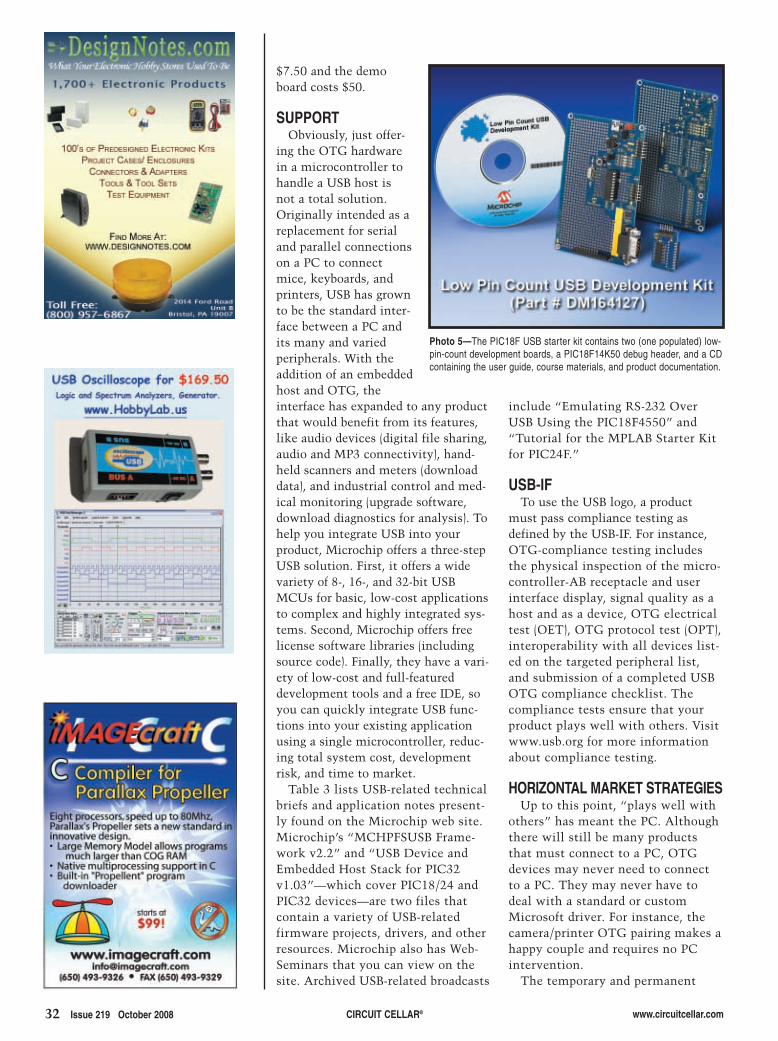
32 Issue 219 October 2008 CIRCUIT CELLAR® www.circuitcellar.com
$7.50 and the demoboard costs $50.
SUPPORTObviously, just offer-
ing the OTG hardwarein a microcontroller tohandle a USB host isnot a total solution.Originally intended as areplacement for serialand parallel connectionson a PC to connectmice, keyboards, andprinters, USB has grownto be the standard inter-face between a PC andits many and variedperipherals. With theaddition of an embeddedhost and OTG, theinterface has expanded to any productthat would benefit from its features,like audio devices (digital file sharing,audio and MP3 connectivity), hand-held scanners and meters (downloaddata), and industrial control and med-ical monitoring (upgrade software,download diagnostics for analysis). Tohelp you integrate USB into yourproduct, Microchip offers a three-stepUSB solution. First, it offers a widevariety of 8-, 16-, and 32-bit USBMCUs for basic, low-cost applicationsto complex and highly integrated sys-tems. Second, Microchip offers freelicense software libraries (includingsource code). Finally, they have a vari-ety of low-cost and full-featureddevelopment tools and a free IDE, soyou can quickly integrate USB func-tions into your existing applicationusing a single microcontroller, reduc-ing total system cost, developmentrisk, and time to market.
Table 3 lists USB-related technicalbriefs and application notes present-ly found on the Microchip web site.Microchip’s “MCHPFSUSB Frame-work v2.2” and “USB Device andEmbedded Host Stack for PIC32v1.03”—which cover PIC18/24 andPIC32 devices—are two files thatcontain a variety of USB-relatedfirmware projects, drivers, and otherresources. Microchip also has Web-Seminars that you can view on thesite. Archived USB-related broadcasts
include “Emulating RS-232 OverUSB Using the PIC18F4550” and“Tutorial for the MPLAB Starter Kitfor PIC24F.”
USB-IF To use the USB logo, a product
must pass compliance testing asdefined by the USB-IF. For instance,OTG-compliance testing includesthe physical inspection of the micro-controller-AB receptacle and userinterface display, signal quality as ahost and as a device, OTG electricaltest (OET), OTG protocol test (OPT),interoperability with all devices list-ed on the targeted peripheral list,and submission of a completed USBOTG compliance checklist. Thecompliance tests ensure that yourproduct plays well with others. Visitwww.usb.org for more informationabout compliance testing.
HORIZONTAL MARKET STRATEGIESUp to this point, “plays well with
others” has meant the PC. Althoughthere will still be many productsthat must connect to a PC, OTGdevices may never need to connectto a PC. They may never have todeal with a standard or customMicrosoft driver. For instance, thecamera/printer OTG pairing makes ahappy couple and requires no PCintervention.
The temporary and permanent
Photo 5—The PIC18F USB starter kit contains two (one populated) low-pin-count development boards, a PIC18F14K50 debug header, and a CDcontaining the user guide, course materials, and product documentation.
2810020-bachiochi-PRINT.qxp 9/8/2008 12:00 PM Page 32
www.circuitcellar.com CIRCUIT CELLAR® Issue 219 October 2008 33
Jeff Bachiochi (pronounced BAH-key-AH-key) has been writing for Circuit
RESOURCESJ. Bachiochi, “Accessing the USBFramework: A Quick Transition fromUART to USB,” Circuit Cellar 195,2006.
———, “Create a USB Hybrid Hub,”Circuit Cellar 170, 2004.
———, “Embedded USB Breakthrough,”Circuit Cellar 200, 2007.
———, “USB DMX,” Circuit Cellar 172,2004.
———, “USB in Embedded Design,”Parts 1 and 2, Circuit Cellar 165 and166, 2004.
Microchip Technology, Inc.,“PIC18F87J50 Family Data Sheet:64/80-Pin High-Performance, 1-MbitFlash USB Microcontrollers withnanoWatt Technology,” DS39775B,2007.
———, “PIC32MX3XX/4XX FamilyData Sheet: 64/100-Pin General Pur-pose and USB 32-Bit Flash Microcon-trollers,” DS61143D, 2008.
K. Otten, “Tutorial for MPLAB StarterKit for PIC24F,” Microchip Technology,Inc., 2008, http://techtrain.microchip.com/webseminars/documents/PIC24FStrKit_031708.pdf.
R. Rojvanit, “Emulating RS-232 over USBwith PIC18F4550,” Microchip Technolo-gy, 2004, http://techtrain.microchip.com/webseminars/documents/EmulatingRS-232overUSB_121004.pdf.
SOURCEPIC18F14K50, PIC18F4550, PIC18F66J50,PIC18F87J50, PIC24FJ256GB110, andPIC32MX460F512L Microcontrollers,DM164127 development kit,DM240011 starter kit, DM320003starter board, DV163025 demonstra-tion board, and PICkit 2 developmentprogrammer/debuggerMicrochip Technology, Inc. www.microchip.com
Cellar since 1988. His backgroundincludes product design and manu-facturing. You can reach him [email protected] www.imaginethatnow.com.
storage and exchange of audio, video,and data files is thriving thanks tosolid-state storage media. By far, themost popular function for USB is themoving of data. USB has made thethumb drive common place. I seethem around necks, on key chains,and hanging up in groups waitingtheir turn in a rotational game ofdaily system backups. A product thatsupports MSD may never need toconnect to anything other than athumb drive.
One of the features that flashmemory microcontrollers havebrought to products is the ability toupdate their own operating systems.Back in Circuit Cellar 200, I used aUSB MSD device in a logger for myelectric bicycle project (“EmbeddedUSB Breakthrough,” 2007). When athumb drive was plugged in, the fileswere searched for a particular filename. If it found a file with thatname, it used the bootloader to readin the file (a new operating system)and reboot. This, however, is causefor the USB-IF to sit up and takenotice because this may violate com-pliance. The USB-IF states that if anychanges are made to the product, cre-ating “significant differences”between the production product andthe product samples tested, retestingis required. They state that as long asthe PCB hasn’t changed and the USBfunction code remains unchanged,retesting is not required.
I’m predicting that the sensor mar-ket will take up USB with openarms. Up to this point, USB peripher-al developers have been wearingblinders. Products were developedonly if the PC could make use of it.With full support for embedded host-ing and OTG, I think we will seesmart sensors being developed forembedded hosts. Smart sensors pro-vide their hosts with the informationnecessary to make use of the sensorwithout any manual configuration.
Microchip has readied itself for theUSB onslaught. It can provide youwith the parts, tools, and informationto make it happen (see Photo 5). I
2810020-bachiochi-PRINT.qxp 9/8/2008 12:00 PM Page 33
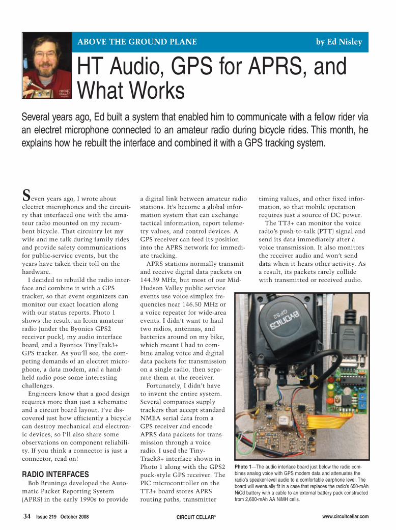
34 Issue 219 October 2008 CIRCUIT CELLAR® www.circuitcellar.com
Seven years ago, I wrote aboutelectret microphones and the circuit-ry that interfaced one with the ama-teur radio mounted on my recum-bent bicycle. That circuitry let mywife and me talk during family ridesand provide safety communicationsfor public-service events, but theyears have taken their toll on thehardware.
I decided to rebuild the radio inter-face and combine it with a GPStracker, so that event organizers canmonitor our exact location alongwith our status reports. Photo 1shows the result: an Icom amateurradio (under the Byonics GPS2receiver puck), my audio interfaceboard, and a Byonics TinyTrak3+GPS tracker. As you’ll see, the com-peting demands of an electret micro-phone, a data modem, and a hand-held radio pose some interestingchallenges.
Engineers know that a good designrequires more than just a schematicand a circuit board layout. I’ve dis-covered just how efficiently a bicyclecan destroy mechanical and electron-ic devices, so I’ll also share someobservations on component reliabili-ty. If you think a connector is just aconnector, read on!
RADIO INTERFACESBob Bruninga developed the Auto-
matic Packet Reporting System(APRS) in the early 1990s to provide
a digital link between amateur radiostations. It’s become a global infor-mation system that can exchangetactical information, report teleme-try values, and control devices. AGPS receiver can feed its positioninto the APRS network for immedi-ate tracking.
APRS stations normally transmitand receive digital data packets on144.39 MHz, but most of our Mid-Hudson Valley public serviceevents use voice simplex fre-quencies near 146.50 MHz ora voice repeater for wide-areaevents. I didn’t want to haultwo radios, antennas, andbatteries around on my bike,which meant I had to com-bine analog voice and digitaldata packets for transmissionon a single radio, then sepa-rate them at the receiver.
Fortunately, I didn’t haveto invent the entire system.Several companies supplytrackers that accept standardNMEA serial data from aGPS receiver and encodeAPRS data packets for trans-mission through a voiceradio. I used the Tiny-Track3+ interface shown inPhoto 1 along with the GPS2puck-style GPS receiver. ThePIC microcontroller on theTT3+ board stores APRSrouting paths, transmitter
timing values, and other fixed infor-mation, so that mobile operationrequires just a source of DC power.
The TT3+ can monitor the voiceradio’s push-to-talk (PTT) signal andsend its data immediately after avoice transmission. It also monitorsthe receiver audio and won’t senddata when it hears other activity. Asa result, its packets rarely collidewith transmitted or received audio.
Several years ago, Ed built a system that enabled him to communicate with a fellow rider viaan electret microphone connected to an amateur radio during bicycle rides. This month, heexplains how he rebuilt the interface and combined it with a GPS tracking system.
ABOVE THE GROUND PLANE by Ed Nisley
Photo 1—The audio interface board just below the radio com-bines analog voice with GPS modem data and attenuates theradio’s speaker-level audio to a comfortable earphone level. Theboard will eventually fit in a case that replaces the radio’s 650-mAhNiCd battery with a cable to an external battery pack constructedfrom 2,600-mAh AA NiMH cells.
HT Audio, GPS for APRS, andWhat Works
2810004_nisley.qxp 9/8/2008 12:01 PM Page 34

www.circuitcellar.com CIRCUIT CELLAR® Issue 219 October 2008 35
At the event control station, apacket radio modem extracts the dig-ital data from the radio receiver’saudio output. A laptop running XAS-TIR, a free software program thatintegrates GPS position data withthe APRS network, then displays ourlocation on a map of the area.
On solo rides, when I’m not inter-ested in talking or breathing too hardto chat, I can switch the radio to144.39 MHz and transmit GPS track-ing data directly into the existingAPRS network covering the Mid-Hudson Valley.
Our Icom IC-Z1A and IC-W32Aradios have the standard Icom“external interface” consisting of a3.5-mm external speaker jack and a2.5-mm microphone jack. Althoughthe dimensions don’t quite work out,they were formerly known as 0.125″and 0.1″ subminiature phone plugs
and jacks.According to the radio interface
schematics, the sleeve terminalsof both jacks connect to theradio’s common voltage, whichis also the battery’s negative ter-minal. The 3.5-mm ring termi-nal is a bidirectional serial datainterface for radio control,although that seems to beunused on the Z1A. The 2.5-mmring terminal supplies 3.5 Vthrough a 400-Ω resistor for elec-tret microphone bias. The tipterminals connect to the exter-nal speaker and microphone,respectively.
AUDIO ROUTINGThe schematic in Figure 1 has
three main sections: the electretmicrophone amplifier, the Tiny-Trak3+ interface, and power
control. I put SMD capacitors on allof the inputs to keep RF out of the
Figure 1—The audio transformer and optocouplers break a galvanic loop that would otherwise link the two radio jacks through the board. The Maxim Integrated ProductsMAX4544 analog switch isolates the microphone and the Byonics TinyTrak3+ audio from each other, while the LM336 isolates the MAX4468’s supply from the TT3+ microcontroller’sdigital noise. Optocouplers OK1 and Q1 activate the TinyTrak3+ when the radio power is on.
Photo 2—This washable push button switch has worked reli-ably for seven years in an environment where open-frameswitches fail within months. Hot-melt glue secures it to thehandlebar and seals the cable connection.
2810004_nisley.qxp 9/8/2008 12:01 PM Page 35

36 Issue 219 October 2008 CIRCUIT CELLAR® www.circuitcellar.com
circuitry, which works just as welland is far simpler than the ferritetoroids in my previous amplifier.
I used a Maxim Integrated ProductsMAX4468 electret microphoneamplifier that’s designed specificallyfor this task. It includes a shutdownfunction to save power; but at itshighest, the amplifier draws less than1% of the power required by the GPSreceiver, so I didn’t bother using it.
My original design amplified thevoice signal by a factor of two, whichmade us rather soft-spoken. A fewweeks of experimentation showedthat a gain of 10 was about right.Your radios will certainly have differ-ent requirements, but this is thewrong place for a mechanical trimpot.
The MAX4468 has a decompensatedamplifier that must be used with again of five or more. If your radiorequires a gain less than five, use theMAX4467 instead: it’s compensatedfor unity-gain stability.
The TT3+ includes a 5-V linear reg-ulator, but its output carries all of theusual digital noise from the PICmicrocontroller. I used an LM336, nor-mally a voltage reference, as a simpleshunt regulator to get rid of most ofthat hash. A resistive divider producesthe VCC/2 virtual ground required forsingle-supply op-amps.
The PIC microcontroller generates1.2- and 2.2-kHz audio signals througha 4-bit discrete-resistor DAC, withonly a dozen or so steps in each cycle.It has no reconstruction or antialiasingfilters, because the radio’s 3-kHz voice
cutoff acts as a steep low-pass filterthat eliminates most of the harmonics.The output is capacitively coupledfrom a trimpot level control.
My first-pass circuit combined thevoice and data signals with an op-ampadder. That was a serious blunder,because the DAC’s inactive outputcoupled a noisy background janglebehind the voice transmissions. Ishould have known better, right?
The second version of the circuit,shown in Figure 1, uses a MAX4544single-pole/double-throw (SPDT) ana-log switch that connects one of thetwo inputs to the radio at a time. Thevoice signal now has no trace ofmachine chatter and the digital signaldoesn’t carry any noise from themicrophone.
Speaking of microphone noise, asimple 20-mm ball carved fromacoustic foam eliminates nearly all ofthe wind noise you’d expect from amicrophone in a 25-MPH breeze. It’ssurprisingly effective and utterly triv-ial, with only one drawback: rainfloods the microphone capsule andkills the audio. I still haven’t figuredout a waterproof and audio-transpar-ent fix for that problem!
POWER CONTROLAlthough the radio’s microphone
and speaker jacks share a commonsleeve connection, I decided to isolatethe microphone jack’s common fromthe circuit board common. This pre-vents power supply current from flow-ing through the microphone cable,
where it would add directly to thelow-level audio signal. This may notbe necessary in all applications, butit’s a good trick to keep in mind whenyou’re dealing with audio and digitalcircuitry.
A small 1:1 transformer passes theaudio signal while isolating the twogrounds. C8 blocks the VCC/2 virtualground bias on the input side.
Connecting the radio’s microphoneinput line to the sleeve contactthrough a 33-kΩ resistor activatesthe transmitter, requiring AC cou-pling for the audio signal throughC10 on the output side of the trans-former. The radio has a 2-kΩ inputimpedance and the lowest audio fre-quency is about 300 Hz, so the block-ing cap must be larger than:
[1]
C8 and C10 are effectively inseries, so I used tiny 1-µF caps to get500 nF. The output is down about 1 dBat 100 Hz.
Optocoupler OK2 isolates theboard’s PTT signal from the radio’smicrophone common. The TT3+includes diode steering logic thatcombines its internal PTT with thevoice PTT push button on the han-dlebars, activating OK2 for bothvoice and data transmissions.
The GPS2 receiver requires about70 mA, roughly twice the Icom’s idlecurrent. I didn’t want a separatepower switch for the GPS hardware,because I knew I’d never rememberto turn it off, so I controlled the GPSpower with the radio’s microphonebias supply. OK1, another SFH615optocoupler, has a minimum currenttransfer ratio of 65%, which, combinedwith the 2N2907 transistor’s mini-mum hFE of 100, ensures that 8 mA
C 12 • 300 • 2 10
270 nF3=×
=π
Photo 3—After our commercial antenna mounts frac-tured from constant vibration, I machined sturdyreplacements. The rear-facing LED light includes myreplacement microcontroller for its up-convertingswitching power supply.
Photo 4—These PS/2 keyboard connectors allow thehelmet to part easily from the bike. The joints havebeen reliable but the cable attached to the helmet failsevery year or two.
a) b)
2810004_nisley.qxp 9/8/2008 12:02 PM Page 36

www.circuitcellar.com CIRCUIT CELLAR® Issue 219 October 2008 37
from the microphone supply satu-rates the transistor when the radio isturned on.
I ran wires from the TT3+ powerterminals directly to the 2N2907 andthe board’s battery power entry, thus
keeping its relativelyhigh currents out of theboard’s ground planes. Ididn’t do that in thefirst version and the dif-ference is clearly audi-ble: all this finicky ana-log layout stuff reallydoes matter.
I’ve taken the circuitfor some test rides andit works fine, althoughreliable reception posesmore of a problem fordigital signals. I mustnow do some CNCmachining for a casethat will replace theradio’s battery pack andhold the two boards.We’ll see how every-thing behaves during
the radio club’s fall public serviceevent schedule.
Speaking of changes, the circuitboard isn’t the only thing that’schanged since that early design.Here’s a quick rundown of some
other components that requiredattention.
THINGS THAT WORK AND FAILLet’s start with the one component
that has been absolutely reliable: thepush-to-talk switch shown in Photo 2.I soldered a washable through-holepush button switch to a cable with amolded 3.5-mm plug on the otherend, secured it to the handlebarswith a blob of hot-melt glue that alsosealed the cable end, and that wasthat.
The key attributes turned out to bewashable and sealed, as similarswitches failed within months. Marypreferred taller buttons that were, alas,available only on open-frame switches.After a year of intermittent chattingas the switches failed, she grew accus-tomed to that flat button.
On the RF side of the radio, I boughta pair of antenna mounts designed toclamp on truck mirror support bars,figuring that they’d last forever on ourbikes’ seat frame tubes. Six years later,metal fatigue fractured both mounts
Photo 5—The 3.5- and 2.5-mm plugs repeatedly ripped the jacks off theradio’s circuit board, so the blob of epoxy putty fixes them firmly in placeand eliminates that problem. The joints inside the connector shells havebecome intermittent, despite being potted in hot-melt glue.
Save Up To 60% On Electronic Components
Wide Range Including,
• New Ethernet Board
• SD Card
• Memory Cards
• Real Time Clocks
and Much More
Exciting New Mini-Boards
www.futurlec.com
We are your one-stop shop for Microcontroller Boards,
PCB Manufacture and Electronic Components
•
•
•
•
Powerful New ARM2368 Controller
Just arrived our new range
of Solar Controllers, Gas Sensors
and Wireless Data Link Modules,
all at very competitive prices.
.
ONLY$19.90
ONLY$69.90
Now available our most powerful Embedded Controller Yet!
Includes LPC2368 Microcontroller
- 512kb Flash Memory
SD Card Socket
Ethernet LAN Connection
2 CAN Network Controllers
ONLY$25.90
Save Heaps on Components
2810004_nisley.qxp 9/8/2008 12:02 PM Page 37

38 Issue 219 October 2008 CIRCUIT CELLAR® www.circuitcellar.com
SOURCESPowerpole connectorsAnderson Power Products, Inc.www.andersonpower.com/products/singlepole-connectors.html
TinyTrak3+ Tracker and GPSreceivers Byonicswww.byonics.com
Amateur radio products: IC-W32Adual-band transceiver and IC-Z1Ahandheld transceiverIcom America, Inc. http://icomamerica.com/en/amateur/default.aspx
X Amateur tracking and informationsystemXASTIRwww.xastir.org
PROJECT FILESTo download code, go to ftp://ftp.circuitcellar.com/pub/Circuit_Cellar/2008/219.
Ed Nisley is an EE and author in Pough-keepsie, NY. Contact him at [email protected] with “Circuit Cellar” in thesubject to avoid spam filters.
RESOURCESB. Bruninga “Automatic PacketReporting System,” www.aprs.org.
D. DePriest, “GPS Data Format,”www.gpsinformation.org/dale/nmea.htm.
E. Nisley, “Building Boxes,” CircuitCellar 173, 2004.
———, “Capacitors at RF,” CircuitCellar 175, 2005.
———, “LED Power,” Circuit Cellar209, 2007.
during a 350-mile bike tour.Photo 3a shows an antenna mount I
made from a box-section extrusion,Delrin plate, and CNC-machined cir-cumferential clamps. Photo 3b showsa simpler mount machined from analuminum plate. Both are absolutelyrigid, which means the antenna mastor the coils and capacitors along it willfail next.
My December 2007 columnexplored the power supply inside thewhite LED blinky light clamped to theantenna in Photo 3a (“LED Power,”Circuit Cellar 209). It’s worked fineever since and, in fact, NiMH AA cellslast much longer than in the originallights. I’m tempted to replace themicrocontrollers in our other lights,but I’m even more reluctant to messwith things that work.
My original helmet-to-amplifier con-nection used delicate earbud wire andPS/2-style mini-DIN keyboard connec-tors. That wiring disintegrated withinone riding season, so I soldered afemale DIN connector to a stout cablethat replaced the helmet wiring.
That lasted another season beforethe cable fatigued at the helmet andthe connector pins disintegrated. Aftertrying an increasingly bizarre series ofunsuccessful strain-relief ideas, I gaveup and used molded keyboard cableson both ends, joined by a female-to-female adapter, as shown in Photo 4.
The heatshrink tubing that stabi-lizes the joints isn’t entirely water-tight, so rain affects the microphonesignals. I could use watertight connec-tors, but that joint must slip apart toallow the helmet and bike to go theirseparate ways when I drop the bike.Yes, I’ve tested that feature.
Photo 5 shows the old microphoneamplifier and radio connections. As I’dhoped, the surface-mount componentsin the microphone amplifier provedmore durable than through-hole resis-tors, but the radio connections failedwhen vibration broke the internal jacksfrom their circuit-board moorings.
I finally stabilized the plugs with ablob of epoxy putty molded to the topand rear of the radio, a fix thatpromptly moved the failure point tothe cables between the jacks and theradio. I had potted the connector shells
with hot-melt glue and strain reliefbushings, but that obviously wasn’tenough.
Despite not being designed for ahigh-vibration environment, the radioitself held up remarkably well. We’vebeen using long-obsolete Icom IC-Z1Aradios and I’m setting up the GPSinterface with the similar and slightlyless obsolete IC-W32A shown inPhoto 1. The current crop of water-resistant radios looks attractive, butthese oldies continue to work.
The radio rides inside a foam-padded seat-wedge pack, strapped in awater bottle holder attached to thelower seat rail with two circumferen-tial clamps. The tight packing andcables made battery changes quite dif-ficult, so I converted an alkaline AA-cell holder into a remote battery con-nection. The black-and-blue AndersonPowerpole Products connectors,shown in Photo 5, mate reliably withan external pack that I can replacewithout disturbing the radio and itscables.
All this may seem like a nasty caseof forcing cheap consumer hardwareinto the wrong application and thengriping about the failure rate, but thetruth is a bit more complex. I coulduse rugged components, but their costand bulk seem unwarranted for alightweight installation.
Worse, there’s no single weakestlink that would benefit from anupgrade. Apart from that PTT button,I’ve seen failures in essentially everycomponent. Add up, if you dare, thecost of building everything withruggedized and weatherproof compo-nents, then factor in a new radio. Mul-tiply that total by three to outfit myfamily’s bikes and I think you’ll agreethat desirable though an ideal systemmay be from a design standpoint, thebottom line simply isn’t justifiable.
Having learned a lot more aboutvibration and strain relief, I hope thatthe current iteration will survive withfewer repairs and less down time,despite the additional complexity.
CONTACT RELEASEFor reasons best known to the man-
ufacturers, no two radios have thesame jack configuration. You should
assume that you’ll need a differentradio cable as well as a differentamplifier gain.
By the time this reaches print, youshould be able to track the KE4ZNU-9’sbicycle-mobile progress around thePoughkeepsie, NY, area through any ofthe APRS mapping web sites. I
2810004_nisley.qxp 9/8/2008 12:02 PM Page 38

39.qxp 9/3/2008 3:53 PM Page 1
Bargain MSO 100/200/300MHz DSO 1/2GHz RF Generators
Color LCD Scope World’s Fastest50MHz USB Scope Logic Analyzer
6 in 1 Scope Automotive Testing
DMM
EMC Spectrum Analyzer
Pen Scope
USB Bus Analyzers
Handheld Scope
Scope + Analyzer
Mixed -Signal PC Oscilloscope
Low-Cost Scope
15/20MHz Wfm Gen
Testg
ear
Mis
c
60/100/120MHz AWG
Owon - 25MHz 2-ch +
trigger standalone USB bench
scope with 7.8” color LCD.
Battery powered optional.
PDS5022S (25MHz) $325
PDS6062T (60MHz) $599
20MHz or 60MHz rugged
handheld USB scope with 3.8”
color LCD. Built-in meter -
great for your tool kit.
HDS1022MN (20MHz) $593
HDS2062M (60MHz) $699
ZeroPlus - Intuitive full-featured 16-ch
4MB 200MHz sampling memory.
Sophistcated triggering. I2C, SPI,
and UART monitoring. Includes
clipleads, USB cable and software.
LAP-16128U $299
6-in-1 USB scope adapter! 200kHz 2-ch
10-bit scope, 2-ch spectrum analyzer,
2-ch chart recorder, 16-ch 8MHz logic
analyzer, 5-ch signal gen, 8-ch pattern
gen. SPI/I2C/1-w/UART decoding.
PoScope with probes $199
Best
Seller
PS5204 - 2-ch 250MHz Scope with
128 MS/s and real-time sampling of
1GS/s. Adv triggering. 250MHz spec.
analyzer and 125MS/s waveform gen.
PS5203 32MS buffer $2237
PS5204 128MS buffer $3360
PS2105 - 25MHz USB powered
scope - i n -a -p robe ! Up t o
100MS/s, 24kS buffer C/VB/
Delphi/LabView/VEE drivers.
PS2105 (25MHz, 100MS/s) $369
PS2104 (10MHz, 50MS/s) $234
PS3206 - Is an impressive 2-ch
200MS/s 8-bit PC scope adapter
- 10GS/s for repetitive signals!
No power supply needed, simple
USB 2.0 connection
PS3206 Bundle $1574
USB1.1/2.0/WiMedia analyzers
and now - EX260 can test
USB3.0 5Gbps too! Emulate
host/device, verify compliance.
TR110 / EX200 / EX260
$999 / $2999 / CALL
Auto Diagnostics - Award-winning
kits turn yours into vehicle-electrics
diagnostic tool. PS3423 kit $2293
3-ch logger for 16-bit current/voltage/
temp msmt. KLARI-MOD MC $1900
100/200/300MHz 2 ch, 2000 wfm/s
refresh rate.
DS1102C (400MS/s) $999
DS1102A (2GS/s) $1295
DS1202A (2GS/s) $1595
DS1302A (2GS/s) $1995
15/20MHz USB 14-bit Function/
Arbitrary wfm Generators. 10 built-in
wfms; FM, AM, PM, FSK,
SWEEP and BURST; 6 digit
200MHz frequency counter.
DG1011 / DG1021 $650 / $795
100MHz 2-ch /16 logic scope and
logic analyzer. 2000 wfm/s refresh
rate. See waveforms and logic
data simultaneously. Trigger on
data or signal edge.
DS1102CD $1499
High accuracy/stability, wide
range, low phase noise/leakage,
serial control. Keypad/rotary setting.
TGR1040: 10MHz-1GHz, FM int/ext
TGR2050: 150kHz-2GHz AM/FM/PM
$2498/4558
25MHz 100 MS/s 2/16ch scope/
logic-analyzer 5ns-5s/div with
complex triggering. See wfm +
data lines. 7.8” TFT Color LCD.
USB-connected. 4MS buffer.
MSO5022 $899
60/100/120MHz USB 14-bit ARB
w. USB RS-232, LAN/GPIB. 10
built-in wfms; 6 digit 200MHz
frequency counter; opt. 16-ch
gen. DG3061A $1895
DG3101A/DG3121A $2795/$3995
6 1/2 digit 50KS/s, 2MS mem. Opt.
16-ch mux. Automeasure DC/AC,
2/4-wire R, C, Continuity, Diode,
Frequency, Period, Ratio, Temp,
Sensor, High/Low Limit Math.
DM3061 $795
Handheld Palm PC-based 2.7GHz
Spectrum Analyzer. Multiple
sweep settings – store wfms,
set-ups, etc. Use WiFi PC for
email, reports, calculations.
PSA2701T $1990
100 MHz Scope and Logic Analyzer
lets you do complex triggering to find
hard-to-get-at glitches, spikes, etc.
Huge 4 or 8 MS buffer for deep data
drilling and zooming. Optional built-in
swept signal generator. 2 Analog
channels x 10, 12, 14 bit with more
than 60 dB dynamic range. 8 digital
inputs for mixed signal display/trigger.
CS328A-4 (4MS Buffer) $1259
CS328A-8 (8MS Buffer) $1474
CS700A (signal generator) $299
NEW!
RIGOL
NEW!
RIGOL
We search the world for unique, time-saving products - see our website for 100s more: volt/temp data loggers,wireless boards, LCD display kits, Ethernet/IO, USB/RS232/485, USB-OTG, instant Ethernet-serial,CAN/LINbus, USB cables/extenders, line testers, logic analyzers, color sensors, motion controllers,eng. software, wireless boards, SMD adapters, I2C adapters, FPGA kits, GPS loggers, automotive testing,security dongles, video motion detectors, crystals/oscillators, custom switches, barcode scanners,robots, DSP filters, PLCs, Remote MP3 players, etc. Don’t forget to ask for your FREE Starbucks cardwith your order! Check www.sae l ig . com often for special offers, bargains, business hints, blog, etc.
NEW!
RIGOL
NEW!
RIGOL
NEW!
RIGOL
NEW!
U N I Q U E P R O D U C T S & S U P P O R Tw w w . s a e l i g . c o m
Winner!
Electronic DC Load
For testing dc power/battery sources
Const. current, resistance,
conductance, voltage and power
modes 0 to 80 V and 0 to 80 A 300W
Transient generator. Variable drop-out.
LD300 $1532
2-ch 40/100/200MS/s 8-bit scope
range with 5/10/25MHz bandwidth
and USB2.0 for fast screen
updates. Inc. scope/FFT/logging
software.
PS2203/4/5 from $297
FreeCase!
FreeCase!SALE! $799
Serial-Ethernet Cable
Network your serial product easily
without a PC using this 28” cable.
Provides an instant IP address.
RS-232 port compatible with most
10/100mpbs Ethernet hubs.
eCOV-110-P $89
Devasys - Provides a simple
“drop-in” solution for connecting
your PC to 90kHz I2C + 20 I/O
lines. Free software. Use multiple
boards for more I2C/IO.
USB I2C/IO $89
USB to I2C I2C for PCs
PCI93LV: industry-standard I2C card
for PCs. WINI2C/PCI software
gives windows-interface to develop
and debug I2C bus systems.
UCA93LV is USB version.
Transparently monitor at
400kHz! $499
RF Modules
RF TX/RX Modules - simultaneously
transmit composite video and
stereo audio signals. 2.4 GHz
ISM band. 4-ch RF, 5V operation
AWM630TX $16
AWM634RX $27
Ether-IO - UDP/IP-controlled 24
digital I/O board 3 x 8-bit TTL
ports each independently
programmable. Connects to any
TCP/IP Ethernet network.
Ether-IO 24 $119
Ethernet - IO
Mini-logger with built-in temp/humidity/
pressure/3-axis accel sensors.
Customize msmt/record parameters;
send data to PC after or during logging.
Synchronize multiple loggers,
merge data to single record
MSR145S from $468
Multiparameter Loggers
1/2/4/8/16 x RS232
Add COMports via your PC’s
USB Port. USB-COM-S $20
USB-2COM $48
USB-4COM $105
USB-8COM $195
USB-16COM-RM (rackmount) $459
TinyOne ZigbeeTM
Complete RF solution for fast & reliable
data transmission. Miniaturized OEM
RF module ensures fast and easy
integration into wireless applications.
TinyOne Zigbee $58
B915FH-tiny/40-SMD-WA $63
RF Testing
Economical, portable RF test
enclosures, for initial compliance
testing. from $1295
Shielding Tents with external
frame, instant up/down for
emissions-free room. from $3500
Wireless Analog
4-ch analog input wireless
module 433/868/915MHz. Low
power serial interface. Easy
configure. 24 bit ID to avoids
cross- talk. 2 digital output.
EmbedRF Module $59
EmbedRF DevKit $299
GPS Logger
TrackStick II - Pocket-sized logger
tracks position data for vehicles,
personnel, etc. Records date, time,
location, route and speed. Shows
data on Google maps! $175
Super TrackStick II $239
SPI Bus Analyzer
SPI Bus Analyzer - SPI protocol
exerciser and analyzer for standard
SPI and non-standard 4-wire and
3-wire serial protocol interfaces up
to 50 Mbps. PC control via free GUI
8Pl Control Panel Software.
SPI Xpress $783
Temp/RH Sensors
UPSICAP™- novel ambient sensors
and modules accurately measure
temp/RH. Amazing range/response:
0% to 100% RH, -90 to +85degC;
0.25s! Interchangeable without
recalibration. from $3 / $40
Alan Lowne
says: "I started
Saelig as an
engineer - for
e n g i n e e r s !
Saelig - an
Olde English
word meaning 'happy, prosperous,
blessed' - which is what I want for
my customers, my staff, and
myself! See my blog for behind-
the-scenes company details,
business hints, kudos, etc. "
Saelig
Instant Ethernet
10/100 Ethernet controller on a chip!
Fully hardwired TCP/IP core. No
OS required. TCP offload improves
system performance. PCB too!
W5100 (integrated PHY) $5.88
WIZ110SR $35
40.qxp 8/25/2008 2:13 PM Page 1
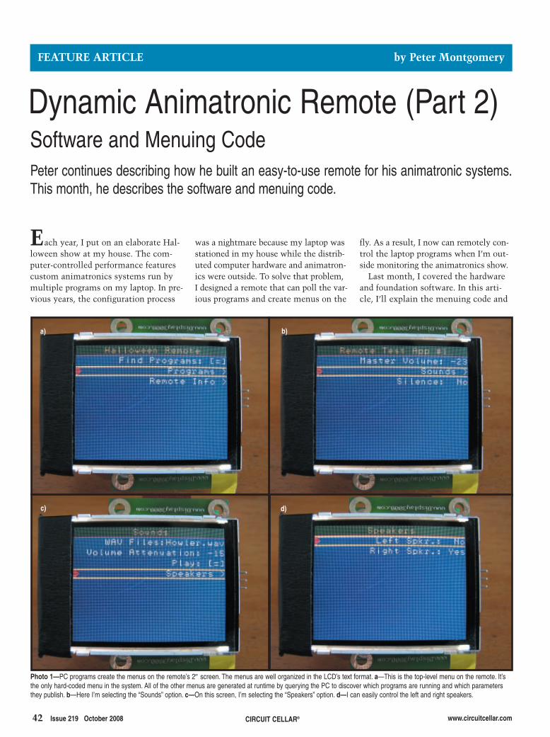
42 Issue 219 October 2008 CIRCUIT CELLAR® www.circuitcellar.com
was a nightmare because my laptop wasstationed in my house while the distrib-uted computer hardware and animatron-ics were outside. To solve that problem,I designed a remote that can poll the var-ious programs and create menus on the
Each year, I put on an elaborate Hal-loween show at my house. The com-puter-controlled performance featurescustom animatronics systems run bymultiple programs on my laptop. In pre-vious years, the configuration process
fly. As a result, I now can remotely con-trol the laptop programs when I’m out-side monitoring the animatronics show.
Last month, I covered the hardwareand foundation software. In this arti-cle, I’ll explain the menuing code and
FEATURE ARTICLE by Peter Montgomery
Peter continues describing how he built an easy-to-use remote for his animatronic systems.This month, he describes the software and menuing code.
Dynamic Animatronic Remote (Part 2) Software and Menuing Code
b)
c) d)
Photo 1—PC programs create the menus on the remote’s 2″ screen. The menus are well organized in the LCD’s text format. a—This is the top-level menu on the remote. It’sthe only hard-coded menu in the system. All of the other menus are generated at runtime by querying the PC to discover which programs are running and which parametersthey publish. b—Here I’m selecting the “Sounds” option. c—On this screen, I’m selecting the “Speakers” option. d—I can easily control the left and right speakers.
a)
2810015_Montgomery.qxp 9/8/2008 1:08 PM Page 42
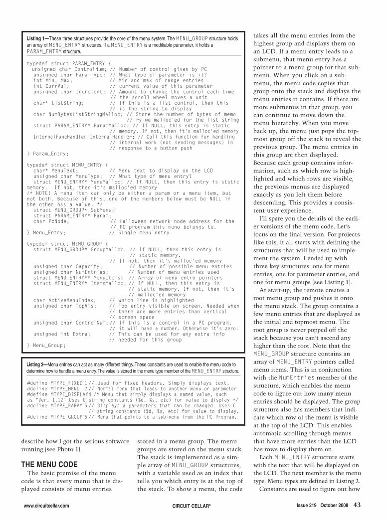
www.circuitcellar.com CIRCUIT CELLAR® Issue 219 October 2008 43
stored in a menu group. The menugroups are stored on the menu stack.The stack is implemented as a sim-ple array of MENU_GROUP structures,with a variable used as an index thattells you which entry is at the top ofthe stack. To show a menu, the code
describe how I got the serious softwarerunning (see Photo 1).
THE MENU CODEThe basic premise of the menu
code is that every menu that is dis-played consists of menu entries
takes all the menu entries from thehighest group and displays them onan LCD. If a menu entry leads to asubmenu, that menu entry has apointer to a menu group for that sub-menu. When you click on a sub-menu, the menu code copies thatgroup onto the stack and displays themenu entries it contains. If there aremore submenus in that group, youcan continue to move down themenu hierarchy. When you moveback up, the menu just pops the top-most group off the stack to reveal theprevious group. The menu entries inthis group are then displayed.Because each group contains infor-mation, such as which row is high-lighted and which rows are visible,the previous menus are displayedexactly as you left them beforedescending. This provides a consis-tent user experience.
I’ll spare you the details of the earli-er versions of the menu code. Let’sfocus on the final version. For projectslike this, it all starts with defining thestructures that will be used to imple-ment the system. I ended up withthree key structures: one for menuentries, one for parameter entries, andone for menu groups (see Listing 1).
At start-up, the remote creates aroot menu group and pushes it ontothe menu stack. The group contains afew menu entries that are displayed asthe initial and topmost menu. Theroot group is never popped off thestack because you can’t ascend anyhigher than the root. Note that theMENU_GROUP structure contains anarray of MENU_ENTRY pointers calledmenu items. This is in conjunctionwith the NumEntries member of thestructure, which enables the menucode to figure out how many menuentries should be displayed. The groupstructure also has members that indi-cate which row of the menu is visibleat the top of the LCD. This enablesautomatic scrolling through menusthat have more entries than the LCDhas rows to display them on.
Each MENU_ENTRY structure startswith the text that will be displayed onthe LCD. The next member is the menutype. Menu types are defined in Listing 2.
Constants are used to figure out how
Listing 2—Menu entries can act as many different things. These constants are used to enable the menu code todetermine how to handle a menu entry. The value is stored in the menu type member of the MENU_ENTRY structure.
#define MTYPE_FIXED 1 // Used for fixed headers. Simply displays text. #define MTYPE_MENU 2 // Normal menu that leads to another menu or parameter#define MTYPE_DISPLAY4 /* Menu that simply displays a named value, suchas "Ver. 1.12" Uses C string constants (%d, %s, etc) for value to display */#define MTYPE_PARAM 5 // Displays a parameters that can be changed. Uses C
// string constants (%d, %s, etc) for value to display.#define MTYPE_GROUP 6 // Menu that points to a sub-menu from the PC Program.
Listing 1—These three structures provide the core of the menu system. The MENU_GROUP structure holdsan array of MENU_ENTRY structures. If a MENU_ENTRY is a modifiable parameter, it holds aPARAM_ENTRY structure.
typedef struct PARAM_ENTRY {unsigned char ControlNum; // Number of control given by PCunsigned char ParamType; // What type of parameter is it?int Min, Max; // Min and max of range entriesint CurrVal; // current value of this parameterunsigned char Increment; // Amount to change the control each time
// the scroll wheel moves a unitchar* ListString; // If this is a list control, then this
// is the string to displaychar NumBytesListStringMalloc; // Store the number of bytes of memo
// ry we malloc'ed for the list stringstruct PARAM_ENTRY* ParamMalloc; // If NULL, this entry is static
// memory. If not, then it's malloc'ed memoryInternalFuncHandler InternalHandler; // Call this function for handling
// internal work (not sending messages) in// response to a button push
} Param_Entry;
typedef struct MENU_ENTRY {char* MenuText; // Menu text to display on the LCDunsigned char MenuType; // What type of menu entry?struct MENU_ENTRY* MenuMalloc; // If NULL, then this entry is static
memory. If not, then it's malloc'ed memory/* NOTE! A menu item can only be either a param or a menu item, butnot both. Because of this, one of the members below must be NULL ifthe other has a value. */
struct MENU_GROUP* SubMenu;struct PARAM_ENTRY* Param;char PcNode; // Halloween network node address for the
// PC program this menu belongs to.} Menu_Entry; // Single menu entry
typedef struct MENU_GROUP {struct MENU_GROUP* GroupMalloc; // If NULL, then this entry is
// static memory. // If not, then it's malloc'ed memory
unsigned char Capacity; // Number of possible menu entriesunsigned char NumEntries; // Number of menu entries usedstruct MENU_ENTRY** MenuItems; // Array of menu entry pointersstruct MENU_ENTRY* ItemsMalloc; // If NULL, then this entry is
// static memory. If not, then it's// malloc'ed memory
char ActiveMenuIndex; // Which line is highlightedunsigned char TopVis; // Top entry visible on screen. Needed when
// there are more entries than vertical// screen space
unsigned char ControlNum; // If this is a control in a PC program,// it will have a number. Otherwise it's zero.
unsigned int Extra; // This can be used for any extra info// needed for this group
} Menu_Group;
2810015_Montgomery.qxp 9/8/2008 1:08 PM Page 43

44 Issue 219 October 2008 CIRCUIT CELLAR® www.circuitcellar.com
to display the text for the menu entry.For example, an MTYPE_FIXED menuis displayed on the top row of the LCDwith the text centered. All of the othermenu entries display the text as right-justified. The MTYPE_MENU is a normalmenu entry that displays the text asit appears in the entry. MTYPE_PARAMentries are parameters. The textstored in the MENU_ENTRY structure isactually a string with “sprintf( )”formatting sequences. This enables themenu code to add the parameter’svalue at runtime using “sprintf( )”to format the values as ASCII text.MTYPE_GROUP menu entries get a >appended to the end. This informsyou that you can click the Menu but-ton to descend down a level. The texton a group menu is displayed as anMTYPE_FIXED entry when that groupis displayed. This provides a referenceat the top of the LCD that tells youwhat the menu entries represent. Asample menu running on the LCD isshown in Photo 1a.
Note that the MENU_ENTRY structurehas two structure pointers in it. One is
to a MENU_GROUP called SubMenu, andthe other is to a param_entry struc-ture called Param. Only one of thepointers can have a value at a giventime. If the SubMenu pointer isn’tNULL, the menu entry leads toanother group of menu entries. If theParam pointer isn’t NULL, the menuentry is actually a parameter andenables you to change a value on aPC program.
The Param entry structure wasdesigned as a substructure to conservememory. Every menu item needs aMENU_ENTRY structure to represent it,but only parameters need the extrainformation to let the menu entry actas a parameter. Why put all of the
members in a single structure whenmost of them will go unused? By hav-ing the substructure, you can conservememory and locate all of the impor-tant parameter information in a single,dedicated structure.
All of the menu code for the remotemakes extensive use of malloc( ).This is a touchy point for some.Many designers feel that mallocshould never be used in embeddedprojects due to the possibility of amalloc call failing at runtime, leav-ing the program without the memoryit needs. I went back and forth onwhether I should use malloc, butultimately decided to use it. Thestandard non-malloc solution is to
Listing 3—This simplified function shows the conventional approach to memory allocation for a menu entrythat has text assigned to it. Note there are two calls to malloc().
struct MENU_ENTRY* MENU_CreateNewEntry(char* EntryText{
struct MENU_ENTRY* NewMenuItem;NewMenuItem = malloc(sizeof(struct MENU_ENTRY));
NewMenuItem->MenuText = malloc(strlen(EntryText));}
2810015_Montgomery.qxp 9/8/2008 1:08 PM Page 44
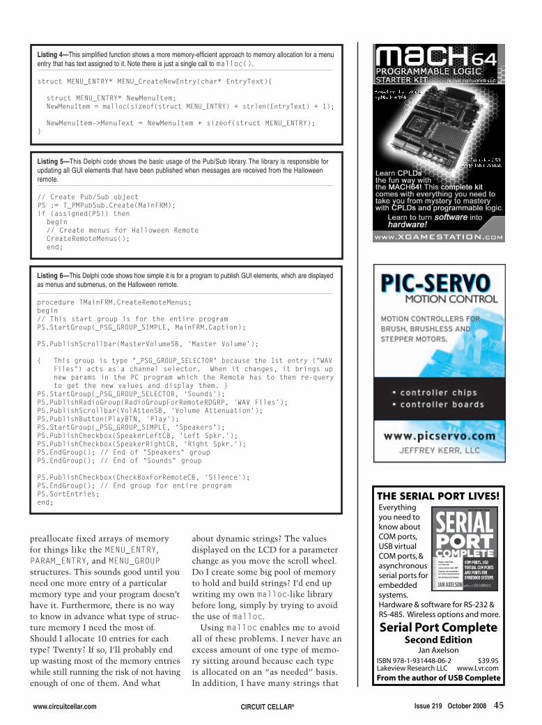
www.circuitcellar.com CIRCUIT CELLAR® Issue 219 October 2008 45
about dynamic strings? The valuesdisplayed on the LCD for a parameterchange as you move the scroll wheel.Do I create some big pool of memoryto hold and build strings? I’d end upwriting my own malloc-like librarybefore long, simply by trying to avoidthe use of malloc.
Using malloc enables me to avoidall of these problems. I never have anexcess amount of one type of memo-ry sitting around because each typeis allocated on an “as needed” basis.In addition, I have many strings that
preallocate fixed arrays of memoryfor things like the MENU_ENTRY,PARAM_ENTRY, and MENU_GROUPstructures. This sounds good until youneed one more entry of a particularmemory type and your program doesn’thave it. Furthermore, there is no wayto know in advance what type of struc-ture memory I need the most of.Should I allocate 10 entries for eachtype? Twenty? If so, I’ll probably endup wasting most of the memory entrieswhile still running the risk of not havingenough of one of them. And what
Listing 4—This simplified function shows a more memory-efficient approach to memory allocation for a menuentry that has text assigned to it. Note there is just a single call to malloc().
struct MENU_ENTRY* MENU_CreateNewEntry(char* EntryText){
struct MENU_ENTRY* NewMenuItem;NewMenuItem = malloc(sizeof(struct MENU_ENTRY) + strlen(EntryText) + 1);
NewMenuItem->MenuText = NewMenuItem + sizeof(struct MENU_ENTRY);}
Listing 5—This Delphi code shows the basic usage of the Pub/Sub library. The library is responsible forupdating all GUI elements that have been published when messages are received from the Halloweenremote.
// Create Pub/Sub objectPS := T_PMPubSub.Create(MainFRM);if (assigned(PS)) then
begin// Create menus for Halloween RemoteCreateRemoteMenus();end;
Listing 6—This Delphi code shows how simple it is for a program to publish GUI elements, which are displayedas menus and submenus, on the Halloween remote.
procedure TMainFRM.CreateRemoteMenus;begin// This start group is for the entire programPS.StartGroup(_PSG_GROUP_SIMPLE, MainFRM.Caption);
PS.PublishScrollbar(MasterVolumeSB, 'Master Volume');
{ This group is type "_PSG_GROUP_SELECTOR" because the 1st entry ("WAVFiles") acts as a channel selector. When it changes, it brings upnew params in the PC program which the Remote has to then re-queryto get the new values and display them. }
PS.StartGroup(_PSG_GROUP_SELECTOR, 'Sounds');PS.PublishRadioGroup(RadioGroupForRemoteRDGRP, 'WAV Files');PS.PublishScrollbar(VolAttenSB, 'Volume Attenuation');PS.PublishButton(PlayBTN, 'Play');PS.StartGroup(_PSG_GROUP_SIMPLE, ‘Speakers’);PS.PublishCheckbox(SpeakerLeftCB, 'Left Spkr.');PS.PublishCheckbox(SpeakerRightCB, 'Right Spkr.');PS.EndGroup(); // End of "Speakers" groupPS.EndGroup(); // End of "Sounds" group
PS.PublishCheckbox(CheckBoxForRemoteCB, 'Silence');PS.EndGroup(); // End group for entire programPS.SortEntries;end;
2810015_Montgomery.qxp 9/8/2008 1:08 PM Page 45
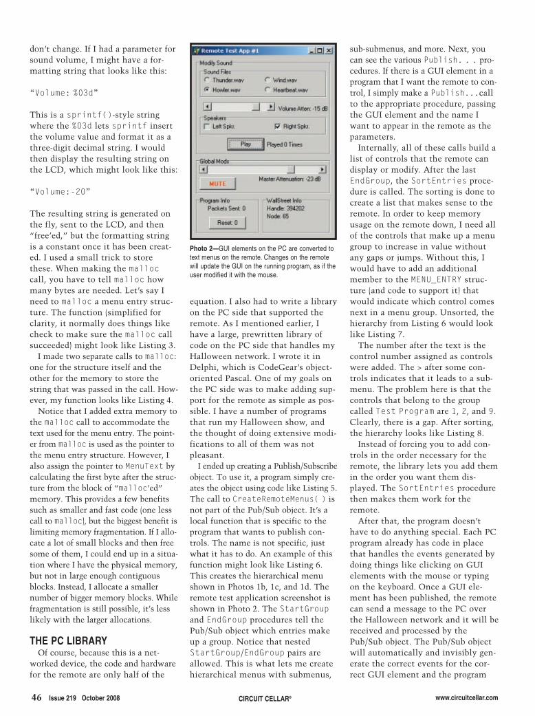
sub-submenus, and more. Next, youcan see the various Publish. . . pro-cedures. If there is a GUI element in aprogram that I want the remote to con-trol, I simply make a Publish...callto the appropriate procedure, passingthe GUI element and the name Iwant to appear in the remote as theparameters.
Internally, all of these calls build alist of controls that the remote candisplay or modify. After the lastEndGroup, the SortEntries proce-dure is called. The sorting is done tocreate a list that makes sense to theremote. In order to keep memoryusage on the remote down, I need allof the controls that make up a menugroup to increase in value withoutany gaps or jumps. Without this, Iwould have to add an additionalmember to the MENU_ENTRY struc-ture (and code to support it) thatwould indicate which control comesnext in a menu group. Unsorted, thehierarchy from Listing 6 would looklike Listing 7.
The number after the text is thecontrol number assigned as controlswere added. The > after some con-trols indicates that it leads to a sub-menu. The problem here is that thecontrols that belong to the groupcalled Test Program are 1, 2, and 9.Clearly, there is a gap. After sorting,the hierarchy looks like Listing 8.
Instead of forcing you to add con-trols in the order necessary for theremote, the library lets you add themin the order you want them dis-played. The SortEntries procedurethen makes them work for theremote.
After that, the program doesn’thave to do anything special. Each PCprogram already has code in placethat handles the events generated bydoing things like clicking on GUIelements with the mouse or typingon the keyboard. Once a GUI ele-ment has been published, the remotecan send a message to the PC overthe Halloween network and it will bereceived and processed by thePub/Sub object. The Pub/Sub objectwill automatically and invisibly gen-erate the correct events for the cor-rect GUI element and the program
46 Issue 219 October 2008 CIRCUIT CELLAR® www.circuitcellar.com
don’t change. If I had a parameter forsound volume, I might have a for-matting string that looks like this:
“Volume: %03d”
This is a sprintf()-style stringwhere the %03d lets sprintf insertthe volume value and format it as athree-digit decimal string. I wouldthen display the resulting string onthe LCD, which might look like this:
“Volume:-20”
The resulting string is generated onthe fly, sent to the LCD, and then“free’ed,” but the formatting stringis a constant once it has been creat-ed. I used a small trick to storethese. When making the malloccall, you have to tell malloc howmany bytes are needed. Let’s say Ineed to malloc a menu entry struc-ture. The function (simplified forclarity, it normally does things likecheck to make sure the malloc callsucceeded) might look like Listing 3.
I made two separate calls to malloc:one for the structure itself and theother for the memory to store thestring that was passed in the call. How-ever, my function looks like Listing 4.
Notice that I added extra memory tothe malloc call to accommodate thetext used for the menu entry. The point-er from malloc is used as the pointer tothe menu entry structure. However, Ialso assign the pointer to MenuText bycalculating the first byte after the struc-ture from the block of “malloc’ed”memory. This provides a few benefitssuch as smaller and fast code (one lesscall to malloc), but the biggest benefit islimiting memory fragmentation. If I allo-cate a lot of small blocks and then freesome of them, I could end up in a situa-tion where I have the physical memory,but not in large enough contiguousblocks. Instead, I allocate a smallernumber of bigger memory blocks. Whilefragmentation is still possible, it’s lesslikely with the larger allocations.
THE PC LIBRARYOf course, because this is a net-
worked device, the code and hardwarefor the remote are only half of the
equation. I also had to write a libraryon the PC side that supported theremote. As I mentioned earlier, Ihave a large, prewritten library ofcode on the PC side that handles myHalloween network. I wrote it inDelphi, which is CodeGear’s object-oriented Pascal. One of my goals onthe PC side was to make adding sup-port for the remote as simple as pos-sible. I have a number of programsthat run my Halloween show, andthe thought of doing extensive modi-fications to all of them was notpleasant.
I ended up creating a Publish/Subscribeobject. To use it, a program simply cre-ates the object using code like Listing 5.The call to CreateRemoteMenus( ) isnot part of the Pub/Sub object. It’s alocal function that is specific to theprogram that wants to publish con-trols. The name is not specific, justwhat it has to do. An example of thisfunction might look like Listing 6.This creates the hierarchical menushown in Photos 1b, 1c, and 1d. Theremote test application screenshot isshown in Photo 2. The StartGroupand EndGroup procedures tell thePub/Sub object which entries makeup a group. Notice that nestedStartGroup/EndGroup pairs areallowed. This is what lets me createhierarchical menus with submenus,
Photo 2—GUI elements on the PC are converted totext menus on the remote. Changes on the remotewill update the GUI on the running program, as if theuser modified it with the mouse.
2810015_Montgomery.qxp 9/8/2008 1:08 PM Page 46
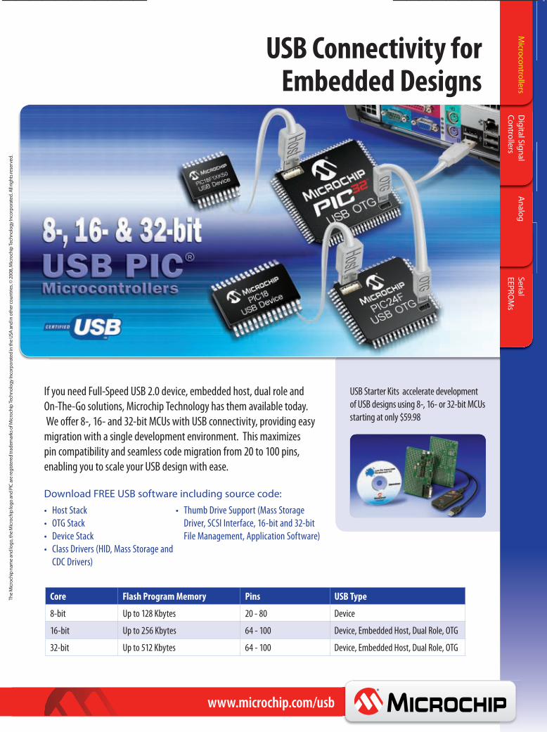
USB Starter Kits accelerate developmentof USB designs using 8-, 16- or 32-bit MCUsstarting at only $59.98
If you need Full-Speed USB 2.0 device, embedded host, dual role and On-The-Go solutions, Microchip Technology has them available today. We offer 8-, 16- and 32-bit MCUs with USB connectivity, providing easy migration with a single development environment. This maximizes pin compatibility and seamless code migration from 20 to 100 pins, enabling you to scale your USB design with ease.
Host StackOTG StackDevice StackClass Drivers (HID, Mass Storage andCDC Drivers)
Core Flash Program Memory Pins USB Type
8-bit Up to 128 Kbytes 20 - 80 Device
16-bit Up to 256 Kbytes 64 - 100 Device, Embedded Host, Dual Role, OTG
32-bit Up to 512 Kbytes 64 - 100 Device, Embedded Host, Dual Role, OTG
Thumb Drive Support (Mass StorageDriver, SCSI Interface, 16-bit and 32-bitFile Management, Application Software)
Download FREE USB software including source code:
Microchip
Direct...
2ndline
www.microchip.com/usb
TheMicrochipnameandlogo
,the
Microchiplogo
andPICareregistered
trad
emarks
ofMicrochipTechno
logy
Incorporated
intheUSA
andinothe
rcou
ntries.©2008,M
icrochipTechno
logy
Incorporated
.Allrightsreserved.
SerialEEPRO
Ms
AnalogDigitalSignal
ControllersMicrocontrollers
www.microchip.com/usb
USB Connectivity for Embedded Designs
Microchip USB Ad for Circuit Cellar.indd 1 5/13/2008 12:57:56 PM
11.qxp 6/5/2008 11:26 AM Page 1

will then handle the event as if itcame from the mouse or keyboard. Ifa program already works with theHalloween network, adding Pub/Subcapability is as simple as creating thePub/Sub object, publishing somecontrols, and then sorting them. Therest happens without any additionalcode. I can add remote capability tomy Halloween programs in a matterof minutes, which is exactly the wayit is supposed to be.
IT’S SHOWTIME!The finished remote uses an OKW
case with a 0.125″ aluminum panelthat fits in the top. I used FrontPanel Express to create an exception-al panel to hold the LCD and mainboard. It was a wise $75 spent. I useda rugged connector from Neutrik toprovide a cable hook-up to theremote. I originally planned to useindustrialized Ethernet connectors,but they were too big to fit on myremote case. The cable is CAT-5, andthe other end has a standard RJ-45jack that plugs into my Halloween
www.circuitcellar.comCIRCUIT CELLAR®48 Issue 219 October 2008
network. The Halloween networkprovides full-duplex RS-485 as wellas 12 VDC, so plugging it in provides
both data and power.I’m really looking forward to this
Halloween. I can’t wait to modify
Listing 7—Without sorting, it’s easy for controls to become nonsequential. Note that the Test Program menuwould have controls 1, 2, and 9.
Test Program 0Master Volume 1
Sounds > 2WAV Files 3Volume Attenuation 4Play 5Speakers > 6
Left Spkr. 7Right Spkr. 8
Silence 9
Listing 8—By sorting, the controls are added to menu groups in a way that makes the source code logicaland easy to follow, while ensuring all controls in a group are sequential. The Test Program menu nowhas controls 0, 1, and 2.
Test Program 0Master Volume 1Silence 2
Sounds > 3WAV Files 4Volume Attenuation 5Play 6Speakers > 7
Left Spkr. 8Right Spkr. 9
2810015_Montgomery.qxp 9/8/2008 1:08 PM Page 48

www.circuitcellar.com CIRCUIT CELLAR® Issue 219 October 2008 49
SOURCESDelphi IDECodeGearwww.codegear.com
D012 Display module Display3000www.display3000.com/html/english.html
Custom panel Front Panel Expresswww.frontpanelexpress.com
Z8F4821 Microcontroller Zilog, Inc.www.zilog.com
Peter Montgomery ([email protected]) spent 12 yearsworking as a visual effects supervisoron films such as Mortal Kombat andAce Ventura: When Nature Callsbefore becoming a director. He has
Author’s note: For videos and addi-tional photos of the show in action,go to www.socalhalloween.com.
PROJECT FILESTo download code, go to ftp://ftp.circuitcellar.com/pub/Circuit_Cellar/2008/219.
directed dozens of commercials andmade the transition to episodic televi-sion with The Disney Channel’sLizzie McGuire. Self-taught in bothprogramming and digital hardwaredesign, Peter uses his super powersonly for good, not evil.
and control the show from outsidewhile keeping the laptop inside. I won’tbe calling my friend in the yard on hiscell phone, and I won’t be runninginside and outside like a madman.
This remote project turned out to befar more involved than I thought. Themenu code went through at least threemajor iterations, each time gaining fea-tures and becoming more flexible. Inter-estingly, the code became smaller andmore streamlined as I refined the datastructures and came up with more ele-gant ways to achieve the same goals.The serial backpack I created for theDisplay3000 LCD was an entire projectunto itself, but it made the project sim-pler overall. Furthermore, I have my eyeon a bigger LCD from another vendor.After I buy that, I will create a newbackpack for it and then just swap it in.If all goes well, I shouldn’t even have tochange any of the code running on theHalloween remote’s main board.
My goal was to create an easy-to-use remote for my Halloween showthat was not hard-coded to the pro-grams I am running today. I wanted a
future-proofed design—something thatcould literally handle programs Ihaven’t even thought of yet. By creat-ing a system that integrates into myexisting Halloween network, I lever-aged a lot of previous work. By using asystem that polls the PC and talks tothe programs that are running on it,the remote can generate menus on thefly, no matter what programs are run-ning. The user interface includes threebuttons and a scroll wheel, so learninghow to use it takes about 30 secondsof playing around. It was a lot ofwork, but I know I’ll be smiling onHalloween night! I
2810015_Montgomery.qxp 9/8/2008 1:09 PM Page 49

50 Issue 219 October 2008 CIRCUIT CELLAR® www.circuitcellar.com
automated the entire process with anovel design. We call our design theTravel WIZard. It is an embedded server
The bone-chilling wind and week-ly ice storms that come with winterin central Illinois often leave us won-dering where we can go to get awayfrom the cold. Far away. Destinationson our short list this year includeJeju (South Korea), Buenos Aires,Acapulco, and Honolulu. As engi-neers, we didn’t want to make a ran-dom decision with no logic behind it.We wanted to have a process. Wewanted to travel to one of these far-off destinations, but how would wedecide where to go and when?
As cost-conscious engineers, wewanted to locate the best airfareprices and travel dates. A few search-es on one of the many availableonline travel search engines revealedthat airfare can fluctuate significant-ly depending on the time of year.Airfare even fluctuates with the daysof the week. We knew the only wayfor us to make a proper decisionwould be to collect about a year’sworth of airfare data for our desireddestination and then inspect the datafor the cheapest time of year to trav-el. But manually executing a year’sworth of airfare searches to a desireddestination would have taken a longtime. In fact, we would have spentthe entire winter sitting in front ofour computers, sipping hot choco-late, and running searches. But wehad basketball to play and beaches tolounge on. Thus, we did what anyengineers repulsed by the thought ofendless repetitive work would do: we
application featuring a WIZnet W5100hard-wired TCP/IP Ethernet controllerand a Microchip Technology Explorer 16
FEATURE ARTICLE by Matt Pennell and Aaron Thomas
This well-designed embedded server application enables you to find airfare deals on the ’Net.The WIZnet W5100-based system uses Kayak, an online travel search engine, to search forflights. The data is then graphed to show you the best time of year to travel.
Automated Data MiningBuild an Embedded Server Application
Photo 1a—The WIZnet WIZ810MJ network module plugs into a pair of female pin headers soldered to a 120-pin card edgeconnector board. The connector board plugs into the Explorer 16 development board. b—This is the top of the module.
a) b)
Photo 2—The Travel WIZard’s server interacts with Kayak’s search engine to gather a year of useful airfare information.
HONORABLE MENTION
2810016_Pennell.qxp 9/8/2008 1:24 PM Page 50

www.circuitcellar.com CIRCUIT CELLAR® Issue 219 October 2008 51
communicating with the device asnap.
The only problem was figuring outhow to physically connect theWIZ810MJ to the Explorer 16 board(see Figure 2). Additional schematics,figures, and files are available atwww.circuitcellar.com/wiznet/winners/001130.html.
After considering some kind ofbreadboard-fly-wire-solder combina-tion, we decided there was no bettertime than the present to design ourfirst PCB. Although it was intimidat-ing at first, the PCB layout processturned out to be an enjoyable experi-ence. We used the freeware versionof CadSoft Computer’s Eagle layouteditor to design the board. The free-ware version has some limitationswith respect to board size, number oflayers, and circuit complexity, but itwas more than adequate for our pur-poses. Advanced Circuits fabricatedthe board. It took about two weeksto lay out the board, and then anadditional week to receive prototypeboards. The completed assembly isshown in Photo 1. The WIZ810MJplugs into two pinheaders, which are sol-dered to the adapterboard. The adapter boardplugs into the 120-pincard edge connector onthe Explorer 16.
We included bothW5100 bus interfaceoptions in our layout tomaximize flexibility. Weuse thePIC24FJ128GA010’s gen-eral-purpose I/O pin RF1to select between theSPI and parallel businterfaces via theWIZ810MJ’s SPI enablecontrol line. At buildtime, a preprocessor def-inition selects betweenthe SPI bus driver andthe parallel bus driver,so only the necessarycode is included in thebuild.
The PIC24FJ128GA010has a PMP peripheralspecifically designed to
development board (see Photo 1).To use the Travel WIZard, simply
enter your search criteria (e.g., depar-ture airport, destination airport, andtrip length) on the Travel WIZardweb site (embedded in EEPROM onthe Explorer 16). When you click thebutton to start your search, theembedded server interacts with theKayak flight search engine(www.kayak.com) to acquire oneyear’s worth of airfare data (seePhoto 2). After the data is acquired,you can retrieve the results in acomma-separated value format viaFTP. The resulting data can be easilygraphed to reveal seasonal trends inticket prices. Photo 3 is a screenshotof the results from a Chicago-to-Hon-olulu flight search.
HARDWAREWe used a Microchip Explorer 16
development board populated with aPIC24FJ128GA010 microcontroller asthe basis for the project (see Figure 1).The Explorer 16 brings out many ofthe microcontroller’s pins to a 120-pincard edge connector, including twoSPI bus interfaces and the PIC24’sparallel bus interface, the parallelmaster port (PMP). We acquired aWIZnet WIZ810MJ network moduleto handle our Ethernet interface. TheWIZ810MJ is an excellent choice forquick Ethernet prototyping becauseit comes as a plug-in module withpin headers and it includes a Mag-Jack and supporting circuitry for theW5100. It also brings out theW5100’s SPI and parallel bus inter-faces to the pin headers, making
interface with parallel bus-enableddevices such as the W5100. The PMPis convenient because it includesspecial hardware to handle chipselects, read/write lines, and waitstates. However, its many pins aremultiplexed with various otherperipherals of the PIC24FJ128GA010,including a second SPI module,which is used to interface with theEEPROM that stores our embeddedweb page. We didn’t want to lose theability to serve a web page from ourboard just because we switched tothe parallel bus, so each time ourW5100 parallel bus driver softwarefunctions are called, the PMP isenabled, data is transferred, and thenthe PMP is disabled. When the PMPis disabled, the associated pins revertto the function they had been previ-ously assigned. In this case, thatmeans the SPI module pins go backto SPI functionality. Enabling thePMP only when we need to accessthe W5100 incurs a slight run-timepenalty because we have to executemore than the necessary number ofinstructions every time we access
Photo 3—Data retrieved from the Travel WIZard is incomma-separated values (CVS) format. Flight searchresults retrieved via FTP are graphed to reveal sea-sonal trends in ticket prices.
Figure 1—This block diagram shows the Microchip Explorer 16 devel-opment board populated with a PIC24 microcontroller at the heart ofthe system. You can connect to the system via HTTP or FTP to begin asearch session or retrieve search results. Once search criteria havebeen entered, the Explorer 16 automatically interacts with the Kayakflight search engine to retrieve airfare search results.
HTTP Client(Firefox, IE, etc.)
FTP Client
Internet gateway
W5100Ethernetcontroller
EEPROM(Web page)
PIC24 MCU
DHCP, FTP, HTTP, DNS, and Sockets
Explorer 16
Remote flightsearch engine
(Kayak)
2810016_Pennell.qxp 9/8/2008 1:24 PM Page 51

52 Issue 219 October 2008 CIRCUIT CELLAR® www.circuitcellar.com
the device. However, it enables us tomaximize the PIC24FJ128GA010’savailable pin functions.
TCP/IP STACKMicrochip provides a free TCP/IP
software stack designed to interfacewith its ENC28J60 Ethernet con-troller. The stack is a modular imple-mentation of the five-layer TCP/IPmodel. ENC28J60 driver routines areat the lowest level of the stack. Ontop of the hardware drivers are thenetwork layer ARP and IP protocols,followed by the transport layer TCPand UDP protocols, and finally theapplication layer protocols such asHTTP, FTP, and dynamic host config-uration protocol (DHCP). In a layeredsoftware environment, the rule isthat each layer can depend on onlythe functions in the same layer orlower. That means functions in thenetwork layer should not be calling
functions from the higher transportlayer. Layering software also meansthat data and implementation detailscan be encapsulated within a layer.The advantage is that implementa-tion details may change in a givenlayer; but as long as the functionalitystays the same, the upper layers willnever be the wiser. Understandingthe layered structure of the stack isimportant because it is the mecha-nism that enabled us to replace thesoftware stack with the W5100’sstack, which implements everythingfrom the transport layer on down inhardware.
Let’s clarify all of this abstractionwith a specific example. Listing 1 isa code snippet from Microchip’sHTTP server routine. The logic flowis not too informative when takenout of context in this snippet, but itis useful to notice that the routine isrelying on transport layer functions—
such as TCPDisconnect, TCPGetArray,and TCPDiscard—to do its work.Listing 2 reveals the internal detailsof the software stack TCPDiscardfunction, which is used to clear asocket’s receive RAM. Compare thatto Listing 3, which shows the sameTCPDiscard function. This time itis implemented for the hardwarestack. Notice that the function pro-totype is the same, as is the overallfunctionality (the socket’s receiveRAM is cleared). Under the hood,however, the implementation detailshave changed drastically. Neverthe-less, from the perspective of theHTTP server routine, nothing haschanged. It can call the same func-tion and obtain the same result.
For another example, refer to Listing 3for the hardware stack that we reliedon for our W5100 driver routinesW5100WriteReg and W5100ReadWord,which we used to access registers onthe Ethernet controller. Doing soenabled us to swap out a SPI busdriver with a parallel bus driverwithout having to make a singlechange to any layer-accessing W5100registers. This incredible techniqueenabled us to switch from using theSPI bus interface to using the parallelbus interface in a single evening. Itwas amazing considering it took sev-eral weeks to get the entire applica-tion functioning properly with theSPI bus.
The Microchip stack implementsnumerous application-layer protocols.Because of the modular implementa-tion, we were able to rip out the gutsof the lower layers of the stack andreplace them with W5100 socketdriver routines. We were careful tokeep the functionality and externalinterface of the transport and net-work layers exactly the same. Nomodifications were necessary to theapplication layer software. This pow-erful technique enabled us to reuseall of Microchip’s application proto-cols. At one time or another, we ranHTTP (server and client), DHCP,TELNET, FTP (server and client),DNS, and NBNS application proto-cols using the W5100. As we testedeach protocol one by one, we had tolearn enough about it to be able to
Figure 2—The two jumpers are located on the WIZ810MJ development board. On the left, you can see theconnections from the WIZ810MJ 28-pin connectors to PIC24 processor pins. On the right, you can see theExplorer 16 board’s 120-pin card edge connector. These pins go directly to the PIC24 processor.
2810016_Pennell.qxp 9/8/2008 1:24 PM Page 52

www.circuitcellar.com CIRCUIT CELLAR® Issue 219 October 2008 53
We implemented a custom TCPclient software package for retrievingairfare information from a remoteserver. The client software uses thetransport layer driver interface tocommunicate over Ethernet. Thepackage is a group of related filesthat enable the flight search TCPclient to be easily integrated into thetop-level application. The center-piece of the package is the flight
know whether or not it was workingcorrectly. Doing so enabled us toacquire a mountain of knowledge onthe inner-workings of the Internetduring our testing.
FLIGHT SEARCH PACKAGEAfter mastering the low-level
details of Internet communication, itwas time to move on to the task athand: automating airfare data mining.
search task, which actually imple-ments the API for communicatingwith the remote flight search server.
The flight search task waits for asoftware flag to be set, indicatingthat search parameters have beenentered and a search may begin. Theflag is set when a button is clickedon our board’s web page. We addedcode to the Microchip HTTP serverto kick off a flight search session.When the flag is set, the next timethe flight search task runs, it con-nects to the remote flight searchserver Kayak.com using DNS toresolve Kayak’s IP address. After theIP address of Kayak’s server wasresolved, we configured a W5100socket to be used in TCP clientmode. The TCP client mode socketestablishes the connection withKayak, and then uses that connec-tion to acquire airfare data.
The first step toward interactingwith Kayak is to acquire a searchsession ID, which is needed to sub-mit search queries. The Kayak serveruses an HTTP interface so all com-munication is done using TCP. Ourclient software calls the transportlayer TCP functions to transmit toand receive data from Kayak.
Kayak returns all data in XML for-mat. For us, that meant writing acouple of simple parser functions inour client to retrieve data from with-in Kayak’s XML tags. We learned thatthe equivalent of a function call ismade over the Internet by using aweb address as the function name fol-lowed by CGI-formatted functionarguments. Furthermore, the datatransmitted over the Internet is sim-ply ASCII text. For example, toacquire a session ID from Kayak, wemake the “function call” by writing“api.kayak.com/k/ident/apisession?token= cRGMxxxxxxxxhT7kSEZE2Dw” tothe W5100’s transmit RAM andflushing our TCP socket. The“token” argument is actually adeveloper key, which must beacquired from Kayak in order to usethe API. Kayak responds to the func-tion call with an XML document.One of the elements within the XMLdocument is the session ID. We parsethrough the socket’s receive RAM to
Listing 1—Microchip Technology’s application layer implementation of HTTP relies on transport layer func-tions to handle the details of TCP. The implementation details of TCP are hidden from the application layer.
static void HTTPProcess(HTTP_HANDLE h){…
if(w == 0xFFFFu){
if(TCPGetRxFIFOFree(ph->socket) == 0){
// Request is too big, we can't support it.TCPDisconnect(ph->socket);
}break;
}
lbContinue = TRUE;if(w > sizeof(httpData)-1)
w = sizeof(httpData)-1;
// Populate httpData array with w bytesTCPGetArray(ph->socket, httpData, w);httpData[w] = '\0';
// Discard remaining data from this socketTCPDiscard(ph->socket);
…}
Listing 2—This code snippet reveals the implementation details of the TCPDiscard function fromMicrochip’s software stack.
void TCPDiscard(TCP_SOCKET hTCP){
TCB_STUB *ps;
if(TCPIsGetReady(hTCP)){
ps = &TCBStubs[hTCP];LoadTCB(hTCP);
// Delete all data in the RX bufferps->rxTail = ps->rxHead;
// Send a Window update messageSendTCP(hTCP, ACK);
SaveTCB(hTCP);}
}
2810016_Pennell.qxp 9/8/2008 1:24 PM Page 53

about how the Internet really func-tions under the hood. This projecttaught us a lot about the underlyingdetails of Internet communication.
If you’re planning to put your cur-rent embedded project online, werecommend obtaining a network pro-tocol analyzer. It will do wonders foryour debugging capabilities. We usedan excellent open-source applicationcalled Wireshark (formerly Ethereal).Wireshark captures Ethernet packetsin real time from your PC’s wirelessor LAN cards. Packet contents are
54 Issue 219 October 2008 CIRCUIT CELLAR® www.circuitcellar.com
locate the session ID. We then storeit safely away into processor RAMand clear the receive RAM buffer.
The session ID, after beingacquired once, is used with all ensu-ing flight search queries. The sessionID expires after 30 min. of inactivity(no search queries). To manage theload on its servers, Kayak restrictsthe frequency of search queries.Developers are limited to about 41queries per hour. Beyond that, Kayakresponds with a message indicatingthat you have run out of searchquota and you need to wait (a mes-sage we received frequently duringdevelopment).
We submit a search query usingdata supplied from the user enteredinto our web page via HTTP. Wethen wait 90 s before polling forresults. After retrieving the resultsfrom Kayak’s XML document, wewait another 90 s, update our searchdates to a week later, and run anoth-er query. The process continues until52 searches—covering one year fromthe initial search date—have beenperformed. At our current quotalimit of 41 queries per hour, it takesabout 156 minutes to complete asearch run.
We save the top result (the cheap-est result from each flight searchquery). The result is parsed out ofKayak’s XML data in the W5100socket’s receive RAM. A snippet ofan XML reply from Kayak is shownin Listing 4. This is the actual datathat the W5100 buffers into itsreceive RAM. From this, we parseout the airline and the price (in bold)and store them into an array inmicrocontroller RAM along with ourcalculated date.
During a flight search run, all foursockets on the W5100 are activesimultaneously. We have one socketin TCP Server mode listening toTCP port 80 for HTTP connections.Another TCP server socket is listen-ing on TCP port 21 for FTP connec-tions. A third socket is configuredfor UDP to listen for NetBIOS nameservice requests. The fourth socketdoes double duty. It manages ourDHCP lease, and it is used in TCPClient mode to connect to Kayak and
retrieve flight search results. We canuse a single socket to manage DHCPand connect to Kayak because, inboth cases, the socket does not needto stay connected all of the time.
FINDINGS & IMPROVEMENTSWe learned a lot about the Internet
as we worked on this project. Sure,we were already familiar with termssuch as “MAC address,” “DHCP”,“gateway server,” and “client appli-cation,” and we knew enough to getby. But we didn’t know too much
Listing 3—This code snippet illustrates how implementation details of the TCPDiscard function werechanged to support the W5100’s hardware stack. The interface and functionality remain the same, so nochanges are required to higher level software. With this new implementation, the function relies on lower-leveldriver routines to communicate with the W5100.
void TCPDiscard(TCP_SOCKET hTCP){
WORD ReceiveDataLength, ReadPointer;
if((ReceiveDataLength = TCPIsGetReady(hTCP))){/* Retrieve the current read pointer */ReadPointer = W5100ReadWord(Sn_RX_RD0(hTCP));
/* Increment by the size of available data */ReadPointer += ReceiveDataLength;W5100WriteReg(SnRXRD0(hTCP),((ReadPointer&0xFF00)>>8));W5100WriteReg((SnRXRD0(hTCP)+1),(ReadPointer & 0x00FF));
/* Delete all data in the RX buffer */W5100WriteReg(Sn_CR(hTCP),W5100_SOCKET_RECV);
}}
Listing 4—The Kayak flight search API returns results in XML format. Key off of the tag names to parse outresults of interest such as airfare price and the airline offering the trip.
<?xml version="1.0"?><searchresult>
<searchinstance></searchinstance><searchid>s_c7Lu3a6QgVzrppeNtQ</searchid><count>15</count><morepending>true</morepending><trips>
<trip><price url="/book/flight?code=2-
zEGArPtH5_L$r14jZSJ1.s_c7Lu3a6QgVzrppeNtQ.19-ZGnLUYLfGuVsthbFkgeW.F.AA.20880.0&_sid_=19-ZGnLUYLfGuVsthbFkgeW" currency="USD">209</price>
<legs><leg><airline>AA</airline><airline_display>American Airlines</airline_display><orig>ORD</orig><dest>MIA</dest><depart>2008/01/17 20:10</depart><arrive>2008/01/18 00:05</arrive>
2810016_Pennell.qxp 9/8/2008 1:24 PM Page 54

Mixed Signal OscilloscopeCapture and display analog and logic signals
together with sophisticated cross-triggers for
precise analog/logic timing.
Digital Storage OscilloscopeDual Channel Digital Scope with industry
standard probes or POD connected analog
inputs. Fully opto-isolated.
Multi-Band Spectrum AnalyzerDisplay analog waveforms and their spectra
simultaneously. Base-band or RF displays with
variable bandwidth control.
Multi-Channel Logic AnalyzerEight logic/trigger channels with event capture
to 25nS.
DSP Waveform GeneratorOptional flash programmable DSP based function
generator. Operates concurrently with waveform
and logic capture.
Innovations in modern electronics engineering are leading the new wave of
inventions that promise clean and energy efficient technologies that will
change the way we live.
It's a sophisticated world mixing digital logic, complex analog signals and
high speed events. To make sense of it all you need to see exactly what's
going on in real-time.
BS100U combines analog and digital capture and analysis in one cost
effective test and measurement package to give you the tools you need to
navigate this exciting new frontier.
USB Mixed Signal OscilloscopeInventing the future requires a lot of test gear...
...or a BitScope
�
�
�
�
�Mixed Signal Data Recorder
Record to disk anything BitScope can capture.
Supports on-screen waveform replay and export.�User Programmable Tools and Drivers
Use supplied drivers and interfaces to build
custom test and measurement and data
acquisition solutions.�
BS100U Mixed Signal Storage Scope & Analyzer
BS100U includes BitScope DSO the fast and
intuitive multichannel test and measurement
software for your PC or notebook.
Capture deep buffer one-shots, display waveforms
and spectra real-time or capture mixed signal data
to disk. Comprehensive integration means you can
view analog and logic signals in many different
ways all at the click of a button.
The software may also be used stand-alone to
share data with colleagues, students or customers.
Waveforms may be exported as portable image
files or live captures replayed on another PC as if a
BS100U was locally connected.
BitScope DSO Software for Windows and Linux
Standard 1M/20pF BNC inputs Smart POD Connector Opto-isolated USB 2.0 12VDC with low power modes
www.bitscope.comwww.bitscope.com
Analog + Digital
5.qxp 6/5/2008 12:03 PM Page 1

SOURCESEAGLE Light EditionCadSoft Computer, Inc.www.cadsoftusa.com
Wireshark Network analyzerGerald Combswww.wireshark.org
ENC28J60 Ethernet controller,Explorer 16 development board, andPIC24FJ128GA010 microcontrollerMicrochip Technology, Inc.www.microchip.com
WIZ810MJ Network module andW5100 Ethernet controller WIZnet, Inc. www.wiznet.co.kr/en
Aaron Thomas ([email protected])is an engineer for Caterpillar’s Elec-tronics & Connected Worksite Divi-sion. He specializes in FPGA devel-opment for electronic control mod-ules. Aaron earned a B.S. in computerengineering from the University ofToledo in Ohio. His technical inter-ests include computer design, pro-gramming, and automation usingembedded systems. In his spare time,Aaron enjoys traveling, sports, andvideo games.
Matt Pennell ([email protected])is an embedded software engineer forCaterpillar’s Electronics & ConnectedWorksite Division. He specializes inhardware drivers, TPU microcode,and eTPU microcode for engine con-trol units. Matt earned a B.S.E.E. atthe University of Illinois at Urbana-Champaign. His technical interestsinvolve designing hardware and soft-ware for real-time embedded sys-tems. Outside of work, Matt enjoysweight lifting and sports.
displayed in a user-friendly, easy-to-read format. Depending on the pack-et’s protocol, the contents are brokenout byte-by-byte according to the dif-ferent fields contained in the packet.The program also has numerous fil-tering options to limit the number ofcaptured packets to only what youare interested in. Wireshark wasessential to the development of ourproject.
PLANNING AHEADWe have used the Travel WIZard to
acquire airfare data to destinationsall over the world. It is interesting toobserve seasonal trends in ticketprices to different locations. Howev-er, the application has plenty ofroom for improvement. The once-per-week sample rate is rathersparse, allowing opportunities forprice variation that we could miss ifwe happen to sample on the wrongday. We plan to implement a moredense mechanism for storing resultsso we can pack a greater number ofresults into the same amount of
Editor’s note: To learn more aboutthis project, you can review theschematics, photos, diagrams, and
PROJECT FILESTo download code, go to ftp://ftp.circuitcellar.com/pub/Circuit_Cellar/2008/219.
www.circuitcellar.comCIRCUIT CELLAR®56 Issue 219 October 2008
RAM. (Currently, we store in ASCIIformat.)
We also want to be able to viewthe search progress from the embed-ded web page. Google offers a graph-ing API (Google Chart), in much thesame way that Kayak offers an API,which can be used to graph data.Using the Google Chart API, wecould graph the flight search resultsas they come in, right on the embed-ded web page.
Many web sites offer easy-to-useAPIs just like Kayak. Using theW5100 and the Internet applicationlayer protocols, the number of appli-cations is limitless. We are anxiousto add more automated packages tothe Travel WIZard to make it aneven more productive machine.Doing so should enable us to spendmore time on the beach while thesystem does the dirty work for us. I
additional files posted at www.circuitcellar.com/wiznet/winners/001130.html.
2810016_Pennell.qxp 9/8/2008 1:24 PM Page 56
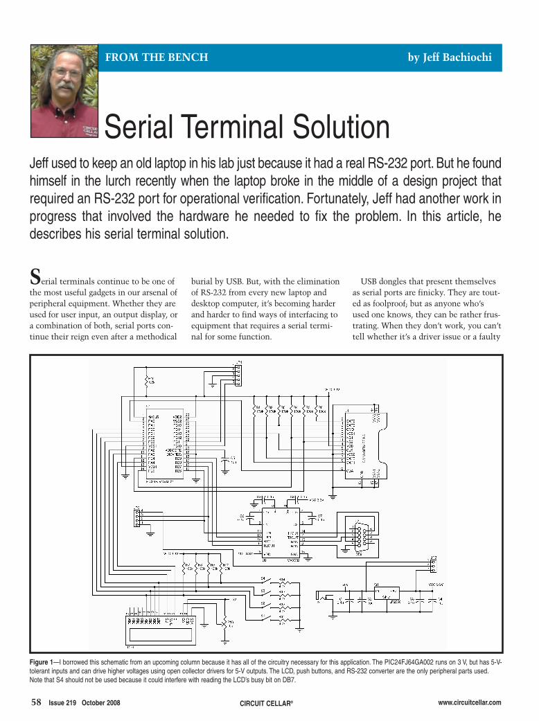
Serial Terminal Solution
58 Issue 219 October 2008 www.circuitcellar.com
USB dongles that present themselvesas serial ports are finicky. They are tout-ed as foolproof; but as anyone who’sused one knows, they can be rather frus-trating. When they don’t work, you can’ttell whether it’s a driver issue or a faulty
burial by USB. But, with the eliminationof RS-232 from every new laptop anddesktop computer, it’s becoming harderand harder to find ways of interfacing toequipment that requires a serial termi-nal for some function.
CIRCUIT CELLAR®
Serial terminals continue to be one ofthe most useful gadgets in our arsenal ofperipheral equipment. Whether they areused for user input, an output display, ora combination of both, serial ports con-tinue their reign even after a methodical
FROM THE BENCH by Jeff Bachiochi
Jeff used to keep an old laptop in his lab just because it had a real RS-232 port. But he foundhimself in the lurch recently when the laptop broke in the middle of a design project thatrequired an RS-232 port for operational verification. Fortunately, Jeff had another work inprogress that involved the hardware he needed to fix the problem. In this article, hedescribes his serial terminal solution.
Figure 1—I borrowed this schematic from an upcoming column because it has all of the circuitry necessary for this application. The PIC24FJ64GA002 runs on 3 V, but has 5-V-tolerant inputs and can drive higher voltages using open collector drivers for 5-V outputs. The LCD, push buttons, and RS-232 converter are the only peripheral parts used.Note that S4 should not be used because it could interfere with reading the LCD’s busy bit on DB7.
2810002-bachiochi.qxp 9/8/2008 1:25 PM Page 58

dongle. I used to keep an old laptoparound because it had a real RS-232 porton it. During a recent design project, acompany required an RS-232 port as partof the design for operational verifica-tion. (Imagine RS-232 as a designrequirement!) With the design proto-typed, I had just begun to exercise somecode when my laptop flew south forthe summer and every desktop I ownedno longer had any RS-232 hardware.
As luck would have it, a project Iwas developing for an upcoming col-umn had just the hardware necessaryto give me what I needed to keep thepresent project on track. This was agood excuse to check out the prototypehardware that was patiently waiting itsturn for the limelight. This proposalseemed a little like watching a “big-screen epic” on one of those handheldLCD televisions. Using a 2 × 20 displayas a serial terminal has serious issues.Let’s see if this application has anymerit.
STOLEN PROTOTYPEThe schematic diagram for my
future project is shown in Figure 1. J1will not be used in this circuit’s incar-nation. Although the microcontrollerruns on 3.3 V, it has 5-V tolerantinputs and can directly interface high-voltage circuitry via configuring out-puts as open drain. The MicrochipTechnology PIC24FJ64GAxxx micro-controller has an interesting featurethat is especially valuable in low-pin-count microcontrollers, peripheral pinselect (PPS). It allows up to 26 I/O pinsto have their default functions reconfig-ured. Potential candidates for the PPSfunction are listed in Table 1. Lockingregisters prevent the configuration from
being altered (unless the correct proce-dure is followed). While this allowschanges on the fly, it can preventchanges by errant code.
The circuit uses the legendaryMAX232-type RS-232 level shifter tointerface the serial port interface to themicrocontroller. The microcontrollermultiplexes an LCD and a few pushbuttons as user I/O. Using the 4-bitLCD mode reduces interfacing to justseven lines. Three of the four datalines have push buttons that can bringthe data lines low when not beingdriven by the microcontroller. Becausethe microcontroller needs to read onlythe most significant data line (DB7) tomonitor the LCD’s busy bit, the pushbuttons (on the other three data lines)will not interfere with any data.
UARTThe real challenge is not in the cir-
cuitry, but how the available circuit isused to make the application useful.So, let’s start with the UART, which isresponsible for clocking data out at apredetermined fixed rate and format.At idle, the transmitter remains in the
Mark, or the TTL logic level 1 state.(Space is known as a TTL logic level 0state.) The clocking rate, or data rate,is the duration of a particular state(Mark or Space), usually defined asstates or bits per second.
This is a one-wire transmission, sothe receiver must be able to stay insync with the transmitter. This is pos-sible if the timing logic of the trans-mitter and the receiver are set to thesame data rate and the asynchronoustransmission always begins with a startbit (a Space), telling the receiver tobegin its reception of bit states. Thebits directly following the start bit aresampled at some point during theexpected duration of the bit to deter-mine the state (Mark or Space) of thatbit. Data bits are sent least significantbit first.
One of the things that made the seri-al port popular was its ability to beconfigured to accept data in severalways. First, the serial data could bestreamed at different rates. While ini-tial speeds were less, 300 bps becamethe standard as acoustically coupledmodems were used in the early 1960s(see Photo 1). Baud is the data rate innumber of pulses or bits per second.Early TeleTYpewriter (TTY) devices usedreduced character sets requiring 5 bits tosend a data character (actual data).
www.circuitcellar.com CIRCUIT CELLAR® Issue 219 October 2008 59
Table 1—Input and output functions of these peripheralsin the PIC24FJ64GAxxx can be configured to any ofthe remappable port pins.
Input selections Output selectionsNULL
External interrupt 1
External interrupt 2
Timer2 external clock
Timer3 external clock
Timer4 external clock
Timer5 external clock
Input capture 1 Output compare 1
Input capture 2 Output compare 2
Input capture 3 Output compare 3
Input capture 4 Output compare 4
Input capture 5 Output compare 5
Output compare fault A Comparator 1 output
Output compare fault B Comparator 2 output
UART1 Receive UART1 Transmit
UART1 Clear to send UART1 Request to send
UART2 Receive UART2 Transmit
UART2 Clear to send UART2 Request to send
SPI1 Data input SPI1 Data output
SPI1 Clock input SPI1 Clock output
SPI1 Slave select input SPI1 Slave select output
SPI2 Data input SPI2 Data output
SPI2 Clock input SPI2 Clock output
SPI2 Slave select input SPI2 Slave select output
Photo 1—The first data modems used acoustic tones for awhopping 300 bps. If you still have one of these on theshelf, raise your hand. (Source: http://en.wikipedia.org/wiki/Image:Coupleur-accoustique-IMG_0298.JPG)
Photo 2—The photo of the top display shows what isdisplayed for an empty UART buffer. The lower photoshows the start of the properties mode that allowschanges to the UART (data rate, number of bits, parity,number of stops, and flow control) on the fly.
2810002-bachiochi.qxp 9/8/2008 1:25 PM Page 59

60 Issue 219 October 2008 CIRCUIT CELLAR® www.circuitcellar.com
Today, 8-bit data is more or less thestandard using a 7-bit ASCII set or 8-bitbinary data.
Early clocking mechanisms wereoften unreliable, so a simple parity bitcould be appended to the data to helpassure correct reception or at leastpoint out an error. This parity bit (aone or zero) was inserted so that thetotal number of ones (including parity)was an odd or even number. Thus, theparity if used was defined as O (odd) orE (even).
Finally, to give the receiving devicetime to digest the newly received dataand get ready to sync on the next startbit, a number of stop bits (as Mark) areadded to each byte of the transmitteddata. Stop bits are no more than idletime between the last data bit of onecharacter and the start bit of the nextcharacter.
When vast amounts of data are passed,the receiver may need extra time tostore data (or spend time executingother timely events). A method ofinstructing the transmitter to go awaywas needed. In situations where ASCIIdata is being transmitted, two specialcharacters can be used to indicateBusy/Ready. To request that the trans-mitter suspend transmission, thereceiver sends an X-OFF, character0x1. To request transmission resump-tion, the receiver can send an X-ON,character 0x11. When the data beingtransmitted is binary the X_ON/OFF
characters may be part of the transmit-ted data and therefore cannot be used.In this case, only hardware flow con-trol can be used. Additional I/O linesclear to send from the receiver (CTS)talks to ready to send at the transmit-ter (RTS) to accomplish the flow con-trol request.
ON-THE-FLY FORMATTING Sometimes you don’t know the for-
mat or data rate of a serial stream ofdata. Being able to reconfigure a receiv-er’s UART at any time may come inhandy. You can use hardware jumpers toaccomplish the configuration task.Because I have buttons and an LCD, thiscan be done through the program. Formost functions, I designate button 1 asUp, button 2 as Down, and button 3 asSelect. Where applicable, the mode ispresented on the upper line of the LCD,while the keys are labeled using thelower line of the display (see Photo 2).You can choose it using Select, orchange modes using Up or Down todisplay other modes.
The application has two modes of oper-ation: Operational mode and Propertiesmode. The main loop of the programhandles Operational mode (see Figure 2).This is where any data in the UARTbuffer can be called to the LCD. In thismode, Up (increment) or Down (decre-ment) changes the DisplayStringvariable, which is used to select astring from the UART buffer. Select isused to change modes.
When Properties mode is selected,you are presented with a number ofchoices for setting a new data rate,the number of data bits (includingany Parity), the number of stop bits,and the flow control. Use Up orDown to display choices. Use Selectto make them permanent. Table 2shows the possible choices madeavailable using this UART.
Changes are made to the UARTwhen you exit Properties mode. Thishas the added benefit of also clearingthe data/display ring buffer. I will dis-cuss the buffer in more detail shortly.The UART can be set to just about anystandard (or oddball) data rate depend-ing on the value placed in the appropri-ate baud rate generator (BRG) register.Based on an 8-MHz oscillator, the
available limits of the BRG are approxi-mately 4 to 1 million bps.
ONE-WAY RING BUFFERAn area in RAM is set aside for data
reception. A RAM ring (circular orendless) buffer gives the received data aplace to reside while waiting to beoperated on by the system. Two bufferpointers (initialized to the buffer’s bot-tom) are used to keep track of the datain the buffer. The head pointer movestoward the top of the buffer as data isadded. A second pointer or tail movestoward the head pointer as the data isread out of the buffer by the system.When either pointer reaches the top ofthe buffer, it is redirected to the bot-tom of the buffer. (This action is wherethe buffer gets its name—ring.) As longas the data buffer is large enough andthe data continues to be read out of thebuffer by the system at an average rateequal to the input rate, the head pointer
Figure 2—This block diagram shows the basic loop forthe application. Enabled interrupts include Timer1 over-flow (100 µs), Timer2 overflow (10 ms), and UART RX.When a character is received, it is added to the UARTbuffer. The UART input buffer gets a carriage returnadded every 20 characters (the width of the display) ifnone of the data contains one.
Initialize
Call KeyScan
Call IncDisplayString
Time for KeyScan?
Button1 pushed?
Call DecDisplayString
Button2 pushed?
Call ModeDisplay
Button3 pushed?
Call DisplayBuffer
Buffer changed?
YN
YN
YN
YN
YN
Table 2—The three buttons and 2 × 20 LCD availableto this application can be reconfigured.
Function SettingData rate 300
1,200
2,400
9,600
19,200
38,400
250,000
Data bits and parity Eight bits no parity
Eight bits even parity
Eight bits odd parity
Nine bits no parity
Stop bits 1
2
Flow control None
Software
Hardware
2810002-bachiochi.qxp 9/8/2008 1:25 PM Page 60

www.circuitcellar.com CIRCUIT CELLAR® Issue 219 October 2008 61
will never reach the tail pointer. Thiswould mean the buffer is completelyfilled and is about to overflow intounread data.
For this application, data will never beremoved from the buffer. Instead, olddata will be overwritten by new data. Inessence, you want to hang on to themost recent data. Naturally, theamount of data you can hold dependson the size of the data buffer, so thelarger the buffer the better. If new datacan continuously overwrite previousdata in the buffer, you need a way todetermine where the old data ends andthe new data begins. This is accom-plished by allowing the head pointer topush the tail pointer ahead of it.
From the user’s point of view, using atwo-line LCD presents a number ofissues. Because the window into thebuffer is rather limited, you need someway of knowing when you’ve bumpedinto the top or bottom of the buffer.Let’s assume the buffer is empty (no datahas been received). StringCount holdsthe number of lines in the buffer (zero inthis case). A line could be a single-char-acter carriage return (0x0D) or a group of
characters up to and includ-ing a carriage return. TheBufferStringCount routinecalculates this by countingthe number of carriagereturns between the headand tail pointers.
Data is sent to the LCDwhenever a character isreceived or Up or Down hasbeen pressed (while in Oper-ational mode). Four routinesare used to display bufferdata (see Figure 3). The rou-tines are based on the String-Count and the Display-Count. When StringCount =0, the string “Top of Buffer”is displayed on the first lineof the LCD and “Bottom ofBuffer” is displayed on thesecond line of the LCD.
If the buffer is not emptywhen DisplayCount (a valuebetween 0 and StringCountthat is controlled by the Upor Down buttons) = 0, thestring “Top of Buffer” is dis-played on the first line of the
LCD and the first string in the bufferis displayed on the second line of theLCD. If DisplayCount = StringCount,the last string is displayed on the firstline of the LCD and “Bottom ofBuffer” is displayed on the second lineof the LCD. Finally, if none of theseconditions are met, string number Dis-playCount is displayed on the first lineof the LCD and string number Dis-playCount + 1 is displayed on the sec-ond line of the LCD.
The LCD limits the view to only 20characters of any received string, sohow can you view longer strings? Tosimplify the operations, I discountedhorizontal scrolling. Instead, I opted toreduce the size of incoming strings to20 characters (the width of the LCD).Thus, as characters are received andplaced in the buffer, a counter (Char-Count) keeps track of the number ofreceived characters. If CharCount reach-es 20 and the character is not a carriagereturn, then an extra 0x0D character isadded to the buffer and CharCount isreset to zero. Checking for wholewords is not performed in this applica-tion. Although it might be easy to keep
track of the last <space> character andreplace it with a 0x0D if the Char-Count reaches 20 and the characterisn’t a carriage return or a <space>.
Not all of the characters in the ASCIIcharacter set are printable. For instance,characters 0x00 to 0x1F are controlcharacters (e.g., X-ON and X-OFF) usedfor other purposes. When received, theyare tossed into the bit bucket (eliminat-ed) except for 0x0D, which normallyindicates the end of a string. Note thatmost LCDs have a <space> (blank)located at these positions in their char-acter tables. If they are not filtered out,they will print as blanks. While theyaren’t informative, you might decide toinclude them for display purposes. Youcould even program the locations in theLCD character table to display specialcharacters that you provide.
TAKE MY PORTUsing circuitry from a future From
The Bench project, I was able to keepa new contracted product design ontrack. I needed to monitor RS-232 out-put, but using this circuit’s 2 × 20character LCD seemed like an exer-cise in futility. With a little creativityand the simple user interface, I nowhave a useful tool that allows you toscroll through its serial port’s receivebuffer. So, go ahead, take away myserial port. See if I care! I
Figure 3—This block diagram shows what data is selected to displayon the two LCD lines. Two ROM strings are defined to indicate thebuffer’s top and bottom. RAM strings come from the UART inputbuffer and are selected using the variable DisplayString.
DisplayBuffer
Call BufferStringCount
StringCount = 0?
DisplayString = 0?
YN
YN
Y
N
Call ROMString“Top Of Buffer” at Row 1
StringCount=DisplayCount ?
Call RAMString(StringCount) at Row 2
Call ROMString“Top Of Buffer” at Row 1
Call ROMString“Bottom Of Buffer” at Row 2
Call RAMString(StringCount) at Row 1
Call ROMString“Bottom Of Buffer” at Row 2
Call RAMString(StringCount) at Row 1
Call RAMString(StringCount + 1) at Row 2
Return
Jeff Bachiochi (pronounced BAH-key-AH-key) has been writing for CircuitCellar since 1988. His backgroundincludes product design and manu-facturing. You can reach him [email protected] at www.imaginethatnow.com.
SOURCESPIC24FJ64GA002 MicrocontrollerMicrochip Technology, Inc.www.microchip.com
NHD-0220GZ-FSW-GBW-L LCDCharacter moduleNewhaven Display Internationalwww.newhavendisplay.com
PROJECT FILESTo download code, go to ftp://ftp.circuitcellar.com/pub/Circuit_Cellar/2008/219.
2810002-bachiochi.qxp 9/8/2008 1:25 PM Page 61

62 Issue 219 October 2008 CIRCUIT CELLAR® www.circuitcellar.com
form of pinball doesn’t resemble theform that you have come to know. Itwasn’t until 1947 that an innovator inthe industry, Gottlieb, added player-controlled flippers, which introduced askill factor to the game. The introduc-tion of solid-state electronics in theearly 1970s brought about the golden
The electronic gaming industry hasnever been more popular than it istoday. Modern consoles are makingthe gaming experience more realistic.This begs the question: Why did wedesign and build a universal pinballmachine controller?
The simple answer is that whilethe conversion of discrete elec-tronics into embedded systemsmay have a wide range ofapplicability, there will alwaysbe a market for vintage sys-tems. Beautiful casings andhardware from 1970s electron-ics now languish in limbobecause many components areunavailable. There is a largecommercial opportunity in aes-thetic gaming.
You can trace back the ori-gins of pinball to the latter partof the nineteenth century. Infact, in 1871, a U.S. patent wasawarded to British inventorMontague Redgrave for animprovement to an existingtable game called Bagatelle,which used a “plunger” to fire asmall metal ball on a playingsurface. Although there were noelectronics on his table, it iswidely accepted as the birth ofthe pinball table. This primitive
age of pinball. The microprocessorenabled games to be built with com-plex rule sets with onboard sound andspeech. Pinball machines laid thegroundwork for the video-game erathat was quickly taking over the elec-tronic gaming industry.
Like every industry, the gaming
FEATURE ARTICLE by Phil Laird and Jeff Shewan
Hardware emulation is an effective phase of the prototyping process. The purpose of thisproject was to build a robust hardware platform to run the rule sets for old pinball machines.Using the PinMAME program, the design emulates the hardware for almost 500 pinballmachines and runs the rule sets.
Universal Machine ControlHow Hardware Emulation Leads to Prototype Development
Main control module
Ethernet hub
Solenoid module
Switch module
Light module
Display module
24 Controlled solenoids
3 x 3 Switch matrix
8 x 8 Switch matrix
128 Controlled LEDs
1 VFD Display
Figure 1—This is a modular approach to the functionality of the pinball table. The control module acts as a client and allother modules are servers on the game network.
2809016_Shewan.qxp 9/8/2008 1:26 PM Page 62

in 1980 and was not functioning whenwe began.
When we started this project, ourgoal was to build a robust hardwareplatform that used PinMAME to runthe rule sets for old pinball machines.We wanted the design to be open-source so anyone could add function-ality after we finished our original pro-totype. Any pinball enthusiast willnote the wide variety of playfield partsfound on machines that are not cov-ered by this project.
Because PinMAME already knowshow to play pinball, half of the chal-lenge was simply to input informationinto the emulator and direct its out-puts. The other half of the challengewas to build a flexible hardware plat-form that could adapt to many pinballmachines and their various playfieldparts. For our prototype, we decided totackle four components found on anypinball table: switches, displays,lamps, and solenoids.
UNIVERSAL SYSTEM DESIGNOne of the problems we encoun-
tered when trying to design a univer-sal system was how to separate the
industry is subject to the fundamentalrules of economics. Early arcadegames such as Pac-Man and Asteroidsrequired relatively little maintenance,took up less space, and simply mademore money than pinball machines.Since the introduction of the first arcadegames, pinball has been on a steadydecline, leaving many tables rusting andout of repair. Today, it is hard to findreplacement electronic boards for manyold tables because manufacturers havestopped producing them.
The dwindling availability of parts,a broken pinball machine, a penchantfor gaming, and an emulation programcalled pinball multiple arcade machineemulator (PinMAME) were the inspi-ration for our universal pinballmachine controller (UPMC). We devel-oped the prototype for our final projectin the Computer and Electronics Engi-neering Technology course at Camo-sun College in Victoria, BritishColumbia.
THE PROJECT For our prototype, we used a Gottlieb
System 80 pinball machine called Pan-thera. The machine was manufactured
functionality of the pinball table intomanageable and flexible parts. Eachpinball table is unique and containsdifferent numbers of switches, dis-plays, lamps, and solenoids. For thisreason, we chose a modular systemthat uses the TCP/IP protocol to com-municate. Figure 1 shows the modularsystem, which is the essence of ourUPMC.
We used TCP/IP as the system’sbackbone for a few reasons. The proto-col had to run fast enough that latencywas not an issue. Most modern proto-cols run at a speed that is sufficientfor our application, but theclient/server relationship of TCP/IPlent itself well to the UPMC. We hadno latency issues while running oursystem using TCP/IP at 10 Mbps.Most importantly, the brain of the sys-tem is a PC, so we had to choose aprotocol that would interface easily toa computer. Using TCP/IP enabled usto simply connect our modules togeth-er using a hub and standard Ethernetcables.
In the future, we hope to takeadvantage of the ability of our boardsto connect to the Internet to imple-ment a few features that we were notable to cover during our originaldesign. Adding an external EEPROMto each board would give us the abilityto store a web page on each board (seePhoto 1). The web page would act as avisual aid, and we could use it to mapthe I/O and ports on the chip to sim-plify the boards’ installation and con-figuration. We also hope to implementan online scoreboard where any pin-ball machine running the UPMC sys-tem could update the online score-board automatically.
Although the decision to split func-tionality into modules multiplied theamount of hardware used, it simplifiedthe design. A universal system shouldbe designed in a generic way. There-fore, a modular design seemed mostlogical.
Each module has a defined and lim-ited functionality, which can be com-bined with other modules to fulfillthe requirements of a specific pinballmachine. The modular systemenabled (and required) us to completeblocks of our prototype and helped
www.circuitcellar.com CIRCUIT CELLAR® Issue 219 October 2008 63
Photo 1—Each of the four server modules was fitted with screw terminals, making it easy to interface to existinghardware. Clockwise from the top left are the switch module, the LED driver, the VFD driver, and the solenoid driver.
2809016_Shewan.qxp 9/8/2008 1:26 PM Page 63

64 Issue 219 October 2008 CIRCUIT CELLAR® www.circuitcellar.com
facilitate our development process.
PinMAMEPinMAME is a derivative work of the
multiple arcade machine emulator(MAME), which was originally designedto emulate the hardware of arcade sys-tems in software. The emulator acts asa software layer between the originalgame and the platform it’s running on.It does so by interacting with ROMsthat contain all of the individual gameprograms, graphics, and sounds.
Currently, PinMAME can emulate thephysical hardware of more than 480 pin-ball machines. In our project, PinMAMEinterfaces the ROMs to our customhardware. Although you can downloadPinMAME and MAME and the fullsource is available, they are not consid-ered open-source software because com-mercial use and redistribution is pro-hibited due to the fact that many gameROMs are still covered by copyright.
HARDWARE EMULATION Interfacing to the PinMAME hard-
ware emulation and getting our system
to run without latency was thesingle largest challenge for thisproject. From the start, wedecided that there was anacceptable amount of latencythat would not be noticed in arelatively slow electromechani-cal system. For most events, alatency of 100 ms would not benoticed by the player with theexception of the main playfieldbumpers and flippers, whichwere handled directly by the sole-noid module that we will discusslater. The original hardware wasrunning at a frequency of 2 MHz, givingus a big advantage in terms of process-ing power. With each module runningat 40 MHz and the backbone of thesystem running at 10 Mbps, we foundthat most transactions averaged lessthan 10 ms in an isolated situation. Aslong as our game network did not getflooded with excessive communica-tions, a latency of less than 100 mswas easily attained.
Therefore, the challenge becamefiguring out how to gather an update
from the emulation and send it out toour modules in an efficient manor. Thiswas done by gathering the informationfrom its peripheral interfacing chips,the MOS Technologies RAM input out-put timer (RIOT) 6532 chips (specific tothe Gottlieb System 80), and sendingout an update to our modules.
To get the UPMC to work on a spe-cific table, we added functionality tothe PinMAME source code. Specifical-ly, the files that contain the machinecode for its peripheral interfacing
Figure 2—This is the solenoid driving circuit. L1 is the actualsolenoid. D2 is mounted across the coil on the playfield. The firstversion of our solenoid module contains 24 of these circuits.
2809016_Shewan.qxp 9/8/2008 1:26 PM Page 64

www.circuitcellar.com CIRCUIT CELLAR® Issue 219 October 2008 65
original chip did in hardware. The rawdata found on the outputs and inputs ofthese ports are where we can interactwith the actual game. By providing infor-mation from our physical playfield to theinputs of its switch RIOT and decodingthe outputs of its display, lamp, and sole-noid RIOTs, our hardware platform caninteract with the game ROM.
MAIN CONTROL MODULEThe main control module is a PC
motherboard with an OS dedicated torunning PinMAME. For our project, we
chips had to be altered. On the Gottlieb System 80, three
RIOT 6532 chips were used to inter-face to its peripheral devices. It usedone chip for the displays, one for theswitches, and one for solenoids andlights. The PinMAME source codesupports this series of chips. The filespertaining to this chip were found in/src/machine/riot6532.c.
The RIOT 6532 uses two bidirec-tional 8-bit ports to address and con-trol the playfield. The emulation ofthe RIOT 6532 does exactly what the
used an old PC with a sound card and a10BaseT network card. An Intel Pen-tium III 800 with 128 MB of RAM wassufficient to run the hardware emula-tion without a visual front end.
The main control module acts asthe client. All of the other modulesact as servers on the game network.We used sockets to get information inand out of PinMAME and into ourTCP/IP network. Sockets enable thecontrol module to prioritize commu-nications and ensure that only oneserver is talking to the client at a
Listing 1—Writing information to the MAX6954 is easy. The MAX6954 must receive a digit select command (0x68) preceding the data for eight lights. LEDdata [ ] holdsall of the information received in our asynchronous packet from the control module.
//write data to P0 and P1 digit 0aLEDDRIVER_CS_IO = 0; //set Chip Select lo to select the MAX6954SSPBUF=0x68; //write 0x68 which is the command to write the same data to
//plane 0 and plane 1while(!PIR1bits.SSPIF); //wait until the SPI module has finished writingPIR1bits.SSPIF = 0; //reset the SPI interrupt flag for the next transmission
SSPBUF=ledData[1]; //write desired datawhile(!PIR1bits.SSPIF); //wait until SPI module has finished writingLEDDRIVER_CS_IO = 1; //set chip select high to deselect MAX6954PIR1bits.SSPIF = 0; //reset the SPI interrupt flag for the next transmission
2809016_Shewan.qxp 9/8/2008 1:26 PM Page 65

given time. This is required becauseeach server module has unique com-munication and timing demands onthe network.
The switch module is the only mod-ule that inputs information into theemulator. This is done by frequentinquiries by the control unit (the client)to the switch module about the statusof the switches. The maximum timebetween requests has to be 10 msbecause this is the time required for avalid switch press. For each request,the switch module returns a packetcontaining updated switch informa-tion as an array of 8 bytes. PinMAMEemulates an active high switchmatrix. Each byte received from theswitch module contains the activelevel of eight switches. As PinMAMEcycles through each column in itsswitch matrix, the appropriate bytefrom our playfield is assigned to theinputs of the RIOT.
The solenoid, LED, and display mod-ules only receive information from themain control module and are neverrequired to send input to PinMAME.
The display modules receive asynchro-nous packets and are addressed by thecontrol module only when the score orthe game status has changed. The lightdriver module receives a synchronousupdate from the main control moduleevery 100 ms, so the playfield lights don’t“lag” behind game play. The solenoidmodule receives an asynchronous packetfrom the control module when pro-gram-controlled solenoids are activated.
The control module also handles thein-game sounds. PinMAME alreadyhas the ability to play the soundsstored in the game’s sound ROM, soall we had to do was enable the emu-lator to run and enable the PC to out-put the sounds via the sound card.
HARDWARE MODULES We designed each of the four hard-
ware modules with the MicrochipTechnology PIC18Fxxxx series ofchips. With an external 10-MHz oscil-lator, and by enabling the internalphase-locked loop, a PIC18F2620 canoperate at 40 MHz. This series of chipsalso has a built-in SPI module that can be
set up in code. The speed of the SPI busis set by the PIC18F2620. It is 10 MHz(fOSC/4). This was needed for communica-tion with the Ethernet interface and thechip that we chose for the light module.
For development, a Maxim IntegratedProducts MAX232 chip connects thePIC18F2620 to the PC via an RS-232serial port. The MAX232 uses a 5-VDCsupply to internally generate a ±10-VDCsupply for RS-232 communication.Each board contains a nine-pin femaleserial port connector.
Each module has the ability to com-municate on a network via aMicrochip Technology ENC28J60stand-alone Ethernet controller and aMicrochip TCP/IP stack version 4.16.The ENC28J60 communicates withthe PIC18F2620 using an industry-standard SPI. Each module, which isassigned a unique IP and MAC storedin the PIC18F2620 EEPROM, acts as aserver on the TCP/IP network.
SOLENOID DRIVER MODULEThe solenoid driver module is the
only module in the UPMC that
66 Issue 219 October 2008 CIRCUIT CELLAR® www.circuitcellar.com
2809016_Shewan.qxp 9/8/2008 1:26 PM Page 66

requires high voltages and currents.For this reason, we used optical isola-tion to separate our high-voltage cir-cuitry from our control circuitry. Thehigh-voltage output circuitry wasdesigned to withstand continuous cur-rents of up to 4 A and uses MOSFETSto switch the high-powered coils.
The solenoid-driver module acceptsinput from the playfield and the main-control module and powers all of theplayfield solenoids. The playfield sole-noids were broken into two categories:
www.circuitcellar.com CIRCUIT CELLAR® Issue 219 October 2008 67
software-controlled and direct-controlled. The direct-controlled solenoids are
the flippers, bumpers, and pop-bumpers. They fire immediatelywhen the ball comes in contact withthe playfield part closing a switch orthe switch is closed manually in thecase of the flippers. To minimizelatency, these switch hits are senseddirectly by the solenoid board via athree-by-three active-low switchmatrix. This was required to limitlatency caused by a transaction with
the main control module. It was alsorequired because most pinball tablesoperate in a similar fashion, whichmeans the hardware emulation wouldnot support it.
The program-controlled solenoidsare all of the other solenoids on theboard, including the ball return andthe drop-bank resets. The timing iscontrolled by the main control moduleand ultimately by the game rules.
Both program- and direct-con-trolled solenoids are driven with a
common circuit (see Figure 2).We wanted this driving circuit-ry to be adaptable to variousvoltages used on different pin-ball machines. The solenoidson our table required 24 VDC,but some tables require highervoltages of up to 50 VDC. Whenthe input matrix senses a hit ora packet is sent by the maincontrol board, the chip drivesthe input of a PS2501 opticalisolation chip for 100 ms.
The PS2501 provides opticalisolation of up to 5,000 VRMS
to protect the PIC18F2620from the high-power drivingcircuitry. The PS2501 is atransistor output optical isola-tion chip with a high collector-to-emitter voltage of 80 VDC.This collector-to-emitter volt-age enabled us to use a supplyvoltage to drive the solenoidsup to 80 VDC. The output ofthe PS2501 is connected asshown in Figure 2. D1 is a 10-VDC Zener diode, 1N4740,used to protect the gate of thepower MOSFET. When the cir-cuit is activated, the gate ofthe International RectifierIRL520 MOSFET is pulsedwith 10 VDC. This turns it onand enables current to flowfrom drain to source throughthe solenoid. Resistor R3 is ableed resistor used to dis-charge the energy stored bythe gate capacitance of theMOSFET after it has fired.
The first version of our sole-noid-driver module can power24 playfield solenoids. Thecircuitry on this board could be
Photo 2—We rewired the entire table with custom LED boards (down the middle). Using ring terminals makes it easy to replacelights when they burn out.
2809016_Shewan.qxp 9/8/2008 1:26 PM Page 67

68 Issue 219 October 2008 CIRCUIT CELLAR® www.circuitcellar.com
used to drive other devices, such asmagnets and servos found on manypinball machines.
LIGHT DRIVER MODULEWhen designing the light module,
we replaced all of the incandescentbulbs with LEDs. We did this for tworeasons. One, LEDs are more efficientand will last longer than traditionalincandescent bulbs. And two, itenabled us to use a sophisticated IC,the Maxim MAX6954 to control them(see Listing 1).
The MAX6954 operates off of a logicsupply of 5 V and supplies up to 40 mAper LED. Compared to the originalincandescent bulb in the machine,which required 6.3 V at 150 mA, thedifference in power consumption isconsiderable. One drawback to usingLEDs is their dispersion pattern,which tends to illuminate directional-ly as opposed to the halo created by anincandescent bulb. We chose LEDswith a 140° viewing angle to mimicthe effect of an incandescent bulb.
Some manufactures have createdLEDs that behave like incandescentbulbs, which would be suitable forthis application. For our prototype,trying these LEDs did not fit into ourschedule or budget.
The MAX6954 is an LED driver chipthat can control up to 128 discreteLEDs. The MAX6954 uses 19 I/O pinsand a technique called Charlieplexingto drive the LEDs. Charlieplexing wasdeveloped by Charlie Allen, a Maximemployee, as a way of driving largenumbers of LEDs with a reduced num-ber of I/O pins relative to traditionalmultiplexing. This is done by usingpins (eight in our case) as both inputsand outputs. Each of the eight bidirec-tional pins sinks the current for 16 LEDsat any given point in time. TheMAX6954 uses an external resistor toset the current, which flows througheach discrete LED (see Photo 2).
The MAX6954 communicates withthe PIC18F2620 via a SPI, which isalready used on the board for theENC28J60 chip, requiring only one
extra I/O pin. A typical update fromthe main control module to the lightboard is a TCP/IP packet containing16 bytes of data. Each bit in thispacket corresponds to a playfieldlight and is either a one or zero cor-responding to an on or off. The bytesare then written over the SPI bus tothe MAX6954 one byte at a time.The MAX6954 expects 2 bytes ofdata in each communication transac-tion. The first represents a group ofeight LEDs and the second representswhich LEDs in the group are on. ThePIC18F2620 has to write 32 bytes ofinformation to the MAX6954 toupdate all 128 of the playfield lights.Operating at 10-MHz latency is notan issue because the write time takesless than 5 µs. The light driver mod-ule updates the playfield lights every100 ms when it receives an updatefrom the main control module.
SWITCH MATRIX MODULEThe switch-matrix module is the
simplest of the four modules. It
Listing 2—Check out the switch debouncing routine. Using code looping to debounce switches allowed us to debounce all 64 switches simultaneously.
LATA=0xFE; //set output lo
Nop();//make sure port has had a chance to change
if(PORTBbits.RB0 == 0 && sReady[0]&0x01) //check if input is lo and switch is hitable
{
sCount[0]=sCount[0]+1;//increase debounce count
if(sCount[0]>=DEBOUNCEDELAY)//if count greater than debounce delay, valid hit
{
sNum[0]|=0x01;//activate valid switch hit so detected switch hit is//sent out over network
sReady[0]&=0xFE;//say switch is no longer hitable
}
}
else if(PORTBbits.RB0)
{
sCount[0]=0x00;//reset debounce count
sReady[0]|=0x01;//say switch is hitable
}
2809016_Shewan.qxp 9/8/2008 1:26 PM Page 68

www.circuitcellar.com CIRCUIT CELLAR® Issue 219 October 2008 69
PROJECT FILESTo download code, go to ftp://ftp.circuitcellar.com/pub/Circuit_Cellar/2008/219.
RESOURCESPinMAME emulation home page,http://pinmame.retrogames.com.
S. Young, “The Pinball Resource,”www.pbresource.com.
Jeff Shewan ([email protected])is a recent Electronics EngineeringTechnology graduate. He is interestedin computer gaming and the audioengineering side of electronics.
SOURCESIRL520 MOSFETInternational Rectifierwww.irf.com
ENC28J60 Ethernet controller andPIC18F2620 microcontrollerMicrochip Technology, Inc. www.microchip.com
Phil Laird ([email protected]) is arecent Computer Engineering Technol-ogy graduate. He is interested in com-puter gaming, embedded systems, andsoftware engineering.
implements an active-low switchmatrix to scan and debounce switchhits. We used a PIC18F2620 with twoeight-pin ports to give us 64 switches.For the Gottlieb System 80, a 5 × 5switch matrix would have beenenough because it is common on pin-ball tables to tie switches on thetable with the same point valuetogether. The switch-matrix moduleholds an array containing the currentstatus of the switches. When themain-control module inquires for thestatus of the switches, the switchmodule returns a packet containingthe 8 bytes of data required for 64switches. Each bit in the packet cor-responds to a switch on the playfield.It is up to the main control moduleto decide what to do with the switchinformation (see Listing 2).
For systems with mechanicalswitches, debouncing routines arerequired to distinguish between noiseand valid switch presses. In order to beable to debounce all of the switchessimultaneously, delay routines are notused. Instead, when a switch is sensed,it is assigned a count value, which isdecremented each time we loopthrough the scanning routine. If at anytime during the count the switchreturns to an idle state, the countresets. When the switch has beenactive for the entire count, the switchmatrix status array is updated. Aswitch can not be “hit” again until ithas returned to an idle state. For theswitch matrix module, debounce tim-ing is set by the count value. Thecount value is defined as a macro,making it easy to change thedebounce timing.
An interesting characteristic of thepinball table switch matrix is the non-momentary switches found on thedrop targets. Once hit, the switchesare always down, which can causeghosting in a switch matrix. To solvethis problem, blocking diodes wererequired on all non-momentaryswitches.
DISPLAY MODULEThe display module is the most
difficult module to design for a uni-versal system because there are somany different displays on pinball
machines. Thus, our display moduleworks only on machines using VFDs.The displays on the Gottlieb System80 are eight-segment six-digit VFDs.The VFD modules contain onboarddriving chips, which require logiclevels to control. So, our displaymodule can interface to any eight-segment six-digit VFD with onboarddriving circuitry. Most VFDs, includ-ing the ones on the System 80,require a DC voltage as well as anAC voltage to excite the filaments.Our system needed 60 VDC and 5 VACfor the score displays and 42 VDCand 3 VAC for the game-status dis-play. These voltages were provideddirectly from the power supply.
Communication between the maincontrol module and the display mod-ule is simple. PinMAME emulatesthe hardware for each machine, so itcan provide the appropriate digit datain the form of 6 bytes. To avoid send-ing excessive packets on our net-work, we wait for a change in thescore before a display module isaddressed. Even though there are foursix-digit score displays, PinMAMEtreats them as two 12-digit displays.Therefore, we must distinguishbetween which display in the groupof two is being talked to. PinMAMEuses chip select pins to determinewhich display is being addressed.When the first group is selected, thefirst 6 bytes of data are sent to thefirst display board and the second 6are sent to the second display board.Each byte corresponds to a value on acorresponding display digit.
The other two score displays aretreated in a similar way. Our displaymodule then parses the digit infor-mation to provide the VFD moduleswith the appropriate segment anddigit data. Our PIC18F2620 uses sixpins on PORTA for digit data and alleight pins on PORTB for segmentdata. The VFD’s digits are multi-plexed using positive logic, and 1-msdigit-select pulses are required tolight the displays.
THE FUTUREWe already have several ideas about
improving the capabilities of ourUPMC because our first prototype has
some limitations. The initial designis flexible enough to be tested onmany machines from the same erabut lacks the functionality to betruly universal. Multiple modulescould be easily used on tables requir-ing larger numbers of controlled play-field parts. New modules could beadded to control the functionality ofplayfield parts found on newermachines. As long as new functional-ity is built with the same designprinciples in mind, a universal plat-form could be a reality.
PinMAME is updated on a regularbasis. Each update adds more pinballtables to the list of machines it canemulate. Each table, or series oftables, requires us to alter the Pin-MAME source to interface to ourplatform. Once the raw data isextracted from the emulation, theUPMC platform can take care of therest. I
2809016_Shewan.qxp 9/8/2008 1:26 PM Page 69

70 Issue 219 October 2008 CIRCUIT CELLAR® www.circuitcellar.com
a noisy signal—say, a digital signal.You know from experience that somenoise will probably appear on yoursensor signal. But how? As long as thesignal and noise frequencies stay low,two main coupling mechanisms couldbe involved: capacitive coupling andinductive coupling. Capacitive cou-pling is the interaction of electricfields between the two wires. Induc-tive coupling is the interaction ofmagnetic fields between the two cir-cuits. At higher frequencies, or at alonger distance, a combination of botheffects can lead to electromagneticcoupling. But I won’t cover this. I willfocus on short-distance effects.
Let’s start with capacitive coupling.When two wires are close to eachother, there is a parasitic capacitancebetween both wires, which can bedepicted on an equivalent electric cir-cuit (see Figure 1). The parasitic capac-itance depends on the length, distance,and geometry of the wires. When asso-ciated with the loading impedance of
Welcome back to the Darker Side.I always do my best to find a topicthat coincides with the monthly Cir-cuit Cellar theme, but this time Ifailed. I will not talk about signal pro-cessing, and I apologize. But I have anexcuse. I just rediscovered a book inmy technical library titled NoiseReduction Techniques in ElectronicSystems by Henry W. Ott (AT&T BellLabs). Although the book is 40 yearsold, I was amazed at its timeliness. Itis the kind of book that any electronicdesign engineer must forever keepclose by because the content is toofundamental and important to be out-dated as technology changes. Its firstedition was published in 1975, andthen updated in 1988. In addition tochapters on grounding, filtering,shielding, ESD, thermal noise, PCB lay-out rules, and more, Ott devoted achapter to cabling issues. What grabbedmy attention was that he presented notonly theories but also actual experi-ments on noise coupling with differentkinds of cables and wiringsetups. I thought this was defin-itively an interesting “darkside” subject, so I decided to tryto reproduce the spirit of theseexperiments. This month, I’llshare my results.
THEORY REFRESHImagine that you have a
wire conducting a low-level sig-nal—say, from a sensor—andanother nearby wire conducting
your signal wire, the capacitanceimplements a high-pass RC filterbetween the noise source and your sig-nal receptor because the capacitance isin series between the noise source andthe receiver circuit. Look at the for-mula in Figure 1’s caption. First, thenoise voltage added to your precioussignal will be proportional to thenoise source voltage, so the morenoise you have, the more noise youget. But it also will be proportional tothe noise frequency, so capacitive cou-pling is mainly a problem with high-frequency noise. In addition, it isinversely proportional to the signalload impedance, meaning that capaci-tance coupling noise will be a majorproblem with high-impedance signals.Last but not least, it is proportional tothe value of the paracitic capacitor:the higher the capacitance betweenthe two wires, the more noise you get.The good news is that this capacitivecoupling is quickly reduced when thedistance between the two wires is
increased. The other good newsis that using shielded cablestheoretically removes anycapacitive coupling as long asthe shield is grounded at leastat one point, except for the por-tion of the cable that willinevitably extend beyond theshield. So, capacitive couplingis mainly a problem when twounshielded cables are close toeach other, such as betweenwires of a ribbon cable.
THE DARKER SIDE by Robert Lacoste
Cable Shielding ExperimentsRobert recently came across an old book about electronic design. After reading aboutthe topic of noise coupling with various cables and wiring setups, he reproduced thecable shielding experiments described in the book. This month, he shares the results.
Figure 1—This is the equivalent circuit of a capacitive coupling betweentwo wires. The noise voltage added on VRECEIVE is calculated as 2π FNOISE
VNOISE RLOAD CCOUPLING/2. Capacitively coupled noise is then a problem mainlywith high-frequency noise, high impedances, and closely spaced wires.
2810005Lacoste.qxp 9/8/2008 2:07 PM Page 70

Inductive coupling is a bit morenasty and difficult to imagine. When acurrent flows through a circuit, in thiscase the noise generator circuit, there isa corresponding magnetic flux generatedproportional to the current going throughthe noise generator circuit. The magneticflux will generate a current in any othernearby circuit, proportional to the mag-netic flux level, proportional to the noisefrequency, and proportional to the mutualinductance between both circuits (seeFigure 2). The mutual inductance isroughly proportional to areas A and Bof the two circuits, which are theareas between each signal and its cor-responding return path (see Figure 2).
That’s why the current return pathshould always be as close as possibleto the signal path—to reduce theinductive loop area.
Now the bad news. The coupling actslike a transformer with windings inseries with both circuits, so the noisegenerated on the signal circuit is a volt-age added in parallel to the wire. Thismeans it is independent of the signalload impedance. In other words, whenthere is an inductive coupling, the gen-erated noise voltage level is roughly thesame for low-impedance or high-impedance signal circuits. (The con-trary is true with capacitive coupling.)
There’s even a way to distinguish
between capacitive and inductive cou-pling. If you change the load impedanceand the noise level stays roughly thesame, you have inductive coupling. Theother bad news is that a shield may notreduce, even theoretically, an inductive-ly coupled noise especially if it isgrounded only at one point. I will coverthis topic in more detail later in thisarticle. However, there is an efficientsolution to inductive coupling: twistedwires. A twisted wire pair enables youto keep the net area between a con-ductor and its current return path atzero, because the polarities are out ofphase at each half-twist, at least if thecurrents are perfectly balanced.
EXPERIMENTAL SETUPI’ve covered the theory. Now I’ll
focus on the process of testing induc-tive coupling. I will also describe goodshielding and wiring strategies toreduce noise coupling.
It took me just 30 minutes to build thesmall test bench illustrated in Figure 3.First, I needed to generate a strongmagnetic field. I used an oldPhilips/Fluke PM5134A lab signal gen-erator and tuned it to frequencies from200 Hz to 20 kHz. To amplify the signal,I hooked a 300-W audio amplifier andconnected the speaker output to a coil
www.circuitcellar.com CIRCUIT CELLAR® Issue 219 October 2008 71
Figure 3—The reference configuration uses a single wire exposed in a strong magnetic field with a return path through a ground-plane situated 10 cm below the wire. This con-figuration is our 0-dB reference by definition.
Figure 2—For inductive coupling, the noise is coupled on the signal wire as though it is a transformer. The couplingfactor, or mutual inductance, is mainly dependent on the areas A and B of the two coupled circuits, their distance,and their mutual orientation.
Spectrum analyzerHP3585A
(1-MΩ input)
Ground plane
10 cm
25 cm
80 cm
47 Ω
10 Ω / 50 W
Without amplifierfor 20 MHz
Signal generatorPhilips PM5134A
(200 Hz / 2 kHz / 20 kHz / 20 MHz)
Audio amplifierMax Farlow AMP-300
(2 × 300 W)
100-m Cable roll
Reference measurement (single wire)
Frequency 200 Hz 2 kHz 20 kHz 20 MHz
Absolute –43 dBm –38 dBm –36 dBm –33 dBm
Relative 0 dB 0 dB 0 dB 0 dB
2810005Lacoste.qxp 9/8/2008 2:07 PM Page 71
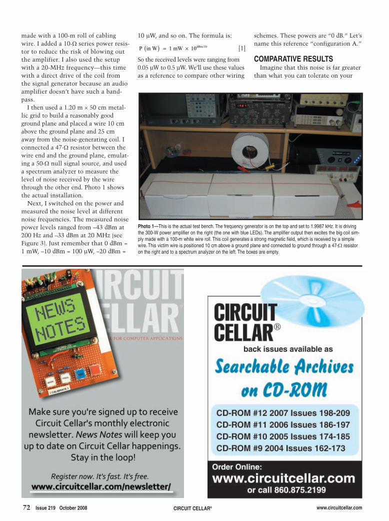
72 Issue 219 October 2008 CIRCUIT CELLAR® www.circuitcellar.com
schemes. These powers are “0 dB.” Let’sname this reference “configuration A.”
COMPARATIVE RESULTSImagine that this noise is far greater
than what you can tolerate on your
10 µW, and so on. The formula is:
[1]
So the received levels were ranging from0.05 µW to 0.5 µW. We’ll use these valuesas a reference to compare other wiring
P in W 1 mW 10dBm/10( ) = ×
made with a 100-m roll of cablingwire. I added a 10-Ω series power resis-tor to reduce the risk of blowing outthe amplifier. I also used the setupwith a 20-MHz frequency—this timewith a direct drive of the coil fromthe signal generator because an audioamplifier doesn’t have such a band-pass.
I then used a 1.20 m × 50 cm metal-lic grid to build a reasonably goodground plane and placed a wire 10 cmabove the ground plane and 25 cmaway from the noise-generating coil. Iconnected a 47-Ω resistor between thewire end and the ground plane, emulat-ing a 50-Ω null signal source, and useda spectrum analyzer to measure thelevel of noise received by the wirethrough the other end. Photo 1 showsthe actual installation.
Next, I switched on the power andmeasured the noise level at differentnoise frequencies. The measured noisepower levels ranged from –43 dBm at200 Hz and –33 dBm at 20 MHz (seeFigure 3). Just remember that 0 dBm =1 mW, –10 dBm = 100 µW, –20 dBm =
Photo 1—This is the actual test bench. The frequency generator is on the top and set to 1.9987 kHz. It is drivingthe 300-W power amplifier on the right (the one with blue LEDs). The amplifier output then excites the big coil sim-ply made with a 100-m white wire roll. This coil generates a strong magnetic field, which is received by a simplewire. This victim wire is positioned 10 cm above a ground plane and connected to ground through a 47-Ω resistoron the right and to a spectrum analyzer on the left. The boxes are empty.
2810005Lacoste.qxp 9/8/2008 2:07 PM Page 72
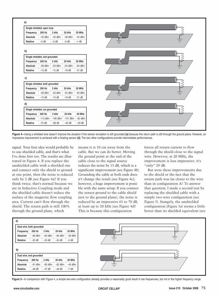
www.circuitcellar.com CIRCUIT CELLAR® Issue 219 October 2008 75
signal. Your first idea would probably beto use shielded cable, and that’s whatI’ve done first too. The results are illus-trated in Figure 4. If you replace theunshielded cable with a shielded oneand connect only the shield to groundat one point, then the noise is reducedonly by 2 dB (see Figure 4a)! If youthink twice, that’s normal because weare in Inductive Coupling mode andthe shielded cable doesn’t reduce thesurface of the magnetic flow couplingarea. Current can’t flow through theshield. The return path is still 100%through the ground plane, which
means it is 10 cm away from thecable. But we can do better. Movingthe ground point at the end of thecable close to the signal sourcereduces the noise by 15 dB, which is asignificant improvement (see Figure 4b).Grounding the cable at both ends does-n’t change the result (see Figure 4c);however, a huge improvement is possi-ble with the same setup. If you connectthe sensor ground to the cable shield(not to the ground plane), the noise isreduced by an impressive 65 to 70 dB,at least up to 20 kHz (see Figure 4d)!This is because this configuration
forces all return current to flowthrough the shield close to the signalwire. However, at 20 MHz, theimprovement is less impressive: it’s“only” 29 dB.
But were these improvements dueto the shield or the fact that thereturn path was far closer to the wirethan in configuration A? To answerthat question, I made a second test byreplacing the shielded cable with asimple two-wire configuration (seeFigure 5). Stangely, the unshieldedconfiguration (Figure 5a) seems a littlebetter than its shielded equivalent (see
Figure 5—In comparison with Figure 4, a simple two-wire configuration already provides a reasonably good result in low frequencies, but not in the higher frequency range.
Dual wire, both grounded
Frequency 200 Hz 2 kHz 20 kHz 20 MHz
Absolute –68 dBm –63 dBm –60 dBm –38 dBm
Relative –25 dB –25 dB –24 dB –5 dB
Dual wire, end grounded
Frequency 200 Hz 2 kHz 20 kHz 20 MHz
Absolute –91 dBm –85 dBm –82 dBm –40 dBm
Relative –48 dB –47 dB –46 dB –7 dB
a)
b)
Figure 4—Using a shielded wire doesn’t improve the situation if the sensor emulation is still grounded (a) because the return path is still through the ground plane. However, animpressive improvement is achieved with a floating sensor (d). The two other configurations provide intermediate performances.
Single shielded, open loop
Frequency 200 Hz 2 kHz 20 kHz 20 MHz
Absolute –45 dBm –40 dBm –38 dBm –34 dBm
Relative –2 dB –2 dB –2 dB –1 dB
Single shielded, end grounded
Frequency 200 Hz 2 kHz 20 kHz 20 MHz
Absolute –58 dBm –53 dBm –54 dBm –64 dBm
Relative –15 dB –15 dB –18 dB –31 dB
Single shielded, both grounded
Frequency 200 Hz 2 kHz 20 kHz 20 MHz
Absolute –58 dBm –53 dBm –54 dBm –64 dBm
Relative –15 dB –15 dB –18 dB –31 dB
Single shielded, out grounded
Frequency 200 Hz 2 kHz 20 kHz 20 MHz
Absolute –113 dBm –106 dBm –101 dBm –62 dBm
Relative –70 dB –68 dB –65 dB –29 dB
a)
b)
c)
d)
2810005Lacoste.qxp 9/8/2008 2:07 PM Page 75

76 Issue 219 October 2008 CIRCUIT CELLAR® www.circuitcellar.com
Figure 4c) up to 20 kHz, but it is farworse at 20 MHz. Similarly, Figure 5bis significantly worse than Figure 4d.In a nutshell, routing two wires closeto each other drastically improves thesituation (as compared to Figure 3),but a shielded cable nearly always per-forms better, especially at high fre-quencies. Not a surprise.
Can we do even better? You bet. Oneof the solutions is to use a dual-wire
shielded cable. The shield can be dedi-cated to a shield function, and the twoinner wires can be used respectively forsignal and return current. This is a bet-ter configuration to avoid inductivecoupling because the two wires areeven closer and protected against elec-tric fields by the shield. Figure 6 showsthe corresponding configurations andmeasurements. Once again, the bestresults are achieved when the shield is
grounded only at the receiving side (seeFigure 6a). If you compare it with ourprevious winner (Figure 4d), you’llnotice that the performances are bet-ter and especially improved at high fre-quencies: 42-dB attenuation at 20 MHz.The other configurations (Figures 6b–d)aren’t bad, but they aren’t as good asthe configuration in Figure 6a.
Lastly, I have tested an unshieldedtwisted pair (see Figure 7). Once again,
Figure 7—A simple twisted cable is a good solution at low frequencies. Unfortunately, the lack of a shield is a problem at higher frequencies. That’s why shielded twisted cablesare a good mix.
Twisted, out grounded
Frequency 200 Hz 2 kHz 20 kHz 20 MHz
Absolute –120 dBm –109 dBm –93 dBm –40 dBm
Relative –77 dB –71 dB –57 dB –7 dB
Twisted, end grounded
Frequency 200 Hz 2 kHz 20 kHz 20 MHz
Absolute –115 dBm –97 dBm –84 dBm –31 dBm
Relative –72 dB –59 dB –48 dB 2 dB
a)
b)
Twisted, both grounded
Frequency 200 Hz 2 kHz 20 kHz 20 MHz
Absolute –68 dBm –61 dBm –59 dBm –42 dBm
Relative –25 dB –23 dB –23 dB –9 dB
c)
Figure 6—A two-wire plus shield cable is a clear improvement over a single-wire shielded cable because the current return path is decorrelated from the shield. The configuration inFigure 6a is better than the others.
Dual shielded, out grounded
Frequency 200 Hz 2 kHz 20 kHz 20 MHz
Absolute –155 dBm –111 dBm –106 dBm –75 dBm
Relative –72 dB –73 dB –70 dB –42 dB
Dual shielded, both grounded
Frequency 200 Hz 2 kHz 20 kHz 20 MHz
Absolute –105 dBm –104 dBm –102 dBm –70 dBm
Relative –62 dB –66 dB –66 dB –37 dB
Dual shielded, end grounded
Frequency 200 Hz 2 kHz 20 kHz 20 MHz
Absolute –111 dBm –109 dBm –104 dBm –58 dBm
Relative –68 dB –71 dB –68 dB –25 dB
Dual shielded, both + signal grounded
Frequency 200 Hz 2 kHz 20 kHz 20 MHz
Absolute –89 dBm –84 dBm –82 dBm –58 dBm
Relative –46 dB –46 dB –46 dB –25 dB
a)
b)
c)
d)
2810005Lacoste.qxp 9/8/2008 2:07 PM Page 76

www.circuitcellar.com CIRCUIT CELLAR® Issue 219 October 2008 77
close as possible to a ground plane ordisconnecting (if possible) the signalreference from the ground and using atwo-wire cable ideally shielded andtwisted (see Figure 5b).
I also concluded that it is alwaysbetter to ground a cable at one point.If you are not convinced, examineFigures 4c–d for examples. This isbecause any “ground loop” will gener-ate currents in the loop when exposedto a magnetic field so noise currentwould flow in the ground. The currentwill then generate noise in the signaleither through a non-null groundimpedance effect or capacitive cou-pling. However, keep in mind that thisrecommendation applies only for low-frequency signals, not for radio waveswhere standing wave effects start toappear. At radio frequencies, it is usu-ally better to connect shields toground at as many points as possibleto form a meshed ground structure.But for audio signals, the “one pointto ground only” rule seems applicable.
But which side of the cable should begrounded? Figures 4b–d (or Figures 6a–c)show the clear answer. With anungrounded source and a groundedreceiver (the spectrum analyzer inthis case), it is always better toground the shield at the receiver end,not at the source. Even though I havenot tested it, the situation would bereciprocal with a grounded sourceand an ungrounded receiver. Theshield should then be grounded at
the best configuration is when the returnwire is grounded only on the receiverside, but the measurement results arereally impressive (see Figure 7a)! At200 Hz, the noise attenuation is evenbetter than with a two-wire untwistedshielded cable (–77 dB against –72 dB).The attenuation is similar at 2 kHz,but the shielded cable is by far thewinner at higher frequencies. In par-ticular, the unshielded twisted pairdoesn’t seem to provide any signifi-cant attenuation at 20 MHz (–7 dB),where the two-wire shielded cablesprovide –42 dB.
Unfortunately, I didn’t have ashielded twisted cable on hand thatday, but I can assume that such acable would add the benefits of a two-wire shielded cable (see Figure 6) andthe benefits of an unshielded twistedpair (see Figure 7). This cable wouldthen be as good as a twisted pair atlow frequencies, and as good as ashielded cable at higher frequencies, adefinitive winner. That’s why shieldedtwisted pairs are everywhere in net-works and industrial applications.
RULES TO KEEP IN MINDAfter performing these experiments,
I concluded that the theory was cor-rect. The first thing to keep in mind isthat the current return path of any sig-nal should always be kept as close aspossible to the signal to reduce induc-tive coupling effects. This can be doneby either routing the active wire as
RESOURCEH. W. Ott, Noise Reduction Techniquesin Electronic Systems, Second edition,John Wiley & Sons Inc., Hoboken, NJ,1988.
Robert Lacoste lives near Paris, France.He has 18 years of experience workingon embedded systems, analog designs,and wireless telecommunications. Hehas won prizes in more than 15 interna-tional design contests. In 2003, Robertstarted a consulting company, ALCIOM,to share his passion for innovativemixed-signal designs. You can reach himat [email protected]. Don’t forgetto write “Darker Side” in the subjectline to bypass his spam filters.
Figure 8—This is the best way to ground a shield, depending on which side of the connection is grounded. If bothends are grounded, the performances will be worse and you’ll need to test to see if it is better to ground the shieldon one side or both. This may depend on the environment.
Floating receiver Grounded source
Grounded receiver Floating source
the source side. Figure 8 shows theseconfigurations. If you check again,you’ll see that this configurationonce again reduces the ground loopsize.
All of these tests were done with avictim cable exposed under a fixedhigh magnetic flux for immunity con-cerns. Keep in mind that the sameanalysis is applicable if you need toreduce magnetic flux emitted by anoisy wire (e.g., to comply with spuri-ous emission restrictions). If a givenconfiguration is immune to externalfields, it will not generate any field ifthe internal wire is excited. This isthe beauty of reciprocity.
WRAPPING UPI had fun performing the aforemen-
tioned experiments. Although someof the results surprised me, theyalways ended up being compatiblewith the underlying theory—andthat’s good news for both the theoryand my sanity. They don’t exactlymatch the results published in theoriginal works of Henry Ott, butthey are qualitatively close. Onceagain, this demonstrates that youalways need to think twice beforeputting an old book in your base-ment, or worse. I hope you are nowtempted to do your own shieldingexperiments. I sure was after readingHenry’s book. Cable shielding is nolonger on the darker side for me, andI hope it isn’t for you. I
2810005Lacoste.qxp 9/8/2008 2:07 PM Page 77

78 Issue 219 October 2008 CIRCUIT CELLAR® www.circuitcellar.com
the specs here and out they popthere. Notably, a trade-off betweenrange and accuracy is a commontheme.
The devices most designers arefamiliar with are “contact” tempera-ture sensors that require physicalmounting to the object of interest. Inturn, that can limit the allowed tem-perature range. Any contact sensorcan tolerate temperate applications(e.g., –40° to 85°C), but the list nar-rows quickly beyond that. You sim-ply can’t use a plastic IC sensor in ablast furnace.
When it comes to accuracy, in manyapplications, a couple-of-few degreesbetween friends is fine; but in others,it isn’t. Medical applications come tomind. You wouldn’t want the doctorto think your temperature is normalwhen in fact you have a fever. Onceagain, the list of temperature sensoroptions shrinks if you up the antewith demands for better (i.e., fractional-degree) accuracy.
Similarly, response times measuredin seconds are fine for human-inter-est applications like your home ther-mostat. But it’s not hard to imaginereal-time scientific and industrialprocesses that need to track andrespond to temperature changesmore quickly.
arrows in a designer’s quiver. Theseare all fine devices that continue toserve designers in good stead.
But, pardon the pun, to one degreeor another, they all come with cer-tain compromises depending on thetask at hand. It’s up to designers tojuggle all the trade-offs: cost, power,temperature range, accuracy,response time, and so on. A tempera-ture sensor is like a balloon. Squeeze
This month, let’s take a look atyet another new MCU—not!
Don’t get me wrong. As far as I’mconcerned, MCUs are the shiningstars of the silicon revolution, rightup there with fancy microprocessorsand memory chips. MCUs may notget the headlines, but they sure getthe sockets.
Yes, it’s grand to have more MIPSand megahertz on tap than everbefore, but it’s all for naught unlessthere’s some meaningful real-worlddata to crunch on. And when we’retalking about “meaningful real-worlddata,” we’re talking about sensors.
Last June, while I was waiting forthe Sensors Expo and some neatgadgets to write about, I decided toplay with the one sitting on mydesk. I thought, why wait? The sili-con climate is always changing andsensor season started a bit early thisyear.
ASK AND YE SHALL RECEIVEMeasuring temperature is a funda-
mental task at the heart of myriadapplications. That’s reflected in thewide variety of temperature sensorson the market. Thermocouples,resistance temperature detectors(RTDs), thermistors, and IC tempera-ture sensors are just some of the
Hot Enough for You?
SILICON UPDATE by Tom Cantrell
As Tom explains, having all the MIPS and megahertz in the world means nothing unlessyour design has some meaningful real-world data to process. To gather such meaningfuldata, you need innovative sensors. This month, Tom introduces a handy option youshould consider for your next temperature-sensing design—an infrared noncontact ICthermometer.
Photo 1—The Melexis Microelectronic SystemsMLX90614 brings noncontact IR temperature sensingto an application near you.
Seeing Red (Infrared, That Is)
2810003-cantrell.qxp 9/8/2008 2:13 PM Page 78

Another headache taken for grantedis the wires that connect the sensorto the data-acquisition gear. Theproblem isn’t just stringing the wire,which can itself be a real challenge inharsh environments. There’s also theissue of signal conditioning—non-trivial for something like a thermo-couple that puts out just a fewmeasly microvolts per degreeCelsius.
In a way, it’s funny that designerstake all of the compromises andtrade-offs in stride. Just haul out thesame old bag of temperature sensortricks and make do the best you can.But we don’t cut other high-techgadgets any slack. They’re alwaysexpected to do Moore for less. Whydo temperature sensors get a freepass?
I say it’s time for designers tostand up and demand more. By golly,I want a temperature sensor that hasmore range and more accuracy thanI’ll ever need. Oh yeah, and whileyou’re at it, make sure it’s low-powerand easy to wire up. Better yet, just
make it noncontact and digital to getrid of the wires and signal-condition-ing hassles altogether.
My wish has been granted. Sayhello to the Melexis Microelectronic
Systems MLX90614 (see Photo 1).
TEMPERATURE IS THE MESSAGEOf course, one way to make a
wireless thermometer is to mate a
Photo 2—Long-time Circuit Cellar readers may remember when Steve Ciarcia took on the challenge of IR temperaturesensing way back in 1978. His lash-up used an IR photodetector with a blue-collar optical assist (i.e., focus) from asolar cigarette lighter.
2810003-cantrell.qxp 9/8/2008 2:13 PM Page 79

80 Issue 219 October 2008 CIRCUIT CELLAR® www.circuitcellar.com
traditional (i.e., wired) temperaturesensor with one of the ever-prolifer-ating low-cost ISM-band radios (e.g.,IEEE 802.15.4). Instead, theMLX90614 determines an object’stemperature indirectly by measuringits IR emissions. In other words,temperature is both the medium andthe message.
The idea of using an IR detector tomeasure temperature isn’t new at all.Old-timers may remember SteveCiarcia’s design from the 1970s. Hiswhimsical lash-up combined an IR pho-todiode with a solar-powered cigarettelighter (i.e., a parabolic mirror) acting asan IR magnifier (see Photo 2).[1] TheMelexis parts don’t do anything new;they just do it a heck of a lot better.
Ironically, under the hood of this“noncontact” temperature sensor is,you guessed it, a “contact” tempera-ture sensor. A tiny thermocouplearrangement (the “thermopile”) isheated by IR radiation that passesthrough the circular window on topof the package. To minimize sunlightinterference, the window is treated
Figure 1—Under the hood of the MLX90614 are two chips. One is the IR sensor itself (the “thermopile”). The otheris a signal conditioner integrating the signal chain (amp, ADC, filter DSP), digital interface (i.e., SMBus, PWM), andEEPROM for configuration and calibration settings.
2 - PWM/SDA
3 - VDD
1 - SCL/VZ
4 - VSS
ADC DSP PWM
Top view
State machine
Voltageregulator
to
OPA
81101
90302
EARLY BIRD REGISTRATION OPEN! REGISTER TODAY & SAVE!
Platinum Sponsors
Gold Sponsor
Questions, Please Contact: [email protected] or (949) 851–1714 — www.SavantCompany.com
The Most Informative, Targeted & Affordably Priced SoC, ASIC, CSSP, FPGA, and Foundry Technology Conference, Exhibit & Workshops of the Year
Don't Miss Out!
www.SoCconference.com
2810003-cantrell.qxp 9/8/2008 2:13 PM Page 80

Buying electronic components can be difficult withhundreds of thousands of products to choose from.Unfortunately, the choice has been between wieldinga twenty pound catalog or sifting through a complicated web site. Jameco solves the problem of finding the products you need with the industry'sfirst and only web-enabled catalog.
The Jameco Catalog... It’s packed with features tohelp you quickly narrow your search. The catalogpresents our most popular products in a way thatmakes it easy to compare everything from franchisesourced brands to house brands and factory overruns.
The Jameco Website...Once you've found the section you like in the catalog, just use the product category web codefound on each page to continue your search atJameco.com where you’ll find more information,more choices, the latest pricing and availability withnone of the complications that other websites have.
Jameco has everything you would expect from a components distributor, plus a few surprises.
Reach for Jameco first.
Order Your Web-EnabledCatalog Today!
For More InformationCall 1-800-731-4242 or Visit www.Jameco.com/News
81.qxp 8/25/2008 1:41 PM Page 1
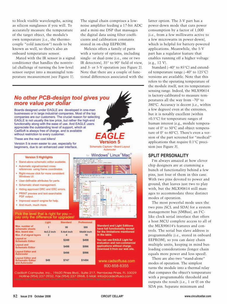
82 Issue 219 October 2008 CIRCUIT CELLAR® www.circuitcellar.com
to block visible wavelengths, actingas silicon sunglasses if you will. Toaccurately measure the temperatureof the target object, the module’sown temperature (i.e., the thermo-couple “cold junction”) needs to beknown as well, so there’s also anonboard temperature sensor.
Mated with the IR sensor is a signalconditioner that handles the nontriv-ial challenge of turning the low-levelsensor output into a meaningful tem-perature measurement (see Figure 1).
The signal chain comprises a low-noise amplifier feeding a 17-bit ADCand a mini-me DSP that massagesthe digital data using filter coeffi-cients and calibration constantsstored in on-chip EEPROM.
Melexis offers a family of partswith a variety of options, includingsingle- or dual-zone (i.e., one or twoIR detectors), 35° to 90° field of view,and 3- or 5-V operation (see Figure 2).Note that there are a couple of func-tional differences associated with the
latter option. The 3-V part has apower-down mode that cuts powerconsumption by a factor of 1,000(i.e., from a few milliwatts active toa few microwatts in power-down),which is helpful for battery-poweredapplications. Meanwhile, the 5-Vpart has a regulator feature thatenables running off a higher voltage(e.g., 12 V).
Standard (–40° to 85°C) and extend-ed temperature range (–40° to 125°C)versions are available. Note that thisrefers to the operating temperature ofthe module itself, not its temperature-sensing range. Indeed, the MLX90614is factory-calibrated to measure tem-peratures all the way from –70° to380°C. Accuracy is decent (i.e., withina few degrees) even at the extremes,but it is notably excellent (within±0.5°C) for temperature ranges ofhuman interest (e.g., module tempera-ture of 0° to 50°C and object tempera-ture of 0° to 60°C). There’s even a ver-sion of the part screened for “medical”applications that require 0.1°C preci-sion (see Figure 3).
SPLIT PERSONALITYI’m always amazed at how clever
chip designers are at cramming abunch of functionality behind a fewpins, just four of them in this case.With two pins devoted to power andground, that leaves just two to playwith, but the MLX90614 still man-ages to accommodate three distinctmodes of operation.
The most powerful mode uses thetwo pins (SCL and SDA) for a systemmanagement bus (SMBus), an I2C-like clock serial interface that offersa host MCU complete access to all ofthe MLX90614’s features and con-trols. The serial bus slave address isprogrammable (i.e., stored in onboardEEPROM), so you can daisy chainmultiple units, keeping in mind bus-loading considerations (longer chainequals more power and less speed).
There are also two “stand-alone”modes of operation. The simplestturns the module into a thermal relaythat compares the object’s temperaturewith a programmable threshold andoutputs the result (i.e., 1 or 0) on theSDA pin. Separate minimum and
2810003-cantrell.qxp 9/8/2008 2:13 PM Page 82

www.circuitcellar.com CIRCUIT CELLAR® Issue 219 October 2008 83
I noticed there are a few cases where asingle register contains both bits youmight want to program (e.g., configu-ration) and ones you shouldn’t (i.e.,factory calibration). Just be carefulslinging those ones and zeros around.
PAINT IT BLACKI’d rather walk the Planck than
launch into a physics tutorial onheat transfer and the like, a duty forwhich I have neither the time nor
maximum threshold registers allowdialing in some hysteresis to preventoutput chattering. The output can beconfigured as push-pull or open-col-lector. The latter option allows thealarm outputs from multiple mod-ules to be wire-ORed together.
The second stand-alone mode usesthe SDA pin as a continuous PWMoutput of the temperature reading.This means the sensor can provide ameasure of control itself, possibly eveneliminating the need for an MCU.
I’ve got mixed feelings about thePWM mode. It’s got some nice fea-tures, such as programmable frequen-cy and repeat factor plus the abilityto “zoom in” on a temperature sub-range of interest. There’s also anoption to output two different read-ings (e.g., object and ambient temper-ature, or two object temperatures fora dual-zone part) interleaved on thesingle PWM pin. The PWM format isa bit odd because the duty cycledoesn’t vary between 0% and 100%,as you might expect (see Figure 4).
These days, most MCUs come withADCs. So, you might be tempted tohang an RC filter on the PWM outputand convert the 1-and-0 PWM pulsetrain to an analog voltage for samplingwith the MCU’s ADC. That’s certainlyan option, but not without caveats.[2] Ifyou decide to go that route, make surethe ADC is referenced to theMLX90614’s VDD pin, lest power supplynoise and drift compromise measure-ment accuracy and repeatability.
It is possible to dynamicallychange between the different modes(i.e., Host, Alarm, and PWM) by in-system programming the configura-tion EEPROM. For instance, a mod-ule might be configured to automati-cally power-up in PWM mode, but ahost MCU can take charge at anytime by toggling the SCL pin toswitch back to Serial Bus mode.
From the host MCU’s perspective,the module appears as two banks of 3216-bit registers, one bank for EEP-ROM, and one for RAM (see Table 1).Many of these are for housekeeping(e.g., ID number) or reserved, whileothers store settings such as factorycalibration factors or the programma-ble temperature thresholds and ranges.
the expertise. Sure this is one smartgadget; but nevertheless, determiningthe actual temperature of a particularobject isn’t a simple point- and-shootaffair. Yes, what you see is what youget, but only if you know whatyou’re seeing.
There are two major considerationsthat affect what number the ther-mometer spits out. One is so obviousthat it is easily overlooked, andthat’s the “field of view” (FOV).
Figure 2—What you see is what you get. The wide 90° field of view single- (a) and 70° dual-zone parts providelarge area coverage (b). The 35° option narrows the focus (c).
1.00
0.75
0.50
0.25
0.00-800 -600 -400 -200 00 200 400 600 800
Angle deg
1.00
0.75
0.50
0.25
0.00-800 -600 -400 -200 00 200 400 600 800
Angle deg
1.00
0.75
0.50
0.25
0.00-800 -600 -400 -200 00 200 400 600 800
Angle deg
a)
b)
c)
2810003-cantrell.qxp 9/8/2008 2:13 PM Page 83
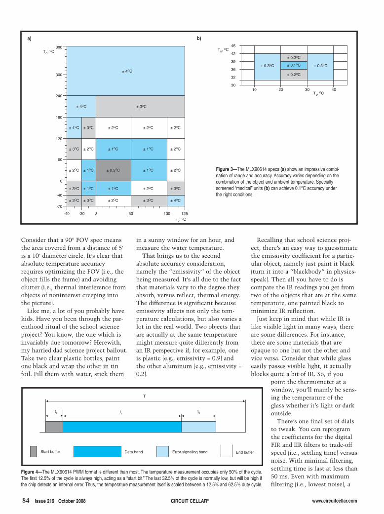
84 Issue 219 October 2008 CIRCUIT CELLAR® www.circuitcellar.com
in a sunny window for an hour, andmeasure the water temperature.
That brings us to the secondabsolute accuracy consideration,namely the “emissivity” of the objectbeing measured. It’s all due to the factthat materials vary to the degree theyabsorb, versus reflect, thermal energy.The difference is significant becauseemissivity affects not only the tem-perature calculations, but also varies alot in the real world. Two objects thatare actually at the same temperaturemight measure quite differently froman IR perspective if, for example, oneis plastic (e.g., emissivity = 0.9) andthe other aluminum (e.g., emissivity =0.2).
Consider that a 90° FOV spec meansthe area covered from a distance of 5′is a 10′ diameter circle. It’s clear thatabsolute temperature accuracyrequires optimizing the FOV (i.e., theobject fills the frame) and avoidingclutter (i.e., thermal interference fromobjects of noninterest creeping intothe picture).
Like me, a lot of you probably havekids. Have you been through the par-enthood ritual of the school scienceproject? You know, the one which isinvariably due tomorrow? Herewith,my harried dad science project bailout.Take two clear plastic bottles, paintone black and wrap the other in tinfoil. Fill them with water, stick them
Recalling that school science proj-ect, there’s an easy way to guesstimatethe emissivity coefficient for a partic-ular object, namely just paint it black(turn it into a “blackbody” in physics-speak). Then all you have to do iscompare the IR readings you get fromtwo of the objects that are at the sametemperature, one painted black tominimize IR reflection.
Just keep in mind that while IR islike visible light in many ways, thereare some differences. For instance,there are some materials that areopaque to one but not the other andvice versa. Consider that while glasseasily passes visible light, it actuallyblocks quite a bit of IR. So, if you
point the thermometer at awindow, you’ll mainly be sens-ing the temperature of theglass whether it’s light or darkoutside.
There’s one final set of dialsto tweak. You can reprogramthe coefficients for the digitalFIR and IIR filters to trade-offspeed (i.e., settling time) versusnoise. With minimal filtering,settling time is fast at less than50 ms. Even with maximumfiltering (i.e., lowest noise), a
Figure 4—The MLX90614 PWM format is different than most. The temperature measurement occupies only 50% of the cycle.The first 12.5% of the cycle is always high, acting as a “start bit.” The last 32.5% of the cycle is normally low, but will be high ifthe chip detects an internal error. Thus, the temperature measurement itself is scaled between a 12.5% and 62.5% duty cycle.
Start buffer Data band Error signaling band End buffer
T
t2t1 t3
300
380
240
180
120
60
0
-40
-70
45
42
39
36
32
30
-40 -20 0 50 100 125
10 20 30 40
± 0.3OC ± 0.3OC
± 0.2OC
± 0.1OC
± 0.2OC
TO, OC
Ta, OC
± 4OC
± 4OC ± 3OC
± 4OC ± 3OC ± 2OC ± 2OC ± 2OC
± 3OC ± 2OC ± 1OC ± 1OC ± 2OC
± 2OC ± 1OC ± 0.5OC ± 1OC ± 2OC
± 3OC ± 1OC ± 1OC ± 2OC ± 3OC
± 3OC ± 3OC ± 2OC ± 3OC ± 4OC
TO, OC
Ta, OC
Figure 3—The MLX90614 specs (a) show an impressive combi-nation of range and accuracy. Accuracy varies depending on thecombination of the object and ambient temperature. Speciallyscreened “medical” units (b) can achieve 0.1°C accuracy underthe right conditions.
a) b)
2810003-cantrell.qxp 9/8/2008 2:13 PM Page 84

www.circuitcellar.com CIRCUIT CELLAR® Issue 219 October 2008 85
“Are my pants on fire?” I’ve installed anoil temperature gauge that uses a dip-stick in the oil tank, but its reading israther sluggish and not necessarily a trueindicator. Indeed, contemplating failurescenarios (e.g., low oil level or failing oilpump), it’s apparent that the oil tempera-ture gauge could be misleading. Low oiltemperature might simply mean the bikeisn’t warmed up yet. But it might alsomean the oil isn’t circulating—orworse, that the level is so low the dip-stick is measuring air temperature!
I want to know the actual temperatureof the engine (i.e., the rear cylinder
temperature readingtakes less than 1 s.
EASY RIDEREnough of this book
learning. It’s time towire something up. I gotmy hands-on fix courtesyof Parallax and theirMLX90614 applicationmodule (see Photo 3). Itcombines the Melexispart with a dedicatedcoprocessor (i.e., MCU)that provides a high-levelcommand set and UARThost connection. Pairingthe module with BASICStamp, it takes only three jumperwires and a few lines of code to take atemperature reading.
The timing was right because I hada perfect application in mind. I havea Harley-Davidson motorcycle withan air-cooled engine, something thathasn’t changed in 100 years. Theother thing that hasn’t changed isthe fact that the engine can get hotin low-airflow situations (e.g., trafficjams), especially the rear cylinder.[3]
“How hot?” you ask. That’s a goodquestion—a question historicallyanswered with another question like
head, not the oil). Whilethere are plenty of con-tact temperature sensoroptions, I’m not inspiredby the concept of bolt-ing/taping/gluing somekludge to my engine.Voila, a perfect applica-tion for a noncontacttemperature sensor.
I hacked together asimple temperature-log-ging program, which ispretty self-explanatory(see Listing 1). As writ-ten, it takes up to 1,800readings (max_count) at1-s (PAUSE 1000) inter-
vals, which makes for 30 min. ofcapacity. If you want to expand theprogram or data capacity, just makesure everything will still fit. Both theprogram and data are stored in theStamp’s EEPROM and no doubt badthings will happen if you log data ontop of the program! Also, this programisn’t power-optimized. A more bat-tery-friendly version can take advan-tage of features like the Stamp SLEEPand NAP commands and the module“Z” (continuous read at low power)command.
Heading out on the highway (seePhoto 4), even this quick and dirtyexperiment yielded some insight (seePhoto 5). I was surprised to see howlong it takes the engine to warm up.Ignoring the idling temperature spikesnear the end of the run, it almostlooked as though temperature was lev-eling off, but it would clearly take alonger ride to verify that.
You could experiment with theemissivity register setting or other-wise calibrate the setup to get anaccurate absolute temperature.However, this is a good time to notethat many applications don’t reallyneed absolute measurements, butrather just relative consistency (e.g.,linearity) and repeatability.
And it’s obvious that engine temper-ature indeed shoots up quickly whenidling, but fortunately just as quicklymoderates once you get going again.
HEAT WAVEThe MLX90614 is a novel solution
Photo 3—A Parallax BASIC Stamp and MLX90614 application module make it super quick and easy to getstarted with IR temperature sensing.
Table 1—The register map of the MLX90614 includes EEPROM to store configuration andfactory calibration settings and RAM for the IR and ambient temperature readings.
Address EEPROM Function RAM Function0 Object temperature threshold/range max Reserved
1 Object temperature threshold/range min Reserved
2 PWM Options configuration Reserved
3 Ambient temperature range min/max Reserved
4 Emissivity correction coefficient Reserved
5 Configuration and factory calibration Reserved
6 Reserved Ambient temperature
7 Reserved Object 1 temperature
8 Reserved Object 2 temperature (dual zone)
14 SMBus Slave address Reserved
28 ID Number Reserved
29 ID Number Reserved
30 ID Number Reserved
31 ID Number Reserved
2810003-cantrell.qxp 9/8/2008 2:13 PM Page 85

to the age-old application challengeof measuring temperature. It surelydeserves a place in your quiver oftemperature-sensing solutions.
But as is often the case, a technicaladvance can offer more than just anew way of implementing an old
REFERENCES[1] S. Ciarcia, “I’ve Got You In MyScanner: A Computer ControlledStepper Motor Light Scanner,” Byte,Vol. 3, Issue 11, 1978.
[2] Melexis Microelectronic Systems,“Application Note: Analog VoltageOutput with MLX90614,” 39011 9061401, 2006, www.melexis.com/Assets/Analog_voltage_output_with_MLX90614_5176.aspx.
[3] J. Minton, “Hot New Harleys:Richening Your Engine’s Air/FuelMixtures,” American Rider Magazine,www.americanrider.com/output.cfm?ID=1279963.
SOURCESMLX90614 Infrared thermometerMelexis Microelectronic Systems www.melexis.com
MLX90614 Application module Parallax, Inc.www.parallax.com
Tom Cantrell has been working onchip, board, and systems design andmarketing for several years. You mayreach him by e-mail at [email protected].
www.circuitcellar.comCIRCUIT CELLAR®86 Issue 219 October 2008
application. Themore interesting out-come is when design-ers discover that anew technology pro-vides a new way ofdoing something new.Witness the wayMEMS accelerome-ters—which got theirstart as automotive“airbag chips”—havetransformed videogame systems likethe Nintendo Wii.I’m excited by theprospects for IR tem-perature sensing tosimilarly spark novelnew applications.
Once again, it’s time for designersto think outside the box. When it
Listing 1—This simple data logger program shows how easy it is to use the MLX90614. Just issue the tem-perature read command using a SEROUT statement and read back the high- and low-byte of the temperaturedata along with a checksum using a SERIN statement. The funny calculation that follows uses the BASICStamp integer math to convert Kelvin to Centigrade.
' {$STAMP BS2}lowtemp VAR Bytehightemp VAR Bytepecbyte VAR Bytetemp VAR Wordi VAR Wordsamples CON 1799
INPUT 1
IF (IN1=1) THEN dump 'otherwise log data
'begin by clearing sample bufferFOR i = 0 TO samples
WRITE i,255 'clear sample bufferNEXT'now read temp, convert K to C and store in sample bufferFOR i = 0 TO samples
PAUSE 1000SEROUT 0,396,[0,"!TEMR",$5A,$07]SERIN 0,396,[lowtemp, hightemp, pecbyte]temp = ((((hightemp * 256)+lowtemp)*2)-27300)/100WRITE i,temp'DEBUG DEC temp,CR
NEXTEND 'if sample buffer full
dump:'output temp samples via UARTFOR i = 0 TO samples
READ i,tempIF (temp=255) THEN quit 'at end of sample dataDEBUG DEC temp,CR
NEXTquit:END
Photo 4—Things get hot on the highway to hell, espe-cially the rear cylinder of this air-cooled twin. Here wesee both the traditional oil temperature gauge and theMLX90614 lash-up.
comes to the race to invent the nextbig thing, the heat is always on. I
Photo 5—Interesting results came from my initial experiment, a roughly 30-min.ride. The engine was more cold-blooded than I had imagined and took quite a whileto warm up. The first 20 min. or so were mostly highway cruising and then you canclearly see the temperature spikes as I hit stoplights near the end of the ride.
2810003-cantrell.qxp 9/8/2008 2:13 PM Page 86

www.circuitcellar.com CIRCUIT CELLAR® Issue 219 October 2008 87
IDEA BOXTHE DIRECTORY OF PRODUCTS AND SERVICES
AD FORMAT: Advertisers must furnish digital submission sheet and digital files that meet the specifications on the digital submission sheet. ALL TEXT AND OTHERELEMENTS MUST FIT WITHIN A 2" x 3" FORMAT. Call for current rate and deadline information. E-mail [email protected] with your file and digital submissionor send it to IDEA BOX, Circuit Cellar, 4 Park Street, Vernon, CT 06066. For more information call Shannon Barraclough at (860) 875-2199.
The Vendor Directory at www.circuitcellar.com/vendor/ is your guide to a variety of engineering products and services.
UUSSBBAdd USB to your next
project—it’s easier than youmight think!
USB-FIFO up to 8 mbpsUSB-UART up to 3 mbpsUSB/Microcontroller boards
pre-programmed with firmware2.4GHz ZigBee™ & 802.15.4RFID Reader/Writer
Absolutely NO driver softwaredevelopment required!
www.dlpdesign.com
FDI Advertisement
7/23 0 8
D:\~Magazine 219 FDI Ad x3 f tur S B-T G .doc
NXP ARM7 LPC2K TFBGAProgramming Adapters
SAB-TFBGAxxx Low Cost Socket Adapter Boards allow the userto program and test ARM7 LPC2K BGA devices outside of theirapplication circuit. The SAB-TFBGAxxx Family includes supportfor most NXP LPC2xxx devices in the following packages:TFBGA100, TFBGA180 and TFBGA208. SAB-TFBGAxxx is usedalong with our USB-ICP-LPC2K, In-Circuit Programmer - $69.00.
Stand-alone mode allows the SAB to be used for verification ofbasic functionality of the user software. The board includes 12MHz oscillator circuit, POR circuit, and a single LED connected to auser I/O signal. The kit includes Power Supply and ProgrammingCable for only $399.00.
The USB-ICP-LPC2K & SAB-TFBGAxxx are available directlyfrom Digi-Key www.digikey.com and Mouser www.mouser.com.
NXP ARM7 LPC2K TFBGAProgramming Adapters
USB-ICP-LPC2K with SAB-TFBGA180 AdapterXA Development Kits, I2C, SPI & MDIO tools in stock, visit
www.teamfdi.com for details.
www.teamfdi.com
Future Designs, Inc.2702 Triana Blvd
Huntsville, AL 35805(256) 883-1240
Fax (256) 883-1241
ib-219.qxp 9/8/2008 2:29 PM Page 87
32.qxp 7/11/2008 11:59 AM Page 66

www.circuitcellar.com CIRCUIT CELLAR® Issue 219 October 2008 89
ib-219.qxp 9/8/2008 2:29 PM Page 89

90 Issue 219 October 2008 CIRCUIT CELLAR® www.circuitcellar.com
ib-219.qxp 9/8/2008 2:30 PM Page 90

www.circuitcellar.com CIRCUIT CELLAR® Issue 219 October 2008 91
Freescale 9S12C microcontroller
DIP modules
www.nanocore12.comToll-free: 1-877-963-8996
40-pin
32-pin
M68MOD912C32
24-pin
���������
Too
ls f
or
Em
bed
ded
Dev
elo
pm
ent
ARM8051COLDFIRE� C/C++*
� Code Wizards� Debugging� Simulation� Support
www.crossware.com360-812-2397
Embedded C++ for ARM andColdFire only
*
Advanced softwaretools since 1984
Three quality tool suites
®
®
®
ib-219.qxp 9/8/2008 2:30 PM Page 91

92 Issue 219 October 2008 CIRCUIT CELLAR® www.circuitcellar.com
When contacting ouradvertisers, tell themwhere you found their ad...
...tell them,“Circuit Cellar
sent me.”
Advertiser
ib-219.qxp 9/8/2008 2:30 PM Page 92

1
2 3
4
5 6 7
8 9
10
11 12
13 14
15 16
17
18
19
www.circuitcellar.com CIRCUIT CELLAR® Issue 219 October 2008 93
CCRROOSSSSWWOORRDD
The answers are available atwww.circuitcellar.com/crossword.
Down1. A computer that runs Windows and includes an
Intel chip3. A basic particle with a mass about 200 times the
size of an electron that is common in radiationnear the Earth’s surface
4. An old-timer interested in embedded design7. Dot dot dot9. 10–24
10. A particle detector used to measure radiation12. A small version of a picture on a computer14. Wolfram16. An extremely small web server
Across2. The unique name of a computer system on a network5. The “9000” in Space Odyssey6. Series of monomers in a chain8. Text message: “probably”11. The “K” in CMYK13. A set of acceptable e-mail addresses15. Staging area17. A program that searches the Internet for new web
pages18. Time between wave repetitions19. A unit of electric charge; French physicist
crossword2.qxp 9/8/2008 2:32 PM Page 93

94 Issue 219 October 2008 CIRCUIT CELLAR® www.circuitcellar.com
Radiation Detection: A System that Measures Digital and Analog Pulses
Embedded Cause and Effect: A Lighting System that Responds to Audio Stimuli
Time Server Design: Synchronization with the U.S. WWVB Timecode Signal
Low-Cost Serial-to-USB Migration
Digital Stompboxing: An Easy-to-Use Digital Signal Processing Platform
Weather-Monitoring Circuitry: A Design for Indoor-Outdoor Use
LESSONS FROM THE TRENCHES What Can C Structures Do for You?
FROM THE BENCH Drive by Wire: A Look at Noncontact Sensing
SILICON UPDATE It’s the Sensors, Stupid: A Review of New Sensor Technology
91 AAG Electronica, LLC
66 AP Circuits
92 All Electronics Corp.
90 Apex Embedded Systems
7 Atmel
55 Bitscope Designs
65 CWAV
82 CadSoft Computer, Inc.
56 Comfile Technology, Inc.
91 Crossware Products, Inc.
91 Custom Computer Services, Inc.
44 Custom Solutions, Inc.
87 DLP Design
32 DesignNotes
44 EMAC, Inc.
90 Earth Computer Technologies
74 Embedded Developer
22 ExpressPCB
9 ezPCB
87 FDI-Future Designs, Inc.
91 FlexiPanel Ltd.
The Index of Advertisers with links to their web sites is located at www.circuitcellar.com under the current issue.Page
37 Futurlec
64 Grid Connect, Inc.
90 Hagstrom Electronics
90 HI-TECH Software LLC
32 HobbyLab LLC
73 Holtek Semiconductor, Inc.
89 ISP Micro
32, 89 IMAGEcraft
90 IMAGEcraft
1 Imagineering, Inc.
92 Ironwood Electronics
64, 66 JKmicrosystems, Inc.
91 JKmicrosystems, Inc.
81 Jameco
45 Jeffrey Kerr LLC
18 Keil Software
23 LPKF Laser & Electronics
45 Lakeview Research
90 Lawicel AB
9, 89 Lemos International
49 Linx Technologies
57 Luminary Micro
89 MCC (Micro Computer Control)
47 Microchip
92 microEngineering Labs, Inc.
95 Mouser Electronics
89 Multilabs
17 NKK Switches
C2 NetBurner
45 Nurve Networks LLC
91 Ontrak Control Systems
19 PCB-Pool
C4 Parallax, Inc.
89 Phytec America LLC
92 Pioneer Hill Software
33 Pololu Corp.
87 Pulsar, Inc.
79 R4
27, 49 Rabbit, A Digi International Brand
89 Rabbit, A Digi International Brand
89 Reach Technology, Inc.
29, 39 Renesas Technology
Page Page Page
80 SoC Conference
40 Saelig Co.
5 Saleae LLC
11 SEGGER Microcontroller Systems LLC
21 Silicon Laboratories, Inc.
48 Solder By Numbers (Schmartboard)
41 Spark Fun Electronics
91 Systronix
C3 Tech Tools
2, 3 Technologic Systems
91 Technological Arts
90 Tern, Inc.
89 Tin Can Tools, LLC
31 Total Phase, Inc.
87 Trace Systems, Inc.
91 Triangle Research Int’l, Inc.
37 WCSC (Willies Computer Software Co.)
10 WIZnet
92 Xytronix Research & Design, Inc.
December Issue 221Deadlines
Space Close: Oct. 10Material Close: Oct. 20
Theme:Programmable Logic
ATTENTION ADVERTISERS
Call Shannon Barraclough now to reserve your space!
860.875.2199e-mail: [email protected]
INDEX OF ADVERTISERS
Preview of November Issue 220Theme: Analog Techniques
nsing
94-advertiser's index.qxp 9/8/2008 2:33 PM Page 94

New Products from:
TMS320C672x Digital Signal Processorwww.mouser.com/tidsp/a
www.mouser.comOver A Million Products Online
Experience Mouser’s time-to-market advantage with no minimums and same-day shipping of the newest products from more than 366 leading suppliers.
(800) 346-6873
The Newest Products For Your Newest Designs
The ONLY New Catalog Every 90 Days
The Newest Semiconductors
DSPIC33F Digital Signal Processorswww.mouser.com/microchip/a
CS48540 32-bit DSPwww.mouser.com/cirruslogic/a
Mouser_CircuitCellar_10-1.indd 1Mouser_CircuitCellar_10-1.indd 1 8/18/08 4:33:23 PM8/18/08 4:33:23 PM
95.qxp 8/28/2008 1:55 PM Page 1

96 Issue 219 October 2008 CIRCUIT CELLAR® www.circuitcellar.com
I doubt that there are many other people in the technical landscape with enough sense of humor to equate the evolution of horses and cars tohard drives and solid state drives (SSDs), but here I am. Horses, for the most part, were reliable, low-cost, had predictable operating parameters,and were cheap to operate (grass). Cars, on the other hand, were noisy and smelly (neglecting that horses had their own unique fragrance), hadsuspect reliability, had an extremely high purchase cost, had unpredictable operation (bad roads), and fuel was hard to find (no gas stations). Weshould all still be riding horses, right?
That would certainly be the case if this was strictly a price/performance comparison of two nonevolving technologies at a single point in his-tory. But cars continued evolving while horses did not. Flash memory is a similar story of evolution. Embedded developers, iPod users, cell phonecrazies, digital photographers, etc., all rely on the significant advantages of nonvolatile flash memory as a core design element in the functionsof these products. Of course, incorporating flash successfully had its learning curves and some experiences are hard to forget.
Back in the early 1990s, I was called in as a consultant to help a company having problems getting one of its new communication products tostop failing. The device was unique for the time and offered significant advantages over the competition. The bad news was that after about twoweeks of operation, it lost its marbles (i.e., forgot all its setup information and user inputs). I suppose I could have milked the job for a few daysplaying with a scope probe, but after looking at the schematic, I chuckled and asked the software guys how often they were writing the setup infor-mation to the flash memory.
You know software guys. When doing a task one time works, doing it a whole lot more often is better. ;-) It turns out that they were refreshingthe configuration and user settings to the on-board flash chip every time they dumped the communication traffic RAM buffer to the hard drive—about once a minute. Worse yet, they were writing it to the same flash memory address every time. I guess no one on the hardware team told thesoftware guys that any single address on the flash memory was only good for about 10,000 write cycles. It should have only lasted one week.They were lucky it lasted for two.
I can’t speak for all embedded engineers, but it is experiences like these that add a certain personal skepticism about incorporating flash mem-ory in everything. Certainly, technology has changed a lot through the years and flash write cycles are now in the hundreds of thousands (I believeI even heard 1 million quoted by one vendor) and flash makes absolute sense in digital cameras, cell phones, and A/V gadgets. The likelihood ofwriting to any single address a couple hundred thousand times in an 8-GB MP3 player or camera memory is so remote that all skepticism isremoved. Flash cards in these devices just aren’t worked all that hard.
Flash-based SSDs (versus spindle hard drives—HDDs) is another story and still a work in progress. Like the horse-versus-car scenario, there’sno doubt in my mind that in the long run SSDs will win, and at least for laptops and subnotebooks, the transition will be sooner than later. SSDssurvive hostile environments better than mechanical systems—HDDs don’t like extreme high or low temperatures. (Ever try starting your laptopafter it’s been sitting in the trunk overnight during the winter?) Higher random access data transfer speeds over equivalent-size hard drives—stilla lot of testing going on but electrons beat mechanical rotation. High reliability—beyond environmental attributes, SSD manufacturers quote signif-icant life spans in normal use. More energy efficient than HDDs—this appears to depend on brand names and the SSD generation technology.
Still, for a graybeard who knows that flash chips have write cycle limitations, stuffing a $1,000 SSD in my next notebook so that all forms ofMicrosoft bloatware can disk cache the heck out of it until it turns into silicon dust is a hard sell. But, old dogs can learn new tricks, and diskendurance is one of them. HDDs are good, but SSDs can ultimately be better.
Writing to flash in an SSD is not the same as writing to a raw flash chip. Specifically because they incorporate life-cycle limited technology,SSDs have controllers that count the number of times that memory blocks are written to and dynamically reallocate physical blocks transparent-ly to spread data across the whole memory space. Basically, you’d have to write a file the size of the entire SSD for whatever thousands of writecycles to hit the endurance life of any one cell. The controller provides many layers of virtualization between the software and silicon.
Don’t get me wrong. HDDs still have a long life, and it may be years before the curves cross. The lowest cost/MB, high memory density, largedata caches, and decent energy efficiency continue to extend their design life. Still, the handwriting is on the wall, and I can see the future. Atleast for one old dog, my greatest fear in using SSDs has been addressed.
Horses and Hard Drives
PPRRIIOORRIITTYY IINNTTEERRRRUUPPTT
by Steve Ciarcia, Founder and Editorial Director
steve_edit_v1.qxp 9/8/2008 2:34 PM Page 96