chapter windows - The BCIT cIRcuit
387
-
Upload
khangminh22 -
Category
Documents
-
view
2 -
download
0
Transcript of chapter windows - The BCIT cIRcuit


CHAPTER
WINDOWS
6B5

AEROSTAR AIRCRAFT 600/601/601P/602P/700P MAINTENANCE MANUAL
CHAPTER 56 - WINDOWS
TABLE OF CONTENTS/EFFECTIVITY
CHAPTER SECTION GRID SUBJECT SUBJECT NO. EFFECTIVITY
56-00-00 GENERAL 6B7 56-01-00 Limitations 6B7 56-02-00 Precautions 6B7 56-03-00 Cleaning 6B9
56-10-00 FLIGHT COMPARTMENT 6B9 56-11-00 Windshield 6B9 56-11-01 Removal of Windshield 6B9 56-11 -02 Installation of Windshield 6B11
56-20-00 CABIN 6B13 56-21 -00 Side or Eyebrow Windows 6B13 56-21 -01 Removal of Side or Eyebrow Window
(600 and 601) 6B13 56-21 -02 Installation of Side or Eyebrow Window
(600 and 601) 6B13 56-21 -03 Removal of Side or Eyebrow Window
(601P, 602P and 700P) 6B13 56-21 -04 Installation of Side or Eyebrow Window
(601P, 602P and 700P) 6B15 56-22-00 Double Inner Windows 6B15 56-22-01 Removal of Double Window 6B15 56-22-02 Installation of Double Window 6B17
56-30-00 DOOR 6B17 56-31-00 Door Window 6B17 56-31-01 Removal of Door Window (600 and 601) 6B17 56-31 -02 Installation of Door Window (600 and 601) 6B17 56-31 -03 Removal of Door Window (601P, 602P and 700P) 6B19 56-31 -04 Installation of Door Window (601P, 602P and 700P) 6B19
6B6
56 - ContTEffec. Page -1
Issued: June 1,1995

AEROSTAR AIRCRAFT 600/601/601P/602P/700P MAINTENANCE MANUAL
GENERAL.
The airplane is equipped with 8 cabin windows, 2 upper front eyebrow windows and the windshield. The windows are designated Pilot-Copilot (2), Passsenger (4), Aft (2), and Eyebrow (2).
The windows and windshield on the 601P, 602P and 700P are made of clear stretched acrylic and are installed with sealant and fasteners as necessary to retain them securely and prevent water or air leaks.
The windows and windshield on the Model 600 and 601 airplanes are made of plexiglass and are also installed with sealant and fiberglass frames as necessary to retain them. A slight green tint is standard on these models.
LIMITATIONS.
1. Time Limits (601P, 602P and 700P). A. The windshield must be replaced before 4,860 flight hours. Bird strikes or other damage to the wind-
shield may necessitate replacement prior to the time limit. Discoloration is nomnally the first step prior to crazing and is usually an indication of improper cleaning.
B. The side cabin windows and upper front eyebrow windows must be replaced before 16,000 flight hours.
C. The windshield and windows on aircraft eqipped with Option 262 (5.5 PSID Pressurization System) must be replaced at 13,200 hours instead of the times given in A & B above.
2. Time Limits (600-601). A. There is no specific service life on the windows and windshield. However, they must be replaced
when discoloration or crazing occur. 3. Damage Limits.
A. Definitions (See Figure 56-1.) (1) Critical areas: zones, measured in plane of the windshield. (2) Non-critical area: a one-inch band around the entire periphery of the daylight opening.
B. Maximum dimensions for nicks, cuts and scratches for windows and windshield on the Models 601, 602P and 700P are: (1) 1.5 inch long. (2) .050 inch deep. (3) .2 inch wide. (4) .25 sq. in. area. No more than 2 of the above items allowable per 10 sq. in. of area.
C. No cracks or crazing of any dimension are allowed for pressurized flight. D. Minor nicks, dents or scratches are any whose dimensions are less than those stated in Paragraph 3
(B). Rework of minor damage may be made to the depth, approximately twice the length and three times the width, removing all sharp edges.
PRECAUTIONS.
1. If a Model 601P, 602P and 700P must be flown with a cracked or crazed window or windshield, it must not be flown in a pressurized condition.
2. Pressurized flights with discoloration should be avoided, but if absolutely necessary while waiting replacement, flights may be made if careful obsen/ation for crazing is implemented.
6B7
56-02-00 Page 56-01
Issued: June 1,1995

AEROSTAR AIRCRAFT 600/601/601P/602P/700P
MAINTENANCE MANUAL
B 6 5 g
Figure 56-1. Windshield Damage Zones
56-02-00 Page 56-02 issued: Junel, 1995 RRft
AEROSTAR AIRCRAFT 600/601/60TP/602P/700P MAINTENANCE MANUAL
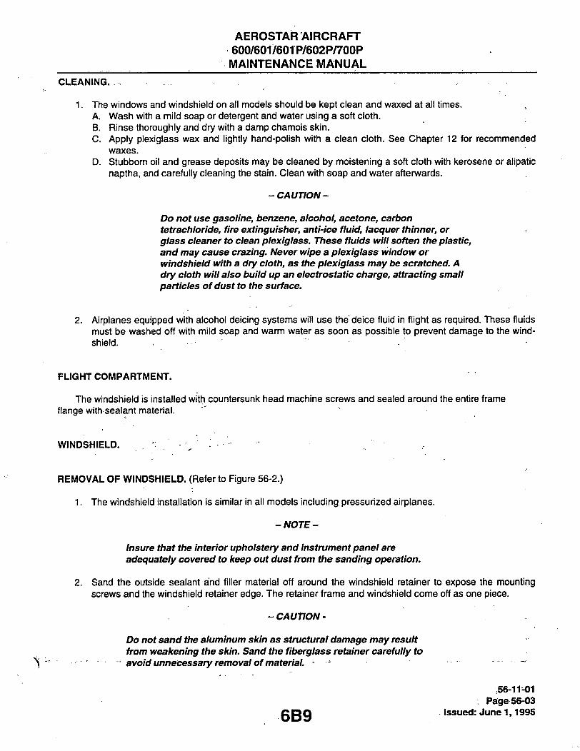
CLEANING. .
1. The windows and windshield on all models should be kept clean and waxed at all times. A. Wash with a mild soap or detergent and water using a soft cloth. B. Rinse thoroughly and dry with a damp chamois skin. C. Apply plexiglass wax and lightly hand-polish with a clean cloth. See Chapter 12 for recommended
waxes. D. Stubborn oil and grease deposits may be cleaned by moistening a soft cloth with kerosene or alipatic
naptha, and carefully cleaning the stain. Clean with soap and water aftenwards.
- CAUTION-
Do not use gasoline, benzene, alcohol, acetone, carbon tetrachloride, fire extinguisher, anti-ice fluid, lacquer thinner, or glass cleaner to clean plexiglass. These fluids will soften the plastic, and may cause crazing. Never wipe a plexiglass window or windshield with a dry cloth, as the plexiglass may be scratched. A dry cloth will also build up an electrostatic charge, attracting small particles of dust to the surface.
2. Airplanes equipped with alcohol deicing systems will use the deice fluid in flight as required. These fluids must be washed off with mild soap and warm water as soon as possible to prevent damage to the wind-shield.
FLIGHT COMPARTMENT.
The windshield is installed with countersunk head machine screws and sealed around the entire frame flange with sealant material.
WINDSHIELD.
REMOVAL OF WINDSHIELD. (Refer to Figure 56-2.)
1. The windshield installation is similar in all models including pressurized airplanes.
-NOTE-
Insure that the interior upholstery and instrument panel are adequately covered to keep out dust from the sanding operation.
2. Sand the outside sealant and filler material off around the windshield retainer to expose the mounting screws and the windshield retainer edge. The retainer frame and windshield come off as one piece.
- CAUTION-
Do not sand the aluminum skin as structural damage may result from weakening the skin. Sand the fiberglass retainer carefully to
- avoid unnecessary removal of material. '-
6B9
56-11-01 : Page 56-03
. issued: June 1,1995

AEROSTAR AIRCRAFT 600/601/601P/602P/700P
MAINTENANCE MANUAL
B 6 6 0
. 3. DISTANCE FROM EDGE OF WINDSHIELD 4. DISTANCE OF RETAINER EDGE FROM
EDGE OF WINDSHIELD 5. ONE LONG SCREW IN EAa^ CORNER
Figure 56-2. Windshieid Removai
56-11-01 Page 56-04
issued: June 1,1995 6B10

AEROSTAR AIRCRAFT 600/601/601P/602P/700P MAINTENANCE MANUAL
3. After all screw heads are exposed, clean out screw heads so that they may be removed with a Phillips type screwdriver.
4. Remove all screws. Note that there are two long screws for attachment of the glareshield, located in the two lower corners of the windshield frame. Verify all screws are removed by measuring center-to-center.
-NOTE-
All models have 48 machine screws attaching the windshield frame to the fuselage.
5. Break the windshield frame loose from the bonded installation by bumping at the inside of either lower corner of the windshield with a rubber mallet.
6. When the windshield breaks loose, insert wooden or plastic spatulas under the frame to add tension for removal of the windshield assembly.' ' .
- CAUTION -
Do not use wood chisels or other sharp objects that could damage the skin or fiberglass windshieid retainer when prying under the frame.
7. After removing the windshield, sand away all remaining sealant to provide a clean surface for bonding the new windshield assembly.
INSTALLATION OF WINDSHIELD. (Refer to Figure 56-3.)
1. Refer to Chapter 20 for cleaning and preparation of windshield frame and fuselage area where wind-shield will be sealed.
2. Fit-check the new windshield to the fuselage without sealant to verify the contour of the windshield wilkfit the contour of the fuselage. Trim excess material as required.
-NOTE-
The new windshield retainer will have no holes and must be drilled to match the hole pattern of the fuselage. Most holes can be drilled through from the back-side, but a hole finder or a light inside the fuselage may be required for certain blind holes.
3. Assure that all necessary hardware for installation of the windshield is on hand. 4. Install windshield assembly. Refer to'Chapter 20 for instructions on mixing sealant and method of appli-
cation. 5. Apply filler and extend as required to fair windshield retainer lap smoothly with skin.
6B11
56-11-02 Page 56-05
Issued:. June 1,1995

AEROSTAR AIRCRAFT 600/601/601P/602P/700P MAINTENANCE MANUAL
B661
PR1435 (TYP)—f^:-^
601P SHOWN
4.0"-H
F A I R F L U S H W I T H R E T A I N E R
U S I N G P R 1435 O R E P O X O 88 .
[—.50/1.0" PR1435 FILLET
PR1435 (TYP)
601 SHOWN
.50/1.0" PR1435 FILLET
F A I R F L U S H W I T H R E T A I N E R
U S I N G P R 1435 O R E P O X O 88 .
F A I R F L U S H W I T H R E T A I N I E R
U S I N G P R 1435 O R E P O X O 8 8 . .50/1.0" PR1435 FILLET
APPLY BONDO TO FAIR DOOR AS REQUIRED-
^BCNDC^ F A I R F L U S H W I T H - ^ OVER R E T A I N E R U S I N G PR1435 P R 1435 O R E P O X O 88 .
—.020/.080" GAP MUST NOT VARY MORE THAN .020" FROM TOP TO BOTTOM
56-11-02 Page 56-06 Issued: June 1,1995
Figure 56-3. Windshield Area Detail
6B12

AEROSTAR AIRCRAFT 600/601/601P/602P/700P MAINTENANCE MANUAL
r CABIN
SIDE OR EYEBROW WNDOW (600 &601)
REMOVAL OF SIDE OR EYEBROW WINDOW (MODELS 600 & 601). (Refer to Figure 56-4.)
1. Remove the "Royalite" reveal molding to expose the window retainer. Refer to Chapter 25 for "Royalite" molding removal.
2. Remove the inner double window, if so equipped. Refer to the section titled Removal of Double Window. 3. Locate rivets around outside of window by sanding the painted surface through to reveal rivets. 4. Station a helper inside airplane with "back-up bar" to assist in removing the rivets from around retainer.
(Refer to Chapter 20 for instructions on rivet removal.) 5. After removing all rivets, remove retainer frame. 6. Break window loose from sealant by bumping with a rubber mallet. 7. Clean all old sealant from window mounting area and prepare surface for installation of new window.
INSTALLATION OF SIDE OR EYEBROW WINDOW (MODELS 600 & 601). (Refer to Figure 56-4.)
1. Refer to Chapter 20 for application of sealants. Follow those instructions for cleaning and preparation of window frame and fuselage area where window is to be installed.
2. Fit-check the new window to the fuselage before applying sealant to verify proper fit and alignment. 3. Assure that all necessary hardware for installation of the window is on hand. 4. Apply the sealant, fit the window and retainer in place and install the rivets. Be sure to clean all excess
sealant off window and outside of fuselage before sealant sets. 5. Replace "Royalite" molding.
REMOVAL OF SIDE OR EYEBROW WINDOW (MODELS 601P, 602P AND 700P). (Refer to Figure 56-5.)
Remove the "Royalite" reveal molding to expose the window retainer. Refer to Chapter 25 for "Royalite" molding removal. Remove the inner double window, if so equipped. Refer to the section titled Removal of Double Window. Locate rivets around outside of window by sanding the painted surface through to reveal rivets. Station a helper inside airplane with a "back-up bar" to assist in removing the rivets from around retainer and clips. (Refer to Chapter 20 for instructions on rivet removal.) Remove the rivets that go through the retainer and window as well as the rivets that go through the skin and retainer only. After removing all rivets, remove the retainer, which is composed of eight separate pieces (4 sides and 4 corners or "clips"). . , Break window loose from sealant by bumping with a rubber mallet. Clean all old sealant from window mounting area and prepare surface for installation of new window.
1.
2. 3. 4.
5.
6.
7. 8.
6B13
56-21-03 Page 56-07
Issued: June 1,1995

AEROSTAR AIRCRAFT 600/601/601P/602P/700P MAINTENANCE MANUAL
B 6 6 2
1. RETAINER
2. WINDCftV
3. SKIN
4. SEALANT
SIDE WINDOW, (TYP)
o 4 1 3 -
56-21-03 Page 56-08 Issued: June 1,1995
Figure 56-4. Window Detail, Models 600-601
6B14

AEROSTAR AIRCRAFT 600/601/601P/602P/700P MAINTENANCE MANUAL
INSTALLATION OF SIDE OR EYEBROW WINDOW (MODELS 601P, 602P AND 700P). (Refer to Figure 56-5.)
1. Refer to Cfiapter 20 for application of sealants. Follow those instructions for cleaning and preparation of window frame and fuselage area where window is to be installed.
-NOTE-
The side and eyebrow windows on ttie Models 601P, 602P and 700P are installed and retained with specially formed aluminum retainers, spacers, washers, cherry rivets and flush aluminum rivets. The window blank must be drilled to the rivet pattern before installation.
2. Prepare window blank for drilling holes using the retainer parts as a template. Insure correct placement of retainer parts during the drilling operation. . ,
3. Fit-check the window to fuselage before applying sealant to verify proper fit and alignment. Check retain-er fit and alignment.
4. Insure that spacer bushings are installed in each rivet hole prior to setting the cherry rivets.
- CAUTION-
Failure to install rivet spacer bushings in each rivet hole in the . window will cause the window to crack when setting the rivet. Such damage will ruin the window, requiring it to be replaced.
5. Apply the sealant, fit the window into place and install assembly with rivets. 6. Clean all excess sealant off window and outside of the fuselage before sealant sets. 7. Replace "Royalite" molding.
DOUBLE INNER WINDOWS.
The double window installation was optional A/F 0003-0129. However, beginning with A/F 0130 and subsequent, the installation is standard on all models.
The double window installation consists of a .060 inch sheet of plexiglass contoured to the window and held in place by double-back tape. On the 700P, the double-back tape has been eliminated and the inner window is held in place by adhesive backed pressure sensitive hook and loop tape.
- NOTE -
The pilot and copilot's windows are always clear regardless of the color of the rest of the windows, while the two eyebrow windows are always tinted green in all installations. Since the pilot's window on the 601P, 602P and 700P is shaped differently from the rest of the similarly shaped windows, this double window must be cut to shape.
REMOVAL OF DOUBLE WINDOW. (Refer to Figure 56-6.)
1. Remove the "Royalite" to reveal molding. Refer to Chapter 25 for molding removal. 2. Using a knife edge or other suitable tool, pry loose the inner window from the tape at any convenient
"place.Contihue to pry inner window loose from tape until completely free. 3. Remove double-back tape from outer window and discard.
56-22-01 Page 56-09
Issued: June 1,1995

AEROSTAR AIRCRAFT 600/601/601P/602P/700P MAINTENANCE MANUAL
5 2
Figure 56-5. Window Detail, iModeis 601P, 602P and 700P
56-22-01 Page 56-10 issued: June 1,1995 6B16

AEROSTAR AIRCRAFT 600/60r/601 P/602P/700P MAINTENANCE MANUAL
INSTALLATION OF DOUBLE WINDOW. (Refer to Figure 56-6.)
To reinstall a double window that had previously been installed with double-face tape: 1. Install double-face tape (Type 4004, 3M Corp.) continuous around outer window and inline with window
retainer edge. Insure that a 1/4 inch gap is left at the lower aft corner of the window to allow for moisture removal or drainage.
-NOTE-
Insure that both window surfaces are clean prior to assembly of double window.
2. On pressurized models, add EC 1357 sealant to retainer/rivets to aid installation of tape. Refer to Figure 56-6.
3. Align the .060 inch plexiglass sheet to outer window in both horizontal and vertical planes. 4. Press fimnly to tape, insuring good adhesion all around the periphery of the window. 5. Replace "Royalite" molding.
DOOR.
DOOR WINDOW. ' " .
The Airplane incorporates a two-piece clamshell door containing the pilot's cabin window in the upper half. Installation of the window is similar to the other cabin and eyebrow windows.
REMOVAL OF DOOR WINDOW (MODELS 600 & 601). (Refer to Figure 56-4.)
1. Remove the "Royalite" molding to expose the window retainer. Refer to Chapter 25 for "Royalite" mold-ing removal. .
2. Remove the inner double window, if so equipped. Refer to the section titled Removal of Double Window. 3. Locate rivets around outside of window by sanding the painted surface through to reveal rivets. 4. Station a helper inside airplane with a "back-up bar" to assist in removing the rivets from around retainer.
(Refer to Chapter 20 for instructions on rivet removal). 5. After removing all rivets, remove retainer frame. 6. Break window loose from sealant by bumping with a rubber malleL 7. Clean all old sealant from window mounting area and prepare surface for installation of new window.
INSTALLATION OF DOOR WJNDOW (MODELS 600 & 601). (Refer to Figure 56-4.)
1. Refer to Chapter 20 for application of sealants. Follow those instructions for cleaning and preparation of window frame and door area.
2. Fit-check the new window to the door before applying sealant to verify proper fit and alignment. 3. Assure that all necessary hardware for installation of the window is on hand. 4. Apply the sealant, fit the window and retainer in place and install the rivets. Be sure to clean all excess
sealant off window and outside of fuselage before sealant sets. 5. Replace "Royalite" molding.
56-31-02 Page 56-11
g g -j y Issued: June 1,1995

AEROSTAR AIRCRAFT 600/601/601P/602P/700P MAINTENANCE MANUAL
PRESSURIZED MODELS (TYPICAL SECTION)
3
NON PRESSURIZED MODELS (TYPICAL SECTION)
4. DOUBLE WINDOW 5. TRIM MOULDING 6. WINDLACE 7. 4004 TAPE (HOOK AND LOOP TAPE ON 700P) 8. EC 1357 SEALANT (TO RETAINER/RIVETS
TO AID IN INSTALLATION OF TAPE)
Figure 56-6. Double Window Detail
56-31-02 Page 56-12 issued: June 1,1995 6B18
AEROSTAR AIRCRAFT 600/601/601P/602P/700P MAINTENANCE MANUAL
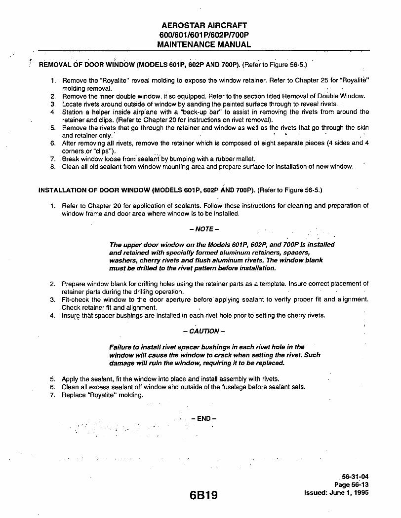
^' REMOVALOFDOORWINDOW(MODELS601P, 602P AND 700P). (Refer to Figure 56-5.)
1. Remove the "Royalite" reveal molding to expose the window retainer. Refer to Chapter 25 for "Royalite" molding removal.
2. Remove the inner double window, if so equipped. Refer to the section titled Removal of Double Window. 3. Locate rivets around outside of window by sanding the painted surface through to reveal rivets. 4 Station a helper inside airplane with a "back-up bar" to assist in removing the rivets from around the
retainer and clips. (Refer to Chapter 20 for instructions on rivet removal). 5. Remove the rivets that go through the retainer and window as well as the rivets that go through the skin
and retainer only. , 6. After removing all rivets, remove the retainer which is composed of eight separate pieces (4 sides and 4
corners or "clips"). 7. Break window loose from sealant by bumping with a rubber mallet. 8. Clean all old sealant from window mounting area and prepare surface for installation of new window.
INSTALLATION OF DOOR WINDOW (MODELS 601P, 602P AND 700P). (Refer to Figure 56-5.)
1. Refer to Chapter 20 for application of sealants. Follow these instructions for cleaning and preparation of window frame and door area where window is to be installed.
-NOTE-
The upper door window on the Models 601P, 602P, and 700P is installed and retained with specially formed aluminum retainers, spacers, washers, cherry rivets and flush aluminum rivets. The window blank must be drilled to the rivet pattern t>efore installation.
2. Prepare window blank for drilling holes using the retainer parts as a template. Insure correct placement of retainer parts during the drilling operation.
3. Fit-check, the window to the door aperture before applying sealant to verify proper fit and alignment. Check retainer fit and alignment.
4. Insure that spacer bushings are installed in each rivet hole prior to setting the cherry rivets.
- CAUTION-
Failure to install rivet spacer bushings in each rivet hole in the window will cause the window to crack when setting the rivet. Such damage will ruin the window, requiring it to be replaced.
5. Apply the sealant, fit the window into place and install assembly with rivets. 6. Clean all excess sealant off window ahd outside of the fuselage before sealant sets. 7. Replace "Royalite" molding.
- E N D -
56-31-04 Page 56-13
Q Q Q Issued: June 1,1995

AEROSTAR AIRCRAFT 600/601/601P/602P/700P
. MAINTENANCE MANUAL
THIS PAGE INTENTIONALLY LEFT BLANK
6B20

AEROSTAR AIRCRAFT 600/6017603 P/602R/7P0P
MAINTENANCE MANUAL
THIS PAGE INTENTIONALLY LEFT BLANK

CHAPTER
6B22

AEROSTAR AIRCRAFT 600/601/601P/602P/700P MAINTENANCE MANUAL
CHAPTER 57 - WINGS
TABLE OF CONTENTS/EFFECTIVITY
CHAPTER SECTION GRID SUBJECT SUBJECT NO. EFFECTIVITY
57-00-00 ^ G E N E R A L 6B24 57-01-00 , ^Description 6B24
57-10-00 MAIN FRAME 6B24
57-20-00 AUXILIARY STRUCTURE 6B24 57-21-00 Wing Tip 601 57-21-01 Wing Tip Removal 601 57-21-02 Wing Tip Repairs 601 57-21-03 Wing Tip Installation 603
57-30-00 PLATES/SKINS 603 57-31-00 Skin Repairs 603
57-40-00 ATTACH FITTINGS 603 57-41-00 Wing 603 57-41-01 Wing Removal 603 57-41-02 Wing Inspection 606 57-41-03 Wing Repair 608 57-41-04 Wing Installation 608
57-50-00 FLIGHT SURFACES 6011 57-51-00 Aileron 6011 57-51-01 Aileron Removal 6011 57-51-02 Balancing Aileron/Rudder/Elevator 6011 57-51-03 Aileron Installation 6011 57-52-00 Flap 6015 57-52-01 Flap Removal 6015 57-52-02 Flap Inspection/Repair 6015 57-52-03 Flap Installation 6015
57 - ContTEffec. Page -1
6B23 Issued: June 1,1995

AEROSTAR AIRCRAFT 600/601/601P/602P/700P MAINTENANCE MANUAL
GENERAL.
This section includes the removal and installation procedures for wings, wing tips, ailerons, and flaps. Illustrations for material and maintenance requirements are provided and referenced as applicable.
DESCRIPTION.
Each wing is a three-spar all metal structure with stressed skins and removable fiberglass tips. Flaps, ailerons, integrated fuel tanks, and attach fittings for wing to fuselage, engines, and main landing gear complete the wing assembly.
MAIN FRAME. (Referto Figure 57-1.)
The wing main frame structure members consists of spars, ribs, and stringers. An integral, 65 U.S. gallon, fuel tank is built into the wing structure outboard of the engine nacelles. Repairs of minor nature are approved in accordance with AC 43.13-1 A Standard Practices. For fuel tank sealant repairs refer to Sealants, Chapter 20.
AUXILIARY STRUCTURE. (Refer to Figure 57-2.)
Includes the fixed leading edge, which is hydro-formed top and bottom back to 35% spar, and is part of the fuel tank outboard of engine nacelle. The fiberglass wing tips are removable, and house a navigation and strobe light assembly. The tips are flush-mounted with brass machine screws.
B665
] USABLE FUEL AREA
Figure 57-1. Wing Main Frame Structure
57-20-00 Page 57-01
issued: June 1,1995

AEROSTAR AIRCRAFT 600/601/601P/602P/700P MAINTENANCE MANUAL
WING TIP.
WING TIP REMOVAL.
1. Remove machine screvys, being careful not to cause damage to tip and wing, or stripping the heads of the brass screws.
2. Pull wing tip out enough to disconnect the navigation and strobe lights assembly and remove from wing. 3. Inspect wing tip for cracks, dents, or other damage.
WING TIP REPAIRS.
1. ' Minor repairs may be made in accordance with Fiberglass Repairs, Chapter 51. 2. Badly damaged tips should be replaced.
B666
1.
2.
3.
4.
5.
6.
SKIN L.H. INBRD (LEADING EDGE)
SKIN L.H. OUTBRD (LEADING EDGE)
SKIN FWD. L.H. EXTENDED WING
WING TIP MODELS 601, 601P. 602P
AND 700P EXTENDED WING
WING TIP MODEL 600, 601, AND 601P. WITH STD.WING
ACCESS COVER
57-21-02 Page 57-02 Issued: June 1,1995
Figure 57-2. Wing Auxiliary Structure
6C1

AEROSTAR AIRCRAFT 600/601/601P/602P/700P
MAINTENANCE MANUAL
B667
V Figure 57-3. Wing SItin/Paneis
57-21-02 Page 57-03
c r ^ O lssued:.June 1,1995

AEROSTAR AIRCRAFT 600/601/601P/602P/700P MAINTENANCE MANUAL
WING TIP INSTALLATION.
1. Place wing tip in position to connect navigation and strobe light electrical leads, per Navigation and Strobe Lights Installation, Chapter 33.
2. Insert wing tip into position on wing, install brass machine screws, and check navigation and strobe light operation.
PLATES/SKIN. (Refer to Figure 57-3.)
The top and bottom skin panels are sealed outboard of engine nacelles between 35% and 70% (chord) spars which completes the fuel tank structure. The bottom skin is fitted with nine access covers for fuel tank inspection and maintenance. The standard length wing has four additional access covers, and the extended wing has six additional access covers for entry to wing component installations.
SKIN REPAIRS.
1. Minor sheetmetal repairs shall be in accordance with AC 43.13-1 A, Standard Practices. 2. For resealing skins/repairs refer to Sealants, Chapter 20.
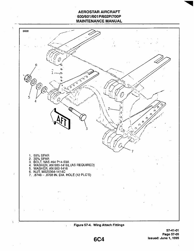
ATTACH FITTINGS. (Refer to Figures 57-4 and 57-5.)
The wings incorporate primary and secondary attach points for wing to fuselage attachment, including attach points for the main landing gear and engines. The attach points should be inspected for general condition and security of attachment when a major assembly is removed.
WING.
WING REMOVAL.
1. Defuel airplane, per Chapter 12. 2. Drain brake system, per Chapter 32. 3. Deplete pressure in main Hydraulic system by cycling flaps. 4. Remove affected engine from wing, per Chapter 71.
-NOTE-
All disconnected lines, hoses, fittings and electrical leads should be identified and protected from damage. For installation requirements, all attach point hardware material/locations should be noted.
5. Remove fairing assembly from wing-root to fuselage. 6. Install tail stand and jack airplane per Chapter 7. 7. Place suitable cradle under fuselage in position to hold fuselage securely. Remove jack from wing to be
removed. 8. Open affected wheel well door, per Chapter 32. 9. Disconnect the long (33.38 inch) pushrod to main landing gear stmt, at bellcrank inside the wheel well.
57-41-01 Page 57-04 Issued: June 1,1995 6C3
AEROSTAR AIRCRAFT 600/601/601P/602P/700P MAINTENANCE MANUAL
B 6 6 8
1. 55% SPAR 2. 35% SPAR 3. BOLT NAS 464 P14-53A 4. WASHER. AN 960-1416L(AS REQUIRED) 5. WASHER, AN 960-1416 6. NUT MS20364-1414C 7. .8748 - .8768 IN. DIA. HOLE (12 PLC'S)
Figure 57-4. Wing Attach Fittings
6C4 57-41-01
Page 57-05 issued: June 1,1995

AEROSTAR AIRCRAFT 600/601/601P/602P/700P
MAINTENANCE MANUAL
57-41-01 Page 57-06 Issued: June 1,1995 6C5

AEROSTAR AIRCRAFT 600/601/601P/602P/700P MAINTENANCE MANUAL
10. Place wing cradle under wing in position to permit lateral and vertical movement of wing during removal from fuselage.
11. Disconnect aileron pushrod from bellcrank inside fuselage. Entry to bellcrank is provided by access cover on hat shelf.
-NOTE-
Optional equipment installations cause the disconnect/connect procedures to vary. Major differences are noted.
12. At wing-root to.fuselage disconnect, as applicable, electrical plugs and leads, hoses, lines, and fittings. 13. Remove nuts ahd washers from wing tofuselage attach fittings. 14. Remove bolts from fore and aft fittings. 15. Unload wing weight on main spars upper attach bolts, and remove bolts being careful to prevent damage
to fittings. 16. Slowly lower outer wing, only far enough, to allow final disconnect of leads, hoses, lines, and fittings.
Ensure aileron push rod is free of interference inside of fuselage. For initial right wing removal, airplanes equipped with deicer-boots require cutting the pneumatic hose at the inside of fuselage wall. When cut-ting hose, allow for fabrication of a 5 inch beaded tube-splice during wing installation. It may be neces-sary to reposition the upper hydraulic angled bulkhead fitting to remove an upper main spar attach bolt.
17. Unload wing weight on main spars lower attach bolts, and remove bolts. 18. While guiding detached rods, plugs, leads, hoses, and lines; pull wing from fuselage.
WING INSPECTION.
1. Wing Installed. A. Remove wing root fairing. B. Check all attach fittings for security of attachment, cracks, corrosion and evidence of loose/wori<ing
attach bolts. C. Check wing surfaces for cracks, dents, buckling, abrasion, and corrosion. D. Check for evidence of fuel leaks as evidenced by fuel stains on wing surface, particulariy around riv-
ets and skin joints. Install root fairing. 2. Wing Removed.
A. Check attach fittings for security of attachment, wori<ing rivets, nicks, dents, cracks, con-osion, and evidence of loose/working attach bolts.
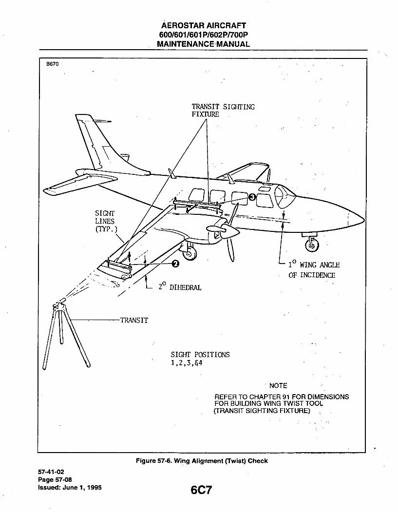
B. Check wire hamess, lines, hoses, and pushrod through root rib, for wear and security of routing. 3. Wing 'Twist" Inspection (Figure 57-6).
A. Fabricate wing twist sighting fixtures per dimensions given in Chapter 91. B. Place airplane on reasonably level surface. C. Place sighting fixtures on wing per illustration with legs of fixtures placed on rivet rows wing station
29.40 and 195.00. The aft legs of the fixtures (short legs) must be placed at the 70% spar intersect with wing ribs wing station 29.40 and 195.00.
D. Using bubble level; level the fixture angle bracket between point No's 1 and 2, chordwise and span-wise (with the rib and spar lines) respectively.
E. Repeat Step D on fixture angle bracket between point No's 3 and 4. F. Place transit at point beyond wing tip sufficient to sight across point No's 1 and 4, and point No's 2
and 3 without relocating the transit. G. Record variation across rods. Variation of less then 0.40 of an inch across either sighting is accept-
able.
57-41-02 Page 57-07
gQg Issued: June 1,1995
AEROSTAR AIRCRAFT 600/601/601P/602P/700P MAINTENANCE MANUAL
B670
TRANSIT siarriNG
TRANSIT
SIGHT POSITIONS 1,2,3,54
NOTE
REFER TO CHAPTER 91 FOR DIMENSIONS FOR BUILDING WING TWIST TOOL (TRANSIT SIGHTING FIXTURE)
57-41-02 Page 57-08 Issued: June 1,1995
Figure 57-6. Wing Alignment (Twist) Check
6C7

AEROSTAR AIRCRAFT 600/601/601P/602P/700P MAINTENANCE MANUAL
4. Wing Angle of Incidence/Dihedral Check. A. Referencing the angles given in Figure 57-6, compute angle of wing incidence and dihedral, from
sightings recorded in Step 3-G above.
WING REPAIR.
1. Minor structural damage may be repaired in accordance with AC 43.13-1 A. 2. Fuel tank resealing requirements should be accomplished, per Chapter 20.
WING INSTALLATION.
When reinstalling original wing proceed with Steps No. 1 through No. 25 only. For new wing replacement and in the sequence indicated, all of the maintenance steps are required. A rigging check on flaps, ailerons, and main landing gear and gear doors is required after installing wing^
1. Ensure wing is ready for installation by checking the completion, condition, and security of attachment for all associated systems and components.
2. Position wing on cradle with root-end at attach point height and the tip end slightly lower. 3. Insert wooden wedge block between the wing's forward fitting brackets just enough to spread apart the
brackets to engage with fuselage fitting. 4. Apply a thin film of "Lubriplate" on the main fuel distribution hose and fitting. Read Steps No's 5 and 6
before proceeding. 5. While guiding the aileron push rod, all lines/hoses, and electrical leads to their respective locations, place
the wing in position to align the wing's lower main spar fittings with fuselage carry-through spars lower fit-tings, and insert attach bolts with bolt heads on front side of fitting assemblies (except for Models 601P and 602P, which require the front lower attach bolt be installed with bolt head on aft side of fitting assem-bly). Do not install washers and nuts yet.
6. Ensure, main fuel distribution hose is mated with its fitting, large electrical cannon-plug and 2 fuel vent lines are started on their fitting connections, and the rod-end clevis on aileron push rod is aligned with bellcrank, before raising the outer wing to align upper main spar attach fitting holes.
7. Raise outer portion of wing to align upper main spar attach fitting holes and install bolts with heads on front side of fitting assemblies. Remove wedge block from brackets on front fitting assembly.
8. Install washers and nuts on the 4 main spar fitting attach bolts, and torque nuts 600-800 inch-pounds, plus nut tare torque. See Chart 9103 (Special Torque Values).
9. For original wing installation, proceed with Step No's. 10 through 25; for a new replacement wing installa-tion, proceed to Step No. 26.
10. Install front and aft fitting attach bolts, washers, and nuts. Torque nuts 140-160 inch-pounds. 11. On airplanes equipped with deicer-boots, a 5 inch beaded tube splice is required in pneumatic hose for
right wing only. Trim hose length to fabricate splice inside the fuselage on right side. After splice is made, perfonn a pressure/vacuum test on splice connection.
12. Ensure final connection, security, and safety of all affected lines, hoses, fittings, electrical plugs, and leads.
13. Connect aileron pushrod clevis with bellcrank at fuselage location under hat shelf. 14. Connect, pushrod from main landing gear strut to bellcrank clevis inside wheel well. 15. Close wheel well door, per Chapter 32. 16. Replace wing cradle with wing jack under affected wing, and remove fuselage cradle. 17. Perform operation/rigging check, as applicable, on main landing gear and doors, flaps, and ailerons in
accordance with their respective Chapters. Observe "note" information.
57-41-04 Page 57-09
QQQ Issued: June 1,1995
AEROSTAR AIRCRAFT 600/601/601P/602P/700P MAINTENANCE MANUAL
-NOTE- '
A rigging ctieclf is required on main landing gear and doors, flaps, and aiierons when any nominal rigging adjustment has been affected by an equipment removal, installation, or repair.
18. Down-jack airplane, but maintain tail stand security, and use one jack to stabilize the opposite wing for engine installation. '
19. Install affected engine, per Chapter 71. ' 20. Remove tail stand and jack. 21. Service airplane, and check all affected lines, hoses, fittings, and lower wing surface for leaks. 22. Perform engine run-up check, per Flight Manual, and bleed fuel and oil pressure transmitter lines at
instrument panel. Check again, for fuel and oil leaks. 23. Perform flaps/ailerons operational check; again checking for hydraulic leaks. 24. Perform deicer-boots operational check if applicable, and check for pressureA/acuum leaks. 25. Install wing-root fairing assembly, engine cowling, and access covers. 26. When installing a new replacement wing the fore and aft secondary wing attach fitting holes must be
drilled to the existing fuselage fitting holes. Also, at front wing fitting the 2 brackets must be final drilled and riveted to wing skin after the attach bolts are installed and torqued.
27. Install "C"-clamps at top and bottom of aft wing fitting to fuselage fitting holding them securely together. Pick up existing outboard hole in fuselage fitting and drill 5/16 inch (.3125 inch) hole in wing fitting.
28. Install hole-finder in fonward fuselage fitting's outboard hole, using "C"-clamps, securely fasten the two wing fitting brackets together over the hole-finder and drill pilot-hole in wing fitting brackets.
29. Remove clamps and hole-finder, reinstall "C"-clamps and final drill the forward fitting brackets with one 5/16 inch (.3125 inch) hole. Remove clamps from fore and aft fitting assemblies.
30. Remove burrs from holes, but do not ream holes. 31. Install fore and aft fitting assembly attach bolts (heads on front side), washers, and nuts. Torque nuts 140
to 160 inch-pounds. 32. At fonward wing fitting, clamp top and bottom wing skin to the flange on the rear bracket with "C"-clamps.
Pick-up existing pilot holes in front and rear bracket flanges and drill No. 40 pilot-holes 4 places (2 top and 2 bottom) in wing skin.
33. For rivet edge row, draw 4 lines on skin from center of holes just drilled to skin inner edge at mid- point of bracket flange (2 places top of fitting bracket assembly and 2 places bottom). Establish 3/10 inch (.300) rivet edge row line across 2 lines on top skin and 2 lines on bottom skin. Drill No. 40 pilot-holes through skin and bracket flanges in 4 places (2 top and 2 bottom).
34. Remove "C'-clamps and clean out cuttings. Install clecos and finish drill 8 places (4 top and 4 bottom) for Cherry-rivets, CR-2249-5-4/-5, and remove cuttings from hole areas.
35. Install standard head -4 length Cherry-rivets on fonward bracket flange to skin (2 places top and 2 places bottom), and -5 length Cherry-rivets on rear bracket flange to skin (2 place top and 2 places bottom).
. Proceed with Steps No's. 11 through 25.
57-41-04 Page 57-10 issued: June 1,1995 6C9

AEROSTAR AIRCRAFT 600/601/601P/602P/700P MAINTENANCE MANUAL
B 6 7 1
12
1. TRIM TAB 9. INBOARD HINGE BRACKEl
2. SKIN 10. BOLT, AN4-12A
3. RIB 11. WASHER, AN 960-416 4. SPAR 12. NUT, MS 21042-4
5. LEADING EDGE 13. CENTER HINGE BRACKET
6. BALANCE WEIGHTS 14. CONTROL ROD END 7. NUT PLATE 15. BOLT, AN4-14A . . 8. WILKIE BUTTON 16. NUT, AN364-428C
(ACCESS COVER)
Figure 57-7. Aiieron Structure
6C10
57-41-04 Page 57-11
Issued: June 1,1995

AEROSTAR AIRCRAFT 600/601/601P/602P/700P MAINTENANCE MANUAL
FLIGHT SURFACES. (Referto Figure 57-7.)
AILERON.
AILERON REMOVAL.
1. Remove wing tip from standard length wing, per Wing Tip Removal this Chapter, or remove lower out-board aft access cover from extended wing as required.
2. Remove plug ("Wilkie") button from aileron outboard bottom corner. 3. Cut safety wire from outboard hinge bolt shank end by access through bottom hole on aileron. 4. Remove outboard hinge bolt. 5. Disconnect aileron control rod at center hinge bracket. 6. Remove nuts and washers from center and inboard hinge bolts. 7. Support aileron, remove inboard hinge bolt first, and then, remove center hinge bolt. Remove aileron, and
inspect surfaces and hinge points for general condition. Minor damage repairs are approved in accor-dance with AC 43.13-1 A, Standard Practices.
BALANCING AILERON/RUDDER/ELEVATOR. (Referto Figure 57-8.)
- W O T E -
The static balance should be checked after a structure , i repair, or after the paint type or paint scheme is changed.
1. The static balance of the aileron, rudder and elevator must be maintained within the limits specified in this section.
2. Figure 57-8 demonstrates an acceptable means for determining the specified limits. The limits shown are for a completed assembly, installed and ready for flight, including paint and trim tabs or motors if applicable. If modification, repairs or paint type or paint scheme or painting without prior stripping is per-formed on any control surfaces, the static balance should be rechecked. If the control surface is not with-in the specified limits, weight should be added to or removed from the area forward of the surface hinge.
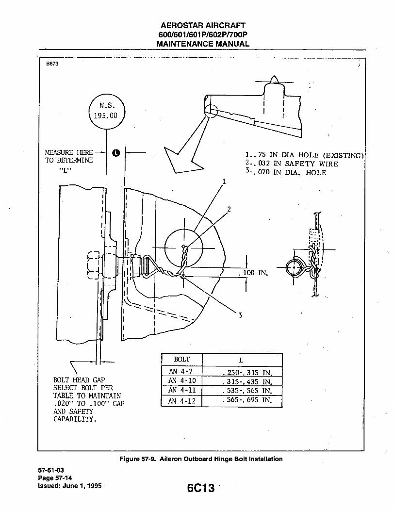
AILERON INSTALLATION. (Refer to Figure 57-9.)
1. Support, and position aileron to insert center hinge bolt first, and then inboard hinge bolt with heads to outboard side of hinge. Install washers and nuts on bolts. Torque nuts 30-40 inch-pounds.
2. Measure across existing gap (L), to determine the length for outboard hinge bolt installation. 3. Insert outboard hinge bolt through hinge fitting plate on wing rib and thread into the aileron nutplate only
far enough to allow safetying the shank-end on bolt. Measure bolt head gap to ensure .020'to .100 inch gap, reference Figure 57-8.
4. Check aileron travel for freedom of movement, and safety-wire shank-end on outboard hinge bolt. 5. Connect aileron control rod-end at center hinge bracket, install bolt with head to outboard side, install
washer and nut, and torque nut 30-40 inch-pounds. 6. If aileron rigging adjustment has been affected, perform rigging and operational check per Chapter 27.
57-51-03 Page 57-12 Issued: June 1,1995 6C11

AEROSTAR AIRCRAFT
600/601/601P/602P/700P
MAINTENANCE MANUAL
- T A R E
CONTROL SURFACE TOLERANCE * SCALE READING
ELEVATOR AND RUDDER
AILERON
+6.75 to +9.75 IN.-LBS.
-1.0 to +3.0 IN.-LBS.
POUNDS OUNCES
ELEVATOR AND RUDDER
AILERON
+6.75 to +9.75 IN.-LBS.
-1.0 to +3.0 IN.-LBS.
0.675 to 0.975
-0.10 to +0.30
10.8 to 15.6
-1.6 to +4.8
SUBTRACT TARE WEIGHT FROM SCALE READING
Figure 57-8. Fiight Controis Baiance (Exampie)
6C12
57-51-03 Page 57-13
Issued: June 1,1995
AEROSTAR AIRCRAFT 600/601/601P/602P/700P
MAINTENANCE MANUAL
B 6 7 3
MEASURE HERE TO DETERMINE
1..75 IN DIA HOLE (EXISTING)
2.. 032 IN SAFETT WIRE
3-. 070 IN DIA. HOLE
. 100 IN.
BOLT HEAD GAP SELECT BOLT PER TABLE TO MAINTAIN .020" TO .100" GAP AND SAFETY CAPABILITY.
BOLT L
AN 4-7 . 250-. 315 IN. AN 4-10 .315-. 435 IN.
AN 4-11 . 535-. 565 IN.
AN 4-12 . 565-. 695 IN.
57-51-03 Page 57-14 Issued: June 1,1995
Figure 57-9. Aileron Outboard Hinge Bolt Instaiiation
6C13

AEROSTAR AIRCRAFT 600/601/601P/602P/700P MAINTENANCE MANUAL
1. BOLT, AN4-12A 9. SPACER, 920037-505 2. WASHER, AN960-416 10. WASHER, 920039-501 3. SPACER, 920037-1
WASHER, AN970-5 11. ROLLER, 920038-505
4. SPACER, 920037-1 WASHER, AN970-5 12. WASHER, AN960-416L
5. ROLLER, 920038-1 13. WASHER, AN960-616 6. NUT, MS21042-4 14. SPACER, NAS43DD4-20 7. WASHER, 920016-505 15. BOLT, AN4-24A 8. AN960-516L 16. BOLT, AN4-2IA
Figure 57-10. Fiap Removai/lnstaiiation 57-51-03
Page 57-15 gQ*!^ Issued: June 1,1995

AEROSTAR AIRCRAFT 600/601/601P/602P/700P MAINTENANCE MANUAL
FLAP.
FLAP REMOVAL.
-NOTE-
When removing any flap attacfi fiardware, make note of bolts, wasfiers, spacers, and roller locations.
1. Position flap control lever to 1/2 down. Flaps will extend when pressure is indicated on hydraulic pressure gauge. If no pressure exists, flaps may be extended by hand with control lever placed down.
2. Remove 2 bolts and related flap track hardware from inboard upper and lower flap tracks. 3. Remove 1 bolt and related flap track hardware from outboard flap track, while supporting flap. 4. Remove 2 bolts and related hardware from center flap track and actuator control rod-end connection, the
flap is now free and can be removed from wing.
FLAP INSPECTION/REPAIR.
1. Inspect flap and attach points for general condition. 2. Minor damage may be repaired in accordance with AC 43.13-1 A, Standard Practices.
FLAP INSTALLATION. (Referto Figure 57-10.)
- CAUTION-
Failure to properly assemble ttie flap track fiardware could cause excessive wear, binding, or loss of flap control.
1. Place flap actuator in 1/2 down (extended) position by operating flap control lever, or by hand, if no hydraulic pressure exists.
2. Support flap in position to insert bolt only in center bracket, track, and actuator rod-end. Insert bolts only in outboard and inboard brackets and tracks.
3. Install spacers, roller, washers, and nut on bolt at center bracket, actuator rod-end, and track assembly, but do not torque nut yet. Refer to Figure 57-10 (Detail B-1 or B-2).
4. Install spacers, rollers, washers, and nuts on 2 bolts at inboard upper and lower bracket and track assembly, but do not torque nuts yet. Refer to Figure 57-10 (Detail A).
5. Install spacers, roller, washers, and nut on bolt at outboard bracket and track assembly, but do not torque nut yet. Refer to Figure 57-10 (Detail C).
6. On left wing and if flap rigging adjustment has not been disturbed, connect flap position transmitter lever with appropriate hardware. Refer to Figure 57-10 (Detail B-1).
7. Perform flaps operation/rigging check, per Chapter 27. 8. Torque all nuts 30-40 inch-pounds at inboard, center, and outboard bracket and track assemblies. 9. Lubricate flap tracks, per Chapter 12.
-END-
57-52-03 Page 57-16 Issued: June 1,1995 6C15
AEROSTAR AIRCRAFT 600/601/601 P/6d2P/700P MAINTENANCE MANUAL
THIS PAGE INTENTIONALLY LEFT BLANK
6C16

CHAPTER
PROPELLERS
6C17

AEROSTAR AIRCRAFT 600/601/601P/602P/700P MAINTENANCE MANUAL
CHAPTER 61 - PROPELLERS
TABLE OF CONTENTS/EFFECTIVITY
' CHAPTER SECTION GRID SUBJECT SUBJECT NO. EFFECTIVITY
61-00-00 GENERAL 6019 61-01-00 Description 6C19 61-02-00 Troubleshooting 6C19
61-10-00 PROPELLER ASSEMBLY 6021 61-11-00 Removal of Propeller 6021 61-12-00 Cleaning and Inspection of Propeller 6021 61-13-00 Propeller Blades 6021 61-13-01 Repair of Propeller Blades 6021 61-13-02 Lubrication of Propeller Blades 6023 61-14-00 Propeller Adjustments 6024 61-14-01 Adjusting Feathering Pitch Stop 6024 61-14-02 Adjusting Low Pitch Stop 6024 61-14-03 Checking Blade Track 6D1 61-15-00 Installation of Propeller 6D1
61-20-00 CONTROLLING 6D2 61-21-00 Propeller Governor 6D2 61-21-01 Removal of Propeller Govemor 6D2 61-21-02 Installation of Propeller Governor 6D2 61-21-03 Adjustment and Rigging of Propeller Govemor 6D2 61-22-00 Prop RPM Limiter 6D6 61-23-00 Synchrophaser System 6D6 61-23-01 Synchrophaser Computer 6D6 61-23-02 Removal of Synchrophaser Computer 6D6 61-23-03 Installation of Synchrophaser Computer 6D6 61-23-04 Pulse Generators 6D8 61-23-05 Removal of Pulse Generators 6D8 61-23-06 Installation of Pulse Generators 6D8 61-23-07 Timing and Testing 6D11 61-23-08 Timing Synchrophaser System,./VF 0455
and Subsequent 6D11 61-23-09 Testing Synchrophaser System, AF 0455
and Subsequent 6D11 61-23-10 Timing Synchrophaser System A/F 0001-0454 6D12 61-23-11 Testing Synchrophaser System /VF 0001-0454 6D14
61 - ContyEffec. Page -1
gQ- g Issued: June 1,1995

AEROSTAR AIRCRAFT 600/601/601P/6P2P/700P MAINTENANCE MANUAL
GENERAL.
DESCRIPTION.
600, 601, 601P, 602P and 700P airplanes are equipped with Hartzell controllable, three blade, constant speed, feathering propellers (Model HC-C3YR-2UF). The propellers utilize a combination air spring and counter-weights on each blade to increase pitch and feather, opposed by oil pressure regulated by the propeller governor to reduce pitch. When the propeller control lever is pulled back to the limit of its travel, governor oil pressure is released, allowing the countenweights, feathering spring and cylinder air charge to feather the blades.
'On 600, 601 and 601P airplanes equipped with a synchrophaser system, the standard F-6-35Z propeller gov-ernor on the right engine is exchanged for the F-8-45Z propeller governor with an electrically controlled solenoid valve. For the 601P and 602P an F-8-60Z is used.
On the 700P, the standard propeller governors are: Left engine - F-6-63LZ or F-6-63L, Right engine - F-6-63Z or F-6-63. On 700P's equipped with synchrophaser, the standard propeller governor on the right engine is replaced with either an F-8-63Z or an F-8-63 propeller governor.
The synchrophaser system installed in A/F 0494 and subsequent consists of a pulse generator driven by the tach drive output fonward of each engine's tach generator, a computer mounted on the lower left side of the fuse-lage station 176.88 bulkhead, a solenoid type control valve on the right engine propeller governor, and a syn-chrophaser switch on the console, fonward of the engine controls. In A/F 0455-0493 equipped with a dual tach installation, the tach generator also functions as a pulse generator and no separate pulse generators are installed. A/F prior to 0455 have a strobe sensor unit in place of the right engine pulse generator. Refer to Chapter 91 for synchrophaser system wiring diagrams.
TROUBLESHOOTING.
Troubles peculiar to the synchrophaser system are listed in Chart 6101 along with their probable causes and suggested remedies. Troubles listed are indications obtained during Testing Synchrophaser System" using the Hartzell B-4467 synchrophaser test box.
6C19
61-02-00 Page 61-01
Issued: June 1,1995

AEROSTAR AIRCRAFT 600/601/601P/602P/700P MAINTENANCE MANUAL
CHART 6101. TROUBLESHOOTING (SYNCHROPHASER SYSTEM)
Trouble Cause Remedy
Coil short light illumi-nated.
Propeller governor solenoid valve coil shorted.
Replace propeller governor.
Wire SNPH 40A20 and SNPH 41A20 shorted.
Locate and repair short circuit.
No lights illuminated. Synchrophaser circuit breaker de-energized.
Reset circuit breaker.
Open circuit between synchrophaser circuit breaker and bus.
Perform continuity check; lo-cate and repair open circuit
Open circuit between circuit breaker and synchrophaser switch.
Perform continuity check; lo-cate and repair open circuit
Open circuit between synchrophaser switch and computer.
Perform continuity check; lo-cate and repair open circuit.
Left or right engine light does not illumi-nate.
Pulse generator defective.
Open circuit between pulse generator and computer.
Replace pulse generator.
Perform continuity check; lo-cate and repair open circuit.
Manual or phase light does not illuminate.
Open circuit between synchrophaser switch and computer.
Perform continuity check; lo-cate and repair open circuit.
Coil light does not illuminate.
Propeller governor sole-noid valve coil open.
Replace propeller governor.
Open circuit between sole-noid valve and computer.
Perform continuity check; lo-cate and repair open circuit
61-02-00 Page 61-02
Issued: June 1,1995 6C20

AEROSTAR AIRCRAFT 600/601/601P/602P/700P MAINTENANCE MANUAL
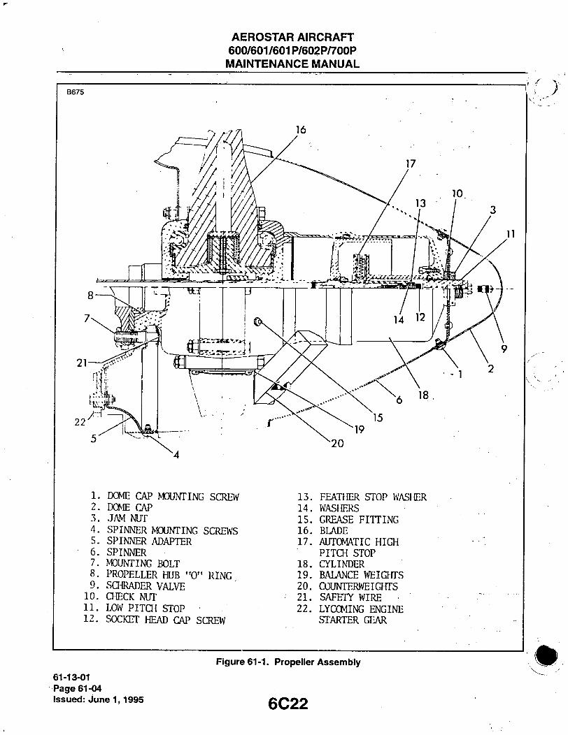
• PROPELLER ASSEMBLY. (Refer to Figure 61-1.)
REMOVAL OF PROPELLER.
1. Ensure l\/laster Battery and Magneto switcfies are in OFF position. 2. Place Fuel Selector in OFF position. 3. Place mixture control in IDLE CUT-OFF position. 4. Remove dome cap mounting screws and remove dome cap. 5. Mark spinner and spinner adapter for re-installation. 6. Remove spinner mounting screws and jam nut, and remove spinner. ' ' 7. If installed, disconnect propeller deice electrical wire clamp from spinner adapter, and electrical connector
from starter gear. 8. Place drip pan under propeller. 9. Remove safety wire from propeller mounting bolts, and remove bolts and propeller.
CLEANING AND INSPECTION OF PROPELLER.
Check for oil or grease leaks. Clean spinner, dome cap, propeller interior and exterior, and blades with Shell 360 or 365 solvent or equivalent. Inspect hub parts for cracks. Clean and treat aisted areas and touch up with Hartzell Polane paint. Check all visible parts for wear and security of attachment. Rock blades back and forth through the slight freedom allowed by the pitch change mechanism to deter-mine if they will tum freely on the hub. If blades are properly lubricated yet appear tight, the pitch change mechanism should be removed so that each blade can be checked individually. If blades are tight, pro-peller should be disassembled. Inspect blades for damage or cracks. Repair before next flight. For severe damage, intemal repairs, and replacement of parts, refer propeller to Hartzell factory or autho-rized propeller repair facility. Check condition of propeller mounting bolts.
PROPELLER BLADES.
REPAIR OF PROPELLER BLADES.
Nicks, gouges, or scratches in the leading or trailing edges, or on blade face of camber surfaces may cause fatigue cracks and blade failure, and should be removed prior to flight. The outer 18 inches of propeller diameter is the area of highest vibratory stress. Damage in this area must be treated as critical. Methods such as leading edge rolling or cold working which result in moving metal, covering, and possibly concealing damage are not acceptable. Repairs that form a continuous line across the propeller are not acceptable. Damage that may affect the structure, balance or operation of the propeller should be referred to the Hartzell factory or an authorized repair facility. Refer to Figure 61-2 for field maintenance repair limitations. ;
1. Remove damaged material to bottom of damaged area with round file. 2. Remove material from bottom of damaged area outward on both sides to provide a smooth faired depres-
\ sion, maintaining the original airfoil concept.
6C21 61-13-01
Page 61-03 Issued: June 1,1995
AEROSTAR AIRCRAFT 600/601/601P/602P/700P MAINTENANCE MANUAL
B675
1. DOME CAP MOUOTING SCREW 2. DOME CAP 3. JAM NUT 4. SPINNER MOUNTING SCREWS 5. SPINNER ADAPTER 6. SPINNER 7. «DUN ING BOLT 8. PROPELLER HUB "0" RING 9. SaiRADER VALVE
10. CHECK NUT 11. LOW PITCH STOP 12. SOCKET HEAD CAP SCREW
13. FEATHER STOP WASIER 14. WASHERS 15. GREASE FITTING 16. BLADE 17. AUTOMATIC HIQl
PITCH STOP 18. CYLINDER 19. BALANCE WEIGHTS 20. COUNTERWEia-TTS 21. SAFETY WIRE 22. LYCCMING ENGINE
STARTER GEAR
61-13-01 Page 61-04 Issued: June 1,1995
Figure 61-1. Propeller Assembiy
6C22

AEROSTAR AIRCRAFT 600/601/601P/602P/700P MAINTENANCE MANUAL
3. Fair and remove traces of initial filing and rework witfi emery cloth. 4. Polish area with crocus cloth. 5. Inspect rework area with lOx magnifying glass and dye penetrant, ensuring no indications of damage or
cracks remain. 6. Treat reworked area with Alodine or Hartzell Polane paint.
LUBRICATION OF PROPELLER BLADES.
1. Remove dome cap, jam nut and spinner.
- CAUTION-
To prevent tiub pressurization and possible damage to hub gaskets, remove one of the two zerk fittings provided in each blade position during lubrication of the propeller. Alternate fittings at next lubrication.
B 6 7 6
TO DETERMINE THE NEEDED AMOUNT OF REWORK, USE THE FOLLOWING FORMULA:
LEADING AND TRAILING EDGE= DEPTH OF NICK x 10
FACE AND CAMBER= DEPTH OF NICK x 20 < ^ ^ ^ ^ ^
2-1/2" =
NOTE: LOCAL WIDTH OR THICKNESS REPAIR DEPTH MAY NOT EXCEED THE MANUFACTURER'S MINIMUM REPAIR TOLERANCES.
1 LOOKING AT LEADING EDGE
LEADING EDGE
2-1/2" =
1/8"(S)' 3 LOCAL REPAIR
Figure 61-2. Repair Limitations
6C23
61-13-02 Page 61-05
Issued: June 1,1995

AEROSTAR AIRCRAFT 600/601/601P/602P/700P MAINTENANCE MANUAL
2. Apply Hartzell DG grease (or equivalent) through remaining zerk fitting at each blade position until fresh grease appears at the fitting hole of the removed fitting.
3. Install removed zerk fitting. 4. install spinner, jam nut and dome cap.
PROPELLER ADJUSTMENTS.
ADJUSTING FEATHERING PITCH STOP.
1. Start engine per Flight Manual. 2. Run engine up to 1500 rpm and hold. 3. Feather propeller and shut down engine.
- CAUTION-
Low pitch stop will be blown out with great force if unscrewed with cylinder pressurized. Relieve cylinder pressure prior to adjusting or removing low pitch stop.
4. Remove dome cap and jam nut, relieve cylinder pressure, and remove spinner. 5. Loosen check nut and remove low pitch stop. 6. Remove socket head cap screw with Allen wrench.
- CAUTION-
When adjusting feathering pitch stop, ensure that no more than a total of six washers are placed under feathering pitch stop washer.
7. Add or remove 1/32 inch AN960-516L (1.11 pitch change) or 1/16 inch AN960-516 ( 2.23 pitch change) washers under feathering pitch stop washer as necessary to produce 82.5° ± 1° pitch angle for the 600, 601, 601P and 602P or 80° ± 1 ° for the 700P pitch angle at 30 inches from hub center.
8. Install and adjust low pitch stop.
ADJUSTING LOW PITCH STOP.
1. Remove dome cap and jam nut, relieve cylinder pressure, and remove spinner. 2. Tum propeller so that propeller blade with lowest serial number is in outboard position. 3. Install blade wrench onto either of other blades and turn blade against low pitch stop. 4. ' Measure pitch of outboard blade at 30 inches from hub center. 5. Turn low pitch stop clockwise to increase low pitch and decrease static RPM, or counterclockwise to
decrease low pitch and increase static RPM until low pitch measurement reads 14° ± .1° for the 600, 601, and 601P, 15.9° ± .1° for the 602P or 15.9° ± .2° for the 700P. Tighten check nut
6. Install spinner and jam nut, and safety wire jam nut. 7. Charge cylinder with dry shop air or gaseous nitrogen per Chart 6102 or decal on cylinder. 8. Install dome cap.
61-14-02 Page 61-06 Issued: June 1,1995 6C24
AEROSTAR AIRCRAFT 600/601/601P/602P/700P MAINTENANCE MANUAL
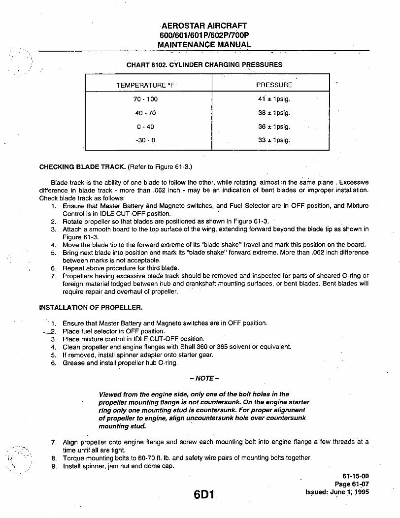
CHART 6102. CYLINDER CHARGING PRESSURES
TEMPERATURE °F PRESSURE
70-100 41 ± 1 psig.
40-70 38 ± Ipsig.
0-40 36 ± 1 psig.
-30-0 33 ± Ipsig.
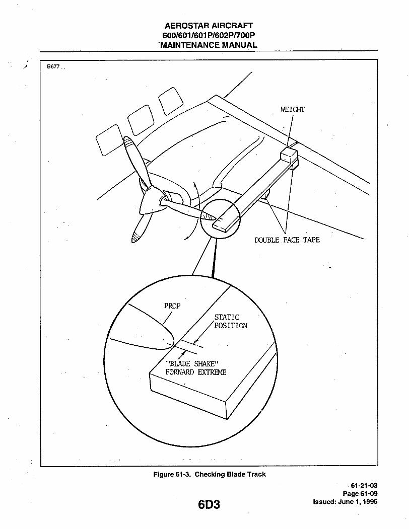
CHECKING BLADE TRACK. (Refer to Figure 61-3.)
Blade track is the ability of one blade to follow the other, while rotating, almost in the same plane . Excessive difference in blade track - more than .062 inch - may be an indication of bent blades or improper installation. Check blade track as follows:
1. Ensure that Master Battery and Magneto switches, and Fuel Selector are in OFF position, and Mixture Control is in IDLE CUT-OFF position.
2. Rotate propeller so that blades are positioned as shown in Figure 61-3. 3. Attach a smooth board to the top surface of the wing, extending forward beyond the blade tip as shown in
Figure 61-3. 4. Move the blade tip to the forward extreme of its "blade shake" travel and mark this position on the board. 5. Bring next blade into position and mark its "blade shake" fonvard extreme. More than .062 inch difference
between marks is not acceptable. 6. Repeat above procedure for third blade. 7. Propellers having excessive blade track should be removed and inspected for parts of sheared O-ring or
foreign material lodged between hub and crankshaft mounting surfaces, or bent blades. Bent blades will require repair and overhaul of propeller.
INSTALLATION OF PROPELLER.
• 1. Ensure that Master Battery and Magneto switches are in OFF position. -_2. Place fuel selector in OFF position.
3. Place mixture control in IDLE CUT-OFF position. 4. Clean propeller and engine flanges with Shell 360 or 365 solvent or equivalent. 5. If removed, install spinner adapter onto starter gear. 6. Grease and install propeller hub O-ring.
-NOTE-
Viewed from ttie engine side, oniy one of the boit holes in the propeller mounting flange is not countersunk. On the engine starter ring only one mounting stud is countersunk. For proper alignment of propeller to engine, align uncountersunk hole over countersunk mounting stud.
7. Align propeller onto engine flange and screw each mounting bolt into engine flange a few threads at a time until all are tight.
8. Torque mounting bolts to 60-70 ft. lb. and safety wire pairs of mounting bolts together. 9. Install spinner, jam nut and dome cap.
61-15-00 Page 61-07
g Q H Issued: June 1,1995

AEROSTAR AIRCRAFT 600/601/601P/602P/700P MAINTENANCE MANUAL
CONTROLLING.
PROPELLER GOVERNOR.
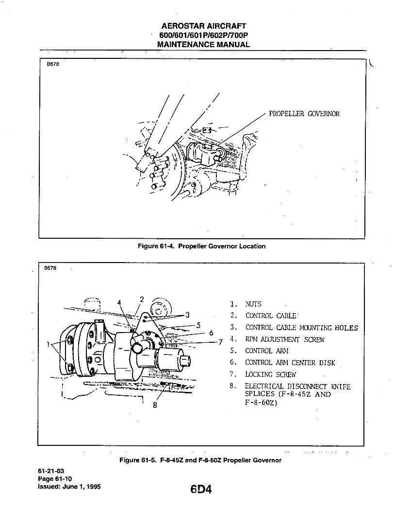
REMOVAL OF PROPELLER GOVERNOR. (Refer to Figures 61-4 and 61-5.)
1. Remove engine upper, lower and nose cowls. 2. Disconnect electrical leads (airplanes with synchrophaser only). 3. Disconnect control cable rod end from govemor control arm. 4. Remove governor mounting stud nuts, and remove governor. 5. Remove governor gasket. If it is to be removed for a considerable amount of time, cover governor mount-
ing pad to prevent foreign matter from entering engine.
INSTALLATION OF PROPELLER GOVERNOR.
1. Clean mounting pads on engine and governor, and inspect recess around drive shaft for foreign matter. 2. Install govemor gasket with concave side of filter screen to engine. 3. Align splines on governor shaft with engine drive and slide governor into position on mounting pad. 4. Install nuts onto governor mounting studs. 5. Connect control cable rod end to inner hole on governor control arm (to outennost hole on later model
602P's). 6. Connect electrical leads (airplanes with synchrophaser only). On 600's S/N 8261001 and up and 602P's
S/N 8265030 and up, insure that the wires are covered by the firesleeve. 7. Adjust govemor control arm.
ADJUSTMENT AND RIGGING OF PROPELLER GOVERNOR.
1. Install engine cowis. 2. Start and wann engine per Flight Manual. Ensure oil temperature is 90°C and oil pressure is 80 psi. 3. Push propeller fully forward. Govemor control amn should be against high RPM stop. With throttle fully
fonvard, tachometer should read a minimum of 2500 rpm for the 600, 601, and 601P, a minimum of 2400 rpm for the 602P, or a minimum of 2425 RPM for the 700P.
4. If necessary, adjust engine RPM as follows: A. Shut down engine. B. Loosen RPM adjustment screw locknut and tum adjustment screw clockwise to decrease RPM or
counterclockwise to increase RPM. One turn produces approximately 25 RPM change. C. Start and wamn engine per Flight Manual, and verify RPM adjustment. D. Shut down engine and tighten RPM adjustment screw locknut.
5. Adjust propeller control lever "cushion" as follows:
61-21-03 Page 61-08
issued: June 1,1995 6D2
AEROStAR AIRCRAFT 600/601/601P/602P/700P MAINTENANCE MANUAL
J I B 6 7 7
Figure 61-3. Checl(ing Biade Tracic
61-21-03 Page 61-09
issued: June 1,1995
AEROSTAR AIRCRAFT 600/601/601P/602P/700P
MAINTENANCE MANUAL
B678
Figure 61-4. Propeiier Governor Location
B678
8
1. NUTS
2. CONTROL CABLE
3. CONTROL CABLE MOUNTING HOLES
_ 7 4 . RPM ADJUSTNevr SCRBV
5. CONTROL AR I
6. CONTROL ARM CENTER DISK
7. LOCKING SCREW
8. ELECTRICAL DISCONNECT KNIFE SPLICES (F-8-45Z AND F-8-60Z)
61-21-03 Page 61-10 Issued: June 1,1995
Figure 61-5. F-8-45Z and F-8-60Z Propeller Governor
6D4

AEROSTAR AIRCRAFT 600/601/601P/602P/700P MAINTENANCE MANUAL
B 6 7 9
DISENGAGED
Figure 61-6. Propeiier RPIM Limiter 61-21-03
Page 61-11 gQg Issued: June 1,1995
I
AEROSTAR AIRCRAFT 600/601/601P/602P/700P MAINTENANCE MANUAL
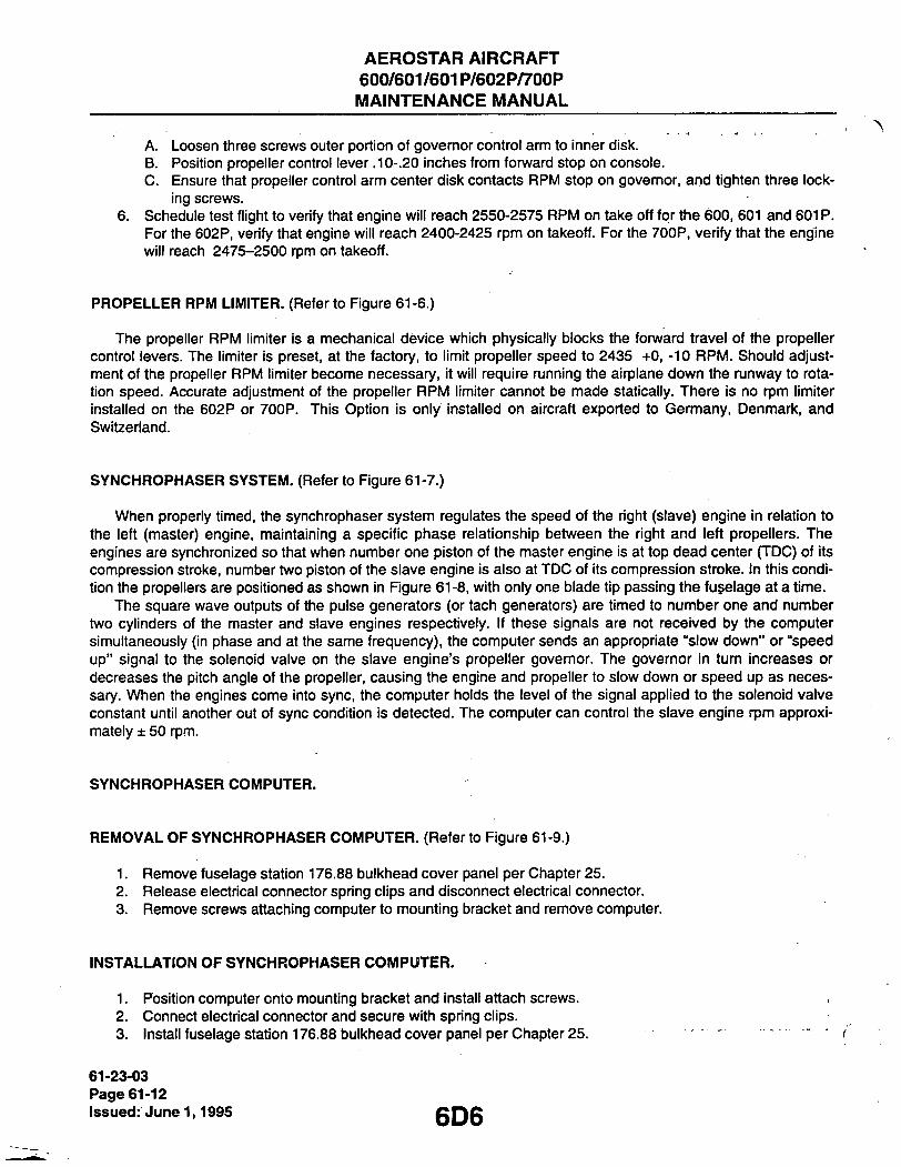
A. Loosen three screws outer portion of governor control ann to inner disk. B. Position propeller control lever .10-.20 inches from fonward stop on console. C. Ensure that propeller control arm center disk contacts RPM stop on governor, and tighten three lock-
ing screws. 6. Schedule test flight to verify that engine will reach 2550-2575 RPM on take off for the 600, 601 and 601 P.
For the 602P, verify that engine will reach 2400-2425 rpm on takeoff. For the 700P, verify that the engine will reach 2475-2500 rpm on takeoff.
PROPELLER RPM LIMITER. (Referto Figure 61-6.)
The propeller RPM limiter is a mechanical device which physically blocks the fonward travel of the propeller control levers. The limiter is preset, at the factory, to limit propeller speed to 2435 +0, -10 RPM. Should adjust-ment of the propeller RPM limiter become necessary, it will require running the airplane down the runway to rota-tion speed. Accurate adjustment of the propeller RPM limiter cannot be made statically. There is no rpm limiter installed on the 602P or 700P. This Option is only installed on aircraft exported to Germany, Denmark, and Switzeriand.
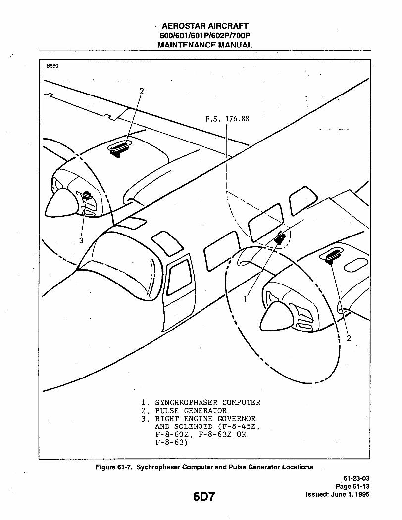
SYNCHROPHASER SYSTEM. (Referto Figure 61-7.)
When properly timed, the synchrophaser system regulates the speed of the right (slave) engine in relation to the left (master) engine, maintaining a specific phase relationship between the right and left propellers. The engines are synchronized so that when number one piston of the master engine is at top dead center (TDC) of its compression stroke, number two piston of the slave engine is also at TDC of its compression stroke. In this condi-tion the propellers are positioned as shown in Figure 61-8. with only one blade tip passing the fu§elage at a time.
The square wave outputs of the pulse generators (or tach generators) are timed to number one and number two cylinders of the master and slave engines respectively. If these signals are not received by the computer simultaneously (in phase and at the same frequency), the computer sends an appropriate "slow down" or "speed up" signal to the solenoid valve on the slave engine's propeller governor. The governor in tum increases or decreases the pitch angle of the propeller, causing the engine and propeller to slow down or speed up as neces-sary. When the engines come into sync, the computer holds the level of the signal applied to the solenoid valve constant until another out of sync condition is detected. The computer can control the slave engine rpm approxi-mately ± 50 rpm.
SYNCHROPHASER COMPUTER.
REMOVAL OF SYNCHROPHASER COMPUTER. (Referto Figure 61-9.)
Remove fuselage station 176.88 bulkhead cover panel per Chapter 25. Release electrical connector spring clips and disconnect electrical connector. Remove screws attaching computer to mounting bracket and remove computer.
INSTALLATION OF SYNCHROPHASER COMPUTER.
1. Position computer onto mounting bracket and install attach screws. 2. Connect electrical connector and secure with spring clips. 3. Install fuselage station 176.88 bulkhead cover panel per Chapter 25.
61-23-03 Page 61-12 Issued: June 1,1995 6D6
AEROSTAR AIRCRAFT 600/601/601P/602P/700P
MAINTENANCE MANUAL
B680
1. SYNCHROPHASER COMPUTER 2. PULSE GENERATOR 3. RIGHT ENGINE GOVERNOR
AND SOLENOID (F-8-45Z, F-8-60Z, F-8-63Z OR F-8-63)
Figure 61-7. Sychrophiaser Computer and Puise Generator Locations
61-23-03 Page 61-13
C r\7 Issued: June 1,1995

AEROSTAR AIRCRAFT 600/601/601P/602P/700P MAINTENANCE MANUAL
fl
Figure 61-8. Propeiier Position
PULSE GENERATORS.
REIVIOVAL OF PULSE GENERATORS. (Refer to Figure 61-10.)
1. On right engine, remove access cover aft of upper engine cowling. On left engine, remove inboard access cover aft of upper engine cowling.
2. Remove bolts from tach generator clamp and cut ty-raps on pulse generator and tach generator wiring. 3. Remove safety wire from drive shaft nut on fonward end of tach generator. Loosen drive shaft nut until
released from tach generator and slide tach generator aft to provide working space. 4. Loosen drive shaft connector on forward end of pulse generator. 5. Disconnect electrical connector and remove pulse generator. /
INSTALLATION OF PULSE GENERATORS.
1. Slide pulse generator onto tach drive shaft and rotate pulse generator casing until drive shaft keyway is aligned with scribe mark on aft surface of casing.
2. Position tach generator onto aft end of pulse generator and tighten drive shaft nut finger tight 3. Position tach generator into mounting clamp and tighten clamp bolts. 4. Connect electrical connector to pulse generator. 5. install ty-raps onto pulse generator and tach generator wiring. 6. Perform 'Timing of Synchrophaser System, A/F 0455 and Subsequent"
61-23-06 Page 61-14 Issued: June 1,1995 6D8

AEROSTAR AIRCRAFT 600/601/601P/602P/700P MAINTENANCE MANUAL
B682
1. SYNCHROPHASER COMPUTER 2. PNEUMATIC SYSTEM MANIFOLD 3. F.S. 176.88 BULKHEAD
Figure 61-9. Sychrophaser Computer
6D9 '61-23-06
Page 61-15 issued: June 1,1995

AEROSTAR AIRCRAFT 600/601/601P/602P/700P MAINTENANCE MANUAL
Figure 61-10. Puise Generator
61-23-06 Page 61-16
issued: June 1,1995 6D10

AEROSTAR AIRCRAFT 600/601/601P/602P/700P MAINTENANCE MANUAL
TIMING AND TESTING.
TIMING SYNCHROPHASER SYSTEM, A/F 0455 AND SUBSEQUENT.
1. Remove upper engine cowlings from both engines. 2. Remove upper spark plug from number one cylinder (number two cylinder on 700P) of left engine and
number two cylinder (number one cylinder on 700P) of right engine. 3. Using piston position.indicator, rotate engines to bring pistons of number one and two cylinders to TDC of
compression stroke. 4. Remove fuselage station 176.88 bulkhead cover panel per Chapter 25. 5. Disconnect electrical connector from synchrophasercomputer, and plug Hartzell B-4467 synchrophaser
test box into system in place of computer.
- CAUTION-
Ensure all switches and equipment are turned OFF and all autopilot circuit breakers are pulled prior to connecting an auxiliary power unit (APU). The master battery and alternator switches must be left in the OFF position until the APU is disconnected, to protect the voltage regulators and system electrical equipment from voltage transients and possible damage.
6. Connect APU to airplane or place Master Battery switch in ON position. 7. Rotate right engine pulse generator (airplanes with A.N. tach generators, and airplanes with A.N. tach
generators field retrofitted with synchrophaser system) or tach generator (airplanes with Aerosonic tach generators and dual tach, and airplanes initially equipped with A.N. tach generators field retrofitted with Aerosonic tach generators and dual tach, and synchrophaser system) clockwise until right engine light on test box just comes on.
8. Lock pulse generator or tach generator in position, tighten drive shaft nut and safety wire pulse generator electrical connector to tach generator drive shaft nut.
9. Repeat Steps 7 and 8 for left engine. 10. Disconnect APU or place Master Battery switch in OFF position. 11. Re-install removed spark plugs, engine cowlings, and access covers. 12. Disconnect test box and connect electrical connector to synchrophaser computer. 13. Install fuselage station 176.88 bulkhead cover panel per Chapter 25.
TESTING SYNCHROPHASER SYSTEM, A/F 0455 AND SUBSEQUENT.
1. Remove fuselage station 176.88 bulkhead cover panel per Chapter 25. 2. Disconnect electrical connector from synchrophaser computer and plug Hartzell B-4467 synchrophaser
test box into system in place of computer.
- CAUTION-
Ensure all switches and equipment are turned OFF and all autopilot circuit breakers are pulled prior to connecting an auxiliary power unit (APU). The master battery and alternator switches must remain OFF until the APU is disconnected to protect the voltage regulators and system electrical equipment from voltage transients and possible damage.
61-23-09 Page 61-17
1 Issued: June 1,1995

AEROSTAR AIRCRAFT 600/601/601P/602P/700P MAINTENANCE MANUAL
3. Connect APU to airplane, or place Master Battery switch in ON position. Test box power light and coil light should illuminate. Should coil short light illuminate, immediately remove power from circuit and refer to Chart 6101, Troubleshooting Synchrophaser System. Disregard any other lights that illuminate at this time.
-NOTE-
The left engine light or right engine light may be either on or off depending on the position of the number one or number two piston respectively. It may be necessary to rotate either propeller as much as two complete revolutions to bring the appropriate piston to TDC of its compression stroke and illuminate its respective light on the test box.
Rotate left engine until left engine light on test box illuminates. If left engine light is already illuminated, rotate engine until left engine light goes out. This verifies proper operation of the pulse generator (or tach generator depending on airplane configuration). Observing right engine light, repeat Step 4 for right engine. Place synchrophaser switch in PHASE position. Test box phase light should illuminate. Manual light should go out. Place synchrophaser switch in manual position. Test box manual light should illuminate. Phase light should go out. Disconnect APU or place Master Battery switch in OFF position, and refer to Chart 6101 for any test light that failed to operate correctly. Disconnect test box and connect electrical connector to synchrophaser computer. Install fuselage station 176.88 bulkhead cover panel per Chapter 25.
TIMING SYNCHROPHASER SYSTEM, A/F 0001-0454. (Refer to Figure 61-11.)
1. Remove upper engine cowlings from both engines. 2. Remove upper spark plug from number one cylinder of left engine and number two cylinder of right
engine. 3. Using piston position indicator, rotate engines to bring pistons of number one and two cylinders to TDC of
compression stroke. 4. On right engine, remove access cover aft of upper engine cowling. On left engine, remove inboard
access cover aft of upper engine cowling. 5. With flexible drive shafts connected at both engines, but only loosely connected at, strobe sensor and
pulse generator, rotate strobe sensor and pulse generator casings until drive shaft keyway is aligned with index mark on boss of casing. Tighten cables to casings.
-NOTE-
If casing rotation leaves electrical connector inaccessible, completely disconnect flex drive from unit and rotate unit casing and shaft as necessary. Reinstall flex drive after repeating Step 5.
6. Re-install removed spark plugs, engine cowlings, and access covers.
4.
5. 6.
7.
8.
9. 10.
61-23-10 Page 61-18
Issued: June 1,1995 6D12

AEROSTAR AIRCRAFT 600/601/601P/602P/700P
MAINTENANCE MANUAL
B 6 8 4
1. PULSE GE^ERATOR 2. DRIVE SHAFT 3. TACH GENERATOR 4. TACH GENERATOR CLAMP 5. DRIVE SHAFT NUT
Figure 61-11. Strot>e Sensor, A/F 0001-0454 61-23-10
Page 61-19 e r j - I O issued: June 1,1995

AEROSTAR AIRCRAFT 600/601/601P/602P/700P MAINTENANCE MANUAL
TESTING SYNCHROPHASER SYSTEM, A/F 0001 -0454.
This test requires the use of a standard multimeter, and Hartzell's A-4354 harness test plug, A-4355 com-puter test plug, and A-4358 pulse generator simulator.
1. On right engine, remove access cover aft of upper engine cowling. On left engine, remove inboard access cover aft of upper engine cowling.
2. Remove fuselage station 176.88 bulkhead cover panel per Chapter 25. 3. Disconnect both electrical connectors (PI and P2) from synchrophaser computer. 4. Disconnect strobe sensor electrical connector (P3) and plug A-4354 test plug into system in place of
strobe sensor.
- CAUTION-
Ensure all switches and equipment are turned OFF and all autopilot circuit breakers are pulled prior to connecting an auxiliary power unit (APU). The master battery and alternator switches must be left in the OFF position until the APU is disconnected, to protect the voltage regulators and system electrical equipment from voltage. transients and possible damage.
5. Connect APU to airplane or place Master Battery switch in ON position. 6. Measure voltage between pins F (ground) and G (airplane power) of P2 of synchrophaser computer.
Voltmeter should indicate 24 volts. 7. Disconnect APU or place Master Battery switch in OFF position. 8. Measure resistance of pulse generator coil between pins E and F of P2. Ohmmeter should indicate \
approximately 300 ohms. 9. Disconnect electrical connector (P4) from pulse generator and check for continuity between pin A of P4
and pin E of PI, and between pin B of P4 and pin F of P2. 10. Place synchrophaser switch in phase position and measure resistance between pins C and D of P2.
Ohmmeter should indicate short circuit. 11. Measure resistance between pins C and A of disconnected computer plug, PI. Ohmmeter should indi-
cate 3.3K ohms. Check for 3.9K ohms between pins C and B, 10K ohms between pins F and D, and 15K ohms between pins F and E.
12. Measure resistance of propeller govemor solenoid coil between pins G and H of PI. Ohmmeter should indicate approximately seven ohms.
13. Check continuity from each pin of PI and P2 to ground. All should show open circuit except pin F of P2 which should show a short circuit.
14. Plug C-4355 computer test plug into SI of computer and connect P2 to S2. 15. Disconnect P4 from S4 on pulse generator and connect A-4358 pulse generator simulator to P4 in place
of pulse generator. 16. Place synchrophaser switch in phase position, and connect APU to airplane or place Master Battery
switch in ON position. Pulse generator simulators two neon lights should flash simultaneously. 17. Place C-4355 increase/decrease switch in HOLD position, and synchrophaser switch in MANUAL posi-
tion. Measure voltage between C-4355 coil terminals. Allow 45 seconds for voltage to stabilize. Voltmeter should indicate 7-8 volts.
18. Place synchrophaser switch in PHASE position. Voltmeter should show immediate increase of one volt, followed by a gradual increase to 12-14 volts.
19. Place increase/decrease switch in HOLD position, and synchrophaser switch in MANUAL position. After approximately 45 seconds, voltmeter indication should stabilize around 7-8 volts.
61-23-11 P^ge 61-20 issued: June 1,1995 6D14
AEROSTAR AIRCRAFT 600/601/601P/602P/700P MAINTENANCE MANUAL
20. Place synchrophaser switch in PHASE Position and increase/diecrease switch in DECREASE position. Voltmeter should show an immediate decrease of one volt, followed by a gradual decrease to one volt or less. - • ' ' v . . .
21. Place synchrophaser switch in MANUAL position. Voltmeter should return to 7-8 volts. 22. Disconnect APU or place Master Battery switch in OFF position. 23. Remove strobe sensor and disassemble so that lights and photo conductors are accessible. 24. Disconnect A-4354 harness test plug from S3, connect strobe sensor plug (P3) to S3. 25. Connect voltmeter across knife splices in propeller governor solenoid wiring near solenoid. 26. Connect APU to airplane or place Master Battery switch in ON position, and place synchrophaser switch
in PHASE position. 27. Cover each photo conductor (one at a time) with a completely opaque material, blocking out all ambient
light. Voltmeter should gradually increase from approximately zero volts to approximately 12 volts as each photo conductor is covered. Disconnect voltmeter.
28. Disconnect APU or place Master Battery switch in OFF position. 29. Remove, reassemble, and install strobe sensor. 30. Disconnect A-4358 pulse generator simulator from P4 and connect P4 to S4. 31. Disconnect C-4355 computer test plug from SI and connect PI to SI. 32. Install fuselage station 176.88 bulkhead cover panel per Chapter 25. 33. Install access covers aft of upper engine cowlings.
-END-
6D15
61-23-11 Page 61-21
issued: June 1,1995

AEROSTAR AIRCRAFT 600/601/601P/602P/700P
MAINTENANCE MANUAL
THIS PAGE INTENTIONALLY LEFT BLANK
6D16

AEROSTAR AIRCRAFT 600/601/601P/602P/700P
MAINTENANCE MANUAL
CHAPTER
6D17

AEROSTAR AIRCRAFT 600/601/601P/602P/700P MAINTENANCE MANUAL
CHAPTER 71 - POWER PLANT
TABLE OF CONTENTS/EFFECTIVITY
CHAPTER SECTION GRID SUBJECT SUBJECT NO. EFFECTIVITY
71-00-00 GENERAL 6019 71-01-00 Description 6019 71-02-00 Troubleshooting 6019 71-03-00 Precautions 6E1 71-04-00 Removal of Engine 6E1 71-05-00 Installation of Engine to Mounting Frame 6E2 71-06-00 Installation of Engine 6E4 71-07-00 Hose Routing (602P) 6E5 71-08-00 Pre-Oiling Of Engine 6E6 71-09-00 Engine Operational Check 6E7
71-10-00 COWLING 6E9 71-11-00 Description 6E9 71-12-00 Engine Cowling 6E11 71-12-01 Removal of Engine Cowling " 6E11 71-12-02 Cleaning, Inspection and Repair of Engine Cowling 6E11 71-12-03 Installation of Engine Cowling 6E11 71-13-00 Engine Cooling Baffles 6E11 71-13-01 Maintenance of Baffles 6E11 71-14-00 Procedure for Bonding Neoprene (Synthetic)
Rubber to Itself or to Aluminum 6E12 71-15-00 Rigging of Manual Cowl Flaps (700P) 6E12
71-20-00 MOUNTS 6E14 71-21-00 Replacement of Engine Shock Mounts 6E14
71-50-00 ELECTRICAL HARNESS 6E14
71-60-00 AIR INTAKES 6E14 71-61-00 Description 6E14 71 -62-00 Pressure Differential Check (601, 601P) 6E24 71-63-00 Flexible Duct 6E24 71-63-01 Removal of Flexible Duct 6E24 71-63-02 installation of Flexible Duct 6F1 71-64-00 Inspection of Induction System 6F1 71-65-00 Replacement of Mode Door Seals (601, 601P) 6F1
71-70-00 ENGINE DRAINS 6F2
71 - ContTEffec. Page -1
Issued: June 1,1995

AEROSTAR AIRCRAFT 600/601/601P/602P/700P MAINTENANCE MANUAL
GENERAL.
This section covers the power plant and is comprised of instructions for the removal, minor repairs, service and installation.
For further instructions on major repairs, consult the appropriate publication of the engine or component manufacturer.
DESCRIPTION.
The 600, 601, 601P and 602P are powered by two Avco-Lycoming IO-540 series engines of 290 horsepower each. The 700P is powered by an LTIO-540-U2A and a TIO-540-U2A which develop 350 horsepower each. The power plant contains the following major systems:
1. Starting and Ingition System. A. The ignition system is composed of dual magnetos, ignition switch, starting vibrator, high tension har-
ness and spark plugs. B. A prestolite starting motor cranks the engine when energized by means of the ignition switch and
starting solenoid. 2. Fuel and Induction System.
A. The engine is equipped with a Bendix RSA 10ED1 Fuel Injector. The fuel injection system schedules fuel flow in proportion to air flow. Fuel vaporization takes place at the intake ports.
B. The fuel injector feeds metered fuel to the flow divider, which in turn provides fuel to the individual cylinder nozzles.
C. Induction air is directed to the fuel injection regulator thrugh disposable type air filter in an airbox mounted on the nacelle firewall. An automatic alternate air door (Model 601, 601P and 700P) is installed in the airbox to ensure a source of air to the fuel injection regulator if the air filter should become obstructed. On the 602P the air doors are manually operated.
3. Lubrication. A. The engine employs a full pressure,^vet;sump-lubrication system. After passing through the oil filter,
an oil pressure relief valve regulates system oil pressure from which the oil is distributed throughout the engine to return to the sump by gravity.
B. An oil cooler is incorporated in the system for oil temperature control. 4. Cooling.
A. Cooling air entering the cowling is directed around the cylinders by baffles, through the accessory section and is exhausted through exhaust chutes.
B. Two blast tubes mounted on the rear baffle direct cooling air to each magneto. 5. Instrumentation.
A. The airplane is provided with panel-mounted instruments that monitor important engine functions. These include fuel and oil pressure, oil and cylinder head temperature, manifold pressure and tachometer. Most airplanes will have an EGT gauge in addition to the above.
6. Turbocharging System. A. The model 601, 601P, 602P, and 700P are equipped with exhaust-driven turbochargers. This acces-
sory raises the pressure of the induction air delivered to the engine making high altitude operation possible.
B. The turbocharger also provides air for cabin pressurization in models 601P, 602P and 700P. 7. Propeller.
A. Each engine drives a Hartzell 3-bladed, hydraulically operated, constant speed, full-feathering pro-peller.
TROUBLESHOOTING.
Refer to Troubleshooting Chart 7101.
6D19 71-02-00
Page 71-01 Issued: June 1,1995
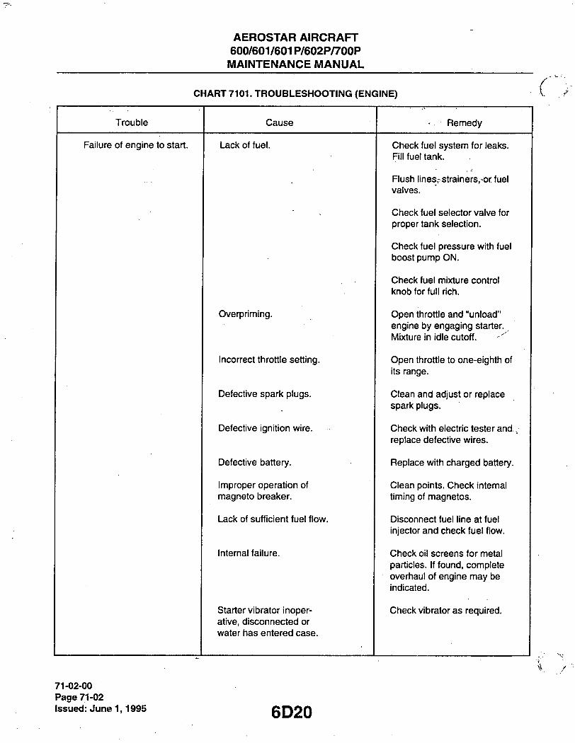
AEROSTAR AIRCRAFT 600/601/601P/602P/700P MAINTENANCE MANUAL
CHART 7101. TROUBLESHOOTING (ENGINE)
Trouble Cause Remedy
Failure of engine to start. Lack of fuel. Cfieck fuel system for leaks. Fill fuel tank.
Flusfi lines,- strainers, or fuel valves.
Cfieck fuel selector valve for proper tank selection.
Cfieck fuel pressure witfi fuel boost pump ON.
Cfieck fuel mixture control knob for full ricfi.
Overpriming. Open tfirottle and "unload" engine by engaging starter. I ixture in idle cutoff.
Incorrect tfirottle setting. Open tfirottle to one-eigfitfi of its range.
Defective spark plugs. Clean and adjust or replace spark plugs.
Defective ignition wire. Ctieck witfi electric tester and , replace defective wires.
Defective battery. Replace witti cfiarged battery.
Improper operation of magneto breaker.
Clean points. Check intemal timing of magnetos.
Lack of sufficient fuel flow. Disconnect fuel line at fuel injector and check fuel flow.
Internal failure. Check oil screens for metal particles. If found, complete overhaul of engine may be indicated.
Starter vibrator inoper-ative, disconnected or water fias entered case.
Check vibrator as required.
71-02-00 Page 71-02 Issued: June 1,1995 6D20

AEROSTAR AIRCRAFT 600/601/601P/602P/700P MAINTENANCE MANUAL
CHART 7101. TROUBLESHOOTING CHART (ENGINE) (cont.)
Trouble Cause Remedy
Failure of engine to start, (cont.)
Water in fuel injector. Drain fuel injector and fuel lines.
Failure of engine to idle properly.
Incorrect idle mixture. Adjust mixture.
Leak in tfie induction system. Tigfiten all connections in tfie induction system. Replace any parts tfiat are defective.
Incorrect idle adjustment. Adjust tfirottle stop to obtain correct idle.
Uneven cylinder compression. Cfieck condition of piston rings and valve seats.
Faulty igntion system. Cfieck entire ignition system.
Incorrect magneto timing. Adjust timing.
Insufficient fuel pressure. Adjust fuel pressure.
Bad induction drain valve. Clean or replace.
Leak in air bleed nozzle balance line.
Cfieck connection and replace if necessary.
Plugged fuel injector nozzle. Clean or replace nozzle.
Flow divider fitting plugged. Clean fitting.
Lower power and uneven running.
Mixture too ricfi; indicated by sluggisfi engine operation, red exfiaust flame at nigfit. Extreme cases indicated by black smoke from exfiaust.
Readjustment of fuel injector servo by autfiorized personnel is indicated.
Mixture too lean; indicated by overfieating or backfiring.
Cfieck fuel lines for dirt or ottier restrictions. Ctieck fuel injection nozzles. Readjustment of fuel injector is indicated.
Leaks in induction system. Tigfiten all connections. Replace defective parts.
6D21 71-02-00
Page 71-03 Issued: June'1,1995

AEROSTAR AIRCRAFT 600/601/601P/602P/700P MAINTENANCE MANUAL
CHART 7101. TROUBLESHOOTING (ENGINE) (cont)
Trouble Cause Remedy -
Lower power and uneven running, (cont)
Defective spark plugs. Clean and gap or replace spark plugs.
Improper fuel. Fill tank with fuel of - . recommended grade.
Magneto breaker points not working properly.
Clean points. Check internal timing of magnetos.
Defective ignition wire. Check wire with electric tester. Replace defective wire.
Defective spark plug temninal connectors.
Replace connectors on spark plug wire.
Plugged fuel injector nozzle. Clean or replace nozzle.
Failure of engine to develop full power.
Leak in the induction system.
Tighten all connections and replace defective parts.
Plugged fuel injector nozzle. Clean or replace nozzle.
TTirottle lever out of adjustment. Adjust throttle lever.
Improper fuel flow. Check strainer, gauge and flow at fuel injector inlet.
Restriction in air inlet. Examine air inlet and remove restrictions.
Improper fuel. Drain and refill tank with recommended fuel.
Faulty ignition. Tighten all connections. Check system with tester. Check ignition timing.
Incorrect wastegate controller system adjustment.
Readjust.
Rough engine. Cracked engine mount. Replace or repair mount.
Defective mounting bushings. Install new mounting bushings.
Uneven compression Check compression
71-02-00 Page 71-04 issued: June 1,1995 6D22

AEROSTAR AIRCRAFT 600/601/601P/602P/700P MAINTENANCE MANUAL
CHART 7101. TROUBLESHOOTING (ENGINE) (cont)
Trouble Cause Remedy
Rough engine, (cont.) Too rich or too lean mixture. Check and adjust injector sen/o.
Plugged fuel injector nozzle. Clean or replace nozzle.
Low oil pressure.^ Insufficient oil. Fill sump with recommended oil.
Air lock or dirt in relief valve.
Remove and clean oil pressure relief valve and adjust per Chapter 79.
Leak in suction line or pressure line.
Check gasket between accessory housing and crankcase.
Dirty oil strainer. Remove and clean oil strainers.
Defective pressure gauge. Replace gauge.
Stoppage in oil pump intake passage.
Check line for obstruction. Clean suction strainer.
High oil temperature. See "High Oil Temperature" in "Trouble" column.
Oil pressure slow to rise. Air in instrumentation line. Bleed line with lightweight oil (5W).
High oil temperature. Insufficient air cooling. Check air inlet and outlet for deformation or obstruction.
Insufficient oil supply. Fill oil sump to proper level with specified oil.
Low grade of oil. Replace with oil conforming to specifications.
Clogged oil lines or strainers.
Remove and clean oil strainers.
Excessive blow-by. Usually caused by worn or stuck rings.
Failing or failed bearing. Examine sump for metal particles. If found, overhaul of engine is indicated.
Defective temperature gauge. Replace gauge.
6D23 71-02-00
Page 71-05 Issued: June 1,1995

AEROSTAR AIRCRAFT 600/601/601P/602P/700P MAINTENANCE MANUAL
CHART 7101. TROUBLESHOOTING (ENGINE) (cont)
Trouble Cause Remedy
Excessive oil consumption. Low grade of oil. Fill tank witfi oil conforming to specifications.
Failing or failed bearings. Check sump for metal particles.
Worn piston rings. Install new rings.
Incorrect installation of piston rings.
Install new rings.
Failure of rings to seat (new nitrided cylinders).
Use mineral base oil. Climb to cruise altitude at full power and operate at 75% cruise power setting until oil consumption stabilizes.
71-02-00 Page 71-06 Issued: June 1,1995 6D24

AEROSTAR AIRCRAFT 600/601/601P/602P/700P
^MAINTENANCE MANUAL
PRECAUTIONS.
1. The engines depend on the fonward movement of the airplane to maintain proper cooling. Particular care • is necessary when operating the engines on the ground toprevent over-heating. It is recommended that
the following precautions be observed:
- CAUTION-
Any ground check that requires full throttle operation must be limited to 3 minutes, or less if indicated cylinder head temperature should exceed the maximum allowable.
A. Head the airplane into the wind. B. Leave mixture in "full rich". C. Operate the engine on the ground only with the propeller in minimum blade angle setting. D. Warm up at approximately 1000-1200 rpm. Avoid prolonged idling and do not exceed 2200 rpm on
the ground. 2. Extreme care should be observed by maintenance personnel to ensure that no cleaning solvents are
spilled or sprayed in the vicinity of the Air Pump Inlet Filter and ignition lead connections. If contamination of the filter occurs, that filter must be changed to prevent damage to the air pump.
3. If use of cleaning solvents cannot be avoided, ensure the Air Pump Inlet Filter in adequately covered prior to use of these materials.
4. When using the Auxiliary Power Unit, allow the APU voltage to stabilize at 24-28 volts before installing the power plug in the tail receptacle. To protect electronic components from possible damage due to external power supply voltage spikes, ensure the Radio master switch is OFF and the Autopilot circuit breakers are pulled. Master Battery and Alternator switches must be OFF as long as extemal power is connected.
REMOVAL OF ENGINE.
-NOTE-
The recommended procedure for engine removal/installation is to remove/install the engine and the mounting frame from/to the firewall as a unit. - - f::.
1. Set ali switches in the cockpit to OFF. 2. Set Master Battery switch to ON then to OFF. This action causes all electrically operated valves to
cycle to the OFF position if any were in the ON mode at the time of switch turnoff. 3. _ Set mixture control to full rich and throttle to ull to deplete fuel pressure. 4. Disconnect battery ground cable (negative terminal).
-NOTE-
Install caps or plugs at all disconnected lines to prevent contamination or entrance of foreign material.
5. Remove upper, lower and nose cowlings (A/F 0005 and up) and disconnect oil lines from oil cooler at nose cowling
71-04-00 . Page 71-07
Issued: Jtme 1,-1995

AEROSTAR AIRCRAFT 600/601/601P/602P/700P MAINTENANCE MANUAL
I 6. Remove propeller assembly per Chapter 61. Remove nose cowling (A/F 0001 -0004). 7. Disconnect the throttle and mixture cables at fuel injector. 8. Remove starter battery cable at starter motor cable stud. 9. Disconnect fuel gauge and fuel pump sense hose from duct to fuel injector sen/o (601, 601P, 602P and
700P). 10. Remove flexible air duct from right and left air inlet assembly (or air discharge assembly, models 601,
601P, 602P and 700P), and "J" duct between airbox and fuel injector. 11. Disconnect the fuel pump supply line and fuel pressure line. 12. Disconnect magneto ground and retard leads (left magneto) and ground lead from right magneto.. 13. Remove engine oil temperature connector at aft end of engine. 14. Remove tachometer drive cable at engine tach connection (A/F 0144 and up). Remove tach electrical
connector (A^F 0001-0143). 15. Disconnect oil pressure line at aft end of engine. 16. Disconnect flexible hose at air pump. 17. Disconnect alternate air door control cable from door and remove clamp attaching cable to plenum
assembly (601 /VF No. 0826 and up and all 602P's). Disconnect altemate air hoses from firewall (700P). 18. Disconnect electrical leads up from cylinder head temperature sensor. 19. Disconnect electrical leads from EGT (if installed). 20. Disconnect the turbo controller line on models 601, 601P, 602P and 700P. 21. Disconnect fuel flow pressure line from the flow divider (/VF 0001-0265). 22. Disconnect manifold pressure line at firewall. 23. Disconnect alternator output connector. 24. Disconnect nacelle drain lines (3) from frame. 25. If engine mounted compressor is installed, discharge air conditioning system and disconnect freon lines
from compressor (right engine only) (later 602P and 700P). 26. Attach a 1/2 ton (minimum) hoist to the lifting straps and relieve the tension from the engine mounts.
27. Check the engine for any attachments remaining to obstruct its removal. 28. Drain the engine oil, if desired, and then close drain. 29. Remove the five mounting bolts securing the engine mount to the wing (firewall) and remove engine and
mounting frame together.
INSTALLATION OF ENGINE TO MOUNTING FRAME. (Referto Figure 71-1, Detail A.)
1. With engine suspended by hoist, insert an engine mounting bolt with washer against head, through mounting pcii!? and slide rear half of mount assembly on the bolt. Repeat for other 3 attach points.
2. F'osition engine mounting lugs into aiignment with attach points on mounting frame. 3. Install fonvard half of mounting assembly on bolts (note ground strap, upper righthand mount only). 4. Install washers and nuts. Determine friction drag torque for the nut (it must be a minimum of 14 in. lbs.).
Add the friction drag torque to 450-500 in. lbs. to get the final torque.
-NOTE-
Place a tail stand under the tail of the airplane Itefore removing engine (double engine change only) and a wing stack under opposite wing.
71-05-00 Page 71-08 Issued: June 1,1995 6E2

AEROSTAR AIRCRAFT 600/601/601P/602P/700P
MAINTENANCE MANUAL
B685
ENGINE BOSS MOUNT (TYPICAL 4 PLACES)
1 2 3 4. 5. 6 7. 8. 9
10
11
12
13
14
15 16 17
ENGINE MOUNTING FRAME FRAME MOUNTING LUG (4 PLCS) AN7-43A BOLTS (4 PLCS) LOWER CENTER MTG. LUG AN3-36A BOLT 1 (PLC) AN7-36A BOLT. ENGINE MTG. BOLTS (4 PLCS) LORD TYPE SHOCK MOUNTS (4 PLCS) GROUND STRAP ENGINE MOUNT PAD WIDE PAD. AFT ON UPPER MTS.
FWD ON LOWER MTS. NARROW PAD.- FWD ON UPPER MTS.
AFT ON LOWER MTS. MS20365-720 NUT > MS20365-720C NUT (700P) AN960-716 WASHER. TYP. 3 PLCS. (AR) AN960-716L WASHER. UPPER RH MT. ONLY AN970-7 WASHER 98-9077.10 WASHER (700P) SPACER NACELLE DRAIN LINE ROLL PIN (700P ONLY)
Figure 71-1. Engine IWount and instailation
6E3 71-05-00
Page 71-09 Issuejd: June 1,1995

AEROSTAR AIRCRAFT 600/601/601P/602P/700P MAINTENANCE MANUAL
TYPICAL 2 PLACES
SEE TEXT
Figure 71-1. Engine IWount Detaii A (cont)
iNSTALLATiON OF ENGINE. (Refer to Figure 71-1.)
1. With engine and mounting frame suspended by hoist, swing frame into alignment with the 5 mounting points on firewall.
2. Insert mounting bolts and washer, tighten bolts evenly at the five mounting points on firewall. 3. Determine the friction drag torque for the nut (it must be a minimum of 14 in lbs.). Add the friction drag
torque to 450-500 in. lbs. to get the final torque. 4. Install ailternator connector. 5. Connect manifold pressure line at firewall. 6. Connect fuel supply line and fuel pressure line. 7. Connect fuel flow pressure line at fuel divider (A/F 0001 -0265). 8. Connect electrical leads to EGT (if installed). 9. Connect electrical leads to cylinder head temperature sensor. 10. Install flexible hose to air pump. *• 11. Connect oil pressure line at aft end of engine. 12. Connect turbo controller line on models 601, 601Pand602P. 13. Tachometer Installation:
A. Install tachometer drive cable at engine tachometer connection (/VF 0144 and up). B. Install tachometer electrical connector to tach generator (/VF 0001-0143).
14. Install oil temperature connector at aft end of engine.
71-06-00 Page 71-10
Issued: June 1,1995 6E4
AEROSTAR AIRCRAFT 600/601/601P/602P/700P MAINTENANCE MANUAL
15. Connect magneto ground and retard leads to left magneto and ground lead to rigfit magneto. 16. Install flexible air duct from rigtit and left air inlet assemblies (or discfiarge assemblies on models 601,
601P, 602P and 700P) and "J" duct between air box and fuel injector. 17. Connect fuel pressure gauge and fuel pump sense hose to fuel injector sen/o air duct (601, 601P, 602P
and 700P). 18. Attach nacelle drain lines to frame. 19. Connect alternate air door control cable and install clamp (if required). Connect alternate air hoses to fire-
wall (700P). 20. Connect starter battery cable at starter motor cable stud. 21. Install throttle and mixture cables at fuel injector. 22. Install nose cowling (A/F 0001-0004) or split-nose cowling {A/F 0005 and up). 23. Connect oil lines to oil cooler (oil cooler should be flushed out before intallation). 24. Install propeller assembly per Chapter 61 (ensure magneto switches are OFF). 25. Check and secure any harness, hose, lines or wires that may be loose. Refer to the latest revision of
Aerostar S/L 755. 26. If engine mounted compressor is installed, reconnect freon lines to it. Service the air conditioning system
(later 602P and 700P). 27. Connect battery ground cable and replace battery compartment cover. 28. Install the proper grade and amount of engine oil (12 quarts MIL-L-6082 or N/IIL-L-22851). (Refer to
Chapter 12.) 29. Turn Master Battery switch ON. Set fuel selector switch to ON and turn fuel boost pump ON. Set throttle
and mixture to full. 30. Check fuel lines and connectors for leaks. If no leaks, turn fuel boost pump OFF. 31. Pre-oil the engine per the section titled Pre-Oiling Engine. 32. Replace upper engine cowling. (Lower cowling is left off to check for oil leaks later.) 33. Perform an engine operational check per the section titled Engine Operational Check.
HOSE ROUTING (602P). ppssooez
When installing the engine on the 602P, insure that the hoses are routed as follows: 1. Manifold pressure hose: Insure that the 90 elbow (under the fonward section of the No. 2 cylinder) is
approximately at the 5 o'clock position (looking rearwards from the front of the engine). Keep the hose away from the No. 2 exhaust stack.
2. Compressor (turbine) discharge pressure hose: Route the hose from the airbox to the left, aft of the oil/air separator discharge line, over the fuel vent line, over the 2 inch hose, under the engine mount to the cen-ter controller port.
, 3. Fuel vent line left side: Route from the tee on the filter airbox to the left, aft of the air/oil separator dis-charge line, under the engine mount, over the 2 inch hose and over the controller hose to the fitting to the baffle.
4. Fuel vent line right side: Route from the fitting at the baffle (right side) aft and over the propeller control cable, forward of the diagonal engine mount tube and under the 2 inch hose, aft of the magneto and under the dry air duct, fonward of the airbox bleed line to the tee on the airbox.
5. Oil pressure sense line: Keep away from exhaust stacks. Tie as necessary.
6E5
71-07-00 Page 71-11
Issued: June 1,1995
AEROSTAR AIRCRAFT 600/601/601P/602P/700P MAINTENANCE MANUAL
6. Engine sump to pump, right side: Insure that the swivel fitting (on the lower end of the hose) is positioned between the 10 and 11 o'clock position looking from the right side. Route the hose over th^ small turbine support tube, fonvard of the manifold pressure line, above the wastegate cross shaft to the elbow on the pump. Tie the tube to the turbine support tube above the cross shaft.
7. Fuel pressure sense line: Keep away from exhaust stacks. Tie as necessary. 8. Engine sump to controller on firewall, left side: Insure that the swivel is facing aft and towareJs the engine
centeriine (approximately the 7 o'clock position when looking aft from the front). Route the hose over the lower engine mount tube between the oil air separator discharge tube and the wire bundle at this same point. Continue up to the controller with the 45 end of the hose. Tie the hose at the separator discharge tube.
9. Oil supply line, left turbine: Face hose fonvard and away from the engine centeriine approximately 11 o'clock from turbine centeriine looking from top and forward, go fonvard and under the turbine air inlet hose, (keep away from the number 6 cylinder exhaust tube) over the small turbine tube (tie here after routing), over the wire bundle and the wastegate cross shaft, aft of the large turbine support tube, aft of the vertical hose on top of the injector, (tie here just above the elbow after routing), to the restrictor tee just above the fuel injector. The restrictor tee will face up and aft, approximately 2 o'clock looking from the left side.
10. Oil supply line, right turbine: Face hose forward and away from the engine centeriine approximately 1 o'clock from the turbine centeriine looking down and fonvard. Route the hose fonvard of the turbine inlet air hose and over the manifold pressure line from the number 5 cylinder, fonvard of the controller cylinder over the two cylinder hoses and over the turbine support tube. Continue fonvard of the vertical engine mount tube and over the wastegate cross shaft, forward of the hydraulic vent line and connect to the restrictor tee over the fuel injector. Tie to the hose from the controller cylinder.
11. Upper port wastegate actuator to controller: Route aft and up from the actuator, between the airbox and the blast tube over the turbine support bracket, over the dry air vacuum pump elbow and aft of the pump,/ under the engine mount tube, under the air/oil separator, under the engine mount, over the 2 inch hose under the fuel vent line and aft to the controller. Tie at the dry air vacuum pump elbow.
12. Dry air vacuum pump duct (right engine only): Route from pump aft and down to go aft and over the fuel vent line, aft of the filter airbox bleed line, under the tee on the center of the filter airbox, under the 2 inch hose and over the diagonal engine mount tube, to the bulkhead fitting on the inboard banjo. Keep away from the turbine as far as possible.
13. Dry air vacuum pump duct (left engine only): Route from the pump aft and down, fonvard of the fuel vent line, under the 2 inch hose to the bulkhead fitting on the inboard banjo. Keep away from the turbine as far as possible, approximately 1 inch. Tie to engine mount diagonal tube.
PRE-OILING OF ENGINE. AVCO-LYC sii24i.
To avoid possible high speed bearing failure resulting from lack of lubrication during initial starts, all aircraft engines should be pre-oiled prior to first start. Engines need not be pre-oiled after an oil change or after oil lines have been disconnected.
-NOTE-
Engines should be pre-oiled prior to initial start after engine change, overhaul or any prolonged period of inactivity.
1. On turbocharged engine (models 601, 601P, 602P, 700P), disconnect the oil inlet line at the turbocharg-er.
2. Remove one spari< plug from each cylinder of the engine.
71-08-00 Page 71-12 issued: June 1,1995
6E6

AEROSTAR. AIRCRAFT 600/601/601P/602P/700P MAINTENANCE MANUAL
3. - Ground the "P" lead on the magnetos. . 4. Place the mixture control in idle cut-off., . 5. Set fuel selector switch to the OFF position.
- CAUTION-
Do not energize starter for periods of over one minute. Aiiow starter to cooi after each cranl(ing period.
6. Turn engine with starter (or external power source if available) until a minimum pressure of 20 lbs. is indi-cated on the oil pressure gauge.
-NOTE-
If oil pressure is not attained after cranking one minute, allow starter to cool.
7. Energize starter for 2 or more one-minute periods. 8. Continue alternately cranking and rest periods until minimum oil pressure of 20 lbs. is attained. 9. After oil pressure is attained and oil flows freely from lines disconnected in Step 1, reconnect oil inlet lines
to the turbocharger. 10. Turn the engine with the starter for approximately 45 seconds to check for continued oil pressure. 11. Re-install spark plugs and proceed with normal starting procedure per the section titled Engine
Operational Check. This should not be later than 3 hours after pre-oiling. 12. After engine start, run engine for about 3 minutes at approximately 1000 rpm before increasing power.
(Check for oil leaks before njnning up engine to higher rpm.)
- CAUTION-
On turbocfiarged engines maintain low speed operation until pressure has stabilized. OverbooSt can occur if abnormal oil pressures are present in the. turbocharger control system, due to oil being below minimum operational temperature. Never run engine at high power. Run up tielow 80°C of oil temperature.
13. If no oil leaks, install lower engine cowling. 14. Perform an engine operational check per the section titled Engine Operational Check.
ENGINE OPERATIONAL CHECK. PPS60167
1. Starting engines (right engine normally started first). A. Set propeller control - Full Foward. B. Set mixture control - Idle Cut-off. C. Set throttle-1/2 inch open. D. fvlaster Battery switch ON (unless on external power). E. Fuel Selector switch ON. F. Fuel Boost switch ON. G. Right propeller clear. H. Set magneto/ignition switch to START. Hold until engine fires. Move mixture control to Full Rich as
engine fires. Set ignition to BOTH magneto position.
6E7
71-09-00 Page 71-13
Issued: June 1,1995

AEROSTAR AIRCRAFT 600/601/601P/602P/700P MAINTENANCE MANUAL
1. Set throttle to 1000 rpm. J. Check engine oil pressure for 25 psi minimum in 30 seconds. If no oil pressure is indicated, shut
down engine immediately and determine cause. K. Turn fuel boost switch OFF. Check for fuel pressure. L. Check hydraulic pressure. M. Check to insure that the fireguard is in position. Have him move to the left engine. N. Repeat Steps A-C and E-M for left engine. 0. Disconnect extemal power (if used). P. Master Battery switch ON (after external power disconnected). Q. Alternator switches - both ON (warning lights out). 2. Warm up and ground check. A. Warm up engines at 1000 rpm. (Avoid prolonged idling.) B. Check engine temperature - GREEN ARC. C. After a satisfactory warm-up, set throttles at 1500 RPM for 600/601/601P, 1300 RPM for 602P and
700P. D. Check engine instruments for operation and indication. E. Turn off the left altemator and check for 28± 2 volts output on the right alternator by depressing the
button on the volt/ammeter. F. Turn on the left alternator, turn the right alternator off and check for 28± 2 volts output on the left
alternator by depressing the button on the volt/ammeter. Turn the right altemator switch on.
-NOTE-
If the alternator does not come in, advance the throttle to 2000 RPM and reduce the load until it comes on the line; return the throttle to 1500 RPM for 600/601/601P or 1300 RPM for 602P or 700P.
G. Pull both propeller controls to full feather until the rpm drops to 1000, move the controls quickly back to full increase. Check for 100 rpm maximum lag between propellers. Repeat 3 or 4 times."
H. Set the throttles to 2100 rpm. 1. Record the following instrument reading for each engine:
Engine: RPM Oil Temp. Cylinder Head Temp. MAP Fuel Press. Exhaust Gas Temp. Hyd. Press. Fuel Flow Oil Press. Boost Pump Press
J. Position the left ignition switch to L (left magneto) and record the rpm drop. Return the switch to BOTH. Position the left ignition to R (right magneto) and record the RPM drop. Return the switch to BOTH.
-NOTE-
Maximum drop should not exceed 175 rpm and should not vary more than 50 rpm between magnetos.
K. Repeat Step J for the right engine.
71-09-00 Page 71-14
Issued: June 1,1995 6E8

AEROSTAR AIRCRAFT 600/601/601P/602P/700P MAINTENANCE MANUAL
3. Stopping engines. , A. Propeller control full fonward. ' - .
B. Set engine rpm to idle, cfieck magnetos for grounding by momentarily switcfiing to OFF, tfien back to BOTH. * , .. -
C. Idle engines until tfiere is a marked decrease in cylinder fiead temperature. D. All radios and ligfits off. E. Set mixture controis to IDLE CUT-OFF. F. Wfien engines stop, set botfi ignition switcties to OFF. G. Set fuel selector switcties to OFF. H. Set alternator switcties to OFF; I. Set f /laster Battery switcfi to OFF.
COWLING. (Referto Figure 71-2.)
Tfie engine cowling consists of an upper, a lower, and a nose cowling.
DESCRIPTION.
Tfie engine cowling is attacfied to two side support members for eacfi nacelle, wfiicfi are permanently fastened to tfie wing structure. Tfie fonward ends field tfie fiberglass nose cowling in place and tfie upper and lower engine cowlings attach along the top and bottom edges with camlocs. Camlocs also secure the upper and lower aluminum engine cowlings along the leading and trailing edges.
The upper engine cowling has access doors with thumb latches for ease of sen/icing the engine lubricating oil system. Removal of the upper engine cowling provides access to the tach generator cable, magnetos, induction air filter, and lubricating oil filter.
Removal of the lower engine cowling provides access to the fuel injector servo unit, hydraulic pump, fuel pump and the oil and fuel drain plugs.
The nose cowling is a formed fiberglass unit. Removal of the nose cowling requires prior removal of the propeller assembly (A/F 0001-0004). A split-nose cowling is provided at /VF 0005 and up.
6E9
71-11-00 Page 71-15
Issued: June 1,1995

AEROSTAR AIRCRAFT 600/601/601P/602P/700P MAINTENANCE MANUAL
B687
Figure 71-2. Engine Cowiing 71-11-00 Page 71-16 issued: June 1,1995 r l"~ •<

AEROSTAR AIRCRAFT 600/601/601P/602P/700P MAINTENANCE MANUAL
ENGINE COWLING.
REMOVAL OF ENGINE COWLING.
1. Release camloc fasteners at sides, leading, center of upper cowling and trailing edges of upper and lower cowlings.
2. Remove cowling. 3. Remove propeller assembly per Cfiapter 61 (A/F 0001-0004). 4. Remove nose cowling.
CLEANING, INSPECTION AND REPAIR OF ENGINE COWLING.
1. Tfie cowling stiould be cleaned witfi a suitable solvent and tfien wiped with a clean cloth. 2. Inspect the cowling for dents, crackes, loose rivets, damaged or missing fasteners, and damaged fiber-
glass areas. 3. Repair all defects to prevent further damage.
INSTALLATION OF ENGINE COWLING.
1. Install nose cowling (after prior removal of propeller assembly, AJF 0001-0004) or split cowling (/VF 0005 and up).
2. Install upper cowling, fasten all camlocs. 3. Install lower cowling, fasten all camlocs.
ENGINE COOLING BAFFLES.
The engine cooling baffles are of conventional design, with aluminum plates and synthetic rubber air seals attached with screws and rivets and held in place by several springs.
MAINTENANCE OF BAFFLES.
1. Maintenance of baffles is important because the system does not include cowl flaps to regulate air flow. When a baffle cracks in such a way that any part of its sealing capability is impaired, it must be repaired
- to its original dimensions or be replaced. 2. Loose or damaged pressure seals must be repaired or replaced as soon as they are discovered. 3. Repair of synthetic rubber parts should be performed per the following section. 4. All engine baffles must be checked at 100 hour intervals for cracks, security and condition of flexible
perimeter seals.
6E11
71-13-01 Page 71-17
Issued: June 1,1995

AEROSTAR AIRCRAFT 600/601/601P/602P/700P MAINTENANCE MANUAL
PROCEDURE FOR BONDING, NEOPRENE (SYNTHETIC) RUBBER TO ITSELF OR TO ALUMINUM.
1. Products compatible with both substances: A. 3M-1357. B. 3M- 1300or1300L.
2. Either of these products is suitable for baffle or seal repair. For simplicity, a one-part adhesive is used. 3. Application methods:
A. Brush (3M-1357). B. Spray (3M-1357). C. Flow (3M- 1300, 1300L).
4. Bonding technique. A. Open time bonding (3M-1357, 3M -1300,1300L). B. Contact bonding (3M - 1357, 3M -1300, 1300L).
5. Application. A. Brush application:
Adhesives that have low viscosity and will be used on a small area, a common paint brush of suitable size is recommended.
B. Spray application: Adhesives of low viscosity may be suitably applied by the spraying method. This is one of the fastest and most economical methods of applying adhesives to large areas.
6. Bonding techniques. A. Open time bonding - When the adhesive is applied to both surfaces and allowed to stand "open" until
suitable tack in stickiness is achieved. The simplest test to determine the right tach is to touch the adhesive with the knuckles. If the adhesive feels sticky, but does not transfer to the knuckles, the material is ready to be joined.
B. Contact bonding - Provides near ultimate strength as soon as adhesive-coated surfaces are pressed together. After the adhesive is applied, an open time is required ranging from 8-60 minutes, depend-ing on the adhesive being used. After nearly all the solvent has been allowed to evaporate, the adhe-sive-coated surfaces are ready for joining. As soon as the coated surfaces are pressed together, although there is no apparent stickiness or tack, they join tenaciously and cannot be separated with-out destroying the material. Therefore, positioning or indexing of the parts to be joined must be extremely accurate before pressing together.
RIGGING OF MANUAL COWL FLAPS (700P). (Referto Figure 71-3.)
1. Remove upper cowl. 2. Insure that pivot is screwed onto control cables as far as possible. 3. Adjust rod end and eyebolt to 2.10 inches between hole centers. 4. Extend control cable fully and insure that cowl flap opens 3.00 inches minimum. 5. Retract control cable fully and insure that cowl flap is flush with lower cowling. 6. Reinstall upper cowl. 7. Repeat steps 1-6 for other cowl flaps.
71-15-00 Page 71-18 Issued: June 1,1995 6E12

AEROSTAR AIRCRAFT 600/601/601P/602P/700P MAINTENANCE MANUAL
1 COWL FLAP 2 COWL FLAP BRACKET 3 IDLER ARM 4 IDLER ARM SUPPORT 5 CABLE 6 FIREWALL " 7 BRACKET 8 CLEVIS PIN. WASHER AND COTTER PIN 9 ROD END
10. JAM NUT 11 EYE BOLT 12 NUT •
13 PIVOT
TO CONTROL HANDLE
Figure 71-3. Cowi Fiap Rigging (700P)
6E13 71-15-00 \
Page 71-19 issued: June 1,1995

AEROSTAR AIRCRAFT 600/601/601P/602P/700P MAINTENANCE'MANUAL
MOUNTS.
The engines are supported by tubular mounting frames that are attached to the nacelle firewall. The engine mounts are constructed of steel tube, welded and internally treated with corrosion preventive
compound. They are extemally treated with zinc chromate and finished with a coating of aluminum paint. The mounting frames are attached to the nacelle firewall at five main support points.
REPLACEMENT OF ENGINE SHOCK-MOUNTS. (Refer to Figure 71 -1, Detail A.)
1. Remove the engine cowling. 2. Relieve the engine weight on the mounts using a one-half ton hoist attached to the engine lifting points. 3. Remove the four engine mounting bolts and the front half of the mount assemblies. 4. Carefully raise the engine just enough to remove the shock mounts. Check all lines, wires and cables for
interference. Disconnect any lines and cables if necessary. 5. Check all components for wear, damage or cracks and install new mounting kit. 6. Lower the engine slowly and use mounting bolts to keep the components aligned. 7. When the engine is supported by the mount, check the mounts for proper seating. 8. Install mounting bolt, nut and washer; torque 450 to 500 inch-pounds and safety. 9. Reconnect any lines, wires or cables that were disconnected and install engine cowling.
ELECTRICAL HARNESS.
1. All engine electrical circuits are included in a main wiring harness which is routed out of the engine com-, partment through the firewall.
2. The point of exit through the firewall must be adequately sealed.
AIR INTAKES.
The engine is fitted with an air induction system which operates at atmosphere air pressure in the model 600, and at higher than atmospheric pressure in models 601, 601P, 602P and 700P.
DESCRIPTION.
In the model 600, induction air is directed to the fuel injection servo through a disposable type air filter in an airbox mounted on the nacelle firewall. An altemate door is installed in the filter airbox to ensure continuing air flow if the air filter should become obstructed (Figure 71-4).
In the model 601 (Figure 71-5), induction air is directed through the two plenums mounted on the rear engine baffle to the turbocharger where it is raised to higher than atmospheric pressure. From the turbocharger it is directed to the airbox and filter and on to the filter injector servo. Ice screens are provided in the plenum assembly to prevent induction of ice in case of ice formation. An alternate air door is installed on the filter airbox, the same as in the model 600 (normally aspirated).
A mode door installed in each of the turbocharger plenums closes during turbocharging to prevent loss of compressed air through the plenum inlets. Should the turbocharger fail, the mode doors will open thereby allowing ram intake air to flow directly to the filter airbox ensuring continued engine operation in the normally aspirated mode. The model 601 also incorporates a bleed port and pressure relief valve in the airbox.
71-61-00 Page 71-20 Issued: June 1,1995 6E14

AEROSTAR AIRCRAFT 600/601/601P/602P/700P MAINTENANCE MANUAL
2927
SIDE VIEW LOOKING FORWARD J -
ALTERNATE AIR
1. AIR BOX 2. RIGHT AND LEFT FLEXIBLE AIR DUCT 3. AIR FLEXIBLE DUCT TO FUEL INJECTOR SERVO 4. REMOVABLE AIR FILTER 5. AIR BOX COVER 6. ALTERNATE DOOR 7. DOOR DETAIL
SIMPLIFIED AIRFLOW DIAGRAM
Figure 71-4. IModei 600 induction System
6E15 71-61-00
Page 71-21 issued: June 1,1995
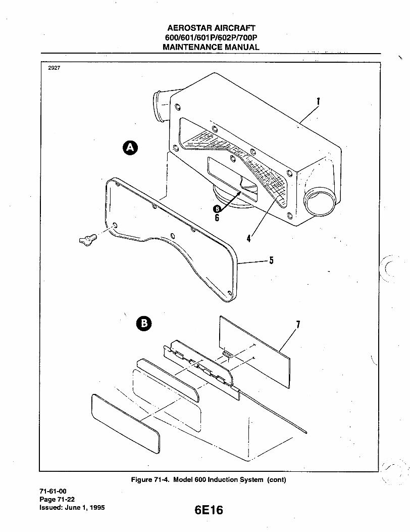
AEROSTAR AIRCRAFT 600/601/601P/602P/700P
MAINTENANCE MANUAL
2927
Figure 71-4. iVIodei 600 induction System (cont)
71-61-00 Page 71-22 issued: June 1,1995 6E16

AEROSTAR AIRCRAFT 600/601/601P/602P/700P MAINTENANCE MANUAL
TURBOCHARGER
SIMPLIFIED AIRFLOW DIAGRAM
MOTE
IF KIT 764 927v HAS BEEN INSTALLED, THE DISCHARGE AIRBOXES (AFT PORTION OF THE PLENUM ASSEMBLIES) WILL NOT BE USED AND THE FLEXIBLE AIR DUCTS FROM THE SIDES Of THE AIR BOXES |2| WILL BE CQNNEriED DlREf:TLY TO THE TURBO (.HAHCiEH OUTLETS
TOP VIEW LOOKING FORWARD WITH TOP COWLING REMOVED
1. PLENUM ASSEMBLY 2 AIR BOX 3 ALTERNATE AIR DOOR (SEE FIGURE
7 1 - 5 FOR DOOR AND FILTER 4 . RT. AND LT FLEX AIR DUCT
TURBOCHARGER DISCHARGE TURBOCHARGER INLET FUEL INJECTOR INLET TUBE ("J" DUCT) PRESSURE RELIEF VALVE (A.'F NO. 0 0 0 1 THRU 0 3 4 1 )
9. AIR SCOOP 1 0 . BLEED PORT 11 CL^MP 1 2 . BELLOWS 1 3 COWLING 1 4 HOSE 1 5 . FUEL PRESSURE GAUGE AND FUEL PUMP
HOSE CONNECTION RIGHT HAND ENGINE SHOWN
Figure 71-5. Modei 601 induction System
6E17
71-61-00 Page 71-23
Issued: June 1,1995
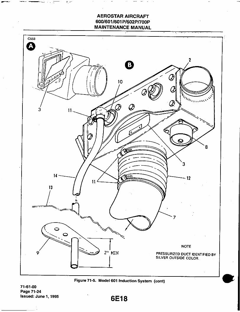
AEROSTAR AIRCRAFT 600/601/601P/602P/700P
MAINTENANCE MANUAL
C 5 5 8
71-61-00 Page 71-24 Issued: June 1,1995

AEROSTAR AIRCRAFT 600/60^/601 P/602P/700P MAINTENANCE MANUAL
2 9 2 9 C 5 5 7
S I D E V I E W L O O K I N G F O R W A R D
S I M P L I F I E D A I R F L O W D I A G R A M
N O T E
IF K I T 762 9 2 7 v H A S B E E N I N -S T A L L E D , T H E D I S C H A R G E A I R B O X E S ( A F T P O R T I O N O F T H E P L E -N U M A S S E M B L I E S ) W I L L N O T B E U S E D A N D T H E F L E X I B L E A I R D U C T S F R O M T H E S I D E S O F T H E A I R B O X E S (2) W I L L B E C O N N E C T E D D I R E C T L Y T O T H E T U R B O C H A R G E R O U T L E T S .
T O P V I E W L O O K I N G F O R W A R D - W I T H C O W L I N G R E M O V E D
1. P L E N U M A S S E M B L Y 2 . A I R B O X 3 . A L T E R N A T E A I R D U C T 4 . R T . A N D L T . F L E X A I R D U C T 5 . T U R B O C H A R G E R D I S C H A R G E 6 T U R B O C H A R G E R I N L E T 7 . B E L L O W S 8 . F U E L I N J E C T O R I N L E T T U B E
( - J - D U C T )
9 . A I R F I L T E R 1 0 . F R A M E 1 1 . G A S K E T 1 2 . C O V E R : 1 3 . A L T E R N A T E A I R D O O R i 14 . F U E L P R E S S U R E G A U G E A N D F U E L
P U M P S E N S E H O S E C O N N E C T I O N
• ' - r—y _ c - T ^ -
R I G H T H A N D E N G I N E S H O W N
Figure 71-6. iViodei 601P induction System
6E19 71-61-00
Page 71-25 Issued: June 1,1995

AEROSTAR AIRCRAFT 600/601/601P/602P/700P
MAINTENANCE MANUAL
C 5 6 0
Figure 71-6. IViodeiOOIP induction System (cont.) 71-61-00 Page 71-26 issued: June 1,1995 6E20

AEROSTAR AIRCRAFT 600/601/601P/602P/700P MAINTENANCE MANUAL
3 0 5 1
STANDARD OPERATION ALTERNATE AIR FLOW AIR INDUCTION
RIGHT ENGINE • LOOKING FORWARD TOP VIEW - LOOKING FORWARD
1 PLENUM ASSEMBLY 2 AIR BOX 3 ALTERNATE AIR DOOR (SEE NOTE 2) 4 FLEX AIR DUCT 5 TURBO DISCHARGE 6 TURBO INLET 7 AIR FILTER BOX 8 FUEL INJECTOR INLET TUBE 9 AIR FILTER
10 ICE SCREENS 1 1 FRAME 12 GASKET
NOTES
1. REFER TO CHAPTER 1 2 FOR INDUCTION 2 |F KIT 764 926v HAS BEEN INSTALLED A AIR FILTER SERVICING PROCEDURES. TRAP DOOR" TYPE OF ALTERNATE AIR
DOOR IS USED INSTEAD OF THE 13 COVER SLIDING ALTERNATE AIR DOOR AS 14 CABLE SHOWN. 15 PRESSURE RELIEF VALVE 16 SONIC NOZZLE 17 FUEL PRESSURE GAUGE AND
FUEL PUMP SENSE LINE CONNECTION 18 OVERBOARD BLEED 19 FUEL NOZZLE (REFERENCE) 20 AIR SCOOP 21 COWLING 22 TURBOCHARGER 23 FUEL SERVO
Figure 71-7. Mode\ 602P induction System
6E21 71-61-00
Page 71-27 issued: June 1,1995
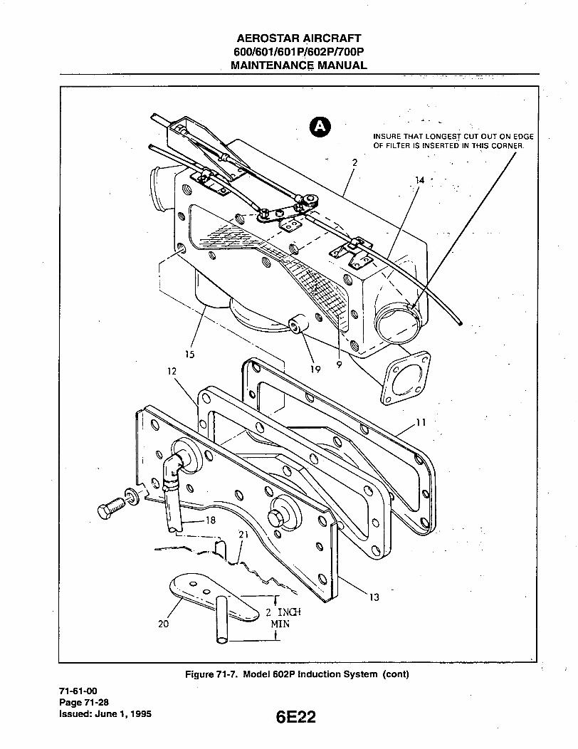
AEROSTAR AIRCRAFT 600/601/601P/602P/700P
MAINTENANCE MANUAL
Figure 71-7. Modei 602P induction System (cont)
71-61-00 Page 71-28 issued: June 1,1995

AEROSTAR AIRCRAFT 600/601/601P/602P/700P
MAINTENANCE MANUAL
ra; scmiEN TURBOCHARGER
<2 Avcol /AVCOI f AVCO)
• LYC 1/ LYC ] / LYC J Lp>—] EXHAUST
nm, SFRvo-STA\DARD OPKR,Vria\
ICE SCREEN
TURBOa(ARCJ;R
J LX1L\UST
FUEL SERVO
ALTERNATE AIR FLOh'
AIR IMWCTIOX
S I D E V I E W
L O O K I N G F O R W A R D
TO TO ALTERNATE CONTROLLER
VALVE
T O P V I E W
L O O K I N G F O R W A R D
1
1. PLENUM ASSEMBLY 2. INTERCOOLER 3 TURBOCHARGER INLET DUCT 4. FUEL INJECTOR INLET DUCT 5 TURBOCHARGER OUTLET DUCT 6 TURBOCHARGER 7 AIR INLET FILTER 8 ABSOLUTE PRESSURE RELIEF VALVE 9 NOZZLE
Figure 71-8. iVIodei 700P Induction System
6E23
71-61-00 Page 71-29
issued: June 1,1995

AEROSTAR AIRCRAFT 600/601/601P/602P/700P MAINTENANCE MANUAL
The model 601P (Figure 71-6) is similiar to the 601, except it does not incorporate the bleed port or the ice screens.
On the 602P and 700P, the induction system eliminates the rear airboxes of the plenum assemblies, directing air from the turbocharger directly to the filter airbox (Figures 71-7 and 71-8). If the pilot elects to manually open the alternate air doors, intake air will be obtained from above the plenum assembly (for 602P) or from a sheltered location behind the intercooler (for 700P). This alternate air will go from the plenum assembly to the turbocharger and then on to the air filter box (602P) or the intercooler (700P). The bleed air switch must be off when the alternate air doors are open. An ice screen is mounted ahead of normal air intake with space left around the side for air entry if the screen becomes clogged with ice.
PRESSURE DIFFERENTIAL CHECK (601, 601P).
1. Tools and materials required: A. Shop vacuum cleaner. B. Air pressure gauge, 0-10 psi. C. Adapter fitting, shop vacuum to airbox inlet connection.
2. Preliminary set-up (Figure 71-9). A. Disconnect the air duct at the fuel injector servo inlet. B. Block opening of air duct to an airtight condition. C. Disconnect air duct at left side of airbox and attach the adapter. D. With hose and pressure gauge connected to pressure side of vacuum cleaner, turn on machine while
blocking air escape at end of hose. E. Note reading at pressure gauge. This reading is the static pressure the machine is capable of pro-
ducing and will be in the 5 to 8 psi range for the average shop vacuum. 3. Test procedure.
A. Connect end of vacuum cleaner hose to the adpater at the airbox inlet. B. Turn on machine and note reading at pressure gauges. This reading will.be the difference between
the static pressure of the machine and the leak pressure of the induction system. 4. Test evaluation.
A. Since the alternate air doors and mode valves in the plenums will close under the reverse air pres-sure from the vacuum cleaner, a perfect leak-free induction system would give the same reading on the pressure gauge as the static pressure found in Step 2E.
B. A lower pressure would indicate the presence of leaks in the induction system. C. Close off air hose outlet from the bleed port (model 601) and note rise in pressure. D. A pressure differential of more than 2.3 psi would be excessive, indicating the existance of a leak
which must be found and corrected. E. Restore the left side of the airbox to its normal configuration and disconnect air duct at right side of
airtDox inlet. F. Connect vacuum cleaner hose to the right side of airbox and repeat Steps 3A and B for the right side
of airbox. G. Remove vacuum cleaner hose and adapter, reconnect the air duct to right side of airbox and restore
air inlet duct at sen/o intake to its original configuration.
FLEXIBLE DUCT.
REMOVAL OF FLEXIBLE DUCT.
1. Removal of duct consists of releasing the clamps securing duct to the various air inlets or outlets, and removing duct.
71-63-01 Page 71-30 Issued: June 1,1995 6E24

AEROSTAR AIRCRAFT 600/601/601P/602P/700P MAINTENANCE MANUAL
LEFT
PLENUM 0
AIR BLEED,
(601)
SHOP
VACCUUM
POS PRESSURE
0-10 PSI
AIR
BOX
ii BLOCK DUCT
TO FUEL SERVO
INIET
RIGHT
PLENUM
- Figure 71-9. Air Pressure Differentiai Test Setup
iNSTALLATiON OF FLEXiBLE DUCT.
1. Installation of duct consists of sliding end of duct over air inlet and discharge assemblies and tightening . clamps.
2. A light coating of "Sylglide" or similar lubricant assists installation of duct on mounting assembly.
INSPECTION OF INDUCTION SYSTEM.
1. Check flexible duct for cracks, tears or deterioration. 2. Check hinged altemate air doors for proper movement. 3. Check airbox for cracks, damage, obstructions and security of mounting. (Refer to Chapter 81 for tur-
bochager maintenance procedures.)
REPLACEMENT OF MODE DOOR SEALS - (601, 601P).
-NOTE-
Repair Kit 764 408V will redo all four plenum assemblies. Re-seal all four simultaneously due to tfie sfiort pot life of Epibond 1210 adhesive.
1. Remove the plenum assembly from the engine. 2. Cover the turbocharger inlet and outlet ducts to prevent entry of foreign matter. 3. Separate the inlet and discharge assemblies. 4. Remove the trap assembly from the discharge assembly.
71-65-00 Page 71-31
ep-l Issued: June 1,1995
AEROSTAR AIRCRAFT 600/601/601P/602P/700P MAINTENANCE MANUAL
5. Remove the mode/door hinge assembly from the trap assembly. 6. Remove old gasket. 7. Clean surface of trap assembly with alcohol or MEK. Resurface with 320 grit emery cloth on a surface
plate. 8. Bond a new gasket to the trap assembly with Epibond 1210 (P/N 763-392V). Allow four hours set time
before reassembly. 9 Reassemble plenum assembly. Seal seams and screws with RTV106 (P/N 762-500V) (red high temp sili-
cone). Allow eight hours cure time before pressure check or engine run-up. 10. Pressure check induction system per pressure differential check.
ENGINE DRAINS.
1. The engine is drained of oil by removal of oil drain plugs located on the induction sump. 2. A fuel drain plug is also provided in the sump cover. 3. The lower engine cowling must be removed for access to the oil and fuel drain plugs.
-END-
71-70-00 Page 71-32 Issued: June 1,1995 6F2
AEROSTAR AIRCRAFT 600/601/601P/602P/700P MAINTENANCE MANUAL
CHAPTER
ENGINE FUEL SYSTEM
6F3

AEROSTAR AIRCRAFT 600/601/601P/602P/700P MAINTENANCE MANUAL
CHAPTER 73 - ENGINE FUEL SYSTEM
TABLE OF CONTENTS/EFFECTIVITY
CHAPTER SECTION GRID SUBJECT SUBJECT NO. EFFECTIVITY
73-00-00 GENERAL 6F5 73-01-00 Description 6F5 73-02-00 Troublestiooting 6F5 73-03-00 Precautions 6F12
73-10-00 DISTRIBUTION 6F12 73-11-00 Fuel Injector 6F12 73-11-01 Fuel Injector Maintenance 6F12 73-11-02 Removal of Fuel Injector 6F16 73-11-03 Inspection and Overiiaul 6F16 73-11 -04 Installation of Fuel Injector 6F16 73-12-00 Flow Divider 6F16 73-12-01 Removal of Flow Divider 6F17 73-12-02 Inspection and Overhaul of Flow Divider 6F17 73-12-03 Installation of Flow Divider 6F17 73-13-00 Fuel Air Bleed Nozzles 6F17 73-13-01 Removal of Fuel Air Bleed Nozzles 6F17 73-13-02 Cleaning and Inspection of Fuel Air Bleed Nozzle 6F18 73-13-03 Fuel Flow Test Procedure 6F18 73-13-04 Installation of Fuel Air Bleed Nozzle 6F19 73-14-00 Adjustment of Idle Speed and Mixture 6F19 73-15-00 Fuel Pump 6F20 73-15-01 Description 6F20 73-16-00 Adjusting Fuel Pressure 6F20
73-20-00 CONTROLLING 6F20 73-21-00 Description 6F20 73-22-00 Rigging Controls 6F21
73-30-00 INDICATING 6F21 73-31-00 Description 6F21 73-32-00 Fuel Pressure Gauge Float Valve
(Model 601/601P Only) 6F21 73-33-00 Removal of Panel Mounted Gauges 6F21 73-34-00 Removal of Fuel Flow Transducers (/VF 0267 & up) 6F21
6F4 73 - ContVEffec.
Page -1 Issued: June 1,1995
AEROSTAR AIRCRAFT 600/601/601P/602P/700P MAINTENANCE MANUAL
GENERAL.
The engine is equipped with a Bendix RSA 10-ED1 Fuel Injection System.
DESCRIPTION.
The engine-driven fuel pump supplies fuel under pressure to the fuel injection sen/o, which meters the correct proportion of fuel to the flow divider. The flow divider then directs the fuel to each of the individual cylinder injection nozzles.
The Bendix RSA 10-ED1 fuel injection system is based on the principle of measuring air flow and using the air flow signal in a stem-type regulator to convert the air-force into a fuel-force. This fuel-force (fuel pressure differential) when applied across the fuel metering section (jetting system) makes fuel flow proportional to air flow. Fuel vaporization takes place at the intake ports.
A fuel vent system provides a common reference vent pressure to the fuel flow gauge (A/F 0001-0266), fuel pressure gauge, engine-driven fuel pump and injection nozzles. The vent source is taken down-stream of the turbochargers (models 601, 601P, 602P and 700P) to ensure proper vent pressure during normal aspiration or turbocharger operation.
TROUBLESHOOTING.
Refer to Troubleshooting Chart 7301.
6F5
73-02-00 Page 73-01
Issued: June 1,1995
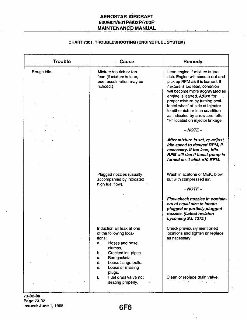
AEROSTAR AIRCRAFT 600/601/601P/602P/700P MAINTENANCfE MANUAL
CHART 7301. TROUBLESHOOTING (ENGINE FUEL SYSTEM)
Trouble Cause Remedy
Rough idle. Mixture too rich or too Lean engine if mixture is too lean (if mixture is lean, rich. Engine will smooth out and poor acceleration may be pick up RPM as it is leaned. If noticed.) mixture is too lean, condition
will become more aggravated as engine is leaned. Adjust for proper mixture by turning scal-loped wheel at side of injector to either rich or lean condition as indicated by arrow and letter "R" located on injector linkage.
-NOTE-
After mixture is set, re-adjust idle speed to desired RPM, if necessary. If too lean. Idle RPM win rise if boost pump is turned on. 1 click =10 RPM.
Plugged nozzles (usually Wash in acetone or MEK, blow accompanied by indicated out with compressed air. high fuel flow).
-NOTE-
Flow-check nozzles in contain-ers of equal size to locate plugged or partially plugged nozzles. (Latest revision Lycoming S.L 1275.)
Induction air leak at one Check previously mentioned of the following loca- locations and tighten or replace tions: as necessary. a. Hoses and hose
clamps. b. Cracked int. pipes. c. Bad gaskets. d. Loose flange bolts. e. Loose or missing
plugs. f. Fuel drain valve not Clean or replace drain valve.
seating properly.
73-02-00 Page 73-02 issued: June 1,1995

AEROSTAR AIRCRAFT 600/601/601P/602P/700P MAINTENANCE MANUAL
CHART 7301. TROUBLESHOOTING (ENGINE FUEL SYSTEM) (cont)
Trouble Cause Remedy
Rough idle, (cont) " Cracked engine mounts or defective mount bushings.
Replace same.
Mount bushings improperly installed.
Install as per manufacturer's instructions.
Internal injector leak (usually unable to adjust injector at idle) or won't hold adjustment.
Replace injector. Check by dis-connecting induction system at injector inlet to observe impact tubes, then put throttle in full forward position and mixture in full rich position, cap fuel line to flow divider, turn on boost pump, and if fuel is observed coming out of impact tubes, then injector has intemal leak and must be replaced.
Fuel vaporizing in lines and distributor (encoun-tered only at high ambient temperatures and prolonged operation at low or idle RPM).
Keep ground operation to a min-imum (if necessary, operate with boost pump on).
Nozzle screen and shroud deformed to extent it blocks or partially blocks airbleed hole.
Replace nozzle. Remove nozzles from cylinder so that they may be adequately inspected.
Sticking valve in fuel flow divider.
Disassemble and clean. Remove divider from engine. Disas-semble and flush out dirt. Also divider valve may be hand lap-ped in seat to remove any burrs that may be present.
-NOTE-
Never interchange fuel flow divider parts and do not dam-age diaphragm.
6F7 73-02-00
Page 73-03 Issued: June 1,1995

AEROSTAR AIRCRAFT 600/601/601P/602P/700P MAINTENANCE MANUAL
V ' CHART 7301. TROUBLESHOOTING (ENGINE FUEL SYSTEM) (cont)
Trouble Cause Remedy
Rough idle, (cont) Uneven cylinder com-pression.
Differential check cylinders to determine if further disassembly and repairs are necessary. Step-by-step procedures and equip-ment requirements will be found in S.I. 1191 (Lycoming).
Improper fuel pressure. Adjust as necessary (on all air-planes to A/F 0323 and on 601, 60IP A/F 0324 and sub-sequent and.all 602P's and 700P's). . ^
Faulty ignition system. Check mag drop and condition of plugs and leads. Set engine to produce 50-65% power with prop at min. angle. Check mag-netos for excessive dropoff.
Fuel pressure too low. Adjust to at least minimum pressure.
-NOTE-
If unable to adjust pressure, replace pump.
Engine will not idle unless boost pump on.
Idle mixture extremely lean.
Enrich idle mixture at injector.
Engine fuel pump failed, or pressure too low at idle speed.
Replace fuel pump, or adjust pressure as necessary.
Fuel pump by-passing fuel internally.
Replace fuel pump.
If engine has diaphragm type fuel pump, consider either a loose fuel injector fitting or a missing or defective O-ring.
Tighten fitting or replace O-ring as required. If O-ring seat is damaged, pump may have to be replaced.
73-02-00 Page 73-04 Issued: June 1,1995
6F8

AEROSTAR AIRCRAFT 600/601/601P/602P/700P MAINTENANCE MANUAL
CHART 7301. TROUBLESHOOTING (ENGINE FUEL SYSTEM) (cont)
- Trouble Cause Remedy
Engirie will not idle unless -boost pump on (cont) .
-TVOTE-
Check O-ring seat machined in fuel pump to be sure seat is smooth.
Fuel vaporizing in fuel lines.
Keep engine nacelle as cool as possible.
Engine will not idle unless boost pump is off.
Idle mixture extremely rich.
Lean idle mixture at injector.
r Engine pump fuel pressure set too high.
Adjust fuel pressure at pump if adjustable. Replace fuel pump if diaphragm type.
Booster pump pressure set too high.
Adjust pressure or replace pump.
Poor idle cut-off. Improper rigging of mix-ture control linkage.
Adjust same.
. . . . Mixture control valve scored or not seating properly, or O-ring on mixture jetbroken or deformed.
Disassemble and remove scratches and burrs. Replace O-ring, if necessary.
Vapor in lines. Avoid prolonged ground opera-tion at low RPM and idle. Keep nacelle as cool as possible.
-NOTE-
Use boost pump, if necessary.
Dirt in airbleed hole of nozzle.
Remove and clean.
Fuel jets in nozzle improperly located.
Replace nozzle.
73-02-00 Page 73-05
Issued: June 1,1995

AEROSTAR AIRCRAFT 600/601/601P/602P/700P MAINTENANCE MANUAL
CHART 7301. TROUBLESHOOTING (ENGINE FUEL SYSTEM) (cont)
Trouble Cause Remedy
Poor idle cut-off (cont) Valve in flow divider sticking.
Remove flow dividerfrom en-gine and disassemble. Flusfi out any dirt tfiat may be present. Flow divider valve may be fiand lapped in seat to remove any burrs. Clean tfiorougtily and reassemble.
-NOTE-
Never interchange flow divider parts.
Loose fuel line at flow divider or nozzle.
-NOTE-
Engine may be rich at idle.
Check main fuel line at flow di-vider and fuel injector. Also all fuel lines at divider and nozzles. Make sure nozzles are tight in cylinders and not cross-threaded.
Higfi fuel flow. Plugged nozzles. Clean or replace same. Inspect with magnifying lens first.
Air leak or restriction in deck pressure gauge (airframe).
Locate and repair. Pressure check to 9 lbs. and observe gauge for drop in pressure.
Injector ricfi. Replace same. Check mags for excessive drop in RPM. Re-calibrate and/or overhaul in-jector at an approved facility.
Faulty fuel flow gauge. Replace same. Prove by in-stalling master gauge and run-ning engine to compare gauges.
Faulty fuel flow trans-ducer.
Swap left with right to prove out and replace faulty trans-ducer.
I.D. of fuel lines too small.
Replace lines. Lines must be be-tween .085 - .090 in. I.D. Check with gauge and be sure not to mark inside of fuel lines.
73-02-00 Page 73-06 Issued: June 1,1995 6F10

AEROSTAR AIRCRAFT 600/601/601P/602P/700P MAINTENANCE MANUAL
CHART 7301. TROUBLESHOOTING (ENGINE FUEL SYSTEM) (cont)
Trouble Cause Remedy
High fuel flow (cont) - - Incorrect nozzle flow. Replace nozzles. Flow check nozzles in containers of equal size to locate problem nozzles. Flow rate of nozzles may be determined by following pro-cedures set forth in latest revision S.I. 1275 Lycoming.
Cracked or broken fuel injector nozzle line.
-NOTE-
Replace defective line. While pressurizing system with boost pump, give it a good visual in-spection for signs of fuel dye.
Separation may be at silver solder connection.
Deck pressure gauge line plugged (turbocharged).
Remove any obstruction.
Low fuel flow. Dirty fuel filter screen. (Refer to Chapter 28.)
Remove and clean in Acetone or MEK. Blow out with com-pressed air.
Rigging. Rerig and check lord engine mount sag.
Injector lean. Replace same or recalibrated or overhaul at approved facility.
Faulty gauge. Replace same. Prove by in-stalling master gauge and run-ning engine to compare gauges.
Flow divider does not open all the way (prob-lem may not occur at all times).
Disassemble, check for dirt, and drag on diaphragm stem. Also parts may be lapped to-gether to ensure free operation.
-NOTE-
Never interchange flow divider parts. They are manufactured as an assembly.
6F11 73-02-00
Page 73-07 Issued: June 1,1995

AEROSTAR AIRCRAFT 600/601/601P/602P/700P MAINTENANCE MANUAL
CHART 7301. TROUBLESHOOTING (ENGINE FUEL SYSTEM) (cont)
Trouble Cause Remedy
Low fuel flow, (cont) Fuel line to fuel flow gauge broken, loose, or plugged.
Low fuel pressure.
Repair or replace line. To detect broken or loose line, check for fuel dye stains. To check plugged line, disconnect at gauge and in-jector and blow out with com-pressed air.
Increase fuel pump pressure to limits in the section titled Adjusting Fuel Pressure and also check for leaks.
PRECAUTIONS.
Exercise caution to prevent engine oil or fuel from entering the air section of the injector when performing rou-tine maintenance such as washing down the engine,,servicing the air filter or when injecting preservatives into the engine prior to storing or shipping.
During sen/icing of any component in the fuel injection system, extreme care should be used to prevent the introduction of foreign material into the system.
DISTRIBUTION.
The fuel injector distribution system consists of a fuel injector, flow divider and air bleed nozzles (Figure 73-1).
FUEL INJECTOR.
FUEL INJECTOR MAINTENANCE.
1. In general, little attention is required between injector overhauls. However, it is recommended that the fol-lowing items be checked during periodic inspection of the engine:
A. Check tightness and lock of all nuts and screws which fasten the injector to the engine, torquing all nuts to 135-150 inch-pounds.
B. Seat the pal type locknuts and finger tighten them against the plain nuts. After this has been done tighten the locknuts an additional 1/3 to 1/2 turn.
C. Check all fuel lines for tightness and evidence of leakage. A slight fuel stain adjacent to the air bleed nozzles is not cause for concern.
D. Check throttle and mixture control rod ends and levers for tightness, lock, full and proper travel. E. Remove and clean the injector inlet strainer at the first 25 hours of operation and each 50 hour
inspection thereafter. Check the screen for distortion or openings in the strainer. Replace for either of these con-ditions. Clean screen assembly in solvent and dry with compressed air. Damaged strainer O-rings should be replaced. To install the screen assembly, place the gasket on the screen assembly and install the assembly in the throttle body and tighten to 35-40 inch-pounds torque.
73-11-01 Page 73-08 Issued: June 1,1995 6F12

AEROSTAR AIRCRAFT 600/601/601P/602P/700P MAINTENANCE MANUAL
C 5 1 0
A / F 0001-0266
13' 1. FUEL LN'LET 2. FUEL STRAINER 3. NETERING JET 4. 1-UEL FLOW INDICATOR 5. FLOW DIVIDER 6. FLOW DIVIDER DIAPHRAGM 7. 1/8" 0 . D. STAINLESS
STEEL LINE 8. NOZZLE (ONE PER CYL.) 9. FLOW DIVIDER VALVE
10. THROTTLE VALVE 11 . n-iRorrLE LEVER 12. IDLE SPEED .ADJUSTNENT 13. IDLE VALVE L E \ ^ R 14. IDLE MDCTURE ADJUST. 15. IMPACT TUBE 16. AIR INLET 22 17. VE.\TURI 18. FUEL DIAPHRAGM 21 19. BALL SERVO VALVE 20. AIR DIAPHRAGM 20 21. CONSTA^JT EFFORT SPRING 22. CO.\-STANr HEAD IDLE SPRING 23. MANUAL MIXTURE CONl'ROL
AND IDLE CUT OFF LEVER
Figure 73-1. Sctiematic Diagram of RSA Fuei injection System
6F13
73-11-01 Page 73-09
Issued: June 1,1995

AEROSTAR AIRCRAFT 600/601/601P/602P/700P MAINTENANCE MANUAL
FLOW DIVIDER
INDUCTION AIR INLET (FLEX DUCT)
FUEL INJECTOR
1. DIVIDER ASSEMBLY 2. SCRBV, 10-24 x 3/4 3. WASHER, FLAT 4. COVER ASSEMBLY
5. SPRING, HELICAL 6. SCREW, 8-32 x 3/8 7. WASHER, FLAT 8. WASIER, DIAPHRAM 9. DIAPI-IRAM 10. WASHER, DIAPHRAM 11. SCREW, 6-32 X 3/8 12. COVER 13. GASKET 14. BODY ASSBffiLY
15. VALVE 16. BODY
Figure 73-2. Fuei injector RSA 10-ED1 instaiiation, Fuei Fiow Divider and Air Bieed Nozzie Asembiy 73-11-01 Page 73-10 issued: June 1,1995 6F1 4

AEROSTAR AIRCRAFT 600/601/601P/602P/700P MAINTENANCE MANUAL
C508
(TYPICAL 6 PLACES)
AIR BLEED.NOZZLE ASSEMBLY
1. HOLDER, SPRING 2. SPRING, HELICAL 3. PACKING 4. TUBE ASSY. 5. BODY ASSY. 6. SHIELD NOZZLE 7. SCREEN NOZZLE 8. .NOZZLE
NORMALLY ASPIRATED ENGIN'E
TURBOaiARGED ENGINT
Figure 73-2. Fuel injector RSA 10-ED1 instaiiation, Fuel Flow Divider and Air Bleed Nozzle Asembiy (cont.) 0 73-11-01
Page 73-11 gp-|g Issued: June 1,1995

AEROStAR AIRCRAFT 600/601/601P/602P/700P MAINTENANCE MANUAL
REMOVAL OF FUEL INJECTOR. (Refer to Figure 73-2.)
1. Set fuel selector switcfi to OFF. 2. Set tfirottle and mixture controls to full ricfi to deplete fuel pressure. 3. Remove upper and lower engine cowling. 4. Disconnect fuel supply line at fuel injector. Cap line to prevent contamination or entrance of foreign mate-
rial. 5. Disconnect fuel outlet line to flow divider. 6. Disconnect throttle and mixture cables at fuel injector. 7. Remove flexible air duct at air intake on fuel injector. 8. Remove fuel injector attach hardware (four places) and remove fuel injector.
INSPECTION AND OVERHAUL.
Refer to the latest revision of Bendix Model RSA 10-ED1 Fuel Injector overhaul manual (Form 15-458B) for disassembly and overhaul instructions.
INSTALLATION OF FUEL INJECTOR. (Referto Figure 73-2.)
1. Install fuel injector to engine using new gasket Use two thick washers at the slots in the injector on the 700P. Torque nuts (bolts on the 700P) to 135-150 inch-pounds.
2. Install flexible air duct to injector air intake. 3. Connect throttle and mixture controls. Ensure conect travel and stop for each control. 4. Connect fuel outlet line from flow divider. 5. Connect fuel supply line from fuel pump. 6. Set fuel selector switch to ON and fuel boost switch to ON. 7. Set throttle and mixture to full rich. 8. Check for fuel leaks at injector fuel line connections. 9. If no leaks, turn fuel boost and fuel selector switches to OFF. 10. Check idle and mixture adjustments if injector was replaced or reworked. 11. Replace engine cowling.
FLOW DIVIDER. (Refer to Figure 73-2.)
The flow divider is mounted on the upper engine surface and serves to channel fuel to each nozzle. Metered fuel is delivered from the fuel injector to the flow divider. The fuel is kept under pressure by the flow
divider to assure positive shutoff of fuel to the nozzles when the injector is placed in idle cutoff. Metered fuel enters the flow divider assembly through a fuel line from the injector assembly and flows through
the inside diameter of the flow divider valve and through a passage to the lower side of the diaphragm. At idle the fuel pressure from the injector must, through force against the diaphragm, overcome the flow divider spring to open the valve and pass fuel to the nozzles through ports drilled in the hollow valve. The fuel is divided equally by ports machined in the valve bushing. Since the injector meters and delivers a fixed amount of fuel to the flow divider, the valve will open only as far as required to pass this amount of fuel to the nozzles. At idle the valve opening required is very small and discharge nozzle pressure negligible, thus the fuel to individual cylinders is divided at this point by the flow divider. As fuel flow through the injector is increased above idle requirements, fuel pressure builds up in the nozzle lines, fully opens the flow divider valve, and fuel distribution to the cylinders becomes a function of the pressure drop across the discharge nozzles.
73-12-00 Page 73-12 Issued: June 1,1995 6F16
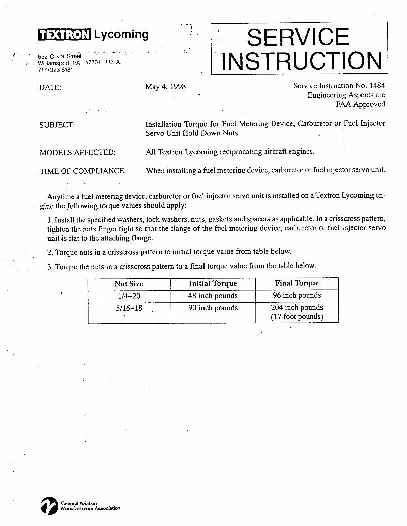
T E X T R O N Lycoming / ' 652 Oliver Street • -
/ Williamsport. PA 17701 U.S.A. 717/323-6181
DATE:
SUBJECT:
SERVICE INSTRUCTION
May 4, 1998 Service Instruction No. 1484
Engineering Aspects are
FAA Approved
Installation Torque for Fuel Metering Device, Carburetor or Fuel Injector
Servo Unit Hold Down Nuts
MODELS AFFECTED: All Textron Lycoming reciprocating aircraft engines.
TIME OF COMPLIANCE: When installing a fuel metering device, carburetor or fuel injector servo unit.
Anytime a fuel metering device, carburetor or fuel injector servo unit is installed on a Textron Lycoming en
gine the following torque values should apply:
1. Install the specified washers, lock washers, nuts, gaskets and spacers as applicable. In a crisscross pattem,
tighten the nuts finger tight so that the flange of the fuel metering device, carburetor or fuel injector servo
unit is flat to the attaching flange.
2. Torque nuts in a crisscross pattern to initial torque value from table below.
3. Torque the nuts in a crisscross pattem to a final torque value from the table below.
Nut Size Initial Torque Final Torque
1/4-20 48 inch pounds 96 inch pounds
5/16-18 .. 90 inch pounds 204 inch pounds (17 foot pounds)
General Aviation Manufacturers Association
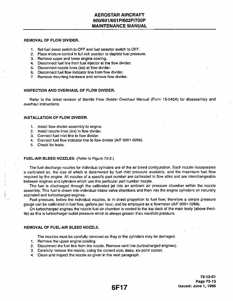
AEROSTAR AIRCRAFT 600/601/601P/602P/700P MAINTENANCE MANUAL
REMOVAL OF FLOW DIVIDER.
1. Set fuel boost switch to OFF and fuel selector switch to OFF. 2. Place mixture control in full rich position to deplete fuel pressure. 3. Remove upper and lower engine cowling. 4. Disconnect fuel line from fuel injector at the flow divider. 5. Disconnect nozzle lines (six) at flow divider. 6. Disconnect fuel flow indicator line from flow divider. 7. Remove mounting hardware and remove flow divider.
INSPECTION AND OVERHAUL OF FLOW DIVIDER.
Refer to the latest revision of Bendix Flow Divider Overhaul N anual (Form 15-540A) for disassembly and overhaul instructions.
INSTALLATION OF FLOW DIVIDER.
1. Install flow divider assembly to engine. 2. Install nozzle lines (six) to flow divider. 3. Connect fuel inlet line to flow divider. 4. Connect fuel flow indicator line to flow divider (A/F 0001-0266). 5. Check for leaks.
FUEL-AIR BLEED NOZZLES. (Referto Figure 73-2.)
The fuel discharge nozzles for individual cylinders are of the air bleed configuration. Each nozzle incorporates a calibrated jet, the size of which is determined by fuel inlet pressure available, and the maximum fuel flow required by the engine. All nozzles of a specific part number are calibrated to flow alike and are interchangeable between engines and cylinders which use this particular part number nozzle.
The fuel is discharged through the calibrated jet into an ambient air pressure chamber within the nozzle assembly. This fuel is drawn into individual intake valve chambers and then into the engine cylinders on naturally aspirated and turbocharged engines.
Fuel pressure, before the individual nozzles, is in direct proportion to fuel flow; therefore a simple pressure gauge can be calibrated in fuel flow, gallons per hour, and be employed as a flowmeter {AJF 0001-0266).
On turbocharged engines the nozzle fuel air chamber is vented to the top deck of the main body (above throt-tle) as this is turbocharger outlet pressure which is always greater than manifold pressure.
REMOVAL OF FUEL-AIR BLEED NOZZLE.
The nozzles must be carefully removed as they or the cylinders may be damaged. 1. Remove the upper engine cowling. 2. Disconnect the fuel line from the nozzle. Remove vent line (turbocharged engines). 3. Carefully remove the nozzle, using the correct size; deep, six-point socket. 4. Clean and inspect the nozzle as given in the next paragraph.
6F17
73-13-01 Page 73-13
Issued: June 1,1995
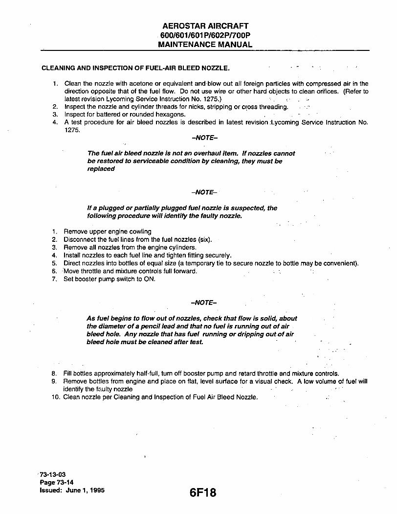
AEROSTAR AIRCRAFT 600/601/601P/602P/700P MAINTENANCE MANUAL
CLEANING AND INSPECTION OF FUEL-AIR BLEED NOZZLE. . .
1. Clean the nozzle with acetone or equivalent and blow out all foreign particles with compressed air in the direction opposite that of the fuel flow. Do not use wire or other hard objects to clean orifices. (Refer to latest revision Lycoming Service Instruction No. 1275.) ? . -
2. Inspect the nozzle and cylinder threads for nicks, stripping or cross threading. 3. Inspect for battered or rounded hexagons. 4. A test procedure for air bleed nozzles is described in latest revision Lycoming Service Instruction No.
1275. -NOTE-
The fuel air bleed nozzle is not an overhaul item. If nozzles cannot be restored to serviceable condition by cleaning, they must be replaced
-NOTE-
If a plugged or partially plugged fuel nozzle is suspected, the following procedure will identify the faulty nozzle.
1. Remove upper engine cowling 2. Disconnect the fuel lines from the fuel nozzles (six). 3. Remove all nozzles from the engine cylinders. 4. Install nozzles to each fuel line and tighten fitting securely. 5. Direct nozzles into bottles of equal size (a temporary tie to secure nozzle to bottle may be convenient). 6. Move throttle and mixture controls full fonvard. 7. Set booster pump switch to ON.
-NOTE-
AS fuel begins to flow out of nozzles, check that flow is solid, about the diameter of a pencil lead and that no fuel is running out of air bleed hole. Any nozzle that has fuel running or dripping out of air bleed hole must lie cleaned after test.
8. Fill bottles approximately half-full, turn off booster pump and retard throttle and mixture controls. 9. Remove bottles from engine and place on flat, level surface for a visual check. A low volume of fuel will
identify the faulty nozzle ' 10. Clean nozzle per Cleaning and Inspection of Fuel Air Bleed Nozzle.
i
73-13-03 Page 73-14 Issued: June 1,1995 6F18
AEROSTAR AIRCRAFT 600/601/601P/602P/700P MAINTENANCE MANUAL
INSTALLATION OF FUEL-AIR BLEED NOZZLES.
-NOTE-
Prior to attaching the nozzle, reference manifold flexible rubber-hoses to the fuel injection nozzles, inspect the interior and exterior of the hoses for indications of dryness, cracking or flaking, or rubber,
- particles inside the hoses. Replace as necessary prior to assembly.
1. Carefully install nozzle using correct size socket. Do not tighten at this time. 2. Check for location of number or letter stamped on one of the flats of the wrenching hex on the nozzle
body.
-CAUTION-
DO not exceed maximum nozzle torque value when aligning air
bleed hole of nozzle during installation.
ADJUSTMENT OF IDLE SPEED AND MIXTURE
1. Start engine per Flight Manual procedures. Warm up engines until oil and cylinder temperature are nor-mal.
2. Check magnetos for "mag-drop". (Refer to Chapter 71.) If normal, proceed with idle adjustment. If not normal, determine cause and correct before proceeding with idle adjustment.
3. Set throttle stop screw so that the engine idles at 750-850 rpm. If the rpm changes appreciably after making the mixture adjustment during the succeeding steps, readjust the throttle speed to the desired rpm.
4. When the idling speed has been stabilized, move the cockpit mixture control lever with a smooth steady pull toward the "Idle Cut-Off' position and observe the tachometer for any change during the leaning process. Caution must be exercised to return the mixture control to the "Full Rich" position before the rpm can drop to a point where the engine cuts out. An increase of more than 100 rpm while "leaning ouf indicates an excessively rich idle mixture. An immediate decrease in rpm (if not preceded by a momen-tary increase) indicates the idle mixture is too lean.
5. If the above indicates that the idle mixture is too rich or too lean, turn the idle mixture adjustment in the direction required for correction, and check this new position by repeating the above procedure. Make additional adjustments as necessary until a check results in a momentary pick-up of approximately 50 (never more than 100) rpm. Each time the adjustment is changed, the engine should be run up to 2000
. rpm to clear the engine before proceeding with the rpm check. Make final adjustments of the idle speed . adjustment to obtain the desired idling rpm with closed throttle. The above method aims at a setting that
will obtain maximum rpm with minimum manifold pressure. In case the setting does not remain stable, check the idle linkage; any looseness in this linkage would cause erratic idling. In all cases, allowance should be made for the effect of weather conditions and field altitude upon idling adjustment.
73-14-00 Page 73-15
gp-|g Issued: June 1,1995

AEROSTAR AIRCRAFT 600/601/601P/602P/700P MAINTENANCE MANUAL
FUEL PUMP.
The engine is equipped with one of two types of fuel pumps.
DESCRIPTION.
A non-adjustable AC diaphragm pump is used on the model 600, A/F 0324 and up. /VP 0001-0323 and all 601, 601P, 602P, and 700P models use an adjustable pump. This is a positive displacement, rotary vane pump which is connected to the drive train by a splined shaft. The fuel pump is mounted under the left magneto on the accessory case.
Neither of these pumps is normally sen/iced in the field, but is replaced as a unit. Refer to Chapter 28 for removal and installation procedure.
ADJUSTING FUEL PRESSURE.
1. Remove engine lower cowling.
- CAUTION-
Do not operate an engine with upper and lower cowlings both' ' removed. When operating engine with one cowiing removed, make sure the other cowling is secure with all fasteners engaged. Do not run engine more than 4 minutes with upper cowling removed.
2. Run engine at 2100 rpm and record fuel pressure. 3. Remove safety wire from adjusting screw at rear of pump body and turn screw in to increase pressure or
out to decrease pressure. - • . A. For model 600 (/V/F 0001-0323), all 601's and all 601 P's set pressure at 27 psi at 2100 rpm. B. For model 602P set pressure at 35 psi at 2100 rpm. C. For model 700P set pressure at 44 psi at 2100 rpm.
4. Re-safety adjusting screw and install cowling. 5. Boost pump pressure should be checked at this time. (See Chapter 28 for pressures.)
CONTROLLING.
The engine control levers are mounted on the fonward portion of the control pedestal at the center of the instrument panel.
DESCRIPTION.
The throttle control levers are mounted on the left side of the pedestal and are provided with smooth, round knobs. For maximum power the levers are positioned fully forward.
The mixture control levers are mounted on the right side of the pedestal and are provided with round knobs having angular radial red bumps. The fully aft position is idle cut-off and the fully fonward position is full-rich.
All engine controls are of the flexible wire type, encased in Teflon-lined plastic tubing. There is no adjustable friction device provided, and no lubrication is required.
73-21-00 Page 73-16 Issued: June 1,1995 6F20

AEROSTAR AIRCRAFT 600/601/601P/602P/700P MAINTENANCE MANUAL
RIGGING CONTROLS.
Refer to Chapter 76 for rigging and complete engine control procedures.
INDICATING.
Fuel pressure and fuel flow-gauges are provided to monitor these engine functions.
DESCRIPTION.
Fuel pressure is derived from the engine-driven fuel pump. A flexible pressure hose fitted to the fuel injector input side transfers the fuel pressure to the combination 3-way gauge which presents oil temperature and pressure in addition to fuel pressure. Normal fuel pressure is in the range of 18-40 psi, with a nominal pressure of 29 psi. On the 602P and 700P the fuel pressure portion of the three-way gauge has been replaced by a cylinder head temperature gauge. The fuel pressure is now read on a separate gauge.
Prior to A/F 0267, the fuel flow indicator was directly connected to the input side of the flow divider. Since the fuel pressure in the fuel-air bleed nozzle lines is proportional to fuel flow, a simple pressure gauge calibrated in gallons per hour could be used as a flow indicator. Any change to the system that would alter the pressure/flow ratio would naturally invalidate the flow meter readings.
A fully electronic type of flow meter is used on /VF 0267 and up. Flow transducers installed in the main fuel supply line to each engine transmit flow rate data to the dual panel mounted flow indicator. The calibration is in gallons per hour, with dual concentrically mounted indicator pointers. The circuit is protected by a 2-amp circuit breaker. Refer to Chapter 91 for electrical schematic.
FUEL PRESSURE GAUGE FLOAT VALVE (MODEL 601 AND 601P ONLY)
The fuel pressure guage must sense the induction air pressure supplied by the turbochargers. The sense line is connected to the "J" duct (duct between the air box and the fuel injector servo). The float valves are installed in the sense lines. This prevents fuel from entering the servo and producing a fuel rich mixture should the diaphragm in the 3-way gauge rupture or fuel leak past the diaphragm into the sense line. For A/F prior to 0266 the float valves are mounted on the back of the fuel flow gauge. For A/F 0267 to 0799 the float valves are mount-ed on the fonvard lower portion on the center console A/F No. 0800 and up do not require float valves.
REMOVAL OF PANEL MOUNTED GAUGES.
Refer to Chapter 39 for removal/installation procedures.
REMOVAL OF FUEL FLOW TRANSDUCERS, A/F 0267 & UP.
Refer to Chapter 28 for removal/installation procedures.
6F21
73-34-00 Page 73-17
Issued: June 1,1995

AEROSTAR AIRCRAFT 600/601/601P/602P/700P MAINTENANCE MANUAL
C 5 6 2
A / F N O . 0 0 3 T H R U 0 2 6 6
F U E L F L O W G A U G E
A / F N O . 0 2 6 7 T H R U 0 7 9 9
1 F L O A T V A L V E 2 V E N T
3 . T H R E E - W A Y E N G I N E G A U G E 4 . C O N S O L E S T R U C T U R E ( F . S . 7 6 . 0 0 ) 5 C O - P I L O T I N S T R U M E N T P A N E L
N O T E
M A I N T A I N V E R T I C A L
O F F L O A T V A L V E S .
O R I E N T A T I O N
73-34-00 Page 73-18 Issued: June 1,1995
Figure 73-3. Fuel Pressure Guage Float Vaive installation
6F22

AEROSTAR AIRCRAFT 600/601/601P/602P/700P MAINTENANCE MANUAL
C 5 6 1
C I 6 5
1. F U E L I N J E C T O R S E R V O
2 . " J " D U C T
3 . A I R B O X
4 . F U E L P R E S S U R E G A U G E
A N D F U E L P U M P S E N S E
L I N E C O N N E C T I O N
5 . F L O A T V A L V E S
6 . O - R I N G A / F N O . 0 2 6 7 T H R U 0 7 9 9
7 . A D A P T E R
Figure 73-3. Fuei Pressure Guage Fioat Vaive instailation (cont) 73-34-00
Page 73-19 epoo issued: June 1,1995

AEROSTARrAIRCRAFT 600/601/601P/602P/700P
MAINTENANCE MANUAL
THIS PACE INTENTIONALLY LEFT BLANK
6F24

AEROSTAR AIRCRAFT 600/601/601P/602P/700P MAINTENANCE MANUAL
THIS PAGE INTENTIONALLY LEFT BLANK
I
6G1

AEROSTAR AIRCRAFT 600/601/601P/602P/700P
MAINTENANCE MANUAL
THIS PAGE INTENTIONALLY LEFT BLANK
6G2

AEROSTAR AIRCRAFT 600/601/601P/602P/700P
MAINTENANCE MANUAL
CHAPTER
IGNITION
6G3

AEROSTAR AIRCRAFT 600/601/601P/602P/700P MAINTENANCE MANUAL
CHAPTER 74 - IGNITION
TABLE OF CONTENTS/EFFECTIVITY
CHAPTER SECTION GRID SUBJECT SUBJECT NO. EFFECTIVITY
74-00-00 GENERAL 6G5 74-01-00 Description 6G5 74-02-00 Troublestiooting 6G5
74-10-00 ELECTRICAL POWER SUPPLY 6G7 74-11-00 Magneto 6G7 74-11-01 Inspection of Magneto 6G7 74-11-02 Removal of Magneto 6G11 74-11-03 Timing Procedure (Internal Timing) 6G12 74-11-04 Installation and Timing Procedure (Timing
Magneto to Engine) 6G13 74-12-00 Starting Vibrator 6G16 74-12-01 Troublestiooting 6G16 74-12-02 Vibrator, Removal 6G20 74-12-03 Vibrator, Installation 6G20 74-12-04 Vibrator, Testing 6G20
74-20-00 DISTRIBUTION 6G21 74-21-00 Harness 6G21 74-21-01 Inspection of Harness 6G21 74-21-02 Cleaning of Harness 6G22 74-21-03 Replacements 6G22 74-21-04 Removal of Harness 6G22 74-21-05 Maintenance of Harness 6G24 74-21-06 Installation of Harness 6G24 74-22-00 Spark Plugs 6H2 74-22-01 Spark Plugs, Removal 6H2 74-22-02 Inspection and Cleaning of Spari< Plug 6H3 74-22-03 Spark Plugs, Installation 6H3 74-22-04 Spark Plug Identification 6H3
74-30-00 SWITCHING 6H4 74-31-00 Description 6H4 74-32-00 Removal/Installation of Ignition Switcfi 6H4
6G4
74 - ContTEffec. Page -1
Issued: June 1,1995

AEROSTAR AIRCRAFT 600/601/601P/602P/700P MAINTENANCE MANUAL
GENERAL.
The ignition consists of dual magnetos, high tension hamess, spark plugs and a magneto switch. Additionally a vibrator is used to provide an intensified spark for easier starting at low cranking rpm.
DESCRIPTION.
Each engine is provided with a combination magneto/starter switch. Moving the switch to the spring loaded "START' position grounds the right magneto, activates the starting vibrator, retards the left magneto, and engages the starting motor. When the engine starts, release of the switch allows it to spring back to the "BOTH" (magnetos) position, disengages the starting motor and removes the vibrator from the starting circuit. The right magneto is simultaneously ungrounded and both magnetos will be in full advance.
The induction type starting vibrators provide an interrupted D.C. current to the left magneto high tension coil through the ignition switch and the "Retard" set of points. When the engine is cranked to the retard timing position, the vibrator output is applied to the high tension coil to produce the spark to start the engine.
TROUBLESHOOTING.
Refer to Troubleshooting Chart 7401 for the most commonly encountered troubles and their remedy.
THIS SPACE INTENTIONALLY LEFT BLANK
74-02-00 Page 74-01
gQg Issued: June 1,1995

AEROSTAR AIRCRAFT 600/601/601P/602P/700P MAINTENANCE MANUAL
CHART 7401. TROUBLESHOOTING (MAGNETO)
Trouble Cause Remedy
Failure of engine to start.
Defective spark plugs. Clean and adjust or replace spark plugs.
Defective ignition wire. Check with electric tester and replace defective wires.
Defective battery. Replace with charged battery.
Improper operation of magneto breaker.
Check points. Check internal timing of magnetos.
Failure of engine to idle properly.
Faulty ignition system. Check entire ignition system.
Low power and uneven running.
Defective spark plugs. Clean and gap or replace spark plugs.
.V:
Magneto breaker points not working properly.
Clean points. Check internal timing of magnetos.
Defective ignition wire. Check wire with electric tester. Replace defective wire.
Defective spark plug terminals connectors.
Replace connectors on spark plug wire.
Failure of engine to develop full power.
Faulty ignition. Tighten all connections. Check system with tester. Check ignition timing.
74-02-00 Page 74-02 issued: June 1,1995 6G6

AEROSTAR AIRCRAFT 600/601/601P/602P/700P MAINTENANCE MANUAL
ELECTRICAL POWER SUPPLY.
MAGNETO. (See Chart 7402.)
- CAUTION-
Ascertain that the primary circuit of both magnetos is grounded t>efore working on the engine.
INSPECTION OF MAGNETO.
-NOTE-
Comply with the latest revision of Bendix Service Bulletin No. 608 at first opportunity, but no later than next magneto overhaul. Install self-locking cam retaining screw (10-391213) and torque 21-25 inch pounds. If self locking screw is removed at any time, always replace with new self locking screw and torque to the specified value.
1. After the first 25 hour and 50 hour periods, and periodically thereafter, the contact assemblies should be checked. Examine the points for excessive wear or burning. Points which have deep pits or excessively bumed areas should be discarded. Examine the cam follower felt for proper lubrication. If necessary, points can be cleaned by using any hard finished paper. Clean breaker compartment with dry cloth.
2. If engine operating troubles develop which appear to be caused by the ignition system, it is advisable to check the spark plugs and wiring first before working on the magnetos.
3. Should the trouble appear definitely associated with the magneto, the most effective measure is to install a replacement magneto which is known to be in satisfactory condition and send the suspected unit to the overhaul shop for test and repair.
4. Should this not be possible, a visual inspection may disclose the source of trouble. Remove the harness outlet plate from the magneto. Inspect for the presence of moisture and foreign matter on the rubber grommet and high tension outlet side of the distributor block. Check height of block contact springs (0.422 inch maximum from top of the block tower to the spring). Also check for broken leads or damaged insulation. If either is present, remove magneto and replace with one known to be in satisfactory condi-tion.
5. Remove the breaker cover and hamess securing screws and nuts, and separate cover from magneto housing. Check contact assemblies to see that cam follower is securely riveted to its spring. Examine the contact points for excessive wear or burning. Figure 74-1 shows how the average contact point will look when surfaces are separated for inspection. Desired contact surfaces have a dull gray, sand-blasted (almost rough) or frosted appearance, over the area where electrical contact is made. This means that the points are worn in and mated to each other, thereby providing the best possible electrical contact and highest efficiency of performance.
i
6G7
74-11-01 Page 74-03
issued: Jiine 1,1995

AEROSTAR AIRCRAFT 600/601/601P/602P/700P MAINTENANCE MANUAL
CHART 7402. GENERAL SPECIFICATIONS, MAGNETO
SUBJECT DATA
Lubrication
Cam Follower Felt Housing Pole Shoes, Magnet
Pole Pieces Gears Felt Washer
Distributor Block Bushing
Large Distributor Gear Shaft
Impulse Coupling Spring Stop Pins Rotating Magnet Shaft Cushion Drive Grommet
10-86527 Breaker.Felt Lubricant Rust Preventative or SAE 30 Oil
(Non-Detergent) Bendix Magneto Grease, 10-27165 Bendix Distributor Block Lubricant
10-391200 Bendix Distributor Block Lubricant
10-391200 Bendix Distributor Block Lubricant
10-391200 Light Oil Bendix Magneto Grease, 10-27165 GO-JO NO-LOK 72 Compound Engine Oil
Tolerances
Capacitor Contact Clearance
Main Retard "E" Gap Coil Primary Secondary
0.30 to 0.45 mfd
0.003-0.016 IN 0.006-0.016 IN 15° ± 2 ° Main Contact 1.0-1.5 ohms 17,000-23,000 ohms
Torques
Contact Support Screws Distributor Block Studs
Cam Screw or
Self Locking Cam Screw* Drive Shaft Nut Capacitor Screws Flange Screws Retard Lead Screw Cover Securing Screw
20 to 25 In.-Lbs. Start 4 to 8 In.-Lbs. Final 18 to 22 In.-Lbs. 16 to 20 In.-Lbs.
Contact Support Screws Distributor Block Studs
Cam Screw or
Self Locking Cam Screw* Drive Shaft Nut Capacitor Screws Flange Screws Retard Lead Screw Cover Securing Screw
21 to 25 In.-Lbs. 20 to 25 Ft.-Lbs. 8 to 12 In.-Lbs. 65 to 85 In.-Lbs. 24 to 26 In.-Lbs. 30 to 35 In.-Lbs.
*Must be replaced with new screw at each removal. -
74-11-01 Page 74-04 Issued: June 1,1995 6G8

AEROSTAR AIRCRAFT 600/601/601P/602P/700P MAINTENANCE MANUAL
CHART 7402. GENERAL SPECIFICATIONS, MAGNETO (cont)
SUBJECT DATA
Ventilator Plug Timing Window Plug
10 to 15 In.-Lbs. 10 to 15 In.-Lbs.
Miscellaneous
Internal Timing Marks Magneto Drive Speeds
See Instructions 6 cyl -1 Engine Speed '
Testing
Spark Gap Setting 7 mm
Vendors (Harness Lube and Sprays)
Silicone Spray S-512, IMS Company, 10373 Stafford Road Chagrin Fall, OH 44023
Flurocarbon Spray MS-SI 22 or 122N/C02 Miller-Stephenson Chemical Co., Inc. George Washington Hwy. Danburry, Conn. 06810
74-11-01 Page 74-05
gQg Issued: June 1,1995

AEROSTAR AIRCRAFT 600/601/601P/602P/700P MAINTENANCE MANUAL
6. Minor irregularities or roughness of point surfaces are not hannful. (Refer to Figure 74-1, center.) Neither are small pits or mounds, if not too pronounced. If there is a possibility of pit becoming deep enough to penetrate pad. Figure 74-1, right, reject contact assembly.
-NOTE-
NO attempt stiould be made to stone or dress contact points. Should,
contact assembly have bad points or show excessive wear, the
complete contact assembly should be replaced.
7. Check the condition of the cam follower felt. Squeeze felt tightly between thumb and forefinger. If fingers are not moistened with oil, re-oil using 2 or 3 drops of Scintilla 10-391200 lubricant. Allow approximately 30 minutes for the felt to absorb the oil. Blot off the excess with a clean cloth. Too much oil rriay foul con-tact points and cause excessive burning. .
8. Check the capacitor mounting bracket for cracks or looseness. Using the Scintilla 11-1767-1,-2, or -3 Condenser Tester or equivalent, check capacitor for capacitance, series resistance and leakage. Capacitance shall be least 0.30 microfarads.
9. Check magneto to engine timing as follows: A. Connect Scintilla 11 -851 Timing Light or equivalent across the contact assembly. B. Slowly bring the engine up to number one cylinder advance firing position. At this instant the timing
light should go out. If it does, the magneto is property timed to the engine. If the timing light does not go out, removal of the magneto for internal timing check and inspection is recommended.
-NOTE-
The magneto service Instructions in this manual are to cover minor repairs and timing. For further repairs and adjustments of the magneto, it is recommended that the manufacturer's recommended service instructions be followed.
10. For Aerostars with STC SA980-NW Machen, Inc. conversion refer to the latest revisions of Lycoming S/B 459 and Bendix S/B 618.
74-11-01 Page 74-06 Issued: June 1,1995 6G10
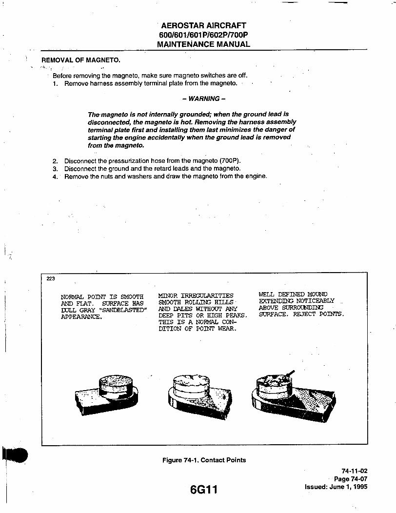
AEROSTAR AIRCRAFT 600/601/601P/602P/700P MAINTENANCE MANUAL
REMOVAL OF MAGNETO.
Before removing the magneto, mal<e sure magneto switches are off. 1. Remove harness assembiy terminal plate from the magneto.
The magneto is not internally grounded; when the ground lead is disconnected, the magneto is hot. Removing the harness assembly terminal plate first and installing them last minimizes the danger of starting the engine accidentally when the ground lead is removed from the magneto.
2. Disconnect the pressurization hose from the magneto (700P). 3. Disconnect the ground and the retard leads and the magneto. 4. Remove the nuts and washers and draw the magneto from the engine.
- WARNING-
2 2 3
NOFMftL POINT IS SMOOTH AND FLAT. SURFACE HAS DOLL GRAY "SANDBLASTED' APPEARANCE.
MINOR IRRBGDLARITIES SMOOTH ROLLING HILLS AND DALES WITHODT ANY DEEP PITS OR HIGH PEAKS
WELL DEFINED MOUND EXTENDING NOTICEABLY .. ABOVE SURROUNDING • SURFACE. REJECT POINTS.
THIS IS A NORMAL CON-DITION OF POINT WEAR.
Figure 74-1. Contact Points
6G11
74-11-02 Page 74-07
issued: June 1,1995

AEROSTAR AIRCRAFT 600/601/601P/602P/700P MAINTENANCE MANUAL
TIMING PROCEDURE (Internal Timing).
1. Remove the cover at the contact(s), distributor blocl<, etc. 2. To internally time the contact assembly of the magnetos, proceed as follows:
A. Loosen the nut securing the drive plate to the magneto shaft sufficiently in order to install the Scintilla 11-8465 Rotor Holding Tool under the nut and flat washer as shown in Figure 74-2. Tighten the nut securely.
B Remove the timing inspection plug from the top of the magneto. Turn rotating magnet to proper neu-tral position. This position is determined by locating keyways on drive end of magnet shaft at 12 o'clock with respect to nameplate on housing. Tighten adjusting knob of 11-8465 Rotor Holding Tool until pressure is applied on housing flange preventing magnet from turning.
C. Loosen and rotate cam until cam follower of contact assembly rests on highest point of cam lobe. Adjust contact assembly to obtain the clearance of 0.016 of an inch. Tighten contact assembly secur-ing screws to 20-25 inch-pounds.
D. Install the 11-8693 Timing Plate Assembly and the 11-8149 Pointer Assembly of the 11-8150 Scintilla Timing Kit to breaker compartment of magneto. (Refer to Figure 74-3.) Align pointer assembly with the 0 mark on timing plate. Loosen adjusting knob of 11-8465 Rotor Holding Tool and tum rotating magnet in normal direction of rotation until pointer indexes with the respective E gap mark (15° ± 2°). Tighten adjusting knob of 11-8465 Tool and remove the 11-8149 Pointer Assembly from magneto. Using a timing light, adjust contact points to just open. This adjustment shall be made by rotating cam, in opposite direction of rotation until contacts just open. While holding cam in this exact position^ push cam on magnet shaft as far as possible with the fingers. Extreme care must be exercised in this operation. If cam adjustment is changed in the slightest degree, the timing of the magneto will be thrown off. Do not drive cam on shaft with a mallet or other instrument. Tighten the securing screw thereby drawing the cam down, evenly and tightly. Torque screw to 16- 20 inch-pounds or 21-25 inch-pounds if self-locking cam screw is installed. Loosen the 11-8465 Rotor Holding Tool adjusting knob and retum rotating magnet to neutral position. Reinstall the 11-8149 Pointer Assembly over 0 mark on timing plate. Rotate magnet shaft in normal direction of rotation and check for opening of main contact points at E gap setting (15° ± 2°).
3. If the distributor block was not removed from the housing, the internal timing may be checked by turning the magneto in the normal rotation to number one firing position (keyway up and points just opening). At this position, the reference line on the distributor block should line up between the L and LB marks on the gear.
4. If the distributor block was removed from the housing, the distributor gear alignment and intemal check may be accomplished as follows: A. Turn rotating magnet in direction of rotation until it is located in firing position (keyway up and points
just opening). Tighten adjusting knob of 11 -8465 Rotor Holding Tool. Apply a light coating of Bendix Grease P/N 10-27165 to teeth of distributor gear, if needed. The large distributor gear incorporates four timing mari<s, L and LB for left-hand rotation and R and RB for right-hand rotation.
B. With distributor gear assembly to block, tum gear until raised rib on block lines up between the L and LB marks. Assemble block and gear into housing, meshing the distributor gears together. The rib should favor the L mark if possible. (Refer to Figure 74-4.)
74-11-03 Page 74-08 issued: June 1,1995 6G12

AEROSTAR AIRCRAFT 600/601/601P/602P/700P MAINTENANCE MANUAL
C. Secure distributor blocl< to tiousing witti studs and wastiers. Tigtiten studs finger tigfit. Loosen tfie 11-8465 Rotor Holding Tool and turn rotating magnet in reverse direction of rotation until timing ligfit indi-cates contact assembly had just opened and check to make certain timing marks align within toler-ance indicated above. Tighten block securing studs, first to 4-8 inch-pounds torque and final torque to 20 inch^ pounds.
5. Adjusting retard contact assembly. V ^
-NOTE-
On dual contact assembly magnetos, the retard contact assembly Is adjusted to open a predetermined number of degrees after the main contact assembly opens. The degree of retard for any particular magneto is stamped in the bottom of the breaker compartment.
A. At EXACT position of rotating magnet that main contact assembly opens, lock the 11-8465 Holding Tool. Install the Timing Kit (Figure 74-3) and move the pointer back to zero.
B. Unlock holding tool and advance rotating magnet until pointer of timing kit indexes with required degree of retard. Lock the holding tool in this position.
C. Using timing light, adjust retard contact assembly to just open. Tolerance of retard is +2, -0. D. Unlock holding tool. Tum rotating magnet until cam follower is on high point of cam lobe. Measure
point clearance; should be .016 ± .006 inch. If not within tolerance, reset point clearance. E. Recheck to be sure points open within retard degree tolerance. Replace contact assembly if toler-
ance cannot be obtained. F. Remove pointer assembly and timing plate assembly from magneto. G. Tighten block securing studs, first 4-8 inch-pounds, and then final torque to 20 inch-pounds. H. Insert the tip of your small finger through timing hole in housing and against large distributor gear
teeth. Rock distributor gear back and forth slightly. There must be perceptable backlash between teeth of large and small gears. This check should be made at three different points, 120° apart on gear. If backlash is not evident, replace large distributor gear.
I. Install the breaker cover and complete reassembly of the magneto. Refer to the manufacturer's publi-cations for complete disassembly and reassembly procedures.
6. Install and time triagneto, removed from engine, in accordance with Installation and Timing Procedure (Timing Magneto to Engine).
7. Secure external switch leads to the breaker cover terminals. Connect harness assembly to the magneto.
INSTALLATION AND TIMING PROCEDURE (Timing Magneto to Engine).
Although only the left magneto is equipped with a retard breaker, the timing procedure in the following para-graphs is the same for both magnetos.
1. Remove the upper and lower engine cowling and left tialf of nose cowl. 2. Remove the spark plug from No. 1 cylinder and place a thumb over the spark plug hole. Rotate the
crankshaft in direction of normal rotation until the compression stroke is reached; this is indicated by a positive pressure inside the cylinder tending to push the thumb off the spark plug hole. Continue rotating the crankshaft in direction of nornial rotation until the advance timing mark (20) on the face of the starter ring gear is in exact alignment with the small hole located at the two o'clock position on the front face of the starter housing. (Refer to Figure 74-5, Detail A.)
74-11-04 Page 74-09
gQ' 2 Issued: June 1,1995

AEROSTAR AIRCRAFT 600/601/601P/602P/700P MAINTENANCE MANUAL
B 6 8 9
Figure 74-2. Rotor i-ioiding Tooi Instaiied
B689
74-11-04 Page 74-10 Issued: June 1,1995
Figure 74-3. Timing Kit instaiied
6G14

AEROSTAR AIRCRAFT 600/601/601P/602P/700P MAINTENANCE MANUAL
Figure 74-5. Engine Timing IViari(s
6G15
.74-11-04 Page 74-11
issued: June 1,1995
9 AEROSTAR AIRCRAFT 600/601/601P/602P/700P MAINTENANCE MANUAL
-NOTE-
The advance timing marif on the top face of the starter ring gear is marlied at both 20 and 25 BTC. Use only the 20 BTC mark when timing the magneto to the engine.
If the crankshaft is accidentally turned in the direction opposite normal rotation, repeat the above procedure as accumulated backlash will make the final timing incorrect.
3. At this point, the engine is ready for assembly of the magnetos. Remove the inspection plugs from both magnetos and turn the drive shafts in direction of normal rotation (counterclockwise facing the coupling), until the first painted chamfered tooth on the distributor gear is aligned in the center of the inspection win-dow. (Refer to Figure 74-4.) Being sure that the gear does not move from this position, install gaskets and magnetos on the engine. Secure with clamps, tighten only finger tight.
4. Using a battery powered timing light, attach the positive lead to a suitable terminal connected to the ground terminal of the magneto and the negative lead to any unpainted portion of the engine. Rotate the magneto in its mounting flange to a point where the light comes on, then slowly turn it in the opposite direction until the light goes out. Bring the magneto back slowly until the light just comes on. Repeat this with the second magneto.
-NOTE-
AC timing lights operate in the reverse manner as described above; the light goes out when the breaker points open.
5. After both magnetos have been timed, check, as described below, to ascertain that both magnetos are set to fire together.
6. Back off the crankshaft a few degrees; the timing lights should go out. Bring the crankshaft slowly back in direction of normal rotation until the timing mark and the hole in the starter housing are in alignment. At this point, both lights should go on simultaneously. Tighten nuts to specified torque.
7. After magnetos have been properly timed, replace breaker cover and secure. 8. Install the ground lead and the retard spark lead on the left magneto. 9. Connect pressurization hose to magneto (700P). 10. Place the harness terminal plate on the magneto and tighten nut around the plate altemately to seat
cover squarely on magneto. Torque nuts to 18 to 22 inch-pounds.
STARTING VIBRATOR.
The starting vibrators are located on the Master Electrical Panel at fuselage station 176.88 bulkhead, aft end of cabin.
TROUBLESHOOTING.
Refer to Troubleshooting Chart 7403
74-12-01 Page 74-12
Issued: J u n e l , 1995 6G16

AEROSTAR AIRCRAFT 600/601/6(31 P/602P/700P MAINTENANCE MANUAL
CHART 7403. TROUBLESHOOTING (VIBRATOR)
Trouble Cause Remedy
Hard starting. Low voltage at vibrator input.
Measure voltage between vibrator terminal marked "IN" and the ground terminal while operating starter. Must be at least 13 volts on 24 volt systems.
Inoperative or defective vibrator.
If voltage is adequate, listen for buzzing of vibrator during starting. If no buzzing is heard, either the vibrator is defective or the circuit to the retard (dual contact assembly) magneto is open. Check both "Switch" and "Retard" circuits. Also check for good electrical ground.
,-
Retard contact assembly in retard (dual contact) magneto not operating electrically. Engine may kick back during cranking due to advance timing of ignition.
Retard points may not be closing due to wrong adjust-ment, or may not be electrical-ly connected in the circuit due to a poor connection. Inspect retard points to see if they close. Check for proper con-tact at the "Switch" and "Re-tard" terminals of retard (dual contact assembly) magneto and at the vibrator. Check wiring.
6G17
74-12-01 Page 74-13
Issued: J u n e l , 1995

AEROSTAR AIRCRAFT 600/601/601P/602P/700P MAINTENANCE MANUAL
CHART 7403, TROUBLESHOOTING (VIBRATOR) (cont)
Trouble Cause Remedy
Hard starting, (cont) Vibrator-magneto combina-tion not "putting out" electrically.
Tum engine in proper direction of rotation until retard points just open on No. 1 cylinder position. Remove input connec-tion from starter to prevent engine turning and, while hold-ing No. 1 plug lead 3/16 inch from ground, energize vibrator by fuming switch to start. Plug lead should throw a 3/16 inch spark. If spark is weak or miss-ing try new vibrator. If this does not correct trouble remove mag-neto and check for improper intemal timing or improperly meshed distributor gears.
Magneto improperly timed to engine.
Check magneto to engine timing in accordance with the sec-tion titled Timing Pro-cedure (Internal Timing).
Advance contact assembly out of adjustment (inter-nal timing off.)
Check magneto timing per section titled Timing Pro-cedure (Internal Timing).
Retard points opening too late.
Check timing of retard points according to the section titled Timing Procedure (Intemal Timing)7
Engine rougtiness. Try new spark plugs.
Check plug leads for continuity and breakdown.
Check magneto contact assem-blies for burning or dirt. (Main and Retard.)
Magneto check out of limits.
Check magneto-to-engine timing.
Inspect contact assemblies for proper opening.
Check plugs and leads.
74-12-01 Page 74-14 issued: June 1,1995 6G18

AEROSTAR AIRCRAFT 600/601/601P/602P/700P MAINTENANCE MANUAL
B 6 9 1
IGNmCN AND STARTER SWITCH
STARTING! VIBRATOR
NOTE THIS DRAWnSG FOR REFERENCE ONLY.
Figure 74-6. Starting Circuit 74r12-01
— Page 74-15 gQ-| g issued: June 1,1995
AEROSTAR AIRCRAFT 600/601/601P/602P/700P MAINTENANCE MANUAL
REMOVAL OF VIBRATOR.
1. Master Battery switch OFF/Auxiliary power unit disconnected. 2. At aft end of cabin, remove "Royalite" panel for access to Master Electrical Panel. 3. Locate starting vibrator(s) at center left portion of panel, looking aft. 4. Remove electrical leads (2) from vibrator. Tag leads for identification. 5. Remove screws securing unit and remove vibrator.
INSTALLATION OF VIBRATOR.
1. Locate vibrator placement at Master Electrical Panel. 2. Install vibrator. Secure with screws to panel. 3. Identify and connect electrical leads to the IN and BO terminals. 4. Replace "Royalite" panel.
TESTING VIBRATOR. (Referto Figure 74-6.)
1. Disconnect all spark plug leads at spark plugs.
- WARNING -
Be sure all magneto spark plug leads are removed and grounded to the engine case, thus preventing the hazardous condition of plug firing during test.
2. Rotate engine crankshaft until No. 1 cylinder is in its retard firing position. Using a timing light (Bendix 11-9110-1 or equivalent), ensure retard and main contact assemblies (points) are open.
3. Electrically disconnect starting solenoid or remove battery cable from starter so engine will NOT crank during this test.
- WARNING -
It is necessary that the starter be electrically removed from the circuit before the vibrator is put into operation to eliminate the possibility of starter t)eing energized during test.
4. Place ignition/starter switch in "START" position. 5. Using care not to touch "hot" portion of spark plug lead, hold lead (No. 1 plug) about 3/16 inch from
engine ground. A series of sparks or high voltage arcs should be seen jumping gap to ground. 6. If spari< fails to jump gap or is weak, check voltage to vibrator; should be 24 volts D.C. 7. If voltage is correct, check contact points at magneto. Both sets of points should be open (Step 2). 8. Any vibrator failing the proceeding requirement should be rejected.
-NOTE-
Vibrators can be swapped to help isolate the problem.
74-12 04 Page 74-16 Issued: June 1,1995 6G20

AEROSTAR AIRCRAFT 600/601/601P/602P/700P MAINTENANCE MANUAL
DISTRIBUTION. (Refer to Figure 74-7.)
Each magneto distributes the spark to one set of the dual spark plugs at each cylinder. A high tension ignition hamess routes the magneto output to the spark plugs.
The ignition harness is composed of a six-wire assembly from each magneto. It is held securely in place by clamps and clips.
HARNESS.
INSPECTION OF HARNESS.
1. Check lead assemblies for nicks, cuts, mutilated braiding, badly worn section or any other evidence of physical damage. Inspect spark plug sleeves for chafing or tears and damaged or stripped threads on coupling nuts. Check compression spring to see if it is broken or distorted. Inspect grommet for tears. Check all mounting brackets and clamps to see that they are secure and not cracked.
2. Using an ohmmeter, buzzer, or other suitable low voltage device, check each lead for continuity. If conti-nuity does not exist, wire is broken and must be replaced.
3. For electrical test of harness assembly, use a high voltage, direct current tester such as the TAKK Model 86 or 86A or an equivalent direct current high voltage tester capable of delivering a test potential of 10,000 volts. Connect ground lead to high voltage tester to outer shielding braid of a single lead. Connect plug terminal. Turn tester "ON" and apply 10,000 volts. The insulation resistance should be 100 megohms minimum. Proceed to check other leads of harness in same manner.
4. Minor repair of the hamess assembly, such as replacement of contact springs, spring retainer assem-blies, insulating sleeves or of one lead assembly, can be accomplished with the harness assembly mounted on the engine. However, should repair require replacement of more than one lead assembly or of a cable outlet plate, the hamess should be removed from the engine and sent to an overhaul shop.
Figure 74-7. Magneto instaiiation and Harness Assembiy
74-21-01 Page 74-17
efjo-l issued: June 1,1995
AEROSTAR AIRCRAFT 600/601/601P/602P/700P MAINTENANCE MANUAL
CLEANING OF HARNESS.
- WARNING -
Methylethylketone, fed/spec. TT-M-261 is flammable - keep away from heat, sparks, and open flames. Use only with adequate ventilation. Avoid prolonged or repeated breathing of vapors. Avoid prolonged or repeated contact with skin. Prolonged contact may cause drying and irritation of skin. Keep in approved safety container.
- CAUTION-
USE ONLY MEK OR UNLEADED GASOLINEI
1. Using a clean, lint-free clotfi moistened witfi Metfiyletfiylketone (MEK) or unleaded gasoline, wipe tfie insulating sleeve until free of contaminants.
2. Clean tfie contact spring in a similar manner. 3. Dry sleeves and springs witfi a gentle blast of compressed air, not to exceed 30 psig. 4. Inspect contact springs for signs of arcing, corrosion or lack of normal lengtti or compression pressure.
Replace any springs tfiat appear questionable.
-NOTE-
Contact springs will corrode and deteriorate quickly if a trace of moisture or solvent remains. Spark plug cavity must be completely dried out.
REPLACEMENTS. Refer to tfie latest revision of Bendix Ligtit aircraft Ignition Harness "Installation and Maintenance
Instructions", Publication Form L-2039 for procedures covering individual parts replacement.
REMOVAL OF HARNESS.
Disconnect ttie clamps ttiat secure tfie wires to tfie engine and accessories. Loosen tfie coupling nuts at tfie spark plugs and remove ttie insulators from tfie spark plug barrel well. Use caution wfien witfidrawing tlie insulator not to damage ttie insulator spring. -Place a guard over tfie harness insulators. Remove the harness assembly terminal plate from the magneto. Remove the harness from the airplane.
1. 2.
3. 4. 5.
74-21-04 Page 74-18
Issued: June 1,1995 6G22

AEROSTAR AIRCRAFT 600/601/601P/602P/700P MAINTENANCE MANUAL
B 6 9 3
Figure 74-8. Harness lUlaintenance 74-21-04
Page 74-19 RC^O"^ issued: Junel, 1995

AEROSTAR AIRCRAFT 600/601/601P/602P/700P MAINTENANCE MANUAL
MAINTENANCE OF HARNESS.
1. To replace contact springs or spring retainer assemblies, proceed as follows: A. Using a Scintilla 11-7073 Needle or a mechanical pencil with the lead retracted, hook the end of the
contact spring as shown in Figure 74-8(A). B. Using the needle or pencil, unscrew the spring. C. Slide insulating sleeve and spring retainer assembly off end of lead assembly. D. Replace defective component and reassemble as follows:
(1) Fabricate a tool for installing the insulating sleeves over cable terminals. Refer to Chapter 91 for tool fabrication.
(2) Push the tool through insulating sleeve and spring retainer assembly as shown in Figure 74-8(B). Screw the cable terminal into the tool.
(3) Work insulating sleeve and spring retainer assembly into position over the cable and unscrew the tool. Install contact spring on cable terminal.
-NOTE-
It may be necessary to lubricate cable and insulating sleeve by spraying with either Silicone spray S-512 or Fluorocarbon spray MS-122 to facilitate assembly.
INSTALLATION OF HARNESS.
Before installing harness on magneto, check mating surfaces for cleanliness. Spray entire face of grommet with a light coat of Plastic Mold Spray, SM-O-O-TH Silicone Spray or equivalent. This will prevent hamess grommet from sticking to magneto distributor block.
1. Place the harness terminal plate on the magneto and tighten nuts around the plate altemately to seat cover squarely on magneto. Torque nuts to 18 to 22 inch-pounds.
2. Route ignition wires to their respective cylinders. 3. Clamp the harness assembly in position. 4. To prevent sticking of insulating sleeves to the spark plug barrel, spray the sleeve with either Silicone
Spray S-312 or Fluorocarbon Spray MS-122. (See Figure 74-9.) 5. To reduce friction of coupling nut to ferrule shoulder, lubricate the ferrule shoulder with GO-JO-NO LOK
or Molykote Type G as shown in Figure 74-9. 6. Install the harness spark plug ends in their proper plug barrels.
- CAUTION-
Avoid contamination of terminal sleeves during installation to ^ sparkplug wells.
7. Torque coupling nuts to 90-95 inch-pounds for 5/8-24 spark plug coupling thread or 110-120 inch-pounds for 3/4-20 thread.
74-21-06 Page 74-20 Issued: June 1,1995 6G24

AEROSTAR AIRCRAFT 600/601/601P/602P/700P MAINTENANCE MANUAL
B694
LUBRICATE (A) COAT (B)
(A) GO-JO-NO LOK OR MOLYKOTE TYPE G (B) SILICONE SPRAY S-312 OR FLUOROCARBON SPRAY MS-SI22.
Figure 74-9. Ferruie and Sieeve Lubrication
Figure 74-10. Removing Spari< Piug Frozen to Bushing
6H1 74-21-06
Page 74-21 Issued: June 1,1995

AEROSTAR AIRCRAFT 600/601/601P/602P/700P MAINTENANCE MANUAL
SPARK PLUGS.
REMOVAL OF SPARK PLUGS.
1. Loosen the coupling nut on the hamess lead and remove the terminal insulator from the spark plug barrel well.
-NOTE-
When withdrawing the ignition cable lead connection from theiplug, care must be taken to pull the lead straight out and in line with the center line of the plug barrel; otherwise a side load will be applied, which frequently results in damage to the barrel insulator and connector. If the lead cannot lie removed easily in this manner, the resisting contact between the neoprene collar and the barrel insulator will be broken by a rotary twisting of the collar. Avoid undue distortion of the collar and possible side loading of the barrel insulator.
2. Remove the spark plug from the engine. In the course of engine operation, carbon and other combustion products will be deposited on the end of the spark plug and will penetrate the lower threads to some degree. As a result, greater torque is frequently required for removing a plug than for its installation. Accordingly, the torque limitations given do not apply to plug removal and sufficient torque must be used to unscrew the plug. The higher torque in removal is not as detrimental as in installation, since it cannot stretch the threaded section. It does, however, impose a shearing load on this section, and may, if suffi-ciently severe, produce a failure in this location.
-NOTE-
Torque indicating handle should not be used for spark plug removal because of the greater torque requirement.
3. As soon as they are removed, place spark plugs in a tray that will identify their position in the engine.
-NOTE-
Spark plugs should not be used if they have been dropped.
A: Removal of seized spark plugs in the cylinder may be accomplished by application of liquid carbon diox-ide by a Conical metal funnel adapter with a hole at the apex just large enough to accommodate the fun-nel of the C02 bottle. (Refer to Figure 74-10.) When a seized spark plug cannot be removed by nomnal means, the funnel adapter is placed over and around the spark plug. Place the funnel of the C02 bottle inside the funnel adapter and release the carbon dioxide to chill and contract the spark plug. Break the spark plug loose with a wrench. A warm cylinder head at the time the carbon dioxide is applied will aid in the removal of an excessively seized plug.
5. Do not allow foreign objects to enter the spark plug hole.
74-22-01 Page 74-22
Issued: June 1,1995 6H2

AEROSTAR AIRCRAFT 600/601/601P/602P/700P MAINTENANCE MANUAL
INSPECTION AND CLEANING OF SPARK PLUG.
1. Visually inspect eacti spark plug for ttie following non-repairable defects: A. Severely damaged stiell or sfiield ttireads nicked up, stripped or crosstfireaded. B. Badly battered or rounded sfiell fiexagons. C. Out-of-round or damaged stiielding barrel. D. Cfiipped, cracked or broken ceramic insulator portions. E. Badly eroded electrodes worn to approximately 50% of original size.
2. Clean tfie spark plug as required, removing carbon and foreign deposits. 3. Set tfie electrode gap at .017 to .021 incties. 4. Test tfie spark plug botti electrically and for resistance.
INSTALLATION OF SPARK PLUGS.
Before installing spark plugs, ascertain tfiat the threads within the cylinder are clean and not damaged. 1. Apply anti-seize compound sparingly on the threads and install gasket and spark plugs. Torque to 420
inch-pounds.
-NOTE-
Make certain tfie deep socket is property seated on tfie sparkplug tiexagon as damage to ttie plug could result if the wrench is cocked to one side when pressure is applied.
2. Carefully insert the terminal insulator in the spark plug and tighten the coupling unit.
SPARK PLUG IDENTIFICATION. (Refer to Chart 7404.)
Two types of spari< plugs are used, depending on the model. The model 600 engine uses a short reach spark plug, while the model 601, 601P, 602P and 700P use the long reach spark plug.
CHART 7404. COLOR CODE FOR FIN AREA BETWEEN SPARK PLUG AND ROCKER BOX
Engine grey, blue or unpainted Cylinder designed for short reach spari< plugs.
Yellow Cylinder designed for long reach spark plugs.
- CAUTION-
I It is very important to use only approved spark plugs for all models of Avco Lycoming engines. Severe engine damage will result from use of long reach plugs in engines designed for short reach plugs.
74-22-04 Page 74-23
Issued: June 1,1995

AEROSTAR AIRCRAFT 600/601/601P/602P/700P MAINTENANCE MANUAL
-NOTE-
See latest revision of service instruction No. 1042 for sparkplugs approved for Avco Lycoming engines.
SWITCHING.
The ignition system is equipped with a combination ignition/start switch. It is a rotary type, 3-pole, 5-position unit.
DESCRIPTION.
The five switch positions are as follows: (Figures 74-11 and 74-12.) 1. OFF - both magnetos are grounded. 2. R - right magneto operating, left one grounded. 3. L - left magneto operating, right one grounded. 4. BOTH - both magnetos operating. 5. START - starter motor engaged and vibrator energized to supply chopped D.C. current to left magneto
through switch and retard points. Right magneto grounded.
REMbVAUINSTALLATION OF IGNITION SWITCH.
Refer to Chapter 39 for removal/installation procedures.
THIS SPACE INTENTIONALLY LEFT BLANK
74-32-00 Page 74-24 Issued: June 1,1995 6H4

AEROSTAR AIRCRAFT 600/601/601P/602P/700P MAINTENANCE MANUAL
Figure 74-11. Starter Switch
B 6 9 5 IGNITION AND STARTER SWITCH
LR
R
Figure 74-12. Schematic, ignition/Starter Switch
6H5
74-32-00 Page 74-25
issued: June 1,1995

AEROSTAR AIRCRAFT 600/601/601P/602P/700P MAINTENANCE MANUAL
THIS PAGE INTENTIONALLY LEFT BLANK

AEROSTAR AIRCRAFT 600/601/601P/602P/700P
MAINTENANCE MANUAL
THIS PAGE INTENTIONALLY LEFT BLANK
AEROSTAR AIRCRAFT 600/601/601P/602P/700P
MAINTENANCE MANUAL
THIS PAGE INTENTIONALLY LEFT BLANK
6H8
p .
k

AEROSTAR AIRCRAFT 600/601/601P/602P/700P
MAINTENANCE MANUAL
CHAPTER
ENGINE CONTROLS
6H9

AEROSTAR AIRCRAFT 600/601/601P/602P/700P MAINTENANCE MANUAL
CHAPTER 76 - ENGINE CONTROLS
TABLE OF CONTENTS/EFFECTIVITY
CHAPTER SECTION GRID SUBJECT SUBJECT NO. EFFECTIVITY
76-00-00 GENERAL 6H11
76-10-00 POWER CONTROLS 6H11 76-11 -00 Control Cables 6H11 76-11 -01 Replacement of Engine Control Cables 6H11 76-11 -02 Replacement of Alternate Air Door Control Cables
(601P With Known Icing, 602P and 700P) 6H18 76-12-00 Control Levers 6H19 76-12-01 Removal of Engine Control Levers 6H19 76-12-02 Installation of Engine Control Levers 6H20 76-13-00 Rigging Engine Controls 6H20 76-13-01 Rigging of Altemate Air Door Controls
(601P With Known Icing, 602P and 700P) 6H20
76 - ContTEffec. Page -1 g| -|Q Issued: June 1,1995

AEROSTAR AIRCRAFT 600/601/601P/602P/700P MAINTENANCE MANUAL
GENERAL.
The engine control levers are mounted on the fonward portion of the console at the center of the instrument panel. The levers are connected to flexible wire control cables encased in teflon-lined plastic tubing which require no lubrication. The engine control cables are routed aft through the floor support intercostals to the fuselage sta-tion 176.88 bulkhead, then up and through the fuselage and wing roots into the wings and nacelles to the throttle and mixture control arms on the fuel injection servos, and propeller governor control arms. All engine controls are rigged in the same manner.
The alternate induction air system provides the engine with an alternate source of air should the primary air source be blocked by ice or other foreign matter. The alternate air control knobs are mounted on the lower portion of the center console between the pilot and co-pilot seats. The knobs are attached to flexible control cables which require no lubrication. The alternate air control cables are routed aft through the floor support intercostal to the fuselage station 176.88 bulkhead, then up and through the fuselage and wing roots, into the wings and nacelle to the bellcrank located on the filter airbox. At the filter airbox, the bellcrank connects two separate and short cables to the left and right induction airbox doors. Refer to the appropriate paragraph in this chapter for rigging instnjc-tions.
POWER CONTROLS.
CONTROL CABLES.
REPLACEMENT OF ENGINE CONTROL CABLES.
-NOTE-When replacing engine control cable on A/F 0001 through 0933 replace throttle, prop, and mixture control cables with fire resistant cables per Aerostar Service Bulletin 600-120
1. Remove seats per Chapter 25. 2. Remove seat tracks and floor per Chapter 53. 3. Remove console left side "Royalite" cover. 4. Remove cable retainer bracket from fonward edge of console cable support. ^ 5. Disconnect control cable clevis from control lever, and remove clevis from cable. Reler to Figure 76-1
(A). 6. Loosen locknut securing cable to console cable support and slide cable out through slotted fonvard side
of support. 7. Remove locknuts, washers and dust boots from cable. 8. Remove fuselage station 176.88 bulkhead covering and disconnect cable from bulkhead. 9. Remove wing root fairing per Chapter 53. 10. Remove upper and lower engine cowls. 11. For replacement of throttle control cable on left engine, or mixture control cable on right engine; remove a
section of inboard exhaust stack per Chapter 78, and remove induction duct assembly between airbox and fuel injection servo.
12. Disconnect throttle or mixture control cable from cable support on engine mount. Refer to Figure 76-1 (C).
13. Disconnect propeller pitch control cable from cable clamp on number 1 cylinder push rod housing, and cable support bracket at engine centerline.
14. Remove rod end from engine end of cable, and remove dust boots, locknuts, washers, tapered washers and fire sleeve.
15. Remove cable retainer assembly from firewall access panel and remove firewall access panel. Refer to Figure 76-1 (B).
16. Cut ty-raps and pull cable aft through floor support intercostals. 17. Remove sealant from cables at fuselage. 18. Connect engine end of replacement cable to lever end of old cable with a locally manufactured threaded
sleeve or a piece of 1/4 inch inside diameter rubber tubing. Refer to Figure 76-2.
76-11-01 Page 76-01
Issued: June 1,1995
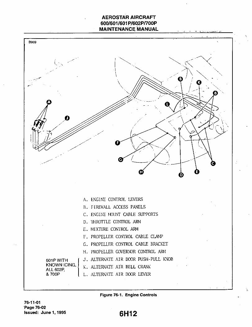
AEROSTAR AIRCRAFT 600/601/601P/602P/700P
. MAINTENANCE MANUAL . . , ,
B969
601P WITH KNOWN ICING, ALL 602P, &700P
A. KNGLN'E COmOL LEVEI^
B. FIREWALL ACCESS PANELS
C. ENGINE MOUNT C'VBLE SUPPORTS
D. 'IHROTTLE CONTROL ARM
E. MIXTURE CONTROL ARM
F . PROPELLER CONTROL CABLE CLANtt
G. PROPELLER CONTROL CABLE BRACKET
H. PROPELLER GOVERNOR CONTROL ARM
J . ALTERNATE AIR DOOR PUSH-PULL KNOB
K. ALTERNATE AIR BELL CRANK
L. .'UTERNATE AIR DOOR LEVER
Figure 76-1. Engine Controls
76-11-01 Page 76-02
Issued: June 1,1995 6H12
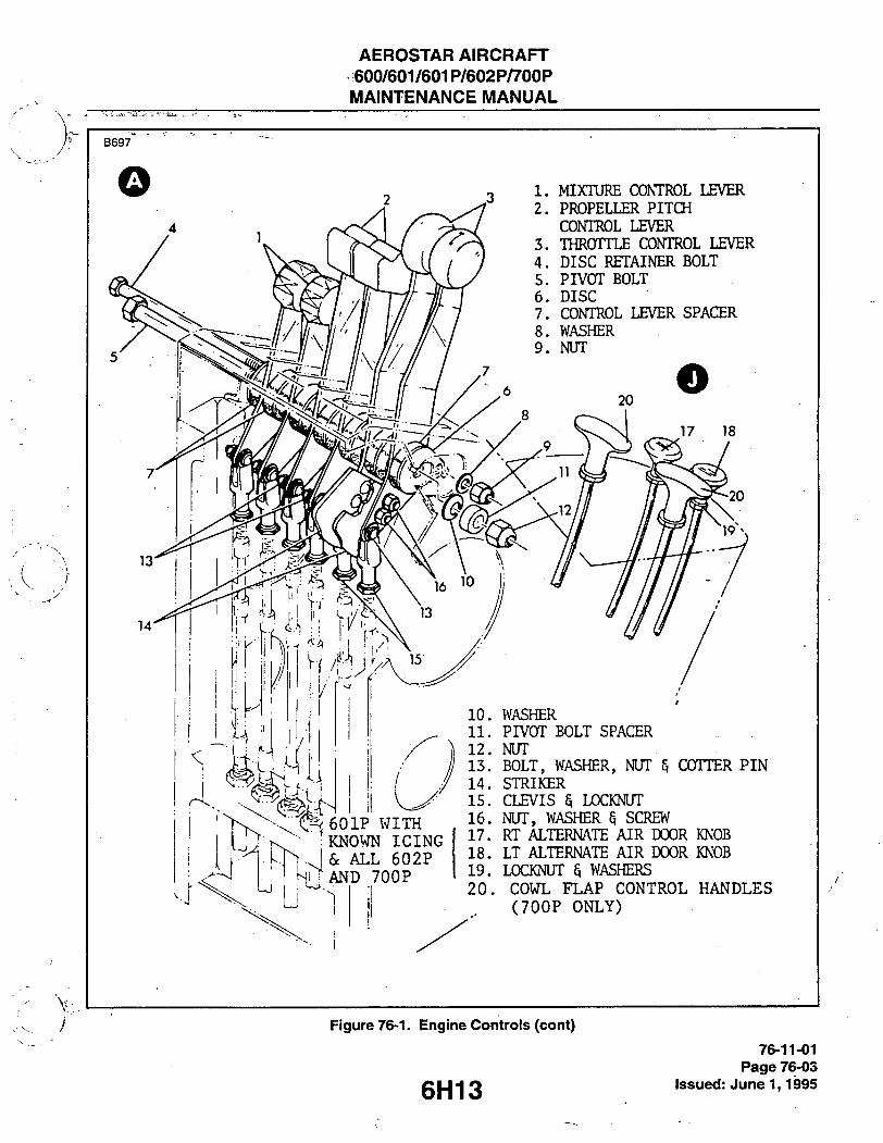
AEROSTAR AIRCRAFT 600/601/601P/602P/700P
MAINTENANCE MANUAL
B 6 9 7
MIXTURE CONTROL LEVER PROPELLER PITCH CONITOL LEVER THROTTLE CONTROL LEVER DISC RETAINER BOLT PIVOT BOLT DISC
CONTROL LEVER SPACER WASHER NUT
10. WASHER 11. PIVOT BOLT SPACER 12. NUT 13. BOLT, WASHER, NUT 5 COTTER PIN 14. STRIKER 15. CLEVIS 3 LOCKNUT 16. NUT, WASHER SCREW 17. RT ALTERNATE AIR DOOR KNOB 18. LT ALTERNATE AIR DOOR KNOB 19. LOCKNUT 5 WASHERS 20. COWL FLAP CONTROL HANDLES
(700P ONLY)
Figure 76-1. Engine Controis (cont)
6H13 76-11-01
Page 76-03 Issued: June 1,1995
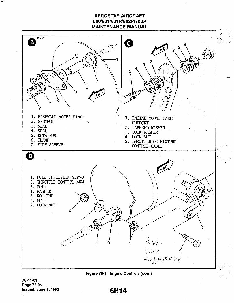
AEROSTAR AIRCRAFT 600/601/601P/602P/700P
MAINTENANCE MANUAL
b 6 9 8
1. FIREWALL ACCES PANEL 2. GRCMCT 3. SEAL 4. SEAL 5. RETAINER 6. CLAMP 7. FIRE SLEEVE-
1. ENGINE MOUNT CABLE SUPPORT
2. TAPERED WASHER 3. LOCK WASHER 4. LOCK NUT 5. THROTTLE OR MIXTURE
CONTROL CABLE
1. RJEL INJECTION SERVO 2. THROTTLE CONTROL ARM 3. BOLT 4. WASHER 5. ROD END 6. NUT 7. LOCK NUT
76-11-01 Page 76-04 Issued: June 1,1995
Figure 76-1. Engine Controis (cont)
6H14

AEROSTAR AIRCRAFT 600/601/601P/602P/700P
MAINTENANCE MANUAL
1. FUEL INJECTOR SERVO 2. : MIXTURE CONTROL ARM 3. BOLT 4. SPACER 5. ROD -END 6. V iASHER 7. NUT 8. LOCK NUT
1. CABLE CLAMP 2. BOLT, WASHER d, NUT 3. #1 CYLINDER PUSH ROD HOUSING 4. PROPELLER PITCH CONTROL CABLE
1. PROPEL 2. BRACKET 3. WASHER 4. LOCK NUT
ER PITCH CONTROL CABLE
1. LOCK NUT 2. ROD END 3. WASHER 4. NUT 5. PROPELLER GOVERNOR CONTROL ARM 6. BOLT
Figure 76-1. Engine Controis (cont)
6H15
76-11-01 Page 76-05
issued: June 1,1995

AEROSTAR AIRCRAFT 600/601/601P/602P/700P MAINTENANCE MANUAL
C 5 0 7
1. ALTEmiATE AIR DOOR 2. ALTERNATE AIR BELL CRANK 3. ICE SCREEN
Figure 76-1. Engine Controis (cont)
76-11-01 Page 76-06
issued: June 1,1995 6H1 6

AEROSTAR AIRCRAFT 600/601/601P/602P/700P MAINTENANCE MANUAL
19. Safety wire cable housings together to prevent slippage. Refer to Figure 76-2.
- CAUTION-
Insure that all hardware (locknuts, washers, dust boots, etc.) has been removed prior to pulling cables through fuselage, wing and nacelle.
20. While guiding cable at wing root and firewall, carefully pull cable through fuselage, wing and nacelle from outside airplane. Remove old cable.
21. Route replacement cable fonward from fuselage station 176.88 bulkhead through floor support inter-costals to control lever.
22. Install locknuts, washers, dust boots and clevis onto lever end of replacement cable. 23. Connect clevis to control lever and secure cable support. 24. Install cable retainer bracket onto fonward edge of console cable support. 25. Install firewall access panel and cable retainer assembly. 26. Install fire sleeve, locknuts, washers, tapered washers, dust boots and rod end onto engine end of
replacement cable. 27. Secure throttle or mixture control cable to support bracket on engine mount, or propeller pitch control
cable to cable clamp on number 1 cylinder push rod housing and cable support bracket at engine center line as applicable.
28. Install aft section of exhaust stack and induction duct assembly as applicable. 29. Connect cable to throttle, mixture or propeller governor control arm as applicable. Refer to Figure 76-1D,
E or H respectively.
B 7 0 0
1.
2.
3.
4.
CABLE H3USING ^ ENGINE CONTROL CABLE
LOCALLY MANUFACTURED THREADED SLEEVE,
OR 1/4" INSIDE DIAMETER REINFORCED RUBBER SAFETY WIRE
2.
Figure 76-2. Old and New Engine Controi Cables Connected Together for Removal/Installation
76-11-01 Page 76-07
Issued: June 1,1995

AEROSTAR AIRCRAFT 600/601/601P/602P/700P MAINTENANCE MANUAL
-NOTE-
Bends in engine control cables should have a bend radius of not less , than 6 in. Clearance between the propeiier pitch control cable and the turbocharger or exhaust stack should be 2.00 in. minimum.
30. Inspect cable along its entire length for proper routing and installation. : . 31. Install ty-raps between floor support intercostals. 32. Secure cable to fuselage station 176.88 bulkhead. 33. Seal cables at fuselage per Chapter 20. 34. Install floor and seat tracks per Chapter 53. t . 35. Install fuselage station 176.88 bulkhead covering. . . 36. Install seats per Chapter 25. 37. Install wing root fairing per Chapter 53. 38. Rig control and install console side cover.
REPLACEMENT OF ALTERNATE AIR DOOR CONTROL CABLES (601 P's Equipped for known Icing and all 602P's and 700P's). (Refer to Figures 76-1 & 2.)
1. Remove seats per Chapter 25. 2. Remove seat tracks and floor per Chapter 53. 3. Remove console left and right side "Royalite" cover. 4. Remove knobs from cables (unscrew, right hand thread). 5. Loosen locknut securing cable to console and pull cable through hole in console. 6. Remove locknuts, washers and ty-raps from cable. 7. Remove fuselage station 176.88 bulkhead "Royalite" cover to gain access to cable. 8. Remove wing root fairing per Chapter 53. 9. Remove upper engine cowling. 10. Disconnect cable from bellcrank at filter airbox. 11. Remove clevis end from airbox end of cable and remove dust boots, locknuts, washers and firesleeve. 12. Remove cable retainer assembly from firewall and remove firewall access panel. 13. Pull cable aft through floor support intercostal. 14. Remove sealant from cables at fuselage. 15. Connect airbox end of replacement cable to console end of old cable as shown in Figure 76-2. Use short
piece of fabric reinforced rubber hose to splice the two cables together. " 16. Safety wire cable housings together to prevent slippage (refer to Figure 76-2).
- CAUTION-
Ensure that all hardware (locknuts, washers, etc.) has been removed prior to pulling cables through fuselage, wing and nacelle.
17. While guiding cable at wing root and firewall, carefully pull cable through fuselage, wing and nacelle from outside airplane. Remove old cable.
18. Route replacement cable fonward from fuselage station 176.88 bulkhead through floor support intercostal to center console.
19. Install locknuts, washers and knobs on console end of replacement cable. 20. Install firewall access panel and cable retainer assembly. 21. Install firesleeve, locknuts, washers and the clevis onto airbox end of replacement cable. 22. Connect cable to airbox bellcrank.
76-11-02 Page 76-08 issued: June 1,1995 6H18

AEROSTAR AIRCRAFT 600/601/601P/602P/700P MAINTENANCE MANUAL
23. Inspect cable along its entire lengtti for proper routing and installation. Minimum bend radius is 2 incties. 24. Install ty-raps between floor support intercostals. 25. Secure cable to fuselage station 176.88 bulktiead. 26. Seal cables at fuselage per Ctiapter 20. ' 27. Install floor and seat tracks per Ctiapter 53. ' 28. Install fuselage station 176.88 "Royalite" cover. 29. Install seats per Cfiapter 25. 30. Install wing root fairing per Ctiapter 53. 31. Ttie sfiort cables, installed between ttie filter airbox and tfie inlet airboxes are removed and installed as
sfiown in Figure 76-1. 32. Rig cable. 33. Install console side cover and upper cowling.
CONTROL LEVERS.
REMOVAL OF ENGINE CONTROL LEVERS. (Refer to Figure 76-1, View A.)
1. Remove console side covers. ' 2. Remove nut, spacer and wasfier from pivot bolt. 3. Disconnect cable clevis from lever being removed. 4. Measure tfie distance from tfireaded end of pivot bolt to rigtit side of lever being removed.
-NOTE-
To prevent spacers between control levers from falling out as pivot bolt is retracted, and to act as a pilot for the pivot bolt when being reinstalled, push the pivot bolt with a bolt or rod of the same diameter and length as the pivot bolt
5. Wfiile pustiing tfie pivot bolt, insert tfie pilot bolt or rod tfie same distance as measured in Step 4 above. 6. If removing a tfirottle control lever, remove knob from lever. 7. Retract pilot bolt approximately .2 - .25 in. 8. Drop throttle control lever down through console and remove. Mixture or propeller pitch control levers
may be lifted out by knob. 9. Remove and retain striker from throttle control lever for installation onto replacement lever.
-NOTE-
If removed engine control lever is not to be re-installed or replaced at this time, push pilot out with pivot t)olt and temporarily install
• washer, spacer and nut onto pivot bolt
76-12-01 Page 76-09
6 H1 9 Issued: June 1,1995

AEROSTAR AIRCRAFT 600/601/601P/602P/700P MAINTENANCE MANUAL
INSTALLATiON OF ENGINE CONTROL LEVERS.
1. , Perform Steps 2, 4, 5 and 7 of Removal of Engine Control Levers as necessary. 2. If installing a replacement throttle control lever, install striker onto lever. 3. Align lever with pivot bolt and push pilot bolt out with pivot bolt. 4. Install washer, spacer and nut onto pivot b6lt. 5. Connect cable clevis to lever. 6. Rig control. 7. Install console side covers.
RIGGING ENGINE CONTROLS. PPS6014S
1. Position and hold control lever in center of its travel. 2. Position rod end and clevis in center of threads. 3. Position control arm (throttle, mixture or propeller governor) in center of its travel. 4. With an equal amount of control rod exposed at each end of control cable, adjust rod end and clevis to
facilitate installation of attach bolts. 5. Cycle control lever on console from fully forward to fully aft positions. Ensure that control arm at
engine goes firmly against its stops, and the control lever on the console stops approximately .20 to .30 from the end of its slot and that it has an acceptable amount of cushion at the end of its travel.
6. Inspect control cable for proper routing, security of locknuts, clamps and retainers, and installation of cotter pins.
7. Use a chatillon force gauge to determine that the actuating force (in either direction) does not exceed 6 lbs. maximum for the throttle control or 10 lbs. maximum for the prop or mixture control. The maxi-mum force spread between the two throttle control levers is 1.0 lb. The maximum force spread between the two prop control levers or the two mixture control levers is 1.5 lbs.
RIGGING OF ALTERNATE AIR DOOR CONTROLS. (601P Equipped for known icing and ai! 602P's and 700P's) (Refer to Figure 76-3.) 300141
1. Set control knobs 1.00 inch from full closed position. 2. Center bellcranks mounted on filter airboxes with engine centerline. 3. Secure clevis end of primary cables to bellcranks. 4. Push control knobs to full closed position, then backoff .10 inch (for cushion). 5. Fully close alternate air doors against their respective stops. 6. Secure secondary cables at pivot on doors and bellcranks. 7. Actuate alternate air door control knobs and ensure the following:
A. Knobs fully pulled: (1) Ali four doors fully open against their respective stops. (2) Both knobs are at approximately the same level ± .10 inch.
B. Knobs fully pushed: (1 )AII four doors fully closed against their respective stops. (2)Approximately .10 inch of cushion travel remaining at knob.
8. After rigging, operate the system to ensure full opening and closing of the airbox alternate doors and to ensure that there is no binding in all the Push/Pull cables at the points of clamping.
9. The minimum bend radius for all cables is 2 inches. 10. The maximum installed operating load is a 17 lb. pull, measured with a fish scale.
76-13-01 Page 76-10 Issued: June 1,1995 6H20

AEROSTAR AIRCRAFT 600/601/601P/602P/700P MAINTENANCE MANUAL
Figure 76-3, Alternate Air Door Controi instaliation 76-13-01
Page 76-11 issued: June 1,1995
AEROSTARRAIRCRAFT 600/601/601P/602P/700P
MAINTENANCE .MANUAL
THIS PAGE INTENTIONALLY LEFT BLANK
6H22

AEROSTAR AIRCRAFT 600/601/601P/602P/700P
MAINTENANGE MANUAL .
THIS PAGE INTENTIONALLY LEFT BLANK
6H23
AEROSTAR AIRCRAFT 600/601/601P/602P/700P MAINTENANCE MANUAL
THIS PAGE INTENTIONALLY LEFT BLANK
6H24

>in5i
AEROSTAR AIRCRAFT 600/601/601P/602P/700P
MAINTENANCE MANUAL
CHAPTER
ENGINE INDICATING
611
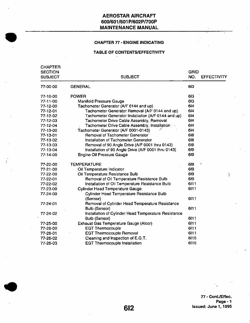
AEROSTAR AIRCRAFT 600/601/601P/602P/700P MAINTENANCE MANUAL
CHAPTER 77 - ENGINE INDICATING
TABLE OF CONTENTS/EFFECTIVITY
CHAPTER SECTION GRID SUBJECT SUBJECT NO. EFFECTIVITY
77-00-00 GENERAL 613
77-10-00 POWER 613 77-11-00 Manifold Pressure Gauge 613 77-12-00 Tacfiometer Generator (/VF 0144 and up) 614 77-12-01 Tacliometer Generator Removal (A/F 0144 and up) 614 77-12-02 Tacfiometer Generator Installation (/VF 0144 and up) 614 77-12-03 Tacfiometer Drive Cable Assembly, Removal 614 77-12-04 Tacfiometer Drive Cable Assembly, Installation 614 77-13-00 Tacfiometer Generator (/VF 0001-0143) ^ 614 77-13-01 Removal of Tacfiometer Generator 618 77-13-02 Installation of Tacfiometer Generator 618 77-13-03 Removal of 90 Angle Drive (A/F 0001 tfiru 0143) 619 77-13-04 Installation of 90 Angle Drive (A/F 0001 tfiru 0143) 619 77-14-00 Engine Oil Pressure Gauge 619
77-20-00 TEMPERATURE 619 -77-21-00 Oil Temperature Indicator 619 77-22-00 Oil Temperature Resistance Bulb 619 ) 77-22-01 Removal of Oil Temperature Resistance Bulb 619 77-22-02 Installation of Oil Temperature Resistance Bulb 6111 77-23-00 Cylinder Head Temperature Gauge 6111 77-24-00 Cylinder Head Temperature Resistance Bulb
(Sensor) 6111 77-24-01 Removal of Cylinder Head Temperature Resistance
Bulb (Sensor) 6111 77-24-02 Installation of Cylinder Head Temperature Resistance
Bulb (Sensor) 6111 77-25-00 Exfiaust Gas Temperature Gauge (Alcor) 6111 77-26-00 EGT Ttiermocouple 6111 77-26-01 EGT Tfiennocouple Removal 6111 77-26-02 Cleaning and Inspection of E.G.T. 6115 77-26-03 EGT Ttiermocouple Installation 6115
77 - ContTEffec. Page -1
g|2 Issued: June 1,1995

AEROSTAR AIRCRAFT 600/601/601P/602P/700P MAINTENANCE MANUAL
GENERAL.
Certain gauges and instruments monitor engine operation. These include cylinder head and exhaust gas temperature (optional on model 600), manifold and oil pressure and a tachometer.
POWER.
MANIFOLD PRESSURE GAUGE.
The manifold pressure gauge is a vapor proof, absolute pressure type instrument. Pressure from the intake manifold of the engine is transmitted to the instrument through a line. A pointer indicates the manifold pressure available at the engine in inches of mercury. See Chapter 39 for instrument removal.
CHART 7701. TROUBLESHOOTING (MANIFOLD PRESSURE INDICATOR)
Trouble Cause Remedy
Excessive error at ambient barometric pressure.
Pointer shifted. Replace instrument.
Excessive error when engine is running.
Line leaking. Tighten line connections. Pressure tests. Replace.
Sluggish or jerky pointer movement.
Defective instmment. Replace instaimenL
Dull or discolored marking.
Age. Replace instrument.
Incorrect reading. Iv/loisture or oil in line. Disconnect lines and blow out.
77-11-00 Page 77-01
g I < Issued: June 1,1995

AEROSTAR AIRCRAFT 600/601/601P/602P/700P MAINTENANCE MANUAL
TACHOMETER GENERATOR A/F 0144 & UP.
The tachometer generator is connected to the engine accessory by a flexible cable approximately 22 inches in length running through the firewall to the nacelle-mounted generator.
TACHOMETER GENERATOR REMOVAL A/F 0144 & UP. (Refer to Figure 77-1.)
1. Remove access panel aft of engine firewall, right upper side of engine nacelle (center of nacelle on 700P). '
2. Remove electrical connector from tachometer generator. 3. Loosen mounting clamp screws. 4. Remove flexible drive cable from generator housing. 5. Slip generator out of mounting clamp and remove.
TACHOMETER GENERATOR INSTALLATION AAF 0144 & UP. (Refer to Figure 77-1.)
1. Slip generator into mounting clamp, centering unit. 2. Install flexible drive cable assembly. Safety-wire locking bolts. 3. Tighten clamp to hold generator securely. 4. Install electrical connector to generator. 5. Replace access panel.
TACHOMETER DRIVE CABLE ASSEMBLY REMOVAL (Refer to Figure 77-1.)
1. Remove access panel aft of engine firewall, right upper side of engine nacelle (center of nacelle on 700P).
>>.>. , 2. Disconnect cable assembly from tachometer generator housing. 3. Remove upper engine cowling. ,. 4. Disconnect cable assembly from engine tachometer connection. 5. Remove bolts securing cable retainer to firewall. 6. Loosen grommet from hole in firewall to release cable assembly. 7. Remove cable assembly by pulling tachometer end of cable through hole in firewall.
TACHOMETER DRIVE CABLE ASSEMBLY INSTALLATION. (Refer to Figure 77-1.)
1. At fonvard side of firewall, push tachometer generator end of cable assembly through grommet and through hole in firewall.
2. Set grommet in place in hole and adjust cable length to engine tachometer connection. 3. Install cable assembly to engine tachometer connector. 4. Install cable assembly retainer to firewall. 5. Relace upper engine cowling per Chapter 77.
TACHOMETER GENERATOR A/F 0001-0143. (Refer to Figure 77-2.)
The tachometer generator is connected to the engine accessory by a 90° angle drive. The generator is engine-mounted on a clamp-plate assembly.
77-13-00 Page 77-02 Issued: June 1,1995 CM
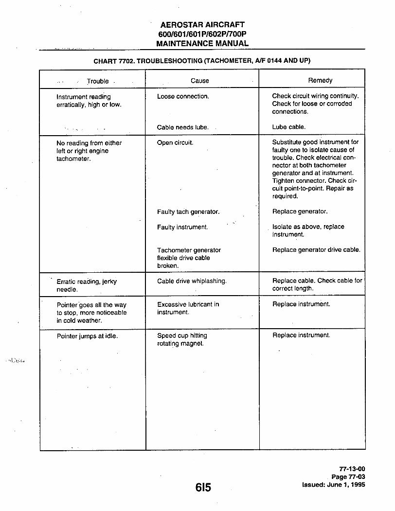
AEROSTAR AIRCRAFT 600/601/601P/602P/700P MAINTENANCE MANUAL
CHART 7702. TROUBLESHOOTING (TACHOMETER, A/F 0144 AND UP)
Trouble Cause Remedy
Instrument reading erratically, higti or low.
Loose connection. Check circuit wiring continuity. Check for loose or corroded connections.
Cable needs lube. . Lube cable.
No reading from either left or right engine tachometer.
Open circuit. Substitute good instmment for faulty one to isolate cause of trouble. Check electrical con-nector at both tachometer generator and at instrument. Tighten connector. Check cir-cuit point-to-point. Repair as required.
Faulty tach generator. Replace generator.
Faulty instalment. Isolate as above, replace instrument.
Tachometer generator flexible drive cable broken.
Replace generator drive cable.
Erratic reading, jerky needle.
Cable drive whiplashing. Replace cable. Check cable for correct length.
Pointer "goes all the way to stop, more noticeable in cold weather.
Excessive lubricant in instrument.
Replace instrument
Pointer jumps at idle. Speed cup hitting rotating magnet.
Replace instrument.
615
77-13-00 Page 77-03
Issued: June 1,1995

AEROSTAR AIRCRAFT 600/601/601P/602P/700P MAINTENANCE MANUAL
B 7 0 1
CABLE ASSY ACCESS CCfVER
REFER TO CHAPT 91 FOR WIRING DIAGRAMS
Figure 77-1. Tachometer Generator and Drive Cabie instaiiation (A/F No. 0144 thru 0455, 0494 and up)
77-13-00 Page 77-04 issued: June 1,1995 616

AEROSTAR AIRCRAFT 600/601/601P/602P/700P
MAINTENANCE MANUAL
Figure 77-2. Engine Mounted Tachometer Generator A/F 0001-0143
77-13-00 Page77-05
C|7 Issued: June 1,1995

AEROSTAR AIRCRAFT 600/601/601P/602P/700P MAINTENANCE MANUAL
REMOVAL OF TACHOMETER GENERATOR (A/F NO. 0001 THRU 0143). (Refer to Figure 77-2.)
1. Remove upper engine cowling. 2. Remove electrical connector from tachometer generator. 3. Loosen bracket mounting bolt to release generator. 4. Remove 90° angle drive from generator housing. 5. Remove tachometer generator.
INSTALLATION OF TACHOMETER GENERATOR (A/F NO. 0001 THRU 0143).
1. Place generator in approximate position in mounting bracket. 2. Install 90° angle drive to generator housing. 3. Tighten mounting bracket bolt ensuring correct alignment of generator with angle drive. 4. Install electrical connector to generator. 5. Replace upper engine cowling.
CHART 7703. TROUBLESHOOTING (TACHOMETER A/F 0001-0143)
Trouble Cause ' Remedy
Instrument reading erratically, high or low.
Loose connection. Check circuit continuity. Check for loose or corroded connec-tions.
No reading from either left or right engine tach.
Open circuit. Substitute good instrument for faulty one to isolate cause of trouble. Check electrical con-nector at both tachometer gen-erator and at instrument. Tighten connector. Check cir-cuit point-to-point. Repair as required.
Faulty tach generator. Replace generator.
Faulty instrument. Isolate as above. Replace instrument.
Tachometer generator angle drive broken.
Replace generator drive.
Pointer goes all the way to stop, more noticeable in cold weather.
Excessive lubricant in instrumenL
Replace instalment.
Pointer jumps at idle. Speed cup hitting rotating magnet.
Replace instrumenL
77-13-02 Page 77-06 Issued: June 1,1995 618

AEROSTAR AIRCRAFT 600/601/601P/602P/700P MAINTENANCE MANUAL
REMOVAL OF 90° ANGLE DRIVE. (A/F NO. 0001 THRU 0143)
1. Remove upper engine cowling. 2. Loosen tachometer generator mounting bracket bolt to release generator. 3. Remove angle drive from generator housing. , . 4. Remove angle drive from engine tachometer connection. 5. Remove angle drive.
INSTALLATION OF 90° ANGLE DRIVE. (A/F No. 0001 THRU 0143).
1. Install angle drive at engine tachometer connection. 2. Install angle drive at generator housing. 3. Tighten generator mounting bracket bolt ensuring correct alignment of generator and angle drive.
ENGINE OIL PRESSURE GAUGE.
The oil pressure gauge is mounted in the combination 3-way gauge on the copilot's panel. This gauge will indicate the amount of oil pressure available at the pressurized engine oil passage. See Chapter 39 for instrument removal.
TEMPERATURE.
The temperature indicating instruments are the oil temperature gauge, the cylinder head temperature gauge and the exhaust gas temperature gauge.
OIL TEMPERATURE INDICATOR.
The oil temperature indicator is mounted in the combination 3-way gauge on the copilot's panel. This instrument will provide a temperature indication of the engine oil in degrees Celsius. The instrument has a temperature bulb located on the upper aft section of the engine accessory case. See Chapter 39 for instrument removal.
OIL TEMPERATURE RESISTANCE BULB.
REMOVAL OF OIL TEMPERATURE RESISTANCE BULB. (Refer to Figure 77-3.)
1. Remove top engine cowling. 2. Remove electrical connector from bulb assembly. 3. Unscrew resistance bulb out of engine accessory case.
619 77-22-01
Page 77-07 Issued: J u n e l , 1995

AEROSTAR AIRCRAFT 600/601/601P/602P/700P MAINTENANCE MANUAL
CHART 7704. TROUBLESHOOTING (ENGINE OIL PRESSURE GAUGE)
Trouble Cause Remedy ,
Excessive error at zero. Pointer loose on shaft.
Overpressure or seasoning of Bourdon tube.
Replace instrument.
Excessive pointer oscillation.
Air in line.
Rough engine relief valve.
Disconnect line andfill with light oil. Check for leaks.
Clean and adjust relief valve.
Sluggish operation of pointer or pressure fails to build up.
Engine relief valve open. Check and clean relief valve.
Oil on gauge dial. Internal leak in instrument
Replace instrument
CHART 7705. TROUBLESHOOTING (OIL TEMPERATURE INDICATIONS)
Trouble Cause Remedy
Instrument fails to show any reading.
Broken or damaged bulb.
Open circuit.
Check engine unit.
Check wiring.
Excessive scale error. Improper calibration adjustment.
Calibrate instrument or replace.
Dull or discolored markings.
Age. Replace instrument.
Instrument registering high, low or erratic.
Defective sensor, (bulb). Replace sensor.
77-22-01 Page 77-08 Issued: June 1,1995 6110

AEROSTAR AIRCRAFT 600/601/601P/602P/700P MAINTENANCE MANUAL
I INSTALLATION OF OIL TEMPERATURE RESISTANCE BULB.
1. Thread bulb into engine accessory case, torque to 60 inch-pounds. 2. Replace ejectrical connector. 3. Replace engine cowling.
CYLINDER HEAD TEMPERATURE GAUGE.
The cylinder head temperature gauge is a dual instrument located on the upper copilot's panel. This instru-ment measures the cylinder head temperature using a sensor located in the No. 2 cylinder head (in the 4 cylinder of the L/H engine and the 5 cylinder of the R/H engine on"the 700P). On 601's and 601 P's modified per Piper Sen/ice Spares Letter 394, the sense probe has been relocated to the 3 cylinder. See Chapter 39 for instrument removal.
CYLINDER HEAD RESISTANCE BULB (SENSOR).
REMOVAL OF CYLINDER HEAD RESISTANCE BULB (SENSOR). (Refer to Figure 77-3.)
1. Remove top engine cowling. 2. Disconnect electrical leads from sensor. 3. Remove sensor by pushing assembly in against spring tension and twist half-turn to right to release.
INSTALLATION OF CYLINDER HEAD RESISTANCE BULB (SENSOR). (Refer to Figure 77-3.)
1. Insert CHT sensor in cylinder head receptacle. 2. Push in against spring tension and twist one-half turn to left to lock sensor. 3. Connect electrical leads to sensor. 4. Replace top engine cowling.
EXHAUST GAS TEMPERATURE GAUGE (Alcor). (Refer to Figure 77-4.)
This instrument, which is commonly referred to as EGT, is used to aid the pilot in selecting the most economi-cal fuel-air mixture for cruising flight and determining the proper fuel mixture setting at altitudes above 5,000 ft. It is a sensing device to monitor the fuel-air mixture leaving the engine cylinders. This gauge is adjustable. If it is found defective after checking with troubleshooting chart it should be replaced. If the leads to the, gauge are defective in any way they should be replaced. When replacing leads, it is very important to use the same type and length of wire, as the resistance of the leads is critical for the proper operation of this gauge. Attempts to lean the engine with a faulty EGT can result in excessive cylinder head temperature or bumed exhaust valves. See Chapter 39 for instrument removal.
EGT THERMOCOUPLE.
EGT THERMOCOUPLE REMOVAL (Refer to Figure 77-4.)
1. Disconnect electrical leads from themnocouple. 2. Loosen clamp securing thermocouple to right side manifold. 3. Remove probe assembly.
6111
77-26-01 Page 77-09
Issued: June 1,1995

AEROSTAR AIRCRAFT 600/601/601P/602P/700P MAINTENANCE MANUAL
N O T E
O N 6 0 r s A N D 6 0 1 P 'S M O D I F I E D P E R A E R O S T A R KIT NO. 764-422V
T H E S E N S E P R O B E H A S B E E N R E L O -C A T E D T O T H E #3 C Y L I N D E R . O N T H E 7 0 0 P T H E C H T S E N S E P R O B E IS L O C A T E D O N T H E #4 C Y L I N D E R O N T H E L / H E N G I N E A N D T H E #5 C Y L I N -D E R O N T H E R / H E N G I N E .
- V / ^
1. O IL T E M P S E N S O R
? E L E C T R I C A L C O N N E C T O R 3 W I R I N G H A R N E S S 4 C H T S E N S O R ( S E E N O T E ) • S E E C H A P T . 9 1 F O R W I R I N G D I A G R A M S . . .
J \
^ ^ ^ ^
77-26-01 Page TT'-IO Issued: June 1,1995
Figure 77-3. Oil and Cylinder Head Temperature Sensors
6112

AEROSTAR AIRCRAFT 600/601/601P/602P/700P MAINTENANCE MANUAL
CHART 7706. TROUBLESHOOTING (CYLINDER HEAD TEMPERATURE GAUGE)
Trouble Cause Remedy
Instrument stiows no indication.
Power supply wire broken.
Defective instrument.
Master battery switcti off or CHT breaker off.
Repair wire.
Replace instrument.
Tum switcti or breaker on.
Pointer goes all ttie way to upper stop.
Wire broken between sensor and gauge.
Defective sensor.
Repair wire.
Replace sensor.
Instrument registering tiigti, low, en-atically or no reading.
Defective sensor. Replace sensor.
CHART 7707. TROUBLESHOOTING (EGT GAUGE)
Trouble Cause Remedy
Gauge inoperative. Defective gauge, ttiermo-couple or wiring.
Ctieck ttiermocouple and leads for cfiafing, breaks or stiorts be-tween wiring and/or metal structure.
Fluctuating reading. Loose, frayed or faulty connections.
Broken leads.
Clean and tigfiten connections.
Repair or replace leads. '
77-26-01 Page 77-11
issued: June 1,1995

AEROSTAR AIRCRAFT 600/601/601P/602P/700P MAINTENANCE MANUAL
B 7 0 5
1. RED LEAD
2. YELLOW LEAD
3. ECT THERNfOCOUPLE
4. RIGHT HAND EXH. MANIFOLD
5. SECURING CLAMP
RED
•DUAL GAUGE
77-26-01 Page 77-12 Issued: June 1,1995
Figure 77-4. Exiiaust Gas Temperature System
6114
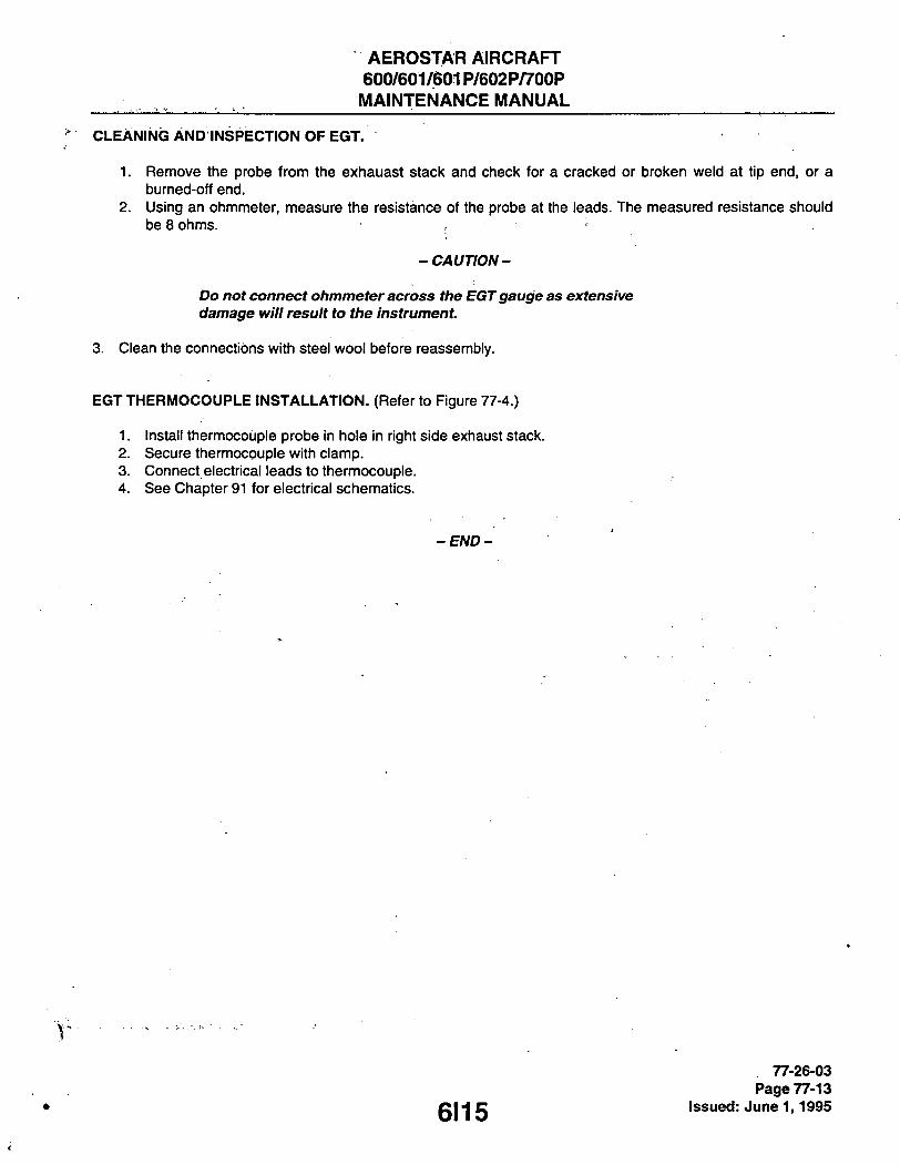
AEROSTAR AIRCRAFT 600/601/601P/602P/700P
_ MAINTENANCE MANUAL
CLEANING AND INSPECTION OF EGT.
1. Remove the probe from the exhauast stack and check for a cracked or broken weld at tip end, or a burned-off end.
2. Using an ohmmeter, measure the resistance of the probe at the leads. The measured resistance should be 8 ohms. . •
- CAUTION-
Do not connect ohmmeter across the EGT gauge as extensive damage will result to the instrument.
3. Clean the connections with steel wool before reassembly.
EGT THERMOCOUPLE INSTALLATION. (Referto Figure 77-4.)
1. Install thermocouple probe in hole in right side exhaust stack. 2. Secure thermocouple with clamp. 3. Connect electrical leads to thermocouple. 4. See Chapter 91 for electrical schematics.
-END-
6115
77-26-03 Page 77-13
Issued: June 1,1995

AEROSTAR^IRCR AFT 600/601/601P/602P/700P MAINTENANCE MANUAL
THIS PAGE INTENTIONALLY LEFT BLANK
6116

AEROSTAR AIRCRAFT 600/601/601P/602P/700P
MAINTENANCE MANUAL
THIS PAGE INTENTIONALLY LEFT BLANK
6117

AEROSTAR AIRCRAFT 600/601/601P/602P/700P
MAINTENANCE MANUAL
THIS PAGE INTENTIONALLY LEFT BLANK
6118

AEROSTAR AIRCRAFT 600/601/601P/602P/700P MAINTENANCE MANUAL
CHAPTER
EXHAUST
6119

AEROSTAR AIRCRAFT 600/601/601P/602P/700P MAINTENANCE MANUAL
CHAPTER 78 - EXHAUST
TABLE OF CONTENTS/EFFECTIVITY
CHAPTER SECTION GRID SUBJECT SUBJECT NO. EFFECTIVITY
78-00-00 GENERAL 6121
78-10-00 COLLECTOR 6121 78-11 -00 Exhaust Stacks 6121 78-11 -01 Removal of Exhaust System (600) 6121 78-11 -02 Removal of Exhaust System (601, 601P, 602P
and 700P) 6122 78-11 -03 Inspection of Exhaust System 6122 78-11 -04 Installation of Exhaust System (600) 6J1 78-11 -05 Installation of Exhaust System (601, 601P, 602P
and 700P) 6J1
6120
78 - ContTEffec. Page -1
Issued: June 1,1995

AEROSTAR AIRCRAFT 600/601/601P/602P/700P MAINTENANCE MANUAL
GENERAL.
Model 600 airplanes have two exhaust stack assemblies connected to the exhaust ports of the cylinders. The fonvard section attaches to the two forward cylinders, and the aft section attaches to the aft cylinder. The two sections are joined, through slip joint design, just fonvard of the rear cylinder. The stack extends aft through tun-nels built into the nacelles.
Models 601, 601P, 602P and 700P have a third and fourth section. The third section, containing the waste gate, is attached in line to the second section by a slip joint just aft of the rear cylinder. The fourth section is attached to the third section by a slip joint, and to the turbo exhaust port by a Marmon clamp. Marmon clamp nuts should be replaced when their friction drag torque is less than 12 in-lbs
COLLECTOR.
EXHAUST STACKS.
REMOVAL OF EXHAUST SYSTEM (MODEL 600). (Refer to Figure 78-1.)
1. Remove lower engine cowl. 2. Remove exhaust stack support clamp from stack. 3. Disconnect all three stack flanges and remove complete exhaust stack assembly.
B 7 0 6
5
1. 2. 3.
FORWARD SECTION AFT SECTION EXHAUST STACK SUPPORT CLAMP EXHAUST STACK SUPPORT
4. 2
5. 6.
STACK FLANC2 GASKET
Figure 78-1. 600 Model Exhaust System
6121
78-11-01 Page 78-01
Issued: June 1,1995
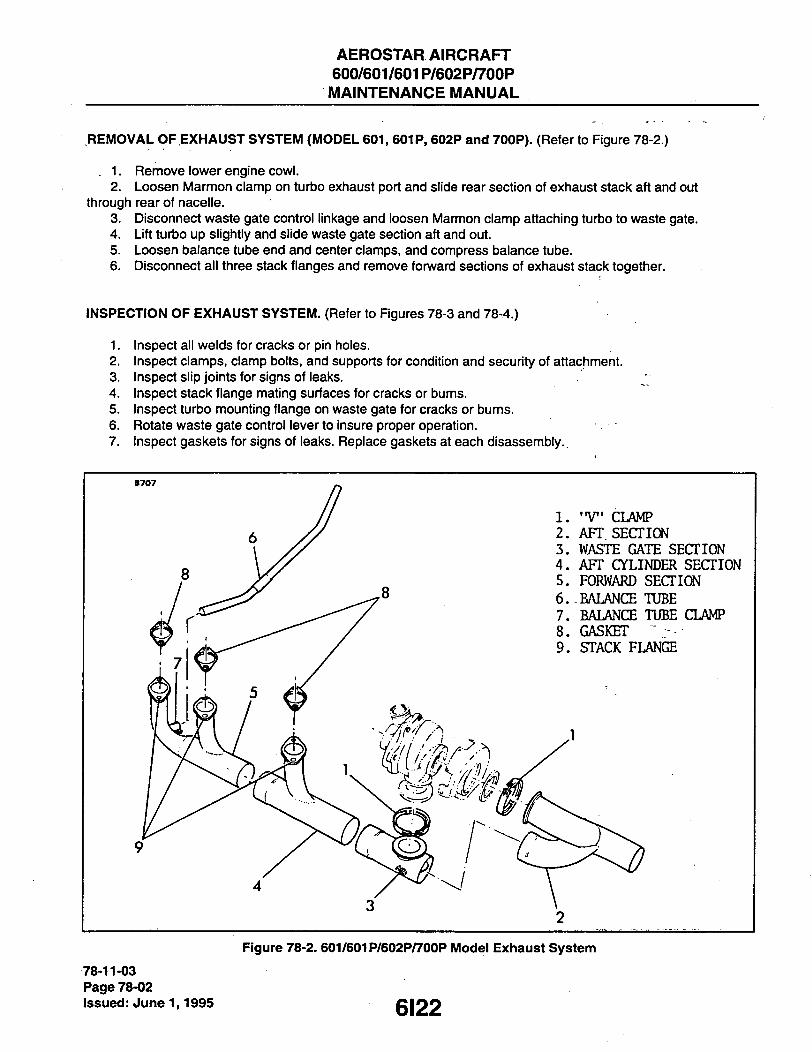
AEROSTAR AIRCRAFT 600/601/601P/602P/700P MAINTENANCE MANUAL
REMOVAL OF EXHAUST SYSTEM (MODEL 601, 601P, 602P and 700P). (Refer to Figure 78-2.)
. 1. Remove lower engine cowl. 2. Loosen Marmon clamp on turbo extiaust port and slide rear section of exhaust stack aft and out
through rear of nacelle. 3. Disconnect waste gate control linkage and loosen Marmon clamp attaching turbo to waste gate. 4. Lift turbo up slightly and slide waste gate section aft and out. 5. Loosen balance tube end and center clamps, and compress balance tube. 6. Disconnect all three stack flanges and remove fonward sections of exhaust stack together.
INSPECTION OF EXHAUST SYSTEM. (Refer to Figures 78-3 and 78-4.)
1. Inspect all welds for cracks or pin holes. 2. Inspect clamps, clamp bolts, and supports for condition and security of attachment. 3. Inspect slip joints for signs of leaks. 4. Inspect stack flange mating surfaces for cracks or bums. 5. Inspect turbo mounting flange on waste gate for cracks or bums. 6. Rotate waste gate control lever to insure proper operation. 7. Inspect gaskets for signs of leaks. Replace gaskets at each disassembly..
B707
1. 2. 3. 4. 5. 6. 7. 8. 9.
"V" CLAMP AFT SECTION WASTE GATE SECTION AFT CYLINDER SECTION FORWARD SECTION BALANCE TUBE BALANCE TUBE CLAMP GASKET • STACK FLANGE
9
3 2
Figure 78-2. 601/601P/602P/700P Model Exhaust System
78-11-03 Page 78-02 Issued: June 1,1995
6122
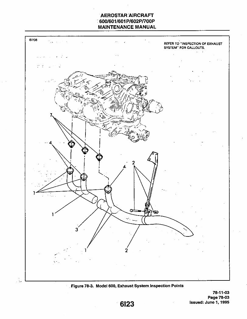
AEROSTAR AIRCRAFT 600/601/601P/602P/700P MAINTENANCE MANUAL
B 7 0 8 ' R E F E R T O " I N S P E C T I O N O F E X H A U S T
S Y S T E M " F O R C A L L O U T S .
Figure 78-3. IUlodei 600, Exhaust System inspection Points 78-11-03
Page 78-03 gj22 Issued: June 1,1995

AEROSTARAIRCRAFT 600/601/601P/602P/700P MAINTENANCE MANUAL
B 7 0 9
Figure 78-4. IUlodei 601 / 601P / 602P / 700P Exiiaust System inspection Points
78-11-03 Page 78-04 Issued: June 1,1995 6124

AEROSTAR AIRCRAFT 600/601/601P/602P/700P MAINTENANCE MANUAL
INSTALLATION OF EXHAUST SYSTEM (600) . . .
1. Position fonward section of exfiaust stack gaskets onto two fonward cylinder exfiaust ports. Iristall flange nuts loosely.
2. Slide aft section onto forward section and connect stack flange and gasket to rear cylinder extiaust port. 3. Torque all flange nuts to 140-150 in. lb. 4. Install exfiaust stack support clamp onto stack, and adjust support rod end so tliat clamp can be moved
along stack by fiand. 5. Distance between stack and tunnel surface stiould be .50 incfi min. to 1.60 inch max. on the left stack;
.75 inch min. to 1.6 inch max. on the right stack. 6. Install lower engine cowl.
INSTALLATION OF EXHAUST SYSTEM (MODEL 601, 601P, 602P and 700P). (Refer to Figure 78-2.)
Slide first and second sections of exhaust stack together. Position stack flanges and gaskets onto exhaust ports. Install flange nuts loosely. Install Marmon clamp onto turbo wastegate flange with opening aft. Install wastegate, spread Marmon clamp on turbo wastegate flange, and install turbo onto wastegate. Torque Marmon clamp to 45-55 in. lb. Install Marmon clamp onto turbo exhaust port, install aft section of exhaust stack and torque Marmon clamp to 45-55 in. lb. Install balance tube, insuring that ends extend into clamps beyond slits in tube ends, and tighten end-clamps. -
1. 2. 3. 4.
5.
6.
6J1
78-11-05 Page 78-05
issued: June 1,1995

AEROSTAR AIRCRAFT 600/601/601P/602P/700P MAINTENANCE MANUAL
THIS PAGE INTENTIONALLY LEFT BLANK
6J2

AERbSTiDiR AIRCRAFT 600/601/601P/602P/700P MAINTENANCE MANUAL
CHAPTER
OIL SYSTEM
6J3

AEROSTAR AIRCRAFT 600/601/601P/602P/700P MAINTENANCE MANUAL
CHAPTER 79 - OIL SYSTEM
TABLE OF CONTENTS/EFFECTIVITY
CHAPTER SECTION GRID SUBJECT SUBJECT NO. EFFECTIVITY
79-00-00 GENERAL 6J5 79-01-00 Troubleshooting 6J5
79-10-00 STORAGE 6J8 79-11-00 Oil Sump 6J8 79-11 -01 Removal of Oil Sump 6J8 79-11-02 Installation of Oil Sump 6J8 79-11-03 Cleaning Oil Sump 6J8 79-11 -04 Oil Sump Drain Plug and Oil Suction Screen 6J10 79-11 -05 Cleaning Oil Suction Screen 6J10
79-20-00 DISTRIBUTION 6J11 79-21-00 Oil Filter Adapter 6J11 79-21-01 Removal of Oil Filter Adapter 6J11 79-21-02 Installation of Oil Filter Adapter 6J12 79-22-00 Thermostatic Valve 6J12 79-22-01 Removal of Thermostatic Valve 6J12 79-22-02 Installation of Thermostatic Valve 6J12 79-23-00 Oil Pressure Relief Valve 6J12 79-23-01 Adjustment of Oil Pressure Relief Valve 6J12 79-23-02 Removal of Oil Pressure Relief Valve 6J16 79-23-03 Installation of Oil Pressure Relief Valve 6J16 79-24-00 OilCooler(s) 6J16 79-24-01 Removal of Fonward Oil Cooler 6J16 79-24-02 Installation of Fonward Oil Cooler 6J16 79-24-03 Removal of Aft Oil Cooler 6J18 79-24-04 Installation of Aft Oil Cooler 6J18
79-30-00 INDICATING 6J18 79-31-00 Oil Temperature Transmitter 6J19 79-31-01 Removal of Oil Temperature Transmitter 6J19 79-31-02 Installation of Oil Temperature Transmitter 6J19
79 - ContTEffec. Page -1
QJ/l Issued: June 1,1995

AEROSTAR AIRCRAFT 600/601/601P/602P/700P MAINTENANCE MANUAL
G E N E R A L .
The engine oil system is a full pressure wet sump system consisting of: a sump with sump baffle, drain plug and oil suction screen; a spin-on full flow oil filter, filter adapter and thermostatic valve; an oil cooler (or coolers) and connecting lines; an adjustable oil pressure relief valve; an oil temperature transmitter and gauge; and an oil pressure gauge. Sump capacity is 12 U.S. quarts. Figure 79-1 shows the oil system in schematic fomri. Refer to Chapter 81 for turbocharger lubrication.
TROUBLESHOOTING.
Troubles peculiar to the oil system are listed in Chart 7901 along with their probable causes and suggested remedies.
B 7 1 0
USE OtL TRANSFER COVER WHCN NOT USING GOV
Sfl-ASH OIL TO PISTONS.PISTON PINS CAMS.ETC
C R A N K P I N
P R O P G O V
S P L A S H OIL T O R O C K E R A R M S , \ « L V E S T E M S . E T C
D R A I N OIL TO S U M P T H R U OIL D R A I N T U B E S
G R A V I T Y OIL T H R U S H R O U O T U B E S
TO P R O P
C A M S H A F T BEARING_NOS.2.3.a
C A M S H A F T B E A R I N G N O I
S P L A S H OIL TO R O C K E R f A R M S . V A L V E S T E M S . E T C . — I
D R A I N OIL TO S U M P T H R U OIL D R A I N T U B E S
P U S H R O O S O C K E T S
—o 5 C R A N K P I N S •
N O 3 M A I N —O ""O S P I - 4 S H O I L T O
B E A R I N G T B E A R I N G J T A C H . D R I V E
L_ C R A N K C A S E H E A D E R - R I G H T
T A P P E T S RIGHT B A N K
P U S H R O O S " A N F U E L P U . M P R O C K E R A R M 4 N 0 DRlv l 'v -N
B U S H I N G S ^ ( ^
P R E S S C R E E N I
J WIT t o i l . THRU \
0 GRAVITY Oil. THRU SHROUD TUBES -
OIL P U M P
o :o
'E
h ' S E S S u R E OIL
A N O DRIVE
V A C U U M P U M P A N O DRIVE
S P R I N G L O A D E D OIL C O O L E R B T B B S S WU.VE
OIL RELIEF
VALVE
D R A I N OIL TO S U M P
O P T I O N A L T M E R M O S T A F I C B T - P A S S V A L V E A V A I L A B L E
0 S U C T I O N S C R E E N
OIL S U M P
• i - =• ^ .=7 ST .-'J OIL C O O L E R
Figure 79-1. Oil System Schematic
6J5 79-01-00
Page 79-01 issued: June 1,1995

AEROSTAR AIRCRAFT 600/601/601P/602P/700P MAINTENANCE MANUAL
CHART 7901. TROUBLESHOOTING (OIL SYSTEM) V
Trouble Cause Remedy
Low oil pressure. Insufficient oil. Sen/ice perChapter'l2.'
Oil pressure relief valve out of adjust-ment
Turn valve clockwjse to increase oil pressure, counterclockwise to decrease.
Dirt or metal chips under oil pressure relief valve.
Remove valve dis-assemble and clean.
High oil temperature. See high oil tempera-ture in trouble column.
Obstruction in oil suction screen.
Remove and clean oil suction screen.
Defective oil press-ure gauge.
Repair or replace gauge.
High oil pressure. Oil pressure relief valve out of adjust-ment.
Turn valve clockwise to increase oil pressure, counterclockwise to decrease. ' ' "
Improper weight oil. Drain oil and service per Chapter 12.
Obstruction between oil pressure relief valve and oil sump.
Remove oil pressure relief valve and probe passage to sump with a soft copper wire.
79-01-00 Page 79-02 Issued: June 1,1995 6J6

AEROSTAR AIRCRAFT 600/601/601P/602P/700P MAINTENANCE MANUAL
CHART 7901. TROUBLESHOOTING (OIL SYSTEM) (cont)
Trouble . Cause Remedy
High oil pressure, (cont) Incorrect oil pressure relief valve spring.
Replace with correct spring.
High oil temperature. Insufficient oil. Sen/ice per Chapter 12.
Improper grade oil. Drain oil and service per Chapter 12.
Obstructed or damaged oil cooler or lines.
Clean, repair or replace oil cooler and lines as necessary.
Themnostatic valve not operating properly.
Replace thermostatic valve.
Excessive blow-by-usually caused by wom or sticking rings.
Perfomi differential compression check and over-haul top end as necessary.
Defective oil tempera-ture gauge.
Repair or replace gauge.
Excessive oil consumption. Improper grade oil. Drain oil and service per Chapter 12.
Oil level too high. Drain oil and service per Chapter 12.
New rings not proper-ly seated.
On new or remanufactured engines - use mineral oil until consumption stabilizes.
Worn rings or cylinder barrels.
Perform differential comp-ression check - remove cylinders, de-glaze barrels and replace rings as necessary.
Worn valve guides. Replace valve guides.
Bearing failure. Overhaul engine.
79-01-00 Page 79-03
gjy Issued: June 1,1995

AEROSTAR AIRCRAFT 600/601/601P/602P/700P MAINTENANCE MANUAL
STORAGE.
The storage portion of the oil system consists of a wet sump and its components, the baffle, drain plug and oil suction screen.
OIL SUMP.
REMOVAL OF OIL SUMP. (Refer to Figure 79-2.)
1. Remove engine per Chapter 71. 2. With engine suspended from hoist, remove engine mount assembly. 3. Remove lower aft engine mount pads. 4. Drain oil from sump. 5. Remove induction duct assembly between airbox and fuel injection servo. 6. Remove fuel injection servo, air inlet housing, induction housing and intake pipes per Chapter 73. 7. Remove bolts securing oil sump to crankcase and remove oil sump and gasket. Discard gasket.
INSTALLATION OF OIL SUMP.
1. Install oil sump and new gasket onto bottom of crankcase. Torque per Avco-Lycoming SSP 2070-3. 2. Install induction housing, air inlet housing, fuel injection servo and intake pipes per Chapter 73. 3. Install induction duct assembly between airbox and fuel injection servo. 4. Sen/ice per Chapter 12.
CLEANING OIL SUMP. (Referto Figure 79-3.)
1. Remove oil suction screen, baffle and baffle gasket from sump.
- CAUTION-
Extreme care must be exercised whenever water mixed de-greasing solutions containing caustic compounds or soap are used for cleaning engine parts. In addition to being potentially dangerous to aluminum and magnesium, these compounds may become impregnated into the pores of the metal and cause oil foaming when the engine is returned to service. It is Imperative that parts cleaned with water mixed compounds tie thoroughly rinsed with boiling water after cleaning, and blown dry.
2. Spray sump, baffle, and baffle hex plug with (or immerse in) white furnace oil (specific gravity 38-40) or suitable commercial solvent. Scrub with stiff bristle brush.
3. Rinse with boiling water as applicable, and blow dry. 4. Coat sump, baffle and baffle hex plug with lubricating oil immediately after cleaning.
79-11-03 Page 79-04 Issued: June 1,1995 6J8

AEROSTAR AIRCRAFT 600/601/601P/602P/700P MAINTENANCE MANUAL
B 7 1 1
1. 2. 3. 4. 5. 6. 7. 8. 9.
OIL SUMP ACCESSORY OIL RETURN OIL SUMP DRAIN PLUG OIL SUCTION SCREEN OIL FILTER ADAPTER THERMOSTATIC VALVE OIL TEMPERATURE TRANSMITTER BREATHER FITTING OIL FILLER TUBE/LEVEL GAGE
10. 11. 12. 13. 14. IS. 16. 17.
OIL TO COOLER OIL FRCM COOLER OIL PRESSURE GAGE CONNECTION FUEL INJECTION SERVO AIR INLET HOUSING INDUCTION HOUSING INTAKE PIPES ENGINE MOUNT PADS
Figure 79-2. Oii System Component Location
6J9
79-11-03 Page 79-05
issued: June 1,1995
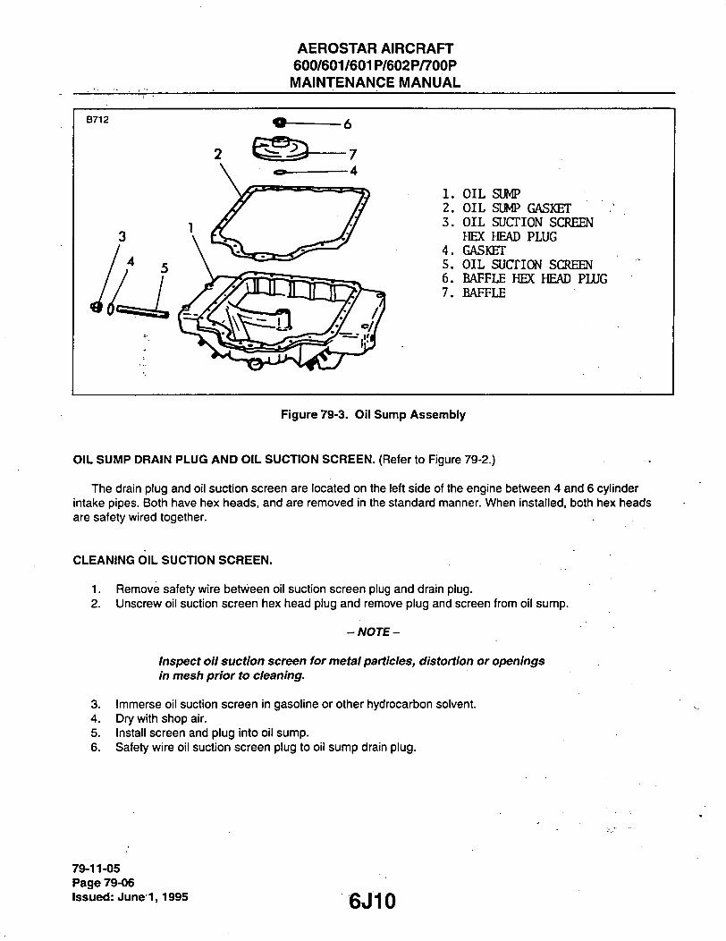
AEROSTAR AIRCRAFT 600/601/601P/602P/700P MAINTENANCE MANUAL
1. OIL SUMP 2. OIL SUMP GASKET 3. OIL SUCTION SCREEN
HEX HEAD PLUG 4. GASKET 5. OIL SUCTION SCREEN 6. BAFFLE HEX HEAD PLUG 7. BAFFLE
Figure 79-3. Oii Sump Assembly
OIL SUMP DRAIN PLUG AND OIL SUCTION SCREEN. (Refer to Figure 79-2.)
Tfie drain plug and oil suction screen are located on tfie left side of tfie engine between 4 and 6 cylinder intake pipes. Botfi have hex heads, and are removed in the standard manner. When installed, both hex heads are safety wired together.
CLEANING OIL SUCTION SCREEN.
1. Remove safety wire between oil suction screen plug and drain plug. 2. Unscrew oil suction screen hex head plug and remove plug and screen from oil sump.
-NOTE-
Inspect oil suction screen for metal particles, distortion or openings in mesh prior to cleaning.
3. Immerse oil suction screen in gasoline or other hydrocarbon solvent. 4. Dry with shop air. 5. Install screen and plug into oil sump. 6. Safety wire oil suction screen plug to oil sump drain plug.
79-11-05 Page 79-06 Issued: June'1,1995 6J10
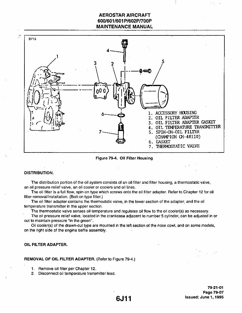
AEROSTAR AIRCRAFT 600/601/601P/602P/700P MAINTENANCE MANUAL
B 7 1 3
0 h'fJ {Til 1. 2. 3. 4. 5.
6. 7.
ACCESSORY HCXJSING OIL FILTER ADAPTER OIL FILTER ADAPTER GASKET OIL TEMPERATURE TRANSMITTER SPIN-ON-OIL FILTER (CHAMPION CH-48110) GASKET THERMOSTATIC VALVE
DISTRIBUTION.
Figure 79-4. Oil Filter IHousing
The distribution portion of the oil system consists of an oil filter and filter housing, a thermostatic valve, an oil pressure relief valve, an oil cooler or coolers and oil lines.
The oil filter is a full flow, spin-on type which screws onto the oil filter adapter. Refer to Chapter 12 for oil filter removal/installation. (Bolt-on type filter.)
The oil filter adapter contains the thermostatic valve, in the lower section of the adapter, and the oil temperature transmitter in the upper section.
The thermostatic valve senses oil temperature and regulates oil flow to the oil cooler(s) as necessary. The oil pressure relief valve, located in the crankcase adjacent to number 5 cylinder, can be adjusted in or
out to maintain pressure "in the green". Oil cooler(s) of the drawn-cut type are mounted in the left section of the nose cowl, and on some models,
on the right side of the engine baffle assembly.
OIL FILTER ADAPTER.
REMOVAL OF OIL FILTER ADAPTER. (Refer to Figure 79-4.)
1. Remove oil filter per Chapter 12. 2. Disconnect oil temperature transmitter lead.
6J11
79-21-01 Page 79-07
issued: June 1,1995

AEROSTARAIRCRAFT 600/601/601P/602P/700P MAINTENANCE MANUAL
-NOTE- ' -
The lower left corner of the oil filter adapter is attached to ttie accessory housing with a nut. To remove this nut without removing the left magneto, a 7/16 inch crows foot is required. The remaining fasteners are capscrews accessible with a screwdriver.
3. Remove capscrews and nut securing oil filter adapter to accessory housing, and remove oil filter adapter and gasket. Discard gasket.
INSTALLATION OF OIL FILTER ADAPTER.
1. Install oil filter adapter and new gasket onto accessory housing. 2. Connect oil temperature transmitter lead. 3. Install oil filter per Chapter 12.
THERMOSTATIC VALVE.
REMOVAL OF THERMOSTATIC VALVE. (Refer to Figure 79-4.)
The themnostatic valve is located in the bottom of the oil filter adapter. 1. Remove oil filter adapter. 2. Remove safety wire securing thermostatic valve to oil filter adapter. 3. Unscrew and remove thermostatic valve and gasket. Discard gasket.
INSTALLATION OF THERMOSTATIC VALVE. (Refer to Figure 79-4.)
1. Install thermostatic valve and new gasket into oil filter adapter. 2. Safety wire thermostatic valve to oil filter adapter. 3. Install oil filter adapter.
OIL PRESSURE RELIEF VALVE.
ADJUSTMENT OF OIL PRESSURE RELIEF VALVE. (Refer to Figure 79-5.)
The oil pressure relief valve is located on the crankcase adjacent to number 5 cylinder, fonvard and below the top right engine mount. The adjusting screw can be turned with either a screwdriver or socket wrench. Each complete turn results in approximately 5 psi change in oil pressure. Newly installed valves should be adjusted fully clockwise, then backed off 2 1/2 tums, as a coarse initial setting.
1. Remove upper engine cowling. 2. Tum adjusting screw clockwise to increase, counterclockwise to decrease oil pressure. Refer to Figure 79-5. 3. Install upper engine cowling. 4. Start and warm engine per Flight Manual. 5. With engine operating at approximately 2000 rpm, engine oil pressure gauge should read 80 psi at 90°F. 6. Shut down engine per Flight Manual, and repeat Steps 1 - 5 as necessary.
79-23-01 Page 79-08 Issued: Junie 1,1995 6J12

AEROSTARAIRCRAFT 600/601/601P/602P/700P MAINTENANCE MANUAL
B714
1. OIL PRESSURE RELIEF VALVE 2. ENGINE BAFFLE ASSEMBLY 3. UPPER ENGINE MOUNT CRIGHT) 4. NUMBER 5 CYLINDER '
L_._qi . M i l ! !
8
lUnmitnwicv —>Bai Dma"""" —or 1. NUT 2. SPRING PIN 3. VALVE CAP
4. VALVE INSERT 5. VALVE PLUG 6. GASKET
7. VALVE SCREEN 8. SPRING 9. BALL
Figure 79-5. Oii Pressure Reiief Vaive
6J13
79-23-01 Page 79-09
issued: June 1,1995

AEROSTAR AIRCRAFT 600/601/601P/602P/700P
MAINTENANCE MANUAL
B 7 1 5
1. OIL FROM ENGINE 2. OIL FRCM AFT COOLER
TO FORWARD COOLER 3. OIL FROM FORWARD COOLER
TO ENGINE """ • -'/A 4. BREATHER (NOT USED ON 700?) ^ f f 5. OIL FILTER ^ 6. OIL FRCM ENGINE 4.
TO COOLER 7. OIL FRCM COOLER
TO ENGINE
^ 1 •1
8. OIL FILTER MODEL 600 § 601 A/F 0341 AND BELOW AND 601? A/F 0151-0212
MODEL 601, 601?, 602? AND 700?
79-23-01 Page 79-10 Issued: June 1,1995
Figure 79-6. Oil Lines
6J14

AEROSTAR AIRCRAFT 600/601/601P/602P/700P MAINTENANCE MANUAL
B716
1. O I L INLET F I T T I N G 2. O I L OUTLET F I T T I N G 3. LOWER MOUNTING FLANGE 4. UPPER MOUNTING FLANGE
Figure 79-7. lUlodel 600 Forward Oii Cooler
B716
1. O I L INLET F I T T I N G 2. O I L OUTLET F I T T I N G 3. LOWER MOUNTING FLANGE 4. UPPER MOUNTING FLANGE
Figure 79-8. IVIodel 601, 601P, 602P and 700P Forward Oii Cooler 79-23-01
Page 79-11 C M C Issued: June 1,1995

AEROSTARAIRCRAFT 600/601/601P/602P/700P MAINTENANCE MANUAL
REMOVAL OF OIL PRESSURE RELIEF VALVE. (Refer to Figure 79-5.)
1. Remove upper engine cowling. 2. Remove safety wire from valve. 3. Unscrew and remove valve, gasket, spring and ball from crankcase. Discard gasket.
INSTALLATION OF OIL PRESSURE RELIEF VALVE.
Insert ball into oil pressure relief valve cavity in crankcase. With spring installed onto adjustment screw, install valve (with new gasket) into crankcase. Safety wire valve to crankcase. Install upper engine cowling.
1. 2. 3. 4.
OIL COOLER(S).
All 600, 601, 601P and 700P airplanes utilize a drawn-cut type oil cooler mounted inside the lower left side of the nose cowling. Model 600; 601 prior to A/F 0341; and 601P /VF 0157-0212 also have an additional aft oil cooler mounted on the right rear side of the engine baffle assembly. Figure 79-6 shows the routing of oil lines to and from the oil cooler(s).
REMOVAL OF FORWARD OIL COOLER. (Refer to Figure 79-7/8.)
1. Remove upper and lower engine cowlings. 2. Separate nose cowling and pull left section fonvard. Refer to Figure 79-7. 3. Disconnect and cap-off oil cooler inlet and oulet lines, and remove left section of nose cowling. 4. Remove attach bolts securing oil cooler to nose cowling and remove oil cooler.
INSTALLATION OF FORWARD OIL COOLER.
1. Attach oil cooler to left section of nose cowling. 2. Connect oil cooler inlet and outlet lines. 3. Install nose cowling and upper engine cowling.
-NOTE-
When installed in the airplane, .60 inch clearance must exist between the forward oil cooler body and fittings and any part which moves with the engine. Clearance between oil lines and exhaust system components must be 1.00 inch minimum.
4. Inspect oil cooler installation for proper clearances, and make adjustments as necessary. 5. Install lower engine cowling.
79-24-02 Page 79-12 Issued: June 1,1995 6J16

AEROStAR AIRCRAFT 600/601/601P/602P/700P
MAINTENANCE MANUAL
B 7 1 7
BOLT AND WASHER WASHER SPACER ENGINE BAFFLE ASSEMBLY
5. NUT AND WASHER 6. BOLT, WASHER AND NUT 7. OIL PORT 8. AFT OIL COOLER
(TYP. BOTH ENGINES)
Figure 79-9. Aft Oii Cooier
6J17
79-24-02 Page 79-13
Issued: June 1,1995
AEROSTAR AIRCRAFT 600/601/601P/602P/700P MAINTENANCE MANUAL
REMOVAL OF AFT OIL COOLER. (Refer to Figure 79-9.)
1. Remove upper and lower engine cowling. 2. Disconnect and cap-off oil cooler inlet and outlet lines.
-CAUTION- '
To prevent putting undue stress on the aft oil cooler lower mounting flange during removal, remove lower attach bolts first.
3. Remove nuts, wasfiers and bolts securing lower mounting flange to engine baffle assembly. 4. Remove nuts from upper attach bolts and remove oil coolers. 5. Remove washers, spacers, and bolts from upper mounting flanges.
INSTALLATION OF AFT OIL COOLER. (Refer to Figure 79-9.)
1. Install bolts, washers and spacers onto oil cooler upper mounting flange.
- CAUTION-
To prevent undue strain on the lower mounting flange during installation, install upper attach bolts first.
2. Position oil cooler onto engine baffle assembly, and install nuts onto upper attach bolts. 3. Install lower attach bolts, washers and nuts. 4. Connect oil cooler inlet and outlet lines. 5. Install upper and lower engine cowling.
INDICATING.
The indicating portion of the oil system consists of an oil temperature transmitter and gauge, and an oil pressure gauge. The electrically operated oil temperature transmitter is located in the top of the oil filter adapter.
Oil pressure is taken from a restrictor tee in the oil pressure line on the accessory housing, and fed directly to the oil pressure gauge by a wet line. This wet line is pumped full of "Zepreserve" at the factory to provide quick oil pressure indications.
Oil pressure and temperature, are indicated on each engine's 3-way combination gauge. Refer to Chapter 39 for instrument maintenance.
79-30-00 Page 79-14 Issued: June 1,1995 6J18

AEROSTARAIRCRAFT 600/601/601P/602P/700P MAINTENANCE MANUAL
OIL TEMPERATURE TRANSMITTER.
REMOVAL OF OIL TEMPERATURE TRANSMITTER. (Refer to Figure 79-4.)
1. Remove upper engine cowling. 2. Disconnect oil temperature transmitter lead. 3. Remove safety wire between transmitter and oil filter adapter. 4. Unscrew and remove transmitter.
INSTALLATION OF OIL TEMPERATURE TRANSMITTER.
1. Apply anti-seizing compound to threads on stem side of transmitter. 2. Install transmitter into oil filter adapter. 3. Safety wire transmitter to oil filter adapter. 4. Connect transmitter lead. 5. Install upper engine cowling.
-END-
79-31-02 Page 79-15
g J 0 Issued: June 1,1995


AEROSTAR ,
MAINTENANCE MANUAL
r
C m d 7 0M-
AEROSTAR 600 AEROSTAR 601
AEROSTAR 601P AERflSTAR 602P AEROSTAR 700#
AEROSTAR AIRCRAFT eORPORATION
r (PART NUMBER 761 732)
7A1

AEROSTAR AIRCRAFT 600/W1/601P/S02P/700P
MAINTENANCE MANUAL
P a g e s 7A2 Through 7B3 • • .',(,'
Ha\^ Seen Intentionally Excluded
P lease N«fer To Pages 1A2 Th rough 1 g3
7 B 4

CHAPTER
TURBINES
785

AEROSTAR AIRCRAFT 600/601/601P/602P/700P MAINTENANCE MANUAL
CHAPTER 81 - TURBINES
TABLE OF CONTENTS/EFFECTIVITY
CHAPTER SECTION GRID SUBJECT SUBJECT NO. EFFECTIVITY
81-00-00 GENERAL 7B7 81-01-00 Description and Operation 7B7 81-02-00 Troublestiooting 7B7
81-20-00 TURBOCHARGER 7B11 81-20-01 Removal of Turboctiarger 7B11 81-20-02 Installation of Turboctiarger 7B16 81-21-00 Manually Operated Wastegate 7B17 81-21-01 Adjustment of Turboctiarger Position Switcfi 7B17 81 -21-02 Adjustment of Wastegate Linkage 7B17 81-22-00 Automatic Wastegate System 7B19 81-22-01 Controller 7B19 81-22-02 Removal of Controller 7B19 81-22-03 Installation of Controller 7B19 81 -22-04 Adjustment of Controller (601,601P) 7B19 81 -22-05 Adjustment of Controller (602P, 700P) 7B20 81-22-06 Adjustment of Wastegate Linkage 7B24 81-23-00 Functional Test of Scavenge Pump 705 81 -24-00 Testing Turbocfiarger Oil Supply Relief Valve 705 81 -25-00 Actuator Cfieck and Wastegate Rigging 705 81-26-00 Pressure Cfieck of Wastegate Assembly 706
81 - ContTEffec. Page -1
ygg Issued: June 1,1995

AEROSTAR AIRCRAFT 600/601/601P/602P/700P MAINTENANCE MANUAL
GENERAL.
DESCRIPTION AND OPERATION.
The turbocharger system consists of a turbine and compressor assennbly, a controllable wastegate assembly, a wastegate actuator, a wastegate controller, and the necessary oil and sense lines, and engine air intake ducts. In the open position the wastegate allows the exhaust gasses to bypass the turbine and flow directly overboard. In the closed position the wastegate diverts the exhaust gasses into the turbine, driving the compressor which provides compressed air to the air induction system and, on the 601P, 602P and 700P, to the pressurization system.
Model 601 airplanes (A/F 0001-0341) were equipped with manually operated electric wastegate motors, (Figure 81-1). Subsequent airplanes have been equipped with automatic, hydraulically operated wastegate controllers and actuators (Figure 81-2).
Because of the increased pressures experienced within the induction systems of turbocharged engines. Models 601, 601P, 602P and 700P are equipped with strong, metal induction duct assembles. The induction duct attaches to the airbox and induction servo with standard clamps, and to the pressurization system in the 601P, 602Pand700P.
TROUBLESHOOTING.
Troubles peculiar to the turbocharger system are listed in Chart 8101 along with their probable causes and suggested remedies. Refer to Lycoming Service Bulletin No. 369 (latest revision) for recommended engine inspection after any overspeed or overboost condition.
Listed below are some suggested steps to be used in troubleshooting the turbochargers: 1. Ensure wastegates are clean, free of carbon and seal well. 2. Ensure there is no play in the wastegate linkage and that the wastegate is rigged in the fully closed posi-
tion. 3. Inspect wastegate actuator for leaks by disconnecting return line while wastegates are actuated fully
closed. 4. Inspect all ducts for security. Ensure no pinholes or worn spots are present. 5. Inspect main firewall mounted airbox front cover seal (Attempt to insert a 6 inch steel rule between front
cover and airbox gasket). If in doubt, replace gasket. 6. Inspect altemate air door seal. Door should close completely. 7. Check turbocharger doors in individual turbo airboxes for freedom of movement, proper operation and
proper sealing. 8. Pressure check sense line from #2 cylinder to 100 psi and submerse in water. Ensure line or fitting is not
plugged in any way. 9. Remove sense line from airbox to controller. Remove large fitting from controller that sense line attaches
to and check for evidence of oil. 10. Check engine intake manifold area for loose or missing plugs, leaky "O" rings or gaskets. Check cylinder
head plugs. 11. Perform compression check - 80/64 minimum requirements. 12. Check entire exhaust system for leaks, cracks or blown gaskets. 13. If above checks do not improve condition, interchange controllers to ascertain whether problem changes
sides.
81-02-00 Page 81-01
ygy issued: June 1,1995

AEROSTAR AIRCRAFT 600/601/601P/602P/700P MAINTENANCE MANUAL
CHART 8101. TROUBLESHOOTING (TURBOCHARGER SYSTEM)
Trouble Cause Remedy
Rapid drop in MAP after take-off ( Engine acts almost like normally aspirated).
Blown sen/o induction duct or other induction pressure ducts in engine compartment
Repair or replace ducL
Leak in MAP sense line to controller.
Replace line.
Plugged oii pressure line to actuator.
Clear line.
Disconnected wastegates. Connect wastegates.
Damaged turbocharger. Replace.
Rapid drop in MAP after approximately 19,000 ft.
Bad wastegates a. Bad fit when closed b. Insuffecient
a. Adjust. b. Adjust.
Leaky induction downstream of compressor.
Repair or replace as necessary.
Slow drop in MAP after take-off, still approx. 22-24 in. MAP at 25,000 ft.
Controller out of adjustment. Readjust.
Minor oscillation in MAP Slack actuator cables Adjust "S"'tube. .
High oscillation and / or MAP overboost.
Internal oil leak in controller, check for oil in compressor pressure sense line.
Replace controller.
Leaky compressor sense line to controller.
Repair or replace line.
Having to retard throttle after take-off or alvyays much less throttle required to obtain same MAP as on the opposite engine.
Leaky compressor pressure line to controller.
Wastegates getting stuck in closed or almost closed position.
Repair or replace line.
Determine difficulty, repair or replace wastegate.
7B8
81-02-00 Page 81-02 Issued: June 1,1995

AEROSTAR AIRCRAFT 600/601/601P/602P/700P MAINTENANCE MANUAL
CHART 8101. TROUBLESHOOTING (TURBOCHARGER SYSTEM) (cont)
- Trouble Cause Remedy
Turbocharger difficult to adjust to desired setting.
For electrically oper-ated controller: ,
Wastegate actuator failure.
For hydraulically operated controller:
Replace actuator.
Controller damaged. Repair or replace controller.
Leak in actuator. Repair or replace . actuator.
Wastegate linkage binding.
Repair or replace linkage.
Worn cross shaft bearing.
Replace bearing
Leak in controller sense line.
Repair or replace line.
Manifold pressure . rises less than 6 in. Hg. when upper portion of rocker switch is depressed. (Elect-rically operated con-troller),
Leaking, damaged, or disconnected turbo-charger ducting.
Wastegate not clos-ing completely.
Repair, replace or re-install ducting as necessary.
Adjust wastegate link-age.
Damaged wastegate or linkage.
Repair or replace as necessary.
Cracked compressor case, worn or damaged impeller or wom impeller bearing.
Replace turbocharger
-:
Rocker switch amber light does not come on when wastegate closes (electrically operated wastegate).
Position switch out of adjustment or damaged.
Adjust or replace position switch
7B9 81-02-00
,Page 81-03 issued: June 1,1995

AEROSTAR AIRCRAFT 600/601/601P/602P/700P MAINTENANCE MANUAL
CHART 8101. TROUBLESHOOTING (TURBOCHARGER SYSTEM) (cont)
Trouble Cause Remedy
Loss, reduction, fluctua- Malfunction of manifold Repair or replace line as tion or overboost of man- pressure gauge;.oil or necessary; replace gauge. ifold pressure, (turbos leak in line. operating).
Turbocfiarger inlet or Clear obstruction, repair. compressor discfiarge duct replace or re-install . blocked. ducting as necessary.
Altemate air door blocked Repair as necessary. open or seal damaged.
Turbocfiarger rotor jammed. Replace turbocfiarger.
Extiaust leak upstream of Locate and repair leak. wastegate.
Wastegate controller Electrically operated failure. controller. Repair or
replace microswitcfi. motor, wiring, linkage or wastegate as necess-ary.
Hydraulically operated controller. Cfieck controller sense lines- , for leaks or- oil; re- ' pair or replace link-age; check engine driven oil pump for adequate output; clean actuator restrictor . fitting orifice; Check oil lines for obstructions; Adjust wastegate link-age; adjust controller; overhaul actuator.
81-02-00 Page 81-04 Issued: June 1,1995
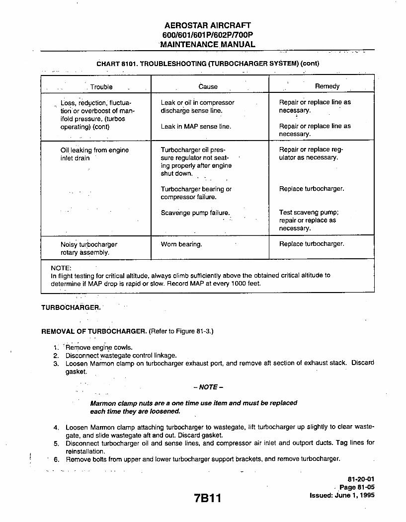
AEROSTAR AIRCRAFT 600/601/601P/602P/700P MAINTENANCE MANUAL
CHART 8101. TROUBLESHOOTING (TURBOCHARGER SYSTEM) (cont)
. Trouble Cause Remedy
Loss, reduction, fluctua-tion or overboost of man-ifold pressure, (turbos operating) (cont)
Leak or oil in compressor discharge sense line.
Leak in MAP sense line.
Repair or replace line as necessary.
Repair or replace line as necessary.
Oil leaking from engine inlet drain
Turbocharger oil pres-sure regulator not seat-ing properly after engine shut down.
Turbocharger bearing or compressor failure.
Scavenge pump failure.
Repair or replace reg-ulator as necessary.
Replace turbocharger.
Test scaveng pump; repair or replace as necessary.
Noisy turbocharger rotary assembly.
Worn bearing. Replace turbocharger.
NOTE: In flight testing for critical altitude, always climb sufficiently above the obtained critical altitude to determine if MAP drop is rapid or slow. Record MAP at every 1000 feet.
TURBOCHARGER.
REMOVAL OF TURBOCHARGER. (Refer to Figure 81-3.)
1. Remove engine cowls. 2. Disconnect wastegate control linkage. 3. Loosen Marmon clamp on turbocharger exhaust port, and remove aft section of exhaust stack. Discard
gasket.
-NOTE-
Marmon clamp nuts are a one time use item and must be replaced each time they are loosened.
4. Loosen Mannon clamp attaching turbocharger to wastegate, lift turbocharger up slightly to clear waste-gate, and slide wastegate aft and out. Discard gasket.
5. Disconnect turbocharger oil and sense lines, and compressor air inlet and outport ducts. Tag lines for reinstallation.
6. Remove bolts from upper and lower turbocharger support brackets, and remove turbocharger.
7B11
81-20-01 Page 81-05
Issued: June 1,1995

AEROSTARAIRCRAFT 600/601/601P/602P/700P MAINTENANCE MANUAL
B 7 2 2
1. EXHAUST OUTLET 2. ALTERNATE AIR DOOR 3. MODE VALVE-4. THROTTLE 5. WASTEGATE ' 6. EXIIAUST MANIFOUD 7. SCREENED: AIR INLET 8. CROSS SHAFT 9. ELECTRICALLY OPERATED
WASTEGATE MOTOR 10. TURBOCHARGER ROCKER
SWITQI 11. INTAKE MANIFOLD 12. BALANCE TUBE PI. CCMPRESSOR DISCHARGE
PRESSURE P2. ENGINE MAP
81-20-01 Page'81-06 Issued: June 1,1995
Figure 81-1. Manuaiiy Controiied Turbocharger System
7B12

AEROSTAR AIRCRAFT 600/601/601P/602P/700P MAINTENANCE MANUAL
B 7 2 3
1. EXHAUST OUTLET 2. ALTERNATE AIR DOOR 3. MODE VALVE 4. THROITLE 5. WASTEGATE 6. AIR INLET 7. CROSS SHAFT 8. WASTEGATE ACTUATOR 9. EXHAUST MANIFOLD
10. INTAKE MANIFOLD 11. HYDRAULICALLY, OPERATED
•5 CONTROLLER (AUTOMATIC) 12. ACTUATOR DRAIN LINE 13. OUTLET TO CABIN
PRESSURIZATION SYSTEM 14. BALANCE TUBE 15. OIL SUMP
OIL PUMP 9 l 7 . AIR INLET SCREEN 18. ENGINE 19. AIR FILTER 20. INDUCTION AIR BOX
PI. C0 FRESSOR DISCHARGE PRESSURE
P2. ENGINE MAP
© NDDEL 601 ONLY 0 MODEL 6aiP ONLY
Figure 81-2. Automaticaiiy Controiied Turboctiarger System
7B13 81-20-01
Page 81-07 issued: June 1,1995

AEROSTAR AIRCRAFT 600/601/601P/602P/700P MAINTENANCE MANUAL
B723
1. EXHAUST OUTLET 2. MANUALLY CONTROLLED
ALTERNATE AIR DOOR 3. COMPRESSOR 4. THROTTLE 5. WASTEGATE 6. DOUBLE SCREENED
AIR INLET 7. CROSS SHAFT 8. WASTEGATE ACTUATOR 9. EXHAUST MANIFOLD 10. INTAKE MANIFOLD
11. HYDRAULICALLY OPERATED CONTROLLER CAUTOMATIC)
12. ACTUATOR DRAIN LINE 13. OVERBOOST VALVE 14. B.ALANCE TUBE 15. OIL SUMP 16. OIL PUMP 17. TURBINE 18. Pi COMPRESSOR DISCHARGE 19. P2 ENGINE MAP 20. FUEL NOZZLE (REF) 21. OVERBOARD BLEED 22. BLEED AIR NOZZLE 23. BLEED AIR TO CABIN 24. AIR FILTER 25. INDUCTION AIR.BOX 26. ENGINE " "
Figure 81-2. Automaticaiiy Controiied Turbocharger System (cont) (IModei 602P Oniy)
81-20-01 Page 81-08 Issued: Junel, 1995 7B14

AEROSTAR AIRCRAFT 600/601/601P/602P/700P MAINTENANCE MANUAL
SYSTEM SHOWN IN CONTROLLED PARTIALLY TURBOCHARGED CONFIGURATION
-WASTE GATE RH EXHAUST MANIFOLD -TURBINE
EXHAUST TLET
ACTUATOR DRAIN LINE
INTAKE -MANIFOLD /-MANII
TURBOCHARGER CONTROLLER
P I L T E R ^ j T ^ ^ ^ ^ ^ W AIR SOURCE
r^W^- \ ^ ^ \ COMPRESSOR ^ K K ^
N ^ ^ N ^ F T \ \ AIR SOURCE ^ ^ ^ ^ • U _
jvA<;Tg r.ATE ovrRBOOST VALVE^'^ = \ = I
CROSS A_ SHAFT—'
y>7^/////////^///////777-
r ^ ^ ^ ^ ^ ^ V U B L E E O AIR T O CABIN
' / ^ / / / / \ / / X / ^ ^ ^ /
TO INLET AIR SOURCE
LH EXHAUST MANIFOLD-P2 ENGINE MAP
P1 COMPRESSOR DISCHARGE PRESSURE '
3 EXHAUST OUTLET
-TURBINE *- WASTE GATE
Figure 81-2. Automaticaily Controiied Turbocharger System (cont) (iViodei 700P Only) 81-20-01
Page 81-09 Issued: June 1,1995 7B15

AEROSTAR AIRCRAFT 600/601/601P/602P/700P MAINTENANGE MANUAL
INSTALLATION OF TURBOCHARGER. (Refer to Figure 81-3.)
1. Position turbocharger onto upper and lower support brackets and install attach bolts. Do not tighten. 2. Slide wastegate (with new gasket) onto exhaust stack until slip joint "bottoms out", then slide wastegate
1/4 in. aft.
- CAUTION-
Insure that turbocharger mounting flanges match perfectly, and gaskets are not damaged during installation.
3. Position turbocharger onto wastegate and torque Marmon clamp to 45-55 in. lb. Ensure no preload. 4. Tighten support bolts in incremental torque sequence until desired torque is reached. Insure no preload. 5. Install aft section of exhaust stack (with new gasket) onto turbocharger exhaust port and wastegate.
Torque Marmon clamp to 45-55 in. lb. 6. Connect turbocharger oil and sense lines, and compressor air inlet and output ducts. 7. Connect wastegate control linkage, and adjust as necessary. 8. Retorque Marmon clamps after high power run-up.
4. WASTEGATE Figure 81-3. Turbocharger Removal/instaiiation
81-20-02 Page 81-10 issued: June 1,1995 7B1 6

AEROSTAR AIRCRAFT 600/601/601P/602P/700P MAINTENANCE MANUAL
MANUALLY OPERATED WASTEGATE SYSTEM.
ADJUSTMENT OF TURBOCHARGER POSITION SWITCH. (Refer to Figure 81-4.)
- CAUTION-
Ensure all switches and equipment are turned off and all autopilot circuit breakers are pulled prior to connecting an external power unit. The master batt. and alternator switches must be left in the off position until the external power unit is disconnected to protect the voltage regulators and system electrical equipment from voltage transients and possible damage.
1. Connect external power to airplane. If extemal power is not available, place Master Battery switch in ON position.
2. Depress and hold lower portion of turbo rocker switch until wastegate reaches fully open position. 3. Loosen position switch attach screws, rotate position switch aft in slotted mounting holes until amber light
in rocker switch just goes out, and tighten position switch attach screws.
- CAUTION-
Do not depress and hold upper portion of turbocharger rocker switch with engine running - overboost may result.
4. Momentarily depress upper portion of turbocharger rocker switch; amber light should come on immedi-ately (.5-1.0 SEC) .
5. Depress and hold lower portion of rocker switch; amber light should go out as wastegate reaches fully open position.
.6 , Reniove extemal power, or place Master Battery switch in OFF positon.
ADJUSTMENT OF WASTEGATE LINKAGE. (Refer to Figure 81-4.)
- CAUTION-
. Ensure all switches and equipment are turned off and all autopilot circuit breakers are pulled prior to connecting an external power unit. The master batt. and alternator switches must be left in the off position until the external power unit is disconnected to protect the voltage regulators and system electrical equipment from voltage transients and possible damage.
1. Connect external power to airplane. If extemal power is not available, place Master Battery switch in ON position.
2. Depress and hold lower portion of turbo rocker switch until amber light goes out. (Wastegate fully open.) ' 3. Check wastegate retaining rods for free play. 4. If free play is evident, loosen actuating rods as necessary to provide approximately .10 inch preload of
wastegate butterfly. 5. Tighten jam nuts.
-6r- -Remove extemal power or place Master Battery switch in OFF position. .
7B17
81-21-02 , Page 81-11
Issued: June 1,1995

AEROSTAR AIRCRAFT 600/601/601P/602P/700P
MAINTENANCE MANUAL
B725
EXHAUST STACK POSITION SWITCH CROSS SHAFT JAM NUT AND ROD END ELECTRICALLY OPERATED WASTEGATE MOTOR WASTEGATE BUTTERFLY
MANUALLY OPERATED
1. 2, 3.
AIRBOX CCMPRESSOR SENSE LINE CONTROLLER ADJUSTMENT SCREW CQNTROLLER CONTROLLER OIL "IN" PORT ENGINE OIL SUMP: MANIFOLD SENSE LINE. OIL TO CONTROLLER OIL SUPPLY LINE ACIUATOR VENT LINE ACIUATOR OIL "OUT' PORT ACTUATOR OIL "IN" PORT CROSS SHAFT JAM NUTS AND ROD ENDS WASTEGATE BUTTERFLY EXHAUST STACK -
AUTOMATIC CONTROLLER
81-21-02 Page 81-12 Issued: June 1,1995
Figure 81-4. Wastegate Linkage
7B18

AEROSTAR AIRCRAFT 600/601/601P/602P/700P MAINTENANCE MANUAL
AUTOMATIC WASTEGATE SYSTEM.
CONTROLLER.
REMOVAL OF CONTROLLER. (Refer to Figure 81 -4.)
1. Remove engine cowling. 2. Disconnect hose from pressurization system sonic nozzle. (Pressurized Model 601P airplane only-
refer to Figure 81-5.) 3. Disconnect controller sense and oil lines. 4. Remove nuts and washers from bolts attaching controller to mounting bracket, and remove controller.
INSTALLATION OF CONTROLLER.
1. Position controller onto mounting bracket and install washers and nuts onto attach bolts. 2. Connect controller sense and oil lines. 3. Connect hose to pressurization system sonic nozzle. (Pressurized Model 601P airplane only-refer to
Figure 81-5.) 4. Install engine cowling.
ADJUSTMENT OF CONTROLLER, MODEL 601/601 P. (Refer to Figure 81 -6.) pps60i48
1. Place throttles fully fonward and attach a .75 inch piece of masking tape between pedestal throttle slots. 2. Mark full throttle position of each throttle on tape, and retard throttles fully. Mark tape .20 inch aft of full
throttle. 3. Start and wann engines per Flight Manual. 4. For 601P, place the pressure bleed air and the dump valve "ON". -5. Set pari<ing brake. . _ 6. When engine oil temperature reaches 80°C place fuel mixture controls to full rich, and prop controls fully
toward. 7. Advance throttle controls slowly until MAP gauge indicates 29.5 in Hg. and mark throttle position on tape. 8. If throttle is more than .20 inch aft of full throttle mark decrease MAP by turning turbocharger controller
adjustment screw clockwise in 1/8 tum increments (11/2 tums max.) until fonvard edge of throttle is at .20 inch mark ± .05 inch at 29.5 in. Hg.
9. If throttle is less than .20 inch aft of full throttle mark, increase MAP by turning turbocharger controller adjustment screw counterclockwise in 1/8 turn increments (1 1/2 tums max.) until forward edge of throt-tle is at .20 inch mark ± .05 inch at 29.5 in. Hg.
10. Perform full power mn-up on both engines to insure smooth operation and correct throttle control lever position. Maximum allowable mis-match between throttle control levers at 29.5 in. Hg. MAP is .15 inch.
81-22-04 Page 81-13
Issued: June 1,1995

AEROSTAR AIRCRAFT 600/601/601 P/6b2P/700P MAINTENANCE MANUAL
11. If ttie max. MAP (red line) cannot be obtained, or if ttie system surges: A. Cfieck ttie tfirottle rigging to insure tfiat tfie tfirottle arm is not bottoming out on tfie console slot prior
to tfie tfirottle valve at the servo reaching the full open position. Re-rig as required. B. Check the wastegate rigging and sealing. C. Check for evidence of oil leaks in the controller/actuator system, including the actuator
venVdrain line. D. Check the orifice fitting on the actuator "Oil Inlet" for blockage. E. Check the sense line from the controller to the compressor discharge for air leakage or signs of
oil, signs of oil would indicate a failure of the controller diaphragm. F. Check the sense line from the controller to the 2 cylinder for air leakage. G. Check all alternate air door seals and their freedom of operation (601, 601P, 602P and 700P). Check all
induction ducts. Check the main air box and intercooler for leakage. Check to see if the filter is still in position (601, 601P, 602P and 700P).
H. Check the pressure relief valve (overboost valve, when installed) for leaks or proper relief setting.
-NOTE-
If the sense line from the controller to the compressor discharge has leaks or has oil in it, the turbocharger system will overboost. If the sense line from the controller to the #2 cylinder leaks, the controller will not schedule properly and engine MAP will drop with altitude prior to the aircraft reaching normal critical altitude. In both cases, adjustment of the controller will be ineffective. Leaks must be corrected.
ADJUSTMENT OF CONTROLLER, MODEL 602P, 700P. (Refer to Figure 81-6.) PPS60148
- WARNING -
This procedure is for the controller on Model 602P and 700P only. If Models 601 or 601P are run-up at this manifold pressure, engine damage may result.
1. Place throttles fully forward and attach a .75 inch piece of masking tape between pedestal throttle slots. 2. Mark full throttle position of each throttle on tape and retard throttles fully. Mark tape .20 inch aft of full
throttle. 3. Start and warm engine per Flight Manual. 4. Place the pressure bleed air and dump valve "ON". 5. Set parking brake. 6. When engine oil temperature reaches 80° C, place fuel mixture controls to full rich and prop controls fully
fonward. 7. Advance throttle controls slowly until MAP gauge indicates 37.0 in. Hg.(42.0 in. Hg. for 700P) and mark
throttle position on tape.
81-22^5 Page 81-14
* Issued: June 1,1995 7B20

AEROSTAR AIRCRAFT 600/601/601P/602P/700P
MAINTENANCE MANUAL
B 7 2 6
BOITCM VIEW RIGHI ENGINE
1. HOSE TO PRESSURIZATION . SYSTEM SONIC NOZZLE
(MODEL 601P ONLY) 2. CONTROLLER KDUNTING BRACKET .3. BRACKET ATTAOI BOLT 4. CONTROLLER ATTACH BOLT
Figure 81-5. Pressurization System Sonic Nozzie Hose (Right Wing Oniy) 81-22-05
Page 81-15 yg2'| issued: June 1,1995

AEROSTARAIRCRAFT 600/601/601P/602P/700P
MAINTENANCE MANUAL
C 5 6 8
D E C R E A S E M A P
I N C R E A S E M A P
1. M A N I F O L D P R E S S U R E A D J U S T M E N T
2 . S E R V O V A L V E B O D Y
3 . B A L A N C E D P I S T O N V A L V E A S S E M B L Y 4. T U R B O C O M P R E S S O R P R E S S U R E ( P I ) 5 . D I A P H R A G M
6 E N G I N E M A N I F O L D P R E S S U R E (P2 ) 7 . A N E R O I D B E L L O W S (Pp) 8 . S P A C E R 9 . C O N T R O L L E R H O U S I N G 1 0 . J A M N U T
V I E W
L O O K I N G A F T
r
81-22-05 Page 81-16 Issued: June .1,1995
Figure 81-6. Automatic Controiier Adjustment
7B22

AEROSTAR AIRCRAFT 600/601/601P/602P/700P
MAINTENANGE MANUAL
B 7 2 7
MODEL 602P AND 700?
1. 0.25 IN. MAXIMUM GAP 2. 0.15 IN. MAXIMUM MISMATCH ALLOWABLE AT MAXIMUM MAP 3/TAPE 4. 37.0 IN. HG. MAP MARK (602P) OR 42.0 IN. HG.
MAP MARK (700P) 5. ' FULL THROTTLE MARK 6. THROTTLE CONTROL LEVER FULLY FORWARD-I. THROTTLE CONTROL LEVER AT 37.0 IN. HG. MAP (602P) OR
42.0 IN. HG.. MAP (700P)
Figure 81-6. Automatic Controiier Adjustment (cont)
7B23
81-22-05 Page 81-17
Issued:June 1,1995

AEROSTAR AIRCRAFT 600/601/601P/602P/700P MAINTENANCE MANUAL
8. If tfirottle is more tfian .20 incfi aft of full tfirottle mark, decrease MAP by turning turbocfiarger controller adjustment screw clockwise in 1/8 turn increments (1 1/2 turns max.) until fonward edge of tfirottle is at .20 incfi mark ± .05 incfi at 37.0 in. Hg. (42.0 in. Hg. for 700P).
9. , If tfirottle is less tfian .20 inch aft of full throttle mark, increase MAP by turning turbocharger controller adjustment screw clockwise in 1/8 turn increments (1 1/2 tums max.) until fonward edge of throttle is at .20 inch mark ± .05 inch at 37.0 in. Hg. (42.0 in. Hg. for 700P).
10. Perform full power run-up on both engines to ensure smooth operation and correct throttle control lever position. Maximum allowable mis-match between throttle control levers at 37.0 in. Hg. MAP is .15 inch. (42.0 in Hg. for 700P). ' ^
11. If max MAP (red line) cannot be obtained or if the system surges. Refer to adjustment of controller. Model 601 and 601 P.
ADJUSTMENT OF WASTEGATE LINKAGE. (Refer to Figure 81-7 and 81-8.)
1. Remove upper and lower engine cowling. . , 2. Adjust actuator rod end per Figure 81-7 with actuator retracted. 3. Disconnect oil supply hose to wastegate actuator at the oil "banjo" fitting near the crankcase breather
tube (top center of engine accessory case). 4. Connect test set to disconnected line. 5. Disconnect "oil in" port hose. Plug hose. 6. Disconnect lower rod ends by removing the through bolts. 7. Connect shop air to tester. Adjust regulator to 80 psi. 8. Actuator should extend. 9. Close wastegate by hand and adjust rod ends so holes will align. Adjust right side rod end (actuator side)
out an additional 4 1/2 (four and one-half) turns. Adjust left side (opposite actuator) out an additional 6 (six) turns.
AUTCMATIC TURBOCHARGER CONTROL
81-22-06 Page 81-18
* Issued: J u n e l , 1995
Figure 81-7. Hydraulic Wastegate Actuator
7B24

AEROSTAR AIRCRAFT 600/601/601P/602P/700P MAINTENANCE MANUAL
C 5 6 9 .
TEST SET PALLET MOUNTED
FLARED TUBE PLUG AN806-4 ^
SURPLUS ACCUMULATOR
EXISTING LINE TO ENGINE CONTROLLER DISCONNECT FROM 'OIL IN" PORT »• AND PLUG
PRESSURE REGULATOR
WASTEGATE OIL PRESSURE SUPPLY (NEAR CRANKCASE BREATHER. TOP AFT OF ENG) DISCONNECT HERE TO CONNECT TEST SET.
WASTEGATE ACTUATOR
DISCONNECT HERE TO CHECK ACTUATOR FOR BY-PASSING
3 iIil[T') ACTUATOR DRAIN LINE (RETURN TO CRANKCASE)
Figure 81-8: Wastegate Rigging - Ground Test Set-Up
7C1
81-22-06 Page 81-19
Issued: June 1,1995
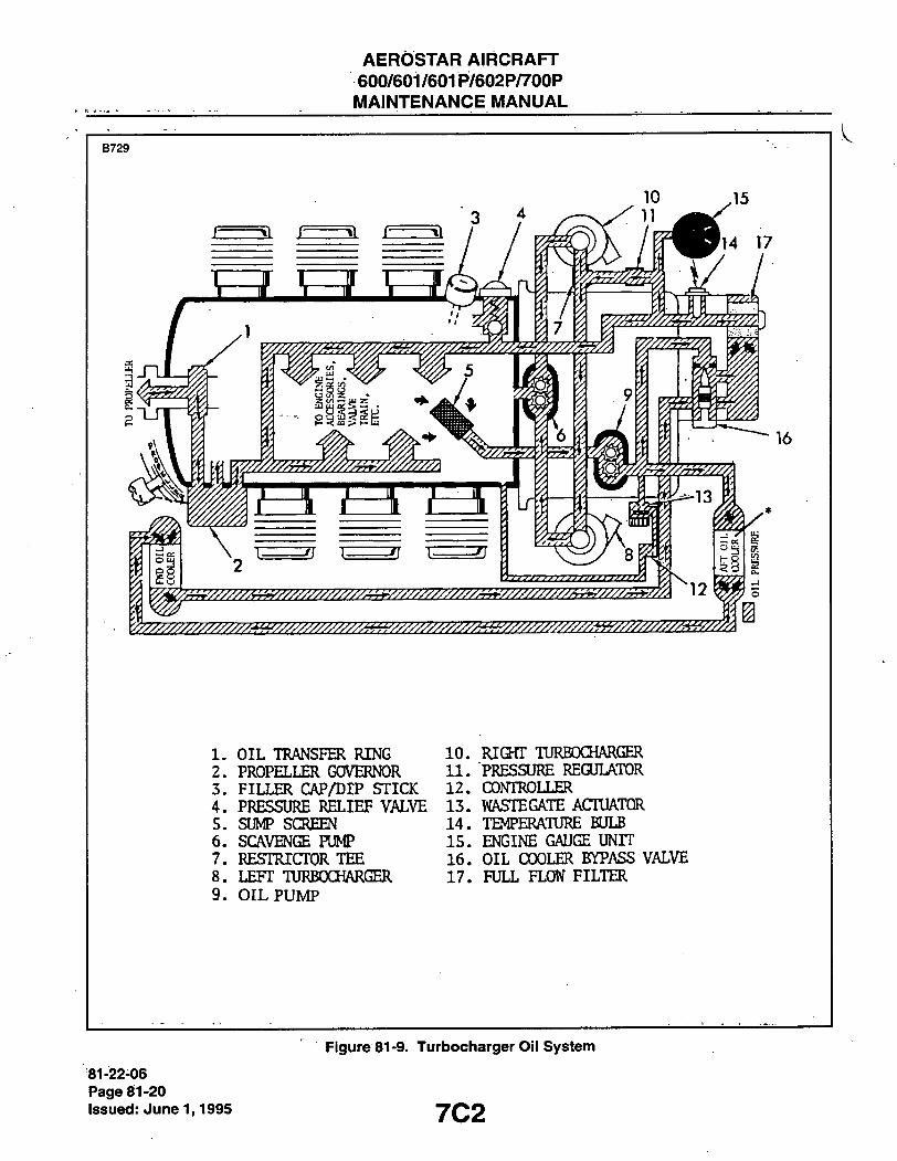
AEROSTAR AIRCRAFT 600/601/601P/602P/700P MAINTENANCE MANUAL
B 7 2 9
1. OIL TRANSFER RING 10. 2. PROPELLER GOVERNOR 11. 3. FILLER CAP/DIP STICK 12. 4. PRESSURE RELIEF VALVE 13. 5. SUMP SCREEN 14. 6. SCAVENGE PUMP 15. 7. RESTRICTOR TEE 16. 8. LEFT TURBOCHARGER 17. 9. OIL PUMP
RIGHT TURBOCHARGER "PRESSURE REGULATOR CONTROLLER WASTEGATE ACTUATOR TEMPERATURE BULB ENGINE GAUGE UNTT OIL COOLER BYPASS VALVE FULL FLOW FILTER
81-22-06 Page 81-20 Issued: June 1,1995
Figure 81-9. Turbocharger Oii System
7C2
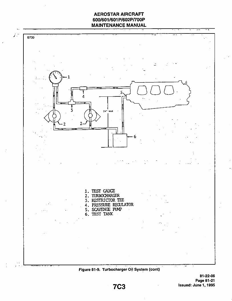
AEROSTAR AIRCRAFT 600/601/601P/602P/700P
MAINTENANCE MANUAL
B 7 3 0
1. "EEST GAUGE 2. TURBOCHARGER 3. RESTRICTOR TEE 4. PRESSURE REGULATOR 5. SCAVENGE PUMP 6. TEST TANK
Figure 81-9. Turbociiarger Oii System (cont)
7C3 81-22-06
Page 81-21 Issued: Junel, 1995

AEROSTAR AIRCRAFT 600/601/601P/602P/700P MAINTENANCE MANUAL
B 7 3 1
FLEX TUBING
TEST: REVERSE FLOW 980214-001
RELIEF VALVE
10 p FILTER
SHOP AIR OR NITROGEN GAS
REGULATOR S/O VALVE
0-200 PSIG GAUGE
FLEX TUBING
TEST: FORWARD FLOW
/
WATER
10p FILTER
SHOP AIR
OR NITROGEN GAS
REGULATOR S/O VALVE
980214-001
RELIEF VALVE
0-200 PSIG . GAUGE ,
81-22-06 Page 81-22 Issued: June 1,1995
Figure 81-10. Turbocharger Oii Suppiy Reiief Vaive Test Set-Up
7C4

AEROSTAR AIRCRAFT 600/601/601P/602P/700P MAINTENANCE MANUAL
10. Insure that rod ends are safe by observing the witness holes on all 4 (four) rod-ends. Insure rod ends are aligned. '
11. Release air pressure on test regulator. 12. Actuator should retract. 13. Connect rod ends to wastegate. 14. Reactuate the system. 15. Using thumb and forefinger, grasp wastegate linkage rods and check for play. Wastegates should close
fully with good strong preload. There should be no play evident. 16. With wastegates actuated, remove drain line from lower fitting on actuator to check actuator for bypass-
ing of oil. No oil should be permitted to bypass.
FUNCTIONAL TEST OF SCAVENGE PUMP. (Refer to Figure 81 -9.)
1. Connect line from turbocharger oil outlets to test tank. 2. Connect scavenge pump inlet line to test tank. 3. Install oil pressure test gauge between turbocharger oil inlet and restrictor tee. Test gauge should read
25 psig hriinimum. 4. Start.engine per Flight Manual and run for 6-7 seconds. Oil should flow from turbochargers into test tank. 5. Oil in test tank should deplete rapidly, indicating that scavenge pump is operating properly.
TESTING TURBOCHARGER OIL SUPPLY RELIEF VALVE. ppseoiei
1. Set up test per Figure 81 -10. 2. Slowly apply pressure to valve in direction opposite to direction of flow indicated on valve body. No bub-
bling should be evident from 0-100 psig. 3. Remove and reverse valve. 4. Slowly apply pressure to valve in direction of flow indicated on valve body. Valve should start to relieve
and start bubbling at 21 ± 2 psig. 5. Relieve pressure. Valve should reseat between 19 psig and cracking pressure.
ACTUATOR CHECK AND WASTEGATE RIGGING ppseous
1. Prior to connecting the actuator and wastegate to the cross shaft and prior to installing the exhaust out-lets duct aft of the turbocharger: A. Manually actuate the cross shaft to insure a smooth operation (no binding or interference). B. Manually actuate the wastegates to insure no binding and free retum. C. Check that the wastegates in the fully closed position fully seal all around the top and bottom of the
exhaust and have clearance with the exhaust tube sidewall near the shaft. 2. Install the exhaust outlets insuring proper position of gaskets, proper torque on clamp and adequate
•clearance with engine mounts. Refer to Figure 81-7 for applicable installation on the following: 1. Insure that the actuator is free to pivot around its mounting bolt. 2. Connect the actuator to the cross shaft arm insuring a correct angle with the cross shaft bracket. Check
that the clearance between the rod end jam nut and the actuator housing is at least .12 inches when the actuator is fully retracted.
7C5
81-25-00 Page 81-23
Issued: June 1,1995

AEROSTAR AIRCRAFT 600/601/601P/602P/700P MAINTENANCE MANUAL
3. Disconnect the line going to the "OIL INLET" and "OIL OUTLET' ports on the actuator and remove (if installed) the orifice fitting on the actuator "OIL INLET" port.
4. Cap off the "OIL OUTLET" port on the actuator. Connect the discharge line of the reservoir test unit to the actuator "OIL INLET" port.
5. Slowly apply oil pressure to the actuator and observe that the actuator shaft: A. Starts moving at 27 ± 3 PSIG. B. Fully extends at 40 ± 3 PSIG. C. Has a full extension of .90 to .98 inch from the rest position. D. Retracts at 30 ± 3 PSIG. E. Is fully retracted at 12 ± 3 PSIG.
6. Apply 70 PSIG to the actuator: A. Check for oil leaks through the vent port or actuator shaft. The actuator should not have any leaks. B. With the cross shaft fully rotated, check for clearance with:
(1) Surrounding hoses (min. .50 inch clearance). (2) Adjacent engine and turbo mounts (min. .37 inch clearance).
7. Relieve the oil pressure on the actuator and connect the linkage arms to the wastegates. 8. Cycle the actuator and wastegates a few time and check that the operation is smooth and has the follow-
ing values. A. Oil pressure 25-30 PSIG: wastegates start closing. B. Oil pressure 40-50 PSIG: wastegates fully closed. C. Oil pressure 28-34 PSIG: wastegates start opening. D. Oil pressure 10-15 PSIG: wastegates open.
9. Install the orifice fitting on the actuator "OIL INLET' port, and reconnect the oil lines to the "OIL INLET" port and "OIL OUTLET' port.
PRESSURE CHECK OF WASTEGATE ASSEMBLY. (Refer to Figure 81-11). PPS60163
1. Remove the wastegate assembly from the aircraft. 2. install the seal, blank flange and Marmon clamp on the flanged part of the assembly. Tighten the Mannon
clamp. 3. Install the wastegate assembly on the base plate holding fixture. 4. Tighten the nuts on the rods to effect a seal on both end plates. 5. Connect the 20-30 lb. weight to the shaft arm with the butterfly in the closed position. 6. Connect the air pressure source, pressure gauge and flow meter as shown in Figure 81-11. Pressurize
the wastegate assembly to 2 PSIG and hold the pressure constant. Squirt leak detector solution (MIL-L-25667 or a mixture of household liquid detergent and water) on test fittings, including,sealed end plate joint and flanged joint seal. There should be no visible leakage on the test connections.
7. Adjust the pressure to maintain an indicated flow rate of 1.9 cfm on the Flow Meter. Observe the pres-sure indicated on the manometer. The minimum allowable indicated pressure at this rate shall be 1.6 inches Hg.
8. Reduce pressure to zero. Remove weight, blank flange and end plates.
81-26-00 Page 81-24 Issued: June 1,1995 7C6

AEROSTAR AIRCRAFT 600/601/601P/602P/700P
MAINTENANCE MANUAL
2 0 - 2 3 L B . W T .
Figure 81-11. Pressure Checl( of Wastegate Assembiy
7C7
81-26-00 Page 81-25
issued: June 1,1995

AEROSTAR AIRCRAFT 600/601/601P/602P/700P
MAINTENANCE MANUAL
THIS PAGE INTENTIONALLY LEFT BLANK
7C8
AEROSTAR AIRCRAFT 600/601/601P/602P/700P
MAINTENANCE MANUAL
CHAPTER
CHARTS AND
WIRING DIAGRAMS
7C9

AEROSTAR AIRCRAFT 600/601/601P/602P/700P MAINTENANCE MANUAL
CHAPTER 91 - CHARTS AND WIRING DIAGRAMS
TABLE OF CONTENTS/EFFECTIVITY
CHAPTER SECTION GRID SUBJECT SUBJECT NO. EFFECTIVITY
91-00-00 GENERAL 7011 91-01-00 Torque Requirements 7011 91-01-01 Flare Fitting Torques 7011 91-01-02 Recommended Nut Torques 7C12 91-01-03 Special Torque Values 7015 91-02-00 Conversion Data 7016 91-02-01 Decimal Conversions 7017 91-02-02 Decimal Equivalents of Drill Sizes 7018 91-02-03 Torque Conversion 7019 91-02-04 Incties to f /lillimeter 7021 91-02-05 Temperature Conversions 7023 91-02-06 Conversion Formulas 7024 91-03-00 Approved AntiSeize and Lubricants 701 91-04-00 Special Tools 7D2
91-10-00 ELECTRICAL 7D20 91-11-00 Electrical Wire Coding 7D20 91-12-00 Electrical Symbols 7021 91-13-00 Electrical Scfiematics Index 7D23
91 - ContTEffec. Page -1
yQ^Q Issued: June 1,1995

AEROSTAR AIRCRAFT 600/601/601P/602P/700P MAINTENANCE MANUAL
GENERAL.
TORQUE REQUIREMENTS.
The t o r ^ values given in Chart 9102 are derived from oil-free cadmium-plated threads and are recommended for all airframe installation procedures where torquing is required. Unless othenwise noted in sections where other values are stipulated. Engine torque values are found in the latest revision of Lycoming Overhaul Manual, and propeller torque values are found in Chapter 61 of this manual. Chart 9101 lists the torque values for flared fittings of various sizes and material.
- CAUTION-
Do not overtorque fittings.
-NOTE-
When flared fittings are being installed, ascertain that the male threads are properly lubricated. Torque the fittings in accordance with Chart 9101.
CHART 9101. FLARE FITTING TORQUES
TORQUE — INCH-POUND
TUBING
OD
INCHES
ALUMINUM - ALLOY
TUBING FLARE - AND
10061 OR 10078
STEEL TUBING
FLARE
AND I006I
HOSE END FITTING
AND
HOSE ASSEMBLIES
MINIMUM MAXIMUM MINIMUM MAXIMUM MINIMUM MAXIMUM
1/8 3/16
1/4
5/16
3/8
1/2
5/8
3/4
! 1-1/4
1-1/2
1-3/4
2
40 65
60 80
75 , 125
150 250
200 350
300 500
500 700
600 900
600 900
90 100
135 150
180 200
270 300
450 500
650 700
900 1000
1200 1400
70 100
70 120
85 180
100 250
210 420
300 480
500 850
700 1150
91-01-01 Page 91-01
yQ-| "I Issued: June 1,1995

AEROSTAR AIRCRAFT 600/601/601P/602P/700P MAINTENANCE MANUAL
CHART 9102. RECOMMENDED NUT TORQUES P P S 2 0 0 1 5
TORQUES: The importance of correct application cannot be overemphasized. Undertorque can result in unnec-essary wear of nuts and bolts as well as the parts they are holding together. When insufficient pressures are applied, uneven loads will be transmitted throughout the assembly which may result in excessive wear or prema-ture failure due to fatigue. Overtorque can be equally damaging because of failure of a bolt or nutt;fbm over-stressing the thread areas. The following procedures should be followed to assure that the correct torque is applied:
1 . Torque (self-locking fasteners) Add the friction torque from Chart A for sizes 8 through 7/16 to the recom-mended torque from Chart B to get the final torque. This would be the actual reading on the torque wrench.
2. Torque (castellated and non-self-locking nuts)- Use only the torque given in Chart B. Unless othenwise specified, when castellated nuts are used with a cotter pin on moving joints, do not torque the nut. Tum the nut onto the bolt until proper grip is established and alignment with the cotter pin hole is achieved. Then install the cotter pin.
GENERAL REQUIREMENTS: 1. Calibrate the torque wrench periodically to assure accuracy; recheck frequently. 2. Ascertain that the bolt and nut threads are clean and dry (unless othenwise specified by the manufactur-
er). If the bolt or nut is specified to be lubricated prior to tightening, the torque range should be reduced 50 percent.
3. Use a bolt length long enough to prevent bearing loads on the threads. The complete chamfer or end radius of the bolt or screw must extend through the nut.
4. Unique torques specified in the text of this manual supersede the torques given in Charts A and B. 5. Refer to the latest revision of Lycoming SSP 1776 for torques on parts used on Lycoming engines. 6. A maximum of two AN960 washers may be added under the bolt heads or nuts to correct,for variations in
material thickness within the tolerances permitted. 7. Limitations of the use of self-locking nuts, bolts and screws including fasteners with non-metallic inserts
are as follows: A. Fasteners incorporating self-locking devices shall not be reused if they can be mn up using only fin-
gers. They may be reused if hand tools are required to run them up, providing there is no obvious damage to the self-locking device prior to installation.
B. Bolts 5/16 inch diameter and over with cotter pin holes may be used with self-locking nuts. Nuts with non-metallic locking devices may be used in this application only if the bolts are free from burrs around the cotter pin hole.
C. Do not use self-locking nuts at joints which subject either the nut or the bolt to rotation. D. Never tap or rethread self-locking fasteners. Do not use nuts, bolts or screws with damaged threads
or rough ends.
91-01-02 Page 91-02 issued: June 1,1995 7C12

AEROSTAR AIRCRAFT 600/601/601P/602P/700P MAINTENANCE MANUAL
Chart 9102. RECOMMENDED NUT TORQUES (cont)
CHART A
BOLT-' FRICTION DRAG SIZE TORQUE (IN LBS )
8- 15 10 18
1/4 30 5/16- - • 60 3/8 80 7/16 100
CHART B
APPLICABLE TO;COARSE THREADS ONLY
COARSE THREAD SERIES
BOLTS Steel Tension
AN 3 thru AN 20 AN 42 thru AN 49 AN 73 thru AN 81 AN 173 thru AN 186 MS 20033 thru MS 20046 MS 20073 . MS 20074 AN 509 NK9 MS 24694 AN 525 NK525 MS 27039
NUTS
Steel Tension Steel Shear
AN 310 AN 320 AN 315 AN 364 AN 363 NAS 1022 AN 365 MS 17826 NAS 1021 MS 20364 MS 17825 MS 21045 MS 20365 MS 20500 NAS 679
Nul bolt Torque Limits Torque Limits size in-lbt in-lbs
Mm. Max. Min. Max.
8 -32 12 15 7 9 10 -24 20 25 12 15
1/4-20 40 50 25 30 5/16-18 80 90 48 55
3/8-16 160 185 95 110 7/16-14 235 255 140 155
1/2-13 400 480 240 290 9/16-12 500 700 300 420
5/8-11 700 900 420 540 3/4-10 1,150 1,600 700 950 7/8- 9 2,200 3,000 1,300 1.800
1 - 8 3,700 5.000 2,200 3,000 1-1/8-8 5,500 6.500 3.300 4,000 1-1/4-8 6,500 8.000 4,000 5.000
7C13
91-01-02 Page 91-03
Issued: June 1,1995

AEROSTAR AIRCRAFT 600/601/601P/602P/700P MAINTENANCE MANUAL
Chart 9102. RECOMMENDED NUT TORQUES (cont)
FINE THREAO SERIES
BOLTS BOLTS BOLTS Steel Tension Steel Tension Aluminum
AN 3 thru AN 20 MS 20004 thru MS 20024 AN 300 thru AN 20DD AN 42 thru AN 49 NAS 144 thru NAS 158 AN 17300 thru AN 18600 AN 73 thru AN 81 NAS 333 thru NAS 340 AN 50900 AN 173 thru AN 186 NAS 583 thru NAS 590 AN 5250 MS 20033 thru MS 20046 NAS 624 thru NAS 644 MS 27039D MS 20073 NAS 1303 thru NAS 1320 MS 2469400 MS 20074 NAS 172 AN 509 NK9 NAS 174 MS 24694 NAS 517 Steel shear bolt AN 525 NK 525 MS 27039 NAS 464
NUTS NUTS NUTS
Steel Tension Steel Shear Steel Tension Steel Shear Alum. Tension Alum. Shear
AN 310 AN 320 AN 310 AN 320 AN 3650 AN 3200 AN 315 AN 364 AN 315 AN 364 AN 3100 AN 3640 AN 363 NAS 1022 AN 363 NAS 1022 NAS 10210 NAS 10220 AN 365 MS 17826 AN 365 MS 17826 NAS 1021 MS 20364 MS 17825 MS 20364 MS 17825 MS 20365 MS 21045 MS 21045 MS 20365 NAS 1021 MS 20500 NAS 679 NAS 679 NAS 1291
Nut-bolt Torque Limits Torque Limits Torque Limits Torque Limits Torque Limits Torque Limits size in-lbs in-lbs in-lbs in-lbs in-lbs in-lbs
Min. Max. Min. Max. Min. Max. Min. Max. Min. Max. Min. Max.
8 -36 12 15 7 9 5 10 3 6 10 -32 20 25 12 15 25 30 15 20 10 15 5 10
1/4-28 50 70 30 40 80 100 50 60 30 45 15 30 5/16-24 100 140 60 85 120 145 70 90 40 65 25 40 3/8-24 160 190 95 110 200 250 120 150 75 110 45 70
7/16-20 450 500 270 300 520 630 300 400 180 280 .110 170 1/2-20 480 690 290 410 770 950 450 550 280 410 160 260
9/16-18 800 1,000 480 600 1.100 1,300 650 800 380 580 230 360 5/8-18 1,100 1,300 660 780 1,250 1,550 750 950 550 670 270 420 3/4-16 2,300 2,500 1,300 1.500 2,650 3.200 1.600 1,900 950 1,250 56C 880 7/8-14 2.500 3,000 1,500 1,800 3,550 4,350 2,100 2,690 1,250 1,900 750 1,200
1 -14 3,700 4.500 2,200 3,300 4,500 5,500 2.700 3,300 1,600 2.400 950 1,500 1-1/8-12 5.000 7,000 3,000 4.200 6,000 7,300 3,600 4.400 2,100 3,200 1.250 2,000 1-1/4-12 9,000 11.000 5,400 6,600 11,000 13,400 6,600 8,000 3,900 5,600 2,300 3,650
91-01-02 Page 91-04
Issued: J u n e l , 1995 7C1 4

AEROSTAR AIRCRAFT 600/601/601P/602P/700P MAINTENANCE MANUAL
Chart 9103. SPECIAL TORQUE VALUES
SPECIFIC ITEM - SPECIAL TOROUE VALUES
INSTALLATION TOROUE INCH POUNDS
MIN - MAX
MINIMUM READING FRICTION DRAG TORQUE IN-LBS
Wing attach bolts (7/8-14) NAS 464-15; AN364-1414 Nut* 600 - 800 70 Empennage attach bolts (3/4-16) NAS 464-12; AN364-1216 Nut 290 - 410 Empennage attach bolts (5/8-18) NAS 461-10; AN364-1018 Nut 270 - 300 Engine Mount attach to firewall AN7 (7/16-20) 450 - 500 • 14 Engine Mount attach to Lord Mount, AN7 (7/16-20), 450 - 500 14 Engine mount pads to engine block 275 -Marmon Clamps - Turbo and Wastegate** 45 - 55 4 Propeller to flywheel/crankshaft 720 - 840 Sparkplugs to Engine 360 - 420 Fuel Injector Nozzles 60 -Exhaust Flange to Engine 100 - 140 Spin on Oil Filter 216 - 240 Injector to Intake Plenum Chamber 130 - 150 Worm Drive Hose Clamps 35 - 45 -Out Flow and Safety Valve Flange 20 -Jam Nut, 980014-1 Brake Master Cylinder 35 -Goodyear Wheel Assembly Bolts'" 115-Cleveland Wheel Assembly Bolts*** 180 - 7 Main Landing Gear Axle Nut**** 25 -Nose Wheel Assembly Bolts 165 -Nose Wheel Hub Nut (OZONE, OAS5462) 85 - 105
160-190.
— NOTES — •Friction torque for wing attach bolts must not exceed 400 in-lbs. therefore, "final" torque is limited to 1000 in-lbs. Max. **Retorque check is required after first run up when cooled. ***Sets of Wheel bolts must be torqued evenly in 20 in-lbs. increments up to "final torque". ****Torque axle nut to 50 in-lbs. while manually rotating wheel. Back off to zero torque - all parts still contacting. Retorque to 25-in-lbs. while manually rotating wheel. If not in locking position, advance nut to next cotter pin hole and install cotter pin. *****lf not in locking position, back off nut to next cotter pin hole and install cotter pin.
All nuts and bolts related to engine; See latest revision of Lycoming Service Table of Limits NO.SSP1776.
Refer to the write up in Chart 9102, Recommended Nut Torques, for instructions on determining Friction Drag Torque.
91-01-03 Page 91-05
Issued: June 1,1995

AEROSTAR AIRCRAFT 600/601/601P/602P/700P MAINTENANCE MANUAL
CONVERSION DATA
1. This section contains the various conversion data that may be useful when figuring capacities, lengths, temperatures, and various weights and measures from the English system values to the metric system values or back again. . .
2. The English system is in use by England and the United States. All other countries use the metric system.
3. Procedure for Converting Inches to Millimeters. (Chart 9107).
A. Example: Convert 1.5 inches to millimeters. (1) Read down inches colurnn to 1. inches. (2) Read across top inch column to 0.5. (3) Read down and across to find millimeters (1.5 inches is 38.10 millimeters).
4. Procedure for Converting Fahrenheit (F) and Celsius (C) (Centigrade) Temperature. (Chart 9108).
A. Read number in middle column, if in degrees Celsius (°C), read Fahrenheit equivalent in right hand column. If in degrees Fahrenheit (°F), read Celsius equivalent in left hand column.
(1) 70°F 21.rC. (2) 30°C 86.0°F.
91-02-00 Page 91-06 Issued: June 1,1995 7C16

AEROSTAR AIRCRAFT 600/601/601P/602P/700P MAINTENANCE MANUAL
Chart 9104. DECIMAL CONVERSION
4TNI BTNI 16rN* 32)€M 64TN« TO 3 PLACK*
TO X •LACK!
M . M . tquiy.
1 1
S4- .016 .031
.02
.03 .397 .794 32
.016
.031 .02 .03
.397
.794
^ - .047 .062
.05
.06 1.191 1.587 16
.047
.062 .05 .06
1.191 1.587
&- .078 .094
.08
.09 1.984 2.381 32
.078
.094 .08 .09
1.984 2.381
i z . 64
.109
.125 .11 .12
2.778 3.175 8
.109
.125 .11 .12
2.778 3.175
5 9 64" .141
.156 .14 .16
3.572 3.969 32
.141
.156 .14 .16
3.572 3.969
3 a- .172 .188
.17
.19 4.366 4.762
.172
.188 .17 .19
4.366 4.762
7 12. 64 .203
.219 .20 .22
5.159 5.556 32
.203
.219 .20 .22
5.159 5.556
1 15. 64 .234
J!50 .23 .25
5.593 6.350 4
.234 J!50
.23
.25 5.593 6.350
9 17 64" .266
.281 .27 .28
6.747 7.144
.266
.281 .27 .28
6.747 7.144
5 19 S4- .297
.312 JO J l
7.540 7.937 16
.297
.312 JO J l
7.540 7.937
11 32"
21 64" .328
Mi .33 M
8.334 8.731
3 H- J59 .375
J6 .38
9.128 9.525 d
J59 .375
J6 .38
9.128 9.525
25 64 .391
.406 .39 .41
9.922 10.319
7 27. 64 .422
.438 .42 .44
10.716 11.112
.422
.438 .42 .44
10.716 11.112
15 i f - .453 .469
.484
.500
.45
.47
.48
.50
11.509 11.906
12.303 12.700
32 31 S4'
.453
.469
.484
.500
.45
.47
.48
.50
11.509 11.906
12.303 12.700
4rNS STHI h 6 r H .
11 16'
13 re
32)0
21 32
23 32
25 52
15 16
27 32
29 32"
31 32"
6 4 r H *
35 63"
§2. 64
41 g4"
45. 64
47 64'
49 64'
51 63-
55 64
61
TO J PLACtt
TO 2 rLACtt
M.M IQUIV.
.516
.531 .52 .53
13.097 13.494
.547
.562 .55 .56
13.891 14.288
.578
.594 .58 .59
14.684 15.081
.609
.625 .61 .62
15.478 15.875
.641
.656 .64 .66
16.272 16.669
.672
.688 .67 .69
17.065 17.462
.703
.719 .70 .72
17.859 18256
.734
.750 .73 .75
18.653 19.050
.766
.781 .77 .78
19.447 19.844
.797
.812 .80 .81
20.241 20.637
.828
.844 .83 .84
21.034 21.431
.859
.875 .86 .88
21.828 22225
.891
.906 .89 .91
22.622 23.019
.922
.938 .92 .94
23.416 23.812
.953
.969 .95 .97
24.209 24.606
.984 1.000
.98 1.00
25.003 25.400
7C17
91-02-01 Page 91-07
Issued: June 1,1995
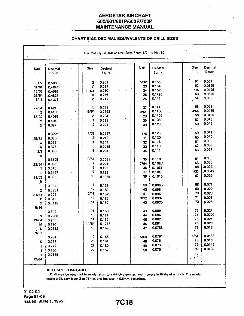
AEROSTAR AIRCRAFT 600/601/601P/602P/700P MAINTENANCE MANUAL
CHART 9105. DECIMAL EQUIVALENTS OF DRILL SIZES
D e c i m a l E q u i v a l e n t s o f D r i l l S i z e s F r o m 1 / 2 " t o N o . 8 0
S i z e D e c i m a l S i z e D e c i m a l S i z e D e c i m a l S i z e D e c i m a l
E q u i v . E q u i v . E q u i v . • E q u i v .
1 /2 0 : 5 0 0 G 0 . 2 6 1 5 / 3 2 0 . 1 5 6 2 51 0 . 0 6 7
3 1 / 6 4 0 . 4 8 4 3 F 0 . 2 5 7 2 3 0 . 1 5 4 5 2 0 . 0 6 3 5
15/32 0 . 4 6 8 7 E - 1 / 4 0 . 2 5 0 2 4 0 . 1 5 2 1 / 1 6 : 0 . 0 6 2 5
29/64 , 0 . 4 5 3 1 D 0 . 2 4 6 2 5 0 . 1 4 9 5 5 3 0 . 0 5 9 5
7 / 1 6 0 . 4 3 7 5 C 0 . 2 4 2 2 6 0 . 1 4 7 54 0 . 0 5 5
2 7 / 6 4 0 . 4 2 1 8 B 0 . 2 3 8 2 7 0 . 1 4 4 5 5 0 . 0 5 2
z • 0 . 4 1 3 15/64 0 . 2 3 4 3 9/64 0 . 1 4 0 6 3 / 6 4 0 . 0 4 6 8
1 3 / 3 2 0 . 4 0 6 2 A 0 . 2 3 4 2 8 0 . 1 4 0 5 5 6 - 0 . 0 4 6 5
Y 0 . 4 0 4 1 0 . 2 2 8 2 9 0 . 1 3 6 5 7 0 . 0 4 3
X 0 . 3 9 7 2 0 . 2 2 1 3 0 0 . 1 2 8 5 5 8 0 . 0 4 2
0 . 3 9 0 6 7 / 3 2 0 . 2 1 8 7 1 /B 0 . 1 2 5 5 9 0 . 0 4 1
26/64 0 . 3 8 6 3 0 . 2 1 3 3 1 0 . 1 2 0 6 0 0 . 0 4 0
W 0 . 3 7 7 4 0 . 2 0 9 3 2 0 . 1 1 6 61 0 . 0 3 9
V 0 . 3 7 5 5 0 . 2 0 5 5 3 3 0 . 1 1 3 6 2 0 , 0 3 8
3 / 8 0 . 3 6 8 6 0 . 2 0 4 3 4 0 . 1 1 1 6 3 0 . 0 3 7
U 0 . 3 5 9 3 1 3 / 6 4 0 . 2 0 3 1 3 5 0 . 1 1 0 6 4 0 . 0 3 6
23/64 0 . 3 5 8 7 0 . 2 0 1 7 / 6 4 0 . 1 0 9 3 6 5 0 . 0 3 5
T 0 . 3 4 6 8 0 . 1 9 9 3 6 0 . 1 0 6 5 6 6 0 . 0 3 3
S 0 . 3 4 3 7 9 0 . 1 9 6 3 7 0 . 1 0 4 1 /32 , 0 . 0 3 1 2
n / 3 2 0 . 3 3 9 10 0 . 1 9 3 5 3 8 0 . 1 0 1 5 6 7 0 . 0 3 2
R
0 . 3 3 2 11 0 . 1 9 1 3 9 0 . 0 9 9 5 6 8 0 . 0 3 1
Q 0 . 3 2 8 1 12 0 . 1 8 9 4 0 0 . 0 9 8 6 9 0 . 0 2 9
2 1 / 6 4 0 . 3 2 3 3 / 1 6 0 . 1 8 7 5 4 1 0 . 0 9 6 7 0 0 . 0 2 8
P 0 . 3 1 6 13 0 . 1 8 5 3 / 3 2 0 . 0 9 3 7 7 1 0 . 0 2 6
0 0 . 3 1 2 5 14 0 . 1 8 2 4 2 0 . 0 9 3 5 7 2 0 . 0 2 5
5 /16 0 . 3 0 2 15 0 . 1 8 0 4 3 0 . 0 8 9 7 3 0 . 0 2 4
N 0 . 2 9 6 8 16 0 . 1 7 7 4 4 0 . 0 8 6 - 7 4 0 . 0 2 2 9
19/64 0 . 2 9 5 17 0 . 1 7 3 4 5 0 . 0 8 2 7 5 0 . 0 2 1
M 0 . 2 9 0 1 1 / 6 4 0 . 1 7 1 8 4 6 0 . 0 8 1 7 6 0 . 0 2 0
L 0 . 2 8 1 2 18 0 . 1 6 9 5 4 7 0 . 0 7 8 5 7 7 0 . 0 1 8
9 / 3 2
0 . 2 8 1 19 0 . 1 6 6 5 / 6 4 0 . 0 7 8 1 1 /64 0 . 0 1 5 6
K 0 . 2 7 7 2 0 0 . 1 6 1 4 8 0 . 0 7 6 - 7 8 0 . 0 1 6
J 0 . 2 7 2 21 0 . 1 5 9 4 9 0 . 0 7 3 7 9 , 0 , 0 1 4 5
1 0 . 2 6 6 2 2 0 . 1 5 7 5 0 0 . 0 7 0 8 0 0 . 0 1 3 5
H 0 . 2 6 5 6
17/64
D R I L L S I Z E S A V A I L A B L E :
D r i l l m a y be o b t a i n e d i n regu la r s izes t o a 4 - i n c h d i a m e t e r , a n d i n c r e a s e in 6 4 t h s o f an i n c h . T h e regu la r
m e t r i c d r i l l s v a r y f r o m 2 t o 7 6 m m . a n d inc rease it i 0 . 5 m m . v a r l a t i o r t s .
91-02-02 Page 91-08
Issued: June 1,1995 7C1 8

AEROSTAR AIRCRAFT 600/601/601P/602P/700P MAINTENANCE MANUAL
CHART 9106. TORQUE CONVERSIONS
INCH POUNnS TOCeNTlMF.THR KII.OCiRAMS (cmkg.)
5 in. lbs. .5.76 cmkg. 45 in. lbs. 5l,X4cmkg, 85 in" lbs. 97.92-cmkg. 10 in. lbs. 11.52 cmkg. 50 in. lbs. " 57.60 cmkg, • 90-in. lbs, • I().1,6X cmkg. I.S in: lbs. I7.2K cmkg. 55 in lbs. 6,1,.16 cmkg. 95 in lbs, , 109,44 cmkg. 30 in. lbs. 2.V04 cmkg. 6(1 in lbs. 64,12 cmkg. 100 in lbs. , 1 15,20 cmkg. 2.S in. lbs. 2K.SO cmkg. 65 in lbs. 74,XX cmkg. 105 in lbs. • 120,96 cmkg.
;. , .10 in. lbs' .14.56 cmkg. 70 in lbs. X0.64 cmkg. 110 in lbs. 126,72 cmkg. - ". . .VS in. lbs. 40..12 cmkg. 75 in lbs. 86,40 cmkg. 115 in lbs. l,12,4X cmkg.
40 in. lbs. 46.0X cmkg. XO in lbs. 42.16 cmkg. 120 in lbs. MX,24 cmkg.
(cmkg.) C L M IMF IfcR KII.OCiRAMS TO INCH POUND.S
.•iO cnikg. 4.V4 in. lbs. .'00 cmkg. 260,4 in, lbs. 550 cmkg. 477.4 in, lbs. lOOtmkg. K6.X in. lbs. 150 cmkg. ,10,1,X in, lbs. N)0 cmkg. 520,8 in. lbs. 1.SO cmkg. 1.10.2 in. lbs. • 400 cmkg. .147.2 in, lbs, i 650 cmkg. 564.2 in, lbs. 200 cmkg. 17.1.6 in. lbs. 450 cmkg. .140.6 in. Ihs, 700 cmkg. 607,6 in, lbs. 250 cmkg. 217.0 in. lbs. 500 cmkg. 4.14.0 in, lbs.
. FOOT POUNDS TO MHTER KILOGRAMS (mkg.)
2'/. It. lbs. .146 mkg. 67'/; ll. lbs. 4..V12 mkg. 165 fl. lbs. 22,81.1 mkg. It. lbs. .691 mkg. 70 ll lbs. 4.67K mkg. 170 fl. lbs. 2.1,504 mkg.
. .. 71/: 11. lbs. 1.0,17 mkg. 72'/: ft. lbs. 10.024 mkg. 175 ll. lbs. • 24,195 mkg. . • ,10 n. lbs. • I..1K.1 mkg. 75 11. lbs. l(),.164 mkg. IKO fl. lbs. 24,8X7 mkg.
. I2',A tl. lbs. I.72X mkg. 77', ll. lbs. 10,715 mkg. 1X5 ll. lbs. 25,578 mkg. \i 11, lbs. 2.074 mkg. SO n. lbs. 11,060 mkg. 190 fl. lbs. 26.269 mkg. 17','; ii, lbs. 2.4iy mkg. X2'/: ll. lbs. 11,406 mkg. 195 fl. lbs. 26.9(>0 mkg.
, .20 ll. lbs. 2.765 mkg. X5 ll. lbs. 11.752 mkg. 2(H) fl. lbs. 27.652 mkg. 22'/: U. lbs. .till mkg. X7'/: (1. lbs. 12,047 mkg. 105 fl. lbs. 2X..14.1 mkg. 2.S It. lbs. .1.456 mkg. 40 It. lbs. 12.441 mkg. 210 (1, lbs. 24.0.14 mkg.
- 27'/.. ll. lbs. .1.X02 mkg. 42'.': fl lbs. 12.7X4 mkg. 215 ll. lbs. 29,726 mkg. M) U. lbs. 4.14X mkg. 45 fl. lbs. 1,1, |.14 mkg. 220 fl. lbs. .10.417 mkg. .12'':- 11; lbs. 4.44.1 mkg. 47'/: II. lbs. 1.1.4X0 mkg. 225 fl. lbs. .1I.I0X mkg. .VS 11. lbs. 4.X.19 mkg. 100 ll. lbs. I.1.X26 mkg. 2,10 ll. lbs. ,1|,X(K)mkg.
• M</: ll. lbs. .5.1X5 mkg. 105 11. lbs. 14.517 mkg. 2.15 fl. lbs. .12.491 mkg. 40 ll. lbs. 5.5.10 mkg. Ill) ll. lbs. I5.2()X mkg. 240 fl. lbs. .1.1,1X2 mkg. 42'/: 11. Ihs. 5.X76 mkg. 115 ll. lbs. 15.400 mkg. 245 ll. lbs. ' ,V1,X7.1 mkg. 4.S ll. lbs. 6.222 mkg. 120 fl. lbs. 16.541 mkg. 250 fl. lbs. " .14.565 mkg.
-"° .47'/..11. lbs. 6.567 mkg. 125 ll. lbs. 17.2X2 mkg. 255 fl. lbs. .15,256 mkg. '50 ll. lbs. 6.41.1 mk-i-. 1.10 fl. lbs. 17.474 mkg. 260 fl. lbs. .15.947 mkg. S2',': Ii. lbs. 7.25X mkg. 1.15 fl. lbs. IX.665 mkg. 265 ll. lbs. .16,6.19 mkg. 5S It. lbs. 7.604 mkg. 140 ll. lbs. I4..156 mkg. 270 fl. lbs. ' ,17..1.10 mkg.
• - ' 57'/. ll. lbs. 7.450 mkg. 145 ll. lbs. 10.047 mkg. 275 fl. lbs. .1X.02I mkg. • Ml ll. lbs. S.295 mkg. 150 ll. lbs. 20.7.14 mkg. 2X0 ll. lbs. .IX. 71.1 mkg.
." 62'/: H. lbs. K.64I mkg. 155 ll. lbs. 21,4.10 mkg. 2X5 fl. lbs. .19,404 mkg. .. f.5 a. lbs. K.4X7 mkg. 160 ll. lbs. 22.121 mkg. 290 fl. lbs. 40,095 mkg.
295 fl. lbs. 40.7X6 mkg. .100 (t. lbs. 4I.47X mkg.
(mkg.) MKTER KILOGRAMS TO HOOT POUNDS
- • • 1 mkg. 7.2.1 It. lbs. K mkg. 57,X6 fl. lbs. 15 mkg. 108.49 ll, lbs. 2 mkg. 14.46 (1. lbs. 4 mkg. 65.04 ft. lbs. 16 mkg. •115.72 ft. lbs. .1 mkg. ' 21.64 11. lbs. 10 mkg. 72..12 fl. lbs. 17 mkg. 122.95 It. lbs. 4 mkg. 2K.4.1 ft. lbs. ' 11 mkg. 79.56 ft. lbs. IX mkg. 1.10,19 ft. lbs.
" " 5 mkg. ' .16.16 It. lbs. 12 mkg. 86.74 fi.-|bs. 19 mkg. I.17.42 ft. lbs." 6 mkg. 4.1..14 tl. lbs. 1.1 mkg. 94.02 ll. lbs. ...20 mkg. |44,65 fl, lbs. 7,mkg. 50.6.1 ll. lbs. 14 mkg. 101.26 ft. lbs. " 21 mkg. 151.84 fl, lbs.
22 mkg. 159,12 fl. lbs.
91-02-03 . Page 91.-09
Issued: June 1,1995

AEROSTAR AIRCRAFT 600/601/601P/602P/700P
MAINTENANCE MANUAL
THIS PAGE INTENTIONALLY LEFT BLANK
91-02-03 Page 91-10 Issued: June 1,1995 7C20

AEROSTAR AIRCRAFT 600/601/601P/602P/700P
MAINTENANCE MANUAL
CHART 9107. INCHES TO MILLIMETERS
Fraction Daetraol Inch
D«cim<il MllUmvwrt
Fraclion ol Inch
D K l m a l Inch
Decimal FracUoa ollnch
DKlmal Inch
Decimal Millimewisl
Fraction oltnch
Decimal Inch
Decimal Millimeleie
1/64
1/32
3/64..
1/16
S/64...
3/32 -
7/64...
1/8
9/64 ..
S/32
II,'64
1/16
, 13/64
7/32
15/64
1/4
.01562S
.03125
.046875
.0625
.076125
.09375
.109375
.125
.140625
.l"i625
.171875
.1875
.203125
.21875
.234375
.25
0.3968B
0.79375
1.19063
1.58750
1.98438
2.38125
2.77813
3.17501
3.57188
3.96876
4.36563
4.76251
5.15939
5.SS826
5.95314
6.35001
17/64
9/32
19/64.
5/I8.._
21/64
11/32
23/64.
3/8
25/64.
13/32
27/64.
7/16
29/64
15/32
31/64
1/2
.265625
.28125
.296875
.3125
.328125
.34375
.359375
.375
.390625
.43625
.421875
.4375
.453125
.46875
.484375
.5
6.74689
7.14376
7.54064
7.93752
B.33439
8.73127
9.12814
9.52S02
9.92189
10.31877
10.71565
11.11252
11.50940
n.90627
12.30315
12.70003
33/64.
17/32
35/64.
9/16
37/64
19/32
39/64.
S/«
41/64.
21/32
43/64.
n/i«
45/64.
23/32
47/64
,3/4
.515625
.53125
.546875
.5625
.578125
.59375
.609375
.625
.640625
.65625
.671875
.6975
.703125
.71875
.734375
.75
13.03690
13.49378
13.89065
14.28753
14.68440
13.08128
1S.47816
1S.875C3
16.27191
18.66878
17.06566
17.46253
17.85941
18.25629
1B65316
19 05004
49/64
25/32
51/64.
13/16
53/64.
27/32
55/64.
7/8
57/64
29/32
59/64.
lS/16
61/64
31/32.
63/64
1
.765625
.79125
.796875
.8125
.828125
.64375
.859375
.875
.890625
.90625
.921875
.9375
.953125
.96975
.984375
I.
19.44691
19.84379
ZO.24067
20.63754
21.03442
21.43123
21.82817
22.22504
22.62192
23.04B80
23.41567
23.81255
24.20942
24.60630
25.00318
25.40005
Millj- •A 0 1 2 3 4 5 6 7 8 9 mcfcrt
4. INCH EQUIVALENTS
0.00000 0.03937 0.07874 0.11811 0.15741 0.19685 0.23622 0.27559 0.31496 0.35433
10 0.39370 0.43307 0.47244 0.51181 0.55118 0.590S5 0.62992 0.66929 0.70866 074803 20 0.78740 0.82677 0.86614 0.90551 0.94488 0.98425 1.02362 1.06399 1.10236 1.14173 30 1.18110 1.22047 1.25984 1.29921 1.3385S 1.37795 1.41732 1.45669 1.49606 1.53543 40 1.57480 1.61417 1.65354 1.69291 1.73228 1.77165 1.81102 1.85039 1.88976 1.92913 50 1.96850 2.00787 2.04724 2.08661 2.12598 2.16535 2.20472 2.24409 2.28346 3.32283
AO 2 36220 2.40157 2.44094 2.48031 2.51968 2.55905 2.59842 2.63779 2.67716 2.71653 70 2 75590 279S27 2.83464 2.87401 2.91338 2.9S275 2.99212 3.03149 3.07086 3.11023 80 3.14960 3.18897 3.22834 3.26771 3.30708 3.34645 3.38582 3.42519 3.46456 3.50393 90 3.54330 3.58267 3.62204 3.66141 3.70078 3.74015 3.77952 3.81889 3.85826 3.89763
100 3.93700 3 9763/ 4.01574 4.055 n 4.09448 4.13385 4.17322 4.21259 4.25196 4.29133 MO 4.33070 4.37007 4.40944 4.44881 4.48818 4.52755 4.56692 4.60629 4.64566 4.68503 I M 4.72440 4.76377 4.80314 4.842S1 4.88188 4.92125 4.96062 4.99999 5.03936 5.07873 130 5.11810 5.15747 5.19684 S.2362I 5.37558 5.31495 5.35432 5.39369 5.43306 S.47243 140 s.sneo 5.55117 5 59054 S.6299I 5.66928 5.70865 5.74802 5.78739 5.82676 5.86613
150 5.90550 S.94487 S.98424 6.02361 6.06298 6.10235 6.14172 6.18109 6.22046 6.25983 160 6.29920 6.33857 637794 6.41731 6 45668 6.49605 6.53542 6.57479 6.61416 6.65353 170 6.69290 6.73227 677164 6.81101 6.85038 6.88975 6.92912 6.96849 7.00786 7.04723 ISO 7.08660 7.12597 7.16534 7.20471 7.24408 7.28345 7.32282 7.36?19 7.40156 7.44093 190 748030 7.51967 7.S5904 7.59841 7.63778 7.67715 7.71652 7.75589 7.79526 7.83463
200 7.87400 7.91337 7.95274 7 99211 8 03148 8.07085 8.11022 8 14959 8.18896 8.22833 210 8.26770 8.30707 8.34644 8 38581 8.43518 8 46455 8.50392 8.54329 8.58266 8.62203 220 8.66140 8.70077 8.74014 8.77951 8.81888 8.85835 8.89762 8.93699 8.97636 9.01573 230 90SS10 9.09447 9.13384 9.17321 9.21258 9.25195 9.29132 9 33069 9.37006 9.40943 240 9.44880 9.48817 9.52754 9.36691 9.60628 9.64365 9.68502 9.72439 9.76376 9.80313
250 9.84250 9.88187 9.92124 9.96061 999998 10.03935 10.07872 10.11809 10.15746 10.19683 2«0 10.23620 10.27557 10.31494 10.35431 10.39368 10.43305 10.47242 10.51179 10.55116 10.59053 270 10.62990 10.66927 10.70864 10.74801 10.78738 10.83675 10.86613 10.90549 10.94486 10.98433 2S0 11 02360 11.06297 11.10234 11.14171 11.18108 11.22045 11.25982 11.29919 11.33856 11.37793 290 11.41730 11.45667 11.49604 11.53541 11.S7478 11.61415 11.65352 11.69289 11.73226 11.77163
91-02-04 Page 91-11
issued: June 1,1995

AEROSTAR AIRCRAFT 600/601/601P/602P/700P
MAINTENANCE MANUAL
THIS PAGE INTENTIONALLY LEFT BLANK
91-02-04 Page 91-12 Issued: June 1,1995 7C22
•I
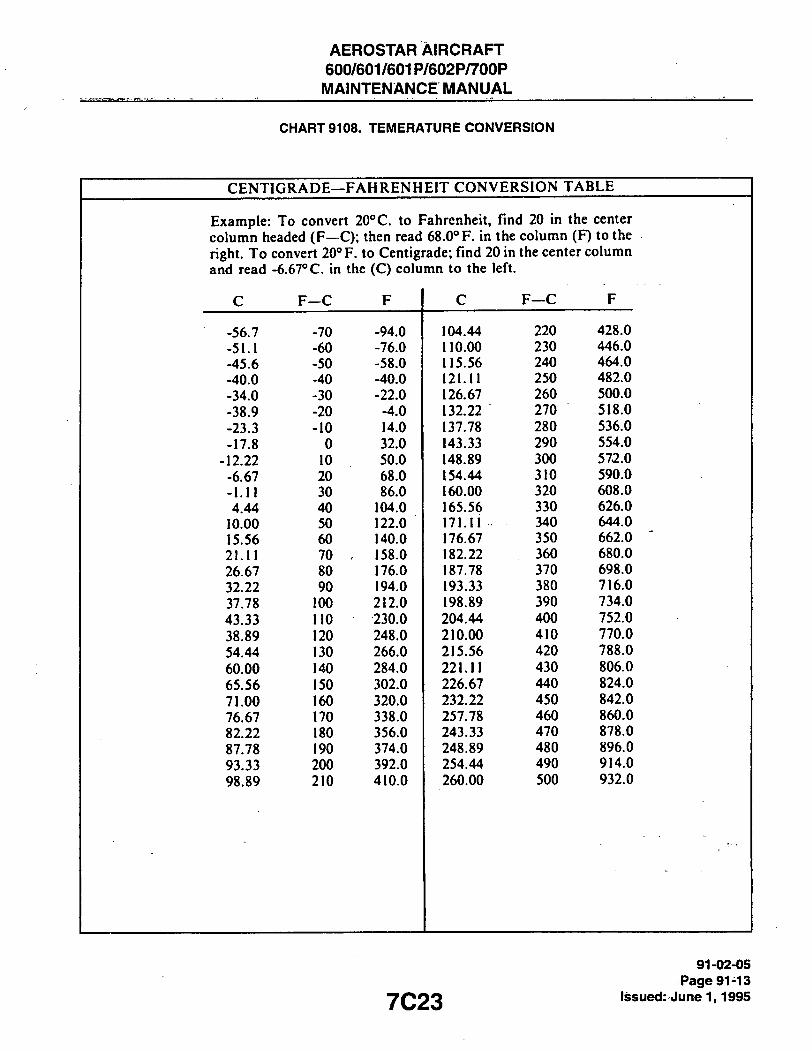
AEROSTAR AIRCRAFT 600/601/601P/602P/700P MAINTENANCE MANUAL
CHART 9108. TEMERATURE CONVERSION
CENTIGRADE—FAHRENHEIT CONVERSION TABLE
Example: To convert 20°C. to Fahrenheit, find 20 in the center column headed (F—C); then read 68.0° F. in the column (F) to the right. To convert 20° F. to Centigrade; find 20 in the center column and read -6.67° C. in the (C) column to the left.
c F C F C F C F
-56.7 -70 -94.0 104.44 220 428.0
-51.1 -60 -76.0 110.00 230 446.0
-45.6 -50 -58.0 115.56 240 464.0
-40.0 -40 -40.0 121.11 250 482.0
-34.0 -30 -22.0 126.67 260 500.0
-38.9 -20 -4.0 132.22 270 518.0
-23.3 -10 14.0 137.78 280 536.0
-17.8 0 32.0 143.33 290 554.0
-12.22 10 50.0 148.89 300 572.0
-6.67 20 68.0 154.44 310 590.0
-1.11 30 86.0 160.00 320 608.0
4.44 40 104.0 165.56 330 626.0
10.00 50 122.0 171.11 340 644.0
15.56 60 140.0 176.67 350 662.0
21.11 70 , 158.0 182.22 360 680.0
26.67 80 176.0 187.78 370 698.0
32.22 90 194.0 193.33 380 716.0
37.78 100 212.0 198.89 390 734.0
43.33 110 230.0 204.44 400 752.0
38.89 120 248.0 210.00 410 770.0
54.44 130 266.0 215.56 420 788.0
60.00 140 284.0 221.11 430 806.0
65.56 150 302.0 226.67 440 824.0
71.00 160 320.0 232.22 450 842.0
76.67 170 338.0 257.78 460 860.0
82.22 180 356.0 243.33 470 878.0
87.78 190 374.0 248.89 480 896.0
93.33 200 392.0 254.44 490 914.0
98.89 210 410.0 260.00 500 932.0
7C23 91-02-05
Page 91-13 Issued: June 1,1995

AEROSTAR AIRCRAFT 600/601/601P/602P/700P MAINTENANCE MANUAL
CHART 9109. CONVERSION FORMULAS
• M U L T I P L Y ' B Y T O O B T A I N
C E N T I M E T E R S 0 .3937 I N . 0.03281 F T .
C U . C E N T I M E T E R S O.OOl L I T E R S 0 .06102 C U . I N . 0 .0002642 U . S . G A L .
C U . F T . 28.320 C U . C M . 1.728 C U . I N . 7.481 U . S . G A L . 28.32 L I T E R S
C U . I N . 16.39 C U . C M . 0 .01639 L I T E R S 0 .004329 U . S . G A L .
0.017.12 Q U A R T S
C U . M E T E R S 1000000 C U . C M . 35.314 C U . F T .
61.023 C U . I N . 264.17 G A L . "
999 .97 L I T E R S
F E E T 0.3048 M E T E R S 12.000 M I L S . 304.8 M M .
0 .3333 Y A R D S
F T . - L B . 0 .1383 M - K G
0 .001285 B T U 0 .000000376 K W - H R
F L U I D O Z . 8 D R A M
29.6 C U . C M .
G A L . . I M P E R I A L 277.4 C U . I N .
L 2 0 I U . S . G A L .
4 .546 L I T E R S
G A L . . U . S . D R Y 268.8 C U . I N . 0 .1556 C U . F T . 1.164 U . S . G A L . . l . IQ . 4 .405 L I T E R S
G A l . . . U . S . l . IQ . 231.0 C U . I N . 0.1337 C U . F T . 3.785 L I T E R S 0.8327 I M P E R I A L G A l . . 128 F L U I D O Z .
I N . 2.540 C M .
.08333 F T .
J O U L E S 0 .000948 B T U 0 .7376 F T . - L B .
M U L T I P L Y B Y T O O B T A I N
K I L O G R A M S 2.205 - L B . . 35 .27 O Z . 1000 G R A M S
L I T E R S 1000 C U . C M .
61 .03 C U . I N . , 0 .03532 C U . F T . 0 .2642 U . S . G A L . 0 .22 I M P E R I A L G A L . 1.057 Q U A R T S
M E T E R S 39.37 I N .
3.281 F T . 1000 M M .
M E T E R - K I L O C R A M 7.233 F T . - L B .
9 .807 J O U L E S
O U N C E S . A V D P 0 .0625 L B . . A V D P
28 .35 G R A M S
437 .5 G R A I N S
O U N C E S . F L U I D 29.57 C U . C M . 1.805 C U . I N .
L B . . A V D P 4 5 3 . 6 G R A M S 7000 G R A I N S
16.0 O U N C E S
S Q U A R E I N C H 6.4516 S Q . C M .
P O U N D P E R 0.0703 K C - C M
S Q U A R E I N C H S Q U A R E D
( P S I )
S T A T U T E M I L E 1.609 K I L O M E T E R 0 .8684 N A U T I C A L M I L E
N A U T I C A L M I L E 1.151 S T A T U T E
M I L E
Q U A R T .9463 L I T E R
M I L L I M E T E R 1000 M I C R O N
M I C R O N 0.001 M I L L I M E T E R 0.0000.19 . I N C H
I N C H 11,521 M E T E R
P O U N D S G R A M S
I N C H 0 .72 M E T E R
O U N C E S G R A M S
P O U N D S 0 .453 K I L O G R A M S
91-02-06 Page 91-14 Issued: June 1,1995 7C24
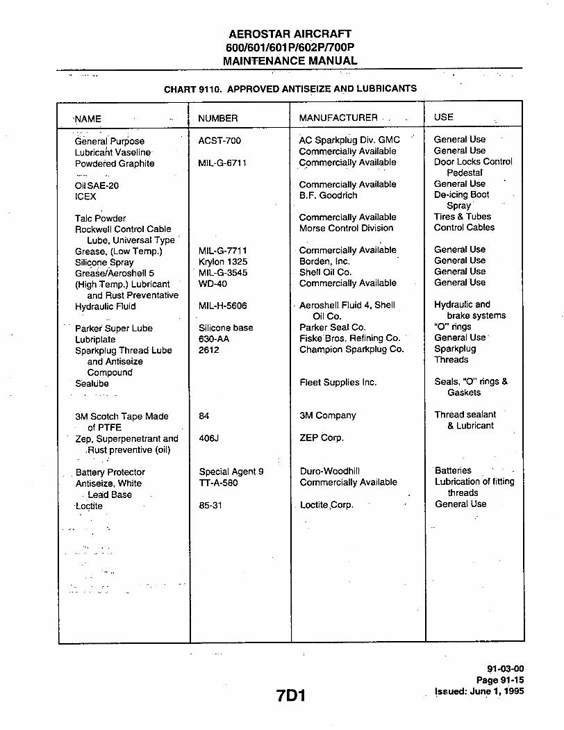
AEROSTAR AIRCRAFT 600/601/601P/602P/700P MAINTENANCE MANUAL
CHART 9110. APPROVED ANTISEIZE AND LUBRICANTS
NAME NUMBER MANUFACTURER . . USE
General Purpose Lubricant Vaseline
ACST-700 AC Sparkplug Div. GMC General Use General Purpose Lubricant Vaseline Commercially Available . General Use Powdered Graphite MiL-G-6711 Commercially Available Door Locks Control Commercially Available
Pedestal OilSAE-20 Commercially Available General Use ICEX B.F. Goodrich De-icing Boot
Spray Talc Powder Commercially Available Tires & Tubes Rockwell Control Cable Morse Control Division Control Cables
Lube, Universal Type Grease, (Low Temp.) MIL-G-7711 Commercially Available General Use Silicone Spray Krylon 1325 Borden, Inc. General Use Grease/Aeroshell 5 MIL-G-3545 Shell Oil Co. General Use (High Temp.) Lubricant WD-40 Commercially Available General Use
and Rust Preventative Hydraulic Fluid MIL-H-5606 Aeroshell Fluid 4, Shell Hydraulic and Hydraulic Fluid
Oil Co. brake systems Parker Super Lube Silicone base Parker Seal Co. "O" rings Lubriplate 630-/W\ Fiske Bros. Refining Co. General Use Sparkplug Thread Lube 2612 Champion Sparkplug Co. Sparkplug
and Antiseize Threads Compound
Sealiibe Fleet Supplies Inc. Seals, "O" rings & Gaskets
3M Scotch Tape Made 84 3M Company Thread sealant of PTFE & Lubricant
Zep, Superpenetrant and 406J ZEP Corp. .Rust preventive (oil)
Battery Protector Special Agent 9 Duro-Woodhill Batteries Antiseize, White TT-A-580 Commercially Available Lubrication of fitting
Leaid Base threads Loctite 85-31 Loctite,Corp. General Use
91-03-00 Page 91-15
yQ.j Issued: June 1,1995

AEROSTAR AIRCRAFT 600/601/601P/602P/700P MAINTENANCE MANUAL
SPECIAL TOOLS.
B 7 3 2
0.18"
NOTES:
1. MAKE TOOLS FROM 0.125 INCH
2024-T3 ALCLAD SET (QQ-A-250/5) 0 PAINT GAUGE BLACK
0 LOCATE GAUGE SO THAT 2-INCH
MARK IS OPPOSITE 6.50 INCH
DIMENSION, SCRIBE A LINE.
MLG RIGGING AID #2
U -0?5" MS.'0470AD4 RIVET AN960 4 WASHER TYPICAl (? PLCSI -J Lo 125" 0.250" OIA HOLE /
T 0 80"
l l 18"
-SCRIBED LINE C607 GAUGE (SINGER)^
© 0 66"
6.50"-•0 80" - 0 40"
•8.90"
MLG RIGGING AID #1
91-04-00 Page 91-16 Issued:June 1,1995
Figure 91-1. Main I-anding Gear Rigging Tools
7D2

AEROSTAR AIRCRAFT 600/601/601P/602P/700P MAINTENANCE MANUAL
D 1 3 9
_1 . 6 2 5 " O D x . 1 2 0 W A L L T U B E 1 0 1 5 - 1 0 1 8 S T E E L
1 D I A . T O P R O V I D E
. 0 0 0 5 / 0 0 1 5 P R E S S FIT
.50
1 W X 1" X 6 "
F L A T S T O C K
T A P D R I L L
R ( . 339 )
T A P % - 2 4
W ID X O D
X ' / a " L O N G
A L L O Y 6 4 2 1 O R
E Q U I V . A L U M B R O N Z E
17.50 % " x 2 4 T H R E A D E D S T O C K
R O U N D S T O C K . 2 8 1 W A L L T U B E 1 0 1 5 -1 0 1 8 S T E E L
.625
.628
-1.125-
is I I I 1 I
L
3.0
. 0 3 " X 4 5 ° C H A M F E R
B O T H E N D S
V B O D X . 1 2 0
W A L L T U B E
1 0 1 5 - 1 0 1 8
S T E E L
M S 2 1 0 4 2 - 6
N U T
Fiigure 91-2. Main Landing Gear Actuator Tooi
7D3
91-04-00 Page 91-17
issued: June 1,1995

AEROSTAR AIRCRAFT 600/601/601P/602P/700P MAINTENANCE MANUAL
2930
ROD LOCATIONS
• SIGHT LINES (TYP.)
APPLICATION
LOCATION
O W.S. 0 W.S. © W.S. O W.S.
195. 00 & 70% SPAR 195.00 & 10% CORD 29. 4 & 10% CORD 29.4 & 70% SPAR
PART m. DESCRIPTION STOCK SIZE
-09 NUT 5 - 13 NUT -08 BRACE l?i X 15 X 3/16 X 25 -07 BRACE 1 5 X l!i X 3/16 X 50 -06 SUPPORT EXT. h DIA X 12.0" -05 LEG SUPPORT h DIA X 12.0" -04 LEG #4 h DIA X 9.827"
' -03 LEG #3 h DIA X 15.377" -02 LEG #2 h DIA X 7.154" -01 LEG #1 h DIA X 6.603"
MATL. SPEC.
STEEL STEEL ANGLE STEEL ANGLE
r~~ is X 13 . THREADED ROD
i
NO. REQD.
8 1 1 2 2 1 1 1 1
91-04-00 Page 91-18 Issued: June 1,1995
Figure 91-3. Wing Twist Tooi
7D4
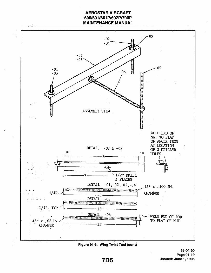
AEROSTAR AIRCRAFT 600/601/601P/602P/700P
MAINTENANCE MANUAL
3/4"
DETAIL -07 5 -08
A
WELD END OF NUT TO FLAT OF ANGLE IRON AT LOCATION OF 3 DRILLED
1" HOLES.
-B- ^1/2" DRILL 3 PLACES
DETAIL -01,-02,-03,-04 ^450 . 100 IN.
CHAMFER
1/4R. TYP. A
DETAIL -05 l lil!l|l!ll!!!l|i!l!'l;!ii|iiH'!'!';!!l!!!!!i'i;i!i!illl'|!N'!l!l!
12'
DETAIL -06
45« X . 05 IN.^ CHAMFER
fl!|i|i|iiilili;iliii|i|i|iii;iiiiiiil;iiiiii|ilil,|;iililiii|i|i|il^
-12'
-WELD END OF ROD TO FLAT OF NUT
Figure 91-3. Wing Twist Tooi (cont)
7D5 91-04-00
Page 91-19 • issued: June 1,1995

AEROSTARrAIRCRAFT 600/601/601P/602P/700P MAINTENANCE MANUAL
THIS PAGE INTENTIONALLY LEFT BLANK
91-04-00 Page 91-20 Issued: June 1,'1995 7D6

AEROSTAR AIRCRAFT 600/601/601P/602P/700P MAINTENANCE MANUAL
THIS PAGE INTENTIONALLY LEFT BLANK
707
91-04r00 Page 91-21
.Issued: June 1,1995

AEROSTAR AIRCRAFT 600/601/601P/602P/700P MAINTENANGE MANUAL
C 5 0 5
ALL DIMnNSIONS FROM m i w r "A"
•8.655"-
• 9 . 2 9 9 -
9.39(f-
1 1 . 0 3 9 " ( -(TO CEOTER !-
LINE) [
91-04-00 Page 91-22 Issued: June 1,1995
Figure 91-5. Rudder/Eievator Rigging Template
7D8

AEROSTAR AIRCRAFT 600/601/601P/602P/700P
MAINTENANCE MANUAL
2932 N O T E
T H I S I L L U S T R A T I O N C O N T I N U E D O N F O L L O W I N G P A G E
cr
STAMP NOTE
1. TO BE USED WITH DEICE BOOT 2. TO BE USED WITHOUT DEICE BOOT 3. PAG 1188-USE W. S. 156. 00 4. ALL DEGREE MARKS 30° DOWN THRU IT UP
Figure 91-6. Aiieron Rigging Template 91-04-00
Page, 91-23 yQg issued: June 1,1995
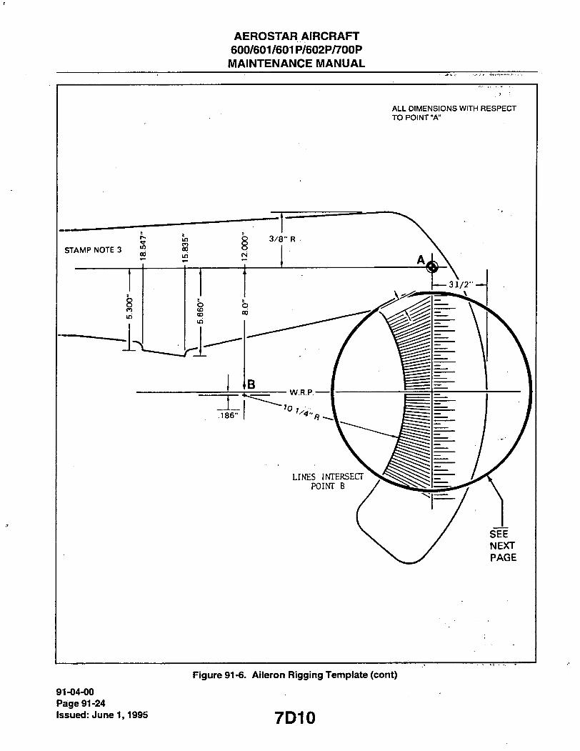
AEROSTAR AIRCRAFT 600/601/601P/602P/700P MAINTENANCE MANUAL
A L L D I M E N S I O N S W I T H R E S P E C T T O P O I N T " A "
91-04-00 Page 91-24 Issued: June 1,1995
Figure 91-6. Aiieron Rigging Template (cont)
7D10

AEROSTAR AIRCRAFT 600/601/601P/602P/700P MAINTENANCE MANUAL
B 7 3 5
1. 886 IN_ 2.148
2. 2.507
2.658
— 3.334 3.633
— 4.101 4.332
5.009
_5.668
6.100 6.314
6.739 6.951
10.115
—10.350 10.770
11.215 11.440
_11.899 12.131
12.606 # 12.848 /
13.093 —13.342
13.542 _
_ 14.114^^'/"
^14.380 14.651
14.928 IN'
/
Figure 91-6. Aileron Rigging
7D11
91-04-00 Page 91-25
Issued: June 1,1995

AEROSTAR AIRCRAFT 600/601/601P/602P/700P MAINTENANCE MANUAL
THIS PAGE INTENTIONALLY LEFT BLANK
91-04-00 Page 91-26 Issued: June 1,1995 7D12

AEROSTAR AIRCRAFT 600/601/601P/602P/700P MAINTENANCE MANUAL
2 9 3 3 N O T E 0 5 7 1 T H I S I L L U S T R A T I O N C O N T I N U E D O N
F O L L O W I N G P A G E
Figure 91-7. Fiap Rigging Tempiate
7D13
91-04-00 Page 91-27
issued: June 1,1995

AEROSTARAIRCRAFT 600/601/601P/602P/700P MAINTENANCE MANUAL
2 9 3 3 C 5 7 2
Figure 91-7. Flap Rigging template
91-04-00 Page 91-28
Issued: June 1,1995 7D14

AEROSTAR AIRCRAFT 600/601/601P/602P/700P MAINTENANCE MANUAL
B 7 3 6
GAUGE FOR LOCATING GROUND ELECTRODE IN JANITROL HEATERS
•6.00"'-
•1.50' ^.38'
.SLIP FIT C.255' DIA. HOLE)
250"DLA. ROD
•18 m THREAD
.875'HEX STOCK
3.444'
•3.387=-
UNDER CUT .010" MARK WITH BLACK PAINT
MATERIAL CAN BE SAE TYPE 303, 321 OR 347 ST. ST. OR ALUMINUM CASE HARDENED
Figure 91-8. Spari< Plug Gap Adjustment Tooi
7D15
91-04-00 Page 91-29
issued: June 1,1995

AEROSTAR AIRCRAFT 600/601/601P/602P/700P
MAINTENANCE MANUAL
B 7 3 7
CUT WRENCH IN HALF
LGRIND METAL AWAY TO PROVIDE CLEARANCE UNDER FAIRING
9/16" OPEN END WRENCH MODIFIED
CUT WRENCH AT APPROXIMATELY 3/4 OF HANDLE LENGTH 7
' CUT A 5/16" SLOT INTO THE END OF BOX GRIND EDGES SMOOTH
9/16" BOX END WRENCH MODIFIED
Figure 91-9. Windshieid Alcohoi Deice Nozzle Wrench
91-04-00 Page 91-30 Issued: June 1,1995 7D16

AEROSTAR AIRCRAFT 600/601/601P/602P/700P MAINTENANCE MANUAL
B738
IT
TOOL IS MADE WITH OXYGEN MASK CONNECTOR, 3 INCH LONG n BOLT WITH NUT, AND 3 INCH LONG ROUND PIECE OF WOOD.
Figure 91-10. Oxygen Outiet Bezei Remover
7D17
91-04-00 Page 91-31
issued: June 1,1995

AEROSTAR AIRCRAFT 600/601/601P/602P/700P
MAINTENANCE MANUAL
B 7 3 9
,BRAZE
DRILL NO. 47 1/4" DEEP-
TAP 3-48
CM
1 BLEND O.D. TO I.D. POLISH
-12.000"
MATERIAL: NO. 30 DRILL ROD OR EQUIVALENT.
91-04-00 Page 91-32 Issued: June 1,1995
Figure 91-11. Cable Terminal Assembiy Tool
7D18

AEROSTAR AIRCRAFT 600/601/601P/602P/700P MAINTENANCE MANUAL
D 1 4 2
ADDITIONAL BAGGAGE CAPABILITY MAY BE OBTAINED BY THE REMOVAL OF THE FOUR PASSENGER SEATS AND THE ADDITION OF A LOAD SPREADING FLOOR.
IT IS RECOMMENDED THAT THIS LOAD SPREADING FLOOR BE CONSTRUCTED FROM Vi INCH PLYWOOD (OR EQUIVALENT) SPREAD ACROSS THE RAILS (SEE SKETCH). AT LEAST EVERY THIRD SEAT TRACK SCREWSHOULD BE USEDTO RETAIN THE PLYWOOD. NORMAL TIE DOWN IS RECOMMENDED FOR ALL LOADING. WITH TOTAL LOADING FOR THIS AREA (1ST ANO 2ND PASSENGER STATIONS) NOT TO EXCEED 1100 LBS. INCLUDING THE WEIGHT OF THE LOAD SPREADING FLOOR. (EQUIVALENT TO 79 PSF MAXIMUM FLOORBOARD LOADING).
CONSIDERATION OF THE STRUCTURAL INTEGRITY AND CENTER OF GRAVITY CONCERNS HAVE BEEN ACCOUNTED FOR IN THIS DETERMINATION. THE LOADING SHOWN IS IN ADDITION TO THE 240 LBS. ALLOWED IN THE BAGGAGE COMPARTMENT.
Figure 9-11a.- Load Spreading Fioor 91-04-00
Page 91-33 yQ-|Q issued: June 1,1995
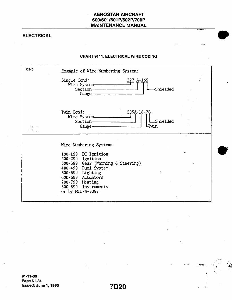
AEROSTAR AIRCRAFT 600/601/601P/602P/700P MAINTENANCE MANUAL
ELECTRICAL
CHART 9111. ELECTRICAL WIRE CODING
C 5 4 6 Example of Wire Numbering System:
Single Cond: 227 A-16S Wire System
Section Gauge
-Shielded
Twin Cond: Wire System-
Section— Gauge—
-18-2S
I Shielded
LTwin
Wire Numbering, System:
100-199 200-299 300-399 400-499 500-599 600-699 700-799 800-899
DC Ignition Ignition Gear (Waming Fuel System Lighting Actuators Heating Instruments
§ Steering)
or by MIL-W-5088
91-11-00 Page 91-34
Issued: June 1,1995 7D20

AEROSTAR AIRCRAFT 600/601/601P/602P/700P
MAINTENANCE MANUAL
CHART 9112. ELECTRICAL SYMBOLS
C 5 0 4
o ^ o o AUTCMATIC PUSH TO
RESET RESET
CIROJIT BREAKERS
PUSH ON
PULL OFF I
i
CAPACITOR
RHEOSTAT
J l LAMP
SINGLE EIIOIISLS CROSSII*] OVER EACH OTHER
CONDUCTORS •
+ - - low
GROUND HORN
ZENER
DIODE DIDOE
soon
RESISTOR
"O" ~& 0 0 ^ METERS MOTOR ALTERNATOR PUMP METER SHUNT
SHIELDED
WIRE
THERMOCOUPLE
OVERHEAT SW.
SPOT ROTARY
SWITCH
BI-METAL SPST
THERMAL CUT OUT
(KLIXON)
2 AMP —O >.
12V _ 12V
ROLLER SWITCH
\ IhH SERIES CONNECTED BATTERIES
T V f
FUSE
I
THERMOCOUPLE
TEMPERATURE
SENSOR
3 SOLENOID TRANSFORMER SPST
APU
SOCKET
L3J
SPOT
• RELAYS•
BUS
2 TERMINAL
STRIP
P S
t-O i o-f
n SOLENOID
CONTACTOR
O-^To CCff^CTOR, PINS • H NCI' ALL SHOWN
S P
A
B
C
D
MPDT 1 CONNECTOR,
P- PINS ALL PINS SiKm S- SOCKET
7D21
91-12-00 Page 91-35
Issued: June 1,1995

AEROSTAR AIRCRAFT 600/601/601P/602P/700P MAINTENANCE MANUAL
ELECTRICAL SCHEMATICS
- NOTES -
1. All relays shown in de-energized positions. 2. All switches shown in off position. 3. All ground terminals not marked with a signifying letter, wire callout, and/or letter-number
combination are grounded thru the case of the component. 4. The letter "F" at the end of the shielded wire signifies a floated condition. 5. Refer to installation drawings of the respective models for referenced material. 6. The letter "N" added to wire no. indicates ground wire. 7. Supplied bus bar must be installed as shown on the left and right ignition and starter switches part no.
IO-357230-1 between terminal "R" and terminal directly adjacent. 8. Calibrate Fuel Quantity System per Chapter 28. 9. For Auxiliary Power Schematics A/F 0173-0189, see Battery System. For Auxiliary Power
Schematics /V/F 0190 and up, see Alternator System. 10. For Battery System Schematics /VF 0190 and up, see Alternator System.
91-12-00 Page 91-36 Issued: June 1,1995 7D22

AEROSTARAIRCRAFT 600/601/601P/602P/700P MAINTENANCE MANUAL
ELECTRICAL SCHEMATIC INDEX
FIGURE NO. SCHEMATIC GRID NO.
ANNUNCIATOR SYSTEMS Annunciator Panel/Controller
91-12. A/F: 0366 to 0455 7E7 91-13. A/F: 0456 and up 7E8
DEICE SYSTEMS ' 91-14. Defroster - Blower Motor > 7E9
Oxygen Regulator - Heater 91-15. A/F: 0080-0129 7E9
Pitot Heat 91-16. A/F: 0001-0848 7E9 91 -16. A/F: 0849 and up (except 700P) 7E9 91-17. A/F: 60-8223001 and up (700P only) 7E9
Propeller Deice System • 91-18. Models 600/601/601P/602P 7E10 91-18a. Model 700P 7E11 91-19. Surface Deice System 7E12 91-20. Windshield-Alcohol Pump (Optional) 7E13 91-21. Windshield - Electrically Heated Panel (Optional) 7E13
ELECTRICAL SYSTEMS Alternator - 50 Amp Systems
91-22. A/F: 0001 to 0143 7E14 Alternator "Ouf Lights
91-22a A/F: 0001-0364 7E14 Alternator - 50 Amp Systems
91-23. /VF: 0001 to 0143 (Mod. S.B. 600-24 and STC S/V2336WE) 7E15
Altemator - 70 Amp Systems 91-24. A/F: 0001 to 0143 (Mod. S.B. 600-24 and
STCSA2336WE) 7E16 91 -25. A/F: 0144 to 0189 (Mod - STC SA2367WE) 7E17 91 -26. A/F: 0190 to 0364 (Refer to S.B. 600-54 on
/VPs: 0190 to 0355) 7E18 91-27. A/F: 0365 to 0465 7E19 91-28. A/F: 0466 to 0714 7E20 91 -29. A/F: 0715 to 0848 7E21 91-30. A/F: 0849 and up (Except 600 and 602P) 7E22 91-31. A/F: 0849 and up (600 and 602P only) 7E23 91-32. S/N's: 60-8323001 and up (700P only) 7E24
Avionics Power Relay and Bus (Optional) 91-33. A/F: 0715 and up . • 7F1 91-33a. Ground Clearance Switch 7F1
7D23
91 - Elec. Sch. Index Page -1
Issued:June T, 1995

AEROSTAR AIRCRAFT 600/601/601P/602P/700P MAINTENANCE MANUAL
ELECTRICAL SCHEMATIC INDEX
FIGURE NO. SCHEMATIC GRID NO.
91-34. 91-35. 91-36. 91-36a.
91-37. 91-38. 91-39. 91-40.
91-41.
91-42.
ELECTRICAL SYSTEMS (cont) Battery Systems
A/F: 0001 to 0172 7F2 A/F: 0173 to 0189 7F2 A/F: 0190 and up 7F3 S/N's: 60-8323001 and up (700P Only) 7F3
Distribution Diagram - Electrical Power A/F: 0001 to 0143 . 7F4 A/F: 0144 to 0189 7F5 A/F: 0190 to 0364 7F6 A/F: 0365 and up 7F7
External Power A/F: 0144 to 0189 7F8 (For ottier /VPs see Alternator System Sctiematics)
Inverter - A.C. Power (Gyro Instruments) A/F: 0002-0005 7F8 Volf Ammeters (See Indicators Section of Index)
91-43. 91-44.
91-45. 91-46. 91-47.
91-48. 91-49. 91-50.
ENGINE SYSTEMS Magnetos
A/F: 0001 to 0848 /VF: 0849 and up
Starter System A/F: 0001 to 0189 A/F: 0190 to 0848 /VF: 0849 and up
Starter Warning Ligtit (See Warning Systems) Turbo Wastegate Actuators
A/F: 0001 to 0145 A/F: 0146 to 0204 A/F: 0205 to 0341
Tacfiometers (See Indicators Section of index)
7F9 7F9
7F10 7F10 7F11
7F12 7F13 7F14
91-50a. 91-51.
91-52.
91-53. 91-54. 91-55. 91-56.
ENVIRONMENTAL SYSTEMS Cabin Vent Fan (Optional)
/VP: 0982 and up Air Conditioning (Later Models) Air Conditioning (700P Only)
S/N's: 60-8323001 and up Heater
A/F: 0001 to 0355 A/F: 0356 to 0848 /VP: 0849 and up
Auxilary Hydraulic Pump (601P/700P Only)
7F14 7F15
7F16
7F17 7F18 7F19 7F20
91 - Elec. Sch. Index Page - 2 Issued: June 1,1995 7D24

AEROSTAR AIRCRAFT 600/601/601P/602P/700P MAINTENANCE MANUAL
ELECTRICAL SCHEMATIC INDEX
FIGURE NO. SCHEMATIC GRID NO.
ENVIRONMENTAL SYSTEMS (cont.) 91 -57. Oxygen "REQUIRED" Light 601P/602P/700P 7F21
Oxgyen Regulator Heat (See Deice Systems) Pressurization - Cabin
91-58. A/F: 0306 to 0674 7F23 . 91-59. A/F: 0675 to 0848 7G1
91-60. /VF: 0849 and up (601P) 7G3 f 91-61. S/N's: 60-8265001 and up (602P) 7G5
91-61. S/N's: 60-8323001 and up (700P) 7G5
FUEL SYSTEMS 91-62. Boost Pump 7G7
Fuel Flow - Transducer/Indicator 91-63. /VF: 0001 to 0266 7G8 91-64. /VP: 0267 and up. 7G8
Fuel Flow w/Totalizer (700P Only) (See Indicator Systems) Fuel Quantity Indicators (See Indicator Systems) Fuel Selector
91-65. A/F: 0001 to 0848 7G9 91-66. A/F: 0849 and up 7G10
Low Fuel Waming (See Warning Systems)
HYDRAULIC SYSTEMS 91-68. Auxiliary Hydraulic Pump 7G11
Auxiliary Hydraulic Pump (601P/700P Only) (See Environmental Systems)
Nose Wheel Steering 91-68a. S/N's: 60-8323001 and up 7G11 91-69. A/F: 0001 to 0399 7G12
. 91-70. A/F: 0400 to 0545 7G12 91-71. /VP: 0546 and up 7G13 91 -72. Hydraulic "SHUT-OFF" Valve 7G13
91 - Elec. Sch. Index Page - 3
yg- issued: J u n e i , 1995

AEROSTAR AIRCRAFT 600/601/601P/602P/700P MAINTENANCE MANUAL
ELECTRICAL SCHEMATIC INDEX
FIGURE NO. SCHEMATIC -GRID NO.
91-73. 91-74.
91-75. 91-76. 91-77. 91-78. 91-79. 91-80.
91-80a
91-81. 91-82. 91-83. 91-84. 91-85. 91-86.
91-87. 91-88.
91-89. 91-90. 91-91.
INDICATOR SYSTEMS Annunciator-(See Annunciator Systems) Alternator "OUT" Light (See Electricial Systems) Attitude Horizon (A.H.) Clock-Digital Electronic Cylinder Head Temp. (C.H.T.)
A/F: 0001 to 0799 (Weston Garwin only) A/F: 0800 to 0848 A/F: 0849 and up
Directional Gyro (D.G.) Exhaust Gas Temp. (EGT) Flap Position Indicator - Wing Fuel Flow Indicators/Tranducers (See Fuel Systems) Fuel Flow w/ Totalizer (700P Only) Fuel Quantity
A/F: 0001 to 0149 A/F: 0150 to 0289 A/F: 0290 to 0499 A/F: 0500 to 0674 A/F: 0675 to 0714 A/F: 0715 and up
Fuel "LOW" Waming Light (See Warning Systems) Hour Meter Engine
A/F: 0001 to 0860 A/F: 0861 and up
Landing Gear^arning Indicators (See Waming Systems) Oil Temperature
A/F: 0001 to 0799 A/F: 0800 to 0848 A/F: 0849 and up
7G14 7G14
7G15 7G15 7G16 7G16 7G16 7G17
7G17
7G18 7G18 7G19 7G19 7G20 7G20
7G22 7G22
7G23 7G23 7G24
91 - EkiC. Sch. Index Page - 4 Issued: June 1,1995 7E2
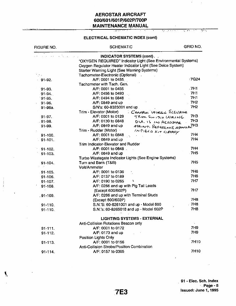
AEROSTAR AIRCRAFT 600/601/601P/602P/700P MAINTENANCE MANUAL
ELECTRICAL SCHEMATIC INDEX (cont)
FIGURE NO. SCHEMATIC GRID NO.
INDICATOR SYSTEMS (cent). . "OXYGEN REQUIRED" Indicator Light (See Environmental Systems) Oxygen Regulator Heater Indicator Light (See Deice System) Starter Warning Light (See Warning Systems) Tachometer-Electronic (Optional)
91 -92. A/F: 0001 to 0455, • 7G24 Tachometer with Tach. Gen.
91-93. /VF: 0001 to 0455 -THI 91-94. /VF: 0456 to 0493 . 7H1 91-95. /VF: 0494 to 0848 7H1 91-96. /VF: 0849 and up 7H2 91-96a. S/N's: 60-8323001 and up 7H2
Trim - Elevator (Motor) : CoArrRot U) vwife . I^^ECAroft 91-97. /VF: 0001 to 0129 Tf t / *^ Soa . TCW C A J I K . / M G - ^^^^ 91-98. A/F: 0130 to 0848 ^ \ A . \% , ^ f\Z(ios^flfL
91 -99- A/F: 0849 and up 4 ^ . ^ ^ , R s ^ ^ ^ ^ t y i ^ ^ p j ^ ^
Trim - Rudder (Motor) <r;fe«: o J< ,T O ^ ^ A R - X 91-100. A/F: 0001 to 0848 • ^ 7H4 91-101. /VF: 0849 and.up 7H4
Trim Indicator-Elevator and Rudder 91-102. /VF: 0001 to 0848 . 7H4 91-103. /VF: 0849 and up 7H5
Turbo Wastegate Indicator Lights (See Engine Systems) 91-104. Turn and Bank (T&B) 7H5
Volt/Ammeter 91-105. /VF: 0001 to 0136 7H6 91-106. /VF: 0137 to 0189 7H6 91-107. A/F: 0190 to 0265 ^ 7H7 91-108. /VF: 0266 and up with Pig Tail Leads
(Except 600/602P) 7H7 ,91-109. /VF: 0266 and up. with Terminal Studs
(Except 600/602P) 7H8 91-110. S.N.'S: 60-8261001 and up - Model 600 7H8 91-110. S.N.'s: 60-8265018 and up-Model 602P 7H8
LIGHTING SYSTEMS - EXTERNAL Anti-Collision Rotations Beacon only
91-111. A/F: 0001 to 0172 7H9 91-112. /VF: 0173 and up 7H9
Position Lights Only 91-113. /VF: 0001 to 0156 7H10
Anti-Collision Strobe/Position Combination 91-114. A/F: 0157 to 0305 7H10
91 - Elec. Sch. Index Page-5
Issued: June 1,1995

AEROSTAR AIRCRAFT 600/601/601P/602P/700P MAINTENANCE MANUAL
ELECTRICAL SCHEMATIC INDEX (cont)
FIGURE NO. SCHEMATIC - GRID NO.
LIGHTING SYSTEMS - EXTERNAL (cont) Anti-Collision Strobe/Beacon/Position Combination
91-115. A/F: 0306 to 0577 (Strobes Stn'd.-Beacons Opt.) . 7H11 91-116. /V/F: 0578 to 0604 (Strobes Opt.) 7H12 91-117. /VF: 0605 and up (Complete Installation Std.) 7H13 91-118. Landing 7H14 91-119. Wing Inspection Ligtit 7H14
Wing Inspection Ligtit (700P Only)(See Warning Systems)
LIGHTING SYSTEMS - INTERNAL Baggage/Instrument
91-120. A/F: 0001 to 0505 7H15 91-121. A/F: 0506 to 0629 '7H15 91-122. A/F: 0630 and up 7H16
.91-123. Cabin 7H16 91-124. Map 7H17
Radio Switcti Panel 91-125. A/F: 0630 and up 7H17
PROPELLER SYSTEMS Ice Protection (See Deice Systems)
91-126. Synctiroptiaser with Aerosonic Tach. Gen.'s and Dual Tach. 7H19
91 -127. Synchrophaser with A.N. Tach Gen's - Field Retrofitted with Aerosonic Tach Gens, and Dual Tachs. 7H21
91-128. Synchrophaser with A.N. Tach. Gens. - Field Retrofitted with Synchrophaser System 7H23 Synchrophaser System
91-129. A/F: 0001-0454 711 Synchrophaser System with A.N. Tach Gens.
91-130. A/F: 0455 and up 713
WARNING SYSTEMS Annunciator - (See Annunciator Systems) Altemator "OUT' Lights (See Electrical Systems) Cross-Feed Indicator
91-131. A/F: 0456 and up 715
91 - Elec. Sch. Index Page - 6 Issued: June 1,1995 7E4

AEROSTAR AIRCRAFT 600/601/601 P/602P/7b0P MAINTENANCE MANUAL
ELECTRICAL SCHEMATIC INDEX (cont)
FIGURE NO. SCHEMATIC ' GRID NO.
WARNING SYSTEMS (cont) Heater Fail Light ; .'
91-132. A/F: 0466 and up ' ' 716 91-132a Wing Inspection Light (700P Only) 716
Landing Gear Warning - Horn/Lights 91-133. A/F: 0001 to 0355 .717 91-134. A/F: 0356 to 0433 ' • '718 91-135'. A/F: 0434 to 0607 719 91-136. A/E: 0608 to 0848 •7110 91-137. /VF: 0849 and up 7111 91-137a. S/N's: 60-8323001 and up'(700P Only) 7112
Low Fuel Warning Light V 91-138. A/F: 0001 to 0499 - 7113
. 91-139. A/F: 0500 to 0674 " 7113 91-140. /VP: 0675 and up 7113
"OXYGEN REQUIRED" (See Environmental Systems) Oxygen Regulator Heat (See Deice Systems)
91-141. Starter Warning Light 7114 91-142. Fire Detection - (Optional) 7115 91-143. Stall Warning (7d0P only) 7116
91 - Elec. Sch. Index Page-7
y Issued: June 1,1995

AEROSTAR AIRCRAFT 600/601/601P/602P/700P
MAINTENANCE MANUAL
THIS PAGE INTENTIONALLY LEFT BLANK
91-13-00 Page 91-44 Issued: June 1,1995 7E6

AEROSTAR AIRCRAFT 600/601/601P/602P/700P MAINTENANCE MANUAL
EL1517 Mm PAxa WIN BUS o 2A '
/WNUHCIATW PAKEL ^
L ALT
LO FUEL
Cl L FIRE
G£A«
I) ALT
f) FIXE
Cl HTR FAIL ll
DEICE
iM3 A/P INTi)
AUX NTO
IK
15K I AAlr
. 15lt
-^vw-^
• 15IC 4—
4—
15IC
4—wv
* — w v
4— IK
15K
15K
15K
IK
15K
10
12
£4
j::4
BRIGHT
TEST
390
15K
10
IRDA5-22
RDA5-22^
'AW106A-22..
10 AI-71 INDiaTOit
Al(106-22
(EXISTING)
FD103a-18
308E-22
AKiO'i-22-^
HiaA-20
VOLIAGE SENSOR
FUSELAGE FUEL TRANSMITTER
LEFT
H'40A-20-^ (EXISTING)
FT)102B-18
•mm. STRIP
RIG
to THROHLE S«
STTP DOWN SPLItt
TO NAMING HORN
H39A-20
CABIN ALTITUDE SNITCH
NO. 2 KAIN CONNKTOR
71SC-16
715C-1$'- (EXISTING)
D102-22
20
D102-22—' (UlSTING)
HrD102-20,
TR'IMCR DEICE
TO RE«TE C/B
HTDlCB-20^ (aiSTiNG) AN17-22 RNAVI2A-22
/ N
HYDI02A-20
JlSK
o 2 3r CD.12 'WAY23-22
16
KAV
AN20-22N
.A/P INTR TEST
IC7i(l-3 ACCELER-OHETER
t I
Figure 91-12. Annunciator Panel/Controller, A/F 0366-0455
7E7
91-13-00 Page 91-45
Issued: June 1,1995
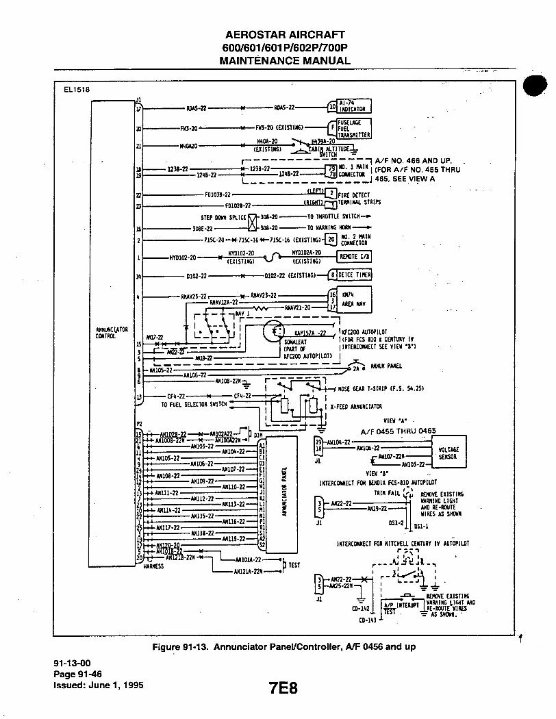
AEROSTAR AIRCRAFT 600/601/601P/602P/700P MAINTENANCE MANUAL
E L 1 5 1 8
MXUNCIATOR COKTROL
•RnA5-22-
-FW-20-
-WlAS-22-
-FWJ-20 (aiSTIW)-
IHDICATOK
FUS£IAGE FUEL TlWISHinEll
" (EX1ST1N6) '^J>JeABIj |^ | lTJTUDE4-
r " r T r "I A / F N O . 4 6 6 A N D U P . •123B-22-
L r _ J ~ 1 _ _ _ _ J 4 6 5 , S E E V I E W A
-FD103B-22--FD102B-22-
STEP DOm SPLICE -508E-22
508-20-308-20-
-'l EmjFIRE DETECT _lilSllIlQ]TE««"««- ST«IR —TO THROnU MITCH-* -TO mxm HOWl
-HYD102-20-
- 715C-20 -H 715C-16 *»-715C-16 (EXISTING) „ HYD102-20 _ HYl)102*-20
-a c"SiHE'l CONNECTOR
(EXISTING) (EXISTING) REMTE C/B
•0102-22- -0102-22 (EXISTING) (jJPEICE TIHER|
RHAV23-22. -M-IWAV25-22 (16 WH
r i - i n ^ i - - ^ " T J
' ! • v V l I I ( V) I(AP15;A -22 [ 'ffC200 AUTOPILOT ., J z z h z r SONALERT "™ f« 810 I CI • ^ A / E - J T --I
l-*N'iosT2' -AN19-22-
-ANlOG-22-
SfliijiicoT • IiruK rti Biu 1 CENTURY IV (PART Of I INTERCONNECT SEE VIEW T ) KFC200 AUTOPILOT) j
' ^ J A O «<M«fAN£L
•CFii-22- CFl-22 NOSE GEAR T-StRlP (F.S. M.2S)
TO FUEL SELECTOR SWITCH ]
P2
I 11 <( 9
13
i 25
iiwa-T* ]
•AN105-22-
^ i « ^ 2 N --AN103-22
ANlOH-22-
I 2i X-FEED ANNUNCIATOR
-ANI06-22-- •AN108-22-
-AN107-22-
Dlfl
VIEW 'A-A / F 0 4 5 5 T H R U 0 4 6 5
-AN109-22-t-ANm-22-
-ANllO-22--AN112-22-
^ A«im-22 • -AN113-22-
-AN115-22-
1 - * --ANU7-22-
-AN116-22-•AN118-22-
-AN119-22-
ANmB-22N -
I s
19 18 JT
V-AinW-22 -
VOLTAGE VOLTAGE r- AW107-22N — SENSOR « AW105-22-
VIEW 'B' INTERCONNECT FOR BENDIX FCS-810 AUTOPILOT
TRIN FAIL {<•}, |£jnv£ EXISTING I . u iDHlur. I i r i i T 3
5
Jl
y-AN22-22- -AW9-22-
OSl-2
WARNING LIGHT AND RE-ROUTE WIRES AS SHOWN
DSl-1
HARNESS -ANlOU-22-•AN121A-22N-
b TEST
INTERCONNECT FOR HITCHEa CENTURY IV AUTOPILOT
3V-AN22-22-5 -AK25-Z2N—1
Jl - i CD-1<I2
CO-143
. • RDIOVE aiSIlRG 4/P i.TniipTlWRNING LIGHT AND
•^'"^^**'J_RE-ROUTE WIRES ^ AS SHOWN. -
91-13-00 Page 91-46 Issued: June 1,1995
Figure 91-13. Annunciator Panel/Controller, A/F 0456 and up
7E8

AEROSTAR AIRCRAFT 600/601/601P/602P/700P MAINTENANCE MANUAL
E L I 5 0 6
NOTE: OK A/F PRIOR TO 0190
niL ShlTQ) AND CIRCUIT
BRliAKER FUNCTIONS ARE
COMBINED IN ONE UNIT. •
DEFROSTCR BLOWER
_ W A B I o — 6
714-18 IN4003 0NA/F05B6X _L ANO UP
i _LMLTF.R —
Figure 91-14. Defroster Biower IVIotor
E L 1 5 0 6
H12A-20N
o 2A<
OXYGEN REGULATOR IIEATFR FAll LIGHT .NO. 2 HAIN
CONNECTOR ,
T-STRIP
1-J F.S. 83
HllA-20
I 1^
HlOC-20
HlOA-20
56 HllB-20
HlOB-20
HIZB-20N ~
RED
RED
WHT
WHT
OXYGEN
REGULATOR
HEATER
Figure 91-15. Oxygen Regulator Heater, A/F 0080-0129
E L 1 5 0 6 A/F 0001 TO 0848 NO. 3 MAIN
T-STRIP 1-9
F.S.332 A720-I2 720-12
j 720A-I2
720B-I2 / PITOT HEATER
A/F 0849 AND UP
720-12
NO.3 MAIN F.S. CONNEaOR 332.50
r20A- 7208-12
prroT HEATER 'l
Figure 91-16. Pitot Heat, A/F 0001 and up (Except 700P)
E L I 5 0 6 NOTE: ON A/F PRIOR TO 0190
Tin St 'lTOI AND CIRCUIT
, BREAXER FUNaiONS ARE
CCMBINEU IN ONE UNIT.
DErROSTER BLOMER
_ 7I4AI8 I -Cr^o
714-18 IN4003 0NA/F0S86i J-ANO UP
i _Ll-lLTER —
Figure 91-17. Pitot Heat (700 P Oniy) S/N 60-8223001 and up
7E9
91-13-00 Page 91-47
issued: June 1,1995

AEROSTAR AIRCRAFT 600/601/601P/602P/700P MAINTENANCE MANUAL
E L 1 5 1 9 6 4 0 0 5 3
D E I C E R B O O T
LEFT PRDPELUER
RIGHT PROPELLER
2QT\^ CIRCUIT BREAKER
I 28V DC I
Figure 91-18. Propeiier Deice System. IVIodeis 600/601/601P/602P
91-13-00 Page 91-48 Issued: June 1,1995 7E10

AEROSTAR AIRCRAFT 600/601/601P/602P/700P MAINTENANCE MANUAL
Figure 91-18A Propeiier Deice System - iViodei 700P
7E11
91-13-00 Page 91-49
issued: June 1,1995

AEROSTAR AIRCRAFT 600/601/601P/602P/700P MAINTENANCE MANUAL
E L I 5 1 9
D102-22
IND LIGHT (INST PANEL)
WING DEICE
D105-22
I — J
2H59-3 DUPLEX DEICE VALVE
(LH WHEEL WELL)!
DlOl-22
1 WATT 4.7n RESISTOR
D103-22
I : SPOT CO, SWITCH
(INST PANEL)
2E14-8-17 SWITCH
ASSY (F.S. 332.11)
' 32445 SPLICE D104-22 (LOCATE NEAR TIMER)
8
15 1E19-1
15 TINER (F.S.
1 176.88)
2
D106-22
J L
DOOR SEAL
loW CONSOLE)
r
DOOR SEAL SWITCH (REF)
H27C-22
TERMINAL BLOCK
DIODE IN4720
(601?)
9^ r-f r - ^ ) ^
CONTROL A rA-*l-<Y''^ 3112A- ~ 0 D112A-22 D112-22
H27D-22
H28820 CREF)..
D107A-22 (600,601)
H288A20 (REF)
D107B-22 600,601)
1
PRESSURE SW.
CAPACITOR 12.01.0.044 IK PF 50V
CCKTROL OKTRDL VALVE VALVE
(LH WING) (RH WING)
91-13-00 Page 91-50 Issued: June 1,1995
Figure 91-19. Surface Deice System
7E12

AEROSTAR AIRCRAFT 600/601/601P/602P/700P MAINTENANCE MANUAL
EL1532 04070
ALCOHOL
SHUT-OFF
VALVE
4r IN4003 DIODE
^DI0 2 A )
MAIN
BUS
(WDIOIA )—( 2 0 >
v_ y — 2A ,
PUMP
Figure 91-20. Windshield Alcohol Pump Deice (Opt.)
ELI 532 040192
HEATER GRIDS
T E M P SENSOR n
LIGHT IBLUEl
,WOiM )—C22N
I (ZO) CS\P (wor09>-(2F 2A
BLK
- ( B L U E
- { B L U E )—IC
-(aR/w4—H P
Figure 91-21. Electrically Heated Windshieid Panel (Opt.)
7E13 91-13-00
Pagie 91-51 Issued: June 1,1995

AEROSTAR AIRCRAFT 600/601/601P/602P/700P MAINTENANCE MANUAL
E L 1 5 0 7
T-STRIP
1-5
F.S. 73
1 2 0 - 6 S
NO. 1 fWIN
CONNECTOR
in-20N 111-20 o 13, lllA-2n
TO MAIN SHUNT
SHUNT
BUS
T-STRIP 1-5 F.S. 73
123-1
REJIOTE , „ T . T C.B. l, ?120-2ON 4r ---]S^P^ -113-1
NO. 1 MAIN CONNECTOR
I I I - 2 0 N
ALT SW (L.H.)
-"5 LEFT ALT SHUNT
RIGHT ALT SHUNT
REMOTE
C.B.
2 !T1_L1J . i p i l 3 A - 1 8 S . ^ - - r „ 0 A . 2 0
I F LFT VR G
s i B c rH 112-18S '
A - - - 7 * r : ^ - n i - i 8 s IWA-ISS
NO. 2 MAIN CONNECTOR
105A-20
lW-20N_r^-^ 101-20 o o-
I N X OVR . T I VR
CONNECTOR _ir"X J - O- _L
- in3A-18S
110-20
105-20
^ NO. 1 WIN
-'102A-18S
119-6S
.- 102-18S
V -
103-18S I
ALT SW (R.M.:
105-20fl
Figure 91-22. 50 AiViP Aiternator System, A/F 0001-0143
• \
E L I 5 1 6
6 4 0 0 0 1
Lf.FT ALT. IVDICATUR Liarr
6 5 l l O , S - l S h V i l R Riarr A L T . urr , U T . B A T T E R Y
SHTTai .ShTTQI MA.STKR
91-13-00 Page 91-52 issueci: June 1,1995
Figure 91-22a. Aiternator "Out" Lights AJF 0001-0364
7E14
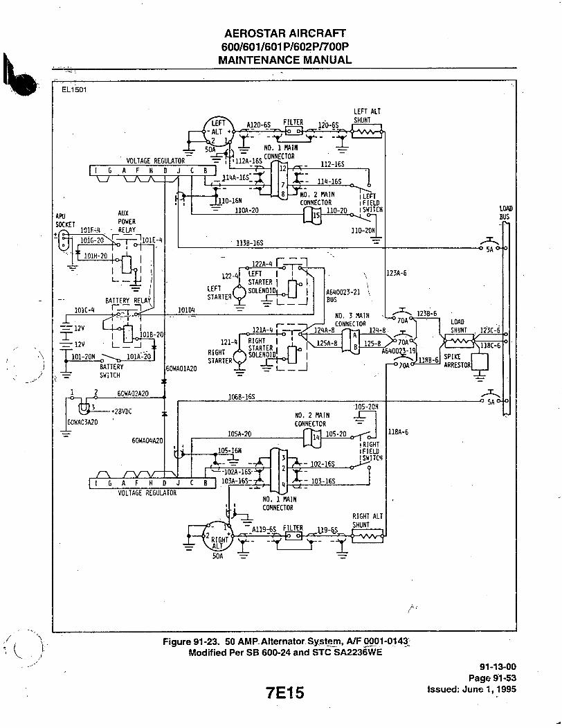
AEROSTAR AIRCRAFT 600/601/601P/602P/700P MAINTENANCE MANUAL
E L I 501
VOLTAGE REGULATOR D 6 A F H D J C
— V A _ A _ L ^
APU
SOCKET lOlF-.f
AUX POWER
REUY
lOlG lOlE-'J
lOlH-20
BATTERY RELAY
—i 2 v d X — 12V
IO:B-20|
101-20N L _ _
^ lOlA^O
BATTERY
SWiTCH
9 60HA02A20
-••28VDC
60WA03A20 60WA04IA20
A120-6S FILTER 120-6S
^IITA--L- NO. 1 MAIN
CONNECTOR irn2A-16S
_jiw-ies. 3-ril0-16N
"=" llOA-20
12 . 112-ies
LEFT ALT
SHUNT
8 -JKQ 111-16$
KO. 2 MAIN jLEFT CONNECTOR I FIELD
110-20 I SWITCH 15
110-20N
113B-16S
122-1 LEFT I I STARTER I
LEFT / ° \ sOLENOlDi S T A R T E R ^ I —
101»
E R y _J
A610023-21 BUS
121-1 I I RIGHT STARTER I
60WA01A20
RIGHT /SOLENOID .. STARTERVJ - -LT -J
106B-16S
121A-8
NO. 3 fWIN
CONNECTOR
LOAD!
BUS
5A' 123A-6
'70A' 123B-6
125A-8
121-8
105-20N
KO. 2 fWIN
CONNECTOR
105A-20
105-16N
11
G A F H D J C B
VOLTAGE REGULATOR
•102A-16S-
103A-16S-
102-16S
•RIGHT IFIEU) [SWITCH
103-16S
NO. 1 MAIN
CONNECTOR
A119-6S fllJER 119-6S
RIGHT ALT SHUNT
^- -1
>70A*' 118B-6I
LOAD SHUNT 123C-6'
A610023-19 (',_ I r i SPIKE
ARRESTORi
-o 5A«Ho
n8A-6
Figure 91-23. 50 AlWFLAiternator-System, A/F 0001-0143; iVIodified Per SB 600-24 and STC SA2236WE
7E15
91-13-00 Page 91-53
issued: June 1,1995

AEROSTAR AIRCRAFT 600/601/601P/602P/700P MAINTENANCE MANUAL
E L I 5 0 1
LH VOLTAGE REGUUTOR
I G A F H D J
APU SOCKET
AUX
POWER
RELAY lOlF-1
101G-20Nc-r-ni01E-1
lOlH-20 4^
lOlC-t
I— — 12V
-=:i2v
101-20N
BATTERY -
REL;»Y
I
JlOlB-20
lOlA-20
BAHERY
SWITCH
60WA02A20
-+28 VDC
e0WA03A20
60WA0'JA20
, r\ ry-y I 1 6 A F H D
NO. 1 MAIN
il2A-16S
;:1 11'(A-16S'
110-lWl
~ llOA-20
NO. 2 flAlN ^r>T CONNECTOR IpiELB
110-20 . ISHITCII
11C-20N ffl
113E-1ES
J22A-<l
122-t
LEFT
STARTER
LEFT STARTER SGLENOI^
lOlDI
4 J I ^ 1 I
Ati(0023-21 (BUS)
123A-6
LOAD!
BUS
L. ALT
LH ALT
MAIN C.B.
'70A' 123B-6
I
60WAU1A20
121-1 RIGHT I DtruT A STARTER I
10£B-16S
12IIA-8
NO. 3 MAIN
CONNECTOR
DIODE BUS
123C-E
125A-8^
12i(-8
125-8 >'7dA' 501-6
105-20N
it; 105A-20
^105-16H
RH VOLTAGE REGULATOR
11 1 . v ^ j q .
7DA
103A-16S
NO. 2 MAIN
CONNECTOR —
I l 0 5 - 1 0 _ ^ RIGHT FIELD
- , SWITCH
105-16S
NO. 1 MAIN
CONNECTOR
RH ALT flAIN C.B,
SIOA-H
LOAD SHUNT/1
SPIKE ARRESTER
I
E l R. ALT
, /RIGHT \ALT
_511A-6
80A
A119-6S
118A-6
RIGHT
ALT
SHUNT
119-6S --r-.
FILTER
Figure 91-24. 70 AiViP Aiternator System, A/F 0001-0143 iViodified Per SB 600-24 and STC SA2236WE
91-13-00 Page 91-54 issued: June 1,1995 7E16

\

2 O
en
>< .J:O
f- Q
X !.• cQ
UJQ
Q
>-CD
a Lu U-<
o 2 cn Ld D C
Q
2

AEROSTAR AIRCRAFT 600/601/601P/602P/700P
MAINTENANCE MANUAL
E L I 501
Figure 91-25. 70 AiViP Aiternator System, A/F 0144-0189 and Prior IWiodified Per STC SA2367WE
7E17
91-13-00 Page 91-55
issued: June 1,1995

AEROSTAR AIRCRAFT 600/601/601P/602P/700P MAINTENANCE MANUAL
ELI 534
FlLlER
AW «fl>y 153t)-65
H5B-8S
Xr 155C-8S
TEH I-SIRIP
L£FI ALT output CB
A-8 >' 'H^^y^r^
AUX Avionics BUS SWltCH
AVlOKICa
eus -H
BAI fWS![B SmtCH 101-20 ^ 101-7C!!
1)6-18S ± i : .0S-.8S.^'""_i^".'l^'! -
] c: 102-18S-T K- •T T
r- 105-18S
ICA-
P;A-I?|
wAr JlftPlRl
P8A-12
AVIOKICS, . WS U J 8ELAT
lil>2-20li
RADIO RASIER S»I1CH
RPl-20
SPI« ARREStOR
RPS-18
A119-6S
Figure 91-26. 70 AiMP Alternator System, A/F 0190-0364 (For A/F 0190-0355, See SB 600-54) \ V
91-13-00 Page 91-56
issued: June 1,1995 7E18

AEROSTAR AIRCRAFT 600/601/601P/602P/700P MAINTENANCE MANUAL
E L I 5 0 2
L. ALT. MASTER
C O N N .
N O . l
L E F T
W I N G
C O N N .
Figure 91-27. Alternator System, A/F 0365-0465
7E19
91-13-00 Page 91-57
issued: June 1,1995

AEROSTAR AIRCRAFT 600/601/601P/602P/700P
MAINTENANCE MANUAL
E L I 533 6 4 0 0 0 1
NOTE 20 JMP 2AC/B IS 4A FUSE IF AEROSTAR S/L 957 HAS BEEN
METER SHUNT (31
:RP4A>-(7i>-. . AVIONKS BUS
j o o D ^ - J U M P E R r " p . r m "
91-13-00 Page 91-SS Issued: June 1,1995
Figure 91-28. 70 AMP Alternator, A/F 0466 to 0714
7E20

AEROSTAR AIRCRAFT 600/601/601P/602P/700P MAINTENANCE MANUAL
ELI 534 640001 2 0 J M P
OR (NO 20 JUMPER)
METER SHUNT (3)
ALT. I NOR SWITCH
CONN NO I
77 12 13
77 12 13
' G R N ~ X B A T
32 B )
O/V RELAY
S E E STARTER
B U S
d o . f l E L o '
^ j - < i i l l >
;V0LT KREG.
PAR
IGND
-yV-70A
1 [ ) E I 8 F C
D E t B - G
(1338) (T33C)
I
(es)
CONN. NO. 3
( I 3 < B ) ( | 3 5 B )
C* ) I2V /l2V
( l O I D )
-(i£X
NOTE
2AC/B IS 4A FUSE IF AEROSTAR S/L957 HAS BEEN INCORPORATED.
^ ^ ^ ^ - ^
I - 1 ' ' AI
(7350)
16
5 6 1 76
5 6 1 T8
ALT. I NOP. ^ S W T C H
REG
IOAS
, O/V RELAY
.<ilGA>J
N0.I6 P A " JUMPER
GNDi
• ^ SEE l 0 2 A ) - [ STARTER
-(f l03A)—(TsN
VOLT
""4 BUS
FIELD —-'V I
( | 0 6 A ) ( | 2 6 A )
WING CONN.
r s
I J
- f l - { 6 F ) - < I I9A ) 21 j
fioSB)
FILTER
-V GRN
y g 4 ' f l
' NOTE
. REO - ( B L K
l ^ 2 A TcT^
-N0.6 JUMPER
Figure 91-29. 70 AiMP Alternator, A/F 0715 to 0848
7E21 91-13-00
Page 91-59 issued: June 1,1995

AEROSTAR AIRCRAFT 600/601/601P/602P/700P
MAINTENANCE MANUAL
91-13-00 Page 91-60 Issued: June 29,1983
Figure 91-30. 70 AMP Alternator, A/F 0849 and up (E.xcept 600 and 602P)
7E22

AEROSTAR AIRCRAFT 600/601/601P/602P/700P MAINTENANCE MANUAL
E L I 5 3 6 " 6 4 0 0 0 1
. LEFT ALT. OUT
2 0 J M P OR
- (N0 .20 JUMPER)
LEFT ALT. I NOR SWITCH
L. A L T MASTER
^ — ^ ( | 2 3 A ) ( I I O A ) ( I 3 2 B J
r GRN fREFV
< i L K > ,
I76T.S. [
LEFT O/V RELAY
I 64 65 ~JJRE(
S E E
STARTER C 16 J
LEFT WING CONN.
-<ITIA>.
BUS
FIELD
VOLT REG.
^ I—QML
\ 26 2,1/ ) 26 A
- ( T F s B
( I I 3 B )
( I Z O B )
ftL
lOA
70 A 70 A 70 A
MAIN BUSv
® (43 Csp
( T 3 2 A ) ^
L-cr\_p e o A
. .70 ) C i l o A )
- d 70AMP (3 ^I^d?)—I
s*o«ET [p3C!£ilDl
JL ' CHH) 12V y i 2 v
- ( 2 0 > - ( l 2 8
INST. v^^LIGHTS
\ •
J
R. ALT MASTER
U J S W ^ ^ ^
IAT. SW,
REG. O /V , I RELAY
\ _ , N 0 . I 6 JUMPER
\ GNO
- ( I 0 3 A ) — ( | 6 N ) —
- ( 6 ? V - ( 7 T 9 A > - ~ " t I—CTRFI-TO 13— FILTER
Figure 91-31. 70 AlWP Alternator, /l^F 0849 and up (600 and 602P Only)
7E23 91-13-00
Page 91-61 issued: June 1,1995
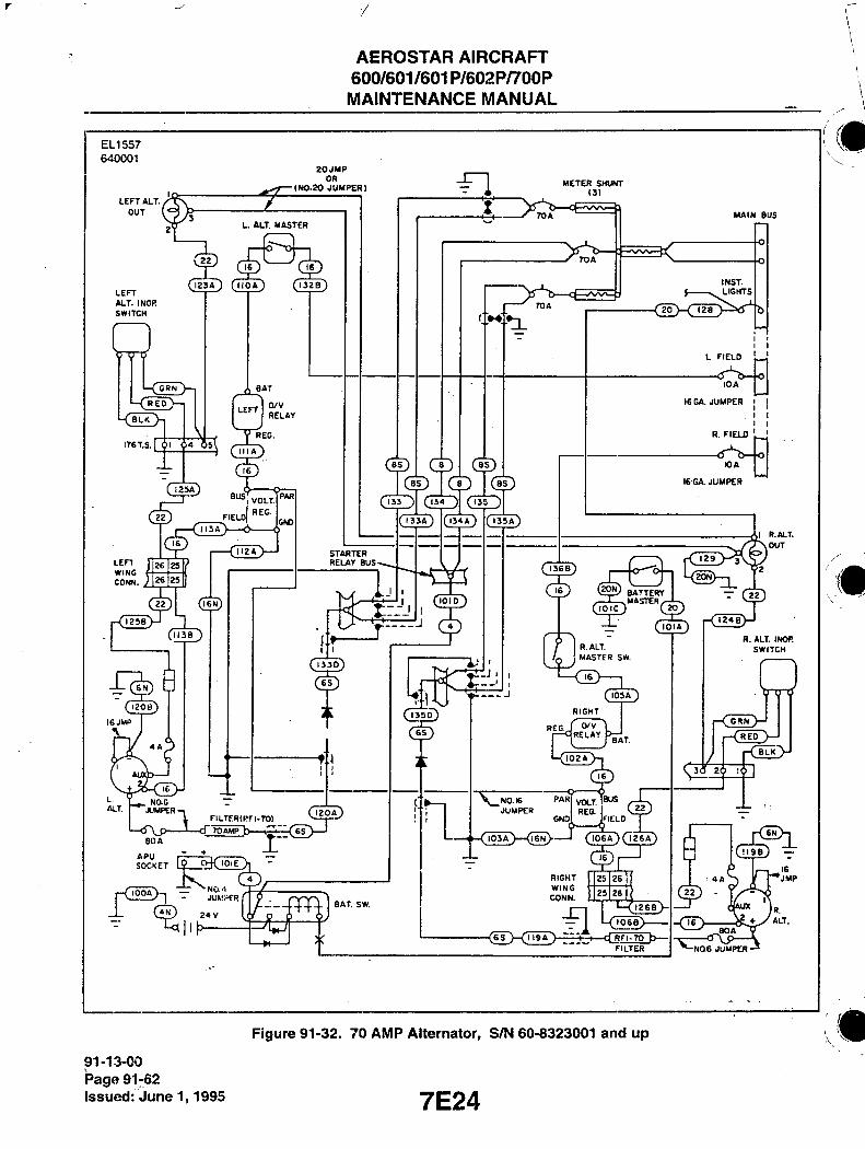
r
AEROSTAR AIRCRAFT 600/601/601P/602P/700P MAINTENANCE MANUAL
E L I 5 5 7
6 4 0 0 0 1
L E F T A L T . /
O U T
2 0 J M P OR
( N 0 . 2 0 J U M P E R )
U A L T . M A S T E R
L E F T A L T . I NOR S W I T C H
I 2 3 A ) ( I I O A ) ( I 3 Z B )
C R N
I7ST.S. 6l 64
BAT
L E F T 0 / V R E L A Y
(jJJAJ
L E F T W I N G c o m .
<7TTA>
FIELD
1' 25
«>i _L
M E T E R S H U N T 13)
C D
- X 70A
M A I N B U S
I N S T . L I G H T S
eg) dD
S T A R T E R R E L A Y B U S -
ciin
-CTTOAWP b—5r=<iL>—' F I L T E R ( R F I - 7 0 )
S 0 « E T 1? O-KJoiE r
juiii;ifR
CiN) 2 4 V
hf—
(TisA)
; ^ L I G H T S
•<'T2a>:^b
L F I E L D |__J
10 A
16 G A . J U M P E R
R. F I E U 3 ^
lOA
16 GA. JUMPER
1^ G p ® B A T T E R Y
, T ^ M A S T E R ,
1 2 9
I R .ALT.
O U T
( l o i c ) C M )
L(2^>-,
( T O T A )
R.ALT. MASTER SW.
BAT. SW.
( J M A )
0 / V R E L A Y
B A T .
C I 0 2 A ,
\ _ N 0 . I 6 J U M P E R
PAR,
- ( I 0 3 A )—( iJN)"
V O L T R E G .
IBUS
( | 0 6 A ) ( 7 2 6 A )
R I G H T W I N G C O N N .
J25 26
{23 26
t26aj
- ( 6 s " ) - C r i i A " ) ~ " ) I d R F I - 7 0
" F I L T E R
R. A L T . INOP. S W I T C H
i4
[ R E D
26 1
-NOe J U M P E R
91-13-00 Page 91-62 Issued: June 1,1995
Figure 91-32. 70 AMP Aiternator, S/N 60-8323001 and up
7E24

AEROSTAR AIRCRAFT 600/601/601P/602P/700P MAINTENANCE MANUAL
ELI526 -(RP4a>-(TT>
AUX AVIONICS BUS SW. -(Tr)-( RP3A)— I p
AVIONICS BUS RELffir
I \t|Ql I I
<20>
BAOlO MASTER SW.
MAIN AVIONICS BUS BUS
Figure 91-33. Avionics Power Reiay and Bus (Optionai) A/F 0715 and up
70 c/fr
T
fiC /ro-ffl-CC lOi'lO'
43-4 «
CLEfle
an
71
mtrnw — C C I 0 2 D -
/-mmftf!
I
• IIA . 7 1 — i
,9
•A mrcR Al
&C (02-21 - o /12
s—almo-in —
-j TO com'/
Figure 91-33a. Ground Clearance Switchi Wiring
7F1 91-13-00
Page 91-63 issued: June 1,1995

AEROSTAR AIRCRAFT 600/601/601P/602P/700P MAINTENANCE MANUAL
E L 1 5 0 6
lOlD-HN
MAIN BUS
SHUNT
NO. 3 MAIN
CONNECTOR
125A-8
121A-8
125-8
MAIN
BUS
121-8
MAIN REMOTE C.B. BATTERY SOLENOID 12V 12V
1A2 lOlC-l Tl
NO. 1 MAIN CONNECTOR
126-20N 126-20 ^ 5A0 31 31
126A-20 C5
U lOlD-1 Al
121A-1N
SEE STARTING SYSTEM
||||Hl|l| lOlB-20 5MA1;P-
T-STRIP
1-5 F.S. 73
MASTER
NO. 1 MAIN
CONNECTOR
101-20N 101-20 lOlA-20
T-STRIP
1-5
F.S. 73
Figure 91-34. Battery System, A/F OO01-O172
E L I 5 0 5
NO, 3 MAIN CONNECTOR
TO LER ALT DIODE
125A-8
NO. 1 MAIN CONNECTOR
121A-8
MAIN REMOTE C.B.
l l
125-8
121-8
126-20
126A-20
C3
126-20N
lOlD-1
BUS BAR MAIN
1 MAIN B
[ 513A-1 r f SHUNT ' L
121A-1N
SEE
ST.WT1NG
SYSTEM
BAR
TO RIGHT ALT
DIODE
BAnERY/APU RELAY 70 EXT.
r ~ / — ^ 1 PWR SOCKET, + TERM
T-STRlP
1-5
F.S. 75
1 MASTER
T-STRIP 1-5 F.S. 73
101-20N 101-20 1 1
—>
T-STRIP
3-1
F.S. 3781
NO. 1 MAIN
CONNECTOR
91 T1 3-00 Page 91-64 issued: June 1,1995
Figure 91-35. Battery System, 70 AiVIP, A/F 0173-0189
7F2

7
AEROSTARAIRCRAFT 600/601/601P/602P/700P MAINTENANCE MANUAL
E L 1 5 3 1
/ I - EXTERNAL POWER
BATTERY/APU RELAY •
O 1 o LEFT STARTER SaENOlO
CONN 3
LEFT ALT. C.B.
SEE ALT f (5''~~b—'W\r 1 TOA
/—(jy-ciiii A A • - ( B B -<
134 M 8
BATTERY C.B.
[ I 3 4 A ) — ( 8
( fo' I O rt<> •
70 A
RT ALT C.a
r<I> SHUNT
_/WV> 1
LOAD
MAIN BUS
S E E ALT I cf'Tj-^—VW 1 70 A
RIGHT STARTER .SOliENOID
12 V .ri. "L—(I5>-(7o7r)—fr|i j—C — ( l o i )-(2ON)—I
I 12V —
BATTERY MASTER
Figure 91-36. Battery System, 70 AIVIP, A/F 0190 and up
E L I 5 5 6 6 4 0 0 0 1
126-30 I26-20N
5A
31
' 31
i25A-a
TO LEFT BUS BAR ALT DIODE
N0.3 MAIN CONNECTOR
125-8
I24A.8 124-8 MAIN , I53A-4 SHUNT
V J
TO RIGHT BUS BAR j ALT DIODE
MAIS REMOTE C B .
IOID-4
MAIN BUS
•0 EXTERNAL POWER SOCKET, -t-TERM
I26A-20
i-r^ J I
J-o
24 V
" 1
rt iq I
BATTERY/APU I RELAY
I IOIA-20
I2IA-4N
MASTER SW. NO.I MAIN CONN.
101-20 N 101-20
m -
Figure 91-36a. Battery System, 70 AIVIP, (700P Only) Serial Numbers 60-8323001 and up
7F3 91-13-00
Page 91465 issued: June 1,1995
i

•
AEROSTAR AIRCRAFT 600/601/601P/602P/700P
MAINTENANCE MANUAL
E L I 5 0 3
UFT A L T E R N A T O H r
E X T E R N A L
P O W R P L U G LEFT R E M O T E
C / « 1 T O A I R C R A F T
S Y S T E M S
1 . I R A D I O
-m- M A S T E R S H I T C H
A V I O N I C S B U S
REUr T O
A V I O N I C S
- O - T ^
R I O f T AlTER.>IATO« F I E L D S K
Figure 91-37. Distribution Diagram - Eiectricai Power, A/F 0001-0143
91-13 00 Page 91-56 issued: June 1,1995
7F4

AEROSTAR AIRCRAFT 600/60iy601 P/602P/700P MAINTENANCE MANUAL
E L 1 5 0 4
E X T E R N A L E X T E R N A L POWER R E L A Y
BATTERY
REUY
T O A I R C R A F T S Y S T E M S
A V I O N I C S B U S
T O A V ' I O M I C S
RIOHT A L T E R N A T O R
F I E L D S »
Figure 91-38. Distribution Diagram Eiectricai Power, A/F 0144-0189 j
91-13-00 ;Page91^7
ypg issued: June 1,'l995

AEROSTARAIRCRAFT 600/601/601 P/6d2P/700P , MAINTENANCE MANUAL
' E L I 5 0 4
tXTERNAL I'OWtR PLUG
TO A V I O N I C S
i CVER-VOLTACE RfiAY
VOLrAGl
\ CVER-VOLTACE RfiAY RtlUlUrOR RICKT
a
Figure 91-39.
91-13-00 Page 91-6S Issued: June 1,1995
Distribution Diagram Eiectricai Power, A/F 0190-0364
7F6

AEROSTAR AIRCRAFT 600/601/601P/602P/700P
MAINTENANCE MANUAL
E L 1 5 0 5
L E K T A L T E R N A T O R
V O L r A C h O V E R . V O L T A G E R E U Y
R E G U L A T O R
O V E R . V O L T A G E R E U Y
EXTERNAL
rOHER PLUG
T O A I R C R A F T S Y S T E M S
RIGHT A L T E R N A T O R
N A T U R / C \ V O L T A G E K I G U L A T O R
O V E R -V O L T A G E R E L A Y
\ \
V O L T A G E K I G U L A T O R
O V E R -V O L T A G E R E L A Y
RiGia A L T E R N A T O R
F I E L D S K .
Figure 91-40. Distribution Diagram Eiectricai Power, A/F 0365 and up
91-13-00 Page 91-69
issued: June 1,1995

AEROSTAR AIRCRAFT 600/601/601P/602P/700P MAINTENANCE MANUAL
ELI 505
AN2552-3hCREF) APU SOCKET
O lOlF-4
7064-534C (REF) EXT. POWER SOLENOID ioiG-20
A2 I lOlE-4,
'AT lOlH-20 XI
5MA4-D-K (REF)
•X2 Al P
7064-534C -QfREF)
BATTERY SOLENOID
Figure 91-41. External Power, A/F 0144-0189 (See Alternator Schematics for ail Other Airframes)
EL1501
-05; o -
\
H
6
f
INVERTER D
NO. 1 E
C
A
B
835-20
838-20 1 A810-20 857-20
o 5A o -
'V
H
G
INVERTER F n
NO. 2 E
C
A
V
852-20
859-20
—f) 2A o -831-20
836-20.
"t~^L. ! 833-20
4-0 1 ^
' 2A o-310-20
851-20
'l D DIR
c GYRO
B IND
.A
AIM 200E
E E
D HORIZ
C GYRO
B IND
A
AIM SOOB
Figure 91-42. inverter - A.C. Power (Gyro instruments) 0002-0005
91-13-00 Page 91-70 Issued: June 1,1995 7F8

600/501/601P/602P/700P MAINTENANCE MANUAL
H I V 1 o u r
.4. I
i 7
I
r....
- V ) ' • 1
I'M K;V
F>qufe914J MagopU,^ A/r OO J) 0846
l i r p 91-44 Magneto', A/F 0849 .ind
91-13 00
i'1-.up-d June 1 '995
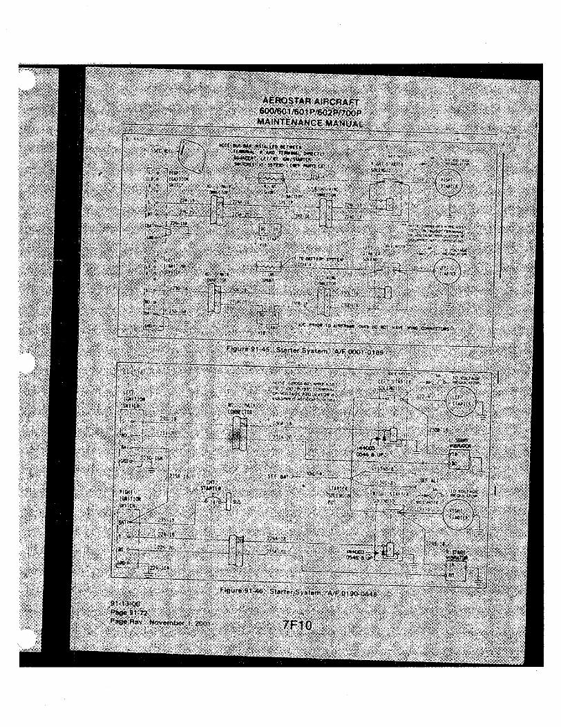
AEROSTAR AIRCRAFT 600/601/601P/602P/700P
MAINTENANCE MANUAL
• ' • • " • f c • • • « < > • ( • • « * M«c; T
r •
^
F.-gure9145 StJirtef 3 s>.-<n A/F OOC1-018'»
' .ff
J o.,..^ . . _ _ . : , kj j i _
|/5y i«
1. W T
0
• t r - , .
/»Moo8," j : isssf,'.
< i. Jf»«»
P.giirr i*J-4b Slu'terS/ilom A/F 0190'J64K 91 i J - < n ,
PiKje 91-72
7 F 1 0 •

AEROSTARRAIRCRAFT 600/^01/601 P/602P/700P
MAINTENANCE MANUAL
E L 1 5 3 1
3 NOTE: 108085-501 WIRE ASSEMBLY TO BUS TERMINAL OF VOLTAGE REGULATOR IF EQUIPPED WITH OPTION 263. ,
S E E N O T E - I T O V O L T A G E
R E G U L A T O R
STARTER; v
. 2 A \ I J
• - / S E E - B A T T E f i ^ f e h r K i ^ H ^ I i ^ ^ • ( | 3 4 B ) — ( 8
SEE ALT. T O V O L T A G E R E G U L A T O R ,
R IGHT S T A R T E R '
Figure 91-47. Starter System, A/F 0849 and up
\
THIS SPACE iNTENTiONALLY LEFT BLANK
91-13-00 Page 91-73=
7FT1 issued: June 1,1995
i.

AEROSTAR AIRCRAFT 600/601/601P/602P/700P MAINTENANCE MANUAL
E L 1 5 1 1
NO. 1 fWIN CONNECTOR
602-20
601-20
" S A "
601-20N
P—i •p^ 8 , 601-20
" ^ ^ ^ 2 603-20
I 6 1 , 617-20
75
77
76
602A-20
601A-20
603A-20
NO 2 HAIN CONNECTOR
" l 3 0 ^ I [Hi i 1/2 W I t!^ I
LEFfluRBO SWITCH
68 617A-20
YEL
RED
-X-BLU
INDICATOR' NC
SWITCH ' F-l
1 1 7
2 8
3 6 9
TUT
REAR VIEW
OF SWITCH
NO 1 MAIN CONNECTOR
606-20
y-^^ 605-20 o 5 o
608-20N
78
—
606A-20
1 ^ 2
~i)3owr 1/2 W
NO. 2 MAIN
CONNECTOR
YEL
608-20
607-20
618-20
I I TURBO SWITCH RIGHT
67
608A-20 RED.
607A-20 BLU
6i8A-20
INDICATOR! I SWITCH
91 r13-00 Page 91-74 Issued: June 1,1995
Figure 91-48. Turbo Wastegate Actuators, A/F 0001-0145
7F12 1

AEROSTAR AIRCRAFT 600/601/601 P/6b2P/700P
MAINTENANCE MANUAL
! \ E L 1 5 1 2
NO 1 KAIN
CONNECTOR
606-20
_ NO 2 MAIN
^ 605-20 r 7 ^ CONNECTOR
608-20N
JL
^ 3
OH H OHM"
608-20
607-20
618-20 ^7
RIGHT TURBO
SWITCH RIGHT TURBO
RELAY
RIGHT WING
CONNECTOR
JZZL a 1 7 \
2 , 8
3/ 6 9
REAR VIEW OF SWITCH
(FOR TERMINAL INDENT)
i|30 OHM
1/2 W
LEFT TURBO SWITCH
LEFT TURBO
RELAY
LEFT WING CONNECTOR
601B-20
603B-20 . BLL'
622A-20 ^^BLK
523A-20 Y L ORWHT
62tA-20 GRN
.
Figure 91-49. Turbo Wastegate Actuators, A/F 0146-0204 91-13-00
Page 91-75 yp-|2 issued: June 1,1995

AEROSTAR AIRCRAFT 600/601/601P/602P/700P MAINTENANCE MANUAL
E L 1 5 1 2 NO 1 MAIN
CONNECTOR
130 OHM
1/2 W
Figure 91-50. Turbo Wastegate Actuators, A/F 0205-0341
E L I 5 2 4
- ( ] £ ) — ( B L W - « >
l A 100 w
ze\ 0 r > - ( B L W 2 ) o-
2 9 ] Cir)—(BLW3) O -0—o ( B L W - I ) -
LO
C .B .
10 A M P
-X QBI-W-S)—(isN
( B L A C K )
A S S Y
91-13-00 Page 91-76 Issued: June 1,1995
Figure 91-50a. Cabin Ventilating (Opt) A/F 0982 and up
7F14

AEROSTAR AIRCRAFT 600/601/601P/602P/700P MAINTENANCE MANUAL
E L I 5 2 3
A / C
EVAP FAN
-(AA:4a>-(TT)-
I EVAP DRAIN SOLENOID
I NOT USED ON , A / F 0 4 S 6 AND
J
3: —J [—(lo A A : >
(ib
1 1
2
3 3
4 4 5 5
6 6
r 7
e 8
9 9
10 10
II II
12 12
I o-t-CTeXBLw I >-o7S'
(EXISTING) (-<308A>—(TF)
, . , . 5 A R.H. ALTERNATOR - ( T 6 > - ( 7 A / C > — Q / ^
ATTACH UPSTREAM OF ALTERNATOR ISOLATION -oiooe
5A
L.H. ALTERNATOR
- < 5 A ^ (liZTE) G«a^O AT RELAY
( l 9 A A A J
MOUNTING SWITCH
60AOR 70A
B O A . LWITER
28 VOLT POWER SOURCE
COMR COND FAN
Figure 91-51. Air Conditioning System (Later lUiodeis)
7F15
91-13-00 Page 91-77
issued:June 1,1995

E L 1 5 5 2
0 4 0 3 1 6
AEROSTAR AIRCRAFT 600/601/601P/602P/700P MAINTENANCE MANUAL
AIR CONDITIONING
E V A P
F A N -» -(irXBLWI05>
E L E C T R I C A L P A N E L A S S Y .
r"
- ( 1 2 ~ ) - ( B L W I 0 4 ) - 4
LOW PRESS SW.
HI PRESS SWITCH
2 O . - (12~)-(BLWI00)—(5^ b 2 0 A C / B
{T2)-<BLWI07>-l-f
{ l 2 ~ ) - ( B L w i o ?
{T2~)-(BLWI02
G I O - { B L W I O I >
-{ir>-(Brwi09)-[ < 1 2X B L W I 0 6 > -(TFKSLWI06A) X c/cCMP.
f22)-<BLwioa)-
RIGHT WING DISC
(RT. ENGINE) —
CONO.
Figure 91-52. Air Conditioning System (700P Oniy) 91-13-00 Page 91-78
issued: Junel, 1995 7F1 6

AEROSTAR AIRCRAFT 600/601/601P/602P/700P MAINTENANCE MANUAL
E L I 5 1 6 ^ Z ' , , . , •
NO. 2 MAIN
CONNECTOR
T-STRIP 1-9
F.S. 2t5
BLOWER
olOA 701-18
705-18
701A-18
713-20
BLO SW 1-20-
o3|
2-20'
701B-18
713A-20
703-20
R.n. GEAR
UPLOCK B-D SW
701-20
707-18 707A-18
703 A-20
'707B-18
702-18
702A-18N r 701C-20
BLOWER DELJ>Y
COMB AIR BLO 0= .... /
1 FILTER
RELAY
707C-20
706-18 706A-18 706B-18
HEATER COHTROt
706-20N
- 6 0 I / 6 0 I P ONLY
1
M l X2
HTR , FUEL
,711A-20 I 1 .02mW 710-18
711-2nNi
HTR REG t 7118-20
SHUT-OFF 711B-20N
VALVE 1
T-STRIP
1-1 F.S. 221
SWITCH .
A 709-18
— RELAY
711-20
710A-18
709A-18
J A711-20
FILTER VENT AIR
BLOWER
SEE I DETAIL •A'
RADIO NOISE FILTER
IGN-UNIT-
• COMB A.AIR '-^PRESS
SW
OVERHEAT SW (NC)' V . . /
3Z CYCLING SW (KC)
FUEL SOL VALVE
HEATER
VENT AIR BLOWER
702-16N
DETAIL A
MODELS 601/601P
Figure 91-53. Heater, A/F 0001-0355
7F17
91-13-00 Page 91-75
Issued: June 1,1.995

AEROSTAR AIRCRAFT 600/601/601P/602P/700P MAINTENANCE MANUAL
E L I 537
2 MAIN COP«ECTOR
T-STRIP 1-9 F.S.
26500
cT^^b^—-(705 ) - - ( T r > - , (Jo^ DA ^ ^ ^ ^ 1 —-T-
BLOWER
HEATER HOT,
(r—T^)—I
V
K i i E > — Q -
( ^I3A)
20|20}-(T6
r-I
• T j F ) - ( ~ 7 0 F ) 1 FILTER H
•(7i5B>-|7
C O BLOWER DELAY
R.M. SWITCH GEAR UPUXK
BLOWERSW.
•o o
T > 7 0 7 B V ^ ^ A .
— (TSN)
( 7 n ? A )
d p e n
B - C W E R D E L A Y R E U S Y 33->
FILTER
HEATER CONTROL SWITCH
XI
G£Z£)~GE " 7 0 7 )—(l6N>
-< 104 >-(76>
£ - ^ 6 N ) -
<ii><li2>-E 1 r >
, 0 2 M F f ! ' H E A T DUCT SW,
C!°D
^ 1 ( H E )
HEATER CONTROL RELAY
•<!J2D-Gi>
702
( 7 0 2 B )
VENT I6N; AIR
BLOWER
3C T a : N G SWITCH (NC)
F U E L SOLENOID VAUVE
RAOO NOISE FILTER
IGM RAOO NOISE FILTER UNIT
i TO
I G N I T O R
C0M8. AIR PRESS. SW.
HEATER FUEL PUMP
INTEGRAL LEADS
I OVERHEAT SW. i (NCI
HTR. REG. B
SHUTOFF V A L V E
-STRIP l-l ES.224
91-13-00 Page 91-80 Issued: June 1,1995
Figure 91-54. Heater, A/F 0356 to 0848
7F18

AEROSTARAIRCRAFT
600/601/601P/602P/700P
MAINTENANCE MANUAL
E L I 5 3 7 E L I 5 3 8 T-STWP 1-9
F.S. 26500
HEATER HOT <7i5c)-(77>
(70IS) BLOWER
I6N
-<7D—irToF"> 1 FILTER h .
! ^ I ( 702B )
Cie) (rojA )
( 7 0 3 ) ( T 6 )
BLOWER DELAY
R.M. SWITCH GEAR UPLOCK
acCWER SW.
— (I6N) I
nl ! (702A) VENT I6N) AIR
' BIDWER
d p
QT)
L(7i5A
BLOWER DELAY RELAY C P ' l « d _
FILTER
HEATER CONTROL SWITCH
> - B n
-<TOrc)-(Ti>
70 7y-(l6N) j
-<Ti>-(To6> {2W^B><]6>
7 ^ •<]D-G!°>-E
02 MF t HEAT DUG r SW.
( 7 0 6 )
-(j7o7y(T£)-
INTEGRAL LEADS
HTR. REG 8
SHUTOFF
It;" ^
T-STRIP l-l
1 FS.224
< 7 ^ r > X
CYCLING S w n C H fNCl
FUEL SOLENOID VALVE
RADO IGN
UNIT NOISE IGN UNIT FILTER
IGN UNIT
TO IGMTOR
I
! CCNB. AIR
I OVERHEAT SW I INC)
VALVE I
Figure 91-55. Heater, A/F 0849 and up
7F19 91-13-00
Page 91-81 Issued: June 1,1995

AEROSTAR AIRCRAFT 600/601/601P/602P/700P MAINTENANCE MANUAL
E L 1 5 1 3
, IOlD-4 EXISTING IOID-4 EXISTING
HYDI0IA-20 MAIN BUS HYDII3-6
35A
KYOIII-6 HYDI0I-20
HYDI08-20 O j 26898-4
I RELAY
i IN4003
INSTR. LTS.
HYDII2-6I
20GA JUMPER ^ HYDI02A-20
HYDI02-20
22 6A JUMPER
980074. AUX. HYD.
PUMP
98QD77-1 PRESS SWITCH 22 6A JUMPER
HYDI05-6N
INDICATOR LIGHT
Figure 91-56. Auxiliary Hydrauiic Pump 601P/700P H/lodeis only
S t
/
/
i ,
91-13-00 Page 91-82 Issued: June 1,1995 7F20
/

AEROSTAR AIRCRAFT 600/601/601P/602P/700P
MAINTENANCE MANUAL
E L 1 5 1 7
H 3 9 A 2 0
INST. LIGHTS C.B.
I I C I NO I I ^ » I I
ALTITUDE SWITCH
OXYGEN REQD LKHT
H4LA20N
Figure 91-57. Oxygen Required Liglit 601P/602P/700P
91-13-00 Page 91-83
y P 2 i s s u e d : June 1,1995

AEROSTAR AIRCRAFT 600/601/601P/602P/700P MAINTENANCE MANUAL
THIS PAGE INTENTIONALLY LEFT BLANK
91-13-00 Page 91-84 Issued: June 1,1995 7F22

t ,< cc o DC
<
o oc UJ
<
(o us
r UJ
t < oc o oc < oc iS w o oc UJ
<
o 3 Q: <
JO UJ Q: O i= z o <
§ < to 5: A/1 (Jl /(/I
c o o
to
s s
3
U W 0 )
.a a U
3
iZ
<o 9 <o o
s o
1 3
M M
£ c !5 O 06 L O
3
LL
O)
CO c 3
9 5 - 0 C O <u 0)
r o> 3
S; £ i2
o in in o 00 o>
r i - 0) 1 -
<0 I -
Q- 3
•o v 3
M
CO CM
3

. < o H to C/) . O o CC SS in o —
to
3 Z <
UJ o z • z
UJ I-z <
t < cc o QC <
o 3 Q: <
CD UJ
< O < H (O 2 CO ;= s o S K-oc z 2 3
o < <o s
o
C O
• t— u.
I . oc
Hi' - 5 ^
[7
i i
i-H CM in ir>
V < a Q Z C a t
; ill CM CM CM CM • •
CO oa
CM CM
CM CM I
m a:
G O s
O S I— I—
5 2 i CM CM
s CO
I oo c/>
su||,
a C O
i i
i
is
it! Si
H I .
1
s {3

I
< o
<
O 3
z CL < g 2 SP 111
o < H ig 5 S2 ^ m o S H a ^ z
2 5
>? «^ S DC o ^ (O UJ
^ s < I" S5 z o S H cc i5 z <r o <
^ <o 5
c o u
o (O
C m
s o
c o
3 w
.a CO
O d T -
2> 3 O)
0.
o SS-a 3 •o c a o>
s o u.
^ _ c o "I •c 3 (0 u 21 Q. c !5 n O d cn
£ 3 O)
CD
in o> 0)
o 0)
CO 0) A>
« £ i2
o o) in O CO o T - 0> \^ r- 0) 1 -O) CD (0 f Q- 3 •o V 3 0)
CO
O
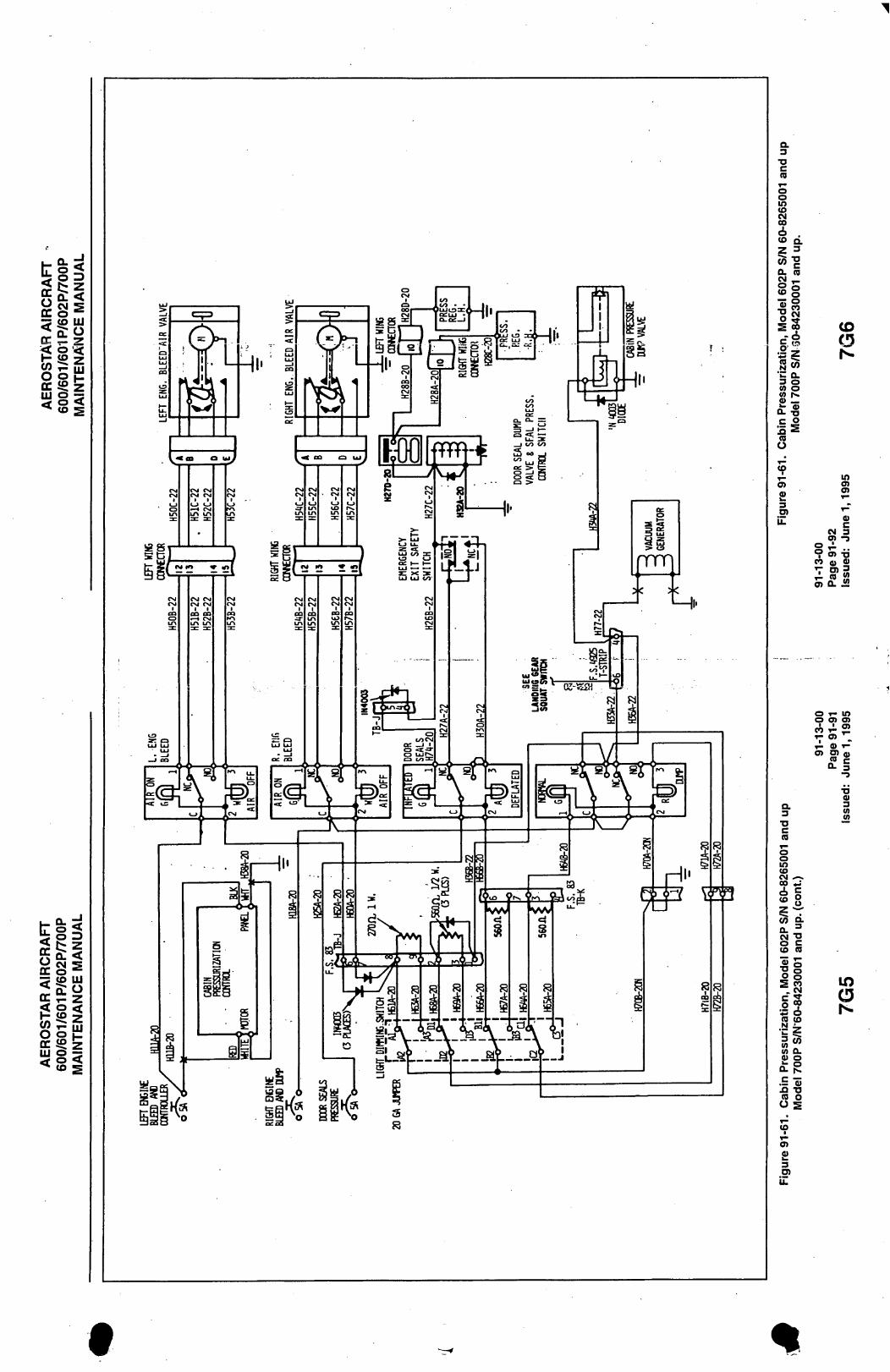
1
O 3
(O UJ o
< cc o cc K — z < o '< H JO z CO ;= m O S H cc iS z
g 3 to rs
^ (O UJ
oc T- z ^ S <
^ 2 CO T- UJ O S H oc iS z
S 3 o < <o s
HI'
—t CNI J O
:1 ) i l ) )
<.9
CM CM CM CM CO CO i — • CM
CO LA 5S CO
£1
C/)CM
nmn
Ml.
U J ( 9 e n s ,
ivji'ji
f at-—a!
<J3
a 3
T J C
n O o in <o CM CO 6 . CO a Z 3 a. ra
s g 1 °
&2
0. o o k 0 1 OL -S
o
9>
D>
a 3
T J C
n O o in C O
a OO ^
^ § &I o c CO n o 8 S CO = s •Si IS 3 (0 M
a. .E a! Si -a o
Q. O
o
5 CO
I
3
CD
in a>
0) c
m a CO o <» 5 2 J2
o T - in O O) CJ)
T °> -
tt- 3
T J <U 3 (0 V>

E L I 5 0 7
AEROSTAR AIRCRAFT 600/601/601P/602P/700P MAINTENANCE MANUAL
RIGHT FUEL BOOST
nm-20 mi 6 -
lEFl FUEL BOOST
PRIOR TO AF0I90- SWITCH AND CIRCUIT BREAKER ARE COMBINED
N O T U S E D O N
A / F 0 8 4 9 A N D U P
m-20
1(01-20
k N D ^ U P ^ ^
32
FILTER
•t 101-20N
" J T " "
iiOlA-20
NO. 1 HA IN CONNECTOR JC
o RIGHT FUEL BOOST PIW
LER FUEL BOOST PUHP
Figure 91-62. Fuei Boost Pump
91-13-00 Page 91-93
yQy issued: June 1,1995

AEROSTAR AIRCRAFT 600/601/601P/602P/700P MAINTENANCE MANUAL
E L 1 5 0 6
FUEL FLOW INDICATOR
tBLUE/>-v
RED! ! FF100-22S
REDi I FF101-22S
GREEN SUPPRESSOR
GREEN
FF102-22N
RED FF104-22
BLK
SUPPRESSOR
MEMaRY
RED
- N „ M n - S T R I P E ,
RED
_BLK_
—t„WHr STRIPE,
LEFT FLOW TRANSDUCER
RED
_BLK
BLK
FF103-22 -O 2A O FUEL FLOW
RIGHT FLOW TRANSDUCER
A/C BATTERY
I HI 24V 1
Figure 91-63. Transducer, Fuei Flow System, A/F 0001-0266
E L I 5 0 6
l^ L HOH INDICATOR
NOT USED A/F 0849 a UP-
BLUE / - >
RED I FF100-22S
BLUE f
-I— r 4rf
RED I FF101-22S I I
FF104-2n GREEN SUPPRESSOR
RED
BLK
GREEN
FF102-22N
BLUE r-\ FF1O0A-22S /-y.Mff STRIPE
BLK
RH) I - A - FFlDlA-22S/-x„Wrr STRIPE
BLK
LEFT FLOW TRANSDUCER
R i a r r FLOW TRANSDUCER
No. 2 MAIN CONNECTOR A/C BATTERY
A FF1O4A-20
SUPPRESSOR BLK
MEMORY
RED
~ ^ 2 ^ ^ ^ 24V -r= 1
FFI03-22 -O 2A o
1
91-13-00 Page 91-94 Issued: June 1,1995
Figure 91-64. Transducer, Fuel Flow System, A/F 0267 and up
7G8

AEROSTARAIRCRAFT 600/601/601P/602P/700P MAINTENANCE MANUAL
RIGHT FUEL VALVE
SELECTOR SWITCH NO. 1 flAIN CONNECTOR
x (TTTl t06-20
CL NO,
CL NO. 2
OP NO. 1
( OP NO. 2
o Ao-
C. Ao
1 129-20
2 '(05-20
3 '(28-20
"OFF-
LEFT FUEL VALVE
SELECTOR SWITCH
CL NO. 1 C ^ C >
CL NO. 3 >o^, c OP NO; 1
( OP NO. 3
o A>
Acv
• O F F "
H03-20
1 127-20
1(02-20
1(26-20
N O T E S W I T C H S H O W N IN " O F F " P O S I T I O N
03 70
36
69
NO. 2 fWIN CONNECTOR
NO. : MAIN-
CONNECTOR
3'( 3'(
72
• — '
33
71
NO. 2 MAIN CONNECTOR
'(29A-20
<l28A-20 ^
B
C
D
r K05A-20
'(06A-20
K26A-20
'(27A-20
'(02A-20
r
'(03A-20 .
NO. 2 VALVE
B
C NO. <( VALVE
B
C NO. 3 VALVE
0
NO. 1 VALVE
RIGHT FliEL
SHUT-OFF
LEFT FUEL
SHUT-OFF
Figure 91-65. Fuei Seiector, A/F 0001-0848
7G9
91-13-00 Page 91-95
issued: June 1,1995

AEROSTAR AIRCRAFT 600/601/601P/602P/700P
MAINTENANCE MANUAL
RIGHT FUEL VAIVE
SELECTOR SWITCH
429-20
40S-20
420-20
"OFF"
LEFT FUEL VAIVE SELECTOR SWITCH
403-20
427-20
402-20
426-20
NOTE SWITCH SHOWN IN "OFF" POSITION
r
r
'A
B c
Na 2 VALVE
1°
'A
B c
NO. 4 VAtVE
NO. S VAIVE
Na I VAIVE
RI6KT FUEL
SHUT-OFF
liFTFUa SHUT-OFF
Figure 91-66. Fuei Seiector, A/F 0849 and up
Figure 91-67. Not Used
91-13-00 Page 91-96 Issued: June 1,1995 7G10

AEROSTAR AIRCRAFT 600/601/601P/602P/700P
MAINTENANCE.MANUAL
E L 1 5 1 3 l O l D - l EXISTING
-o o-5A
r L l
101D1 EXISTING
^ HYD105-6N
HYD108-20
T l I • HYDIOH-G
I a
^61003_3-l JE«OT_E C / B ,
HYD106-20
HYD107-20N
1 6 36 <) 2
980077-1 PRESS SWITCH
HYD102-20
INDICATOR LIGHT (PRESS TO TEST)
AUX HYD PUMP
Figure 91-68.. Auxiliary l-iydraulic
E L I 5 5 4
NOSE STEER
NOSE T.S. F S 54 25
109-20
" " ' " ^ CONSOLE NOSE
0
3I8-20N —K>
STEERING SW. 3I0B-20
318-20
LEFT 312-20
311-20
3IBA-20N
RIGHT
339A-20
-rO , 1
—M>
GLARESHIELD NOSE STEERING SWITCH 335-20
336-20
3 3 7 - 2 0
3 3 8 - 2 0
3 3 9 B - 2 0 N
309A-20 82
NOSE GEAR RELAY
r O - n B 3
I o B l
3I0A-20
3I8A.20
3I2A-20
3IIA-20
NOSE WHEEL
B STEERING SOLENOID
VALVE
«A
F.S.49.25T.S.
60CG0IA-20
6OCG02A-2O
SOLENOID SHUT-OFF
VALVE
Figure 91-68a. Nosewheei Steering (700P Oniy)
7G11 91-13 00
Page 91-97 issued: June 1,1995

AEROSTAR AIRCRAFT 600/601/601P/602P/700P MAINTENANCE MANUAL
E L I 5 0 9
509-20
NOSE STEERING
RIGHT
318-20N
LEFT
310B-20
318-20
312-20
311-20
T-STRIP 1-13 F.S. S^
3
309A-20
NOSEGEAR REUY
i l l 310A-20
318A-20
60C602A-20
512A-20
311A-20
NOSE WHEEL STEERI IK SOLENOID VALVE
SOLENOID SHUT-OFF VALVE
__0N A^ 0 1 3 0 £ U P _ J
Figure 91-69. Nose Wlieei Steering, A/F 0001-0399
E L I 5 0 9
NOSE , STEER
309-20
NOSE STEERING
Riarr 310B-20
318-2a\
—r—o
LEFT
318-20
312-20
311-20
318A20N
F.S. 54.25
•a-61 - = =
•0.
60CG02A20
NOSE T.S. F.S. 54.25
NOSE GEAR REUY
309A-20
31OA-20
318A-20
312A-20
311A-20
NOSE WHEEL
STEERING
SOLENOID
VALVE
60CG0LA20
lA's 0501 a UP) i
I I I 41} SOLENOID
SHUT-OFF
VALVE
^ A/F 0130 6 UP J
91-13-00 Page 91-98 issued: June 1,1995
Figure 91-70. Nose Wheei Steering, A/F 0400-0545
7G12
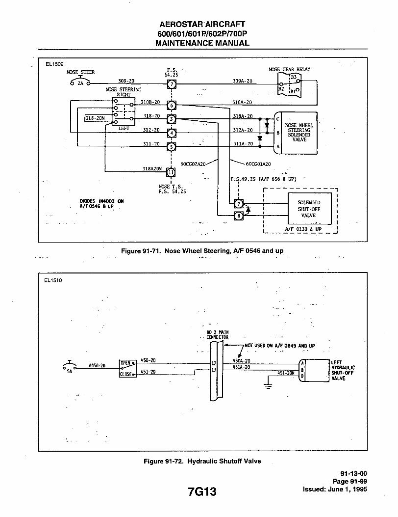
AEROSTARAIRCRAFT 600/601/601P/602P/700P MAINTENANCE MANUAL
E L I 5 0 9
NOSE STEER F.S. S4.25
309-20
NOSE STEERING Riarr
|318-20N O I
LEFT
3108-20
318-20
312-20
311-20
318A20N 60CG02A20'
NOSE T.S. F.S. 54.25
DIODES IN40C3 ON A/F 0546 8 UP
NOSE GEAR RELAY
309A-20
b2 !
510A-20
318A-20
312A-20
311A-20
c NOSE WHEEL
B STEERING
B SOLENOID VALVE
A
^~^60CX;01A20
F.S.49.-25 fA/F 656 5 UP)
I I
SOLENOID SJWT-OFF VALVE
A/F 0130 5 UP
Figure 91-71. Nose Whieei Steering, /V/F 0546 and up
E L I 5 1 0
NO 2 MAIN CONNECTOR
° 5 A " -A150-20
OPEN
ICLOSEo-
150-20
151-20
7 NOT USED ON A/F 0B49 AND UP
150A-20
151A-20 151-20N
LEFT HYDRAULIC SHUT-OFF VALVE
Figure 91-72. Hydraulic Sfiutoff Valve
7G13 91-13-00
Page 91-99 Issued: June 1,1995

AEROSTAR AIRCRAFT 600/601/601P/602P/700P
MAINTENANCE MANUAL
E L I 5 0 5
/
* 2A^
r 810r20N ARTIFICIAL
HORIZON
INDICATOR
OR
. . J s . g'<0-20 °2ti^ 8H0-2DN
'A ARTIFICIAL
"HORIZON
INDICATOR
Figure 91-73. >Attitude Horizon
E L I 5 1 9
BATT. TER.MINAL
MAIN CONNECTOR NO. 2
DC100B20 DClOO-20
•JL
o ;A O-
40
IX:iOOA20
r-1-. CLOCK .ME.MORY
o'. SWITCH
DC100C20
DC102-22
1 .i 4
DC10I-22N
ELECTRONIC DIOrTAL CLOCK
91-13-00 Page 91-100 Issued: June 1,1995
Figure 91-74. Electronic Digital Clocic Wiring Diagram
7G14

AEROSTAR AIRCRAFT 600/601/601P/602P/700P MAINTENANCE MANUAL
i ix :
E L I 5 2 7
DUAL CYLINDER B
<EAD C FEUP D INDICATOR
8 1 7 - 2 0 8 1 8 - 2 0
NO. i IIAIM CONNECTOR
8 2 0 - 2 0 N 8 1 9 - 2 0 N
8 2 1 - 2 0 ^ 8 2 0 8 - 2 0 N
8 2 1 - 2 0
F . S . 73
• REQUIRED FOR WESTON GARWIN ONLY
8 1 E A - 2 0 3 1 9 A - 2 0 820A.-20 821A-2C)
LEFT WIIIG
COKNECTOR
8 1 8 B - 2 0
Rir-IIT WING CONNECTOR
L ENG
819B-2'.I
8 2 0 B - 2 0 R EN6
A 8 2 1 B - 2 0 'I i
Figure 91-75. Cyiinder Head Temperature (CHT), (Westin Garwin), A/F 0001-0799
E L 1 5 2 7
LEFT ENG. IND.
2A
LEFT ENGINE INO.
GROUND T.S.
824-20N 819-ZON 61 62
LEFT WING CONNEaOR
BI8A-20 8iaA-20N
8188-20 8I9B-20N
RIGHT ENG. INO.
RIGHT ENGINE INDICATOR
827-20N
RIGHT WING CONieCTOR
a20-20N 82OA-20N 848-20 62lA- 0
2A
NO.l MAIN CONNECTOR
820B-20N 82IB-20
Figure 91-76. Cyiinder Head Temperature (CHT), A/F 0800-0848
7G15
91-13-00 Page 91-101
issued: June 1,1995

AEROSTAR AIRCRAFT 600/601/601P/602P/700P MAINTENANCE MANUAL
E L I 5 2 7 L E F T ENG. IND.
2 A
LEFT ENGINE IND. B 2 4 - 2 0 N
G R O U N D T . S . L E F T WING CONNECTOR
8 I 8 A - 2 0 8I8A-20N
8 I 8 B - 2 0 8 I 9 B - 2 0 N
RIGHT E N G . IND.
RIGHT ENGINE
INDICATOR
8 2 7 - 2 0 N
2 A
RIGHT WING CONNECTOR
B 2 0 A - 2 0 N B 2 I A - 2 0
8 2 0 B - 2 0 N B 2 I B - 2 0
Figure 91-77. Cylinder Head Temperature (CHT), A/F 0849 and up
E L I 5 0 6
0 ^ 831-20
831-20N U
DIRECTIONAL GYRO INDICATOR
OR
831-20
831-20N DIRECTIONAL RYRO
Figure 91-78. Directional Gyro D.G.
E L 1 5 0 6
EGT INDICATOR
EGT SCHEMATIC DIAGRAM
' YEL R EN6
- REC
- RED ' YEL
L EN6
Figure 91-79. Exiiaust Gas Temperature (EGT)
91-13-00 Page 91-102
issued: June 1,1995 7G16

AEROSTAR AIRCRAFT 600/601/601P/602P/700P MAINTENANCE MANUAL
E I 1 5 1 2
FLAP 0 > POS
IND B
D /
829-20
808-20
809-20
A807-20 807-20
NO-1 NAIN
CONNECTOR
NOT USED ON A/F 0849 AND UP'
808A-20
809A-20
8O7A-20
•• TRANSninER
Figure 91-80. Wing-Hiap Position indicator
E l l 5 5 3
0 4 0 3 1 9
FUEL FLOW
INDICATOR
BLUE
RED FFIOO-22S I I
j WHT STRIPE
BLUE
RED
LT RED
B L K
LEFT FLOW TRANSDUCER
..WHT STRIPE
FFI0 I -22S
TO DIGITAL CLOCK t-
DClOOA-20
I I RED
_BLK_
RKSHT FLOW TRANSDUCER!
FFI04-20 G R E E N , ^SUPPRESSOR
R E 0 „ FF I04A-20
B L K T 2A
GREEN CRN-20
BATTERY
•l|Hlh 24 V
FFI02-22N ! SUPPRESSOR RED , , - F F I 0 3 - 2 2 ^ PLOW
2A B L K I
Figure 91-80a. Fuei Fiow w/Totaiizer (700P Oniy) Seriai Numbers 60-8323001 and up
7G17 91-13-00
Page 91-103 issued: June 1,1995
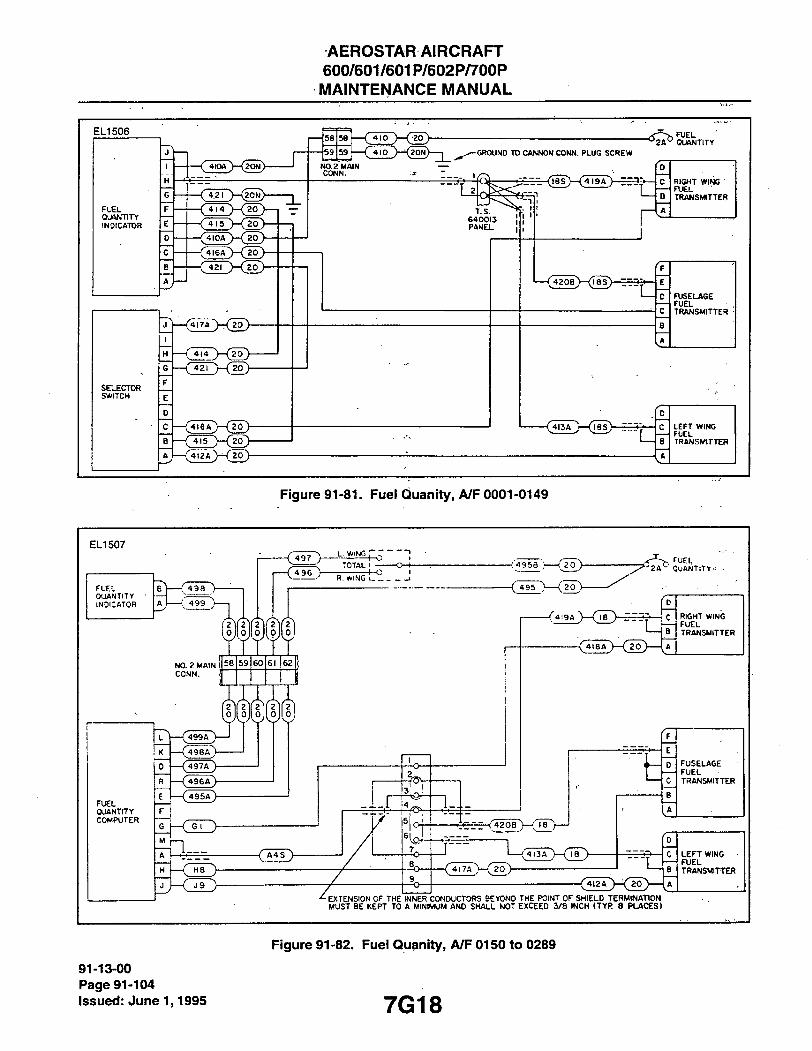
AEROSTARAIRCRAFT 600/601/601P/602P/700P MAINTENANCE MANUAL
E L 1 5 0 6
F U E L
OJftNTlTY INDICATOR
S E L E C T O R S W I T C H
-< 4I0A ) - < 2 0 N ) -
- ^ 4 I 0 A ' > - { ^ 0 ) -
- < 4 I 6 A > - < J 0 >
•<jlLKio>
' 4 1 4 )—(20-)-
-(4TeA>-(|o> - ( T l 5 X 2 0 >
58 58
59 59
' 410 )—(joy
N O . ? M A I N C O N N .
' 410 )-^{i0N) 1 ^ ^ G R O U N D TO CANNON CONN. PLUG SCREW
^ 2 A " Q U A N T I T Y
L
T . S . 6 4 0 0 1 3 P A N E L
1_-
-(42OB)—(ias)
- < 4 i ^ - - - ( i l l ) - ^
R I G H T W I N G F U E L T R A N S M I T T E R
F
E
0 C
F U S E L A G E F U E L T R A N S M I T T E R
B
A
D
C
B
L E F T W I N G F U E L T R A N S I W T T E R
J
Figure 91-81. Fuel Quanity, A/F 0001-0149
E L I 5 0 7
F U E L QUANTITY INDICATOR
F U E L Q U A N T I T Y C O M P U T E R
4 9 9
< 4 ¥ r > -- ( 4 9 6 >-
L. WrNG
TOTAL ' 4 - 0
4-C R. WING I
N O . 2 M A I N C O N N .
5 8 59 60 61 62
I
•C498A">
( 4 9 ^
( 4 9 6 A ) -
( 4 9 5 A ) -
A I H B y
- < A 4 S >
-l_.r
X
- ; ' 4 9 S B ; — i ' 2 o ) -
-( O S h
FUEL ' 2 A ' - OUANTlTY---
l .- i-
-/<;9A>-(Tr) _ . J - - ; C
jere-(420B>-cri>
' 4 I 3 A
- { 4 I 7 A )—(To)-
u - < 7 i 8 A > - < | 0 >
-C4I2A
R I G H T W I N G F U E L T R A N S M I T T E R
F U S E L A G E F U E L T R A N S M I T T E R
D
C L E F T W I N G • F U E L
T T R A N S M I T T E R
A
E X T E N S I O N O F T H E I N N E R C O N D U C T O R S B E Y O N D T H E P O I N T O F S H I E L D T E R M I N A T I O N M U S T B E K E P T T O A M I N I M U M A N O S H A L L N O T E X C E E D 3 / 8 I N C H ( T Y R 8 P L A C E S )
91-13-00 Page 91-104 issued: June 1,1995
Figure 91-82. Fuei Quanity, A/F 0150 to 0289
7G18

AEROSTAR AIRCRAFT 600/601/601P/602P/700P MAINTENANCE MANUAL
E L I 5 4 4
F U E L Q U A N T I T Y INDICATOR
- ( " 9 6 y
L. WING p
TOTAL ' R. WING 1 1
- : > 9 S B ^ — —
-CJsT) (jo) -
1 ^loyXwXy^
ZA"-" OUANTITY
NO. 2 MAIN CONN.
390n.2W
58 59 GO 61 62 63
FUEL OUANTITY COMPUTER
{497A ) -
( •»95A)-
(7se£)-' F W 3 V
CIL> -i-.r
He ")-
•2
i-i-
[ G } — ( 7 W 5 A > - < 1 0 >
D
C
B
RIGHT WING F U E L T R A N S M I T T E R
- ( 2 0 ) — i
- < l o >
4ee5^52orKTe>
1—(tlSA^)—(Ti')-- ( 4 I 7 A ) — ( T o ) ) -
G
F
C
B FUSELAGE FUEL TRANSMITTER
K
- < 4 T 2 r > - < 2 0 ) -
EXTENSION OF THE INNER CONDUCTORS BEYOND THE POINT OF SHIEiLD TERMINATION MUST BE KEPT TO A MINIMUM AND SHALL NOT EXCEED 3/8 INCH (TYR 8 PLACES)
[o c LEFT WING
FUEL B T R A N S M I T T E R
A
Figure 91-83. Fuei Quanity, A/F 0290 to 0499
E L I 5 4 5
F U E L QUANTITY
• INKCATOR
R.WING i - l I
[ 2 0 j s o n . 2 w
-(4_95_)—(j^y { T w T ) — ( z o ) -
- y , F O E L SUMJTITY
60 61 |62 63
i 1
F U E L QUANTITY C O M P U T E R
[499A
2 2 0 0
( 4 9 8 A > -
C497A V-
!(o)o
( 4 9 6 A ) -
F W 3 > -
(Try -i-.r
He J 9 •2
1_
_D_
> ;-• C
B
RIGHT WING FUEL TRANSMITTER
) — J C
B
RIGHT WING FUEL TRANSMITTER
h-< 20)—1 A
^ e
"xuawFuol
3 FUSCLAGE FUEL TRANSMITTER
K
-(*I2A > - ( 7 o ^
L E F T WING F U E L T R A N S M I T T E R
EXTENSION OF THE INNFR CONmiCTORS BEYOND THE POINT OF SHIELD TERMINATION MUST BE KEPT TO A MINMUM AND SMALL NOT EXCEED 3/8 INCH (TYF 8 PLACESl
Figure 91-84. Fuei Quanity, A/F 0500 to 0674
7G19 91-13-00
Page 91-105 Issued: June 1,1995

AEROSTARAIRCRAFT 600/601/601P/602P/700P
MAINTENANCE MANUAL
E L 1 5 4 6
FUEL CttNTITY INDICATOR
ATTSCH TO SCREW ON , INDICATOS CONNECTOR
ATTACH rOSCHEWON CONCnlO^£R COrjM.
T B - E , PILOT'S soe fS .S I . i b
- ( BLUE y
- ( BLUF ) -
F U E L SIGNAL
CONOITPONtn
18l-22-2Sf-
482 2 2 - 2 S H
^ 4 8 1 - 2 2 2 5 i -
! I
I I
-(m 2 )-
- C L O - i >
- ( H I Z '
CLO Z
f a A ^ QUANTITY
•;2o
^oN>-<7^r>-0
>— B
RICHT WING F U E L TRANSMITTER
g } - < ^ ? > - ( i 0 N > ^
-( A2nJ
.417
•<4i3 )—(lis) -TTTT)—Tic) A
S I , EXTENSION OF THE INNER CONDUCTORS BEYOND THE POINT I , ^ , ^ ~ OF SHIELD TERMINATION MUST BE KEPT TO A MINIMUM AND
2 —4 ( 493) (ZDN) ^ SHALL NOT EXCEED 3/8 INCH I TYP 6 PLACES I
i F U S E L A G E 'LOW F U E L
FRoee J A S S E M K - Y
FUSELAGE FUEL TBANSMITTES
L E F T WING F U E L i T R A N S M I T T E R
Figure 91-85. Fuei Quanity, A/F 0675 to 0714
91-13-00 Page 91-106 Issued: June 1,1995 7G20

AEROSTAR^AIRCRAFHT 600/601/601P/602P/700P MAINTENANCE MANUAL
E L I 5 4 7
arriCH TO SCREW OM i N C C C A r O R C O N N E C T O R
ATTiCH TOSCHEWOfJ CENDinONER CONN.
EXTENSION OF THE INNER CONOUCfORS 3EV0ND THE POINT"' OF SHIELD TERMINATION MUST BE KEPT TO A MINIMUM A.>1D SHALL N O T EXCEED 3 /8 INCI' (TYP 6 PLACES)
Figure 91-86. Fuei Quanity, A/F 0715 and up
7G21 91-13-00
Page 91-107 Issued: June 1,1995

AEROSTAR AIRCRAFT 600/601/601P/602P/700P MAINTENANCE MANUAL
E L I 5 2 4
2A
HOUR. METER o B3
BI
^EXISTING
<P^P-(899-22> lA
o o
Figure 91-87. Hourmeter, A/F 0001-0860
E L I 5 2 4
RS. 49.25 T-STRIP HOUR METER
<f\jy)((e99-Z2} lA
91-13-00 Page 91-108 issued: June 1,1995
Figure 91-88. Hourmeter, A/F 0861 and up
7G22

AEROSTARAIRCRAFT 600/601/601P/602P/700P MAINTENANCE MANUAL
E L 1 5 2 7
825-20 2A
RIGHT ENGINE INDICATOR
826-20 A827-20
822-20 2A" "
LEFT ENGINE INDICATOR
823-20 A82i(-20
827-20
GND LUG F . S . 83
GND LUG F . S . 83
8211-20
NO. 1 HAIN CONNECTOR
826A-20 827A-20
823A-20 82'4A-20
RIGHT WING CONNECTOR
82eB-20 B27B-20
LEFT HING
CONNECTOR
823B20 824B20 1 ^
Figure 91-89. Oii Temperature, A/F 0001-0799
E L I 5 2 7
825-20
RIGHT ENGINE INDICATOR
* ' 2 A ^ 822-20
LEFT ENGINE INDICATOR
NO. 1 MAIN CONNECTOR
RIGHT HING CONNECTOR
8 2 6 - 2 0 B 2 7 - 2 0 N
8 2 3 - 2 0
8 2 4 - 2 0 N
r B 2 7 C - 2 0 N
GND LUG F . S . 83
8240 - 20N
GND LUG F . S . 85
8 2 6 A - 2 0 827A-20N
8 2 6 B - 2 0
OIL TEUP PROBE •
B27B-20N
LEFT WING CONNECTOR
8 2 3 A - 2 0
8 2 4 A - 2 0 N
8 2 3 B - 2 0
OIL TEMP PROBE
Figure 91-90. Oii Temperature, A/F 0800-0848
7G23
91-13-00 Page 91-109
issued: June 1,1995
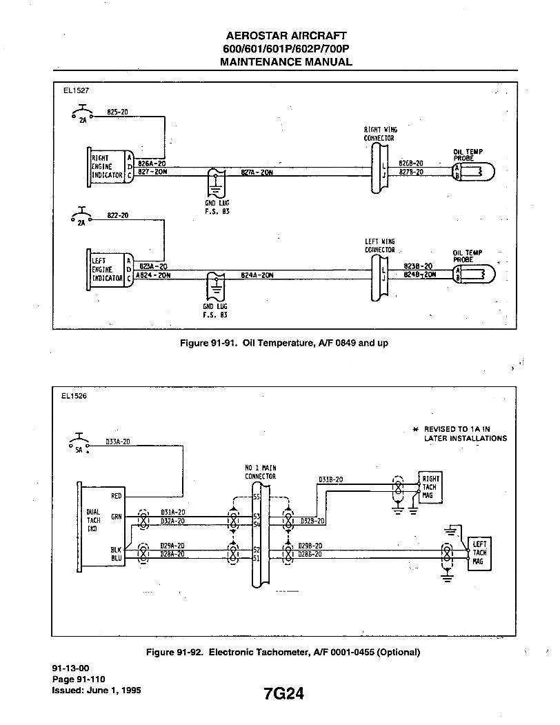
AEROSTAR AIRCRAFT 600/601/601P/602P/700P MAINTENANCE MANUAL
E L 1 5 2 7
825-20
° 2 A ' ^
RlfiHT
ENGINE
INDICATOR
RIGHT WING
CONNECTOR
626A-20 827-20N «7A-2gW
8263-20
827B-?0
»2A'^ 822-20
GNO LUG F.S. 83
LEFT
ENGINE
INDICATOR
LEFT WING
CONNECTOR
823A-20 A824-20W 824A-20W
823B-20
OIL TEMP PROBE
a m
OIL TEMP PROBE
e24B720W
GND LUG F.S. 83
Figure 91-91. Oii Temperature, A/F 0849 and up
E L 1 5 2 6
D33A-20
^ R E V I S E D T O 1 A I N L A T E R I N S T A L L A T I O N S
D31B-20 RIGHT
(TACH
MAG
LEFT TACH
HAG
Figure 91-92. Eiectronic Tacliometer, A/F 0001-0455 (Optional)
91-13-00 Page 91-110 Issued: June 1,1995 7G24

AEROSTAR AIRCRAFT 600/601/601P/602P/700P
MAINTENANCE MANUAL
E L I 5 2 6 NO 1 KAIN
CONNECTOR
DUAL ITACH • INDICATOR
C B
B A
812-20 811-20 810-20
815-20
813-20
LEFT WING CONNECTOR
812A-20
811A-20
810A-20
815A-20
812B-20 fc LEFT TACH GEN
8118-20 B A
LEFT TACH GEN 810B-20
B A
LEFT TACH GEN
LEFT TACH GEN
81^-20
813A-20
815B-20 fc RIGHT TACH GEN
8WB-20 B A
RIGHT TACH GEN 8138-20
B A
RIGHT TACH GEN
V.
RIGHT TACH GEN
RIGHT WING
CONNECTOR
Figure 91-93. Tacfiometer, A/F 0001-0455
E L 1 5 1 1
O 5A O -| * -SYNPH44-20
SNPH 42-22
R. WING CONNECTOR
R. TACH GEN. CCWNECTOR ;
SNPH 43-22
SNPH 50-22
SNPH 51-22
SNPH 45-20N
DUAL TAGH IND.
SNPH 42A22
SNPH 43A22
SNPH 50A22
SNPH 42B22
SNPH 43B22
SNPH 51A22
SNPH 50B22
SNPH S1B22
WHT R. TACH GEN. BLK
R. TACH GEN.
WHT L. BLK TAQI
GEN.
#1 MAIN CCNNECrOR
L. WING aWIECTOR
L. TACH GEN. CONNECTOR
Figure 91-94. Taciiometer, A/F 0456-0493
E L I 511
SYNPH66-20N-SYNPH65-22-35
SYNPH65A22-35-
L. WING
CQNN
RED
BLUE
.YELLOW
RED
BLUE
[YELLCW
DUAL TAQI IND
SYNPH64-22-35
SYNPH65B22-35
jBLUE
!YELLOW 7
..RED ^
1 jBLUE / / 11 ; [YELLOW /
1 1 1 1
1,1 y
SYNPH64A22-35
R. WING •SrNPH64B22-35
Figure 91-95. Tachometer, A/F 0494-0848
7H1
91-13-00 Page 91-111
issued: June 1,1995
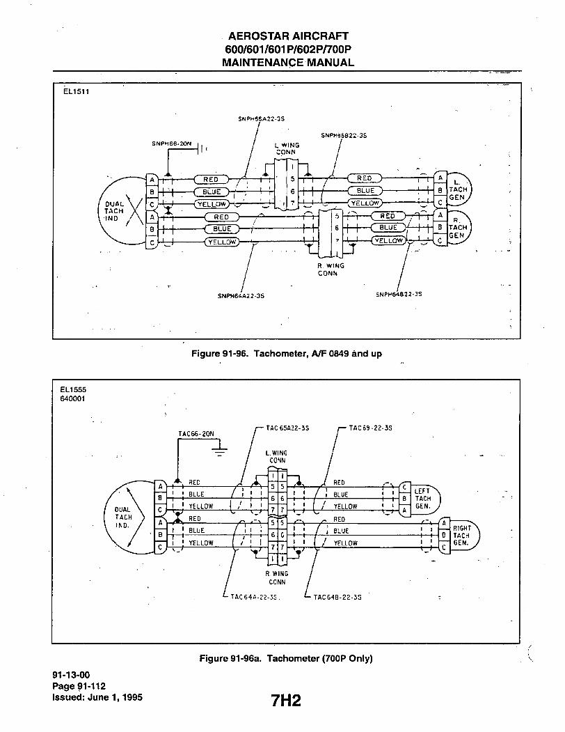
AEROSTAR AIRCRAFT 600/601/601P/602P/700P MAINTENANCE MANUAL
E L I 511
S N P H 6 5 A 2 2 - 3 S
S N P H 6 6 - 2 0 N
- C R E P >
- ( B L U E >
- ( Y E L L Q W ) - ' - :
- ( R E D >
-< BLUE > - ( Y E L L O W )
S N P H 0 5 8 2 2 - 3 S
1 1
> / M r . . - Tj
< R E D y - ( B L U E >
- C Y E L L Q W >
1—r
i — 1 — ( Y E L L O W ) ! .
_1 R WING C O N N
-< R E D >-r=^t -( BLUE y—f
S N P H 6 ' l A 2 2 - 3 S S N P H 6 4 B 2 2 - 3 S
Figure 91-96. Tachometer, A/F 0849 and up
E L I 5 5 5
6 4 0 0 0 1
TAC66-20N rAC65A22-3S
/ YELLOW
• TAC69-22-3S
YELLOW
TAC64A-e?-JS. TAC64B-22-3S
-I—r-
I I
-XT'-
91-13-00 Page 91-112 issued: June 1,1995
Figure 91-96a. Tachometer (700P Oniy)
7H2
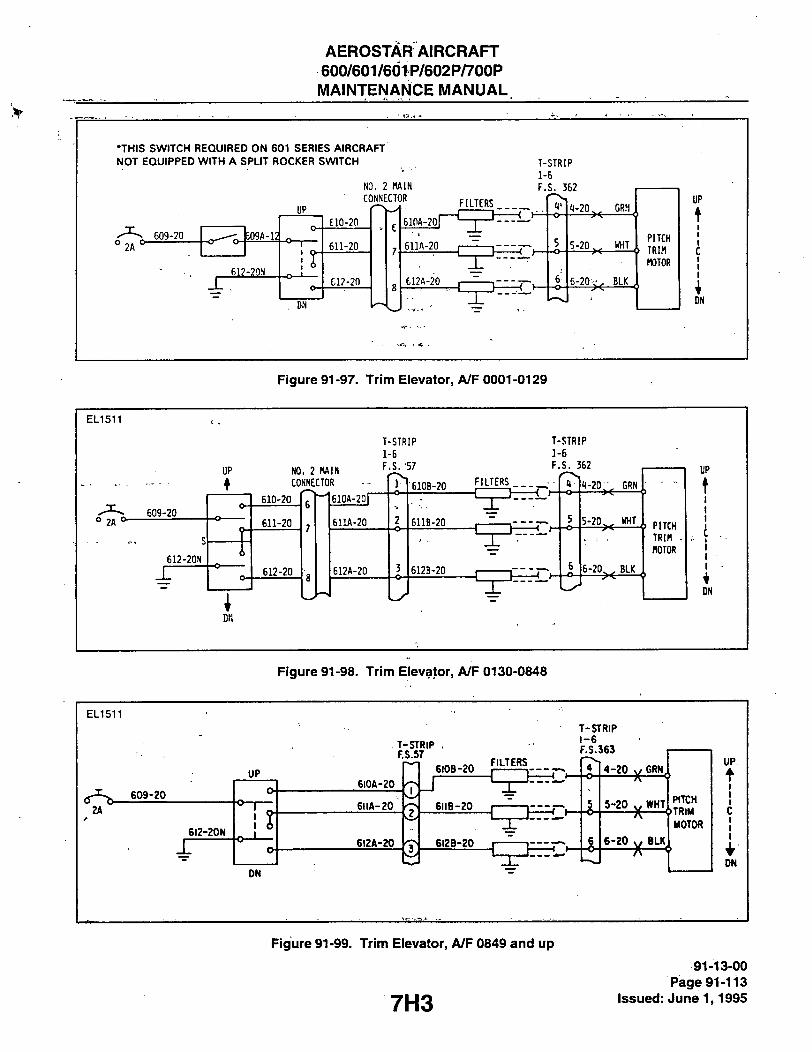
AEROSTARAIRCRAFT 600/601/601P/602P/700P MAINTENANCE MANUAL
•THIS SWITCH REQUIRED ON 601 SERIES AIRCRAFT NOT EQUIPPED WITH A SPLIT ROCKER SWITCH
NO. 2 MAIN
CONNECTOR
T-STRIP
1-6
F.S. 362
UP
° 2 A ' ^ 609-20 b09A-i:
612-20N
E10-2n
611-20
C12-20
DN
FILTERS
610A-20 -<.
611A-20
tl2A-20 - ( H
1-20^^ GRN
S-20^^ WHT
6-20 ' BLK
PITCH
TRIM
MOTOR
UP
t I I C
1 I
DN
Figure 91-97. Trim Elevator, A/F 0001-0129
E L 1 5 1 1
UP NO. 2 MAIN CONNECTOR
T-STRIP
1-6
F._S. 57
7
T-STRIP
1-6
F.S. 362
2A
610-20
609-20 611-20
S ? S
1 612-2aN 6
612-20
; DN
610A-20r
6nA-20
612A-20
610B-20 FILTERS . •
-I 1 t-
611B-20
612B-20
1-20,:. GRN
^-^°>< j. PITCH TRIM -
6-20^^ BLK
MOTOR
UP
t 1 I I
I I I
i DN
Figure 91-98. Trim Elevator, A/F 0130-0848
E L I 511
UP
T-STRIP . FS.57
6I0B-20
T-STRIP 1-6 F.S.363
6I2-20N
r
6I0A-20
6IIA-20
6I2A-20
FILTERS
6118-20
6I2B-20
4-20 y GRN
5-20 y WHT
6-20 y BLK
DN
PITCH <»TRlM
MOTOR
UP t I 1 I
C I I
DN
Figure 91-99. Trim Elevator, A/F 0849 and up
7H3
91-13-00 Page 91-113
Issued: June 1,1995

AEROSTAR AIRCRAFT 600/601/601P/602P/700P MAINTENANCE MANUAL
E L I 5 1 0
0 2A o -613-20
616-20N
NO. 2 MAIN CONNECTOR
LEFT o.
RIGHT"
6W-20
615-20
616-20
610A-20I
615A-20
6 i6A-20
FILTERS
T-STRIP 1-9 F . S . 332
11-20 GRN
5 5-20 ^ , WHT
6 6 -20 BLK
RUDDER
TRIM
MOTOR
LEFT
t I I
C-I I •
RIGHT
Figure 91-100. Trim Fludder, A/F 0001-0848
E L I 5 0 9
613-20
6I6-20M
RUDDER TRIMSW1TCH
LEFT o.
-O-T
RIGHT'
614-20
615-20
616-20
FILTERS
T-STRtP 1-9 F.S. 332
4-20 GRN
5-20 WHT
6-20 BLK
RUDDER TRIM MOTOR
LEFT
\ I I C I *
RIGHT
Figure 91-101. Trim Rudder, A/F 0849 and up
E L I 5 1 0 828-20
\ E
RUDDER
^ ^ D
TRIM TAB C
INDICATOR
B ELEVATOR
A
80^-20
805-20
GND LUG
F . S . 73
801-20
806-20
802-20
NO. 1 HAIN
CONNECTOR
GND LUG F . S . 73
X 803-20
IS
HE
17
804A-20
805A-20
806A-20
801A-20
802A-20
803A-20
T-STRIP 1-9
F . S . 332
1 1-20 BLU
2-20 BRN
3-20 - X - YEL
T-STRIP
1-6 ^
F.S. 36
1-20 - X -BLU
2-20 BRN
3-20 - X -YEL
RUDDER TRin TRANSHIHER
I I
! ELEVATOR T R I H J ,
TRANSHinER
91-13-00 Page 91-114 issued: June 1,1995
Figure 91-102, Trim Indicator A/F 0001-0848
7H4

AEROSTAR AIRCRAFT 600/601/601P/602P/700P MAINTENANCE MANUAL
E L I 5 2 6
E RUOOER
D C
TRIM TAB INDICAIOR
^ B A /
804-20 ' 805-20
801-20
802-20
806-20 GND LUG F.S.73
803-20 GNO LUG F.S.73
T-STRIP 1-9 F.SJ32
1-20 2-20
3-20
T-STRIP 1-6 F.S. 362
1-20
2-20 3-20
BUJ
RUDDER TRIM TRANSMITTER
1
BRN
YEL SI BUJ
BRN
YEL
; J
1 ; I
ELEVATOR TRIM TRANSMITTER
Figure 91-103. Trim indicator A/F 0849 and up
E L 1 5 1 2
830-20
830-20N
TURN AND
BANK
INDICATOR
Figure 91-104. Turn and Bani< indicator
THIS SPACE iNTENTiONALLY LEFT BLANK
7H5
91-13-00 Page 91-115
issued: June 1,1995

AEROSTAR AIRCRAFT 600/601/601P/602P/700P
MAINTENANCE MANUAL
E L 1 5 1 2 •VOLT
AMMETER
n5-20N •IF AMMETER HAS ONLY ONE
POSITIVE (•) TERMINAL, CONNECT
A* WIRE TO • TERMINAL.
CAP AND STOW WIRE 115-20.
MAIN BUS
SHUNT
Figure 91-105. Voit Ammeter, A/F 0001-0136
E L 1 5 1 2
A*
VOLT
AMMETER
115-20N
• A + T O V + J U M P E R S T A N D A R D A T 6 0 0 / 6 0 1 A / F
0 1 8 1 A N D U P . 6 0 1 P A / F 0 1 6 3 A N D U P , ( R E F S L 6 0 - 2 4 )
W H E N R E P L A C I N G A M M E T E R S O N P R I O R A / F , A D O
J U M P E R A N D C A P . S T O W W I R E 1 1 5 - 2 0 R E M O V E D
F R O M V + T E R M I N A L .
JUMPER
127-20
HO, 1 MAIN
CONNEgOR 1^
127A-20
MAIN BUS
SHUNT
AMM, SEL. SW
1 0 - 4 —
O o o-
116-20
29 29
30 30 116A-20
•(r\j)-127B-20
116B-20
BATTERY
107-20
108-20 r
9 107A-20
10 108A-20
10
lA 107B-20
108B-20
-( R, ALT
REAR VIEW OF SWITCH,
KEY ON THIS S I D E - ^ 109-20
117-20
11 11
15
109A-20 109B-20
117A-20 1178-20
- i L. ALT.
91-13-00 Page 91-116 issued:June 1,1995
Figure 91-106. Voit Ammeter, A/F 0137-0189
7H6
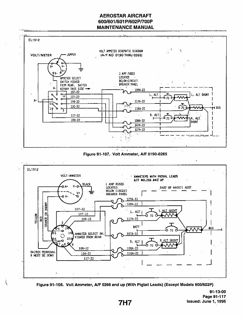
AEROSTAR AIRCRAFT 600/601/601P/602P/700P MAINTENANCE MANUAL
E L 1 5 1 2
V O L T / M E T E R JUMPER
A*
A -
6 <>
AMMETER SELECT SWITCH VIEWED FROM REAR, SWITCH KEYWAY THIS SIDE -<
107-22
12 o-
19 o
127-22
3(18-22
ne-22
117-22
109-22
VOLT AMMETER SCHEMATIC DIAGRAM
( A / F N O . 0 1 9 0 T H R U 0 2 6 5 )
1 AMP. FUSES LOCATED • BELOW CIRCUIT BREAKER PANEL
Figure 91-107. Voit Ammeter, A/F 0190-0265
E L I 5 1 2
VOLT-AMMETER AMMETERS WITH PiGTAIL LEADS A/F NO.266 AND' UP
1 AMP FUSES LOaTED BELOW CIRCUIT BREAKER PANEL
PART OF 640071 ASSY
127A-22
SWiTCH TERMINAL 8 MUST BE DOWN
R. ALT KALTSmr
\ 670 O ^ j f V S A ^ f ^ 108A
116A-22
Figure 91-108. Volt Ammeter, A/F 0266 and up (With Pigtail Leads) (Except Models 600/602P)
91-13-00 Page 91-117
YYYJ Issued: June 1,1995

AEROSTAR AIRCRAFT 600/601/601P/602P/700P
MAINTENANCE MANUAL
E L 1 5 1 3
• JUMPER AMMETERS WITH TERMINAL STUDS A/F NO. 26€ AND UP
AmtTER TfRfllNAL VIEWED FROII REAR
Figure 91-109. Voit Ammeter, A/F 0266 and up (With Terminal Studs) (Except Models 600/602P)
E L I 5 4 8 VOLT/AMMETER
[•—f YELLO ) -\ A » V')
<T08A>-(ir)-
<I07A)-C2T>
7
8 / 7
•;TFF)—crv_P—(ii^c >
15)
A B C 1 D E F H J
1
—Q21U—'^\!>>~ -{i* ")—C lose)—cP\__p-<li>-<ii!i>—
BELOW C . B .
PANEL
lOi I I
REAR OF SWITCH KEYWAY DOWN
it'
-I TO L E F T ALT
L. ALT SHUNT
-<io^c)-
•<ioec)-TO R . A L T t -
BUS
91-13-00 Page 91-118 issued: June 1,1995
Figure 91-110. Voit Ammeter (h/iodeis 600/602P only) (S/N 60-8261001 and up / S/N 60-8265018 and up)
7H8
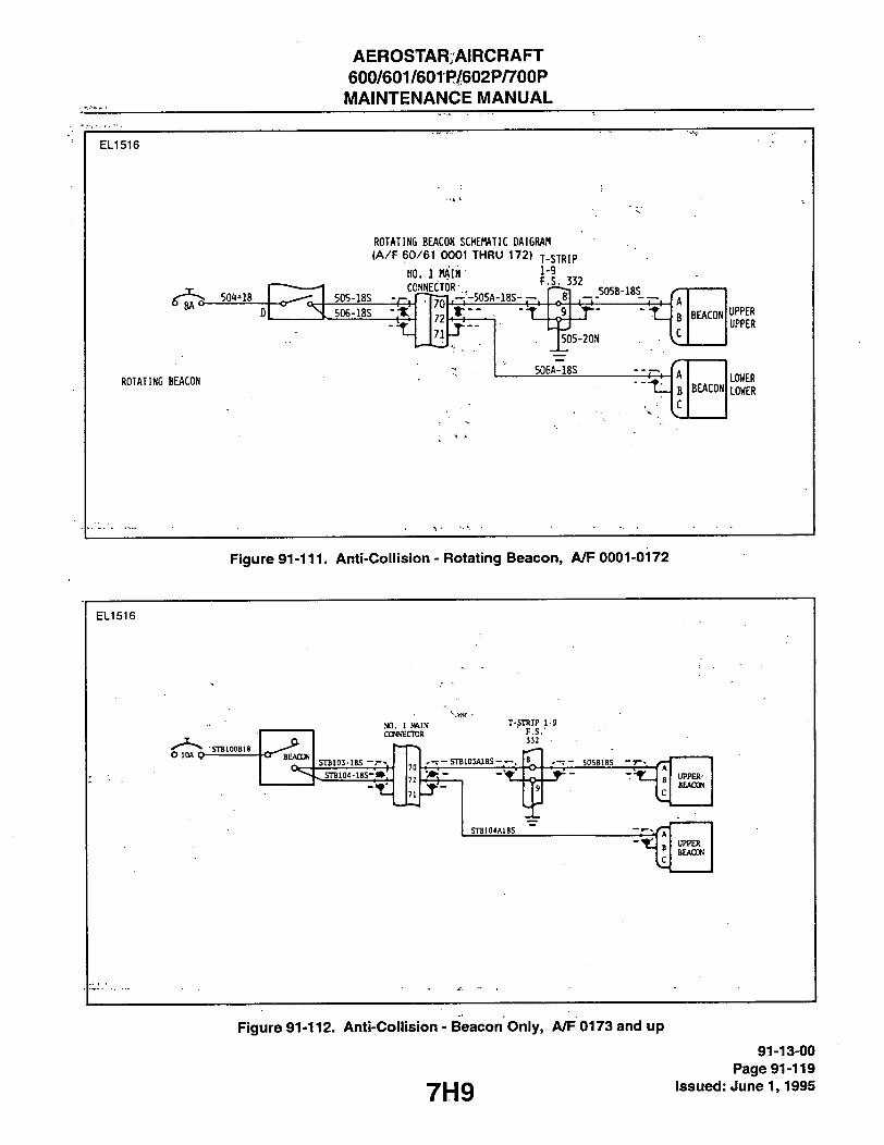
AEROSTARrAIRCRAFT 600/601/601P/602P/700P MAINTENANCE MANUAL
E L 1 5 1 6
, - - 5 0 5 A - 1 8 S -
ROTATING BEACON
ROTATING BEACON SCHEMATIC DAI GRAM
( A / F 6 0 / 6 1 0 0 0 1 T H R U 1 7 2 ) j - S T R l P
NO. 1 MAIN 1-9
_ 505B-18S_ CONNECTOR- .
505-20N
S06A~18S
BEACON
A
B BEACON
C
UPPER UPPER
LOWER LOWER
Figure 91-111. Anti-Coiiision - Rotating Beacon, A/F 0001-0172
E L 1 5 1 6
O lOA Q' SIB100B18
NO. 1 MMN CONNECTOR
STB103-18S
71
T-STRIP 1-9 • F.S.-
332
. - T - S T B I D J W S S - . - . - T - 505B1BS -7 UPPER' BEACON
STJ104A18S UPPER BEAOO.'
Figure 91-112. Anti-Coiiision - Beacon Oniy, /V/F 0173 and up
7H9
91-13-00 Page 91-119
Issued: June 1,1995

AEROSTAR AIRCRAFT 600/601/601P/602P/700P MAINTENANCE MANUAL
E L 1 5 1 5
501F-18S
NOT USED ON A/F 0649 AND UP-I
NO. 1 HAIN CONNECTOR
o 5AO
501D-18
5018-18
T-STRIP 1-3 F.S. 176
501F-18N
501C-18 AFT NAV LIGHT
501E-18 — 501H-18S
5D1H-18N 3'
Figure 91-113. Position Oniy, A/F 0001-0156
E L 1 5 1 5
O SA o- I o!
NO. 1 K*IN a»«F.CTO«
soin-n sciF-n
_i21£JJL
_ « ! A a _
mum .Slimy
SUPPLY!
I Rian
irarr
PCkTJ! SIPPl.Y
Figure 91-114. Anti-Coiiision - Strobe, Position Combination, A/F 0157-0305
91-13-00 Page 91-120 Issued: June 1,1995 7H10
i

AEROSTAR AIRCRAFT 600/601/601P/602P/700P
MAINTENANCE MANUAL
E L 1 5 1 6
AFT NAV/STRDBE LIGHT
LEFT NAV/STROBE LIGHT
P/0 640021 HARNESS
S05B18S VERTICALl
FIN BEACCW
STB104A18S
Figure 91-115. Anti-Coiiision - St'roBe Beacon, Position Combination (Strobes - Standard/Beacon - Optionai). A/F 0306-0577
91-13-00 Page 91-121
Issued: June 1,1995 7H11

AEROSTAR AIRCRAFT 600/601/601P/602P/700P
MAINTENANCE MANUAL
E L I 5 1 5
R I G H T NAV/STROBE UNIT
S T R O B E O P T I O N A L
A / F 0 5 7 8 T O 0 6 0 4
C O M P L E T E I N S T A L L A T I O N
A / F 0 6 0 5 T O 0 8 9 8
VERTICAL! FIN
BEACCW
STB104A18S A
i BELLY BEACON
Figure 91-116. Anti-Collision - Strobe Beacon, Position Combination (Strobes - Optional). /V/F 0578-0604
91-13-00 Page 91-122 Issued: June 1,1995 7H12

AEROSTAR AIRCRAFT 600/601/601P/602P/700P MAINTENANCE MANUAL
E L 1 5 1 5
RIGHT NAV UNI NAV(/,SrRDBE
S T R O B E L I G H T P O W E R S U P P L Y
A F T NAV/STRDBE LIGHT
LEFT NAV/STROBE LIGHT
Ih ??L01^8S_
F.S. 332.50
STB105-18N
S0SB18S
P/0 640021 HARNESS
VERTICAL] FIN
rrj BEAC(»j
SrB104-18S SrB104A18S
Figure 91-117. Anti-Coiiision - Strobe Beacon, Position Combination, A/F 0578 and up
91-13-00 Page 91-123
7H13 issued: June 1,1995

AEROSTAR AIRCRAFT 600/601/601P/602P/700P MAINTENANCE MANUAL
E L 1 5 1 4
O lOA O-502-16 5d2A-16 p
\ 502B-16 .
RIGHT
502C-I8N
lOA , 503-16 i<'v-'''''^rv- 503A-16 F
\ 503B-16
LA ©ING LIGHTS
LEFT
503CI8N
Figure 91-118. Landing Lights
E L 1 5 1 4
MAIN BUS 28VDC
L201A20
A507-20 .CAB. "*LTS.
o-L202A20
1 I
CONTROL SWITCH
LIGHT
L203A20N
Figure 91-119. Wing inspection Light 600, 601, 601P, and 602P iViodeis
91-13-00 Page 91-124 Issued: June 1,1995 7H14

AEROSTAR AIRCRAFT 600/601/601P/602P/700P MAINTENANCE MANUAL
EL1514
NO. 1 MAIN CONNECTOR
T-STRIP
1-9
F.S. 265
0 5A 510B-20
511-20
20 GA JUMPER
71) 510A-20 8 510-20:
BAGGAGE
LIGHT SV
BAGGAGE
LIGHT
A510-20 510-20N
H42A-20 5 1 5 - 2 0 ^^^^^ LIGHT 0 Qw
PRESSURIZATION POST LIGHTS (60IP ONLY)
OFF©
RED INST LIGHT SHJ
t RHEOSTAT
J EFFECTIVE A/F NO. 0256 AND UP jf^ SE£ COLOR LIST BELOW
51© 509-20N
J _ - _L JL I POST LIGHTS
A/F 0256 THRU 0472 -RED A/F 0473 AND UP - WHITE
Figure 91-120. Baggage and instrument Lighits, A/F 0001-0505
EL1514
NO. 1 MWN LNsr. onwEcroR
- J - Liarrs
T. STRIP F.S. 265
BAGGAGE LIGHT swrrai '
BAGGAGE
LIGHT
POST LIGHTS CO-PILOT
51 OA-20 510-20 -o I o-
A510-20 51O-20N
515-20
S1S-22N L i a r r
511820
/ A -L 0 - : 511A20
MUTE INS. LTS. SW. t, RHEOSTAT
PILOTS SIDE 20 GA PANEL JIWPER
511C20
509-20
511D20 - X -
to 5UC2IK
R
RED INST. LTS. SW. 6 RHEOSTAT
H42A-20
PRESSURIZATION POST LIGHTS (60IP ONLY) CO-PlLOrS SIDE PANEL-J Figure 91-121. Baggage and instrument Ligiits, A/F 0506-0629
7H15 91-13-00
Page 91-125 Issued: Jiine 1,1995

AEROSTAR AIRCRAFT 600/601/601P/602P/700P MAINTENANCE MANUAL
E L 1 5 1 4
MAIN BUS
5A
O O - Sioe-20 NO. I MAM CONN
plOA-20 74 }_ VF0M£^TD_0848_ _ _^;2:^Zrt ^TL _J L! I BAGGAGE LIGKT
PRESSURIZATION POST LIGHTS (60IP/602P0NLY)
S10A20- 510-20 ^ j ^ A510-20
S10-20N
515-20.\
515-20
X -4r W
H42A-20
3 ) s
RED RHEOSTAT
O F F ? "
hHITE RHEOSTAT
OFF
509A20
509B20
COMPASS Liarr
509-20
7 511C20
R W
511A20
511D20
511-20N
I A509-20 AS11A2P I ASii-ZON
\ R [ _
1 t
w|
1 \ (
1 filfi RLI WLI
A 1
— ( >—— •
5 <S 1
R R W
h ft
1 Q fnl R W R
PILOTS LOWER
LIGHIS GLARESHIELD LIGKFS
CO-PILOTS
LOWER
LIGHTS
W R
S11B20N 511C20N
Figure 91-122. Baggage and Instrument Lights, A/F 0630 and up
EL1514 RIGHT
FRONT
o 5A o-A507-20
NOT USED ON A/F 0899 a UP
SWITCH / 507-20
21 507A-20
RIGHT REAR
507D-20N
507D-20
LEFT
FRONT!
507E-20
507E-20N
BOS
507B-20 W
tQ) 507B-20N
LEFT REAR /p^ JH1507C-20N
507C-20
91-13-00 Page 91-126 issued: June 1,1995
Figure 91-123. Cabin Lights
7H16

AEROSTAR AIRCRAFT 600/601/601P/602P/700P
MAINTENANCE MANUAL
E L 1 5 1 4
CABIN LIGHT
O 5A O- 518-20 ,'50 n ,5W
520-20N
20 GAGE WIRE 2180 MAP LIGHT 1495 LAMP
Figure 917124. Map Ligiit
E L 1 5 1 4
RADIO PANEL
AVIONICS BUS
580-20 OFF
5 A
FLAP POSITION POST LIGHT
w 5IIB20
7\ TRIM POSITION POST LIGHT
VOLT/ANWETER POST LIGHT
W
W
RADIO LIGHTS RHEOSTAT
581-20
TO FUEL QTY. IND.
490-20 r ^
TB-E F.S. 54.25
„ EGT POST LIGHT LpJ CIF INSTALLED)
. W W
_ _ _ J RADIO SWITCH PANEL LIGHTS
Figure 91-125. Radio Switcii Panei Lights, A/F 0630 and up
7H17 91-13-00
Page 91-127 Issued: June 1,1995
AEROSTAR AIRCRAFT 600/601/601P/602P/700P MAINTENANCE MANUAL
THIS PAGE INTENTIONALLY LEFT BLANK
7H18

i
i:: z a: <
Sp UJ
o <
< DC O OC
o oc
t < cc o QC <
O 3
(O UJ t> CC T- Z
CO ;= S DC iS Z ! ^ 2
o < ^ <D S
• ! f if
> \
2
3 8 S
1 i ^ ^8 i I I L IS
I I
M:-:>d:.-.:::>?
. i -r •< • ', r B
I ' 111 • I !• I fc— I t
§
12
I g
a u i2 o c o w 2
^ i
n o
EI « Q >> c (0 n k. a> w Q a o
CJ
&! 3 D) iZ
2 i at c 0) O O |2 u c o 10
o < s
S o
f «
p
a o U c >
CM
in
« 5
9 S -o CO 0) 0)
CM 0>
T ?!
•g
3 M W
I
O)
21 3 O)
/
1

t o.
y CM S
DC — 3
^ s < H JO z cn ;= S O O a SS z i* 2 3
<o 2
<
I- Q-
> « S cc o •= ^ jO Ul
^ S < r - j p 2 S2 ^ W O S H DC SS z
2 3 ^ to 5
11
(ED (ED
I I
f '+-4- 1—
i i
I
i I
3 3 b
0 0
4-
S3
t .+—y—+,
4.
4'^ ••<:tM::t::t'
2
2 1
g B
|2 8
0)
(0 3 o •o c n CM
CM
.S-2
E o W _ >. a W H
n o
II N - 2
3 D) E
2
12 o 12 EH I i
t- a
c a iS &
< O
0) « o
818
2 £
> « ID
OT g
v oc
£ 3
in CT) CT)
CM CO 0)
o 9 CO CT>
^1 a.
o 1 - in O CO O) T - T -
A 0> T - '
2 = •D 0) 3 V) (0
CM
A

t § 3
y S CC o — (O UJ < S: o cc z ^ S < O S H cc iS Z
2 3 ^ <0 5
t < cc o a < cc
(0 o cc UJ
<
a- ^ O 3
Q: <
CD UJ
IS O i_
o <
8
o o
MEL
1 » 1 r I v
•
« • *
1 ,
« • * • L 1
«B CL
I i a.
8
o IM
O
I I I
CM fM
I
•2
(g) ( ^ t - ) ' f e ^ m (Si
^ I. Hi'
3 O a. o S
i l i s
1—*1
• • k
1
u ><, 1 1
CO
I CM
I }
1 1 o
I
c O xz .8
8 1 JS V) P- >-
< M
2 | .2 g, Q to
i | E S | 2 ? l
s U c (/> eo
2 3 O) IE
2 5 2 c u a
u
c o 9 U
5- >. •<««
U) o 1- ^ 0) m
Ii I-o c >< 0)
00 OJ
.<>>
LT
' i t CM
in a>
0) c
- 3 ? 5 CO d)
5; £ i2
o CO in o CO o> • T - O)
0» r - "
n -1
• • •o a> 3 (A M
CO CM

O 3 Q: <
(p UJ
t < cc o GC
< CC _
z 5| i i i s s<
o oc UI
<
I- Q- ^
oc o •=
^ S < h- iP J2 ^ w o S H cc SS z ^ o < ^ to s
u
CO
U
UJ •A-eo to a . (o
(N
(N to to
3S
CO fN N <M CM CM I
- " s z
CM
X cu
w
u
a.
Ui
00 00 r-l rH 1
1 to to
to X
X Q. cu Z
CO w
00 CO
< < u
Q O
UJ UJ
O o
X X
cu CO
a. i H
CO
H I - to 2
00
I o X cu
o o
u_
UJ
a O
u U
CO CO
< < (Nl CM CU CO
s ? o s E 2 O) (0 i5 o> c •c
I CO
%
a o. 2 u c >> CO
to 0)
9 o» -o O (1) 0>
in u) CO o>
at 0>
3 (0 w
o o o
E 2 O) n
D ) C
E S
Ui i-0> M (0 £ Q.
2 U c >
£ 3 O)
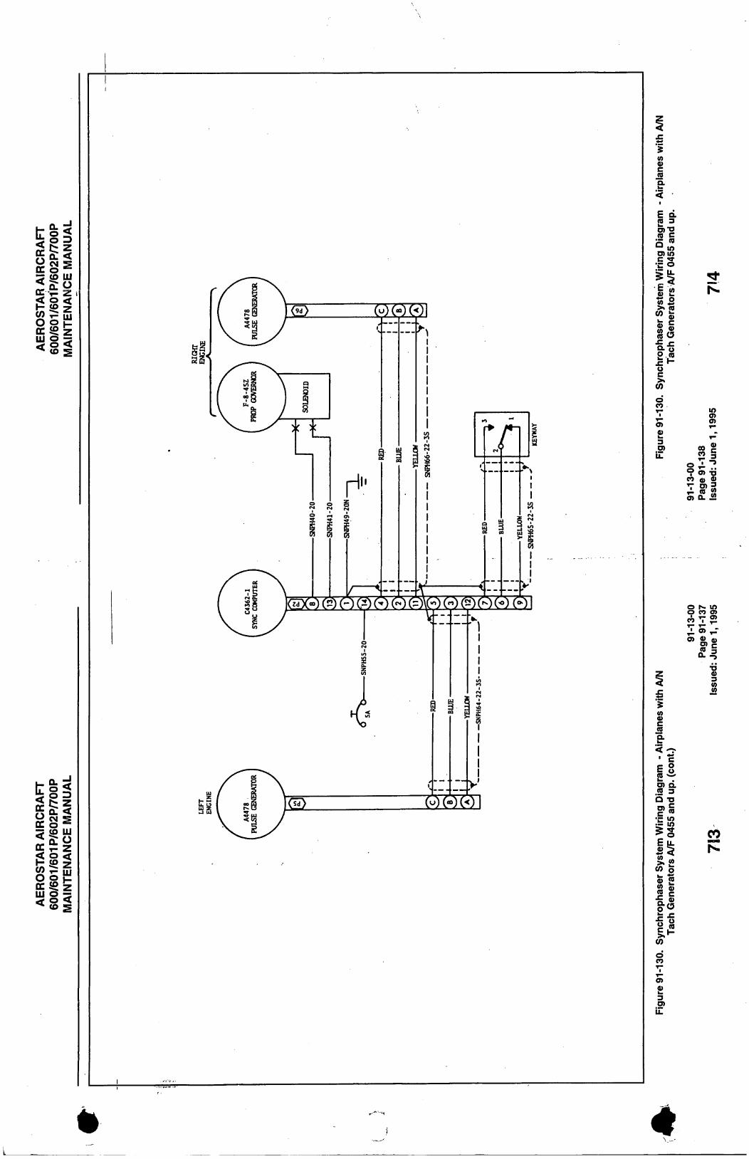
W <M 5 DC O ^ - JO UJ ^ S: O OC v : z 00 ;= £ O o iZ DCSSZ S 5 to s
; ^ £ 0 UJ
< o < H sg 5 CO ;s S O 2 H-CC JO z 1" S 5
Hi-o o § N S g 2 2 o> S S ?
I
Ul
.1 (•-•) a C- (-- W (b' M M I
a.
I
I
w
0) c a.
E d
O) Ui
Si o c
o CO
3 o> 'iT
w a> c « a. w
< '-^ • •£ E o 2 o> a « 3 Q -D
c (0
cn
>2
(0 0)
ll d CO
£ 3 o>
in
o r- m O C O o> c ^ T -,1 o> 1-"
£ = •o 0> 3 w w
S2
4

AEROSTAR AIRCRAFT 600/601/601P/602P/700P MAINTENANCE MANUAL
E L 1 5 1 7
R. SEL. SW. rT- - 4 2 8 - 2 0 (TO VALVE 2)
NOSE GEAR TERM. STRIP F.S. STA. 54.25
Figure 91-131. Cross-Feed (X-FEED) indicator Light, A/F 0456 and up
715 91-13-00
Page 91-139 issued: June 1,1995

AEROSTAR;^IRCRAFT 600/601/601P/602P/700P MAINTENANCE MANUAL
E L 1 5 1 7
CABIN HEATER BLOWER SWITCH
NO. 2 MAIN CONN. F.S.j 265
O ISA O 705-16
717A16 HTR. FAIL.
-. •LAMPii_jj2
707-16
715C16
4
20 O
707A16 707B16 707C16
715B16 715A16
OVER-HEAT SWITCH
Figure 91-132. Heater Faii Light, A/F 0466 and up
E L 1 5 1 6 0 4 0 1 0 1
MAIN
BUS 28 VDC CAB. \
LTS.
L20IA20
i 5 0 7 : 2 0 _ CAB. LTS.
L202A20
LIGHT
CONTROL -SWITCH
1 C
Figure 91-132a. Wing Inspection Light (700P Oniy) Seriai Numbers 60-8323001 and up
91-13-00 Page 91-140 Issued: June 1,1995 y | g

AEROSTARAIRCRAFT 600/601/601P/602P/700P MAINTENANCE MANUAL
E L I 5 2 6
301A-20
T-STRIP 1-13 F.S. 51
\ 13
'2A
ALL GEAR UPLOCK LIGIIT
301-20 0 A j,^
302-20
NOSE GEAR DN LOCK LIGHT
/t '^3c
303-20
12
R rm GEAR DN LOCK LIGHT
10
L RAIN GEAR DN LOCK LIGHT
\M 30 -20N
308B-20
Al
4- X2
301B-20
1-20
6-20
3-20
3oeA-2n
305-20
3014-20
•308A-20
T-STRIP 1-3 F.S, 176
31HA-20
NOSE GEAR UP LOCK
1
<b5 H-20
NOSE GEAR DN LOCK
3111-20
3-20
R. KAIN UP LOCK
2-20 1-20
38
3D6B-20
305A-20
30'JA-2n
HO. 1 MAIN CONNECTOR
308-20
THROTTLE SH 5-20
307A-20 307B-20
NO. 1 PAIN CONNECTOR
I r 1
308D-20 WARNING HORN
I 10 onn I 6.2V l i H O H j
LT I
3070-20^5-20
^6-20 DN
«5 it-20
3-20
R. MAIN DN LOCK
L. MAIN UP LOCK •o3 1-20
3n7E-205-20 UP|
. C-20 '4-20
L. MAIN BN LOCK
2 T-STRIP 1-3 F.S. 176
307C-20
308C-20
Figure 91-133. Gear Position Warning, A/F 0001-0355
717 91-13-00
Page 91-141 issued: June 1,1995

AEROSTAR AIRCRAFT 600/601/601P/602P/700P MAINTENANCE MANUAL
E L 1 5 0 8
r301-20 R MAIN GEAR L MAIN GEAR
DN IJOCK DN LOCK LIGHT LIQTT
R. MAIN DN LOCK
R.MAIN . UPLOCK
RELAY I(STRUT OCNPRESSED)
91-13-00 Page 91-142 Issued: June 1,1995
Figure 91-134. Gear, Position Warning, A/F 0356-0433
718

AEROSTAR AIRCRAFT 600/601/6G1P/602P/700P MAINTENANCE MANUAL
ELI 508 r 3 0 l - 2 0
ALL GEAR UPLOCK
• LICW
NOSE GEAR DN LOCK
LIOfT
R MAIN GEAR L MAIN GEAR DN LOCK DN LOCK LIQfT LIOfT
NC-20
SqUAT Sh' REUY
NOSE T.S. F.S.
v49.25
NCA20
301CZ0
320A20
322A20
.NC NC
A A NO NO
,NC-Z0N'
L. MAIN UPLOCK 1-20
L..MAIN ,DN LOCK
R.,MAIN DN LOCK
R.MAIN UPLOCK
304-ZON
n MAIN CONNECTOR
UP
304-20
305-20
302-20
30LA-20 NOSE GEAR
RELAY 301B-20
10
11
306A-20
304A-Z0 ^306B-20
30SA-20
3-20
I—I NOSE GEAR UPljOCK
1-20
6-20
NOSE CEAR DN LOCK
3ZSB-20N
IN4003 DIODE
' A l
T - STRIP F.S.
54.25 308B-2o|
3 0 ^ ^ 307B
2 0
324-20
L.6. LEVER SWITCH
320-20
322-20
CJ1DA20 — U i S O U
32SA-20N
THRCrrTLE S>>TTQ1
308A-20
ED _2I 307C.Z0
308-10
121-20
NARNINC HOW
oo,
I
LEVER LOCK SOLENOID
308C-20
640090-1 BRACKET ASSY
6.2V lOK
SQUAT SW RELAY
(STRUT CCMPRESSED)
1N4003 DIODE
I
I ' " " J ^ l I Z . J
+
Figure 91-135. Gear, Position Warning, A/F 0434-0607
719 91-13-00
Page 91-143 issued: June 1,1995

AEROSTAR AIRCRAFT 600/601/601P/602P/700P MAINTENANCE MANUAL
E L 1 5 0 8
r-30l-Z0 ALL GEAR NOSE GEAR R MAIN GEAR L MAIN GEAR UPLOCK DN LOCK DN LOCK DN LOCK Liatr LIQfF LIQfT LIQfT
R.MAIN UPLOCK
I -
SQUAT SW RELAY
I(STRUT COMPRESSED)
91-13-00 Page 91-144 Issued: June 1,1995
Figure 91-136. Gear, Position Warning, A/F 0608-0848
7110

AEROSTARAIRCRAFT 600/601/60tP/602P/700P MAINTENANCE MANUAL
E L 1 5 0 8
r-301-20
R.miN UTLOCK
SQUAT SW RELAY
•(STRUT CCMPRESSED)
Figure 91-137. Gear, Position Warning, A/F 0849 and up
7111
91-13-00 Page 91-145
Issued: June 1,1995

AEROSTAR^-AIRCRAFT 600/601/601P/602P/700P MAINTENANCE MANUAL
E L 1 5 5 8
GEAR POS
r-301-22
ALL GEAR NOSE GEAR R MAIN GEAR L MAIN GEAR UPLOCK DN LOCK EN LOCK DN LOCK LIOfT LIGHT . LIQfT LIGHT
R. MAIN Df) LOCK
R.MAIN UPLOCK
SQUAT SW RELAY (STRUT CCMPRESSED)
91-13-00 Page 91-146 Issued: June 1,1995
Figure 91-137a. Gear, Position Warning, (700P Oniy) Serial Numbers 60-8223001 and up
7112
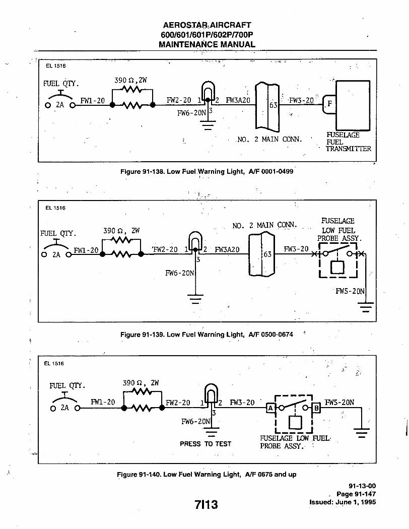
AEROSTARAIRCRAFT 600/601/601P/602P/700P MAINTENANCE MANUAL
E L 1516
FUEL QTY. 390 n,2W
O 2A a FlVl-20 r—\W—I n
FW6-20N
2 FW3A20 63
• 1 3-20
NO. 2 MAIN CONN. FUSELAGE FUEL TRANSMITTER
Figure 91-138. Low Fuei Warning Ligiit, A/F 0001-0499
E L 1516
FUEL QTY.
O 2A O FWl-20
390 n, 2W
'FW2-20
FW6-20N
, NO. 2 MAIN COhJN.. .
2 FW3A20 63
FUSELAGE
LOW FUEL PROBE ASSY.
FW3-20 ^ — 1
FW5-20N
Figure 91-139. Low Fuel Warning Ligiit, A/F 0500-0674 '
E L 1516
FUEL QTY.
O 2A O-FWl-20
390 n, 2W
-VvV-| FW2-20 J 2 FW3-20 r
FW6-20N
I — z n FW5-20N
PRESS TO TEST
L « b i j FUSELAGE LOW FUEL: PROBE ASSY. '
Figure 91-140. Low Fuei Warning Lighit, A/F 0675 and up
7113
91-13-00 . Page 91-147
issued: June 1,1995

AEROSTAR AIRCRAFT 600/601/601P/602P/700P MAINTENANCE MANUAL
LEFT STARTER SOLENOID
STARTER SOLENOID BUS (REF)
r-O ^ SWlA-14
<122-4 230B18
SWlB-22
RIGHT STARTER SOLENOID
T
o o-CYL HEAD TEMP
SW2B22
(REF)
SW3-22
n _ LEFT ^ 3 J WARNING
TT-^ LIGHT
SW4-22N
4 121-4
-* 224B-18 (REF)
SW2A14
DRIGHT
WARNING LIGHT
91-13-00 Page 91-148 Issued: June 1,1995
Figure 91-141. Starter Warning Light
7114

AEROSTAp/AIRCRAFT 600/601/^bi P/602P/70bP MAINTENANCE MANUAL
E L 1 5 4 3
L E F T I N D I C A T O R
L I G H T
S I G H T I N D I C A T O R
L I G H T
SI
A N N U N C I A T O R '
C O N T R O L
-(FDI03B)—fzF)-
HORM
- loze^-CiT)-
- < F D I 0 0 > - ( 2 ? ) -
A / C MAIN BUS
I N I O O i X I Z D I O D E S
- ( F D I 0 3 > - < " ^
-<FDIO^B)-{ ^—73>->, S W I T C H
->4 CiFHFDioaA)-
-(FDI07>-(?2N>-
- ( F D I 0 2 ) - ( 2 2 ) -
<FDIOIB>7<.22
1 L E F T E N « N E
/ 2 2 ~ ) D E T E C T O R
— ,
R I G H T T - S T R I P ' — ^ ^ F E | P i > A 5 ^ ^ - )( ' CzrKFPIOIA)^
S TO EXISTING T -STHIP '
2 2 rijEmSf-
TO EXISTIfW T-STRIP
1_ ' (FDIOS)
R I G H T E N G I N E
D E T E C T O R
Figure 91-142. Fire Deteiction
THIS SPACE INTENTIONALLY LEFT BLANK
91-13-00 y ; jPage'gi-Wg
g , Issueid: June 1,1995
V

AEROSTAR AIRCRAFT 600/601/601P/602P/700P MAINTENANCE MANUAL
E L 1 5 3 9
S T A L L WARN R E L A Y
~^- (STWI24)—(^i> S T A L L HEAT
TO ANNUNCIATOR COMPUTER
( S T A L L FAIL)
Figure 91-143. Stiaii Warning (700P) ^
91-13-00 Page 91-150 Issued: June 1,1995 711 6