for Windows
394
for Windows User Guide
-
Upload
khangminh22 -
Category
Documents
-
view
3 -
download
0
Transcript of for Windows

for Windows
User Guide

ContentsWELCOME TO SKETCHUP 4.0 8
Learning SketchUp 8
SketchUp Concepts 11
What’s New in this Release? 17
APPLICATION USER INTERFACE 20
Drawing Window 20
Toolbars 22
Menus 25
File Menu 26
Edit Menu 30
Window Menu 33
Camera Menu 35
View Menu 37
Tools Menu 39
Help Menu 42
Value Control Box 43
Keyboard Shortcuts 44
Page Tabs 46
Standard Windows Dialog Boxes 47
DRAWING TOOLS 49
Line Tool 49
Arc Tool 53
Freehand Tool 56
Rectangle Tool 58
Circle Tool 60
Polygon Tool 62
MODIFICATION TOOLS 64
Select Tool 64
Eraser Tool 67
Paint Bucket Tool 68
Move Tool 71

Rotate Tool 75
Scale Tool 78
Push/Pull Tool 83
Follow Me Tool 86
Offset Tool 91
Tape Measure Tool 93
Protractor Tool 95
Axes Tool 97
Dimensions Tool 98
Text Tool 100
Section Plane Tool 102
CAMERA TOOLS 104
Undo View Change 104
Standard Views 104
Perspective vs. Paraline 105
Orbit Tool 107
Pan Tool 108
Zoom Tool 108
Zoom Window Tool 109
Zoom Extents Tool 109
Position Camera Tool 110
Walk Tool 111
Look Around Tool 112
Align View 112
MODEL SETTINGS AND MANAGERS 113
Model Info Dialog Box 113
Entity Info Dialog Box 121
Material Browser 122
Material Editor 126
Component Browser 129
Layer Manager 132
Pages Dialog Box 134

Display Settings Dialog Box 137
Shadow Settings Dialog Box 140
Soften/Smooth Edges Dialog Box 142
Preferences 143
RENDER AND DISPLAY SETTINGS 147
Face Rendering Styles 147
Edge Rendering Styles 151
Soft Edges/Smooth Edges 155
Shadows 158
Sky and Ground Effects 162
Sections 163
DRAWING AIDS 165
Drawing Axes 165
Inference 168
Hiding 172
Multi-Copy 174
The Intersector 177
Auto-Fold 179
Layers 181
In-Place Editing 183
Pages and TourGuide 185
Divide 186
MATERIALS 187
SketchUp Materials 187
Color Picker 189
Material Transparency 190
Material Browser 192
Material Editor 197
Texture Positioning 200
PRINTING 206
Print 206
Print To Scale 209
IMPORTING AND EXPORTING 211
CAD/3D Model Formats 211
2D Still Images 220
Animation 232
ENTITIES 241
Context Menus 242
Lines 242
Faces 245
Arcs 248
Circles 251
Polygons 254
Polyline Curves 256
Curved Face Sets 259
Groups 261
Components 266
Construction Lines 274
Image Objects 277
Section Planes 280
Text Objects 282
Dimension Objects 284
Multiple Entity Context Commands 286
TECHNICAL INFORMATION 289
Raster Image File Formats 289
SketchUp and OpenGL 291
Codec List 293
Animation Tips 298
SketchUp Template Files 299
Bug Splat 300
SketchUp Ruby API and Console 301
BEGINNING TUTORIALS 302
Beginning Tutorials 302
Starting SketchUp 303
Drawing Lines 305
Creating Faces 307
Viewing Your Model 310
Sketching in 3D 311
Using Push/Pull 315
Creating a Simple Roof 317
Creating a Dormer 320
Creating Openings in Faces 323
INTERMEDIATE TUTORIALS 325
Intermediate Tutorials 325
Creating Construction Lines 326
Moving and Copying Faces 328
Hiding and Reversing Faces 331
Making Precision Measurements 334
Making Arrays with Multi-Copy 337
Inserting Components 340
Scaling Geometry and Objects 345
Introducing Layers 352
Creating Your Own Components 354
Creating Attached Components 357
Painting Components 362
Adding a Section Cut 367
Importing a CAD Drawing 372
Importing a Scanned Image 376
ADVANCED TUTORIALS 379
Advanced Tutorials 379
Using Inference Locking 379
Using Auto-Fold 380
Printing To Scale 381
Exporting 2D Vector Drawings 384
INDEX 385

8
Welco
me to
Sketch
Up 4
.0
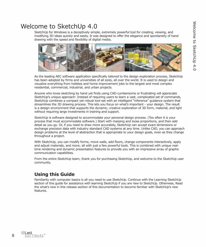
Welcome to SketchUp 4.0SketchUp for Windows is a deceptively simple, extremely powerful tool for creating, viewing, and modifying 3D ideas quickly and easily. It was designed to offer the elegance and spontaneity of hand drawing with the speed and fl exibility of digital media.
As the leading AEC software application specifi cally tailored to the design exploration process, SketchUp has been adopted by fi rms and universities of all sizes, all over the world. It is used to design and visualize everything from hobbies and home improvement jobs to the largest and most complex residential, commercial, industrial, and urban projects.
Anyone who loves sketching by hand yet fi nds using CAD cumbersome or frustrating will appreciate SketchUp’s unique approach: Instead of requiring users to learn a vast, complicated set of commands, SketchUp combines a compact yet robust tool-set with an intelligent “inference” guidance system that streamlines the 3D drawing process. This lets you focus on what’s important - your design. The result is a design environment that supports the dynamic, creative exploration of 3D form, material, and light without requiring large investments in training and support.
SketchUp is software designed to accommodate your personal design process. (Too often it is your process that must accommodate software.) Start with massing and loose proportions, and then add detail as you go. Or, if you need to draw more accurately, SketchUp can accept exact dimensions or exchange precision data with industry standard CAD systems at any time. Unlike CAD, you can approach design problems at the level of abstraction that is appropriate to your design goals, even as they change throughout a project.
With SketchUp, you can modify forms, move walls, add fl oors, change components interactively, apply and adjust materials, and more; all with just a few powerful tools. This is combined with unique real-time rendering and dynamic presentation features to provide you with an impressive array of graphic communication capabilities.
From the entire SketchUp team, thank you for purchasing SketchUp, and welcome to the SketchUp user community.
Using this GuideFamiliarity with computer basics is all you need to use SketchUp. Continue with the Learning SketchUp section of this guide for assistance with learning SketchUp if you are new to SketchUp. Otherwise, Read the what’s new in this release section of this documentation to become familiar with SketchUp’s new features.

Welco
me to
Sketch
Up 4
.0
9
SketchUp 4.0 User Guide
Learning SketchUpWe have endeavored to make SketchUp straightforward and easy to learn. Like any design tool, SketchUp takes a little getting used to at fi rst, and attaining profi ciency requires practice. For fi rst-time users who are more comfortable with a pencil than a mouse, it may take some time to attain the same level of fl uency as you have with traditional media.
Fortunately, many users report that the learning process is relatively painless and well worth the initial time investment. The following information can help you learn more effectively.
Video TutorialsVideo Tutorials is perhaps the best way to learn SketchUp, as it allows you to fully visualize the dynamic quality of the tools and drawing procedures. You can view them directly through the Help Menu:
Menu Access: ( Help > View Tutorials > Video Tutorials )
If you have a SketchUp CD-ROM inserted into your drive, the video training tutorials will play directly from the CD-ROM. If not, your computer will try to go online and access streaming versions of the tutorials from the SketchUp web site. If you have an lower internet connection, you may also download the online tutorials to your hard drive so that they would play smoothly.
Note: The training videos require Internet Explorer version 5.0 or higher as well as the latest Windows Media Player to run.
Written Tutorials The tutorials included in this document are presented in three sections; Beginning, Intermediate, and Advanced. SketchUp has many unique tools and procedures which work together in a special way. We suggest that you fi nish the beginning block of tutorials fi rst so that you’ll be able to use SketchUp effectively right away. It is also recommended that you complete the intermediate and advanced tutorials sequentially, but once you have the basics down you should feel free to jump around to any subject you wish.
Online HelpThis online help provides a combination of three levels of information about SketchUp. You can use the online help to fi nd explanations of each feature (reference), learn how to perform some task using the tools, or take a tour (tutorial) of SketchUp. The online help uses these conventions:
Note - Used to describe additional detail for a feature or aspect of SketchUp.
Warning - Used to identify issues that might cause problems for the user.
Menu Access: Menu > Menu Item - Used to identify a location for a specifi c menu item.
Menu > Menu Item - Used to identify a location for a specifi c menu item.
hyperlink - Used to identify a link to a related topic.

10
What’s N
ew
Context Sensitive HelpClicking on the Context Help button in the Standard Toolbar and then immediately clicking on any tool button, dialog box, or menu command will open the online reference material to the appropriate topic. You can also display information about any open dialog box by pressing the F1 key.
MenusMany commands in SketchUp are accessible via both tool buttons, as well as by the pull-down menu system. Scanning through the menu system can give you a good overview of SketchUp’s features.
Menu Access: ( File, Edit, View, Camera, Draw, Tools, Window, Help )
Quick Reference Card The Quick Reference Card, which is in PDF format and also available online, is handy to keep beside you while learning the various tools. The quick reference is available using the Help > Quick Reference Card menu item. The quick reference card is also placed in your SketchUp application directory upon install.
The Status Bar The Status Bar is located at the bottom edge of the SketchUp Drawing window. The left side displays tips about each drawing tool as well as special functions which are accessible via modifi er keys. This is a great way to discover advanced capabilities within each of SketchUp’s tools.
User ForumThe SketchUp forums are a great way to contact others in the user community. (http://www.sketchup.com/forum) There, you can ask questions, make feature requests, offer advice, obtain 24 hour peer technical support, share models and materials, submit work for criticism and feedback, or show us your humorous side.
SketchUp Training@Last Software provides beginning and advanced training courses for users who want a little extra help from the SketchUp experts. Visit http://www.sketchup.com/class_live.php to see a list of beginning and advanced training courses in your location.

Welco
me to
Sketch
Up 4
.0
11
SketchUp 4.0 User Guide
SketchUp ConceptsSketchUp is unique by design. It is not CAD, not really a traditional 3D modeler, and not a renderer. Most AEC software today is created exclusively for the representation of concrete information, as well as data entry and retrieval. This is especially true of CAD systems. SketchUp, by comparison, is designed to be a medium for the exploration of ideas and the synthesis of information. Although a full description of this philosophy is beyond the scope of this document, the following tips can help you more quickly understand what SketchUp is all about:
1. SketchUp GeometrySketchUp’s patent-pending geometry engine is designed specifi cally for design exploration and works very differently than those found in typical CAD and 3D modelling packages.
Perhaps the closest traditional media analogue to SketchUp is a chipboard or foam-core design study model, where 3D forms are constructed from fl at shapes attached together: A model may be created, torn apart, and reassembled quickly to study massing and proportion, something that isn’t feasible with a more fi nished presentation model. When necessary or desirable, a model can be extremely accurate and precise, but it can be very rough as well. While it is not necessary to model wall thickness, as one thin piece of material is enough during early stages, you can build up volumes from multiple faces. As a designer, you decide at all times what represents the appropriate level of detail and/or abstraction. Beyond this point, however, the similarities to physical design models begin to fade away, and an understanding of how SketchUp’s geometry engine works can provide insight into its idiosyncrasies.
The key to the malleability of SketchUp models lies in the geometric topology of the two basic drawing elements it relies on; lines (also referred to as edges) and faces. For all SketchUp models, lines form the basis of geometry as they connect together in 3D to provide a framework for faces, which are in turn attached to those lines.
Faces, which are shapes bound to a plane, essentially fi ll the spaces between coplanar lines. In practice, this works like an infi nitely fl exible handkerchief draped precisely over a wire mesh. Once connected to each other, lines and faces are programmed to maintain an “awareness” of their surrounding geometry. This awareness imbues your models with a great deal of intelligence compared with simple CAD systems, yet at the same time provides greater design fl exibility than many other systems. It also enables SketchUp to provide advanced features such as Push/Pull and Auto-Fold via a deceptively simple interface.
Although individual faces cannot be curved in one direction like the side of a cylinder or two directions like the surface of a sphere, you can approximate just about any surface using multiple connected faces shapes or Curved Face Sets, which have the appearance of a smooth, non-planar surface.
Faces depend on the lines that defi ne their edges, so that deleting an edge also deletes any faces the use that edge to defi ne their boundary. The converse is not true, however. Deleting a single face does not delete any of the edges that defi ne it. Also, SketchUp always tries to merge basic geometry together into one object. For this reason, it is important to make Groups and Components to keep geometry separated.

12
Learnin
g S
ketchU
p
2. Just Draw ItThere are many ways to create geometry in SketchUp, but the most direct is to simply draw it.
Like its traditional media counterpart, the Line Tool alone offers a tremendous amount of hidden capability. When used with SketchUp’s unique Inference and Inference Locking features, it becomes one of the most powerful digital 3D drawing tools available. Inference Locking lets you use any geometry (both edges and surfaces) to reference distances, directions, and surfaces mid-command and without the need for a snap grid. You can extend and intersect anything in your model, realign the Drawing Axes to a particular surface, align planar relationships or intersections, and more... The possibilities are endless.
Drawing in SketchUp works like drafting on a drafting table but it’s 3D. Inference Locking is your 3D-T-Square, and the lines and planes in your model replace all your old drafting triangles and templates.
3. Be Very Loose or Very AccurateIt’s easy to experiment with geometry in SketchUp without worrying about dimensions, but it’s just as easy to be highly accurate. SketchUp always lets you enter and re-enter precise values which are displayed in the Value Control Box. This includes distances, lengths and widths, arc bulges, the radius and segmentation of a circle, Multi-Copy arrays, etc. Until you move on to another tool or command, you can re-enter your values indefi nitely.
This allows you to be very abstract, very precise, or anywhere between at anytime during the design process.
4. LayersLayers in SketchUp work very differently from most CAD and Illustration packages. In other software, layers create a new “universe” for data, and thus provide complete separation for objects within them. This allows layers to be individually hidden or locked without impacting objects on other layers.
Unfortunately, this approach does not work so well with SketchUp geometry, where geometry on different layers depend on each other and are fundamentally inter-connected. In order for the SketchUp geometry engine to work properly, geometry on different layers must depend on each other. This is a departure from layer systems you may be accustomed to. At the same time, it is important for SketchUp fi les to maintain “round-trip” compatibility with CAD systems, which rely heavily on layers. Thus, layers are supported, but they work differently:
In SketchUp, a layer is not so much a dimensional space as it is an attribute of geometry. Elements and objects on different layers remain fully interconnected with one another. This makes SketchUp layers useful primarily for visibility management, rather than as an organizational container.
Fortunately, Groups and Components DO encapsulate and separate geometry in a way that is congruent with other layer systems. You can achieve the same kind of layer behavior you may be accustomed to by fi rst making groups or components BEFORE placing elements on different layers.

Welco
me to
Sketch
Up 4
.0
13
SketchUp 4.0 User Guide
5. Make Groups and ComponentsThe best way to organize a SketchUp model is to make Groups and Components. Geometry that is not grouped or stored within a Component will always try to merge with other geometry. Groups and Components also allow the layer system to function in a more CAD like manner, and they enhance performance of redraw and drawing operations.
Making a Group is like defi ning objects or building blocks. They can be quickly created, edited in place, and used to quickly re-select portions of your model. Groups may also be nested and edited within other Groups or Components.
Components are similar to blocks in CAD, as they allow you to easily re-use existing drawing parts. They also act like a “kit of parts”, in that once many components are placed in your scene, any changes to one instance affects them all. This allows you to easily modify standardized parts of a model. Any model can inserted as be a Component in any other model.
You can also put any Components you don’t need to see for the current drawing task onto a layer that you turn off. When a Component is placed on a layer that is off, everything within the Component is turned off, regardless of how it is defi ned internally.
6. Viewing Your ModelAs you work, you may fi nd yourself spending a great deal of time going between drawing tools and viewing tools. For this reason, SketchUp offers many viewing operation shortcuts that can greatly enhance your effi ciency.
First, a three-button scroll wheel mouse is key. The three most often used view tools – Orbit, Zoom, and Pan, are accessible via the middle mouse scroll wheel at any time. This allows you to modify your view without having to leave your drawing tools.
• To Orbit: Press down on the wheel as you would a button and move the mouse.
• To Zoom: Scroll the wheel up and down.
• To Pan: Press down on the wheel and hold down the Shift key.
Using these methods is many times faster than clicking back and forth between view tool buttons on the Toolbar. Assigning custom Keyboard Shortcuts can also provide a vast speed improvement to all tool activation operations.
7. Use PagesIn SketchUp, Pages are much more than just saved views. The settings of a page work like special fi lters, allowing it to recall or ignore any combination of settings. If a particular property setting is saved with a page, SketchUp will enable that setting when that page is activated. If a property is not saved with a page, SketchUp will use the setting that previously existed. (usually from the previous page or what you had set manually).
This allows you to create quick shortcuts to a specifi c viewpoint, a set of rendering display settings, a specifi c time and place for shadows, a named set of visible layers, a selection of hidden objects, a section cut activation, or any combination thereof.
Pages, particularly when being activated from a Tour Guide slideshow, can be especially valuable during presentations, as it frees you from having to interact with a computer and allows you to focus on communicating with your audience.
14
Installin
g S
ketchU
p
8. File EmbeddingLike most applications, you can bring other fi les into your SketchUp drawings. Most programs rely on fi le linking rather than embedding for the simple reason that it keeps things simple and effi cient for the computer. SketchUp, on the other hand, will link to and embed a copy of textures, Components, and Image Objects in order to keep things simple for YOU. The reasoning behind this is simple: If you send a fi le to a client or a co-worker, it should look exactly the same when they open it up on their screen. Period.
This does create additional burdens on hard drives and bandwidth, but that is far less expensive than the costs imposed on your time and the time of your clients when things don’t work smoothly. Have you ever sent a linked fi le to someone and somehow not all the pieces were sent? They have to respond and inform you that it’s broken, you have to deduce what’s missing, resend additional fi les, explain where they go, and so on. It can be diffi cult and a huge waste of time to talk someone through “rebuilding” something, especially if they aren’t very experienced with computers, all of which works against your bottom line. Computer resources are valued in pennies, but a professional’s time is worth much, much more.
This use of embedding can, however, cause your fi les to expand with a lot of unwanted data. The following tips can help keep your fi les lean and mean:
ComponentsIf you place a Component then delete it, the defi nition of that component remains in your fi le. You can purge any unused component defi nitions through the component browser. Also, try to keep the detail in Components appropriate to their purpose, as the aggregate fi le size can quickly become large.
MaterialsMaterials get stored in a manner similar to components. A material with only color information is tiny, but materials with textures can get fairly large, depending on the fi e size of your texture. Try to keep texture resolution as small as needed and no bigger, and when appropriate, using compressed formats such as JPEG or PNG to keep the fi le size down. Like components, you can purge unused materials via the Materials Palette.
Image ObjectsImage Objects use lots of space just like textures do. The best strategy is to make sure your objects are at a resolution and format that are appropriate for their intended use. A picture on a desk in a building doesn’t need to be more than a few kilobytes, and a site plan can still be traced over if it is scanned at a low resolution.
Welco
me to
Sketch
Up 4
.0
15
SketchUp 4.0 User Guide
9. OpenGL Rendering PerformanceThere are two major “bottlenecks” for 3D performance in SketchUp. These are fi ll rate and transform.
Fill RateFill rate has to do with how much screen real estate your system can “paint”. If SketchUp uses software OpenGL, make a single rectangle, paint it with a brick texture, then zoom so that the rectangle fi lls your screen, the rendering speed will drastically slow down. That’s because your CPU isn’t very good at fi lling your screen with texture. 3D Video cards have a specialized GPU (graphics processing unit) that takes over this fi lling function. These cards are a must if you run at high screen resolution, (doubling your screen resolution increases the area to be fi lled by a factor of four) use a lot of textures, or like to run with shadows, transparency, image objects, etc. In the last few years, these specialized 3D video cards have become very affordable and can provide signifi cant performance enhancements (up to 3,000%) on computers that have them installed. In general, they do NOT, however, help with geometry calculations, or transform.
TransformThis second bottleneck has to do with how much geometric detail your CPU can handle. SketchUp is designed for design exploration, and as described above, each of the face and edge entities are a lot more “aware” of the other elements around them than in 3D modeling or CAD applications. This means that your CPU has to do more work to process the geometry of a SketchUp model. This also means that if you have a lot of edges and geometric detail in your model, it’s likely that your video card may not be where the slowdown is happening. A good way to test this is to resize your window to a very small size. This cuts down the fi ll rate requirement quite a bit thereby bypassing most of the video fi ll rate issues. A heavy model will still run slowly. Aside from using as little detail as is necessary, the only way to improve the transform performance is to upgrade your CPU: The faster, the better.
10. Model PerformanceOne of the things that makes SketchUp so usable is the way it maintains internal geometric relationships described above. In addition, SketchUp is constantly anticipating your actions by way of pre-calculating inference lines, and faces are always “2-sided”. All this requires more computer resources than standard CAD and 3D software, and large, detailed fi les can become unwieldy and slow.
Key to avoiding this, perhaps more so than any hardware upgrade, is to follow the following guidelines:
Appropriate Level of AbstractionWith digital media, it can be very tempting to cram a ton of geometry into a single model. With physical models, if you need to show two vastly different scales, like, say, a site layout and a wall detail, it’s much more effi cient to just make two different models, each at the appropriate size and level of abstraction. Making one model that does it all would start to work against you pretty quickly, as you’d wind up working on a very intricate level with a small scale model, and having to work with a lot of material on a large scale one. In the end, making two separate models that each focus on accomplishing the two particular goals produces better models and requires less work. The same principal applies in the digital realm and can be used to pare down overhead in SketchUp.

16
Sketch
Up C
oncep
ts
Appropriate Level of DetailTry to use only the level of detail you need. If your model is a group of buildings on a large site, and you have wisely used window components, those windows benefi t from being as simple as possible. Modeling every last mullion and connection detail can be counter-productive, and is probably better suited to a separate model. Better still, ask yourself whether or not the windows even necessary. A large site massing model may be successful representing building massing alone.
This applies to vegetation, people, site contours, etc. In general, the simplest possible level of detail that accomplishes your overall design exploration and communication goals is the best way to go.
Use Components as Proxy Stand-InsAnother good strategy is to keep a project broken up into smaller parts and using Components to swap out proxies when you don’t need them. For example, you can have a very rough site model that you bring in to replace a detailed site while editing buildings, and then swap the detailed model back in when you’re creating presentation images.
11. Material Color explorationWith SketchUp, you can explore the relationships between form and material in ways not practical, or even possible, using other software or traditional methods. By allowing you to assign a material THEN pick its color, you can visualize relationships directly and immediately, thus avoiding a lot of the trial-and-error necessary with other software applications. Also, by colorizing textures, you can make a single texture fi le into a wide variety of materials directly in SketchUp.
This color relationship exploration capability combined with the ability to color-shift textures makes SketchUp’s material system very different from other applications: The process is more important than the result... and the journey really is the destination.

Welco
me to
Sketch
Up 4
.0
17
SketchUp 4.0 User Guide
What’s New in this Release?SketchUp 4.0 contains the following enhancements and new features:
• User Interface Modifi cations
The user interface has been modifi ed in several ways to better facilitate the design process:
o Menus have been redesigned to allow learning the program on both platforms easy: Files (opening, closing, import, exporting), Edit (selecting, deleting, hiding, and entity-level editing), View (items that affect the visibility of items in the work space and the rendering of your model), Camera (viewing your model), Draw (creating geometry), Tools (manipulate geometry), Window (settings dialogs and other workspace items), and Help (learning to use SketchUp).
o Many of SketchUp’s dialog boxes have been enhanced such that they can remain open while you work on your model. This “modeless behavior” allows you to explore design options while simultaneously working with your model. In fact, most all options under the View menu now invoke a modeless dialog box.
o The Preferences dialog box only contains program preferences while other, model-specifi c settings , are within a new Model Info dialog box under the View menu.
o The Entity properties dialog box, now called “Entity Info” gives you information about the currently selected entity or multiply selected entities. Additionally, this dialog box contains a material swatch that you can click on to edit the material painted on the of entity without having to invoke the Materials Browser.
o A new entity specifi c sub-menu item on the Edit menu has been added to give you convenient access to the context commands for the currently selected entity. This feature is particularly useful for users who have a single button mouse or pen tablet.
o Indications of inference locking have been visually enhanced by bolding the inference rubber band to four pixels, making it easier to determine that you are locked to an axes. Press the Shift key to activate this enhancement.
• New "Follow MeTM” Tool
A “Follow MeTM” tool has been added to allow any profi le to be pulled or pushed along any path, surface profi le, or edge.
• New Texture Positioning
SketchUp’s new Texture Positioning feature allows textures to be placed, scaled, rotated, and corrected for perspective distortion, directly on a surface. This feature allows the user map images to an existing model.
• New Projected Textures
SketchUp’s new Texture Positioning feature also allows textures and images to be wrapped over forms as though “projected” onto the form. This feature is useful for projecting an image on to terrain.
• New Ruby API for creating SketchUp macros
A new Ruby application programming interface (API) allows users to write macros to automate almost any task within SketchUp. This API allows you to perform endless actions such as spinning a model, creating pre-defi ned shapes, and creating a door generator.

18
Sketch
Up C
oncep
ts
@Last Software provides unlimited technical support for SketchUp via email. Support is limited to the English language. Currently, we do not offer technical support for the Ruby Application Programmers Interface (API) or for any Ruby scripts created by third parties. We encourage posting Ruby API questions to our SketchUp Ruby API Forum. General Ruby information may be obtained at http://www.ruby-lang.org/en/.
We reserve the right to change this policy at any time.
• New Intersection capabilities
With the Intersector, any geometry can be intersected with other geometry, automatically creating the edges along the intersecting geometry. This feature allows you to combine geometry to easily create complex shapes.
• New "Face MeTM” behavior for 2D components
2D components, such as trees and people, can be turned into billboard objects, which always face the camera. This feature speeds performance by allowing you to use far fewer polygons to describe very complex objects, while maintaining a 3D look and feel.
• Component Browser enhancement: The Component Browser allows you to view components visually or by name.
• Ability to delete (purge) a material that is used in a model
The Materials Browser allows you to select and purge “in use” materials. This feature is invoked by context clicking (right-clicking) on a swatch in the “in use” tab of the materials browser and selecting Delete. SketchUp gives you the option to revert objects to the default material while the selected material while purging the material from the model.
• Zoom Extents for selected entities: Zoom Extents can be performed on additional entities through a context commands menu item.
• Enhanced multiple page editing in the Page Manager
The Page Manager allows you to select multiple pages and assign or reassign attributes across the set of pages. This feature is particularly useful in managing changes during animation modeling.
• Rectangle Tool enhancements: The Rectangle Tool contains new “constrain to square” and “constrain to golden section” feature allowing you to create perfect squares and golden sections (for classical proportioning).
• Text Tool default labels: The Text Tool contains default labels for entities, such as component names for components, square footage for a rectangle, and length for an edge.
• Layers enhancement: The contents of a layer can now be deleted without affecting other layers.
• Enhanced AutoCAD support: An improved AutoCAD importer allows you to import AutoCAD 2004 drawings and additional entities, such as solids and splines.
• Mouse control enhancement: The input for three button mice has been improved such that you can now use of middle mouse wheel in conjunction with the left mouse button to activate the Pan Tool.
• New Camera Field of View Tool: The Camera menu contains a Field of View Tool allowing you to modify your perspective of your model by dragging your mouse.
• Check model for invalid geometry: A Check Validity button has been added to the Statistics

Welco
me to
Sketch
Up 4
.0
19
SketchUp 4.0 User Guide
panel of the Model Info dialog box. When depressed, this button scans your fi le, reports any invalid geometry, and attempts to fi x any problems.
• New Templates Feature: Common settings, such as units, location, and background colors, and geometry can be saved in templates which can be loaded automatically when starting SketchUp or creating a new document.
• New BugSplat integration: BugSplat technology has been built into the product for capturing information pertaining to irrecoverable errors. This feature will help @Last Software create the most stable products in the industry.

20
Applicatio
n u
ser Interface
Application User Interface
Drawing WindowThe Drawing Window is where you create and visualize your model.
The main parts of the Drawing Window are the Title Bar, the Drawing View, the Status Bar, and the Value Control Box.
Title BarThe Title Bar (at the top of the Drawing Window) contains the standard Windows controls (close, minimize, and maximize) on the right, and the name of the document open in the window.
When you start SketchUp, a blank Drawing Window will appear, with the name “Untitled”, indicating that you have not yet saved the document.

Applicatio
n U
ser Interface
21
SketchUp 4.0 User Guide
MenusMenus appear below the title bar. The majority of SketchUp’s tools, commands, and settings are available through the menus. The menus that appear by default are: , File, Edit, View, Camera, Draw, Tools, Window, Help.
ToolbarsThe Toolbars, which appear below the menus and along the left side of the application, contain a user-customizable set of tools and controls.
Drawing AreaThe Drawing Area is where you work on your model. The 3D space of the Drawing Area is identifi ed visually by the Drawing Axes.
Status BarThe Status Bar is the long gray rectangular area at the bottom of the Drawing window.
The left side of the Status Bar provides command prompts and SketchUp status messages. These messages vary depending on what you’re doing, but in general they offer descriptions of commands, guided instructions on using each tool, and reminders about a modifi er keys and how they modify the function of the active tool.
Sometimes your window is not open large enough to see the entire message, in which case you may want to make it larger using the resize handle.
Value Control Box (VCB)The right side of the status bar contains the Value Control Box (VCB). The VCB displays dimensional information while you draw, and can accept typed values as well.
Window Resize HandleTo the right of the VCB is the window resize handle which you can use to change the size of the Drawing Window.

22
ToolbarsSketchUp’s Toolbars are similar to those in other windows applications. They are tool strips that can contain a variety of different SketchUp controls. They can be detached by clicking and dragging the control strip, resized from the corners, then re-docked to the edge of the Drawing Window to suit your preferences.
You can control whether each toolbar is displayed under the ( View > Toolbars ) Menu.
Standard ToolbarThe Standard Toolbar contains a variety of tools which help with fi le and drawing management, as well as shortcuts to printing and help operations. These include New, Open, Save, Make Component, Cut, Copy, Paste, Erase, Undo, Redo, Print, Preferences, and Context Sensitive Help.
Edit ToolbarThe Edit Toolbar contains geometry modifi cation tools. These include the Select Tool, Paint Tool, Offset Tool, Push/Pull Tool, Move Tool, Rotate Tool, Scale Tool, and Erase Tool.
Drawing ToolbarThe buttons on the Drawing Toolbar activate the Rectangle Tool, Line Tool, Circle Tool, Arc Tool, Polygon Tool, Freehand Tool, Dimension Tool, Text Tool, Measure Tool, and Protractor Tool.
Camera ToolbarThe buttons on the Camera Toolbar activate Viewing Tools such as the Orbit Tool, Pan Tool, Look Around Tool, Walk Tool, Zoom Tool, Zoom Window Tool, Zoom Extents Tool, and the Undo View Change Tool.

Applicatio
n U
ser Interface
23
SketchUp 4.0 User Guide
Display Modes ToolbarThe buttons on the Display Modes Toolbar are shortcuts to SketchUp’s Display Options, including wireframe, hidden line, shaded, shaded with textures, and X-ray transparency.
Views ToolbarThe buttons on the Views Toolbar are shortcuts to SketchUp’s Standard View Presets. The bottom view is not included, but is available from the View Menu.
Layers ToolbarThe Layers Toolbar provides quick access to several often used layer operations:
Display the Current LayerWhen nothing is selected, the current layer name is displayed in the toolbar and has a check mark next to it. Any new entities you draw will be assigned to the current layer.
See What Layer an Entity is OnIf you select an entity, the layer it is assigned to will be displayed in the toolbar with a selection arrow next to it.
Change the Layer Assignment of Entities.To change the layer of an entity, select it and choose a different layer from the list provided.
Bring up the Layers Manager.The button on the right hand side displays the Layers Manager, which allows you to create new layers, control their visibility, and more.
24
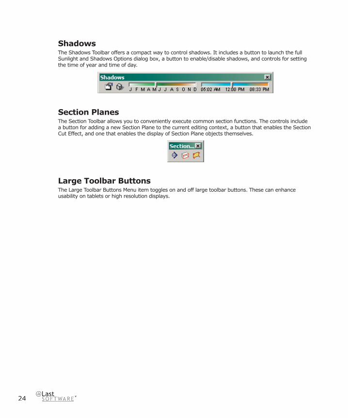
ShadowsThe Shadows Toolbar offers a compact way to control shadows. It includes a button to launch the full Sunlight and Shadows Options dialog box, a button to enable/disable shadows, and controls for setting the time of year and time of day.
Section PlanesThe Section Toolbar allows you to conveniently execute common section functions. The controls include a button for adding a new Section Plane to the current editing context, a button that enables the Section Cut Effect, and one that enables the display of Section Plane objects themselves.
Large Toolbar ButtonsThe Large Toolbar Buttons Menu item toggles on and off large toolbar buttons. These can enhance usability on tablets or high resolution displays.
Applicatio
n U
ser Interface
25
SketchUp 4.0 User Guide
Menus
SketchUp MenuThe SketchUp Application Menu contains commands that control the SketchUp application, including commands to show and hide SketchUp, application preferences, and the SketchUp license manager.
About SketchUpThe About SketchUp menu item activates the About SketchUp panel, which gives you information about the version of SketchUp you are currently running, as well as support contact information and a link to the SketchUp web site.
Preferences...The Preferences... menu choice opens SketchUp’s application preferences, where you can set various global behaviors for the program.
License...The License menu choice gives you access to SketchUp’s licensing panel, which you can use to enter a new License, determine which licence’s are currently in use, and see a list of all available licenses. To enter a new license, follow the directions that came with it.
ServicesThe Services menu gives you access to Mac OS X’s system-wide Services, which may vary from computer to computer depending on what additional functionality your other applications may have installed.
Hide SketchUpThe Hide SketchUp menu choice will hide SketchUp and all of its open drawing windows, allowing you access to other programs running in Mac OS X. To return SketchUp to view, click on its icon in your Dock.
Keyboard Shortcut: Command-H
Hide OthersThe Hide Others command will hide all visible applications except SketchUp allowing you to focus on SketchUp alone. To return other applications to view, click on their icon in your Dock.
Show AllThe Show All menu choice unhides all running programs in Mac OS X.
Quit SketchUpThe Quit SketchUp menu choice quits SketchUp and closes all open documents. You will be given an opportunity to save any unsaved work before SketchUp quits.
Keyboard Shortcut: Command-Q
26
File MenuThe File Menu contains commands that relate to SketchUp documents, including commands to create, open, save, print, import, and export documents.
NewChoosing New closes the current model and creates a new SketchUp document. If you have not saved changes to the current model, you will be prompted to do so. (If you need to view or edit multiple documents simultaneously, you can launch another SketchUp application window instead.) If you have selected a , SketchUp will use the settings in this fi le to defi ne the initial document state.
Keyboard Shortcut: Ctrl+N
Open...Choosing Open launches the File Open dialog, which allows you to open a previously saved SketchUp document. If an unsaved model is already open, you will be prompted to save changes if needed before it is closed.(If you need to view or edit multiple documents simultaneously, you can launch another SketchUp application window instead.)
Keyboard Shortcut: Ctrl+O
SaveThe Save command saves the currently active SketchUp document to your fi le system. If you wish to quit SketchUp with unsaved open documents, SketchUp will prompt you to save your work before continuing.
Keyboard Shortcut: CTRL+S
Tip: If Create Backup is enabled under the General Tab of Preferences, the existing fi le will be converted to a backup fi le, and the new drawing will be saved as the currently saved .skp. This can help preserve your data if you accidentally overwrite something.
Tip: It’s good to save often. You can have SketchUp automatically save for you at a specifi c time increment by enabling the Auto-save under the General Tab of Preferences.
Save As...This opens the Save As dialog box to the current document’s folder. From there you can save the current drawing as a new document. (It can have a new name, or can be saved to a different folder.) The new fi le will then becomes the current document.
Save a Copy ...The Save a Copy command creates a new document based on your current model and prompts you to save it. This does not overwrite or close the current fi le you are working on. It is handy for saving milestone copies or tentative schemes as you work.
RevertThe Revert command allows you to revert your current document to its last saved state.
Applicatio
n U
ser Interface
27
SketchUp 4.0 User Guide
ExportThe Export submenu gives you access to SketchUp’s export functionality, which is useful for sharing your work with other people or taking your drawings to other applications. You can export your SketchUp model as a 3D Model, a 2D Graphic, a Section Slice, or an Animation.
3D Model...
Choosing 3D Model... allows you to export to 3D formats, including the AutoCAD 2000 DXF and DWG, AutoCAD R14 DXF and DWG CAD formats, as well as the 3DS and VRML modeling formats.
2D Graphic...
This command allows you to export 2D raster, or pixel-based images and dimensionally accurate, resolution independent 2D vector drawings. Pixel-based images can be exported in JPEG, PNG, TIFF, BMP, TGA, and Epix fi le formats. These formats allow you to capture the image exactly as you see it on your screen, including shadows and textures. You can also specify the image size in pixels, allowing you to export images in much higher resolution as well as apply anti-aliasing, which eliminates the jagged look of pixellation. Keep in mind that larger images will take longer to generate.
Vector images can be exported in PDF, EPS, DWG, and DXF fi le formats. This makes it easy to send your SketchUp ideas to a plotter, quickly integrate them into construction documentation, or even further refi ne them using vector-based illustration software. Note that vector output formats may not support certain display options, such as shadows, transparency, and textures.
Section Slice...
The Export 2D Section Slice menu item allows you to output dimensionally accurate 2D section slices directly in standard vector formats.
Animation...
Choosing Animation... exports a pre-rendered animated video fi le of the page sequence you’ve created. This makes it easy burn your TourGuide Presentations to CD or DVD, as well as create smooth animations of complex models.
28
InsertSketchUp allows you to insert information from other fi les into your SketchUp drawings.
Component...
This command allows you to place another SketchUp fi le into your drawing as a Component. This is useful for referencing external information, managing the level of detail in your model, and editing many instances of repeated geometry. Alternately, you can simply drag and drop a SketchUp document directly into the Drawing Window.
Image...
This command places a pixel-based raster image into your drawing as an Image Object. Alternately, you can simply drag and drop an image fi le directly into the Drawing Window.
Image As Texture...
This command places a pixel-based raster image into your drawing as a material that can be applied to any surface.
DWG/DXF...
This option allows you to bring AutoCAD DWG and DXF fi les into your SketchUp model. Supported AutoCAD entities include lines, arcs, circles, polylines, faces, entities with thickness, 3D Faces, and nested blocks. The imported geometry will be converted to SketchUp lines and faces on the appropriate layer, and will come in as a Group. Once a drawing is imported, you may have to Zoom Extents to see it.
Print Setup...This gives you access to the print setup control, where you can choose and confi gure the printer and page properties you wish to use for printing.
Print Preview...This generates a preview of how the print will appear on the paper using the specifi ed print settings.
Print...The Print... menu choice opens the Print Dialog Box, which enables you to print the current SketchUp document’s Drawing Window to the currently selected printer.
Keyboard Shortcut: Control+P
(Recently Opened File List)This is a list of recently opened SketchUp fi les. Choosing any of these will open the fi le.

Applicatio
n U
ser Interface
29
SketchUp 4.0 User Guide
ExitChoosing exit closes the open document and closes the SketchUp application window. You will be given an opportunity to save any unsaved work before exiting.
30
Edit MenuThe Edit Menu contains commands that operate on geometry and operations inside SketchUp documents. These include cut/copy/paste commands, visibility operations, and commands for creating and editing groups and components.
UndoThe Undo command will undo the last drawing or editing commands performed. SketchUp allows you to undo all operations you have performed one at a time up to the last state at which you saved your fi le. The number of undos may also be limited by available memory. The opposite of Undo is Redo, which returns the last undo to its previous state.
Keyboard Shortcut: Ctrl+Z
Note: Undo works for any creation or modifi cation of geometry, but it does not work for view changes. To undo a view change, use the Undo View Change Tool.
RedoThe Redo Command cancels Undo operations, stepping forward in the modifi cation history.
Keyboard Shortcut: Ctrl+Y
CutThe Cut command removes the selected elements from your model and places them in the Clipboard. The contents of the clipboard may then be inserted back into any open SketchUp document by using the Paste command.
You can use Cut, Copy and Paste to move geometry between open SketchUp windows. Contents of the clipboard will remain on the clipboard until replaced with either a Cut or a Copy operation.
Keyboard Shortcut: Ctrl+X
CopyThe Copy command copies the selected items to the Clipboard without deleting them from the model. The contents of the clipboard may then be inserted back into any open SketchUp document by using the Paste command.
You can use Cut, Copy and Paste to move geometry between open SketchUp windows. Contents of the clipboard will remain on the clipboard until replaced with either a Cut or a Copy operation.
Keyboard Shortcut: Ctrl+C
PasteThe Paste command copies the contents of the clipboard into the current SketchUp document. The pasted objects will be attached to and placed by the point of the cursor, allowing you to position the new geometry when it is pasted. Click to “drop” the pasted objects in place.
You can use Cut, Copy and Paste to move geometry between open SketchUp windows. Contents of the clipboard will remain on the clipboard until replaced with either a Cut or a Copy operation.

Applicatio
n U
ser Interface
31
SketchUp 4.0 User Guide
Keyboard Shortcut: Ctrl+V
EraseThe Erase command removes the current selection from your model.
Keyboard Shortcut: Delete
Select AllChoosing Select All selects all selectable items the model.
Keyboard Shortcut: Ctrl+A
Deselect AllThe Deselect All command clears the selection set, deselecting any currently selected items in the model.
Keyboard Shortcut: Ctrl+T
HideMakes invisible any selected object. Hiding geometry can help simplify your current view, or to enable viewing and working inside closed objects.
Unhide
Selected
Makes visible any selected hidden object. To select hidden geometry, make sure you have Show Hidden Geometry enabled under the View Menu.
Last
Makes visible the last object or objects hidden with the Hide command.
All This unhides all hidden geometry in your current document.
Construction Geometry
Hide
Makes all Construction Lines in the drawing invisible.
Unhide
Makes all Construction Lines in the drawing visible.
32
Erase
Deletes all Construction Lines from the drawing.
Make Component...This creates a Component from the selected geometry.
Make GroupThis creates a Group from the selected geometry.
Close Group/ComponentIf you are In-Place Editing a Group or a Component, you can exit by using this command.
Intersect With ModelComplex geometry in SketchUp can be easily created using the Intersect With Model command. This command allows you intersect two elements, such as a box and a tube, and automatically create new faces where the elements intersect. These faces can then be pushed, pulled or deleted to create new geometry.
Entity Commands Sub-MenuThis sub-menu presents all of the commands available to manipulate the currently selected entity (which are the same as the commands found in the entity’s context command menu). The sub-menu’s name and contents will change depending on the item that you have selected.

Applicatio
n U
ser Interface
33
SketchUp 4.0 User Guide
Window MenuThe Window Menu contains commands that modify the appearance of SketchUp’s Drawing Window.
Model InfoDisplays the Model Info dialog box.
Entity InfoDisplays the Entity Info dialog box for the currently selected entity.
Materials BrowserDisplays the Materials Browser .
Material EditorDisplays the Materials Editor dialog box.
ComponentsDisplays the Component Browser.
LayersToggles the display of the Layer Manager.
PagesLaunches the Page dialog box. The current Page will be highlighted.
Display SettingsSketchUp has four basic Display Styles that determine the appearance of the model view. These are Wireframe, Hidden Line, Shaded, and Shaded with Textures. You can also activate X-ray transparency, profi le lines, jitter lines, and extended edges.
Shadow Settings Displays Shadow Settings dialog box.
Soften EdgesDisplays the Soften Edges dialog box.

34
PreferencesThe Preferences... menu choice opens SketchUp’s application preferences, where you can set various global behaviors for the program.
Ruby ConsoleDisplays the Ruby Console where you can type Ruby commands.

Applicatio
n U
ser Interface
35
SketchUp 4.0 User Guide
Camera MenuThe Camera Menu contains commands for altering the point of view of the model.
PreviousThe Previous command will undo the last camera command performed.
Standard This submenu provides access to the standard model views: Top, Bottom, Front, Right, Back, Left, and Isometric. Selecting any of these will immediately set your active drawing window to that view.
PerspectiveThis switches between Perspective and Paraline, the two modes of spatial visualization that are available in SketchUp.
Field of ViewInvokes the zoom tool in Field of View mode allow you to widen or narrow your fi eld of view.
OrbitInvokes the Orbit Tool.
PanInvokes the Pan Tool.
ZoomLaunches the Zoom Tool.
Zoom WindowLaunches the Zoom Extents Tool
Zoom ExtentsLaunches the Zoom Window Tool.
Position CameraAllows you to precisely position camera at eye-height or from an exact point to an exact point.

36
WalkInvokes the Walk Tool for maneuvering through your SketchUp model as if you were walking.
Look AroundInvokes the Look Around Tool which pivots the camera around a stationary point at the point of view.
Applicatio
n U
ser Interface
37
SketchUp 4.0 User Guide
View MenuThe View Menu contains commands for displaying your model.
ToolbarsToggles on and off all the toolbars: Standard, Edit, Drawing, Camera, Display Modes, Views, Layers, Shadows, and Section Planes. The ‘Large Toolbar Buttons’ option toggles on and off large toolbar buttons, which can enhance usability on tablets or large-resolution displays.
Hidden GeometryIn order to be able to selectively Unhide hidden geometry, you must be able to select it. SketchUp provides a way to do this through the Show Hidden Geometry command. Show Hidden Geometry displays hidden geometry with a light cross-hatch pattern that enables you to select it. Once selected, hidden geometry can be made visible again with the Unhide command.
The View Menu contains commands that modify the appearance of SketchUp’s Drawing Window, display the Toolbar controls, and modify the way that SketchUp visualizes the geometry in your model (Perspective, Standard Views, Display style, etc.)
Section PlanesToggles display of the Section Planes in your model.
Section CutToggles display of any Section Cuts in your model.
AxesThe Show Axes command toggles the display of the Drawing Axes on and off.
X-rayActivates X-ray mode.
RenderingSketchUp has four basic Rendering Styles that determine the appearance of the model view. These are Wireframe, Hidden Line, Shaded, Shaded with Textures, and Monochrome. You can also activate edge rendering styles: profi le lines, jitter lines, and extended edges.
Component EditAlters display when editing components. The Show Rest of Model option will toggle the display of the model when editing a component. The Show Similar Components option will toggle the display of similar components on and off when editing a component.

38
Page TabsToggles Page Tabs at top of Drawing Window on and off.
TourGuideLaunches the TourGuide Settings dialog box, which allows you to adjust how pages are displayed using the TourGuide page interpolation system, as well as the TourGuide slide show.
Draw MenuThe DrawMenu gives you access to all of SketchUp’s drawing tools and provides an alternative to using the Tool Toolbar or Keyboard shortcuts.
LineInvokes a Line Tool used to draw single lines, multiple connected lines, or closed shapes.
ArcInvokes a Arc Tool used to draw Arc entities, which are comprised of multiple connected straight line segments but can still be edited as an arc curve.
FreehandLaunches a Freehand Tool used to draw irregular, coplanar connected lines in the form of Polyline Curves or simpler Freehand Sketch Objects.
RectangleLaunches a Rectangle Tool used to draw rectangular faces, specifi ed by clicking at two opposite corners of the desired shape.
CircleInvokes a Circle Tool used to draw Circle Entities.
PolygonInvokes a Polygon Tool used to draw regular Polygon Entities inscribed within a circle with anywhere between 3 to 100 sides.
Applicatio
n U
ser Interface
39
SketchUp 4.0 User Guide
Tools MenuThe Tools Menu gives you access to all of SketchUp’s Construction tools and provides an alternative to using the Tool Toolbar or Keyboard shortcuts.
SelectThe Select Tool allows you to specify which drawing entities to work with when using other tools or commands. While you can build a complex selection set by manually adding or subtracting individual entities, the Select Tool offers many automated features that can greatly speed your work fl ow.
EraserThe Eraser Tool is used primarily to delete edges, Construction Lines, and objects from the Drawing Window. It also offers secondary functions such as hiding and softening edges.
Paint BucketThe Paint Bucket Tool is used to assign Materials (colors and/or textures) to entities in your model. You can use it to paint individual elements, fi ll a number of connected faces, or replace a material with another throughout your model.
MoveThe Move Tool allows you to move, stretch and copy geometry. It can also be used to rotate Components.
RotateUse the Rotate Tool to rotate drawing elements as well as single or multiple objects within a single rotation plane. Also, by selecting only a portion of an object, the Rotate Tool can be used to stretch and distort geometry.
ScaleThe Scale Tool allows you to resize and stretch selected geometry relative to other elements in your SketchUp model.
Push/PullThe Push/Pull Tool is used to distort and re-proportion faces of your model. Depending on the nature of geometry you use it on, it will displace, extrude, re-attach, and/or subtract faces. It is valuable both as a massing exploration tool and as a precise construction tool.
Follow MeThe Follow Me Tool is used to extrude faces along a path such as an edge or line drawn with the freehand pencil. This tool is especially useful when trying to add details to a model by allowing you to draw the detail at one end of a path on the model and essentialy tell SketchUp to continue that detail along a particular path in the model.

40
OffsetThe Offset Tool creates copies of co-planar lines and faces that are a uniform distance from the originals. You can offset edges of faces either inside the original face, or outside of it. Offsetting a face will always create a new face.
Tape MeasureThe Tape Measure Tool performs a number of dimension-related operations. These include measuring the distance between two points, creating Construction Lines, and re-scaling an entire model to an exact dimension.
ProtractorThe Protractor Tool allows you to measure angles and create Construction Lines.
AxesThe Axes Tool allows you to move the Drawing Axes around within your model. You may wish to do this when you are constructing rectangular objects that are skewed relative to one another, or you may use this tool to allow for more accurate scaling of objects not oriented along the default coordinate planes.
DimensionsLaunches a Dimension Tool used to place Dimension Objects in your model.
TextLaunches a Text Tool used to insert Text Objects into your model.
Section PlaneInvokes a Section Plane Tool used to make section cuts in your model.
Utilities
Create Face
The Create Face utility is a Ruby script allowing you to troubleshoot face creation and, in most cases, create a face for three or more intersecting edges. Specifi cally, the Create Face utility is useful when:
• A model might has two edges that have a common end point geometrically (the coordinates of the end point are the same), but the edges are not connected topologically. In this case, the Create Face utility will properly connect edges and create a face.
• A face cannot be created because edges are not exactly planer, or appear to be connected when there is actually a small gap between the ends of the edges. In these instances, Create Face will not create a face, but displays a message indicating why SketchUp cannot create a face. This message can be used to troubleshoot face creation.

Applicatio
n U
ser Interface
41
SketchUp 4.0 User Guide
Query Tool
The Query Tool utility is a Ruby script that displays the current mouse position in the VCB.
Note - Ruby scripts are contained in the Plugins directory under the installation directory.
Fix Non-planar Faces
The Fix Non-plannar Faces utility uses SketchUp’s Validity Check feature, within Model Info > Statistics, to fi nd and fi x non-planar faces.
42
Help Menu
Help TopicsThis opens SketchUp’s online documentation, where you can fi nd reference information about each feature, as well as detailed illustrated tutorials.
Quick Reference CardThis launches SketchUp’s Quick reference card.
SketchUp WebsiteThis opens your default web browser and connects to SketchUp’s web site, where you will fi nd support forums, additional training information, and access to new software patches and releases. You can also contact our technical support staff here, who will be happy to answer any questions for you that are not covered in this documentation.
View Tutorials
Written Tutorials
This takes you directly to the tutorials section of SketchUp’s online documentation.
Video Tutorials
We have prepared a number of video tutorials on a wide variety of topics. These tutorials are perhaps the best way to learn SketchUp, and they are posted for your use on our web site. Select this command to open your default web browser and connect to our online training video site. If you have your SketchUp CD inserted into your CD-Drive, SketchUp will run the higher quality videos on the CD instead.
LicenseThis submenu includes several options that allow you to view and manage your SketchUp license.
Tip of the DayThis brings up a list of tips and suggestions for getting the most out of SketchUp.
About SketchUp...This activates the About SketchUp Dialog, which gives you information about the version of SketchUp you are currently running, as well as license information.
Applicatio
n U
ser Interface
43
SketchUp 4.0 User Guide
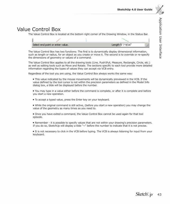
Value Control BoxThe Value Control Box is located at the bottom right corner of the Drawing Window, in the Status Bar.
The Value Control Box has two functions: The fi rst is to dynamically display dimensional information, such as length or radius, for an object as you create or move it. The second is to override or re-specify the dimensions of geometry or values of a command.
The Value Control Box applies to all the drawing tools (Line, Push\Pull, Measure, Rectangle, Circle, etc.) as well as editing tools such as Move and Rotate. The sections specifi c to each tool provide more detailed information regarding the types of values they can accept via VCB entry.
Regardless of the tool you are using, the Value Control Box always works the same way:
• This value indicated by the mouse movements will be dynamically previewed in the VCB. If the value defi ned by the tool cursor is not within the precision parameters as defi ned in the Model Info dialog box, a tilde will be displayed before the number.
• You may type in a value either before the command is complete, or after it is complete and before you start a new operation.
• To accept a typed value, press the Enter key on your keyboard.
• While the original command is still active, (before you start a new operation) you may change the value of the geometry as many times as you need to.
• Once you have exited a command, the Value Control Box cannot be used again for that tool episode.
• Remember - it is possible to specify values that are not within your drawing's precision parameters. If you do so, SketchUp will display a tilde "~" before the number to indicate that it is not precise.
• It is not necessary to click in the VCB before typing. The VCB is always listening for input from your keyboard.
44
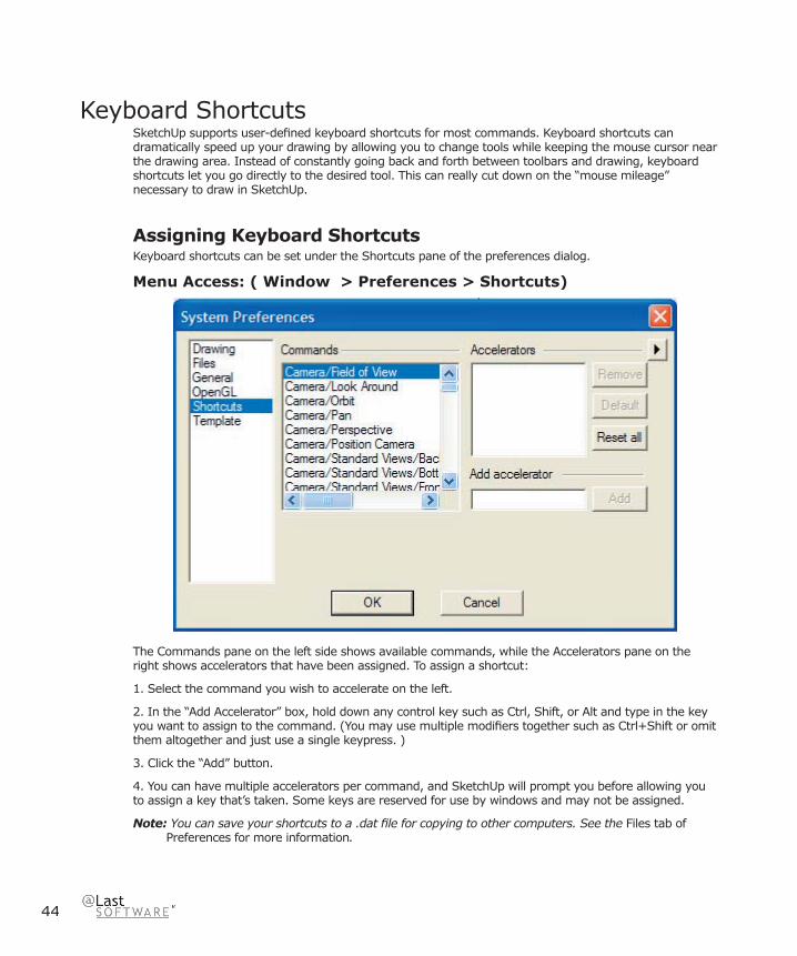
Keyboard ShortcutsSketchUp supports user-defi ned keyboard shortcuts for most commands. Keyboard shortcuts can dramatically speed up your drawing by allowing you to change tools while keeping the mouse cursor near the drawing area. Instead of constantly going back and forth between toolbars and drawing, keyboard shortcuts let you go directly to the desired tool. This can really cut down on the “mouse mileage” necessary to draw in SketchUp.
Assigning Keyboard ShortcutsKeyboard shortcuts can be set under the Shortcuts pane of the preferences dialog.
Menu Access: ( Window > Preferences > Shortcuts)
The Commands pane on the left side shows available commands, while the Accelerators pane on the right shows accelerators that have been assigned. To assign a shortcut:
1. Select the command you wish to accelerate on the left.
2. In the “Add Accelerator” box, hold down any control key such as Ctrl, Shift, or Alt and type in the key you want to assign to the command. (You may use multiple modifi ers together such as Ctrl+Shift or omit them altogether and just use a single keypress. )
3. Click the “Add” button.
4. You can have multiple accelerators per command, and SketchUp will prompt you before allowing you to assign a key that’s taken. Some keys are reserved for use by windows and may not be assigned.
Note: You can save your shortcuts to a .dat fi le for copying to other computers. See the Files tab of Preferences for more information.

Applicatio
n U
ser Interface
45
SketchUp 4.0 User Guide
Single Keyboard Shortcut LimitationThe reason one can’t use numbers as single key shortcuts is that typing a number gives temporary focus to the Value Control Box for entering values. The letters S, R, X, and the symbols / and * can each be used to enter other values in the VCB. For example R is used to specify a radius in the Arc Tool. X, /, and * are used to in the Multi-Copy array commands. S is used to indicate the segmentation in a polygon, circle, or arc. If you have one of these keys assigned to a shortcut you will need to enter your values starting with a number. Example: Typing “7s” would be the correct entry to redefi ne segmentation. “s7” would activate whatever tool was assigned to S.
46
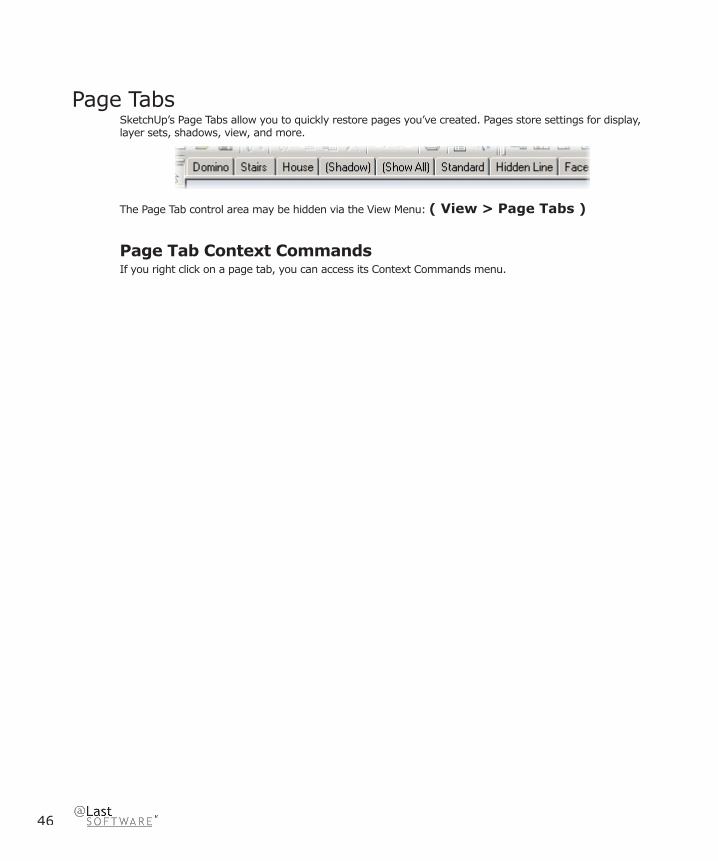
Page TabsSketchUp’s Page Tabs allow you to quickly restore pages you’ve created. Pages store settings for display, layer sets, shadows, view, and more.
The Page Tab control area may be hidden via the View Menu: ( View > Page Tabs )
Page Tab Context CommandsIf you right click on a page tab, you can access its Context Commands menu.
Applicatio
n U
ser Interface
47
SketchUp 4.0 User Guide
Standard Windows Dialog BoxesSketchUp makes use of the standard ‘Open’ and ‘Save As’ Windows dialog boxes, which are very similar in organization.
Open Dialog BoxThe Open dialog box is used for a variety of purposes, such as opening an existing drawing fi le, selecting a Component for insertion into a drawing, or creating a new Home Library. It is particularly well suited for browsing, as image thumbnails often reveal a fi les contents far better than a name can.
The Open dialog box displays all the drawing fi les in the current drawing folder or Component folder. To open a fi le, click on the fi le name you want and click the Open button. The dialog box closes automatically. If you do not want to open a fi le, click on the Cancel button, and the dialog box also will close.
Note: Another way to open a recent drawing, is to click on its name in the roster of recent drawings near the bottom of the File menu.
Look InThe Look in list box displays the current drawing folder name. If the required folder is not displayed, click on the arrow at the right of the list box, and use the list to navigate to the folder you need.
Up One LevelUse the Up One Level button to move up to the next higher directory.
New FolderThe New Folder button will create a new folder within the current folder.
ListThe List button will display only the drawing fi le names. This way more fi les are visible in the display window.
DetailsThe Details button displays fi le data: size, type, when last modifi ed, and attributes.
File NameThe File Name fi eld displays the name of the fi le you have selected to open.
Files of TypeThe Files of Type list box allows you to control what type of fi les are displayed in the list window.

48
OpenOpen will open the selected fi le and close the dialog box. You may also hit Enter.
CancelCancel will close the dialog box without performing any open function.
Save As Dialog Box The Save As dialog box is used to save a fi le, rename a fi le, and save a fi le to a new location. The format of the dialog box is very similar to the Open dialog box.
When the Save As dialog box opens, you are prompted for a fi le name. Until you enter a name, the File Name fi eld will show the default name: Untitled.
If you try to save a the drawing with a name that already exists in the display list, a query box will appear asking if you want to replace it.
Save InThe Save In fi eld displays the name of the folder to which the fi le will be saved. The contents of that folder are displayed in the display window. You may navigate to a new folder using the Save In list box, the Up One Level button, and the View Desktop button.
Save As TypeThe Save As Type list box determines what fi le format in which it will be saved as. All SketchUp drawing fi les are .skp’s.
SaveSave performs the save function. You may also press Enter.
CancelCancel closes the dialog box without performing a save function.
Browse Dialog BoxThe Browse dialog box is used primarily for specifying a directory. This is used in the Files tab of the Preferences Dialog Box.

49
SketchUp 4.0 User GuideD
rawin
g To
ols
Drawing Tools
Line ToolThe Line Tool is used to draw single lines, multiple connected lines, or closed shapes. It may also be used to split faces or “heal” deleted faces. Although it appears simple on the surface, the Line Tool allows you to draw extremely complex 3D geometry accurately and quickly.
The Line Tool may be activated from either the Drawing Toolbar or the Draw Menu.
Menu Access: ( Draw> Line )
Drawing a Straight Line1. Activate the Line Tool.
2. Click on the starting point of your line.
3. Move the mouse in the direction you wish to make a line. As you draw a line, the length is displayed dynamically in the Value Control Box (VCB), and may be specifi ed precisely via type-in either before clicking the second point or after the line has been drawn.
4. Click a second time on the endpoint of your line. (You can also hold down the mouse button, drag, and release on the second point to create a line.)
Creating a Face When connected at their endpoints, three or more continuous planar lines create a face. In order to make sure that any lines you draw are continuous, make sure that the Endpoint inference ToolTip is visible whenever you close a face. After a face has been created, the Line Tool is released but is still active. To draw another line, simply start drawing again.
Tip: A good way to be certain that your faces are created properly is to keep the display in Shaded Mode. This clearly shows new faces as they are created.
50
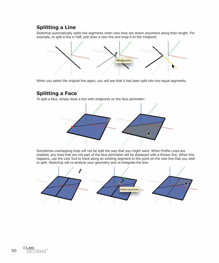
Splitting a Line SketchUp automatically splits line segments when new lines are drawn anywhere along their length. For example, to split a line in half, just draw a new line and snap it to the midpoint:
When you select the original line again, you will see that it has been split into two equal segments.
Splitting a FaceTo split a face, simply draw a line with endpoints on the face perimeter:
Sometimes overlapping lines will not be split the way that you might want. When Profi le Lines are enabled, any lines that are not part of the face perimeter will be displayed with a thicker line. When this happens, use the Line Tool to trace along an existing segment to the point on the new line that you wish to split. SketchUp will re-analyze your geometry and re-integrate the line:
Draw
ing To
ols
51
SketchUp 4.0 User Guide
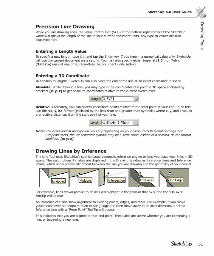
Precision Line DrawingWhile you are drawing lines, the Value Control Box (VCB) at the bottom right corner of the SketchUp window displays the length of the line in your current document units. Any type-in values are also displayed here.
Entering a Length ValueTo specify a new length, type it in and tap the Enter key. If you type in a numerical value only, SketchUp will use the current document units setting. You may also specify either Imperial (1’6”) or Metric (3.652m) units at any time, regardless the document units setting.
Entering a 3D CoordinateIn addition to lengths, SketchUp can also place the end of the line at an exact coordinate in space.
Absolute: While drawing a line, you may type in the coordinates of a point in 3D space enclosed by brackets [x, y, z] to get absolute coordinates relative to the current sketch axes:
Relative: Alternately, you can specify coordinate points relative to the start point of your line. To do this, use the <x, y, z> format (enclosed by the less-than and greater-than symbols) where x, y, and z values are relative distances from the start point of your line.
Note: The exact format for type-ins will vary depending on your computer’s Regional Settings. For European users, the list separator symbol may be a semi-colon instead of a comma, so the format would be: [x; y; z]
Drawing Lines by InferenceThe Line Tool uses SketchUp’s sophisticated geometric inference engine to help you place your lines in 3D space. The assumptions it makes are displayed in the Drawing Window as Inference Lines and Inference Points, which show precise alignment between the line you are drawing and the geometry of your model.
For example, lines drawn parallel to an axis will highlight in the color of that axis, and the “On Axis” ToolTip will appear.
An inference can also show alignment to existing points, edges, and faces. For example, if you move your mouse over an endpoint of an existing edge and then move away in an axial direction, a dotted Inference Line with a “From Point” ToolTip will appear.
This indicates that you are aligned to that end point. These aids are active whether you are continuing a line, or beginning a new one.
52
Inference LockingSometimes SketchUp cannot properly infer alignments exactly where you need them. The inference can make wrong assumptions, or it can become distracted by other geometry. When this happens, you can lock in a desired inference by holding down the Shift key. This action causes the inference line to thicken indicating the line’s alignment to a particular axis.
For example, if you move the mouse over a face so that the blue “On Face” ToolTip appears, then hold down Shift, any further drawing points will be locked to the plane of that face.
Dividing a Line into Equal SegmentsLine segments can be divided into any number of equal line segments. To divide an edge, right click on it, and select Divide from the context menu.

Draw
ing To
ols
53
SketchUp 4.0 User Guide
Arc Tool The Arc Tool is used to draw Arc entities, which are comprised of multiple connected straight line segments but can still be edited as an arc curve. It may be activated from the Drawing Toolbar or from the Draw Menu.
Menu Access: ( Draw> Arc )
To Draw an Arc1. Activate the Arc Tool
2. Click to place the starting point of your arc.
3. Click a second time to place the end point of your arc.
4. Move your mouse to adjust the bulge distance. You can optionally type in values for the arc chord length, bulge distance, radius, and number of segments. See below for more information.
Drawing a Half CircleAs you pull out a bulge distance, the arc will temporarily snap to a semi-circle. Watch for the Half Circle inference ToolTip.

54
Drawing TangentiallyWhen drawing from an unconnected edge, the Arc Tool will display a cyan tangent arc while you are placing the second endpoint. After clicking the second point, you may move the mouse to break the tangent inference and set your own bulge. If you want to keep the tangent arc, simply keep the mouse still after setting the second point and click a third time.
Extruding an ArcYou can use the Push/Pull Tool on faces that have an arc as an edge in a manner similar to regular faces. The face that results from the push/pull operation is an arc curved face set. Although curved face sets display as curves and can be adjusted as curves, they are still comprised of a number of planar faces. See below for more info.
Specifying Precise Arc ValuesAs you draw an arc, the VCB (Value Control Box) displays the length of the base chord of the arc, then the bulge distance. You may specify a value by typing in the desired length followed by the Enter key. Radius and segmentation require special type-in formats.
If you type in a numerical value only, SketchUp will use the current document units setting. You may also specify either Imperial (1’6”) or Metric (3.652m) units at any time, regardless the document units setting.

Draw
ing To
ols
55
SketchUp 4.0 User Guide
Entering an Exact Length for the Base ChordTo specify a value for the base chord, type the desired length after clicking the fi rst endpoint. You can use negative values (-6’5”) to indicate that you want the length to apply in an opposite direction to the one you indicated when drawing. You must do this before clicking to accept the base chord, and before setting the arc bulge.
Specifying a Bulge DistanceAfter entering the chord length, you may also specify an exact bulge length or the radius for your arc.
To specify a new bulge distance, type it in and press the Enter key. You may do this either during the creation of the arc or afterwards, as long as the bulge distance is displayed in the VCB. Negative bulge values may also be used to create an arc in a direction opposite the one indicated while drawing.
Specifying a Radius ValueIn place of a bulge distance, you may specify an arc radius. To do so, type the desired radius followed by the letter ‘r’, (For example: 24r or 3’6”r or 5mr) then press Enter. You may do this either during or following the creation of the arc.
Specifying The Number of SegmentsYou may specify the number of arc segments by typing in the desired number followed by the letter ‘s’ and the Enter key. This may be done either during or following the creation of the arc.

56
Freehand Tool
The Freehand Tool allows you to draw irregular, coplanar connected lines in the form of Polyline Curves or simpler Freehand Sketch Objects. These can be useful for representing contours or other organic shapes. The Freehand Tool can be activated from Draw Menu or from the Drawing Toolbar.
Menu Access: ( Draw > Freehand )
Drawing Polyline Curves 1. Activate the Freehand Tool.
2. Press the mouse button on a starting point, and drag the cursor to draw.
3. Release the mouse button to stop drawing.
To draw a closed shape with the Freehand Tool, end your line at point where you started drawing. SketchUp will close the shape for you.

Draw
ing To
ols
57
SketchUp 4.0 User Guide
Drawing a Freehand Curve Freehand Sketch Objects do not generate inference snaps or affect geometry in any way. You can use them for tracing imported drawings, 2D sketching, or for decorating your model.
To create Freehand Sketch objects, hold down the Shift key before drawing with the Freehand Tool. To convert a Freehand Sketch object into regular edge geometry, select Explode from its context menu.

58
Rectangle ToolThe Rectangle Tool draws rectangular faces, specifi ed by clicking at two opposite corners of the desired shape. It may be activated from either the Edit Toolbar or the Draw menu.
Menu Access: ( Draw > Rectangle )
Drawing a Rectangle1. Activate the Rectangle Tool and Click once on the fi rst corner point.
2. Move your mouse to the opposite corner.
3. Click again to fi nish.
Drawing a Square1. Activate the Rectangle Tool and Click once on the fi rst corner point.
2. Move your mouse to the opposite corner. A dotted line will appear, along with a “Square” ToolTip when you are in a postion that will create a square.
3. Click again to fi nish.
Tip: A dotted line and “Golden Section” ToolTip appear when you are in a postion to create a Golden Section.
Alternately, you can press your mouse button on the fi rst corner of your rectangle, drag to the opposite corner, and release the mouse button. Using either method, you can tap the Esc key to cancel.
Tip: If you want to draw a rectangle that is not aligned with the default Drawing Axes orientation, use the Axes Tool to re-align the axes prior to drawing your rectangle.

Draw
ing To
ols
59
SketchUp 4.0 User Guide
Entering Precise DimensionsAs you draw a rectangle, its dimensions dynamically appear in the VCB (Value Control Box). You may specify exact dimensions by typing them in either after the fi rst corner is clicked, or immediately after the rectangle is drawn.
If you type in a numerical value only, SketchUp will use the current document units setting. You may also specify either Imperial (1’6”) or Metric (3.652m) units at any time, regardless the document units setting.
You can only type in one dimension if you wish. If you enter a value and a comma, (3’,) the new value will be applied to the fi rst dimension, and the second dimension will be retained from before. Similarly, if you type a comma and then a dimension, (,3’) only the second dimension will be changed.
Tip: If you enter a negative value, (-24,-24) SketchUp will apply that value in a direction opposite to the one you indicated while drawing and accept any new values in the new direction.
Drawing Rectangles by InferenceThe Rectangle Tool uses SketchUp’s sophisticated geometric inference engine to help you draw in 3D space. These assumptions are displayed in the Drawing Window as Inference Lines and Inference Points, which show precise alignment between the rectangle you are drawing and the geometry of your model.
For example, if you move your mouse over an endpoint of an existing edge and then move away in an axial direction, a dotted Inference Line with a “From Point” ToolTip will appear.
This indicates that you are aligned to that end point. You can also use a “From Point” inference to draw rectangles vertically or at non-orthogonal planes.

60
Circle Tool The Circle Tool is used to draw Circle Entities. It may be activated from the Drawing Toolbar or the Draw menu.
Menu Access: ( Draw > Circle )
Drawing Circles1. Activate the Circle Tool. A circle will appear underneath the pencil cursor.
2. If you wish to place your circle on an existing face, move the cursor onto that face. SketchUp will align the circle as necessary. You cannot lock the inference plane for the circle. (If you do not locate the cursor over a face, SketchUp will create the circle on the axis planes, depending on your view.) You may also specify the segmentation for the circle in the Value Control Box (VCB).
3. Once your orientation is set, move the cursor to the desired center point.
4. Click the mouse to set the center point of your circle. This locks the circle orientation as well.
5. Move the mouse out from the center point to defi ne the radius of your circle. As you do so, the radius value is displayed dynamically in the VCB and can be specifi ed by typing in a length value followed by the Enter key.
6. Click the left mouse button a second time to fi nish the circle. (Alternately, you can click once to set the center of the circle, and drag outward without releasing the button to set the radius. Then release the mouse button to complete the circle.)
Immediately after a circle is drawn, the radius and segment values may still be specifi ed via the VCB as described below.
Specifying Precise Circle ValuesWhile creating a circle, its values are displayed dynamically in the Value Control Box, which is at the bottom right corner of the SketchUp Drawing Window. The VCB also allows you to specify values via type-in, including the radius of the circle, as well as the number of line segments that make up the circle.
Specifying a Radius ValueAfter placing the center point, you may specify a radius simply by typing in the desired length and pressing the Enter or Return key. As with most type-ins, you may use an alternate measuring system. (For example, if you are using metric system as your default, you may still type in Imperial units: (3’6”) Conversion will be done automatically.)
You may also re-specify a radius after the circle has been created simply by typing in a length value.

Draw
ing To
ols
61
SketchUp 4.0 User Guide
Specifying The Number of SegmentsWhen the Circle Tool is fi rst activated and before the circle center point is placed, the VCB prompt will display the label “Sides” and allow a numerical type-in. At this time, you may specify an exact number of segments followed by the Enter key.
Once you place the center point and start drawing the circle radius, the radius prompt will come up and any further type-in values will be read as a radius. You may, however, override this by typing the desired number of segments followed by the letter ‘s’ and the Enter key.
Segment input works the same way after you have fi nished placing the circle as well. Segmentation values will now apply retroactively to the last drawn circle until you begin drawing a new circle or change tools. (Any values you specify after a circle is drawn will apply to the last one drawn, and will set the tool to that value as well for future circles.)
Circle SegmentationIn SketchUp, all curves, including circles, are made up of multiple straight line segments connected together.
When you create an circle using the Circle Tool, straight line segments are stitched together to approximate the circle you specify. Although this circle entity can be parametrically modifi ed as an circle in some cases, and will create curved faces when extruded, it is still essentially faceted. All inference techniques will operate on it as segments.
Circles with more line segments will appear to have smoother curvature than circles with fewer line segments. However, more line segments will increase the size of your model, and can also degrade performance. Depending on your goals, you may often achieve acceptable results with small segmentation. Also, small segmentation values can be combined with smoothing and edge softening to more effi ciently create the impression of rounded geometry.
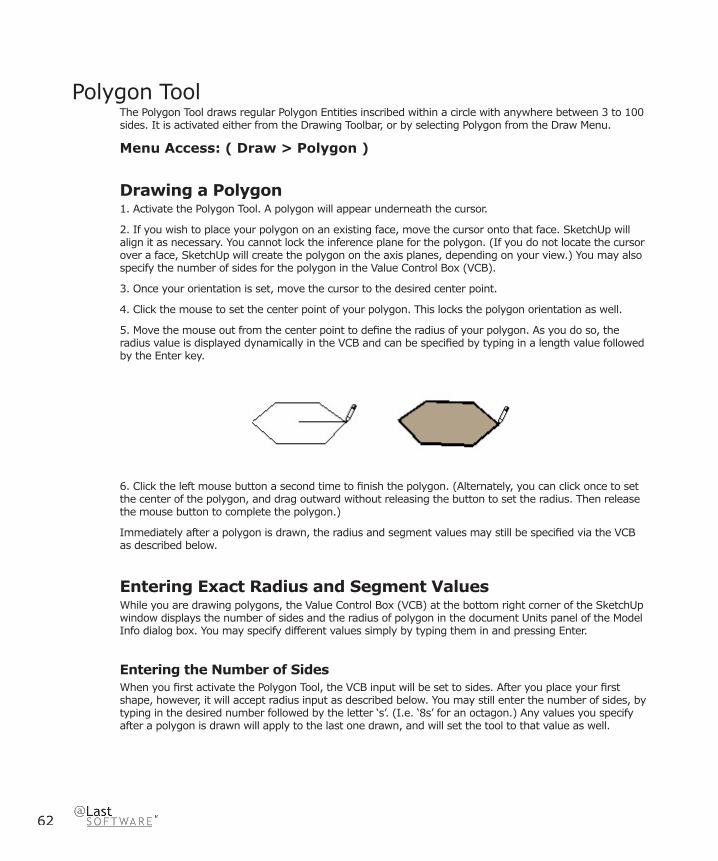
62
Polygon ToolThe Polygon Tool draws regular Polygon Entities inscribed within a circle with anywhere between 3 to 100 sides. It is activated either from the Drawing Toolbar, or by selecting Polygon from the Draw Menu.
Menu Access: ( Draw > Polygon )
Drawing a Polygon 1. Activate the Polygon Tool. A polygon will appear underneath the cursor.
2. If you wish to place your polygon on an existing face, move the cursor onto that face. SketchUp will align it as necessary. You cannot lock the inference plane for the polygon. (If you do not locate the cursor over a face, SketchUp will create the polygon on the axis planes, depending on your view.) You may also specify the number of sides for the polygon in the Value Control Box (VCB).
3. Once your orientation is set, move the cursor to the desired center point.
4. Click the mouse to set the center point of your polygon. This locks the polygon orientation as well.
5. Move the mouse out from the center point to defi ne the radius of your polygon. As you do so, the radius value is displayed dynamically in the VCB and can be specifi ed by typing in a length value followed by the Enter key.
6. Click the left mouse button a second time to fi nish the polygon. (Alternately, you can click once to set the center of the polygon, and drag outward without releasing the button to set the radius. Then release the mouse button to complete the polygon.)
Immediately after a polygon is drawn, the radius and segment values may still be specifi ed via the VCB as described below.
Entering Exact Radius and Segment ValuesWhile you are drawing polygons, the Value Control Box (VCB) at the bottom right corner of the SketchUp window displays the number of sides and the radius of polygon in the document Units panel of the Model Info dialog box. You may specify different values simply by typing them in and pressing Enter.
Entering the Number of SidesWhen you fi rst activate the Polygon Tool, the VCB input will be set to sides. After you place your fi rst shape, however, it will accept radius input as described below. You may still enter the number of sides, by typing in the desired number followed by the letter ‘s’. (I.e. ‘8s’ for an octagon.) Any values you specify after a polygon is drawn will apply to the last one drawn, and will set the tool to that value as well.

Draw
ing To
ols
63
SketchUp 4.0 User Guide
Entering a Radius ValueOnce you have set the center point of your polygon, you can use the Value Control Box to enter an exact radius for your polygon. Just type the radius length into the Value Control Box followed by the Enter key. You may change this setting either during or following the creation of a polygon.
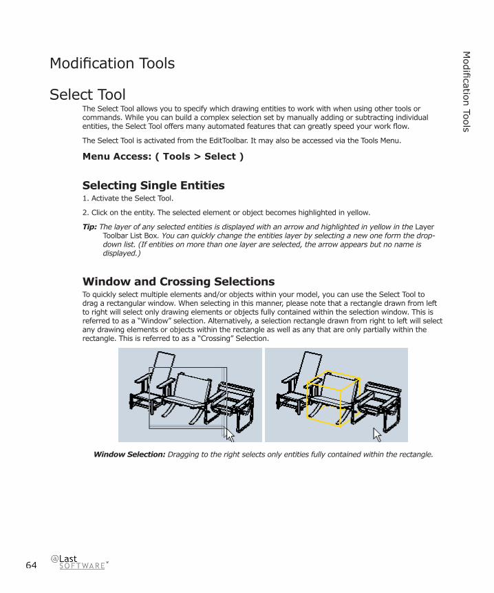
64
Modifi catio
n To
ols
Modifi cation Tools
Select ToolThe Select Tool allows you to specify which drawing entities to work with when using other tools or commands. While you can build a complex selection set by manually adding or subtracting individual entities, the Select Tool offers many automated features that can greatly speed your work fl ow.
The Select Tool is activated from the EditToolbar. It may also be accessed via the Tools Menu.
Menu Access: ( Tools > Select )
Selecting Single Entities1. Activate the Select Tool.
2. Click on the entity. The selected element or object becomes highlighted in yellow.
Tip: The layer of any selected entities is displayed with an arrow and highlighted in yellow in the Layer Toolbar List Box. You can quickly change the entities layer by selecting a new one form the drop-down list. (If entities on more than one layer are selected, the arrow appears but no name is displayed.)
Window and Crossing SelectionsTo quickly select multiple elements and/or objects within your model, you can use the Select Tool to drag a rectangular window. When selecting in this manner, please note that a rectangle drawn from left to right will select only drawing elements or objects fully contained within the selection window. This is referred to as a “Window” selection. Alternatively, a selection rectangle drawn from right to left will select any drawing elements or objects within the rectangle as well as any that are only partially within the rectangle. This is referred to as a “Crossing” Selection.
Window Selection: Dragging to the right selects only entities fully contained within the rectangle.

Modifi catio
n To
ols
65
SketchUp 4.0 User Guide
Crossing Selection: Dragging to the left selects any entities that are inside or touch the rectangle.
Selection Modifi er KeysYou can also select with greater fl exibility by using the Control and Shift modifi er keys:
When you hold down the Control key, the Select Tool becomes additive, and only adds to the selection set.
When you hold down Shift, the tool will invert the selection status of any geometry you select. (Things that are selected are de-selected, and vise-versa.)
By holding down Control and Shift simultaneously, you make the Select Tool subtractive, which means it will only remove geometry from the selection set.
Selection Modifi ers: Invert, Additive, and Subtractive.
By combining modifi er keys with window or crossing drag selections, you can very quickly create complex selection sets.
Expanding SelectionsYou can automatically expand selection operations on elements by clicking the Select Tool multiple times in rapid succession. For example, clicking twice on a face will select that face as well as all connected edges. Clicking three times will select that face as well as all geometry physically connected to that face.
(1) First click. (2) Second click expansion. (3) Third click expansion to all connected.
While in the Select Tool, you may also use a right-click to bring up a context menu. From there, you can use the Select submenu to expand the selection by Bounding Edges, Connected Faces, All Connected, All on Same Layer, and All with Same Material.
66
Selecting or De-Selecting All GeometryTo select all visible drawing elements in your model, you may use either the ( Edit > Select All ) menu command, or press Ctrl+A on the keyboard.
To de-select all currently selected elements, simply click on any empty part of the Drawing Window modeling space. You may also use either the ( Edit > Deselect All ) menu command, or Ctrl+T on the keyboard.
Making and Editing GroupsOnce you have created a selection set, you may want to preserve it for quick re-selection in the future by creating a Group. ( Edit > Group ) Once a group is defi ned, the elements within it become encapsulated so that selecting one will instantly select the entire group instead. This is a great way to speed selection of things like cars or trees.
Another advantage is that elements within a group become isolated from elements outside it so that they cannot be directly altered. The Explode command ( Edit > Group > Explode ) returns geometry back to normal edges and faces.
To edit a group without un-grouping, simply double click on it with the Select Tool or select it and press Enter. This will place you within the objects context, and allow you to edit it directly. Once you are fi nishing, you can use the Select Tool to click outside the context or press ESC to return to a higher level.

Modifi catio
n To
ols
67
SketchUp 4.0 User Guide
Eraser ToolThe Eraser Tool is used primarily to delete edges, Construction Lines, and objects from the Drawing Window. It also offers secondary functions such as hiding and softening edges.
The Eraser Tool is activated either from the Edit Toolbar, or by selecting Eraser from the Tools Menu.
Menu Access: ( Tools > Eraser)
Erasing Geometry1. Activate the Eraser Tool.
2. Click on the entity you wish to erase. You may also hold down the mouse button and drag it over geometry to be erased. As you do so, geometry will be highlighted. Once you release the mouse button, all selected geometry will be erased.
If you accidentally select geometry you do not wish to delete, you can cancel the Erase operation before it deletes your selection by hitting the ESC key.
You might “skip over” lines if you move the mouse very fast while using the Eraser Tool. If this happens, repeat the operation moving a bit more slowly.
Tip: To erase a large number of lines it may be faster to select them with the Select Tool, and use the Delete key on your keyboard. You may also delete selected items by selecting Erase from the Edit Menu.
Notice that the Eraser Tool highlights and selects only edges, not faces.
To Hide EdgesYou can use the Eraser Tool to hide rather than delete by holding down the Shift key as you use it.
To Soften EdgesYou can also use the Eraser Tool to soften rather than delete by holding down the Ctrl key while using it. You can unsoften by holding down Ctrl and Shift simultaneously. Please see the section on Soft Edges for more information.
68
Paint Bucket ToolThe Paint Tool is used to assign Materials (colors and/or textures) to entities in your model. You can use it to paint individual elements, fi ll a number of connected faces, or replace a material with another throughout your model.
The Paint Tool may be activated from the Edit Toolbar, or by choosing Paint from the Tools Menu.
Menu Access: ( Tools > Paint )
Applying Materials1. Activate the Paint Tool. This automatically opens the Materials Palette if it is not open. The Materials Palette is a window that may detached from its location and re-attached to another portion of the screen. The current active material is indicated in the upper left corner of the palette. An ‘X’ indicates that the default material is active.
2. To change the active material, click on any of the color tiles in the tabbed views. The ‘Library’ tab shows groups of materials stored in material libraries which you can select in the drop box. The ‘In Model’ tab shows materials used in your scene.
3. After choosing the desired material in the palette, move the cursor, which now appears as a paint bucket, over the element you want to paint and click on it. If you select multiple elements using the Select Tool, you may paint all of them at once with a single click.
Paint Modifi er Shortcut Keys The Paint Tool may be used to quickly assign materials to many faces at once by using the Ctrl, Shift, and Alt modifi er keys. These modifi ers activate capabilities which can greatly accelerate the exploration of materials in your designs. Selection defi nes the extent of these operations.
Element Fill (No Modifi er)The Paint Tool normally operates by fi lling in single edges and faces as you click on them. If you have selected a number of entities with the Select Tool, the Paint Tool will paint all of them at the same time.
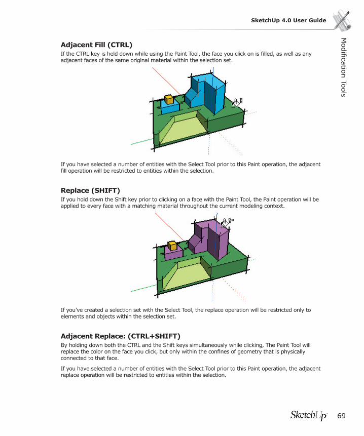
Modifi catio
n To
ols
69
SketchUp 4.0 User Guide
Adjacent Fill (CTRL)If the CTRL key is held down while using the Paint Tool, the face you click on is fi lled, as well as any adjacent faces of the same original material within the selection set.
If you have selected a number of entities with the Select Tool prior to this Paint operation, the adjacent fi ll operation will be restricted to entities within the selection.
Replace (SHIFT)If you hold down the Shift key prior to clicking on a face with the Paint Tool, the Paint operation will be applied to every face with a matching material throughout the current modeling context.
If you’ve created a selection set with the Select Tool, the replace operation will be restricted only to elements and objects within the selection set.
Adjacent Replace: (CTRL+SHIFT)By holding down both the CTRL and the Shift keys simultaneously while clicking, The Paint Tool will replace the color on the face you click, but only within the confi nes of geometry that is physically connected to that face.
If you have selected a number of entities with the Select Tool prior to this Paint operation, the adjacent replace operation will be restricted to entities within the selection.
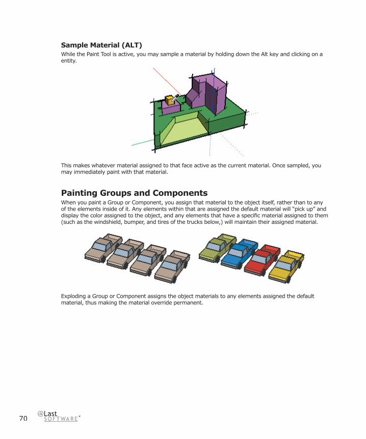
70
Sample Material (ALT)While the Paint Tool is active, you may sample a material by holding down the Alt key and clicking on a entity.
This makes whatever material assigned to that face active as the current material. Once sampled, you may immediately paint with that material.
Painting Groups and ComponentsWhen you paint a Group or Component, you assign that material to the object itself, rather than to any of the elements inside of it. Any elements within that are assigned the default material will “pick up” and display the color assigned to the object, and any elements that have a specifi c material assigned to them (such as the windshield, bumper, and tires of the trucks below,) will maintain their assigned material.
Exploding a Group or Component assigns the object materials to any elements assigned the default material, thus making the material override permanent.
Modifi catio
n To
ols
71
SketchUp 4.0 User Guide
Move ToolThe Move Tool allows you to move, stretch and copy geometry. It can also be used to rotate Components. You can activate it through the Edit Toolbar or the Tools Menu.
Menu Access: ( Tools > Move )
Moving Geometry 1. First, use the Select Tool to specify which elements or objects are to be moved.
2. Activate the Move Tool.
3. Click once to select the start point of the move operation. As you move the mouse, the selected geometry will follow. An inference line will appear between the start and ending points of the move, and the distance of the move is displayed dynamically in the Value Control Box (VCB). You may also type in a specifi c distance as described below.
4. Click on the destination point to fi nish your move operation.
Select and MoveYou may activate the Move Tool when nothing is selected. In this case, the move cursor will auto-select any point, edge, face, or object over which it is placed. However, you can only move one entity at a time using this method. Also, using this method, the selection click point becomes the base point for the move operation.
If you want to move something exactly from one exact point to another, you should fi rst use the Select Tool to specify which elements or objects are to be moved. Then you can use the Move Tool to specify both an exact start and end point.
Inference Locking During MoveBefore or during a Move Tool operation, you can lock an inference by holding down the Shift key. This keeps the inference from being ‘distracted’ by other geometry in your model.
Moving Groups and Components Moving a Component only moves that particular instance of it. The Component’s defi nition does change unless you in-place edit it directly.
If an object is “glued” to a face, it will stay in the plane of that face when moved unless it is fi rst “unglued”. Copies of a glued object will be glued to the originating plane as well.
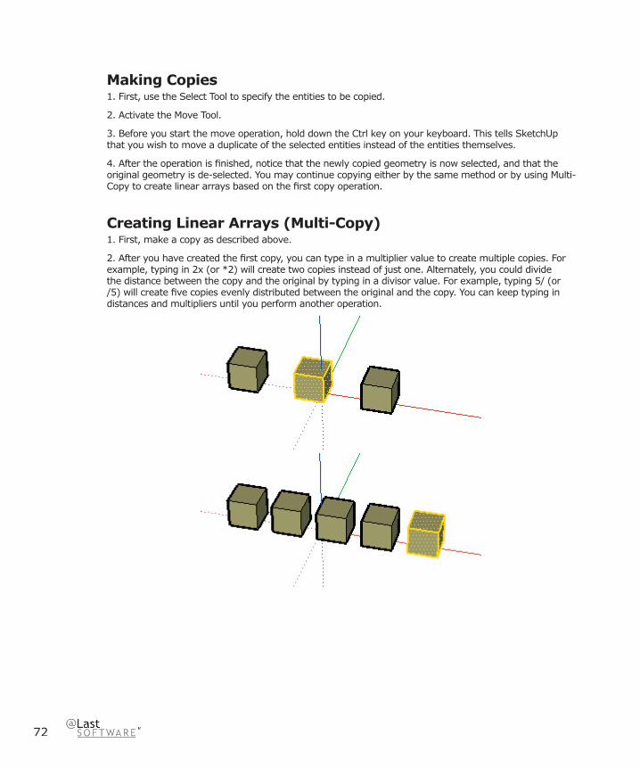
72
Making Copies1. First, use the Select Tool to specify the entities to be copied.
2. Activate the Move Tool.
3. Before you start the move operation, hold down the Ctrl key on your keyboard. This tells SketchUp that you wish to move a duplicate of the selected entities instead of the entities themselves.
4. After the operation is fi nished, notice that the newly copied geometry is now selected, and that the original geometry is de-selected. You may continue copying either by the same method or by using Multi-Copy to create linear arrays based on the fi rst copy operation.
Creating Linear Arrays (Multi-Copy) 1. First, make a copy as described above.
2. After you have created the fi rst copy, you can type in a multiplier value to create multiple copies. For example, typing in 2x (or *2) will create two copies instead of just one. Alternately, you could divide the distance between the copy and the original by typing in a divisor value. For example, typing 5/ (or /5) will create fi ve copies evenly distributed between the original and the copy. You can keep typing in distances and multipliers until you perform another operation.

Modifi catio
n To
ols
73
SketchUp 4.0 User Guide
Stretching GeometryWhen you move an element that is interconnected with others, SketchUp will stretch geometry as necessary. You can move points, edges, and faces in this manner. For example, the face shown below can be moved back in the negative red direction or up in the positive blue direction:
You can also move single line segments to stretch an object. In the next example, a line is selected and moved up in the blue direction to form a gable roof.
Moving/Stretching With Auto-FoldIf a move or stretch operation will create non-planar faces, SketchUp will Auto-fold those faces automatically. You can force Auto-folding behaviour at any time by holding down the ALT key.
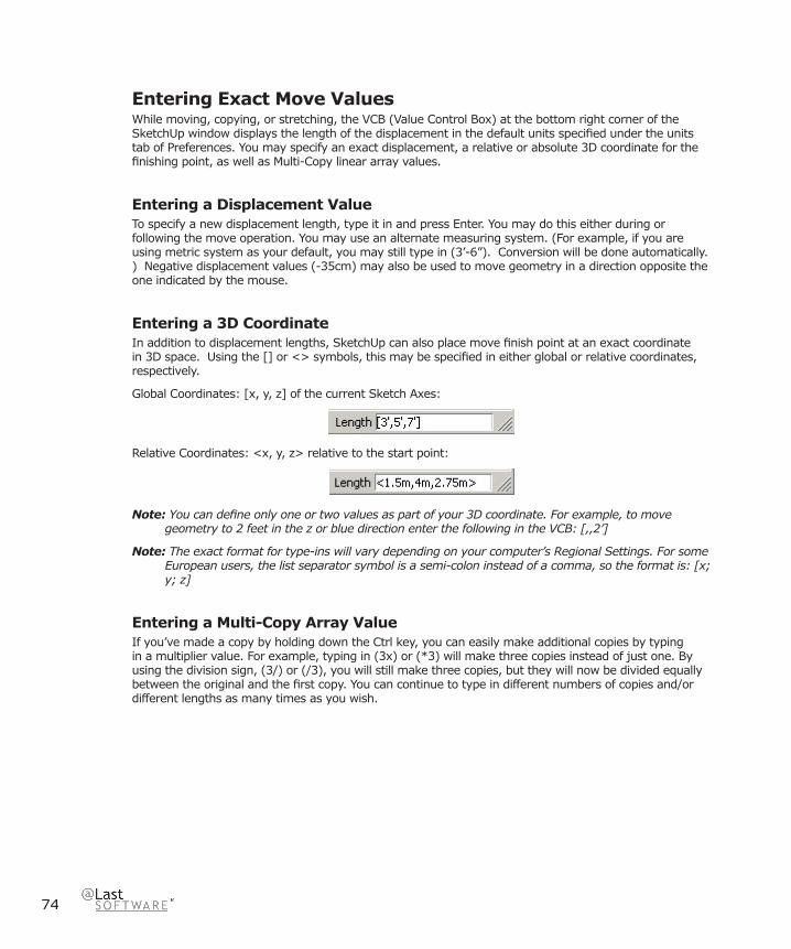
74
Entering Exact Move ValuesWhile moving, copying, or stretching, the VCB (Value Control Box) at the bottom right corner of the SketchUp window displays the length of the displacement in the default units specifi ed under the units tab of Preferences. You may specify an exact displacement, a relative or absolute 3D coordinate for the fi nishing point, as well as Multi-Copy linear array values.
Entering a Displacement ValueTo specify a new displacement length, type it in and press Enter. You may do this either during or following the move operation. You may use an alternate measuring system. (For example, if you are using metric system as your default, you may still type in (3’-6”). Conversion will be done automatically.) Negative displacement values (-35cm) may also be used to move geometry in a direction opposite the one indicated by the mouse.
Entering a 3D CoordinateIn addition to displacement lengths, SketchUp can also place move fi nish point at an exact coordinate in 3D space. Using the [] or <> symbols, this may be specifi ed in either global or relative coordinates, respectively.
Global Coordinates: [x, y, z] of the current Sketch Axes:
Relative Coordinates: <x, y, z> relative to the start point:
Note: You can defi ne only one or two values as part of your 3D coordinate. For example, to move geometry to 2 feet in the z or blue direction enter the following in the VCB: [,,2’]
Note: The exact format for type-ins will vary depending on your computer’s Regional Settings. For some European users, the list separator symbol is a semi-colon instead of a comma, so the format is: [x; y; z]
Entering a Multi-Copy Array ValueIf you’ve made a copy by holding down the Ctrl key, you can easily make additional copies by typing in a multiplier value. For example, typing in (3x) or (*3) will make three copies instead of just one. By using the division sign, (3/) or (/3), you will still make three copies, but they will now be divided equally between the original and the fi rst copy. You can continue to type in different numbers of copies and/or different lengths as many times as you wish.
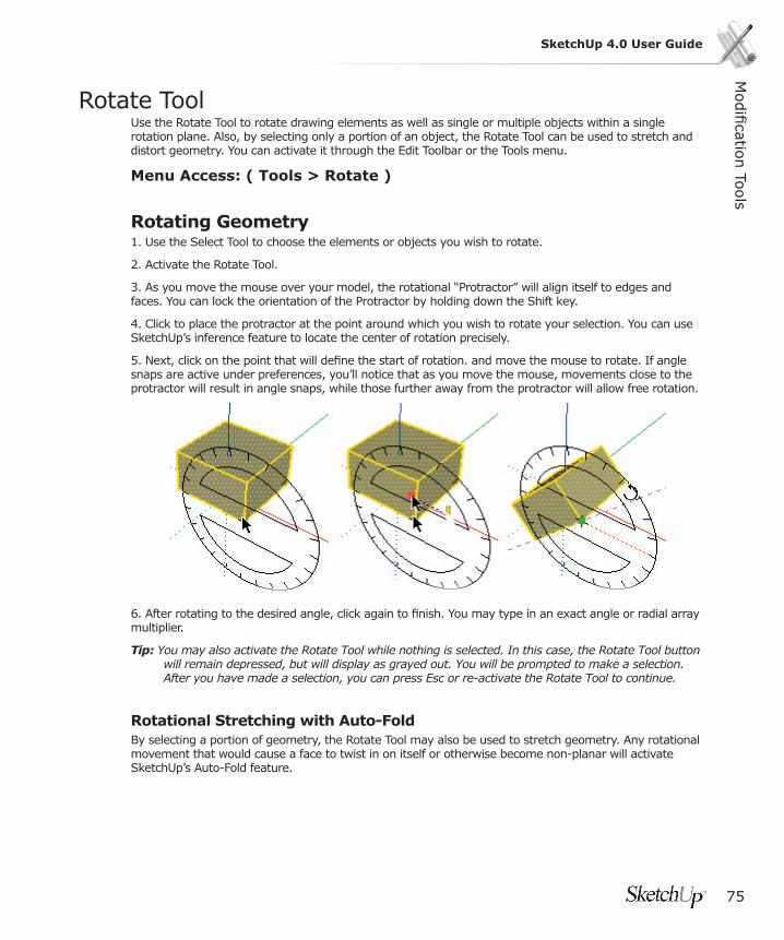
Modifi catio
n To
ols
75
SketchUp 4.0 User Guide
Rotate Tool Use the Rotate Tool to rotate drawing elements as well as single or multiple objects within a single rotation plane. Also, by selecting only a portion of an object, the Rotate Tool can be used to stretch and distort geometry. You can activate it through the Edit Toolbar or the Tools menu.
Menu Access: ( Tools > Rotate )
Rotating Geometry1. Use the Select Tool to choose the elements or objects you wish to rotate.
2. Activate the Rotate Tool.
3. As you move the mouse over your model, the rotational “Protractor” will align itself to edges and faces. You can lock the orientation of the Protractor by holding down the Shift key.
4. Click to place the protractor at the point around which you wish to rotate your selection. You can use SketchUp’s inference feature to locate the center of rotation precisely.
5. Next, click on the point that will defi ne the start of rotation. and move the mouse to rotate. If angle snaps are active under preferences, you’ll notice that as you move the mouse, movements close to the protractor will result in angle snaps, while those further away from the protractor will allow free rotation.
6. After rotating to the desired angle, click again to fi nish. You may type in an exact angle or radial array multiplier.
Tip: You may also activate the Rotate Tool while nothing is selected. In this case, the Rotate Tool button will remain depressed, but will display as grayed out. You will be prompted to make a selection. After you have made a selection, you can press Esc or re-activate the Rotate Tool to continue.
Rotational Stretching with Auto-FoldBy selecting a portion of geometry, the Rotate Tool may also be used to stretch geometry. Any rotational movement that would cause a face to twist in on itself or otherwise become non-planar will activate SketchUp’s Auto-Fold feature.

76
Copying Objects Using Rotate Just as with the Move Tool, holding down the Ctrl key before initiating a rotation operation will tell SketchUp to rotate a copy of your selection instead of the original.
Creating Radial Arrays with Multi-Copy After making a copy with the Rotate Tool, you can also use Multi-Copy to create a polar array. Just as you would for a Linear Array, type in either a multiplier or a divisor into the VCB. For example, typing in “5x” following a rotation will create 5 copies instead of one.
By using the division sign, “5/”, you will still make three copies, but they will now be divided equally between the original and the fi rst copy along the arc of rotation. You can continue to type in different numbers of copies and/or different angular displacements as many times as you wish.
Modifi catio
n To
ols
77
SketchUp 4.0 User Guide
Entering Exact Rotation ValuesWhile you are performing a rotation operation, degree of rotation you have indicated appears in the VCB (Value Control Box) at the bottom right corner of the SketchUp window. To specify an angle, simply type it in during or after completing the rotation operation.
Entering an Angular Rotation ValueTo specify a new angle in degrees, type it in. You may specify a negative angle which rotates your geometry in a direction opposite the one indicated.
Entering a Multi-Copy Radial Array ValueIf you’ve made a copy by holding down the Ctrl key, you can easily make additional copies by typing in a multiplier value.

78
Scale ToolThe Scale Tool allows you to resize and stretch selected geometry relative to other elements in your SketchUp model.
The Scale Tool is activated from the Edit Toolbar or the Tools Menu.
Menu Access: ( Tools > Scale )
Scaling Geometry 1. Using the Select Tool, select the elements to be scaled.
2. Activate the Scale Tool.
3. Click on the scaling grips and move the mouse to adjust the relative size of the selected geometry. As described below, different grips provide different operations. Note that the drag will snap to whole scale factors, (1.0, 2.0, etc.) as well as .5 increments. (0.5, 1.5, etc.)
4. The VCB (Value Control Box) display defaults to showing a scale factor. You may enter the desired scale value(s) or dimension(s) after the scale operation is complete. See below for details.
Scaling Auto-Folding GeometrySketchUp’s Auto-fold feature works automatically with all Scale operations. SketchUp will create folding lines as necessary to maintain planar faces.
Scaling a 2D Surface or Image ObjectTwo-dimensional surfaces and Image Objects can be scaled just as easily as three-dimensional geometry. When scaling a face, the Scale Tool’s bounding box contains only nine grips. These operate in a similar manner to the grips in a 3D bounding box, and also work with the Ctrl and Shift modifi ers.
When scaling a single 2D surface that lies in the red-green plane, the bounding box will be a 2D rectangle instead. If the surface to be scaled is out of plane with the current red-green plane, the bounding box will be a 3D volume. You can ensure a 2D scale by aligning the Drawing Axes to a surface prior to scaling.
Scaling Components and GroupsScaling Components and Groups works differently than scaling regular geometry.
Scaling a Component externally does not change its underlying defi nition, but rather scales the individual instance. All other instances of the Component will retain their individual scales. This allows you to have many differently scaled versions of the same Component in your model. If you are working inside the Component’s context, scale operations will effect the Component defi nition, and therefore all instances of the Component will be scaled to match.
Scaling Groups scales them directly, as there are no instances to keep track of.
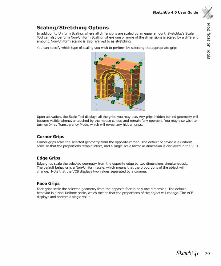
Modifi catio
n To
ols
79
SketchUp 4.0 User Guide
Scaling/Stretching Options In addition to Uniform Scaling, where all dimensions are scaled by an equal amount, SketchUp’s Scale Tool can also perform Non-Uniform Scaling, where one or more of the dimensions is scaled by a different amount. Non-Uniform scaling is also referred to as stretching.
You can specify which type of scaling you wish to perform by selecting the appropriate grip:
Upon activation, the Scale Tool displays all the grips you may use. Any grips hidden behind geometry will become visible whenever touched by the mouse cursor, and remain fully operable. You may also wish to turn on X-ray Transparency Mode, which will reveal any hidden grips.
Corner GripsCorner grips scale the selected geometry from the opposite corner. The default behavior is a uniform scale so that the proportions remain intact, and a single scale factor or dimension is displayed in the VCB.
Edge GripsEdge grips scale the selected geometry from the opposite edge by two dimensions simultaneously. The default behavior is a Non-Uniform scale, which means that the proportions of the object will change. Note that the VCB displays two values separated by a comma.
Face GripsFace grips scale the selected geometry from the opposite face in only one dimension. The default behavior is a Non-Uniform scale, which means that the proportions of the object will change. The VCB displays and accepts a single value.
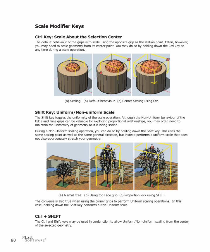
80
Scale Modifi er Keys
Ctrl Key: Scale About the Selection CenterThe default behaviour of the grips is to scale using the opposite grip as the station point. Often, however, you may need to scale geometry from its center point. You may do so by holding down the Ctrl key at any time during a scale operation.
(a) Scaling. (b) Default behaviour. (c) Center Scaling using Ctrl.
Shift Key: Uniform/Non-uniform ScaleThe Shift key toggles the uniformity of the scale operation. Although the Non-Uniform behaviour of the Edge and Face grips can be valuable for exploring proportional relationships, you may often need to maintain the uniformity of geometry as it is being scaled.
During a Non-Uniform scaling operation, you can do so by holding down the Shift key. This uses the same scaling point as well as the same general direction, but instead performs a uniform scale that does not disproportionately stretch your geometry.
(a) A small tree. (b) Using top Face grip. (c) Proportion lock using SHIFT.
The converse is also true when using the corner grips to perform Uniform scaling operations. In this case, holding down the Shift key performs a Non-Uniform scale.
Ctrl + SHIFTThe Ctrl and Shift keys may be used in conjunction to allow Uniform/Non-Uniform scaling from the center of the selected geometry.
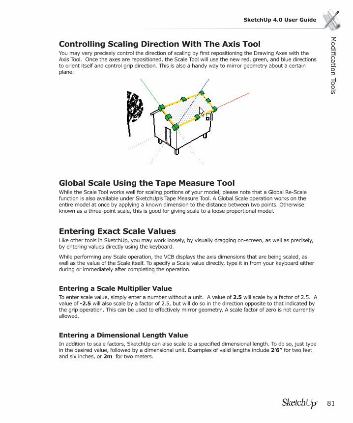
Modifi catio
n To
ols
81
SketchUp 4.0 User Guide
Controlling Scaling Direction With The Axis Tool You may very precisely control the direction of scaling by fi rst repositioning the Drawing Axes with the Axis Tool. Once the axes are repositioned, the Scale Tool will use the new red, green, and blue directions to orient itself and control grip direction. This is also a handy way to mirror geometry about a certain plane.
Global Scale Using the Tape Measure ToolWhile the Scale Tool works well for scaling portions of your model, please note that a Global Re-Scale function is also available under SketchUp’s Tape Measure Tool. A Global Scale operation works on the entire model at once by applying a known dimension to the distance between two points. Otherwise known as a three-point scale, this is good for giving scale to a loose proportional model.
Entering Exact Scale ValuesLike other tools in SketchUp, you may work loosely, by visually dragging on-screen, as well as precisely, by entering values directly using the keyboard.
While performing any Scale operation, the VCB displays the axis dimensions that are being scaled, as well as the value of the Scale itself. To specify a Scale value directly, type it in from your keyboard either during or immediately after completing the operation.
Entering a Scale Multiplier ValueTo enter scale value, simply enter a number without a unit. A value of 2.5 will scale by a factor of 2.5. A value of -2.5 will also scale by a factor of 2.5, but will do so in the direction opposite to that indicated by the grip operation. This can be used to effectively mirror geometry. A scale factor of zero is not currently allowed.
Entering a Dimensional Length ValueIn addition to scale factors, SketchUp can also scale to a specifi ed dimensional length. To do so, just type in the desired value, followed by a dimensional unit. Examples of valid lengths include 2’6” for two feet and six inches, or 2m for two meters.
82
Mirror: Scaling Geometry Inside-Out The Scale Tool may also be used to mirror geometry by pulling a grip towards and then beyond the point about which you are scaling. In effect, this allows you to pull geometry inside out. Note that the grips detent (snap) to certain negative values (-1, -1.5, -2) just as they do in the positive direction. You may force a mirror by typing in a negative value or dimension.
Entering Multiple Scale Values The VCB always indicates the scaling factors associated with a particular operation. A 1D scaling operation requires one value. A 2D scaling operation requires two values, separated by a comma. A Uniform 3D scaling operation requires only one value whereas a Non Uniform 3D scaling operation requires three values, each separated by a comma.
You’ll notice that during the scale operation, a dashed line appears between the scaling point and the grip you’ve selected. Entering a single value or distance in the VCB tells SketchUp adjust the anchor to grip distance to be that scale value or distance, regardless of which mode (1D, 2D, 3D) is active.
When scaling in multiple directions, typing in multiple values separated by commas will resize the object(s) based on the entire bounding box dimension(s), not the objects individually. (To scale objects based on a particular edge or known distance, you can use the Tape Measure Tool.)

Modifi catio
n To
ols
83
SketchUp 4.0 User Guide
Push/Pull ToolThe Push/Pull Tool is used to distort and re-proportion faces of your model. Depending on the nature of geometry you use it on, it will displace, extrude, re-attach, and/or subtract faces. It is valuable both as a massing exploration tool and as a precise construction tool. The Push/Pull Tool may be activated from either the Edit Toolbar or the Tools Menu.
Note: Push/Pull works only on faces, and therefore does not work when SketchUp is set to Wireframe display.
Menu Access: ( Tools > Push/Pull )
Using Push/PullAfter activating the Push/Pull Tool, there are two methods from which you may choose:
a. Press the mouse button on the face, drag it, and release,
or
b. Click on the face, move the mouse, and click again.
Depending on the geometry, SketchUp will perform one of several geometric transformations, including movement, extrusion, or creating a void. Push/pull works with SketchUp’s inference feature, and can snap to any point or line in the model.
Entering Precise Push/Pull ValuesThe displacement of a Push/Pull operation is displayed in the Value Control Box. You can type in a precise value either during the operation or afterwards, and you can keep typing in updated values as often as you like. You may also enter a negative value, which will apply the operation in the direction opposite of the one you indicated.
Using Push/Pull to Extrude a FaceAnother powerful method is extrusion, which creates new geometry for you. Extrusions will happen automatically whenever you to use the Push/Pull Tool on faces that either have no adjoining faces, or are connected to faces that are not perpendicular.

84
Repeating a Push/Pull OperationOnce you have performed a Push/Pull operation, you can have SketchUp automatically apply another Push/Pull of the same amount by double-clicking.
Note: When you create a single face, as demonstrated in the previous screenshot, on the ground plane (the red/green plane), SketchUp assumes you are going to be using that face as the fl oor of a building. The front of the face (green) points down and the back of the face (purple) points up. Therefore, when you pull a single face up (in the blue direction), you are really pulling up from the back of the face and the blue plane temporarily acts as the “below ground” direction. Therefore a double-click, after performing this action, applies the same positive amount or returns the entity to the single face you started with.
Using Push/Pull to Create VoidsIf you draw a shape on a rectilinear box or wall, you can use the Push/Pull Tool to extrude it inwards and to the back face. If the back face is parallel to the one in front, then SketchUp will subtract it and heal the 3D object, thus creating a void.
Note: This operation will only work where the front and back faces are parallel to one another.
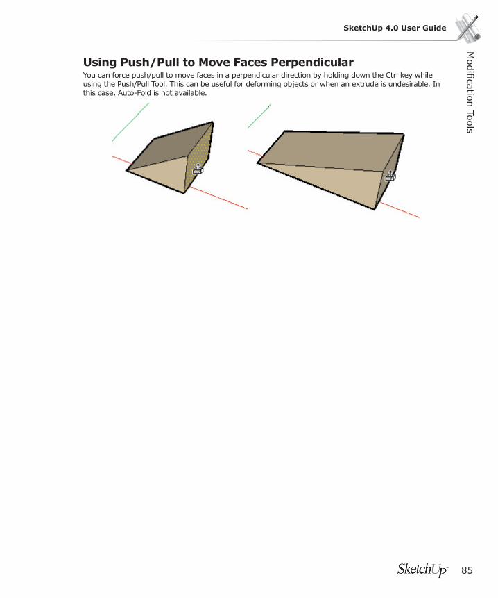
Modifi catio
n To
ols
85
SketchUp 4.0 User Guide
Using Push/Pull to Move Faces PerpendicularYou can force push/pull to move faces in a perpendicular direction by holding down the Ctrl key while using the Push/Pull Tool. This can be useful for deforming objects or when an extrude is undesirable. In this case, Auto-Fold is not available.

86
Follow Me ToolThe Follow Me tool is used to extrude faces along a path such as an edge or line drawn with the freehand pencil. This tool is especially useful when trying to add details to a model by allowing you to draw the detail at one end of a path on the model and essentially tell SketchUp to continue that detail along a particular path in the model. The Follow Me tool is activated from the Tools Menu.
Menu Access: ( Tools > Follow Me )
Note: The path and the face must be in the same context to use the Follow Me tool.
Manually Extruding a Face Along a Path To manually extrude a face along a path using the Follow Me tool:
1. Identify the edge of the geometry you want to modify. This edge will be your “path.”
2. Draw a profi le of the face that you want to follow the path. Make sure that this profi le is approximately perpendicular to the path (fi gure 1).
3. Select the Follow Me tool from the Tools menu and click on the profi le that you created.
4. Move the mouse along the path to modify. SketchUp will line highlight in red the edge along the path you are following as you move your cursor around the model (fi gure 2). It is important to note that you must touch the segment of the path immediately adjacent to the profi le for the Follow Me to start in the correct location. If you select an edge that is not touching the profi le as your starting edge, Follow Me will start extruding at that edge, not from the profi le to that edge.
5. When you reach the end of the path, click again to execute the Follow Me command (fi gure 3).
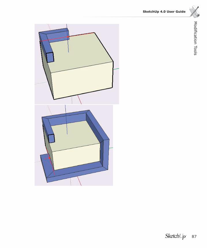
Modifi catio
n To
ols
87
SketchUp 4.0 User Guide

88
Preselecting the Path
You can preselect the path using the select tool to help the follow me tool follow the correct path.
1. Select a continuous set of edges to represent the path.
2. with the edges selected, select the Follow Me tool.
3. Click on the profi le surface. The surface will be extruded continuously along your pre-selected path.
Automatically Extruding a Face Along a Single Surface PathThe simplest and most accurate way to extrude a face along a path is to have the follow me tool automatically select and follow a path. To automatically extrude a face along a path on an single surface using the Follow Me tool:
1. Identify the edge of the geometry you want to modify. This edge will be your “path.”
2. Draw a profi le of the face that you want to follow the path. Make sure that this profi le is perpendicular to the path (fi gure 1).
3. Select the Follow Me tool from the Tools menu and hold down the Alt Key while clicking on the profi le that you created.
4. Move the cursor off the profi le surface onto the surface around which you wish to sweep. The path will automatically be closed for you (fi gure 2).
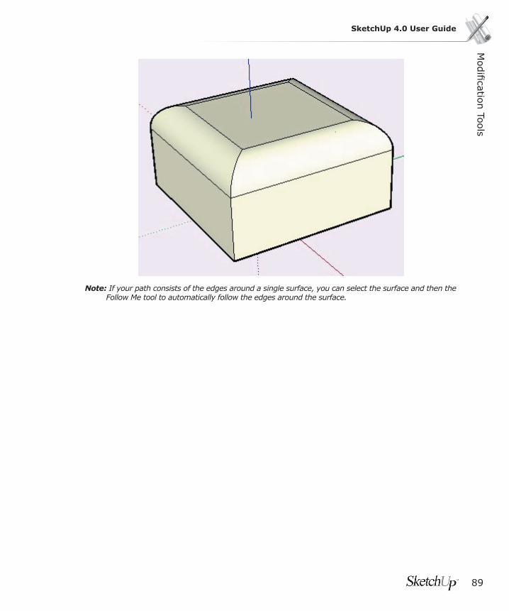
Modifi catio
n To
ols
89
SketchUp 4.0 User Guide
Note: If your path consists of the edges around a single surface, you can select the surface and then the Follow Me tool to automatically follow the edges around the surface.
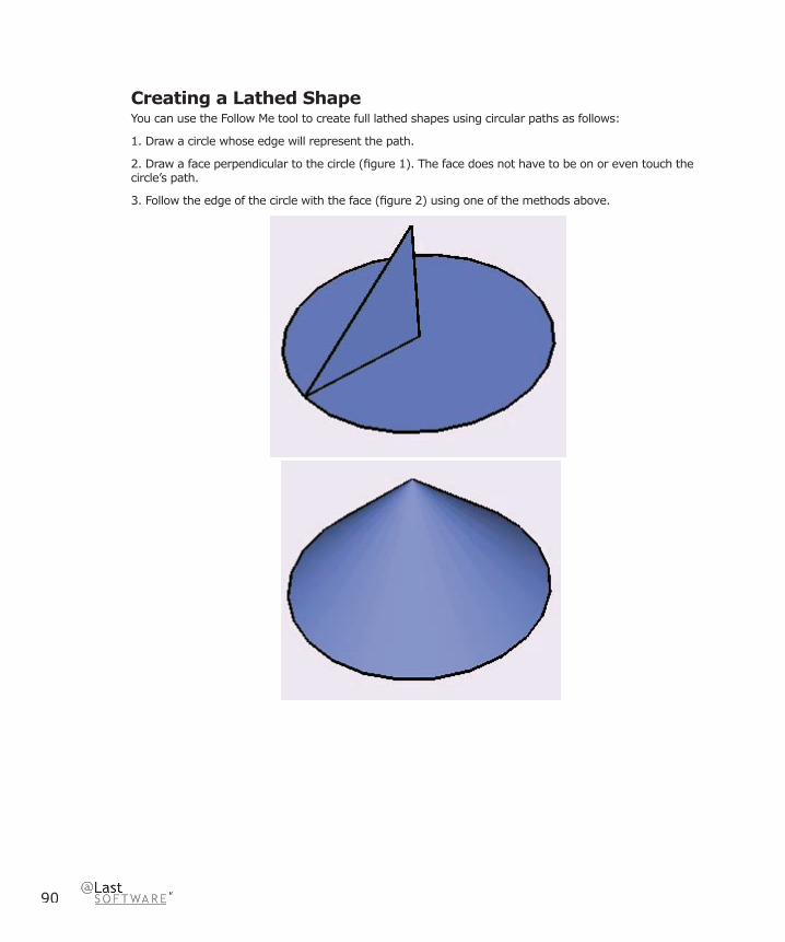
90
Creating a Lathed ShapeYou can use the Follow Me tool to create full lathed shapes using circular paths as follows:
1. Draw a circle whose edge will represent the path.
2. Draw a face perpendicular to the circle (fi gure 1). The face does not have to be on or even touch the circle’s path.
3. Follow the edge of the circle with the face (fi gure 2) using one of the methods above.

Modifi catio
n To
ols
91
SketchUp 4.0 User Guide
Offset ToolThe Offset Tool creates copies of co-planar lines and faces that are a uniform distance from the originals. You can offset edges of faces either inside the original face, or outside of it. Offsetting a face will always create a new face.
The Offset Tool may be activated from the Edit Toolbar or from the Tools Menu.
Menu Access: ( Tools > Offset )
Face Offset1. Use the Select Tool to select the face to offset. (You can only select one face at a time for the Offset Tool.)
2. Activate the Offset tool.
3. Click on one of the edges of your selected face. The cursor will automatically snap to the nearest edge or line segment.
4. Move the mouse cursor and to defi ne the offset dimension. The offset distance is displayed in the Value Control Box.
5. Click to accept the offset and create the offset polygon.
Tip: You may activate the Offset Tool before geometry is selected but you will be switched automatically to the Select tool fi rst. Once geometry is selected, hit the Offset button or the Esc key to return to the Offset command.

92
Line OffsetYou may select a number of simply connected, co-planar lines for offset. To offset lines:
1. Use the Select Tool to select the lines you wish to offset. You must select two or more connected lines, and all your lines must be coplanar. You can use the CTRL and/or Shift keys to change your selection.
2. Activate the Offset Tool.
3. Click on one of your selected line segments. The cursor will automatically snap to the nearest line segment. Move the mouse to defi ne the offset dimension.
4. Click your mouse to accept the offset lines.
Tip: You can click once on the selected line segments, drag to set the offset while holding down the mouse button, and release the button to accept.
Note: When you offset an arc, it will degrade to a curve and you will lose the ability to edit it as an arc..
Entering Precise Offset ValuesWhile you are performing an Offset Tool operation, the VCB (Value Control Box) at the bottom right corner of the SketchUp window displays the length of the offset in the units specifi ed under preferences. You may specify different values simply by typing them in either during or after an offset operation.
Entering an Offset ValueTo specify a new offset length, type in the length. You may also specify a negative length which draws the line in the direction opposite the one indicated.
When you are defi ning the offset dimension with the mouse, the Value Control Box will display the offset dimension in your default units. You may enter the offset dimension in either Metric or English units- SketchUp will automatically convert them for you. Negative values specifi ed in the Value Control Box will offset in the opposite direction.

Modifi catio
n To
ols
93
SketchUp 4.0 User Guide
Tape Measure Tool The Tape Measure Tool performs a number of dimension-related operations. These include measuring the distance between two points, creating Construction Lines, and re-scaling an entire model to an exact dimension.
The Tape Measure Tool is activated from the Drawing Toolbar. It may also be accessed via the Tools Menu.
Menu Access: ( Tools > Tape Measure )
Measuring Distance1. Activate the Tape Measure Tool.
2. Click on the starting point of the distance you wish to measure. Use the inference ToolTip to make sure you click on exact points. You may also press on the starting point of the distance you wish to measure and drag the mouse in the direction of your measurement.
3. A temporary ‘measuring tape’ line will stretch out from your starting point as you move the mouse. The Tape Measure Tool’s measuring tape line functions like an inference line; it will change color to match sketch axes when it is parallel to them. The Value Control Box will dynamically show the length of your ‘measuring tape’ as you move the mouse around your model.
4. Click again to fi x the end point of your measurement. The fi nal distance measured will be displayed in the Value Control Box.
You do not have to measure in any particular plane. The Tape Measure Tool will give you accurate measurements between any two points in your model.
Creating Construction Lines and PointsConstruction Lines are useful for drawing in a very precise manner. You can create them by using the Tape Measure Tool to click and drag from a reference element. Starting from an ‘On Edge’ inference and moving across a face generates a parallel line which is infi nite. starting from an endpoint or midpoint results in a fi nite Construction Line with a point marker at the end.
1. Activate the Tape Measure Tool.
2. Click on a line segment parallel to the Construction Line you wish to create.
3. Move the mouse away from the line segment to the place where you want your Construction Line.
4. Click a second time to create the Construction Line.
94
Scaling the Entire ModelThis feature is handy because it allows you to start working very loosely or visually. At any time, you can give a more precise scale to your design simply by specifying the desired dimension between two points. Unlike CAD, SketchUp affords you the freedom to focus on massing and proportion without worrying about accuracy... until you want it.
To scale a model:
1. Activate the Tape Measure Tool.
2. Click on the two endpoints of the line segment you wish to scale against. This does not create any construction geometry, which would interfere with the scale adjustment. The Value Control Box will display the measured length of the line segment as it currently exists in your model.
3. Using the keyboard, enter in the dimension you would like the measured line segment to be. A dialog box will appear asking you if you are sure you want to resize your entire model. If you confi rm the operation by clicking the ‘Yes’ button, all of the objects in your model will be resized proportionally so that the line segment you measured matched the new dimension you specifi ed.
Globally Scaling Components When you re-scale your model, any Components you placed from outside your drawing will not be affected. These “External” Components have their own scale and geometric constraints independent from your active model. Any Components drawn and defi ned directly in your current model will be scaled, however.
You may globally redefi ne the scale of any Component while you’re editing it in place. This changes the defi nition of the Component, thus changing all instance.
Modifi catio
n To
ols
95
SketchUp 4.0 User Guide
Protractor Tool The Protractor Tool allows you to measure angles and create Construction Lines. It may be activated from the Drawing Toolbar or the Tools Menu.
Menu Access: ( Tools > Protractor )
Measuring an Angle 1. Activate the Protractor Tool. A protractor will appear, (aligned to the red/green plane by default) its center point fi xed to the cursor.
2. As you move the protractor cursor around your model, you will see it shift its orientation as it aligns with nearby axes and geometry. You can lock in a particular orientation by holding down the Shift key when the Protractor is in your desired orientation.
3. Set the center point of the protractor on the vertex point of the angle to be measured. Take advantage of ToolTip to be sure you have the Protractor exactly where you want it.
4. Align the base of the protractor with the fi rst line in the angle to be measured by dragging away from the vertex along the line. Use the ToolTips to ensure that you are setting the line appropriately. Click the mouse a second time to set the angle start.
5. Drag the mouse around the Protractor and snap to a point on the second line segment in the angle you are measuring. A dotted construction line will follow your cursor around the Protractor. Click a third time on the line to set the angle measurement. The angle will be displayed in the Value Control Box (VCB).
Creating Angled Construction Lines 1. Activate the Protractor tool.
2. Snap the blue center point of the protractor to the vertex through which the new line will pass, and click on that point.
3. Align the edge of the protractor with the existing line or edge by next clicking on any point on that line or edge.
3. A new construction line appears coincident with the existing line. Move the cursor to place the construction line. The angle is dynamically displayed in the Value Control Box.
The Protractor has snap points, indicated by evenly spaced tick marks along the circular edge. To use these snaps, keep the cursor close to these marks; the construction line will snap to the tick mark. To create a construction line not on a preset angle, keep the cursor away from the Protractor. (Use the Units tab of the Preferences dialog box to activate and control angle snap.)
4. When the Construction Line is angled appropriately, click the left mouse button. The angle may also be set by entering a value in the Value Control Box, and pressing the hitting Enter. The value may either be in decimal degrees, (i.e. 34.1 ) or slope (i.e. 1:6 ). The entered value may be changed any number of times before proceeding to the next command.
Locking the Rotate ProtractorUse the Shift key to lock the protractor to its current orientation. This can be combined with inference locking.
96
Entering Exact Angle ValuesWhile creating construction geometry using the Protractor Tool, the degree of rotation you have indicated appears in angular degrees in the Value Control Box (VCB) at the bottom right corner of the SketchUp window and may be edited. To specify an angle, simply type it in during or after completing the rotation operation.
Entering an Angular Rotation ValueTo specify a new angle in degrees, type it in. You may specify a negative angle which rotates your geometry in a direction opposite the one indicated by entering in a negative value.
These values can either be angular (decimal degree) measurements, or they may be slope values.
To specify an exact angle in degrees, type a decimal value into the Value Control Box. Negative values will rotate your in the opposite direction from that which you specifi ed with the mouse. For example, typing in 34.1 will give you an exact 34.1 degree angle. You can specify an exact angular value either during or immediately after your rotation operation.
Entering a Slope ValueTo specify a new angle as a slope, type in the two values separated by a colon. (i.e. 8:12 ) You may specify a negative slope which creates Construction Lines in a direction opposite the one indicated by the operation.

Modifi catio
n To
ols
97
SketchUp 4.0 User Guide
Axes ToolThe Axes Tool allows you to move the Drawing Axes around within your model. You may wish to do this when you are constructing rectangular objects that are skewed relative to one another, or you may use this tool to allow for more accurate scaling of objects not oriented along the default coordinate planes.
The Axes Tool may be activated from the Tools Menu.
Menu Access: ( Tools > Axes )
To re-orient the Drawing Axes:1. Activate the Axes Tool. As you move your cursor around your model, a bold set of red/green/blue axes will follow. You will see them snap to inferred alignments and points as you move near them in your model.
2. Move your cursor to a point in your model that you wish to be the new coordinate origin. Use the inference ToolTips to make sure your cursor is located exactly where you want it to be. Click to accept that point.
3. Drag your cursor away from the origin to set an alignment for the red axis. Use the inference ToolTips to make sure you are aligned precisely. Click to accept the alignment.
4. Move your cursor away from the origin to set an alignment for the green axis. Use inference ToolTips again to make sure you are aligned precisely. Click again to accept the alignment.
You have now re-oriented your axes. The blue axis will appear perpendicular to the new red/green plane.
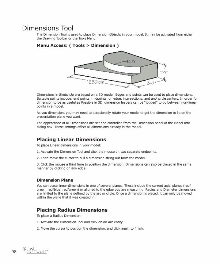
98
Dimensions ToolThe Dimension Tool is used to place Dimension Objects in your model. It may be activated from either the Drawing Toolbar or the Tools Menu.
Menu Access: ( Tools > Dimension )
Dimensions in SketchUp are based on a 3D model. Edges and points can be used to place dimensions. Suitable points include: end points, midpoints, on edge, intersections, and arc/ circle centers. In order for dimension to be as useful as Possible in 3D, dimension leaders can be “jogged” to go between non-linear points in a model.
As you dimension, you may need to occasionally rotate your model to get the dimension to lie on the presentation plane you want.
The appearance of all Dimensions are set and controlled from the Dimension panel of the Model Info dialog box. These settings affect all dimensions already in the model.
Placing Linear DimensionsTo place Linear dimensions in your model:
1. Activate the Dimension Tool and click the mouse on two separate endpoints.
2. Then move the cursor to pull a dimension string out form the model.
3. Click the mouse a third time to position the dimension. Dimensions can also be placed in the same manner by clicking on any edge.
Dimension PlaneYou can place linear dimensions in one of several planes. These include the current axial planes (red/green, red/blue, red/green) or aligned to the edge you are measuring. Radius and Diameter dimensions are limited to the plane defi ned by the arc or circle. Once a dimension is placed, it can only be moved within the plane that it was created in.
Placing Radius DimensionsTo place a Radius Dimension:
1. Activate the Dimension Tool and click on an Arc entity.
2. Move the cursor to position the dimension, and click again to fi nish.

Modifi catio
n To
ols
99
SketchUp 4.0 User Guide
Placing Diameter DimensionsTo place a Diameter Dimension:
1. Activate the Dimension Tool and click on a Circle entity.
2. Move the cursor to position the dimension, and click again to fi nish.
Diameters to Radius, Radius to DiameterTo change a Radius dimension to a diameter dimension or vice-versa, right click on the dimension and choose Type – Radius or Diameter.

100
Text ToolThe Text Tool is used to insert Text Objects into your model. It may be activated from either the Drawing Toolbar or the Draw Menu.
Menu Access: ( Draw > Text )
In SketchUp, there are two main kinds of text: Leader Text and Screen Text.
Placing Leader TextTo place a Leader Text Object:
1. Activate the Text Tool and click on an entity (surfaces, edges, vertexes, Components, Groups, etc) to indicate where the leader should point.
2. Next, click to position the text.
3. Finally, a text entry box will appear with default text, such as the name of an component if you are anchored to a component, or the square footage of a square when you are anchored to a square. Click inside the entry box to modify this text. Click outside the text box to complete the modifi cation, or tap the Enter key twice. Hitting Escape at any time will cancel creation of the Text entity.
Attached Leader TextText can also be placed directly on SketchUp entities without a leader line by double clicking the fi rst point with the Text Tool. The leader will be hidden automatically.
Text LeadersThere are two main styles of leaders: View Based and Pushpin. A View Based leader will always retain its 2D screen orientation. A Pushpin leader is aligned in 3D space, and rotate with your model as you change your view. You can specify which type of leader is used from the Text panel of the Model Info dialog box.
Placing Screen TextTo place Screen Text:
1. Activate the Text Tool and click the cursor on a blank area of the screen.
2. After the text entry box appears just type in the note text.
3. To fi nish, click outside the text box or tap the Enter key twice. Screen text will stay fi xed on the screen regardless of how you manipulate and orbit the model.
Editing TextText can be edited at any time by double clicking on it with the Text Tool or Select Tool active. You can also right -click on a text entity and select ‘Edit Text’ form the context menu.

Modifi catio
n To
ols
101
SketchUp 4.0 User Guide
Text SettingsAny new Text Objects you create with the Text Tool will be created using the settings found in the Text panel of the Model Info dialog box. These include type of leader, end point, and font. Any currently selected text
entities can be changed to the current active style settings by using the ‘Apply to Selected Text’ button.
102
Section Plane ToolThe Section Plane Tool is used to create SketchUp section cutting effects. Their position in space and in relation to Groups and Components determine the nature of the section cut effect. You can paint Section Planes, which controls the color of the section slice lines, or create a group from the slice lines, which is useful for modeling operations.
Menu Access: ( Tools > Section Plane )
Adding Section Planes1. To add a Section Plane to your scene, use the Create Menu ( Tools > Section Plane ) or the “Add Section Plane” button on the Section Planes Toolbar.
2. A new Section Plane will be attached to your cursor. As you move the cursor over geometry, the section plane will align to each surface. At this time, you may hold down the Shift key to lock the plane to a particular orientation. Releasing the Shift key returns the plane to its previous behaviour.
3. Once the plane is in the desired position, click the mouse button to place it.
Re-Positioning Section PlanesSection Planes may be manipulated and repositioned like other entities in SketchUp by using the Move and Rotate tools.
Reverse Cutting DirectionThe direction of a Section Plane can be reversed by right clicking on it and selecting Reverse from context menu.
Changing The Active SectionWhen you place a new Section Plane, it automatically becomes active. You can have numerous Sections in your scene, but only one may be active at any one time. Activating a Section Plane will automatically de-activate all other planes.
There are two ways to activate a Section Plane: You may either use the Select Tool to double click on it, or right click on it and select Activate from the context menu.
Hiding SectionsThe Section Planes Toolbar contains controls for globally hiding both Section Planes and the section cutting effects from view. This can be particularly handy while you are actively modeling or to dynamically present an idea. You may also use the Camera Menu (Camera > Section Cut and Camera > Section Planes).
Sections within Groups and ComponentsAlthough you can have only one Section Plane active at a time, this applies only per editing context. Since Groups and Components act somewhat like “models within models,” they can each contain an active Section Plane within their own context, as well. For example, a model that has a Group that in turn contains two other groups has four different editing contexts, and therefore can have four active sections

Modifi catio
n To
ols
103
SketchUp 4.0 User Guide
at once. The section cut effect applies to geometry within that context and everything within it.
By double clicking on a Group or Component with the Select Tool, you can enter the context of objects within your model.
Creating Grouped Section Slices1. Right click on a Section Plane, then select Create Group from Slice from the context menu.
2. This will generate new edges, encapsulated within a Group, wherever the Section Plane intersects with faces.
This Group may be moved off to the side as a section outline, or it may be immediately exploded, making the edges merge with the geometry from which they were generated. This technique allows you to quickly make “hot wire” slices through any complex shape.
Exporting SectionsSections may be exported from SketchUp in several ways:
2D GraphicOne method for exporting Section views from your model is to export it as a raster image fi le. Since Section Planes are an active part of the model view, any raster image export will include Section effects.
Section Slice...SketchUp can also save the active section slice as a 2D vector fi le in one of the supported formats. (DWG and DXF) As with other vector outputs from SketchUp, 2D Vector Sections can be accurately scaled and measured.
Using Sections with PagesAs with Rendering and camera position information, the active Section Plane may be saved to a page. Also, as you change pages, this setting will animate the section slice effect in real-time using SketchUp’s TourGuide technology.
Align ViewUsing the Align View command from the Section Plane Context menu, you can re-orient the model view to a view perpendicular to the Section Plane. Combined with Paraline Mode, you can use this command to quickly generate sectional elevation or 1-point perspective views of your model.
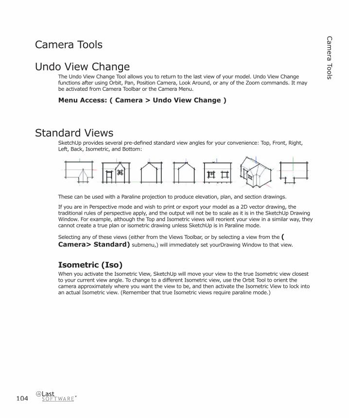
104
Cam
era Tools
Camera Tools
Undo View ChangeThe Undo View Change Tool allows you to return to the last view of your model. Undo View Change functions after using Orbit, Pan, Position Camera, Look Around, or any of the Zoom commands. It may be activated from Camera Toolbar or the Camera Menu.
Menu Access: ( Camera > Undo View Change )
Standard ViewsSketchUp provides several pre-defi ned standard view angles for your convenience: Top, Front, Right, Left, Back, Isometric, and Bottom:
These can be used with a Paraline projection to produce elevation, plan, and section drawings.
If you are in Perspective mode and wish to print or export your model as a 2D vector drawing, the traditional rules of perspective apply, and the output will not be to scale as it is in the SketchUp Drawing Window. For example, although the Top and Isometric views will reorient your view in a similar way, they cannot create a true plan or isometric drawing unless SketchUp is in Paraline mode.
Selecting any of these views (either from the Views Toolbar, or by selecting a view from the ( Camera> Standard) submenu,) will immediately set yourDrawing Window to that view.
Isometric (Iso)When you activate the Isometric View, SketchUp will move your view to the true Isometric view closest to your current view angle. To change to a different Isometric view, use the Orbit Tool to orient the camera approximately where you want the view to be, and then activate the Isometric View to lock into an actual Isometric view. (Remember that true Isometric views require paraline mode.)
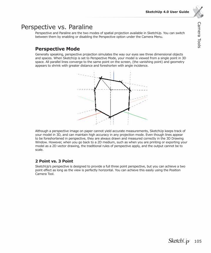
Cam
era Tools
105
SketchUp 4.0 User Guide
Perspective vs. ParalinePerspective and Paraline are the two modes of spatial projection available in SketchUp. You can switch between them by enabling or disabling the Perspective option under the Camera Menu.
Perspective ModeGenerally speaking, perspective projection simulates the way our eyes see three dimensional objects and spaces. When SketchUp is set to Perspective Mode, your model is viewed from a single point in 3D space. All parallel lines converge to the same point on the screen, (the vanishing point) and geometry appears to shrink with greater distance and foreshorten with angle incidence.
Although a perspective image on paper cannot yield accurate measurements, SketchUp keeps track of your model in 3D, and can maintain high accuracy in any projection mode. Even though lines appear to be foreshortened in perspective, they are always drawn and measured correctly in the 3D Drawing Window. However, when you go back to a 2D medium, such as when you are printing or exporting your model as a 2D vector drawing, the traditional rules of perspective apply, and the output cannot be to scale.
2 Point vs. 3 PointSketchUp’s perspective is designed to provide a full three point perspective, but you can achieve a two point effect as long as the view is perfectly horizontal. You can achieve this easily using the Position Camera Tool.

106
Paraline ModeParaline mode corresponds to an axonometric projection (not an axonometric drawing, which is sometimes referred to as an oblique) in which the casting rays are projected perpendicular to the viewing plane. In Paraline mode, all parallel lines appear parallel on the screen.
In order to print to scale, SketchUp must be in paraline mode. Be aware that only faces that are parallel to the view plane will be measurable.

Cam
era Tools
107
SketchUp 4.0 User Guide
Orbit ToolThe Orbit Tool rotates the camera about the model. This is most useful when viewing an object from the outside (especially for objects like chairs, or exterior massing models of buildings).
The Orbit Tool may be activated from either the Camera Toolbar or the Camera Menu.
Menu Access: ( Camera > Orbit )
Orbiting the ViewFirst, activate Orbit Tool. Then press the mouse button and drag in the document window. It does not matter where in the window you press the mouse button, as the Orbit Tool automatically rotates around an appropriate point in your model.
By double-clicking with the Orbit Tool, you can center your view. This can also help any subsequent orbits to rotate more correctly.
The Orbit Tool works to constantly adapt itself to your model as it changes. If it is not working in an intuitive way, try starting the press and drag operation over the geometry you are interested in orbiting around. This provides useful hints to SketchUp.
ShortcutsYou may fi nd that the Orbit Tool is very heavily used as you create and edit your models. We’ve provided several shortcuts to make orbiting more effi cient.
Middle ButtonIf you have a three-button mouse (or a mouse with a wheel that also works as a middle mouse button), pressing the middle mouse button temporarily activates the Orbit Tool while in any other tool. (Except for walk below) This alone can dramatically increase your effi ciency.
PanHolding down the Shift key while in the Orbit Tool activates the Pan Tool temporarily. You can do this while using the Orbit Tool directly or while using the middle button shortcut.
Tip: You will also be put in Pan temporarily if you click on the middle-mouse wheel and then click and hold the left mouse button.
RollNormally, the Orbit Tool has a sense of gravity. This feature helps keep vertical edges pointed up and down. Holding down the Ctrl key during orbit suspends this gravity setting allows the camera to roll on its side.
PagesYou can reduce the need to orbit by using pages to quickly restore often used views.
108
Pan ToolThe Pan Tool moves the camera vertically and horizontally along the picture plane. The Pan Tool may be activated from either the Camera Toolbar or the Camera Menu.
Menu Access: ( Camera > Pan )
Panning the ViewTo use the Pan Tool, activate it, then press and drag in the document window.
Tip: If you have a three-button or scroll mouse, you can activate the Pan Tool temporarily while using any other tool by holding down the Shift key and clicking your middle mouse button/scroll wheel. Or, if you are currently orbiting by clicking the middle mouse button, you can also activate the Pan Tool temporarily by left clicking on the mouse.
Zoom ToolThe Zoom Tool allows you to interactively zoom in and out of your current view, moving back and forth in a sense. It may be activated from either the Camera Toolbar or the Camera Menu.
Menu Access: ( Camera > Zoom )
Using Zoom1. Activate the Zoom Tool.
2. Press anywhere on the Drawing Screen and drag the mouse up and down. Moving the mouse cursor up zooms in bringing you forward and closer to the model; moving the mouse cursor down zooms out, moving you backwards and away.
The Zoom Tool works to constantly adapt itself to your model as it changes. If it is not working in an intuitive way, try starting the press and drag operation over the geometry you are interested in zooming from. This provides useful hints to SketchUp.
Using the WheelIf you have a mouse equipped with a scroll wheel, you can use the wheel at any time and while using any tool to zoom in and out. Rolling the wheel forward zooms in, and rolling backwards zooms out. Your current mouse location determines the point towards which or away from which you will be zooming.
Centering the ViewAnother shortcut that can enhance the use of the Zoom Tool is double click. This quickly centers the view onto the point you wish to zoom to, eliminating the need for panning in some instances.
Cam
era Tools
109
SketchUp 4.0 User Guide
Perspective Adjustment (Field of View)While the Zoom Tool is active, you can adjust the screen to an exact perspective or camera lens by typing in an exact value. You can also specify which system to use. For example, “45 deg” sets a 45 degree Field of View and “35 mm” sets the equivalent focal length of a 35mm camera. You can also visually adjust the camera lens or Field of View by holding down the Shift key while using the Zoom Tool. Note that changing the FOV keeps the camera in the same location in 3D space. see also Field of View under the Camera Menu.
Zoom Window ToolThe Zoom Window Tool allows you to select a rectangular region to enlarge to fi ll your window. It may be activated from either the Camera Toolbar or the Camera Menu.
Menu Access: ( Camera > Zoom Window )
Using Zoom Window1. Activate the Zoom Window Tool.
2. Press and drag a window with your mouse. When you release the mouse button, your selection will be zoomed to fi ll the window.
Zoom Extents ToolThe Zoom Extents Tool zooms your view to a distance which makes the whole model visible, and centers it in the drawing window. It may be activated from either the Camera Toolbar or the Camera Menu.
Menu Access: ( Camera > Zoom Extents )
110
Position Camera ToolDuring the design process, you may often need to quickly check the visibility of mechanical equipment on roofs, check sight lines of other building elements, or otherwise establish what a view from a certain location will look like.
This is traditionally done with simple models, as precise perspective construction is tedious and does not lend itself to the speculative nature of early design investigation. While loose perspectives DO lend themselves to tentative design exploration, loosely sketched perspectives do not offer the exactness necessary for visibility and occlusion determination.
Using SketchUp, you can solve this paradoxical problem nicely, as precise, measured perspective drawing becomes very inexpensive and therefore accessible during any stage of design. SketchUp’s Position Camera capability allows you to:
• Determine what you CAN see from an exact point
• Determine what you CANNOT see from an exact point
• Place the view point at a specifi c eye height
• Make better perspective compositions in less time
Using the Position Camera ToolTo start, select Position Camera from the Camera Menu ( Camera > Position Camera ) .
Notice that the Value Control Box (VCB) at the lower right corner of your SketchUp screen indicates that the eye height above the ground plane is set to 5 feet, 6 inches. You can override this height at this time by typing in a desired value.
The Position Camera Tool can be used in two different ways. If you only need general view positioning that approximates an eye-level view, use the Single Click method. For more precise camera positioning, use the Click and Drag method.
Single ClickSingle click uses the existing viewing direction and simply places your camera viewpoint at an average eye-height over the point you click on.
If you place the camera from a plan view, the viewing direction defaults to the top of screen, which is due north by default.
Click and DragThis method lets you specify position and target points exactly. Simply press on the point you want your eye or station point to be with the mouse button, drag the mouse cursor, and release on the point you wish to look at.
Tip: You can use the Tape Measure Tool and the VCB to drag parallel construction lines off of edges. This is a great way to provide accurate camera placements.
After the camera travels to the new viewpoint, the Turn Camera Tool becomes engaged, allowing you to look around from that point. You may type in a different eye height once the camera is in position.

Cam
era Tools
111
SketchUp 4.0 User Guide
Walk ToolThe Walk Tool allows you to maneuver through your SketchUp model as if you were walking. Specifi cally, the Walk Tool fi xes the point of view to a particular height, and then allows you to “steer” it around your model. The Walk Tool is available only when Perspective is enabled.
The Walk Tool may be activated from either the Camera Toolbar or the Camera Menu.
Menu Access: ( Camera > Walk )
Using the Walk Tool1. Activate the Walk Tool and press the mouse button anywhere in the Drawing Window. Notice you have placed a small cross hair. This acts as a cursor reference point.
2. Keeping the mouse button pressed, move your mouse up to go forward, down to go backward and left or right to move left or right. The further you are from the cursor reference point, the faster you will go.
Holding down the Shift key while moving allows you to move up or down instead of forward or backward.
Holding down the Ctrl key makes you move faster. This “run” feature is especially useful for navigating through large models.
Once the Walk Tool has been activated, you may also navigate using the Arrow Keys on your keyboard:
Using a Wider Field of View (FOV)Walking around in your model is usually much more satisfying with a wider fi eld of view. To change your fi eld of view, activate the Zoom Tool, hold down the Shift key, and press and drag up and down to zoom in or out.
Look Around ShortcutWhile using the Walk Tool, you can quickly turn your viewpoint by holding down the middle mouse button. This places you temporarily in the Look Around Tool.
112
Look Around ToolThe Look Around Tool pivots the camera around a stationary point at the point of view. This is like standing still while turning your head to look around. you can look up and down as well as side to side. In fi lm camera terms, these are referred to as ‘tilt’ and ‘pan’ respectively. The Look Around tool is particularly useful for viewing the inside of spaces, or to evaluate visibility after using the Position Camera Tool.
The Look Around Tool may be activated from either the Camera Toolbar or the Camera Menu.
Menu Access: ( Camera > Look Around
Looking AroundFirst, activate the Look Around Tool. Then press the mouse button and drag it around in the document window. It does not matter where in the window you press the mouse button.
Specifying an Eye HeightWhile in the Look Around Tool, you can specify exact eye height above the ground plane by typing a height into the Value Control Box followed by the Enter key.
Using Look Around with Walk ToolUsually, the middle mouse activates the Orbit Tool, but if you are in the Walk Tool, this activates the Look Around Tool instead.
Align ViewThe Align View command precisely orients the SketchUp view to be perpendicular with elements in your drawing.
AxesSelecting Align View from the Drawing Axes context menu will align the SketchUp Camera with the perpendicular plane to the axis selected.
SectionSelecting Align View from the Section Plane context menu will align the SketchUp Camera with the selected Section plane. This is useful for generating 1-point sectional perspective drawings.
FaceSelecting Align View from the Face context menu will align the SketchUp Camera with the selected face. This can be used to generate measurable drawings of non-orthographic faces.
113
SketchUp 4.0 User GuideM
odel S
ettings an
d M
anag
ers
Model Settings and Managers
Model Info Dialog BoxThe Model Info dialog box allows you to set a number of different settings specifi c to your current SketchUp document. It’s accessible under the Window Menu: ( Window > Model Info)
ColorsThe Colors pane allows you to set default colors for several elements in SketchUp’s model view. Clicking on any of the color wells will activate the Color Picker.
GeometryEdges: This sets the default color for edges in SketchUp. You can force SketchUp to use this color for all edges (instead of a color you may have assigned manually) by setting ‘Edge Color’ to ‘All the Same’ in the Display Settings dialog box.
Face Front: This sets the default color for the front face of faces. When you assign a material to the front of a face, that color will be used instead.
Face Back: This sets the default color for the back face of faces. When you assign a material to the back of a face, that material will be used instead.
Highlight: This sets the color of the highlight that is used to indicate selection. It is best to use a color that will contrast well with the other colors in your scene.
Construction Lines: This sets the color of any Construction Lines you may have created.
BackgroundBackground: This sets the background color of SketchUp’s Drawing Window.
Solid Color: This allows you to use a solid color for the entire background.
Gradient: This allows you to select separate gradients for both sky and ground. SketchUp will show the sky color as a gradient from the horizon up. SketchUp will show the ground color as a gradient from the horizon down. The ground color can be set from the color well.
Transparency Slider: The transparency slider allows you to adjust the level of transparency for the ground plane, allowing you to see geometry below the ground plane.
Show Ground from Below: This checkbox enables the display of the ground plane from viewpoints below the horizon.
114
ComponentsThe Components pane allows you to modify the visual appearance of your model during the Component and Group editing process.
Fade Similar ComponentsUsing these controls, you can modify the appearance of the other visible instances of the component you are editing. Using the radio buttons, you can choose to either “Fade” or “Hide” the rest of your model. If you choose to “Fade”, you can control the degree of fading with the slider adjacent slider.
While editing a Component, SketchUp can either fade back or hide other similar Components and the rest of the model to make it easier to concentrate on modifi cations to the open Component.
Fade Rest of ModelUsing these controls, you can modify the appearance of the parts of your model unrelated to the group or component you are editing. Using the radio buttons, you can choose to either “Fade” or “Hide” the rest of your model. If you choose to “Fade”, you can control the degree of fading with the slider adjacent slider.
Show Component AxesThis checkbox controls the visibility of Component axes.
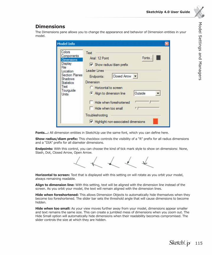
Model S
ettings an
d M
anag
ers
115
SketchUp 4.0 User Guide
DimensionsThe Dimensions pane allows you to change the appearance and behavior of Dimension entities in your model.
Fonts...: All dimension entities in SketchUp use the same font, which you can defi ne here.
Show radius/diam prefi x: This checkbox controls the visibility of a “R” prefi x for all radius dimensions and a “DIA” prefi x for all diameter dimensions.
Endpoints: With this control, you can choose the kind of tick mark style to show on dimensions: None, Slash, Dot, Closed Arrow, Open Arrow.
Horizontal to screen: Text that is displayed with this setting on will rotate as you orbit your model, always remaining readable.
Align to dimension line: With this setting, text will be aligned with the dimension line instead of the screen. As you orbit your model, the text will remain aligned with the dimension lines.
Hide when foreshortened: This allows Dimension Objects to automatically hide themselves when they become too foreshortened. The slider bar sets the threshold angle that will cause dimensions to become hidden.
Hide when too small: As your view moves further away from your model, dimensions appear smaller and text remains the same size. This can create a jumbled mess of dimensions when you zoom out. The Hide Small option will automatically hide dimensions when their readability becomes compromised. The slider controls the size at which they are hidden.
116
Highlight non-associated dimensions: Dimensions that have lost their direct link to geometry or that have had their text edited may not show accurate measurements. This option will highlight these dimensions In the color you specify.
Display
Face DisplayUse sun for shading: When enabled, SketchUp will shade the faces of your model based on the position of the sun. When unenabled, SketchUp uses standard shading that follows the camera.
Wireframe: This option displays the model in Wireframe Mode, as a collection of simple lines. There are no faces displayed.
Hidden Line: This displays the model in Hidden Line Mode, where faces in the model and hides lines and edges and are rendered in the background color.
Monochrome: This option displays the model with default shading (no colors or texture).
Shaded: Shaded Mode displays any materials you have applied to faces, and applies a tonal value to faces based on the light source. Remember that both sides of faces can have different colors.
Textured: In Textured mode, texture images that have been applied to a faces will be displayed. Textures can slow down SketchUp’s performance in some cases, so you may need to disable them temporarily.
TransparencyX-Ray mode: Displays all faces in SketchUp with a global transparency, allowing you to see through the model and edit edges behind faces.
Enable transparency: When enabled, this renders materials with their transparency settings. The drop down menu controls the order used to draw transparent faces, which may help you achieve better results for animations or still images.
Quality: There are 3 settings for the quality of transparency display; Faster, Medium, and Nicer. Each one is optimized to trade off speed vs. accuracy of transparency sorting. To produce a “Nicer” display, more calculations are necessary to correctly sort transparent surfaces. Still, some models may produce “popping” artifacts, where a surface appears to jump in front of another. “Faster” display sacrifi ces sorting accuracy to provide a faster rendering update rate.
Edges DisplayAll Same: The All Same checkbox causes all edges to display in the Foreground Color as defi ned in the Colors pane of the Model Info dialog box. It does not actually change any edge color assignments you may have made, preserving them if you choose to view them again.
By Material: When this option is selected, edges display in the material color they’ve been assigned.
By Axis: When By Axis is enabled, the color of an edge corresponds to the color of the axis to which it is parallel.

Model S
ettings an
d M
anag
ers
117
SketchUp 4.0 User Guide
Edge StyleProfi les: The Show Profi les option draws lines that are in profi le with a thicker line weight. This can make drawings “read” much better. You can control the thickness of Profi les by setting higher or lower numbers in the associated text box.
Extension: This enables Extension Lines, where edges are drawn so as to extend slightly past their intersections. You can control the length of Extensions by setting a dimension in the associated text box.
Jitter: Jitter Lines applies a dynamic sketched look to lines in the drawing.
FileThe File pane contain settings related to your SketchUp document, including its location in your fi le system (if it has been saved), the fi le’s size, version of SketchUp last used to edit it, and the date of last modifi cation.
The File pane also gives you access to a text description fi eld, where you can save notes about the fi le.
LocationThe Location pane allows you to specify a location for your model based on the nearest major city. To specify a location, fi rst choose a country from the Country pop-up list, and then a city from the City pop-up list. If you don’t see exactly the city you want listed, pick the nearest one you can. SketchUp’s shadow rendering engine is mathematically precise, but in most cases choosing a ‘close’ location will give you the results you need.
You may also specify a precise location clicking the ‘Custom Location...’ Button and providing longitude and latitude coordinates.
You can also set an angular direction for north in you model from this pane. By default, North is aligned with the ‘positive’ (solid) green axis. To change the north angle, you can either set a new angle in the text box, or you can set it dynamically in the model view by clicking the ‘Select’ button.
When you do so, SketchUp will display a north arrow in the model view for you to locate. Click once to set the origin of the north angle, and then click a second time to set the angle. You can move the north arrow around in your model to allow for precise orientation.
Checking the ‘Show in model’ checkbox will cause SketchUp to display an indication of north as a yellow line drawn out from the model origin.
Section PlanesThe Section Planes pane allows you to change the appearance and behavior of Section Plane entities in your model.
LinesCut Line Width: This value defi nes the thickness (in pixels) of all cut lines in the active Section Plane.
ColorsSection Cut Line: This color well is used to defi ne the color to be used in displaying the slice lines for the active section plane.
118
Active Section Plane: This color well is used to defi ne the color of the active Section Plane.
Inactive Section Plane: This color well is used to defi ne the color of all inactive Section Planes in your model.
Shadows
Display ShadowsThis checkbox enables and disables SketchUp’s shadow casting functionality, turning all shadows on and off.
On Faces: The Faces checkbox enables the casting of Face shadows. This feature makes intensive use of your 3D graphics hardware, and can cause performance degradation.
On Ground: The Ground checkbox enables the casting of shadows on the ground plane (the red/green plane).
From Edges: The From Edges checkbox enables the casting of shadows from standalone edges.
Time: The Time slider adjusts the time of day that is used by SketchUp to model shadow casting. The slider adjusts the time from sunrise to sunset, with 12:00 noon in the middle of the slider. To set the time precisely, you can type a time into the associated text fi eld.
Date: The Date slider adjusts the day of the year that is used by SketchUp to model shadow casting. The slider adjusts the date from January 1st to December 31st. You can also set the date precisely by typing it into the associated text fi eld. You can specify the date in numerical form (11/8) or you can type in more general dates, like “next monday” or “day after tomorrow.”
Light: The Light slider controls the intensity of the diffuse light in the model view. This effectively lightens and darkens illuminated surfaces.
Dark: The Dark slider controls the amount of ambient lighting in the model view. This effectively lightens and darkens the areas under shade and shadows.
StatisticsThe Statistics pane displays information about the type and number of drawing elements in your model. This is occasionally useful for troubleshooting performance issues.
Selecting ‘Entire model’ from the pop-up menu will show statistics for your entire model. Checking the ‘Show nested components’ checkbox will count individual elements within placed components as well.
Selecting ‘Only components’ from the pop-up menu will give you a tally of all placed Components - which may be useful for generating quick window/door schedules.
Clicking the Purge Unused button will remove any unused components, materials, image objects, layers, and other extraneous information from your fi le.
Clicking the Check Validity button will cause SketchUp to scan your model, report any invalid geometry, and attempt to fi x any problems.
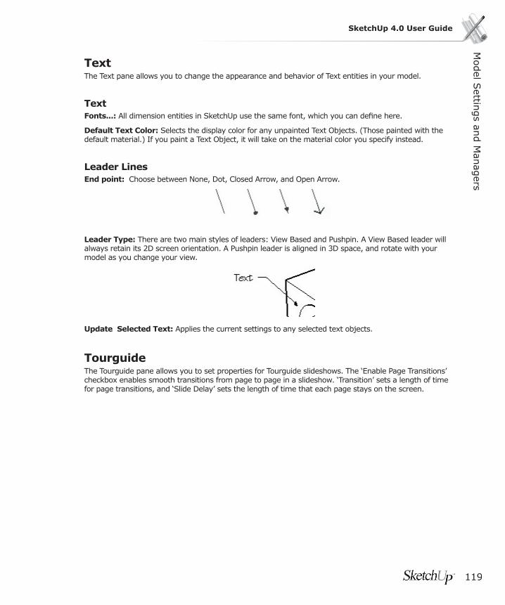
Model S
ettings an
d M
anag
ers
119
SketchUp 4.0 User Guide
TextThe Text pane allows you to change the appearance and behavior of Text entities in your model.
TextFonts...: All dimension entities in SketchUp use the same font, which you can defi ne here.
Default Text Color: Selects the display color for any unpainted Text Objects. (Those painted with the default material.) If you paint a Text Object, it will take on the material color you specify instead.
Leader LinesEnd point: Choose between None, Dot, Closed Arrow, and Open Arrow.
Leader Type: There are two main styles of leaders: View Based and Pushpin. A View Based leader will always retain its 2D screen orientation. A Pushpin leader is aligned in 3D space, and rotate with your model as you change your view.
Update Selected Text: Applies the current settings to any selected text objects.
TourguideThe Tourguide pane allows you to set properties for Tourguide slideshows. The ‘Enable Page Transitions’ checkbox enables smooth transitions from page to page in a slideshow. ‘Transition’ sets a length of time for page transitions, and ‘Slide Delay’ sets the length of time that each page stays on the screen.

120
UnitsThe Units Preferences allow you to set defaults for linear and angular unit measurements.
Length UnitsSketchUp is capable of working in a number of different units simultaneously, but with the Units Preferences, you can choose the units your document will use by default.
Format: Controls the display of entities and measurements in the VCB (Value Control Box). Architectural displays as feet and inches. Decimal displays decimal units, including inches, feet, millimeters, centimeters, and meters. Engineering displays feet and decimal units of feet, and Fractional displays in fractions of units.
Precision: Architectural Units use units in increments of feet and inches, with an adjustable level of precision from 1” to 1/64”.
Decimal Units can be set to inches, feet, millimeters, centimeters or meters. Precision can be set in numbers of decimal places beyond zero for any of these units. SketchUp users working in Metric will want to use this unit setting.
Engineering Units use units in decimal increments of feet. Precision for Engineering Units can be set in decimal places beyond zero.
Enable length snapping: By checking the ‘Enable length snapping’ checkbox, you tell SketchUp to snap to the specifi ed length while you are drawing. SketchUp does not have a “grid snap” function like you may be used to in other CAD applications. Length snaps can be overridden by entering exact values into the VCB, or by using any of SketchUp’s intervening functions. To set a Snap Length, type it into the text fi eld in whatever units appropriate.
Display units format: With this checkbox checked, SketchUp will suppress the display of units.
Force Display of 0”: With this checkbox checked, SketchUp will display 0” in architectural units when there are no inches in the measurement. Ordinarily, inches would be suppressed in this case. For example, a measurement of three feet in length would read as 3’0” with this setting enabled.
Angle UnitsPrecision: SketchUp uses decimal degree units, with a level of precision of either ‘0’ (no decimal places) or ‘0.0’ (one decimal place).
Enable angle snapping: By checking the ‘Enable angle snapping’ checkbox, you tell SketchUp to enable snapping to the specifi ed increment while in the Protractor and Rotate tools. To snap to the specifi ed increment while using these tools, move your cursor inside the Protractor. You will see tick marks corresponding to your snap angle on the Protractor.
Snap Angle: With this pop-up menu, you can choose the snap increment for angular measurements and rotations.
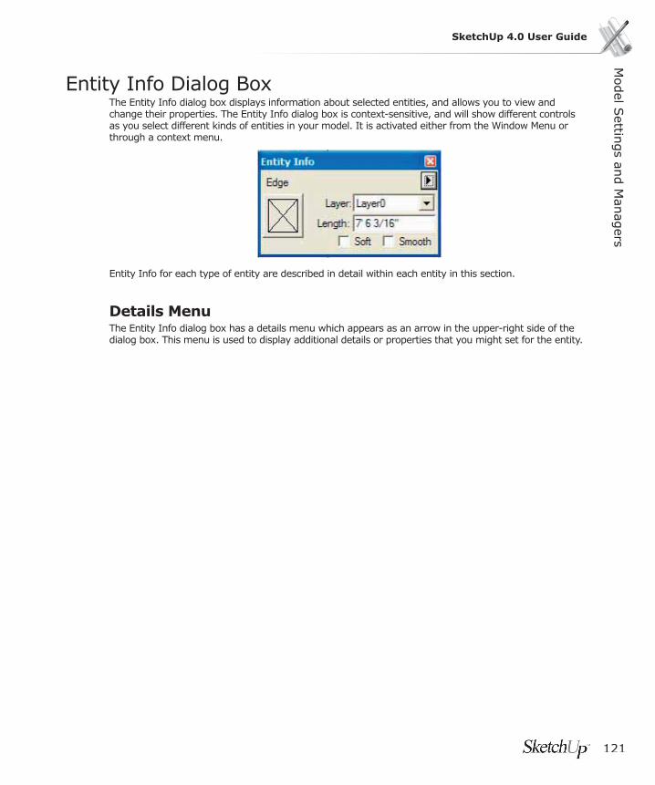
Model S
ettings an
d M
anag
ers
121
SketchUp 4.0 User Guide
Entity Info Dialog BoxThe Entity Info dialog box displays information about selected entities, and allows you to view and change their properties. The Entity Info dialog box is context-sensitive, and will show different controls as you select different kinds of entities in your model. It is activated either from the Window Menu or through a context menu.
Entity Info for each type of entity are described in detail within each entity in this section.
Details MenuThe Entity Info dialog box has a details menu which appears as an arrow in the upper-right side of the dialog box. This menu is used to display additional details or properties that you might set for the entity.

122
Material BrowserThe Material Browser lets you select materials, organize them into libraries, and view materials in your scene in a manner similar to a traditional materials
You may call up the Materials Browser by activating the Paint Bucket Tool or from the Window Menu.
Menu Access: ( Window > Material Browser )
Materials Palette Options
Active MaterialDisplays the material that the Paint Tool will use. Clicking on this preview will automatically activate the Paint Tool.
Sample MaterialWill ‘acquire’ a material from your scene and make it active. (This does not select the pixel color.)
Default MaterialSets the active material as the default or null material. Read more about it here.
Library TabDisplays materials stored in .skm, or SketchUp material library fi les. To change your library, select another one from the drop-down list. To open new library, click on the ‘fi le open’ button.

Model S
ettings an
d M
anag
ers
123
SketchUp 4.0 User Guide
ArrowsThe left and right arrows move you forward and back, in a manner similar to a web browser.
In Model TabDisplays materials defi ned in your scene. Materials that are assigned to entities in your model are displayed with a triangle.
Choosing A Material From The PaletteTo select a material for painting, click on it. The active material is indicated in the preview tile to the upper left and the Paint Tool is automatically activated.
By right clicking on a material swatch in the ‘Library’ Tab, you can create a new one based on it, delete it from the library, or add it to the materials stored in your model. Right clicking on a material swatch in the Model Tab, you can get a material area take off, delete a material, (only available if it isn’t being used by elements or objects) edit that material interactively, add a copy of that material to your library, or update it in the library if there is a similarly named copy there that is different.
Matching MaterialsTo sample and apply more of a material which already appears on your model:
1. Click the Sample Material button in the upper right corner of the palette.
2. Move the ‘eye dropper’ sample cursor over the material you want and click on it. That material will appear in the active color tile.
3. You may now paint that material to your scene.
Purging Unused MaterialsIn SketchUp, any materials you add to your model are stored within the SKP fi le. A material with only color information is very small, but materials with textures can get fairly large, depending on the fi e size of your texture. Try to keep texture resolution as small as needed and no bigger, and when appropriate, using compressed formats such as JPEG or PNG to keep the fi le size down. You can also purge unused materials via the Materials Palette.
To purge unused materials:
1. Select the “In Model” tab of the Materials Palette. This displays all materials defi ned in your scene. Materials that are actually being used have a small triangle in the bottom right corner.
2. Right click on the material you want to purge and select Purge Unused.

124
Editing MaterialsTo adjust any materials you have assigned:
1. Select the “In Model” tab of the Materials Palette. This displays all materials defi ned in your scene. Materials that are actually being used have a small triangle in the bottom right corner.
2. Select the material you wish to edit.
3. Right click on the material and select the Edit menu item. This brings up the Material Editor. Any changes you make are refl ected throughout your scene. You can also double click a material to edit it.
Area Take OffTo get an area readout indicating the usage of a particular material in your scene:
1. Select the “In Model” tab of the Materials Palette. This displays all materials defi ned in your scene. Materials that are actually being used have a small triangle in the bottom right corner.
2. Right click on the material you wish to calculate and select ‘Area’. This displays the area used by that material. The area will be displayed in the units set under Preferences.
Selecting All Entities With a Specifi c MaterialTo select all entities with a specifi c material:
1. Select the “In Model” tab of the Materials Palette. This displays all materials defi ned in your scene. Materials that are actually being used have a small triangle in the bottom right corner.
2. Right click on the material you wish to select and select ‘Select’. This selects all of the entities that have the identifi ed material. This is useful if you want to apply a new material to all items containing a specifi c material.
Adding Materials to LibraryTo add a material to the current library:
1. Select the “In Model” tab of the Materials Palette. This displays all materials defi ned in your scene. Materials that are actually being used have a small triangle in the bottom right corner.
2. Right click on the material you wish to add and select ‘Add to Library’. This adds the material to the currently loaded Library in the Library tab.
Updating Library CopySketchup allows you to easily modify materials in the library and update the library copy with the the modifi ed materials. To update a material in the library:
1. Select the “In Model” tab of the Materials Palette. This displays all materials defi ned in your scene. Materials that are actually being used have a small triangle in the bottom right corner.
2. Double click on any material that is currently in the library. Right click on the material and select the Edit menu item. This brings up the Material Editor. Any changes you make are refl ected throughout your scene. You can also double click a material to edit it.
3. Modify the material and click Close.
4. Right click on the on the material you just edited and select ‘Update Library Copy.’
Model S
ettings an
d M
anag
ers
125
SketchUp 4.0 User Guide
Details MenuPlease note that the details menu for “Library” and “In Model” tabs have different items. All of the items found in both menus are described below.
Display Sizes (Small Images, Medium Images, and Large Images)The square color tiles can be set to different sizes to suit your needs. To adjust them, click on the Details menu and select Small, Medium, or Large. Selecting ‘Library Default’ sets it to the size the library was saved as.
Library DefaultUses the saved Display Size as the Display size for displaying the square color tiles. If you haven’t saved your library, the Library Default uses the last display size you set.
Insert MaterialTo insert add the currently active material to a library, click on the Details menu and select ‘Add to Library.’
Purge UnusedAllows you to purge unused materials from your “in use” pallet. Objects painted with the removed material revert to the default material and the selected material will be purged from the model.
Clear Library...To clear all materials out of a library, click on the Details menu and select ‘Clear Library....’
Open Library...To open a library on the fi le system, click on the Details menu and select ‘Open Library...’
MergeLibrary...To merge in all materials from another library, click on the Details menu and select ‘Merge Library...’
Sort by NameSketchup sorts colors in a library by hue. To sort colors in a library by name, click on the Details menu and select ‘Sort by Name...’
Saving Libraries (Save and Save As...)The ‘Save’ and ‘Save As’ menu items allow you to update and save out any changes made to your library. The ‘Save as Library’ menu item allows you to create a new library from the materials currently in the “In Model” tab.

126
Detaching/Docking the Materials PaletteThe Materials Palette may be ‘detached’ from its position in your SketchUp window and either repositioned as a free-fl oating window or re-attached in another position. You may fi nd that reattaching it away from the other Drawing Tools is more effi cient. Also, docking the palette may improve performance as your SketchUp window doesn’t have to draw ‘behind’ it like it does when it’s free-fl oating. If you press the Ctrl key while moving the palette over the SketchUp window it will remain detached instead of trying to dock.
Material EditorThe Material Editor lets you quickly create and/or edit the properties of individual materials. It may be accessed by pressing the ‘Create’ or ‘Edit’ buttons in the Materials Palette, or selecting Window > Materials Editor.
Material Editor Options
Material NameDisplays the name of the material currently being edited or created.

Model S
ettings an
d M
anag
ers
127
SketchUp 4.0 User Guide
Sample MaterialSamples a material from the model. If you are sampling while editing, you will now be editing what you have just sampled. If you are sampling while creating, you are creating based on what you just sampled.
Preview SwatchDisplays a preview of the material. If a texture image is used, a color band is displayed around it. Like in the Materials Palette, clicking on this swatch activates the Paint Tool.
Color SystemAllows you to select between the RGB, (Red-Green-Blue) HSL, (Hue-Saturation-Lightness) HSB, and Wheel Color models. RGB is the color model traditionally used in computers and CRT’s as it is loosely based on the physiology of the human eye. HSL, HSB, and the color wheel provide a more intuitive model for developing color relationships.
Previous ColorRestores the material color to the one used in the beginning of the edit session.
Sample ColorSamples a “materials” color from the screen, setting the color value of the material to that color.
Color From Material Library PaletteA palette within the editor that brings up another version of the Materials Palette. This changes only the color of the active material to that which you select.
Use Texture ImageThe use texture checkbox is used to set and clear using a texture in the material. Checking the box specifi es that you would like a texture, and it will automatically bring up an fi le open dialog for you to choose a texture image. Un-checking the box specifi es that you no longer want to use a texture and erases your texture setting. Note that re-checking the use texture checkbox will not restore a previous image setting, but instead will prompt you to select a new image.
Texture FileAllows you to specify the texture fi le. You can drag image fi les into the box, or you can click on the fi le open icon to the right.
Reset (Texture) ColorResets the color of the texture to the original fi le colors.
ColorizeWhen checked, this will lock all colors throughout the image to the same hue. This is handy for fi les that exhibit “color noise” effects.

128
DimensionsAllows you to specify the dimensions of the texture fi le as it appears in your SketchUp model. This does not affect the image fi le itself. The vertical and horizontal arrows to the left reset the dimensions to their pre-edit state.
Lock Aspect RatioLocks to the current aspect ratio so that any height or width changes are refl ected in the other dimension. The horizontal and vertical arrows are a button that allows you to reset to the previous width/height settings.
Transparency ControlsThe slider and the numerical input box allow adjustment of the amount of transparency.
AddThis button will add the material currently in the editor to your scene.
EditThis button sets the editor to edit materials interactively. This is only available when are in the create mode and you have just selected a material that is already in the model.
Matching Colors If you would like to apply a material which already appears on your model:
1. Click the Material Sample button in the editor.
2. Move the “eye dropper” sample cursor over the material you want and click on it. That material will appear as the active material and may be painted onto other elements.
Bringing in an Image File as a Texture MaterialTo specify an image fi le to use as a texture material:
1. Click the open button to the right of the image fi le text box. This brings up a fi le open dialog box with which you may select a fi le.
2. Alternatively, you can type in the name of the fi le you wish to use directly.
3. Another method is to drag the fi le from you desktop or fi le manager directly into the Material Editor.
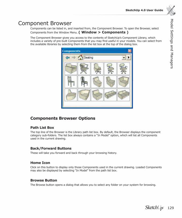
Model S
ettings an
d M
anag
ers
129
SketchUp 4.0 User Guide
Component BrowserComponents can be listed in, and inserted from, the Component Browser. To open the Browser, select Components from the Window Menu. ( Window > Components )
The Component Browser gives you access to the contents of SketchUp’s Component Library, which includes a variety of pre-built Components that you may fi nd useful in your models. You can select from the available libraries by selecting them from the list box at the top of the dialog box.
Components Browser Options
Path List Box The top line of the Browser is the Library path list box. By default, the Browser displays the component category sub-folders. The list box always contains a “In Model” option, which will list all Components used in the current drawing.
Back/Forward ButtonsThese will take you forward and back through your browsing history.
Home IconClick on this button to display only those Components used in the current drawing. Loaded Components may also be displayed by selecting “In Model” from the path list box.
Browse ButtonThe Browse button opens a dialog that allows you to select any folder on your system for browsing.
130
Inserting a ComponentTo insert a Component from the browser, click on its name and then click in the Drawing Window. Components can also be loaded into a drawing by dragging and dropping .SKP fi les into your drawing window or by using the ( File > Insert > Component ) menu command.
Detaching/Docking the Component BrowserThe Browser can be docked to either side of the Drawing Window. To undock the Browser, click on the Maximize button at the top right corner, or drag it by the move handles. You can re-size the Browser easily by dragging its sides. By holding down the Ctrl key while moving it, you can prevent it from re-docking.
Component Browser Context CommandsA number of useful commands are accessible via context menu. The context menu will display only commands relating to the current state of the Browser and where you click. To open the context menu, right click on a Component icon or name in the Component Browser.
PropertiesDisplays the Properties Dialog for that Component.
PurgePurge removes a specifi c Component from the current fi le. This is available only for Components that are no longer used in the drawing.
ReloadReload loads a Component again from it’s original source. If you have modifi ed the external defi nition, use this command to update the instance in the Drawing.
Save As...The Save As... command will save the selected Component to a separate SketchUp document, with a new name and/or location in your fi le system. If the Component is only defi ned locally, you can use this command to export it for use in other SketchUp documents.
Reset Insertion PointRecovers any changes made to a Component defi nitions insertion point.
Details MenuClick on the right arrow next to the pop-up list at the top of the panel to open the details pop-up menu. This menu allows you perform additional components-related functions.

Model S
ettings an
d M
anag
ers
131
SketchUp 4.0 User Guide
Icon ViewClick on Icon View to display components in the Component Browser as icons.
List ViewClick on the List View to display the components in the Component Browser by name and dimension.
Show NestedDisplays components nested within other components.
Purge UnusedRemoves all Components from the Loaded Components that are no longer used in the drawing.
Add FolderClick on Add Folder to add a new folder containing components to the pop-up list of component categories in the Component Browser.
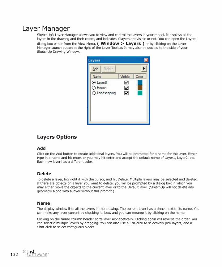
132
Layer ManagerSketchUp’s Layer Manager allows you to view and control the layers in your model. It displays all the layers in the drawing and their colors, and indicates if layers are visible or not. You can open the Layers dialog box either from the View Menu, ( Window > Layers ) or by clicking on the Layer Manager launch button at the right of the Layer Toolbar. It may also be docked to the side of your SketchUp Drawing Window.
Layers Options
AddClick on the Add button to create additional layers. You will be prompted for a name for the layer. Either type in a name and hit enter, or you may hit enter and accept the default name of Layer1, Layer2, etc. Each new layer has a different color.
DeleteTo delete a layer, highlight it with the cursor, and hit Delete. Multiple layers may be selected and deleted. If there are objects on a layer you want to delete, you will be prompted by a dialog box in which you may either move the objects to the current layer or to the Default layer. (SketchUp will not delete any geometry along with a layer without this prompt.)
Name The display window lists all the layers in the drawing. The current layer has a check next to its name. You can make any layer current by checking its box, and you can rename it by clicking on the name.
Clicking on the Name column header sorts layer alphabetically. Clicking again will reverse the order. You can select a multiple layers by dragging. You can also use a Ctrl-click to selectively pick layers, and a Shift-click to select contiguous blocks.

Model S
ettings an
d M
anag
ers
133
SketchUp 4.0 User Guide
VisibleToggle the visibility of a layer by clicking on the Visible icon. When the icon is grayed out, the layer is hidden. Clicking on the Visible header will sort layers by visibility. Clicking again will reverse the order. If you make a hidden layer current, it will become visible automatically.
ColorThe color column displays the color of each layer. You can change the color of a layer by clicking on it and selecting a new color. Clicking on the Color header sorts layers by color. Clicking again will reverse the order.
Details Menu
PurgeThis command deletes all unused layers.
Color by LayerWhen Color by Layer is checked, the layer’s color is used to render all geometry on that layer.

134
Pages Dialog BoxThe dialogs listed here control various features of Pages. This dialog is launched whenever you create new pages or edit the properties of existing pages.
At the top of the Pages dialog boxis a list of all the Pages set up in the active document. Pages in this list are displayed in the order in which they will be displayed when running a Slideshow.
Page Dialog Options
AddThis adds a new page to the active document based on the current settings.
UpdateIf you have made changes to a Page that you wish to keep as a permanent part of the Page view, you need to Update the Page. To do so, activate the page you wish to update, make the changes you want, and then click on the Update button. This button will display a small dialog box with items that will be updated. Note, you can click on items in this dialog box which you have not decided to save with the page. Those items, that are not also selected in the Properties to save section (see below) will not be updated.
Additionally, you can update a Page by selecting ‘Update’ from the Page Tab context menu for the view you wish to update.

Model S
ettings an
d M
anag
ers
135
SketchUp 4.0 User Guide
DeleteTo delete a Page from the active document, select it’s name from the page list, and click on the delete button. You can also use the Page Tab context menu.
Page Properties
Include in SlideshowWhen the TourGuide Slideshow is activated, each saved page with this option enabled is displayed successively. Disabling this option is a handy way to keep working views but not have them appear in your presentation.
NameUse this fi eld to change the Page’s name.
DescriptionUse this fi eld for a short description or note about the Page.
Properties to SaveThe row of checkbox controls allow you to control which properties of your model are recorded with a page. Whenever a page is activated, it will restore all recorded settings and ignore the rest. Any properties that are not checked in the Properties to save section, cannot be updated.
Camera: This option stores the camera view you have selected, as well as the zoom distance and fi eld of view.
Shadows: This records all shadow related information, including type, time, date, and so forth.
Hidden: If enabled, the Page will record and restore the hidden or unhidden status of entities.
Sections: This option will save the active Section Plane and restore it upon activation. Combined with TourGuide, this can provide a very dynamic way to visualize models.
Display: When enabled, this records general display properties such as line rendering, shading, background effects, etc.
Axes: This records the display and position of SketchUp’s Drawing Axes.
Layers: The hidden layer option will allow control of what layers are displayed in a given page. This is a great way to create named layer sets.
Details Menu
Show/Hide DetailsHides the page details.
136
TourguideLaunches the TourGuide Settings dialog box, which allows you to adjust how pages are displayed using the TourGuide page interpolation system, as well as the TourGuide slide show.
Hides the page details.
DeleteThis option deletes the currently selected page.
Move Up/Down in ListThese buttons change the order in which Pages display with TourGuide, you can either re-order the Pages list using the Move Up and Move Down buttons, or you can re-order the Page Tabs by selecting Move Right or Move Left from the Page Tab context menu.

Model S
ettings an
d M
anag
ers
137
SketchUp 4.0 User Guide
Display Settings Dialog BoxThe Display Settings dialog box controls how your SketchUp model is rendered. It may be activated from the Window Menu: ( Window > Display Settings )
Face Rendering Styles
X-Ray ModeDisplays all faces in SketchUp with a global transparency, allowing you to see through the model and edit edges behind faces.
WireframeThis option displays the model in Wireframe Mode, as a collection of simple lines. There are no faces displayed.
Hidden LineThis displays the model in Hidden Line Mode, where faces in the model are rendered in the background color and hide edges.
ShadedShaded Mode displays any materials you have applied to faces, and applies a tonal value to faces based on the light source. Remember that both sides of faces can have different colors.
Shaded with TexturesIn Shaded with Textures mode, texture images that have been applied to a faces will be displayed. Textures can slow down SketchUp’s performance in some cases, so you may need to disable them temporarily.

138
Edge Rendering Styles
Profi lesThe Show Profi les option draws lines that are in profi le with a thicker line weight. This can make drawings “read” much better. You can control the thickness of Profi les by setting higher or lower numbers in the associated text box.
ExtensionThis enables Extension Lines, where edges are drawn so as to extend slightly past their intersections. You can control the length of Extensions by setting a dimension in the associated text box.
JitterJitter Lines applies a dynamic sketched look to lines in the drawing.
Edge Color
All SameThe All Same checkbox causes all edges to display in the Foreground Color as defi ned in the Colors pane of the Model Info dialog box. It does not actually change any edge color assignments you may have made, preserving them if you choose to view them again.
By MaterialWhen this option is selected, edges display in the material color they’ve been assigned.
By AxisWhen Color by Direction is enabled, SketchUp will display edges in colors corresponding to the color of the Drawing Axis to which they are parallel.

Model S
ettings an
d M
anag
ers
139
SketchUp 4.0 User Guide
Faces
Use sun for shadingWhen enabled, SketchUp will shade the faces of your model based on the position of the sun. When unenabled, SketchUp uses standard shading that follows the camera.
Enable TransparencyWhen enabled, this renders materials with their transparency settings. The slider controls the order used to draw transparent faces, which may help you achieve better results for animations or still images.
QualityThere are 3 settings for the quality of transparency display; Faster, Medium, and Nicer. Each one is optimized to trade off speed vs. accuracy of transparency sorting. To produce a “Nicer” display, more calculations are necessary to correctly sort transparent surfaces. Still, some models may produce “popping” artifacts, where a surface appears to jump in front of another. “Faster” display sacrifi ces sorting accuracy to provide a faster rendering update rate.

140
Shadow Settings Dialog BoxThe Shadow Settings dialog box manually controls SketchUp’s shadows feature, including display, time and date, and site location and orientation. You may use it with Pages to automate viewing a model at different times of day and in different seasons. Menu Access: ( Window > Shadow Settings )
Note: For accurate shadow casting, make sure you have set the proper location for your model through the Location pane of the Model Info dialog box.
Shadow Settings Options
Display ShadowsThis checkbox enables and disables SketchUp’s shadow casting functionality, turning all shadows on and off.
On Ground: The Ground checkbox enables the casting of shadows on the ground plane (the red/green plane).
On Faces: The Faces checkbox enables the casting of Face shadows. This feature makes intensive use of your 3D graphics hardware, and can cause performance degradation.
From Edges: The From Edges checkbox enables the casting of shadows from standalone edges.
TimeThe Time slider adjusts the time of day that is used by SketchUp to model shadow casting. The slider adjusts the time from sunrise to sunset, with 12:00 noon in the middle of the slider. To set the time precisely, you can type a time into the associated text fi eld.
DateThe Date slider adjusts the day of the year that is used by SketchUp to model shadow casting. The slider adjusts the date from January 1st to December 31st. You can also set the date precisely by typing it into the associated text fi eld. You can specify the date in numerical form (11/8) or you can type in more general dates, like “next monday” or “day after tomorrow.”
Model S
ettings an
d M
anag
ers
141
SketchUp 4.0 User Guide
LightThe Light slider controls the intensity of the diffuse light in the model view. This effectively lightens and darkens illuminated surfaces.
DarkThe Dark slider controls the amount of ambient lighting in the model view. This effectively lightens and darkens the areas under shade and shadows.
Details Menu
Hide DetailsThis option toggles between hiding and showing the checkboxes and light and dark slider controls.
Location...This option opens the Location panel of the Model Info dialog box. This panel is used for defi ning a virtual geographical location for your model.

142
Soften/Smooth Edges Dialog BoxLaunched by selecting ( Window > Soften Edges ) or from the contextual menu of multiple selected edges, the Soften/Smooth Edges dialog box allows you to automatically apply or remove softness and smoothing based on an angle threshold. This can produce good smoothing results on complex geometry very quickly.
Soften/Smooth Edges Options
Angle Between NormalsAllows you to modify the size of angle that will be soften or smoothed.
Smooth NormalsEnabling Smooth Normals will simultaneously smooth any edges softened by the control.
Soften CoplanarWhen enabled, this will soften edges between coplanar surfaces.
Model S
ettings an
d M
anag
ers
143
SketchUp 4.0 User Guide
PreferencesSketchUp’s application preferences allow you to set various global behaviors for the program.
DrawingDrawing preferences control options related to using the mouse or track pad.
Click StyleClick Style refers to sketching technique. If the Click-drag-release option button is selected, the Line Tool will only draw by pressing on a point, dragging the cursor, and ending the line when the mouse button is released. If the Click-move-click option button is selected, lines are drawn by clicking on each endpoint. If the default setting “Auto Detect” is active, you may use either sketching technique; SketchUp will know what you are doing.
Another advantage of using the Auto Detect feature is that SketchUp will continue lines if you click-move-click, but not if you click-drag-click. This can be a handy way to quickly draw either single or multiple lines.
Continue Line DrawingIf ‘Continue line drawing’ is enabled, the Line Tool will begin to draw another line at the end of each new line. If not checked, it will be free to draw from whatever point you select.
Display CrosshairsThe checkbox toggles on and off a set of axes for use with the drawing tools. These can be helpful in determining where your pointer is in 3D space.
FilesThis tab displays the default fi le paths to look in for a variety of SketchUp’s functions. To modify a path, selected and press the ‘Modify...’ button. A standard Browse File dialog box will open and allow you to specify a new path.
The ‘Import’ and ‘Export’ buttons allow you to save and retrieve SketchUp preferences. This is handy when you need to standardize preferences across a large networked offi ce environment.
144
General
Create BackupWhen this checkbox is checked, SketchUp will automatically create a backup fi le whenever you save a drawing. The backup fi le is the previously saved version of the fi le. It will be saved to the same folder as the drawing fi le. For example, if your drawing is hotel.skp, the backup will be called hotel.skb.
Auto SaveWe’ve worked hard to make SketchUp as stable as possible on the widest possible array of system confi gurations. We perform exhaustive testing before every release. Despite this, however, the reality of modern hardware/software is that SketchUp may occasionally crash while you are working.
Auto-save will automatically save changes to your drawing into a temporary fi le at the time interval you specify. Should the program exit improperly, this temp fi le is kept in the fi le system where you can easily fi nd it to resume your work. When you launch SketchUp again, you may be prompted to open the temporary fi le instead of the older fi le.
If you are working on a very large fi le, the automatic saving may become disruptive. This is especially true on laptops, which tend to have relatively slow disk transfer capabilities. If this is the case, you may wish to increase the time interval or adopt fi le size reduction strategies such as using placeholder components or purging unused data.
Use large tool buttonsSketchUp for has two differently sized Tool Palettes available for your use. Large tool buttons are easier for some users to see and use (they provide larger targets for to hit with your mouse) and are easier to use with a pen/tablet. Smaller buttons save screen real estate, and are preferred by some users for their compactness.
OpenGL
Use Hardware AccelerationThis checkbox allows SketchUp to use the 3D hardware acceleration features of your system. In previous versions of SketchUp, (1.0) hardware-assisted rendering has been used by default due to the dramatic performance increase that can be realized. Unfortunately, only a small percentage of 3D drivers in the consumer market are 100% OpenGL compatible. Most are designed only for games, and are rarely tested using other 3D programs. This has resulted in numerous incompatibility problems which we are powerless to fi x, as the drivers for video cards are written and maintained solely by the cards manufacturer.
For this reason, SketchUp defaults to using software rendering. (acceleration is not enabled) While this option does compromise on speed and quality, it dramatically increases your chances of having a positive experience with SketchUp. Also, if you are lucky enough to own a graphics card that truly supports OpenGL acceleration as advertised, all you have to do is enable the checkbox.
Note: Depending on your card and driver, Hardware Acceleration may only be available at certain resolutions and color depths. The setting of the slider under Windows Control Panel/Display/Advanced/Performance may also impact acceleration at the global Operating System level.
Please be careful when changing this setting. The majority of drivers shipped today do not fully support

Model S
ettings an
d M
anag
ers
145
SketchUp 4.0 User Guide
the OpenGL specifi cation, yet routinely advertise otherwise to the public and to the applications running on your computer. Unfortunately, @Last software has no way of controlling the quality of the OpenGL driver on your system. They are proprietary and are maintained solely by the manufacturer of there video card in your system. Due to this circumstance, @Last Software cannot guarantee that SketchUp will work with hardware acceleration.
Correct Reversed Picking Driver BugSome drivers exhibit a strange bug that makes SketchUp select the reverse of faces with the Select Tool. This setting provides a work-around. Do not change this setting unless you are experiencing this problem.
Use Fast FeedbackWhen models become large or rendering becomes slow due to shadows and /or textures, fast feedback can help drawing be faster. This may cause a fl icker when drawing large elements. Fast Feedback will automatically engage only when rendering is slow.
Use Carmack’s Reverse for shadowsCarmack’s Reverse is a algorithm for stencil shadow volumes that solves the problem of when the viewer’s “eye” enters the shadow volume. For more information on Carmack’s Reverse, visit http://en.wikipedia.org/wiki/John_Carmack
Capabilities Certain OpenGL modes do not fully support casting shadows on faces. Due to quality issues with most OpenGL drivers, some modes may exhibit rendering artifacts in low precision modes. We have tried to minimize this effect, but it may sometime occur, especially on dimensionally large models.
SketchUp attempts to determine the mode that will provide the best results, but since we cannot test SketchUp with every card and driver combination, you may wish to choose one on your own. Please be careful when changing this setting. There is no way of knowing beforehand if the mode you choose will work properly.
SurveyThis button guides you through a series of questions that allow @Last technical support to better identify certain problems. For more information, see 3D Hardware Issues.
DetailsThis dialog displays important information regarding your video card, resolution and color depth settings, OpenGL driver, and the current rendering mode that SketchUp is using. Being a heavily graphics-oriented application, SketchUp is very dependent on the graphics subsystem of your computer. This information can be very helpful when diagnosing technical problems.
146
ShortcutsSketchUp supports user-defi ned hotkey shortcuts for most commands. Simply fi nd a command in the list and add your desired shortcut key using the fi eld at the bottom of the pane. Shortcut keys can be any key except number keys, with a few exceptions. Any key that can be used as a shortcut can also be assigned a modifi er key like Shift, Control, Option, or Command. SketchUp will tell you when a key or key combination can’t be used or is already assigned.
TemplateSketchUp supports the creation and use of fi le templates, which give you the opportunity to set default settings and add your own base geometry to new documents you create. To make a template, open a new SketchUp document and modify it to suit your needs based on any settings in the Model Info dialog box or any geometry you want to include in your models by default. For example, you may wish to set default units and snaps, activate a ground plane, and set a geographic location. Save this fi le to the directory, and then choose by clicking the ‘Browse’ button in this preferences pane to select your template. Now every time you start SketchUp or create a new SketchUp document, SketchUp will use your template settings for your model. The pop-up menu is a list of all the template fi les that are in your template folders (<SketchUpInstallDirectory>/Templates) or any other fi le that has ever been used as a template.
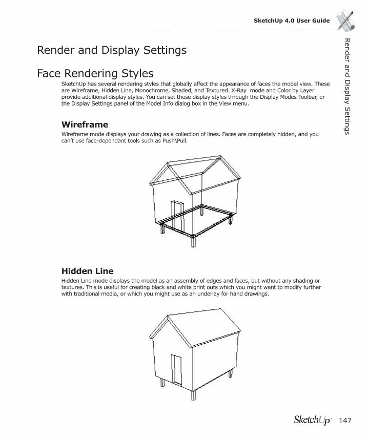
147
SketchUp 4.0 User GuideRen
der an
d D
isplay S
ettings
Render and Display Settings
Face Rendering StylesSketchUp has several rendering styles that globally affect the appearance of faces the model view. These are Wireframe, Hidden Line, Monochrome, Shaded, and Textured. X-Ray mode and Color by Layer provide additional display styles. You can set these display styles through the Display Modes Toolbar, or the Display Settings panel of the Model Info dialog box in the View menu.
WireframeWireframe mode displays your drawing as a collection of lines. Faces are completely hidden, and you can’t use face-dependant tools such as Push\Pull.
Hidden LineHidden Line mode displays the model as an assembly of edges and faces, but without any shading or textures. This is useful for creating black and white print outs which you might want to modify further with traditional media, or which you might use as an underlay for hand drawings.
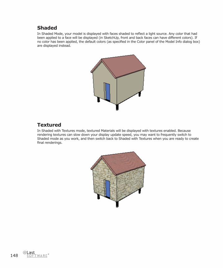
148
ShadedIn Shaded Mode, your model is displayed with faces shaded to refl ect a light source. Any color that had been applied to a face will be displayed (in SketchUp, front and back faces can have different colors). If no color has been applied, the default colors (as specifi ed in the Color panel of the Model Info dialog box) are displayed instead.
TexturedIn Shaded with Textures mode, textured Materials will be displayed with textures enabled. Because rendering textures can slow down your display update speed, you may want to frequently switch to Shaded mode as you work, and then switch back to Shaded with Textures when you are ready to create fi nal renderings.
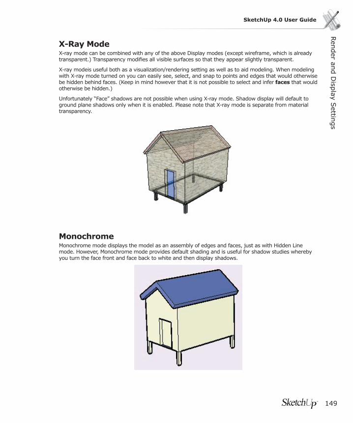
Ren
der an
d D
isplay S
ettings
149
SketchUp 4.0 User Guide
X-Ray ModeX-ray mode can be combined with any of the above Display modes (except wireframe, which is already transparent.) Transparency modifi es all visible surfaces so that they appear slightly transparent.
X-ray modeis useful both as a visualization/rendering setting as well as to aid modeling. When modeling with X-ray mode turned on you can easily see, select, and snap to points and edges that would otherwise be hidden behind faces. (Keep in mind however that it is not possible to select and infer faces that would otherwise be hidden.)
Unfortunately “Face” shadows are not possible when using X-ray mode. Shadow display will default to ground plane shadows only when it is enabled. Please note that X-ray mode is separate from material transparency.
MonochromeMonochrome mode displays the model as an assembly of edges and faces, just as with Hidden Line mode. However, Monochrome mode provides default shading and is useful for shadow studies whereby you turn the face front and face back to white and then display shadows.

150
Color by LayerColor by Layer applies materials to geometry on a per layer basis. This display mode overrides all painted materials. To see these materials make sure shaded or shaded with Textures display is turned on. Color by Layer may be also enabled from within the Layers Manager.

Ren
der an
d D
isplay S
ettings
151
SketchUp 4.0 User Guide
Edge Rendering StylesAlthough computer-generated images excel at accurately representing geometry, they often leave much to be desired in terms of drawing quality and style. This is especially true for conceptual ideas, where images that are too clean or hard edged can detract from a presentation. One of the biggest dangers is that others can interpret the drawings as “fi nished,” and that there is no longer any room for their feedback. This is why hand-drawn images are so powerful for initial conceptual work. They convey both the idea and the “looseness” of its current state.
SketchUp’s Edge Rendering enhancements are intended to give you the ability to maintain the advantages of 3D digital modeling without compromising your ability to make effective presentations. Also, they can be combined to create a distinct look and style for your drawings. You can access these settings through the Display Settings panel of the Model Info dialog box.
Edge DisplayThe Edge Display option controls weather or not edges are displayed, or how they should be displayed (All Same, By Material, By Axis, or None). Please note that inference alignments to edges are not available when edges are hidden. This option is only available in Shaded and Shaded with Textures Display modes.
Profi le LinesBorrowing from a proven traditional media drawing technique, Profi le or Silhouette Lines are used to make the 3D nature of geometry read more clearly by emphasizing the outlines of major shapes. You can control the thickness of Profi le Lines to suit your needs.
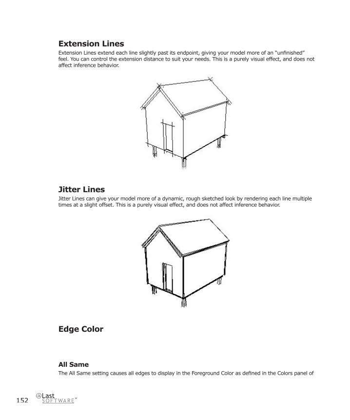
152
Extension LinesExtension Lines extend each line slightly past its endpoint, giving your model more of an “unfi nished” feel. You can control the extension distance to suit your needs. This is a purely visual effect, and does not affect inference behavior.
Jitter LinesJitter Lines can give your model more of a dynamic, rough sketched look by rendering each line multiple times at a slight offset. This is a purely visual effect, and does not affect inference behavior.
Edge Color
All SameThe All Same setting causes all edges to display in the Foreground Color as defi ned in the Colors panel of
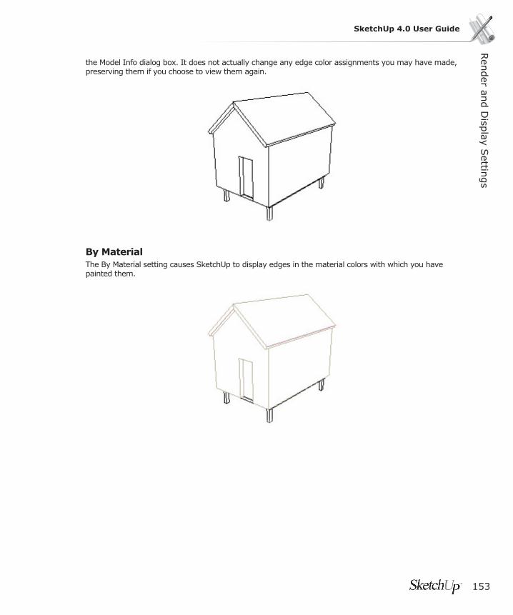
Ren
der an
d D
isplay S
ettings
153
SketchUp 4.0 User Guide
the Model Info dialog box. It does not actually change any edge color assignments you may have made, preserving them if you choose to view them again.
By MaterialThe By Material setting causes SketchUp to display edges in the material colors with which you have painted them.
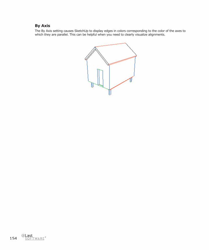
154
By AxisThe By Axis setting causes SketchUp to display edges in colors corresponding to the color of the axes to which they are parallel. This can be helpful when you need to clearly visualize alignments.

Ren
der an
d D
isplay S
ettings
155
SketchUp 4.0 User Guide
Soft Edges/Smooth EdgesSketchUp’s edges can be softened and smoothed in order to give a rounded appearance to a faceted model. When an edge is softened, it automatically hides itself when it isn’t displayed in profi le. Softened edges may optionally be smoothed as well, which renders the adjoining faces with a smooth tonal gradient.
(a) Standard edge display. (b) Softened. (c) Softened and Smoothed.
These allow you to reduce the visual clutter of rounded models, as well as to better represent rounded geometry using less geometric faceting. Since softened edges only hide themselves automatically, they still exist in your model. When you enable the Show Hidden Geometry option, ( Camera > Hidden Geometry ) edges that are currently not visible will be displayed along with any explicitly hidden geometry.
Softening and EdgesThere are several ways to soften an edge:
Erase ToolBy holding down the Ctrl key while using the Eraser Tool, you can soften edges instead of erasing them.
Context MenuBy clicking on an edge, you bring up its context menu, from which you can soften and unsoften the edge.
Soften/Smooth CommandBy fi rst selecting multiple edges with the Select Tool, then right clicking on the selection set, you can choose Soften/Smooth Edges from the context menu. This launches the Soften/Smooth dialog box described below.
Entity Info Dialog BoxBy right clicking on an edge and selecting Properties from the context menu, you can adjust the soften and smooth setting for that edge in its Entity Info Dialog Box.
156
Window> Soften EdgesFinally, you can soften and smooth edges by selecting the Soften Edges menu item from the Window menu.
Unsoftening Edges
Eraser ToolThe Eraser Tool can be set to unsoften edges by holding down Ctrl and Shift simultaneously.
Context MenuBy clicking on an edge, you bring up its context menu, from which you can soften and unsoften the edge.
Soften/Smooth Edges Dialog BoxBy fi rst selecting multiple edges with the Select Tool, then right clicking on the selection set, you can choose Soften/Smooth Edges from the context menu. This launches the Soften/Smooth Edges dialog box described below.
Entity Info Dialog BoxBy right clicking on an edge and selecting Properties from the context menu, you can adjust the soften and smooth setting for that edge in its Entity Info Dialog Box.
Window > Soften Edges Finally, you can soften and smooth edges by selecting the Soften Edges menu item from the Window menu.
Arc and Circle EntitiesArc and Circle entities are special in that they automatically produce softened edges when extruded using the Push/Pull Tool.
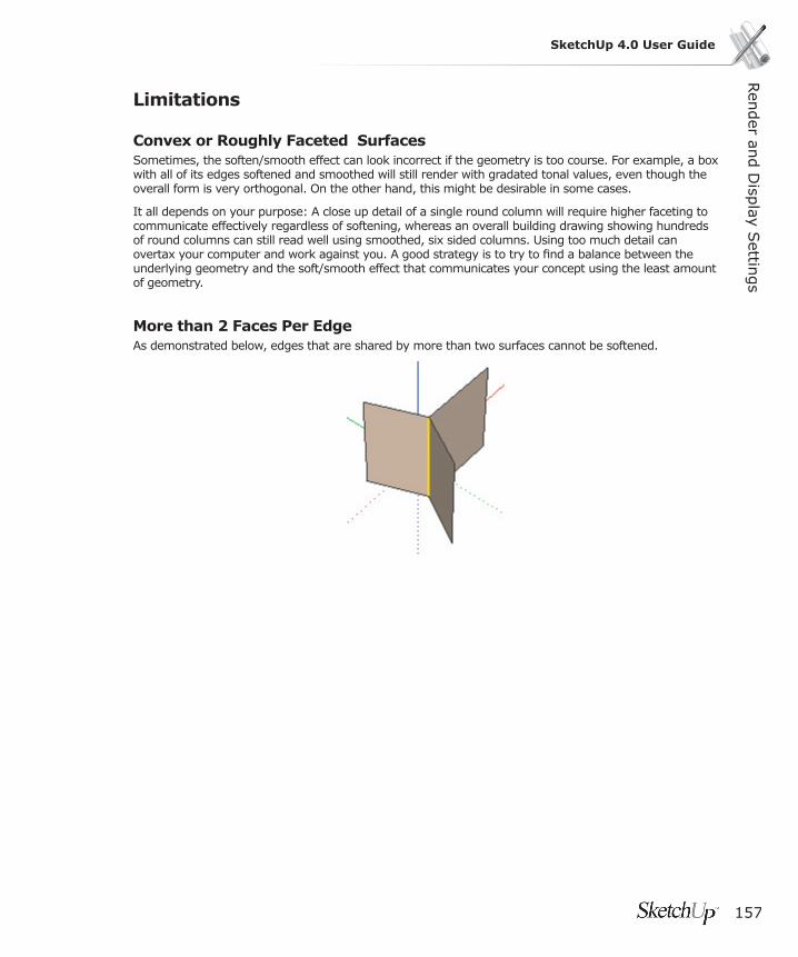
Ren
der an
d D
isplay S
ettings
157
SketchUp 4.0 User Guide
Limitations
Convex or Roughly Faceted SurfacesSometimes, the soften/smooth effect can look incorrect if the geometry is too course. For example, a box with all of its edges softened and smoothed will still render with gradated tonal values, even though the overall form is very orthogonal. On the other hand, this might be desirable in some cases.
It all depends on your purpose: A close up detail of a single round column will require higher faceting to communicate effectively regardless of softening, whereas an overall building drawing showing hundreds of round columns can still read well using smoothed, six sided columns. Using too much detail can overtax your computer and work against you. A good strategy is to try to fi nd a balance between the underlying geometry and the soft/smooth effect that communicates your concept using the least amount of geometry.
More than 2 Faces Per EdgeAs demonstrated below, edges that are shared by more than two surfaces cannot be softened.
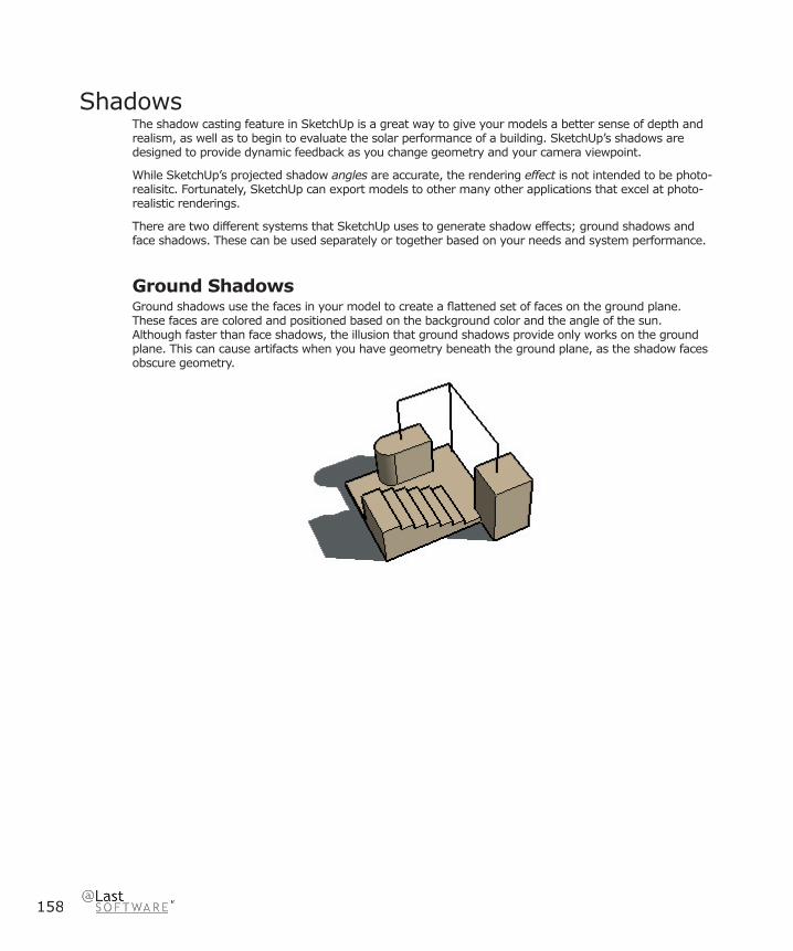
158
ShadowsThe shadow casting feature in SketchUp is a great way to give your models a better sense of depth and realism, as well as to begin to evaluate the solar performance of a building. SketchUp’s shadows are designed to provide dynamic feedback as you change geometry and your camera viewpoint.
While SketchUp’s projected shadow angles are accurate, the rendering effect is not intended to be photo-realisitc. Fortunately, SketchUp can export models to other many other applications that excel at photo-realistic renderings.
There are two different systems that SketchUp uses to generate shadow effects; ground shadows and face shadows. These can be used separately or together based on your needs and system performance.
Ground ShadowsGround shadows use the faces in your model to create a fl attened set of faces on the ground plane. These faces are colored and positioned based on the background color and the angle of the sun. Although faster than face shadows, the illusion that ground shadows provide only works on the ground plane. This can cause artifacts when you have geometry beneath the ground plane, as the shadow faces obscure geometry.
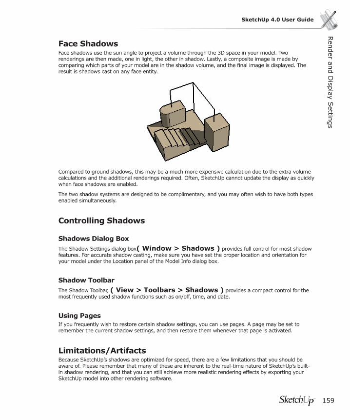
Ren
der an
d D
isplay S
ettings
159
SketchUp 4.0 User Guide
Face ShadowsFace shadows use the sun angle to project a volume through the 3D space in your model. Two renderings are then made, one in light, the other in shadow. Lastly, a composite image is made by comparing which parts of your model are in the shadow volume, and the fi nal image is displayed. The result is shadows cast on any face entity.
Compared to ground shadows, this may be a much more expensive calculation due to the extra volume calculations and the additional renderings required. Often, SketchUp cannot update the display as quickly when face shadows are enabled.
The two shadow systems are designed to be complimentary, and you may often wish to have both types enabled simultaneously.
Controlling Shadows
Shadows Dialog BoxThe Shadow Settings dialog box( Window > Shadows ) provides full control for most shadow features. For accurate shadow casting, make sure you have set the proper location and orientation for your model under the Location panel of the Model Info dialog box.
Shadow ToolbarThe Shadow Toolbar, ( View > Toolbars > Shadows ) provides a compact control for the most frequently used shadow functions such as on/off, time, and date.
Using PagesIf you frequently wish to restore certain shadow settings, you can use pages. A page may be set to remember the current shadow settings, and then restore them whenever that page is activated.
Limitations/ArtifactsBecause SketchUp’s shadows are optimized for speed, there are a few limitations that you should be aware of. Please remember that many of these are inherent to the real-time nature of SketchUp’s built-in shadow rendering, and that you can still achieve more realistic rendering effects by exporting your SketchUp model into other rendering software.

160
Ground Shadows Cover Below-Ground GeometryBecause they are comprised of faces, Ground shadows can look incorrect when there is geometry underneath the ground (red-green) plane.
The illusion of ground shadows only works well for solid color backgrounds when all geometry is above the ground plane. You can get around this by disabling ground shadows and creating faces where you want face shadows to be cast. Easier still is moving the entire model so that all geometry lies above the ground plane.
TransparencyGeometry with transparent materials in SketchUp cannot cast a “partial” shadow. A face either blocks the sunlight completely or not at all, and therefore a partially transparent element cannot be made to cast a 50% shadow like you might expect. Instead, there is a threshold around 70% opacity above which casting will be enabled, and below which it will be disabled.
Likewise, transparent geometry cannot receive shadows at all. Only fully opaque geometry can receive shadows.

Ren
der an
d D
isplay S
ettings
161
SketchUp 4.0 User Guide
Exporting 3DShadows themselves cannot be saved with a 3D model. It is up to the application you import your model into to generate shadows. Also, none of the 2D vector output formats support rendering features such as shadows, textures, or transparency. The only export formats that will represent shadows as seen on your display are pixel-based raster images and animations.
Dirty Shadow ArtifactsYou may sometimes see intermittent streaks or small spots of light within face shadows. A minimal amount of these artifacts is to be expected on most systems, and it can vary greatly with the quality of your OpenGL driver.
OpenGL PerformanceSketchUp’s Shadow feature may have a severe performance impact on slower computers or those using software rendering. If you wish to use SketchUp interactively with shadows enabled, we strongly recommend an inexpensive 100% OpenGL compatible graphics card.
Caution: Certain OpenGL modes do not fully support casting shadows on faces. Due to quality issues with most OpenGL drivers, some modes may exhibit rendering artifacts in low precision modes. We have tried to minimize this effect, but it may sometimes occur, especially on dimensionally large models.
SketchUp attempts to determine the mode that will provide the best results, but you may wish to choose one on your own by using the OpenGL Tab of Preferences dialog. Please be careful when changing this setting. Unfortunately, OpenGL drivers tend to inform the application that it supports features which are in reality unsupported. Therefore, there is no way of knowing beforehand if the mode you choose will work properly.

162
Sky and Ground EffectsSketchUp’s sky and ground effects allow you to represent an atmosphere-like gradient sky and a horizon line on the background of your model, as well as a gradient rendered on the ground plane.
The controls for these effects are located under the Color section of the Model Info dialog box. Select Gradient from the Background drop down list.
Menu Access: ( Window> Model Info > Colors)
Sky EffectWhen enabled, the sky effect displays your background from the horizon upwards as a gradient. The gradient is drawn from white at the horizon to the color you specify at the top.
Ground EffectThis effect displays the ground plane in the color you specify as a gradient that fades into the horizon.
TransparencyThis makes the gradient ground effect transparent to various degrees, allowing you to see geometry below the ground plane. We recommend that this option be used only with hardware acceleration.
Show ground from belowWhen enabled, this makes the gradient ground effect visible when your camera view is below the ground plane. (Worm’s eye view)

Ren
der an
d D
isplay S
ettings
163
SketchUp 4.0 User Guide
Sections The section cut has been fundamental to building design since the dawn of civilization. Not only do sections provide a powerful way to visualize spatial relationships, but they can make documenting and constructing complex forms much more straightforward and accurate.
SketchUp’s dynamic Section Planes give you all the advantages of the traditional section plus a powerful new set of capabilities not found in any other software package:
• Visualization: By allowing you to look and work inside your SketchUp models non-destructively, Section Planes offer unparalleled ways to visualize space and “work from the inside-out.”
• Interiors: Not only do Section Planes free you from having to constantly hide and un-hide geometry to reveal otherwise occluded parts of your model, they also dynamically demonstrate the inter-relationships of spaces in a very powerful, easy to use way.
• Section Drawings: At any time, you can export measurable section slices to your CAD system using industry standard formats. These slices can be used as instant templates for creating working drawings of your SketchUp models, or they may be printed to help build accurate physical models.
• Illustration: In addition to measurable section drawings, you may export projected section slices directly to most industry standard illustration packages. This is a handy way of creating diagrams, illustrations, renderings, underlays, and so forth.
• Modeling: Sections can be very useful inside your SketchUp models as well. By generating permanent slices through geometry, Section Planes can work as subtractive modeling tools similar to a “digital hot wire.” This is handy for generating new ideas, creating templates for physical models, and much more.
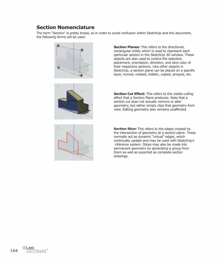
164
Section NomenclatureThe term “Section” is pretty broad, so in order to avoid confusion within SketchUp and this document, the following terms will be used:
Section Planes: This refers to the directional, rectangular entity which is used to represent each particular section in the SketchUp 3D window. These objects are also used to control the selection, placement, orientation, direction, and slice color of their respective sections. Like other objects in SketchUp, a section plane can be placed on a specifi c layer, moved, rotated, hidden, copied, arrayed, etc.
Section Cut Effect: This refers to the visible culling effect that a Section Plane produces. Note that a section cut does not actually remove or alter geometry, but rather simply clips that geometry from view. Editing geometry also remains unaffected.
Section Slice: This refers to the edges created by the intersection of geometry at a section plane. Thesenormally act as dynamic “virtual” edges, which continually update and may be used with SketchUp’s inference system. Slices may also be made into permanent geometry by generating a group from them as well as exported as complete sectiondrawings.

165
SketchUp 4.0 User GuideD
rawin
g A
ids
Drawing Aids
Drawing Axes SketchUp’s Drawing Axes are three colored lines, perpendicular to each other, displayed in the Drawing Window. They can be very helpful in providing a sense of direction in 3D space while you work.
The Red, Green, and blue axes correspond to the X, Y, and Z directions in a 3D coordinate system. They are referred to by their color in SketchUp so that you can work and think visually instead of numerically. Also, notice that each axis line is drawn with a solid line in the positive direction, and a dotted line in the negative direction. The center point where the axes cross is called the origin.
You can also think of the planes defi ned by any two of the axes. For example, the Red/Green plane is considered the “ground” in SketchUp. When you draw on the background, SketchUp will determine the most appropriate plane based on your viewing angle.
Showing and Hiding the Drawing AxesThe display of the Drawing Axes can be toggled on and off from the Camera Menu: ( Camera > Axes ). You can also right-click on the Drawing Axes and select Hide from the context menu.
Note: The Drawing Axes will be automatically hidden in any images exported from SketchUp.

166
To Re-Orient the Drawing AxesWhile the normal position and orientation of the Drawing Axes is consistent with ‘global coordinates’ in other 3D programs, you can temporarily reposition and/or realign them to suit your needs. To do so:
1. Either activate the Axis Tool or right click on the Drawing Axes and select Place from the context menu.
2. As you move your cursor around your model, a bold set of red/green/blue axes will follow. You will see them snap to inferred alignments and points as you move near them in your model.
3. Move your cursor to a point in your model that you wish to be the new coordinate origin. Use the inference ToolTips to make sure your cursor is located exactly where you want it to be. Click to accept that point.
4. Drag your cursor away from the origin to set an alignment for the red axis. Use the inference ToolTips to make sure you are aligned precisely. Click to accept the alignment.
5. Move your cursor away from the origin to set an alignment for the green axis. Use inference ToolTips again to make sure you are aligned precisely. Click again to accept the alignment. You have now re-oriented your axes. The blue axis will appear perpendicular to the new red/green plane.
Resetting the Drawing AxesTo restore the axes to the default position, Right click on the Drawing Axes, and select Reset from the context menu.
Aligning the Drawing Axes to a FaceInstead of manually placing the Drawing Axes, you can quickly align them to a face. To do so, right click on a face, and select Align Axes from the context menu.
Aligning the View to the Drawing AxesYou can align SketchUp’s view to be perfectly aligned with the red/green plane of the drawing axes. This is useful for creating measurable drawings for non-orthographic surfaces. To do so, right click on the Drawing Axes and select Align View from the context menu.

Draw
ing A
ids
167
SketchUp 4.0 User Guide
Relative Move & Rotate You can quickly and accurately move and/or rotate the Drawing Axes relative to their current position using the Move Sketching Context dialog box.
1. Right click on the Drawing Axes, and select Move from the context menu.
2. The Move Sketching Context dialog box will be launched, and you can specify displacement and rotation values in the units specifi ed under the Units panel of the Model Info dialog box.

168
InferenceSketchUp features a sophisticated a geometric analysis engine that allows you want to work in 3D space using a 2D screen and input device. The inferences it creates can also help you draw very accurately, by “snapping” to existing geometry. SketchUp is always looking to infer alignments as you draw, and tries to anticipate your needs and read your mouse movements to modify its assumptions.
Inference ToolTipsInference ToolTips are cues which appear automatically while working on the model to identify signifi cant points or geometric conditions. These are an important part of SketchUp’s Inference engine, as they can make complex inference combinations more clear.
“Encouraging” an InferenceAt times, the inference you need may not come up immediately or SketchUp may choose alignments with the wrong geometry. In these cases, you can strengthen the chances of a particular alignment by temporarily keeping your mouse cursor stationary over the particular geometry you’re interested in. When the ToolTips appears, SketchUp will briefl y prioritize that alignment as you continue drawing.

Draw
ing A
ids
169
SketchUp 4.0 User Guide
Inference TypesThere are three main types of inferences; point, linear, and planar. At times, SketchUp may combine multiple inferences together to form a more complex inference, but the basics are listed below:
Point InferenceA point inference is based on an exact point in your model.
Endpoint: A green Endpoint inference identifi es the end of a line or arc entity.
Midpoint: A cyan Midpoint inference indicates the middle point on a line or edge.
Intersection: A black Intersection inference indicates an exact point where a line intersects another line or face.
On Face: A blue On Face inference identifi es a point which lies on a face.
On Edge: A red On Edge inference identifi es a point that lies along an edge.
Equi-Distant On Edge: This indicates an equidistant point, or a chamfer, when a magenta line appears between two connected edges.
Half Circle: The Half Circle inference appears when drawing an arc to indicate the point that creates an exact half circle.

170
Linear InferenceA linear inference snaps along a line or direction in space. In addition to a ToolTip, a linear Inference sometimes displays a temporary dotted line while you draw.
On Axis: This indicates a linear alignment to one of the Drawing Axes. The solid line is drawn in the related color; red, green, and blue.
From Point: A dotted From Point inference indicates a linear alignment from a point along the Drawing Axes directions.
Perpendicular: This magenta line indicates perpendicular alignment to another edge.
Parallel: This magenta line indicates a parallel alignment to another edge.
Tangent: When drawing from the endpoint of an Arc Entity.
Planar InferenceDrawing Planes: If SketchUp cannot fi nd a connection with geometry, it will use the planes defi ned by the Drawing Axes and your view to determine where to draw. For example, if you are looking down on the model, drawing on the background will create geometry on the ground plane, or red-green plane.
On Face: A blue On Face inference identifi es a point which lies on a face. Although initially a point inference, On Face can also serve as a planar alignment by using Inference Locking described below.
Component InferencesAll normal geometry inferences can be obtained from geometry inside Components or Groups. Group and Component inferences are all indicated by magenta dots. Appropriate ToolTip will tell users exactly which kind of inference they have.

Draw
ing A
ids
171
SketchUp 4.0 User Guide
Inference LockingAt times, geometry might interfere with your ability to inference, making it diffi cult to draw what you want. The solution is to use an Inference Lock, which tells SketchUp not to waver from the direction it is currently inferring from. To use the inference lock, hold down the Shift key when SketchUp infers the desired alignment. The alignment will remain locked, even as you move the mouse and/or pick a secondary inference point.
In the example above, the inference has been locked onto the slanted edge to the left. While keeping the Shift key pressed and touching the midpoint indicated, SketchUp will infer that we want our drawing point to be locked along the fi rst edge while remaining aligned to the midpoint.
Any of the inference conditions may be locked; along an axis direction, along an edge direction, on a face, from a point, parallel or perpendicular to an edge, etc.
Inference Points During In-Place EditingWhile editing a Component, you can only alter geometry inside that Component context. You can still, however, perform inference alignments to outside geometry.

172
HidingTo simplify your current view, or to enable viewing and working inside closed volumetric geometry, it occasionally helps to hide geometry. Hidden geometry is invisible, but it still exists in the model. It will still merge like normal geometry, and it can be un-hidden as needed.
Displaying Hidden GeometryDrawing elements that you have hidden may be made partially visible by enabling the Show Hidden Geometry option from the Camera Menu. ( Camera > Hidden Geometry )
When enabled, Show Hidden Geometry lets you see, select , and un-hide hidden objects.
Hiding and Un-hiding EntitiesAny drawn entity in SketchUp can be hidden. This includes Groups, Components, Construction Geometry, the Drawing Axes, Image Objects, Section Planes, Text, and Dimensions. SketchUp offers a variety of ways to control the visibility of objects:
1. Edit Menu: To hide geometry, select the entities you want to hide using the Select Tool, then select Hide from the Visibility sub-menu within the Edit menu. Other Hiding related Edit Menu commands include Unhide, Unhide Last, and Unhide All.
2. Context Menu: To hide using a context menu, Right click on an entity, then select Hide. To unhide, select Unhide All from the Visibility sub-menu within the Edit menu.
3. Eraser Tool: Visible edges can be hidden with the Eraser Tool by holding down the Shift key while erasing.
Hiding the Sketch AxesSketchUp’s Drawing Axes are drawing aids and cannot be selected for hiding like drawn geometric entities. To hide the Drawing Axes, uncheck the Axes option in the Camera Menu. You may also Right click on an axis, and select Hide from the context menu.

Draw
ing A
ids
173
SketchUp 4.0 User Guide
Hiding Section PlanesSection Planes have a special control that allows their visibility to be toggled globally. You can use the toolbar controls or the View menu:
Menu Access: ( View > Section Planes )
Hiding LayersYou can hide and un-hide all the geometry on a layer at once. This can be a more effi cient way to hide and unhide complex geometries. Layer visibility is controlled from the Layers Manager.
1. First, open the Layers Manager by selecting Layers from the Window Menu or click the Layer Manager button on the Layer toolbar
2. Next, click on the visibility control for the layer you’d like to make invisible. The entities on that layer will disappear from the Drawing Window.
Using PagesPages can be set to record and quickly restore the hidden status of multiple entities in your model.
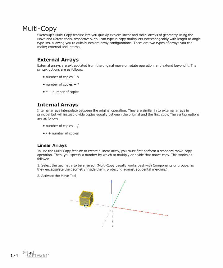
174
Multi-CopySketchUp’s Multi-Copy feature lets you quickly explore linear and radial arrays of geometry using the Move and Rotate tools, respectively. You can type in copy multipliers interchangeably with length or angle type-ins, allowing you to quickly explore array confi gurations. There are two types of arrays you can make; external and internal.
External ArraysExternal arrays are extrapolated from the original move or rotate operation, and extend beyond it. The syntax options are as follows:
• number of copies + x
• number of copies + *
• * + number of copies
Internal ArraysInternal arrays interpolate between the original operation. They are similar in to external arrays in principal but will instead divide copies equally between the original and the fi rst copy. The syntax options are as follows:
• number of copies + /
• / + number of copies
Linear ArraysTo use the Multi-Copy feature to create a linear array, you must fi rst perform a standard move-copy operation. Then, you specify a number by which to multiply or divide that move-copy. This works as follows:
1. Select the geometry to be arrayed. (Multi-Copy usually works best with Components or groups, as they encapsulate the geometry inside them, protecting against accidental merging.)
2. Activate the Move Tool
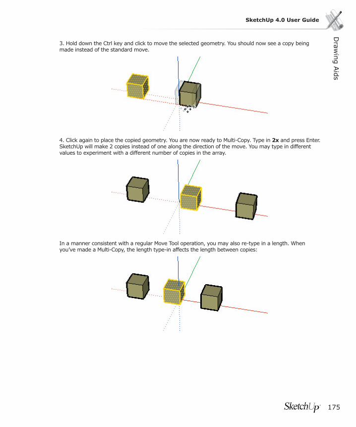
Draw
ing A
ids
175
SketchUp 4.0 User Guide
3. Hold down the Ctrl key and click to move the selected geometry. You should now see a copy being made instead of the standard move.
4. Click again to place the copied geometry. You are now ready to Multi-Copy. Type in 2x and press Enter. SketchUp will make 2 copies instead of one along the direction of the move. You may type in different values to experiment with a different number of copies in the array.
In a manner consistent with a regular Move Tool operation, you may also re-type in a length. When you’ve made a Multi-Copy, the length type-in affects the length between copies:
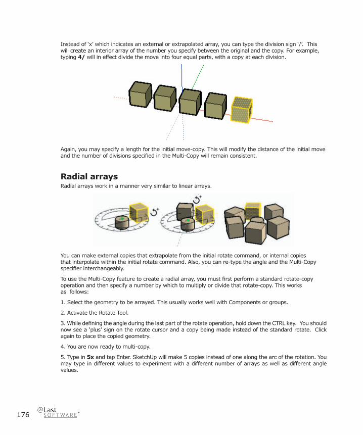
176
Instead of ‘x’ which indicates an external or extrapolated array, you can type the division sign ‘/’. This will create an interior array of the number you specify between the original and the copy. For example, typing 4/ will in effect divide the move into four equal parts, with a copy at each division.
Again, you may specify a length for the initial move-copy. This will modify the distance of the initial move and the number of divisions specifi ed in the Multi-Copy will remain consistent.
Radial arraysRadial arrays work in a manner very similar to linear arrays.
You can make external copies that extrapolate from the initial rotate command, or internal copies that interpolate within the initial rotate command. Also, you can re-type the angle and the Multi-Copy specifi er interchangeably.
To use the Multi-Copy feature to create a radial array, you must fi rst perform a standard rotate-copy operation and then specify a number by which to multiply or divide that rotate-copy. This works as follows:
1. Select the geometry to be arrayed. This usually works well with Components or groups.
2. Activate the Rotate Tool.
3. While defi ning the angle during the last part of the rotate operation, hold down the CTRL key. You should now see a ‘plus’ sign on the rotate cursor and a copy being made instead of the standard rotate. Click again to place the copied geometry.
4. You are now ready to multi-copy.
5. Type in 5x and tap Enter. SketchUp will make 5 copies instead of one along the arc of the rotation. You may type in different values to experiment with a different number of arrays as well as different angle values.
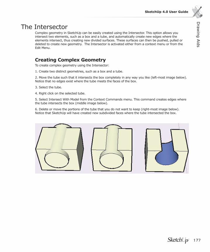
Draw
ing A
ids
177
SketchUp 4.0 User Guide
The IntersectorComplex geometry in SketchUp can be easily created using the Intersector. This option allows you intersect two elements, such as a box and a tube, and automatically create new edges where the elements intersect, thus creating new divided surfaces. These surfaces can then be pushed, pulled or deleted to create new geometry. The Intersector is activated either from a context menu or from the Edit Menu.
Creating Complex GeometryTo create complex geometry using the Intersector:
1. Create two distinct geometries, such as a box and a tube.
2. Move the tube such that it intersects the box completely in any way you like (left-most image below). Notice that no edges exist where the tube meets the faces of the box.
3. Select the tube.
4. Right click on the selected tube.
5. Select Intersect With Model from the Context Commands menu. This command creates edges where the tube intersects the box (middle image below).
6. Delete or move the portions of the tube that you do not want to keep (right-most image below). Notice that SketchUp will have created new subdivided faces where the tube intersected the box.
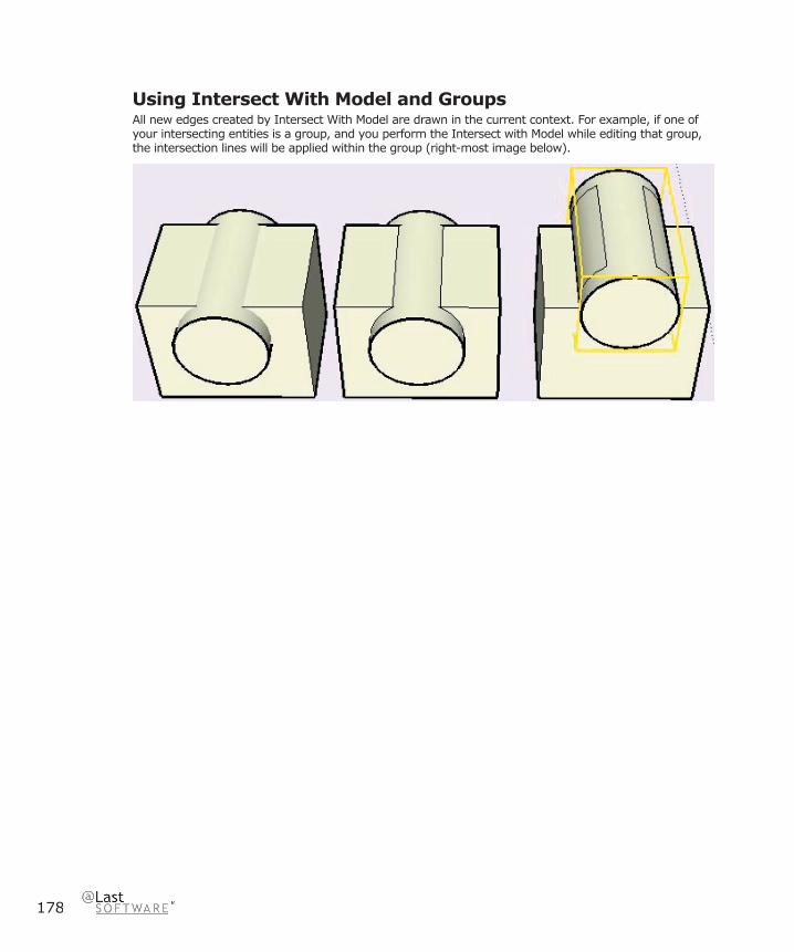
178
Using Intersect With Model and GroupsAll new edges created by Intersect With Model are drawn in the current context. For example, if one of your intersecting entities is a group, and you perform the Intersect with Model while editing that group, the intersection lines will be applied within the group (right-most image below).

Draw
ing A
ids
179
SketchUp 4.0 User Guide
Auto-FoldFaces in SketchUp must remain planar at all times. If you perform an operation that would result in warped faces, SketchUp will Auto-fold, or “score” those faces as necessary to accommodate the operation you request while keeping all connected faces planar.
Forcing Auto-fold with the ALT keyAuto-Fold is fully automatic whenever possible. For example, moving a corner point of a box requires an Auto-Fold, so it happens automatically:

180
There may be times, however, when an operation is constrained in favor of keeping all faces planar and not creating additional lines. For example, if you were to move one of the side edges of a box, it is free to move in any horizontal direction, (red and green) but not vertically (blue). You may override this behaviour by holding down the ALT key before performing the move. This tells SketchUp to go ahead and enable Auto-Fold without analyzing the model, which allows geometry to move freely in any direction regardless of the topology.

Draw
ing A
ids
181
SketchUp 4.0 User Guide
LayersIn 2D software, layers act like a stack of transparent sheets of paper on which drawing elements exist. In 3D applications like SketchUp, there really aren’t layers of sheets per se, but the technique of organizing geometry using “layers” persists. SketchUp layers are simply a named attribute or property that drawing elements and objects may be assigned to. You can place objects on different layers to more easily control visibility.
It is important to know that SketchUp layers do not isolate geometry. Just because you are drawing on a different layer DOES NOT mean that geometry will not merge with entities on other layers. Only geometry inside Components and Groups will be isolated from outside geometry.
For situations too complex for Layers to manage, SketchUp also supports hierarchical instancing and grouping through its Component capabilities. Components, and especially nested Components, will often work better as organizing elements than Layers will.
Default “Layer0”Every drawing has a default layer, called Layer0. Any geometry assigned to Layer0 will take on the layer of any Groups or Components that encapsulate it.
Note: You cannot delete layer0 or change its name. Also, entities that reside on layer 0 always inherit their visibility from the layer of the components/groups that contain them. This makes layer 0 work like the default drawing layer. If you use any other layer as a drawing layer, all the entities that were created on that layer will become invisible when you hide that layer. This is not the case when hiding layer 0. Anything that is on layer 0 but inside a group or component that is on another layer will remain visible when you hide layer 0.
Creating a New LayerTo make a new layer, click on the New button at the bottom of the Layers Manager. SketchUp will add a new layer to the layer list, with a default name that you can edit.
Rename an Existing LayerYou can rename an existing layer by selecting it in the Layers Manager then clicking on its name. Type in your new layer name, and press Enter.
Make a Layer the Current LayerAny drawn geometry will be created on the current layer. To make a layer the current layer, click the check box to the left of the layer name. You can also use the Layer Toolbar control. To do so, make sure nothing is selected, and select the name of the layer you wish to be active from the list.
Make a Layer Visible or InvisibleYou can control layer visibility by checking or un-checking the checkbox in the Visible column for each layer. Un-checking the Visibility checkbox for a layer with geometry on it will cause that geometry to disappear. To make it visible again, check the layer’s visibility checkbox again. You cannot make the current active layer invisible.
182
Move Geometry From One Layer to AnotherTo move an object or objects to a different layer:
1. Select the object(s) with the Select Tool.
2. The Layer Toolbar List Box is highlighted in yellow and the objects’ layer name is displayed with an arrow. If objects on more than one layer have been selected, the Layer Toolbar will display the yellow shading, but no layer name will be displayed.
3. Click the down arrow in the Layer Toolbar List Box and choose the layer to which you want your object(s) to belong. The object(s) are moved to the assigned layer, and the assigned layer also becomes the current layer.
You can also use the Properties Dialog for changing the layer of one entity at a time. Right click on it, select Properties, and select a new layer.
Activating Color By LayerSketchUp allows you to set a color or material to be applied to all the entities on a layer. When you create a new layer, SketchUp will assign it a new and unique color. To view your model with Color by Layer view active, check the Color By Layer checkbox at the bottom of the Layers Manager.
Changing a Layer’s ColorClick on the color box next to the layer name. This brings up a color picker, where you can set a new color.
Delete a Layer1. To delete a layer, select it’s name from the layers list, and click on the ‘Delete’ button.
If the layer is currently empty of geometry, SketchUp will delete it without asking for confi rmation. If not, SketchUp will bring up a sheet asking what you would like to do with the geometry on the layer you are trying to delete. SketchUp will not let you delete the geometry along with the layer.
2. Choose the action you would like SketchUp to take, and then click on the ‘Delete’ button to confi rm deletion of the layer.
Purge Unused LayersTo purge all unused layers (all layers without anything on them), click on the ‘Purge’ button at the bottom of the Layers Manager. SketchUp will delete all unused layers without confi rmation.
Draw
ing A
ids
183
SketchUp 4.0 User Guide
In-Place EditingWhen you organize geometry into objects such as Groups and Components, that geometry becomes encapsulated within that object, and thus in several ways separated from the rest of your model. You will fi nd it often necessary, however, to edit geometry within an object. Instead of exploding, editing, re-selecting, and re-defi ning an object, you may simply edit it in place.
In-place editing changes SketchUp’s drawing window to an object’s context, effectively placing you “inside” a group or component. Once inside, you may edit encapsulated geometry as you would normally, while drawing elements outside that context are inaccessible.
You can think of in-place editing almost as a shortcut to opening up an externally referenced fi le, making changes, then reopening your original fi le. SketchUp’s interface is designed to allow quick and painless context navigation, allowing instant access to all geometry without compromising your organizational hierarchy.
ContextA context is SketchUp’s most simple organizing entity. A context is like an isolated realm that separates geometry within from anything outside.
When you start a SketchUp model you are working within a context. When you make a Group or Component you have created another context inside of the macro context - your .skp fi le. Certain command or operations, such as Unhide All, scaling using the Measure Tool, and placing active Section Planes, are limited to a particular context.
Perhaps the most useful quality of contexts is that they keep geometry from merging together and allow you to work with discreet objects.
Editing a Group or Component ObjectYou may edit an object in one of three ways:
A. Use the Select Tool to double-click on the object.
B. Select it and press the Enter key.
C. Right click and select ‘Edit Group’ or ‘Edit Component’ from the context menu.
Component InstancingRemember that editing a component actually edits that components’ defi nition, meaning that all other instances of that component will refl ect those changes. Groups, on the other hand, are merely a collection of geometry and do not exhibit the defi nition/instance behavior of components. Components also maintain their own drawing axes. see here for more information regarding how groups and components complement each other.
If you right click on a component which has multiple instances placed in your scene, you can select Edit (Just This One) from the context menu. This makes a new duplicate defi nition out of the component before editing it, so that the original and its instances are not affected.
While editing a Component, you can only alter geometry inside that Component context, but you can still perform inference alignments to outside geometry.
184
Exiting From Editing a Group or ComponentOnce you are fi nished editing an object, you can exit back to a higher level by doing any of the following:
A. Use the Select Tool to click outside the context.
B. If still in the Select Tool, press the ESC key
C. Right click on the Drawing Window background and select ‘Close Group’ or ‘Close Component’ from the context menu.
Attaching and Detaching Geometry From an ObjectWhile editing an object, you can cut, copy, and paste using the clipboard. This allows you to move geometry between objects.
Display PreferenceWhen editing an object, SketchUp can grey out everything outside that objects context. This allows you to more clearly see which drawing elements are accessible to you as you traverse through multiple contexts.
In some cases, this may not be as valuable, so SketchUp allows you to adjust the amount of this effect in the Components panel of the Model Info dialog box.
Draw
ing A
ids
185
SketchUp 4.0 User Guide
Pages and TourGuidePages allow you to save one or many different view settings within one drawing fi le. These are quickly accessible via tabs at the top of the Drawing Window. You may use Pages to create pre-set customized views of your model from different perspectives, at different times of day, with different rendering settings, and layer and geometry visibility settings.
Any changes made to the model geometry will appear in all Pages. However, you may select unique combinations of various viewing options that will make each Page unique. Page commands are accessible from the Page menu and by right-clicking on page tabs.
Adding PagesYou can create new Pages using the Pages dialog box in the View menu.
TourGuide™TourGuide is a powerful presentation tool which enables you to create compelling presentations right inside SketchUp. When changing between Pages, TourGuide will smoothly transition from one view to the next. This offers an effortless way to visualize 3D forms, shadow studies and design options in presentations.
To activate SketchUp’s TourGuide features, select ( View> Tourguide)
Play SlideShowThis command activates SketchUp’s slideshow presentation mode, which will sequentially transition from Page to Page. You can set various properties for the slideshow through the Tourguide panel of the Model Info dialog box, including page transition duration and slide delay.
The TourGuide Slideshow may be paused and re-started by clicking on the pause button or tapping the space bar.
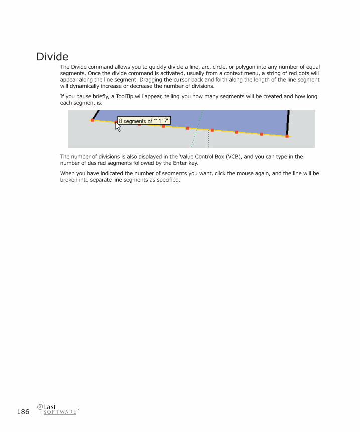
186
DivideThe Divide command allows you to quickly divide a line, arc, circle, or polygon into any number of equal segments. Once the divide command is activated, usually from a context menu, a string of red dots will appear along the line segment. Dragging the cursor back and forth along the length of the line segment will dynamically increase or decrease the number of divisions.
If you pause briefl y, a ToolTip will appear, telling you how many segments will be created and how long each segment is.
The number of divisions is also displayed in the Value Control Box (VCB), and you can type in the number of desired segments followed by the Enter key.
When you have indicated the number of segments you want, click the mouse again, and the line will be broken into separate line segments as specifi ed.

187
SketchUp 4.0 User GuideM
aterials
Materials
SketchUp MaterialsA SketchUp material is a collection of properties including name, color, transparency, texture, and dimension. Materials can be applied to edges, faces, Text Objects, Section Planes, Groups, and Components.
Once applied, a material is added to a list of materials used in your SketchUp fi le. This list is saved with your geometry in the .skp fi le so that used materials are always available at any time. By changing a material in your scene, you can change it everywhere it is used.
Working with MaterialsSketchUp provides different tools for working with materials.
1. The Paint Bucket Tool is used for applying, fi lling, and replacing materials as well as sampling materials from an object.
2. The Materials Palette is used for selecting a material from a library as well as organizing and managing groups of materials.
3. The Material Editor is used to adjust and explore different properties of a single material.
Default Material (Override)As it is created, geometry in SketchUp is assigned a default material. This is displayed as a box with an ‘X’ marked through it in the Materials Palette. The default Material has a couple of very valuable properties:
SidednessThe default material displays different colors depending on the orientation of the face it is assigned to. This ‘front’ and ‘back’ behavior allows you to easily visualize and manage face orientation so that your SketchUp models can be more compatible with CAD and 3D Modeling programs. The front and back color may be adjusted in the Color panel of the Model Info dialog box..
OverrideThe default material also has the advantage of fl exibility as it can ‘take on’ the material of the Group or Component it is inside of. For example, if you were to make a vehicle Component, you could assign materials to the tires, bumper, and windows, but leave the body as default material. When you make copies of the vehicle component, you can assign them different colors, and only the elements such as edges or faces of the body take on that material.
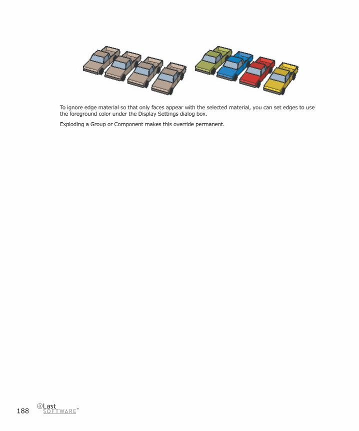
188
To ignore edge material so that only faces appear with the selected material, you can set edges to use the foreground color under the Display Settings dialog box.
Exploding a Group or Component makes this override permanent.

Materials
189
SketchUp 4.0 User Guide
Color PickerYou can activate the Color Picker by clicking on any color swatch in SketchUp’s interface (such as in the Colors section of the Model Info dialog box) or by activating the Paint Bucket Tool.
Color System MenuSketchUp allows you to choose between four color systems: Color Wheel, Grayscale, RGB, and HSB. To choose one of the color systems, pick it from the pop-up menu at the top of the Choose Color dialog box.
Color WheelTo use the Color Wheel, select the color you want visually by clicking your mouse over that color in the wheel. You can also click and drag the cursor around the Color Wheel to browse through many different colors quickly. You will see a dynamic preview of the selected color in the active color well at the top of the color picker.
The color wheel arranges color hue radially around the wheel, with the highest saturation at the outer edge of the wheel. To change the brightness of the color, slide the value slider to the right of the wheel up or down.
GrayscaleThe Grayscale Color Picker select colors from the grayscale color space (shades of gray).
To select a color using the Grayscale Color Picker, adjust the slider for Black until you see the color you want in the Active Color Well. You can also type in a percent gray value directly in the text box to the right of the slider, or choose from one of the fi ve preset gray values below the slider.
RGB (Red, Green & Blue)The RGB Color Picker allows you to select colors from the RGB (Red, Green and Blue) color space. RGB colors are traditionally used when modeling color on a computer screen, and represent the closest approximation of the actual range of colors the human eye is capable of discerning. RGB has a “wide” color gamut, and is one of the most effective color spaces to use in SketchUp.
To use the RGB picker, drag the sliders left and right for each of the component colors (red, green and blue) until you have the color you want. To help you zero in on the right color, the background color of each slider will change as you modify values to help you predict how adjustments will change your color mix.
If you are trying to precisely match a color that you have specifi ed elsewhere, you can type in exact numerical values for red, green or blue in the value boxes to the right of the sliders.
HSB (Hue, Saturation & Brightness)Like the Color Wheel, the HSB Color Picker allows you to pick colors from the HSB (Hue Saturation and Brightness) color space. HSB often gives you a more intuitive color model for selecting de-saturated colors.
To use the HSB Color Picker, adjust the sliders for Hue, Saturation and Brightness until you see the color you want in the Active Color Well.
Sometimes it is easier to mix de saturated colors using the HSB Color Picker in conjunction with one of the other pickers. To do this, switch to another color picker to make your rough color selection, then switch back to the HSB Color Picker to fi ne tune.

190
Material TransparencyMaterials can have variable transparency between 0 and 100%, and individual faces can be made transparent by painting them with a transparent material.
Any SketchUp material can be made transparent using the Material Editor. Material transparency can be disabled globally from the Display Settings dialog box.
Material Transparency Quality/SortingBecause SketchUp’s transparency system is designed for real-time feedback and display, it may sometimes display transparent faces in an unrealistic way: Faces may appear as if they were in front of other surfaces when they are really behind, and vice-versa.
There are 3 settings for the quality of transparency display; Faster, Medium, and Nicer. Each one is optimized to trade off speed vs. accuracy of transparency sorting. To produce a “Nicer” display, more calculations are necessary to correctly sort transparent surfaces. Still, some models may produce “popping” artifacts, where a surface appears to jump in front of another. “Faster” display sacrifi ces sorting accuracy to provide a faster rendering update rate.
Although the transparency effect may not be perfectly accurate, it should be suffi cient for most design exploration and communication purposes. SketchUp can export 3D models with materials to most rendering applications, where realistic shadow/transparency representation and rendering effects are possible.
Transparency By LayerYou can adjust transparency to layer materials. When ‘Color by Layer’ is enabled, geometry is displayed with layer material assignments, including transparency. This can be an effective way to show abstract relationships.
Materials
191
SketchUp 4.0 User Guide
Known Limitations for Transparency
Shadows/Transparency Rendering AccuracySketchUp shadows are designed to render several times per second, and thus do not provide photo-realistic shadow rendering in general. This applies to transparency, as well, and many “real world” light interactions of shadows and transparency cannot be accurately modeled in SketchUp.
Casting: In terms of casting, faces can either cast a full shadow onto other surfaces or none at all. “Partially cast” shadows are not supported. SketchUp uses a threshold value to determine if a face casts or not, where 70% opacity and above will cast shadows, and below will not.
Receiving: Also, only fully opaque surfaces can receive shadows. Faces with any level of material transparency cannot receive shadows.
Sided-ness IssuesSketchUp materials are normally applied to a single side of a surface at a time. Painting a default colored surface with transparent material will result in both sides of that surface being displayed with a transparent material. This allows the surface to be transparent when viewed from both sides. If the backside of a surface has already been painted with some non-transparent material, applying a transparent material to the front side will not cause the backside to also display as transparent. Likewise, if you paint the back side of a surface with a different transparent material, it will not effect the front side. Thus, by specifi cally applying a material to both sides, it is possible to have transparent surfaces that can have different colors and levels of transparency on each side.
Material Transparency vs. Global ‘X-Ray’ TransparencySketchUp transparency exists in two distinct forms. The fi rst is a global transparent model display which can be enabled via the Display Settings dialog box. This “X-ray” mode transparency is useful as it allows you to edit edges that would otherwise be hidden. The second form of transparency allows variable transparency based on materials.
To turn on Global transparency, check “X-ray mode” in Display Settings dialog box.
X-ray transparency is useful both as a visualization/rendering setting as well as to aid modeling. When modeling with X-ray transparency turned on you can easily see, select, and snap to points and edges that would otherwise be hidden behind faces. (Keep in mind however that it is not possible to select and infer faces that would otherwise be hidden.)
Unfortunately “Face” shadows are not possible when using X-ray transparency. Shadow display will be limited to ground plane shadows when transparency is enabled.

192
Material BrowserThe Material Browser lets you select materials, organize them into libraries, and view materials in your scene in a manner similar to a traditional materials
You may call up the Materials Browser by activating the Paint Bucket Tool or from the Window Menu.
Menu Access: ( Window > Material Browser )
Materials Palette Options
Active MaterialDisplays the material that the Paint Tool will use. Clicking on this preview will automatically activate the Paint Tool.
Sample MaterialWill ‘acquire’ a material from your scene and make it active. (This does not select the pixel color.)
Default MaterialSets the active material as the default or null material. Read more about it here.
Library TabDisplays materials stored in .skm, or SketchUp material library fi les. To change your library, select another one from the drop-down list. To open new library, click on the ‘fi le open’ button.
Materials
193
SketchUp 4.0 User Guide
ArrowsThe left and right arrows move you forward and back, in a manner similar to a web browser.
In Model TabDisplays materials defi ned in your scene. Materials that are assigned to entities in your model are displayed with a triangle.
Choosing A Material From The PaletteTo select a material for painting, click on it. The active material is indicated in the preview tile to the upper left and the Paint Tool is automatically activated.
By right clicking on a material swatch in the ‘Library’ Tab, you can create a new one based on it, delete it from the library, or add it to the materials stored in your model. Right clicking on a material swatch in the Model Tab, you can get a material area take off, delete a material, (only available if it isn’t being used by elements or objects) edit that material interactively, add a copy of that material to your library, or update it in the library if there is a similarly named copy there that is different.
Matching MaterialsTo sample and apply more of a material which already appears on your model:
1. Click the Sample Material button in the upper right corner of the palette.
2. Move the ‘eye dropper’ sample cursor over the material you want and click on it. That material will appear in the active color tile.
3. You may now paint that material to your scene.
Purging Unused MaterialsIn SketchUp, any materials you add to your model are stored within the SKP fi le. A material with only color information is very small, but materials with textures can get fairly large, depending on the fi e size of your texture. Try to keep texture resolution as small as needed and no bigger, and when appropriate, using compressed formats such as JPEG or PNG to keep the fi le size down. You can also purge unused materials via the Materials Palette.
To purge unused materials:
1. Select the “In Model” tab of the Materials Palette. This displays all materials defi ned in your scene. Materials that are actually being used have a small triangle in the bottom right corner.
2. Right click on the material you want to purge and select Purge Unused.
194
Editing MaterialsTo adjust any materials you have assigned:
1. Select the “In Model” tab of the Materials Palette. This displays all materials defi ned in your scene. Materials that are actually being used have a small triangle in the bottom right corner.
2. Select the material you wish to edit.
3. Right click on the material and select the Edit menu item. This brings up the Material Editor. Any changes you make are refl ected throughout your scene. You can also double click a material to edit it.
Area Take OffTo get an area readout indicating the usage of a particular material in your scene:
1. Select the “In Model” tab of the Materials Palette. This displays all materials defi ned in your scene. Materials that are actually being used have a small triangle in the bottom right corner.
2. Right click on the material you wish to calculate and select ‘Area’. This displays the area used by that material. The area will be displayed in the units set under Preferences.
Selecting All Entities With a Specifi c MaterialTo select all entities with a specifi c material:
1. Select the “In Model” tab of the Materials Palette. This displays all materials defi ned in your scene. Materials that are actually being used have a small triangle in the bottom right corner.
2. Right click on the material you wish to select and select ‘Select’. This selects all of the entities that have the identifi ed material. This is useful if you want to apply a new material to all items containing a specifi c material.
Adding Materials to LibraryTo add a material to the current library:
1. Select the “In Model” tab of the Materials Palette. This displays all materials defi ned in your scene. Materials that are actually being used have a small triangle in the bottom right corner.
2. Right click on the material you wish to add and select ‘Add to Library’. This adds the material to the currently loaded Library in the Library tab.
Updating Library CopySketchup allows you to easily modify materials in the library and update the library copy with the the modifi ed materials. To update a material in the library:
1. Select the “In Model” tab of the Materials Palette. This displays all materials defi ned in your scene. Materials that are actually being used have a small triangle in the bottom right corner.
2. Double click on any material that is currently in the library. Right click on the material and select the Edit menu item. This brings up the Material Editor. Any changes you make are refl ected throughout your scene. You can also double click a material to edit it.
3. Modify the material and click Close.
4. Right click on the on the material you just edited and select ‘Update Library Copy.’
Materials
195
SketchUp 4.0 User Guide
Details MenuPlease note that the details menu for “Library” and “In Model” tabs have different items. All of the items found in both menus are described below.
Display Sizes (Small Images, Medium Images, and Large Images)The square color tiles can be set to different sizes to suit your needs. To adjust them, click on the Details menu and select Small, Medium, or Large. Selecting ‘Library Default’ sets it to the size the library was saved as.
Library DefaultUses the saved Display Size as the Display size for displaying the square color tiles. If you haven’t saved your library, the Library Default uses the last display size you set.
Insert MaterialTo insert add the currently active material to a library, click on the Details menu and select ‘Add to Library.’
Purge UnusedAllows you to purge unused materials from your “in use” pallet. Objects painted with the removed material revert to the default material and the selected material will be purged from the model.
Clear Library...To clear all materials out of a library, click on the Details menu and select ‘Clear Library....’
Open Library...To open a library on the fi le system, click on the Details menu and select ‘Open Library...’
MergeLibrary...To merge in all materials from another library, click on the Details menu and select ‘Merge Library...’
Sort by NameSketchup sorts colors in a library by hue. To sort colors in a library by name, click on the Details menu and select ‘Sort by Name...’
Saving Libraries (Save and Save As...)The ‘Save’ and ‘Save As’ menu items allow you to update and save out any changes made to your library. The ‘Save as Library’ menu item allows you to create a new library from the materials currently in the “In Model” tab.

196
Detaching/Docking the Materials PaletteThe Materials Palette may be ‘detached’ from its position in your SketchUp window and either repositioned as a free-fl oating window or re-attached in another position. You may fi nd that reattaching it away from the other Drawing Tools is more effi cient. Also, docking the palette may improve performance as your SketchUp window doesn’t have to draw ‘behind’ it like it does when it’s free-fl oating. If you press the Ctrl key while moving the palette over the SketchUp window it will remain detached instead of trying to dock.

Materials
197
SketchUp 4.0 User Guide
Material EditorThe Material Editor lets you quickly create and/or edit the properties of individual materials. It may be accessed by pressing the ‘Create’ or ‘Edit’ buttons in the Materials Palette, or selecting Window > Materials Editor.
Material Editor Options
Material NameDisplays the name of the material currently being edited or created.
Sample MaterialSamples a material from the model. If you are sampling while editing, you will now be editing what you have just sampled. If you are sampling while creating, you are creating based on what you just sampled.
Preview SwatchDisplays a preview of the material. If a texture image is used, a color band is displayed around it. Like in the Materials Palette, clicking on this swatch activates the Paint Tool.
198
Color SystemAllows you to select between the RGB, (Red-Green-Blue) HSL, (Hue-Saturation-Lightness) HSB, and Wheel Color models. RGB is the color model traditionally used in computers and CRT’s as it is loosely based on the physiology of the human eye. HSL, HSB, and the color wheel provide a more intuitive model for developing color relationships.
Previous ColorRestores the material color to the one used in the beginning of the edit session.
Sample ColorSamples a “materials” color from the screen, setting the color value of the material to that color.
Color From Material Library PaletteA palette within the editor that brings up another version of the Materials Palette. This changes only the color of the active material to that which you select.
Use Texture ImageThe use texture checkbox is used to set and clear using a texture in the material. Checking the box specifi es that you would like a texture, and it will automatically bring up an fi le open dialog for you to choose a texture image. Un-checking the box specifi es that you no longer want to use a texture and erases your texture setting. Note that re-checking the use texture checkbox will not restore a previous image setting, but instead will prompt you to select a new image.
Texture FileAllows you to specify the texture fi le. You can drag image fi les into the box, or you can click on the fi le open icon to the right.
Reset (Texture) ColorResets the color of the texture to the original fi le colors.
ColorizeWhen checked, this will lock all colors throughout the image to the same hue. This is handy for fi les that exhibit “color noise” effects.
DimensionsAllows you to specify the dimensions of the texture fi le as it appears in your SketchUp model. This does not affect the image fi le itself. The vertical and horizontal arrows to the left reset the dimensions to their pre-edit state.
Lock Aspect RatioLocks to the current aspect ratio so that any height or width changes are refl ected in the other dimension. The horizontal and vertical arrows are a button that allows you to reset to the previous width/height settings.

Materials
199
SketchUp 4.0 User Guide
Transparency ControlsThe slider and the numerical input box allow adjustment of the amount of transparency.
AddThis button will add the material currently in the editor to your scene.
EditThis button sets the editor to edit materials interactively. This is only available when are in the create mode and you have just selected a material that is already in the model.
Matching Colors If you would like to apply a material which already appears on your model:
1. Click the Material Sample button in the editor.
2. Move the “eye dropper” sample cursor over the material you want and click on it. That material will appear as the active material and may be painted onto other elements.
Bringing in an Image File as a Texture MaterialTo specify an image fi le to use as a texture material:
1. Click the open button to the right of the image fi le text box. This brings up a fi le open dialog box with which you may select a fi le.
2. Alternatively, you can type in the name of the fi le you wish to use directly.
3. Another method is to drag the fi le from you desktop or fi le manager directly into the Material Editor.

200
Texture PositioningTextures within SketchUp are applied as tiled images meaning that the pattern or image will repeat both vertically and horizontally across any entities you paint. SketchUp’s Texture Positioning features two modes, fi xed pin and free pin mode, allowing you to adjust a texture on a surface in a number of ways, including repositioning, resizing, and distorting. Additionally, the texture positioning feature allows you to perform unique actions on images such as painting a picture around a corner or projecting it on a model.
Note: Texture positioning is available for textures applied to fl at surfaces. For example, you cannot edit a texture applied to a curved surface as a whole. However, you can show hidden geometry to edit the texture on the individual faces that make up the curve’s face set.
Fixed Pin ModeFixed Pin Mode, each pin has a fi xed and distinctly different function. Fixed pin mode allows you to scale, skew, shear and distort a texture, while constraining or “fi xing” one or more other pins. Context-click on the texture to ensure that the Fixed Pins option is checked. Notice that each push-pin has a icon next to it. These icons represent actions that can be performed on the texture by clicking and dragging the icon or its associated pin. These actions are only available in fi xed pin mode.
Note: Single-clicking on a pin grabs the pin allowing you to move the pin to a different location on the texture. This new position will be the starting point for any of the fi xed pin mode actions. This action works in both Fixed Pin and Free Pin modes.
Fixed pin mode is best for materials that tile seamlessly like brick or roofi ng textures.

Materials
201
SketchUp 4.0 User Guide
Repositioning a Texture 1. Context-click on a textured surface to display its Context Commands.
2. Select the Position option from the Texture sub-menu.
2. Drag the mouse cursor on the surface to reposition the texture on that surface. If you want to rotate the tiled image, context click on the surface again and select Rotate or Flip.
Notice that there is a grid of dashed lines showing the tiling of the image across the surface. Notice too that there are four push-pins holding the texture to the surface. In SketchUp there are two modes of behavior to change the appearance of a texture on a surface: fi xed pin and free pin positioning modes.
Pressing the Esc key anytime during editing causes the texture to reset to its previous position. Press Esc twice to cancel the entire texture positioning operation. While positioning a texture, you can back up a step at anytime by right-clicking and selecting Undo from the context menu.
When you are fi nished modifying the texture, right click and select Done, or just click outside the texture to close it. Or you can simply press Return (Enter) when fi nished.
Fixed Pin Mode Options
Move Icon and Pin: Drag (click and hold) the Move icon or pin to reposition the texture. When you are fi nished modifying the texture, right click and select Done, or just click outside the texture to close it. Or you can simply press Return (Enter) when fi nished.
Scale / Rotate Icon and Pin: Dragging the Scale/ Rotate icon or pin allows you to scale and rotate the texture to any angle, based on the fi xed pin location of the move pin. Dragging the cursor closer to, or farther from, the base pin will scale the texture. Dragging the pin icon around the base pin causes SketchUp to rotate the texture. A dashed arc is created in the direction that you rotate the texture. If you hold the cursor over the dashed arc, the texture will rotate, but not scale.
Notice that the dots along the dashed lines and arcs show you the current size and the original size of the image for reference. You can change back to the original size by moving the cursor to the original arc and line. Or you can select Reset from the Context menu. Be forewarned that selecting Reset also resets the rotation as well as the scale.

202
Scale / Shear Icon and Pin: Dragging on the Scale/Shear icon or pin allows you to simultaneously slant or shear and resize the texture. Notice that the two bottom pins are fi xed during this operation.
When you are fi nished modifying the texture, right click and select Done, or just click outside the texture to close it. Or you can simply press Return (Enter) when fi nished.
Distort Icon and Pin: Dragging on the Distort icon or pin performs a perspective correction on the texture. This feature is useful for applying image photos to geometry.
Free Pin ModeFree pin mode is best for positioning and removing the distortion from photographs. Pins are not constrained to other pins in Free Pin mode allowing you to drag pins anywhere to distort the texture just as you might distort a skin as you stretch it over a drum.
Note: Single-clicking on a pin grabs the pin allowing you to move the pin to a different location on the texture. This new position will be the starting point for any of the fi xed pin mode actions. This action works in both Fixed Pin and Free Pin modes.
Using an Image as the Foundation for GeometryFree pin mode is especially useful when using an image as the foundation for geometry. For example, you can use a picture containing a birdhouse as the foundation for a three dimensional birdhouse in SketchUp. To create a three dimensional birdhouse using the Free Pin mode:
1. Insert the image containing a birdhouse as a texture using File > Insert > Image as Texture.
2. Size the birdhouse texture on a cube. Your fi rst mouse click anchors the image, and the second mouse click sizes the image on the face. The cube represents the geometry that is the basis for the fi nished birdhouse.
3. Enter a texture positioning session and select free pin mode.
4. Single-click on each pin and place each pin at the middle of each of the four sides of the birdhouse. The pin positions represent the beginning position for your distort operations.
5. Grab each pin and stretch the birdhouse portion of the image to each edge of the cube’s geometry. Now you will have a birdhouse that occupies an entire face of the cube.
6. At this point, you can model directly to the image by using other tools in SketchUp, such as using the Push/Pull tool size portions of the cube to the birdhouse’s roof and eaves.
Pressing the Esc key anytime during editing causes the texture to reset to its previous position. Press Esc twice to cancel the entire texture positioning operation. While positioning a texture, you can back up a step at anytime by right-clicking and selecting Undo from the context menu.
When you are fi nished modifying the texture, right click and select Done, or just click outside the texture to close it. Or you can simply press Return (Enter) when fi nished.
Materials
203
SketchUp 4.0 User Guide
Fixed Pin and Free Pin Mode Context CommandsContext click on any of the icons or pins to display the position texture context commands.
Done: Exits the texture positioning session, saving the current texture position.
Reset: Resets the position of the texture.
Flip: This menu item allows you to fl ip the texture horizontally (Left/Right) and vertically (Up/Down).
Rotate: This menu item allows you to rotate the texture one of three predefi ned increments: 90, 180, and 270 degrees.
Fixed Pins: This menu item toggles between Fixed Pin and Free Pin modes.
Undo: The Undo command will undo the last texture positioning command. Unlike the Undo command in the Edit menu, this undo command will only keep track of a single operation at a time.
Redo: The Redo Command cancels Undo operations, returning you to the texture positioning state previous to using the Undo command.
Note: The Edit > Undo command will Undo everything you did during your texture positioning session. The Edit > Redo command cancels the Undo Edit > Undo command, returning you to the last texture positioning command that you performed.
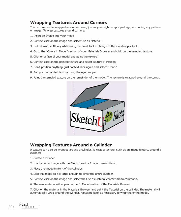
204
Wrapping Textures Around CornersThe texture can be wrapped around a corner, just as you might wrap a package, continuing any pattern or image. To wrap textures around corners:
1. Insert an Image into your model
2. Context click on the image and select Use as Material.
3. Hold down the Alt key while using the Paint Tool to change to the eye dropper tool.
4. Go to the “Colors in Model” section of your Materials Browser and click on the sampled texture.
5. Click on a face of your model and paint the texture.
6. Context click on the painted texture and select Texture > Position
7. Don’t position anything, just context click again and select “Done.”
8. Sample the painted texture using the eye dropper
9. Paint the sampled texture on the remainder of the model. The texture is wrapped around the corner.
Wrapping Textures Around a CylinderA texture can also be wrapped around a cylinder. To wrap a texture, such as an image texture, around a cylinder:
1. Create a cylinder.
2. Load a raster image with the File > Insert > Image... menu item.
3. Place the image in front of the cylinder.
4. Size the image so it is large enough to cover the entire cylinder.
5. Context click on the image and select the Use as Material context menu command.
6. The new material will appear in the In Model section of the Materials Browser.
7. Click on the material in the Materials Browser and paint the Material on the cylinder. The material will automatically wrap around the cylinder, repeating itself as necessary to wrap the entire model.
Materials
205
SketchUp 4.0 User Guide
Texture Positioning and Hidden GeometryYou can adjust textures on a face, such as the faces of a cylinder, and then repaint the adjust texture across the entire curved surface of the cylinder. For example, to adjust a texture on a cylinder:
1. Create a cylinder.
2. Load a raster image with the File > Insert > Image... menu item.
3. Place the image in front of the cylinder.
4. Size the image so it is large enough to cover the entire cylinder.
5. Context click on the image and select the Use as Material context menu command.
6. The new material will appear in the In Model section of the Materials Browser.
7. Click on the material in the Materials Browser and paint the Material on the cylinder. The material will automatically wrap around the cylinder, repeating itself as necessary to wrap the entire model.
8. Click on Display > Hidden Geometry.
9. Select one of the faces of the cylinder, context click, and select Texture > Position.
10. Reposition the texture on the face.
11. Sample the repositioned texture using the eyedropper button on the material browser, or using the Alt key with the Paint Bucket tool.
12. Click on Display > Hidden Geometry to turn off Hidden Geometry.
13. Paint the sampled, repositioned, texture on the remainder of the cylinder. Your texture now appears as though it has been repositioned on the entire cylinder.
Projecting a TextureSketchUp’s Texturing Positioning feature also lets you project textures or images onto geometry as though projected using a slide in a fi lm projector. This feature is particularly useful if you wish to project a topographic image over a site model, or an image of a building onto a model representing the building. To project an image over a model:
1. Create a model, such as a cone, topography, or building front. This model will receive the projected image.
2. Load a raster image with the File > Insert > Image... menu item.
4. Place the image in front of the model that will receive the projection.
5. Size the image so it is large enough to cover the entire model.
6. Right click on the image and select Explode to turn the image into a projected texture.
Note: Turn on x-ray display mode for the image to ensure the image is positioned such that it will cover the entire model.
7. Select the Sample Paint Tool (eyedropper) from the Materials Browser. Notice, when you drag the Sample Paint Tool over the image, a square appears on the tip of the tool. This square indicates that you are in projected texture mode.
8. Sample the projected texture with the Sample Paint Tool.
9. Paint the texture onto the faces of the model. The image will appear as though it were projected directly on the faces, adjusting to the contours of model.
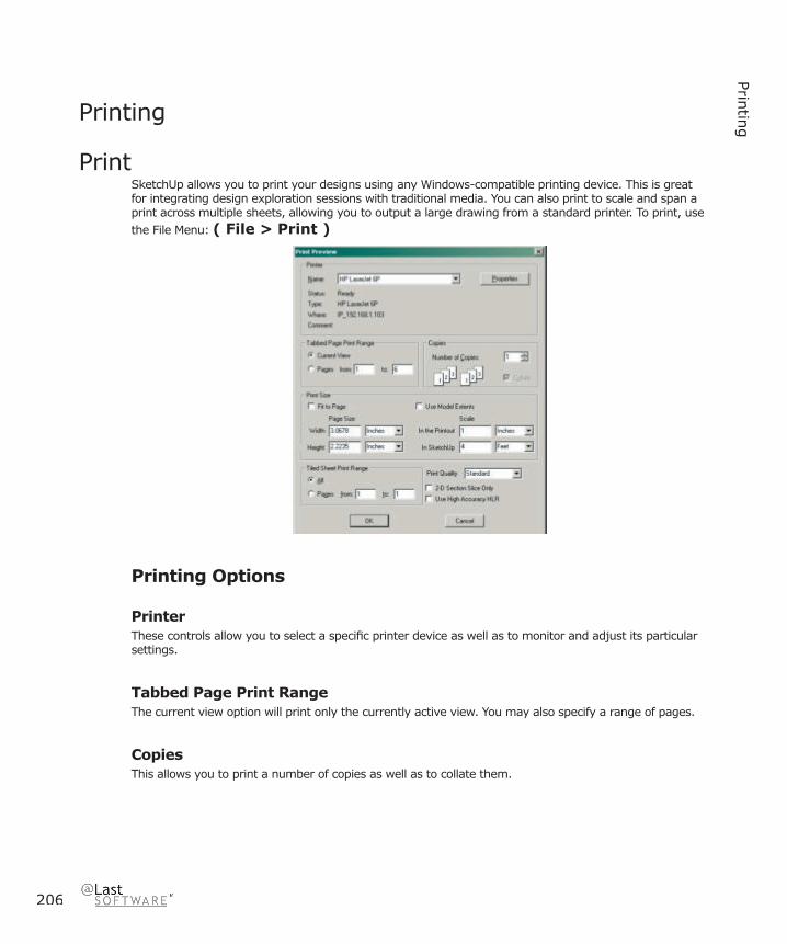
206
Printin
gPrinting
PrintSketchUp allows you to print your designs using any Windows-compatible printing device. This is great for integrating design exploration sessions with traditional media. You can also print to scale and span a print across multiple sheets, allowing you to output a large drawing from a standard printer. To print, use the File Menu: ( File > Print )
Printing Options
PrinterThese controls allow you to select a specifi c printer device as well as to monitor and adjust its particular settings.
Tabbed Page Print RangeThe current view option will print only the currently active view. You may also specify a range of pages.
CopiesThis allows you to print a number of copies as well as to collate them.

Printin
g
207
SketchUp 4.0 User Guide
Print SizeThis option allows you to adjust the physical size of your print and/or adjust the output scale. (Scaled output is only available for measurable views.)
Fit to Page: When enabled, the current view will be sized to fi t onto a single printer sheet. This must be disabled in order to specify a different size or scale.
Use Model Extents: This will print only the model extents and may discard any surrounding empty background.
Tiled Sheet Print RangeIf your print will require multiple tiled sheets, you can specify the range. See below for more information.
Print QualityPrinting large tiled output can be taxing on your computers resources. By selecting the appropriate print quality, you can expedite large area print jobs and rough drafts.
Draft
This setting produces images with jagged lines, but it is fast, making it useful for quick prints.
Standard
This setting provides the optimum balance of speed and quality for most printers and purposes.
High Defi nition
This setting is useful for presentation drawings and high quality prints.
Ultrahigh Defi nition
This setting can send a very large amount of data to your printer, and may tax some systems. It does, however, produce very crisp lines making it useful for measured drawings or ultra fi ne prints in general.
Large Format
This setting produces images that are optimized for large format prints or that are meant to be viewed from several feet away. Resolution and line weights are set accordingly. This is useful for plotters and tiled sheets.
2D Section Slice Only
When you have an active section in your scene, this option outputs only the section slice outlines.
Use High Accuracy HLR
This option sends the drawing information to the printer as vector information. While this can result in a much smaller amount of information, you cannot print textures, transparency, or shadows. Drawing accuracy may be adversely affected, as well.
Print Tiling If the current page size is larger than the paper size of your printer or plotter, the entire drawing page is printed with as many printer pages as needed. This process is called tiling. When the page size is larger than the printer’s paper size, the printer pages can be assembled like individual pieces of tile to compose the entire drawing.

208
Tiling lets you print proofs of a large drawing, such as a B size (11” x 17”), on a printer that uses a smaller paper size, such as an A size (8.5” x 11”). Tiling also lets you print banners that are made up of multiple pages.
You can print selected page tiles within the set by entering a page number range in the Print dialog box. Page tiles are numbered top to bottom beginning at the top left of the drawing page.
You can display a preview of tile pages using ‘Print Preview’ on the File Menu: ( File > Print Preview )

Printin
g
209
SketchUp 4.0 User Guide
Print To Scale SketchUp allows you to print your designs to scale using any Windows-compatible printing device. This is great for integrating design exploration sessions with traditional media. You can also span a print across multiple sheets, allowing you to create a large tiled drawing from a standard printer.
Menu Access: ( File > Print )
Print to Scale Options
Print Size/Tiled Sheet Print RangeThese controls allow you to adjust the physical scale and size of the printed output. Due to inherent properties of certain types of drawings, some options may be unavailable. For example, a perspective drawing cannot be accurately measured and thus cannot have a scale. When the SketchUp display is set to perspective, the scale output options will be grayed out. If you’re having trouble printing to scale, see below.
Fit To PageWhen this option is enabled, SketchUp will size your drawing to fi t onto a single printer sheet and scaled output is not available.
Use Model ExtentsThis option forces SketchUp to ignore the background part of an image and calculate the printable area from the dimensional extents of your model. This is often handy for scaled printing, as it makes it much easier to fi t a certain model onto a sheet or certain page size.
When disabled, the printable area will be determined by the contents and composition displayed on your monitor screen. Thus, keeping this option disabled is most appropriate for printing perspective images.
Page SizeThese dimensions refl ect the physical dimensions of the print in width and height.
ScaleThese controls allow you to specify a certain drawing scale, and follow architectural conventions. The fi rst measurement, labeled ‘In The Printout’ is the measurement on paper. The second measurement, labeled ‘In SketchUp’ is the actual measurement of the object (actual model dimensions) in real scale.
For example, for a scale of 1/4” = 1’, simply enter 1 inch(es) in the printout equals 4 feet in SketchUp.
Note: It’s not possible to print a perspective image to scale. Also, even if perspective is off, many projection angles available via the Orbit Tool cannot be measured once printed out. This is due to the ‘foreshortening’ effect of projecting a 3D object onto a 2D drawing. If you need to print to scale, make sure perspective is disabled and that the view is either orthographic (Top, Front, Right, Left, Back, Bottom) or isometric.
Because perspectives and certain paraline projections do not yield measurable results, the Print To Scale feature is only available from paraline projections of the standard orthographic and isometric views. Non-measurable views provide for adjusting Page Size only. See below for more information.
210
Tiled Sheet Print RangeIf the print you have specifi ed will require multiple sheets, this control allows you to specify a range. We recommend you do a ‘Print Preview’ before printing tiled output to avoid wasting printer resources. SketchUp will warn you if your print operation will create many sheets.
Troubleshooting GuideWhen using the Measure Tool in SketchUp, it can give you accurate measurements in any projection, including perspective. This is because SketchUp is actually measuring the underlying 3D model. When that same model is printed, however, the traditional rules of projection apply: It becomes a projected 2D image and the 3D information is no longer available. Unless it’s an orthographic or isometric drawing, lines are no longer reliably measurable.
In order for SketchUp to print to scale, it is necessary for the SketchUp display itself to be a measurable drawing projection. Performing the following steps in order will ensure you can print to scale.
1. Turn Perspective Off. Perspective-projected images cannot be used as scale drawings. Use the Camera Menu: ( Camera > Perspective )
2. Put SketchUp in a Measurable View. The pre-set standard views, namely plan, elevations, and the four isometric views, will all yield measurable results for orthogonal geometry and can be printed to scale. You can use the ( Camera> Standard Views ) menu or the Views Toolbar to instantly set SketchUp to one of these measurable views. If the face you’re measuring is not orthogonal, you will need to align the view to that face instead.
3. Make sure ‘Fit To Page’ is off. This option forces your print to the edges of a page, and thus prevents accurate scale printing when enabled.
4. Type in the desired output scale.

211
SketchUp 4.0 User GuideIm
portin
g an
d E
xportin
g
Importing and Exporting
CAD/3D Model Formats
DWG/DXF ImportIn order to be a true design exploration tool, SketchUp must support your entire design process. Loose, abstract conceptual studies are important, but so are precision drawing, documentation, and collaboration with other disciplines. For these reasons, the ability to both import and export industry standard AutoCAD DWG and DXF fi les has been built into SketchUp since its fi rst release. @Last Software is also a member of the OpenDWG Alliance, which allows SketchUp to offer the most reliable DWG fi le translation available.
Importing CAD Files1. First, use the File Menu: ( File > Insert > DWG/DXF... )
2. This will launch a File Open dialog, where you choose the fi le to be imported.
3. Depending on the nature of the fi le to be imported, you may need to specify a units setting or have SketchUp modify the imported entities. Click the Options... button to do so. Import Options are described in further detail below.
4. After you click OK, SketchUp will process the fi le. This may take several minutes for a large fi le, as SketchUp’s native geometry is very different from most CAD software and the conversion process is calculation-intensive. Once the import is complete, SketchUp will present a report on what entities were imported.
5. If the current SketchUp fi le contains any entities prior to the import operation, all imported geometry will import as a group so as not to interfere with (stick to) existing geometry. Importing into a blank model will not create a Group. Once a drawing is imported, you may have to use the Zoom Extents button to see it.
Supported EntitiesWhen importing a fi le, SketchUp must translate the contents into usable drawing elements. Supported CAD entities include lines, arcs, circles, polylines, faces, entities with thickness, 3D Faces, and nested blocks. CAD layers are also supported.
Currently, SketchUp does not support AutoCAD regions, XREFS, hatching, dimensions, text, and proprietary ADT or ARX objects. These will be ignored on import. If you need to import unsupported entities, you may be able to explode them into more primitive drawing elements within your CAD application. For example, ADT walls and extrusions, once exploded, import as faces. Some objects may need to be exploded multiple times in order for them to be translated into SketchUp geometry.
212
File SizeTry to keep the size of imported fi les to a minimum. Importing very large CAD fi les can take a long time as each drawing entity must be analyzed. Also, once imported, a complex CAD fi le can create a drag on SketchUp’s performance while you are working, as each line and face in SketchUp has quite a bit more intelligence and “overhead” than it’s CAD counterpart. It’s important to remember that SketchUp is not a CAD system. It is just as accurate, but is not designed for the same type of line-intensive drawings. For these reasons, it is a good idea to clean up and/or crop your CAD drawings so that you only import content which is absolutely necessary.
Another strategy is to keep different levels of detail/abstraction separate. For example, instead of importing a single large fi le with all of your information, you can elect to use a greater number of simpler fi les. One imported CAD fi le may contain site plan information, while another may have a fl oor plan, and yet another may have a specifi c detail. By using three separate fi les that come into SketchUp as three separate groups, you can more easily hide the data that is not immediately relevant to what you are doing.
Import OptionsSome fi les may contain non-standard units, coplanar faces, or inconsistently oriented faces. You can force SketchUp to automatically analyze and repair these scenarios during the import process.
Import Units
In SketchUp, you draw in real-world units, so you can start drawing in feet and inches, then change your units to millimeters and keep on drawing without losing dimensional accuracy.
Some CAD formats, such as DXF, save data in generic units. This means that you may need to specify base unit value for fi les you import in order to import geometry at the correct scale. If you know the drawing units of your fi le, matching them here will produce the correct input. If not, you may want to contact the drawing author. If no information is available, you may guess, then resize the model correctly after it is imported. Be aware that it’s better to err on the side of larger units in this case:
Caution: SketchUp only recognizes surfaces of .001 square inches and larger.
If you try to import a model with an edge length of .01, it will be rejected, as .01 x .01 = .0001 sq units. For example, say we have a DWG or DXF of a building drawn at 35 units (feet) long. If you specify millimeters as the input unit, then the imported model will come into SketchUp as only 35 mm long. Many of the faces can therefore be too small for SketchUp and will be discarded. The rest may be distorted in undesirable ways. If you specify meters instead, the imported building will be too big, but all of the faces will import in a proportional manner. You can then measure the side of the building, type in 35 feet, and the geometry will be correctly sized.
Merge Coplanar Faces: When importing DWG/DXF fi les, you may fi nd that many planes are coming into SketchUp with triangulating lines. Removing these manually can often be tedious. You can have SketchUp automatically remove these lines by enabling the Merge Coplanar Faces option.
Orient Faces Consistently: This features will analyze the direction of imported faces and orient them so that they are uniform in direction.
Importin
g an
d E
xportin
g
213
SketchUp 4.0 User Guide
3D DWG/DXF ExportSketchUp can export 3D geometry to several AutoCAD formats: DWG r12, DWG r13, DWG r14, DWG r2000, DWG r2004, DXF r12, DXF r13, DXF r14, DXF r2000, and DXF r2004. SketchUp uses the industry standard OpenDWG Alliance fi le import/export model libraries to ensure maximum possible compatibility with AutoCAD.
Exporting CAD Files1. First, use the File Menu: ( File > Export > 3D Model... )
2. This will bring up a standard Save File dialog. Make sure that the Export Type drop-down is set to the appropriate format.
3. From here, you may save your fi le using the current settings or you can click on the Options... button to bring up the DWG/DXF Export Options dialog box.
Export OptionsSketchUp can export faces, edges (wires), dimensions, text, or Construction Geometry in any combination. All surfaces in SketchUp are exported as a triangulated polyface mesh with interior ‘splframe’ lines hidden where appropriate. This simulates the appearance of your native SketchUp fi le, even when all exported faces are triangular.
When exporting AutoCAD fi les, SketchUp looks at the current unit of measurement set Units tab of the Model Info dialog box and uses that as a reference for translation. For instance, if the SketchUp current unit setting is Decimal/Meters, SketchUp will export the DWG fi le accordingly, and AutoCAD must be set to Decimal in order for the units to translate correctly as meters.
Note: When exporting, duplicate line entities will not be created on top of a p-line entity.
214
3DS ExportThe 3DS format is native to the original DOS-based 3D Studio modeling and animation application. Although obsolete in many ways, the 3DS format is still widely used and offers a direct way to export simpler SketchUp models into a wide range of 3D modeling packages. Because 3DS preserves material assignments, texture mapping, and camera position, it can often allow ideas generated in SketchUp to be transferred with greater fi delity than formats designed for CAD.
Exporting 3DS Files1. Use the File Menu: ( File > Export > 3D Model... )
2. This will bring up a standard Save File dialog. Make sure that the Export Type drop-down is set to 3D S (*.3ds).
3. From here, you may save your fi le using the current settings or you can click on the Options... button to bring up the 3DS Export Options dialog box.
Export Options
Single Object
This option outputs your 3DS model as a single named object. This can be useful when creating simple massing models for site context, as your building model remains simple to select and manipulate once imported into another application.
Objects By Geometry
This setting will analyze your SketchUp model and try to break it up into named objects based on the connections of faces, groups, and component defi nitions. Please note that only top level objects organizations become objects in the 3DS output. In other words, any nested systems of Components or Groups will be treated as one one object. Also, layer assignments are not supported in 3DS fi les.
Output Texture Maps
This assigns texture maps to 3DS materials whenever the corresponding SketchUp material uses a texture. Please be aware of the limitations: Texture fi lenames in the 3DS format are limited to eight characters, so any long fi le names will be truncated in the 3DS fi le material description and may not work properly. Also, any color changes made to textures in SketchUp will not be preserved.
This option only affects 3DS materials. UV texture mapping coordinates are always exported with faces, regardless of the presence of a SketchUp texture.
Importin
g an
d E
xportin
g
215
SketchUp 4.0 User Guide
Output 2 Sided
When 2-sided output is enabled, SketchUp will use one of two techniques to better simulate the appearance of geometric solidity:
The Materials 2-sided option enables the 2-sided fl ag in the 3DS material defi nition. This outputs the same number of polygons as 1-sided output, but can slow down rendering speeds of other applications, particularly when shadows and refl ections are being rendered. Also, this option prevents 3DS faces from having a different material on the back as is possible in SketchUp.
Conversely, the Geometry 2-sided option outputs each SketchUp face twice; Once for the front and once for the back. This doubles the number of polygons in the resulting 3DS fi le and can slow down rendering, but it ensures that your model will look more like it does in SketchUp: Both faces will always render, and faces that have two different materials on the front and back are preserved within limits.
Output Standalone Edges
Standalone Edges, or SketchUp lines not connected to any faces, are somewhat unique to SketchUp and not supported by many other 3D programs or the 3DS format. When enabled, this option creates very thin rectangles that appear as edges. Unfortunately, this is a compromise that can result in invalid texture coordinates. In such a case, UV mapping must be re-applied before you can render the scene in many applications. Also, certain exported standalone edge geometries can create invalid 3DS fi les altogether. For these reasons, this setting is disabled by default. If you need to export edges, the VRML format may better suit your needs.
Output Selection Only
Outputs the currently selected portions of the model in the 3DS format.
Use “Color by Layer” Materials
The 3DS format doesn’t support layers directly. This option assigns 3DS materials based on your model’s layer assignments, rather than its materials. It can sometimes be preferable to export layers as materials in this manner when exporting to other rendering applications.
Generate Cameras
This option creates a camera for the default view as well as any SketchUp pages which have been defi ned.
Units
This option allows you to specify the measurement unit in which the model is exported. The default setting is ‘Model Units’, which uses the units specifi ed under SketchUp preferences. The other options override the SketchUp units, and force the 3DS fi le to use the units you’ve chosen.
216
3DS Issues and LimitationsBecause SketchUp is designed for idea exploration, many of its features are foreign to 3D modeling applications. Some information cannot be preserved when exporting via 3DS. Also, the 3DS format itself is obsolete in many ways and has many inherent limitations.
SketchUp is designed to automatically work around many of these limitations, and offers a variety of output options to suit different needs. The following are the most notable issues:
Object Vertex Limit
Individual objects in the 3DS format are limited to 64,000 vertex points and 64,000 faces. While SketchUp itself can handle larger geometries, any exported 3DS fi les that go over this limit may not be readable in other applications. SketchUp will automatically detect this condition and present a warning dialog.
You can work around this limitation by fi rst making sure that the ‘Objects By Geometry’ option is enabled. Next, try breaking up the geometry of your model into a larger number of smaller top-level Groups or Components.
Nested Groups and Components
Currently, SketchUp cannot output Group and Component hierarchies via 3DS. In other words, Groups within Groups will get “fl attened” at the top level.
2 Sided Faces
In some 3D programs, the direction of the polygon ‘face normal’ is very important because faces are only visible from the front by default. This behavior seems counterintuitive, as real-world objects do not exhibit this quality, but it does allow for much more effi cient rendering.
In SketchUp, both sides of a face are always visible, and you don’t have to worry about which side it is facing unless you want to. For example, if you create a box with the default material in SketchUp, the outside is shown as tan and the inside is shown as blue. Once both sides are painted with a material, however, their direction isn’t really important and is therefore not made immediately obvious.
However, when importing a model with non-uniform face normals into another application, it can appear to have “missing” faces throughout its geometry. They’re not really missing, of course, they’re simply facing the wrong direction.
One way to fi x this problem is to manually re-orient your SketchUp faces using the Reverse command, or to use the Orient Faces command to make face directions uniform for a given set of connected geometry. In particular, Orient Faces can automatically fi x many face normal problems very quickly.
The ‘Output 2-Sided’ settings, both ‘Material’ and ‘Geometry’, in the 3DS output option dialog can also fi x this. It is a kind of brute force method, but it can be quite convenient if you don’t have the time or desire to fi x the faces manually.
2 Sided Textures
Since faces share vertex front and back, only the UV of the front can be exported. if you have a texture on the back, it will take on the UV of the front side of the face.
Importin
g an
d E
xportin
g
217
SketchUp 4.0 User Guide
Multiple UV Vertices
SketchUp automatically handles all texture mapping in a way that cannot be stored in regular 3DS geometry. 3DS fi les allow only one UV mapping coordinate per vertex, which means you cannot have different mapping on two faces that share the same vertex. In order to accommodate this limitation, SketchUp breaks up geometry so that each coplanar group of polygons has its own set of vertices. This lets you keep your material mapping intact, but duplicate vertices can cause some 3D modeling operations such as smoothing or boolean operations to work incorrectly.
Fortunately, most modern 3D modeling applications allow you to “weld” overlapping vertices together while maintaining correct mapping. Performing this operation on a 3DS fi le exported from SketchUp after it is imported into a modeling application can give you the best of both worlds in terms of mapping and modeling.
Note: If both the front and back materials of a face are textured, the UV mapping on the back face is discarded.
Standalone Edges
Many 3D programs use a vertex-face model and do not recognize SketchUp’s notion of standalone lines. Consequently, neither does the 3DS format. SketchUp can try to overcome this by creating very thin rectangles in their place, but this has a tendency to create invalid 3DS fi les. Try to keep standalone edges out of your 3DS fi les if possible.
Texture Map Names
Because the 3DS format was designed in an era when DOS-based systems roamed the earth, it is not capable of storing texture fi lenames that exceed the 8.3 DOS character limit. This is, of course, quite an encumbering limitation to anyone who uses modern OS fi lename capabilities to manage large, complex projects or fi le libraries. Unfortunately, the only option is to work around it.
SketchUp tries to create unique names for unique texture fi les based on the old DOS ~1 convention. For example, a fi le named “corrugated metal.jpg” will be described in the 3DS fi le as “corrug~1.jpg”. Any other fi les that use the same fi rst six letters is truncated with a “~2”, and so forth. (We know it’s ugly.)
This work-around allows you to keep using long texture fi lenames in SketchUp without losing texture mapping info in 3DS fi les. It is fragile, however, as any fi lename changes made to your SketchUp textures or changes within your directory could cause texture loading errors when importing the 3DS fi le afterwards. If you do need to make changes to your texture fi lenames, you can always re-export your 3DS fi le. This will contain updated texture fi lenames that should work again. (And we DO use the term “work” loosely in this case...)
Texture Map Paths
When you save a SketchUp fi le, any textures you assign become embedded within it. This way, if you send your fi le via email, the recipient is sure to see it the way you intended. 3DS fi les, on the other hand, contain only a reference to a fi le name. Neither the actual path nor the texture information itself can be stored. This limitation can easily break your texture assignments. The easiest work-around is to assign any directories you use for SketchUp’s textures as a map path in the 3D application into which you are importing your model. This works pretty well, as textures that look good in SketchUp tend to look good in other 3D applications, as well.
This does NOT work if the textures are not separate fi les stored locally. In other words, if someone sends you a SketchUp fi le with embedded custom texture materials, those textures will not be accessible to an exported 3DS fi le. They will either need to send those textures as separate fi les or you will need to extract embedded textures directly from the .SKP fi le and save them as image fi les.

218
Material Names
SketchUp allows a greater variety of characters in, as well as longer names for, its native materials than the 3DS format is capable of storing. As a result, material names may be modifi ed and/or truncated to 12 characters during export.
Texture Image Hue Shift/Colorize
SketchUp offers the ability to assign a different color to a texture that cannot be carried across in the 3DS format. In a future release, we may add the ability to export hue-modifi ed textures as individual fi les. Although this compromises the effi ciency of having one texture appear as a variety of colors, it would allow exported 3DS fi les to better maintain their appearance.
Visibility
Only objects that are currently visible in SketchUp are output to the 3DS fi le. This does not take rendering display options into account, which means that faces are output even if SketchUp is in wireframe mode. Faces are not output, however, if they are hidden or if they reside on a layer that is hidden.
Multiple Cameras
Some 3D applications cannot properly read more than one camera position. This is a known limitation in SketchUp’s 3DS output.
Layers
The 3DS format does not support layers, so any layers you assign in SketchUp will be lost. If you need layers to export, the DWG format may be a better solution for you. Alternately, you can export with the “Color by Layer” Materials option enabled, which may allow you to easily select and organize geometry based on SketchUp layers once imported into other applications.
Units
SketchUp exports 3DS fi les at the units specifi ed under Options. This can affect the way geometry is described within the 3DS fi le. For example, a 1 meter cube in SketchUp will export to 3DS with sides of length 1 when units are set to meters. If you change the export units to centimeters, the same cube will export to 3DS with a length of 100.
The 3DS format contains an extra piece of information that indicates the original units via a scale factor. This allows an application that reads 3DS to automatically adjust the size of 3DS models to the correct “real world” size. For example, the 1 meter cube fi les mentioned above will both import into applications that support this in at the same size, even though one fi le is 1 unit, and the other is 100 units.
Unfortunately, many applications ignore this extra unit scale information, which means that the centimeter cube imports as 100 times larger than the 1 meter cube, instead of at the same size. Worse, it isn’t always clear in which unit 3DS fi les are saved as, resulting in considerable trial and error. In these cases, the best work-around is simply to always export fi les at the units setting expected by the 3DS importing application.

Importin
g an
d E
xportin
g
219
SketchUp 4.0 User Guide
VRML ExportVRML 2.0 (Virtual Reality Modeling Language) is a 3D scene/object description format often used to exchange data between 3D applications and to publish 3D information to the web. VRML fi les can store SketchUp geometry structure in the form of edges, faces, Groups, materials and textures, transparency, camera views, and lights.
Exporting VRML Files1. To export a VRML fi le from SketchUp, use the File Menu:
Menu: ( File > Export > 3D Model...)
2. This brings up the standard Save File dialog. Make sure that the Export Type drop-down is set to ‘VRML (*.wrl)’. From here, you may save your fi le using the current settings or you can click the ‘Options’ button to bring up the VRML Export Options dialog box.
Export OptionsOutput Texture Maps: If enabled, SketchUp will export texture information to the VRML fi le. When disabled, it will export colors only. When publishing VRML fi les to the web, you may want to edit the fi les so that textures read from the relative location rather than from your local hard drive. Also, VRML texture and material names cannot have blanks, so SketchUp will use the underscore character instead.
Ignore Back of Face Material: SketchUp exports VRML fi les with double faces so that fi les will be viewable from any viewpoint. If Ignore Back of Face Material is enabled, both the front and back of faces will be exported with the front material.
Output Edges: When enabled, SketchUp will export displayed edges as VRML edge entities.
Use “Color by Layer” Materials: If checked, SketchUp will export materials based on the layer assignment of geometry.
Use VRML Standard Orientation: The VRML standard considers the XZ plane to be horizontal (i.e. the ground plane) whereas SketchUp considers the XY plane to be the ground plane. If Use VRML Standard Orientation is enabled, the exported fi le will conform to the VRML standard.
Generate Cameras: If enabled, SketchUp will create VRML cameras from any pages that have saved camera orientations. The current SketchUp view is exported with the name “Default Camera”, and other Page camera defi nitions are output using their Page Name.
Allow Mirrored Components: This option allows exporting of components that have been mirrored or resized such that they are an opposite of the original component.
Check for Material Overrrides: Use this option to determine if any of the faces or edges or components within this component contain references to the default material or default layer.
220
2D Still Images
Image ObjectsAs a part of the everyday design process, you may often need to draw over a scan, a fax or a photograph stored as a pixel-based “raster” image fi le. SketchUp allows you to integrate these types of fi les into your 3D drawings as Image Objects.
An Image Object is essentially a rectangular face with an image fi le mapped onto its surface. Image Objects can be moved, rotated and scaled. They can also be stretched horizontally or vertically, but they cannot be made non-rectangular.
Image Formats
SketchUp supports the following formats for import as an Image Object: JPEG, PNG, TGA, BMP, and TIFF. Some formats may be more appropriate than others for certain types of images and applications.
Inserting Image ObjectsImages can be added to SketchUp models in one of two ways. First, you can use the ( File > Insert > Image... ) menu command, which will open a File Open dialog allowing you to navigate to the fi le you want. Alternately, you can simply drag and drop from the File Explorer directly into your Drawing Window.
Image ProportionsBy default, Image Objects retain the proportions of the fi le from which they are derived. While inserting an image, you can hold down the Shift key to de-constrain the proportions. You can also use the Scale Tool to alter the image object’s proportions after it is placed.
Image File Size vs. QualityWhen you add an Image Object to your scene, the image fi le it is based on becomes embedded in your SketchUp document. This allows you to send your SketchUp fi les to others without any data loss through misplaced linked fi les, but it also means that your fi les can quickly balloon to unwieldy sizes. When inserting images, try to keep fi le size as small as possible:
Resolution
Resolution can have a large impact on image size. Try to use only as much resolution as you need, and no more. You may sometimes fi nd that even a pixilated, low resolution fi le can be suffi cient to provide the information you need from a photograph, sketch, or drawing. You can also cut down on image fi le size by converting your images to grayscale before inserting them into SketchUp.
Also, the resolution of Image Objects is limited to the largest texture that OpenGL can handle. For most systems this limit is 1024 x 1024 pixels. This should be suffi cient for most purposes, but if higher resolution is required, you can always stitch together multiple Image Objects.
Image File Compression
Another way to minimize fi le size is to use compressed fi le formats such as JPEG and PNG. These take up far less space both on disk and inside a SketchUp fi le.
Importin
g an
d E
xportin
g
221
SketchUp 4.0 User Guide
Image Object Context CommandsYou can access context menu commands by clicking on an entity with the right mouse button.
Entity Info
This launches the Entity Info dialog box for that Image Object, which allows you to view and change its attributes.
Erase
This deletes the Image Object from your model.
Hide/Unhide
Hiding makes the selected Image Object invisible. If “Show Hidden Geometry” is enabled, all hidden entities are displayed in a ghosted pattern, allowing you to select them. Thus, if the selected geometry is hidden, this command will be ‘Unhide’, and choosing it will restore visibility.
Explode
Exploding an Image Object breaks it back into its constituent parts.
Export
This option allows you to save out an embedded image object to a fi le which may be edited in an image editor.
Reload
If you make changes to an image fi le using an image editor, use the Reload command to make sure those changes are brought back into SketchUp.
Zoom Extents
Zooms your view to a distance which makes the whole entity visible, and centers it in the drawing window.
Shadows
Cast: This command controls how Shadows are affected by the Image Object. The Image Object will cast shadows.
Receive: The Image Object will receive cast shadows cast onto it by other geometry.
Unglue
If you’ve attached an image object to a face, it cannot be moved off that face. The Unglue command makes it free to move off that face.
Use As Material
This command creates a material swatch in the In Model section of the Material Browser.
222
Image Object Entity Info Dialog BoxWith an Image Object selected, you can see and change its attributes in the Entity Info dialog box.
Material
This displays the material assigned to the Group. If no material is applied, the default material icon will be displayed. You can select another material in your scene by clicking on the swatch.
Layer
This displays the layer of the selected entity. To move it to a new layer, choose a new one from the pop-up list.
Name
This fi eld displays the fi lename of the Image Object.
in pixels
This fi eld displays the pixel dimensions of the selected Image Object.
Width/Height
This displays the dimensions of the Image Object in your SketchUp model. You can lock or unlock the proportions.
Details Menu
Hide Details: Hides the group’s details.
Cast Shadows: When the Cast Shadows option is enabled, the face will be allowed to cast a shadow.
Receive Shadows: When the Receive Shadows option is enabled, the face will be allowed to receive shadows cast by other entities.

Importin
g an
d E
xportin
g
223
SketchUp 4.0 User Guide
Image ExportSketchUp allows you to export 2D raster image fi les in JPG, BMP, TGA, TIFF, PNG, and Epix formats.
1. To export a raster image from SketchUp, begin by setting up the model view in your Drawing Window to look as you want for the export. SketchUp will export the model view as it is currently displayed, including display style, edge rendering, shadows, and view orientation.
2. Once you have set the view you want to export, use the File Menu to access this feature:
Menu: ( File > Export > 2D Graphic... )
3. This brings up the standard Save File dialog. Make sure that the Export Type drop-down is set to the appropriate format. From here, you may save your fi le using the current settings or you can click the ‘Options’ button to bring up the Export Options dialog box for that format.
Export OptionsImage Size Determines the dimensions, in pixels, of the saved fi le.
Image Size
Use Viewport Size:When enabled, the image fi le will be the exact dimensions, in pixels, of your SketchUp Drawing Window. When disabled, it allows you to specify your own dimensions. Typically, an image intended to be printed needs to be signifi cantly larger than normal screen resolution.
Width/Height:These control the size of image as measured in pixels. As you specify larger dimensions, the export operation will take longer and consume more memory, and the resulting fi le will use more storage space on your system. It’s a good idea to use only the minimum image size necessary to achieve your goals.
ImageQuality
Anti-Alias: When enabled, SketchUp will smooth the exported image. This method can take longer, but it helps to reduce jagged lines and pixilated artifacts in images.
224
Section Slice ExportSketchUp can save the active Section Slice as its own 2D fi le in the DWG and DXF formats. As with all vector information, this has the advantage of precise measurements. Use the File Menu to access this feature:
Menu Access: ( File > Export > Section Slice... )
This brings up the standard Save File dialog. Make sure that the Export Type drop-down is set to the appropriate format. From here, you may save your fi le using the current settings or you can click the ‘Options’ button to bring up the Section Slice Export Options dialog box.
Section Export Options
Projection
True Section (Orthographic): This option outputs the section slice as a true orthographic drawing. This is useful for creating templates for CD drawings or any other time you want to generate accurate, measurable slices.
Screen Projection (WYSIWG): This projects the section cut as you see it on your SketchUp screen, including any perspective distortion. This is most useful for diagrams that need not be measured.
Drawing Scale & Size
Full Scale (1:1): When enabled, This outputs your section slice to CAD at a true 1:1 scale.
Width/Height: These values represent the overall dimensions of the slice output, and will update depending on the slice being exported and its scale.
In Drawing/In Model: These controls allow you to specify a certain drawing scale, and follow architectural conventions. The fi rst measurement, labeled ‘In Drawing’ is the measurement of the exported geometry. The second measurement, labeled ‘In Model’ is the actual measurement of the object in real scale.
For example, for a scale of 1/4” = 1’, simply enter 1 inch in the output equals 4 feet in SketchUp.
Note: You can’t export a perspective screen projection to scale. Also, even if the view is a paraline projection, only faces whose normals are perpendicular to the view angle will be measurable.
Automatic/Width: When enabled, this automatically sets the width of profi le lines by matching the output to the proportions you see in the SketchUp display. If disabled, you can specify an exact width.
Section Lines
None: Outputs section slice lines at normal width.
Polylines with width: Outputs lines as poly-line entities.
Wide line entities: Outputs lines as wide line entities. This option is only available when saving AutoCAD 2000 or later DWG fi les.
Always Prompt for Hidden Line Options: When enabled, the options dialog will come up each time you output a section slice. When disabled, SketchUp will use whatever options were used the last time by default.

Importin
g an
d E
xportin
g
225
SketchUp 4.0 User Guide
2D DWG/DXF Vector ExportSketchUp allows you to export your models as 2D vector drawings in many formats, including DWG, DXF, EPS, and PDF. This topic covers DWG and DXF formats.
2D vector export has advantages over raster image export in that it produces drawings that are resolution independent and can be easily imported and modifi ed in any CAD or illustration program. This is great for adding a detail to a set of CDs, plotting a perspective in a large format, or adding further graphic refi nement in an illustration package.
Caution: Some graphic features of SketchUp, including textures, shadows, and transparency, cannot be exported to 2D vector formats.
1. To export a vector image from SketchUp, begin by setting up the model view in your Drawing Window to look as you want for the export. SketchUp will export the model view as it is currently displayed, with the exception of unsupported features such as textures and shadows.
2. Once you have set the view you want to export, use the File Menu to access this feature:
Menu: ( File > Export > 2D Graphic)
3. This brings up the standard Save File dialog. Make sure that the Export Type drop-down is set to the appropriate format. From here, you may save your fi le using the current settings or you can click the ‘Options’ button to bring up the Export Options dialog box for that format. This allows you to adjust the size, scale, and appearance of the output.
2D DWG/DXF Vector Export OptionsThese control the output size and scale of the fi le.
Drawing Scale & Size
Full Scale (1:1): This option sets your output to a 1:1 ratio. This outputs the 2D fi le at real-world scale.
In Drawing/In Model: These controls allow you to specify a certain drawing scale, and follow architectural conventions. The fi rst measurement, labeled ‘In Drawing’ is the measurement of the exported geometry. The second measurement, labeled ‘In Model’ is the actual measurement of the object in real scale.
For example, for a scale of 1/4” = 1’, simply enter 1 inch in the printout equals 4 feet in SketchUp.
Note: You can’t export a perspective screen projection to scale. Also, even if the view is a paraline projection, only faces whose normals are perpendicular to the view angle will be measurable.
Width/Height: This indicates the height and width of the output.
226
Profi le Lines
None: Profi le lines are output at standard width.
Polylines with width: Outputs profi le lines as poly-line entities.
Wide line entities: Outputs profi le lines as wide line entities. This option is only available when saving AutoCAD 2000 or later DWG fi les.
Separate on a layer: When enabled, this outputs profi le lines onto their own layer. This can be handy if you’d like to plot profi le lines using a different pen weight or quickly change the line width of all profi le lines in a separate CAD or Illustration program.
Note: This merely creates a single additional layer for profi le edges. SketchUp Layer assignments do not translate directly when exporting 2D hidden line vectors.
Width and Automatic: When enabled, this automatically sets the width of profi le lines by matching the output to the proportions you see in the SketchUp display. If disabled, you can specify an exact width.
Section Lines
None: Section slice lines are output at standard width.
Polylines With width: Outputs Section Slice lines as polyline entities.
Wide line entities: Outputs Section Slice lines as wide line entities. This option is only available when saving AutoCAD 2000 or later DWG fi les.
Separate on a layer: When enabled, this outputs section lines onto their own layer. This can be handy if you’d like to plot profi le lines using a different pen weight or quickly change the line width of all profi le lines in a separate CAD or Illustration program.
Note: This merely creates a single additional layer for section edges. SketchUp Layer assignments do not translate directly when exporting 2D hidden line vectors.
Width and Automatic: When enabled, this automatically sets the width of Section Slice lines by matching the output to the proportions you see in the SketchUp display. If disabled, you can specify an exact width.
Extension Lines
Show extensions: When enabled, any lines that are displayed with extensions on the SketchUp display are output similarly in the 2D fi le. When disabled, lines are output normally, regardless of the screen display.
Tip: It’s okay to keep extensions enabled in SketchUp, as its inference system is smart enough not to get intersection snaps confused, This might not work so well with snap systems of CAD applications, however. If you want to generate a measurable drawing and have endpoint and intersection snaps work accurately, keep Extend Edges disabled.
Length and Automatic: This will analyze the output size you’ve specifi ed and try to match the extension length so that it will look like your screen. If disabled, you can specify an exact length.
Always Prompt for Hidden Line Options: When enabled, the options dialog will come up each time you output a 2D DWG or DXF fi le. When disabled, SketchUp will use whatever options were used the last time.
Defaults: You can return the option to their recommended default settings at any time by pressing the Defaults button.

Importin
g an
d E
xportin
g
227
SketchUp 4.0 User Guide
PDF/EPS ExportSketchUp allows you to export your models as 2D vector drawings in many formats, including DWG, DXF, EPS, and PDF. This topic covers PDF and EPS formats.
2D vector export has advantages over raster image export in that it produces drawings that are resolution independent and can be easily imported and modifi ed in many other programs. This is great for adding a detail to a set of CDs, plotting a perspective in a large format, or adding further graphic refi nement in an illustration package.
EPSEncapsulated PostScript format is based on PostScript, a graphics description language developed by Adobe as a standard way for graphics programs and print devices to communicate with each other. It is widely used in the graphic design and publishing industries.
PDFAdobe® Portable Document Format (PDF) is the open standard for electronic document distribution worldwide. It preserves all the fonts, formatting, graphics, and color of any source document, regardless of the application and platform used to create it. Also, PDF fi les are compact and can be shared, viewed, navigated, and printed exactly as intended by anyone with free Adobe Acrobat® Reader® software.
Caution: Some graphic features of SketchUp, including textures, shadows, smooth shading, backgrounds, and transparency, cannot be exported to PDF and EPS.
Exporting to PDF or EPS1. To export a PDF or EPS vector image from SketchUp, begin by setting up the model view in your Drawing Window to look as you want for the export. SketchUp will export the model view as it is currently displayed, with the exception of unsupported features such as textures and shadows.
2. Once you have set the view you want to export, use the File Menu to access this feature:
Menu: ( File > Export > 2D Graphic... )
3. This brings up the standard Save File dialog. Make sure that the Export Type drop-down is set to ‘Encapsulated PostScript Format (*.eps)” or Portable Document Format (*.pdf) From here, you may save your fi le using the current settings or you can click the ‘Options’ button to bring up the Export Options dialog box for that format. This allows you to adjust the size, scale, and appearance of the output.

228
PDF/EPS Export Options
Drawing Size
These control the output size and scale of the fi le.
Full Scale (1:1): This option sets your output to a 1:1 ratio. This outputs the 2D fi le at real-world scale.
Width/Height: This indicates the height and width of the output. PDF and EPS fi les are limited in dimension to 100 inches (7200 points) in both height and width.
Scale: These controls allow you to specify a certain drawing scale, and follow architectural conventions. The fi rst measurement, labeled ‘In Hidden Line Output’ is the measurement of the exported geometry. The second measurement, labeled ‘In SketchUp’ is the actual measurement of the object in real scale.
For example, for a scale of 1/4” = 1’, simply enter 1 inch in the printout equals 4 feet in SketchUp.
Note: You can’t export a perspective screen projection to scale. Also, even if the view is a paraline projection, only faces whose normals are perpendicular to the view angle will be measurable.
Profi le Lines
Show Profi les: When enabled, any lines that are displayed in profi le on the SketchUp display are output as thicker lines in the 2D vector fi le. When disabled, all lines are output normally, (without profi le thickness) regardless of the screen display. This is useful if you never want to see profi le lines in your 2D vector output.
Match Screen Display (Auto-Width): When enabled, this automatically sets the width of profi le lines by matching the output to the proportions you see in the SketchUp display. If disabled, you can specify an exact width.
Section Lines
Specify Section Line Width: When enabled, allows you to adjust settings for Section Slice lines that are output.
Match Screen Display (Auto-Width): When enabled, this automatically sets the width of Section Slice lines by matching the output to the proportions you see in the SketchUp display. If disabled, you can specify an exact width.
Extension Lines
Extend Edges: When enabled, any lines that are displayed with extensions on the SketchUp display are output similarly in the EPS fi le. When disabled, lines are output normally, regardless of the screen display.
Tip: It’s okay to keep extensions enabled in SketchUp, as its inference system is smart enough not to get intersection snaps confused, This might not work so well with snap systems of other applications, however. If you want to generate a measurable drawing and have endpoint and intersection snaps work accurately, keep Extend Edges disabled.
Match Screen Display (Auto-Length): This will analyze the output size you’ve specifi ed and try to match the extension length so that it will look like your screen. If disabled, you can specify an exact length.
Always Prompt for EPS Export Options: When enabled, the options dialog will come up each time you output a 2D EPS fi le. When disabled, SketchUp will use whatever options were used for the previous export.
Importin
g an
d E
xportin
g
229
SketchUp 4.0 User Guide
Defaults: You can return the option to their recommended default settings at any time by pressing the Defaults button.
Map Windows fonts to PDF base fonts: When enabled, this option will attempt to select a PDF fonts that correspond to the Windows fonts used in the model.
LimitationsThe primary intent of PDF and EPS export is to provide a vector export of SketchUp that can be brought into vector based editing programs like Adobe Illustrator. The fi le output consists of lines and fi lled regions.
Because SketchUp does not use OpenGL rendering to create vector output, you will lose a number of rendering effects that are provided by OpenGL. In particular, you will lose shadows, textures, smooth shading, and transparency.
If you need output that will match what you see on the screen, or want to bring it into an image editing application like Photoshop, then exporting raster images will likely better suit your needs.
Text and Dimensions
SketchUp will attempt to output text annotation and notes to your 2D drawing. Please note the following limitations:
• Text and Dimension entities that are obscured (partially or totally) by other geometry in the SketchUp Drawing Window exports "on top of" that geometry.
• Text and Dimension entities that are partially clipped by the edges of the SketchUp Drawing Window are not exported.
• Certain fonts may not translate exactly.
Piranesi EpixNamed after Giovanni Battista Piranesi (1720-1778), an 18th century architect known for his masterful drawings and etchings, Piranesi is a painting application that enables you to create stunning renderings from your SketchUp models.
Piranesi responds to depth and material information provided by SketchUp, enabling you to work quickly and accurately as you “paint in space.” You can use colors and tints, apply photographic or hand drawn textures, and add backgrounds and supporting detail. Feedback is instantaneous, allowing you to test options and steadily refi ne your image.
For more information, please visit the Piranesi Web Site: www.informatix.co.uk/piranesi.htm
The Anatomy of an Epix FileThe native fi le format of Piranesi is referred to as an Epix (Extended Pixel) fi le. In addition to storing the actual rendered image, Epix embed additional information from the original 3D model. This information allows Piranesi’s paint tools to intelligently render the image. There are three “channels” of an Epix fi le:
RGB: The fi rst, known as the RGB Channel, contains the color of each pixel. This is the same data typically stored in other raster image formats. (In fact, Epix fi les are readable in most image editors as TIFF fi les.)
230
Depth: The second, known as the Depth Channel, stores the distance of each pixel from the eye point. This information helps Piranesi understand the surface topology under the image and allows it to apply textures, scale objects, lock orientation, and many other capabilities dependant on the 3D surfaces of your model.
Material: The third, a Material Channel stores the material for each pixel. This lets you paint one part of your rendering loosely without having to worry about painting another by mistake.
In General, Piranesi expects a fl at shaded, non-textured Epix fi le. Some of the rendering modes in SketchUp, such as Wireframe and Hidden Line, don’t really work well for Piranesi, and are disabled during export in favor of shaded output.
Other features of SketchUp, such as edges and textures, are also different from that which Piranesi expects, yet may be desirable in many cases. While adding support for Epix fi les in SketchUp, we have tried to adhere to Piranesi’s expectations whenever possible while retaining enough fl exibility to accommodate the varying needs of different artists and renderers.
Exporting an Epix File1. First, choose the image export option:
Menu Access: ( File > Export > 2D Graphic... )
This brings up the standard Save File dialog. Make sure that the Export Type drop-down is set to “Epix Document”. From here, you may save your fi le using the current settings or you can click the ‘Options’ button to bring up the Epix Export Options dialog box.
Note: Your display must be set to 32-bit color in order to correctly export Epix fi les.
EPIX-Specifi c Export Options
Appearance
Allow Edges: In most 3D programs that output to Piranesi, edges are not available during fi nal rendering output. This is unfortunate, as these edges serve as the basis for most traditional hand drawing techniques. Due to this limitation, Piranesi has extensive tools for putting edges back on a computer-generated rendering. SketchUp, on the other hand, is much more in tune with hand drawing techniques than other 3D applications and provides edge display capabilities such as profi le and extension lines. When enabled, the “Allow Edges” option maintains the edge rendering style you see on your SketchUp screen when saving your drawings as an Epix File.
Conversely, when the “Allow Edges” option is unchecked, SketchUp will automatically hide edges whenever you save an Epix fi le.
Note: If edges are turned off under the SketchUp rendering preferences, they will be hidden in your Epix fi le, regardless of whether “Allow Edges” is enabled or not.
Allow Textures: One of the most innovative features of Piranesi is its ability to place textures on a two-dimensional drawing while automatically maintaining the proper perspective foreshortening and scale. For certain types of painting, it is best to provide Piranesi with a fl at shaded, non-textured Epix fi le. You may fi nd it useful, however, to apply textures in SketchUp and use the resulting image as a base to start from in Piranesi. This depends on the process you feel is most appropriate. When enabled, the “Allow Textures” option permits all textures to come through in the Epix fi le.
Note: The “Allow Textures” option is only applicable when Textures have been assigned to faces and SketchUp is in the Shaded rendering mode with Textures enabled.

Importin
g an
d E
xportin
g
231
SketchUp 4.0 User Guide
Generate Ground Plane: While SketchUp is not well suited to rendering organic objects such as people and trees, Piranesi is. The “Generate Ground Plane” option creates a plane in the depth channel of an Epix fi le so you can quickly place people, trees, paint textures, etc. without having to explicitly model a “ground” in SketchUp. This is sometimes necessary if you are casting ground plane shadows. Please note that this does not change the SketchUp fi le at all. This phantom plane exists only in the Epix fi le. Also, in some cases this plane way not extend to the extents of your model view.
Image Size
Use Viewport Size: When enabled, the Epix fi le will be the exact dimensions of your SketchUp drawing window. When disabled, it allows you to set your own dimensions. Typically, when a rendering done in Piranesi is intended for printing, the image size needs to be signifi cantly larger than normal screen resolution. Because Epix fi les store more information channels than the typical raster fi le, they tend to be larger. Please note the size readout as you enter larger dimensions, as this will consume memory and storage on your system.
Tip: SketchUp cannot export Epix fi les with compression enabled. Re-saving your fi le in Piranesi can reduce fi le size considerably.
Note: Panoramic output is currently not supported.
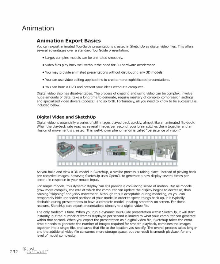
232
Animation
Animation Export BasicsYou can export animated TourGuide presentations created in SketchUp as digital video fi les. This offers several advantages over a standard TourGuide presentation:
• Large, complex models can be animated smoothly.
• Video fi les play back well without the need for 3D hardware acceleration.
• You may provide animated presentations without distributing any 3D models.
• You can use video editing applications to create more sophisticated presentations.
• You can burn a DVD and present your ideas without a computer.
Digital video also has disadvantages. The process of creating and using video can be complex, involve huge amounts of data, take a long time to generate, require mastery of complex compression settings and specialized video drivers (codecs), and so forth. Fortunately, all you need to know to be successful is included below.
Digital Video and SketchUpDigital video is essentially a series of still images played back quickly, almost like an animated fl ip-book. When the playback rate reaches several images per second, your brain stitches them together and an illusion of movement is created. This well-known phenomenon is called “persistence of vision.”
As you build and view a 3D model in SketchUp, a similar process is taking place. Instead of playing back pre-recorded images, however, SketchUp uses OpenGL to generate a new display several times per second in response to your mouse input.
For simple models, this dynamic display can still provide a convincing sense of motion. But as models grow more complex, the rate at which the computer can update the display begins to decrease, thus causing “skipping” and jerky movement. Although this is acceptable during modeling, as you can temporarily hide unneeded portions of your model in order to speed things back up, it is typically desirable during presentations to have a complete model updating smoothly on screen. For these reasons, SketchUp can export presentations directly to a digital video fi le.
The only tradeoff is time. When you run a dynamic TourGuide presentation within SketchUp, it will start instantly, but the number of frames displayed per second is limited to what your computer can generate within that second. When you export the presentation as a digital video fi le, SketchUp takes the extra time it needs to generate the number of images required for smooth playback, combines the images together into a single fi le, and saves that fi le to the location you specify. The overall process takes longer and the additional video fi le consumes more storage space, but the result is smooth playback for any level of model complexity.
Importin
g an
d E
xportin
g
233
SketchUp 4.0 User Guide
Size of Video FilesDigital video fi les have a tendency to get very large. In fact, working with video routinely involves tens or even hundreds of times more data than other types of computer fi les. For instance, a SketchUp .SKP fi le that is several hundred kilobytes is very small and easy to transmit via the Internet. As a video, however, a TourGuide presentation from the same .SKP fi le can easily take up several megabytes or more. This makes fi le size one of the biggest technical hurdles when dealing with digital video, and it can be helpful to understand more about how they get so large.
Video Size
A single still screen image that is 640 x 480 pixels takes up roughly 1 megabyte in your computer’s RAM memory. Viewing it is no problem, as it takes only a fraction of a second for the computer to load the fi le and display it on your screen. In order to view a video fi le, however, there are several still images per second that the computer has to store and process. This means that if you are playing back a 640 x 480 pixel video at 30 frames per second (fps), there is 30 times more information to process, and a single second of video will require a whopping 30 megabytes of memory to store! A single minute of the same video would require 1,800 megabytes, or 1.8 gigabytes, to store.
Video Bandwidth
In addition to the storage problem, there are also bandwidth limitations to consider. Even if you have enough room to store a large video fi le, most personal computer systems can only comfortably transfer around 5-7 megabytes of data per second from the hard drive. Video fi les that require higher data rates will stutter and skip frames because the system simply can’t keep up. For CD-ROM drives, the maximum data transfer rate is even slower than that of a hard drive, and bandwidth becomes even more of a factor.
Managing Video DataModern consumer-oriented digital video systems, such as DVD’s, camcorders, and video editing software, are designed so that you don’t have to worry about the amount of data involved. The bandwidth requirements and capacities are usually fi xed, and the settings are permanently set for you. The closed nature of these systems makes them easier to use.
By contrast, when you use SketchUp to make video fi les, you will often want more fl exibility. For example, sending a fi le via email or burning it to a CD-ROM means that the fi le size and bandwidth are more limited, and that you’ll need to keep tighter control over the data. Fortunately, there are several techniques available for keeping fi le size and data rate reasonable:

234
Frame Size
Frame size refers to the pixel dimensions of your video, and it usually has the most dramatic effect on fi le size. In fact, doubling the dimensions of your frame can multiply the amount of data in your video by a factor of four! It is for this reason that computers are designed to run videos at frame sizes much lower than standard screen resolution. For example, even though most computer screens run at 1024x768 pixels or higher, a frame size of around 640x480 is typically considered full size. The missing space is fi lled in during full screen playback by stretching the pixels in your video fi le to cover more space. Many digital videos are commonly created at even smaller frame sizes, such as 400x300, or 320x240.
You may be asking yourself how such a low resolution image can be effective. It’s true that for a still image, 320x240 pixels would be too small for most purposes. For video, however, the primary advantage lies in the movement and sequencing of many images rather than the detail within a single one. This has to do with the fact that the human brain can only process a limited amount of information at any given moment. Unlike still images, video simply cannot convey both small details and an overall picture simultaneously.
For this reason, it is common to employ both still and video imagery in a complimentary fashion: You can generate videos at smaller frame sizes and present them in combination with several high-resolution still images, all from a single model. This way, even though the video display may be slightly more fuzzy or blocky when expanded to fi ll the screen, the still images allow details to remain clear and well communicated at any time during a presentation.
Frame Rate
Frame rate refers to the number of images that are displayed per second of video. The greater the frame rate, the smoother the illusion of movement will be, and the larger the data rate and video fi le size will become. You can achieve a large reduction in fi le size by trading off a little frame rate and smoothness without compromising the effectiveness of your video. For example, generating a video at 15 frames per second, instead of the full 30, cuts the data volume by half yet still delivers a very convincing sense of movement.
Digital video generally affords quite a bit of fl exibility in setting frame rate. For example, if you plan to play a video directly from your computer, the frame rate can often be whatever you like. A very low frame rate setting, such as 3 or 4, can give you a good preview of how your video will fl ow and require much less time to generate. Certain applications of video, such as transferring to fi lm, DV tape, or DVD, benefi t from a certain frame rate setting to match the fi xed playback rate of the target medium or device.
Compression
When you export a 2D image as a JPEG fi le, your computer uses data compression techniques to squeeze out extraneous information. The result is a fi le that takes up a fraction of the space when saved onto a hard drive. While 2D images are still manageable without compression, the larger size of video fi les usually makes using compression mandatory. To further complicate matters, there are many different types and variants of compression, each with particular advantages and limitations. Compression is so complex that it deserves to be covered in detail in its own topic. (See the next page for more information.)
Video EditingYou may want to leverage SketchUp’s animation exporting capability with third party video editing tools. These allow you to assemble animations together, add transitions, music, sound and voice, titles, and more.

Importin
g an
d E
xportin
g
235
SketchUp 4.0 User Guide
Video CompressionVideo compression is the process by which the size and data rate of digital video fi les are condensed so that those fi les can function more effi ciently on your computer.
Because digital video involves calculating, processing, and storing extremely large amounts of data compared to other kinds of computer fi les, understanding compression can be critical to your overall success. In cases where bandwidth is limited, such as sending a video by email, compression can be even more important.
Unfortunately, working with compression can also be dauntingly complex when you fi rst begin. This is mainly because the amount of compression you need, as well as which type to use, depends greatly on several factors simultaneously; your goals, playback environment, available media bandwidth, audience expectations, and, perhaps most importantly, the visual nature of your video images.
That’s a lot of considerations to balance at fi rst, but once you have a working process established, compression becomes much easier to deal with. In fact, after reading this topic, you will be well prepared to evaluate the various compression options available and to choose the right one for your project.
CodecsAll video compression is handled by a special piece of software called a ‘codec’. The term codec is short for Compressor/Decompressor, which is a rather apt description of what a codec does. When you create a compressed video fi le, the codec applies a compression algorithm that removes less important or redundant information, thus reducing the amount of data. During playback, the codec decompresses the fi le, which involves reconstructing the data so that the image within each frame appears similar to the original.
In principle, codecs are plug-ins. They serve as intermediaries between applications which create video fi les, such as SketchUp, and those that read video fi les, such as your favorite playback utility or video editing application.
This plug-in system provides a lot of fl exibility, as you can install and use new codecs without having to update SketchUp. Unfortunately, it can also create problems as SketchUp cannot directly control the quality of your video fi les. More importantly, codecs are mostly incompatible with one another: Video fi les won’t play back on a computer if the correct codec is not present. Some media players are designed to automatically download the necessary codecs, but this doesn’t always work as advertised. There is also a cost factor: Some codecs are provided free of charge while others can be quite expensive. (Most of the commercial codecs provide a free “decompression only” version so that it’s easier to distribute your videos.)
Since the entire codec system sits in the background, it is transparent to most users. But as a creator of video content, the burden has unfortunately been placed upon you to know and understand what codecs are, how they work, and the differences between them.
236
Compression TypesEach codec uses its own special compression techniques. Some of these are better suited to a given type of imagery than others as well as how that imagery moves across time. Also, some codecs are designed specifi cally to work over a low bandwidth medium, such as the Internet or a CD-ROM, or from a high bandwidth source such as a hard drive or Digital Video (DV) tape. Others still are designed to automatically detect and adapt to the available bandwidth.
The descriptions of the various compression techniques presented below can help you better match codecs to the type of video you are generating in SketchUp. If you are familiar with these concepts, a list of specifi c codecs and their properties is availablelater in this guide.
Spatial Compression
Spatial compression refers to a reduction in data size within a single frame of video. This is typically accomplished by searching each image for repetitive patterns among pixels, and then using a visual shorthand to describe that part of the image.
For example, for an image that includes a face fi lled with a solid green color, a codec that employs spatial compression will recognize that many of the face pixels are a similar shade. Instead of individually describing each and every pixel, (pixel1=green, pixel2=green, pixel3=green, pixel4=blue) the codec records a much shorter description, such as “pixels1-3=green, 4=blue.” The result is a fi le that is much smaller, and therefore easier to transmit and store.
Spatial compression can either be ‘Lossy’, which means that the image is altered in an effort to make the fi le size very small, or ‘Loss-less,’ which preserves image fi delity and creates larger fi les. When using the lossy variety, increasing the amount of spatial compression typically decreases picture sharpness and defi nition but results in a much smaller fi le, especially if the image contains large textured areas. Most of the codecs that use spatial compression allow you to adjust the degree of compression versus image quality.
Loss-less and Lossy Compression
As mentioned above, some codecs can use loss-less compression, which ensures that all of the information in the original clip is preserved after compression. This maintains the full quality of the original, making loss-less compression useful for video editing or moving clips between platforms. However, preserving the original level of quality limits the degree to which you can lower the data rate and fi le size, and the resulting data rate may be too high for smooth playback on many systems.
Codecs that employ lossy compression intentionally discard some of the original data during compression. For example, if the pixels making up a sky actually contain hundreds of different shades of blue, a lossy codec may record only a few shades. Other lossy compression schemes are designed to discard the type of visual details that the human eye doesn’t immediately perceive. While these techniques can produce impressive quality using considerably less video data, they also tend to create visual irregularities known as artifacts.
Since artifacts, when too noticeable, can detract from the visual quality of your imagery, most lossy codecs allow you to specify how much picture quality you’re willing to trade in order to lower the data rate and fi le size. This allows you to tailor your video for your audience and playback medium. For example, lossy codecs are commonly used with certain settings for fi nal production of video delivered using CD-ROM and other, lower quality settings designed for the Internet.
Some codecs are always lossy, such as JPEG, or always lossless, such as those which use Run-Length Encoding. (RLE) Other codecs may or may not be lossy, usually depending on the settings you specify for the Quality and Data Rate options.

Importin
g an
d E
xportin
g
237
SketchUp 4.0 User Guide
Temporal Compression
Temporal (time) compression, (also called ‘delta’ compression,) is a process by which data is reduced over a sequence of frames. Instead of recording each frame as a full image, a codec using temporal compression will record only the changes from frame to frame. This allows patterns and repetition over time to be condensed into less space.
A good example is a video clip of an object rotating in front of a blank background: A codec that uses temporal compression will notice that only the pixels forming the object will change from frame to frame. The pixels forming the background remain static, and therefore need not be recorded on all frames. This technique is called ‘frame differencing.’ During decompression, the codec overlays the changed pixels over the previous frame, thus reconstructing an image nearly identical to the original uncompressed frame.
This has consequences for SketchUp. As long as a model above remains shaded with solid areas, it will benefi t greatly from temporal compression when saved to video. Once a texture is applied, however, the same model creates much more visual change at the pixel level from frame to frame. Also, once you move into the interior of the model, much less of the static background is visible, resulting in even greater changes between frames.
Keyframes
Temporal compression is often used in conjunction with spatial compression techniques mentioned above, which can cause very distracting visual artifacts. In these cases, it’s valuable to intermittently record a complete frame and start the differencing process once again. The complete frames are called ‘Keyframes’, and the frames which only contain differences are called ‘Delta Frames.’
Many codecs will create keyframes at an interval you specify and others can even analyze the data visually and automatically create keyframes whenever there are substantial differences between frames. The degree of this difference determines how much loss there will be, but in general, fewer keyframes means a smaller data rate and fi le size, as well as decreased picture quality.
Asymmetrical Compression
Different codecs can require varying amounts of time to compress or decompress video, depending on the algorithms they employ. A codec that requires more time to compress than it does to decompress is called asymmetrical. When using SketchUp to produce video, the time it takes to compress each frame is usually a fraction of time it takes to render, so the symmetry of a codec typically isn’t as much of a factor.
Other FactorsWhile some video characteristics can affect compression effi ciency, others can impact your ability to use some codecs altogether. Here are a few things to keep in mind:
Frame Size
Frame size refers to the pixel dimensions of your video, and it usually has the most dramatic effect on fi le size. In fact, doubling the dimensions of your frame can multiply the amount of data that must be compressed by a factor of four!
While many modern codecs are designed for full screen images such as 640x480, many others, including those provided at no charge, simply cannot squeeze that much data into usable data rates. Another thing to keep in mind is that some compressors accept arbitrary frame sizes, whereas others will only work with a set of specifi c frame sizes and/or aspect ratios.
238
Frame Rate
The frame rate, or number of frames per second, (fps) has a large impact on fi le size. In general, doubling the frame rate doubles the amount of data that the codec needs to compress. While you can set SketchUp to output full frame rate video in the 24-30 fps range, you can still achieve acceptable motion quality at 12-15 fps. Files rendered at these lower rates will be half the size and likely be just as effective.
Aspect Ratio
The vast majority of videos and display screens have an aspect ratio of 4:3. This means that the horizontal dimension is four units wide and the vertical dimension is three units tall. Widescreen displays typically have an aspect ratio of 16:9. Although you can produce a video at any aspect ratio, those that are not standard can result in images that do not fi ll up the entire screen.
Certain codecs are optimized to deliver smaller fi le sizes at standard aspect ratios. Others still will not even work properly with anything but a standard ratio.
Bit Depth
The bit depth of a video refers to the number of colors that are used for the images in each frame. Higher bit depths create larger fi les. SketchUp outputs to 24-bit resolution, but certain codecs may allow you to compress video at a lower bit depth in order to reduce fi le size. When using lower bit depths, you may be able to retain more control over color quality by specifying a custom color palette.
Internet Delivery
When creating video for the web or for sending via email, fi le size can quickly become more important than picture quality. First, dramatically reducing the frame size and frame rate can help compression by reducing the initial amount of data to compress. Second, try to match the codec to the type of images you are creating. Third, it may be necessary to specify lower quality/higher compression settings to minimize the video data rate.
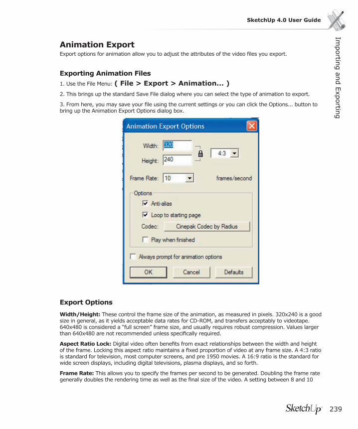
Importin
g an
d E
xportin
g
239
SketchUp 4.0 User Guide
Animation ExportExport options for animation allow you to adjust the attributes of the video fi les you export.
Exporting Animation Files1. Use the File Menu: ( File > Export > Animation... )
2. This brings up the standard Save File dialog where you can select the type of animation to export.
3. From here, you may save your fi le using the current settings or you can click the Options... button to bring up the Animation Export Options dialog box.
Export Options
Width/Height: These control the frame size of the animation, as measured in pixels. 320x240 is a good size in general, as it yields acceptable data rates for CD-ROM, and transfers acceptably to videotape. 640x480 is considered a “full screen” frame size, and usually requires robust compression. Values larger than 640x480 are not recommended unless specifi cally required.
Aspect Ratio Lock: Digital video often benefi ts from exact relationships between the width and height of the frame. Locking this aspect ratio maintains a fi xed proportion of video at any frame size. A 4:3 ratio is standard for television, most computer screens, and pre 1950 movies. A 16:9 ratio is the standard for wide screen displays, including digital televisions, plasma displays, and so forth.
Frame Rate: This allows you to specify the frames per second to be generated. Doubling the frame rate generally doubles the rendering time as well as the fi nal size of the video. A setting between 8 and 10

240
is considered the minimum required for convincing movement, between 12 and 15 is good for keeping fi le size down while providing smooth playback, and between 24 and 30 is considered “full speed.” These are just general guidelines, however, and you should feel free to set frame rate to match your needs. For example, a setting of 3 fps is a great way to quickly create draft quality test videos.
Certain applications have exact frame rate requirements, such as 29.97 fps for television in the US and other countries, 25 fps for television in Europe, 24 fps for fi lm, etc.
Loop to Starting Page: When enabled, this option generates an additional video segment that animates from the last page back to the fi rst. This is a great way to make infi nitely looping videos.
Smooth (Anti-Alias): When enabled, SketchUp will smooth the exported image. This method can take longer, but it helps to reduce jagged lines and pixilated artifacts in images.
Codec: This allows you to specify which codec, or compression plug-in, to apply to your video, as well as adjust quality settings.
Play When Finished: When this option is enabled, SketchUp will start your default video player and play the fi le immediately after it is fi nished creating it.
Always Prompt for Animation Options: When enabled, the Animation Export Options Dialog will always come up prior to generating the video fi le.

241
SketchUp 4.0 User GuideEntities
EntitiesEntities are the individual elements that make up a SketchUp model. There are many different types of entities in SketchUp. The simplest ones, such as lines and faces, serve as building blocks of form. Some entities, such as arcs, circles, polygons, polyline curves, and curved face sets, are collections of lines or faces that have special intelligent properties. Groups and Components are examples of entities that can encapsulate other entities, and which have special properties of their own. Finally, entities such as Construction Lines, Image Objects, Section Planes, and Text or Dimension Objects can help you get more out of your models by offering highly specialized behavior.
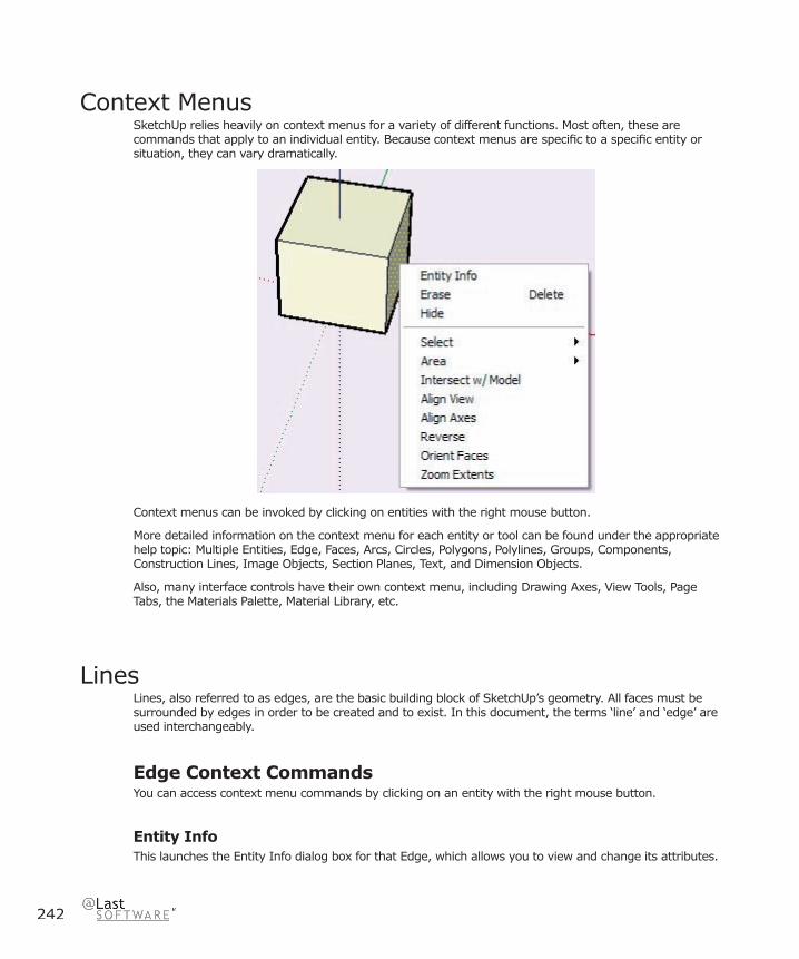
242
Context MenusSketchUp relies heavily on context menus for a variety of different functions. Most often, these are commands that apply to an individual entity. Because context menus are specifi c to a specifi c entity or situation, they can vary dramatically.
Context menus can be invoked by clicking on entities with the right mouse button.
More detailed information on the context menu for each entity or tool can be found under the appropriate help topic: Multiple Entities, Edge, Faces, Arcs, Circles, Polygons, Polylines, Groups, Components, Construction Lines, Image Objects, Section Planes, Text, and Dimension Objects.
Also, many interface controls have their own context menu, including Drawing Axes, View Tools, Page Tabs, the Materials Palette, Material Library, etc.
LinesLines, also referred to as edges, are the basic building block of SketchUp’s geometry. All faces must be surrounded by edges in order to be created and to exist. In this document, the terms ‘line’ and ‘edge’ are used interchangeably.
Edge Context CommandsYou can access context menu commands by clicking on an entity with the right mouse button.
Entity InfoThis launches the Entity Info dialog box for that Edge, which allows you to view and change its attributes.
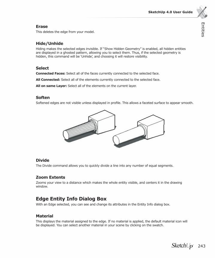
Entities
243
SketchUp 4.0 User Guide
EraseThis deletes the edge from your model.
Hide/UnhideHiding makes the selected edges invisible. If “Show Hidden Geometry” is enabled, all hidden entities are displayed in a ghosted pattern, allowing you to select them. Thus, if the selected geometry is hidden, this command will be ‘Unhide’, and choosing it will restore visibility.
SelectConnected Faces: Select all of the faces currently connected to the selected face.
All Connected: Select all of the elements currently connected to the selected face.
All on same Layer: Select all of the elements on the current layer.
SoftenSoftened edges are not visible unless displayed in profi le. This allows a faceted surface to appear smooth.
DivideThe Divide command allows you to quickly divide a line into any number of equal segments.
Zoom ExtentsZooms your view to a distance which makes the whole entity visible, and centers it in the drawing window.
Edge Entity Info Dialog BoxWith an Edge selected, you can see and change its attributes in the Entity Info dialog box.
MaterialThis displays the material assigned to the edge. If no material is applied, the default material icon will be displayed. You can select another material in your scene by clicking on the swatch.
244
LayerThis displays the layer of the selected entity. To move it to a new layer, choose a new one from the pop-up list.
LengthThis fi eld displays the actual length of the selected edge.
SoftWhen enabled, this renders the edge as a soft edge.
SmoothWhen enabled, this renders the faces connected to the edge with a varying tonal value.
Details MenuCast Shadows: When the Cast Shadows option is enabled, the edge will be allowed to cast a shadow.

Entities
245
SketchUp 4.0 User Guide
FacesFaces are planar elements that make up the surfaces of a SketchUp model. In order to be drawn, faces depend on a closed and co-planar ring of three or more lines. Faces are created automatically by SketchUp when such a condition occurs.
If you delete a face, the edges that defi ned it will remain. If you delete an edge, however, any faces that it depend on it will disappear as well. If you alter one of the edges of a face so that it is no longer co-planar with that face, SketchUp will create new edges and faces, a feature called Auto-fold.
Face OrientationFaces in SketchUp have a front side and a back side. Each side can be painted independently. In most cases when exporting from SketchUp, only material assignments to the front face are preserved. Faces can be created with the Line Tool, Arc Tool, Freehand Tool, Rectangle Tool, Circle Tool, and the Polygon Tool.
Face Context CommandsYou can access context menu commands by clicking on an entity with the right mouse button.
Entity InfoThis launches the Entity Info dialog box for that face, which allows you to view and change its attributes.
EraseThis deletes the selected faces from your model.
Hide/UnhideHiding makes the selected faces invisible. If “Show Hidden Geometry” is enabled, all hidden entities are displayed in a ghosted pattern, allowing you to select them. Thus, if the selected geometry is hidden, this command will be ‘Unhide’, and choosing it will restore visibility.
SelectBounding Edges: Select all of the edges currently bounding the selected face.
Connected Faces: Select all of the faces currently connected to the selected face.
All Connected: Select all of the elements currently connected to the selected face.
All on same Layer: Select all of the elements on the current layer.
All with same Material: Select all of the faces with the same material.
AreaThe Area sub-menu of the Face context menu allows you to calculate the surface area in your SketchUp model. The results of the calculation are displayed in a fl oating window when complete.
Selection: This calculates the total surface area of the face you clicked on.

246
Layer: This provides the total area of all faces in the layer of the face you clicked on.
Materials: This provides the total area of the faces in the entire model, hidden or unhidden, using the material of the face you clicked on.
Intersect With ModelThis command allows you intersect two elements, such as a box and a tube, and automatically create new faces where the elements intersect. These faces can then be pushed, pulled or deleted to create new geometry.
Align View This aligns the SketchUp Camera to the face you clicked on. The view direction becomes perpendicular to the face, which is useful for creating non-standard orthographic drawings.
Align Axes This aligns the Drawing Axes to the face you right clicked on.
Reverse Faces in SketchUp have a front and a back side. Each side of a face can have a material assigned to it. However, when exporting SketchUp geometry to a fi le format that only supports single-sided faced polygons (like DXF, DWG, and 3DS), it becomes important to know which side of the face will be exported. Use the Reverse command to fl ip the front and back sides of the selected face as needed.
Orient Faces Choosing this command automatically orients all the connected faces of your model to the orientation of the face you clicked on.
Zoom ExtentsZooms your view to a distance which makes the whole entity visible, and centers it in the drawing window.
TexturePosition: Texture Positioning allows textures to be placed and scaled directly on a surface and corrected for perspective distortion.
Reset Position: Resets the texture to its previous position.
Projected: Allows you to wrap images and textures over forms as though “projected” onto the form.
Face Entity Info Dialog BoxWith a Face selected, you can see and change its attributes in the Entity Info dialog box.

Entities
247
SketchUp 4.0 User Guide
Material This displays the material assigned to the Group. If no material is applied, the default material icon will be displayed. You can select another material in your scene by clicking on the swatch.
LayerThis displays the layer of the selected entity. To move it to a new layer, choose a new one from the pop-up list.
AreaThis displays the area of the selected entity. To calculate the area of multiple selected entities, you can use the [ Area > Selection ] contextual menu item.
Details MenuCast Shadows: When the Cast Shadows option is enabled, the face will be allowed to cast a shadow.
Receive Shadows: When the Receive Shadows option is enabled, the face will be allowed to receive shadows cast by other entities.
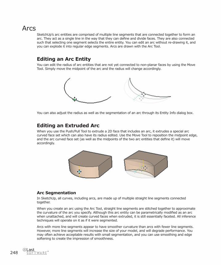
248
ArcsSketchUp’s arc entities are comprised of multiple line segments that are connected together to form an arc. They act as a single line in the way that they can defi ne and divide faces. They are also connected such that selecting one segment selects the entire entity. You can edit an arc without re-drawing it, and you can explode it into regular edge segments. Arcs are drawn with the Arc Tool.
Editing an Arc EntityYou can edit the radius of arc entities that are not yet connected to non-planar faces by using the Move Tool. Simply move the midpoint of the arc and the radius will change accordingly.
You can also adjust the radius as well as the segmentation of an arc through its Entity Info dialog box.
Editing an Extruded ArcWhen you use the Push/Pull Tool to extrude a 2D face that includes an arc, it extrudes a special arc curved face set which can also have its radius edited. Use the Move Tool to reposition the midpoint edge, and the arc curved face set (as well as the midpoints of the two arc entities that defi ne it) will move accordingly.
Arc SegmentationIn SketchUp, all curves, including arcs, are made up of multiple straight line segments connected together.
When you create an arc using the Arc Tool, straight line segments are stitched together to approximate the curvature of the arc you specify. Although this arc entity can be parametrically modifi ed as an arc when unattached, and will create curved faces when extruded, it is still essentially faceted. All inference techniques will operate on it as if it were segmented.
Arcs with more line segments appear to have smoother curvature than arcs with fewer line segments. However, more line segments will increase the size of your model, and will degrade performance. You may often achieve acceptable results with small segmentation, and you can use smoothing and edge softening to create the impression of smoothness.
Entities
249
SketchUp 4.0 User Guide
Arc DeformationIf an Arc is deformed in a way that destroys its radial defi nition, such as with a non-uniform scale operation, it will become a non-parametric Polyline Curve. Polyline Curves can no longer be edited as arcs.
Arc Context CommandsYou can access context menu commands by clicking on an entity with the right mouse button.
Entity InfoThis launches the Entity Info dialog box for that arc, which allows you to view and change its attributes.
EraseThis deletes the selected arc from your model.
Hide/UnhideHiding makes the selected arc invisible. If “Show Hidden Geometry” is enabled, all hidden entities are displayed in a ghosted pattern, allowing you to select them. Thus, if the selected geometry is hidden, this command will be Unhide, and choosing it will restore visibility.
SelectConnected Faces: Select all of the faces currently connected to the selected face.
All Connected: Select all of the elements currently connected to the selected face.
All on same Layer: Select all of the elements on the current layer.
SoftenSoftened edges are not visible unless displayed in profi le. This allows a faceted surface to appear smooth.
DivideThe Divide command allows you to quickly divide an arc into any number of equal segments. This is available only for arcs that aren’t connected to 3D geometry.
Explode CurveThe Explode Curve command breaks the arc entity into regular edges. An exploded arc will appear the same, but it can no longer be edited, and will no longer respond to tool operations as a single entity.
Convert to PolygonThis converts the arc into a polygon arc, which will remain editable, yet generate standard facets when extruded.
250
Zoom ExtentsZooms your view to a distance which makes the whole entity visible, and centers it in the drawing window.
Entity Info Dialog BoxWith an arc selected, you can see and change its attributes in the Entity Info Dialog Box.
MaterialThis displays the material assigned to the Group. If no material is applied, the default material icon will be displayed. You can select another material in your scene by clicking on the swatch.
LayerThis displays the layer of the selected entity. To move it to a new layer, choose a new one from the pop-up list.
RadiusThis displays the radius of the selected entity, and can accept new values you type into it.
SegmentsThis displays the number of segments in the selected entity, and can accept new values you type into it.
Details MenuCast Shadows: When the Cast Shadows option is enabled, the face will be allowed to cast a shadow.

Entities
251
SketchUp 4.0 User Guide
CirclesDrawn with the Circle Tool, SketchUp’s Circle Entities are comprised of multiple line segments that are connected together to form a circle. They act as a single line in the way that they can defi ne and divide faces. They are also connected such that selecting one segment selects the entire entity. You can edit the radius and segmentation of an circle without re-drawing it, and you can explode it into regular edge segments.
Editing a Circle EntityYou can edit the radius of a circle entity that is not connected to 3D faces by using the Move Tool. Simply move one of the four cardinal points of the circle and the radius will change accordingly.
You can also adjust the radius as well as the segmentation of a circle through its Entity Info dialog box.
Snapping to the CenterSketchUp’s inference capability sometimes can get distracted, preventing it from snapping to the center of a circle. You can “encourage” a center point inference by fi rst hovering the mouse cursor over the edges of the circle and then moving it towards the center point.
Editing an Extruded CircleWhen you use the Push/Pull Tool to extrude a 2D face that includes a circle, it extrudes a special cylindrical curved face set which can also have its radius edited. Use the Move Tool to reposition one of the four cardinal edges, and the cylindrical curved face set radius (as well as the radii of the two circle entities that defi ne it) will be adjusted accordingly.
252
Circle SegmentationIn SketchUp, all curves, including circles, are made up of multiple straight line segments connected together.
When you create a Circle Entity, straight line segments are stitched together to approximate the curvature of the circle you specify. Although this circle entity can be parametrically modifi ed as an circle when unattached, and will create curved faces when extruded, it is still essentially faceted. All inference techniques will operate on it as if it were segmented.
Circles with more line segments appear to have smoother curvature than circles with fewer line segments. However, more line segments will increase the size of your model, and will degrade performance. You may often achieve acceptable results with small segmentation, and you can use smoothing and edge softening to create the impression of smoothness.
Circle DeformationIf a Circle is deformed in a way that destroys its radial defi nition, such as with a non-uniform scale operation, it will become a non-parametric Polyline Curve. Polyline Curves can no longer be edited as circles.
Circle Context CommandsYou can access context menu commands by clicking on an entity with the right mouse button.
Entity InfoThis displays information about the circle in the Entity Info dialog box.
EraseThis deletes the selected circle from your model.
Hide/UnhideHiding makes the selected circle invisible. If “Show Hidden Geometry” is enabled, all hidden entities are displayed in a ghosted pattern, allowing you to select them. Thus, if the selected geometry is hidden, this command will be Unhide, and choosing it will restore visibility.
SelectConnected Faces: Select all of the faces currently connected to the selected face.
All Connected: Select all of the elements currently connected to the selected face.
All on same Layer: Select all of the elements on the current layer.
SoftenSoftened edges are not visible unless displayed in profi le. This allows a faceted surface to appear smooth.
Entities
253
SketchUp 4.0 User Guide
DivideThe Divide command allows you to quickly divide a circle into any number of equal arc segments.
Explode CurveThe Explode Curve command breaks the circle entity into regular edges. An exploded circle will appear the same, but it can no longer be edited, and will no longer respond to tool operations as a single entity.
Convert to PolygonThis converts the circle into a polygon entity, which will remain editable, yet generate standard facets when extruded.
Zoom ExtentsZooms your view to a distance which makes the whole entity visible, and centers it in the drawing window.
Circle Entity Info Dialog BoxWith a Circle selected, you can see and change its attributes in the Entity Info dialog box.
MaterialThis displays the material assigned to the circle. If no material is applied, the default material icon will be displayed. You can select another material in your scene by clicking on the swatch.
LayerThis displays the layer of the selected entity. To move it to a new layer, choose a new one from the pop-up list.
RadiusThis displays the radius of the selected entity, and can accept new values you type into it.
SegmentsThis displays the number of segments in the selected entity, and can accept new values you type into it.
Details MenuCast Shadows: When the Cast Shadows option is enabled, the face will be allowed to cast a shadow.

254
PolygonsSketchUp’s Polygon Entities are comprised of multiple line segments that are connected together to form a polygon. They act as a single line in the way that they can defi ne and divide faces. They are also connected such that selecting one segment selects the entire entity. You can edit the radius and segmentation of an polygon without re-drawing it, and you can explode it into regular edge segments.
Editing a Polygon EntityYou can edit the radius of the circle in which the polygon entity is inscribed if it is not connected to 3D faces by using the Move Tool. Make sure nothing is selected, then follow along the edge of the polygon with the Move Tool cursor until it does not highlight. The points that do not highlight the polygon can be moved and thus change the radius.
You can also adjust the radius as well as the segmentation of a polygon through its Entity Info dialog box.
Editing an Extruded PolygonWhen you use the Push/Pull Tool to extrude a 2D face that includes a polygon, it extrudes a special polygonal curved face set which can also have its radius edited. Use the Move Tool to reposition one of the control edges, and the polygonal curved face set radius (as well as the radii of the two polygon entities that defi ne it) will be adjusted accordingly.
Polygon DeformationIf a polygon is deformed in a way that destroys its radial defi nition, such as with a non-uniform scale operation, it will become a non-parametric Polyline Curve. Polyline Curves can no longer be edited as polygons.
Polygon Context CommandsYou can access context menu commands by clicking on an entity with the right mouse button.
Entity InfoThis launches the Entity Info dialog box for that Polygon, which allows you to view and change its attributes.
EraseThis deletes the edge from your model.
Hide/UnhideHiding makes the selected edges invisible. If “Show Hidden Geometry” is enabled, all hidden entities are displayed in a ghosted pattern, allowing you to select them. Thus, if the selected geometry is hidden, this command will be ‘Unhide’, and choosing it will restore visibility.
Entities
255
SketchUp 4.0 User Guide
SelectConnected Faces: Select all of the faces currently connected to the selected face.
All Connected: Select all of the elements currently connected to the selected face.
All on same Layer: Select all of the elements on the current layer.
SoftenSoftened edges are not visible unless displayed in profi le. This allows a faceted surface to appear smooth.
DivideThe Divide command allows you to quickly divide a line into any number of equal segments.
Explode CurveThe Explode Curve command breaks the polygon entity into regular edges. An exploded polygon will appear the same, but it can no longer be edited, and will no longer respond to tool operations as a single entity.
Zoom ExtentsZooms your view to a distance which makes the whole entity visible, and centers it in the drawing window.
Polygon Entity InfoWith a Polygon selected, you can see and change its attributes in the Entity Info dialog box.
MaterialThis displays the material assigned to the edge. If no material is applied, the default material icon will be displayed. You can select another material in your scene by clicking on the swatch.
LayerThis displays the layer of the selected entity. To move it to a new layer, choose a new one from the pop-up list.
RadiusThis displays the radius of the selected entity, and can accept new values you type into it.
SegmentsThis displays the number of segments in the selected entity, and can accept new values you type into it.
Details MenuCast Shadows: When the Cast Shadows option is enabled, the edge will be allowed to cast a shadow.
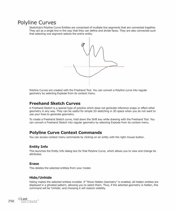
256
Polyline CurvesSketchUp’s Polyline Curve Entities are comprised of multiple line segments that are connected together. They act as a single line in the way that they can defi ne and divide faces. They are also connected such that selecting one segment selects the entire entity.
Polyline Curves are created with the Freehand Tool. You can convert a Polyline curve into regular geometry by selecting Explode from its context menu.
Freehand Sketch CurvesA Freehand Sketch is a special type of polyline which does not generate inference snaps or effect other geometry in any way. They can be useful for simple 2D sketching in 3D space when you do not want to use your lines to generate geometry.
To create a Freehand Sketch curve, hold down the Shift key while drawing with the Freehand Tool. You can convert a Freehand Sketch into regular geometry by selecting Explode from its context menu.
Polyline Curve Context CommandsYou can access context menu commands by clicking on an entity with the right mouse button.
Entity InfoThis launches the Entity Info dialog box for that Polyline Curve, which allows you to view and change its attributes.
EraseThis deletes the selected entities from your model.
Hide/UnhideHiding makes the selected entities invisible. If “Show Hidden Geometry” is enabled, all hidden entities are displayed in a ghosted pattern, allowing you to select them. Thus, if the selected geometry is hidden, this command will be ‘Unhide’, and choosing it will restore visibility.
Entities
257
SketchUp 4.0 User Guide
SelectConnected Faces: Select all of the faces currently connected to the selected face.
All Connected: Select all of the elements currently connected to the selected face.
All on same Layer: Select all of the elements on the current layer.
SoftenSoftened edges are not visible unless displayed in profi le. This allows a faceted surface to appear smooth.
DivideThe Divide command allows you to quickly divide a line into any number of equal segments.
Explode CurveThe Explode Curve command breaks the polygon entity into regular edges. An exploded polygon will appear the same, but it can no longer be edited, and will no longer respond to tool operations as a single entity.
Convert to PolygonThis converts the polyline curve into a polygon curve, which will remain editable, yet generate standard facets when extruded.
Zoom ExtentsZooms your view to a distance which makes the whole entity visible, and centers it in the drawing window.
258
Polyline Curve Entity Info Dialog BoxWith a Polyline Curve selected, you can see and change its attributes in the Entity Info dialog box.
MaterialThis displays the material assigned to the edge. If no material is applied, the default material icon will be displayed. You can select another material in your scene by clicking on the swatch.
LayerThis displays the layer of the selected entity. To move it to a new layer, choose a new one from the pop-up list.
SegmentsThis displays the number of segments in the selected entity, and can accept new values you type into it.
LengthThis fi eld displays the actual length of the selected edge.
Details MenuCast Shadows: When the Cast Shadows option is enabled, the edge will be allowed to cast a shadow.
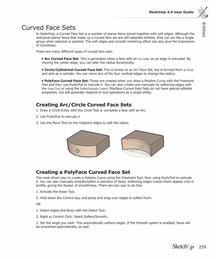
Entities
259
SketchUp 4.0 User Guide
Curved Face SetsIn SketchUp, a Curved Face Set is a number of planar faces joined together with soft edges. Although the individual planar faces that make up a curved face set are still separate entities, they can act like a single group when selected or painted. The soft edges and smooth rendering effect can also give the impression of roundness.
There are many different types of curved face sets:
• Arc Curved Face Set: This is generated when a face with an Arc entity as an edge is extruded. By moving the center edge, you can alter the radius dynamically.
• Circle/Cylindrical Curved Face Set: This is similar to an Arc Face Set, but is formed from a Circle and acts as a cylinder. You can move any of the four cardinal edges to change the radius.
• PolyFace Curved Face Set: These are created when you draw a Polyline Curve with the Freehand Tool and then use Push/Pull to extrude it. You can also create one manually by softening edges with the Erase Tool or using the Soften/Smooth Control. PolyFace Curved Face Sets do not have special editable properties, but still generally respond to tool operations as a single entity.
Creating Arc/Circle Curved Face Sets1. Draw a Circle Entity with the Circle Tool or complete a face with an Arc.
2. Use Push/Pull to extrude it.
3. Use the Move Tool on the midpoint edges to edit the radius.
Creating a PolyFace Curved Face SetThe most direct way to create a Polyline Curve using the Freehand Tool, then using Push/Pull to extrude it. You can also manually smooth/soften a selection of faces. Softening edges makes them appear only in profi le, giving the illusion of smoothness. There are two way to do this:
1. Activate the Erase Tool.
2. Hold down the Control key, and press and drag over edges to soften them.
OR
1. Select edges and faces with the Select Tool.
2. Right or Control Click, Select Soften/Smooth.
3. Set the angle you wish. This automatically softens edges. If the Smooth option is enabled, faces will be smoothed automatically, as well.

260
Face Set Context CommandsBecause Face Sets are simply a collection of standard faces, the context menu commands are the same as those of an individual face, but in general apply to the whole set.

Entities
261
SketchUp 4.0 User Guide
GroupsGroups allow you to organize your model into discreet geometry. Groups are similar to Components, but are simpler in many ways. In general, Groups offer the following advantages:
• Quick Selection: When you select a Group, all elements within that group are selected as well.
• Isolates Geometry: Grouping keeps the geometry within it separate from the rest of the model, meaning that it cannot be “broken” by drawing other geometry on top of it.
• Helps Organize Your Model: You can Group several groups together, making a hierarchical collection of sub-groups.
• Improve Performance: By “compartmentalizing” your model, Groups allow SketchUp to more effi ciently use your computers resources. This means faster drawing and viewing operations.
• Group Material: Groups can be assigned a material of their own, which remains separate from the material assignments of elements within that Group. This allows you to quickly paint certain faces, but not others. (Exploding a Group makes this “material override” permanent.)
Creating a GroupIn SketchUp, geometry may be quickly organized by using the Group Command, which is available via the Edit Menu as well as right-click context menus.
Menu Access: ( Edit > Make Group)
To organize geometry into a Group:
1. Using the Select Tool, select the geometry to be grouped. You can click multiple times rapidly to quickly select connected geometry:

262
2. Select the Make Group command from the Edit Menu. Alternatively, right-click and select Make Group from the context menu.
The geometry you selected should now be shown as grouped with a highlighted bounding box around it:
If you group geometry that is connected to other parts, the grouping operation effectively disconnects that geometry and places it into a separate context as if you had performed a cut and paste operation. You may select a number of groups and group them together. This creates a hierarchy which is maintained while editing and/or exploding a collection of Groups.
Exploding (Ungrouping) a GroupExploding breaks a Group back into its original constituent parts. To explode a Group:
1. Select the Group to be exploded with the Select Tool.
2. Choose the Group > Explode command from the Edit Menu, or activate the Group’s context menu, and select Explode.
The Group will be broken back into its constituent elements.
When you Explode, whatever was grouped becomes as it was before grouping. Connectivity may be lost and separate edges that share the same space may become joined. If you explode a Group that was composed of two or more Groups, they will become separate groups again, but will not be decomposed any further unless you specifi cally do so.
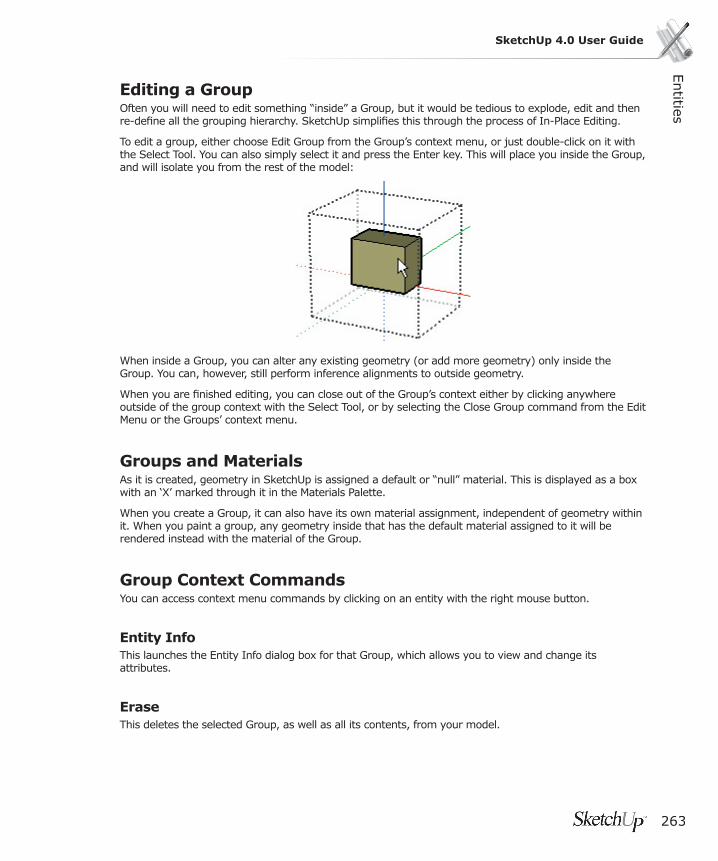
Entities
263
SketchUp 4.0 User Guide
Editing a GroupOften you will need to edit something “inside” a Group, but it would be tedious to explode, edit and then re-defi ne all the grouping hierarchy. SketchUp simplifi es this through the process of In-Place Editing.
To edit a group, either choose Edit Group from the Group’s context menu, or just double-click on it with the Select Tool. You can also simply select it and press the Enter key. This will place you inside the Group, and will isolate you from the rest of the model:
When inside a Group, you can alter any existing geometry (or add more geometry) only inside the Group. You can, however, still perform inference alignments to outside geometry.
When you are fi nished editing, you can close out of the Group’s context either by clicking anywhere outside of the group context with the Select Tool, or by selecting the Close Group command from the Edit Menu or the Groups’ context menu.
Groups and MaterialsAs it is created, geometry in SketchUp is assigned a default or “null” material. This is displayed as a box with an ‘X’ marked through it in the Materials Palette.
When you create a Group, it can also have its own material assignment, independent of geometry within it. When you paint a group, any geometry inside that has the default material assigned to it will be rendered instead with the material of the Group.
Group Context CommandsYou can access context menu commands by clicking on an entity with the right mouse button.
Entity InfoThis launches the Entity Info dialog box for that Group, which allows you to view and change its attributes.
EraseThis deletes the selected Group, as well as all its contents, from your model.

264
Hide/UnhideHiding makes the selected Group invisible. If “Show Hidden Geometry” is enabled, all hidden entities are displayed in a ghosted pattern, allowing you to select them. Thus, if the selected geometry is hidden, this command will be ‘Unhide’, and choosing it will restore visibility.
Edit GroupThis command opens the selected Group for In-Place Editing. You can also double-click on it with the Select Tool, or select it and press Enter.
Close GroupWhen editing a group, the Close Group command is available by right clicking outside the groups geometry. It will exit the in-place editing session for that group. You can also exit by clicking outside the group with the Select Tool, or pressing the ESC key.
ExplodeExploding a Group breaks it back into its constituent parts.
Make ComponentThis converts the Group into a new Component defi nition.
UnglueIf you have attached a hole-cutting Group to a face, it cannot be moved off that face. The Unglue command detaches it from the face, making it free to move off the face.
Reset ScaleThis command removes any scaling operations applied to the Group.
Reset SkewScaling a Group multiple times from more than one axis orientation results in ‘skew’. This is often intended, but when it is not, Reset Skew will correct it.
Flip Along This mirrors the selected geometry along the Group axis you specify. The groups axes are the axial directions that existed when the group was originally created. You may also use the Axis Tool to reposition the global Drawing Axes, allowing you to fl ip selected geometry in virtually any direction.
Entities
265
SketchUp 4.0 User Guide
Group Entity Info Dialog BoxWith an Group selected, you can see and change its attributes in the Entity Info dialog box.
MaterialThis displays the material assigned to the Group. If no material is applied, the default material icon will be displayed. You can select another material in your scene by clicking on the swatch.
LayerThis displays the layer of the selected entity. To move it to a new layer, choose a new one from the pop-up list.
StatisticsThis reports quantities of various drawing elements, such as faces, edges, construction lines, within the component.
Details MenuHide Details: Hides the group’s details.
Cast Shadows: When the Cast Shadows option is enabled, the face will be allowed to cast a shadow.
Receive Shadows: When the Receive Shadows option is enabled, the face will be allowed to receive shadows cast by other entities.
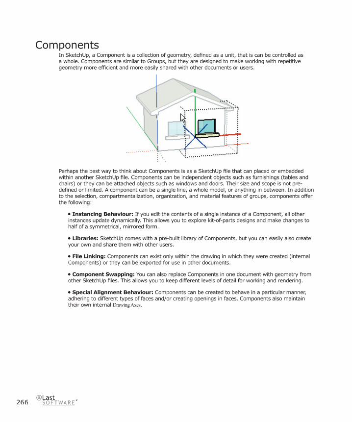
266
ComponentsIn SketchUp, a Component is a collection of geometry, defi ned as a unit, that is can be controlled as a whole. Components are similar to Groups, but they are designed to make working with repetitive geometry more effi cient and more easily shared with other documents or users.
Perhaps the best way to think about Components is as a SketchUp fi le that can placed or embedded within another SketchUp fi le. Components can be independent objects such as furnishings (tables and chairs) or they can be attached objects such as windows and doors. Their size and scope is not pre-defi ned or limited. A component can be a single line, a whole model, or anything in between. In addition to the selection, compartmentalization, organization, and material features of groups, components offer the following:
• Instancing Behaviour: If you edit the contents of a single instance of a Component, all other instances update dynamically. This allows you to explore kit-of-parts designs and make changes to half of a symmetrical, mirrored form.
• Libraries: SketchUp comes with a pre-built library of Components, but you can easily also create your own and share them with other users.
• File Linking: Components can exist only within the drawing in which they were created (internal Components) or they can be exported for use in other documents.
• Component Swapping: You can also replace Components in one document with geometry from other SketchUp fi les. This allows you to keep different levels of detail for working and rendering.
• Special Alignment Behaviour: Components can be created to behave in a particular manner, adhering to different types of faces and/or creating openings in faces. Components also maintain their own internal Drawing Axes.
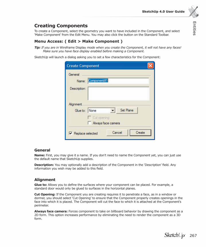
Entities
267
SketchUp 4.0 User Guide
Creating ComponentsTo create a Component, select the geometry you want to have included in the Component, and select ‘Make Component’ from the Edit Menu. You may also click the button on the Standard Toolbar.
Menu Access: ( Edit > Make Component )
Tip: If you are in Wireframe Display mode when you create the Component, it will not have any faces! Make sure you have face display enabled before making a Component.
SketchUp will launch a dialog asking you to set a few characteristics for the Component:
GeneralName: First, you may give it a name. If you don’t need to name the Component yet, you can just use the default name that SketchUp supplies.
Description: You may optionally add a description of the Component in the ‘Description’ fi eld. Any information you wish may be added to this fi eld.
AlignmentGlue to: Allows you to defi ne the surfaces where your component can be placed. For example, a standard door would only be glued to surfaces in the horizontal planes.
Cut Opening: If the Component you are creating requires it to penetrate a face, as in a window or dormer, you should select ‘Cut Opening’ to ensure that the Component properly creates openings in the face into which it is placed. The Component will cut the face to which it is attached at the Component’s perimeter.
Always face camera: Forces component to take on billboard behavior by drawing the component as a 2D form. This option increases performance by eliminating the need to render the component as a 3D form.
268
Replace selected: If this checkbox is checked, the source geometry will be turned into a Component instance. If this is not checked, the source geometry will remain as it is.
Pick Origin: This lets you specify a different origin for the Component. To see the existing axes on a Component, select ‘Show Component Axes’ in the Components Panel of Model Info dialog box.
Inserting ComponentsThere are a variety of different ways to insert component instances in SketchUp.
Component BrowserPre-defi ned Components are most often inserted from the Components Browser. The Component Browser gives you access to the contents of SketchUp’s Component Library, which includes a variety of pre-built Components that you may fi nd useful in your models. The Component Browser is activated through the Window Menu:
Menu Access: ( Window> Components )
To insert a Component from the Component Browser, select it, and click inside your Drawing Window to place it.
As you place or create new Components in your Model, SketchUp adds them to the ‘In Model’ library, which you can fi nd by selecting ‘In Model’ from the pop-up list at the top of the panel.
Insert a Component from an External .skp FileYou can also insert an external SketchUp document as a Component. There are two ways to do this:
1. First, you can choose ( File > Insert > Component... ) to activate an Open fi le dialog that will enable you to select a fi le from your fi le system. You can also click on the folder icon to the right of the Library pop-up menu in the Component Browser. Click on the Open button to place the fi le.
2. Second, you can drag and drop SketchUp fi les from the File Explorer. To do this, fi nd the icon of the fi le you want to place, then press the mouse button and drag it into any open SketchUp Drawing Window. Release your mouse button to place the fi le as a Component.
When inserting a SketchUp fi le as a Component, you should take a few moments to make sure it is prepared for placing. Keep the following in mind:
Make sure you have set the appropriate component behavior under the Component Properties.
The default insertion point for your model when placed as a Component will match the location of its original Axes. To change the default insertion point, change the location of the Axes before you insert the Component.
Entities
269
SketchUp 4.0 User Guide
Moving/Rotating a ComponentYou can use the Move Tool to quickly move or rotate a Component around a central axis.
1. Activate the Move Tool
2. Move the cursor over a face that is perpendicular to the desired axis of rotation. Four rotation handles and a protractor will appear on the face.
3. Click on a rotation handle and rotate the Component. Clicking on any other point will result in a standard move operation.
Component Instancing BehaviorBuilding Components is like building a kit of parts. When you place a Component in your scene, it is dependent on the ‘Component defi nition’ for its form. All other instances of that Component are also dependent on the same defi nition so that editing one Component edits all others in the model simultaneously. (Groups do not exhibit this instancing behaviour.)
Each instance of a Component has its own position, orientation, scale, and material, but the basic geometry is defi ned by the defi nition at all times.
In Place Editing of a ComponentWhen you organize geometry into Components, that geometry becomes encapsulated within the Component and is separated from the rest of your model. You will fi nd that it is often necessary to edit the geometry within a Component, and SketchUp allows you to do this without exploding and redefi ning the Component every time you want to edit it.
In-place editing changes SketchUp’s drawing window to a component’s context, effectively placing you “inside” the component. Once you are inside, you can edit the component’s encapsulated geometry as you would in any other SketchUp model without being distracted by elements outside the component.
Saving Internal Components as External FilesTo save a Component out as a separate SketchUp document (thereby making it available for insertion in other documents), select the Component and choose ‘Save As...’ from its context menu.
Exploding a ComponentExploding a Component detaches it from all the other instances of that Component, and breaks it back down into its constituent parts. If you explode a Component that includes sub-components, they will become separate components again, but will not be decomposed into geometry.
To explode a Component, select it and then choose ( Edit > Component >Explode ). Alternately, you can select ‘Explode’ from the Component’s context commands menu.
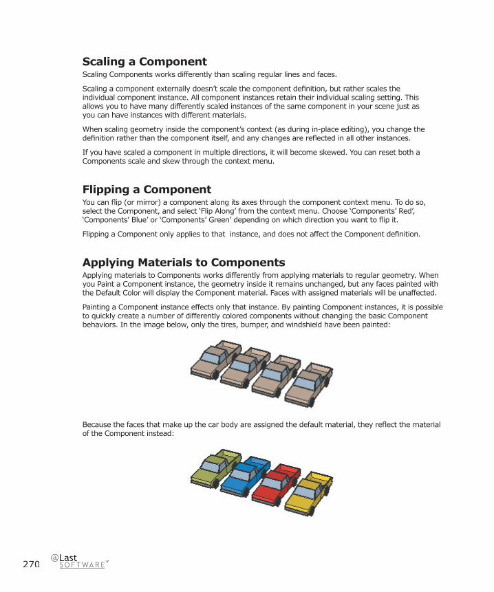
270
Scaling a Component Scaling Components works differently than scaling regular lines and faces.
Scaling a component externally doesn’t scale the component defi nition, but rather scales the individual component instance. All component instances retain their individual scaling setting. This allows you to have many differently scaled instances of the same component in your scene just as you can have instances with different materials.
When scaling geometry inside the component’s context (as during in-place editing), you change the defi nition rather than the component itself, and any changes are refl ected in all other instances.
If you have scaled a component in multiple directions, it will become skewed. You can reset both a Components scale and skew through the context menu.
Flipping a ComponentYou can fl ip (or mirror) a component along its axes through the component context menu. To do so, select the Component, and select ‘Flip Along’ from the context menu. Choose ‘Components’ Red’, ‘Components’ Blue’ or ‘Components’ Green’ depending on which direction you want to fl ip it.
Flipping a Component only applies to that instance, and does not affect the Component defi nition.
Applying Materials to ComponentsApplying materials to Components works differently from applying materials to regular geometry. When you Paint a Component instance, the geometry inside it remains unchanged, but any faces painted with the Default Color will display the Component material. Faces with assigned materials will be unaffected.
Painting a Component instance effects only that instance. By painting Component instances, it is possible to quickly create a number of differently colored components without changing the basic Component behaviors. In the image below, only the tires, bumper, and windshield have been painted:
Because the faces that make up the car body are assigned the default material, they refl ect the material of the Component instead:

Entities
271
SketchUp 4.0 User Guide
Component OriginThe Origin is the insertion point of the Component. All Components are assigned an Origin point whose axes correspond to the Drawing Axes. The orientation of the Component axes can affect how the Component is oriented in the drawing.
Component Context CommandsYou can access context menu commands by clicking on an entity with the right mouse button.
Entity InfoThis displays information about the component in the Entity Info dialog box.
EraseThis deletes the selected circle from your model.
Hide/UnhideHiding makes the selected circle invisible. If “Show Hidden Geometry” is enabled, all hidden entities are displayed in a ghosted pattern, allowing you to select them. Thus, if the selected geometry is hidden, this command will be ‘Unhide’, and choosing it will restore visibility.
Edit ComponentEdits the Component Defi nition. This edits all instances of that Component simultaneously.
Edit (Just This One)If you select Edit (Just This One), SketchUp will make a duplicate component defi nition before editing it so that other instances are not affected. (Any copies made of the new component will be instances of that component, not the old one...)
Close ComponentWhen editing a Component, the Close Component command is available by right clicking outside the groups geometry. It will exit the in-place editing session for that Component. You can also exit by clicking outside the group with the Select Tool, or pressing the ESC key.
ExplodeExploding a Component returns it to its source geometry; lines and faces, as well as any sub objects. If the Component is attached to a model with the ‘Cut Opening’ behavior, the opening remains.
Unglue If you’ve attached a hole-cutting component to a face, it cannot be moved off that face. The unglue command makes it free to move off that face.
272
ReloadThe Reload Command updates an external component that has been inserted from another .skp fi le. Components that have been defi ned internally do not have this option.
Save As...The Save As... command will save the selected Component to a separate SketchUp document, with a new name and/or location in your fi le system. If the Component is only defi ned locally, you can use this command to export it for use in other SketchUp documents.
Change AxisThis command allows you to redefi ne the origin axes of the selected component. It is congruent with changing the “local coordinate system” in other 3D applications.
Depending on how you made the component, a couple of options accrue: If you selected “Align Red/Green plane” when you made the component (so that it will stick its R/G plane to any face you put it on), you will be able to move the origin around only on the component’s R/G plane (the Blue axis will be represented by a fl at ‘X’).
But if you did not make the component this way (“Align Red/Green axes” was NOT selected), you will be free to place the axes anywhere you want them.
Once you click to place the origin, you are given the chance to place the new red and green directions. It’s much faster than reading about it, very easy.
Reset ScaleThis command removes any scaling operations applied to the group.
Reset SkewScaling a group multiple times from more than one axis orientation results in a skewed distortion. This is often intended, but when it is not, ‘Reset Skew’ will correct it.
Scale Defi nitionThis applies any scaling you have done to an instance of a Component to the defi nition itself, thus affecting all other instances.
Properties (All Like This)This opens a Properties dialog box that displays and controls properties of the source Component for the instance selected. Changes made here will affect display of all instances, except where noted. More detailed information on Component Properties have their own section, which you can access here.
Intersect With ModelThis command allows you intersect two elements, such as a box and a tube, and automatically create new faces where the elements intersect. These faces can then be pushed, pulled or deleted to create new geometry.
Entities
273
SketchUp 4.0 User Guide
Flip Along This mirrors the selected geometry along the axis you specify. You can use the Axis Tool to reposition the drawing axes, allowing you to fl ip in virtually any direction.
Component Entity Info Dialog BoxWith a Component is selected, you can see and change its attributes in the Entity Info dialog box.
MaterialThis displays the material assigned to the circle. If no material is applied, the default material icon will be displayed. You can select another material in your scene by clicking on the swatch.
LayerThis displays the layer of the selected entity. To move it to a new layer, choose a new one from the pop-up list.
Component NameThis displays the name of the currently selected Component.
Defi nition TabThis displays an optional description in additional to other component defi nition options.
Statistics TabThis reports quantities of various drawing elements, such as faces, edges, construction lines, within the component.
Details MenuHide Details: Hides the component’s details.
Cast Shadows: When the Cast Shadows option is enabled, the face will be allowed to cast a shadow.
Receive Shadows: When the Receive Shadows option is enabled, the face will be allowed to receive shadows cast by other entities.
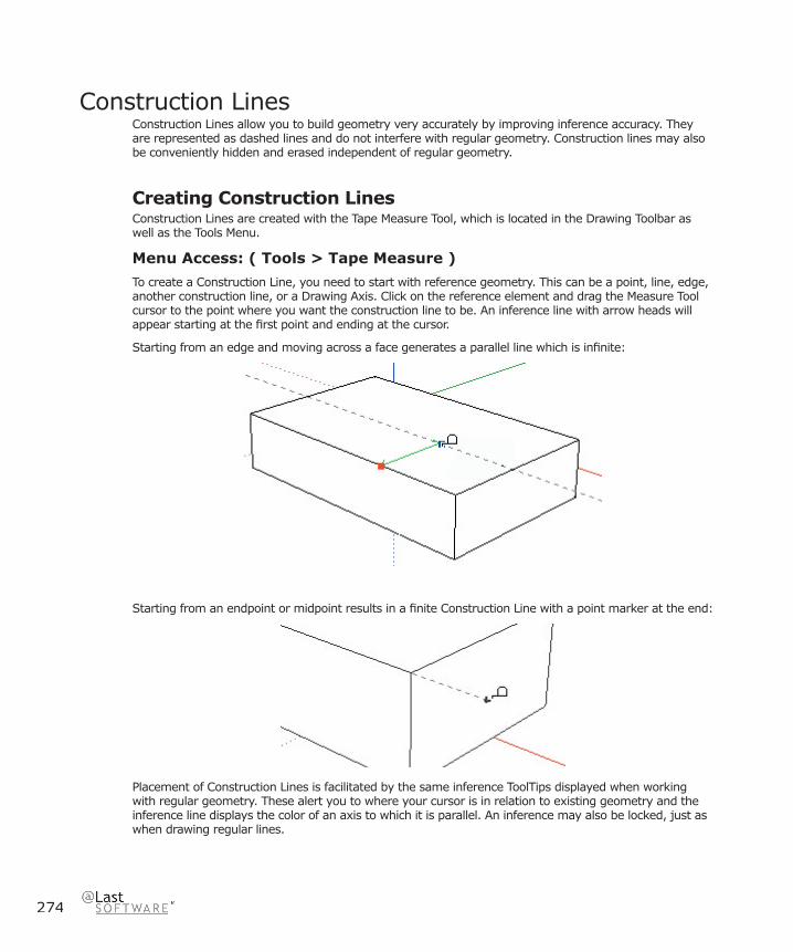
274
Construction LinesConstruction Lines allow you to build geometry very accurately by improving inference accuracy. They are represented as dashed lines and do not interfere with regular geometry. Construction lines may also be conveniently hidden and erased independent of regular geometry.
Creating Construction LinesConstruction Lines are created with the Tape Measure Tool, which is located in the Drawing Toolbar as well as the Tools Menu.
Menu Access: ( Tools > Tape Measure )
To create a Construction Line, you need to start with reference geometry. This can be a point, line, edge, another construction line, or a Drawing Axis. Click on the reference element and drag the Measure Tool cursor to the point where you want the construction line to be. An inference line with arrow heads will appear starting at the fi rst point and ending at the cursor.
Starting from an edge and moving across a face generates a parallel line which is infi nite:
Starting from an endpoint or midpoint results in a fi nite Construction Line with a point marker at the end:
Placement of Construction Lines is facilitated by the same inference ToolTips displayed when working with regular geometry. These alert you to where your cursor is in relation to existing geometry and the inference line displays the color of an axis to which it is parallel. An inference may also be locked, just as when drawing regular lines.

Entities
275
SketchUp 4.0 User Guide
Entering Exact ValuesWhile you are drawing Construction Lines, the Value Control Box (VCB) at the bottom right corner of the Drawing Window displays either the length of the line or its parallel offset in the units specifi ed under preferences. You may specify different values simply by typing them in. You may specify a negative length which draws the line in the direction opposite the one indicated.
Editing Construction LinesConstruction lines can be edited like any other line. You can use the Move, Rotate, and Erase Tools to modify them. You can also delete unwanted Construction Lines by selecting them with the Select Tool, and tapping the Delete key on your keyboard.
Hiding/Erasing All Construction LinesConstruction Lines may be hidden individually, or by layer just like any other geometry. You can also control construction line visibility globally with the Edit menu commands ( Edit > Construction Geometry > Hide /Unhide).
Since construction lines are usually created as a temporary means to build a portion of your model, and keeping too many can decrease SketchUp’s inference accuracy and display performance, you may want to delete all of them at once when you have fi nished constructing. To do this, select ( Edit > Construction Geometry > Erase)
Note: These commands are applied on a per context basis and will not effect construction lines inside groups and components.
Construction Line Context CommandsYou can access context menu commands by clicking on an entity with the right mouse button.
Entity InfoThis displays information about the Construction Line in the Entity Info dialog box.
EraseThis deletes the selected Construction Line from your model.
Hide/UnhideHiding makes the selected Construction Line invisible. If “Show Hidden Geometry” is enabled, all hidden entities are displayed in a ghosted pattern, allowing you to select them. Thus, if the selected geometry is hidden, this command will be ‘Unhide’, and choosing it will restore visibility.

276
Construction Line Entity Info Dialog BoxWith a Construction Line selected, you can see and change its attributes in the Entity Info dialog box.
LayerThe layer on which the Construction Line resides is displayed in the Layer list box. To move it to a different layer, select the name of the new layer from the list.

Entities
277
SketchUp 4.0 User Guide
Image ObjectsAs a part of the everyday design process, you may often need to draw over a scan, a fax or a photograph stored as a pixel-based “raster” image fi le. SketchUp allows you to integrate these types of fi les into your 3D drawings as Image Objects.
An Image Object is essentially a rectangular face with an image fi le mapped onto its surface. Image Objects can be moved, rotated and scaled. They can also be stretched horizontally or vertically, but they cannot be made non-rectangular.
Image FormatsSketchUp supports the following formats for import as an Image Object: JPEG, PNG, TGA, BMP, and TIFF. Some formats may be more appropriate than others for certain types of images and applications.
Inserting Image ObjectsImages can be added to SketchUp models in one of two ways. First, you can use the ( File > Insert > Image... ) menu command, which will open a File Open dialog allowing you to navigate to the fi le you want. Alternately, you can simply drag and drop from the File Explorer directly into your Drawing Window.
Image ProportionsBy default, Image Objects retain the proportions of the fi le from which they are derived. While inserting an image, you can hold down the Shift key to de-constrain the proportions. You can also use the Scale Tool to alter the image object’s proportions after it is placed.
Image File Size vs. QualityWhen you add an Image Object to your scene, the image fi le it is based on becomes embedded in your SketchUp document. This allows you to send your SketchUp fi les to others without any data loss through misplaced linked fi les, but it also means that your fi les can quickly balloon to unwieldy sizes. When inserting images, try to keep fi le size as small as possible:
ResolutionResolution can have a large impact on image size. Try to use only as much resolution as you need, and no more. You may sometimes fi nd that even a pixilated, low resolution fi le can be suffi cient to provide the information you need from a photograph, sketch, or drawing. You can also cut down on image fi le size by converting your images to grayscale before inserting them into SketchUp.
Also, the resolution of Image Objects is limited to the largest texture that OpenGL can handle. For most systems this limit is 1024 x 1024 pixels. This should be suffi cient for most purposes, but if higher resolution is required, you can always stitch together multiple Image Objects.
Image File CompressionAnother way to minimize fi le size is to use compressed fi le formats such as JPEG and PNG. These take up far less space both on disk and inside a SketchUp fi le.
278
Image Object Context CommandsYou can access context menu commands by clicking on an entity with the right mouse button.
Entity InfoThis launches the Entity Info dialog box for that Image Object, which allows you to view and change its attributes.
EraseThis deletes the Image Object from your model.
Hide/UnhideHiding makes the selected Image Object invisible. If “Show Hidden Geometry” is enabled, all hidden entities are displayed in a ghosted pattern, allowing you to select them. Thus, if the selected geometry is hidden, this command will be ‘Unhide’, and choosing it will restore visibility.
ExplodeExploding an Image Object breaks it back into its constituent parts.
ExportThis option allows you to save out an embedded image object to a fi le which may be edited in an image editor.
ReloadIf you make changes to an image fi le using an image editor, use the Reload command to make sure those changes are brought back into SketchUp.
Zoom ExtentsZooms your view to a distance which makes the whole entity visible, and centers it in the drawing window.
ShadowsCast: This command controls how Shadows are affected by the Image Object. The Image Object will cast shadows.
Receive: The Image Object will receive cast shadows cast onto it by other geometry.
UnglueIf you’ve attached an image object to a face, it cannot be moved off that face. The Unglue command makes it free to move off that face.

Entities
279
SketchUp 4.0 User Guide
Use As MaterialThis command creates a material swatch in the In Model section of the Material Browser.
Image Object Entity Info Dialog BoxWith an Image Object selected, you can see and change its attributes in the Entity Info dialog box.
MaterialThis displays the material assigned to the Group. If no material is applied, the default material icon will be displayed. You can select another material in your scene by clicking on the swatch.
LayerThis displays the layer of the selected entity. To move it to a new layer, choose a new one from the pop-up list.
NameThis fi eld displays the fi lename of the Image Object.
in pixelsThis fi eld displays the pixel dimensions of the selected Image Object.
Width/HeightThis displays the dimensions of the Image Object in your SketchUp model. You can lock or unlock the proportions.
Details MenuHide Details: Hides the group’s details.
Cast Shadows: When the Cast Shadows option is enabled, the face will be allowed to cast a shadow.
Receive Shadows: When the Receive Shadows option is enabled, the face will be allowed to receive shadows cast by other entities.
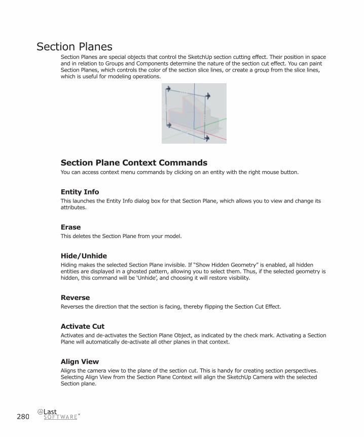
280
Section PlanesSection Planes are special objects that control the SketchUp section cutting effect. Their position in space and in relation to Groups and Components determine the nature of the section cut effect. You can paint Section Planes, which controls the color of the section slice lines, or create a group from the slice lines, which is useful for modeling operations.
Section Plane Context CommandsYou can access context menu commands by clicking on an entity with the right mouse button.
Entity InfoThis launches the Entity Info dialog box for that Section Plane, which allows you to view and change its attributes.
EraseThis deletes the Section Plane from your model.
Hide/UnhideHiding makes the selected Section Plane invisible. If “Show Hidden Geometry” is enabled, all hidden entities are displayed in a ghosted pattern, allowing you to select them. Thus, if the selected geometry is hidden, this command will be ‘Unhide’, and choosing it will restore visibility.
ReverseReverses the direction that the section is facing, thereby fl ipping the Section Cut Effect.
Activate CutActivates and de-activates the Section Plane Object, as indicated by the check mark. Activating a Section Plane will automatically de-activate all other planes in that context.
Align ViewAligns the camera view to the plane of the section cut. This is handy for creating section perspectives. Selecting Align View from the Section Plane Context will align the SketchUp Camera with the selected Section plane.

Entities
281
SketchUp 4.0 User Guide
Create Group from SliceGenerates new edges, encapsulated within a Group, wherever the section intersects with a face.
Section Plane Entity Info Dialog BoxWith a Section Plane selected, you can see and change its attributes in the Entity Info dialog box.
MaterialThis displays the material assigned to the edge. If no material is applied, the default material icon will be displayed. You can select another material in your scene by clicking on the swatch.
LayerThis displays the layer of the selected entity. To move it to a new layer, choose a new one from the pop-up list.
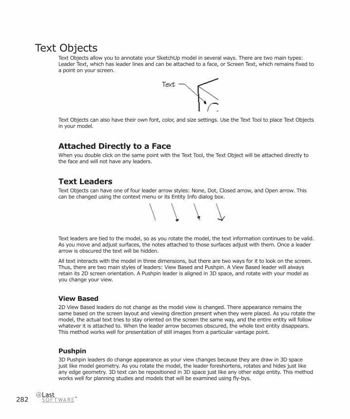
282
Text ObjectsText Objects allow you to annotate your SketchUp model in several ways. There are two main types: Leader Text, which has leader lines and can be attached to a face, or Screen Text, which remains fi xed to a point on your screen.
Text Objects can also have their own font, color, and size settings. Use the Text Tool to place Text Objects in your model.
Attached Directly to a FaceWhen you double click on the same point with the Text Tool, the Text Object will be attached directly to the face and will not have any leaders.
Text LeadersText Objects can have one of four leader arrow styles: None, Dot, Closed arrow, and Open arrow. This can be changed using the context menu or its Entity Info dialog box.
Text leaders are tied to the model, so as you rotate the model, the text information continues to be valid. As you move and adjust surfaces, the notes attached to those surfaces adjust with them. Once a leader arrow is obscured the text will be hidden.
All text interacts with the model in three dimensions, but there are two ways for it to look on the screen. Thus, there are two main styles of leaders: View Based and Pushpin. A View Based leader will always retain its 2D screen orientation. A Pushpin leader is aligned in 3D space, and rotate with your model as you change your view.
View Based2D View Based leaders do not change as the model view is changed. There appearance remains the same based on the screen layout and viewing direction present when they were placed. As you rotate the model, the actual text tries to stay oriented on the screen the same way, and the entire entity will follow whatever it is attached to. When the leader arrow becomes obscured, the whole text entity disappears. This method works well for presentation of still images from a particular vantage point.
Pushpin3D Pushpin leaders do change appearance as your view changes because they are draw in 3D space just like model geometry. As you rotate the model, the leader foreshortens, rotates and hides just like any edge geometry. 3D text can be repositioned in 3D space just like any other edge entity. This method works well for planning studies and models that will be examined using fl y-bys.
Entities
283
SketchUp 4.0 User Guide
Text Object Context CommandsYou can access context menu commands by clicking on an entity with the right mouse button.
Entity InfoThis launches the Entity Info dialog box for that Text Object, which allows you to view and change its attributes.
EraseThis deletes the Text Object from your model.
Hide/UnhideHiding makes the selected edges invisible. If “Show Hidden Geometry” is enabled, all hidden entities are displayed in a ghosted pattern, allowing you to select them. Thus, if the selected geometry is hidden, this command will be ‘Unhide’, and choosing it will restore visibility.
Edit TextThis allows you to re-edit the text. Click outside the text editing window to fi nish.
ArrowThis submenu allows you to choose between the leader styles: None, Dot, Closed, and Open.
LeaderThis submenu allows you can change the leader type between View Based, Push-pin, and Hidden.
Text Object Entity Info Dialog BoxWith a Text object selected, you can see and change its attributes in the Entity Info dialog box.
MaterialThis displays the material assigned to the edge. If no material is applied, the default material icon will be displayed. You can select another material in your scene by clicking on the swatch.
LayerThis displays the layer of the selected entity. To move it to a new layer, choose a new one from the pop-up list.
ArrowSelect the type of arrowhead for the selected Text Object.

284
Dimension ObjectsDimension Objects allow you to quickly and effectively communicate key dimensions of your model. By linking with geometry in your model, Dimensions can move and update automatically as you make changes. Use the Dimension Tool to place them in your model.
Each Dimension Object lies in its own plane, which is determined by the entity from which it is drawn and the direction used when it was created.
Dimension display properties of all dimensions in your model may be adjusted via the Dimension option of the Model Info dialog box, where you can adjust the font, font size and color, text alignment, tick mark style, and other display properties.
Changing TextA Dimension Objects’ text will display the value it measures by default. You can, however, edit the dimension text. If you include the symbols <> anywhere in your text, SketchUp will insert the measured value.
Caution: Dimensions that have lost their direct link to geometry or that have had their text edited may not show accurate measurements. Enabling the Review Problem Dims. option in the Dimension panel of the Model Info dialog box will highlight these dimensions in the color you specify.
Dimension Object Context CommandsYou can access context menu commands by clicking on an entity with the right mouse button.
Entity InfoThis displays information about the dimension object in the Entity Info dialog box.
EraseThis deletes the Dimension Object from your model.
Hide/UnhideHiding makes the selected Dimension Object invisible. If “Show Hidden Geometry” is enabled, all
Entities
285
SketchUp 4.0 User Guide
hidden entities are displayed in a ghosted pattern, allowing you to select them. Thus, if the selected geometry is hidden, this command will be Unhide, and choosing it will restore visibility.
Edit TextThis allows you to re-edit the text. Click outside the text editing window or press the Enter key to fi nish.
Dimension Entity Info Dialog BoxWith a Dimension entity selected, you can see and change its attributes in the Entity Info dialog box.
MaterialThis displays the material assigned to the Group. If no material is applied, the default material icon will be displayed. You can select another material in your scene by clicking on the swatch.
LayerThis displays the layer of the selected entity. To move it to a new layer, choose a new one from the pop-up list.
ArrowSelect the type of arrowhead you wish to use on Dimension Objects in your model. In SketchUp, all Dimension entities are displayed using the same settings, so a change here will effect all Dimensions in your model.
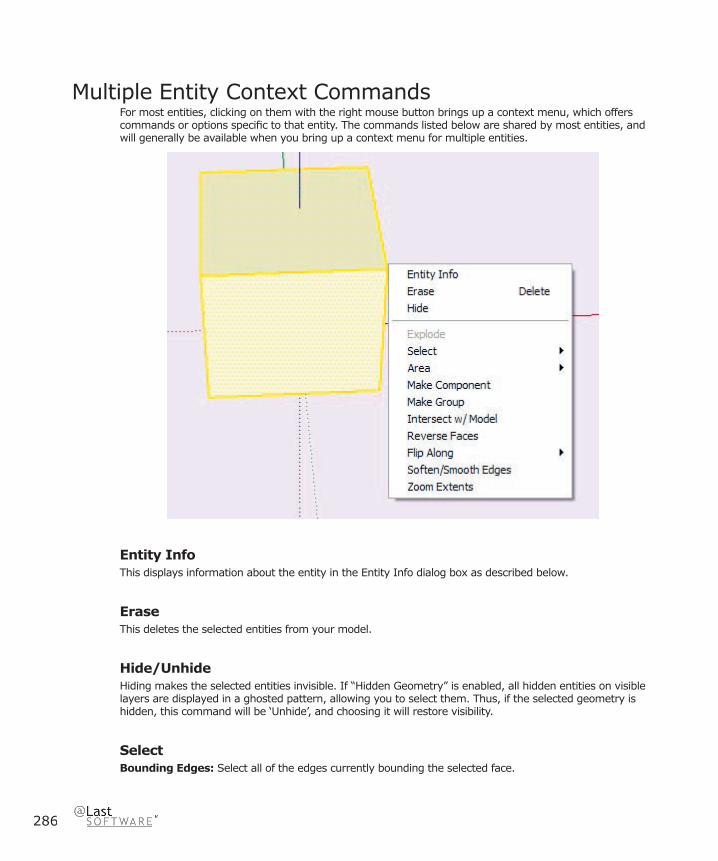
286
Multiple Entity Context CommandsFor most entities, clicking on them with the right mouse button brings up a context menu, which offers commands or options specifi c to that entity. The commands listed below are shared by most entities, and will generally be available when you bring up a context menu for multiple entities.
Entity InfoThis displays information about the entity in the Entity Info dialog box as described below.
EraseThis deletes the selected entities from your model.
Hide/UnhideHiding makes the selected entities invisible. If “Hidden Geometry” is enabled, all hidden entities on visible layers are displayed in a ghosted pattern, allowing you to select them. Thus, if the selected geometry is hidden, this command will be ‘Unhide’, and choosing it will restore visibility.
SelectBounding Edges: Select all of the edges currently bounding the selected face.

Entities
287
SketchUp 4.0 User Guide
Connected Faces: Select all of the faces currently connected to the selected face.
All Connected: Select all of the elements currently connected to the selected face.
All on same Layer: Select all of the elements on the current layer.
All with same Material: Select all of the faces with the same material.
AreaSelection: This calculates the total surface area of the face you clicked on.
Layer: This provides the total area of all faces in the layer of the face you clicked on.
Materials: This provides the total area of the faces in the entire model, hidden or unhidden, using the material of the face you clicked on.
Make ComponentThis creates a Component from the selected geometry.
GroupThis creates a Group out of the selected geometry.
Intersect with ModelThis command allows you intersect two elements, such as a box and a tube, and automatically create new faces where the elements intersect. These faces can then be pushed, pulled or deleted to create new geometry.
Reverse FacesThis fl ips the direction of each selected face so that they point in the opposite direction.
Flip AlongThis mirrors the selected geometry along the axis you specify. You can reposition the Drawing Axes, allowing you to fl ip in virtually any direction.
Zoom ExtentsZooms your view to a distance which makes the entities visible, and centers them in the drawing window.
DivideThe Divide command allows you to quickly divide a line or arc into any number of equal segments.
SoftenSoftened edges are not visible unless displayed in profi le. This allows a faceted surface to appear smooth.

288
Soften/Smooth EdgesThis option is available when the selection includes multiple edges and/or faces. It brings up the soften/smooth dialog, which lets you adjust the apparent rendered smoothness of geometry based on the angle you choose.
Explode CurveThe Explode Curve command breaks the arc/circle/polygon entity into regular edges. An exploded entity will appear the same, but it can no longer be edited, and will no longer respond to tool operations as a single entity.
Zoom ExtentsZooms your view to a distance which makes the whole entity visible, and centers it in the drawing window.
Entity Info Dialog BoxThe Entity Info Dialog Box allows you to view and change the attributes of entities. To access it, right click on the drawing element you wish to modify and select Entity Info from the context menu.
MaterialThis displays the material assigned to the edge. If no material is applied, the default material icon will be displayed. You can select another material in your scene by clicking on the swatch.
LayerThe layer on which the line/edge resides is displayed in the Layer list box. To move the line/edge to a different layer, select the name of the new layer from the list.
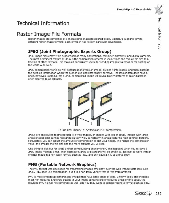
289
SketchUp 4.0 User GuideTech
nical In
form
ation
Technical Information
Raster Image File FormatsRaster images are composed of a mosaic grid of square colored pixels. SketchUp supports several different raster image formats, each of which has its own particular advantages.
JPEG (Joint Photographic Experts Group)JPEG image fi les enjoy wide support across many applications, computer platforms, and digital cameras. The most prominent feature of JPEG is the compression scheme it uses, which can reduce fi le size to a fraction of other formats. This makes it particularly useful for sending images via email or for posting on the world wide web.
JPEG compression works so well because it analyzes an image, divides it into blocks, and then discards the detailed information which the human eye does not readily perceive. The loss of data does have a price, however. Zooming into a JPEG compressed image will reveal blocky patterns of color distortion often referred to as artifacts.
(a) Original image. (b) Artifacts of JPEG compression.
JPEGs are best suited to photograph-like type images, or images with lots of detail. Images with large areas of solid color cannot hide artifacts very well, particularly in areas featuring high-contrast borders. Fortunately, you can adjust the amount of compression to suit your needs. The higher the compression value, the smaller the fi le size and the more artifacts you will see.
One thing to look out for is the artifact compounding phenomenon. This happens when you re-save a JPEG image multiple times. With each save, artifact distortions will be amplifi ed. It’s best to work with an original image in a non-lossy format, such as PNG, and only save a JPG as a fi nal copy.
PNG (Portable Network Graphics)The PNG format was developed for transferring images effi ciently over the web without data loss. Like JPEG, PNG does use compression, but it is a non-lossy variety that is free from artifacts.
PNG is most effi cient at compressing images that have large areas of solid, uniform color. This includes most non-textured SketchUp output. If your image contains lots of textured areas or fi ne detail, the resulting PNG fi le will not compress as well, and you may want to consider using a format such as JPEG.
290
TIFF (Tagged Image File Format)Co-developed by Aldus (now Macromedia) and Microsoft, the TIFF fi le format is a standard in the desktop publishing industry. It offers high quality and is widely supported.
However, there are a large number of variations to the TIFF format available, and therefore it may not be as universally readable as other formats such as PNG and JPEG. SketchUp supports as wide a range of TIFF variants as possible, but you may want to test compatibility before using it. Some kinds of TIFF fi les, particularly 1-bit “bitmap” fi les, or TIFF fi les with “gif” encoding, are not fully compatible with SketchUp.
Also, while formats such as PNG and JPEG are viewable by any web browser and can therefore be sent to virtually any other person with good chance of success, TIFF fi les may require additional software to be viewed on some systems.
Note: SketchUp does not support TIFF fi les at 1 bit per pixel. Images compressed using RLE will expand to uncompressed sizes once imported into SketchUp.
BMPCreated for use with Windows operating systems, the BMP format is used to copy and paste images through the Windows clipboard. Because BMP does not use compression, it can be useful for creating temporary fi les to be further modifi ed in other applications. However, this also means it tends to create very large fi les that are not suitable for archive, web, and email use.
TGA (Targa Truevision)TrueVision Advanced Raster Graphics Adapter (TGA) fi les were developed by AT&T for use with Targa boards, which brought high resolution and full color capability to early computers. Today, all personal computers have graphics capabilities that easily surpass the early Targa boards. Nonetheless, the TGA format remains in use today for its combination of non-lossy compression, stability, and alpha channel support.
EpixEpix is the native format of Piranesi, which is an architectural painting application designed to work with images generated from 3D models. See Piranesi Epix Export for more information.

Technical In
form
ation
291
SketchUp 4.0 User Guide
SketchUp and OpenGLSketchUp is a 3D-intensive application that depends heavily on the CPU, RAM, 3D graphics hardware, and OpenGL drivers installed on your system. A 100% compliant OpenGL driver is required to run SketchUp.
What is OpenGL?OpenGL is an industry-standard system used by numerous software applications and games to draw 3D objects in real-time. All modern fl avors of Windows and Mac OS X come with a fairly reliable software-based OpenGL driver built in. A software OpenGL driver relies exclusively on the CPU to “paint” your screen. Unfortunately, since the CPU is a very generalized device, it isn’t very effi cient at this task.
In an effort to improve the 3D performance, many graphics card manufacturers have designed their products to take over the calculation-intensive parts of OpenGL rendering from the CPU and run it through a specialized chip, called a ‘GPU’, or Graphics Processing Unit. In general, GPU chips are far better suited to the task of painting 3D onto your screen than the CPU, and can provide signifi cant performance enhancements (up to 3,000%) on computers that have them installed. This is often referred to as “Hardware Acceleration.”
Hardware Acceleration and SketchUpWhen you fi rst install SketchUp, it will use software OpenGL rendering by default. If your computer has a 100% OpenGL compatible hardware accelerator, you can take advantage of the superior 3D performance it offers under the OpenGL panel of the Preferences dialog bBox.
Compatibility IssuesIf your video drivers are 100% OpenGL compliant, SketchUp should look and function exactly the same when accelerated as it does when in software rendering mode. The only difference you should notice is a dramatic increase in speed.
If you are experiencing diffi culties using some of the tools, or see odd rendering artifacts, your video card drivers may not be 100% OpenGL compatible as advertised or are simply intended to accelerate 3D games only. If that is the case, it is highly recommended that you disable 3D Hardware acceleration under the OpenGL tab of the Preferences dialog box.
If you are certain that you do have 100% OpenGL compatible hardware acceleration, but the option is disabled in SketchUp, make sure you have your color depth set to 32-bit. Some drivers do not fully support 3D acceleration in 16-bit color mode.
For more details regarding compatibility issues for specifi c boards, please consult the Graphics Card Compatibility section of the Readme fi le, which installs with SketchUp.
Common Symptoms of Sub-Standard OpenGL DriversThe following symptoms indicate your OpenGL driver may not offer 100% OpenGL compatibility.
Streaking or dark artifacts when using face-casting shadows.This is often due to a bug in the stencil buffer of the Software OpenGL driver.

292
“Mini” OpenGL Client Driver causes SketchUp to crash. Many 3D video card drivers are designed only to run games. Consequently, the OpenGL driver only contains a subset of the features needed for any other use. SketchUp requires a 100% OpenGL compatible driver to function. Please be aware that many manufacturers advertise full OpenGL compliance, but in reality do not offer it. If you fi nd yourself in this situation, please continue to use SketchUp with hardware acceleration turned off. (It is turned off by default)
When selecting faces, the reverse faces are picked.This is a common OpenGL bug to which we have found a work-around. The work-around may be enabled by selecting “Correct Reversed Picking Driver Bug” in the OpenGL tab of the Preferences Dialog. This is recommended over disabling 3D Hardware Acceleration.
Missing axes, all lines visible and dashed, and strange texture colors (blue bricks) in 16 bit mode.This is common in laptops that have the ATI Rage Mobility chipset. The drivers for this chipset does not support full OpenGL acceleration. Please use software rendering instead.
Rolling Image ObjectsSome Graphics chips do not support large or high resolution Image Objects. Try reducing the size of the image you are trying to import.
Dual Display MonitorsAt this time, SketchUp does not offi cially support systems running dual monitors, the use of which can prevent SketchUp from operating properly or from taking advantage of hardware acceleration.
If you are using a system that spreads your desktop across multiple monitors, SketchUp may not launch properly with both monitors active or you may experience strange dialog box positioning. Also, if only one of the graphics cards on a dual monitor system supports OpenGL graphics acceleration, windows may not properly report its capability to SketchUp and, as a result, SketchUp will not be able to utilize it. Also, since running dual monitors requires twice as much video memory, some systems that run well on a single monitor may disable hardware acceleration surreptitiously when the second monitor is used.
Anti-AliasingMany modern hardware acceleration systems support hardware anti-aliasing, which reduces the jagged appearance of edges and other pixelation artifacts.

Technical In
form
ation
293
SketchUp 4.0 User Guide
Codec ListThere are many codecs (COmpressor/DECompressor) available, and it’s not always clear which one to use. Codecs are usually evaluated based on their intended uses, compression methods, and how they handle different kinds of pictures or sound. Digital video is used for a wide range of video-related tasks, such as video conferencing, and some codecs may not be appropriate for what you’re trying to accomplish. For example, if you plan to edit your video, you may want to choose a codec that provides higher quality at the expense of fi le size and compatibility. Conversely, if you plan to email your video or play it off a CD, you may want to select a codec that provides lower data rates at the expense of quality. Some codecs are designed specifi cally for a certain device, such as a digital video camera.
You can also choose to use no codec whatsoever, thus creating an uncompressed video. This provides excellent picture and sound quality because no compression is applied. However, working with uncompressed video is not always desirable because the resulting data rate requires an extremely fast system and very large amounts of disk space.
Note: The following codecs were available in the version of Video for Windows that was current at the time this user guide was written. The actual list of available codecs may change in the future. Also, additional codecs may be available depending on the video and audio software and hardware you have installed.
Video for Windows CodecsThe following is a list of codecs that ship with Windows systems.
Cinepak Codec by RadiusThis is the default codec for SketchUp. Although not as advanced as modern codecs, videos compressed using Cinepack will work reliably on any platform, play smoothly from CD-ROM, and will provide decent fi le size compression. Cinepak is asymmetrical and lossy.
Intel Indeo Video R3.2 This codec was designed for video playback from CD-ROM discs. It is comparable in quality to the Cinepak codec, but Cinepack may be preferable due to wider support.
Microsoft Video 1This codec originally shipped with Video for Windows (Windows 3.1) and is low quality and rarely used today.
Intel Indeo Video 4.5This is a lossy codec that provides good compatibility, speed, and fl exibility with average image quality. Advanced features include a quick compression option, keyframe control, transparency, and the ability to adapt to the available bandwidth. (Access to some of these requires software available separately from Intel.)
Intel Indeo Video 5.10This is a lossy codec that provides good compatibility, speed, and fl exibility with average image quality. Advanced features include a quick compression option, keyframe control, transparency, and the ability to
294
adapt to the available bandwidth. (Access to some of these requires software available separately from Intel.)
Tech Smith Screen Capture CodecThis codec is a capture card codec made by the TechSmith Corporation. You will need to download the codec to be able to view fi les produced on a computer using one of TechSmith’s products.
Full Frames UncompressedThis option allows you to export your animation without any compression.
QuickTimeApple developed QuickTime as a comprehensive software framework for creating, playing, and streaming digital media for Mac OS X and Windows. It is widely supported and offers both ease of use and professional functionality in the same package. QuickTime can be downloaded for free at http://www.apple.com/quicktime/
AnimationThis codec works well for images that use large areas of solid colors, and is great for SketchUp images that have no textures or background gradients. It is lossy, but a compression setting of 100% is lossless.
Apple H.263H.263 is a QuickTime codec designed for video conferencing at low data rates and may not be suitable for general-purpose video.
Apple VC H.263This codec is a modifi ed version of H.263 for iChat
CinepakThis is the default codec for SketchUp. Although not as advanced as modern codecs, videos compressed using Cinepack will work reliably on any platform, play smoothly from CD-ROM, and will provide decent fi le size compression. Cinepak is asymmetrical and lossy.
Component videoThis codec provides relatively little compression, which means fi les can get large. It’s useful for archiving, or temporarily storing video.
DV - PAL and DV - NTSCThese are used by PAL and NTSC digital video hardware such as camcorders.
Technical In
form
ation
295
SketchUp 4.0 User Guide
GraphicsThis provides a high quality, 8-bit color image that can work well with SketchUp output. The compression ratio is low, however, which means that it might not be well suited to playback from CD-ROM or the web.
H.261H.263 is a codec designed for video conferencing at low data rates and may not be suitable for general-purpose video. The H.263 requires half the bandwidth to achieve the same video quality as in the H.261.
JPEG 2000
Motion JPEG A and Motion JPEG BThese codecs are designed for many video-capture cards, which provide hardware acceleration for JPEG compression.
MPEG-4 VideoMPEG-4 is the new worldwide standard for interactive multimedia creation, delivery, and playback for the Internet. The MPEG-4 video codec is designed to provide the highest quality across a wide array of data rates over the Internet.
NoneDo not use a codec.
Photo - JPEGThe Photo JPEG codec is built into QuickTime and implements the Joint Photographic Experts Group ISO version 9R9 algorithm for image compression. This codec is generally used for storage of still images, but can also be used for editing and storage of high-quality video fi les.
Planar RGBThis is similar to the Animation codec in that it is effective for images that use large areas of solid colors.
PNGThe PNG codec implementsthe lossless PNG compression - decompression algorithm used by many Web browsers.
Sorenson VideoThis is a very good codec for general video, and is great for playback from CD-ROM the web. It is similar to Cinepak, but provides better picture quality and smaller fi le sizes at the cost of lightly longer compression times. It also supports dynamic playback that automatically adjusts to available bandwidth and CPU resources.
Sorenson Video 3Makes improvements over Sorenson Video in the form of higher quality video and better data compression.

296
TGAThe TGA codec implementsthe lossless TGA compression - decompression algorithm.
TIFFThe TIFF codec implementsthe lossless PNG compression - decompression algorithm.
VideoThis provides high-quality playback from hard disk and moderate quality playback from CD-ROM. It supports both spatial and temporal compression of 16-bit video. Data can be re-compressed or recompiled later for higher compression ratios with minimal or no quality degradation.
Third Party CodecsYou may wish to invest in codecs available for purchase from third party developers. These can offer capabilities and performance not typically available with the freely distributed codecs listed above. The only thing to beware of is that the machine you are playing the video on needs to have the codec as well, or at least a playback-only version.
TechSmith Screen Capture Codec (TSCC)The TechSmith Screen Capture Codec is available as part of the Camtasia capturing application. It was designed primarily for screen capture, but works very well with the type of non-textured imagery that SketchUp produces. Visit the Techsmith Web Site for more information.
Pros:
TSCC is a lossless codec, so it preserves 100% of the SketchUp image quality.
TSCC works very effi ciently with non-textured SketchUp imagery.
TSCC compresses very quickly and works with arbitrary frame sizes.
Cons:
TSCC is for Windows only. Files compressed with TSCC cannot be played back reliably on the Macintosh platform.
TSCC can create rather large fi le sizes, especially with textures or gradients on your screen.
Playback FPS is limited for large frame images.
TSCC is optimized for screen capture, and works best when large areas of the screen do not change.
SorensonSorenson provides a number of products and tools designed to make effi cient video compression easier to use. Sorenson commercial codecs are typically lossy, yet provide excellent quality at small fi le sizes. In particular, Sorenson Squeeze is easy to use and requires no in-depth knowledge of the complexities of compression technology. Visit the Sorenson Web Site for more information.

Technical In
form
ation
297
SketchUp 4.0 User Guide
Pros:
Excellent image quality at small fi le sizes.
Runs on QuickTime for both windows and Mac platforms.
Cons:
Lossy compression better suited to video than graphics.
Divx CodecThe DivX® codec based on MPEG-4 video compression technology and is designed to shrink digital video to sizes small enough to be transported over the Internet, while maintaining high visual quality. It’s very lossy, however.
To view the compressed version of the video, you need a media player that can play DivX-encoded content.
Pros:
Free version available.
Free version can still compress, great image quality, multi-platform support.
Cons:
Lossy compression better suited to video than graphics.
Dispute over its use of MPEG-4 technology.
298
Animation TipsThe following are some guidelines that may help you get more out of your video projects.
Create Quick PreviewsBefore generating a large animation of a complex scene, it is often advisable to create a quick preview. To do so, set the frame size to a minimal resolution such as 200 or so pixels wide. Also, set your frame rate to a very low number, such as 2 or 3 frames per second. Although the fi le will not be presentable, it will take much less time to render, and will give you a better sense of the timing and fl ow of your video. It can also show potential problems such as aspect ratio mismatches, walking through walls, etc.
Make a DVDMany computers today come with the ability to write a DVD digital video disc. When you put your animation onto a DVD, it handles most of the tricky issues, such as compression, for you. If you use DVD-R discs, you have a high degree of compatibility with any system that plays DVD’s.
Mix MediaAnimation is better than stills for communicating 3D info, movement such as sun/shadow studies, or slow, paused walkthroughs. Stills are better than animation for showing lots of small details or large, comprehensive drawings. Rather than rely on one medium alone, it can be very effective to mix the two, using each for what it’s best at.
Multi-TaskAn animation can take hours to render, especially with shadows, high quality, high frame rate and large frame sizes. It’s desirable to have the computer work over night while you sleep, or while you relax, or do other tasks. It’s also a good technique to output still drawings before outputting an animation. You can then refi ne them with markers and colored pencils while the computer works.
If you have multiple systems at your disposal, another technique is to have the exterior animation rendering on one computer while you set up the interior walkthrough on another. An older, slower computer may take longer to render, but it keeps faster systems free for use.
Only Do What’s NecessaryCreating animations and putting them together into presentations can take quite a bit of time. Also, changes are harder to make afterwards. Try to leverage SketchUp’s real-time rendering capabilities as much as possible.
Technical In
form
ation
299
SketchUp 4.0 User Guide
SketchUp Template FilesSketchUp allows you to specify a template fi le to use each time you create a new document. This can be handy if you often start with a grid or with particular rendering settings, layer standards, pages views, or units. For example, you may wish to always launch SketchUp with units set to metric instead of imperial
To specify a fi le for use as a template:
1. First, launch the SketchUp preferences dialog. Menu Access: ( View > Preferences ).
2. Click on the Template option from the list, and select the SketchUp fi le you’d like to use from the fi le system.

300
Bug SplatBugSplat (www.bugsplatsoftware.com) is a 3rd party software application that we have enthusiastically chosen to integrate in SketchUp 4.0 for Microsoft Windows 2000 and XP to help us improve the quality of our product. We are including this technology as a way of troubleshooting unrecoverable SketchUp errors or “crashes.” BugSplat provides a mechanism for Microsoft Windows users to send information about all crashes to @Last Software for troubleshooting.
How Does it Work?In the rare event that SketchUp crashes you will see a dialog, similar to Microsoft Window’s crash report dialog. This dialog will give you the option to send us the information regarding the crash. Here is what is collected if you decide to send us the information:
• Your version of the SketchUp executable.
• Your language setting, such as English.
• A "stack trace" of the bug allowing us to see the exact line of code where SketchUp crashed.
• A list of SketchUp code dependencies.
• (optional) Your name and email address.
• (optional) A description of what you were doing before the crash.
Note: If you happen to look at the BugSplat Software website, you will see a security statement that is aimed at assuring clients of BugSplat - in this case @Last Software – that the information on our crashes (e.g., how many we have, and so on) will be protected. The above information is all that we are collecting.
How To Load An Offl ine Crash Report.If a crash occurs when you are not connected to the Internet, BugSplat displays a dialog box indicating that a zip fi le has been created on your local hard drive. This dialog box will also indicate the name and location of the zip fi le (normally AtLastCrashMMDDYY_HHMMSS.zip in your Windows temporary directory). Go to http://www.bugsplatsoftware.com/post/post_form.php and follow the instructions on the Web page to send this fi le to BugSplat Software when you reconnect to the Internet. Or email the zip fi le to @Last Software directly at [email protected].

Technical In
form
ation
301
SketchUp 4.0 User Guide
SketchUp Ruby API and ConsoleSketchUp contains a Ruby application programming interface (API) for users who are familiar with (or want to learn) Ruby scripting and want to extend the functionality of SketchUp. This interface allows users to create macros, such as automated component generators and additional tools, to be included in the menus within SketchUp. In addition to the API, SketchUp also includes a Ruby console which is an environment where you can experiment with Ruby commands and methods .
For additional information on the Ruby programming language, visit www.rubycentral.com.
For additional information on SketchUp Ruby API, click on Help > Ruby Help.
@Last Software provides unlimited technical support for SketchUp via email. Support is limited to the English language. Currently, we do not offer technical support for the Ruby Application Programmers Interface (API) or for any Ruby scripts created by third parties. We encourage posting Ruby API questions to our SketchUp Ruby API Forum. General Ruby information may be obtained at http://www.ruby-lang.org/en/.
We reserve the right to change this policy at any time.
302
Tuto
rials
Tutorials
Beginning TutorialsIf you’re just learning how to use SketchUp, you’ve come to the right place. The beginning tutorials in this section will introduce you to SketchUp’s overall layout, demonstrate basic commands and drawing techniques, and get you up and running in no time.
In addition to these tutorials, we recommend that you view SketchUp Video Training, which may be found on your installation CD-ROM or downloaded directly from the Video Training web page at SketchUp.com.
1. Starting SketchUp
2. Drawing Lines
3. Creating Faces
4. Viewing Your Model
5. Sketching in 3D
6. Using Push/Pull
7. Creating a Simple Roof
8. Creating a Dormer
9. Creating Openings in Faces
10. Applying Materials

Tuto
rials
303
SketchUp 4.0 User Guide
Starting SketchUpTo start SketchUp, click on the Windows Start button and select ‘Programs.’ Go to the ‘@Last Software’ entry and click on the item labeled SketchUp 4.
If you are running SketchUp for the fi rst time, you will be presented with a copy of SketchUp’s License Agreement. Please read this carefully, and accept the agreement to continue. Next, you will be presented with an authorization dialog box. If you have purchased a license for SketchUp, click the Authorize button, and follow the directions that came with your license. If not, you may run SketchUp in Evaluation Mode for eight hours.
SketchUp will open with a blank Drawing Window that looks like this:
Toolbars SketchUp’s Toolbars contains all of the construction, drawing, modifi cation, and viewing tools you will need to work in SketchUp. As you move your mouse cursor across and pause over each button, you will see a ToolTip indicating the name of each tool.
Generally speaking, all tools are activated by clicking on their icon button in the Toolbar , then returning your cursor to the Drawing Window to work. To try this out, activate the Line Tool (the pencil icon) by clicking once on its icon button:
Move your cursor (which should now look like a pencil) back into the Drawing Window. Click anywhere and drag to create a line. Don’t worry about what you are drawing or about how the Line Tool actually works just yet, as we will cover these topics in more detail later. When you are fi nished, tap the ‘Esc’ key on your keyboard to end your line drawing.
The Drawing WindowThe Drawing Window is where you will do most of your work in SketchUp. It is a fully dynamic 3D space that you can move around in freely. Like other Windows applications, the drawing window can have toolbars and other controls docked around its edge.
First of all, you will notice that the Drawing Window has the name “Untitled” in the Title Bar. This is because you have not yet saved your drawing. When you do so, SketchUp will show you the name you have chosen for your model in the Title Bar.
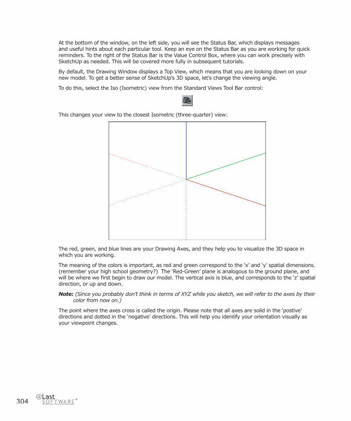
304
At the bottom of the window, on the left side, you will see the Status Bar, which displays messages and useful hints about each particular tool. Keep an eye on the Status Bar as you are working for quick reminders. To the right of the Status Bar is the Value Control Box, where you can work precisely with SketchUp as needed. This will be covered more fully in subsequent tutorials.
By default, the Drawing Window displays a Top View, which means that you are looking down on your new model. To get a better sense of SketchUp’s 3D space, let’s change the viewing angle.
To do this, select the Iso (Isometric) view from the Standard Views Tool Bar control:
This changes your view to the closest Isometric (three-quarter) view:
The red, green, and blue lines are your Drawing Axes, and they help you to visualize the 3D space in which you are working.
The meaning of the colors is important, as red and green correspond to the ‘x’ and ‘y’ spatial dimensions. (remember your high school geometry?) The ‘Red-Green’ plane is analogous to the ground plane, and will be where we fi rst begin to draw our model. The vertical axis is blue, and corresponds to the ‘z’ spatial direction, or up and down.
Note: (Since you probably don’t think in terms of XYZ while you sketch, we will refer to the axes by their color from now on.)
The point where the axes cross is called the origin. Please note that all axes are solid in the ‘postive’ directions and dotted in the ‘negative’ directions. This will help you identify your orientation visually as your viewpoint changes.
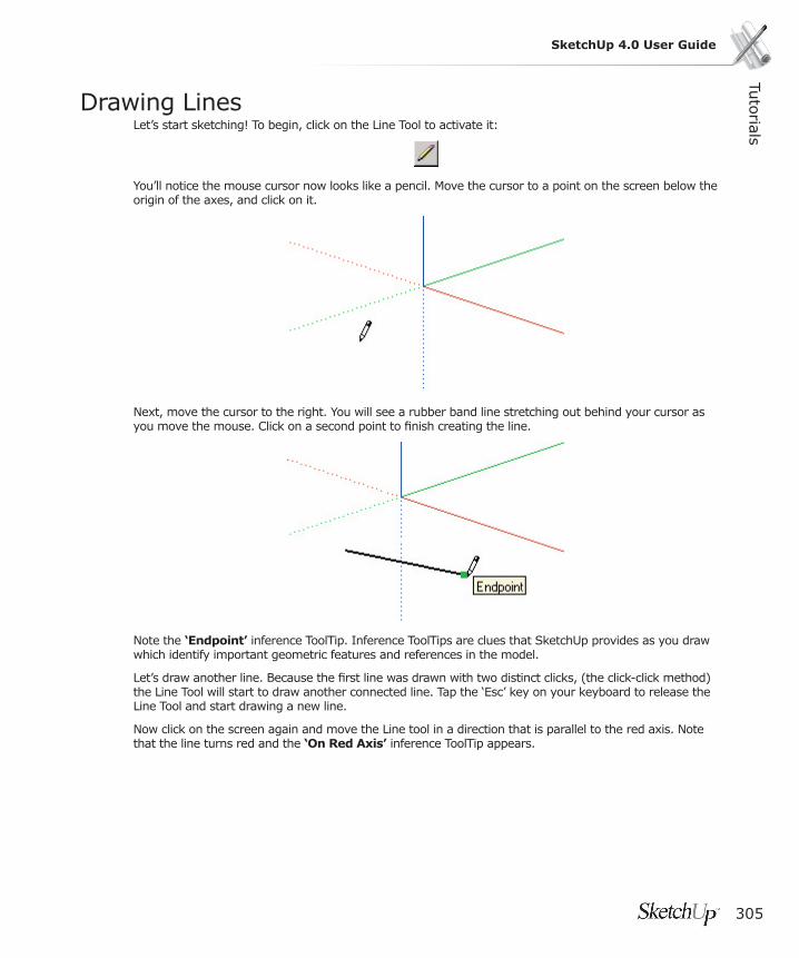
Tuto
rials
305
SketchUp 4.0 User Guide
Drawing LinesLet’s start sketching! To begin, click on the Line Tool to activate it:
You’ll notice the mouse cursor now looks like a pencil. Move the cursor to a point on the screen below the origin of the axes, and click on it.
Next, move the cursor to the right. You will see a rubber band line stretching out behind your cursor as you move the mouse. Click on a second point to fi nish creating the line.
Note the ‘Endpoint’ inference ToolTip. Inference ToolTips are clues that SketchUp provides as you draw which identify important geometric features and references in the model.
Let’s draw another line. Because the fi rst line was drawn with two distinct clicks, (the click-click method) the Line Tool will start to draw another connected line. Tap the ‘Esc’ key on your keyboard to release the Line Tool and start drawing a new line.
Now click on the screen again and move the Line tool in a direction that is parallel to the red axis. Note that the line turns red and the ‘On Red Axis’ inference ToolTip appears.

306
Before selecting a second point, wiggle the line a bit. Notice that it turns black again when the rubber band line is no longer parallel to the axis. If you now move the end of the new line so that it becomes parallel to the fi rst, it will turn magenta and display a ToolTip indicating that it is truly parallel.
These alignment guides are examples of SketchUp’s Inference capability, which anticipates your needs while you work and allows you to draw line in 3D using a 2D mouse and screen interface. As you continue learning to draw in SketchUp, you’ll fi nd that the ability to draw by inference affords a great deal of speed and precision, without the need for complicated snapping controls typically found in CAD systems.
Before you move on to the next tutorial, try drawing lines in all three directions; red, green, and blue. Also, practice drawing from the end points and mid points of other lines. In addition to clicking, you can also draw lines by pressing the mouse button, dragging, and releasing. This will create a single unconnected line.

Tuto
rials
307
SketchUp 4.0 User Guide
Creating FacesIn addition to lines, SketchUp lets you draw fl at (planar) faces of any shape. These faces can be joined together, divided, subtracted from each other, split into multiple faces, stretched, and extruded into 3D forms.
Before we begin, let’s make sure that the display style is set to the Shaded from the View Menu. Menu Access: (View > Display Settings > Shaded).
Note: SketchUp can also display surfaces in Hidden Line Mode, where faces will hide what is behind them and become the same color as the background of the drawing screen. While this can be useful when applying traditional media over a SketchUp printed output, we’ll need shaded faces for this tutorial.
Let’s begin by drawing a rectangular face. Activate the Line Tool, and click a point in front of the vertical blue axis to start your line. Move the mouse in the red direction like you did in the previous tutorial, but do not pick an end point.
Notice as you draw the line that its length displayed dynamically in the Value Control Box at the lower right of your screen:
Let’s make it 10’ line. Type in 10’ using the keyboard, and press the Enter key.
The line will be drawn to exactly 10 feet, and will end with a green square indicating an Endpoint. Notice that the line you have created is now black, and the Line Tool is still active and ready for further drawing.

308
Note: Unlike other 3D CAD programs, SketchUp does not require exact dimensions for drawing. In order to maximize your creativity, SketchUp allows you to be as exact or loose as you wish.
Draw your next line 90 degrees from the fi rst line. (This should be 90 degrees visually in the 3D model, not graphically on the 2D screen.) The line should be green as you draw it, since it is parallel to the green axis. Now type in 8’ and press Enter.
The line is drawn 8’ long, but you can continue to enter different length values. Try typing in 5’ followed by the Enter key. The line will continue re-size with each new dimension. Let’s change it back to 8’ again before we continue.
Next, draw a third line parallel to the red axis, but instead of using the Value Control Box to make it exact, let’s take advantage of SketchUp’s inference capabilities. Extend the third line back towards the green axis. You’ll know you are parallel to the red axis when the line turns red.
When the length of the new line is the roughly same as the fi rst one you drew, notice that a green dotted line appears connecting the two. The cursor tip should also change to read ‘From Point’. This indicates that the end point of the new line is now lined up precisely with the endpoint of the fi rst line. Go ahead and click to complete the line on that point.

Tuto
rials
309
SketchUp 4.0 User Guide
Now fi nish the rectangle by clicking on the fi rst point.
Notice that the completed rectangle becomes fi lled with a solid face. Also, note that the Line Tool is still active, but no longer drawing connecting lines.
In order for SketchUp to create a face, all the lines that border the face must be connected end to end and lie in the same plane. If there are any gaps or non-planar geometries, SketchUp cannot create a face.

310
Viewing Your ModelBefore we move on to drawing in three dimensions, let’s look at some of the basic ways to control your view of the model.
SketchUp’s most versatile tool for rotating the model in space is the Orbit Tool. Go ahead and activate it:
Now, press and drag the cursor anywhere in the Drawing Window.
The Orbit Tool pivots your view of the model about a center point. You can use it to dynamically view your model from any point in space; above, below, and from any side.
Tip: If you have a middle button on your mouse, you can press it to orbit your model at any time.
Sometimes the Orbit Tool alone won’t show you what you need to see in your model, and you may need a closer look. To zoom in or out in your model, click on the Zoom Tool:
Now click and drag the cursor up and down on the screen. As you drag up, your viewpoint moves closer to the model, and as you drag down, it moves further away.
Tip: If you have a mouse with a scroll-wheel, you can zoom in and out at any time by scrolling the wheel forward and backward.
If at any time you lose track of where you are in space, you can return you to a familiar orientation by clicking on the Isometric view button. You can also activate Zoom Extents, which will center your whole model on the screen:
Another valuable tool for working on your model is the Zoom Window Tool:
The Zoom Window Tool allows you to drag a rectangle on a part of the drawing screen you’d like to see in greater detail. When used, the area indicated will expand to fi ll the entire SketchUp window, making it very useful for detail work or to check features of your model.
When you are done with the close-up view, click the Undo View Change button to restore your previous viewpoint.

Tuto
rials
311
SketchUp 4.0 User Guide
Sketching in 3DThe techniques you have learned for creating 2D shapes can be applied to 3D sketching as well. For this exercise, we are going to draw a 3D box using only the Line Tool. Start by drawing a rectangle like you did in the Creating Faces tutorial.
While still in the Line Tool, snap to a corner of your rectangle. Make certain that the green ‘Endpoint’ inference with a ToolTip appears to confi rm you have the right starting point.
Click your mouse on the endpoint to start drawing a new line. Then, move the cursor up from the corner. Move the mouse around so that your line is vertical and turns blue to indicate alignment with the blue axis. You should also see the ‘On Axis’ ToolTip appear:
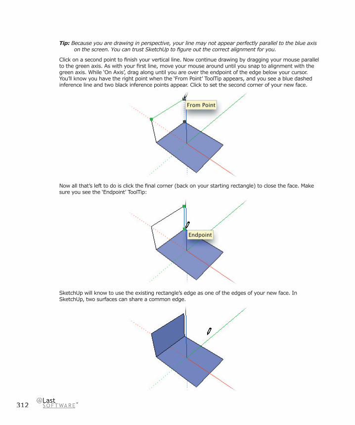
312
Tip: Because you are drawing in perspective, your line may not appear perfectly parallel to the blue axis on the screen. You can trust SketchUp to fi gure out the correct alignment for you.
Click on a second point to fi nish your vertical line. Now continue drawing by dragging your mouse parallel to the green axis. As with your fi rst line, move your mouse around until you snap to alignment with the green axis. While ‘On Axis’, drag along until you are over the endpoint of the edge below your cursor. You’ll know you have the right point when the ‘From Point’ ToolTip appears, and you see a blue dashed inference line and two black inference points appear. Click to set the second corner of your new face.
Now all that’s left to do is click the fi nal corner (back on your starting rectangle) to close the face. Make sure you see the ‘Endpoint’ ToolTip:
SketchUp will know to use the existing rectangle’s edge as one of the edges of your new face. In SketchUp, two surfaces can share a common edge.

Tuto
rials
313
SketchUp 4.0 User Guide
Let’s continue drawing new faces the rest of the way around the original rectangle. Since SketchUp already knows to use existing lines in your model as edges for new faces, you can start drawing the next face from the top right corner of the previous face. As before, let SketchUp guide you with the appropriate inference indications.
In the image above, you can tell that the line you are drawing is parallel to the red axis, and that its endpoint is directly above the corner of your base rectangle. Close the face by clicking back on the base rectangle. Start drawing the next face by clicking on the upper right end point:
SketchUp will usually try to fi nd the right points for you to draw accurately, but it can become confused if there are too many alignments available. When this happens, you can help SketchUp fi nd what you are looking for by “encouraging” an inference. To do this, simply hover over the point or line you wish to align with. In this case, move your mouse over the corner on the base rectangle that you wish to align with until you see an endpoint ToolTip:
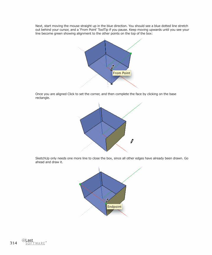
314
Next, start moving the mouse straight up in the blue direction. You should see a blue dotted line stretch out behind your cursor, and a ‘From Point’ ToolTip if you pause. Keep moving upwards until you see your line become green showing alignment to the other points on the top of the box:
Once you are aligned Click to set the corner, and then complete the face by clicking on the base rectangle.
SketchUp only needs one more line to close the box, since all other edges have already been drawn. Go ahead and draw it.
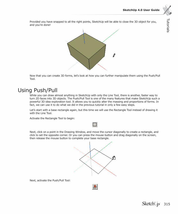
Tuto
rials
315
SketchUp 4.0 User Guide
Provided you have snapped to all the right points, SketchUp will be able to close the 3D object for you, and you’re done!
Now that you can create 3D forms, let’s look at how you can further manipulate them using the Push/Pull Tool.
Using Push/PullWhile you can draw almost anything in SketchUp with only the Line Tool, there is another, faster way to turn 2D faces into 3D objects. The Push/Pull Tool is one of the many features that make SketchUp such a powerful 3D idea exploration tool. It allows you to quickly alter the massing and proportions of forms. In fact, we can use it to do what we did in the previous tutorial in only a few easy steps.
Let’s start with a base rectangle again, but this time we will use the Rectangle Tool instead of drawing it with the Line Tool.
Activate the Rectangle Tool to begin:
Next, click on a point in the Drawing Window, and move the cursor diagonally to create a rectangle, and click to set the opposite corner. Or you can press the mouse button and drag diagonally on the screen, then release the mouse button to complete your base rectangle.
Next, activate the Push/Pull Tool:

316
Click on the rectangle you have created...
...and move up to extrude it into 3D.
Presto! You have just made a 3D object!
Next, try clicking and dragging on the vertical surfaces. Pretty easy, isn’t it?
As you work, notice that the displacement distance of the Push/Pull operation is displayed in the VCB. As you’ve probably guessed, you can enter in exact values followed by the Enter key, just as you did when drawing lines of a specifi c length. The number is interpreted as the distance to move from where the Push/Pull started. As long as no other tool has been activated, typing successive distances moves the face that amount relative to the original starting position.
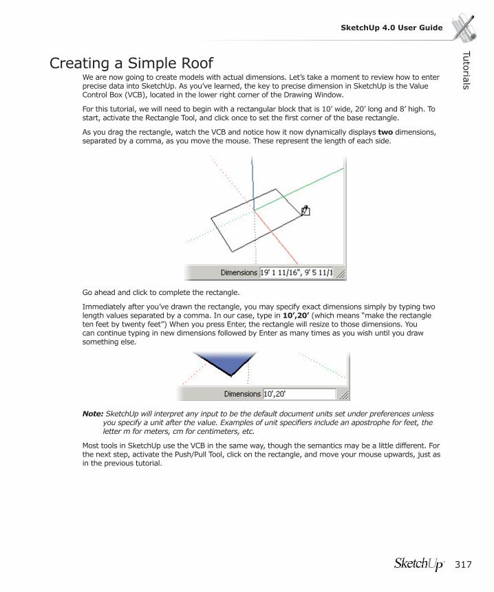
Tuto
rials
317
SketchUp 4.0 User Guide
Creating a Simple RoofWe are now going to create models with actual dimensions. Let’s take a moment to review how to enter precise data into SketchUp. As you’ve learned, the key to precise dimension in SketchUp is the Value Control Box (VCB), located in the lower right corner of the Drawing Window.
For this tutorial, we will need to begin with a rectangular block that is 10’ wide, 20’ long and 8’ high. To start, activate the Rectangle Tool, and click once to set the fi rst corner of the base rectangle.
As you drag the rectangle, watch the VCB and notice how it now dynamically displays two dimensions, separated by a comma, as you move the mouse. These represent the length of each side.
Go ahead and click to complete the rectangle.
Immediately after you’ve drawn the rectangle, you may specify exact dimensions simply by typing two length values separated by a comma. In our case, type in 10’,20’ (which means “make the rectangle ten feet by twenty feet”) When you press Enter, the rectangle will resize to those dimensions. You can continue typing in new dimensions followed by Enter as many times as you wish until you draw something else.
Note: SketchUp will interpret any input to be the default document units set under preferences unless you specify a unit after the value. Examples of unit specifi ers include an apostrophe for feet, the letter m for meters, cm for centimeters, etc.
Most tools in SketchUp use the VCB in the same way, though the semantics may be a little different. For the next step, activate the Push/Pull Tool, click on the rectangle, and move your mouse upwards, just as in the previous tutorial.

318
For this model, we want to extrude the rectangle exactly eight feet up, so enter a value of 8’. SketchUp will adjust the Push/Pull operation to make it exactly eight feet.
Now that we have the initial box object built, we can begin making our simple roof. Activate the Line Tool, and snap to a midpoint on the top face of the object. Use the ‘Midpoint’ ToolTip to make sure you have exactly the right point. Click to set the fi rst point in your line, then move your cursor across the face to the midpoint of the opposite edge.
Once more, click to set the endpoint of the line. This line has just split the top face of your object into two separate faces, an operation referred to as “introducing” an edge.
Next, activate the Move Tool:

Tuto
rials
319
SketchUp 4.0 User Guide
Move the cursor over the line you just completed. Notice that since nothing was explicitly selected beforehand, the Move Tool senses ‘movable’ geometry underneath itself, and shows you what it is ready to move by highlighting it in yellow.
Go ahead and click on the line and move the mouse upwards. To make certain you are moving the line straight up, watch for the blue inference line as well as the ‘On Axis’ selection tip. This will form the peak of a simple gable roof.
Sometimes SketchUp can’t fi gure out exactly what alignment you are looking for. If this happens, drag the line farther up in the blue direction until you see the blue dashed inference you want. Then hold down the Shift key to lock in the vertical inference and move the line back down until it is in the correct place. As long as you hold down Shift, the direction of movement will remain vertical.
You can also use the VCB to tell SketchUp precisely how high you want the ridge to be. To set the ridge fi ve feet up, type 5’ followed by Enter immediately after the move operation. Remember that you can repeatedly make changes via the VCB at any time, so long as you haven’t changed tools or started another move operation.
Go ahead and save this model so that we may use it as a starting point for the next tutorial.
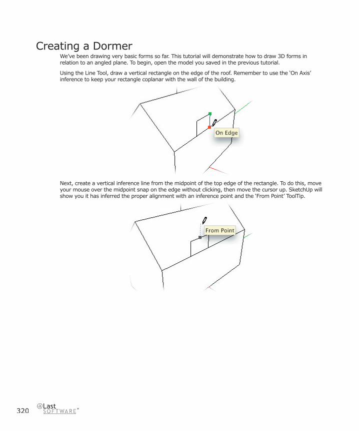
320
Creating a DormerWe’ve been drawing very basic forms so far. This tutorial will demonstrate how to draw 3D forms in relation to an angled plane. To begin, open the model you saved in the previous tutorial.
Using the Line Tool, draw a vertical rectangle on the edge of the roof. Remember to use the ‘On Axis’ inference to keep your rectangle coplanar with the wall of the building.
Next, create a vertical inference line from the midpoint of the top edge of the rectangle. To do this, move your mouse over the midpoint snap on the edge without clicking, then move the cursor up. SketchUp will show you it has inferred the proper alignment with an inference point and the ‘From Point’ ToolTip.
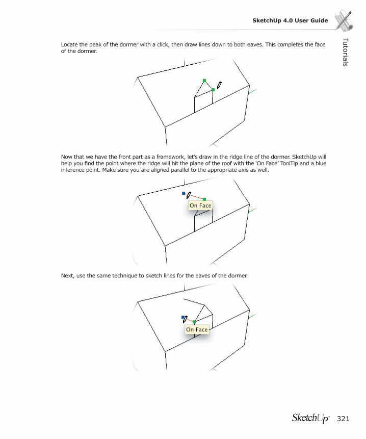
Tuto
rials
321
SketchUp 4.0 User Guide
Locate the peak of the dormer with a click, then draw lines down to both eaves. This completes the face of the dormer.
Now that we have the front part as a framework, let’s draw in the ridge line of the dormer. SketchUp will help you fi nd the point where the ridge will hit the plane of the roof with the ‘On Face’ ToolTip and a blue inference point. Make sure you are aligned parallel to the appropriate axis as well.
Next, use the same technique to sketch lines for the eaves of the dormer.
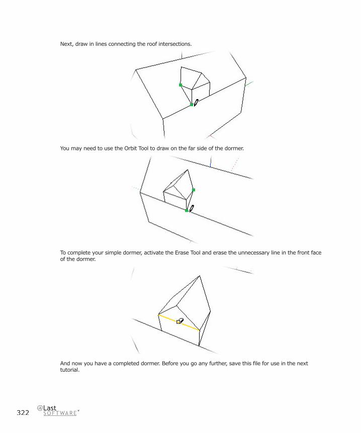
322
Next, draw in lines connecting the roof intersections.
You may need to use the Orbit Tool to draw on the far side of the dormer.
To complete your simple dormer, activate the Erase Tool and erase the unnecessary line in the front face of the dormer.
And now you have a completed dormer. Before you go any further, save this fi le for use in the next tutorial.
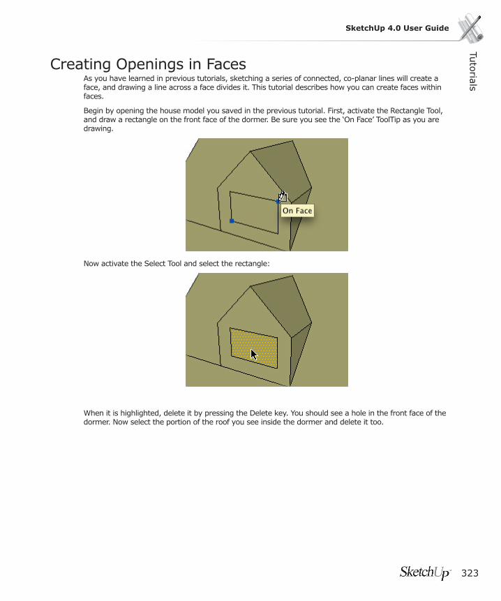
Tuto
rials
323
SketchUp 4.0 User Guide
Creating Openings in FacesAs you have learned in previous tutorials, sketching a series of connected, co-planar lines will create a face, and drawing a line across a face divides it. This tutorial describes how you can create faces within faces.
Begin by opening the house model you saved in the previous tutorial. First, activate the Rectangle Tool, and draw a rectangle on the front face of the dormer. Be sure you see the ‘On Face’ ToolTip as you are drawing.
Now activate the Select Tool and select the rectangle:
When it is highlighted, delete it by pressing the Delete key. You should see a hole in the front face of the dormer. Now select the portion of the roof you see inside the dormer and delete it too.

324
This illustrates an important point: As you draw, any lines that form a closed, planar shape will also create a new face. Wether or not they were originally intended to.

Tuto
rials
325
SketchUp 4.0 User Guide
Intermediate
Intermediate TutorialsAfter fi nishing the Beginning Tutorials, you should be able to draw most simple forms quickly and easily. The Intermediate Tutorials in this section will further explore creating and modifying geometry as well as introduce you to materials, layers, and components.
Remember that in addition to these online tutorials, we recommend that you view SketchUp’s training videos. These can be found on your installation CD as well as on the SketchUp Video Training web site.
1. Creating and Using Construction Lines
2. Moving and Copying Faces
3. Hiding and Reversing Faces
4. Making Precision Measurements
5. Making Arrays with Multi-Copy
6. Scaling Geometry and Objects
7. Introducing Layers
8. Working with Materials
9. Inserting Components
10. Creating Your Own Components
11. Creating Attached Components
12. Painting Components
13. Adding a Section Cut
14. Importing a CAD Drawing
15. Importing a Scanned Drawing or Photo
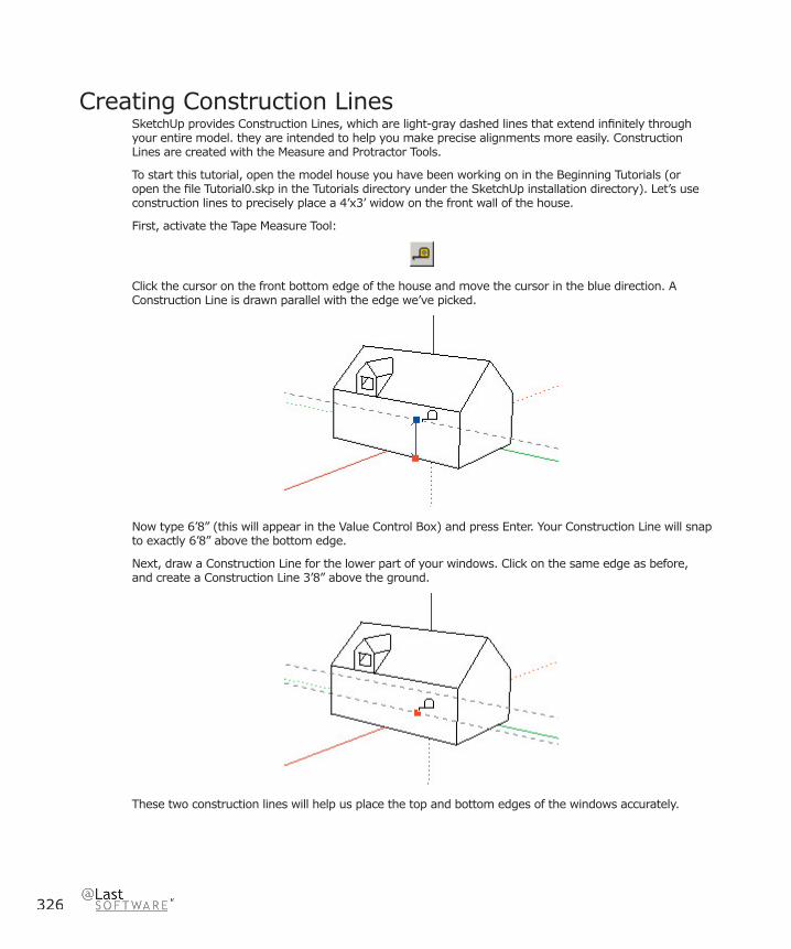
326
Creating Construction LinesSketchUp provides Construction Lines, which are light-gray dashed lines that extend infi nitely through your entire model. they are intended to help you make precise alignments more easily. Construction Lines are created with the Measure and Protractor Tools.
To start this tutorial, open the model house you have been working on in the Beginning Tutorials (or open the fi le Tutorial0.skp in the Tutorials directory under the SketchUp installation directory). Let’s use construction lines to precisely place a 4’x3’ widow on the front wall of the house.
First, activate the Tape Measure Tool:
Click the cursor on the front bottom edge of the house and move the cursor in the blue direction. A Construction Line is drawn parallel with the edge we’ve picked.
Now type 6’8” (this will appear in the Value Control Box) and press Enter. Your Construction Line will snap to exactly 6’8” above the bottom edge.
Next, draw a Construction Line for the lower part of your windows. Click on the same edge as before, and create a Construction Line 3’8” above the ground.
These two construction lines will help us place the top and bottom edges of the windows accurately.
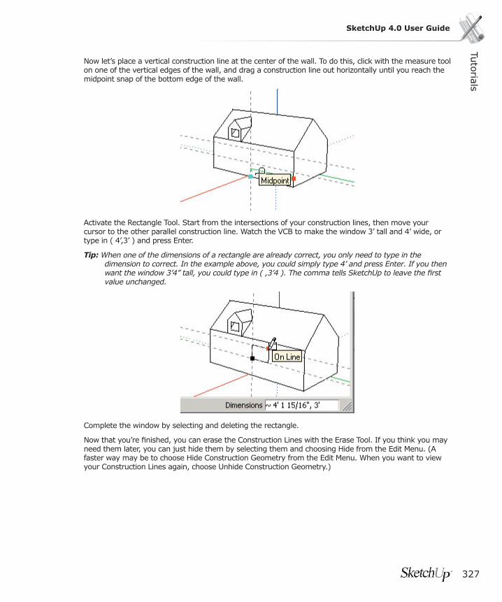
Tuto
rials
327
SketchUp 4.0 User Guide
Now let’s place a vertical construction line at the center of the wall. To do this, click with the measure tool on one of the vertical edges of the wall, and drag a construction line out horizontally until you reach the midpoint snap of the bottom edge of the wall.
Activate the Rectangle Tool. Start from the intersections of your construction lines, then move your cursor to the other parallel construction line. Watch the VCB to make the window 3’ tall and 4’ wide, or type in ( 4’,3’ ) and press Enter.
Tip: When one of the dimensions of a rectangle are already correct, you only need to type in the dimension to correct. In the example above, you could simply type 4’ and press Enter. If you then want the window 3’4” tall, you could type in ( ,3’4 ). The comma tells SketchUp to leave the fi rst value unchanged.
Complete the window by selecting and deleting the rectangle.
Now that you’re fi nished, you can erase the Construction Lines with the Erase Tool. If you think you may need them later, you can just hide them by selecting them and choosing Hide from the Edit Menu. (A faster way may be to choose Hide Construction Geometry from the Edit Menu. When you want to view your Construction Lines again, choose Unhide Construction Geometry.)

328
Moving and Copying FacesThis tutorial covers moving and copying geometry and faces, but it’s just a hint of the variety of things you can do when you combine tools and modifi er keys.
Let’s continue working with the house model you have been building in the Construction Lines Tutorial (if you didn’t save this fi le, open the Tutorial1.skp fi le in the Tutorials directory under the SketchUp installation directory). You should have a rectangular window in the front wall of your house. Let’s move it so that it is aligned with the dormer above.
Note: Holding down another key while performing an operation is known as using a Modifi er Key. Common modifi er keys in SketchUp are the Shift, Control and Alt keys.
First, activate the Select Tool, and select all four edges of the window. One way to do this is to select one line, hold down the Shift key, and then select the rest. Your selection cursor will indicate a +/- symbol beside it...
Next, activate the Move Tool, and click on one of the window’s corners. Using a linear inference, drag the window into alignment with the dormer above. Click the mouse button again to complete the move operation.

Tuto
rials
329
SketchUp 4.0 User Guide
But wait... We need another window in this house. Rather than drawing it from scratch, why not just copy the window we already have? With the window lines still selected, and the Move Tool still active, hold down the Ctrl key and click on the window again. (You should see a + symbol next to the move cursor.) When you move the cursor away from the window, you are dragging a copy of the original, not the original itself.
Release the Ctrl key, and type 7’ followed by Enter. Notice that when you have copied the window lines, the hole (or absence of a face) is copied as well.
What if we want to have two dormers? You can use the same method to move a copy of the dormer. Try that now. Activate the Select tool and drag a selection “window” (rectangle) from left to right around the dormer.
Selecting objects by dragging a select window can sometimes grab stuff that is behind the visible parts of the model. This is because the select left-to-right window picks EVERYTHING that is within the window, all the way through the model. To check that we have not selected an edge or face we don’t want, enable Wireframe display mode.
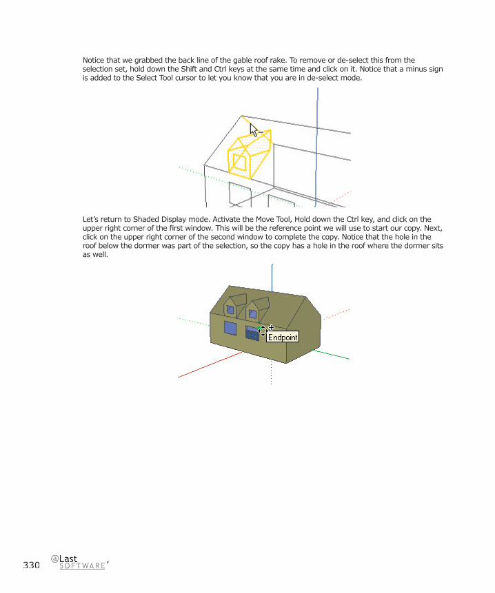
330
Notice that we grabbed the back line of the gable roof rake. To remove or de-select this from the selection set, hold down the Shift and Ctrl keys at the same time and click on it. Notice that a minus sign is added to the Select Tool cursor to let you know that you are in de-select mode.
Let’s return to Shaded Display mode. Activate the Move Tool, Hold down the Ctrl key, and click on the upper right corner of the fi rst window. This will be the reference point we will use to start our copy. Next, click on the upper right corner of the second window to complete the copy. Notice that the hole in the roof below the dormer was part of the selection, so the copy has a hole in the roof where the dormer sits as well.
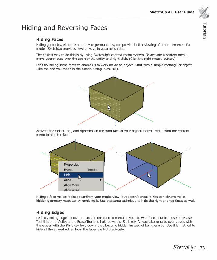
Tuto
rials
331
SketchUp 4.0 User Guide
Hiding and Reversing Faces
Hiding FacesHiding geometry, either temporarily or permanently, can provide better viewing of other elements of a model. SketchUp provides several ways to accomplish this:
The easiest way to do this is by using SketchUp’s context menu system. To activate a context menu, move your mouse over the appropriate entity and right click. (Click the right mouse button.)
Let’s try hiding some faces to enable us to work inside an object. Start with a simple rectangular object (like the one you made in the tutorial Using Push/Pull).
Activate the Select Tool, and rightclick on the front face of your object. Select “Hide” from the context menu to hide the face.
Hiding a face makes it disappear from your model view- but doesn’t erase it. You can always make hidden geometry reappear by unhiding it. Use the same technique to hide the right and top faces as well.
Hiding EdgesLet’s try hiding edges next. You can use the context menu as you did with faces, but let’s use the Erase Tool this time. Activate the Erase Tool and hold down the Shift key. As you click or drag over edges with the eraser with the Shift key held down, they become hidden instead of being erased. Use this method to hide all the shared edges from the faces we hid previously.
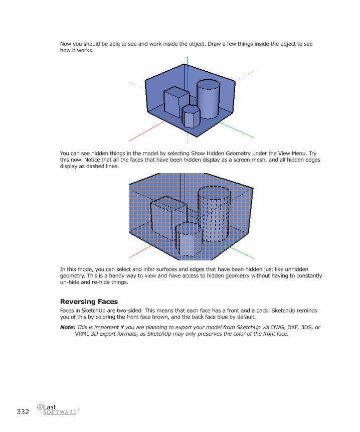
332
Now you should be able to see and work inside the object. Draw a few things inside the object to see how it works.
You can see hidden things in the model by selecting Show Hidden Geometry under the View Menu. Try this now. Notice that all the faces that have been hidden display as a screen mesh, and all hidden edges display as dashed lines.
In this mode, you can select and infer surfaces and edges that have been hidden just like unhidden geometry. This is a handy way to view and have access to hidden geometry without having to constantly un-hide and re-hide things.
Reversing FacesFaces in SketchUp are two-sided. This means that each face has a front and a back. SketchUp reminds you of this by coloring the front face brown, and the back face blue by default.
Note: This is important if you are planning to export your model from SketchUp via DWG, DXF, 3DS, or VRML 3D export formats, as SketchUp may only preserves the color of the front face.

Tuto
rials
333
SketchUp 4.0 User Guide
Sometimes you will want to reverse the orientation of a face, which you can also do through the context menu. Select multiple faces, rightclick on any part of the selection, and select Reverse Faces. In our example model, reversing a face will change its color to brown.
If you orbit around to the back of your model now, you will see the difference between the “inside” and “outside” faces of your model.
Unhiding ObjectsYou can unhide all the entites that you hid at the beginning of this tutorial by selecting Unhide All from the Edit Menu.
But let’s say that you want to selectively unhide only some of your hidden geometry. Like before, choose Show Hidden Geometry from the View menu. This will display hidden geometry and allow you to select it. Go ahead and select all the entities you’d like to unhide, and then choose Unhide from the Edit menu.
To turn off the hatch pattern, choose Show Hidden Geometry again from the View menu.
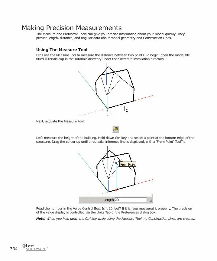
334
Making Precision MeasurementsThe Measure and Protractor Tools can give you precise information about your model quickly. They provide length, distance, and angular data about model geometry and Construction Lines.
Using The Measure Tool Let’s use the Measure Tool to measure the distance between two points. To begin, open the model fi le titled Tutorial4.skp in the Tutorials directory under the SketchUp installation directory..
Next, activate the Measure Tool:
Let’s measure the height of the building. Hold down Ctrl key and select a point at the bottom edge of the structure. Drag the cursor up until a red axial inference line is displayed, with a ‘From Point’ ToolTip.
Read the number in the Value Control Box. Is it 20 feet? If it is, you measured it properly. The precision of the value display is controlled via the Units Tab of the Preferences dialog box.
Note: When you hold down the Ctrl key while using the Measure Tool, no Construction Lines are created.
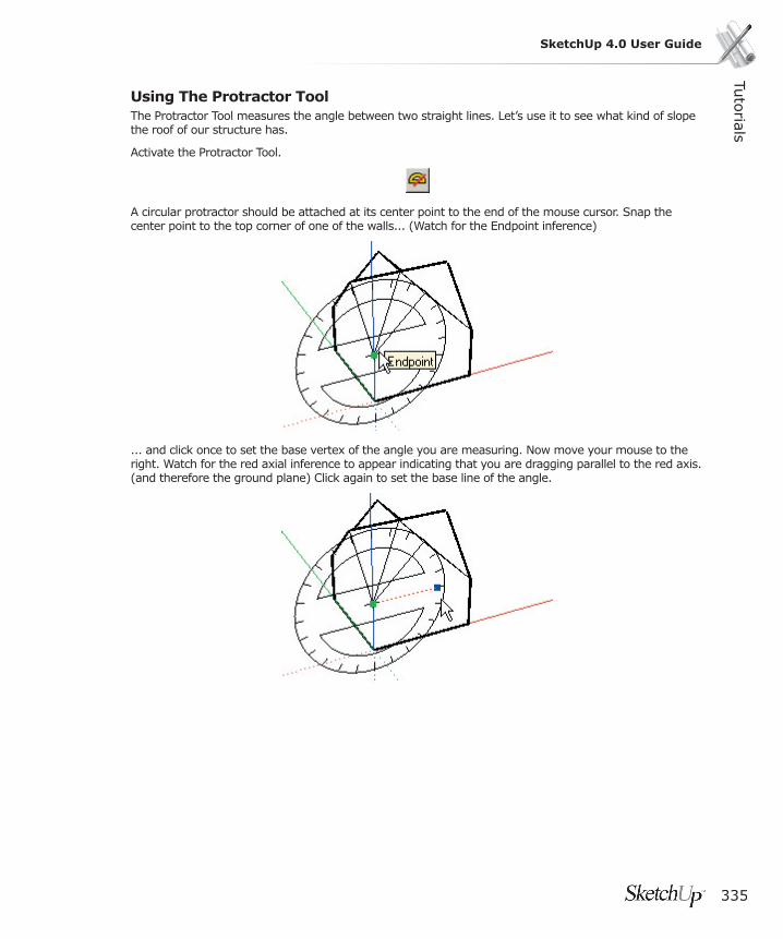
Tuto
rials
335
SketchUp 4.0 User Guide
Using The Protractor Tool The Protractor Tool measures the angle between two straight lines. Let’s use it to see what kind of slope the roof of our structure has.
Activate the Protractor Tool.
A circular protractor should be attached at its center point to the end of the mouse cursor. Snap the center point to the top corner of one of the walls... (Watch for the Endpoint inference)
... and click once to set the base vertex of the angle you are measuring. Now move your mouse to the right. Watch for the red axial inference to appear indicating that you are dragging parallel to the red axis. (and therefore the ground plane) Click again to set the base line of the angle.
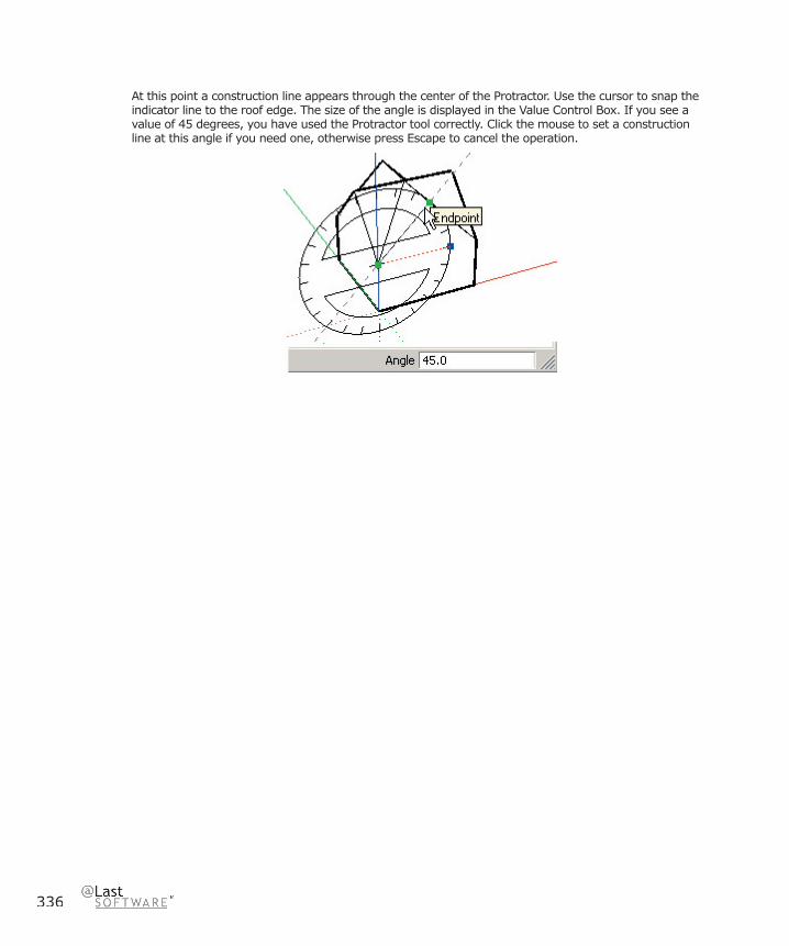
336
At this point a construction line appears through the center of the Protractor. Use the cursor to snap the indicator line to the roof edge. The size of the angle is displayed in the Value Control Box. If you see a value of 45 degrees, you have used the Protractor tool correctly. Click the mouse to set a construction line at this angle if you need one, otherwise press Escape to cancel the operation.

Tuto
rials
337
SketchUp 4.0 User Guide
Making Arrays with Multi-Copy
Linear ArraysYou can quickly explore various types of arrays with SketchUp’s Multi-Copy capability. Using Multi-Copy, you can essentially repeat a move or rotate copy along any direction.
To begin, open the fi le Tutorial8.skp in the Tutorials directory under the SketchUp installation directory.. It contains a box as a group within the fi le.
The fi rst step is to use the Move Tool to make a copy. As you may recall, copies are made by holding down the Ctrl key while moving.
After you have made the initial copy, you’re ready to Multi-copy. Go ahead and type 3x for “three copies.” This is called an external array, because it extends beyond from your original copy distance. You can continue typing in array values. Type in 4x for “four copies.” SketchUp will update the copy as necessary.
One neat thing about Multi-Copy is that you can still type in the distance between copies at any time. This will not change the number of copies, it simply re-adjusts their spacing. This allows you to test arrays quite easily. Type in a distance of 3m and notice the results.
Now, let’s change the array to an internal array. First, type in a greater distance of 10m, and then type 5/ for “fi ve divisions.” We call this an internal array because it interpolates equal divisions in between the original and the copy.
You can continue typing in new distances and/or multiplier/divisor values interchangeably as many times as you want until you activate another tool or perform another operation. This is a great way to create regular column layouts.

338
Radial ArraysTo create radial arrays, use the Rotate Tool in a manner similar to that described above. Select the end box on the right with the Select tool, and then activate the Rotate Tool.
Place the base of rotation below the end cube on the screen. Before clicking the second point for the base of rotation, hold down the Ctrl key. Notice a plus sign is added to the cursor to let you know that you are going to make a copy.
Keep holding down the Ctrl key and click to select the second base point. As you drag away the copy angle you can visually place the copy. Click to fi nish. You are now ready to Multi-Copy radially.
Use the same syntax as a linear array: Type 7x for “seven copies.”

Tuto
rials
339
SketchUp 4.0 User Guide
Just like before, you can type in angle rotation values, external array multipliers, and internal array divisors as often as you wish until you start a new operation.
With Multi-copy in both the Move and Rotate tools, SketchUp allows you to more easily investigate layout options before committing to a fi nal decision as well as study repetition in your designs.
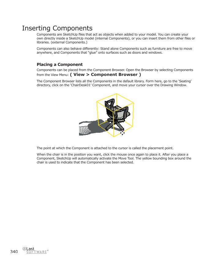
340
Inserting ComponentsComponents are SketchUp fi les that act as objects when added to your model. You can create your own directly inside a SketchUp model (internal Components), or you can insert them from other fi les or libraries. (external Components.)
Components can also behave differently: Stand alone Components such as furniture are free to move anywhere, and Components that “glue” onto surfaces such as doors and windows.
Placing a ComponentComponents can be placed from the Component Browser. Open the Browser by selecting Components from the View Menu: ( View > Component Browser )
The Component Browser lists all the Components in the default library. Form here, go to the ‘Seating’ directory, click on the ‘ChairDesk01’ Component, and move your cursor over the Drawing Window.
The point at which the Component is attached to the cursor is called the placement point.
When the chair is in the position you want, click the mouse once again to place it. After you place a Component, SketchUp will automatically activate the Move Tool. The yellow bounding box around the chair is used to indicate that the Component has been selected.
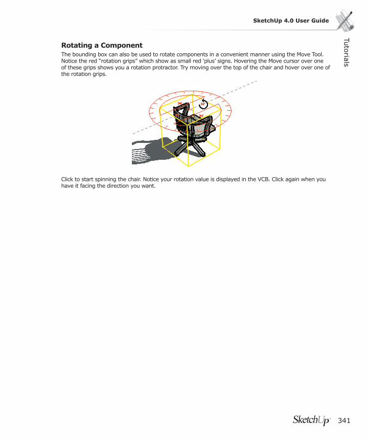
Tuto
rials
341
SketchUp 4.0 User Guide
Rotating a ComponentThe bounding box can also be used to rotate components in a convenient manner using the Move Tool. Notice the red “rotation grips” which show as small red ‘plus’ signs. Hovering the Move cursor over one of these grips shows you a rotation protractor. Try moving over the top of the chair and hover over one of the rotation grips.
Click to start spinning the chair. Notice your rotation value is displayed in the VCB. Click again when you have it facing the direction you want.
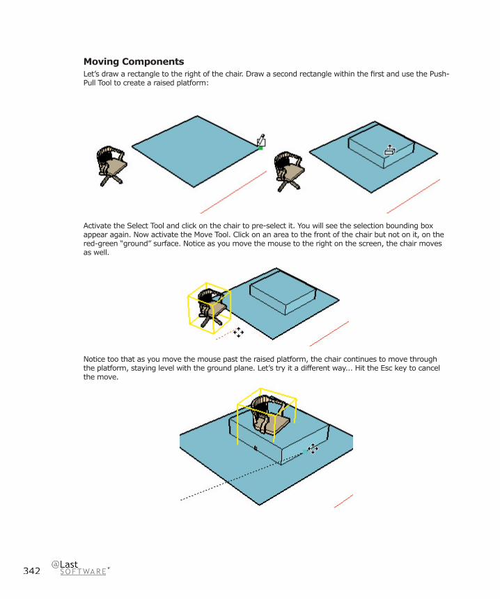
342
Moving ComponentsLet’s draw a rectangle to the right of the chair. Draw a second rectangle within the fi rst and use the Push-Pull Tool to create a raised platform:
Activate the Select Tool and click on the chair to pre-select it. You will see the selection bounding box appear again. Now activate the Move Tool. Click on an area to the front of the chair but not on it, on the red-green “ground” surface. Notice as you move the mouse to the right on the screen, the chair moves as well.
Notice too that as you move the mouse past the raised platform, the chair continues to move through the platform, staying level with the ground plane. Let’s try it a different way... Hit the Esc key to cancel the move.

Tuto
rials
343
SketchUp 4.0 User Guide
This time, move the Move cursor over the chair seat until it displays the ‘On Face in Component’ ToolTip and click. This sets the initial movement point.
Now move the chair over the surface of the rectangle and the surface of the raised platform. Notice that the Pick point you selected controls where the Component geometry will be repositioned relative to other geometry in the rest of the model...
The point on a Component under the cursor when you begin your move is known as your Pick point. During a move operation you are essentially “holding” the component by that point as the point of reference for the move. If you want to accurately place a Component, you must fi rst carefully pick it up by the point you are going to use to position it.
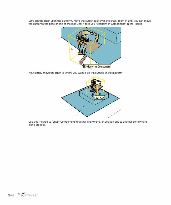
344
Let’s put the chair upon the platform. Move the cursor back over the chair. Zoom in until you can move the cursor to the base of one of the legs until it tells you “Endpoint in Component” in the ToolTip.
Now simply move the chair to where you want it on the surface of the platform!
Use this method to “snap” Components together end to end, or position one to another somewhere along an edge.

Tuto
rials
345
SketchUp 4.0 User Guide
Scaling Geometry and ObjectsOnce something is drawn in SketchUp it can be re-sized dynamically with the Scale Tool. Like other tools, you can work as loosely as you want, or as precisely as you need to, at any time. The Scale Tool allows you to scale geometry in any direction, including inside-out to perform mirror operations.
Start by opening the fi le Tutorial7.skp in the Tutorials directory under the SketchUp installation directory..
Go ahead and select the objects you wish to scale using the Select Tool. Although single surfaces can be scaled in a 2D fashion, go ahead and select a 3D volume for now.
Next, click on the Scale Tool button in the Edit Toolbar:
A studded bounding box will appear around your selection. Each of the little green cubes is a scaling grip.
As you move your cursor over each grip, both it and its opposing “anchor” grip will turn red and a dashed vector line is drawn between them. This dashed line and the mouse cursor indicate the direction of the scale operation. Go ahead and try scaling with the various grips.
To do so, click on a grip, and move the cursor around to resize the geometry. Click again to fi nish. Note that even obscured grips may be moved as they will instantly appear when you move your mouse cursor over them. In addition to clicking twice, you can also press and drag the mouse button on grips to scale the object.

346
Grip TypesYou’ll notice that the grips are arranged in a rectangular bounding-box volume, and each perform a type of scale operation. These correspond to the number of faces each grip touches.
The grips positioned at the center of each “face” of the bounding box touch one face, and allow you to scale the object in one direction.
The grips at the midpoint of each of the “edges” of the bounding box touch two faces, and allow you to scale the object in two directions.

Tuto
rials
347
SketchUp 4.0 User Guide
The grips at the “corners” of the bounding box touch three faces, and allow scaling of the object in all three directions at one time.
If you pause over a grip, a selection tip will appear that describes the kind of scale operation you can perform with that grip.
Try using each kind of grip to see the results. Also, notice that as you are scaling, the scale factor or size ‘detents’ or snaps to half and whole scale factors, which are displayed in the Value Control Box below.
Modifi er Keys
Uniform/Non-Uniform Toggle
Both the center face and edge midpoint grips allow non-uniform scaling of the selected objects. You can toggle this behaviour to make the object scale uniformly by holding down the Shift key.

348
Go ahead and insert a Tree component. From the ViewMenu, select Components. Navigate to the Landscape group and insert one of the trees. Use the Scale Tool to move the top surface grip up and down. We do want the base of the tree to be the scale base point, but this distorts the tree...
Now try holding down the Shift key. This changes the scale from a 1D “stretch” to a uniform 3D scale. Try this out using other SketchUp Components. The Shapes components lend themselves quite nicely to scaling for domes and spheres.
Unlike the other grips, the corner grips make the object scale uniformly in all three directions by default. This is toggled via Shift as well, which allows you to scale non-uniformly in each direction.
Scaling From the Center
You can force your scaling operation to use the center of mass of the bounding box as its base point. To do so, grab a corner grip and begin to scale your selection. While you are scaling, press and hold Ctrl. When you release the key mid-operation, the scale operation reverts to using the opposite point.
The Ctrl and Shift keys may be used together to allow Uniform/Non-Uniform scaling from the centroid of the selected geometry. These combinations allow the user to try a wide variety of scaling and stretching operations very quickly.
Working Precisely Using the VCBAt any time during or immediately after a Scale operation, you can type a precise scale value into the Value Control Box (VCB). Let’s try this now.

Tuto
rials
349
SketchUp 4.0 User Guide
Scale Factor
Go ahead and grab a corner grip and move it on the screen. Now type 2 and tap the Enter key. Notice the object becomes 2 times as large (or 200% bigger). Now type 1.5 and hit Enter. Notice the object becomes one and one-half times as large as it started. (or 150% bigger)
Note: Like all SketchUp tools, one can keep re-entering values into the VCB until you perform another mouse operation or move on to a different tool.
Distance
In addition to a scale factor, you may type in a distance. Grab a top surface grip and move it on the screen. This time, instead of typing a numeric value, type in a distance value of 5’ and hit Enter. Notice the object size along the dashed scale direction becomes that exact distance value.
It’s important to remember that for distances, you need to specify the unit as part of the value. For example 5’ for fi ve feet, 3m for three meters, or 5’6” for fi ve feet six inches. If you type in a value by itself, SketchUp will interpret you entry as a scale factor.
Multiple Directions
The VCB uses numeric values separated by a comma when multiple numbers are present. You can specify exact scale values by including commas in your input.
To see how this works, try moving a midpoint edge grip. You should see two directions displayed with dynamically changing values.
Now type in a new scale value of 1.5,3. The object becomes one and one-half times bigger in one direction, but three times larger in the other direction. As long as you do not move another grip, or change to another tool, you can continue re-typing in values to experiment with your design. If you want to specify the second value while leaving the fi rst unchanged, you can type in a comma, followed by the second scale value: ,4
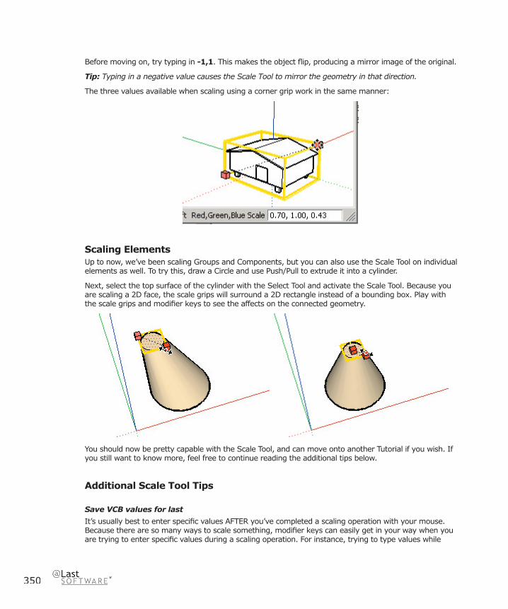
350
Before moving on, try typing in -1,1. This makes the object fl ip, producing a mirror image of the original.
Tip: Typing in a negative value causes the Scale Tool to mirror the geometry in that direction.
The three values available when scaling using a corner grip work in the same manner:
Scaling ElementsUp to now, we’ve been scaling Groups and Components, but you can also use the Scale Tool on individual elements as well. To try this, draw a Circle and use Push/Pull to extrude it into a cylinder.
Next, select the top surface of the cylinder with the Select Tool and activate the Scale Tool. Because you are scaling a 2D face, the scale grips will surround a 2D rectangle instead of a bounding box. Play with the scale grips and modifi er keys to see the affects on the connected geometry.
You should now be pretty capable with the Scale Tool, and can move onto another Tutorial if you wish. If you still want to know more, feel free to continue reading the additional tips below.
Additional Scale Tool Tips
Save VCB values for last
It’s usually best to enter specifi c values AFTER you’ve completed a scaling operation with your mouse. Because there are so many ways to scale something, modifi er keys can easily get in your way when you are trying to enter specifi c values during a scaling operation. For instance, trying to type values while

Tuto
rials
351
SketchUp 4.0 User Guide
holding Ctrl could activate other tools, or pressing shift to indicate inches using the “ (quotes character) could toggle the uniformity of your scale.
Components and Axes
An single Component or Group defaults to scaling in the directions of its axes. This makes it easy to scale them based on the original orientation in which they were created. If you want to scale a component using the current axes directions, include your Component as part of a larger selection set. This can be done by drawing a line and selecting it along with your Component.
Other Things to Try
Go ahead and play with the Scale Tool on your own. You can’t break anything. The only way to get a feel for all the different things it can do is to try things out.
Try Scaling objects that are adjacent to other objects. If you pick the correct grip you can maintain adjacency.
Make yourself a component and then make several copies of it. Then try scaling and mirroring the copies by different values. Now perform and in-place edit on that Component. Notice that your changes are still refl ected in the other scaled and mirrored instances.
Try scaling a single face that is off plane from the axes direction. The single face is enclosed within a 3D bounding box. This process is great for creating warped volumes. Remember that you can re-orient the Axes to any surface using the Axes Tool.

352
Introducing LayersAt times, you may fi nd it advantageous to organize entities within a SketchUp drawing using layers. This allows you to control the color and/or visibility of many entities at once using a non-discreet mechanism.
To begin, open the fi le Tutorial9.skp in the Tutorials directory under the SketchUp installation directory..
Layers are created using the Layers Manager. Launch it by selecting ‘Layers’ from the View Menu.
Creating a New LayerTo create a new layer, click the New button in the lower left corner of the Layer Manager. A new layer appears in the list, with a default name of Layer1. Let’s name our new layer “Walls” instead.
In the Visible column, click on the little house icon. This will make it appear grayed out, indicating the layer is not visible.
Next, in the Drawing Window, activate the Select Tool and right click on the left face on the model. Select Properties from the context menu that appears. This will launch the Properties dialog box. Under the General Tab, click the layer drop-down box and select Walls. This moves the selected face to the Walls layer, which is currently set to be invisible. As you do so, you should see the face disappear.
You can now toggle the visibility of the walls layer in the Layers Manager, which will in turn toggle the visibility of the face.
Next, let’s try another method to move faces to the ‘Walls’ layer.
Use the Select Tool to select the top and right faces of the model (remember to hold down Shift to allow you to select multiple items).
Click on the Layer Toolbar control and select ‘Walls’ from the drop-down list.

Tuto
rials
353
SketchUp 4.0 User Guide
The two faces will now be assigned to the Walls layer, and will refl ect it’s visibility when hidden:
You may be used to working with layers in other software programs. SketchUp layers are unique in that they do not separate the objects within them. SketchUp layers are better described as an attribute of geometry, as elements and objects on different layers remain fully interconnected with one another. This makes SketchUp layers useful primarily for visibility management, rather than as an organizational container. If you do need to separate and/or encapsulate geometry, you can use Groups and Components.

354
Creating Your Own ComponentsLet’s learn how to make a Component.
Begin by creating a new drawing. Use the ( File > New ) Command. Next, draw a rectangle in the red/green plane that is 30 inches wide and 5 feet long. Push/pull the rectangle to a height of 27 inches.
Note: Remember, you should not click in the Value Control Box (VCB) when typing in specifi c values for operations, just type the value at the keyboard. It will show up in the VCB.
Next, we’re going to offset the side and back edges. To do this, fi rst select those edges with the Select Tool. ( Hold down the Shift key to select multiple edges ) Now activate the Offset Tool.
Click the Offset cursor on any of the highlighted edges, and move the cursor away from the edge but inside the top face.

Tuto
rials
355
SketchUp 4.0 User Guide
Enter 6 inches in the Value Control Box, and tap Enter.
Now Push/Pull the new rectangular face on top, and specify a distance of 12 inches. You have just modeled a simple couch.
If we turn this couch into a Component, we can reuse it in this drawing, or in any other SketchUp model, thus saving the effort of having to make it again.
The fi rst step in creating a Component is selecting geometry. Select the whole couch by using the Select Tool and dragging a “window” from left to right on the screen around the couch geometry. All the geometry should be highlighted:

356
Once geometry is selected, select the ‘Make Component’ command from the Edit Menu. This opens the Create Component dialog:
Type in the name “Couch” for the new Component, and leave the rest of the options as they are. Click ‘OK’. That’s all there is to it!
Insertingif it is not already visible, activate the Components Browser from ( View > Component Library ). Click on the drop-down list box and click on the ‘In Model’ library.
Notice the Browser now displays only the loaded components, including the couch.
Go ahead and click on the couch. Drag it into the Drawing Window.
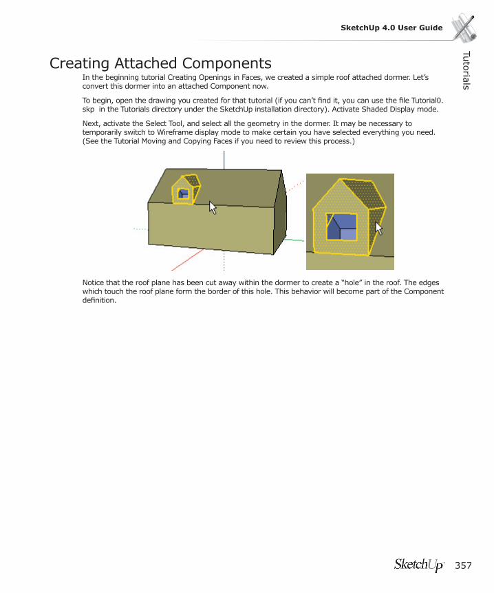
Tuto
rials
357
SketchUp 4.0 User Guide
Creating Attached ComponentsIn the beginning tutorial Creating Openings in Faces, we created a simple roof attached dormer. Let’s convert this dormer into an attached Component now.
To begin, open the drawing you created for that tutorial (if you can’t fi nd it, you can use the fi le Tutorial0.skp in the Tutorials directory under the SketchUp installation directory). Activate Shaded Display mode.
Next, activate the Select Tool, and select all the geometry in the dormer. It may be necessary to temporarily switch to Wireframe display mode to make certain you have selected everything you need. (See the Tutorial Moving and Copying Faces if you need to review this process.)
Notice that the roof plane has been cut away within the dormer to create a “hole” in the roof. The edges which touch the roof plane form the border of this hole. This behavior will become part of the Component defi nition.

358
When you have selected everything, make the selection into a Component by selecting ‘Make Component’ from the Edit Menu.
Name the Component “Dormer”, and check the ‘Align Red/Green Plane’ checkbox. This means that when you insert the Dormer, it will align its red/green plane to the face you choose. If you did not choose this special alignment option, the red/green plane of the Component would align to the red/green plane of the model.
Also select ‘Sloped’ in the Faces pop-up list. This means that the new Component’s red/green face will snap to any sloped face (a face that is not aligned to any current axis). Next, check the ‘Cut Opening’ checkbox. This means the Component will cut a hole in the roof at its perimeter.
Click the ‘Create’ button to make your new Dormer Component. You should see it appear in the Component Browser’s ‘Loaded Components’ List. Notice that since the ‘Replace selected objects with a component’ option was checked, the individual elements you had selected are replaced with a dormer Component, shown by the bounding box.
You have now made an attached Component!
In SketchUp, a Component is a collection of geometry, defi ned as a unit, that can be reused in a drawing. All occurrences (instances) of a Component are drawn the same. If you modify a component, all similar components change also.

Tuto
rials
359
SketchUp 4.0 User Guide
Now we’re ready to add a new Dormer to the model. Select the Dormer component in the Component Browser, and drag it into place on the roof of your model. Snap its insertion point to the place on the roof you’d like it, and presto! A new dormer.
Notice that the roof has been properly trimmed by the component- Just as it was in the original dormer.
Let’s make a window that cuts a hole in the wall. Draw a 2’ x 4’ rectangle on the wall with the Rectangle Tool. Then use the Push-Pull Tool to push the window 4” back into the wall:
Now erase the surface of the window and select all the edges around the opening to create your window Component.
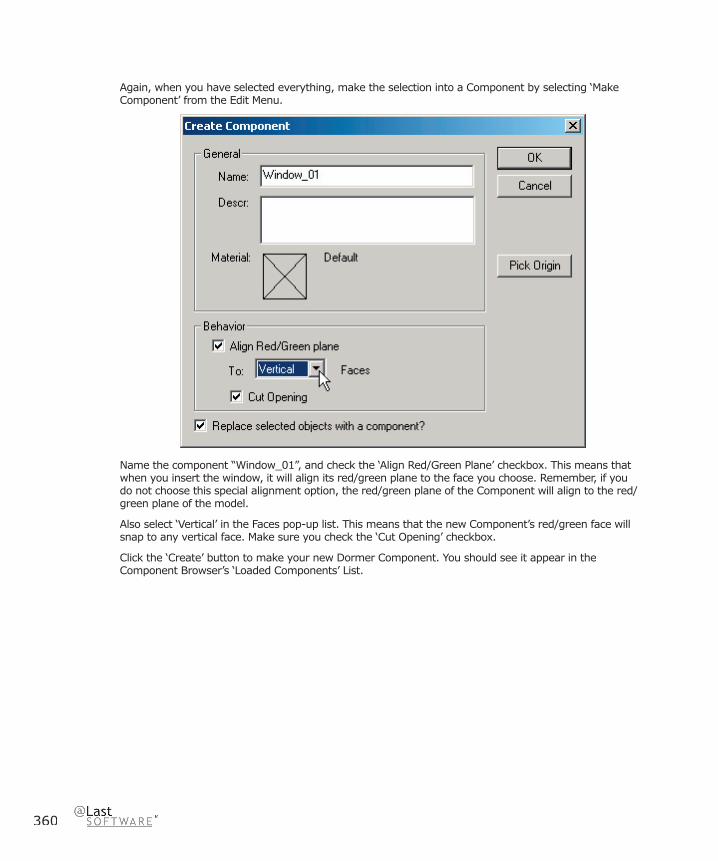
360
Again, when you have selected everything, make the selection into a Component by selecting ‘Make Component’ from the Edit Menu.
Name the component “Window_01”, and check the ‘Align Red/Green Plane’ checkbox. This means that when you insert the window, it will align its red/green plane to the face you choose. Remember, if you do not choose this special alignment option, the red/green plane of the Component will align to the red/green plane of the model.
Also select ‘Vertical’ in the Faces pop-up list. This means that the new Component’s red/green face will snap to any vertical face. Make sure you check the ‘Cut Opening’ checkbox.
Click the ‘Create’ button to make your new Dormer Component. You should see it appear in the Component Browser’s ‘Loaded Components’ List.
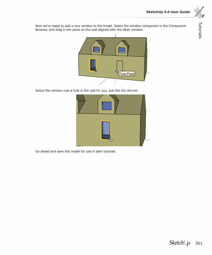
Tuto
rials
361
SketchUp 4.0 User Guide
Now we’re ready to add a new window to the model. Select the window component in the Component Browser, and drag it into place on the wall aligned with the other window.
Notice the window cuts a hole in the wall for you, just like the dormer.
Go ahead and save this model for use in later tutorials.

362
Painting ComponentsTo start, activate the Paint Tool. This brings up the Material Browser Color Picker. For this tutorial, select the ‘Markers’ palette library to work from.
Default Material Override
In SketchUp, the default material is the “working material” that is initially assigned to all surfaces and entities. You can also think of it as a “no specifi c material” assignment.
Also, Groups and Components can have a material applied independently from the geometry within them. That means that when a material is applied to a Group or Component, that material assignment applies only to that entity, not the geometry within it.
This results in a special behavior in SketchUp called ‘Default Material Override’, where any surfaces that have a default material assignment will ‘pick up’ (inherit) the material from the Group or Component it is inside of.
Let’s look at an example.
First, create a simple box, and use the Paint Tool to assign a red material to the top face. Leave the rest as the default material. Select the entire box, and make a Component out of it.
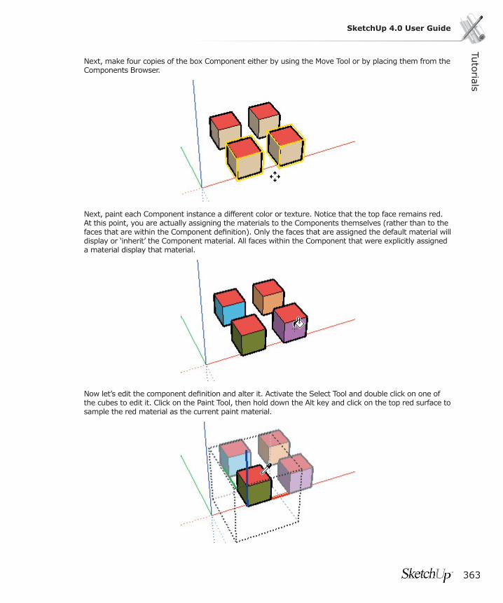
Tuto
rials
363
SketchUp 4.0 User Guide
Next, make four copies of the box Component either by using the Move Tool or by placing them from the Components Browser.
Next, paint each Component instance a different color or texture. Notice that the top face remains red. At this point, you are actually assigning the materials to the Components themselves (rather than to the faces that are within the Component defi nition). Only the faces that are assigned the default material will display or ‘inherit’ the Component material. All faces within the Component that were explicitly assigned a material display that material.
Now let’s edit the component defi nition and alter it. Activate the Select Tool and double click on one of the cubes to edit it. Click on the Paint Tool, then hold down the Alt key and click on the top red surface to sample the red material as the current paint material.
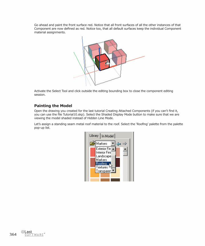
364
Go ahead and paint the front surface red. Notice that all front surfaces of all the other instances of that Component are now defi ned as red. Notice too, that all default surfaces keep the individual Component material assignments.
Activate the Select Tool and click outside the editing bounding box to close the component editing session.
Painting the ModelOpen the drawing you created for the last tutorial Creating Attached Components (if you can’t fi nd it, you can use the fi le Tutorial10.skp). Select the Shaded Display Mode button to make sure that we are viewing the model shaded instead of Hidden Line Mode.
Let’s assign a standing seam metal roof material to the roof. Select the ‘Roofi ng’ palette from the palette pop-up list.
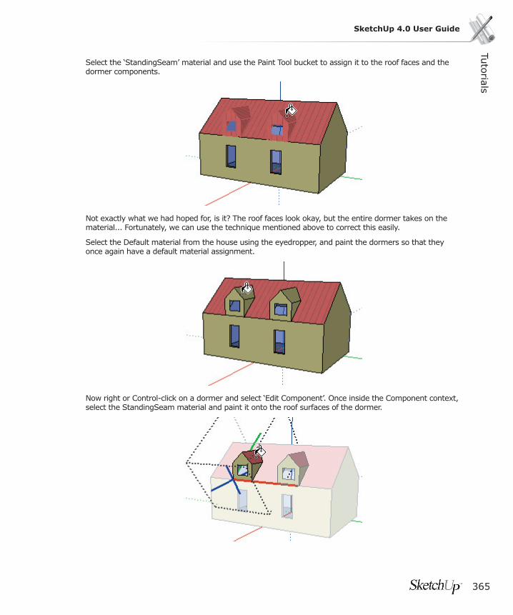
Tuto
rials
365
SketchUp 4.0 User Guide
Select the ‘StandingSeam’ material and use the Paint Tool bucket to assign it to the roof faces and the dormer components.
Not exactly what we had hoped for, is it? The roof faces look okay, but the entire dormer takes on the material... Fortunately, we can use the technique mentioned above to correct this easily.
Select the Default material from the house using the eyedropper, and paint the dormers so that they once again have a default material assignment.
Now right or Control-click on a dormer and select ‘Edit Component’. Once inside the Component context, select the StandingSeam material and paint it onto the roof surfaces of the dormer.

366
Don’t forget to orbit the model and paint the other side of the dormer!
Close the Component editing by right or clicking on a blank area of the screen and selecting ‘Close Component’. You can see that the model is now painted correctly.
This behavior has uses beyond just playing with boxes and dormers. For example, if you were to make a vehicle component, you could assign specifi c material colors to the tires, windows and bumpers, but leave the body panels defi ned in the default material.
Now, when you make copies of the vehicle component, you can assign each instance a different color- and only the body panels will take on that material! Best of all, your fi le size remains very small, as there is only one component defi nition stored for each of the cars.
Tip: Exploding a Group or Component makes this color behavior permanent.

Tuto
rials
367
SketchUp 4.0 User Guide
Adding a Section CutSection Planes allow you to work with the model in a cut-away view. Section Planes behave just like any other SketchUp entity, and can be moved, copied, arrayed, rotated, hidden, placed on layers, and so forth. They do not, however, directly affect other entities, as the section cut effect they produce is purely visual.
To start, open the drawing Tutorial-11.skp in the Tutorials directory under the SketchUp installation directory. Select Shaded Display Mode.
To add a Section Plane, use the Tools Menu ( Tools > Sections > Add ) or click on the ‘Add Section’ Button from the Sections toolbar:
As you move your mouse over the Drawing Window, you should see a rectangular Section Plane frame object attached to it. Notice that the Section Plane will align to surfaces underneath it as you move the mouse.
At any time, you can hold down the Shift key to lock the orientation of the Section Plane. Try this now:

368
Hold the cursor over the end wall of the house and then ‘lock’ the direction by holding down the Shift key. Continue to hold down Shift and move the Section Plane to the location where you want to cut the model. Let’s try the Midpoint of the long wall of the house. Click at the midpoint of the wall and the SketchUp cuts a section through the model at that point.
You can reposition a Section Plane by using the Move Tool on an edge of the Section Plane. Note that Section Planes will only move in a direction perpendicular to their face.

Tuto
rials
369
SketchUp 4.0 User Guide
Placing Multiple PlanesYou can place more than one Section Plane at one time. Go ahead and try it now. Note that as you place new Section Planes, they become the ‘active’ cut and any previously placed Section Planes become inactive and are displayed with a grayed out appearance.
Where the Section Plane intersects with the model geometry is called the slice. (The slice is displayed in red by default).
Changing PlanesYou can switch between active section planes by using the Select Tool to double click on the Section Plane you want to make active. You may also Right-click on a section plane and select ‘Activate Cut’ from the pop-up context menu.
You can reverse the direction of the section cut effect by Right-click on the Plane and selecting ‘Reverse’ from the context menu.
You can change the orientation of a Section Plane more dynamically by using the Rotate Tool. Let’s try it now. Select your active Section Plane with the Select Tool. Then activate the Rotate Tool and rotate it about a point along the side of the house. Notice how your section cut updates dynamically as the plane is rotated. Hit the Esc key to cancel the rotate operation.
To get a traditional section view, right-click on the Section Plane and select ‘Align View’ from the context menu. With the resulting camera viewpoint, you can achieve either a one-point perspective

370
section or a traditional orthogonal section by turning off perspective. (To turn off Perspective, un-check Perspective from the View Menu. )
You can turn all sections planes on or off quickly using the toggle button on the sections toolbar.
You can also toggle between working in a section view and working in a full modeling view using the Display Section Cuts toggle button.
Hiding Section PlanesAs you place more Section Planes, you may fi nd your model becoming too busy. You can hide Section Planes just like any other item. Context click on a Section Plane and select ‘Hide’. The ( View > Show Hidden Geometry ) menu item will allow you to select hidden Section Planes in the future. You can also use layers or pages to hide or display groups of Section Planes at once.
Let’s try using sections to work ‘inside’ the model. Spin your view with the Orbit Tool until you are looking at the end of the angled section of the house. Now place a Section Plane on the face of the house.

Tuto
rials
371
SketchUp 4.0 User Guide
Zoom into the house and context click on the wall inside the house and erase it.
Now you can see the entire interior of the house. Try placing the couch we made from the Creating Your Own Components tutorial. Go to ( File > Insert > Component.. ) and pick it from your Desktop.
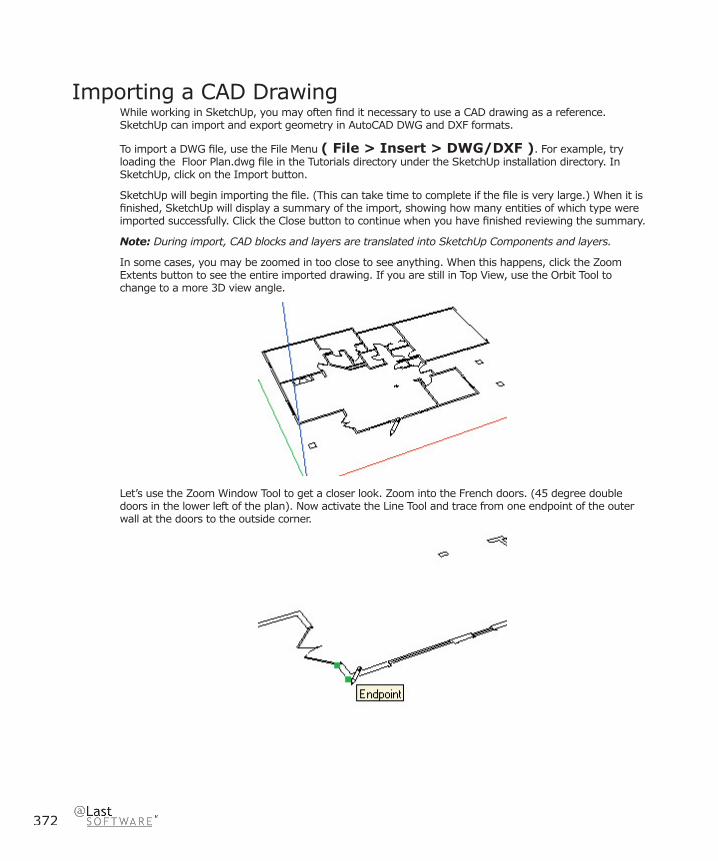
372
Importing a CAD DrawingWhile working in SketchUp, you may often fi nd it necessary to use a CAD drawing as a reference. SketchUp can import and export geometry in AutoCAD DWG and DXF formats.
To import a DWG fi le, use the File Menu ( File > Insert > DWG/DXF ). For example, try loading the Floor Plan.dwg fi le in the Tutorials directory under the SketchUp installation directory. In SketchUp, click on the Import button.
SketchUp will begin importing the fi le. (This can take time to complete if the fi le is very large.) When it is fi nished, SketchUp will display a summary of the import, showing how many entities of which type were imported successfully. Click the Close button to continue when you have fi nished reviewing the summary.
Note: During import, CAD blocks and layers are translated into SketchUp Components and layers.
In some cases, you may be zoomed in too close to see anything. When this happens, click the Zoom Extents button to see the entire imported drawing. If you are still in Top View, use the Orbit Tool to change to a more 3D view angle.
Let’s use the Zoom Window Tool to get a closer look. Zoom into the French doors. (45 degree double doors in the lower left of the plan). Now activate the Line Tool and trace from one endpoint of the outer wall at the doors to the outside corner.
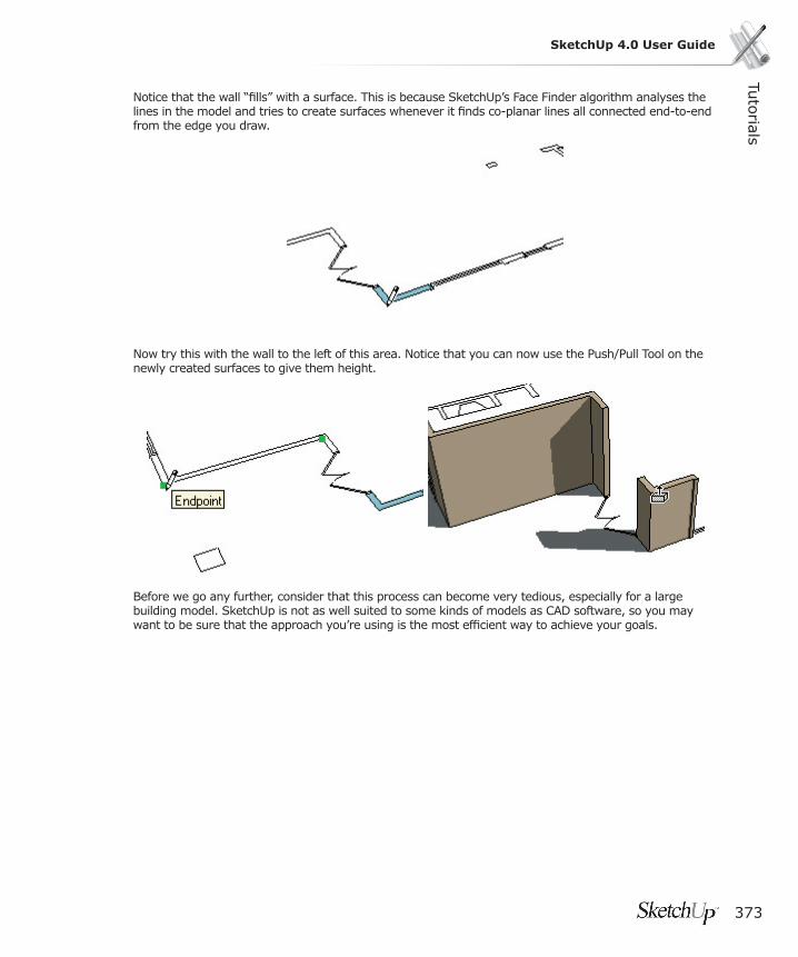
Tuto
rials
373
SketchUp 4.0 User Guide
Notice that the wall “fi lls” with a surface. This is because SketchUp’s Face Finder algorithm analyses the lines in the model and tries to create surfaces whenever it fi nds co-planar lines all connected end-to-end from the edge you draw.
Now try this with the wall to the left of this area. Notice that you can now use the Push/Pull Tool on the newly created surfaces to give them height.
Before we go any further, consider that this process can become very tedious, especially for a large building model. SketchUp is not as well suited to some kinds of models as CAD software, so you may want to be sure that the approach you’re using is the most effi cient way to achieve your goals.
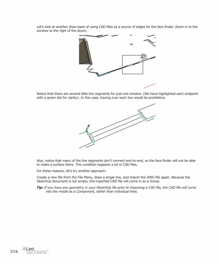
374
Let’s look at another draw-back of using CAD fi les as a source of edges for the face fi nder. Zoom in to the window to the right of the doors:
Notice that there are several little line segments for just one window. (We have highlighted each endpoint with a green dot for clarity). In this case, tracing over each line would be prohibitive.
Also, notice that many of the line segments don’t connect end-to-end, so the face fi nder will not be able to make a surface there. This condition happens a lot in CAD fi les.
For these reasons, let’s try another approach:
Create a new fi le from the File Menu, draw a single line, and import the DWG fi le again. Because the SketchUp document is not empty, the imported CAD fi le will come in as a Group.
Tip: If you have any geometry in your SketchUp fi le prior to importing a CAD fi le, the CAD fi le will come into the model as a Component, rather than individual lines.

Tuto
rials
375
SketchUp 4.0 User Guide
Now, instead of using it directly, we’ll use the CAD geometry as reference for tracing over. This keeps the SketchUp faces separate from the sometimes unreliable CAD line work.
Importing 3D CAD Files3D CAD entities such as faces, entities with thickness (height), and 3D meshes all translate as faces in SketchUp. AutoCAD solids are NOT translated.
Tip: To bring AutoCAD solids into SketchUp, use the AutoCAD ‘3DSout’ command to export a temporary fi le. Then immediately use the ‘3DSin’ command to import the temporary fi le back into AutoCAD. This converts the solids into faces that can be properly imported into SketchUp.
Let’s look at input from a 3D CAD fi le. For example, try loading the Floor Plan.dwg fi le in the Tutorials directory under the SketchUp installation directory. In SketchUp, click on the Import button. Notice the listing of entities translated is more extensive than before.
Strategies: File SizeImporting very large CAD fi les can take a while as each and every drawing entity must be analyzed. A complex CAD fi le can easily become a drag on SketchUp’s performance while you are working, as each line and face in SketchUp has quite a bit of intelligence built-in.
For these reasons, it is a good idea to clean up and/or crop your CAD drawings so that you only import content which is absolutely necessary. Another strategy is to use varying levels of detail. For example, one imported CAD fi le may contain site plan information, while another may have a fl oor plan, and yet another may have detail. By using three separate fi les that come into SketchUp as three separate groups, you can hide the other two when they are not immediately necessary and still reference the third.
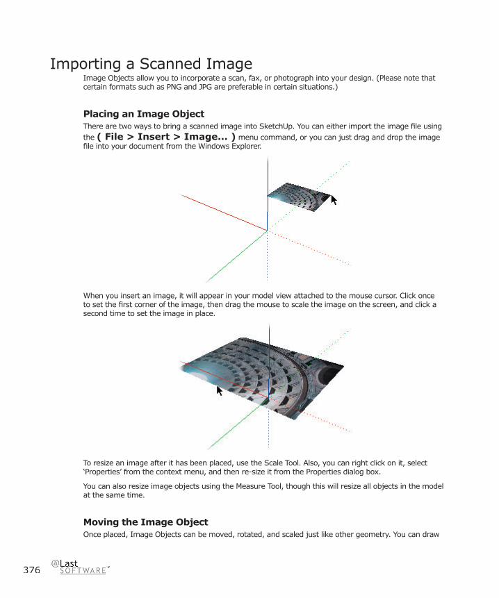
376
Importing a Scanned ImageImage Objects allow you to incorporate a scan, fax, or photograph into your design. (Please note that certain formats such as PNG and JPG are preferable in certain situations.)
Placing an Image ObjectThere are two ways to bring a scanned image into SketchUp. You can either import the image fi le using the ( File > Insert > Image... ) menu command, or you can just drag and drop the image fi le into your document from the Windows Explorer.
When you insert an image, it will appear in your model view attached to the mouse cursor. Click once to set the fi rst corner of the image, then drag the mouse to scale the image on the screen, and click a second time to set the image in place.
To resize an image after it has been placed, use the Scale Tool. Also, you can right click on it, select ‘Properties’ from the context menu, and then re-size it from the Properties dialog box.
You can also resize image objects using the Measure Tool, though this will resize all objects in the model at the same time.
Moving the Image ObjectOnce placed, Image Objects can be moved, rotated, and scaled just like other geometry. You can draw

Tuto
rials
377
SketchUp 4.0 User Guide
directly on top of Image Objects to develop quick models, or to develop quick context around your site.
This is a great way to do fast urban design studies, not only letting you show buildings in their actual context, but also providing shade and shadow studies directly among the buildings.
Tip: If you know the exact date and time a photograph was taken, you can quickly give the buildings approximate heights by matching their shadows on the image using the Push-Pull tool.
You can even use Image Objects to create realistic banners or signage. Simply drag the image into the scene and place it on the surface you want.

378
Image Objects As BackdropsRaster Objects can be moved around like any other surface in SketchUp. To create a backdrop, simply put the Move Tool over the edge and use the rotate dot to tilt the image vertically.
ShadowsNotice that the raster sign on the pole casts a shadow on the ground and the image behind.
The mountain image can be set to not accept shadows by right or Option-clicking on the image and disabling the ( Shadows > Receive ) option. This makes it look more like a backdrop from any vantage point.
There’s more to Image Objects than is covered in this tutorial. Please consult the Image Object Reference for more information.
This completes the Intermediate Tutorials for SketchUp. To learn more about the program, please continue on with the Advanced Tutorials.
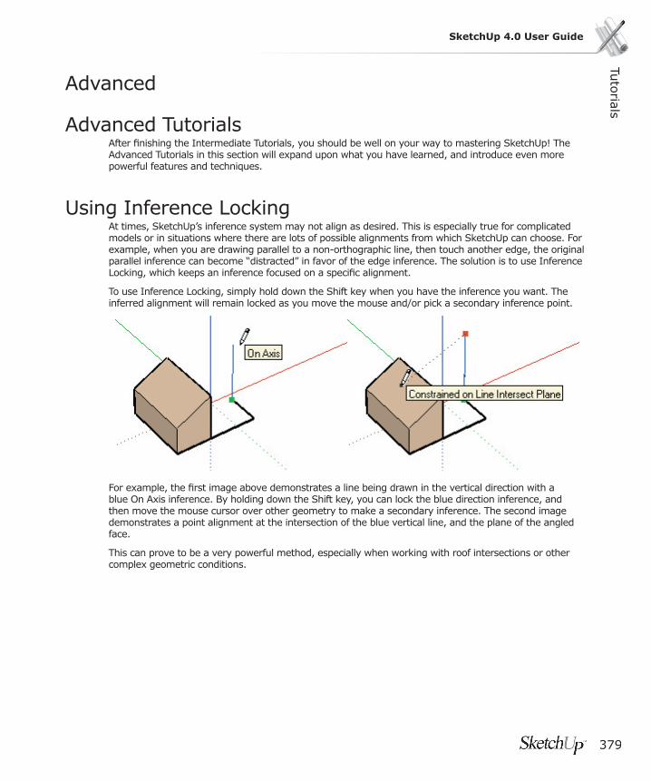
Tuto
rials
379
SketchUp 4.0 User Guide
Advanced
Advanced TutorialsAfter fi nishing the Intermediate Tutorials, you should be well on your way to mastering SketchUp! The Advanced Tutorials in this section will expand upon what you have learned, and introduce even more powerful features and techniques.
Using Inference LockingAt times, SketchUp’s inference system may not align as desired. This is especially true for complicated models or in situations where there are lots of possible alignments from which SketchUp can choose. For example, when you are drawing parallel to a non-orthographic line, then touch another edge, the original parallel inference can become “distracted” in favor of the edge inference. The solution is to use Inference Locking, which keeps an inference focused on a specifi c alignment.
To use Inference Locking, simply hold down the Shift key when you have the inference you want. The inferred alignment will remain locked as you move the mouse and/or pick a secondary inference point.
For example, the fi rst image above demonstrates a line being drawn in the vertical direction with a blue On Axis inference. By holding down the Shift key, you can lock the blue direction inference, and then move the mouse cursor over other geometry to make a secondary inference. The second image demonstrates a point alignment at the intersection of the blue vertical line, and the plane of the angled face.
This can prove to be a very powerful method, especially when working with roof intersections or other complex geometric conditions.
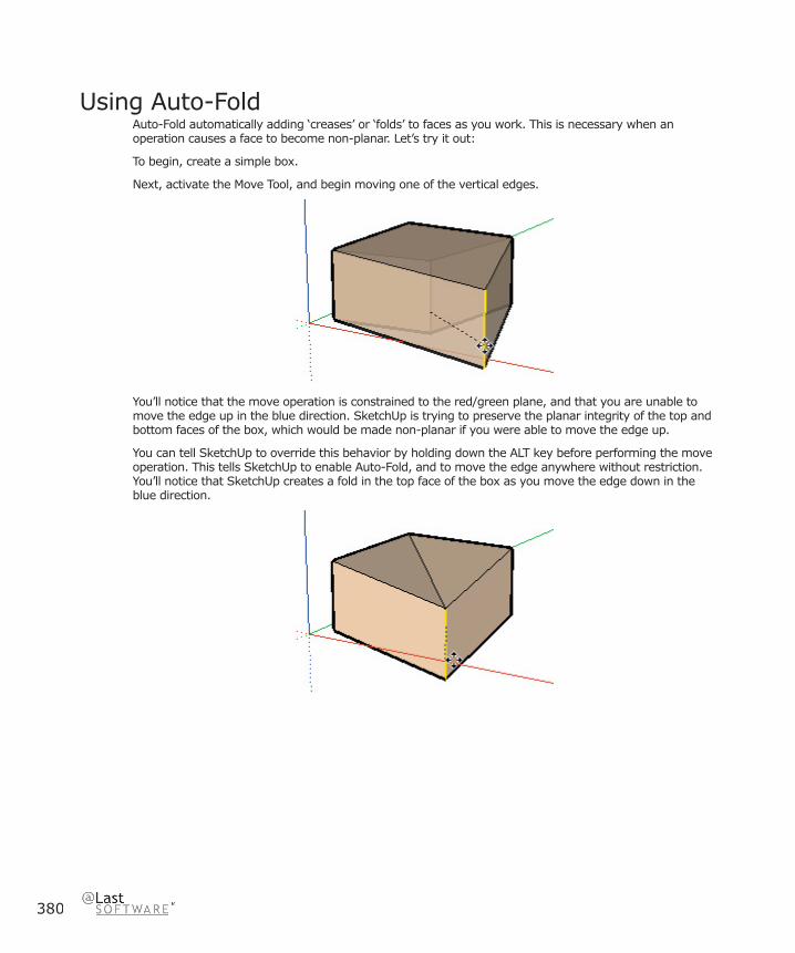
380
Using Auto-FoldAuto-Fold automatically adding ‘creases’ or ‘folds’ to faces as you work. This is necessary when an operation causes a face to become non-planar. Let’s try it out:
To begin, create a simple box.
Next, activate the Move Tool, and begin moving one of the vertical edges.
You’ll notice that the move operation is constrained to the red/green plane, and that you are unable to move the edge up in the blue direction. SketchUp is trying to preserve the planar integrity of the top and bottom faces of the box, which would be made non-planar if you were able to move the edge up.
You can tell SketchUp to override this behavior by holding down the ALT key before performing the move operation. This tells SketchUp to enable Auto-Fold, and to move the edge anywhere without restriction. You’ll notice that SketchUp creates a fold in the top face of the box as you move the edge down in the blue direction.
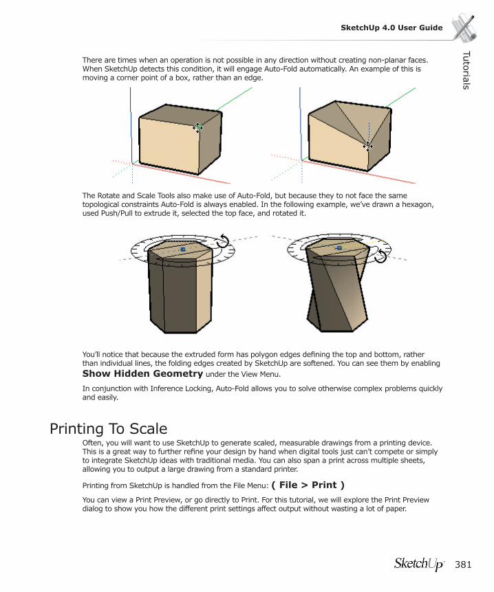
Tuto
rials
381
SketchUp 4.0 User Guide
There are times when an operation is not possible in any direction without creating non-planar faces. When SketchUp detects this condition, it will engage Auto-Fold automatically. An example of this is moving a corner point of a box, rather than an edge.
The Rotate and Scale Tools also make use of Auto-Fold, but because they to not face the same topological constraints Auto-Fold is always enabled. In the following example, we’ve drawn a hexagon, used Push/Pull to extrude it, selected the top face, and rotated it.
You’ll notice that because the extruded form has polygon edges defi ning the top and bottom, rather than individual lines, the folding edges created by SketchUp are softened. You can see them by enabling Show Hidden Geometry under the View Menu.
In conjunction with Inference Locking, Auto-Fold allows you to solve otherwise complex problems quickly and easily.
Printing To ScaleOften, you will want to use SketchUp to generate scaled, measurable drawings from a printing device. This is a great way to further refi ne your design by hand when digital tools just can’t compete or simply to integrate SketchUp ideas with traditional media. You can also span a print across multiple sheets, allowing you to output a large drawing from a standard printer.
Printing from SketchUp is handled from the File Menu: ( File > Print )
You can view a Print Preview, or go directly to Print. For this tutorial, we will explore the Print Preview dialog to show you how the different print settings affect output without wasting a lot of paper.

382
Measurable Drawings
Before we start, please note that because all perspectives and certain paraline projections do not yield measurable results, the Print To Scale feature only works properly from paraline projections of the standard orthographic and isometric views. Only with Perspective turned off can you get true elevation, plan, and isometric views. If Perspective is enabled, the drawing scale options will be unavailable.
Printing to Scale
To start, select the view and rendering settings you would like to print. Make sure that the Perspective option is disabled. Menu: ( View > Perspective )
Also, make sure that you’ve chosen one of the measurable pre-set views such as top, front, isometric, etc. Next, activate the ‘Print Preview’ command. Menu: ( File > Print Preview... )
This brings up the print setting dialog box. This is similar to other windows print dialogs for printer settings, multiple pages and collating.
The ‘Tabbed Page Print Range’ control allows you to print what is currently on the screen, or all the pages you have saved in your model. For now, let’s keep the Current View option.
Fit to Page
Under the Print Size section, if ‘Fit to Page’ is enabled, SketchUp will size your drawing to fi t onto a single printer sheet, and cannot print to an exact scale. Make sure ‘Fit to Page’ is disabled.

Tuto
rials
383
SketchUp 4.0 User Guide
Use Model Extents
Also notice the ‘Use Model Extents’ checkbox. When this option is disabled, the area to be printed is calculated from the current screen. This means that any white space around the model will be printed to scale as well, resulting in drawings needlessly stretching across multiple printer sheets. This can be fi xed either by zooming tightly into the desired print area or enabling ‘Use Model Extents’, which ignores the background area and zoom factor. It’s a good idea to turn ‘Use Model Extents’ on whenever you want to print to scale, so go ahead and do so now.
If the scale fi elds are still grayed out at this point, you may not have SketchUp set to a measurable view. This is the case for perspective images or non-orthographic or isometric axonometric projections. (SketchUp currently does not support axonometric drawings, or oblique projection.)
Scale
The scale controls follow architectural conventions. The fi rst measurement, labeled ‘In The Printout’ is the measurement on paper. The second measurement, labeled ‘In SketchUp’ is the actual measurement of the object in real scale.
For example, for a scale of 1/4” = 1’, simply enter 1 inch(es) in the printout equals 4 feet in SketchUp.
The number of tiled sheets is also displayed.
Once you are fi nished, click OK and the print preview will come up. This is a handy way to see how your model will print before using valuable paper resources.
From here, you can close the dialog, cancelling the print operation, or go ahead and print it.
G or DXF. Select File Export 2D Section Slice.

384
Exporting 2D Vector DrawingsSketchUp allows you to output paraline and perspective views of your model directly to a 2D Vector fi le, preserving the visual richness of your 3D model while converting it to a format more useable by CAD and illustration software.
2D vector output can be saved at full scale, or to a specifi ed size. You can include the profi le lines and extended edges, thus giving life to your details without the overhead of reworking them in CAD. Please keep in mind that some rendering effects, such as textures, shadows, and transparency, are not supported for vector output at this time. (If you need to preserve these effects, you may be better served with raster images.)
Let’s Begin
Let’s begin this exercise by choosing the view you would like to export. Next, go ahead and set SketchUp to either Hidden Line or Shaded display mode. For most CAD applications, you’ll want to export lines only, in which case Hidden Line mode works best. For applications that support fi lled regions, including vector illustration software, use Shaded mode. You may also want to disable Shadows and material transparency. This should offer a good preview of what the vector output will look like:
Once you have the view set up the way you want it, use the File Menu to select ( File > Export > 2D Hidden Line )
SketchUp will launch a fi le save dialog, where you can navigate through your fi le system to the folder in which you want to save your fi le. Give the fi le a name, and choose an export fi le format from the pop-up at the bottom of the sheet. SketchUp saves 2D Vectors as in several formats: DWG, DXF, PDF, and EPS. Each format has its own options and idiosyncrasies.
Next, click the Options button. This brings up a dialog box that allows you to adjust the size, scale, and appearance of the output.
Note: The default Export settings are designed to produce output that is as similar as possible to your SketchUp screen.
Click on the Save button to complete the export. SketchUp will process your model and generate the exported fi le for you. If the view you exported was a measurable, non-perspective projection and you selected the Full Scale (1:1) option, the vector output should be dimensionally accurate.
385
Index
Index
Symbols
2D
Exporting 223, 383
File Formats 289
Image Entities 220, 276, 383
2D 167, 7, 7 383
3D
Exporting 212, 214
Importing 211, 371
3DS 214
3D 20, 99, 150, 167, 7, 7 219
A
About SketchUp Dialog 41
Accelerator 43
Alignment
Align View Command 112
Components 265
Drawing Axes 165
Re-Orienting Drawing Axes 165
Alignment 165
Apple Color Pickers 188
Applying Materials 121, 126, 187, 7, 7 191, 197
Arc
Drawing 52, 247
Architectural Units 142
Arcs 52, 247
Arc 52, 247
Arc Tool 52, 247
Area 245
Array 10, 174
Auto-Fold 178
AutoCAD
Exporting Files 212, 223, 225
Importing Files 211
AutoCAD 211, 212, 223, 225
Axes
Align View Command 112
Component 265
Drawing 165
Edge Rendering 150
Axes 165
Axes Tool 96
B
Back 104, 245
Base Chord 52
Bottom 104
BugSplat 299
Bulge Distance 52
C
CAD
Exporting 212, 223, 225
Importing 211
CAD 10, 383
Camera Menu 34
Circles
Drawing 60, 250
Drawing a Half Circle 52
Circles 60, 250
Circle Tool 60, 250
Codec
Exporting Options 238
Codec 235, 293
Color Picker 188
Color Wheel 188
Components
Closing 182
Creating 353
Editing 182, 265
Instancing 182, 265
Components 10, 128, 171, 182, 265, 353
Component Browser 128, 265, 353
Compression 232, 235, 238, 293
Construction Lines 273
Context Menu 171, 182, 241, 245

386
Coordinate 49
CPU 10
Current Layer 181
Curved Face Sets 52, 60, 61, 82, 253, 258
Customize Toolbar 34
D
Default 181
Defi nition/instance 182
Degrees 108
Detaching Geometry From 182
Detail 10
Dimension Objects 97
Dimension Tool 97, 7, 7 284
Display
Drawing Axes 165
Displaying Hidden Geometry 171
Display 20, 34, 45, 150, 165, 171
Divide 185, 253
Dock 20, 128
Drawing Axes
Aligning 165
Hiding 165
Re-Orient 165
Resetting 165
Drawing Axes 20, 165
Drawing View 20
Drawing Window 20, 34, 184
Draw Menu 38
DWG 211, 212, 223, 225, 383
DXF 211, 212, 223, 225, 383
E
Edge 49, 150, 167, 7, 7 242, 379
Edge Color 150
Edge Rendering 150
Edit Component 182
Edit Group 182
Edit Menu 30, 171
Embedding 10
Entering
Length Value 49
Entering 49
EnterReturn key 182
Entities 52, 245, 253
Epix 229
EPS 227
Equal Segments 49
Equi-Distant On Edge 167
Eraser Tool 66, 171
ESC key 182
Exiting
From Editing 182
Exiting 182
Explode Curve 253
Export 10, 212, 214, 219, 383
Export Options 219
Extents 109
Eye Height 111
F
Faces
Creating 49
Faces 49, 178, 245, 253, 323, 379
Face Orientation 245
Face Shadows 245
Fill Rate 10
Follow Me Tool 85
Foreground Color 150
FOV 108
Freehand Tool 55
From Point inference 167
Front 34
G
GPU 10
Green 165
Green Endpoint inference 167
Ground 111
Ground plane 111, 167
387
Index
Groups 10, 182, 260
H
Help Menu 41
Hide/Unhide 245
Hide 171
Hiding
Drawing Axes 165
Hiding 165, 171
Hotkeys 10, 43
Hotkey 43
I
I-lock 167
Illustration 10
Image Objects 171
Import 211
In-Place Editing 182
IndexedFaceSet 219
IndexedLineSet 219
Inference 10, 49, 165, 167, 7, 7 182, 316, 379
Inference Locking 167
Inference Types 167
Insert Component 128
Intersection inference 167
Intersect with Model 177
Isometric 34, 104
J
Just This One 182
K
Keyboard 43
Keyboard Shortcuts 43
Keypress 43
L
Layer0 131, 181
Layers 10, 131, 171, 181, 219
Layers Panel 171
Layer Manager 131, 171
Layer Toolbar 131, 181
Layer Toolbar Control 131, 181
Layer Toolbar List Box 131, 181
Leader 99
Leader Style 99
Leader Text 99
Learning SketchUp 8, 41
Left 34, 104
Length Value
Entering 49
Length Value 49
Library 128
Library fi le 128
Lines 49, 150, 167, 7, 7 178, 185, 242, 379
Line Tool 49, 242, 316
Loaded Components 128
Lock 167, 7, 7 379
Look Around 111
Look Around Shortcut 111
Look Around Tool 111
M
Make Component 353
Materials 187, 7, 7 219, 245
Materials Editor 121, 126, 191, 197
Materials Palette 121, 126, 191, 197
Menus 25, 30, 32, 34, 36, 38, 39, 41
Middle Button 106
Midpoint inference 167
Mirror 77
Model Info 113
Model Performance 10
Move Left 45
Move Right 45
Move Sketching Context 165
Move Tool 70, 316
MOV 232
Multi-Copy 10, 70, 174

388
N
New Features 16
Non-orthographic line 379
Non-perspective 383
O
Object
Detaching Geometry From 182
Object 182, 241
Offset Tool 91
On Face 167
OpenGL 10, 290
Openings
Creating 323
Openings 323
Orbit 10, 106
Orbit Tool 106
P
Page
Dialogs 133, 184
Tabs 45
TourGuide and 184
Page 45, 133
Paint Bucket Tool 67
Pan 10, 106, 108, 111
Pan Tool 108
Paraline 104, 383
PDF 227
Perspective 34, 104, 108, 109, 383
Perspective Adjustment 108
Piranesi 229
Placing
Components 265
Drawing Axes 165
Images 220, 276
Leader Text 99
Screen Text 99
Placing 109, 165
Point 167, 7, 7 316, 379
Polygons 253
Polygon Tool 61, 253
Polylines 55
Position Camera 34, 109
Position Camera Tool 109
Pre-Set Views 104
Preferences 34, 128, 142, 316
Print 208
Print to Scale 208
Profi le 150
Profi le Lines 49
Projecting Textures 199
Properties 128, 171, 245
Properties Dialog 128
Properties Dialog Box 245
Protractor Tool 94
Proxy Stand-Ins 10
Purge 10, 128, 181
Purge Unused 128
Purge Unused Layers 181
Push/Pull 316
Push/Pull Tool 82, 316
Pushpin 99
Q
QuickTime 232, 235, 238, 293
R
Radius Value 52
Re-Orient Drawing Axes 165
Rectangle Tool 57
Red/green/blue 165
Red/Green 165
Red 165, 167
Red On Edge inference 167
Rendering 147, 7, 7 150
Rendering Performance 10
Resetting
Drawing Axes 165
Resetting 165

389
Index
Resize Handle 20
Right 34, 104
Rotate Tool 74
Ruby 300
Running
SlideShow 184
Running 184
S
Scale Tool 77
Screen Text 99
Section 10, 162, 280
Section Cut 280
Section Planes 280
Section Slice 280
Segments 52
Select Tool 64, 353
Shadows 139, 157, 7, 7 245
Shadow Settings 139, 157
Shift 43, 108
Shortcut 43
Show Axes 34
Show Hidden 128
Show Hidden Geometry 34, 171, 245
Show Toolbar 34
Silhouette Lines 150
Simple Roof
Creating 316
Simple Roof 316
Single Hotkey Shortcuts Limitations 43
SketchUp 20
SketchUp Concepts 10
SketchUp layers 181
SketchUp Menu 25
SketchUp Tutorials 41
SketchUp Web Site 41
Sketch Axes 171
Sky 161
Slideshow
control 184
Running 184
Slideshow 184
Slideshow Toolbar 184
Smooth Faces 154
Soft Edges 154
Specifying
Bulge Distance 52
Eye Height 111
Radius Value 52
Specifying 52, 111
Standard Views 104
Status Bar 20, 34
T
Tangentially 52
Tape Measure Tool 92
Template 298
Text
Leaders 99
Objects 99, 281
Textures
Positioning 199
Textures 219
Text 99
Text Tool 99
TGA 289
TIFF 289
Title Bar 20
Toolbars 20, 21, 34
Tools Menu 39
Tool 49, 52, 55, 57, 7, 7 60, 61, 64, 66, 67, 7, 7 70, 74, 77, 7, 7
82, 91, 92, 94, 96, 97, 7, 7 99
Tool Palette 34
Top 34, 104
TourGuide 184
Transparency 10, 190
Trial-and-error 10

390
U
Un-hiding Entities 171
Undo View Change 104
Ungrouping 260
Unhide 34, 171, 245
Units 298
Update 45, 184
V
Value Control Box 20
VCB 20, 43, 52
Vector Files 211, 212, 223, 227, 7, 7 383
Video 10, 232, 235, 238, 293
Video Card 290
Video Tutorials 41
View
Aligning 165
View 20, 104, 108, 165, 245
View Align 112
View Based 99
View Change 104
View Menu 36
View positioning 109
VIZ 211, 212, 214
VRML
VRML IndexedLineSet entities 219
VRML Standard Orientation 219
VRML Transform grouping 219
VRML 219
W
Walk 106, 111
What’s New? 16
Windows 20
Windows Dialog Boxes 46
Window Menu 32
Written Tutorials 41
WRL 219
X
XY 219
XZ 219
X 49, 165
Y
Y 49, 165
Z
Zooming 34, 108, 109
Zoom Extents Tool 109
Zoom Tool 108
Zoom Window Tool 109
Z 49, 165

391
Index

392

393
Index

394