SPEL for Windows 2.0 - FTP Directory Listing
134
Rev.3 EM01OS901F Program Development Software SPEL for Windows 2.0
-
Upload
khangminh22 -
Category
Documents
-
view
0 -
download
0
Transcript of SPEL for Windows 2.0 - FTP Directory Listing

Rev.3 EM01OS901F
Program Development Software
SPEL for Windows 2.0

Program
Developm
ent Software SPEL for W
indows 2.0
Rev.3

i
Program Development Software
SPEL for Windows 2.0 Rev.3
Copyright 1998-2001 SEIKO EPSON CORPORATION. All rights reserved.

ii
WARRANTY The robot and its optional parts are shipped to our customers only after being subjected to the strictest quality controls, tests and inspections to certify its compliance with our high performance standards. Product malfunctions resulting from normal handling or operation will be repaired free of charge during the normal warranty period. (Please ask your Regional Sales Office for warranty period information.) However, customers will be charged for repairs in the following cases (even if they occur during the warranty period):
1. Damage or malfunction caused by improper use which is not described in the manual, or careless use.
2. Malfunctions caused by customers’ unauthorized disassembly.
3. Damage due to improper adjustments or unauthorized repair attempts.
4. Damage caused by natural disasters such as earthquake, flood, etc. Warnings, Cautions, Usage:
1. If the robot or associated equipment is used outside of the usage conditions and product specifications described in the manuals, this warranty is void.
2. If you do not follow the WARNINGS and CAUTIONS in this manual, we cannot be
responsible for any malfunction or accident, even if the result is injury or death. 3. We cannot foresee all possible dangers and consequences. Therefore, this manual
cannot warn the user of all possible hazards.
NOTICE − No part of this manual may be copied or reproduced without authorization.
− The content of this manual is subject to change without notice.
− We ask that you please notify us if you should find any errors in this manual or if you have any comments regarding its content.
TRADEMARKS Pentium is a trademark of the Intel Corporation. Microsoft is a registered trademark and Windows and Windows logo are registered trademarks of the Microsoft Corporation. Other brand and product names are trademarks or registered trademarks of the respective holders.
Please direct any inquiries about the use of this manual to:
Program Development Software SPEL for Windows 2.0 manual
SEIKO EPSON CORPORATION Sales Engineering Group
TEL: 81-266-24-2004

iii
To Use This Software Microsoft Windows 95, Microsoft Windows 98 or Microsoft Windows NT is necessary to use this software.
Safety Precautions Please carefully read this manual and any other manuals before installing this robot system (and definitely before cable connection). Keep this manual in a handy location for easy access at all times.
This sign indicates that a danger of serious injury or death will exist if instructions thereunder are not followed.
This sign indicates that ignoring the instructions thereunder may cause harm to people or physical damage to equipment and facilities.
- Use ONLY the PC cable that comes with the software. NEVER use a substitute cable, such as the cable that comes with SPEL Editor for
the SRC-200. This latter cable is equipped with a normally-open emergency stop switch, and pushing this switch does NOT cause an emergency stop.
- When you use a teaching pendant or SPEL Editor together with SPEL for Windows, please be certain to read "7. Using a Teaching Pendant or SPEL Editor".
WARNING
CAUTION
WARNING
CAUTION

iv
SERVICE CENTER Contact the following service center for robot repairs, inspections or adjustments. Please have the software version and a description of the problem ready when you call. If service center information is not indicated here, please contact the supplier office for your region as listed in the following SUPPLIERS section.
SUPPLIERS
Japan & Others SEIKO EPSON CORPORATION Okaya Plant No. 2 1-16-15, Daiei-cho Okaya-shi, Nagano-ken, 394-0025 Japan TEL: 81-266-23-0020 (switchboard) 81-266-24-2004 (direct) FAX: 81-266-24-2017
North & South EPSON AMERICA, INC. America Factory Automation/Robotics 18300 Central Avenue Carson, CA 90746 TEL: (562) 290-5900 FAX: (562) 290-5999 E-MAIL: [email protected] Europe EPSON DEUTSCHLAND GmbH Factory Automation Division Zuelpicher Str. 6 D-40546 Duesseldorf TEL: (++) 49 - 211 - 5603 391 (Inside Sales) FAX: (++) 49 - 211 - 5603 444 E-MAIL: [email protected]

v
FOREWORDThis manual specifies matters that you need to know to use the SPEL for Windows. Please thoroughly read this and other related manuals before using the equipment.
MANUALS 1. User's manual
A manual that gives a general description of robots. It describes such things as safety precautions, operating methods, teaching methods, programming methods, and file management. Please read user’s manual first.
2. Manipulator manual A manual for the manipulator itself. It describes such things as robot installation, motion range, safety, and hands.
3. Robot controller manual A manual for the robot controller. It describes such things as installation, switch settings, and connection with peripheral equipment.
4. SPEL III Reference manual
A manual that describes the commands for the SPEL III robot language.
5. Maintenance manual A manual that describes the maintenance procedure of the robot. It describes such things as check points, troubleshooting, how to repair and so on.
6. Operating unit manual (option) A manual for the operating unit that describes such things as operating methods.
7. Programming support software manual (option)
A manual for the program development support software. It describes such things as operating environment and operating methods of SPEL Editor or SPEL for Windows. We provide two kinds of software, SPEL Editor (for MS-DOS) and SPEL for Windows (for Microsoft Windows). We also provide Vision Guide, the integrated robot vision system, as an option of SPEL for Windows.
8. Teaching Pendant Manual (option) A manual for the teaching pendant. It describes such things as how to operate the teaching pendant.
About Conventions Used in This Manual
The commands that can be directly typed in from the keyboard on the control software, SPEL for Windows are addressed in all upper case as follows: CONFIG, MCAL, etc.

vi
TABLE OF CONTENTS
1. Introduction ................................................................................... 1
About This Manual .............................................................................................. 1
Package Contents ............................................................................................... 1
Major changes from V1.0E to V1.14E................................................................. 2
Major changes from V1.14E to V1.2E................................................................. 2
Major changes from V1.20E to V2.0E................................................................. 3
The SPEL for Windows Concept......................................................................... 4
SPEL for Windows Features ............................................................................... 5
Conventions Used in This Manual....................................................................... 8
Key Equivalents................................................................................................... 9
2. Basic Operations......................................................................... 10
Setup ................................................................................................................. 10
Environment required by SPEL for Windows ............................................. 10
Using the setup program ............................................................................ 11
Launching SPEL for Windows........................................................................... 12
The Start-up Window ........................................................................................ 12
Selecting Commands ........................................................................................ 13
Selecting commands from the tool bar....................................................... 13
Selecting commands from the menu.......................................................... 13
Selecting commands by using shortcut keys ............................................. 13
Using Dialog Boxes ........................................................................................... 14
Using Online Help.............................................................................................. 15
3. Program Input and Execution ..................................................... 17 Preparations ...................................................................................................... 17
Cable connection and controller mode....................................................... 17
To confirm communication ......................................................................... 18
Using SPEL for Windows in S.NET mode.................................................. 18
Inputting and Executing Simple Programs ........................................................ 19
Saving Projects ................................................................................................. 23
Project Building Errors....................................................................................... 24
Programming Rules........................................................................................... 25
Basic Configuration of Program ................................................................. 25
Function Names ......................................................................................... 26
Comments .................................................................................................. 26
Labels ......................................................................................................... 26
Multi-statement ........................................................................................... 27

vii
4. Projects .......................................................................................28 What is a Project............................................................................................... 28
Project Configuration ........................................................................................ 28
Project make .............................................................................................. 29
Project Building ................................................................................................. 30
Compiling and linking by controller ............................................................ 30
Compiling and linking by personal computer ............................................. 32
About Program Groups ..................................................................................... 33
Execution From AUTO mode............................................................................ 34
REMOTE2(OPU-320) ................................................................................ 34
REMOTE3(I/O-1) ....................................................................................... 34
S. NET........................................................................................................ 34
5. Program Editing...........................................................................35 Moving the Cursor............................................................................................. 35
Selecting Text ................................................................................................... 36
Deleting Text..................................................................................................... 37
Cut-and-Paste................................................................................................... 37
Renumber ......................................................................................................... 38
Editing Between Projects .................................................................................. 38
6. Editing Point Data .......................................................................39
Using the Point Edit Window............................................................................. 39
7. How to Use the Teaching Pendant and SPEL Editor ..................42
When Used with Teaching Pendant ................................................................. 43
Method that does not use the <Pendant> button ....................................... 43
Method that uses the <Pendant> button .................................................... 45
When Used with SPEL Editor ........................................................................... 46
How to use the SPEL Editior to update the project’s program files ........... 46
How to use the SPEL Editor to build a project in the controller.................. 47
How to use the SPEL Editor to modify point files for a project................... 49
How to transfer a program or point data newly ceated via the SPEL Editior
to a SPEL for Windows project .................................................................. 49
How to Use the [Monitor] Window to Modify Programs or Point Data .............. 50
When you want to change a program with the [Monitor] window............... 50
When you added a program using the [Monitor] window........................... 51
When you revised point data using the [Monitor] window.......................... 51
Main Memory and File Memory......................................................................... 52
8. Explanation of Commands ..........................................................53 [File] menu ........................................................................................................ 53

viii
[New] command ......................................................................................... 53 [Open] command........................................................................................ 53 [Close] command ....................................................................................... 54 [Save] command ........................................................................................ 54 [Restore] command .................................................................................... 54 [Save As] command ................................................................................... 54 [Rename] command................................................................................... 54 [Delete] command ...................................................................................... 55 [Import] command ...................................................................................... 55 [Print] command ......................................................................................... 59 [Exit] command........................................................................................... 61
[Edit] menu ........................................................................................................ 62 [Undo] command ........................................................................................ 62 [Cut] command ........................................................................................... 62 [Copy] command ........................................................................................ 62 [Paste] command ....................................................................................... 62 [Find] command.......................................................................................... 62 [Find Next] command ................................................................................. 63 [Replace] command ................................................................................... 63 [Select All] command.................................................................................. 64 [Indent] command....................................................................................... 64 [Outdent] command.................................................................................... 64 [Renumber] command................................................................................ 64 [Strip line numbers] command.................................................................... 64
[Project] menu ................................................................................................... 65 [New] command ......................................................................................... 65 [Open] command........................................................................................ 66 [Edit] command .......................................................................................... 67 [Variable Library] command........................................................................ 68 [Robot Points] command ............................................................................ 69 [Robot Controller Number] command......................................................... 70 [Robot Parameters] command ................................................................... 70 [Save] command ........................................................................................ 75 [Save As] command ................................................................................... 76 [Rename] command................................................................................... 76 [Copy] command ........................................................................................ 77 [Delete] command ...................................................................................... 78 [Compile File] command............................................................................. 78 [Build] command......................................................................................... 79 [Rebuild] command .................................................................................... 79 [Update Point Files] command ................................................................... 79
[Run] menu........................................................................................................ 80 [Start] command ......................................................................................... 80 [Operator Window] command .................................................................... 81

ix
[Step Into] command.................................................................................. 83 [Step Over] command ................................................................................ 83 [Resume] command................................................................................... 83 [About All] command.................................................................................. 83 [Toggle Breakpoint] command................................................................... 83 [Clear All Breakpoints] command............................................................... 84 [Display Variables] command..................................................................... 84 [Instant Watch] command .......................................................................... 84
[Tools] menu ..................................................................................................... 85 [Jog and Teach] command ........................................................................ 85 [Monitor] command .................................................................................... 91 [Robot Control Panel] command................................................................ 91 [I/O Label Editor] command ....................................................................... 95 [I/O Monitor] command .............................................................................. 95 [Memory I/O Monitor] command ................................................................ 96 [Task Manager] command ......................................................................... 97 [Macro] command ...................................................................................... 99 [Maintenance] command.......................................................................... 100
[Setup] menu................................................................................................... 102 [PC ro Robot Communications Setup] command .................................... 102 [Robot Controller Configuration] command.............................................. 102 [Preferences] command........................................................................... 106
[Window] menu ............................................................................................... 113 [Cascade] command ................................................................................ 113 [Tile Horizontal] command ....................................................................... 113 [Tile Vertical] command ........................................................................... 113 [Arrange Icons] command........................................................................ 113 [Close All] command ................................................................................ 113
[Help] menu..................................................................................................... 114 [Contents] command................................................................................ 114 [Search for Help On] command ............................................................... 114 [How to Use Help] command ................................................................... 114 [About SPEL for Windows] command...................................................... 114
9. GUI for Safety Input ..................................................................115
ROBOT COMMAND PAUSED Dialog Box ..................................................... 115
Display on Run Window.................................................................................. 116
10. Other Important Dialog Boxes ...................................................117
[Point File Update] dialog box ......................................................................... 117
[Update File] dialog box .................................................................................. 118
[Pendant has control] dialog box..................................................................... 118
[Customize] dialog box.................................................................................... 119
11. Maintenance Parts List..............................................................121

x

1. Introduction
1
1. Introduction
About This Manual This manual explains the functions of SPEL for Windows and how to use them.
To get the most efficient use of SPEL for Windows, please be sure to read this manual first.
You may also refer to online help when you have questions while you are using SPEL for Windows.
Package Contents This software includes the following items:
• This manual
• Usage agreement
• Five setup disks
• PC cable (with emergency stop switch)
• Conversion connector (25-9 pin)
All setup disks are 1.44 MB.

1. Introduction
2
Major changes from V1.0E to V1.14E The following items are major changes from V1.0E.
• Support for XM3000 series robots has been added.
• Point labels and I/O labels are supported in user programs and from the monitor window.
• Teaching pendant or SPEL Editor can be used with SPEL for Windows easily.
• Line numbers are no longer required in programs.
• Memory I/O monitor has been added.
• Maintenance dialog box has been added to the Tools menu. This supports MKVER and SETVER commands, which allow you to save and restore all robot controller parameters.
• Group name MAINGRP can be renamed.
• MSGBOX, INPUTBOX and other commands are supported. These commands work with SPEL for Windows.
• Vision Guide option is supported. This helps you to create robot vision application.
• VB Guide option is supported. This allows you to communicate with SPEL for Windows from Microsoft Visual Basic using DDE.
Other changes for V1.14E are written in Read Me. Read Me includes the information which is not written in the manual. Please be sure to read it before using SPEL for Windows.
Major changes from V1.14E to V1.2E The following items are major changes from V1.14E.
• Pulse generating board option is supported. The boards, which are installed to the controller, can control up to 4 axes in addition to manipulator. You can jog and teach points for pulse generating board very easily by using SPEL for Windows.
• A new command line option has been added for the operator window that will auto start automatically after the operator window has opened. Use "/OPRAS" on the SPEL for Windows command line.
Other changes for V1.2E are written in Read Me. Read Me includes the information which is not written in the manual. Please be sure to read it before using SPEL for Windows.

1. Introduction
3
Major changes from V1.20E to V2.0E The following items are major changes from V1.20E.
• Source program's debugging function has been improved. A multiwindow debugger and multitasking function, which is equipped with functions such as breakpoint setup, step execution, and variable watch, have been added.
• Programs can be compiled and linked using a PC (personal computer).
• 32KB and larger source files (.PRG) can be edited.
• Multiple I/O monitors, memory I/O monitors, and task managers can be opened at the same time.
• I/O and memory I/O output controls can be changed while a task is in progress.
• Up to eight immediately preceding project names can be listed in the project menu.
• A [Save As] command has been added to the file menu.
• A [Close All Windows] command had been added to the window menu.
• Function names and variable names that start with "P" can be used. To enable this option, open the [Setup]-[Preferences]-[Project] panel, and check the [Allow Identifiers Starting with P] check box.
• Windows 3.1 cannot be used. Use a computer that runs Windows 95, Windows 98, or Windows NT 4.0 when starting up SPEL for Windows V2.0E.
• Toolbars can be customized.
• In the program editor window, commands and statements (reserved words) are displayed in blue, error lines in red, and comments in green, making it easier to check grammar.
• Overwrite mode can be used from the program editor window.
• Using the MKVER command, you can save backup variables on your computer's hard disk.
• DDE (dynamic data exchange) used with applications created using Microsoft Visual BASIC has been changed to Active X.
Other changes are written in Read Me. Read Me includes the information which is not written in the manual. Please be sure to read it before using SPEL for Windows.

1. Introduction
4
The SPEL for Windows Concept SPEL for Windows is program development software that was developed on the basis of a new concept. The philosophy is completely different from that of SPEL Editor and SPEL-80M. It is not simply an easier-to-use version of those programs. SPEL for Windows offers a new development environment by making full use of the Windows environment.
The basic concept of SPEL for Windows is that all environments can be handled using a personal computer. Here "environment" refers to the total environment, encompassing such things as application programs, point data and robot settings (this is called a "project").
Moreover, they are treated collectively, and you can set up an environment merely by specifying the project. Various settings are memorized for each application, so it is no longer necessary to reset them. Rather than use commands as in the past, you make the required settings simply by checking the content of the screen on the display and operating the mouse. For example, for the CONFIG command, which establishes the communication settings for the RS-232C on the back of the controller, you formerly had to refer to the manual and set the required parameters. With SPEL for Windows, however, all you have to do is select the baud rate and number of bits. This means that the command instructions you once had to give to the controller have, in most cases, become unnecessary.

1. Introduction
5
SPEL for Windows Features
Online Help
SPEL for Windows is equipped with an extensive help function to support users in almost any situation. Online help covers such subjects as software setup and program creation; it also explains such things as what to do in case of an error and provides a reference for the SPEL III robot language. For example, when you don't know how to use a command when you are developing a program, align the cursor with the command you want to know about, then hit function key [F1]. The command reference appears along with a sample of its use. Likewise, you can display details about any error that occurs by using the same procedure.
With this powerful help function you do not need to keep the manual on hand when you are developing user programs; all the information you need is easily accessible right on your PC.
GUI Environment
SPEL for Windows' graphical user interface (GUI) depicts operations as easy-to-understand icons, thus providing an intuitive, smooth operating environment.
Centralized Management by Projects
The robot's environment and settings differ from system to system, but you can centrally control settings and robot environments that contain program data by means of projects. Management of the system is extremely simple. All you need to do when you switch applications is to switch projects and all will be changed.

1. Introduction
6
Jog and Teach Window The [Jog and Teach] window makes teaching easy. All the tools required for teaching operations are displayed. All you need to do is click on the buttons.
Task Manager
Task manager tracks and displays the progress of all tasks being performed. In addition, it can control such things as execution, pauses, and restarts.
Multiscreen Editor The mouse-operated Multiscreen Editor supports program development with functions that allow you to display multiple windows; cut, copy and paste between programs; and automatically indent when you press the return key.
Command Macro Function The command macro function allows you to record and save a set of commands under a function key. You can record and save a user-defined command set which is optionally combined with SPEL III.
Monitor Window The monitor window communicates directly with the controller. Monitor mode is a command interface that communicates with the robot controller. It sends the executed command's signal to the controller (It is equivalent to SPEL Editor's command mode.).
Debugging Function A multi-window debugger and multitasking function, which is equipped with functions such as breakpoint setup, step execution, and variable watch, can be used.

1. Introduction
7
Off-line Compiling Project building time is reduced, since project programs are compiled and linked without having to go through a controller. Even if there is no controller, grammar checks can be done from the program editor window.
I/O Monitor The [I/O monitor] not only displays the state of I/Os visually but also allows you to control output with a double-click of the mouse.
Preferences
The [Preferences] dialog allows you to easily establish the settings of SPEL for Windows and the controller.
Vision Guide Option
Vision Guide gives you best solution for you robot vision applications. Active X (VB Guide option: scheduled to go on sale)
Active X allows data communication with applications created using Visual BASIC. The robot can be operated from the control panel designed with Visual BASIC.

1. Introduction
8
Conventions Used in This Manual The following conventions are used in this manual.
Menu, command, and dialog box notation Notation Description
[File] menu Menu names are written in brackets ([ ]) in upper-case letters.
[File] - [New] command Command names are attached to the name of the menu that contains the command. Both menu name and command name are written in brackets ([ ]).
[Open File] dialog box The name of a dialog box is written in brackets ([ ]) on the dialog boxes' title bar.
<Help> button Command button and tool button names in dialog boxes are enclosed in angle brackets (< >).
Notations for mouse operations
Notation Description
Click The act of pressing and quickly releasing the left button on the mouse.
Double-click The act of clicking the left button on the mouse twice in rapid succession.
Drag The act of moving the mouse while holding down the left mouse button and releasing the button when the object being "dragged" reaches the desired destination.
Notations for key operations
Notation Description
[Shift] Keys are written in brackets ([ ]).
[Alt]+[F] The plus symbol (+) indicates that the second key should be pressed while the first key is held down. In this example, the [Alt] key should be held down while the [F] key is pressed.
[Alt], [P], [E] When the keys are separated by a comma (,), it means that you should hit the keys in the order shown. In this example, the [Alt], [P] and [E] keys should be hit in that order.
Arrow Keys [→], [←], [↑] and [↓]

1. Introduction
9
Key Equivalents In this manual, key operations are denoted by common key notations (generic key notations) that are the same for all keyboards.
Generic Key Notation 101 Keyboard
[Esc] [Esc]
[Tab] [Tab]
[Ctrl] [Ctrl]
[Shift] [↑Shift]
[Alt] [Alt]
[Space] [ ]
[Enter] [Enter]
[BackSpace] [BackSpace]
[Ins] [Insert]
[Del] [Delete]
[Home] [Home]
[End] [End]
[F1] [F1]
[F12] [F12]
Nao
:
Nao
:
Nao

2. Basic Operations
10
2. Basic Operations
Setup Use the setup program to install SPEL for Windows. Simply copying the contents of the program disk will not enable you to use this software.
Environment required by SPEL for Windows
Personal computer
CPU: 80486DX or later (Pentium 90 MHz or higher processor is recommended)
Operating system: Microsoft Windows 95, Microsoft Windows 98, or Microsoft Windows NT 4.0
Resolution: VGA or higher (at least 640 × 480)
Memory: At least 16 MB (however, at least 32 MB is recommended)
Free space on hard disk: At least 10 MB
Mouse
RS-232C port for use in communicating with robot controller
PC cable (included)
Robot controller SRC-300 series
ROM: Version 6.3 or later

2. Basic Operations
11
Using the setup program
Install the program as follows:
1. Launch Windows.
2. Load setup disk 1 into your floppy disk drive.
3. Select the [File]-[Run] command in Program Manager.
4. Input a:setup in the execution dialog box (when the SPEL for Windows disk is loaded in drive A).
5. Follow the instructions that are shown on the display.
When setup is complete, a program group called "SPEL for Windows 2.0E" will be registered in the status bar [Start]-[Programs] area. The three icons depicted below are stored in this group.
Main SPEL for Windows program.Click on this item to launch program.
Provides information that is not in the manual. Click on this item to view.
SPEL for Windows help file

2. Basic Operations
12
Launching SPEL for WindowsTo launch SPEL for Windows, go to the status bar and click on [Start], then on [Programs] and[SPEL for Windows 2.0E] (from within "SPEL for Windows 2.0E").
SPEL for Windows inputs programs and creates projects even when it is off-line. However, acommunication error will occur if you select the [Jog and Teach] window when the PC andcontroller are not connected.
The Start-up WindowWhen SPEL for Windows is successfully launched on your system, you will see the window such as shown below displayed on your monitor.
The menu barThere are seven menus on the menu bar. Each menu contains various commands.
The tool barThe tool bar contains buttons (tools) that help you access frequently used commands. Clickon the buttons as a shortcut to execute their respective commands.
[Jump to Function] list box
The function names which have been input in the program file are displayed. Select a functionname to jump to.
Click on this item tolaunch the program.
Menu bar Tool bar
[Jump to Function] list box

2. Basic Operations
13
Selecting Commands In SPEL for Windows, commands are the instructions that make the program execute a given function. Commands are executed in any of the following ways:
- by clicking with the mouse on a button in the tool bar
- by selecting a command from a menu
- by using a shortcut key
Selecting commands from the tool bar Click with the mouse on a button displayed on the tool bar. For example, to open the Jog and Teach window, click on the <Jog and Teach> button.
Selecting commands from the menu When you click on the menu title that contains the command you want to select, the menu is displayed. From this menu, click on the command that you want to execute.
Selecting commands by using shortcut keys
Some commands on the menus have shortcut key equivalents. Shortcut keys are shown to the right of the command name. You can use the shortcut keys to directly execute commands without opening the menu.
Tool bar
Menu bar
Shortcut keys that can be used to select the command
Commands that are dimmed are not currently available

2. Basic Operations
14
Using Dialog Boxes Depending on the command you select, a dialog box may appear so that you can input settings related to the command.
Some dialog boxes may contain more than one panel. Panels are divided by type and each panel has its own settings, as shown below.
Radio button Use to select/deselect option.
Check box Click on the check box to switch an option on and off.
Text box Input characters to set the option.
<Help> button Displays help for this panel.
Command buttons Execute operations and display other dialog boxes.
Click here to switch panels.

2. Basic Operations
15
Using Online Help SPEL for Windows is equipped with online help to enable you to learn about such things as functions and their use on-screen.
You can refer to the following subjects with online help:
- using SPEL for Windows
- creating programs
- command reference
Before using Windows help for the first time, select the [Help]-[How to use help] command and read it carefully.
There are three methods for accessing help on SPEL for Windows.
1. To view help using contents
If you select [Help]-[Contents], the [SPEL for Windows Help Topics] window appears. If you click on a part that is underlined with a solid green line, the screen jumps to that item and the window changes. If you click on a part that is underlined with a dotted green line, an explanation of the item is displayed via a pop-up window.
<Index> buttonJumps to the [Search for Help On] in Help.
<Print> buttonPrints out the window that is displayed currently.
<Back> buttonClick on this button to go back to the help subject that was displayed earlier.
NOTE
2. Basic Operations
16
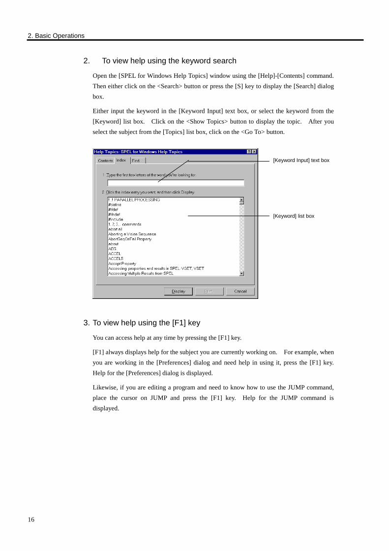
2. To view help using the keyword search
Open the [SPEL for Windows Help Topics] window using the [Help]-[Contents] command. Then either click on the <Search> button or press the [S] key to display the [Search] dialog box.
Either input the keyword in the [Keyword Input] text box, or select the keyword from the [Keyword] list box. Click on the <Show Topics> button to display the topic. After you select the subject from the [Topics] list box, click on the <Go To> button.
3. To view help using the [F1] key
You can access help at any time by pressing the [F1] key.
[F1] always displays help for the subject you are currently working on. For example, when you are working in the [Preferences] dialog and need help in using it, press the [F1] key. Help for the [Preferences] dialog is displayed.
Likewise, if you are editing a program and need to know how to use the JUMP command, place the cursor on JUMP and press the [F1] key. Help for the JUMP command is displayed.
[Keyword Input] text box
[Keyword] list box

3. Program Input and Execution
17
3. Program Input and Execution
Before doing the operation in this chapter, connect controller to manipulator and wire safe guard input and emergency stop input properly. Refer to the User’s manual, Manipulator manual and Controller manual and make sure manipulator moves safely before executing program.
Preparations Cable connection and controller mode
Connect the personal computer that will be used to run SPEL for Windows to the robot controller by plugging one end of the special PC cable (with Emergency stop switch or Enable switch) into the RS-232C port on the PC and the other end into the TEACH connector on the front of the robot controller. Plug the side of the cable with the emergency stop switch into the connector on the personal computer.
Use ONLY the PC cable that comes with the software. NEVER use a substitute cable, such as the cable that comes with SPEL Editor for the SRC-200. This latter cable is equipped with a normally-open emergency stop switch, and pushing this switch does NOT cause an emergency stop.
Controller
Emergency stop switch or Enable switch
WARNING

3. Program Input and Execution
18
Turn on the robot controller and put the controller in TEACH mode.
To confirm communication
Check whether SPEL for Windows is communicating with the controller.
Turn on the personal computer and launch SPEL for Windows.
Execute the [Setup]-[PC to Robot Communications Setup] command and display the [PC to Robot Communications Setups] dialog box.
Check the number of the PC's RS-232C port and click on the <Test> button. A message is displayed that tells you whether communication is normal.
If communication failed, follow the instructions shown on the display and reset items accordingly.
Using SPEL for Windows in S.NET mode
SPEL for Windows can be used in S.NET mode. When you use it in this mode, the settings of the [PC to Robot Communications Setup] dialog box must be the same as the configuration settings for the controller's RS-232C port.
Note, however, that operations in S.NET mode are performed in normal power mode.
For safety reasons, we recommend using TEACH mode as much as possible while teaching points or making programs. In TEACH mode, the robot operates in low-power mode. Motor power in TEACH mode is held below that of normal power mode, making TEACH mode safer.
NOTE
<Test> button

3. Program Input and Execution
19
Inputting and Executing Simple Programs Here, we will describe how to create and execute a simple application program.
1. Create a new project
a. Execute the [Project]-[New] command.
b. Input the name of the project in the [New Project Name] dialog box. For example, FIRSTAPP, etc.
c. Click on OK and save and register the new project.
When a new project is registered, a program called "MAIN.PRG" is created and a window titled "MAIN.PRG" opens with a cursor flashing in the upper left corner.
2. Edit the program
Input the program line shown below into the MAIN.PRG editing window. You may use either upper-case or lower-case letters, but we recommend inputting lower-case letters. If you input lowercase letters and if the word you input is a reserved word (command, statement, or function), the word is automatically converted to uppercase letters so that you can see at a glance whether there were any input errors.
FUNCTION main
PRINT "This is my first program."
FEND
MAIN.PRG editing window

3. Program Input and Execution
20
3. Build the program
Execute the [Project]-[Build] command. The [Project Build Status] window opens and the build procedures are displayed (The program created is transmitted to the robot controller and compiled.). If an error occurs, it is displayed in this status window.
4. Execute the program
When you execute the [Run]-[Start] command, the [Run] window is displayed. When you click on the [Start maingrp : MAIN] button, the program is executed. The [Run] window is displayed as follows:
If you execute the [Run]-[Start] command without building a project, the [Project Build Status] window opens automatically and building is performed. Unless there is an error, the [Run] window opens next.
<Project Build> button [Ctrl]+[B]
<Run> button[F5]
NOTE
Result of execution
Execution button

3. Program Input and Execution
21
Teaching and executing points
Next, teach points and operating the robot.
5. Calibrate the robot
When you execute the [Tools]-[Robot Control Panel] command, the [Robot Control Panel] dialog box is displayed.
Select Robotic manipulator as the point device (If you have not installed any optional pulse generating board, then there will only be one selection: Robotic Manipulator.).
Click on the <MOTOR ON> button. A confirmation message appears. Follow the instructions provided by this message.
Click on the <MCAL> button. You can skip this if your manipulator is a BNA or BNA-CL type, or EC, ES, EL, or EH series. Follow the instructions provided by this message. Calibration is performed.
If you sense danger, immediately press the E. STOP switch.
To reset the system after an emergency stop, turn the E. STOP switch clockwise to release the mechanical hold; then click on the <RESET> button on the [Robot Control Panel].
<MOTOR ON> button <MCAL> button
WARNING
Robotic manipulator has been selected.
<Robot Control Panel> button
[Ctrl]+[L]

3. Program Input and Execution
22
6. Teach points
When you execute the [Tools]-[Jog and Teach] command, the [Jog and Teach] window appears.
Set the desired point device. Click on the <Robot> radio button to select. The Point Device option is located in the top center of the Points control group (If you have not installed any optional pulse generating board, then there will only be one selection <Robot>.). When <Robot> is selected, <Jog> buttons are shown like the figure on this page.
Register the current position at P0. Click on the <Teach P0> at the bottom of the screen.
Check jog distance by looking at the values in the Jog Distance control group. If necessary, select Coarse, Medium, and Fine jog distance. You can also type in the desired jog distance. Refer to Chapter 3 of User’s manual for the detail of jog mode.
Check jog mode by looking at the values in the Jog Mode control group. If necessary, select Base, Joint and Tool jog mode.
Check the jog speed by looking at the value for SPEED. If necessary, change it.
Click on the Jog button on the upper left of the screen to operate the robot. If you hold the mouse button down, the robot will continue to jog.
Register the current position at P1. Click on the <Point Slider Right> button on the lower left of the screen and change the current point to P1. Click on the <Teach P1> button.
<Jog> button
<Teach> button <Point Slider Right>
<Coarse>, <Medium> and <Fine> radio buttons [Jog Distance] text box
<Robot> radio button <Base>, <Joint> and <Tool> radio buttons
<Job & Teach> button [Ctrl]+[J]

3. Program Input and Execution
23
Use the Jog button to operate the robot.
Register the current position at P2. Click on the <Point Slider Right> button on the lower left of the screen and change the current point to P2. Click on the <Teach P2> button.
Click on the <Close> button in the lower right corner of the screen, and quit the Jog screen. A message indicating that changes were made appears. Click on the <Yes> button to save the changes.
7. Modify the program, and input and execute robot operation commands Insert new lines in the MAIN.PRG program.
FUNCTION main
PRINT "This is my first program."
JUMP P1
JUMP P2
JUMP P0
FEND
After pressing the [F5] key (the shortcut key for the [Run]-[Start] command) and displaying the [Run] window, execute the program by clicking on the <Start maingrp : MAIN> button.
After "This is my first program." is displayed in the [Run] window, the robot moves to the point that was taught.
Saving Projects
In the above example, all project files are saved at the time a project is built. To save a project when you are creating a program, execute the [Project]-[Save] command.
A confirmation message asking you whether you want to save a file appears if you attempt to quit SPEL for Windows without saving the file.
Project files are saved to the following directory of the drive where SPEL for Windows is installed:
SPELW PROJECTS <project name>
When you want to change the drive where a project is stored, change the drive registered in the [New] dialog box that is displayed when you register a new project (display by using the [Project]-[New] command).
Project files also contain the program and point data files.

3. Program Input and Execution
24
Project Building Errors If an error occurs while a project is being built, you can make the cursor jump to a reference describing the error or to the line where the error occurred.
Change the program as shown below (An error is made deliberately.).
FUNCTION main
PRINT "This is my first program."
JUMP P1
JUMP P2
JUNP P0 ← Input JUNP instead of JUMP. FEND
The project is built.
The following [Project Build Status] window will be displayed.
Move the cursor to the line displaying the error (line 3); then do the following:
Double-click. The screen will jump to the program line that produced the error.
Press the [F1] key. The following [SPEL for Windows Help Topics] window will be displayed.

3. Program Input and Execution
25
Programming Rules
Basic Configuration of Program
The basic unit of a program is called a "line," and a collection of such lines becomes a program. A line consists of a "line number" and a "statement." The line number can be omitted.
100 JUMP P7 C0 LIMZ-50
Line number Statement Line number: Integer from 1 to 32767 Number of characters in a line: Up to 79 (half-width)
As for the basic format, a program starts with FUNCTION for the first line and FEND for the last line.
FUNCTION MAIN ⋅ ⋅ ⋅
FEND
This sequence from FUNCTION to FEND is called a "function." The name of the function is attached after FUNCTION. In the example above, "MAIN" is the name of the function.

3. Program Input and Execution
26
Function Names
Function names have the following restrictions:
• Eight characters or less
• Alphanumeric characters and underscores ( _ ) can be used. No distinction is made between uppercase and lowercase letters.
• Reserved words (commands, statements, and functions) cannot be used. If an underscore or numeral is attached after a reserved word, the name will still be considered a reserved word and cannot be used.
Comments
To make programs easier to understand, comments can be written as needed.
The apostrophe ( ' ) symbolizes and precedes a comment. When a program is executed, all written contents that follow an apostrophe are ignored. Any character can be used in a comment. Up to 79 characters can be written in a single line, including the line number, statements, and comment. FUNCTION MAIN
' **************************
' * HANDLER -1 *
' * PROGRAMMED BY SATOU *
' **************************
'
' GOSUB LOOP ←GOSUB LOOP will not be executed. SPEED 100 ;ACCEL 50,100
JUMP P10 ;ON 1 ;WAIT 0.2 'Work attaches at Feeder 1 ←Comment
Labels
Generally, when the order of execution of a program is to be changed using GOTO, GOSUB, IF...THEN...ELSE, or similar keyword, the jump address (destination) is specified by the line number. The line number is simply a numeral, however, and is not very meaningful. If meaningful words could be used to specify jump addresses, it would be extremely convenient for the people who write and read the programs. With SPEL III, you can attach a meaningful "label" after the line number, enabling you to specify the jump address with the label instead of the line number.

3. Program Input and Execution
27
Label names have the following restrictions:
• Eight characters or less
• Alphanumeric characters and underscores ( _ ) can be used. No distinction is made between uppercase and lowercase letters.
FUNCTION MAIN
LOOP: ← Attach label. JUMP P1
JUMP P2
GOTO LOOP ← Using label, shift control. FEND
In the above example, the label LOOP is inserted in the second line. When you insert a label, attach a colon (:) after it to indicate that it is a label.
Multi-statement
When a semicolon (;) is used to separate commands and statements, multiple commands and statements can be written on one line. This method of writing is called a "multi-statement."
Multi-statements are advantageous in that they make programs easier to read, reduce program size, and thus reduce program run time. Keep in mind, however, that if too many commands and statements are written consecutively, programs will instead be harder to read and understand.
JUMP P7 ;ON 1 ;WAIT 0.2
JUMP P17 ;OFF 1 ;WAIT 0.2

4. Projects
28
4. Projects
What is a Project Applications created with SPEL for Windows are managed as projects. A project is made up of one or more program files, point files and controller settings related to the application.
The project concept is a beneficial one, even if an application consists of only one program. With applications that consist of multiple programs, control of the whole can be performed simply by treating them as a project.
Project Configuration A project is configured as shown in the figure below.
A project is comprised of a number of "program groups", "include files", "variable library" and "controller settings for each project". A program group consists of a number of programs and a point file. The programs in a program group are compiled and linked to form a single object file, which is an executable file. A program group consists of a single application program, whereas a project consists of multiple application programs.
Project
Program file
···
Controller settings managed for each project
···
Program Group Program
file Point file
Program file
··· Program file
Point file
Variable library
Include files

4. Projects
29
Project make
In the project make, you have to register what kind of files make up a project. To register the project make, use the [Edit Project] dialog box that is displayed when you execute the [Project]-[Edit] command.
To create a program group, click on the <New Group> button to display the [Create New Group] dialog box. To register the program group, input the group name in the text box.
To register a program, input the program name in the [File Name] text box, select the group that you want to register from the [Program Group] list box, and click on the <Add> button.
"Variable library" is set in the [Variable Library] command from the [Project] menu. "Controller settings for each project" are the settings in the [Robot Points], [Robot Number] and [Robot Parameters] command from the [Project] menu.
NOTE
[File Name] text box
[Program Group] list box
<New Group>button
Project Make

4. Projects
30
Project Building Project building is the action of transferring program files, point files, and project settings to the controller; performing tasks such as compiling and linking; and otherwise preparing a usable environment, based on project make data. Program compiling and linking are executed in two ways during building:
• By controller
• By personal controller
Compiling and linking by controller
When compiling and linking are executed by a controller, build projects as described by the following procedure:
1. Erase project files in controller.
2. Renew PNTSIZE.
3. Renew backup variable if the backup variable has been registered.
4. Transfer point files.
5. Transfer [Controller Settings Managed For Each Project].
6. Transfer and compile program files.
7. Link multiple program files that have been registered in a program group.
8. Save status information on projects in the controller (_PROJECT.PRG).
With regard to controller settings managed on a project basis, the robot parameters are read from the controller during the first building after [Maintain Robot Parameters] on the [Project Setting] panel is checked (The panel is displayed by using the [Setup]-[Preferences] command.). When a project is built for the second or subsequent time, the robot parameters are transferred from the PC to the controller, without being read from the controller. The robot parameters will not be transferred to the controller, however, unless the [Maintain Robot Parameters] check box has been checked.
NOTE

4. Projects
31
The controller environment (programs and point data) and parameter settings are managed on a project basis.
When a project is built, object files are created corresponding with program groups.
When a project is built for a second or subsequent time, only the changes are rebuilt. For example, if only one of the programs included in a project is changed, only the changed program is transmitted to the controller and compiled. If there are other programs in the program group to which that file belongs, linking is performed and a new object file is created.
Project
Program file ···
Controller settings managed for each project
···
Program Group Point file
Variable library
Include files
Controller
- Object files with OBJ extension - Point files with PNT extension
Build
Variable library
Controller settings managed for each project
Project files
NOTE
NOTE
Program file
Program file ··· Point file Program file

4. Projects
32
Compiling and linking by personal computer
When compiling and linking are executed by a personal computer, build projects as described by the following procedure:
1. Using the PC, compile and link the program files.
2. Erase the project files that are in the controller.
3. Update PNTSIZE.
4. Update the backup variables if the backup variables have been registered.
5. Transfer the object programs and symbol data to the controller.
6. Transfer the point files to the controller.
7. Transfer the controller settings (that are managed on a project basis) to the controller.
8. Save project status information in the controller (_PROJECT.PRG).
Compile, link
Project files
· Object files with OBJ extension · Symbol data with SYM extension · Point files with PNT extension
Transfer
Project
Program file · · ·
· · ·
Project files
Program Group
· Object files with OBJ extension · Symbol data with SYM extension · Point files with PNT extension
Controller
Program file
Variable library
Point file
Control settings managed for each project
Program file · · · Program
file Point file
Control settings managed for each project
Variable library
Include files

4. Projects
33
Starting with SPEL for Windows V2.0E, it has become possible to compile and link using a personal computer. If it is not necessary to leave a program in the controller, using a PC to perform compiling reduces compile time, since no time is spent transferring the program to the controller. When compiling is completed, only the object programs and symbol data that succeeded in linking are transferred to the controller. For details, refer to the [Project] panel described in Chapter 8 (The panel is accessed by using the [Preferences] command from the [Setup] menu.).
The personal computer environment (program files and point data) and parameter settings are managed on a project basis. When a project is built, the object (executable) files and symbol data corresponding to each program group are created by the PC.
When a project is built for a second or subsequent time, only the modified files are rebuilt. For example, if only one of the program files included in a project is modified, when the project is rebuilt, only the modified program file will be compiled. The object files and symbol data will be updated and sent to the controller. If there are other programs in the program group to which the modified file belongs, compiling and linking will be performed and the object files and symbol data will be updated and sent to the controller.
About Program Groups
A single application program is called an application group. One or more programs are registered in a program group. When multiple programs are registered, they are linked after each has been compiled to form one object file (executable file). The name of an object file that has been created is the name of the program group.
The following two program groups have been pre-registered in SPEL for Windows projects.
[IPL] program group
[MAINGRP] program group
The [IPL] program group is a special program group that can automatically execute a program when the power is turned on. When you turn on the controller in AUTO mode after a program has been registered in the [IPL] program group and built, the [IPL] program group is automatically executed.
The [MAINGRP] program group is a program group that is automatically created when a project in made anew. When you register and build the program in this, an object file called MAINGRP.OBJ is created.
Create a new program group when you want to use multiple executable files.
NOTE
NOTE

4. Projects
34
Execution From AUTO mode Robot controllers have two modes: TEACH mode, which is dedicated to teaching programming; and AUTO mode, for factory operation. SPEL for Windows creates programs and point data in TEACH mode. Programs created in TEACH mode are executed in AUTO mode during factory operation.
You can select from among the following three consoles to execute programs in AUTO mode:
REMOTE2(OPU-320) : use the operating unit
REMOTE3(I/O-1) : use user mode
S.NET : use RS-232C
REMOTE2(OPU-320)
When you are using an operating unit, open the file selection screen and select the program group you want to run. Press the START switch to execute.
REMOTE3(I/O-1)
When you are using a user remote, allocate the remote to I/O-1.
Allocate the remote by using the [I/O Bit 0-15 settings] panel which is displayed when you execute the [Setup]-[Robot Controller Configuration] command.
The allocated function has a [Program Selection Number]. Select the program to be executed by using the program number. Attach a two-digit program number (01-64) to the front of the program group name. For example, attached the program number to the program group name as follows:
Program group name: 05TEST
S. NET
Use the RS-232C port on the back of the controller as the console. For example, connect the personal computer from which you will launch SPEL for Windows to the RS-232C port and execute the program from SPEL for Windows. You can use the operator-dedicated program execution window by executing the [Run]-[Operator Window] command.
You can also open the Operator Window and run the program automatically right after you start SPEL for Windows so that operator cannot access the development environment of SPEL for Windows. Refer to the [Operator Window] command for detail.
5. Program Editing
35
5. Program Editing
Moving the Cursor The cursor appears in the program editing window as a blinking vertical bar. The cursor indicates the on-screen position at which text will be inserted. When you want to insert text in a different position in a program, first move the cursor to that position, then insert the text.
The cursor can be moved by using either the mouse or the keyboard.
Moving the cursor with the mouse
1. Using the scroll bar, scroll the screen up or down to the position to which you want to move the cursor.
2. Click on the position where you want to place the cursor.
Moving the cursor with the keyboard Movement position (using the cursor position as a reference) Key used
one character to the right [→]
one character to the left [←]
one character up [↑]
one character down [↓]
end of a word [Ctrl]+[→]
start of a word [Ctrl]+[←]
end of a row [End]
start of a row [Home]
end of a program [Ctrl]+[End]
start of a program [Ctrl]+[Home]
set tab position [Tab]

5. Program Editing
36
Selecting Text To copy, move, delete and change text in a program, you have to select the text.
Use either the mouse or keyboard to select text. Selected text is presented in inverse color as shown below. To cancel a selection, either press one of the direction (arrow) keys or click the left mouse button.
Selecting text with the mouse
Align the mouse pointer with the start of the text that you want to select, then drag the mouse to determine the scope of your selection.
If you want select only one word, align the mouse pointer with the word and double click. That one word will be selected.
Selecting characters strings with the keyboard
Selection scope (using the cursor position as a reference) Key used
one character to the right [Shift]+[→]
one character to the left [Shift]+[←]
end of a word [Ctrl]+[Shift]+[→]
start of a word [Ctrl]+[Shift]+[←]
end of a row [Shift]+[End]
start of a row [Shift]+[Home]
one row down [Shift]+[↓]
one row up [Shift]+[↑]
end of a program [Ctrl]+[Shift]+[End]
start of a program [Ctrl]+[Shift]+[Home]
entire program [Ctrl]+[A]

5. Program Editing
37
Deleting Text Do the following to delete text:
Object of deletion Key used
selected portion Press either the [BackSpace] key or +[Del] key, or click on the <Cut> button.
character to the left of the cursor [BackSpace]
character to the right of the cursor [Del]
all characters to the right of the cursor [Ctrl]+[Del]
entire row where the cursor is located [Ctrl]+[Y]
To restore deleted text
When you want to restore text that you deleted, execute the [Edit]-[Undo] command.
To replace any text with new text
1. Select the text that you want to replace.
2. Input the new text. The selected portion is replaced with the new text.
Cut-and-Paste You can copy or move the text of your choice that is displayed in the program editing window to another place in the same window, or to a different window altogether.
To move or copy text
1. Select the text that you wish to move or copy.
2. Perform either of the following operations:
- To move the text, execute the [Edit]-[Cut] command
- To copy the text, execute the [Edit]-[Copy] command
3. Place the cursor in the place where you want to insert the text.
4. Execute the [Edit]-[Paste] command. The above commands can also be performed using the tool buttons or shortcut keys shown on the left. Once you get used to using the shortcut keys, you may find that they speed up operations. Moreover, these shortcut keys perform the same functions in other Windows applications.
<Cut> button[Ctrl]+[X]
<Copy> button [Ctrl]+[C]
<Paste> button[Ctrl]+[V]

5. Program Editing
38
Renumber To edit the program with line numbers, the numbers of the program to be transferred to the controller should be arranged in ascending order. In the program editor window, the line numbers may not be in ascending order. Prior to building, however, it is necessary to renumber them using the [Edit]-[Renumber] command. When the <Auto Renumber Before Save> is checked on the [Editor] panel which is displayed by the [Setup]-[Preferences] command, renumbering is automatically executed.
The line numbers in GOTO and GOSUB are automatically adjusted.
Editing Between Projects You can launch multiple SPEL for Windows applications simultaneously. You can easily cut and paste between projects by treating each project as a discrete entity.
If your personal computer has more than one RS-232C port, it can communicate with up to four different controllers. This can be done by assigning a special robot number to each robot by using the [Project]-[Robot Number] command. Communication settings are made for each robot number and are executed using the [Setup]-[PC to Robot Communications] command.

6. Editing Point Data
39
6. Editing Point Data
Using the Point Edit Window Point data is normally registered from the [Jog & Teach] window. You can directly rewrite point data and change point numbers from the [Point Edit] window as well. If, however, point data is changed from the [Point Edit] window, there will be no communication with the controller; consequently, the point data must be transferred to the controller through the execution of a [Jog & Teach] command or [Build] command.
To open the [Point Edit] window, check <Point Data> in the [File Type] group box of the dialog box that you display by executing the [File]-[Open] command. Then, after selecting the point file that you want to open, click on the <Open> button.
The following [Point Edit] window is displayed.
Registered point data is displayed in the edit window.
Point No.
Point Name You can attach a names to each point. You can use point name in user programs.
Coordinate data Indicates coordinate data for robot's orthogonal coordinates. X,Y,Z : mm U : degree
Orientation Indicates to the point belongs. You can select Righty arm, Lefty arm or pulse generating board as orientation.
LOCAL# Indicates the local coordinate number. 0 means the basic coordinate point data.
<Select All Point Data> button
<Point Date Selection> button
<Open> button [Ctrl]+[O]

6. Editing Point Data
40
You can assign any name you wish for a point name; however, do not use reserved words (commands, statements, and functions). If a program contains a reserved word that is the same as a point name, an error will occur during building.
To change coordinate data When you wish to enter a number for coordinate data, move the mouse pointer to the coordinate data for the point you wish to change; then click on it. The cursor will appear. Next, enter the number. It will be inserted at the cursor position. To replace coordinate data with new data, double-click on the data that you wish to change. It will be highlighted. Then enter the new coordinate data.
To change orientation A drop-down list box appears when you click on the location where the orientation for the point data you want to change is displayed. Select the arm mode from this list box. You can select Righty arm, Lefty arm or pulse generating board as orientation. Pulse generating board is selected when the point is for additional axes controlled by pulse generating board.
To change the LOCAL # A drop-down list box is displayed when you click on the location where the LOCAL # of the local number you want to change is displayed. Select the number from this list box.
To move or copy point data 1. Select the point data that you want to move or copy by clicking on the <Select Point Data>
button. The selected point data is presented in inverse color.
2. Do either of the following: - To move the point data, execute the [Edit]-[Cut] command. - To copy the point data, execute the [Edit]-[Copy] command.
3. Either place the cursor somewhere on the row containing the point number for the point data that you wish to move or copy, or click on the <Select Point Data> button. The selected point data is presented in inverse color.
4. Execute the [Edit]-[Paste] command.
To select multiple point data that appear consecutively, first display the point data in inverse color by clicking on the <Select Point Data> button at the start of the point data that you want to select, then hold down the [Shift] key and click on the <Select Point Data> button at the end of the point data you want to select. Alternately, you can click on the <Select Point Data> button and drag the mouse.
NOTE
NOTE
6. Editing Point Data
41
To select all point data Click on the <Select All Point Data> button to select all the point data in the [Point Edit] window.
To select the number of point data to be edited The number of items of point data is set to 200 by default. However, you can change the number of items of point data used for each project. To change the number, execute the [Project]-[Robot Points] command.
The domain of the object program increases when you reduce the number of items of point data for use. Similarly, the domain of the object program decreases when you increase the number of items of point data for use.
NOTE

7. How to Use the Teaching Pendant and SPEL Editor
42
7. How to Use the Teaching Pendant and SPEL Editor
SPEL for Windows is software whose uses range from creating programs to teaching. However, sometimes it is not possible to have a PC on hand to run SPEL for Windows. In such cases, the teaching pendant option can be used to make simple point modifications. In addition, the SPEL Editor can be used to make minor program modifications at the manufacturing site. This chapter explains some points of caution with regard to the joint use of either the teaching pendant or the SPEL Editor with SPEL for Windows. Be sure to read this explanation before using either of these combinations. This chapter also explains points of caution concerning the modification of programs or point data via the SPEL for Windows monitor window.
SPEL for Windows handles programs and point data together as projects, and the project information is stored on a PC that is running SPEL for Windows. When a program has been built, opening the [Jog and Teach] window enables the PC's and controller's program files and point files to be updated as one file. When the teaching pendant is used to modify point data or when the SPEL Editor is used to modify a program, only the information on the controller side is changed—not the project data in the PC. Therefore, discrepancies arise between the information in the controller and the information kept in the PC (For details, refer to the "Main Memory and File Memory" section of this chapter.).
For such cases, SPEL for Windows includes a function that updates the program files and point files in the PC and controller, and imports the controller-modified point files and program files into projects in order to make the point files and program files identical.

7. How to Use the Teaching Pendant and SPEL Editor
43
When Used with Teaching Pendant When using SPEL for Windows with the teaching pendant, the most important parameter is the <Verify point file updates> check box in the [Project] panel for the [Setup]-[Preferences] commands. Be sure that this check box is checked (i.e., set to ON) when using SPEL for Windows with the teaching pendant (The default setting is ON.).
There are two methods for using SPEL for Windows with the teaching pendant.
A method that does not use the <Pendant> button in the [Robot Control Panel] dialog box.
A method that uses the <Pendant> button in the [Robot Control Panel] dialog box.
Each method is described below.
Method that does not use the <Pendant> button With this method, it is not necessary to run SPEL for Windows in order to use the teaching pendant. This method should be used when separately creating programs and point data during the initial development stage or when using a PC to run SPEL for Windows at a manufacturing site. If you are able to run SPEL for Windows while using the teaching pendant, refer to the second method (Method that uses the <Pendant> button) described below.
(1) When using the teaching pendant to modify a project point file in the controller When using SPEL for Windows to build a project, when you open the [Jog and Teach]
window the project's point file is transferred to the controller's file memory. The teaching pendant modifies the point file in the controller. Make this modification via the following steps:
1. Connect the teaching pendant to the controller. Refer to the Teaching pendant manual for the operation and usage of teaching pendant.
2. Use the DLOAD command to read the point file to be modified. The point file's filename is (project_group_name).PNT.
3. Modify the point data.
4. Use the DSAVE command with the teaching pendant to save the newly created point data to the controller's file memory.
Use the [Point File Update] dialog box to incorporate the modified point file into a SPEL for Windows project. This [Point File Update] dialog box is opened when building projects, when opening the [Jog and Teach] window, and when using the [Project]-[Point File Update] command. If you select the <Prompt for each point file update> option in this dialog box, SPEL for Windows will compare the time stamps on the point files in the PC and controller and will open the [Update File] dialog box. At that point, it selects which file to use (In this example, let us assume it selects the controller's point file that was modified by the teaching pendant.).
NOTE

7. How to Use the Teaching Pendant and SPEL Editor
44
If you select the <Make point files on PC same as on controller> option, all of the project's point files will be overwritten by the files in the controller. For details, refer to the description of the [Update File] dialog box in Chapter 10.
Although the default setting for the current project's point data is <Use separate point file for each group>, if this setting is changed to <Use same points for all groups>, all of the groups' point files (group_name.PNT) are made same as MAINGRP.PNT when building a project.
When updating point files, SPEL for Windows compares the MAINGRP.PNT in the PC with the same file in the controller, which means that the points are not updated if they are in a point file other than MAINGRP.PNT. Therefore, when modifying point files other than MAINGRP.PNT, be sure to add the same modifications to MAINGRP.PNT.
When the setting for the current project's point data is <Use separate point file for each group> (the default setting), only the point files need to be modified (not MAINGRP.PNT).
Refer to the description of the "[Robot Points] Commands" in Chapter 8 with regard to setting for the current project's point data.
(2) When transferring point files that have been newly created using the teaching pendant to a SPEL for Windows project:
Perform the following steps.
1. Using the DSAVE command, save the point data created via the teaching pendant into the controller’s file memory.
2. Connect the PC to the controller and start SPEL for Windows.
3. Use the [Project]-[New] command to create a project (Or use the [Project]-[Open] command to open an existing project.).
4. Use the [File]-[Import] command to transfer the point files in the controller to the SPEL for Windows project.
The point data in the controller's main memory cannot be transferred to a SPEL for Windows project. Be sure to save the data using DSAVE so that the data is saved to file memory before being transferred (For details, refer to the "Main Memory and File Memory" section of this chapter.).
NOTE
NOTE

7. How to Use the Teaching Pendant and SPEL Editor
45
Method that uses the <Pendant> button
This method requires SPEL for Windows to be running while using the teaching pendant with a PC at the teaching site. To use the teaching pendant without SPEL for Windows running, use the "Method that does not use the <Pendant> button" described above.
1. Open the [Robot Control Panel] dialog box.
2. Click on the <Pendant> button.
3. If the SPEL for Windows [Jog and Teach] dialog box is active, a message will be shown indicating whether or not to save modified point data.
4. If using several point files (i.e., if the <Use separate point file for each group> option has been selected via the [Project]-[Point data] command), the [Select Point File] dialog box will be displayed. Use this dialog box to select the point file to be edited via the teaching pendant.
5. As instructed in the message, remove the PC cable that is connected to the controller's TEACH port and connect the teaching pendant to the TEACH port. Refer to the Teaching pendant manual for the operation and usage of the teaching pendant.
6. A dialog box will appear with the message "Pendant has control". Now point data can be modified using the teaching pendant. For details of this dialog box, Refer to Chapter 10.
7. Use the teaching pendant to modify the point data and save using DSAVE. When using several point files, if you want to modify a different point file, use DLOAD to download (read) the file to be modified, then use DSAVE to save it after completing the modifications.
8. When you are finished using the teaching pendant, click on the <Update> button in the [Pendant has control] dialog box.
9. As instructed in the message, remove the teaching pendant from the TEACH port and connect the PC to the TEACH port.
10. A message will be displayed to ask you whether or not you want to save the last point file to be edited via the teaching pendant. If you forgot to save it using DSAVE (see "7." above), click on <Yes>.
11. The [Update file] dialog box will be displayed with regard to the updated file(s). (Refer to the [Update file] dialog box description in Chapter 10.)

7. How to Use the Teaching Pendant and SPEL Editor
46
When Used with SPEL Editor
When using SPEL for Windows with the SPEL Editor, the most important parameters are the <Verify program file updates>, <Verify point file updates>, and <Leave source in robot controller> check boxes in the [Project] panel for the [Setup]-[Preferences] command.
When editing a program file using the SPEL Editor, be sure that the <Verify point file updates> and <Leave source in robot controller> check boxes are checked (i.e., set to ON). The default setting is OFF. Note that if you build a project with <Verify program file updates> check box empty (set to OFF), the project's program files in the PC will be transferred to the controller and the program files created by the SPEL Editor will be overwritten.
Be sure to check (set to ON) the <Verify point file updates> check box when using the SPEL Editor to update point files. If the <Verify point file updates> check box is empty (set to OFF), building a project or opening the [Jog and Teach] window will cause the project's point files in the PC to be transferred to the controller and the point files created by the SPEL Editor will be overwritten.
It should be noted that jog distance specified with SPEL Editor is changed when you change jog distance with SPEL for Windows. SPEL for Windows uses bank number 0, 1 and 2 of SEL or SET command according to jog distance: fine, medium and coarse. If you use both SPEL Editor and SPEL for Windows, make sure how much jog distance is before jogging. Even if you change jog distance with SPEL Editor, jog distance specified with SPEL for Windows is not changed.
How to use the SPEL Editor to update the project's program files in the controller
When using SPEL for Windows to create and build programs, all of the program files that are grouped together under a project in the PC are transferred to the controller. However, the default setting does not leave any source programs in the controller. Accordingly, the controller's program files cannot be modified, such as via the SPEL Editor. To edit programs using the SPEL Editor, you must check the <Leave source in robot controller> check box in the [Project] panel for the [Setup]-[Preferences] command. This enables source programs to remain in the controller after building programs. In such cases, perform the following steps to edit using the SPEL Editor:
NOTE
NOTE

7. How to Use the Teaching Pendant and SPEL Editor
47
1. Start the SPEL Editor.
2. Use the DLOAD command to download the program file to be edited.
3. Edit the program.
4. Use the DSAVE command to save the edited program to the controller.
Use the [Program File Update] dialog box to incorporate the modified program file in the controller into the SPEL for Windows project. The [Program File Update] dialog box is displayed when building a project. If you select <Prompt for each program file update> in this dialog box, SPEL for Windows will compare the time stamps on the program files in the PC and controller and will open the [Update File] dialog box. At that point, you can select which file to use. For this example, select the controller's program files. If you select the <Make program files on PC same as on controller> option, all of the project's program files will be overwritten by the files in the controller. For details, refer to the description of the [Update File] dialog box in Chapter 10.
SPEL for Windows included expanded versions of ordinary SPEL functions (support for point labels, I/O labels, and code without line numbers, Vision Guide commands such as VRUN and VGET, and expanded commands such as MSGBOX and INPUTBOX). In the SPEL Editor, these labels cannot be used and other commands (PRINT and INPUT) are used instead of these commands. Be careful not to change these functions during editing.
How to use the SPEL Editor to build a project in the controller To build a SPEL for Windows project, you must transfer files from the PC to the controller and then compile and link the program files. If a check mark is shown in the <Leave source in robot controller> check box in the [Project] panel for the [Setup]-[Preferences] command, source programs can be left in the controller even after building. After editing a program using the SPEL Editor, enter the following at the command prompt to set up for building via SPEL for Windows. 1. >PATH=A:
2. >MKPRJ.BAT MKPRJ.BAT is a batch file that compiles and links project programs. When a project is rebuilt via SPEL for Windows, it is generated in the controller's file memory. For example, MKPRJ.BAT includes the following contents when building a project such as the one shown in the following diagram.
com "main"
com "main2"
com "main3"
NOTE

7. How to Use the Teaching Pendant and SPEL Editor
48
com "sub1"
com "sub2"
link main+sub1+sub2,maingrp
link main2+sub2,grp2
link main3,grp3
When a project is built using SPEL for Windows, the procedure can also be viewed from Project Build Status information such as that shown below.

7. How to Use the Teaching Pendant and SPEL Editor
49
How to use the SPEL Editor to modify point files for a project in the controller
When using SPEL for Windows to build a project or to open the [Jog and Teach] window, the project's point files are transferred to file memory in the controller. These point files can be modified via the SPEL Editor. Perform the following steps to modify them:
1. Start the SPEL Editor.
2. Use the DLOAD command to download the point file to be edited. The point file's filename will be (project_group_name).PNT.
3. Edit the point file.
4. Use the DSAVE command to save the newly created point data to the controller's file memory.
Use the [Point File Update] dialog box to incorporate the modified point file into a SPEL for Windows project. This [Point File Update] dialog box is opened when building projects, when opening the [Jog and Teach] window, and when using the [Project]-[Point File Update] command.
If you select the <Prompt for each point file update> option in this dialog box, SPEL for Windows will compare the time stamps on the point files in the PC and controller and will open the [Update File] dialog box. At that point, it selects which file to use. In this example, select the controller's point file that was modified by the teaching pendant.
If you select the <Make point files on PC same as on controller> option, all of the project's point files will be overwritten by the files in the controller. For details, refer to the description of the [Update File] dialog box in Chapter 10.
How to transfer a program or point data newly created via the SPEL Editor to a SPEL for Windows project
1. Connect the personal computer to the controller and start SPEL for Windows.
2. Use the [Project]-[New] command to create a project at the transfer destination (Or transfer the project at the transfer destination to an existing project.).
3. Use the [File]-[Import] command to transfer the program files or point files in the controller to the PC.
The program or point data in the controller's main memory cannot be transferred to the PC via SPEL for Windows. Be sure to either save the data to file memory using DSAVE so that the data is saved before being transferred or use the SPEL Editor to make a floppy-disk backup copy and then transfer it from the floppy disk to the SPEL for Windows project ([File]-[Import] command.).
NOTE

7. How to Use the Teaching Pendant and SPEL Editor
50
How to Use the [Monitor] Window to Modify Programs or Point Data
Although the [Monitor] window is basically not intended for use in editing programs or modifying point data, the following describes how it can be used for this purpose.
When you want to change a program with the [Monitor] window
As in the above example, since with SPEL for Windows the source program is not left in the controller, you cannot revise the program using the monitor window.
Use the [Setup]-[Preferences] command to display the [Project] panel. If <Leave source in robot controller> on this panel has been checked, the source program can remain in the controller even after the program is built. In this case, you can revise the program using the [Monitor] window.
1. Open the [Monitor] window.
2. Load the program that you want to revise into main memory from file memory using the DLOAD command.
3. Revise the program.
4. When you save the revised program to file memory using the DSAVE command, the dialog box shown below appears.
Click on <Yes> to save the program and update the program file of the project in the personal computer.
You must execute the DSAVE command to update the SPEL for Windows project. If you build the project without updating it, the altered program will be deleted.
NOTE

7. How to Use the Teaching Pendant and SPEL Editor
51
When you added a program using the [Monitor] window
You can use the [Monitor] window to create a new program.
1. Open the [Monitor] window.
2. Create the program.
3. Compile and execute the program if necessary.
Use the [File]-[Import] command if you want to incorporate a program that you have created in a SPEL for Windows project.
When you revised point data using the [Monitor] window
You can revise point data using the [Monitor] window.
1. Open the [Monitor] window.
2. Execute the DLOAD command to load the point data file that you want to revise from file memory to main memory.
3. Revise the point data using either direct teaching or MDI teaching.
4. The next dialog box appears when you save the revised point data to file memory using the DSAVE command.
Click on <Yes> to save the point data and update the point data file of the project in the personal computer.
You must execute the DSAVE command to update the SPEL for Windows project. If you build a project or open the [Jog and Teach] window without updating the project, the revised point data file is deleted.
NOTE

7. How to Use the Teaching Pendant and SPEL Editor
52
Main Memory and File Memory There are two types of memory within the controller: main memory and file memory. Main memory is operating memory for creating and implementing programs; file memory is storage memory for storing programs that have been created.
There is no need to even think about the details of memory when you create programs or point data with SPEL for Windows. However, when you use a teaching pendant or SPEL Editor, you need to understand the role of each type of memory.
As shown in the diagram below, SPEL for Windows projects are stored on the PC's hard disk (or other storage device). When a project is being built, the project's program files and point files are transferred to the controller's file memory and then are compiled and linked to create an executable file. Meanwhile, any program or point data that has been edited via the SPEL Editor or teaching pendant resides in the controller's main memory. Since updating of files is performed between the PC's hard disk and the controller's files memory, when using the SPEL Editor or teaching pendant, you must use the DLOAD command to download the file to be edited from the controller's file memory to its main memory. After editing the file, use the DSAVE command to save the file in the controller's main memory to the controller's file memory (Note that data in the main memory cannot be updated by the Update File function.).
Main memoryFiles edited by SPEL Editoror teaching pendant
-Program files-Point files
File memoryFiles belonging to projectsbuilt via SPEL for Windows
-Program files-Point files-Executable files
Hard diskProject-Program files-Point files
SPEL Editor
SPEL for Windows
PC Controller
Teachingpendant
PC
EditEdit
DSAVE DLOAD
Update files
Build
Update files
Edit

8. Explanation of Commands
53
8. Explanation of Commands
[File] menu
[New] command
Registers a new file in the present project.
When this command is executed, the [Edit Project] dialog box is displayed. Input the file name and click on the <OK> button in the program group. The edit program window for the registered program is displayed.
[Open] command
Opens the edit file window for the file registered in the present project. There are <Program>, <Points>, and <Include> files. After selecting the type of file, select the file from the list box on the right and click on the <Open> button.
For a file that is already open, make the edit window the current window.
<New file> button
A list of the files registered in the project of the type selected are displayed. Choose the file which you wish to open, and click on the <Open> button.
Select the type of file.
<Open file> button[Ctrl]+[O]

8. Explanation of Commands
54
[Close] command
Closes the file presently being edited in the current window. If the file has not been saved, a dialog box confirming whether or not to save it is displayed.
[Save] command
Saves the file being edited in the current window.
<Save All Files> button This tool button saves all the files.
[Restore] command Restores the file being edited in the current window in its previously saved form.
A dialog box confirming whether or not to restore it is displayed.
[Save As] Command Use this command to name and save the file being edited in the current window.
[Rename] command Changes the file name of the current window (Program and Include files) presently being edited. The [Rename Program] dialog box is displayed. Input the new changed file name from the [New Program Name] text box.
NOTE
<Close window> button[Ctrl]+[D]
The registered file names are displayed. Upon selecting a file it is displayed in the <New program name> text box. The displayed file name can also be amended.
Input the new file name after changing.
<Save> button[Ctrl]+[S]

8. Explanation of Commands
55
[Delete] command This command allows you to delete a file in the current project directory. You can delete program files or include files. The file does not have to be in the project make to delete it. Select the file to delete from the list box on the right and click on the <Delete> button.
[Import] command
Transfers Program or Point files from a PC disk or robot controller to the current project.
Program or Point files created in other projects or by a SPEL Editor (SPEL-80M) can be transferred.
The [Import] dialog box is displayed when this command is executed. Select the import source and import file type and then click on the <Continue> button.
Choose the type of file to be transferred. For transferring Include files, choose Program.
Select the import source.

8. Explanation of Commands
56
When the import source is a [PC disk file] and the file to be transferred is a [Program, Include] file
When the import source is a [PC disk file] and the file to be transferred is a [Program, Include] file, the following dialog box is displayed when the <Continue> button is clicked on.
After inputting the name of the file which you wish to transfer in the [File Name] text box, click on the <OK> button.
When a file with the same name is saved in the current project, a message confirming whether or not to overwrite is displayed.
The [Edit Project] dialog box is displayed. Please register the file.
[File Name] text box Input the name of the file to be transferred, or choose from the list box below.
[Directory] selection box Select the directory in which the file to be transferred is to be saved. Selection is carried out by double-clicking on the directory name to select it.
[Drive] drop-down list box Select the drive on which the transferred file is saved.
NOTE

8. Explanation of Commands
57
When the import source is a [PC disk file] and the file to be transferred is a [Points] file
When the import source is a [PC disk file] and the file to be transferred is a [Points] file, the following dialog box is displayed when the <Continue> button is clicked on.
After inputting the name of the file that you wish to transfer in the [File Name] text box, click on the <OK> button. The [Import Points] dialog box is displayed.
Select the transfer destination group from the [Group point file name] drop-down list box, click on the <Import> button, and the file is transferred to the current project.
When you click on the <Select> button, you return to the [Import Points] dialog box.
[File Name] text box Input the name of the file to be transferred, or choose from the list box below.
[Directory] selection box Select the directory in which the file to be transferred is to be saved. Double-clicking on the directory name to select it.
NOTE
[Drive] drop-down list box Select the drive on which the transferred file is saved.
Select the transfer destination group.

8. Explanation of Commands
58
When the import source is a [Robot controller] and the file to be transferred is a [Program, Include] file
When the import source is a [Robot controller] and the file to be transferred is a [Program, Include] file, the following dialog box is displayed when the <Continue> button is clicked on.
After you select the file that you wish to transfer by clicking on the <Continue> button, the [Edit Project] dialog box is displayed. After selecting the group that you wish to register, click on the <Add> button and registering is carried out. Click on the <OK> button and the dialog box closes.
When a file with the same name is saved in the current project, a message confirming whether or not to overwrite is displayed.
When the import source is a [Robot controller] and the file to be transferred is a [Points] file
When the import source is a [Robot controller] and the file to be transferred is a [Points] file, the following dialog box is displayed when the <Continue> button is clicked on.
After clicking on the <Continue> button to select the file that you wish to transfer, the following dialog box is displayed.
NOTE
8. Explanation of Commands
59
After choosing the transfer destination group name, click on the <Import> button.
[Print] command
Enables printing of Program, Point Data files, etc.
The contents of each button are as follows.
<Print> Print the selected files. This button will be dimmed if nothing is selected to be printed.
<Cancel> Closes the dialog box.
<Font> Opens a dialog box for selecting the printer font. The selected font is saved for subsequent printing.
<Setup> Opens a dialog box for selecting which printer to use. You can also select Portrait or Landscape mode.
<Print> button [Ctrl]+[P]

8. Explanation of Commands
60
The selection buttons are as follows:
[Program and Include Files] group box
<None> No printing.
<Current file> Only the current file is printed.
<All programs and includes> All Program and Include files registered in the current project are printed.
<Current Selection> Only a selected range is printed.
[Points] group box
<None> No printing.
<Current points file> Only the current point data is printed.
<All points> All the Point files registered in the current project are printed.
<Defined points only> Only the point data that has been defined is printed. When this button is not checked, the entire number of items set in the [No. of Usable Point Data Items] in the [Point Data Setup] dialog box displayed by the [Project]-[Point Data] command are printed.
[Vision] group box
<Sequence Listings> Prints listings for all vision sequences in the current project. If Vision Guide is not installed, this option will not be available.
<Calibration Data> Prints listings for all vision camera calibration schemes in the current project. If Vision Guide is not installed, this option will not be available.
[Others] group box
<Project Summary> The project overview is printed.
<Input Output Labels> The I/O labels are printed.
<Variable Library> The backup variables are printed.
<VER command output> The contents displayed at the time of executing the VER command are printed. When a robot controller is not connected, a transmission error occurs.

8. Explanation of Commands
61
[Exit] command
SPEL for Windows closes.
If there are files that have been changed but not saved, a dialog box confirming whether or not to save is displayed.

8. Explanation of Commands
62
[Edit] menu
[Undo] command
Restores the last change made to the program. <Undo> button [Ctrl]+[Z]
[Cut] command
Deletes a selected range after copying it to the Clipboard. <Cut> button [Ctrl]+[X]
[Copy] command
Copies a selected range to the Clipboard. <Copy> button [Ctrl]+[C]
[Paste] command
Inserts the contents of the Clipboard at the position of the cursor in the current window. <Paste> button [Ctrl]+[V]
[Find] command
Searches for text in the current program or all files included in the current project.
Enter the text that you wish to search for in the [Find What] text box. Click on the <OK> button to search the range specified by [Search]. The retrieved text is displayed in inverse color.
[Search] group box
<This File> button Only the current file is searched.
<All Files> All files in the current project are searched.
<Match whole words only> The object of the search is only whole words, not individual
<Find> button [Ctrl]+[F]

8. Explanation of Commands
63
parts of other words.
Searching is carried out in the direction following the cursor position. When you wish to search for the next item, execute the [Edit]-[Find Next] command. The shortcut key is [F3].
[Find Next] command
Searches for the next occurrence of the item of text to be found specified by the [Find What] command.
[Replace] command
Searches for text and replaces it with new text.
Enter the text that you want to find in the [Find What] text box. After entering the new text to replace the old text in the [Replace With] text box, click on the [Verify] button to search the range specified in [Search].
The text to be replaced is found and a dialog box confirming whether or not to replace is displayed. After confirmation, the next text item to be found is searched for.
Click on the [Replace All] button to replace all specified text without confirmation.
When using the [Replace All] button, please use it with the [Match whole words only] check box checked. Additionally, because you are carrying out replacement without confirmation, please take special care in using this button.
[Search] group box
<This File> Finds and replaces in the current file only.
<All Files> Finds and replaces in all Program files registered in the current project.
<Match whole words only> The object of the search is only full words, not individual parts of other words.
NOTE
NOTE
<Find Next> button [F3]
<Replace> button [Ctrl]+[R]

8. Explanation of Commands
64
[Select All] command
Selects the whole of the current file. The range selected can be copied or deleted. <Select All> button [Ctrl]+[A]
[Indent] command
Inserts a tab stop into the selected range of the current file. <Indent> button [Tab]
[Outdent] command
Clears a tab stop in the selected range of the current file. <Outdent> button [Shift]+[Tab]
[Renumber] command
Changes the line number of the program in the current window. A dialog box is displayed that shows the starting line number and the increment. If the current program has line numbers, then the starting line number will equal the line number for the first line of the program.
The default line number increment is determined by the setting in Preferences: Editor tab. GOTO and GOSUB line numbers are automatically adjusted. If you change the increment, then the line number increment preference is set to this value.
If the [Auto Renumber Before Save] in the [Editor] panel of the dialog box displayed by the [Setup]-[Preferences] command is checked, renumbering is carried out every time on saving.
[Strip line numbers] command
Use this command to strip all line numbers from the currently active program window. This is useful for converting program files that were written using previous versions of SPEL for Windows that required line numbers. The line numbers used in GOTO, GOSUB, and ONERR statements will be replaced with labels.
<Renumber> button
NOTE
<Strip line numbers> button

8. Explanation of Commands
65
[Project] menu
[New] command
Creates a new project.
The following [New Project] dialog box is displayed when you choose this command. Enter the project name in the [New Project Name] text box, click on the <OK> button, and a new project is created.
The new project is created in the drive in which SPEL for Windows is installed. If you wish to change the drive creating the new project, do so using the [Select Drive] list box. A list of projects in the selected drive is displayed in the [Existing Projects] list box.

8. Explanation of Commands
66
[Open] command
Opens a project.
When a project is opened, the currently open project closes. If there is an unsaved file, a dialog box confirming whether or not to save it is displayed.
Select the drive in which the project you wish to open exists from the [Select Drive] drop-down list, and after selecting the project that you wish to open from the [Select Project to open] list box, click on the <OK> button.
The project created by SPEL for Windows V1.3E or earlier versions can be opened by SPEL for Windows V2.0E. Projects created by SPEL for Windows V2.0E, or the ones created by SPEL for Windows V1.3E or earlier versions and edited by SPEL for Windows V2.0E cannot be opened by SPEL for Windows V1.3E or earlier versions.
NOTE
8. Explanation of Commands
67
[Edit] command
Defines Program and Include files used in the current project.
The [Edit Project] dialog box is divided into two main sections. The left-hand section is made up of two lists of files from the current directory. One is a list of Program files, and the other is a list of Include files. The right-hand section is made up of two create project lists. One of these is Program groups and the other is Include files.
The files displayed in the file lists are all the programs and included files in the current project directory. Before using a Program file, you must enter it into a Program group. Files not entered into Program groups are not recognized as structural components of the project and cannot be edited. Similarly, in order to use an Include file, you must enter it into the Include file list in the create project section.

8. Explanation of Commands
68
[Variable Library] command
When this command is executed, the [Variable Library] dialog box is displayed. Input the name of the variable in the [Name] text box, and click on the <Add> button after selecting the format from the [Data Type] drop-down list. The registered variable is displayed in the [Variable List] list box.
The entered variables can be used in any program within the project. As shown below the variables list box, SPEL for Windows automatically calculates the amount of memory necessary for backup variables.

8. Explanation of Commands
69
[Robot Points] command
Performs settings related to current project point data.
[Point Files] group box
<Use same points for all groups> Uses identical point data for all groups registered in the current project.
<Use separate point file for each group> Uses different point data for all groups registered in the current project.
[Number Of Points] group box Sets the unit number for usable point data. The default is 200. Setting can be done within the range 1-1000.

8. Explanation of Commands
70
[Robot Controller Number] command
Selects the number of robots used in the current project.
Multiple SPEL for Windows can be started. If the PC has multiple RS-232C ports, multiple robots can be run at the same time by using a different number for the robot used for each project.
The robot number used is that referring to the communication parameters defined by the [Setup]-[PC to Robot Communications] command.
[Robot Parameters] command
Sets the parameters for the robot used in the current project.
This command cannot be executed if the controller is not connected. Ten panels are provided in the [Robot Parameters] dialog box:
[ARCH] panel
[WEIGHT] panel
[TLSET] panel
[ARMSET] panel
[XYLIM] panel
[RANGE] panel
[HOMESET] panel
[HORDR] panel
[MCORDR] panel
[CONFIG] panel
<Robot Parameters> button

8. Explanation of Commands
71
[ARCH] panel
Sets the shape of the arcing motion in a JUMP instruction.
Place the cursor in the [Rizing Z] or [Falling Z] text boxes of the arch number you wish to change, and then change it. Click on the <OK> button to execute the change.
When the <Defaults> button is clicked on, the default values are displayed. After that, click on the <OK> button to change them to the default settings.
[WEIGHT] panel
Sets the parameters for determining Maximum Speed/Minimum Speed during PTP operation.
The Weight setting is the weight of the hand plus the weight of the object carried.
In a SCARA robot the length is only changed in the case of a special configuration where the length of the second arm is changed. For instructions on how to use this panel, and an explanation of the WEIGHT command, please refer to the online help.

8. Explanation of Commands
72
[TLSET] panel
Sets the tool coordinate system.
If the tool coordinate system is not registered, empty columns are displayed.
For instructions on how to use this panel and an explanation of the TOOL command, please refer to the online help.
[ARMSET] panel
Performs setting of the extension arms.
If the arm parameters are not registered, empty columns are displayed.
For instructions on how to use this panel and an explanation of the ARMSET command, please refer to the online help.

8. Explanation of Commands
73
[XYLIM] panel
Performs setting of the allowable operation area in the XY plane.
The default is with all the parameters set to zero. In this case, the operation area is unlimited.
For instructions on how to use this panel and an explanation of the XYLIM command, please refer to the online help.
[RANGE] panel
Performs setting of the allowable operation area by pulse values.
For instructions on how to use this panel and an explanation of the RANGE command, please refer to the online help.

8. Explanation of Commands
74
[HOMESET] panel
Performs setting of the home position (standby position) position attitude pulse.
For instructions on how to use this panel and an explanation of the HOMESET command, please refer to the online help.
[HORDR] panel
Specifies the order of operation of each axis at the time of executing a HOME command.
For instructions on how to use this panel and an explanation of the HORDR command, please refer to the online help.

8. Explanation of Commands
75
[MCORDR] panel
Specifies the order of operation axes when performing recalibration by MCAL.
For instructions on how to use this panel and an explanation of the MCORDR command, please refer to the online help.
[CONFIG] panel
Sets the configuration of the controller's RS-232C port.
For instructions on how to use this panel and an explanation of the CONFIG command, please refer to the online help.
[Save] command
Saves all changes to Program and Point files presently open in the current project. When saving is not necessary this menu is dimmed.

8. Explanation of Commands
76
[Save As] command
Saves the current project with a name.
[Rename] command
Changes the name of the current project.
Enter the new project name in the [New project name] text box.

8. Explanation of Commands
77
[Copy] command
Copies the current project.
The current project name is displayed in the [Destination Project Name] text box. To copy the project, change this to the name of the project that is the copy destination and click on the <OK> button. When you change the copy destination drive, the project may be copied with the same name as the current project.
The following directory is automatically created in the copy destination drive:
<Drive Name>: SPELW PROJECT [Project Name]
Files set in the project are stored in this directory.
NOTE

8. Explanation of Commands
78
[Delete] command
Deletes a project.
Select the project to be deleted from the [Select project to delete] list box, click on the <Delete> button and a confirmation dialog box is displayed.
[Compile File] command
Compiles the program in the current window.
The [Compile Status] window is opened and a source file is sent to the robot controller, where it is compiled. The results of the compilation are displayed in the [Compile Status] window.
This command is not necessary in normal operation. It is used to confirm whether a file has been properly compiled before an entire project is built.
NOTE
<Compile File> button

8. Explanation of Commands
79
[Build] command
Builds the current Builds project.
When the [Build] command is executed, the [Project Build Status] window opens and each step in the building operation is displayed. If an error occurs, it is displayed in this status window.
The [Build] command only performs the minimum operations necessary in order to update the project in the robot controller. For example, when only one Program file in the project is changed, the [Build] command only transfers the changed program to the robot controller, where it is compiled. When there is another program in the program group to which that file belongs, they are linked and renewed as a new object file.
[Rebuild] command Rebuilds a project.
When this command is executed, all projects in the controller are renewed. When the [Rebuild] command is executed, the [Project Build Status] window opens and each step in the building operation is displayed. If an error occurs, it is displayed in this status window.
When [Maintain robot parameters] is checked in the [Project] panel, which is displayed by executing the [Setup]-[Preferences] command, the robot parameters set in the current project are transferred whenever rebuilding occurs. If it is not checked, the robot parameters are not transferred, and the rebuilding time becomes shorter.
[Update Point Files] command Updates point files in current project.
When this command is executed, all point files in current project are compared with point files in the controller. The [File Update] dialog box opens when required. Refer to “[File Update] dialog box” in Chapter 10 for more details.
NOTE
NOTE
<Build Project> button [Ctrl]+[B]

8. Explanation of Commands
80
[Run] menu
[Start] command
Opens the [Run] window.
If building has not finished, first the [Project Build Status] window is displayed, and [Build] is executed. If building has finished normally, the [Run] window is displayed.
The contents of each button and list box are as follows:
[Program group] list box Selects the group to execute.
[Function to Start] list box Selects the function to execute. Usually selects the function (main task) entered at the beginning of the program group. If other functions (sub tasks) are selected, those functions can be executed independently. This is useful when debugging each task.
<Start [Group Name]:[Function Name]> button
Executes the function selected by the [Program group] list box and [Function to start] list box.
<Pause> button Temporarily halts the program being executed. The temporarily halted task is the task set by the [Set HTASK] dialog box of the [Task Manager] dialog box.
<Continue> button Continues execution of the task temporarily halted by the <Pause> button.
<Stop All> button Forcibly ends all tasks.
<Run window> button [F5]

8. Explanation of Commands
81
[Operator Window] command
Opens the [Operator Window].
Before the [Operator Window] opens, if building is taking place, the [Project Build Status] window opens and building takes place. If building has finished normally, the [Operator Window] opens.
The contents of each button are as follows:
<START> button Executes the [MAINGRP] program group.
<STOP> button Forcibly ends the program.
<Pause> button Temporarily halts the program being executed. The temporarily halted task is the task set by the [Set HTASK] dialog box of the [Task Manager] dialog box.
<Continue> button Continues execution of the task temporarily halted by the <Pause> button.
<Jog & Teach> button Opens the [Jog and Teach] window.
<Robot Control> button Opens the [Robot Control Panel] dialog box.
The size of the [Operator Window] and the buttons displayed in the lower portion can be changed by the [Operator Window] panel, which is displayed by the [Setup]-[Preferences] command.
When closing the [Operator Window] double click here.
The result of the program is displayed here.
NOTE

8. Explanation of Commands
82
You can also open Operator Window automatically when you start SPEL for Windows so that operator cannot access to the development environment of SPEL for Windows to prevent the operator from changing setting accidentally. Use "/OPR" on the SPEL for Windows command line. The SPEL for Windows command line is set in the program properties for the SPEL for Windows icon in the Program manager.
Example 1) C:\SPELW\SPELJW.EXE/OPR
Execution of example 1) opens Operator Window with the project you used last time. If you want to specify the project to execute from the Operator Window, specify drive name and project name after /OPR option.
Example 2) C:\SPELW\SPELJW.EXE/OPR C:MYPROJ
Drive name Project name
In addition to that, you can also open the Operator Window and run program automatically right after you start SPEL for Windows. Use "/OPRAS" on the SPEL for Windows command line.
Example 3) C:\SPELW\SPELJW.EXE/OPRAS
As well as /OPR option, execution of example 3) opens Operator Window with the project you used last time. If you want to specify the project to execute from the Operator Window, specify the drive name and project name after /OPRAS option.
Example 4) C:\SPELW\SPELJW.EXE /OPRAS C:MYPROJ
Drive name Project name
When the operator window opens, a message will be displayed indicating the number of seconds before auto start. You can click on the Stop button or type [Ctrl]+[C] key to abort auto start.

8. Explanation of Commands
83
[Step Into] command
Executes the current line of a task that is currently halted, and steps to the next line or to the first line of a function/subroutine.
[Step Over] command
Executes the current line of a task that is currently halted, and steps to the next line.
[Resume] command
Resumes a task that is currently halted.
[Abort All] command
Ends all tasks currently being executed.
[Toggle Breakpoint] command
If a breakpoint is placed in a specific location of a program, the task will be executed to the breakpoint and then halt. After the task halts, operate by using the [Step Into], [Step Over], [Resume], or [Abort All] command.
If you click on the <Toggle Breakpoint> button, a breakpoint will be inserted in the program file line containing the cursor.
If you click on the <Toggle Breakpoint> button again, the breakpoint will be removed.
<Step Into> button [F8]
Breakpoint
<Step Over> button [Shift]+[F8]
<Resume> button [F7]
<Abort All> button
<Toggle Breakpoint> button [F9]

8. Explanation of Commands
84
[Clear All Breakpoints] command
Removes all breakpoints set in the program file.
[Display Variables] command
Displays the function variables and backup variables of the task currently halted. If multiple tasks are being performed, the variables of tasks not halted can also be displayed. Variables can also be rewritten.
If you click on the <Read> button, latest variable information will be displayed.
If you click on the <Write> button, the rewritten variables will be set.
[Instant Watch] command
Displays the function variables of the task currently halted. If multiple tasks are being performed, the variables of tasks not halted can also be displayed. Variables can also be rewritten.
If you click on the <Read> button when multiple tasks are being performed, latest variable information will be displayed for tasks not affected by a HALT command. If you click on the <Write> button, the rewritten variables will be set.
<Clear All Breakpoints> button [Ctrl]+[Shift]+[F9]
<Display Variables> button
<Instant Watch> button

8. Explanation of Commands
85
[Tools] menu
[Jog and Teach] command
<Jog and Teach> button [Ctrl]+[J]
The [Jog and Teach] window comprises one tool bar and seven group boxes. Tool Bar
[Tool] drop-down list box The tool coordinate system can be selected.
[Arm] drop-down list box The extension arm can be selected.
<Environment Settings> button Displays the [Preferences] dialog box.
<Robot Parameters> button Displays the [Robot Parameters] dialog box.
<Monitor> button Displays the [Monitor] window.
<I/O Monitor> button Displays the [I/O Monitor] dialog box.
<Robot Control Panel> button Displays the [Robot Control Panel] dialog box.
<Help> button Displays Help.
Opens the [Jog and Teach] window.
Teaching can be carried out in this window.

8. Explanation of Commands
86
[Jogging & Motion Commands] group box
When you change the point device, the [Jogging & Motion Commands] group box will change to match the selected device. If you have installed an optional pulse generating board, you can select <Robot> or <Pulse Generator> as current point device by clicking on the radio buttons located in top center of the [Points] control group box. If you have not installed an optional pulse generating board, then there will only be one selection: <Robot>.
When you select <Robot> as current point device
When the <Jog> button is clicked on, the robot initiates jog movement.
The distance of the movement is set in the [Jog Distance] group box.
When the [Jog Mode] is changed, the arrangement of the buttons changes automatically.
The directions of the <Jog> buttons can be changed by the [Jogging] panel displayed by the [Setup]-[Preferences] command.
By inputting integers (1-5) in the [SPEED] text box, or by using the horizontal slider, the speed of the jog movement and [Move] instruction execution can be changed.
When the <Move> button is clicked on, the robot moves. By using the [Jogging] panel displayed by the [Setup]-[Preferences] command, it can be set so that the [Move] command cannot be used.
For the sake of safety, the jog speed and the speed of execution of movement commands such as <JUMP> etc. are limited to up to SPEED 5 during teaching.
<Jog> button
[SPEED] text box and slider
<Move> button
NOTE

8. Explanation of Commands
87
When you select <Pulse Generator> as a current point device
You can install up to 2 pulse generating board into a controller. Select the correct board by clicking on the <1> or <2> radio button on the [Board] group box located at upper left corner.
Select the axis you want to move in the [Axis select] group box.
When the <Jog> button is clicked on, the additional axis initiates jog movement.
The distance of the movement is set in the [Jog Distance] group box.
You can select only <Base> mode for [Jog mode].
By inputting integers (1-10) in the [SPEED] text box, or by using the horizontal slider, the speed of the jog movement and [Move] instruction execution can be changed.
When the <PGGO P0> button is clicked on, the additional axes move. By using the [Jogging] panel displayed by the [Setup]-[Preferences] command, it can be set so that the [Move] command cannot be used.
For the sake of safety, the jog speed and the speed of execution of movement commands such as <PGGO> etc. are limited to up to SPEED 10 during teaching.
NOTE
<Jog> button
[SPEED] text box and slider
<Move> button

8. Explanation of Commands
88
[Jog Distance] group box
Sets the travel distance of the jog movement.
When the right-hand radio buttons <Coarse>, <Medium> and <Fine> are clicked on, the setting changes.
The setting values allocated to each respective radio button may be changed. First, click on the radio button you wish to change, then change the number in the text box of the coordinate system for the direction to be changed. The number and radio button are displayed in red. Click on the radio button to be changed once more and it changes to the new setting value.
[Current Position] group box
Displays the current position in the coordinate system selected by the right-hand radio buttons.
<XY> radio button Displays the current position in the robot basic coordinate system.
<Joint> radio button Displays the current position of each joint. The unit used to display the rotation axis is degrees.
<Pulse> radio button Displays the pulse position of each axis.
[Jog Mode] group box
Selects the coordinate system of the jog movement. Refer to Chapter 3 of User’s manual for details on jog mode.
<Base> radio button Moves by jogging by the robot basic coordinate system.
<Joint> radio button Moves by jogging in each joint. You cannot select this for the additional axis controlled by pulse generating board.
<Tool> radio button Moves by jogging by the tool coordinate system. You cannot select this for the additional axis controlled by pulse generating board.

8. Explanation of Commands
89
[Free Axes] group box
Enables de-energizing of each axis of the robot.
Check the axis that you wish to de-energize. The de-energized axis can be moved by hand. Use this when carrying out direct teaching.
[Outputs] group box
Performs outputting.
When the left-hand radio buttons are double-clicked on, the output bits set in the right-hand drop-down list box are switched on. Radio buttons switched on are displayed in red. To switch them off, double click on the radio buttons displayed in red.
The output bit number and label name set in the [I/O Label Editor] window are displayed in the drop-down list boxes. When a label has been attached to an output bit, movement can be carried out easily.
[Points] group box
Registering and deleting of positions can be carried out by this group box.
[Input Coordinates] text boxes
<Teach> button Registers the present position.
[Point File Name] list box Selects the name of the Point file in which teaching is carried out.
<PDEL> button Deletes the data of the selected Point number.
<Clear All> button Deletes all data from the selected Point file.
[Point No.] text box [Point No.] slider
[Point Name] You can attach a name to each point. You can use point name in user programs.
[Point Device] radio buttons Specify the current point device.

8. Explanation of Commands
90
Select current point device on [Point Device] radio button in the upper center of this dialog box.
<Robot> radio button
Selects manipulator as point device.
When you select manipulator, you can select arm orientation: righty (default) or lefty. You can also specify the local number.
<Pulse Generator> radio button
Selects the additional axis controlled by a pulse generating board as a point device. You cannot select this device if you have not installed any optional pulse generating board.
You can assign any name you wish for a point name; however, do not use reserved words (commands, statements, and functions). If a program contains a reserved word that is the same as a point name, an error will occur during building.
Registering the Present Position
Remote Teaching
Move the robot to the position that you wish to register using the <Jog> button. If it has been moved to the target position, using the [Point No.] slider or the [Point No.] text box, set the point number you wish to register.
Register it by clicking on the <Teach> button.
Direct Teaching
De-energize the robot arm using the [Free Axes] group box. Move the robot arm directly to the target position by hand. If it has been moved to the target position, use the [Point No.] slider or the [Point No.] text box to set the point number you wish to register.
Register it by clicking on the <Teach> button.
You cannot perform direct teaching of the point for the additional axes.
Directly Inputting Coordinate Data (MDI Teaching)
Set the point number you wish to register using the [Point No.] slider or [Point No.] text box. Input the coordinate data into the [Input Coordinates] text boxes. While being input, they are displayed in red. When you select <Robot> as the point device, arm mode and local attributes can also be set. When you have input the coordinate data, click on the <Set> button. The coordinate data is registered.
Changing the Registered Coordinate Data
Display the point number to be changed using the [Point No.] slider or the [Point No.] text box. Input the coordinate data you wish to change in the [Input Coordinates] text boxes. By clicking on the <Set> button, the coordinate data is changed.
The <Clear All> button deletes all data of the selected Point file. Please exercise appropriate caution concerning the use of this button.
NOTE
NOTE

8. Explanation of Commands
91
[Monitor] command
<Monitor> button [Ctrl]+[M]
The [Monitor] window can draft programs and amend point data, but if possible do not amend or add them using the [Monitor] window.
If you do use the [Monitor] window for adding programs or amending point data, please refer to chapter 7 "Using a Teaching Pendant or SPEL Editor".
[Robot Control Panel] command
<Robot Control Panel> button [Ctrl]+[L]
Allows you to select the device for subsequent operations from the <Device> drop-down list in this dialog box. If you have not installed any optional motion devices, then there will only be one selection: Robotic Manipulator. When you select a device, the control panel will change to support the device selected.
See the descriptions for Robotic Manipulator Controls and Pulse Generator Controls below.
When this command is executed, the [Robot Control Panel] dialog box is displayed.
The robot control panel contains buttons for basic robot operations, such as turning motors on/off or returning the robot to the origin position. While the panel is displayed, it monitors Emergency stop and Safeguard status and displays them.
When this command is executed, the [Monitor] window is displayed.
The [Monitor] window can execute commands directly, in contrast to the controller.
Fundamentally speaking, it is not necessary to use the [Monitor] window.
NOTE

8. Explanation of Commands
92
When you select <Robotic manipulator> as the current device
These controls appear when a robotic manipulator has been selected in the Device drop down list.
[Status Indicators]
E stop : ON Indicates that the controller is in emergency stop state. Once an E stop: ON occurs, you must execute a RESET to clear it.
: OFF Indicates that the controller is not in emergency stop state.
Safe Guard : ON Indicates safeguard input is on.
: OFF Indicates safeguard input is off.
The contents of each button are as follows:
<MOTOR OFF> button Turns off the manipulator motors of all axes and initiates braking operation.
<MOTOR ON> button Energizes the manipulator motors of all axes and releases the brakes. You will be prompted to confirm this operation.
<POWER LOW> button Puts servo system in low power mode. This button does not appear if the robot controller is in AUTO mode. For some earlier controllers, this button also does not appear when the robot control panel is opened from the Jog and Teach dialog box.
Status Indicators <Robotic manipulator> has been selected.

8. Explanation of Commands
93
<POWER HIGH> button Puts servo system in high power mode. This button does not appear if the robot controller is in AUTO mode. For some earlier controllers, this button also does not appear when the robot control panel is opened from the Jog and Teach dialog box.
<MCAL> button Returns to original point. This command must be performed after motors are turned on for the first time since the controller was powered on. When you use an E series, BNA or BNA-CL type manipulator, this button is disabled because MCAL is not necessary for these types of manipulators.
<HOME> button Sends the manipulator to origin position (standby position) specified with the HOMESET command.
<RESET> button Resets the controller. When the robot is stopped in an emergency or when an error (except special errors) occurs, clicking on this button releases the situation.
<Pendant> button Use this button to transfer control to the teach pendant. This button will be dimmed if the robot controller is an earlier model than the SRC-310A. Refer to “Using a Teaching Pendant” in Chapter 7 for more details.

8. Explanation of Commands
94
When you select <Pulse generating board> as the current device
These controls appear when a pulse generating board has been selected in the Device drop down list.
[Status Indicators]
E stop : ON Indicates that the controller is in emergency stop state. Once an E stop: ON occurs, you must execute a RESET to clear it.
: OFF Indicates that the controller is not in emergency stop state.
Safe Guard : ON Indicates safeguard input is on.
: OFF Indicates safeguard input is off.
The contents of each button are as follows:
<Axis select> radio buttons Allows you to select one or more axes for subsequent operations.
<PGMOT OFF> button Turns off the motors for the selected axes in the Axis select group.
<PGMOT ON> button Turns on the motors for the selected axes in the Axis select group. You will be prompted to confirm this operation.
<PGHOME> button Returns the selected axes to origin position. You will be prompted to confirm this operation.
<RESET> button Resets the controller. When the robot is stopped in an emergency or when an error (except special errors) occurs, clicking on this button releases the situation.
<Pendant> button Use this button to transfer control to the teach pendant. This button will be dimmed if the robot controller is an earlier model than the SRC-310A. Refer to “Using a Teaching Pendant” in Chapter 7 for more details.
<Pulse generating board> has been selected. Status Indicators

8. Explanation of Commands
95
[I/O Label Editor] command
<I/O Label Editor> button
Labels can be attached to INPUT, OUTPUT and MEMORY I/O. Select by clicking on the upper row of radio buttons.
Input labels by placing the cursor in the [Label] column. Comments are input in the same fashion.
You can use the labels in user programs.
The number of characters used for I/O label is less than 8: alphabets, numbers and "_" (underscore).
File name cannot be case-sensitive.
The first character must be an alphabet or "_".
[I/O Monitor] command
<I/O Monitor> button
When this command is executed, the [I/O Label Editor] window is displayed.
Labels can be attached to I/O and comments can be added.
When this command is executed, the [I/O Monitor] dialog box is displayed.
This monitors the I/O condition and can be output.

8. Explanation of Commands
96
16 bits of input and output are displayed on 1 panel. It comprises a total of eight panels. Bits being input or output are displayed in red. When you want to output from these panels, double click on the radio button of the bit number that you wish to output.
An error will occur when output of unextended I/O is attempted
[Memory I/O Monitor] command
32 bits memory I/O are displayed on 1 panel. It comprises a total of 16 panels. Bits being turned on are displayed in red. When you want to turn memory I/O on or off from these panels, double click on the radio button of the bit number that you wish to manipulate.
NOTE
<Memory I/O Monitor> button

8. Explanation of Commands
97
[Task Manager] command
<Task Manager> button
When you halt or resume execution of each task, the task must first be selected. Select the task by clicking on the line of the task you wish to select. It is displayed in light blue in inverse color.
The contents of each button are as follows:
<HALT> button Halts the selected task.
<RESUME> button Resumes execution of a task halted by the <HALT> button.
<QUIT> button Stops the selected task.
<PAUSE> button Halts a task which has HTASK set "ON".
<Continue> button Resumes execution of a task halted by the <PAUSE> button.
<Abort All> button Stops all tasks.
When this command is executed, the [Task Manager] dialog box is displayed.
This command allows you to display execution conditions of a task, and set Halt, Continue execution, HTASK, etc. for each task.

8. Explanation of Commands
98
<Set HTASK> button Displays the [Set HTASK] dialog box.
If the check box is checked, it is halted by PAUSE. However, the robot movement stops faster if the HTASK setting is not used. This dialog box cannot be opened during program execution.
[Task Status] screen display
During program execution the execution condition of each task is displayed in [Task Status].
The present line being executed is displayed in the [Line] column.
The task conditions are displayed in the [Status] column as follows:
QUIT Indicates that the task is stopped.
RUN Indicates that the task is operating.
HALT Indicates that the task is halted by HALT.
PAUSE Indicates that the task is halted by PAUSE.

8. Explanation of Commands
99
[Macro] command
If you click on this button, the [Command Macros] dialog box will be displayed. The [Command Macros] dialog box permits continuous execution of SPEL III commands.
Registering a Macro
1. From the [Function Key] drop-down list box, select the function key to be registered.
2. Enter the macro name into the [Macro Name] text box (This step is optional.).
3. Write the command you wish the macro to execute in the [Macro] text box.
4. If you register or change the macro, a message box will be displayed when you close the [Command Macros] dialog box, asking you if you wish to save the macro. If you wish to save the macro, click on the <Yes> button.
"Functions keys" that are needed to register macros include the function keys and the "Alt" key.
Executing a Macro
1. To execute a macro, click on the [Macro] button, select the [Tools]-[Macro] command, or press the [Alt] key + function key assigned to the macro. The [Command Macros] dialog box will be displayed.
2. If you click on the <Execute> button, the macro will be executed. If you click on the <Abort> button, the macro will be canceled.
Results of macro execution are displayed.
NOTE
<Macro> button

8. Explanation of Commands
100
[Maintenance] command
This command opens the [Maintenance] dialog box. From this dialog box you can perform the following operations:
Save all robot controller parameters on the PC.
Restore all robot controller parameters from the PC.
<MKVER> button If you click on this button, all robot controller parameters and
backup variables will be saved on the personal computer's hard disk. When you attempt to execute MKVER, you will first be prompted for a file name. Use a unique file name that allows you to differentiate the robot from other robots.
<Maintenance> button

8. Explanation of Commands
101
<SETVER> button If you click on this button, all robot controller parameters and backup variables on the personal computer's hard disk will be restored. First, select a file from the list of files previously created using the MKVER command.

8. Explanation of Commands
102
[Setup] menu
[PC to Robot Communications Setup] command
Sets the allocation of robot controller and PC ports.
In SPEL for Windows, multiple units can be operated at the same time, and communication is possible with each different robot. A robot number is allocated in each project - this sets the communication with each robot.
Use the [Project]-[Robot Controller Number] command to set the number of the robot used in the project.
[Robot Controller Configuration] command
Displays the [Robot Controller Configuration] dialog box. This dialog box is comprised of five panels:
[Software Switches] panel
[DIP Switches] panel
[Configure I/O Bits 0-15 ] panel
[HOFS] panel
[MCOFS] panel
<PC to Robot Communications> button
<Robot Controller Configuration Setup> button

8. Explanation of Commands
103
[Software Switches] panel
Display and changing of the robot controller software switch settings. Setting or changing of the software switches for the robot controller becomes effective after the power of the robot controller is turned on again.
[DIP Switches] panel
Displays the settings of the controller MPU board DIP switches.

8. Explanation of Commands
104
[Configure I/O Bits 0-15] panel
Enables remote allocation of I/O-1 as Remote 3.
The method of remote allocation is as follows: click on the [Type] column of the bit that you wish to allocate a remote function to, and a drop-down list box is displayed, then select REMOTE.
Bits that are not allocated a remote function will operate as normal I/O.
[HOFS] panel
Enables display and setting of amendment pulses from the encoder origin point to the software origin point.
This [HOFS] panel is for maintenance use. The HOFS value is set at the factory before shipping. Careless setting changes cause operational point misalignment and unexpected movement.
NOTE

8. Explanation of Commands
105
[MCOFS] panel
Sets and displays the recalibration parameters.
The [MCOFS] panel is for maintenance use. Please do not use it except when necessary.
NOTE

8. Explanation of Commands
106
[Preferences] command
Displays the [Preferences] dialog box. This dialog box is comprised of five panels:
[Project] panel
[Editor] panel
[Font] panel
[Jogging] panel
[Operator Window] panel.
[Run Window] panel.
[Project] panel
Performs settings related to the project. The contents of the check boxes are as follows:
<Auto file save>
Files are saved automatically without a confirmation message being displayed in the following instances:
- All Program and Point files are saved before building a project.
- All Point files are saved before the Jog and Teach window opens.
- All Program and Point files and I/O Label files are saved before the [Print] dialog box opens.
- I/O labels are saved before the I/O Monitor window opens.
<Variables must be declared>
During compiling, this checks whether or not the variables used in a program are specified. When this box is checked, all the variables except the backup variables used in the program must be specified. If they are not specified, an error will occur during compilation.
<Preferences> button

8. Explanation of Commands
107
<Maintain robot parameters>
When this box is checked, robots parameters are read and transferred. Reading takes place on the first occasion that building is carried out after the box is checked. On the second and subsequent occasions that building takes place, the robot parameters maintained in the project are sent to the robot controller.
If this box is not checked, robot parameters are not read and transferred at the time of building (the time taken for building is shortened).
<Delete previous project files before build>
Checking this box will cause the previous project files in the controller file memory to be deleted before a new project is built.
<Verify point file updates>
Checking this box will cause SPEL for Windows to display a dialog every time point files need to be updated on the PC or in the robot controller. This allows you to read files from the controller to the PC, or send them from the PC to the controller. If this box is off, then files are always sent from the PC to the robot controller.
<Identifiers can start with the letter P>
If you checkmark this box, function names or variables starting from the letter P can be used.
<Compile and Link On>
Allows you to select the PC or the controller as a location where file compiling and linking are executed.
Selection of <PC> radio button
<Confirm before transferring file to controller> If you checkmark this box, a confirmation message will appear when the file is
transferred to the controller after compiling by the PC is completed. If you do not checkmark this box, a confirmation message will not appear when the file
is transferred to the controller after compiling by the PC is completed.
Selection of <Controller> radio button
<Leave Source in robot controller> Check this box if you want the source code for each program file in the project to be left
in the robot controller's file memory after the file is sent to the controller. Leaving this box unchecked can help create more room for object files in the robot controller file memory. But you will not be able to use the DLOAD command from the Monitor window to load program source into main memory. Normally this is not required, but you can edit your program from the Monitor window if you leave the source in the controller. See Running and debugging programs for more details.

8. Explanation of Commands
108
<Verify program file updates in controller>
Checking this box will cause SPEL for Windows to display a dialog every time program files need to be updated on the PC or in the robot controller. This allows you to read files from the controller to the PC, or send them from the PC to the controller. If this box is off, then files are always sent from the PC to the robot controller.
[Editor] panel
Carries out settings related to the program editor. The contents of the check boxes are as follows:
<Auto Indent> Indentation of amended lines matches that of the lines before amendment. This function only applies to the final line. The default is "ON".
<Auto End Construct> Automatically adds the final line of a construction such as "FEND" for "FUNCTION" or "NEXT" for "FOR." The default is ON. Auto End Construct function will be available only when Auto Indent function is effective.
<Auto Line Numbers> Automatically applies line numbering when amending lines. This function only applies to the final line. The default is "ON".
<Margin Indicators> An indicator appears at the left edge of the program file. The default is ON.
<Syntax Checking> Checks the grammar when a program is input. Also, rechecks the program contents when a project or file is opened. The default if OFF.
<Auto Renumber Before Save> Renumbers automatically whenever a program is saved. The default is "ON".

8. Explanation of Commands
109
<Function Separators> Underlines the final line of the program. The default is ON.
<Auto Line Format> <Keyword Format>
<All Caps> radio button Reserved words that are entered in lowercase letters are converted to uppercase letters, and spaces are inserted in suitable locations to make programs easier to read. The default is ON.
<Capitalize First Letter> radio button The initial letter of reserved words entered in lowercase
letters is converted to an uppercase letter, and spaces are inserted in suitable locations to make programs easier to read. The default is OFF.
<Keyword Color> <Dark Blue> radio button Displays reserved words in dark blue. The default is ON. <Light Blue> radio button Displays reserved words in light blue. The default is OFF.
[Tab Stop] Inputs the number allocated to the [Tab] key. The default is 4.
[Line Increment] The line number increment value. The default is 10.
[Font ] panel
Sets colors and fonts for use in the Program Editor window, the Monitor window, the Execute window and the Operator screen.
<Font> Displays the [Font] dialog box. The font can be changed. However, the italics cannot be used.

8. Explanation of Commands
110
[Jogging] panel
Carries out settings related to the Jog and Teach window. The contents of the check boxes are as follows:
<Jog Button Orientation> group box Sets the arrangement of the jog movement buttons allocated to the robot coordinate system X axis and Y axis.
<Confirm teach> Displays a confirmation dialog box when the <Teach> button is clicked on.
<Enable motion commands> Enables the use of movement commands.
<Confirm motion commands> Displays a confirmation dialog box when the movement command button is clicked on.

8. Explanation of Commands
111
[Operator Window] panel
Sets the Operator window in the current project. The contents of the group boxes are as follows:
[Window Title] group box Input the title of the Operator window in the text box.
[Window Size] group box
<Normal> Displays at normal size.
<Maximized> Maximized display.
[Buttons] group box
<Start and Stop> Displays Start button and Stop button on Operator window.
<Pause and Continue> Displays Pause button and Continue button on Operator window.
<Jog and Teach> Check this box if you want the Jog button to be displayed.
<Robot Control Panel> Check this box if you want the Robot Control button to be displayed.
[Options] group box
<Vision Display> Displays Vision image in Operator window

8. Explanation of Commands
112
[Run Window] panel
Run Window tab: Preferences command (Setup menu)
This tab allows you to change preferences for the Run Window.
<Vision Display> If you have installed Vision Guide, then checking this box will cause the Run Window to display the vision image buffer on the left side of the window.
<Clear screen on start> Checking this option will cause the Run Window text pane to be cleared each time the Start button is clicked on.
8. Explanation of Commands
113
[Window] menu
[Cascade] command
Displays all presently open files layered in identically sized windows. <Cascade> button
[Tile Horizontal] command
Displays all presently open files separated horizontally. <Tile Horizontal> button
[Tile Vertical] command
Displays all presently open files separated vertically. <Tile Vertical> button
[Arrange Icons] command
Arranges all the minimized icons. <Arrange Icons> button
[Close All] command
Closes all files that are currently open. <Close All> button

8. Explanation of Commands
114
[Help] menu
[Contents] command
Displays the contents of SPEL for Windows. <Contents> button
[Search for Help On] command
Searches help topic related to the specified keyword and displays the topic. <Search for Help On> button
[How to Use Help] command
Displays the [How To Use Help] window. This is helpful when using Windows Help for the first time.
[About SPEL for Windows] command
Displays the [About SPEL for Windows] dialog box.
The information displayed is the software version, user registration information, and the size of the free memory and the system resources.

9. GUI for Safety Input
115
9. GUI for Safety Input
SRC-300 series controller has the safety functions such as safety input or enable switch. SPEL for Windows provides the GUI to cope with them which makes the operation very easy.
ROBOT COMMAND PAUSED Dialog Box
This dialog box appeared when safety input is turned on and off or enable switch is released while executing program from monitor window or executing robot motion command from Robot Control Panel.
<Continue> button Resume program or robot motion. This button is enabled only when it is available. It is dimmed when it is not available.
<Abort> button Abort program or motion command.

9. GUI for Safety Input
116
Display on Run Window
Message appears when safety input is turned on and off or enable switch is released while executing program from Run window. <Continue> button is enabled only when it is available. It is dimmed when it is not available.
Message

10. Other Important Dialog Boxes
117
10. Other Important Dialog Boxes
[Point File Update] dialog box
This dialog box is displayed during program or point file update if the preferences for Verify program file update or Verify point file update are turned on. Refer to Preferences: Project tab. SPEL for Windows always keeps the files current in both the PC and the controller. This is required during project build, before jogging or before using the pendant.
From this dialog, box you must choose how the files will be updated.
<Prompt for each file update>
During file update, you will be prompted for each file with the time and date of the file in the PC and in the controller. You can then decide which file you want to use.
<Make point files on controller same as on PC>
This will force all program or point files in the project to be sent to the controller.
<Make point files on PC same as on controller>
This will force all program or point files in the project to be read from the controller. If a file is missing on the controller, a dialog box will be displayed indicating the file is missing.
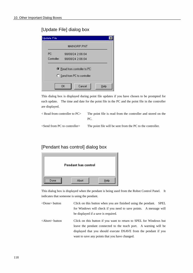
10. Other Important Dialog Boxes
118
[Update File] dialog box
This dialog box is displayed during point file updates if you have chosen to be prompted for each update. The time and date for the point file in the PC and the point file in the controller are displayed.
< Read from controller to PC> The point file is read from the controller and stored on the PC.
<Send from PC to controller> The point file will be sent from the PC to the controller.
[Pendant has control] dialog box
This dialog box is displayed when the pendant is being used from the Robot Control Panel. It indicates that someone is using the pendant.
<Done> button Click on this button when you are finished using the pendant. SPEL for Windows will check if you need to save points. A message will be displayed if a save is required.
<Abort> button Click on this button if you want to return to SPEL for Windows but leave the pendant connected to the teach port. A warning will be displayed that you should execute DSAVE from the pendant if you want to save any points that you have changed.

10. Other Important Dialog Boxes
119
[Customize] dialog box
If you right-click on the tool bar and select the [Customize] item, this dialog box will be displayed. The [Customize] dialog box allows you to create an optional tool bar.
Descriptions of the buttons are as follows:
<New>
Click on this button to register a new tool bar.
<Rename>
Click on this button to change the name of the registered tool bar.
<Delete>
Click on this button to delete the registered tool bar.
<Reset>
Click on this button to reset the contents of the changed tool bar to the original one.
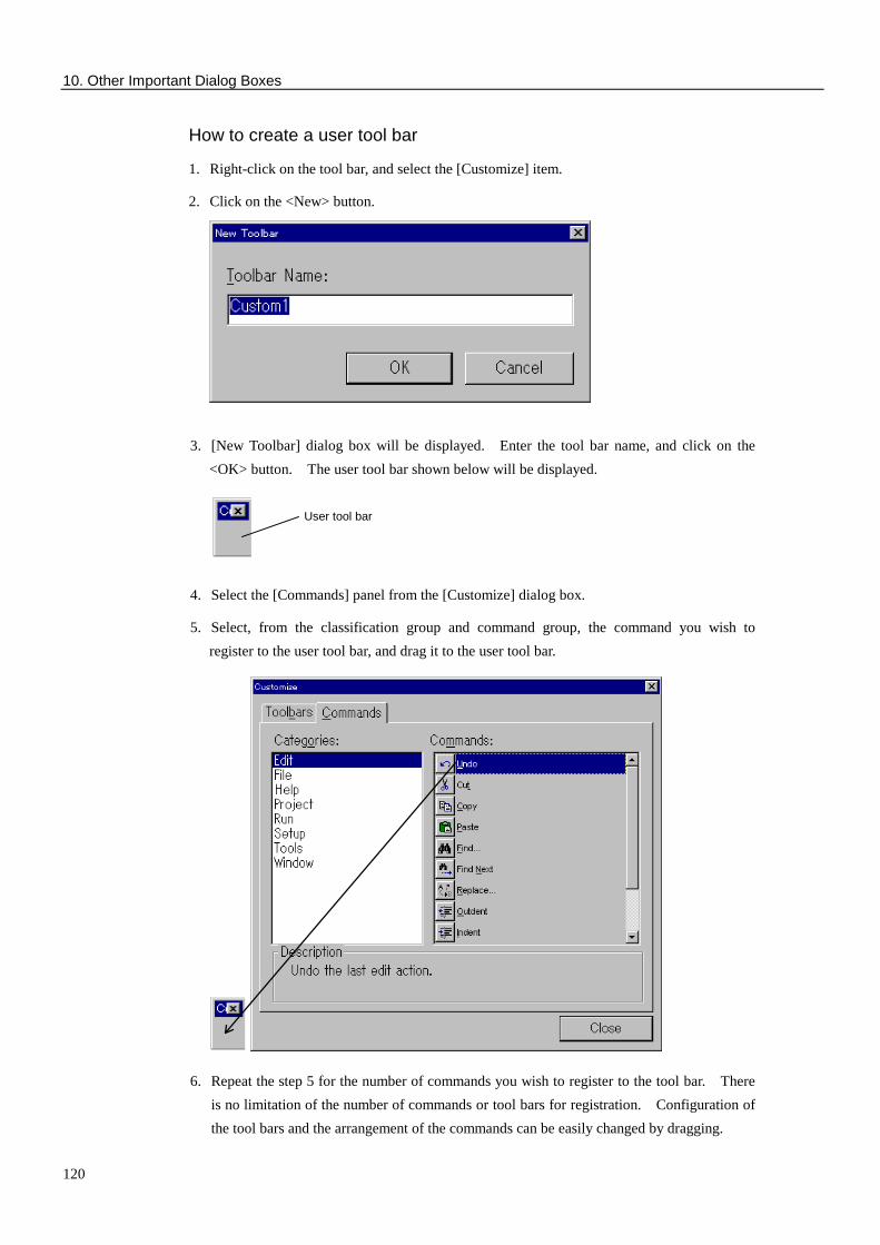
10. Other Important Dialog Boxes
120
How to create a user tool bar
1. Right-click on the tool bar, and select the [Customize] item.
2. Click on the <New> button.
3. [New Toolbar] dialog box will be displayed. Enter the tool bar name, and click on the <OK> button. The user tool bar shown below will be displayed.
4. Select the [Commands] panel from the [Customize] dialog box.
5. Select, from the classification group and command group, the command you wish to register to the user tool bar, and drag it to the user tool bar.
6. Repeat the step 5 for the number of commands you wish to register to the tool bar. There is no limitation of the number of commands or tool bars for registration. Configuration of the tool bars and the arrangement of the commands can be easily changed by dragging.
User tool bar

11. Maintenance Parts List
121
11. Maintenance Parts List
Part Name New Code Old Code Comments PC Cable (with ENABLE switch) R13ZA00210100 ZA002101
For connecting to an SRC-310A or SRC-320
PC Cable (with E.STOP switch) R13ZA00210200 ZA002102
For connecting to an SRC-300
Converting connector ( 25 - 25 pin ) R13ZA00210300 ZA002103
For connecting to an IBM-compatible 25-pin port
Converting connector ( 25 - 9 pin ) R13ZA00210400 ZA002104
For connecting to an IBM-compatible 9-pin port

11. Maintenance Parts List
122