Athena 2.0
49
Athena 2.0 General Purpose Robot Platform Model: N5M32-R2 2022/03/16.rev.1.0 Read through this user manual carefully before use. User Manual ○ Small- to medium-sized robot development ○ Highly adaptable and scalable ○ Powerful optional functions Learn more > Shanghai Slamtec Co., Ltd.
-
Upload
khangminh22 -
Category
Documents
-
view
0 -
download
0
Transcript of Athena 2.0

Athena 2.0 General Purpose Robot Platform
Model: N5M32-R2
20
22
/03
/16
.rev.1.0
Read
thro
ugh
this u
ser man
ual carefu
lly befo
re use.
User Manual ○ Small- to medium-sized robot
development ○ Highly adaptable and scalable ○ Powerful optional functions
Learn more >
Shanghai Slamtec Co., Ltd.

1 / 49
Table of Contents 1. PRODUCT OVERVIEW .......................................................................................... 3
1.1 INTRODUCTION .................................................................................................... 3
1.2 BASIC FUNCTIONS ................................................................................................ 3
1.3 EXTERIOR ............................................................................................................ 5
1.4 CHARGING DOCK ................................................................................................. 6
1.5 PRODUCT LIST ..................................................................................................... 6
2.PRODUCT PARAMETERS ...................................................................................... 7
3. INSTRUCTIONS OF HARDWARE .......................................................................... 10
3.1 WIRE INSTRUCTIONS .......................................................................................... 10
3.2 IMPORTANT INTERFACES OF DEVELOPING BOARD ON RK3399 ................................. 13
3.3 REFERENCE OF HARDWARE DESIGN ....................................................................... 13
4. REFERENCE OF STRUCTURE DESIGN .................................................................. 24
4.1 INSTALLING INTERFACE OF HOST COMPUTER .......................................................... 24
4.2 INSTRUCTION OF LOAD LIMIT ............................................................................... 24
4.3 RADAR CLEARANCE AREA .................................................................................... 25
4.4 DEEP CAMERA CLEARANCE AREA .......................................................................... 26
5. SETUP INSTRUCTIONS ........................................................................................ 27
5.1 OPENING .......................................................................................................... 27
5.2 PLACING CHARGING BASE ................................................................................... 27
5.3 POWER ON/OFF ............................................................................................... 28
5.4 CHARGING ........................................................................................................ 28
5.5 EMERGENCY STOP & BRAKE AND RESET .................................................................. 28
5.6. CONNECTION TO COMPUTER .............................................................................. 29
5.7 MAP BUILDING AND UPLOAD ............................................................................... 31
5.8 HOST COMPUTER COMPLETES STARTUP AND LOADING THE MAP .............................. 34
6. ADJUSTING TOOLS ............................................................................................. 36
6.1 ROBOSTUDIO .................................................................................................... 36
6.2 WEB MANAGEMENT BACKSTAGE ......................................................................... 36

2 / 49
7. DEVELOPER TOOLS ............................................................................................. 37
7.1 START USING .................................................................................................... 37
7.2 INTER-SYSTEM ADJUSTING FRAMEWORK ................................................................ 37
7.3 INSTRUCTIONS OF EACH SYSTEM ........................................................................... 37
7.4 DEMONSTRATIONS OF CODE ................................................................................ 38
7.5 DETAILS OF ROBOT API ...................................................................................... 39
8. INTRODUCTION AND USE OF ELEVATOR CONTROL .......................................... 42
8.1 INTRODUCTION .................................................................................................. 42
8.2 FEATURES ......................................................................................................... 42
9. SPECIAL NOTE .................................................................................................... 44
9.1 CHARGE POINT DEPLOYMENT ............................................................................... 44
9.2 RESTRICTED USAGE SCENARIOS ............................................................................. 44
9.3 FAULTS THAT CANNOT BE HANDLED TEMPORARILY ................................................... 45
9.4 NOTES ............................................................................................................. 45
10. MAINTENANCE ................................................................................................. 47
11. COMMON FAULTS AND TROUBLESHOOTING.................................................. 48
12. CERTIFICATE ..................................................................................................... 48

3 / 49
1. Product Overview
1.1 Introduction
Developed by Slamtec, Athena 2.0 is a scalable and low-cost robot platform capable of meeting the needs of small-sized robot application development in areas such as smart patrol robots, container transportation robots, food delivery robots, and more.
The built-in SLAMCUBE 2 autonomous localization and navigation system enables path-finding and localization and navigation features, making Athena 2.0 capable of performing a variety of tasks across different commercial environments.
Cross-floor Moving, Light Deployment
Athena 2.0 is equipped with the latest version of Slamtec Smart Elevator Control 4.0, which allows it to adapt to different brands of elevators.
Through the latest version of Slamtec RoboStudio 2.0, Athena 2.0 supports integration of maps of multiple floors in one click. This improves the mapping efficiency and streamlines the deployment, thus enabling light deployment and fast use.
Multi-Sensor Data Fusion
Athena 2.0 uses multi-sensor data fusion technology. Fitted with equipment such as lidar, magnetic sensors, depth cameras, and bumper sensors, Athena 2.0 can implement autonomous mapping, localization, and navigation by flexibly responding to complex and ever-changing operational environments.
1.2 Basic Functions
1.2.1 Compact and Flexible
Athena 2.0 can move flexibly in a small size, thus meeting the needs of flexible moving and deployment-free scenarios. Thanks to its high obstacle passing stability, Athena 2.0 can easily pass narrow aisles and ramps.
1.2.2 Cross-floor Delivery and Light Deployment
Athena 2.0 is equipped with the latest version of Slamtec Smart Elevator Control 4.0, which allows it to adapt to different brands of elevators. When combined with RoboStudio 2.0, it can effectively enable light deployment and fast use.
Smart Elevator Control 4.0 addresses the challenges of bad weather, as well as unstable air pressure and communication in high-rise buildings. It provides accurate detection of elevator statuses along with call-control functionality. For hotel/restaurant delivery robots, it provides efficient and reliable solutions that help them autonomously navigate elevators in cross-floor scenarios.
1.2.3 Autonomous Mapping, Localization and Navigation
Athena 2.0 is built with the latest version of Slamtec SLAMCUBE 2 autonomous localization and navigation system which is more stable and can accommodate more interfaces. The

4 / 49
structural design integrated three boxes into one, saving more space for chassis layout. With the path-finding, autonomous mapping and localization and navigation features, it helps robots figure out where they are, where they should go, and the best way to get there. It enables the robots to automatically find paths, locate, and move as needed without human assistance. In addition, Athena 2.0 supports multi-route patrol mode.
1.2.4 Rich Port Options and High Scalability
Athena 2.0 owns a completely open hardware and software platform and supports extended hardware. The rich port options eliminate the restrictions in development platform and programming language, which makes Athena 2.0 universal for all types of host computer and support development of business logic applications through SLAMWARE SDK.
1.2.5 360° Protection and Smart Obstacle Avoidance
Athena 2.0 is fitted with equipment such as lidar, magnetic sensors, depth cameras, and bumper sensors, and adopts the multi-sensor fusion technology. It provides rapid and accurate identification of surrounding active environments, enabling smart obstacle avoidance and greatly reducing the chances of safety incidents. It also has fall-resistant and collision-resistant protection and emergency stop features, making the food delivery process fully protected, secure, and reliable.
1.2.6 Autonomous Recharging
The autonomous recharging feature ensures that Athena 2.0 will have enough power to complete the assigned tasks. Athena 2.0 will return automatically to its charging station when its remaining power falls below the set limits or when its tasks are completed.
1.2.7 Multi-robot Scheduling & Collaboration
In scenarios such as large hotels, office buildings, and malls, multiple robots will avoid each other according to the task priority when they meet. The collaboration of multiple robots can further improve the delivery and guide efficiency.
Athena 2.0 supports local area network (LAN) and cloud platform collaborative operations, along with the dynamic adjustment of both speed and delivery routes in accordance with the environment to realize efficient, safe, and reliable multi-point delivery.

5 / 49
1.3 Exterior

6 / 49
1.4 Charging Dock
Charging dock diagram
1.5 Product List
Name Quantity Notes Athena 2.0 body 1 Athena 2.0 chassis body
Charging dock 1 Select environment for deployment before use.

7 / 49
2.Product Parameters Name Athena 2.0 chassis
Core feature SLAMCUBE 2 localization and navigation
Mass and volume
Length x width 460*428 mm, rotation diameter
551 mm
Height 232mm (excludes controller)
Weight 22 kg Rated load 40 kg
Max load (parallel cement
pavement) 60kg
Sensor performance parameters
Lidar sensor Max scan radius (90% surface reflective rate)
30 m (TOF S2 radar)
Depth camera sensor
Quantity 1 for standard configuration (2
can be customized) Detection range 0.4–2 m
Field of View (FOV) H: 58.4° V: 45.5° Physical
magnetic sensor
Quantity 2 units
Max detection range 3.5 cm
Bumper Quantity 2 units
Trigger method Physical collision
Mapping performance Map resolution 5 cm
Max mapping area 500m×500m
Motion parameters
Max move speed 1.0 m/s (1.2 m/s can be
customized)
Max cross slope
10° Ramp: Max slope angle of chassis:
10°; Slope =18%*Ramp; The height of the full-machine mass center is within 18 cm, and the
safety ramp within 10°. (A 100% slope means a 45° ramp, whose height difference for 100 m
is 100 m.)
Passing obstacle height 2 cm
Passing obstacle width 4 cm Min pass range 55 cm
Motor Wheelset 2x 6.5-inch in-wheel motor 4x 2.5-inch omni-directional
wheel User port Hardware port Ethernet 1x RJ45 Gigabit Ethernet port

8 / 49
Power connector DC 24V 9.5A
DC 12V 2A Wi-Fi 2.4 GHz
HDMI 1x HDMI
Audio
1x 3.5mm headset socket
1x LINE_MIC audio jack (Co-lay with headset socket)
1x Dual-channel 5w/8Ω amplifier jack
Type-C Standard USB 3.0 Type-C port
Software API SLAMWARE™
HTTP API, supports different development languages and
platforms, such as Windows, iOS, Android, and Linux
Battery and capacity
Capacity specifications 16 AH (standard)
Battery scalable to 90 AH
No-load operating time
19h (no load)
Full- load operating time
8h(full load)
Charging time 3-4 h (standard charging station) Battery life 500 charges
Power consumption
Power dissipation in standby time
17W (no load)
Full-load rated power consumption
(full load weight: 40kg) 40W (moving)
Max power consumption with
external load 228W
Rated output 24V 1.5A Noise Operating noise ≤ 60 db
Operating environment
Operating temperature
0℃–40℃
Transport and storage temperature
-25℃ to +55℃
Operating humidity 30%–70%RH (No condensation) Applicable altitude ≤ 2000 m

9 / 49
Charging station
Size 360 mm*150 mm*320 mm (W*D*H)
Color White
Rated input 100-240V 50/60 Hz 3A Max
Rated output DC 25.5V 6A

10 / 49
3. Instructions Of Hardware
3.1 Wire Instructions
Interfaces Picture Index Function Note
Power ON/OFF
-- Power switch of the entire system. Short press until the indicator light turns on power-on, long press until the indicator light turns off power-off.
--
Shut Down
-- Effectively control Athena2.0 in an emergency. After pressing, Athena2.0 will immediately shut down.
It is a switch that must be designed according to rigid regulations. If the switch is not designed, Athena2.0 will refuse to run.
Brake
-- When robot is energized, press this switch to release the brake and you can push the robot freely; press it once again to brake, and the robot will not be able to push it freely.
Invalid if the robot is not turned on
24V Power
Rated Voltage 24V
Maximum current 9.5A
Maximum output power is 200W, can be used to supply power to external devices
No overload
12V RK3399 Power Supply Wire
Rated Voltage 12V
Maximum Current 20A
Cube2 supplies power to the RK3399 development board.

11 / 49
Depth Camera Interface
USB3.0 Connected to the RK3399 development via USB3.0 to obtain information.
Need to pay attention to the left and right sequence.
Docking Camera
USB2.0 Connected to the RK3399 development via USB3.0 to obtain information of code scanning camera.
Assist precise docking.
12V -DISP
Rated Voltage 12V
(See the figure below for the design drawings)
12V working power of Cube2 to provide the external display screen of human-computer interaction.
Maximum current 2A
USB-Type-C
USB3.0 Used for communication between 3399 and Cube2.
Connect to Hub3.0
Design drawing of 12V -DISP terminal

12 / 49

13 / 49
3.2 Important Interfaces of Developing Board on RK3399
3.3 Reference of Hardware Design
Notice:
(1) Before starting, please read the manual carefully to avoid product damage caused by misoperation;
(2)The working temperature of the main board is 0℃ to +40℃, 30%-70%RH, in order not to damage
the product due to excessive cold/heat or moisture;
Test Screen
USB Warning Light
User Button
WIFI Antenna
4G MODULE (ANTENNA INCLUDED)
SIM Card USB Port
User Signal Port
Chassis to be tested

14 / 49
(3) Do not make strong mechanical movement of this product, and operate this product before static
protection is done;
(4) Please turn off the power before installing any external cards or modules;
(5) Please ensure the external power supply is DC 12V to avoid damage to the main board;
3.3.1 Product Description
RK3399 Android system main board adopts Rockchip RK3399 main control solution. The specification of
the main board is a standard 3.5-inch structure with a size of 146*102mm.
The main board processing core RK3399 is based on the dual Cortex-A72+four Cortex-A53 core CPU
structure. It uses the powerful Mali-T864 GPU graphics display core, supports VP9, H.265/H264 hardware
decoding, and 4K ultra high-definition output.
Onboard 4GB DDR3 memory and 32GB storage.
The display interfaces are: 1*HDMI, 1*eDP/LVDS, supporting dual-screen display, which can meet the
needs of flexible and diverse point-screen applications.
The board has a 3.5mm headset socket and a dual-channel 5W power amplifier speaker interface,
which can meet the needs of audio applications.
The main board integrates a gigabit network port, and also integrates a WIFI/Bluetooth module to
support various network access methods.
The onboard Mini-PCIe expansion slot supports 4G network card module expansion.
The main board has 5 USB ports and 1 Type-C slot, 2 serial slots, and 1 set of 8 GPIO pins. In addition,
the main board has a rich function expansion pin interface.
The main board uses a single 12V DC adapter for power supply.
Characteristics of Main Board:
★Based on Rockchip RK3399 ARM processor solution;
★Display interfaces: LVDS, eDP and HDMI;
★Hardware decoding H.265 high-definition video, support 4K ultra high-definition output;
★Rich functions, onboard 5*USB/2*COM/8*GPIO/1*IR infrared;

15 / 49
6-1 RK3399 Main board basic application diagram
3.3.2 Product specifications
(1)Hardware Specification Sheet
Processor Rockchip RK3399 ①
RAM 4GB DDR3
Display
1*eDP 1*LVDS output revolution maximum supports 4096x2160 ② 1*HDMI output supports 480p/480i/576p/576i/720p/1080p/1080i/4k
Internet 1*RJ45 Gigabit Ethernet 1*WIFI+Bluetooth ③
Audio
1*3.5mm headset socket
1*LINE_MIC audio pin(with headset socket Co-lay)
1*Dual-channel 5w/8Ω power amplifier speaker pin
Storage 32GB eMMC
COM 2* serial port ④
Others
4*USB2.0、1*USB3.0、1*USB3.0 Type-C OTG;
1* standard Mini-PCIE slot,for 4G module
1*TF card extension ⑤ 8 GPIO pin 1*IR infrared extension pin 1*I2C touch screen extension pin

16 / 49
2 A/D conversion pin 2*MIPI-CSI2 camera expansion port 1*G-Sensor gravity sensor
Power connector DC2.5*5.5 socket/PH2.0-4pin,12V DC input
Main board specifications
146*102*22mm, green
Operating system Android 7.1
Working environment Temperature:0~+40℃
Humidity: 30~70%RH
Remark:
①RK3399 is dual-core Cortex-A72 (the highest frequency is 1.8GHz) + 4-core Cortex-A53 (the highest
frequency is 1.4GHz);
②The eDP interface and the LVDS interface share the backlight and control signals, and cannot be
connected to the screen at the same time, only one of the two can be selected;
③WIFI specifications:802.1b/n/g @ 2.4GHz; Bluetooth specifications:Bluetooth 4.0;
④COM1 is the Debug interface and supports TTL/RS232, COM2 can communicate with the onboard
MCU, and can also be used as an external RS232/RS485 interface;
⑤TF card supports maximum expansion to 128GB.
(2)Size of main board
Unit: mm

17 / 49
3.3.3 Introduction of Interfaces
(1)Front view of main board
(2)Front IO diagram of the main board
(3)IO diagram behind the main board
(4)Back view of main board

18 / 49
Caution:The identification method of the first pin on the main board is: 1 has a white and bold
silkscreen; 2 the pins seen on the back of the main board are square holes.
3.3.4 Definition of pin function
(1)Pin Interface Distribution

19 / 49
(2)Description of silkscreens
Silkscreen Description DC_IN +12V DC input interface (φ2.5mm base)
PWRIN PH2.0-4PIN power input terminal LINE_MIC PH2.0-5P LINE-OUT&MIC-IN audio extension socket
UBOOT1 Uboot flash mode button[1]
SPK1 4-PIN PH2.0 amplifier speaker pin(5W/8Ω)
HP_MIC 3.5mm headset socket HDMI Standard HDMI HD digital display interface
TYPEC Standard USB3.0 Type-C interface[2]
USB1 Standard USB3.0 Type-A single layer interface USB2 Standard USB2.0 Type-A single layer interface
USB3 Standard USB3.0 Type-A single layer interface RJ45 Gigabit RJ45 network interface
SIM SIM card slot SD TF expanded card slot
JCOM1 PH2.0-4PIN COM1 RS232 mode pin
TTL_DBUG PH2.0-4PIN COM1 TTL battery mode pin(DEBUG serial port)
JCOM2 4PIN-PH2.0 RS232/485 serial port 2 sockets DEBUG PH2.0-4PIN onboard MCU module debugging interface
JC2 COM1 RS232/TTL mode setting jumper [3]
JC3 COM1 RS232/TTL mode setting jumper [3] JC4 COM2 internal onboard MCU/external JCOM2 setting jumper [4]
JC5 COM2 internal onboard MCU/external JCOM2 setting jumper [4] JIR DuPont 2.0-3pin infrared receiver extension pin
ANT WIFI/Bluetooth IPEX antenna interface
BAT RTC clock 3.3V battery plug JLV1 LVDS/eDP screen voltage(3.3/5/+12V)jumper selection
CAM_FLASH Camera flashlight interface
F-KEY Function key pin [5]
MINI-PCIE Mini-PCIe module slot CMR_MIPI0 MIPI-CSI2 camera interface 1
CMR_MIPI1 MIPI-CSI2 camera interface 2 WLED1 mini-PCIe expansion module signal light
JUSB1 4PIN-PH2.0 USB2.0 extension pin 1
JUSB2 4PIN-PH2.0 USB2.0 extension pin 2 JUSB3 4PIN-PH2.0 USB2.0 extension pin 3(and USB1 Co-lay)
S-KEY 4PIN-PH2.0 system power on/off, reset pin
PWRLED Power indicator pin [6]
JEDP eDP HD digital display interface [7]

20 / 49
AD 2 way A/D conversion pin
I2C I2C pin IVCN LVDS/eDP backlight inverter control interface
LVDS Dual channel 24-bit LVDS interface GP 10PIN-5.08mm 8 reserved programmable control input and output
plug-in terminals SYS_FAN System cooling fan power supply pin
Remark:
[1] After the main board is powered on, press and hold the Uboot button to enter Uboot mode to
upgrade the system;
[2] Type-C interface only supports Slave mode, connect to computer for firmware upgrade;
[3] JC2 and JC3 jointly determine the COM1 signal connection:
Mode RS232(JCOM3 pin) TTL(TTL_DEBUG pin)
JC2&JC3 1-2P short interface 2-3 short interface
[4] JC4 and JC5 jointly determine the COM2 signal connection:
Mode RS232(JCOM2 pin) MCU(485A base)
JC4&JC5 1-2P short interface 2-3 short interface
[5] The extension pin contains function key signals such as volume up, volume down, home, back, and
OEM customization;
[6] Preset power indicates two-color lamp extension pin;
[7] The JEDP interface and the LVDS interface share the backlight control pins IVCN and JLV.
(3)Definition of Interface pin and jumper selection
JP/CN pin# Signal pin# Signal Remark
LINE_MIC
1 MIC_IN+
2 MIC_IN-
3 GND
4 LINEOUT_R
5 LINEOUT_L
JP/CN pin# Signal pin# Signal Remark
SPK
1 SPK_L-
2 SPK_L+
3 SPK_R-
4 SPK_R+
JP/CN pin# Signal pin# Signal Remark
PWR_IN
1 12V
2 12V
3 GND
4 GND

21 / 49
JP/CN pin# Signal pin# Signal Remark
SYS_FAN
1 GND
2 +5V
3 FAN_INT
4 NC
JP/CN pin# Signal pin# Signal Remark
JIR
1 +5V
2 GND
3 IR
JP/CN pin# Signal pin# Signal Remark
S-KEY
1 PWR_ON
2 GND
3 RSET
4 GND
JP/CN pin# Signal pin# Signal Remark
F-KEY
1 VOL+ 2 GND
co-lay 1st PIN and upgrade button co-lay
3 VOL- 4 GND
5 HOME_KEY 6 GND
7 BACK_KEY 8 GND
9 OEM_KEY 10 GND
JP/CN pin# Signal pin# Signal Remark
PWRLED
1 +3.3V
2 GND
3 LED_A
4 LED_B
Main board and jumper definition (continued 1)
JP/CN pin# Signal pin# Signal Remark
JCOM1
1 RS232_TX
2 RS232_RX
3 GND
4 +5V
JP/CN pin# Signal pin# Signal Remark
JCOM2
1 RS232_TX/485+
2 RS232_RX/485-
3 GND
4 +5V
JP/CN pin# Signal pin# Signal Remark
GP
1 5V(NC) 2
3 GPIO1 4 GPIO2
5 GPIO3 6 GPIO4
7 GPIO5 8 GPIO6
9 GPIO7 10 GPIO8
11 GND 12 GND
JP/CN pin# Signal pin# Signal Remark
I2C
1 +3.3V
2 GND
3 TP_SDA
4 TP_SCL

22 / 49
5 TP_INT
6 TP_RSET
JP/CN pin# Signal pin# Signal Remark
JUSB1 JUSB2 JUSB3
1 +5V
2 DT-
3 DT+
4 GND
Main board and jumper definition (continued 2)
JP/CN pin# Signal pin# Signal Remark
IVCN
1 +12V
2 +12V
3 BKLT_ON
4 BKLT_PWM
5 GND
6 GND
JP/CN pin# Signal pin# Signal Remark
LVDS
1 VCC 2 VCC
3 VCC 4
5 GND 6 GND
7 TXA0- 8 TXA0+
9 TXA1- 10 TXA1+
11 TXA2- 12 TXA2+
13 GND 14 GND
15 TXA_CLK- 16 TXA_CLK+
17 TXA3- 18 TXA3+
19 TXB0- 20 TXB0+
21 TXB1- 22 TXB1+
23 TXB2- 24 TXB2+
25 GND 26 GND
27 TXB_CLK- 28 TXB_CLK+
29 TXB3- 30 TXB3+
JP/CN pin# Signal pin# Signal Remark
JLV1
1 +3.3V 2 LVDS_PV 1-2:
choose+3.3V;
3-4:
choose+5V;
5-6:
choose+12V;
3 +5V 4 LVDS_PV
5 +12V 6 LVDS_PV
JP/CN pin# Signal pin# Signal Remark
JEDP
1 VCC 2 VCC
3 HPD 4 GND
5 EDP_AUX+ 6 EDP_AUX-
7 GND 8 GND
9 EDP_TX0+ 10 EDP_TX1+
11 EDP_TX0- 12 EDP_TX1-

23 / 49
13 GND 14 GND
15 EDP_TX2+ 16 EDP_TX3+
17 EDP_TX2 18 EDP_TX3-
19 GND 20 GND
Main board and jumper definition (continued 3)
JP/CN pin# Signal pin# Signal Remark
AD
1 +3.3V
2 GND
3 AD1
4 AD2
JP/CN pin# Signal pin# Signal Remark
WLED 1 +3.3V
2 WLAN_LED-
JP/CN pin# Signal pin# Signal Remark
CAM_FLASH
1 +12V
2 GND
3 Flash_ON
4 FLASH_PWM
JP/CN pin# Signal pin# Signal Remark
CMR_MIPI0 CMR_MIPI1
1 AGND
2 +2.8V
3 +1.8V
4 +1.5V
5 GND
6 CMR_CLK
7 GND
8 MIPI_RX_CLK+
9 MIPI_RX_CLK-
10 GND
11 MIPI_RX_D2+
12 MIPI_RX_D2-
13 +2.8V
14 MIPI_RST0
15 CIF_PDN1
16 I2C_SDA_CAM
17 I2C_SCL_CAM
18 GND
19 MIPI_RX_D3+
20 MIPI_RX_D3-
21 MIPI_RX_D0+
22 MIPI_RX_D0-
23 MIPI_RX_1+
24 MIPI_RX_D1-

24 / 49
4. Reference of Structure Design
4.1 Installing Interface of Host Computer
As shown in the figure above, there are a total of 8 M3 threaded holes for the installation and fixation
of the host computer.
It is recommended to use M3 screws with spring washer and blue anti-loosening glue.
4.2 Instruction of Load Limit

25 / 49
(1) Max load of host computer is 60 kg,Rated load is about 40kg..
(2) * It is recommended that the center of gravity of the whole machine is not higher than 300mm
from the ground during installation.
i. *The center of gravity of chassis is the one which Slamtec provides, the height is 82 mm;
ii. The center of gravity of the whole machine is the overall center of gravity of the chassis plus the
robot;
iii. If the center of gravity of the whole machine exceeds 300mm, the slope-climbing and obstacle-
crossing performance may be reduced.
4.3 Radar Clearance Area

26 / 49
There is a radar between the chassis body and the host computer, which requires a certain clearance
area to avoid being shielded or interfered;
The boundary of the host computer cannot exceed the lower boundary line of the host computer as
shown in the figure.
4.4 Deep Camera Clearance Area
There is a deep camera on the chassis, which requires a certain clearance area to avoid being shielded
or interfered;
The host computer cannot exceed the clearance area as shown in the figure. Due to the angled layout
of the dual cameras, the superimposed clearance area is larger than a single FOV.

27 / 49
5. Setup Instructions
5.1 Opening
1. After receiving the Athena2.0 machine, please check whether the packing box is intact as shown in
the left picture, and whether the box on the right side of the Athena2.0 sample of the outer box is checked.
After confirming that the packing is complete and the box contains Athena2.0, use packing pliers to cut the
packing tape, remove all packing straps and paper corners, it should be shown as on the right picture.
5-1 Athena2.0 unpacking
5.2 Placing Charging Base
Athena2.0 can be charged by returning to the charging base automatically, so the position of the
charging base will affect the automatic return charging function of Athena2.0. When Athena2.0 returns to
the charging station, it will generate propelling force. Therefore, it is best to place the charging stand with its
back against the wall. The wall must meet the following conditions:
a. The charging base must be attached to the wall, without no obstacle in the middle, try to avoid the
wall with skirting, etc.
b. The wall material cannot be high-permeability materials, such as mirror or glass
c. The wall width needs to be at least three times wider than the width of the charging stand
d. The wall must be a straight wall, not a curved wall
The charging base needs to be connected to a 220V power supply. The length of the external power
cord of the charging base is 1.5m. Therefore, it is necessary to ensure that there is a 220 V interface within
1.5m of the wall against which the charging base rests. The ground wiring harness is messy causing
unnecessary trouble).
The ground in front of the charging base must meet the following conditions:

28 / 49
a. Open, with no obstacles within a radius of 2m in front of the charging stand as the center of the
circle
b. Plane, no slope
c. The ground cannot be covered with soft carpet that causes Athena2.0 to sink more than 2cm
To ensure that Athena2.0 automatically returns to the charging function, it is necessary to ensure that
Athena2.0 always starts from the charging base.
Note: If you want to change the position of the charging stand, you need to set the corresponding
setting according to the position you need when loading the map. For detailed operations, please see the
SDK corresponding interface operation document.
5.3 Power ON/OFF
Power on: if the machine is not in the position of charging pile, long press the power switch until the
power switch indicator lights up and release it. The machine system enters the startup process, the front
light strip lights up, and the wheel hub is in the brake state, indicating that the startup is completed.
If the machine is in the position of charging pile, short press the power switch until the power switch
indicator lights up and then release it. The machine system enters the startup process, the front light strip
lights up, and the wheel hub is in the brake state, indicating that the startup is completed.
Power off: long press the power switch until indicator light goes out, then release it, the machine
enters the shutdown process, the light strip on the front of the machine goes out, and the machine can be
pushed arbitrarily, indicating that the shutdown is completed.
5.4 Charging
As shown in the figure below, align the charging piece of the machine with the charging electrode of
the charging pile. After waiting for 10 seconds, the front light strip of the robot lights up, the wheel hub
enters the braking state, and the breathing light of the charging pile flashes, indicating that charging has
started.
5-2 Athena2.0 charging
5.5 Emergency stop & brake and reset
Charging electrode
Charging board

29 / 49
(1)Emergency stop button
Press the emergency stop button, the Athena2.0 machine will stop immediately, stop and no longer
respond to any motion control commands, and the manual push is blocked.
Release the "emergency stop button " and the machine can return to normal working conditions.
(2) Brake button
Press the "brake button", the Athena2.0 machine will stop immediately, stop and no longer respond to
any motion control commands. The machine can be pushed manually, such as pushing it to the charging pile.
Release the "brake button", the machine can return to normal working condition, and the manual push
is blocked.
5.6. Connection to Computer
【Step 1】The hotspot of the computer connected to the chassis
Athena 2.0's hotspot is auto-started by default,the hotspot format is: SLAMWARE-XXXXXX
Hot spot identification method: query the last six digits of the SSID in the chassis label.
5-3 Chassis label SSID
For example, if the label SSID: Robot-D70CED, the hot spot of this Chassis is SLAMWARE-D70CED
【Step 2】Download and install Slamtec RoboStudio from the official website of Silan
5-4 Official Slamtec RoboStudio

30 / 49
If you downloaded slamtec robostudio, After logging in to RS, click the "Robot" option and manually connect the robot with the right mouse button.
5-5 Robo studio login screen
[step 3] if you downloaded slamtec robostudio, run "robostudio.exe", enter the interface of slamtec robostudio, enter the IP address and port, click "connect", and RS login succeeds.
5-6 Robo studio interface
Note : The method of IP address query is to press the shortcut key, Windows+R, and enter the code ipconfig. Copy the IP of the default gateway and paste it into the IP address box of Slamtec RoboStudio. Click Connect to enter Slamtec RoboStudio.

31 / 49
5-7 Method of obtaining an IP address
5.7 Map Building and Upload
Download and install the robot graphical control management tool Robot Studio from our official
website http://www.slamtec.com/cn/RoboStudio to adjust and use Athena2.0, sign up account and log in. In
the menu-toolbar area, click "File-Robot" in turn, and a docking page named Robot will appear on the left
side of the workspace, as shown in the figure below. The user connects/disconnects the robot through this
page.
5-8 Rob Studio Robot page
Right-click the blank space of the robot list, click "Manually connect robots" in the pop-up menu, and
the connect robot dialog box will pop up (as shown below). Enter the IP address and port number of the

32 / 49
Athena2.0 robot above and click the connect button to connect (This connection method is suitable for
machines that have been assigned an IP address through the Web portal management backstage). When
the computer has been connected to the SSID of the aforementioned Athena2.0 robot through a network
adapter (SSID can be viewed on the label of the machine), enter the IP address 192.168.11.1 by default
(note that your wireless network adapter IP address should be set to automatically obtain it using DHCP).
5-9 Rob Studio Robot connecting page
When finishing connecting, the work area will display the robot, map information, and status
information. In the robot page, you will find that the name of the connected device turns green, and the
status is "Connected", as shown in the figure below.
5-10 Rob Studio Robot connecting page
Left click the spot inside the map-building area, let Athena2.0 build the map. When finishing, please use
the virtual wall function to isolate the places that need to be isolated. Then click "File-Map Editor" in turn,
choose to save the file or upload to the firmware to save the map.
IP Address
PORT

33 / 49
5-11 RoboStudio Robot Map Editor Window
There is a difference between the functions of restricted areas and virtual walls.
Restricted Area: When the Athena 2.0 is accidentally pushed into the restricted area, the Athena 2.0 machine can be automatically freed from the restricted area by giving a random point in RoboStudio.
Virtual Wall: When a human accidentally pushes Athena 2.0 into the virtual wall, the Athena 2.0 machine cannot automatically get out of the virtual wall and needs to be pushed out by a human at a random point in RoboStudio.
The Forbidden Area management function relies on the Slamware Forbidden Area plug-in. Slamware Forbidden Area is a public plug-in, the computer is connected to the Internet, after logging in RoboStudio, click Tools -> Plug-ins -> Shop -> All ->Slamware Forbidden Area-> Get -> Download -> Restart RoboStudio.
Public plug-in links:
https://wiki.slamtec.com/pages/viewpage.action?pageId=56164379)

34 / 49
5-12 RoboStudio Public plug-in
After the plug-in runs normally, connect to the machine, you can see the "Ban zone" toolbar in the menu bar.
5-13 RoboStudio No-go areas
5.8 Host Computer Completes Startup and Loading The Map
Below is a reference example of how to use the SDK to complete the startup and loading of a specific
map on the host computer.
1. /* 2. * upload map file to Athena2.0 3. */
4. #include <iostream>
5. #include <rpos\robot_platforms\slamware_core_platform.h>
6. #include <rpos\robot_platforms\objects\composite_map_reader.h>
7. #include <rpos\core\pose.h>
9. using namespace std;
11. int main()
12. {
13. try
14. {
15. string map_path = ".\\map.stcm"; //the path of map
16. string Athena2.0_ip = "192.168.11.1"; //the ip of Athena2.0
17. int Athena2.0_port = 1445; //the port of Athena2.0 ,default is 1445
19. rpos::robot_platforms::SlamwareCorePlatform Athena2.0 =
20. rpos::robot_platforms::SlamwareCorePlatform::connect(Athena2.0_ip, Athena2.0_port);
21. //connect to the Athena2.0
8.
10.
18.

35 / 49
22. rpos::robot_platforms::objects::CompositeMapReader cmapreader;
23. //map reader
24. rpos::core::Pose Athena2.0_pose = rpos::core::Pose(rpos::core::Location(0, 0, 0));
25. //the Athena2.0 pose in map(Athena2.0_pose should be the Athena2.0's real pose in new map)
26. //using Athena2.0.getpose() to get the old Athena2.0 pose
27. auto map = cmapreader.loadFile(map_path);
28. //load map
29. Athena2.0.setCompositeMap(*map, Athena2.0_pose);
30. //set compositemap
31. rpos::core::Pose home_pose = rpos::core::Pose(rpos::core::Location(0, 0, 0));
32. //the home pose in map(home_pose should be the home's real pose in new map)
33. //using Athena2.0.gethomepose() to get the old home pose
34. Athena2.0.setHomePose(home_pose);
35. //set home pose
36. }
37. catch (rpos::robot_platforms::ConnectionFailException &e)
38. {
39. cout << "connect failed on " << e.what() << endl;
40. }
41. catch (rpos::system::detail::ExceptionBase &e)
42. {
43. cout << "failed on " << e.what() << endl;
44. }
45.
46. return 0; 47. }
Further motion deployment details, please see the SDK instruction document

36 / 49
6. Adjusting Tools
6.1 RoboStudio
RoboStudio graphical tools are used to adjust and use Athena2.0, please download and install it from
our official website: http://www.slamtec.com/cn/RoboStudio, and coming with manual to introduce those
features.
6.2 Web Management Backstage
In the process of developing, adjusting and using SLAMWARE equipment, various operations can be
performed on the equipment through the web management backstage, such as viewing basic information,
updating the version, configuring WiFi,etc. (Default username: admin, default password: admin111)
Currently, web management backstage supports following functions:
1. Check basic information of the device
2. Restart the module
3. Update the firmware
Slamtec will regularly provide Athena2.0 firmware updates and upgrades. You can easily upgrade the
firmware for Athena2.0 through the management backstage. Please obtain the latest firmware from sales or
technical support personnel. The update process will last 5-10 minutes. The buzzer of Athena2.0 will
continue to sound during the update, and Athena2.0 will automatically restart after the update. Before that,
please make sure that Athena2.0 has sufficient power.
4. Configuring WIFI
5. Start the SLAMWARE Core diagnostic mode
6. Modify the administrator password
More details on usages please refer to:
https://wiki.slamtec.com/display/SD/SQ001+SLAMWARE+Web+Portal+Function+Overview

37 / 49
7. Developer Tools
7.1 Start Using
The Agent SDK of the Athena2.0 chassis is developed based on the C++ language to reduce user access
costs and improve the robustness of the SDK. At the same time, it has strong compatibility and supports
multiple languages such as Java, C++, C, and Kotlin. The following is a detailed introduction to the relevant
examples and usage guidelines of the Agent SDK call based on the Athena2.0 chassis.
7.2 Inter-system Adjusting Framework
Robot App controls the robot's positioning, movement, and return to piles through communication; at
the same time, Robot App sends instructions to the robot according to various business scenarios, and
Robot Agent will provide data interfaces, task operation interfaces, and business services to Robot App.
7-1 COMMUNICATION BETWEEN EACH SYSTEM OF ATHENA2.0
7.3 Instructions of Each System
7.3.1 Robot Agent
Robot Agent is a service program running on the Athena2.0 chassis, through which the cloud and the
elevator control terminal communicate with the elevator control equipment. Inside the Robot system, the
Robot Agent communicates with the Robot App, receives instructions from the Robot App to control the
Robot, and sends the Robot status at the same time.
The core function of Robot Agent is:
✓ Communicate with the Robot Cloud, Robot APP, send the Robot status and receive instructions
7.3.2 Elevator Agent

38 / 49
Elevator Agent is a service program running on the Linux system of the elevator control main control
box. The cloud and the robot end communicate with the elevator control equipment through it. Inside the
elevator control system, the Elevator Agent communicates with the Elevator Controller through UDP,
sending elevator control instructions and obtaining elevator status.
The core function of Elevator Agent is:
✓ Communicate with the Robot Cloud, Robot APP, send the elevator status and receive instructions
of elevator control
✓ Communicate with the Elevator Controller, receive the elevator status and send instructions of
elevator control
7.3.3 Robot Cloud
Robot Cloud is a set of services provided to realize remote management, scheduling, and control of
robots. It runs in the cloud and communicates with the robot at one end and the elevator control
equipment at the other end. Therefore, elevator control is part of the function. Robot Cloud communicates
with the Elevator Agent running on the main control box of the elevator control through the MQTT protocol.
Its core functions include:
✓ Send instructions, control the elevator to the designated floor
✓ Send instructions, control the elevator to open the door
✓ Send instructions, control the elevator to close the door
✓ Receive the up/down status of elevator
✓ Receive the current floor of the elevator
7.3.4 Robot App
Open-Source application – Restaurant Delivery App
The restaurant delivery app is a service program running on the robot. The application scene is a
restaurant. It draws a map and loads it to the robot's local area through RoboStudio graphical tools. It is a
universal application for human-computer interaction to achieve multi-point task delivery.
7.4 Demonstrations of Code
1. The following is an example of the Robot APP calling the Robot Agent interface to check the battery
status
GET http://127.0.0.1:1448/api/core/system/v1/power/status
The format of the returned data is application/json
DELIVERY PROCESS

39 / 49
2. The following is the Robot App calling the Robot Agent interface to make the robot move across
floors
POST http://127.0.0.1:1448/api/core/motion/v1/actions
The request message format is application/json
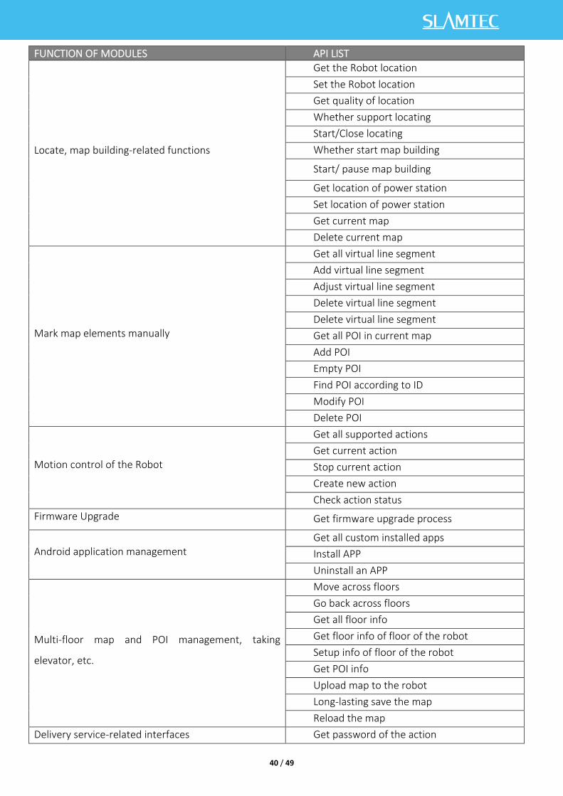
7.5 Details Of Robot API
40 / 49
FUNCTION OF MODULES API LIST
Locate, map building-related functions
Get the Robot location
Set the Robot location
Get quality of location
Whether support locating
Start/Close locating
Whether start map building
Start/ pause map building
Get location of power station
Set location of power station
Get current map
Delete current map
Mark map elements manually
Get all virtual line segment
Add virtual line segment
Adjust virtual line segment
Delete virtual line segment
Delete virtual line segment
Get all POI in current map
Add POI
Empty POI
Find POI according to ID
Modify POI
Delete POI
Motion control of the Robot
Get all supported actions
Get current action
Stop current action
Create new action
Check action status
Firmware Upgrade Get firmware upgrade process
Android application management Get all custom installed apps
Install APP
Uninstall an APP
Multi-floor map and POI management, taking
elevator, etc.
Move across floors
Go back across floors
Get all floor info
Get floor info of floor of the robot
Setup info of floor of the robot
Get POI info
Upload map to the robot
Long-lasting save the map
Reload the map
Delivery service-related interfaces Get password of the action

41 / 49
Set password of the action
Get configuration info of the device
Get setup info related to the delivery
Check task info
Create task
Cancel all task
Cancel some task
Get current mission status
Stop/ continue current mission
Start picking up items
End picking up items
Get info of objects
NOTE: delivery business please inform
marketing department
Restaurant delivery service-related interfaces
Get the current battery percentage
Get the health info of the device
Get POI info
Get password of the action
Make up new actions
Get current action
Terminate current action
Shut down or restart the robot
MORE DETAILS OF API: https://github.com/slamtec/Athena2.0SampleApp

42 / 49
8. Introduction And Use Of Elevator Control
8.1 Introduction
Intelligent elevator control, independently developed by Shanghai SLAMTEC CO., Ltd, can provide
accurate detection of elevator status, program control call elevators, control elevators, combined with
MercuryⅡ hotel robots, helping the robots to take and exit the elevators autonomously. Providing reliable
solutions to multi-floor operation scenarios. In addition to working with hotel robots, the product can be
used as an independent set of solutions. Through the API interface we provide, this product can also interact
with other smart devices or products to meet the different customization needs of customers. At the same
time, the product can also be seamlessly connected to the Athena2.0 chassis, to provide technical service
support for more specific needs in other scenarios.
8.2 Features
8.2.1 Intelligence Elevator Control
The core function of this product is to help robots and other intelligent devices to control the elevator,
such as calling the elevator, going to the designated floor, and controlling the elevator to open and close the
door. This function greatly improves the business scenario of robots and breaks the previous limitation that
robots can only work on the same floor.
8.2.2 Intelligence Status Detection
Through the built-in sensor and adaptive algorithm, this product can accurately detect the current floor,
up and down status of the elevator, real-time to the millisecond level, with an accuracy of more than 96%,
providing a very critical foundation so that the robot can enter and exit the elevator correctly and complete
the work.
8.2.3 Elevator Diversity Adaption
The main control box has developed a variety of optimized filtering algorithms, so that this product is
suitable for many different types of elevators, such as single-door elevators, double-door elevators, front
and rear door elevators, etc. As it covers as many scenes as possible, this product can be used in most
elevators at present. Users only need to simply calibrate and adjust through the APP provided after
installing the equipment.
8.2.4 Multi-Level Network Adaption
Considering the limitations of the elevator network, how to ensure data interconnection and program
interoperability is a very critical factor, and relatively it is also a difficult point. After continuous optimization
iterations, we finally found a way to solve this problem. This product provides 4G, WIFI, BLE and other
multi-level network communication methods to interact with robots and other smart devices to ensure the
reliability of the communication link.
8.2.5 OTA Remote Upgrade

43 / 49
Support OTA remote upgrade of software and firmware, and batch deployment. At the same time, it
provides support for VPN, which can remotely log in to the Linux system of this product for upgrades and
other operations. Through the OTA function, real-time updates, upgrades and optimization can be done.
8.2.6 Interface Support
The intelligent elevator control provides a consistent API interface to the outside world, supports
Bluetooth, MQTT, and HTTP communication protocols. Customers can control and interact with the elevator
by writing their own program code. At the same time, it supports secondary development to meet the
different customization needs of customers.
8.2.7 Swipe To Bypass
For some elevators that require a swipe card to ride, this product can also be easily supported. Just
install the equipment we specify when installing the device, and then turn on the swipe card to bypass it in
the APP. In this way, even if there is a card reader, it can be easily bypassed and freely enter and exit the
elevator.
8.2.8 Unified Management
The cloud platform provided by SLAMTEC can perform real-time monitoring of the status of all
deployed products, batch upgrades, and further data mining through online management, information
statistics, equipment monitoring, etc., to provide exclusive accurate data models for hotels or commercial
buildings, to guide them to improve their overall operational capabilities and service quality.
To know more about the detailed solution of elevator control, obtain it from the marketing department.
Elevator control user manual->>

44 / 49
9. Special Note
9.1 Charge point deployment
Precautions for the selection of charging pile location:
(1) The charging pile should be placed on the wall with a space of more than 0.35 meters on both sides
and more than 1 meter in front;
(2) The charging pile shall be close to the wall, and shall not be placed in the mirror wall, back hollowed
out and other areas, etc;
(3) The position of the charging pile must not be placed on soft ground such as carpet, otherwise it will
cause height difference and cannot be charged;
(4) The position of the charging pile in the scene needs to be marked to prevent incorrect recovery
after moving.
9.2 Restricted usage scenarios
Please avoid using Athena2.0 chassis in the following scenarios to avoid chassis failure or damage.
(1) Overrun/heavy transportation
Do not put in items that exceed the maximum weighing parameter value to avoid affecting the normal
use of Athena2.0. Please refer to the information in the product parameter table for the maximum load-
bearing parameter value.
(2) Sill height
Please ensure that there are no obstacles more than 20mm in front of Athena2.0, and the maximum
height of Athena2.0 over the sill is 20mm. During Athena2.0 driving, please try to avoid passing through
uneven ground or other environments with large height.
(3) Man -made impact
Do not forcefully push or hit the Athena2.0 body when Athena2.0 is in normal use.

45 / 49
(4) Temperature / humidity
Do not place Athena2.0 in places with high temperature, high humidity or water stains.
(5) Ground obstacles
Please ensure that the ground is clean and free of wireless obstacles and sundries.
(6) Outdoor
Do not use the machine outdoors.
(7) It is limited to safe use below 2000m above sea level.
9.3 Faults that cannot be handled temporarily
When the machine encounters a fault that cannot be handled temporarily, you can try the following
operations:
(1)Please press the brake button;
(2) Push the machine back to the charging pile;
(3) The machine can be forced to switch on and off in any state after power- on.
*Use only in emergency situations.
9.4 Notes
Notes for storage:
(1) Since the machine contains battery, it should be stored in a cool and dry environment;
(2)For long-term storage (more than 3 months), it is recommended to put it in a dry environment with
room temperature of 10-25 ℃ and no corrosive gas;
(3) Athena2.0 shall be charged every 6 months during long-term storage to ensure that the voltage of
each battery unit is in the range of 3.6v-3.9v.
Packing notes:
(1)The packaging material must have a certain degree of strength and toughness, and can withstand
slight vibration, extrusion, friction and collision during transportation;
(2)There should be padding around the package, which can play a good cushioning role;
Notes for transportation, loading and unloading:
(1)Please handle with care to prevent falling, collision, dragging and inversion;
(2)Stacking needs to be built firmly, compactly, stably and neatly;
Other notes:
(1)Do not treat Athena2.0 violently (such as kicking, pushing, pulling);
(2)Do not spill liquid on the machine;

46 / 49
(3)Do not use the automatic recharge function on the soft carpet with a subsidence of more than 2cm;
(4)It is recommended to start the equipment on the charging base;
(5)Do not change the inside of the machine without authorization;
(6)In environments with many high-transmittance materials, please use auxiliary protection functions,
such as virtual walls.

47 / 49
10. Maintenance
1. General maintenance
(1) Radar cleaning: When the machine is shut down and not working, check the surroundings of the
radar to ensure that there are no obstructions.
(2) Universal wheel cleaning: When the machine is shut down and not working, gently lift the chassis,
wipe the universal wheel with a soft dry cloth, and remove the surrounding foreign matters.
(3) Depth camera lens cleaning: Please wipe the lenses of the depth cameras with a soft dry cloth when
the machine is powered off.
(4) Cleaning the charging pile: Please wipe the charging pile and charging electrode with a soft dry cloth
when the power is off.
(5) Collision bar cleaning: Please wipe the collision bar with a soft dry cloth when the power is off, and
ensure that there are no wires, paper scraps and other foreign objects stuck on the anti-collision bar.
2. Maintenance cycle
For the maintenance of the main engine, it mainly includes depth camera lens inspection, collision bar
inspection, clearance inspection around the radar, foreign matter inspection around the driving wheel and
universal wheel, charging pile inspection, etc. The time interval of the maintenance cycle can be
appropriately adjusted according to the environment, frequency, intensity and temperature of the machine.
Athena2.0 maintenance schedule Time interval
NO Name Maintenance level Year Month Week
1 Depth camera lens Clean -- -- 1 time
2 Collision bar Clean -- -- 1 time
3 Around the radar clearance -- 1 time --
4 Universal wheel Clean -- -- 1 time
5 Driving wheel Clean -- -- 1 time
6 Charging pile Clean -- 1 time --
7 Machine body Overhaul 1 time -- --
10-1 Athena2.0 maintenance schedule

48 / 49
11. Common faults and troubleshooting
When an abnormality occurs during Athena2.0 operation, please refer to the following table or page
tips to solve the problem:
NO Fault prompt Solutions
1 Collision bar abnormal
Please check whether the collision bar is jammed, and tap the anti-collision bar several times to return the anti-collision bar to its position.
2 Athena2.0 battery low
Please press the brake release button and push the machine back to the charging point to charge.
3 The charging point cannot be charged
Please check whether the power cord plug of the charging point is inserted into the socket and whether the indicator light of the charging point is on normally.
4 Unable to power on
Please check whether the charging point is connected to the power supply. After the charging point and Athena2.0 are connected normally, if it cannot be solved, please contact the after-sales service department.
5
Athena2.0 cannot be charged on the pile
Please try again on the charging pile. If you cannot solve it, please contact after-sales service.
6 Unable to go back to the charging point
1. Please confirm whether the position of the charging point has been moved. If the position has been moved, please contact the after-sales department. 2. Please confirm whether there is a slope at the position of the charging point. If there is a slope, please contact the after-sales department. 3. Please push Athena2.0 back to the charging point and try to restart Athena2.0.
7 Unable to get in / out of the elevator
1. Please confirm whether there are obstacles in the elevator. 2. Please confirm the internet signal near the elevator. 3. Please push Athena2.0 back to the charging point and try to restart Athena2.0.
8 Universal wheels rotate intermittently
Please check whether there are any foreign objects such as threads, cards, etc. around the universal wheels and the driving wheels. If there are foreign objects, please clean them.
9 Machine can't walk
Please check whether the drive cable is connected normally. If it cannot be solved, please contact the after-sales service.
10 The light strip does not light up
Please check whether the connecting wire of the light strip is connected normally. If it cannot be solved, please contact the after-sales service.
12. Certificate
Company name: Shanghai Slamtec Co., Ltd
Company Address: Unit 01, 2nd Floor, Building E, Shengyin Building, No.666 Shengxia Road, China
(Shanghai) Pilot Free Trade Zone.
Contact information: (+86) 021 68581569