I-7530 Manual - FTP Directory Listing - ICP DAS
42
ACS-10V-MF User’s Manual (Ver.1.1, Mar./2017) ------------- 1 User’s Manual www.icpdas.com ACS-10V(P)-MF Access Control Reader
-
Upload
khangminh22 -
Category
Documents
-
view
1 -
download
0
Transcript of I-7530 Manual - FTP Directory Listing - ICP DAS

ACS-10V-MF User’s Manual (Ver.1.1, Mar./2017) ------------- 1
User’s Manual
www.icpdas.com
ACS-10V(P)-MF
Access Control Reader

ACS-10V-MF User’s Manual (Ver.1.1, Mar./2017) ------------- 2
Warranty
All products manufactured by ICP DAS are under warranty regarding
defective materials for a period of one year from the date of delivery to the
original purchaser.
Warning
ICP DAS assumes no liability for damages resulting from the use of
this product. ICP DAS reserves the right to change this manual at any time
without notice. The information furnished by ICP DAS is believed to be
accurate and reliable. However, no responsibility is assumed by ICP DAS
for its use, or for any infringements of patents or other rights of third
parties resulting from its use.
Copyright
Copyright 2016 by ICP DAS. All rights are reserved.
Trademark
The names used for identification only may be registered trademarks
of their respective companies.
Document Revision
Version Date Description of changes
1.0 2016/05/06 First Release Revision
1.1 2017/03/15 Add communication example

ACS-10V-MF User’s Manual (Ver.1.1, Mar./2017) ------------- 3
Table of Contents 1. Introduction ....................................................................................... 5
1.1 Features ............................................................................................. 6
1.2 Applications ........................................................................................ 6
1.3 Specifications ..................................................................................... 6
2. Hardware ........................................................................................... 8
2.1 Front Panel ........................................................................................ 8
2.1.1 LED Indicator ................................................................................... 8
2.2 Back Panel ......................................................................................... 9
2.3 Dimensions ....................................................................................... 11
2.4 Hardware Connections...................................................................... 11
2.4.1 Power and I/O wiring architecture ................................................... 11
2.4.2 I/O connection ................................................................................ 13
2.5 Jumper Settings ............................................................................... 13
2.5.1 Terminator Resistor Settings .......................................................... 13
2.5.2 Operation Mode Settings................................................................ 14
2.6 Firmware update method ................................................................. 14
3. Software ........................................................................................... 17
3.1 Installing the eSearch Utility ............................................................. 17
3.2 Using the eSearch Utility to Assign an IP Address ........................... 17
3.3 Web Configuration ........................................................................... 20
3.3.1 IP Address Configuration ................................................................ 21
3.3.2 Reader Configuration ..................................................................... 23
3.3.3 RTC Configuration .......................................................................... 25
3.3.4 Change Password Configuration .................................................... 25
3.4 Installation ........................................................................................ 26
4. Communication command Example .............................................. 31
4.1 Communication settings ................................................................... 31
4.2 Command List .................................................................................. 31
4.2.1 Add Card Number .......................................................................... 31
4.2.2 Delete Card Number ...................................................................... 32
4.2.3 Delete All Cards’ Number ............................................................... 33
4.2.4 Card Number Inquiry ...................................................................... 33
4.2.5 Add Password Number .................................................................. 34
4.2.6 Delete Password Number .............................................................. 35
4.2.7 Delete All Passwords’ Number ....................................................... 35
4.2.8 Inquire Access Record ................................................................... 36
4.2.9 Delete Access Record .................................................................... 37

ACS-10V-MF User’s Manual (Ver.1.1, Mar./2017) ------------- 4
4.2.10 Delete All Access Records ............................................................. 38
4.2.11 Configure System Time .................................................................. 38
4.2.12 Check Door Position....................................................................... 39
4.3 CRC Calculation (CCITT-16) ............................................................ 40

ACS-10V-MF User’s Manual (Ver.1.1, Mar./2017) ------------- 5
1. Introduction
Access Control systems are one of the most important infrastructures
for a safe, secure society. ACS-10V(P)-MF is an access control reader
that supports RFID induction of access control. It integrates three
functions of door access control, voice guidance and floor control all in
one, suitable for use in community door access and elevator control. ACS-
10V(P)-MF supports Ethernet and RS-485 communication interface and
provides anti-sabotage sensor and door position detection function which
can consolidate the security of access control systems and effectively
enhance the service quality of management.
The ACS-10VP-MF has integrated Power-over-Ethernet (PoE), it
allows power and data to be carried over a single Ethernet cable, so a
device can operate solely from the power it receives through the data
cable. This innovation allows greater flexibility in office design, higher
efficiency in systems design, and faster turnaround time in set-up and
implementation. The ACS-10VP-MF feature true IEEE 802.3af-compliant
(classification, Class 1) Power over Ethernet (PoE) using both Ethernet
pairs (Category 5 Ethernet cable).
When using ACS-10VP-MF module, you can choose ICP DAS “PoE”
Switch – “NS-205PSE” as the power source, NS-205PSE automatically
detects the connected devices whether they are PoE devices or not. This
mechanism ensures NS-205PSE to work with both PoE and non-PoE
devices coordinately at the same time.

ACS-10V-MF User’s Manual (Ver.1.1, Mar./2017) ------------- 6
1.1 Features Supports card type: Mifare
Built-in Voice message function
Supports Ethernet / RS-485 interface
Built-in RTC and WDT
Supports electronic lock control and door position detection
Provides access records
Max card capacity:8000 cards
Supports elevator floor control (max. 16F)
1.2 Applications
1.3 Specifications
Table 1-1: System Specifications
Models ACS-10V-MF ACS-10VP-MF
CAN Bus
Baud rate(bps) 1M -
Specification ISO-11898-2, CAN 2.0A/B -
UART
COM RS-485(D+, D-)
Baud rate(bps) 9600
Format N, 8, 1
Ethernet
Controller 10/100Base-TX Ethernet Controller (Auto-negotiating, Auto MDIX)
Connector RJ-45 with LED indicator
PoE - Yes

ACS-10V-MF User’s Manual (Ver.1.1, Mar./2017) ------------- 7
Digital Input
Channels 4 2
Input type Dry Contact (Source), Wet Contact (Sink, Source)
Relay Output
Channels 2
Output Type Form C
Contact Rating 0.5A 120VAC / 2A 30VDC
Micro Switch
Channels 1
Circuit arrangement SPDT
Contact Rating 6A 125/250VAC
RFID
Supported Card Mifare S50
Standard ISO 14443 A
Keypad
Supported No
Power
Reverse Polarity Protection Yes
Powered from CN1 Connector 10 ~ 30 VDC -
Powered from PoE - Yes, IEEE 802.3af, Class1
Consumption 2.0W 1.7W
Mechanical
Installation Wall Mounting (Suitable for the outlet box in United States)
Dimensions 83mm x 120mm x 28mm (W x L x H)
Environment
Operating Temperature -20℃ ~ +60℃
Storage Temperature -30℃ ~ +80℃
Humidity 10% ~ 90%, non-condensing

ACS-10V-MF User’s Manual (Ver.1.1, Mar./2017) ------------- 8
2. Hardware
2.1 Front Panel
The front panel of the ACS-10V(P)-MF module contains the RFID
induction area and status LEDs.
Figure 2-1: Front Panel of the ACS-10V(P)-MF
2.1.1 LED Indicator Table 2-1: System Status Indicator
System Status Indicator
LED Module Status LED Status
PWR
Default IP operation mode Blink per 100 ms
Camera control module connection failed Blink per 1000 ms
Elevator control module 1 connection failed Blink per 2000 ms
Elevator control module 2 connection failed Blink per 3000 ms
Power failure Off
RF RFID induction Blink
Firmware update mode Blink per 500 ms
Idle Off
S1 Data transmission Blink
Idle Off
Status Indicator
Induction area

ACS-10V-MF User’s Manual (Ver.1.1, Mar./2017) ------------- 9
2.2 Back Panel
The back panel of the ACS-10V(P)-MF module contains the Ethernet
port and power, signal connectors.
Figure 2-2: ACS-10V-MF Connector Assignment
Table 2-2: ACS-10V-MF Pin Assignment
Connector Type Pin Assignment Description
CN1 GND VDC Power (+10V~+30 VDC)
CN2 DI0 G DI1 G DI2 G DI3 G
DI0(Door position detection)
DI1(Electric lock trigger)
DI2/3(n/a)
(Digital Input, Dry Contact)
CN3 COM NO NC Anti-sabotage detection
(Relay Output)
CN4
NC Electronic lock control
(Relay Output) COM
NO
CN5
NC Door position alarm output
(Relay Output) COM
NO
CN6 CAN_L CAN_H D+ D-
CAN(CAN_H/CAN_L)
Baud Rate (bps) : 1M
RS-485(D+/D-)
Baud Rate (bps): 9600
Parity: NONE
Data Bits: 8
Stop Bits: 1

ACS-10V-MF User’s Manual (Ver.1.1, Mar./2017) ------------- 10
Figure 2-3: ACS-10VP-MF Connector Assignment
Table 2-3: ACS-10VP-MF Pin Assignment
Connector Type Pin Assignment Description
CN1 D+ D-
RS-485(D+/D-)
Baud Rate (bps): 9600
Parity: NONE
Data Bits: 8
Stop Bits: 1
CN2 DI0 G DI1 G
DI0(Door position detection)
DI1(Electric lock trigger)
(Digital Input, Dry Contact)
CN3
NC Electronic lock control
(Relay Output) COM
NO
CN4
NC Door position alarm output
(Relay Output) COM
NO
CN5 COM NO NC Anti-sabotage detection
(Relay Output)

ACS-10V-MF User’s Manual (Ver.1.1, Mar./2017) ------------- 11
2.3 Dimensions
The following diagrams provide the dimensions of the ACS-10V(P)-
MF module and can be used as a reference when defining the
specifications for any custom enclosures. All dimensions are in millimeters.
Figure 2-4: Dimension of the ACS-10V(P)-MF Module
2.4 Hardware Connections
2.4.1 Power and I/O wiring architecture
ACS-10V(P)-MF series modules provide a variety of communication
interfaces to suit a range of applications. Below is a description of the
configuration for simple applications using the ACS-10V(P)-MF.

ACS-10V-MF User’s Manual (Ver.1.1, Mar./2017) ------------- 12
Figure 2-5: ACS-10V-MF Power and I/O wiring architecture
Figure 2-6: ACS-10VP-MF Power and I/O wiring architecture

ACS-10V-MF User’s Manual (Ver.1.1, Mar./2017) ------------- 13
2.4.2 I/O connection
Figure 2-7: Wire connection
2.5 Jumper Settings
2.5.1 Terminator Resistor Settings
According to the ISO 11898 specifications, the CAN Bus network must
be terminated by two terminal resistors (120Ω) for proper operation, as
shown in the below figure.
Figure 2-8: Terminal Resistor
Therefore, the ACS-10V-MF module supplies a jumper for users to
active the terminal resistor or not. If users want to use this terminal resistor,
please open the ACS-10V-MF cover and use the JP3 to activate the 120Ω
terminal resistor built in the module, as the Table 2-4. Note that the default
setting is active.

ACS-10V-MF User’s Manual (Ver.1.1, Mar./2017) ------------- 14
Table 2-4: Terminal Resistor Jumper (ACS-10V-MF) Jumper Position
Enable (default) Disable
2.5.2 Operation Mode Settings
ACS-10V(P)-MF module supplies a jumper for users to select the
firmware operation or firmware update mode of the module.
Table 2-5: Operation Mode Setting Jumper (ACS-10V(P)-MF)
Jumper Position
Firmware operation mode (default) Firmware update mode
2.6 Firmware update method
There are three ways to make the product enters "Firmware update
mode", please refer to the following settings mode. When ACS-10V(P)-MF
is in firmware update mode, the RF LED will blink per 500 ms. Users can
update the firmware of the ACS-10V(P)-MF module by the Ethernet
interface.
Item Setting Mode
1 Press and hold the No.0 key for 10 seconds
2 Press and hold the No.0 key, and reset the power of ACS-10V(P)-MF
3 Set the JP2 to the "Firmware update mode" position as Table 2-5, and reset the power of ACS-10V(P)-MF
Please follow the below steps to complete the firmware updating
process.
Step1. Make the product enters "Firmware update mode".
Step2. Network configuration of computer.

ACS-10V-MF User’s Manual (Ver.1.1, Mar./2017) ------------- 15
Entry the IP address as "192.168.0.x", where "x" is a number
that between 1 and 254 except 1, Subnet mask as
"255.255.0.0". Finally, press "OK" button.
Figure 2-9: Network configuration
Step3. Establish a network connection between PC and
ACS-10V(P)-MF
Step4. Launch the firmware update tool "FW_Update_Tool_v2.00.exe"
1. Select the connection network interface of ACS-10V(P)-MF
2. Set IP address as: IP 192.168.0.1
3. Click “Browser” button to choose firmware file (ACS-11-MF_vx.fw)
4. Click “Firmware Update” button to start firmware updating process
5. After firmware update is complete, please reset the power of ACS-
10V(P)-MF

ACS-10V-MF User’s Manual (Ver.1.1, Mar./2017) ------------- 16
Figure 2-10: Firmware update process

ACS-10V-MF User’s Manual (Ver.1.1, Mar./2017) ------------- 17
3. Software
3.1 Installing the eSearch Utility
The eSearch Utility is a useful tool that provides a quick and easy
way to configure the Ethernet settings to the ACS-xxx-MF from a PC.
Step 1: Install the eSearch Utility tool
The eSearch Utility can be obtained either from the companion CD at:
CD:\Napdos\Software\eSearch\
Or from the ICP DAS FTP site at:
http://ftp.icpdas.com/pub/cd/tinymodules/napdos/software/esearch/
Step 2:Follow the instructions in the Setup Wizard to complete the
installation. After the installation has been completed, a new short cut for
the eSearch Utility will be displayed on your desktop.
3.2 Using the eSearch Utility to Assign an IP Address
The factory default IP settings are as follows:
Item Default
IP Address 192.168.0.1
Subnet Mask 255.255.0.0
Gateway 192.168.0.254(Fixed)

ACS-10V-MF User’s Manual (Ver.1.1, Mar./2017) ------------- 18
Step 1:Run the eSearch Utility
Double-click the "eSearch Utility" shortcut on your desktop.
Step 2:Press the "Search Servers" button to search for your
module
After pressing the "Search Servers" button, the utility will perform a
search of all ACS-xxx-MF modules on your network.
Step 3:Click the "ACS-xxx-MF" item for which you want to change
the IP setting and then click the "configuration(UDP)" button.
All ACS-xxx-MF series module are IP-based devices that may not be
suitable for your network using the default IP address. Therefore, you
must first assign a new IP address to the ACS-xxx-MF series module
depending on your network settings.

ACS-10V-MF User’s Manual (Ver.1.1, Mar./2017) ------------- 19
After the search has been completed, click the name of the module,
and then click the "configuration(UDP)" button to open the Configuration
Server dialog.
Step 4:Assign a new IP address and then click the "OK" button
Contact your Network Administrator to obtain the correct network
configuration information. Modify the network settings as necessary and
then click the “OK” button. The ACS-xxx-MF series module will use the
new settings immediately. (ACS-xxx-MF doesn’t support DHCP function)
Step 5:After save the settings, ACS-xxx-MF will automatically
reboot and then press the "Search Servers" button to check the IP
settings
After completing and saving the settings, ACS-xxx-MF will
automatically reboot and then use the eSearch Utility to perform another
search for the module to make sure that the IP settings are correct. See
Step 2 for details.

ACS-10V-MF User’s Manual (Ver.1.1, Mar./2017) ------------- 20
3.3 Web Configuration
The ACS-xxx-MF series contains an advanced web configuration
system that provides users with access to ACS-xxx-MF series
applications through a standard web browser.
Step 1:Open a browser
Use a standard internet browser to view the ACS-xxx-MF web pages,
such as Google Chrome, Mozilla Firefox and Internet Explorer are
reliable and popular internet browsers that can be used to configure
ACS-xxx-MF series module.
Step 2:Enter the URL address for the ACS-xxx-MF
If you haven’t changed the default IP address of the ACS-xxx-MF
module, please refer to section 3.2. Using the "eSearch Utility" to assign
an IP address to configure it.
Step 3:Enter the Login Password
After entering the IP address, the main login dialog page will be
displayed prompting you to enter a password. The factory default
password is as follows; Click the "Submit" button to continue.

ACS-10V-MF User’s Manual (Ver.1.1, Mar./2017) ------------- 21
Item Default
Password Admin
Step 4: Log in to the ACS-xxx-MF web server
After logging into the ACS-xxx-MF web server, the "IP Config" page
will be displayed.
The first section provides basic information related to the ACS-xxx-
MF series module hardware and software including the Firmware version,
MAC Address and IP Address, etc.
3.3.1 IP Address Configuration
Clicking the "IP Config" tab will display the network and control I/O
connection setting of camera and elevator settings page allowing you
verify the current settings and configure the IP address parameters,
configure the general parameters for the ACS-xxx-MF device, each of
which will be described in more detail below.

ACS-10V-MF User’s Manual (Ver.1.1, Mar./2017) ------------- 22
Network Configuration
The following table provides an overview of the parameters
contained in the Network Configuration section:
Item Description
DHCP
Open: Dynamic Host Configuration Protocol (DHCP) is a network application protocol that automatically assigns an IP address to each device(ACS-xxx-MF does not support this feature)
Close(Default): Static IP: If there is no DHCP server installed in your network, you can configure the network settings manually.
IP
Each ACS-xxx-MF device connected to the network must have its own unique IP address. This parameter is used to assign a specific IP address (Default:192.168.0.1)
Mask
This parameter is used to assign the subnet mask for the ACS-xxx-MF device. The subnet mask indicates which portion of the IP address is used to identify the local network or subnet. (Default:255.255.0.0)
MAC This parameter is used to show the MAC address of the ACS-xxx-MF, which must be in the format FF-FF-FF-FF-FF-FF.
FW Ver. Firmware version of the ACS-xxx-MF
Camera and elevator control I/O connection IP Configuration
In addition to the card access control function, ACS-xxx-MF series
modules also support floor control and camera control functions. Users
can enable this feature in these setting contents.

ACS-10V-MF User’s Manual (Ver.1.1, Mar./2017) ------------- 23
The following table provides an overview of the parameters
contained in the Camera and Elevator control I/O connection IP
Configuration section.
Camera control I/O Item Description
IP
This parameter is used to assign a specific IP address of the tET-P2R2 that can control the camera with the external trigger signal. (Default:192.168.1.1)
Open/Close Open: Enable this function Close: Disable this function (Default: Close)
Elevator control I/O Item Description
IP1: 1-8F
This parameter is used to assign a specific IP address of the ET-7067 that can control the elevator (1F to 8F) for building floor control. (Default:192.168.2.1)
IP2: 9-16F
This parameter is used to assign a specific IP address of the ET-7067 that can control the elevator (9F to 16F) for building floor control. (Default:192.168.2.2)
Open/Close Open: Enable this function Close: Disable this function (Default:Close)
3.3.2 Reader Configuration
Clicking the "Reader Configure" tab will display the settings page

ACS-10V-MF User’s Manual (Ver.1.1, Mar./2017) ------------- 24
allowing you verify the current settings and configure the general
parameters for the ACS-xxx-MF device, each of which will be described
in more detail below.
Item Description
Serial Number
Serial number assigned to each unit and is used to track project. (Default:1) (Range:0~65535)
Connection Type
Select the connection interface. (Default:TCP)
Host station number
The station Identifier in RS-485 connection type application. (Default:1) (Range:1~247)
Port number Communication port number of ACS-xxx-MF. (Default:10001) (Range:1~65535)
Reader Name The module information indicates the name of the alias that is used to identify the module.
Installation location
The module information indicates the installation location that is used to identify the module.
IP Address Display the IP address of the module.
Volume control Volume control settings of the module. (Default:3) (Range:1~5)
Door monitoring delay time(sec)
If the time is reached, but the door is still not closed (DI 0 is on), then the relay(CN5) will be triggered. (Default:5)
Opening delay time(sec)
Relay(CN5) trigger time to open the electric lock. (Default:1)

ACS-10V-MF User’s Manual (Ver.1.1, Mar./2017) ------------- 25
3.3.3 RTC Configuration
Clicking the "RTC Configure" tab will display the settings page
allowing you verify the current system time settings of the ACS-xxx-MF
device.
Item Description
RTC Calibration Reference computer time to set the system time of the module
3.3.4 Change Password Configuration
Clicking the "Change Password" tab will display the settings page
allowing you change the login password settings of the ACS-xxx-MF
device.
Item Description
Change Password
Enter the Current password, New password and Confirm password information and then click the “Submit” button to finish configuring.

ACS-10V-MF User’s Manual (Ver.1.1, Mar./2017) ------------- 26
3.4 Installation
Before use, associated software configuration, the steps described as
follows:
Step 1: Install and setup MySQL operating environment
01. Download the XAMPP installation files as the following link, and install
on computer. XAMPP is an easy to install Apache distribution containing
MySQL, PHP.
http://sourceforge.net/projects/xampp/files/XAMPP%20Windows/
Note. Windows XP or Windows 2003: Install version 1.8.2 of XAMPP that includes
PHP version 5.4 or earlier.
Installation includes:
a. Apache web server
b. MySQL database
c. PHPMyAdmin web database management program
02. Select Components to install 03. Completing the XAMPP setup

ACS-10V-MF User’s Manual (Ver.1.1, Mar./2017) ------------- 27
04. Launch XAMPP control panel and start Apache and MySQL service
05. Entry MySQL management environment
06. Import database file of access control system – acs.sql
2
3
4 5
1

ACS-10V-MF User’s Manual (Ver.1.1, Mar./2017) ------------- 28
Step 2: Network setup 01. Network configuration and connection
a. Entry the IP address as "192.168.0.x", where "x" is a number between 1 and 254 except 1, Subnet mask as "255.255.0.0". Finally, press "OK" button.
b. Establish a network connection between PC and ACS-xxx-MF
Step 3: Install Door Access Control Communication Program

ACS-10V-MF User’s Manual (Ver.1.1, Mar./2017) ------------- 29
Step 4: Configure Mifare card UID in the database 01. Launch Database Communication Program (RFIDCardReader_DB.exe)
a. Fill and Add ACS-xxx-MF IP address: 192.168.0.1
a. Fill card UID: 2632528336 b. Fill voice number: 0 c. Select ACS-xxx-MF IP address: 192.168.0.1 d. Fill floor control selection: 1111111111111111(16F………………1F)
e. Add/Modify UID
f. It will automatically add the card UID to the database
a
a b
c d
e

ACS-10V-MF User’s Manual (Ver.1.1, Mar./2017) ------------- 30
02. Launch Door Access Control Communication Program
(RFIDCardReader.exe)
a1. The program will automatically add the card UID to the ACS-xxx-
MF
a2. Place the Mifare card close to the ACS-xxx-MF
a3. ACS-xxx-MF will read the card UID and return to database via Door
Access Control Communication Program
a4. Since the card UID is allowed, so ACS-xxx-MF will open the
electronic lock relay and play card correctly voice

ACS-10V-MF User’s Manual (Ver.1.1, Mar./2017) ------------- 31
4. Communication command Example
After the establishment of the Ethernet wire connection between the
PC and the ACS-11(P)-MF, please follows the sections below to learn
how to configure the ACS-11(P)-MF.
4.1 Communication settings
The default ACS-11(P)-MF communication port number is 10001.
4.2 Command List
4.2.1 Add Card Number
Function
Code
Data
Length
UID
(8 byte)
Reserve
(1 byte)
Elevator
Floor
Selection
(2 byte)
Elevator
Floor
Open
Time
(1 byte)
Voice
Code
(2 byte)
Reserve
(2 byte)
CRC
H
CRC
L
0x05 0x10 0x01 0x00
0x01
UID: 0x9CEBA860 00000000(2632689760), if the data length is less than 8 bytes, please fill
the remaining data fields to zero.
Elevator Floor Selection: 0x01 0x80 (1~8F, 9~16F; in this case 1F and 16F is allowed)
Elevator Floor Open Time: 0x05 (5 Second)
Voice Code: 0x30 0x31 (The 01 Voice Code)
Response: Success
Function Code Data Length Result CRCH CRCL
0xAF 0x01 0x01
Response: Fail
Function Code Data Length Result CRCH CRCL

ACS-10V-MF User’s Manual (Ver.1.1, Mar./2017) ------------- 32
0xAE 0x01 0x01
Response: Full number of cards
Function Code Data Length Result CRCH CRCL
0xAE 0x01 0x02
Example
Request: 05 10 9C EB A8 60 00 00 00 00 01 01 80 05 30 31 00 01 7A A9
Response: AF 01 01 DE 81 (Success)
Response: AE 01 01 EE B6 (Fail)
Response: AE 01 02 8D 86 (Full)
4.2.2 Delete Card Number
Function
Code
Data
Length
UID
(8 byte)
CRCH CRCL
0x06 0x08
UID: 0x9CEBA860 (2632689760), if the data length is less than 8 bytes, please fill the
remaining data fields to zero.
Response: Success
Function Code Data Length Result CRCH CRCL
0xAF 0x01 0x01
Response: Fail
Function Code Data Length Result CRCH CRCL
0xAE 0x01 0x01
Example
Request: 06 08 9C EB A8 60 00 00 00 00 7E 33
Response: AF 01 01 DE 81 (Success)
Response: AE 01 01 EE B6 (Fail)

ACS-10V-MF User’s Manual (Ver.1.1, Mar./2017) ------------- 33
4.2.3 Delete All Cards’ Number
Function Code Data Length Reserve
(2 byte)
CRCH CRCL
0x07 0x02 0x44 0x45
Response: Success
Function Code Data Length Result CRCH CRCL
0xAF 0x01 0x01
Response: Fail
Function Code Data Length Result CRCH CRCL
0xAE 0x01 0x01
Example
Request: 07 02 44 45 1B 9D
Response: AF 01 01 DE 81 (Success)
Response: AE 01 01 EE B6 (Fail)
4.2.4 Card Number Inquiry
Function Code Data Length UID
(8 byte)
CRCH CRCL
0x0A 0x08
UID: 0x9CEBA860 (2632689760), if the data length is less than 8 bytes, please fill the
remaining data fields to zero.
Response (Have this card)
Function Code Data Length UID
(8 byte)
Elevator
Floor
Selection
(2 byte)
Voice
Code
(2 byte)
CRCH CRCL
0xAA 0x0C
UID:0x9CEBA860 (2632689760) , if the data length is less than 8 bytes, please fill the
remaining data fields to zero.
Elevator Floor Selection: 0x01, 0x80 (1~8F, 9~16F; in this case 1F and 16F is allowed)
ACS-10V-MF User’s Manual (Ver.1.1, Mar./2017) ------------- 34
Voice Code: 0x30 0x31 (The 01 Voice Code)
Response (No such card)
Command Len Result CRCH CRCL
0x80 0x1 0x80
Example
Request: 0A 08 9C EB A8 60 00 00 00 00 00 D4
Response: AA 0C 9C EB A8 60 00 00 00 00 01 80 30 31 d8 b8 (Have this card)
Response: 80 01 80 80 AA (No such card)
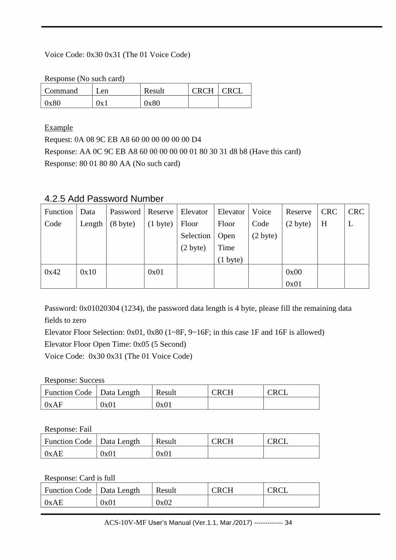
4.2.5 Add Password Number
Function
Code
Data
Length
Password
(8 byte)
Reserve
(1 byte)
Elevator
Floor
Selection
(2 byte)
Elevator
Floor
Open
Time
(1 byte)
Voice
Code
(2 byte)
Reserve
(2 byte)
CRC
H
CRC
L
0x42 0x10 0x01 0x00
0x01
Password: 0x01020304 (1234), the password data length is 4 byte, please fill the remaining data
fields to zero
Elevator Floor Selection: 0x01, 0x80 (1~8F, 9~16F; in this case 1F and 16F is allowed)
Elevator Floor Open Time: 0x05 (5 Second)
Voice Code: 0x30 0x31 (The 01 Voice Code)
Response: Success
Function Code Data Length Result CRCH CRCL
0xAF 0x01 0x01
Response: Fail
Function Code Data Length Result CRCH CRCL
0xAE 0x01 0x01
Response: Card is full
Function Code Data Length Result CRCH CRCL
0xAE 0x01 0x02

ACS-10V-MF User’s Manual (Ver.1.1, Mar./2017) ------------- 35
Example
Request: 42 10 01 02 03 04 00 00 00 00 01 01 80 05 30 31 00 01 E2 04
Response: AF 01 01 DE 81 (Success)
Response: AE 01 01 EE B6 (Fail)
Response: AE 01 02 8D 86 (Full)
4.2.6 Delete Password Number
Function
Code
Data
Length
Password
(8 byte)
CRCH CRCL
0x43 0x08
Password: 0x01020304 (1234), the password data length is 4 byte, please fill the remaining data
fields to zero
Response: Success
Function Code Data Length Result CRCH CRCL
0xAF 0x01 0x01
Response: Fail
Function Code Data Length Result CRCH CRCL
0xAE 0x01 0x01
Example
Request: 43 08 01 02 03 04 00 00 00 00 3A 94
Response: AF 01 01 DE 81 (Success)
Response: AE 01 01 EE B6 (Fail)
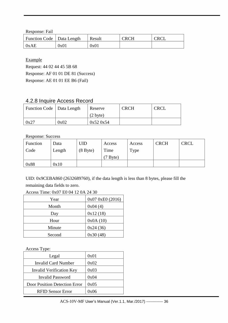
4.2.7 Delete All Passwords’ Number Function Code Data Length Reserve
(2 byte)
CRCH CRCL
0x44 0x02 0x44 0x45
Response: Success
Function Code Data Length Result CRCH CRCL
0xAF 0x01 0x01
ACS-10V-MF User’s Manual (Ver.1.1, Mar./2017) ------------- 36
Response: Fail
Function Code Data Length Result CRCH CRCL
0xAE 0x01 0x01
Example
Request: 44 02 44 45 5B 68
Response: AF 01 01 DE 81 (Success)
Response: AE 01 01 EE B6 (Fail)
4.2.8 Inquire Access Record
Function Code Data Length Reserve
(2 byte)
CRCH CRCL
0x27 0x02 0x52 0x54
Response: Success
Function
Code
Data
Length
UID
(8 Byte)
Access
Time
(7 Byte)
Access
Type
CRCH CRCL
0x88 0x10
UID: 0x9CEBA860 (2632689760), if the data length is less than 8 bytes, please fill the
remaining data fields to zero.
Access Time: 0x07 E0 04 12 0A 24 30
Year 0x07 0xE0 (2016)
Month 0x04 (4)
Day 0x12 (18)
Hour 0x0A (10)
Minute 0x24 (36)
Second 0x30 (48)
Access Type:
Legal 0x01
Invalid Card Number 0x02
Invalid Verification Key 0x03
Invalid Password 0x04
Door Position Detection Error 0x05
RFID Sensor Error 0x06

ACS-10V-MF User’s Manual (Ver.1.1, Mar./2017) ------------- 37
Elevator Control Error 0x07
Camera Control Error 0x08
Response: No Record
Function Code Data Length Result CRCH CRCL
0x80 0x01 0x80
Example
Request: 27 02 52 54 90 01
Response: 88 10 9C EB A8 60 00 00 00 00 07 E0 04 12 0A 24 30 01 9E C7
Response: 80 01 80 80 AA (No Record)
4.2.9 Delete Access Record
Function Code Data Length Reserve
(2 byte)
CRCH CRCL
0x28 0x02 0x52 0x54
Response: Success
Function Code Data Length Result CRCH CRCL
0xAF 0x01 0x01
Response: Fail
Function Code Data Length Result CRCH CRCL
0xAE 0x01 0x01
Example
Request: 28 02 52 54 7E D5
Response: AF 01 01 DE 81 (Success)
Response: AE 01 01 EE B6 (Fail)

ACS-10V-MF User’s Manual (Ver.1.1, Mar./2017) ------------- 38
4.2.10 Delete All Access Records
Function Code Data Length Reserve
(2 byte)
CRCH CRCL
0x52 0x02 0x44 0x45
Response: Success
Function Code Data Length Result CRCH CRCL
0xAF 0x01 0x01
Response: Fail
Function Code Data Length Result CRCH CRCL
0xAE 0x01 0x01
Example
Request: 52 02 44 45 65 54
Response: AF 01 01 DE 81 (Success)
Response: AE 01 01 EE B6 (Fail)
4.2.11 Configure System Time
Function Code Data Length System Time
(7 Byte)
CRCH CRCL
0x10 0x07
System Time: 0x07 E0 04 12 0A 24 30
Year 0x07 0xE0 (2016)
Month 0x04 (4)
Day 0x12 (18)
Hour 0x0A (10)
Minute 0x24 (36)
Second 0x30 (48)
Response: Success
Function Code Data Length Result CRCH CRCL
0xAF 0x01 0x01

ACS-10V-MF User’s Manual (Ver.1.1, Mar./2017) ------------- 39
Response: Fail
Function Code Data Length Result CRCH CRCL
0xAE 0x01 0x01
Example
Request: 10 07 07 E0 04 12 0A 24 30 6E A5
Response: AF 01 01 DE 81 (Success)
Response: AE 01 01 EE B6 (Fail)
4.2.12 Check Door Position Function Code Data Length Reserve CRCH CRCL
0x50 0x02 0x52 0x54
Response
Function Code Data Length Status CRCH CRCL
0xAF 0x01
Status: 1=>Close, 2=>Open
Response: Fail
Function Code Data Length Result CRCH CRCL
0xAE 0x01 0x01
Example:
Request: 50 02 52 54 C8 12
Response: AF 01 01 DE 81 (Close)
Response: AF 01 02 BD B1 (Open)
Response: AE 01 01 EE B6 (Fail)

ACS-10V-MF User’s Manual (Ver.1.1, Mar./2017) ------------- 40
4.3 CRC Calculation (CCITT-16)
(C# Example)
public static byte[] HexStringToByteArray(string hexString)
{
if (hexString.Length != 4) hexString = "0" + hexString;
byte[] HexAsBytes = new byte[hexString.Length / 2];
for (int index = 0; index < HexAsBytes.Length; index++)
{
string byteValue = hexString.Substring(index * 2, 2);
HexAsBytes[index] = byte.Parse(byteValue, NumberStyles.HexNumber,
CultureInfo.InvariantCulture);
}
return HexAsBytes;
}
private byte[] CRC_16(byte[] data, int DataLength)
{
uint CRC_Polynomial = 0x1021;
uint CRC_Init = 0xFFFF;
for (int i = 0; i < DataLength; i++)
{
CRC_Init = CRC_Init ^ ((uint)data[i] << 8);
for (int j = 0; j < 8; j++)
{
if (System.Convert.ToBoolean(CRC & 0x8000))
CRC_Init = (CRC_Init << 1) ^ CRC_Polynomial;
else
CRC_Init = (CRC_Init << 1);
}
}
return HexStringToByteArray(Convert.ToString((UInt16)(CRC^ 0xFFFF), 16));
}

ACS-10V-MF User’s Manual (Ver.1.1, Mar./2017) ------------- 41
Example:
Input: 0xAF, 0x01, 0x01
Data length: 3
Output:0xDE(CRCH), 0x81(CRCL)

ACS-10V-MF User’s Manual (Ver.1.1, Mar./2017) ------------- 42
Troubleshooting
Item Problem Description Solution
1 Power Failure
(PWR LED Off)
1. Please return to the ICP DAS for inspection and
repair
2 Cards can not be used
1. Make sure cards support Mifare S50 standard
( ISO 14443-A)
2. EM and HID cards are not supported
3 How to find out IP address of
ACS-xxx-MF?
1. Entry the default IP operation mode
Step1. Press and hold the No. 1 key
Step2. Reset the power of ACS-xxx-MF
Step3. Now the PWR led flashes and IP address
is "192.168.0.1"
Step4. Enter the settings web page then find out
IP address
2. Use eSearch Utility
Step1. Launch eSearch.exe
Step2. Press "Search Servers" button then find
out IP address
Technical Support If you have problems about using the ACS-xxx-MF series module, please
contact ICP DAS Product Support.
Email: [email protected]