MRL TC100 Trip circuit supervision
15
1 T AFM 26431278N ER محورآزمای فارسFars Mehvar Azema MRL TC100 MRL TC100 Trip circuit supervision
-
Upload
khangminh22 -
Category
Documents
-
view
5 -
download
0
Transcript of MRL TC100 Trip circuit supervision

1 T
AFM 26431278N ER
فارس محورآزمای
Fars Mehvar Azema
MRL TC100
MRL TC100 Trip circuit supervision

2 T
AFM 26431278N ER
فارس محورآزمای
Fars Mehvar Azema
MRL TC100
T: Technical specifications T-1: Inputs
2 digital inputs considered for trip contact & C.B. ( 52a N.O.) Nominal voltage: 110 Vdc Voltage range: 80 – 180 Vdc Aux. power supply Nominal: 110Vdc Range: 60 – 180Vdc Power consumption: Max 2W
T-2: Outputs - 2 relay contacts fixed for TCS alarm & power safe - 2 optional contacts for user request i.e. for C.B. open & close Contact specification: 12A 250Vac /12A 30Vdc/ 0.3A 125Vdc/0.4A 110Vdc
T-3: User interfaces -Rear RS485 with Modbus protocol -Front USB port for settings & events extraction directly from PC -Safety front LED (Green blink) -Trip circuit status monitoring LED (3 color, green=OK, red=not OK, yellow=Acceptable fail) -Graphic dot matrix LED display for monitoring time, date, & trip circuit status
T-4: Settings -Time & date, Christian or Solar (Get data only from PC if selected) -Delay time for perfect operation (d1) -Max allowable delay time for circuit breaker operation (d2) -Modbus address & name -Modbus baud rate
T-5: Features - Event recording with time tag & detailed information of trip steps (Up to 200 events) - 1 mSec time tag accuracy for events - PC software, via USB or based on Modbus protocol via RS485 for settings &

3 T
AFM 26431278N ER
فارس محورآزمای
Fars Mehvar Azema
MRL TC100
events - Ability to network several relays via RS485 Modbus & receive related events - Ability to synchronize relays with station server time, via RS485 - Two delay steps d1 & d2 d1: 10 to 1000 mSec definable on relay by setting (uncritical as time out) d2: d1 to 5000 mSec definable on relay by setting(critical delay as breaker failure) - Breaker "DC power out of range" detection and alarm
T-6: Technical specifications according to standard
T-6.1 Mechanical specifications Design Modular FMA Full draw-out Case – 2U Mounting Rack or flush mounting. Connections Rear (Green Phoenix pluggable connectors)
T-6.2 Environmental conditions Ambient Temperature Range Per IEC 60255-6: 1988 Operating temperature range: Continuous Withstand: –20 to +55°C Storage Temperature Range: –20 to +70°C Tested as per IEC 60068-2-1:2007: –20°C storage (16 hours), –20°C operation (16 hours) IEC 60068-2-2-2007: +70°C storage (16 hours), +55°C operation (16 hours) Ambient Humidity Range Humidity: Per IEC 60068-2-78: 2001: Per IEC 60068-2-30: 2005: Solar radiation Avoid exposure of the front panel to direct solar radiation.

4 T
AFM 26431278N ER
فارس محورآزمای
Fars Mehvar Azema
MRL TC100
Insulation Rated insulation: 300
PER IEC 60255-5: 2000, Insulation resistance > 100MΩ at 500Vdc
High Voltage (Dielectric) Withstand Per IEC 60255-5: 2000, 2 kV rms AC, 1 minute: Between all case terminals connected together, and the case earth, and between all terminals of independent circuits (RS232 ports excepted). 2.0kVrms for one minute between all terminals and case earth 2.0kVrms for one minute between all terminals of independent circuits, including contact circuits 1.5kVrms for one minute across dedicated normally open contacts of output relays. 1.5kVrms AC for 1 minute, across open contacts and across open contacts of changeover output relays.
Impulse Voltage Withstand Test Per IEC 60255-5: 2000 The product will withstand without damage impulses of 1.2 / 50 μs, peak value: 5 kV, 0.5J across: Each independent circuit and the case with the terminals of each independent circuit connected together. Independent circuits with the terminals of each independent circuit connected together. Terminals of the same circuit except normally open metallic contacts ELECTROMAGNETIC COMPATIBILITY (EMC) DC Supply Interruption Per IEC60255-11:1979: The product will withstand a 20ms interruption in the auxiliary voltage in its quiescent condition AC Ripple on DC Supply Per IEC60255-11:1979: The product will operate with 12% AC ripple on the DC auxiliary supply without any additional measurement errors Disturbances on AC Supply Per IEC61000-4-11:1994: The products satisfies the requirements of EN61000 - 4 - 11 for voltage dips and short interruptions.
5 T
AFM 26431278N ER
فارس محورآزمای
Fars Mehvar Azema
MRL TC100
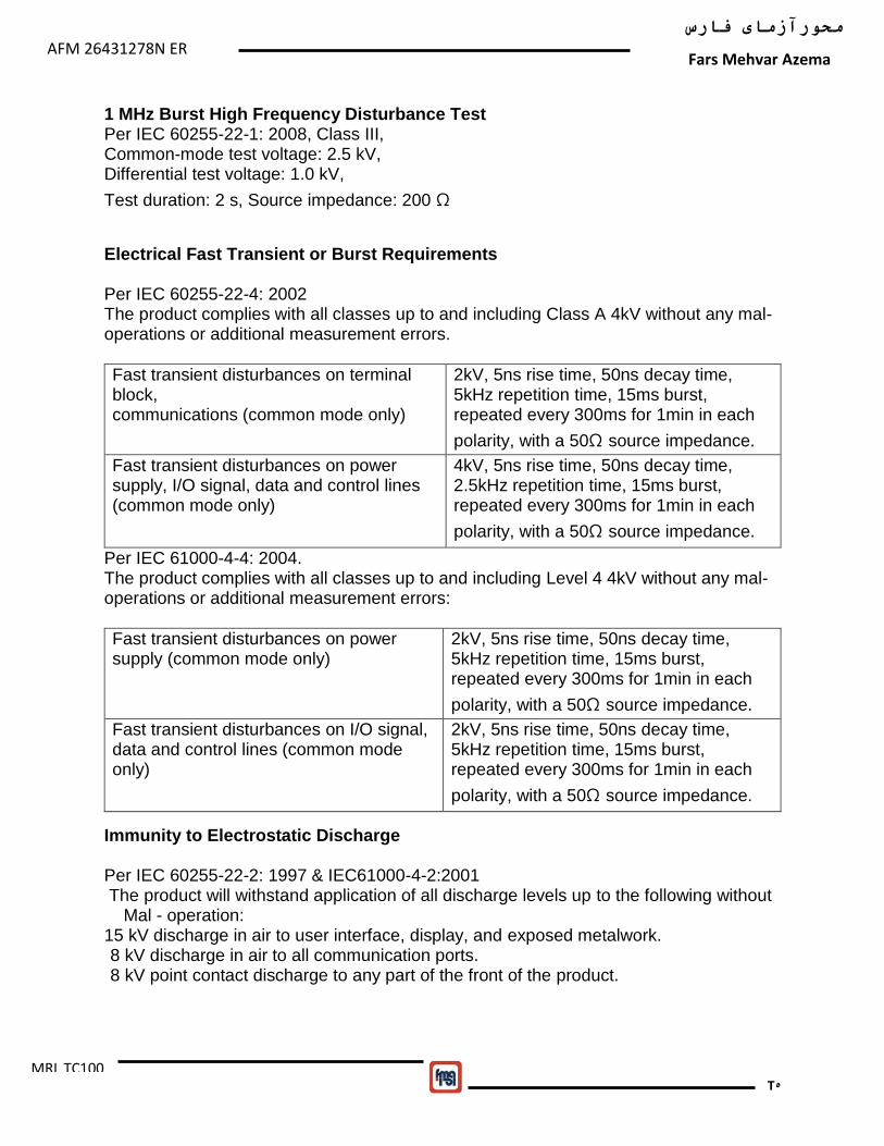
1 MHz Burst High Frequency Disturbance Test Per IEC 60255-22-1: 2008, Class III, Common-mode test voltage: 2.5 kV, Differential test voltage: 1.0 kV,
Test duration: 2 s, Source impedance: 200 Ω
Electrical Fast Transient or Burst Requirements Per IEC 60255-22-4: 2002 The product complies with all classes up to and including Class A 4kV without any mal-operations or additional measurement errors.
Fast transient disturbances on terminal block, communications (common mode only)
2kV, 5ns rise time, 50ns decay time, 5kHz repetition time, 15ms burst, repeated every 300ms for 1min in each
polarity, with a 50Ω source impedance.
Fast transient disturbances on power supply, I/O signal, data and control lines (common mode only)
4kV, 5ns rise time, 50ns decay time, 2.5kHz repetition time, 15ms burst, repeated every 300ms for 1min in each
polarity, with a 50Ω source impedance.
Per IEC 61000-4-4: 2004. The product complies with all classes up to and including Level 4 4kV without any mal-operations or additional measurement errors:
Fast transient disturbances on power supply (common mode only)
2kV, 5ns rise time, 50ns decay time, 5kHz repetition time, 15ms burst, repeated every 300ms for 1min in each
polarity, with a 50Ω source impedance.
Fast transient disturbances on I/O signal, data and control lines (common mode only)
2kV, 5ns rise time, 50ns decay time, 5kHz repetition time, 15ms burst, repeated every 300ms for 1min in each
polarity, with a 50Ω source impedance.
Immunity to Electrostatic Discharge Per IEC 60255-22-2: 1997 & IEC61000-4-2:2001 The product will withstand application of all discharge levels up to the following without Mal - operation: 15 kV discharge in air to user interface, display, and exposed metalwork. 8 kV discharge in air to all communication ports. 8 kV point contact discharge to any part of the front of the product.

6 T
AFM 26431278N ER
فارس محورآزمای
Fars Mehvar Azema
MRL TC100
Conducted Emissions Per EN 55022: 1998:
0.15 – 0.5MHz, 79dBμV (quasi peak) 66dBμV (average)
0.5 – 30MHz, 73dBμV (quasi peak) 60dBμV( average ).
Radiated Emissions Per EN 55022: 1998:
30 - 230MHz, 40dBμV/m at 10m measurement distance
230 – 1GHz, 47dBμV/m at 10m measurement distance.
Immunity to Radiated Electromagnetic Energy Per IEC 60255-22-3: 2000, Class III & IEC61000-4-3:2002 Test field strength, frequency band 80 to 1000 MHz: 10 V/m, test using AM: 1 kHz / 80%, at 80 to 1GHz, 30 V/m, test using AM: 1 kHz / 80%, at 80 to 900MHz and 1.4GHz to 2.0GHz Conducted Immunity Per IEC 60255-22-6: 2001 10 V/m, test using AM: 1 kHz / 80%, at 0.15 to 80MHz, Surge Immunity Per IEC 60255-22-5: 2002 Class IV: 4kV common mode 12Ω source impedance, 2kV differential mode 2Ω source impedance – power supply Class IV: 4kV common mode 42Ω source impedance, 2kV differential mode 42Ω source impedance – Opto inputs, relays, CT, VT Class IV - 4kV common mode 2Ω source impedance applied to cable screen – terminal block communications Power Frequency Magnetic Field Immunity Per IEC 61000-4-8:2001, class V: 100A/m quiescent condition, 1000A/m short duration (1-3s) Pulse Magnetic Field Immunity Per IEC 61000-4-9:2001, class V: 1000A/m pulse (5 positive, 5 negative) Damped Oscillatory Magnetic Field Per IEC 61000-4-10:2001, class V: 100A/m @100kHz / 1MHz 2 second burst duration Oscillatory Waves Immunity Per IEC 61000-4-12:2001: 2.5kV peak between independent circuits and case earth 1.0kV peak across terminals of the same circuit

7 T
AFM 26431278N ER
فارس محورآزمای
Fars Mehvar Azema
MRL TC100
T-8: Terminals & connection guide (Single phase)
7
8
9
10
11
12
13
14
15
16
17
7 18
19
20
21
22
23
24
COM
Aux DC (110V)
Relay 2
Relay 3
Relay 1
WD
6
5
4
3
2
1
Trip
52a / 52b
COM
COM
COM
NC
NC
NO
NO
NO
NO
NC
NC
RS 485
A
GND
RS
B
8 T
AFM 26431278N ER
فارس محورآزمای
Fars Mehvar Azema
MRL TC100
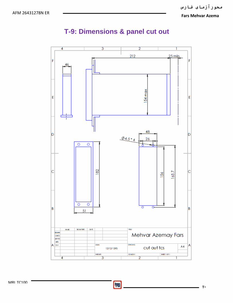
T-9: Dimensions & panel cut out

9 T
AFM 26431278N ER
فارس محورآزمای
Fars Mehvar Azema
MRL TC100
A: Application & operation principles The MRL TC100 relay is used to monitor and report the situation of circuit breaker trip circuit and also the operation of circuit breaker. This is done by using two inputs of relay,one connected in parallel with trip contact ( pins 3 , 4 ), and the other , connected in parallel with breaker aux. contacts 52a & 52b, as shown in the following figure.
Typical connrction
Depending on the stuations of input contacts, there are the condition states of trip circuit and C.B. : State1: in this state, trip contact is not operated and circuit breaker is closed, trip circuit connections are OK and a small current will flow throug input of terminal 3 , 4 (input trip = 1 , input 52a = 0) (No fault, trip circuit OK).
State1: Normal condition(Before trip, C.B. closed)

10 T
AFM 26431278N ER
فارس محورآزمای
Fars Mehvar Azema
MRL TC100
State2: This state declares that trip contact of protection relay is operated, but C.B. has not operated to open yet, and should operate during a defined time. This state should not prolong for a long time, otherwise shows a problem in C.B. operation or trip circuit( such as disconnection ).
State 2,3,4:Trip condition, before operation of C.B. or trip circuit disconnection or DC power loss
If this state is continiued for time longer than defined time d2 ( Max. allowed time for breaker to operate to open ), this means a problem in C.B. operation, or a disconnection in C.B. trip coil circuit, or loss of breaker DC supply. So this state for times longer than d2, means fault. State4,5,7,8: In this case, circuit breaker and trip contact of protection relay are open.This may be caused by the following reasons:
- Circuit breaker is operated in time, because of trip signal(state7). - C.B. operated at time>d1 & <d2, not critical fault (state5). - C.B. opearation timeout,operate time > d2, critical fault (state4) - C.B. is opened manually( state8)
A small current is flowing through both inputs of relay in this case. The situation of contacts and inputs of relay are shown in the following figure.
11 T
AFM 26431278N ER
فارس محورآزمای
Fars Mehvar Azema
MRL TC100
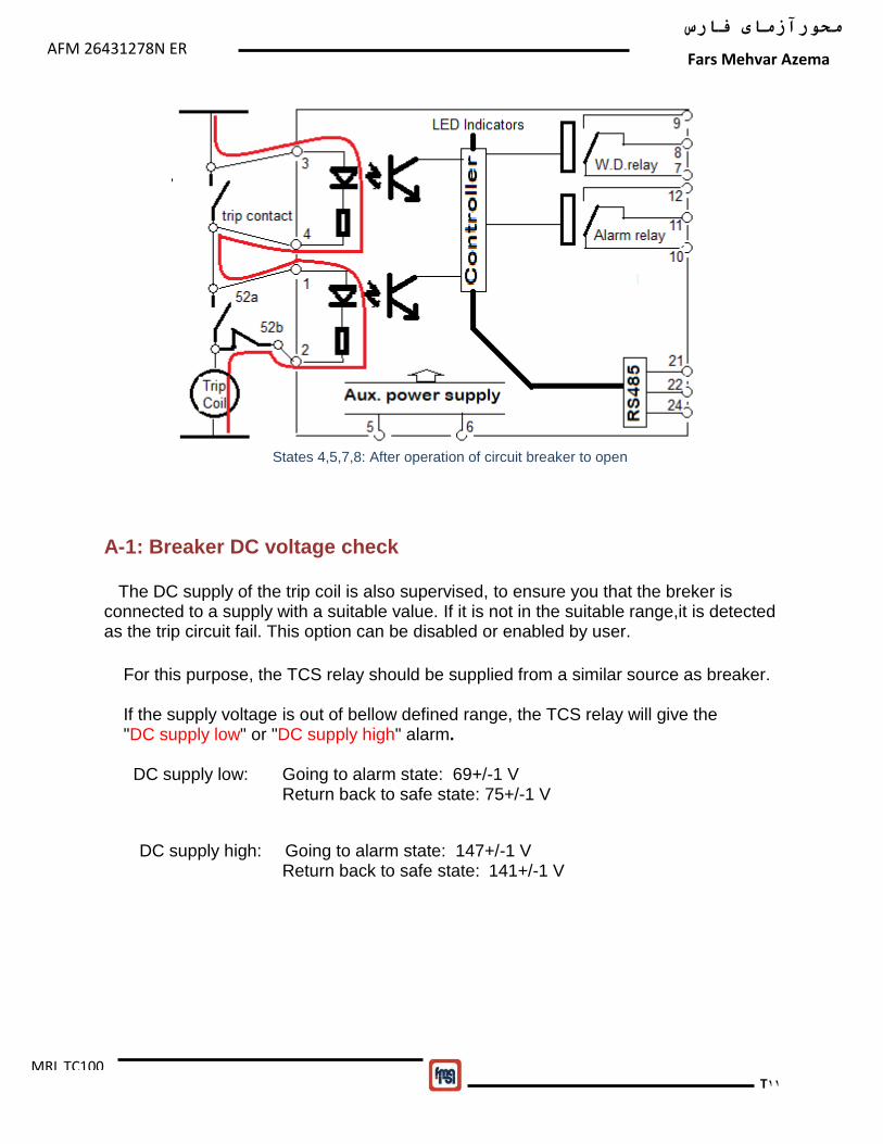
States 4,5,7,8: After operation of circuit breaker to open
A-1: Breaker DC voltage check The DC supply of the trip coil is also supervised, to ensure you that the breker is connected to a supply with a suitable value. If it is not in the suitable range,it is detected as the trip circuit fail. This option can be disabled or enabled by user. For this purpose, the TCS relay should be supplied from a similar source as breaker. If the supply voltage is out of bellow defined range, the TCS relay will give the "DC supply low" or "DC supply high" alarm. DC supply low: Going to alarm state: 69+/-1 V Return back to safe state: 75+/-1 V
DC supply high: Going to alarm state: 147+/-1 V Return back to safe state: 141+/-1 V

12 T
AFM 26431278N ER
فارس محورآزمای
Fars Mehvar Azema
MRL TC100
D: description D-1: Defined messages in relay (pc log text)
- Back to Normal State
- trip Signal or trip circuit fail
- CB close at timeout1 due to TC/CB fail
- TC Fail or CB not Operate in time; CB close at timeout2
- TC Fail or CB not Operate in time; CB open after timeout2,
- TC is ok CB open by trip after timeout1
- Reset by Key
- CB Operate in Time after trip signal
- CB open Without Trip
- TC/CB fail is acknowledged; CB close
- TC/CB fail is acknowledged; CB open
Defined messages (display text in "show record")
- Back to Normal State
- trip signal or TC fail
- CB close or TC fail timeout1
-

13 T
AFM 26431278N ER
فارس محورآزمای
Fars Mehvar Azema
MRL TC100
TC/CB fail CB close timeout2
- TC/CB fail CB open timeout2
- TC OK CB open timeout1
- TC/CB OK
CB Open
- CB open without trip
- TC/CB fail CB close timeout2-A
- CB fail CB open timeout2-A
- DC voltage is LOW
- DC voltage is HIGH
- DC Voltage return to range

14 T
AFM 26431278N ER
فارس محورآزمای
Fars Mehvar Azema
MRL TC100
Defined messages (display text in "supervision mode")
- CB close or TC fail timeout1 VDC LOW / VDC HIGH
- TC/CB fail CB close timeout2 VDC LOW / VDC HIGH
- TC/CB fail CB open timeout2 VDC LOW / VDC HIGH
- TC OK CB open timeout1 VDC LOW / VDC HIGH
- TC/CB OK CB Open VDC LOW / VDC HIGH
- CB open without trip VDC LOW / VDC HIGH
- TC/CB fail CB close timeout2-A VDC LOW / VDC HIGH
- CB fail CB open VDC LOW / VDC HIGH

15 T
AFM 26431278N ER
فارس محورآزمای
Fars Mehvar Azema
MRL TC100
D-2: Sample of event recording No Event Message Date Time ms 001 , trip Signal or trip circuit fail ,97/05/02,10:45:06,121 002 , CB close at timeout1 due to TC/CB fail ,97/05/02,10:45:06,222 003 , TC Fail or CB not Operate in time ; CB close at timeout2 ,97/05/02,10:45:08,360 004 , TC/CB fail is acknowledged ; CB open ,97/05/02,10:45:22,868 005 , Back To Normal State ,97/05/02,10:45:23,005