— Miniature Circuit Breaker UL / CSA Range - ABB
146
• UL489 / CSA C22.2 No.5 devices • UL1077 / CSA C22.2 No. 235 devices • Electronic Protection Devices • Technical data — PRODUCT CATALOG CANADA Miniature Circuit Breaker UL / CSA Range — Miniature Circuit Breakers UL / CSA Range
-
Upload
khangminh22 -
Category
Documents
-
view
0 -
download
0
Transcript of — Miniature Circuit Breaker UL / CSA Range - ABB

• UL489 / CSA C22.2 No.5 devices• UL1077 / CSA C22.2 No. 235 devices• Electronic Protection Devices• Technical data
—PRODUC T C ATALOG C ANADA
Miniature Circuit BreakerUL / CSA Range
—
Min
iatu
re C
ircu
it B
reak
ers
UL
/ C
SA
Ran
ge

— With more than 100 years of product development and knowledge, ABB's miniature circuit breakers are today's market reference for electrical distribution and equipment protection.

112
34
INTRODUCTION, DEFINITIONS AND EXPLANATIONS
UL489 / CSA C22.2 NO.5 DEVICE SELECTION
UL1077 / CSA C22.2 NO.235 DEVICE SELECTION
ELECTRONIC PROTECTIONDEVICE SELECTION
—Miniature Circuit Breakers

M I N I ATU R E CI RCU IT B R E A K E R - PR O D U C T C ATA LO G U E C A N A DA
1

M I N I ATU R E CI RCU IT B R E A K E R - PR O D U C T C ATA LO G U E C A N A DA
1
— Introduction, Definitions and
Explanations
005 Introduction and Definition
006 – 008 Circuit Breaker Construction
009 – 010 Current Limitation
011 – 012 Selective Coordination
013– 014 UL489 vs UL1077
015 – 020 Wiring in DC applications

1/5 M I N I ATU R E CI RCU IT B R E A K E R - PR O D U C T C ATA LO G U E C A N A DA
1
OverloadAn overload is a slow and small overcurrent situa-tion that causes the ampacity and temperature of the circuit to gradually increase over time. This type of event is characterized by a slight increasein the load (ampacity) on the circuit and is inter-rupted by the thermal trip unit of the breaker.
Short circuitA short circuit is a rapid and intense overcurrent situation that causes the ampacity of the circuit to increase. This type of event is characterized by a dramatic increase in the load (ampacity) on thecircuit and is interrupted by the magnetic trip unit of the breaker.
Breaker definitionA breaker is a device designed to isolate a circuit during an overcurrent event without the use of a fusible element. A breaker is a resettable protective device that protects against two types of overcur-rent situations: overload and short circuit
—Miniature circuit breakersIntroduction and definition
The circuit breaker plays an important role in providing overcurrent protection and a disconnect means in electrical networks. Recent advancements in circuit breaker technology has increased breaker performance and protection.
Magnetic Example
10 A
BreakerLight
10 A
The wire connected between the light and breaker is cut and shorted to ground creating a short circuit.
Thermal Example
10 A
BreakerLight
15 A
The light draws more than 10 amps for an extended period of time creating a thermal overload.
Lower terminal
Space for identification marker
Tripping lever
Moving contact
DIN rail holder
Operating mechanism
Upper terminalElectromagnetic protection
Thermal protection (bimetal)
Arc chamber
Fixed contact
Operator

M I N I ATU R E CI RCU IT B R E A K E R - PR O D U C T C ATA LO G U E C A N A DA 1/6
1
Thermal / Magnetic trip unitsABB Current Limiting Breakers use an electrome-chanical (Thermal/Magnetic) trip unit to open the breaker contacts during an overcurrent event. The thermal trip unit is temperature sensitive and the magnetic trip unit is current sensitive. Both units act independently and mechanically with the break-er’s trip mechanism to open the breaker’s contacts.
Current flow during operation:
Overload protectionThe thermal trip unit protects against a continuous overload. The thermal unit is comprised of a bi-metal element located behind the circuit breaker trip bar and is part of the breaker’s current carrying path. When there is an overload, the increasedcurrent flow heats the bimetal causing it to bend. As the bimetal bends, it pulls the trip bar that opens the breaker’s contacts.
The time required for the bimetal to bend and trip the breaker varies inversely with the current. Be-cause of this, the tripping time becomes quicker as current increases in magnitude.
Overload protection is applicable to any installa-
tion, conductor, or component that can be sub-jected to low-magnitude but long-time overcur-rents. Low-magnitude, long-time overcurrentscan be dangerous because they reduce the life of the electrical installation, conductor, and compo-nents. If left unchecked, fire could result.
Magnetic trip unitThe magnetic trip unit protects against a short cir-cuit. The magnetic trip unit is comprised of an elec-tromagnet and an armature.
—Miniature circuit breakersCircuit breaker construction
Current Flow During Operation
All highlighted components are energized during opera-
Magnetic Trip Unit Thermal Trip Unit
Current flow during operation
Thermal trip unit
.
Magnetic trip unit Thermal trip unit
All highlighted components are energized during operation
Trip bar
Operating mechanism Thermal trip unit
Trip bar
Operating mechanism Thermal trip unit
Armature and plunger
Movable contact Magnetic trip unitMagnetic trip unit
Armature and plunger
Movable contact

1/7 M I N I ATU R E CI RCU IT B R E A K E R - PR O D U C T C ATA LO G U E C A N A DA
1
Components of a magnetic trip unitWhen there is a short circuit, a high magnitude of current passes through the coils creating a mag-netic field that attracts the movable armature to-wards the fixed armature. The hammer trip is pushed against the movable contact and the con-tacts are opened. The opening of the breaker’s contacts during a short circuit is complete in 0.5 milli-seconds.
Arc runners / arc chutesThe arc runner guides the electric arc away from the open contacts into the arc chute where it is ex-tinguished.
During an overload or short circuit event, the con-tacts of the breaker separate, and an electrical arc is formed between the contacts through air. The arc is moved into the arc chute by “running” the arc down the interior of the breaker along the arcrunner. When the arc reaches the arc chute, it is broken into small segmented arcs. The segmented arcs split the overall energy level into segments less than 25 V. Each 25 V segment does not have a high enough energy level to maintain an arc and all en-ergy is naturally dissipated.
Breaker's thermal trip (region 1)The first sloping region of the breaker curve is a graphical representation (next page) of the trip-ping characteristics of the thermal trip unit. This portion of the curve is sloped due to the nature of the thermal trip unit. The trip unit bends to trip the breaker’s trip bar in conjunction with a rise in am-perage (temperature) over time.
As the current on the circuit increases, the tem-perature rises, the faster the thermal element will trip. Example using the curve on next page: If you had a 10 A breaker and the circuit was producing 30 amps of current, the breaker would trip between two seconds and one minute. In this example, youwould find the circuit current on the bottom of the graph (multiples of rated current). The first line is 10 amps (10 amp breaker x a multiple of one), the second line is 20 amps (10 amp breaker x multiple of two), and the third line is 30 amps (10 amp breaker x multiple of three). Next, you would trace the vertical 30A line up until it intersects the red portion of the breaker thermal curve. If you follow the horizontal lines on both sides of the red curve to the left, you will see that the breaker can trip as fast as two seconds and no slower than one min-ute.
—Miniature circuit breakersCircuit breaker construction
Arc runner Arc chuteArc runner Arc chute

M I N I ATU R E CI RCU IT B R E A K E R - PR O D U C T C ATA LO G U E C A N A DA 1/8
1
Breaker's magnetic trip (region 2)This region of the breaker curve is the instanta-neous trip unit. ABB’s miniature circuit breaker’s in-stantaneous trip unit interrupts a short circuit in 2.3 to 2.5 milliseconds. Because of this, the curve has no slope and is graphically represented as a vertical straight line.
See curve example. If you had a 10 amp breaker, the magnetic trip element would interrupt a short cir-cuit between 10 and 30 amps (10 amp breaker x multiple of two and three) in 2.3 to 2.5 milliseconds
Breaker's contacts (region 3)This region of the curve is the time required for the contacts of the breaker to begin to separate. The contacts will open in less than .5 milliseconds and is graphically represented by the bottom vertical portion of the curve.
—Miniature circuit breakersCircuit breaker construction
Magnetic Trip Unit(Region Two)
Thermal Trip Unit(Region One)
Moving Contacts(Region Three)

1/9 M I N I ATU R E CI RCU IT B R E A K E R - PR O D U C T C ATA LO G U E C A N A DA
1
60Hz AC cycle (UL)UL defines an AC cycle as the potential energy of the wave form traveling from zero-to-positive am-plitude, positive-to-zero amplitude, zero-to-nega-tive amplitude, negative-to-zero amplitude 60 times in one second. One cycle is completedevery 16.6 milliseconds.
Current limiting breaker (UL)UL defines breaker current limitation as a breaker that interrupts and isolates a fault in less than 1/2 of an AC cycle. Half a cycle is completed in 8.3 milli-seconds.
NEC240.2 current limitingA device that, when interrupting current in its cur-rent-limiting range, reduces the current flowing in the faulted circuit to a magnitude substantially less than that obtainable in the same circuit if the de-vice were replaced with a solid conductor havingcomparable impedance.
IEC 60947-2 current limitingA circuit breaker with sufficiently short trip time to prevent the short-circuit current from reaching the peak value which would otherwise be reached.
ABB's current limiting circuit breakersABB current limiting breakers can interrupt and iso-late a fault in 1/8 of an AC cycle. The breaker fault interruption is completed in 2.3 to 2.5 milliseconds.
Zero point extinguishing breakersA typical zero point extinguishing breaker inter-rupts a fault and does not isolate the energy. The breaker allows an arc to be present between the open contacts until the AC wave form crosses zero.
When the wave form crosses zero, the potentialenergy is zero and the arc (fault) naturally extin-guishes. The arc could be present for up to 8.3 milli-seconds.
Current limiting breakers and electrical networks current limitationWhen a short-circuit condition occurs, the “ideal” current limiting circuit breaker opens before the current waveform can reach its full potential magni-tude which occurs at ¼ cycle (4.17ms). ABB’scurrent limiting breakers can interrupt a fault in about ½ cycle or 2.3 ms to 2.5 ms. ABB’s current limiting breakers interrupt a short circuit in less than 1/8 cycle and limit the amount of current thatcan reach a circuit. Limiting the available current on the circuit provides additional protection against network, breaker, or bus damage and prevents the tripping of upstream breakers (selective coordina-tion).
I2t (let-thru energy)The true destructive nature of a short circuit is measured by the time it is available combined with the peak value of the short circuit. The IsqT (Amps Squared over Time) value represents the amount of energy available on a network during a short circuitand is represented by the shaded area on the graph next page.
During a short circuit, both magnetic forces and thermal energy combine to damage devices on the electrical network. The level of thermal energy and magnetic forces are directly proportional to the square of the current. The magnetic forces vary as a square of the peak current available and the ther-mal energy varies as a square of the RMS (root mean square) current available.
ABB’s current limiting breakers will limit the let-through energy to a fraction (1/100) of the value that is available from the network. By comparison, a zero crossing breaker would let through approxi-mately 100 times as much destructive energyas the current limiting circuit breaker [ (100,000A / 10,000A) squared – 100X].
—Miniature circuit breakersCircuit breaker current limitation
All ABB miniature circuit breakers are UL tested and certified as current limiting protective devices. Current limiting circuit breakers provide a higher level of circuit protection than typical zero point external breakers.

M I N I ATU R E CI RCU IT B R E A K E R - PR O D U C T C ATA LO G U E C A N A DA 1/10
1
ABB’s current limiting breakers limit the shortcircuit current to a relatively small magnitude in an extremely short time, which dramatically limits a short circuit’s destructive energy.
Current limiting and zero crossing breakersDuring the initial stages of a short circuit, a break-er’s contacts open to interrupt the circuit. After the contacts open, an arc forms in the air between the contacts on both the current limiting and zero crossing breaker contacts. What distinguishes a current limiting breaker from a zero, crossing breaker is what each breaker does after an arc is formed between the open contacts.
A current limiting breaker “runs” the arc down the breaker arc runner into an arc chute that extin-guishes the arc.
A zero crossing breaker does not attempt to extin-guish the arc. The breaker is designed to withstand the energy of the arc long enough for the waveform to cross zero. When the wave form crosses zero the potential energy is zero and the arc naturally extin-guishes itself.
ABB’s current limiting breakers interrupt the arc en-
ergy in 2.3 ms to 2.5 ms (1/8 cycle) and a zero cross-ing breaker allows the arc to be present for up to 8.3 ms (1/2 cycle). A zero crossing breaker will let through 100 times as much energy as an ABBcurrent limiting breaker.
Current limiting exampleThe lab test report below details a 20 A S200 series current limiting breaker interrupting a 28 kA fault in 1.7 milliseconds. The total “I Square T” value is 32.0 kA.
Zero crossing exampleThe test report below details a 20 A zero point ex-tinguishing breaker interrupting a 9 kA fault in 9 milliseconds. The total “I Square T” value is 104.0 kA.
—Miniature circuit breakersCircuit breaker current limitation
500
-500
V
U-L2100 /div
-400
-300
-200
-100
100
200
300
400
0 6.9990.9999 1.9997 2.9996 3.9994 4.9993 5.9991kSample499.93 Sample/div
10
-10
kA
I-L22 k/div
-8
-6
-4
-2
2
4
6
8
Time A Time B
Legend
Voltage
Amps
500
-500
V
U-BCP L2100 /div
-400
-300
-200
-100
100
200
300
400
0 6.9990.9999 1.9997 2.9996 3.9994 4.9993 5.9991kSample499.93 Sample/div
10
-10
kA
I-L22 k/div
-8
-6
-4
-2
2
4
6
8
Time A Time B
Legend
Voltage
Amps

1/11 M I N I ATU R E CI RCU IT B R E A K E R - PR O D U C T C ATA LO G U E C A N A DA
1
Definition of selective coordinationCoordination between the operating characteris-tics of two or more overcurrent protection devices, so that when an over-current within established limits occurs, the device designated to operate within those limits trips whereas the other devices does not trip.
Example of breaker coordinationWhen an over-current event occurs at the branch breaker level (CB1), and the event is within the oper-ating characteristics of the breaker, then the branch breaker should interrupt the circuit(open) and the main breaker should remain closed and energized. The chart below gives a graphical representation of a down stream branch breaker (B curve) and a main breaker (A curve) with coordina-tion. The separation between the curves allows thebranch breaker to react to the fault and the main breaker remains closed and energized.
NEC240.2 current limiting
Example of no breaker coordinationSelective breaker coordination is not achieved when there is an overload event at the branch breaker level (MCB1) and both the branch breaker and main breaker interrupt the circuit (open). When there is no breaker coordination, several circuits lose power that should remain operational during and after the overload event. The chart below gives a graphical representation of a down stream branch breaker (B curve) and a main breaker(A curve) without coordination. There is no separa-tion between the curves. The branch breaker will re-act to a fault and the main breaker will open and de-energize all circuits down stream.
Problems in coordination occur when the branch breaker allows the “I Square T” value of the short circuit to rise to a level that is in the operating range of the upstream main breaker. Proper breaker coordination is easier to achieve with the use of current limiting breakers at the branch level.
Selective coordination and current limitingRecent improvements in ABB circuit breaker tech-nology has pushed the performance of breakers to the same level as fuses. The reaction time and trip-ping characteristics of current limiting breakers are now on par with fuses. This allows ABB to providea high level of coordination between branch break-ers and the main. A current limiting branch breaker will limit the “I Square T” value well below the level
—Miniature circuit breakersSelective coordination and series rating
Mainbreaker
CB1 CB2 CB3 CB4
Short circuit

M I N I ATU R E CI RCU IT B R E A K E R - PR O D U C T C ATA LO G U E C A N A DA 1/12
1
of the operating range of the upstream main breaker. ABB’s current limiting branch breakers cancoordinate between the main breaker up to 35 kA.
Selective coordination and zero crossingZero crossing breakers do not limit the “I Square T” value. They wait for the wave form to cross zero and allow a high level of let-through energy to pass through the system. The “I Square T” value of a zero crossing breaker is high enough that the mainbreaker will likely trip during a short circuit. With zero crossing breakers it is extremely difficult to coordinate between branch and main breakers. A typical zero crossing breaker’s coordination level is below 10 kA. There are a few manufacturers that have achieved coordination between a branch zero crossing breaker and the main by slowing the per-formance (protection) of the main breaker.
Selective coordinationSelective coordination is achieved when there is a short circuit on a branch circuit breaker, the branch breaker opens and isolates the fault, and the main breaker remains closed. The rating is usually a value above the “stand alone” interrupting rating of the branch breaker and the “stand alone” rating of the main breaker.
Example:• 65 kA rated main breaker• 10 kA rated branch breaker• Coordination between the two breakers up to
35 kA
There can be a short circuit on the branch breaker up to 35 kA where the branch will open (CB1) and the main breaker will remain closed. Although the branch has a 10 kA “stand alone” rating, both the breakers work together to limit the available short circuit to allow the branch (CB1) to isolate the fault.
Series ratingsSeries ratings are different from coordination rat-ings. Unlike coordination ratings where the branch opens and the main remains closed, a series rated combination is one where both the branch and main breakers open and work together to isolate the fault.
The series rating combination of two breakers is equal to the “stand alone” interrupting value of the main breaker. This is a result of the main breaker let-through value being lower than the “stand alone” interrupting value of the branch breaker.
During a short circuit the main breaker will limit the energy to a level that is below the “stand alone” value of the branch breaker.Example:• 65 kA rated main breaker• 10 kA rated branch breaker• Series combination rating between the two
breakers up to 65 kA
There can be a short circuit on the branch breaker up to 65 kA where the branch will open and the main breaker will open. Although the branch breaker (CB1) has a 10 kA “stand alone” rating the main breaker has a let-through value below 10 kA.If there is a fault up to 65 kA on the network, the main breaker will limit the energy to a value less than the rating of the branch breaker (CB1). Both breakers will trip (no coordination), but the net-work can safely withstand a fault of 65 kA.
—Miniature circuit breakersSelective coordination and series rating
Mainbreaker65 kA
CB110 kA
CB210 kA
CB310 kA
CB410 kA
35 kA or 65 kA short circuit

1/13 M I N I ATU R E CI RCU IT B R E A K E R - PR O D U C T C ATA LO G U E C A N A DA
1
Definition of branch circuits (UL489) and supple-mental protectors (UL1077)A branch circuit is defined as a circuit that has the first overcurrent device. UL489 has additional spacing requirements (over surface, through air) compared to supplemental protection. Branch pro-tection breakers also have some different spacing,and slight mechanical differences, internally to the breaker, as compared to a Supplemental Protector.
A Supplemental Protector is defined as an overcur-rent device for protection of the end circuit. Or, said another way, may be added to a circuit to pro-vide an extra level of protection for a specificcomponent. These devices require the use of an up-stream protective device, or Branch Protection. It is not designed to be used as a substitute for Branch Protection (per NEC Article 240.10).
Where to use supplemental protectors.If the Branch Protection is adequate to protect the circuit and/ or components, a supplemental pro-tector can be inserted. If the supplemental protec-tor is part of the circuit, and then removed, and the Branch protection meets the above protectionrequirements, the supplemental protector is prop-erly applied.
Drawing below based on UL “Description of termi-nology,” Figure 6.1 effective April 25, 2003 for UL508A, UL489 & UL1077 (UL copyrighted)
—Miniature circuit breakersUL489 vs UL1077

M I N I ATU R E CI RCU IT B R E A K E R - PR O D U C T C ATA LO G U E C A N A DA 1/14
1
Misuse of supplemental protectionIn this circuit, a UL489 molded case circuit breaker (MCCB) is correctly used as the main breaker for the four motors being controlled. However, each motor is protected by a UL1077 supplemental “min-iature breaker.”
This is not correct and violates both the NEC and UL. Each individual motor circuit is a separate branch circuit and requires the use of a UL489 listed circuit breaker.
This is determined by evaluating the conductors feeding the loads. Supplemental protectors must be ignored because they are not listed branch cir-cuit protective devices. Therefore, in this example, the 10 AWG conductors are only being protected by the 100A MCCB. The 100A MCCB is too large to ad-equately protect the small 10 AWG conductors perthe NEC. The supplemental protectors must be re-placed by appropriately sized UL489 listed circuit breakers.
Correct usage of supplemental protectionIn this circuit, a UL489 molded case circuit breaker (MCCB) is again correctly used as the main breaker for the three heater loads being protected.
Each individual heater is protected by a UL1077 supplemental device. It is essential the wire feed-ing each individual heater is adequately protected by the UL489 breaker, and in this case the wire size has not been decreased but remains 6 AWG throughout the circuit. Since heaters may appro-priately be connected in parallel, the use of the supplemental devices is optional and therefore permitted.
A failure of one heater may trip the associated sup-plemental device but not trip the upstream 80A breaker. This will allow the other two heaters to continue to function.
—Miniature circuit breakersUL489 vs UL1077

1/15 M I N I ATU R E CI RCU IT B R E A K E R - PR O D U C T C ATA LO G U E C A N A DA
1
Use of S2T00M in direct current circuits (60 / 125 Vdc)In DC systems up to 60 Vdc or, as the case may be, series connection up to 125 Vdc, customary ST200M series MCBs can be used. Polarity does not need to be taken into consideration, the outgoing circuit may be implemented from above or below the device.
For higher direct voltage up to 500 Vdc, devices of the S200MUC series must be used.
—Miniature circuit breakersWiring in DC applications
—Example of permissible voltages between the conductors depending on the number of poles and type of connection
Voltage between conductors 60 Vdc 125 Vdc 125 Vdc 60 Vdc
1 pole 2 pole 2 pole 2 pole
Supply from top or bottom
1 2 56 0 6 0 6 01 2 5
—Example for different voltages between a conductor and earth where voltages between conductors are identical
Maximum voltage allowed 60 Vdc 125 Vdc
2 pole 4 pole
6 0 1 2 5

M I N I ATU R E CI RCU IT B R E A K E R - PR O D U C T C ATA LO G U E C A N A DA 1/16
1
—Miniature circuit breakersWiring in DC applications
Use of S200MUC in direct current circuits (250 / 500 Vdc)S200MUC miniature circuit breakers can be used in the 1 pole version at 250 VDC, and in the 2-pole or 4-pole version with series connection of two poles up to 500 VDC. S200MUC differs from the standard S200 type. It is equipped with permanent magnets that assist in the forced extinguishing of the arc.
If voltages to ground exceeding 250 VDC occur, 2-pole S200MUC should be used for one-pole disconnection and four-pole S200MUC for all-pole disconnection
For DC incoming supply from top / aboveS200MUC MCBs have permanent magnets in the area of arc chutes. Therefore, it is necessary to take into account the polarityduring the installation process. In the case of a short circuit, the magnetic field of the permanent magnets corresponds with theelectromagnetic field of the short-circuit current, therefore, safely leading the short circuit into the arc chute. Incorrect polari-ties may cause damage to the MCB. As a result for top-fed devices, terminal 1 must be connected to (-) and terminal 3 to (+).
—Example of permissible voltages between the conductors depending on the number of poles and circuit layout
Voltage between conductors 250 Vdc 500 Vdc 500 Vdc 500 Vdc 500 Vdc
Voltage between conductor and earth 250 Vdc 250 Vdc 500 Vdc 250 Vdc 250 Vdc
S201MUC S202MUC S202MUC S202MUC S204MUC
Supply from bottom / below
Supply from top / above
(1) In the circuit diagram, the negative pole is earthed (2) In the circuit diagram, the positive pole is earthed
1/17 M I N I ATU R E CI RCU IT B R E A K E R - PR O D U C T C ATA LO G U E C A N A DA
1
—Miniature circuit breakersWiring in DC applications
—Example of permissible voltages between the conductors depending on the number of poles and circuit layout for S200MUC
Voltage between conductors500 VdcAll-pole disconnection
500 Vdc1-pole disconnection
500 VdcAll-pole disconnection
Voltage between conductor and earth250 VdcSymmetricallly grounded
250 VdcUnsymmetrically grounded
250 VdcUnsymmetrically grounded
S202MUC S202MUC S204MUC
Supply from bottom / Below
(1) In the circuit diagram, the negative pole is earthed (2) In the circuit diagram, the positive pole is earthed
M I N I ATU R E CI RCU IT B R E A K E R - PR O D U C T C ATA LO G U E C A N A DA 1/18
1
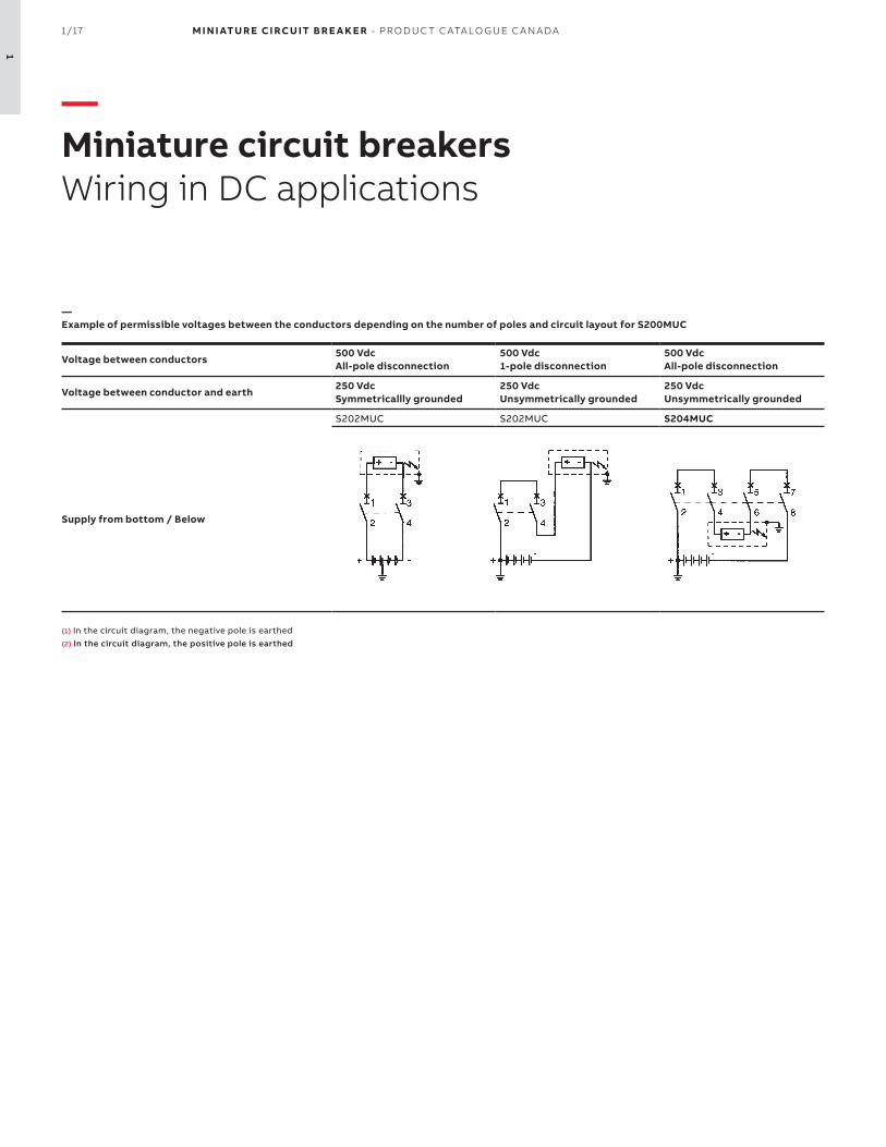
—Miniature circuit breakersWiring in DC applications
—Example of permissible voltages between the conductors depending on the number of poles and circuit layout
Use of S200UDC in direct current circuits (60 / 125 Vdc) according to UL489 / CSA C22.2 No.5S200UDC MCBs can be used in the one-pole version as 60 Vdc, and in the 2-pole version with series connection of two poles up to 125 Vdc.
S200UDC contains fitted permanent magnets, which assists in the forced extinguishing of the arc. If voltages to earth exceeding 60 Vdc may occur, 2-pole S200UDC is to be used for one-pole disconnection.
For DC incoming supply from above S200UDC-… MCBs have, in the area of arc chutes, permanent magnets, it is therefore necessary to take into account the polarity during the installation process.
Doing so ensures that in the case of a short circuit the magnetic field of the permanent magnets corresponds with theelectromagnetic field of the short-circuit current, therefore safely leading the short circuit into the arc chute.
Incorrect polarities may cause damage to the MCB. This is why – in the case of top-fed devices – terminal 1 must be connectedto (-) and terminal to 3 (+).
Voltage between conductors Un
125 V– (≤40 A) 60 V– (>40 A)
250 V– (≤40 A)125 V– (>40 A)
250 V– (≤40 A)125 V– (>40 A)
250 V– (≤40 A)125 V– (>40 A)
Voltage between conductor and earth Un
125 V– (≤40 A) 60 V– (>40 A)
125 V– (≤40 A) 60 V– (>40 A)
250 V– (≤40 A)125 V– (>40 A)
125 V– (≤40 A) 60 V– (>40 A)
1- pole - S201UDC 2-pole - S202UDC 2-pole - S202UDC 2-pole - S202UDC
Supply from bottom
Supply from top
0 V( )
1
2
125 V (≤40 A) 60 V (>40 A)
1
2
3
4
0 V250 V (≤40 A)125 V (>40 A)
1
2
3
4
0 V( )
250 V (≤40 A)125 V (>40 A)
1
2
3
4
0 V( )
125 V (≤40 A) 60 V (>40 A)
125 V (≤40 A) 60 V (>40 A)
1
2
0 V( )
125 V (≤40 A) 60 V (>40 A)
1
2
3
4
0 V250 V (≤40 A)125 V (>40 A)
1
2
3
4
0 V( )
250 V (≤40 A)125 V (>40 A)
1
2
3
4
0 V( )
125 V (≤40 A) 60 V (>40 A)
125 V (≤40 A) 60 V (>40 A)

1/19 M I N I ATU R E CI RCU IT B R E A K E R - PR O D U C T C ATA LO G U E C A N A DA
1
—Miniature circuit breakersWiring in DC applications
—Example for different voltage levels between conductor and earth in case of identical voltage between conductors for S200UDC
Voltage between conductors Un
250 V– (≤40 A)125 V– (>40 A)all-pole disconnection
250 V– (≤40 A)125 V– (>40 A)1-pole disconnection
Voltage between conductor and earth Un
125 V– (≤40 A) 60 V– (>40 A)circuit symmetrically earthed
250 V– (≤40 A)125 V– (>40 A)circuit unsymmetrically earthed
2-pole - S202UDC 2-pole - S202UDC
+
1
2
3
4
– +
1
2
3
4
–

M I N I ATU R E CI RCU IT B R E A K E R - PR O D U C T C ATA LO G U E C A N A DA 1/20
1
—Notes

2/1 M I N I ATU R E CI RCU IT B R E A K E R - PR O D U C T C ATA LO G U E C A N A DA
2

M I N I ATU R E CI RCU IT B R E A K E R - PR O D U C T C ATA LO G U E C A N A DA
2
— CSA C22.2 No.5 / UL489 devices
003 – 006 SU200M
007 SU200MR
008 S200UDC
009 – 013 Accessories
014– 019 Technical details
020 – 024 Tripping curves details
025 – 026 Dimensions
029 – 032 S800U
033 – 034 S804U-UCZ
035 – 036 S804U-PVS
037 – 040 Accessories
041 – 045 Technical details
046 – 049 Tripping curves details
050 – 052 Dimensions
2/3 M I N I ATU R E CI RCU IT B R E A K E R - PR O D U C T C ATA LO G U E C A N A DA
2
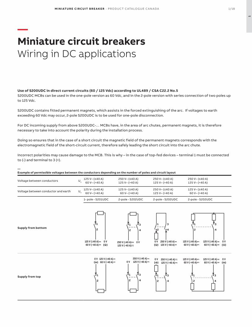
—SU200M seriesUL489 Branch Circuit Protection
The miniature circuit breaker SU200M is ABB’s solution for UL 489 branch circuit protection up to 480 Y/277 V AC and 96 V DC.
This circuit breaker is an all-round device for AC and DC applications for universal use in North American
Moreover, SU200M is fully compatible with System pro M compact® UL 489 accesso-ries.
General Data SU200M
Amperage 0.2 up to 63 A
Voltage 480Y/277 V AC
48/96 V DC (1/2-pole)
Poles 1, 2, 3, 4
Trip curves C, K, Z
Short circuit interrupt rating 10 kA
Auxiliary contacts Yes
Ambient temperature -25 … +55 °C
Mechanical life 20,000 operations
Bell alarm Yes
Shunt trip Yes
Undervoltage release Yes
Busbar Yes
Features• UL current limiting• Fast breaking time (2.3–2.5 ms)• Bus connection system• Wide range of accessories• Available with variable depth handle mechanism• CE certified and marked• DIN rail mounting• Finger-safe terminals• Multi-function terminals• Suitable for reverse feed• CSA C22.2 No.5 certified• UL 489 listed branch circuit protective device• UL File #E212323

M I N I ATU R E CI RCU IT B R E A K E R - PR O D U C T C ATA LO G U E C A N A DA 2/4
2
1 pole Box Qty
Weight each(kg)
Rated Current
Part number
10 0.125 0.5 A SU201M-C0.5
1.0 A SU201M-C1
1.6 A SU201M-C1.6
2.0 A SU201M-C2
3.0 A SU201M-C3
4.0 A SU201M-C4
5.0 A SU201M-C5
6.0 A SU201M-C6
7.0 A SU201M-C7
8.0 A SU201M-C8
10.0 A SU201M-C10
13.0 A SU201M-C13
15.0 A SU201M-C15
16.0 A SU201M-C16
20.0 A SU201M-C20
25.0 A SU201M-C25
30.0 A SU201M-C30
32.0 A SU201M-C32
35.0 A SU201M-C35
40.0 A SU201M-C40
50.0 A SU201M-C50
60.0 A SU201M-C60
63.0 A SU201M-C63
2 poles Box Qty
Weight each(kg)
Rated Current
Part number
5 0.250 0.5 A SU202M-C0.5
1.0 A SU202M-C1
1.6 A SU202M-C1.6
2.0 A SU202M-C2
3.0 A SU202M-C3
4.0 A SU202M-C4
5.0 A SU202M-C5
6.0 A SU202M-C6
7.0 A SU202M-C7
8.0 A SU202M-C8
10.0 A SU202M-C10
13.0 A SU202M-C13
15.0 A SU202M-C15
16.0 A SU202M-C16
20.0 A SU202M-C20
25.0 A SU202M-C25
30.0 A SU202M-C30
32.0 A SU202M-C32
35.0 A SU202M-C35
40.0 A SU202M-C40
50.0 A SU202M-C50
60.0 A SU202M-C60
63.0 A SU202M-C63
3 poles Box Qty
Weight each(kg)
Rated Current
Part number
3 0.375 0.5 A SU203M-C0.5
1.0 A SU203M-C1
1.6 A SU203M-C1.6
2.0 A SU203M-C2
3.0 A SU203M-C3
4.0 A SU203M-C4
5.0 A SU203M-C5
6.0 A SU203M-C6
7.0 A SU203M-C7
8.0 A SU203M-C8
10.0 A SU203M-C10
13.0 A SU203M-C13
15.0 A SU203M-C15
16.0 A SU203M-C16
20.0 A SU203M-C20
25.0 A SU203M-C25
30.0 A SU203M-C30
32.0 A SU203M-C32
35.0 A SU203M-C35
40.0 A SU203M-C40
50.0 A SU203M-C50
60.0 A SU203M-C60
63.0 A SU203M-C63
4 poles Box Qty
Weight each(kg)
Rated Current
Part number
2 0.500 0.5 A SU204M-C0.5
1.0 A SU204M-C1
1.6 A SU204M-C1.6
2.0 A SU204M-C2
3.0 A SU204M-C3
4.0 A SU204M-C4
5.0 A SU204M-C5
6.0 A SU204M-C6
7.0 A SU204M-C7
8.0 A SU204M-C8
10.0 A SU204M-C10
13.0 A SU204M-C13
15.0 A SU204M-C15
16.0 A SU204M-C16
20.0 A SU204M-C20
25.0 A SU204M-C25
30.0 A SU204M-C30
32.0 A SU204M-C32
35.0 A SU204M-C35
40.0 A SU204M-C40
50.0 A SU204M-C50
60.0 A SU204M-C60
63.0 A SU204M-C63
—SU200M seriesC tripping characteristic

2/5 M I N I ATU R E CI RCU IT B R E A K E R - PR O D U C T C ATA LO G U E C A N A DA
2
—SU200M seriesK tripping characteristic
1 pole Box Qty
Weight each(kg)
Rated Current
Part number
10 0.125 0.5 A SU201M-K0.5
1.0 A SU201M-K1
1.6 A SU201M-K1.6
2.0 A SU201M-K2
3.0 A SU201M-K3
4.0 A SU201M-K4
5.0 A SU201M-K5
6.0 A SU201M-K6
7.0 A SU201M-K7
8.0 A SU201M-K8
10.0 A SU201M-K10
13.0 A SU201M-K13
15.0 A SU201M-K15
16.0 A SU201M-K16
20.0 A SU201M-K20
25.0 A SU201M-K25
30.0 A SU201M-K30
32.0 A SU201M-K32
35.0 A SU201M-K35
40.0 A SU201M-K40
50.0 A SU201M-K50
60.0 A SU201M-K60
63.0 A SU201M-K63
2 poles Box Qty
Weight each(kg)
Rated Current
Part number
5 0.250 0.5 A SU202M-K0.5
1.0 A SU202M-K1
1.6 A SU202M-K1.6
2.0 A SU202M-K2
3.0 A SU202M-K3
4.0 A SU202M-K4
5.0 A SU202M-K5
6.0 A SU202M-K6
7.0 A SU202M-K7
8.0 A SU202M-K8
10.0 A SU202M-K10
13.0 A SU202M-K13
15.0 A SU202M-K15
16.0 A SU202M-K16
20.0 A SU202M-K20
25.0 A SU202M-K25
30.0 A SU202M-K30
32.0 A SU202M-K32
35.0 A SU202M-K35
40.0 A SU202M-K40
50.0 A SU202M-K50
60.0 A SU202M-K60
63.0 A SU202M-K63
3 poles Box Qty
Weight each(kg)
Rated Current
Part number
3 0.375 0.5 A SU203M-K0.5
1.0 A SU203M-K1
1.6 A SU203M-K1.6
2.0 A SU203M-K2
3.0 A SU203M-K3
4.0 A SU203M-K4
5.0 A SU203M-K5
6.0 A SU203M-K6
7.0 A SU203M-K7
8.0 A SU203M-K8
10.0 A SU203M-K10
13.0 A SU203M-K13
15.0 A SU203M-K15
16.0 A SU203M-K16
20.0 A SU203M-K20
25.0 A SU203M-K25
30.0 A SU203M-K30
32.0 A SU203M-K32
35.0 A SU203M-K35
40.0 A SU203M-K40
50.0 A SU203M-K50
60.0 A SU203M-K60
63.0 A SU203M-K63
4 poles Box Qty
Weight each(kg)
Rated Current
Part number
2 0.500 0.5 A SU204M-K0.5
1.0 A SU204M-K1
1.6 A SU204M-K1.6
2.0 A SU204M-K2
3.0 A SU204M-K3
4.0 A SU204M-K4
5.0 A SU204M-K5
6.0 A SU204M-K6
7.0 A SU204M-K7
8.0 A SU204M-K8
10.0 A SU204M-K10
13.0 A SU204M-K13
15.0 A SU204M-K15
16.0 A SU204M-K16
20.0 A SU204M-K20
25.0 A SU204M-K25
30.0 A SU204M-K30
32.0 A SU204M-K32
35.0 A SU204M-K35
40.0 A SU204M-K40
50.0 A SU204M-K50
60.0 A SU204M-K60
63.0 A SU204M-K63

M I N I ATU R E CI RCU IT B R E A K E R - PR O D U C T C ATA LO G U E C A N A DA 2/6
2
—SU200M seriesZ tripping characteristic
1 pole Box Qty
Weight each(kg)
Rated Current
Part number
10 0.125 0.5 A SU201M-Z0.5
1.0 A SU201M-Z1
1.6 A SU201M-Z1.6
2.0 A SU201M-Z2
3.0 A SU201M-Z3
4.0 A SU201M-Z4
5.0 A SU201M-Z5
6.0 A SU201M-Z6
7.0 A SU201M-Z7
8.0 A SU201M-Z8
10.0 A SU201M-Z10
13.0 A SU201M-Z13
15.0 A SU201M-Z15
16.0 A SU201M-Z16
20.0 A SU201M-Z20
25.0 A SU201M-Z25
30.0 A SU201M-Z30
32.0 A SU201M-Z32
35.0 A SU201M-Z35
40.0 A SU201M-Z40
50.0 A SU201M-Z50
60.0 A SU201M-Z60
63.0 A SU201M-Z63
2 poles Box Qty
Weight each(kg)
Rated Current
Part number
5 0.250 0.5 A SU202M-Z0.5
1.0 A SU202M-Z1
1.6 A SU202M-Z1.6
2.0 A SU202M-Z2
3.0 A SU202M-Z3
4.0 A SU202M-Z4
5.0 A SU202M-Z5
6.0 A SU202M-Z6
7.0 A SU202M-Z7
8.0 A SU202M-Z8
10.0 A SU202M-Z10
13.0 A SU202M-Z13
15.0 A SU202M-Z15
16.0 A SU202M-Z16
20.0 A SU202M-Z20
25.0 A SU202M-Z25
30.0 A SU202M-Z30
32.0 A SU202M-Z32
35.0 A SU202M-Z35
40.0 A SU202M-Z40
50.0 A SU202M-Z50
60.0 A SU202M-Z60
63.0 A SU202M-Z63
3 poles Box Qty
Weight each(kg)
Rated Current
Part number
3 0.375 0.5 A SU203M-Z0.5
1.0 A SU203M-Z1
1.6 A SU203M-Z1.6
2.0 A SU203M-Z2
3.0 A SU203M-Z3
4.0 A SU203M-Z4
5.0 A SU203M-Z5
6.0 A SU203M-Z6
7.0 A SU203M-Z7
8.0 A SU203M-Z8
10.0 A SU203M-Z10
13.0 A SU203M-Z13
15.0 A SU203M-Z15
16.0 A SU203M-Z16
20.0 A SU203M-Z20
25.0 A SU203M-Z25
30.0 A SU203M-Z30
32.0 A SU203M-Z32
35.0 A SU203M-Z35
40.0 A SU203M-Z40
50.0 A SU203M-Z50
60.0 A SU203M-Z60
63.0 A SU203M-Z63
4 poles Box Qty
Weight each(kg)
Rated Current
Part number
2 0.500 0.5 A SU204M-Z0.5
1.0 A SU204M-Z1
1.6 A SU204M-Z1.6
2.0 A SU204M-Z2
3.0 A SU204M-Z3
4.0 A SU204M-Z4
5.0 A SU204M-Z5
6.0 A SU204M-Z6
7.0 A SU204M-Z7
8.0 A SU204M-Z8
10.0 A SU204M-Z10
13.0 A SU204M-Z13
15.0 A SU204M-Z15
16.0 A SU204M-Z16
20.0 A SU204M-Z20
25.0 A SU204M-Z25
30.0 A SU204M-Z30
32.0 A SU204M-Z32
35.0 A SU204M-Z35
40.0 A SU204M-Z40
50.0 A SU204M-Z50
60.0 A SU204M-Z60
63.0 A SU204M-Z63

2/7 M I N I ATU R E CI RCU IT B R E A K E R - PR O D U C T C ATA LO G U E C A N A DA
2
—SU200MR seriesUL489 Branch Circuit Protection
The SU200MR is a high-performance cir-cuit breaker with ring cable lug connec-tions compliant with UL , CSA and IEC standards.
The integrated captive connecting screws simplify the connection of electric lines with extra protection and time saving.
As part of the proven product range Sys-tem proM compact®, SU200MR can be combined with most of the UL 489 and CSA 22.2 No. 5 approved components.
General Data SU200MR
Amperage 0.2 up to 63 A
Voltage 480Y/277 V AC
Poles 1, 2, 3, 4
Trip curves K
Short circuit interrupt rating 10 kA
Auxiliary contacts Yes
Ambient temperature -25 … +55 °C
Mechanical life 20,000 operations
Bell alarm Yes
Shunt trip Yes
Undervoltage release Yes
Busbar Yes
Features• UL current limiting• Fast breaking time (2.3–2.5 ms)• Bus connection system• Wide range of accessories• Available with variable depth handle mechanism• CE certified and marked• DIN rail mounting• Ring terminals• Finger-safe terminals• Multi-function terminals• Suitable for reverse feed• CSA C22.2 No.5 certified• UL 489 listed branch circuit protective device• UL File #E212323

M I N I ATU R E CI RCU IT B R E A K E R - PR O D U C T C ATA LO G U E C A N A DA 2/8
2
3 pole BoxQty
Weight each(kg)
Rated current
Part number
3 0.420 0.2 A SU203MR-K0.2
0.3 A SU203MR-K0.3
0.5 A SU203MR-K0.5
0.75 A SU203MR-K0.75
1.0 A SU203MR-K1
1.6 A SU203MR-K1.6
2.0 A SU203MR-K2
3.0 A SU203MR-K3
4.0 A SU203MR-K4
5.0 A SU203MR-K5
6.0 A SU203MR-K6
8.0 A SU203MR-K8
10.0 A SU203MR-K10
13.0 A SU203MR-K13
15.0 A SU203MR-K15
16.0 A SU203MR-K16
20.0 A SU203MR-K20
25.0 A SU203MR-K25
30.0 A SU203MR-K30
32.0 A SU203MR-K32
35.0 A SU203MR-K35
40.0 A SU203MR-K40
50.0 A SU203MR-K50
60.0 A SU203MR-K60
63.0 A SU203MR-K63
—SU200MR (ring terminals) seriesK tripping characteristic
1 pole BoxQty
Weight each(kg)
Rated current
Part number
10 0.140 0.2 A SU201MR-K0.2
0.3 A SU201MR-K0.3
0.5 A SU201MR-K0.5
0.75 A SU201MR-K0.75
1.0 A SU201MR-K1
1.6 A SU201MR-K1.6
2.0 A SU201MR-K2
3.0 A SU201MR-K3
4.0 A SU201MR-K4
5.0 A SU201MR-K5
6.0 A SU201MR-K6
8.0 A SU201MR-K8
10.0 A SU201MR-K10
13.0 A SU201MR-K13
15.0 A SU201MR-K15
16.0 A SU201MR-K16
20.0 A SU201MR-K20
25.0 A SU201MR-K25
30.0 A SU201MR-K30
32.0 A SU201MR-K32
35.0 A SU201MR-K35
40.0 A SU201MR-K40
50.0 A SU201MR-K50
60.0 A SU201MR-K60
63.0 A SU201MR-K63
2 pole BoxQty
Weight each(kg)
Rated current
Part number
5 0.280 0.2 A SU202MR-K0.2
0.3 A SU202MR-K0.3
0.5 A SU202MR-K0.5
0.75 A SU202MR-K0.75
1.0 A SU202MR-K1
1.6 A SU202MR-K1.6
2.0 A SU202MR-K2
3.0 A SU202MR-K3
4.0 A SU202MR-K4
5.0 A SU202MR-K5
6.0 A SU202MR-K6
8.0 A SU202MR-K8
10.0 A SU202MR-K10
13.0 A SU202MR-K13
15.0 A SU202MR-K15
16.0 A SU202MR-K16
20.0 A SU202MR-K20
25.0 A SU202MR-K25
30.0 A SU202MR-K30
32.0 A SU202MR-K32
35.0 A SU202MR-K35
40.0 A SU202MR-K40
50.0 A SU202MR-K50
60.0 A SU202MR-K60
63.0 A SU202MR-K63
4 pole BoxQty
Weight each(kg)
Rated current
Part number
2 0.560 0.2 A SU204MR-K0.2
0.3 A SU204MR-K0.3
0.5 A SU204MR-K0.5
0.75 A SU204MR-K0.75
1.0 A SU204MR-K1
1.6 A SU204MR-K1.6
2.0 A SU204MR-K2
3.0 A SU204MR-K3
4.0 A SU204MR-K4
5.0 A SU204MR-K5
6.0 A SU204MR-K6
8.0 A SU204MR-K8
10.0 A SU204MR-K10
13.0 A SU204MR-K13
15.0 A SU204MR-K15
16.0 A SU204MR-K16
20.0 A SU204MR-K20
25.0 A SU204MR-K25
30.0 A SU204MR-K30
32.0 A SU204MR-K32
35.0 A SU204MR-K35
40.0 A SU204MR-K40
50.0 A SU204MR-K50
60.0 A SU204MR-K60
63.0 A SU204MR-K63

2/9 M I N I ATU R E CI RCU IT B R E A K E R - PR O D U C T C ATA LO G U E C A N A DA
2
—S200UDC seriesUL489 Branch Circuit Protection (DC)
The S200UDC Miniature circuit breaker was designed for DC system in UL489 ac-cordance for 60Vdc and 125Vdc
As part of the proven product range Sys-tem proM compact®, S200UDC can be combined with most of the UL 489 and CSA 22.2 No. 5 approved components.
General Data S200UDC
Amperage 1A up to 63 A
Voltage 60 / 125 Vdc
Poles 1, 2
Trip curves K, Z
Short circuit interrupt rating 14 kA
Auxiliary contacts Yes
Ambient temperature -25 … +55 °C
Mechanical life 20,000 operations
Bell alarm Yes
Shunt trip Yes
Undervoltage release Yes
Busbar Yes
Features• UL current limiting• Fast breaking time (2.3–2.5 ms)• Bus connection system• Wide range of accessories• Available with variable depth handle mechanism• CE certified and marked• DIN rail mounting• Ring terminals• Finger-safe terminals• Multi-function terminals• Suitable for reverse feed• CSA C22.2 No.5 certified• UL 489 listed branch circuit protective device• UL File #E212323

M I N I ATU R E CI RCU IT B R E A K E R - PR O D U C T C ATA LO G U E C A N A DA 2/10
21 pole BoxQty
Weight each(kg)
Rated current
Part number
10 0.150 1.0 A S201UDC-K1
1.6 A S201UDC-K1.6
2.0 A S201UDC-K2
3.0 A S201UDC-K3
4.0 A S201UDC-K4
5.0 A S201UDC-K5
6.0 A S201UDC-K6
8.0 A S201UDC-K8
10.0 A S201UDC-K10
13.0 A S201UDC-K13
15.0 A S201UDC-K15
16.0 A S201UDC-K16
20.0 A S201UDC-K20
25.0 A S201UDC-K25
30.0 A S201UDC-K30
32.0 A S201UDC-K32
40.0 A S201UDC-K40
50.0 A S201UDC-K50
60.0 A S201UDC-K60
63.0 A S201UDC-K63
2 poles BoxQty
Weight each(kg)
Rated current
Part number
5 0.300 1.0 A S202UDC-K1
1.6 A S202UDC-K1.6
2.0 A S202UDC-K2
3.0 A S202UDC-K3
4.0 A S202UDC-K4
5.0 A S202UDC-K5
6.0 A S202UDC-K6
8.0 A S202UDC-K8
10.0 A S202UDC-K10
13.0 A S202UDC-K13
15.0 A S202UDC-K15
16.0 A S202UDC-K16
20.0 A S202UDC-K20
25.0 A S202UDC-K25
30.0 A S202UDC-K30
32.0 A S202UDC-K32
40.0 A S202UDC-K40
50.0 A S202UDC-K50
60.0 A S202UDC-K60
63.0 A S202UDC-K63
—S200UDC seriesK tripping characteristic
1 pole BoxQty
Weight each(kg)
Rated current
Part number
10 0.150 1.0 A S201UDC-Z1
1.6 A S201UDC-Z1.6
2.0 A S201UDC-Z2
3.0 A S201UDC-Z3
4.0 A S201UDC-Z4
5.0 A S201UDC-Z5
6.0 A S201UDC-Z6
8.0 A S201UDC-Z8
10.0 A S201UDC-Z10
13.0 A S201UDC-Z13
15.0 A S201UDC-Z15
16.0 A S201UDC-Z16
20.0 A S201UDC-Z20
25.0 A S201UDC-Z25
30.0 A S201UDC-Z30
32.0 A S201UDC-Z32
40.0 A S201UDC-Z40
50.0 A S201UDC-Z50
60.0 A S201UDC-Z60
63.0 A S201UDC-Z63
—S200UDC seriesZ tripping characteristic
2 poles BoxQty
Weight each(kg)
Rated current
Part number
5 0.300 1.0 A S202UDC-Z1
1.6 A S202UDC-Z1.6
2.0 A S202UDC-Z2
3.0 A S202UDC-Z3
4.0 A S202UDC-Z4
5.0 A S202UDC-Z5
6.0 A S202UDC-Z6
8.0 A S202UDC-Z8
10.0 A S202UDC-Z10
13.0 A S202UDC-Z13
15.0 A S202UDC-Z15
16.0 A S202UDC-Z16
20.0 A S202UDC-Z20
25.0 A S202UDC-Z25
30.0 A S202UDC-Z30
32.0 A S202UDC-Z32
40.0 A S202UDC-Z40
50.0 A S202UDC-Z50
60.0 A S202UDC-Z60
63.0 A S202UDC-Z63

2/11 M I N I ATU R E CI RCU IT B R E A K E R - PR O D U C T C ATA LO G U E C A N A DA
2
—Auxiliary contacts and bell alarms
Description Part number
Auxiliary contact (1 form C)
The auxiliary contacts will signal whether the breaker is in the ON or OFF position. Mounts on the right side of the breaker up to maximum of 3 sets
S2C-H6RU
Bell alarm contact (1 form C)
The bell alarm includes a set of contacts that will only signal when the breaker has tripped. It also includes a test button for testing the alarm contacts without opening the breaker. Mounts on the right side of the breaker up to a maximum of 3 sets
S2C-S6RU
—Shunt trip
Description Part number
12...60 Vac/dc Shunt trip
For remote tripping of the breaker, a shunt trip device can be added onto the MCB. The solenoid device opens the breaker after a control voltage is applied. Mounts on the right side of the MCB and can be mixed with auxiliary contacts
S2C-A1U
110...415 Vac (110...250 Vdc) Shunt trip
For remote tripping of the breaker, a shunt trip device can be added onto the MCB. The solenoid device opens the breaker after a control voltage is applied. Mounts on the right side of the MCB and can be mixed with auxiliary contacts
S2C-A2U
+ST+S/H+S/H (H)+S/H (H)
+ST+H+H+H
+S/H+S/H (H)+S/H (H)
+H+H+H
Possible mounting arrangements of electrical accessories
LegendAuxiliary contact H
Bell alarm/auxiliary contact S/H
Bell alarm/auxiliary contact used as auxiliary contact
S/H (H)
Shunt trip ST
—AccessoriesElectrical accessories

M I N I ATU R E CI RCU IT B R E A K E R - PR O D U C T C ATA LO G U E C A N A DA 2/12
2
—Busbars for SU200M (uncuttable)
Amp rating Phase Nbr of pins Busbar length (mm) Part number
80 / 115 A
1
6 103.2 PS 1/6/16BP
12 208.8 PS 1/12/16BP
18 314.4 PS 1/18/16BP
2
6 103.2 PS 2/6/16BP
12 208.8 PS 2/12/16BP
18 314.4 PS 2/18/16BP
3
6 103.2 PS 3/6/16BP
12 208.8 PS 3/12/16BP
18 314.4 PS 3/18/16BP
—Accessories for busbars (uncuttable)
Description Part number
Busbar pin covers (covers 3 unused pins) BSK-BP
Insulated feeder terminal with pin contact (breaker mounting) AST35/15BP
Single pole feeder terminal (busbar mounting) SZ-ESKBP
—AccessoriesElectrical accessories

2/13 M I N I ATU R E CI RCU IT B R E A K E R - PR O D U C T C ATA LO G U E C A N A DA
2
—Busbars for SU200M and SU200MR (cuttable, end caps not included)
Used with Phase Nbr of pins Phase sequence Part number
SU200M
157 L1-L1-L1... PS 1/57/25 BP-C
37 L1-AUX-L1-AUX... (1) PS 1/37/25 H BP-C
256 L1-L2-L1-L2... PS 2/56/25 BP-C
46 L1-L2-AUX-L1-L2-AUX...(1) PS 2/46/25 H BP-C
3
57 L1-L2-L3-L1-L2-L3... PS 3/57/25 BP-C
48 L1-L2-L3-AUXL1-L2-L3-AUX...(1) PS 3/48/25 H BP-C
39 L1-AUX-L2-AUX-L3-AUX...(1) PS 3/39/25 H BP-C
SU200MR
157 L1-L1-L1... PS 1/57/25 BP-CR
37 L1-AUX-L1-AUX... (1) PS 1/37/25 H BP-CR
256 L1-L2-L1-L2... PS 2/56/25 BP-CR
46 L1-L2-AUX-L1-L2-AUX...(1) PS 2/46/25 H BP-CR
3
57 L1-L2-L3-L1-L2-L3... PS 3/57/25 BP-CR
48 L1-L2-L3-AUXL1-L2-L3-AUX...(1) PS 3/48/25 H BP-CR
39 L1-AUX-L2-AUX-L3-AUX...(1) PS 3/39/25 H BP-CR
(1) For devices with auxiliary contact(half module) after each phase sequence
—Accessories for busbars (cuttable)
Used with Description Part number
BothBusbar end cap (mandatory, not included with busbar) covers busbar endings.
PS-END 3 BP-C
SU200M Busbar pin cover (covers 3 unused pins) BSK BP-C
SU200MR Busbar pin cover (covers 3 unused pins) BSK BP-CR
SU200M Single pole feeder terminal (busbar mounting) AST 35/58 BP-C
—AccessoriesElectrical accessories

M I N I ATU R E CI RCU IT B R E A K E R - PR O D U C T C ATA LO G U E C A N A DA 2/14
2
—Rotary handle mechanism
Description Part number
External handle rotary drive. For the actuation of 2, 3 or 4 pole miniature circuit breakers. To be used with 5 or 6 mm2 shafts
S2C-DH
—External handles
Description Color With defeater Part number
Type 3R/12 selector handle, padlockable with maximum 3 padlocks (bail diameter 5...8mm) with door interlock in ON position. Available with defeating option to allow the MCB to stay in ON state when opening the door.
BlackYes OHBS2AJ
No OHBS2AJ1
Yellow-RedYes OHYS2AJ
No OHYS2AJ1
SilverYes OHSS2AJ
No OHSS2AJ1
GreyYes OHGS2AJ
No OHGS2AJ1
—Shafts
Description Length Part number
Shaft extensions to be used with selector typ handles. Shafts are cuttable. 6 mm2 diameter
85 mm OXS6X85
105 mm OXS6X105
120 mm OXS6X120
130 mm OXS6X130
160 mm OXS6X160
180 mm OXS6X180
250 mm OXS6X250
330 mm OXS6X330
—AccessoriesMechanical accessories

2/15 M I N I ATU R E CI RCU IT B R E A K E R - PR O D U C T C ATA LO G U E C A N A DA
2
—Front flange mounting kits
Description Nbr of MCBs Part number
Front flange mounting kit
1 ME1-1
2 ME2-2
3 ME3-3
4 ME4-4
6 ME6-6
8 ME8-8
—Locking devices (lock out / tag out)
Description Used with Part number
Lock out / Tag out adaptor device, removable1 pole devices S2C-LOTO-S
2, 3, 4 pole devices S2C-LOTO-M
—AccessoriesMechanical accessories
—False pole
Description Used with Part number
Used to fill empty spaces on DIN rails (one of each is required)
False pole (1) FP1
DIN rail support for false pole SFP

M I N I ATU R E CI RCU IT B R E A K E R - PR O D U C T C ATA LO G U E C A N A DA 2/16
2
—Technical specifications MCBs
SU200M SU200MR S200UDC
SpecificationsCSA C22.2 No.5
UL489IEC 60947-2
CSA C22.2 No.5UL489
IEC 60947-2
CSA C22.2 No.5UL489
VDE 0660
UL file number E 212323, current limiting E 212323, current limiting E 212323
Nbr of poles 1, 2, 3, 4 1, 2, 3, 4 1,2
Trip curves C, K, Z K K, Z
Amperage 0.2...63 A 0.2...63 A 1...63 A
Voltage AC (1) (1) -
Voltage DC (1p/2p) 48/96 Vdc - 60/125 Vdc
Interrupt rating 10 kA 10 kA 14 kA
Calibration temp 40oC 40oC 25oC
Mounting position Any Any Any
Protection degree IP20 IP20 IP20
Mounting 35 mm DIN rail 35 mm DIN rail 35 mm DIN rail
Tightening torque25 in-lbs
2.8Nm25 in-lbs
2.8Nm25 in-lbs
2.8Nm
Terminal wire size 16...4 AWG 16...4 AWG 16...4 AWG
Ambient temperature-25oC...+55oC-13oF...+131oF
-25oC...+55oC-13oF...+131oF
-25oC...+55oC-13oF...+131oF
Shock resistance (IEC60068-2-27) 25g - 2 shocks - 13ms 25g - 2 shocks - 13ms 25g - 2 shocks - 13ms
Mechanical life 20,000 ops 20,000 ops 20,000 ops
(1) Amperage range Max. Voltage
SU200M-C0.5...40 A 480Y / 277 Vac
50...63 A 240 Vac
SU200M-KSU200MR-K
0.2...35 A 480Y / 277 Vac
40...63 A 240 Vac
SU200M-Z0.5...40 A 480Y / 277 Vac
50...63 A 240 Vac
All types All range 240 Vac
—Technical detailsSU200M (R) and S200UDC series
2/17 M I N I ATU R E CI RCU IT B R E A K E R - PR O D U C T C ATA LO G U E C A N A DA
2
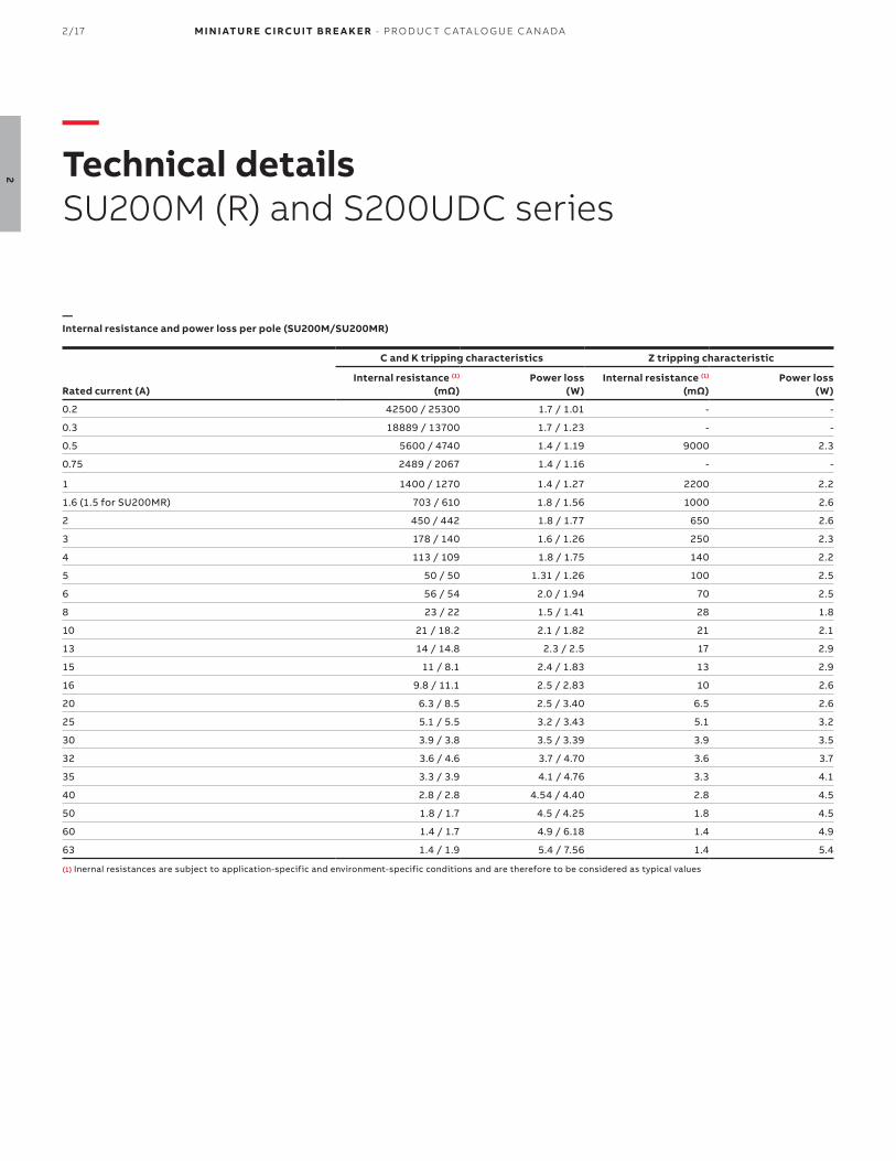
—Internal resistance and power loss per pole (SU200M/SU200MR)
C and K tripping characteristics Z tripping characteristic
Rated current (A)Internal resistance (1)
(mΩ)Power loss
(W)Internal resistance (1)
(mΩ)Power loss
(W)
0.2 42500 / 25300 1.7 / 1.01 - -
0.3 18889 / 13700 1.7 / 1.23 - -
0.5 5600 / 4740 1.4 / 1.19 9000 2.3
0.75 2489 / 2067 1.4 / 1.16 - -
1 1400 / 1270 1.4 / 1.27 2200 2.2
1.6 (1.5 for SU200MR) 703 / 610 1.8 / 1.56 1000 2.6
2 450 / 442 1.8 / 1.77 650 2.6
3 178 / 140 1.6 / 1.26 250 2.3
4 113 / 109 1.8 / 1.75 140 2.2
5 50 / 50 1.31 / 1.26 100 2.5
6 56 / 54 2.0 / 1.94 70 2.5
8 23 / 22 1.5 / 1.41 28 1.8
10 21 / 18.2 2.1 / 1.82 21 2.1
13 14 / 14.8 2.3 / 2.5 17 2.9
15 11 / 8.1 2.4 / 1.83 13 2.9
16 9.8 / 11.1 2.5 / 2.83 10 2.6
20 6.3 / 8.5 2.5 / 3.40 6.5 2.6
25 5.1 / 5.5 3.2 / 3.43 5.1 3.2
30 3.9 / 3.8 3.5 / 3.39 3.9 3.5
32 3.6 / 4.6 3.7 / 4.70 3.6 3.7
35 3.3 / 3.9 4.1 / 4.76 3.3 4.1
40 2.8 / 2.8 4.54 / 4.40 2.8 4.5
50 1.8 / 1.7 4.5 / 4.25 1.8 4.5
60 1.4 / 1.7 4.9 / 6.18 1.4 4.9
63 1.4 / 1.9 5.4 / 7.56 1.4 5.4
(1) Inernal resistances are subject to application-specific and environment-specific conditions and are therefore to be considered as typical values
—Technical detailsSU200M (R) and S200UDC series
M I N I ATU R E CI RCU IT B R E A K E R - PR O D U C T C ATA LO G U E C A N A DA 2/18
2
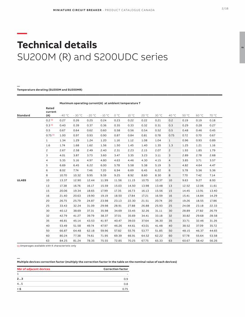
—Temperature derating (SU200M and SU200MR)
Standard
Rated current(A)
Maximum operating current(A) at ambient temperature T
- 40 °C - 30 °C - 20 °C - 10 °C 0 °C 10 °C 20 °C 30 °C 40 °C 50 °C 60 °C 70 °C
UL489
0.2 (1) 0.27 0.26 0.25 0.24 0.23 0.22 0.22 0.21 0.2 0.19 0.19 0.18
0.3 (1) 0.40 0.39 0.37 0.36 0.35 0.33 0.32 0.31 0.3 0.29 0.28 0.27
0.5 0.67 0.64 0.62 0.60 0.58 0.56 0.54 0.52 0.5 0.48 0.46 0.45
0.75 (1) 1.00 0.97 0.93 0.90 0.87 0.84 0.81 0.78 0.75 0.72 0.70 0.67
1 1.34 1.29 1.24 1.20 1.16 1.12 1.08 1.04 1 0.96 0.93 0.89
1.6 1.74 1.68 1.62 1.56 1.50 1.45 1.40 1.35 1.3 1.25 1.21 1.16
2 2.67 2.58 2.49 2.40 2.31 2.23 2.15 2.07 2 1.93 1.85 1.79
3 4.01 3.87 3.73 3.60 3.47 3.35 3.23 3.11 3 2.89 2.78 2.68
4 5.35 5.16 4.97 4.80 4.63 4.46 4.30 4.15 4 3.85 3.71 3.57
5 6.69 6.45 6.22 6.00 5.78 5.58 5.38 5.19 5 4.82 4.64 4.47
6 8.02 7.74 7.46 7.20 6.94 6.69 6.45 6.22 6 5.78 5.56 5.36
8 10.70 10.32 9.95 9.59 9.25 8.92 8.60 8.30 8 7.70 7.42 7.14
10 13.37 12.90 12.44 11.99 11.56 11.15 10.75 10.37 10 9.63 9.27 8.93
13 17.38 16.76 16.17 15.59 15.03 14.50 13.98 13.48 13 12.52 12.06 11.61
15 20.06 19.34 18.65 17.99 17.35 16.73 16.13 15.56 15 14.45 13.91 13.40
16 21.40 20.63 19.90 19.19 18.50 17.84 17.21 16.59 16 15.41 14.84 14.29
20 26.75 25.79 24.87 23.98 23.13 22.30 21.51 20.74 20 19.26 18.55 17.86
25 33.43 32.24 31.09 29.98 28.91 27.88 26.88 25.93 25 24.08 23.18 22.33
30 40.12 38.69 37.31 35.98 34.69 33.45 32.26 31.11 30 28.89 27.82 26.79
32 42.79 41.27 39.79 38.37 37.01 35.69 34.41 33.18 32 30.82 29.68 28.58
35 46.81 45.14 43.53 41.97 40.47 39.03 37.64 36.30 35 33.71 32.46 31.26
40 53.49 51.58 49.74 47.97 46.26 44.61 43.01 41.48 40 38.52 37.09 35.72
50 66.87 64.48 62.18 59.96 57.82 55.76 53.77 51.85 50 48.15 46.37 44.65
60 80.24 77.38 74.61 71.95 69.39 66.91 64.52 62.22 60 57.78 55.64 53.58
63 84.25 81.24 78.35 75.55 72.85 70.25 67.75 65.33 63 60.67 58.42 56.26
(1) Amperages available with K characteristic only
—Technical detailsSU200M (R) and S200UDC series
Nbr of adjacent devices Correction factor
1 -
2...3 0.9
4...5 0.8
> 6 0.75
—Multiple devices correction factor (multiply the correction factor in the table on the nominal value of each devices)

2/19 M I N I ATU R E CI RCU IT B R E A K E R - PR O D U C T C ATA LO G U E C A N A DA
2
—Technical detailsElectrical accessories
—Technical specifications auxiliary contacts
S2C-H6RU S2C-S6RU
Amperage 10 A 10 A
Voltage 24 Vac/dc 24 Vac/dc
Contact type Dry SPDT (form C) Dry SPDT (form C)
Terminal wire capacity #18...14 AWG #18...14 AWG
Installation / wiring See below See below
Tightening torque11 in-lbs
1.2Nm11 in-lbs
1.2 Nm
Shock resistance (DIN IEC 68-2-6)5g , 20 cycles (5...150...5 Hz) at 24 Vac/dc, 5mA auto-
reclosing < 10 ms5g , 20 cycles (5...150...5 Hz) at 24 Vac/dc, 5mA auto-
reclosing < 10 ms
Mechanical life 10,000 ops 10,000 ops
—Connection drawings and installation
Auxiliary contact S2C-H6RU
ON position OFF position
Mounting instruction of S2C-H6RU ProcedureA Remove coupling cover on the right
B Circuit breaker in ON position
C Auxiliary contact in ON position
D Assemble switches
Bell alarm contact S2C-S6RU
ON and OFF position after hand operation
OFF position after tripping
Mounting instruction of S2C-S6RU ProcedureA Remove coupling cover on the right
B Circuit breaker in ON position
C Auxiliary contact in ON position
D Assemble switches

M I N I ATU R E CI RCU IT B R E A K E R - PR O D U C T C ATA LO G U E C A N A DA 2/20
2
—Technical detailsElectrical accessories
—Technical specifications shunt trips
S2C-A1U S2C-A2U
Voltage AC 12...60 V 110...415 V
Voltage DC 12...60 V 110...250 V
Maximum release duration < 10 ms < 10 ms
Minimum release voltage AC 7 V 55 V
Minimum release voltage DC 10 V 80 V
Consumption on release AC 40...200 VA 55...210 VA
Consumption on release DC 40...200 VA 55...110 VA
Coil resistance 3.7 Ω 225 Ω
Installation / wiring See below See below
Terminal wire capacity #18...6 AWG #18...6 AWG
Tightening torque18 in-lbs
2 Nm18 in-lbs
2 Nm
Shunt trip S2C-A...U
Shunt tripin OFFposition
Mounting instruction of S2C-A...U
SU200M S2C-A....U
—Connection drawings and installation

2/21 M I N I ATU R E CI RCU IT B R E A K E R - PR O D U C T C ATA LO G U E C A N A DA
2
—Technical detailsElectrical accessories
—Technical specifications busbars (Electrical)
PS...BP-C / PS...BP-CR
Standards UL508, EN 60947-1 / IEC 60947-1:2004
Rated voltage 600 Vac/dc
Rated frequency 50 Hz (IEC) / 60 Hz (UL/CSA)
Rated impulse withstand voltage ≥ 10kV
Rated current (1) 100 A (200A center-fed)
Short circuit current rating (SCCR) 10 kA 3 cycles @ 600V / 140 kA Fuse class J 200A
—Technical specifications busbars (mechanical)
PS...BP-C / PS...BP-CR
Housing UL508, EN 60947-1 / IEC 60947-1:2004
Resistance to climatic conditions According to DIN EN 60068
Overvoltage category III
Pollution degree 2
—Technical specifications busbars (installation)
PS...BP-C / PS...BP-CR
Cross section 25 mm2
Mounting position Optional
Supply Via cable with ring tongue (PS...BP-CR) direct or via feeder terminal (PS...BP-C)
—Technical specifications busbars (accessories)
PS...BP-C / PS...BP-CR
Shock protection caps BSK BP-C (PS...BP-C) or BSK BP-CR (PS...BP-CR)
End caps Via cable with ring tongue (PS...BP-CR) direct or via feeder terminal (PS...BP-C)
—Technical specifications busbars (approvals)
PS...BP-C / PS...BP-CR
UL508, cULus listed
CE, RoHS
(1) Independently from the current rating of the feeder terminal or busbar, the current-carrying capacity/current rating of the MCB terminal must not be exceeded.

M I N I ATU R E CI RCU IT B R E A K E R - PR O D U C T C ATA LO G U E C A N A DA 2/22
2
—Tripping curves detailsC tripping curve
—
DescriptionThe "C" time-current curve is designed for medium magnetic start-up currents. Instantaneous tripping occurs between 5 and 10 times rated current in 50/60 Hz systems.
Thermal release (1) Magnetic release (2)
Standard ValueTrippingtime
Range of instantaneoustrip
Trippingtime
UL489
Conventional non-tripping current I1 1.03 x In > 1 hr 5 x In > 0.2 s
Conventional trippingcurrent I2 1.25 x In < 1 hr (3) 10 x In < 0.2 s
(1) The thermal releases are calibrated to a nominal reference ambient temperature e.g. for UL489 of 40°C. In the case of higher ambient temperature, the current values fall by approx. 4% for each 10 K temperature rise.
(2) The indicated tripping value of electromagnetic tripping devices apply to a frequency of 50/60Hz. The thermal release operated independent of frequency.
(3) As from operating temperature (after I1 > 1 hr)

2/23 M I N I ATU R E CI RCU IT B R E A K E R - PR O D U C T C ATA LO G U E C A N A DA
2
—Tripping curves detailsK tripping curve
—
DescriptionThe "K" time-current characteristic considers high magnetic start-up currents from motors, transformers and other equipment. Instantaneous tripping occurs between 8 and 12 times rated current in 50/60Hz systems. The "K" characteristic is available up through 63 amperes.
The "K" curve offers the best protection for the broadest range of electrical systems. The higher magnetic trip settings maximizes protection while allowing for higher in-rush currents during system start-up.
Thermal release (1) Magnetic release (2)
Standard ValueTrippingtime
Range of instantaneoustrip
Trippingtime
UL489
Conventional non-tripping current I1 1.03 x In > 1 hr 10 x In > 0.2 s
Conventional trippingcurrent I2 1.25 x In < 1 hr (3) 14 x In < 0.2 s
(1) The thermal releases are calibrated to a nominal reference ambient temperature e.g. for UL489 of 40°C. In the case of higher ambient temperature, the current values fall by approx. 4% for each 10 K temperature rise.
(2) The indicated tripping value of electromagnetic tripping devices apply to a frequency of 50/60Hz. The thermal release operated independent of frequency.
(3) As from operating temperature (after I1 > 1 hr)

M I N I ATU R E CI RCU IT B R E A K E R - PR O D U C T C ATA LO G U E C A N A DA 2/24
2
—Tripping curves detailsZ tripping curve
—
DescriptionThe "Z" characteristic offers instantaneous tripping between 2 and 3 times rated current in 50/60Hz systems.
Many applications require a very low short circuit trip settings in order to protect semiconductor or other sensitive devices and the "Z" trip characteristic may provide maximum protection and service in these applications.
Thermal release (1) Magnetic release (2)
Standard ValueTrippingtime
Range of instantaneoustrip
Trippingtime
UL489
Conventional non-tripping current I1 1.03 x In > 1 hr 2 x In > 0.2 s
Conventional trippingcurrent I2 1.25 x In < 1 hr (3) 3 x In < 0.2 s
(1) The thermal releases are calibrated to a nominal reference ambient temperature e.g. for UL489 of 40°C. In the case of higher ambient temperature, the current values fall by approx. 4% for each 10 K temperature rise.
(2) The indicated tripping value of electromagnetic tripping devices apply to a frequency of 50/60Hz. The thermal release operated independent of frequency.
(3) As from operating temperature (after I1 > 1 hr)

2/25 M I N I ATU R E CI RCU IT B R E A K E R - PR O D U C T C ATA LO G U E C A N A DA
2
—Tripping curves detailsK tripping curve (S200UDC)
—
DescriptionThe "K" time-current characteristic for S200UDC was specifically designed to offer instantaneous tripping between 14 and 25 times rated current in DC systems.
Thermal release (1) Magnetic release
Standard ValueTrippingtime
Range of instantaneoustrip
Trippingtime
UL489
Conventional non-tripping current I1 1.0 x In > 1 hr 14 x In > 0.2 s
Conventional trippingcurrent I2 1.35 x In < 1 hr (3) 25 x In < 0.2 s
(1) The thermal releases are calibrated to a nominal reference ambient temperature e.g. for UL489 of 40°C. In the case of higher ambient temperature, the current values fall by approx. 4% for each 10 K temperature rise.
(3) As from operating temperature (after I1 > 1 hr)

M I N I ATU R E CI RCU IT B R E A K E R - PR O D U C T C ATA LO G U E C A N A DA 2/26
2
—Tripping curves detailsZ tripping curve (S200UDC)
—
DescriptionThe "Z" time-current characteristic for S200UDC was specifically designed to offer fast instantaneous tripping between 3 and 6 times rated current in DC systems.
Thermal release (1) Magnetic release
Standard ValueTrippingtime
Range of instantaneoustrip
Trippingtime
UL489
Conventional non-tripping current I1 1.00 x In > 1 hr 3 x In > 2 s
Conventional trippingcurrent I2 1.35 x In < 1 hr (3) 6 x In < 2 s
(1) The thermal releases are calibrated to a nominal reference ambient temperature e.g. for UL489 of 40°C. In the case of higher ambient temperature, the current values fall by approx. 4% for each 10 K temperature rise.
(3) As from operating temperature (after I1 > 1 hr)

2/27 M I N I ATU R E CI RCU IT B R E A K E R - PR O D U C T C ATA LO G U E C A N A DA
2
—DimensionsSU200M and S200UDC series
—SU200M approximate dimensions
—SU200MR approximate dimensions
—S200UDC approximate dimensions

M I N I ATU R E CI RCU IT B R E A K E R - PR O D U C T C ATA LO G U E C A N A DA 2/28
2
—DimensionsAccessories and busbars
—S2C-H6RU, S2C-S6RU approximate dimensions
—S2C-A1U, S2C-A2U approximate dimensions
10.50 1.8
22
17.60
950-1003
5.00
19.3
1.8
—PS...BP-C, PS...BP-CR approximate dimensions
2/29 M I N I ATU R E CI RCU IT B R E A K E R - PR O D U C T C ATA LO G U E C A N A DA
2
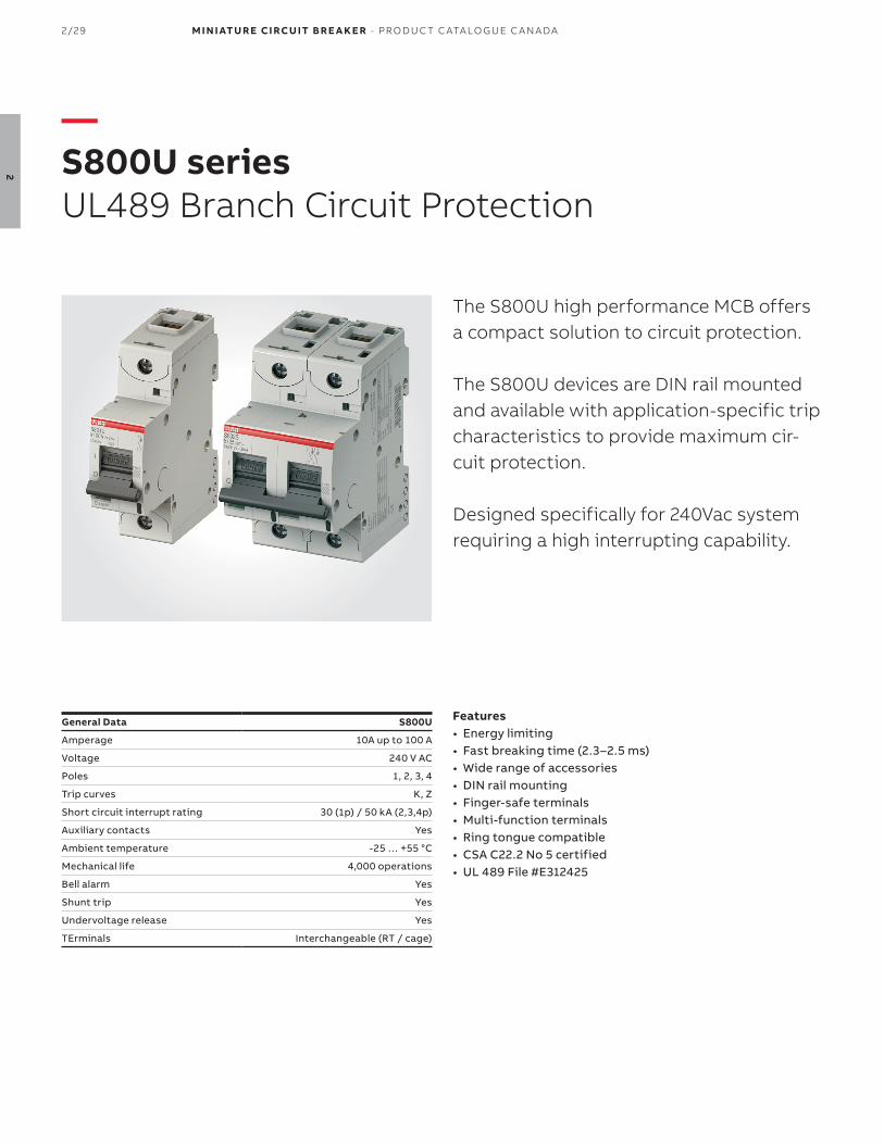
—S800U seriesUL489 Branch Circuit Protection
The S800U high performance MCB offers a compact solution to circuit protection.
The S800U devices are DIN rail mounted and available with application-specific trip characteristics to provide maximum cir-cuit protection.
Designed specifically for 240Vac system requiring a high interrupting capability.
General Data S800U
Amperage 10A up to 100 A
Voltage 240 V AC
Poles 1, 2, 3, 4
Trip curves K, Z
Short circuit interrupt rating 30 (1p) / 50 kA (2,3,4p)
Auxiliary contacts Yes
Ambient temperature -25 … +55 °C
Mechanical life 4,000 operations
Bell alarm Yes
Shunt trip Yes
Undervoltage release Yes
TErminals Interchangeable (RT / cage)
Features• Energy limiting• Fast breaking time (2.3–2.5 ms)• Wide range of accessories• DIN rail mounting• Finger-safe terminals• Multi-function terminals• Ring tongue compatible• CSA C22.2 No 5 certified• UL 489 File #E312425

M I N I ATU R E CI RCU IT B R E A K E R - PR O D U C T C ATA LO G U E C A N A DA 2/30
2
2 poles BoxQty
Weight each(kg)
Rated current
Part number
1 0.490 10.0 A S802U-K10
15.0 A S802U-K15
20.0 A S802U-K20
25.0 A S802U-K25
30.0 A S802U-K30
40.0 A S802U-K40
50.0 A S802U-K50
60.0 A S802U-K60
70.0 A S802U-K70
80.0 A S802U-K80
90.0 A S802U-K90
100.0 A S802U-K100
1 pole BoxQty
Weight each(kg)
Rated current
Part number
1 0.245 10.0 A S801U-K10
15.0 A S801U-K15
20.0 A S801U-K20
25.0 A S801U-K25
30.0 A S801U-K30
40.0 A S801U-K40
50.0 A S801U-K50
60.0 A S801U-K60
70.0 A S801U-K70
80.0 A S801U-K80
90.0 A S801U-K90
100.0 A S801U-K100
—S800U seriesK tripping characteristic (240Vac)
3 poles BoxQty
Weight each(kg)
Rated current
Part number
1 0.735 10.0 A S803U-K10
15.0 A S803U-K15
20.0 A S803U-K20
25.0 A S803U-K25
30.0 A S803U-K30
40.0 A S803U-K40
50.0 A S803U-K50
60.0 A S803U-K60
70.0 A S803U-K70
80.0 A S803U-K80
90.0 A S803U-K90
100.0 A S803U-K100
4 poles BoxQty
Weight each(kg)
Rated current
Part number
1 0.980 10.0 A S804U-K10
15.0 A S804U-K15
20.0 A S804U-K20
25.0 A S804U-K25
30.0 A S804U-K30
40.0 A S804U-K40
50.0 A S804U-K50
60.0 A S804U-K60
70.0 A S804U-K70
80.0 A S804U-K80
90.0 A S804U-K90
100.0 A S804U-K100

2/31 M I N I ATU R E CI RCU IT B R E A K E R - PR O D U C T C ATA LO G U E C A N A DA
2
1 pole BoxQty
Weight each(kg)
Rated current
Part number
1 0.245 10.0 A S801U-Z10
15.0 A S801U-Z15
20.0 A S801U-Z20
25.0 A S801U-Z25
30.0 A S801U-Z30
40.0 A S801U-Z40
50.0 A S801U-Z50
60.0 A S801U-Z60
70.0 A S801U-Z70
80.0 A S801U-Z80
90.0 A S801U-Z90
100.0 A S801U-Z100
2 poles BoxQty
Weight each(kg)
Rated current
Part number
1 0.490 10.0 A S802U-Z10
15.0 A S802U-Z15
20.0 A S802U-Z20
25.0 A S802U-Z25
30.0 A S802U-Z30
40.0 A S802U-Z40
50.0 A S802U-Z50
60.0 A S802U-Z60
70.0 A S802U-Z70
80.0 A S802U-Z80
90.0 A S802U-Z90
100.0 A S802U-Z100
—S800U seriesZ tripping characteristic (240Vac)
3 poles BoxQty
Weight each(kg)
Rated current
Part number
1 0.735 10.0 A S803U-Z10
15.0 A S803U-Z15
20.0 A S803U-Z20
25.0 A S803U-Z25
30.0 A S803U-Z30
40.0 A S803U-Z40
50.0 A S803U-Z50
60.0 A S803U-Z60
70.0 A S803U-Z70
80.0 A S803U-Z80
90.0 A S803U-Z90
100.0 A S803U-Z100
4 poles BoxQty
Weight each(kg)
Rated current
Part number
1 0.980 10.0 A S804U-Z10
15.0 A S804U-Z15
20.0 A S804U-Z20
25.0 A S804U-Z25
30.0 A S804U-Z30
40.0 A S804U-Z40
50.0 A S804U-Z50
60.0 A S804U-Z60
70.0 A S804U-Z70
80.0 A S804U-Z80
90.0 A S804U-Z90
100.0 A S804U-Z100

M I N I ATU R E CI RCU IT B R E A K E R - PR O D U C T C ATA LO G U E C A N A DA 2/32
2
—Notes

2/33 M I N I ATU R E CI RCU IT B R E A K E R - PR O D U C T C ATA LO G U E C A N A DA
2
—S804U-UCZ and PVS5 seriesUL489 Branch Circuit Protection
The S804U-UCZ high performance MCB offers a compact solution to circuit pro-tection in 600Vdc systems
It is available as 4-pole version with a short-circuit current rating of 10 kA accord-ing to UL 489.
General Data S800U
Amperage 10A up to 80 A
Voltage 600 Vdc
Poles 4p in series
Trip curves Z
Short circuit interrupt rating 10 kA
Auxiliary contacts -
Ambient temperature -25 … +60 °C
Bell alarm -
Shunt trip -
Undervoltage release -
TErminals Cage (compression)
Features• Energy limiting• Fast breaking time (2.3–2.5 ms)• Wide range of accessories• DIN rail mounting• Finger-safe terminals• Multi-function terminals• CSA C22.2 No 5 certified• UL 489 File #E312425

M I N I ATU R E CI RCU IT B R E A K E R - PR O D U C T C ATA LO G U E C A N A DA 2/34
2
—S804U-UCZ seriesZ tripping characteristic (600Vdc)
4 poles BoxQty
Weight each(kg)
Rated current
Part number
1 0.980 10.0 A S804U-Z10
15.0 A S804U-Z15
20.0 A S804U-Z20
25.0 A S804U-Z25
30.0 A S804U-Z30
40.0 A S804U-Z40
50.0 A S804U-Z50
60.0 A S804U-Z60
70.0 A S804U-Z70
80.0 A S804U-Z80
90.0 A S804U-Z90
100.0 A S804U-Z100
—Technical specifications
10...32 A 40...63 A 70...80 A
Conductor typeSingle conductor per terminal
copper only, 60/75 °C wireSingle conductor per terminal
copper only, 60 °C wireSingle conductor per terminal
copper only, 60 °C wire
Wire range#14...2 AWG, Cu
solid or stranded1/0...8 AWG, Cu
solid or stranded1/0...8 AWG, Cu
solid or stranded
Jumper length 1 ft (30.5 cm) 1 ft (30.5 cm) 2 ft (61 cm)
—Tested and listed wirings (line and load might be reversed)
jumper jumper jumper jumper
jumper jumperjumper
jumperjumperjumperjumper
jumper
jumper jumper
Line and load migth be reversed
jumper+ LOADLOAD+-
LOAD+
-
+
-
LOAD
LOAD LOAD
++
-+-
Ampere rating (A) 10–32
Conductor typeSingle conductor per terminal –copper only, 60/75 ºC wire
AWG, wire range
Jumper length (cm)Jumper length (ft)
14 AWG–2 AWGCu, solid or stranded
130.5
40–63
Single conductor per terminal –copper only, 60 ºC wire only
1/0 AWG–8 AWGCu, solid or stranded
130.5
70–80
Single conductor per terminal –copper only, 60 ºC wire only
1/0 AWG–8 AWGCu, solid or stranded
261

2/35 M I N I ATU R E CI RCU IT B R E A K E R - PR O D U C T C ATA LO G U E C A N A DA
2
—S804U-PVS5 seriesUL489B Branch Circuit Protection
The S804U-PVS5 is for GFDI application (GroundFault Detector Interrupter) in pho-tovoltaic systems.
In case of a ground fault, the breaker will trip. Thus the PV generator will not be damaged. The breaker is tested acc. to UL489B for 1000 V d.c.
General Data S804U-PVS
Amperage 5 A
Voltage 1000 Vdc
Poles 4p in series
Trip curves PVS
Short circuit interrupt rating 3 kA
Auxiliary contacts -
Ambient temperature -25 … +55 °C
Bell alarm -
Shunt trip -
Undervoltage release -
TErminals Cage (compression)
Features• Energy limiting• Fast breaking time (2.3–2.5 ms)• Wide range of accessories• DIN rail mounting• Finger-safe terminals• Multi-function terminals• CSA C22.2 No 5 certified• UL 489 File #E312425

M I N I ATU R E CI RCU IT B R E A K E R - PR O D U C T C ATA LO G U E C A N A DA 2/36
2
—S804U-PVS5 seriesPV-S tripping characteristic for GFDI in PV applications (1000Vdc)
4 poles BoxQty
Weight each(kg)
Rated current
Part number
1 0.980 5.0 A S804U-PVS5
—Tested and listed wirings (line and load might be reversed)
1-ft 1-ft 1-ft 1-ft
1-ft 1-ft1-ft
1-ft1-ft1-ft1-ft
1-ft
1-ft 1-ft
Line and load migth be reversed
1-ft+ LOADLOAD
+-
LOAD+
-
+
-
LOAD
LOAD LOAD
++
-+-
Ampere Rating [A]10–32
Conductor TypeSingle conductor per terminal –copper only, 60/75°C wire
AWG, Wire Range
Jumper Length [cm]Jumper Length [ft]
14 AWG–2 AWGCu, solid or stranded
130.5
40–63Single conductor per terminal –copper only, 60°C wire only1/0 AWG–8 AWGCu, solid or stranded
130.5
70–80Single conductor per terminal –copper only, 60°C wire only1/0 AWG–8 AWGCu, solid or stranded
261

2/37 M I N I ATU R E CI RCU IT B R E A K E R - PR O D U C T C ATA LO G U E C A N A DA
2
—Auxiliary contacts and bell alarms
Description Part number
Auxiliary contact (2 form C)
The auxiliary contacts will signal whether the breaker is in the ON or OFF position. Mounts on the left side of the breaker up to maximum of 2 sets
S800-AUX
Combined auxiliary contact + bell alarm (2 form C)
The S800-AUX/ALT combined auxiliary and signal contact is used for electrical signaling of theoperating state of the high performance MCB. One signal for the on/off/ state, one signal for tripped state only. Mounts on the left side of the breaker up to maximum of 2 sets.
S800-AUX/ALT
—Shunt trip
—AccessoriesElectrical accessories
Description Part number
24 Vac/dc Shunt trip
For remote tripping of the breaker, a shunt trip device can be added onto the MCB. The solenoid device opens the breaker after a control voltage is applied. Mounts on the left side of the MCB and can be mixed with auxiliary contacts
S800-SOR24
48...130 Vac/dc Shunt trip
For remote tripping of the breaker, a shunt trip device can be added onto the MCB. The solenoid device opens the breaker after a control voltage is applied. Mounts on the left side of the MCB and can be mixed with auxiliary contacts
S800-SOR130
110...250 Vdc Shunt trip
For remote tripping of the breaker, a shunt trip device can be added onto the MCB. The solenoid device opens the breaker after a control voltage is applied. Mounts on the left side of the MCB and can be mixed with auxiliary contacts
S800-SOR250

M I N I ATU R E CI RCU IT B R E A K E R - PR O D U C T C ATA LO G U E C A N A DA 2/38
2
—Undervoltage release
—AccessoriesElectrical accessories
Description Part number
24...36 Vac/dc undervoltage release
For remote tripping of the breaker, when the voltage drops below approximately 50% of rated voltage. The breaker can't be operated unless proper voltage is first applied. Mounts on the left side of the MCB and can be mixed with auxiliary contacts
S800-UVR36
48...60 Vac/dc undervoltage release
For remote tripping of the breaker, when the voltage drops below approximately 50% of rated voltage. The breaker can't be operated unless proper voltage is first applied. Mounts on the left side of the MCB and can be mixed with auxiliary contacts
S800-UVR60
110...130 Vac/dc undervoltage release
For remote tripping of the breaker, when the voltage drops below approximately 50% of rated voltage. The breaker can't be operated unless proper voltage is first applied. Mounts on the left side of the MCB and can be mixed with auxiliary contacts
S800-UVR130
220...250 Vdc undervoltage release
For remote tripping of the breaker, when the voltage drops below approximately 50% of rated voltage. The breaker can't be operated unless proper voltage is first applied. Mounts on the left side of the MCB and can be mixed with auxiliary contacts
S800-UVR250
—Remote switching unit and cable
Description Part number
Remote switching unit (breaker not included)
The RSU will allow a remote operation of the circuit breaker when 24Vdc is appliedS800W-RSU
Connecting cable and plug (mandatory with RSU)
Used with the RSU to provide power and controle. 3 meter cable 0.5 mm2 (#20 AWG) including 10-pole Micro-Fit 3.0 TM plug.
S800-RSU-CP
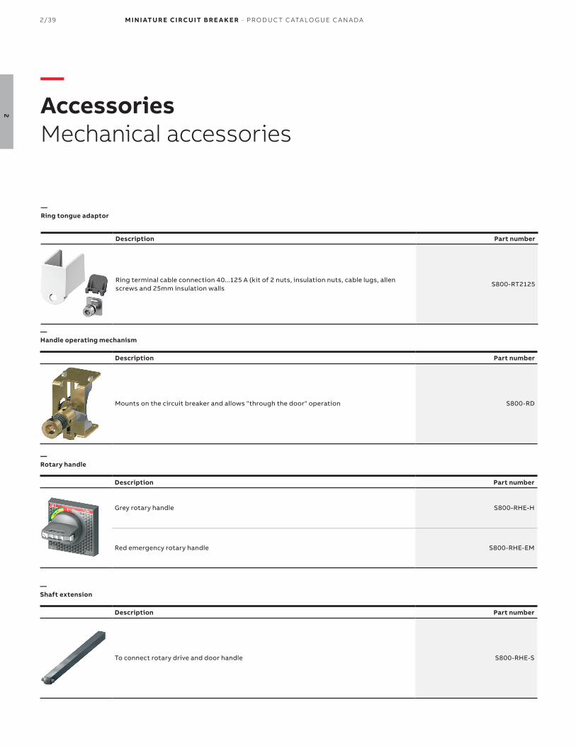
2/39 M I N I ATU R E CI RCU IT B R E A K E R - PR O D U C T C ATA LO G U E C A N A DA
2
—Ring tongue adaptor
Description Part number
Ring terminal cable connection 40...125 A (kit of 2 nuts, insulation nuts, cable lugs, allen screws and 25mm insulation walls
S800-RT2125
—AccessoriesMechanical accessories
—Rotary handle
Description Part number
Grey rotary handle S800-RHE-H
Red emergency rotary handle S800-RHE-EM
—Shaft extension
Description Part number
To connect rotary drive and door handle S800-RHE-S
—Handle operating mechanism
Description Part number
Mounts on the circuit breaker and allows "through the door" operation S800-RD

M I N I ATU R E CI RCU IT B R E A K E R - PR O D U C T C ATA LO G U E C A N A DA 2/40
2
—AccessoriesMechanical accessories
—UL locking device
Description Part number
Lock out / tag out device for S800 series (padlock not included) S800U-PLL

2/41 M I N I ATU R E CI RCU IT B R E A K E R - PR O D U C T C ATA LO G U E C A N A DA
2
—Technical specifications MCBs
S800U S800U-UCZ S800U-PVS
SpecificationsCSA C22.2 No.5-02
UL489IEC 60947-2
CSA C22.2 No.5UL489
IEC 60947-2
CSA C22.2 No.5UL489B
IEC 60947-2
UL file number E 312425, cULus E 212323, current limiting E 212323, current limiting
Nbr of poles 1, 2, 3, 4 4 4
Trip curves K, Z UCZ PVS
Amperage 10...100 A 10...80 A 5 A
Voltage AC 240 Vac - -
Voltage DC (1p/2p) - 600 Vdc 1000 Vdc
Interrupt rating 30 kA (1p), 50 kA 10 kA 1.5 kA
Calibration temp 25oC 25oC 50oC
Mounting position Any Any Any
Protection degree IP20 IP20 IP20
Mounting 35 mm DIN rail 35 mm DIN rail 35 mm DIN rail
Tightening torque31 in-lbs
3.5Nm31 in-lbs
3.5Nm31 in-lbs
3.5Nm
Terminal wire size (1) (1) (1)
Ambien temperature-25oC...+60oC-13oF...+140oF
-25oC...+60oC-13oF...+140oF
-25oC...+60oC-13oF...+140oF
Application type Building installation Datacenter, critical power GFDI in PV applications
Mechanical life 4,000 ops 4,000 ops 1,000 ops
—Technical detailsS800U, UCZ, PVS series
(1) Wire size (Cu, solid or stranded)
S800U 14...2 AWG (10-30A)8...1/0 AWG (10-100A)
S800U-UCZ 14...2 AWG (10-32A)8...1/0 AWG (40-80A)
S800U-PVS 14...2AWG

M I N I ATU R E CI RCU IT B R E A K E R - PR O D U C T C ATA LO G U E C A N A DA 2/42
2
—Internal resistance and power loss at 25oC (S800-K, S800U-Z)
K and Z tripping characteristics
Rated current (A)Internal resistance (1)
(mΩ)Power loss
(W)
10 15.2 1.5
15 12.1 2.7
20 8.7 3.5
25 6.8 4.2
30 3.1 2.8
40 2.3 3.7
50 1.7 4.3
60 1.6 5.8
70 1.0 6.4
80 1.0 6.4
90 0.8 6.5
100 0.8 8.3
—Technical detailsS800U, UCZ, PVS series
—Temperature derating (S800U, UCZ and PVS)
Standard
Rated current(A)
Maximum operating current(A) at ambient temperature T
10 °C 15 °C 20 °C 25 °C 30 °C 35 °C 40 °C 45 °C 50 °C 55 °C 60 °C
UL489
10 10.9 10.7 10.4 10.0 9.6 9.3 9.0 8.7 8.4 8.0 7.6
15 16.5 16.0 15.6 15.0 14.4 14.0 13.5 13.0 12.6 12.0 11.4
20 22.0 21.4 20.8 20.0 19.2 18.6 18.0 17.4 16.8 16.0 15.2
25 27.5 26.8 26.0 25.0 24.0 23.3 22.5 21.8 21.0 20.0 19.0
30 33.1 32.1 31.2 30.0 28.8 27.9 27.0 26.1 25.2 24.0 22.9
40 44.0 42.8 41.6 40.0 38.4 37.2 36.0 34.8 33.6 32.0 30.9
50 55.1 53.5 52.0 50.0 48.0 46.5 45.0 43.5 42.0 40.0 38.3
60 66.2 64.2 62.4 60.0 57.6 55.8 54.0 52.2 50.4 48.0 46.0
70 76.9 74.9 72.8 70.0 67.2 65.1 63.0 60.9 58.8 56.0 53.4
80 88.0 85.6 83.2 80.0 76.8 74.4 72.0 69.6 67.1 64.0 61.6
90 99.1 96.3 93.6 90.0 86.4 83.7 81.0 78.3 75.6 72.0 69.5
100 110.5 107.0 104.0 100.0 96.0 93.0 90.0 87.0 83.8 80.0 77.8

2/43 M I N I ATU R E CI RCU IT B R E A K E R - PR O D U C T C ATA LO G U E C A N A DA
2
—Technical detailsElectrical accessories
—Technical specifications auxiliary contacts S800AUX, S800AUX/ALT
S800-AUX S800-AUX/ALT
Usage category
AC15 400/2 A-ULAC15 240/6 A-ULDC13 250/0.55 ADC13 125 V/1.1A
DC13/60 V/2ADC13 24 V/4A
AC15 400/2 A-ULAC15 240/6 A-ULDC13 250/0.55 ADC13 125 V/1.1A
DC13/60 V/2ADC13 24 V/4A
Continuous thermal current 6 A 6 A
Ratd insulation voltage 690 V 690 V
Number of contacts 2 2 (1 AUX + 1 ALT)
Rated impulse withstand voltage 6 kV 6 kV
Protection degree 3 3
Function of contact Change over (dry SPDT) Change over (dry SPDT)
Connection (CU) 1x 2.5mm2 or 2x 1.5 mm2 1x 2.5mm2 or 2x 1.5 mm2
Tightening torque 1 Nm 1 Nm
Ensured contacts during shake testaccording to IEC 68-2-6
5g, 20 frequency cycle at 24 Vac/dc5 mA brief interrupt < 10 ms
5g, 20 frequency cycle at 24 Vac/dc5 mA brief interrupt < 10 ms
Supply Any Any
Mounting On MCB, DIN rail On MCB, DIN rail
Type of protection IP20 IP20
Permissible ambient temperature-25oC...+60oC-13oF...+140oF
-25oC...+60oC-13oF...+140oF
Storage temperature-40oC...+70oC
-40oF...+158oF-40oC...+70oC
-40oF...+158oF
Mechanical life 6,000 ops 6,000 ops
Resistance to vibration IEC 60068-2-27, 60068-2, 61373 Cat. 1/ class B IEC 60068-2-27, 60068-2, 61373 Cat. 1/ class B
—Connection drawings (normal state - OFF position below)
Auxiliary contact S800-AUX Auxiliary contact S800-AUX/ALT
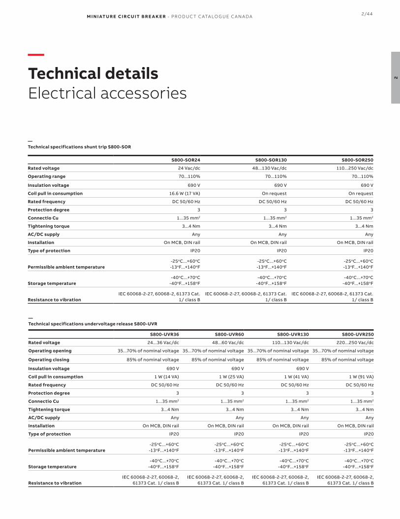
M I N I ATU R E CI RCU IT B R E A K E R - PR O D U C T C ATA LO G U E C A N A DA 2/44
2
—Technical detailsElectrical accessories
—Technical specifications shunt trip S800-SOR
S800-SOR24 S800-SOR130 S800-SOR250
Rated voltage 24 Vac/dc 48...130 Vac/dc 110...250 Vac/dc
Operating range 70...110% 70...110% 70...110%
Insulation voltage 690 V 690 V 690 V
Coil pull in consumption 16.6 W (17 VA) On request On request
Rated frequency DC 50/60 Hz DC 50/60 Hz DC 50/60 Hz
Protection degree 3 3 3
Connectio Cu 1...35 mm2 1...35 mm2 1...35 mm2
Tightening torque 3...4 Nm 3...4 Nm 3...4 Nm
AC/DC supply Any Any Any
Installation On MCB, DIN rail On MCB, DIN rail On MCB, DIN rail
Type of protection IP20 IP20 IP20
Permissible ambient temperature-25oC...+60oC-13oF...+140oF
-25oC...+60oC-13oF...+140oF
-25oC...+60oC-13oF...+140oF
Storage temperature-40oC...+70oC
-40oF...+158oF-40oC...+70oC
-40oF...+158oF-40oC...+70oC
-40oF...+158oF
Resistance to vibrationIEC 60068-2-27, 60068-2, 61373 Cat.
1/ class BIEC 60068-2-27, 60068-2, 61373 Cat.
1/ class BIEC 60068-2-27, 60068-2, 61373 Cat.
1/ class B
S800-UVR36 S800-UVR60 S800-UVR130 S800-UVR250
Rated voltage 24...36 Vac/dc 48...60 Vac/dc 110...130 Vac/dc 220...250 Vac/dc
Operating opening 35...70% of nominal voltage 35...70% of nominal voltage 35...70% of nominal voltage 35...70% of nominal voltage
Operating closing 85% of nominal voltage 85% of nominal voltage 85% of nominal voltage 85% of nominal voltage
Insulation voltage 690 V 690 V 690 V
Coil pull in consumption 1 W (14 VA) 1 W (25 VA) 1 W (41 VA) 1 W (91 VA)
Rated frequency DC 50/60 Hz DC 50/60 Hz DC 50/60 Hz DC 50/60 Hz
Protection degree 3 3 3 3
Connectio Cu 1...35 mm2 1...35 mm2 1...35 mm2 1...35 mm2
Tightening torque 3...4 Nm 3...4 Nm 3...4 Nm 3...4 Nm
AC/DC supply Any Any Any Any
Installation On MCB, DIN rail On MCB, DIN rail On MCB, DIN rail On MCB, DIN rail
Type of protection IP20 IP20 IP20 IP20
Permissible ambient temperature-25oC...+60oC-13oF...+140oF
-25oC...+60oC-13oF...+140oF
-25oC...+60oC-13oF...+140oF
-25oC...+60oC-13oF...+140oF
Storage temperature-40oC...+70oC
-40oF...+158oF-40oC...+70oC
-40oF...+158oF-40oC...+70oC
-40oF...+158oF-40oC...+70oC
-40oF...+158oF
Resistance to vibrationIEC 60068-2-27, 60068-2,
61373 Cat. 1/ class BIEC 60068-2-27, 60068-2,
61373 Cat. 1/ class BIEC 60068-2-27, 60068-2,
61373 Cat. 1/ class BIEC 60068-2-27, 60068-2,
61373 Cat. 1/ class B
—Technical specifications undervoltage release S800-UVR

2/45 M I N I ATU R E CI RCU IT B R E A K E R - PR O D U C T C ATA LO G U E C A N A DA
2
—Technical detailsElectrical accessories
—Technical specifications S800W-RSU
S800-SOR250
Operating voltage 24 Vdc
Current consumption 2.5 A
Standby current < 50 mA
Switching time (OFF-ON) < 500 ms
Switching time (ON-OFF) < 250 ms
Ambient operating temperature -25oC...+70oC
Mechanical life 10,000 operations
Maximum cable length 10 M
Protection degree IP20
Weight 0.661387 lbs (300 g)
Type of protection
Connection 1-pole Micro-FitTM 3.0
—General details for S800W-RSU
Features:• The remote switching unit S800W-RSU has a brushless,
high precision DC motor to ensure fast remote control op-erations
• Low power consumption• Short switching times• The S800W-RSU is mounted on any multi-pole S800 high-
performance• MCB• Installation and wiring can be field installable• The connection is done by a 10-pole Micro-Fit 3.0™ (not
included in delivery)• The S800W-RSU can be operated by a standard pushbut-
ton or drive by a PLC
Safety intelligence• Inputs are deactivated when detecting manual use• All outputs become active when spindle is rotated more
than 360 degrees• S800W-RSU si loked for five minutes after three switching
attemps leading to a trip• Manual switch off possible for 3 and 4 pole devices
Switching times:• OFF > ON
< 500 ms from signal to contact closing
• ON > OFF <250 ms from signal to contact opening
• TRIP > OFF > ON <1500 ms from signal to contact closing
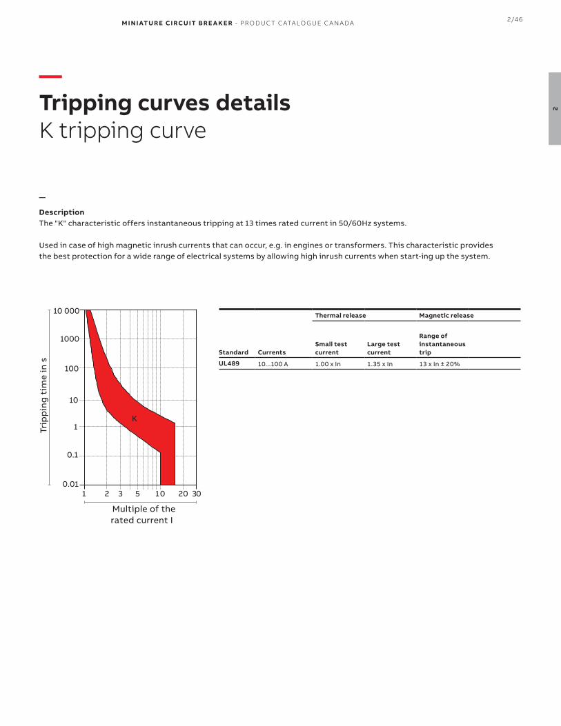
M I N I ATU R E CI RCU IT B R E A K E R - PR O D U C T C ATA LO G U E C A N A DA 2/46
2
—Tripping curves detailsK tripping curve
—
DescriptionThe "K" characteristic offers instantaneous tripping at 13 times rated current in 50/60Hz systems.
Used in case of high magnetic inrush currents that can occur, e.g. in engines or transformers. This characteristic provides the best protection for a wide range of electrical systems by allowing high inrush currents when start-ing up the system.
Thermal release Magnetic release
Standard CurrentsSmall test current
Large test current
Range of instantaneoustrip
UL489 10...100 A 1.00 x In 1.35 x In 13 x In ± 20%
10 000
1000
100
10
2 011 3 5 20 30
1
0.1
0.01
K
Multiple of the rated current I
Trip
pin
g t
ime
in s

2/47 M I N I ATU R E CI RCU IT B R E A K E R - PR O D U C T C ATA LO G U E C A N A DA
2
—Tripping curves detailsZ tripping curve
—
DescriptionThe "Z" characteristic offers instantaneous tripping at 4 times rated current in 50/60Hz systems.
Used as Ground-Fault Detector Interrupter (GFDI) in photo-voltaic systems.
Thermal release Magnetic release
Standard CurrentsSmall test current
Large test current
Range of instantaneoustrip
UL489 10...100 A 1.00 x In 1.35 x In 4 x In ± 20%
10 000
1000
100
10
2 7 011 4 20 30
1
0.1
0.01
Multiple of the rated current I
Trip
pin
g t
ime
in s

M I N I ATU R E CI RCU IT B R E A K E R - PR O D U C T C ATA LO G U E C A N A DA 2/48
2
—Tripping curves detailsUCZ tripping curve
—
DescriptionThe "UCZ" characteristic offers instantaneous tripping at 11 times rated current in DC systems.
Used in case of circuit breaker in 600 Vdc networks, especially in datacenters.
Thermal release Magnetic release
Standard CurrentsSmall test current
Large test current
Range of instantaneoustrip
UL489 10...80 A 1.00 x In 1.35 x In 11 x In ± 20% (DC)
10 000
1000
100
10
2 7 011 4 20 30
1
0.1
0.01
Multiple of the rated current I
Trip
pin
g t
ime
in s

2/49 M I N I ATU R E CI RCU IT B R E A K E R - PR O D U C T C ATA LO G U E C A N A DA
2
—Tripping curves detailsPVS tripping curve
—
DescriptionThe "PVS" characteristic offers instantaneous tripping at 6 times rated current in DC systems.
Used in case of circuit breaker protecting electric circuits feeding consumers that do not generate any current peaks, or only mild ones.
Thermal release Magnetic release
Standard CurrentsSmall test current
Large test current
Range of instantaneoustrip
UL489 5 A 1.13 x In 1.30 x In 6 x In (DC)
10 000
1000
100
10
2 011 3 5 20 30
1
0.1
0.01
Multiple of the rated current I
Trip
pin
g t
ime
in s

M I N I ATU R E CI RCU IT B R E A K E R - PR O D U C T C ATA LO G U E C A N A DA 2/50
2
—DimensionsS800U, UCZ and PVS series
—S800U approximate dimensions
954535
79.5
53
26.5
1P 2P 3P 4P
106
2CC
C41
3010
Z00
01
76.5
46
82.56
95 142
4535
79.5
53
26.5
1P 2P 3P 4P
106
2CC
C41
3012
Z00
01
76.5
46
82.56
—S800U-UCZ and S800U-PVS approximate dimensions

2/51 M I N I ATU R E CI RCU IT B R E A K E R - PR O D U C T C ATA LO G U E C A N A DA
2
—DimensionsAccessories
—S800-AUX and S800-AUX/ALT approximate dimensions
—S800-SOR and S800-UVR approximate dimensions
T
954535
2CCC41
3017
Z000
1
76.5
46
82.569
954535
26.5
76.5
46
82.56
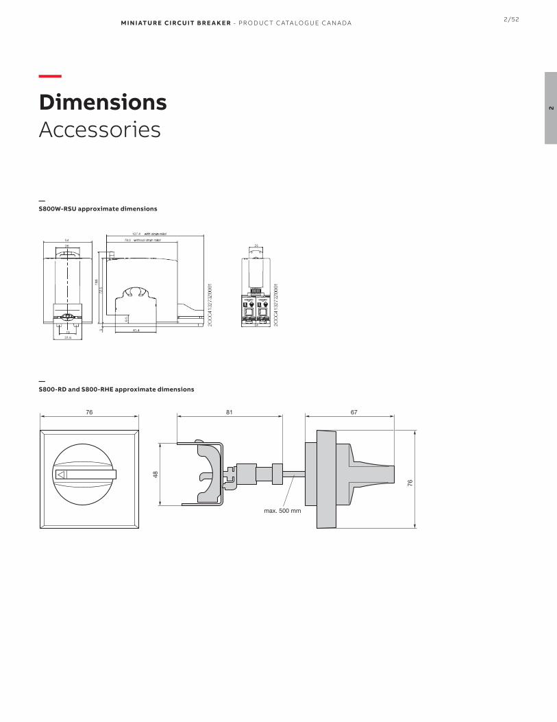
M I N I ATU R E CI RCU IT B R E A K E R - PR O D U C T C ATA LO G U E C A N A DA 2/52
2
—DimensionsAccessories
—S800W-RSU approximate dimensions
—S800-RD and S800-RHE approximate dimensions
76
48
76 6781
max. 500 mm

3
M I N I ATU R E CI RCU IT B R E A K E R - PR O D U C T C ATA LO G U E C A N A DA

— CSA C22.2 No.235 / UL1077 devices
003 – 014 ST200M series
015 – 016 S200MR series
017 – 020 S200MUC series
021 – 025 Accessories
026 – 033 Technical details
034 – 038 Tripping curves details
039 – 040 Dimensions
041 – 045 S800C
046 – 047 S800S
048 S800HV
049 – 053 Accessories
054 – 059 Technical details
060 – 063 Tripping curves details
064 – 066 Dimensions
3
M I N I ATU R E CI RCU IT B R E A K E R - PR O D U C T C ATA LO G U E C A N A DA

3/3 M I N I ATU R E CI RCU IT B R E A K E R - PR O D U C T C ATA LO G U E C A N A DA
3
—ST200M seriesUL 1077 Supplementary Protectors
The ST 200 M miniature circuit breaker pro-vides supplementary protection acc. to CSA C22.2 No. 235 and UL 1077 up to 480 Y/277 V AC and 125 V DC. With a broad range of options and approv-als acc. to the international standards UL, CSA and IEC, the ST 200 M is ideal for mul-tiple applications and markets. It is also fully compatible with System pro M compact® accessories.
Features• High performance MCB with interrupt rating up to 10 kA• DIN rail mounting• CE certified and marked• CSA 22.2 No. 235 and UL1077 (UL file #E76126) certified• Energy limiting• Fast breaking time (2.3 to 2.5 ms)• Wide range of accessories• Finger-safe terminals• Suitable for reverse feed• High calibration temperature of 40 °C for reduced derating
in ICP applications• Laser printing provides clear product information on device• Clear contact position indication in red/green (“real CPI”)• Unique, patented twin terminal for wiring up to 35 mm² with
captive screws• Field wiring available for most types• Bus conection system• Robust thermoplastic housing material for better protection
against external influences
General Data ST200M
Amperage 0.5 up to 63 A
Voltage 480Y/277 V AC
60/125 V DC (1/2-pole)
Poles 1, 1+N, 2, 3, 3+N, 4
Trip curves B, C, D, K, Z
Short circuit interrupt rating 10 kA (up to 32 A)5kA (32...63 A)
Auxiliary contacts Yes
Ambient temperature -25 … +55 °C
Mechanical life 20,000 operations
Bell alarm Yes
Shunt trip Yes
Undervoltage release Yes
Busbar Yes

M I N I ATU R E CI RCU IT B R E A K E R - PR O D U C T C ATA LO G U E C A N A DA 3/4
3
1 pole Box Qty
Weight each(kg)
Rated Current
Part number
10 0.115 0.5 A ST201M-B0.5
1.0 A ST201M-B1
1.6 A ST201M-B1.6
2.0 A ST201M-B2
3.0 A ST201M-B3
4.0 A ST201M-B4
5.0 A ST201M-B5
6.0 A ST201M-B6
7.0 A ST201M-B7
8.0 A ST201M-B8
10.0 A ST201M-B10
13.0 A ST201M-B13
15.0 A ST201M-B15
16.0 A ST201M-B16
20.0 A ST201M-B20
25.0 A ST201M-B25
30.0 A ST201M-B30
32.0 A ST201M-B32
35.0 A ST201M-B35
40.0 A ST201M-B40
50.0 A ST201M-B50
60.0 A ST201M-B60
63.0 A ST201M-B63
—ST200M seriesB tripping characteristic
2 poles Box Qty
Weight each(kg)
Rated Current
Part number
5 0.230 0.5 A ST202M-B0.5
1.0 A ST202M-B1
1.6 A ST202M-B1.6
2.0 A ST202M-B2
3.0 A ST202M-B3
4.0 A ST202M-B4
5.0 A ST202M-B5
6.0 A ST202M-B6
7.0 A ST202M-B7
8.0 A ST202M-B8
10.0 A ST202M-B10
13.0 A ST202M-B13
15.0 A ST202M-B15
16.0 A ST202M-B16
20.0 A ST202M-B20
25.0 A ST202M-B25
30.0 A ST202M-B30
32.0 A ST202M-B32
35.0 A ST202M-B35
40.0 A ST202M-B40
50.0 A ST202M-B50
60.0 A ST202M-B60
63.0 A ST202M-B63
1 pole + Neutral Box Qty
Weight each(kg)
Rated Current
Part number
5 0.230 0.5 A ST201M-B0.5NA
1.0 A ST201M-B1NA
1.6 A ST201M-B1.6NA
2.0 A ST201M-B2NA
3.0 A ST201M-B3NA
4.0 A ST201M-B4NA
5.0 A ST201M-B5NA
6.0 A ST201M-B6NA
7.0 A ST201M-B7NA
8.0 A ST201M-B8NA
10.0 A ST201M-B10NA
13.0 A ST201M-B13NA
15.0 A ST201M-B15NA
16.0 A ST201M-B16NA
20.0 A ST201M-B20NA
25.0 A ST201M-B25NA
30.0 A ST201M-B30NA
32.0 A ST201M-B32NA
35.0 A ST201M-B35NA
40.0 A ST201M-B40NA
50.0 A ST201M-B50NA
60.0 A ST201M-B60NA
63.0 A ST201M-B63NA
3 poles Box Qty
Weight each(kg)
Rated Current
Part number
1 0.345 0.5 A ST203M-B0.5
1.0 A ST203M-B1
1.6 A ST203M-B1.6
2.0 A ST203M-B2
3.0 A ST203M-B3
4.0 A ST203M-B4
5.0 A ST203M-B5
6.0 A ST203M-B6
7.0 A ST203M-B7
8.0 A ST203M-B8
10.0 A ST203M-B10
13.0 A ST203M-B13
15.0 A ST203M-B15
16.0 A ST203M-B16
20.0 A ST203M-B20
25.0 A ST203M-B25
30.0 A ST203M-B30
32.0 A ST203M-B32
35.0 A ST203M-B35
40.0 A ST203M-B40
50.0 A ST203M-B50
60.0 A ST203M-B60
63.0 A ST203M-B63
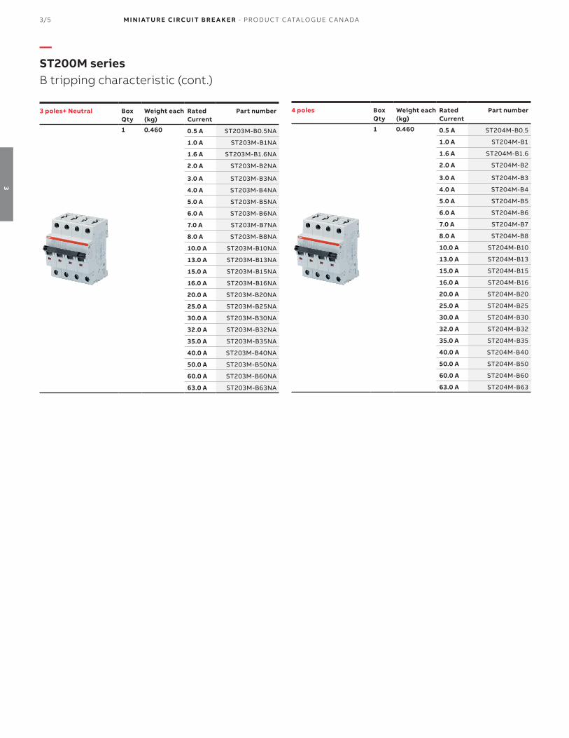
3/5 M I N I ATU R E CI RCU IT B R E A K E R - PR O D U C T C ATA LO G U E C A N A DA
3
—ST200M series B tripping characteristic (cont.)
3 poles+ Neutral Box Qty
Weight each(kg)
Rated Current
Part number
1 0.460 0.5 A ST203M-B0.5NA
1.0 A ST203M-B1NA
1.6 A ST203M-B1.6NA
2.0 A ST203M-B2NA
3.0 A ST203M-B3NA
4.0 A ST203M-B4NA
5.0 A ST203M-B5NA
6.0 A ST203M-B6NA
7.0 A ST203M-B7NA
8.0 A ST203M-B8NA
10.0 A ST203M-B10NA
13.0 A ST203M-B13NA
15.0 A ST203M-B15NA
16.0 A ST203M-B16NA
20.0 A ST203M-B20NA
25.0 A ST203M-B25NA
30.0 A ST203M-B30NA
32.0 A ST203M-B32NA
35.0 A ST203M-B35NA
40.0 A ST203M-B40NA
50.0 A ST203M-B50NA
60.0 A ST203M-B60NA
63.0 A ST203M-B63NA
4 poles Box Qty
Weight each(kg)
Rated Current
Part number
1 0.460 0.5 A ST204M-B0.5
1.0 A ST204M-B1
1.6 A ST204M-B1.6
2.0 A ST204M-B2
3.0 A ST204M-B3
4.0 A ST204M-B4
5.0 A ST204M-B5
6.0 A ST204M-B6
7.0 A ST204M-B7
8.0 A ST204M-B8
10.0 A ST204M-B10
13.0 A ST204M-B13
15.0 A ST204M-B15
16.0 A ST204M-B16
20.0 A ST204M-B20
25.0 A ST204M-B25
30.0 A ST204M-B30
32.0 A ST204M-B32
35.0 A ST204M-B35
40.0 A ST204M-B40
50.0 A ST204M-B50
60.0 A ST204M-B60
63.0 A ST204M-B63

M I N I ATU R E CI RCU IT B R E A K E R - PR O D U C T C ATA LO G U E C A N A DA 3/6
3
1 pole Box Qty
Weight each(kg)
Rated Current
Part number
10 0.115 0.5 A ST201M-C0.5
1.0 A ST201M-C1
1.6 A ST201M-C1.6
2.0 A ST201M-C2
3.0 A ST201M-C3
4.0 A ST201M-C4
5.0 A ST201M-C5
6.0 A ST201M-C6
7.0 A ST201M-C7
8.0 A ST201M-C8
10.0 A ST201M-C10
13.0 A ST201M-C13
15.0 A ST201M-C15
16.0 A ST201M-C16
20.0 A ST201M-C20
25.0 A ST201M-C25
30.0 A ST201M-C30
32.0 A ST201M-C32
35.0 A ST201M-C35
40.0 A ST201M-C40
50.0 A ST201M-C50
60.0 A ST201M-C60
63.0 A ST201M-C63
—ST200M seriesC tripping characteristic
2 poles Box Qty
Weight each(kg)
Rated Current
Part number
5 0.230 0.5 A ST202M-C0.5
1.0 A ST202M-C1
1.6 A ST202M-C1.6
2.0 A ST202M-C2
3.0 A ST202M-C3
4.0 A ST202M-C4
5.0 A ST202M-C5
6.0 A ST202M-C6
7.0 A ST202M-C7
8.0 A ST202M-C8
10.0 A ST202M-C10
13.0 A ST202M-C13
15.0 A ST202M-C15
16.0 A ST202M-C16
20.0 A ST202M-C20
25.0 A ST202M-C25
30.0 A ST202M-C30
32.0 A ST202M-C32
35.0 A ST202M-C35
40.0 A ST202M-C40
50.0 A ST202M-C50
60.0 A ST202M-C60
63.0 A ST202M-C63
1 pole + Neutral Box Qty
Weight each(kg)
Rated Current
Part number
5 0.230 0.5 A ST201M-C0.5NA
1.0 A ST201M-C1NA
1.6 A ST201M-C1.6NA
2.0 A ST201M-C2NA
3.0 A ST201M-C3NA
4.0 A ST201M-C4NA
5.0 A ST201M-C5NA
6.0 A ST201M-C6NA
7.0 A ST201M-C7NA
8.0 A ST201M-C8NA
10.0 A ST201M-C10NA
13.0 A ST201M-C13NA
15.0 A ST201M-C15NA
16.0 A ST201M-C16NA
20.0 A ST201M-C20NA
25.0 A ST201M-C25NA
30.0 A ST201M-C30NA
32.0 A ST201M-C32NA
35.0 A ST201M-C35NA
40.0 A ST201M-C40NA
50.0 A ST201M-C50NA
60.0 A ST201M-C60NA
63.0 A ST201M-C63NA
3 poles Box Qty
Weight each(kg)
Rated Current
Part number
1 0.345 0.5 A ST203M-C0.5
1.0 A ST203M-C1
1.6 A ST203M-C1.6
2.0 A ST203M-C2
3.0 A ST203M-C3
4.0 A ST203M-C4
5.0 A ST203M-C5
6.0 A ST203M-C6
7.0 A ST203M-C7
8.0 A ST203M-C8
10.0 A ST203M-C10
13.0 A ST203M-C13
15.0 A ST203M-C15
16.0 A ST203M-C16
20.0 A ST203M-C20
25.0 A ST203M-C25
30.0 A ST203M-C30
32.0 A ST203M-C32
35.0 A ST203M-C35
40.0 A ST203M-C40
50.0 A ST203M-C50
60.0 A ST203M-C60
63.0 A ST203M-C63

3/7 M I N I ATU R E CI RCU IT B R E A K E R - PR O D U C T C ATA LO G U E C A N A DA
3
—ST200M series C tripping characteristic (cont.)
3 poles+ Neutral Box Qty
Weight each(kg)
Rated Current
Part number
1 0.460 0.5 A ST203M-C0.5NA
1.0 A ST203M-C1NA
1.6 A ST203M-C1.6NA
2.0 A ST203M-C2NA
3.0 A ST203M-C3NA
4.0 A ST203M-C4NA
5.0 A ST203M-C5NA
6.0 A ST203M-C6NA
7.0 A ST203M-C7NA
8.0 A ST203M-C8NA
10.0 A ST203M-C10NA
13.0 A ST203M-C13NA
15.0 A ST203M-C15NA
16.0 A ST203M-C16NA
20.0 A ST203M-C20NA
25.0 A ST203M-C25NA
30.0 A ST203M-C30NA
32.0 A ST203M-C32NA
35.0 A ST203M-C35NA
40.0 A ST203M-C40NA
50.0 A ST203M-C50NA
60.0 A ST203M-C60NA
63.0 A ST203M-C63NA
4 poles Box Qty
Weight each(kg)
Rated Current
Part number
1 0.460 0.5 A ST204M-C0.5
1.0 A ST204M-C1
1.6 A ST204M-C1.6
2.0 A ST204M-C2
3.0 A ST204M-C3
4.0 A ST204M-C4
5.0 A ST204M-C5
6.0 A ST204M-C6
7.0 A ST204M-C7
8.0 A ST204M-C8
10.0 A ST204M-C10
13.0 A ST204M-C13
15.0 A ST204M-C15
16.0 A ST204M-C16
20.0 A ST204M-C20
25.0 A ST204M-C25
30.0 A ST204M-C30
32.0 A ST204M-C32
35.0 A ST204M-C35
40.0 A ST204M-C40
50.0 A ST204M-C50
60.0 A ST204M-C60
63.0 A ST204M-C63
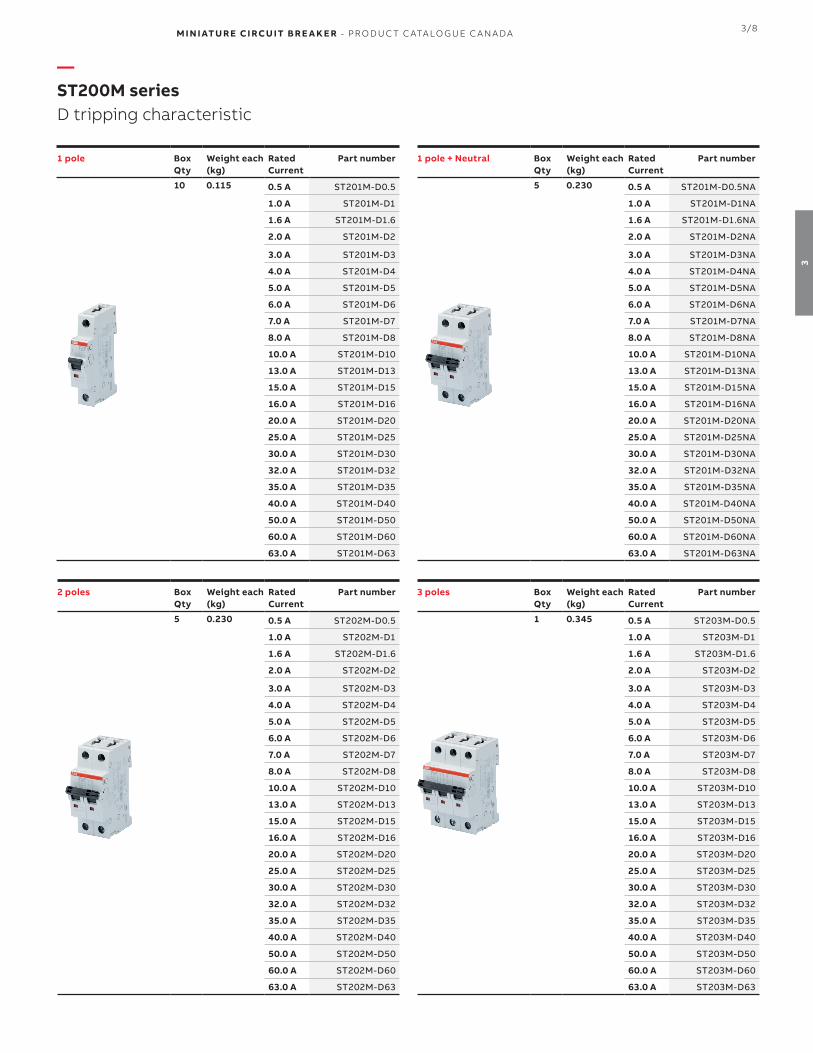
M I N I ATU R E CI RCU IT B R E A K E R - PR O D U C T C ATA LO G U E C A N A DA 3/8
3
1 pole Box Qty
Weight each(kg)
Rated Current
Part number
10 0.115 0.5 A ST201M-D0.5
1.0 A ST201M-D1
1.6 A ST201M-D1.6
2.0 A ST201M-D2
3.0 A ST201M-D3
4.0 A ST201M-D4
5.0 A ST201M-D5
6.0 A ST201M-D6
7.0 A ST201M-D7
8.0 A ST201M-D8
10.0 A ST201M-D10
13.0 A ST201M-D13
15.0 A ST201M-D15
16.0 A ST201M-D16
20.0 A ST201M-D20
25.0 A ST201M-D25
30.0 A ST201M-D30
32.0 A ST201M-D32
35.0 A ST201M-D35
40.0 A ST201M-D40
50.0 A ST201M-D50
60.0 A ST201M-D60
63.0 A ST201M-D63
—ST200M seriesD tripping characteristic
2 poles Box Qty
Weight each(kg)
Rated Current
Part number
5 0.230 0.5 A ST202M-D0.5
1.0 A ST202M-D1
1.6 A ST202M-D1.6
2.0 A ST202M-D2
3.0 A ST202M-D3
4.0 A ST202M-D4
5.0 A ST202M-D5
6.0 A ST202M-D6
7.0 A ST202M-D7
8.0 A ST202M-D8
10.0 A ST202M-D10
13.0 A ST202M-D13
15.0 A ST202M-D15
16.0 A ST202M-D16
20.0 A ST202M-D20
25.0 A ST202M-D25
30.0 A ST202M-D30
32.0 A ST202M-D32
35.0 A ST202M-D35
40.0 A ST202M-D40
50.0 A ST202M-D50
60.0 A ST202M-D60
63.0 A ST202M-D63
1 pole + Neutral Box Qty
Weight each(kg)
Rated Current
Part number
5 0.230 0.5 A ST201M-D0.5NA
1.0 A ST201M-D1NA
1.6 A ST201M-D1.6NA
2.0 A ST201M-D2NA
3.0 A ST201M-D3NA
4.0 A ST201M-D4NA
5.0 A ST201M-D5NA
6.0 A ST201M-D6NA
7.0 A ST201M-D7NA
8.0 A ST201M-D8NA
10.0 A ST201M-D10NA
13.0 A ST201M-D13NA
15.0 A ST201M-D15NA
16.0 A ST201M-D16NA
20.0 A ST201M-D20NA
25.0 A ST201M-D25NA
30.0 A ST201M-D30NA
32.0 A ST201M-D32NA
35.0 A ST201M-D35NA
40.0 A ST201M-D40NA
50.0 A ST201M-D50NA
60.0 A ST201M-D60NA
63.0 A ST201M-D63NA
3 poles Box Qty
Weight each(kg)
Rated Current
Part number
1 0.345 0.5 A ST203M-D0.5
1.0 A ST203M-D1
1.6 A ST203M-D1.6
2.0 A ST203M-D2
3.0 A ST203M-D3
4.0 A ST203M-D4
5.0 A ST203M-D5
6.0 A ST203M-D6
7.0 A ST203M-D7
8.0 A ST203M-D8
10.0 A ST203M-D10
13.0 A ST203M-D13
15.0 A ST203M-D15
16.0 A ST203M-D16
20.0 A ST203M-D20
25.0 A ST203M-D25
30.0 A ST203M-D30
32.0 A ST203M-D32
35.0 A ST203M-D35
40.0 A ST203M-D40
50.0 A ST203M-D50
60.0 A ST203M-D60
63.0 A ST203M-D63

3/9 M I N I ATU R E CI RCU IT B R E A K E R - PR O D U C T C ATA LO G U E C A N A DA
3
—ST200M series D tripping characteristic (cont.)
3 poles+ Neutral Box Qty
Weight each(kg)
Rated Current
Part number
1 0.460 0.5 A ST203M-D0.5NA
1.0 A ST203M-D1NA
1.6 A ST203M-D1.6NA
2.0 A ST203M-D2NA
3.0 A ST203M-D3NA
4.0 A ST203M-D4NA
5.0 A ST203M-D5NA
6.0 A ST203M-D6NA
7.0 A ST203M-D7NA
8.0 A ST203M-D8NA
10.0 A ST203M-D10NA
13.0 A ST203M-D13NA
15.0 A ST203M-D15NA
16.0 A ST203M-D16NA
20.0 A ST203M-D20NA
25.0 A ST203M-D25NA
30.0 A ST203M-D30NA
32.0 A ST203M-D32NA
35.0 A ST203M-D35NA
40.0 A ST203M-D40NA
50.0 A ST203M-D50NA
60.0 A ST203M-D60NA
63.0 A ST203M-D63NA
4 poles Box Qty
Weight each(kg)
Rated Current
Part number
1 0.460 0.5 A ST204M-D0.5
1.0 A ST204M-D1
1.6 A ST204M-D1.6
2.0 A ST204M-D2
3.0 A ST204M-D3
4.0 A ST204M-D4
5.0 A ST204M-D5
6.0 A ST204M-D6
7.0 A ST204M-D7
8.0 A ST204M-D8
10.0 A ST204M-D10
13.0 A ST204M-D13
15.0 A ST204M-D15
16.0 A ST204M-D16
20.0 A ST204M-D20
25.0 A ST204M-D25
30.0 A ST204M-D30
32.0 A ST204M-D32
35.0 A ST204M-D35
40.0 A ST204M-D40
50.0 A ST204M-D50
60.0 A ST204M-D60
63.0 A ST204M-D63

M I N I ATU R E CI RCU IT B R E A K E R - PR O D U C T C ATA LO G U E C A N A DA 3/10
3
1 pole Box Qty
Weight each(kg)
Rated Current
Part number
10 0.115 0.5 A ST201M-K0.5
1.0 A ST201M-K1
1.6 A ST201M-K1.6
2.0 A ST201M-K2
3.0 A ST201M-K3
4.0 A ST201M-K4
5.0 A ST201M-K5
6.0 A ST201M-K6
7.0 A ST201M-K7
8.0 A ST201M-K8
10.0 A ST201M-K10
13.0 A ST201M-K13
15.0 A ST201M-K15
16.0 A ST201M-K16
20.0 A ST201M-K20
25.0 A ST201M-K25
30.0 A ST201M-K30
32.0 A ST201M-K32
35.0 A ST201M-K35
40.0 A ST201M-K40
50.0 A ST201M-K50
60.0 A ST201M-K60
63.0 A ST201M-K63
—ST200M seriesK tripping characteristic
2 poles Box Qty
Weight each(kg)
Rated Current
Part number
5 0.230 0.5 A ST202M-K0.5
1.0 A ST202M-K1
1.6 A ST202M-K1.6
2.0 A ST202M-K2
3.0 A ST202M-K3
4.0 A ST202M-K4
5.0 A ST202M-K5
6.0 A ST202M-K6
7.0 A ST202M-K7
8.0 A ST202M-K8
10.0 A ST202M-K10
13.0 A ST202M-K13
15.0 A ST202M-K15
16.0 A ST202M-K16
20.0 A ST202M-K20
25.0 A ST202M-K25
30.0 A ST202M-K30
32.0 A ST202M-K32
35.0 A ST202M-K35
40.0 A ST202M-K40
50.0 A ST202M-K50
60.0 A ST202M-K60
63.0 A ST202M-K63
1 pole + Neutral Box Qty
Weight each(kg)
Rated Current
Part number
5 0.230 0.5 A ST201M-K0.5NA
1.0 A ST201M-K1NA
1.6 A ST201M-K1.6NA
2.0 A ST201M-K2NA
3.0 A ST201M-K3NA
4.0 A ST201M-K4NA
5.0 A ST201M-K5NA
6.0 A ST201M-K6NA
7.0 A ST201M-K7NA
8.0 A ST201M-K8NA
10.0 A ST201M-K10NA
13.0 A ST201M-K13NA
15.0 A ST201M-K15NA
16.0 A ST201M-K16NA
20.0 A ST201M-K20NA
25.0 A ST201M-K25NA
30.0 A ST201M-K30NA
32.0 A ST201M-K32NA
35.0 A ST201M-K35NA
40.0 A ST201M-K40NA
50.0 A ST201M-K50NA
60.0 A ST201M-K60NA
63.0 A ST201M-K63NA
3 poles Box Qty
Weight each(kg)
Rated Current
Part number
1 0.345 0.5 A ST203M-K0.5
1.0 A ST203M-K1
1.6 A ST203M-K1.6
2.0 A ST203M-K2
3.0 A ST203M-K3
4.0 A ST203M-K4
5.0 A ST203M-K5
6.0 A ST203M-K6
7.0 A ST203M-K7
8.0 A ST203M-K8
10.0 A ST203M-K10
13.0 A ST203M-K13
15.0 A ST203M-K15
16.0 A ST203M-K16
20.0 A ST203M-K20
25.0 A ST203M-K25
30.0 A ST203M-K30
32.0 A ST203M-K32
35.0 A ST203M-K35
40.0 A ST203M-K40
50.0 A ST203M-K50
60.0 A ST203M-K60
63.0 A ST203M-K63

3/11 M I N I ATU R E CI RCU IT B R E A K E R - PR O D U C T C ATA LO G U E C A N A DA
3
—ST200M series K tripping characteristic (cont.)
3 poles+ Neutral Box Qty
Weight each(kg)
Rated Current
Part number
1 0.460 0.5 A ST203M-K0.5NA
1.0 A ST203M-K1NA
1.6 A ST203M-K1.6NA
2.0 A ST203M-K2NA
3.0 A ST203M-K3NA
4.0 A ST203M-K4NA
5.0 A ST203M-K5NA
6.0 A ST203M-K6NA
7.0 A ST203M-K7NA
8.0 A ST203M-K8NA
10.0 A ST203M-K10NA
13.0 A ST203M-K13NA
15.0 A ST203M-K15NA
16.0 A ST203M-K16NA
20.0 A ST203M-K20NA
25.0 A ST203M-K25NA
30.0 A ST203M-K30NA
32.0 A ST203M-K32NA
35.0 A ST203M-K35NA
40.0 A ST203M-K40NA
50.0 A ST203M-K50NA
60.0 A ST203M-K60NA
63.0 A ST203M-K63NA
4 poles Box Qty
Weight each(kg)
Rated Current
Part number
1 0.460 0.5 A ST204M-K0.5
1.0 A ST204M-K1
1.6 A ST204M-K1.6
2.0 A ST204M-K2
3.0 A ST204M-K3
4.0 A ST204M-K4
5.0 A ST204M-K5
6.0 A ST204M-K6
7.0 A ST204M-K7
8.0 A ST204M-K8
10.0 A ST204M-K10
13.0 A ST204M-K13
15.0 A ST204M-K15
16.0 A ST204M-K16
20.0 A ST204M-K20
25.0 A ST204M-K25
30.0 A ST204M-K30
32.0 A ST204M-K32
35.0 A ST204M-K35
40.0 A ST204M-K40
50.0 A ST204M-K50
60.0 A ST204M-K60
63.0 A ST204M-K63

M I N I ATU R E CI RCU IT B R E A K E R - PR O D U C T C ATA LO G U E C A N A DA 3/12
3
1 pole Box Qty
Weight each(kg)
Rated Current
Part number
10 0.115 0.5 A ST201M-Z0.5
1.0 A ST201M-Z1
1.6 A ST201M-Z1.6
2.0 A ST201M-Z2
3.0 A ST201M-Z3
4.0 A ST201M-Z4
5.0 A ST201M-Z5
6.0 A ST201M-Z6
7.0 A ST201M-Z7
8.0 A ST201M-Z8
10.0 A ST201M-Z10
13.0 A ST201M-Z13
15.0 A ST201M-Z15
16.0 A ST201M-Z16
20.0 A ST201M-Z20
25.0 A ST201M-Z25
30.0 A ST201M-Z30
32.0 A ST201M-Z32
35.0 A ST201M-Z35
40.0 A ST201M-Z40
50.0 A ST201M-Z50
60.0 A ST201M-Z60
63.0 A ST201M-Z63
—ST200M seriesZ tripping characteristic
2 poles Box Qty
Weight each(kg)
Rated Current
Part number
5 0.230 0.5 A ST202M-Z0.5
1.0 A ST202M-Z1
1.6 A ST202M-Z1.6
2.0 A ST202M-Z2
3.0 A ST202M-Z3
4.0 A ST202M-Z4
5.0 A ST202M-Z5
6.0 A ST202M-Z6
7.0 A ST202M-Z7
8.0 A ST202M-Z8
10.0 A ST202M-Z10
13.0 A ST202M-Z13
15.0 A ST202M-Z15
16.0 A ST202M-Z16
20.0 A ST202M-Z20
25.0 A ST202M-Z25
30.0 A ST202M-Z30
32.0 A ST202M-Z32
35.0 A ST202M-Z35
40.0 A ST202M-Z40
50.0 A ST202M-Z50
60.0 A ST202M-Z60
63.0 A ST202M-Z63
1 pole + Neutral Box Qty
Weight each(kg)
Rated Current
Part number
5 0.230 0.5 A ST201M-Z0.5NA
1.0 A ST201M-Z1NA
1.6 A ST201M-Z1.6NA
2.0 A ST201M-Z2NA
3.0 A ST201M-Z3NA
4.0 A ST201M-Z4NA
5.0 A ST201M-Z5NA
6.0 A ST201M-Z6NA
7.0 A ST201M-Z7NA
8.0 A ST201M-Z8NA
10.0 A ST201M-Z10NA
13.0 A ST201M-Z13NA
15.0 A ST201M-Z15NA
16.0 A ST201M-Z16NA
20.0 A ST201M-Z20NA
25.0 A ST201M-Z25NA
30.0 A ST201M-Z30NA
32.0 A ST201M-Z32NA
35.0 A ST201M-Z35NA
40.0 A ST201M-Z40NA
50.0 A ST201M-Z50NA
60.0 A ST201M-Z60NA
63.0 A ST201M-Z63NA
3 poles Box Qty
Weight each(kg)
Rated Current
Part number
1 0.345 0.5 A ST203M-Z0.5
1.0 A ST203M-Z1
1.6 A ST203M-Z1.6
2.0 A ST203M-Z2
3.0 A ST203M-Z3
4.0 A ST203M-Z4
5.0 A ST203M-Z5
6.0 A ST203M-Z6
7.0 A ST203M-Z7
8.0 A ST203M-Z8
10.0 A ST203M-Z10
13.0 A ST203M-Z13
15.0 A ST203M-Z15
16.0 A ST203M-Z16
20.0 A ST203M-Z20
25.0 A ST203M-Z25
30.0 A ST203M-Z30
32.0 A ST203M-Z32
35.0 A ST203M-Z35
40.0 A ST203M-Z40
50.0 A ST203M-Z50
60.0 A ST203M-Z60
63.0 A ST203M-Z63

3/13 M I N I ATU R E CI RCU IT B R E A K E R - PR O D U C T C ATA LO G U E C A N A DA
3
—ST200M series Z tripping characteristic (cont.)
3 poles+ Neutral Box Qty
Weight each(kg)
Rated Current
Part number
1 0.460 0.5 A ST203M-Z0.5NA
1.0 A ST203M-Z1NA
1.6 A ST203M-Z1.6NA
2.0 A ST203M-Z2NA
3.0 A ST203M-Z3NA
4.0 A ST203M-Z4NA
5.0 A ST203M-Z5NA
6.0 A ST203M-Z6NA
7.0 A ST203M-Z7NA
8.0 A ST203M-Z8NA
10.0 A ST203M-Z10NA
13.0 A ST203M-Z13NA
15.0 A ST203M-Z15NA
16.0 A ST203M-Z16NA
20.0 A ST203M-Z20NA
25.0 A ST203M-Z25NA
30.0 A ST203M-Z30NA
32.0 A ST203M-Z32NA
35.0 A ST203M-Z35NA
40.0 A ST203M-Z40NA
50.0 A ST203M-Z50NA
60.0 A ST203M-Z60NA
63.0 A ST203M-Z63NA
4 poles Box Qty
Weight each(kg)
Rated Current
Part number
1 0.460 0.5 A ST204M-Z0.5
1.0 A ST204M-Z1
1.6 A ST204M-Z1.6
2.0 A ST204M-Z2
3.0 A ST204M-Z3
4.0 A ST204M-Z4
5.0 A ST204M-Z5
6.0 A ST204M-Z6
7.0 A ST204M-Z7
8.0 A ST204M-Z8
10.0 A ST204M-Z10
13.0 A ST204M-Z13
15.0 A ST204M-Z15
16.0 A ST204M-Z16
20.0 A ST204M-Z20
25.0 A ST204M-Z25
30.0 A ST204M-Z30
32.0 A ST204M-Z32
35.0 A ST204M-Z35
40.0 A ST204M-Z40
50.0 A ST204M-Z50
60.0 A ST204M-Z60
63.0 A ST204M-Z63

M I N I ATU R E CI RCU IT B R E A K E R - PR O D U C T C ATA LO G U E C A N A DA 3/14
3
—Notes
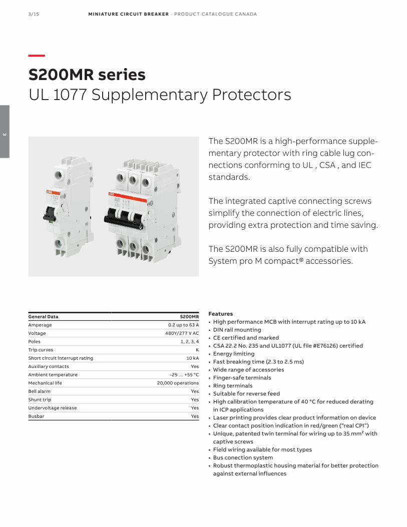
3/15 M I N I ATU R E CI RCU IT B R E A K E R - PR O D U C T C ATA LO G U E C A N A DA
3
—S200MR seriesUL 1077 Supplementary Protectors
The S200MR is a high-performance supple-mentary protector with ring cable lug con-nections conforming to UL , CSA , and IEC standards.
The integrated captive connecting screws simplify the connection of electric lines, providing extra protection and time saving.
The S200MR is also fully compatible with System pro M compact® accessories.
Features• High performance MCB with interrupt rating up to 10 kA• DIN rail mounting• CE certified and marked• CSA 22.2 No. 235 and UL1077 (UL file #E76126) certified• Energy limiting• Fast breaking time (2.3 to 2.5 ms)• Wide range of accessories• Finger-safe terminals• Ring terminals• Suitable for reverse feed• High calibration temperature of 40 °C for reduced derating
in ICP applications• Laser printing provides clear product information on device• Clear contact position indication in red/green (“real CPI”)• Unique, patented twin terminal for wiring up to 35 mm² with
captive screws• Field wiring available for most types• Bus conection system• Robust thermoplastic housing material for better protection
against external influences
General Data S200MR
Amperage 0.2 up to 63 A
Voltage 480Y/277 V AC
Poles 1, 2, 3, 4
Trip curves K
Short circuit interrupt rating 10 kA
Auxiliary contacts Yes
Ambient temperature -25 … +55 °C
Mechanical life 20,000 operations
Bell alarm Yes
Shunt trip Yes
Undervoltage release Yes
Busbar Yes

M I N I ATU R E CI RCU IT B R E A K E R - PR O D U C T C ATA LO G U E C A N A DA 3/16
3
—S200MR (ring terminals) seriesK tripping characteristic
1 pole BoxQty
Weight each(kg)
Rated current
Part number
10 0.140 0.2 A S201MR-K0.2
0.3 A S201MR-K0.3
0.5 A S201MR-K0.5
0.75 A S201MR-K0.75
1.0 A S201MR-K1
1.6 A S201MR-K1.6
2.0 A S201MR-K2
3.0 A S201MR-K3
4.0 A S201MR-K4
5.0 A S201MR-K5
6.0 A S201MR-K6
8.0 A S201MR-K8
10.0 A S201MR-K10
13.0 A S201MR-K13
15.0 A S201MR-K15
16.0 A S201MR-K16
20.0 A S201MR-K20
25.0 A S201MR-K25
30.0 A S201MR-K30
32.0 A S201MR-K32
35.0 A S201MR-K35
40.0 A S201MR-K40
50.0 A S201MR-K50
60.0 A S201MR-K60
63.0 A S201MR-K63
3 pole BoxQty
Weight each(kg)
Rated current
Part number
3 0.420 0.2 A S203MR-K0.2
0.3 A S203MR-K0.3
0.5 A S203MR-K0.5
0.75 A S203MR-K0.75
1.0 A S203MR-K1
1.6 A S203MR-K1.6
2.0 A S203MR-K2
3.0 A S203MR-K3
4.0 A S203MR-K4
5.0 A S203MR-K5
6.0 A S203MR-K6
8.0 A S203MR-K8
10.0 A S203MR-K10
13.0 A S203MR-K13
15.0 A S203MR-K15
16.0 A S203MR-K16
20.0 A S203MR-K20
25.0 A S203MR-K25
30.0 A S203MR-K30
32.0 A S203MR-K32
35.0 A S203MR-K35
40.0 A S203MR-K40
50.0 A S203MR-K50
60.0 A S203MR-K60
63.0 A S203MR-K63
2 pole BoxQty
Weight each(kg)
Rated current
Part number
5 0.280 0.2 A S202MR-K0.2
0.3 A S202MR-K0.3
0.5 A S202MR-K0.5
0.75 A S202MR-K0.75
1.0 A S202MR-K1
1.6 A S202MR-K1.6
2.0 A S202MR-K2
3.0 A S202MR-K3
4.0 A S202MR-K4
5.0 A S202MR-K5
6.0 A S202MR-K6
8.0 A S202MR-K8
10.0 A S202MR-K10
13.0 A S202MR-K13
15.0 A S202MR-K15
16.0 A S202MR-K16
20.0 A S202MR-K20
25.0 A S202MR-K25
30.0 A S202MR-K30
32.0 A S202MR-K32
35.0 A S202MR-K35
40.0 A S202MR-K40
50.0 A S202MR-K50
60.0 A S202MR-K60
63.0 A S202MR-K63
4 pole BoxQty
Weight each(kg)
Rated current
Part number
2 0.560 0.2 A S204MR-K0.2
0.3 A S204MR-K0.3
0.5 A S204MR-K0.5
0.75 A S204MR-K0.75
1.0 A S204MR-K1
1.6 A S204MR-K1.6
2.0 A S204MR-K2
3.0 A S204MR-K3
4.0 A S204MR-K4
5.0 A S204MR-K5
6.0 A S204MR-K6
8.0 A S204MR-K8
10.0 A S204MR-K10
13.0 A S204MR-K13
15.0 A S204MR-K15
16.0 A S204MR-K16
20.0 A S204MR-K20
25.0 A S204MR-K25
30.0 A S204MR-K30
32.0 A S204MR-K32
35.0 A S204MR-K35
40.0 A S204MR-K40
50.0 A S204MR-K50
60.0 A S204MR-K60
63.0 A S204MR-K63

3/17 M I N I ATU R E CI RCU IT B R E A K E R - PR O D U C T C ATA LO G U E C A N A DA
3
—S200MUC seriesUL 1077 Supplementary Protectors
The S200MUC extends the established ABBSystem pro M compact® product range with an MCB for DC and AC applications. The S200MUC impresses with its extended DC performaces up to 500Vdc.
Its high inbuilt short circuit breaking capac-ity across the entire model line, its flexible AC and DC application and its approval and compliance in accordance with all major in-ternational and local standards make it truly unique.
Features• High performance MCB with interrupt rating up to 10 kA• DIN rail mounting• CE certified and marked• CSA 22.2 No. 235 and UL1077 (UL file #E76126) certified• Energy limiting• Fast breaking time (2.3 to 2.5 ms)• Wide range of accessories• Finger-safe terminals• Suitable for reverse feed in AC only• High calibration temperature of 40 °C for reduced derating
in ICP applications• Laser printing provides clear product information on device• Clear contact position indication in red/green (“real CPI”)• Unique, patented twin terminal for wiring up to 35 mm² with
captive screws• Field wiring available for most types• Bus conection system• Robust thermoplastic housing material for better protection
against external influences
General Data S200MUC
Amperage 0.2 up to 63 A
Voltage 480Y/277 V AC250/500 V DC
Poles 1, 2, 3, 4
Trip curves C, K, Z
Short circuit interrupt rating 10 kA
Auxiliary contacts Yes
Ambient temperature -25 … +55 °C
Mechanical life 20,000 operations
Bell alarm Yes
Shunt trip Yes
Undervoltage release Yes
Busbar Yes

M I N I ATU R E CI RCU IT B R E A K E R - PR O D U C T C ATA LO G U E C A N A DA 3/18
3
1 pole Box Qty
Weight each(kg)
Rated Current
Part number
10 0.125 0.5 A S201MUC-C0.5
1.0 A S201MUC-C1
1.6 A S201MUC-C1.6
2.0 A S201MUC-C2
3.0 A S201MUC-C3
4.0 A S201MUC-C4
6.0 A S201MUC-C6
8.0 A S201MUC-C8
10.0 A S201MUC-C10
13.0 A S201MUC-C13
16.0 A S201MUC-C16
20.0 A S201MUC-C20
25.0 A S201MUC-C25
32.0 A S201MUC-C32
40.0 A S201MUC-C40
50.0 A S201MUC-C50
63.0 A S201MUC-C63
—S200MUC seriesC tripping characteristic
2 poles Box Qty
Weight each(kg)
Rated Current
Part number
5 0.250 0.5 A S202MUC-C0.5
1.0 A S202MUC-C1
1.6 A S202MUC-C1.6
2.0 A S202MUC-C2
3.0 A S202MUC-C3
4.0 A S202MUC-C4
6.0 A S202MUC-C6
8.0 A S202MUC-C8
10.0 A S202MUC-C10
13.0 A S202MUC-C13
16.0 A S202MUC-C16
20.0 A S202MUC-C20
25.0 A S202MUC-C25
32.0 A S202MUC-C32
40.0 A S202MUC-C40
50.0 A S202MUC-C50
63.0 A S202MUC-C63
3 poles Box Qty
Weight each(kg)
Rated Current
Part number
1 0.375 0.5 A S203MUC-C0.5
1.0 A S203MUC-C1
1.6 A S203MUC-C1.6
2.0 A S203MUC-C2
3.0 A S203MUC-C3
4.0 A S203MUC-C4
6.0 A S203MUC-C6
8.0 A S203MUC-C8
10.0 A S203MUC-C10
13.0 A S203MUC-C13
16.0 A S203MUC-C16
20.0 A S203MUC-C20
25.0 A S203MUC-C25
32.0 A S203MUC-C32
40.0 A S203MUC-C40
50.0 A S203MUC-C50
63.0 A S203MUC-C63
4 poles Box Qty
Weight each(kg)
Rated Current
Part number
1 0.500 0.5 A S204MUC-C0.5
1.0 A S204MUC-C1
1.6 A S204MUC-C1.6
2.0 A S204MUC-C2
3.0 A S204MUC-C3
4.0 A S204MUC-C4
6.0 A S204MUC-C6
8.0 A S204MUC-C8
10.0 A S204MUC-C10
13.0 A S204MUC-C13
16.0 A S204MUC-C16
20.0 A S204MUC-C20
25.0 A S204MUC-C25
32.0 A S204MUC-C32
40.0 A S204MUC-C40
50.0 A S204MUC-C50
63.0 A S204MUC-C63

3/19 M I N I ATU R E CI RCU IT B R E A K E R - PR O D U C T C ATA LO G U E C A N A DA
3
—S200MUC seriesK tripping characteristic
1 pole BoxQty
Weight each(kg)
Rated current
Part number
10 0.125 0.2 A S201MUC-K0.2
0.3 A S201MUC-K0.3
0.5 A S201MUC-K0.5
0.75 A S201MUC-K0.75
1.0 A S201MUC-K1
1.6 A S201MUC-K1.6
2.0 A S201MUC-K2
3.0 A S201MUC-K3
4.0 A S201MUC-K4
5.0 A S201MUC-K5
6.0 A S201MUC-K6
8.0 A S201MUC-K8
10.0 A S201MUC-K10
13.0 A S201MUC-K13
15.0 A S201MUC-K15
16.0 A S201MUC-K16
20.0 A S201MUC-K20
25.0 A S201MUC-K25
30.0 A S201MUC-K30
32.0 A S201MUC-K32
35.0 A S201MUC-K35
40.0 A S201MUC-K40
50.0 A S201MUC-K50
60.0 A S201MUC-K60
63.0 A S201MUC-K63
3 pole BoxQty
Weight each(kg)
Rated current
Part number
1 0.375 0.2 A S203MUC-K0.2
0.3 A S203MUC-K0.3
0.5 A S203MUC-K0.5
0.75 A S203MUC-K0.75
1.0 A S203MUC-K1
1.6 A S203MUC-K1.6
2.0 A S203MUC-K2
3.0 A S203MUC-K3
4.0 A S203MUC-K4
5.0 A S203MUC-K5
6.0 A S203MUC-K6
8.0 A S203MUC-K8
10.0 A S203MUC-K10
13.0 A S203MUC-K13
15.0 A S203MUC-K15
16.0 A S203MUC-K16
20.0 A S203MUC-K20
25.0 A S203MUC-K25
30.0 A S203MUC-K30
32.0 A S203MUC-K32
35.0 A S203MUC-K35
40.0 A S203MUC-K40
50.0 A S203MUC-K50
60.0 A S203MUC-K60
63.0 A S203MUC-K63
2 pole BoxQty
Weight each(kg)
Rated current
Part number
5 0.250 0.2 A S202MUC-K0.2
0.3 A S202MUC-K0.3
0.5 A S202MUC-K0.5
0.75 A S202MUC-K0.75
1.0 A S202MUC-K1
1.6 A S202MUC-K1.6
2.0 A S202MUC-K2
3.0 A S202MUC-K3
4.0 A S202MUC-K4
5.0 A S202MUC-K5
6.0 A S202MUC-K6
8.0 A S202MUC-K8
10.0 A S202MUC-K10
13.0 A S202MUC-K13
15.0 A S202MUC-K15
16.0 A S202MUC-K16
20.0 A S202MUC-K20
25.0 A S202MUC-K25
30.0 A S202MUC-K30
32.0 A S202MUC-K32
35.0 A S202MUC-K35
40.0 A S202MUC-K40
50.0 A S202MUC-K50
60.0 A S202MUC-K60
63.0 A S202MUC-K63
4 pole BoxQty
Weight each(kg)
Rated current
Part number
1 0.500 0.2 A S204MUC-K0.2
0.3 A S204MUC-K0.3
0.5 A S204MUC-K0.5
0.75 A S204MUC-K0.75
1.0 A S204MUC-K1
1.6 A S204MUC-K1.6
2.0 A S204MUC-K2
3.0 A S204MUC-K3
4.0 A S204MUC-K4
5.0 A S204MUC-K5
6.0 A S204MUC-K6
8.0 A S204MUC-K8
10.0 A S204MUC-K10
13.0 A S204MUC-K13
15.0 A S204MUC-K15
16.0 A S204MUC-K16
20.0 A S204MUC-K20
25.0 A S204MUC-K25
30.0 A S204MUC-K30
32.0 A S204MUC-K32
35.0 A S204MUC-K35
40.0 A S204MUC-K40
50.0 A S204MUC-K50
60.0 A S204MUC-K60
63.0 A S204MUC-K63
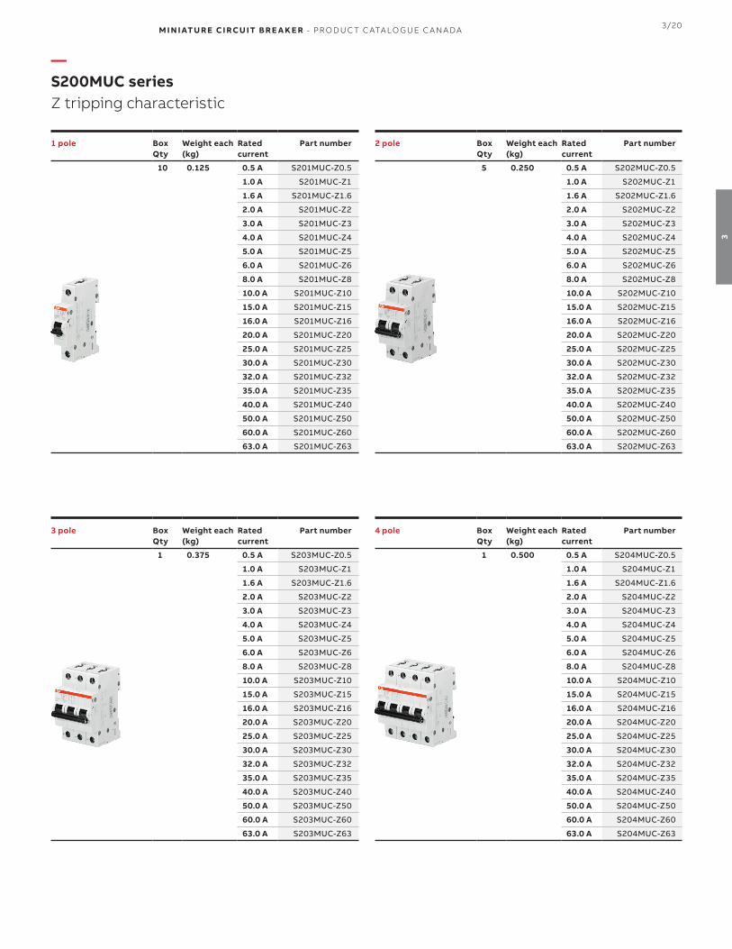
M I N I ATU R E CI RCU IT B R E A K E R - PR O D U C T C ATA LO G U E C A N A DA 3/20
3
—S200MUC seriesZ tripping characteristic
1 pole BoxQty
Weight each(kg)
Rated current
Part number
10 0.125 0.5 A S201MUC-Z0.5
1.0 A S201MUC-Z1
1.6 A S201MUC-Z1.6
2.0 A S201MUC-Z2
3.0 A S201MUC-Z3
4.0 A S201MUC-Z4
5.0 A S201MUC-Z5
6.0 A S201MUC-Z6
8.0 A S201MUC-Z8
10.0 A S201MUC-Z10
15.0 A S201MUC-Z15
16.0 A S201MUC-Z16
20.0 A S201MUC-Z20
25.0 A S201MUC-Z25
30.0 A S201MUC-Z30
32.0 A S201MUC-Z32
35.0 A S201MUC-Z35
40.0 A S201MUC-Z40
50.0 A S201MUC-Z50
60.0 A S201MUC-Z60
63.0 A S201MUC-Z63
3 pole BoxQty
Weight each(kg)
Rated current
Part number
1 0.375 0.5 A S203MUC-Z0.5
1.0 A S203MUC-Z1
1.6 A S203MUC-Z1.6
2.0 A S203MUC-Z2
3.0 A S203MUC-Z3
4.0 A S203MUC-Z4
5.0 A S203MUC-Z5
6.0 A S203MUC-Z6
8.0 A S203MUC-Z8
10.0 A S203MUC-Z10
15.0 A S203MUC-Z15
16.0 A S203MUC-Z16
20.0 A S203MUC-Z20
25.0 A S203MUC-Z25
30.0 A S203MUC-Z30
32.0 A S203MUC-Z32
35.0 A S203MUC-Z35
40.0 A S203MUC-Z40
50.0 A S203MUC-Z50
60.0 A S203MUC-Z60
63.0 A S203MUC-Z63
2 pole BoxQty
Weight each(kg)
Rated current
Part number
5 0.250 0.5 A S202MUC-Z0.5
1.0 A S202MUC-Z1
1.6 A S202MUC-Z1.6
2.0 A S202MUC-Z2
3.0 A S202MUC-Z3
4.0 A S202MUC-Z4
5.0 A S202MUC-Z5
6.0 A S202MUC-Z6
8.0 A S202MUC-Z8
10.0 A S202MUC-Z10
15.0 A S202MUC-Z15
16.0 A S202MUC-Z16
20.0 A S202MUC-Z20
25.0 A S202MUC-Z25
30.0 A S202MUC-Z30
32.0 A S202MUC-Z32
35.0 A S202MUC-Z35
40.0 A S202MUC-Z40
50.0 A S202MUC-Z50
60.0 A S202MUC-Z60
63.0 A S202MUC-Z63
4 pole BoxQty
Weight each(kg)
Rated current
Part number
1 0.500 0.5 A S204MUC-Z0.5
1.0 A S204MUC-Z1
1.6 A S204MUC-Z1.6
2.0 A S204MUC-Z2
3.0 A S204MUC-Z3
4.0 A S204MUC-Z4
5.0 A S204MUC-Z5
6.0 A S204MUC-Z6
8.0 A S204MUC-Z8
10.0 A S204MUC-Z10
15.0 A S204MUC-Z15
16.0 A S204MUC-Z16
20.0 A S204MUC-Z20
25.0 A S204MUC-Z25
30.0 A S204MUC-Z30
32.0 A S204MUC-Z32
35.0 A S204MUC-Z35
40.0 A S204MUC-Z40
50.0 A S204MUC-Z50
60.0 A S204MUC-Z60
63.0 A S204MUC-Z63

3/21 M I N I ATU R E CI RCU IT B R E A K E R - PR O D U C T C ATA LO G U E C A N A DA
3
—Auxiliary contacts and bell alarms
Description Part number
1 SPDT auxiliary contact (form C)
The auxiliary contacts will signal whether the breaker is in the ON or OFF position. Mounts on the right side of the breaker up to maximum of 3 sets
S2C-H6R
1 NO + 1 NC auxiliary contact
The auxiliary contacts will signal whether the breaker is in the ON or OFF position. Mounts on the right side of the breaker up to maximum of 2 sets
S2C-H6-11R
2 NO auxiliary contact
The auxiliary contacts will signal whether the breaker is in the ON or OFF position. Mounts on the right side of the breaker up to maximum of 2 sets
S2C-H6-20R
2 NC auxiliary contact (2 NC)
The auxiliary contacts will signal whether the breaker is in the ON or OFF position. Mounts on the right side of the breaker up to maximum of 2 sets
S2C-H6-02R
1 NC auxiliary micro contact (bottom fitting) S2C-H01
1 NO auxiliary micro contact (bottom fitting) S2C-H10
Bell alarm contact (1 form C)
The bell alarm includes a set of contacts that will only signal when the breaker has tripped. It also includes a test button for testing the alarm contacts without opening the breaker. Mounts on the right side of the breaker up to a maximum of 3 sets
S2C-S/H6R
—AccessoriesElectrical accessories
H Auxiliary contact S2C-H6R
H-R Auxiliary contact S2C-H6-...R
S/H Signal/auxiliary contact S2C-S/H6R
S/H (H) Signal/auxiliary contact S2C-S/H6R
used as auxiliary contact
ST Shunt trip S2C-A...
UR Undervoltage release S2C-UA
LegendAuxiliary contact S2C-H6R H
Auxiliary contact S2C-H6-..R H-R
Bell alarm/auxiliary contact S2C-S/H6R
S/H
Bell alarm/auxiliary contact used as auxiliary contact
S/H (H)
Possible mounting arrangements of auxiliary contacts
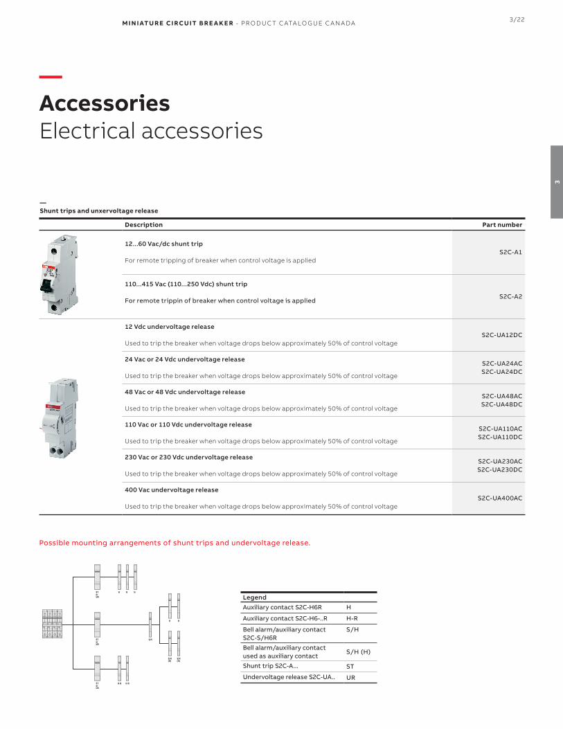
M I N I ATU R E CI RCU IT B R E A K E R - PR O D U C T C ATA LO G U E C A N A DA 3/22
3
—Shunt trips and unxervoltage release
Description Part number
12...60 Vac/dc shunt trip
For remote tripping of breaker when control voltage is appliedS2C-A1
110...415 Vac (110...250 Vdc) shunt trip
For remote trippin of breaker when control voltage is appliedS2C-A2
12 Vdc undervoltage release
Used to trip the breaker when voltage drops below approximately 50% of control voltageS2C-UA12DC
24 Vac or 24 Vdc undervoltage release
Used to trip the breaker when voltage drops below approximately 50% of control voltage
S2C-UA24AC S2C-UA24DC
48 Vac or 48 Vdc undervoltage release
Used to trip the breaker when voltage drops below approximately 50% of control voltage
S2C-UA48ACS2C-UA48DC
110 Vac or 110 Vdc undervoltage release
Used to trip the breaker when voltage drops below approximately 50% of control voltage
S2C-UA110ACS2C-UA110DC
230 Vac or 230 Vdc undervoltage release
Used to trip the breaker when voltage drops below approximately 50% of control voltage
S2C-UA230ACS2C-UA230DC
400 Vac undervoltage release
Used to trip the breaker when voltage drops below approximately 50% of control voltageS2C-UA400AC
—AccessoriesElectrical accessories
Possible mounting arrangements of shunt trips and undervoltage release.
LegendAuxiliary contact S2C-H6R H
Auxiliary contact S2C-H6-..R H-R
Bell alarm/auxiliary contact S2C-S/H6R
S/H
Bell alarm/auxiliary contact used as auxiliary contact
S/H (H)
Shunt trip S2C-A... ST
Undervoltage release S2C-UA.. UR

3/23 M I N I ATU R E CI RCU IT B R E A K E R - PR O D U C T C ATA LO G U E C A N A DA
3
—Busbars for S200 and S200P (cuttable)
MaximumAmp.
Cross-section Phase
Nbr of pins Phase sequence Part number
80 A (1) 18 mm2
157 L1-L1-L1... PS 1/57/18 CB
37 L1-AUX-L1-AUX... PS 1/37/18 H CB
256 L1-L2-L1-L2... PS 2/56/18 CB
46 L1-L2-AUX-L1-L2-AUX... PS 2/46/18 H CB
3
57 L1-L2-L3-L1-L2-L3... PS 3/57/18 CB
48 L1-L2-L3-AUX-L1-L2-L3-AUX... PS 3/48/18 H CB
39 L1-AUX-L2-AUX-L3-AUX... PS 3/39/18 H CB
100 A (1) 25 mm2
157 L1-L1-L1... PS 1/57/25 CB
37 L1-AUX-L1-AUX... PS 1/37/25 H CB
56 L1-L2-L1-L2... PS 2/56/25 CB
46 L1-L2-AUX-L1-L2-AUX... PS 2/46/25 H CB
57 L1-L2-L3-L1-L2-L3... PS 3/57/25 CB
48 L1-L2-L3-AUX-L1-L2-L3-AUX... PS 3/48/25 H CB
39 L1-AUX-L2-AUX-L3-AUX... PS 3/39/25 H CB(1) Maximum rating of busbar with end-feeding. For center-fed details, please consult technical detail section of the accessories.
—AccessoriesElectrical accessories
—Accessories for busbars (cuttable)
Description Part number
1 phase busbar end caps PS-END 1 CB
2 and 3 phase busbar end caps PS-END 3 CB
Busbar pin cover (covers 5 unused pins) BSK CB
Feeder terminal with pin contact for use with MCB and 1-phase busbar AST 35/15-2 CB
Feeder terminal with pin contact for use with MCB and 2-/3-phase busbar AST 35/38-2 CB
Feeder terminal with pin contact for use with E90 and 2-/3-phase busbar AST 35/38-1 CB
Feeder terminal with pin contact for use with E90 and 1-phase busbar AST 35/15-1 CB
Single pole feeder terminal can be mounted side by side, feed to the busbar pin
SZ-ESKSP

M I N I ATU R E CI RCU IT B R E A K E R - PR O D U C T C ATA LO G U E C A N A DA 3/24
3
—Rotary handle mechanism
Description Part number
External handle rotary drive. For the actuation of 2, 3 or 4 pole miniature circuit breakers. To be used with 5 or 6 mm2 shafts
S2C-DH
—External handles
Description Color With defeater Part number
Type 3R/12 selector handle, padlockable with maximum 3 padlocks (bail diameter 5...8mm) with door interlock in ON position. Available with defeating option to allow the MCB to stay in ON state when opening the door.
BlackYes OHBS2AJ
No OHBS2AJ1
Yellow-RedYes OHYS2AJ
No OHYS2AJ1
SilverYes OHSS2AJ
No OHSS2AJ1
GreyYes OHGS2AJ
No OHGS2AJ1
—Shafts
Description Length Part number
Shaft extensions to be used with selector typ handles. Shafts are cuttable. 6 mm2 diameter
85 mm OXS6X85
105 mm OXS6X105
120 mm OXS6X120
130 mm OXS6X130
160 mm OXS6X160
180 mm OXS6X180
250 mm OXS6X250
330 mm OXS6X330
—AccessoriesMechanical accessories

3/25 M I N I ATU R E CI RCU IT B R E A K E R - PR O D U C T C ATA LO G U E C A N A DA
3
—Locking device and padlock
Description Used with Part number
Locking device (3mm hasp) S200 series SA1
Padlock with 2 keys Locking device SA2
—AccessoriesMechanical accessories
—Front flange mounting kits
Description Nbr of MCBs Part number
Front flange mounting kit
1 ME1-1
2 ME2-2
3 ME3-3
4 ME4-4
6 ME6-6
8 ME8-8
—False pole
Description Used with Part number
Used to fill empty spaces on DIN rails (one of each is required)
False pole (1) FP1
DIN rail support for false pole SFP

M I N I ATU R E CI RCU IT B R E A K E R - PR O D U C T C ATA LO G U E C A N A DA 3/26
3
—Technical specifications MCBs
ST200M S200MR S200MUC
SpecificationsCSA C22.2 No.235
UL1077IEC 60947-2
CSA C22.2 No.235UL1077
IEC 60947-2
CSA C22.2 No.235UL1077
IEC 60947-2
Nbr of poles 1, 1+N, 2, 3, 3+N, 4 1, 2, 3, 4 1,2
Trip curves B, C, D, K, Z K B, C, K, Z
Amperage 0.5...63 A 0.2...63 A 0.2...63 A
Voltage AC 480Y/277 Vac 480Y/277 Vac 480Y/277 Vac
Voltage DC (1p/2p) 60/125 Vdc - 250/500 Vdc
Interrupt rating10 kA (up to 32A)
5 kA (35...63A) 10 kA10 kA (DC)
6 kA (AC)
Calibration temp 40oC 25oC 25oC
Mounting position Any Any Any
Protection degree IP20 IP20 IP20
Mounting 35 mm DIN rail 35 mm DIN rail 35 mm DIN rail
Tightening torque25 in-lbs
2.8Nm25 in-lbs
2.8Nm25 in-lbs
2.8Nm
Terminal wire size 18...4 AWG 18...4 AWG 18...4 AWG
Ambient temperature (mechanical)-25oC...+55oC-13oF...+131oF
-25oC...+55oC-13oF...+131oF
-25oC...+55oC-13oF...+131oF
Shock resistance (IEC60068-2-27) 25g - 2 shocks - 13ms 25g - 2 shocks - 13ms 25g - 2 shocks - 13ms
Mechanical life 20,000 ops 20,000 ops 20,000 ops
—Technical detailsST200M, S200MR, S200MUC series

3/27 M I N I ATU R E CI RCU IT B R E A K E R - PR O D U C T C ATA LO G U E C A N A DA
3
—Internal resistance and power loss per pole (ST200M)
B, C, K tripping characteristics D tripping characteristic Z tripping characteristic
Rated current (A)
Internal resistance
(mΩ)Power loss
(W)
Internal resistance
(mΩ)Power loss
(W)
Internal resistance
(mΩ)Power loss
(W)
0.5 5500 1.40 4300 1.10 8100 2.40
1 1440 1.40 1250 1.25 2100 2.30
1.6 645 1.80 600 1.50 1000 2.80
2 460 1.80 410 1.70 620 2.50
3 150 1.60 130 1.20 235 2.40
4 110 1.80 105 1.70 150 2.40
5 55.0 1.40 52.0 1.30 75.0 1.90
6 55.0 2.00 52.0 1.90 75.0 3.20
7 24.0 1.20 26.0 1.30 28.0 1.40
8 23.0 1.50 24.0 1.50 27.0 2.00
10 21.0 2.20 16.0 1.60 24.0 2.70
13 14.0 2.30 14.0 2.20 15.0 2.60
15 8.50 2.00 8.50 2.00 11.0 2.50
16 8.50 2.50 8.50 2.50 10.9 2.80
20 6.25 2.50 6.10 2.30 6.00 2.40
25 5.00 3.20 4.30 3.10 4.50 3.30
30 3.50 3.10 3.50 3.20 3.50 3.20
32 3.50 3.70 3.50 3.60 3.50 3.60
35 3.40 4.20 3.40 4.20 3.50 4.30
40 3.00 4.80 2.20 4.20 2.50 4.10
50 1.80 4.30 1.30 2.90 1.50 4.10
60 1.20 4.40 1.20 4.40 1.30 4.70
63 1.20 4.50 1.20 4.80 1.30 5.20
—Technical detailsST200M, S200MR, S200MUC series
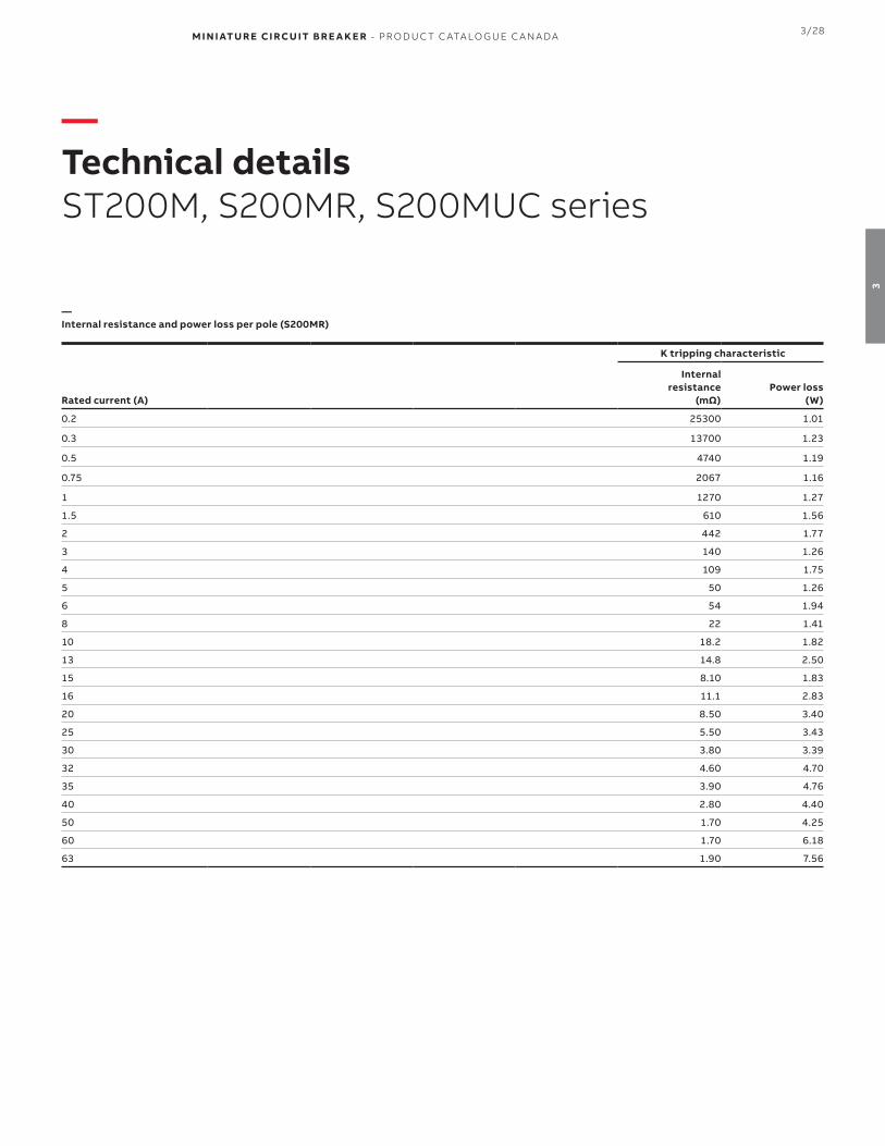
M I N I ATU R E CI RCU IT B R E A K E R - PR O D U C T C ATA LO G U E C A N A DA 3/28
3
K tripping characteristic
Rated current (A)
Internal resistance
(mΩ)Power loss
(W)
0.2 25300 1.01
0.3 13700 1.23
0.5 4740 1.19
0.75 2067 1.16
1 1270 1.27
1.5 610 1.56
2 442 1.77
3 140 1.26
4 109 1.75
5 50 1.26
6 54 1.94
8 22 1.41
10 18.2 1.82
13 14.8 2.50
15 8.10 1.83
16 11.1 2.83
20 8.50 3.40
25 5.50 3.43
30 3.80 3.39
32 4.60 4.70
35 3.90 4.76
40 2.80 4.40
50 1.70 4.25
60 1.70 6.18
63 1.90 7.56
—Technical detailsST200M, S200MR, S200MUC series
—Internal resistance and power loss per pole (S200MR)

3/29 M I N I ATU R E CI RCU IT B R E A K E R - PR O D U C T C ATA LO G U E C A N A DA
3
—Temperature derating (ST200M - B, C, D, K, Z tripping characteristics)
Standard
Rated current(A)
Maximum operating current (A) at ambient temperature T
- 40 °C - 30 °C - 20 °C - 10 °C 0 °C 10 °C 20 °C 30 °C 40 °C 50 °C 60 °C 70 °C
UL1077
0.5 0.65 0.63 0.61 0.59 0.57 0.56 0.54 0.52 0.50 0.48 0.46 0.44
1 1.30 1.26 1.22 1.19 1.15 1.11 1.07 1.04 1.00 0.96 0.93 0.89
1.6 2.06 2.01 1.96 1.90 1.84 1.78 1.72 1.66 1.60 1.54 1.48 1.42
2 2.60 2.52 2.44 2.37 2.30 2.22 2.15 2.07 2.00 1.93 1.85 1.78
3 3.89 3.78 3.67 3.56 3.44 3.33 3.22 3.11 3.00 2.89 2.78 2.67
4 5.19 5.04 4.89 4.74 4.59 4.44 4.30 4.15 4.00 3.85 3.70 3.56
5 6.50 6.31 6.13 5.94 5.75 5.56 5.38 5.00 5.00 4.81 4.63 4.44
6 7.77 7.55 7.33 7.11 6.89 6.67 6.44 6.22 6.00 5.78 5.56 5.33
7 9.10 8.84 8.58 8.31 8.05 7.79 7.53 7.00 7.00 6.74 6.48 6.21
8 10.36 10.07 9.78 9.48 9.18 8.89 8.59 8.30 8.00 7.70 7.41 7.11
10 13.00 12.60 12.20 11.90 11.50 11.10 10.70 10.40 10.00 9.60 9.30 8.90
13 16.90 16.40 15.90 15.40 14.90 14.40 14.00 13.50 13.00 12.50 12.00 11.60
15 19.50 18.94 18.38 17.81 17.25 16.69 16.13 16.00 15.00 14.44 13.88 13.31
16 20.60 20.10 19.60 19.00 18.40 17.80 17.20 16.60 16.00 15.40 14.80 14.20
20 26.00 25.20 24.40 23.70 23.00 22.20 21.50 20.70 20.00 19.30 18.50 17.80
25 32.40 31.50 30.60 29.60 28.70 27.80 26.90 25.90 25.00 24.10 23.20 22.20
30 39.00 37.88 36.75 35.63 34.50 33.38 32.25 31.00 30.00 28.88 27.75 26.63
32 41.50 40.30 39.10 37.90 36.70 35.60 34.40 33.20 32.00 30.80 29.60 28.40
35 47.00 45.30 43.70 42.10 40.60 39.10 37.70 36.30 35.00 33.70 32.50 31.30
40 51.90 50.40 48.90 47.40 45.90 44.40 43.00 41.50 40.00 38.50 37.00 35.60
50 64.90 63.00 61.10 59.30 57.40 55.60 53.70 51.90 50.00 48.20 46.30 44.50
60 80.50 77.60 74.80 72.10 69.50 67.00 64.60 62.30 60.00 57.80 55.70 53.70
63 81.60 79.30 77.00 74.70 72.30 70.00 67.70 65.30 63.00 60.70 58.30 56.00
—Technical detailsST200M, S200MR, S200MUC series

M I N I ATU R E CI RCU IT B R E A K E R - PR O D U C T C ATA LO G U E C A N A DA 3/30
3
—Temperature derating (S200MR/S200MUC - K, Z tripping characteristics)
Standard
Rated current(A)
Maximum operating current (A) at ambient temperature T
- 40 °C - 30 °C - 20 °C - 10 °C 0 °C 10 °C 20 °C 30 °C 40 °C 50 °C 60 °C 70 °C
IEC / UL / CSA
0.5 0.66 0.64 0.61 0.59 0.56 0.53 0.5 0.47 0.43 0.40 0.35 0.31
1 1.32 1.27 1.22 1.17 1.12 1.06 1.0 0.94 0.87 0.79 0.71 0.61
1.6 2.12 2.04 1.96 1.88 1.79 1.70 1.6 1.50 1.39 1.26 1.13 0.98
2 2.65 2.55 2.45 2.35 2.24 2.12 2.0 1.87 1.73 1.58 1.41 1.22
3 4.00 3.80 3.70 3.50 3.40 3.20 3.0 2.80 2.60 2.40 2.10 1.80
4 5.30 5.10 4.90 4.70 4.50 4.20 4.0 3.70 3.50 3.20 2.80 2.40
6 7.90 7.60 7.30 7.00 6.70 6.40 6.0 5.60 5.20 4.70 4.20 3.70
8 10.8 10.2 9.80 9.40 8.90 8.50 8.0 7.50 6.90 6.30 5.70 4.90
10 13.2 12.7 12.2 11.7 11.2 10.6 10.0 9.40 8.70 7.90 7.10 6.10
13 17.2 16.6 15.9 15.2 14.5 13.8 13.0 12.2 11.3 10.3 9.20 8.00
16 21.2 20.4 19.6 18.8 17.9 17.0 16.0 15.0 13.9 12.6 11.3 9.80
20 26.5 25.5 24.5 23.5 22.4 21.2 20.0 18.7 17.3 15.8 14.1 12.2
25 33.1 31.9 30.6 29.3 28.0 26.5 25.0 23.4 21.7 19.8 17.7 15.3
32 42.3 40.8 39.2 37.5 35.8 33.9 32.0 29.9 27.7 25.3 22.6 19.6
40 52.9 51.0 49.0 46.9 44.7 42.4 40.0 37.4 34.6 31.6 28.3 24.5
50 66.1 63.7 61.2 58.6 55.9 53.0 50.0 46.8 43.3 39.5 35.4 30.6
63 83.3 80.3 77.2 73.9 70.4 66.8 63.0 58.9 54.6 49.8 44.5 38.6
—Technical detailsST200M, S200MR, S200MUC series

3/31 M I N I ATU R E CI RCU IT B R E A K E R - PR O D U C T C ATA LO G U E C A N A DA
3
—Technical detailsElectrical accessories
—Technical specifications auxiliary contacts
S2C-H6R S2C-H6-11R S2C-H6-20R S2C-H6-02R S2C-H01 S2C-H10 S2C-S/H6R
Amperage 10 A 10 A 10 A 10 A 7.5 A 7.5 A 10 A
Voltage 230 Vac 230 Vac 230 Vac 230 Vac 230 Vac 230 Vac 230 Vac
Contact type 1 CO 1 NO+1 NC 2 NO 2 NC 1 NC 1 NO 1 CO
Terminal wire capacity #18...14 AWG #18...14 AWG #18...14 AWG #18...14 AWG #18...14 AWG #18...14 AWG #18...14 AWG
Installation / wiring See below See below See below See below See below See below See below
Tightening torque 1.2Nm 1.2 Nm 1.2 Nm 1.2 Nm 0.5 Nm 0.5 Nm 1.2 Nm
Shock resistance (DIN IEC 68-2-6)
5g , 20 cycles (5...150...5 Hz) at 24 Vac/dc,
5mA auto-reclosing < 10
ms
5g , 20 cycles (5...150...5 Hz) at 24 Vac/dc,
5mA auto-reclosing < 10
ms
5g , 20 cycles (5...150...5 Hz) at 24 Vac/dc,
5mA auto-reclosing < 10
ms
5g , 20 cycles (5...150...5 Hz) at 24 Vac/dc,
5mA auto-reclosing < 10
ms - -
5g , 20 cycles (5...150...5 Hz) at 24 Vac/dc,
5mA auto-reclosing < 10
ms
Mechanical life 10,000 ops 10,000 ops 10,000 ops 10,000 ops 10,000 ops 10,000 ops 10,000 ops
—Connection drawings and installation
S2C-H6R
ON OFF
Mounting instruction of S2C-H6...S2C-H6-11R
ON OFF
S2C-H6-20R
ON OFF
S2C-H6-02R
ON OFF
Mounting instruction of S2C-H10/H01
S2C-S/H6R (as signal contact) Mounting instruction of S2C-S/H6R Selection of signal or auxiliary contact
ON TRIPPED OFFMANUAL

M I N I ATU R E CI RCU IT B R E A K E R - PR O D U C T C ATA LO G U E C A N A DA 3/32
3
—Technical specifications shunt trips
S2C-A1 S2C-A2
Voltage AC 12...60 V 110...415 V
Voltage DC 12...60 V 110...250 V
Maximum release duration < 10 ms < 10 ms
Minimum release voltage AC 7 V 55 V
Minimum release voltage DC 10 V 80 V
Consumption on release AC 40...200 VA 55...210 VA
Consumption on release DC 40...200 VA 55...110 VA
Coil resistance 3.7 Ω 225 Ω
Installation / wiring See below See below
Terminal wire capacity #18...6 AWG #18...6 AWG
Tightening torque18 in-lbs
2.8 Nm18 in-lbs
2.8 Nm
—Technical detailsElectrical accessories
—Technical specifications undervoltage release
S2C-UA12 S2C-UA24 S2C-UA48 S2C-UA110 S2C-UA230 S2C-UA400
Voltage AC - 24 V 48 V 110 V 230 V 400 V
Voltage DC 12 V 24 V 48 V 110 V 230 V -
Frequency 50/60 Hz 50/60 Hz 50/60 Hz 50/60 Hz 50/60 Hz 50/60 Hz
Release trip 0.35...0.7 x V 0.35...0.7 x V 0.35...0.7 x V 0.35...0.7 x V 0.35...0.7 x V 0.35...0.7 x V
Consumption on release AC - 3.6 VA 3.6 VA 3.5 VA 3.7 VA 2.4 VA
Consumption on release DC 2.2 VA 2 VA 2.1 VA 2.2 VA 2.3 VA -
Terminal wire capacity 2x #16 AWG 2x #16 AWG 2x #16 AWG 2x #16 AWG 2x #16 AWG 2x #16 AWG
Tightening torque3.5 in-lbs
0.4 Nm3.5 in-lbs
0.4 Nm3.5 in-lbs
0.4 Nm3.5 in-lbs
0.4 Nm3.5 in-lbs
0.4 Nm3.5 in-lbs
0.4 Nm

3/33 M I N I ATU R E CI RCU IT B R E A K E R - PR O D U C T C ATA LO G U E C A N A DA
3
—Technical detailsElectrical accessories
—Technical specifications busbars (Electrical)
PS...SP
Standards UL1077, EN 60947-1 / IEC 60947-1
Rated voltage 480 Vac
Rated frequency 50 / 60 Hz
Rated current (1) up to 80 A (130 A center-fed)
Short circuit current rating (SCCR) 10 kA in series with fuse.
—Technical specifications busbars (mechanical)
PS...SP
Housing Light grey RAL 7035
Resistance to climatic conditions According to DIN EN 60068
Overvoltage category III
Pollution degree 2
—Technical specifications busbars (installation)
PS...SP
Cross section 10 mm2 or 16 mm2
Mounting position Optional
Supply Via MCB terminal or feeder terminal (AST35/15SP)
—Technical specifications busbars (accessories)
PS...SP
SZ-ESKSP wire size #1 AWG (50 mm2)
AST35/15SP wire size #2 AWG (35 mm2)
—Technical specifications busbars (approvals)
PS...SP
UL 1077, cURus
(1) In case of feed in from the middle of the busbar it needs to be ensured, that the sum of junction currents per side must not exceed the max busbar current. Irrespective of
current carrying capacity of the busbar, the max rated current of the devices terminal may not be exceeded
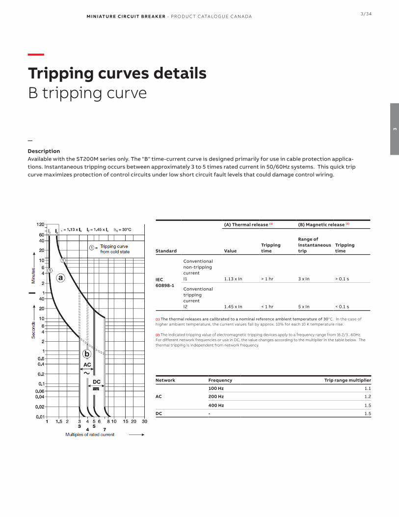
M I N I ATU R E CI RCU IT B R E A K E R - PR O D U C T C ATA LO G U E C A N A DA 3/34
3
—Tripping curves detailsB tripping curve
—
DescriptionAvailable with the ST200M series only. The "B" time-current curve is designed primarily for use in cable protection applica-tions. Instantaneous tripping occurs between approximately 3 to 5 times rated current in 50/60Hz systems. This quick trip curve maximizes protection of control circuits under low short circuit fault levels that could damage control wiring.
(A) Thermal release (1) (B) Magnetic release (2)
Standard ValueTrippingtime
Range of instantaneoustrip
Trippingtime
IEC 60898-1
Conventional non-tripping current I1 1.13 x In > 1 hr 3 x In > 0.1 s
Conventional trippingcurrent I2 1.45 x In < 1 hr 5 x In < 0.1 s
(1) The thermal releases are calibrated to a nominal reference ambient temperature of 30°C. In the case of higher ambient temperature, the current values fall by approx. 10% for each 10 K temperature rise.
(2) The indicated tripping value of electromagnetic tripping devices apply to a frequency range from 16 2/3...60Hz. For different network frequencies or use in DC, the value changes according to the multiplier in the table below. The thermal tripping is independent from network frequency.
Network Frequency Trip range multiplier
AC
100 Hz 1.1
200 Hz 1.2
400 Hz 1.5
DC - 1.5

3/35 M I N I ATU R E CI RCU IT B R E A K E R - PR O D U C T C ATA LO G U E C A N A DA
3
—Tripping curves detailsC tripping curve
—
DescriptionAvailable for all series with rated currents up through 63 amperes. The "C" time-current curve is designed for medium mag-netic start-up currents. Instantaneous tripping occurs between 5 and 10 times rated current in 50/60 Hz systems. The ‘’C’’ characteristic is the most commonly used curved.
(A) Thermal release (1) (B) Magnetic release (2)
Standard ValueTrippingtime
Range of instantaneoustrip
Trippingtime
IEC 60898-1
Conventional non-tripping current I1 1.13 x In > 1 hr 5 x In > 0.1 s
Conventional trippingcurrent I2 1.45 x In < 1 hr 10 x In < 0.1 s
(1) The thermal releases are calibrated to a nominal reference ambient temperature of 30°C. In the case of higher ambient temperature, the current values fall by approx. 10% for each 10 K temperature rise.
(2) The indicated tripping value of electromagnetic tripping devices apply to a frequency range from 16 2/3...60Hz. For different network frequencies or use in DC, the value changes according to the multiplier in the table below. The thermal tripping is independent from network frequency.
Network Frequency Trip range multiplier
AC
100 Hz 1.1
200 Hz 1.2
400 Hz 1.5
DC - 1.5
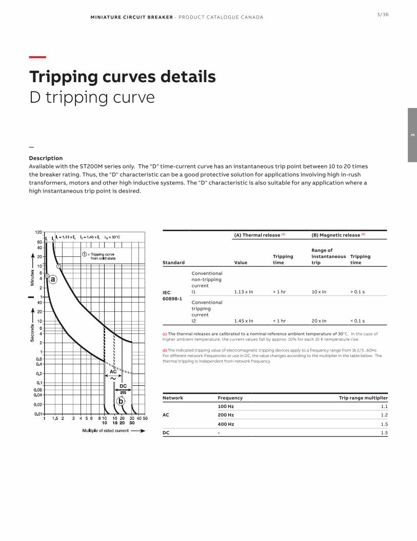
M I N I ATU R E CI RCU IT B R E A K E R - PR O D U C T C ATA LO G U E C A N A DA 3/36
3
—Tripping curves detailsD tripping curve
—
DescriptionAvailable with the ST200M series only. The "D" time-current curve has an instantaneous trip point between 10 to 20 times the breaker rating. Thus, the "D" characteristic can be a good protective solution for applications involving high in-rush transformers, motors and other high inductive systems. The "D" characteristic is also suitable for any application where a high instantaneous trip point is desired.
(A) Thermal release (1) (B) Magnetic release (2)
Standard ValueTrippingtime
Range of instantaneoustrip
Trippingtime
IEC 60898-1
Conventional non-tripping current I1 1.13 x In > 1 hr 10 x In > 0.1 s
Conventional trippingcurrent I2 1.45 x In < 1 hr 20 x In < 0.1 s
(1) The thermal releases are calibrated to a nominal reference ambient temperature of 30°C. In the case of higher ambient temperature, the current values fall by approx. 10% for each 10 K temperature rise.
(2) The indicated tripping value of electromagnetic tripping devices apply to a frequency range from 16 2/3...60Hz. For different network frequencies or use in DC, the value changes according to the multiplier in the table below. The thermal tripping is independent from network frequency.
Network Frequency Trip range multiplier
AC
100 Hz 1.1
200 Hz 1.2
400 Hz 1.5
DC - 1.5

3/37 M I N I ATU R E CI RCU IT B R E A K E R - PR O D U C T C ATA LO G U E C A N A DA
3
—Tripping curves detailsK tripping curve
—
DescriptionAvailable for all series with rated currents up through 63 amperes. The "K" time-current characteristic considers high mag-netic start-up currents from motors, transformers and other equipment. Instantaneous tripping occurs between 10 to 14 times rated current in 50/60Hz systems. The "K" characteristic is available up through 63 amperes.
The "K" curve offers the best protection for the broadest range of electrical systems. The higher magnetic trip settings max-imizes protection while allowing for higher in-rush currents during system start-up.
(A) Thermal release (1) (B) Magnetic release (2)
Standard ValueTrippingtime
Range of instantaneoustrip
Trippingtime
IEC 60898-1
Conventional non-tripping current I1 1.05 x In > 1 hr 10 x In > 0.2 s
Conventional trippingcurrent I2
1.20 x In1.50 x In6.00 x In
< 1 hr (3)
< 2 min (3)
> 2 s (T1)
14 x In < 0.2 s
(1) The thermal releases are calibrated to a nominal reference ambient temperature of 20°C. In the case of higher ambient temperature, the current values fall by approx. 10% for each 10 K temperature rise.
(2) The indicated tripping value of electromagnetic tripping devices apply to a frequency range from 16 2/3...60Hz. For different network frequencies or use in DC, the value changes according to the multiplier in the table below. The thermal tripping is independent from network frequency.
(3) As from operating temperature (after I1 > 1 hr or, as applicable, 2 h)
Network Frequency Trip range multiplier
AC
100 Hz 1.1
200 Hz 1.2
400 Hz 1.5
DC - 1.5
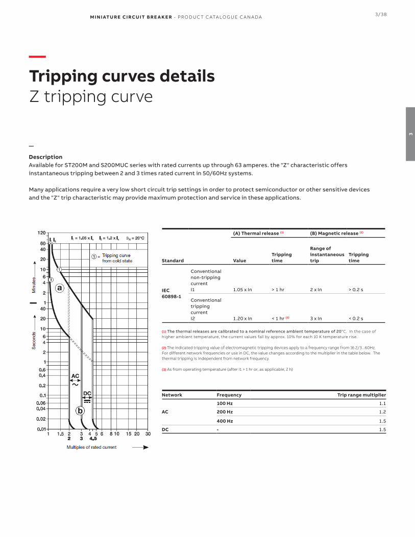
M I N I ATU R E CI RCU IT B R E A K E R - PR O D U C T C ATA LO G U E C A N A DA 3/38
3
—Tripping curves detailsZ tripping curve
—
DescriptionAvailable for ST200M and S200MUC series with rated currents up through 63 amperes. the "Z" characteristic offersinstantaneous tripping between 2 and 3 times rated current in 50/60Hz systems.
Many applications require a very low short circuit trip settings in order to protect semiconductor or other sensitive devices and the "Z" trip characteristic may provide maximum protection and service in these applications.
(A) Thermal release (1) (B) Magnetic release (2)
Standard ValueTrippingtime
Range of instantaneoustrip
Trippingtime
IEC 60898-1
Conventional non-tripping current I1 1.05 x In > 1 hr 2 x In > 0.2 s
Conventional trippingcurrent I2 1.20 x In < 1 hr (3) 3 x In < 0.2 s
(1) The thermal releases are calibrated to a nominal reference ambient temperature of 20°C. In the case of higher ambient temperature, the current values fall by approx. 10% for each 10 K temperature rise.
(2) The indicated tripping value of electromagnetic tripping devices apply to a frequency range from 16 2/3...60Hz. For different network frequencies or use in DC, the value changes according to the multiplier in the table below. The thermal tripping is independent from network frequency.
(3) As from operating temperature (after I1 > 1 hr or, as applicable, 2 h)
Network Frequency Trip range multiplier
AC
100 Hz 1.1
200 Hz 1.2
400 Hz 1.5
DC - 1.5

3/39 M I N I ATU R E CI RCU IT B R E A K E R - PR O D U C T C ATA LO G U E C A N A DA
3
—DimensionsS200, S200P and S200MUC series
—ST200M, S200MUC approximate dimensions
—S200MR approximate dimensions

M I N I ATU R E CI RCU IT B R E A K E R - PR O D U C T C ATA LO G U E C A N A DA 3/40
3
—DimensionsAccessories
—S2C-H6...S2C-S/H6R approximate dimensions
—S2C-A1, S2C-A2 approximate dimensions
—S2C-H10, H01 approximate dimensions
85
8 . 8
85
17. 5
—S2C-UAapproximate dimensions
85
17. 4

3/41 M I N I ATU R E CI RCU IT B R E A K E R - PR O D U C T C ATA LO G U E C A N A DA
3
—S800 seriesUL 1077 Supplementary Protectors
The S800 series are high performance cir-cuit breakers.
The current range covers nominal rated currents from 10 A up to 100 A (S800C) and 6 A up to 63 A (S800S) with a maxi-mum rated short-circuit interrupt rating of up to 20 kA (S800C) and 30 kA (S800S) in UL / CSA applications.
The S800HV is available for 600Y/347 VAC requirements up to 32A with 15kA IC
Features• Rated operational voltage up to 480Y/277 V AC – 500 V DC
(S800C) and 600Y/347 V AC (S800S), respectively (UL)• Compression terminals can be easily converted to ring
tongue terminals • Compact • Space saving
General Data S800C S800S S800HV
Amperage 10...100 A 10...63 A 10...32 A
Voltage 480Y/277 Vac125/500 Vdc
600Y/347 Vac 600Y/347 Vac
Poles 1, 2, 3, 4 1, 2, 3, 4 3
Trip curves B, C, D, K B, C, D, K C, K
Short circuit interrupt rating 10 kA 6 kA 15 kA
Mechanical life 4,000 ops 4,000 ops 4,000 ops
Ambient temperature -25 … +60 °C -25 … +60 °C -25 … +60 °C
Auxiliary contacts Yes Yes Yes
Bell alarm Yes Yes Yes
Shunt trip Yes Yes Yes
Undervoltage release Yes Yes Yes
Busbar No No No
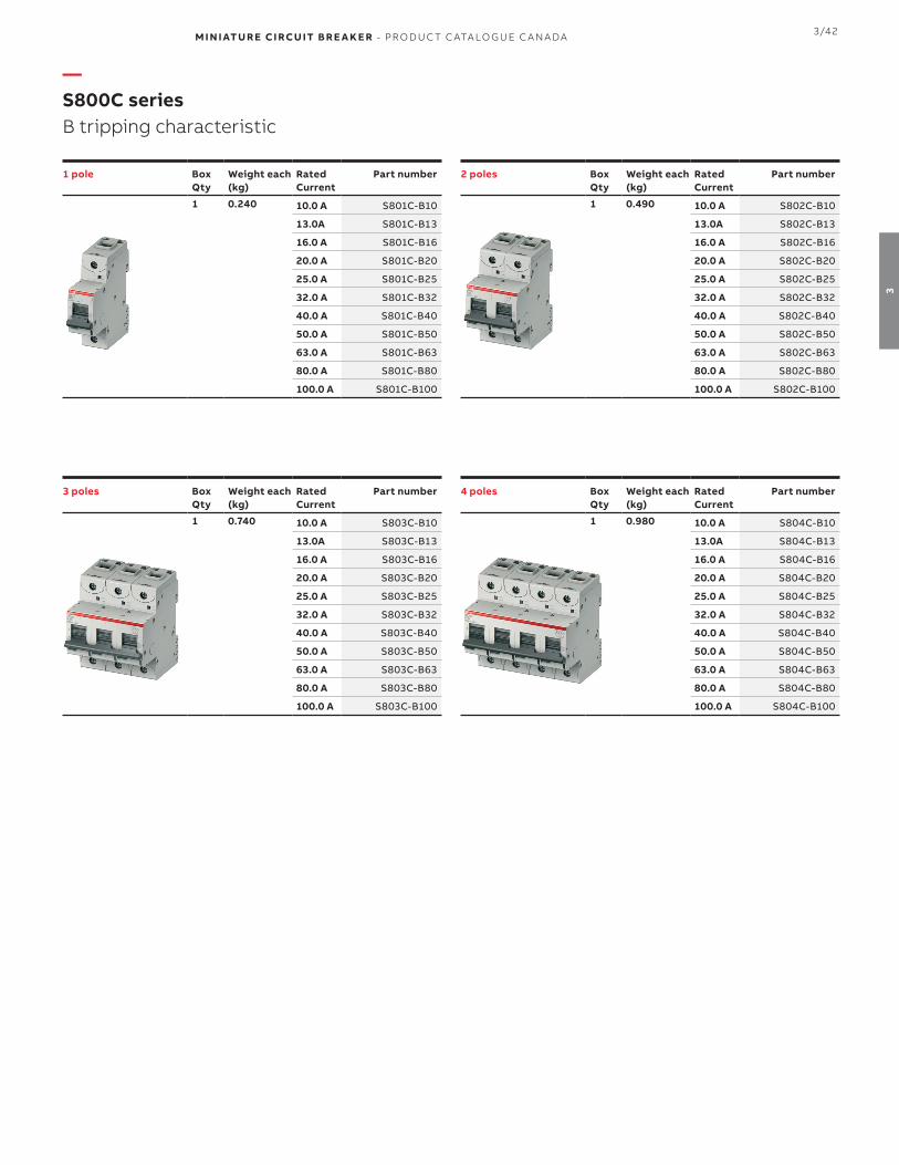
M I N I ATU R E CI RCU IT B R E A K E R - PR O D U C T C ATA LO G U E C A N A DA 3/42
3
1 pole Box Qty
Weight each(kg)
Rated Current
Part number
1 0.240 10.0 A S801C-B10
13.0A S801C-B13
16.0 A S801C-B16
20.0 A S801C-B20
25.0 A S801C-B25
32.0 A S801C-B32
40.0 A S801C-B40
50.0 A S801C-B50
63.0 A S801C-B63
80.0 A S801C-B80
100.0 A S801C-B100
2 poles Box Qty
Weight each(kg)
Rated Current
Part number
1 0.490 10.0 A S802C-B10
13.0A S802C-B13
16.0 A S802C-B16
20.0 A S802C-B20
25.0 A S802C-B25
32.0 A S802C-B32
40.0 A S802C-B40
50.0 A S802C-B50
63.0 A S802C-B63
80.0 A S802C-B80
100.0 A S802C-B100
3 poles Box Qty
Weight each(kg)
Rated Current
Part number
1 0.740 10.0 A S803C-B10
13.0A S803C-B13
16.0 A S803C-B16
20.0 A S803C-B20
25.0 A S803C-B25
32.0 A S803C-B32
40.0 A S803C-B40
50.0 A S803C-B50
63.0 A S803C-B63
80.0 A S803C-B80
100.0 A S803C-B100
4 poles Box Qty
Weight each(kg)
Rated Current
Part number
1 0.980 10.0 A S804C-B10
13.0A S804C-B13
16.0 A S804C-B16
20.0 A S804C-B20
25.0 A S804C-B25
32.0 A S804C-B32
40.0 A S804C-B40
50.0 A S804C-B50
63.0 A S804C-B63
80.0 A S804C-B80
100.0 A S804C-B100
—S800C seriesB tripping characteristic

3/43 M I N I ATU R E CI RCU IT B R E A K E R - PR O D U C T C ATA LO G U E C A N A DA
3
1 pole Box Qty
Weight each(kg)
Rated Current
Part number
1 0.240 10.0 A S801C-C10
13.0A S801C-C13
16.0 A S801C-C16
20.0 A S801C-C20
25.0 A S801C-C25
32.0 A S801C-C32
40.0 A S801C-C40
50.0 A S801C-C50
63.0 A S801C-C63
80.0 A S801C-C80
100.0 A S801C-C100
2 poles Box Qty
Weight each(kg)
Rated Current
Part number
1 0.490 10.0 A S802C-C10
13.0A S802C-C13
16.0 A S802C-C16
20.0 A S802C-C20
25.0 A S802C-C25
32.0 A S802C-C32
40.0 A S802C-C40
50.0 A S802C-C50
63.0 A S802C-C63
80.0 A S802C-C80
100.0 A S802C-C100
3 poles Box Qty
Weight each(kg)
Rated Current
Part number
1 0.740 10.0 A S803C-C10
13.0A S803C-C13
16.0 A S803C-C16
20.0 A S803C-C20
25.0 A S803C-C25
32.0 A S803C-C32
40.0 A S803C-C40
50.0 A S803C-C50
63.0 A S803C-C63
80.0 A S803C-C80
100.0 A S803C-C100
4 poles Box Qty
Weight each(kg)
Rated Current
Part number
1 0.980 10.0 A S804C-C10
13.0A S804C-C13
16.0 A S804C-C16
20.0 A S804C-C20
25.0 A S804C-C25
32.0 A S804C-C32
40.0 A S804C-C40
50.0 A S804C-C50
63.0 A S804C-C63
80.0 A S804C-C80
100.0 A S804C-C100
—S800C seriesC tripping characteristic

M I N I ATU R E CI RCU IT B R E A K E R - PR O D U C T C ATA LO G U E C A N A DA 3/44
3
1 pole Box Qty
Weight each(kg)
Rated Current
Part number
1 0.240 10.0 A S801C-D10
13.0A S801C-D13
16.0 A S801C-D16
20.0 A S801C-D20
25.0 A S801C-D25
32.0 A S801C-D32
40.0 A S801C-D40
50.0 A S801C-D50
63.0 A S801C-D63
80.0 A S801C-D80
100.0 A S801C-D100
2 poles Box Qty
Weight each(kg)
Rated Current
Part number
1 0.490 10.0 A S802C-D10
13.0A S802C-D13
16.0 A S802C-D16
20.0 A S802C-D20
25.0 A S802C-D25
32.0 A S802C-D32
40.0 A S802C-D40
50.0 A S802C-D50
63.0 A S802C-D63
80.0 A S802C-D80
100.0 A S802C-D100
3 poles Box Qty
Weight each(kg)
Rated Current
Part number
1 0.740 10.0 A S803C-D10
13.0A S803C-D13
16.0 A S803C-D16
20.0 A S803C-D20
25.0 A S803C-D25
32.0 A S803C-D32
40.0 A S803C-D40
50.0 A S803C-D50
63.0 A S803C-D63
80.0 A S803C-D80
100.0 A S803C-D100
4 poles Box Qty
Weight each(kg)
Rated Current
Part number
1 0.980 10.0 A S804C-D10
13.0A S804C-D13
16.0 A S804C-D16
20.0 A S804C-D20
25.0 A S804C-D25
32.0 A S804C-D32
40.0 A S804C-D40
50.0 A S804C-D50
63.0 A S804C-D63
80.0 A S804C-D80
100.0 A S804C-D100
—S800C seriesD tripping characteristic
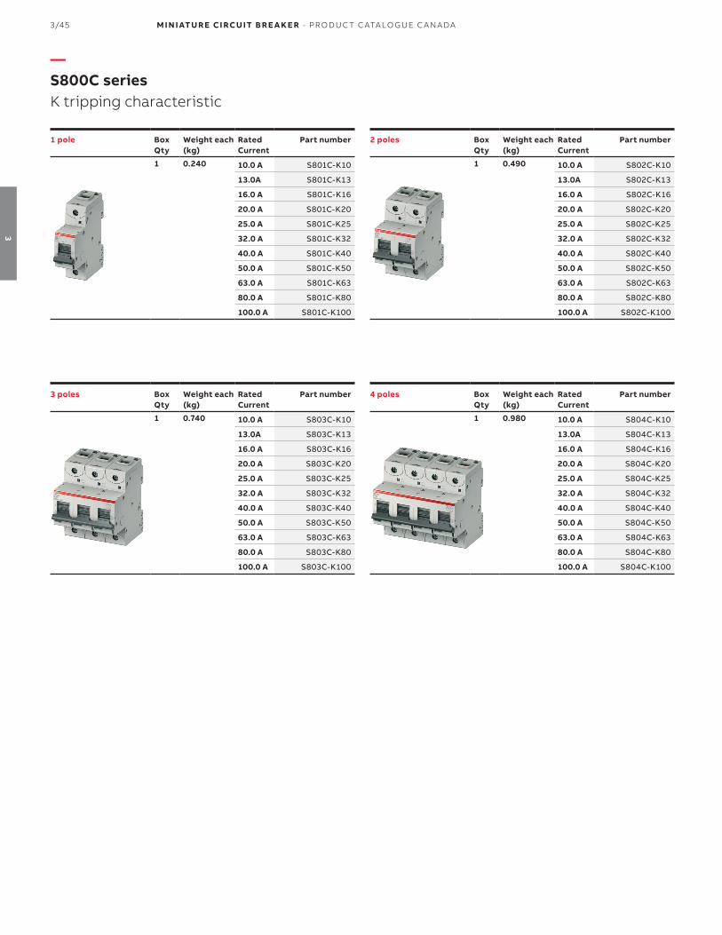
3/45 M I N I ATU R E CI RCU IT B R E A K E R - PR O D U C T C ATA LO G U E C A N A DA
3
1 pole Box Qty
Weight each(kg)
Rated Current
Part number
1 0.240 10.0 A S801C-K10
13.0A S801C-K13
16.0 A S801C-K16
20.0 A S801C-K20
25.0 A S801C-K25
32.0 A S801C-K32
40.0 A S801C-K40
50.0 A S801C-K50
63.0 A S801C-K63
80.0 A S801C-K80
100.0 A S801C-K100
2 poles Box Qty
Weight each(kg)
Rated Current
Part number
1 0.490 10.0 A S802C-K10
13.0A S802C-K13
16.0 A S802C-K16
20.0 A S802C-K20
25.0 A S802C-K25
32.0 A S802C-K32
40.0 A S802C-K40
50.0 A S802C-K50
63.0 A S802C-K63
80.0 A S802C-K80
100.0 A S802C-K100
3 poles Box Qty
Weight each(kg)
Rated Current
Part number
1 0.740 10.0 A S803C-K10
13.0A S803C-K13
16.0 A S803C-K16
20.0 A S803C-K20
25.0 A S803C-K25
32.0 A S803C-K32
40.0 A S803C-K40
50.0 A S803C-K50
63.0 A S803C-K63
80.0 A S803C-K80
100.0 A S803C-K100
4 poles Box Qty
Weight each(kg)
Rated Current
Part number
1 0.980 10.0 A S804C-K10
13.0A S804C-K13
16.0 A S804C-K16
20.0 A S804C-K20
25.0 A S804C-K25
32.0 A S804C-K32
40.0 A S804C-K40
50.0 A S804C-K50
63.0 A S804C-K63
80.0 A S804C-K80
100.0 A S804C-K100
—S800C seriesK tripping characteristic

M I N I ATU R E CI RCU IT B R E A K E R - PR O D U C T C ATA LO G U E C A N A DA 3/46
3
1 pole Box Qty
Weight each(kg)
Rated Current
Part number
1 0.240 0.5 A S801S-B0.5
1.0 A S801S-B1
1.6 A S801S-B1.6
2.0 A S801S-B2
2.5 A S801S-B2.5
3.0 A S801S-B3
4.0 A S801S-B4
5.0 A S801S-B5
6.0 A S801S-B6
8.0 A S801S-B8
10.0 A S801S-B10
13.0A S801S-B13
16.0 A S801S-B16
20.0 A S801S-B20
25.0 A S801S-B25
32.0 A S801S-B32
40.0 A S801S-B40
50.0 A S801S-B50
63.0 A S801S-B63
2 poles Box Qty
Weight each(kg)
Rated Current
Part number
1 0.490 0.5 A S802S-B0.5
1.0 A S802S-B1
1.6 A S802S-B1.6
2.0 A S802S-B2
2.5 A S802S-B2.5
3.0 A S802S-B3
4.0 A S802S-B4
5.0 A S802S-B5
6.0 A S802S-B6
8.0 A S802S-B8
10.0 A S802S-B10
13.0A S802S-B13
16.0 A S802S-B16
20.0 A S802S-B20
25.0 A S802S-B25
32.0 A S802S-B32
40.0 A S802S-B40
50.0 A S802S-B50
63.0 A S802S-B63
3 poles Box Qty
Weight each(kg)
Rated Current
Part number
1 0.740 0.5 A S803S-B0.5
1.0 A S803S-B1
1.6 A S803S-B1.6
2.0 A S803S-B2
2.5 A S803S-B2.5
3.0 A S803S-B3
4.0 A S803S-B4
5.0 A S803S-B5
6.0 A S803S-B6
8.0 A S803S-B8
10.0 A S803S-B10
13.0A S803S-B13
16.0 A S803S-B16
20.0 A S803S-B20
25.0 A S803S-B25
32.0 A S803S-B32
40.0 A S803S-B40
50.0 A S803S-B50
63.0 A S803S-B63
4 poles Box Qty
Weight each(kg)
Rated Current
Part number
1 0.980 0.5 A S804S-B0.5
1.0 A S804S-B1
1.6 A S804S-B1.6
2.0 A S804S-B2
2.5 A S804S-B2.5
3.0 A S804S-B3
4.0 A S804S-B4
5.0 A S804S-B5
6.0 A S804S-B6
8.0 A S804S-B8
10.0 A S804S-B10
13.0A S804S-B13
16.0 A S804S-B16
20.0 A S804S-B20
25.0 A S804S-B25
32.0 A S804S-B32
40.0 A S804S-B40
50.0 A S804S-B50
63.0 A S804S-B63
—S800S seriesB tripping characteristic
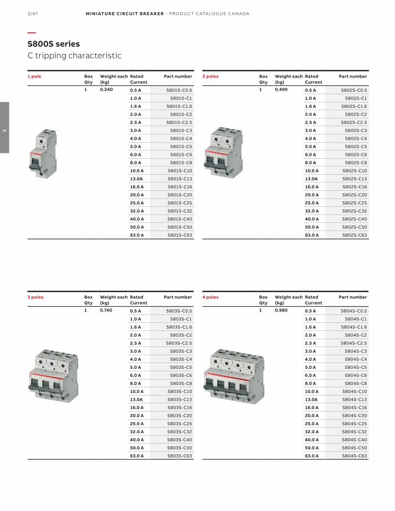
3/47 M I N I ATU R E CI RCU IT B R E A K E R - PR O D U C T C ATA LO G U E C A N A DA
3
1 pole Box Qty
Weight each(kg)
Rated Current
Part number
1 0.240 0.5 A S801S-C0.5
1.0 A S801S-C1
1.6 A S801S-C1.6
2.0 A S801S-C2
2.5 A S801S-C2.5
3.0 A S801S-C3
4.0 A S801S-C4
5.0 A S801S-C5
6.0 A S801S-C6
8.0 A S801S-C8
10.0 A S801S-C10
13.0A S801S-C13
16.0 A S801S-C16
20.0 A S801S-C20
25.0 A S801S-C25
32.0 A S801S-C32
40.0 A S801S-C40
50.0 A S801S-C50
63.0 A S801S-C63
2 poles Box Qty
Weight each(kg)
Rated Current
Part number
1 0.490 0.5 A S802S-C0.5
1.0 A S802S-C1
1.6 A S802S-C1.6
2.0 A S802S-C2
2.5 A S802S-C2.5
3.0 A S802S-C3
4.0 A S802S-C4
5.0 A S802S-C5
6.0 A S802S-C6
8.0 A S802S-C8
10.0 A S802S-C10
13.0A S802S-C13
16.0 A S802S-C16
20.0 A S802S-C20
25.0 A S802S-C25
32.0 A S802S-C32
40.0 A S802S-C40
50.0 A S802S-C50
63.0 A S802S-C63
3 poles Box Qty
Weight each(kg)
Rated Current
Part number
1 0.740 0.5 A S803S-C0.5
1.0 A S803S-C1
1.6 A S803S-C1.6
2.0 A S803S-C2
2.5 A S803S-C2.5
3.0 A S803S-C3
4.0 A S803S-C4
5.0 A S803S-C5
6.0 A S803S-C6
8.0 A S803S-C8
10.0 A S803S-C10
13.0A S803S-C13
16.0 A S803S-C16
20.0 A S803S-C20
25.0 A S803S-C25
32.0 A S803S-C32
40.0 A S803S-C40
50.0 A S803S-C50
63.0 A S803S-C63
4 poles Box Qty
Weight each(kg)
Rated Current
Part number
1 0.980 0.5 A S804S-C0.5
1.0 A S804S-C1
1.6 A S804S-C1.6
2.0 A S804S-C2
2.5 A S804S-C2.5
3.0 A S804S-C3
4.0 A S804S-C4
5.0 A S804S-C5
6.0 A S804S-C6
8.0 A S804S-C8
10.0 A S804S-C10
13.0A S804S-C13
16.0 A S804S-C16
20.0 A S804S-C20
25.0 A S804S-C25
32.0 A S804S-C32
40.0 A S804S-C40
50.0 A S804S-C50
63.0 A S804S-C63
—S800S seriesC tripping characteristic

M I N I ATU R E CI RCU IT B R E A K E R - PR O D U C T C ATA LO G U E C A N A DA 3/48
3
1 pole Box Qty
Weight each(kg)
Rated Current
Part number
1 0.240 0.5 A S801S-D0.5
1.0 A S801S-D1
1.6 A S801S-D1.6
2.0 A S801S-D2
2.5 A S801S-D2.5
3.0 A S801S-D3
4.0 A S801S-D4
5.0 A S801S-D5
6.0 A S801S-D6
8.0 A S801S-D8
10.0 A S801S-D10
13.0A S801S-D13
16.0 A S801S-D16
20.0 A S801S-D20
25.0 A S801S-D25
32.0 A S801S-D32
40.0 A S801S-D40
50.0 A S801S-D50
63.0 A S801S-D63
2 poles Box Qty
Weight each(kg)
Rated Current
Part number
1 0.490 0.5 A S802S-D0.5
1.0 A S802S-D1
1.6 A S802S-D1.6
2.0 A S802S-D2
2.5 A S802S-D2.5
3.0 A S802S-D3
4.0 A S802S-D4
5.0 A S802S-D5
6.0 A S802S-D6
8.0 A S802S-D8
10.0 A S802S-D10
13.0A S802S-D13
16.0 A S802S-D16
20.0 A S802S-D20
25.0 A S802S-D25
32.0 A S802S-D32
40.0 A S802S-D40
50.0 A S802S-D50
63.0 A S802S-D63
3 poles Box Qty
Weight each(kg)
Rated Current
Part number
1 0.740 0.5 A S803S-D0.5
1.0 A S803S-D1
1.6 A S803S-D1.6
2.0 A S803S-D2
2.5 A S803S-D2.5
3.0 A S803S-D3
4.0 A S803S-D4
5.0 A S803S-D5
6.0 A S803S-D6
8.0 A S803S-D8
10.0 A S803S-D10
13.0A S803S-D13
16.0 A S803S-D16
20.0 A S803S-D20
25.0 A S803S-D25
32.0 A S803S-D32
40.0 A S803S-D40
50.0 A S803S-D50
63.0 A S803S-D63
4 poles Box Qty
Weight each(kg)
Rated Current
Part number
1 0.980 0.5 A S804S-D0.5
1.0 A S804S-D1
1.6 A S804S-D1.6
2.0 A S804S-D2
2.5 A S804S-D2.5
3.0 A S804S-D3
4.0 A S804S-D4
5.0 A S804S-D5
6.0 A S804S-D6
8.0 A S804S-D8
10.0 A S804S-D10
13.0A S804S-D13
16.0 A S804S-D16
20.0 A S804S-D20
25.0 A S804S-D25
32.0 A S804S-D32
40.0 A S804S-D40
50.0 A S804S-D50
63.0 A S804S-D63
—S800S seriesD tripping characteristic

3/49 M I N I ATU R E CI RCU IT B R E A K E R - PR O D U C T C ATA LO G U E C A N A DA
3
1 pole Box Qty
Weight each(kg)
Rated Current
Part number
1 0.240 0.5 A S801S-K0.5
1.0 A S801S-K1
1.6 A S801S-K1.6
2.0 A S801S-K2
2.5 A S801S-K2.5
3.0 A S801S-K3
4.0 A S801S-K4
5.0 A S801S-K5
6.0 A S801S-K6
8.0 A S801S-K8
10.0 A S801S-K10
13.0A S801S-K13
16.0 A S801S-K16
20.0 A S801S-K20
25.0 A S801S-K25
32.0 A S801S-K32
40.0 A S801S-K40
50.0 A S801S-K50
63.0 A S801S-K63
2 poles Box Qty
Weight each(kg)
Rated Current
Part number
1 0.490 0.5 A S802S-K0.5
1.0 A S802S-K1
1.6 A S802S-K1.6
2.0 A S802S-K2
2.5 A S802S-K2.5
3.0 A S802S-K3
4.0 A S802S-K4
5.0 A S802S-K5
6.0 A S802S-K6
8.0 A S802S-K8
10.0 A S802S-K10
13.0A S802S-K13
16.0 A S802S-K16
20.0 A S802S-K20
25.0 A S802S-K25
32.0 A S802S-K32
40.0 A S802S-K40
50.0 A S802S-K50
63.0 A S802S-K63
3 poles Box Qty
Weight each(kg)
Rated Current
Part number
1 0.740 0.5 A S803S-K0.5
1.0 A S803S-K1
1.6 A S803S-K1.6
2.0 A S803S-K2
2.5 A S803S-K2.5
3.0 A S803S-K3
4.0 A S803S-K4
5.0 A S803S-K5
6.0 A S803S-K6
8.0 A S803S-K8
10.0 A S803S-K10
13.0A S803S-K13
16.0 A S803S-K16
20.0 A S803S-K20
25.0 A S803S-K25
32.0 A S803S-K32
40.0 A S803S-K40
50.0 A S803S-K50
63.0 A S803S-K63
4 poles Box Qty
Weight each(kg)
Rated Current
Part number
1 0.980 0.5 A S804S-K0.5
1.0 A S804S-K1
1.6 A S804S-K1.6
2.0 A S804S-K2
2.5 A S804S-K2.5
3.0 A S804S-K3
4.0 A S804S-K4
5.0 A S804S-K5
6.0 A S804S-K6
8.0 A S804S-K8
10.0 A S804S-K10
13.0A S804S-K13
16.0 A S804S-K16
20.0 A S804S-K20
25.0 A S804S-K25
32.0 A S804S-K32
40.0 A S804S-K40
50.0 A S804S-K50
63.0 A S804S-K63
—S800S seriesK tripping characteristic

M I N I ATU R E CI RCU IT B R E A K E R - PR O D U C T C ATA LO G U E C A N A DA 3/50
3
3 poles Box Qty
Weight each(kg)
Rated Current
Part number
1 0.740 10.0 A S803HV-C10
13.0A S803HV-C13
16.0 A S803HV-C16
20.0 A S803HV-C20
25.0 A S803HV-C25
32.0 A S803HV-C32
3 poles Box Qty
Weight each(kg)
Rated Current
Part number
1 0.740 10.0 A S803HV-K10
13.0A S803HV-K13
16.0 A S803HV-K16
20.0 A S803HV-K20
25.0 A S803HV-K25
32.0 A S803HV-K32
—S800HV seriesC tripping characteristic
—S800HV seriesK tripping characteristic
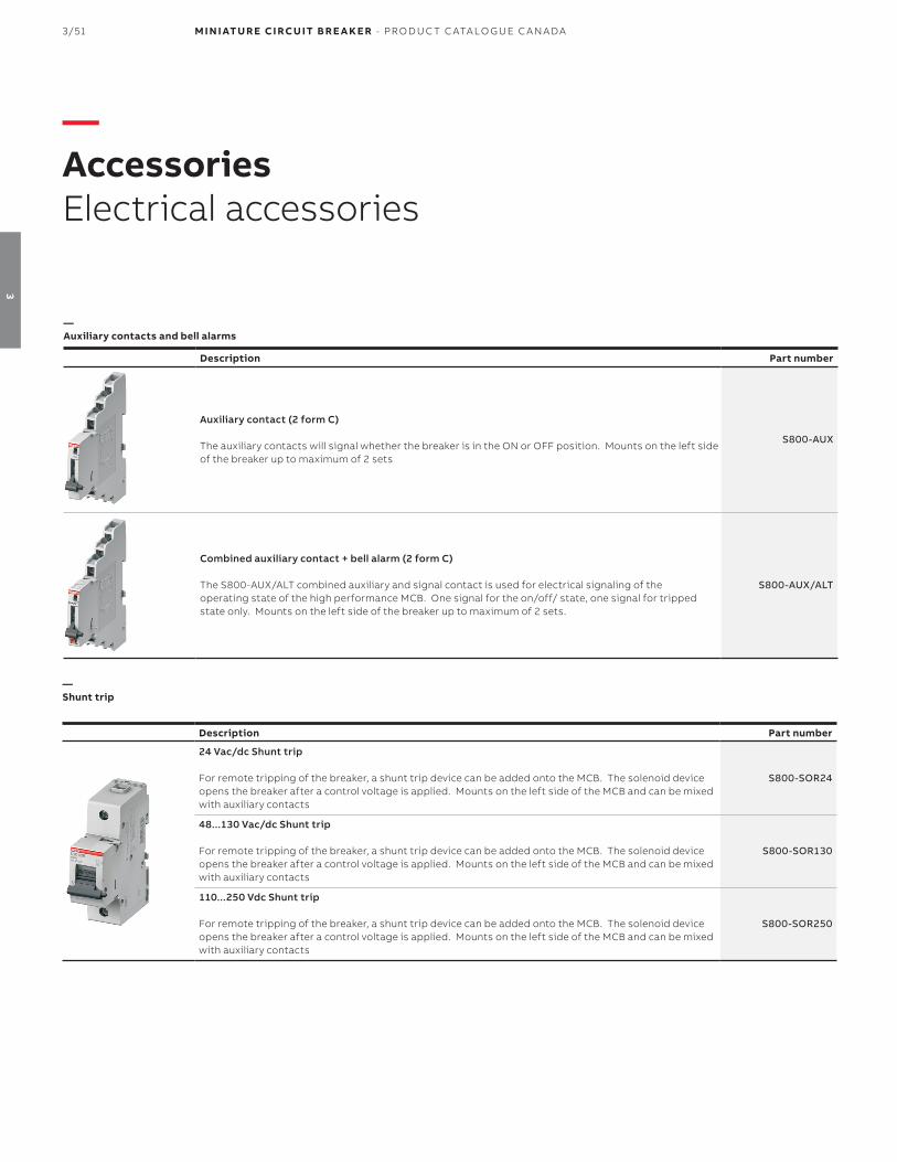
3/51 M I N I ATU R E CI RCU IT B R E A K E R - PR O D U C T C ATA LO G U E C A N A DA
3
—Auxiliary contacts and bell alarms
Description Part number
Auxiliary contact (2 form C)
The auxiliary contacts will signal whether the breaker is in the ON or OFF position. Mounts on the left side of the breaker up to maximum of 2 sets
S800-AUX
Combined auxiliary contact + bell alarm (2 form C)
The S800-AUX/ALT combined auxiliary and signal contact is used for electrical signaling of theoperating state of the high performance MCB. One signal for the on/off/ state, one signal for tripped state only. Mounts on the left side of the breaker up to maximum of 2 sets.
S800-AUX/ALT
—Shunt trip
—AccessoriesElectrical accessories
Description Part number
24 Vac/dc Shunt trip
For remote tripping of the breaker, a shunt trip device can be added onto the MCB. The solenoid device opens the breaker after a control voltage is applied. Mounts on the left side of the MCB and can be mixed with auxiliary contacts
S800-SOR24
48...130 Vac/dc Shunt trip
For remote tripping of the breaker, a shunt trip device can be added onto the MCB. The solenoid device opens the breaker after a control voltage is applied. Mounts on the left side of the MCB and can be mixed with auxiliary contacts
S800-SOR130
110...250 Vdc Shunt trip
For remote tripping of the breaker, a shunt trip device can be added onto the MCB. The solenoid device opens the breaker after a control voltage is applied. Mounts on the left side of the MCB and can be mixed with auxiliary contacts
S800-SOR250
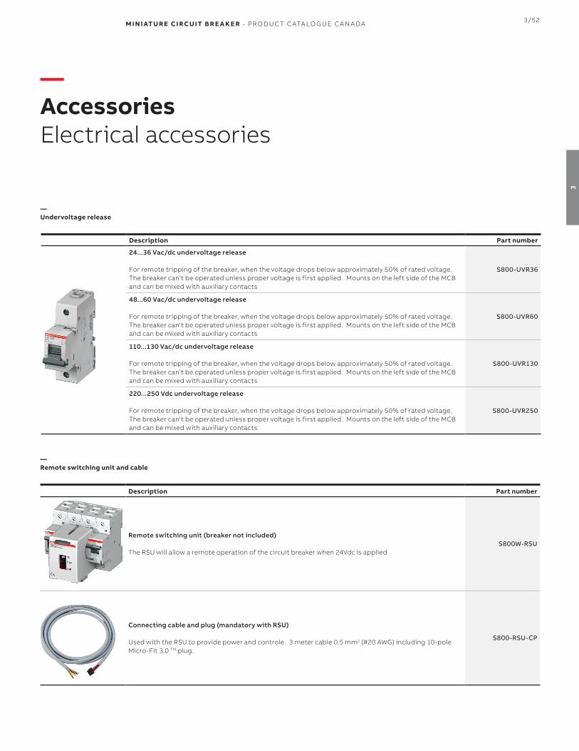
M I N I ATU R E CI RCU IT B R E A K E R - PR O D U C T C ATA LO G U E C A N A DA 3/52
3
—Undervoltage release
—AccessoriesElectrical accessories
Description Part number
24...36 Vac/dc undervoltage release
For remote tripping of the breaker, when the voltage drops below approximately 50% of rated voltage. The breaker can't be operated unless proper voltage is first applied. Mounts on the left side of the MCB and can be mixed with auxiliary contacts
S800-UVR36
48...60 Vac/dc undervoltage release
For remote tripping of the breaker, when the voltage drops below approximately 50% of rated voltage. The breaker can't be operated unless proper voltage is first applied. Mounts on the left side of the MCB and can be mixed with auxiliary contacts
S800-UVR60
110...130 Vac/dc undervoltage release
For remote tripping of the breaker, when the voltage drops below approximately 50% of rated voltage. The breaker can't be operated unless proper voltage is first applied. Mounts on the left side of the MCB and can be mixed with auxiliary contacts
S800-UVR130
220...250 Vdc undervoltage release
For remote tripping of the breaker, when the voltage drops below approximately 50% of rated voltage. The breaker can't be operated unless proper voltage is first applied. Mounts on the left side of the MCB and can be mixed with auxiliary contacts
S800-UVR250
—Remote switching unit and cable
Description Part number
Remote switching unit (breaker not included)
The RSU will allow a remote operation of the circuit breaker when 24Vdc is appliedS800W-RSU
Connecting cable and plug (mandatory with RSU)
Used with the RSU to provide power and controle. 3 meter cable 0.5 mm2 (#20 AWG) including 10-pole Micro-Fit 3.0 TM plug.
S800-RSU-CP

3/53 M I N I ATU R E CI RCU IT B R E A K E R - PR O D U C T C ATA LO G U E C A N A DA
3
—AccessoriesElectrical accessories
—S803W-SCL-SR Short circuit current limiter, self-resetting UL
Description Part number
32 A Self-resetting current limiter
For increased short circuit breaking capacity of downstream manual motor starters and high performance MCBs (S800 series)- up to 65kA on approved combination.
S803W-SCL32-SR
63 A Self-resetting current limiter
For increased short circuit breaking capacity of downstream manual motor starters and high performance MCBs (S800 series)- up to 65kA on approved combination.
S803W-SCL63-SR
100 A Self-resetting current limiter
For increased short circuit breaking capacity of downstream manual motor starters and high performance MCBs (S800 series)- up to 65kA on approved combination.
S803W-SCL100-SR
See technical detail section for approved combination and technical data.

M I N I ATU R E CI RCU IT B R E A K E R - PR O D U C T C ATA LO G U E C A N A DA 3/54
3
—Ring tongue adaptor
Description Part number
Ring terminal cable connection 40...125 A (kit of 2 nuts, insulation nuts, cable lugs, allen screws and 25mm insulation walls
S800-RT2125
—AccessoriesMechanical accessories
—Rotary handle
Description Part number
Grey rotary handle S800-RHE-H
Red emergency rotary handle S800-RHE-EM
—Shaft extension
Description Part number
To connect rotary drive and door handle S800-RHE-S
—Handle operating mechanism
Description Part number
Mounts on the circuit breaker and allows "through the door" operation S800-RD
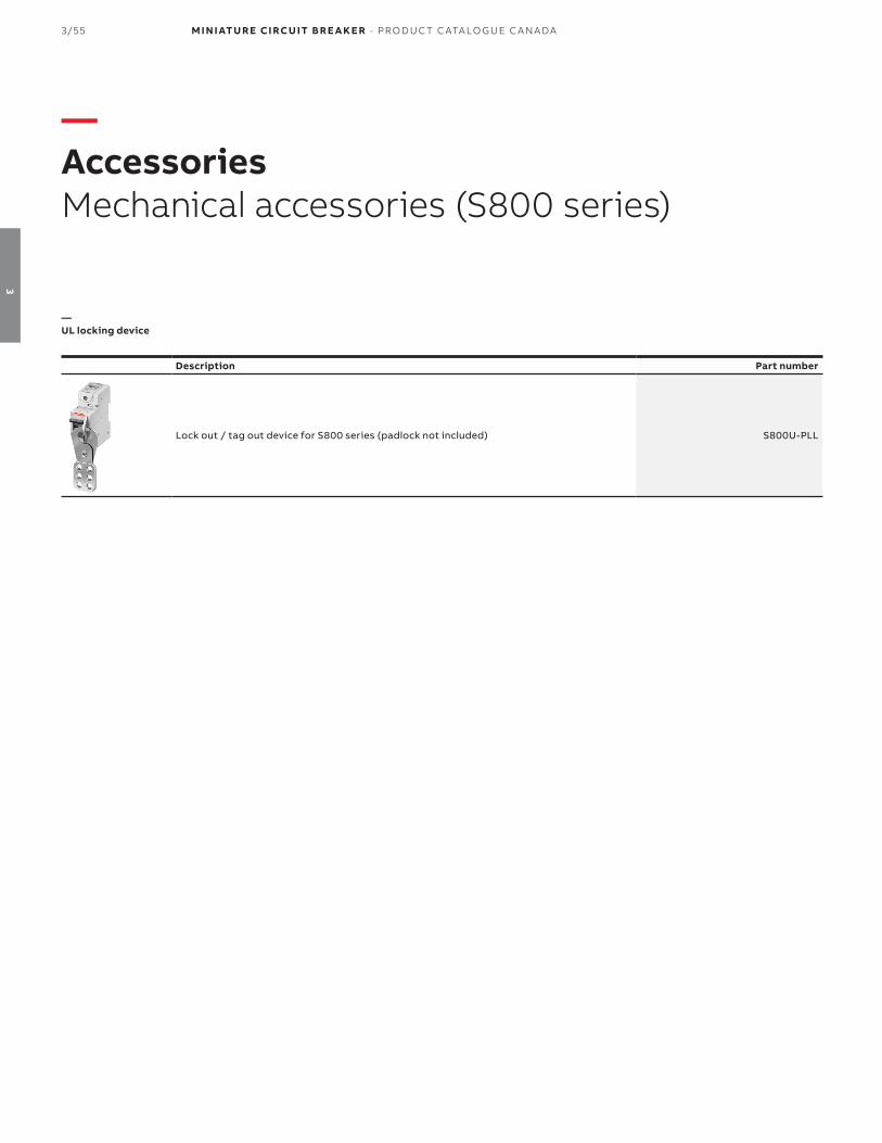
3/55 M I N I ATU R E CI RCU IT B R E A K E R - PR O D U C T C ATA LO G U E C A N A DA
3
—AccessoriesMechanical accessories (S800 series)
—UL locking device
Description Part number
Lock out / tag out device for S800 series (padlock not included) S800U-PLL

M I N I ATU R E CI RCU IT B R E A K E R - PR O D U C T C ATA LO G U E C A N A DA 3/56
3
—Technical specifications MCBs
S800C S800S S800HV
SpecificationsCSA C22.2 No.235
UL1077IEC 60947-2
CSA C22.2 No.235UL1077
IEC 60947-2
CSA C22.2 No.235UL1077
IEC 60947-2
Nbr of poles 1, 2, 3, 4 1, 2, 3, 4 3
Trip curves B, C, D, K B, C, D, K C, K
Amperage 10...100 A 10...63 A 10...32 A
Voltage AC 480Y/277 Vac 600Y/347 Vac 600Y/347 Vac
Voltage DC 125 per pole - -
Interrupt rating 10 kA 6 kA 15 kA
Calibration temp 30...40 oC 30...40 oC 40 oC
Mounting position Any Any Any
Protection degree IP20 IP20 IP20
Mounting 35 mm DIN rail 35 mm DIN rail 35 mm DIN rail
Tightening torque31 in-lbs
3.5 Nm31 in-lbs
3.5 Nm31 in-lbs
3.5 Nm
Terminal wire size14...2 AWG (10...30 A)8...1 AWG (40...100A)
14...2 AWG (10...30 A)8...1 AWG (40...100A) 14...2 AWG
Ambien temperature-25oC...+60oC-13oF...+140oF
-25oC...+60oC-13oF...+140oF
-25oC...+60oC-13oF...+140oF
Mechanical life 10,000 ops 10,000 ops 10,000 ops
—Technical detailsS800 series

3/57 M I N I ATU R E CI RCU IT B R E A K E R - PR O D U C T C ATA LO G U E C A N A DA
3
—Internal resistance and power loss per pole (S800C and S800S)
B, C, D, K tripping characteristics
Rated current (A)
Internal resistance
(mΩ)Power loss
(W)
10 15.2 1.5
13 12.1 2.0
16 12.1 3.1
20 8.7 3.5
25 6.8 4.3
32 3.1 3.2
40 2.3 3.7
50 1.7 4.3
63 1.6 6.4
80 (1) 1.0 6.4
100 (1) 0.8 8.0
—Technical detailsS800 series
(1) Only for S800C series
—Internal resistance and power loss per pole (S800HV)
B, C, D, K tripping characteristics
Rated current (A)
Internal resistance
(mΩ)Power loss
(W)
10 15.2 1.5
13 12.1 2.0
16 12.1 3.1
20 8.7 3.5
25 6.8 4.3
32 3.1 3.2

M I N I ATU R E CI RCU IT B R E A K E R - PR O D U C T C ATA LO G U E C A N A DA 3/58
3
—Temperature derating (B, C, D tripping characteristics)
Standard
Rated current(A)
Maximum operating current (A) at ambient temperature T
- 25 °C - 15 °C - 10 °C - 5 °C 0 °C 10 °C 20 °C 30 °C 40 °C 50 °C 60 °C 70 °C
IEC
10 12.0 11.7 11.5 11.3 11.1 10.7 10.4 10.0 9.6 9.3 8.9 8.5
13 15.6 15.1 14.9 14.7 14.4 14.0 13.5 13.0 12.5 12.0 11.6 11.1
16 19.2 18.6 18.3 18.1 17.8 17.2 16.6 16.0 15.4 14.8 14.2 13.7
20 24.0 23.3 22.9 22.6 22.2 21.5 20.7 20.0 19.3 18.5 17.8 17.1
25 30.0 29.1 28.7 28.2 27.8 26.8 25.9 25.0 24.1 23.2 22.2 21.3
32 38.5 37.3 36.7 36.1 35.5 34.3 33.2 32.0 30.8 29.7 28.5 27.3
40 48.1 46.6 45.9 45.1 44.4 42.9 41.5 40.0 38.5 37.1 35.6 34.1
50 60.1 58.3 57.3 56.4 55.5 53.7 51.8 50.0 48.2 46.3 44.5 42.7
63 75.7 73.4 72.2 71.1 69.9 67.6 65.3 63.0 60.7 58.4 56.1 53.8
80 96.1 93.2 91.7 90.3 88.8 85.9 82.9 80.0 77.1 74.1 71.2 68.3
100 120.2 116.5 114.7 112.8 111.0 107.3 129.6 100.0 96.3 92.7 89.0 85.3
—Technical detailsS800 series
—Temperature derating (K tripping characteristics)
Standard
Rated current(A)
Maximum operating current (A) at ambient temperature T
- 25 °C - 15 °C - 10 °C - 5 °C 0 °C 10 °C 20 °C 30 °C 40 °C 50 °C 60 °C 70 °C
IEC
10 12.4 12.0 11.8 11.7 11.5 11.1 10.7 10.4 10.0 9.6 9.3 8.9
13 16.1 15.6 15.4 15.1 14.9 14.4 14.0 13.5 13.0 12.5 12.0 11.6
16 19.8 19.2 18.9 18.6 18.3 17.8 17.2 16.6 16.0 15.4 14.8 14.2
20 24.8 24.0 23.7 23.3 22.3 22.2 21.5 20.7 20.0 19.3 18.5 17.8
25 31.0 30.0 29.6 29.1 28.7 27.8 26.8 25.9 25.0 24.1 23.2 22.2
32 39.6 38.5 37.9 3.3 36.7 35.5 34.3 33.2 32.0 30.8 29.7 28.5
40 49.5 48.1 47.3 46.6 45.9 44.4 42.9 41.5 40.0 38.5 37.1 35.6
50 61.9 60.1 59.2 58.3 57.3 55.5 53.7 51.8 50.0 48.2 46.3 44.5
63 78.0 75.7 74.6 73.4 72.2 69.9 67.6 65.3 63.0 60.7 58.4 56.1

3/59 M I N I ATU R E CI RCU IT B R E A K E R - PR O D U C T C ATA LO G U E C A N A DA
3
—Technical detailsElectrical accessories (S800)
—Technical specifications auxiliary contacts S800AUX, S800AUX/ALT
S800-AUX S800-AUX/ALT
Usage category
AC15 400/2 A-ULAC15 240/6 A-ULDC13 250/0.55 ADC13 125 V/1.1A
DC13/60 V/2ADC13 24 V/4A
AC15 400/2 A-ULAC15 240/6 A-ULDC13 250/0.55 ADC13 125 V/1.1A
DC13/60 V/2ADC13 24 V/4A
Continuous thermal current 6 A 6 A
Ratd insulation voltage 690 V 690 V
Number of contacts 2 2 (1 AUX + 1 ALT)
Rated impulse withstand voltage 6 kV 6 kV
Protection degree 3 3
Function of contact Change over (dry SPDT) Change over (dry SPDT)
Connection (CU) 1x 2.5mm2 or 2x 1.5 mm2 1x 2.5mm2 or 2x 1.5 mm2
Tightening torque 1 Nm 1 Nm
Ensured contacts during shake testaccording to IEC 68-2-6
5g, 20 frequency cycle at 24 Vac/dc5 mA brief interrupt < 10 ms
5g, 20 frequency cycle at 24 Vac/dc5 mA brief interrupt < 10 ms
Supply Any Any
Mounting On MCB, DIN rail On MCB, DIN rail
Type of protection IP20 IP20
Permissible ambient temperature-25oC...+60oC-13oF...+140oF
-25oC...+60oC-13oF...+140oF
Storage temperature-40oC...+70oC
-40oF...+158oF-40oC...+70oC
-40oF...+158oF
Mechanical life 6,000 ops 6,000 ops
Resistance to vibration IEC 60068-2-27, 60068-2, 61373 Cat. 1/ class B IEC 60068-2-27, 60068-2, 61373 Cat. 1/ class B
—Connection drawings (normal state - OFF position below)
Auxiliary contact S800-AUX Auxiliary contact S800-AUX/ALT

M I N I ATU R E CI RCU IT B R E A K E R - PR O D U C T C ATA LO G U E C A N A DA 3/60
3
—Technical detailsElectrical accessories (S800)
—Technical specifications shunt trip S800-SOR
S800-SOR24 S800-SOR130 S800-SOR250
Rated voltage 24 Vac/dc 48...130 Vac/dc 110...250 Vac/dc
Operating range 70...110% 70...110% 70...110%
Insulation voltage 690 V 690 V 690 V
Coil pull in consumption 16.6 W (17 VA) On request On request
Rated frequency DC 50/60 Hz DC 50/60 Hz DC 50/60 Hz
Protection degree 3 3 3
Connectio Cu 1...35 mm2 1...35 mm2 1...35 mm2
Tightening torque 3...4 Nm 3...4 Nm 3...4 Nm
AC/DC supply Any Any Any
Installation On MCB, DIN rail On MCB, DIN rail On MCB, DIN rail
Type of protection IP20 IP20 IP20
Permissible ambient temperature-25oC...+60oC-13oF...+140oF
-25oC...+60oC-13oF...+140oF
-25oC...+60oC-13oF...+140oF
Storage temperature-40oC...+70oC
-40oF...+158oF-40oC...+70oC
-40oF...+158oF-40oC...+70oC
-40oF...+158oF
Resistance to vibrationIEC 60068-2-27, 60068-2, 61373 Cat.
1/ class BIEC 60068-2-27, 60068-2, 61373 Cat.
1/ class BIEC 60068-2-27, 60068-2, 61373 Cat.
1/ class B
S800-UVR36 S800-UVR60 S800-UVR130 S800-UVR250
Rated voltage 24...36 Vac/dc 48...60 Vac/dc 110...130 Vac/dc 220...250 Vac/dc
Operating opening 35...70% of nominal voltage 35...70% of nominal voltage 35...70% of nominal voltage 35...70% of nominal voltage
Operating closing 85% of nominal voltage 85% of nominal voltage 85% of nominal voltage 85% of nominal voltage
Insulation voltage 690 V 690 V 690 V
Coil pull in consumption 1 W (14 VA) 1 W (25 VA) 1 W (41 VA) 1 W (91 VA)
Rated frequency DC 50/60 Hz DC 50/60 Hz DC 50/60 Hz DC 50/60 Hz
Protection degree 3 3 3 3
Connectio Cu 1...35 mm2 1...35 mm2 1...35 mm2 1...35 mm2
Tightening torque 3...4 Nm 3...4 Nm 3...4 Nm 3...4 Nm
AC/DC supply Any Any Any Any
Installation On MCB, DIN rail On MCB, DIN rail On MCB, DIN rail On MCB, DIN rail
Type of protection IP20 IP20 IP20 IP20
Permissible ambient temperature-25oC...+60oC-13oF...+140oF
-25oC...+60oC-13oF...+140oF
-25oC...+60oC-13oF...+140oF
-25oC...+60oC-13oF...+140oF
Storage temperature-40oC...+70oC
-40oF...+158oF-40oC...+70oC
-40oF...+158oF-40oC...+70oC
-40oF...+158oF-40oC...+70oC
-40oF...+158oF
Resistance to vibrationIEC 60068-2-27, 60068-2,
61373 Cat. 1/ class BIEC 60068-2-27, 60068-2,
61373 Cat. 1/ class BIEC 60068-2-27, 60068-2,
61373 Cat. 1/ class BIEC 60068-2-27, 60068-2,
61373 Cat. 1/ class B
—Technical specifications undervoltage release S800-UVR

3/61 M I N I ATU R E CI RCU IT B R E A K E R - PR O D U C T C ATA LO G U E C A N A DA
3
—Technical detailsElectrical accessories (S800)
—Technical specifications S803W-SCL-SR
S803W-SCL-SR
Operating voltage Up to 600 Vac (per UL 508)
Short circuit current rating (SCCR) Up to 65 kA (per UL 508, CSA C22.2)
Pole 3
Frequency 50 / 60 Hz
Switching time (ON-OFF) < 250 ms
Ambient operating temperature -40oC...+70oC
Cable cross section #14...1 AWG
Minimum cable length between devices See below
—Minimum cable length between S803W-SCL-SR and downstream devices
Minimum length (X) Minimum cross section
S803w-SCL32-SR 80 mm #10 AWG (6 mm2)
S803W-SCL63-SR 80 mm #6 AWG (16 mm2)
S803W-SCL100-SR 250 mm #2 AWG (35 mm2)
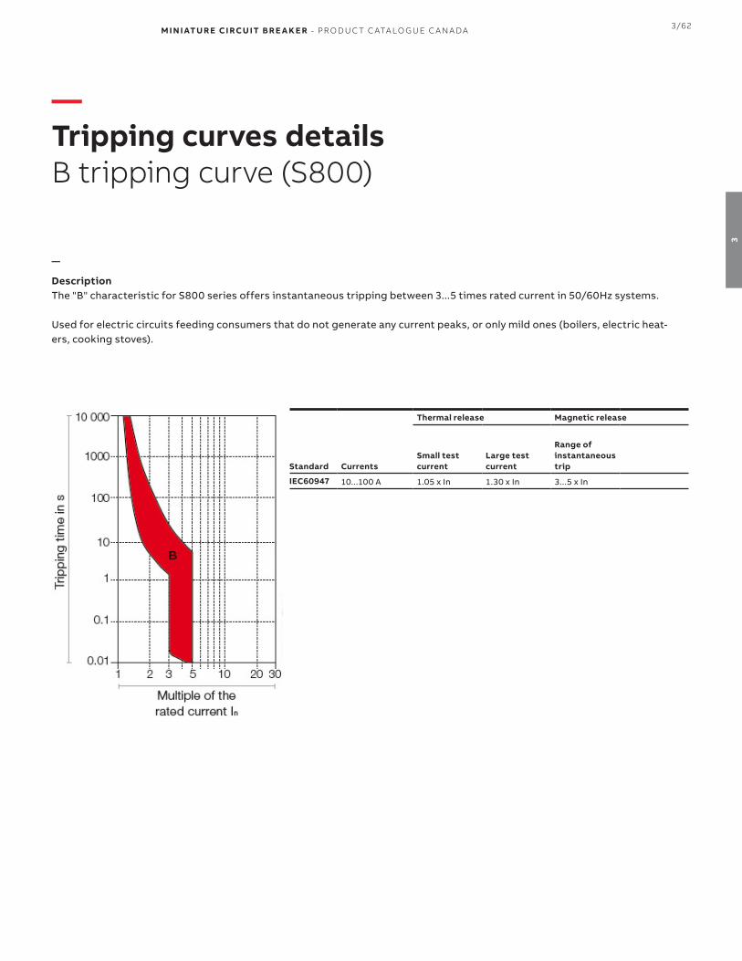
M I N I ATU R E CI RCU IT B R E A K E R - PR O D U C T C ATA LO G U E C A N A DA 3/62
3
—Tripping curves detailsB tripping curve (S800)
—
DescriptionThe "B" characteristic for S800 series offers instantaneous tripping between 3...5 times rated current in 50/60Hz systems.
Used for electric circuits feeding consumers that do not generate any current peaks, or only mild ones (boilers, electric heat-ers, cooking stoves).
Thermal release Magnetic release
Standard CurrentsSmall test current
Large test current
Range of instantaneoustrip
IEC60947 10...100 A 1.05 x In 1.30 x In 3...5 x In

3/63 M I N I ATU R E CI RCU IT B R E A K E R - PR O D U C T C ATA LO G U E C A N A DA
3
—Tripping curves detailsC tripping curve (S800)
—
DescriptionThe "C" characteristic for S800 series offers instantaneous tripping between 5...10 times rated current in 50/60Hz systems.
Used for for electric circuits feeding consumers that generate current peaks normal within inductive devices (fluorescent tubes, electric discharge lamps) as well as for circuits within sockets in commercially used systems/plants.
Thermal release Magnetic release
Standard CurrentsSmall test current
Large test current
Range of instantaneoustrip
IEC60947 10...100 A 1.05 x In 1.30 x In 5...10 x In

M I N I ATU R E CI RCU IT B R E A K E R - PR O D U C T C ATA LO G U E C A N A DA 3/64
3
—Tripping curves detailsD tripping curve (S800)
—
DescriptionThe "D" characteristic for S800 series offers instantaneous tripping between 10...20 times rated current in 50/60Hz sys-tems.
Used for for electric circuits feeding consumers that generate extremely high current peaks (transformers, capacitor banks).As main circuit breaker connected upstream of other circuit breakers (reference overcurrent circuit breaker).
Thermal release Magnetic release
Standard CurrentsSmall test current
Large test current
Range of instantaneoustrip
IEC60947 10...100 A 1.05 x In 1.30 x In 10...20 x In

3/65 M I N I ATU R E CI RCU IT B R E A K E R - PR O D U C T C ATA LO G U E C A N A DA
3
—Tripping curves detailsK tripping curve (S800)
—
DescriptionThe "K" characteristic for S800 series offers instantaneous tripping between 10...14 times rated current in 50/60Hz systems.
Used as High Performance MCB in case of high magnetic inrush currents that occur, e.g. in engines or transformers.This characteristic provides the best protection for a wide range of electrical systems by allowing high inrush currentswhen starting up the system.
Thermal release Magnetic release
Standard CurrentsSmall test current
Large test current
Range of instantaneoustrip
IEC60947 10...100 A 1.05 x In 1.20 x In 10...14 x In

M I N I ATU R E CI RCU IT B R E A K E R - PR O D U C T C ATA LO G U E C A N A DA 3/66
3
—DimensionsS800 series
—S800C, S800S, S800HVC approximate dimensions
954535
79.5
53
26.5
1P 2P 3P 4P
106
2CC
C41
3010
Z00
01
76.5
46
82.56
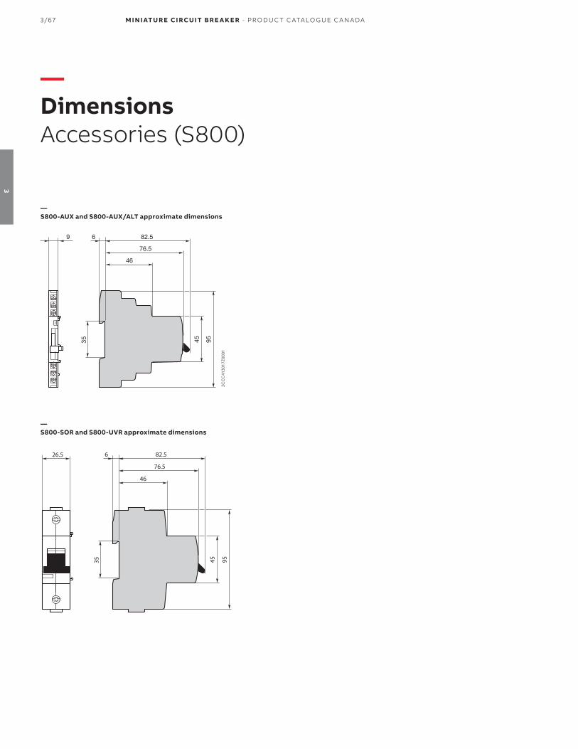
3/67 M I N I ATU R E CI RCU IT B R E A K E R - PR O D U C T C ATA LO G U E C A N A DA
3
—DimensionsAccessories (S800)
—S800-AUX and S800-AUX/ALT approximate dimensions
—S800-SOR and S800-UVR approximate dimensions
T
954535
2CCC41
3017
Z000
1
76.5
46
82.569
954535
26.5
76.5
46
82.56

M I N I ATU R E CI RCU IT B R E A K E R - PR O D U C T C ATA LO G U E C A N A DA 3/68
3
—Notes

M I N I ATU R E CI RCU IT B R E A K E R - PR O D U C T C ATA LO G U E C A N A DA
4

M I N I ATU R E CI RCU IT B R E A K E R - PR O D U C T C ATA LO G U E C A N A DA
4
— Electronic protection devices
003 Description and features
004 EPD24 series, accessories & dimensions

4/3 M I N I ATU R E CI RCU IT B R E A K E R - PR O D U C T C ATA LO G U E C A N A DA
4
—Electronic Protection DevicesEPD24 series
DescriptionThe protection devices EPD24 extend the ABB product range of Modular DIN Rail Components by electronic overcurrent protection modules for selective protection of 24 V DC load circuits. This protection is achieved by a combination of active electronic current limitation in the case of a short circuit and an overload deactivation from 1.1 x IN upwards.
If a fault occurs in a load circuit, the protection device EPD24 will detect this rapidly and reliably, disable the power output transistor and hence interrupt the current flow in the defective circuit. The maximum possible overcurrent is always limited to 1.3…1.8 times the selected rated current. An activation ofcapacitive loads up to 20,000 μF is possible, deactivation only occurring in the case of overloads or short circuits. Selective deactivation of the defective current circuit means undefined error states and a complete system stop are prevented.
Main features• Selective load protection, one electronic tripping charac-
teristic.• Active current limitation for safe connection of capacitive
loads up to 20,000 μF and on overload/short circuit.• Current ratings from 0.5...12 A• Reliable overload disconnection with 1.1 x In plus• Manual ON/OFF button• Clear status and failure indication through LED and inte-
grated auxiliary contact• Integral fail-safe element adjusted to current rating• 12.5 mm wide unit• DIN rail mounting• Easy wiring through busbar LINE+ and 0V as well as signal
bars• UL and CSA approvals allow international use of the de-
vices
EPD24
Rated voltage 24 Vdc
Current range 0.5...12 A
Load output Power-MOSFET switching output (high slide switch)
Degree of protection IP20
Dielectric strength 32 Vdc max. (load circuit)
Protection degree 3
Weight Apprx. 65g
Tightening torque 1.5...1.8 Nm
Wire size 0.5...4 mm2
Installation DIN rail
Approvals
UL 2367 Solid state overcurrent protectorsUL 1604 (Class 1 Div.2 Group A, B, C, D)
UL508CSA C22.2 No. 213 (Class 1 Div.2)
CSA C22.2 No. 142CSA C22.2 No. 14
CE marked

M I N I ATU R E CI RCU IT B R E A K E R - PR O D U C T C ATA LO G U E C A N A DA 4/4
4
—Busbar / signal bar accessories for EPD24 series
Description Part number
BusbarsBusbars for LINE + and 0V, grey insulation, 500 mm length (1) EPD-BB500
Signal barsSignal bars for auxiliary contacts, grey insulation, 21 mm length
EPD-SB21
(1) Maximum load with one line entry 50 A (recommended center-feeding). Maximum load with two line entries 63 A
—EPD24 SERIESElectronic Protection Devices
1 pole Box Qty
Weight each(kg)
Rated Current
Part number
4 0.065 0.5 A EPD24-TB-101-0.5A
1.0 A EPD24-TB-101-1A
2.0 A EPD24-TB-101-2A
3.0 A EPD24-TB-101-3A
4.0 A EPD24-TB-101-4A
6.0 A EPD24-TB-101-6A
8.0 A EPD24-TB-101-8A
10.0 A EPD24-TB-101-10A
63.0 A EPD24-TB-101-12A
—EPD24 approximate dimensions

1SX
P4
030
01C
020
4, J
uly
20
20
© Copyright 2019 ABB. All rights reserved. Specifications subject to change without notice.
— ABB - Campus Montréal800 Hymus BoulevardSt-Laurent, Qc CanadaH4S 0B5abb.com
Technical Support: [email protected]
We reserve the right to make technical changes or modify the contents of this document without prior notice. With regard to purchase orders and/or contracts, the agreed particulars shall prevail. ABB does not accept any responsibility whatsoever for potential errors or possible lack of information in this document. We reserve all rights in this document and in the subject matter and illustrations contained therein. Any reproduction, disclosure to third parties or utilization of its contents - in whole or in parts - is forbidden without prior written consent of ABB.