Compact NSX
248
Catalogue 2008 Low Voltage Circuit breakers and switch disconnectors Measurement and communication From 100 to 630A Compact NSX
-
Upload
khangminh22 -
Category
Documents
-
view
1 -
download
0
Transcript of Compact NSX

Catalogue 2008
Low Voltage
Circuit breakers and switch disconnectorsMeasurement and communication From 100 to 630A
Compact NSX


Introduction 3
Functions and characteristics A-1
Installation recommendations B-1
Dimensions and connection C-1
Wiring diagrams D-1
Additional characteristics E-1
Catalogue numbers F-1
Glossary G-1
Contents
1

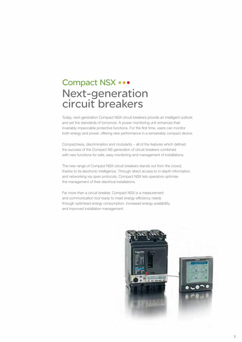
Compact NSXNext-generation circuit breakersToday, next-generation Compact NSX circuit breakers provide an intelligent outlook and set the standards of tomorrow. A power monitoring unit enhances their invariably impeccable protective functions. For the first time, users can monitor both energy and power, offering new performance in a remarkably compact device.
Compactness, discrimination and modularity – all of the features which defined the success of the Compact NS generation of circuit breakers combined with new functions for safe, easy monitoring and management of installations.
The new range of Compact NSX circuit breakers stands out from the crowd, thanks to its electronic intelligence. Through direct access to in-depth information, and networking via open protocols, Compact NSX lets operators optimise the management of their electrical installations.
Far more than a circuit breaker, Compact NSX is a measurement and communication tool ready to meet energy-efficiency needs through optimised energy consumption, increased energy availability, and improved installation management.
3

Expert technologyA roto-active contact breaking principle provides each circuit breaker with very high breaking capacity in a very small device, remarkable fault current limitation performance, and endurance.
> Compact NSX benefits from a patented double roto-active contact breaking concept, together with a reflex tripping system for ultimate breaking.
> Exceptional fault current limitation guarantees robust, reliable protection and, above all, reduces the causes of component aging, thus extending service life for installations.
Safety and performanceCompactness, discrimination and modularity – new Compact NSX circuit breakers incorporate advanced monitoring and communication functions, from 40 amps up, combined with impeccable protection.
23new patents pending confirm the innovative character of Compact NSX
100-630ACompact NSX
4

New breaking capacitiesNew performance levels for Compact NSX improve application targeting:
> 36-50 kA – standard applications (industrial plants, buildings and hospitals),
> 70-100 kA – high performance at controlled cost,
> 150 kA – demanding applications (maritime).
Enhanced protection for motorsCompact NSX meets the requirements of IEC 60947-4-1 standards for protection of motors:
> well adapted to motor-starting solutions up to 315 kW at 400 V, providing protection against short circuits, overloads, phase unbalance and loss,
> also enables set-up of additional protection systems for starting and braking with the motor running, reverse braking, jogging or reversing in complete safety,
> add a Schneider Electric contactor; Compact NSX complies with the requirements of so-called type 2 coordination.
Reduced installation costsOptimising installations allows for achieving up to 30% savings:
> considerable savings at the time of installation, thanks to total discrimination with miniature circuit breakers,
> smaller devices, more economic switchboards mean best overall installation cost, without overcalibration.
With the integration of electronics, trip units have gained in speed and accuracy.
Greater reliability and better discrimination allows more refinedsettings, especially for time delays.
The trip units are now true circuit breaker control systems.
5
NS400 NSX250
NS160(100 A)
NSX100
Multi 9
Breaking performance at 415 V
NSX 100 NSX 160 NSX 250 NSX 400 NSX 630
L 150kA
S 100kA
H 70kA
N 50kA
F 36kA

Integrated monitoring> The new Compact NSX range incorporates Micrologic electronic trip units in the circuit breaker, offering both:
> A Micrologic electronic tripping device combines next-generation sensors:
to the electronics,
for measurement, guaranteeing high accuracy.
> These electronic systems are designed to withstand high temperatures (105°C), ensuring reliability under severe operating conditions.
> The originality lies in how Compact NSX measures, processes and displays data, either directly on screen, on the switchboard front panel, or via a monitoring system.
Monitoring and managementCompact NSX is a single device, which contains a monitoring unit to control energy consumption and power.
10%Monitoring consumption can reduce energy costs by as much as 10%.
100-630ACompact NSX
6

Accessibility of information…To keep costs under control and ensure service continuity, relevant information must be available in real time:
> a kilowatt-hour meter helps optimise costs and their allocation,
> harmonic distortion rate shows the quality of electrical supply,
> alarm notification secures operational control and maintenance planning,
> event logs and tables, activated continuously, ensure the installed equipment base operates correctly, so energy efficiency is maximized.
…for power monitoring> Together with power monitoring software (e.g., PowerLogic), the Compact NSX Modbus communication interface provides operators with a parameter set and tools that make system monitoring very easy.
> Operators have real-time data to control energy availability, to monitor power supply quality, to optimise consumption of different applications or zones, reducing load peaks and continuously supplying priority loads, and to draw up maintenance schedules.
> and alarm configuration, in addition to testing communications with all installed devices.
Monitoring software PowerLogic ION-E
Measurement functions are controlled by an additional microprocessor.
An ASIC (Application-Specific Integrated Circuit) is common to all trip units, which boosts immunity to conducted or radiated interference and increases reliability.
ASIC
Protection functions are electronically managed independently of measurement functions.
7

Simple in designCompact NSX is mounted and wired reusing the same measurements as Compact NS.
Cut-outs are the same whatever the type of handle. Engineering drawings are the same, so installation and connection layouts can be used on new projects, simplifying extensions or retrofits, and reducing maintenance costs.
Integration in help software, for parameter settings and switchboard installation, further eases design.
Simple to install> A transparent lead-sealable cover protects access to tripping device switches and prevents settings from being changed.
> The new electrical control adjustment also has a transparent lead- sealable cover to prevent it from being operated accidentally.
> Compact NSX has an optional functional terminal shield that offers excellent protection against direct contact (IP40 on all sides, IP20 at cable entry points) and easy installation.
> All Compact NSX devices can be equipped with a communication function via a pre-wired connection with a Modbus interface module. When the Modbus address is declared, the Compact NSX device is integrated into the network.
SimplicityCompact NSX takes the principles of easy installation and use – which made its predecessor so successful – to a higher level.
100-630ACompact NSX
8

> There are four levels of functionalities:
On/Off position, trip indication and fault-trip indication,
open, close, and reset,
data: settings, parameters, alarms, histograms and event tables, and maintenance indicators.
> connects to the trip unit without any special settings or configuration. A cable fitted
integration with communications networking.
Simple to use> for all parameters, assign them to indicator lights, choose display priorities, and configure time delay thresholds and modes.
> Event logs and tables are continuously-activated. Providing a wealth of information, they enable users to ensure that the installed equipment base operates correctly, to optimize settings, and to maximise energy efficiency.
> Local and remote displays offer easy access to operators and provide the main electrical
distortion, etc. The user-friendly switchboard display unit with intuitive navigation is more comfortable to read, and offers quick access to information.
Performance, yet unimposing.Compact NSX perfectly blends into its environment.
Attractively designed.The front of Compact NSX circuit breakers has an attractive curved profile. Measurements are easy to read on a backlit LCD display. Screen navigation is intuitive and settings are simplified by immediate readouts in amps.
9

Service continuityCompact NSX makes discrimination its main advantage in minimising the impact of short circuits, ensuring service continuity for installations.
Total discriminationThanks to its 30 years of experience, Schneider Electric, with Compact NSX, offers perfect mastery of discrimination for ever more reliable service continuity. Compact NSX circuit breakers strongly limit fault currents, occurring as the result of short-circuits, which reduces installation downtime and avoids over-dimensioning cables.When several circuit breakers are used in series, the downstream circuit breaker trips as close as possible to the fault, isolating only the circuit concerned. The upstream circuit breaker is not affected and allows the other circuits to remain operational.
Service continuity
indication of motor overloads and actuation of a contactor, ensuring total service continuity:
> of tripping the circuit breaker,
> the module allows for machine restart directly from the contactor without having to operate circuit breakers.
Preventive maintenanceMaintenance indicators provide information on the number of operations, level of wear on contacts and total load rates. This makes it far easier to monitor equipment ageing and optimise investments over time. Maintenance is now preventive, avoiding faults.
100%service continuity
Direct access to maintenance indicators
100-630ACompact NSX
10

Schneider Electric expertiseSchneider Electric commits to reducing energy costs and CO2 emissions for its customers. It offers products, solutions and services that integrate with all levels of the energy value chain. Compact NSX is part and parcel of the Schneider Electric energy efficiency approach.
Up to 30%savings in energy costs
4 steps> Diagnostics> Proposals> Implementation> Follow-up
Solutions for the futureWith Compact NSX, Schneider Electric works through flexible solutions for commercial and industrial buildings, Schneider Electric commits to help customers gradually move towards an active approach to their energy efficiency. It helps get more return from investments and future design solutions.
Energy performance contracts An energy performance contract offers innovative service to modernise technical installations.
The objective is dramatically to reduce energy costs, whilst improving comfort and safety, all in an environmentally-responsible way.
Environmentally responsibleSchneider Electric meets the expectations of its markets with products adapted to the practices of the 190 countries where it is present and strongly commits to respect the norms and directives of each of those countries.
in its LV ranges, is a product designed to comply with all European directives for the environment. It has also received international certifications and approval from independent agencies.
all of its factories are nonpolluting.
and recycling at end of life, Compact NSX complies with environmental directives
11

Pro
tect
ion
, mea
sure
men
t an
d c
om
mu
nic
atio
n...

IntroductionOverview of applications A-2General characteristics of the Compact NSX range A-4Characteristics and performance of Compact NSX circuit breakers from 100 to 630 A A-6Compact NSX trip units A-8Overview of trip units for Compact NSX A-10
Protection of distribution systemsTM thermal-magnetic and MA magnetic trip units A-14Micrologic 2 and 1.3-M trip units A-16Micrologic 5 / 6 A or E trip units A-18
Power Meter functionsElectronic Micrologic 5 / 6 A or E A-20
Operating-assistance functionsMicrologic 5 / 6 A or E trip units A-22
Switchboard-display functionsMicrologic 5 / 6 A or E trip units A-24
Compact NSX communication Communications modules A-26Networks and software A-28RSU and RCU utilities A-30Supervision software A-31
Accessories for Micrologic trip units A-32
Earth-leakage protectionAdd-on protection against insulation faults using a Vigi module or Vigirex relay A-34
Motor protection General information on motor feeders A-36Motor-feeder characteristics and solutions A-38Compact NSX motor-feeder solutions A-39MA and Micrologic 1.3-M instantaneous trip units A-40Micrologic 2-M electronic trip units A-42Micrologic 6 E-M electronic trip units A-44
Special applicationsGenerator protection with Micrologic 2.2-G A-48Protection of industrial control panels A-5016 Hz 2/3 network protection A-51Micrologic 5 A-Z trip unit A-51Protection of 400 Hz systems A-52
Switch-disconnectors Overview of applications A-54Switch-disconnector functions A-55Characteristics and performance of Compact NSX switch-disconnectors from 100 to 630 NA A-56
Source-changeover systemsPresentation A-58Manual source-changeover systems A-59Remote-operated and automatic source-changeover systems Coupling accessory on base plate A-60
Accessories and auxiliariesOverview of Compact NSX100 to 630 fixed version A-62Overview of Compact NSX100 to 630 plug-in and withdrawable versions A-64Device installation A-66Connection of fixed devices A-78Connection of withdrawable and plug-in devices A-70Insulation of live parts A-71Selection of auxiliaries for Compact NSX100/160/250 A-72Selection of auxiliaries for Compact NSX400/630 A-74Connection of electrical auxiliaries A-76Indication contacts A-78SDx and SDTAM modules for Micrologic A-79Motor mechanism A-80Remote tripping A-81Rotary handles A-82Additional measurement and indication modules A-84Locks A-86Sealing accessories A-87Individual enclosures A-88Escutcheons and protection collars A-89
Installation recommendations B-1Dimensions and connection C-1Wiring diagrams D-1Additional characteristics E-1Catalogue numbers F-1Glossary G-1
Compact NSX Functions and characteristics
A-1 559E1000.indd version: 1.0

A-2
Functions and characteristics
IntroductionOverview of applications
Functions
Compact NSX100 to 630 offers high performance and a wide range of interchangeable trip units to protect most applications. Electronic versions provide highly accurate protection with wide setting ranges and can integrate measurement, metering and communication functions. They can be combined with the FDM121 switchboard display unit to provide all the functions of a Power Meter as well as operating assistance.
Applications
Operating assistance page A-22
Integration of measurement functions provides operators with operating assistance functions including alarms tripped by user-selected measurement values, time-stamped event tables and histories, and maintenance indicators.
Switchboard display unit page A-24
The main measurements can be read on the built-in screen of Micrologic 5 / 6 trip units. They can also be displayed on the FDM121 switchboard display unit along with pop-up windows signalling the main alarms.
Communication page A-26
Compact NSX equipped with Micrologic 5 / 6 trip units provide communication capabilities. Simple RJ45 cords connect to a Modbus interface module.
G
Power Meter page A-20
Compact NSX equipped with Micrologic 5 / 6 trip units offer type A (ammeter) or E (energy) metering functions as well as communication. Using Micrologic sensors and intelligence, Compact NSX provides access to measurements of all the main electrical parameters on the built-in screen, on a dedicated FDM121 display unit or via the communication system.
DB
1120
86
DB
1120
87
DB
1120
88
DB
1120
89D
B11
2090
DB
1120
91
559E1100.inddversion: 1.0

A-3
Protection of distribution systems(AC 220/690 V)
page A-14
Protection of motors(AC 220/690 V)
page A-36
Control and isolation using switch-disconnectors
page A-56
Protection of special applications
page A-48
Source changeover systems
page A-60
Compact NSX devices are equipped with MA or TM thermal-magnetic trip units or Micrologic 2 / 5 / 6 electronic trip units to provide protection against short-circuits and overloads for:
distribution systems supplied by transformers bdistribution systems supplied by engine generator b
sets long cables in IT and TN systems. b
They can be easily installed at all levels in distribution systems, from the main LV switchboard to the subdistribution boards and enclosures.All Compact NSX devices can protect against insulation faults by adding a Vigi module or Vigirex relay.
The Compact NSX range includes a number of versions to protect motor applications:
basic short-circuit protection with MA magnetic trip bunits or the electronic Micrologic 1-M version, combined with an external relay to provide thermal protection
protection against overloads, short-circuits and bphase unbalance or loss with Micrologic 2-M trip units
more complete protection against overloads and bshort-circuits with additional motor-specific protection (phase unbalance, locked rotor, underload and long start) with Micrologic 6 E-M trip units. These versions also offer communication, metering and operating assistance. The exceptional limiting capacity of Compact NSX circuit breakers automatically provides type-2 coordination with the motor starter, in compliance with standard IEC 60947-4-1.
Special applications : The Compact NSX range offers a number of versions for special protection applications:
service connection to public distribution systems b page A-48generators b s page A-50industrial control panels b s page A-52
with: compliance with international standards v
IEC 60947-2 and UL 508 / CSA 22-2 N14 compliance with US standard UL 489 vinstallation in universal and functional enclosures. v16 Hz 2/3 systems b s page A-53400 Hz systems b s page A-54
For all these applications, circuit breakers in the Compact NSX range offer positive contact indication and are suitable for isolation in accordance with standards IEC 60947-1 and 2.
A switch-disconnector version of Compact NSX circuit breakers is available for circuit control and isolation.All add-on functions of Compact NSX circuit breakers may be combined with the basic switch-disconnector function, including:
earth-leakage protection bmotor mechanism bammeter, etc. b
For information on other switch-disconnector ranges, see the Interpact (offering positive contact indication and visible break) and Fupact (fusegear) catalogues.
To ensure a continuous supply of power, some electrical installations are connected to two power sources:
a normal source ba replacement source to supply the installation when b
the normal source is not available.A mechanical and/or electrical interlocking system between two circuit breakers or switch-disconnectors avoids all risk of parallel connection of the sources during switching.
A source-changeover system can be: manual with mechanical device interlocking bremote controlled with mechanical and/or electrical b
device interlocking automatic by adding a controller to manage b
switching from one source to the other on the basis of external parameters.
559E1100.indd version: 1.0

A-4
Functions and characteristics
IntroductionGeneral characteristics of the Compact NSX range
DB
1120
18
100 10070 7065 6550 5035 3510 10
1006535
NSX250 H
4
2
1
3
6
5
7
98
10
Standardised characteristics indicated on the rating plate: 1 Type of device: frame size and breaking capacity class2 Ui: rated insulation voltage.3 Uimp: rated impulse withstand voltage.4 Ics: service breaking capacity.5 Icu: ultimate breaking capacity for various values of the rated operational voltage Ue6 Ue: operational voltage. 7 Colour label indicating the breaking capacity class.8 Circuit breaker-disconnector symbol.9 Reference standard.10 Main standards with which the device complies.Note: when the circuit breaker is equipped with an extended rotary handle, the door must be opened to access the rating plate.
Compliance with standardsCompact NSX circuit breakers and auxiliaries comply with the following:
international recommendations: bIEC 60947-1: general rules vIEC 60947-2: circuit breakers vIEC 60947-3: switch-disconnectors vIEC 60947-4: contactors and motor starters vIEC 60947-5.1 and following: control circuit devices and switching elements; v
automatic control components European (EN 60947-1 and EN 60947-2) and corresponding national standards: bFrance NF vGermany VDE vUnited Kingdom BS vAustralia AS vItaly CEI vthe specifications of the marine classification companies (Veritas, Lloyd's Register b
of Shipping, Det Norske Veritas, etc.), standard NF C 79-130 and recommendations issued by the CNOMO organisation for the protection of machine tools. For U.S. UL, Canadian CSA, Mexican NOM and Japanese JIS standards, please consult us.
Pollution degreeCompact NSX circuit breakers are certified for operation in pollution-degree III environments as defined by IEC standards 60947-1 and 60664-1 (industrial environments).
Climatic withstandCompact NSX circuit breakers have successfully passed the tests defined by the following standards for extreme atmospheric conditions:
IEC 60068-2-1: dry cold (-55 °C) bIEC 60068-2-2: dry heat (+85 °C) bIEC 60068-2-30: damp heat (95 % relative humidity at 55 °C) bIEC 60068-2-52 severity level 2: salt mist. b
EnvironmentCompact NSX respects the European environment directive EC/2002/95 concerning the restriction of hazardous substances (RoHS).Product environment profiles (PEP) have been prepared, describing the environmental impact of every product throughout its life cycle, from production to the end of its service life.All Compact NSX production sites have set up an environmental management system certified ISO 14001.Each factory monitors the impact of its production processes. Every effort is made to prevent pollution and to reduce consumption of natural resources.
Ambient temperatureCompact NSX circuit breakers may be used between -25 °C and +70 °C. For b
temperatures higher than 40°C (65°C for circuit breakers used to protect motor feeders), devices must be derated (pages B-8 and B-9).
Circuit breakers should be put into service under normal ambient, operating- btemperature conditions. Exceptionally, the circuit breaker may be put into service when the ambient temperature is between -35 °C and -25 °C.
The permissible storage-temperature range for Compact NSX circuit breakers in bthe original packing is -50 °C (1) and +85 °C.
(1) -40 °C for Micrologic control units with an LCD screen.
559E1100.inddversion: 1.0

A-5
Electromagnetic compatibilityCompact NSX devices are protected against:
overvoltages caused by circuit switching (e.g. lighting circuits) bovervoltages caused by atmospheric disturbances bdevices emitting radio waves such as mobile telephones, radios, walkie-talkies, b
radar, etc.electrostatic discharges produced by users. b
Immunity levels for Compact NSX comply with the standards below.IEC/EN 60947-2: Low-voltage switchgear and controlgear, part 2: Circuit b
breakers:Annex F: Immunity tests for circuit breakers with electronic protection vAnnex B: Immunity tests for residual current protection vIEC/EN 61000-4-2: Electrostatic-discharge immunity tests bIEC/EN 61000-4-3: Radiated, radio-frequency, electromagnetic-field immunity b
testsIEC/EN 61000-4-4: Electrical fast transient/burst immunity tests bIEC/EN 61000-4-5: Surge immunity tests bIEC/EN 61000-4-6: Immunity tests for conducted disturbances induced by radio- b
frequency fieldsCISPR 11: Limits and methods of measurement of electromagnetic disturbance b
characteristics of industrial, scientific and medical (ISM) radio-frequency equipment.
DiscriminationCompact NSX reinforces the discrimination capabilities of the Compact NS range by applying the rapid calculation capacity of the Micrologic trip units.Total discrimination is now possible between NSX100 and modular Multi 9 circuit breakers rated y 63 A (see page A-8).
Suitable for isolation with positive contact indicationAll Compact NSX circuit breakers are suitable for isolation as defined in IEC standard 60947-2:
The isolation position corresponds to the O (OFF) position. bThe operating handle cannot indicate the OFF position unless the contacts are b
effectively open. Padlocks may not be installed unless the contacts are open. b
Installation of a rotary handle or a motor mechanism does not alter the reliability of the position-indication system. The isolation function is certified by tests guaranteeing:
the mechanical reliability of the position-indication system bthe absence of leakage currents bovervoltage withstand capacity between upstream and downstream connections. b
The tripped position does not insure isolation with positive contact indication. Only the OFF position guarantees isolation.
Installation in class II switchboards All Compact NSX circuit breakers are class II front face devices. They may be installed through the door of class II switchboards (as per IEC standards 61140 and 60664-1) without downgrading switchboard insulation. Installation requires no special operations, even when the circuit breaker is equipped with a rotary handle or a motor mechanism.
Degree of protection The following indications are in accordance with standards IEC 60529 (IP degree of protection) and IEC 62262 (IK protection against external mechanical impacts).
Bare circuit breaker with terminal shieldsWith toggle: IP40, IK07. bWith standard direct rotary handle / VDE: IP40 IK07 b
Circuit breaker installed in a switchboard With toggle: IP40, IK07. bWith direct rotary handle: bstandard / VDE: IP40, IK07 vMCC: IP43 IK07 vCNOMO: IP54 IK08 vWith extended rotary handle: IP56 IK08 bWith motor mechanism: IP40 IK07. b
PB
1035
78-5
3D
B11
2093
559E1100.indd version: 1.0
A-6
Functions and characteristics
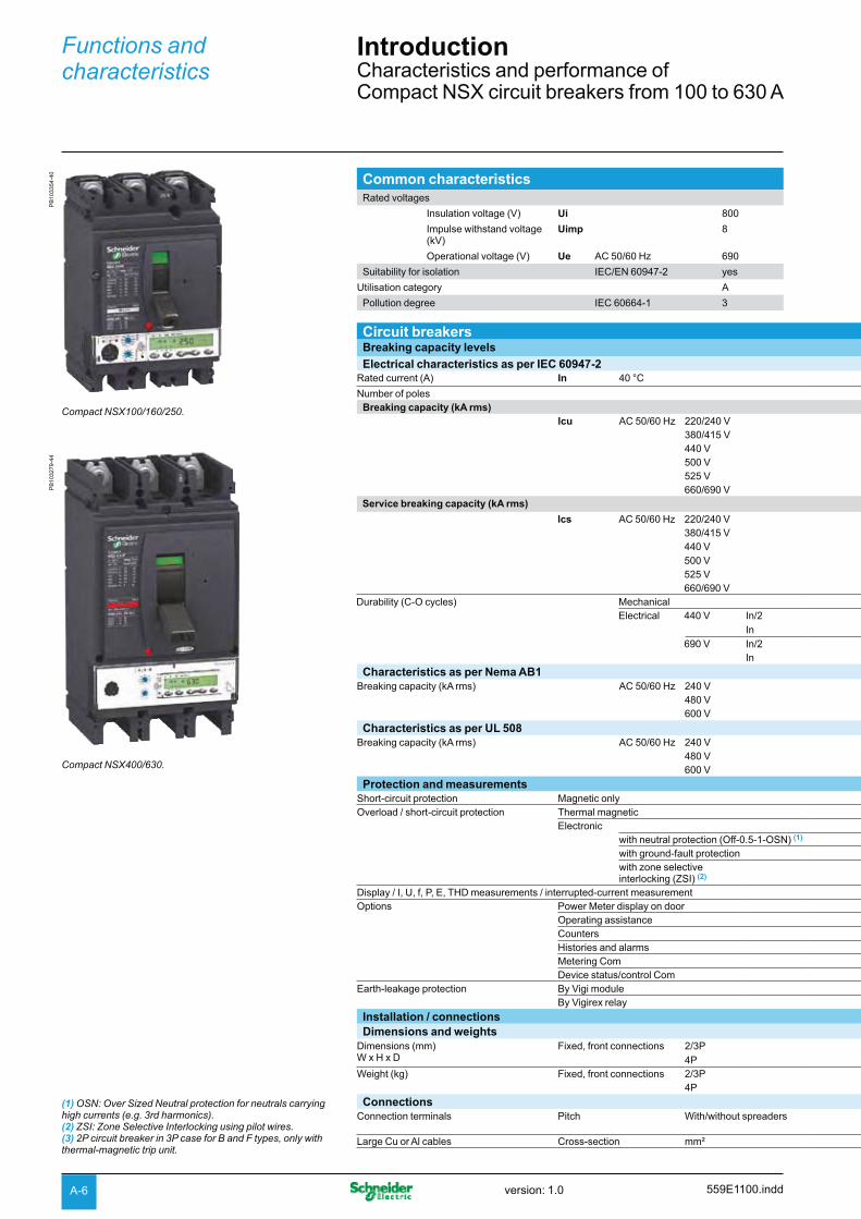
IntroductionCharacteristics and performance of Compact NSX circuit breakers from 100 to 630 A
Common characteristicsRated voltages
Insulation voltage (V) Ui 800
Impulse withstand voltage (kV)
Uimp 8
Operational voltage (V) Ue AC 50/60 Hz 690
Suitability for isolation IEC/EN 60947-2 yes
Utilisation category A
Pollution degree IEC 60664-1 3
PB
1033
54-4
0
Compact NSX100/160/250.
PB
1032
79-4
4
Compact NSX400/630.
Circuit breakersBreaking capacity levels Electrical characteristics as per IEC 60947-2
Rated current (A) In 40 °C
Number of poles Breaking capacity (kA rms)
lcu AC 50/60 Hz 220/240 V 380/415 V 440 V 500 V525 V660/690 V
Service breaking capacity (kA rms)
lcs AC 50/60 Hz 220/240 V 380/415 V 440 V 500 V525 V660/690 V
Durability (C-O cycles) Mechanical Electrical 440 V In/2
In690 V In/2
In
Characteristics as per Nema AB1Breaking capacity (kA rms) AC 50/60 Hz 240 V
480 V600 V
Characteristics as per UL 508Breaking capacity (kA rms) AC 50/60 Hz 240 V
480 V600 V
Protection and measurementsShort-circuit protection Magnetic onlyOverload / short-circuit protection Thermal magnetic
Electronicwith neutral protection (Off-0.5-1-OSN) (1)
with ground-fault protectionwith zone selective interlocking (ZSI) (2)
Display / I, U, f, P, E, THD measurements / interrupted-current measurementOptions Power Meter display on door
Operating assistanceCountersHistories and alarmsMetering ComDevice status/control Com
Earth-leakage protection By Vigi moduleBy Vigirex relay
Installation / connectionsDimensions and weights
Dimensions (mm) W x H x D
Fixed, front connections 2/3P 4P
Weight (kg) Fixed, front connections 2/3P 4P
ConnectionsConnection terminals Pitch With/without spreaders
Large Cu or Al cables Cross-section mm²
(1) OSN: Over Sized Neutral protection for neutrals carrying high currents (e.g. 3rd harmonics). (2) ZSI: Zone Selective Interlocking using pilot wires.(3) 2P circuit breaker in 3P case for B and F types, only with thermal-magnetic trip unit.
559E1100.inddversion: 1.0

A-7
Common characteristicsControl
Manual With toggle b
With direct or extended rotary handle b
Electrical With remote control b
Versions
Fixed b
Withdrawable Plug-in base b
Chassis b
NSX100 NSX160 NSX250 NSX400 NSX630F N H S L F N H S L F N H S L N H S L N H S L
100 160 250 400 630
2 (3), 3, 4 2 (3), 3, 4 2 (3), 3, 4 3, 4 3, 4
85 90 100 120 150 85 90 100 120 150 85 90 100 120 150 85 100 120 150 85 100 120 15036 50 70 100 150 36 50 70 100 150 36 50 70 100 150 50 70 100 150 50 70 100 15035 50 65 90 130 35 50 65 90 130 35 50 65 90 130 42 65 90 130 42 65 90 13025 36 50 65 70 30 36 50 65 70 30 36 50 65 70 30 50 65 70 30 50 65 7022 35 35 40 50 22 35 35 40 50 22 35 35 40 50 22 35 40 50 22 35 40 508 10 10 15 20 8 10 10 15 20 8 10 10 15 20 10 20 25 35 10 20 25 35
85 90 100 120 150 85 90 100 120 150 85 90 100 120 150 85 100 120 150 85 100 120 15036 50 70 100 150 36 50 70 100 150 36 50 70 100 150 50 70 100 150 50 70 100 15035 50 65 90 130 35 50 65 90 130 35 50 65 90 130 42 65 90 130 42 65 90 13012.5 36 50 65 70 12.5 36 50 65 70 30 36 50 65 70 30 50 65 70 30 50 65 7011 35 35 40 50 11 35 35 40 50 22 35 35 40 50 11 11 12 12 11 11 12 124 10 10 15 20 4 10 10 15 20 8 10 10 15 20 10 10 12 12 10 10 12 1250000 40000 20000 15000 1500050000 10000 20000 12000 800030000 20000 10000 6000 400020000 15000 10000 6000 600010000 7500 5000 3000 2000
40 85 90 100 120 150 40 85 90 100 120 150 40 85 90 100 120 150 40 85 100 120 150 40 85 100 120 15020 35 50 65 90 130 20 35 50 65 90 130 20 35 50 65 90 130 30 42 65 90 130 30 42 65 90 130- 8 20 35 40 50 - 20 20 35 40 50 - 20 20 35 40 50 - 20 35 40 50 - 20 35 40 50
- 85 85 85 - - - 85 85 85 - - - 85 85 85 - - 85 85 85 - - 85 85 85 - -- 25 50 65 - - - 35 50 65 - - - 35 50 65 - - 35 50 65 - - 35 50 65 - -- 10 10 10 - - - 10 10 10 - - - 15 15 15 - - 20 20 20 - - 20 20 20 - -
b b b b bb b b - -b b b b bb b b b bb b b b bb b b b b
b b b b bb b b b bb b b b bb b b b bb b b b bb b b b bb b b b bb b b b bb b b b b
105 x 161 x 86 105 x 161 x 86 105 x 161 x 86 140 x 225 x 110 140 x 225 x 110140 x 161 x 86 140 x 161 x 86 140 x 161 x 86 185 x 255 x 110 185 x 255 x 1102.05 2.2 2.4 6.05 6.22.4 2.6 2.8 7.90 8.13
35/45 mm 35/45 mm 35/45 mm 45/52.5 mm45/70 mm
45/52.5 mm45/70 mm
300 300 300 4 x 240 4 x 240
559E1100.indd version: 1.0

A-8
Functions and characteristics
IntroductionCompact NSX trip units
With Micrologic electronic trip units, Compact NSX stands out from the crowd. Thanks to the new generation of sensors and its processing capability, protection is enhanced even further. It also provides measurements and operating information.
Thermal-magnetic or electronic trip unit? Thermal-magnetic trip units protect against overcurrents and short-circuits using tried and true techniques. But today, installation optimisation and energy efficiency have become decisive factors and electronic trip units offering more advanced protection functions combined with measurements are better suited to these needs.Micrologic electronic trip units combine reflex tripping and intelligent operation. Thanks to digital electronics, trip units have become faster as well as more accurate and reliable. Wide setting ranges make installation upgrades easier. Designed with processing capabilities, Micrologic trip units can provide measurement information and device operating assistance. With this information, users can avoid or deal more effectively with disturbances and can play a more active role in system operation. They can manage the installation, anticipate on events and plan any necessary servicing.
Accurate measurements for complete protectionCompact NSX devices take advantage of the vast experience acquired since the launch of Masterpact NW circuit breakers equipped with Micrologic trip units. From 40 amperes on up to the short-circuit currents, they offer excellent measurement accuracy. This is made possible by a new generation of current transformers combining "iron-core" sensors for self-powered electronics and "air-core" sensors (Rogowski toroids) for measurements. The protection functions are managed by an ASIC component that is independent of the measurement functions. This independence ensures immunity to conducted and radiated disturbances and a high level of reliability.
Numerous security functions Torque-limiting screws The screws secure the trip unit to the circuit breaker. When the correct tightening torque is reached, the screw heads break off. Optimum tightening avoids any risk of temperature rise. A torque wrench is no longer required.
Easy and sure changing of trip units All trip units are interchangeable, without wiring. A mechanical mismatch-protection system makes it impossible to mount a trip unit on a circuit breaker with a lower rating.
"Ready" LED for a continuous self-test The LED on the front of the electronic trip units indicates the result of the self-test runs continuously on the measurement system and the tripping release. As long as the green LED is flashing, the links between the CTs, the processing electronics and the Mitop release are operational. The circuit breaker is ready to protect. No need for a test kit. A minimum current of 15 to 50 A, depending on the device, is required for this indication function.
A patented dual adjustment system for protection functions.Available on Micrologic 5 / 6, the system consists of:
a first adjustment, under de-energised conditions and using a dial, sets the bmaximum value
a second adjustment, made via the keypad or remotely, fine-tunes the setting. bThe second setting may not exceed the first. It can be read directly on the Micrologic screen, to within one ampere and a fraction of a second.
Coordinated tripping systemsCompact NSX detects faults even faster and its tripping time is reduced. It protects the installation better and limits contact wear.
DB
1155
65
100 A
E.g. NSX100F
1000 A 1500 A 2400 A 36000 A
IcuReflex thresholdIiIsdIr
CurrentsL
Time delayProtection function S or S0
I
1 - 200 s
10 - 50 ms
< 5 ms
z
20 - 500 ms
z
Overload: Slow trip inversely proportional to the current level
Instantaneous: Ultra-fast detection with micro delay for discrimination Reflex:
Energy-based ultra-fastdetection with major current limiting (1)
Short time: Impedant short-circuit, instantaneous trip with adjustable S or fixed S0 time delay
(1) This tripping system is completely independent of the trip unit.Because it directly actuates the mechanism, it precedes the trip unit by a few milliseconds.
559E1100.inddversion: 1.0

A-9
Unmatched discriminationDiscriminationCompact NSX provides maximum continuity of service and savings through an unmatched level of discrimination:
given the high accuracy of measurements, overload discrimination is ensured beven between very close ratings
for major faults, the fast processing of the Micrologic trip units means the bupstream device can anticipate the reaction of the downstream device. The upstream breaker adjusts its tripping delay to provide discrimination
for very high faults, the energy of the arc dissipated by the short-circuit in the bdownstream breaker causes reflex tripping. The current seen by the upstream device is significantly limited. The energy is not sufficient to cause tripping, so discrimination is maintained whatever the short-circuit current.
For total discrimination over the entire range of possible faults, from the long-time pick-up Ir to the ultimate short-circuit current Icu, a ratio of 2.5 must be maintained between the ratings of the upstream and downstream devices. This ratio is required to ensure selective reflex tripping for high short-circuits.
Understanding the names of Micrologic electronic trip unitsProtection Frame Measurements Applications
1: I 2: NSX100/160/250 A: Ammeter Distribution, otherwise
2: LS0I G: Generator
5: LSI M: Motors
6: LSIG
I: Instantaneous 3: NSX400/630 E: Energy
L: Long time
S0: Short time (1)
(fixed delay)
S: Short time
G: Ground fault
ExamplesMicrologic 1.3 Instantaneous only 400 or 630 A Distribution
Micrologic 2.3 LS0I 400 or 630 A Distribution
Micrologic 5.2 A LSI 100, 160 or 250 A Ammeter Distribution
Micrologic 6.3 E-M LSIG 400 or 630 A Energy Motor
(1) LS0I protection is standard on Micrologic 2. To ensure discrimination, it offers short-time protection S0 with a non-adjustable delay and instantaneous protection.
DB
1120
94
DB
1121
55
DB
1121
20
DB
1121
56
DB
1113
54
NS400 NSX250
NS160(100 A)
NSX100
Multi 9
Compact NSX100 with Micrologic for total discrimination.* Better coordination between protection functions reduces the difference in ratings required for total discrimination.* Please refer to supplementary technical catalogue.
559E1100.indd version: 1.0

A-10
Functions and characteristics
IntroductionOverview of trip units for Compact NSX
Compact NSX offers a range of trip units in interchangeable cases, whether they are magnetic, thermal-magnetic or electronic. Versions 5 and 6 of the electronic trip unit offer communication and metering. Using Micrologic sensors and intelligence, Compact NSX supplies all the information required to manage the electrical installation and optimise energy use.
Type of protection and applicationsMA magnetic TM-D thermal-magnetic
Distribution and motors b Distribution bGenerators b
1.3-M Distribution and motors
MA Distribution and motors
TM-D DistributionTM-G Generators
Adjustment and readingPick-up set in amps using dialsNon-adjustable time delay
Adjustment and readingPick-up set in amps using dialsNon-adjustable time delay
Compact NSX100/160/250
Compact NSX400/630
DB
1120
28
DB
1120
29
DB
1120
22
DB
1120
23
DB
1120
37
DB
1120
38
DB
1120
92
DB
1120
94D
B11
2120
Circuit breakers and trip units
Settings and indications
559E1100.inddversion: 1.0

A-11
Micrologic 2 electronic Micrologic 5 / 6 A or E electronic trip units
Adjustment and readingPick-up set in amps with fine adjustment using dialsNon-adjustable time delay
Front indications
Test connector
Self test
Adjustment and readingPick-up set in amps
Fine adjustment via keypad
Adjustable time delays
Front indications
Test connector
Self test
Distribution bService connection (public b
distribution)Generators bMotors (I only) bMotors b
Distribution band generators
Distribution band generators
Motors b
2.2 Distribution2.2-G Generators2.2-M Motors
2.3 Distribution1.3-M Motors (I only)2.3-M Motors
5.2 A Distribution and generators5.2 E Distribution and generators5.2 A-Z 16 Hz 2/3 networks
5.3 A Distribution and generators5.3 E Distribution and generators5.3 A-Z 16 Hz 2/3 networks
6.2 A Distribution and generators6.2 E Distribution and generators
6.2 E-M Motors
6.3 A Distribution and generators6.3 E Distribution and generators
6.3 E-M Motors
DB
1120
30
DB
1120
32
DB
1120
33
DB
1120
24
DB
1120
26
DB
1120
25
DB
1120
27
DB
1120
39
DB
1120
41D
B11
2042
0.5
DB
1120
43D
B11
2019
DB
1120
40
DB
1120
19D
B11
2040
Connection to switchboard display unit
5 A or E 6 A or E 6 E-M
A: current metering functionsE :current and energy metering functions.
Date:
Time:
07 May 2007
10:28:03.01 PM
ESC OK
Total reactivePower
Alarm History 2/3
DB
1113
66D
B11
1367
Communication to Modbus
classDB
1156
35D
B11
1401
N 1/A 2/B 3/C
OK
470
400
280320
350380
440
500Ir (A)
250
Mode
Micrologic 6.3 E-M
Ig (x In)
.9
.7
.3
.4.5 .6
.8
OFF.2
test
Rea
dy
Ala
rm
% T°>95>30A
Ir Cl. Isd Ig tgIunbal tunbal Ijam tjam
Ii=6500AIEC60947-4-1
Ir Isd
Class
7.2Ir
A500DB
1114
02
559E1100.indd version: 1.0

A-12
Functions and characteristics
IntroductionOverview of trip units for Compact NSX
The capabilities of Micrologic 5 / 6 A and E trip units come into full play with the FDM121 switchboard display unit.When the two are connected via a simple cord with RJ45 connectors, the combination offers full Power Meter capabilities and all the measurements required to monitor the electrical installation.
I measurementsCurrent measurements
Phase and neutral currents I1, I2, I3, IN bAverage current of the 3 phases Iavg bHighest current of the three phases Imax bGround-fault current Ig (Micrologic 6.2 / 6.3 A) bMaximeter/minimeter for I measurements b
Operating and maintenance assistanceIndications, alarms and histories
Indication of fault types bAlarms for high/low alarm thresholds linked to I b
measurementsTrip, alarm and operating histories bTime-stamped tables for settings and maximeters b
Maintenance indicatorsOperation, trip and alarm counters bOperating hours counter bContact wear bLoad profile and thermal image b
CommunicationModbus with add-on module b
Ammeter Micrologic (A)
DB
1120
44
DB
1125
26
559E1100.inddversion: 1.0
A-13
I, U, f, P, E, THD measurementsCurrent measurements
Phase and neutral currents I1, I2, I3, IN bAverage current of the 3 phases Iavg bHighest current of the three phases Imax bGround-fault current Ig (Micrologic 6.2 / 6.3 A) bMaximeter/minimeter for I measurements bCurrent unbalance between phases b
Voltage measurementsPhase-to-phase (U) et phase-to-neutral (V) voltages bAverage voltages Uavg, Vavg bPh-Ph (U) and Ph-N (V) voltage unbalance b
Frequency measurementsFrequency (f) b
Power-quality indicatorsTotal harmonic distortion (THD) for current and b
voltage
Power measurementsActive, reactive and apparent power, total and per b
phasePower factor and cos b
Maximeters/minimetersFor all I, U, f, P, E measurements b
Demand current and power measurementsDemand values, total and per phase bMaximum demand b
Energy meteringActive, reactive and apparent energy, total and per b
phase
Operating and maintenance assistanceIndications, alarms and histories
Indication of fault types bAlarms for high/low thresholds linked to I, U, f, P, E b
measurementsTrip, alarm and operating histories bTime-stamped tables for settings and I, U, f, P, E b
maximeters
Maintenance indicatorsOperation, trip and alarm counters bOperating hours counter bContact wear bLoad profile and thermal image b
CommunicationModbus with add-on module b
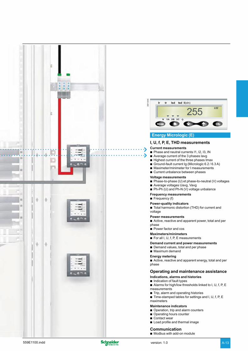
Energy Micrologic (E)
DB
1120
45
559E1100.indd version: 1.0

559E1200.inddversion: 1.0
Functions and characteristics
Protection of distribution systemsTM thermal-magnetic and MA magnetic trip units
TM thermal-magnetic and MA magnetic trip units can be used on Compact NSX100/160/250 circuit breakers with performance levels B/F/H/N/S/L.TM trip units are available in 2 versions:b TM-D, for the protection of distribution cablesb TM-G, with a low threshold, for the protection of generators or long cable lengths.Vigi modules or Vigirex relays can be added to all the circuit breakers to provide external earth-leakage protection.
TM-D and TM-G thermal-magnetic trip units
Circuit breakers equipped with thermal-magnetic trip units are used mainly in industrial and commercial electrical distribution applications:
TM-D, for protection of cables on distribution systems supplied by transformers bTM-G, with a low pick-up for generators (lower short-circuit currents than with b
transformers) and distribution systems with long cable lengths (fault currents limited by the impedance of the cable).
Protection ..............................................................................
Thermal protection (Ir)Thermal overload protection based on a bimetal strip providing an inverse time curve I2t, corresponding to a temperature rise limit. Above this limit, the deformation of the strip trips the circuit breaker operating mechanism. This protection operates according to:
Ir b that can be adjusted in amps from 0.7 to 1 times the rating of the trip unit (16 A to 250 A), corresponding to settings from 11 to 250 A for the range of trip units
a non-adjustable time delay, defined to ensure protection of the cables. b
Magnetic protection (Im)Short-circuit protection with a fixed or adjustable pick-up Im that initiates instantaneous tripping if exceeded.
TM-D: fixed pick-up, Im, for 16 to 160 A ratings and adjustable from 5 to 10 x In for b200 and 250 A ratings
fixed pick-up for 16 to 630 A ratings. b
Protection against insulation faultsTwo solutions are possible by adding:
a Vigi module acting directly on the trip unit of the circuit breaker ba Vigirex relay connected to an MN or MX voltage release. b
Protection versions3-pole: b3P 3D: 3-pole frame (3P) with detection on all 3 poles (3D) v3P 2D: 3-pole frame (3P) with detection on 2 poles (2D). v4-pole: b4P 3D: 4-pole frame (4P) with detection on 3 poles (3D). v4P 4D: 4-pole frame (4P) with detection on all 4 poles (same threshold for phases v
and neutral).
MA magnetic trip units
In distribution applications, circuit breakers equipped with MA magnetic-only trip units are used for:
short-circuit protection of secondary windings of LV/LV transformers with overload bprotection on the primary side.
as an alternative to a switch-disconnector at the head of a switchboard in order to bprovide short-circuit protection.Their main use is however for motor protection applications, in conjunction with a thermal relay and a contactor or motor starter (see "Motor protection", page A-36).
Protection .............................................................................. Magnetic protection (Im)Short-circuit protection with an adjustable pick-up Im that initiates instantaneous tripping if exceeded.
Im = In x ... b set in amps on an adjustment dial covering the range 6 to 14 x In for 2.5 to 100 A ratings or 9 to 14 In for 150 to 220 A ratings.
Protection versions3-pole (3P 3D): 3-pole frame (3P) with detection on all 3 poles (3D). b4-pole (4P 3D): 4-pole frame (4P) with detection on 3 poles (3D). bNote: all the trip units have a transparent lead-sealable cover
that protects access to the adjustment dials.
DB
1120
46D
B11
2047
A-14

559E1200.indd version: 1.0
Thermal-magnetic trip units TM16D to 250D TM16G to 63GRatings (A) In at 40 °C (1) 16 25 32 40 50 63 80 100125 160 200 250 16 25 40 63
Circuit breaker Compact NSX100 b b b b b b b b - - - - b b b b
Compact NSX160 - - b b b b b b b b - - - b b b
Compact NSX250 - - - - - b b b b b b b - - b b
Thermal protectionPick-up (A)tripping between1.05 and 1.20 Ir
Ir = In x ... adjustable in amps from 0.7 to 1 x In
Time delay (s) tr non-adjustable non-adjustable
tr at 1.5 x In 120 to 400 120 to 400
tr at 6 x Ir 15 -
Magnetic protectionPick-up (A) Im fixed adjustable fixed
accuracy ±20 % Compact NSX100 190 300 400 500 500 500 640 800 63 80 80 125
Compact NSX160/250 190 300 400 500 500 500 640 800 1250 1250 5 to 10xIn 63 80 80 125
Time delay tm fixed
Neutral protectionUnprotected neutral 4P 3D no detection no 4P3D version
Fully protected neutral 4P 4D 1 x Ir 1 x Ir
Magnetic trip units MA 2.5 to 220Ratings (A) In at 65 °C 2.5 6.3 12.5 25 50 100 150 220Circuit breaker Compact NSX100 b b b b b b - -
Compact NSX160 - - - b b b b -
Compact NSX250 - - - - - b b b
Instantaneous magnetic protectionPick-up (A)accuracy ±20 %
Im = In x ... adjustable in ampsfrom 6 to 14 x In (9 settings)
adjustable in amps from 9 to 14 x In
Time delay (ms) tm none
(1) For temperatures greater than 40°C, the thermal protection characteristics are modified. See the temperature derating table.
A-15

559E1200.inddversion: 1.0
Functions and characteristics
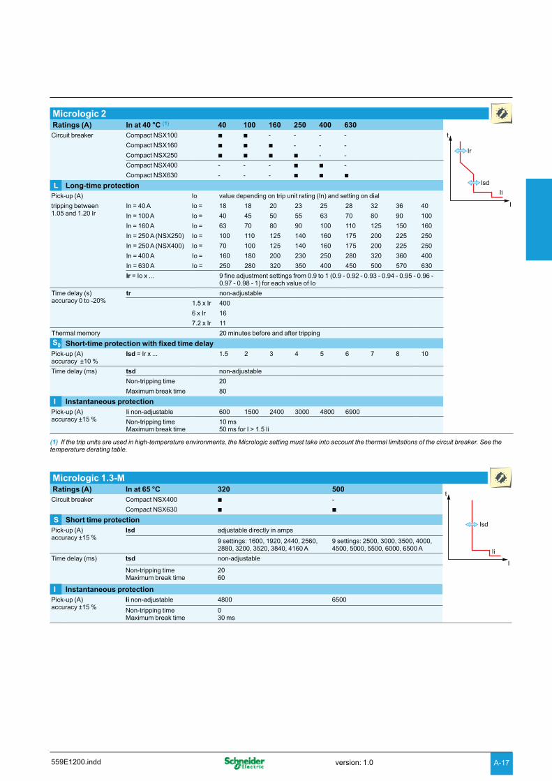
Protection of distribution systemsMicrologic 2 and 1.3-M trip units
Micrologic 2 trip units can be used on Compact NSX100 to 630 circuit breakers with performance levels B/F/H/N/S/L.They provide:b standard protection of distribution cablesb indication of:v overloads (via LEDs)v overload tripping (via the SDx relay module).Circuit breakers equipped with Micrologic 1.3-M trip units, without thermal protection, are used in certain applications to replace switch-disconnectors at the head of switchboards. Micrologic 1.3-M trip units are dedicated to Compact NSX400/630 A circuit breakers.
Micrologic 2
Circuit breakers equipped with Micrologic 2 trip units can be used to protect distribution systems supplied by transformers. For generators and long cables, Micrologic 2-G trip units offer better suited low pick-up solutions (see page A-50).
Protection .............................................................. Settings are made using the adjustment dials with fine adjustment possibilities.
Overloads: Long time protection (Ir)Inverse time protection against overloads with an adjustable current pick-up Ir set using a dial and a non-adjustable time delay tr.
Short-circuits: Short-time protection with fixed time delay (Isd)Protection with an adjustable pick-up Isd. Tripping takes place after a very short delay used to allow discrimination with the downstream device.
Short-circuits: Non-adjustable instantaneous protectionInstantaneous short-circuit protection with a fixed pick-up.
Neutral protectionOn 3-pole circuit breakers, neutral protection is not possible. bOn four-pole circuit breakers, neutral protection may be set using a three-position b
switch:4P 3D: neutral unprotected v4P 3D + N/2: neutral protection at half the value of the phase pick-up, i.e. 0.5 x Ir v4P 4D: neutral fully protected at Ir. v
Indications ............................................................. Front indications
Green “Ready” LED: flashes slowly when the circuit breaker is ready to trip in the bevent of a fault.
Orange overload pre-alarm LED: steady on when I > 90 % Ir bRed overload LED: steady on when I > 105 % Ir b
Remote indicationsAn overload trip signal can be remoted by installing an SDx relay module inside the circuit breaker. This module receives the signal from the Micrologic electronic trip unit via an optical link and makes it available on the terminal block. The signal is cleared when the circuit breaker is reclosed. For description, see page A-81.
Micrologic 1.3-M for magnetic protection only
Micrologic 1.3-M trip units provide magnetic protection only, using electronic technology. They are dedicated to 400/630 A 3-pole (3P 3D) circuit breakers or 4-pole circuit breakers with detection on 3 poles (4P, 3D) and are used in certain applications to replace switch-disconnectors at the head of switchboards. They are especially used in 3-pole versions for motor protection, see page A-40.
50A
Note: all the trip units have a transparent lead-sealable cover that protects access to the adjustment dials.
PB
1033
77
SDx remote indication relay module with its terminal block.
DB
1120
50D
B11
2051
DB
1120
19D
B11
2106
A-16
559E1200.indd version: 1.0
Micrologic 2Ratings (A) In at 40 °C (1) 40 100 160 250 400 630Circuit breaker Compact NSX100 b b - - - -
Ii
Compact NSX160 b b b - - -
Compact NSX250 b b b b - -
Compact NSX400 - - - b b -
Compact NSX630 - - - b b b
L Long-time protectionPick-up (A) Io value depending on trip unit rating (In) and setting on dial
tripping between1.05 and 1.20 Ir
In = 40 A Io = 18 18 20 23 25 28 32 36 40
In = 100 A Io = 40 45 50 55 63 70 80 90 100
In = 160 A Io = 63 70 80 90 100 110 125 150 160
In = 250 A (NSX250) Io = 100 110 125 140 160 175 200 225 250
In = 250 A (NSX400) Io = 70 100 125 140 160 175 200 225 250
In = 400 A Io = 160 180 200 230 250 280 320 360 400
In = 630 A Io = 250 280 320 350 400 450 500 570 630
Ir = Io x ... 9 fine adjustment settings from 0.9 to 1 (0.9 - 0.92 - 0.93 - 0.94 - 0.95 - 0.96 - 0.97 - 0.98 - 1) for each value of Io
Time delay (s)accuracy 0 to -20%
tr non-adjustable
1.5 x Ir 400
6 x Ir 16
7.2 x Ir 11
Thermal memory 20 minutes before and after tripping
S0 Short-time protection with fixed time delayPick-up (A)accuracy ±10 %
Isd = Ir x ... 1.5 2 3 4 5 6 7 8 10
Time delay (ms) tsd non-adjustable
Non-tripping time 20
Maximum break time 80
I Instantaneous protectionPick-up (A) accuracy ±15 %
Ii non-adjustable 600 1500 2400 3000 4800 6900
Non-tripping time Maximum break time
10 ms50 ms for I > 1.5 Ii
(1) If the trip units are used in high-temperature environments, the Micrologic setting must take into account the thermal limitations of the circuit breaker. See the temperature derating table.
Micrologic 1.3-M Ratings (A) In at 65 °C 320 500Circuit breaker Compact NSX400 b -
Compact NSX630 b b
S Short time protectionPick-up (A) accuracy ±15 %
Isd adjustable directly in amps
9 settings: 1600, 1920, 2440, 2560, 2880, 3200, 3520, 3840, 4160 A
9 settings: 2500, 3000, 3500, 4000, 4500, 5000, 5500, 6000, 6500 A
Time delay (ms) tsd non-adjustable
Non-tripping timeMaximum break time
2060
I Instantaneous protection Pick-up (A)accuracy ±15 %
Ii non-adjustable 4800 6500
Non-tripping timeMaximum break time
030 ms
A-17

559E1200.inddversion: 1.0
Functions and characteristics
Protection of distribution systemsMicrologic 5 / 6 A or E trip units
Micrologic 5 / 6 A (Ammeter) or E (Energy) trip units can be used on Compact NSX100 to 630 circuit breakers with performance levels B/F/H/N/S/L. They all have a display unit.They offer basic LSI protection (Micrologic 5) or LSI and ground-fault protection G (Micrologic 6).They also offer measurement, alarm and communication functions.
Protection ……………………………………………Settings can be adjusted in two ways, using the dials and/or the keypad . The keypad can be used to make fine adjustments in 1 A steps below the maximum value defined by the setting on the dial. Access to setting modifications via the keypad is protected by a locking function displayed on the screen and controlled by a microswitch . The lock is activated automatically if the keypad is not used for 5 minutes. Access to the microswitch is protected by a transparent lead-sealable cover. With the cover closed, it is still possible to display the various settings and measurements using the keypad.
Overloads: Long time protection (Ir)Inverse time protection against overloads with an adjustable current pick-up Ir set using a dial or the keypad for fine adjustments. The time delay tr is set using the keypad.
Short-circuits: Short-time protection (Isd)Short-circuit protection with an adjustable pick-up Isd and adjustable time delay tsd, with the possibility of including a portion of an inverse time curve (I2t On).
Short-circuits: Instantaneous protection (Ii)Instantaneous protection with adjustable pick-up Ii.
Additional ground fault protection (Ig) on Micrologic 6Residual type ground-fault protection with an adjustable pick-up Ig (with Off position) and adjustable time delay tg. Possibility of including a portion of an inverse time curve (I2t On).
Neutral protection On 4-pole circuit breakers, this protection can be set via the keypad: bOff: neutral unprotected v0.5: neutral protection at half the value of the phase pick-up, i.e. 0.5 x Ir v1.0: neutral fully protected at Ir vOSN: Oversized neutral protection at 1.6 times the value of the phase pick-up. v
Used when there is a high level of 3rd order harmonics (or orders that are multiples of 3) that accumulate in the neutral and create a high current. In this case, the device must be limited to Ir = 0.63 x In for the maximum neutral protection setting of 1.6 x Ir.
With 3-pole circuit breakers, the neutral can be protected by installing an external bneutral sensor with the output (T1, T2) connected to the trip unit.
Zone selective interlocking (ZSI) A ZSI terminal block may be used to interconnect a number of Micrologic control units to provide zone selective interlocking for short-time (Isd) and ground-fault (Ig) protection, without a time delay. For Compact NSX 100 to 250, the ZSI function is available only in relation to the upstream circuit breaker (ZSI out).
Display of type of fault ..........................................On a fault trip, the type of fault (Ir, Isd, Ii, Ig), the phase concerned and the interrupted current are displayed. An external power supply is required.
Indications ............................................................. Front indications
b Green “Ready” LED: flashes slowly when the circuit breaker is ready to trip in the event of a fault.
Orange overload pre-alarm LED: steady on when I > 90 % Ir bRed overload LED: steady on when I > 105 % Ir b
Remote indicationsAn SDx relay module installed inside the circuit breaker can be used to remote the following information:
overload trip boverload prealarm (Micrologic 5) or ground fault trip (Micrologic 6). b
This module receives the signal from the Micrologic electronic trip unit via an optical link and makes it available on the terminal block. The signal is cleared when the circuit breaker is closed.These outputs can be reprogrammed to be assigned to other types of tripping or alarm. The module is described in detail in the section dealing with accessories.
DB
1155
66 Measurement
Display
Settings
Maintenance
Trip unit menus.
DB
1155
67 Isd fault
Faulty phase Interrupted current
Display of interrupted current.
PB
1033
77
SDx remote indication relay module with its terminal block.
Note: all the trip units have a transparent lead-sealable cover that protects access to the adjustment dials.
DB
1121
09
A-18

559E1200.indd version: 1.0
Protection Micrologic 5 / 6 A or E trip unitsRatings (A) In at 40 °C (1) 40 100 160 250 400 630Circuit breaker Compact NSX100 b b - - - -
Compact NSX160 b b b - - -
Compact NSX250 b b b b - -
Compact NSX400 - - - - b -
Compact NSX630 - - - - b b
L Long-time protectionPick-up (A)tripping between 1.05 and 1.20 Ir
Ir = ... dial setting value depending on trip unit rating (In) and setting on dial
In = 40 A Io = 18 18 20 23 25 28 32 36 40
In = 100 A Io = 40 45 50 55 63 70 80 90 100
In = 160 A Io = 63 70 80 90 100 110 125 150 160
In = 250 A Io = 100 110 125 140 150 175 200 225 250
In = 400 A Io = 160 180 200 230 250 280 320 360 400
In = 630 A Io = 250 280 320 350 400 450 500 570 630
keypad setting Fine adjustment in 1 A steps below maximum value set on dial
Time delay (s)accuracy 0 to -20 %
tr = ... keypad setting 0.5 1 2 4 8 16
1.5 x Ir 15 25 50 100 200 400
6 x Ir 0.5 1 2 4 8 16
7.2 x Ir 0.35 0.7 1.4 2.8 5.5 11
Thermal memory 20 minutes before and after tripping
S Short-time protection with adjustable time delayPick-up (A)accuracy ±10 %
Isd = Ir x ... dial setting 1.5 2 3 4 5 6 7 8 10
Fine adjustment in 0.5 x Ir steps using the keypad
Time delay (s) tsd = ... keypad setting
I2Off 0 0.1 0.2 0.3 0.4
I2On - 0.1 0.2 0.3 0.4
Non-tripping time (ms) 20 80 140 230 350
Maximum break time (ms) 80 140 200 320 500
I Instantaneous protectionPick-up (A) accuracy ±15 %
Ii = In x keypad setting Adjustment in steps of 0.5 x In over the range 1.5 x In to:15 x In (NSX100/160), 12 x In (NSX250/400) or 11 x In (NSX630)
Non-tripping time Maximum break time
10 ms50 ms for I > Ii
G Ground-fault protection - for Micrologic 6 A or EPick-up (A) accuracy ±10 %
Ig = In x dial setting
In = 40 A 0.4 0.4 0.5 0.6 0.7 0.8 0.9 1 Off
In > 40 A 0.2 0.3 0.4 0.5 0.6 0.7 0.8 1 Off
Fine adjustment in 0.05 A steps using the keypad
Time delay (s) tg = ... keypad setting
I2Off 0 0.1 0.2 0.3 0.4
I2On - 0.1 0.2 0.3 0.4
Non-tripping time (ms) 20 80 140 230 350
Maximum break time (ms) 80 140 200 320 500
Test Ig function built-in
(1) If the trip units are used in high-temperature environments, the Micrologic setting must take into account the thermal limitations of the circuit breaker. See the temperature derating table.
A-19

559E1200.inddversion: 1.0
Functions and characteristics
Power Meter functionsElectronic Micrologic 5 / 6 A or E
In addition to protection functions, Micrologic 5 / 6 trip units offer all the functions of Power Meter products as well as operating-assistance for the circuit breaker.b display of settingsb measurement functions: v Ammeter (A)v Energy (E) b alarmsb time-stamped histories and event tablesb maintenance indicatorb communication.
Micrologic A and E measurement functions are made possible by Micrologic intelligence and the accuracy of the sensors. They are handled by a microprocessor that operates independent of protection functions.
Display ..................................................................
Micrologic LCDThe user can display all the protection settings and the main measurements on the LCD screen of the trip unit.
Micrologic A: instantaneous rms current measurements bMicrologic E: voltage, frequency and power measurements and energy metering, b
in addition to the measurements offered by Micrologic ATo make the display available under all conditions and increase operating comfort, an external power supply is recommended for Micrologic A. It is indispensable to:
display faults and interrupted current measurements buse all the functions of Micrologic E (e.g. metering of low power and energy b
values)ensure operation of the communication system. b
The external power supply can be shared by several devices. For description, see page A-32.
FDM121 display unitAn FDM121 switchboard display unit can be connected to a Micrologic trip unit using a prefabricated cord to display all measurements on a screen. The result is a veritable 96 x 96 mm Power Meter.In addition to the information displayed on the Micrologic LCD, the FDM121 screen shows demand, power quality and maximeter/minimeter values along with alarms, histories and maintenance indicators.The FMD121 display unit requires a 24 V DC power supply. The Micrologic trip unit is supplied by the same power supply via the cord connecting it to the FDM121.
PC screenWhen the Micrologic, with or without an FDM121 switchboard display unit, is connected to a communication network, all information can be accessed via a PC.
Measurements .....................................................
Instantaneous rms measurementsThe Micrologic A and E continuously display the RMS value of the highest current of the three phases and neutral (Imax). The navigation buttons can be used to scroll through the main measurements.In the event of a fault trip, the current interrupted is memorised.The Micrologic A measures phase, neutral, ground fault currents.The Micrologic E offers voltage, frequency and power measurements in addition to the measurements provided by Micrologic A
Maximeters / minimetersEvery instantaneous measurement provided by Micrologic A or E can be associated with a maximeter/minimeter. The maximeters for the highest current of the 3 phases and neutral, the demand current and power can be reset via the trip unit keypad, the FDM121 display unit or the communication system.
Energy meteringThe Micrologic E also measures the energy consumed since the last reset of the meter. The active energy meter can be reset via the keypad and the FDM121 display unit or the communication system.
Demand and maximum demand valuesMicrologic E also calculates demand current and power values. These calculations can be made using a block or sliding interval that can be set from 5 to 60 minutes in steps of 1 minute. The window can be synchronised with a signal sent via the communication system. Whatever the calculation method, the calculated values can be recovered on a PC via Modbus communication. Ordinary spreadsheet software can be used to provide trend curves and forecasts based on this data. They will provide a basis for load shedding and reconnection operations used to adjust consumption to the subscribed power.
Power qualityMicrologic E calculates power quality indicators taking into account the presence of harmonics up to the 15th order, including the total harmonic distortion (THD) of current and voltage.
PB
1033
65
Micrologic built-in LCD display showing an energy measurement.
DB
1122
11
Alarms
Services
ESC OK
Main Menu
Quick View
Metering
FDM121 display: navigation.
DB
1121
31
I1I
%
310 A I2
%
315 A
I3
%
302 A IN
%
23 A
ESC
DB
1121
32
ESC
U1
U2
U3
V 4/7
402 V 100 120%
398 V 100 120%
401 V 100 120%
Current. Voltage.
DB
1121
33
ESC
P 64 kW
Q 38 kVar
S 51 kVA
PQS
DB
1121
34
ESC
Ep 14397 kWh
Eq 8325 kVarh
Es 13035 kVAh
E
Power. Consumption.
Examples of measurement screens on the FDM121 display unit.
A-20

559E1200.indd version: 1.0
Micrologic 5 / 6 integrated Power Meter functions Type DisplayA E Micrologic
LCDFDM121 display
Display of protection settingsPick-ups (A) and delays All settings can be displayed Ir, tr, Isd, tsd, Ii, Ig, tg b b b
MeasurementsInstantaneous rms measurements
Currents (A) Phases and neutral I1, I2, I3, IN b b b b
Average of phases Iavg = (I1 + I2 + I3) / 3 b b - b
Highest current of the 3 phases and neutral Imax of I1, I2, I3, IN b b b b
Ground fault (Micrologic 6) % Ig (pick-up setting) b b b b
Current unbalance between phases % Iavg - b - b
Voltages (V) Phase-to-phase U12, U23, U31 - b b b
Phase-to-neutral V1N, V2N, V3N - b b b
Average of phase-to-phase voltages Uavg = (U12 + U21 + U23) / 3 - b - b
Average of phase-to-neutral voltages Vavg = (V1N + V2N + V3N) / 3 - b - b
Ph-Ph and Ph-N voltage unbalance % Uavg and % Vavg - b - b
Phase sequence 1-2-3, 1-3-2 - b b b
Frequency (Hz) Power system f - b b b
Power Active (kW) P, total and per phase - b b b
Reactive (kVAR) Q, total and per phase - b - b
Apparent (kVA) S, total and per phase - b - b
Power factor and cos (fundamental) PF and cos , total and per phase - b - b
Maximeters / minimeters
Associated with instantaneous rms measurements
Reset via Micrologic or FDM121 display unit b b - b
Energy metering
Energy Active (kW), reactive (kVARh), apparent (kVAh)
Total since last reset - b b b
Absolute or signed mode (1)
Demand and maximum demand values
Demand current (A) Phases and neutral Present value on the selected window - b - b
Maximum demand since last reset - b - b
Demand power Active (kWh), reactive (kVAR), apparent (kVA)
Present value on the selected window - b - b
Maximum demand since last reset - b - b
Calculation window Sliding, fixed or com-synchronised Adjustable from 5 to 60 minutes in 1 minute steps
- b - (2)
Power quality
Total harmonic distortion (%)
Of voltage with respect to rms value THDU,THDV of the Ph-Ph and Ph-N voltage - b - b
Of current with respect to rms value THDI of the phase current - b - b
(1) Absolute mode: E absolute = E out + E in; Signed mode: E signed = E out - E in.(2) Available via the communication system only.
Additional technical characteristicsMeasurement accuracy Accuracies are those of the entire measurement system, including the sensors:
Current: Class 1 as per IEC 61557-12 bVoltage: 0.5 % bPower and energy: Class 2 as per IEC 61557-12 bFrequency: 0.1 %. b
PB
1033
54
PB
1033
60
PB
1033
64
A-21

559E1200.inddversion: 1.0
Functions and characteristics
Operating-assistance functionsMicrologic 5 / 6 A or E trip units
Personalised alarms with time-stamping ............ Alarm typesThe user can assign an alarm to all Micrologic A or E measurements or events:
up to 12 alarms can be used together: btwo alarms are predefined and activated automatically: vMicrologic 5: overload (Ir) -Micrologic 6: overload (Ir) and ground fault (Ig) -thresholds, priorities and time delays can be set for ten other alarms. vthe same measurement can be used for different alarms to precisely monitor b
certain values, e.g. the frequency or the voltagealarms can also be assigned to various states: phase lead/lag, four quadrants, b
phase sequence selection of display priorities, with pop-up possibility balarm time-stamping. b
Alarm settingsAlarms cannot be set via the keypad or the FDM121 display unit. They are set via communication with the PC. Set-up includes the threshold, priority, activation delay before display and deactivation delay. It is also possible to reprogram the standard assignment for the two SDx relay outputs to user-selected alarms.
Alarm readingRemote alarm indications
reading on FDM121 display unit or on PC via the communication system bremote indications via SDx relay with two output contacts for alarms. b
Histories and event tables.....................................Micrologic A and E have histories and event tables that are always active.
Three types of time-stamped histories Tripping due to overruns of Ir, Isd, Ii, Ig: last 17 trips bAlarms: last 10 alarms bOperating events: last 10 events b
Each history record is stored with: indications in clear text in a number of user-selectable languages btime-stamping: date and time of event bstatus: pick-up / drop-out b
Two types of time-stamped event tablesProtection settings bMinimeters / maximeters b
Display of alarms and tablesThe time-stamped histories and event tables may be displayed on a PC via the communication system.
Embedded memoryMicrologic A and E have a non-volatile memory that saves all data on alarms, histories, event tables, counters and maintenance indicators even if power is lost.
Maintenance indicators .........................................Micrologic A and E have indicators for, among others, the number of operating cycles, contact wear and operating times (operating hours counter) of the Compact NSX circuit breaker. It is possible to assign an alarm to the operating cycle counter to plan maintenance.The various indicators can be used together with the trip histories to analyse the level of stresses the device has been subjected to. The information provided by the indicators cannot be displayed on the Micrologic LCD. It is displayed on the PC via the communication system.
Management of installed devicesEach circuit breaker equipped with a Micrologic 5 or 6 trip unit can be identified via the communication system:
serial number bfirmware version bhardware version bdevice name assigned by the user. b
This information together with the previously described indications provides a clear view of the state of the installed devices.
DB
1121
27
Date:
Time:
07 May 2007
10:28:03.01 PM
ESC OK
Total reactivePower
Alarm History 2/3
DB
1121
28
Date:
Time:
10 Nov 2007
06:35:08.04 AM
ESC OK
Over maximumCurrent unbalance
Alarm History 2/3
Overpower alarm. Phase unbalance alarm.
DB
1121
29
Date:
Time:
05 Nov 2007
02:31:03.61 AM
ESC OK
Under voltagePick-up
Alarm History 2/3
DB
1121
30
Date:
Time:
05 Nov 2007
02:32:26.12 AM
ESC OK
Under voltageDrop-out
Alarm History 3/3
Alarm pick-up and drop-out.
Examples of operating-assistance screens on the FDM121 display unit.
PB
1033
65
Micrologic built-in LCD display.
DB
1122
12
ESC OK
Main Menu
Quick View
Metering
Services
Alarms
FDM121 display: navigation.
A-22

559E1200.indd version: 1.0
Micrologic 5 / 6 operating assistance functions Type DisplayA E Micrologic
LCDFDM121 display
Operating assistancePersonalised alarms
Settings Up to 10 alarms assigned to all A and E measurements b b - (2)
Phase lead/lag, four quadrants, phase sequence, display priority selection - b - (2)
Display Alarms and tripping b b - (2)
Remote indications Activation of two dedicated contacts on SDx module b b - -
Time-stamped histories
Trips(last 17)
Cause of tripping(timestamping with ms)
Ir, Isd, Ii (Micrologic 5, 6) b b - (2)
Ig (Micrologic 6) b b - (2)
Alarms(last 10)
b b - (2)
Operating events(last 10)
Event types Modification of protection setting by dial - b - (2)
Opening of keypad lock - b - (2)
Test via keypad - b - (2)
Test via external tool - b - (2)
Time setting (date and time) - b - (2)
Reset for maximeter/minimeter and energy meter b b b b
Time stamping Presentation Date and time, text, status b b - (2)
Time-stamped event tables
Protection settings Setting modified (value displayed) Ir tr Isd tsd Ii Ig tg b b - (2)
Time stamping Date and time of modification b b - (2)
Previous value Value before modification b b - (2)
Min/Max Values monitored I1 I2 I3 IN b - - (2)
I1 I2 I3 IN U12 U23 U31 f - b - (2)
Time-stamping of each value Date and time of min/max record b b - (2)
Current min/max value Min/max value b b - (2)
Maintenance indicators
Counter Mechanical cycles (1) Assignable to an alarm b b - (2)
Electrical cycles (1) Assignable to an alarm b b - (2)
Trips One per type of trip b b - (2)
Alarms One for each type of alarm b b - (2)
Hours Total operating time (hours) b b - (2)
Indicator Contact wear % b b - (2)
Load profile Hours at different load levels % of hours in four current ranges: 0-49 % In, 50-79 % In, 80 - 89 % In and u 90 % In
b b - (2)
(1) The BSCM module (page A-27) is required for these functions.(2) Available via the communication system only.
Additional technical characteristicsContact wear
Each time Compact NSX opens, the Micrologic 5 / 6 trip unit measures the interrupted current and increments the contact-wear indicator as a function of the interrupted current, according to test results stored in memory. Breaking under normal load conditions results in a very slight increment. The indicator value may be read on the FDM121 display. It provides an estimation of contact wear calculated on the basis of the cumulative forces affecting the circuit breaker. When the indicator reaches 80%, it is advised to replace the circuit breaker to ensure the availability of the protected equipment.
Circuit breaker load profileMicrologic 5 / 6 calculates the load profile of the circuit breaker protecting a load circuit. The profile indicates the percentage of the total operating time at four current levels (% of breaker In):
0 to 49 % In b50 to 79 % In b80 to 89 % In bu b 90 % In.
This information can be used to optimise use of the protected equipment or to plan ahead for extensions.
PB
1033
54
PB
1033
60
PB
1033
64
A-23

559E1200.inddversion: 1.0
Functions and characteristics
Switchboard-display functionsMicrologic 5 / 6 A or E trip units
Micrologic measurement capabilities come into full play with the FDM121 switchboard display. It connects to Compact NSX via a simple cord and displays Micrologic information. The result is a true integrated unit combining a circuit breaker and a Power Meter. Additional operating assistance functions can also be displayed.
FDM121 switchboard displayThe FDM121 is a switchboard display unit that can be integrated in the Compact NSX100 to 630 A system. It uses the sensors and processing capacity of the Micrologic trip unit. It is easy to use and requires no special software or settings. It is immediately operational when connected to the Compact NSX by a simple cord.The FDM121 is a large display, but requires very little depth. The anti-glare graphic screen is backlit for very easy reading even under poor ambient lighting and at sharp angles.
Display of Micrologic measurements and alarmsThe FDM121 is intended to display Micrologic 5 / 6 measurements, alarms and operating information. It cannot be used to modify the protection settings.Measurements may be easily accessed via a menu. All user-defined alarms are automatically displayed. The display mode depends on the priority level selected during alarm set-up:
high priority: a pop-up window displays the time-stamped description of the alarm band the orange LED flashes
medium priority: the orange "Alarm" LED goes steady on blow priority: no display on the screen. b
All faults resulting in a trip automatically produce a high-priority alarm, without any special settings required.In all cases, the alarm history is updated.If power to the FDM121 fails, all information is stored in the Micrologic non-volatile memory. The data is automatically recovered when power is restored and can be consulted via the communication system.
Status indications and remote controlWhen the circuit breaker is equipped with the BSCM module (page A-27), the FDM121 display can also be used to view circuit breaker status conditions:
O/F: ON/OFF bSD: trip indication bSDE: Fault-trip indication (overload, short-circuit, ground fault) b
Main characteristics96 x 96 x 30 mm screen requiring 10 mm behind the door (or 20 mm when the b
24 volt power supply connector is used).White backlighting. bWide viewing angle: vertical ±60°, horizontal ±30°. bHigh resolution: excellent reading of graphic symbols. bAlarm LED: flashing orange for alarm pick-up, steady orange after operator reset if b
alarm condition persists.Operating temperature range -10 °C to +55 °C. bCE / UL marking. b24 V DC power supply, with tolerances 24 V -20 % (19.2 V) to 24 V +10 % (26.4 V). b
When the FDM121 is connected to the communication network, the 24 V is supplied by the communication system wiring system.
Consumption 40 mA. b
MountingThe FDM121 is easily installed in a switchboard.
Standard door cut-out 92 x 92 mm. bAttached using clips. b
To avoid a cut-out in the door, an accessory is available for surface mounting by drilling only two 22 mm diameter holes.The FDM121 degree of protection is IP54 in front. IP54 is maintained after switchboard mounting by using the supplied gasket during installation.
ConnectionThe FDM121 is equipped with:
a 24 V DC terminal block: bplug-in type with 2 wire inputs per point for easy daisy-chaining vpower supply range of 24 V -20 % (19.2 V) to 24 V +10 % (26.4 V) vtwo RJ45 jacks. b
The Micrologic connects to the internal communication terminal block on the Compact NSX via the pre-wired NSX cord. Connection to one of the RJ45 connectors on the FDM121 automatically establishes communication between the Micrologic and the FDM121 and supplies power to the Micrologic measurement functions.When the second connector is not used, it must be fitted with a line terminator.
PB
1035
82
PB
1038
07-3
2
FDM121 display. Surface mount accessory.
PB
1035
81-3
1
Connection with FDM121 display unit.
A-24

559E1200.indd version: 1.0
NavigationFive buttons are used for intuitive and fast navigation. The “Context” button may be used to select the type of display (digital, bargraph, analogue).The user can select the display language (Chinese, English, French, German, Italian, Portuguese, Spanish, etc.) Other languages can be downloaded.
ScreensMain menuWhen powered up, the FDM121 screen automatically displays the ON/OFF status of the device.
Quick view
Metering
Alarms
Services.
When not in use, the screen is not backlit. Backlighting can be activated by pressing one of the buttons. It goes off after 3 minutes.
Fast access to essential information“Quick view” provides access to five screens that display a summary of essential b
operating information (I, U, f, P, E, THD, circuit breaker On / Off).
Access to detailed information"Metering" can be used to display the measurement data (I, U-V, f, P, Q, S, E, b
THD, PF) with the corresponding min/max values.Alarms displays active alarms and the alarm history. bServices provides access to the operation counters, energy and maximeter reset b
function, maintenance indicators, identification of modules connected to the internal bus and FDM121 internal settings (language, contrast, etc.)
DB
1121
35
I1I
%
310 A I2
%
315 A
I3
%
302 A IN
%
23 A
1 3 4 5 62
ESC
1 Escape2 Down3 OK4 Up5 Context6 Alarm LED
DB
1121
36
Micrologic 5.3A
Produit Id
Serial number:
Part number:
Firmware:
P07451
LU432091
1.02
ESC
DB
1121
37
Metering
Alarms
Services
ESC OK
Main Menu
Quick View
Product identification. Quick view.
DB
1121
38
ESC OK
I
U-V
PQS
E
F - PF - cos Φ
Metering
DB
1121
39
ESC
avg
MIN
MAX
U Average 9/10
387 V 100 120%
392 V 100 120%
388 V 100 120%
Metering: sub-menu. Metering: U average.
DB
1121
40
ESC
EpIN 5111947 kWh
EpOut 12345678 kWh
NonResettableEnergy 1/3
DB
1121
41
ESC OK
Contrast
Brightness
Language
Display
Metering: meter. Services.
A-25

All Compact NSX devices can be equipped with the communication function via a prewired connection system and a Modbus network interface.The interface can be connected directly or via the FDM121 switchboard display unit. Four functional levels can be combined to adapt to all supervision requirements.
A-26
Functions and characteristics
Compact NSX communication Communications modules
Four functional levelsThe Compact NSX can be integrated in a Modbus communication environment. Four functional levels can be used separately or combined.
Communication of status indicationsThis level is compatible with all Compact NSX circuit breakers, whatever the trip unit, and with all switch-disconnectors. Using the BSCM module, the following information is accessible:
ON/OFF position (O/F) btrip indication (SD) bfault-trip indication (SDE). b
Communication of commandsAlso available on all circuit breakers and switch-disconnectors, this level (communicating remote control) can be used to:
open bclose breset. b
Communication of measurements with Micrologic 5 / 6 A or EThis level provides access to all available information:
instantaneous and demand values bmaximeters/minimeters benergy metering bdemand current and power bpower quality. b
Communication of operating assistance with Micrologic 5 / 6 A or Eprotection and alarm settings btime-stamped histories and event tables bmaintenance indicators. b
1 Modbus network2 Modbus interface3 NSX cord4 Internal terminal block for communication via NSX cord5 BSCM module6 Prefabricated wiring7 Micrologic trip unit8 FDM121 display9 RJ45 cable10 Line terminator (on unused connector if applicable)
Communication components and connections
ConnectionsCompact NSX is connected to the Modbus interface or b
FDM121 display unit via the internal terminal block for the NSX cord equipped with an RJ45 connector.
cord available in three lengths: 0.35 m, 1.3 m and 3 m. vinsulated 0.35 m version for installations > 480 V AC vlengths up to 10 m possible using extensions. vThe FDM121 display unit is connected to the Modbus b
interface by a communication cable with RJ45 connectors on both ends.
DB
1120
60
1.3 m
DB
1155
68 Modbus
24 V DC
10
10
559E1300.inddversion: 1.0

A-27
Modbus interface module
FunctionsThis module, required for connection to the network, contains the Modbus address (1 to 99) declared by the user via the two dials in front. It automatically adapts (baud rate, parity) to the Modbus network in which it is installed.It is equipped with a lock-out switch to enable or disable operations involving writing to Micrologic, i.e. reset, counter reset, setting modifications, device opening and closing commands, etc.There is a built-in test function to check the connections of the Modbus interface module with the Micrologic and FDM121 display unit.
MountingThe module is mounted on a DIN rail. A number of modules may be clipped one next to the other. For this, a stacking accessory is available for fast clip-connection of both the Modbus link and the 24 V DC supply.The Modbus interface module supplies 24 V DC to the corresponding Micrologic, FDM121 display and BSCM module. Module consumption is 60 mA / 24 V DC.
BSCM module FunctionsThe optional BSCM Breaker Status & Control Module is used to acquire device status indications and control the communicating remote-control function. It includes a memory used to manage the maintenance indicators.
Status indicationsIndication of device status: O/F, SD and SDE.
Maintenance indicatorsThe BSCM module manages the following indicators:
mechanical operation counter belectrical operation counter bhistory of status indications. b
It is possible to assign an alarm to the operation counters.
ControlsThe module can be used to carry out communicating remote control operations: (open, close and reset) in different modes (manual, auto).
MountingThe BSCM module can be installed on all Compact NSX circuit breakers and switch-disconnectors. It simply clips into the auxiliary contact slots. It occupies the slots of one O/F contact and one SDE contact. The BSCM is supplied with 24 V DC power automatically via the NSX cord when the communication system is installed.
DB
1120
35
DB
1120
83
Modbus interface module.
DB
1120
84
Mounting with stacking accessory.
DB
1120
85
BSCM module.
1 Five-point Modbus and 24 V DC connector2 Two Modbus address dials (1 to 99)3 Modbus traffic LED4 Lock-out to disable writing to the NSX5 Test LED6 Test button7 Two connectors for RJ45 cable
559E1300.indd version: 1.0

A-28
Functions and characteristics
Compact NSX communication Networks and software
DB
1155
69
Firewall
Internet
Automaticnotification
Nomadmode
Site Intranet
MPS100
Modbus Modbus
EGX400
Ethernet (TCP/IP/Modbus)
ConsultationRSURCU
ConsultationRSURCU
FDM121
Masterpact Compact NSX
Modbus
PowerLogicPower Meter
Sepam
Compact NSX uses the Modbus communication protocol, compatible with SMS PowerLogic supervision systems. Two downloadable utilities facilitate implementation of communication functions.
ModbusModbus is the most widely used communication protocol in industrial networks. It operates in master-slave mode. The devices (slaves) communicate one after the other with a gateway (master).Masterpact, Compact NSX, PowerLogic and Sepam products all operate with this protocol. A Modbus network is generally implemented on an LV or MV switchboard scale. Depending on the data monitored and the desired refresh rate, a Modbus network connected to a gateway can serve 4 to 16 devices. For larger installations, a number of Modbus networks can be connected to an Ethernet network (TCP/IP/Modbus protocol) via their gateways.
559E1300.inddversion: 1.0
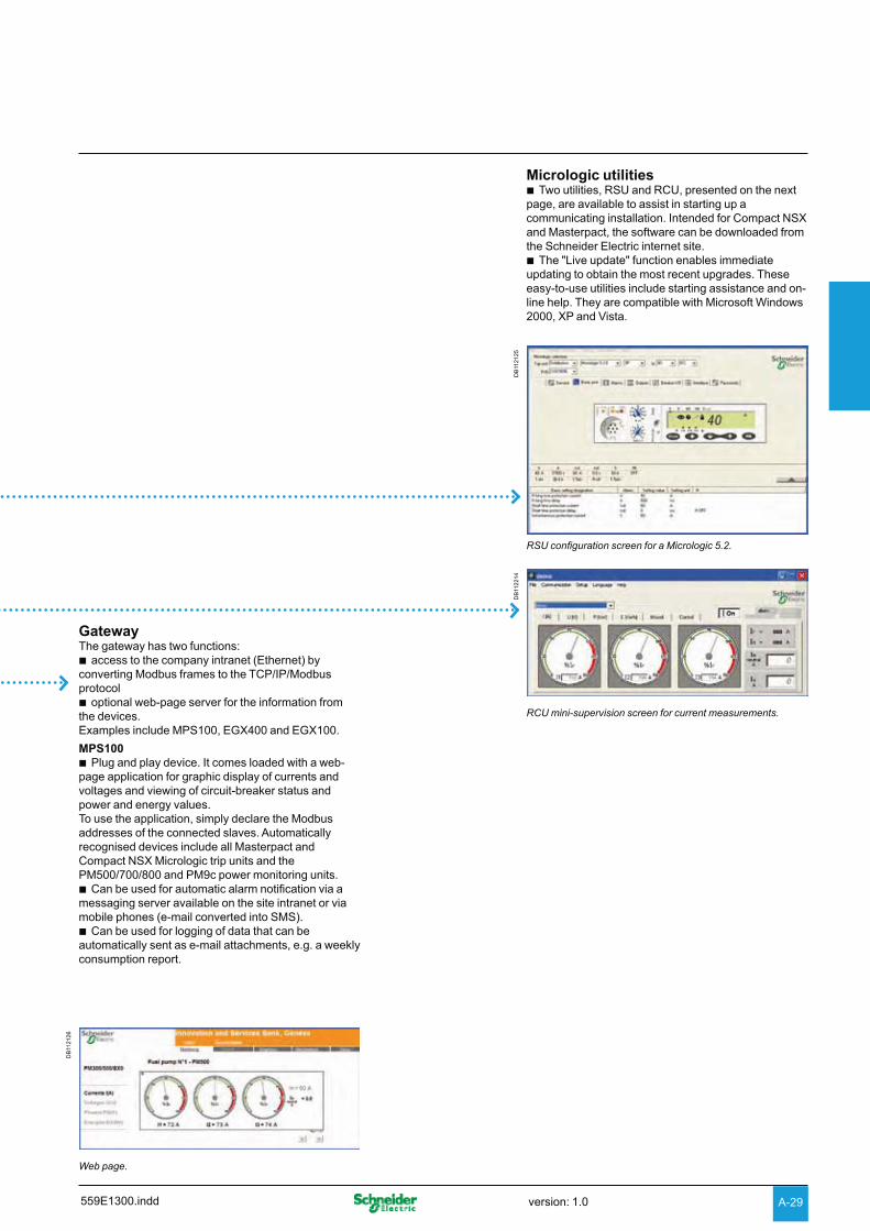
A-29
GatewayThe gateway has two functions:
access to the company intranet (Ethernet) by bconverting Modbus frames to the TCP/IP/Modbus protocol
optional web-page server for the information from bthe devices.Examples include MPS100, EGX400 and EGX100.
MPS100Plug and play device. It comes loaded with a web- b
page application for graphic display of currents and voltages and viewing of circuit-breaker status and power and energy values. To use the application, simply declare the Modbus addresses of the connected slaves. Automatically recognised devices include all Masterpact and Compact NSX Micrologic trip units and the PM500/700/800 and PM9c power monitoring units.
Can be used for automatic alarm notification via a bmessaging server available on the site intranet or via mobile phones (e-mail converted into SMS).
Can be used for logging of data that can be bautomatically sent as e-mail attachments, e.g. a weekly consumption report.
Micrologic utilitiesTwo utilities, RSU and RCU, presented on the next b
page, are available to assist in starting up a communicating installation. Intended for Compact NSX and Masterpact, the software can be downloaded from the Schneider Electric internet site.
The "Live update" function enables immediate bupdating to obtain the most recent upgrades. These easy-to-use utilities include starting assistance and on-line help. They are compatible with Microsoft Windows 2000, XP and Vista.
DB
1121
25
RSU configuration screen for a Micrologic 5.2.
DB
1122
14
RCU mini-supervision screen for current measurements.
DB
1121
26
Web page.
559E1300.indd version: 1.0

A-30
Functions and characteristics
Compact NSX communication RSU and RCU utilities
RSU (Remote Setting Utility)This utility is used to set the protection functions and alarms for each Masterpact and Compact NSX device. After connection to the network and entry of the circuit-breaker Modbus address, the software automatically detects the type of trip unit installed.There are two possible operating modes.
Off-line with the software disconnected from the communication network For each selected circuit breaker, the user can do the following.
Determine the protection settings The settings are carried out on a screen that shows the front of the trip unit. The Micrologic setting dials, keypad and screen are simulated for easy use of all Micrologic setting functions.
Save and duplicate the protection settingsEach configuration created can be saved for subsequent device programming. It can also be duplicated and used as the basis for programming another circuit breaker.
On-line with the software connected to the networkSimilarly, for each selected circuit breaker, the user can do the following.
Display the current settingsThe software displays the trip unit and provides access to all settings.
View the corresponding protection curvesA graphic curve module in the software displays the protection curve corresponding to the settings. It is possible to lay a second curve over the first for discrimination studies.
Modify settings in a secure mannerThere are different levels of security: bpassword: by default, it is the same for all devices, but can be differentiated for v
each devicelocking of the Modbus interface module which must be unlocked before the v
corresponding device can be set remotelymaximum settings limited by the positions of the two dials on the trip unit. v
These dials, set by the user, determine the maximum settings that can be made via the communication system.
Settings are modified by: beither direct, on-line setting of the protection settings on the screen vor by loading the settings prepared in off-line mode. This is possible only if the v
positions of the dials allow the new settings. All manual settings made subsequently on the device have priority.
Program alarmsUp to 12 alarms can be linked to measurements or events. btwo alarms are predefined and activated automatically: bMicrologic 5: overload (Ir) vMicrologic 6: overload (Ir) and ground fault (Ig) vthresholds, priorities and time delays can be set for 10 other alarms. They may be b
selected from a list of 91 alarms
Set the outputs of the SDx relaysThis is required when the user wants to change the standard configuration and assign different signals to the 2 outputs of the SDx relay.
RCU (Remote Control Utility)The RCU utility can be used to test communication for all the devices connected to the Modbus network. It is designed for use with Compact NSX, Masterpact, Advantys OTB and Power Meter devices. It offers a number of functions.
Mini supervisor Display of I, U, f, P, E and THD measurements for each device, via navigation bDisplay of ON/OFF status b
Open and close commands for each device A common or individual password must first be entered.
When all functions have been tested, this utility is replaced by the supervision software selected for the installation.
Two utilities, RSU and RCU, are available to assist in starting up a communicating installation.They can be downloaded from the Schneider Electric internet site and include a "Live update" function that enables immediate updating.
DB
1122
16D
B11
2217
RSU: Micrologic Remote Setting Utility.
DB
1122
15
RCU: Remote Control Utility for communication tests.
559E1300.inddversion: 1.0

A-31
Types of softwareMasterpact and Compact NSX communication functions are designed to interface with software dedicated to electrical installations:
switchboard supervision belectrical installation supervision bpower system management: electrical engineering expert systems bprocess control bSCADA (Supervisory Control & Data Acquisition), EMS (Enterprise Management b
System) or BMS (Building Management System) type software.
Integration of Compact NSXCompact NSX devices are integrated via Modbus interface modules connected via FDM121 display units or NSX cords. For easy connection of the different modules, the prefabricated cables are identified by ULP (Universal Logic Plug) symbols. The connection points on compatible modules are marked in the same manner.
Schneider Electric solutions
Electrical switchboard supervision via MPS100 or EGX400 Web serversA simple solution for customers who want to consult the main electrical parameters of switchboard devices without dedicated software. Up to 16 switchboard devices are connected via Modbus interfaces to an MPS100 or EGX400 Ethernet gateway integrating the functions of a web page server. The embedded Web pages can be easily configured with just a few mouse clicks. The information they provide is updated in real time. The Web pages can be consulted using a standard Web browser on a PC connected via Ethernet to the company Intranet or remotely via a modem. Automatic notification of alarms and threshold overruns is possible via e-mail or SMS (Short Message Service).
Electrical installation supervision via PowerView softwarePowerLogic® PowerView software is ideally suited to the supervision needs of small system applications, monitoring up to 32 devices. Installed on a PC under Windows, it represents a cost-effective and easy-to-implement power-monitoring solution that offers:
automatic detection of compatible devices breal-time monitoring of data including power consumption ba report generator with a number of pre-defined reports that can be exported to b
Excelcost allocation btime-stamped data-logging possibilities bModbus serial and Modbus TCP/IP compatible communication. b
SMS electrical engineering expert system softwarePowerLogic® SMS is a family of web-enabled software products for high-end power-monitoring applications. It is designed for large power systems.SMS products offer detailed analysis of electrical events, long-duration data logging and extensive, economical report-building capabilities (e.g. consumption monitoring and tariff management).A wide variety of screens can be displayed in real time, including more than 50 tables, analogue meters, bargraphs, alarms logs with links to display waveforms and predefined reports on energy quality and service costs.
Other software Compact NSX devices can forward their measurement and operating information to special software integrating the electrical installation and other technical facilities:
SCADA process control software: Vijeo CITECT bBMS Building Management System software: Vista. b
Please consult us.
PE
8610
6-62
PowerView software.
DB
1121
45
SMS software screen.
Supervision software
Schneider Electric electrical installation supervision, management and expert system software integrates Compact NSX identification modules.
DB
1113
70
Connection symbol for Compact NSX compatible modules.
559E1300.indd version: 1.0

Functions and characteristics
Accessories for Micrologic trip units
External neutral current transformer (ENCT)The external transformer is a sensor required for a three-pole circuit breaker in a system with a distributed neutral to measure the neutral current in order to:
protect the neutral conductor bprotect against insulation faults. b
This current transformer can be connected to Micrologic 5 / 6 trip units. The transformer rating must be compatible with that of the circuit breaker.
Required current transformers for different circuit breaker models
Type of circuit breaker Rating Catalogue number
NSX100/160/250 25 – 100 A LV429521150 – 250 A LV430563
NSX400/630 400 – 630 A LV432575
External neutral voltage tap (ENVT)The neutral voltage transformer is required for Micrologic E power metering with a three-pole circuit breaker in a system with a distributed neutral. It is used to connect the neutral to the Micrologic trip unit to measure phase-to-neutral (Ph-N) voltages.
External 24 V DC power-supply moduleUseAn external 24 V DC power supply is required for installations with communication, whatever the type of trip unit.On installations without communication, it is available as an option for Micrologic 5/6 in order to make it possible to:
modify settings when the circuit breaker is open bdisplay measurements when the current flowing through the circuit breaker is low b
(15 to 50 A depending on the rating)maintain the display of the cause of tripping and interrupted current. b
CharacteristicsA single external 24 V DC supply may be used for the entire switchboard.The required characteristics are:
output voltage: 24 V DC ±5 % bripple: ±1%. bovervoltage category: OVC IV - as per IEC 60947-1 b
External 24 V DC power-supply modules with an output current of 1 A are available:
Available external power-supply modules Cat. no.Power supply V DC (±5 %) 24/30 54440
48/60 54441100/125 54442
V AC (+10 %, -15 %) 110/130 54443200/240 54444380/415 54445
Output voltage 24 V DC (±5 %)Ripple ±1 %Overvoltage category (OVC) OVC IV - as per IEC 60947-1
An external 24 V DC power-supply module with an output current of 3 A is also available:
Available external power-supply modules Cat. no.Power supply V DC 110/230
ABL8RPS24030V AC 110/240
Output voltage 24 V DC (±5 %)Ripple ±1 %Overvoltage category (OVC) OVC II
Total consumptionTo determine the required output current of the 24 V DC power supply, it is necessary to sum up the currents consumed by the different loads supplied:
Consumption of Compact NSX modules Module
Consumption (mA)
Micrologic 5/6 20BSCM module 10FDM121 40Modbus communication interface 60NSX cord U > 480 V AC 30
PB
1038
43-1
8
External neutral current transformers.
PB
1035
83-1
8
External 24 V DC power-supply module.
PB
1038
42-4
7
External neutral voltage tap (cat. no. LV434208).
559E1400.inddversion: 1.0A-32

DB
1155
70
USB or Bluetooth link
Test connector
Display
110/240 V
TEST
30
Using the configuration and maintenance module.
PB
1037
90-2
0
Test battery (cat. no. LV434206).
PB
1038
33-1
8
Battery module (cat. no. 54446).
PB
1037
99-2
4
PB
1037
89-2
4
24 V DC power-supply terminal block (cat. no. LV434210).
NSX cord U > 480 V (cat. no. LV434204).
PB
1038
03-2
7
Maintenance case (cat. no. TRV00910).
PB
1037
94-3
2
Configuration and maintenance module (cat. no. TRV00911).
Test batteryThis pocket battery connects to the Micrologic test connector. It powers up the Micrologic and the Ready LED. It supplies the screen and allows settings to be made via the keypad.
Battery moduleThe battery module is a back-up supply for the external power-supply module. The input/output voltages are 24 V DC and it can supply power for approximately three hours (100 mA).
24 V DC power-supply terminal blockThe 24 V DC power-supply terminal block can be installed only on Micrologic 5/6 trip units. It is required to power the trip unit when the trip unit is not connected to an FDM121 display unit or to the communication system. When used, it excludes connection of an NSX cord.
NSX cordFor voltage U b y 480 V, available in 3 prefabricated lengths: 0.35 m, 1.3 m and 3 m.For voltages U > 480 V, a special 0.35 m cord with an insulation accessory is b
required.A set of cords with RJ45 connectors is available to adapt to different distances b
between devices.
Maintenance case The case includes:
configuration and maintenance module bpower supply (110...220 V AC / 50-60 Hz 24 V DC - 1 A) bspecial cable for connection to the trip-unit test connector bstandard USB cable bstandard RJ45 cable buser manual boptional Bluetooth link (to PC). b
Configuration and maintenance moduleIncluded in the maintenance kit, this module tests Micrologic operation and provides access to all parameters and settings. It connects to the Micrologic test connector and can operate in two modes.
Stand-alone mode to: bsupply the Micrologic and check operation via the Ready LED vcheck mechanical operation of the circuit breaker (trip using pushbutton). vPC mode, connected to a PC via USB or Bluetooth link. This mode provides b
access to protection settings, alarm settings and readings of all indicators. Using the associated RSU software utility, it is possible to store, in a dedicated file for each device, all the data that can transferred to another device.This mode also offers operating-test functions:
check on trip time delay (trip curve) vcheck on non-tripping time (discrimination) vcheck on ZSI (Zone Selective Interlocking) function valarm simulation vdisplay of setting curves vdisplay of currents vprinting of test reports. v
559E1400.indd version: 1.0 A-33

Functions and characteristics
Earth-leakage protectionAdd-on protection against insulation faults using a Vigi module or Vigirex relay
There are two ways to add earth-leakage protection to any three or four-pole Compact NSX100 to 630 circuit breaker equipped with a magnetic, thermal-magnetic or Micrologic 2, 5 or 6 trip unit:b by adding a Vigi module to the circuit breaker to form a Vigicompact NSXb by using a Vigirex relay and separate toroids.
Circuit breaker with add-on Vigi module (Vigicompact NSX)
For general characteristics of circuit breakers, b see pages A-6 and A-7.Add-on Vigi modules. Earth-leakage protection is achieved by installing a Vigi b
module (characteristics and selection criteria on next page) directly on the circuit breaker terminals It directly actuates the trip unit (magnetic, thermal-magnetic or Micrologic).
Circuit breaker combined with a Vigirex relay
Compact NSX circuit breaker + Vigirex relayVigirex relays may be used to add external earth-leakage protection to Compact NSX circuit breakers. The circuit breakers must be equipped with an MN or MX voltage release. The Vigirex relays add special tripping thresholds and time delays for earth-leakage protection. Vigirex relays are very useful when faced with major installation constraints (circuit breaker already installed and connected, limited space available, etc.).
Vigirex-relay characteristicsSensitivity adjustable from 30 mA to 250 mA and 9 time-delay settings (0 to b
4.5 seconds).Closed toroids up to 630 A (30 to 300 mm in diameter), split toroids up to 250 A b
(46 to 110 mm in diameter) or rectangular sensors up to 630 A.50/60 Hz, 400 Hz distribution systems. b
OptionsTrip indication by a fail-safe contact bPre-alarm contact and LED, etc. b
Compliance with standardsIEC 60947-2, annex M bIEC/EN 60755: general requirements for residual-current operated protective b
devicesIEC/EN 61000-4-2 to 4-6: immunity tests bCISPR11: radio-frequency radiated and conducted emission tests bUL1053 and CSA22.2 No. 144 for RH10, RH21 and RH99 relays at supply b
voltages up to and including 220/240 V.
0443
22
Earth-leakage relay.
0513
52
Separate toroids.
PB
1035
79-2
1
Vigicompact NSX100 to 630.
559E1400.inddversion: 1.0A-34
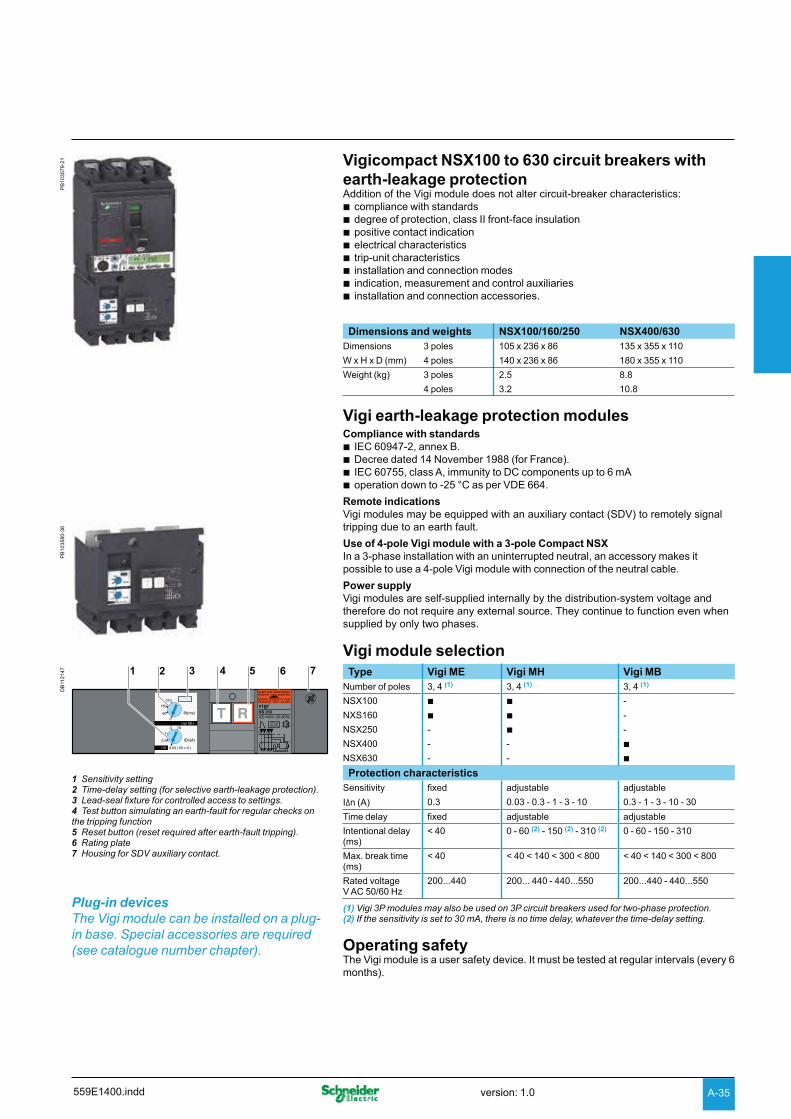
PB
1035
79-2
1 Vigicompact NSX100 to 630 circuit breakers with earth-leakage protectionAddition of the Vigi module does not alter circuit-breaker characteristics:
compliance with standards bdegree of protection, class II front-face insulation bpositive contact indication belectrical characteristics btrip-unit characteristics binstallation and connection modes bindication, measurement and control auxiliaries binstallation and connection accessories. b
Dimensions and weights NSX100/160/250 NSX400/630Dimensions 3 poles 105 x 236 x 86 135 x 355 x 110
W x H x D (mm) 4 poles 140 x 236 x 86 180 x 355 x 110
Weight (kg) 3 poles 2.5 8.8
4 poles 3.2 10.8
Vigi earth-leakage protection modulesCompliance with standards
IEC 60947-2, annex B. bDecree dated 14 November 1988 (for France). bIEC 60755, class A, immunity to DC components up to 6 mA boperation down to -25 °C as per VDE 664. b
Remote indicationsVigi modules may be equipped with an auxiliary contact (SDV) to remotely signal tripping due to an earth fault.
Use of 4-pole Vigi module with a 3-pole Compact NSXIn a 3-phase installation with an uninterrupted neutral, an accessory makes it possible to use a 4-pole Vigi module with connection of the neutral cable.
Power supplyVigi modules are self-supplied internally by the distribution-system voltage and therefore do not require any external source. They continue to function even when supplied by only two phases.
Vigi module selection
DB
1121
47 1 2 3 4 5 6 7
1 Sensitivity setting2 Time-delay setting (for selective earth-leakage protection).3 Lead-seal fixture for controlled access to settings.4 Test button simulating an earth-fault for regular checks on the tripping function5 Reset button (reset required after earth-fault tripping).6 Rating plate7 Housing for SDV auxiliary contact.
Plug-in devices The Vigi module can be installed on a plug-in base. Special accessories are required (see catalogue number chapter).
Type Vigi ME Vigi MH Vigi MBNumber of poles 3, 4 (1) 3, 4 (1) 3, 4 (1)
NSX100 b b -
NXS160 b b -
NSX250 - b -
NSX400 - - b
NSX630 - - b
Protection characteristicsSensitivity fixed adjustable adjustable
I n (A) 0.3 0.03 - 0.3 - 1 - 3 - 10 0.3 - 1 - 3 - 10 - 30
Time delay fixed adjustable adjustable
Intentional delay (ms)
< 40 0 - 60 (2) - 150 (2) - 310 (2) 0 - 60 - 150 - 310
Max. break time (ms)
< 40 < 40 < 140 < 300 < 800 < 40 < 140 < 300 < 800
Rated voltage V AC 50/60 Hz
200...440 200... 440 - 440...550 200...440 - 440...550
(1) Vigi 3P modules may also be used on 3P circuit breakers used for two-phase protection.(2) If the sensitivity is set to 30 mA, there is no time delay, whatever the time-delay setting.
Operating safetyThe Vigi module is a user safety device. It must be tested at regular intervals (every 6 months).
PB
1035
80-3
6
559E1400.indd version: 1.0 A-35

A-36
Functions and characteristics
Motor protection General information on motor feeders
The parameters to be considered for motor-feeder protection depend on:b the application (type of machine driven, operating safety, frequency of operation, etc.)b the level of continuity of service required by the load or the applicationb the applicable standards for the protection of life and property.The required electrical functions are:b isolationb switching, generally at high endurance levelsb protection against overloads and short-circuits, adapted to the motorb additional special protection.A motor feeder must comply with the requirements of standard IEC 60947-4-1 concerning contactors and their protection: b coordination of feeder componentsb thermal-relay trip classesb contactor utilisation categoriesb coordination of insulation.
Motor-feeder functionA motor feeder comprises a set of devices for motor protection and control, as well as for protection of the feeder itself.
IsolationThe purpose is to isolate the live conductors from the upstream distribution system to enable work by maintenance personnel on the motor feeder at no risk. This function is provided by a motor circuit breaker offering positive contact indication and lockout/tagout possibilities.
SwitchingThe purpose is to control the motor (ON / OFF), either manually, automatically or remotely, taking into account overloads upon start-up and the long service life required. This function is provided by a contactor. When the coil of the contactor's electromagnet is energised, the contactor closes and establishes, through the poles, the circuit between the upstream supply and the motor, via the circuit breaker.
Basic protectionShort-circuit protection b
Detection and breaking, as quickly as possible, of high short-circuit currents to avoid damage to the installation. This function is provided by a magnetic or thermal-magnetic circuit breaker.
Overload protection bDetection of overload currents and motor shutdown before temperature rise in the motor and conductors damages insulation. This function is provided by a thermal-magnetic circuit breaker or a separate thermal relay.
Overloads: I < 10 x In They are caused by: b an electrical problem, related to an anomaly in the distribution system (e.g. phase failure, voltage outside tolerances, etc.)b a mechanical problem, related to a process malfunction (e.g. excessive torque) or damage to the motor (e.g. bearing vibrations). These two causes will also result in excessively long starting times. Impedant short-circuits: 10 x In < I < 50 x InThis type of short-circuit is generally due to deteriorated insulation of motor windings or damaged supply cables.Short-circuits: I > 50 x InThis relatively rare type of fault may be caused by a connection error during maintenance.
Additional electronic protectionLocked rotor bUnder-load bLong starts and stalled rotor bInsulation faults. b
Motor-feeder solutionsStandard IEC 60947 defines three types of device combinations for the protection of motor feeders.
Three devicesmagnetic circuit breaker + contactor + thermal relay. b
Two devicesthermal-magnetic circuit breaker + contactor. b
One devicethermal-magnetic circuit breaker + contactor in an integrated solution (e.g. b
Tesys U).
DB
1155
71
M
Isolationand short-circuit protection
Circuit breaker with magnetic protection
Contactor
Additional protection functions
Power switching
Thermal protection, separate or built into the circuit breaker
Overload protection or thermal protection
Specific or internalmotor protection
Switchgear functions in a motor feeder.
Phase unbalance or phase loss protection bPhase unbalance or phase loss can cause temperature rise and braking torques that can lead to premature ageing of the motor. These effects are even greater during starting, therefore protection must be virtually immediate.
559E1500.inddversion: 1.0

A-37
Device coordinationThe various components of a motor feeder must be coordinated. Standard IEC 60947-4-1 defines three types of coordination depending on the operating condition of the devices following a standardised short-circuit test.
Type-1 coordinationNo danger to life or property. bThe contactor and/or the thermal relay may be damaged. bRepair and replacement of parts may be required prior to further b service.
Type-2 coordinationNo danger to life or property. bNo damage or adjustments are allowed. The risk of contact welding is accepted as b
long as they can be easily separated.Isolation must be maintained after the incident, the motor feeder must be suitable b
for further use without repair or replacement of parts.A rapid inspection is sufficient before return to service. b
Total coordinationNo damage and no risk of contact welding is allowed for the devices making up the b
motor feeder. The motor feeder must be suitable for further use without repair or replacement of parts.This level is provided by integrated 1-device solutions such as Tesys U.
Contactor utilisation categoriesFor a given motor-feeder solution, the utilisation category determines the contactor withstand capacity in terms of frequency of operation and endurance. Selection, which depends on the operating conditions imposed by the application, may result in oversizing the contactor and circuit-breaker protection. Standard IEC 60947 defines the following contactor utilisation categories.
Contactor utilisation categories (AC current)
Contactor utilisation categories
Type of load Control function Typical applications
AC1 Non-inductive (cos u 0.8) Energising Heating, distribution
AC2 Slip-ring motor (cos u 0.65) StartingSwitching off motor during runningCounter-current brakingInching
Wiring-drawing machine
AC3 Squirrel-cage motor(cos = 0.45 for y 100 A)(cos = 0.35 for > 100 A)
StartingSwitching off motor during running
Compressors, elevators, pumps, mixers, escalators, fans, conveyer systems, air-conditioning
AC4 StartingSwitching off motor during runningRegenerative brakingPluggingInching
Printing machines, wire-drawing machines
Utilisation category AC3 - common coordination tables for circuit breakers and contactors This category covers asynchronous squirrel-cage motors that are switched off during running, which is the most common situation (85 % of cases). The contactor makes the starting current and switches off the rated current at a voltage approximately one sixth of the nominal value. The current is interrupted without difficulty. The circuit breaker-contactor coordination tables for Compact NSX are for use with contactors in the AC3 utilisation category, in which case they ensure type-2 coordination.
Utilisation category AC4 - possible oversizing This category covers asynchronous squirrel-cage motors capable of operating under regenerative braking or inching (jogging) conditions The contactor makes the starting current and can interrupt this current at a voltage that may be equal to that of the distribution system. These difficult conditions make it necessary to oversize the contactor and, in general, the protective circuit breaker with respect to category AC3.
559E1500.indd version: 1.0

A-38
Functions and characteristics
Motor protection Motor-feeder characteristics and solutions
The trip class determines the trip curve of the thermal protection device (inverse-time curve) for a motor feeder.Standard IEC 60947-4-1 defines trip classes 5, 10, 20 and 30.These classes are the maximum durations, in seconds, for motor starting with a starting current of 7.2 Ir, where Ir is the thermal setting indicated on the motor rating plate.
Example: In class 20, the motor must have finished starting within 20 seconds (6 to 20 s) for a starting current of 7.2 Ir.
Trip class of a thermal-protection deviceThe motor feeder includes thermal protection that may be built into the circuit breaker. The protection must have a trip class suited to motor starting. Depending on the application, the motor starting time varies from a few seconds (no-load start) to a few dozen seconds (high-inertia load). Standard IEC 60947-4-1 defines the trip classes below as a function of current setting Ir for thermal protection.
Trip class of thermal relays as a function of their Ir setting
Class 1.05 I r (1) 1.2 Ir (1) 1.5 Ir (2) 7.2 I r(1) 5 t > 2 h t < 2h t < 2 mn 2 s < t y 5 s 10 t > 2 h t < 2h t < 4 mn 4 s < t y 10 s 20 t > 2 h t < 2h t < 8 mn 6 s < t y 20 s 30 t > 2 h t < 2h t < 12 mn 9 s < t y 30 s (1) Time for a cold motor (motor off and cold).(2) Time for warm motor (motor running under normal conditions).
Currents of squirrel-cage motors at full rated loadStandardised values in HP
Rated operational power
Indicative values of the rated operational currents Ie (A) for 110 -
120 V
200 V 208 V 220 -
240 V
380 -
415 V
440 -
480 V
550 -
600 Vhp
1/2 4.4 2.5 2.4 2.2 1.3 1.1 0.93/4 6.4 3.7 3.5 3.2 1.8 1.6 1.31 8.4 4.8 4.6 4.2 2.3 2.1 1.71 1/2 12 6.9 6.6 6 3.3 3 2.42 13.6 7.8 7.5 6.8 4.3 3.4 2.73 19.2 11 10.6 9.6 6.1 4.8 3.95 30.4 17.5 16.7 15.2 9.7 7.6 6.17 1/2 44 25.3 24.2 22 14 11 910 56 32.2 30.8 28 18 14 1115 84 48.3 46.2 42 27 21 1720 108 62.1 59.4 54 34 27 2225 136 78.2 74.8 68 44 34 2730 160 92 88 80 51 40 3240 208 120 114 104 66 52 4150 260 150 143 130 83 65 5260 - 177 169 154 103 77 6275 - 221 211 192 128 96 77100 - 285 273 248 165 124 99125 - 359 343 312 208 156 125150 - 414 396 360 240 180 144200 - 552 528 480 320 240 192250 - - - 604 403 302 242300 - - - 722 482 361 289
Note: 1 hp = 0.7457 kW.
Standardised values in kW
Rated operational power
Standardised values in kW
currents Ie (A) for:230 V 400 V 500 V 690 V
kW A A A A0.06 0.35 0.32 0.16 0.120.09 0.52 0.3 0.24 0.170.12 0.7 0.44 0.32 0.230.18 1 0.6 0.48 0.350.25 1.5 0.85 0.68 0.490.37 1.9 1.1 0.88 0.640.55 2.6 1.5 1.2 0.870.75 3.3 1.9 1.5 1.11.1 4.7 2.7 2.2 1.61.5 6.3 3.6 2.9 2.12.2 8.5 4.9 3.9 2.83 11.3 6.5 5.2 3.84 15 8.5 6.8 4.95.5 20 11.5 9.2 6.77.5 27 15.5 12.4 8.911 38 22 17.6 12.815 51 29 23 1718.5 61 35 28 2122 72 41 33 2430 96 55 44 3237 115 66 53 3945 140 80 64 4755 169 97 78 5775 230 132 106 7790 278 160 128 93110 340 195 156 113132 400 230 184 134160 487 280 224 162200 609 350 280 203250 748 430 344 250315 940 540 432 313
DB
1155
72
td
t”d
I”dIdIr
Startingtime
Typical motor-starting curve
Asynchronous-motor starting parameters The main parameters of direct on-line starting of three-phase asynchronous motors (90 % of all applications) are listed below.
Ir b : rated currentThis is the current drawn by the motor at full rated load (e.g. approximately 100 A rms for 55 kW at 400 V).
Id b : starting currentThis is the current drawn by the motor during starting, on average 7.2 In for a duration td of 5 to 30 seconds depending on the application (e.g. 720 A rms for 10 seconds). These values determine the trip class and any additional "long-start" protection devices that may be needed.
I’’d b : peak starting currentThis is the subtransient current during the first two half-waves when the system is energised, on the average 14 In for 10 to 15 ms (e.g. 1840 A peak).
The protection settings must effectively protect the motor, notably via a suitable thermal-relay trip class, but let the peak starting current through.
559E1500.inddversion: 1.0

A-39
Compact NSX motor-feeder solutions
Compact NSX motor circuit breakers are designed for motor-feeder solutions using:b three devices, including an MA or 1.3-M magnetic-only trip unitb two devices including a TM-D or 2-M thermal-magnetic trip unit.They are designed for use with contactors in the AC3 utilisation category (80 % of all cases) and they ensure type-2 coordination with the contactor.For the AC4 utilisation category, the difficult conditions generally make it necessary to oversize the protection circuit breaker with respect to the AC3 category.
Compact NSX motor-protection range Compact NSX trip units can be used to create motor-feeder solutions comprising two or three devices. The protection devices are designed for continuous duty at 65 °C.
Three-device solutions1 NSX circuit breaker with an MA or Micrologic 1.3-M trip unit b1 contactor b1 thermal relay. b
Two-device solutions1 Compact NSX circuit breaker bwith a Micrologic 2.2-M or 2.3-M electronic trip unit vwith a Micrologic 6 E-M electronic trip unit. This version offers additional protection v
and Power Meter functions.1 contactor. b
Type of motor protection 3 devices 2 devicesCompact NSX circuit breaker NSX100/160/250 NSX400/630 NSX100 to 630
Type-2 coordination with Contactor + thermal relay Contactor
Trip unit Type MA Micrologic 1.3-M Micrologic 2-M Micrologic 6 E-M
Technology Magnetic Electronic Electronic Electronic
Thermal relay Separate b b
Built-in, class 5 b b
10 b b
20 b b
30 b
Protection functions of Compact NSX circuit breaker
Short-circuits b b b b
Overloads b b
Insulation faults
Ground-fault b
Special motor functions
Phase unbalance b b
Locked rotor b
Under-load b
Long start b
Built-in Power Meter functions
I, U, energy b
Operating assistance
Counters (cycles, trips, alarms, hours)
b
Contact-wear indicator b
Load profile and thermal image
b
559E1500.indd version: 1.0

A-40
Functions and characteristics
Motor protection MA and Micrologic 1.3-M instantaneous trip units
MA magnetic trip units
Circuit breakers with an MA trip unit are combined with a thermal relay and a contactor or a starter.
Protection ……………………………………………
Magnetic protection (Im)Short-circuit protection with an adjustable pick-up Im that initiates instantaneous tripping if exceeded.
Im b = In x ... is set on an adjustment dial in multiples of the rating:6 to 14 x In (2.5 to 100 A ratings) v9 to 14 x In (150 to 200 A ratings) v
Protection version3-pole (3P 3D): 3-pole frame (3P) equipped with detection on all 3 poles (3D). b
Micrologic 1.3-M trip units
Circuit breakers with a Micrologic 1.3-M trip unit are combined with a thermal relay and a contactor.
Protection .............................................................. Settings are made using a dial.
Short-circuits: Short-time protection (Isd)Protection with an adjustable pick-up Isd. There is a very short delay to let through motor starting currents.
Isd is set in amperes from 5 to 13 x In, as follows: bfrom 1600 to 4160 A for the 320 A rating. vfrom 2500 to 6500 A for the 500 A rating. v
Short-circuits: Non-adjustable instantaneous protection (li)Instantaneous protection with non-adjustable pick-up Ii.
Protection version3-pole (3P 3D): 3-pole frame (3P) equipped with detection on all 3 poles (3D). b
Indications ………………………………………… Front indications
Green “Ready” LED: flashes slowly when the circuit breaker is ready to trip in the bevent of a fault.
MA magnetic trip units are used in 3-device motor-feeder solutions. They can be mounted on all Compact NSX100/160/250 circuit breakers with performance levels B/F/H/N/S/L.They provide short-circuit protection for motors up to 110 kW at 400 V.
Micrologic 1.3-M trip units are used in 3-device motor-feeder solutions on Compact NSX400/630 circuit breakers with performance levels B/F/H/N/S/L.They provide short-circuit protection for motors up to 250 kW at 400 V.They also provide the benefits of electronic technology:b accurate settingsb testsb "Ready" LED.
Note: all the trip units have a transparent lead-sealable cover that protects access to the adjustment dials.
DB
1121
10
50A
DB
1121
06
559E1500.inddversion: 1.0

A-41
Magnetic trip units MA 2.5 to 220Ratings (A) In at 65 °C (1) 2.5 6.3 12.5 25 50 100 150 220Circuit breaker Compact NSX100 b b b b b b - -
Compact NSX160 - - - b b b b -
Compact NSX250 - - - - - b b b
Instantaneous magnetic protectionPick-up (A)accuracy ±20 %
Im = In x ... Adjustable from 6 to 14 x In(settings 6, 7, 8, 9, 10, 11, 12, 13, 14)
Adjustable from 9 to 14 x In(settings 9, 10, 11, 12, 13, 14)
Time delay (ms) tm fixed
Micrologic 1.3-M Ratings (A) In at 65 °C (1) 320 500Circuit breaker Compact NSX400 b -
Compact NSX630 b b
S Short-time protectionPick-up (A) accuracy ±15 %
Isd Adjustable directly in amps
9 settings: 1600, 1920, 2440, 2560, 2880, 3200, 3520, 3840, 4160 A
9 settings: 2500, 3000, 3500, 4000, 4500, 5000, 5500, 6000, 6500 A
Time delay (ms) tsd Non-adjustable
Non-tripping timeMaximum break time
2060
I Instantaneous protection Pick-up (A)accuracy ±15 %
Ii non-adjustable 4800 6500
Non-tripping timeMaximum break time
030 ms
(1) Motor standards require operation at 65 °C. Circuit-breaker ratings are derated to take this requirement into account.
559E1500.indd version: 1.0

A-42
Functions and characteristics
Motor protection Micrologic 2-M electronic trip units
Circuit breakers with a Micrologic 2.2 / 2.3-M trip unit include protection similar to an inverse-time thermal relay. They are combined with a contactor.
Protection .............................................................. Settings are made using a dial.
Overloads (or thermal protection): Long-time protection and trip class (Ir)Inverse-time thermal protection against overloads with adjustable pick-up Ir. Settings are made in amperes. The tripping curve for the long-time protection, which indicates the time delay tr before tripping, is defined by the selected trip class.
Trip class (class)The class is selected as a function of the normal motor starting time.
Class 5: starting time less than 5 s bClass 10: starting time less than 10 s bClass 20: starting time less than 20 s b
For a given class, it is necessary to check that all motor-feeder components are sized to carry the 7.2 Ir starting current without excessive temperature rise during the time corresponding to the class.
Short-circuits: Short-time protection (Isd)Protection with an adjustable pick-up Isd. There is a very short delay to let through motor starting currents.
Short-circuits: Non-adjustable instantaneous protection (li)Instantaneous protection with non-adjustable pick-up Ii.
Phase unbalance or phase loss (lunbal) ( )This function opens the circuit breaker if a phase unbalance occurs:
that is greater than the 30% fixed pick-up b Iunbalfollowing the non-adjustable time delay b tunbal equal to:0.7 s during starting v4 s during normal operation. v
Phase loss is an extreme case of phase unbalance and leads to tripping under the same conditions.
Indications ………………………………………… Front indications
Green “Ready” LED: flashes slowly when the circuit breaker is ready to trip in the bevent of a fault.
Red alarm LED for motor operation: goes ON when the thermal image of the rotor band stator is greater than 95% of the permissible temperature rise.
Remote indications via SDTAM moduleCompact NSX devices with a Micrologic 2 can be equipped with an SDTAM module dedicated to motor applications for:
a contact to indicate circuit-breaker overload ba contact to open the contactor. In the event of a phase unbalance or overload, b
this output is activated 400 ms before circuit-breaker tripping to open the contactor and avoid circuit breaker tripping.This module takes the place of the MN/MX coils and an OF contact.
Note: all the trip units have a transparent lead-sealable cover that protects access to the adjustment dials.
PB
1033
76
SDTAM remote indication relay module with its terminal block.
Micrologic 2-M trip units provide built-in thermal and magnetic protection. They are used in 2-device motor-feeder solutions on Compact NSX100 to 630 circuit breakers with performance levels B/F/H/N/S/L.They provide protection for motors up to 315 kW at 400 V against:b short-circuitsb overloads with selection of a trip class (5, 10 or 20)b phase unbalance.
DB
1121
11
559E1500.inddversion: 1.0

A-43
Micrologic 2.2 / 2.3-MRatings (A) In at 65 °C (1) 25 50 100 150 220 320 500Circuit breaker Compact NSX100 b b b - - - -
Compact NSX160 b b b b - - -Compact NSX250 b b b b b - -Compact NSX400 - - - - - b -Compact NSX630 - - - - - b b
L Overloads (or thermal protection): Long-time protection and trip classPick-up (A)tripping between 1.05 and 1.20 Ir
Ir value depending on trip unit rating (In) and setting on dialIn = 25 A Ir = 12 14 16 18 20 22 23 24 25In = 50 A Ir = 25 30 32 36 40 42 45 47 50In = 100 A Ir = 50 60 70 75 80 85 90 95 100In = 150 A Ir = 70 80 90 100 110 120 130 140 150In = 220 A Ir = 100 120 140 155 170 185 200 210 220In = 320 A Ir = 160 180 200 220 240 260 280 300 320In = 500 A Ir = 250 280 320 350 380 400 440 470 500
Trip class as per IEC 60947-4-1 5 10 20
Time delay (s) tr 1.5 x Ir 120 240 480 for warm motor
depending on selected trip class 6 x Ir 6.5 13.5 26 for cold motor7.2 x Ir 5 10 20 for cold motor
Thermal memory 20 minutes before and after tripping
Cooling fan non-adjustable - motor self-cooledS0 Short-circuits: Short-time protection with fixed time delayPick-up (A)accuracy ±15 %
Isd = Ir x ... 5 6 7 8 9 10 11 12 13
Time delay (ms) tsd non-adjustableNon-tripping time 20 Maximum break time 60
I Short-circuits: Non-adjustable instantaneous protectionPick-up (A) accuracy ±15 %
Ii non-adjustable 425 750 1500 2250 3300 4800 6500
Time delay (ms) Non-tripping time Maximum break time
0 30
Phase unbalance or phase lossPick-up (A) accuracy ±20 %
Iunbal in % average current (2) > 30 %
Time delay (s) non-adjustable 0.7 s during starting4 s during normal operation
(1) Motor standards require operation at 65°C. Circuit-breaker ratings are derated to take this requirement into account. (2) The unbalance measurement takes into account the most unbalanced phase with respect to the average current.
Additional technical characteristicsPhase unbalanceAn unbalance in three-phase systems occurs when the three voltages are not equal in amplitude and/or not displaced 120° with respect to each other. It is generally due to single-phase loads that are incorrectly distributed throughout the system and unbalance the voltages between the phases. These unbalances create negative current components that cause braking torques and temperature rise in asynchronous machines, thus leading to premature ageing.
Phase lossPhase loss is a special case of phase unbalance.b During normal operation, it produces the effects mentioned above and tripping must occur after four seconds.b During starting, the absence of a phase may cause motor reversing, i.e. it is the load that determines the direction of rotation. This requires virtually immediate tripping (0.7 seconds).
Starting time in compliance with the class (Micrologic 2-M)For normal motor starting, Micrologic 2-M checks the conditions below with respect to the thermal-protection (long-time) pick-up Ir:b current > 10 % x Ir (motor-off limit)b overrun of 1.5 x Ir threshold, then return below this threshold before the end of a 10 s time delay.If either of these conditions is not met, the thermal protection trips the device after a maximum time equal to that of the selected class.Pick-up Ir must have been set to the current indicated on the motor rating plate.
Long starts (Micrologic 6 E-M)When this function is not activated, the starting conditions are those indicated above. When it is activated, this protection supplements thermal protection (class).A long start causes tripping and is characterised by:b current > 10 % x Ir (motor-off limit) with: b either overrun of the long-time pick-up (1 to 8 x Ir) without return below the pick-up before the end of the long-time time delay (1 to 200 s)b or no overrun of the long-time pick-up (1 to 8 x Ir) before the end of the long-time time delay (1 to 200 s).Pick-up Ir must have been set to the current indicated on the motor rating plate.This protection should be coordinated with the selected class.
DB
1121
14
Unbalance of phase currents and voltages
DB
1155
73
1 to 200 s
Return
Overrun
Ir 1.5 Ir (Micrologic 2-M)or Ilong (Micrologic 6 E-M)
10 % Ir
Motor-off zone
Starting time
Long start time
limit
Motor starting and long starts
559E1500.indd version: 1.0

A-44
Functions and characteristics
Motor protection Micrologic 6 E-M electronic trip units
Protection …………………………………………… The protection functions are identical to those of Micrologic 2-M and can be fine-adjusted via the keypad .Access to setting modifications via the keypad is protected by a locking function that is controlled by a microswitch . The lock is activated automatically if the keypad is not used for 5 minutes. Access to the microswitch is protected by a transparent lead-sealable cover. It is possible to scroll through settings and measurements with the cover closed.
Overloads (or thermal), class and short-circuits The long-time, short-time and instantaneous functions are identical to those of Micrologic 2-M.In addition, there is trip class 30 for long-time protection and a setting for self-cooled or fan-cooled motors ( ).
Ground-fault protection (Ig) Residual type ground-fault protection with an adjustable pick-up Ig (with Off position) and adjustable time delay tg.
Phase unbalance or phase loss (lunbal)This function opens the circuit breaker if a phase unbalance occurs:
that is greater than the b Iunbal pick-up that can be fine-adjusted from 10 to 40 % (30 % by default)
following the b tunbal time delay that is:0.7 s during starting vadjustable from 1 to 10 seconds (4 seconds by default) during normal operation. v
Phase loss is an extreme case of phase unbalance and leads to tripping under the same conditions.
Locked rotor (Ijam)This function detects locking of the motor shaft caused by the load.During motor starting (see page A-43), the function is disabled. During normal operation, it causes tripping:
above the b Ijam pick-up that can be fine-adjusted from 1 to 8 x Irin conjunction with the b tjam time delay that can be adjusted from 1 to 30 seconds.
Under-load (Iund)This function detects motor no-load operation due to insufficient load (e.g. a drained pump). It detects phase undercurrent.During motor starting (see page A-43), the function is always enabled.During normal operation, it causes tripping:
below the b Iund pick-up that can be fine-adjusted from 0.3 to 0.9 x Irin conjunction with the b tund time delay that can be adjusted from 1 to 200
seconds.
Long starts (Ilong)This protection supplements thermal protection (class).It is used to better adjust protection to the starting parameters.It detects abnormal motor starting, i.e. when the starting current remains too high or too low with respect to a pick-up value and a time delay.It causes tripping:
in relation with a b llong pick-up that can be fine-adjusted from 1 to 8 x Irin conjunction with the b tlong time delay that can be adjusted from 1 to 200
seconds.(see "long starts" page A-43)
Display of type of fault ……………………………On a fault trip, the type of fault (Ir, Isd, Ii, Ig, lunbal, ljam), the phase concerned and the interrupted current are displayed.
Indications ………………………………………… Front indications
Green “Ready” LED: flashes slowly when the circuit breaker is ready to trip in the bevent of a fault.
Red alarm LED for motor operation: goes ON when the thermal image of the rotor bor stator is greater than 95% of the permissible temperature rise.
Remote indications via SDTAM or SDx moduleSee description on page A-42 for SDTAM and page A-81 for SDx.
Note: all the trip units have a transparent lead-sealable cover that protects access to the adjustment dials.
Micrologic 6.E-M is used in 2-device motor-feeder solutions. It provides the same protection as Micrologic 2-M:b short-circuitsb overloads with selection of the same trip classes (5, 10 or 20), plus trip class 30 for starting of machines with high inertia.In addition, it offers specific motor-protection functions that can be set via the keypad.
PB
1033
76
SDTAM remote indication relay module with its terminal block.
DB
1121
16
559E1500.inddversion: 1.0

A-45
Micrologic 6.2 / 6.3 E-MRatings (A) In at 65 °C (1) 25 50 80 150 220 320 500Circuit breaker Compact NSX100 b b b - - - -
Compact NSX160 b b b b - - -Compact NSX250 b b b b b - -Compact NSX400 - - - - - b -Compact NSX630 - - - - - b b
L Overloads: Long-time protectionPick-up (A) Ir Dial setting Value depending on trip-unit rating (In) and setting on dialTripping between 1.05 and 1.20 Ir
In = 25 A Ir = 12 14 16 18 20 22 23 24 25In = 50 A Ir = 25 30 32 36 40 42 45 47 50In = 80 A Ir = 35 42 47 52 57 60 65 72 80In = 150 A Ir = 70 80 90 100 110 120 130 140 150In = 220 A Ir = 100 120 140 155 170 185 200 210 220In = 320 A Ir = 160 180 200 220 240 260 280 300 320In = 500 A Ir = 250 280 320 350 380 400 440 470 500Keypad setting Fine adjustments in 1 A steps below maximum value defined by dial setting
Trip class as per IEC 60947-4-1 5 10 20 30
Time delay (s) tr 1.5 x Ir 120 240 480 720 for warm motor
depending on selected trip class 6 x Ir 6.5 13.5 26 38 for cold motor7.2 x Ir 5 10 20 30 for cold motor
Thermal memory 20 minutes before and after tripping
Cooling fan Settings for self-cooled or fan-cooled motorsS0 Short-circuits: Short-time protection with fixed time delayPick-up (A)accuracy ±15 %
Isd = Ir x ... 5 6 7 8 9 10 11 12 13
Time delay (ms) tsd non-adjustableNon-tripping time 20 Maximum break time 60
I Short-circuits: Non-adjustable instantaneous protectionPick-up (A) accuracy ±15 %
Ii non-adjustable 425 750 1200 2250 3300 4800 6500Non-tripping time Maximum break time
0 ms30 ms
G Ground faultsPick-up (A) accuracy ±10 %
Ig = In x ... Dial settingIn = 25 A Ig = 0.6 0.6 0.6 0.6 0.7 0.8 0.9 1 OffIn = 50 A Ig = 0.3 0.4 0.5 0.6 0.7 0.8 0.9 1 OffIn > 50 A Ig = 0.2 0.3 0.4 0.5 0.6 0.7 0.8 1 Off
fine adjustments in 0.05 x In stepsTime delay (ms) tg 0 0.1 0.2 0.3 0.4
Non-tripping time 20 80 140 230 350Maximum break time 80 140 200 320 500
Phase unbalance or phase lossPick-up (A) accuracy ±20 %
lunbal = in % average current (2) adjustable from 10 to 40 %, default setting = 30 %fine adjustments in 1 % steps using the keypad activated during motor starting
Time delay (s) tunbal 0.7 s during starting1 to 10 seconds during normal operation, default setting = 4 secondsfine adjustments in 1 s steps using the keypad
Locked rotorPick-up (A) accuracy ±10 %
Ijam = Ir x ... 1 x 8 Ir with Off position, default setting = Offfine adjustments in 0.1 x Ir steps using the keypaddisabled during motor starting
Time delay (s) tjam = 1 to 30 secondsfine adjustments in 1 s steps using the keypad, default setting = 5 s
Under-load (under-current)Pick-up (A) accuracy ±10 %
Iund = Ir x ... 0.3 x 0.9 Ir with Off position, default setting = OffFine adjustments in Ir x 0.01 steps using the RSU softwareactivated during motor starting
Time delay (s) tund = 1 to 200 secondsfine adjustments in 1 s steps using the RSU software, default setting = 10 s
Long startsPick-up (A) accuracy ±10 %
Ilong = Ir x ... 1 x 8 Ir with Off position, default setting = OffFine adjustments in Ir x 0.01 steps using the RSU softwareactivated during motor starting
Time delay (s) tlong = 1 to 200 secondsfine adjustments in 1 s steps using the RSU software, default setting = 10 s
(1) Motor standards require operation at 65 °C. Circuit-breaker ratings are derated to take this requirement into account. (2) The unbalance measurement takes into account the most unbalanced phase with respect to the average current.
559E1500.indd version: 1.0

A-46
Functions and characteristics
Motor protection Micrologic 6 E-M electronic trip units (cont.)
Micrologic 6 E-M provides Power Meter functions with energy metering. With the FDM121 display unit, all metering data and operating indicators are available on the switchboard front panel. This version also displays the thermal image of the motor.
Power Meter functionsThe built-in Power Meter functions of the Micrologic 6 E-M are the same as those for the Micrologic 6-E presented in the section on distribution (see page A-20). When used exclusively in the three-phase version, neutral measurements are excluded.
Operating-assistance functionsThe operating-assistance functions of the Micrologic 6 E-M are the same as those for the Micrologic 6-E presented in the section on distribution (see page A-22).
Special functions for motor feedersAdditional operating functions specifically for motor feeders are available.
Phase sequenceThe order in which the phases L1, L2, L3 are connected determines the direction of motor rotation. If two phases are inverted, the direction is reversed. Information on the direction of rotation is provided. It can be linked to an alarm to detect an inversion in the direction following servicing on the supply under de-energised conditions and disable restarting.
Thermal image of the rotor and statorMicrologic 6 E-M offers a thermal-image function.Taking into account the Ir setting and the class, an algorithm simulates rotor and stator temperature rise. It includes the slow temperature rise of the stator and its metal mass. Also included is the faster temperature rise of the copper rotor.The thermal protection function trips the circuit breaker when the calculated thermal image reaches 100 % of the permissible temperature rise.The communication indicates the thermal-image value as a percentage of the permissible temperature rise. One or more alarms may be assigned to selected thresholds. A red LED on the front signals when the value exceeds 95 %. An SDx module with two outputs programmed for thermal-image values can be used to implement other alarm functions.
PB
1033
65
Micrologic 6 E-M.
DB
1114
04
ESC
I1
I2
I3
I
165 A 100 120%
165 A 100 120%
164A 100 120%
DB
1114
05
ESC
° motor = 97%
Current values. Thermal-image alarm.
DB
1114
03
PC screen with motor thermal image and value monitoring.
The additional technical characteristics are identical to those of Micrologic 6-E (see pages A-21 and A-23).
559E1500.inddversion: 1.0

A-47
Micrologic 6 E-M integrated Power Meter and operating-assistance functions DisplayMicrologic LCD
FDM121 display
MeasurementsInstantaneous rms measurementsCurrents (A) Phase currents and average value I1, I2, I3 and Iavg = (I1 + I2 + I3) / 3 b b
Highest current of the 3 phases Imax of I1, I2, I3 b bGround-fault protection % Ig (pick-up setting) b bCurrent unbalance between phases % Iavg - b
Voltages (V) Phase-to-phase voltages and average value U12, U23, U31 and Uavg = (U12 + U21 + U23) / 3 b b
Unbalance between phase-to-phase voltages % Uavg - bPhase sequence 1-2-3, 1-3-2 b -
Frequency (Hz) Power system F b bPower Active (kW), reactive (kVAR), apparent (kVA) P, Q, S total and per phase - b
Power factor and cos (fundamental) PF, cos , total and per phase - b
Maximeters / minimeters Associated with instantaneous rms measurements
Reset via Micrologic and the display unit - b
Energy meteringEnergy Active (kWh), reactive (kVARh),
apparent (kVAh)Total since last reset b bAbsolute or signed mode (1) - b
Demand and maximum demand valuesDemand current (A) Phases Present value on the selected window
Maximum demand since last reset--
(2)
(2)
Demand power Active (kWh), reactive (kVARh), apparent (kVAh)
Present value on the selected windowMaximum demand since last reset
--
(2)
(2)
Calculation window Sliding, fixed or com-synchronised Adjustable from 5 to 60 minutes in 1 minute stepsAbsolute or signed mode(1)
--
(2)
(2)
Power qualityTotal harmonic distortion (%)
Of voltage with respect to rms value THDU,THDV of the Ph-Ph and Ph-N voltage - bOf current with respect to rms value THDI of the phase current - b
Operating assistancePersonalised alarmsSettings Up to 10 alarms can be assigned to all measurements and events - (2)
as well as to phase lead/lag, four quadrants, phase sequence and thermal image - (2)
Time-stamped historiesTrips last 17 Ir, Isd, Ii, Ig, Iunbal, Ijam, Iund, Ilong - (2)
Alarms last 10 - (2)
Operating events last 10 events and type: Modification of protection setting by dial - (2)
Opening of keypad lock - (2)
Test via keypad - (2)
Test via external tool - (2)
Time setting (date and time) - (2)
Reset for maximeter/minimeter and energy meter b (2)
Time stamping Presentation Date and time, text, status - (2)
Time-stamped event tablesProtection settings One of the following settings modified Ir tr Isd tsd Ii Ig tg - (2)
Time-stamping of modification Date and time of modification - (2)
Previous value Value before modification - (2)
Min/Max Value monitored I1 I2 I3 U12 U23 U31 f - (2)
Time-stamping of min/max value Date and time of record - (2)
Present min/max value Min/max recorded for the value - (2)
Maintenance indicatorsCounter Mechanical cycles (3) Assignable to an alarm - (2)
Electrical cycles (3) Assignable to an alarm - (2)
Trips One per type of trip - (2)
Alarms One for each type of alarm - (2)
Hours Total operating time (hours) - (2)
Indicator Contact wear % - b
Load profile Hours at different load levels % of hours in four current ranges: 0-49 % In, 50-79 % In, 80-89 % In, u 90 % In
- (2)
Thermal image Stator and rotor % of permissible temperature rise - (2)
(1) Absolute mode: E absolute = E out + E in; Signed mode: E signed = E out - E in.(2) Available via communication system.(3) The BSCM module (page A-27) is required for these functions.
559E1500.indd version: 1.0

A-46 559E1600.inddversion: 1.0

A-47 559E1600.indd version: 1.0

Functions and characteristics
Special applicationsGenerator protection with Micrologic 2.2-G
Micrologic G trip units are used for the protection of systems supplied by generators or comprising long cable lengths. They can be mounted on all Compact NSX100/160/250 circuit breakers.With extensive setting possibilities, Micrologic 5 offers the same functions from 100 to 630 A. A thermal-magnetic trip unit is also available for the NSX100 (see page A-15).
Circuit breakers equipped with Micrologic G trip units protect systems supplied by generators (lower short-circuit currents than with transformers) and distribution systems with long cable lengths (fault currents limited by the impedance of the cable).
Protection ……………………………………………Settings are made using the adjustment dials with fine adjustment possibilities.
Overloads: Long-time protection (Ir)Inverse-time thermal protection against overloads with an adjustable current pick-up Ir and a very short, non-adjustable time delay tr (15 seconds for 1.5 x Ir).
Short-circuits: Short-time protection (Isd) with fixed time delayShort-circuit protection with an adjustable pick-up Isd, delayed 200 ms, in compliance with the requirements of marine classification companies.
Short-circuits: Non-adjustable instantaneous protection (li)Instantaneous short-circuit protection with a fixed pick-up required for generator protection.
Neutral protectionOn 3-pole circuit breakers, neutral protection is not possible. bOn four-pole circuit breakers, neutral protection may be set using a three-position b
switch:4P 3D: neutral unprotected v4P 3D + N/2: neutral protection at half the value of the phase pick-up, i.e. 0.5 x Ir v4P 4D: neutral fully protected at Ir. v
Indications …………………………………………Front indications
Green “Ready” LED: flashes slowly when the circuit breaker is ready to trip in the bevent of a fault.
Orange overload pre-alarm LED: steady on when I > 90 % Ir bRed overload LED: steady on when I > 105 % Ir b
Remote indicationsAn SDx relay module installed inside the circuit breaker can be used to remote the overload-trip signal.This module receives the signal from the Micrologic electronic trip unit via an optical link and makes it available on the terminal block. The signal is cleared when the circuit breaker is closed.The module is described in detail in the section dealing with accessories.
PB
1033
77
SDx remote indication relay module with its terminal block.
DB
1121
18
A-48 559E1600.inddversion: 1.0

Micrologic 2.2-GRatings (A) In at 40°C (1) 40 100 160 250Circuit breaker Compact NSX100 b b - -
Ii
Compact NSX160 b b b -
Compact NSX250 b b b b
L Long-time protectionPick-up (A)tripping between 1.05 and 1.20 Ir
Io value depending on trip unit rating (In) and setting on dial
In = 40 A Io = 18 18 20 23 25 28 32 36 40
In = 100 A Io = 40 45 50 55 63 70 80 90 100
In = 160 A Io = 63 70 80 90 100 110 125 150 160
In = 250 A (NSX250) Io = 100 110 125 140 150 176 200 225 250
Ir = Io x ... 9 fine-adjustment settings from 0.9 to 1 for each Io value
Time delay (s)accuracy 0 to -20%
tr non-adjustable
1.5 x Ir 15
6 x Ir 0.5
7.2 x Ir 0.35
Thermal memory 20 minutes before and after tripping
S0 Short-time protection with fixed time delayPick-up (A)accuracy ±10 %
Isd = Ir x ... 1.5 2 2.5 3 4 5 6 7 8 9
Time delay (ms) tsd non-adjustable
Non-tripping time 140
Maximum break time 200
I Non-adjustable instantaneous protectionPick-up (A) accuracy ±15 %
Ii non-adjustable 600 1500 2400 3000
Non-tripping time Maximum break time
15 ms50 ms
(1) If the trip units are used in high-temperature environments, the Micrologic setting must take into account the thermal limitations of the circuit breaker. See the temperature derating table.
A-49 559E1600.indd version: 1.0

Functions and characteristics
Special applicationsProtection of industrial control panels
Compact NSX circuit breakers are also used in industrial control panels.They serve as an incoming devices or can be combined with contactors to protect motor feeders:b compliance with worldwide standards including IEC 60947-2 and UL 508 / CSA 22-2 no. 14 boverload and short-circuit protectionb isolation with positive contact indication, making it possible to service machines safely by isolating them from all power sourcesb installation in universal and functional type enclosuresb NA switch-disconnector version.
Industrial control panelsCompact NSX circuit breakers equipped for public distribution or motor protection functions as described in the previous pages can be used in industrial control panels. The accessories for the Compact NSX range are suitable for the special needs of these switchboards.
AuxiliariesAll auxiliaries can be added to the circuit breaker by the user:
padlocking devices (in the OFF position) brotary handle bstatus-indication auxiliary contacts (ON, OFF and tripped) bshunt (MX) or undervoltage (MN) releases bearly-make or early-break contacts. b
Rotary handleDirect or extended versions for mounting up to 600 mm behind the front:
black front with black handle byellow front with red handle (for machine tools or emergency off as per IEC 204 / b
VDE 0013).All rotary handles can be padlocked in the OFF position. Optional door interlock, recommended for MCC panels (motor control centres).When the device is equipped with an extended rotary handle, a control accessory mounted on the shaft makes it possible to operate the device with the door open.The device can be padlocked in the OFF position in compliance with UL508.
Early-make or early-break contactsThese contacts can be used respectively to supply an MN undervoltage release before the circuit breaker closes or to open the contactor control circuit before the circuit breaker opens.
Special functionsIndication of thermal overloads with the SDx module. bEarly opening of the contactor for overload faults with the SDTAM module. bLinks with PLCs via the communication system. bMeasurement of all electrical parameters with Micrologic A and E. bProgrammable alarms with Micrologic 5 and 6. b
Installation in enclosuresCompact circuit breakers can be installed in a metal enclosure together with other devices (contactors, motor-protection circuit breakers, LEDs, etc.) (see page A-90).
Compliance with North American industrial control equipment standardsCompact NSX devices have received UL508 / CSA 22-2 no. 14 approval for industrial control equipment of the "Manual Motor Controller", "Across the Line Starter", "General Use" and "Disconnecting Means" types.Type NA devices are switch-disconnectors that must always be protected upstream.
UL508 approval
Circuit breakers Trip units Approvals
Compact NSX100 to 630 F/N/H
TMD, Micrologic 2, 5 and 6 General UseMotor Disconnecting Means
NA, MA, Micrologic 1.3 M, 2.2 M, 2.3 M, Micrologic 6.2 E-M and 6.3 E-M
Manual Motor Controller Across the Line StarterMotor Disconnecting Means
Table of 3-phase motor ratings in hp (1 hp = 0.7457 kW)V AC ratings 115 230 460 575TMD Micrologic 2, 5 and 6
NA, MA Micrologic 1.3 M, 2.2 M, 2.3 M Micrologic 6.2 E-M and 6.3 E-M
25 25 3 7.5 15 20
50 50 7.5 15 30 40
100 100 15 30 75 100
160 150 25 50 100 150
250 220 40 75 150 200
400 320 - 125 250 300
550 500 - 150 350 500
The deratings indicated on pages B-8 and B-9 apply to TMD, Micrologic 2, 5 and 6 trip units, rated at 40 °C.
DB
1152
33 D
B11
5234
Underwriters Laboratories Inc.®
CERTIFICATE
OF COMPLIANCE
Certificate of Compliance
A-50 559E1600.inddversion: 1.0

16 Hz 2/3 network protectionMicrologic 5 A-Z trip unit
Compact NSX circuit breakers may be used on 16 Hz 2/3 systems with special thermal-magnetic and electronic (Micrologic 5 A-Z) trip units.
16 Hz 2/3 networksSingle-phase distribution networks with a frequency of 16 Hz 2/3 are used for railroad applications in certain European countries.
Breaking capacity for 16 Hz 2/3 at 250/500 VCompact NSX circuit breakers of the 3P 2D or the 3P 3D type protect 16 Hz 2/3 networks at 250 V or 500 V.They can be equipped with either:
a b TM-D thermal-magnetic trip unit for Compact NSX100 to 250or an electronic Micrologic 5.2 A-Z trip unit for Compact NSX100 to 250 or b
a 5.3 A-Z for Compact NSX400/630.The possible breaking-capacity performance levels are B, F, N and H as indicated below.Breaking capacity Icu
Operating voltage TMD and Micrologic 5 A-Z trip units
Performance B F N H
250 V / 500 V Icu (kA) 25 36 50 70
ProtectionTM-D thermal-magnetic trip units
Trip-unit selectionRating 16 88 100 160 250 400 630
Compact
NSX100 TM-D
NSX160 TM-D
NSX250 TM-D
NSX100 to 250 Micrologic 5.2 A-Z
NSX400/630 Micrologic 5.3 A-Z
Wiring for NSX100 to 630 A
DB
1120
46D
B11
2153
The 16 Hz 2/3 frequency does not modify the thermal settings with respect to those at 50 Hz (see page A-15). The magnetic pick-ups are modified as shown below.
Magnetic protection for Compact NSX 100/160/250 at 50 Hz and at 16 Hz 2/3
Rating (A) In at 40 °C 16 25 32 40 50 63 80 100 125 160 200 250
Pick-up (A) Im accur. ±20% Fixed Adjustable
NSX100 50Hz 190 300 400 500 500 500 640 800
16Hz 2/3 170 270 360 450 450 450 580 720
NSX160/250
50Hz 190 300 400 500 500 500 640 800 1250 1250 5 to 10 In
16 Hz 2/3 170 270 360 450 450 450 580 720 1100 1100 4.5 to 9 In
Micrologic 5 A-Z trip units
Micrologic 5.2 A-Z and 5.3 A-Z are dedicated to 16 Hz 2/3 networks. They use a suitable sampling frequency. The protection settings are identical to those of Micrologic 5 A (see page A-19). They also offer a current-measurement function for this specific frequency.
Phase and isolated neutral interrupted- 250 / 500 V 2 poles in series - Earthed neutral - 250 / 500 V
B and F (3P 2D version) N and H (3P 3D version) B and F (3P 2D version) N and H (3P 3D version)
DB
1155
75 L N
load
DB
1155
76 L N
load
DB
1155
77 L N
load
DB
1155
78 L N
load
Remark. For an operating voltage > 250 V, the installation must be designed to eliminate all risk of double earth faults.
A-51 559E1600.indd version: 1.0

PB
1033
66
Micrologic TM-D trip unit.
Functions and characteristics
Special applicationsProtection of 400 Hz systems
Compact NSX circuit breakers may be used on 400 Hz systems.
400 Hz distribution systemsThe main 400 Hz applications are in aeronautics and certain military ships. Modern aircraft have three-phase 115/200 V 400 Hz networks.
Impact on protective devicesDue to the higher frequency, circuit breakers are subjected to additional temperature rise for identical current levels, resulting from higher losses caused by Foucault currents and an increase in the skin effect (reduction in the useful CSA of conductors). To remain within the rated temperature-rise limits of devices, current derating is required.The power levels of 400 Hz applications rarely exceed a few hundred kW with relatively low short-circuit currents, generally not exceeding four times the rated current.The standard Compact NSX and Masterpact NT/NW ranges are suitable for 400 Hz applications if derating coefficients are applied to the protection settings. See the derating table below.
Breaking capacity of Compact NSX circuit breakers in 400 Hz, 440 V systems
Circuit breaker Breaking capacity Icu
NSX100 10 kA
NSX160 10 kA
NSX250 10 kA
NSX400 10 kA
NSX630 10 kA
Trip units equipped with thermal-magnetic protectionThe 400 Hz current settings are obtained by multiplying the 50 Hz values by the following adaptation coefficient:
K1 for thermal trip units bK2 for magnetic trip units. b
These coefficients are independent of the trip-unit setting.
Thermal trip unitsThe current settings are lower at 400 Hz than at 50 Hz (K1 < 1).
Magnetic trip unitsThe current settings are conversely higher at 400 Hz than at 50 Hz (K2 > 1). Consequently, when the trip units are adjustable, they must be set to the minimum value.
Adaptation coefficients for thermal-magnetic trip units
Circuit breaker
Trip unit In (A)
50Hz
Thermal at 40°C Im (A)
50Hz
Magnetic
K1 400 Hz K2 400 Hz
NSX100 TM16G 16 0.95 15 63 1.6 100
TM25G 25 0.95 24 80 1.6 130
TM40G 40 0.95 38 80 1.6 130
TM63G 63 0.95 60 125 1.6 200
NSX100 TM16D 16 0.95 15 240 1.6 300
TM25D 25 0.95 24 300 1.6 480
TM40D 40 0.95 38 500 1.6 800
TM63D 63 0.95 60 500 1.6 800
TM80D 80 0.9 72 650 1.6 900
TM100D 100 0.9 90 800 1.6 900
NSX250 TM100D 100 0.9 90 800 1.6 900
TM160D 160 0.9 144 1250 1.6 2000
TM200D 200 0.9 180 1000 to 2000 1.6 1600 to 3200
TM250D 250 0.9 225 1250 to 2500 1.6 2000 to 4000
ExampleNSX100 equipped with a TM16G with 50 Hz settings Ir = 16 A and Im = 63 A.400 Hz settings Ir = 16 x 0.95 = 15 A and Im = 63 A x 1.6 = 100 A.
A-52 559E1600.inddversion: 1.0

Protection of 400 H systems (cont.)
Protection(cont.)
Micrologic electronic trip unitsMicrologic 2.2, 2.3 or 5.2, 5.3 with A or E measurement functions are suitable for 400 Hz. The use of electronics offers the advantage of greater operating stability when the frequency varies. However the units are still subject to temperature rise caused by the frequency.The practical consequences are:
limit settings to 0.9 In (see the Ir derating table below) bthe long-time, short-time and instantaneous pick-ups are not modified b (see pages
A-17 or A-19)the accuracy of the displayed measurements is 2 % (class II). b
Thermal derating: maximum Ir setting
Circuit breaker Maximum setting coefficient
Max. Ir setting at 400 Hz
NSX100N 1 100NSX250N 0.8 225NSX400N 0.8 320NSX630N 0.8 500
ExampleAn NSX250N, equipped with a Micrologic 2.2, Ir = 250 A at 50 Hz, must be limited to use at Ir = 250 x 0.9 = 225 A.Its short-time pick-up with fixed time delay is adjustable from 1.5 to 10 Ir (60 to 400 A).The instantaneous pick-up remains at 3000 A.
PB
1033
63
Micrologic 5 E trip unit.
OF auxiliary contacts in 400 Hz networksElectrical characteristics of auxiliary contacts
Contacts Standard Low level
Utilisation cat. (IEC 60947-5-1) AC12 AC15 CA12 CA15
Operational current (A)
24 V 6 6 5 3
48 V 6 6 5 3
110 V 6 5 5 2.5
220/240 V 6 4 5 2
380/415 V 6 2 5 1.5
0443
14
OF auxiliary contact.
MN and MX voltage releases for Compact NSX100/630 at 400 Hz and 440 VFor circuit breakers on 400 Hz systems, only 125 V DC MN or MX releases may be used. The release must be supplied by the 400 Hz system via a rectifier bridge (to be selected from the table below) and an additional resistor with characteristics depending on the system voltage.
U (V) 400 Hz Rectifier Additional resistor
220/240 V Thomson 110 BHz or 4.2 k -5 W
General Instrument W06 or
Semikron SKB at 1.2/1.3
380/420 V Semikron SKB at 1.2/1.3 10.7 k -10 W
Note: other models of rectifier bridges may be used if their characteristics are at least equivalent to those stated above.
0443
13
MX or MN voltage release.
DB
1155
79
U volt
R
a 400 Hz
a MN/MX125 V DC
Wiring diagram.
SDx indication contactsThe SDx module may be used in 400 Hz systems for voltages from 24 to 440 V.An SDx relay module installed inside the circuit breaker can be used to remote the overload-trip signal.This module receives the signal from the Micrologic electronic trip unit via an optical link and makes it available on the terminal block. The signal is cleared when the circuit breaker is closed.These outputs can be reprogrammed to be assigned to other types of tripping or alarm (see page A-81).
PB
1033
77
SDx remote indication relay module with its terminal block.
A-53 559E1600.indd version: 1.0

A-56
Functions and characteristics
Switch-disconnectors Overview of applications
A switch-disconnector is a control device that can be used to open and close a circuit under normal operating conditions.It is suitable for isolation as indicated on the front by the symbol .
Position of switch-disconnectorsCompact NSX switch-disconnectors are used primarily for the following applications:
busbar coupling and isolation bisolation of industrial distribution boards and industrial control panels bisolation of subdistribution boards for modular devices bisolation of local enclosures bisolation of final distribution enclosures for commercial applications bindustrial control panel switch-disconnectors. b
M MMM M
Main power distribution board for commercial applications
y 1000 A
Subdistribution board for modular products
Industrial distribution board
Local isolation enclosure
Local isolation enclosure
Building utilities Building final distribution Continuous processes Manufacturing processes and individual machines
Industrial control panel
N.B. Adjacent to or built into the machine.
Final distribution enclosure for commercial applications
Main power distribution board for industrial applications
Replacement source
Source coupling switch-disconnector
15 - 40 kA
y 160 A 15 - 25 kA
y 63 A
y 63 A
y 10 kA
y 630 A
y 25 kA
y 10 kA y 40 A y 5 kA
y 400 Ay 160 A : 15 - 25 kAy 400 A : 20 - 80 kA
y 1600 A 20 - 80 kA
DB
1155
80
559E1700.inddversion: 1.0

A-57
Switch-disconnector functions
Compact NSX100 to 630 NA switch-disconnectors are available in fixed, plug-in and withdrawable versions. They use the same accessories and offer the same connection possibilities as the circuit-breaker versions.They may be interlocked with another Compact switch-disconnector or circuit breaker to form a source-changeover system.
Suitability for isolation with positive contact indicationCompact NSX switch-disconnectors are suitable for isolation as defined by standard IEC 60947-3. The corresponding conformity tests guarantee:
the mechanical reliability of the position indication, i.e. the O (OFF) position bindicated by the control device always reflects the open position of the contacts:
the required distance between contacts is provided vpadlocks may not be installed unless the contacts are open vthe absence of leakage currents bovervoltage withstand capacity between upstream and downstream connections. b
Installation of a rotary handle or a motor mechanism does not alter the reliability of the position-indication system.
Emergency-off functionA Compact NSX NA is combined with an MN or MX release connected to an emergency-off button. In an emergency, an operator at a remote location can interrupt the circuit at rated load to isolate the entire switchboard and the downstream loads.
Motor mechanismCompact NSX NA devices equipped with a motor mechanism module enable remote closing and opening. This function may be combined with the emergency-off function. In this case, the emergency off function is combined with a closing lock-out that must be intentionally reset (electrical diagram with closing lock-out).
Earth-leakage protectionA Vigi module may be added to a switch-disconnector to monitor all leakage currents in the outgoing circuits of the switchboard on which the switch-disconnector is installed. When the Vigi module detects an earth-leakage current, the switch-disconnector interrupts the load current. This function may be combined with the motor mechanism and the emergency-off function using an MN or MX release.
Switch-disconnector protectionThe switch-disconnector can make and break its rated current. For an overload or a short-circuit, it must be protected by an upstream device, in compliance with installation standards. The circuit-breaker/switch-disconnector coordination tables determine the required upstream circuit breaker. However, due to their high-set magnetic release, Compact NSX100 to 630 A switch-disconnectors are self-protected.
Switch-disconnector utilisation category Depending on the rated operational current and the mechanical durability (A for frequent operation or B for infrequent operation), standard IEC 60947-3 defines the utilisation categories as shown in the table below. Compact NSX NA switch-disconnectors comply with utilisation categories AC22A or AC23A.
PB
1031
99-2
8
Compact NSX switch-disconnector.
PB
1033
72-3
4
Compact NSX switch-disconnector equipped with a motor mechanism module.
PB
1036
29-3
1
Compact NSX switch-disconnector equipped with a Vigi module.
Utilisation category Typical applicationsInfrequent operation
Frequent operation
AC-21A AC-21B Resistive loads including moderate overloads (cos = 0.95)
AC-22A AC-22B Mixed resistive and inductive loads including moderate overloads (cos = 0.65)
AC-23A AC-23B Motor loads or other highly inductive loads (cos = 0.45 or 0.35)
559E1700.indd version: 1.0

A-58
Functions and characteristics
Switch-disconnectorsCharacteristics and performance of Compact NSX switch-disconnectors from 100 to 630 NA
Installation standards require upstream protection. However Compact NSX100 to 630 NA switch-disconnectors are self-protected by their high-set magnetic release.
Common characteristicsRated voltages
Insulation voltage (V) Ui 800
Impulse withstand voltage (kV)Uimp 8
Operational voltage (V) Ue AC 50/60 Hz 690
Suitability for isolation IEC/EN 60947-3 yes
Utilisation category AC 22 A/AC 23 A - DC 22 A/DC 23 A
Pollution degree IEC 60664-1 3
PB
1031
99-3
9
Compact NSX100 to 250 NA.
PB
1032
71
Compact NSX400 to 630 NA.
Switch-disconnectorsElectrical characteristics as per IEC 60947-3 and EN 60947-3
Conventional thermal current (A) Ith 60 °C
Number of poles
Operational current (A) depending on the utilisation category
le AC 50/60 Hz
220/240 V
380/415 V
440/480 V (2)
500/525 V
660/690 V
DC
250 V (1 pole)
500 poles (2 poles in series)
750 V (3 poles in series)
Short-circuit making capacity (kA peak)
lcm min. (switch-disconnector alone)
max. (protection by upstream circuit breaker)
Rated short-time withstand current (A rms)
lcw for 1 s
3 s
20 s
Durability (C-O cycles) mechanical
electrical AC
440 V In/2
In
690 V In/2
In
DC 250 V (1 pole) and In/2
500 V (2 poles in series)In
Positive contact indication
Pollution degree
ProtectionAdd-on earth-leakage protection By Vigi module
By Vigirex relay
Additional indication and control auxiliariesIndication contacts
Voltages releases MX shunt release
MN undervoltage release
Voltage-presence indicator
Current-transformer module
Ammeter module
Insulation monitoring module
Remote communication by bus
Device-status indication
Device remote operation
Operation counter
Installation / connectionsDimensions (mm) fixed, front connections 2/3P
W x H x D 4P
Weight (kg) fixed, front connections 3P
4P
Source-changeover systems (see chapter on Source-changeover systems)Manual source-changeover systems
Remote-operated or automatic source-changeover systems
(1) 2P in 3P case.(2) Suitable for 480 V NEMA.
559E1700.inddversion: 1.0

A-59
Common characteristicsControl
Manual With toggle b
With direct or extended rotary handle b
Electrical With remote control b
Versions
Fixed b
Withdrawable Plug-in base b
Chassis b
NSX100NA NSX160NA NSX250NA NSX400NA NSX630NA
100 160 250 400 630
2 (1), 3, 4 2 (1), 3, 4 2 (1), 3, 4 3, 4 3, 4
AC22A / AC23A AC22A / AC23A AC22A / AC23A AC22A / AC23A AC22A / AC23A
100 160 250 400 630
100 160 250 400 630
100 160 250 400 630
100 160 250 400 630
100 160 250 400 630
DC22A / DC23A DC22A / DC23A DC22A / DC23A DC22A / DC23A DC22A / DC23A
100 160 250 400 630
100 160 250 400 630
100 160 250 400 630
2.6 3.6 4.9 7.1 8.5
330 330 330 330 330
1800 2500 3500 5000 6000
1800 2500 3500 5000 6000
690 960 1350 1930 2320
50000 40000 20000 15000 15000
AC22A / AC23A AC22A / AC23A AC22A / AC23A AC22A / AC23A AC22A / AC23A
35000 30000 15000 10000 6000
20000 15000 7500 5000 3000
15000 10000 6000 5000 3000
8000 5000 3000 2500 1500
10000 10000 10000 2000 2000
5000 5000 5000 1000 1000
b b b b b
III III III III III
b b
b b
b b
b b
b b
b b
b b
b b
b b
b b
b b
b b
105 x 161 x 86 140 x 255 x 110
140 x 161 x 86 185 x 255 x 110
1.5 to 1.8 5.2
2.0 to 2.2 6.8
b b
b b
559E1700.indd version: 1.0

A-60
Functions and characteristics
Source-changeover systemsPresentation
Some installations use two supply sources to counter the temporary loss of the main supply. A source-changeover system is required to safely switch between the two sources.The replacement source can be a generator set or another network.
Manual source changeoverThis is the most simple system. It is controlled manually by a maintenance technician and consequently the time required to switch from the normal source to the replacement source can vary.A manual source-changeover system is made up of:
two devices (circuit breakers or switch-disconnectors) controlled manually bmechanical interlocking. b
The interlock prevents connection to both sources at the same time, even momentarily.
Remote-operated source-changeover systemsThis is the most commonly employed system. No human invention is required. The transfer from the normal to the replacement source is controlled electrically.A remote-operated source-changeover system is made up of two circuit breakers or switch-disconnectors equipped with motor mechanisms and:
an electrical interlocking system implemented in a number of manners ba mechanical interlocking system that protects against the consequences of an b
electrical malfunction and prevents incorrect manual operation.
Automatic source-changeover systemsAn automatic controller may be added to the remote-operated source-changeover system for automatic source control according to programmable operating modes.This solution ensures optimum energy management:
switching to a replacement source depending on external requirements bsource management bload shedding bemergency source replacement, etc. b
PB
1039
37P
B10
3936
Service sector:b hospital operating roomsb safety systems for tall buildingsb computer rooms (banks, insurance companies, etc.)b lighting systems in shopping centres, etc.
PB
1039
34
Industry:b assembly linesb engine rooms on shipsb critical auxiliaries in thermal power stations, etc.
PB
1039
35
Infrastructures:b runway lighting systemsb port and railway installationsb control systems for military installations, etc.
559E1700.inddversion: 1.0

A-61
Manual source-changeover systems
Interlocking of two or three toggle-controlled devicesInterlocking systemTwo devices can be interlocked using this system. Two identical interlocking systems can be used to interlock three devices installed side by side.Authorised positions:
one device closed (ON), the others open (OFF) ball devices open (OFF). b
The system is locked using one or two padlocks (shackle diameter 5 to 8 mm).This system can be expanded to more than three devices.There are two interlocking-system models:
one for Compact NSX100 to 250 bone for Compact NSX400/630. b
Combinations of Normal and Replacement devicesAll toggle-controlled fixed or plug-in Compact NSX100 to 630 circuit breakers and switch-disconnectors of the same frame size can be interlocked. The devices must be either all fixed or all plug-in versions.
Interlocking of two devices with rotary handlesInterlocking systemInterlocking involves padlocking the rotary handles on two devices which may be either circuit breakers or switch-disconnectors.Authorised positions:
one device closed (ON), the other open (OFF) bboth devices open (OFF). b
The system is locked using up to three padlocks (shackle diameter 5 to 8 mm).There are two interlocking-system models:
one for Compact NSX100 to 250 bone for Compact NS400/630. b
Combinations of Normal and Replacement devicesAll rotary-handle fixed or plug-in Compact NSX100 to 630 circuit breakers and switch-disconnectors of the same frame size can be interlocked. The devices must be either all fixed or all plug-in versions.
Interlocking of a number of devices using keylocks (captive keys)Interlocking using keylocks is very simple and makes it possible to interlock two or more devices that are physically distant or that have very different characteristics, for example medium-voltage and low-voltage devices or a Compact NSX100 to 630 circuit breaker and switch-disconnector.Interlocking systemEach device is equipped with an identical keylock and the key is captive on the closed (ON) device. A single key is available for all devices. It is necessary to first open (OFF position) the device with the key before the key can be withdrawn and used to close another device.A system of wall-mounted captive key boxes makes a large number of combinations possible between many devices.Combinations of Normal and Replacement devicesAll rotary-handle Compact NSX100 to 630 circuit breakers and switch-disconnectors can be interlocked between each other or with any other device equipped with the same type of keylock.
Interlocking of two devices on a base plateInterlocking systemA base plate designed for two Compact NSX devices can be installed horizontally or vertically on a mounting rail. Interlocking is carried out on the base plate by a mechanism located behind the devices. In this way, access to the device controls and trip units is not blocked.Combinations of Normal and Replacement devicesAll rotary-handle and toggle-controlled Compact NSX100 to 630 circuit breakers and switch-disconnectors can be interlocked. Devices must be either all fixed or all plug-in versions, with or without earth-leakage protection or measurement modules.An adaptation kit is required to interlock:
two plug-in devices ba Compact NSX100-250 with an NSX400-630. b
Connection to the downstream installation can be made easier using a coupling accessory (see next page).
DB
1121
98
Interlocking of two or three toggle-controlled devices.
DB
1121
94
ONI
OFFO
tripped
tripped
ONI
OFFO
reset
reset
Interlocking of two devices with rotary handles.
DB
1121
95
Interlocking with keylocks.
DB
1121
96
Interlocking on a base plate.
559E1700.indd version: 1.0

A-62
Functions and characteristics
Source-changeover systemsRemote-operated and automatic source-changeover systemsCoupling accessory on base plate
Remote-operated systemsIt is made up of two devices with motor mechanisms, mounted on a base plate and combined with:
an electrical interlocking unit boptional mechanical interlocking system. b
Electrical interlocking unit (IVE)Interlocks two devices equipped with motor mechanisms and auxiliary contacts.The IVE unit is mandatory to ensure the necessary time-delays required for safe switching.
Mechanical interlocking systemThe mechanical interlocking system is strongly recommended to limit the effects of design or wiring errors and to avoid manual switching errors.
Automatic systemsAn automatic controller can manage switching from one source to the other.The controller can be:
a device provided by the customer ban integrated BA controller ban integrated UA controller. b
An integrated BA or UA automatic controller manages source transfer according to user-selected sequences that can include source priorities, start-up of a generator, return to the Normal source, etc. An ACP auxiliaries control plate facilitates installation of the BA and UA controllers. The plate includes two circuit breakers to protect the control circuits and two contactors to control the motor mechanisms of the devices.
Coupling accessory on base plateThis accessory may be used with a manual or remote-operated source-changeover system (with or without an automatic controller). It respects the mounting distance between the devices secured to the ACP plate and provides downstream coupling of the two sets of busbars. It is compatible with standard device accessories.The short terminal shields of the device can be installed on the upstream connectors of the coupling accessory. Downstream, it is possible to use the connection accessories and the long or short terminal shields of the device.
PB
1038
32-5
1
Remote-operated source-changeover system.
DB
1121
97
QNØ5...8
Ø5...8Ø5...8
1 23
5
4
1 Circuit breaker QN equipped with a motor mechanism and auxiliary contacts, connected to the Normal source2 Circuit breaker QR equipped with a motor mechanism and auxiliary contacts, connected to the Replacement source3 Base plate with mechanical interlocking4 Electrical interlocking unit IVE5 Coupling accessory (downstream connection)
DB
1121
99
1
2
3
4
Standard device accessories may be used for the coupling accessory on the base plate.
1 Short terminal shields2 Terminals3 Interphase barriers4 Long terminal shields
559E1700.inddversion: 1.0

A-63
By combining a remote-operated source-changeover system with an integrated BA or UA automatic controller, it is possible to automatically control source transfer according to user-selected sequences.
PB
1008
55-3
0
BA controller.
PB
1008
56-3
0
UA controller.
PB
1008
57-3
5
Auxiliary control plate for a BA or UA controller.
Functions of the BA and UA controllersController BA UA
Compatible circuit breakers Compact NSX100 to 630 circuit breakers
4-position switch
Automatic operation b b Forced operation on Normal source b b Forced operation on Replacement source b b Stop (both Normal and Replacement sources OFF) b b
Automatic operation
Monitoring of the Normal source and automatic transfer from one source to the other
b b
Engine generator set start-up control b Delayed shutdown (adjustable) of engine generator set b Load shedding and reconnection of non-priority loads b Transfer to Replacement source if one of the Normal source phases is absent
b
Test
By opening the P25M circuit breaker upstream of the controller bBy pressing the test button on the front of the controller b
Indications
Circuit-breaker status indication on the front of the controller: ON, OFF, fault trip
b b
Automatic-mode indication contact b bOther functions
Selection of type of Normal source(single-phase or three-phase)
b
Voluntary transfer to Replacement source b b
Forced operation on Normal source if Replacement source is not operational
b
Additional test contact (not part of controller) Transfer to Replacement source only if contact closed (e.g. for a UR frequency check)
b b
Setting of maximum start-up time for the Replacement-source bPower supply
Control voltages (1) 220 to 240 V 50/60 Hz b b380 to 415 V 50/60 Hz b b440 V 60 Hz b b
Operating thresholds
Undervoltage 0.35 Un y voltage y 0.7 Un b bPhase failure 0.5 Un y voltage y 0.7 Un bVoltage presence voltage u 0.85 Un b b
Characteristics of output contacts (dry, volt-free contacts)
Rated thermal current (A) 8
Minimum load 10 mA at 12 V
AC DC
Utilisation category (IEC 60947-5-1) AC12 AC13 AC14 AC15 DC12 DC13
Operational current (A) 24 V 8 7 5 6 8 2
48 V 8 7 5 5 2 -
110 V 8 6 4 4 0.6 -
220/240 V 8 6 4 3 - -
250 V - - - - 0.4 -
380/415 V 5 - - - - -
440 V 4 - - - - -
660/690 V - - - - - -
(1) The controller is powered by the ACP auxiliaries control plate. The same voltage must be used for the ACP plate, the IVE unit and the circuit-breaker operating mechanisms. If this voltage is the same as the source voltage, then the “Normal” and “Replacement” sources can be used directly for the power supply. If not, an isolation transformer must be used.
559E1700.indd version: 1.0

A-64
Interphase barriers
Sealable terminal shields
Ammeter module
Current-transformer module
Vigi module
Micrologic 2 trip unit
Micrologic 5 / 6 trip unit
TM-D, TM-G trip unit
SDTAM module
SDx module
Indication contact
Voltage release
Functions and characteristics
Accessories and auxiliariesOverview of Compact NSX100 to 630 fixed version
DB
1155
81
Insulation accessories A-73
Protection and measurements A-86
Electrical auxiliaries A-80
559E1800.inddversion: 1.0

A-65
Cable connectors
One-piece spreader
Cable connectors
Rear connectors
NSX cord
FDM121
BSCM module
Direct rotary handle Extended rotary handle
Motor mechanism
Terminal extensions
Modbus interface
Connection A-70
Communication and display A-26
Control accessories A-82
559E1800.indd version: 1.0

A-66
Functions and characteristics
Accessories and auxiliariesOverview of Compact NSX100 to 630 plug-in and withdrawable versions
Interphase barriers
Sealable long terminal shields for plug-in base
Automatic withdrawable auxiliary connector
Manual auxiliary connector
Circuit-breaker side plate
Chassis side plate
DB
1158
88
Insulation accessories A-73
Mechanical accessories A-69
Electrical accessories A-78
559E1820.inddversion: 1.0

A-67
Power connections for Vigicompact
Power connections
Adapter
Plug-in base
Cable connectors
Cable connectors
Terminal extensions
Rear connectors
Rear connectors
Lugs
Connection A-70 and A-72
Power connection accessories
Circuit breaker
559E1820.indd version: 1.0

A-68
Functions and characteristics
Accessories and auxiliariesDevice installation
Compact NSX circuit breakers may be installed horizontally, vertically or flat on their back, without derating performance levels.There are three installation versions:b fixedb plug-in (on a base)b withdrawable (on a chassis).For the last two, components must be added (base, chassis) to the fixed version.Many connection components are shared by the three versions.
PB
1033
54-3
2
DB
1122
08
Fixed Compact NSX250. Installation positions.
PB
1035
98-3
2
DB
1122
09
Plug-in Compact NSX250. Installation positions.
Fixed circuit breakersFixed circuit breakers are designed for standard connection using bars or cables with lugs. Bare-cable connectors are available for connection to bare copper or aluminium cables.For connection of large cables, a number of solutions with spreaders may be used for both cables with lugs or bare cables.
DB
1122
00
DB
1122
01
DB
1122
02
Mounting on a backplate. Mounting on rails. Mounting on DIN rail (with adapter).
DB
1122
03
DB
1122
04
L1L2
L3
L2
8 Nm
L3
8 Nm
8 Nm
L1L2
L3
Mounting on a Prisma mounting plate.
Mounting on busbars with an adapter.
Plug-in circuit breakersThe plug-in version makes it possible to:
extract and/or rapidly replace the circuit breaker without having to touch the bconnections on the base
allow for the addition of future circuits by installing bases that will be equipped with ba circuit breaker at a later date
isolate the power circuits when the device is mounted on or through a panel. It acts bas a barrier for the connections of the plug-in base. Insulation is made complete by the mandatory short terminal shields on the device. The degrees of protection are:
circuit breaker plugged in = IP4 vcircuit breaker removed = IP2 vcircuit breaker removed, base equipped with shutters = IP4. v
Parts of a plug-in configurationA plug-in configuration is made by adding a "plug-in kit" to a fixed device.To avoid connecting or disconnecting the power circuits under load conditions, a safety trip causes automatic tripping if the device is ON, before engaging or withdrawing it. The safety trip, supplied with the kit, must be installed on the device. If the device is disconnected, the safety trip does not operate. The device can be operated outside the switchboard.
AccessoriesOptional insulation accessories are available.
Terminal shields to protect against direct contact. bInterphase barriers to reinforce insulation between phases and protect against b
direct contact.
Mounting
DB
1122
06
DB
1122
05
DB
1122
07
Mounting on a backplate. Mounting through a front panel.
Mounting on rails.
559E1840.inddversion: 1.0

A-69
Withdrawable circuit breakersIn addition to the advantages provided by the base, installation on a chassis facilitates handling. It offers three positions, with transfer from one to the other after mechanical unlocking:
connected: the power circuits are connected bdisconnected: the power circuits are disconnected, the device can be operated to b
check auxiliary operationremoved: the device is free and can be removed from the chassis. b
Parts of a withdrawable configurationA withdrawable configuration requires two side plates installed on the base and two sides plates mounted on the circuit breaker. Similar to the plug-in version, a safety trip causes automatic tripping if the device is ON, before engaging or withdrawing it, and enables device operation in the disconnected position.
AccessoriesAccessories are the same as for the base, with in addition:
auxiliary contacts for installation on the fixed part, indicating the "connected" and b"disconnected" positions
locking by 1 to 3 padlocks (shackle diameter 5 to 8 mm), to: bprevent insertion for connection vlock the circuit breaker in connected or disconnected position vtoggle collar for circuit breakers with a toggle mounted through a front panel, b
intended to maintain the degree of protection whatever the position of the circuit breaker (supplied with a toggle extension)
telescopic shaft for extended rotary handles. The door can then be closed with the bdevice in the connected and disconnected positions.
Mounting
DB
1122
20
DB
1122
21
DB
1123
12
Mounting on a backplate. Mounting through a front panel.
Mounting on rails.
DB
1122
10
Connected. Disconnected. Removed.
PB
1035
99-4
2
Withdrawable Compact NSX250.
DB
1122
09
Installation positions.
DB
1113
69
DB
1122
19
Protection collar for toggle and toggle extension to provide IP4 in the connected and disconnected positions.
Telescopic shaft.
559E1840.indd version: 1.0

A-70
Functions and characteristics
Accessories and auxiliariesConnection of fixed devices
Front connection Bars or cables with lugs Standard terminalsCompact NSX100 to 630 come with terminals comprising snap-in nuts with screws:
Compact NSX100: M6 nuts and screws. Compact NSX160/250: M8 nuts and bscrews
Compact NSX400/630: M10 nuts and screws. bThese terminals may be used for:
direct connection of insulated bars or cables with lugs bterminal extensions offering a wide range of connection possibilities. b
Interphase barriers or terminal shields are recommended. They are mandatory for certain connection accessories (in which case the interphase barriers are provided).
BarsWhen the switchboard configuration has not been tested, insulated bars are mandatory.Maximum size of bars
Compact NSX circuit breaker 100/160/250 400/630Without spreaders pitch (mm) 35 45
maximum bar size (mm) 20 x 2 32 x 6 With spreaders pitch (mm) 45 52.5
maximum bar size (mm) 32 x 2 40 x 6
Crimp lugsThere are two models, for aluminium and copper cables. It is necessary to use narrow lugs, compatible with device connections. They must be used with interphase barriers or long terminal shields. The lugs are supplied with interphase barriers and may be used for the types of cables listed below.Cable sizes for connection using lugs
Compact NSX circuit breaker 100/160/250 400/630Copper cables size (mm²) 120, 150, 180 240, 300
crimping hexagonal barrels or punchingAluminium cables size (mm²) 120, 150, 180 240, 300
crimping hexagonal barrels
Terminal extensionsExtensions with anti-rotation ribs can be attached to the standard terminals to provide numerous connection possibilities in little space:
straight terminal extensions bright-angle terminal extensions bedgewise terminal extensions bdouble-L extensions b45° extensions. b
SpreadersSpreaders may be used to increase the pitch:
NSX100 to 250: the 35 mm pitch can be increased to 45 mm bNSX400/630: the 45 mm pitch can be increased to 52 or 70 mm. b
Bars, cable lugs or cable connectors can be attached to the ends.
One-piece spreader for NSX100 to 250Connection of large cables may require an increase in the distance between the device terminals. The one-piece spreader is the means to:
increase the 35 mm pitch of the NSX100 to 250 circuit-breaker terminals to the b45 mm pitch of a NSX400/630 device
use all the connection and insulation accessories available for the next largest bframe size (lugs, connectors, spreaders, right-angle and edgewise terminal extensions, terminal shields and interphase barriers).It may also be used for Interpact INS switch-disconnectors. Equipped with a single-piece spreader, Compact NSX devices can be mounted:
at the back of a switchboard bbehind the front panel with a raiser. b
The one-piece spreader is also the means to:align devices with different frame sizes in the switchboard buse the same mounting b plate, whatever the device.
Pitch (mm) depending on the type of spreader
Compact NSX circuit breaker NSX100 to 250 NSX400 to 630Without spreaders 35 45With spreaders 45 52.5 or 70With one-piece spreader 45 -
Fixed circuit breakers are designed for standard front connection using bars or cables with lugs.Cable connectors are available for bare cables. Rear connection is also possible.
DB
1121
68
DB
1121
69
Insulated bar.
DB
1121
70
Small lug for copper cables.
DB
1121
71
Small lug for Al cables.
DB
1121
72
DB
1121
73
DB
1121
74
Straight terminal extensions.
Right-angle terminal extensions.
45° terminal extensions.
DB
1121
75
DB
1121
76
DB
1121
77
Edgewise terminal extensions.
Double-L terminal extensions.
Spreaders.
DB
1121
81
DB
1121
79
DB
1121
80
Mounting at the back of a switchboard.
Mounting behind the front panel with a raiser.
559E1840.inddversion: 1.0

A-71
DB
1123
13
DB
1123
14
Bare cable.
DB
1123
15
DB
1123
16
DB
1123
17
DB
1113
26
1-cable connector for NSX100 to 250 NSX400/630.
2-cable connector for NSX100 to 250 NSX400/630.
DB
1113
27
DB
1115
00
DB
1152
25
Distribution connector forNSX100 to 250.
Polybloc 100/160 A and 250 A distribution blocks.
Four positions. Two lengths.
DB
1113
29
DB
1113
30
Rear connection.
DB
1113
32
Connection of bare cables to NSX100 to 250.
Bare cablesFor bare cables (without lugs), the prefabricated bare-cable connectors may be used for both copper and aluminium cables.
1-cable connectors for Compact NSX100 to 250The connectors snap directly on to the device terminals or are secured by clips to right-angle and straight terminal extensions as well as spreaders.
1-cable connectors for Compact NSX400 to 630The connectors are screwed directly to the device terminals.
2-cable connectors for Compact NSX100 to 250 and 400/630The connectors are screwed to device terminals or right-angle terminal extensions.
Distribution connectors for Compact NSX100 to 250These connectors are screwed directly to device terminals. Interphase barriers are supplied with distribution connectors, but may be replaced by long terminal shields. Each connector can receive six cables with cross-sectional areas ranging from 1.5 to 35 mm² each.
Polybloc distribution block for Compact NSX100 to 630Polybloc connects directly to device terminals.It is used to connect up to six or nine flexible or rigid cables with cross-sectional areas not exceeding 10 mm² or 16 mm², to each pole.Connection is made to spring terminals without screws.
Maximum size of cables depending on the type of connector
Compact NSX circuit breaker
100/160 250 400 630
Steel connectors 1.5 to 95 mm² b
Aluminium connectors 25 to 95 mm² b b
120 to 185 mm² b b
2 cables 50 to 120 mm² b b
2 cables 35 to 240 mm² b b
35 to 300 mm² b b
Distribution connectors 6 cables 35 mm² b b
Polybloc distribution blocks 6 or 9 cables 10/16 mm² b b
Rear connectionDevice mounting on a backplate with suitable holes enables rear connection.
Bars or cables with lugsRear connections for bars or cables with lugs are available in two lengths. Bars may be positioned flat, on edge or at 45° angles depending on how the rear connections are positioned.The rear connections are simply fitted to the device connection terminals. All combinations of rear connection lengths and positions are possible on a given device.
Bare cables For the connection of bare cables, the 1-cable connectors for Compact NSX100 to 250 may be secured to the rear connections using clips.
559E1840.indd version: 1.0

A-72
Functions and characteristics
Accessories and auxiliariesConnection of withdrawable and plug-in devices
Connection is identical for both withdrawable and plug-in versions. The same accessories as for fixed devices may be used.
Bars or cables with lugsThe plug-in base is equipped with terminals which, depending on their orientation, serve for front and rear connection. For rear connection of a base mounted on a backplate, the terminals must be replaced by insulated, long right-angle terminal extensions.For Compact NSX630 devices, connection most often requires the 52.5 or 70 mm pitch spreaders.
Four positions. Two lengths.
DB
1113
46
DB
1113
45
DB
1113
37
DB
1113
38
DB
1113
39
Front connection. Front connection with spreaders.
Rear connection of a base mounted on a backplate.
Connection accessoriesAll accessories for fixed devices (bars, lugs, terminal extensions and spreaders) may be used with the plug-in base (see pages A-70, A-71).
Bare cablesAll terminals may be equipped with bare-cable connectors. See the "Connection of fixed devices" section.
DB
1113
40
DB
1113
41
With a 100 to 250 A base. With a 400/630 A base.
Adapter for plug-in baseThe adapter is a plastic component for the 100 to 250 base and the 400/630 base that enables use of all the connection accessories of the fixed device.It is required for interphase barriers and the long and short terminal shields.
DB
1113
44
DB
1113
42
DB
1113
43
Adapter for 100 to 250 A - 3P base.Connection with bars or cables with lugs.
Adapter for 400/630 A - 4P base.Connection with spreaders and interphase barriers.
559E1840.inddversion: 1.0
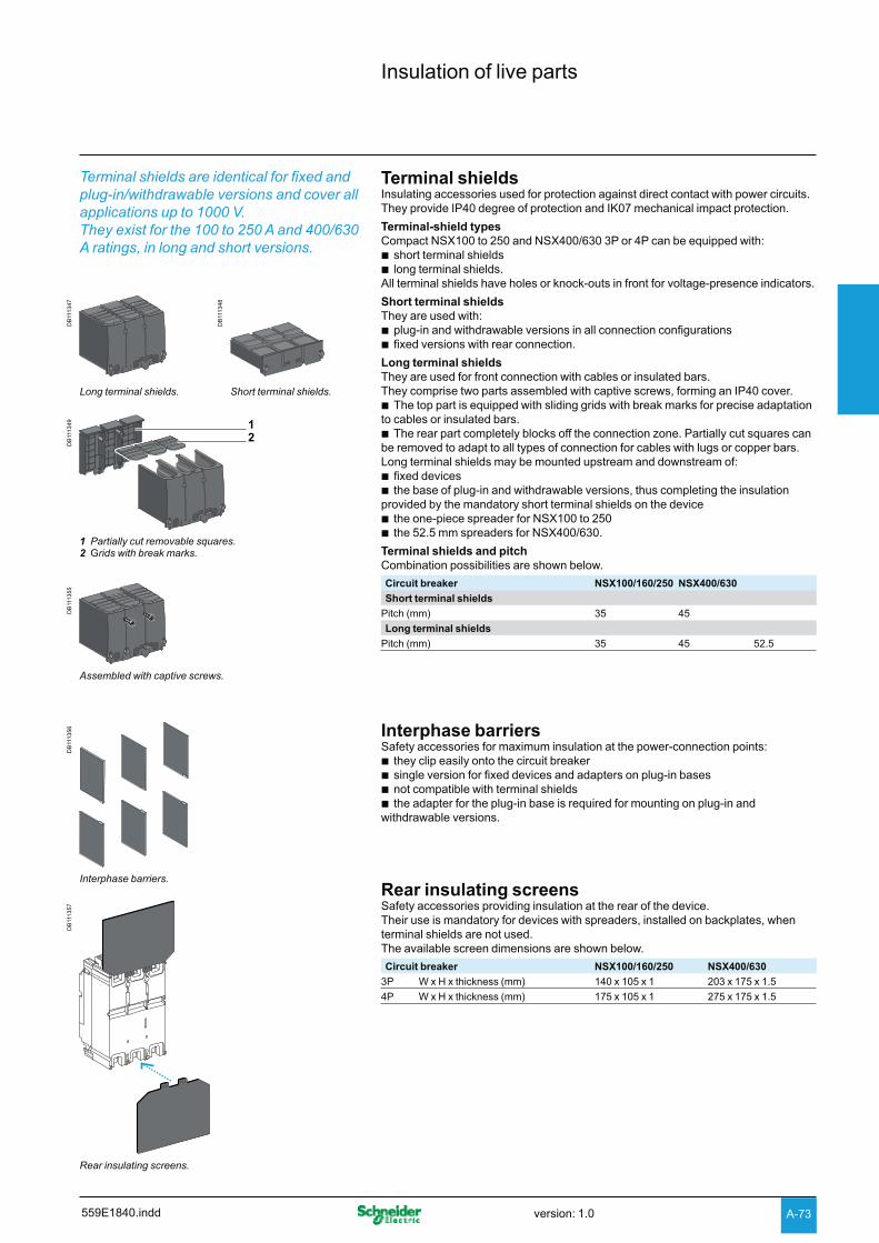
A-73
Insulation of live parts
Terminal shieldsInsulating accessories used for protection against direct contact with power circuits. They provide IP40 degree of protection and IK07 mechanical impact protection.
Terminal-shield typesCompact NSX100 to 250 and NSX400/630 3P or 4P can be equipped with:
short terminal shields blong terminal shields. b
All terminal shields have holes or knock-outs in front for voltage-presence indicators.
Short terminal shields They are used with:
plug-in and withdrawable versions in all connection configurations bfixed versions with rear connection. b
Long terminal shieldsThey are used for front connection with cables or insulated bars. They comprise two parts assembled with captive screws, forming an IP40 cover.
The top part is equipped with sliding grids with break marks for precise adaptation bto cables or insulated bars.
The rear part completely blocks off the connection zone. Partially cut squares can bbe removed to adapt to all types of connection for cables with lugs or copper bars.Long terminal shields may be mounted upstream and downstream of:
fixed devices bthe base of plug-in and withdrawable versions, thus completing the insulation b
provided by the mandatory short terminal shields on the device the one-piece spreader for NSX100 to 250 bthe 52.5 mm spreaders for NSX400/630. b
Terminal shields and pitchCombination possibilities are shown below.
Circuit breaker NSX100/160/250 NSX400/630
Short terminal shields
Pitch (mm) 35 45
Long terminal shields
Pitch (mm) 35 45 52.5
DB
1113
47
DB
1113
48
Long terminal shields. Short terminal shields.
DB
1113
49
21
1 Partially cut removable squares.2 Grids with break marks.
DB
1113
55
Assembled with captive screws.
Interphase barriersSafety accessories for maximum insulation at the power-connection points:
they clip easily onto the circuit breaker bsingle version for fixed devices and adapters on plug-in bases bnot compatible with terminal shields bthe adapter for the plug-in base is required for mounting on plug-in and b
withdrawable versions.
Rear insulating screensSafety accessories providing insulation at the rear of the device.Their use is mandatory for devices with spreaders, installed on backplates, when terminal shields are not used.The available screen dimensions are shown below.
Circuit breaker NSX100/160/250 NSX400/630
3P W x H x thickness (mm) 140 x 105 x 1 203 x 175 x 1.5
4P W x H x thickness (mm) 175 x 105 x 1 275 x 175 x 1.5
DB
1113
56
Interphase barriers.
DB
1113
57
Rear insulating screens.
Terminal shields are identical for fixed and plug-in/withdrawable versions and cover all applications up to 1000 V. They exist for the 100 to 250 A and 400/630 A ratings, in long and short versions.
559E1840.indd version: 1.0

A-74
Functions and characteristics
Accessories and auxiliariesSelection of auxiliaries for Compact NSX100/160/250
StandardAll Compact NSX100/160/250 circuit breakers and switch-disconnectors have slots for the electrical auxiliaries listed below.5 indication contacts (see page A-80)
2 ON/OFF (OF1 and OF2) b1 trip indication (SD) b1 fault-trip indication (SDE) b1 earth-fault indication (SDV), when the device is equipped with a Vigi module. b
1 remote-tripping release (see page A-83)either 1 MN undervoltage release bor 1 MX shunt release. b
Remote indicationsCircuit breakers equipped with Micrologic trip units may be equipped with a fault-trip indication to identify the type of fault by installing:1 indication module with two outputs (see page A-81)
either an SDx module with Micrologic 2.2 / 5.2 A or E / 6.2 A or E bor an SDTAM module with Micrologic 2.2 M or 6-2 E-M (motor protection). b
This module occupies the slots of one OF contact and an MN/MX release.
All these auxiliaries may be installed with a motor mechanism or a rotary handle. The following table indicates auxiliary possibilities depending on the type of trip unit.
NA, TMD, TMG, MAStandard
DB
1155
83
OF1
SD
OF2
SDE
SDV
Motor mechanism / rotary handle
MN /MX
DB
1113
92
SD
OF1
OF2
SDV
SDE
MN /MX
Micrologic 2 / 5 / 6Standard Remote indications via SDx or SDTAM
DB
1155
84
OF1
SD
OF2
SDE
Motor mechanism / rotary handle
MN /MX
DB
1155
85
SDx /SDTAM
Motor mechanism / rotary handle
24 V DC supply terminal block
The SDx or SDTAM uses the OF1 and MN/MX slots.External connection is made via a terminal block in the OF1 slot. The 24 V DC supply provides for the Micrologic 5 / 6 display when the device is OFF or under low-load conditions.
or
559E1860.inddversion: 1.0

A-75
Communication Communication requires specific auxiliaries (see page A-26).
Communication of status indications1 BSCM module. b1 NSX cord (internal terminal block) for both communication and 24 V DC supply b
to the BSCM.Communication of status conditions is compatible with a standard motor mechanism and a rotary handle.
Communication of status indications and controls This requires, in addition to the previous auxiliaries:
1 communicating motor mechanism connected to the BSCM. b
Communication of measurementsAvailable on Micrologic 5 / 6, the system consists of:
1 NSX cord (internal terminal block) for both communication and 24 V DC supply bto the Micrologic.Communication of measurements is compatible with a standard or communicating motor mechanism and a rotary handle.
Communication of status indications, controls and measurementsAvailable on Micrologic 5 / 6, the system consists of:
1 BSCM module b1 NSX cord (internal terminal block) for both communication and 24 V DC supply b
to the BSCM and the Micrologic1 communicating motor mechanism connected to the BSCM. b
Installation of SDx or SDTAM is compatible with communication.The following table indicates auxiliary possibilities depending on the type of trip unit.
NA, TMD, TMG, MA, Micrologic 2Communication of status indications Communication of status indications and controls
DB
1155
86
NSX cord
BSCM
Motor mechanism / rotary handle
DB
1155
87
NSX cordBSCM
Communicating motor mechanism
Micrologic 5 / 6Communication of measurements with or without FDM121 display
Communication of status indications, controls and measurements with or without FDM121 display
DB
1155
88
NSX cord
Motor mechanism / rotary handle D
B11
5589
Communicating motor mechanism
NSX cordBSCM
or
or
559E1860.indd version: 1.0
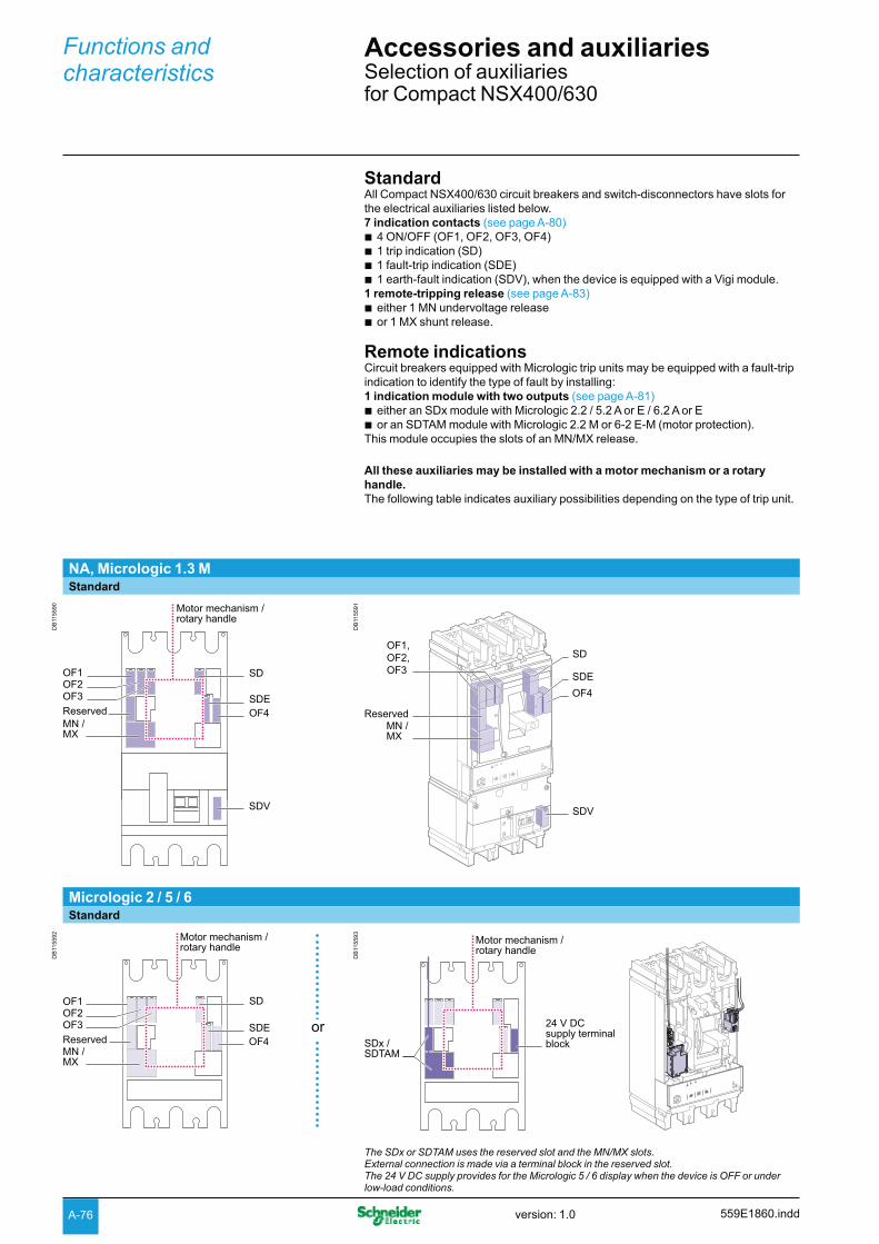
A-76
Functions and characteristics
Accessories and auxiliariesSelection of auxiliaries for Compact NSX400/630
StandardAll Compact NSX400/630 circuit breakers and switch-disconnectors have slots for the electrical auxiliaries listed below.7 indication contacts (see page A-80)
4 ON/OFF (OF1, OF2, OF3, OF4) b1 trip indication (SD) b1 fault-trip indication (SDE) b1 earth-fault indication (SDV), when the device is equipped with a Vigi module. b
1 remote-tripping release (see page A-83)either 1 MN undervoltage release bor 1 MX shunt release. b
Remote indicationsCircuit breakers equipped with Micrologic trip units may be equipped with a fault-trip indication to identify the type of fault by installing:1 indication module with two outputs (see page A-81)
either an SDx module with Micrologic 2.2 / 5.2 A or E / 6.2 A or E bor an SDTAM module with Micrologic 2.2 M or 6-2 E-M (motor protection). b
This module occupies the slots of an MN/MX release.
All these auxiliaries may be installed with a motor mechanism or a rotary handle. The following table indicates auxiliary possibilities depending on the type of trip unit.
NA, Micrologic 1.3 MStandard
DB
1155
90
OF1 SD
SDE
SDV
OF4
OF2OF3
ReservedMN /MX
Motor mechanism / rotary handle
DB
1155
91
OF1,OF2,OF3
SD
SDE
SDV
OF4
ReservedMN /MX
Micrologic 2 / 5 / 6Standard
DB
1155
92
SDOF1OF2OF3
ReservedMN /MX
SDEOF4
Motor mechanism / rotary handle
DB
1155
93
SDx /SDTAM
24 V DC supply terminal block
Motor mechanism / rotary handle
The SDx or SDTAM uses the reserved slot and the MN/MX slots.External connection is made via a terminal block in the reserved slot. The 24 V DC supply provides for the Micrologic 5 / 6 display when the device is OFF or under low-load conditions.
or
559E1860.inddversion: 1.0

A-77
Communication Communication requires specific auxiliaries (see page A-26).
Communication of status indications 1 BSCM module b1 NSX cord (internal terminal block) for both communication and 24 V DC supply b
to the BSCM.Communication of status conditions is compatible with a standard motor mechanism and a rotary handle.
Communication of status indications and controlsThis requires, in addition to the previous auxiliaries:
1 communicating motor mechanism connected to the BSCM. b
Communication of measurements Available on Micrologic 5 / 6, the system consists of:
1 NSX cord (internal terminal block) for both communication and 24 V DC supply bto the Micrologic.Communication of measurements is compatible with a standard or communicating motor mechanism and a rotary handle.
Communication of status indications, controls and measurementsAvailable on Micrologic 5 / 6, the system consists of:
1 BSCM module b1 NSX cord (internal terminal block) for both communication and 24 V DC supply b
to the BSCM and the Micrologic1 communicating motor mechanism connected to the BSCM. b
Installation of SDx or SDTAM is compatible with communication.The following table indicates auxiliary possibilities depending on the type of trip unit.
NA, Micrologic 1.3 M, Micrologic 2Communication of status indications Communication of status indications and controls
DB
1155
94
NSX cord
BSCM
Motor mechanism / rotary handle
DB
1155
95
NSX cord
BSCM
Communicating motor mechanism
Micrologic 5 / 6Communication of status indications Communication of status indications, controls and
measurements with or without FDM121 display
DB
1155
96
NSX cord
Motor mechanism / rotary handle
DB
1155
97
NSX cord
BSCM
Communicating motor mechanism
or
or
559E1860.indd version: 1.0

A-78
DB
1113
76
Automatic auxiliary connector:Fixed part
Moving part
Functions and characteristics
Accessories and auxiliariesConnection of electrical auxiliaries
DB
1121
62
Fixed Compact NSX.
DB
1121
67
Plug-in/withdrawable Compact NSX.
Fixed Compact NSXAuxiliary circuits exit the device through a knock-out in the front cover.
DB
1156
01
Connector 1
Connector 2
Compact NSX100/160/250.
DB
1156
10
Compact NSX400/630.
Connector 1
Connector 2
Connector 3
Withdrawable or plug-in Compact NSX
Automatic auxiliary connectorsAuxiliary circuits exit the circuit breaker via one to three automatic auxiliary connectors (nine wires each). These are made up of:
a moving part, connected to the circuit breaker via a support (one support per bcircuit breaker)
a fixed part, mounted on the plug-in base, equipped with connectors for bare bcables up to 2.5 mm².Micrologic trip unit options are also wired via the automatic auxiliary connectors.
Selection of automatic auxiliary connectorsDepending on the functions installed, one to three automatic auxiliary connectors are required.
559E1860.inddversion: 1.0
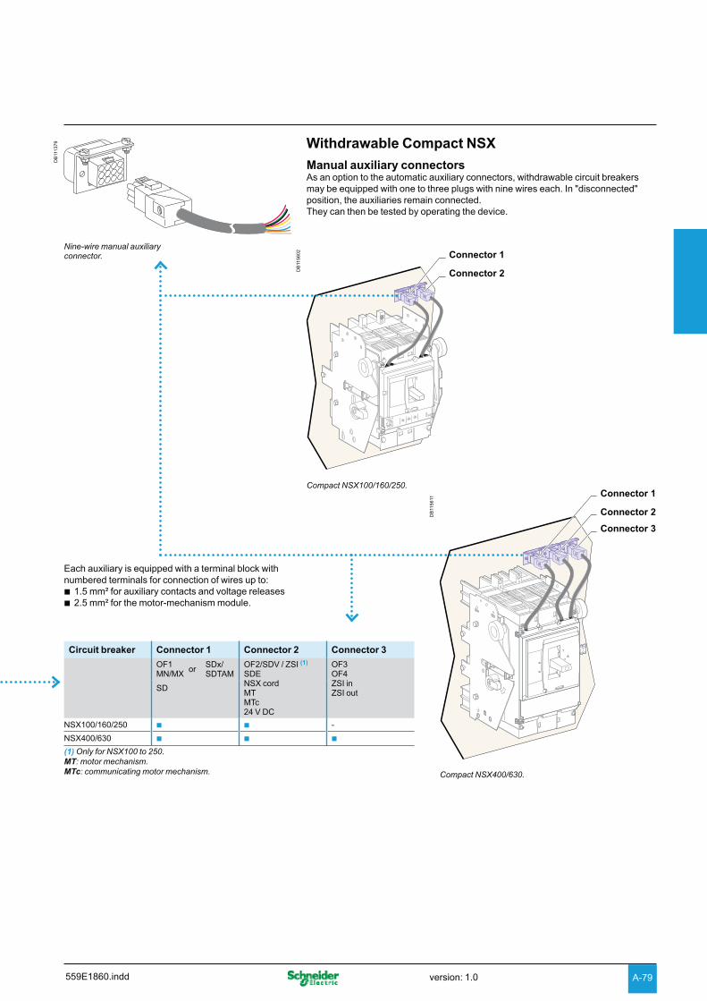
A-79
Each auxiliary is equipped with a terminal block with numbered terminals for connection of wires up to:
1.5 mm² for auxiliary contacts and voltage releases b2.5 mm² for the motor-mechanism module. b
Withdrawable Compact NSX
Manual auxiliary connectorsAs an option to the automatic auxiliary connectors, withdrawable circuit breakers may be equipped with one to three plugs with nine wires each. In "disconnected" position, the auxiliaries remain connected.They can then be tested by operating the device.
DB
1113
79
Nine-wire manual auxiliary connector.
DB
1156
02 Connector 1
Connector 2
Compact NSX100/160/250.
DB
1156
11
Connector 1
Connector 2
Connector 3
Compact NSX400/630.
Circuit breaker Connector 1 Connector 2 Connector 3
OF1MN/MX
orSDx/SDTAM
OF2/SDV / ZSI (1)
SDENSX cordMTMTc24 V DC
OF3OF4ZSI inZSI out
SD
NSX100/160/250 b b -
NSX400/630 b b b
(1) Only for NSX100 to 250.MT: motor mechanism.MTc: communicating motor mechanism.
559E1860.indd version: 1.0

A-80
Functions and characteristics
Accessories and auxiliariesIndication contacts
One contact model provides circuit-breaker status indications (OF - SD - SDE - SDV).An early-make or early-break contact, in conjunction with a rotary handle, can be used to anticipate device opening or closing. A CE / CD contact indicates that the chassis is connected / disconnected.
These common-point changeover contacts provide remote circuit-breaker status information.They can be used for indications, electrical locking, relaying, etc.They comply with the IEC 60947-5 international recommendation.
FunctionsBreaker-status indications, during normal operation or after a faultA single type of contact provides all the different indication functions:
OF (ON/OFF) indicates the position of the circuit breaker contacts bSD (trip indication) indicates that the circuit breaker has tripped due to: ban overload va short-circuit van earth fault (Vigi) or a ground fault (Micrologic 6) voperation of a voltage release voperation of the "push to trip" button vdisconnection when the device is ON. v
The SD contact returns to de-energised state when the circuit breaker is reset.SDE (fault-trip indication) indicates that the circuit breaker has tripped due to: ban overload va short-circuit van earth fault (Vigi) or a ground fault (Micrologic 6). v
The SD contact returns to de-energised state when the circuit breaker is reset.SDV indicates that the circuit breaker has tripped due to an earth fault. It returns to b
de-energised state when the Vigi module is reset.All the above auxiliary contacts are also available in "low-level" versions capable of switching very low loads (e.g. for the control of PLCs or electronic circuits).
Rotary-handle position contact for early-make or early-break functionsCAM (early-make or early-break function) contacts indicate the position of the b
rotary handle. They are used in particular for advanced opening of safety trip devices (early break) or to energise a control device prior to circuit-breaker closing (early make).
Chassis-position contactsCE/CD (connected/disconnected) contacts are microswitch-type carriage b
switches for withdrawable circuit breakers.
InstallationOF, SD, SDE and SDV functions: a single type of contact provides all these b
different indication functions, depending on where it is inserted in the device. The contacts clip into slots behind the front cover of the circuit breaker (or the Vigi module for the SDV function).The SDE function on a circuit breaker equipped with a thermal-magnetic trip unit requires the SDE actuator.
CAM function: the contact fits into the rotary-handle unit (direct or extended). bCE/CD function: the contacts clip into the fixed part of the chassis. b
Electrical characteristics of auxiliary contacts
Contacts Standard Low levelTypes of contacts All OF, SD, SDE, SDV
Rated thermal current (A) 6 5
Minimum load 100 mA at 24 V DC 1 mA at 4 V DC
Utilisation cat. (IEC 60947-5-1) AC12 AC15 DC12 DC14 AC12 AC15 DC12 DC14
Operational current (A)
24 V AC/DC 6 6 6 1 5 3 5 1
48 V AC/DC 6 6 2.5 0.2 5 3 2.5 0.2
110 V AC/DC 6 5 0.6 0.05 5 2.5 0.6 0.05
220/240 V AC 6 4 - - 5 2 - -
250 V DC - - 0.3 0.03 5 - 0.3 0.03
380/440 V AC 6 2 - - 5 1.5 - -
480 V AC 6 1.5 - - 5 1 - -
660/690 V AC 6 0.1 - - - - - -
0443
14
Indication contacts.
xxxx
xx
CE/CD carriage switches.
559E1860.inddversion: 1.0

A-81
SDx and SDTAM modules for Micrologic
SDx and SDTAM are relay modules with two static outputs. They send different signals depending on the type of fault. They may not be used together.
PB
1033
77-2
0
SDx relay module with its terminal block.
PB
1033
76-2
0
SDTAM relay module with its terminal block.
SDx moduleThe SDx module remotes the trip or alarm conditions of Compact NSX circuit breakers equipped with electronic protection.The SD2 output, available on all Micrologic trip units, corresponds to the overload-trip indication. The SD4 output, available on Micrologic 5 / 6, is assigned to:
overload pre-alarm (Micrologic 5) bground-fault trip indication (Micrologic 6). b
These two outputs automatically reset when the device is closed (turned ON). For Micrologic 5 / 6, the SD2 and SD4 outputs can be reprogrammed to be assigned to other types of tripping or alarm.
Output characteristicsIt is possible to assign a function:
latching with a time delay. Return to the initial state occurs at the end of the time bdelay
permanent latching. In this case, return to the initial state takes place via the bcommunication function.Static outputs: 24 to 415 V AC / V DC; 80 mA max.
SDTAM moduleThe SDTAM module is specifically for the motor-protection Micrologic trip units 2.2 M, 2.3 M and 6.2 E-M, 6.3 E-M.The SDTAM module, linked to the contactor controller, opens the contactor when an overload or other motor fault occurs, thus avoiding opening of the circuit breaker.
Micrologic 2 MThe SD4 output opens the contactor 400 ms before normal circuit-breaker opening in the following cases:
overload (long-time protection for the trip class) bphase unbalance or phase loss. b
The SD2 output serves to memorise contactor opening by SDTAM.
Micrologic 6 E-MThe SD4 output opens the contactor 400 ms before normal circuit-breaker opening in the following cases:
overload (long-time protection for the trip class) bphase unbalance or phase loss blocked rotor bunderload (undercurrent protection) blong start. b
The SD2 output serves to memorise contactor opening by SDTAM.
Output characteristicsOutput reset can be:
manual by a pushbutton included in the wiring diagram bautomatic after an adjustable time delay (1 to 15 minutes) to take into account the b
motor-cooling time.Static outputs: 24 to 415 V AC / V DC; 80 mA max.
DB
1156
03 a (+) 24 to 415 V
a (-)
SD4SD2SD3
SDx
Q
SD1
SDTor output 1
PAL Iror SDGor output 2
DB
1156
04 a (+) 24 to 415 V
a (-)
SDTAM
Auto reset (mn)OFF
1 1415
2 124 10
6 8
SD1
SD4SD2SD3
SDTManualreset
KAI
KAI
KMI
KMI
Q
KMI
Closing order
Openingorder
SDx wiring diagram. SDTAM wiring diagram with contactor control.
559E1860.indd version: 1.0

A-82
Functions and characteristics
Accessories and auxiliariesMotor mechanism
PB
1033
72-3
0
Compact NSX250 with motor mechanism.
When equipped with a motor-mechanism module, Compact NSX circuit breakers feature very high mechanical endurance as well as easy and sure operation:
all circuit-breaker indications and information remain visible and accessible, bincluding trip-unit settings and indications
suitability for isolation is maintained and padlocking remains possible bdouble insulation of the front face. b
A specific motor mechanism is required for operation via the communication function. This communicating motor mechanism must be connected to the BSCM module to receive the opening and closing orders. Operation is identical to that of a standard motor mechanism.
ApplicationsLocal b motor-driven operation, centralised operation, automatic distribution control.Normal/standby source changeover or switching to a replacement source to b
ensure availability or optimise energy costs.Load shedding and reconnection. bSy b nchrocoupling.
OperationThe type of operation is selected using the manual/auto mode selection switch (7).A transparent, lead-seal cover controls access to the switch.AutomaticWhen the switch is in the "auto" position, the ON/OFF (I/O) buttons and the charging lever on the mechanism are locked.
Circuit-breaker ON and OFF controlled by two impulse-type or maintained signals. bAutomatic spring charging following voluntary tripping (by MN or MX), with b
standard wiring.Mandatory manual reset following tripping due to an electrical fault. b
ManualWhen the switch is in the "manual" position, the ON/OFF (I/O) buttons may be used. A microswitch linked to the manual position can remote the information.
Circuit-breaker ON and OFF controlled by 2 pushbuttons I/O. bRecharging of stored-energy system by pumping the lever 8 times. bPadlocking in OFF position. b
Installation and connectionsAll installation (fixed, plug-in/withdrawable) and connection possibilities are maintained.Motor-mechanism module connections are made behind its front cover to integrated terminals, for cables up to 2.5 mm².
Optional accessoriesKeylock b for locking in OFF position.Operations counter for the Compact NSX400/630, indicating the number of ON/ b
OFF cycles. Must be installed on the front of the motor-mechanism module.
Characteristics
Motor mechanism MT100 to MT630Response time (ms) opening
closing< 600< 80
Operating frequency cycles/minute max. 4Control voltage (V) DC 24/30 - 48/60 - 110/130 - 250
AC 50/60 Hz 48 (50 Hz) - 110/130 - 220/240 - 380/440
Consumption (1) DC (W) opening closing
y 500y 500
AC (VA) opening closing
y 500y 500
(1) For NSX100 to NSX250, the inrush current is 2 In for 10 ms.
Electrical endurance
DB
1113
35
discharged0OFF
OFF ON
31 2
5678
4
1 Position indicator (positive contact indication)2 Spring status indicator (charged, discharged)3 Manual spring-charging lever4 Keylock device (optional) Locking device (OFF position), using 1 to 3 padlocks, shackle diameter 5 to 8 mm, not supplied5 I (ON) pushbutton6 O (OFF) pushbutton7 Manual/auto mode selection switch. The position of this switch can be indicated remotely.8 Operation counter (Compact NSX400/630)
DB
1156
90
0.2 0.7 10.50.3
NS100
NS160
NS250
NS400
NS630
504030
2015
10
6
4
0.1 I/In
Circuit breaker + motor-mechanism module, in thousands of operations (IEC 60947 2), at 440 V.
559E1880.inddversion: 1.0

A-83
Remote tripping
MX or MN voltage releases are used to trip the circuit breaker. They serve primarily for remote, emergency-off commands.It is advised to test the system every six months.
MN undervoltage releaseThe MN release opens the circuit breaker when its supply voltage drops to a value below 35% of its rated voltage Un.Undervoltage tripping, combined with an emergency-off button, provides fail-safe tripping. The MN release is continuously supplied, i.e. if supply is interrupted:
either voluntarily, by the emergency-off button, bor accidentally, through loss of power or faulty wiring, b
the release provokes opening of the circuit breaker.
Opening conditionsCircuit-breaker tripping by an MN release meets the requirements of standard IEC 60947-2.
Automatic opening of the circuit breaker is ensured when the continuous voltage bsupply to the release U y 0.35 x Un.
If the supply voltage is between 0.35 and 0.7 Un, opening is possible, but not bguaranteed. Above 0.7 Un, opening does not take place.
Closing conditions If there is no supply to the MN release, it is impossible to close the circuit breaker, either manually or electrically. Closing is ensured when the voltage supply to the release U u 0.85 x Un. Below this threshold, closing is not guaranteed.
Characteristics
Power supply V AC 50/60 Hz: 24 - 48 - 100/130 - 200/24050 Hz: 380/415 60 Hz: 208/277
V DC 12 - 24 - 30 - 48 - 60 - 125 -250Operating threshold Opening 0.35 to 0.7 Un
Closing 0.85 UnOperating range 0.85 to 1.1 UnConsumption (VA or W) Pick-up: 30 - Hold: 5Response time (ms) 50
Time-delay unit for an MN releaseA time delay unit for the MN release eliminates the risk of nuisance tripping due to a transient voltage dip lasting y 200 ms. For shorter micro-outages, a system of capacitors provides temporary supply to the MN at U > 0.7 to ensure non tripping. The correspondence between MN releases and time-delay units is shown below.
Power supply Corresponding MN releaseUnit with fixed delay 200 ms
48 V AC 48 V DC220 / 240 V AC 250 V DCUnit with adjustable delay y 200 ms
48 - 60 V AC/DC 48 V DC100 - 130 V AC/DC 125 V DC220 - 250 V AC/DC 250 V DC
MX shunt releaseThe MX release opens the circuit breaker via an impulse-type (u 20 ms) or maintained order.
Opening conditionsWhen the MX release is supplied, it automatically opens the circuit breaker. Opening is ensured for a voltage U u 0.7 x Un.
Characteristics
Power supply V AC 50/60 Hz: 24 - 48 - 100/130 - 200/24050 Hz: 380/415 60 Hz: 208/277
V DC 12 - 24 - 30 - 48 - 60 - 125 -250Operating range 0.7 to 1.1 UnConsumption (VA or W) Pick-up: 30Response time (ms) 50
Circuit breaker control by MN or MXWhen the circuit breaker has been tripped by an MN or MX release, it must be reset before it can be reclosed.MN or MX tripping takes priority over manual closing.In the presence of a standing trip order, closing of the contacts, even temporary, is not possible.
Connection using wires up to 1.5 mm² to integrated terminal blocks. bNote: circuit breaker opening using an MN or MX release must be reserved for safety functions. This type of tripping increases wear on the opening mechanism. Repeated use reduces the mechanical endurance of the circuit breaker by 50 %.
0443
13
MX or MN voltage release.
DB
1156
05
0.70.35 Un0
Possible openingFailsafe opening
1.1
Opening conditions of the MN release.
DB
1156
06
0.85 Un0
Failsafe closing
1.1
Closing conditions of the MN release.
PB
1037
52-3
2
DB
1156
07
Delayedtrip order
Instantaneoustrip order
Time-delayunit
MN
D2
D1
10 12
3 6
MN release with a time-delay unit.
Wiring diagram for emergency-off function with MN + time-delay unit.
DB
1156
08
0.7 Un0
Possible opening Failsafe opening
1.1
Opening conditions of the MX release.
559E1880.indd version: 1.0
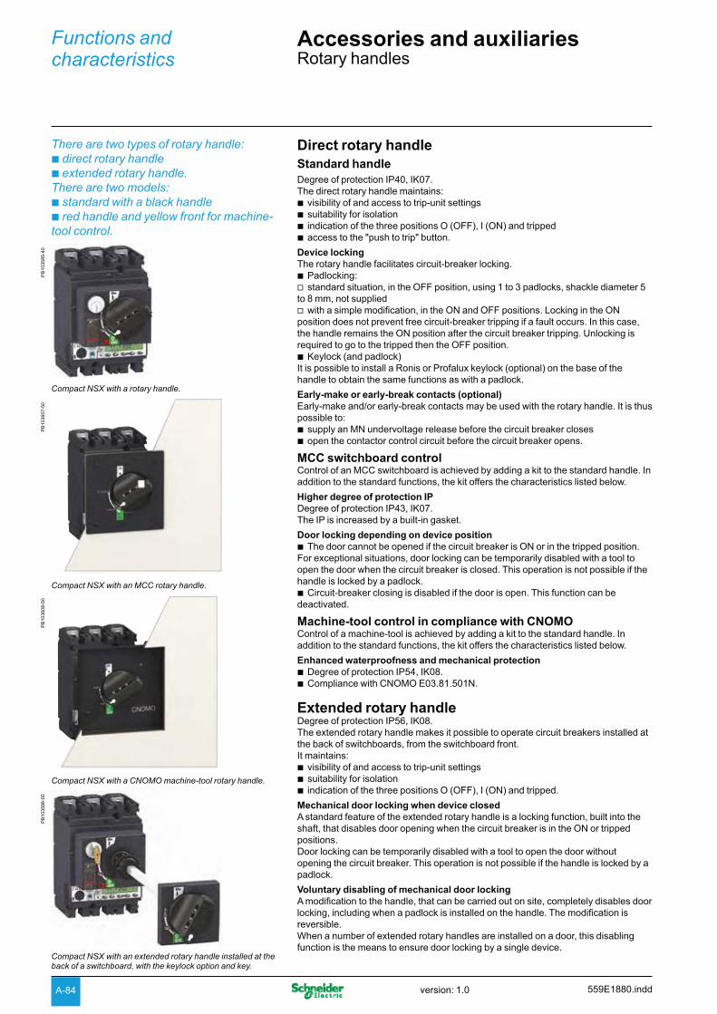
A-84
Functions and characteristics
Accessories and auxiliariesRotary handles
There are two types of rotary handle:b direct rotary handleb extended rotary handle.There are two models:b standard with a black handleb red handle and yellow front for machine-tool control.
Direct rotary handleStandard handleDegree of protection IP40, IK07.The direct rotary handle maintains:
visibility of and access to trip-unit settings bsuitability for isolation bindication of the three positions O (OFF), I (ON) and tripped baccess to the "push to trip" button. b
Device lockingThe rotary handle facilitates circuit-breaker locking.
Padlocking: bstandard situation, in the OFF position, using 1 to 3 padlocks, shackle diameter 5 v
to 8 mm, not suppliedwith a simple modification, in the ON and OFF positions. Locking in the ON v
position does not prevent free circuit-breaker tripping if a fault occurs. In this case, the handle remains the ON position after the circuit breaker tripping. Unlocking is required to go to the tripped then the OFF position.
Keylock (and padlock) bIt is possible to install a Ronis or Profalux keylock (optional) on the base of the handle to obtain the same functions as with a padlock.
Early-make or early-break contacts (optional)Early-make and/or early-break contacts may be used with the rotary handle. It is thus possible to:
supply an MN undervoltage release before the circuit breaker closes bopen the contactor control circuit before the circuit breaker opens. b
MCC switchboard controlControl of an MCC switchboard is achieved by adding a kit to the standard handle. In addition to the standard functions, the kit offers the characteristics listed below.
Higher degree of protection IP Degree of protection IP43, IK07. The IP is increased by a built-in gasket.
Door locking depending on device position The door cannot be opened if the circuit breaker is ON or in the tripped position. b
For exceptional situations, door locking can be temporarily disabled with a tool to open the door when the circuit breaker is closed. This operation is not possible if the handle is locked by a padlock.
Circuit-breaker closing is disabled if the door is open. This function can be bdeactivated.
Machine-tool control in compliance with CNOMOControl of a machine-tool is achieved by adding a kit to the standard handle. In addition to the standard functions, the kit offers the characteristics listed below.
Enhanced waterproofness and mechanical protectionDegree of protection IP54, IK08. bCompliance with CNOMO E03.81.501N. b
Extended rotary handleDegree of protection IP56, IK08.The extended rotary handle makes it possible to operate circuit breakers installed at the back of switchboards, from the switchboard front. It maintains:
visibility of and access to trip-unit settings bsuitability for isolation bindication of the three positions O (OFF), I (ON) and tripped. b
Mechanical door locking when device closedA standard feature of the extended rotary handle is a locking function, built into the shaft, that disables door opening when the circuit breaker is in the ON or tripped positions.Door locking can be temporarily disabled with a tool to open the door without opening the circuit breaker. This operation is not possible if the handle is locked by a padlock.
Voluntary disabling of mechanical door lockingA modification to the handle, that can be carried out on site, completely disables door locking, including when a padlock is installed on the handle. The modification is reversible.When a number of extended rotary handles are installed on a door, this disabling function is the means to ensure door locking by a single device.
PB
1035
85-4
0
Compact NSX with a rotary handle.
PB
1036
07-5
0
Compact NSX with an MCC rotary handle.
PB
1036
08-5
0
Compact NSX with a CNOMO machine-tool rotary handle.
PB
1035
86-5
0
Compact NSX with an extended rotary handle installed at the back of a switchboard, with the keylock option and key.
559E1880.inddversion: 1.0

A-85
Extended rotary handle (cont.)Device and door padlockingPadlocking locks the circuit-breaker handle and disables door opening:
standard situation, in the OFF position, using 1 to 3 padlocks, shackle diameter 5 bto 8 mm, not supplied
with a simple modification, in the ON and OFF positions. Locking in the ON bposition does not prevent free circuit-breaker tripping if a fault occurs.In this case, the handle remains in the ON position after the circuit breaker tripping. Unlocking is required to go to the tripped then the OFF position. If the door controls were modified to voluntarily disable door locking, padlocking does not lock the door, but does disable handle operation of the device.
Device locking using a keylock inside the switchboardIt is possible to install a Ronis or Profalux keylock (optional) on the base of the rotary handle to lock the device in the OFF position or in either the ON or OFF positions.
Accessory for device operation with the door openWhen the device is equipped with an extended rotary handle, a control accessory mounted on the shaft makes it possible to operate the device with the door open.
The device can be padlocked in the OFF position. bThe accessory complies with UL508. b
Early-make or early-break contacts (optional)The extended rotary handle offers the same possibilities with early-make and/or early-break contacts as the standard rotary handle.
Parts of the extended rotary handlesA unit that replaces the front cover of the circuit breaker (secured by screws). bAn assembly (handle and front plate) on the door that is always secured in the b
same position, whether the circuit breaker is installed vertically or horizontally.An extension shaft that must be adjusted to the distance. The min/max distance b
between the back of circuit breaker and door is:185…600 mm for Compact NSX100 to 250 v209…600 mm for Compact NS400/630. v
For withdrawable devices, the extended rotary handle is also available with a telescopic shaft to compensate for device disconnection. In this case, the min/max distances are:
248…600 mm for Compact NSX100 to 250 v272...600 mm for Compact NS400/630. v
Manual source-changeover systemsAn additional accessory interlocks two devices with rotary handles to create a source-changeover system. Closing of one device is possible only if the second is open.This function is compatible with direct or extended rotary handles.Up to three padlocks can be used to lock in the OFF or ON position.
PB
1036
18-5
6
PB
1035
88-6
8
559E1880.indd version: 1.0

A-86
Functions and characteristics
Accessories and auxiliariesAdditional measurement and indication modules
PB
1037
95-3
6
Voltage-presence indicator.
PB
1036
00-3
2
Compact NSX with current-transformer module.
PB
1036
01-3
2
Compact NSX with ammeter module.
Voltage-presence indicatorThe indicator detects and indicates that circuit breaker terminals are supplied with power.
InstallationMounted in the long or short terminal shields, via the knockouts. bMay be positioned upstream or downstream of the circuit breaker. bDegree of protection IP40, IK04. bNot compatible with the motor-mechanism module. b
Electrical characteristicsOperates on all networks with voltages ranging from 220 to 550 V AC.
Current-transformer moduleThis module enables direct connection of a measurement device such as an ammeter or a power meter.
InstallationThe module is installed directly on the downstream circuit-breaker terminals. bDegree of protection IP40, IK04. bClass II insulation between front and the power circuits. bConnection to 6 integrated connectors for cables up to 2.5 mm². b
Electrical characteristicsCurrent transformer with 5 A secondary winding. bClass 3 for the following output-power consumptions: b
Accuracy:100 A rating: 1.6 VA v150 A rating: 3 VA v250 A rating: 5 VA v400/600 A rating: 8 VA. v
Current-transformer module with voltage measurement outputsThis module enables direct connection of a digital measurement device such as a Power Meter PM700, PM800, etc. (not supplied).
InstallationThe module is installed directly on the downstream circuit-breaker terminals. bDegree of protection IP40, IK04. bClass II insulation between front and the power circuits. bBuilt-in connectors for cables from 1.5 to 2.5 mm². b
Electrical characteristicsRated operational voltage Ue: 530 V bFrequencies of measured values: 50...60 Hz bThree CTs with 5 A secondary windings for the rated primary current In : bclass 0.5 to 1 for rated power consumption values at the output: v125 A, 150 A and 250 A ratings: class 1 for 1.1 VA -400/600 A rating: class 0.5 for 2 VA -Connection using a 2.5 mm2 cable up to 2.5 m long. vFour voltage measurement outputs including protection with automatic reset. bvoltage measurement output impedance 3500 v ±25 %, maximum current 1 mAThe voltage measurement outputs are intended only for measurements (1 mA v
max.) and may not be used to supply the display.
Ammeter and Imax ammeter modulesAmmeter moduleMeasures and displays (dial-type ammeter) the current of each phase (selection of phases by 3-position switch in front).
Imax ammeter moduleMeasures and displays (dial-type ammeter) the maximum current flowing in the middle phase. The Imax value can be reset on the front.
InstallationIdentical for both types of ammeter module. bThe module is installed directly on the downstream circuit-breaker terminals. bThe ammeter clips into the module in any of four 90° positions, i.e. it can be b
installed of devices mounted both vertically and horizontally.Degree of protection IP40, IK04. bClass II insulation between front and the power circuits. b
Electrical characteristicsAmmeter module: accuracy class 4.5 bImax ammeter module: accuracy ±6 % bMaximum currents are displayed only if they last b u 15 minutes.
559E1880.inddversion: 1.0

A-87
Insulation monitoring moduleThis module detects and indicates an insulation drop on a load circuit (TN-S or TT systems).Operation is identical to that of a Vigi module, but without circuit-breaker tripping.Indication by a red LED in front.An auxiliary contact may be installed for remote insulation-drop indications.When insulation drops below a minimum, user-set threshold, the LED goes on and the auxiliary contact switches. The fault indication cannot be cancelled except by pressing the manual reset button.
InstallationThe module is installed directly on the downstream circuit-breaker terminals. bDegree of protection IP40, IK04. bDouble insulation of the front face. b
Electrical characteristicsSettings: 100 - 200 - 500 - 1000 mA bAccuracy: -50 +0 % bTime delay following insulation drop: 5 to 10 seconds bAC-system voltage: 200 to 440 V AC. b
PB
1036
02-3
2
Insulation monitoring module.
559E1880.indd version: 1.0
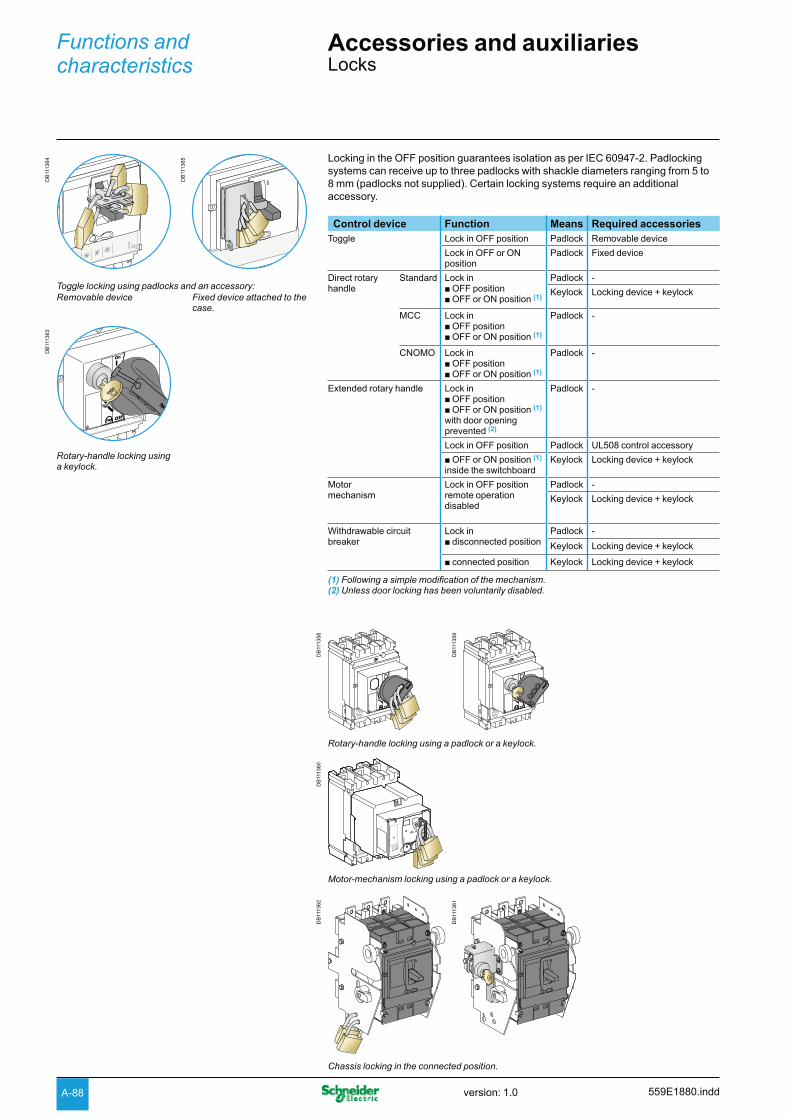
A-88
Functions and characteristics
Accessories and auxiliariesLocks
Locking in the OFF position guarantees isolation as per IEC 60947-2. Padlocking systems can receive up to three padlocks with shackle diameters ranging from 5 to 8 mm (padlocks not supplied). Certain locking systems require an additional accessory.
Control device Function Means Required accessoriesToggle Lock in OFF position Padlock Removable device
Lock in OFF or ON position
Padlock Fixed device
Direct rotary handle
Standard Lock in b OFF positionb OFF or ON position (1)
Padlock -
Keylock Locking device + keylock
MCC Lock in b OFF positionb OFF or ON position (1)
Padlock -
CNOMO Lock in b OFF positionb OFF or ON position (1)
Padlock -
Extended rotary handle Lock in b OFF positionb OFF or ON position (1)
with door opening prevented (2)
Padlock -
Lock in OFF position Padlock UL508 control accessory
b OFF or ON position (1)
inside the switchboardKeylock Locking device + keylock
Motor mechanism
Lock in OFF positionremote operation disabled
Padlock -
Keylock Locking device + keylock
Withdrawable circuit breaker
Lock in b disconnected position
Padlock -
Keylock Locking device + keylock
b connected position Keylock Locking device + keylock
(1) Following a simple modification of the mechanism.(2) Unless door locking has been voluntarily disabled.
DB
1113
64
DB
1113
65
Toggle locking using padlocks and an accessory:Removable device Fixed device attached to the
case.
DB
1113
63
Rotary-handle locking using a keylock.
DB
1113
58
DB
1113
59
Rotary-handle locking using a padlock or a keylock.
DB
1113
60
manu auto
Ø5...8
manu auto
Motor-mechanism locking using a padlock or a keylock.
DB
1113
62
DB
1113
61
Chassis locking in the connected position.
559E1880.inddversion: 1.0

A-89
Sealing accessoriesD
B11
5224
Identification accessories.
Outgoing-circuit identificationCompact NSX100 to 630 can be equipped with label holders supplied in sets of ten (cat. no. LV429226). They are compatible with escutcheons.
Sealing accessoriesSealing accessories are available. Each bag of accessories contains all the parts required for the types of sealing indicated below.A bag contains:
6 sealing accessories b6 lead seals b0.5 m of wire b2 screws. b
DB
1150
33
Sealing accessories.
Types of seals and corresponding functionsToggle control
DB
1123
00
DB
1123
01
DB
1123
03
Rotary handle
DB
1123
02
DB
1123
06
DB
1123
08
Motor mechanism
DB
1123
04
manu auto
Ø5...8
DB
1123
05
DB
1123
09
manu auto
Ø5...8
manu auto
DB
1123
07
uto
Ø5...8
Types of seals
Protected operations
Front-cover fixing screw
front removal baccess to auxiliaries btrip-unit removal. b
Trip-unit transparent cover
modification of settings baccess to test connector. b
Motor-mechanism transparent cover
access to manual/auto bmode selection switch: depending on its position, manual (1) or automatic operation is not possible.(1) In this case, local operation is not possible.
Terminal-shield fixing screw
access to power bconnections (protection against direct contact).
Access to Vigi-module settings
DB
1123
10
DB
1123
11
Types of seals
Protected operations
Vigi-module fixing device
removal of the Vigi bmodule.
Protection cover for settings
modification of settings. b
559E1880.indd version: 1.0

A-90
Functions and characteristics
Accessories and auxiliariesIndividual enclosures
PB
1035
93-4
0
IP55 heavy-duty metal enclosure.
PB
1035
92-4
0
IP55 heavy-duty insulating enclosure.
DB
1156
09
WD
H
Individual enclosures are available for Compact/Vigicompact NSX devices with two, three or four poles.All fixed, front connections are possible, except right-angle, 45°, double-L and edgewise terminal extensions. All spreaders may be installed in the enclosures intended for Compact/Vigicompact NSX250 to 630 devices, except the 70 mm spreaders for NSX400/630.
Two models of enclosuresIP55 heavy-duty metal individual enclosure, with: bmetal enclosure vdoor with keylock and cut-out for rotary handle vextended rotary handle, IP56, IK08, black or red/yellow vdevice mounting plate vremovable plate (without holes) for cable entry through bottom. vIP55 heavy-duty insulating individual enclosure, with: bpolyester insulating enclosure vtransparent cover, screwed, lead sealable, with cut-out for extended rotary handle vextended rotary handle, IP56, IK08, black or red/yellow vdevice mounting plate v2 removable plates (without holes) for cable entry through bottom and/or top. v
Dimensions (H x W x D in mm)Metal enclosures: bCompact NSX100/160 450 x 350 x 250 vCompact NSX250 and Vigicompact NSX100 to 250 650 x 350 x 250 vCompact NSX400 650 x 350 x 250 vCompact NSX630 and Vigicompact NSX400/630 850 x 350 x 250 vInsulating enclosures: bCompact NSX100/160 360 x 270 x 235 vCompact NSX250 and Vigicompact NSX100/160 540 x 270 x 235 vCompact NSX400/630 720 x 360 x 235 vVigicompact NSX250/630 720 x 360 x 235 v
559E1880.inddversion: 1.0

A-91
Escutcheons and protection collars
DB
1122
90
DB
1122
91
Escutcheon for toggle without and with access to the trip unit.
DB
1122
92
DB
1122
93
A160
120
80
400
Escutcheon for Vigi module. Wide escutcheon for ammeter.
IP30 or IP40 escutcheons for fixed devicesIP30 The three types are glued to the cut-out in the front door of the switchboard:
escutcheon for all control types (toggle, rotary handle or motor mechanism) bwithout access to the trip unit vwith access to the trip unit vfor Vigi modules, can be combined with the above. b
IP40The four types, with a gasket, are screwed to the door cut-out:
three escutcheons identical to the previous, but IP40 ba wide model for Vigi and ammeter modules that can be combined with the above. b
Escutcheons are an optional feature mounted on the switchboard door. They increase the degree of protection to IP40, IK07. Protection collars maintain the degree of protection, whatever the position of the device (connected, disconnected).
PB
1035
90-4
3
IP30 escutcheon.
PB
1036
06-5
0
IP30 escutcheon with access to the trip unit.
559E1880.indd version: 1.0

A-92
Functions and characteristics
Accessories and auxiliariesEscutcheons and protection collars
IP40 escutcheons for withdrawable devices IP40 for withdrawable devicesThe two types, with a gasket, are screwed to the door cut-out:
for rotary handle or motor mechanism: standard IP40 escutcheon bfor toggle with extension: standard escutcheon + collar for withdrawal. b
IP40 for Vigi module on withdrawable devicesThe two types, with a gasket, are screwed to the door cut-out:
for rotary handle or motor mechanism: standard IP40 escutcheon bfor toggle: standard escutcheon + collar for withdrawal. b
DB
1122
97
DB
1122
98
Ø5...8
DB
1122
99
Escutcheon for Vigi module, with escutcheons for the three types of control.
IP43 toggle coverAvailable only for devices with toggles. Fits over toggle and front cover of the device.
Mounted on the front of the circuit breaker. bDegree of protection IP43, IK07. b
PB
1017
77-3
6
Escutcheon with collar for toggle.
PB
1037
80-3
6
Escutcheon for Vigi module.
DB
1122
94
DB
1122
95
Ø5...8Ø5...8
DB
1122
96
Ø5...8
Standard escutcheon with rotary handle.
Standard escutcheon for motor mechanism.
Standard escutcheon with collar for withdrawal, for toggle.
Retrofit front coversThese replacement front covers make it possible to install NSX devices in existing switchboards containing NS devices by installing the NS-type retrofit covers on the NSX devices.
NS100 to 250 cover. bNS400/630 cover. b
DB
1122
18
Toggle cover.
PB
1037
75-4
0
Toggle cover.
PB
1038
20-3
5
NS retrofit front cover.
559E1880.inddversion: 1.0

A-93 559E1880.indd version: 1.0

Op
erat
ing
saf
ety

Compact NSX Installation recommendationsContents
Functions and characteristics A-1
Operating conditionsOperating conditions B-2
Installation in switchboardsPower supply and weights B-3Safety clearances and minimum distances B-4Installation example B-5
Control wiringControl wiring B-6
Temperature deratingCompact NSX100 to 250 equipped with thermal-magnetic trip units B-8Compact NSX equipped with electronic trip units B-9
Power loss/ ResistanceCompact NSX equipped with thermal-magnetic trip units B-10Compact NSX equipped with electronic trip units B-11
Dimensions and connection C-1Wiring diagrams D-1Additional characteristics E-1Catalogue numbers F-1Glossary G-1
B-1version: 1.0 559E2000.indd
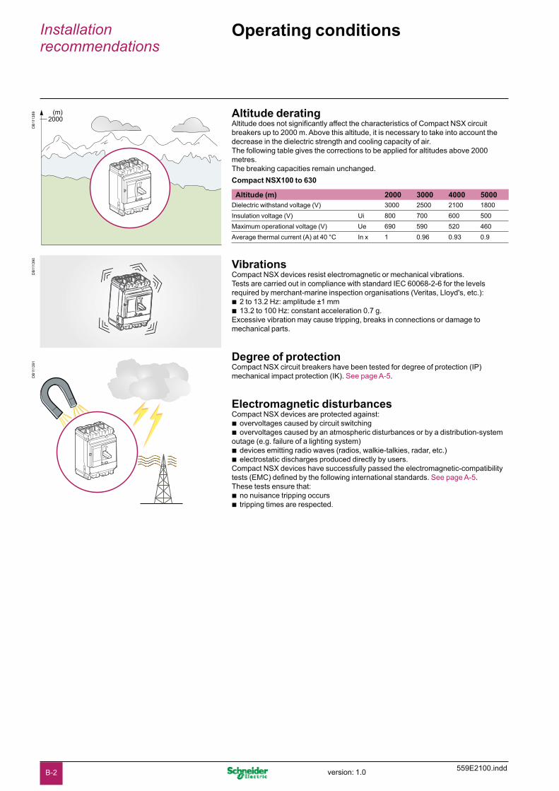
559E2100.inddversion: 1.0
Installation recommendations
Operating conditionsD
B11
1389
2000(m)
DB
1113
90D
B11
1391
Altitude deratingAltitude does not significantly affect the characteristics of Compact NSX circuit breakers up to 2000 m. Above this altitude, it is necessary to take into account the decrease in the dielectric strength and cooling capacity of air.The following table gives the corrections to be applied for altitudes above 2000 metres.The breaking capacities remain unchanged.
Compact NSX100 to 630
Altitude (m) 2000 3000 4000 5000Dielectric withstand voltage (V) 3000 2500 2100 1800
Insulation voltage (V) Ui 800 700 600 500
Maximum operational voltage (V) Ue 690 590 520 460
Average thermal current (A) at 40 °C In x 1 0.96 0.93 0.9
VibrationsCompact NSX devices resist electromagnetic or mechanical vibrations.Tests are carried out in compliance with standard IEC 60068-2-6 for the levels required by merchant-marine inspection organisations (Veritas, Lloyd's, etc.):
2 to 13.2 Hz: amplitude ±1 mm b13.2 to 100 Hz: constant acceleration 0.7 g. b
Excessive vibration may cause tripping, breaks in connections or damage to mechanical parts.
Degree of protectionCompact NSX circuit breakers have been tested for degree of protection (IP) mechanical impact protection (IK). See page A-5.
Electromagnetic disturbancesCompact NSX devices are protected against:
overvoltages caused by circuit switching bovervoltages caused by an atmospheric disturbances or by a distribution-system b
outage (e.g. failure of a lighting system)devices emitting radio waves (radios, walkie-talkies, radar, etc.) belectrostatic discharges produced directly by users. b
Compact NSX devices have successfully passed the electromagnetic-compatibility tests (EMC) defined by the following international standards. See page A-5.These tests ensure that:
no nuisance tripping occurs btripping times are respected. b
B-2

559E2100.indd version: 1.0
Installation in switchboardsPower supply and weights
DB
1113
83 Power supply from the top or bottomCompact NSX circuit breakers can be supplied from either the top or the bottom, even when equipped with a Vigi earth-leakage protection module, without any reduction in performance. This capability facilitates connection when installed in a switchboard.All connection and insulation accessories can be used on circuit breakers supplied either from the top or bottom.
WeightThe table below presents the weights (in kg) of the circuit breakers and the main accessories, which must be summed to obtain the total weight of complete configurations. The values are valid for all performance categories.
Type of device Circuit breakers Base Chassis Vigi module Visu module Motor mech.NSX100 3P/2D 1.79 0.8 2.2 0.87 2 1.2
3P/3D 2.05 0.8 2.2 0.87 2 1.2
4P/4D 2.4 1.05 2.2 1.13 2.2 1.2
NSX160 3P/2D 1.85 0.8 2.2 0.87 2 1.2
3P/3D 2.2 0.8 2.2 0.87 2 1.2
4P/4D 2.58 1.05 2.2 1.13 2.2 1.2
NSX250 3P/2D 1.94 0.8 2.2 0.87 2 1.2
3P/3D 2.4 0.8 2.2 0.87 2 1.2
4P/4D 2.78 1.05 2.2 1.13 2.2 1.2
NSX400/630 3P/3D 6.19 2.4 2.2 2.8 4.6 2.8
4P/4D 8.13 2.8 2.2 3 4.9 2.8
B-3
559E2100.inddversion: 1.0
Installation recommendations
Installation in switchboardsSafety clearances and minimum distances
General rulesWhen installing a circuit breaker, minimum distances (safety clearances) must be maintained between the device and panels, bars and other protection devices installed nearby. These distances, which depend on the ultimate breaking capacity, are defined by tests carried out in accordance with standard IEC 60947-2.If installation conformity is not checked by type tests, it is also necessary to:
use insulated bars for circuit-breaker connections bsegregate the busbars using insulating screens. b
For Compact NSX100 to 630 devices, terminal shields and interphase barriers are recommended and may be mandatory depending on the operating voltage of the device and type of installation (fixed, withdrawable, etc.).
Power connectionsThe table below indicates the rules to be respected for Compact NSX100 to 630 devices to ensure insulation of live parts for the various types of connection.
fixed devices with front connection (FC) or rear connection (RC) bplug-in or withdrawable devices. b
Connection accessories such as crimp lugs, bare-cable connectors, terminal extensions (straight, right-angle, double-L and 45°) and spreaders are supplied with interphase barriers.Long terminal shields provide a degree of protection of IP40 (ingress) and IK07 (mechanical impact).
Compact NSX100 to 630: rules to be respected to ensure insulation of live parts
Type of connection Fixed, front connection Fixed, rear connection
Plug-in or withdrawable
On backplate Through panel
Possible, recommended or mandatory accessories:
With:
No insulating accessory
Interphase barriers
Long terminal shields
Short terminal shields
Short terminal shields
Short terminal shields
operating voltage type of conductor
y 500 V Insulated bars
Possible Possible Possible Recommended Recommended Mandatory
Extension terminalsCables + crimp lugs
NoMandatory (supplied)
Possible (instead of ph. barriers)
Recommended Recommended Mandatory
Bare cables + connectors
Possible for NSX100 to 250
Possible for NSX100 to 250
Possible for NSX100 to 250
Recommended Recommended Mandatory
NoMandatory (supplied)
Possible (instead of ph. barriers)
> 500 V Insulated bars
No No Mandatory Mandatory Mandatory Mandatory
Extension terminalsCables + crimp lugs
No No Mandatory Mandatory Mandatory Mandatory
Bare cables + connectors
No No Mandatory Mandatory Mandatory Mandatory
DB
1150
55
DB
1150
56
DB
1150
57
DB
1150
58
DB
1150
59
DB
1150
60
DB
1150
61
DB
1150
61
DB
1150
61
B-4

559E2100.indd version: 1.0
Safety clearanceMinimum distance between two adjacent circuit breakers
Minimum distance between circuit breaker and front or rear panels
DB
1150
46
A1
DB
1156
97 Frontpanel
F
FB = 0
Bare or painted sheetmetal Note: if F < 8 mm: an insulating screen or long terminal shield is mandatory (see page A-73).
Minimum safety clearances for Compact NSX100 to 630
Operating voltage Clearance (mm)
Between devices
Between device and sheetmetal
Painted sheet metal Bare sheet metalA1 C1 D1 D2 C1 D1 D2
U y 440 Vfor devices equipped with: b no accessories 0 0 30 30 5 40 40
b interphase barriers 0 0 0 0 5 0 0
b long terminal shields 0 0 0 0 0 0 0
440 V < U y 600 Vfor devices equipped with:
b interphase barriers (1) 0 0 0 0 20 10 10
b long terminal shields (2) 0 0 0 0 10 10 10
U > 600 V
for devices equipped with:
b long terminal shields 0 10 50 50 20 100 100
(1) Only for NSX100 to 250.(2) For all cases.
Clearances with respect to live bare busbarsMinimum clearances for Compact NSX100 to 630
Operating voltage Clearances with respect to live bare busbars
spacing y 60 mm spacing > 60 mmF1 F2 F1 F2
U < 440 V 350 350 80 80
U y 440 V y 600 V 350 350 120 120
U > 600 V prohibited: insulating screen required between device and busbars
These clearances can be reduced for special installations as long as the configuration is checked by tests.
DB
1156
98
F1
Spacing y 60 mm
F2
F1
Spacing > 60 mm
Bars
Bars
F2
Live busbars.
Minimum distance between circuit breaker and top, bottom or side panels
DB
1150
48
D1
D2 C1
DB
1150
49
D1 DB
1150
50
D1
Devices without accessories. Devices with interphase barriers or long terminal shields.
Installation example
B-5

559E2100.inddversion: 1.0
Installation recommendations
Control wiring
Remote tripping by MN or MX releasePower consumption is approximately:
30 VA for pick-up of the MN and MX releases b300 VA to 500 VA for the motor mechanism. b
The table below indicates the maximum permissible cable length for different supply voltages and cable cross-sectional areas.
Recommended maximum cable lengths (in metres)
Power supply voltage (V DC) 12 V 24 V 48 V
Cable cross-section (mm²) 1.5 2.5 1.5 2.5 1.5 2.5 MN U source 100 % 15 – 160 – 640 –
U source 85 % 7 – 40 – 160 –
MX U source 100 % 60 – 240 – 960 –
U source 85 % 30 – 120 – 480 –
Motor mechanism U source 100 % – – 10 16 65 110
U source 85 % – – 2 4 17 28
Note: the indicated length is that of each of the two wires.
External neutral voltage tap (ENVT)This connection is required for accurate power measurements on 3-pole circuit breakers equipped with Micrologic 5 / 6 E trip units in installations with a distributed neutral. It can be used to measure phase-neutral voltages and calculate power using the 3 wattmeter method.Compact NSX 3-pole circuit breakers come with a wire installed on the device for the connection to the ENVT.This wire is equipped with a connector for connection to an external wire with the following characteristics:
cross-sectional area of 1 mm² to 2.5 mm² bmaximum length of 10 metres. b
External neutral current transformer (ENCT)This connection is required to protect the neutral on 3-pole circuit breakers equipped with Micrologic 5 / 6 A or E trip units in installations with a distributed neutral. For Micrologic 6 A or E, it is required for type G ground-fault protection.The ENCT is connected in the same way for fixed, plug-in or withdrawable devices:
fixed devices are connected via terminals T1 and T2 of the internal terminal block. bplug-in and withdrawable devices are not connected via the auxiliary terminals. b
The wires must be connected/disconnected inside the device via terminals T1 and T2.The ENCT must be connected to the Micrologic trip unit by a shielded twisted pair. The shielding should be connected to the switchboard earth only at the CT end, no more than 30 cm from the CT.
the power connections of the CT to the neutral (H2 and H1) must be made in the bsame way for power supply from the top or the bottom (see figure). Make sure they are not reversed for devices with power supply from the bottom.
cross-sectional area of 0.4 mm² to 1.5 mm² bmaximum length of 10 metres. b
ULP connection system between Micrologic, FDM 121 switchboard display and Modbus interfaceThe ULP (Universal Logic Plug) wiring system used by Compact NSX for connections through to the Modbus network requires neither tools nor settings.The prefabricated cords are sued for both data transfer and distribution of 24 V DC power. Connectors on each component are identified by ULP (Universal Logic Plug) symbols, ensuring total compatibility between each component.
Available cordsAll connections are made with prefabricated cords:
NSX cord for connection of the internal terminal block to the Modbus interface or bthe FDM 121 display via an RJ45 connector. The cord is available in three lengths, 0.35 m, 1.3 m and 3 m
ULP cords with RJ45 connectors at each end for the other connections between bcomponents. The cord is available in six lengths, 0.3 m, 0.6 m, 1 m, 2 m, 3 m and 5 m. For greater distances, two cords can be interconnected using the RJ45 female/female accessory.Maximum length of 10 m between 2 modules and 30 m in all.A line terminator must be fitted to all components with an unused RJ45 connector.
DB
1156
99 N L1 L2 L3
I
U
ENVT
Wireready forconnection
External wire
3P+N
External neutral voltage tap (ENVT).
DB
1157
00 N L1 L2 L3 3P+N: supply from the top
I
U
ENCT
T1
T2
H2
H1
T1
T2
DB
1157
01 N L1 L2 L3
I
U
ENCT
T1
T2
H2
H1
T1
T2
3P+N: supply from the bottom
External neutral current transformer (ENCT).
DB
1157
02 Modbus
24 V DC
ULP wiring
1
3
2
ULP connection system.
1 RJ452 Line terminator3 ULP symbol
B-6

559E2100.indd version: 1.0
24 V DC power-supply module
UseAn external 24 V DC power supply is required for installations with communication, whatever the type of trip unit.On installations without communication, it is available as an option for Micrologic 5/6 to:
modify settings when the circuit breaker is open (OFF position) bdisplay measurements when the current flowing through the circuit breaker is low bmaintain the display of the cause of tripping. b
CharacteristicsThe external 24 V DC supply may be used for the entire switchboard.The required characteristics are indicated in the table below.
CharacteristicsOutput voltage 24 V DC -20 % to +10 %
Ripple ±1 %
Overvoltage category (OVC) OVC IV - as per IEC 60947-1
SizingSizing must take into account all supplied modules.
Module Consumption (mA)Micrologic 5 / 6 40
BSCM module 10
FDM 121 40
Modbus communication interface 60
NSX cord U > 480 V AC 30
SDx / SDTAM module 20
WiringMicrologic 5 or 6 not using the Communication functionThe external 24 V DC supply is connected via the circuit breaker terminal block.Use of a 24 V DC battery provides backup power for xx minutes in the eventof an interruption in the external supply.
Micrologic 5 or 6 using the Communication functionThe external 24 V DC supply is connected via the Modbus interface using a five-pin connector, including two for the power supply. Stacking accessories (see page A-27) can be used to supply a number of interfaces by fast clip-on connection.The 24 V DC power is distributed downstream by the ULP (Universal Logic Plug) communication cords with RJ45 connectors. This system ensures both data transfer and power distribution to the connected modules.
Recommendations for 24 V DC wiringDo not connect the positive terminal to earth. bDo not connect the negative terminal to earth. bThe maximum length for each conductor (+/-) is ten metres. bFor connection distances greater than ten metres, the plus and minus conductors b
of the 24 V DC supply must be twisted to improve EMC.The 24 V DC conductors must cross the power cables perpendicularly. If this is b
difficult or impossible, the plus and minus conductors must be twisted.
ModbusEach Compact NSX circuit breaker equipped with Micrologic 5/6 and an FDM 121 display is connected to the Modbus network via the Modbus interface module.Connection of all the circuit breakers and other Modbus devices in the switchboard to a Modbus bus is made much easier by using a Modbus RJ45 junction block installed in the switchboard.
Recommendations for Modbus wiringThe shielding may be earthed. bThe conductors must be twisted to improve immunity (EMC). bThe Modbus conductors must cross the power cables perpendicularly. b
DB
1157
03
24 V DC 24 V DC
Battery
Power supply, without the Communication function, via the terminal block with a backup battery.
DB
1157
04
Downstream ULP wiringfor 24 V DC supply
24 V DC
Modbus
Supply, with the Communication function, via the Modbus interface.
DB
1157
05
4W
ires2
Wires
Termination
ON
OF
F
5/OUT
4 3 2 1
0/IN
FDM121
Masterpact NW
Masterpact NT
Compact NSXPM800
24 V DC
Modbusjunction block
Modbus interfacemodule
24 V DC
Modbus Network
Battery
B-7

559E2100.inddversion: 1.0
Installation recommendations
Temperature deratingCompact NSX100 to 250 equipped withthermal-magnetic trip units
When thermal-magnetic trip units are used at ambient temperatures other than 40 °C, the Ir pick-up is modified.
The overload protection is calibrated at 40 °C in the lab. This means that when the ambient temperature is less or greater than 40 °C, the Ir protection pick-up is slightly modified.To obtain the tripping time for a given temperature:
see the tripping curves for 40 °C b (see pages E-2 and E-3)determine tripping times corresponding to the Ir value (thermal setting on the b
device), corrected for the ambient temperature as indicated in the tables below.
Settings of Compact NSX100 to 250 equipped with TM-D and TM-G trip units, as a function of the temperatureThe table indicates the real Ir (A) value for a given rating and temperature.
Rat. (A)
Temperature (°C)
10 15 20 25 30 35 40 45 50 55 60 65 7016 18.4 18.7 18 18 17 16.6 16 15.6 15.2 14.8 14.5 14 13.8
25 28.8 28 27.5 27 26.3 25.6 25 24.5 24 23.5 23 22 21
32 36.8 36 35.2 34.4 33.6 32.8 32 31.3 30.5 30 29.5 29 28.5
40 46 45 44 43 42 41 40 39 38 37 36 35 34
50 57.5 56 55 54 52.5 51 50 49 48 47 46 45 44
63 72 71 69 68 66 65 63 61.5 60 58 57 55 54
80 92 90 88 86 84 82 80 78 76 74 72 70 68
100 115 113 110 108 105 103 100 97.5 95 92.5 90 87.5 85
125 144 141 138 134 131 128 125 122 119 116 113 109 106
160 184 180 176 172 168 164 160 156 152 148 144 140 136
200 230 225 220 215 210 205 200 195 190 185 180 175 170
250 288 281 277 269 263 256 250 244 238 231 225 219 213
Example 1. What is the tripping time of a Compact NSX100 equipped with a TM100D trip unit set to 100 A, for an overload I = 500 A?The overload I/Ir is calculated as a function of the temperature. Use the above values and the curve on page E-3 (shown on the left) to determine the corresponding time.
At 40 °C, Ir = 100 A, I/Ir = 5 and the tripping time is between 6 and 60 seconds. bAt 20 °C, Ir = 110 A, I/Ir = 4.54 and the tripping time is between 8 and 80 seconds. bAt 60 °C, Ir = 90 A, I/Ir = 5.55 and the tripping time is between 5 and 50 seconds. b
Example 2. What is the setting to obtain a real Ir of 210 A, taking into account the temperature, for a Compact NSX250 equipped with a TM250D trip unit?The necessary dial setting, in amperes, is shown below.
At 40 °C, Ir = (210/250) x 250 A = 210 A bAt 20 °C, Ir = (210/277) x 250 A = 189.5 A bAt 60 °C, Ir = (210/225) x 250 A = 233 A b
Additional derating coefficient for an add-on moduleThe values indicated in the previous tables are valid for fixed circuit breakers equipped with one of the following modules:
Vigi module binsulation monitoring module bammeter module bcurrent-transformer module. b
They also apply for plug-in or withdrawable circuit breakers equipped with:ammeter module bcurrent-transformer module. b
However, for plug-in or withdrawable circuit breakers equipped with a Vigi module or an insulation monitoring module, the coefficient 0.84 must be applied.The table below sums up the situation for add-on modules.
Type of device
Circuit breaker TM-D trip-unit rating
Vigi or insulation monitoring module
Ammeter or current transformer module
Fixed NSX100 to 250 16 to 100
1
1
NSX160 to 250 125
NSX160 to 250 160
NSX250 200 to 250
Plug-in or withdrawable
NSX100 to 250 16 to 100
NSX160 to 250 125
NSX160 to 250 1600.84
NSX250 250
DB
1150
53 (A)
110
100
90
80
10 20 30 40 50 60 70 (°C)
Temperature derating curve for Compact NSX100.
DB
1157
06 10 0005 000
2 000
1 000
500
200100
50
20
10
5
2
1.5
.2
.1
.05
.02
.01
.005
.002
.001.5 .7 1 2 3 4 5 7 10 20 30 50 70100 200300
I / Ir
t(s)
NSX80/100
Reflex tripping:t < 10 ms
Example 1. Fault I = 500 A
I/Ir 4.5 5 5.5
T°C 20 °C 40 °C 60 °C
t min. 8 s 6 s 5 s
t max. 80 s 60 s 50 s
Thermal-protection curve with minimum and maximum values.
B-8

559E2100.indd version: 1.0
Compact NSX equipped with electronic trip units
Electronic trip units are not affected by variations in temperature. If the trip units are used in high-temperature environments, the Micrologic setting must nevertheless take into account the temperature limits of the circuit breaker.
Changes in temperature do not affect measurements by electronic trip units.The built-in CT sensors with Rogowski toroids measure the current. bThe control electronics compare the value of the current to the settings defined b
for 40 °C.Because temperature has no effect on the toroid measurements, the tripping thresholds do not need to be modified.However, the temperature rise caused by the flow of current and the ambient temperature increase the temperature of the device. To avoid reaching the thermal withstand level of the equipment, it is necessary to limit the current flowing through the device, i.e. the maximum Ir setting as a function of the temperature.
Compact NSX100/160/250The table below indicates the maximum long-time (LT) protection setting Ir (A) depending on the ambient temperature.
Type of device
Rating (A) Temperature (°C)
40 45 50 55 60 65 70NSX100/160
Fixed, plug-in or withdr.
40 no derating
100 no derating
NSX250
Fixed, plug-in or withdrawable
100 no derating
160 no derating
Fixed 250 250 250 250 245 237 230 225
Plug-in or withdr. 250 250 245 237 230 225 220 215
Compact NSX400 and 630The table below indicates the maximum long-time (LT) protection setting Ir (A) depending on the ambient temperature.
Type of device
Rating (A) Temperature (°C)
40 45 50 55 60 65 70NSX400
Fixed 400 400 400 400 390 380 370 360
Plug-in/withdr. 400 400 390 380 370 360 350 340
NSX630
Fixed 630 630 615 600 585 570 550 535
Plug-in/withdr. 630 570 550 535 520 505 490 475
Example. A fixed Compact NSX400 equipped with a Micrologic can have a maximum Ir setting of:b 400 A up to 50 °Cb 380 A up to 60 °C.
Additional derating coefficient for an add-on moduleFor fixed or plug-in / withdrawable circuit breakers, the addition of a:
Vigi module binsulation-monitoring module bammeter module bcurrent-transformer module b
can modify the derating values. Apply the coefficients shown below.
Derating of a Compact NSX equipped with a Micrologic trip unit
Type of device
Circuit breaker
TM-D trip-unit rating
Vigi / Insulation monitoring module
Ammeter module /External sensor (CT)
Fixed NSX100 to 250 40 to 100
1
1
NSX160 to 250 125
NSX250 250
Plug-in or withdrawable
NSX100 to 250 40 to 100
NSX160 to 250 160
NSX250 250 0.86
Fixed NSX400 250 to 400 0.97
NSX630 250 to 630 0.90
Plug-in or withdrawable
NSX400 250 to 400 0.97
NSX630 250 to 630 0.90
Note: to provide the Visu function, Compact NSX circuit breakers, with or without a Vigi module, are combined with INV switch-disconnectors. Tripping values for the selected combination are indicated in the Interpact catalogue.
B-9

559E2100.inddversion: 1.0
Installation recommendations
Power loss/ ResistanceCompact NSX equipped with thermal-magnetic trip units
Compact NSX thermal power loss values are used to calculate total temperature rise in the switchboard in which the circuit breakers are installed.
The values indicated in the tables below are typical values for a device at full rated load and 50/60 Hz.
Power loss per pole (P/pole) in Watts (W)The value indicated is the power loss at I
N, 50/60 Hz, for a three-pole or four-pole
circuit breaker. Measurement and calculation of power loss are carried out in compliance with the recommendations of Annex G of standard IEC 60947-2.
Resistance per pole (R/pole) in milliohms (m )The value of the resistance per pole is provided as a general indication for a new device.The value of the contact resistance must be determined on the basis of the measured voltage drop, in accordance with the manufacturer's test procedure (ABT instruction document no. 1 - BEE - 02.2 -A).Note: this measurement is not sufficient to determine the quality of the contacts, i.e. the capacity of the circuit breaker to carry its rated current.
Additional power lossAdditional power loss is equal to the sum of the power dissipated by the following:
Vigi module: note that the deviation of the N and L3 bars required to pass through bthe toroid results in higher power losses compared to those of the L1 and L2 bars (diagram opposite). When calculating total power loss, use L1, L2, L3 for a 3P device and N, L1, L2, L3 for a 4P device
disconnecting contacts (plug-in and withdrawable devices) bammeter module btransformer module. b
Calculation of total power lossTotal power loss at full rated load and 50/60 Hz is equal to the sum of the device and additional power losses per pole multiplied by the number of poles (2, 3 or 4).If a Vigi module is installed, it is necessary to differentiate between N and L3 on one hand and L1 and L2 on the other.
Compact NSX100 to 250 equipped with TM-D and TM-G trip units
Type of device Fixed device Additional power / pole
3/4 poles Rat. (A)
R/pole P/pole Vigi (N, L3)
Vigi (L1, L2)
Plug-in / withdr.
Ammeter module
Transfo. module
NSX100 16 11.42 2.92 0 0 0 0 0
25 6.42 4.01 0 0 0.1 0 0
32 3.94 4.03 0.06 0.03 0.15 0.1 0.1
40 3.42 5.47 0.10 0.05 0.2 0.1 0.1
50 1.64 4.11 0.15 0.08 0.3 0.1 0.1
63 2.17 8.61 0.3 0.15 0.4 0.1 0.1
80 1.37 8.77 0.4 0.2 0.6 0.1 0.1
100 0.88 8.8 0.7 0.35 1 0.2 0.2
NSX160 80 1.26 8.06 0.4 0.2 0.6 0.1 0.1
100 0.77 7.7 0.7 0.35 1 0.2 0.2
125 0.69 10.78 1.1 0.55 1.6 0.3 0.3
160 0.55 13.95 1.8 0.9 2.6 0.5 0.5
NSX250 125 0.61 9.45 1.1 0.55 1.6 0.3 0.3
160 0.46 11.78 1.8 0.9 2.6 0.5 0.5
200 0.39 15.4 2.8 1.4 4 0.8 0.8
250 0.3 18.75 4.4 2.2 6.3 1.3 1.3
Compact NSX100 to 630 equipped with MA/1.3-M trip units
Type of device Fixed device Additional power / pole
3 poles Rat. (A)
R/pole P/pole Vigi (N, L3)
Vigi (L1, L2)
Plug-in / withdr.
Ammeter module
Transfo. module
NSX100 2.5 148.42 0.93 0 0 0 0 0
6.3 99.02 3.93 0 0 0 0 0
12.5 4.05 0.63 0 0 0 0 0
25 1.66 1.04 0 0 0.1 0 0
50 0.67 1.66 0.2 0.1 0.3 0.1 0.1
100 0.52 5.2 0.7 0.35 1 0.2 0.2
NSX160 150 0.38 8.55 1.35 0.68 2.6 0.45 0.45
NSX250 220 0.3 14.52 2.9 1.45 4.89 0.97 0.97
NSX400 320 0.12 12.29 3.2 1.6 6.14 1.54 1.54
NSX630 500 0.1 25 13.99 7 15 3.75 3.75
DB
1150
52 N L1 L2 L3
With a Vigi module, the deviation of the N and L3 bars required to pass through the toroid results in higher power losses compared to those of the L1 and L2 bars.
B-10

559E2100.indd version: 1.0
Compact NSX equipped with electronic trip units
The values indicated in the table below are typical values for a device at full rated load and 50/60 Hz. The definitions and information are the same as that for circuit breakers equipped with thermal-magnetic trip units.
Compact NSX100 to 630 equipped with Micrologic trip units
Type of device Fixed device Additional power / pole3/4 poles Rat.
(A)R/pole P/pole Vigi
(N, L3)Vigi (L1, L2)
Plug-in / withdr.
Ammeter module
Transfo. module
NSX100 40 0.84 1.34 0.1 0.05 0.2 0.1 0.1
100 0.468 4.68 0.7 0.35 1 0.2 0.2
NSX160 40 0.73 1.17 0.4 0.2 0.6 0.1 0.1
100 0.36 3.58 0.7 0.35 1 0.2 0.2
160 0.36 9.16 1.8 0.9 2.6 0.5 0.5
NSX250 100 0.27 2.73 1.1 0.55 1.6 0.2 0.2
250 0.28 17.56 4.4 2.2 6.3 1.3 1.3
NSX400 400 0.12 19.2 3.2 1.6 9.6 2.4 2.4
NSX630 630 (1) 0.1 39.69 6.5 3.25 19.49 5.95 5.95
(1) The power loss values for the Vigi modules and withdrawable circuit breakers are given for 570 A.
B-11

Eas
y in
stal
lati
on

Functions and characteristics A-1Installation recommendations B-1
Dimensions and mountingCompact NSX100 to 630 fixed version C-2Vigicompact NSX100 to 630 fixed version C-3Compact NSX100 to 630 plug-in version C-4Compact NSX100 to 630 withdrawable version C-6Vigicompact NSX100 to 630 plug-in and withdrawable versions C-8Visu function for Compact NSX100 to 250 fixed version C-9Visu function for Compact NSX400/630 fixed version C-10Motor mechanism module for Compact NSX100 to 630 C-11Direct rotary handle for Compact and Vigicompact NSX100 to 630 C-12MCC and CNOMO type direct rotary handles for Compact NSX100 to 630 fixed version C-13Extended rotary handle for Compact NSX100 to 630 C-14Indication and measurement modules for Compact NSX100 to 630 fixed version C-15One-piece spreader for Compact NSX100 to 250 fixed version C-16FDM121 switchboard display C-17
Front-panel accessoriesCompact NSX100 to 630 C-18
Front-panel cutoutsCompact NSX100 to 630 fixed version C-20Vigicompact NSX100 to 630 fixed version C-22Compact NSX100 to 630 plug-in and withdrawable versions C-24Vigicompact NSX100 to 630 plug-in and withdrawable versions C-25Visu function for Compact NSX100 to 630 fixed version C-26Motor mechanism module for Compact and Vigicompact NSX100 to 630 C-27Direct rotary handle for Compact and Vigicompact NSX100 to 630 C-28MCC and CNOMO type direct rotary handles for Compact NSX100 to 630 fixed version C-13Extended rotary handle for Compact NSX100 to 630 C-14Indication and measurement modules for Compact NSX100 to 630 C-30FDM121 switchboard display C-17
Power connectionsCompact and Vigicompact NSX100 to 630 fixed version C-32Compact and Vigicompact NSX100 to 630 plug-in and withdrawable versions C-36Connection of insulated bars or cables with lugs to Compact and Vigicompact NSX100 to 630 C-40Connection of bare cables to Compact and Vigicompact NSX100 to 630 C-41
Wiring diagrams D-1Additional characteristics E-1Catalogue numbers F-1Glossary G-1
Compact NSX Dimensions and connectionContents
C-1 559E3000.indd version: 1.0

C-2
Dimensions and connection
Dimensions and mountingCompact NSX100 to 630 fixed version
Dimensions 2/3P 4P
Interphase barriers. Short terminal shields.
Long terminal shields (also available for NSX400/630 spreaders with 52.5 mm pitch: B1 = 157.5 mm, B2 = 210 mm).
DB
1120
61
DB
1120
62
Z
X
A
A
C1
A2
A3
A1
A3A4
A2
A4
C2C3
D
B11
2063
B1B
X
Y
DB
1120
64
Y
X
BB2
Mounting NSX100 to 250 NSX400/630 NSX100 to 630On backplate 2/3P 3P 4P
DB
1120
66
Y
X
F1
F2
F1 F1
4 Ø6
DB
1120
67
Y
X
F1 F1 F1
F3
F2
4 Ø6
DB
1120
65
(1) The ØT holes are required for rear connection only.For two-pole circuit breakers, the middle holes are not required.
On rails 2/3P 3P 4P
DB
1120
69
Y
X
F2
F1
4 Ø6
DB
1120
70
Y
X
F2
F3
4 Ø6
DB
1120
68
On DIN rail with adapter plate (NSX100 to 250)
DB
1120
71
DB
1120
72
X
Z
G5
G4
G3
G2G1
DB
1114
11
Y
X
F1
F2
F1 F1
E3
E4
2 Ø6 ØT(1)
E2
E1
DB
1114
12
Y
X
E1
E2
2 Ø6
U
F2
F1
559E3100.inddversion: 1.0

C-3
Vigicompact NSX100 to 630 fixed version
Type A A1 A2 A3 A4 A5 A6 A7 A8 A9 B B1 B2 C1 C2 C3 E1
NSX100/160/250 80.5 161 94 145 178.5 155.5 236 169 220 253.5 52.5 105 140 81 86 126 62.5
NSX400/630 127.5 255 142.5 200 237 227.5 355 242.5 300 337 70 140 185 95.5 110 168 100
Type E2 E3 E4 E5 E6 E7 E8 F1 F2 F3 G1 G2 G3 G4 G5 ØT U
NSX100/160/250 125 70 140 137.5 200 145 215 35 17.5 70 95 75 13.5 23 17.5 24 y 32
NSX400/630 200 113.5 227 200 300 213.5 327 45 22.5 90 - - - - - 32 y 35
Dimensions 3/4P 3/4P
DB
1120
73
DB
1120
74
A
A5
C1
A2
A7
A6
A3
A8
A4
A9
C2C3
Z
XX
DB
1120
75
B1B
Y
XX
B2
DB
1120
76
Y
XX
B2B1
B
Mounting NSX100 to 250 NSX400/630 NSX100 to 630On backplate 3P 3P 4P
DB
1120
78
Y
F1
F2F1 F1
X
6 Ø6
DB
1120
79
6 Ø6
F3
F2
F1 F1F1
Y
X
DB
1120
77
(1) The ØT holes are required for rear connection only.For two-pole circuit breakers, the middle holes are not required.
On rails 3P 3P 4P
DB
1120
81
X
Y
F2
F1
6 Ø6
DB
1120
82
X
Y
F2
F3
6 Ø6
DB
1120
80
NSX100 to 250 NSX400/630
DB
1114
20
Y
F1
F2F1 F1
E7E5E8
3 Ø6ØT(1)
E1E6
X
DB
1114
21
X
Y
F2
F1
E1
E5
E6
U
3 Ø6
559E3100.indd version: 1.0

C-4
Dimensions and connection
Dimensions and mountingCompact NSX100 to 630 plug-in version
DB
1126
40
M
N
DB
1126
41
2745
D1 C3
A1
M
N
A10
A10
A2
A2
A11
A11
Z
XX
A
A
DB
1126
42
Y
XX
B1
B
DB
1126
43
Y
XX
B2
B
Dimensions 2/3P 4P
MountingThrough front panel (N) 2/3P 3P 4P
NSX100 to 250 NSX400/630 NSX100 to 630
DB
1126
49
F4
F2
E12E10
E11E9
F5
F1
Y
X
2 Ø6
DB
1126
50
F4
F3
F2
F6
Y
YX
4 Ø6
DB
1126
48
N
Interphase barriers for base. Short terminal shields on circuit breaker.
Long terminal shields (also available for NSX400/630 spreaders with 52.5 mm pitch: B1 = 157.5 mm, B2 = 210 mm).
Adapter for base, required to mount long terminal shields or interphase barriers.
DB
1156
37
F4
F2
F5
F1
Y
X
4 Ø6
559E3100.inddversion: 1.0

C-5
(1) The ØT1 holes are required for rear connection only (for two-pole circuit breakers, the middle holes are not required).
On backplate (M) 2/3P 4P
Front connection (an insulating screen is supplied with the base and must be fitted between the base and the backplate)
DB
1126
55
E14
E13
Y
X
F2
F1
2 Ø6
DB
1126
56
Y
X
F2
F3
4 Ø6
DB
1126
54
Connection by exterior-mounted rear connectors
DB
1126
58
E14
E13 E15
E16
Y
X
F2
F1
F1 F1
2 Ø6 ØT1(1)
DB
1126
59
Y
X
F2
F1 F1F1
Y
X
F2F3
F1 F1F1
4 Ø6
DB
1126
57
Connection by interior-mounted rear connectors
DB
1126
61
E14
E13 E17
E18
Y
X
F2F1
F1 F1
2 Ø6 ØT1(1)
DB
1126
62
Y
X
F2
F1 F1F1
F2F3
F1 F1F1
4 Ø6
DB
1126
60
Type A A1 A2 A10 A11 B B1 B2 C3 D1 E9 E10 E11 E12 E13 E14 E15
NSX100/160/250 80.5 161 94 175 210 52.5 105 140 126 75 95 190 87 174 77.5 155 79
NSX400/630 127.5 255 142.5 244 281 70 140 185 168 100 150 300 137 274 125 250 126
Type E16 E17 E18 E19 E20 F1 F2 F3 F4 F5 F6 F7 F8 F9 ØT1 U
NSX100/160/250 158 61 122 37.5 75 35 17.5 70 54.5 109 144 70 105 35 24 y 32
NSX400/630 252 101 202 75 150 45 22.5 90 71.5 143 188 100 145 50 33 y 35
On rails 2/3P 4P
DB
1126
64
E19E20
Y
X
F9
F7
U
2 Ø6
DB
1126
65
Y
X
F9
F8
4 Ø6
DB
1126
63
(1) The ØT1 holes are required for rear connection only (for two-pole circuit breakers, the middle holes are not required).
559E3100.indd version: 1.0

C-6
Dimensions and connection
Dimensions and mountingCompact NSX100 to 630 withdrawable version
Dimensions 2/3P 4P
DB
1126
44
M
N
DB
1126
45
2745
D1 C3
M
N
A10
A10
A12
A13
A11
A11
Z
XX
DB
1126
81
C3 32
M
N
Z
XX
MountingThrough front panel (N) 2/3P 3P 4P
NSX100 to 250 NSX400/630 NSX100 to 630
DB
1126
52
F10
F2
E12E10
E11E9
F11
F1
Y
X
2 Ø6
DB
1126
53
F10
F3
F2
F12Y
X
4 Ø6
DB
1126
51
3
N
Interphase barriers for base. Short terminal shields on circuit breaker.
Long terminal shields. Adapter for base, required to mount long terminal shields or interphase barriers.
DB
1126
46
XX
B3B4B5
Y
DB
1126
47
XX
B3B6B7
Y
DB
1156
38
F10
F2
F11
F1
Y
X
4 Ø6
559E3100.inddversion: 1.0

C-7
(1) The ØT1 holes are required for rear connection only (for two-pole circuit breakers, the middle holes are not required).
On backplate (M) 2/3P 4P
Front connection (an insulating screen is supplied with the base and must be fitted between the base and the backplate)
DB
1126
55
E14
E13
Y
X
F2
F1
2 Ø6
DB
1126
56
Y
X
F2
F3
4 Ø6
DB
1126
82
Connection by exterior-mounted rear connectors
DB
1126
58
E14
E13 E15
E16
Y
X
F2
F1
F1 F1
2 Ø6 ØT1(1)
DB
1126
59
Y
X
F2
F1 F1F1
Y
X
F2F3
F1 F1F1
4 Ø6
DB
1126
83
Connection by interior-mounted rear connectors
DB
1126
61
E14
E13 E17
E18
Y
X
F2F1
F1 F1
2 Ø6 ØT1(1)
DB
1126
62
Y
X
F2
F1 F1F1
F2F3
F1 F1F1
4 Ø6
DB
1126
84
Type A10 A11 A12 A13 B3 B4 B5 B6 B7 C3 D1 E9 E10 E11 E12 E13 E14
NSX100/160/250 175 210 106.5 103.5 92.5 185 216 220 251 126 75 95 190 87 174 77.5 155
NSX400/630 244 281 140 140 110 220 250 265 295 168 100 150 300 137 274 125 250
Type E15 E16 E17 E18 E19 E20 F1 F2 F3 F7 F8 F9 F10 F11 F12 ØT1 U
NSX100/160/250 79 158 61 122 37.5 75 35 17.5 70 70 105 35 74 148 183 24 y 32
NSX400/630 126 252 101 202 75 150 45 22.5 90 100 145 50 91.5 183 228 33 y 35
On rails 2/3P 4P
DB
1126
64
E19E20
Y
X
F9
F7
U
2 Ø6
DB
1126
65
Y
X
F9
F8
4 Ø6
DB
1126
85
(1) The ØT1 holes are required for rear connection only (for two-pole circuit breakers, the middle holes are not required).
559E3100.indd version: 1.0
C-8
Dimensions and connection
Dimensions and mountingVigicompact NSX100 to 630 plug-in and withdrawable versions
Interphase barriers for base. Short terminal shields on circuit breaker.
Long terminal shields (also available for NSX400/630 spreaders with 52.5 mm pitch: B1 = 157.5 mm, B2 = 210 mm).
Adapter for base, required to mount long terminal shields or interphase barriers.
DB
1126
66
M
N
DB
1126
67
2745
D1 C3
A
A5
A10
A10
A11
A11
N
A7
A2
A6
Z
XX
M
DB
1126
68
B1B
Y
B2
XX
DB
1126
69
Y
XX
B2B1
B
Dimensions - plug-in version NSX100 to 250 NSX400/6303/4P 3/4P
DB
1126
70 M
N
DB
1126
71
Z
2745
D1 C3 32
MN
XX
DB
1126
72
XX
B3B4B5
Y
DB
1126
73
XX
B3B6B7
Y
MountingThrough front panel (N)
See Compact NSX100 to 630 plug-in version, page C-4, or withdrawable version, page C-6
On backplate (M)
See Compact NSX100 to 630 plug-in version, page C-5, or withdrawable version, page C-7
On rails
See Compact NSX100 to 630 plug-in version, page C-5, or withdrawable version, page C-7
Type A A2 A5 A6 A7 A10 A11 B B1 B2 B3 B4 B5 B6 B7 C3 D1
NSX100/160/250 80.5 94 155.5 236 169 175 210 52.5 105 140 92.5 185 216 220 251 126 75
NSX400/630 127.5 142.5 227.5 355 242.5 244 281 70 140 185 110 220 250 265 295 168 100
Dimensions - withdrawable version NSX100 to 6303P 4P
559E3100.inddversion: 1.0

C-9
Visu function for Compact NSX100 to 250 fixed version
Interphase barriers. Short terminal shields. Long terminal shields.
DB
1126
74
DB
1126
75
131
80.5
8696
138
94
145
284.5
178.5
314
331.5
XX
XX
Z
233.5
DB
1126
76
215
52.5105
353535140
XX
Y
XX
DB
1126
77
353535140
215
XX
Y
52.5140
XX
Dimensions - combination with Interpact INV100 to 250 3P 4P
Mounting 3P 4POn rails or backplate
DB
1126
79
17.535
70
Y
X
X
7 Ø6
U
157.5
62.5
50
100
125
22.3
DB
1126
80
Y
X
X
17.5
70
U
157.5
62.5
50
22.3
100
125
359 Ø6
DB
1126
78
U y 32
559E3100.indd version: 1.0

C-10
Dimensions and connection
Dimensions and mountingVisu function for Compact NSX400/630 fixed version
Interphase barriers for base. Short terminal shields. Long terminal shields.
DB
1126
86
Dimensions - combination with Interpact INV400 to 630 3P 4P
DB
1126
90
DB
1126
88
XX
Y
241
70140
45 45 4545185
XX
Mounting 3P 4POn rails or backplate
DB
1126
87
492.5
127.5 142.5
422.5
477.5
120
130160.4
162
237
365
XX
XX
Y
200
DB
1126
89
XX
Y
241
70185
45 45 4545185
XX
DB
1126
91
22.5
90
Y
X
X
9 Ø6
U
241
100
200
75
33
150
45
DB
1126
92
22.5
90
Y
X
X
U
241
100
200
75
33
150
459 Ø6
U y 35
559E3100.inddversion: 1.0

C-11
Plug-in circuit breaker
Motor mechanism module for Compact NSX100 to 630
Withdrawable circuit breaker
DB
1126
98
2745
D1 C5
M
N
Z
XX
DB
1126
97 M
N
Ø5...8
Dimensions 3P 4PFixed circuit breaker
DB
1126
93
Ø5...8
DB
1126
95
B1B
B8B9
X
Y
DB
1126
94
C4
Z
XX
C5/C6
A17A15
A14 A16
DB
1126
96
B2B
B8B9
X
Y
DB
1127
00
C5 32
2745
D1
M
N
Z
XX
DB
1126
99 M
N
Ø5...8
Type A14 A15 A16 A17 B B1 B2 B8 B9 C4 C5 C6 D1
NSX100/160/250 27.5 73 34.5 62.5 52.5 105 140 45.5 91 143 182 209.5 75
NSX400/630 40 123 52 100 70 140 185 61.5 123 215 256 258 100
C5: without keylockC6: with keylock
559E3100.indd version: 1.0

C-12
Dimensions and connection
Dimensions and mountingDirect rotary handle for Compact and Vigicompact NSX100 to 630
Dimensions 3P 4PFixed circuit breaker
Withdrawable circuit breaker
Type A14 A15 A18 B B1 B2 B8 B9 B10 C7 C8 C9 D1
NSX100/160/250 27.5 73 9 52.5 105 140 45.5 91 9.25 121 155 164 75
NSX400/630 40 123 24.6 70 140 185 61.5 123 5 145 179 188 100
DB
1127
01
DB
1127
03
A18
B10
X
BB1
B8B9
Y
60°
60°
O
I
DB
1127
02
C7
Z
XX
C8/C9
A14
A15
DB
1127
04
X
B2B
B8B9
Y
DB
1127
05 M
N
DB
1127
06
2745
D1 C8
M
N
Z
XX
DB
1127
07 M
N
DB
1127
08
C8 32
2745
D1
M
N
Z
XX
Plug-in circuit breaker
C8: without keylockC9: with keylock
559E3200.inddversion: 1.0
C-13
DB
1127
12
DB
1127
14
A18
A19
A20X
B10
B12B11
Y
DB
1127
13
P1
1...3 max.
Z
XX
DB
112
715
D
B11
2717
A18
A21
A22X
B10
B14B13
Y
DB
1127
16
P2
1...3 max.
Z
XX
Type A18 A19 A20 A21 A22 B10
NSX100/160/250 9 60 120 65 130 9.25
NSX400/630 24.6 83 160 82 164 5
Type B11 B12 B13 B14 P1 P2
NSX100/160/250 69 120 65 130 125 135
NSX400/630 85 160 82 164 149 158
MCC and CNOMO type direct rotary handles for Compact NSX100 to 630 fixed version
Dimensions MCC type direct rotary handle
CNOMO type direct rotary handle
DB
1114
14
X
Y
51
145
75
145
DB
1114
13
41
100X
50
100
Y
DB
1114
16
50.4
150
X
15080
Y
DB
1114
15
50.5
119X
11968.75
Y
Front-panel cutout NSX100 to 250 NSX400/630MCC type direct rotary handle
CNOMO type direct rotary handle
DB
1127
12
DB
112
715
559E3200.indd version: 1.0

C-14
DB
1127
09 M
N
DB
1127
11
R2 47
2745
D1
M
N
Z
XX
DB
1127
10
10
2745
D1 R1 47
M
N
Z
XX
DB
1114
19
2 Ø4.2
Ø50
X
Y
A18
B10
36
72
45°DB
1114
18
X
Y
A18
37.5
B10
60°
60°
37.5
75
75
Type A18 B10 D1
NSX100/160/250 9 9.25 75
NSX400/630 24.6 5 100
Dimensions Fixed and plug-in circuit breakers
Dimensions and connection
Dimensions and mountingExtended rotary handle for Compact NSX100 to 630
Withdrawable circuit breaker
DB
1114
17 M
N
Dimensions and front-panel cutout
Cutout for shaft (mm)
Type R1
NSX100/160/250 min. 171max. 600
NSX400/630 min. 195max. 600
Cutout for shaft (mm)
Type R2
NSX100/160/250 min. 248max. 600
NSX400/630 min. 272max. 600
559E3200.inddversion: 1.0
C-15
Type A A2 A3 A4 A5 A6 A7 A8 A9 C1 C2 C11 E1 E5 E6 E7 E8
NSX100/160/250 80.5 94 145 178.5 155.5 236 169 220 253.5 81 86 137 62.5 137.5 200 145 215
NSX400/630 127.5 142.5 200 237 227.5 355 242.5 300 337 95.5 110 162 100 200 300 213.5 327
Type F1 F2 F3 ØT U
NSX100/160/250 35 17.5 70 24 y 32
NSX400/630 45 22.5 90 32 y 35
Dimensions and mountingIndication and measurement modules for Compact NSX100 to 630 fixed version
DimensionsCircuit breaker with ammeter module Circuit breaker with current-transformer module
Mounting NSX100 to 250 NSX400/630 NSX100 to 630On backplate 2/3P 3P 4P
DB
1127
18
A160
120
80
400
DB
1127
20
DB
1127
19
A
A5
C1
A2
A7
A6
A3
A8
A4
A9
C2C11
Z
XX
DB
1127
21
A
A5
C1
A2
A7
A6
A3
A8
A4
A9
C2
Z
XX
DB
1120
78
Y
F1
F2F1 F1
X
6 Ø6
DB
1120
79
6 Ø6
F3
F2
F1 F1F1
Y
X
DB
1120
81
X
Y
F2
F1
6 Ø6
DB
1120
82
X
Y
F2
F3
6 Ø6
On rails 2/3P 3P 4P
(1) The ØT holes are required for rear connection only.For two-pole circuit breakers, the middle holes are not required.
DB
1127
22
DB
1127
23
Interphase barriers. Short terminal shields. Long terminal shields.
DB
1114
20
Y
F1
F2F1 F1
E7E5E8
3 Ø6ØT(1)
E1E6
X
DB
1114
21
X
Y
F2
F1
E1
E5
E6
U
3 Ø6
559E3200.indd version: 1.0
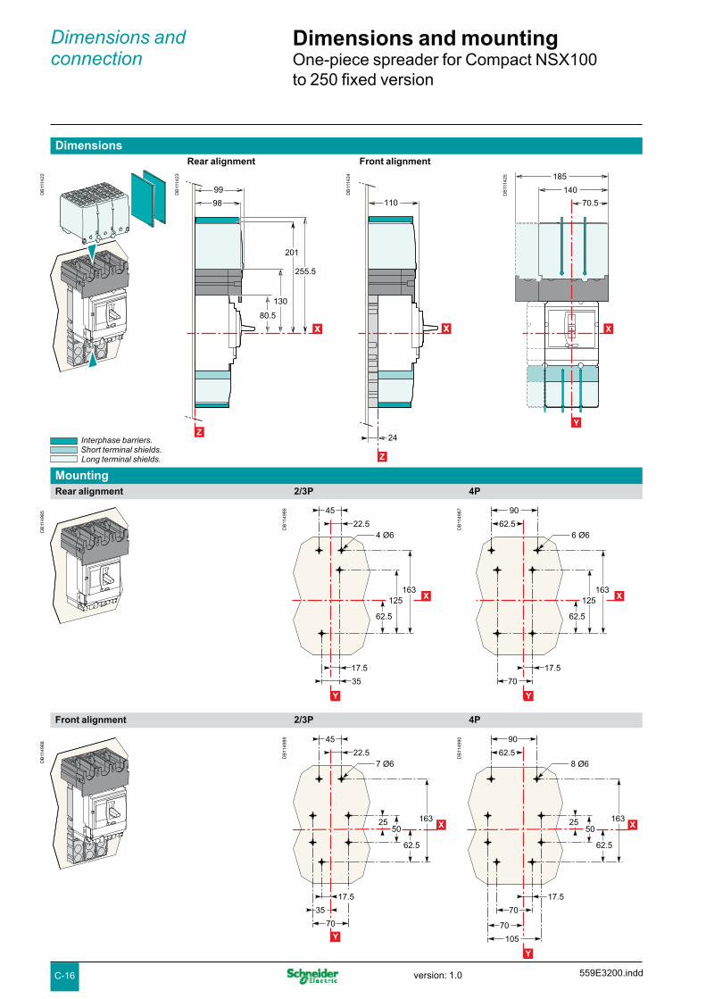
C-16
Dimensions and connection
Dimensions and mountingOne-piece spreader for Compact NSX100 to 250 fixed version
DimensionsRear alignment Front alignment
DB
1114
22
DB
1114
24
110
24
XX
Z
DB
1114
23
98
201
255.5
XX
Z
80.5
130
99
DB
1114
25
140
185
70.5
X
Y
Interphase barriers. Short terminal shields. Long terminal shields.
MountingRear alignment 2/3P 4P
Front alignment 2/3P 4P
DB
1149
85
DB
1149
86
Y
X
17.5
125
62.5
163
22.5
45
35
4 Ø6
DB
1149
87
Y
X
17.5
125
62.5
163
62.5
90
70
6 Ø6
DB
1149
88
DB
1149
89
Y
X
17.5
62.5
25 16350
22.5
45
35
70
7 Ø6
DB
1149
90
Y
X
17.5
62.5
2550
163
70
62.5
90
70
105
8 Ø6
559E3200.inddversion: 1.0

C-17
FDM121 switchboard display
Dimensions
MountingThrough panel
DB
1149
94
X
2330
10.6
Z
DB
1149
95
Y
X92+ 0,80
92+ 0,80
DB
1149
91
DB
1149
92Y
X96
96
On panel
DB
1149
93
DB
1151
21
3715
Z
X
DB
1151
22
Y
X
33+1.5-
32+0.5-
19
16.5
1320
17
99.3
99.3
+0.3- 2 Ø22.5
2 Ø22.5
DB
1149
96
Connector (optional).
DB
1152
70
559E3200.indd version: 1.0
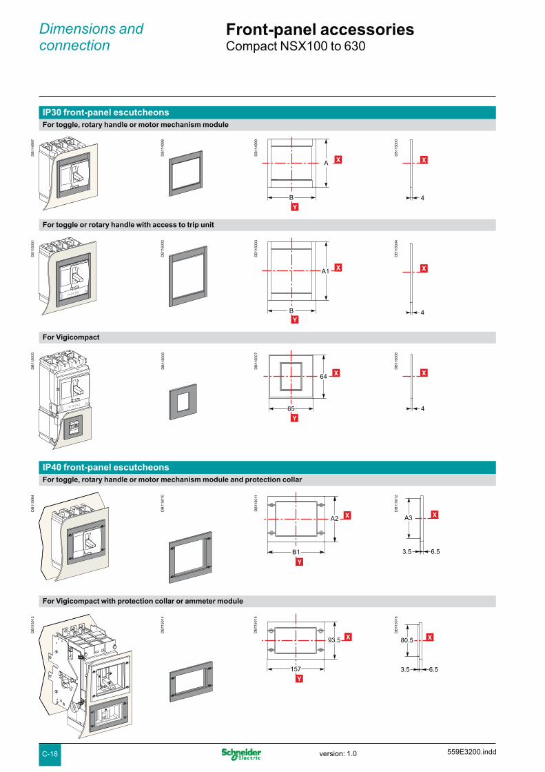
C-18
Dimensions and connection
Front-panel accessoriesCompact NSX100 to 630
IP30 front-panel escutcheonsFor toggle, rotary handle or motor mechanism module
DB
1149
97
DB
1149
98
DB
1149
99
A
B
X
Y
DB
1150
00
4
X
For toggle or rotary handle with access to trip unit
DB
1150
01
DB
1150
02
DB
1150
03
B
A1 X
Y
DB
1150
04
4
X
For Vigicompact
DB
1150
05
DB
1150
06
DB
1150
07
65
64 X
Y
DB
1150
08
4
X
IP40 front-panel escutcheonsFor toggle, rotary handle or motor mechanism module and protection collar
DB
1150
64
DB
1150
10
DB
1150
11
B1
A2 X
Y
DB
1150
12
6.53.5
A3 X
For Vigicompact with protection collar or ammeter module
DB
1150
13
DB
1150
14
DB
1150
15
157
93.5 X
Y
DB
1150
16
80.5
6.53.5
X
559E3200.inddversion: 1.0

C-19
IP40 front-panel escutcheons (cont.)
For Vigicompact
DB
1150
17
DB
1150
18
DB
1150
19
79
69
X
Y
DB
1150
20
64
6.53.5
X
Protection collars for IP40 front-panel escutcheonsFor toggle
DB
1150
21
DB
1150
22
DB
1150
23
B2
A4 X
Y
DB
1150
24
35
X
For Vigicompact
DB
1150
25
DB
1150
26
DB
1150
27
91
52.5
Y
DB
1150
28
35
X
IP43 toggle cover
DB
1150
30
DB
1150
31
DB
1150
32
B3
A5
Y
DB
1151
20
C
X
Type A A1 A2 A3 A4 A5 B B1 B2 B3 C
NSX100/160/250 113 138 114 101 73 85 113 157 91 103 40
NSX400/630 163 215 164 151 122.5 138 163 189 122.5 138 60
DB
1150
29
63
X
Circuit breaker with toggle or rotary handle.
Circuit breaker with motor-mechanism module.
559E3200.indd version: 1.0

C-20
Dimensions and connection
Front-panel cutoutsCompact NSX100 to 630 fixed version
Bare sheet metal NSX100 to 250 NSX400/630For toggle
DB
1150
35
DB
1150
37
XX
Z
P3
DB
1150
38
XX
Y
7729.5
95
47.5
DB
1150
39
Y
XX127
42
127
63.5
For toggle with access to trip unit
DB
1150
40
DB
1150
41
XX
Z
P3
With IP30 front-panel escutcheon NSX100 to 250 NSX400/630For toggle
DB
1150
44
DB
1150
45
XX
Z
P3
For toggle with access to trip unit
DB
1150
62
DB
1150
63
P3
XX
Z
DB
1150
38
XX
Y
7729.5
95
47.5
DB
1150
39
Y
XX127
42
127
63.5
DB
1150
42
XX
Y
54.5
95
47.5
102
DB
1150
43
Y
XX179
94
127
63.5
DB
1150
42
XX
Y
54.5
95
47.5
102
DB
1150
43
Y
XX179
94
127
63.5
559E3300.inddversion: 1.0

C-21
With IP40 front-panel escutcheon NSX100 to 250 NSX400/630For toggle
DB
1150
64
DB
1150
65
XX
Z
P4
DB
1150
66
XX
Y
10342.5
148
74
DB
1150
67
XX
Y
155
56.5
180
90
With IP43 toggle cover NSX100 to 250 NSX400/630For toggle
DB
1150
68
DB
1151
23
XX
Z
P4
DB
1150
38
XX
Y
7729.5
95
47.5
DB
1150
39
Y
XX127
42
127
63.5
Note: door cutout dimensions are given for a device position in the enclosure where u 100 + (h x 5) with respect to the door hinge.
DB
1154
39
h
ΔY
Type P3 P4
NSX100/160/250 88 89
NSX400/630 112 113
559E3300.indd version: 1.0

C-22
Dimensions and connection
Front-panel cutoutsVigicompact NSX100 to 630 fixed version
Bare sheet metal NSX100 to 250 NSX400/630For toggle
DB
1150
72
DB
1150
73
P3
XX
Z
DB
1150
74
85.5
38
29
14.5
XX
Y
DB
1150
75
148
38
29
32
XX
Y
For toggle with access to trip unit
DB
1150
76
DB
1150
77
P3
XX
Z
DB
1150
78
85.5
38
29
14.5
XX
Y
DB
1150
79148
38
29
32
XX
Y
With IP30 front-panel escutcheon NSX100 to 250 NSX400/630For toggle
DB
1150
80
DB
1150
81
P3
XX
Z
DB
1150
74
85.5
38
29
14.5
XX
Y
DB
1150
75
148
38
29
32
XX
Y
559E3300.inddversion: 1.0

C-23
With IP30 front-panel escutcheon (cont.) NSX100 to 250 NSX400/630For toggle with access to trip unit
DB
1150
82
DB
1150
83
P3
XX
Z
With IP40 front-panel escutcheon NSX100 to 250 NSX400/630For toggle
Note: door cutout dimensions are given for a device position in the enclosure where u 100 + (h x 5) with respect to the door hinge.
Type P3 P4
NSX100/160/250 88 89
NSX400/630 112 113
DB
1150
78
85.5
38
29
14.5
XX
Y
DB
1150
79
148
38
29
32
XX
Y
DB
1150
84
DB
1150
85
XX
ZP4
DB
1150
86
71
68
58
29
XX
Y
DB
1150
87
132
68
47
58
XX
Y
DB
1154
39
h
ΔY
559E3300.indd version: 1.0

C-24
Dimensions and connection
Front-panel cutoutsCompact NSX100 to 630 plug-in and withdrawable versions
Plug-in version
DB
1150
88 M
N
DB
1150
89 M
N
Z
XX
27
45
D1 P3
Bare sheet metal
See Compact NSX100 to 630 fixed version, page C-20
With IP30 front-panel escutcheon
See Compact NSX100 to 630 fixed version, page C-20
With IP40 front-panel escutcheon
See Compact NSX100 to 630 fixed version, page C-21
With toggle cover
See Compact NSX100 to 630 fixed version, page C-21
Withdrawable version NSX100 to 250 NSX400/630With protection collar and IP40 front-panel escutcheon
DB
1150
90 M
N
DB
1150
91
27
45
D1 P5
Z
XX
M
N
DB
1150
66
XX
Y
10342.5
148
74
DB
1150
67
XX
Y
155
56.5
180
90
559E3300.inddversion: 1.0

C-25
Vigicompact NSX100 to 630 plug-in and withdrawable versions
Plug-in version
Bare sheet metal
See Compact NSX100 to 630 fixed version, page C-22
With IP30 front-panel escutcheon
See Compact NSX100 to 630 fixed version, page C-22
With IP40 front-panel escutcheon
See Compact NSX100 to 630 fixed version, page C-23
Note: door cutout dimensions are given for a device position in the enclosure where u 100 + (h x 5) with respect to the door hinge.
Type D1 P3 P5
NSX100/160/250 75 88 123
NSX400/630 100 112 147
DB
1150
92 M
N
DB
1150
94 M
N
Z
XX
27
45
D1 P3
Withdrawable version NSX100 to 250 NSX400/630With protection collar and IP40 front-panel escutcheon
DB
1150
95 M
N
DB
1150
96
Z
XX
27
45
D1 P5
M
N
DB
1150
97
82.5
55
XX
Y
148
74
DB
1150
98
XX
Y
122.5
82.5
90
148
DB
1154
39
h
ΔY
559E3300.indd version: 1.0
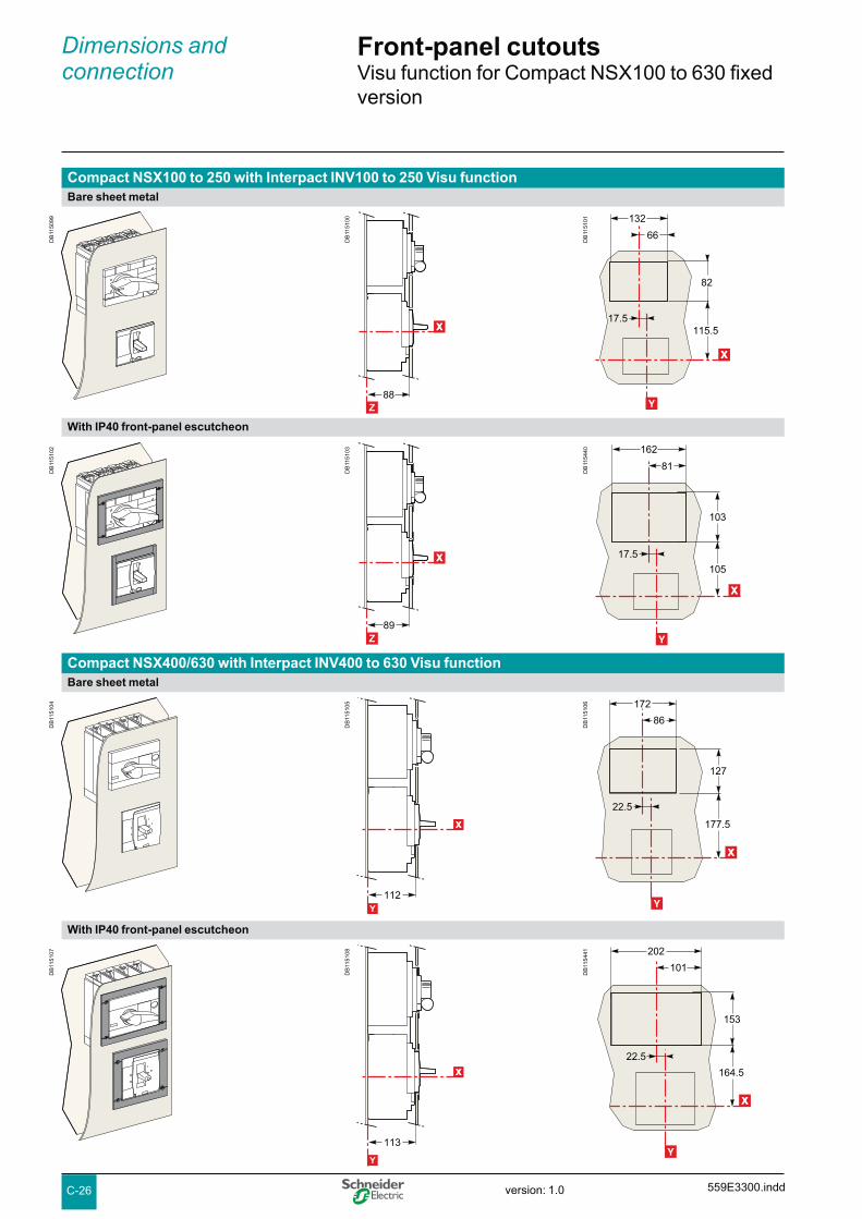
C-26
Dimensions and connection
Front-panel cutoutsVisu function for Compact NSX100 to 630 fixed version
Compact NSX100 to 250 with Interpact INV100 to 250 Visu functionBare sheet metal
DB
1150
99
DB
1151
00
88
XX
Z
With IP40 front-panel escutcheon
Compact NSX400/630 with Interpact INV400 to 630 Visu functionBare sheet metal
With IP40 front-panel escutcheon
DB
1151
01
XX
Y
115.5
82
132
66
17.5
DB
1151
02
DB
1151
03
89
XX
Z
DB
1154
40XX
Y
105
103
162
81
17.5
DB
1151
04
DB
1151
05
112
XX
Y
DB
1151
06
XX
Y
177.5
127
172
86
22.5
DB
1151
07
DB
1151
08
113
XX
Y
DB
1154
41
XX
Y
164.5
153
202
101
22.5
559E3300.inddversion: 1.0

C-27
Motor mechanism module for Compact and Vigicompact NSX100 to 630
DB
1151
09 M
N
Ø5...8
DB
1151
10
XX
Z
MN
2745 P6
D1 P7
Fixed or plug-in circuit breaker with access to Vigi module
DB
1150
69
Y
XX127
42
127
63.5
Bare sheet metal NSX100 to 250 NSX400/630Fixed, plug-in or withdrawable circuit breaker
With IP30 front-panel escutcheon NSX100 to 250 NSX400/630Fixed, plug-in or withdrawable circuit breaker
With IP40 front-panel escutcheon NSX100 to 250 NSX400/630Fixed, plug-in or withdrawable circuit breaker without access to Vigi module
Type D1 P6 (1) P7 (2) P8 (1) P9 (2)
NSX100/160/250 75 145 177 146 178 (1) Plug-in version.
NSX400/630 100 217 249 218 250 (2) Withdrawable version.
DB
1150
38
XX
Y
7729.5
95
47.5
DB
1151
11 M
N
Ø5...8
DB
1151
12
XX
Z
MN
2745 P6
D1 P7
DB
1151
13 M
N
Ø5...8
DB
1151
14
XX
Z
MN
2745 P8
D1 P9
DB
1150
67
XX
Y
155
56.5
180
90
DB
1150
66
XX
Y
10342.5
148
74
DB
1151
15
Ø5...8
M
N
DB
1151
16
XX
Z
MN
2745
D1 P8
DB
1151
18
XX
Y
122.5
56.5
155
90
180
DB
1151
17
XX
Y
148
74
55
103
42.5
DB
1150
69
Y
XX127
42
127
63.5
DB
1150
38
XX
Y
7729.5
95
47.5
559E3400.indd version: 1.0

C-28
Bare sheet metal with access to the trip unit
Fixed or plug-in circuit breakers NSX100 to 250 NSX400/630Bare sheet metal
DB
1151
19 M
N
DB
1151
44
Z
MN
2745
D1 P10
XX
DB
1151
46
127
42
148
127
63.5
Y
XX
DB
1151
45
Y
XX7729.5
95
47.5
85.5
DB
1151
47 M
N
Dimensions and connection
Front-panel cutoutsDirect rotary handle for Compact and Vigicompact NSX100 to 630
DB
1151
24
Z
MN
2745
D1 P10
XX
With IP30 front-panel escutcheon
DB
1151
27 M
N
DB
1151
28
Z
MN
2745
D1 P10
XX
DB
1151
46
127
42
148
127
63.5
Y
XX
DB
1151
45
Y
XX7729.5
95
47.5
85.5
DB
1151
26
179
94148
127
63.5
Y
XX
DB
1151
25
102
54.5
95
47.5
85.5
Y
XX
559E3400.inddversion: 1.0

C-29
DB
1151
26
179
94148
127
63.5
Y
XX
DB
1151
25
102
54.5
95
47.5
85.5
Y
XX
DB
1151
29 M
N
DB
1151
30
Z
MN
2745
D1 P10
XX
With IP40 front-panel escutcheon
DB
1151
31 M
N
DB
1152
71
DB
1151
33
155
56.5
148
180
90
Y
XX
DB
1151
32
Y
XX103
42.5
148
74
85.5
Fixed or withdrawable circuit breakers NSX100 to 250 NSX400/630With IP40 front-panel escutcheon
DB
1151
34 M
N
DB
1151
35
Z
XX
27
45
D1 P12
M
N
DB
1151
18
XX
Y
122.5
56.5
155
90
180
DB
1151
17
XX
Y
148
74
55
103
42.5
Type D1 P10 P11 P12
NSX100/160/250 75 89 90 123
NSX400/630 100 112 113 147
Fixed or plug-in circuit breakers (cont.) NSX100 to 250 NSX400/630With IP30 front-panel escutcheon with access to the trip unit
559E3400.indd version: 1.0

C-30
With IP40 front-panel escutcheon
With toggle Rotary handle
Fixed or plug-in circuit breakers with ammeter module and voltage-presence indicatorBare sheet metal
With toggle Rotary handle
DB
1151
36 M
N
DB
1151
39
XX
Y
93K1
56.5
J2
J1
Ø31
Dimensions and connection
Front-panel cutoutsIndication and measurement modules for Compact NSX100 to 630
DB
1151
40 M
N
DB
1151
41
XX
M
N
Z
27
45
D1 P4
DB
1151
43
XX
Y
148K2
82.5
J3
J1
Ø31
DB
1151
42 M
N
Z
27
45
D1 P11
XX
DB
1152
72
DB
1152
73
Type D1 J1 J2 J3 K1 K2 P3 P4 P10 P11
NSX100/160/250 75 78.5 67.5 55 46.5 74 88 89 89 90
NSX400/630 100 122 129 122.5 64.5 90 112 113 112 113
559E3400.inddversion: 1.0

C-31 559E3400.indd version: 1.0

C-32
Connection locations
DB
1154
42
Z
C2
C1
XX
DB
1154
43
Y
B1B1B1
A1
A2
A3
XX
Dimensions and connection
Power connectionsCompact and Vigicompact NSX100 to 630 fixed version
Type A1 A2 B1 C1 C2 Type A1 A3 B1 C1 C2
NSX100/160 70 140 35 19.5 19.5 NSX100/160 + Vigi 70 215 35 19.5 21.5
NSX250 70 140 35 21.5 19.5 NSX250 + Vigi 70 215 35 21.5 21.5
NSX400/630 113.5 227 45 26 26 NSX400/630 + Vigi 113.5 327 45 26 26
Front connection without accessoriesNSX100 to 250 NSX400/630
DB
1154
44
DB
1154
45
70
10.5
Z
XX
DB
1154
46
113.5
14
Z
XX
Connection with accessoriesLong and short rear connectors
NSX100 to 250
DB
1154
47
DB
1161
07
706
13
Z
XX
18
43 for short RC88 for long RC
8.6
20
10
DB
1161
08
8
113.5
14
Z
XX
30
50 for short RC115 for long RC
13 23.215
NSX400/630
Cables with lugs/bars Bars/cables with lugs
559E3500.inddversion: 1.0

C-33
Connection with accessories (cont.)
Bare-cable connectors
NSX100 to 250
DB
1154
50
D
B11
5451
70
22
Z
XX
NSX400/630
DB
1154
53
DB
1154
54
113.5
14
Z
XX D
B11
5455
Z
113.5
46.5
XX
Distribution connectors (for NSX100 to 250 only)
Right-angle terminal extensions (upstream only)
NSX100 to 250 NSX400/630
DB
1154
56
DB
1154
57
Z
41
70
XX
64.566.5 (a)
DB
1154
58
DB
1154
59
70
20.5
Z
XX
37.539.5 (b) 4
DB
1154
60 Z
XX
61
113.5
34
8
Straight terminal extensions (for NSX100 to 250 only)
DB
1154
61
DB
1154
62
70
41
Z
XX
30
4
DB
1154
52
70
63Z
XX
(b) NSX250.
(a) Vigi module or NSX250.
559E3500.indd version: 1.0

C-34
Dimensions and connection
Power connectionsCompact and Vigicompact NSX100 to 630 fixed version
Connection with accessories (cont.)Edgewise terminal extensions NSX100 to 250 NSX400/630
DB
1154
63
D
B11
5464
70
5342
Z
XX
23.5
4
DB
1154
65 Z
XX
113.5
58
42
30
8
45° terminal extensions NSX100 to 250 NSX400/630
DB
1154
66
DB
1154
67
4031
70
Z
XX
70
XX
70
XX
70
XX
13.5
4
DB
1154
68 Z
113.5
61.548
X
10
8
Double-L terminal extensions NSX100 to 250
DB
1154
69
DB
1154
70
70
46 35
Z
XXXXXXXX
45
4
559E3500.inddversion: 1.0

C-35
Type C3 C4 E1 E2 E3 F1 F2
NSX100/160 23.5 - 114 45 159 100 11
NSX250 25.5 - 114 45 159 100 11
NSX400/630 - 44 135170
52.570
187.5240
152.5166
1515
One-piece spreader (for NSX100 to 250 only)
DB
1154
71
DB
1154
72E2 E2
E1
F1
F2
Y
XX
DB
1154
74
Z
C3
XX
Z
C4
XX
DB
1154
73
E2 E2 E2
E3
Y
XX
Connection with accessories (cont.)Spreaders 3P 4P
NSX100 to 250
DB
1154
75
DB
1154
76
4545 45
140
180.5
130113.5
X
Y
DB
1154
77
98
26
Z
X
NSX400/630
559E3500.indd version: 1.0

C-36
Dimensions and connection
Power connectionsCompact and Vigicompact NSX100 to 630 plug-in and withdrawable versions
Connection locations
DB
1154
78
Z
XX
M
N
V
2745
D1
DB
1154
79
Y
B1
A4
B1 B1
A5 XX
Connection without accessoriesFront connection: mounting on backplate (M) or rails (V)
NSX100 to 250 NSX400/630
DB
1154
81
Z
100
108.5
419
XX
DB
1154
82
156.5171
Z
XX
626
Rear connection: mounting through front panel (N) or on rails (V)
NSX100 to 250 NSX400/630
DB
1154
83
DB
1154
84
Z
49
67
57.5
75.5
63.5
80.5
XX
4
DB
1154
85
100.5114.5
104
129
Z
XX
82.596.5
6
DB
1154
80
DB
1154
88
Z
49
67
57.5
75.5
70
XX
Ø8.5
DB
1154
89
100.5114.5
113.5
Z
XX
82.596.5
Ø11
Type A4 A5 B1 D1
NSX100 to 250 100 200 35 75
NSX400/630 156.5 313 45 100
Note:b for mounting on a backplate, the insulating screen supplied with the plug-in base must be installed.b for withdrawable versions, terminal shields are recommended.
559E3500.inddversion: 1.0

C-37
Connection with accessoriesBare-cable connectors: mounting on backplate (M) or rails (V)
NSX100 to 250
DB
1154
91
Z
100
110
48.5
XX
30
DB
1154
92
Z
100
163
X
70
30
DB
1154
90
NSX400/630
DB
1154
94
156.5171
Z
XX
68
55
DB
1154
95
Z
XX
156.5
203
94
55
DB
1154
93
Bare-cable connectors: mounting through front panel (N) or on rails (V)
NSX100 to 250
DB
1154
97
Z
100
110
XX
54
18
DB
1154
98
74
Z
100
163
18
XX
DB
1154
96
NSX400/630
DB
1155
00
84
18
156.5171
Z
XX
DB
1155
01
Z
XX
156.5
203
111
18
DB
1154
99
559E3500.indd version: 1.0

C-38
Dimensions and connection
Power connectionsCompact and Vigicompact NSX100 to 630 plug-in and withdrawable versions
Connection with accessories (cont.)45° extensions: mounting through front panel (N) or on rails (V)
NSX100 to 250 NSX400/630
DB
1155
06
DB
1155
07
Z
100
131
33
XX
4
140
18
DB
1155
08
18
156.5
204.5Z
XX
57
218
8
Double-L extensions: mounting on backplate (M) or rails (V)
NSX100 to 250
DB
1155
09
DB
1155
10
30
Z
100
135
47
146
XX
4
Double-L extensions: mounting through front panel (N) or on rails (V)
NSX100 to 250
DB
1155
05
Z
100
135
51
146
XX
4
18
559E3500.inddversion: 1.0

C-39
DB
1155
11
DB
1155
12
Y
XX
E2 E2
E1
F1
F2
DB
1155
13
Y
XX
E2 E2 E2
E3
DB
1155
14
Z
27
XX
50
Z
XX
Connection with accessories (cont.)Spreaders: mounting on backplate (M) or rails (V)
3P 4P NSX100 to 250
DB
1155
15
DB
1155
16
Z
6775.5
80.5
XX30
DB
1155
17
94.5108.5
129
Z
XX55
Interior-mounted rear connectors NSX100 to 250 NSX400/630
DB
1155
18
DB
1155
19
Z
6775.5
63.5
XX30
DB
1155
20
94.5108.5
104
Z
XX55
Long, insulated connectors are mandatory.
Long insulated rear connectors: mounting on backplate (M) or rails (V)
Exterior-mounted rear connectors NSX100 to 250 NSX400/630
Type E1 E2 E3 F1 F2
NSX100 to 250 114 45 159 130 11
NSX400/630 135170
52.570
187.5240
195.5209
1515
NSX400/630
559E3500.indd version: 1.0

C-40
Dimensions and connection
Power connectionsConnection of insulated bars or cables with lugs to Compact and Vigicompact NSX100 to 630
Direct connection to NSX100 to 630Dimensions NSX100 NSX160/250 NSX400/630
Bars L (mm) y 25 y 25 y 32
I (mm) d + 10 d + 10 d + 15
d (mm) y 10 y 10 y 15
e (mm) y 6 y 6 3 y e y 10
Ø (mm) 6.5 8.5 10.5
Lugs L (mm) y 25 y 25 y 32
Ø (mm) 6.5 8.5 10.5
Torque (Nm) (1) 10 15 50
Torque (Nm) (2) 5/5 5/5 20/11
Torque (Nm) (3) 8 8 20
(1) Tightening torque on the circuit breaker for lugs or bars.(2) Tightening torque on fixed devices for rear connectors//tightening torque on plug-in or withdrawable devices for power connectors.(3) Tightening torque on the plug-in base for terminal extensions.
Connection with accessories to NSX100 to 250 (IEC 228)Pole pitch
Without spreaders 35 mm
With spreaders 45 mm
Dimensions With spreaders or terminal extensions
NSX100 NSX160/250
DB
1156
55
Ø
I
400
L
e
d
L
Bars L (mm) y 25 y 25
l (mm) 20 y I y 25 20 y I y 25
d (mm) y 10 y 10
e (mm) y 6 y 6
Ø (mm) 6.5 8.5
Lugs L (mm) y 25 y 25
Ø (mm) 6.5 8.5
Torque (Nm) (1) 10 15
Torque (Nm) (2) 5 5
(1) Tightening torque on the circuit breaker for spreaders or terminal extensions.(2) Tightening torque on the plug-in base for spreaders or terminal extensions.
Spreaders and straight, right-angle, 45°, double-L and edgewise terminal extensions are supplied with flexible interphase barriers.
Connection with accessories to NSX400 and 630 (IEC 228)Pole pitch
Without spreaders 45 mm
With spreaders 52.5 or 70 mm
Dimensions With spreaders With terminal extensions
DB
1156
55
Ø
I
400
L
e
d
L
Bars L (mm) y 40 y 32
l (mm) d + 15 30 y I y 34
d (mm) y 20 y 15
e (mm) 3 y e y 10 3 y e y 10
Ø (mm) 12.5 10.5
Lugs L (mm) y 40 y 32
Ø (mm) 12.5 10.5
Torque (Nm) (1) 50 50
Torque (Nm) (2) 20 20
(1) Tightening torque on the circuit breaker for spreaders or terminal extensions.(2) Tightening torque on the plug-in base for spreaders or terminal extensions.
Spreaders and right-angle, 45° and edgewise terminal extensions are supplied with flexible interphase barriers.
DB
1156
58
Mounting detail: 2 cableswith lugs.
DB
1121
68
DB
1156
53
Ø
I
400
L
e
d
Bar.
DB
1156
54
L
Ø
Lug.
Accessories for NSX100 to 250Straight terminal extensions
Double-L terminal extensions
DB
1121
72
DB
1121
76
Tinned copper Tinned copper
Spreaders:
separate parts one-piece spreader
DB
1121
77
DB
1156
55
Tinned copper
For U > 600 V, the mandatory insulation kit is not compatible with spreaders made up of separate parts. The one-piece spreader must be used.
Accessories for NSX400 and 630Spreaders made up of separate parts for 52.5 and 70 mm pitch
DB
1156
57
Tinned copper
For U > 600 V, use of the 52.5 mm pitch spreaders requires a specific insulation kit.The 70 mm pitch spreaders may not be used.
Accessories for NSX100 to 630Right-angle terminal extensions
Edgewise terminal extensions
DB
1121
73
DB
1121
75
Tinned copperTo be mounted on upstream side.
Tinned copper
45° terminal extensions
DB
1121
74
Tinned copper
559E3500.inddversion: 1.0

C-41
Connection of bare cables to Compact and Vigicompact NSX100 to 630
Connection for NSX100 to 250
DB
1123
15
DB
1123
17
DB
1113
27
DB
1156
61
DB
1156
62
1-cable connector
2-cable connector
Distribution connector Polybloc distribution block
1-cable connector Steely 160 A
Aluminiumy 250 A
DB
1156
63
L
S
L (mm) 25 25
S (mm²) Cu / Al 1.5 to 95 (1) 25 to 50 70 to 95 120 to 185150 max. flex.
Torque (Nm) 12 20 26 26
2-cable connector
L (mm) 25 or 50
S (mm²) Cu / Al 2 x 50 to 2 x 120
Torque (Nm) 22
6-cable distribution connector (copper or aluminium)
L (mm) 15 or 30
S (mm²) Cu / Al 1.5 to 6 (1) 8 to 35
Torque (Nm) 4 6
Polybloc distribution block (6 or 9 cables)
L (mm) 12 16
S (mm²) Cu / Al 6 x 4 to 10 3 x 6 to 16
(1) For flexible cables from 1.5 to 4 mm², connection with crimped or self-crimping ferrules.
Connection to NSX400 and 630
DB
1123
16
DB
1113
26
1-cable connector 2-cable connector
1-cable connector 2-cable connector
DB
1156
63
L
S
L (mm) 30 30 or 60
S (mm²) Cu / Al 35 to 300 rigid240 max. flex.
2 x 35 to 2 x 240 rigid240 max. flex.
Torque (Nm) 31 31
Conductor materials and electrodynamic stressesCompact NSX circuit breakers can be connected indifferently with bare-copper, tinned-copper and tinned-aluminium conductors (flexible or rigid bars, cables).In the event of a short-circuit, thermal and electrodynamic stresses will be exerted on the conductors. They must therefore be correctly sized and held in place by supports.Electrical connection points on switchgear devices (switch-disconnectors, contactors, circuit breakers, etc.) should not be used for mechanical support.Any partition between upstream and downstream connections of the device must be made of non-magnetic material.
DB
1125
659
DB
1156
60
559E3500.indd version: 1.0

Acc
um
ula
ted
exp
erie
nce

Compact NSX Wiring diagramsContents
Functions and characteristics A-1Installation recommendations B-1Dimensions and connection C-1
Compact NSX100 to 630Fixed circuit breakers D-2Plug-in / withdrawable circuit breakers D-4Motor mechanism D-6SDx module with Micrologic D-8SDTAM module with Micrologic M D-9
Additional characteristics E-1Catalogue numbers F-1Glossary G-1
D-1 559E4000.indd version: 1.0

559E4100.indd
Wiring diagrams Compact NSX100 to 630Fixed circuit breakers
Micrologic A or E
A/E CommunicationH(WH), L(BL): data- (BK), + (RD): 24 V DC power supply
A/E ZSI (Zone Selective Interlocking)Z1: ZSI OUT SOURCEZ2: ZSI OUTZ3: ZSI IN SOURCEZ4: ZSI IN ST (short time)Z5: ZSI IN GF (ground fault)
Note: Z3, Z4, Z5 for NSX400/630 only.
A/E ENCT: external neutral current transformer:- shielded cable with 1 twisted pair (T1, T2)- shielding earthed at one end only (CT end). Connection L = 30 cm max.- maximum length of 10 metres- cable size 0.4 to 1.5 mm2
- recommended cable: Belden 8441 or equivalent.
E ENVT: external neutral voltage tap for connection to the neutral via a 3P circuit breaker.
Remote operation
MN:
or
undervoltage release
MX: shunt release
Motor mechanism (MT)
A4: opening order
A2: closing order
B4, A1: power supply to motor mechanism
L1: manual position (manu)
B2: SDE interlocking (mandatory for correct operation)
BPO: opening pushbutton
BPF: closing pushbutton
Communicating motor mechanism (MTc)
B4, A1: motor mechanism power supply
BSCM: breaker status and control module
Power Micrologic Remote operation
DB
1157
07
+-
LH
Motor mechanism (MT)
Communicating motormechanism (MTc)
BPO BPF
D2
C2
A4
A2
B4
MN MX
D1
C1 A1
B2
SDE
SDE
8482
81
L1
a (-)manu
a (+) a (+)
a (-)
ou0 I
auto
manuZ
2Z1
Upstream CB
Z1
Z2
Z3
Z4
Z5
Z3
Z4
Z5
Downstream CB
Z1
Z2
Z3
Z4
Z5
T1
T2
N L1 L2 L3
Q
I
U
+-
LH
NSX cord3P or 4P
3P + NN L1 L2 L3
ENVT
Q
T1
T2
H2
H1
I U
ENCT
Z2Z1
Z3
Z4
Z5
T1
T2B
4A
1
a (220/240 V)
a
0 Iauto
manu
NSX cord
BSCM
D-2 version: 1.0

559E4100.indd
Indication contacts
OF2 / OF1: device ON/OFF indication contacts
OF4 / OF3: device ON/OFF indication contacts (NSX400/630)
SDE: fault-trip indication contact (short-circuit, overload, ground fault, earth leakage)
SD: trip-indication contact
CAF2/CAF1: early-make contact (rotary handle only)
CAO1: early-break contact (rotary handle only)
SDV: earth leakage fault trip indication contact (add-on Vigi module)
The diagram is shown with circuits de-energised, all devices open, connected and charged and relays in normal position.
Terminals shown in red O must be connected by the customer.
Indication contacts
DB
1157
08
41
OF4
42 44
OF3
31
32 34
21
OF2
Open
22 24
OF1
11
Closed Closed
12 14
81
SDE
Fault82 84
91
SD
Fault
92 94
121
CAF2
131
CAF1
RD
WH
134
124
101
CAO1
Open
YE
VT
102
104
71
SDV
Fault
72 74
RD
WH
GY
Colour code for auxiliary wiring
RD: red VT: violet
WH: white GY: grey
YE: yellow OR: orange
BK: black BL: blue
GN: green
D-3version: 1.0
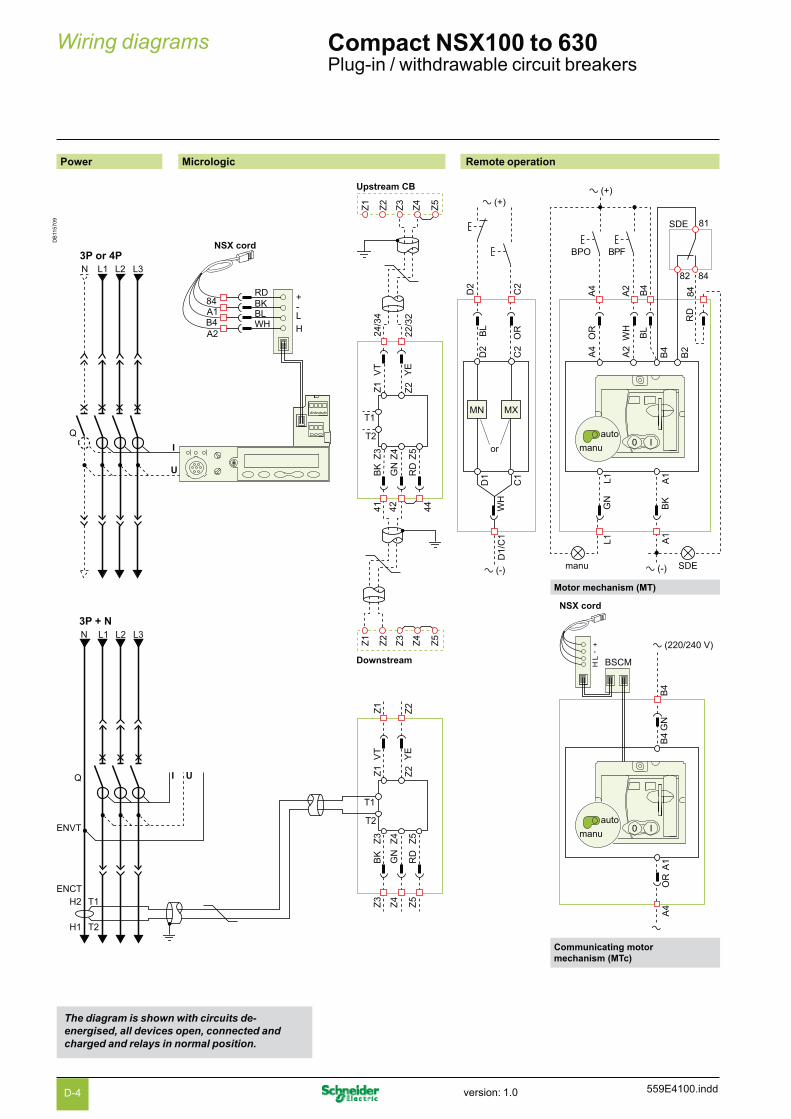
559E4100.indd
Wiring diagrams Compact NSX100 to 630Plug-in / withdrawable circuit breakers
Power Micrologic Remote operation
DB
1157
09
+-
LH
BPO BPF
D2
C2
D2
C2
A4
A2
RD
BL
WH
OR
ORBL
B4
A4
A2
B4
MN MX
D1
C1
D1/
C1
A1
BK
GN
WH
A1
B2
SDE
SDE
84
84
82
81
L1L1
a (-) manu
a (+)a (+)
a (-)
or0 I
auto
manu
Z2Z1
Z2Z1
Z3
Z4
Z5
Z3
Z4
Z5
BK
GN
VT
YE
RD
T1
T2
N L1 L2 L3
ENVT
Q
T1
T2
H2
H1
I U
ENCT
3P + N
B4
B4
GN
A1
OR
A4
a
0 Iauto
manu
a (220/240 V)
Z2Z1
22/3
2
24/3
4
Upstream CB
Z1
Z2
Z3
Z4
Z5
Z3
Z4
Z5
41 42 44
BK
GN
VT
YE
RD
Downstream
Z1
Z2
Z3
Z4
Z5
T1
T2
N L1 L2 L3
Q
I
U
+-
LH
B4A184
A2
NSX cord3P or 4P
RDBKBLWH
Motor mechanism (MT)
Communicating motormechanism (MTc)
NSX cord
BSCM
The diagram is shown with circuits de-energised, all devices open, connected and charged and relays in normal position.
D-4 version: 1.0

559E4100.indd
Indication contacts Carriage switches
DB
1157
10
41
OF4
42 44
OF3
31
32 34
21
OF2
Open
22 24
OF1
11
Closed
12 14
81
SDE
Fault82 84
91
SD
Fault
92 94
121
CAF2
131
CAF1
Closed
RD
WH
134
124
101
CAO1
Open
YE
VT
VT
VT
GY
GY
102
314
312
352
354
104
71
SDV CE CD
Fault
72 74
Connected Disconnected
RD
WH
GY
GN
RD
YE
VT
GN
RD
GN
RD
YE
VT
YE
VT
BK
GY
GY
GY
BK
BK
YE
VT
GY
YE
YE
71 311
351
41 31 21 11 81 91
42 44 32 34 22 24 12 14 82 84 92 94 72 74
Terminals shown in red v / O must be connected by the customer.
Colour code for auxiliary wiring
RD: red VT: violet
WH: white GY: grey
YE: yellow OR: orange
BK: black BL: blue
GN: green
Micrologic A or E
A/E CommunicationH(WH), L(BL): data- (BK), + (RD): 24 V DC power supply
A/E ZSI (Zone Selective Interlocking)Z1: ZSI OUT SOURCEZ2: ZSI OUTZ3: ZSI IN SOURCEZ4: ZSI IN ST (short time)Z5: ZSI IN GF (ground fault)Note: Z3, Z4, Z5 for NSX400/630 only.
A/E ENCT: external neutral current transformer:- shielded cable with 1 twisted pair (T1, T2)- shielding earthed at one end only (CT end). Connection L = 30 cm max.- maximum length of 10 metres- cable size 0.4 to 1.5 mm2
- recommended cable: Belden 8441 or equivalent.
E ENVT: external neutral voltage tap for connection to the neutral via a 3P circuit breaker.
Remote operation
MN:
or
undervoltage release
MX: shunt release
Motor mechanism (MT)
A4: opening order
A2: closing order
B4, A1: motor mechanism power supply
L1: manual position (manu)
B2: SDE interlocking (mandatory for automatic or remote recharging)
BPO: opening pushbutton
BPF: closing pushbutton
Communicating motor mechanism (MTc)
B4, A1: motor mechanism power supply
BSCM: breaker status and control module
Indication contacts
OF2 / OF1: device ON/OFF indication contacts
OF4 / OF3: device ON/OFF indication contacts (NSX400/630)
SDE: fault-trip indication contact(short-circuit, overload, ground fault, earth leakage)
SD: trip-indication contact
CAF2/CAF1: early-make contact(rotary handle only)
CAO1: early-break contact(rotary handle only)
SDV: earth leakage fault trip indication contact (add-on Vigi module)
D-5version: 1.0

559E4100.indd
Wiring diagrams Compact NSX100 to 630Motor mechanism
The diagram is shown with circuits de-energised, all devices open, connected and charged and relays in normal position.
Motor mechanism (MT) with automatic reset
DB
1146
66
Q
BPO BPF
A4
A2
B4
A1
B2
SDE
SDE
8482
81
L1manu
a (+)
a (-)
0 Iauto
manu
Motor mechanism (MT) with remote reset
DB
1146
67
BPO BPF Reset
A4
A2
B4
A1
B2
8482
81
L1
manu
a (+)
a (-)
0 Iauto
manu
Q
SDE
SDE
Motor mechanism (MT) with manual reset
DB
1146
68
Q
BPO BPF
A4
A2
B4
A1
B2
8482
81
L1
manu
a (+)
a (-)
0 Iauto
manu
SDE
SDE
Symbols
Q: circuit breaker
A4 : opening order
A2: closing order
B4, A1: motor mechanism power supply
L1: manual position (manu)
B2: SDE interlocking (mandatory for correct operation)
BPO: opening pushbutton
BPF: closing pushbutton
SDE: fault-trip indication contact (short-circuit, overload, ground fault, earth leakage)
After tripping initiated by the "Push to trip" button or by the undervoltage (MN) release or the shunt (MX) release, device reset can be automatic, remote or manual.
Following tripping due to an electrical fault (with an SDE contact), reset must be carried out manually.
D-6 version: 1.0

559E4100.indd
Communicating motor mechanism (MTc)
DB
1146
69
+-
LH
Q
B4
A1
a (220/240 V)
a
0 Iautomanu
NSX cord
BSCM
Schematic representation of the communicating motor mechanism (MT).
Single-line diagram of communicating motor mechanismOpening, closing and reset orders are transmitted via the communication network.The "Enable automatic reset" and "Enable reset even if SDE" parameters must be set using the RSU software via the screen by clicking the blue text.
"Auto/manu" is a switch on the front of the motor mechanism.
RSU screen for the communicating motor mechanism (MTc)
DB
1146
70
Open motor
Opencommand
220VAC
OF OF
SD
Closecommand
Resetcommand
Enableautomaticreset
Enablereseteven ifSDESDE
SDB4
A1
Close motor Reset motor
Auto
Manu
Symbols
Q: circuit breakerB4, A1: motor mechanism power supplyBSCM: breaker status and control module
Terminals shown in red O must be connected by the customer.
DB
1154
36
RSU utility setup screen for the communicating motor mechanism.
D-7version: 1.0
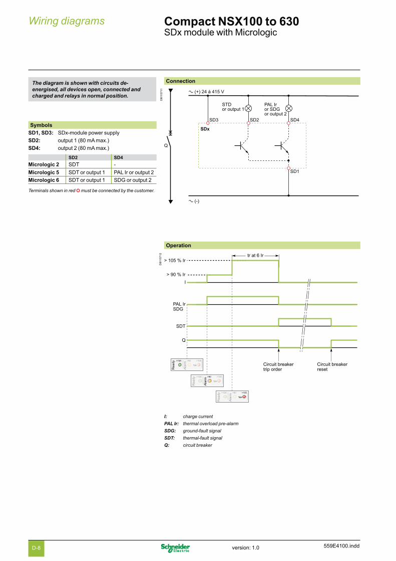
559E4100.indd
Connection
DB
1157
11 a (+) 24 à 415 V
a (-)
SD1
SD4SD2SD3
STDor output 1
PAL Iror SDGor output 2
SDx
Q
Wiring diagrams Compact NSX100 to 630SDx module with Micrologic
Symbols
SD1, SD3: SDx-module power supply
SD2: output 1 (80 mA max.)
SD4: output 2 (80 mA max.)
SD2 SD4
Micrologic 2 SDT -
Micrologic 5 SDT or output 1 PAL Ir or output 2
Micrologic 6 SDT or output 1 SDG or output 2
Terminals shown in red O must be connected by the customer.
Operation
DB
1157
12
Circuit breakertrip order
Circuit breakerreset
PAL IrSDG
SDT
Q
> 90 % Ir
I
> 105 % Irtr at 6 Ir
I: charge current
PAL Ir: thermal overload pre-alarm
SDG: ground-fault signal
SDT: thermal-fault signal
Q: circuit breaker
The diagram is shown with circuits de-energised, all devices open, connected and charged and relays in normal position.
D-8 version: 1.0

559E4100.indd
SDTAM module with Micrologic M
The diagram is shown with circuits de-energised, all devices open, connected and charged and relays in normal position.
Connection
DB
1157
13 a (+) 24 to 415 V
a (-)
SD1
SD4SD2SD3
SDTManualreset KA1
KA1
KM1
KM1
Closingorder
Openingorder
SDTAM
Auto reset (minutes)
Q
KM1
OFF1 14
15
2 124 10
6 8
Symbols
SD1, SD3: SDTAM-module power supply
SD2: thermal-fault signal output(80 mA max.)
SD4: contactor-control output(80 mA max.)
SD2 SD4
Micrologic 2-M SDT KA1
Micrologic 6 E-M SDT KA1
Terminals shown in red O must be connected by the customer.
I: charge current
SDT: thermal-fault signal
KA1: auxiliary relay (e.g. Merlin Gerin RDN or RTBT relay)
KM1: motor contactor
Q: circuit breaker
Operation
DB
1157
14 Class (tr) at 7.2 Ir
400 ms
400 ms before circuit-breaker tripping order
Contactor closing order
Manual orautomatic reset
SDT
KA1
KM1
Q
I
< 95 % T°
> 95 % T°
%T°
%T°
D-9version: 1.0

Rei
nfo
rced
dis
crim
inat
ion

Functions and characteristics A-1Installation recommendations B-1Dimensions and connection C-1Wiring diagrams D-1
Tripping curvesCompact NSX100 to 250 protection of distribution systems E-2Compact NSX100 to 250 motor protection E-6Compact NSX400 to 630 protection of distribution systems E-8Compact NSX400 to 630 motor protection E-10Compact NSX100 to 630 reflex tripping E-12
Current and energy limiting curves
Catalogue numbers F-1Glossary G-1
Compact NSX Additional characteristicsContents
E-1 559E5000.indd version: 1.0

E-2
Tripping curvesCompact NSX100 to 250Protection of distribution systems
Additional characteristics
TM magnetic trip units
TM16D / TM16G TM25D / TM25G
DB
1147
59
.5 .7 1 2 3 4 5 7 10 20 30 50 70 100 200 300
I / Ir
10 0005 000
2 000
1 000
500
200
100
50
20
10
5
2
1
.5
.2
.1
.05
.02
.01
.005
.002
.001
t(s)
TM16G : Im = 4 x In
TM16D : Im = 12 x In
t < 10 ms
DB
1147
60
.5 .7 1 2 3 4 5 7 10 20 30 50 70 100 200 300
I / Ir
10 0005 000
2 000
1 000
500
200
100
50
20
10
5
2
1
.5
.2
.1
.05
.02
.01
.005
.002
.001
t(s)
TM25G : Im = 3.2 x In
TM25D : Im = 12 x In
t < 10 ms
Reflex tripping.
TM32D / TM40D / TM40G TM50D / TM63D / TM63G
DB
1147
61
.5 .7 1 2 3 4 5 7 10 20 30 50 70 100 200 300
I / Ir
10 0005 000
2 000
1 000
500
200
100
50
20
10
5
2
1
.5
.2
.1
.05
.02
.01
.005
.002
.001
t(s)
TM40G : Im = 2 x In
TM40D : Im = 12 x In
TM32D : Im = 12.5 x In
t < 10 ms
DB
1147
62
.5 .7 1 2 3 4 5 7 10 20 30 50 70 100 200 300
I / Ir
10 0005 000
2 000
1 000
500
200
100
50
20
10
5
2
1
.5
.2
.1
.05
.02
.01
.005
.002
.001
t(s)
TM63G : Im = 2 x In
TM50D : Im = 10 x In
TM63D : Im = 8 x In
t < 10 ms
Reflex tripping.
559E5100.inddversion: 1.0

TM magnetic trip units (cont.)
TM80D / TM100D TM125D / TM160D
DB
1147
63
.5 .7 1 2 3 4 5 7 10 20 30 50 70 100 200 300
I / Ir
10 0005 000
2 000
1 000
500
200
100
50
20
10
5
2
1
.5
.2
.1
.05
.02
.01
.005
.002
.001
t(s)
TM80D/TM100D :Im = 8 x In
t < 10 ms
DB
1147
64
.5 .7 1 2 3 4 5 7 10 20 30 50 70 100 200 300
I / Ir
10 0005 000
2 000
1 000
500
200
100
50
20
10
5
2
1
.5
.2
.1
.05
.02
.01
.005
.002
.001
t(s)
TM160D :Im = 8 x In
TM125D : Im = 10 x In
t < 10 ms
Reflex tripping.
TM200D / TM250D
DB
1147
65
.5 .7 1 2 3 4 5 7 10 20 30 50 70 100 200 300
I / Ir
10 0005 000
2 000
1 000
500
200
100
50
20
10
5
2
1
.5
.2
.1
.05
.02
.01
.005
.002
.001
t(s)
TM200D/TM250D :Im = 5 ... 10 x In
t < 10 ms
Reflex tripping.
E-3 559E5100.indd version: 1.0

E-4
Tripping curvesCompact NSX100 to 250Protection of distribution systems (cont.)
Additional characteristics
Micrologic 2.2 and 2.2 G electronic trip units
Micrologic 2.2 - 40... 160 A Micrologic 2.2 - 250 A
DB
1147
66
.5 .7 1 2 3 4 5 7 10 20 30 50 70 100 200 300
I / Ir
10 0005 000
2 000
1 000
500
200
100
50
20
10
5
2
1
.5
.2
.1
.05
.02
.01
.005
.002
.001
t(s)
t < 10 ms
Isd = 1.5 ...10 x Ir
Ii = 15 x In
40 A : Ir = 16 ...40 A100 A : Ir = 36 ...100 A160 A : Ir = 57 ...160 A
DB
1147
67
.5 .7 1 2 3 4 5 7 10 20 30 50 70 100 200 300
I / Ir
10 0005 000
2 000
1 000
500
200
100
50
20
10
5
2
1
.5
.2
.1
.05
.02
.01
.005
.002
.001
t(s)
Ii = 12 x In
t < 10 ms
250 A : Ir = 90 ...250 A
Isd = 1.5 ...10 x Ir
Reflex tripping.
Micrologic 2.2 G - 40... 160 A Micrologic 2.2 G - 250 A
DB
1147
68
.5 .7 1 2 3 4 5 7 10 20 30 50 70 100 200 300
I / Ir
10 0005 000
2 000
1 000
500
200
100
50
20
10
5
2
1
.5
.2
.1
.05
.02
.01
.005
.002
.001
t(s)
Ii = 15 x In
t < 10 ms
40 A : Ir = 16 ...40 A100 A : Ir = 36 ...100 A160 A : Ir = 57 ...160 A
Isd = 1.5 ...9 x Ir
DB
1147
69
.5 .7 1 2 3 4 5 7 10 20 30 50 70 100 200 300
I / Ir
10 0005 000
2 000
1 000
500
200
100
50
20
10
5
2
1
.5
.2
.1
.05
.02
.01
.005
.002
.001
t(s)
Ii = 12 x In
t < 10 ms
250 A : Ir = 90 ...250 A
Isd = 1.5 ...9 x Ir
Reflex tripping.
559E5100.inddversion: 1.0

Micrologic 5.2 and 6.2 A or E electronic trip units
Micrologic 5.2 and 6.2 A or E - 40... 160 A Micrologic 5.2 and 6.2 A or E - 250 A
DB
1147
70
.5 .7 1 2 3 4 5 7 10 20 5 7 10 20 30 50
10 0005 000
2 000
1 000
500
200
100
50
20
10
5
2
1
.5
.2
.1
.05
.02
.01
.005
.002
.001
t(s)
I / Ir I / In
0.40.30.20.1
0
I²t OFF
t < 10 ms
I²t ON
40 A : Ir = 16 ...40 A100 A : Ir = 36 ...100 A160 A : Ir = 56 ...160 A
tr = 0.5 ...16 s
Isd = 1.5 ...10 x Ir
Ii = 1.5 ...15 In
DB
1147
71
.5 .7 1 2 3 4 5 7 10 20 5 7 10 20 30 50
10 0005 000
2 000
1 000
500
200
100
50
20
10
5
2
1
.5
.2
.1
.05
.02
.01
.005
.002
.001
t(s)
I / Ir I / In
0.40.30.20.1
0
I²t OFF
I²t ON
t < 10 ms
250 A : Ir = 90 ...250 A
Ii = 1.5 ...12 In
Isd = 1.5 ...10 x Ir
tr = 0.5 ...16 s
Reflex tripping.
Micrologic 6.2 A or E (ground-fault protection)
DB
1147
72
.05 .07 .1 .2 .3 .4 .5 .7 1 2 3 5 7 10 20 30
I / In
10 0005 000
2 000
1 000
500
200
100
50
20
10
5
2
1
.5
.2
.1
.05
.02
.01
.005
.002
.001
t(s)
I²t OFF
I²t ON
0
0.40.30.20.1
40 A : Ig = 0.4 ...1 x In> 40 A : Ig = 0.2 ...1 x In
4
The tripping curve is identical to that of Micrologic 5.Ground-fault protection is shown separately.
E-5 559E5100.indd version: 1.0

E-6
Tripping curvesCompact NSX100 to 250Motor protection
Additional characteristics
MA magnetic trip units
MA2.5... MA100 MA150 and MA220
DB
1157
15
.5 .7 1 2 3 4 5 7 10 20 30 50 70 100 200 300
I / Ir
10 0005 000
2 000
1 000
500
200
100
50
20
10
5
2
1
.5
.2
.1
.05
.02
.01
.005
.002
.001
t(s)
Im = 6 ... 14 x In
Thermal withstand
t < 10 ms
DB
1157
16
.5 .7 1 2 3 4 5 7 10 20 30 50 70 100 200 300
I / Ir
10 0005 000
2 000
1 000
500
200
100
50
20
10
5
2
1
.5
.2
.1
.05
.02
.01
.005
.002
.001
t(s)
Im = 9 ... 14 x In
MA150
MA220
Thermal withstand
t < 10 ms
Reflex tripping.
Micrologic 2.2 M electronic trip units
Micrologic 2.2 M - 25 A Micrologic 2.2 M - 50... 220 A
DB
1147
75
.5 .7 1 2 3 4 5 7 10 20 30 50 70 100 200 300
I / Ir
10 0005 000
2 000
1 000
500
200
100
50
20
10
5
2
1
.5
.2
.1
.05
.02
.01
.005
.002
.001
t(s)
Ii = 17 x In
t < 10 ms
25 A : Ir = 12 ...25 A
Isd = 5 ...13 x Ir
class 20class 10class 5
DB
1147
76
.5 .7 1 2 3 4 5 7 10 20 30 50 70 100 200 300
I / Ir
10 0005 000
2 000
1 000
500
200
100
50
20
10
5
2
1
.5
.2
.1
.05
.02
.01
.005
.002
.001
t(s)
Ii = 15 x In
t < 10 ms
50 A : Ir = 25 ...50 A100 A : Ir = 50 ...100 A150 A : Ir = 70 ...150 A220 A : Ir = 100 ...220 A
class 20class 10class 5
Isd = 5 ...13 x Ir
Reflex tripping.
559E5100.inddversion: 1.0
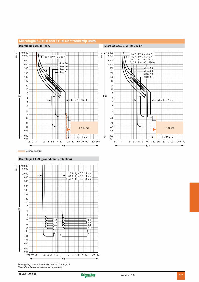
Micrologic 6.2 E-M and 6 E-M electronic trip units
Micrologic 6.2 E-M - 25 A Micrologic 6.2 E-M - 50... 220 A
DB
1147
77
.5 .7 1 2 3 4 5 7 10 20 30 50 70 100 200 300
I / Ir
10 0005 000
2 000
1 000
500
200
100
50
20
10
5
2
1
.5
.2
.1
.05
.02
.01
.005
.002
.001
t(s)
Ii = 17 x In
t < 10 ms
25 A : Ir = 12 ...25 A
class 30class 20class 10class 5
Isd = 5 ...13 x IrD
B11
4778
.5 .7 1 2 3 4 5 7 10 20 30 50 70 100 200 300
I / Ir
10 0005 000
2 000
1 000
500
200
100
50
20
10
5
2
1
.5
.2
.1
.05
.02
.01
.005
.002
.001
t(s)
Ii = 15 x In
t < 10 ms
50 A : Ir = 25 ...50 A80 A : Ir = 35 ...80 A
150 A : Ir = 70 ...150 A220 A : Ir = 100 ...220 A
class 30class 20class 10class 5
Isd = 5 ...13 x Ir
Reflex tripping.
Micrologic 6 E-M (ground-fault protection)
DB
1147
91
.05 .07 .1 .2 .3 .4 .5 .7 1 2 3 5 7 10 20 30
I / In
10 0005 000
2 000
1 000
500
200
100
50
20
10
5
2
1
.5
.2
.1
.05
.02
.01
.005
.002
.001
t(s)
4
0
0.40.30.20.1
0
0.40.30.20.1
25 A : Ig = 0.6 ...1 x In 50 A : Ig = 0.3 ...1 x In> 50 A : Ig = 0.2 ...1 x In
The tripping curve is identical to that of Micrologic 6.Ground-fault protection is shown separately.
E-7 559E5100.indd version: 1.0

E-8
Tripping curvesCompact NSX400 to 630Protection of distribution systems
Additional characteristics
Micrologic 2.3, 5.3 and 6.3 A or E electronic trip units
Micrologic 2.3 - 250... 400 A Micrologic 2.3 - 630 A
DB
1147
80
.5 .7 1 2 3 4 5 7 10 20 30 50 70 100 200 300
I / Ir
10 0005 000
2 000
1 000
500
200
100
50
20
10
5
2
1
.5
.2
.1
.05
.02
.01
.005
.002
.001
t(s)
Ii = 12 x In
t < 10 ms
250 A : Ir = 63 ...250 A400 A : Ir = 144 ...400 A
Isd = 1.5 ...10 x IrD
B11
4781
.5 .7 1 2 3 4 5 7 10 20 30 50 70 100 200 300
I / Ir
10 0005 000
2 000
1 000
500
200
100
50
20
10
5
2
1
.5
.2
.1
.05
.02
.01
.005
.002
.001
t(s)
Ii = 11 x In
t < 10 ms
630 A : Ir = 225 ...630 A
Isd = 1.5 ...10 x Ir
Reflex tripping.
Micrologic 5.3 and 6.3 A or E - 400 A Micrologic 5.3 and 6.3 A or E - 630 A
DB
1147
82
.5 .7 1 2 3 4 5 7 10 20 5 7 10 20 30 50
10 0005 000
2 000
1 000
500
200
100
50
20
10
5
2
1
.5
.2
.1
.05
.02
.01
.005
.002
.001
t(s)
I / Ir I / In
0.40.30.20.1
0
I²t OFF
t < 10 ms
I²t ON
400 A : Ir = 100 ...400 A
tr = 0.5 ...16 s
Isd = 1.5 ...10 x Ir
Ii = 1.5 ...12 In
DB
1147
83
.5 .7 1 2 3 4 5 7 10 20 5 7 10 20 30 50
10 0005 000
2 000
1 000
500
200
100
50
20
10
5
2
1
.5
.2
.1
.05
.02
.01
.005
.002
.001
t(s)
I / Ir I / In
0.40.30.20.1
0
I²t OFF
I²t ON
t < 10 ms
630 A : Ir = 225 ...630 A
Isd = 1.5 ...10 x Ir
Ii = 1.5 ...11 In
tr = 0.5 ...16 s
Reflex tripping.
559E5100.inddversion: 1.0

Micrologic 6.3 A or E electronic trip units (cont.)
Micrologic 6.3 A or E (ground-fault protection)
DB
1147
72
.05 .07 .1 .2 .3 .4 .5 .7 1 2 3 5 7 10 20 30
I / In
10 0005 000
2 000
1 000
500
200
100
50
20
10
5
2
1
.5
.2
.1
.05
.02
.01
.005
.002
.001
t(s)
I²t OFF
I²t ON
0
0.40.30.20.1
40 A : Ig = 0.4 ...1 x In> 40 A : Ig = 0.2 ...1 x In
4
The tripping curve is identical to that of Micrologic 6.Ground-fault protection is shown separately.
E-9 559E5100.indd version: 1.0

E-10
Tripping curvesCompact NSX400 to 630Motor protection
Additional characteristics
Micrologic 1.3 M and 2.3 M electronic trip units
Micrologic 1.3 M - 320 A Micrologic 1.3 M - 500 A
DB
1157
17
.5 .7 1 2 3 4 5 7 10 20 30 50 70 100 200 300
I / In
10 0005 000
2 000
1 000
500
200
100
50
20
10
5
2
1
.5
.2
.1
.05
.02
.01
.005
.002
.001
t(s)
Ii = 15 x In
Thermal withstand
t < 10 ms
Isd = 5 ...13 x In
DB
1157
18
.5 .7 1 2 3 4 5 7 10 20 30 50 70 100 200 300
I / In
10 0005 000
2 000
1 000
500
200
100
50
20
10
5
2
1
.5
.2
.1
.05
.02
.01
.005
.002
.001
t(s)
Ii = 13 x In
t < 10 ms
Thermal withstand
Isd = 5 ...13 x In
Reflex tripping.
Micrologic 2.3 M - 320 A Micrologic 2.3 M - 500 A
DB
1147
87
.5 .7 1 2 3 4 5 7 10 20 30 50 70 100 200 300
I / Ir
10 0005 000
2 000
1 000
500
200
100
50
20
10
5
2
1
.5
.2
.1
.05
.02
.01
.005
.002
.001
t(s)
Ii = 15 x In
t < 10 ms
320 A : Ir = 160 ...320 A
class 20class 10class 5
Isd = 5 ...13 x Ir
DB
1147
88
.5 .7 1 2 3 4 5 7 10 20 30 50 70 100 200 300
I / Ir
10 0005 000
2 000
1 000
500
200
100
50
20
10
5
2
1
.5
.2
.1
.05
.02
.01
.005
.002
.001
t(s)
Ii = 13 x In
t < 10 ms
500 A : Ir = 250 ...500 A
class 20class 10class 5
Isd = 5 ...13 x Ir
Reflex tripping.
559E5100.inddversion: 1.0

Micrologic 6.3 E-M and 6 E-M electronic trip units
Micrologic 6.3 E-M - 320 A Micrologic 6.3 E-M - 500 A
DB
1147
89
.5 .7 1 2 3 4 5 7 10 20 30 50 70 100 200 300
I / Ir
10 0005 000
2 000
1 000
500
200
100
50
20
10
5
2
1
.5
.2
.1
.05
.02
.01
.005
.002
.001
t(s)
Ii = 15 x In
t < 10 ms
320 A : Ir = 160 ...320 A
class 30class 20class 10class 5
Isd = 5 ...13 x IrD
B11
4790
.5 .7 1 2 3 4 5 7 10 20 30 50 70 100 200 300
I / Ir
10 0005 000
2 000
1 000
500
200
100
50
20
10
5
2
1
.5
.2
.1
.05
.02
.01
.005
.002
.001
t(s)
Ii = 13 x In
t < 10 ms
500 A : Ir = 250 ...500 A
class 30class 20class 10class 5
Isd = 5 ...13 x Ir
Reflex tripping.
Micrologic 6 E-M (motor protection)
DB
1156
34
.05 .07 .1 .2 .3 .4 .5 .7 1 2 3 5 7 10 20 30
I / In
10 0005 000
2 000
1 000
500
200
100
50
20
10
5
2
1
.5
.2
.1
.05
.02
.01
.005
.002
.001
t(s)
4
0
0.40.30.20.1
0
0.40.30.20.1
Ig = 0.2 ...1 x In
The tripping curve is identical to that of Micrologic 6.Ground-fault protection is shown separately.
E-11 559E5100.indd version: 1.0

E-12
Tripping curvesCompact NSX100 to 630Reflex tripping
Additional characteristics
Compact NSX100 to 630 devices incorporate the exclusive reflex-tripping system.This system breaks very high fault currents.The device is mechanically tripped via a "piston" actuated directly by the pressure produced in the breaking units by the short-circuit.For high short-circuits, this system provides a faster break, thereby ensuring discrimination.Reflex-tripping curves are exclusively a function of the circuit-breaker rating.
DB
1157
21
3
4
5
6
7
8
10
20
2 3 4 6 10 20 30 40 60 100 200
t(ms)
kA rms
NSX630
NSX400
NSX250
NSX100NSX160
559E5100.inddversion: 1.0

Current and energy limiting curves
The limiting capacity of a circuit breaker is its aptitude to let through a current, during a short-circuit, that is less than the prospective short-circuit current.
Ics = 100 % IcuThe exceptional limiting capacity of the Compact NSX range greatly reduces the forces created by fault currents in devices.The result is a major increase in breaking performance.In particular, the service breaking capacity Ics is equal to 100 % of Icu.The Ics value, defined by IEC standard 60947-2, is guaranteed by tests comprising the following steps:
break three times consecutively a fault current equal to 100% of Icu bcheck that the device continues to function normally, that is: bit conducts the rated current without abnormal temperature rise vprotection functions perform within the limits specified by the standard vsuitability for isolation is not impaired. v
Longer service life of electrical installationsCurrent-limiting circuit breakers greatly reduce the negative effects of short-circuits on installations.
Thermal effectsLess temperature rise in conductors, therefore longer service life for cables.
Mechanical effectsReduced electrodynamic forces, therefore less risk of electrical contacts or busbars being deformed or broken.
Electromagnetic effectsFewer disturbances for measuring devices located near electrical circuits.
Economy by means of cascadingCascading is a technique directly derived from current limiting. Circuit breakers with breaking capacities less than the prospective short-circuit current may be installed downstream of a limiting circuit breaker. The breaking capacity is reinforced by the limiting capacity of the upstream device. It follows that substantial savings can be made on downstream equipment and enclosures.
Current and energy limiting curvesThe limiting capacity of a circuit breaker is expressed by two curves which are a function of the prospective short-circuit current (the current which would flow if no protection devices were installed):
the actual peak current (limited current) bthermal stress (A b 2s), i.e. the energy dissipated by the short-circuit in a conductor
with a resistance of 1 Ω.
ExampleWhat is the real value of a 150 kA rms prospective short-circuit (i.e. 330 kA peak) limited by an NSX250L upstream ?The answer is 30 kA peak (curve page E-14).
Maximum permissible cable stressesThe table below indicates the maximum permissible thermal stresses for cables depending on their insulation, conductor (Cu or Al) and their cross-sectional area (CSA). CSA values are given in mm² and thermal stresses in A2s.
CSA 1.5 mm² 2.5 mm² 4 mm² 6 mm² 10 mm²
PVC Cu 2.97x10⁴ 8.26x10⁴ 2.12x10⁵ 4.76x10⁵ 1.32x10⁶
Al 5.41x10⁵
PRC Cu 4.10x10⁴ 1.39x10⁵ 2.92x10⁵ 6.56x10⁵ 1.82x10⁶
Al 7.52x10⁵
CSA 16 mm² 25 mm² 35 mm² 50 mm²
PVC Cu 3.4x10⁶ 8.26x10⁶ 1.62x10⁷ 3.31x10⁷
Al 1.39x10⁶ 3.38x10⁶ 6.64x10⁶ 1.35x10⁷
PRC Cu 4.69x10⁶ 1.39x10⁷ 2.23x10⁷ 4.56x10⁷
Al 1.93x10⁶ 4.70x10⁶ 9.23x10⁶ 1.88x10⁷
ExampleIs a Cu/PVC cable with a CSA of 10 mm² adequately protected by an NSX160F?The table above indicates that the permissible stress is 1.32x10⁶ A2s.All short-circuit currents at the point where an NSX160F (Icu = 35 kA) is installed are limited with a thermal stress less than 6x10⁵ A2s (curve page E-14).Cable protection is therefore ensured up to the limit of the breaking capacity of the circuit breaker.
DB
1157
19
(t)
ProspectiveIsc peak
(Isc)
Prospectivecurrent
ProspectiveIsc
Limited Iscpeak
Actualcurrent
LimitedIsc
The exceptional limiting capacity of the Compact NSX range is due to the rotating double-break technique (very rapid natural repulsion of contacts and the appearance of two arc voltages in-series with a very steep wave front).
E-13 559E5100.indd version: 1.0

E-14
Current and energy limiting curvesAdditional characteristics
Current-limiting curves
Voltage 400/440 V AC Voltage 660/690 V AC
Limited short-circuit current (k peak) Limited short-circuit current (k peak)
DB
1163
69
2 3 4 6 10 20 30 4050 70 100 200 300
300
200
10080706050
40
30
20
1087654
kA rms
kÂ
NSX630LS
HN
F LS
HN
FB
NSX400
NSX250NSX100NSX160
146
DB
1163
70
2 3 4 6 10 20 30 40 6065
100 200 300
300
200
146
10080706050
40
30
20
1087654
k NSX630L
L
NSX400
NSX250
NSX100NSX160
S
S
H
F, N
FN, H
kA rms
Energy-limiting curves
Voltage 400/440 V AC Voltage 660/690 V AC
Limited energy Limited energy
DB
1163
71
2 3 4 6 10 20 30 4050 70 100 150200 30023
5
2
105
3
5
106
2
3
5
107
2
3
5
108
21.41
3
5
109
A2s
B
NSX630
NSX400
NSX250
NSX100NSX160
LSHF N
LSHF N
kA rms
DB
1163
72
2 3 4 6 10 20 30 4050 70 100 150200 30023
5
2
105
3
5
106
2
3
5
107
2
3
5
108
21.41
3
5
109
A2s
N, H
HNSX630
NSX400
NSX250
NSX100NSX160
L
L
S
S
F, N
F
kA rms
559E5100.inddversion: 1.0

E-15 559E5100.indd version: 1.0

Cat
alo
gu
e n
um
ber
s

Functions and characteristics A-1Installation recommendations B-1Dimensions and connection C-1Wiring diagrams D-1Additional characteristics E-1
NSX100 to 250 F-3
NSX400 to 630 F-29
Glossary G-1
Compact NSX Catalogue numbersContents
559E6000.indd version: 1.0 F-1

559E6000.inddversion: 1.0F-2

F-3
Compact NSX Compact NSX100 to 250Contents
NSX100/160/250F: complete fixed/FC device F-4Compact NSX100/160/250F (36 kA 380/415 V) F-4
NSX100/160/250N: complete fixed/FC device F-5Compact NSX100/160/250N (50 kA 380/415 V) F-5
NSX100/160/250H: complete fixed/FC device F-6Compact NSX100/160/250H (70 kA 380/415 V) F-6
NSX100/160/250NA: complete fixed/FC device F-7Compact NSX100/160/250NA F-7
NSX100/160/250F/N/H/S/L: fixed/FC device based on separate components F-8Compact and Vigicompact F-8
Trip unit accessories F-10Compact and Vigicompact NSX100/160/250 F-10
Installation and connection F-11Compact and Vigicompact NSX100/160/250 F-11
Accessories F-12Compact and Vigicompact NSX100/160/250 F-12
Monitoring and control, test tools F-21Compact and Vigicompact NSX100/160/250 F-21
version: 2.0 559E6100TDM.indd

F-4
Catalogue numbers NSX100/160/250F: complete fixed/FC deviceCompact NSX100/160/250F (36 kA 380/415 V)
Compact NSX100/160/250FWith thermal-magnetic trip unit TM-D
DB
1122
22 Compact NSX100F (36 kA at 380/415 V)Rating 3P 2d 3P 3d 4P 3d 4P 4dTM16D LV429627 LV429637 LV429647 LV429657TM25D LV429626 LV429636 LV429646 LV429656TM32D LV429625 LV429635 LV429645 LV429655TM40D LV429624 LV429634 LV429644 LV429654TM50D LV429623 LV429633 LV429643 LV429653TM63D LV429622 LV429632 LV429642 LV429652TM80D LV429621 LV429631 LV429641 LV429651TM100D LV429620 LV429630 LV429640 LV429650Compact NSX160F (36 kA at 380/415 V)
Rating 3P 2d 3P 3d 4P 3d 4P 4dTM80D LV430623 LV430633 LV430643 LV430653TM100D LV430622 LV430632 LV430642 LV430652TM125D LV430621 LV430631 LV430641 LV430651TM160D LV430620 LV430630 LV430640 LV430650Compact NSX250F (36 kA at 380/415 V)
Rating 3P 3d 3P 3d 4P 3d 4P 4dTM125D LV431623 LV431633 LV431643 LV431653TM160D LV431622 LV431632 LV431642 LV431652TM200D LV431621 LV431631 LV431641 LV431651TM250D LV431620 LV431630 LV431640 LV431650
With electronic trip unit Micrologic 2.2 (LSOI protection)
DB
1122
23 Compact NSX100F (36 kA at 380/415 V)Rating 3P 3d 4P 3d, 4d, 3d + N/240 LV429772 LV429782100 LV429770 LV429780Compact NSX160F (36 kA at 380/415 V)
Rating 3P 3d 4P 3d, 4d, 3d + N/2100 LV430771 LV430781160 LV430770 LV430780Compact NSX250F (36 kA at 380/415 V)
Rating 3P 3d 4P 3d, 4d, 3d + N/2100 LV431772 LV431782160 LV431771 LV431781250 LV431770 LV431780
With electronic trip unit Micrologic 5.2 A (LSI protection, ammeter)
DB
1122
24 Compact NSX100F (36 kA at 380/415 V)Rating 3P 3d 4P 3d, 4d, 3d + N/2, 3d + OSN40 LV429882 LV429887100 LV429880 LV429885Compact NSX160F (36 kA at 380/415 V)
Rating 3P 3d 4P 3d, 4d, 3d + N/2, 3d + OSN100 LV430881 LV430886160 LV430880 LV430885Compact NSX250F (36 kA at 380/415 V)
Rating 3P 3d 4P 3d, 4d, 3d + N/2, 3d + OSN100 LV431862 LV431867160 LV431861 LV431866250 LV431860 LV431865
With electronic trip unit Micrologic 5.2 E (LSI protection, energy meter)To be ordered with 2 catalogue numbers: 1 basic frame + 1 trip unit
With electronic trip unit Micrologic 6.2 A (LSIG protection, ammeter)To be ordered with 2 catalogue numbers: 1 basic frame + 1 trip unit
With electronic trip unit Micrologic 6.2 E (LSIG protection, energy meter)To be ordered with 2 catalogue numbers: 1 basic frame + 1 trip unit
With electronic trip unit Micrologic 6.2 E-M (LSIG motor protection, energy meter)To be ordered with 2 catalogue numbers: 1 basic frame + 1 trip unit
559E6100.inddversion: 2.0

F-5
Catalogue numbers NSX100/160/250N: complete fixed/FC deviceCompact NSX100/160/250N (50 kA 380/415 V)
Compact NSX100/160/250NWith thermal-magnetic trip unit TM-D
DB
1122
22 Compact NSX100N (50 kA at 380/415 V)Rating 3P 3d 4P 3d 4P 4dTM16D LV429847 LV429857 LV429867TM25D LV429846 LV429856 LV429866TM32D LV429845 LV429855 LV429865TM40D LV429844 LV429854 LV429864TM50D LV429843 LV429853 LV429863TM63D LV429842 LV429852 LV429862TM80D LV429841 LV429851 LV429861TM100D LV429840 LV429850 LV429860Compact NSX160N (50 kA at 380/415 V)
Rating 3P 3d 4P 3d 4P 4dTM80D LV430843 LV430853 LV430863TM100D LV430842 LV430852 LV430862TM125D LV430841 LV430851 LV430861TM160D LV430840 LV430850 LV430860Compact NSX250N (50 kA at 380/415 V)
Rating 3P 3d 4P 3d 4P 4dTM125D LV431833 LV431843 LV431853TM160D LV431832 LV431842 LV431852TM200D LV431831 LV431841 LV431851TM250D LV431830 LV431840 LV431850
With electronic trip unit Micrologic 2.2 (LSOI protection)
DB
1122
23 Compact NSX100N (50 kA at 380/415 V)Rating 3P 3d 4P 3d, 4d, 3d + N/240 LV429797 LV429807100 LV429795 LV429805Compact NSX160N (50 kA at 380/415 V)
Rating 3P 3d 4P 3d, 4d, 3d + N/2100 LV430776 LV430786160 LV430775 LV430785Compact NSX250N (50 kA at 380/415 V)
Rating 3P 3d 4P 3d, 4d, 3d + N/2100 LV431872 LV431877160 LV431871 LV431876250 LV431870 LV431875
With electronic trip unit Micrologic 5.2 A (LSI protection, ammeter)
DB
1122
24 Compact NSX100N (50 kA at 380/415 V)Rating 3P 3d 4P 3d, 4d, 3d + N/2, OSN40 LV429892 LV429897100 LV429890 LV429895Compact NSX160N (50 kA at 380/415 V)
Rating 3P 3d 4P 3d, 4d, 3d + N/2, OSN100 LV430891 LV430896160 LV430890 LV430895Compact NSX250N (50 kA at 380/415 V)
Rating 3P 3d 4P 3d, 4d, 3d + N/2, OSN100 LV431882 LV431887160 LV431881 LV431886250 LV431880 LV431885
With electronic trip unit Micrologic 5.2 E (LSI protection, energy meter)To be ordered with 2 catalogue numbers: 1 basic frame + 1 trip unit
With electronic trip unit Micrologic 6.2 A (LSIG protection, ammeter)To be ordered with 2 catalogue numbers: 1 basic frame + 1 trip unit
With electronic trip unit Micrologic 6.2 E (LSIG protection, energy meter)To be ordered with 2 catalogue numbers: 1 basic frame + 1 trip unit
With electronic trip unit Micrologic 6.2 E-M (LSIG motor protection, energy meter)To be ordered with 2 catalogue numbers: 1 basic frame + 1 trip unit
version: 2.0 559E6100.indd

F-6
Catalogue numbers NSX100/160/250H: complete fixed/FC deviceCompact NSX100/160/250H (70 kA 380/415 V)
Compact NSX100/160/250HWith thermal-magnetic trip unit TM-D
DB
1122
22 Compact NSX100H (70 kA at 380/415 V)Rating 3P 3d 4P 3d 4P 4dTM16D LV429677 LV429687 LV429697TM25D LV429676 LV429686 LV429696TM32D LV429675 LV429685 LV429695TM40D LV429674 LV429684 LV429694TM50D LV429673 LV429683 LV429693TM63D LV429672 LV429682 LV429692TM80D LV429671 LV429681 LV429691TM100D LV429670 LV429680 LV429690Compact NSX160H (70 kA at 380/415 V)
Rating 3P 3d 4P 3d 4P 4dTM80D LV430673 LV430683 LV430693TM100D LV430672 LV430682 LV430692TM125D LV430671 LV430681 LV430691TM160D LV430670 LV430680 LV430690Compact NSX250H (70 kA at 380/415 V)
Rating 3P 3d 4P 3d 4P 4dTM125D LV431673 LV431683 LV431693TM160D LV431672 LV431682 LV431692TM200D LV431671 LV431681 LV431691TM250D LV431670 LV431680 LV431690
With electronic trip unit Micrologic 2.2 (LSOI protection)
DB
1122
23 Compact NSX100H (70 kA at 380/415 V)Rating 3P 3d 4P 3d, 4d, 3d + N/240 LV429792 LV429802100 LV429790 LV429800Compact NSX160H (70 kA at 380/415 V)
Rating 3P 3d 4P 3d, 4d, 3d + N/2100 LV430791 LV430801160 LV430790 LV430800Compact NSX250H (70 kA at 380/415 V)
Rating 3P 3d 4P 3d, 4d, 3d + N/2100 LV431792 LV431802160 LV431791 LV431801250 LV431790 LV431800
With electronic trip unit Micrologic 5.2 A (LSI protection, ammeter)
DB
1122
24 Compact NSX100H (70 kA at 380/415 V)Rating 3P 3d 4P 3d, 4d, 3d + N/2, OSN40 LV429794 LV429804100 LV429793 LV429803Compact NSX160H (70 kA at 380/415 V)
Rating 3P 3d 4P 3d, 4d, 3d + N/2, OSN100 LV430795 LV430805160 LV430794 LV430804Compact NSX250H (70 kA at 380/415 V)
Rating 3P 3d 4P 3d, 4d, 3d + N/2, OSN100 LV431797 LV431807160 LV431796 LV431806250 LV431795 LV431805
With electronic trip unit Micrologic 5.2 E (LSI protection, energy meter)To be ordered with 2 catalogue numbers: 1 basic frame + 1 trip unit
With electronic trip unit Micrologic 6.2 A (LSIG protection, ammeter)To be ordered with 2 catalogue numbers: 1 basic frame + 1 trip unit
With electronic trip unit Micrologic 6.2 E (LSIG protection, energy meter)To be ordered with 2 catalogue numbers: 1 basic frame + 1 trip unit
With electronic trip unit Micrologic 6.2 E-M (LSIG motor protection, energy meter)To be ordered with 2 catalogue numbers: 1 basic frame + 1 trip unit
559E6100.inddversion: 2.0

F-7
Catalogue numbers NSX100/160/250NA: complete fixed/FC deviceCompact NSX100/160/250NA
Compact NSX100/160/250NA switch-disconnectorWith NA switch-disconnector unit
DB
1122
44 Compact NSX100NARating 3P 4P100 LV429629 LV429639Compact NSX160NA
Rating 3P 4P160 LV430629 LV430639Compact NSX250NA
Rating 3P 4P250 LV431629 LV431639
version: 2.0 559E6100.indd

F-8
Catalogue numbers NSX100/160/250F/N/H/S/L: fixed/FC device based on separate componentsCompact and Vigicompact
Basic frame
DB
1122
45 Compact NSX1003P 4P
NSX100F (36 kA 380/415 V) LV429003 LV429008NSX100N (50 kA 380/415 V) LV429006 LV429011NSX100H (70 kA 380/415 V) LV429004 LV429009NSX100S (100 kA 380/415 V) LV429018 LV429019NSX100L (150 kA 380/415 V) LV429005 LV429010Compact NSX160
3P 4PNSX160F (36 kA 380/415 V) LV430403 LV430408NSX160N (50 kA 380/415 V) LV430406 LV430411NSX160H (70 kA 380/415 V) LV430404 LV430409NSX160S (100 kA 380/415 V) LV430391 LV430396NSX160L (150 kA 380/415 V) LV430405 LV430410Compact NSX250
3P 4PNSX250F (36 kA 380/415 V) LV431403 LV431408NSX250N (50 kA 380/415 V) LV431406 LV431411NSX250H (70 kA 380/415 V) LV431404 LV431409NSX250S (100 kA 380/415 V) LV431391 LV431396NSX250L (150 kA 380/415 V) LV431405 LV431410
+ Trip unitDistribution protection
DB
1122
46 Thermal-magnetic TM-DRating 3P 3d 4P 3d 4P 4dTM16D LV429037 LV429047 LV429057TM25D LV429036 LV429046 LV429056TM32D LV429035 LV429045 LV429055TM40D LV429034 LV429044 LV429054TM50D LV429033 LV429043 LV429053TM63D LV429032 LV429042 LV429052TM80D LV429031 LV429041 LV429051TM100D LV429030 LV429040 LV429050TM125D LV430431 LV430441 LV430451TM160D LV430430 LV430440 LV430450TM200D LV431431 LV431441 LV431451TM250D LV431430 LV431440 LV431450
DB
1122
47 Micrologic 2.2 (LSOI protection)
Rating 3P 3d 4P 3d, 4d, 3d + N/2Micrologic 2.2 40 A LV429072 LV429082Micrologic 2.2 100 A LV429070 LV429080Micrologic 2.2 160 A LV430470 LV430480Micrologic 2.2 250 A LV431470 LV431480
DB
1122
48 Micrologic 5.2 A (LSI protection, ammeter)Rating 3P 3d 4P 3d, 4d, 3d + N/2, 3d + OSNMicrologic 5.2 A 40 A LV429091 LV429101Micrologic 5.2 A 100 A LV429090 LV429100Micrologic 5.2 A 160 A LV430490 LV430495Micrologic 5.2 A 250 A LV431490 LV431495Micrologic 5.2 E (LSI protection, energy meter)
Rating 3P 3d 4P 3d, 4d, 3d + N/2, 3d + OSNMicrologic 5.2 E 40 A LV429096 LV429106Micrologic 5.2 E 100 A LV429095 LV429105Micrologic 5.2 E 160 A LV430491 LV430496Micrologic 5.2 E 250 A LV431491 LV431496Micrologic 6.2 A (LSIG protection, ammeter)Rating 3P 3d 4P 3d, 4d, 3d + N/2, 3d + OSN
Micrologic 6.2 A 40 A LV429111 LV429136Micrologic 6.2 A 100 A LV429110 LV429135Micrologic 6.2 A 160 A LV430505 LV430515Micrologic 6.2 A 250 A LV431505 LV431515Micrologic 6.2 E (LSIG protection, energy meter)Rating 3P 3d 4P 3d, 4d, 3d + N/2, 3d + OSN
Micrologic 6.2 E 40 A LV429116 LV429141Micrologic 6.2 E 100 A LV429116 LV429140Micrologic 6.2 E 160 A LV430506 LV430516Micrologic 6.2 E 250 A LV431506 LV431516
559E6100.inddversion: 2.0

F-9
Catalogue numbers NSX100/160/250F/N/H/S/L: fixed/FC device based on separate components (cont.)Compact and Vigicompact (cont.)
+ Trip unit (cont.)
Motor protection
DB
1156
66 Magnetic MA (I protection)Rating 3P 3d 4P 3dMA2.5 LV429125MA6.3 LV429124MA12.5 LV429123MA25 LV429122MA50 LV429121MA100 LV429120 LV429130MA150 LV430500 LV430510MA220 LV431500 LV431510
DB
1122
47 Micrologic 2.2-M (LSOI protection)
Rating 3P 3dMicrologic 2.2-M 25 A LV429174Micrologic 2.2-M 50 A LV429172Micrologic 2.2-M 100 A LV429170Micrologic 2.2-M 150 A LV430520Micrologic 2.2-M 220 A LV431520
DB
1122
48 Micrologic 6.2 E-M (LSIG protection, energy meter)Rating 3P 3dMicrologic 6.2 E-M 25 A LV429184Micrologic 6.2 E-M 50 A LV429182Micrologic 6.2 E-M 80 A LV429180Micrologic 6.2 E-M 150 A LV430521Micrologic 6.2 E-M 220 A LV431521
Generator protection
DB
1122
46 Thermal-magnetic TM-GRating 3P 3d 4P 4dTM16G LV429155 LV429165TM25G LV429154 LV429164TM40G LV429153 LV429163TM63G LV429152 LV429162
DB
1122
47 Micrologic 2.2 G (LSOI protection)
Rating 3P 3d 4P 3d, 4d, 3d + N/2Micrologic 2.2-G 40 A LV429076 LV429086Micrologic 2.2-G 100 A LV429075 LV429085Micrologic 2.2-G 160 A LV430475 LV430485Micrologic 2.2-G 250 A LV431475 LV431485
+ Vigi module or insulation monitoring moduleVigi module
DB
1122
49 3P 4PME type for NSX100/160 (200 to 440 V) LV429212 LV429213MH type for NSX100/160 (200 to 440 V) LV429210 LV429211MH type for NSX250 (200 to 440 V) LV431535 LV431536MH type for NSX100/160 (440 to 550 V) LV429215 LV429216MH type for NSX250 (440 to 550 V) LV431533 LV431534Connection for a 4P Vigi on a 3P breaker LV429214
Insulation monitoring module
DB
1122
49 3P 4P200 to 440 V AC LV429459 LV429460Connection for a 4P insulation monitoring module on a 3P breaker
LV429214
version: 2.0 559E6100.indd

F-10
Catalogue numbers Trip unit accessoriesCompact and Vigicompact NSX100/160/250
Trip unit accessoriesExternal neutral CT for 3 pole breaker with Micrologic 5/6
DB
1127
33 25-100 A LV429521150-250 A LV430563
24 V DC wiring accessory for Micrologic 5/6
DB
1127
30 24 V DC power supply connector LV434210
ZSI wiring accessory for NS630b NW with NSX
DB
1156
65 ZSI module LV434212
External power supply module (24 V DC - 1 A), class 4
DB
1127
36 24-30 V DC 5444048-60 V DC 54441100-125 V DC 54442110-130 V AC 54443200-240 V AC 54444380-415 V AC 54445
Battery module
DB
1127
29
L3
G1
AD 220A
L4
G2
Input
24VDC
Output
24VDC
24 V DC battery module 54446
559E6100.inddversion: 2.0

F-11
Catalogue numbers Installation and connectionCompact and Vigicompact NSX100/160/250
Fixed/RC device = fixed/FC device + rear connection kit
DB
1122
51 Short RC kitKit 3P 3 x LV429235Kit 4P 4 x LV429235Mixed RC kit
Kit 3P Short RCs 2 x LV429235Long RCs 1 x LV429236
Kit 4P Short RCs 2 x LV429235Long RCs 2 x LV429236
Plug-in version = fixed/FC device + plug-in kitKit for Compact
DB
1122
52 2P (3P) 3P 4PPlug-in kit LV429288 LV429289 LV429290Comprising:Base = 1 x LV429265 = 1 x LV429266 = 1 x LV429267Power connections + 2 x LV429268 + 3 x LV429268 + 4 x LV429268Short terminal shields + 2 x LV429515 + 2 x LV429515 + 2 x LV429516Safety trip interlock + 1 x LV429270 + 1 x LV429270 + 1 x LV429270
Kit for Vigicompact
DB
1122
53 3P 4PVigicompact plug-in kit LV429291 LV429292Comprising:Base = 1 x LV429266 = 1 x LV429267Power connections + 3 x LV429269 + 4 x LV429269Short terminal shields + 2 x LV429515 + 2 x LV429516Safety trip interlock + 1 x LV429270 + 1 x LV429270
Withdrawable version = fixed/FC device + withdrawable kitKit for Compact
DB
1127
31 2P (3P) 3P 4PKit for Compact Kit for Compact Kit for Compact
= = =Plug-in kit 1 x LV429288 1 x LV429289 1 x LV429290
+ + +Chassis side plates 1 x LV429282 1 x LV429282 1 x LV429282for base + + +Chassis side plates 1 x LV429283 1 x LV429283 1 x LV429283for breaker
Kit for Vigicompact
DB
1127
32 3P 4PKit for Vigicompact Kit for Vigicompact
= =Plug-in kit 1 x LV429291 1 x LV429292
+ +Chassis side plates 1 x LV429282 1 x LV429282for base + +Chassis side plates 1 x LV429283 1 x LV429283for breaker
version: 2.0 559E6100.indd

F-12
Catalogue numbers AccessoriesCompact and Vigicompact NSX100/160/250
Connection accessories (Cu or Al)Rear connections
DB
1122
25 2 short LV4292352 long LV429236
Bare cable connectors
DB
1122
26 Steel connectors 1 x (1.5 to 95 mm²) ; y 160 A Set of 3 LV429242Set of 4 LV429243
DB
1122
25 Aluminium connectors 1 x (25 to 95 mm²) ; y 250 A Set of 3 LV429227Set of 4 LV429228
1 x (120 to 185 mm²) ; y 250 A Set of 3 LV429259Set of 4 LV429260
DB
1127
26 Clips for connectors Set of 10 LV429241
DB
1122
27 Aluminium connectors for 2 cables (1) 2 x (50 to 120 mm²) ; y 250 A Set of 3 LV429218Set of 4 LV429219
DB
1122
28 Aluminium connectors (1) for 6 cables 6 x (1.5 to 35 mm²) ; y 250 A Set of 3 LV429248Set of 4 LV429249
DB
1127
24 6.35 mm voltage tap for steel or aluminium connectors Set of 10 LV429348
"Polybloc" distribution block (for bare cable)
DB
1156
13 160 A (40 °C) 6 cables S y 10 mm² 1P 04031250 A (40 °C) 9 cables S y 10 mm² 3P 04033
4P 04034
Terminal extensions
DB
1122
30 45° terminal extension (1) Set of 3 LV429223Set of 4 LV429224
DB
1122
31 Edgewise terminal extensions (1) Set of 3 LV429308Set of 4 LV429309
DB
1122
32 Right-angle terminal extensions (1) Set of 3 LV429261Set of 4 LV429262
DB
1122
33 Straight terminal extensions (1) Set of 3 LV429263Set of 4 LV429264
DB
1122
34 Double-L terminal extensions (1) Set of 3 LV429221Set of 4 LV429222
DB
1122
35 Spreaders from 35 to 45 mm pitch (1) 3P LV4315634P LV431564
DB
1122
36 One-piece spreader from 35 to 45 mm pitch 3P LV4310604P LV431061
Front alignment base (for one-piece spreader) 3P/4P LV431064
(1) Supplied with 2 or 3 interphase barriers.
559E6100.inddversion: 2.0

F-13
Catalogue numbers Accessories (cont.)Compact and Vigicompact NSX100/160/250 (cont.)
Crimp lugs for copper cable (1)
DB
1122
37 For cable 120 mm² Set of 3 LV429252Set of 4 LV429256
For cable 150 mm² Set of 3 LV429253Set of 4 LV429257
For cable 185 mm² Set of 3 LV429254Set of 4 LV429258
Crimp lugs for aluminium cable (1)
DB
1122
38 For cable 150 mm² Set of 3 LV429504Set of 4 LV429505
For cable 185 mm² Set of 3 LV429506Set of 4 LV429507
Insulation accessories
DB
1122
39 1 short terminal shield for breaker or plug-in base 3 P LV4295154 P LV429516
DB
1122
40 1 long terminal shield for breaker or plug-in base 3 P LV4295174 P LV429518
DB
1122
41 Interphase barriers for breaker or plug-in base Set of 6 LV429329
DB
1127
34 Connection adapter for plug-in base 3P LV4293064P LV429307
DB
1122
42 2 insulating screens for breaker (45 mm pitch) 3P LV4293304P LV429331
(1) Supplied with 2 or 3 interphase barriers.
version: 2.0 559E6100.indd

F-14
Catalogue numbers Accessories (cont.)Compact and Vigicompact NSX100/160/250 (cont.)
Electrical auxiliariesAuxiliary contacts (changeover)
DB
1122
54 OF or SD or SDE or SDV 29450OF or SD or SDE or SDV low level 29452SDE adapter, mandatory for trip unit TM, MA or Micrologic 2 LV429451
SDx output module for Micrologic
DB
1122
75 SDx module 24/415 V AC/DC LV429532
SDTAM contactor tripping module (early-break thermal fault signal) for Micrologic 2.2-M/6.2 E-M
DB
1122
76 SDTAM 24/415 V AC/DC overload fault indication LV429424
Voltage releases
DB
1114
54 Voltage MX MNAC 24 V 50/60 Hz LV429384 LV429404
48 V 50/60 Hz LV429385 LV429405110-130 V 50/60 Hz LV429386 LV429406220-240 V 50/60 Hz and 208-277 V 60 Hz LV429387 LV429407380-415 V 50 Hz and 440-480 V 60 Hz LV429388 LV429408525 V 50 Hz and 600 V 60 Hz LV429389 LV429409
DC 12 V LV429382 LV42940224 V LV429390 LV42941030 V LV429391 LV42941148 V LV429392 LV42941260 V LV429383 LV429403125 V LV429393 LV429413250 V LV429394 LV429414
DB
1156
31 MN 48 V 50/60 Hz with fixed time delayComposed of: MN 48 V DC LV429412
Delay unit 48 V 50/60 Hz LV429426MN 220-240 V 50/60 Hz with fixed time delayComposed of: MN 250 V DC LV429414
Delay unit 220-240 V 50/60 Hz LV429427MN 48 V DC/AC 50/60 Hz with adjustable time delayComposed of: MN 48 V DC LV429412
Delay unit 48 V 50/60 Hz 33680MN110-130 V DC/AC 50/60 Hz with adjustable time delayComposed of: MN 125 V DC LV429413
Delay unit 110-130 V 50/60 Hz 33681MN 220-250 V 50/60 Hz with adjustable time delayComposed of: MN 250 V DC LV429414
Delay unit 220-250 V 50/60 Hz 33682
559E6100.inddversion: 2.0

F-15
Catalogue numbers Accessories (cont.)Compact and Vigicompact NSX100/160/250 (cont.)
Motor mechanismMotor mechanism module supplied with SDE adapter
DB
1122
65 Voltage MT100/160 MT250AC 48-60 V 50/60 Hz LV429440 LV431548
110-130 V 50/60 Hz LV429433 LV431540220-240 V 50/60 Hz and LV429434 LV431541208-277 V 60 Hz380-415 V 50/60 Hz and LV429435 LV431542440-480 V 60 Hz
DC 24-30 V LV429436 LV43154348-60 V LV429437 LV431544110-130 V LV429438 LV431545250 V LV429439 LV431546
Communicating motor mechanism module supplied with SDE adapter
DB
1122
65 Motor mechanism module MTc NSX100/160 220-240 V 50/60 Hz LV429441MTc NSX250 220-240 V 50/60 Hz LV431549
+Breaker and Status Communication Module
BSCM LV434205
+
NSX cord Wire length L = 0.35 m LV434200Wire length L = 1.3 m LV434201Wire length L = 3 m LV434202U > 480 V AC wire length L = 0.35 m LV434204
version: 2.0 559E6100.indd

F-16
Catalogue numbers Accessories (cont.)Compact and Vigicompact NSX100/160/250 (cont.)
Indication and measurement modulesAmmeter module
DB
1122
56 Rating (A) 100 160 2503P LV429455 LV430555 LV4315654P LV429456 LV430556 LV431566
I max. ammeter module
DB
1122
56 Rating (A) 100 160 2503P LV434849 LV434850 LV434851
Current transformer module
DB
1122
57 Rating (A) 125 150 2503P LV429457 LV430557 LV4315674P LV429458 LV430558 LV431568
Current transformer module and voltage output
DB
1122
57 Rating (A) 125 150 2503P LV429461 LV430561 LV4315694P LV429462 LV430562 LV431570
Voltage presence indicator
DB
1122
58 3P/4P LV429325
Rotary handlesDirect rotary handle
DB
1122
59 With black handle LV429337With red handle on yellow front LV429339MCC conversion accessory LV429341CNOMO conversion accessory LV429342
Extended rotary handle
DB
1122
60 With black handle LV429338With red handle on yellow front LV429340With telescopic handle for withdrawable device LV429343
Accessories for direct or extended rotary handleIndication auxiliary 1 early-break contact LV429345
2 early-make contacts LV429346
559E6100.inddversion: 2.0

F-17
Catalogue numbers Accessories (cont.)Compact and Vigicompact NSX100/160/250 (cont.)
LocksToggle locking device for 1 to 3 padlocks
DB
1122
61 By removable device 29370
DB
1122
62 By fixed device LV429371
Locking of rotary handle
DB
1122
63 Keylock adapter (keylock not included) LV429344Keylock (keylock adapter not included) Ronis 1351B.500 41940
Profalux KS5 B24 D4Z 42888
Locking of motor mechanism module
DB
1122
64 Keylock adapter + Ronis keylock (special) LV429449
version: 2.0 559E6100.indd

F-18
Catalogue numbers Accessories (cont.)Compact and Vigicompact NSX100/160/250 (cont.)
InterlockingMechanical interlocking for circuit breakers
DB
1114
86 With toggles LV429354
DB
1114
87 With rotary handles LV429369
Interlocking with key (2 keylocks / 1 key) for rotary handles
DB
1122
68 Keylock kit (keylock not included) (1) LV4293441 set of 2 keylocks Ronis 1351B.500 41950(1 key only, keylock kit not included) Profalux KS5 B24 D4Z 42878
Installation accessoriesFront-panel escutcheons
DB
1127
37 IP40 escutcheon for all control types LV429317IP40 escutcheon for Vigi module LV429316IP40 escutcheon for Vigi or ammeter module LV429318
IP40
IP43 rubber toggle cover
DB
1127
38 1 toggle cover LV429319
Lead-sealing accessories
DB
1156
15 Bag of accessories LV429375
Din rail adapter
DB
1127
39 1 adapter LV429305
60 mm busbar adapter
DB
1114
28 3P 60 mm busbar adapter 29372
(1) For only 1 device.
559E6100.inddversion: 2.0

F-19
Catalogue numbers Accessories (cont.)Compact and Vigicompact NSX100/160/250 (cont.)
Plug-in/withdrawable version accessoriesInsulation accessories
DB
1171
59 1 connection adapter for plug-in base 3P LV4293064P LV429307
Auxiliary connections
DB
1171
60 1 9-wire fixed connector (for base) LV429273
DB
1171
61 1 9-wire moving connector (for circuit breaker) LV429274
DB
1171
62 1 support for 2 moving connectors LV429275
DB
1158
85 9-wire manual auxiliary connector (fixed + moving) LV429272
Plug-in base accessories
DB
1171
64 2 long insulated right angle terminal extensions Set of 2 LV429276
DB
1171
65 2 IP40 shutters for base LV429271
DB
1171
66 Base 2P LV4292653P LV429266
DB
1171
67 Base 4P LV429267
DB
1171
68 2 power connections 2/3/4P LV429268
DB
1171
69 1 short terminal shield 2/3P LV429515
DB
1171
70 1 short terminal shield 4P LV429516
DB
1171
71 1 safety trip interlock 2/3/4P LV429270
Chassis accessories
DB
1171
72 Escutcheon collar Toggle LV429284
DB
1171
73 Escutcheon collar Vigi module LV429285
DB
1171
63 Locking kit (keylock not included) LV429286
Keylock (keylock adapter not included) Ronis 1351B.500 41940Profalux KS5 B24 D4Z 42888
DB
1114
26 2 carriage switches (connected/disconnected position indication) LV429287
version: 2.0 559E6100.indd

F-20
Catalogue numbers Accessories (cont.)Compact and Vigicompact NSX100/160/250 (cont.)
Spare parts
DB
1114
30 10 spare toggle extensions (NSX250) LV429313
DB
1156
20 Bag of screws LV429312
DB
1114
31 12 snap-in nuts (fixed/FC) M6 for NSX100N/H/L LV429234M8 for NSX160/250N/H/L LV430554
DB
1114
32 NS retrofit escutcheon Small cut-out LV429528
DB
1114
33 IP40 toggle escutcheon Compact NS type/small cut-out 29315
DB
1114
38 1 set of 10 identification labels LV429226
DB
1114
29 1 base for extended rotary handle LV429502
DB
1114
35 LCD display for electronic trip unit Micrologic 5 LV429483Micrologic 6 LV429484Micrologic G-E-M LV429486
DB
1114
36 5 transparent covers for trip unit TM, MA, NA LV429481Micrologic 2 LV429481Micrologic 5/6 LV429478
DB
1158
86 5 opaque covers for Micrologic 5/6 LV429479
559E6100.inddversion: 2.0
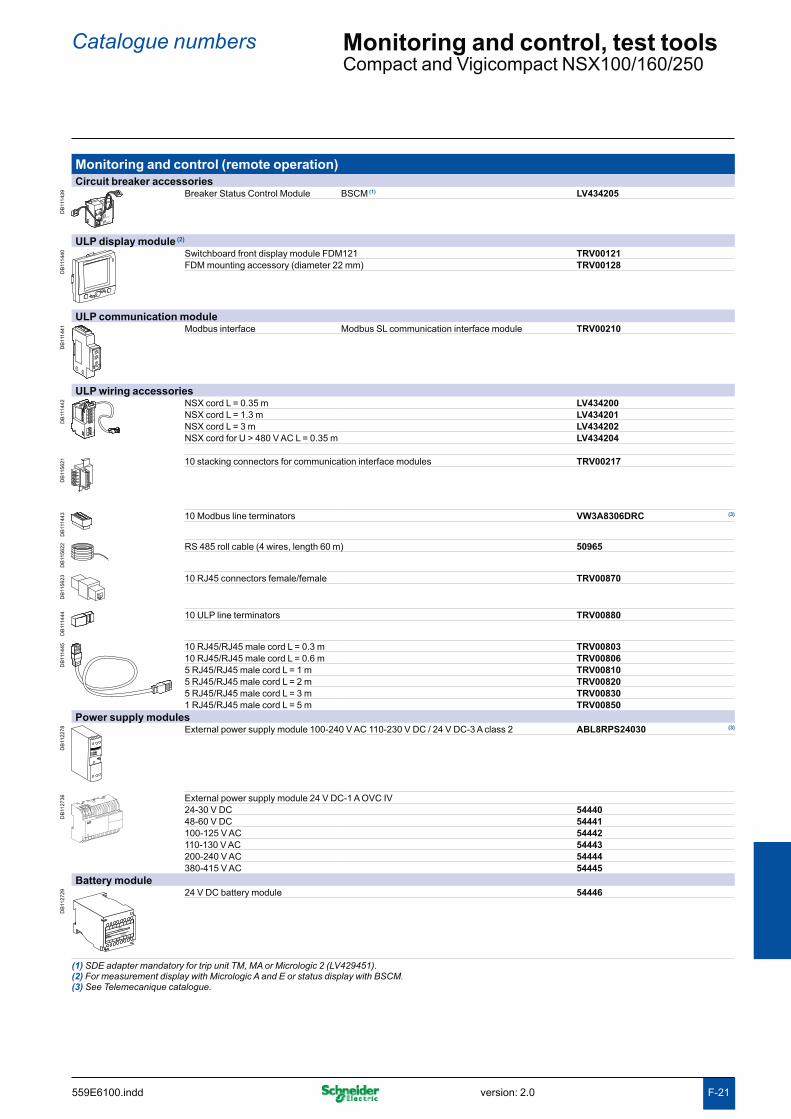
F-21
Catalogue numbers Monitoring and control, test toolsCompact and Vigicompact NSX100/160/250
Monitoring and control (remote operation)Circuit breaker accessories
DB
1114
39 Breaker Status Control Module BSCM (1) LV434205
ULP display module (2)
DB
1114
40 Switchboard front display module FDM121 TRV00121FDM mounting accessory (diameter 22 mm) TRV00128
ULP communication module
DB
1114
41 Modbus interface Modbus SL communication interface module TRV00210
ULP wiring accessories
DB
1114
42 NSX cord L = 0.35 m LV434200NSX cord L = 1.3 m LV434201NSX cord L = 3 m LV434202NSX cord for U > 480 V AC L = 0.35 m LV434204
DB
1156
21 10 stacking connectors for communication interface modules TRV00217
DB
1114
43 10 Modbus line terminators VW3A8306DRC (3)
DB
1156
22 RS 485 roll cable (4 wires, length 60 m) 50965
DB
1156
23 10 RJ45 connectors female/female TRV00870
DB
1114
44 10 ULP line terminators TRV00880
DB
1114
45 10 RJ45/RJ45 male cord L = 0.3 m TRV0080310 RJ45/RJ45 male cord L = 0.6 m TRV008065 RJ45/RJ45 male cord L = 1 m TRV008105 RJ45/RJ45 male cord L = 2 m TRV008205 RJ45/RJ45 male cord L = 3 m TRV008301 RJ45/RJ45 male cord L = 5 m TRV00850
Power supply modules
DB
1122
78 External power supply module 100-240 V AC 110-230 V DC / 24 V DC-3 A class 2 ABL8RPS24030 (3)
DB
1127
36 External power supply module 24 V DC-1 A OVC IV24-30 V DC 5444048-60 V DC 54441100-125 V AC 54442110-130 V AC 54443200-240 V AC 54444380-415 V AC 54445
Battery module
DB
1127
29
L3
G1
AD 220A
L4
G2
Input
24VDC
Output
24VDC
24 V DC battery module 54446
(1) SDE adapter mandatory for trip unit TM, MA or Micrologic 2 (LV429451).(2) For measurement display with Micrologic A and E or status display with BSCM.(3) See Telemecanique catalogue.
version: 2.0 559E6100.indd

F-22
Catalogue numbers Monitoring and control, test tools (cont.)Compact and Vigicompact NSX100/160/250 (cont.)
Test tool, software, demoTest tool
DB
1114
49 Pocket battery for Micrologic NSX100-630 LV434206
DB
1114
51 Maintenance case TRV00910Comprising: - USB maintenance interface- Power supply- Micrologic cord- USB cord- RJ45/RJ45 male cord
DB
1114
50 Spare USB maintenance interface TRV00911
DB
1114
52 Spare power supply 110-240 V AC TRV00915
DB
1114
53 Spare Micrologic cord for USB maintenance interface TRV00917
DB
1114
48 Bluetooth/Modbus option for USB maintenance interface VW3A8114 (1)
Software
DB
1171
58 Configuration and setting software RSU LV4ST100 (2)
Test software LTU LV4ST121 (2)
Monitoring software RCU LV4SM100 (2)
(1) See Telemecanique catalogue.(2) Downloadable from http://schneider-electric.com.
559E6100.inddversion: 2.0

F-29
Compact NSX Compact NSX400 to 630Contents
NSX400/630N: complete fixed/FC device F-30Compact NSX400/630N (50 kA 380/415 V) F-30
NSX400/630H: complete fixed/FC device F-31Compact NSX400/630H (70 kA 380/415 V) F-31
NSX400/630NA: complete fixed/FC device F-32Compact NSX400/630NA F-32
NSX400/630N/H/S/L: fixed/FC device based on separate components F-33Compact and Vigicompact F-33
Trip unit accessories F-34Compact and Vigicompact NSX400/630 F-34
Installation and connection F-35Compact and Vigicompact NSX400/630 F-35
Accessories F-37Compact and Vigicompact NSX400/630 F-37
Monitoring and control, test tools F-46Compact and Vigicompact NSX400/630 F-46
version: 2.0 559E6200TDM.indd

F-30
Catalogue numbers NSX400/630N: complete fixed/FC device Compact NSX400/630N (50 kA 380/415 V)
Compact NSX400/630NElectronic trip unit Micrologic 2.3 (LS
OI protection)
DB
1114
55 3P 3d 4P 3d, 4d, 3d + N/2Compact NSX400N (50 kA at 380/415 V) 250 A LV432707 LV432708
400 A LV432693 LV432694Compact NSX630N (50 kA at 380/415 V) 630 A LV432893 LV432894
Electronic trip unit Micrologic 5.3 A (LSI protection, ammeter)
DB
1114
56 3P 3d 4P 3d, 4d, 3d + N/2, 3d + OSNCompact NSX400N (50 kA at 380/415 V) 400 A LV432699 LV432700Compact NSX630N (50 kA at 380/415 V) 630 A LV432899 LV432900
Electronic trip unit Micrologic 1.3-M A (I motor protection)
DB
1114
57 3P 3dCompact NSX400N 1.3-M (50 kA at 380/415V) 320 A LV432749Compact NSX630N 1.3-M (50 kA at 380/415V) 500 A LV432949
Electronic trip unit Micrologic 2.3-M (LSOI motor protection)
DB
1114
57 3P 3dCompact NSX400N 2.3-M (50 kA at 380/415V) 320 A LV432776Compact NSX630N 2.3-M (50 kA at 380/415V) 500 A LV432976
With electronic trip unit Micrologic 5.3 E (LSI protection, energy meter)To be ordered with 2 catalogue numbers: 1 basic frame + 1 trip unit
With electronic trip unit Micrologic 6.3 A (LSIG protection, ammeter)To be ordered with 2 catalogue numbers: 1 basic frame + 1 trip unit
With electronic trip unit Micrologic 6.3 E (LSIG protection, energy meter)To be ordered with 2 catalogue numbers: 1 basic frame + 1 trip unit
With electronic trip unit Micrologic 6.3 E-M (LSIG motor protection, energy meter)To be ordered with 2 catalogue numbers: 1 basic frame + 1 trip unit
559E6200.inddversion: 2.0

F-31
Catalogue numbers NSX400/630H: complete fixed/FC deviceCompact NSX400/630H (70 kA 380/415 V)
Compact NSX400/630HElectronic trip unit Micrologic 2.3 (LS
OI protection)
DB
1114
55 3P 3d 4P 3d, 4d, 3d + N/2Compact NSX400H (70 kA at 380/415 V) 250 A LV432709 LV432710
400 A LV432695 LV432696Compact NSX630H (70 kA at 380/415 V) 630 A LV432895 LV432896
Electronic trip unit Micrologic 5.3 A (LSI protection, ammeter)
DB
1114
56 3P 3d 4P 3d, 4d, 3d + N/2, 3d + OSNCompact NSX400H (70 kA at 380/415 V) 400 A LV432701 LV432702Compact NSX630H (70 kA at 380/415 V) 630 A LV432901 LV432902
Electronic trip unit Micrologic 1.3-M (I motor protection)
DB
1114
57 3P 3dCompact NSX400H 1.3-M (70 kA at 380/415V) 320 A LV432750Compact NSX630H 1.3-M (70 kA at 380/415V) 500 A LV432950
Electronic trip unit Micrologic 2.3-M (LSOI motor protection)
DB
1114
57 3P 3dCompact NSX400H 2.3-M (70 kA at 380/415V) 320 A LV432777Compact NSX630H 2.3-M (70 kA at 380/415V) 500 A LV432977
With electronic trip unit Micrologic 6.3 E (LSIG protection, energy meter)Only available as separate components.
With electronic trip unit Micrologic 6.3 E-M (LSIG motor protection, energy meter)Only available as separate components.
version: 2.0 559E6200.indd

F-32
Catalogue numbers NSX400/630NA: complete fixed/FC deviceCompact NSX400/630NA
Compact NSX400/630 0.3 NA switch-disconnectorWith 0.3 NA switch-disconnector unit
DB
1114
59 3P 4PCompact NSX400 0.3 NA LV432756 LV432757Compact NSX630 0.3 NA, 45 mm pitch LV432956 LV432957
559E6200.inddversion: 2.0

F-33
NSX400/630N/H/S/L: fixed/FC device based on separate components Compact and Vigicompact
Basic frame
DB
1114
60 Compact NSX4003P 4P
NSX400N (50 kA 380/415 V) LV432403 LV432408NSX400H (70 kA 380/415 V) LV432404 LV432409NSX400S (100 kA 380/415 V) LV432414 LV432416NSX400L (150 kA 380/415 V) LV432405 LV432410Compact NSX630
3P 4PNSX630N (50 kA 380/415 V) LV432803 LV432808NSX630H (70 kA 380/415 V) LV432804 LV432809NSX630S (100 kA 380/415 V) LV432814 LV432816NSX630L (150 kA 380/415 V) LV432805 LV432810
+ Trip unitDistribution protection
DB
1114
61 Micrologic 2.3 (LSOI protection)
Rating 3P 3d 4P 3d, 4d, 3d + N/2Micrologic 2.3 250 A LV432082 LV432086Micrologic 2.3 400 A LV432081 LV432085Micrologic 2.3 630 A LV432080 LV432084
DB
1114
62 Micrologic 5.3 A (LSI protection, ammeter)Rating 3P 3d 4P 3d, 4d, 3d + N/2, 3d + OSNMicrologic 5.3 A 400 A LV432091 LV432094Micrologic 5.3 A 630 A LV432090 LV432093
Micrologic 5.3 E (LSI protection, energy meter)Rating 3P 3d 4P 3d, 4d, 3d + N/2, 3d + OSNMicrologic 5.3 E 400 A LV432097 LV432100Micrologic 5.3 E 630 A LV432096 LV432099
DB
1114
62 Micrologic 6.3 A (LSIG protection, ammeter)Rating 3P 3d 4P 3d, 4d, 3d + N/2, 3d + OSNMicrologic 6.3 A 400 A LV432103 LV432106Micrologic 6.3 A 630 A LV432102 LV432105Micrologic 6.3 E (LSIG protection, energy meter)
Rating 3P 3d 4P 3d, 4d, 3d + N/2, 3d + OSNMicrologic 6.3 E 400 A LV432109 LV432112Micrologic 6.3 E 630 A LV432108 LV432111
Motor protection
DB
1114
63 Micrologic 1.3-M (I protection)Rating 3P 3d 4P 3dMicrologic 1.3-M 320 A LV432069 LV432078Micrologic 1.3-M 500 A LV432068 LV432077
DB
1114
61 Micrologic 2.3-M (LSOI protection)
Rating 3P 3dMicrologic 2.3-M 320 A LV432072Micrologic 2.3-M 500 A LV432071
DB
1114
62 Micrologic 6.3 E-M (LSIG protection, energy meter)Rating 3P 3dMicrologic 6.3 E-M 320 A LV432075Micrologic 6.3 E-M 500 A LV432074
Catalogue numbers
version: 2.0 559E6200.indd

F-34
Trip unit accessoriesCompact and Vigicompact NSX400/630
+ Vigi module or insulation monitoring moduleVigi module
DB
1114
64 3P 4PType MB 200 to 440 V LV432455 LV432456
440 to 550 V LV432453 LV432454Connection for a 4P Vigi on a 3P breaker LV432457
Insulation monitoring module
DB
1114
64 3P 4P200 to 440 V AC LV432659 LV432660Connection for a 4P insulation monitoring LV432457module on a 3P breaker
Trip unit accessoriesExternal neutral CT for 3 pole breaker with Micrologic 5/6
DB
1122
77 400-630 A LV432575
24 V DC wiring accessory for Micrologic 5/6
DB
1127
30 24 V DC power supply connector LV434210
ZSI accessory for NS630b-NW with NSX
DB
1156
65 ZSI module LV434212
External power supply module (24 V DC - 1 A), class 4
DB
1127
36 24-30 V DC 5444048-60 V DC 54441100-125 V DC 54442110-130 V AC 54443200-240 V AC 54444380-415 V AC 54445
Battery module
DB
1127
29
L3
G1
AD 220A
L4
G2
Input
24VDC
Output
24VDC
24 V DC battery module 54446
Catalogue numbers
559E6200.inddversion: 2.0

F-35
Catalogue numbers Installation and connectionCompact and Vigicompact NSX400/630
Fixed/RC device = fixed/FC device + rear connection kitMixed RC kit
DB
1114
65 Kit 3P Short RCs 2 x LV432475Long RCs 1 x LV432476
Kit 4P Short RCs 2 x LV432475Long RCs 2 x LV432476
Fixed/FC device with 52.5 mm or 70 mm pitch = fixed/FC device with 45 mm pitch + spreadersThe pitch of all Compact and Vigicompact NSX400/630 devices is 45 mm. Spreaders are available for fixed front, plug-in or withdrawable connection with pitch of 52.5 mm or 70 mm.
Upstream or downstream spreaders
DB
1114
66 52.5 mm 3P LV4324904P LV432491
70 mm 3P LV4324924P LV432493
Plug-in version = fixed/FC device + plug-in kitKit for Compact
DB
1114
67 3P 4PPlug-in kit LV432538 LV432539Comprising:Base = 1 x LV432516 = 1 x LV432517Power connections + 3 x LV432518 + 4 x LV432518Short terminal shields + 2 x LV432591 + 2 x LV432592Safety trip interlock + 1 x LV432520 + 1 x LV432520
Kit for Vigicompact
DB
1114
69 3P 4PVigi plug-in kit LV432540 LV432541Comprising:Base = 1 x LV432516 = 1 x LV432517Power connections + 3 x LV432519 + 4 x LV432519Short terminal shields + 2 x LV432591 + 2 x LV432592Safety trip interlock + 1 x LV432520 + 1 x LV432520
version: 2.0 559E6200.indd

F-36
Catalogue numbers Installation and connection (cont.)Compact and Vigicompact NSX400/630 (cont.)
Withdrawable version = fixed/FC device + withdrawable kitKit for Compact
DB
1114
68 3P 4PKit for Compact Kit for Compact
= =Plug-in kit: 1 x LV432538 1 x LV432539
+ +Chassis side plates 1 x LV432532 1 x LV432533 for base + +Chassis side plates 1 x LV432532 1 x LV432533 for breaker
Kit for Vigicompact
DB
1171
74 3P 4PKit for Vigicompact Kit for Vigicompact
= =Plug-in kit: 1 x LV432540 1 x LV432541
+ +Chassis side plates 1 x LV432532 1 x LV432532 for base + +Chassis side plates 1 x LV432533 1 x LV432533for breaker
559E6200.inddversion: 2.0

F-37
Catalogue numbers AccessoriesCompact and Vigicompact NSX400/630
Connection accessories (Cu or Al)Rear connections
DB
1114
71 2 short LV4324752 long LV432476
Bare cable connectors (1)
DB
1156
24 Aluminium connectors 1 x (35 to 300 mm²) Set of 3 LV432479Set of 4 LV432480
DB
1156
25 Aluminium connectors for 2 cables 2 x (35 to 300 mm²) Set of 3 LV432481Set of 4 LV432482
DB
1127
24 6.35 mm voltage tap for steel or aluminium connectors Set of 10 LV429348
Terminal extensions (1)
DB
1156
49 45° terminal extensions Set of 3 LV432586Set of 4 LV432587
DB
1156
50 Edgewise terminal extensions Set of 3 LV432486Set of 4 LV432487
DB
1156
51 Right-angle terminal extensions Set of 3 LV432484Set of 4 LV432485
DB
1156
52 Spreaders 52.5 mm 3P LV4324904P LV432491
70 mm 3P LV4324924P LV432493
Crimp lugs for copper cable (1)
DB
1122
37 For cable 240 mm² Set of 3 LV432500Set of 4 LV432501
For cable 300 mm² Set of 3 LV432502Set of 4 LV432503
Supplied with 2 or 3 interphase barriersCrimp lugs for aluminium cable (1)
DB
1122
38 For cable 240 mm² Set of 3 LV429504Set of 4 LV429505
For cable 300 mm² Set of 3 LV429506Set of 4 LV429507
Supplied with 2 or 3 interphase barriers(1) Supplied with 2 or 3 interphase barriers.
version: 2.0 559E6200.indd

F-38
Catalogue numbers Accessories (cont.)Compact and Vigicompact NSX400/630 (cont.)
Insulation accessories
DB
1114
72 Short terminal shield, 45 mm (1 piece) 3 P LV4325914 P LV432592
DB
1114
73 Long terminal shield, 45 mm (1 piece) 3 P LV4325934 P LV432594
DB
1156
26 Long terminal shield for spreaders, 52.5 mm (1 piece) (supplied with insulating plate) 3 P LV4325954 P LV432596
DB
1156
32 Interphase barriers Set of 6 LV432570
DB
1156
27 Connection adapter for plug-in base 3P LV4325844P LV432585
DB
1156
28 2 insulating screens (70 mm pitch) 3P LV4325784P LV432579
559E6200.inddversion: 2.0

F-39
Accessories (cont.)Compact and Vigicompact NSX400/630 (cont.)
Electrical auxiliariesAuxiliary contacts (changeover)
DB
1122
54 OF or SD or SDE or SDV 29450OF or SD or SDE or SDV low level 29452
SDx output module for Micrologic electronic trip unit
DB
1122
75 SDx module 24/415 V AC/DC LV429532
SDTAM contactor tripping module (early-break thermal fault signal) for Micrologic 2.3-M/6.3 E-M
DB
1122
76 SDTAM 24/415 V AC/DC overload fault indication LV429424
Voltage releases
DB
1114
54 Voltage MX MNAC 24 V 50/60 Hz LV429384 LV429404
48 V 50/60 Hz LV429385 LV429405110-130 V 50/60 Hz LV429386 LV429406220-240 V 50/60 Hz and 208-277 V 60 Hz LV429387 LV429407380-415 V 50 Hz and 440-480 V 60 Hz LV429388 LV429408525 V 50 Hz and 600 V 60 Hz LV429389 LV429409
DC 12 V LV429382 LV42940224 V LV429390 LV42941030 V LV429391 LV42941148 V LV429392 LV42941260 V LV429383 LV429403125 V LV429393 LV429413250 V LV429394 LV429414
DB
1156
31 MN 48 V 50/60 Hz with fixed time delayComposed of: MN 48 V DC LV429412
Delay unit 48 V 50/60 Hz LV429426MN 220-240 V 50/60 Hz with fixed time delay
Composed of: MN 250 V DC LV429414Delay unit 220-240 V 50/60 Hz LV429427
MN 48 V DC/AC 50/60 Hz with adjustable time delayComposed of: MN 48 V DC LV429412
Delay unit 48 V 50/60 Hz 33680MN110-130 V DC/AC 50/60 Hz with adjustable time delay
Composed of: MN 125 V DC LV429413Delay unit 110-130 V 50/60 Hz 33681
MN 220-250 V 50/60 Hz with adjustable time delayComposed of: MN 250 V DC LV429414
Delay unit 220-250 V 50/60 Hz 33682
Catalogue numbers
version: 2.0 559E6200.indd

F-40
Accessories (cont.)Compact and Vigicompact NSX400/630 (cont.)
Motor mechanismMotor mechanism module
DB
1114
75
Ø5...8
manuauto
Voltage MT400-630AC 48-60 V 50/60 Hz LV432639
110-130 V 50/60 Hz LV432640220-240 V 50/60 Hz and 208-277 V 60 Hz LV432641380-415 V 50 Hz LV432642440-480 V 60 Hz LV432647
DC 24-30 V LV43264348-60 V LV432644110-130 V LV432645250 V LV432646
Operation counter LV432648Communicating motor mechanism module
DB
1114
76
Ø5...8
manuauto
Motor mechanism module MTc NSX400-630 220-240 V 50/60 Hz LV432652
+
Breaker status BSCM LV434205Communication Module
+
NSX cord Wire length L = 0.35 m LV434200Wire length L = 1.3 m LV434201Wire length L = 3 m LV434202U > 480 V AC wire length L = 0.35 m LV434204
Catalogue numbers
559E6200.inddversion: 2.0
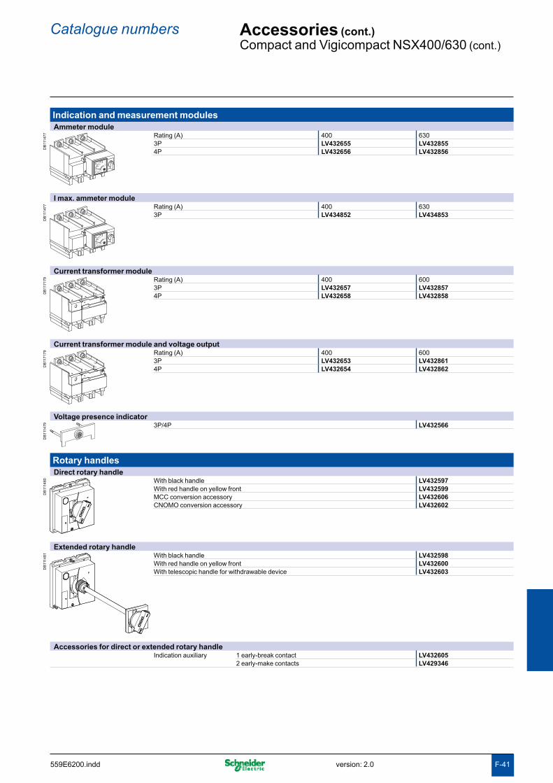
F-41
Catalogue numbers Accessories (cont.)Compact and Vigicompact NSX400/630 (cont.)
Indication and measurement modulesAmmeter module
DB
1114
77
A
Rating (A) 400 6303P LV432655 LV4328554P LV432656 LV432856
I max. ammeter module
DB
1114
77
A
Rating (A) 400 6303P LV434852 LV434853
Current transformer module
DB
1171
79 Rating (A) 400 6003P LV432657 LV4328574P LV432658 LV432858
Current transformer module and voltage output
DB
1171
79 Rating (A) 400 6003P LV432653 LV4328614P LV432654 LV432862
Voltage presence indicator
DB
1114
79 3P/4P LV432566
Rotary handlesDirect rotary handle
DB
1114
80 With black handle LV432597With red handle on yellow front LV432599MCC conversion accessory LV432606CNOMO conversion accessory LV432602
Extended rotary handle
DB
1114
81 With black handle LV432598With red handle on yellow front LV432600With telescopic handle for withdrawable device LV432603
Accessories for direct or extended rotary handleIndication auxiliary 1 early-break contact LV432605
2 early-make contacts LV429346
version: 2.0 559E6200.indd

F-42
Catalogue numbers Accessories (cont.)Compact and Vigicompact NSX400/630 (cont.)
LocksToggle locking device for 1 to 3 padlocks
DB
1114
83 By removable device 29370
DB
1114
82 By fixed device LV432631
Locking of rotary handle
DB
1114
84 Keylock adapter (keylock not included) LV432604Keylock (keylock adapter not included) Ronis 1351B.500 41940
Profalux KS5 B24 D4Z 42888
Locking of motor mechanism module
DB
1114
85 Keylock adapter (keylock not included) LV432649Keylock (keylock adapter not included) Ronis 1351B.500 41940
Profalux KS5 B24 D4Z 42888
559E6200.inddversion: 2.0

F-43
Catalogue numbers Accessories (cont.)Compact and Vigicompact NSX400/630 (cont.)
InterlockingMechanical interlocking for circuit breakers
DB
1114
86 With toggles LV432614
DB
1114
87 With rotary handles LV432621
Interlocking with key (2 keylocks / 1 key) for rotary handles
DB
1122
68 Keylock kit (keylock not included) (1) LV4326041 set of 2 keylocks Ronis 1351B.500 41950(1 key only, keylock kit not included) Profalux KS5 B24 D4Z 42878
Installation accessoriesFront-panel escutcheons
DB
1114
89 IP40 escutcheon for all control types LV432558IP40 escutcheon for Vigi module LV429316IP40 escutcheon for Vigi or ammeter module LV429318
IP40
IP43 rubber toggle cover
DB
1114
90 1 toggle cover LV432560
Lead-sealing accessories
DB
1156
15 Bag of accessories LV429375
60 mm busbar adapter
DB
1114
91
20 Nm
L1L2
L3
L2
20 Nm
L2L3
L3
20 Nm
L12
L3
3P 60 mm busbar adapter 32623
(1) For only 1 device.
version: 2.0 559E6200.indd

F-44
Catalogue numbers Accessories (cont.)Compact and Vigicompact NSX400/630 (cont.)
Plug-in/withdrawable version accessoriesInsulation accessories
DB
1171
59 Connection adapter for plug-in base 3P LV4325844P LV432585
Auxiliary connections
DB
1171
60 1 9-wire fixed connector (for base) LV429273
DB
1171
61 1 9-wire moving connector (for circuit breaker) LV432523
DB
1163
68 1 support for 3 moving connectors LV432525
DB
1158
85 9-wire manual auxiliary connector (fixed + moving) LV429272
Plug-in base accessories
DB
1171
64 Long insulated right angle terminal extensions Set of 2 LV432526
DB
1171
65 2 IP40 shutters for base LV432521
Base 3P LV432516
DB
1171
80D
B11
7181 Base 4P LV432517
DB
1171
82 Power connections 3/4P LV432518
DB
1171
83 Short terminal shields 3P LV432591
DB
1171
84 Short terminal shields 4P LV432592
DB
1171
71 Safety trip interlock 3/4P LV432520
Chassis accessories
DB
1171
72 Escutcheon collar Toggle LV432534
DB
1171
73 Escutcheon collar Vigi module LV429285
DB
1171
63 Locking kit (keylock not included) LV429286
Keylock (keylock adapter not included) Ronis 1351B.500 41940Profalux KS5 B24 D4Z 42888
DB
1114
26 2 carriage switches (connected/disconnected position indication) LV429287
559E6200.inddversion: 2.0

F-45
Catalogue numbers Accessories (cont.)Compact and Vigicompact NSX400/630 (cont.)
Spare parts
DB
1156
33 Additional toggle extension for NSX400/630 32595
DB
1114
30 5 spare toggle extensions LV432553
DB
1156
20 Bag of screws LV432552
DB
1114
93 Compact NS retrofit escutcheon Small cut-out LV432571
DB
1114
33 IP40 toggle escutcheon Compact NS type/small cut-out 32556
DB
1114
38 1 set of 10 identification labels LV429226
DB
1114
95 1 base for extended rotary handle LV432498
DB
1114
35 LCD display for electronic trip unit Micrologic 5 LV429483Micrologic 6 LV429484Micrologic E-M LV429486
DB
1114
36
5 transparent covers for electronic trip unit Micrologic 2 LV432459Micrologic 5/6 LV432461
DB
1159
07 5 opaque covers for Micrologic 5/6 LV432460
version: 2.0 559E6200.indd
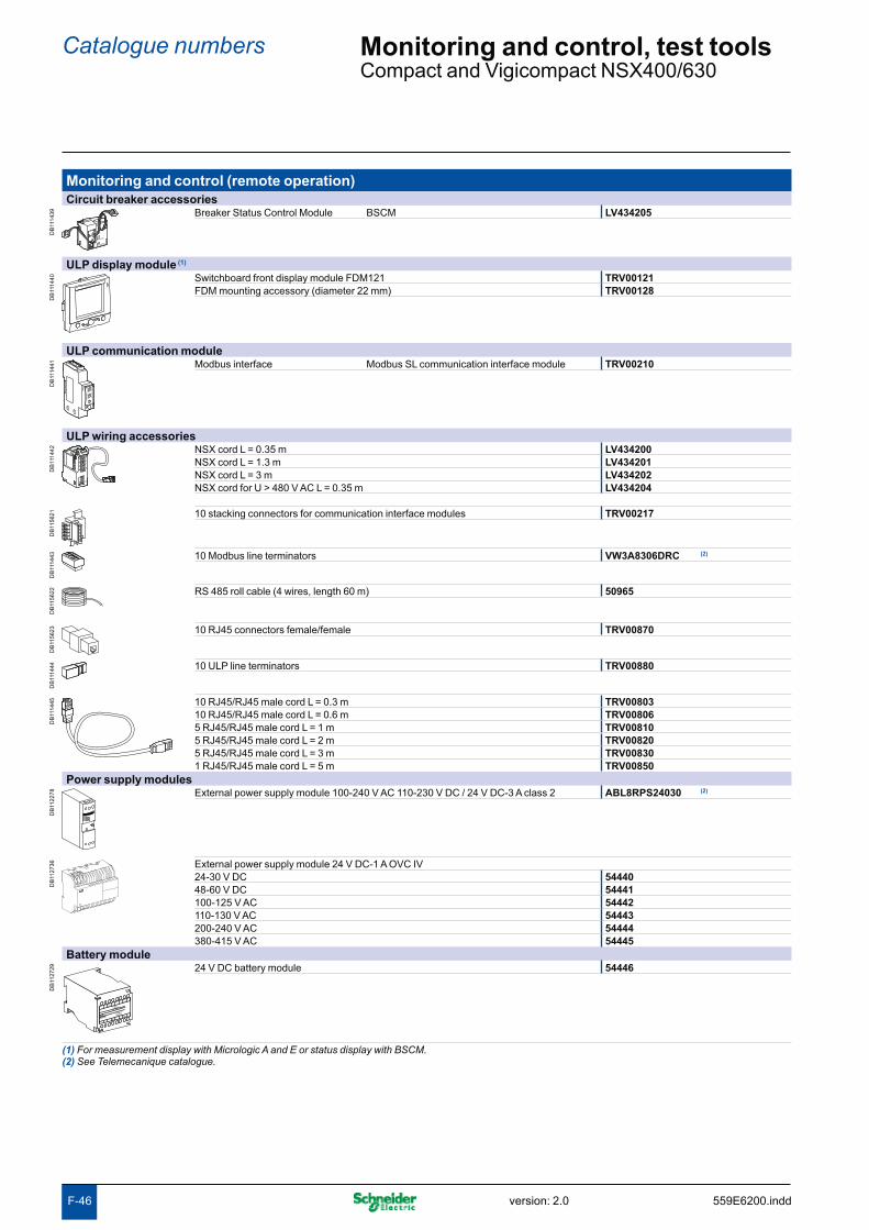
F-46
Catalogue numbers Monitoring and control, test toolsCompact and Vigicompact NSX400/630
Monitoring and control (remote operation)Circuit breaker accessories
DB
1114
39 Breaker Status Control Module BSCM LV434205
ULP display module (1)
DB
1114
40 Switchboard front display module FDM121 TRV00121FDM mounting accessory (diameter 22 mm) TRV00128
ULP communication module
DB
1114
41 Modbus interface Modbus SL communication interface module TRV00210
ULP wiring accessories
DB
1114
42 NSX cord L = 0.35 m LV434200NSX cord L = 1.3 m LV434201NSX cord L = 3 m LV434202NSX cord for U > 480 V AC L = 0.35 m LV434204
DB
1156
21 10 stacking connectors for communication interface modules TRV00217
DB
1114
43 10 Modbus line terminators VW3A8306DRC (2)
DB
1156
22 RS 485 roll cable (4 wires, length 60 m) 50965
DB
1156
23 10 RJ45 connectors female/female TRV00870
DB
1114
44 10 ULP line terminators TRV00880
DB
1114
45 10 RJ45/RJ45 male cord L = 0.3 m TRV0080310 RJ45/RJ45 male cord L = 0.6 m TRV008065 RJ45/RJ45 male cord L = 1 m TRV008105 RJ45/RJ45 male cord L = 2 m TRV008205 RJ45/RJ45 male cord L = 3 m TRV008301 RJ45/RJ45 male cord L = 5 m TRV00850
Power supply modules
DB
1122
78 External power supply module 100-240 V AC 110-230 V DC / 24 V DC-3 A class 2 ABL8RPS24030 (2)
DB
1127
36 External power supply module 24 V DC-1 A OVC IV24-30 V DC 5444048-60 V DC 54441100-125 V AC 54442110-130 V AC 54443200-240 V AC 54444380-415 V AC 54445
Battery module
DB
1127
29
L3
G1
AD 220A
L4
G2
Input
24VDC
Output
24VDC
24 V DC battery module 54446
(1) For measurement display with Micrologic A and E or status display with BSCM.(2) See Telemecanique catalogue.
559E6200.inddversion: 2.0
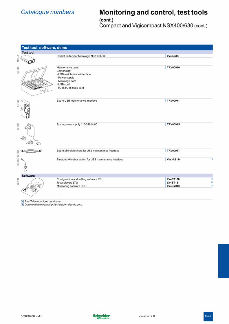
F-47
Test tool, software, demoTest tool
DB
1114
49 Pocket battery for Micrologic NSX100-630 LV434206
DB
1114
51 Maintenance case TRV00910Comprising: - USB maintenance interface- Power supply- Micrologic cord- USB cord- RJ45/RJ45 male cord
DB
1114
50 Spare USB maintenance interface TRV00911
DB
1114
52 Spare power supply 110-240 V AC TRV00915
DB
1114
53 Spare Micrologic cord for USB maintenance interface TRV00917
DB
1114
48 Bluetooth/Modbus option for USB maintenance interface VW3A8114 (1)
Software
DB
1171
58 Configuration and setting software RSU LV4ST100 (2)
Test software LTU LV4ST121 (2)
Monitoring software RCU LV4SM100 (2)
(1) See Telemecanique catalogue.(2) Downloadable from http://schneider-electric.com.
Catalogue numbers Monitoring and control, test tools (cont.)Compact and Vigicompact NSX400/630 (cont.)
version: 2.0 559E6200.indd

F-48 559E6200.inddversion: 2.0

Glo
ssai
reG
loss
ary

version: 1.0
Functions and characteristics A-1Installation recommendations B-1Dimensions and connection C-1Wiring diagrams D-1Additional characteristics E-1Catalogue numbers F-1
Accessories G-2
Circuit-breaker characteristics (IEC 60947-2) G-2
Communication G-4
Components G-5
Controls G-5
Discrimination / Cascading G-6
Environment G-7
Harmonics G-8
Measurements G-8
Protection G-9
Relays and auxiliary contacts G-10
Switchgear G-10
Three-phase asynchronous motors and their protection G-11
Trip units G-12
Compact NSX GlossaryContents
G-1 559E7000.indd

Compact NSX Glossary
For each major section (Accessories, Switchgear, etc.) and for each item (Adapter for plug-in base, Connection terminal, etc.), this glossary provides:b the page number in the concerned catalogueb the reference standardb the standardised IEC symbolb the definition.Text in quotation marks is drawn from the standards.
Accessories ...................................................................................................
Adapter for plug-in base A-72 The adapter is a plastic component that can be installed upstream and/or downstream of the plug-in base and enables use of all the connection accessories of the fixed device.
Bare-cable connector A-71 Conducting part of the circuit breaker intended for connection to power circuits. On Compact NSX, it is an aluminium part that screws to the connection terminals of the circuit breaker. There are one or more holes (single or multiple cable connector) for the ends of bare cables.
Connection terminals A-70 Flat copper surface, linked to the conducting parts of the circuit breaker and to which power connections are made using bars, connectors or lugs.
One-piece spreader A-70 The spreader is a plastic component with copper connectors that can be installed upstream and/or downstream of a Compact NSX100 to 250 circuit breaker with a pole pitch of 35 mm. It increases the pitch of the circuit-breaker terminals to the 45 mm pitch of a NSX400/630 device to facilitate connection of large cables.
Spreaders A-70 Set of three (3P device) or four (4P) flat, conducting parts made of aluminium. They are screwed to the circuit-breaker terminals to increase the pitch between poles.
Circuit-breaker characteristics (IEC 60947-2) ............................................Breaking capacity A-6 Value of prospective current that a switching device is capable of breaking at a
stated voltage under prescribed conditions of use and behaviour. Reference is generally made to the ultimate breaking capacity (Icu) and the service breaking capacity (Ics).
Degree of protection (IP) IEC 60529
A-5 Defines device protection against the penetration of solid objects and liquids, using two digits specified in standard IEC 60259. Each digit corresponds to a level of protection, where 0 indicates no protection.
First digit (0 to 6): protection against penetration of solid foreign objects. b1 corresponds to protection against objects with a diameter > 50 mm, 6 corresponds to total protection against dust.
Second digit (0 to 8): protection against penetration of liquids (water). b1 corresponds to protection against falling drops of water (condensation), 8 corresponds to continuous immersion. The enclosure of Compact NSX circuit breakers provides a minimum of IP40 (protection against objects > 1 mm) and can reach IP56 (protection against dust and powerful water jets) depending on the installation conditions.
Degree of protection against external mechanical impacts (IK)
A-6 Defines the aptitude of an object to resist mechanical impacts on all sides, indicated by a number from 0 to 10 (standard IEC 62262). Each number corresponds to the impact energy (in Joules) that the object can handle according to a standardised procedure.0 corresponds to no protection, 1 to an impact energy of 0.14 Joules, 10 to an impact energy of 20 Joules. Compact NSX provide IK07 (2 Joules) and can provide IK08 (5 Joules) depending on the installation conditions.
Durability A-6 The term "durability" is used in the standards instead of "endurance" to express the expectancy of the number of operating cycles which can be performed by the equipment before repair or replacement of parts. The term "endurance" is used for specifically defined operational performance.
Electrical durability IEC 60947-1
A-6 With respect to its resistance to electrical wear, equipment is characterised by the number of on-load operating cycles, corresponding to the service conditions given in the relevant product standard, which can be made without re replacement.
G-2 559E7100.inddversion: 1.0
Frame size A-70 "A term designating a group of circuit breakers, the external physical dimensions of which are common to a range of current ratings. Frame size is expressed in amperes corresponding to the highest current rating of the group. Within a frame size, the width may vary according to the number of poles. This definition does not imply dimensional standardization."Compact NSX has two frame sizes covering 100 to 250 A and 400 to 630 A.
Insulation class A-5 Defines the type of device insulation in terms of earthing and the corresponding safety for user, in one of three classes.
Class I. The device is earthed. Any electrical faults, internal or external, or caused bby the load, are cleared via the earthing circuit, thus ensuring user safety.
Class II. The device is not connected to a protective conductor. User safety is bensured by reinforced insulation around the live parts (an insulating case and no contact with live parts, i.e. plastic buttons, moulded connections, etc.) or double insulation.
Class III. The device may be connected only to SELV (safety extra-low voltage) bcircuits. The Compact NSX are class II devices (front) and may be installed through the door in class II switchboards (standards IEC 61140 and IEC 60664-1), without reducing insulation, even with a rotary handle or motor mechanism module.
Making capacity Value of prospective making current that a switching device is capable of making at a stated voltage under prescribed conditions of use and behaviour. Reference is generally made to the short-circuit making capacity Icm.
Maximum break time A-17 Maximum time after which breaking is effective, i.e. the contacts separated and the current completely interrupted.
Mechanical durability A-6 With respect to its resistance to mechanical wear, equipment is characterised by the number of no-load operating cycles which can be effected before it becomes necessary to service or replace any mechanical parts.
Non-tripping time A-17 This is the minimum time during which the protective device does not operate in spite of pick-up overrun, if the duration of the overrun does not exceed the corresponding voluntary time delay.
Pollution degree of environment conditions IEC 60947-1 IEC 60664-1
A-6 "Conventional number based on the amount of conductive or hygroscopic dust, ionized gas or salt and on the relative humidity and its frequency of occurrence, resulting in hygroscopic absorption or condensation of moisture leading to reduction in dielectric strength and/or surface resistivity". Standard IEC 60947-1 distinguishes four pollution degrees.
Degree 1. No pollution or only dry, non-conductive pollution occurs. bDegree 2. Normally, only non-conductive pollution occurs. Occasionally, however, b
a temporary conductivity caused by condensation may be expected.Degree 3. Conductive pollution occurs, or dry, non-conductive pollution occurs b
which becomes conductive due to condensation.Degree 4. The pollution generates persistent conductivity caused, for instance, by b
conductive dust or by rain or snow. Compact NSX meets degree 3, which corresponds to industrial applications.
Prospective short-circuit current
E-13 Current that would flow through the poles if they remained fully closed during the short-circuit.
Rated current (In) A-6 This is the current that the device can carry continuously with the contacts closed and without abnormal temperature rise.
Rated impulse withstand voltage (Uimp)
A-6 "The peak value of an impulse voltage of prescribed form and polarity which the equipment is capable of withstanding without failure under specified conditions of test and to which the values of the clearances are referred. The rated impulse withstand voltage of an equipment shall be equal to or higher than the values stated for the transient overvoltages occurring in the circuit in which the equipment is fitted".
Rated insulation voltage (Ui) A-6 "The rated insulation voltage of an equipment is the value of voltage to which dielectric tests and creepage distances are referred. In no case shall the maximum value of the rated operational voltage exceed that of the rated insulation voltage".
Rated operational current (Ie) "A rated operational current of an equipment is stated by the manufacturer and takes into account the rated operational voltage, the rated frequency, the rated duty, the utilization category and the type of protective enclosure, if appropriate".
G-3 559E7100.indd version: 1.0

Rated operational voltage (Ue) A-6 "A value of voltage which, combined with a rated operational current, determines the application of the equipment and to which the relevant tests and the utilisation categories are referred. For multipole equipment, it is generally stated as the voltage between phases".This is the maximum continuous voltage at which the equipment may be used.
Rated short-time withstand current (Icw)
"Value of short-time withstand current, assigned to the equipment by the manufacturer, that the equipment can carry without damage, under the test conditions specified in the relevant product standard". Generally expressed in kA for 0.5, 1 or 3 seconds. This is an essential characteristic for air circuit breakers. It is not significant for moulded-case circuit breakers for which the design targets fast opening and high limiting capacity.
Service breaking capacity (Ics) A-6 Expressed as a percentage of Icu, it provides an indication on the robustness of the device under severe conditions. It is confirmed by a test with one opening and one closing/opening at Ics, followed by a check that the device operates correctly at its rated current, i.e. 50 cycles at In, where temperature rise remains within tolerances and the protection system suffers no damage.
Short-circuit making capacity (Icm)
A-58 Value indicating the capacity of the device to make and carry a high current without repulsion of the contacts. It is expressed in kA peak.
Suitability for isolation (see also Positive contact indication, page G-5)
A-5 This capability means that the circuit breaker meets the conditions below.In the open position, it must withstand, without flashover between the upstream b
and downstream contacts, the impulse voltage specified by the standard as a function of the Uimp indicated on the device.
It must indicate contact position by one or more of the following systems: bposition of the operating handle vseparate mechanical indicator vvisible break of the moving contacts vLeakage current between each pole, with the contacts open, at a test voltage of b
1.1 x the rated operating voltage, must not exceed:0.5 mA per pole for new devices v2 mA per pole for devices already subjected to normal switching operations v6 mA, the maximum value that must never be exceeded. vIt must not be possible to install padlocks unless the contacts are open. Locking in b
the closed position is permissible for special applications. Compact NSX complies with this requirement by positive contact indication.
Suitable for isolation with positive contact indication (see also Suitability for isolation, page G2)
A-5 Suitability for isolation is defined here by the mechanical reliability of the position indicator of the operating mechanism, where:
the isolation position corresponds to the O (OFF) position bthe operating handle cannot indicate the "OFF" position unless the contacts are b
effectively open. The other conditions for isolation must all be fulfilled:
locking in the open position is possible only if the contacts are effectively open bleakage currents are below the standardised limits bovervoltage impulse withstand between upstream and downstream connections. b
Ultimate breaking capacity (Icu) A-6 Expressed in kA, it indicates the maximum breaking capacity of the circuit breaker. It is confirmed by a test with one opening and one closing/opening at Icu, followed by a check that the circuit is properly isolated. This test ensures user safety.
Communication .............................................................................................BSCM (Breaker status and control module)
A-27 The optional BSCM for Compact NSX is used to acquire device status indications and control the communicating remote-control function. It includes a memory used to manage the maintenance indicators. It serves as a converter between the analog outputs of the device indication contacts (O/F, SD, SDE) and the digital communicating functions.
Ethernet TCP/IP (Transmission Control Protocol / Internet Protocol)
A-28 Ethernet is a very common network protocol and complies with IEEE standard 802.3. Ethernet TCP/IP is the protocol that brings web functions to Ethernet networks. Most PCs have an Ethernet 10/100 card (10 or 100 Mbit/s) for connection to the internet. Data communicated from Compact NSX via Modbus are accessible on a PC via a TCP/IP-Modbus gateway such as MPS100 or EGX100.
Network Set of communicating devices that are interconnected by communication lines in order to share data and resources.
Compact NSX Glossary
G-4 559E7100.inddversion: 1.0

Open protocol 3 A protocol for system communication, interconnection or data exchange for which technical specifications are public, i.e. there are no restrictions on access or implementation. An open protocol is the opposite of a proprietary protocol.
Protocol A-28 Standardised specification for dialog between digital components that exchange data. It is an operating mode based on the length and structure of binary words and it must be used by all the components exchanging data between themselves. Communication is not possible without using a protocol.
RJ45 connector A-26 Universal, 8-wire connector that is widely used in digital communication networks. The RJ45 connector is used to interconnect computer equipment (Ethernet, Modbus, etc.), telephones and audiovisual equipment.
RS485 Modbus A-28 Modbus is the most widely used communication protocol in industrial networks. It operates in master-slave mode. An RS485 multipoint link connects the master and slaves via a pair of wires offering throughputs of up to 38400 bits/second over distances up to 1200 m). The master cyclically polls the slaves which send back the requested information.The Modbus protocol uses frames containing the address of the targeted slave, the function (read, write), the datum and the CRC (cyclical redundancy check).
SDTAM A-81 Relay module with two static outputs specifically for the motor-protection Micrologic trip units 1 M, 2 M and 6 E-M. An output, linked to the contactor controller, opens the contactor when an overload or other motor fault occurs, thus avoiding opening of the circuit breaker. The other output stores the opening event in memory.
SDx A-81 Relay module with two outputs that remotes the trip or alarm conditions of Compact NSX circuit breakers equipped with a Micrologic electronic trip unit.
Static output A-81 Output of a relay made up of a thyristor or triac electronic component. The low switching capability means that a power relay is required.This is the case for the SDx and SDTAM outputs.
ULP (Universal Logic Plug) A-31 Connection system used by Compact NSX to communicate information to the Modbus interface via a simple RJ45 cable. Compatible modules are indicated by the symbol opposite.
Components ...................................................................................................ASIC (Application Specific Integrated Circuit)
A-8 Integrated circuit designed, built and intended for a specific application. It carries out repetitive sequences of instructions engraved in the silicon chip. For that reason, it is extremely reliable because it cannot be modified and is not affected by environment conditions.Micrologic trip units use an ASIC for the protection functions. The ASIC cyclically polls the network status at a high frequency, using the values supplied by captors. Comparison with the settings forms the basis for orders to the electronic trip units.
Microprocessor A-8 A microprocessor is a more general purpose device than an ASIC. In Micrologic, a microprocessor is used for measurements and it can be programmed. It is not used for the main protection functions that are carried out by the ASIC.
Controls .........................................................................................................Communicating motor mechanism
A-82 For Compact NSX remote control via the communication system, a communicating motor mechanism is required. Except for the communication function, it is identical to the standard motor mechanism module and connects to and controlled by the BSCM module.
CNOMO machine-tool rotary handle
A-84 Handle used for machine-tool control enclosures and providing IP54 and IK08.
Direct rotary handle A-84 This is an optional control handle for the circuit breaker. It has the same three positions I (ON), O (OFF) and TRIPPED as the toggle control. It provides IP40, IK07 and the possibility, due to its extended travel, of using early-make and early-break contacts. It maintains suitability for isolation and offers optional locking using a keylock or a padlock.
G-5 559E7100.indd version: 1.0

Emergency off A-83 In a circuit equipped with a circuit breaker, this function is carried out by an opening mechanism using an MN undervoltage release or an MX shunt release in conjunction with an emergency off button.
Extended rotary handle A-84 Rotary handle with an extended shaft to control devices installed at the rear of switchboards. It has the same characteristics as direct rotary handles. It offers multiple locking possibilities using a keylock, a padlock or a door interlock.
Failsafe remote tripping A-83 Remote tripping is carried out by an opening mechanism using an MN undervoltage release in conjunction with an emergency off button. If power is lost, the protection device opens the circuit breaker.
Manual toggle control A-89 This is the standard control mechanism for the circuit breaker, with a toggle that can be flipped up or down. In a moulded-case circuit breaker (MCCB), there are three positions, I (ON), O (OFF) and TRIPPED. Once in the TRIPPED position, manual reset is required by switching to O (OFF position before reclosing.The TRIPPED position does not offer isolation with positive contact indication. This is guaranteed only by the O (OFF) position.
MCC rotary handle A-84 Handle used for motor control centres and providing IP43 and IK07.
Motor mechanism module A-82 The optional motor mechanism module is used to remotely open, close and recharge the circuit breaker.
Discrimination / Cascading ..........................................................................Cascading Cascading implements the current-limiting capacity of a circuit breaker, making it
possible to install downstream circuit breakers with lower performance levels.The upstream circuit breaker reduces any high short-circuit currents. This makes it possible to install downstream circuit breakers with breaking capacities less than the prospective short-circuit current at their point of installation.The main advantage of cascading is to reduce the overall cost of switchgear.Because the current is limited throughout the circuit downstream of the limiting circuit breaker, cascading applies to all the devices located downstream.
Current discrimination Discrimination based on the difference between the current-protection settings of the circuit breakers. The difference in settings between two successive circuit breakers in a circuit must be sufficient to allow the downstream breaker to clear the fault before the upstream breaker trips.
Discrimination A-8 Discrimination is ensured between upstream and downstream circuit breakers if, when a fault occurs, only the circuit breaker placed immediately upstream of the fault trips.Discrimination is the key to ensuring the continuity of service of an installation.
Energy discrimination A-8 This function is specific to Compact NSX (see Reflex tripping on page G-7) and supplements the other types of discrimination.
Partial discrimination A-8 Discrimination is partial if the conditions for total discrimination are not met up to the ultimate short-circuit current Icu, but only up to a lesser value. This value is called the discrimination limit. If a fault exceeds the discrimination limit, both circuit breakers trip.
Time discrimination Discrimination based on the difference between the time-delay settings of the circuit breakers. The upstream trip unit is delayed to provide the downstream breaker the time required to clear the fault.
Total discrimination A-8 Total discrimination is ensured between upstream and downstream circuit breakers if, for all fault values, from overloads up to solid short-circuits, only the downstream circuit breaker trips and the upstream circuit breaker remains closed.
Zone selective interlocking (ZSI)
A-18 A number of circuit breakers with Micrologic electronic trip units are interconnected one after another by a pilot wire. In the event of a short-time or ground fault:
in the absence of information from downstream, the circuit breaker directly bconcerned by the fault (i.e. located just upstream of the fault) shifts to the shortest time delay and sends a signal upstream
the upstream device, on receiving the signal from the downstream device, bmaintains its normal time delay.In this manner, the fault is cleared rapidly by the circuit breaker closest to the fault.
Compact NSX Glossary
G-6 559E7100.inddversion: 1.0

Environment ..................................................................................................EMC (Electromagnetic compatibility)
A-5 EMC is the capacity of a device not to disturb its environment during operation (emitted electromagnetic disturbances) and to operate in a disturbed environment (electromagnetic disturbances affecting the device). The standards define various classes for the types of disturbances. Micrologic trip units comply with annexes F and J in standard IEC IE60947-2.
Power loss Pole resistance
B-10 The flow of current through the circuit-breaker poles produces Joule-effect losses caused by the resistance of the poles.
Product environmental profile (PEP) LCA: Life-cycle assessment ISO 14040
A-4 An assessment on the impact of the construction and use of a product on the environment, in compliance with standard ISO 14040, Environmental management, life-cycle assessment (LCA), principles and framework.For Compact NSX, this assessment is carried out using the standardised EIME (Environmental Impact and Management Explorer) software, which makes possible comparisons between the products of different manufacturers.It includes all stages, i.e. manufacture, distribution, use and end of life, with set usage assumptions:
use over 20 years at a percent load of 80% for 14 hours per day and 20% for ten bhours
according to the European electrical-energy model. bIt provides the information presented below.
Materials making up the product: composition and proportions, with a check to bmake sure no substances forbidden by the RoHS directive are included.
Manufacture: on Schneider Electric production sites that have set up an benvironmental management system certified ISO 14001.
Distribution: packaging in compliance with the 94/62/EC packaging directive b(optimised volumes and weights) and optimised distribution flows via local centres.
Use: no aspects requiring special precautions for use. Power lost through Joule beffect in Watts (W) must be < 0.02% of total power flowing through the circuit breaker. Based on the above assumptions, annual consumption from 95 to 200 kWh.
End of life: products dismantled or crushed. For Compact NSX, 81% of materials bcan be recycled using standard recycling techniques. Less than 2% of total weight requires special recycling.
Product environmental profile (PEP) Environmental indicators
A-4 Environmental indicators are also frequently used for the PEP (sheet available on request for Compact NSX):
Depletion of natural resources bDepletion of energy bDepletion of water bPotential for atmospheric warming (greenhouse effect) bPotential for stratospheric ozone depletion bCreation of atmospheric ozone (ozone layer) bAcidification of air (acid rain) bProduction of hazardous waste. b
RoHS directive (Restriction of Hazardous substances)
A-4 European directive 2002/95/EC dated 27 January 2003 aimed at reducing or eliminating the use of hazardous substances. The manufacturer must attest to compliance, without third-party certification. Circuit breakers are not included in the list of concerned products, which are essentially consumer products.That not withstanding, Schneider Electric decided to comply with the RoHS directive.Compact NSX products are designed in compliance with RoHS and do not contain (above the authorised levels) lead, mercury, cadmium, hexavalent chromium or flame retardants (polybrominated biphenyls PBB and polybrominated diphenyl ether PBDE).
Safety clearances A-4 When installing a circuit breaker, minimum distances (safety clearances) must be maintained between the device and panels, bars and other protection systems installed nearby. These distances, which depend on the ultimate breaking capacity, are defined by tests carried out in accordance with standard IEC 60947-2.
Temperature derating B-8 An ambient temperature varying significantly from 40°C can modify operation of magnetic or thermal-magnetic protection functions. It does not affect electronic trip units. However, when electronic trip units are used in high-temperature situations, it is necessary to check the settings to ensure that only the permissible current for the given ambient temperature is let through.
G-7 559E7100.indd version: 1.0

Vibration withstand IEC 60068-2-6
B-2 Circuit breakers are tested in compliance with standard IEC 60068-2-6 for the levels required by merchant-marine inspection organisations (Veritas, Lloyd's, etc.):
2 to 13.2 Hz: amplitude of ±1 mm b13.2 to 100 Hz: constant acceleration of 0.7 g. b
WEEE directive (Waste of Electrical and Electronic Equipment)
c A-4 European directive on managing the waste of electrical and electronic equipment.
Circuit breakers are not included in the list of concerned products.However, Compact NSX products respect the WEEE directive.
Harmonics .....................................................................................................Current harmonics A-20 Non-linear loads cause harmonic currents that flow in the 50 Hz (or 60 Hz)
distribution system. Total harmonic current is the sum of sinusoidal AC currents for which the rms values can be measured and broken down into:
the fundamental current at the 50/60 Hz frequency of the distribution system, with ban rms value of IH1
harmonic currents with whole, odd multiples (3, 5, 7, etc.) of the 50/60 Hz bfrequency, called the third-order, fifth-order, etc. harmonics. For example, IH3, the third-order harmonic at 150/180 Hz, IH
5, the fifth-order harmonic at 250/300 Hz, etc.
The presence of harmonics in the system must be monitored and limited because it results in temperature rise, currents in the neutral (caused by the third-order harmonics and multiples), malfunctions of sensitive electronic devices, etc.Micrologic E trip units take into account harmonics up to order 15 in the THDI and THDU calculations.
Non-linear load Systems producing harmonics are present in all industrial, commercial and residential sectors. Harmonics are caused by non-linear loads. A load is said to be non-linear when the current drawn does not have the same waveform as the supply voltage. Typically, loads using power electronics are non-linear.Examples of non-linear loads include computers, rectifiers, variable-speed drives, arc furnaces and fluorescent lighting.
Total harmonic distortion of current (THDI)
A-21 THDI characterises the distortion of the current wave by harmonics.It indicates the quantity of harmonics in the resulting waveform. It is expressed in percent.The higher the THDI, the more the current is distorted by harmonics.THDI should remain below 10%. Above that level, there is said to be harmonic pollution that is considered severe when it rises above 50%.
Total harmonic distortion of voltage (THDU)
A-21 THDU characterises the distortion of the voltage wave by harmonics.It indicates the quantity of harmonics in the resulting waveform. It is expressed in percent.The higher the THDU, the more the system voltage is distorted by harmonics. It is advised not to exceed 5% for low-voltage systems.
Voltage harmonics A-20 For each current harmonic IHk, there is a voltage harmonic UHk of the same order k, where the resulting voltage is the sum of the two waves. The voltage wave is therefore distorted with respect to the standard sinusoidal wave.
Measurements ..............................................................................................Contact wear A-23 Each time Compact NSX opens, the Micrologic 5 / 6 trip unit measures the
interrupted current and increments the contact-wear indicator as a function of the interrupted current, according to test results stored in memory.
Current transformer with iron-core toroid
10 It is made up of a coil wound around an iron frame through which a power busbar runs. The current flowing in the bar, on passing through the sensor, induces a magnetic field that reverses for each half period. This variation in the field in turn creates an induced current in the coil. This current is proportional to the current flowing in the bar. It is sufficient to supply the measurement electronics.The disadvantage of iron-core measurement current transformers (CT) is that they rapidly saturate for currents > 10 In.
Compact NSX Glossary
G-8 559E7100.inddversion: 1.0

Current transformer with Rogowski toroid or air-core CT
10 It is made up of a coil without an iron frame, through which a power busbar runs. The output voltage at the coil terminals is proportional to the current flowing through the bar. The result is a current transformer (CT) with a voltage output. The advantage is that it never saturates whatever the primary current and thus enables measurement of high currents. The output is however a very low current that is too low to supply the measurement electronics.For Micrologic, Rogowski CTs measure the current and a second CT, with an iron core, provides the electrical supply.
Demand current, demand power and peak values
A-21 Average of the instantaneous current or power values over an adjustable fixed or sliding time interval. The highest value observed over the time interval is the peak value. The time interval runs from the last reset.
Instantaneous current A-21 True rms value of the current measured by the current transformers over a sliding time interval. Available on Micrologic 5/6 A or E.
Instantaneous voltage A-21 True rms value of the voltage measured by the voltage sensors over a sliding time interval. Available on Micrologic 5/6 A or E.
Maximeters/minimeters A-20 Micrologic 5 and 6 A or E can record the minimum and maximum values of electrical parameters over set time periods.
Overvoltage category (OVC - Overvoltage category) IEC 60947-1. Annex H
A-32 Standard IEC 60664-1 stipulates that it is up to the user to select a measurement device with a sufficient overvoltage category, depending on the network voltage and the transient overvoltages likely to occur.Four overvoltage categories define the field of use for a device.
Cat. I. Devices supplied by a SELV isolating transformer or a battery. bCat. II. Residential distribution, handheld or laboratory tools and devices b
connected to standardised 2P + earth electrical outlets (230 V).Cat. III. Industrial distribution, fixed distribution circuits in buildings (main low b
voltage switchboards, rising mains, elevators, etc.).Cat. IV. Utility substations, overhead lines, certain industrial equipment. b
Percent load A-23 Percentage of current flowing through the circuit breaker with respect to its rated current. Micrologic 6 E-M offers this information and can sum it over the total operating time to provide the load profile for the following ranges, 0 to 49%, 50 to 79%, 80 to 89% and u 90%.
Phase sequence A-23 The order in which the phases are connected (L1, L2, L3 or L1, L3, L2) determines the direction of rotation for three-phase asynchronous motors. Micrologic 6 E-M trip units provide this information.
Power and energy metering (consumption)
A-21 The digital electronics in Micrologic 5/6 E calculate the instantaneous power levels, apparent (S in kVA), active (P in kW) and (Q in kV), and integrate over a time interval to determine the corresponding energies (kVAh, kWh kvarh). Calculations are for each phase and for the total.
Time-stamped histories A-23 Micrologic trip units store information on events (e.g. alarms and their cause) that are time-stamped to within a millisecond.
Protection .......................................................................................................Ground-fault protection G (Ig) A-19 Protection function specific to electronic circuit breakers, symbolised by G (Ground).
This protection can calculate high-threshold residual earth-leakage currents (in the order of tens of Amperes) on the basis of phase-current measurements. Micrologic 5/6 offers this protection function with adjustable pick-up Ig and time delay.
Instantaneous protection I (Ii) A-19 This protection supplements Isd. It provokes instantaneous opening of the device. The pick-up may be adjustable or fixed (built-in). This value is always lower than the contact-repulsion level.
Long-time protection L (Ir) A-19 Protection function where the adjustable Ir pick-up determines a protection curve similar to the thermal-protection curve (inverse-time curve I2t). The curve is generally determined on the basis of the Ir setting which corresponds to a theoretically infinite tripping time (asymptote) and of the point at 6 Ir at which the tripping time depends on the rating.
Magnetic protection (Im) A-14 Short-circuit protection provided by magnetic trip units (see this term). The pick-up setting may be fixed or adjustable.
G-9 559E7100.indd version: 1.0

Neutral protection (IN) A-16 The neutral is protected because all circuit-breaker poles are interrupted. The setting may be that used for the phases or specific to the neutral, i.e. reduced neutral (0.5 times the phase current) or OSN (oversized neutral) at 1.6 times the phase current. For OSN protection, the maximum device setting is limited to 0.63 In.
Residual-current earth-leakage protection (I∆n)
A-34 Protection provided by Vigi modules, in which the residual-current toroids directly detect low-threshold earth-leakage currents (in the order of tens of mA) caused by insulation faults.
Short-delay protection S (Isd) A-19 Protection function specific to electronic circuit breakers, symbolised by S (Short delay or short time). This protection supplements thermal protection. The reaction time is very short, but has a slight time delay to enable discrimination with the upstream device. The short-delay pick-up Isd is adjustable from approximately 1.5 to 10 Ir.
Short-delay protection with fixed time delay So (Isd)
A-17 Short-delay protection, but with a fixed time delay. This function is available on Micrologic 2. It is symbolised by So. It ensures discrimination with downstream devices.
Thermal protection (Ir) A-15 Overload protection provided by thermal trip units (see this term) using an inverse-time curve (I2t).
Relays and auxiliary contacts .......................................................................Auxiliary contact IEC 60947-1
"Contact included in an auxiliary circuit and mechanically operated by the switching device".
Break contact IEC 60947-1
A-84 "Control or auxiliary contact which is open when the main contacts of the mechanical switching device are closed and closed when they are open".
Make contact IEC 60947-1
A-84 "Control or auxiliary contact which is closed when the main contacts of the mechanical switching device are closed and open when they are open".
Relay (electrical) IEC 60947-1
A-18 "Device designed to produce sudden, predetermined changes in one or more electrical output circuits when certain conditions are fulfilled in the electrical input circuits controlling the device".
Relay module with static output
A-81 Output of a relay made up of a thyristor or triac electronic component. The low interrupting capacity means that a power relay is required. This is the case for the SDx and SDTAM outputs.
Switchgear .....................................................................................................Circuit breaker IEC 60947-2
A-6 "Mechanical switching device, capable of making, carrying and breaking currents under normal circuit conditions and also making, carrying for a specified time and breaking currents under specified abnormal circuit conditions such as those of short circuit". Circuit breakers are the device of choice for protection against overloads and short-circuits. Circuit breakers may, as is the case for Compact NSX, be suitable for isolation.
Circuit-breaker utilisation category IEC 60947-2
A-6 The standard defines two utilisation categories, A and B, depending on breaker discrimination with upstream breakers under short-circuit conditions.
Category A. Circuit breakers not specifically designed for discrimination bapplications.
Category B. Circuit breakers specifically designed for discrimination, which brequires a short time-delay (which may be adjustable) and a rated short-time withstand current in compliance with the standard.Compact NSX100 to 630 circuit breakers are category A, however, by design, they provide discrimination with downstream devices (see the Complementary technical information guide).
Contactor IEC 60947-1
A-36 "Mechanical switching device having only one position of rest, operated otherwise than by hand, capable of making, carrying and breaking currents under normal circuit conditions including operating overload conditions". A contactor is provided for frequent opening and closing of circuits under load or slight overload conditions. It must be combined and coordinated with a protective device against overloads and short-circuits, such as a circuit breaker.
Compact NSX Glossary
G-10 559E7100.inddversion: 1.0

Contactor utilisation categories IEC 60947-4-1
s A-37 The standard defines four utilisation categories, AC1, AC2, AC3 and AC4 depending on the load and the control functions provided by the contactor. The class depends on the current, voltage and power factor, as well as contactor withstand capacity in terms of frequency of operation and endurance.
Current-limiting circuit breaker IEC 60947-2
A-36 "A circuit-breaker with a break-time short enough to prevent the short-circuit current reaching its otherwise attainable peak value".
Disconnector IEC 60947-3
"Mechanical switching device which, in the open position, complies with the requirements specified for the isolating function". A disconnector serves to isolate upstream and downstream circuits. It is used to open or close circuits under no-load conditions or with a negligible current level. It can carry the rated circuit current and, for a specified time, the short-circuit current.
Switch-disconnector IEC 60947-3
A-56 "Switch which, in the open position, satisfies the isolating requirements specified for a disconnector". A switch-disconnector serves for switching and isolation. The switch function breaks the circuit under load conditions and the disconnection function isolates the circuit. Protection is not provided. It may be capable of making short-circuit currents if it has the necessary making capacity, but it cannot break short-circuit currents. Compact NSX100 to 630 NA switch-disconnectors have a making capacity.
Switch-disconnector utilisation category IEC 60947-3
A-57 The standard defines six utilisation categories, AC-21A or B, AC-22 A or B, AC23 A or B. They depend on the rated operational current and the mechanical durability (A for frequent operation or B for infrequent operation). Compact NSX NA switch-disconnectors comply with utilisation categories AC22A or AC23A.
Three-phase asynchronous motors and their protection .............................Locked-rotor protection (Ijam) A-44 This function steps in when the motor shaft cannot or can no longer drive the load.
The result is a high overcurrent.
Long-start protection (Ilong) A-44 An overly long start means the current drawn remains too high or too low for too long, with respect to the starting current. In all cases, the load cannot be driven and the start must be interrupted. The resulting temperature rise must be taken into account before restarting.
Phase-unbalance or phase- loss protection (Iunbal)
A-43 This protection function steps in if the current values and/or the unbalance in the three phases supplying the motor exceeds tolerances. Currents should be equal and displacement should be one third of a period. Phase loss is a special case of phase unbalance.
Starting current A-38 Start-up of a three-phase, asynchronous motor is characterised by:a high inrush current, approximately 14 In for 10 to 15 ms ba starting current, approximately 7.2 In for 5 to 30 seconds breturn to the rated current after the starting time. b
Starting time A-38 Time after which the motor ceases to draw the starting current and falls back to the operating current Ir (y In).
Thermal image of the rotor and stator
A-44 The thermal image models the thermal behaviour of a motor rotor and stator, taking into account temperature rise caused by overloads or successive starts, and the cooling constants. For each motor power rating, the algorithm takes into account a theoretical amount of iron and copper which modifies the cooling constants.
Thermal protection Protection against overcurrents following an inverse time curve I2t = constant, which defines the maximum permissible temperature rise for the motor.Tripping occurs after a time delay that decreases with increasing current.
Trip class IEC 60947-4-1
A-38 The trip class determines the trip curve of the thermal protection device for a motor feeder. The standard defines trip classes 5, 10, 20 and 30. These classes are the maximum durations, in seconds, for motor starting with a starting current of 7.2 Ir, where Ir is the thermal setting indicated on the motor rating plate.
Under-load protection (Iund) A-44 This function steps in when the driven load is too low. It detects a set minimum phase current which signals incorrect operation of the driven machine. In the example of a pump, under-load protection detects when the pump is no longer primed.
G-11 559E7100.indd version: 1.0
Trip units .......................................................................................................Electronic trip unit (Micrologic) A-16 Trip unit that continuously measures the current flowing through each phase and the
neutral if it exists. For Micrologic, the measurements are provided by built-in current sensors linked to an analog-digital converter with a high sampling frequency. The measurement values are continuously compared by the ASIC to the protection settings. If a setting is overrun, a Mitop release trips the circuit-breaker operating mechanism.This type of trip unit offers much better pick-up and delay setting accuracy than thermal-magnetic trip units. It also provides a wider range of protection functions.
Magnetic release A-14 Release actuated by a coil or a lever. A major increase in the current (e.g. a short-circuit) produces in the coil or the lever a change in the magnetic field that moves a core. This trips the circuit breaker operating mechanism. Action is instantaneous. The pick-up setting may be adjustable.
Reflex tripping A-8 Compact NSX circuit breakers have a patented reflex-tripping system based on the energy of the arc and that is independent of the other protection functions. It operates extremely fast, before the other protection functions. It is an additional safety function that operates before the others in the event of a very high short-circuit.
Release IEC 60947-1
Device, mechanically connected to a mechanical switching device (e.g. a circuit breaker), which releases the holding means and permits the opening or the closing of the switching device. For circuit breakers, releases are often integrated in a trip unit.
Shunt release (MX) A-83 This type of release operates when supplied with current. The MX release provokes circuit-breaker opening when it receives a pulse-type or maintained command.
Thermal-magnetic trip unit A-14 Trip unit combining thermal protection for overloads and magnetic protection.
Thermal release A-14 Release in which a bimetal strip is heated by the Joule effect. Above a temperature-rise threshold that is a function of the current and its duration (I2t curve = constant, which is representative of temperature rise in cables), the bimetal strip bends and releases the circuit-breaker opening mechanism. The pick-up setting may be adjustable.
Undervoltage release (MN) A-83 This type of release operates when the supply voltage drops below the set minimum.
Compact NSX Glossary
G-12 559E7100.inddversion: 1.0


Nationwide support on one number - call the Customer Information Centre on
0870 608 8 608Fax 0870 608 8 606
Schneider Electric’s local supportSchneider Electric is committed to supporting its customers at every stage of a project. Our 180 sales engineers, the largest dedicated sales force in the UK electrical industry, operate from 4 customer support centres.
Our sales engineers are skilled at assessing individual requirements and combined with the expert support of our product specialists, will develop the most effective and economical answer taking relevant regulations and standards fully into account.
To access the expertise of the Schneider Electric group, please call 0870 608 8 608. Each customer support centre includes facilities for demonstrations and training, and presentation rooms fully equipped with audio visual and video, providing excellent meeting facilities.
Merlin Gerin is a world leader in the manufacture and supply of high, medium and low voltage products for the distribution, protection, control and management of electrical systems and is focused on the needs of both the commercial and industrial sectors. The newly launched VDI Network Solutions offer provides flexible, configurable ethernet systems for all communication needs.
Square D is a total quality organisation and its business is to put electricity to work productively and effectively, protecting people, buildings and equipment. Its low voltage electrical distribution equipment, systems and services are used extensively in residential and commercial applications.
Telemecanique is a UK market leader and world expert in automation and control. It provides complete solutions, with its range of components, Modicon range of high technology programmable controllers (PLCs), multiple fieldbus and ethernet communication networks, HMI, motion control systems, variable speed drives and communications software. In addition, it offers power distribution through prefabricated busbar trunking.
Local customer support centresScotlandSchneider Electric LtdUnit 18 Claremont Centre112a Cornwall Street SouthKinning ParkGlasgow G41 1AA
South WestSchneider Electric LtdPO Box 41Langley RoadChippenhamWiltshire SN15 1JJ
North WestSchneider Electric Ltd First Floor Market HouseChurch StreetWilmslowCheshire SK9 1AY
Product showroomsIndustrial systems and solutions showroomSchneider Electric Ltd, University of Warwick Science Park, Sir William Lyons Road, Coventry CV4 7EZ
Building systems and solutions showroomSchneider Electric Ltd, Stafford Park 5, Telford, Shropshire TF3 3BL
Energy and Infrastructure systems and solutions showroomSchneider Electric Ltd, 123 Jack Lane, Hunslet, Leeds LS10 1BS
SE 6375 OCT 2008www.schneider-electric.co.uk