do not destroy return to library mod-i wind turbine generator ...

IEEE TRANSACTIONS ON POWER SYSTEMS, VOL. 25, NO. 1, FEBRUARY 2010 331
A Variable Speed Wind Turbine Control Strategyto Meet Wind Farm Grid Code Requirements
S. M. Muyeen, Member, IEEE, Rion Takahashi, Member, IEEE, Toshiaki Murata, andJunji Tamura, Senior Member, IEEE
Abstract—This paper presents a new operational strategy for asmall scale wind farm which is composed of both fixed and vari-able speed wind turbine generator systems (WTGS). Fixed speedwind generators suffer greatly from meeting the requirements ofnew wind farm grid code, because they are largely dependent onreactive power. Integration of flexible ac transmission systems(FACTS) devices is a solution to overcome that problem, thoughit definitely increases the overall cost. Therefore, in this paper,we focuses on a new wind farm topology, where series or parallelconnected fixed speed WTGSs are installed with variable speedwind turbine (VSWT) driven permanent magnet synchronousgenerators (PMSG). VSWT-PMSG uses a fully controlled fre-quency converter for grid interfacing and it has abilities to controlits reactive power as well as to provide maximum power to thegrid. Suitable control strategy is developed in this paper for themultilevel frequency converter of VSWT-PMSG. A real gridcode defined in the power system is considered to analyze thelow voltage ride through (LVRT) characteristic of both fixed andvariable speed WTGSs. Moreover, dynamic performance of thesystem is also evaluated using real wind speed data. Simulationresults clearly show that the proposed topology can be a costeffective solution to augment the LVRT requirement as well asto minimize voltage fluctuation of both fixed and variable speedWTGSs.
Index Terms—Frequency converter, low voltage ride through(LVRT), multilevel converter/inverter, permanent magnet syn-chronous generator (PMSG), voltage source converter (VSC),wind generator.
I. INTRODUCTION
WIND energy is playing a vital role in the world’s en-
ergy markets nowadays, considering its striking growth
rate in the last few years. GWEC is predicting the global wind
market to grow by over 155% from the current size reaching
240 GW of total installed capacity until 2012. This means a
146-GW increase in just five years [1]. Due to this huge pene-
tration of wind power to the grid, it is important to analyze both
power quality and low voltage ride through (LVRT) issues of
wind farms to meet the requirements of a new set of grid codes.
Presently, variable speed wind turbine generator system
(WTGS) is becoming more popular than that of fixed speed
[2]. Induction generators are used, in general, as fixed speed
Manuscript received January 13, 2009; revised March 11, 2009. First pub-lished September 25, 2009; current version published January 20, 2010. Thiswork was supported by the Grant-in-Aid for JSPS Fellows from Japan Societyfor the Promotion of Science (JSPS). Paper no. TPWRS-00992-2008.
The authors are with the Electrical and Electronic Engineering Department,Kitami Institute of Technology, Kitami, Hokkaido, 090-8507, Japan (e-mail:[email protected]).
Digital Object Identifier 10.1109/TPWRS.2009.2030421
wind generator due to their superior characteristics such as
brushless and rugged construction, low cost, maintenance free,
and operational simplicity. However, it requires large reactive
power to recover the air gap flux when a short circuit fault
occurs in the power system [3], unless otherwise the induc-
tion generator becomes unstable due to the large difference
between electromagnetic and mechanical torques, and then it
requires to be disconnected from the power system. A shut-
down of large wind farm may have a serious effect on the
power system operation. Therefore, a new set of grid codes
[4]–[7] have been defined recently, which includes the LVRT
requirements for WTGSs during the network disturbances to
avoid the shutdown phenomenon of large wind farms. For
example, according to the U.S. wind farm grid code, if the
voltage of wind farm remains at a level greater than 15% of
the nominal voltage for a period that does not exceed 0.625 s,
the plant must stay online [6].
Therefore, it is important to investigate a suitable method to
enhance the LVRT capability of fixed speed wind generators.
Voltage or current source inverter-based flexible ac transmission
system (FACTS) devices such as static var compensator (SVC),
static synchronous compensator (STATCOM), dynamic voltage
restorer (DVR), solid state transfer switch (SSTS), and unified
power flow controller (UPFC) have been used for flexible power
flow control, secure loading, and damping of power system os-
cillation [8]–[10]. FACTS/ESS, i.e., FACTS with energy storage
system (ESS), has recently emerged as more promising devices
for power system applications [11]. Some of those are even ap-
plicable to wind farm stabilization. STATCOM, SVC, super-
conducting magnetic energy storage system (SMES), and en-
ergy capacitor system (ECS) composed of electric double layer
capacitor, and power electronic devices have already been pro-
posed to enhance the LVRT capability of fixed speed wind farm
[12]–[18]. However, the installation of FACTS devices at a wind
farm composed of fixed speed wind generators increases the
system overall cost.
On the contrary, variable speed WTGS equipped with full or
partial rating power electronic converters has strong fault ride
through capability during the network disturbance [19]–[23].
It also has the ability to extract maximum power from the
wind due to its variable speed operation. These aforementioned
issues make the market share higher for variable speed WTGSs
in the recent years. In [23], double fed induction generator
(DFIG) is used for transient stability enhancement of squirrel
cage induction generator. However, two-mass drive train model
of WTGS is not considered therein, which has significant effect
on the transient stability analysis of fixed speed WTGS [24],
0885-8950/$26.00 © 2009 IEEE
Authorized licensed use limited to: IEEE Xplore. Downloaded on May 13,2010 at 11:45:42 UTC from IEEE Xplore. Restrictions apply.
www.DownloadPaper.irwww.DownloadPaper.ir
332 IEEE TRANSACTIONS ON POWER SYSTEMS, VOL. 25, NO. 1, FEBRUARY 2010
[25]. Moreover, underground cable is not considered in that
study for wind generator connection. In real system, a wind
farm generally employs underground cables with high capac-
itance to connect neighboring wind generators. Therefore, for
LVRT analysis, underground cables should be considered for
preciseness.
Permanent magnet machines are characterized as having
large air gaps, which reduce flux linkage even in machines
with multimagnetic poles [26], [27]. As a result, low rotational
speed generators can be manufactured with relatively small
sizes with respect to its power rating. Moreover, gearbox can be
omitted due to low rotational speed in PMSG wind generation
system, resulting in low cost. In a recent survey, gearbox is
found to be the most critical component, since its downtime per
failure is high in comparison to other components in a WTGS
[28]. Moreover, PMSG wind generation system can supply
more reactive power to the network than that of DFIG [29].
Therefore, in this paper, PMSG is considered as variable speed
wind generator to augment the LVRT capability of wind farm.
In this paper, a small scale new wind farm topology con-
trolled by a new strategy is presented to augment the LVRT
capability of fixed speed WTGS during network disturbances
by using variable speed WTGS installed in the same wind
farm. In the model system used in this paper, a VSWT driving
a PMSG is connected to the power system through a fully con-
trolled frequency converter, which consists of generator side
ac/dc converter, dc-link capacitor, and grid side dc/ac inverter.
The fixed speed WTGSs are connected to the terminal of vari-
able speed WTGS through short underground cables. Though
two-level converter/inverter topology is frequently used in
wind power application [20], [21], multilevel converter/inverter
topology is more suitable in the frequency converter consid-
ering the factors of better harmonic performance and capability
to withstand high phase currents [13]. Therefore, multilevel
topology for the frequency converter is considered in this study
for VSWT-PMSG operation. A suitable control strategy for the
multilevel frequency converter of VSWT-PMSG is developed,
which can provide necessary reactive power demand of induc-
tion generator during the network disturbance as well as can
extract maximum power from the wind. Two-mass drive train
model and underground cables are considered in this study for
preciseness of the analysis. Both series and parallel connected
fixed speed WTGSs are investigated. Extensive simulation
analyses have been carried out considering both symmetrical
and unsymmetrical faults to analyze the LVRT characteristics
of both fixed and variable speed WTGSs. Moreover, dynamic
performance of the system is also verified using the real wind
speed data measured in Hokkaido Island, Japan. Finally, it is
concluded that the proposed WTGS topology is a good and
cost effective solution to enhance the LVRT capability and
minimize voltage fluctuation of both fixed and variable speed
wind generators. This is because additional cost to integrate
the FACTS devices at wind farm terminal can be eliminated to
meet the wind farm grid code. Moreover, additional electrical
output can be supplied to the grid from VSWT-PMSG, which is
not possible in the case of using FACTS devices. This topology
might be suitable to new wind farm as well as to the existing
wind farm where wind farm expansion is considered.
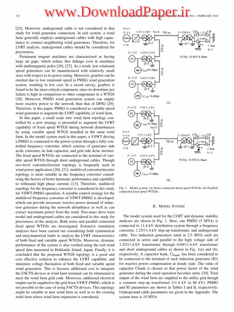
Fig. 1. Model system. (a) Series connected fixed speed WTGSs. (b) Parallelsconnected fixed speed WTGSs.
II. MODEL SYSTEM
The model system used for the LVRT and dynamic stability
analyses are shown in Fig. 1. Here, one PMSG (5 MVA) is
connected to 11.4-kV distribution system through a frequency
converter, 1.25/11.4-kV step-up transformer, and underground
cable. Two induction generators rated at 2.5 MVA each are
connected in series and parallel to the high voltage side of
1.25/11.4-kV transformer through 0.69/11.4-kV transformer
and short underground cables as shown in Fig. 1(a) and (b),
respectively. A capacitor bank, , has been considered to
be connected to the terminal of each induction generator (IG)
for reactive power compensation at steady state. The value of
capacitor Cbank is chosen so that power factor of the wind
generator during the rated operation becomes unity [30]. Total
output of the wind farm are supplied to the utility grid though
a common step-up transformer (11.4 kV to 66 kV). PMSG
and IG parameters are shown in Tables I and II, respectively.
Underground cable parameters are given in the Appendix. The
system base is 10 MVA.
Authorized licensed use limited to: IEEE Xplore. Downloaded on May 13,2010 at 11:45:42 UTC from IEEE Xplore. Restrictions apply.
www.DownloadPaper.irwww.DownloadPaper.ir

MUYEEN et al.: VARIABLE SPEED WIND TURBINE CONTROL STRATEGY 333
TABLE IPARAMETERS OF PMSG
TABLE IIPARAMETERS OF IG
Fig. 2. � � � curves for different pitch angles (used in FSWT).
III. WIND TURBINE MODELING
The mathematical relation for the mechanical power extrac-
tion from the wind can be expressed as follows [31]:
(1)
where is the extracted power from the wind, is the air
density , R is the blade radius [m], is the wind speed
[m/s] and is the power coefficient which is a function of both
tip speed ratio, , and blade pitch angle, [deg]. Both fixed and
variable speed wind turbine characteristics used in this study are
shown in Figs. 2 and 3, respectively [31]–[33].
In variable speed wind turbine, when the wind speed changes,
the rotational speed of wind turbine is controlled to follow the
maximum power point trajectory. Since the precise measure-
ment of the wind speed is difficult, it is better to calculate the
maximum power, , without the measurement of wind
speed as shown in the following:
(2)
Fig. 3. Turbine characteristic with maximum power point tracking (used inVSWT).
Fig. 4. Pitch controller used in variable speed WTGS.
Fig. 5. Conventional pitch controller used in fixed speed WTGS.
where and are optimum values of tip speed ratio
and power coefficient, respectively. From (2), it is clear that the
maximum generated power is proportional to the cube of rota-
tional speed.
The range of rotor speed variation is, in general, approxi-
mately 5 to 16 rpm. During the control of generator side ac/dc
converter, the maximum power, , is calculated based on the
MPPT, which becomes the reference power, , for the con-
verter. If this reference power is greater than the rated power
of PMSG, then the pitch controller shown in Fig. 4 is worked
to control the rotational speed. Therefore, the PMSG output
will not exceed the rated power. A conventional pitch controller
shown in Fig. 5 is also considered in fixed speed WTGS.
As VSWT-PMSG is decoupled from the grid through the fre-
quency converter, the drive train modeling has almost no in-
fluence on fault analysis [33]. Therefore, one-mass drive train
model of variable speed WTGS is considered in the simula-
tion for simplicity. However, in the case of fixed speed WTGS,
detailed drive train dynamics is needed to be considered, espe-
cially for flicker or transient stability analysis [24], [25]. There-
fore, two-mass drive train modeling is considered in this study
for fixed speed WTGSs.
IV. MODELING OF PWM FREQUENCY CONVERTER
The electrical scheme of VSWT-PMSG topology is shown
in Fig. 6. The PMSG model available in the package software
Authorized licensed use limited to: IEEE Xplore. Downloaded on May 13,2010 at 11:45:42 UTC from IEEE Xplore. Restrictions apply.
www.DownloadPaper.irwww.DownloadPaper.ir
334 IEEE TRANSACTIONS ON POWER SYSTEMS, VOL. 25, NO. 1, FEBRUARY 2010
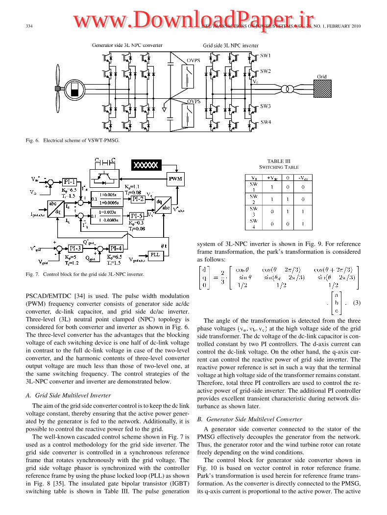
Fig. 6. Electrical scheme of VSWT-PMSG.
Fig. 7. Control block for the grid side 3L-NPC inverter.
PSCAD/EMTDC [34] is used. The pulse width modulation
(PWM) frequency converter consists of generator side ac/dc
converter, dc-link capacitor, and grid side dc/ac inverter.
Three-level (3L) neutral point clamped (NPC) topology is
considered for both converter and inverter as shown in Fig. 6.
The three-level converter has the advantages that the blocking
voltage of each switching device is one half of dc-link voltage
in contrast to the full dc-link voltage in case of the two-level
converter, and the harmonic contents of three-level converter
output voltage are much less than those of two-level one, at
the same switching frequency. The control strategies of the
3L-NPC converter and inverter are demonstrated below.
A. Grid Side Multilevel Inverter
The aim of the grid side converter control is to keep the dc link
voltage constant, thereby ensuring that the active power gener-
ated by the generator is fed to the network. Additionally, it is
possible to control the reactive power fed to the grid.
The well-known cascaded control scheme shown in Fig. 7 is
used as a control methodology for the grid side inverter. The
grid side converter is controlled in a synchronous reference
frame that rotates synchronously with the grid voltage. The
grid side voltage phasor is synchronized with the controller
reference frame by using the phase locked loop (PLL) as shown
in Fig. 8 [35]. The insulated gate bipolar transistor (IGBT)
switching table is shown in Table III. The pulse generation
TABLE IIISWITCHING TABLE
system of 3L-NPC inverter is shown in Fig. 9. For reference
frame transformation, the park’s transformation is considered
as follows:
(3)
The angle of the transformation is detected from the three
phase voltages at the high voltage side of the grid
side transformer. The dc voltage of the dc-link capacitor is con-
trolled constant by two PI controllers. The d-axis current can
control the dc-link voltage. On the other hand, the q-axis cur-
rent can control the reactive power of grid side inverter. The
reactive power reference is set in such a way that the terminal
voltage at high voltage side of the transformer remains constant.
Therefore, total three PI controllers are used to control the re-
active power of grid-side inverter. The additional PI controller
provides excellent transient characteristic during network dis-
turbance as shown later.
B. Generator Side Multilevel Converter
A generator side converter connected to the stator of the
PMSG effectively decouples the generator from the network.
Thus, the generator rotor and the wind turbine rotor can rotate
freely depending on the wind conditions.
The control block for generator side converter shown in
Fig. 10 is based on vector control in rotor reference frame.
Park’s transformation is used herein for reference frame trans-
formation. As the converter is directly connected to the PMSG,
its q-axis current is proportional to the active power. The active
Authorized licensed use limited to: IEEE Xplore. Downloaded on May 13,2010 at 11:45:42 UTC from IEEE Xplore. Restrictions apply.
www.DownloadPaper.irwww.DownloadPaper.ir

MUYEEN et al.: VARIABLE SPEED WIND TURBINE CONTROL STRATEGY 335
Fig. 8. Block diagram for PLL [35].
Fig. 9. Pulse generation system.
Fig. 10. Control block for the generator side converter.
power reference, , is determined in such a way to provide
the maximum power to the grid as explained in Section III.
However, when a network disturbance occurs, the terminal
voltage, , of the high voltage side of the transformer
decreases considerably. Therefore, in such a situation, it would
be appropriate not to keep the active power reference setpoint
at the maximum extracted power level in order to avoid dc-link
overvoltage, which is further discussed in the following section.
Therefore, in this study, is varied according to the terminal
voltage during the time when voltage drops below 0.9 p.u.
It gives excellent transient performance as demonstrated in
Section V. This is one of the salient features of this work. On
the other hand, the d-axis stator current is proportional to the
reactive power. The reactive power reference is set to zero to
perform unity power factor operation. The switching strategy
of 3L-NPC converter is the same that is used in Section IV-A.
In both converter and inverter, the triangular carrier signal
is used as the carrier wave of PWM operation. The carrier
frequency is chosen 1000 Hz for converter and 1050 Hz for
inverter, respectively. The dc-link capacitor value of each
switching device is 15 000 [21]. The rated dc-link voltage
across the two capacitor legs is 2.3 kV.
C. Overvoltage and Undervoltage Protection Schemes
of DC-Link
During the severe network disturbance such as short circuit
fault, the front end inverter has to provide sufficient reactive cur-
rent to support the grid. Therefore, the grid side inverter cannot
supply the active power from the generator to the grid, which
results in overvoltage in the dc-link of the frequency converter
This may hamper normal operation of the frequency converter
unit. In this paper, as the frequency converter of VSWT-PMSG
is used to provide the necessary reactive power support for the
proposed topology which includes fixed speed wind generators,
any type of interruption of the frequency converter would result
in instability in the overall system. Therefore, overvoltage pro-
tection scheme (OVPS) is taken into consideration in this study
as shown in Fig. 6 along with the control technique for gener-
ator side converter explained in Section IV-B.
The braking chopper is modeled in the dc-link in order to pro-
tect the dc-link capacitor during fault situation. The chopper is
activated when the dc-link voltage increases over the predefined
limit and dissipates the active power into the resistance during
the voltage dip in the grid.
Besides the overvoltage protection, undervoltage protection
is also taken into consideration, in this paper. In the grid side
inverter shown in Fig. 7, the output of integrators used in PI
controllers are reset when the dc-link voltage goes below a pre-
defined value. In this way, the undervoltage tripping of the drive
Authorized licensed use limited to: IEEE Xplore. Downloaded on May 13,2010 at 11:45:42 UTC from IEEE Xplore. Restrictions apply.
www.DownloadPaper.irwww.DownloadPaper.ir

336 IEEE TRANSACTIONS ON POWER SYSTEMS, VOL. 25, NO. 1, FEBRUARY 2010
Fig. 11. Low voltage ride-through standard set by FERC, U.S. [6].
can be avoided during the network disturbance when dc-link
voltage tends to decrease extremely.
V. SIMULATION RESULTS
The grid codes were originally decided with synchronous
generators in mind. But due to the recent addition of huge
amount of wind power to the grid, in many countries [4]–[7],
the new grid codes have been developed to ensure secure power
system operation. The wind farm grid codes are more or less
similar to each other. In this study, the simulation results are
described in light of the U.S. grid code, set by Federal Energy
Regulatory Commission (FERC). If the voltage does not fall
below the minimum voltage indicated by the solid line in
Fig. 11 and returns to 90% of the nominal voltage within 3 s
after the beginning of the voltage drop, the plant must stay
online [6].
In this study, a new wind farm topology is considered which
is composed of fixed and variable speed wind generators and
LVRT and dynamic characteristics are analyzed. The frequency
converter of the VSWT-PMSG is controlled in such a way to
maintain the grid voltage (voltage at the high voltage side of
transformer followed by the frequency converter) at desired ref-
erence level set by transmission system operator (TSO). In that
way, the necessary reactive power of the induction generator
can be supplied to restore the electromagnetic torque. To ob-
tain realistic responses, the two-mass shaft model of WTGS
is considered. All types of dampings are disregarded to ob-
tain the worse scenario [25]. Symmetrical three-line-to-ground
fault (3LG) and unsymmetrical double-line-to-ground (2LG),
line-to-line (2LS), and single-line-to-line (1LG) faults are con-
sidered as a network disturbance, which occurs at fault points
F in Fig. 1. The fault occurs at 0.1 s, the circuit breakers (CB)
on the faulted lines are opened at 0.2 s, and at 1.0 s, the cir-
cuit breakers are reclosed. In the simulation study, it is assumed
that wind speed is constant and equivalent to the rated speed for
both fixed and variable speed WTGSs. This is because it may be
considered that wind speed does not change dramatically during
the short time interval of the simulation. Time step and simula-
tion time are chosen 0.00002 s and 10 s, respectively. Simu-
TABLE IVCASE STUDY
lations were carried out by using PSCAD/EMTDC [34]. Two
cases shown in Table IV are considered in the simulation study
to show the effectiveness of the control strategy of the proposed
system to meet the wind farm grid code requirements.
A. LVRT Characteristic Analysis
To show the effectiveness of the control system of the fre-
quency converter under fault condition, pitch controllers con-
nected to the fixed speed WTGSs are not considered in both
Cases 1 and 2.
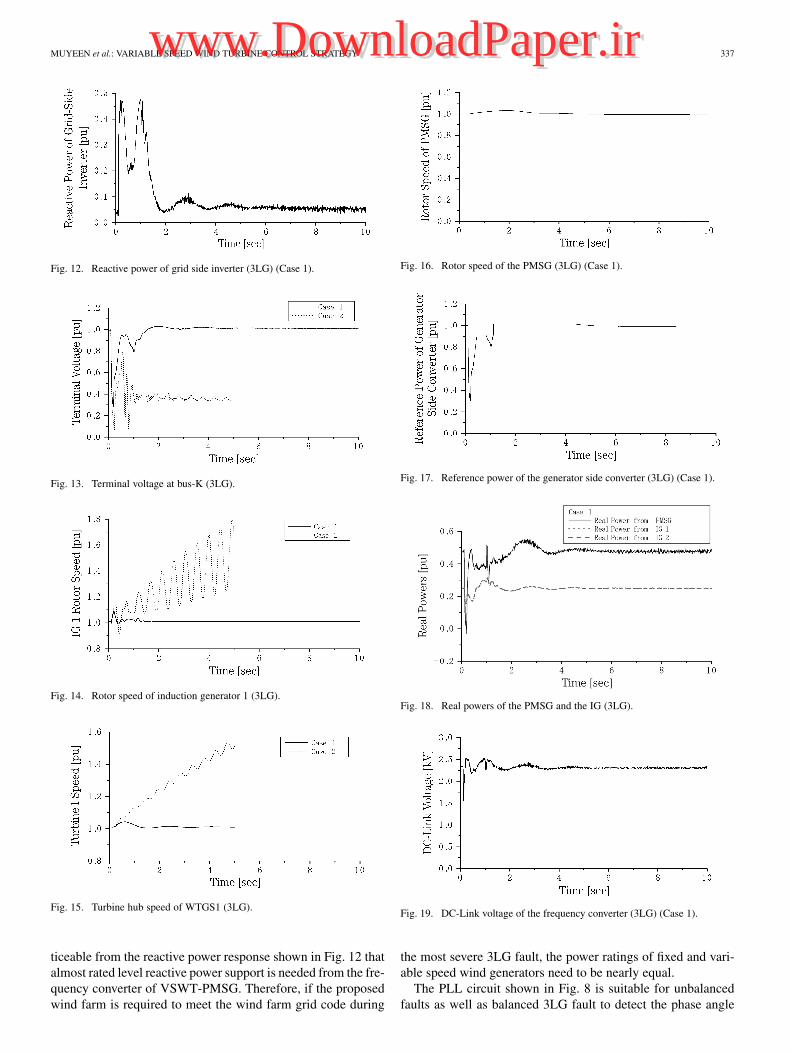
1) Using Model System (a): In this case, series connected
fixed speed WTGSs are connected to the terminal of VSWT-
PMSG at bus-K as shown in Fig. 1(a). The grid side inverter can
provide necessary reactive power during the severe symmetrical
3LG fault which is shown in Fig. 12. Therefore, the terminal
voltage shown in Fig. 13 can return to its pre-fault level for Case
1. As the necessary reactive power of the induction generators
are provided by the VSWT-PMSG, the electromagnetic torques
of IG can be restored quickly. Therefore, electromagnetic and
mechanical torques balance to each other and as a result the rotor
and turbine hub speeds of fixed speed WTGSs become stable for
Case 1 as shown in Figs. 14 and 15, respectively. From Fig. 13,
it is seen that Case 2 fails to achieve the LVRT requirement of
wind farm due to lack of reactive power supply during network
disturbance. The response of PMSG rotor speed is shown in
Fig. 16. When the fault occurs, the reference of the real power
reference for the generator side converter is varied with terminal
voltage as shown in Fig. 17. The real power responses of grid
side inverter (real power from the PMSG) and induction gen-
erators are shown together in Fig. 18. The dc-link voltage re-
sponse of the frequency converter is shown in Fig. 19. It is no-
Authorized licensed use limited to: IEEE Xplore. Downloaded on May 13,2010 at 11:45:42 UTC from IEEE Xplore. Restrictions apply.
www.DownloadPaper.irwww.DownloadPaper.ir
MUYEEN et al.: VARIABLE SPEED WIND TURBINE CONTROL STRATEGY 337
Fig. 12. Reactive power of grid side inverter (3LG) (Case 1).
Fig. 13. Terminal voltage at bus-K (3LG).
Fig. 14. Rotor speed of induction generator 1 (3LG).
Fig. 15. Turbine hub speed of WTGS1 (3LG).
ticeable from the reactive power response shown in Fig. 12 that
almost rated level reactive power support is needed from the fre-
quency converter of VSWT-PMSG. Therefore, if the proposed
wind farm is required to meet the wind farm grid code during
Fig. 16. Rotor speed of the PMSG (3LG) (Case 1).
Fig. 17. Reference power of the generator side converter (3LG) (Case 1).
Fig. 18. Real powers of the PMSG and the IG (3LG).
Fig. 19. DC-Link voltage of the frequency converter (3LG) (Case 1).
the most severe 3LG fault, the power ratings of fixed and vari-
able speed wind generators need to be nearly equal.
The PLL circuit shown in Fig. 8 is suitable for unbalanced
faults as well as balanced 3LG fault to detect the phase angle
Authorized licensed use limited to: IEEE Xplore. Downloaded on May 13,2010 at 11:45:42 UTC from IEEE Xplore. Restrictions apply.
www.DownloadPaper.irwww.DownloadPaper.ir

338 IEEE TRANSACTIONS ON POWER SYSTEMS, VOL. 25, NO. 1, FEBRUARY 2010
Fig. 20. Terminal voltage at bus-K (2LG).
Fig. 21. Terminal voltage at bus-K (2LS).
Fig. 22. Terminal voltage at bus-K (1LG).
used in the grid side inverter. The responses of the terminal volt-
ages at bus-K in the case of 2LG, 2LL, and 1LG faults are shown
in Figs. 20–22, respectively. From the simulation results, it is
seen that the LVRT requirement of wind farm can be met well
for the fault types described in this paper.
2) Using Model System (b): In this case, parallel connected
fixed speed WTGSs are connected to the terminal of VSWT-
PMSG as shown in Fig. 1(b).
The response of terminal voltage at bus-K is shown in Fig. 23
from which it is seen that Case 1 can achieve the LVRT require-
ment of wind farm. The responses of reactive power and dc-link
voltage of frequency converter are shown in Figs. 24 and 25, re-
spectively. Therefore, this model can also help wind farms meet
the new grid code requirements.
B. Dynamic Characteristic Analysis
To evaluate the dynamic performance of the proposed system,
the real wind speed data measured in Hokkaido Island, Japan,
Fig. 23. Terminal voltage at bus-K (3LG).
Fig. 24. Reactive power of grid side inverter (3LG) (Case 1).
Fig. 25. DC-Link voltage of the frequency converter (3LG) (Case 1).
Fig. 26. Wind speed data for generators.
shown in Fig. 26, is used in the simulation. Model system (a)
is considered in this analysis. It is seen that the wind farm ter-
minal voltage at bus-K can be maintained constant in Case 1 also
during randomly fluctuating wind speed as shown in Fig. 27.
The reactive power response at bus-K is also shown in Fig. 28.
Authorized licensed use limited to: IEEE Xplore. Downloaded on May 13,2010 at 11:45:42 UTC from IEEE Xplore. Restrictions apply.
www.DownloadPaper.irwww.DownloadPaper.ir

MUYEEN et al.: VARIABLE SPEED WIND TURBINE CONTROL STRATEGY 339
Fig. 27. Wind farm terminal voltage at bus-K.
Fig. 28. Reactive power at bus-K.
VI. CONCLUSIONS
Integration of FACTS devices to wind farm terminal can aug-
ment the LVRT capability of fixed speed WTGSs, which is re-
ported already in several literatures. However, it increases the
overall system cost. In this paper, a new type of wind farm
topology composed of fixed and variable speed wind turbine
generator systems has been presented. The variable speed wind
turbine driving a PMSG is connected to the grid through a fully
controlled three-level NPC frequency converter which has reac-
tive power control ability. Taking this advantage from VSWT-
PMSG, fixed speed wind generators are connected either series
or parallel to its terminal, so that they can receive the neces-
sary reactive power from VSWT-PMSG during network dis-
turbances. The LVRT characteristics of both fixed and variable
speed WTGSs are evaluated in light of U.S. grid code consid-
ering both symmetrical and unsymmetrical faults. Moreover, the
dynamic performance is verified using real wind speed data. Fi-
nally, it is concluded that the proposed system can be a cost-ef-
fective solution to achieve the requirements of new wind farm
grid code.
APPENDIX
The underground cable parameters are given below [36].
(a) Underground cables between transformers, 1.25/11.4 kV
and 0.69/11.4 kV (350 m): ,
, and .
(b) Underground cables between transformers, 1.25/11.4 kV
and 11.4/66 kV (700 m): ,
, and .
REFERENCES
[1] The Global Wind Energy Council, Global Wind 2007 Report,2nd ed.May 2008. [Online]. Available: http://www.gwec.net/.
[2] F. V. hulle, Large Scale Integration of Wind Energy in the EuropeanPower Supply Analysis, Issue and Recommendations. EWEA, Dec.2005, Tech. Rep.
[3] C. L. Souza et al., “Power system transient stability analysis includingsynchronous and induction generator,” in Proc. IEEE Porto Power
Tech, 2001, vol. 2, p. 6.[4] R. Zavadil, N. Miller, A. Ellis, and E. Muljadi, “Making connections,”
IEEE Power Energy Mag., vol. 3, no. 6, pp. 26–37, 2005.[5] Ireland National Grid, Grid Code Version 2, Jan. 2007, Wind Farm
Power Station Grid Code Provisions, WFPS1, pp. 213–216.[6] Federal Energy Regulatory Commission (FERC), United States of
America, Docket no. RM05-4-000-Order no. 661, Interconnection forWind Energy, Jun. 2, 2005.
[7] Federal Energy Regulatory Commission (FERC), United States ofAmerica, Docket no. RM05-4-001; Order no. 661-A, Interconnectionfor Wind Energy, Dec. 12, 2005.
[8] L. Gyugyi, “Unified power-flow control concept for flexible actransmission systems,” Proc. Inst. Elect. Eng. C, vol. 139, no. 4, pp.323–331, 1992.
[9] L. Gyugyi, “Dynamic compensation of AC transmission lines by solid-state synchronous voltage sources,” IEEE Trans. Power Del., vol. 9, no.2, pp. 904–911, Apr. 1994.
[10] H. F. Wang, F. Li, and R. G. Cameron, “Facts control design basedon power system nonparametric models,” Proc. Inst. Elect. Eng., Gen.,
Transm., Distrib., vol. 146, no. 5, pp. 409–415, 1999.[11] L. Zhang, C. Shen, M. L. Crow, L. Dong, S. Pekarek, and S. Atcitty,
“Performance indices for the dynamic performance of FACTS andFACTS with energy storage,” Elect. Power Compon. Syst., vol. 33, no.3, pp. 299–314, Mar. 2005.
[12] Z. Saad-Saoud, M. L. Lisboa, J. B. Ekanayake, N. Jenkins, and G.Strbac, “Application of STATCOMs to wind farms,” Proc. Inst. Elect.
Eng., Gen., Transm., Distrib., vol. 145, no. 5, pp. 511–516, 1998.[13] S. M. Muyeen, M. A. Mannan, M. H. Ali, R. Takahashi, T. Murata,
and J. Tamura, “Stabilization of wind turbine generator system bySTATCOM,” IEEJ Trans. PE, vol. 126-B, no. 10, pp. 1073–1082,2006.
[14] T. Ahmed, E. Hiraki, M. Nakaoka, and O. Noro, “Static VAr compen-sator-based terminal voltage regulation scheme of self-excited induc-tion generator driven by variable speed prime mover for clean renew-able energy,” in Proc. 4th Int. Power Electronics and Motion Control
Conf. (IPEMC), 2004, vol. 3, no. 14–16, pp. 1219–1224.[15] F. Zhou, G. Joos, C. Abbey, L. Jiao, and B. T. Ooi, “Use of large ca-
pacity SMES to improve the power quality and stability of wind farms,”in Proc. IEEE Power Engineering Society General Meeting, Jun. 2004,vol. 2, pp. 2025–2030.
[16] M. H. Ali, T. Murata, and J. Tamura, “Minimization of fluctuationsof line power and terminal voltage of wind generator by fuzzy logic-controlled SMES,” Int. Rev. Elect. Eng. (I.R.E.E.), vol. 1, no. 4, pp.559–566, Oct. 2006.
[17] T. Kinjo, T. Senjyu, N. Urasaki, and H. Fujita, “Output levelling ofrenewable energy by electric double-layer capacitor applied for en-ergy storage system,” IEEE Trans. Energy Convers., vol. 21, no. 1, pp.221–227, 2006.
[18] S. M. Muyeen, R. Takahashi, M. H. Ali, T. Murata, and J. Tamura,“Transient stability augmentation of power system including windfarms by using ECS,” IEEE Trans. Power Syst., vol. 23, no. 3, pp.1179–1187, Aug. 2008.
[19] S. B. Papaefthimiou and S. A. Papathanassiou, “Simulation and controlof a variable speed wind turbine with synchronous generator,” in CD
Rec. XVII Int. Conf. Electrical Machines (ICEM 2006), Chania, CreteIsland, Greece, Sep. 2–5, 2006, Ref. No. 593.
[20] S. M. Muyeen, R. Takahashi, T. Murata, J. Tamura, and M. H. Ali,“Transient stability analysis of permanent magnet variable speed syn-chronous wind generator,” in Proc. Int. Conf. Electrical Machines and
Systems 2007 (ICEMS 2007), Seoul, Korea, Oct. 2007, pp. 288–293.[21] A. D. Hansen and G. Michalke, “Modelling and control of variable-
speed multi-pole permanent magnet synchronous generator wind tur-bine,” Wind Energy, vol. 11, no. 5, pp. 537–554, 2008, 10.1002/we.278.
[22] T. Sun, Z. Chen, and F. Blaabjerg, “Transient stability of DFIG windturbines at an external short-circuit fault,” Wind Energy, vol. 8, no. 3,pp. 345–360, 2005.
Authorized licensed use limited to: IEEE Xplore. Downloaded on May 13,2010 at 11:45:42 UTC from IEEE Xplore. Restrictions apply.
www.DownloadPaper.irwww.DownloadPaper.ir

340 IEEE TRANSACTIONS ON POWER SYSTEMS, VOL. 25, NO. 1, FEBRUARY 2010
[23] R. Takahashi, J. Tamura, M. Futami, M. Kimura, and K. Ide, “A newcontrol method for wind energy conversion system using a double-fedsynchronous generator,” (in Japanese) IEEJ Power and Energy, vol.126, no. 2, pp. 225–235, 2006.
[24] S. K. Salman and A. L. J. Teo, “Windmill modeling considerationand factors influencing the stability of a grid-connected wind power-based embedded generator,” IEEE Trans. Power Syst., vol. 18, no. 2,pp. 793–802, May 2003.
[25] S. M. Muyeen, M. H. Ali, R. Takahashi, T. Murata, J. Tamura, Y.Tomaki, A. Sakahara, and E. Sasano, “A comparative study on tran-sient stability analysis of wind turbine generator system using differentdrive train models,” IET Proc. Renewab. Power Gen. (IET-RPG), vol.1, no. 2, pp. 131–141, Jun. 2007.
[26] P. Vas, Electrical Machines and Drives—A Space Vector Theory Ap-
proach. New York: Oxford Univ. Press, 1992.[27] T. J. E. Miller, Brushless Permanent-Magnet and Reluctance Motor
Drives. New York: Oxford Univ. Press, 1989.[28] J. Ribrant and L. M. Bertling, “Survey of failures in wind power sys-
tems with focus on Swedish wind power plants during 1997–2005,”IEEE Trans. Energy Convers., vol. 22, no. 1, pp. 167–173, Mar. 2007.
[29] M. B. C. Salles, K. Hameyer, J. R. Cardoso, and W. Freitas, “Dynamicanalysis of wind turbines considering new grid code requirements,”presented at the 2008 Int. Conf. Electrical Machines, Vilamoura, Por-tugal, 2008, Paper ID.1024.
[30] S. M. Muyeen, M. H. Ali, R. Takahashi, T. Murata, and J. Tamura,“Transient stability enhancement of wind generator by a new logicalpitch controller,” IEEJ Trans. PE, vol. 126-B, no. 08, pp. 742–752,Aug. 2006.
[31] S. Heier, Grid Integration of Wind Energy Conversion System. Chich-ester, U.K.: Wiley, 1998.
[32] O. Wasynczuk, D. T. Man, and J. P. Sullivan, “Dynamic behavior ofa class of wind turbine generator during random wind fluctuations,”IEEE Trans. Power App. Syst., vol. PAS-100, no. 6, pp. 2873–2845,1981.
[33] J. G. Slootweg, S. W. H. De Hann, H. Polinder, and W. L. Kling,“General model for representing variable speed wind turbines in powersystem dynamic simulations,” IEEE Trans. Power Syst., vol. 18, no. 1,pp. 144–151, Feb. 2003.
[34] “PSCAD/EMTDC Manual,” Manitoba HVDC Research Center, 1994.[35] M. Akamatsu, M. Tsukada, and D. Itoh, “A novel PLL and frequency
detecting method suited for the abnormal voltages under fault condi-tions in the power system,” IEEJ Trans. PE, vol. 118-B, no. 9, pp.955–961, 1998.
[36] L. Wang and J.-Y. Liou, “Simulations of a commercial wind powergeneration system with four wind-turbine induction generators,” inProc. IEEE Power Engineering Society General Meeting 2007, Tampa,FL, 2007, pp. 1–7.
S. M. Muyeen (M’08) was born in Khulna,Bangladesh, on September 8, 1975. He receivedthe B.Sc. Eng. degree from Rajshahi University ofEngineering and Technology (RUET), Rajshahi,Bangladesh, in 2000 and the M.Sc. Eng. and Dr.Eng. degrees from Kitami Institute of Technology,Kitami, Japan, in 2005 and 2008, respectively, all inelectrical and electronic engineering.
Presently, he is doing research works under theJapan Society for the Promotion of Science (JSPS)Postdoctoral Fellowship Program at the Kitami
Institute of Technology. His research interests are power system, electricalmachine, FACTS, energy storage system (ESS), wind generator stabilization,multi-mass drive train of wind turbine, and HVDC system.
Rion Takahashi (M’07) received the B.Sc. Eng.and Dr. Eng. degrees from Kitami Institute ofTechnology, Kitami, Japan, in 1998 and 2006,respectively, both in electrical and electronicengineering.
Now, he is working as a Research Assistant in theDepartment of Electrical and Electronic Engineering,Kitami Institute of Technology. His major researchinterests include analysis of power system transient,FACTS, and wind energy conversion system.
Toshiaki Murata received the Dr. Eng. degree fromHokkaido University, Japan, Sapporo, in 1991.
He completed his Electrical Engineering Cur-riculum at the Teacher Training School fromHokkaido University. Since 1969, he had been aResearch Assistant at the Kitami Institute of Tech-nology, Kitami, Japan. Presently, he is an AssociateProfessor at the Kitami Institute of Technology.
Junji Tamura (M’87–SM’92) received the B.Sc.Eng. degree from Muroran Institute of Technology,Muroran, Japan, in 1979 and the M.Sc. Eng. and Dr.Eng. degrees from Hokkaido University, Sapporo,Japan, in 1981 and 1984, respectively, all in electricalengineering.
In 1984, he became a Lecturer and in 1986, anAssociate Professor at the Kitami Institute of Tech-nology, Kitami, Japan. Currently, he is a Professor atthe Kitami Institute of Technology.
Authorized licensed use limited to: IEEE Xplore. Downloaded on May 13,2010 at 11:45:42 UTC from IEEE Xplore. Restrictions apply.
www.DownloadPaper.irwww.DownloadPaper.ir
Copyright © 2022 FDOKUMEN