Rotor Speed Sensor Fault Detection in Induction Motors
8
Rotor Speed Sensor Fault Detection in Induction Motors Riccardo Marino, Stefano Scalzi, Patrizio Tomei and Cristiano Maria Verrelli Department of Electronic Engineering, University of Rome “Tor Vergata”, Via del Politecnico 1, 00133 Rome, Italy Keywords: Fault Detection, Speed Sensor Faults, Induction Motors. Abstract: The problem of detecting a speed sensor fault in induction motor applications with load torque and rotor/stator resistances uncertainties is addressed. It is shown that in typical operating conditions involving constant rotor speed and flux modulus and non-zero load torque, a constant non-zero (sufficiently large) difference between the measured speed and the actual speed may be on-line identified by an adaptive flux observer which incorporates a convergent rotor resistance identifier and relies on the measured rotor speed and stator currents/voltages. 1 INTRODUCTION Three-phase induction motors are widely used for electric railway and automotive traction (Hill, 1994) since they offer several advantages such as no com- mutator, no brushes, no rotor windings in squirrel cage motors, simple rugged structure, inherent regen- erative braking capability, ability of tolerating heavy overloading and of producing high torques with low weights, small sizes, and low rotating masses. In high impact automotive applications (see Rehman, 2008) such as electrical and hybrid electrical vehicles, the operation continuity is a key feature and high relia- bility of the drive system should be guaranteed (see Benbouzid et al., 2007). On the other hand, traction main drives are often equipped with rotor speed sen- sors (Guzinski et al., 2009) which are used by clas- sical induction motor control schemes such as direct or indirect field oriented controls (see Marino et al., 2010b) for recent adaptive results). In the case of ro- tor speed sensor fault, a proper and prompt fault de- tection is required so that an effective action can be performed and the fault effect is not widely propa- gated with a resulting hard system failure. The idea underlying a model-based approach to fault diagnosis (see for instance (Isermann, 2011) and (Ding, 2008)) relies on the assumption that certain process signals carry information about the faults of interest. The gist of the approach is then to gener- ate, on the basis of measurements from (and knowl- edge of) the system, a set of ”residual signals” which are zero when no fault is present and non-zero when faults occur (Bennet et al., 1999). However sev- eral difficulties naturally arise for the specific applica- tion to induction motors: induction motor dynamics are nonlinear; flux measurements are not available; three critical parameters, namely rotor and stator re- sistances (which vary during operations due to motor heating) and load torque (which depends on applica- tions), are typically uncertain and are required to be on-line estimated. A first intuitive solution (IS ) to speed sensor fault detection problems relies on designing an adaptive flux/speed observer which does not use the measured speed but only stator currents and voltages measure- ments (see (Guzinski et al., 2010) and (Guzinski et al., 2009)). The gist of the above design is then to com- pare the measured speed with the estimated one with the aim of identifying the possibly occurring speed sensor fault. Since suitable identifiers for the uncer- tain parameters are to be incorporated in the adaptive observer in order to avoid false fault detections, the drawback of the above approach is then constituted by the well-known identifiability and observability is- sues which arise when only stator currents and volt- ages are measured. It is in fact well-established that when the motor operates at constant rotor speed and flux modulus with non-zero load torque to mini- mize power losses and maximize power efficiency at steady-state (see Marinoet al., 2010b), the simultane- ous estimation of rotor speed and rotor resistance can- not be achieved (see (Ha and Lee, 2000), (Marino et al., 2008), as well as (Marino et al., 2010a)) and ref- erences therein) since only a linear combination L = R r + γω of the rotor resistance R r and speed ω (along with the real γ) can be on-line identified by stator currents 59 Marino R., Scalzi S., Tomei P. and Maria Verrelli C.. Rotor Speed Sensor Fault Detection in Induction Motors. DOI: 10.5220/0004026500590066 In Proceedings of the 9th International Conference on Informatics in Control, Automation and Robotics (ICINCO-2012), pages 59-66 ISBN: 978-989-8565-21-1 Copyright c 2012 SCITEPRESS (Science and Technology Publications, Lda.)
-
Upload
khangminh22 -
Category
Documents
-
view
0 -
download
0
Transcript of Rotor Speed Sensor Fault Detection in Induction Motors

Rotor Speed Sensor Fault Detection in Induction Motors
Riccardo Marino, Stefano Scalzi, Patrizio Tomei and Cristiano Maria VerrelliDepartment of Electronic Engineering, University of Rome “Tor Vergata”, Via del Politecnico 1, 00133 Rome, Italy
Keywords: Fault Detection, Speed Sensor Faults, Induction Motors.
Abstract: The problem of detecting a speed sensor fault in induction motor applications with load torque and rotor/statorresistances uncertainties is addressed. It is shown that in typical operating conditions involving constantrotor speed and flux modulus and non-zero load torque, a constant non-zero (sufficiently large) differencebetween the measured speed and the actual speed may be on-line identified by an adaptive flux observerwhich incorporates a convergent rotor resistance identifier and relies on the measured rotor speed and statorcurrents/voltages.
1 INTRODUCTION
Three-phase induction motors are widely used forelectric railway and automotive traction (Hill, 1994)since they offer several advantages such as no com-mutator, no brushes, no rotor windings in squirrelcage motors, simple rugged structure, inherent regen-erative braking capability, ability of tolerating heavyoverloading and of producing high torques with lowweights, small sizes, and low rotating masses. In highimpact automotive applications (see Rehman, 2008)such as electrical and hybrid electrical vehicles, theoperation continuity is a key feature and high relia-bility of the drive system should be guaranteed (seeBenbouzid et al., 2007). On the other hand, tractionmain drives are often equipped with rotor speed sen-sors (Guzinski et al., 2009) which are used by clas-sical induction motor control schemes such as director indirect field oriented controls (see Marino et al.,2010b) for recent adaptive results). In the case of ro-tor speed sensor fault, a proper and prompt fault de-tection is required so that an effective action can beperformed and the fault effect is not widely propa-gated with a resulting hard system failure.
The idea underlying a model-based approach tofault diagnosis (see for instance (Isermann, 2011) and(Ding, 2008)) relies on the assumption that certainprocess signals carry information about the faults ofinterest. The gist of the approach is then to gener-ate, on the basis of measurements from (and knowl-edge of) the system, a set of ”residual signals” whichare zero when no fault is present and non-zero whenfaults occur (Bennet et al., 1999). However sev-eral difficulties naturally arise for the specific applica-
tion to induction motors: induction motor dynamicsare nonlinear; flux measurements are not available;three critical parameters, namely rotor and stator re-sistances (which vary during operations due to motorheating) and load torque (which depends on applica-tions), are typically uncertain and are required to beon-line estimated.
A first intuitive solution (I S ) to speed sensor faultdetection problems relies on designing an adaptiveflux/speed observer which does not use the measuredspeed but only stator currents and voltages measure-ments (see (Guzinski et al., 2010) and (Guzinski et al.,2009)). The gist of the above design is then to com-pare the measured speed with the estimated one withthe aim of identifying the possibly occurring speedsensor fault. Since suitable identifiers for the uncer-tain parameters are to be incorporated in the adaptiveobserver in order to avoid false fault detections, thedrawback of the above approach is then constitutedby the well-known identifiability and observability is-sues which arise when only stator currents and volt-ages are measured. It is in fact well-establishedthat when the motor operates at constant rotor speedand flux modulus with non-zero load torque to mini-mize power losses and maximize power efficiency atsteady-state (see Marinoet al., 2010b), the simultane-ous estimation of rotor speed and rotor resistance can-not be achieved (see (Ha and Lee, 2000), (Marino etal., 2008), as well as (Marino et al., 2010a)) and ref-erences therein) since only a linear combination
L = Rr + gw
of the rotor resistance Rr and speed w (along withthe real g) can be on-line identified by stator currents
59Marino R., Scalzi S., Tomei P. and Maria Verrelli C..Rotor Speed Sensor Fault Detection in Induction Motors.DOI: 10.5220/0004026500590066In Proceedings of the 9th International Conference on Informatics in Control, Automation and Robotics (ICINCO-2012), pages 59-66ISBN: 978-989-8565-21-1Copyright c 2012 SCITEPRESS (Science and Technology Publications, Lda.)

and voltages measurements. This structural difficultymay be used to our advantage by noting that when the(constant) measured speed wm is used by a suitableadaptive flux observer AF O, the identifiable linearcombination becomes
Le = Rr + g(w�wm):
If the rotor speed is measured and no speed sensorfault fault occurs, i.e. w � wm, estimating Le coin-cides with estimating Rr; on the other hand, in thepresence of speed sensor failures, estimating Le coin-cides with estimating a quantity which, depending on(w�wm), may be larger or smaller than any admissi-ble Rr 2 [Rrm;RrM] for the specific motor in consider-ation, that is
Rr + g(w�wm)< Rrm
or
Rr + g(w�wm)> RrM :
In this case a speed sensor fault may be on-lineidentified by designing a speed measurement-basedadaptive observer and by monitoring the estimate ofLe on the basis of the boundary values Rrm and RrM .
The aim of this paper is to show that an adaptiveflux observer AF O which incorporates a convergentrotor resistance identifier and relies on the measuredrotor speed and stator currents/voltages may be ef-fectively used to on-line identify a constant non-zero(sufficiently large) difference w�wm in typical oper-ating conditions involving non-zero load torque andconstant rotor speed and flux modulus. In particular,denoting by a 2 [am;aM] (am = LrRrm, aM = LrRrM)the ratio between the rotor resistance Rr and the ro-tor inductance Lr and by a its estimate (provided bythe AF O), we will show that a residual signal forthe speed sensor fault detection may be chosen asthe steady-state distance of a(t) from the compact set[am;aM], i.e.
limt!+¥
dist(a(t); [am;aM ]):
A similar idea (though not analytically motivated)has been also recently presented in Najafabadi et al.(2011) even though it relies on an observer which isadaptive with respect to the rotor resistance only. Incontrast to Najafabadi et al. (2011), we propose acandidate adaptive flux observer belonging to the setof all adaptive flux observers which provide conver-gent estimates of the rotor resistance despite uncer-tainties in critical parameters such as load torque andstator resistance. This is to avoid false fault detectionswhich may be related to uncertainties in those criti-cal parameters. With this respect, among the adap-tive observers which have been proposed in the lit-erature since 1978 (see for instance (Castaldi et al.,
2005), (Hasan and Husain, 2009), (Jeon et al., 2002),(Kenne et al., 2010), (Marino et al., 2000), (Marinoet al., 2011), (Najafabadi et al., 2011), (Ticlea andBesancon, 2006) and references therein), we con-sider in this paper the one presented in Marino et al.(2011) which is simultaneously characterized by: i)an overall structural simplicity with no use of signfunctions, high gains or output time derivatives whichlead to well-known implementation difficulties andhigh noise sensitivity; ii) persistency of excitationconditions which are naturally related to motor ob-servability and parameter identifiability and are guar-anteed to be satisfied in the typical case of constantmotor speed and flux modulus and non-zero electro-magnetic torque; iii) exponential convergence prop-erties guaranteeing a certain degree of robustness. Itis constituted by an adaptive flux observer which isable to estimate the motor fluxes and to identify therotor resistance and by a stator resistance identifierwhose design is performed on a different time scalein order to isolate its estimation from the estimationof motor fluxes and rotor resistance (see also (Jadotet al., 2009), (Marino et al., 2010c)) for a similar ap-proach to parameter estimation in induction motors).Simulation and experimental results illustrate the ef-fectiveness of the proposed solution and show satis-factory fault detection performances. Such a speedsensor fault detector constitutes a first step toward thedesign of effective fault-tolerant control architectureswhich involve output feedback adaptive tracking con-trols (Marino et al., 2010b) minimizing power lossesin conjunction with sensorless adaptive tracking con-trols (Marino et al., 2010c) imposing rotor speed ob-servability and resistance identifiability. Those fault-tolerant architectures may be of special interest forspeed-controlled traction applications in which induc-tion motor controls are required to tolerate rotor speedsensor faults (see (Benbouzid et al., 2007), (Guzinskiet al., 2010), (Guzinski et al., 2009)) and to main-tain at the same time high power efficiency at everyspeed (see (Bennet et al., 1999), (Diallo et al., 2004),(Lee and Ryu, 2003), (Romero et al., 2010), (Wang etal., 2006) for the general problem of designing fault-tolerant induction motor controls).
2 PHYSICAL MODELING
Assuming linear magnetic circuits, the dynamics of abalanced non-saturated induction motor with one polepair in a fixed reference frame attached to the statorare given by the well known fifth-order model (see forinstance (Marino et al., 2010a) and references therein)
ICINCO�2012�-�9th�International�Conference�on�Informatics�in�Control,�Automation�and�Robotics
60
dw
dt= µ(yraisb�yrbisa)�
TL
Jdyra
dt= �ayra�wyrb +aMisa
dyrb
dt= �ayrb +wyra +aMisb (1)
disa
dt= �
�Rs
s+baM
�isa +
1s
usa +bayra +bwyrb
disb
dt= �
�Rs
s+baM
�isb +
1s
usb +bayrb�bwyra
in which: w is the rotor speed, (yra;yrb) are the ro-tor fluxes, (isa; isb) are the stator currents, (usa;usb)are the stator voltages in a fixed reference attachedto the stator. The constant model parameters are:load torque TL; motor moment of inertia J; rotor andstator windings resistances (Rr;Rs) and inductances(Lr;Ls); mutual inductance M. To simplify nota-tions we use the reparameterization: a = Rr
Lr, b = M
sLr,
µ = MJLr
, s = Ls(1� M2
LsLr ). The rotor fluxes (yra;yrb)are unmeasured variables since flux sensors are usu-ally not available while the parameters TL, a and Rsare typically uncertain owing to load torque depen-dence on applications and owing to resistance varia-tions which depend on motor heating. We will onlyassume, in the following, the boundedness of stateand input variables while any restriction concerningthe boundedness of stator currents integrals, whichhas been proposed for the design of similar adaptiveflux observers in Jeon et al. (2002), (Marino et al.(2000), is not required.
3 OBSERVER DESIGN
The first idea in Marino et al. (2011) is to introducethe variables za = isa +byra, zb = isb +byrb so thatthe motor electro-magnetic equations in (1) become
za = �Rs
sisa +
1s
usa
zb = �Rs
sisb +
1s
usb
disa
dt= �Rs
sisa�a(1+bM)isa�wisb +aza
+wzb +1s
usa (2)
disb
dt= �Rs
sisb�a(1+bM)isb +wisa +azb
�wza +1s
usb:
The advantage of using the (za;zb) variables,which are physically related to the stator fluxes, is thattheir dynamics depend neither on the unmeasured ro-tor fluxes nor on the uncertain rotor resistance. On the
basis of model (2), the following observer is designed(ki is a positive design parameter):
˙isa = � Rs
sisa� a(1+bM)isa�wisb + aza
+wzb +usa
s+ ki(isa� isa)
˙isb = � Rs
sisb� a(1+bM)isb +wisa + azb
�wza +usb
s+ ki(isb� isb) (3)
˙za = � Rs
sisa +
usa
s+ va
˙zb = � Rs
sisb +
usb
s+ vb
which is a copy of system (2) with: i) the estimates(za; zb; a; Rs) in place of the unmeasured/uncertain(za,zb, a, Rs); ii) stabilizing terms on the current esti-mation errors (isa� isa), (isb� isb); iii) the compensat-ing terms va;vb yet to be designed. According to thestability analysis in Marino et al. (2011), the estima-tion laws for a and Rs and the feedback terms va;vbare chosen as
˙a = �ka
h[(1+bM)isa� za] isa +[(1+bM)isb� zb] isb
i˙Rs = �kR (vaisa + vbisb)
va = �kz�wisb� aisa
�vb = kz
�wisa + aisb
�(4)
in which isa = isa � isa, isb = isb � isb are the statorcurrent estimation errors, kz and ka are positive designparameters, kR is a sufficiently small positive designparameter.
The two-time-scale arguments in Marino et al.(2011), under certain identifiability assumptions atsteady-state, allow for isolating the estimation of thestator resistance from the estimation of motor fluxes(achieved through the estimation of (za;zb)) and rotorresistance so that the following persistency of excita-tion condition:
Pe: there exist two positive reals tp and kp such thatthe persistency of excitation condition (I3 is the3�3 identity matrix)Z t+tp
tG
T(t)G(t)dt � kpI3; 8 t � 0 (5)
holds with
G =
�a w b(yra�Misa)�w a b(yrb�Misb)
�is obtained. Inequality (5) is naturally related to mo-tor observability and parameter identifiability: whenthe rotor speed and the rotor flux modulus are con-stant and the load torque is zero so that yra = Misa
Rotor�Speed�Sensor�Fault�Detection�in�Induction�Motors
61

and yrb = Misb, it cannot be satisfied; when a positiveload torque is applied and when the rotor speed andthe rotor flux modulus are constant with y2
ra +y2rb =
cy > 0, it is satisfied.The gist of the estimation design in Marino et al.(2011) and the required assumptions can be simplyexplained in the following terms: if the adaptive ob-server (3)-(4) (with no stator resistance identifier) isused with a constant value of the stator resistance thatis slightly different from its actual value, then a non-zero steady-state solution appears that causes a suit-able measured output function sp = vaisa+vbisb to be,in first approximation, monotone with respect to theRs-estimation error Rs = Rs� Rs; thus, by adjustingthe Rs-estimate Rs on the basis of this output func-tion (slowly, in order not to deviate too much fromthe steady-state solution) one can obtain the correctestimation of Rs and the consequent exponential con-vergence to zero of all the estimation errors isa, isb,za� za, zb� zb, a� a, Rs. Exponential rotor flux re-covering can be finally obtained by�
yrayrb
�= � 1
b
�isa� zaisb� zb
�where the filtered estimates (isa; isb) are preferred tothe measured (isa; isb) for practical implementation is-sues. The following second-order load torque identi-fier (kw and kT are positive design parameters):
˙w = µ(yraisb� yrbisa)�TL
J+ kw(w� w)
˙TL = �kT (w� w)
is finally proposed in Marino et al. (2011). It can beused in conjunction with the adaptive observer (3)-(4)to provide an exponentially convergent estimate of theload torque once convergent estimates of rotor fluxeshave been obtained. The proof, which is reported inMarino et al. (2010a), is based on the quadratic func-tion
VT =1
2kT JT 2
L +12
w2 + ewTL
in which w = w� w, TL = TL� TL and e > 0 is a suf-ficiently small positive real.
4 SENSOR FAULT DETECTION
The aim of this section is to prove that a constant non-zero (sufficiently large) difference between the mea-sured speed and the actual speed may be on-line iden-tified by the adaptive flux observer (3)-(4) (in which
the measured speed wm replaces the actual speed w) intypical operating conditions involving non-zero loadtorque and constant rotor speed and flux modulus. Tothis purpose, we preliminarly note that in those con-ditions we have
˙z }| {y
2ra +y
2rb � 0w � 0;
from which we obtain
Misa = yra� cyrb
Misb = yrb + cyra (6)
with (ws is the slip speed [see (Marino et al., 2010a)])
c =TLMJµcy
=TLLr
cy
= ws=a:
By adding and subtracting in (2) suitable termsproportional to we = w�wm and by using (6), equa-tions (2) can be equivalently rewritten as
za = �Rs
sisa +
1s
usa
zb = �Rs
sisb +
1s
usb
disa
dt= �Rs
sisa�wmisb +wmzb +
1s
usa
+a [za� (1+bM)isa]+we (zb� isb)
disb
dt= �Rs
sisb +wmisa�wmza +
1s
usb
+a [zb� (1+bM)isb]�we (za� isa)
with the last two equations reading
disa
dt= �Rs
sisa�wmisb +wmzb +
1s
usa
+�
a+we
c
�(za� (1+bM)isa)
disb
dt= �Rs
sisb +wmisa�wmza +
1s
usb
+�
a+we
c
�(zb� (1+bM)isb) :
In other terms, in typical operating conditions in-volving non-zero load torque and constant rotor fluxmodulus and (measured and actual) speeds, an equiv-alent constant ae = a + we=c appears in the motormodel (with wm in place of w): it incorporates anypossibly non-zero difference between the measuredspeed and the actual speed.
By virtue of the same analysis presented in Marinoet al. (2011) and discussed in Section 3 (with wm inplace of w), the adaptive observer (3)-(4) is able toguarantee exponential convergence to zero of all theestimation errors isa, isb, za� za, zb� zb, ae� a, Rs
ICINCO�2012�-�9th�International�Conference�on�Informatics�in�Control,�Automation�and�Robotics
62
(provided that initial errors belong to the region of at-traction of the origin for the error system dynamics).Exponential estimation of motor fluxes, equivalent a
and stator resistance are therefore achieved. In par-ticular, limt!+¥ dist(a(t); [am;aM]) may be used as aresidual signal for speed sensor fault detection since
when rotor speed w and flux modulusq
y2ra +y2
rb areconstant along with the measured speed wm, the a-estimate a(t) is guaranteed to exponentially convergeto ae. It is clear that only the speed sensor faults thatlead to a value of ae outside the compact set [am;aM]can be in this way identified. An estimate of we (andtherefore of the sensor failure magnitude) can be fi-nally obtained according to
TLLr
cy
(ae�a) = we
once the load torque (through the load torque identi-fier) and the rotor fluxes have been estimated.
5 SIMULATION RESULTS
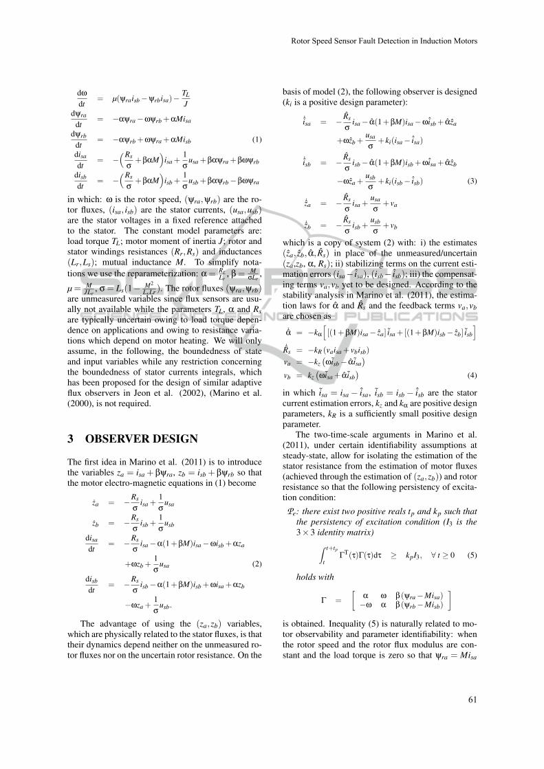
The aim of this section is to illustrate the previ-ously presented results even in the presence of time-varying perturbations of the motor resistances andstep-wise variations of the load torque. To this pur-pose, the nonlinear adaptive observer (3)-(4) and theload torque identifier are simulated for the three-phasesingle pole pair 0:6-kW induction motor OE-MER7-80/C in Marino et al. (2010a) whose parametersare: J = 0:0075 kgm2, Rs = 5:3 Ohm, Rr = 3:3 Ohm,Ls = 0:365 H, Lr = 0:375 H, M = 0:34 H. The motor(with initial conditions yra(0) = yrb(0) = 0:1 Wb) isillustratively controlled by the input-output feedbacklinearizing control reported in Section 2.4 of Marinoet al. (2010a) (which relies on exact rotor speedand stator current measurements and on the perfectknowledge of all motor parameters). The rotor speedand the flux modulus are reported in Figure 1. The de-sign parameters are chosen as (all the values are in SIunits): ki = 120, kz = 3, ka = 450, kR = 0:1, kw = 200,kT = 1002J. All the observer initial conditions are setto zero excepting for a(0) = 9 s�1 and Rs(0) = 5:4Ohm. For t < 1:8 s the measured speed is equal to theactual one (w�wm) while for t � 1:8 s a speed sensorfault occurs leading to w�wm = 0:4w. The equiva-lent rotor resistance Re = Lrae is thus equal to Rr fort < 1:8 s and equal to Rr +wecy=TL for t � 1:8 s. Therotor fluxes, the load torque, the equivalent rotor resis-tance, the stator resistance along with the correspond-ing converging estimates are reported in Figures 2-5.Fast estimation is obtained: the speed sensor fault canbe promptly identified by monitoring the estimated
Figure 1: Rotor speed w and flux modulusq
y2ra +y2
rb.
Figure 2: Rotor fluxes yra;yrb (dash) and their estimatesyra; yrb (solid); rotor fluxes yra;yrb estimation errors.
Figure 3: Load torque TL (dash) and its estimate TL (solid).
Figure 4: Equivalent rotor resistance Rre (dash) and its esti-mate Rr (solid).
rotor resistance on the basis of the available bound-ing values Rrm = Lram = 2:8 Ohm, RrM = LraM = 6:9Ohm. In order to illustrate the possibility of detectingfalse faults by using adaptive observers with no statorresistance identifier (as in (Najafabadiet al., 2011)),the same simulation is carried out in the presence ofno speed sensor fault for the adaptive observer (3)-
Rotor�Speed�Sensor�Fault�Detection�in�Induction�Motors
63
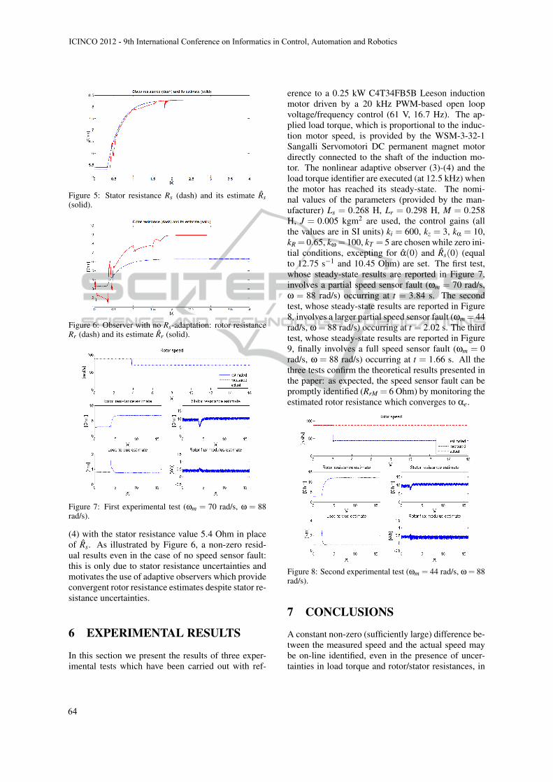
Figure 5: Stator resistance Rs (dash) and its estimate Rs(solid).
Figure 6: Observer with no Rs-adaptation: rotor resistanceRr (dash) and its estimate Rr (solid).
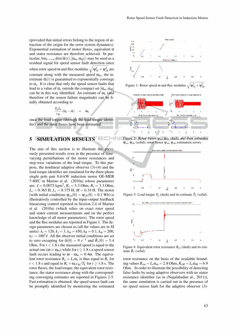
Figure 7: First experimental test (wm = 70 rad/s, w = 88rad/s).
(4) with the stator resistance value 5:4 Ohm in placeof Rs. As illustrated by Figure 6, a non-zero resid-ual results even in the case of no speed sensor fault:this is only due to stator resistance uncertainties andmotivates the use of adaptive observers which provideconvergent rotor resistance estimates despite stator re-sistance uncertainties.
6 EXPERIMENTAL RESULTS
In this section we present the results of three exper-imental tests which have been carried out with ref-
erence to a 0:25 kW C4T34FB5B Leeson inductionmotor driven by a 20 kHz PWM-based open loopvoltage/frequency control (61 V, 16:7 Hz). The ap-plied load torque, which is proportional to the induc-tion motor speed, is provided by the WSM-3-32-1Sangalli Servomotori DC permanent magnet motordirectly connected to the shaft of the induction mo-tor. The nonlinear adaptive observer (3)-(4) and theload torque identifier are executed (at 12:5 kHz) whenthe motor has reached its steady-state. The nomi-nal values of the parameters (provided by the man-ufacturer) Ls = 0:268 H, Lr = 0:298 H, M = 0:258H, J = 0:005 kgm2 are used, the control gains (allthe values are in SI units) ki = 600, kz = 3, ka = 10,kR = 0:65, kw = 100, kT = 5 are chosen while zero ini-tial conditions, excepting for a(0) and Rs(0) (equalto 12:75 s�1 and 10:45 Ohm) are set. The first test,whose steady-state results are reported in Figure 7,involves a partial speed sensor fault (wm = 70 rad/s,w = 88 rad/s) occurring at t = 3:84 s. The secondtest, whose steady-state results are reported in Figure8, involves a larger partial speed sensor fault (wm = 44rad/s, w = 88 rad/s) occurring at t = 2:02 s. The thirdtest, whose steady-state results are reported in Figure9, finally involves a full speed sensor fault (wm = 0rad/s, w = 88 rad/s) occurring at t = 1:66 s. All thethree tests confirm the theoretical results presented inthe paper: as expected, the speed sensor fault can bepromptly identified (RrM = 6 Ohm) by monitoring theestimated rotor resistance which converges to ae.
Figure 8: Second experimental test (wm = 44 rad/s, w = 88rad/s).
7 CONCLUSIONS
A constant non-zero (sufficiently large) difference be-tween the measured speed and the actual speed maybe on-line identified, even in the presence of uncer-tainties in load torque and rotor/stator resistances, in
ICINCO�2012�-�9th�International�Conference�on�Informatics�in�Control,�Automation�and�Robotics
64

Figure 9: Third experimental test (wm = 0 rad/s, w = 88rad/s).
typical operating conditions involving non-zero loadtorque, constant rotor speed and flux modulus. Anadaptive flux observer which incorporates a conver-gent rotor resistance identifier and relies on the mea-sured rotor speed and stator currents/voltages is usedto this purpose. A relevant consequence of the pre-sented analysis is that rotor fluxes (and therefore mo-tor torque), load torque and stator resistance can beactually estimated even in the presence of speed sen-sor faults.
REFERENCES
M. E. H. Benbouzid, D. Diallo, and M. Zeraoulia (2007).Advanced fault-tolerant control of induction-motordrives for EV/HEV traction applications: from con-ventional to modern and intelligent control tech-niques. IEEE Transactions on Vehicular Technology,56(2), 519-528.
S. M. Bennet, R. J. Patton, and S. Daley (1999). Sensorfault-tolerant control of a rail traction drive. ControlEngineering Practice, 7, 217-225.
P. Castaldi, W. Geri, M. Montanari, and A. Tilli (2005). Anew adaptive approach for on-line parameter and stateestimation of induction motors. Control EngineeringPractice, 13(1), 81-94.
D. Diallo, M. E. H. Benbouzid, and A. Makouf (2004). Afault-tolerant control architecture for induction motordrives in automotive applications. IEEE Transactionson Vehicular Technology, 53(6), 1847-1855.
S. X. Ding (2008). Model-based Fault Diagnosis Tech-niques. Springer, Berlin.
J. Guzinski, H. Abu-Rub, M. Diguet, Z. Krzeminski, and A.Lewicki (2010). Speed and load torque observer appli-cation in high-speed train electric drive. IEEE Trans-actions on Industrial Electronics, 57(2), 565-574.
J. Guzinski, M. Diguet, Z. Krzeminski, A. Lewicki, andH. Abu-Rub (2009). Application of speed and load
torque observers in high-speed train drive for diagnos-tic purposes. IEEE Transactions on Industrial Elec-tronics, 56(1), 248-256.
I.-J. Ha and S.-H. Lee (2000). An online identificationmethod for both stator and rotor resistances of in-duction motors without rotational transducers. IEEETransactions on Industrial Electronics, 47(4), 842-853.
S. M. N. Hasan and I. Husain. A Luenberger-sliding modeobserver for online parameter estimation and adap-tation in high-performance induction motor drives(2009). IEEE Transactions on Industry Applications,45(2), 772-781.
R. J. Hill (1994). Electric railway traction. Power Engineer-ing Journal, 8(3), 143-152.
R. Isermann (2011). . Fault-Diagnosis Applications.Springer, Berlin.
F. Jadot, F. Malrait, J. Moreno-Valenzuela, and R. Sepul-chre (2009). Adaptive regulation of vector-controlledinduction motors. IEEE Transactions on Control Sys-tems Technology, 17(3), 646-657.
S. H. Jeon, K. K. Oh, and J. Y. Choi (2002). Flux ob-server with online tuning of stator and rotor resis-tances for induction motors. IEEE Transactions on In-dustrial Electronics, 49(3), 653-664.
G. Kenne, R. S. Simo, F. Lamnabhi-Lagarrigue, A.Arzande, and J.C. Vannier (2010). An online simpli-fied rotor resistance estimator for induction motors.IEEE Transactions on Control Systems Technology,18(5), 1188-1194.
K.-S. Lee and J.-S. Ryu (2003). Instrument fault detectionand compensation scheme for direct torque controlledinduction motor drives. IEE Proceedings on ControlTheory and Applications, 150(4), 376-382.
R. Marino, S. Peresada, and P. Tomei (2000). On-line sta-tor and rotor resistance estimation for induction mo-tors. IEEE Transactions on Control Systems Technol-ogy, 8(3), 570-579.
R. Marino, P. Tomei, and C. M. Verrelli (2010a). InductionMotor Control Design. Springer, London.
R. Marino, P. Tomei, and C. M. Verrelli (2008). An adap-tive tracking control from current measurements forinduction motors with uncertain load torque and rotorresistance. Automatica, 44(10), 2593-2599.
R. Marino, P. Tomei, and C. M. Verrelli (2010b). Adaptiveoutput feedback tracking control for induction mo-tors with uncertain load torque and resistances. Inter-national Symposium on Power Electronics, ElectricalDrives, Automation and Motion, 419-424, Pisa, June14-16.
R. Marino, P. Tomei, and C. M. Verrelli (2010c). Trackingcontrol for sensorless induction motors with uncertainload torque and resistances. 8th IFAC Symposium onNonlinear Control Systems, Bologna, September 1-3.
R. Marino, P. Tomei, and C. M. Verrelli (2011). A new fluxobserver for induction motors with on-line identifica-tion of load torque and resistances. 18th IFAC WorldCongress, 18, Milano, 28 August-2 September.
T. A. Najafabadi, F. R. Salmasi, and P. Jabehdar-Maralani(2011). Detection and isolation of speed-, DC-link
Rotor�Speed�Sensor�Fault�Detection�in�Induction�Motors
65
voltage-, and current-sensor faults based on an adap-tive observer in induction-motor drives. IEEE Trans-actions on Industrial Electronics, 58(5), 1662-1672.
H. U. Rehman (2008). An integrated starter-alternator andlow-cost high-performance drive for vehicular appli-cations. IEEE Transactions on Vehicular Technology,57(3), 1454-1465.
M. E. Romero, M. M. Seron, and J. A. De Dona (2010).Sensor fault-tolerant vector control of induction mo-tors. IET Control Theory and Applications, 4(9),1707-1724.
A. Ticlea and G. Besancon (2006). Observer scheme forstate and parameter estimation in asynchronous mo-tors with application to speed control. European Jour-nal of Control, 12(4), 400-412.
H. Wang, S. Pekarek, and B. Fahimi (2006). Multilayercontrol of an induction motor drive: a strategic step forautomotive applications. IEEE Transactions on PowerElectronics, 21(3), 676-686.
ICINCO�2012�-�9th�International�Conference�on�Informatics�in�Control,�Automation�and�Robotics
66