AC-Choppers Using Instantaneous Voltage Control Technique to Solve Voltage Sag Problems
Upload
independentCategory
view
0download
0
ARTICLE IN PRESS
Mechanical Systemsand
Signal Processing
0888-3270/$ - se
doi:10.1016/j.ym
�CorrespondE-mail addr
URL: http:/
Mechanical Systems and Signal Processing 20 (2006) 1572–1589
www.elsevier.com/locate/jnlabr/ymssp
A validated model for the prediction of rotor bar failure insquirrel-cage motors using instantaneous angular speed
Ahmed Y. Ben Sasi�, Fengshou Gu, Yuhua Li, Andrew D. Ball
Monitoring and Diagnostics Research Group, School of Mechanical, Aerospace and Civil Engineering, The University of Manchester,
Oxford Road, M13 9PL UK
Received 14 September 2004; received in revised form 12 September 2005; accepted 15 September 2005
Available online 25 October 2005
Abstract
Instantaneous angular speed (IAS)-based condition monitoring is an area in which significant progress has been
achieved over the recent years. This condition monitoring technique is less known compared to the existing conventional
methods. This paper presents model-predicted simulation and experimental results of broken rotor bar faults in a three-
phase induction motor using IAS variations. The simulation was performed under normal, and a broken rotor bar fault.
The present paper evaluates through simulating and measuring the IAS of an induction motor at broken rotor bar faults in
both time and frequency domains. Experimental results show a good agreement with the model-predicted simulation
results. Three vital key features were extracted from the angular speed variations. One feature is the modulating contour of
pole pass frequency periods in time domain. The other two features are in frequency domain. The primary feature is the
presence of the pole pass frequency component at the low-frequency region of the IAS spectrum. The secondary feature
which are the multiple of pole pass frequency sideband components around the rotor speed frequency component.
Experimental results confirm the validity of the simulation results for the proposed method. The IAS has demonstrated
more sensitivity than current signature analysis in detecting the fault. This research also shows the power of angular speed
features as a useful tool to detect broken rotor bar deteriorations using any economical transducer such as low-resolution
rotary shaft encoders; which may well be already installed for process control purposes.
r 2005 Elsevier Ltd. All rights reserved.
Keywords: Instantaneous angular speed (IAS); Condition monitoring; Induction motor; Broken rotor bar fault; Pole pass frequency;
Modulation
1. Introduction
Three-phase induction motors are by far the most common type of industrial drive, and although they arerelatively reliable, they do inevitably breakdown, and hence need to be condition monitored. Conditionmonitoring of these machines is notoriously difficult because of the complex combination of mechanical andmagnetic effects that occurs within them. Motors driven by solid-state inverters normally experience severe
e front matter r 2005 Elsevier Ltd. All rights reserved.
ssp.2005.09.010
ing author. Tel.: +44 161 2754315; fax: +44 161 2754541.
ess: [email protected] (A.Y.B. Sasi).
/www.maintenance.org.uk.

ARTICLE IN PRESSA.Y.B. Sasi et al. / Mechanical Systems and Signal Processing 20 (2006) 1572–1589 1573
voltage stresses due to rapid switching on and off. Moreover, induction motors are required to operate inhighly corrosive and dusty environments. Such requirements have lead to improvements in insulation materialand treatment processes used. However, cage rotors design and manufacturing have received littledevelopment. As a result, broken rotor bar faults now account for a large percentage of total inductionmotor faults [1,2]. In general, modelling and simulation of machine operation will provide economical anduseful information for fault prediction and identification. Computer simulation of motor operation can beespecially useful in attaining a close insight into the dynamic behaviour of machines. Modelling theperformance of three-phase induction motors with broken rotor bar faults has a substantial history ofpublished literature [1–5]. Current signature analysis approach has been the main focus to monitor the healthof induction motors with respect to modelling broken rotor bar faults. Of course, over the years other lessappealing methods of detecting faults have already been explored, such as measuring harmonics in motortorque and axial flux [6,7]. To date, broken rotor bar faults condition assessment and fault diagnosis has beenbased upon conventional current signature analysis [8–12]. Similar indications were suggested using vibrationspectra [13–16].
A possible way for induction motor fault diagnosis is the instantaneous rotor speed analysis since thepulsating torque due to rotor faults will alter or modulate rotor speed. This paper addresses the use of themodel-prediction to simulate a squirrel-cage induction motor operation under healthy rotor and broken rotorbar faults using instantaneous angular speed (IAS) analysis. A Runge–Kutta integration algorithm was usedto solve simultaneous differential equations governing motors behaviour. The purpose of this model is toforesee and examine the effects of a rotor with broken rotor bar faults on IAS. Simulation results represent thecontribution to the correct evaluation of the measured data. For that reason, the IAS model-predictedsimulation results will be confirmed using experimental measurements. Both IAS simulated and experimentalresults will be compared with stator currents spectra method under similar operating conditions.
2. IAS-based condition monitoring
In practice many mechanical systems in engineering applications rotate with varying speed, in spite of theassumption they rotate at constant speed. Gear-based power transmission system exhibits speed fluctuationsdue to a combination of effects, including geometric errors and transmission errors [17]. The Monitoring andDiagnostics Research Group at the University of Manchester has adopted the term IAS to refer to thevariations of angular speed that occur within a single shaft revolution. The use of the IAS of an engine wasinvestigated by Gu et al. [18] and Ben Sasi et al. [19] for fault detection and diagnosis. The variation of IASwas explored for the monitoring of electric motors. These investigations show that IAS is useful for thecondition monitoring of a wide variety machines [20,21].
Cheap devices such as shaft encoders, magnetic pickup sensors and gears, etc., are used for IASmeasurement. These devices produce signals in the form of an electrical pulse train. The time interval betweensuccessive pulses is inversely proportional to the speed of the rotor. There are a number of methods to extractIAS that has proven useful in a variety of machinery control and condition monitoring applications. However,these methods can be generally classified into two categories: pulse interval-based methods and fast Fouriertransform (FFT)-based methods [19].
3. Broken rotor bar faults
Broken rotor bar faults can be a serious problem, although they do not initially cause an induction motor tofail. Therefore, there can be serious secondary effects. The fault mechanism may result in broken parts of thebar hitting the end windings or stator core of high voltage motor at high speed. This can cause seriousmechanical damage to the insulation and a consequential winding failure may follow, resulting in a costlyrepair and lost production. Several authors have addressed the typical causes behind broken rotor bar faults asfollows [1,22–24]:
�
Direct-on-line starting duty cycles for which the rotor cage winding was not designed to withstand. Thiscauses high thermal and mechanical stresses.
ARTICLE IN PRESSA.Y.B. Sasi et al. / Mechanical Systems and Signal Processing 20 (2006) 1572–15891574
�
Pulsating mechanical loads, such as reciprocating compressors or coal crushers, can subject the rotor cageto high mechanical stresses. � Imperfections in the manufacturing process of the rotor cage.Ideally, the current drawn by an induction motor should have a single component of supply frequency.However, changes in load will modulate the amplitude of the current to produce sidebands. The basic theory isthat when a broken rotor bar fault develops, it will result in modulation of the air gap flux. This willconsequently affect the current in the stator-winding conductors.
A completely broken bar can carry no significant current so the current is re-distributed in the adjacent barsresulting in rotor asymmetry. The induced currents will manifest load-dependent sideband componentsaround the main supply frequency component at multiple components of twice the per unit slip multiplied bythe supply frequency 2kspuf in the stator windings [1,8,25], where f is the supply frequency, k ¼ 1,2,ysideband components, and spu is the per unit slip.
4. Squirrel-cage motor mathematical model
4.1. Rotor model
A squirrel-cage rotor consists of thick conducting bars embedded in parallel slots. These bars are short-circuited at both ends by means of short-circuiting rings, as shown in Fig. 1. In this paper, the coupledmagnetic circuit theory was used to model a squirrel-cage induction machine [28–33]. The method consistsof describing the machine as a set of multiple coupled circuits defined by self- and mutual inductancematrices. The resultant set of differential equations is then solved for each rotor position. The coupledmagnetic circuit theory representation will be used throughout the derivation. The following generalassumptions are made:
�
Stator and rotor windings are uniformly distributed; � No inter-bar current (insulated rotor bars). � The self- and mutual inductances between stator or rotor phases are constant. � Mutual inductances between stator and rotor windings are functions of rotor displacement.Given the structural symmetry of the rotor, it is convenient to model the cage as identical magneticallycoupled meshes. For simplicity, two adjacent rotor bars and the connecting portions of the end rings betweenthem define each loop. For the purpose of analysis, each rotor bar and segment of end ring is substituted by anequivalent circuit representing the resistive and inductive nature of the cage [34–37].
Rotor bars
End ring
Rotor loops
ei
2ri
rni
1−rni
1ri
Fig. 1. Mesh model of a squirrel-cage rotor.
ARTICLE IN PRESSA.Y.B. Sasi et al. / Mechanical Systems and Signal Processing 20 (2006) 1572–1589 1575
4.2. Basic equations
The voltage balance equation for all stator and rotor windings is as follows:
V ¼ ðRþdL
dtÞ � Iþ L �
dI
dt. (1)
The voltage vector is V ¼ [VsaVsbVsc00y0]T, where Vsph are the voltages of phases ph ¼ a, b, and c, thecurrent vector is I ¼ ½IsaIsbI scir1ir2 . . . irnie�
T where Isph are the currents of phases ph ¼ a, b, and c and iri are thecurrent of the rotor loops i ¼ 1,2yn and ie is the end ring loop. R, and L are the resistance and inductancematrices. The resistance matrix R is defined as follows:
R ¼
Rsa 0 0 0 � � � � � � � � � 0 0
0 Rsb 0 0 � � � � � � � � � 0 0
0 0 Rsc 0 � � � � � � � � � 0 0
0 0 0 Rr1 �Rb1 0 � � � �Rbn Re
� � � � � � � � � �Rb1 Rr2 �Rb2 0 � � � Re
� � � � � � � � � � � � � � � � � � � � � � � � � � �
� � � � � � � � � � � � � � � � � � � � � � � � � � �
0 0 0 �Rbn 0 � � � �Rbn�1 Rrn Re
0 0 0 Re Re � � � � � � Re n� Re
266666666666666664
377777777777777775
. (2)
Rsph are the stator resistances of phases ph ¼ a, b, and c.
Rri ¼ Rbi þ Rbiþ1 þ 2Re, (3)
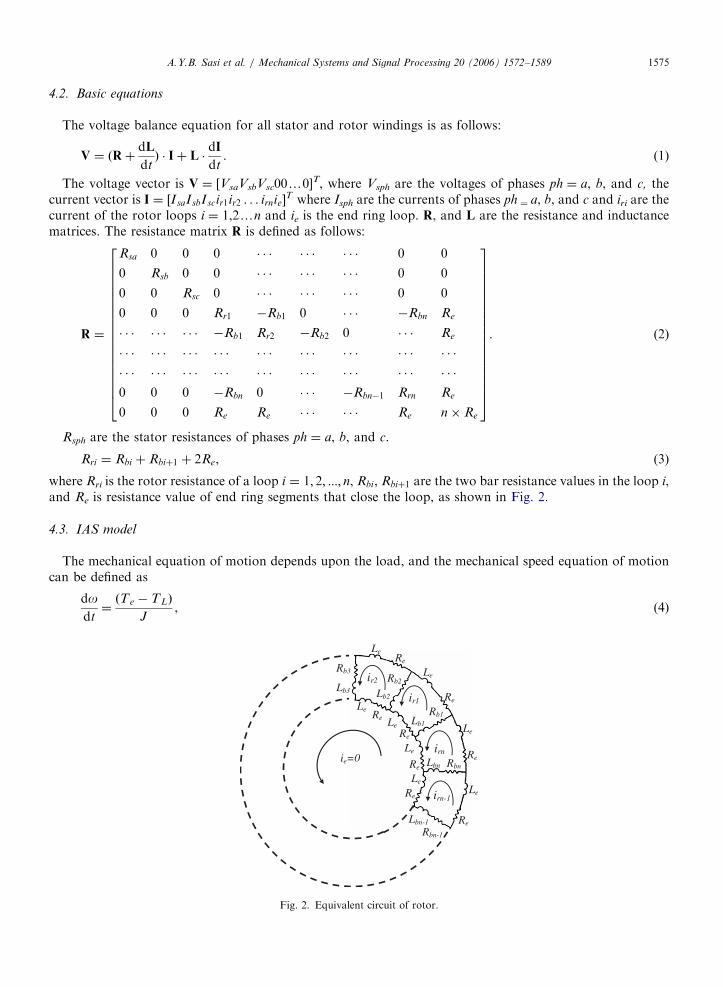
where Rri is the rotor resistance of a loop i ¼ 1; 2; :::; n, Rbi, Rbiþ1 are the two bar resistance values in the loop i,and Re is resistance value of end ring segments that close the loop, as shown in Fig. 2.
4.3. IAS model
The mechanical equation of motion depends upon the load, and the mechanical speed equation of motioncan be defined as
dodt¼ðTe � TLÞ
J, (4)
ir1
irn
irn-1
ir2
Lbn-1
Rbn-1
Lbn Rbn
Lb1
Rb1
Lb2
Rb2Lb3
Rb3
Le
Le
Re
Le
Re
Re
ReLe
Le
Le
Re
Re
Re
ie=0 Re
Le
Le
Fig. 2. Equivalent circuit of rotor.

ARTICLE IN PRESSA.Y.B. Sasi et al. / Mechanical Systems and Signal Processing 20 (2006) 1572–15891576
where o is the rotor angular speed (IAS), J is the moment of inertia of the rotating components of the drive TL
is the applied mechanical load, and Te is the electromagnetic torque that produced by the machine. Theelectromagnetic torque Te can be given by
Te ¼p
4IT @L
@ye
I, (5)
where p denotes the number of poles and ye represents rotor displacement in electrical rad.
4.4. Model-predicted simulation
It is convenient to carry out the analysis using mesh currents as the independent variables. Therefore,Eq. (1) can be rewritten as
dI
dt¼ �L�1: Rþ
dL
dt
� �:Iþ L�1:V. (6)
In a healthy induction motor, the resistance value of every bar segment is Rb. When a broken rotor bar faultis considered, the corresponding bar resistance value is assumed to be very high value or by forcing the currentin the bar to zero [38]. A broken rotor bar is therefore simulated by substituting the faulty value in theresistance matrix and the rotor loop resistance in Eqs. (2) and (3), respectively. In general, for squirrel-cageinduction motor of n rotor bars, there are n+1 independent loops, as shown in Fig. 2. However, in the absenceof an axial flux component, the circumferential current in the end ring ie is identically zero [34]. Hence, it willnot be considered. Therefore, for a three-phase induction machine, there are n+4 unknown variables: threestator current and n rotor bar current variables plus the mechanical speed variable. The n+4 differentialequations in Eqs. (6) and (4) have been reduced to only five (two stator current, two rotor bar current, and onespeed) differential equations using the well-known d�q method [27]. A Runge–Kutta numerical integrationmethod using Matlab was used to solve the first-order differential equations [39].
5. Model-predicted simulation results
5.1. IAS simulation results with perfect rotor motion (ideal case)
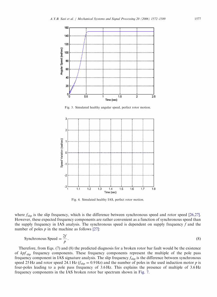
Primary IAS simulations have been carried out under perfect rotor design conditions, which represent theideal case of rotor motion (smooth motion without any fluctuations). Here the simulated external load isconstant and set at 75% of the full load. Fig. 3 shows the simulation results for rotor angular speed, forhealthy conditions, for the first 2.5 s after start-up. The rotor speed settles down to a steady state after atransient period of about 0.65 s. Since the transient state analysis is outside the scope in this research, the focuswill be on the region where the motor is running at a steady state. In this region the speed waveform appearsflat with a value of 151.5 rad/s (24.1Hz).
IAS waveform is obtained by eliminating the average rotor speed value at the steady-state region as shownin Fig. 4 taking into account 20 rotor revolutions. One rotor revolution is equivalent to 0.04 s. As shown inFig. 4 there are no variations in the IAS signal at a healthy condition of the motor. This result is alsoconfirmed taking the spectrum of the IAS, as illustrated in Fig. 5.
Fig. 6 illustrates the steady sate of IAS waveform when one broken rotor bar fault is simulated under aperfect rotor motion, 75% full load. The resulting simulated IAS waveform has a period every 0.28 s aroundthe zero mean value. This result may suggest the presence of components with frequencies of 1/0.28 ¼ 3.6Hz.
The spectrum for the IAS was explored with a broken rotor bar fault, as shown in Fig. 7. The speedspectrum indicates the presence of multiple frequency components of a primary frequency of 3.6Hz. Lookingback to Section 3; the current signature diagnosis of the broken rotor bar faults is function of the powersupply frequency and the per unit slip ðkspuf Þ, which is defined as
spu ¼f slip
Synchronous Speed, (7)
ARTICLE IN PRESS
Fig. 4. Simulated healthy IAS, perfect rotor motion.
Fig. 3. Simulated healthy angular speed, perfect rotor motion.
A.Y.B. Sasi et al. / Mechanical Systems and Signal Processing 20 (2006) 1572–1589 1577
where fslip is the slip frequency, which is the difference between synchronous speed and rotor speed [26,27].However, these expected frequency components are rather convenient as a function of synchronous speed thanthe supply frequency in IAS analysis. The synchronous speed is dependent on supply frequency f and thenumber of poles p in the machine as follows [27]:
Synchronous Speed ¼2f
p. (8)
Therefore, from Eqs. (7) and (8) the predicted diagnosis for a broken rotor bar fault would be the existenceof kpf slip frequency components. These frequency components represent the multiple of the pole passfrequency component in IAS signature analysis. The slip frequency fslip is the difference between synchronousspeed 25Hz and rotor speed 24.1Hz (fslip ¼ 0.9Hz) and the number of poles in the used induction motor p isfour-poles leading to a pole pass frequency of 3.6Hz. This explains the presence of multiple of 3.6Hzfrequency components in the IAS broken rotor bar spectrum shown in Fig. 7.

ARTICLE IN PRESS
Fig. 5. Simulated healthy IAS spectrum, perfect rotor motion.
Fig. 6. Simulated IAS with broken rotor bar, perfect rotor motion.
A.Y.B. Sasi et al. / Mechanical Systems and Signal Processing 20 (2006) 1572–15891578
The previous IAS simulated results represent the ideal case of rotor motion where there are no rotorfluctuations (smooth rotor rotation) while the induction motor is running. However, practically manymechanical systems in engineering applications rotate with varying speed, in spite of the assumption theyrotate at constant speed. Sweeney and Randall [17] showed that a gear-based power transmission systemexhibits inherent speed fluctuations due to a combination of effects, including geometric errors, rotor designimperfection or misalignment and transmission errors. This rotor fluctuation is simulated by adding anoscillating rotor component, with an amplitude d and of a frequency o (IAS), to the mean constant value ofthe load tL. This simple assumption is given by the following equation:
TL ¼ tL þ d sinðotÞ; dotL. (9)
Accordingly, all the following results will be based on the IAS simulations at healthy and a broken rotor barfault under fluctuating rotor motion [17].

ARTICLE IN PRESS
Fig. 7. Simulated IAS spectrum with broken rotor bar, perfect rotor motion.
Fig. 8. Simulated healthy motor: (a) angular speed; (b) stator currents; and (c) zoomed currents.
A.Y.B. Sasi et al. / Mechanical Systems and Signal Processing 20 (2006) 1572–1589 1579
5.2. IAS simulation results with imperfect rotor motion
Figs. 8(a) and (b) shows the simulation results of rotor speed and three-phase stator currents of theinduction motor under 75% load for healthy rotor condition with imperfect motion during the initial 2.5 s ofthe time record.
Both rotor speed and stator currents settle down at a steady state after the transient state of 0.65 s. Speedwaveform appears with little ripples due to the assumed rotor fluctuations around the average value of151.5 rad/s (24.1)Hz. Fig. 8(c) shows the stator currents in one rotor revolution.
ARTICLE IN PRESSA.Y.B. Sasi et al. / Mechanical Systems and Signal Processing 20 (2006) 1572–15891580
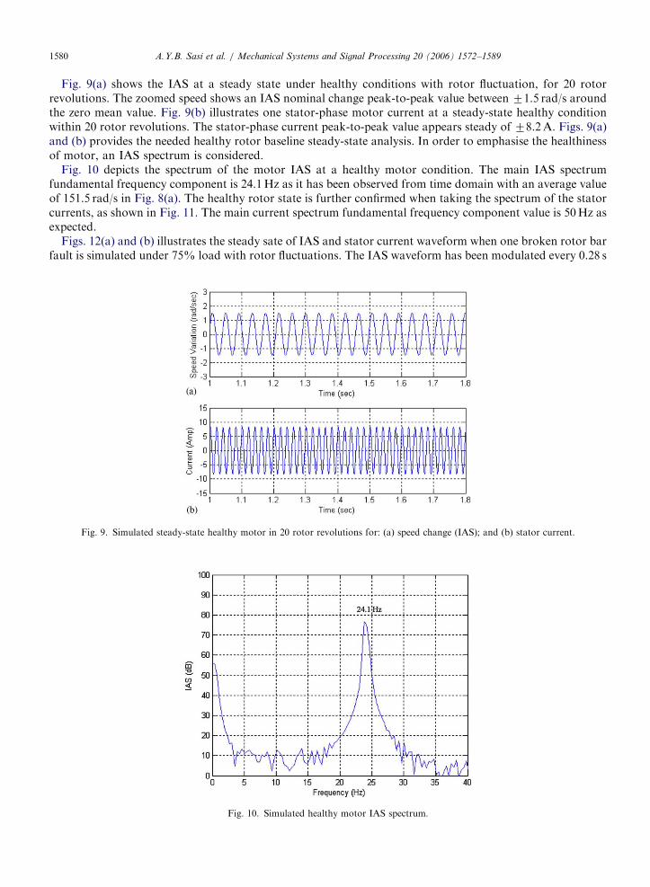
Fig. 9(a) shows the IAS at a steady state under healthy conditions with rotor fluctuation, for 20 rotorrevolutions. The zoomed speed shows an IAS nominal change peak-to-peak value between 71.5 rad/s aroundthe zero mean value. Fig. 9(b) illustrates one stator-phase motor current at a steady-state healthy conditionwithin 20 rotor revolutions. The stator-phase current peak-to-peak value appears steady of 78.2A. Figs. 9(a)and (b) provides the needed healthy rotor baseline steady-state analysis. In order to emphasise the healthinessof motor, an IAS spectrum is considered.
Fig. 10 depicts the spectrum of the motor IAS at a healthy motor condition. The main IAS spectrumfundamental frequency component is 24.1Hz as it has been observed from time domain with an average valueof 151.5 rad/s in Fig. 8(a). The healthy rotor state is further confirmed when taking the spectrum of the statorcurrents, as shown in Fig. 11. The main current spectrum fundamental frequency component value is 50Hz asexpected.
Figs. 12(a) and (b) illustrates the steady sate of IAS and stator current waveform when one broken rotor barfault is simulated under 75% load with rotor fluctuations. The IAS waveform has been modulated every 0.28 s
Fig. 9. Simulated steady-state healthy motor in 20 rotor revolutions for: (a) speed change (IAS); and (b) stator current.
Fig. 10. Simulated healthy motor IAS spectrum.

ARTICLE IN PRESS
Fig. 11. Simulated healthy motor stator current spectrum.
Fig. 12. Simulated broken rotor bar motor in 20 rotor revolutions for: (a) Speed change (IAS); and (b) stator current.
A.Y.B. Sasi et al. / Mechanical Systems and Signal Processing 20 (2006) 1572–1589 1581
around the zero mean value, as shown in Fig. 12(a). The resulting IAS broken rotor bar signal has a contourwith a frequency similar to the IAS simulated waveform with a broken rotor bar but no rotor fluctuations asshown in Fig. 6. This result suggests the presence of frequency components of 1/0.28 ¼ 3.6Hz compared to thehealthy baseline in Fig. 9(a). However, there is no significant modulation in the stator current as shown inFig. 12(b).
Again the spectrum for the IAS was explored with a broken rotor bar fault, as shown in Fig. 13. The speedspectrum indicates the presence a frequency component with a high decibel amplitude at a frequency ofpfslip ¼ 3.6Hz and the presence of the multiple of 3.6Hz sideband components around the rotor speedcomponent value of 24.1Hz. The first lower and upper sideband components are at 20.5 and 27.7Hz,respectively. Therefore, in IAS signature analysis the predicted diagnosis for a broken rotor bar fault is theexistence of two features: a primary feature component with a high decibel amplitude at the low-frequencyregion of the IAS spectrum with a frequency equals to the pole pass frequency of the induction motor (alsopresent for ideal rotor motion), and a secondary feature with multiple pole pass frequency sidebandcomponents around the rotor running speed frequency.

ARTICLE IN PRESS
Fig. 13. Simulated IAS spectrum with broken rotor bar.
Fig. 14. Simulated stator current spectrum with broken rotor bar.
A.Y.B. Sasi et al. / Mechanical Systems and Signal Processing 20 (2006) 1572–15891582
The previous IAS result was confirmed using the spectrum of stator current as shown in Fig. 14. The graphshows the spectrum of the motor current with a broken rotor bar fault. The current spectrum only indicatesthe presence of lower and upper pole pass frequency components around the main supply frequency of 50Hz.The first lower and upper sideband components are at 46.4 and 53.6Hz. From Section 3, the diagnosisfor a broken rotor bar fault using current signature is the existence of 2spuf sideband components aroundthe supply frequency where the per unit slip spu is 0.036 using Eq. (7) and f ¼ 50Hz is the supply frequency.This explains the sideband components of 3.6Hz spaced from the supply frequency component 50Hz.Therefore, the predicted broken rotor bar diagnosis for the current signature method is the presence ofmultiple pole pass frequency components around the supply frequency component which are equivalent to thesecondary feature frequency components deduced from the IAS spectrum shown in Fig. 13. These useful IASsimulation results will be validated using experimental results under similar operating conditions in thefollowing section.

ARTICLE IN PRESS
Induction
Motor
Loading Generator
Cur
rent
T
rans
duce
rs
Loading Bank
Encoder
Load Cell
Fig. 15. Motor test facility.
Photo 1. Encoder connected to motor shaft.
A.Y.B. Sasi et al. / Mechanical Systems and Signal Processing 20 (2006) 1572–1589 1583
6. Motor test rig facility
The motor used in experimental tests was a 3 kW, 4-pole, 28-rotor bar induction motor, driving a large DCmotor via a flexible coupling. The DC motor acted as a generator and its power output was dissipated in avariable resistor bank, as shown in Fig. 15. Optical encoders are one of the most widely used pieces ofequipment for rotor speed and position measurement. An incremental encoder was installed in the inductionmotor test rig. In this encoder, the internal disc consists of 360 uniform patterns of equally spaced lines toproduce detector pulses.
The incremental optical encoder type was attached to the non-drive end and is connected directly to therotor as shown in Photo 1. The test rig facility is also instrumented with Hall-effect current transducers.Photos 2 and 3 show how damage in one of the rotor bars was physically seeded. This was performed bydrilling through one of the aluminium conductors that made up the squirrel cage [40].
7. Experimental results
Fig. 16 illustrates a sample of the raw pulses data collected from the encoder using a data acquisition card.These pulses were processed in order to extract IAS waveforms. For a further comprehensive review of IASextracting techniques, the reader may refer to [41]. Figs. 17(a) and (b) shows the measured IAS and the statorcurrent for a healthy operation under 75% load to be comparable with simulation results. These experimental

ARTICLE IN PRESS
Photo 2. Seeded broken rotor bar fault.
Photo 3. Rotor bars cross-sections.
Fig. 16. Encoder pulses raw data.
A.Y.B. Sasi et al. / Mechanical Systems and Signal Processing 20 (2006) 1572–15891584
ARTICLE IN PRESS
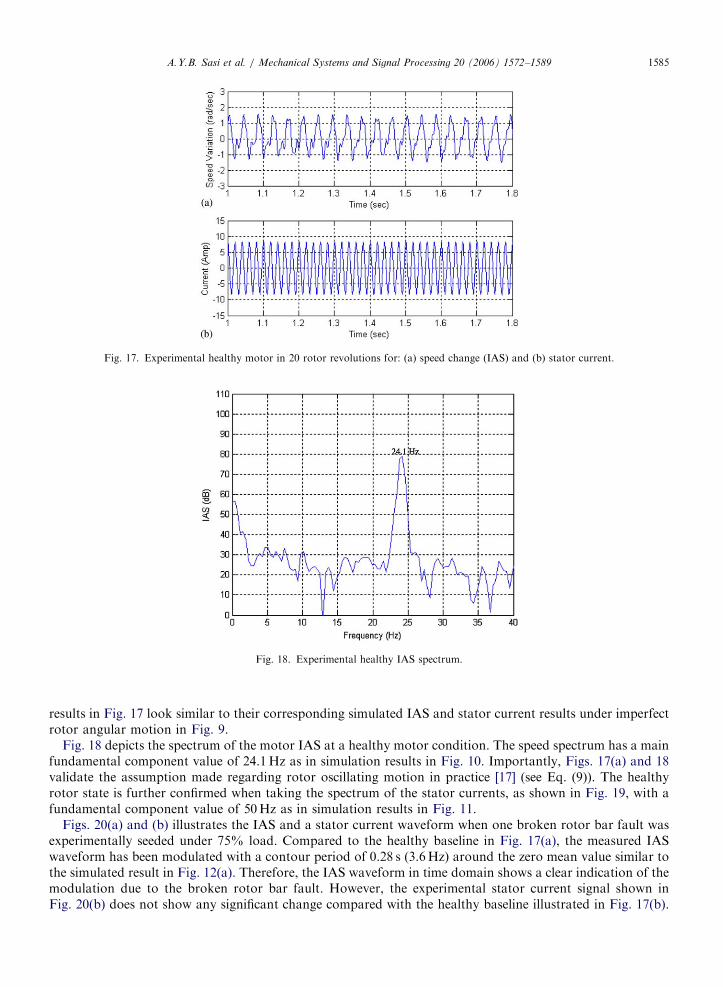
Fig. 17. Experimental healthy motor in 20 rotor revolutions for: (a) speed change (IAS) and (b) stator current.
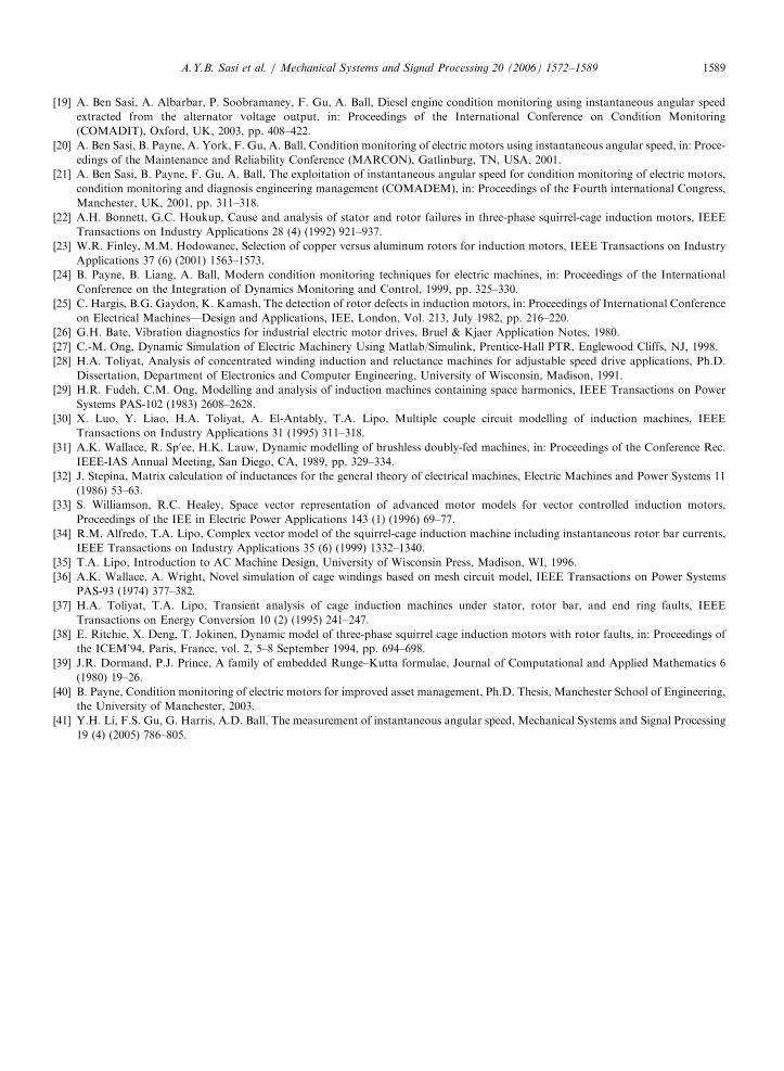
Fig. 18. Experimental healthy IAS spectrum.
A.Y.B. Sasi et al. / Mechanical Systems and Signal Processing 20 (2006) 1572–1589 1585
results in Fig. 17 look similar to their corresponding simulated IAS and stator current results under imperfectrotor angular motion in Fig. 9.
Fig. 18 depicts the spectrum of the motor IAS at a healthy motor condition. The speed spectrum has a mainfundamental component value of 24.1Hz as in simulation results in Fig. 10. Importantly, Figs. 17(a) and 18validate the assumption made regarding rotor oscillating motion in practice [17] (see Eq. (9)). The healthyrotor state is further confirmed when taking the spectrum of the stator currents, as shown in Fig. 19, with afundamental component value of 50Hz as in simulation results in Fig. 11.
Figs. 20(a) and (b) illustrates the IAS and a stator current waveform when one broken rotor bar fault wasexperimentally seeded under 75% load. Compared to the healthy baseline in Fig. 17(a), the measured IASwaveform has been modulated with a contour period of 0.28 s (3.6Hz) around the zero mean value similar tothe simulated result in Fig. 12(a). Therefore, the IAS waveform in time domain shows a clear indication of themodulation due to the broken rotor bar fault. However, the experimental stator current signal shown inFig. 20(b) does not show any significant change compared with the healthy baseline illustrated in Fig. 17(b).

ARTICLE IN PRESS
Fig. 19. Experimental healthy stator current spectrum.
Fig. 20. Experimental broken rotor bar motor in 20 rotor revolutions for: (a) speed change (IAS) and (b) stator current.
A.Y.B. Sasi et al. / Mechanical Systems and Signal Processing 20 (2006) 1572–15891586
The spectrum of the IAS shows the two features extracted from the IAS simulation results, as shown inFig. 21. The primary feature for the IAS is the presence of the pole pass frequency component at 3.6Hz withhigh decibel amplitude. The secondary feature is the existence of multiple pole pass frequency sidebandcomponents kpfslip with a spacing of 3.6Hz around the rotor speed component 24.1Hz. These features verifythe IAS model-predicted simulation results shown in Fig. 13. Stator current spectrum shows only one feature,which is the presence of pole pass frequency sideband components around the supply frequency 50Hz asshown in Fig. 22. These sideband components with a spacing of 3.6Hz are similar to those obtained from thesimulation results as depicted in Fig. 14.
Therefore, the IAS model-predicted simulation results with healthy and broken rotor bar faults have beenvalidated using their corresponding IAS experimental results.
Based on the IAS simulated and experimental results obtained in this study, there is an agreement betweenthe simulation IAS results and the experimental results in time and frequency domains under healthy andbroken rotor bar conditions. These results reflect the accuracy of the proposed model. In addition, resultsdemonstrate the detection capability of the IAS compared to current spectra analysis for one broken rotor bar

ARTICLE IN PRESS
Fig. 21. Experimental IAS spectrum with broken rotor bar.
Fig. 22. Experimental stator current spectrum with broken rotor bar.
A.Y.B. Sasi et al. / Mechanical Systems and Signal Processing 20 (2006) 1572–1589 1587
fault. The results have shown the IAS method is more sensitive than the current signature analysis in detectingbroken rotor bar faults.
8. Conclusions
In conclusion, this research has evaluated the effectiveness of monitoring IAS waveforms in both time andfrequency domains for detecting and diagnosis of broken rotor bar faults. The IAS model-predictedsimulation results are in agreement with the experimental results under similar operating conditions. Inaddition, the IAS model-predicted simulation results were also confirmed experimentally and further validatedagainst current signature analysis. The IAS features were productively utilised to predict the operatingcondition of a squirrel-cage induction motor under broken rotor bar faults.
Three features can be extracted from IAS signals when a broken rotor bar fault was inroduced in a squirrel-cage induction motor demonstrating the richness of IAS. One IAS feature in the time domain and two IAS

ARTICLE IN PRESSA.Y.B. Sasi et al. / Mechanical Systems and Signal Processing 20 (2006) 1572–15891588
features in the frequency domain. The key diagnosis feature of IAS under a broken rotor bar fault in timedomain is the presence of a modulating contour of a period equivalent to the reciprocal of the pole passfrequency. The primary feature of IAS in the frequency spectrum is the presence of pole pass speed componentat the low-frquency region of the IAS spectrum. Remarkably, this useful feature has an advantage of using anyeconomical low-resolution speed transducer.
The secondary IAS feature in frequency domain is the existence of multiple pole pass frequency sidebandcomponents around the rotor speed frequency component. Therefore, the IAS spectrum provides valuableinformation, which is quite novel in the field of condition monitoring, in identifying broken rotor bar faults.On the other hand, the current signature spectrum only indicates one feature which is the presence of multiplepole pass frequency sideband components around the supply frequency component and there is no significantchange in the current waveform in time domain. Thus, indicating the sensitivity of IAS technique over thecurrent signature method to detect broken rotor bar faults.
In addition, although a broken rotor bar fault is classified as an electrical failure in most literature, thisresearch has proven this fault is more closer in nature to a mechanical failure. Therefore, the IAS hasdemonstrated to provide a great potential for practical condition monitoring of a wide range of rotating andreciprocating machines. Further investigations could be very promising to quantify the number of brokenrotor bars using the concluded IAS features.
References
[1] A.H. Bonnett, G.C. Soukup, Rotor failures in squirrel cage induction motors, IEEE Transactions on Industry Applications IA-22 (6)
(1986) 1165–1173.
[2] G.B. Kliman, R.A. Koegl, J. Stein, R.D. Endicott, M.W. Madden, Non-invasive detection of broken rotor bars in operating
induction motors, IEEE Transactions on Energy Conversion EC-3 (4) (1988) 873–879.
[3] H. Weichel, Squirrel-cage rotors with split resistance ring, Journal of AIEE 47 (1928) 929–943.
[4] E. Mishkin, Disturbances in the induction machine due to broken squirrel cage rings, Journal of the Franklin Institute 259 (1955)
133–143.
[5] P.C. Krause, C.H. Thomas, Simulation of symmetrical induction machinery, AIEE Transactions on Power Apparatus and Systems
PAS-84 (11) (1965) 1038–1053.
[6] W.T. Thomson, R.A. Leonard, A.J. Milne, N.D. Deans, Condition monitoring of induction motors for availability assessment in
offshore insulations, in: Proceedings of Fourth Euredata Conference, Venice, Italy, 1983.
[7] J. Penman, M.N. Dey, A.J. Tait, W.E. Bryan, Condition monitoring of electrical drives, Proceedings of the IEE, Part B 133 (3) (1986)
142–148.
[8] W.T. Thomson, R.J. Gilmore, Motor current signature analysis to detect faults in induction motor drives-fundamentals, data
interpretation, and industrial case histories, in: Proceedings of the 32nd Turbo machinery Symposium, Texas A&M University,
College Station, TX, September 2003, pp. 145–156.
[9] G.B. Kliman, J. Stein, Induction motor fault detection via passive current monitoring, in: Proceedings of the International
Conference on Electrical Machinery, Cambridge, August 1990, pp. 13–17.
[10] G.B. Kliman, J. Stefin, Methods of motor current signature analysis, Electrical Machines and Power System 20 (5) (1992) 463–474.
[11] R.R. Schoen, F. Kamram, T.G. Habetler, R.G. Bartheld, Motor bearing damage detection using stator current monitoring, IEEE
Transactions on Industry Applications 31 (6) (1995) 1274–1279.
[12] D.R. Rankin, The industrial application of phase current analysis to detect rotor winding faults in squirrel cage induction motors,
Power Engineering Journal 23 (2) (1995) 77–84.
[13] E. Erdelyi, P.A. Erie, Vibration modes of states of induction motors, Transactions of the ASME Paper A-28 (1956) 39–45.
[14] I.W. Mayes, A.G. Steer, G.B. Thomas, The application of vibration monitoring for fault diagnosis in large turbo-generators, in:
Proceedings of the Sixth Thermal Generation Specialists Meeting, Madrid, May 1981, pp. 567–575.
[15] R.G. Herbert, Computer techniques applied to the routine analysis of rundown vibration data for condition monitoring of turbine-
alternators, in: Proceedings of the International Conference on Condition Monitoring, Swansea, UK, April 1984, pp. 229–242.
[16] J.R. Cameron, W.T. Thompson, A.B. Row, Vibration and current monitoring for detecting air gap eccentricity in large induction
motors, in: Proceedings of the International Conference on Electrical Machines, Design and Applications, vol. 254, IEEE, London,
September 1982, pp. 173–179.
[17] P.J. Sweeney, R.B. Randall, Sources of gear signal modulation, Proceedings of the Institution of Mechanical Engineers, Part C C492/
027 (1995) 183–198.
[18] F. Gu, P.J. Jacob, A. Ball, Non-parametric models in the monitoring of engine performance and condition—Part 2: non-intrusive
estimation of diesel engine cylinder pressure and its use in fault detection, Proceedings of the Institution of Mechanical Engineers,
Part D 213 (1999) 135–143.
ARTICLE IN PRESSA.Y.B. Sasi et al. / Mechanical Systems and Signal Processing 20 (2006) 1572–1589 1589
[19] A. Ben Sasi, A. Albarbar, P. Soobramaney, F. Gu, A. Ball, Diesel engine condition monitoring using instantaneous angular speed
extracted from the alternator voltage output, in: Proceedings of the International Conference on Condition Monitoring
(COMADIT), Oxford, UK, 2003, pp. 408–422.
[20] A. Ben Sasi, B. Payne, A. York, F. Gu, A. Ball, Condition monitoring of electric motors using instantaneous angular speed, in: Proce-
edings of the Maintenance and Reliability Conference (MARCON), Gatlinburg, TN, USA, 2001.
[21] A. Ben Sasi, B. Payne, F. Gu, A. Ball, The exploitation of instantaneous angular speed for condition monitoring of electric motors,
condition monitoring and diagnosis engineering management (COMADEM), in: Proceedings of the Fourth international Congress,
Manchester, UK, 2001, pp. 311–318.
[22] A.H. Bonnett, G.C. Houkup, Cause and analysis of stator and rotor failures in three-phase squirrel-cage induction motors, IEEE
Transactions on Industry Applications 28 (4) (1992) 921–937.
[23] W.R. Finley, M.M. Hodowanec, Selection of copper versus aluminum rotors for induction motors, IEEE Transactions on Industry
Applications 37 (6) (2001) 1563–1573.
[24] B. Payne, B. Liang, A. Ball, Modern condition monitoring techniques for electric machines, in: Proceedings of the International
Conference on the Integration of Dynamics Monitoring and Control, 1999, pp. 325–330.
[25] C. Hargis, B.G. Gaydon, K. Kamash, The detection of rotor defects in induction motors, in: Proceedings of International Conference
on Electrical Machines—Design and Applications, IEE, London, Vol. 213, July 1982, pp. 216–220.
[26] G.H. Bate, Vibration diagnostics for industrial electric motor drives, Bruel & Kjaer Application Notes, 1980.
[27] C.-M. Ong, Dynamic Simulation of Electric Machinery Using Matlab/Simulink, Prentice-Hall PTR, Englewood Cliffs, NJ, 1998.
[28] H.A. Toliyat, Analysis of concentrated winding induction and reluctance machines for adjustable speed drive applications, Ph.D.
Dissertation, Department of Electronics and Computer Engineering, University of Wisconsin, Madison, 1991.
[29] H.R. Fudeh, C.M. Ong, Modelling and analysis of induction machines containing space harmonics, IEEE Transactions on Power
Systems PAS-102 (1983) 2608–2628.
[30] X. Luo, Y. Liao, H.A. Toliyat, A. El-Antably, T.A. Lipo, Multiple couple circuit modelling of induction machines, IEEE
Transactions on Industry Applications 31 (1995) 311–318.
[31] A.K. Wallace, R. Sp0ee, H.K. Lauw, Dynamic modelling of brushless doubly-fed machines, in: Proceedings of the Conference Rec.
IEEE-IAS Annual Meeting, San Diego, CA, 1989, pp. 329–334.
[32] J. Stepina, Matrix calculation of inductances for the general theory of electrical machines, Electric Machines and Power Systems 11
(1986) 53–63.
[33] S. Williamson, R.C. Healey, Space vector representation of advanced motor models for vector controlled induction motors,
Proceedings of the IEE in Electric Power Applications 143 (1) (1996) 69–77.
[34] R.M. Alfredo, T.A. Lipo, Complex vector model of the squirrel-cage induction machine including instantaneous rotor bar currents,
IEEE Transactions on Industry Applications 35 (6) (1999) 1332–1340.
[35] T.A. Lipo, Introduction to AC Machine Design, University of Wisconsin Press, Madison, WI, 1996.
[36] A.K. Wallace, A. Wright, Novel simulation of cage windings based on mesh circuit model, IEEE Transactions on Power Systems
PAS-93 (1974) 377–382.
[37] H.A. Toliyat, T.A. Lipo, Transient analysis of cage induction machines under stator, rotor bar, and end ring faults, IEEE
Transactions on Energy Conversion 10 (2) (1995) 241–247.
[38] E. Ritchie, X. Deng, T. Jokinen, Dynamic model of three-phase squirrel cage induction motors with rotor faults, in: Proceedings of
the ICEM’94, Paris, France, vol. 2, 5–8 September 1994, pp. 694–698.
[39] J.R. Dormand, P.J. Prince, A family of embedded Runge–Kutta formulae, Journal of Computational and Applied Mathematics 6
(1980) 19–26.
[40] B. Payne, Condition monitoring of electric motors for improved asset management, Ph.D. Thesis, Manchester School of Engineering,
the University of Manchester, 2003.
[41] Y.H. Li, F.S. Gu, G. Harris, A.D. Ball, The measurement of instantaneous angular speed, Mechanical Systems and Signal Processing
19 (4) (2005) 786–805.
Copyright © 2022 FDOKUMEN