Relationship Between Project Changes, Project Objectives ...
Upload
khangminh22Category
view
3download
0
Project Squirrel
Submitted By:
Matthew Simpson
David Ilacqua
Emanuel Demaio
Louie Mistretta
Project Squirrel 2
Contents Table of Figures ............................................................................................................................................. 4
Table of Tables .............................................................................................................................................. 6
Abstract ......................................................................................................................................................... 7
Executive Summary ....................................................................................................................................... 8
Introduction ................................................................................................................................................ 10
Project Goals ........................................................................................................................................... 11
Primary Goals ...................................................................................................................................... 11
Secondary Goals .................................................................................................................................. 11
Reach Goals ......................................................................................................................................... 11
Background ................................................................................................................................................. 11
Lead Screw Inchworm Design ................................................................................................................. 11
Tree Bot ................................................................................................................................................... 12
Snake Design ........................................................................................................................................... 13
Project Rise .............................................................................................................................................. 14
Previous MQPs ........................................................................................................................................ 16
CLAWAR .............................................................................................................................................. 16
2013 – 2014......................................................................................................................................... 17
Background Conclusion ........................................................................................................................... 17
Meeting with USDA ................................................................................................................................. 18
Biology ................................................................................................................................................. 18
Damage ............................................................................................................................................... 19
Detection ............................................................................................................................................. 19
Tree preference .................................................................................................................................. 20
Potential implementation of Project Squirrel ..................................................................................... 20
Alternative Technological Solutions.................................................................................................... 20
Analysis ....................................................................................................................................................... 21
Approach ................................................................................................................................................. 21
Overview of Testing Results .................................................................................................................... 22
Free Body Diagrams ................................................................................................................................ 25
Force Balance .......................................................................................................................................... 26
Tail Torque .............................................................................................................................................. 27

Project Squirrel 3
Identification of Critical Sections............................................................................................................. 29
Shoulder Plates ................................................................................................................................... 29
Leg ....................................................................................................................................................... 30
Trigger Mechanism ............................................................................................................................. 31
Pre-Load Mechanism .......................................................................................................................... 31
Motor Selection ....................................................................................................................................... 32
Climbing Joint ...................................................................................................................................... 33
Shoulder Joint .......................................................................................................................................... 34
Desire for Ballistic Contact Scenario ....................................................................................................... 34
Design .......................................................................................................................................................... 35
Material Selection ................................................................................................................................... 35
Spring Selection ....................................................................................................................................... 37
Tail ........................................................................................................................................................... 39
Ballistic Shoulder Joint Design ................................................................................................................. 40
Vex Pods .................................................................................................................................................. 43
Electrical Box ........................................................................................................................................... 44
Feet and Leg design ................................................................................................................................ 45
Sensors .................................................................................................................................................... 47
Lead Screws ............................................................................................................................................. 47
Manufacturing ............................................................................................................................................ 48
Initial Assembly ....................................................................................................................................... 48
3D Printed Parts .................................................................................................................................. 50
Machined Parts ................................................................................................................................... 51
Electrical: ..................................................................................................................................................... 51
Microcontroller ....................................................................................................................................... 52
Motor driver circuit: ................................................................................................................................ 53
Lead Screw Motors: ................................................................................................................................. 53
Leg Motors .............................................................................................................................................. 54
Motor Sensing: ........................................................................................................................................ 55
Leg Pivot Angle: ....................................................................................................................................... 57
Lead Screw Position: ............................................................................................................................... 57
I2C Encoders: ........................................................................................................................................... 58

Project Squirrel 4
Communications ..................................................................................................................................... 58
Extra Sensors ........................................................................................................................................... 59
PCB Design: ............................................................................................................................................. 59
Control System ............................................................................................................................................ 62
Software Class structure: ........................................................................................................................ 62
Class Architecture.................................................................................................................................... 64
Gait logic Explanation and Diagram ....................................................................................................... 64
Command Flow Chart.............................................................................................................................. 68
User Interface .......................................................................................................................................... 70
Wireless Interface ................................................................................................................................... 71
Social Implications ...................................................................................................................................... 72
Conclusion ................................................................................................................................................... 73
Mechanical .............................................................................................................................................. 73
Results ................................................................................................................................................. 73
Future Work ........................................................................................................................................ 74
Electrical .................................................................................................................................................. 76
Results ................................................................................................................................................. 76
Future Work ........................................................................................................................................ 77
Software .................................................................................................................................................. 77
Results ................................................................................................................................................. 78
Future Work ........................................................................................................................................ 79
Appendix A .................................................................................................................................................. 81
Micro Metal Gear motor Information ..................................................................................................... 81
Shoulder Joint Power Calculations .......................................................................................................... 81
Climbing Joint .......................................................................................................................................... 83
Bibliography ................................................................................................................................................ 84
Table of Figures Figure 1: Inch Worm Design ........................................................................................................................ 12
Figure 2: Tree Bot ........................................................................................................................................ 13
Figure 3: Modular Snake Robot .................................................................................................................. 14

Project Squirrel 5
Figure 4: Rise - Leg Joint 1 ........................................................................................................................... 14
Figure 5: Rise - Leg Joint 2 ........................................................................................................................... 15
Figure 6: Rise - Ankle Design with Foot....................................................................................................... 15
Figure 7: Rise - Single Toe and Claw Design ................................................................................................ 16
Figure 8: Rise - Body and Tail ...................................................................................................................... 16
Figure 9 Pull Fixture .................................................................................................................................... 23
Figure 10 Robot Fixture............................................................................................................................... 24
Figure 11 Robot FBD ................................................................................................................................... 25
Figure 12 Robot FBD ................................................................................................................................... 26
Figure 13 Tail Force Graph .......................................................................................................................... 28
Figure 14 Shoulder Joint ............................................................................................................................. 29
Figure 15 Leg ............................................................................................................................................... 30
Figure 16 Trigger Mechanism ..................................................................................................................... 31
Figure 17 Pre Load Plate ............................................................................................................................. 31
Figure 18 Vex Gear Box ............................................................................................................................... 33
Figure 19 Shoulder Joint ............................................................................................................................. 34
Figure 20 Vero White Plus Material Properties .......................................................................................... 36
Figure 21 Shoulder Spring ........................................................................................................................... 38
Figure 22 Tail Spring .................................................................................................................................... 38
Figure 23 Tail ............................................................................................................................................... 39
Figure 24 Shoulder Step 1 ........................................................................................................................... 40
Figure 25 Shoulder Step 2 ........................................................................................................................... 41
Figure 26 Shoulder Step 3 ........................................................................................................................... 42
Figure 27 Shoulder Step 4 ........................................................................................................................... 42
Figure 28 Vex Pod 1 .................................................................................................................................... 43
Figure 29 Vex Pod open .............................................................................................................................. 44
Figure 30 Vex Pod ISO ................................................................................................................................. 44
Figure 31 Electrical Box ............................................................................................................................... 45
Figure 32 Foot ............................................................................................................................................. 46
Figure 33 Leg Plate ...................................................................................................................................... 47
Figure 34 Old Shoulder joint ....................................................................................................................... 49
Figure 35 Overall Schematic ....................................................................................................................... 53
Figure 36 Vex 393 Motor ............................................................................................................................ 54
Figure 37 VEX Motor Controler ................................................................................................................... 54
Figure 38 Pololu motor ............................................................................................................................... 55
Figure 39 TB6612FNG Motor Driver IC ....................................................................................................... 55
Figure 40 TB6612FNG Control Logic ........................................................................................................... 55
Figure 42 Pololu Motor Schematic .............................................................................................................. 56
Figure 43 Limit Switch Schematic ...................................................................................................................
Figure 44: 3.3V to 5V and 5V to 3.3V Circuitry ........................................................................................... 59
Figure 45 PCB Board 1 ................................................................................................................................. 60
Figure 46 PCB Board 2 ................................................................................................................................. 61

Project Squirrel 6
Figure 47 Class Architecture ....................................................................................................................... 64
Figure 48 Robot Gait State Digram ............................................................................................................. 67
Figure 49 Command Flow Diagram ............................................................................................................. 69
Figure 50 Driver GUI .................................................................................................................................... 70
Figure 51 Robot Logs GUI ............................................................................................................................ 71
Table of Tables Table 1 Climb Time ...................................................................................................................................... 32
Table 2 Material Properties ........................................................................................................................ 36

Project Squirrel 7
Abstract Project Squirrel is a response to the need for a robotic mechanism with the capacity to traverse
vertically oriented trees and gather information. The growing Asian Long-horned beetle infestations in
the United States are one of the most prominent producers of this need. Current solutions to this issue
are largely inefficient and could greatly be improved through the implementation of robotic
mechanisms. The design and production of a robotic device which could be deployed by a single
operator and used to ascend and descend trees of varying dimensions would greatly reduce the time
and labor needed to address these infestations. Project Squirrel primarily seeks to address this need
through the design and production of a robot which improves current processes used to monitor Asian
Long-horned beetle populations.
Project Squirrel has built upon past ideas to create a tree climbing robot and much of its design
has been inspired by the successes and failures of other robots. Background research in other projects
and solutions has aided in steering the direction of project design. As a result of extensive research,
testing, and manufacturing, team has successfully been able to design and build a robot both
mechanically and electrically from the ground up. The robot design consists of a system of four lead
screws running through a system of four shoulder joints. The lead screws allow for upward and
downward travel of the shoulder mechanisms relative to the plane parallel to the climbing surface.
Attached to each shoulder joint is a single leg component with a single needle contact at each end.
Actuation of the shoulder joint enables travel of the legs forward and backwards along the plane
perpendicular to the tree’s surface. Off of the back end of the robot extends a tail which presses against
the tree’s surface for stability. The combination of shoulder and lead screw actuation compose the
robot’s gait and enable climbing.

Project Squirrel 8
Executive Summary Through understanding of the established project need, the team decided that project squirrel
should strive to produce a robot with the capacity to be deployed by a single operator to climb and
navigate trees. Pursuing this goal began with an analysis techniques implemented by past tree climbing
robots. A weighing of the advantages and disadvantages of these robots aided in the direction of robot
design. The primary concept for project squirrel became a combination of several of these methods. It
was decided that the robot’s method of climbing would be a combination of the incremental pulling
technique implemented by Treebot and the legged gripping technique used by project RISE.
Project Squirrel’s general design became a four legged system with actuation at shoulder joints
perpendicular to the tree’s surface for grip positioning and actuation along a system of lead screws
parallel to the tree’s surface for pulling and gait positioning. Thus function required a motor for each of
the four shoulder joints and a motor for each lead screw. Motor selection was driven by an analysis of
the power requirements in each motor scenario given that the target climb speed was one inch per
second. To conserve battery life, it was decided that ach leg would be sprung down against the tree’s
surface with a torsion spring. Therefore the pivot motors of the shoulder joints were only required to
have sufficient power to overcome the torque applied by these springs. Based on this analysis the
chosen pivot motors were the 1000:1 Micro Metal Gear motor HP from Pololu. Lead screw motors were
selected based on the power required for two lead screws with chosen dimensions and efficiencies, to
pull the projected weight of the robot. Creating a design that can operate with only two lead screws
engaged created room for safety and potential payload increases. The chosen lead screw motors were
Vex 393 motors.
Later developments in shoulder design led to a desire for a ballistic contact scenario as a means
of aiding in contact position. Implementation involved a trigger mechanism inside of the shoulder joint

Project Squirrel 9
which at a certain degree of rotation removes the torque applied by the motor on the leg shaft, causing
the torsion springs to accelerate the legs at the tree’s surface.
Extensive testing was required to determine the foot configuration, contact point configuration,
and contact composition. This was accomplished through the production of two test fixtures. The first
was a pull fixture which allowed various contacts to be dragged parallel to a section of tree along
adjustable angles. Pulling was done with a pull scale to provide a comparable measurement of the point
of failure. During testing the load, failure point, and attack angle were analyzed to determine the best
contact scenario. It was revealed that a single surgical needle configuration at a 55 degree attack angle
was the best scenario out of the tests. The second fixture constructed was a robot fixture which allowed
for a simulation of the final robot’s static payload capacity at various gait conditions. This fixture
demonstrated that an estimated 15lb payload could be sustained.
Analysis of a static Free Body Diagram of the projected robot revealed that the addition of a tail
component pushing on the tree surface could reduce unbeneficial loading scenarios on the robot’s
contact points. Manipulation of force and moment balance equations revealed the magnitude and
directions of contact forces for a given tail force. This was then plotted for the robot’s dimensions,
weight, and gait conditions. The graphs revealed that the optimal tail force ranged between 2 and 3lbs.
After completion of the robot’s design phase, manufacturing began. Material and manufacturing
analysis led to the choosing of manufacturing processes for each component. The primary
manufacturing processes implemented were 3D printing, CNC machining, laser cutting, and manual
machining using lathes and mills. Due to the small size of the project many of the complex components,
such as the front/back plates and feet were 3D printed. Small and complex components exposed to
higher loads such as the legs and shoulder joint internals were laser cut out of delrin. Larger
components exposed to high loads such as the shoulder housing, shoulder plates, and leg shafts were
produced using a combination of a mill, lathe, and CNC machine.

Project Squirrel 10
The Arduino Mega was used as the main processor for the robot and was responsible for all the
robots motion control. The leg position was controlled with a Vex 393 and Vex integrated encoders to
provide sensor feedback. The Vex encoders used I2C to communicate amongst each other and the
Arduino Mega. The leg angle was controlled through a Pololu and a vex potentiometer measured the
angle which the leg was at. The sensors and motors were all connected to a custom made Arduino shield
which allowed for seamless integration between the sensors, motors, and the Arduino Mega. The
Arduino Mega then handled all the motion control by interpreting the sensors feedback and reacting
accordingly. In order to control the robots movements an ASCII based communication protocol was
developed so the user could use a computer or android devices to command the robot to perform
specific actions. A java bases user interfaces was developed that allowed the user to drive the robot and
receive valuable feedback from the sensors. All the data from the robot was collected and could be
exported for further analysis.
Introduction The goal of Project Squirrel was to design and build a robot that can independently climb a tree
without direct human contact. Successful completion of the project required the design of a gripper to
support the robot’s weight, a mathematical force analysis of the robot, and the development of a
control system to capitalize on the kinematic design and produce a stable climbing gait. The project has
ventured into under-explored areas of robotics, resulting in technology with the potential for real-world
applications. These applications include: inspecting trees for potential damage due to insects, collecting
information on bird nests that are difficult to reach by conventional means, or inspecting the health of
the tree for logging operations. The goals and specifications of Project Squirrel were cultivated from its
real-world applications.

Project Squirrel 11
Project Goals
Primary Goals
Climb a vertical tree
Climb a 5” to 20” tree of uniform diameter
Complete 2 cycles of the robot’s gait
Maintain a static position on a tree.
Climb a hard wood tree
Inflict no harmful damage to the tree
Secondary Goals
Wirelessly communicate with operator
Attain minimum speed of 1 inch per second
Climb on a variety of trees (oak, maple)
Navigate around branches
Descend
Reach Goals
Control the robot wirelessly from a ground-based station through camera images received from the robot
Have attachments for specific mission needs
Have specified payload capability
Background The research for this project focused on evaluating the strengths and weaknesses of existing
robots that were designed to accomplish similar goals; four specific robots were chosen due to their
overall success in climbing trees. This information has influenced the preliminary design decisions and
will continue to be useful as the design comes to fruition.
Lead Screw Inchworm Design The inch worm robot demonstrates a simplistic method for climbing a vertical tree. The robot
uses eight spikes to support itself on the tree and a simple screw drive to climb. The screw drive powers

Project Squirrel 12
the four upper spikes forward while leaving the bottom four attached to the tree. Once the upper spikes
are in place the lower four spikes are moved to the next position. This process of moving and attaching
the spikes produces an inchworm-style climbing gait. This gait gives the robot a tendency to rotate away
from the tree as the robot climbs. Another disadvantage to this particular design is that robot can’t
avoid branches. This limitation is attributed to the lack of a 3rd joint giving the robot’s leg 3 DOF (Degrees
of Freedom). In spite of this the spikes appear to be a simple but effective method for gripping a tree.
[1]
Figure 1: Inch Worm Design
Tree Bot Tree Bot uses gripper contacts to support the robot’s weight on the tree. This design offers
unique advantages in mobility and payload capacity. The propulsion method allows the robot to move
around the tree without the need for extra joints. Through this method the robot’s step size and CG
(Center of Gravity) can be easily adjusted through the control system. The robot climbs through the use
of two grippers and a system of passive and driven triangular spacers connected together by three
mechanical springs. The mechanical springs act as the body of the robot and pass through each
respective triangular spacer. As the robot extends its body, the driven spacers move along the springs
causing the passive ones to spread out and support the robot. The driven spacers work through the
utilization of three small motors, one for each spring. The gripper uses curved compliant “fingers” to

Project Squirrel 13
grip the tree. As the gripper closes, the fingers deflect, exerting a consistent amount of force on the
tree. This method supplies forces to counteract the vertical and horizontal forces which pull the robot
from the tree. [2]
Figure 2: Tree Bot
Snake Design This design was analyzed to investigate robots that recreate biological motions exhibited by
animals; these motions offer interesting advantages which allow the robot to be highly mobile. One
noticeable feature of this design is the complexity of the actuated joints that enable the robot to mimic
the movement of a snake. The robot uses actuated joints in close intervals with servo motors that are
mechanically limited to move 180 degrees; these joints are flipped by 90 degrees every other joint
allowing the robot to move in all three dimensions. [4]

Project Squirrel 14
Figure 3: Modular Snake Robot
The snake robot secures itself to the tree by tightly wrapping itself around the trees’ branches or
the trunk. One thing to note, however, is that the robot does not have an onboard power supply
indicating that the actuation points may draw a significant amount of power. [4]
Project Rise Project Rise, created by Boston Dynamics, was inspired by animals able to traverse and climb
uneven and vertical terrain. The robot consists of three main components: the leg assembly, the body
of the robot and the foot assembly. The leg has two moving joints: the first acts as a hip that moves the
leg up and down off the tree and is limited to 90 degrees of motion; the second controls a small linkage
system that produces the walking motion. Both of these motions together apply the necessary force to
stay attached to the tree and propel the robot upwards. [3]
Figure 4: Rise - Leg Joint 1

Project Squirrel 15
Figure 5: Rise - Leg Joint 2
Attached to the leg is the foot assembly which contains two major components, the ankle and
the foot. The ankle adds compliance to the system allowing the foot to be flat to the tree at all times. It
is constructed with a rubber tube to control the yaw motion and small rubber bands to control the roll
and pitch motion. The rubber bands give these DOF more compliance than the yaw motion. The foot is
designed with a row of individually compliant toes with needles at the end of each one. As the robot
places its foot on the tree and begins to pull, the needles find small crevasses to dig into and, do to the
compliance, the needles can be secured to different elevations on the surface of the tree. By
distributing the robots weight over six different feet and many needles the robot is able to support itself
on a tree. [3]
Figure 6: Rise - Ankle Design with Foot

Project Squirrel 16
Figure 7: Rise - Single Toe and Claw Design
The last important element of Project Rise is the tail which aids in climbing and assisting the
robot to remain stable on the tree. It is driven by a single servo to apply a constant pressure to the tree
which reduces the pulling force needed by the front two legs. The tail is not essential to the climbing
process but reduces the moment on the hind legs.
Figure 8: Rise - Body and Tail
Previous MQPs
CLAWAR
Project CLAWAR was the first attempt made by a WPI MQP team to produce a tree
climbing robot. The project took place between 2011 and 2012 and consisted of three WPI
students. Mechanically the robot consisted of four legs extending from an acrylic frame, each
with three linkages. At the end of each leg was a single needle. Gripping the tree involved
actuation at each linkage such that compression would drive each needle into the tree. While

Project Squirrel 17
the project was mechanically unsuccessful, it made progress in the implementation of image
processing. Through use of an on board camera the robot could potentially detect bark features
beneficial to climbing and insect detection. Proper implementation of this camera payload could
be very beneficial to the effectiveness of project squirrel.
2013 – 2014
The second MQP team which attempted to produce a tree climbing robot consisted of
four students and took place between 2012 and 2013. The team took a relatively new approach
to design with a focus on a unique gripper concept. This gripper concept consisted of a four
armed mechanism. Each arm on the mechanism contained a series of three needles. It was
designed such that when pressed against a surface from the back, the gripper arms would be
pressed inward. This contraction was intended to enable the robot to cling to the tree’s surface.
The main problem the team encountered with this design was the relatively large force required
to set the gripper sufficiently.
Background Conclusion Each design has its positive and negative attributes; project squirrel will attempt to take the best
aspects of each design and incorporate them into one. The Inch Worm Lead Screw design is a prime
example of how simplicity may be the best option for some tasks. We can see from the Snake Design
that complexity can inhibit a lot of capabilities of the robot simply by requiring a tether. From the Inch
Worm design, the simplicity of the lead screw and the spikes appear to be an effective method for
gripping a tree. Tree Bot’s design contains traits similar to the Lead Screw Inch worm Design while also
offering additional DOF and a larger payload capacity. It is able to move horizontally around trees
avoiding branches. These advantages may however be outweighed by the robot’s complex design.
Project Rise seems to give us the most insight into effective design approaches. The robot’s foot and
ankle design provides a good example of how compliance is required when designing a mechanism to

Project Squirrel 18
attach to a tree. In addition, the general body style of Project Rise, having a modular system with a
centralized structure, offers easily accessible mounting locations. The last trait of Project Rise that
shows promise was the tail. The tail in Rise only pushes down on the tree reducing the moment on the
hind legs of the robot. If the tail could move instead of being stationary on the tree, it could be used to
counteract other forces that exist during the robot’s climbing motions.
Meeting with USDA During the term, the team met with members of the USDA to investigate potential applications
of the project. Below are the key points compiled from the meeting:
Biology
The Asian Long-horned Beetle is known to have migrated to the United States by means
of wood shipments from its native countries of China, Japan, and Korea. These beetles create
holes in trees in order to lay their larva. Once introduced beneath the tree’s bark, these larva
develop until they mature and develop jaws large and strong enough to chew through the tree’s
bark. At this stage of development, the beetle’s escape through newly formed emergence holes
which are made normal to the tree’s surface. Once outside of the tree the Asian Long-horned
Beetle will seek mates to reproduce and continue the cycle. The Asian Long-horned beetle
possesses wings which provide some flight capacity, however it is largely inefficient and as a
result walking is its primary mode of transportation. As a result of their poor flying ability, these
beetles have a strong preference towards continuing the infestation of the tree they were born
in. In spite of this preference towards localization, the species has been observed traveling up to
one kilometer in search of a new host tree.

Project Squirrel 19
Damage
At the meeting it was described that the bark of trees is segmented in various layers
which function in different ways. The inner layers of bark primarily consist of dead plant matter
which provides structural support. Outer layers of the tree’s bark contain mostly living plant
matter which serves to transport nutrients throughout the tree. Trees are able to generate
suction through a process known as transpiration. In this process water evaporates at the pores
of the tree’s leaves creating a vacuum which draws water and nutrients through the tree’s outer
layers of bark and roots from the soil. Infestations of Asian Long-horned Beetles can generate
enough holes in the bark layers which transport nutrients/water that the infested tree roots and
dies. Once a tree is infested this scenario is highly likely as this species of beetle strongly favors
its tree of birth and will dwell and reproduce in the same tree until it dies.
Detection
Identification of Asian Long-horned Beetle infestations is primarily accomplished by
teams of scouts which traverse wooded areas marking and recording trees which appear to be
occupied. Trees are determined to be infested based on the presence of nickel sized holes which
are formed by the beetles when they lay larva as well as when they mature and emerge from the
inner bark. Entrance holes can be identified by the presence of frass which is a white substance
excreted by the insects around the holes when larva are laid. It was expressed that it is extremely
important in the monitoring of this species, to find the pairs of entrance and exit holes for each
infestation. Accuracy of detection is often affected by sun positioning as the casting of shadows
can often distort and hide holes. Sites that are very high in the tree require the scouts to call in
climbers which scale the tree using pulley systems in order to investigate.

Project Squirrel 20
Tree preference
Asian Long-horned Beetles have been known to express an extreme preference towards
the inhabitance of maple trees. This fact is widely known in their native country and often
utilized through the planting of maple trees along the outskirts of heavily forested areas. These
trees act as sentinels which draw the beetles out of the denser sections of forests, keeping their
populations more manageable. It is because of this preference that the geometry of maple trees
should be heavily taken into consideration when designing a robotic solution to this problem.
Potential implementation of Project Squirrel
In its native country these beetles have predators which keep them in check and have
evolved alongside them for many years. Unfortunately, in their new habitat there are far fewer
factors which keep their population in check. As a result, the massive amount of infestations in
the United States has negatively impacted many ecosystems. Some individuals have entertained
the idea of introducing a new species of predators into infested areas as an attempt to balance
the Long-horned beetle population. This idea is largely avoided as there have been many past
scenarios where ecological manipulation has led to even greater unforeseen catastrophes. Based
on this the USDA seems much more open to solutions involving the use of technology to aid in
detection rather than biological manipulation. Project squirrel can be implemented by Asian
Long-horned beetle scouts as a means of investigating sights that are out of reach due to height.
This would eliminate the inefficient method of calling teams of climbers for aid in detection.
Alternative Technological Solutions
During the meeting the concept of a flying detection robot was entertained in addition
to the climbing solution of Project squirrel. The device displayed was a quadro-copter which used
an on board camera to observe tree canopies. The device was highly mobile, fast, and easily

Project Squirrel 21
deployed, but experienced difficulties due to dense branch layers and optics. It is difficult to
attain the precision necessary to bring a flying device deep within a tree canopy such that optical
variables such as shadows, lighting, and distance do not affect observation. Navigation within
these areas which are densely occupied by branches is also a difficult obstacle for a climbing
robot to overcome. It was suggested that chemical detection may be a very effective solution as
the Asian Long-horned beetle emits distinct pheromones as a means of mate attraction.
Analysis
Approach During the background research phase the general form and concept of Project Squirrel was
formed. Through weighing of advantages and disadvantages of past designs, certain tree climbing
techniques were taken and implemented into our concept design. The primary design inspirations were
Project Rise and Treebot. Project Squirrel’s chosen geometry greatly reflects that of Project Rise. Like
Rise, the robot concept consists of a central frame from which a series of leg components extend from
and press against the climbing surface with a single contact point per leg. Also like Rise, the general
design contains a tail component which extends from the rear of the frame and presses against the
tree’s surface to aid in balance. Project Squirrel’s pulling method is similar to the successful technique
implemented by Treebot. Each of the four leg components are able to travel along a system of lead
screws which run along the length of the robot body. This system allows each leg to ascend to higher
contact positions on the tree’s surface and pull the central frame to a new, higher position. These
general concepts formed the foundation of the robot concept which became further refined through the
analysis phase. The goal of the analysis phase was to test climbing concepts critical to the robot and to
guide the design phase following it. Primary topics of this section include a static analysis of the robot,
optimal tail configuration, contact scenarios, load capacity, and power requirements.

Project Squirrel 22
Overview of Testing Results
In order to determine the best method of adhering to the tree, Project Squirrel conducted tests
that isolated critical variable that required the most attention; the three that were investigated were
material selection, quantity per foot, and attack angle. Fixtures were constructed to conduct these
tests.
Fixture one, named needle fixture, was designed to test different adhesion materials as well as
quantity and attack angle. This test was conducted by pulling the fixture horizontally along the tree with
a spring scale. A material and quantity was set to a desired attack angle and pulled to measure the
forces it could support. Observations such as material failure bark failure and penetration depth were
observed. Background research on other robots led the team to test solid pins and surgical needles that
ranged from one to five in quantity. In addition the fixture tested angles from thirty five to eight five
degrees. After the tests were complete conclusions were drawn that needles were the best method of
adhering to the tree. Despite their hollow design, the sharpness of the precision ground tip gave the
needle its advantage. It allowed it to penetrate the tree further with less force allowing more weight to
be supported. In large quantities, the distributed weight would cause the needle to penetrate less and
the fixture would support less force before the needles broke free and skipped across the tree. Also
critical to the penetration depth was the attack angle; observations concluded that the best attack angle
was fifty five degrees. Seen below is a picture of the needle fixture and how it was secured to the tree.

Project Squirrel 23
Figure 9 Pull Fixture
Critical conclusions from the needle fixture were then carried over into more testing. Since
specific quantity of needles was still indecisive, the team decided to construct its second test fixture
called the robot fixture. The idea of this test was to simulate the real conditions of the robot as best as
possible and observe how it interacted with the tree. The fixture consisted of four legs, four feet, a
body, a tail and a location for a weight. The feet were designed to hold one to three surgical needles
and be secured at the desired fifty five degree angle. The fixture was then brought up to the tree,
placed on it and the weights were applied. It was designed to be able to test all the different
configurations and gait conditions the robot could exist in; this allowed the team to observe if the robot
could support itself indefinitely with the estimated six pound weight. The team spent a lot of time
studying this fixture because it was the only insight into what the robot needed to mimic when being
designed. This led the team to a number of conclusions that were essential to the robot’s success. The

Project Squirrel 24
first was that one needle was ideal for setting conditions as the weight distributed over less contact
points allowed for the deepest penetration into the bark. A major factor that affected the needles
setting was if they were able to reach the tree. Even though the team new independent leg articulation
was probably required, original design of the robot fixture concluded that it was needed. Alterations
were made so the legs could move independently and the fixture became easier to set up and
consistently more stable. Another contributing factor was the critical role played by the tail component
in balancing the forces between the top and bottom feet. We realized that it limited pull out forces and
kept the robot more consistently parallel to the tree. It was actually observations of how the tail held
the robot straight the made the team realize how essential that was; if the robot began to tilt, each step
would slowly bring the top or bottom feet further away from the tree and the robot would fall. Seen
below is the robot fixture and how it was secured to the tree.
Figure 10 Robot Fixture

Project Squirrel 25
Free Body Diagrams
A force analysis of the main robot body yields a free body diagram with weight (W) acting in the
–y direction at the center of mass. Static stability requires that two pairs of x and y reaction forces result
at each of the foot contact points. For the sake of analysis, the top and bottom foot pairs will be
respectively considered a single unit.
Figure 11 Robot FBD
The addition of a tail component results in a third contact point with a reaction force FT acting in
the positive x direction. The magnitude of this reaction force is dependent on the spring torque at the
tail joint (Tspring) as well as the length of the tail. This additional force component alters the magnitude of
the remaining x-directional forces and has the potential to change their direction whilst in static and
dynamic equilibrium. Thus through manipulation of the magnitude of Tspring, lower x-directional force
magnitudes at both pairs of feet can be achieved in comparison to the non-tail scenario.

Project Squirrel 26
Figure 12 Robot FBD
Force Balance
In order for our design to achieve a successful climb, it must have the capacity to maintain static
and dynamic equilibrium. Assuming this scenario yields the following equations:
∑
∑
To minimize the x-directional reaction forces at each pair of feet, Tspring must be chosen such that
FT yields the lowest potential values for Fx1 and Fx2. This value can be determined through an analysis of
the Moments acting on the contact point of the tail:
∑ ( )

Project Squirrel 27
Tail Torque
Through algebraic manipulation of the moment and force balance equations shown previously,
the x-directional forces at each foot pair can be written as a function of the tail force FT:
By simultaneously plotting both of these functions in Mathcad, the lowest potential output
values can be determined in relation to the inputted tail force value. This scenario indicated by the point
of intersection. During operation the robot will undergo a preset change in the distance relationships
between each of the feet. In addition, changes in tree diameter will result in changes in the d3
parameter. To account for this a tail force must be chosen such that it creates an optimal Fx1 and Fx2
scenario for the open and closed gait conditions. Below is a plot of a sample condition:
d3 2.5in d1 12.28in d2 6.14in d4 1in w 7lbf
Fx2 FT w d3 FT d1 w d4
d2 d1
Fx1 FT w d3 FT d2 w d4
d1 d2

Project Squirrel 28
Figure 13 Tail Force Graph
Once the tail force FT is selected, the spring torque Ts can be found from the relationship:

Project Squirrel 29
Identification of Critical Sections
Shoulder Plates
Figure 14 Shoulder Joint
The pair of shoulder plates present at each pivot joint has a great relative potential for structural
failure due to the large magnitude of bending stress they are exposed to during operation. The leg
component wedged between them generates a combination of tension and compression forces as
dictated by the forces Fy1 and Fy2 imposed by the tree at the foot pairs. These forces generate scenario in
which the leg acts as a lever forcing the shoulder plates apart. Since these components are at the
furthest potential affected distance from the contact points they must resist the maximum moment
magnitude generated by the reaction forces at each contact. It is for these reasons that this component
must be made from a material with a high flexural modulus (low flexibility) and a high flexural yield
strength. These plates must exhibit very little deflection in order to attain optimal functionality.

Project Squirrel 30
Leg
Figure 15 Leg
The leg component is exposed to a constant shear force throughout its entirety, but experiences
a varying bending moment which increases linearly from its contact with the foot to its contact with the
shoulder. It is for this reason that the component is tapered with increasing thickness from the foot to
the shoulder. The force of the tree on the far end of the leg generates a pair of compression and tension
forces at the end of the leg which is secured to the shoulder joint. On the outer portion of the shoulder
joint the junction is in tension while the inner portion is in compression. It is for this reason that the bolt
which secures the leg component to the shoulder was placed towards the outer section. This provides
greater resistance to the tensile forces which induce separation of the leg component and the shoulder
joint.

Project Squirrel 31
Trigger Mechanism
Figure 16 Trigger Mechanism
The internal components of the shoulder mechanism are exposed to relatively large bending
force magnitudes. In order to attain desired functionality, these components must resist the loads
applied by the pivot motors and torsion springs without experiencing a degree of deflection or failure
which prevents the restraint of the applied loads.
Pre-Load Mechanism
Figure 17 Pre Load Plate
In response to the material fractures observed in a test assembly, it has been determined that
the housing of the torsion springs must be designed such that it can be easily assembled and adjusted. If

Project Squirrel 32
misdirected, forces applied by the torsion springs can create many unforeseen material failures. The
new pre-loading mechanism allows for easy spring insertion and adjustment. The spring is fixed in a
preset hole inside of a rotating wheel which can become fixed by the insertion of a screw when the
desired angle of preload deflection is acquired.
Motor Selection
The goal is to achieve a climb speed of around one in/second in normal operating conditions.
Motors were selected based on the specifications of this goal. The table below details the time it takes
to complete each step in the robots gait. The robots travel distance is then divided by the time to
complete one cycle of the robots gait. To simplify the calculations each step was allotted its own
desecrate amount of time. However in the final product multiple steps may be complete simultaneously
under normal operating conditions increasing the speed of the robot. The calculations in this section
were performed for worst case scenario to ensure that the goals of the project were meet.
Climb Time
Reset Leg Time 1.67 sec
Leg pivot time 1.00 sec
Pull time 0.78 sec
Time per step 3.44 sec
Inch/second 0.98
Table 1 Climb Time
To select each motor three issues were carefully considered. The first was whether the
mechanical power requirements of the system were met. The second was the cost of the motor. Motors
that were designed for hobby applications were evaluated first because they are readily available and
cheap. The last criteria were whether it was able to easily interface with the control system.

Project Squirrel 33
Climbing Joint
Figure 18 Vex Gear Box
Vex 393 motors were chosen due to their relatively low cost compared to the other motors that
met the power requirements. The 393 motor offers customizable gearing that could be reconfigured
into different ratios in order to meet the power requirement of the system. This eliminated the need to
purchase gears to reduce the speed of the motor and increase the systems output torque. Vex also
offers integrated encoders that allow the robot to receive position feedback from the motors. The
system also meets the electrical requirements for control system.
The system needs to exert 4.04 Watts in order to reach a climb speed of 1 in/second in sub
optimal conditions of having only two legs in contact with the tree. However it is expected to operate
with more than two legs in contact with tree. Two legs were used in this calculation as a factor of safety.
The Vex motor can output a maximum of 4.8 Watts at the motor. Fifteen Percent loss of power is to be
expected through the three stages of gearing which results in 4.08 Watts of power at the lead screw
which meets the calculated power requirements. The calculations and motor information can be found
in Appendix A.
Project Squirrel 34
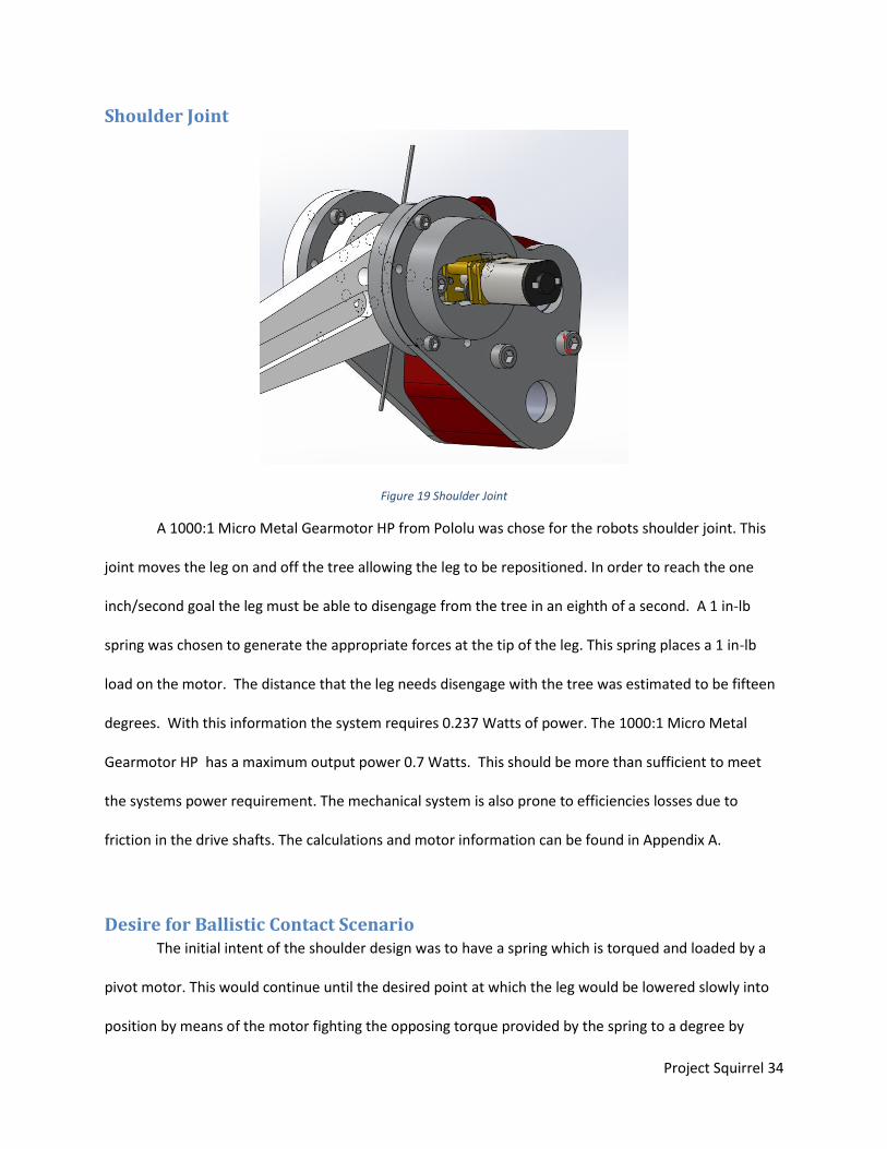
Shoulder Joint
Figure 19 Shoulder Joint
A 1000:1 Micro Metal Gearmotor HP from Pololu was chose for the robots shoulder joint. This
joint moves the leg on and off the tree allowing the leg to be repositioned. In order to reach the one
inch/second goal the leg must be able to disengage from the tree in an eighth of a second. A 1 in-lb
spring was chosen to generate the appropriate forces at the tip of the leg. This spring places a 1 in-lb
load on the motor. The distance that the leg needs disengage with the tree was estimated to be fifteen
degrees. With this information the system requires 0.237 Watts of power. The 1000:1 Micro Metal
Gearmotor HP has a maximum output power 0.7 Watts. This should be more than sufficient to meet
the systems power requirement. The mechanical system is also prone to efficiencies losses due to
friction in the drive shafts. The calculations and motor information can be found in Appendix A.
Desire for Ballistic Contact Scenario The initial intent of the shoulder design was to have a spring which is torqued and loaded by a
pivot motor. This would continue until the desired point at which the leg would be lowered slowly into
position by means of the motor fighting the opposing torque provided by the spring to a degree by

Project Squirrel 35
which the leg could lightly be placed in position. The primary purpose of the spring in this case was to
maintain sufficient positioning and contact between the feet and bark of the tree. Setting the needles
would then be almost entirely attributed to the downward pull of gravity. It was later decided that the
needles could be positioned with greater sufficiency whilst also providing less stress on the motor and
the structural integrity of the shoulder joint. The new and finalized concept involves a trigger
mechanism by which the pivot motors lift their respective legs against the force of a torsion spring,
eventually spinning past a point by which the trigger mechanism will fire and release the motor’s
constraint on the spring. This results in a ballistic scenario by which the foot will accelerate towards the
tree towards its desired contact position. The larger kinetic inertia and impulse generated by this
scenario greater ensures that the foot will travel straight down its preset path and create a solid groove
in the bark which will aid in attaining sufficient needle setting conditions.
Design
This section of the report is a detailed description of all the major components of the robot.
Material Selection Large structural components of the robot such as the shoulder plates and shafts were
constructed out of aluminum because of its light weight, durability, and cost effectiveness. The material
of the remaining parts was decided based on a careful balance between material properties and
manufacturability. The primary materials considered were Delrin, Lexan, and a 3D printing material
known as VeroWhitePlus. Below is the primary data which was considered in material selection:

Project Squirrel 36
Delrin
Lexan
Tensile Yield Stress 71MPa
Tensile Yield Stress 70MPa
Yield Strain 14%
Yield Strain 14%
Tensile Modulus 3250MPa
Tensile Modulus 2350MPa
Flexural Modulus 3100MPa
Flexural Modulus 2300MPa
Flexural Strength (Yield) 73MPa
Flexural Strength (Yield) 90MPa
Compressive Strength 36MPa
Compressive Strength 86.18MPa Table 2 Material Properties
Figure 20 Vero White Plus Material Properties
Based on these properties it was decided that Lexan was the best material out of the three in
terms of material properties because of its greater flexibility as well as flexural and compressive yield
strengths. The second best fit material wise was Delrin followed by the 3D printing material.
Manufacturability yielded the opposite scenario as VeroWhitePlus could be easily made into intricate
configurations on the 3D printer, Delrin could be cut using the laser cutter, and Lexan was considered to
have the least manufacturability in comparison to the other materials. With these factors taken into
consideration, different components were constructed with their most suitable material. Complicated
and intricate components such as the front and back plates were constructed using VeroWhitePlus
whereas larger more simplistic components requiring greater structural integrity such as the legs were
constructed from Lexan. The internals of the shoulder mechanism were initially composed of 3D printed
material, but the large loads on these components lead to failure during testing. From this it was

Project Squirrel 37
decided that the shoulder internals will be laser cut from Delrin. Testing showed that the Delrin
components were much more effective in the trigger mechanism. In spite of this, once placed under
loading the Delrin trigger components experienced multiple instances of structural failure. This instances
involved the d section which fit around the shaft of the shoulder motors. When exposed to enough
resistance the shafts would remove material from the inside of the component, allowing them to spin
freely and no longer function properly. However, because accessible manufacturing facilities were
insufficient for making the component out of a metal given our time constraints and making an order for
the part was too costly, Delrin remained as the best material solution to the component as they could
be quickly and cheaply made and replaced using a laser cutter.
Spring Selection Spring selection of the shoulder components was based around the desire to propel the legs
such that the needles contacted the tree with just enough force to aid in positioning. The actual setting
of the needles is purely attributed to the weight of the robot. Unnecessary spring torque magnitudes in
the shoulder component will overly stress the shoulder joint and create greater resistance for the small
pivot motors to overcome. In addition, it was necessary for our selected spring to have an effective
spring rate relative to the operation. If the spring rate is two high then the ratio of torque to deflection
will be such that the motor will have to overcome large quantity of resistance in a short period of time.
This would also limit the precision of our preload mechanism, as the torque output of the spring would
vary more dramatically under deflection. On the contrary the spring rate could not be so low that
preloading to the necessary torque value would reduce the spring diameter to a value smaller than the
shaft that passes through it. Too much deflection in the preloading phase could also cause the spring to
exceed its elastic range, creating weak and unpredictable torque values. The chosen shoulder spring
accounts for these variables and can be seen below:

Project Squirrel 38
Figure 21 Shoulder Spring
Unlike the shoulder spring selection scenario, the selection of the tail spring did not have to
consider the potential for overstressing motors or structures because it is static component of much less
complexity. The forces produced by the tail stress the robot along a different axis which is much
stronger due to support from lead screws and the electronics box. In spite of this the tail springs still
must possess a relatively low spring rate so that the preloading mechanisms can be as precise as
possible. As shown in the tail torque section, the force of generated by the tail on the tree must fall
within a range met by the maximum and minimum gait distance conditions in order to attain optimal
force conditions at the feet. Errors in preloading could result in the tilting or slipping of the robot.
Therefore it was decided that two torsion springs will be used in the tail component with the following
properties:
Figure 22 Tail Spring

Project Squirrel 39
Tail
Figure 23 Tail
From analysis of the tail torque calculations it was made clear that increase in tail length results
in a decreased force requirement at the contact point between the tail and the tree to attain. In addition
the equation for torque shows that an increase in length requires a larger torque at the pivot point in
order to meet the same force requirement at the end contact point. It was decided that a tail length
equivalent to the maximum gait distance (6.14in) would be a sufficient balance between attaining the
lower force requirements of a longer tail without making the tail so long that it added too much weight
or made setup of the robot too difficult. The contact area of the tail is rounded such that a very small
portion of the surface contacts the tree during operation. This is done to reduce the friction between
the tail and bark. Added friction by this component is a double edged sword in that it creates an added
static benefit by supporting the robot, but it also increases the load that the lead screws must overcome
during climbing. Since the pulling capacity of the lead screws is of much greater concern than the ability
of the robot to maintain its hold, it was decided that the contact area of the tail should be made as small
as possible. The tail is exposed to a constant shear force throughout its entirety, but experiences a
moment which linearly increases in magnitude from the contact point to the pivot. To account for this
the size of the tail tapers from the pivot point to the point of contact. The torque applied by the two

Project Squirrel 40
torsion spring components can be adjusted by a wheel mechanism which can be rotated to the desired
preload position and then fixed by a screw insert.
Ballistic Shoulder Joint Design The ballistic shoulder joint works by engaging and disengaging a motor. The motor is engaged
with the leg in order to raise the leg. When the leg needs to contact the tree the motor is disengaged
from the sprung loaded leg. The spring causes the leg to accelerate towards the tree. Once the leg is
stopped the motor then reengages and waits until it receives the commanded to raise the leg again.
Step 1: For this example the leg will start in the lowered position such that the leg is contacting the tree.
The motor is then connected to the blue part in the middle of the drawing. The red part is connected to
the green part but can spin freely about its shaft.
Figure 24 Shoulder Step 1
Step 2: When the Leg is commanded to move the blue part spins until it is in contact with the red L
shaped part. Once these two parts are in contact the motor is engaged with the leg. The red component

Project Squirrel 41
rotates such that the other end of the L is in contact with the gray bearing housing. This motion couples
the motors rotation with the leg rotation. A POT is connected to the leg to detect the legs position. The
current sensor connected to the shoulder motor will also see a spike in current as the leg begins to
move.
Figure 25 Shoulder Step 2
Step 3: The motor continue to move until it is commanded to stop in the pre firing position. The motor
stops when it reaches a specific POT Value. At this point the red L is still in contact with the outside
bearing housing and the blue part connected to the motor can’t move past the Red Piece.

Project Squirrel 42
Figure 26 Shoulder Step 3
Step 4: When the system commands the leg to fire the blue piece rotates past the red piece. This
disengages the motor from the leg allowing the spring to snap the leg onto the surface of the tree.
Figure 27 Shoulder Step 4

Project Squirrel 43
Vex Pods This subassembly serves a variety of functions. It houses the vex motors and the gear boxes that
drive the lead screws. The design of this gear box offered some unique challenges. In order to reduce
cost gears that came internal to the VEX 393 motor were used. This served two purposes it made
coupling the vex shaft easy and eliminated the need to purchase more gears. This housing also had to
accommodate a vex encoder and two push button switches to zero out the encoders. On the back of
this assembly are mounting holes for the tail to connect to. This subassembly was also designed to be
symmetrical allowing it to be placed at the front or back of the robot. This makes manufacturing and
assembly process easier by reducing the number of unique parts and the potential for assembly error.
Figure 28 Vex Pod 1

Project Squirrel 44
Figure 29 Vex Pod open
Figure 30 Vex Pod ISO
Electrical Box The electrical box was designed to add structural righty to the frame and provide mounting
brackets to support the control system. In order to get the center of gravity coolest to the tree the
battery was placed in the belly of the robot. However this decision will make the battery difficult to

Project Squirrel 45
change so charging circuits has been built into the control system so the battery can be plugged in and
charged without having to remove it from the robot.
Figure 31 Electrical Box
Feet and Leg design
Influenced by the testing conduct prior to the design phase, the foot needed to be built in such a
way to that a surgical needle was secured at a fifty five degree angle. To accomplish this, this part was
3D printed to account for the complex features to be easily manufactured. Through the testing phase,
featured the foot needed to have were decided. The foot was designed to support as much as the
needle as possible in order to prevent bending of the needle, however, enough of the needle needed to
protrude so it reached the maximum setting depth. Although the exact penetration distance was hard
to calculate due to the varying physical properties of the tree’s bark, observations during the testing
Project Squirrel 46
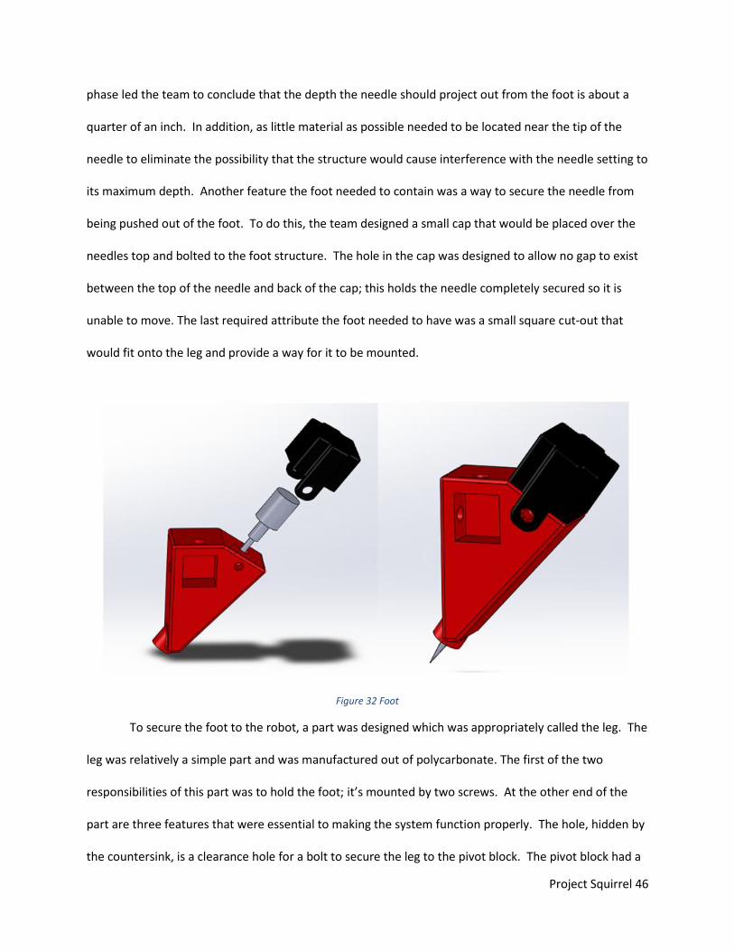
phase led the team to conclude that the depth the needle should project out from the foot is about a
quarter of an inch. In addition, as little material as possible needed to be located near the tip of the
needle to eliminate the possibility that the structure would cause interference with the needle setting to
its maximum depth. Another feature the foot needed to contain was a way to secure the needle from
being pushed out of the foot. To do this, the team designed a small cap that would be placed over the
needles top and bolted to the foot structure. The hole in the cap was designed to allow no gap to exist
between the top of the needle and back of the cap; this holds the needle completely secured so it is
unable to move. The last required attribute the foot needed to have was a small square cut-out that
would fit onto the leg and provide a way for it to be mounted.
Figure 32 Foot
To secure the foot to the robot, a part was designed which was appropriately called the leg. The
leg was relatively a simple part and was manufactured out of polycarbonate. The first of the two
responsibilities of this part was to hold the foot; it’s mounted by two screws. At the other end of the
part are three features that were essential to making the system function properly. The hole, hidden by
the countersink, is a clearance hole for a bolt to secure the leg to the pivot block. The pivot block had a

Project Squirrel 47
shaft that runs through the largest hole seen on the part and part of the ballistic shoulder system talked
about later in the report. The leg is secured in order to rotate with the pivot block.
Figure 33 Leg Plate
Sensors In order to ensure that the robot operates properly various sensors were used. These sensors
provide the robot with valuable feedback and allow it to operate effectively. Encoders were placed on
each lead screw to determine the position of the lead screw. Four pushbutton switches were used to
zero the encoders out when the leg carriage reached their limits. This switch also prevents the robot
from damaging its self. On each leg a potentiometer is used to indicate the angle of the leg. Feedback
from this potentiometer is crucial to making the ballistic firing mechanism function properly. Each
motor has a current sensor which can detect if a leg is supporting weight or a motor that is in a stalled
condition. The control system also incorporates a gyro and accelerometer to be used in future iterations
of this project.
Lead Screws A lead screw system was chosen because the system unable to be back driven. Alternatives to
this design were to use a clutch to prevent the system from back driving. But the complication and

Project Squirrel 48
expense of a clutch out weighted the disadvantage of an efficient screw based system. A 3/8-8 ACME
lead screw was selected because it was the most efficient ACME lead screw. The other lead screw
options were either back drivable or the nuts were too expensive.
Manufacturing
Initial Assembly
As with every assembly process, small flaws and failure points in the system began to arise as
part were put together and tested. To achieve the level of complexity some of the parts required, the
3D printing was chosen as a form of manufacturing. An early over estimation of the strength of the 3D
printed material, VeraWhitePlus, led the team down a design path that predominantly focused on the
use of this process. However, upon testing the physical robot for the first time, the real strength of the
material began to become apparent. Parts such as the original leg and ballistic shoulder system were
completely manufactured out of plastic but cracked when held under load as the firing mechanism was
tested. The areas of failure, indicated by the green arrows, can be seen below in the image. In order to
resolve this issue, the system was broken down into simpler parts.
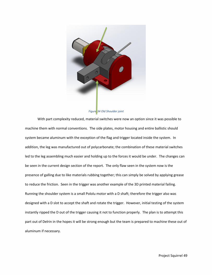
Project Squirrel 49
Figure 34 Old Shoulder joint
With part complexity reduced, material switches were now an option since it was possible to
machine them with normal conventions. The side plates, motor housing and entire ballistic should
system became aluminum with the exception of the flag and trigger located inside the system. In
addition, the leg was manufactured out of polycarbonate; the combination of these material switches
led to the leg assembling much easier and holding up to the forces it would be under. The changes can
be seen in the current design section of the report. The only flaw seen in the system now is the
presence of galling due to like materials rubbing together; this can simply be solved by applying grease
to reduce the friction. Seen in the trigger was another example of the 3D printed material failing.
Running the shoulder system is a small Pololu motor with a D shaft; therefore the trigger also was
designed with a D slot to accept the shaft and rotate the trigger. However, initial testing of the system
instantly ripped the D out of the trigger causing it not to function properly. The plan is to attempt this
part out of Delrin in the hopes it will be strong enough but the team is prepared to machine these out of
aluminum if necessary.

Project Squirrel 50
The team also experienced a major setback when a major miscalculation was made with the vex
motors. As seen through the mathematical analysis, the desired ratio needed to be about seventeen to
one but the original arrangement of gear only produced a four to one. Upon initial inspection of the vex
motor, the second stage of the gear box was overlooked. When the vex pod was designed, it arranged
only three of the gears into a one stage gear box instead of all four and a two stage gear box. This
reduced ratio led a single leg to lift roughly a third of the weight it was supposed to. Redesigning of the
vex pod was tested and the robot was able to lift the correct weight per leg.
3D Printed Parts
Due to the complexity and time constraints of these project 3D printers were used to
manufacture many of the parts. 3D printers are able to produce complex parts with significantly less
human involvement than conventional manufacturing methods. 3D printers eliminate the need to
fixture the parts in the machine which eliminates most of the time involved with manufacturing.
Through the use of WPI’s Maker Bot the team was able to produce prototype parts quickly and cheaply.
This allowed test fixtures and robot designs to be actualized with little manufacturing time allowing the
team to focus on the other aspects of the project. 3D printed parts were also used on the final robot to
produce parts such as the electrical brackets which do not have significant loads. Two 3D printers were
used to produce parts for the robot. The Maker Bot Replicator 2 was used to produce parts made from
PLA. PLA was the cheapest form of 3D printed material so it was used for parts simple or large parts. But
the Maker Bot is unable to meet the surface finish/ tolerance requirements for some of the parts. Parts
that required tighter tolerances and better surface finishes were sent to an Objet printer. The Objet
printer use Vero White Plus which is stronger than PLA. The Objet is also able to make significantly
smaller and more complicated features than the Maker Bot. The Objet can down support material which
allows the printer to print overhangs. The support material is then removed in post processing
operations. This support material is what allows the objet to print some complicated parts. The objet

Project Squirrel 51
also uses UV light to harden the material which allows it to produce smaller parts because the size is not
limited to the size of the filament feed into the machine. Every part was evaluated and a manufacturing
process was selected to meet the parts design specification.
Machined Parts
Parts also needed to be manufactured through traditional subtractive methods. Originally the
plan was to us a 3D printer to produce most of parts on the robot but concerns arose about the material
strength. Due these concerns 4 additional parts were slated to be made with traditional methods. These
change required that four parts be redesign such that they could be easily manufactured. Once the
designs were complete materials needed to be ordered for the parts but as well as to produce custom
fixtures to hold the parts in the machine. In order to quickly and safely machine the parts custom
fixtures needed to be designed and manufactured. A 3/4 inch thick block of aluminum was purchased to
produce one of the fixtures. Using a CNC this block of aluminum was machined to have features to allow
the parts to be securely held in the machine. A custom lathe fixture was also produced to hold a part
concentric in a lathe for a post processing operation. The parts for this project need to be produced
four times so the manufacturing process was optimized to save time. After creating all of the custom
fixtures it became easier to machine the remaining four legs. Four of the parts also required the use of a
CNC (Computer Numerical Control) machine to produce the complex features. In order to program the
CNC machine FeatureCam was used to develop the G code that would eventually run on the machine.
Electrical: After advancements in the overall mechanical design of the robot, conclusions were able to be
made about the electrical specifications. The general circuitry was configured to meet the specifications
of the robot. This section will explain the electrical design of Project Squirrel including the

Project Squirrel 52
microcontroller selection, motor control and sensing circuits, communications and the custom printed
circuit board.
Microcontroller After determining the total input and outputs of the microcontroller, the Arduino Mega was
chosen to run the system. The Arduino Mega has 54 digital I/O pins, 14 of which can be configured for
pwm outputs; 8 of which will actually be used for the pwm outputs (one for each motor). There are 16
analog inputs and 15 are required: 8 current sensing circuits, 4 potentiometers and 3 for the
accelerometer. Of the 4 UART ports 3 will be used. UART0 is reserved by the usb connection for
programming, UART3 is used for tethered communications with a computer and UART2 is used for
wireless communications through the Bluetooth chip. UART1 is used for additional external interrupts.
The four external interrupts that are used are as follows: one for limit switches, two for UART
handshaking and the final one is used as a user interface button to control the robot. A 7.2V battery will
be used to power the board through its Vin pin. The overall schematic for the pin connections is shown
below:

Project Squirrel 53
Figure 35 Overall Schematic
Motor driver circuit: As mentioned in the mechanical design sections, Project squirrel implements 8, individually
controlled motors: 4 lead screw motors and 4 leg motors.
Lead Screw Motors: Vex 2-wire 393 motors are used to run the lead screws and are controlled by Vex motor
controller 29. The 393 motors have a free run current of .37A and are geared to lift approximately 4 lbs.
The stall current for the motors is 4.8A, however the motor controller can only handle a maximum of 4A.
A 2920L200 resettable ptc fuse is used to regulate the current to 4A. The motor controllers have three

Project Squirrel 54
ports: power (7.2V), ground and pulse width (pwm) control. The direction of the motor is controlled by
the frequency of the pwm signal; 1- 2 ms will provide full forward to backward control of the motor with
1.5 ms being neutral.
Figure 36 Vex 393 Motor
Figure 37 VEX Motor Controler
Leg Motors Pololu micro metal gear motors are used to move the pivot joints in the legs. These motors
have a stall current of 1.6A and will be controlled by the TB6612FNG motor driver IC. The TB6612FNG is
an integrated, dual h-bridge motor driver that can control two motors from one chip. Digital I/O is used
to dictate the direction of the motor and the duty cycle of the pwm signal controls the speed. A
1206L050/15 ptc resettable fuse is used to regulate the current to 1A.

Project Squirrel 55
Figure 38 Pololu motor
Figure 39 TB6612FNG Motor Driver IC
The following table shows the logic used to control the motors:
Figure 40 TB6612FNG Control Logic
Motor Sensing: There are many ways to properly control and take input from motors. For the leg pivot motors,
it is important to know the current drawn from the motor as well as the angle of the pivot. For the lead

Project Squirrel 56
screw motors, current is also monitored but instead of the angle, the number of rotations (which
corresponds to position) of the lead screw is used.
Current Sensing:
Each motor has current sensing circuitry. A small sense resistor is placed in the power path and
the voltage across it will be used to measure the current using Ohms law relationship between current
and voltage across a resistor (I = V/R). The MAX9918 current-sense amplifier is used to amplify the
voltage drop across the sense resistor to a readable range by the microcontroller. The figure below
show the schematic for current sensing on a vex motor:
Figure 41 Pololu Motor Schematic
From the schematic, AIN1 and AIN2 are digital control pins for the motor driver. AO1 is the
positive output to the motor and AO2 is the negative output. The speed of motor A is controlled by
PWMA. Pins 1 &2 from the MAX9918 chip (U2) are placed across the sense resistor, R3. R3 was
selected to produce a full-scale range between 0- 50mV. Since the motor is limited to 1A, Ohms law can
be used to calculate the resistor value to be 50 mΩ. The Vex motors are limited to 4A and thus 10mΩ
resistors will be used. The MAX9918 uses negative feed from the voltage divider, R5 and R4, to get the
proper gain. To obtain a full scale analog range of 5V we need a gain of 100 V/V. Gain can be calculate

Project Squirrel 57
using the equation G= [1+R5/R4]; we get for following values: R5 = 98.8kΩ and R4 = 1kΩ. The voltage
divider between R6 and R7 sets the MAX9918 to bidirectional mode.
Leg Pivot Angle: The pololu leg motors rotate the pivot so the legs can detach from the tree and advance forward
on the lead screw. In order to detect the angle of the pivot a Vex potentiometer is attached to the shaft
of the motor. As the leg pivot rotates, the resistance is varied proportionally. The voltage across the
potentiometer can be measured through an analog input on the microcontroller.
Lead Screw Position: The Vex motors are used to move the legs up and down; knowing the position of each leg is an
integral part of the gait. The first way to detect the position is by the use of limit switches. When the
limit is reached, an external interrupt will be triggered. Due to a lack of external interrupt pins, an OR
logic gate is used; when any or all of the motors reach their limit, the interrupt is triggered. Each signal
is then sent to digital input pins to determine which motor has reached its limit,LED’s are used to
indicate which motors have triggered the interrupt. The schematic is shown below:
Figure 42 Limit Switch Schematic

Project Squirrel 58
The limit switches are a crucial safety system used to stop the motors when they have reached the end
of the lead screw to prevent damage.
I2C Encoders: Vex Integrated Encoder Modules are used to get the location of the legs using quadrature
encoders. The encoders use I2C communication to relay the count of the encoder to the
microcontroller. The encoders have four connections: 5V power, ground, SCL(serial clock) and
SDA(serial data). The serial clock and data lines require pull-up resistors to the 5V to ensure that the
signals are transmitted clearly.
Communications The Arduino Mega supports up to 4 UART ports and 1 serial port. 3 out of the four UART ports
will be used for different communication methods and the serial port will be used for the gyroscope.
UART0 is reserved for the USB programming. UART3 is used as an external communication tether along
with a handshaking interrupt. UART2 is connected to the wireless chip.
The original design for wireless communications was implemented through the XBEE wifi chip.
The XBEE functions on 3.3V, not 5V like the Arduino. In order to make the two compatible, the 5V
transmit lines from the Arduino needed to be reduced to 3.3V for the Bluetooth chip receive line and
the 3.3V transmit line from the Bluetooth chip needed to be brought up to 5V. A simple voltage divider
was used to reduce the 5V data line. The data was reduced to 2.5V (a 50-50 voltage divider) instead of
3.3V for simplicity and is still above the threshold for a logic high for the Bluetooth chip. An n-channel
mosfet was used to bring up the 3.3V to 5V. When the signal is high, the mosfet is off and the voltage
across the output resistor (R38) is 5V. When the signal drops low, the mosfet is trigger connecting the

Project Squirrel 59
output resistor to ground, thus bringing the output to ground. These two circuits are shown below in
Figure 43:
Figure 43: 3.3V to 5V and 5V to 3.3V Circuitry
Extra Sensors Project Squirrel also has attachments for an accelerometer and gyroscope. Although these
sensors were not implemented, they were allotted header connections and pin outs to the Arduino. The
L3GD20 triple-axis gyroscope and ADXL335 triple-axis accelerometer can easily be attached to the
custom PCB mentioned in the next section.
PCB Design: In order to organize all of the connections and integrate each component in a space-efficient
manner, a custom PCB shield was made. The shield integrates all aspects of the design (shown in the
figure above) into one board that mounts directly on to the Arduino Mega and powers it. The shield is
roughly the same size as the Arduino with the exception of an external row of headers on each side of
the board and the wireless extension off of the back. A battery connection was soldered directly to the
custom board and the 7.2V is sent to the Arduino and all of the motor circuits directly. The 5V digital I/O
will come from the Arduino’s regulator. The 5V is used to power the following: MAX9918, TB6612fng,
the potentiometers, and the CD4072B. The wireless chip uses the 3.3V power source from the Arduino.

Project Squirrel 60
The most important aspect of the shield is the placement of the header pins. The pins must be
aligned with those of the Arduino otherwise none of the connections will match up; routing is another
consideration. It is ideal to reduce the amount of turns and in any high speed communication lines such
as the I2C and serial ports. The board can be seen below:
Figure 44 PCB Board 1
Accelerometer/Gyroscope

Project Squirrel 61
Figure 45 PCB Board 2
As seen in the images above, the headers for the motors are strategically placed close to their
external components on the robot. The board has 2 buttons, a reset button for the entire Arduino and a
button to reset the legs. The wireless extension is placed on the bottom of the board so there is
minimal interference with the antenna.

Project Squirrel 62
Control System
Software Class structure: The class structure of the motor control command was designed for simplicity and ease of use
when writing the gait logic for the robot. Each leg will have its own class: Leg(*Leg_Motor, *Leg_Screw).
The Leg class takes in a pointer to its corresponding leg motor and lead screw motor. From the Leg
class, all of the commands for the motors can be made such as:
Forward(speed) //moves upward
Backward(speed) //moves the leg dow
Up(speed) //lifts the leg off of the tree
fStop() //stops the leadscrew motor
uStop() //stops the leg motor
position() //gets the position of the leg
getPOt() //gets the angle of the leg Furthermore, the leg class contains many of the flags that are needed to keep track of the state that the
leg is in. These include:
state //indicates which leg it is
pos //location on leadscrew
ang //angle of leg
legRaised //if the leg is held up
climbPos //where the leg should stop on leadscrew
firePos //where the leg needs to be to fire
legHomeFlag //if the leg has homed properly
legClimbFlag //if the leg has finished its climb sequence
legAngleFlag //if the leg is at the proper angle
legZeroFlag //if the leg has been zeroes
legPosFlag //if the leg is in the proper position
The Leg_Motor class and the Lead_Screw motor classes both have two subclass used to normalize
the direction of the motors. In other words, since the motors have different orientations, it makes sure
that calling up on all leg motors will lift the leg off of the tree. Virtual functions are used to ensure that
the proper functions are used within the given sub classes.

Project Squirrel 63
The leg_motor class takes in the pin values for the leg motors digital input (for TB6612FNG chip), the
potentiometer, the pwm signal, and the current sensing. The Leg_motor class has the following
functions:
Stop() //stop the motor
Standby() //turn off the motor driver chip
getPot() //read the potentiometer value
getI() //read the current value
getSpeed() //read the speed value
Forward(speed) //lift the leg
Backward(speed) //lower the leg (never used)
The lead_screw_motor class takes in the pin values for the pwm signal, and the current sense. It
contains the following functions:
Stop() //stops the lead screw
getLoc() //reads the location of the leg
getSpeed() //reads the speed of the leg
getI() //reads the current value
Forward(speed) //moves the leg upward
Backward(speed) //moves the leg down The overall class hierarchy can be seen in the figure below:

Project Squirrel 64
Class Architecture
Figure 46 Class Architecture
Gait logic Explanation and Diagram
An integral component of the robot’s control was implemented in the gait logic; the use of a
case statement and a concept of the robot’s current and previous state were used to coordinate the
various motions of the robot. A major design characteristic required of the architecture of the program
was it needed to enter and exit extremely quickly. Due to the nature of the communications, the robot
need to constantly check for commands sent from the user. In order to accommodate that need,
functions were written in such a way that allowed them to enter the program, make a quick decision
and exit without getting blocked into sections of code. To accomplish that goal, if statements would

Project Squirrel 65
determine if the robot’s current action was in the correct location and either commanded motors to
continue to move along the lead screws as well as the leg angle or to stop.
The overall structure is controlled by a case statement called robotGait that only allows sections
of code to be called at a time. This not only aids the program’s ability to run quickly but allows the flow
of logic to be easily understood and diagnosed. Seen in figure xx is how logic controls the climbing
sequence. The use of flags allows the robot to move from one step to the next. For example, when the
robot’s state is zero it is commanded to move leg one to its fire position. This function will call two of
the functions talked about above and continues to call them until they reach their respective
destinations, lead screw position and leg angle. Once both the flags indicate the leg is in the correct
position, it updates the robot’s state. In this example, the robot’s state will equal one. As robotGait is
continued to be called, it now calls the next step in the gait. The next step in the gait sequence would
be to fire leg one down to the tree. Again, using the simple motion commands, will move the leg to the
desired location and set flags to indicate it. Once this happens, the robot’s state is again updated and it
will now call the next step in the gait. This process continues to happen until all four legs have been
successfully moved and fired down to the tree and then brought through the climb phase of the gait,
when the robot moves all its legs down at the same time to propel itself vertically upward. After the
climb phase is complete, the robot’s state is set back to zero and the code repeats.
Other essential robot operations were added to robotGait in order to make the functionality of
the robot safe for users as well as itself. The most important is the homing sequence; every time the
robot is powered on, it needs to run its homing sequence to zero its encoders and prepare itself to be
placed on the tree. At the end of home, all legs are raised to their fire positions and the robot is set to
its stop command. It then waits for the command from the user to fire the legs all at once to the tree.
Another condition under robotGait is the fire command; this will fire all its legs to the tree. The last

Project Squirrel 66
function to note is the idle command; if the robot is stopped and waiting for a command, it sits in an
empty function which will allow the robot to respond as quickly as possible to user input.

Project Squirrel 67
Figure 47 Robot Gait State Digram

Project Squirrel 68
Command Flow Chart
To control the robot a distributed system was created between an Arduino Mega and a
computer. The two devices were connected wirelessly through the use of a Bluetooth serial adapter or
wired through a USB cable. The Arduino Mega handles all motion control and is where the gait logic was
stored. This decision was made to avoid needing a fast communication protocol. The robot only needs
commands from the computer after it receives a command it is able to execute it without any further
communication with the computer. For safety reasons a heartbeat was implemented between the
computer and the robot. If the robot does not receive a command for more than 500ms then it will
automatically enter the stop condition. A simple ASCII base command structure was implemented to
communicate between the two devices. If the user wants the robot to stop they send “Stop” plus
carriage return and new line charterers. The robot looks for the carriage return and new line charters to
detriment when it has received a full command. Once it receives these characters it will then process
the text revived from the robot and execute the desired instruction. Detailed bellow is a flow chart that
describes all the commands that the robot responds to and how it is implemented on the computer. The
computer user interface developed in Java implements a communication stack. Every time the user or
the system needs to communicate with the robot the command is added to the stack. The program then
takes the first command off the stack and repeatedly sends the command until it receives a response
from the robot. Once a response is revived this command is removed from the stack moves to the next
item in the stack. Some commands are prioritized over others. For example if the user sends the stop
command it is placed in the front of the stack. This gives messages of critical importance priority over
other commands. In the figures Figure 48 Command Flow Diagram details the flow of the
communication between the user, computer, and robot.

Project Squirrel 69
Figure 48 Command Flow Diagram

Project Squirrel 70
User Interface
A Java based graphical user interface was created to allow the user to control the robot, receive
sensor information back from the robot, and log various forms of data. To control the robot the user can
push and hold the up or down button. For safety reasons the user is forced to hold the UP button for the
robot to move. Once the user releases the up button the command to stop is automatically set. Future
work of the project will include navigating around branches to add this functionality to the GUI a slider
was added to allow the user to adjust the amount the robot turns as it climbs or descends. The HOME
button is used before the user places the robot on the tree to zero out all the encoders. Once the robot
is homed the robot can be placed up against the tree and the user can use the FIRE button is used to fire
the legs onto the tree. In the four blank text fields shown in Figure 49 Driver GUI is where sensor data is
returned from the robot. The user can control the sample rate of the sensor data by moving the slider
under Update Speed.
Figure 49 Driver GUI

Project Squirrel 71
Logging functions were built into the graphical user interface to assist in debugging. If the user navigates
to the robot logs tab they are able to see in the text field any error messages received from the robot.
They can also chose to export the leg sensor log which exports a csv of all the sensor information
received from the robot organized by leg. The user can also choose to export a log of all the
communications sent and received from the robot as well as the error log. These logging features
proved to be a helpful when debugging the robots gait.
Figure 50 Robot Logs GUI
Wireless Interface To communicate wirelessly with the robot using a smart phone or android tablet the Android app “Blue
Tooth Serial Controller” was used. This android app allowed the team to quickly create an Android
interface to control the robot. This app mapped on screen buttons to ascii commands that would then
be sent over the blue tooth to the robot. The app allowed the user to customize the ascii commands to
their particular robot. The only disadvantage to using this android app is that the ability to log and
display sensor data was lost.

Project Squirrel 72
Social Implications Several design features of the robot were constructed with a heavy focus on ergonomics and
user safety. One potentially high risk phase of operation is the initial engagement of the robot on its
contact surface. During this phase a fire command is given to the robot which causes all of the
previously raised legs to snap down, with the design intent of securing the robot to its chosen climbing
surface. To remove the potential danger of this phase, a handle component was designed and
constructed. The handle allows the user to hold the robot from the back of the frame direct the
hazardous components away from themselves and toward the target climbing surface. Also
implemented in the handle is a single button which can be used to send the fire command. Another
potential danger during the engagement phase is the somewhat complicated process of positioning the
tail. Since this component is sprung downward toward the robot frame, it can be difficult to pull back
and position to the proper location. An alternative tail design was constructed with geometry such that
its contact point does not extend past the feet components. Therefore the operator would have
significantly less distance to pull it to its proper position.
Initial designs left a section of exposed gears in the shoulder motors. This created the potential
for small external objects to jam an entire shoulder component which would make the robot completely
dysfunctional. If this were to happen during operation, the robot could fall on the user or crash and
break. To solve this problem, motor covers were designed and implemented, removing exposure of the
shoulder internals.
Another potential hazard of the robot design was the sharpness of the contact points. Two
design features were implemented to prevent damage to the operator. The first of these features was a
cap component placed on the rear of each foot. Removal of this component allows the user to safely
replace the needle. The second of these features was the implementation of small pieces of cork. Each
Project Squirrel 73
of these pieces can easily be slid over any of the contact components when not in use, protecting the
operator from potential harm.
Conclusion This section outlines the mechanical, electrical and software results and future works.
Mechanical
Results
After completion of the testing phase, the robot demonstrated the capacity to complete over
two cycles of gait on a vertically oriented tree on multiple instances. Testing began on a flat tree
segment, in which the robot had no trouble traversing. During the next stage of testing climbing
performance was analyzed and the tree segment was oriented vertically. This stage demonstrated that
the implemented ballistic needle setting mechanism was very effective in positioning the needles such
that the robot’s weight could sufficiently set them. The robot consistently engaged the tree with high
degrees of static stability. Once properly calibrated to the tail greatly aided in balance and general
stability of the robot during all phases of climbing.
Testing of the vertical gait revealed four primary issues, which once resolved, the robot was
able to climb and demonstrate that it is a highly effective mechanical design. The first of these issues
was that the shoulder motors and internal trigger components were not strong enough to assist in the
pull out phase of the gait. Instances of the shoulders engaging to soon would overly stress the motors
and trigger components causing one of the two to break and require replacement. This issue was
resolved by changing the gait sequence such that the significantly stronger lead screw system was the
only component involved in the needle removal process. The robot also experienced gear box dimension
issues which resulted in resistance and binding within the lead screw components. This was fixed by
providing more electrical power to the motors to push through the unexpected resistance. The third
issue was that the initial gait sequence created a scenario where the weight of the robot was too heavily

Project Squirrel 74
concentrated over the rear right leg during climbing. This was resolved by changing the gait sequence
such that it began with the movement of the upper left leg, followed by the lower left leg, then the
upper right leg, and lastly the lower right leg. The final issue encountered during testing was that slight
timing and positioning variations were making it difficult for the lead screws to pull the robot. Since the
robot was designed such that a minimum of two synchronized lead screw systems are required to pull
the robot, subtle changes in timing can hinder the pulling phase of climbing. This issue was resolved by
altering the tolerances on shoulder position requirements such that the pull sequences initiated closer
together. With these issues resolved the robot was able to climb with performance that met the
projects initial goals. Overall the mechanical concept proved very effective and if pursued further will
provide a highly functional tree climbing robot.
Future Work
To improve the functionality of this robot’s mechanical design in future iterations, focus should
be placed on the shoulder, gearbox, and lead screw components. The chosen pololu motors cannot
structurally handle the torque that they generate and thus are not designed to handle stalling.
Therefore interference in the motion of the leg during operation can cause portions of the shoulder
motor to break to a degree where they are no longer functional. Since the motor housing is designed to
fit the relatively small dimensions of the pololu motors, solving this problem will require finding motors
with the same dimensions that meet the power requirements of the shoulder mechanism, or
scaling/redesigning the shoulder components to fit a larger motor. Initially the small pololu motors were
chosen to minimize the robot’s size and weight. However since the design demonstrated the capacity to
handle significant loading, larger more powerful shoulder motors could prove to be more beneficial to
the robot’s functionality. In addition to this motor issue, effort should be made to investigate other
potential materials and manufacturing methods to create the two trigger components within each of
the shoulder components. During testing these components would regularly experience structural

Project Squirrel 75
failure, but because of their scale machining them out of a stronger material could not be accomplished
due to time constraints. Instead the circumstances made it much more effective to continue laser
cutting the components out of Delrin and replacing them when mechanical failures occurred. Improving
these components will not only reduce instances of mechanical failure, but will also allow for the
shoulder springs to be preloaded to a greater degree, creating more leg acceleration during climbing
and potentially improving gait stability. The robot would also benefit from the addition of a third degree
of freedom. Adding this extra joint would allow the robot to navigate around branches more easily. A
third degree of freedom would also allow the robot to pull its self into the tree. Currently the robot
could potentially move away from the tree. By adding a third degree of freedom the robot would be
able to pull itself into the tree. By adding this third joint it also opens the possibility of improving the
robots stability on the tree through the use of controls to evaluate the robots state.
The final two components which should be further investigated are the gearboxes and lead
screw systems. These components, while still allowing for proper climbing function, could be improved a
great deal. The lead screw system experienced large amounts of resistance and occasional binding,
which worsened when the robot was hanging from the test tree segment. Although the motors could
still provide sufficient power to eliminate this issue, the gait could become much more efficient if it the
system is improved. The resistance has been isolated to be an issue with gear box dimensioning and
thus can be resolved through ensuring all gears and gearbox geometry is sufficient for proper
functionality. In addition, more efficient lead screw components may also improve this condition.

Project Squirrel 76
Electrical
Results
The electrical design had its share of successes and failures. After the first evaluation of the
requirements for the microcontroller, the TI-TMS302F28069 chip was selected. However, because there
was limited time and money to produce the custom pcb and a lot of unknowns with the wiring of this
chip, the Arduino Mega was chosen to replace it. Without a functioning microcontroller, the project
would have been delayed significantly.
The motor control circuits worked well after adjustments to the original design. The addition of
PTC fuses helped us avoid burning out the TB6612FGN motor drivers, which saved us time and money.
Despite a grounding issue with the logic for the limit switches (a simple wiring fix) the circuit worked up
to specifications and allowed us to trigger the interrupt from all 4 motors. Due to an overlook with the
MAX9918 current sensing chip, the current sensing circuitry was not able to be implemented. The
thermal ground pads underneath the chip did not have proper connections to the board and were
essential to the functionality of the chip. All of the potentiometers worked up to specifications despite
the varying ranges; this was fixed within software.
When experimenting with the XBEE wireless chip, we were unable to get it to function properly.
If configured incorrectly, the chip would become “bricked”; rendering it essentially useless. Due to this
complication, we replaced the XBEE chip with a wireless Bluetooth chip. This switch was simple after
reconfiguring the top four pins of the XBEE header pin with a custom ribbon cable. The circuitry used on
the data lines to switch between 3.3V and 5V worked well at a baud rate of 9600. The circuitry had not
been tested under higher speeds but higher speeds are not necessary for this application.

Project Squirrel 77
Future Work
The first print of the PCB board design had various connections problems and bugs. One major
problem was the disregard for the thermal pads under the MAX9918 chips. Since these were not
implemented on the board, there was no current sensing available and the robot gait was made without
the luxury of knowing when the motors where stuck or stalling. The other problems were easily fixed by
jumping the connections on the board using regular wires. The first of these problems includes
connecting the ground of the upper left hand portion (near U4) to the rest of the ground rails. The ICSP
header (in the middle of the board) was not mapped to standard header pin sizes and thus did not fit.
These connections are used to power and ground the OR Gate and access the serial ports for the
gyroscope. Since the gyroscope was not implemented, the serial ports were never re-connected. The
power trace for potentiometer 4 was never connected to power. In two different instances, the 3.3V
power line for the wireless chip cross the ground rail. This issue caused unnecessary power loss and
current drain as well as disabling the power to the wireless chip. Finally, the transmit and receive lines
to the wireless chip need to be switched to ensure the proper conversion between 3.3V and 5V. It
would also be beneficial to replace the XBEE header pins with headers that match the chip being used.
There are also many improvements that could be made to advance the project further. The first
is implementing various detectors and sensors including: a gyroscope, accelerometer, camera and
stability checking sensors. Since the Arduino has been essentially used to its limit, additional sensors
would also require a stronger microcontroller with more inputs and outputs.
Software The software can be divided up into three major components: communications, gait logic and
the class structure. The class architecture was designed in such a way to make writing the gait logic easy
and simple to navigate. It was constructed so there was a concept of leg and a set of commands that

Project Squirrel 78
could be called for it. The gait logic used a case statement to control the flow of code and a system of
move function and completion flags to coordinate the motion. Lastly was the communication, which
used a custom made ASCII protocol to tell the robot which sections of code to run. A Bluetooth module
was used to send those commands wirelessly to the robot from an Android App that was usable from a
phone or tablet.
Results
The overall integration between the three sections of code went very well. The class structure
created did a good job at facilitating the implementation of the gait logic and controlled effectively by
the communications. However there were few design errors and alterations in the implementation that
needed to be made to make this successful. The first to note was that the leg motor functions to
command the legs to raise and fire could not be run at anything but full speed; this was a bug that
couldn’t be resolved. When a value other than 255, top speed, was introduced into the function the
motors would not run. This problem was discovered when p loops to control the speed of the motors
was implemented. Due to this issue the loops were bypassed and all the leg motor functions were run
at full speed. Generally the communications ran very smoothly and only encountered a few minor
issues during testing that were easily solved. The first was the robot occasionally didn’t respond to
commands sent from the user. A feature implemented in the GUI was the ability to log information
about the legs and when the user requested too much information at one time it bogged down the line.
The ability to slow down and increase this rate was added with a slider and this problem was avoided.
The last issue seen was if the robot lost communications with the device it was connected to it would
continue to send the last command given. If this command was up and not stop the robot could cause
serious damage to itself and possibly the user. To resolve this safety concern, a heartbeat was added
where if the robot didn’t receive a command for more than 500 ms it automatically enters the stop
condition. The remainder of the issues seen with the software stemmed from the architecture of the

Project Squirrel 79
gait software. Due to its rather bulky and repeatable nature, diagnosing the small issues became harder
to debug. Simply, there were more areas of code where things could go wrong. One specific example is
when an error needed to be added into the move commands to account for the motors stopping before
their destination. Instead of adding that error in one spot, it needed to be added in multiple making it
harder to keep track of what was changed. The bugs were eventually worked out and the gait was
successful on the tree but in order to fix this permanently the gait software would need to be
redesigned.
Future Work
The majority of the modifications to code can be made to the gait logic. An early design flaw led
the code to be bulky and repeatable making it difficult to diagnose. Another issue with it was it was
designed only to move the robot in its upward gait; an entire new gait would need to be written to make
the robot perform a different action such as down. Although this early decision led the project down a
path it didn’t have time to remedy, a solution was conceptualized instead and offered as a
recommendation on how to approach the problem. The new design would use a series of arrays to
conduct the robot to move to certain positions along its gait. This would allow a few simple functions to
be created to control basic motion and have the arrays contain custom arrangements of these
movements that coordinate the desired gait motion. The flow of the gait would be coordinated by an
“isComplete” function that is called in every move command. Once is complete indicates the motion
desired is in the correct position, it will move onto the next position in the array. Designing the
architecture in this way allows custom arrays to be built so up, down and turning are simple to
implement.
Since the main objective of the project was to get the robot to climb the tree, software to
expand the robots capabilities were left to be explored. Cameras and additional sensors could be added
to this robot to further its capabilities and begin to make the robots proposed uses a reachable goal. For

Project Squirrel 80
example, a camera could be added to detect the holes left by the Asian long horn beetle. Software
would need to be developed to implement these changes. The user interface could also use some
improvements. The team created a user interface without speaking with the robots eventual end user.
Future work could include speaking with the end user to get their take on how the user interface is laid
out and how they interpret the language of the buttons. For instance to a Robotics engineer Home
means zero out the encoders and move everything to a known state. But this may not be obvious to our
end user. As the project moves forward input from the end user should be obtained to improve the
current user interface.

Project Squirrel 81
Appendix A
Micro Metal Gear motor Information Speed (rpm)
Torque (N m)
Torque (in lbs)
Current (A)
Power (wt) Efficiency
Heat (wt)
0 0.883 7.813 1.6 0.0 0% 19
2 0.824 7.292 1.5 0.2 1% 18
4 0.765 6.771 1.4 0.3 2% 16
6 0.706 6.250 1.3 0.5 3% 15
9 0.648 5.729 1.2 0.6 4% 14
11 0.589 5.208 1.1 0.7 5% 12
13 0.530 4.688 1.0 0.7 6% 11
15 0.471 4.167 0.9 0.7 7% 10
17 0.412 3.646 0.8 0.7 8% 9
19 0.353 3.125 0.7 0.7 9% 7
21 0.294 2.604 0.6 0.7 9% 6
23 0.235 2.083 0.5 0.6 10% 5
26 0.177 1.563 0.4 0.5 10% 4
28 0.118 1.042 0.3 0.3 10% 3
30 0.059 0.521 0.2 0.2 9% 2
32 0.000 0.000 0.1 0.0 0% 1
Shoulder Joint Power Calculations
Leg Power Requirements
LiftTime 0.125sec Time it takes to lift the leg
TravelDeg 15deg Deg the leg has to travel in time
DegPerSecTravelDeg
LiftTime120
deg
sec
RPSDegPerSec
360deg
rev( ) 0.333rev
sec
w RPS 2rad
rev2.094
rad
sec
SpringT 1in lbf Chosen torsion spring
SpringTNm SpringT 0.113 N m
P SpringTNm w 0.237W

Project Squirrel 82
Vex Motor Information
Speed (rpm)
Torque (in lbs)
Current (A)
Power (wt)
Efficiency
0 0.022 4.800 0.000 0%
4561 0.020 4.505 1.195 3%
9123 0.019 4.209 2.220 7%
13684 0.017 3.914 3.073 10%
18246 0.016 3.619 3.756 13%
22807 0.014 3.323 4.268 16%
27369 0.013 3.028 4.610 19%
31930 0.012 2.733 4.781 22%
36492 0.010 2.437 4.781 25%
41053 0.009 2.142 4.610 27%
45615 0.007 1.847 4.268 29%
50176 0.006 1.551 3.756 31%
54737 0.004 1.256 3.073 31%
59299 0.003 0.961 2.220 29%
63860 0.001 0.665 1.195 23%
68422 0.000 0.370 0.000 0%

Project Squirrel 83
Climbing Joint
Lead Screw and Robot Information
RobotWeight 6lbf Weight of the robot
LegWeight 0.3lbf Leg Weight
Lead 0.125in
rev Lead of the Screw
ef 42% Efficiency of lead screw system
Speed Calculation
RobotSpeed 1in
sec the desired speed of the robot
StepSize 3.375in distance traveled per step
LegMoves 5 number of leg moves required per step
ScrewDistance LegMoves StepSize 16.875 in Distance the carriages mustmove to complete one step
RevPerStepScrewDistance
Lead135 rev
Screw revs per step
RPS RevPerStepRobotSpeed
StepSize 40
rev
sec RPS of the screw
wscrew RPS 2 rad
rev251.327
rad
sec
Angular velocity of the screw
Reset 1 leg Torque and Power Requirements
rLead LegWeight( )
2rad
revef
0.01421 in lbf
Pr r wscrew 0.404 W Power required to move one leg
Pull Power Requirements
numLegs 2 Number of legs providing pulling force
p
LeadRobotWeight
numLegs
2rad
revef
0.142 in lbf
Pp p wscrew 4.035 W

Project Squirrel 84
Bibliography
[1] Ben_k. Tree Climbing Robot. Internet: http://www.instructables.com/id/Tree-Climbing-Robo
t/#step1, 2011 [Sept. 14, 2013]
[2] Heater, B. Treebot climbs trees, is a robot.
Internet: http://www.engadget.com/2011/05/29/treebot-climbs- trees-is-a-robot-video/, 2011 [Sept.
18 2013]
[3] Spenko, M., Haynes, G., Saunders, J., Cutkosky, M., Rizzi, A., Full, R., & Koditschek,
D. (2008). Biologically Inspired Climbing with a Hexapedal Robot. PDF. Presented Journal of Field
Robotics.
[4] Wright C., Johnson, A., Peck, A., McCord, Z., Naaktgeboren, A., Gianfortoni, P., Gonzalez-
Rivero, M., ... Choset, H. (2007). Design of a Modular Snake Robot. PDF. Presented IEEE/RSJ
International Conference on Intelligent Robots and Systems, San Diego, CA, USA
Copyright © 2022 FDOKUMEN