PV Integrated single-phase dynamic voltage restorer for sag ...

The 2014 International Power Electronics Conference
AC-Choppers Using Instantaneous Voltage Control Technique to Solve Voltage Sag Problems
Surin Khomfoi Dept. of Electrical Engineering, Faculty of Engineering King Mongkut's Institute of Technology Ladkrabang
Bangkok, Thailand [email protected]
Abstract- AC-Choppers using instantaneous voltage control
technique to solve voltage sag problems are proposed in this
paper. The developed AC-chopper for series voltage sag
compensation is applied for three phase four wire system;
therefore, three single phase ac chopper circuits and three series
transformers are utilized. By using AC-chopper, there are no
required for a dc bus; thereupon, the size of proposed voltage sag
compensator is smaller. Each AC-chopper cell is independently
controlled by using instantaneous voltage control method. With
this proposed technique, the AC-chopper can rapidly compensate
the related voltage sag and provide constant output voltages.
Positive sequence PLL is applied to generate angle velocity (00)
thus the proposed AC-chopper can perform both balance and
unbalance voltage sag. MATLAB/Simulink is used to simulate
the proposed control algorithm and circuit operation. The 2-kW
prototype is also developed for experimental validation. The
results illustrate that the developed voltage sag compensator can
perform within 3 ms responding time and the total harmonic
voltage distortion is less than 2 % with overall system efficiency
about 90%. Keywords- AC-chopper, series voltage sag compensation,
instantaneous value voltage control
I. INTRODUCTION
Voltage sag is one of the most important issues in power quality. It does cause the problems in the power system and industry. Voltage sag can cause operation downtime in the manufacturing system. This may cause damage in products and components; especially, electronic devices e.g. variable speed drive (VSD), Programmable logic control (PLC). To avoid such problems, the voltage sag compensator should be installed to the system. Several topologies of the voltage sag compensator have been proposed and they can be categorized into two groups: parallel and series compensators. The advantages and disadvantages on both categories have been clearly described in [1-2]. A series compensator can offer a smaller size of VA rating comparing to a parallel compensator. Moreover, a series compensator can provide fault tolerance and fault limiter capabilities to a system. However, a parallel compensator may have less compensator system losses and better dynamic voltage response comparing to a series compensator [I]. Therefore, better system efficiency and fast dynamic voltage response are required in a series compensator.
978-1-4799-2705-0/14/$31.00 ©2014 IEEE 2392
AC-chopper configuration can have better system efficiency because AC-chopper does not have dc bus. Thereupon, the application of an AC-chopper is widely used in several applications; for instance, a single phase UPS, and a LED driver as shown in [3-4]. A symmetrical PWM AC-chopper voltage controller has been developed in [4]. AC-choppers have been used as AC voltage regulator and voltage sag compensation as proposed in [5-8]. The AC-Chopper can be used to perform like an automatic voltage regulator as presented in [5]. The AC-chopper can offer a minimum energy injection using of micro-SMES has clearly been verified in [6]. The application of an AC-chopper on dynamic voltage restorer has also been reported in [9]. One can see that an ACchopper can be applied in many applications; however, a few researches are focusing on a series voltage sag compensator.
The PWM line conditioner with fast output voltage control has been developed in [10]. Also, a non-liner feed-forward control technique for single phase UPS has been report in [11]. As can be seen, a developed PWM technique in [10-11] is for fast output voltage control for a conventional converter which can be utilized in AC-chopper with some modification. Hence, fast dynamic voltage response for AC-choppers can be achieved by using instantaneous voltage control technique as presented in [11-12]. The simulation and experimental results have been reported in [11] and have been validated in [12] for a single phase AC-chopper applications. The simulation study of AC-choppers for a series voltage sag application using instantaneous voltage control technique has been reported in [13]. Therefore, the experimental results are required to validate the AC-chopper for a series voltage sag application. A series voltage sag compensator using instantaneous voltage control technique is presented in this paper. AC-chopper can offer low losses and smaller size comparing to a conventional ac-dc-ac configuration.
This paper presents a series voltage sag compensator using ac-chopper as shown in Fig.1. The three single phase acchoppers are used to compensate voltage sag in three phase four wire system. The advantages of using ac-chopper are without DC-Link, nearly sinusoidal output voltage with small size of input and output low-pass filter, high input power factor. As a result, the size and weight of this compensator is smaller which would lead to cost effectiveness.

The 2014 International Power Electronics Conference
II. PROPOSED AC-CHOPPER CONFIGURATION AND CONTROL
TECHNIQUE
The proposed system consists of three single phase acchoppers connected in series through the injection transformer between source and load as illustrated in Fig 2. During voltage sag condition, each ac-chopper injects compensated in-phase voltage with the source voltage to maintain the desired load voltage independently. If unbalanced voltage sag occurs (i.e. single phase sag, poly phase sag and unbalanced three phase sag), ac-chopper will generate the compensated voltage to the related phases of the ac-chopper. The other ac-chopper will operate in by-pass mode.
Rs Cs
R; L; R, L,
r SI S2 r Rs Yin C C, Vo
I Cs
I Fig. I. A single phase ac-chopper.
A B C
3 Phase Source
Fig. 2. Proposed system paradigm.
Fig. 3. Power f10w diagram during normal condition.
Fig. 4. Power flow diagram during voltage sag condition.
2393
For instance, if voltage sag occurs in phase A and B, both phase A and B ac-choppers are operating but phase C ac-chopper will operate in a by-pass mode. During normal condition, all three single phase ac-chopper will operate in by-pass mode.
In by-pass mode, IGBT switch S I, S2 is turned-off and S3, S4 is turned-on. Power flow diagram from source to load during normal condition is depicted in Fig 3. Fig. 4 shows power flow diagram during voltage sag condition. As can be seen, the acchopper will inject power when voltage sag occurs. In this proposed control, the delay 3;' cycles is used after the voltage increases to normal condition. So, the ac-chopper will work for next 3;' cycles to make sure that source voltage is in absolute normal condition. If voltage sag is repeatedly occurred within 3;' cycles, ac-chopper will work until source voltage completely increases to normal condition.
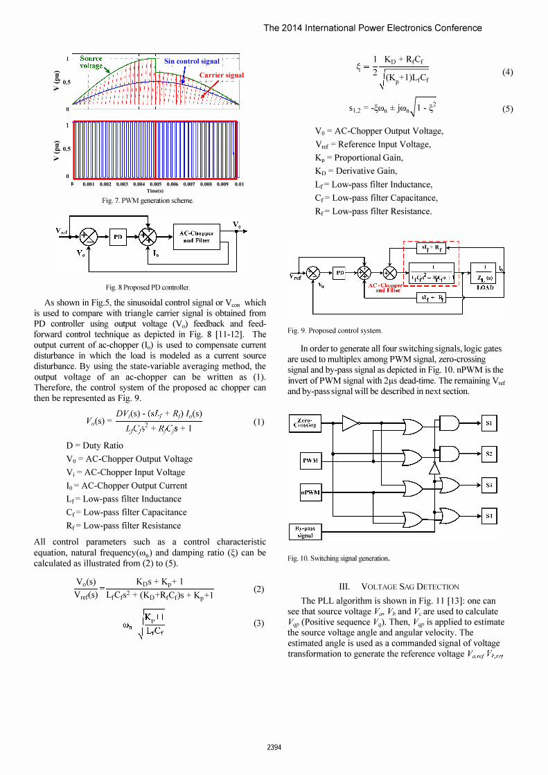
An instantaneous voltage control technique is used to control ac-chopper during voltage sag. This technique provides fast response, robustness against the supply voltage sag, nearly sinusoidal wave form under non-linear load condition [12-13]. The explanation is explained below and the control diagram is illustrated in Fig. 5. Fig. 5 shows the control diagram of ac-chopper. An instantaneous value voltage control is the method that uses sinusoidal control signal comparing with modulated triangle carrier signal. The triangle carrier signal is generated from an integrator operation of source voltage and we will reset the integrator every switching period as shown in Fig.6. As a result, the amplitude of triangle carrier signal will be varied with amplitude of the source voltage. As can be seen in Fig.7, voltage sag occurs at O.005s: the amplitude of triangle carrier signal will decrease and duty ratio will automatically increase. Therefore, voltage sag of the source is not effect to the load and independent to ac-chopper controller.
Fig. 5. Control Diagram.
Fig. 6. Simulation model of PWM generator.
SI S2 S3 S4
PWM
The 2014 International Power Electronics Conference
-= -= 0.5 �
-= -= 0.5
�
- Sin control signal T I I I I
Carrier signal
-+- -+--
o ��������������� 0.001 0.002 0.003 0.004 0.005 0.006 0.007 0.008 0.009 0.01
Time(s) Fig. 7. PWM generation scheme.
Fig. 8 Proposed PD controller.
As shown in Fig.5, the sinusoidal control signal or Veon which is used to compare with triangle carrier signal is obtained from PD controller using output voltage (Vo) feedback and feedforward contro I technique as depicted in Fig. 8 [11-12]. The output current of ac-chopper (10) is used to compensate current disturbance in which the load is modeled as a current source disturbance. By using the state-variable averaging method, the output voltage of an ac-chopper can be written as (1). Therefore, the control system of the proposed ac chopper can then be represented as Fig. 9.
V s - DVi(s) - (sLj + Rj)/,,(s)
o( ) -L C 2 + Res + I
(1) fP f f
D = Duty Ratio Vo = AC-Chopper Output Voltage Vi = AC-Chopper Input Voltage 10 = AC-Chopper Output Current Lf= Low-pass filter Inductance Cf= Low-pass filter Capacitance Rf= Low-pass filter Resistance
All control parameters such as a control characteristic equation, natural frequency(con) and damping ratio (�) can be calculated as illustrated from (2) to (5).
Vo(s) KDs + Kp+ I -- -Vrer<:s) LfCfS2 + (KD+RfCf)S + Kp+1
(2)
(3)
2394
1 KD + RfCf �=-r==== 2 (K +1)LfCf p
SI,2 = -�con ±jCOn-H Vo = AC-Chopper Output Voltage, Vref = Reference Input Voltage, Kp = Proportional Gain, KD = Derivative Gain, Lf= Low-pass filter Inductance, Cf= Low-pass filter Capacitance, Rf= Low-pass filter Resistance.
r-------, .----+----1 s't + Rf
Fig. 9. Proposed control system.
(4)
(5)
In order to generate all four switching signals, logic gates are used to multiplex among PWM signal, zero-crossing signal and by-pass signal as depicted in Fig. 10. nPWM is the invert of PWM signal with 2f.ls dead-time. The remaining Vref and by-pass signal will be described in next section.
Fig. 10. Switching signal generation.
III. VOLTAGE SAG DETECTION
The PLL algorithm is shown in Fig. 11 [13]: one can see that source voltage Va, Vh and Vc are used to calculate Vqp (Positive sequence Vq). Then, Vqp is applied to estimate the source voltage angle and angular velocity. The estimated angle is used as a commanded signal of voltage transformation to generate the reference voltage Va,ref Vb,ref

The 2014 International Power Electronics Conference
Fig. 11. Three-phase PLL Algorithm.
abc-dqO
8
dqO-abc Va,ref V bore! Vc,ref
Fig. 12. Voltage sag detection topology.
and Vc,re( as shown in Fig.12. R(s) is a phase-shift filter transfer function having +n12 output phase-shift at angular frequency which can be expressed as follows:
H(s)=_I-sTI I-sTI '
where, T 1 = 1Iw and w is the angular frequency.
(6)
Fig.12 shows the topology to determine the magnitude of voltage sag. 1.0 pu., 0.0 pu., and 0.0 pu. of voltage reference are used to compare with Vd, Vq and Va generated from Park's transformation (abc to dq) respectively. Then, calculate Vreffrom the difference of Vd, Vq, and Vo by using Inverse Park's transformation (dq to abc) for providing to PO controller as shown in Fig.5. The by-pass signal in each phase is generated by comparing absolute of Vrefand 0.05 per unit as shown in Fig. 13. If the absolute of �-efis higher than 0.05, this means that voltage sag occurs, the by-pass signal will deactivate ac-chopper for compensating voltage sag. When the system voltage returns to normal condition, by-pass signal will be delayed for 1 Yz cycles to make sure that the source voltage is completely return to normal condition.
Fig. 13. By-pass signal generation
2395
IV. SIMULATION
MA TLAB/Simulink is used to simulate the proposed application. Fig.14 shows the power circuit diagram of the system which has a three single phase ac-chopper connected between the line through the series injection transformer. The source supplies to the 1.5-kW load. The simulation is performed under three different voltage sag conditions: balanced three phase voltage sag, single phase voltage sag, and two phase voltage sag, respectively. Some important parameters used for simulation are shown in Table I.
Source "¢' .. d.,
nod" 1 nod"l.
Fig. 14. Power circuit diagram of the system.
The simulation results under source voltage sag to 70% condition are shown in Fig. 15, 16 and 17 which are the source and load voltage waveform under balanced three phase sag, single phase sag and two phase sag at time (t) from t = 0.045s to 0.105s respectively. The results show that an AC-chopper does perform both balanced and unbalanced compensation effectively.

The 2014 International Power Electronics Conference
TABLE!. PARAMETERS FOR SIMULATIONS
AC-chopper
Supply voltage 220 V
Switching frequency 10 kHz
Low-pass filter
Rrand Ri 0.50
Lfand Li 0.5mH
Cr and Ci 25uF
Controller parameters
KD 0.0002s
R
C
0.04
RC Snubber
0.06 0.08 Tmo(s)
Fig. 15. Balanced three phase sag.
820
22nF
0.1 O.IZ
Fig. 15 is a simulation result showing a balance three phase voltage sag to 70% at 0.045 s (top). As can be seen, the proposed AC-chopper series compensator can perform to compensate the voltage sag as the normal voltage at the load (bottom).
€ �� (,I 200 . : , . . . -.. H :
j ::---------------f:ITffiiiJJijjJjj .s -100
400L------L------�----�------�----� 0.02 0.04 0.06 0.08 0.1 0.12
Timc(s)
Fig. 16. Single phase sag on phase B.
Fig. 16 shows a simulation result of a phaseS voltage sag to 70% at 0.045 s (top). Clearly, the proposed AC-chopper system can also solve the voltage sag problems.
2396
f: zoo E � 0
0.04 0.06 0.08 Time/s)
0.1
Fig. 17. Two phase sag on phase B and C.
0.12
Simulation results on phase B and C voltage sag are illustrated in Fig. 17. Obviously, the voltage sag can be compensated by using the proposed AC-chopper technique. The simulation results indicate that the proposed AC-chopper togather with instantaneous voltage control technique can be applied in a series voltage sag compensator. Fig.18 shows the voltage waveform and the harmonic spectrum of the load of the phase A voltage sag condition. As can be seen, the waveform is nearly sinusoidal which has a total harmonic voltage distortion about l.9% i Slgna, 10 analyZi
. . '
. •
I FFT window: 4 of 8 cycles of selected siognal
.,
i 20t V\L • •••.••. D . •.•••.•• D j(� j �-20:lL�J\j
i FfTana,ys,s I 100
0.04 0.05 0.06 0.07 0.08 0.09 Time(s)
Fundamental (50Hz):o 316.4 , THO: 1.73%
• �r� . I /' , 500<) '0000
5000 10000 Frequency (Hz)
Fig. 18. FFT analysis of the load voltage.
V. EXPERIMENTAL RESULTS
0.1 0.11
I ,500<)
15000
The 2 k W prototype was developed to validate the proposed system as shown in Fig. 19 and Fig. 20. A single chip DSP (TMS320F2808) was used to perform central calculation . During normal operation, the by-passed signal was sent to the AC chopper acting as a standby mode. If the voltage sag occurs at the source voltage, the voltage sag algorithm will detect and then calculate amount of voltage sag. After that, the amount of voltage sag will send to the PWM generator unit via D/A converter to generate desired PWM signals for the AC-choppers as depicted in Fig. 19.

Source
Fig. 19. Prototype diagram of proposed AC-chopper system.
Fig. 20. 2-kW AC-chopper series compensator prototype.
Fig. 21 . Experimental set-up.
Fig. 22. Measurement points: voltage and current during validation
The 2014 International Power Electronics Conference
2397
The experimental set-up is shown in Fig. 21. The voltage sag generator was used to validate the proposed AC- chopper system. The voltage sag generator was used as a voltage source which can perform voltage sag situations. The developed prototype was connected with 1: I transformer. Normally, AC-chopper can compensate with a fine power quality performance at the source voltage sag to 50 % [13]. Therefore, the source voltage to 90%, 80% and 70% conditions were validated. Also, three phase, two phase and single phase voltage sag categories were examined in this test. The measurement points are illustrated in Fig. 22 to probe the voltage and current data. All parameters of the developed prototype are listed in Table II.
TABLE II. PARAMETERS OF DEVELOPED PROTOTYPE
AC-chopper
IGBT-HGTG20N60B3D 600V 40A
Switching frequency 10 kHz
Low-pass filter
Rrand R, 0.50
Lfand L, 0.5mH
Cfand C, 25uF
Controller parameters
0.7
0.0002s
RC Snubber
R 820
C 22nF
The experimental results on three phase, two phase and single phase voltage sag conditions are shown in Fig. 23-25, respectively. The (a) is a source voltage from voltage sag generator and the (b) is load voltage. As can be seen, the voltage sag generator was created the voltage sag to 70 % for all categories at 90° magnitude. The proposed AC-chopper series voltage sag compensator can compensate voltage sag for all tested categories. The efficiency evaluation of proposed AC-chopper system is illustrated in Table III
TABLE III. EFFICIENCY EVALUATION
Magnitude of Voltage Chopper Efficiency System Sag to (%) Efficiency (%)
100% - 96.67
90% 68.12 92.29
80% 78.35 90.32
70% 82.81 90.61
As shown in Table III, the efficiency is about 96.7% at normal condition because of the output filter and transformer losses. Also, the efficiency of AC-chopper will increase if the voltage sag at the source increases. It should be noted that the overall system efficiency is more than 90%; therefore, the proposed AC-chopper series voltage sag compensator is satisfactorily operated under this validation.

The 2014 International Power Electronics Conference
(a) (b) Fig. 23. Three phase voltage sag to 70% : (a) showing voltage sag at sources and (b) showing voltage at load terminals
(a) (b) Fig. 24. Two phase voltage sag to 70% : (a) showing voltage sag at sources and (b) showing voltage at load terminals
(a) (b) Fig.25. Single phase voltage sag to 70%: (a) showing voltage sag at sources and (b) showing voltage at load terminals
2398

The 2014 International Power Electronics Conference
w � Fig. 26. Voltage and current signals of the proposed AC-chopper during voltage sag to 70%:
(a) voltage and current at source (up) and voltage and current at load terminal (bottom), (b) voltage and current at input ac-chopper (up) and output ac-chopper (bottom).
The voltage and current at the source, load terminal, input AC-chopper and output AC-chopper operating at voltage sag to 70% are illustrated in Fig. 26. Fig. 26 (a) shows the voltage and current at source and load terminals. Fig. 26 (b) illustrates the input/output voltage and current at AC-chopper. The signal both current and voltage at the load terminal is in good power quality. The overshoot current is still under IGBT current limit. The total harmonic voltage distortion at source, load terminal and output AC-chopper are listed in Table IV
TABLE IV. TOTAL HARMONIC VOLTAGE DISTORTION VALIDATION
Source THDvs (%) THDvL (%) THDvc (%)
voltage sag to at source at load terminal at AC-chopper
100% 1.8 1.98 -
90% 1.5 1.68 7.25
80% 1.67 1.90 4.40
70% 1.84 2.02 4.07
VI. CONCLUSION
The AC-chopper to solve voltage sag problem has been proposed. An instantaneous value voltage control technique has been used to control AC-chopper. The simulations for both balanced and unbalanced voltage sag have been performed using MATLAB/Simulink and the 2-kW ACchopper prototype has been developed and validated with experiments. The system efficiency performance of under test conditions is more than 90% with only 2% total voltage harmonic distortion. The experimental results show that the proposed AC-chopper circuit can be applied in series voltage sag compensation with a fine efficiency and fast dynamic voltage response and total harmonic voltage distortion.
ACKNOWLEDGMENT
The author would prefer to thank Mr. Saradech Varanavin for helping on the experiments, Provincial Electricity Authority (PEA) of Thailand and KMITL for supporting research funds.
2399
REFERENCES [I] A-A Edris, "Proposed Terms and Definitions for Flexible ac
Transmission System (FACTS)", IEEE Transaction on Power Delivery,Yol 12, No.4, Oct 1997
[2] Electric Power Research Institute (EPRI), Power quality in commercial buildings, Tech. Rep. BR-I05018, 1995
[3] M.J. Ryan; W.E. Brumsickle, and R.D. Lorenz. "Control topology options for single-phase UPS inverters", IEEE Trans. Industry Applications, Vol. 33, No. 2, March-April (1997)
[4] Nabil A Ahmed, Kenji Amei, and Masaaki Sakui, "A New Configuration of Single-Phase Symmetrical PWM AC Chopper Voltage Controller," IEEE Transactions on Industrial Electronics, Oct 1999, Vol. 46, No.5, pp.942-952.
[5] Steven M. Hietpas and Mark Naden, "Automatic Voltage Regulator Using an AC Voltage-Voltage Converter," IEEE Transactions on Industry Application, Jan/Feb 2000, Vol. 36, No. I, pp.33-38.
[6] S. Polmai, Toshifumi Ise and Sadatoshi Kumagai, "Experiment on Voltage Sag Compensation with Minimum Energy Injection by Use of a Micro-SMES", Proceedings of the Power Conversion Conference-Osaka 2002, Vol. II, pp. 415-420, Osaka, Japan, April 2-5, 2002,
[7] Vazquez, N., Velazquez A, Hernandez C., "AC Voltage Regulator Based on the AC-AC Buck-Boost Converter," IEEE International on Industrial Electronics, ISlE 2007., June 4-7, 2007, pp.533 - 537.
[8] Flores-Arias, 1. M., Moreno-Munoz, A, Domingo-Perez, F., Pal1aresLopez, V. and Gutierrez, D., "Voltage regulator system based on a PWM AC chopper converter," IEEE International Symposium on Industrial Electronics (ISIE), Jun 27-30, 2011, pp.468-473.
[9] Nam-Sup Choi, Byung-Moon Han, Eui-Cheol Nho and Hanju Cha, "Dynamic voltage restorer using PWM ac-ac converter," Proceeding of the Power Electronics Conference (tPEC), June 21-24, 2010, pp. 2690-2695
[10] Josep M. Guerrero, Luis Garcia de Vicuna, Jaume Miret, and Jose Matas. "A nonlinear feed-forward control technique for single-phase UPS inverters", in the Proceeding of the IEEE Conference IECON 02, Vol. I, pp. 257-261, 2002
[II] S. Polmai, "Instantaneous-value voltage control of a single-phase AC chopper", Proc. International Power Electronics Conference, IPECNiigata 2005, vol. 49, No.4, April 4 - 8, 2005
[12] S. Polmai and E. Sugprajun, "Experiment on Instantaneous Value Voltage Control of a Single-Phase AC Chopper", Power Conversion Conference - Nagoya, 2007. PCC '07
[13] Saradech Varanavin and Surin Khomfoi, "An Instantaneous Value Voltage Control AC Chopper for Compensating Voltage Sag in Three Phase Four Wire System," ECTI-CON 2012, Hua-Hin, Thailand, May 16-19, 2012
Copyright © 2022 FDOKUMEN