Mean Instantaneous Firing Frequency Is Always Higher Than the Firing Rate
Upload
khangminh22Category
view
4download
0
sensors
Article
Instantaneous, Dual-Frequency, Multi-GNSS Precise RTKPositioning Using Google Pixel 4 and Samsung Galaxy S20Smartphones for Zero and Short Baselines
Chien Zheng Yong 1,2, Robert Odolinski 1,* , Safoora Zaminpardaz 3, Michael Moore 4, Eldar Rubinov 5,Jeremiah Er 1 and Mike Denham 1
�����������������
Citation: Yong, C.Z.; Odolinski, R.;
Zaminpardaz, S.; Moore, M.; Rubinov,
E.; Er, J.; Denham, M. Instantaneous,
Dual-Frequency, Multi-GNSS Precise
RTK Positioning Using Google Pixel 4
and Samsung Galaxy S20
Smartphones for Zero and Short
Baselines. Sensors 2021, 21, 8318.
https://doi.org/10.3390/s21248318
Academic Editors: Jari Nurmi and
Maorong Ge
Received: 1 November 2021
Accepted: 9 December 2021
Published: 13 December 2021
Publisher’s Note: MDPI stays neutral
with regard to jurisdictional claims in
published maps and institutional affil-
iations.
Copyright: © 2021 by the authors.
Licensee MDPI, Basel, Switzerland.
This article is an open access article
distributed under the terms and
conditions of the Creative Commons
Attribution (CC BY) license (https://
creativecommons.org/licenses/by/
4.0/).
1 National School of Surveying, University of Otago, 310 Castle Street, Dunedin 9016, New Zealand;[email protected] (C.Z.Y.); [email protected] (J.E.); [email protected] (M.D.)
2 Faculty of Built Environment and Surveying, Universiti Teknologi Malaysia, Johor Bahru 81310, Malaysia3 School of Science, College of Science, Engineering and Health, RMIT University, GPO Box 2476V,
Melbourne, VIC 3001, Australia; [email protected] Geoscience Australia, GPO Box 378, Canberra, ACT 2601, Australia; [email protected] FrontierSI, Goods Shed, Village Street, Docklands, VIC 3008, Australia; [email protected]* Correspondence: [email protected]
Abstract: The recent development of the smartphone Global Navigation Satellite System (GNSS)chipsets, such as Broadcom BCM47755 and Qualcomm Snapdragon 855 embedded, makes instanta-neous and cm level real-time kinematic (RTK) positioning possible with Android-based smartphones.In this contribution we investigate the instantaneous single-baseline RTK performance of SamsungGalaxy S20 and Google Pixel 4 (GP4) smartphones with such chipsets, while making use of dual-frequency L1 + L5 Global Positioning System (GPS), E1 + E5a Galileo, L1 + L5 Quasi-Zenith SatelliteSystem (QZSS) and B1 BeiDou Navigation Satellite System (BDS) code and phase observations inDunedin, New Zealand. The effects of locating the smartphones in an upright and lying downposition were evaluated, and we show that the choice of smartphone configuration can affect thepositioning performance even in a zero-baseline setup. In particular, we found non-zero mean andlinear trends in the double-differenced carrier-phase residuals for one of the smartphone modelswhen lying down, which become absent when in an upright position. This implies that the twoassessed smartphones have different antenna gain pattern and antenna sensitivity to interferences.Finally, we demonstrate, for the first time, a near hundred percent (98.7% to 99.9%) instantaneousRTK integer least-squares success rate for one of the smartphone models and cm level positioningprecision while using short-baseline experiments with internal and external antennas, respectively.
Keywords: smartphone positioning; real-time kinematic (RTK); multi-GNSS; dual frequency
1. Introduction
The use of survey-grade Global Navigation Satellite System (GNSS) receivers andantennas has traditionally been the only solution to achieve fast and high precision po-sitioning. With the emerging GNSSs, such as the BeiDou Navigation Satellite System(BDS), Galileo and the Quasi-Zenith Satellite System (QZSS), low-cost receivers have beenproven to be capable to bring a near competitive ambiguity resolution and mm–cm levelpositioning performance to that of more expensive survey-grade GNSS receivers andantennas [1–4]. Before 2005, there were fewer than ten smartphone models equippedwith GPS [5]. Currently, it is hard to find any smartphone that is without GPS (or GNSS)positioning functionality. There has also been a recent rapid development in small-sizeand low-cost GNSS smartphone chipsets that adopt dual-frequency, multi-GNSS, code andphase measurements for enhanced positioning precisions [6,7].
Several studies [8–12] have highlighted that smartphone antennas are highly sensitiveto multipath effects. Pesyna et al. [8] showed by using an auxiliary external antenna
Sensors 2021, 21, 8318. https://doi.org/10.3390/s21248318 https://www.mdpi.com/journal/sensors

Sensors 2021, 21, 8318 2 of 21
connected to a smartphone that it was possible to overcome the multipath sensitivity ofthe smartphone antennas and subsequently achieved cm level positioning precision. Afew other recent studies [12,13] have further suggested that cm level positioning precisioncan be achieved in a short-baseline model while using the smartphone internal antennasand a Kalman filter to link parameters in time (multi-epoch model). Geng and Li [14]and Gao et al. [15] recently confirmed that there is a presence of carrier phase drifts insome smartphone observation data with an arbitrary phase offset, whereas similar phaseoffsets and drifts appeared in other earlier and later smartphone positioning studies aswell (e.g., [8,9,12,16–18]).
In this contribution, we will assess such anomalies in the phase data and the instanta-neous (single-epoch) real-time kinematic (RTK) performance of two Samsung Galaxy S20and two Google Pixel 4 smartphones, all forming their individual RTK baselines. In ourmodel and different from other studies above is that all parameters will be unlinked in time,and the benefit of using the instantaneous RTK model is that it then becomes insensitive tocycle slips. For all analysed baselines we will make use of several hours of data with a onesecond measurement interval, so that our conclusions will be statistically significant. As apart of our analysis, we will explicitly investigate two setup configurations, namely havingthe smartphones in an (i) upright and (ii) lying down position, while tracking GNSS signalsfrom both external and internal antennas. This is motivated by the fact that we want theinternal smartphone antennas to be as uninfluenced from the surrounding environmentas possible to minimize possibility of signal interference or other effects coming from thepoor antenna gain of the smartphones [13].
This contribution is organised as follows. In Section 2, the multi-GNSS RTK functionalmodel is described and in Section 3 the smartphone GNSS data and stochastic modelsettings are presented. The combined dual-frequency GPS L1 + L5, Galileo E1 + E5a, QZSSL1 + L5 and BDS B1 code and carrier phase observations, are then evaluated in Section 4by empirical integer least square (ILS) ambiguity success rates (SR) and the obtainable po-sitioning precisions for a zero-baseline experiment. The tracked BDS constellation consistsof BDS-2 [19] and BDS-3 satellites [20]. The zero-baseline is formed by placing the smart-phones inside a Radio Frequency (RF) shielding box with a re-radiating antenna, which isfurther connected through an amplifier to an external low-cost antenna. The instantaneoussmartphone RTK positioning performance is then assessed, and the characteristics of thedouble-differenced (DD) carrier-phase and code residuals are analysed while having thesmartphones in an upright and lying down position. In this process we will also comparethe formal and empirical positioning confidence ellipses and intervals, and analyse whetherthe data follow a normal distribution. In Section 5, we extend our analysis to investigatethe DD phase residuals and the instantaneous RTK positioning performance for a shortbaseline. In this section, we focus our attention on the performance of external as well asthe smartphone internal antennas. Finally, in Section 6, a summary with conclusions isdrawn.
2. The Multi-GNSS, Dual Frequency, Single-Baseline RTK Functional Model
The functional model we will use assumes two receivers r = 1,2 that track s = 1, . . . , mGPS, Galileo, QZSS and BDS satellites on f frequencies. For the zero- and short-baselinemodels, the relative ionospheric and tropospheric delays and satellite orbit errors can beassumed negligible. We make use of broadcast ephemerides for satellite orbits and clocksand the instantaneous (single-epoch), linearized DD system of observation equations read,
y = Aa + Bb, (1)
where y is the vector of DD carrier-phase and code observations, A is the design matrixof the DD integer ambiguities in vector a and B corresponds to the design matrix of thereal-valued baseline components b. The LAMBDA method [21] will be used for full integerambiguity resolution (IAR) to obtain the precise fixed baseline solution. Provided thatthe success rate, i.e., the probability of correct integer estimation, is sufficiently high, the

Sensors 2021, 21, 8318 3 of 21
baseline will have mm–cm level precision owing to the precise carrier-phase observations.We make use of system-specific reference satellites when performing the between-satellitesingle-differences. However, it is emphasized that if we would take a common referencesatellite on the overlapping frequencies between the systems, it could further strengthenthe model provided that the inter-system biases (ISBs) can be calibrated [22,23]. For thestochastic model, an elevation weighting sine-function was used, as employed in RTKlibv2.4.3 [24].
3. GNSS Data Collection with Android-Based Smartphones
This section presents the setup configurations of the zero-baseline and short-baselinesin upright and lying down positions, and describe the stochastic model settings. In thefollowing sections, we will investigate the effects the setup has on the instantaneous RTKpositioning performance and the corresponding DD carrier-phase and code residuals.
3.1. General Setup Configuration with External Antennas
Figure 1 and Table 1 depict the general external antenna setup to assess the observationquality of the GNSS data collected by two Android-based smartphones, namely, SamsungGalaxy S20 (S20) and Google Pixel 4 (GP4). The duty-cycling settings of all smartphoneswere disabled during the experiment. Hence, we were able to observe continuous carrier-phase observations without discontinuity [9]. The GP4 and S20 smartphones are ableto track dual-frequency GPS L1 + L5, Galileo E1 + E5a, QZSS L1 + L5 and BDS B1 codeand phase observations. The receivers and antennas are placed in a radio frequency (RF)shielding box to prevent them from receiving GNSS signals other than from the intendedre-radiating antenna. The direct GNSS signals are collected from a rooftop active low-costantenna, Swift GPS500, which costs a few hundred USDs, and then re-radiated via a passiveantenna inside the RF shielding box. A signal amplifier is connected in between the rooftopantenna and re-radiating antenna to reduce the effect of signal attenuation, see Figure 1.The smartphones are also benchmarked against survey-grade Trimble NetR9 receivers +Zephyr-2 antennas and low-cost ublox ZED-F9P receivers + patch antennas that are alsoplaced inside the RF shielding box. The main purpose of this benchmarking is to assurethat no GNSS signal leakage is experienced in the RF shielding box that could potentiallyworsen the RTK performance. Note that L2 rather than L5 observations were tracked bythe Trimble and ublox receivers, respectively. For ublox, we did so since, at the time ofwriting, there was no support for L5 observations, whereas for the Trimble NetR9 receiverswe made use of an old firmware version that was possibly not able to track the GPS/QZSSL5 observations [25]. We also note that the analysed smartphones are all restricted (at thetime of writing) to L5 rather than L2 observations.
The Trimble NetR9 and low-cost ublox receivers logged GPS + Galileo + QZSS +BDS measurements at 1-s data interval (cf. Table 1), and the smartphones logged theobservations through the Geo++ RINEX Logger vers. 2.1.6. At the time of collecting thisdata, we found that a maximum timespan of about 17 h and 15 h can be collected for S20and GP4, respectively. This was limited by a battery-saving mechanism preventing them tooperate for longer timespans. The Geo++ RINEX logger developers found a similar issueon e.g., the Xiaomi Mi8 and Huawei P20X smartphones [26].

Sensors 2021, 21, 8318 4 of 21Sensors 2021, 21, x FOR PEER REVIEW 4 of 21
Figure 1. General external antenna setup configuration of S20 and GP4 smartphones that will be benchmarked against survey-grade Trimble NetR9 and low-cost ublox receivers/antennas. All re-ceivers/antennas are placed in a RF shielding box to prevent them from receiving GNSS signals that are not from the re-radiating antenna. The direct GNSS signals are collected from the active low-cost antenna on the rooftop, Swift GPS500, and re-radiated via a passive antenna. A signal amplifier is connected in between the rooftop antenna and re-radiating antenna to reduce the effect of signal attenuation. Inset (right column) depicts the location map of Dunedin, New Zealand.
Table 1. Site identity, receivers and the GNSS signals used in this study.
Site ID Receiver Chipset Constellations Frequencies SGD1 Samsung
Galaxy S20 Broadcom BCM47755
GPS, Galileo, QZSS, BDS
L1 + L5, E1 + E5a, L1 + L5, B1 SGD2
GPD1 Google Pixel 4
Qualcomm Snap-dragon 855 embed-
ded
GPS, Galileo, QZSS, BDS
L1 + L5, E1 + E5a, L1 + L5, B1 GPD2
UBX1 휇Blox F9P
GPS, Galileo, QZSS, BDS
L1 + L2, E1 + E5b, L1 + L2, B1 + B2 UBX2
TRD1 Trimble NetR9
MaxwellTM 6 GPS, Galileo, QZSS, BDS
L1 + L2, E1 + E5b, L1 + L2, B1 + B2 + B3 TRD2
3.2. The ‘Upright’ and ‘Lying Down’ Setup Configurations The built-in antennas of the smartphones have been found to be sensitive to poor
quality GNSS signals and the surrounding environment [27]. The GNSS signals tracked by the S20 and GP4 smartphones are likely interfered with when placed too close to other objects even inside an RF shielding box. In this contribution we therefore assess the per-formance of the smartphones under two different setup configurations: (i) when the smartphones are in an upright position as depicted in Figure 2a and (ii) when lying down in Figure 2b. As a result of the zero-baseline setup, multipath is largely eliminated. The remaining small multipath effects would mainly be due to the non-simultaneity of sam-pling between the receivers.
Figure 1. General external antenna setup configuration of S20 and GP4 smartphones that will bebenchmarked against survey-grade Trimble NetR9 and low-cost ublox receivers/antennas. Allreceivers/antennas are placed in a RF shielding box to prevent them from receiving GNSS signalsthat are not from the re-radiating antenna. The direct GNSS signals are collected from the activelow-cost antenna on the rooftop, Swift GPS500, and re-radiated via a passive antenna. A signalamplifier is connected in between the rooftop antenna and re-radiating antenna to reduce the effectof signal attenuation. Inset (right column) depicts the location map of Dunedin, New Zealand.
Table 1. Site identity, receivers and the GNSS signals used in this study.
Site ID Receiver Chipset Constellations Frequencies
SGD1 SamsungGalaxy S20 Broadcom BCM47755
GPS, Galileo,QZSS, BDS
L1 + L5, E1 + E5a, L1+ L5, B1SGD2
GPD1 Google Pixel 4 Qualcomm Snapdragon855 embedded
GPS, Galileo,QZSS, BDS
L1 + L5, E1 + E5a, L1+ L5, B1GPD2
UBX1µBlox F9P
GPS, Galileo,QZSS, BDS
L1 + L2, E1 + E5b,L1 + L2, B1 + B2UBX2
TRD1Trimble NetR9 MaxwellTM 6
GPS, Galileo,QZSS, BDS
L1 + L2, E1 + E5b, L1+ L2, B1 + B2 + B3TRD2
3.2. The ‘Upright’ and ‘Lying Down’ Setup Configurations
The built-in antennas of the smartphones have been found to be sensitive to poorquality GNSS signals and the surrounding environment [27]. The GNSS signals trackedby the S20 and GP4 smartphones are likely interfered with when placed too close toother objects even inside an RF shielding box. In this contribution we therefore assessthe performance of the smartphones under two different setup configurations: (i) whenthe smartphones are in an upright position as depicted in Figure 2a and (ii) when lyingdown in Figure 2b. As a result of the zero-baseline setup, multipath is largely eliminated.The remaining small multipath effects would mainly be due to the non-simultaneity ofsampling between the receivers.

Sensors 2021, 21, 8318 5 of 21Sensors 2021, 21, x FOR PEER REVIEW 5 of 21
Figure 2. Zero-baseline setup configurations for smartphones in (a) upright and (b) lying down positions. The re-radiating antenna receives the GNSS signals through the roof-top antenna in Figure 1.
Figure 3. Short-baseline setup configurations with external antennas (c,f) in upright (a,d) and lying down (b,e) positions.
In addition to the zero-baselines in Figure 2, we assess the performance of four short-baseline setup configurations, namely with external antennas (i) in the upright position (c.f. Figure 3a,d) and (ii) lying down position (Figure 3b,e). We further show results with internal smartphone antennas in the upright position (Figure 4a,b) and in a lying down position (Figure 4c,d).
3.3. Stochastic Model Settings The stochastic model was then determined by fitting empirical 95 percent confidence
ellipses/levels to the formal counterparts, as derived from the corresponding variance co-variance (VCV) matrices of the positions. The empirical VCV-matrix is given by the posi-tioning errors as derived by comparing the estimated positions to precise benchmark co-ordinates, whereas the formal VCV-matrix is given from the mean of all single-epoch for-mal VCV-matrices of the entire observation span [28]. Independent data were used to for-mulate the stochastic model for the data to be analysed in the following sections. By mak-ing use of a realistic stochastic model, we can assure that all baselines can achieve their best possible ambiguity resolution and positioning performance.
Table 2 shows the undifferenced and zenith-referenced standard deviations (STDs) employed in the stochastic model, together with a description of all the used setup con-figurations in Figures 2–4. We make use of the same code and phase STDs for each indi-vidual frequency/GNSS and an elevation weighting function, as employed in RTKlib [24].
Figure 2. Zero-baseline setup configurations for smartphones in (a) upright and (b) lying down positions. The re-radiatingantenna receives the GNSS signals through the roof-top antenna in Figure 1.
In addition to the zero-baselines in Figure 2, we assess the performance of four short-baseline setup configurations, namely with external antennas (i) in the upright position(cf. Figure 3a,d) and (ii) lying down position (Figure 3b,e). We further show results withinternal smartphone antennas in the upright position (Figure 4a,b) and in a lying downposition (Figure 4c,d).
Sensors 2021, 21, x FOR PEER REVIEW 5 of 21
Figure 2. Zero-baseline setup configurations for smartphones in (a) upright and (b) lying down positions. The re-radiating antenna receives the GNSS signals through the roof-top antenna in Figure 1.
Figure 3. Short-baseline setup configurations with external antennas (c,f) in upright (a,d) and lying down (b,e) positions.
In addition to the zero-baselines in Figure 2, we assess the performance of four short-baseline setup configurations, namely with external antennas (i) in the upright position (c.f. Figure 3a,d) and (ii) lying down position (Figure 3b,e). We further show results with internal smartphone antennas in the upright position (Figure 4a,b) and in a lying down position (Figure 4c,d).
3.3. Stochastic Model Settings The stochastic model was then determined by fitting empirical 95 percent confidence
ellipses/levels to the formal counterparts, as derived from the corresponding variance co-variance (VCV) matrices of the positions. The empirical VCV-matrix is given by the posi-tioning errors as derived by comparing the estimated positions to precise benchmark co-ordinates, whereas the formal VCV-matrix is given from the mean of all single-epoch for-mal VCV-matrices of the entire observation span [28]. Independent data were used to for-mulate the stochastic model for the data to be analysed in the following sections. By mak-ing use of a realistic stochastic model, we can assure that all baselines can achieve their best possible ambiguity resolution and positioning performance.
Table 2 shows the undifferenced and zenith-referenced standard deviations (STDs) employed in the stochastic model, together with a description of all the used setup con-figurations in Figures 2–4. We make use of the same code and phase STDs for each indi-vidual frequency/GNSS and an elevation weighting function, as employed in RTKlib [24].
Figure 3. Short-baseline setup configurations with external antennas (c,f) in upright (a,d) and lying down (b,e) positions.
3.3. Stochastic Model Settings
The stochastic model was then determined by fitting empirical 95 percent confidenceellipses/levels to the formal counterparts, as derived from the corresponding variancecovariance (VCV) matrices of the positions. The empirical VCV-matrix is given by thepositioning errors as derived by comparing the estimated positions to precise benchmarkcoordinates, whereas the formal VCV-matrix is given from the mean of all single-epochformal VCV-matrices of the entire observation span [28]. Independent data were used toformulate the stochastic model for the data to be analysed in the following sections. Bymaking use of a realistic stochastic model, we can assure that all baselines can achieve theirbest possible ambiguity resolution and positioning performance.
Table 2 shows the undifferenced and zenith-referenced standard deviations (STDs)employed in the stochastic model, together with a description of all the used setup configu-rations in Figures 2–4. We make use of the same code and phase STDs for each individualfrequency/GNSS and an elevation weighting function, as employed in RTKlib [24].

Sensors 2021, 21, 8318 6 of 21Sensors 2021, 21, x FOR PEER REVIEW 6 of 21
Figure 4. Short-baseline setup configurations with smartphones internal antennas in upright (a,b) and lying down (c,d) positions.
Table 2. The zenith-referenced and undifferenced code/phase STDs for zero- and short-baseline setup configurations, where we make use of the same STD for all frequencies (L1/L5/E1/E5a/B1) and GNSS for each smartphone setup. In the last column [within square brackets we depict the day of year (DOY) and Coordinated Universal Time (UTC) time for when the smartphones were in a lying down position].
Baselines Phase STD
(m) Code STD
(m) Description
DOY, Hours of Data, hh:mm:ss UTC
Zero-baseline external antenna:
GPD1–GPD2 0.001 0.457 Smartphones in upright (Figure 2a) and lying down (Figure 2b) positions.
2020 (12 h): 305, 01:16:00–13:15:59 [298, 01:44:00–13:43:59] SGD1–SGD2 0.001 0.175
Short-baseline external antennas: GPD1-GPD2 0.002 1.198 Smartphones in upright (Figure
3a,d) and lying down (Figure 3b,e) positions.
2021 (8 h): 228, 13:35:00–21:34:59 [258, 11:35:00–19:34:59] SGD1–SGD2 0.003 0.485
Short-baseline internal antennas: GPD1-GPD2 0.004 5.997
Smartphones in upright (Figure 4a,b) and lying down (Figure 4c, d) positions.
2020 (3.5 h): 344–345, 21:10:00– 00:41:59 2021 (3.5 h): [261, 02:18:00–05:49:00]
SGD1–SGD2 0.003 2.327
We can see in Table 2 that the code STDs increase by a factor of five when going from using external antennas in the short-baseline setup, to using internal antennas. For in-stance, we can see that the GP4 code STD increases from about 1.2 m when using external antennas up to approximately 6.0 m when internal antennas are used, whereas the corre-sponding S20 code STD increases from about 0.5 m to 2.3 m, respectively. The correspond-ing GP4 phase STD increases from 2 mm to 4 mm, whereas the S20 phase STD remains the same at 3 mm when going from using external to internal antennas. This increase in code STDs implies that the internal antennas are indeed very sensitive to multipath effects
Figure 4. Short-baseline setup configurations with smartphones internal antennas in upright (a,b) and lying down (c,d)positions.
Table 2. The zenith-referenced and undifferenced code/phase STDs for zero- and short-baseline setup configurations, wherewe make use of the same STD for all frequencies (L1/L5/E1/E5a/B1) and GNSS for each smartphone setup. In the lastcolumn [within square brackets we depict the day of year (DOY) and Coordinated Universal Time (UTC) time for when thesmartphones were in a lying down position].
Baselines Phase STD(m)
Code STD(m) Description DOY, Hours of Data, hh:mm:ss
UTC
Zero-baseline external antenna:
GPD1–GPD2 0.001 0.457 Smartphones in upright(Figure 2a) and lying down(Figure 2b) positions.
2020 (12 h):305, 01:16:00–13:15:59[298, 01:44:00–13:43:59]SGD1–SGD2 0.001 0.175
Short-baseline external antennas:
GPD1-GPD2 0.002 1.198 Smartphones in upright(Figure 3a,d) and lying down(Figure 3b,e) positions.
2021 (8 h):228, 13:35:00–21:34:59[258, 11:35:00–19:34:59]SGD1–SGD2 0.003 0.485
Short-baseline internal antennas:
GPD1-GPD2 0.004 5.997 Smartphones in upright(Figure 4a,b) and lying down(Figure 4c,d) positions.
2020 (3.5 h):344–345, 21:10:00– 00:41:592021 (3.5 h):[261, 02:18:00–05:49:00]
SGD1–SGD2 0.003 2.327
We further note that we make use of the upright position stochastic model settingsalso on that of the lying down positions (cf. Table 3). The dates of the data in Table 2 for thelying down positions are given within square brackets. It will become clear in the followingsections that the stochastic model settings in Table 2 are indeed overly optimistic for thedata when the smartphones are lying down, which implies that this likely is a suboptimalsetup to use.

Sensors 2021, 21, 8318 7 of 21
Table 3. Empirical ILS SR for instantaneous zero-baseline dual-frequency RTK positioning and 12 h of data (cf. Figure 2).The instantaneous (single-epoch) empirical mean and STDs (East, North and Up) of the correctly fixed and float positioningerrors are also shown. The mean RMSs of the DD phase (code within square bracket) residuals are also depicted in the lastcolumn for GPS and QZSS that repeat between the datasets (cf. Table 2).
Baselines Setup ILS SR(%)
Avg. #of Sat.
Mean RMS of DD Phase [Code] Residuals (m)
Mean ± STDs (m) GPS QZSS
Correctly Fixed Float L1 L2 L5 L1 L2 L5
GPD1–GPD2 upright 99.9 21E 0.000 ± 0.001 −0.014 ± 0.580 0.003
[2.479]- 0.003
[0.243]0.004[2.319]
- 0.003[0.248]N 0.000 ± 0.001 0.004 ± 0.702
U 0.004 ± 0.003 0.006 ± 1.429
GPD1–GPD2 lyingdown
99.9 23E 0.000 ± 0.001 0.006 ± 0.599 0.005
[2.543]- 0.004
[0.312]0.004[2.323]
- 0.004[0.274]N 0.000 ± 0.002 −0.005 ± 0.627
U −0.008 ± 0.003 −0.030 ± 1.429
SGD1–SGD2 upright 97.8 13E 0.000 ± 0.001 0.005 ± 0.338 0.005
[1.401]- 0.005
[1.119]0.005[1.043]
- 0.006[0.932]N 0.000 ± 0.001 −0.011 ± 0.411
U 0.001 ± 0.003 −0.017 ± 0.920
SGD1–SGD2 lyingdown
79.4 17E 0.000 ± 0.002 −0.019 ± 0.473 0.012
[2.053]- 0.016
[2.028]0.013[1.735]
- 0.013[1.644]N 0.001 ± 0.002 0.001 ± 0.555
U −0.004 ± 0.006 −0.017 ± 1.251
TRM1–TRM2 upright 99.9 25E 0.000 ± 0.001 0.004 ± 0.215 0.004
[0.586]0.003[0.525]
- 0.006[0.569]
0.002[0.404]
-N 0.000 ± 0.001 0.000 ± 0.238U 0.000 ± 0.002 0.045 ± 0.576
UBX1–UBX2 upright 100.0 25E 0.000 ± 0.001 −0.027 ± 0.158 0.005
[0.303]0.005[1.022]
- 0.004[0.441]
0.004[0.843]
-N 0.000 ± 0.001 0.032 ± 0.198U −0.010 ± 0.002 0.046 ± 0.352
Note: The dashes indicate when the L2/L5 DD phase/code residuals are not tracked in our zero-baseline setup. Note that the GalileoMEO satellites have a repeatability of every tenth sidereal day and the BDS MEO satellites every eleventh day, and these GNSSs are thusexcluded from the comparison. The mean RMS values of the DD phase and code residuals are determined based on the period stated inTable 2. Finally, Avg. # of sat. denotes the average number of satellites over the entire observation time-span.
We note that for all datasets to be compared between the upright and lying downpositions, we have taken the GPS and QZSS satellite constellation repeatability period ofapproximately 23 h and 56 min into account [29]. We also note that for the short-baselineexternal antenna experiment there is ten days between the datasets (cf. Table 2), allowingus to also take into account the repeatability of the Galileo satellites. Finally, we remark thatthe common low-noise amplifier (LNA) noise between the receivers is mostly cancelledout in the zero-baseline setup [30].
We can see in Table 2 that the code STDs increase by a factor of five when going fromusing external antennas in the short-baseline setup, to using internal antennas. For instance,we can see that the GP4 code STD increases from about 1.2 m when using external antennasup to approximately 6.0 m when internal antennas are used, whereas the correspondingS20 code STD increases from about 0.5 m to 2.3 m, respectively. The corresponding GP4phase STD increases from 2 mm to 4 mm, whereas the S20 phase STD remains the same at3 mm when going from using external to internal antennas. This increase in code STDsimplies that the internal antennas are indeed very sensitive to multipath effects and thatthe code observations are more affected [31]. We can also see in Table 2 that the phase andcode STDs are significantly improved in the zero-baseline setup, since here we can expectany multipath effects to be significantly reduced.
4. Zero-Baseline Instantaneous RTK Positioning with Smartphones in Lying Downand Upright Positions
In this section we examine the positioning performance of the smartphones, S20 andGP4, under the two setup configurations in Figure 2, i.e., the (i) upright position; and (ii)lying down position. The two configurations will be tested in a zero-baseline while usingan external antenna (cf. Figure 1). In addition, we will investigate the DD phase and coderesiduals of each setup. For all our results we make use of a single-epoch RTK model (1)since it is insensitive to cycle slips.
The single-epoch integer least-squares (ILS) success rate (SR) and the empirical posi-tioning mean and STDs (correctly fixed and float positioning errors) for the zero-baseline,
Sensors 2021, 21, 8318 8 of 21
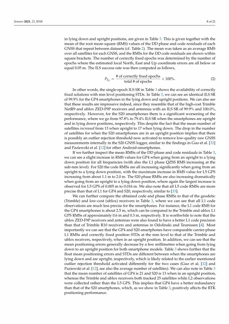
in lying down and upright positions, are given in Table 3. This is given together with themean of the root mean square (RMS) values of the DD phase and code residuals of eachGNSS that repeat between datasets (cf. Table 2). The mean was taken as an average RMSover all satellites for each GNSS, and the RMSs for the DD code residuals are shown withinsquare brackets. The number of correctly fixed epochs was determined by the number ofepochs where the estimated local North, East and Up coordinate errors are all below orequal 0.05 m. The ILS success rate was then computed as follows,
PSE =# of correctly fixed epochs
total # of epochs× 100%. (2)
In other words, the single-epoch ILS SR in Table 3 shows the availability of correctlyfixed solutions with mm level positioning STDs. In Table 3, we can see an identical ILS SRof 99.9% for the GP4 smartphones in the lying down and upright positions. We can also seethat these results are impressive indeed, since they resemble that of the high-cost TrimbleNetR9 and ublox ZED-F9P receivers and antennas with an ILS SR of 99.9% and 100.0%,respectively. However, for the S20 smartphones there is a significant worsening of theperformance, where we go from 97.8% to 79.4% ILS SR when the smartphones are uprightand in lying down positions, respectively. This despite the fact that the mean number ofsatellites increased from 13 when upright to 17 when lying down. The drop in the numberof satellites for when the S20 smartphones are in an upright position implies that thereis possibly an outlier rejection threshold now activated to remove low-quality raw GNSSmeasurements internally in the S20 GNSS logger, similar to the findings in Guo et al. [32]and Paziewski et al. [12] for other Android-smartphones.
If we further inspect the mean RMSs of the DD phase and code residuals in Table 3,we can see a slight increase in RMS values for GP4 when going from an upright to a lyingdown position for all frequencies (with also the L1 phase QZSS RMS increasing at thesub-mm level). For S20 the code RMSs are all increasing significantly when going from anupright to a lying down position, with the maximum increase in RMS value for L5 GPSincreasing from about 1.1 m to 2.0 m. The S20 phase RMSs are also increasing dramaticallywhen going from an upright to a lying down position, where again the largest increase isobserved for L5 GPS of 0.005 m to 0.016 m. We also note that all L5 code RMSs are moreprecise than that of L1 for GP4 and S20, respectively, similar to [33].
We can further compare the obtained code and phase RMSs to that of the geodetic(Trimble) and low-cost (ublox) receivers in Table 3, where we can see that all L1 codeobservations are much less precise for the smartphones. For instance, the L1 code RMS forthe GP4 smartphones is about 2.5 m, which can be compared to the Trimble and ublox L1GPS RMSs of approximately 0.6 m and 0.3 m, respectively. It is worthwhile to note that theublox ZED-F9P receivers and antennas were also found to have a better L1 code precisionthan that of Trimble R10 receivers and antennas in Odolinski and Teunissen [4]. Mostimportantly we can see that the GP4 and S20 smartphones have comparable carrier-phaseL1 RMSs and correctly fixed position STDs at the mm level to that of the Trimble andublox receivers, respectively, when in an upright position. In addition, we can see that themean positioning errors generally decrease by a few millimetres when going from lyingdown to an upright position for both smartphone models. Table 3 shows further that thefloat mean positioning errors and STDs are different between when the smartphones arelying down and are upright, respectively, which is likely related to the earlier mentionedoutlier rejection threshold activated differently for the two cases (Guo et al. [32] andPaziewski et al. [12], see also the average number of satellites). We can also note in Table 3that the mean number of satellites of GP4 is 21 and S20 is 13 when in an upright position,whereas the Trimble and ublox receivers both tracked 25 satellites while L2 observationswere collected rather than the L5 GPS. This implies that GP4 have a better redundancythan that of the S20 smartphones, which, as we show in Table 3, positively affects the RTKpositioning performance.

Sensors 2021, 21, 8318 9 of 21
To further investigate the dramatic drop in the ILS SR for S20 in Table 3 and toevaluate the corresponding RTK positioning performance, Figure 5 depicts the horizontalNorth/East positioning scatter and vertical Up error time-series for the zero-baseline withthe smartphones in the lying down (top panels) and upright position (bottom panels). Weemploy a zoom-in window to depict the correctly fixed solutions that have mm–cm levelpositioning precisions and are shown as green dots. The incorrectly fixed and ambiguity-float solutions, shown as red and grey dots, respectively, have meter-level positioningprecisions. The GP4 smartphones are shown in the left column and the S20 counterparts inthe right column. For all these results, we use 12 h of data with a one second measurementinterval, an elevation cut-off angle of 10◦, with GPS (L1 + L5), Galileo (E1 + E5a), QZSS(L1 + L5) and BDS (B1) observations, cf. Tables 1 and 2. The empirical and formal correctlyfixed Up-error confidence intervals (CIs) and horizontal error ellipses, depicted as blue andred lines, respectively, have all been determined from the empirical and formal positionVCV-matrices. We also depict at the bottom of the Up time-series in Figure 5 the number ofsatellites for all constellations as black lines, so as to demonstrate the model strengths ofthe two smartphone models GP4 and S20. On the right hand side y-axis we further depictthe correctly fixed formal STDs for the Up-component, so as to measure the effect fromthe receiver-satellite geometry strength on the estimated positioning errors. Note that thelying down position for both GP4 and S20 smartphones achieved an ILS SR of 99.9% and79.4%, respectively (Figure 5a, cf. Table 3), whereas the corresponding ILS SRs for whenthe smartphones are in an upright position read 99.9% and 97.8%, respectively (Figure 5b).Finally, we denote epochs 13,800 to 25,000 in Figure 5 with dashed black lines in the Uppositioning error panel, since here the S20 smartphones seem particularly affected by thefact that the smartphones are lying down with many incorrectly fixed solutions at the meterlevel. This particular period will be further investigated in Figure 7.
Figure 5 shows that the S20 smartphones (right column) have a better float precision,as shown as grey dots, compared to that of the GP4 counterparts (left column). The figurefurther shows that the repeatability of the correctly fixed solutions of the GP4 smartphones,in the left column, are more precise and that GP4 also have less incorrectly fixed solutions(red dots) when compared to that of S20. In particular, we note that less than 3500 outof 11,200 epochs, i.e., an ILS SR of about 31.0%, of the S20 positions were found correctlyfixed between epochs 13,800 to 25,000 in Figure 5a, as indicated by the black dashed lines.Figure 5b shows that the S20 results improve when in an upright position with fewerincorrectly fixed solutions. This since the corresponding ILS SRs between epochs 13,800 to25,000 are now 99.9% and 97.4% for GP4 and S20, respectively, which means that the ILSSR for GP4 remains unchanged but that the ILS SR for S20 has increased by 66.4%. Thisdespite the fact that the mean number of satellites for the same period decreased from 16to 11 satellites when the S20 smartphones were in a lying down position and an uprightposition, respectively. This implies that the S20 internal smartphone antennas are moresensitive to interferences such as multipath, even inside the RF shielding box (cf. Figure 1).Furthermore, note in Figure 5a,b that the formal STDs of the vertical component of the GP4is relatively consistent throughout the observation period between the two setups. For S20,however, Figure 5b shows that there is now an increase in the formal correctly fixed STDs(green lines at bottom) when compared to Figure 5a, in particular just before epoch 14,400.

Sensors 2021, 21, 8318 10 of 21Sensors 2021, 21, x FOR PEER REVIEW 10 of 21
(a)
(b)
Figure 5. Zero baseline with smartphones in a (a) lying down and (b) upright position (c.f. Figure 2): Horizontal (N, E) positioning scatter (first row) and corresponding vertical (U) positioning error time-series (second row) for 12 h of data (c.f. Table 2) with GP4 (left column) and S20 (right column). In this RTK model GPS + Galileo + QZSS +BDS L1 + L5, E1 + E5a, L1 + L5, B1 observations have been used. A zoom-in window is shown to depict the two orders of magnitude when going from incorrectly fixed (red dots) and ambiguity-float (gray dots), to correctly fixed solutions (green dots). The 95% empirical and formal CIs and ellipses for the correctly fixed solutions are shown as blue and red lines, respectively. The number of visible satellites and the correctly fixed formal up STDs (bottom row) are shown as black and green lines, respectively. The black dashed lines indicate the zoom-in period between epoch 13,800 and 25,000, see further Figure 7, with ILS SRs of 99.9% in both (a,b) in the left column for GP4 and 31.0% in (a) and 97.4% in (b) in the right column for S20, respectively. (a) Smartphones used in lying down positions: with GP4 (left): ILS SR 99.9% and S20 (right column): 79.4%. (b) Smartphones used in upright positions: with GP4 (left): ILS SR 99.9% and S20 (right column): 97.8%.
Figure 5. Zero baseline with smartphones in a (a) lying down and (b) upright position (cf. Figure 2): Horizontal (N, E)positioning scatter (first row) and corresponding vertical (U) positioning error time-series (second row) for 12 h of data (cf.Table 2) with GP4 (left column) and S20 (right column). In this RTK model GPS + Galileo + QZSS +BDS L1 + L5, E1 + E5a,L1 + L5, B1 observations have been used. A zoom-in window is shown to depict the two orders of magnitude when goingfrom incorrectly fixed (red dots) and ambiguity-float (gray dots), to correctly fixed solutions (green dots). The 95% empiricaland formal CIs and ellipses for the correctly fixed solutions are shown as blue and red lines, respectively. The numberof visible satellites and the correctly fixed formal up STDs (bottom row) are shown as black and green lines, respectively.The black dashed lines indicate the zoom-in period between epoch 13,800 and 25,000, see further Figure 7, with ILS SRs of99.9% in both (a,b) in the left column for GP4 and 31.0% in (a) and 97.4% in (b) in the right column for S20, respectively. (a)Smartphones used in lying down positions: with GP4 (left): ILS SR 99.9% and S20 (right column): 79.4%. (b) Smartphonesused in upright positions: with GP4 (left): ILS SR 99.9% and S20 (right column): 97.8%.

Sensors 2021, 21, 8318 11 of 21
This increase in the formal STDs can be explained by the drastic drop in the numberof satellites (cf. Table 3) and the poorer receiver-satellite geometry strength. We found thatthe vertical dilution of precisions (VDOPs) reached values close to 7 for this period. If weinspect the horizontal positioning scatter in Figure 5a further, we can see that GP4 and S20in a lying down position setup shows a poor fit both in size and orientation between theempirical (blue lines) and formal (red lines) 95% confidence ellipses, respectively, and apoor fit between the corresponding Up CIs as well. This poor fit implies the use of an overlyoptimistic stochastic model (cf. Table 2). In contrast, the GP4 and S20 smartphones in anupright position in Figure 5b show a good agreement between the formal and empiricalconfidence ellipses/intervals. This implies that the stochastic model settings for GP4 andS20 are now realistic.
To further investigate the distribution of the correctly fixed RTK positioning solutions,we depict in Figure 6 the corresponding North error histograms as green bars. On topof the histograms, we show the corresponding empirical and formal theoretical normaldistributions, in terms of their probability density functions (PDFs), depicted as blue andred lines, respectively. These PDFs are based on the empirical mean and empirical andformal STDs of the North positioning errors. The GP4 smartphones are shown in theleft column and S20 in the right column, with the top row showing the results when thesmartphones are lying down and the bottom row showing the corresponding upright-position results. Finally, we remark that the East and Up positioning errors behave in asimilar manner and that their corresponding histograms are thus not shown for brevity.
1
(a)
(b)
Figure 6. Zero baseline with smartphones in a (a) lying down and (b) upright position (cf.Figure 2): North error histograms (green bars) together with their empirical (blue lines) and formal(red lines) PDFs, with GP4 in the left column and S20 in the right column. (a) Smartphones usedin lying down positions: with GP4 (left) and S20 (right column) using an external antenna. (b)Smartphones used in upright positions: with GP4 (left) and S20 (right column) using an externalantenna.
Figure 6 shows that the empirical normal PDF (blue lines) fit the GP4 histogramsvery well even when the smartphones are in a lying down position at the top row and leftcolumn, but with a poor fit between the formal (red lines) and empirical PDF. However,when the GP4 smartphones are in an upright position, the North errors become more

Sensors 2021, 21, 8318 12 of 21
precise, as shown by the more peaked histograms, and the formal and empirical normalPDFs now fit the histograms very well (red lines are on top of the blue lines). On theother hand, for the S20 smartphones we can see an empirical normal PDF that does not fitthe histograms of the correctly fixed solutions very well (top row, right column), whichimplies that the data are not normally distributed when the S20 smartphones are lyingdown. This improves, however, at the bottom row when the S20 smartphones are in anupright position, where we get more precise North errors with a good fit between theformal and empirical normal PDFs.
To further investigate the problematic period for the S20 smartphones in the zero-baseline setup between epoch 13,800 and 25,000 (cf. dashed black lines in Figure 5), weshow in Figure 7a the corresponding L1 GPS and L1 QZSS DD phase residuals with thesmartphones in a lying down position in the left column and in an upright position in theright column. The selected zoom-in period at the bottom row depicts a transition periodbetween epochs 19,800 to 23,400 (1 h of data), where it goes from having a poorer RTK posi-tioning performance to a better one (cf. Figure 5). In Figure 7b, we show the correspondingGP4 results. We note that the L5 DD phase residuals show a similar pattern for all ourresults and are thus not shown for brevity, and that the depicted L1 DD phase residuals areexpected to repeat between days as the GPS and QZSS constellation repeatability periodwas accounted for (cf. Table 2).
Figure 7a shows, as expected (cf. RMSs in Table 3), that the S20 smartphones obtainedlarger magnitude of DD phase residuals when they were lying down (left column). Incontrast, the S20 smartphones achieved smaller magnitude of DD phase residuals whenthey are in an upright position (right column), despite having fewer number of satellites(cf. Figure 5). This implies that the smartphone setup has played a significant role in thequality of the phase observations and that the S20 internal antennas seem more sensitiveto interferences when the smartphones are lying down. We also remark that there aresome large excursions in the DD phase residuals in the top row and right column ofFigure 7, when there is also fewer number of satellites, which correspond to incorrectlyfixed solutions (cf. Figure 5).
More importantly, in Figure 7a and the left column, we can see that many of theDD phase residuals, when the smartphones are lying down, have a mean different fromzero meters and several linear trends present. However, when the smartphones are in anupright position in the right column, we have a zero mean of all residuals and the lineartrends become absent. Finally, we can see in Figure 7a that the mean RMS values of the L1DD phase residuals decrease from 0.020 m and 0.024 m, for GPS and QZSS respectively, to0.005 m and 0.006 m when the S20 smartphones are in an upright position.
Pesyna et al. [8] first reported similar linear trends and non-zero-mean DD phaseresiduals on a Samsung Galaxy S3 for L1 GPS (in their Figure 5) and Humphreys et al. [9]found similar results for a Samsung Galaxy S5 (in their Figure 10). Similar trends werelater found in the phase observations in Riley et al. [16] and Håkansson [10] for a Nexus9 Android-based tablet tracking L1 GPS (and GLONASS) data. Similar trends were alsofound in, e.g., Geng and Li [14], Wu et al. [17] and Gao et al. [15] for the GNSS observationstracked by Xiaomi Mi8 and in Darugna et al. [34] for a Huawei Mate20X. The commonfactor between all these studies is that the smartphones were located in a lying downposition. We remark, however, that to analyse whether having the smartphones used in theabovementioned studies in an upright position would change their results, would requirefurther investigation outside the scope of our study.

Sensors 2021, 21, 8318 13 of 21Sensors 2021, 21, x FOR PEER REVIEW 13 of 21
(a)
(b)
Figure 7. Zero baseline with S20 in (a) and GP4 in (b), both in a lying down (left column) and upright position (right column): the DD phase residual time series of the L1 signal (top row) is shown for epoch 13,800 and 25,000 (c.f. dashed black lines in Figure 5). The DD phase residuals of GPS are depicted as blue dots and QZSS as cyan dots. The black dashed lines indicate the zoom-in period of the L1 DD phase residuals (bottom row) between the epochs 19,800 and 23,400. (a) S20 smartphones used in the lying down position (left) and upright position (right column) using an external antenna. (b) GP4 smartphones used in the lying down position (left) and upright position (right column) using an external antenna.
5. Short-Baseline Instantaneous RTK Performance with Smartphones in Lying Down and Upright Positions
In the previous section, we showed in a zero-baseline setup that the internal smartphone antennas are sensitive to interference from nearby surfaces, even inside a RF shielding box, and that using the upright position rather than having the smartphones lying down will benefit the RTK positioning performance. This is true in particular for the
Figure 7. Zero baseline with S20 in (a) and GP4 in (b), both in a lying down (left column) and upright position (rightcolumn): the DD phase residual time series of the L1 signal (top row) is shown for epoch 13,800 and 25,000 (cf. dashedblack lines in Figure 5). The DD phase residuals of GPS are depicted as blue dots and QZSS as cyan dots. The black dashedlines indicate the zoom-in period of the L1 DD phase residuals (bottom row) between the epochs 19,800 and 23,400. (a) S20smartphones used in the lying down position (left) and upright position (right column) using an external antenna. (b) GP4smartphones used in the lying down position (left) and upright position (right column) using an external antenna.
In comparison to the S20 results in Figure 7a, one can see in Figure 7b that the GP4performance remains visually more or less unchanged between having the smartphones ina lying down and upright position (left vs. right column). Moreover, there are no apparentlinear trends in the DD phase residuals at the bottom row present. However, it is evidentthat there is a small 2 mm increase in the average RMS values for the GPS L1 DD phaseresiduals when the smartphones are lying down (whereas the corresponding L1 QZSSRMS remains unchanged).

Sensors 2021, 21, 8318 14 of 21
5. Short-Baseline Instantaneous RTK Performance with Smartphones in Lying Downand Upright Positions
In the previous section, we showed in a zero-baseline setup that the internal smart-phone antennas are sensitive to interference from nearby surfaces, even inside a RF shield-ing box, and that using the upright position rather than having the smartphones lyingdown will benefit the RTK positioning performance. This is true in particular for the S20smartphones. We namely observed S20 DD phase residuals with linear trends and non-zeromean values when the smartphones were lying down, which became absent when thesmartphones were upright. To further validate whether these effects are also present forshort-baselines, we analyse in the following the DD phase residuals and RTK positioningperformance with the use of both external and internal antennas (cf. Figures 3 and 4).
5.1. Double-Differenced Carrier-Phase Residuals for Short-Baselines Using External Antennas
Figure 8 shows the DD phase residuals for L1 GPS, E1 Galileo and L1 QZSS for S20 inthe top panels and GP4 in the bottom panels for the first hour of data (out of 8 h, cf. Table 2),while using external antennas in the short-baseline setup configuration (Figure 3). In thisanalysis, we exclude the BDS DD phase residuals since there is thirty days between thedatasets in the left and right column, respectively. This means that only the GPS, QZSS andGalileo constellations are expected to repeat (cf. DOY in Table 2). We do not depict the L5DD GPS, Galileo and QZSS phase residuals in Figure 8 since they exhibit a similar patternto L1 and are thus not shown for brevity. Finally, we remark that there was only one QZSSsatellite tracked for GP4, when in the lying down position, possibly due to an internalGNSS data logger rejection criterion used, so the corresponding DD phase residuals arenot depicted.
Sensors 2021, 21, x FOR PEER REVIEW 15 of 21
(a)
(b)
Figure 8. Short baseline with S20 in (a) and GP4 in (b) using external antennas (c.f. Table 2) in lying down (left column) and upright position (right column): The DD phase residuals for 1 h of data of L1 GPS are depicted as blue, E1 Galileo as green and L1 QZSS as cyan dots. Note that there was only one QZSS satellite in the GP4 dataset in (b) and the left column, and thus the corresponding DD phase residuals were not depicted. (a) S20 smartphones used in the lying down position (left) and upright position (right column) using external antennas. (b) GP4 smartphones used in the lying down position (left) and upright position (right column) using external antennas.
The situation changes entirely, however, when internal antennas are used. We then go from a GP4 ILS SR of 98.7% to 63.1%, which implies that the GP4 internal antennas also become more sensitive to interferences in the absence of the RF shielding box and the use of external antennas, when more multipath effects are present. Moreover, Table 4 shows that the correctly fixed positioning mean errors are at the mm level and the STDs are al-ways at most one centimetre (in the Up component) when the smartphone are in an up-right position rather than lying down.
To further highlight the good instantaneous short-baseline RTK performance of the upright S20 and GP4 smartphones in Table 4 when using external antennas (c.f. Figure 3), Figure 9 depicts the corresponding horizontal North/East positioning scatter and vertical Up error time-series (similar to zero-baseline results in Figure 5) for 8 h of data. The GP4 smartphones are again shown in the left column and the S20 counterparts in the right column. We only depict the results when the smartphones are in an upright position for brevity, because the poor fit of the empirical and formal confidence ellipses/intervals and PDFs are similar between these short-baseline results to that of the zero-baseline results in Figures 5 and 6, respectively.
In Figure 9, we can see a good agreement between the formal and empirical confi-dence ellipses and intervals denoted as red and blue lines, respectively, which implies that the stochastic model settings in Table 2 are realistic. We can also see that the GP4 smartphones in the left column provides a single-epoch ILS SR of 99.9% even for this short-baseline, which implies that when external antennas are used it can give competitive performance to that of high-cost receivers and antennas with mm–cm level positioning performance. This is similar to the results shown in Odolinski and Teunissen [6] for an-other Android-based smartphone when connected to low-cost patch antennas. Figure 9 also shows that S20 can achieve an ILS SR 99.2% when external antennas are used and the smartphones are in an upright position.
Figure 8. Short baseline with S20 in (a) and GP4 in (b) using external antennas (cf. Table 2) in lying down (left column)and upright position (right column): The DD phase residuals for 1 h of data of L1 GPS are depicted as blue, E1 Galileo asgreen and L1 QZSS as cyan dots. Note that there was only one QZSS satellite in the GP4 dataset in (b) and the left column,and thus the corresponding DD phase residuals were not depicted. (a) S20 smartphones used in the lying down position(left) and upright position (right column) using external antennas. (b) GP4 smartphones used in the lying down position(left) and upright position (right column) using external antennas.
In Figure 8a, we can see a poorer RMS in the DD carrier-phase residuals for all threeGNSSs when the S20 smartphones are in a lying down position (left column) and when

Sensors 2021, 21, 8318 15 of 21
compared to an upright position (right column). We can also see linear trends and somemean of the DD carrier phase residuals that are different to zero meters for S20 in the leftcolumn of Figure 8a, similar to the corresponding results in Figure 7a for the zero-baselinesetup. Note that the linear trends are absent when the S20 smartphones are upright in theright column of Figure 8a and also have zero mean errors, similar to the results in Figure 7a.For instance, the RMS of the L1 GPS DD phase residuals goes from 0.021 m to 0.006 mwhen the S20 smartphones are in an upright position. At the same time, we can see that theRMS values for GP4 remain consistent between setups, with the L1 GPS RMS being 0.005m for both setups, however, with a slight increase from 0.004 m to 0.005 m for E1 Galileo,when having the smartphones upright. This consistency in RMSs implies again that theGP4 smartphone antennas are not as sensitive to interferences when lying down as the S20smartphones.
5.2. Instantaneous RTK Positioning Performance for Short-Baselines with External and InternalAntennas
In Table 4, we summarize the ILS SRs and the empirical positioning mean and STDs(correctly fixed and float positioning errors) for the GP4 and S20 smartphones in the short-baseline experiments while using external (cf. Figure 3) and internal antennas (cf. Figure 4).The ILS SRs are shown for when the smartphones are both in an upright and lying downposition, together with the mean number of tracked satellites over the 8 h and 3.5 h dataperiods for the external and internal antennas, respectively (cf. Table 2).
Table 4. Empirical ILS SRs, mean and STDs (East, North and Up) of correctly fixed and floatpositioning errors for instantaneous short-baseline dual-frequency RTK positioning, with 8 h and 3.5h of data used for the external and internal antennas, respectively (cf. Table 2). Average number ofsatellites is denoted by Avg. # of Sat.
Baselines AntennaType Setup ILS SR
(%)Avg. # of
Sat.Mean ± STDs (m)
Correctly Fixed Float
GPD1–GPD2
External
upright 99.9 24E −0.001 ± 0.002 −0.105 ± 1.200N −0.000 ± 0.002 0.375 ± 1.294U −0.000 ± 0.005 −0.121 ± 2.567
lyingdown
99.9 20E −0.001 ± 0.002 −0.016 ± 1.243N −0.001 ± 0.002 0.238 ± 1.312U −0.002 ± 0.005 0.048 ± 2.644
Internal
upright 98.7 21E 0.001 ± 0.005 −0.222 ± 2.977N −0.001 ± 0.006 0.209 ± 3.483U 0.001 ± 0.010 0.370 ± 5.518
lyingdown
63.1 16E −0.002 ± 0.008 −0.098 ± 2.909N −0.000 ± 0.005 0.086 ± 2.516U −0.002 ± 0.013 −0.907 ± 4.282
SGD1–SGD2
External
upright 99.2 15E 0.000 ± 0.003 −0.031 ± 0.729N −0.000 ± 0.006 0.091 ± 1.013U −0.005 ± 0.009 −0.050 ± 1.730
lyingdown
94.9 20E 0.006 ± 0.006 −0.037 ± 0.707N 0.002 ± 0.007 0.043 ± 0.939U 0.001 ± 0.010 −0.124 ± 1.874
Internal
upright 64.4 16E 0.001 ± 0.005 −0.222 ± 2.977N −0.001 ± 0.006 0.210 ± 3.483U −0.001 ± 0.010 0.274 ± 4.677
lyingdown
27.5 17E 0.001 ± 0.004 −0.157 ± 1.531N 0.002 ± 0.005 0.103 ± 2.499U −0.006 ± 0.011 −0.214 ± 3.384
Table 4 shows that the ILS SR decreases from 99.2% to 94.9% for S20 when the smart-phones go from being in an upright position to lying down while using external antennas.We note that the reduction in ILS SR is a bit smaller for S20 for the short-baseline than inthe zero-baseline case in Table 3. This is possibly caused by the shorter amount of dataanalysed (8 h vs. 12 h, cf. Table 2), as well as the fact that in the zero-baseline case thereare more interferences possible since all four smartphones are then put into the same RFshielding box (cf. Figure 2). We can also see that when internal antennas are used, we get a

Sensors 2021, 21, 8318 16 of 21
poorer ILS SR for S20 of 64.4% when being in an upright position, and 27.5% when lyingdown. For GP4 we can see in Table 4 (similar to the zero-baseline in Table 3) that the ILSSR remains at 99.9% when external antennas are used and are in upright and lying downposition, respectively.
The situation changes entirely, however, when internal antennas are used. We thengo from a GP4 ILS SR of 98.7% to 63.1%, which implies that the GP4 internal antennasalso become more sensitive to interferences in the absence of the RF shielding box andthe use of external antennas, when more multipath effects are present. Moreover, Table 4shows that the correctly fixed positioning mean errors are at the mm level and the STDsare always at most one centimetre (in the Up component) when the smartphone are in anupright position rather than lying down.
To further highlight the good instantaneous short-baseline RTK performance of theupright S20 and GP4 smartphones in Table 4 when using external antennas (cf. Figure 3),Figure 9 depicts the corresponding horizontal North/East positioning scatter and verticalUp error time-series (similar to zero-baseline results in Figure 5) for 8 h of data. The GP4smartphones are again shown in the left column and the S20 counterparts in the rightcolumn. We only depict the results when the smartphones are in an upright position forbrevity, because the poor fit of the empirical and formal confidence ellipses/intervals andPDFs are similar between these short-baseline results to that of the zero-baseline results inFigures 5 and 6, respectively.
Sensors 2021, 21, x FOR PEER REVIEW 17 of 21
Figure 9. Short-baseline with external antennas and smartphones in an upright position (c.f. Figure 3): Horizontal (N, E) positioning scatter (first row) and corresponding vertical (U) positioning error time-series (second row) for 8 h of data (c.f. Table 2) with GP4 (left column): ILS SR 99.9% and S20 (right column): 99.2%. In this RTK model GPS + Galileo + QZSS + BDS L1 + L5, E1 + E5a, L1 + L5, B1 observations have been used. A zoom-in window is shown to depict the two order of magnitude improvement when going from incorrectly fixed (red dots) and ambiguity-float (grey dots), to correctly fixed solutions (green dots). The 95% empirical and formal confidence CIs and ellipses for the correctly fixed solutions are shown as blue and red lines, respectively. The number of visible satellites and the correctly fixed formal up STDs (bottom row) are shown as black and green lines, respectively.
6. Conclusions In this contribution, we studied the single-baseline real-time kinematic (RTK) perfor-
mance while having the smartphones upright and in a lying down position, in a zero-baseline and short-baseline setup, respectively. We made use of radio frequency (RF) shielding boxes and re-radiating antennas to track GNSS signals from external low-cost antennas, consisting of L1, L5 GPS, E1, E5a Galileo, L1, L5 QZSS and B1 BDS code and carrier-phase observations, while using two Google Pixel 4 and two Samsung Galaxy S20 smartphones. We assessed their instantaneous (single-epoch) RTK performance and the double-differenced (DD) carrier-phase and code residuals, while also using the internal smartphone antennas. We found that when having the smartphones lying down, the RTK positioning performance, for S20 in particular, will deteriorate. This was also true for the GP4 smartphones when using internal antennas in a short-baseline experiment.
Our zero-baseline instantaneous RTK evaluation consisted of a formal and empirical analysis of the smartphones, in an upright and lying down position, while using 12 h of data with a one second measurement interval. When the smartphones were lying down, we found that the S20 smartphones seem particularly affected by the setup configuration with many incorrectly fixed solutions at the meter-level precision. The integer least-squares (ILS) success-rate (SR), i.e., the probability of correct integer estimation, while us-ing full ambiguity resolution, improved significantly when having the S20 smartphones in an upright position (c.f., Figure 5). The GP4 smartphones showed more or less no ILS SR improvement between the two zero-baseline setup configurations.
However, the formal and empirical positioning confidence ellipses/intervals and probability density functions (PDFs), respectively, showed a contrast difference from each other when all the smartphone models were lying down. This implies that the GP4 anten-nas were also affected by interferences from the smartphone configuration.
Figure 9. Short-baseline with external antennas and smartphones in an upright position (cf. Figure 3): Horizontal (N,E) positioning scatter (first row) and corresponding vertical (U) positioning error time-series (second row) for 8 h of data (cf.Table 2) with GP4 (left column): ILS SR 99.9% and S20 (right column): 99.2%. In this RTK model GPS + Galileo + QZSS +BDS L1 + L5, E1 + E5a, L1 + L5, B1 observations have been used. A zoom-in window is shown to depict the two order ofmagnitude improvement when going from incorrectly fixed (red dots) and ambiguity-float (grey dots), to correctly fixedsolutions (green dots). The 95% empirical and formal confidence CIs and ellipses for the correctly fixed solutions are shownas blue and red lines, respectively. The number of visible satellites and the correctly fixed formal up STDs (bottom row) areshown as black and green lines, respectively.

Sensors 2021, 21, 8318 17 of 21
In Figure 9, we can see a good agreement between the formal and empirical confidenceellipses and intervals denoted as red and blue lines, respectively, which implies that thestochastic model settings in Table 2 are realistic. We can also see that the GP4 smartphonesin the left column provides a single-epoch ILS SR of 99.9% even for this short-baseline,which implies that when external antennas are used it can give competitive performance tothat of high-cost receivers and antennas with mm–cm level positioning performance. Thisis similar to the results shown in Odolinski and Teunissen [6] for another Android-basedsmartphone when connected to low-cost patch antennas. Figure 9 also shows that S20 canachieve an ILS SR 99.2% when external antennas are used and the smartphones are in anupright position.
Finally, Figure 9 shows that when the correctly fixed Up formal STDs get larger, thecorresponding Up errors also get larger for both smartphone models. This happens forinstance at the end of the time-series for GP4 in the left column when there is almost aminimum number of tracked satellites over the observation time span, and just beforeepochs 7200 and 14,400 for S20 in the right column.
To further investigate the instantaneous RTK positioning performance when usinginternal instead of the external antennas, we show in the top panel of Figure 10 the GP4and S20 corresponding results when the smartphones are lying down (cf. Figure 4). In thebottom panel (Figure 10b), we also show the corresponding results when the smartphonesare in an upright position.
In Figure 10a, we again see a poor fit of the formal and empirical confidence ellipsesand intervals when the smartphones are lying down, whereas when the smartphones arein an upright position, in Figure 10b, they fit each other very well. The S20 smartphonesachieve an instantaneous ILS SR of 64.4% when the smartphones are in an upright position(Figure 10b), which decreases to 27.5% when they are lying down (Figure 10a). Moreover,now we can see a decrease in the number of tracked satellites for GP4 when the smartphonesare lying down (cf. Table 4). This is possibly due to the internal GP4 GNSS data loggerthat removes low-quality raw GNSS measurements more consistently with the moremultipath-sensitive internal antennas used. Nevertheless, the consequence of having theGP4 smartphones in an upright position increases the ILS SR from 63.1% in Figure 10a andthe left column, to 98.7% ILS SR when the GP4 smartphones are in an upright positionin Figure 10b. These results are important, as they show that the GP4 smartphones canprovide for close to 100% (98.7%) availability of mm–cm level short-baseline positioningprecisions, even when internal antennas are used.

Sensors 2021, 21, 8318 18 of 21Sensors 2021, 21, x FOR PEER REVIEW 18 of 21
(a)
(b)
Figure 10. Short-baseline with internal antennas and smartphones in a (a) lying down and (b) upright position (c.f. Figure 4): Horizontal (N, E) positioning scatter (first row) and corresponding vertical (U) positioning error time-series (second row) for 3.5 h of data (c.f. Table 2) with GP4 (left column) and S20 (right column). In all RTK models GPS + Galileo + QZSS + BDS L1 + L5, E1 + E5a, L1 + L5, B1 observations have been used for GP4, except for S20 in (b) that did not have more than one QZSS satellite to formulate the DD observations. A zoom-in window is shown to depict the two order of magnitude improvement when going from incorrectly fixed (red dots) and ambiguity-float (grey dots), to correctly fixed solutions (green dots). The 95% empirical and formal CIs and ellipses for the correctly fixed solutions are shown as blue and red lines, respectively. The number of visible satellites and the correctly fixed formal Up STDs (bottom row) are shown as black and green lines, respectively. (a) Smartphones used in lying down positions: with GP4 (left): ILS SR 63.1% and S20 (right column): 27.5% (internal antennas). (b) Smartphones used in upright positions: with GP4 (left): ILS SR 98.7% and S20 (right column): 64.4% (internal antennas).
The vital influence of the setup configuration was also reflected in the observation data quality, in which linear trends were found to be present in the S20 DD phase residu-als while the phones were lying down. The mean root mean square (RMS) values of these
Figure 10. Short-baseline with internal antennas and smartphones in a (a) lying down and (b) upright position (cf.Figure 4): Horizontal (N, E) positioning scatter (first row) and corresponding vertical (U) positioning error time-series(second row) for 3.5 h of data (cf. Table 2) with GP4 (left column) and S20 (right column). In all RTK models GPS + Galileo +QZSS + BDS L1 + L5, E1 + E5a, L1 + L5, B1 observations have been used for GP4, except for S20 in (b) that did not havemore than one QZSS satellite to formulate the DD observations. A zoom-in window is shown to depict the two order ofmagnitude improvement when going from incorrectly fixed (red dots) and ambiguity-float (grey dots), to correctly fixedsolutions (green dots). The 95% empirical and formal CIs and ellipses for the correctly fixed solutions are shown as blue andred lines, respectively. The number of visible satellites and the correctly fixed formal Up STDs (bottom row) are shown asblack and green lines, respectively. (a) Smartphones used in lying down positions: with GP4 (left): ILS SR 63.1% and S20(right column): 27.5% (internal antennas). (b) Smartphones used in upright positions: with GP4 (left): ILS SR 98.7% and S20(right column): 64.4% (internal antennas).

Sensors 2021, 21, 8318 19 of 21
6. Conclusions
In this contribution, we studied the single-baseline real-time kinematic (RTK) per-formance while having the smartphones upright and in a lying down position, in a zero-baseline and short-baseline setup, respectively. We made use of radio frequency (RF)shielding boxes and re-radiating antennas to track GNSS signals from external low-costantennas, consisting of L1, L5 GPS, E1, E5a Galileo, L1, L5 QZSS and B1 BDS code andcarrier-phase observations, while using two Google Pixel 4 and two Samsung Galaxy S20smartphones. We assessed their instantaneous (single-epoch) RTK performance and thedouble-differenced (DD) carrier-phase and code residuals, while also using the internalsmartphone antennas. We found that when having the smartphones lying down, the RTKpositioning performance, for S20 in particular, will deteriorate. This was also true for theGP4 smartphones when using internal antennas in a short-baseline experiment.
Our zero-baseline instantaneous RTK evaluation consisted of a formal and empiricalanalysis of the smartphones, in an upright and lying down position, while using 12 h ofdata with a one second measurement interval. When the smartphones were lying down,we found that the S20 smartphones seem particularly affected by the setup configurationwith many incorrectly fixed solutions at the meter-level precision. The integer least-squares(ILS) success-rate (SR), i.e., the probability of correct integer estimation, while using fullambiguity resolution, improved significantly when having the S20 smartphones in anupright position (cf. Figure 5). The GP4 smartphones showed more or less no ILS SRimprovement between the two zero-baseline setup configurations.
However, the formal and empirical positioning confidence ellipses/intervals andprobability density functions (PDFs), respectively, showed a contrast difference from eachother when all the smartphone models were lying down. This implies that the GP4 antennaswere also affected by interferences from the smartphone configuration.
The vital influence of the setup configuration was also reflected in the observationdata quality, in which linear trends were found to be present in the S20 DD phase residualswhile the phones were lying down. The mean root mean square (RMS) values of these DDphase residuals were higher when the smartphones were in a lying down position ratherthan upright. This was also particularly pronounced in the S20 smartphones for the DDcode residuals. It is worth noting that in these zero-baseline experiments, the multipathfrom the external antennas is expected to be significantly reduced and any remaining smallmultipath effects would mainly be due to the non-simultaneity of sampling between thereceivers. Nevertheless, we found that the RMSs of the GPS and QZSS DD phase residualsresembles those of Trimble NetR9 and ublox ZED-F9P receivers in the zero-baseline setup,whereas the corresponding RMSs of the L1 DD code residuals were several times largerfor both smartphone models (cf. Table 3). Finally, we found that both smartphone modelsobtained correctly fixed positioning error STDs that also resemble that of the Trimble NetR9and ublox ZED-F9P receivers when in an upright position.
In the short-baseline instantaneous RTK results, when multipath from the exter-nal/internal antennas is expected to be present, we found consistent worsening in theresults when the smartphones were lying down (similar to that of the zero-baseline analy-sis). Most importantly we found encouraging instantaneous, short-baseline, cm level RTKpositioning results for the GP4 and S20 smartphones when observing signals from externalantennas, with ILS SR close to 100% (99.9%) for GP4 and 99.2% for S20, respectively, whileusing 8 h of data. When use was made of internal antennas and having the smartphonesin an upright position, we achieved a corresponding ILS SR of 98.7% and 64.4% for GP4and S20, respectively, based on 3.5 h of data. Overall, we concluded that both smartphonemodels were influenced by having them in a lying down position, and we suggest thatfuture studies will need to also consider the setup configuration of the smartphones.

Sensors 2021, 21, 8318 20 of 21
Author Contributions: C.Z.Y. performed the conceptualisation, methodology, software, formal anal-ysis, visualisation and writing the manuscript. R.O. performed the conceptualisation, methodology,software, formal analysis, investigation and writing the manuscript. S.Z. performed the conceptual-ization, review and editing. M.M. and E.R. performed the conceptualization. J.E. and M.D. performeddata collections. All authors have read and agreed to the published version of the manuscript.
Funding: This research was funded by Geoscience Australia for the project 1002B: “Precise GNSSpositioning with smartphones”.
Data Availability Statement: The broadcast ephemerides were used for satellite orbits and clocks.The Google Pixel 4 and Samsung Galaxy S20 smartphones observation data are stored at the Uni-versity of Otago–the School of Surveying data facilities and can be made available upon request bycontacting the corresponding author, C.Y. by email.
Acknowledgments: The second author is the recipient of a Geoscience Australia research granton the project 1002B: “Precise GNSS positioning with smartphones”. We logged the GNSS datawith Geo++ RINEX logger from the Android-based smartphones. All this support is gratefullyacknowledged.
Conflicts of Interest: The authors declare that there is no conflict of interest.
References1. Mongredien, C.; Doyen, J.P.; Strom, M.; Ammann, D. Centimeter level positioning for UAVs and other mass-market applications.
In Proceedings of the 29th International Technical Meeting of the Satellite Division of The Institute of Navigation (ION GNSS+2016), Portland, OR, USA, 12–16 September 2016.
2. Nie, Z.; Liu, F.; Gao, Y. Real-time precise point positioning with a low-cost dual-frequency GNSS device. GPS Solut. 2020, 24, 9.[CrossRef]
3. Odolinski, R.; Teunissen, P.J.G. Single-frequency, dual-GNSS versus dual-frequency, single-GNSS: A low-cost and high-gradereceivers GPS-BDS RTK analysis. J. Geod. 2016, 90, 1255–1278. [CrossRef]
4. Odolinski, R.; Teunissen, P.J.G. Best integer equivariant estimation: Performance analysis using real data collected by low-cost,single- and dual-frequency, multi-GNSS receivers for short- to long-baseline RTK positioning. J. Geod. 2020, 94, 91. [CrossRef]
5. Van Diggelen, F. The Smartphone Revolution: Seven Technologies that Put GPS in Mobile Phones around the World—TheHow and Why of Location’s Entry into Modern Consumer Mobile Communications. GPS World 2009. Available online:https://www.gpsworld.com/wirelesssmartphone-revolution-9183/ (accessed on 9 December 2021).
6. Odolinski, R.; Teunissen, P.J.G. An assessment of smartphone and low-cost multi-GNSS single-frequency RTK positioning for low,medium and high ionospheric disturbance periods. J. Geod. 2019, 93, 701–722. [CrossRef]
7. Paziewski, J. Recent advances and perspectives for positioning and applications with smartphone GNSS observations. Meas. Sci.Technol. 2020, 31, 091001. [CrossRef]
8. Pesyna, K.M.; Heath, R.W.; Humphreys, T.E. Centimeter Positioning with a Smartphone-Quality GNSS Antenna. In Proceedingsof the 27th International Technical Meeting of the Satellite Division of The Institute of Navigation (ION GNSS+ 2014), Tampa, FL,USA, 8–12 September 2014; pp. 1568–1577.
9. Humphreys, T.E.; Murrian, M.; van Diggelen, F.; Podshivalov, S.; Pesyna, K.M. On the feasibility of cm-accurate positioning via asmartphone’s antenna and GNSS chip. In Proceedings of the 2016 IEEE/ION Position, Location and Navigation Symposium,Savannah, GA, USA, 11–16 April 2016; pp. 232–242.
10. Håkansson, M. Characterization of GNSS observations from a Nexus 9 Android tablet. GPS Solut. 2019, 23, 21. [CrossRef]11. Warnant, R.; van de Vyvere, L.; Warnant, Q. Positioning with Single and Dual Frequency Smartphones Running Android 7 or
Later. In Proceedings of the 31st International Technical Meeting of The Satellite Division of the Institute of Navigation (IONGNSS+ 2018), Miami, FL, USA, 24–28 September 2018; pp. 284–303.
12. Paziewski, J.; Fortunato, M.; Mazzoni, A.; Odolinski, R. An analysis of multi-GNSS observations tracked by recent Androidsmartphones and smartphone-only relative positioning results. Measurement 2021, 175, 109162. [CrossRef]
13. Hesselbarth, A.; Wanninger, L. Towards centimeter accurate positioning with smartphones. In Proceedings of the 2020 EuropeanNavigation Conference (ENC), Dresden, Germany, 23–24 November 2020; pp. 1–8.
14. Geng, J.; Li, G. On the feasibility of resolving Android GNSS carrier-phase ambiguities. J. Geod. 2019, 93, 2621–2635. [CrossRef]15. Gao, R.; Xu, L.; Zhang, B.; Liu, T. Raw GNSS observations from Android smartphones: Characteristics and short-baseline RTK
positioning performance. Meas. Sci. Technol. 2021, 32, 084012. [CrossRef]16. Riley, S.; Lentz, W.; Clare, A. On the Path to Precision—Observations with Android GNSS Observables. In Proceedings of the
30th International Technical Meeting of The Satellite Division of the Institute of Navigation (ION GNSS+ 2017), Portland, OR,USA, 25–29 September 2017; pp. 116–129.
17. Wu, Q.; Sun, M.; Zhou, C.; Zhang, P. Precise Point Positioning Using Dual-Frequency GNSS Observations on Smartphone. Sensors2019, 19, 2189. [CrossRef]

Sensors 2021, 21, 8318 21 of 21
18. Aggrey, J.; Bisnath, S.; Naciri, N.; Shinghal, G.; Yang, S. Multi-GNSS precise point positioning with next-generation smartphonemeasurements. J. Spat. Sci. 2019, 65, 79–98. [CrossRef]
19. Odolinski, R.; Teunissen, P.J.G.; Odijk, D. Quality analysis of a combined COMPASS/BeiDou-2 and GPS RTK positioning model.In Proceedings of the International Global Navigation Satellite Systems Society IGNSS Symposium 2013, Golden Coast, Australia,16–18 July 2013.
20. Yang, Y.; Gao, W.; Guo, S.; Mao, Y.; Yang, Y. Introduction to BeiDou-3 navigation satellite system. Navigation 2019, 66, 7–18.[CrossRef]
21. Teunissen, P.J.G. The least-squares ambiguity decorrelation adjustment: A method for fast GPS integer ambiguity estimation. J.Geod. 1995, 70, 65–82. [CrossRef]
22. Odijk, D.; Teunissen, P.J.G. Characterization of between-receiver GPS-Galileo inter-system biases and their effect on mixedambiguity resolution. GPS Solut. 2012, 17, 521–533. [CrossRef]
23. Odolinski, R.; Teunissen, P.J.G.; Odijk, D. Combined BDS, Galileo, QZSS and GPS single-frequency RTK. GPS Solut. 2015, 19,151–163. [CrossRef]
24. Takasu, T.; Yasuda, A. Development of the low-cost RTK-GPS receiver with an open source program package RTKLIB. InProceedings of the International Symposium on GPS/GNSS, Jeju, Korea, 4 November 2009; pp. 1–6.
25. Fletcher, D. Trimble: Personal Communication. 19 October 2021. Available online: https://upa.trimble.com/en/products/end-customer-communications (accessed on 9 December 2021).
26. Ito, A. (Geo++). Personal Communication. 2020. Available online: https://apastyle.apa.org/style-grammar-guidelines/citations/personal-communications (accessed on 9 December 2021).
27. Zhang, X.; Tao, X.; Zhu, F.; Shi, X.; Wang, F. Quality assessment of GNSS observations from an Android N smartphone andpositioning performance analysis using time-differenced filtering approach. GPS Solut. 2018, 22, 70. [CrossRef]
28. Odolinski, R.; Teunissen, P.J.G.; Odijk, D. First combined COMPASS/BeiDou-2 and GPS positioning results in Australia. Part II:Single- and multiple-frequency single-baseline RTK positioning. J. Spat. Sci. 2014, 59, 25–46. [CrossRef]
29. Axelrad, P.; Larson, K.; Jones, B. Use of the correct satellite repeat period to characterize and reduce site-specific multipath errors.In Proceedings of the ION GNSS 18th International Technical Meeting of the Satellite Division, Long Beach, CA, USA, 13–16September 2005.
30. Amiri-Simkooei, A.R.; Tiberius, C.C.J.M. Assessing receiver noise using GPS short baseline time series. GPS Solut. 2007, 11, 21–35.[CrossRef]
31. Khodabandeh, A.; Zaminpardaz, S.; Nadarajah, N. A study on multi-GNSS phase-only positioning. Meas. Sci. Technol. 2021, 32,095005. [CrossRef]
32. Guo, L.; Wang, F.; Sang, J.; Lin, X.; Gong, X.; Zhang, W. Characteristics Analysis of Raw Multi-GNSS Measurement from XiaomiMi 8 and Positioning Performance Improvement with L5/E5 Frequency in an Urban Environment. Remote Sens. 2020, 12, 744.[CrossRef]
33. De Bakker, P.F.; Tiberius, C.C.; van der Marel, H.; van Bree, R.J. Short and zero baseline analysis of GPS L1 C/A, L5Q, GIOVE E1B,and E5aQ signals. GPS Solut. 2012, 16, 53–64. [CrossRef]
34. Darugna, F.; Wübbena, J.; Ito, A.; Wübbena, T.; Wübbena, G.; Schmitz, M. RTK and PPP-RTK Using Smartphones: FromShort-Baseline to Long-Baseline Applications. In Proceedings of the 32nd International Technical Meeting of the Satellite Divisionof The Institute of Navigation (ION GNSS+ 2019), Miami, FL, USA, 16–20 September 2019; pp. 3932–3945.
Copyright © 2022 FDOKUMEN