Including RNAV and GNSS
208
A complete reference to PBN and GNSS for General Aviation non-commercial fixed wing pilots using GNSS for IFR Including RNAV and GNSS 2nd Edition (rev 13) March 2018
-
Upload
khangminh22 -
Category
Documents
-
view
5 -
download
0
Transcript of Including RNAV and GNSS

A complete reference to PBN and GNSS for General Aviation
non-commercial fixed wing pilots using GNSS for IFR
Including RNAV and GNSS
2nd Edition (rev 13) March 2018


PPL/IR Europe
PBN Manual
(including RNAV and GNSS)
2nd Edition (rev 13)
http://www.pplir.org © PPL/IR Europe 2018
March 2018
3
PBN Manual by PPL/IR Europe is licensed under a
Creative Commons Attribution 4.0 International License

Introduction
• This manual covers the PBN theoretical knowledge and ground training for a Europe based
Instrument Rated pilot operating single-pilot general aviation aircraft under IFR in Europe
• The manual also has a recommended syllabus to meet flight training requirements for RNAV enroute
and approach procedures
• It is intended to be used in a classroom training seminar or for self-study
• Some of the detailed content and reference material is beyond the scope of what is required for pilot
training, but may be of interest.
• The learning objectives to meet EASA PBN training requirements shown in Appendix 2 refer to the
applicable text which meets those objectives. Some of these learning objectives are outside the scope
of what a GA fixed wing pilot needs to know, but are included, as they could appear in an exam. In
those cases we have kept detail to an absolute minimum.
• Although this manual is currently available in electronic PDF form, PPL/IR Europe retains copyright to
its original content
• The contents of the manual may not be copied for use in other documents and manuals without
PPL/IR Europe permission
• PPL/IR Europe welcomes feedback and questions via its website forum (www.pplir.org). Any person
interested in operating light aircraft under IFR in Europe is welcome to join.
4
Acknowledgements and notes
• Garmin software and user manual content is reproduced with the kind permission of Garmin
• Jeppesen charts are reproduced with the kind permission of Jeppesen
• UK CAA charts and documents are reproduced with the kind permission of the UK CAA
• Edition 1 was written by Vasa Babic. This edition has been heavily revised by John Shannon,
Timothy Nathan, David Chambers and Ed Bellamy to take account of the many changes that have
occurred since.
• We would like to thank Julian Scarfe, Vasa Babic and Damian Walker for reviewing this document
in detail and for their very knowledgeable feedback. Errors and omissions are entirely the editors’
responsibility
• PPL/IR Europe receives no royalties for this book; the cover price reflects only the costs of printing
and distribution. If you find this material valuable, you are asked to:
– please consider joining and/or donating to PPL/IR Europe (www.pplir.org). This small voluntary
organisation serves GA IFR pilots in Europe by publishing and exchanging information to help
promote the safety and utility of IFR flight in single-pilot aircraft, and works with regulators in
Europe to ensure they have input on the specialised needs of private IFR from a credible and
qualified source
– please also join and support your national AOPA. Internationally, AOPA is the only GA
representative organisation for private pilots accredited to ICAO, the FAA, EASA and national
regulators. IFR regulations are planned and decided upon many years in advance, at a global
and regional level. AOPA needs your support to make sure that private IFR operators continue
to have practical and cost-effective access to airspace worldwide
5

Course contents
1. PBN & RNP theory
a. Introduction to PBN
b. The Path-Terminator
c. PBN procedure design
2. GNSS
a. GNSS and the GPS system
b. RAIM
c. SBAS
d. Databases
e. Procedures
f. Error detection and warnings
3. RNP Approach Procedures
a. Classifications
b. Approach types
c. Requirements and approvals
d. Approach operations
4. Avionics training
5. Simulator and/or Flight training
Appendices
1. Database Coding and Naming Conventions
2. PBN Learning Objectives
3. Additional items mentioned in the PBN
Learning Objectives
Glossary of Abbreviations
6

What is the basic concept of RNAV?
• “Traditional” IFR Navigation relies on aircraft
crossing radio beacons and tracking to and from
them directly, or via intersects
• This constrains IFR routes and procedures to what is
achievable from a limited and expensive
infrastructure of ground-based stations
7
“Traditional” IFR Navigation
RNAV
• Area Navigation (RNAV) is a method of navigation that
permits aircraft to follow IFR routes and procedures
based on any desired routing, subject to the system
limits of the RNAV technology
– Initially, in the 1970s, based on VOR-DME “shifting” or systems
like Loran C; limited by station range and coverage. Large jets
also used Inertial Navigation Systems.
–Modern RNAV in general aviation aircraft is based on panel-
mounted GPS. Transport aircraft also use Inertial Reference and
DME-DME in multi-sensor Flight Management Systems (FMS)

How is RNAV implemented?
• Traditional IFR has a single, simple “implementation” which is valid in airspace worldwide using a
standard set of aircraft equipment (the VOR, DME, ADF and ILS receivers and instruments) and the
standard Instrument Rating pilot qualification. Non-standard applications are relatively rare and
specialised (eg. CAT 2 ILS operations)
• First-generation RNAV was implemented in much the same way. Aircraft equipped with one of the
many kinds of RNAV “box” could fly additional RNAV routes. However, the accuracy and predictability
of an aircraft’s flight path was limited by a lack of standardisation
– in navigation equipment accuracy and reliability
– in how route and procedure data was entered, coded, interpreted and displayed
– in how pilots and autopilots would fly turns, intercepts, climbs to a fix and any other “non-straight
and level” legs
• Modern applications have aimed to increase the usefulness of RNAV by allowing very precise
procedure designs that use airspace more efficiently and create more direct routes. This also has the
benefit of improving terrain and traffic separation, and providing better noise abatement and fuel-
efficient descent management
• However, until recently, no homogenous way of providing the standards and safeguards needed for
accurate and consistent RNAV has emerged, and thus there are a variety of RNAV applications in
different regional and national airspace and for different phases of flight (enroute, terminal, approach)
– eg. RNAV 1 (formerly P-RNAV), RNAV 5 (formerly B-RNAV) in Europe; MNPS (RNP 4) in the
North Atlantic.
8

Objectives of the PBN concept
9
Traditional procedure design
•Standard infrastructure of
ground radio aids
•Aircraft carry a standardised
suite of navigation receivers
and instruments
•Procedure tolerances
designed around these
standards
•PBN is a ‘standard interface’ between the complex worlds of IFR airspace
and procedure design, avionics and autopilot design/certification and the
development of flight training and operating procedures
RNAV procedures pre-PBN
•Proliferation of different RNAV
navigations systems
•Even within one type of aircraft
and one make of avionics, a
variation in the FMS or GPS
software release installed can
make an important difference to
the system’s capabilities for
executing a particular
procedure
•Procedure design increasingly
complex and restricted
PBN procedure design
•Standard performance
specifications established:
“RNP X”
•Procedure tolerances
designed around these RNP X
standards
•Navigation and autopilot
systems certified to RNP X
criteria
•Crew & database PBN
requirements

How PBN fits into the overall ICAO Airspace Concept
10
Airspace Concept
Communications Navigation Surveillance Air Traffic
Management
Navigation
Application
Navigation
Specification
Navigation
Infrastructure
RNAV RNP
Performance
Based
Navigation
No on-board
performance
monitoring
and alerting
On-board
performance
monitoring
and alerting
What is PBN (Performance Based Navigation)?
11
• ‘Performance based navigation is area navigation based on performance requirements
for aircraft operating along an ATS route or on an instrument approach procedure or in a
designated airspace.’ (ICAO PBN Manual [Doc 9613]).
• PBN is based on detailed navigation specifications, which contain performance and
functionality requirements.
• PBN is a shift from sensor based (ie VOR, DME, NDB/ADF, GNSS) to performance
based navigation. Generic navigation requirements are defined based on operational
requirements and include the contributions of crew, ATC and navigational systems;
operators then chose the best mix of available technology and navigation services to
satisfy those requirements.
• The underlying technologies and navigation services can change over time without the
navigational requirements needing to be revisited, as long as the requisite performance
is maintained. That is to say a procedure, such as a SID, STAR or Approach, can be
flown using yesterday’s, today’s or tomorrow’s equipment, as long as the required
performance is achieved.
• In oceanic/remote, enroute and terminal phases of flight, PBN is limited to operations
with linear lateral performance requirements and time constraints. In the approach
phases of flight, PBN accommodates both linear and angular laterally guided operations
(LNAV) and, for certain approaches, vertical guidance (VNAV).

What is PBN (Performance Based Navigation)?
12
• The Navigation Specification prescribes the performance requirements in terms of
accuracy, integrity, continuity and functionality for proposed operations in a particular
Airspace. The Navigation Specification also describes how these performance
requirements are to be achieved i.e., which navigation functionalities are required to
achieve the prescribed performance. Associated with the navigation specification are
requirements related to pilot knowledge and training and operational approval. A
Navigation Specification is either an RNP specification or an RNAV specification. An
RNP specification includes a requirement for on-board self-contained performance
monitoring and alerting while an RNAV specification does not.
• The Navaid Infrastructure relates to ground- or space-based navigation aids that are
called up in each Navigation Specification. The availability of the navaid infrastructure
has to be considered in order to enable the navigation application.
• The Navigation Application refers to the application of the Navigation Specification
and Navaid Infrastructure in the context of an airspace concept to ATS routes and
instrument flight procedures.
• See page 20 for an example of the components of navaid infrastructure, navigation
specification and navigation application.

What is PBN (Performance Based Navigation)?
• Under PBN there are two general classes of specification,
– RNAV, which does not require on-board Performance Monitoring and Alerting
– RNP (Required Navigation Performance), which does.
• RNAV and RNP, as performance specifications, are measures of the lateral accuracy in nautical
miles, relative to a desired flight path, that an aircraft can be expected to maintain 95% of the total
time
– Referred to as “RNAV X” or “RNP X” where the “X” indicates the lateral accuracy. For
example, RNAV 1 means an RNAV specification (no on-board Performance and Alerting
required) which has a required accuracy of 1nm either side of the desired flight path.
– However, it is important to note that aircraft approved to more stringent accuracy requirements
may not necessarily meet some of the functional requirements of the navigation specification
having a less stringent accuracy requirement. So being approved for RNAV 1, for example,
does not by any means imply an approval for RNAV 10, even though, on the face of it, RNAV
10 is less stringent than RNAV 1.
• Flight crew and air traffic controllers must be aware of the on-board RNAV or RNP system
capabilities in order to determine whether the performance of the RNAV or RNP system is
appropriate for the specific airspace requirements.
13

Enroute/Terminal Terminal Approach
Current PBN applications in Europe: an overview
14
• Mandatory on almost all ATS
routes.
• Most SIDs and STARs require RNAV 1
• Conventional SIDs and STARS are still
in place, but are gradually being
replaced.
• RNP APCH is the standard PBN
specification used for instrument
approach procedures.
• RNP approaches may be 2D or 3D,
but EASA and ICAO intends that all
instrument runway ends have
vertical guidance in place by 2024.
RNAV 5 RNAV 1 RNP APCH
Under the EASA Aircrew Regulation, from August 2018 pilots are required to be qualified to fly PBN procedures. These may
be gained as part of the instrument rating training or, for existing instrument rated pilots, the revalidation or renewal process.
This process consists of a theoretical and practical element. The precise mechanism to gain the privileges varies between
States, but generally the theoretical element may be completed by passing an exam or, in some States, verbally by an
examiner during a instrument proficiency check. The practical element is performed as part of the instrument rating test or
proficiency check, which must include one approach based on a PBN specification. This would normally be an RNP
approach, which can be either 2D or 3D (ie without or with vertical guidance). Requirements for the IR(R) are yet to be
formulated by the UK CAA.
Provided this is completed, there are no operational approval requirements for normal GA PBN operations. The three main
PBN specifications likely to be encountered are:
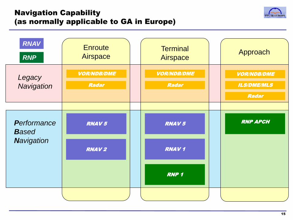
Navigation Capability
(as normally applicable to GA in Europe)
15
RNAV 5
VOR/NDB/DME VOR/NDB/DME VOR/NDB/DME
ILS/DME/MLS
Radar
RNAV 5
RNAV 1
RNP 1
RNP APCH
Enroute
Airspace Terminal
Airspace Approach
Legacy
Navigation
Performance
Based
Navigation
RNAV
RNP
Radar Radar
RNAV 2

Navigation Capability – Complete list
16
Navigation
Specification
Flight Phase
Enroute
Oceanic
Remote
Enroute
Continental ARR
Approach
DEP Initial Intermediate Final Missed
RNAV10 (RNP10) 10
RNAV 5 5 5
RNAV 2 2 2 2
RNAV 1 1 1 1 1 1 1
RNP 4 4
RNP 2 2 2
RNP1 1 1 1 1 1
Advanced RNP 2 2 or 1 1 1 1 0.3 1 1
RNP APCH 1 1 0.3 – 0.1 1
RNP AR APCH 1 - 0.1 1 - 0.1 0.3 – 0.1 1 - 0.1
RNP 0.3* 0.3 0.3 0.3 0.3 0.3 0.3
• Below is a complete list of PBN navigation specifications, flight phases and RNP accuracy limits.
• The GA pilot will normally only encounter those on the previous slide, but they are all included
below for completeness (see Learning Objectives in Appendix 2).
* RNP 0.3 is a helicopter specification

Navigation Capability – Additional Functionalities
17
Navigation
Specification
Additional Functionalities
(Required or Optional)
RF FRT TOAC Baro
VNAV
RNAV10 (RNP10)
RNAV 5
RNAV 2
RNAV 1 O
RNP 4 O
RNP 2 O
RNP1 O O
Advanced RNP R O O O
RNP APCH O O
RNP AR APCH Specific Requirements for RF & VNAV
RNP 0.3 O O
• RF Radius to Fix: Constant Radius Arc Leg defines a constant radius
turn between two database fixes, lines tangent to the arc and a centre
fix
• FRT The fixed radius transition is intended to be used in enroute
procedures. These turns have two possible radii, 22.5 nm for high
altitude routes (above FL195) and 15 nm for low altitude routes. Using
such path elements in an RNAV route enables improvement in airspace
usage through closely spaced parallel routes.
• TOAC Time Of Arrival Control enables an aircraft to reach a waypoint
within X number of seconds of a specific time.
• Baro-VNAV computes vertical navigation based on barometric
pressure, rather than on GPS-based SBAS altitude. (See Appendix 3)
• (RNP AR APCH See Appendix 3)
Required
Optional O
R

Further notes on Navigation Specifications
18
• Note that RNAV specifications have no (or in some way limited) on-board monitoring and alerting.
• Apart from RNAV 5 and RNAV 10, all waypoints, procedures or approaches must be accessed from the receiver
database.
• Not all the specifications below are found in EU continental airspace.
• Oceanic and remote navigation applications
– RNAV 10 (RNP 10) • RNAV 10 requires that aircraft operating in oceanic and remote areas be equipped with at least two independent
and serviceable Long Range Navigation Systems comprising an INS, an IRS FMS or a GNSS, with an integrity
such that the navigation system does not provide an unacceptable probability of misleading information. Dual INS
based systems are subject to a time limit (usually about 6 hours) between being updated from either a ground
based signal (VOR/DME) or GNSS. Dual GNSS receivers are not subject to a time limit as long as it is not
predicted that they will lose Fault Detection and Exclusion for more than 36 minutes.
– RNP 4 • For RNP 4 operations in oceanic or remote airspace, at least two fully serviceable independent long-range
navigation systems (LRNSs), with integrity such that the navigation system does not provide misleading
information, must be fitted to the aircraft and form part of the basis upon which RNP 4 operational approval is
granted. GNSS must be used and can be used as either a stand-alone navigation system or as one of the
sensors in a multi-sensor system (i.e. with an Inertial Navigation System). Fault Detection and Exclusion is
required for the GNSS receiver.
– RNP 2 • RNP 2 is primarily intended for a diverse set of enroute applications; particularly in geographic areas with little or
no ground NAVAID infrastructure, limited or no ATS surveillance, and low to medium density traffic. Use of RNP
2 in continental applications requires a lower continuity requirement than use in oceanic/remote applications. In
the latter application, the traffic is primarily transport category aircraft operating at high altitude; whereas,
continental applications may include a significant percentage of lower altitude general aviation aircraft.
• The RNP 2 specification is based upon GNSS and should not be used in areas of known GNSS signal
interference. GNSS Fault Detection is required.

Enroute and Terminal navigation applications
19
• RNAV 5
– While primarily addressing requirements of RNAV operation in an ATS surveillance environment, RNAV 5
implementation has occasionally occurred in areas where there is no ATS surveillance. This has required an
increase in route spacing to meet the target level of safety.
– RNAV 5 can be based on VOR/DME RNAV equipment or GNSS receivers.
– The RNAV 5 specification does not require an alert to the pilot in the event of excessive navigation errors.
Since the specification does not require the carriage of dual RNAV systems, the potential for loss of RNAV
capability requires an alternative navigation source.
– User defined Waypoints can be input manually. Due to the limitations of the specification, RNAV 5 is not
suitable for IFR navigation below enroute or terminal safety altitudes.
• RNAV 1 and RNAV 2
– The RNAV 1 and 2 specification is applicable to all ATS routes, including enroute, standard instrument
departures (SIDs), and standard arrival routes (STARS). It also applies to instrument approach procedures up
to the final approach fix.
– The RNAV 1 and 2 specification is primarily developed for RNAV operations in a radar environment (for SIDs,
radar coverage is expected prior to the first RNAV course change). RNAV 1 and RNAV 2 may be used in a
non-radar environment but not normally below MEA or MSA, as applicable. If RNAV 1 and 2 are used in a
radar environment below minimum vectoring altitude (MVA) or below MEA or MSA in a non-radar
environment, the implementing State must ensure appropriate system safety and take account of the lack of
on-board performance monitoring and alerting.
– RNAV 1 and 2 for general aviation is usually based on the availability of one GNSS receiver, although
VOR/DME RNAV systems and INS are acceptable as long as they can achieve the required accuracy.

Enroute and Terminal navigation applications
20
• RNP 1
– The RNP 1 specification is intended for connecting routes between the enroute structure and terminal
airspace (TMA) with no or limited ATS surveillance, and with low to medium density traffic.
– The RNP 1 specification is based upon GNSS; only one GNSS receiver is required. RNP 1 shall not be used
in areas of known navigation signal (GNSS) interference
– In the event of a predicted, continuous loss of appropriate level of fault detection of more than five minutes for
any part of the RNP 1 operation, the flight planning should be revised (e.g. delaying the departure or planning
a different departure procedure).
– RNP 1 can be used, when authorised, in a non-radar environment below MEAs or MSAs up to the final
approach fix.
An example of the components of a PBN Specification in terms of a navaid infrastructure, navigation specification and a
navigation application:-
• RNAV 1 and 2
– Navaid infrastructure: Radar environment with radio communications, and with GNSS, DME/DME and
DME/INS availability.
– Navigation specification: RNAV 1 and RNAV 2 operations are based upon the use of RNAV equipment that
automatically determines the aircraft position in the horizontal plane using input from the following types of
position sensors – GNSS, DME/DME RNAV, DME/DME/IRU RNAV approved to the RNAV 1 and 2 accuracy
requirements.
– Navigation application: The RNAV 1 and 2 specification is applicable to all ATS routes, including enroute,
standard instrument departures (SIDs), and standard arrival routes (STARs). It also applies to instrument
approach procedures up to the final approach fix.

Definition of RNP accuracy requirement
• There are four main navigation performance criteria:
1. Accuracy is the as the conformance of the true position and the required position.
2. Integrity is a measure of the trust that can be placed in the correctness of the information supplied by the total system.
Integrity includes the ability of a system to provide timely and valid alerts to the user.
3. Continuity is the capability of the system to perform its function without unscheduled interruptions during the intended
operation
4. Functionality - The detailed capability of the navigation system (such as the execution of leg transitions, parallel offset
capabilities, holding patterns, navigation databases) required to meet the airspace concept
• The key requirement of RNP X is an accuracy specification expressed as a Total System Error (TSE) of X nm or less for more
than 95% of the total flight time
• The navigation system compares ANP (EPE) with the RNP for the phase of flight and annunciates if the RNP is not met
• In practice, the Path Definition and Navigation System Errors are negligible, the key concerns for the GA pilot are FTE and the human
factor errors in selecting RNAV procedures, using GNSS units, interpreting guidance and in manual flying or operating the autopilot
Total System Error (TSE) is the vector sum of
– Path Definition Error (PDE)
– Path Steering Error (PSE)
– Navigation System Error (NSE)
• Path Definition Error is the difference between the path intended by the procedure
designer and the path the aircraft is guided along as a result of database coding
and navigator processing
• Path Steering Error is the sum of display error in Nav systems and Flight
Technical Error (FTE); ie. the errors in manual flight by pilots or autopilot
performance in following a desired path. FTE includes reaction times and
wind/turbulence induced errors, it does not include human “conceptual” errors eg.
selecting the wrong procedure, waypoint or autopilot mode, or simply turning in
the wrong direction
• Navigation System Error is the combination of navigation system/sensor (GNSS)
error and computation error (GNSS software). NSE is expressed as a 95%
confidence radius, called the Estimate of Position Uncertainty (EPU) or Actual
Navigation Performance (ANP). NSE is sometimes also called Estimated Position
Error (EPE)
Desired Path
Defined Path
True Position
Path Definition
Error (PDE)
Path Steering Error (PSE)
Navigation
System
Error (NSE) Estimated Position
21

Course contents
1. PBN & RNP theory
a. Introduction to PBN
b. The Path-Terminator
c. PBN procedure design
2. GNSS
a. GNSS and the GPS system
b. RAIM
c. SBAS
d. Databases
e. Procedures
f. Error detection and warnings
22
3. RNP Approach Procedures
a. Classifications
b. Approach types
c. Requirements and approvals
d. Approach operations
4. Avionics training
5. Simulator and/or Flight training
Appendices
1. Database Coding and Naming Conventions
2. PBN Learning Objectives
3. Additional items mentioned in the PBN
Learning Objectives
Glossary of Abbreviations

What is a Path-Terminator?
• IFR routes and procedures are designed using standardised specifications and criteria
– ICAO PANS-OPS Doc 8168 in Europe
– TERPS (United States Standard Terminal Instrument Procedures) in the USA
• Instrument procedures have always been published in chart and text form. Since the 1970s, the
ARINC 424 standard has also been used to codify IFR procedures, so they can be stored and
managed as records in electronic databases
• A key concept in ARINC 424 is that of the “Path-Terminator” – the definition of which is a specific way
of defining a leg or segment of an IFR procedure, based on a set of standard components that define
the flight path along the leg, and the terminator or end-point of the leg
• Different combinations of Path types (eg. a Heading or a Track) and Terminator types (eg. a radio
beacon, RNAV waypoint or DME arc) are used to define 23 different “Path-Terminator” leg types
– these 23 Path-Terminator types are, in effect, the “periodic table” of IFR procedure design and
codification
• Note: In some earlier receivers (eg Garmin GNS530/430), an enroute flight plan consists only of one
leg type: the basic “Track (from Fix) to Fix” (TF) between each of the waypoints entered. When a
Departure, Arrival or Approach procedure is loaded, the flight plan will include each of the path-
terminators that make up the procedure. Some receivers do not support all the leg types used at
the start and end of RNAV procedures, or in an unpublished GNSS “overlay”
23
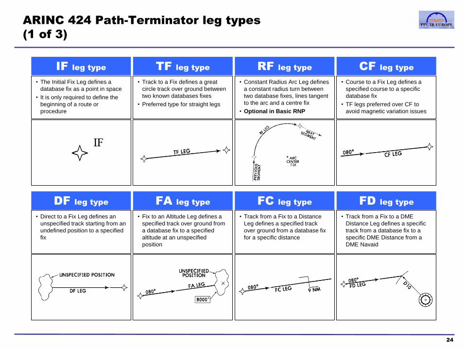
ARINC 424 Path-Terminator leg types
(1 of 3)
24
IF leg type
• The Initial Fix Leg defines a
database fix as a point in space
• It is only required to define the
beginning of a route or
procedure
TF leg type
• Track to a Fix defines a great
circle track over ground between
two known databases fixes
• Preferred type for straight legs
RF leg type
• Constant Radius Arc Leg defines
a constant radius turn between
two database fixes, lines tangent
to the arc and a centre fix
• Optional in Basic RNP
CF leg type
• Course to a Fix Leg defines a
specified course to a specific
database fix
• TF legs preferred over CF to
avoid magnetic variation issues
DF leg type
• Direct to a Fix Leg defines an
unspecified track starting from an
undefined position to a specified
fix
FA leg type
• Fix to an Altitude Leg defines a
specified track over ground from
a database fix to a specified
altitude at an unspecified
position
FC leg type
• Track from a Fix to a Distance
Leg defines a specified track
over ground from a database fix
for a specific distance
FD leg type
• Track from a Fix to a DME
Distance Leg defines a specific
track from a database fix to a
specific DME Distance from a
DME Navaid

ARINC 424 Path-Terminator leg types
(2 of 3)
25
FM leg type
• From a Fix to a Manual
termination Leg defines a
specified track over ground from
a database fix until Manual
termination of the leg
CA leg type
• Course to an Altitude Leg
defines a specified course to a
specific altitude at an unspecified
position
CD leg type
• Course to a DME Distance Leg
defines a specified course to a
specific DME Distance which is
from a specific database DME
Navaid
CI leg type
• Course to an Intercept Leg
defines a specified course to
intercept a subsequent leg
CR leg type
• Course to a Radial termination
Leg defines a course to a
specified Radial from a specific
database VOR Navaid
AF leg type
• Arc to a Fix or defines a track
over ground at specified constant
distance from a database DME
Navaid
VA leg type
• Heading to an Altitude
termination Leg defines a
specified heading to a specific
Altitude termination at an
unspecified position
VD leg type
• Heading to a DME Distance
termination Leg defines a
specified heading terminating at
a specified DME Distance from a
specific database DME Navaid

ARINC 424 Path-Terminator leg types
(3 of 3)
26
VI leg type
• Heading to an Intercept Leg
defines a specified heading to
intercept the subsequent leg at
an unspecified position
VM leg type
• Heading to a Manual termination
Leg defines a specified heading
until a Manual termination
VR leg type
• Heading to a Radial termination
Leg defines a specified heading
to a specified radial from a
specific database VOR Navaid
PI leg type
• Procedure Turn leg defines a
course reversal starting at a
specific fix, includes Outbound
Leg followed by 180 degree turn
to intercept the next leg
HA leg type
• HA leg defines racetrack pattern
or course reversals at a specified
database fix terminating at an
altitude
HF leg type
• HF leg defines racetrack pattern
or course reversals at a specified
database fix terminating at the fix
after a single pattern
HM leg type
• HM leg defines racetrack pattern
or course reversals at a specified
database fix with a manual
termination
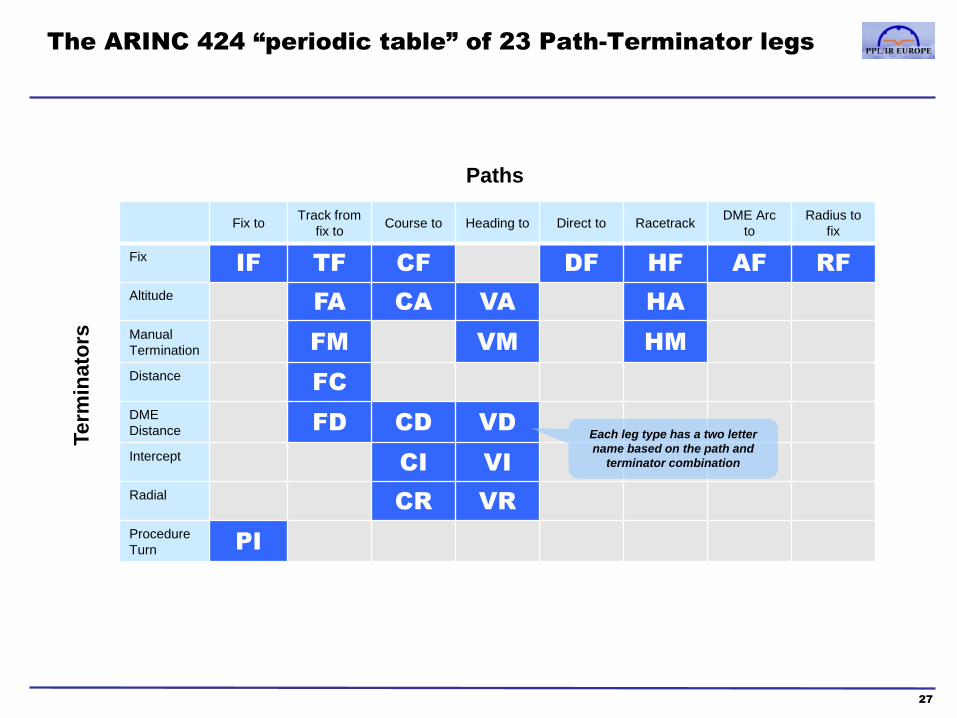
The ARINC 424 “periodic table” of 23 Path-Terminator legs
27
Fix to Track from
fix to Course to Heading to Direct to Racetrack
DME Arc
to
Radius to
fix
Fix IF TF CF DF HF AF RF
Altitude FA CA VA HA
Manual
Termination FM VM HM
Distance FC
DME
Distance FD CD VD
Intercept CI VI
Radial CR VR
Procedure
Turn PI
Paths
Term
inato
rs
Each leg type has a two letter
name based on the path and
terminator combination
Fly-By and Fly-Over RNAV waypoints
28
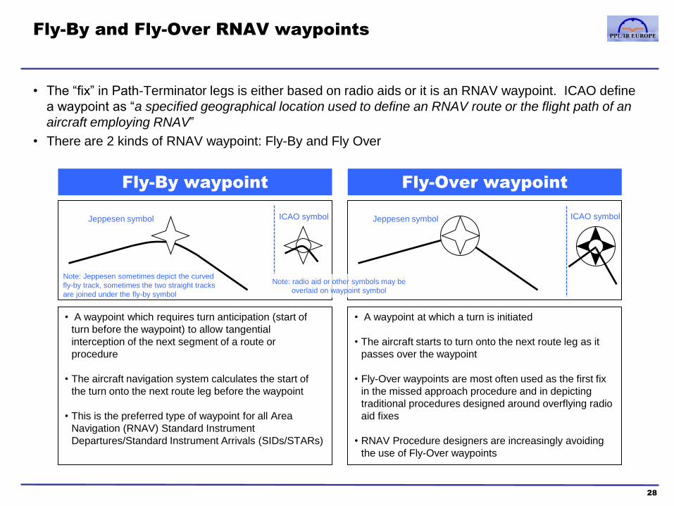
• The “fix” in Path-Terminator legs is either based on radio aids or it is an RNAV waypoint. ICAO define
a waypoint as “a specified geographical location used to define an RNAV route or the flight path of an
aircraft employing RNAV”
• There are 2 kinds of RNAV waypoint: Fly-By and Fly Over
Fly-By waypoint
• A waypoint which requires turn anticipation (start of
turn before the waypoint) to allow tangential
interception of the next segment of a route or
procedure
• The aircraft navigation system calculates the start of
the turn onto the next route leg before the waypoint
• This is the preferred type of waypoint for all Area
Navigation (RNAV) Standard Instrument
Departures/Standard Instrument Arrivals (SIDs/STARs)
Fly-Over waypoint
• A waypoint at which a turn is initiated
• The aircraft starts to turn onto the next route leg as it
passes over the waypoint
• Fly-Over waypoints are most often used as the first fix
in the missed approach procedure and in depicting
traditional procedures designed around overflying radio
aid fixes
• RNAV Procedure designers are increasingly avoiding
the use of Fly-Over waypoints
Jeppesen symbol Jeppesen symbol ICAO symbol ICAO symbol
Note: Jeppesen sometimes depict the curved
fly-by track, sometimes the two straight tracks
are joined under the fly-by symbol
Note: radio aid or other symbols may be
overlaid on waypoint symbol
Aircraft trajectory in Fly-By and Fly-Over waypoints
29
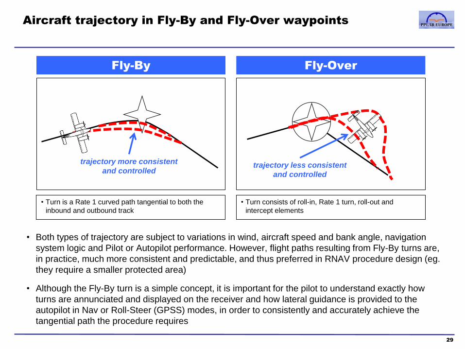
Fly-By
• Turn is a Rate 1 curved path tangential to both the
inbound and outbound track
Fly-Over
• Turn consists of roll-in, Rate 1 turn, roll-out and
intercept elements
trajectory more consistent
and controlled trajectory less consistent
and controlled
• Both types of trajectory are subject to variations in wind, aircraft speed and bank angle, navigation
system logic and Pilot or Autopilot performance. However, flight paths resulting from Fly-By turns are,
in practice, much more consistent and predictable, and thus preferred in RNAV procedure design (eg.
they require a smaller protected area)
• Although the Fly-By turn is a simple concept, it is important for the pilot to understand exactly how
turns are annunciated and displayed on the receiver and how lateral guidance is provided to the
autopilot in Nav or Roll-Steer (GPSS) modes, in order to consistently and accurately achieve the
tangential path the procedure requires

Course contents
1. PBN & RNP theory
a. Introduction to PBN
b. The Path-Terminator
c. PBN procedure design
2. GNSS
a. GNSS and the GPS system
b. RAIM
c. SBAS
d. Databases
e. Procedures
f. Error detection and warnings
30
3. RNP Approach Procedures
a. Classifications
b. Approach types
c. Requirements and approvals
d. Approach operations
4. Avionics training
5. Simulator and/or Flight training
Appendices
1. Database Coding and Naming Conventions
2. PBN Learning Objectives
3. Additional items mentioned in the PBN
Learning Objectives
Glossary of Abbreviations

Principles of ‘traditional’ Instrument Procedure design
1. The Protected Area
31
• Instrument procedures in Europe are designed using the specifications and criteria in ICAO PANS-
OPS Doc 8168. The US equivalent standard is “TERPS” (United States Standard Terminal Instrument
Procedures)
• The key design criteria is to provide safe obstacle and terrain clearance whilst an aircraft is flown in
accordance with the published procedure
– horizontally, within a Protected Area
– vertically, with a specified Minimum Obstacle Clearance (MOC)
Full
MOC
Full width of Protected Area
¼ width ¼ width ½ width
Secondary
Area
Primary
Area
Secondary
Area MOC
declines
to zero
Profile of Protected Area Plan View of Protected Area
Secondary
Area
Primary
Area
Secondary
Area
Principles of ‘traditional’ Instrument Procedure design
2. Track and Fix tolerances, and MOC
32
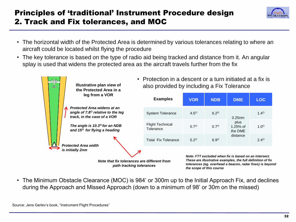
• The horizontal width of the Protected Area is determined by various tolerances relating to where an
aircraft could be located whilst flying the procedure
• The key tolerance is based on the type of radio aid being tracked and distance from it. An angular
splay is used that widens the protected area as the aircraft travels further from the fix
• The Minimum Obstacle Clearance (MOC) is 984’ or 300m up to the Initial Approach Fix, and declines
during the Approach and Missed Approach (down to a minimum of 98’ or 30m on the missed)
Illustrative plan view of
the Protected Area in a
leg from a VOR
Protected Area width
is initially 2nm
Protected Area widens at an
angle of 7.8O relative to the leg
track, in the case of a VOR
The angle is 10.3O for an NDB
and 15O for flying a heading
• Protection in a descent or a turn initiated at a fix is
also provided by including a Fix Tolerance
VOR NDB DME LOC
System Tolerance 4.5O 6.2O
0.25nm
plus
1.25% of
the DME
distance
1.4O
Flight Technical
Tolerance 0.7O 0.7O 1.0O
Total Fix Tolerance 5.2O 6.9O 2.4O
Note that fix tolerances are different from
path tracking tolerances
Examples
Note: FTT excluded when fix is based on an intersect.
These are illustrative examples, the full definition of fix
tolerances (eg. overhead a beacon, radar fixes) is beyond
the scope of this course
Source: Jens Gerlev’s book, “Instrument Flight Procedures”
Principles of ‘traditional’ Instrument Procedure design
3. Fly-Over Turns
33
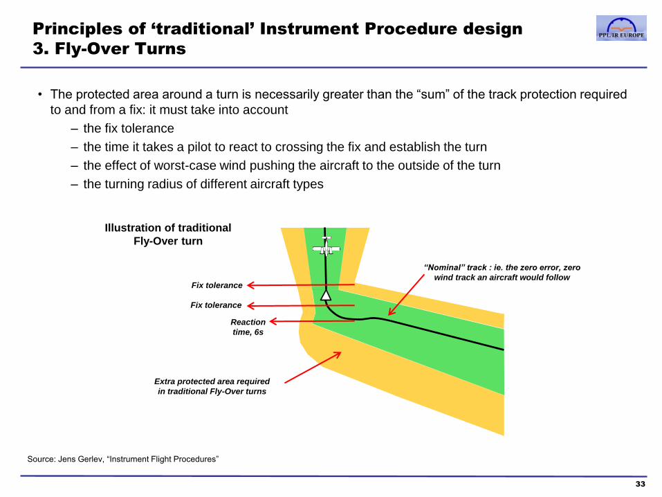
• The protected area around a turn is necessarily greater than the “sum” of the track protection required
to and from a fix: it must take into account
– the fix tolerance
– the time it takes a pilot to react to crossing the fix and establish the turn
– the effect of worst-case wind pushing the aircraft to the outside of the turn
– the turning radius of different aircraft types
“Nominal” track : ie. the zero error, zero
wind track an aircraft would follow Fix tolerance
Reaction
time, 6s
Fix tolerance
Extra protected area required
in traditional Fly-Over turns
Source: Jens Gerlev, “Instrument Flight Procedures”
Illustration of traditional
Fly-Over turn

Principles of ‘traditional’ Instrument Procedure design
4. Aircraft Approach Categories
34
• Aircraft speed is the key criteria for the design of any manoeuvring elements of an instrument
procedure (turns, procedure turns, holds, missed approaches, landing and circling minima)
• Procedures are designed around 5 aircraft categories, based on a notional approach speed of 1.3x the
stalling speed in the landing configuration at maximum landing mass (Vat)
• Most general aviation aircraft are Categories A or B. However, in busy Terminal airspace, ATC will
often request a higher than normal speed from light aircraft. If appropriate, the pilot should also elect to
follow a higher-Category procedure and observe the corresponding minima. Note that the Vat is as
certified but the approach speeds are as flown.
– Note that databases sometimes only include the Category C&D procedures
– In Garmin equipment where there are procedures for different speed categories normally they
are ordered with faster categories on the list above the slower categories (eg C&D before A&B)
Aircraft
Category Vat
Initial
Approach
speeds
Final
Approach
speeds
Max
Circling
speed
A <91 90-150 70-100 100
B 91-120 120-180 85-130 135
C 121-140 160-240 115-160 180
D 141-165 185-250 130-185 205
E 166-210 185-250 155-230 240 All speeds
are KT IAS

How are PBN procedures different?
1. Definition of Protected Area based on RNAV system performance or RNP
35
Based on RNAV system type Based on PBN
• PBN procedures designated for specific
navigation systems, eg
– RNAV(GNSS)
– RNAV(DME-DME)
– RNAV(EXCEPT CLASS A GNSS)
• Each procedure type has a system-
specific “semi area width”, which is the
lateral protection either side of the
nominal track, eg. 3nm for GNSS STARs
• Modern approach is to define procedures
based on PBN, not on specific navigation
systems
• Fix Tolerance is based on system-
specific linear Along Track (ATT) and
Cross-Track (XTT) tolerances, rather
than angular splays
• PANS OPS protected area width on
either side is 2x RNP + a buffer
• The buffer is 2nm for arrival, 1nm for
initial and intermediate approach and
0.5nm for final, missed approach and
departure
• Fix Tolerance is simply a 1x RNP radius
around the waypoint
ie. FMS GNSS only, not
panel mount GNSS
Full width of Protected Area
buffer 4x RNP
Buffer
Area Buffer
Area
buffer
MOC

How are PBN procedures different?
2. Fly-By turn Protected Area is smaller than that of conventional turns
36
• The Fly-By turn design assumes
– a fix tolerance of RNAV X or RNP X (eg. 1nm in RNAV 1)
– aircraft turn at Rate 1 (3°/sec), up to a maximum bank angle of 25°, whichever is lower
– a 5 seconds allowance, from the time the aircraft’s navigation system computes that a turn
should start, for either the pilot or autopilot to react and to establish the appropriate bank angle
• The Fly-By turn design thus uses the same bank angles, fix tolerances, wind effects and pilot/autopilot
reaction times as the Fly-Over design. However, the diagrams below illustrate how much inherently
smaller the Fly-By protected area is with those same safety margins built-in
Identical turns drawn to scale : Fly-Over vs Fly-By Protected Areas
Secondary
Area
Primary Area
Secondary Area
Primary Area
Secondary
Area
Secondary Area
Fly-Over Fly-By
Illustration of a delay in
initiating the turn until
approx 1 minute after
waypoint crossed

120kts 420kts
How are PBN procedures different?
3. A Radius to Fix ensures that aircraft speed does not affect turn radius
37
• A Radius to Fix Leg defines a constant radius turn between two
database fixes, lines tangent to the arc and a centre fix
• Optional in RNP 1
• The RF leg is designed to be used for terminal procedures
• At present RF legs require either approved roll steering autopilots or
flight director, but the requirements are likely to be reduced in the future.
• RF legs can only be flown by more recent GNSS receivers and their use
has not yet been approved by EASA. However EASA approval is
pending.
• RF legs are used in circumstances where navigational precision is vital
(eg due to terrain) so it is important to follow flight director guidance and
the speed constraints associated with the procedure.
A fly by waypoint does not ensure that aircraft flying at different speeds will follow a path within the 1nm
requirement of RNP 1. In the diagram below, the greater radius of the faster aircraft places it further from the
waypoint.

How are PBN procedures different?
3. Procedures use only a few of the most “predictable” Path-Terminators
38
Fix to Track from
fix to Course to Heading to Direct to Racetrack
DME Arc
to
Radius
from fix
Fix IF
Initial
Fix
TF
Track to
Fix
CF
Course to
Fix
DF
Direct to
Fix
HF
Racetrack
to Fix
AF
RF
Radius to
Fix
Altitude FA
Fix to
Altitude
CA
Course to
Altitude
VA
Heading
to
Altitude
HA
Racetrack
to Altitude
Manual
Termination FM
Fix to
man. term.
VM
Heading
to man.
term.
HM
Racetrack
to man.
term.
Distance FC
DME
Distance FD CD VD
Intercept
CI
VI
Course to
Intercept
Radial CR VR
Procedure
Turn PI
Paths
Term
inato
rs Red: “best practice”
RNAV leg types
Orange: RNAV leg types used
mainly at the start and end of
procedures when required (eg.
VA as the first leg of a SID)
Blue: non-RNAV leg types
How are PBN procedures different?
4. There is a distinct PBN procedure “style”
39
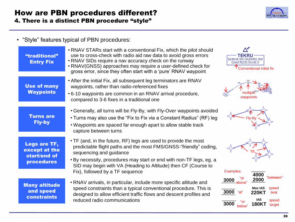
• “Style” features typical of PBN procedures:
“traditional”
Entry Fix
Use of many
Waypoints
Turns are
Fly-by
Many altitude
and speed
constraints
Legs are TF,
except at the
start/end of
procedures
• RNAV STARs start with a conventional Fix, which the pilot should use to cross-check with radio aid raw data to avoid gross errors
• RNAV SIDs require a nav accuracy check on the runway • RNAV(GNSS) approaches may require a user-defined check for
gross error, since they often start with a ‘pure’ RNAV waypoint
• After the initial Fix, all subsequent leg terminators are RNAV
waypoints, rather than radio-referenced fixes
• 6-10 waypoints are common in an RNAV arrival procedure,
compared to 3-6 fixes in a traditional one
• Generally, all turns will be Fly-By, with Fly-Over waypoints avoided
• Turns may also use the “Fix to Fix via a Constant Radius” (RF) leg
• Waypoints are spaced far enough apart to allow stable track
capture between turns
Fly-By
TF
• TF (and, in the future, RF) legs are used to provide the most
predictable flight paths and the most FMS/GNSS-“friendly” coding,
sequencing and guidance
• By necessity, procedures may start or end with non-TF legs, eg. a
SID may begin with VA (Heading to Altitude) then CF (Course to
Fix), followed by a TF sequence
multiple
waypoints
Conventional initial fix
• RNAV arrivals, in particular, include more specific altitude and
speed constraints than a typical conventional procedure. This is
designed to allow efficient traffic flows and descent profiles and
reduced radio communications
3000
3000
3000
“or
above”
“at”
“or
below”
4000 2000
“between”
Max IAS
220KT
IAS
180KT
speed
limit
speed
target
Examples:

How are PBN procedures different?
5. Arrival vertical profile often optimised for jet aircraft “continuous descent”
40
• Unlike most conventional procedures, RNAV STARs are often “closed”, terminating at the final
approach point, rather than an initial or intermediate one (“open”)
• The vertical profile is usually designed to allow jet aircraft to commence descent late and then descend
continuously, at 220KIAS and flight idle power, from the start of the procedure until the final approach
waypoint and speed. This corresponds to a gradient of approximately 300’ per nm. – this is the most efficient and environmentally friendly method, known as CDA (Continuous Descent Approach). Otherwise, for jet aircraft,
the earlier descent and power/configuration changes in a “step-down” arrival involve unnecessary fuel burn and a greater noise footprint
• Note the aircraft performance and pilot workload required during the transition to the final approach
– descending at ~300’ per nm whilst decelerating from 190KIAS (or speed attainable) to approach speed
– no distinct level-off available for slowing down
– cockpit transition of CDI, GNSS course guidance and autopilot mode from RNAV to ILS/DME
0102030405060
Example: Vertical profile of NEMAX1B trial P-RNAV Arrival procedure at Nottingham East Midlands (EGNX)
FL100
FL80
FL60
4000’
2000’
0’
FL100 minFL120 max
FL70 min
FL55 min
4000’ min3500’ min
At
3000’At
2000’
nm to
runway
Gradient approximately
300’ per nm
High target speed: advise ATC if
unable when assigned the procedure
and offer best speed to FAP
How are PBN procedures different?
Summary
41
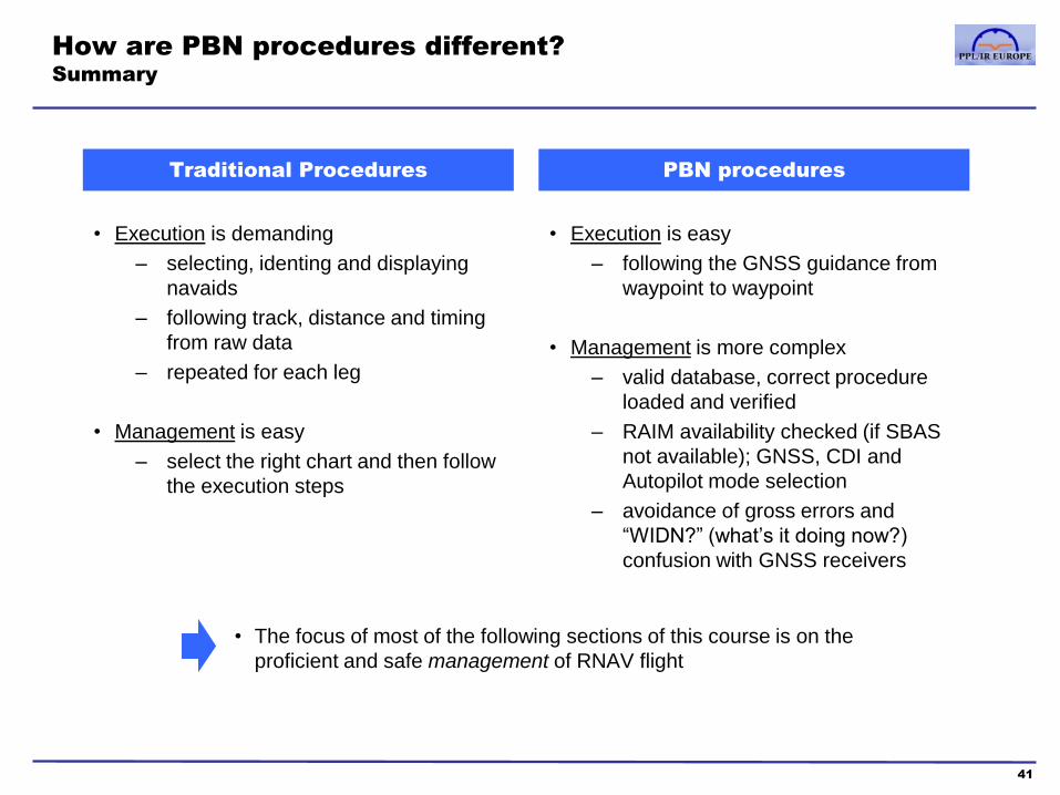
Traditional Procedures PBN procedures
• Execution is demanding
– selecting, identing and displaying
navaids
– following track, distance and timing
from raw data
– repeated for each leg
• Management is easy
– select the right chart and then follow
the execution steps
• Execution is easy
– following the GNSS guidance from
waypoint to waypoint
• Management is more complex
– valid database, correct procedure
loaded and verified
– RAIM availability checked (if SBAS
not available); GNSS, CDI and
Autopilot mode selection
– avoidance of gross errors and
“WIDN?” (what’s it doing now?)
confusion with GNSS receivers
• The focus of most of the following sections of this course is on the
proficient and safe management of RNAV flight

Course contents
1. PBN & RNP theory
a. Introduction to PBN
b. The Path-Terminator
c. PBN procedure design
2. GNSS
a. GNSS and the GPS system
b. RAIM
c. SBAS
d. Databases
e. Procedures
f. Error detection and warnings
42
3. RNP Approach Procedures
a. Classifications
b. Approach types
c. Requirements and approvals
d. Approach operations
4. Avionics training
5. Simulator and/or Flight training
Appendices
1. Database Coding and Naming Conventions
2. PBN Learning Objectives
3. Additional items mentioned in the PBN
Learning Objectives
Glossary of Abbreviations

The Global Satellite Navigation System (GNSS)
The general term for the global navigation satellite and ground station infrastructure
43
GPS
• The USA’s “Navstar”
Global Positioning
System
• A military system that
became fully operational
for worldwide civilian use
in 1995
• Designed around a
network of 24 medium-
earth orbit satellites
• “Selective Availability”
(SA) degradation of
civilian signal accuracy
ended in 2000
The concept is that receivers should be able to operate with multiple systems, creating in
GNSS a single ‘virtual’ system capable of providing a high degree of resilience when used as a
sole source of navigation data for aircraft
In this manual the term GPS refers to the US GPS system and GNSS includes all the above
systems.
GLONASS
• Russian “Global
Navigation Satellite
System”
• Introduced during the
Soviet era for military
applications
• 24 satellites providing
global coverage
Galileo
• The European Union’s
GNSS project
• After some controversy,
formally approved in Nov
2007
• Should be fully operational
by 2020
• USA/EU agreement that
Galileo and GPS will be
“interoperable”
• Will use a 30 satellite
constellation (24 + 6
spares); some service and
accuracy improvements
over current GPS
GNSS Note: there are other national
GNSS programmes and
proposals , eg. India, France
BeiDou
• Chinese Navigation
Satellite System (BDS)
• 24 satellites providing
global coverage
• Certified for Maritime but
not Aviation use as yet,
but expected shortly.

How does GPS work?
1. Overview of the system’s three “segments”
44
Space Segment (SS)
• The system is designed for a minimum of 24 satellites (abbreviated as “SV”, Satellite Vehicle):
4 in each of 6 orbital planes, at a height of ~20,000km and completing one orbit every 12hrs
• Currently there are 31 satellites, the 7 additional ones improve accuracy and resilience. The
constellation is arranged so that at least 6 satellites are always line-of-sight visible from almost
any point on the Earth
•The receipt of ranging codes and navigation messages from multiple satellites
allows GNSS Receivers to compute accurate 3D position, speed and time
Control Segment (CS)
• A Master Control Station in Colorado and 4
Monitor stations across the globe
• They establish the exact orbital position of
each satellite, and maintain the reference
atomic clocks for the system
User Segment (US)
• Navigation devices which typically include
an antenna, an accurate clock, receiver,
processor and control/display components
• Modern ‘multi-channel’ receivers can
simultaneously monitor 12-20 satellites
• Each satellite broadcasts a “ranging code”, used
to establish distance from the GPS receiver, and
its own “Navigation Message” containing
– Clock data at the time of transmission
– Data on the satellite’s orbital position
(“ephemeris”)
– “Almanac” data on the status of the entire
satellite network
(detailed in following pages)
• The location of the Ground Stations
is very accurately established and
used to calibrate the satellites’
position and clock data based on
the navigation messages they send
• The Master Control Station feeds
back a navigational update to each
satellite, synchronising its internal
clock and adjusting the ephemeris
model of its orbit
• Occasional maneuvers are
commanded which maintain a
satellite in its proper orbit

How does GPS work?
2. The satellites broadcast a signal for civilian receivers called “L1”
45
The Navigation message is encoded onto the C/A code, and the C/A is
then modulated on to a carrier frequency of 1575.42 MHz, called “L1”
L1 Carrier
..is the ranging code, used by the GPS receiver to measure distance to
the satellite; also called “the “Standard Positioning Service” or SPS
The C/A code is a 1,023bit “pseudorandom number” (PRN) transmitted at
1.023Mbit/s, ie. repeating every millisecond.
The PRN is unique to each satellite, and all the PRNs are stored in GPS
Receiver memory. Because they are long pseudorandom numbers
designed to be “orthogonal”, any two different PRNs will “correlate”
poorly (ie. when multiplied together, give a value near zero).
The Receiver isolates any given satellite’s transmission by multiplying the
incoming L1 signal by that satellite’s PRN at different time shift intervals,
within the 1 millisecond sequence, until it finds a match or ‘lock-on’ (when
a particular time shift results in a high multiplication value). It can thus
“filter out” all the other satellites from the L1 frequency, and use the time
shift required for lock-on to calculate the satellite’s range and also extract
(demodulate) the Navigation Message from the C/A code. See later
pages for detail.
C/A (Coarse/Acquisition) code
A digital (binary) signal is transmitted by changing (modulating) a (sinusoidal)
carrier wave in one of three ways: amplitude, frequency or phase. The latter is
called Phase Key Shifting (PSK). Binary is the simplest PSK method (BPSK)
which “switches” between 2 carriers 180O out of phase
The Navigation Message consists of 5 subframes of 10x 30bit words
(1500bits total) transmitted at 50bits/s, ie. every 30 seconds. See next
page for detail.
The Navigation Message
“BPSK” Modulation
Broadcast
Signal
“Modulo 2 Adder”
The 1023Mbits/s is sometime also referred to as
the “chipping” rate, and each BPSK modulated
bit of data as a “chip” (change in phase)
The Navigation Message is encoded onto
the C/A at 50bits/s by changing its sign
The fundamental frequency of the system, Fo, is 10.23Mhz. The carrier and code frequencies
are multiples of this , eg. L1 = Fo x 154. All radio frequencies and codes generated in the
satellite are from the same 10.23MHz crystal, controlled by an atomic clock
How does GPS work?
3. The structure of the Navigation Message
46
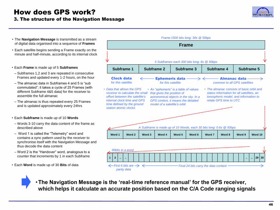
Frame
Frame:1500 bits long; 30s @ 50bps
Subframe 3 Subframe 4 Subframe 1 Subframe 2 Subframe 5
5 Subframes each 300 bits long: 6s @ 50bps
Word 3 Word 4 Word 1 Word 2 Word 5 Word 8 Word 9 Word 6 Word 7 Word 10
A Subframe is made up of 10 Words, each 30 bits long: 0.6s @ 50bps
30bits in a word
.. .. 1 2 .. 29 .. 30
• The Navigation Message is transmitted as a stream
of digital data organised into a sequence of Frames
• Each satellite begins sending a Frame exactly on the
minute and half-minute, according to its internal clock
• Each Frame is made up of 5 Subframes
– Subframes 1,2 and 3 are repeated in consecutive
Frames and updated every 1-2 hours, on the hour
– The almanac data in Subframes 4 and 5 is “sub
commutated”; it takes a cycle of 25 Frames (with
different Subframe 4&5 data) for the receiver to
assemble the full almanac
– The almanac is thus repeated every 25 Frames
and is updated approximately every 24hrs
Clock data
for this satellite
Ephemeris data
for this satellite
Almanac data
common to all GPS satellites
• Data that allows the GPS
receiver to calculate the small
offset between the satellite's
internal clock time and GPS
time defined by the ground
station atomic clocks
• The almanac consists of basic orbit and
status information for all satellites, an
ionospheric model, and information to
relate GPS time to UTC
• An “ephemeris” is a table of values
that gives the position of
astronomical objects in the sky. In a
GPS context, it means the detailed
model of a satellite’s orbit
• Each Subframe is made up of 10 Words
– Words 3-10 carry the data content of the frame as
described above
– Word 1 is called the “Telemetry” word and
contains a sync pattern used by the receiver to
synchronise itself with the Navigation Message and
thus decode the data content
– Word 2 is the “Handover” word, analogous to a
counter that increments by 1 in each Subframe
• Each Word is made up of 30 Bits of data
•The Navigation Message is the ‘real-time reference manual’ for the GPS receiver,
which helps it calculate an accurate position based on the C/A Code ranging signals
First 6 bits are
parity data
Final 24 bits carry the data content

How does GPS work?
4. Other (non-civilian) signals and future enhancements to the system
47
Non-civilian GPS transmissions Future enhancements
L1 Carrier
1575.42 MHz
L2 Carrier
1227.60 MHz
C/A Code
1.023 MHz
Nav.Msg.
50 Hz
P(Y) Code
10.23 MHz
P(Y) Code
10.23 MHz
Same P(Y) Code
transmitted on L1 and L2
Civilian-use signal
• The P (Precise) code is a 10,230bit psuedo-random number, it
is a 10x more accurate version of the C/A code
• Normally, the P code is encrypted by a “Y” code, creating the
10.23 MHz P(Y) signal which can only be decrypted by military
users – known as the “Precise Positioning Service” (PPS)
• The encryption is an “anti-spoofing” technique ,which provides
some assurance that the signal received is not being sent by a
non-GPS “spoofing” transmitter. The C/A code is potentially
vulnerable to such spoofing.
• The ionosphere delays or “disperses” radio signals differently
according to their frequency. Military (and some specialised
civilian) receivers can compensate for this by comparing P(Y)
signal reception between the L1 and L2 carriers.
L1 Carrier
1575.42 MHz
L2 Carrier
1227.60 MHz
• C/A Code
• P(Y) Code
• P(Y) Code
Existing Future
• L2C signal
CM (civilian moderate) code
CL (civilian long) code
• M (Military) code
• L1C
New version of C/A code
• M (Military) code
L5 Carrier
1176.45 MHz • “Safety of Life” signal
• These new signals are being implemented progressively by new
satellite launches
• L1C will be compatible with existing receivers but include better
interoperability with other GNSS systems and other improvements
• L2C is the more accurate “v2.0” civilian GPS signal and allows civilian
ionospheric compensation through comparison of L1C and L2C signals
• The M code is the improved military signal
• The L5 “Safety of Life” signal is specifically for civil aviation use and is
transmitted in the protected Aeronautical Radio Navigation Services
(ARNS) band

How does GPS work?
5. International time and the GPS time system
48
International Atomic Time
(TAI)
• The standard international scientific
time scale
• The length of a second is defined by
a frequency property of the cesium-
133 atom, and atomic clocks are
used to “count” or “accumulate”
seconds
• TAI is derived from 230 atomic
clocks in 65 sites around the world,
and 11 different laboratory caesium
frequency standards
• The data is collated by the BIPM
(Bureau International des Poids et
Mesures) in Paris, who calculate
TAI and promulgate the results to
various international centres
•Time measurement is the basis for GPS navigation, because the range from a
satellite to a receiver can be determined by the time delay in receiving a signal,
and with multiple range fixes, a position can be calculated
Universal Coordinated Time
(UTC)
• “Earth time” (“UT1”) defines the earth’s
angular position with respect to the
celestial sphere; this is the most useful
time scale for navigation and
astronomy
• Fluctuations in the earth’s spin mean
that UT1 deviates from the precise TAI
reference
• UTC, the “official world time” is a
compromise between Earth time and
TAI; it uses the TAI second, but
introduces leap seconds to account for
changes in the earth’s spin and
maintain a useful consistency with UT1
• At any given time, UTC equals TAI
minus an integer number of seconds.
In January 2008, UTC was 33s behind.
Typically, a leap second is subtracted
once a year
“GPS Time”
• The GPS system uses a time
reference (“GPS Time”) maintained
by the Master Control ground
station’s atomic clocks
• GPS time uses the TAI second, and was set equal to
UTC in 1980. It does not introduce leap seconds, and
in 2008, for example, was 14s ahead of UTC (the
difference between TAI & UTC was 19s in 1980, hence
in 2008, 33s-19s=14s). The Navigation Message
transmits a correction for UTC, so that GPS receivers
can display UTC and local time zones.
• Each satellite carries its own atomic
clock, which will have a small error or
“offset” from GPS Time. This is
known as SV (Satellite Vehicle) time
• SV clock offset information is
broadcast in each satellite’s
Navigation Message
• The GPS “calendar” is a counter of
weeks and days of the week. ‘Date
zero’ was 6 January 1980

How does GPS work?
6. The GPS Receiver: Overview
49
Preamplifier and
Down Converter
Demodulation
and Code control Navigation and
Signal Processor
Data decoding
Satellite positions
Pseudo-range
calculation
Receiver position,
velocity and time
calculations
C/A code
generator
Clock
Navigation
Message
C/A Code
Measurement
Time
Measurement
Position,
Velocity,
Time
Antenna Nav functions and user
interface
Aviation navigation database and
charts. Radios and other sensors.
• The antenna is designed to provide
equal sensitivity to all satellite
signals above (typically) 5 degrees
of elevation, and is shielded from
lower elevation signals to avoid
“multi path” error (reflections from
terrain or from the airframe)
• Preamplifier: amplifies the Radio
Frequency (RF) signal and sets
the noise level to reject other RF
interference
• Down Converter: converts the RF
signal to an Intermediate
Frequency (IF)
• Oscillator provides the receiver’s time
and frequency reference
• Frequency synthesiser converts this
reference to a signal providing clock
information to the Processor
• A modern multi-channel receiver simultaneously detects and
processes signals from all visible satellites
• Locks on to the PRN code and extracts the Navigation message
• Calculates the relationship between GPS time and Receiver time
• Determines position and velocity (method described on next page)
•The Navigation processor’s task is complicated, because the GPS receiver has no
accurate time or position reference other than the satellite signals it decodes. These
specify the exact “GPS Time” of transmission – but the receiver doesn’t directly “know”
its own GPS Time of reception. The calculation method is described on the next page.
Simplified GPS receiver diagram (not Garmin specific, photos are illustrative)

How does GPS work?
7. The GPS Receiver: Calculation of time and position
50
Stage 1: The “pseudorange” Stage 2: The accurate fix
• When the GPS receiver is started-up, its internal or “local” clock will be
inaccurate by an unknown error, called clock bias or offset, compared to
the reference GPS Time
• A modern quartz clock may be accurate to one part in a million (ie. drift by one
microsecond every second). This means that after only 1s, the internal clock error can be
the equivalent of hundreds of metres (1µs = ~300m at the speed of light). A unit that’s
been switched off for a week or two could be inaccurate by ~1s or hundreds of thousands
of km.
• The first stage of the navigation problem is to calculate “pseudoranges”
from the visible satellites to the GPS, ignoring the local clock offset.
These ranges are “pseudo” because they are all known to be wrong by
the same (unknown) local clock error
• For any given satellite, the Receiver generates the satellite’s PRN code
internally, based on its “code book”, and starts the code sequence at the
time its local clock says the satellite should have started its PRN
transmission. The internal PRN code is then time-shifted until it matches
(locks-on) to the PRN code signal from the satellite. This time-shift, or
offset, is the (pseudo) elapsed time between transmission and the
reception Time of Arrival (TOA)
• The Pseudorange is derived from the TOA, assuming a given speed for
radio wave travel and the decoded time of transmission from the satellite
• The 1023 bit PRN code is transmitted at 1000 times per second, and the Receiver can
judge the “start” of a bit to about 1%, so the maximum accuracy of the C/A code is ~3m
• By decoding the Navigation Message, the Receiver gets data that allows it to correct
Pseudorange for the following errors
– The SV (Satellite Vehicle) time offset from GPS time
– Basic ionospheric corrections from the Almanac
– Relativistic effects and receiver noise
• The Receiver calculates pseudoranges from different satellites
simultaneously, so they are all subject an identical local clock error
• The Receiver then uses the ephemeris (orbital) data in each
satellite’s Navigation Message to establish the satellite’s position in
space at the time of the Pseudorange calculation
• It requires a minimum of 4 satellite pseudoranges to determine a 3D
navigational fix for the Receiver.
• The GPS system specification is that 5 satellites should always be available above
a mask (elevation) angle of 7.5 degrees (usually it is 6 or more)
• With 4 satellite positions known and 4 pseudoranges calculated, the
navigation problem can be expressed as 4 equations with 4
unknowns (the unknowns being the x,y,z position of the receiver
and t, the clock bias error)
• The Receiver calculates a solution to these equations and
establishes a position fix
• With true (rather than pseudo) ranges, it would only require 3 satellite position
spheres to determine a fix intersect. However, with pseudoranges, a 3 sphere
solution would give the wrong range. 4 pseudoranges spheres won’t intersect at a
point – because the ranges are not true and consistent with a single point in space.
The receiver, in effect, solves the equations to determine which value of local clock
error creates the best intersect of the 4 spheres
• The receiver also calculates a Geometric Dilution of Precision (GDOP), based on
the relative position of the satellites (satellites close together provide a weaker fix)
• When more than 4 satellites are available, modern receivers use
various other algorithms to provide a better fix
• Finally, the x,y,z position from the centre of the earth is translated
into latitude, longitude and altitude using the WGS84 datum, and
GPS Time is converted into UTC. (See later pages on WGS84)
• Velocity (ie. ground speed and ground track) is calculated using a
combination of rate of change of position and Doppler shift
measurement of the L1 carrier frequency of different satellites,
compared to the receiver’s L1 oscillator frequency
1 0 1 1 0 0 1 0 1 0 1 1 0 0 1 1 1 0 0 1 1 0 1 0 0 0 0 1 0 0 0
How does GPS work?
8. Illustration of the GPS navigation calculation
51
• Low correlation:
wrong PRN code
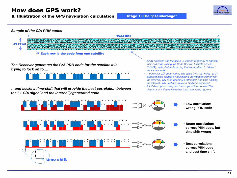
Stage 1: The “pseudorange”
1 0 1 1 0 0 1 0 1 0 1 1 0 0 1 1 1 0 0 1 1 0 1 0 0 0 0 1 0 0 0
1 0 1 1 0 0 1 0 1 0 1 1 0 0 1 1 1 0 0 1 1 0 1 0 0 0 0 1 0 0 0
1 0 0 1 1 0 1 1 0 1 1 0 0 1 1 1 1 0 0 1 0 1 1 1 0 0 1 1 1 1 1
1023 bits
Sample of the C/A PRN codes
31 rows
Each row is the code from one satellite
The Receiver generates the C/A PRN code for the satellite it is
trying to lock on to….
…and seeks a time-shift that will provide the best correlation between
the L1 C/A signal and the internally generated code
1 0 1 1 0 0 1 0 1 0 1 1 0 0 1 1 1 0 0 1 1 0 1 0 0 0 0 1 0 0 0
X
1 0 1 1 0 0 1 0 1 0 1 1 0 0 1 1 1 0 0 1 1 0 1 0 0 0 0 1 0 0 0
X
1 0 1 1 0 0 1 0 1 0 1 1 0 0 1 1 1 0 0 1 1 0 1 0 0 0 0 1 0 0 0
X
• Better correlation:
correct PRN code, but
time shift wrong
• Best correlation:
correct PRN code
and best time shift
time shift
• All 31 satellites use the same L1 carrier frequency to transmit
their C/A codes using the Code Division Multiple Access
(CDMA) method of multiplexing that allows them to “share”
the same carrier.
• A particular C/A code can be extracted from the “noise” of 31
superimposed signals by multiplying the inbound carrier with
the desired PRN code generated internally, and time-shifting
the internal PRN until a correlation “spike” is achieved
• A full description is beyond the scope of this course. The
diagrams are illustrative rather than technically rigorous

How does GPS work?
9. Illustration of the GPS navigation calculation
52
Stage 2: The accurate fix
Two dimensional illustration of the GPS navigation calculation
Determining pseudorange from 3 satellites results in
3 equations with 3 unknowns: the x,y position of the
receiver and t, the local clock bias
The navigation processor solves these equations to
determine a clock bias which gives the best intersect
between the three bias-adjusted “true” range arcs
•The actual method used is analogous to this; 4 satellites provide 4 range spheres, and thus
4 equations to solve for the unknown 3D x,y,z position of the receiver and its clock bias
Pseudoranges calculated from
PRN correlation time shift
Satellite position known from
Navigation Message ephemeris data
Clock bias unknown,
thus receiver position
unknown
Best fit local clock bias (all three black arrows represent
the same clock bias)
Best fit position
solution
Pseudorange arc
True range arc
How does GPS work?
10. The WGS84 map datum
53
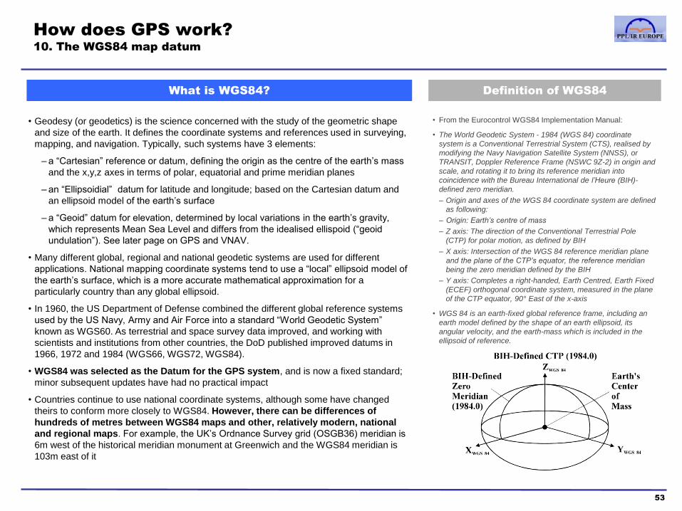
What is WGS84? Definition of WGS84
• Geodesy (or geodetics) is the science concerned with the study of the geometric shape
and size of the earth. It defines the coordinate systems and references used in surveying,
mapping, and navigation. Typically, such systems have 3 elements:
– a “Cartesian” reference or datum, defining the origin as the centre of the earth’s mass
and the x,y,z axes in terms of polar, equatorial and prime meridian planes
– an “Ellipsoidial” datum for latitude and longitude; based on the Cartesian datum and
an ellipsoid model of the earth’s surface
– a “Geoid” datum for elevation, determined by local variations in the earth’s gravity,
which represents Mean Sea Level and differs from the idealised ellispoid (“geoid
undulation”). See later page on GPS and VNAV.
• Many different global, regional and national geodetic systems are used for different
applications. National mapping coordinate systems tend to use a “local” ellipsoid model of
the earth’s surface, which is a more accurate mathematical approximation for a
particularly country than any global ellipsoid.
• In 1960, the US Department of Defense combined the different global reference systems
used by the US Navy, Army and Air Force into a standard “World Geodetic System”
known as WGS60. As terrestrial and space survey data improved, and working with
scientists and institutions from other countries, the DoD published improved datums in
1966, 1972 and 1984 (WGS66, WGS72, WGS84).
• WGS84 was selected as the Datum for the GPS system, and is now a fixed standard;
minor subsequent updates have had no practical impact
• Countries continue to use national coordinate systems, although some have changed
theirs to conform more closely to WGS84. However, there can be differences of
hundreds of metres between WGS84 maps and other, relatively modern, national
and regional maps. For example, the UK’s Ordnance Survey grid (OSGB36) meridian is
6m west of the historical meridian monument at Greenwich and the WGS84 meridian is
103m east of it
• From the Eurocontrol WGS84 Implementation Manual:
• The World Geodetic System - 1984 (WGS 84) coordinate
system is a Conventional Terrestrial System (CTS), realised by
modifying the Navy Navigation Satellite System (NNSS), or
TRANSIT, Doppler Reference Frame (NSWC 9Z-2) in origin and
scale, and rotating it to bring its reference meridian into
coincidence with the Bureau International de l’Heure (BIH)-
defined zero meridian.
– Origin and axes of the WGS 84 coordinate system are defined
as following:
– Origin: Earth’s centre of mass
– Z axis: The direction of the Conventional Terrestrial Pole
(CTP) for polar motion, as defined by BIH
– X axis: Intersection of the WGS 84 reference meridian plane
and the plane of the CTP’s equator, the reference meridian
being the zero meridian defined by the BIH
– Y axis: Completes a right-handed, Earth Centred, Earth Fixed
(ECEF) orthogonal coordinate system, measured in the plane
of the CTP equator, 90° East of the x-axis
• WGS 84 is an earth-fixed global reference frame, including an
earth model defined by the shape of an earth ellipsoid, its
angular velocity, and the earth-mass which is included in the
ellipsoid of reference.

How does GPS work?
11. Aviation charts and WGS84
54
Aviation charting datums GPS Navigators and WGS84
• Aviation charts use 3 types of position data – Surveyed positions for topographic and terrain features, navaid positions and
physical references, like runway thresholds
– Declared positions, defined by latitude and longitude (rather than any surveyed point)
for airspace boundaries and oceanic entry/exit points
– Calculated points, defined by a geometric relationship to a surveyed position (eg. a
fix based on a VOR/DME radial and distance)
• RNAV waypoints are either calculated relative to navaids or at declared
latitudes and longitudes (although, of course, charts will often show both
the navaid reference and the lat/long of a waypoint)
• Historically, each country used its own geodetic datum for aviation
charts. Navigating with ground-based aids, an aircraft could fly between
countries that used datums hundreds of metres apart without any
problem, since IFR terminal and approach charts used in the cockpit
were published with the appropriate local datum
• However, work in Europe on radar and navaid trajectories in the 1970s
demonstrated the inconsistency of national datums. For example, an
aircraft could appear on one county’s radar exactly at the declared
longitude of an airspace boundary and 1km away from it on an adjacent
country’s radar
• In 1989, ICAO adopted WGS84 as the standard
aviation geodetic reference system
• This has been fully implemented in Europe and
North America; so that GPS-derived WGS84
positions, approved electronic charts used in GPS
receivers and approved paper-based aviation charts
are self-consistent
• The source of approved aviation GPS navigation and map data are
the ICAO-compliant charts published in national AIPs.
• These are encoded into electronic databases and maps using the
ARINC 424 standard; proprietary standards may also be used for
additional features like terrain and obstacle data and the electronic
depiction of paper charts
• Aviation GPS receivers establish the aircraft's position in
terms of the WGS84 datum. The aircraft position is then used
as the reference for the GPS navigation and map display
• In “map display mode”, objects such as waypoints, ground features
and airspace boundaries are displayed on the map relative to the
aircraft WGS84 position – based on the objects’ stored WGS84
coordinates. Navigation data (eg. track and distance to waypoint,
cross-track error) is also calculated from the relative WGS84 co-
ordinates of the aircraft and the waypoint or flight plan track.
• In most aviation GPS
Receivers, the WGS84
datum can not be changed
• In non-aviation GPS, the
datum may be changeable
(eg. to be consistent with
maps used for hiking or
marine navigation)
Example from Garmin
GNS530 Pilot’s Guide

How does GPS work?
12. GPS mapping illustration
55
Satellite C/A Code and
Navigation Message
Aircraft’s position
relative to WGS84
datum
GPS map objects, coded with WGS84
datum, depicted relative to aircraft’s position
Data card with
current database
Database supplier encodes
AIP data from the current
AIRAC cycle
Chart supplier publishes
paper charts for in-flight use
based on the current AIP
National AIS publishes WGS84-
referenced charts and procedures in
ICAO format in the AIP, updating them
according to the AIRAC schedule
GPS satellite orbits, GPS-derived aircraft position,
electronic charts, in-flight paper charts and AIP
charts all referenced to the same WGS84 datum
• The use of current, approved WGS84 charts and databases assures the consistency of GPS
navigation with radio aids, paper charts and surveyed airport, terrain and obstacle positions
• If non-approved, non-WGS84 or outdated charts or data are used, inconsistencies may arise that
could exceed the protection designed into IFR routes and procedures
Navigation and
Signal Processor
Using WGS84 datum

GPS and Vertical Navigation
56
Definition of the “geoid” and Mean Sea Level Aviation vertical navigation
• The reference ellipsoid (global or local) for mapping datums is
necessarily a geometric shape – so that latitude and longitude lines may
be perfectly regular
• Measures of elevation (or, in aviation terminology, altitude) also need a
datum; which, by convention, is Mean Sea Level (MSL). This is both a
vertical reference to measure from and a (gravitationally defined)
direction of up and down to measure along
• Climactic, tidal, weather, current and local topographic effects cause the
sea level to fluctuate. At any given point, the actual sea level may be
measured over time to determine its mean. However, measured mean
sea levels do not fit well with any ellipsoid model of the earth - because
of the gravitational effect of irregularities in the earth’s shape and
composition (eg. variations in the density of the earth’s crust).
• In effect, where gravity is locally “stronger”, MSL will be higher. Why?
– water flows downhill under the influence of gravity. A still body of water will establish a
surface which, at all points, is perpendicular to the “down” direction
– in a perfect, ellipsoid planet of uniform density, “down” would always be towards its
geometric centre. In the case of an irregular body like the earth, the gravitational “down”
direction varies locally, rather than always pointing to the earth’s centre of mass. Hence,
the global MSL datum is an irregular surface of gravitational “equipotential”. At any point
on this surface, a plumb line or spirit level (simple devices for identifying local,
gravitationally “true” down ) would indicate a down perpendicular to the surface.
• A “geoid” is the representation of the earth whose surface has the
property of gravitational equipotential and is used as the reference for the
Mean Sea Level datum
• The distinction between the geoid and the ellipsoid model of the earth is
a significant one – MSL across the world can vary by 100m from the
WGS84 ellipsoid.
• The geoid used in WGS84 is called EGM96 (Earth Geodetic Model 96),
most aviation receivers use this model to transform the Ellipsoid height
coordinate into an altitude above MSL
• In aviation, altitude is measured from an MSL datum and pressure
altitude is measured from the ISA pressure datum of 1013.25
hectopascals
• In an aircraft, a barometric altimeter is used to indicate
– pressure altitude, directly, when set to 1013hp or 29.92” Hg
– altitude, indirectly, by using a local pressure setting (QNH) that
approximates to the MSL datum
• Under ICAO, the WGS84 datum is widely used as the standard for
lateral navigation. There is no corresponding standard datum for
Mean Sea Level in vertical navigation. Aviation charts and procedure
designs tend to be based on a local MSL datum
• Using barometric altimetry, these variations in MSL datum are not
observable to the pilot, because QNH is always referenced to the
local MSL datum used for charts and procedures
• Although modern aviation GPS receivers can display an altitude
derived from GPS position data and referenced to EGM96 Mean
Sea Level, this can vary significantly from the local MSL datum
Thus, all enroute and terminal IFR vertical navigation
uses barometric altimetry, not GPS altimetry
Example, from the Garmin GNS530W Pilot’s Guide
• Terrain warning systems also use Radar and GPS altitude inputs to
avoid depending on the manual setting of QNH

GPS System Performance
1. A model of GPS performance measures and factors affecting them
57
Accuracy Integrity Continuity Vulnerability
Definition The difference between true
and indicated position
The ability to provide
timely failure warnings
The ability to perform at the
initiation of use and without
interruption
susceptibility to
unintentional or deliberate
interference
GPS System and
Satellite Signal
• Ephemeris error
• SV clock error
• Ionospheric error
• Tropospheric error
• Multipath error
• Dilution of Precision
• Signal noise
• Ground monitoring of the
Space segment and
provision of RAIM data in
the Almanac
• Satellite coverage
• Satellite reliability
• Terrain masking (situation where terrain creates
a mask angle greater than the
7.5 degrees the GPS
constellation model is designed
to provide coverage for)
• System is unaffected by
number of users
• Spoofing potential Civilian GPS is vulnerable to
‘fake’ transmissions from
‘spoofing’ equipment
GPS Receiver
• Receiver noise
• Receiver processing error
• Receiver display error
• Receiver RAIM
prediction and
monitoring (see Section 2b on
RAIM and FDE)
• Other receiver alarms
and alerts
• Reliability of receiver hardware,
software and antenna
• Quality of installation and power
supply
• Receiver FDE
• Reliability of receiver hardware,
software and antenna
• Quality of installation and power
supply
• Dynamic masking
• Installation vulnerability to
RF interference
GPS Database
• Coding error • Quality assurance by
database supplier
• Completeness of database
• Delivery method for updates
Masking or attenuation of a
satellite signal through aircraft
motion (eg. wing blocks the signal
path in a bank)
Pilot input and
interpretation
• Flight Technical Error
• User “conceptual” error
• Use of RAIM tools • Database updating
• Inadvertent mis-operation

GPS System Performance
2. Sources of accuracy error in GPS
58
Accuracy Nature of error Size of
error
GPS
System
and
Satellite
Signal
• Ephemeris error • Satellite orbits, although precisely positioned, can deviate from the ephemeris model data transmitted
in the Navigation Message 2.5m
• SV clock error • Satellite clock errors are monitored by the Ground Segment and corrections are included in the
Navigation message. These aren’t “real-time” and a small residual error can develop 2m
• Ionospheric error • Inconsistencies in how the ionosphere disperses radio signals can only be partially compensated for
by the model data in the Almanac
– this is the largest single source of error in civilian GPS 5m
• Tropospheric error • Different concentrations of water vapour in the atmosphere cause an inconsistency in how radio
waves are refracted. This error is small, but can not be easily corrected by modelling or calculation 0.5m
• Multipath error • In ground-based applications, a satellite signal may arrive at a receiver via a reflection from a building
or terrain. This type of error is inherently less present in most phases of flight, although it is an issue
for future precision approach systems -
• Dilution of Precision • Like any position line fix, GPS accuracy is reduced if satellites are close together or very far apart. The
total effect is called “Geometric Dilution of Precision” (GDOP). It is also expressed as Horizontal,
Vertical, ‘Position’ (horizontal and vertical) and Time dilution: HDOP, VDOP, PDOP and TDOP
• Dilution of Precision multiplies errors from the other sources
-
• Signal noise • The result of signal noise compromising the accuracy of the PRN code received 1m
GPS
Receiver
• Receiver noise • The result of noise in the receiver further compromising the accuracy of the decoded PRN 1m
• Receiver processing
error and display error • Not operationally significant, unless there is a failure or software bug. Unlike an Inertial system, whose
estimated position drifts away from true position over time, GPS is continuously updated and does not
suffer from systematic “map shift” error -
• The “User Equivalent Range Error” (UERE) in civilian GPS is better than 35m horizontally and 75m
vertically 95% of the time. In practice, the accuracy is significantly better almost all of the time.

GPS System Performance
3. GPS performance model: a practical risk assessment from a pilot’s perspective
(applies only to IFR-approved aircraft installations)
59
Accuracy Integrity Availability Continuity Vulnerability
GPS System
and Satellite
Signal
Very low risk of system or accuracy failures
that are not identified by a Receiver RAIM
or Loss of Integrity alert
At the system level, very low risk of a loss of service not
predicted by RAIM tools. Availability is the percentage of
time (annually) during which the system is available for use.
At the local level, terrain and satellite geometry surveying is
part of the PBN procedure design process and thus a very
low risk of local availability or continuity problems
GPS Receiver Very low risk of design problems with
TSO/ETSO certified hardware and software
Approved installations have proven highly reliable in
millions of hours of service. Of course, like all radio aids,
they depend on aircraft power
GPS Database
Generally highly reliable. However, in the current phase of rapid
deployment of RNAV (both new procedures and approaches and
new designs of procedure and approach) some extra caution is
warranted in checking GPS nav data against paper charts. Use of
unapproved or expired databases presents a distinct risk
Pilot input and
interpretation The major risk is pilot error in operating and interpreting GPS navigation equipment
•Just as in conventional IFR, the human factor risks in using GPS equipment can be safely
managed through pilot training, currency and adherence to Standard Operating Procedures
Note: these “green” risks are
not zero, and regulations
thus require alternative
procedures and facilities to
be available for many GPS
applications
Course contents
1. PBN & RNP theory
a. Introduction to PBN
b. The Path-Terminator
c. PBN procedure design
2. GNSS
a. GNSS and the GPS system
b. RAIM
c. SBAS
d. Databases
e. Procedures
f. Error detection and warnings
60
3. RNP Approach Procedures
a. Classifications
b. Approach types
c. Requirements and approvals
d. Approach operations
4. Avionics training
5. Simulator and/or Flight training
Appendices
1. Database Coding and Naming Conventions
2. PBN Learning Objectives
3. Additional items mentioned in the PBN
Learning Objectives
Glossary of Abbreviations

Principles of RAIM (Receiver Autonomous Integrity Monitoring)
1. The requirement for integrity monitoring
61
GNSS receivers require a minimum of 4
satellites to establish a 3D position fix (see
section 2a)
However, if a satellite develops a fault and broadcasts
an inaccurate signal, this could result in an incorrect
position solution
• The GPS Control Segment ground stations monitor satellites and detect faults
• However, the system may take up to 2hrs to detect a fault and then update the Navigation Message to
declare that a particular satellite signal is erroneous
• This potential delay means that IFR GNSS receivers need an “autonomous” way of assuring the integrity
of the navigation solution
the faulty pseudorange can result in
a navigation solution that appears
to be valid but is inaccurate
true
position of
satellite
position
indicated by
erroneous CA
code
2D representation of
3D range spheres

Principles of RAIM
2. Fault detection and fault exclusion
62
A 5th satellite provides a GNSS receiver with the
capability for Fault Detection (FD)
A 6th satellite provides a GNSS receiver with the capability
for Fault Detection and Exclusion (FDE)
• If RAIM is available, the GNSS receiver can assure the integrity of its calculated position
within a specified protection limit: 4 nm for oceanic, 2 nm for enroute, 1 nm for terminal
and 0.3 nm for RNP approaches.
faulty
satellite faulty
satellite
• The receiver can recognise that a satellite is faulty, because the 5
range spheres don’t all intersect at a consistent point; but,
because any combination of 4 satellites might provide a valid
solution, it can not always identify which satellite is faulty
• RAIM (Receiver Autonomous Integrity Monitoring) is synonymous
with Fault Detection (FD) and is a feature of all approved IFR GNSS
receivers
• The receiver can identify and isolate the faulty satellite, by
finding which combination of 5 satellites will provide a self-
consistent and valid navigation solution, and excluding the 6th
• Many TSO C129 receivers (eg. Garmin 430/530 with software
version 3.0 or higher) and all TSO C146 receivers (eg. Garmin
430W/530W and 480) also feature RAIM with Fault Detection
and Exclusion (FDE), which requires 6 visible satellites

Course contents
1. PBN & RNP theory
a. Introduction to PBN
b. The Path-Terminator
c. PBN procedure design
2. GNSS
a. GNSS and the GPS system
b. RAIM
c. SBAS
d. Databases
e. Procedures
f. Error detection and warnings
63
3. RNP Approach Procedures
a. Classifications
b. Approach types
c. Requirements and approvals
d. Approach operations
4. Avionics training
5. Simulator and/or Flight training
Appendices
1. Database Coding and Naming Conventions
2. PBN Learning Objectives
3. Additional items mentioned in the PBN
Learning Objectives
Glossary of Abbreviations

Systems used to improve upon GPS accuracy and integrity
64
Ground-based Augmentation Systems (GBAS) Satellite-based Augmentation Systems (SBAS)
• The principle of GBAS is also called “Differential” GPS
• Many of the most significant errors in basic civilian GPS are common to
2 receivers in the same geographical area (eg. Ephemeris, SV clock &
Atmospheric errors, Signal noise and GDOP)
• A reference GBAS ground station, whose position is very accurately
surveyed, can calculate a correction for such errors which can be
broadcast to nearby stand-alone GPS receivers.
• The resulting correction can improve the User Equivalent Range Error by
a factor of 20x: from 35m horizontal and 75m vertical to 1m horizontal
and 2m vertical designed to provide precision approach capabilities to
CAT III Autoland levels of accuracy and integrity
• Rarely used directly by GA aircraft
• SBAS uses the same principle as GBAS (differential corrections
derived from ground-based stations) to achieve ~2m accuracy
• The system is implemented by – a network of Reference Stations providing regional/continental coverage
– a Master Station which collates their data, calculates a differential correction for
each satellite in the GPS constellation being tracked and prepares a SBAS
broadcast
– a Ground Earth Station that uplinks the broadcast to a geostationary satellite
– the geostationary satellite broadcast of SV corrections as an additional C/A
code on the L1 frequency
– An SBAS-enabled GPS receiver which decodes the data and applies the
corrections
• There are a number of regional SBAS systems shown below. All
these systems are compatible, so that any current SBAS-enabled
GPS receiver can work in USA, Europe, Japan and India.
WAAS (USA/Canada) EGNOS (Europe)
• Footprint of Continental United
States, Southern Canada and
Alaska
• Operational since 2003
• Approved as a primary (sole)
navigation aid for Enroute and
Oceanic navigation, and LPV
approaches to 200 feet
• Footprint of Europe, Africa and
parts of the Indian Ocean
• Operational since 2011
• Approved as a primary (sole)
navigation aid for Enroute and 3D
(LPV) Approaches down to 200’ DH
MSAS (Japan)
• Footprint of Japan and nearby
region
• Certified operational 2007
• Enroute, Terminal and Non-
Precision approaches
GAGAN (India)
• Footprint of India, Pakistan,
Bangladesh
• Certified Operational Dec 2013
SDCM (Russia)
• Not yet available

SBAS Architecture (EGNOS)
65
1. GNSS signals are
received at 34 RIMS
(Ranging and Integrity
Monitoring Stations)
2. Differential correction
signals are calculated
centrally, to cater for the
entire region
3. Correction signals are
sent via three geo-
stationary satellites which
broadcast using GPS L1
frequency but different
PRN channels
4. Onboard SBAS receiver
combines the corrections
to achieve very high
accuracy of typically 1m
horizontally and 2m
vertically
How SBAS works
(EGNOS)
1 1
2
3
4
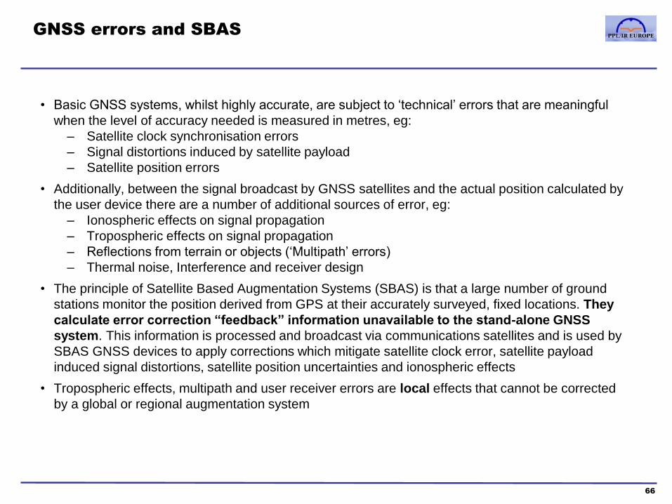
GNSS errors and SBAS
• Basic GNSS systems, whilst highly accurate, are subject to ‘technical’ errors that are meaningful
when the level of accuracy needed is measured in metres, eg:
– Satellite clock synchronisation errors
– Signal distortions induced by satellite payload
– Satellite position errors
• Additionally, between the signal broadcast by GNSS satellites and the actual position calculated by
the user device there are a number of additional sources of error, eg:
– Ionospheric effects on signal propagation
– Tropospheric effects on signal propagation
– Reflections from terrain or objects (‘Multipath’ errors)
– Thermal noise, Interference and receiver design
• The principle of Satellite Based Augmentation Systems (SBAS) is that a large number of ground
stations monitor the position derived from GPS at their accurately surveyed, fixed locations. They
calculate error correction “feedback” information unavailable to the stand-alone GNSS
system. This information is processed and broadcast via communications satellites and is used by
SBAS GNSS devices to apply corrections which mitigate satellite clock error, satellite payload
induced signal distortions, satellite position uncertainties and ionospheric effects
• Tropospheric effects, multipath and user receiver errors are local effects that cannot be corrected
by a global or regional augmentation system
66
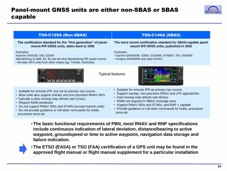
Panel-mount GNSS units are either non-SBAS or SBAS
capable
67
•The basic functional requirements of PBN, most RNAV and RNP specifications
include continuous indication of lateral deviation, distance/bearing to active
waypoint, groundspeed or time to active waypoint, navigation data storage and
failure indication.
•The ETSO (EASA) or TSO (FAA) certification of a GPS unit may be found in the
approved flight manual or flight manual supplement for a particular installation
TSO-C129A (Non-SBAS) TSO-C146A (SBAS)
The certification standard for the “first generation” of panel-
mount IFR GNSS units, dates back to 1996
The more recent certification standard for SBAS-capable panel
mount IFR GNSS units, published in 2002
Examples:
•Garmin GNS430, 530, G1000
•Bendix/King KLN89, 94, 90 and all other Bendix/King IFR panel mounts
• All older GPS units from other makes (eg. Trimble, Northstar)
Examples:
• Garmin GNS430W, 530W, G1000W, GTN650, 750, GNS480
• Avidyne FMS900W and other WAAS
Typical features
• Suitable for enroute IFR, but not as primary nav source
• Most units also support overlay and non-precision RNAV IAPs
• Typically a slow moving map refresh rate (1/sec)
• Require RAIM prediction
• Do not support RNAV SIDs and STARs (except Garmin units)
• Do not provide guidance or roll-steer commands for holds,
procedure turns etc
• Suitable for enroute IFR as primary nav source
• Support overlay, non-precision RNAV and LPV approaches
• Fast moving map refresh rate (5/sec)
• RAIM not required in SBAS coverage area
• Support RNAV SIDs and STARs, and RNP 1 capable
• Provide guidance or roll-steer commands for holds, procedure
turns etc

Course contents
1. PBN & RNP theory
a. Introduction to PBN
b. The Path-Terminator
c. PBN procedure design
2. GNSS
a. GNSS and the GPS system
b. RAIM
c. SBAS
d. Databases
e. Procedures
f. Error detection and warnings
68
3. RNP Approach Procedures
a. Classifications
b. Approach types
c. Requirements and approvals
d. Approach operations
4. Avionics training
5. Simulator and/or Flight training
Appendices
1. Database Coding and Naming Conventions
2. PBN Learning Objectives
3. Additional items mentioned in the PBN
Learning Objectives
Glossary of Abbreviations

What is the AIRAC cycle?
69
• From the Aeronautical Information Management section of the Eurocontrol
website: http://www.eurocontrol.int/aim
Aviation data is constantly changing; airspace structures and routes are
revised, navigation aids change, SIDs and STARs are amended, runway and
taxiway information changes. It is essential, for both efficiency and safety, that
Pilots, Air Traffic Controllers, Air Traffic Flow Managers, Flight Management
Systems and Aviation Charts all have the same data set. How can this be
achieved? The answer is AIRAC
AIRAC stands for Aeronautical Information Regulation And Control and stems
from the ICAO Annex 15 - Aeronautical Information Services (AIS) document.
AIRAC defines a series of common dates and an associated standard
aeronautical information publication procedure for States
All information provided under the AIRAC system is published in paper form
and distributed by national AIS units at least 42 days in advance of the
effective date, with the objective of reaching recipients at least 28 days in
advance of the effective date
• A commercial supplier like Jeppesen thus receives AIS updates at least 28 days
before the Effective Date of a new cycle and uses that time to code the changes
into its electronic and paper products, and to distribute updates to customers
• AIRAC thus provides a standardised batch updating process organised around
13 cycles of data per year, each becoming valid on an Effective Date and
remaining valid for ~28 days until the next Effective Date.
• States may publish charts on a different cycle from AIRAC, eg. 7 or 14 days for
terminal charts, 28 or 56 days for enroute charts
• Jeppesen break down the distribution of paper and electronic charts into 2
batches per AIRAC cycle, delivered at 14 day intervals. GPS databases,
however, are updated 13 times per year in accordance with the AIRAC cycle
• Because the input to an AIRAC cycle is “frozen” up to 42 days before it becomes
effective, more urgent changes are promulgated by NOTAM
Introduction to AIRAC AIRAC Cycle: Jeppesen example
DB Effective Dates
*Database A:
Starts: 12/20/2007
Ends: 1/16/2008
Database B:
Starts: 1/17/2008
Ends: 2/13/2008
*- Database Loaded
• AIRAC cycle Effective Dates are available from AIPs or the Eurocontrol
website, for several years in advance, and from the preface of the Jeppesen
Airway Manual
• Example: imagine today is 14 September 2015, the next AIRAC Effective Date
is 17 September 2015:
M T W T F S S
September 2015
1 2 3 4 5 6
7 8 9 10 11 12 13
14 15 16 17 18 19 20
21 22 23 24 25 26 27
28 29 30 31
today
Next AIRAC
Effective Date
Jeppesen “Issue Date” for
their “01-2008” cycle for
Airway Manuals and
JeppView – changes
become Effective on 25 Jan
Jeppesen “Issue Date” for the
“02-2008” cycle; changes
Effective on 14 Feb
Note: these Jeppesen
products have 26 Issue cycles
per year but they become
effective only on the 13
AIRAC effective dates
• The customer should have received paper chart and JeppView disc updates by today
• NavData GPS updates should be available online from “JSUM”, the update
management software, about 1 week prior to the 17 Jan Effective Date
• If the prior database was loaded in December, and the new database has now been
loaded, the illustration below is an example of how a GPS Database Validity page
should read:
Database now “loaded” for use in
navigation is current and will
expire on 16 January 2008
Next cycle database has been
stored, and will become current on
17 January 2008, when the GPS
unit will automatically load it

Summary: three tasks a GA pilot must perform before using
an approved RNAV database
70
Coverage Currency Cross-Check
• Ensure that the GNSS database
and other charts required have the
coverage needed for the intended
flight - geographic region, specific
airports and types of procedure
• Coverage is not always self-evident for a
user subscribing to European Region data;
the countries included in a given subscription
vary by product
• If you have GNSS database coverage for a
particular country, it may not be included in
the paper chart coverage (or PC readable
electronic version), and vice-versa
• Note: GNSS databases usually do not
include Category A and B approaches
• Ensure that the GNSS database
and other charts required are valid
for the current Effective Period of
the AIRAC cycle
• Check NOTAMs and database
supplier alerts
• Currency is particularly important at present,
because of the rate at which new procedures
are being introduced as many European
countries begin to implement RNAV-1 and
RNP approaches
• It is not legal or practical to try and enter
these as user waypoints. An approved,
current database is essential
• Note that published charts and software
products may distributed up to 2 weeks
before they become effective
• Cross-check the GNSS database
routes and procedures that will be
used against published charts
• The quality of approved navigation data is very
high and gross errors are relatively rare
• However, as new procedures are introduced,
discrepancies arise quite regularly between AIP
charts, commercial service provider charts and
GNSS databases
• In addition, RNAV databases are an inherently
different format from published charts and
some waypoints will not be identical in both
(see ARINC 424 pages later in this section)
• Flying an PBN procedure is not the right time to
be puzzling over such discrepancies
• The requirements for approved database coverage, currency and cross-checks
are not regulatory “gold plating”; they are a practical, as well as legal, necessity
for RNAV operations

If my GNSS database is approved and current, do I really need
to cross-check it with published charts?
71 Sources: http://www.jeppesen.com/download/navdata/German-Step-Down-Fixes-0713.pdf
YES
According to Jeppesen:
• Databases may not contain every SID, STAR and approach procedure.
• Database may not contain every leg or segment of the procedure being flown.
• Not everything needed is in the database.
• The location of each waypoint or navaid retrieved from the database should be
confirmed.
• GNSS and electronic map displays with associated databases are not a substitute for
current published charts.
In addition:
• Many of the GNSS navigators used by GA aircraft do not display altitude restrictions, so
they must be referenced from published charts (SIDs, STARs and Approaches, including
stepdown fixes)
• Databases do not show minima
• Terminal Arrival Altitudes are not shown
• etc

If my GNSS database is approved and current, do I really need
to check NOTAMs for navigation facilities and procedures?
72
EGBJ GLOUCESTERSHIRE GLO
REF: L0004/08
From: 2008-Jan-01 Tue 10:57 To: 2008-May-31 Sat 10:00
ICAO:EGBJ GLOUCESTERSHIRE
RNAV (GNSS) APPROACHES NOT AVBL
REF: L0019/08
From: 2008-Jan-02 Wed 08:00 To: 2008-Mar-31 Mon 23:59
ICAO: EGBJ GLOUCESTERSHIRE
ROTORS RUNNING REFUELS NOT AVAILABLE DURING FOLLOWING
PERIODS: MON-THURS 0830-0900 1815-1900 FRI 0830-0900 1530-
1600 1815-1900 SAT 1100-1130 SUN 1400-1430 1700-1730
REF: L0387/08
From: 2008-Feb-01 Fri 13:32 To: 2008-Feb-29 Fri 09:00
ICAO: EGBJ GLOUCESTERSHIRE
OBST LGT BRG 075 DEG MAG 804M FM ARP U/S
EGBJ: RNAV (GNSS) approach plate
current in AIRAC cycle to 14 Feb 08 EGBJ: Airfield NOTAMs 3 Feb 08
GNSS Approach published, current
and included in databases …but RNAV Approaches NOTAMed not
available
YES
Example: EGBJ Gloucestershire
Do not use for navigation

If am using reputable aviation products, does it matter if the
data is not approved for IFR navigation?
73
Comparison of Raster Chart with
vertical profile depiction
Comparison of Vector chart with Raster chart
position data and vertical profile data
Terrain profile
view understates
actual terrain by
~1500’
Map shift
between Vector
and Raster chart
of ~1nm
YES
Example: non-approved terrain data in popular IFR flight planning software
Flight plan track passes over
7679’ mountain peak “WP1”
indicated on Raster charts
6500’ 5600’ 4700’
6500’ 5700’ 4800’
6800’ 6400’ 5400’
6300’
6400’ 4900’
6200’ 5500’ 4700’
WP1
Underlying terrain data ‘block’
values used in the vertical profile
view. Note that the 7000’ contour
line conflicts with this data
The implied position of
the 7569’ peak based on
the 7000’ contour line in
the Vector chart (actual
peaks not shown)
The position of the 7569’
Peak “WP1” from the
Raster chart
WP1
?
At this sample point, in
the French Alps:
Terrain profile view of the
flight plan track at the 7679’
peak shows a terrain
elevation of only ~6000’
Source: Feb 2007 paper by Vasa Babic, available on www.pplir.org
7000’ contour line from Vector
chart, shown in red for emphasis
Do not use for navigation
Computer Navigation Fix (CNF)
• A Computer Navigation Fix (CNF) is a point defined by a latitude/longitude co-ordinate and is
required to support RNAV system operations.
• Where a procedure does not include all the waypoints needed for RNAV guidance, the state can
define additional “Computer Navigation Fixes” (CNF) or the database supplier will create CNFs and
assign them database identifiers
• The GNSS receiver uses CNFs in conjunction with waypoints to navigate from point to point.
However, CNFs are not recognised by Air Traffic Control (ATC). ATC does not maintain CNFs in
their database and they do not use CNFs for any air traffic control purpose.
• CNFs are usually charted on Jeppesen aeronautical navigation products, are listed in the chart
legends, and are for advisory purposes only. Pilots are not to use CNFs for point to point navigation
(proceed direct), filing a flight plan, or in aircraft/ATC communications. CNFs that do appear on
aeronautical charts allow pilots increased situational awareness by identifying points in the aircraft
database route of flight with points on the aeronautical chart.
• CNFs are random five letter identifiers, not pronounceable like waypoints, and placed in
parenthesis. Eventually, all CNFs will begin with the letters “CF” followed by three consonants (for
example, CFWBG). This five letter identifier will be found next to an “x” on enroute charts and
possibly on an approach chart.
• On instrument approach procedures(charts) in the terminal procedures publication, CNFs may
represent unnamed DME fixes, beginning and ending points of DME arcs, and sensor (ground
based signal i.e., VOR, NDB ILS) final approach fixes on RNAV overlay approaches.
• These CNFs provide the GNSS with points on the procedure that allow the overlay approach to
mirror the ground based sensor approach. These points should only be used by the GNSS system
for navigation and should not be used by pilots for any other purpose on the approach.
74
Course contents
1. PBN & RNP theory
a. Introduction to PBN
b. The Path-Terminator
c. PBN procedure design
2. GNSS
a. GNSS and the GPS system
b. RAIM
c. SBAS
d. Databases
e. Procedures
f. Error detection and warnings
75
3. RNP Approach Procedures
a. Classifications
b. Approach types
c. Requirements and approvals
d. Approach operations
4. Avionics training
5. Simulator and/or Flight training
Appendices
1. Database Coding and Naming Conventions
2. PBN Learning Objectives
3. Additional items mentioned in the PBN
Learning Objectives
Glossary of Abbreviations

Important note
76
• This section of the manual is intended as a guide, not a complete rule book
• A current, approved chart is the definitive source of navigation data; and, in operations where this is approved, a suitable, current database may be used if it agrees with the charted information. In the event of a discrepancy, the charted procedure takes precedence.
• In cases where a database is required (ie RNAV Terminal Procedures and approaches), a discrepancy between the database and chart means that the procedure may not be flown, and an alternative must be used.
• Databases that have expired by no more than 28 days may be used, but only if the relevant waypoints and procedures to be used are checked and found to conform with current published charts.
• In the event of any discrepancy between this document’s description of IFR navigation practice and methods and that of any approved chart, database or product manual, clearly, the published, approved sources must take precedence
• Also, self-evidently, none of the Jeppesen charts or Garmin screen shots in this manual may be used for navigation purposes
• The manual entry, or creation of new waypoints by manual entry, of latitude and longitude or place/bearing/distance values is not permitted into most PBN procedures. The insertion in the flight plan of waypoints loaded from the database is permitted. Route modifications are allowed in the terminal area, with waypoints from the receiver database, up to the Intermediate Fix (IF).
• Pilots must not fly an RNP APCH unless it is retrievable by procedure name from the on-board navigation database and conforms to the charted procedure.
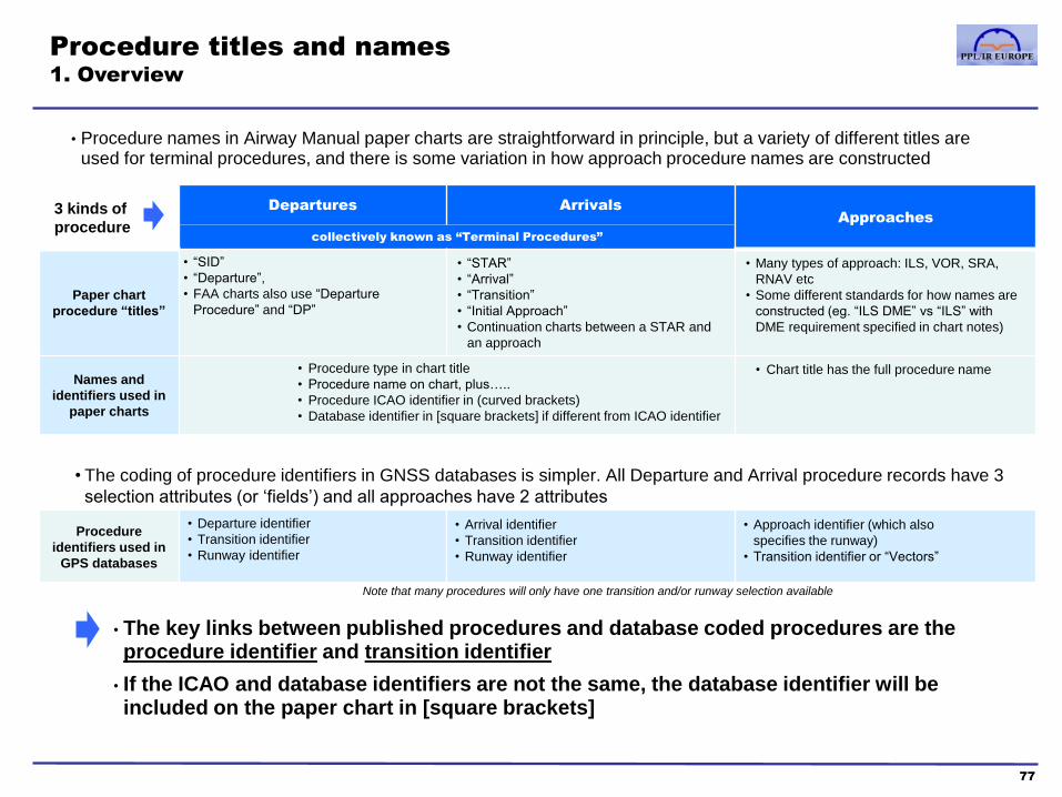
Procedure titles and names
1. Overview
77
3 kinds of
procedure
Departures Arrivals
Approaches
collectively known as “Terminal Procedures”
Paper chart
procedure “titles”
• “SID”
• “Departure”,
• FAA charts also use “Departure
Procedure” and “DP”
• “STAR”
• “Arrival”
• “Transition”
• “Initial Approach”
• Continuation charts between a STAR and
an approach
• Many types of approach: ILS, VOR, SRA,
RNAV etc
• Some different standards for how names are
constructed (eg. “ILS DME” vs “ILS” with
DME requirement specified in chart notes)
Names and
identifiers used in
paper charts
• Procedure type in chart title
• Procedure name on chart, plus…..
• Procedure ICAO identifier in (curved brackets)
• Database identifier in [square brackets] if different from ICAO identifier
• Chart title has the full procedure name
• The coding of procedure identifiers in GNSS databases is simpler. All Departure and Arrival procedure records have 3
selection attributes (or ‘fields’) and all approaches have 2 attributes
Procedure
identifiers used in
GPS databases
• Departure identifier
• Transition identifier
• Runway identifier
• Arrival identifier
• Transition identifier
• Runway identifier
• Approach identifier (which also
specifies the runway)
• Transition identifier or “Vectors”
• The key links between published procedures and database coded procedures are the procedure identifier and transition identifier
• If the ICAO and database identifiers are not the same, the database identifier will be included on the paper chart in [square brackets]
• Procedure names in Airway Manual paper charts are straightforward in principle, but a variety of different titles are used for terminal procedures, and there is some variation in how approach procedure names are constructed
Note that many procedures will only have one transition and/or runway selection available
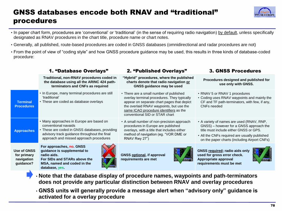
GNSS databases encode both RNAV and “traditional”
procedures
78
1. “Database Overlays” 2. “Published Overlays” 3. GNSS Procedures
Traditional, non-RNAV procedures coded in
the database using all the ARINC 424 path-
terminators and CNFs as required
“Hybrid” procedures, where the published
charts denote that radio navigation or
GNSS guidance may be used
Procedures designed and published for
use only with GNSS.
Terminal
Procedures
• In Europe, many terminal procedures are still
‘traditional’
• These are coded as database overlays
• There are a small number of published
overlay terminal procedures. They typically
appear on separate chart pages that depict
the overlaid RNAV waypoints, but use the
same ICAO procedure identifiers as the
conventional SID or STAR chart
• RNAV 5 or RNAV 1 procedures
• Coding uses RNAV waypoints and mainly the
CF and TF path-terminators, with few, if any,
CNFs needed
Approaches
• Many approaches in Europe are based on
conventional navaids
• These are coded in GNSS databases, providing
advisory track guidance throughout the final
approach and missed approach procedures
• A small number of non-precision approach
procedures in Europe are published
overlays, with a title that includes either
method of navigation (eg. “VOR DME or
RNAV Rwy 27”)
• A variety of names are used (RNAV, RNP,
GNSS) – however for a GNSS approach the
title must include either GNSS or GPS.
• All the CNFs required are usually published
on the paper charts (including Airport CNFs)
Use of GNSS
for primary
navigation
guidance?
For approaches, no. GNSS
guidance is supplemental to
radio aids.
For SIDs and STARs above the
MSA, named and coded in the
database, yes.
GNSS optional, if approval
requirements are met
GNSS required; radio aids only
used for gross error check.
Appropriate approval
requirements must be met
• Note that the database display of procedure names, waypoints and path-terminators does not provide any particular distinction between RNAV and overlay procedures
• GNSS units will generally provide a message alert when “advisory only” guidance is activated for a overlay procedure
• In paper chart form, procedures are ‘conventional’ or ‘traditional’ (in the sense of requiring radio navigation) by default, unless specifically designated as RNAV procedures in the chart title, procedure name or chart notes.
• Generally, all published, route-based procedures are coded in GNSS databases (omnidirectional and radar procedures are not)
• From the point of view of “coding style” and how GNSS procedure guidance may be used, this results in three kinds of database-coded procedure:

Procedure titles and names
2. Background on terminal procedure titles
79
• Terminal procedures always serve to provide safe obstacle and terrain clearance for flight in IMC –“general” procedures, serving mainly this purpose, may be published in text and/or chart form, and may not have ICAO identifiers or even specific route names
• Terminal procedures may also be used for ATC and flight planning purposes: to standardise the transition between the enroute airway network and TMAs, and to standardise routes within TMAs, so that traffic flows may be efficiently managed and ATC communications simplified
–procedures also serving this purpose are generally called “standard” instrument departures (SIDs) and “standard” arrivals (STARs)
• In practice, in Europe, most terminal procedures are SIDs and STARs, and “general” procedures, without the formal ATC function, are labelled “Departures” and “Arrivals”
• However, the nomenclature of terminal procedure titles is not perfectly standardised
• In particular, busy airports often use a more complex set of arrival procedure structures than just the basic model of STARs from the enroute segment to the IAF. These airports may also have arrival charts with a variety of titles such as “Arrivals”, “Transitions”, “Initial Approaches” etc. which have the same ATC status as STARs.
• Transitions can be named either after their start or end waypoint; there may be a naming discrepancy between that shown in the published chart and that displayed on the GNSS Navigator. If a Transition cannot be found on the Navigator, compare the name with the starting and ending waypoint on the published chart to see which is being used.
• The FAA also uses some slightly different procedure titles which are not detailed in this manual

‘general’ IFR procedures standard IFR procedures
Traditional
RNAV
also
Procedure titles and names
3. Departures
80
waypoint 1 digit 1 letter (ICAO designator) [database identifier]
Departure titles in Jeppesen charts:
SID name format in Jeppesen charts:
Example:
In Europe, usually
the full name of
the waypoint or fix
at the end of the
procedure
Version number
of the procedure,
increased by 1
every time a
change is made,
cycling back to 1
after 9
Often the code letter for
a particular departure
runway. More than one
letter may be used for
the same runway, and
the letter codes may
have another meaning
(eg. routes for Jet vs
Prop aircraft)
The ICAO procedure
“designator“ is used for
flight plan filing. It uses the
ICAO identifier for the final
waypoint instead of its full
name (if these are different,
eg. Lambourne Three
Alpha vs. LAM 3A)
The ARINC 424 procedure name is limited
to 6 characters. If the name of the final fix is
a 3 letter VOR ident, the ICAO procedure
identifier will be 5 characters (3+1+1) and
used as the database identifier.
If the final waypoint name is a 5LNC (as in
the example above), the database identifier
will drop the last character of the 5LNC, and
be printed separately in [square brackets]
• The structure of instrument departures is relatively simple and homogenous, they all start on the runway and generally end with an enroute waypoint

Example of a (non-SID) Departure
81
Runway ID
5LNC
Garmin GNS530W procedure selection page
Garmin GNS530W flight plan waypoint list
Bearing/
Distance
CNFs
Note that the Procedure bearing/distance CNF names in this example appear to be referenced
to the BIA NDB at the centre of the airport, the “078” bearing implicit in both names is only
approximate, the alphabet distance codes are more accurate. The naming convention’s
purpose is to create a distinct identifier for CNFs but no navigation meaning should be inferred
from the identifier text (eg. “the next waypoint is D078B so I must fly a track of 078 degrees”) –
navigation data is accurately depicted in the path-terminator information to the right of the
waypoint name and the GNSS Nav or Map pages provide the approved source of guidance
CNF comment
Note that, since these procedures are
not SIDs and do not have an ICAO
identifier, ATC will include the
departure route as part of the overall
clearance, eg. “G-ABCD, cleared to
Jersey via THRED R41 ORTAC…”
and not “G-ABCD, cleared to Jersey
via Runway 08 South departure…”
The South departure is
coded because it has a
specific route (to THRED)
and “South” is used as the
database identifier even
though there is no ICAO
identifier. The West
departure is not coded,
since it lacks a specific
route.
Do not use for navigation
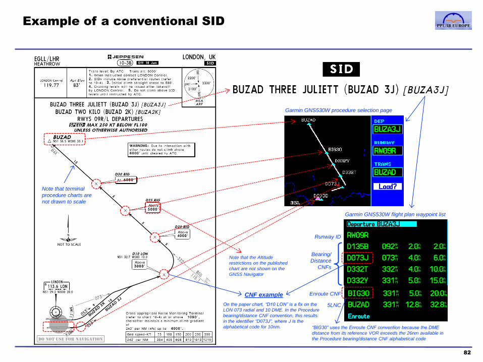
Example of a conventional SID
82
Note that terminal
procedure charts are
not drawn to scale
Runway ID
Enroute CNF
5LNC
Garmin GNS530W procedure selection page
Garmin GNS530W flight plan waypoint list
Bearing/
Distance
CNFs
On the paper chart, “D10 LON” is a fix on the
LON 073 radial and 10 DME. In the Procedure
bearing/distance CNF convention, this results
in the identifier “D073J”, where J is the
alphabetical code for 10nm.
CNF example
“BIG30” uses the Enroute CNF convention because the DME
distance from its reference VOR exceeds the 26nm available in
the Procedure bearing/distance CNF alphabetical code Do not use for navigation
Note that the Altitude
restrictions on the published
chart are not shown on the
GNSS Navigator

Example of an RNAV SID
83
Garmin GNS530W procedure selection page
Garmin GNS530W flight plan waypoint list
Runway ID
5LNC
VOR ident
Bearing/
Distance
CNFs
Note that the bearing/distance CNF identifier “D097C” is referenced from the BT VOR to the
northeast of the Le Bourget. The path-terminator data correctly identifies the track to this waypoint
as 086 degrees after take-off. The along-track distance is coded as 4nm from the start of the take-
off roll. The turning point for the 097 degrees track to “PB093” is published on the chart as 2.6nm
DME distance from the BT VOR. This, rather than the CNF, should be used for primary guidance.
Note “PB093” is a tactical RNAV waypoint identifier, not a CNF.
CNF comment
Question 2:
What is the
difference
between the
“J” and “M”
designators?
(see next page)
Question 1:
Is this a RNAV 1
or RNAV 5 route,
it’s not explicit on
the chart?
(see next page)
Note that PB093 is a Fly-Over
waypoint. These are only
used in RNAV procedures
when turn anticipation is
undesirable; in this case, the
large track change would
result in a very early turn,
especially for fast aircraft, if it
were a Fly-By waypoint
Note that ICAO identifiers are only
printed on the route plan depiction
on this particular chart, not at the top
of the page, as is more common
Note that multiple runways
share the same departure
procedures, hence the
runway field has 3 options
available in the procedure
selection page
Do not use for navigation

Example of an RNAV SID (..continued from previous page)
84
Question 2: (referring to previous page)
What is the difference between the “J” and “M” designators?
Question 1: (referring to previous page)
Is this a RNAV 1 or RNAV 5 route, it’s not explicit on the chart?
• Page 30-3 of the LFPB charts has
departure instructions that are helpful for
interpreting the individual SID pages
• The final letter of the procedure identifier, in the case of LFPB, does not specify a particular
departure runway but the departure direction (W or E) and whether Orly departures are in the
same or reverse direction. This relates to the proximity of the 3 large Paris airports
• Paragraph 1.1 describes how the procedures are designed to protection criteria suitable for
RNAV 5 GNSS, however 1.2 specifies that AIC/AIP sources must be checked for the
minimum requirements; which are RNAV 5 approval in this case. A RNAV 1 requirement
would normally be specified here and on the individual RNAV chart pages - see Section 3.

Example of a SID with a published RNAV Overlay
85
Note that the routes and ICAO
identifiers are the same
The overlay chart depicts RNAV
waypoints instead of radio fixes
Since the procedure identifiers
are the same, there is only one
database coded procedure for
each conventional route and its
overlay version. The published
RNAV tactical waypoint names
are used, and not CNF identifiers
created by Jeppesen
Note: State AIP charts often publish SIDs for the same runway on the same chart. In this case,
the RNAV overlay is only detailed in the in the German AIP text page following the 32R SID chart
Do not use for navigation

Example of a SID followed by Transition routes
86
LSGG Geneva
waypoint digit letter (ICAO designator) [database identifier]
• Geneva is an example (relatively rare in Europe) where some SIDs are followed by a number of different Transition routes connecting to the airways around the TMA
• The SIDs have the usual ICAO designators and are coded in the database with appropriate identifiers
• The transitions are RNAV 5 ATS routes, published in the paper chart but, in this example, without ICAO designators and they are not coded as routes in the GNSS database
• (An airline’s customised database may include such routes)
Garmin
GNS530W
[database
identifier]
No other
transition
available
Do not use for navigation
Do not use for navigation

Example of a SID which is not coded in RNAV databases
87
EICK Cork
• Although this chart has a SID title, the omnidirectional departures do not have a route structure, so they are not coded as a departure procedures in the database.
• Route based SIDs are also available at EICK
Do not use for navigation

The 5
segments of
an instrument
procedure
Approach
transitions
Arrival
transition
segments
common route
segment
Approach chart STAR chart
Structure of Arrival and Approach procedures
1. The ICAO model
88
Initial segment
IAF1
IF FAF MAP
Arrival route Intermediate
segment
Missed
approach
segment
Enroute
a
Enroute
b
Enroute
c
IAF2
IAF3
Transition ID a
Transition ID b
Transition ID c
Transition ID (=initial waypoint ) & Arrival Designator
Transition ID 1
Transition ID 2
Transition ID 3
Approach ID
Final segment
Mapping of the model to Jeppesen charts:
The ICAO arrival and approach procedure model:
In Europe, arrival procedures
usually have a unique starting point
rather than multiple transitions
Instrument approaches are generally coded with more than
one IAF starting point selection available within the
Approach Transition field of the procedure record
Mapping of the chart structure to GNSS database procedure records
• The typical arrival structure involves STAR routes beginning at enroute waypoints and ending at the IAF and Instrument Approach procedures starting at the IAF

Structure of Arrival and Approach procedures
2. Example of conventional STAR and Approach structure
89
STAR chart
1.STAR routes begin
at enroute fixes
2.They end at the Initial
Approach Fix (IAF)
3. The IAF is then used
as the track and course
reversal navigation
reference for Approach
procedures
Note: the JW NDB is the IAF in this case
Approach chart Do not use for navigation
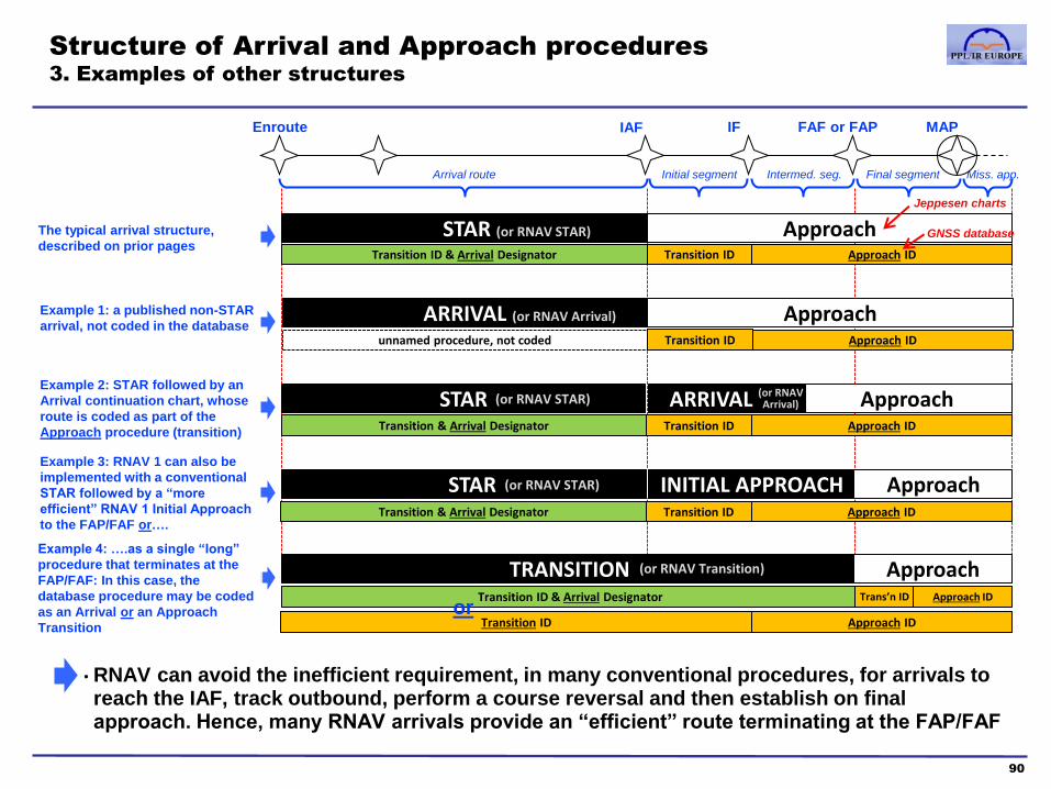
Initial segment Arrival route Intermed. seg. Miss. app. Final segment
IF FAF or FAP MAP Enroute IAF
Structure of Arrival and Approach procedures
3. Examples of other structures
90
• RNAV can avoid the inefficient requirement, in many conventional procedures, for arrivals to reach the IAF, track outbound, perform a course reversal and then establish on final approach. Hence, many RNAV arrivals provide an “efficient” route terminating at the FAP/FAF
Approach STAR (or RNAV STAR)
Transition ID & Arrival Designator Transition ID Approach ID
Approach ARRIVAL (or RNAV Arrival)
unnamed procedure, not coded Transition ID Approach ID
Approach STAR Transition & Arrival Designator Transition ID Approach ID
ARRIVAL
STAR INITIAL APPROACH Approach
TRANSITION Approach
The typical arrival structure,
described on prior pages
Example 1: a published non-STAR
arrival, not coded in the database
Example 2: STAR followed by an
Arrival continuation chart, whose
route is coded as part of the
Approach procedure (transition)
(or RNAV STAR)
(or RNAV Arrival)
Jeppesen charts
GNSS database
Example 3: RNAV 1 can also be
implemented with a conventional
STAR followed by a “more
efficient” RNAV 1 Initial Approach
to the FAP/FAF or….
Transition ID & Arrival Designator
(or RNAV Transition)
Approach ID Transition ID
Transition & Arrival Designator Transition ID Approach ID
Example 4: ….as a single “long”
procedure that terminates at the
FAP/FAF: In this case, the
database procedure may be coded
as an Arrival or an Approach
Transition
Trans’n ID Approach ID
(or RNAV STAR)
or

‘general’ IFR procedures standard IFR procedures
Traditional
RNAV
Procedure titles and names
4. Arrival procedures
91
Summary of Arrival procedure titles in Jeppesen charts:
• Note that an “Arrival” chart may be a ‘general’ route (not coded in the RNAV database), or a continuation route coded within the transition selections for an approach
• The examples that follow illustrate each of the procedure types
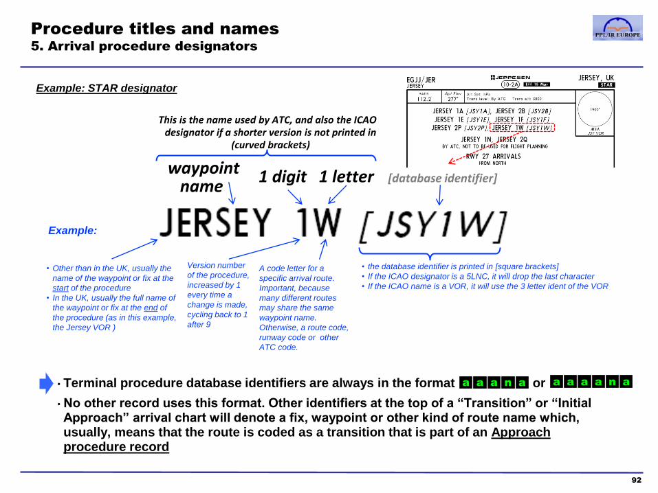
• the database identifier is printed in [square brackets]
• If the ICAO designator is a 5LNC, it will drop the last character
• If the ICAO name is a VOR, it will use the 3 letter ident of the VOR
Procedure titles and names
5. Arrival procedure designators
92
1 digit 1 letter [database identifier]
Example:
• Other than in the UK, usually the
name of the waypoint or fix at the
start of the procedure
• In the UK, usually the full name of
the waypoint or fix at the end of
the procedure (as in this example,
the Jersey VOR )
Version number
of the procedure,
increased by 1
every time a
change is made,
cycling back to 1
after 9
A code letter for a
specific arrival route.
Important, because
many different routes
may share the same
waypoint name.
Otherwise, a route code,
runway code or other
ATC code.
• Terminal procedure database identifiers are always in the format or
• No other record uses this format. Other identifiers at the top of a “Transition” or “Initial Approach” arrival chart will denote a fix, waypoint or other kind of route name which, usually, means that the route is coded as a transition that is part of an Approach procedure record
waypoint name
This is the name used by ATC, and also the ICAO designator if a shorter version is not printed in
(curved brackets)
Example: STAR designator
a a a n a a a a a n a

Procedure titles and names
6. Transition and Initial Approach examples
93
Approach ID RNAV TRANSITION Approach
Transition ID
RNAV TRANSITION Approach Transition ID & Arrival Designator
Approach ID INITIAL APPROACH Approach
Transition ID
1. No route designator…
2. but the route starts at
“BIG” VOR
3. and BIG is also
labelled as the IAF, and
various EGLL STARs
terminate at BIG
4. hence it is an
Approach procedure
record
5. with “BIG”
available as the
Approach transition
1. The route name is not a
procedure identifier
The route starts at “PSA”
VOR and is for Runway 07
approaches, thus the route
name used is “PSA 07”
2. hence it is an
Approach procedure
record
3. with “PSA”
available as the
Approach transition
1. The chart has an ICAO
procedure designator (and
a database procedure
identifier)
4. The route starts at “VELAG”, which is the
only available transition in the database
2. hence it is an
Arrival procedure
record
3. with “NEMA1A” as
the identifier
Approach ID
Note that both the EGLL and EDDF examples, although coded in the database as
Approach transitions, appear in the STAR section of their respective State AIPs
STAR INITIAL APPROACH Approach
Transition & Arrival Designator Transn ID Approach ID
Do not use for navigation

Example of a ‘general’ Arrival
94
Note that, since these procedures are
not STARs and do not have an ICAO
identifier or published route name, ATC
will include the arrival route as part of
the overall clearance, eg. “G-ABCD,
route direct Westcott PEPIS SAM…” The Arrival record selection includes all of
the published STARs for EGHH, which
are coded in the normal way, but not any
routes called “North” or “Northeast” - they
are not coded in the database
The approach procedures at EGHH have
only one transition available, the “BIA”
NDB on the airport, plus Vectors to Final.
In this example, at the end of the arrival
route, an aircraft would be cleared to the
BIA for a procedural approach or be given
radar vectors to the localiser
Garmin GNS530W
procedure selection pages
Do not use for navigation

Example of a conventional STAR
95
NDB ident
Garmin GNS530W procedure selection page
Garmin GNS530W flight plan waypoint list
5LNCs
KOKOS
(name cropped
on screen edge)
OYSTA
(name cropped
on screen edge)
Chart cropped below this point
Do not use for navigation

Example of an RNAV STAR to the IAF
(but see next page) (For illustrative purposes: this procedure no longer exists)
96
Garmin GNS530W procedure selection page
Garmin GNS530W flight plan waypoint list
VOR ident
5LNC
VOR/
Distance
CNFs
Note the comment that the route segment to MERUE is only if holding there. (The
AIP chart is clearer and shows a dotted line for the MONKO to MEURE segment)
Is this a RNAV 1 or RNAV 5
route? Page 30-2 of the LFPB
charts has overall information
on arrivals and includes the
comment
The charted procedure
seems to end at MERUE
but in the GNSS
database DPE4P ends at
MONKO?
The runway field is “All” if
the same route is used for
more than one runway. In
this case, the procedure is
for 2 of the 6 runways at
LFPB
?
In fact, LFPB is an example of an airport that uses an “RNAV
STAR” chart followed by an “RNAV Arrival” continuation chart
- see next page Do not use for navigation
STARs are published RNAV and are available in RNAV 5
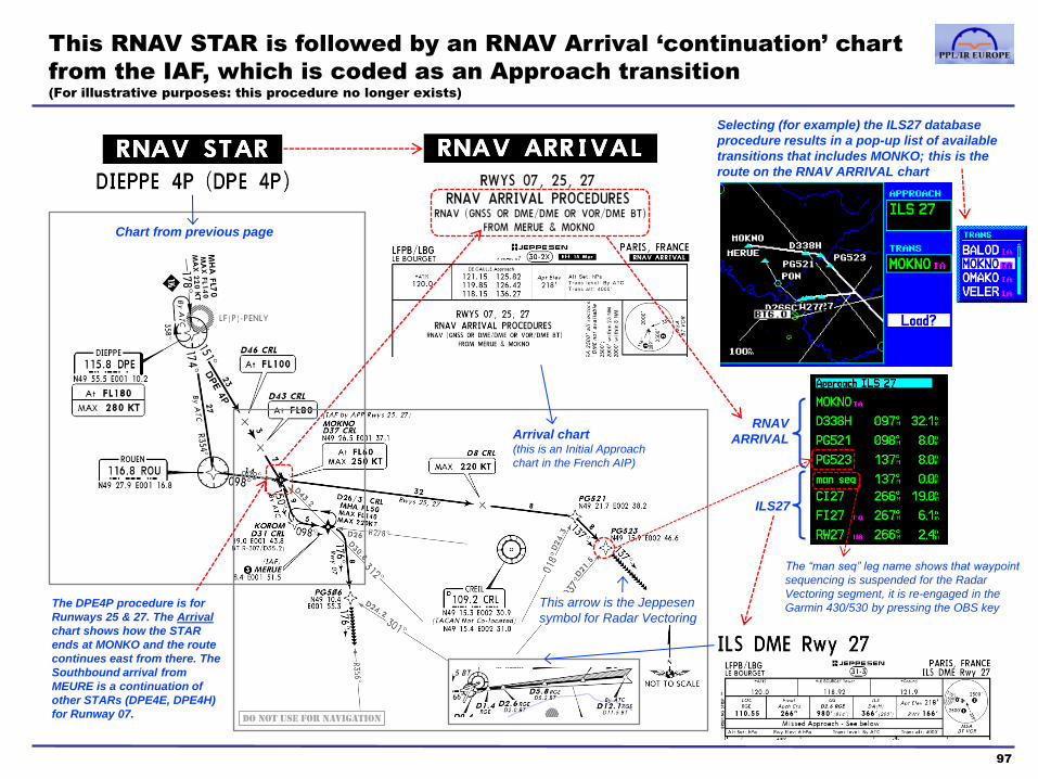
This RNAV STAR is followed by an RNAV Arrival ‘continuation’ chart
from the IAF, which is coded as an Approach transition
(For illustrative purposes: this procedure no longer exists)
97
Chart from previous page
Arrival chart (this is an Initial Approach
chart in the French AIP)
Selecting (for example) the ILS27 database
procedure results in a pop-up list of available
transitions that includes MONKO; this is the
route on the RNAV ARRIVAL chart
RNAV
ARRIVAL
ILS27
This arrow is the Jeppesen
symbol for Radar Vectoring
The “man seq” leg name shows that waypoint
sequencing is suspended for the Radar
Vectoring segment, it is re-engaged in the
Garmin 430/530 by pressing the OBS key The DPE4P procedure is for
Runways 25 & 27. The Arrival
chart shows how the STAR
ends at MONKO and the route
continues east from there. The
Southbound arrival from
MEURE is a continuation of
other STARs (DPE4E, DPE4H)
for Runway 07. Do not use for navigation

Example of an RNAV transition to the final approach
(coded in the database as an Arrival Procedure)
(For illustrative purposes: this procedure no longer exists)
98
Garmin GNS530W procedure selection page
Garmin GNS530W flight plan waypoint list
(IAF) 5LNC
These are tactical RNAV waypoints (not
CNFs) – using the “aannn or aaann”
convention, in this case “NX” are the last two
letters of the EGNX identifier, “S” indicates a
Southerly arrival, and the two digits are the
along-track distance to touchdown in nm
5LNC
Airport CNF
Note QNH setting is
based on LNAV reference
Note various level, altitude and
speed limits at Waypoints
Do not use for navigation

Example of an RNAV transition to the final approach
(coded in the database as an Approach Transition)
99
Garmin GNS530W procedure selection page
Garmin GNS530W flight plan waypoint list
5LNCs
These tactical RNAV waypoints
use the “aannn” convention, in this
case “DF” are the last two letters of
the EDDF identifier. The last 3
digits are arbitrary and unique
within the Frankfurt TMA
5LNC
Airport CNFs
• The transition route name on the chart is
the name of the waypoint at the start of the
procedure plus the runway number (ROLIS
07) and the database identifier in square
brackets is an abbreviated version of this
(ROL07).
• GNSS databases do not use this
convention. All transitions are waypoint
identifiers only (ROLIS in this example)
• The RNAV procedure must be cross-
checked against the paper chart to ensure
the ROLIS RNAV transition route is the
same as the charted ROLIS 07 route
Note that some RNAV Transitions
often do not specify an IAF and/or
IF, only the FAF or FAP
Do not use for navigation
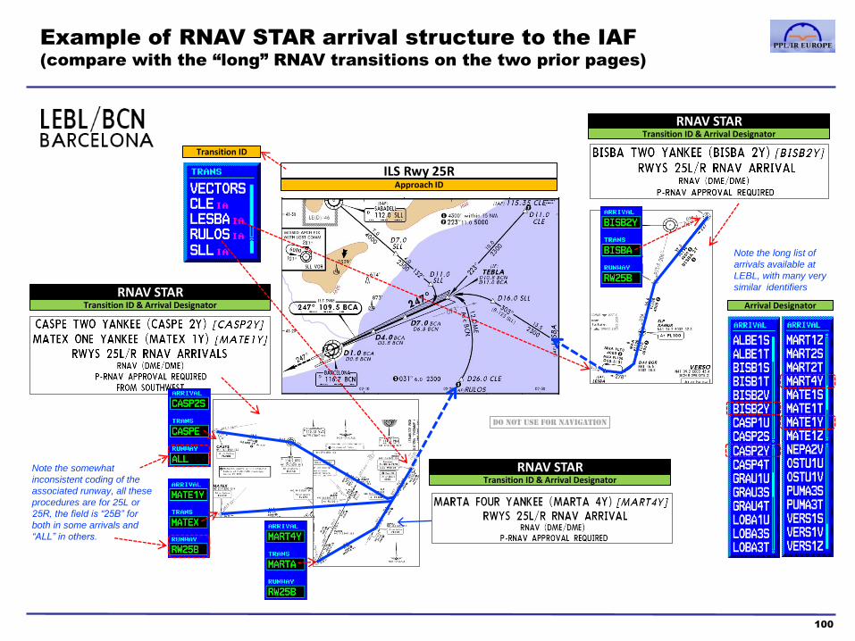
Example of RNAV STAR arrival structure to the IAF
(compare with the “long” RNAV transitions on the two prior pages)
100
RNAV STAR Transition ID & Arrival Designator
ILS Rwy 25R
Transition ID
Approach ID
RNAV STAR Transition ID & Arrival Designator
RNAV STAR Transition ID & Arrival Designator Arrival Designator
Note the long list of
arrivals available at
LEBL, with many very
similar identifiers
Note the somewhat
inconsistent coding of the
associated runway, all these
procedures are for 25L or
25R, the field is “25B” for
both in some arrivals and
“ALL” in others.
Do not use for navigation

Altitude and Speed restriction coding in ARINC 424
database procedures
101
• In departures, a speed limit is applied backwards from the
terminator of the leg on which the limit is encoded to the start of
the procedure, or to the first prior speed limit
• In arrivals, a speed limit is applied forwards from the speed limit
point to the end of arrival, unless a subsequent speed limit is
encoded
• Speed restrictions that only apply during specific times are not
coded
Speed Restrictions
• Altitude restrictions are usually applied at waypoints, although
ARINC 424 provides a number of different ways they can be
coded.
• The altitude field will designate whether a waypoint should be
crossed “at”, “at or above” or “at or below” or “between” specified
altitudes or flight levels.
• If a published departure requires a turn greater than 15
degrees from the runway heading after take-off, without an
altitude specified before the turn, the GNSS database will
generally include a CA, VA, or FA on the runway heading to
an altitude of 400 feet (or as specified by source) as the first
leg of the departure
• Conditional altitudes (eg. turn at 2000’ or 4DME whichever is
later) are treated in different way by different FMS types.
• Altitude restrictions that only apply during specific times are not
coded
Altitude Restrictions
• ARINC 424 provides for the encoding of altitude and speed restrictions published in IFR procedure charts and this feature is implemented in modern Flight Management Systems
• Speed and Altitude restrictions are part of path-terminator records, or the waypoint associated with a path-terminator.
• This data is generally not implemented in panel-mount GNSS units, or the integrated ‘glass cockpits’ currently fitted to GA aircraft, except for the altitude terminator of the CA, VA or FA leg types (course, heading and track to altitude respectively). For SBAS approved receivers FA leg types are used for defining the altitude at which a turn can be commenced to the missed approach holding point. For non-SBAS receivers it is important not to unsuspend waypoint progression after a missed approach until you have reached the initial turning altitude required
• A brief description of the coding is provided below; however, any further detail is beyond the scope of this course.

Approach Procedures: Introduction
102
Database Overlays
Published Overlays
RNP APCHs
Approved flight
procedure • No • Yes • Yes
Precision
Approach
• All ILS approaches are coded as
database overlays • GLS approaches (not used by GA)
• LPV approaches with 200’ DH
Approach with
Vertical
Guidance
• LPV approaches with higher DH
• LNAV/VNAV approaches
Non-Precision
Approach
• Most published conventional non-
precision approach procedures
(VOR,NDB) are coded as database
overlays
• Radar approaches are not coded
• A small number of non-precision
approach procedures in Europe are
published overlays, with a title that
includes an RNAV method of
navigation (eg. “VOR DME or RNAV
Rwy 27”)
• LNAV approaches
• LNAV+V (Garmin – Advisory GS only)
• This section will review how conventional and RNP APCHs are coded and presented in GNSS databases, and the formats used for approach procedure names and database identifiers
• The examples illustrate the RNP APCH issues relevant to this section, but not every variety of procedure is detailed
• Note that important topics not specific to RNP APCH (eg. approach minima, circle-to-land procedures, obstacle clearance and MSAs) are not considered
• The detailed description of Database Overlays does not imply that GNSS can be used as primary guidance for conventional approaches.
• Some receivers do not provide guidance for some of the path-terminators used in database approach overlays. A pilot relying on such GNSS guidance may find that it is suspended, and no “magenta line” and CDI indication (or autopilot LNAV commands) are present during critical segments of approach or missed approach procedures

Procedure titles and names
5. Jeppesen chart index number convention
103
• Usually 1, but higher numbers
are used to distinguish airports
under the same city name
• For example, for LONDON UK,
1 is used for Heathrow, 2 for
Gatwick, 3 for Stansted, 4 for
London City, etc
1st
digit: arbitrary Airport
number
0 – terminal procedure and airport charts
1 – ILS, LOC, LDA (also MLS, SDF, KRM)
2 – GPS (sole use of GPS, not “or GPS”)
3 – VOR
4 – TACAN
5 – Reserved, not currently used
6 – NDB
7 – DF (radio direction finding, QDM approach)
8 – Radar approaches (eg. SRA, PAR)
9 – Vicinity chart, Visual chart
2nd
digit: Chart Type
• For example, in the illustration
above, further ILS approach
charts at EGHH would have a
chart index of 11-2, 11-3 etc
• Note that the “0” chart type can have
many pages of SIDs and STARs, hence
the sequence number may be in the
format 1digit+1letter or 1digit+1letter+
1digit if required
for example:
3rd
digit: sequence number
for charts of the same type
Source: Jeppesen airway manual chart legend section
Jeppesen chart index example
Note on AIP chart naming conventions
There is not a consistent standard for AIP chart names. For example, the UK uses 2:Aerodrome, 4:Airspace, 5:MVA, 6:SID, 7:STAR, 8:Approach. In Germany, it is
2:Aerodrome, 3: STAR, 4:Approach, 5:SID. Other states don’t use a numbered convention, but titles such as IAC, SID, STAR, VAC and sort the charts in that order

Procedure titles and names
6. Approach chart name conventions
104
• Until a few years ago, the ICAO standard for approaches was that the procedure title should include the navaids to be used. This convention led to a significant amount of variation from state to state, and the requirements for navigation equipment were not always explicit.
• The present convention is more highly standardised, but some current European charts still use the former ICAO standards
• The current convention is summarised in the form of the 7 rules below:
• The chart title is the primary
navaid for the procedure plus
“Rwy” and the runway identifier
• eg. ILS Rwy 27, NDB Rwy 09L
• “ILS” means that both the localiser
and glideslope are required
• “LOC” is used instead of “LLZ” as
the Localiser abbreviation
Rule 1: Basic name
• If more than one type of
procedure is published on the
same page, then “or” is used
• eg. ILS or LOC Rwy 27
VOR or NDB Rwy 09L
Rule 2: “or”
• If navaids other than the primary
one are required, this is noted on
the chart rather than included in
the title; eg. “ILS Rwy 27” with a
chart note if DME is required
• Some countries continue to
include DME in the chart title
Rule 3: Secondary navaid
• The chart notes may include
other important requirements eg.
other navaids, communications
equipment, crew training or
authorisations, ATC radar
availability etc
Rule 4: Chart notes
• When there are multiple procedure charts of the same type for the
same runway, their titles are differentiated by adding a single letter,
(starting at “Z” and sequenced in reverse alphabetical order) after the
navaid type and before “Rwy”
• The multiple procedures may relate to different final approach transition
routes published on different pages, requirements for navigation
equipment, charts for different aircraft categories or variations on an
approach design for other operational reasons
• eg. ‘VOR Z Rwy 09L’ followed by ‘VOR Y Rwy 09L’
Rule 5: Multiple procedures
• When a procedure does not
meet straight-in landing minima,
the navaid is followed by “A”.
Subsequent such procedures at
the same airport will use “B”, “C”
etc
• eg. NDB A Rwy 09
Rule 6: Offset final approach
• The current standard is to use
the more generic ‘RNAV’ instead
of GNSS, but GNSS still appears
on a few current charts
• RNP APCHs may specify the
equipment type to be used or an
RNP value required
• The standard is changing to RNP
Rule 7: RNAV

• Example where there are two VOR approach charts to Runway 04,
hence the procedure titles ‘VOR X’ and ‘VOR Y’
• The difference between them is that the ‘VOR Y’ approach has a
later missed approach point (1d inbound from SSN, rather than at
SSN) and correspondingly lower minima
• Only the ‘Z’ variant is coded in the GNSS database, and the
procedure identifier does not include the ‘Z’ character
• In this example, there is only a very small difference between the
“Z” and “Y” procedure, but some alternatives of this kind may have
wholly different routes. In either case, an ARINC database includes
only one procedure of a given type (eg. VOR) per runway and does
not store the “Z”, “Y”, “X” procedures as individual records: there is
not always a systematic mapping between paper charts and
database procedure selections
• It is doubly important to cross-check the database with the
procedure chart in such cases
Procedure titles and names
7. Example of the “Z, Y, X...” approach procedure title convention
105
‘DME required’ chart note
The Garmin 530 database
has 2 approach selections
available for LESO. Note
that the NDB procedure is
“CAT A&B” only and thus
not coded in the database
The VOR/DME 04 procedure has
several transition (starting) waypoints
available, as per the main chart and
the small ‘Arrival Routes’ inset, but
not a “Z” or “Y” selection
The coded version of the procedure has the
MAP at SSN, not 1d inbound from it as in
the ‘Y’ variant. (the small pink letters ‘IA’,
‘FA’ and ‘MA’ denote the IAF, FAF and
MAP respectively. Note that the missed
approach waypoints are not shown above)
Do not use for navigation
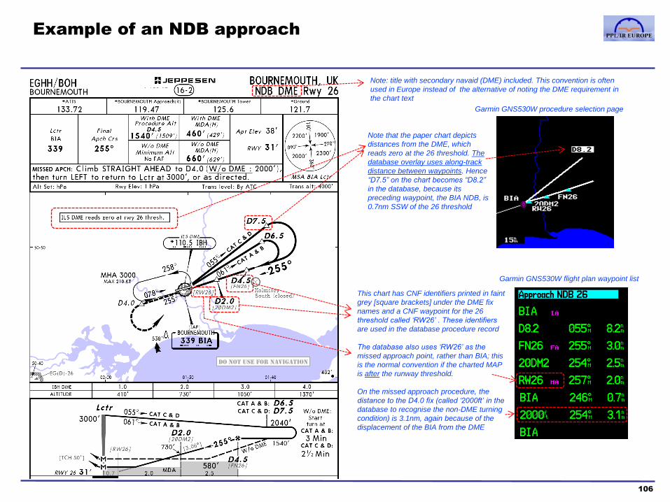
Example of an NDB approach
106
Garmin GNS530W procedure selection page
Garmin GNS530W flight plan waypoint list
This chart has CNF identifiers printed in faint
grey [square brackets] under the DME fix
names and a CNF waypoint for the 26
threshold called ‘RW26’ . These identifiers
are used in the database procedure record
The database also uses ‘RW26’ as the
missed approach point, rather than BIA; this
is the normal convention if the charted MAP
is after the runway threshold.
On the missed approach procedure, the
distance to the D4.0 fix (called ‘2000ft’ in the
database to recognise the non-DME turning
condition) is 3.1nm, again because of the
displacement of the BIA from the DME
Note: title with secondary navaid (DME) included. This convention is often
used in Europe instead of the alternative of noting the DME requirement in
the chart text
Note that the paper chart depicts
distances from the DME, which
reads zero at the 26 threshold. The
database overlay uses along-track
distance between waypoints. Hence
“D7.5” on the chart becomes “D8.2”
in the database, because its
preceding waypoint, the BIA NDB, is
0.7nm SSW of the 26 threshold
Do not use for navigation
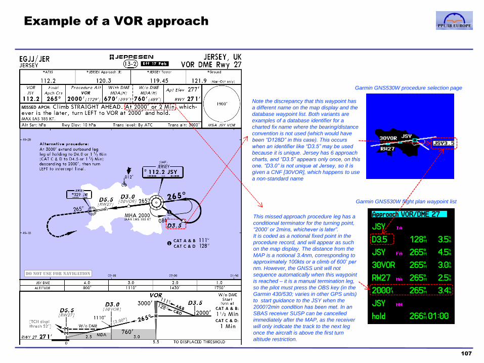
Example of a VOR approach
107
Garmin GNS530W procedure selection page
Garmin GNS530W flight plan waypoint list
This missed approach procedure leg has a
conditional terminator for the turning point,
“2000’ or 2mins, whichever is later”.
It is coded as a notional fixed point in the
procedure record, and will appear as such
on the map display. The distance from the
MAP is a notional 3.4nm, corresponding to
approximately 100kts or a climb of 600’ per
nm. However, the GNSS unit will not
sequence automatically when this waypoint
is reached – it is a manual termination leg,
so the pilot must press the OBS key (in the
Garmin 430/530; varies in other GPS units)
to start guidance to the JSY when the
2000’/2min condition has been met. In an
SBAS receiver SUSP can be cancelled
immediately after the MAP, as the receiver
will only indicate the track to the next leg
once the aircraft is above the first turn
altitude restriction.
Note the discrepancy that this waypoint has
a different name on the map display and the
database waypoint list. Both variants are
examples of a database identifier for a
charted fix name where the bearing/distance
convention is not used (which would have
been “D128D” in this case). This occurs
when an identifier like “D3.5” may be used
because it is unique. Jersey has 6 approach
charts, and “D3.5” appears only once, on this
one. “D3.0” is not unique at Jersey, so it is
given a CNF [30VOR], which happens to use
a non-standard name
Do not use for navigation

Example of an ILS approach
108
Garmin GNS530W procedure selection page
Garmin GNS530W flight plan waypoint list
Note that RARIX, the charted final approach
point, is preceded by a turn from either of
the two IAFs. Older FMS units cannot
support a final approach fix without a prior
waypoint on the final approach track. Hence,
the database procedure uses RARIX as the
final approach course fix and a CNF at the
outer marker (FI32R) as the FAP. This is
“discrepancy” exists only to support a
technicality of older FMS units and illustrates
why non-approved database overlays must
not be used for primary guidance – a pilot
flying this procedure must observe the
published FAP at RARIX
A CNF is created in the coded procedure
corresponding to the intersection between the
COL 246 radial and the lead-in radial for the
turn to the final approach (131 radial KBO)
This is a conventional
transition, the transition
selections available for this
procedure also include ‘long’
RNAV arrivals
Do not use for navigation

Example of an RNP approach
109
Garmin GNS530W procedure selection page
Garmin GNS530W flight plan waypoint list
Note that in this procedure, RARIX is coded
as the Final Approach Fix (compare with
the previous page)
The step down fix is coded with the
published CNF identifier: the “30” refers to
3.0nm to the “TH” (Threshold), the “4” is a
code number to used to uniquely identify
each of the CNFs at 3nm from threshold for
different runways at EDDK
This is not a standard “T”
shaped RNAV approach,
instead the IAFs correspond
to the arrival route structure
at EDDK
PBN procedures generally
have an Intermediate Fix on
the final approach track (as
in this case) so a “C” type
final approach course fix
CNF is not needed
Do not use for navigation
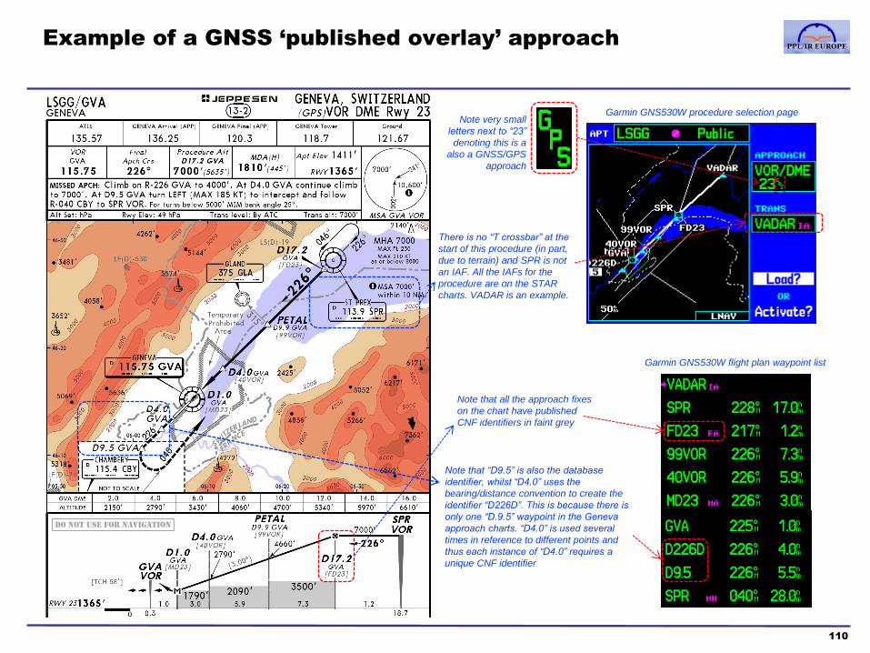
Example of a GNSS ‘published overlay’ approach
110
Garmin GNS530W procedure selection page
Garmin GNS530W flight plan waypoint list
Note that “D9.5” is also the database
identifier, whilst “D4.0” uses the
bearing/distance convention to create the
identifier “D226D”. This is because there is
only one “D.9.5” waypoint in the Geneva
approach charts. “D4.0” is used several
times in reference to different points and
thus each instance of “D4.0” requires a
unique CNF identifier
There is no “T crossbar” at the
start of this procedure (in part,
due to terrain) and SPR is not
an IAF. All the IAFs for the
procedure are on the STAR
charts. VADAR is an example.
Note that all the approach fixes
on the chart have published
CNF identifiers in faint grey
Note very small
letters next to “23”
denoting this is a
also a GNSS/GPS
approach
Do not use for navigation

Course contents
1. PBN & RNP theory
a. Introduction to PBN
b. The Path-Terminator
c. PBN procedure design
2. GNSS
a. GNSS and the GPS system
b. RAIM
c. SBAS
d. Databases
e. Procedures
f. Error detection and warnings
111
3. RNAV Approach Procedures
a. Classifications
b. Approach types
c. Requirements and approvals
d. Approach operations
4. Avionics training
5. Simulator and/or Flight training
Appendices
1. Database Coding and Naming Conventions
2. PBN Learning Objectives
3. Additional items mentioned in the PBN
Learning Objectives
Glossary of Abbreviations

Onboard Performance Monitoring and Alerting
112
• Required for RNP
• Managed by systems or crew procedures (i.e. is it working?)
• Gross reasonableness checks by crew (i.e. does it make sense?)
• The pilot is not required to check RAIM.
• SBAS provides a more accurate method of error
checking.
SBAS Available
• RAIM checks required in-flight
SBAS Not Available

Onboard Performance Monitoring and Alerting
113
Pre-flight Prediction In-flight Integrity
Non-
SBAS
Not required, but recommended for RNAV 5.
RAIM prediction must be conducted before a RNAV 1/ flight,
or SIDs/STARs and approaches. If there is a predicted lack
of availability, the flight must either use alternative
procedures or reschedule for a time when RAIM will be
available.
For RNAV 5 GNSS navigation can be continued without RAIM as long there
is no loss of GNSS position but the pilot must cross-check position using
conventional radio aids.
For RNAV 1 flight, or SIDs/STARs and approaches cannot be continued
without RAIM.
SBAS NOTAMs must be checked for SBAS availability.
RAIM need not be separately checked.
If SBAS is unavailable the receiver will revert to RAIM. SBAS status is
indicated in the Status page of the receiver. In Garmin receivers, a ‘D’ in a
Satellite signal strength bar indicates that ‘Differential’ corrections (SBAS)
are being used for that Satellite. If there is no D, no SBAS is available on
that satellite.
RNP Approaches with vertical guidance are not available and only LNAV or
conventional approaches can be used. (Baro-VNAV remains available if the
aircraft is so equipped.)
• RAIM availability can be lost at any point in a flight if the number of
visible, serviceable satellites falls below 5
• This may happen when RAIM was predicted to be available, if an
unexpected satellite failure takes place
• All IFR GNSS receivers will provide the pilot with a prominent alert
if RAIM is lost at any point in flight – this does not mean the GNSS
position is wrong (eg. if 4 accurate satellite signals remain
available) but it does mean that the integrity of the position is not
assured (ie. one of the 4 signals could be erroneous)
• Where the receiver determines that it cannot provide accuracy
within limits, such as due to lack of SBAS, then the guidance
mode will fallback. For example, LPV would revert to LNAV.
Actual RAIM/SBAS availability
• Although, in practice, the GPS satellite constellation provides 6
or more visible satellites in almost all circumstances, this is not
guaranteed
• On a particular route at a particular time, it may be that the
“geometry” of the satellite constellation, or a known satellite
failure, means that the minimum of 5 satellites needed for RAIM
will not be available
• Such a lack of RAIM availability may be predicted, either by the
GNSS receiver software using almanac data and the time and
route of flight, or by an internet-based RAIM prediction tool
• SBAS non-availability is notified by NOTAM
Predicted RAIM/SBAS availability
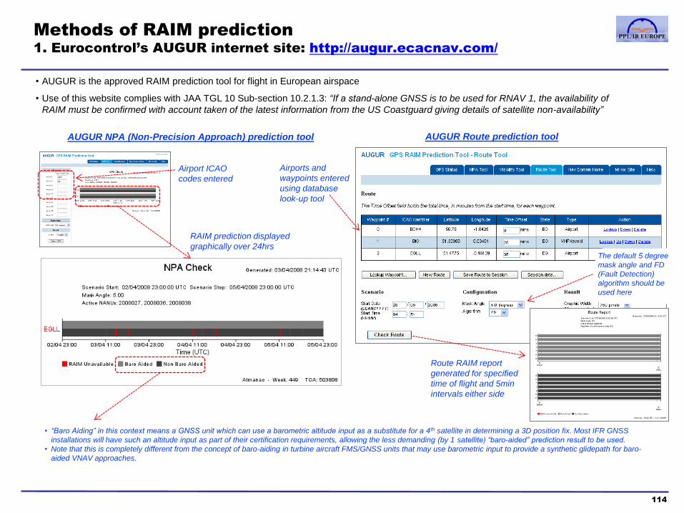
Methods of RAIM prediction
1. Eurocontrol’s AUGUR internet site: http://augur.ecacnav.com/
114
• AUGUR is the approved RAIM prediction tool for flight in European airspace
• Use of this website complies with JAA TGL 10 Sub-section 10.2.1.3: “If a stand-alone GNSS is to be used for RNAV 1, the availability of
RAIM must be confirmed with account taken of the latest information from the US Coastguard giving details of satellite non-availability”
Airport ICAO
codes entered
RAIM prediction displayed
graphically over 24hrs
• “Baro Aiding” in this context means a GNSS unit which can use a barometric altitude input as a substitute for a 4th satellite in determining a 3D position fix. Most IFR GNSS
installations will have such an altitude input as part of their certification requirements, allowing the less demanding (by 1 satellite) “baro-aided” prediction result to be used.
• Note that this is completely different from the concept of baro-aiding in turbine aircraft FMS/GNSS units that may use barometric input to provide a synthetic glidepath for baro-
aided VNAV approaches.
AUGUR NPA (Non-Precision Approach) prediction tool AUGUR Route prediction tool
Airports and
waypoints entered
using database
look-up tool
Route RAIM report
generated for specified
time of flight and 5min
intervals either side
The default 5 degree
mask angle and FD
(Fault Detection)
algorithm should be
used here

Methods of RAIM prediction
2. GNSS receiver software
115
Example: Garmin 530 Pilot’s Guide Section 10.3
• All IFR GNSS receivers can use the Almanac data in the Navigation Message to predict whether there will be adequate satellite coverage to enable RAIM for a given time and route of flight

Methods of RAIM prediction
3. Note on use of GNSS receiver software
116
• RAIM Fault Detection consists of two algorithms
–a geometric screening, to calculate whether the available satellite geometry can provide a position fix of sufficient accuracy for the intended phase of flight
–an error detection algorithm, to check whether any signals (in an otherwise adequate satellite geometry) are faulty
• RAIM prediction performed by a GNSS receiver relies on the Almanac broadcast by satellites. This may not have the most up to date information on the status of the satellite constellation
• The definitive source for this data is the FAA SAPT website: https://sapt.faa.gov/default.php
• For the GPS equivalent of NOTAMs (“NANU”, Notice Advisory to Navstar Users) use https://www.navcen.uscg.gov/?pageName=gpsAlmanacs
• An IFR GPS receiver’s built-in RAIM prediction may not comply with the requirements of some RNAV applications and approvals (particularly RNAV 1), and the AUGUR prediction tools must be used instead. Where SBAS is available (check NOTAMs), it is not necessary to check RAIM availability on an SBAS GNSS receiver.
• Note that RAIM prediction refers to the Fault Detection function (FD). RNAV applications requiring a predicted availability of Fault Detection and Exclusion (FDE), eg. GNSS as a primary means of navigation on Oceanic routes, need the use of approved FDE prediction tools (eg. Garmin’s FDE software for the G430/530/1000 series)
• Note that RAIM prediction is specific to the RNP requirement of a particular phase of flight – if RAIM is available for RNP 1 Procedures along a given route and time, this does not necessarily mean that it is available for RNAV approaches (RNP 0.3): for example, a particular satellite geometry may have a dilution of precision that is acceptable for RNP 1 but not for RNP 0.3

• Whilst RAIM is available, the GNSS receiver assures the integrity and accuracy of its calculated position within a
protection limit specified for a particular phase of flight: 4 nm for oceanic, 2 nm for enroute, 1 nm for terminal and 0.3 nm
for RNP approaches
• Example, from the Garmin 530 Pilot’s Guide:
• The “Loss of Integrity” (LOI) alert provided by a GNSS receiver is very important. It is triggered by – a loss of RAIM availability, or – the detection of a fault in satellite signals which compromises position accuracy, or – an unfavourable satellite geometry and dilution of precision, such that position accuracy does not meet the
protection limit required
• The LOI alert indicates that the GNSS may not be used as a source of primary guidance – during a RNP 1 Procedure, the pilot must advise ATC of the RAIM failure and request radar vectors or a
conventional alternative procedure – during an RNP approach, the pilot must initiate the missed approach and advise ATC
• In practice, most instances of LOI are very brief. However, if an en-route LOI alert persists for more than 60 seconds, it should be treated seriously and an appropriate contingency procedure initiated
Note: the protection provided by the RAIM function subsumes all of the integrity and accuracy requirements for RNAV; therefore the pilot need not be concerned with other measures of navigation accuracy the GNSS unit may provide in the Status or Aux pages (eg. Estimated Position Error, Dilution of Precision and Horizontal Uncertainty Level)
• The CDI scale in IFR GNSS receivers automatically adjusts to the active
phase of flight, or it may be set manually.
• CDI auto-scaling must be enabled for RNAV operations. Activating
terminal and approach procedures from the GNSS database ensures that
the appropriate CDI scale and RAIM protection limits are applied
• In some GNSS, units manually selecting a 1nm or 0.3nm CDI scale may
not change the RAIM protection limit to the corresponding RNP value
(although it does in the Garmin 430/530 series)
GNSS position warnings
1. The Loss of Integrity alert
117

GNSS position warnings
2. Garmin 530 examples
118
• IFR GNSS receivers always display the LOI alert prominently. In the
Garmin 430/530 series, it is a black on yellow “INTEG” annunciator on the
bottom left of the screen:
• In addition to the prominent LOI alert, the GNSS receiver will display one or
more supplementary messages, either as pop-up overlays on the active
screen, or within the Message screen (accompanied by a “MSG”
annunciation).
• The user must be familiar with the meaning of all the alert and advisory
messages in their GNSS unit, and how they are annunciated and accessed
Example: Garmin GNSS receiver status messages Example: Garmin RAIM messages
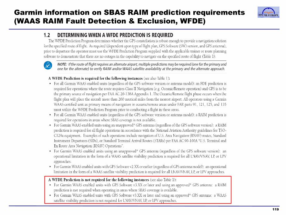
Garmin information on SBAS RAIM prediction requirements
(WAAS RAIM Fault Detection & Exclusion, WFDE)
119
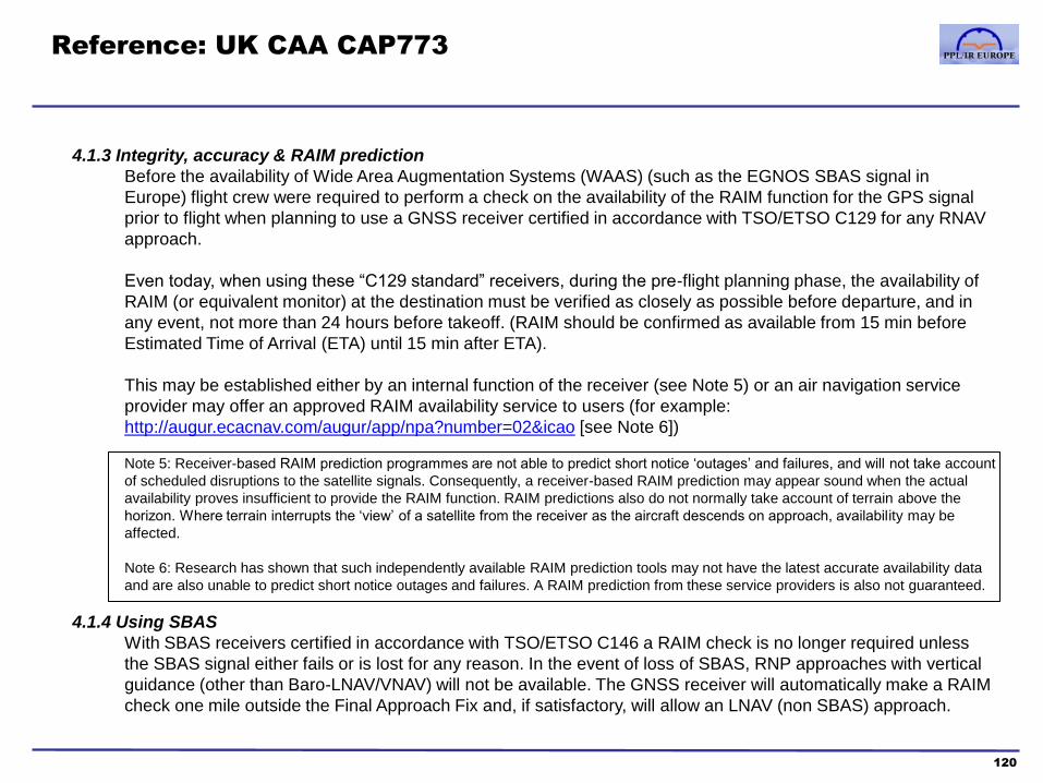
Reference: UK CAA CAP773
120
4.1.3 Integrity, accuracy & RAIM prediction
Before the availability of Wide Area Augmentation Systems (WAAS) (such as the EGNOS SBAS signal in
Europe) flight crew were required to perform a check on the availability of the RAIM function for the GPS signal
prior to flight when planning to use a GNSS receiver certified in accordance with TSO/ETSO C129 for any RNAV
approach.
Even today, when using these “C129 standard” receivers, during the pre-flight planning phase, the availability of
RAIM (or equivalent monitor) at the destination must be verified as closely as possible before departure, and in
any event, not more than 24 hours before takeoff. (RAIM should be confirmed as available from 15 min before
Estimated Time of Arrival (ETA) until 15 min after ETA).
This may be established either by an internal function of the receiver (see Note 5) or an air navigation service
provider may offer an approved RAIM availability service to users (for example:
http://augur.ecacnav.com/augur/app/npa?number=02&icao [see Note 6])
Note 5: Receiver-based RAIM prediction programmes are not able to predict short notice ‘outages’ and failures, and will not take account
of scheduled disruptions to the satellite signals. Consequently, a receiver-based RAIM prediction may appear sound when the actual
availability proves insufficient to provide the RAIM function. RAIM predictions also do not normally take account of terrain above the
horizon. Where terrain interrupts the ‘view’ of a satellite from the receiver as the aircraft descends on approach, availability may be
affected.
Note 6: Research has shown that such independently available RAIM prediction tools may not have the latest accurate availability data
and are also unable to predict short notice outages and failures. A RAIM prediction from these service providers is also not guaranteed.
4.1.4 Using SBAS
With SBAS receivers certified in accordance with TSO/ETSO C146 a RAIM check is no longer required unless
the SBAS signal either fails or is lost for any reason. In the event of loss of SBAS, RNP approaches with vertical
guidance (other than Baro-LNAV/VNAV) will not be available. The GNSS receiver will automatically make a RAIM
check one mile outside the Final Approach Fix and, if satisfactory, will allow an LNAV (non SBAS) approach.
Course contents
1. PBN & RNP theory
a. Introduction to PBN
b. The Path-Terminator
c. PBN procedure design
2. GNSS
a. GNSS and the GPS system
b. RAIM
c. SBAS
d. Databases
e. Procedures
f. Error detection and warnings
121
3. RNAV Approach Procedures
a. Classifications
b. Approach types
c. Requirements and approvals
d. Approach operations
4. Avionics training
5. Simulator and/or Flight training
Appendices
1. Database Coding and Naming Conventions
2. PBN Learning Objectives
3. Additional items mentioned in the PBN
Learning Objectives
Glossary of Abbreviations
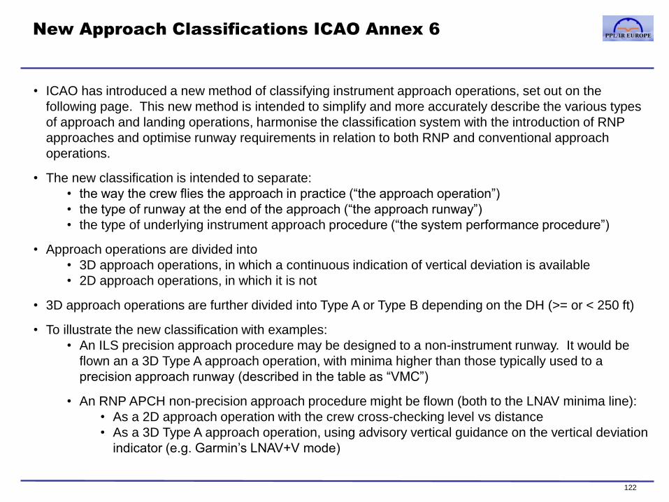
New Approach Classifications ICAO Annex 6
122
• ICAO has introduced a new method of classifying instrument approach operations, set out on the
following page. This new method is intended to simplify and more accurately describe the various types
of approach and landing operations, harmonise the classification system with the introduction of RNP
approaches and optimise runway requirements in relation to both RNP and conventional approach
operations.
• The new classification is intended to separate:
• the way the crew flies the approach in practice (“the approach operation”)
• the type of runway at the end of the approach (“the approach runway”)
• the type of underlying instrument approach procedure (“the system performance procedure”)
• Approach operations are divided into
• 3D approach operations, in which a continuous indication of vertical deviation is available
• 2D approach operations, in which it is not
• 3D approach operations are further divided into Type A or Type B depending on the DH (>= or < 250 ft)
• To illustrate the new classification with examples:
• An ILS precision approach procedure may be designed to a non-instrument runway. It would be
flown an a 3D Type A approach operation, with minima higher than those typically used to a
precision approach runway (described in the table as “VMC”)
• An RNP APCH non-precision approach procedure might be flown (both to the LNAV minima line):
• As a 2D approach operation with the crew cross-checking level vs distance
• As a 3D Type A approach operation, using advisory vertical guidance on the vertical deviation
indicator (e.g. Garmin’s LNAV+V mode)
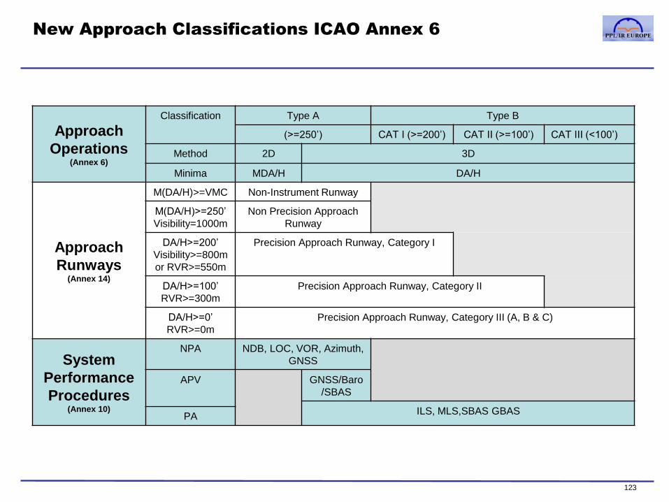
New Approach Classifications ICAO Annex 6
Approach
Operations (Annex 6)
Classification Type A Type B
(>=250’) CAT I (>=200’) CAT II (>=100’) CAT III (<100’)
Method 2D 3D
Minima MDA/H DA/H
Approach
Runways (Annex 14)
M(DA/H)>=VMC Non-Instrument Runway
M(DA/H)>=250’
Visibility=1000m
Non Precision Approach
Runway
DA/H>=200’
Visibility>=800m
or RVR>=550m
Precision Approach Runway, Category I
DA/H>=100’
RVR>=300m
Precision Approach Runway, Category II
DA/H>=0’
RVR>=0m
Precision Approach Runway, Category III (A, B & C)
System
Performance
Procedures (Annex 10)
NPA NDB, LOC, VOR, Azimuth,
GNSS
APV GNSS/Baro
/SBAS
ILS, MLS,SBAS GBAS PA
123

Glossary: ICAO Annex 10 definition of approach types
124
• ICAO Annex 10 recognises three classes of instrument approach:
NPA APV PA
Non-Precision Approach Approach with Vertical Guidance Precision Approach
Based on a navigation system that provides
course deviation information, but no glide path
Procedures have an MDA(H), but, increasingly, where
continuous descent final approach (CDFA) techniques
are to be used, a DA(H) may be published instead
Based on a navigation system that does not meet
the precision approach standards of ICAO Annex
10 but which does provide course and glide path
deviation.
Procedures have a DA(H) rather than an MDA(H)
Based on a navigation system that provides
course and glidepath deviation which meets the
precision standards of ICAO Annex 10
Procedures have a DA(H)
Examples based on traditional radio aids and radar:
VOR, NDB, LOC, LDA, SRA LDA with glidepath
(an ILS-like installation not meeting PA criteria,
eg. because of the localiser offset from the runway)
ILS, MLS, PAR
Examples based on GNSS:
RNP approach procedures to
LNAV minima “Published overlay” or “stand-alone” GPS non-precision
approaches, which use LNAV minima
RNP approach procedures to LNAV/VNAV
minima Vertical guidance provided by SBAS-GPS or Baro-
VNAV systems available only in larger turbine aircraft
RNP approach procedures to
LPV minima Vertical guidance provided by SBAS-GPS. Procedure
may ‘downgrade’ to LNAV/VNAV minima if satellite
signal or runway environment/lighting does not meet
LPV criteria
GLS approach GNSS Landing System: precision approach based on
GNSS with GBAS (eg. LAAS)
Currently, CAT I procedures have been deployed in
limited numbers. CAT II and III applications are being
developed.
GBAS and GLS are not supported at present in GA
aircraft and will not be discussed further in this manual

Course contents
1. PBN & RNP theory
a. Introduction to PBN
b. The Path-Terminator
c. PBN procedure design
2. GNSS
a. GNSS and the GPS system
b. RAIM
c. SBAS
d. Databases
e. Procedures
f. Error detection and warnings
125
3. RNAV Approach Procedures
a. Classifications
b. Approach types
c. Requirements and approvals
d. Approach operations
4. Avionics training
5. Simulator and/or Flight training
Appendices
1. Database Coding and Naming Conventions
2. PBN Learning Objectives
3. Additional items mentioned in the PBN
Learning Objectives
Glossary of Abbreviations

IF
Typical structure of a conventional NPA
126
Initial segment
IAF
MAP
FAF Final segment Missed Approach segment
Intermediate
segment
3000’
2000’
Lctr
M
Racetrack pattern at the IAF
permits arrivals from any direction
Initial approach fix is an NDB or VOR (NDB in this example)
Intermediate fix is a DME
distance or outbound time
Final approach fix is a DME
distance, or (in a non-DME
procedure) upon establishing
the final approach track
Step-down fix altitudes are usually minima
that must be observed but chart notes may
indicate they are advisory or mandatory (ie.
exact required altitudes)
1250’ Final approach fix is always
depicted on an NPA profile view
by this ‘Maltese cross’ symbol
Represents Minimum
descent altitude
Actual MDA value available from
the table below the profile view on
a Jeppesen chart
Missed approach point is
always depicted on an NPA
profile view with a letter M
Missed approach point is usually
the same beacon as the IAF, if
this is located at the airport
Note: this is an illustrative generalisation of a procedure. Always refer to actual charts and chart notes
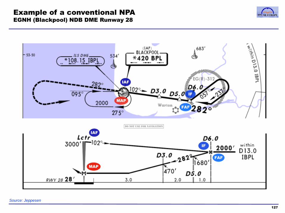
Example of a conventional NPA
EGNH (Blackpool) NDB DME Runway 28
127
IAF
IF
MAP
FAF
IAF
IF
MAP
FAF
Source: Jeppesen
Do not use for navigation

Typical structure of an RNAV NPA: the “T-shaped”
procedure
128
IAF
MAP
FAF Final segment Missed Approach segment
2000’
M
There are 3 Initial Approach Fixes available in the characteristic
“T-shaped” PBN procedure. This allows for arrivals from any
direction to proceed to the Final Approach Fix using only turns
with a track change of no more than 90 degrees
1000’
Missed approach waypoint
name and database identifier
Missed approach point is an RNAV
waypoint (often Fly-Over) at the
runway threshold
IAF
IF/IAF Intermediate segment
In
itia
l se
gm
en
t
In
itia
l se
gm
en
t
2500’
RWYnn [RWYnn]
Step-down altitudes on the
vertical profile are minima
which must be observed
unless explicitly labelled
‘Mandatory’ or ‘Maximum’,
or unless the chart notes
that they are advisory only
Note: this is an illustrative generalisation of a procedure. Always refer to actual charts and chart notes
11.0 6.0
aannF aannI
FAF identifier: aa are the last two
letters of the airport’s ICAO
designator, nn is the runway number,
“F” is the code letter for the Final
Approach Fix
“aann” as per the FAF
identifier, “I” is the code
letter for the IF
5.0
[identifier]
3.0 3.0
Numbers ‘above the line’ are
distances (in nm) between
waypoints, as shown in the GNSS
distance to next waypoint display
Numbers ‘below the
line’ are distance (in
nm) to the threshold,
equivalent to the DME
distance display in an
ILS procedure, but
often not displayed by
the GNSS system
The final approach is depicted as a
continuous descent profile. This is not
mandatory, but the chart will note any
minimum descent restrictions and, often,
depict minimum obstacle clearing
altitudes on the profile view
IF/IAF
In this example, the missed approach consists of
a Track-to-Fix (TF) leg from the MAP followed by
a Direct-to-Fix (DF) leg back to the MAP.
Dual purpose
fix: IAF and IF
Typically, both the initial and
intermediate legs are 5nm

Example of an RNP Approach
EGNH (Blackpool) RNAV(GNSS) Runway 28
129
IAF
IF
MAP
FAF
IF
MAP
FAF
Source: Jeppesen
IAF
IAF
In this example, the basic T-shape is modified
with an IAF and intermediate segment
extending beyond the cross-bar of the T
Altitudes marked on the vertical profile
must be observed as minima unless
they are noted as advisory, in which
case the “grey box” altitudes are the
required minima by segment
Note that in this case, there are
mandatory altitudes on the vertical
profile (ie. not just minima, but an
exact required altitude)
Do not use for navigation
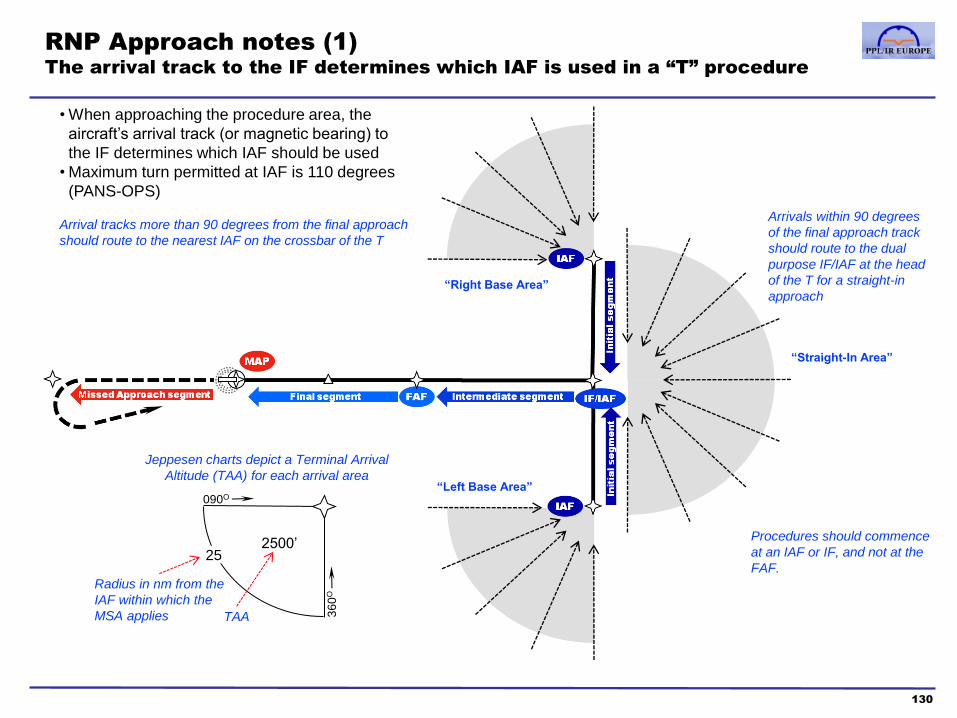
25
RNP Approach notes (1)
The arrival track to the IF determines which IAF is used in a “T” procedure
130
Arrivals within 90 degrees
of the final approach track
should route to the dual
purpose IF/IAF at the head
of the T for a straight-in
approach
• When approaching the procedure area, the
aircraft’s arrival track (or magnetic bearing) to
the IF determines which IAF should be used
• Maximum turn permitted at IAF is 110 degrees
(PANS-OPS)
Arrival tracks more than 90 degrees from the final approach
should route to the nearest IAF on the crossbar of the T
“Right Base Area”
“Left Base Area”
“Straight-In Area”
2500’
090O
36
0O
Jeppesen charts depict a Terminal Arrival
Altitude (TAA) for each arrival area
TAA
Radius in nm from the
IAF within which the
MSA applies
Procedures should commence
at an IAF or IF, and not at the
FAF.

RNP Approach notes (2)
The “T” structure is not used in all RNP approaches
131
LFBZ (Biarritz)
RNAV(GNSS) Rwy 09
EDDK (Cologne-Bonn)
RNP Rwy 32L
Example in which terrain precludes a T-shaped procedure with
low-level arrivals from all directions
BZ400 is the only IAF; note in this case that arrivals to BZ400 are
permitted from an arc of 220 degrees
High terrain means that the MSA for arrivals from the south of Biarritz
is 6000’, hence the middle and southerly IAFs that would make up a
standard T procedure are not available. Southerly arrivals may route
via OSGOT to descend and join the procedure at BZ400
IAF
Example of a larger airport, where the IAFs conform to the
structure of standard arrival routes within the TMA rather than
a T-shape
IAF
IAF
At a larger airport like Cologne, pilots may expect a STAR terminating
at one of the IAFs (eg. NORVENICH or COLA), or radar vectors to the
RNP final approach or to an intermediate waypoint on the RNP
approach
Do not use for navigation

RNP APCH operations and minima lines
LNAV
132
RNP approaches usually have multiple minima lines, drawn from:
LNAV
LNAV/VNAV
LPV
The LNAV minima line corresponds to a non-precision approach.
• When flown with a TSO-C129A (non-SBAS unit)
linear deviation indication on CDI is provided
Garmin annunciation APPR
• When flown with a TSO-C146A (SBAS unit)
angular deviation indication horizontally (localiser-like) and vertically
(glideslope like)
Garmin annunciation LNAV
LNAV+V with advisory vertical guidance may also be available
pilot remains responsible for adherence to step down fix levels on the
published approach plate for LNAV approaches even if a Garmin +V
glideslope is provided by the GNSS
receiver.
glidepath not necessarily obstacle free below MDA

RNP APCH operations and minima lines
LNAV/VNAV and LPV
The LNAV/VNAV minima line corresponds to an approach with vertical
guidance (APV).
• Operated “like an ILS”
• Airliners with FMS use Baro-VNAV to fly these
– Vertical guidance using baro-altitude
– Various scaling conventions
– Minimum temperature
• When flown with a TSO-C146A (SBAS unit)
– angular deviation indication horizontally (localiser-like) and vertically
(glideslope like)
– surveyed vertical guidance
– Garmin annunciation L/VNAV
The LPV minima line corresponds to an APV.
• Operated “like an ILS”
• Requires SBAS
• When flown with a TSO-C146A (SBAS unit)
– angular deviation indication horizontally (localiser-like) and vertically
– surveyed advisory vertical guidance
– Garmin annunciation LPV
• Both LPV and LNAV/VNAV may fall back
to LNAV if SBAS or integrity is lost
(See also page 149)
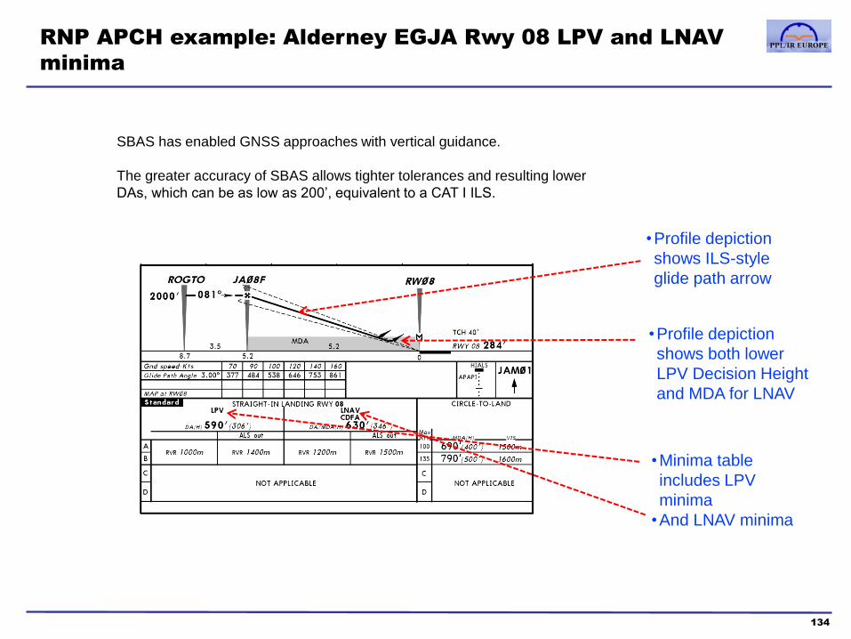
RNP APCH example: Alderney EGJA Rwy 08 LPV and LNAV
minima
134
•Profile depiction
shows ILS-style
glide path arrow
•Profile depiction
shows both lower
LPV Decision Height
and MDA for LNAV
•Minima table
includes LPV
minima
•And LNAV minima
SBAS has enabled GNSS approaches with vertical guidance.
The greater accuracy of SBAS allows tighter tolerances and resulting lower
DAs, which can be as low as 200’, equivalent to a CAT I ILS.
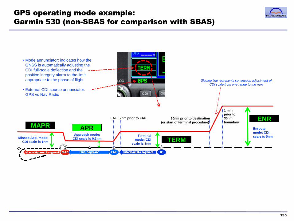
GPS operating mode example:
Garmin 530 (non-SBAS for comparison with SBAS)
135
TERM
ENR
APR
FAF 2nm prior to FAF 30nm prior to destination
(or start of terminal procedure)
1 min
prior to
30nm
boundary
Enroute
mode: CDI
scale is 5nm Terminal
mode: CDI
scale is 1nm
Approach mode:
CDI scale is 0.3nm
• Mode annunciator: indicates how the
GNSS is automatically adjusting the
CDI full-scale deflection and the
position integrity alarm to the limit
appropriate to the phase of flight
• External CDI source annunciator:
GPS vs Nav Radio
Sloping line represents continuous adjustment of
CDI scale from one range to the next
MAPR
Missed App. mode:
CDI scale is 1nm

Missed approach
mode: CDI scale is
0.3NM
Different approach mode annunciations, based on the procedure available and
the position accuracy available
> use LNAV minima, no glidepath available
> use LNAV minima, advisory glidepath will be displayed on HSI
> use LNAV/VNAV minima, glidepath will be displayed on HSI
> use LPV minima and both track and vertical guidance on HSI
CDI scaling from the FAF on GNSS approaches is angular +/-
2 degrees (except very close to the runway +/- 350’), similar
to that provided by a localiser. On all LPV and LNAV/VNAV
approaches, an ILS type glidepath is provided, and on some
LNAV approaches an advisory angular synthetic glidepath is
calculated by the 530W.
136
TERM
ENR LNAV FAF 2nm prior to FAF 30nm prior to destination
(or start of terminal procedure)
1 min
prior to
30nm
boundary
Enroute
mode: CDI
scale is 2nm Terminal
mode: CDI
scale is 1nm
Approach mode:
CDI scale is
Angular
MAPR
CDI scale is 0.3nm
Scaling in ENR mode is
2nm, not 5nm
LNAV LNAV+V L/VNAV
LPV
GNSS operating mode example:
Garmin 530W receiving an SBAS signal

Course contents
1. PBN & RNP theory
a. Introduction to PBN
b. The Path-Terminator
c. PBN procedure design
2. GNSS
a. GNSS and the GPS system
b. RAIM
c. SBAS
d. Databases
e. Procedures
f. Error detection and warnings
137
3. RNAV Approach Procedures
a. Classifications
b. Approach types
c. Requirements and approvals
d. Approach operations
4. Avionics training
5. Simulator and/or Flight training
Appendices
1. Database Coding and Naming Conventions
2. PBN Learning Objectives
3. Additional items mentioned in the PBN
Learning Objectives
Glossary of Abbreviations
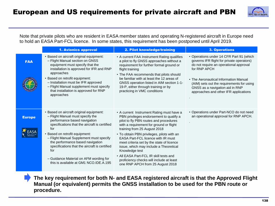
European and US requirements for private aircraft and PBN
138
The key requirement for both N- and EASA registered aircraft is that the Approved Flight Manual (or equivalent) permits the GNSS installation to be used for the PBN route or procedure.
1. Avionics approval 2. Pilot knowledge/training 3. Operations
FAA
• Based on aircraft original equipment:
– Flight Manual section on GNSS
equipment must specify that the
installation is approved for IFR and RNP
approaches
• Based on retrofit equipment:
– Installation must be IFR approved
– Flight Manual supplement must specify
that installation is approved for RNP
approaches
• A current FAA Instrument Rating qualifies
a pilot to fly GNSS approaches without a
requirement for further formal ground or
flight training
• The FAA recommends that pilots should
be familiar with at least the 12 areas of
GNSS operation listed in AIM section 1-1-
19-P, either through training or by
practicing in VMC conditions
• Operations under 14 CFR Part 91 (which
governs IFR flight for private operators)
do not require an operational approval
for RNP APCH
• The Aeronautical Information Manual
(AIM) sets out the requirements for using
GNSS as a navigation aid in RNP
approaches and other IFR applications
.
Europe
• Based on aircraft original equipment:
– Flight Manual must specify the
performance based navigation
specifications that the aircraft is certified
for
• Based on retrofit equipment:
– Flight Manual Supplement must specify
the performance based navigation
specifications that the aircraft is certified
for
– Guidance Material on AFM wording for
this is available at GM1 NCO.IDE.A.195
• A current Instrument Rating must have a
PBN privileges endorsement to qualify a
pilot to fly PBN routes and procedures
with a requirement for ground or flight
training from 25 August 2018
• To obtain PBN privileges, pilots with an
EASA Part-FCL licence with IR must
meet criteria set by the state of licence
issue, which may include a Theoretical
Knowledge test
• All EASA Part-FCL IR skill tests and
proficiency checks will include at least
one RNP APCH from 25 August 2018
• Operations under Part-NCO do not need
an operational approval for RNP APCH.
.
Note that private pilots who are resident in EASA member states and operating N-registered aircraft in Europe need to hold an EASA Part-FCL licence. In some states, this requirement has been postponed until April 2019.
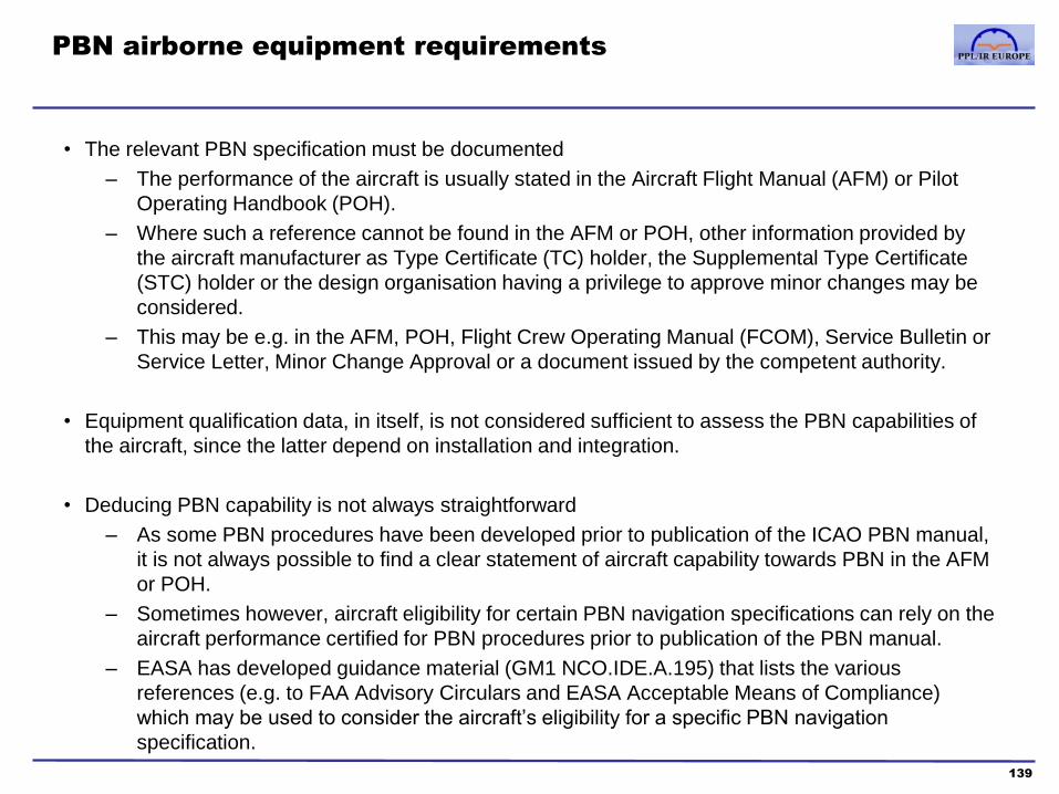
PBN airborne equipment requirements
• The relevant PBN specification must be documented
– The performance of the aircraft is usually stated in the Aircraft Flight Manual (AFM) or Pilot
Operating Handbook (POH).
– Where such a reference cannot be found in the AFM or POH, other information provided by
the aircraft manufacturer as Type Certificate (TC) holder, the Supplemental Type Certificate
(STC) holder or the design organisation having a privilege to approve minor changes may be
considered.
– This may be e.g. in the AFM, POH, Flight Crew Operating Manual (FCOM), Service Bulletin or
Service Letter, Minor Change Approval or a document issued by the competent authority.
• Equipment qualification data, in itself, is not considered sufficient to assess the PBN capabilities of
the aircraft, since the latter depend on installation and integration.
• Deducing PBN capability is not always straightforward
– As some PBN procedures have been developed prior to publication of the ICAO PBN manual,
it is not always possible to find a clear statement of aircraft capability towards PBN in the AFM
or POH.
– Sometimes however, aircraft eligibility for certain PBN navigation specifications can rely on the
aircraft performance certified for PBN procedures prior to publication of the PBN manual.
– EASA has developed guidance material (GM1 NCO.IDE.A.195) that lists the various
references (e.g. to FAA Advisory Circulars and EASA Acceptable Means of Compliance)
which may be used to consider the aircraft’s eligibility for a specific PBN navigation
specification.
139
Course contents
1. PBN & RNP theory
a. Introduction to PBN
b. The Path-Terminator
c. PBN procedure design
2. GNSS
a. GNSS and the GPS system
b. RAIM
c. SBAS
d. Databases
e. Procedures
f. Error detection and warnings
140
3. RNAV Approach Procedures
a. Classifications
b. Approach types
c. Requirements and approvals
d. Approach operations
4. Avionics training
5. Simulator and/or Flight training
Appendices
1. Database Coding and Naming Conventions
2. PBN Learning Objectives
3. Additional items mentioned in the PBN
Learning Objectives
Glossary of Abbreviations

Summary of RNP APCH operating procedures
141
•Each of these procedures is detailed in the following pages
• This section includes only the key elements needed for GNSS Approaches in addition to
conventional IFR operating procedures and checks
Phase of Flight Operating Procedure required or recommended
(in addition to conventional IFR procedures and checks)
1. Pre-Flight Planning
• IFR approval and serviceability of GNSS and alternative navigation equipment
• Availability of GNSS Approach and alternative conventional procedures
• Weather forecasts for destination and alternate. GNSS approach and alternate minima
• RAIM prediction (if non-SBAS)
• NOTAM check (including SBAS)
2. Pre-Flight Checks
• GNSS database currency and coverage
• Check coding of expected GNSS approach procedure against paper charts
• GNSS receiver self-test, user selectable settings, LOI monitoring
• Flight plan entry and RAIM prediction (if necessary)
• Requirement to use a database coded procedure for GNSS SIDs, STARs and approaches
3. Pre-Arrival
• Selecting and checking the Arrival/Approach procedure
• Determining the appropriate IAF
• Activation of the procedure and check CDI scaling is Auto
4. Flying the RNP APCH procedure
• Gross error check approaching the IAF, and check that the GNSS is in TERM mode
• GNSS and Navigation instrument mode selection
• Use of the GNSS receiver if a hold or vectors to an intermediate waypoint on the approach are required
• Check activation of APP, LNAV, LNAV+V, LNAV/VNAV or LPV mode as applicable
5. Flying the Missed Approach • Activation of the Missed Approach procedure and the need to manually re-initiate waypoint sequencing
• Mode selection and pilot actions in non-RNAV missed approach segments
6. ATC communications • Communications during normal procedures
• Communications in the event of a GNSS navigation failure
7. Contingencies in the event of a
GNSS navigation failure
• Immediate actions
• Reverting to alternative procedures
The table below is a suggestion of operating procedures for RNP Approaches

RNP APCH operations (1) Pre-Flight Planning
142
Operating Procedure Notes and comments
IFR approval and
serviceability of GNSS
and conventional
navigation equipment
• The pilot is responsible for ensuring that the GNSS installation is approved for IFR and RNP approaches
- the aircraft flight manual (or equivalent) is the primary source of this information
• The operator must ensure that the flight manual and installation is kept current: the receiver manufacturer may,
at times, require mandatory software and hardware upgrades, or issue updates to the flight manual
• Unless a VFR alternate is available, the pilot must also ensure that appropriate conventional navigation
equipment is serviceable and IFR-approved
Availability of GNSS and
alternative non-GNSS
procedures
• The pilot should review and brief both the RNAV and conventional procedures available at the destination and
alternate. This is useful even though a GNSS satellite system failure is unlikely:
- conventional navaids may be used for gross error checks and monitoring of GNSS guidance
- ATC may require a non-RNAV procedure to be flown for operational reasons
- IFR workload, particularly in demanding weather and traffic conditions, may not allow much time for a pilot to
troubleshoot or reprogram a receiver; eg. after holds and vectors have disrupted guidance sequencing for an
active procedure. In such circumstances, it may be safer and easier to revert to and request a conventional
procedure from ATC
Weather forecasts for
destination and alternate.
RNP and alternate minima
• The normal IFR planning requirements apply to RNP APCH
• Note that different minima apply for different types of RNP APCH. The approach plate will indicate the different
minima applicable. The type of approach chosen, and its related minima, will depend upon the approved
equipment and whether SBAS is available.
• If SBAS is not available and the destination weather is such that an alternate airport is required, the alternate
must have a non-RNP instrument approach procedure which is anticipated to be operational and available at the
estimated time of arrival, and which the aircraft is equipped to fly.
RAIM prediction (SBAS
not available)
• If SBAS is not available, RNP NPAs require RAIM prediction to be performed and to indicate that RAIM will be
available at the destination ETA. The UK CAA recommend that RAIM should be available for a 15 minutes either
side of ETA. In Europe, http://augur.ecacnav.com/ may be used for RAIM prediction, and is preferable to using
the Receiver’s built-in prediction software
NOTAM check
(incl. SBAS)
• The pilot’s review of applicable pre-flight NOTAMs should include a check of the availability of GNSS, SBAS,
conventional and missed approach procedures and of radio aids.

RNP APCH operations (2) Pre-Flight Checks
143
Operating Procedure Notes and comments
GNSS database currency
and coverage
• The receiver must use a current database, supplied from a source approved by
the manufacturer
• As well as checking the overall geographic coverage, the pilot must ensure
the database includes the specific airports and the individual procedures that
may be required example: extract from Garmin 530 database validity page on start-up
Check coding of expected
RNP APCH procedures
against paper charts
• Prior to using a procedure from the database, the pilot must check that it matches the published procedure chart.
A review of waypoint sequence, tracks and distances is adequate; Lat/Long coordinates must only be checked if
there is a potential discrepancy
• This review may be done pre-flight, and it is useful to check all of the potential approach and transition identifier
selections at this point, in order to minimise in-flight workload
• Whilst coding errors are rare, it is common for GNSS databases to include some waypoints which do not appear
on paper charts, or to use different identifiers (see Sections 2b and 2c of this manual)
GNSS receiver self-test,
user selectable settings,
LOI monitoring
• When the GNSS unit is powered-up, the pilot should verify that the self-test procedure is successful
• After a position fix has been acquired, the pilot should monitor the receiver for Loss of Integrity alerts at all times
• UK CAA CAP773 (see Part 2 and Appendix 2) recommends that the status of all the user-definable receiver settings should
also be checked, in particular where an aircraft is flown by a more than one pilot. Such checks may include: Set CDI scaling
to 'automatic'; Check setting of alarms, airspace and altitude buffers; Check Map display settings, de-clutter and map
orientation; Check heading and track display (magnetic, true etc…); Check map datum to WGS 84; Check the units of
measure of distance, speed, altitude, barometric pressure and position format; Select display to show at least: Desired Track
(DTK) / Groundspeed (GS) / Distance to next waypoint (DIS); Check date and time format; Check setting of other units of
measure such as fuel quantity
Flight plan entry and
RAIM prediction (non
SBAS)
• The enroute flight plan may be entered at this point and, if SBAS is not available, a GNSS RAIM prediction
performed, either in lieu of or to update a prediction from an internet site such as AUGUR
• The RAIM prediction should be repeated whenever the destination ETA changes by more than ~15 minutes
Requirement to use a
database coded
procedure for RNP APCH
• All the regulatory sources emphasise that an RNAV terminal or approach procedure must only be flown using
guidance based on a procedure record loaded from the database
• This procedure record must not be amended by any user entries, and, in particular, a procedure created from
user-entered waypoints may never be used

RNP Approach operations (3) Pre-Arrival
144
Operating Procedure Notes and comments
Selecting and checking
the Approach procedure
Determining the
appropriate IAF
• When cleared by ATC for a RNP APCH (ideally, >30nm from the destination), the procedure should be selected
from the database but not (subject to the receiver unit logic) ‘activated’, ‘loaded’ into the active flight plan, or
‘armed’
• If ATC do not provide a clearance to a specific IAF, the correct IAF should be determined based on the aircraft’s
bearing to the IF and the arrival quadrant information in the approach chart (see page 130). This IAF should be
selected from the transition identifier list in the procedure record
• ATC clearances should be read back carefully; some TMAs have a large number of similar sounding RNAV
waypoints
• At this point, a final cross-check of the selected procedure should be performed
- firstly, checking that the correct Airport, Procedure, Transition and Runway identifiers have been selected
- secondly, checking that the database waypoints correspond to the published chart
Activation of the
procedure and CDI
scaling
• If the PBN procedure is satisfactory, it may be activated in the active flight plan
• “GPS” (rather than “VLOC”) mode should be selected for the receiver CDI output,
and the correct annunciator display should be verified
• Within 30mn of the destination, the CDI should scale to 1nm (max deflection) and
“TERM” mode (or equivalent) should be displayed
Example: Garmin 530 mode annunciation CDI sensitivity 1nm in Terminal mode
CDI output toggled from VLOC to GPS
TERM
ENR
APR
FAF 2nm prior to FAF 30nm prior to destination
(or start of terminal procedure)
1 min
prior to
30nm
boundary
Enroute mode:
CDI scale is
5nm (non SBAS)
or 2nm (SBAS)
Terminal
mode: CDI
scale is 1nm
CDI scale depends
on SBAS
• When database terminal and approach procedures are active, IFR units automatically adjust the CDI full-
scale deflection and the RAIM position integrity alarm to the limit appropriate for each phase of flight
• Garmin example:
Sloping line represents continuous adjustment of
CDI scale from one range to the next
MAPR
Missed App. mode:
CDI scale LNAV 1NM
LPV 0.3NM
LNAV+V
LNAV
LPV
SBAS L/VNAV

RNP APCH operations (4) Flying the Approach
145
Operating Procedure Notes and comments
Checks approaching the IAF
• Prior to the IAF the pilot should perform a gross error check of the aircraft position (using non-GNSS
navigation if possible)
• Recheck that the procedure is active and the receiver is in TERM mode
• The receiver will provide excellent “micro” situational awareness in tracking from one waypoint to the next. The pilot must
also maintain “macro” situational awareness with respect to the destination airport, radio aids, airspace boundaries,
traffic, weather and terrain
• Set up any conventional radio aids required for the missed approach, or which may provide supplementary
guidance (eg. DME). If the missed approach is an RNAV procedure, also brief a non-RNAV missed approach
in case of GNSS failure (or determine a safe course of action if a non-RNAV MAP is not available)
GNSS and Navigation
instrument mode selection
and flight guidance
• Prior to the first waypoint, the pilot should reconfirm the CDI output to the HSI is toggled to “GPS” mode, and
that the GNSS Map or Nav page settings are suitable for guidance during the procedure
• The pilot should establish a “mini checklist” for each procedure segment, for example: - approaching a waypoint, self-brief on the next track, distance and level
- when the receiver announces 10s to next waypoint, set the HSI to the next track
- monitor the receiver (not the HSI) during the 10s countdown, and be prepared to promptly establish a
Rate 1 turn as soon as the display says “Turn now to XXXO”
• In particular, note that most receivers display only distance to the next waypoint during a procedure, not
DME-style distance to the runway threshold
Use of the receiver if a hold
or vectors to an intermediate
waypoint on the approach
are required
• The operating logic of most receivers makes it relatively easy to learn how to load and activate a procedure and follow
the guidance from waypoint to waypoint
• Conversely, the same operating logic can be quite difficult and confusing when inevitable ‘real world’ disruptions occur
(ATC vectors and holds; changes of IAF, procedure or runway; direct clearances to intermediate waypoints)
• A pilot must be trained in managing such tactical changes to the flight plan (see sections 5 and 6 of this manual)
Check activation of APP
mode prior to the FAF
• Within 2nm of the FAF, the pilot must check that the appropriate approach mode is active – this is a critical
check which also ensures that the CDI scaling is adjusting correctly and, if SBAS not available, that RAIM is
predicted to be available for the approach. Descent on the final approach must not commence unless
the approach mode is active
• After the FAF, if the alarm limits are exceeded, LPV will degrade to LNAV using RAIM, at which point LNAV
minima apply, and if RAIM is lost, an integrity warning is annunciated and a missed approach commenced.
• In addition to this brief summary, any private pilot intending to fly RNP APCH should study the
appropriate official guidance material.
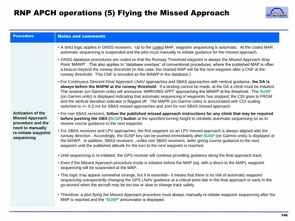
RNP APCH operations (5) Flying the Missed Approach
146
Procedure Notes and comments
Activation of the
Missed Approach
procedure and the
need to manually
re-initiate waypoint
sequencing
• A strict logic applies in GNSS receivers. Up to the coded MAP, waypoint sequencing is automatic. At the coded MAP,
automatic sequencing is suspended and the pilot must manually re-initiate guidance for the missed approach.
• GNSS database procedures are coded so that the Runway Threshold waypoint is always the Missed Approach Way
Point ‘MAWP’. This also applies to “database overlays” of conventional procedures, where the published MAP is often
a beacon beyond the runway threshold (in this case, the charted MAP will be the next waypoint after a CNF at the
runway threshold. This CNF is encoded as the MAWP in the database.)
• For Continuous Descent Final Approach LNAV approaches and SBAS approaches with vertical guidance, the DA is
always before the MAPW at the runway threshold. If a landing cannot be made, at the DA a climb must be initiated.
The receiver (on Garmin units) will announce ‘ARRIVING WPT’ approaching the MAWP at the threshold. The SUSP
(on Garmin units) is displayed indicating that automatic sequencing of waypoints has stopped; the CDI goes to FROM
and the vertical deviation indicator is flagged off. The MAPR (on Garmin units) is annunciated with CDI scaling
switched to +/- 0.3 nm for SBAS missed approaches and 1nm for non SBAS missed approach.
• For non SBAS receivers, follow the published missed approach instructions for any climb that may be required
before pushing the OBS (SUSP) button at the specified turning height to reinitiate automatic sequencing so as to
receive course guidance to the next waypoint.
• For SBAS receivers and LPV approaches, the first waypoint on an LPV missed approach is always aligned with the
runway direction. Accordingly, the SUSP key can be pushed immediately after SUSP (on Garmin units) is displayed at
the MAWP. In addition, SBAS receivers , unlike non SBAS receivers, defer giving course guidance to the next
waypoint until the published altitude for the turn to the next waypoint is reached.
• Until sequencing is re-initiated, the GPS receiver will continue providing guidance along the final approach track.
• Even if the Missed Approach procedure mode is initiated before the MAP (eg. with a direct-to the MAP), waypoint
sequencing will be suspended at the MAP.
• This logic may appear somewhat strange, but it is essential– it means that there is no risk of automatic waypoint
sequencing unexpectedly changing the GPS LNAV guidance at a critical point late in the final approach or early in the
go-around when the aircraft may be too low or slow to change track safely.
• Therefore, a pilot flying the Missed Approach procedure must always manually re-initiate waypoint sequencing after the
MAP is reached and the “SUSP” annunciator is displayed.

RNP APCH operations (6) Flying the Missed Approach
147
Procedure Notes and comments
Mode selection and
pilot actions in
non-RNAV missed
approach segments
• During the missed approach, the GNSS Navigator will always provide track guidance and waypoint sequencing for
“RNAV friendly” path-terminators such as a TF (Track to Fix) segments.
• However, even standalone RNP APCHs often need to use path-terminators that are not fully supported by GNSS
receivers. Such procedure segments will be listed in the flight plan, but some combination of the following is possible
– automatic waypoint sequencing is suspended (for example, the GNSS navigator may not “know” when a conditional
terminator, such as “2000’ or 4DME - whichever is earlier”, is reached).
– track guidance through the CDI is not provided, neither is autopilot LNAV guidance available.
– the GNSS receiver Map may not display a ‘magenta line’ for the segment.
• Path-terminator support is specific to individual GNSS receiver models (and sometimes different software versions for
the same receiver). A pilot must be familiar with the user manual instructions on waypoint sequencing and path-
terminator support, and prepared to fly the missed approach procedure using conventional navigation if RNAV guidance
is not available.
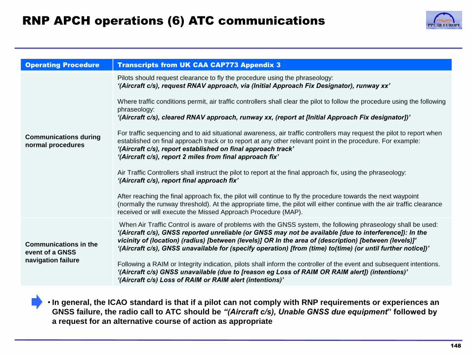
RNP APCH operations (6) ATC communications
148
Operating Procedure Transcripts from UK CAA CAP773 Appendix 3
Communications during
normal procedures
Pilots should request clearance to fly the procedure using the phraseology:
‘(Aircraft c/s), request RNAV approach, via (Initial Approach Fix Designator), runway xx’
Where traffic conditions permit, air traffic controllers shall clear the pilot to follow the procedure using the following
phraseology:
‘(Aircraft c/s), cleared RNAV approach, runway xx, (report at [Initial Approach Fix designator])’
For traffic sequencing and to aid situational awareness, air traffic controllers may request the pilot to report when
established on final approach track or to report at any other relevant point in the procedure. For example:
‘(Aircraft c/s), report established on final approach track’
‘(Aircraft c/s), report 2 miles from final approach fix’
Air Traffic Controllers shall instruct the pilot to report at the final approach fix, using the phraseology:
‘(Aircraft c/s), report final approach fix’
After reaching the final approach fix, the pilot will continue to fly the procedure towards the next waypoint
(normally the runway threshold). At the appropriate time, the pilot will either continue with the air traffic clearance
received or will execute the Missed Approach Procedure (MAP).
Communications in the
event of a GNSS
navigation failure
When Air Traffic Control is aware of problems with the GNSS system, the following phraseology shall be used:
‘(Aircraft c/s), GNSS reported unreliable (or GNSS may not be available [due to interference]): In the
vicinity of (location) (radius) [between (levels)] OR In the area of (description) [between (levels)]’
‘(Aircraft c/s), GNSS unavailable for (specify operation) [from (time) to(time) (or until further notice])’
Following a RAIM or Integrity indication, pilots shall inform the controller of the event and subsequent intentions.
‘(Aircraft c/s) GNSS unavailable (due to [reason eg Loss of RAIM OR RAIM alert]) (intentions)’
‘(Aircraft c/s) Loss of RAIM or RAIM alert (intentions)’
• In general, the ICAO standard is that if a pilot can not comply with RNP requirements or experiences an
GNSS failure, the radio call to ATC should be “(Aircraft c/s), Unable GNSS due equipment” followed by
a request for an alternative course of action as appropriate

RNP APCH operations (7) Contingencies in the event of a
GNSS navigation failure
149
Illustration of contingency procedures
Immediate actions
If GNSS receiver falls back from LPV or LNAV/VNAV to LNAV on the approach above a height of 1000’ you may
continue the approach as an LNAV approach using LNAV minima. If below 1000’ you must go around.
If GNSS receiver fails:
Aviate: stop any descent and configure the aircraft appropriately
Navigate (if prior to the Intermediate fix) continue on current heading if able to immediately contact ATC and
request vectors to an alternative procedure, otherwise turn to the MAP
Navigate (if after the Intermediate fix) continue on final approach track, check the missed approach procedure,
select non-GPS aids as required and continue (or turn to) to the MAP. If a non-RNAV missed approach is not
available, the pilot should have determined an appropriate course of action prior to the approach
Communicate: advise ATC “(Aircraft c/s), Unable RNAV due equipment” and/or as appropriate
Reverting to alternative
procedures
The “default” contingency in the event of a GNSS failure is to fly the missed approach and request ATC clearance
for a conventional procedure at the destination airfield. If no conventional procedure is available, the flight will
have been planned with an alternate airport that does have a conventional procedure or where VFR conditions are
forecast
In practice, ATC may be able to provide vectors directly to a conventional approach if the failure is early in the
procedure. If a conventional procedure is not available, and fuel reserves permit, the pilot may request a hold to
allow the GPS to be reprogrammed or to wait for RAIM availability to be restored
• Before an RNP approach has commenced, there are three additional contingencies a pilot should plan for in addition to the
conventional IFR approach contingencies
- a GNSS Loss of SBAS/Loss of Integrity alert or a GNSS position alarm, warning that the aircraft has deviated beyond the
required lateral or vertical protection limit
- A failure of the receiver to automatically sequence to the correct Approach mode at the FAF
- any uncertainty about whether the procedure may be continued safely; for example: a navigation cross-check
discrepancy, a pilot’s confusion about the GNSS guidance or mode status, excessive deviation from the vertical profile
• The pilot should ensure that appropriate documentation/User Manual for the receiver is
available, and must follow any limitations or contingency procedures it specifies

Course contents
1. PBN & RNP theory
a. Introduction to PBN
b. The Path-Terminator
c. PBN procedure design
2. GNSS
a. GNSS and the GPS system
b. RAIM
c. SBAS
d. Databases
e. Procedures
f. Error detection and warnings
150
3. RNP Approach Procedures
a. Classifications
b. Approach types
c. Requirements and approvals
d. Approach operations
4. Avionics training
5. Simulator and/or Flight training
Appendices
1. Database Coding and Naming Conventions
2. PBN Learning Objectives
3. Additional items mentioned in the PBN
Learning Objectives
Glossary of Abbreviations

GNSS training
1. Introductory comments
151
• GNSS training is required for PBN operations, including RNP Approaches and forms part of the Skill
Test (for initial issue of the IR) and Proficiency Check (for revalidation/renewal).
• The particular challenge for Terminal and Approach RNAV operations is to be
–proficient in all the “combinations” of operating modes and selection changes that may be required
(eg. loading a procedure, being vectored then asked to hold, having the landing runway change
and needing to activate another procedure)
–familiar with the details of GNSS guidance in each of the operating modes and procedure variants
(eg. does the CDI indicate deviation through the curved track of a fly-by turn, or flip from one track
to the next halfway through?)
• Much of this proficiency is specific to individual models of receiver. The operating logic of receiver
models is sufficiently varied that an expert user may struggle with the specialised IFR features in an
unfamiliar model, even if they are able to use the basic navigation functions quite easily.
• The reference pages later in this section have an example of an approved ‘basic’ training syllabus for the Garmin 430/530 series
• Assuming basic “enroute” IFR GNSS skills as starting point, we recommend that pilots and instructors should focus RNAV training on 4 specific topics detailed on the next page

GNSS training
2. RNAV training topics (specific to individual models of receiver)
152
Topic Training objectives
1. Loading,
briefing and
activating
procedures
• Familiarity with terminal and approach procedure selection and briefing
– selecting and verifying Transition, Procedure, Runway and Airport identifiers
– displaying waypoints prior to activating the procedure, in order to cross-check against paper charts
– loading, activating or arming the procedure (terminology and logic varies by model)
– changing or deleting the selected procedure before and after activation/arming
– modifying the enroute flight plan so any ‘overlap’ with a procedure is removed (eg. if the enroute plan ends at a waypoint after the first
waypoint of an arrival)
2. Fly-By
waypoint
guidance
• Understanding turn anticipation in the case of Fly-By waypoints
– is the waypoint ETE the time to the start of the turn, or the time to notionally cross the waypoint?
– roughly how many seconds prior to a waypoint do turns begin, based on track change and ground speed?
– when is the next track after a waypoint annunciated?
– when is the turn countdown annunciated? Is the countdown displayed continuously?
– when and how is the turn command annunciated?
• Understanding turn guidance through Fly-By waypoints
– does the map provide any curved track guidance through the turn?
– does the CDI ‘flip’ from one track to the next in mid-turn, or does it provide deviation information relative to the calculated turn path?
– does the coupled HSI CDI provide the same information?
– does the receiver provide the correct turn guidance to a Flight Director and/or Autopilot in NAV mode/roll steering mode if available?
– how does a Position Alarm alert you to a breach of the RNP protection limit (eg. if you miss a turn)
3. Tactically
modifying a
flight plan
• Changing the procedure selection after it has become active
– how is the new procedure activated? What if the aircraft has passed some of the initial waypoints?
• Selecting “Vectors-to-final” at the start of or during a procedure
– how do you restore procedure guidance if ATC cancel vectoring and direct you to rejoin the procedure?
• Following ATC instructions
– does the Direct-to button provide straight-line guidance to a waypoint (the leg terminator), or an intercept to the leg path prior to the
terminator? Is there a choice of Direct-to or Fly-Leg guidance?
– if instructed to hold at a waypoint, what guidance is available? How is the procedure re-engaged at the end of a hold?
• Using the Missed Approach procedure
– proficiency in re-initiating waypoint sequencing after the MAP, and in the guidance available for non-TF path terminators found in Missed
Approach procedures
– activating the Missed Approach procedure before the MAP. Does the mode change from “APP/LNAV/LPV” to “MAPR” immediately?
What guidance is provided to the MAP from a waypoint before the FAF?
4. Refresher of
GNSS basics
• GNSS validation on start-up: Database currency and coverage. Self-test. Settings. SBAS NOTAMs. RAIM prediction
• GNSS essentials: forms of Integrity alert and other warning messages. CDI scaling and mode annunciation. Recovering the flight plan if the
GNSS receiver is powered down and restarted.

GNSS training
3. Training methods
153
• Receiver user manuals and other training products for non-commercial pilots tend to describe only the
basics of how to load and fly a database procedure and the key operating functions (eg. RAIM
prediction, alerts, CDI and mode activation)
• Proficiency to the level of depth described on the previous page is probably best acquired, initially, by
using the manufacturer’s simulator software, or the actual unit in Simulator mode if the software is not
available
• Where actual procedures and airspace are not easily available for the flight training required, GNSS
training will often be conducted in a synthetic training device with a suitable panel-mount receiver.
• However, this training will be more efficient and cost-effective if the pilot is already proficient in the
GNSS topics described on the previous page
• Our recommendation is that, prior to formal simulator or flight training, a pilot should
–re-read the user manual with particular emphasis on the operating features and functions highlighted
in this manual
–spend at least 2-3 hours practising with the simulator software: firstly creating scenarios with suitable
procedures (and with the paper charts to hand) and then ‘flying’ those scenarios on the software
simulator, becoming proficient in the training objectives described on the prior page
• The training objectives in the prior page are also ones we recommend instructors and flight schools
include in GNSS, PBN and RNP ground, simulator and flight training

Example: studying Fly-By turns for the Garmin 430/530
Garmin manual extract and illustrative simulator software screenshots
154 Source: Garmin GNS530(A) Pilot’s Guide Revision E
Example: GNS530 simulator
screenshots during a Fly-By turn
Note: If the procedure level changes at the turn, the to/from flag flip signifies that the level for the
next leg may be used.
Course contents
1. PBN & RNP theory
a. Introduction to PBN
b. The Path-Terminator
c. PBN procedure design
2. GNSS
a. GNSS and the GPS system
b. RAIM
c. SBAS
d. Databases
e. Procedures
f. Error detection and warnings
155
3. RNP Approach Procedures
a. Classifications
b. Approach types
c. Requirements and approvals
d. Approach operations
4. Avionics training
5. Simulator and/or Flight training
Appendices
1. Database Coding and Naming Conventions
2. PBN Learning Objectives
3. Additional items mentioned in the PBN
Learning Objectives
Glossary of Abbreviations

Flight training
Training course objectives and structure
156
• Our recommendation is that a training course should have the following three parts:
Theory Training objectives (key points)
General PBN theory
- RNAV and RNP Concepts
PBN theory
- changes to charting and documents to reflect PBN
- required navigation equipment for enroute and approaches
Charting, database and avionics topics
- Waypoint naming concepts
- the ‘TF’ and ‘CF’ path terminators
- fly-by and fly-over waypoints
Simulator and/or Flight Training objectives
Operational procedures and practices
- Normal procedures
- Contingency procedures
Use of GNSS Equipment
- retrieving a procedure from the database
- briefing the procedure, comparing it with the charted procedure
- action to be taken if discrepancies are noted
- tactically modifying the flight plan
Flying procedures
- LNAV and associated lateral control techniques,
- Approaches with Vertical Guidance and vertical control techniques,
- use of automatic pilot and flight director
- implications of system malfunctions not GNSS related
PART 2: PRE-FLIGHT BRIEFING
The pre-flight briefing sessions may
require 1-2hrs, and should include:
Use of GNSS Equipment
Covering the four avionics topics
detailed in Section 4 of this manual
Operational procedures
Covering section 3d of this manual, and
using the actual aircraft or training
device checklist/ops manual
PART 3: SIMULATOR OR FLIGHT
TRAINING
The training syllabus we recommend is
based on 2 “notional” lessons
1. Normal operations
2. Contingencies
The objective is for the pilot to
demonstrate proficiency to the
standards required of Instrument Rating
holders and the specific requirements
of GNSS. The minimum time this will
require is probably 2-3hrs for a
candidate who is current in IFR and
RNAV operations.
• Our recommended content for these flight lessons is detailed in the next two pages
PART 1: GROUND THEORY
Self-study method:
A pilot may use this manual to self-study PBN theory. The Instructor should, as a
minimum, conduct an oral exam to ensure the pilot is fully proficient in the key
knowledge items listed in the table on the left
or, Classroom training method:
The instructor may conduct classroom training to cover the required PBN material in
this manual. This may involve several 2-3hr classroom sessions, depending on how
much preparation and reading the student has done

Lesson 1: Normal Operations
157
Element of Lesson Content recommendations
1. Pre-flight preparation • Briefing of route and procedure charts. Availability of non-RNAV procedures
• RAIM check using AUGUR (requires internet access) and the GPS unit’s built-in prediction tool, SBAS NOTAMs
• Briefing on power, pitch and configuration for a high speed arrival
• Other items in accordance with the checklist or ops manual
2. RNAV 1 SID #1
(manually flown)
• A normal IFR departure, flying the SID to its terminating point
note the path-terminators at the start of the procedure which may not be supported by the receiver, and the transition to enroute
guidance
3. Short cruise segment • A cruise segment to the start of the arrival procedure, using an enroute flight plan
a simulator should be slewed as required to reposition the aircraft, only 10mins in the cruise are needed to complete the pre-
arrival checks
4. RNAV 1 STAR#1
(manually flown)
• A normal STAR, transitioning to a low approach and go-around
practising the transition from the arrival to the approach should be included where practical
Repositioning as required
5. RNAV 1 SID #2
(autopilot)
• A normal IFR departure, flown using the autopilot, to the SID airways terminating point
note the point on the procedure at which autopilot may be engaged, and the use of available VNAV features
6. Short cruise segment
7. RNAV 1 STAR#2
(autopilot ) with
continuous descent at
required or maximum
performance
• A RNAV 1 STAR, transitioning to a low approach and go-around, flown using the autopilot in coupled modes
• Subject to the type of aircraft flown/simulated, this procedure should be flown at highest arrival speed attainable up to the
published chart maximum, and, if possible, at 160KIAS to 4 DME on the ILS
• The RNAV 1 star should offer a continuous descent profile (most do, but some older procedures have a stepped arrival)
A pilot’s instrument training will have been conducted at the aircraft’s normal arrival/approach speeds, and it useful for the
RNAV 1 training to include faster arrivals that may be requested by ATC. The limiting speeds for gear and flap, good engine
management and speed control in the transition to the glidepath should be briefed pre-flight.
Tactical changes • The procedure training above should ideally include at least one each of an unplanned hold, a change of procedure, and a direct-
to clearance to an intermediate waypoint

Lesson 2: Contingencies
158
Element of Lesson Content recommendations
1. Pre-flight preparation • Briefing of route and procedure charts.
• Review of RNAV and other contingency procedures in the check list or ops manual
2. Non-GNSS
contingencies:
RNAV 1 SID (optional)
Short cruise (optional)
RNAV 1 STAR#3
• To include at least one RNAV 1 STAR (flown manually or using the autopilot) in which GNSS performance is normal, but other
simulated failures or contingencies are introduced which the pilot must manage whilst flying the full procedure
• The failures may be specific to the aircraft type, but may include instrument, electrical, engine and fuel system problems; icing or
storm avoidance; and, in a multiengine trainer or aircraft, an engine failure may be simulated during the arrival
• The failures should permit the procedure to be flown in full, but the debriefing should emphasise circumstances in which an
alternative course of action or declaring an emergency would be needed
• This element of Lesson 2 should include at least one tactical change (unplanned hold, change of RNAV procedure, vectors)
Repositioning as required
3. GNSS Contingencies:
RNAV 1 SID (optional)
Short cruise (optional)
RNAV 1 STAR#4
• As a minimum, this should include one RNAV 1/P-RNAV procedure in which a simulated loss of GNSS capability takes place (eg.
a failure of the receiver or an SBAS/RAIM, Loss of Integrity) in which the pilot must follow the checklist contingency procedures
and then fly a conventional or radar-vectored arrival
• If a simulator is used which permits other GNSS failures, these may be included (eg. a discrepancy in a cross-check between
GNSS position and radio aids)
Element of Lesson Content recommendations
1. Pre-flight preparation • Briefing of route and procedure charts. Availability of non-RNAV procedures
• RAIM check using the receiver unit’s built-in prediction tool
• Briefing on power, pitch and configuration for a high speed arrival
• Review of RNAV 1 normal and contingency procedures in the check list or ops manual
2. Normal RNAV
Procedure
• To include at least one RNAV procedure (SID, STAR or Approach) and at least one tactical change (unplanned hold, change of
RNAV procedure, vectors)
RNAV 1 differences training or completion of training
If the aircraft or simulator used for Lessons 1 and 2 is not representative of the actual aircraft or specific model of receiver to be used for RNAV 1 operations, the
course should be completed using an appropriate combination of representative PC GPS simulator software, flight training device or aircraft

RNP Approach simulator and/or flight training
Training course objectives and structure
159
• The training and operating requirements for RNP Approaches are detailed in Sections 3d and 5 of this manual and
summarised in the table below. Our recommendation is that a training course should have the following three parts:
Theory Training objectives (key points)
General PBN theory
RNP Approach theory
- PBN procedure designs and coding
- RNP Approach procedure charts, limitations and minima
- requirement for current database and database procedures only
- required navigation equipment for RNP NPAs
Charting, database and avionics topics
- Waypoint naming concepts
- the ‘TF’ and ‘CF’ path terminators
- fly-by and fly-over waypoints
Simulator and/or Flight Training objectives
Operational procedures and practices
- Normal procedures
- Contingency procedures
Use of GNSS Equipment
- retrieving a procedure from the database
- briefing the procedure, comparing it with the charted procedure
- action to be taken if discrepancies are noted
- tactically modifying the flight plan
Flying PBN procedures
- LNAV and approaches with vertical guidance and associated control
techniques,
- use of automatic pilot and flight director
- missed approach and contingency procedures (eg. loss of RAIM/SBAS)
- ATC procedures
PART 2: PRE-FLIGHT BRIEFING
The pre-flight briefing sessions may
require 1-2hrs, to include:
Use of GNSS Equipment
Covering the four avionics topics
detailed in Section 4 of this manual
GNSS Operational procedures
Covering section 3d of this manual, and
using the actual aircraft or training
device checklist/ops manual
PART 3: SIMULATOR OR FLIGHT
TRAINING
The training syllabus we recommend is
based on 2 “notional” lessons
1. Normal GNSS operations
2. GNSS contingencies
The objective is for the pilot under
training to demonstrate proficiency to
the standards required of Instrument
Rating holders and the specific
requirements of RNP approaches. The
minimum time this will require is
probably 2hrs for a candidate who is
current in IFR and RNAV operations.
• Our recommended content for these flight lessons is detailed in the next two pages
PART 1: GROUND THEORY
Self-study method:
A pilot may use this manual to self-study PBN and GNSS theory. The Instructor
should, as a minimum, conduct an oral exam to ensure the pilot is fully proficient in the
key knowledge items listed in the table on the left
or, Classroom training method:
The instructor may conduct classroom training to cover the key PBN material in this
manual. This may require one or two 2-3hr classroom sessions, depending on how
much preparation and reading the student has done
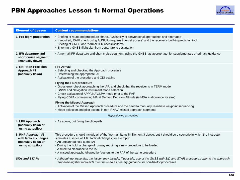
PBN Approaches Lesson 1: Normal Operations
160
Element of Lesson Content recommendations
1. Pre-flight preparation • Briefing of route and procedure charts. Availability of conventional approaches and alternates
• If required, RAIM check using AUGUR (requires internet access) and the receiver’s built-in prediction tool
• Briefing of GNSS and ‘normal’ IFR checklist items
• Entering a GNSS flight plan from departure to destination
2. IFR departure and
short cruise segment
(manually flown)
• A normal IFR departure and short cruise segment, using the GNSS, as appropriate, for supplementary or primary guidance
3. RNP Non-Precision
Approach #1
(manually flown)
Pre-Arrival
• Selecting and checking the Approach procedure
• Determining the appropriate IAF
• Activation of the procedure and CDI scaling
Flying the PBN procedure
• Gross error check approaching the IAF, and check that the receiver is in TERM mode
• GNSS and Navigation instrument mode selection
• Check activation of APP/LNAV/LPV mode prior to the FAF
• Flying CDFA commencing MA at Derived Decision Altitude (ie MDA + allowance for sink)
Flying the Missed Approach
• Activation of the Missed Approach procedure and the need to manually re-initiate waypoint sequencing
• Mode selection and pilot actions in non-RNAV missed approach segments
Repositioning as required
4. LPV Approach
(manually flown or
using autopilot)
• As above, but flying the glidepath
5. RNP Approach #3
with tactical changes
(manually flown or
using autopilot)
This procedure should include all of the “normal” items in Element 3 above, but it should be a scenario in which the instructor
simulates a series of ATC tactical changes; for example:
• An unplanned hold at the IAF
• During the hold, a change of runway requiring a new procedure to be loaded
• A direct-to clearance to the IAF
• A missed approach, followed by Vectors to the FAF of the same procedure
SIDs and STARs • Although not essential, the lesson may include, if possible, use of the GNSS with SID and STAR procedures prior to the approach,
emphasising that radio aids must be used as primary guidance for non-RNAV procedures

RNP Approaches Lesson 2: Contingencies
161
Element of Lesson Content recommendations
1. Pre-flight preparation • Briefing of route and procedure charts.
• Review of GNSS and other contingency procedures in the checklist
2. Non-GNSS
contingencies:
RNP Approach #4
• To include at least one RNP approach (flown manually or using the autopilot) in which GNSS performance is normal, but other
simulated failures or contingencies are introduced which the pilot must manage whilst flying the approach
• The failures may be specific to the aircraft type, but may include instrument, electrical, engine and fuel system problems
• In a multiengine trainer or aircraft, an engine failure should be simulated during the arrival
• The failures should permit the approach to be flown in full, but the debriefing should emphasise circumstances in which an
alternative course of action is preferable
• This element of Lesson 2 may also include tactical changes if appropriate (unplanned hold, change of PBN procedure, vectors)
Repositioning as required
3. GNSS contingencies:
RNP Approach #5
• As a minimum, this should include one RNP APP in which a simulated loss of GNSS capability takes place (eg. failure of the
receiver, SBAS/RAIM or LoI) during the procedure, such that the pilot must initiate the missed approach prior to the MAP.
• The instructor should judge the training value of then flying to an alternate airport with a conventional procedure versus simulating
a restoration of GNSS capability and completing the approach on a second attempt
• If a simulator is used which permits other GNSS failures, these may be included (eg. a discrepancy in a cross-check between
GNSS position and radio aids)
Element of Lesson Content recommendations
1. Pre-flight preparation • Briefing of route and procedure charts.
• RAIM check using the receiver’s built-in prediction tool, as required
• Review of GNSS normal and contingency checklist procedures
2. Normal PBN
procedure
• To include at least one approach procedure (RNP, or conventional approach using the receiver for supplementary guidance) and
including at least one tactical change (unplanned hold, change of procedure, vectors)
RNP Approaches differences training or completion of training
If the aircraft or simulator used for Lessons 1 and 2 is not representative of the actual aircraft or specific model of receiver to be used, the course should be
completed using an appropriate combination of representative PC simulator software, flight training device or aircraft

Course contents
1. PBN & RNP theory
a. Introduction to PBN
b. The Path-Terminator
c. PBN procedure design
2. GNSS
a. GNSS and the GPS system
b. RAIM
c. SBAS
d. Databases
e. Procedures
f. Error detection and warnings
162
3. RNP Approach Procedures
a. Classifications
b. Approach types
c. Requirements and approvals
d. Approach operations
4. Avionics training
5. Simulator and/or Flight training
Appendices
1. Database Coding and Naming
Conventions
2. PBN Learning Objectives
3. Additional items mentioned in the PBN
Learning Objectives
Glossary of Abbreviations

Sources of navigation data
1. Concept of the “aeronautical data chain”
163
Originators AIS Commercial providers Users
(general aviation examples)
Airports
Air Traffic service
providers
Communications
service providers
Procedure and
Airspace
designers
Other
government
agencies
Aeronautical
Information
Publication (AIP)
AIP Supplements
(SUP)
Aeronautical
Information
Circulars (AIC)
Notices to
Airmen (NOTAM)
Example of a commercial provider of
general aviation products: Jeppesen
“The Jeppesen Aviation Database
(JAD) is composed of over one
million records. Each 28-day cycle,
the flight information analysts edit
and verify an average 150,000 JAD
transactions. Only original source
documents are used; gathered from
220 separate agencies worldwide
and then cross-checked using
multiple sources”
Source: www.jeppesen.com
Individual States are responsible for
providing Aeronautical Information
Services (AIS) to ICAO standards
Airways Manual Paper charts
Electronic airways manual
Flight planning software
“NavData” database
PCs, Electronic flight bags (EFBs)
and some multifunction displays
(MFDs) with the ‘Chartview’ feature
Garmin, Honeywell and other
aviation units
Also database of features specific to
individual receiver models (eg.
terrain, obstacles, topographic maps)

Originators AIS Commercial
providers Users
Data standards
how is data originated to a
consistent standard? how is
quality assured in data
processing?
• ICAO doc 8168 PANS OPS
• FAA TERPS
• ECAC Guidance Material
• …etc – standards for the design of IFR
facilities and procedures, and the
format of AIS data
• RTCA Do 201A
• EUROCAE ED 77 – quality assurance for the supply
of AIS data used in databases
• RTCA Do 200A
• EUROCAE ED 76 – data processing quality
assurance for commercial
providers that create
databases from AIS data
• FAA TSOs
• EASA ETSOs – technical certification for IFR
GNSS equipment
• FAA AC120-138,
• EASA modification approval – airworthiness approval for IFR
GNSS units (or Type
Certification for original
equipment in newer aircraft)
• FAA: 14CFR Part 91 or 135
• EASA: Part-NCO
• Airplane Flight Manuals and
AFM Supplements
Coding standards
how are databases created
from AIS data?
• The ARINC 424 standard – standard for the structure of aviation navigation databases, including the type of data records
(eg. Airports, VORs) and the coding of data fields (eg. runway elevation, VOR frequency)
– includes standards for coding routes (airways) and procedures (terminal, approach)
as well as individual facilities and waypoints
Update standards
how are databases kept
current?
• The AIRAC cycle – ICAO standard for publishing additions and revisions to AIP data based on a schedule of calendar
dates and a process associated with those dates to ensure all users receive timely and
“synchronised” updates
Sources of navigation data
2. An overview of standards relevant to databases
164
• Navigation data management and quality assurance is a specialised topic, most of which is beyond the
scope of this course
• The focus in this appendix will be on the basics of the Do200A/ED76 standards and the AIRAC cycle,
and details of ARINC 424 relevant to users of GNSS equipment
ICAO Annex 15 states that ‘Contracting States shall ensure that the integrity of aeronautical data
is maintained throughout the data process from survey/origination to the next intended user’

• RTCA (Radio Technical Commission for Aeronautics) is a US non-profit organisation that develops standards
for communications, navigation, surveillance, and air traffic management (CNS/ATM) with the participation of
government, academic and industry stakeholders. RTCA recommendations are used by the FAA as a basis for
policy and regulatory decisions
http://www.rtca.org
• EUROCAE (the European Organisation for Civil Aviation Equipment) is a non-profit organisation, formed in
Switzerland in 1963 to provide a European forum for developing standards for electronic airborne and ground
systems. Its recommendations are used by EASA for policy-making
http://www.eurocae.eu
• RTCA Do200A and Eurocae ED76 are equivalent, they were developed in the late
1990s to regulate the quality assurance of navigation databases supplied by commercial
providers (such as Jeppesen, EAG, Lufthansa Systems) to airline, commercial and
private users.
• Do200A/ED76 were designed to meet the accuracy and integrity requirements of
RNP applications
• Airline and commercial operators are subject to quality management regulation (eg. JAR-
OPS 1.035). The Do200A/ED76 standard may be used (eg. see JAA TGL 9) as a means
of ensuring compliance for databases in Flight Management Systems (FMS)
• For non-commercial GA operators, the requirements for a database are specific to the
airworthiness approval of an IFR installation and the limitations imposed by the Flight
Manual (eg. a GNSS unit may only use an approved database and data card, they have
part numbers like any other aviation component)
– for RNP 5 above MSA, a current database is not required, but paper charts must be
used to verify data in an expired database
– for RNP approaches, a current database will be a requirement specified in the
AFM GNSS section or supplement
What are the Do200A and ED76 standards?
165
RTCA and Do200A, EUROCAE and ED76 References
• For the interested reader, a source of further detail on the
methods of navigation data quality assurance is the
Eurocontrol website, eg. the document “Integrity of
Aeronautical Information - Data & Quality Management”
(2003, AIM/AISD/DI/0007)
http://www.ecacnav.com/downloads
• The full set of original sources for data standards are (from
JAA TGL 9)
– ICAO Annex 4, International Standards and
Recommended Practices : Aeronautical Charts
– ICAO Annex 11, International Standards and
Recommended Practices: Air Traffic Services
– ICAO Annex 14, International Standards and
Recommended Practices: Aerodromes and Heliports
– ICAO Annex 15, International Standards and
Recommended Practices: Aeronautical Information
Services
– ICAO Document 8126, Aeronautical Information Services
Manual AN/872
– ICAO Document 9613, Manual on Required Navigation
Performance AN/937
– EUROCAE document ED-76; Standards for Processing
Aeronautical Data. RTCA Inc. document DO-200A is
technically equivalent to ED-76. A reference to one
document, at the same revision level, may be interpreted
to mean either document
– EUROCAE document ED-77/RTCA DO-201A, Standards
for Aeronautical Information
– EUROCAE document ED-75A/RTCA DO-236A, Minimum
Aviation System Performance Standards: Required
Navigation Performance for Area Navigation.

• The Do200A/ED76 standard was published in 1998
• International agreements have been developed to reduce the burden of manual checks and to certify Database
Suppliers as conforming to Do200A/ED76 and other defined conditions. There are 2 kinds of certification:
– the Type 1 LoA applies to databases that are not specific to any particular avionics system or aircraft, one can
think of it as a “wholesaler” approval. The Type 1 LoA holder can not release databases directly to end users
– the Type 2 LoA applies to databases compatible with specified avionics systems and may be released
directly to end-users. The GA owner/operator is thus concerned with Type 2 LoA suppliers
• Suppliers are certified by the regulatory agency in their home country (eg. the FAA for Jeppesen, EASA for EAG,
Transport Canada for CAC) and mutual acceptance of this certification has been agreed
• Honeywell, Garmin and Jeppesen hold Type 2 LoAs, but since these are equipment-specific, an operator
must check that they apply to their particular model of receiver and database
– Garmin received a Type 2 LoA from the FAA for the G1000 and 400/500 series in April 2007
– some modern IFR GPS units do not have a Type 2 LoA database available, but the Jeppesen data they use is
Do200A/ED76 compliant, meeting the RNAV 1 requirement. The operator must check the status of their
individual receiver model
Database Supplier approvals relating to Do200A and ED76
The Type 1 and Type 2 Letters of Acceptance (LoA)
166
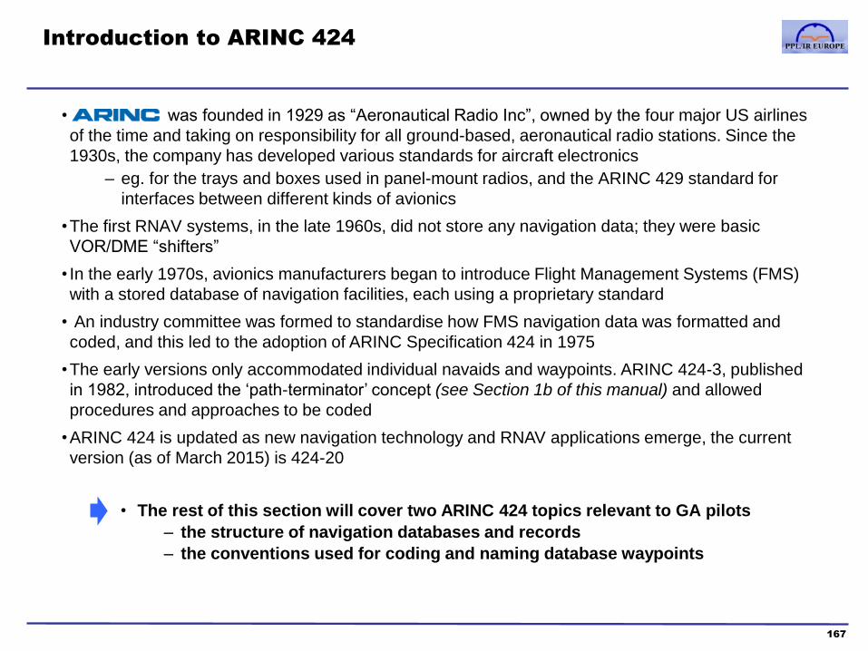
• was founded in 1929 as “Aeronautical Radio Inc”, owned by the four major US airlines
of the time and taking on responsibility for all ground-based, aeronautical radio stations. Since the
1930s, the company has developed various standards for aircraft electronics
– eg. for the trays and boxes used in panel-mount radios, and the ARINC 429 standard for
interfaces between different kinds of avionics
•The first RNAV systems, in the late 1960s, did not store any navigation data; they were basic
VOR/DME “shifters”
• In the early 1970s, avionics manufacturers began to introduce Flight Management Systems (FMS)
with a stored database of navigation facilities, each using a proprietary standard
• An industry committee was formed to standardise how FMS navigation data was formatted and
coded, and this led to the adoption of ARINC Specification 424 in 1975
•The early versions only accommodated individual navaids and waypoints. ARINC 424-3, published
in 1982, introduced the ‘path-terminator’ concept (see Section 1b of this manual) and allowed
procedures and approaches to be coded
•ARINC 424 is updated as new navigation technology and RNAV applications emerge, the current
version (as of March 2015) is 424-20
Introduction to ARINC 424
167
• The rest of this section will cover two ARINC 424 topics relevant to GA pilots
– the structure of navigation databases and records
– the conventions used for coding and naming database waypoints
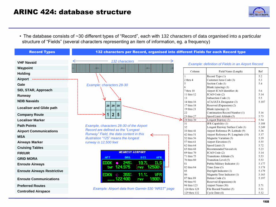
• The database consists of ~30 different types of “Record”, each with 132 characters of data organised into a particular
structure of “Fields” (several characters representing an item of information, eg. a frequency)
ARINC 424: database structure
168
Record Types 132 characters per Record, organised into different Fields for each Record type
VHF Navaid
Waypoint
Holding
Airport
Gate
SID, STAR, Approach
Runway
NDB Navaids
Localiser and Glide path
Company Route
Localiser Marker
Path Points
Airport Communications
MSA
Airways Marker
Cruising Tables
FIR/UIR
GRID MORA
Enroute Airways
Enroute Airways Restrictive
Enroute Communications
Preferred Routes
Controlled Airspace
.. .. 1 2 .. 2
9 ..
3
0 .. .. 1 2 ..
2
9 ..
3
0 .. .. 1 2 ..
2
9 ..
3
0 .. .. 1 2 ..
2
9 ..
3
0
28 29 30
1 2 5
132 characters
Example: characters 28-30
Example: definition of Fields in an Airport Record
Example, characters 28-30 of the Airport
Record are defined as the “Longest
Runway” Field, the data content in this
illustration “125” means the longest
runway is 12,500 feet
Example: Airport data from Garmin 530 “NRST” page

• Most GNSS maps only depict Class
B, C and D airspace. For example,
Class A is omitted because in the
USA it is the entire airspace above
FL180. However, this means that
low-level Class A (and Class E & F)
airspace in Europe is not displayed
and airspace alerts are not provided
There are four kinds of ARINC 424 Record
169
VHF Navaid
Waypoint
Holding
Airport
Runway
NDB Navaids
Company Route
Enroute Airways
Enroute Airways Restrictive
Preferred Routes
“Points” Routes Procedures Miscellaneous
MSA
FIR/UIR
GRID MORA
Enroute Communications
Controlled Airspace
Examples:
Examples:
• Records of specific locations
such as radio navaids,
traditional fixes and
intersections, RNAV waypoints
and airports
• Some fields are common to all
these types of record (eg.
latitude & longitude, ICAO
identifier), others are specific to
the type of point
• Simple routes which are a
named sequence of fixed points
• Route data (eg. for an Airway)
includes - fix sequence number
- fix identifier
- route type
- RNP applicable
- max/min altitudes
- “Rho”: distance in nm to next fix
- “Theta”: magnetic bearing to next fix
• Complex routes coded as a
named sequence of Path-
Terminators (see Section 1b)
• May include Speed and Altitude
limits associated with each fix
• Other record types, mostly
relating to communications and
airspace
• Use is specific to individual
receiver models eg. mapping
function, airspace alerting, ATC
frequency advisories, minimum
IFR levels
• Most types of records are
“independent” of each other,
except for airports, which
have a basic record plus
several associated records
for individual runways,
gates, ILS facilities etc.
• A fix or waypoint will have both its own “stand-alone” record,
and its record repeated within any Route and Procedure
sequences it is part of
• A waypoint may be designated as “Fly-Over” in one route and
“Fly-By” in another
Note: these four kinds of Record are not a formal ARINC distinction, only used here for descriptive purposes
Example: waypoint record included in route & procedure sequences
SID, STAR, Approach
IMPORTANT NOTE
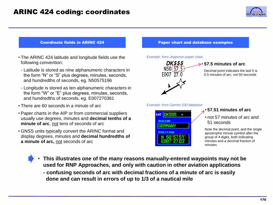
ARINC 424 coding: coordinates
170
Coordinate fields in ARINC 424 Paper chart and database examples
• 57.5 minutes of arc
Decimal point indicates the last 5 is 0.5 minutes of arc, not 50 seconds
• The ARINC 424 latitude and longitude fields use the following convention:
- Latitude is stored as nine alphanumeric characters in the form “N” or “S” plus degrees, minutes, seconds, and hundredths of seconds, eg. N50575196
- Longitude is stored as ten alphanumeric characters in the form “W” or “E” plus degrees, minutes, seconds, and hundredths of seconds, eg. E007270361
• There are 60 seconds in a minute of arc
• Paper charts in the AIP or from commercial suppliers usually use degrees, minutes and decimal tenths of a minute of arc, not tens of seconds of arc
• GNSS units typically convert the ARINC format and display degrees, minutes and decimal hundredths of a minute of arc, not seconds of arc
• This illustrates one of the many reasons manually-entered waypoints may not be
used for RNP Approaches, and only with caution in other aviation applications
- confusing seconds of arc with decimal fractions of a minute of arc is easily
done and can result in errors of up to 1/3 of a nautical mile
Example: from Jeppesen paper chart
Example: from Garmin 530 database
• 57.51 minutes of arc
• not 57 minutes of arc and 51 seconds
Note the decimal point, and the single apostrophe minute symbol after the group of 4 digits, both indicating minutes and a decimal fraction of minutes
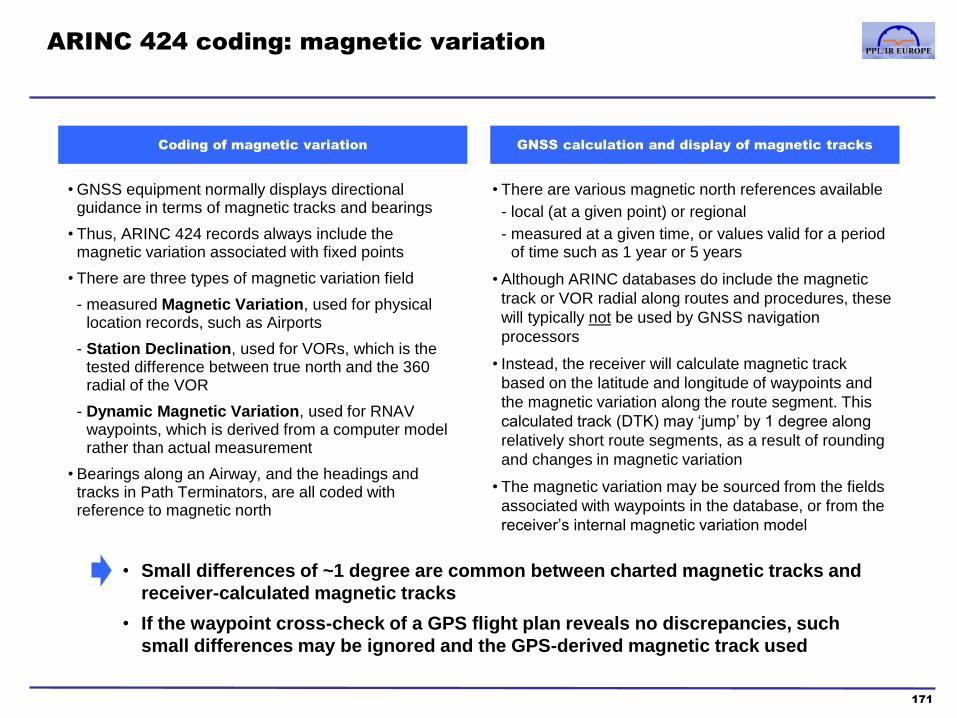
• GNSS equipment normally displays directional guidance in terms of magnetic tracks and bearings
• Thus, ARINC 424 records always include the magnetic variation associated with fixed points
• There are three types of magnetic variation field
- measured Magnetic Variation, used for physical location records, such as Airports
- Station Declination, used for VORs, which is the tested difference between true north and the 360 radial of the VOR
- Dynamic Magnetic Variation, used for RNAV waypoints, which is derived from a computer model rather than actual measurement
• Bearings along an Airway, and the headings and tracks in Path Terminators, are all coded with reference to magnetic north
ARINC 424 coding: magnetic variation
171
• Small differences of ~1 degree are common between charted magnetic tracks and
receiver-calculated magnetic tracks
• If the waypoint cross-check of a GPS flight plan reveals no discrepancies, such
small differences may be ignored and the GPS-derived magnetic track used
Coding of magnetic variation GNSS calculation and display of magnetic tracks
• There are various magnetic north references available
- local (at a given point) or regional
- measured at a given time, or values valid for a period of time such as 1 year or 5 years
• Although ARINC databases do include the magnetic
track or VOR radial along routes and procedures, these
will typically not be used by GNSS navigation
processors
• Instead, the receiver will calculate magnetic track
based on the latitude and longitude of waypoints and
the magnetic variation along the route segment. This
calculated track (DTK) may ‘jump’ by 1 degree along
relatively short route segments, as a result of rounding
and changes in magnetic variation
• The magnetic variation may be sourced from the fields
associated with waypoints in the database, or from the
receiver’s internal magnetic variation model

ARINC 424 name and coding conventions
1. Introduction to names and identifiers
172
• ICAO Annex 11 defines the international standard for the designators of navaids, waypoints, airways and procedures
• Where a waypoint is marked but not named in AIP charts, ARINC 424 provides standards for creating names
• Where a procedure does not include all the waypoints needed for RNAV guidance, the state can define additional
“Computer Navigation Fixes” (CNF) or the database supplier will create CNFs and assign them database identifiers
Names ICAO Identifiers Database Identifiers
The full “prose” version of the name of a facility,
waypoint or procedure
A short letter or alphanumeric version of a
name, corresponding to the ICAO Annex 11
standard. Published on paper charts, and
transmitted as a Morse ident by radio facilities
The record name in a database. Generally the
same as the ICAO identifier, but ARINC 424
may require some variation. CNFs may only
have a database identifier and no published
chart designator
Examples
London Heathrow EGLL EGLL
Daventry DTY DTY
waypoint name is the same as identifier KENET KENET
Lambourne Three Alpha LAM 3A JSY1A
a CNF created by the database supplier and not published in paper charts
• Identifiers are not always unique, waypoint and procedure naming conventions change and databases are an
inherently different format that can not perfectly “mirror” paper charts
•An understanding of naming conventions and coding is essential for PBN operations
E G L L
D T Y
C I 2 7
K E N E T
L A M 3 A
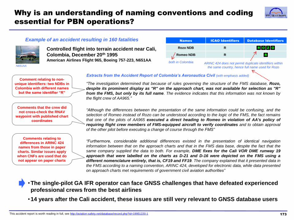
Extracts from the Accident Report of Colombia’s Aeronautica Civil (with emphasis added)
Why is an understanding of naming conventions and coding
essential for PBN operations?
“The investigation determined that because of rules governing the structure of the FMS database, Rozo,
despite its prominent display as "R" on the approach chart, was not available for selection as "R"
from the FMS, but only by its full name. The evidence indicates that this information was not known by
the flight crew of AA965.”
“Although the differences between the presentation of the same information could be confusing, and the
selection of Romeo instead of Rozo can be understood according to the logic of the FMS, the fact remains
that one of the pilots of AA965 executed a direct heading to Romeo in violation of AA's policy of
requiring flight crew members of FMS-equipped aircraft to verify coordinates and to obtain approval
of the other pilot before executing a change of course through the FMS”
“Furthermore, considerable additional differences existed in the presentation of identical navigation
information between that on the approach charts and that in the FMS data base, despite the fact that the
same company supplied the data to both. For example, DME fixes for the Cali VOR DME runway 19
approach that were labelled on the charts as D-21 and D-16 were depicted on the FMS using a
different nomenclature entirely, that is, CF19 and FF19. The company explained that it presented data in
the FMS according to a naming convention, ARINC 424, developed for electronic data, while data presented
on approach charts met requirements of government civil aviation authorities”
173
Controlled flight into terrain accident near Cali,
Colombia, December 20th 1995 American Airlines Flight 965, Boeing 757-223, N651AA
Comment relating to non-
unique identifiers: two NDBs in
Colombia with different names
but the same identifier “R”
Comments that the crew did
not cross-check the RNAV
waypoint with published chart
coordinates
Comments relating to
differences in ARINC 424
names from those in paper
charts. Similar issues apply
when CNFs are used that do
not appear on paper charts
•The single-pilot GA IFR operator can face GNSS challenges that have defeated experienced
professional crews from the best airlines
•14 years after the Cali accident, these issues are still very relevant to GNSS database users
This accident report is worth reading in full, see http://aviation-safety.net/database/record.php?id=19951220-1
Names ICAO Identifiers Database Identifiers
Rozo NDB R ROZO
Romeo NDB R R
R O Z O
R
both in Colombia ARINC 424 does not permit duplicate identifiers within
the same country, hence full name used for Rozo N651AA
Example of an accident resulting in 160 fatalities

ARINC 424 name and coding conventions
2. Overview of databases identifiers
174
“Points” Routes and Procedures Procedure Waypoints
Airports
• 4 letter ICAO identifier eg. EGLL
• ‘K’ added to US 3 letter codes, eg. KLAX
Airways ….
• Alphanumeric identifiers of 2-5 characters. But, not
supported in most panel-mount GPS units
Terminal waypoint names
“Strategic” waypoints:
• Terminal waypoints of major significance to ATC, often
designating the start and end or routes and major transitions
• Use the 5LNC or the 3 letter identifier of a navaid
“Tactical” waypoints:
• Terminal waypoints solely for use in the specific terminal area
and not designated as strategic
• ‘Tactical’ RNAV terminal waypoints use a 5 character
alphanumeric. The first two letters (‘aa’) are the last two
letters of the airport ICAO code, the “x” is either a letter code
(eg. orientation N,E,S or W) or a digit, and the last 2
characters (“nn”) are digits from 00 to 99
• In older procedures, where a tactical waypoint does not have
a suitable name, a CNF identifier will be created using a 5
character alphanumeric, in the form “Dnnna”, based on the
“bearing/distance” convention (see later pages)
Approach waypoint names various – see next pages
• May be named and published (eg. a navaid or 5LNC)
• May be published but with only a generic name (eg. the
Outer Marker, or a Final Approach Fix) or no name, in which
case a CNF identifier will be created (see later pages) using
the Airport CNF convention
VORs and VOR-DMEs
• Usually a 3 letter identifier eg. ABC
• Sometimes a 2 letter identifier, but no longer used for
VORs in Europe
Terminal procedure names
• ARINC 424 permits alphanumeric identifiers of up to
6 characters (see page 80)
• The leading letters usually refer to a fix at the start
or end of a procedure. In the case of a 3 letter VOR
identifier, the “aaana” format is used. If the fix is a
5LNC, the last letter of the 5LNC is dropped and the
procedure name format is “aaaana”
NDBs , ,
• 1, 2 or 3 letter identifier eg. A, AB, ABC
Enroute waypoints
• 5 character alphanumeric names; usually either 5
letters (the ICAO “5 letter name-code” or 5LNC) or 3
letters and 2 numbers representing a VOR reference
and a DME distance in the form aaann
Approach procedure names
• Alphanumeric identifiers of 3-6 characters are used
- 3 characters might specify an approach not
specific to a runway, eg. simply ‘NDB’
- 5-6 characters are typical, eg. ‘ILS27’ or ‘ILS27R’
• They may be specified as starting from an approach
transition waypoint or starting with vectors to
intercept the final approach track
Other “point” records in databases
• Although encoded in ARINC 424 databases, other
facilities (eg. ILSs, runways) are usually not directly
accessible by the GPS user except as part of Airport
or Procedure records
a a a n a
a a a a
a a a
a a a a a a
a a a a a
a a n n n a n
a a a n n
a a x n n
• Published identifiers and database
identifiers are generally identical
• Note that some identifiers are not unique,
except within a country or geographic
region (within Europe, mainly applies to
NDBs)
• Terminal procedure database identifiers are
published in [square brackets] on paper
charts
• Approach procedure identifiers are usually
the same as the charted procedure names,
but see page 92 for potential ambiguities
• Procedure waypoint names are only unique
within a terminal area or for a particular airport
• Note the similar format used for RNAV Tactical
waypoint identifiers and the Bearing/Distance
convention for CNFs
a a a a a

3.Select
transition
ARINC 424 name and coding conventions
3. Since identifiers are not always unique, how is a specific record located?
175
Airports Radio Aids Enroute Waypoints Terminal
Procedures
Approach
Procedures
Is the Identifier
unique?
• ICAO 4 letter airport
codes are unique
worldwide
• NDB and VOR
identifiers are not
unique
• 5LNCs are unique
• ..but not all enroute
intersections use 5LNC
identifiers
• Procedures and
procedure waypoints
are unique to a
particular TMA
• Approaches and
final/missed approach
waypoints are unique to
a particular airport
How is the right
record selected if
duplicates exist?
• (n/a: no duplicates)
• Be familiar with how and when the GPS identifies
that duplicate records exist for an identifier
• Select the record with the correct name and
geographic region
• Confirm correct airport
• Select runway,
transition and
procedure identifier
• Confirm correct airport
• Select runway,
transition and approach
type
How is a record
identification
confirmed?
• Check the airport
name in the database
to confirm ICAO code
• Gross error check of RNAV waypoint position with
paper chart and radio instruments
• Check procedure waypoints with paper chart
terminal and approach waypoints should only be
selected from within a loaded procedure
• Check the end waypoint of the STAR matches the
transition at the start of the approach
Example: select geographic
region from GNS530W list of
duplicated records available for
a given identifier selection
Confirm facility name
correct
data for gross error
check and radio
cross-check
1.Confirm airport
correct
2.Select procedure
identifier
3. Select
transition
4. If applicable,
select runway
Garmin 530 examples
1.Confirm
airport
correct
2.Select procedure
identifier – check
list for multiple
similar procedures

ARINC 424 name and coding conventions
4. When are database waypoints different from those on paper charts?
176
1. When paper chart names are not
suitable for ARINC 424
2. When waypoints are not named
on paper charts, or where only a
generic “label” is used
3. When a waypoint does not exist
on paper charts, but is required for
coding a procedure
• ARINC 424 limits waypoint database
identifiers to 5 character, and duplicate
identifiers are not permitted within a single
country
• When RNAV and the use of FMS databases
were relatively new, paper charts in the USA
and Europe would often have fix and
intersection names not compatible with
ARINC 424
• However, in Europe, AIP charts have been
updated so that ARINC-compatible names are
used in all enroute navigation
• Examples:
- unnamed fixes or intersections
- unnamed turning points in procedures (eg.
simply defined by a time, lead radial)
- points on procedures labelled only with a
DME distance (eg. D4.5), which is not
sufficiently unique to be used as a database
identifier
- points with generic labels such as FAF, IAF,
OM; which, again, are not unique enough –
a single airport may have numerous such
points
• Note that a “generic” name (eg. D4.5) may be used as
a database identifier if it is unique within the
procedures at a particular airport
• Procedures where the paper chart
description is adequate but too “ambiguous”
for the more deterministic coding needed in
databases. Examples:
- the localiser intercept after a base turn will
often not have a published waypoint, but
GNSS systems may require one to establish
the track segment from the intercept to the
FAF
- the point at which a DME arc is intercepted
will often not have a paper chart waypoint
defined, but one may be needed for the
path-terminator coding in a database
• ARINC 424 has coding rules for creating waypoint names when suitable names are lacking,
and for creating Computer Navigation Fixes (CNFs) when suitable waypoints are lacking
• These coding rules can be summarised as 3 waypoint conventions:
– Enroute waypoint naming convention
– Procedure CNF Bearing/Distance convention
– Airport CNF convention
•Each of these conventions is described in the next pages

A B C 3 5
ARINC 424 name and coding conventions
5. Enroute waypoint naming
177 Source: www.jeppesen.com GPS NavData Services > Documentation and Support > see PDF download of NavData name conventions
If an enroute fix has a published name
which is not suitable for ARINC 424
If an enroute fix or intersection is
published without a name
• The identifier is constructed from the identifier of, typically, the nearest airway VOR (which is the reference for the waypoint) and the distance from that VOR
• If the distance is less than 100nm, the identifier format is the three letters of the VOR ident followed by a two digit distance,
eg a waypoint 35nm from “ABC” VOR:
• If the distance is 100-199nm, the identifier format is the three letters of the VOR ident preceded by the last two digits of the distance eg a waypoint 135nm from “ABC” VOR:
• If unnamed waypoint is collocated with a named waypoint on a different route structure then the named waypoint’s identifier is used
3 5 A B C
• European enroute charts have been updated with airway waypoint identifiers that are always
compatible with ARINC 424, hence the paper charts and databases should be highly consistent
• The three formats used are navaid identifiers, 5LNCs and the ‘reference VOR plus 2 digit distance’
Example of Airway waypoints
Jeppesen E(LO)2 low altitude
enroute chart (paper)
Jeppesen low altitude enroute
chart (PC version in JeppView) Garmin GNS480 airway route
“5LNC”
identifier
Reference
VOR and
distance
identifier
VOR
identifier
Note square
brackets and
cross symbol
indicating a CNF
database identifier
which has no flight
plan filing or ATC
function, only aids
pilot orientation.
• The method applied in ARINC 424 coding is as follows
A. If the name is greater than 5 letters, various rules are applied to
shorten it to a “5LNC”
eg. ‘COTTON’ becomes
eg. ‘CLEAR LAKE’ becomes
B. If the 5LNC rule results in duplicate identifiers, a 4 letter name with a
suffix number is used, eg. ,
C. Where more than one short identifier is published, ARINC 424 uses a
long name for one of the duplicates eg. and
C O T O N
C L A K E
C L A K 1 C L A K 2
R R O M
Do not use for navigation

Reference: extract from Jeppesen Enroute Chart legend
Source: Jeppesen Airway Manual Introduction section
178
• Note: the nomenclature of waypoint names is sometimes confusing.
• “Database identifier” can be a generic term for the ARINC 424 short, coded name of any navaid, fix, airport etc.
• In the context of the chart legend above, “database identifier” means a Computer Navigation Fix name which is
not part of the normal published ATC route (although the underlying turning point is, in this case).
• When CNFs are published in state AIP sources, they will be included in paper charts [in square brackets]; if they
are created by Jeppesen, they will only be found in the database
Do not use for navigation
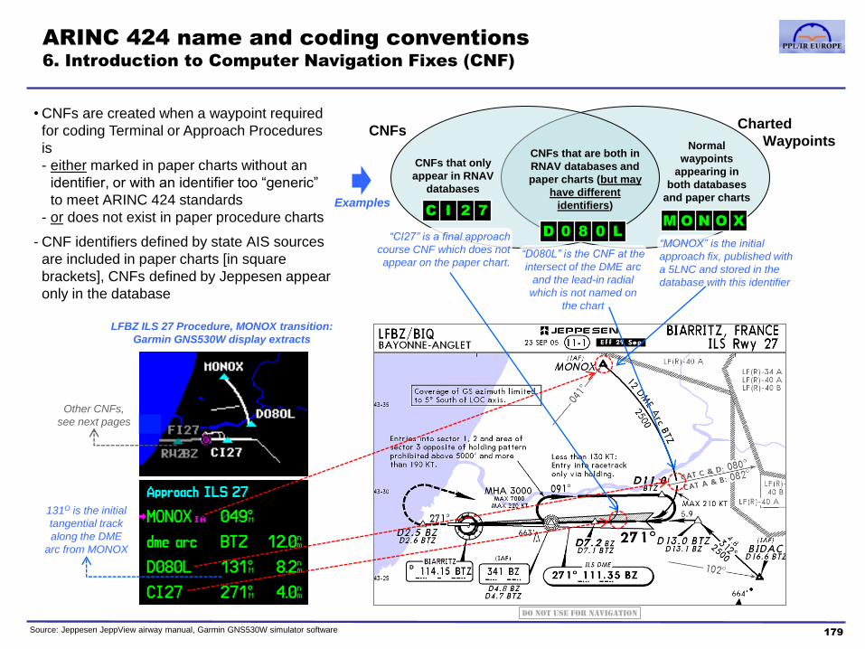
ARINC 424 name and coding conventions
6. Introduction to Computer Navigation Fixes (CNF)
179 Source: Jeppesen JeppView airway manual, Garmin GNS530W simulator software
• CNFs are created when a waypoint required
for coding Terminal or Approach Procedures
is
- either marked in paper charts without an
identifier, or with an identifier too “generic”
to meet ARINC 424 standards
- or does not exist in paper procedure charts
- CNF identifiers defined by state AIS sources
are included in paper charts [in square
brackets], CNFs defined by Jeppesen appear
only in the database
Charted
Waypoints
CNFs
CNFs that only
appear in RNAV
databases
CNFs that are both in
RNAV databases and
paper charts (but may
have different
identifiers)
Normal
waypoints
appearing in
both databases
and paper charts
M O N O X
D 0 8 0 L
C I 2 7
LFBZ ILS 27 Procedure, MONOX transition:
Garmin GNS530W display extracts
Examples
“CI27” is a final approach
course CNF which does not
appear on the paper chart. “D080L” is the CNF at the
intersect of the DME arc
and the lead-in radial
which is not named on
the chart
“MONOX” is the initial
approach fix, published with
a 5LNC and stored in the
database with this identifier
131O is the initial
tangential track
along the DME
arc from MONOX
Other CNFs,
see next pages
Do not use for navigation

• In SIDs, STARs and Approaches, this convention is used to create an identifier for unnamed fixes or DME fixes
• The identifier is always a 5 character alphanumeric in the format:
• The distance letter code is A=1nm, B=2nm….Z=26nm
• Distances are rounded to the nearest integer (i.e. A is used for 0.1nm to 1.4nm, B for 1.5nm to 2.4nm etc)
• If the distance is greater than 26nm, the Enroute waypoint convention is used (3 letters of the VOR ident plus 2 digit distance)
• The A-F letter codes are easy to remember as 1-6nm respectively. It is worth being familiar with G=7nm, H=8nm, I=9nm, J=10nm, K=11nm, L=12nm.
ARINC 424 name and coding conventions
7. Procedure “bearing/distance” CNFs
180 Source: Jeppesen JeppView airway manual, Garmin GNS530W simulator software
• In the previous example, why is the
identifier “D080L” used for the CNF at
the end of the DME arc?
D 0 8 0 L
Procedure waypoint “bearing/distance”
CNF convnetion
D n n n a
first
character is
always “D”
middle 3 digits are
the radial from the
reference VOR ( or
other reference point)
last character is a
letter code for the
distance from the
reference point
• Hence, in the example above, the waypoint on the BTZ 080 radial and 12nm DME arc is given the identifier “D080L”
• Procedure “bearing/distance” CNFs are only unique within a TMA
Garmin
GNS530W
display
extracts
Do not use for navigation

• This convention allows CNFs to be created for all the fixes GNSS equipment needs to provide guidance throughout an approach procedure, which may not be published or have an ARINC 424 compatible name
• The identifier is a 4 or 5 character alphanumeric in the format:
• The various codes for the waypoint type and approach type are detailed on the next page
ARINC 424 name and coding conventions
8. Airport CNFs
181 Source: Jeppesen JeppView airway manual, Garmin GNS530W simulator software
• In the previous example, why is there a
CNF called “CI27” on the final approach
track prior to the FAF?
D 0 8 0 L
Airport CNF convention
a a n n a 1st letter defines
the waypoint type
2 digits are the
runway identifier
If there are parallel
runways, the 5th
character is an L,C
or R runway suffix
C I 2 7
• In the “CI27” example above, the “C” indicates a final approach course fix, the “I” indicates an ILS procedure, and the “27” that the procedure is for runway 27
• Airport CNFs are unique to an individual Airport only. In the example above, there will only be a single instance of a CNF identifier “CI27” associated with LFBZ. Many other airports, including ones in the same TMA, can have an identically named CNF
2nd letter defines the approach type,
if there are multiple approaches to
this runway, otherwise it is the 2nd
letter of the waypoint type code Garmin
GNS530W
display
extracts
Do not use for navigation

ARINC 424 name and coding conventions
9. Airport CNF codes
182
A single approach procedure
exists for a given runway
More than one procedure
exists for a given runway Procedure type codes used
First two characters of the CNF
identifier are the Waypoint Type First character of the CNF
identifier is the Waypoint Type
Second character of the CNF
identifier is the Procedure Type
Source: www.jeppesen.com GPS NavData Services > Documentation and Support > see PDF download of NavData name conventions
Initial Approach Fix AF
Intermediate Approach Fix IF
Final Approach Course Fix CF
Final Approach Fix FF
Missed Approach Point MA
Step-Down Fix SD
Runway Centreline Fix RC
Touchdown point TD
Runway Fix RW
Outer Marker OM
Middle Marker MM
Inner Marker IM
Back course Marker BM
Initial Approach Fix A_
Intermediate Approach Fix I_
Final Approach Course Fix C_
Final Approach Fix F_
Missed Approach Point M_
Step-Down Fix S_
Runway Centreline Fix R_
Touchdown point T_
If an approach marker has an identifier, that will
be used in preference to this CNF convention
CNFs unique
to a runway,
so no need
for a single
letter code
_I ILS Approach
_L Localiser Approach
_D VOR/DME Approach
_V VOR Approach
_N NDB Approach
_Q NDB/DME Approach
_R RNP APCH
_P GPS Approach
These are 8 of the most common types, see next page for the full list of 25
• The only unfamiliar, but frequently used, waypoint type is the Final Approach Course (or Capture) fix, CF or C_
• Many older GNSS systems can only provide guidance from one waypoint to another. Without the CF/C_ fix, they could not provide track guidance along the final approach to the FAF following an intercept (eg. a base turn or radar vectors) that did not commence with a published waypoint
• Hence, many approach procedures are coded with a CF/C_ fix after the intercept of the final approach track and before the FAF
Rarely
used

Reference: extract from Jeppesen NavData documentation
Source: www.jeppesen.com > GPS NavData Services > Documentation and Support
183
Waypoint
types Matrix of Waypoint and Approach type combinations
A. Approach Transition
B. LLZ Back course Approach
C. LORAN Approach
D. VOR/DME Approach
E. VOR Circle-To-Land Approach
F. FMS Approach
G. IGS (Instrument Guidance System) Approach
H. Helicopter Approach
I. ILS Approach
J. LLZ only Circle-To-Land Approach
K. LLZ Back course Circle-To-Land Approach
L. Localiser only Approach
M. MLS Approach
N. NDB Approach
P. GPS Approach
Q. NDB/DME Approach
R. RNP APCH
S. VOR Approach with DME Facility
T. TACAN Approach
U. NDB Circle-To-Land Approach
V. VOR Approach (Non-DME Facility)
W. MLS Type A Approach
X. LDA (Localiser Directional Aid) Approach
Y. MLS Type B and C Approach
Z. SDF (Simplified Directional Facility) Approach
Full List of 25 Approach types

ARINC 424 name and coding conventions
10. Summary of “point” terminology
184
Term Definition On paper
chart
In GNSS
unit
Fix
Specifically, a geographical point
defined by reference to radio aids,
also, in general, includes any of the
below
& name
identifier
& DME
distance or
unnamed
& identifier
usually one
symbol
used for all
fix and
waypoint
types,
except
radio aids
Intersection A fix defined by the intersection of
two VOR radials
RNAV
Waypoint
A geographic point defined by
coordinates rather than radio aids;
the RNAV equivalent of a fix
& identifier
(fly-by
example)
Waypoint
In general, any of the above, also
locations of a radio aid. Sometimes
specifically an RNAV waypoint
Any of the
above
Computer
Navigation
Fix (CNF)
A fix or waypoint used in databases
but not for ATC or flight plan filing
purposes
Identifier, if
shown and
different from
the published
name, will be
in [square
brackets]
Database
Identifier
In general, the primary record name
in a database for any of the above.
Sometimes, specifically the name of
a CNF
• The terminology around “types of point” can be confusing, because it is not always consistently defined and applied. The tables below provides some guidance on the use of various terms
Enroute and Terminal points
Term Definition Traditional
procedure
PBN
procedure
IAF Initial Approach Fix, Intermediate
Fix and Missed Approach Point
definitions are exactly the same
in PBN procedures as in
‘traditional’ IFR approaches
& name
..or navaid
symbol & name
& name
..or navaid
symbol & name
IF
MAP
(or MAPt)
FAP
Final Approach Point – used only in
a precision approach, the point at
which the intermediate approach
altitude or height intersects the glide
path
In paper charts, not defined as a
fix, but a DME distance may be
marked at the FAP
In databases, an “FF/F_“ CNF is
defined at the FAP
FAF
Final Approach Fix – used only in a
non-precision approach (NPA), the
fix which defines the start of the
descent to MDA/MDAH
Fix and fix name depicted on
paper charts and databases (may
be a CNF identifier for a DME fix) NPAs without a fix (eg. NDB approach
based only on timing) will have a
“FF/F_” CNF defined in the database
Note: in the late 1990s, it was proposed that the waypoints in RNP
APCHs should be called “IAWP, IWP, FAWP, MAWP” (with “WP” for
Waypoint replacing “F” for Fix). This new terminology was abandoned,
but some older publications and charts still use the “-WP” notation
Approach waypoints
• This completes the Databases and Coding section
• The next section will review how ARINC 424 is used to code both traditional procedures (the “database overlay”) and PBN procedures, and how GNSS units provide procedure guidance

Course contents
1. PBN & RNP theory
a. Introduction to PBN
b. The Path-Terminator
c. PBN procedure design
2. GNSS
a. GNSS and the GPS system
b. RAIM
c. SBAS
d. Databases
e. Procedures
f. Error detection and warnings
185
3. RNP Approach Procedures
a. Classifications
b. Approach types
c. Requirements and approvals
d. Approach operations
4. Avionics training
5. Simulator and/or Flight training
Appendices
1. Database Coding and Naming Conventions
2. PBN Learning Objectives
3. Additional items mentioned in the PBN
Learning Objectives
Glossary of Abbreviations

Learning Objectives
186
This appendix lists the Learning Objectives (LOs) of the EASA IR theoretical knowledge (TK) syllabus
that are relevant to PBN. The PBN LOs are part of the IR Radio Navigation syllabus and are set out in
the AMC to EASA Part-FCL (Amendment 4, 08/02/2018). Each LO is referenced to the relevant page
of the book in which it is explained.
For existing EASA IR pilots yet to gain "PBN privileges", it covers all the learning required for the TK
element of obtaining them - whether through oral examination during an IR proficiency check, or a
written exam at an ATO
For those training towards the EASA IR, it may be used to revise for the PBN elements of the Radio
Navigation exam.
Some topics which are unlikely to be relevant to most GA fixed-wing pilots, but are in the LOs, are
included in Appendix 3. We have kept explanation of such topics to an absolute minimum, so that
you have enough information to pass any relevant exam questions.

Learning Objectives
187
Section Learning Objective Page
PBN Concept (as described in ICAO Doc 9613)
PBN principles
List the factors used to define area navigation (RNAV) or required navigation
performance (RNP) system performance requirements (accuracy, integrity and
continuity)
21
State that these RNAV and RNP systems are necessary to optimise the utilisation
of available airspace
8
State that it is necessary for flight crew and air traffic controllers to be aware of the
on-board RNAV or RNP system capabilities in order to determine whether the
performance of the RNAV or RNP system is appropriate for the specific airspace
requirements
13
Define accuracy as the conformance of the true position and the required position 21
Define continuity as the capability of the system to perform its function without
unscheduled interruptions during the intended operation
21
Define integrity as a measure of the trust that can be placed in the correctness of
the information supplied by the total system. Integrity includes the ability of a
system to provide timely and valid alerts to the user
21
State that, unlike conventional navigation, performance-based navigation is not
sensor specific
11
Explain the difference between raw data and computed data 200
Define availability as the percentage of time (annually) during which the system is
available for use
59
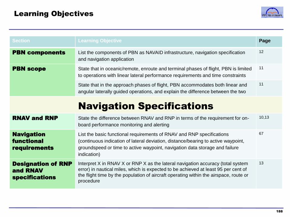
Learning Objectives
188
Section Learning Objective Page
PBN components List the components of PBN as NAVAID infrastructure, navigation specification
and navigation application
12
PBN scope
State that in oceanic/remote, enroute and terminal phases of flight, PBN is limited
to operations with linear lateral performance requirements and time constraints
11
State that in the approach phases of flight, PBN accommodates both linear and
angular laterally guided operations, and explain the difference between the two
11
Navigation Specifications
RNAV and RNP State the difference between RNAV and RNP in terms of the requirement for on-
board performance monitoring and alerting
10,13
Navigation
functional
requirements
List the basic functional requirements of RNAV and RNP specifications
(continuous indication of lateral deviation, distance/bearing to active waypoint,
groundspeed or time to active waypoint, navigation data storage and failure
indication)
67
Designation of RNP
and RNAV
specifications
Interpret X in RNAV X or RNP X as the lateral navigation accuracy (total system
error) in nautical miles, which is expected to be achieved at least 95 per cent of
the flight time by the population of aircraft operating within the airspace, route or
procedure
13

Learning Objectives
189
Section Learning Objective Page
Designation of RNP
and RNAV
specifications
State that aircraft approved to the more stringent accuracy requirements may not
necessarily meet some of the functional requirements of the navigation
specification having a less stringent accuracy requirement
13
State that RNAV 10 and RNP 4 are used in the oceanic/remote phase of flight 16, 18
State that RNAV 5 is used in the enroute and arrival phase of flight 16, 19
State that RNAV 2 and RNP 2 are also used as navigation specifications 16, 19, 18
State that RNP 2 is used in the enroute, and oceanic/remote phases of flight 16, 18
State that RNAV 2 might be used in the en-route continental, arrival and departure
phases of flight
16, 19
State that RNAV 1 and RNP 1 are used in the arrival and departure phases of
flight
16, 19, 20
State that RNP APCH is used in the approach phase of flight 14, 15
State that RNP AR APCH is used in the approach phase of flight 16, 202
State that RNP 0.3 navigation specification is used in all phases of flight except
for oceanic/remote and final approach, primarily for helicopters
16
State that RNAV 1, RNP 1 and RNP 0.3 may also be used in en-route phases of
low-level instrument flight rule (IFR) helicopter flights
16

Learning Objectives
190
Section Learning Objective Page
Use of PBN
Specific RNAV and
RNP system
functions
Recognise the definition of an RF leg 24,37
Recognise the definition of a fixed radius transition (FRT) 17
State the importance of respecting the flight director guidance and the speed
constraints associated with an RF procedure
37
Explain the difference between a fly-by-turn and a flyover 28,29
State that the Aeronautical Radio, Incorporated (ARINC) 424 path terminators set
the standards for coding the SIDs, STARs and instrument approach procedures
(IAPs) from the official published government source documentation into the
ARINC navigation database format
23
State that the path terminators define a specific type of termination of the previous
flight path
24,25
Recognise the definition of an ‘offset flight path’ 200

Learning Objectives
191
Section Learning Objective Page
PBN Operations
PBN principles
Define ‘path definition error’ (PDE) 21
Define ‘flight technical error’ (FTE) and state that the FTE is the error in following
the prescribed path, either by the auto-flight system or by the pilot
21
Define ‘navigation system error’ (NSE) and state that the accuracy of a navigation
system may be referred to as NSE
21
Define ‘total system error’ (TSE) and state that the geometric sum of the PDE,
FTE and NSE equals the TSE
21
State that navigation accuracy depends on the TSE 21
On-board
performance
monitoring and
alerting
State that onboard performance monitoring and alerting of flight technical error is
managed by onboard systems or crew procedures
112
State that on board performance monitoring and alerting of navigation system
error is a requirement of on-board equipment for RNP
113
State that, dependent on the navigation sensor, the estimated position error
(EPE) is compared with the required navigation specification
21
Explain how a navigation system assesses the EPE 21
Give an example of how the loss of the ability to operate in RNP airspace may be
indicated by the navigation system
149 (LPV
to LNAV)
State that on board performance monitoring and alerting of path definition error
are managed by gross reasonableness checks of navigation data
112

Learning Objectives
192
Section Learning Objective Page
Abnormal
situations
State that abnormal and contingency procedures are to be used in case of the loss of
PBN capability
113
Database
management
State that, unless otherwise specified in the operations documentation or
acceptable means of compliance (AMCs), the navigational database must be
valid for the current aeronautical information regulation and control (AIRAC) cycle
70
Requirements of specific RNAV and RNP specifications
RNAV10
State that RNAV 10 requires that aircraft operating in oceanic and remote areas
be equipped with at least two independent and serviceable LRNSs comprising an
INS, an IRS FMS or a GNSS
18
State that operators may extend their RNAV 10 navigation capability time by
updating
18
RNAV5 State that manual data entry is acceptable for RNAV 5 19
RNAV/RNP1/2
State that pilots must not fly an RNAV/RNP 1/2 SID or STAR unless it is
retrievable by route name from the on- board navigation database and conforms
to the charted route
18
State that the route may subsequently be modified through the insertion (from the
database) or deletion of specific waypoints in response to ATC clearances
76
State that the manual entry, or creation of new waypoints by manual entry, of
latitude and longitude or place/bearing/distance values is not permitted
76

Learning Objectives
193
Section Learning Objective Page
RNP APCH State that pilots must not fly an RNP APCH unless it is retrievable by procedure
name from the on- board navigation database and conforms to the charted
procedure
76
State that an RNP APCH to LNAV minima is a non-precision instrument approach
procedure designed for 2D approach operations
123
State that an RNP APCH to LNAV/VNAV minima has lateral guidance based on
GNSS and vertical guidance based on either SBAS or BaroVNAV
197
State that an RNP APCH to LNAV/VNAV minima may only be conducted with
vertical guidance certified for the purpose
197
Explain why an RNP APCH to LNAV/VNAV minima based on BaroVNAV may only
be conducted when the aerodrome temperature is within a promulgated range if
the barometric input is not automatically temperature compensated
197
State that the correct altimeter setting is critical for the safe conduct of an RNP
APCH using BaroVNAV
197
State that an RNP APCH to LNAV/VNAV minima is a 3D operation 123
State that an RNP APCH to LPV minima is a 3D operation 123
State that RNP APCH to LPV minima requires a FAS datablock 196
State that RNP approaches to LPV minima require SBAS 124
State that the FAS data block is a standard data format to describe the final
approach path
196

Learning Objectives
194
Section Learning Objective Page
RNP AR APCH State that RNP AR APCH requires authorisation 202
A-RNP State that Advanced RNP incorporates the navigation specifications RNAV5,
RNAV 2, RNAV 1, RNP 2, RNP 1 and RNP APCH
16,17,201
PBN Point in Space
(PinS) Departure
State that a PinS departure is a departure procedure designed for helicopters only 198
State that a PinS departure procedure includes either a ‘proceed VFR’ or a
‘proceed visually’ instruction from landing location to initial departure fix (IDF)
198
Recognise the differences between ‘proceed VFR’ and ‘proceed visually’
instruction
198
PBN Point in Space
(PinS) Approach
State that a PinS approach is an instrument RNP APCH procedure designed for
helicopter only and that may be published with LNAV minima or LPV minima
199
State that a PinS approach procedure includes either a ‘proceed VFR’ or a
‘proceed visually’ instruction from the MAPt to a landing location
199
Recognise the differences between ‘proceed VFR’ and ‘proceed visually’
instruction
198

Course contents
1. PBN & RNP theory
a. Introduction to PBN
b. The Path-Terminator
c. PBN procedure design
2. GNSS
a. GNSS and the GPS system
b. RAIM
c. SBAS
d. Databases
e. Procedures
f. Error detection and warnings
195
3. RNP Approach Procedures
a. Classifications
b. Approach types
c. Requirements and approvals
d. Approach operations
4. Avionics training
5. Simulator and/or Flight training
Appendices
1. Database Coding and Naming Conventions
2. PBN Learning Objectives
3. Additional items mentioned in the
PBN Learning Objectives
Glossary of Abbreviations

Additional items mentioned in the PBN Learning Objectives
This Appendix contains information required by the EASA 2013-25 Learning Objectives, but are
unlikely to be relevant to most GA fixed wing pilots.
FAS Data Block
• The parameters that define the approach path for a single precision approach or APV is contained in the Final
Approach Segment data block.
• For SBAS, FAS data blocks are stored in airborne databases. The data is formatted to allow for validation by a cyclic
redundancy check
• A cyclic redundancy check (CRC) is an error-detecting code commonly used in digital networks and storage devices
to detect accidental changes to raw data. Blocks of data entering these systems get a short check value attached,
based on the remainder of a polynomial division of their contents. On retrieval the calculation is repeated, and
corrective action can be taken against presumed data corruption if the check values do not match.
• CRCs are so called because the check (data verification) value is a redundancy (it expands the message without
adding information) and the algorithm is based on cyclic codes. CRCs are popular because they are simple to
implement in binary hardware, easy to analyse mathematically, and particularly good at detecting common errors
caused by noise in transmission channels.
196

Additional items mentioned in the PBN Learning Objectives
LNAV/VNAV
• An RNP APCH to LNAV/VNAV minima has lateral guidance based on GNSS and vertical guidance based on either
SBAS or BaroVNAV and may only be conducted with vertical guidance certified for the purpose
Baro/VNAV
• Baro-VNAV computes vertical navigation based on barometric pressure, rather than on GPS-based SBAS altitude.
• The barometric altimeter feeds digital altitude information into the RNAV/VNAV unit, and the RNAV/VNAV unit
provides vertical navigation information to the pilot by computing a synthetic glidepath, to guide the airplane from the
FAF down to DH above the runway. (LNAV/VNAV approach).
• One major factor for Baro-VNAV is temperature, which cannot be set into the altimeter; so these approaches have a
minimum OAT at which they can be used.
• For aircraft using barometric vertical navigation without temperature compensation to conduct the approach, cold
temperature limits are reflected in the procedure design and identified along with any high temperature limits on the
published charted procedure. Cold temperatures reduce the actual glide path angle, while high temperatures
increase the glide path angle. Aircraft using barometric vertical navigation with temperature compensation may
disregard the temperature restrictions.
• BaroVNAV is usually only found in aircraft with FMS (Flight Management Systems) and is uncommon in smaller GA
aircraft, although the latest version of the Garmin G1000 system now has Baro VNAV capability.
Fixed Radius Transition (Advanced RNP)
• The fixed radius transition (FRT) is intended to be used in enroute procedures. These turns have two possible radii,
22.5 nm for high altitude routes (above FL195) and 15 nm for low altitude routes. Using such path elements in an
RNAV route enables improvement in airspace usage through closely spaced parallel routes.
197

Additional items mentioned in the PBN Learning Objectives
PinS Approach and departure (For Helicopters)
PinS Departure
– A PinS departure procedure includes either a “proceed VFR” or “proceed visually” instruction from the heliport
or landing location to the Initial Departure Fix ‘IDF’:
a) For PinS departure with a “proceed VFR” instruction, no obstacle protection is provided from the landing
location to the IDF. The pilot shall remain in VFR conditions to see and avoid obstacles in this part of the
flight up to the IDF, at or above the Minimum Crossing Altitude (MCA). PinS departures with a “proceed
VFR” instruction can serve multiple heliports or landing locations.
b) For PinS departure with a “proceed visually” instruction, a visual manoeuvring area is identified from a
single heliport or landing location to the IDF and obstacle protection is provided within this area. Pilots
shall navigate by visual reference to the surface and the visibility shall be sufficient to see and avoid
obstacles and to return to the heliport or landing location if it is not possible to continue visually to cross
the IDF at or above the IDF MCA.
– After passing the IDF, instrument departure criteria provide obstacle protection. The following requirements
apply to entry of the instrument flight structure at the IDF:
a) For PinS departure with a “proceed VFR” instruction, the helicopter shall depart from the heliport or
landing location and fly VFR until crossing the IDF at or above the IDF MCA. An IFR clearance shall be
obtained prior to reaching the IDF.
b) For a PinS departure with a “proceed visually” instruction, the helicopter shall depart on an IFR
clearance from the heliport or landing location and fly visually until crossing the IDF at or above the IDF
MCA.
198

Additional items mentioned in the PBN Learning Objectives
PinS Approach
– A PinS approach is an instrument RNP APCH procedure flown to a point-in-space. It may be published with
LNAV minima or LPV minima. The PinS approach procedure includes either a “proceed visually” instruction or
a “proceed VFR” instruction from the MAPt to the heliport or landing location.
• Proceed visually:-
– The PinS instrument approach segment delivers the helicopter to a MAPt. A visual segment
connects the MAPt to the heliport or landing location, by a direct visual segment in which there is
obstacle protection. If the heliport or landing location and visual references associated with it can be
acquired visually prior to the MAPt, the pilot may decide to proceed visually to the heliport or
landing location otherwise a missed approach shall be executed.
• Proceed VFR:-
– There is no obstacle protection in the visual segment. The pilot shall comply with VFR to see and
avoid obstacles when proceeding from the MAPt. to the heliport or landing location.
– The visibility for these approaches is the visibility published on the chart, or VFR minima as per the
requirement of the class of airspace or State regulations.
199

Additional items mentioned in the PBN Learning Objectives
Definition of an offset flight path
• Aircraft ability to comply with tactical parallel offset instructions as an alternative to radar vectoring.
For example, if a fast aircraft is following a slow aircraft on the same track, an instruction by ATC to
‘Fly Offset by X nautical miles’ can allow the faster aircraft to overtake and be climbed/descended
through the slower aircraft. This is a useful alternative to radar vectoring.
The difference between Raw data and Computed data
• Raw data is a term for data collected from a source. Raw data has not been subjected to
processing.
• While all navigational receivers convert raw signals into a readable form, conventional navigational
receivers such as ADFs, and VORs do not perform any calculations on the raw signals.
• Computed data is data that has been determined by calculation.
• For example, GNSS receivers use the raw data of satellite signals to calculate position, velocity, and
time estimates.
Holding Pattern
• Usually a racetrack pattern flown by aircraft to delay their progress for ATC, operational or
emergency reasons.
• Historical used on ground based aids, which can be substituted and/or augmented by RNAV
waypoints.
200

Additional items mentioned in the PBN Learning Objectives
Advanced RNP
• Advanced RNP is a route specification that is intended for use from terminal area to enroute to terminal
area. Advanced RNP uses a variable RNP value from 2.0NM to 0.3NM and is inclusive of Standard
Instrument Departures (SIDs) and Standard Arrival Routes (STARs) and RNP APCH – LNAV and LNAV/VNAV
approach procedures.
• Advanced RNP encompasses the following PBN navigation specifications:
a) RNAV 5,
b) RNAV 1 and RNAV 2,
c) Basic RNP 1,
d) RF Turns, and
e) RNP APCH – LNAV and LNAV/VNAV.
• It is intended that Advanced RNP would also include RNP 2 as an enroute component of the specification
once the navigation specification for RNP 2 has been finalised.
• The additional functional requirements of A-RNP are outlined on Page 17
See also http://www.eurocontrol.int/sites/default/files/publication/files/2013-introducing-pbn-a-rnp.pdf
201

Additional items mentioned in the PBN Learning Objectives
RNP AR APCH
• The RNP AR APCH specification are for developing instrument approach procedures to airports
where limiting obstacles exist and/or where significant operational efficiencies can be gained.
• These procedures require additional levels of scrutiny, control and authorisation. The increased
risks and complexities associated with these procedures are mitigated through more stringent RNP
criteria, advanced aircraft capabilities and increased aircrew training.
• An RNP AR APCH authorisation is based on GNSS as the primary navigational system. RNP AR
APCH shall not be used in areas of known navigation signal (GNSS) interference.
• RNP AR APCH implementations do not require any specific communication or ATS surveillance
considerations.
• The State AIP will indicate that the navigation application is an RNP AR APCH procedure and that
specific authorisation is required. If distinct approvals are required for specific RNP AR APCH
procedures or aerodromes, this will be clearly identified in the AIP. An RNP AR APCH operational
approval (letter of authorisation, appropriate operations specifications (Ops Spec) or amendment to
the operations manual) will be issued by the State annotating RNP AR APCH as appropriate.
• No single point of failure: No single point of failure can cause the loss of guidance compliant with the
navigation accuracy associated with the approach. Typically, the aircraft must have at least the
following equipment: dual GNSS sensors, dual flight management systems, dual air data systems,
dual autopilots, and a single inertial reference unit (IRU).
202

Course contents
1. PBN & RNP theory
a. Introduction to PBN
b. The Path-Terminator
c. PBN procedure design
2. GNSS
a. GNSS and the GPS system
b. RAIM
c. SBAS
d. Databases
e. Procedures
f. Error detection and warnings
203
3. RNP Approach Procedures
a. Classifications
b. Approach types
c. Requirements and approvals
d. Approach operations
4. Avionics training
5. Simulator and/or Flight training
Appendices
1. Database Coding and Naming Conventions
2. PBN Learning Objectives
3. Additional items mentioned in the PBN
Learning Objectives
Glossary of Abbreviations

Glossary of Abbreviations
Below is a list of the abbreviations used in the book. Where the definition is included in the text, a page number is given.
2D Two Dimensional 3D Three Dimensional 5LNC Five-Letter Name-Codes 80 ADF Automatic Direction Finder AF Arc to a Fix 25 AFM Aircraft Flight Manual AIM Aeronautical Information
Manual (FAA)
AIRAC Aeronautical Information Regulation And Control
69
AIS Aeronautical Information Service
AOPA Aircraft Owners and Pilots Association
APCH Approach 16 APR Approach 135 APV Approach with Vertical
Guidance 124
ARINC Aeronautical Radio Inc 167 A-RNP Advanced RNP 201 ATC Air Traffic Control ATS Air Traffic Services BIH Bureau International de
l’Heure 53
BIPM Bureau International des Poids et Mesures
48
BPSK Binary Phase Shift Keying 45 B-RNAV Basic Area Navigation 13 C/A Coarse/Acquisition 45 CA Course to Altitude 25 CAA Civil Aviation Authority CD Course to DME Distance 25 CDA/CDFA Constant Descent (Final)
Approach
CDI Course Deviation Indicator CF Course to Fix 24 CFR Code of Federal
Regulations (FAA)
CI Course to an Intercept 25 CNF Computer Navigation Fix 74
CR Course to Radial 25 CRC Cyclic Redundancy Check 196 CS Control Segment 44 CTP Conventional Terrestrial Pole 53 DA Decision Altitude DF Direct to Fix 24 DIS Distance (to next waypoint) 145 DME Distance Measuring Equipment DP Departure Procedure 77 DTK Desired Track 171 EASA European Aviation Safety
Agency
EGM96 Earth Geodetic Model 96 56 EGNOS European Geostationary
Navigation Overlay Service 65
ENR Enroute 135 ETA Estimated Time of Arrival ETSO European Technical Standard
Order
EU European Union FA Fix to an Altitude 24 FAA Federal Aviation Authority (US) FAF Final Approach Fix 127 FAS Final Approach Segment 196 FC Fix to a Distance 24 FD Fix to a DME Distance 24 FD Fault Detection 62 FDE Fault Detection and Exclusion 62 FM Fix to Manual termination 25 FMS Flight Management System FRT Fixed Radius Transition 197 G/S Glideslope GA General Aviation GA Go-Around GAGAN GPS Aided GEO Augmented
Navigation 64
GBAS Ground-based Augmentation System
64
GDOP Geometric Dilution of Precision 58
GLONASS Global Navigation Satellite System
43
GLS GNSS Landing System 124 GNSS Global Navigation Satellite
System 43
GPS Global Positioning System 43 GPSS GPS Steering 29 GS Groundspeed HA Racetrack to Altitude 26 HAL Horizontal Alarm Level HDOP Horizontal Dilution of Precision 58 HF Racetrack to Fix 26 HM Racetrack to Manual 26 HPL Horizontal Position Level IAF Initial Approach Fix 128 ICAO International Civil Aviation
Organization
IDF Initial Departure Fix 198 IF Initial Fix 24 IF Intermediate Fix 128 IF Intermediate Frequency 49 IFR Instrument Flight Rules ILS Instrument Landing System IMC Instrument Meteorological
Conditions
INS Inertial Navigation System IRU Inertial Reference Unit JAA Joint Aviation Authorities KIAS Indicated Air Speed in Knots L of A Letter of Authorization 14 L1 see page 45 L2 see page 47 L5 see page 47 LDA Localiser type Directional Aid 124 LNAV Lateral Navigation 11 LNAV+V Lateral Navigation + Advisory
Glidepath 132
LoA Letter of Acceptance 166 LOI Loss of Integrity 117
204
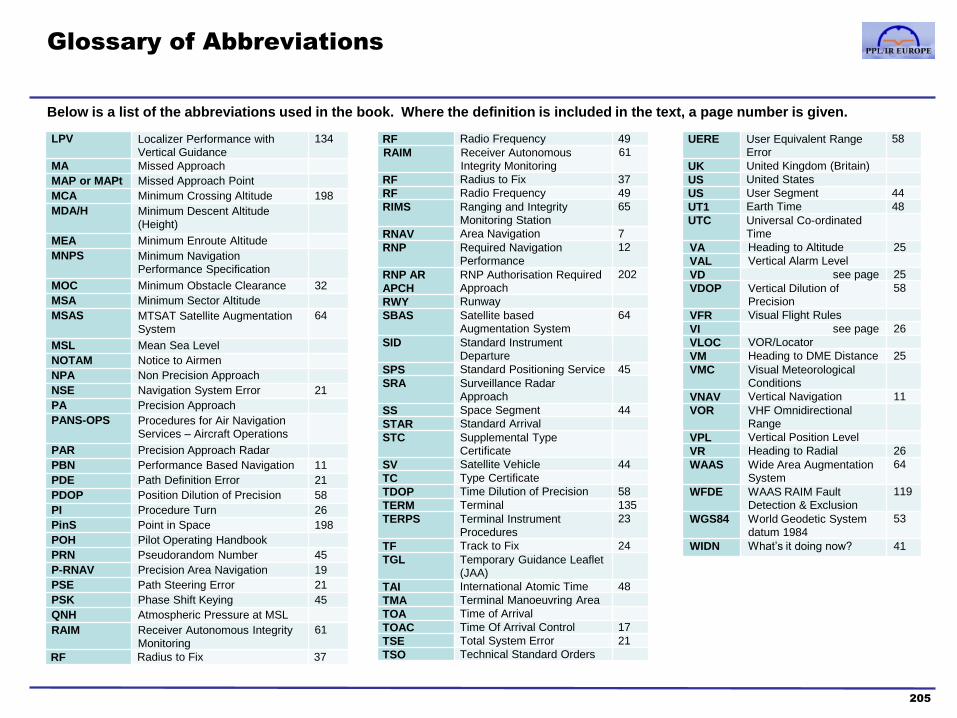
Glossary of Abbreviations
Below is a list of the abbreviations used in the book. Where the definition is included in the text, a page number is given.
LPV Localizer Performance with Vertical Guidance
134
MA Missed Approach
MAP or MAPt Missed Approach Point
MCA Minimum Crossing Altitude 198
MDA/H Minimum Descent Altitude (Height)
MEA Minimum Enroute Altitude
MNPS Minimum Navigation Performance Specification
MOC Minimum Obstacle Clearance 32
MSA Minimum Sector Altitude
MSAS MTSAT Satellite Augmentation System
64
MSL Mean Sea Level
NOTAM Notice to Airmen
NPA Non Precision Approach
NSE Navigation System Error 21
PA Precision Approach
PANS-OPS Procedures for Air Navigation Services – Aircraft Operations
PAR Precision Approach Radar
PBN Performance Based Navigation 11
PDE Path Definition Error 21
PDOP Position Dilution of Precision 58
PI Procedure Turn 26
PinS Point in Space 198
POH Pilot Operating Handbook
PRN Pseudorandom Number 45
P-RNAV Precision Area Navigation 19
PSE Path Steering Error 21
PSK Phase Shift Keying 45
QNH Atmospheric Pressure at MSL
RAIM Receiver Autonomous Integrity Monitoring
61
RF Radius to Fix 37
RF Radio Frequency 49 RAIM Receiver Autonomous
Integrity Monitoring 61
RF Radius to Fix 37 RF Radio Frequency 49 RIMS Ranging and Integrity
Monitoring Station 65
RNAV Area Navigation 7 RNP Required Navigation
Performance 12
RNP AR
APCH
RNP Authorisation Required Approach
202
RWY Runway SBAS Satellite based
Augmentation System 64
SID Standard Instrument Departure
SPS Standard Positioning Service 45 SRA Surveillance Radar
Approach
SS Space Segment 44 STAR Standard Arrival STC Supplemental Type
Certificate
SV Satellite Vehicle 44 TC Type Certificate TDOP Time Dilution of Precision 58 TERM Terminal 135 TERPS Terminal Instrument
Procedures 23
TF Track to Fix 24 TGL Temporary Guidance Leaflet
(JAA)
TAI International Atomic Time 48 TMA Terminal Manoeuvring Area TOA Time of Arrival TOAC Time Of Arrival Control 17 TSE Total System Error 21 TSO Technical Standard Orders
UERE User Equivalent Range Error
58
UK United Kingdom (Britain) US United States US User Segment 44 UT1 Earth Time 48 UTC Universal Co-ordinated
Time
VA Heading to Altitude 25 VAL Vertical Alarm Level VD see page 25 VDOP Vertical Dilution of
Precision 58
VFR Visual Flight Rules VI see page 26 VLOC VOR/Locator VM Heading to DME Distance 25 VMC Visual Meteorological
Conditions
VNAV Vertical Navigation 11 VOR VHF Omnidirectional
Range
VPL Vertical Position Level VR Heading to Radial 26 WAAS Wide Area Augmentation
System 64
WFDE WAAS RAIM Fault Detection & Exclusion
119
WGS84 World Geodetic System datum 1984
53
WIDN What’s it doing now? 41
205

(end of document)
http://www.pplir.org


© 2018 PPL/IR Europe