Testing Multi-GNSS Equipment: Systems, Simulators, and the Production Pyramid
10
52 InsideGNSS JULY/AUGUST 2010 www.insidegnss.com T esting procedures comprise an important element in the devel- opment, manufacturing, and integration of GNSS devices. Essentially, everybody involved in GNSS will be involved in or affected by testing at one time or another. Naturally, when we talk about test procedures, we think of an engineer or scientist developing or validating a new GNSS device. But even a consumer who walks out of a shop with a new GNSS unit can be viewed as being involved in a test. He or she switches on the unit and sees if it works. at is the test. A conference attendant browsing at an exhibition approaches a booth and asks the exhibitor for a demonstration of his GNSS device. e exhibitor is per- forming a test. Up until now, most common tests have been tailored for GPS, but the need to consider multi-GNSS testing is becoming more and more important. e next three GLONASS satellites are planned to be launched in August. is launch should complete the GLONASS constellation, and Russia’s GNSS will have reached its full operational capabil- ity. Europe’s Galileo and China’s Com- pass/Beidou-2 are on the horizon. Con- sequently, market demand is increasing for equipment that supports multiple GNSS technologies. How does the involvement of a sec- ond or third GNSS affect testing proce- dures? In other words, how are multi- GNSS tests different from GPS-only tests, and are they necessary? Can GPS Testing Multi-GNSS Equipment As new GNSS systems appear, the time for multi-GNSS simulator testing has arrived. Three receiver designers and researchers look at use of this essential tool throughout the entire receiver develop- ment cycle: from research, development, design and validation through chip, module, OEM and user device development sequences and on to consumer testing, certification, maintenance, and repair. IVAN PETROVSKI IP-SOLUTIONS BRYAN TOWNSEND ROBERTON ENTERPRISES LTD. TAKUJI EBINUMA UNIVERSITY OF TOKYO Systems, Simulators,and the Production Pyramid
Transcript of Testing Multi-GNSS Equipment: Systems, Simulators, and the Production Pyramid

52 InsideGNSS j u l y / a u g u s t 2 0 1 0 www.insidegnss.com
T esting procedures comprise an important element in the devel-opment, manufacturing, and integration of GNSS devices.
Essentially, everybody involved in GNSS will be involved in or affected by testing at one time or another.
Naturally, when we talk about test procedures, we think of an engineer or scientist developing or validating a new GNSS device. But even a consumer who walks out of a shop with a new GNSS unit can be viewed as being involved in a test. He or she switches on the unit and sees if it works. That is the test.
A conference attendant browsing at an exhibition approaches a booth and asks the exhibitor for a demonstration of his GNSS device. The exhibitor is per-forming a test.
Up until now, most common tests have been tailored for GPS, but the need to consider multi-GNSS testing is
becoming more and more important. The next three GLONASS satellites are planned to be launched in August. This launch should complete the GLONASS constellation, and Russia’s GNSS will have reached its full operational capabil-ity. Europe’s Galileo and China’s Com-pass/Beidou-2 are on the horizon. Con-sequently, market demand is increasing for equipment that supports multiple GNSS technologies.
How does the involvement of a sec-ond or third GNSS affect testing proce-dures? In other words, how are multi-GNSS tests different from GPS-only tests, and are they necessary? Can GPS
testing Multi-gNss Equipment
As new GNSS systems appear, the time for multi-GNSS simulator testing has arrived. Three receiver designers and researchers look at use of this essential tool throughout the entire receiver develop-ment cycle: from research, development, design and validation through chip, module, OEM and user device development sequences and on to consumer testing, certification, maintenance, and repair.
IvaN PEtrovskIiP-SolutionS
BryaN towNsENdRobeRton enteRPRiSeS ltd.
takujI EBINuMauniveRSity of tokyo
systems, simulators,and the Production Pyramid

www.insidegnss.com j u l y / a u g u s t 2 0 1 0 InsideGNSS 53
testing procedures and test equipment still suffice for multi-GNSS testing?
This article, the first of two parts, will look at the professional test proce-dures that appear throughout a GNSS receiver’s life cycle. The second part will look at various simulator designs, spec-ification requirements for various tests involving multiple GNSSes, and whether a specific simulator design is suitable for a particular test.
As we will see, not only do the tests for individual specification parameters vary, but even the definitions of those parameter can differ.
WhyUseSimulators?Quite often live signals from the satel-lites are used for testing GNSS devices. However, this approach has limitations due to the difficulty in anticipating and controlling the manifestation of the signals as well as the inability to repeat the signal environment. For these rea-sons, in many situations the preferred tool for GNSS device testing is a GNSS simulator.
In the activities described in this article, we used a simulation system that provides up to 36 channels of combined GPS, GLONASS, and Galileo L1 with the option to enable one, two, or three con-stellations. We also used a single-chan-nel simulator that can generate a single, combined GPS/SBAS, GLONASS, and Galileo signal to enable testing of GPS only or multi-GNSS devices in a produc-tion environment.
A multi-channel simulator provides a system-level environment incorporat-ing multiple parameters into the simu-lated scenario. Single-channel simulators allow the optimization of the receiver’s tracking and acquisition loops, rather than whole system. The latter type allows more control over specific parameters such as a Doppler profile. In contrast, a multi-channel simulator incorporates such variables as satellite motion, vehicle dynamics, and clock parameters and generally cannot be configured to fit a specific profile.
Simulators provide a universal, high-level capability to cover the necessary tests from design to manufacturing of
GNSS equipment. Moreover, their use allows us to exclude most of the other testing equipment that might otherwise be necessary.
As our primary test subject device, we used a software real-time receiver developed by the first author, which enabled us to conduct most of the tests and, at the same time, obtain the exten-sive visualization and flexibility needed for research purposes. The software receiver operates on a personal computer with a range of performance capabilities depending on the PC processor. Figure 1 shows a test-bench setup in our office.
ReceiverLifeCycleWithin this article we look at the pro-fessional test applications throughout a receiver life cycle. For our purposes, then, we can describe the receiver life cycle as passing through the following stages:1) research and development in which
new a lgorithms and solutions emerge
2) design and validation where spe-cific receiver designs are created and compared with a benchmark design or given specification
3) hierarchical element production, which encompasses the sequential production of chip, module, OEM, and user device, with each sub-stage requiring particular tests of the device’s input and output
4) consumer testing and certification5) repair and maintenance.
We will consider here only the tests that are specific to GNSS and omit those
of a more general nature for consumer electronic products, such as tests for electromagnetic compatibility (EMC), space applications, such as tests for radiation tolerance, and so on.
The issues of test generalization and standardization become more pressing as GLONASS expands from use only in high-end geodetic applications to adop-tion by mass markets such as fleet track-ing and cellular phones.
Meanwhile, Galileo and Compass are expected to come on-line very soon. The Galileo R&D and design stages are already well under way.
This situation leads us to address the question: Do GLONASS, Galileo, Com-pass, and a modernized GPS require any modifications in our test procedures and /or perceptions? The authors believe that they do.
Going forward, the need for these modifications arises first from the fact that these systems are different from today’s GPS, where most of our experi-ence lies, and secondly from the multi-system nature of the devices that will be tested. Therefore, our tests perceptions should account for variations in differ-ent GNSSes and for the use of GNSSes in combination — not as a sum of separate systems, but as an integrated system.
Let us look at these stages in detail.
ReceiverDesignConceptsandTheirEffectonTestProceduresBefore delving more deeply into test pro-cedures and strategies, we should review
FIGURE 1 Single- and multi-channel simulators, GPS/Galileo (on top) and GPS/GLONASS software receiver USB front end with controlled power source

54 InsideGNSS j u l y / a u g u s t 2 0 1 0 www.insidegnss.com
mULTi-gnSSEqUiPmEnT
the basic functions within a GNSS receiver as illustrated in Figure 2.
Channel tracking produces code phase, carrier phase, Doppler and sig-nal-to-noise-ratio (SNR) measurements. The navigation message decoding func-tion deciphers the satellite signal’s data content. PVT (position, velocity, time) represents the calculation of those val-ues for the receiver. The user interface communicates with the receiver opera-tor by means of anything from a serial data stream to a full map display. All these components should be tested.
Testing equipment using multiple GNSS systems introduces additional issues with which receiver designers must deal. Multi-GNSS implies multi-ple radio frequencies. Differences appear in the various GNSS time systems and coordinate reference systems.
Let’s look at these factors a little closer.
The RF bands available for GNSS positioning are fixed and regulated by an international treaty as implemented through the International Telecom-munications Union. Inevitably, some overlap or sharing of frequencies by dif-ferent GNSS systems often occurs. For example, the GPS civilian signal and Galileo civilian signal share a 20 MHz band centered at 1575.42 MHz. However, the GLONASS civilian signal is located around 1603 MHz. As a result, a com-bined GPS/GALILEO receiver can share an RF channel between the two systems while a GPS/GLONASS receiver requires independent RF channels.
GPS has been transmitting signals since the early 1980s when the deci-sion was made to have the system’s time free-running and independent of coor-dinated universal time (UTC). Because a user is for the most part only interested in UTC time or one of the time zone off-sets, the GPS almanac provides a correc-
tion (in leap-seconds) to UTC time. This correction increases every few years; so, manufacturers typically insert the cur-rent value of the UTC offset into the receiver at the time of production and update this value as it changes according to the GPS almanac.
GLONASS and Galileo are locked to UTC time (or one of its derivatives); so, these systems do not require conversions. This presents some interesting problems when one tries to test the combined sys-tems using GNSS simulators, especially if the GPS receiver has a factory present offset embedded in the unit.
We also need to account for a time shift between particular UTC deriva-tives. Such a shift can be modeled, for example, by a second-order Markov pro-cess in a simulator. This shift is usually added to a state vector to be estimated in a multi-GNSS receiver’s PVT.
Technically, each system uses an independent geodetic reference system. However, the reference systems are so closely aligned that only the advanced user, mostly in geodetic applications, would need to take these differences into consideration. For the large majority of users, the variation in coordinate refer-ence systems can be disregarded.
R&DDesignThe R&D stage covers two distinctive sub-areas: basic, which includes funda-mental tests requiring a valid reference signal, reference truth data, and repeat-ability; and advanced, which simulates (with repeatability) situations that are seldom possible or impossible to achieve under the normal circumstances, and also activities that facilitate niche, high-end applications.
The basic tests of signal and truth-data references allow developers to tune up various functions of a receiver, such as navigation message decoding. The
simulator supplies the reference signal with a navigation message in ASCII and binary formats.
This enables designers to verify their algorithms for recovering time synchronization and decoding naviga-tion messages. For example, our soft-ware receiver allows a comparison of the decoded broadcast navigation mes-sage with a navigation message it reads from a binary file, previously dumped from the simulator or from the software receiver itself.
Reference truth data allows optimiza-tion of receiver accuracy and sensitivity, and ensures proper handling of atmo-spheric effects on GNSS signal propaga-tion. For example, the ionospheric- and tropospheric-related errors generated in a receiver can easily be compared with those logged from a simulator.
Repeatability is a feature needed gen-erally at this stage but also is essential for establishing some of the receiver param-eters such as time to first fix (TTFF). At the basic R&D stage we also look at testing a receiver’s one-pulse-per-second (1PPS) performance as well as static and dynamic accuracy.
A real-time software receiver, howev-er, doesn’t always guarantee repeatabil-ity. We should consider that a real-time software receiver is not only a device that can fairly quickly calculate accumulators for code and carrier tracking, but also can successfully operate for a long time with a changing constellation without divergence. Therefore, such a receiver is bound to be multi-threaded.
For example, when a single-thread-ed software receiver operates, it at first acquires satellites and then goes into a tracking mode. When a constellation is changed the receiver cannot normally acquire new satellites without dropping of the real-time tracking function. If the multi-threaded software receiver is run-
FIGURE 2 Receiver design concept

www.insidegnss.com j u l y / a u g u s t 2 0 1 0 InsideGNSS 55
ning without a real-time operating sys-tem (RTOS), then it is difficult to ensure how exactly all threads execute relative to each other.
This leads to a situation where even with a simulator, a test is repeatable only to a certain extent. A number of threads are always being executed simultane-ously on a PC. In two sequential runs, a tracking thread running with a higher priority, for example, can give way to acquisition thread after a different delay, which may lead to an acquisition of satel-lites in a different sequence and so on.
Test repeatability can be ensured for an embedded software receiver, which operates on RTOS; a semi-software receiver where, for example, an acqui-sition thread can be allocated to a field programmable gate array (FPGA), or a hardware receiver.
As for advanced R&D, its first task of repeatably simulating specific situations may include such scenarios as satellite failure for RAIM testing, extensive iono-spheric errors, or intentional and unin-tentional interference.
As for facilitating application-spe-cific, high-end tests, advanced R&D activities may include a simulation of an aircraft and spacecraft onboard receiver. The other tests can facilitate a develop-ment of advanced multipath-mitigation techniques, because they allow an exact specification of the conditions gener-ating the multipath. Figure 3 shows a receiver correlator window with output from 17 correlators with and without a multipath signal.
To give an example here, we refer to a test of an airborne receiver using the BGPS instant positioning method for an aircraft on-board receiver. BGPS is a pat-
ent-pending technology, developed by the first author, that enables a receiver to determine position in real time with-out reading a broadcast navigation mes-sage or using network-assistance data. It relies instead on preloaded data and a snapshot of signal data with which to recover the time of transmission.
Although the main advantage of this method is that it provides an instant positioning without a prior knowledge of initial position, BGPS also enables a receiver to determine coordinates in real-time using as little as 5–20 millisec-onds of signal. In this test we wanted to determine coordinates of an aerobatic aircraft during a performance of highly dynamic maneuvers.
In our test scenario, we simulated a speeding and simultaneously constantly rolling — with one rps (revolutions per second) — angular velocity aircraft. We simulated two antennas, one look-ing up and another down, in order to ensure the existence of a satellite signal at each epoch. Figure 4 shows the simu-lated antenna pattern and changes in the artificial horizon gauge and power of the available satellite signals. This test allows us to demonstrate the ability of BGPS to calculate a position based on a very short chunks of signal.
This test is hardly manageable in real life and on the face of it might seem dif-ficult to program. But with the aid of the multi-GNSS simulator, we were able to prepare this test in less than 10 minutes.
CoordinateSystems&ErrormodelsAt this stage the benefit of multi-GNSS for testing is rather clear. One needs to ensure that a receiver can properly
FIGURE 3 Multipath test. Software receiver correlator panel
FIGURE 4 BGPS test GUI display: simulated antenna pattern and changes in the artificial horizon gauge and power of the available satellite signals.
56 InsideGNSS j u l y / a u g u s t 2 0 1 0 www.insidegnss.com
integrate multi-GNSS coordinate sys-tems (including various associated time frames) and error budget models.
As we discussed earlier, the various GNSS systems’ coordinate frames seem to be fairly well integrated already, and nothing is required in this sense for a standard receiver. The time frames how-ever are unlikely to be coordinated well enough, not only because they differ, but they are also calculated in a different way — either as an assembly of clocks or a master clock.
Another issue to consider for multi-GNSS design and testing is the underly-ing error models. An ionospheric model is of particular importance. For exam-ple, GPS uses the Klobuchar model, and Galileo uses the NeQuick model.
Although on a receiver level, these models can be applied separately to the corresponding signals, in a simulator they must be combined in one common true model, which is used to calculate code delay and phase advance in the simulator’s signals. Consequently broad-cast ionospheric model parameters for all simulated signals should be derived from the same true model.
Tests should ensure an optimal com-bination of the GNSS either in coordi-nate or in measurement domain. The method of combination depends on the optimization criterion and on signal sta-tistics for the particular systems.
What would be more advanta-geous to use in terms of accuracy if, for example, a receiver has acquired GPS L1
and GLONASS L1+L2 signals? Would it be GPS L1 + GLONASS L1+L2 or GLONASS L1+L2? What would be more advantageous to use in terms of accuracy in case the receiver has acquired GPS L1 + L2 and GLONASS L1 signals? Would it be GPS L1 + L2 + GLONASS L1 or GPS L1+L2 only? Would the decision be affected by mask angle or foliage?
We can almost not imagine how to carry out such analyses without today’s simulation techniques.
A further item of interest is that interference will affect systems in a dif-ferent way. The new and future signals of GPS and Galileo are less prone to inter-ference due to their design. GLONASS is less prone to interference due to being a frequency division multiple access (FDMA) system on top of a code divi-sion multiple access (CDMA) system.
(It is interesting to note that usual classification normally refers to GPS as a CDMA system and GLONASS as FDMA. This is somewhat misleading. CDMA implies an existence of two essential components. The first one is an application of a spreading code. The second component is the identification of a signal source by that code.
GLONASS uses a signal source identification based on a frequency slot, which is why it is usually referred to FDMA, but it necessarily uses a spread-ing code. Therefore we can either say it’s FDMA on top of CDMA, or give it a spe-cial name such as “Spread FDMA.”)
As a result of an application of the
various underling systems, undertak-ing interference tests of a multi-system receiver becomes a more complex task with many parameters to consider.
Another important group of R & D testing is related to channel track-ing. This includes pseudorange (PSR) and accumulated Doppler range (ADR) testing, C/N0 accuracy, channel sensi-tivity (tracking and acquisition), and dynamics. Inherent in this is testing for inter-channel bias. These biases could be frequency based, as in GLONASS, or pseudorandom noise (PRN) code–based in the case of GPS.
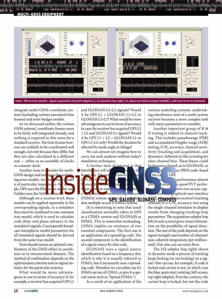
Good channel performance almost always translates to good PVT perfor-mance. Figure 5 shows two screen cap-tures from the graphical user interface (GUI) of our software receiver’s tracking channel in a C/N0 accuracy test using the single-channel simulator to display results from changing tracking loop parameters. The acquisition subplot (top left of each screen) gives visual informa-tion on the possibility of signal detec-tion. The size of the peak depends on the signal strength and number of coherent/non-coherent integrations (per millisec-ond). One also can see noise floor.
The I/Q subplot (top right) shows in dynamic mode a process of tracking loops locking (or not locking) on a sig-nal. One can see, for example, if code is locked and carrier is not, in which case the blue spots start rotating (left screen, top right subplot). If on the contrary, the carrier loop is locked, but not the code
mULTi-gnSSEqUiPmEnT
FIGURE 5 SW receiver panels: signal acquisition (top left subplots), I/Q channels (top right), in-phase correlator output (middle), code/carrier error (bottom)
www.insidegnss.com j u l y / a u g u s t 2 0 1 0 InsideGNSS 57
loop then the blue spots are closing up without rotation (right screen).
We also need to address the issue of testing for backward compatibil-ity, which is always awkward and often unnecessary. For example, we assume that all GLONASS satellites are mod-ernized (M) satellites, which seems reasonable since no earlier generation satellites are broadcasting. We also can assume that testing related to GPS selec-tive availability (SA) is obsolete now.
SomeCommonTestsWe will look at some common tests here, because it all starts at the R&D stage. Most of these tests are also required in further stages, but regardless of the results obtained during R&D, they are not going to be any better later in the development process. Probably the only exception is power consumption.
A TTFF test is required to define this parameter under various receiver start-up modes. Normally those are specified as “Hot,” “Warm,” and “Cold” starts. The definitions of start-up modes, how-ever, are not standardized and depend on the technology implemented in the specific receiver. Sometimes they are defined by the information content available in a receiver, but other times they are understood in terms of a period of receiver inactivity.
In our case, we were particularly interested in our software receiver’s BGPS instant positioning testing. We are measuring TTFF under the conditions when the receiver has a set of predicted ephemeris and time with accuracy of one or a few seconds.
On one hand that sounds like a hot start. On the other hand, our software receiver can calculate such a position after a number of days since it was switched off without any assist informa-tion in the intervening period. In that case it looks more like a cold start.
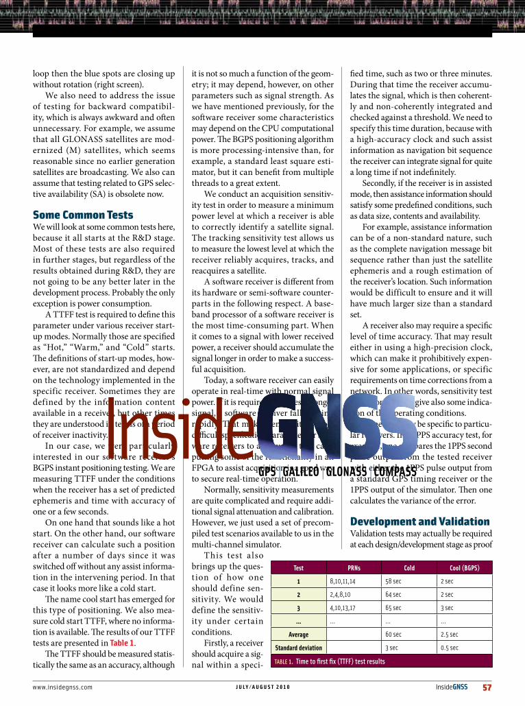
The name cool start has emerged for this type of positioning. We also mea-sure cold start TTFF, where no informa-tion is available. The results of our TTFF tests are presented in table 1.
The TTFF should be measured statis-tically the same as an accuracy, although
it is not so much a function of the geom-etry; it may depend, however, on other parameters such as signal strength. As we have mentioned previously, for the software receiver some characteristics may depend on the CPU computational power. The BGPS positioning algorithm is more processing-intensive than, for example, a standard least square esti-mator, but it can benefit from multiple threads to a great extent.
We conduct an acquisition sensitiv-ity test in order to measure a minimum power level at which a receiver is able to correctly identify a satellite signal. The tracking sensitivity test allows us to measure the lowest level at which the receiver reliably acquires, tracks, and reacquires a satellite.
A software receiver is different from its hardware or semi-software counter-parts in the following respect. A base-band processor of a software receiver is the most time-consuming part. When it comes to a signal with lower received power, a receiver should accumulate the signal longer in order to make a success-ful acquisition.
Today, a software receiver can easily operate in real-time with normal signal power. If it is required to process a longer signal, a software receiver falls behind rapidly. That makes sensitivity a most difficult specification parameter for soft-ware receivers to achieve. In that case, putting some of the functionality in an FPGA to assist acquisition is a good way to secure real-time operation.
Normally, sensitivity measurements are quite complicated and require addi-tional signal attenuation and calibration. However, we just used a set of precom-piled test scenarios available to us in the multi-channel simulator.
This test a lso brings up the ques-t ion of how one should define sen-sitivity. We would define the sensitiv-ity under certain conditions.
Firstly, a receiver should acquire a sig-nal within a speci-
fied time, such as two or three minutes. During that time the receiver accumu-lates the signal, which is then coherent-ly and non-coherently integrated and checked against a threshold. We need to specify this time duration, because with a high-accuracy clock and such assist information as navigation bit sequence the receiver can integrate signal for quite a long time if not indefinitely.
Secondly, if the receiver is in assisted mode, then assistance information should satisfy some predefined conditions, such as data size, contents and availability.
For example, assistance information can be of a non-standard nature, such as the complete navigation message bit sequence rather than just the satellite ephemeris and a rough estimation of the receiver’s location. Such information would be difficult to ensure and it will have much larger size than a standard set.
A receiver also may require a specific level of time accuracy. That may result either in using a high-precision clock, which can make it prohibitively expen-sive for some applications, or specific requirements on time corrections from a network. In other words, sensitivity test conditions should give also some indica-tion of the operating conditions.
Some tests may be specific to particu-lar receivers. In a 1PPS accuracy test, for example, one compares the 1PPS second pulse output from the tested receiver with either the 1PPS pulse output from a standard GPS timing receiver or the 1PPS output of the simulator. Then one calculates the variance of the error.
DevelopmentandValidationValidation tests may actually be required at each design/development stage as proof
Test PRNs Cold Cool (BGPS)
1 8,10,11,14 58sec 2sec
2 2,4,8,10 64sec 2sec
3 4,10,13,17 65sec 3sec
… … … …
Average 60sec 2.5sec
Standard deviation 3sec 0.5sec
TABLE 1. Time to first fix (TTFF) test results
58 InsideGNSS j u l y / a u g u s t 2 0 1 0 www.insidegnss.com
of a job well done. They may include any or all imaginable tests, depending on the stage and specification.
Some parameters are not normally in a specification of a standard receiver, but rather apply to a receiver’s front end. We mention them here because, as far as receiver testing is con-cerned, they should be checked as part of component validation tests. These parameters may include the local oscillator’s phase noise limits, required noise figure, second- and third-order intermodulation, filtering characteristics, and so forth.
One example of the validation tests comes in the chip devel-opment cycle. Because the chip development requires a large amount of initial investment and it is impossible to change the design once completed, more elaborate performance validation tests are required using an FPGA prototype.
Special consideration must be given to a PC-based software receiver, which today must meet some general specification requirements beyond signal acquisition, tracking, and posi-tioning. We should distinguish between R&D tool, which can
simulate acquisition, tracking, and positioning functions of a receiver, and a software receiver per se, which can successfully carry out all generic receiver functions. A functionality test to ensure such functions can be to leave a receiver running for a significant amount of time in order to see a position estimate that didn’t diverge.
When this requirement of continuous operation has been met, we can evaluate the specification. Therefore, a validation test for the software receiver should require a few — and pos-sibly up to 24 — hours of real-time continuous operation.
We can visualize the test results in various ways, including processing and plotting the available NMEA and RINEX-for-mat data. Processing RINEX data with a third-party software can validate embedded navigation algorithms.
Figure 6 is a screenshot of the receiver GUI’s positioning panel displaying root mean square (RMS), twice distance RMS (2DRMS) and mean error after the test. A few rapidly converg-ing fixes can be seen outside the inner (purple) 2DRMS circle are due to a combination of an initial positioning with three satellites and carrier smoothing.
For a test of static positioning, one can always use a geodetic reference point to validate receiver performance. The refer-ence point could be a pre-surveyed monument or one created with a high-end validated geodetic receiver in a low-multipath environment. A simulator becomes indispensable, however, when it comes to the dynamic accuracy tests that are needed for most GNSS receivers. The simulator provides a time-marked reference trajectory, which can be then compared with the tra-jectory estimated by the receiver.
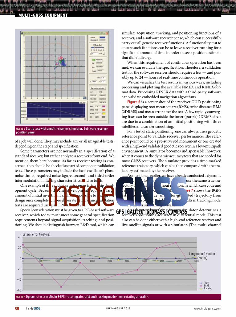
As mentioned earlier, we have already conducted a dynamic accuracy test for BGPS positioning. We use the same true tra-jectory for an aircraft without rotation, in which case code and carrier tracking become available. Figure 7 shows the BGPS estimated versus true (simulator-generated) trajectory from this test with overlapped dynamic test results in tracking mode, where carrier smoothing is available.
Another test benefiting from a simulator determines a receiver’s positioning accuracy in differential mode. This test also can be done either with a high-end reference receiver and live satellite signals or with a simulator. (The multi-channel
FIGURE 7 Dynamic test results in BGPS (rotating aircraft) and tracking mode (non-rotating aircraft).
Lateral error (meters)40
20
0
-20
-40
-60
TrueBGPSTracking
Longitudinal motion (meter)
mULTi-gnSSEqUiPmEnT
FIGURE 6 Static test with a multi-channel simulator. Software receiver position panel

www.insidegnss.com j u l y / a u g u s t 2 0 1 0 InsideGNSS 59
simulator that we use can provide differ-ential corrections in RTCM standard.)
For the test, the antenna of a GPS/GLONASS OEM board is co-located with the antenna of the reference receiver. The positioning data logged from the OEM board is then calculated and compared with the reference receiver data to deter-mine the standard derivation of the posi-tion results as in the stand-alone static test. When using a reference receiver, a zero base-line test is recommended.
Some other tests are equally impor-tant for newly developed receivers, especially multi-GNSS receivers. These include special-date tests, such as end-of-week, end-of-year, week rollover, and leap-second events. Most such tests are available for us in the simulator, and we just examined the predefined scenarios and selected those we needed.
AProductionPyramidWe now should look at the produc-tion stage of receiver development. For mass-production devices (and actually for some high-end equipment as well), this may include the manufacturing of a multi-GNSS chip. Such chips are pro-duced in volume and go to various mod-ules manufactures.
In turn, the modules, being produced in lesser volume by more manufacturers, pass along to the OEM manufacturers. The hierarchy pyramid keeps narrowing as the complexity of the receiver form factor increases (see Figure 8) and even-tually reach a system integrator and then the end users as a finished product.
The bottom band of the pyramid rep-resents chip manufacturers with a pro-duction output from ten to hundreds of thousands per year and a unit cost of a few dollars.
Figure 9 shows an example of produc-tion pyramid products: a GPS/GLONASS receiver chip, GPS RF front-end module, and a GNSS USB receiver.
The interesting thing implied by this pyramid is that production tests, which need to be conducted at each stage, vary in contents and depth according to the form factor’s purpose and production volume.
Production tests generally should include pack sample tests for the com-
ponents that are suppl ied by t he third parties, pack sample tests for the final manufactured product, and quali-fication tests for any specia l sensit ive specifications that might be required, for example, for air-borne or spaceborne applications.
Periodic pack sample tests are necessary to ensure that the incoming components and outgoing products meet their specifications. Production lines both in suppliers and in-house can encounter pre-planned or unexpected changes in technology.
Slight changes in supplied materials can affect performance as well, affecting the quality of the product and its ability to meet a specification. Moreover, the specifications of GNSS systems them-selves are changing, with new frequen-cies and signal designs. The various tests should continuously ensure the quality of product.
Production tests should also be easily adaptable for automation. We will look at this in more details when considering a simulator design in the second part of this article. Tests that can be useful at typical manufacturing facilities along the production chain include: 1) incoming components pack sample
tests2) outgoing component inspection (here
we refer to intermediate component testing)
3) qualification test 4) final production test.
As an example of component test-ing at the lowest level of the production pyramid, we can consider the evaluation of a low noise amplifier (LNA). At the top of the pyramid we have the manu-facturing of final products. These could be cellular phones, handheld receivers, or other equipment, all of which should undergo final tests. In some cases, such as with airborne or spaceborne systems,
a final product may require a lot of extra tests to ensure its specification.
For outgoing inspection, a correlation table between the parameters as speci-fied and as tested may be established. For instance, large code/carrier divergence would indicate that the phase locked loop (PLL) driving the sample clock is not locking properly. Poor C/N0 might indicate an antenna path problem or temperature compensated crystal oscil-lator (TCXO) problem.
In order to look at the tests of a final product, we should brief ly describe a typical receiver. The signal received at the antenna goes to an LNA then through filters along the RF circuitry including down converters to analog to digital converters (ADCs). Then the digi-tized intermediate frequency signal goes to the baseband processor, from where the measurements go to a navigation processor. The whole system is driven by a clock. At the end of the receiver chain is an I/O interface, the form of which depends on the application.
The receiver can be embedded into a host device, such as a cellular phone, navigation complex, or personal com-puter, which means that parts of the receiver can actually belong to the host device. In the case of a software receiver, everything after the ADC can be allo-cated to a host.
In the case of a conventional receiver everything after the baseband proces-sor can be allocated to the host device. Therefore, the final test is an important
FIGURE 8 Production pyramid

60 InsideGNSS j u l y / a u g u s t 2 0 1 0 www.insidegnss.com
part of a manufacturing process both for a receiver manufacturer and for end-user device manufacturer, if it includes a receiver as an integrated part.
In contrast to a validation test (which aims to demonstrate that particular specification parameters are being met for a particular component), a final test has to ensure that all components in the system are working together properly after they are integrated.
For example, an LNA can be inte-grated into an RF chip and, therefore, this integration could be tested on a lower level of the production pyramid, with the integrated chip supplied to the OEM module manufacturer. On the other hand, the LNA could be supplied separately from the RF chip and inte-grated by the module manufacturer.
These options imply slightly different approaches to the tests. The difference, however, is non-essential if the final production phase includes a complex functionality test with complete posi-tioning fix.
Such tests can be organized in a such way that they combine a sensitiv-ity test and dynamic positioning test in one run. Sensitivity, velocity, and acceleration profiles can be defined in a single scenario. If the receiver oper-ates normally in the scenario, then it is proved that the whole set of receiver performance specifications are ful-
filled and meet the product acceptance requirements.
The reference data to check dynamic accuracy in this test is obtained from the simulation data files. Tests at this stage also include one for power consumption, which is measured using a wattmeter under normal receiver operation.
WhynotaRing-UpTest?From a practical point of view, it would be most convenient just to “ring up” the cir-cuits with a sine wave to test them. Unfor-tunately, many potential problems can go undetected with that approach. In fact, ring-up tests cannot even properly ensure that antenna connections are sound.
Some technical issues, such as those related to soldering, wiring, soldering material, impedance mismatch, and so forth, can cause extra signal losses. Such losses in RF may go undetected with ring-up tests but still cause severe degradation in receiver parameters or even equipment failure.
These problems can arise from various causes. They can occur due to unannounced or involuntary changes in the technological processes within the component or material supplier’s facilities. Problems can also result from undetected changes within the manu-facturer’s own production technologies and processes, and from machinery fail-ures or aging. The recommended reflow
parameters in manufacturing can vary among components and, therefore, sometimes cannot be precisely set to fit all of them.
A particularly sensitive part of any receiver is its clock, normally a TCXO or voltage controlled TCXO, and can be affected by the assembly process. The clock can be supplied for assembly inside of a component module, on its own, or within a host device. In either case, the clock should be tested after the final assembly.
Almost all potential problems with the clock cannot be detected with the circuit ring-up test. That would include not only a catastrophic parameters fail-ure, such as a drift, but in many cases the complete operational failure as well.
An excess clock drift beyond the spec will affect the receiver sensitivity because of imposed limitations on coherent inte-gration. It also may cause a failure of an assist mode because of incorrectly cho-sen Doppler bins, or even affect the abil-ity to acquire satellites due to a shifted frequency search area.
Further, the circuit ring-up test can-not check a baseband processor and navigation processor. If the navigation function is performed as a part of the upper-level system and not by a dedi-cated processor, then the overall inte-gration must be checked. That should include a stream of outgoing data from the baseband processor for positioning calculation, raw data, and possibly an incoming stream of assistance data for assisted acquisition.
If the receiver is a software receiver using a host processor for acquisition and tracking as well as navigation, then it becomes essential to test how the host processor copes with the extra tasks. Even in the case of a hardware receiver, if multi-correlators are involved, it implies a significant load for a host processor from the measurements supplied by the multiple correlators. Moreover, the soft-ware or firmware for a host processor is changing constantly and may affect the positioning tasks.
All these types of error, however, can be spotted with one properly designed positioning test.
mULTi-gnSSEqUiPmEnT
FIGURE 9 Size and price versus quantity. From left to right, GPS/GLONASS Receiver Chip, GPS RF front end module, GNSS board

www.insidegnss.com j u l y / a u g u s t 2 0 1 0 InsideGNSS 61
multi-gnSSTestSpecificsA very important question for the designing of the final product test is: Will GPS-only testing serve for multi-GNSS devices?
First of all, a multi-GNSS receiver would also require a final test that included the specifics of each GNSS. Could a proper GPS-only test ensure a proper operation of GLONASS or Gali-leo components? The answer to that is no. The hardware components for each system may significantly differ starting from the RF part.
As we described earlier, the bandwidth and frequencies for various GNSS signals are different, which leads to an implemen-tation of different sets of filters and sepa-rated signal tracks. The correlators also may be different. Therefore, these separate tracks should be tested separately.
Moreover, the same components can work for one system and fail for another. For example, the clock for a dual GPS/GLONASS device can be the same, but the driven sampling rate for GLONASS is two to eight times higher due to the wide bandwidth of FDMA. Consequently, even for the clock one can imagine a situation in which the clock will pass the GPS position-ing test and fail GLONASS in the field.
The second argument for special multi-GNSS tests is that many multi-GNSS mar-kets may require certification, including certification of the manufacturing process. That certification would require a final test for each GNSS used in the product.
ConsumerTestingandCertificationEnd-user products of today and tomor-row not only combine various GNSSes, but their manufacturers also aim to mar-ket them in many countries worldwide, because applications are now global and truly international. So, when multi-GNSS equipment comes to a local mar-ket, the issue of local certification may become crucial for success there.
Of course, various special niche markets, such as those for safety-of-life applications, and associated professional services also generally require certifica-tion — for example, a pre-flight test of an airborne receiver in an aircraft han-
gar using retransmitted GNSS signals or simulator.
Certification is and will be even more important for the equipment that must be endorsed for federally controlled applications, such as aviation, public fleet management, and E911 type of ser-vices for mobile phone users.
Both the multi-GNSS products and the equipment used to test them must be certified. Standard certification equip-ment includes:• multi-channel high end simulator
such as we used in our tests• geodetic reference point• multi-GNSS high-end reference
receiver• timing receiver.
ConclusionAdjustments to test procedures at all stages are required when testing multi-GNSS equipment. The article has exam-ined the some of the differences among GNSS systems that require separate test procedures and how simulators can facilitate this process.
We have also discussed the various phases of equipment manufacturing and the need for testing at various levels of the production pyramid. In the next article we will look at various simulator designs, specification requirements for different types of equipment tests, and whether a specific simulator design is suitable for a particular test.
AcknowledgementThe first author would like to thank Andrew Addy, Asia Pacific director of sales for Spirent Positioning products, for his assistance in designing the BGPS dynamic test described in this article, and for introducing the author to a fascinating field of GNSS simulation in 1998 during user seminars. The first author also would like to acknowledge Dr. Richard Langley, Department of Geodesy and Geomatics Engineering at the University of New Brunswick, for introducing a “cool start” name for the type of start used in BGPS.
manufacturersThe tests described in this article used the multi-channel multi-GNSS GSS6700
simulator, single-channel GSS6300 sim-ulator, and SimGen software suite from Spirent Communications, Paignton, United Kingdom. Real-time software GNSS iPRx receiver from iP-Solutions, Japan. Equipment pictured in Figure 9 includes the MAX2769 GPS/GLONASS receiver chip from Maxim Integrated Products, Sunnyvale, California, USA; the GRM8650 High Sensitivity RF Front-End Module from Rakon Ltd., Auckland, New Zealand; and the Repli-cator board from iP-Solutions, Japan.
AuthorsIvan Petrovskiisaprinci-pal at iP-Solutions, aJapanesebasedcompanyfounded in 2007 todevelop intellectualproperty(IP),productsforR&Dandprofessional
servicesintheGNSSarea.HehasbeeninvolvedintheGNSSfieldformorethan25years.PriortohisworkwithiP-Solutions,heledGNSS-relatedR&DforDXAntenna,GNSSTechnologiesInc.,andtheInstituteofAdvancedSatellitePositioning,ajointventurebetweenGNSSTechnologiesandTokyoUniversityofMarineScienceandTechnology.HisacademiccareerstartedwithhisteachingpostasanassociateprofessorwithMoscowAviationInstitute(MAI),fromwherehereceivedhisPh.D.PetrovskihasbeenworkinginJapansince1997whenhewasaJapanSTAfellowwithNationalAerospaceLaboratory(nowpartofJapanAero-spaceExplorationAgency-JAXA).Youcancontacthimat<[email protected]>.
Bryan Townsendhasmorethan20yearsexperienceinvariousGNSSfieldsinc luding receiverdesign, ground- andspace-basedaugmenta-tionsystems,andreal-
timekinematicpositioningaswellasterrestrial-basedsystems.Hehasauthoredandco-authoredmorethen50papersonthesesubjects.
Takuji EbinumareceivedhisPh.D.inaerospaceengineering from theUniversityofTexasatAustin.HeiscurrentlyaseniorresearcherattheUniversity of Tokyo,
Japan,specializinginspaceborneGNSSreceiverdesignforsmallsatellites.HeparticipatedindesigningtheiPRxreceiverandconductingverificationtests.